Manual of Petroleum Measurement Standards Chapter ... - NET
68
Manual of Petroleum Measurement Standards Chapter 12—Calculation of Petroleum Quantities Section 2—Calculation of Petroleum Quantities Using Dynamic Measurement Methods and Volumetric Correction Factors Part 4—Calculation of Base Prover Volumes by the Waterdraw Method FIRST EDITION, DECEMBER 1997 REAFFIRMED, SEPTEMBER 2014 COMMITTEE USE ONLY
-
Upload
khangminh22 -
Category
Documents
-
view
0 -
download
0
Transcript of Manual of Petroleum Measurement Standards Chapter ... - NET

Manual of Petroleum Measurement StandardsChapter 12—Calculation of
Petroleum Quantities
Section 2—Calculation of Petroleum Quantities Using Dynamic Measurement Methods and Volumetric Correction Factors
Part 4—Calculation of Base Prover Volumes by the Waterdraw Method
FIRST EDITION, DECEMBER 1997 REAFFIRMED, SEPTEMBER 2014
COMMITTEE USE O
NLY

COMMITTEE USE O
NLY

Manual of Petroleum Measurement StandardsChapter 12—Calculation of
Petroleum Quantities
Section 2—Calculation of Petroleum Quantities Using Dynamic Measurement Methods and Volumetric Correction Factors
Part 4—Calculation of Base Prover Volumes by the Waterdraw Method
Measurement Coordination FIRST EDITION, DECEMBER 1997 REAFFIRMED, SEPTEMBER 2014
COMMITTEE USE O
NLY
SPECIAL NOTES
API publications necessarily address problems of a general nature. With respect to partic-ular circumstances, local, state, and federal laws and regulations should be reviewed.
API is not undertaking to meet the duties of employers, manufacturers, or suppliers towarn and properly train and equip their employees, and others exposed, concerning healthand safety risks and precautions, nor undertaking their obligations under local, state, orfederal laws.
Information concerning safety and health risks and proper precautions with respect to par-ticular materials and conditions should be obtained from the employer, the manufacturer orsupplier of that material, or the material safety data sheet.
Nothing contained in any API publication is to be construed as granting any right, byimplication or otherwise, for the manufacture, sale, or use of any method, apparatus, or prod-uct covered by letters patent. Neither should anything contained in the publication be con-strued as insuring anyone against liability for infringement of letters patent.
Generally, API standards are reviewed and revised, reaffirmed, or withdrawn at least everyfive years. Sometimes a one-time extension of up to two years will be added to this reviewcycle. This publication will no longer be in effect five years after its publication date as anoperative API standard or, where an extension has been granted, upon republication. Statusof the publication can be ascertained from the API Authoring Department [telephone (202)682-8000]. A catalog of API publications and materials is published annually and updatedquarterly by API, 1220 L Street, N.W., Washington, D.C. 20005.
This document was produced under API standardization procedures that ensure appropri-ate notification and participation in the developmental process and is designated as an APIstandard. Questions concerning the interpretation of the content of this standard or com-ments and questions concerning the procedures under which this standard was developedshould be directed in writing to the director of the Authoring Department (shown on the titlepage of this document), American Petroleum Institute, 1220 L Street, N.W., Washington,D.C. 20005. Requests for permission to reproduce or translate all or any part of the materialpublished herein should also be addressed to the director.
API standards are published to facilitate the broad availability of proven, sound engineer-ing and operating practices. These standards are not intended to obviate the need for apply-ing sound engineering judgment regarding when and where these standards should beutilized. The formulation and publication of API standards is not intended in any way toinhibit anyone from using any other practices.
Any manufacturer marking equipment or materials in conformance with the markingrequirements of an API standard is solely responsible for complying with all the applicablerequirements of that standard. API does not represent, warrant, or guarantee that such prod-ucts do in fact conform to the applicable API standard.
All rights reserved. No part of this work may be reproduced, stored in a retrieval system, or transmitted by any means, electronic, mechanical, photocopying, recording, or otherwise,
without prior written permission from the publisher. Contact the Publisher, API Publishing Services, 1220 L Street, N.W., Washington, D.C. 20005.
Copyright © 1997 American Petroleum Institute
COMMITTEE USE O
NLY
iii
FOREWORD
This five-part publication consolidates and presents standard calculations for meteringpetroleum liquids using turbine or displacement meters. Units of measure in this publicationare in International System (SI) and United States Customary (USC) units consistent withNorth American industry practices.
This standard has been developed through the cooperative efforts of many individualsfrom industry under the sponsorship of the American Petroleum Institute and the Gas Pro-cessors Association.
API publications may be used by anyone desiring to do so. Every effort has been made bythe Institute to assure the accuracy and reliability of the data contained in them; however, theInstitute makes no representation, warranty, or guarantee in connection with this publicationand hereby expressly disclaims any liability or responsibility for loss or damage resultingfrom its use or for the violation of any federal, state, or municipal regulation with which thispublication may conflict.
Suggested revisions are invited and should be submitted to the Measurement Coordinator,American Petroleum Institute, 1220 L Street, N.W., Washington, D.C. 20005.
COMMITTEE USE O
NLY

COMMITTEE USE O
NLY
v
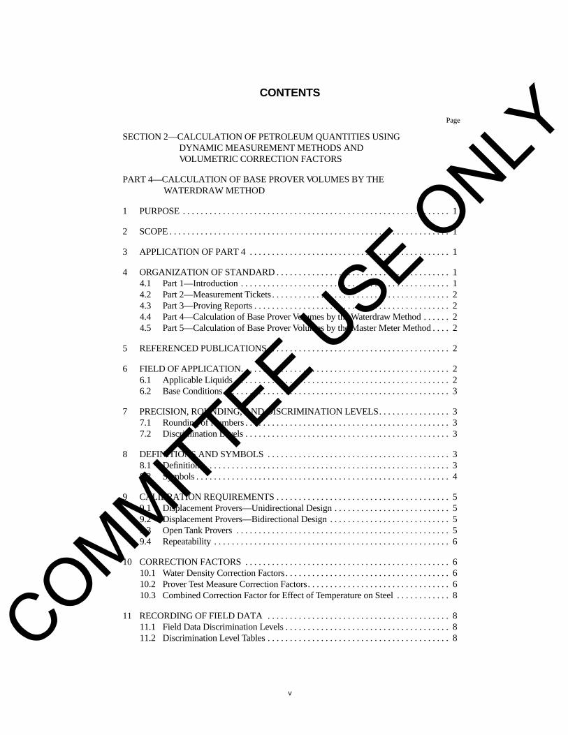
CONTENTS
Page
SECTION 2—CALCULATION OF PETROLEUM QUANTITIES USING DYNAMIC MEASUREMENT METHODS AND VOLUMETRIC CORRECTION FACTORS
PART 4—CALCULATION OF BASE PROVER VOLUMES BY THE WATERDRAW METHOD
1 PURPOSE . . . . . . . . . . . . . . . . . . . . . . . . . . . . . . . . . . . . . . . . . . . . . . . . . . . . . . . . . . . . 1
2 SCOPE . . . . . . . . . . . . . . . . . . . . . . . . . . . . . . . . . . . . . . . . . . . . . . . . . . . . . . . . . . . . . . . 1
3 APPLICATION OF PART 4 . . . . . . . . . . . . . . . . . . . . . . . . . . . . . . . . . . . . . . . . . . . . . 1
4 ORGANIZATION OF STANDARD . . . . . . . . . . . . . . . . . . . . . . . . . . . . . . . . . . . . . . . 14.1 Part 1—Introduction . . . . . . . . . . . . . . . . . . . . . . . . . . . . . . . . . . . . . . . . . . . . . . . 14.2 Part 2—Measurement Tickets . . . . . . . . . . . . . . . . . . . . . . . . . . . . . . . . . . . . . . . . 24.3 Part 3—Proving Reports . . . . . . . . . . . . . . . . . . . . . . . . . . . . . . . . . . . . . . . . . . . . 24.4 Part 4—Calculation of Base Prover Volumes by the Waterdraw Method . . . . . . 24.5 Part 5—Calculation of Base Prover Volumes by the Master Meter Method . . . . 2
5 REFERENCED PUBLICATIONS. . . . . . . . . . . . . . . . . . . . . . . . . . . . . . . . . . . . . . . . . 2
6 FIELD OF APPLICATION. . . . . . . . . . . . . . . . . . . . . . . . . . . . . . . . . . . . . . . . . . . . . . . 26.1 Applicable Liquids . . . . . . . . . . . . . . . . . . . . . . . . . . . . . . . . . . . . . . . . . . . . . . . . 26.2 Base Conditions. . . . . . . . . . . . . . . . . . . . . . . . . . . . . . . . . . . . . . . . . . . . . . . . . . . 3
7 PRECISION, ROUNDING, AND DISCRIMINATION LEVELS. . . . . . . . . . . . . . . . 37.1 Rounding of Numbers . . . . . . . . . . . . . . . . . . . . . . . . . . . . . . . . . . . . . . . . . . . . . . 37.2 Discrimination Levels . . . . . . . . . . . . . . . . . . . . . . . . . . . . . . . . . . . . . . . . . . . . . . 3
8 DEFINITIONS AND SYMBOLS . . . . . . . . . . . . . . . . . . . . . . . . . . . . . . . . . . . . . . . . . 38.1 Definitions . . . . . . . . . . . . . . . . . . . . . . . . . . . . . . . . . . . . . . . . . . . . . . . . . . . . . . . 38.2 Symbols . . . . . . . . . . . . . . . . . . . . . . . . . . . . . . . . . . . . . . . . . . . . . . . . . . . . . . . . . 4
9 CALIBRATION REQUIREMENTS . . . . . . . . . . . . . . . . . . . . . . . . . . . . . . . . . . . . . . . 59.1 Displacement Provers—Unidirectional Design . . . . . . . . . . . . . . . . . . . . . . . . . . 59.2 Displacement Provers—Bidirectional Design . . . . . . . . . . . . . . . . . . . . . . . . . . . 59.3 Open Tank Provers . . . . . . . . . . . . . . . . . . . . . . . . . . . . . . . . . . . . . . . . . . . . . . . . 59.4 Repeatability . . . . . . . . . . . . . . . . . . . . . . . . . . . . . . . . . . . . . . . . . . . . . . . . . . . . . 6
10 CORRECTION FACTORS . . . . . . . . . . . . . . . . . . . . . . . . . . . . . . . . . . . . . . . . . . . . . . 610.1 Water Density Correction Factors . . . . . . . . . . . . . . . . . . . . . . . . . . . . . . . . . . . . . 610.2 Prover Test Measure Correction Factors. . . . . . . . . . . . . . . . . . . . . . . . . . . . . . . . 610.3 Combined Correction Factor for Effect of Temperature on Steel . . . . . . . . . . . . 8
11 RECORDING OF FIELD DATA . . . . . . . . . . . . . . . . . . . . . . . . . . . . . . . . . . . . . . . . . 811.1 Field Data Discrimination Levels . . . . . . . . . . . . . . . . . . . . . . . . . . . . . . . . . . . . . 811.2 Discrimination Level Tables . . . . . . . . . . . . . . . . . . . . . . . . . . . . . . . . . . . . . . . . . 8COMMITTEE U
SE ONLY
Page
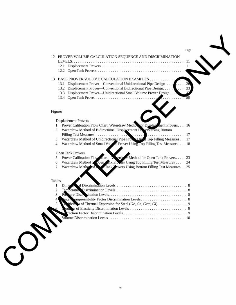
12 PROVER VOLUME CALCULATION SEQUENCE AND DISCRIMINATION LEVELS. . . . . . . . . . . . . . . . . . . . . . . . . . . . . . . . . . . . . . . . . . . . . . . . . . . . . . . . . . . . . 1112.1 Displacement Provers . . . . . . . . . . . . . . . . . . . . . . . . . . . . . . . . . . . . . . . . . . . . . 1112.2 Open Tank Provers . . . . . . . . . . . . . . . . . . . . . . . . . . . . . . . . . . . . . . . . . . . . . . . 19
13 BASE PROVER VOLUME CALCULATION EXAMPLES . . . . . . . . . . . . . . . . . . . 2613.1 Displacement Prover—Conventional Unidirectional Pipe Design . . . . . . . . . . 2613.2 Displacement Prover—Conventional Bidirectional Pipe Design. . . . . . . . . . . . 3313.3 Displacement Prover—Unidirectional Small Volume Prover Design . . . . . . . . 4313.4 Open Tank Prover . . . . . . . . . . . . . . . . . . . . . . . . . . . . . . . . . . . . . . . . . . . . . . . . 50
Figures
Displacement Provers1 Prover Calibration Flow Chart, Waterdraw Method for Displacement Provers. . . . 162 Waterdraw Method of Bidirectional Displacement Provers Using Bottom
Filling Test Measures. . . . . . . . . . . . . . . . . . . . . . . . . . . . . . . . . . . . . . . . . . . . . . . . . 173 Waterdraw Method of Unidirectional Pipe Prover Using Top Filling Measures . . . 174 Waterdraw Method of Small Volume Prover Using Top Filling Test Measures . . . 18
Open Tank Provers5 Prover Calibration Flow Chart—Waterdraw Method for Open Tank Provers . . . . . 236 Waterdraw Method of Open Tank Provers Using Top Filling Test Measures . . . . . 247 Waterdraw Method of Open Tank Provers Using Bottom Filling Test Measures . . 25
Tables1 Dimensional Discrimination Levels . . . . . . . . . . . . . . . . . . . . . . . . . . . . . . . . . . . . . . 82 Temperature Discrimination Levels . . . . . . . . . . . . . . . . . . . . . . . . . . . . . . . . . . . . . . 83 Pressure Discrimination Levels . . . . . . . . . . . . . . . . . . . . . . . . . . . . . . . . . . . . . . . . . . 84 Water Compressibility Factor Discrimination Levels. . . . . . . . . . . . . . . . . . . . . . . . . 85 Coefficients of Thermal Expansion for Steel (
Gc
,
Ga
,
Gcm, Gl
). . . . . . . . . . . . . . . . 96 Modulus of Elasticity Discrimination Levels . . . . . . . . . . . . . . . . . . . . . . . . . . . . . . . 97 Correction Factor Discrimination Levels . . . . . . . . . . . . . . . . . . . . . . . . . . . . . . . . . . 98 Volume Discrimination Levels . . . . . . . . . . . . . . . . . . . . . . . . . . . . . . . . . . . . . . . . . 10
vi
COMMITTEE USE O
NLY
1
Chapter 12—Calculation of Petroleum Quantities
Section 2—Calculation of Petroleum Quantities Using Dynamic Measurement Methods and Volumetric Correction Factors
PART 4—CALCULATION OF BASE PROVER VOLUMES BY THE WATERDRAW METHOD
1 Purpose
When most of the older standards were written, mechani-cal desk calculators were widely used for calculating mea-surement documentation, and tabulated values were usedmore widely than is the case today. Rules for rounding andthe choice of how many figures to enter in each calculationstep were often made on the spot. As a result, different opera-tors obtained different results from the same data.
This five-part publication consolidates and standardizescalculations pertaining to the metering of petroleum liquids,using turbine or displacement meters, and clarifies terms andexpressions by eliminating local variations of such terms. Thepurpose of standardizing the calculations is that all partieswill produce the same unbiased answer from the given data.To obtain identical results from the same data, the rules forrounding, sequence, and discrimination of numbers (decimalplaces) have all been defined.
2 Scope
This document provides standardized calculation methodsfor the quantification of liquids and the determination of baseprover volumes under defined conditions, regardless of thepoint of origin or destination or units of measure required bygovernmental organizations. The criteria contained in thisdocument allows different individuals, using various com-puter languages on different computer hardware (or manualcalculations), to arrive at identical results using the same stan-dardized input data.
This publication rigorously specifies the equations forcomputing correction factors, rules for rounding, thesequence of the calculations, and the discrimination levels ofall numbers to be used in these calculations. No deviationsfrom these specifications are permitted since the intent of thisdocument is to serve as a rigorous standard.
3 Application of Part 4
For custody transfer and fiscal applications, provers aredefined as field transfer standards used to calibrate flowmeters for the purpose of correcting their indicated volumes.
The Base Prover Volume (BPV) of a displacement provermay be determined by several different procedures, two ofwhich are the waterdraw method and the master metermethod.
This standard only discusses the calculation proce-dures for the waterdraw calibration method
.The purpose of standardizing terms and arithmetical proce-
dures employed in calculating the base prover volume is toavoid disagreement between the parties involved in the facil-ity. The purpose of Part 4, “Calculation of Base Prover Vol-ume By Waterdraw Method,” is to obtain the same unbiasedanswer from the same measurement data, regardless of whoor what does the computing. The result of these efforts is toproduce a certified prover volume.
A Calibration Certificate serves as the document that statesthe Base Prover Volume (BPV) and also reports the physicaldata used to calculate that base prover volume.
Operational procedures used to calibrate a prover are spec-ified in different sections of API MPMS Chapter 4—ProvingSystems.
4 Organization of Standard
This standard has been organized into five separate parts.Part 1 contains a complete general introduction to dynamicmeasurement calculations. Part 2 focuses on the calculationof metered quantities for measurement tickets. Part 3 appliesto the calculation of meter factors in proving operations andproving reports. Part 4 applies to the determination of baseprover volumes by the waterdraw method, and Part 5describes the calculation steps required to determine a BaseProver Volume (BPV) by the master meter method.
4.1 PART 1—INTRODUCTION
The base (reference or standard) volumetric determinationof metered quantities is discussed along with the generalterms required for the solution of various equations.
General rules for rounding of numbers, field data and inter-mediate calculation numbers, and discrimination levels, areall specified within the context of this standard.
For the proper use of this standard, a discussion is pre-sented on the prediction of the density of a liquid at bothflowing and base conditions.
COMMITTEE USE O
NLY
2 C
HAPTER
12—C
ALCULATION
OF
P
ETROLEUM
Q
UANTITIES
An explanation of the principal correction factors associ-ated with dynamic measurement are presented in a clear andconcise manner.
4.2 PART 2—MEASUREMENT TICKETS
The application of this standard to the calculation ofmetered quantities is presented for base volumetric calcula-tions in conformance with North American industry practices.
Recording of field data, rules for rounding, calculationsequences and discrimination levels are specified, along witha set of example calculations. The examples are designed toaid in checkout procedures for any routines that are devel-oped using the requirements stated in this part.
4.3 PART 3—PROVING REPORTS
The application of this standard to the calculation of prov-ing reports is presented for base volumetric calculations inconformance with North American industry practices. Prov-ing reports are utilized to calculate the following meter cor-rection and/or performance indicators: Meter Factors (MF),Composite Meter Factors (CMF), K Factors (KF), CompositeK Factors (CKF), and Meter Accuracy Factor (MA). Thedetermination of the appropriate term is based on both thehardware and the preference of the user.
Recording of field data, rules for rounding, calculationsequences and discrimination levels are specified, along witha set of example proving calculations. The examples aredesigned to aid in checkout procedures for any routines thatare developed using the requirements stated in this part.
4.4 PART 4—CALCULATION OF BASE PROVER VOLUMES BY THE WATERDRAW METHOD
The waterdraw method uses the drawing (or displacement)of water from the prover into certified volumetric field stan-dard test measures. For open tank provers, the waterdrawmethod may also employ the displacing (or drawing) ofwater from the certified field standard test measures into thetank prover. This is sometimes referred to as the waterfillmethod. Certification of all field standard test measures mustbe
traceable
to an appropriate national weights and measuresorganization.
Recording of field data, rules for rounding, calculationsequences and discrimination levels are specified, along witha set of example calculations. The examples are designed toaid in checkout procedures for any routines that are devel-oped using the requirements stated in this section.
4.5 PART 5—CALCULATION OF BASE PROVER VOLUMES BY THE MASTER METER METHOD
The master meter method uses a transfer meter (or transferstandard). This transfer meter is proved under actual operat-ing conditions, by a prover which has been previously cali-
brated by the waterdraw method, and is designated the mastermeter. This master meter is then used to determine the basevolume of a field displacement prover.
Recording of field data, rules for rounding, calculationsequences and discrimination levels are specified, along witha set of example calculations. The examples are designed toaid in checkout procedures for any routines that are devel-oped using the requirements stated in this part.
5 Referenced Publications
Several documents served as references for the revisions ofthis standard. In particular, previous editions of API MPMSChapter 12 provided a wealth of information. Other publica-tions which served as a resource of information for this revi-sion are:
API
Manual of Petroleum Measurement Standards
(MPMS)Chapter 4—“Proving Systems”Chapter 5—“Metering”Chapter 6—“Metering Assemblies”Chapter 7—“Temperature Determination”Chapter 9—“Density Determination”Chapter 11—“Physical Properties Data”Chapter 13—“Statistical Aspects of Measuring and
Sampling”
NIST
1
Handbook 105-3 “Specifications and Tolerances forReference Standards and Field Stan-dards”
Monograph 62 “Testing of Metal Volumetric Stan-dards”
6 Field of Application
6.1 APPLICABLE LIQUIDS
This standard applies to liquids that, for all practical pur-poses, are considered to be clean, single-phase, homoge-neous, and Newtonian at metering conditions. Water meets allof these requirements. Specifically, the waterdraw methoddisplaces (or draws) water from the prover into certified volu-metric field standard test measures.
Therefore, the application of this standard shall be limitedto water, which is assumed to be clean, air/gas free, andwhich utilize tables together with implementation proce-dures, to correct metered volumes at flowing temperaturesand pressures to corresponding volumes at base (reference orstandard) conditions. To accomplish this, the density correla-tions for water are specified in API MPMS Chapter 12.2 Part1—Introduction, Appendix B.
1
U.S. Department of Commerce, National Institute of Standards and Technol-ogy, Washington, D.C. 20234 (formerly the National Bureau of Standards).
COMMITTEE USE O
NLY

S
ECTION
2, P
ART
4—C
ALCULATION
OF
P
ROVER
V
OLUMES
B
Y
W
ATERDRAW
M
ETHOD
3
6.2 BASE CONDITIONS
Historically, the measurement of liquids for custody trans-fer and process control has been stated in volume units at base(reference or standard) conditions.
Base conditions for the measurement of liquids, such ascrude petroleum and its liquid products, having a vapor pres-sure equal to or less than atmospheric pressure at the basetemperature are:
United States Customary (USC) Units:Pressure—14.696 psia (101.325 kPa)Temperature—60.0°F (15.56°C)
International System (SI) Units:Pressure—101.325 kPa (14.696 psia)Temperature—15.00°C (59.0°F)
For liquid applications, base conditions may change fromone country to the next. Therefore, it is necessary that thebase conditions be identified and specified in all standardizedvolumetric flow measurements by all the parties involved inthe measurement.
7 Precision, Rounding, and Discrimination Levels
The minimum precision of the computing hardware mustbe equal to or greater than a ten digit calculator to obtain thesame answer in all calculations. All the calculations shall beperformed serially, in the order specified, and rounding shallonly take place after the final value in an equation has beendetermined.
General rounding rules and discrimination levels aredescribed in the following subsections.
7.1 ROUNDING OF NUMBERS
When a number is to be rounded to a specific number ofdecimals, it shall always be rounded off in one step to thenumber of figures that are to be recorded, and shall not berounded in two or more steps of successive rounding. Therounding procedure shall be in accordance with the following:
a. When the figure to the right of last place to be retained is 5or greater, the figure in the last place to be retained should beincreased by 1.b. If the figure to the right of the last place to be retained isless than 5, the figure in the last place retained should beunchanged.
7.2 DISCRIMINATION LEVELS
For field measurements of temperature and pressure, thelevels specified in the various discrimination tables are themaximum levels.
Some examples of recording acceptable discriminationlevels are as follows:
a. If the parties all agree to use “smart” temperature transmit-ters which can indicate temperatures to 0.01°F or 0.005°C,then the reading shall be rounded and recorded to XX.X°F orXX.X5°C value prior to recording for calculation purposes. b. If the parties agree to use a mercury in glass thermometerwith increments of 0.2°F or 0.10°C, then the reading shall berecorded and rounded as XX.X°F or XX.X5°C for purposesof the calculations.
8 Definitions and Symbols
The definitions and symbols described below are relevantin applying Part 4—Calculation of Base Prover Volumes bythe Waterdraw Method.
8.1 DEFINITIONS
8.1.1 barrel (bbl):
A unit of volume equal to 9,702.0cubic inches, or 42.0 U.S. gallons.
8.1.2 U.S. gallon (gal):
A unit of volume equal to 231.0cubic inches.
8.1.3 cubic meter (m
3
):
A unit of volume equal to1,000,000.0 milliliters (ml), or 1,000.0 liters. One cubic meterequals 6.28981 barrels.
8.1.4 liter (l):
A unit of volume equal to 1,000.0 milliliters(ml) or 0.001 cubic meters.
8.1.5 pass:
A single movement of the displacer betweendetectors which define the calibrated volume of a prover.
8.1.6 round-trip:
The combined forward (out) and reverse(back) passes of the displacer in a bidirectional prover.
8.1.7 field standard test measure:
A vessel (usually ofstainless steel), fabricated to meet rigorous design criteria andspecification, that is used as the basic standard of measure-ment in the waterdraw calibration of volumetric provers.After calibration by a National Standards Agency, the fieldstandard test measure is used to determine the base volume ofthe prover under test.
8.1.8 run, prover calibration:
One pass of a unidirec-tional prover or one round trip of a bidirectional prover, orone emptying or filling of a volumetric prover tank, the resultof which is deemed acceptable to provide a single test valueof the Calibrated Prover Volume (CPV).
8.1.9 calibrated prover volume (CPV):
The volume atbase conditions between the detectors in a unidirectionalprover, or the volume of a prover tank between specified“empty” and “full” levels, as determined by a single calibra-tion run. The Calibrated Prover Volume (CPV) of a bidirec-
COMMITTEE USE O
NLY
4 C
HAPTER
12—C
ALCULATION
OF
P
ETROLEUM
Q
UANTITIES
tional prover is the sum of the two volumes swept outbetween detectors during a calibration round-trip.
8.1.10 targeted BPV:
A term associated with Open TankProver calibration, refers to adjusting the scales to an evennominal value, such as 500 gallons, or 1,000 gallons. For loadrack applications, open tank provers are adjusted to arrive atexactly the Targeted BPV value.
8.1.11 calibration certificate:
A document stating theBase Prover Volume (BPV) and the physical data used to cal-culate that base prover volume (e.g.,
E
,
Gc
,
Ga
,
Gl
).
8.1.12 base prover volume:
The volume of the proverat base conditions, as shown on the calibration certificate, andobtained by arithmetically averaging an acceptable number ofconsecutive Calibrated Prover Volume (CPV) determinations.
8.2 SYMBOLS
A combination of upper and lower case notation is used forsymbols and formulas in this publication. Subscripted nota-tion is often difficult to use for computers and other word pro-cessing documents, and therefore has not been used in thispublication, but may, however, be employed if the interestedparties wish.
Symbols have been defined to aid in clarity of the mathe-matical treatments. Notations at the end of a symbol such as“
tm
” always refer to the test measure, “
p
” always refers to theprover, and “
b
” refers to base conditions. Other additional let-ters have also been added to the symbolic notations below forclarity and specificity.
UnitsSI International System of units (Pascal, cubic
meter, kilogram, metric system).USC US Customary units (inch, pound, cubic
inch, traditional system).
Pipe Dimensions
ID
Inside diameter of prover.
OD
Outside diameter of prover.
WT
Wall thickness of prover.
Liquid Density
DEN
Density of the water in kilogram per cubicmeter (kg/m
3
) units.
DENb
Base density of water in kilogram per cubicmeter (kg/m
3
) units.
DENobs
Observed density of the water at base pres-sure in kilograms per cubic meter (kg/m
3
)units.
RHOb
Base density of the water.
RHOp
Density of the water in prover (for provercalibrations).
RHOtm
Density of the water in test measure (forprover calibrations).
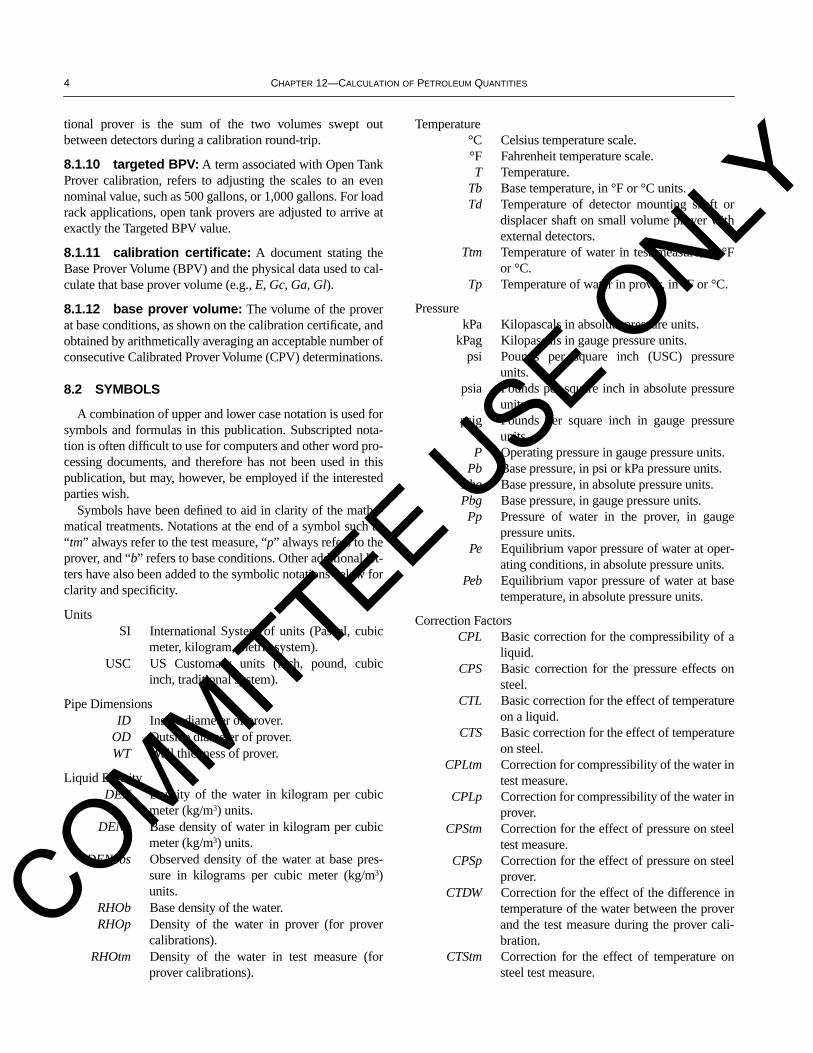
Temperature°C Celsius temperature scale.°F Fahrenheit temperature scale.
T
Temperature.
Tb
Base temperature, in °F or °C units.
Td
Temperature of detector mounting shaft ordisplacer shaft on small volume prover withexternal detectors.
Ttm
Temperature of water in test measure, in °For °C.
Tp
Temperature of water in prover, in °F or °C.
PressurekPa Kilopascals in absolute pressure units.
kPag Kilopascals in gauge pressure units.psi Pounds per square inch (USC) pressure
units.psia Pounds per square inch in absolute pressure
units.psig Pounds per square inch in gauge pressure
units.
P
Operating pressure in gauge pressure units.
Pb
Base pressure, in psi or kPa pressure units.
Pba
Base pressure, in absolute pressure units.
Pbg
Base pressure, in gauge pressure units.
Pp
Pressure of water in the prover, in gaugepressure units.
Pe
Equilibrium vapor pressure of water at oper-ating conditions, in absolute pressure units.
Peb
Equilibrium vapor pressure of water at basetemperature, in absolute pressure units.
Correction Factors
CPL
Basic correction for the compressibility of aliquid.
CPS
Basic correction for the pressure effects onsteel.
CTL
Basic correction for the effect of temperatureon a liquid.
CTS
Basic correction for the effect of temperatureon steel.
CPLtm
Correction for compressibility of the water intest measure.
CPLp
Correction for compressibility of the water inprover.
CPStm
Correction for the effect of pressure on steeltest measure.
CPSp
Correction for the effect of pressure on steelprover.
CTDW
Correction for the effect of the difference intemperature of the water between the proverand the test measure during the prover cali-bration.
CTStm
Correction for the effect of temperature onsteel test measure.
COMMITTEE USE O
NLY

S
ECTION
2, P
ART
4—C
ALCULATION
OF
P
ROVER
VOLUMES BY WATERDRAW METHOD 5
CTSp Correction for the effect of temperature onsteel prover.
CCTS Combined correction for effect of tempera-ture on steel prover and steel test measure.
E Modulus of elasticity of the steel prover.
F Compressibility factor of water.
Fp Compressibility factor of water in the prover.
Gl Linear coefficient of thermal expansion.
Ga Area coefficient of thermal expansion.
Gc Cubical coefficient of thermal expansion ofprovers.
Gcm Cubical coefficient of thermal expansion oftest measure.
Volumes
BMV Field Standard Test Measure base volume(from calibration certificate).
BMVa Field Standard Test Measure base volumeadjusted for the scale reading.
BPV The base volume of the prover at standardconditions.
CPV Calibrated prover volume as determined by asingle calibration run.
SR Scale reading of a field standard test mea-sure.
SRu Upper scale reading of an open tank prover.
SRl Lower scale reading of an open tank prover.
WD The base volume of the field standard testmeasure, adjusted for scale reading (SR), andcorrected for CTDW and CCTS.
WDz The sum of the WD values for all of the fieldstandard test measures used in a single cali-bration pass of the prover.
WDzb The WDz value for a single calibration passcorrected for CPSp and CPLp.
9 Calibration Requirements
The volume of each calibration pass shall be individuallycalculated to obtain a corrected volume at reference condi-tions. The calibration requirements are a function of theprover’s design classification.
There are two general classes of liquid provers—displace-ment provers and open tank provers.
Sub-classes of displacement provers are unidirectionaland bidirectional flow designs, as well as small volumeprovers which may also be of unidirectional or bidirectionalconstruction.
Sub-classes of open tank provers are top filling or bottomfilling designs with or without lower scales.
9.1 DISPLACEMENT PROVERS—UNIDIRECTIONAL DESIGN
For unidirectional provers, three or more consecutivepasses are required for a calibration which shall meet the fol-lowing criteria:
a. The calibration shall be considered acceptable when theprover volumes (WDzb) at reference conditions of three or moreconsecutive passes exhibit a range of 0.020 percent or less.b. The flow rate between consecutive calibration passes shallhave been changed by at least 25 percent or more.
Under certain circumstances, such as environmental condi-tions, if all parties concur, the flowrate change between con-secutive runs may be waived. However, the flowrate betweenall consecutive runs must have a range of at least 25 percent.Most important, the uncertainty associated with this excep-tion is inferior to the preferred method stated above.
9.2 DISPLACEMENT PROVERS—BIDIRECTIONAL DESIGN
For bidirectional provers, three or more consecutive round-trips are required for a calibration and shall meet the follow-ing criteria:
a. The volume at reference conditions (WDzb) for the for-ward “out” pass for three or more consecutive roundtripsshall exhibit a range of 0.020 percent or less.b. The volume at reference conditions (WDzb) for the reverse“back” pass for three or more consecutive roundtrips shallexhibit a range of 0.020 percent or less.c. The Calibrated Prover Volume (CPV) for three or more con-secutive roundtrips shall exhibit a range of 0.020 percent or less.d. The flowrate between the “out” pass and the ”back” passmust remain the same for each roundtrip.e. The flow rate between consecutive roundtrips shall bechanged by at least twenty five percent (25 percent) or more.
Under certain circumstances, such as environmental condi-tions, if all parties concur, the flowrate change between con-secutive runs may be waived. However, the flowrate betweenall consecutive runs must have a range of at least 25 percent.Most important, the uncertainty associated with this excep-tion is inferior to the preferred method stated above.
9.3 OPEN TANK PROVERS
For open tank provers, the calibration shall be consideredacceptable when the following criteria are satisfied:
a. The Calibrated Prover Volumes (CPV) for two or moreconsecutive runs shall exhibit a range of 0.020 percent or less.b. After adjusting the scale(s) and resealing, an additionalcalibrated volume at reference conditions must be deter-mined. This volume must be within ±0.010 percent of the pre-viously established targeted Calibrated Prover Volume (CPV).
COMMITTEE USE O
NLY
6 CHAPTER 12—CALCULATION OF PETROLEUM QUANTITIES
9.4 REPEATABILITY
As a measure of repeatability, the following equation shallbe utilized to calculate and verify the range results for all dis-placement, small volume and open tank provers:
10 Correction Factors
Calculations in this publication are based on determiningthe base volume of a prover by the waterdraw method. Cor-rections are made for:
a. The effects of thermal expansion of the water in the testmeasures and the prover.b. The effects of thermal expansion of the steel in the testmeasures and the prover.c. The compressibility of the water in the prover under cali-bration due to pressure.d. The elastic distortion of the prover under calibration due topressure.
Corrections for the temperature effects on the steel proverand test measures are combined and discussed in the follow-ing sections.
10.1 WATER DENSITY CORRECTION FACTORS
Water density correction factors are employed to accountfor changes in density due to the effects of temperature andpressure. These correction factors are:
CTDW corrects for the effect of water density changesdue to temperature differences between theprover and the test measure.
CPL corrects for the effect of compressibility on thewater density.
In using the waterdraw technique, clean, fresh water isrequired to properly utilize the thermal expansion (CTL) andcompressibility (CPL) terms.
10.1.1 Correction for Effect of Temperature on Water Density (CTDW)
If water is subjected to a change in temperature (above40°F), its density will decrease as the temperature rises orincrease as the temperature falls. The correction factor for theeffect of temperature on the density of the water is calledCTL. A correction factor, CTDW, is applied to make a com-bined correction for the CTL associated with the field stan-dard test measures used and the prover under calibration.
CTDW corrects for the effect of the water density changedue to a temperature difference between the prover and thetest measure. The implementation procedure for CTDW isreferenced in API MPMS Chapter 12.2 Part 1—Appendix B.
API MPMS Chapter 11.2.3 and 11.2.3M can be used to deter-mine CTDW values utilized in the water calibration of volu-metric provers.
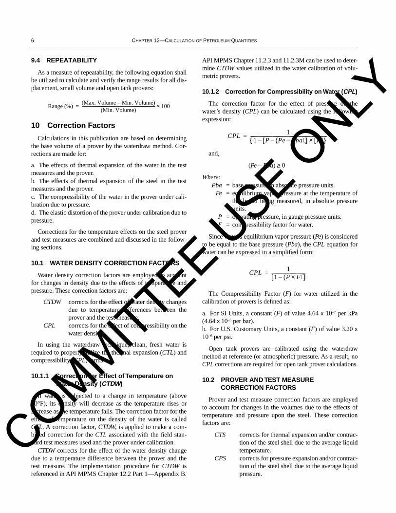
10.1.2 Correction for Compressibility on Water (CPL)
The correction factor for the effect of pressure on thewater’s density (CPL) can be calculated using the followingexpression:
and,
(Pe – Pba) ≥ 0
Where:Pba = base pressure, in absolute pressure units.
Pe = equilibrium vapor pressure at the temperature ofthe liquid being measured, in absolute pressureunits.
P = operating pressure, in gauge pressure units.F = compressibility factor for water.
Since water’s equilibrium vapor pressure (Pe) is consideredto be equal to the base pressure (Pba), the CPL equation forwater can be expressed in a simplified form:
The Compressibility Factor (F) for water utilized in thecalibration of provers is defined as:
a. For SI Units, a constant (F) of value 4.64 x 10⁻⁷ per kPa(4.64 x 10⁻⁵ per bar).b. For U.S. Customary Units, a constant (F) of value 3.20 x10⁻⁶ per psi.
Open tank provers are calibrated using the waterdrawmethod at reference (or atmospheric) pressure. As a result, noCPL corrections are required for open tank prover calculations.
10.2 PROVER AND TEST MEASURE CORRECTION FACTORS
Prover and test measure correction factors are employedto account for changes in the volumes due to the effects oftemperature and pressure upon the steel. These correctionfactors are:
CTS corrects for thermal expansion and/or contrac-tion of the steel shell due to the average liquidtemperature.
CPS corrects for pressure expansion and/or contrac-tion of the steel shell due to the average liquidpressure.
Range (%)(Max. Volume – Min. Volume)
(Min. Volume)--------------------------------------------------------------------------- 100×=
CPL1
1 P Pe Pba–( )–[ ] F[ ]×–{ }-----------------------------------------------------------------------=
CPL1
1 P F×( )–[ ]-------------------------------=
COMMITTEE USE O
NLY

SECTION 2, PART 4—CALCULATION OF PROVER VOLUMES BY WATERDRAW METHOD 7
10.2.1 Correction for the Effect of Temperature on Steel (CTS)
Any metal container, be it a displacement prover, an opentank prover, or a field standard test measure, when subjectedto a change in temperature will change its volume accord-ingly. The volume change, regardless of prover shape, is pro-portional to the coefficient of thermal expansion of thematerial(s). The cubical coefficient of thermal expansion isvalid when the calibrated section of the prover and its detectorswitch mountings are constructed of a single material.
The coefficients of expansion (Gc, Ga, Gl) for the prover,preferably, should be based on data for the materials used inthe construction of the calibrated section. However, the valuescontained in Table 5 shall be used, at the discrimination levelshown, if the actual coefficients of expansion are unknown.
The cubical coefficient of expansion (Gcm) on the report ofcalibration reported by the calibrating agency is the one to beused for that individual field standard test measure.
10.2.1.1 CTS for Displacement Provers, Open Tank Provers and Field Standard Test Measures
The CTS for displacement provers with internal detectors,open tank provers, and field standard test measures assumes asingle construction material, and shall be calculated from:
CTS = {1 + [(T – Tb) x Gc]}
Where:Gc = mean coefficient of cubical expansion per degree
temperature of the material of which the con-tainer is made between Tb and T.
Tb = base temperature.T = average liquid temperature in the container.
The CTS equation stated above is applicable to all dis-placement and tank provers with one exception—small vol-ume provers with externally mounted detectors.
10.2.1.2 CTS for Small Volume Provers with External Detectors
For small volume provers which utilize detectors notmounted in the calibrated section of the pipe, the correction fac-tor for the effect of temperature (CTS) shall be calculated from:
CTS = {(1 + [(Tp – Tb) x (Ga)]) x (1 + [(Td – Tb) x (Gl)])}
Where:Ga = area thermal coefficient of expansion for prover
chamber.Gl = linear thermal coefficient of expansion on dis-
placer shaft.Tb = base temperature.Td = temperature of the detector mounting shaft or dis-
placer shaft on SVP with external detectors.Tp = temperature of the prover chamber.
10.2.2 Correction for the Effect of Pressure on Steel, CPS
If a metal container, such as a displacement prover, is sub-jected to an internal pressure, the walls of the container willstretch elastically and the volume of the container will changeaccordingly.
The modulus of elasticity (E) for a displacement prover,preferably, should be based on data for the materials used inthe construction of the calibrated section. However, the valuescontained in Table 6 shall be used if the modulus of elasticity(E) is unknown.
10.2.2.1 Corrections for Single-Walled Container or Prover
While it is recognized that simplifying assumptions enterthe equations below, for practical purposes the correction fac-tor for the effect of internal pressure on the volume of a cylin-drical container, called CPS, may be calculated from:
Since Pbg, gauge pressure for water, is equal to zero, theequation simplifies to:
and,
ID = [OD – (2 x WT)]
Where:Pp = internal operating pressure of prover, in gauge
pressure units. Pbg = base pressure, in gauge pressure units.
ID = internal diameter of prover.E = modulus of elasticity of the metal in the cali-
brated section of the prover.OD = outside diameter of the prover.WT = wall thickness of the prover.
10.2.2.2 Corrections for Double-Walled Container or Prover
For double wall provers, the inner measuring section of theprover is not subjected to a net internal pressure, and the wallsof this inner chamber do not stretch elastically. Therefore, inthis special case:
CPS = 1.000000
CPS 1Pp Pbg–( ) ID( )×[ ]
E WT×( )--------------------------------------------------+=
CPS 1Pp ID×( )E WT×( )
------------------------+=
COMMITTEE USE O
NLY

8 CHAPTER 12—CALCULATION OF PETROLEUM QUANTITIES
10.2.2.3 Corrections for Open Tank Prover
For open tank provers, the inner measuring section of theprover is not subjected to a net internal pressure, and the wallsof this inner chamber do not stretch elastically. Therefore, inthis special case:
CPS = 1.000000
10.3 COMBINED CORRECTION FACTOR FOR EFFECT OF TEMPERATURE ON STEEL
For the purposes of calculation, the two temperature cor-rections for thermal expansion of the steel are combined asfollows:
11 Recording of Field Data
11.1 FIELD DATA DISCRIMINATION LEVELS
All required field data shall be recorded and rounded inaccordance with the discrimination levels specified in thissection. In addition, see section 4.7.2 of this standard.
Field data discrimination levels less than those specifiedare not permitted in the calculation procedures for determin-ing base prover volumes.
Field data discrimination levels greater than those specifiedare not in agreement with the intent of this standard andshould not be used in the calculation procedures.
The following chart indicates the appropriate table to usefor determination of specified discrimination levels for fielddata.
Prover Data Table
OD 1WT 1ID 1Tp 2Pp 3Fp 4Gl 5Ga 5Gc 5E 6SRu 8SRl 8
Test Measure Data Table
Ttm 2Gcm 5SR 8
Note: For test measures, the thermal expansion coefficients should preferablybe obtained from the calibration certificate.
11.2 DISCRIMINATION LEVEL TABLES
Tables 1 through 8 indicate specified discrimination levelsand values of constants for calculation data.
Note: In all the tables that follow, the number of “X” to the left of the deci-mal point is, in most cases, illustrative only and may have a value more orless than the number of “X” shown. The number of digits “X” to the right ofthe decimal point are however specific and define the discrimination level ofeach value described.
CCTSCTStmCTSp
-----------------=
Table 1—Dimensional Discrimination Levels
USC(inches)
SI Units(mm)
OD XX.XXX XXX.XX
WT X.XXX XX.XX
ID XX.XXX XXX.XX
Table 2—Temperature Discrimination Levels
USC(°F)
SI Units(°C)
Prover Temperature (Tp) XX.X XX.X5
Test Measure Temperature (Ttm) XX.X XX.X5
Base Temperature (Tb) 60.0 15.00
Table 3—Pressure Discrimination Levels
USC Units SI Units
(psia) (psig) (bar) (kPa)
Base Pressure (Pb) 14.696 0.0 1.01325 101.325
Prover Pressure (Pp) XX.X XX.0 X.XX XX.0
Table 4—Water Compressibility FactorDiscrimination Levels
USC Units SI Units
(psi) (bar) (kPa)
Compressibility Factor (Fp) 0.00000320 0.0000464 0.000000464
COMMITTEE USE O
NLY
SECTION 2, PART 4—CALCULATION OF PROVER VOLUMES BY WATERDRAW METHOD 9
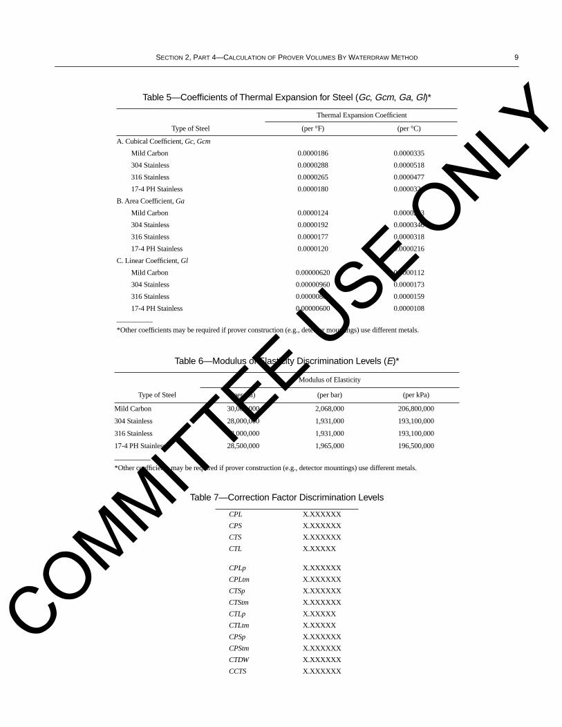
Table 5—Coefficients of Thermal Expansion for Steel (Gc, Gcm, Ga, Gl)*
Type of Steel
Thermal Expansion Coefficient
(per °F) (per °C)
A. Cubical Coefficient, Gc, Gcm
Mild Carbon 0.0000186 0.0000335
304 Stainless 0.0000288 0.0000518
316 Stainless 0.0000265 0.0000477
17-4 PH Stainless 0.0000180 0.0000324
B. Area Coefficient, Ga
Mild Carbon 0.0000124 0.0000223
304 Stainless 0.0000192 0.0000346
316 Stainless 0.0000177 0.0000318
17-4 PH Stainless 0.0000120 0.0000216
C. Linear Coefficient, Gl
Mild Carbon 0.00000620 0.0000112
304 Stainless 0.00000960 0.0000173
316 Stainless 0.00000883 0.0000159
17-4 PH Stainless 0.00000600 0.0000108
__________
*Other coefficients may be required if prover construction (e.g., detector mountings) use different metals.
Table 6—Modulus of Elasticity Discrimination Levels (E)*
Type of Steel
Modulus of Elasticity
(per psi) (per bar) (per kPa)
Mild Carbon 30,000,000 2,068,000 206,800,000
304 Stainless 28,000,000 1,931,000 193,100,000
316 Stainless 28,000,000 1,931,000 193,100,000
17-4 PH Stainless 28,500,000 1,965,000 196,500,000
__________
*Other coefficients may be required if prover construction (e.g., detector mountings) use different metals.
Table 7—Correction Factor Discrimination Levels
CPL X.XXXXXX
CPS X.XXXXXX
CTS X.XXXXXX
CTL X.XXXXX
CPLp X.XXXXXX
CPLtm X.XXXXXX
CTSp X.XXXXXX
CTStm X.XXXXXX
CTLp X.XXXXX
CTLtm X.XXXXX
CPSp X.XXXXXX
CPStm X.XXXXXX
CTDW X.XXXXXX
CCTS X.XXXXXX
COMMITTEE USE O
NLY
10 CHAPTER 12—CALCULATION OF PETROLEUM QUANTITIES
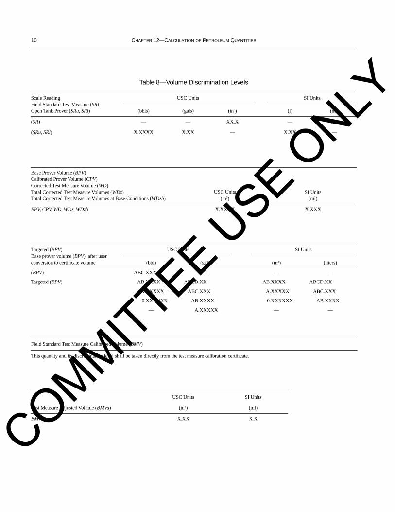
Table 8—Volume Discrimination Levels
Scale ReadingField Standard Test Measure (SR)Open Tank Prover (SRu, SRl)
USC Units SI Units
(bbls) (gals) (in3) (l) (ml)
(SR) — — XX.X — X.0
(SRu, SRl) X.XXXX X.XX — X.XX —
Base Prover Volume (BPV)Calibrated Prover Volume (CPV)Corrected Test Measure Volume (WD)Total Corrected Test Measure Volumes (WDz)Total Corrected Test Measure Volumes at Base Conditions (WDzb)
USC Units(in3)
SI Units(ml)
BPV, CPV, WD, WDz, WDzb X.XXXX X.XXX
Targeted (BPV)Base prover volume (BPV), after userconversion to certificate volume
USC Units SI Units
(bbl) (gal) (m3) (liters)
(BPV) ABC.XXXX — — —
Targeted (BPV) AB.XXXX ABCD.XX AB.XXXX ABCD.XX
A.XXXXX ABC.XXX A.XXXXX ABC.XXX
0.XXXXXX AB.XXXX 0.XXXXXX AB.XXXX
— A.XXXXX — —
Field Standard Test Measure Calibrated Volume (BMV)
This quantity and its discrimination level shall be taken directly from the test measure calibration certificate.
Test Measure Adjusted Volume (BMVa)
USC Units SI Units
(in3) (ml)
BMVa X.XX X.X
COMMITTEE USE O
NLY
SECTION 2, PART 4—CALCULATION OF PROVER VOLUMES BY WATERDRAW METHOD 11
12 Prover Volume Calculation Sequence and Discrimination Levels
This section rigorously specifies the rounding, calculationsequences and discrimination levels required to determine abase prover volume.
12.1 DISPLACEMENT PROVERS
The following rules for rounding, calculation sequence anddiscrimination levels are applicable to the volumetric water-draw calibration of displacement provers (conventional pipeand small volume provers). A flow chart (Figure 1) has beenprepared to graphically explain the calculation sequence.Drawings depicting the process have also been prepared toassist the user (see Figures 2, 3, and 4).
When using the waterdraw calibration method on conven-tional pipe and small volume provers, the recorded pressureshall be the highest pressure experienced by the prover duringflow. This pressure reading shall be taken either at the start orthe finish of the run when flow is through the solenoid valve.
12.1.1 Field Standard Test Measure Data
Obtain, round, and record the following field standard testmeasure data relative to all the test measures to be used in thecalibration. This information may be obtained from the cali-bration certificate delivered by the calibrating agency:
a. Base test measure volume (BMV).b. Coefficient of cubical expansion (Gcm) of test measuremetal of construction.c. Base temperature (Tb).d. Seal number from the graduated scale of the test measure.e. Nominal capacity of the test measure.
If the actual value of Gcm is known, either as reported onthe certificate of calibration or by experimental determina-tion, then it should be used at the same discrimination level asspecified in Table 5, otherwise the basic values defined inTable 5 should be used.
Record the value for BMV, as indicated on the test measurecalibration certificates for all test measures being used.
12.1.2 Prover Data
Obtain, round, and record the following prover data:
a. Prover type and size.b. Type of steel.c. Manufacturer.d. Serial number.e. Coefficient of thermal expansion (Gc) of the prover metalof construction.f. Modulus of elasticity for prover (E).g. Displacer type and size.
h. Outside diameter of the prover pipe (OD).i. Wall thickness of the prover pipe (WT).
Notes:a. If the type of prover being calibrated is a small volume prover, with
external detectors, then Ga and Gl must also be recorded.b. If the prover has a double wall construction then E = 1.c. For ball provers record sphere type and circumference or diameter.
Round and record the values for Gc, Ga, and Gl in accor-dance with Table 5.
Round and record the value of E in accordance with Table 6.Round and record the values for OD and WT in accordance
with Table 1.Calculate the ID of the prover using the following equation:
ID = [OD – (2 x WT)]
Round and record the value of the prover ID in accordancewith Table 1.
12.1.3 Displacement Prover Waterdraw Sequence
Establish water circulation and ensure that the air in thedisplacement prover has been eliminated by venting at thehighest point in the prover. This may require running the dis-placer several times to ensure the complete elimination of airfrom the proving system.
When the circulation of water has stabilized both the flow-rate and temperature, the calibration can be initiated.
12.1.3.1 Calibration of the Forward “Out” Direction or “Out” Pass Volume
This section is structured to determine the WDzb for a sin-gle forward “out” pass of the displacement prover.
Step 1 Record Forward “Out” Pass Prover Data—Flowrate, Tp and Pp
Initiate the waterdraw by “drawing” water into the first cer-tified test measure using a logic circuit in combination withthe detector switch.
Obtain and record the flow rate in the prover. Some exam-ples of commonly used methods are: timing the filling of thefirst test measure, reading a flow meter, or filling all test mea-sures and dividing by the total time. Other acceptable meth-ods may also be used.
Using a certified temperature device (certificate should beavailable for inspection), record the temperature (Tp) of thewater leaving the prover, once sufficient volume and steadyflow rate into the first test measure is established. The provertemperature (Tp) should always be taken at the water outletfrom the prover, before going into the test measure, underflowing conditions. Record this value as defined in Table 2.
Using a certified pressure device (certificate should beavailable for inspection) record the pressure of the water inthe prover (Pp). This pressure can be determined either at the
COMMITTEE USE O
NLY
12 CHAPTER 12—CALCULATION OF PETROLEUM QUANTITIES
beginning or end of the calibration run, when the water flowis passing through the solenoid valve line into the test mea-sure, and the prover pressure is at its highest value. Read andrecord this value as defined in Table 3.
All values specified above shall be taken during every“out” calibration pass of the prover.
Step 2 Record Test Measure Data—SR, Ttm
After filling the test measure, record the scale reading (SR),either above or below the zero line, for every test measurefilled, in accordance with Table 8.
Using a certified temperature device, record the tempera-ture of the water in every test measure filled (Ttm). Round thevalue in accordance with Table 2.
The values specified above shall be taken for every testmeasure filled during a calibration pass.
Step 3 Calculate BMVa, CTDW, CCTS and WD
Determine BMVa
Determine BMVa by combining the certified volume of thetest measure with the scale reading, for every test measurefilled, using the following equation:
BMVa = BMV + SR
Round the value in accordance with Table 8.
Note: SR may be a positive or negative value depending on whether the liq-uid level is above or below the zero mark. Below zero is negative (SR).
Determine CTDW
Using API MPMS Chapter 11.2.3 or 11.2.3M, the recordedprover temperature (Tp), the test measure temperature (Ttm),determine and round the CTDW value in accordance with therequirements specified in Table 7.
Determine CCTS
Using the coefficient of cubical expansion for the test mea-sure steel (Gcm), the recorded temperature of the test measure(Ttm), and the base temperature (Tb), calculate the CTStmfactor as follows:
CTStm = 1 + (Ttm – Tb) x Gcm
Round the CTStm value in accordance with the require-ments specified in Table 7.
Using the coefficient of cubical expansion for the proversteel (Gc), the recorded prover temperature (Tp), and the basetemperature (Tb), calculate the CTSp factor using the follow-ing expression for provers with internal detectors:
CTSp = 1 + (Tp – Tb) x Gc
Round the CTSp value in accordance with the requirementsspecified in Table 7.
Calculate the CCTS value for each fill of the test measureas follows:
CCTS = CTStm/CTSp
Round the CCTS value in accordance with the require-ments specified in Table 7.
Determine WD
Calculate WD using BMVa, CTDW, CCTS in the followingequation:
WD = BMVa x CTDW x CCTS
Round the WD value in accordance with the requirementsspecified in Table 8.
These are the complete calculation steps necessary todetermine the corrected volume of ONE test measure afterfilling.
Step 4 Forward “Out” Pass Termination
Continue “drawing” water from the prover and filling testmeasures until activation of the second detector switch,through the logic circuit, signals completion of the “out” cali-bration pass. Repeat the data collection and calculationsequence in Step 1 through Step 3 for all test measures filled.
Step 5 Calculate WDz, CPSp, CPLp, and WDzb for the “Out” Pass
Determine WDz
When the calibrated section of the prover has been“drawn” completely, determine the total adjusted fill volumefor a “pass” (WDz) by summing the individual WD values forall test measures filled.
WDz = @SUM (WD)
WDz = (WD)
Where:n = number of test measures filled.
Round the WDz value in accordance with the requirementsspecified in Table 8.
Determine WDzb
Using the recorded prover pressure (Pp), the internal diam-eter of the prover (ID), the modulus of elasticity for theprover (E), and the prover wall thickness (WT), calculateCPSp using the following expression:
CPSp = 1 + [(Pp x ID)/(E x WT)]
Σ1
n
COMMITTEE USE O
NLY
SECTION 2, PART 4—CALCULATION OF PROVER VOLUMES BY WATERDRAW METHOD 13
Round the results in accordance with the requirementsspecified in Table 7.
Using the compressibility factor for water (Fp) specified inTable 4 and the recorded prover pressure (Pp), calculate theCPLp factor using the following expression:
CPLp = 1/[1 – (Pp x Fp)]
Round the results in accordance with the requirementsspecified in Table 7.
Determine the volume of the calibrated section of theprover at base conditions for the “out” pass using the follow-ing equation:
WDzb(“out”) = WDz /(CPSp x CPLp)
Round the results in accordance with the requirementsspecified in Table 8.
Step 6 Test for Prover Design
If the prover is unidirectional, proceed to the RunSequence Termination section (see 12.1.4).
If the prover is bidirectional, proceed to “Back” PassSequence to complete the roundtrip.
12.1.3.2 Calibration of the Reverse “Back” Direction or “Back” Pass Volume
The section is structured to determine the WDzb of the cal-ibrated section for a single reverse “back” pass of the dis-placement prover.
Step 1 Record Reverse “Back” Pass Prover Data—Flowrate, Tp and Pp
Initiate the waterdraw by “drawing” water into the first cer-tified test measure using a logic circuit in combination withthe detector switch.
Obtain and record the flow rate in the prover. Some exam-ples of commonly used methods are: timing the filling of thefirst test measure, reading a flow meter, or filling all test mea-sures and dividing by the total time. Other acceptable meth-ods may also be used.
Using a certified temperature device (certificate should beavailable for inspection), record the temperature (Tp) of thewater leaving the prover, once sufficient volume and steadyflow rate into the first test measure is established. The provertemperature (Tp) should always be taken at the water outletfrom the prover, before going into the test measure, underflowing conditions. Record this value as defined in Table 2.
Using a certified pressure device (certificate should beavailable for inspection) record the pressure of the water inthe prover (Pp). This pressure can be determined either at thebeginning or end of the calibration run, when the water flowis passing through the solenoid valve line into the test mea-
sure, and the prover pressure is at its highest value. Read andrecord this value as defined in Table 3.
All values specified above shall be taken during every“back” calibration pass of the prover.
Step 2 Record Test Measure Data—SR, Ttm
After filling the test measure, record the scale reading (SR),either above or below the zero line, for every test measurefilled in accordance with Table 8.
Using a certified temperature device, record the tempera-ture of the water in every test measure filled (Ttm). Round thevalue in accordance with Table 2.
The values specified above shall be taken for every testmeasure filled during a calibration pass.
Step 3 Calculate BMVa, CTDW, CCTS and WD
Determine BMVa
Determine BMVa by combining the certified volume of thetest measure with the scale reading, for every test measurefilled, using the following equation:
BMVa = BMV + SR
Round the value in accordance with Table 8.
Note: SR may be a positive or negative value depending on whether the liq-uid level is above or below the zero mark. Below zero is negative (SR).
Determine CTDW
Using API MPMS Chapter 11.2.3 or 11.2.3M, the recordedprover temperature (Tp), the test measure temperature (Ttm),determine and round the CTDW value in accordance with therequirements specified in Table 7.
Determine CCTS
Using the coefficient of cubical expansion for the test mea-sure steel (Gcm), recorded temperature of the test measure(Ttm), and base temperature (Tb), calculate the CTStm factoras follows:
CTStm = 1 + (Ttm – Tb) x Gcm
Round the CTStm value in accordance with the require-ments specified in Table 7.
Using the coefficient of cubical expansion for the proversteel (Gc), the recorded prover temperature (Tp), and the basetemperature (Tb), calculate the CTSp factor using the follow-ing expression for provers with internal detectors:
CTSp = 1 + (Tp – Tb) x Gc
Round the CTSp value in accordance with the requirementsspecified in Table 7.
COMMITTEE USE O
NLY
14 CHAPTER 12—CALCULATION OF PETROLEUM QUANTITIES
Calculate the CCTS value for each fill of the test measureas follows:
CCTS = CTStm / CTSp
Round the CCTS value in accordance with the require-ments specified in Table 7.
Determine WD
Calculate WD using BMVa, CTDW, CCTS and the follow-ing equation:
WD = BMVa x CTDW x CCTS
Round the WD value in accordance with the requirementsspecified in Table 8.
Step 4 Reverse “Back” Pass Termination
Continue “drawing” water from the prover and filling thetest measures until activation of the second detector switch,through the logic circuit, signals completion of the “back”calibration pass. Repeat the data collection and calculationsequence in Step 1 through Step 3 for all test measures filled.
Step 5 Calculate WDz, CPSp, CPLp, and WDzb for the “Back” Pass
Determine WDz
When the calibrated section of the prover has been“drawn” completely, determine the total adjusted fill volumefor a “pass” (WDz) by summing the individual WD values forall test measures filled.
WDz = @SUM (WD) = (WD)
Where:n = number of test measures filled.
Round the results in accordance with the requirementsspecified in Table 8.
Determine WDzb
Using the recorded prover pressure (Pp), the internal diam-eter of the prover (ID), the modulus of elasticity for theprover (E), and the prover wall thickness (WT), calculateCPSp using the following expression:
CPSp = 1 + [(Pp x ID) / (E x WT)]
Round the results in accordance with the requirementsspecified in Table 7.
Using the compressibility factor for water (Fp) specified inTable 4 and the recorded prover pressure (Pp), calculate theCPLp factor using the following expression:
CPLp = 1 / [1 – (Pp x Fp)]
Round the results in accordance with the requirementsspecified in Table 7.
Determine the volume of the calibrated section of theprover at base conditions for the “back” pass using the fol-lowing equation:
WDzb(“back”) = WDz / (CPSp x CPLp)
Round the results in accordance with the requirementsspecified in Table 8.
12.1.4 Run Sequence Termination
Uni-directional ProverIf the prover is uni-directional, then the corrected volume
as determined from a single calibration run (pass) of theprover is equal to the Calibrated Prover Volume (CPV). Thiscalibration run is equivalent to an “out” pass only calculation,since the “back” pass calculation is not necessary in a uni-directional prover.
WDzb(“out”) = CPV
A minimum of three consecutive Calibrated Prover Volumes(CPV) of a uni-directional prover must all be within a range of0.020 percent to constitute a valid and acceptable calibration.
Calculate the repeatability range as follows:
The Base Prover Volume (BPV) of a uni-directional provershall be calculated from the average of three or more consec-utive Calibrated Prover Volumes (CPV) as shown:
or:
Where:
n = number of acceptable consecutive runs.
Round the BPV value in accordance with the requirementsspecified in Table 8.
Bi-directional ProverIf the prover is bi-directional, then there is a requirement to
make calibration passes of the displacer in both forward andreverse direction. The reverse (”back”) pass of the displacer isan additional requirement for the purposes of making a com-plete round-trip. The sum of these two volumes will give theround trip volume for a bi-directional prover.
CPV = WDzb(“out”) + WDzb(“back”)
Σ1
n
repeatability (%)highestCPV lowestCPV–( )
lowestCPV( )-------------------------------------------------------------------- 100×=
BPVCPV 1( ) CPV 2( ) CPV 3( )+ +
3-------------------------------------------------------------------------=
BPVΣCPV n( )
n------------------------=
COMMITTEE USE O
NLY

SECTION 2, PART 4—CALCULATION OF PROVER VOLUMES BY WATERDRAW METHOD 15
In the case of a bi-directional prover, the following criteriashall be validated for an acceptable calibration:
a. Three or more acceptable consecutive outward passes,WDzb(“out”), for example, passing the displacer from the leftto right direction, must be within a range of 0.020 percent.
b. Three or more acceptable consecutive backward passes,WDzb(“back”), for example, passing the displacer from theright to left direction, must be within a range of 0.020 percent.
c. Three or more acceptable consecutive round trips, madeup of the same passes as described in (a) and (b), which con-stitute three or more Calibrated Prover Volumes (CPV), mustbe within a range of 0.020 percent.
d. The same flow rate, between the “out” pass and “back”pass, must be maintained for each round trip calibration run.
e. The flow rate criteria for three or more consecutive roundtrips of the bi-directional prover must have been satisfied.
The Base Prover Volume (BPV) of a bi-directional provershall be calculated from the average of three or more consec-utive Calibrated Prover Volumes (CPV) as shown:
or:
Where:
n = number of acceptable consecutive runs.
Round the BPV value in accordance with the requirementsspecified in Table 8.
If any of the above criteria, for either a uni-directional orbi-directional prover, is not satisfied, then another calibrationrun sequence must be initiated until all the requirements foran acceptable prover calibration have been met.
Once all of the above criteria have been satisfied, deter-mine the Base Prover Volume (BPV) as the certified volumeof the prover, and convert into the required volume units asdescribed in the following section.
12.1.5 Conversion of the BPV into Appropriate Volume Units
After calculation of a Base Prover Volume (BPV), ineither cubic inch or cubic centimeter (milliliter) units, it isusually necessary to convert this final prover volume intousable field volumes for meter proving. Conversions shall bedone as follows and volumes rounded as specified in Table 8.
a. If the Base Prover Volume (BPV) is determined in cubicinches, then the appropriate conversions are:
BPV (inch3), divided by 231, equals U.S. gallons @ 60°F.
BPV (inch3), divided by 9702, equals barrels @ 60°F.
BPV (inch3), multiplied by 16.387064, divided by 1,000,divided by CTSp,a equals liters @ 15°C.
BPV (inch3), multiplied by 16.387064, divided by1,000,000, divided by CTSp,a equals cubic meters @ 15°C.
b. If the Base Prover Volume (BPV) is determined in millili-ters, then the appropriate conversions are:
BPV (ml), divided by 1,000, equals liters @ 15°C.
BPV (ml), divided by 1,000,000, equals cubic meters @15°C.
BPV (ml), divided by 16.387064, divided by 231, multi-plied by CTSp,a equals U.S. gallons @ 60°F.
BPV (ml), divided by 16.387064, divided by 9702, mul-tiplied by CTSp,a equals barrels @ 60°F.
aCTSp = {1 + [(60 – 59) x Gc]}, simplified: CTSp = {1 + Gc}.Gc = Coefficient of cubical expansion, U.S. Customary Units in °F.
For example (mild steel prover, USC Units):
CTSp = 1 + 0.0000186, CTSp = 1.0000186.
This CTSp factor is used to correct the converted provervolume for the differences in temperatures between the SIand USC conventions (most commonly used to changebetween 60°F and 15°C). This correction factor, CTSp,should be maintained at the same number of decimal placesas indicated by the Coefficient of Cubical Expansion (useTable 5), and NOT the number of decimal places shown inTable 7. This decimal place deviation only applies to this spe-cific application of CTSp.
For different base temperatures other than 60°F and 15°C,a new CTSp will have to be calculated using the new basetemperature, e.g. 4°C, 20°C, etc.
All calculations shall be done serially in a continuous chain,in the order shown, to obtain the required converted volumes.Round these final volumes in accordance with Table 8.
Note: For displacement provers with externally mounted detectors, CTSpshall be calculated as follows: CTSp = [1 + (60 – 59) (Ga)] [1 + (60 – 59)(Gl)]; simplified, CTSp = (1 + Ga) (1 + Gl), where Ga and Gl are describedin the “Symbols” section and also in Table 5.
% round trip repeatability (CPV)highestCPV lowestCPV–( )
lowestCPV( )--------------------------------------------------------------------- 100×=
"out" pass repeatability (%)
highestWDzb("out") lowestWDzb("out")–( )lowestWDzb("out")( )
---------------------------------------------------------------------------------------------------------- 100×=
"back" pass repeatability (%)
highestWDzb("back") lowestWDzb("back")–( )lowestWDzb("back")( )
----------------------------------------------------------------------------------------------------------------- 100×=
BPVCPV 1( ) CPV 2( ) CPV 3( )+ +
3-------------------------------------------------------------------------=
BPVΣCPV n( )
n------------------------=
(text continued on page 19)
COMMITTEE USE O
NLY
16 CHAPTER 12—CALCULATION OF PETROLEUM QUANTITIES
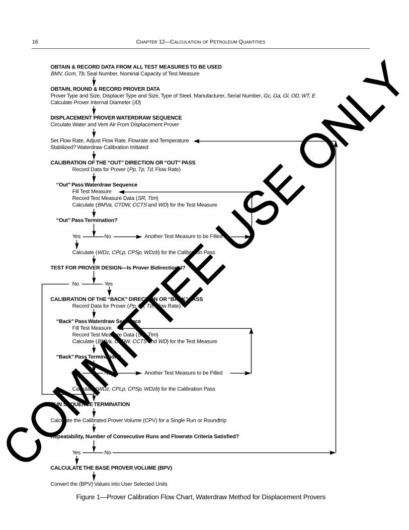
Figure 1—Prover Calibration Flow Chart, Waterdraw Method for Displacement Provers
OBTAIN & RECORD DATA FROM ALL TEST MEASURES TO BE USEDBMV, Gcm, Tb, Seal Number, Nominal Capacity of Test Measure
OBTAIN, ROUND & RECORD PROVER DATAProver Type and Size, Displacer Type and Size, Type of Steel, Manufacturer, Serial Number, Gc, Ga, Gl, OD, WT, ECalculate Prover Internal Diameter (ID)
DISPLACEMENT PROVER WATERDRAW SEQUENCECirculate Water and Vent Air From Displacement Prover
Set Flow Rate, Adjust Flow Rate. Flowrate and TemperatureStabilized? Waterdraw Calibration Initiated
CALIBRATION OF THE “OUT” DIRECTION OR “OUT” PASSRecord Data for Prover (Pp, Tp, Td, Flow Rate)
“Out” Pass Waterdraw SequenceFill Test MeasureRecord Test Measure Data (SR, Ttm)Calculate (BMVa, CTDW, CCTS and WD) for the Test Measure
“Out” Pass Termination?
Yes No Another Test Measure to be Filled
Calculate (WDz, CPLp, CPSp, WDzb) for the Calibration Pass
TEST FOR PROVER DESIGN—Is Prover Bidirectional?
No Yes
CALIBRATION OF THE “BACK” DIRECTION OR “BACK” PASSRecord Data for Prover (Pp, Tp, Td, Flow Rate)
“Back” Pass Waterdraw SequenceFill Test MeasureRecord Test Measure Data (SR, Ttm)Calculate (BMVa, CTDW, CCTS and WD) for the Test Measure
“Back” Pass Termination?
Yes No Another Test Measure to be Filled
Calculate (WDz, CPLp, CPSp, WDzb) for the Calibration Pass
RUN SEQUENCE TERMINATION
Calculate the Calibrated Prover Volume (CPV) for a Single Run or Roundtrip
Repeatability, Number of Consecutive Runs and Flowrate Criteria Satisfied?
Yes No
CALCULATE THE BASE PROVER VOLUME (BPV)
Convert the (BPV) Values into User Selected Units
COMMITTEE USE O
NLY
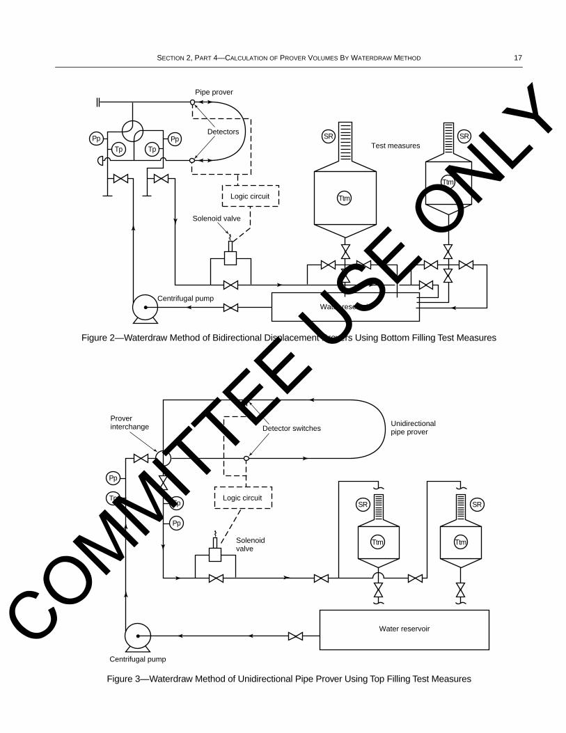
SECTION 2, PART 4—CALCULATION OF PROVER VOLUMES BY WATERDRAW METHOD 17
Figure 3—Waterdraw Method of Unidirectional Pipe Prover Using Top Filling Test Measures
Pp
Tp TpPp
Pipe prover
Detectors
Centrifugal pump
Solenoid valve
Logic circuit
Test measures
Water reservoir
SR SR
Ttm
Ttm
Detector switches
Centrifugal pump
Logic circuit
Unidirectionalpipe prover
Proverinterchange
Water reservoir
Pp
TpTp
Pp
Solenoidvalve
SR
Ttm
SR
Ttm
Figure 2—Waterdraw Method of Bidirectional Displacement Provers Using Bottom Filling Test Measures
COMMITTEE USE O
NLY
18 CHAPTER 12—CALCULATION OF PETROLEUM QUANTITIES
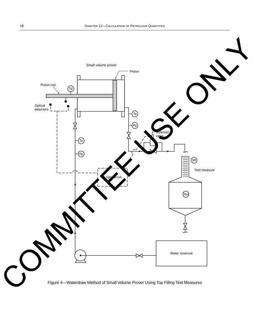
Figure 4—Waterdraw Method of Small Volume Prover Using Top Filling Test Measures
Small volume prover
Piston rod
Piston
Water reservoir
Opticaldetectors
Solenoidvalve
Test measure
Logic circuit
SR
Ttm
Tp
Pp
Tp
Pp
Td
COMMITTEE USE O
NLY
SECTION 2, PART 4—CALCULATION OF PROVER VOLUMES BY WATERDRAW METHOD 19
12.2 OPEN TANK PROVERS
The following rules for rounding, calculation sequence anddiscrimination levels are applicable to the volumetric water-draw (or waterfill) calibration method for all open tank prov-ers. A flow chart (Figure 5) has been prepared to graphicallyexplain the calculation sequence. Drawings depicting theprocess have also been prepared to assist the user (Figures 6and 7).
Tank Prover Neck Scales
For tank provers that have top and bottom necks, either oftwo methods may be used to calibrate the lower and uppernecks of the prover. The first method, commonly used byindustry, consists of installing previously marked scales rep-resenting a tank table in appropriate units of measurement.The second method consists of determining and marking theactual capacity of the prover on the neck scale.
The Calibrated Prover Volume (CPV) of an open tankprover is the corrected volume from the opening upper scale(SRu) reading to the closing lower scale (SRl) reading at whichwithdrawals ceased on any calibration run. Thus, the indicated“to deliver” volume of a prover tank is the difference betweenthe upper scale reading (e.g. 1,000 gallons) and the lower scalereading (e.g. ± zero gallons) after completing the delivery.Ordinarily, the sight glass scale(s) on the prover tank aremoved upward/downward at the time of calibration so that thenormal volume indicated at standard conditions (upper scalereading minus lower scale reading) is the same as the cali-brated volume of the prover tank at standard conditions.
The targeted BPV is a term that refers to adjusting thescales to an even nominal value, such as 500 gallons, or 1,000gallons. For load rack applications, open tank provers areadjusted to arrive at exactly the targeted BPV value.
The upper scale of a prover tank normally reads the actualaccumulated volume at each liquid level (e.g. 999, 1,000,1,001 gallons, etc.) down to the lower neck scale “zero” posi-tion. A field standard test measure reads plus or minus fromzero on an upper scale only.
The lower scale of a tank prover usually reads plus orminus zero (in units consistent with the upper scale). How-ever, there are also two other lower scale possibilities:
a. The lower neck does not have a sight glass and the provertank is simply drained (in the prescribed manner) to essen-tially empty “zero.”b. The lower neck has a weir type “fixed” zero.
Calibration of neck scales—For new open tank provers,the neck volume should be calibrated, and the neck scaleshould reflect the linear increments of volume in the neck.
In the calculations it is assumed that the neck scales havepreviously been calibrated.
The midpoint level of the upper neck scale may be desig-nated the upper reference level.
12.2.1 Field Standard Test Measure Data
Obtain, round, and record the following field standard testmeasure data relative to all the test measures to be used in thecalibration. This information may be obtained from the cali-bration certificate delivered by the calibrating agency:
a. Base test measure volume (BMV).b. Coefficient of cubical expansion (Gcm) of test measuremetal of construction.c. Base temperature (Tb).d. Seal number from the graduated scale of the test measure.e. Nominal capacity of the test measure.
If the actual value of Gcm is known, either as reported onthe certificate of calibration or by experimental determina-tion, then it should be used at the same discrimination level asspecified in Table 5, otherwise the basic values defined inTable 5 should be used.
Record the value for BMV, as indicated on the test measurecalibration certificates for all test measures being used.
12.2.2 Tank Prover Data
Obtain, round and record the following data for the opentank prover:
a. Prover type and size.b. Manufacturer.c. Serial number.d. Seal number(s) from the graduated scale(s).e. Type of steel.f. Cubical coefficient of thermal expansion (Gc).
Record the value for Gc in accordance with Table 5.
12.2.3 Open Tank Prover Waterdraw Sequence
Record the targeted BPV for the open tank prover in accor-dance with Table 8.
The open tank prover should be filled with water to read alevel on the upper sight glass scale (SRu), after which thewater is “drawn” from this tank prover into the field standardtest measure(s). The calibration should not proceed until thewater in the steel shell of the open tank prover, and the waterin the field test measures are stabilized at a constant tempera-ture. Drain test measures before starting calibration run.
Initiate the waterdraw sequence by “drawing” water fromthe prover into the certified test measure(s).
Step 1 Record Opening Tank Prover Data—SRu, Tp
Using a certified temperature device (certificate should beavailable for inspection), determine the average temperatureof the water in the prover, Tp. Record the value in accordancewith Table 2.
COMMITTEE USE O
NLY
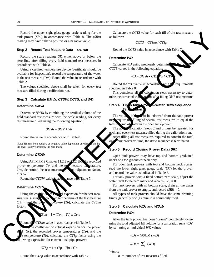
20 CHAPTER 12—CALCULATION OF PETROLEUM QUANTITIES
Record the upper sight glass gauge scale reading for thetank prover (SRu) in accordance with Table 8. The (SRu)reading may have either a positive or a negative value.
Step 2 Record Test Measure Data—SR, Ttm
Record the scale reading, SR, either above or below thezero line, after filling every field standard test measure, inaccordance with Table 8.
Using a certified temperature device (certificate should beavailable for inspection), record the temperature of the waterin the test measure (Ttm). Round the value in accordance withTable 2.
The values specified above shall be taken for every testmeasure filled during a calibration run.
Step 3 Calculate BMVa, CTDW, CCTS, and WD
Determine BMVa
Determine BMVa by combining the certified volume of thefield standard test measure with the scale reading, for everytest measure filled, using the following equation:
BMVa = BMV + SR
Round the value in accordance with Table 8.
Note: SR may be a positive or negative value depending on whether the liq-uid level is above or below the zero mark.
Determine CTDW
Using API MPMS Chapter 11.2.3 or 11.2.3M, the recordedprover temperature, Tp, and the test measure temperature,Ttm, determine the test measure volume adjustment factor,CTDW.
Round the CTDW value in accordance with Table 7.
Determine CCTS
Using the coefficient of cubical expansion for the test mea-sure steel (Gcm), the recorded temperature of the test measure(Ttm), and the base temperature (Tb), calculate the CTStmfactor:
CTStm = 1 + (Ttm – Tb) x Gcm
Round the CTStm value in accordance with Table 7.Using the coefficient of cubical expansion for the prover
steel (Gc), the recorded prover temperatures (Tp), and thebase temperature (Tb), calculate the CTSp factor using thefollowing expression for conventional pipe provers:
CTSp = 1 + (Tp – Tb) x Gc
Round the CTSp value in accordance with Table 7.
Calculate the CCTS value for each fill of the test measureas follows:
CCTS = CTStm / CTSp
Round the CCTS value in accordance with Table 7.
Determine WD
Calculate WD using previously determined BMVa, CTDW,CCTS values in the following equation:
WD = BMVa x CTDW x CCTS
Round the WD value in accordance with the requirementsspecified in Table 8.
This completes all the calculation steps necessary to deter-mine the corrected water volume after filling ONE test measure.
Step 4 Open Tank Prover—Water Draw Sequence Termination
The volume of water to be “drawn” from the tank provermay require the filling of several test measures to equal thetotal volume of water in the open tank prover.
The above calculation Steps 2 and 3 must be repeated foreach and every test measure filled during the calibration run.
After filling all test measures required to contain the totalopen tank prover volume, the draw sequence is terminated.
Step 5 Record Closing Prover Data (SRl)
Open tank provers may have top and bottom graduatednecks or a top graduated neck only.
For open tank provers with top and bottom neck scales,read the lower sight glass gauge scale (SRl) for the prover,and record the value as indicated in Table 8.
For tank provers with a fixed bottom zero scale, adjust thewater level to the zero mark and record (SRl) = 0.
For tank provers with no bottom scale, drain all the waterfrom the tank prover to empty, and record (SRl) = 0.
All types of tank provers should have the same drainingtimes, generally one (1) minute is commonly used.
Step 6 Calculate WDz and WDzb
Determine WDz
After the tank prover has been “drawn” completely, deter-mine the total adjusted fill volume for a calibration run (WDz)by summing all individual WD values:
WDz = @SUM (WD)
WDz = (WD)
Where:n = number of test measures filled.
Σ1
nCOMMITTEE USE O
NLY

SECTION 2, PART 4—CALCULATION OF PROVER VOLUMES BY WATERDRAW METHOD 21
Round the WDz value in accordance with the requirementsspecified in Table 8.
Determine WDzb
To determine the volume of the open tank prover at baseconditions (WDzb), use the following formula:
Since open tank provers are at atmospheric pressure, Pp = 0psig. Therefore:
CPSp = 1.000000
CPLp = 1.000000
resulting in,
WDzb = WDz
Round the WDzb value obtained as indicated in accordancewith Table 8.
Step 7 Determine the Calibrated Prover Volume (CPVn)
The calibrated prover volume for a single run (CPVn), ofthe open tank prover is now calculated from the formula:
CPVn = [(WDzb) – (SRu – SRl) + (Targeted BPV)]
(SRu) and (SRl) are commonly read in gallons, barrels,liters, or cubic meters and must usually be converted to cubicinches or milliliters for calculation purposes.
The units used in the above equation must be consistent.The conversion of units shall be done by multiplying as fol-lows:
a. Barrel times 9,702 equals cubic inches.b. Gallon times 231 equals cubic inches.c. Liter times 1,000 equals milliliters.d. Cubic meter times 1,000,000 equals milliliters.
The values obtained shall be rounded as indicated inTable 8.
Round the Calibrated Prover Volume (CPV) in accordancewith the requirements specified in Table 8.
This completes the calculation for one calibration run ofthe open tank prover to determine the Calibrated Prover Vol-ume (CPV). Additional calibration run(s) shall now be madeto obtain at least two (more if required) consecutive Cali-brated Prover Volumes (CPV). Therefore, prior to commenc-ing the next calibration run, it will be necessary to refill thetank prover with clean water and allow it to settle before initi-ating a new calibration run.
12.2.4 Repeatability
The calibration is considered acceptable if the CalibratedProver Volumes (CPV) of two or more consecutive runs areall within a range of 0.020 percent. The range being definedas:
12.2.5 Determine the Base Prover Volume (BPV)
Average the CPV values for the acceptable consecutiveruns to determine the Base Prover Volume (BPV) for the opentank prover:
Where:
n = number of acceptable consecutive runs.
Round the results in accordance with the requirementsspecified in Table 8.
12.2.6 Adjustment of Scale(s)
The BPV may not exactly agree with the targeted BPV.Normal practice is then to break the scale seals and adjust oneor both of the scales to arrive at exactly the targeted BPV.
For example, if the BPV is 1,000.25 gallons and the tar-geted BPV is 1,000.00 gallons, the upper scale may be moveddownward 0.25 indicated gallons or the lower scale movedupward 0.25 indicated gallons.
Conversely, if the BPV is 999.75 gallons and the targetedBPV is 1,000.00 gallons, the upper scale may be movedupward 0.25 indicated gallons or the lower scale moveddownward 0.25 indicated gallons.
On some occasions it may be more practical to move bothscales, one upward and one downward, so that each scaleshares a part of the overall adjustment.
Reseal the scales after adjustment and record the new num-bers.
12.2.7 Verification of New BPV
After adjusting the scale(s), verify that the BPV for theopen tank prover agrees with the targeted BPV to within0.010 percent by performing one or more additional calibra-tion “run(s).”
If this criteria is satisfied, issue a new certificate for theopen tank prover. If the above range criteria is not satisfied,continue the waterdraw process.
After verification of the BPV, the scale(s) shall be re-sealedand the seal numbers recorded, the tank prover now has a newBase Prover Volume (BPV).
WDzbWDz
CPSp CPLp×( )----------------------------------------=
Range (%)Highest CPV Lowest CPV–( )
Lowest CPV( )-------------------------------------------------------------------------- 100×=
BPV ΣCPV n( )n
-------------------------=
COMMITTEE USE O
NLY
22 CHAPTER 12—CALCULATION OF PETROLEUM QUANTITIES
12.2.8 Conversion of the BPV into Appropriate Volume Units
After verification of the Base Prover Volume (BPV), itis usually necessary to convert this final prover volume fromeither cubic inch or cubic centimeter (milliliter) units intousable field volumes for meter proving. Conversions shall bedone as follows and volumes rounded as specified in Table 8.
a. If the base prover volume is determined in cubic inches,then the appropriate conversions are:
BPV(inch3), divided by 231, equals U.S. gallons @ 60°F.
BPV(inch3), divided by 9,702, equals barrels @ 60°F.
BPV(inch3), multiplied by 16.387064, divided by 1,000,divided by CTSp,a equals liters @ 15°C.
BPV(inch3), multiplied by 16.387064, divided by1,000,000, divided by CTSp,a equals cubic meters @15°C.
b. If the base prover volume is determined in milliliters, thenthe appropriate conversions are:
BPV(ml), divided by 1,000, equals liters @ 15°C.
BPV(ml), divided by 1,000,000, equals cubic meters @15°C.
BPV(ml), divided by 16.387064, divided by 231, multi-plied by CTSp,a equals U.S. gallons @ 60°F.
BPV(ml), divided by 16.387064, divided by 9,702, mul-tiplied by CTSp,a equals barrels @ 60°F.
aCTSp = {1 + [(60 – 59) x Gc]}, simplified: CTSp = {1 + Gc}.Gc = Coefficient of Cubical Expansion, 1°F.
For example (mild steel prover, USC Units):
CTSp = 1 + 0.0000186, CTSp = 1.0000186
This CTSp factor is used to correct the converted provervolume for the differences in temperatures between the SIand USC conventions (most commonly used to changebetween 60°F and 15°C). This correction factor, CTSp,should be maintained at the same number of decimal placesas indicated by the Coefficient of Cubical Expansion Table(use Table 5), and NOT the number of decimal places shownin Table 7. This decimal place deviation only applies to thisspecific application of CTSp.
For different base temperatures other than 60°F and 15°C,a new CTSp, will have to be calculated using the new basetemperature, e.g. 4°C, 20°C, etc.
All calculations shall be done serially in a continuous chain,in the order shown, to obtain the required converted volumes.Round these final volumes in accordance with Table 8.
COMMITTEE USE O
NLY
SECTION 2, PART 4—CALCULATION OF PROVER VOLUMES BY WATERDRAW METHOD 23
Figure 5—Prover Calibration Flow Chart—Waterdraw Method for Open Tank Provers
OBTAIN & RECORD DATA FROM ALL TEST MEASURES TO BE USED BMV, Gcm, Tb, Seal Number, Nominal Capacity of Test Measure
OBTAIN, ROUND & RECORD PROVER DATAGc, Prover Type and Size, Displacer Type and Size, Type of Steel, Manufacturer, Serial Number.
OPEN TANK PROVER WATERDRAW SEQUENCERound and Record the Targeted CPV for the Open Tank
(The open tank prover should be filled with water to read a level on the upper sight glass scale(SRu), after which the water is “drawn” from this tank prover into the field standard test measure(s).The calibration should not proceed until the Open Tank Prover’s steel shell, the water in the prover,and the field test measures are stabilized at approximately the same temperature.)
Record Opening Tank Prover Data (SRu, Tp)
DRAW WATER FROM TANK PROVER INTO TEST MEASURE(S)“Draw” Water From the Prover Into Certified Test Measure(s)
Record Test Measure Data (SR, Ttm)Calculate Test Measures’ BMVa, CTDW, and CCTSCalculate Test Measure WD
Draw Sequence Termination?
Yes No Another Test Measure to be Filled
Record Closing Open Tank Prover Data (SRl)Calculate WDz and WDzb for the Waterdraw Run
RUN SEQUENCE TERMINATION
Calculate the Calibrated Prover Volume (CPV) for a Single Run
Repeatability, and Number of Consecutive Runs Criteria Satisfied?
Yes No
Determine the Base Prover Volume (BPV)
ADJUSTMENT OF SCALE(S)Adjust the Scale(s) so That the Tank Prover BPV Equals the Targeted BPV
VERIFICATION OF NEW BPVAfter Adjusting the Scale(s), Verify the Following:
Is the BPV Reproducible to Within 0.010 Percent or Less?
Yes No
Seal the Scales and Record the Seal Numbers.
CALCULATE THE BASE PROVER VOLUME
Convert the BPV Values Into User Selected Units
COMMITTEE USE O
NLY
24 CHAPTER 12—CALCULATION OF PETROLEUM QUANTITIES
Figure 6—Waterdraw Method of Open Tank Provers Using Top Filling Test Measures
Test measure
Atmospherictank prover
Water reservoir
Transfer pump
Lower scale
Upper scale
Fill pump
Tp
SR
Ttm
SRl
SRu
COMMITTEE USE O
NLY
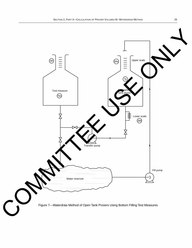
SECTION 2, PART 4—CALCULATION OF PROVER VOLUMES BY WATERDRAW METHOD 25
Figure 7—Waterdraw Method of Open Tank Provers Using Bottom Filling Test Measures
Test measure Atmospherictank prover
Water reservoir
Transfer pump
Lower scale
Upper scale
Fill pump
Tp
SR
Ttm
SRl
SRu
COMMITTEE USE O
NLY

26 CHAPTER 12—CALCULATION OF PETROLEUM QUANTITIES
13 Base Prover Volume Calculation Examples
13.1 DISPLACEMENT PROVER—CONVENTIONAL UNIDIRECTIONAL PIPE DESIGN
The following example depicts the calculations and required documentation for a complete unidirectional proverwaterdraw calibration.
COMMITTEE USE O
NLY
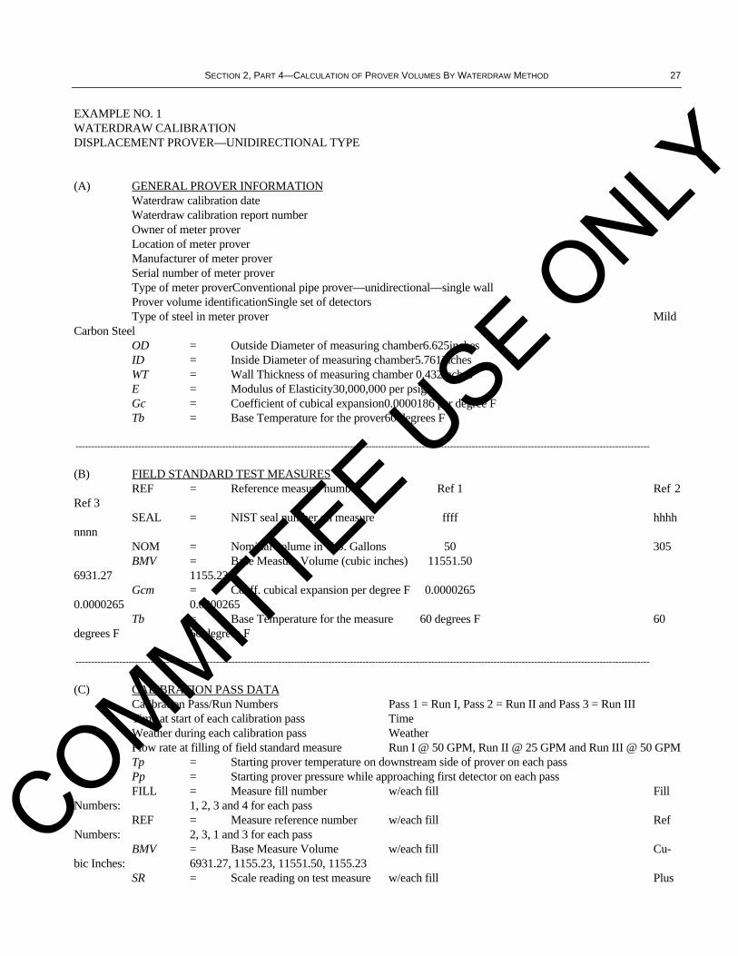
SECTION 2, PART 4—CALCULATION OF PROVER VOLUMES BY WATERDRAW METHOD 27
EXAMPLE NO. 1WATERDRAW CALIBRATIONDISPLACEMENT PROVER—UNIDIRECTIONAL TYPE
(A) GENERAL PROVER INFORMATIONWaterdraw calibration date Waterdraw calibration report number Owner of meter proverLocation of meter proverManufacturer of meter proverSerial number of meter proverType of meter proverConventional pipe prover—unidirectional—single wallProver volume identificationSingle set of detectorsType of steel in meter prover Mild
Carbon SteelOD = Outside Diameter of measuring chamber6.625inchesID = Inside Diameter of measuring chamber5.761inchesWT = Wall Thickness of measuring chamber 0.432inchesE = Modulus of Elasticity30,000,000 per psigGc = Coefficient of cubical expansion0.0000186 per degree FTb = Base Temperature for the prover60 degrees F
----------------------------------------------------------------------------------------------------------------------------------------------------------------------------------------
(B) FIELD STANDARD TEST MEASURESREF = Reference measure number Ref 1 Ref 2
Ref 3SEAL = NIST seal number on measure ffff hhhh
nnnnNOM = Nominal volume in U.S. Gallons 50 305BMV = Base Measure Volume (cubic inches) 11551.50
6931.27 1155.23Gcm = Coeff. cubical expansion per degree F 0.0000265
0.0000265 0.0000265Tb = Base Temperature for the measure 60 degrees F 60
degrees F 60 degrees F
----------------------------------------------------------------------------------------------------------------------------------------------------------------------------------------
(C) CALIBRATION PASS DATACalibration Pass/Run Numbers Pass 1 = Run I, Pass 2 = Run II and Pass 3 = Run IIITime at start of each calibration pass TimeWeather during each calibration pass WeatherFlow rate at filling of field standard measure Run I @ 50 GPM, Run II @ 25 GPM and Run III @ 50 GPMTp = Starting prover temperature on downstream side of prover on each passPp = Starting prover pressure while approaching first detector on each passFILL = Measure fill number w/each fill Fill
Numbers: 1, 2, 3 and 4 for each passREF = Measure reference number w/each fill Ref
Numbers: 2, 3, 1 and 3 for each passBMV = Base Measure Volume w/each fill Cu-
bic Inches: 6931.27, 1155.23, 11551.50, 1155.23SR = Scale reading on test measure w/each fill Plus
COMMITTEE USE O
NLY
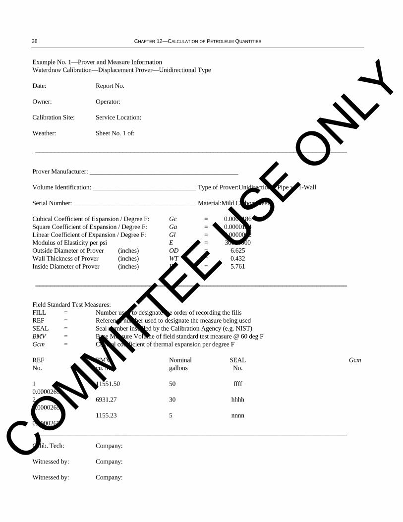
28 CHAPTER 12—CALCULATION OF PETROLEUM QUANTITIES
Example No. 1—Prover and Measure InformationWaterdraw Calibration—Displacement Prover—Unidirectional Type
Date: Report No.
Owner: Operator:
Calibration Site: Service Location:
Weather: Sheet No. 1 of:
__________________________________________________________________________________
Prover Manufacturer: ______________________________________________
Volume Identification: ________________________________ Type of Prover:Unidirectional Pipe w/ 1-Wall
Serial Number: ______________________________________ Material:Mild Carbon Steel
Cubical Coefficient of Expansion / Degree F: Gc = 0.0000186Square Coefficient of Expansion / Degree F: Ga = 0.0000124Linear Coefficient of Expansion / Degree F: Gl = 0.0000062Modulus of Elasticity per psi E = 30000000Outside Diameter of Prover (inches) OD = 6.625Wall Thickness of Prover (inches) WT = 0.432Inside Diameter of Prover (inches) ID = 5.761
__________________________________________________________________________________
Field Standard Test Measures:FILL = Number used to designate the order of recording the fillsREF = Reference number used to designate the measure being usedSEAL = Seal number installed by the Calibration Agency (e.g. NIST)BMV = Base Measure Volume of field standard test measure @ 60 deg FGcm = Cubical coefficient of thermal expansion per degree F
REF BMV Nominal SEAL GcmNo. cu. in. gallons No.
1 11551.50 50 ffff0.00002652 6931.27 30 hhhh0.00002653 1155.23 5 nnnn0.0000265__________________________________________________________________________________
Calib. Tech: Company:
Witnessed by: Company:
Witnessed by: Company:
COMMITTEE USE O
NLY

SECTION 2, PART 4—CALCULATION OF PROVER VOLUMES BY WATERDRAW METHOD 29
Example No. 1—Pass No. 1—w/ ComputerWaterdraw Calibration—Displacement Prover—Unidirectional Type
Date: Time: Report Number:
Sheet No: Of: Manufacturer:
Weather: Serial Number:
Owner/Operator: Location:
__________________________________________________________________________________
Pass Page DirectionFlow Rate Tp Td Degrees F
1 1 Unidirectional50 GPM 86.0 n/a Pp = 39 psig
__________________________________________________________________________________
FILL REF BMV SR BMVa Ttm CTDWCCTS WD
1 2 6931.27 –4.0 6927.27 86.40.999932 1.000216 6928.2951
2 3 1155.23 0.0 1155.23 86.50.999915 1.000218 1155.3836
3 1 11551.50 69.0 11620.50 86.40.999932 1.000216 11622.2197
4 3 1155.23 11.5 1166.73 86.50.999915 1.000218 1166.8852
567891011121314
WDz = SUM WD @ 60 DEGREES F20872.7836CPSp = 1 + [ ( Pp * ID ) / ( E * WT) ]1.000017CPLp = 1 / [ 1 – ( 0.0000032 * Pp ) ]1.000125WDzb = WDz / (CPSp * CPLp) @ 60 DEG F & 0 PSIg20869.8200
__________________________________________________________________________________
Note: Data obtained & calculations performed in U.S. Customary Units.__________________________________________________________________________________
Calibration Tech: Company:
COMMITTEE USE O
NLY

30 CHAPTER 12—CALCULATION OF PETROLEUM QUANTITIES
Example No. 1—Pass No. 2—w/ ComputerWaterdraw Calibration—Displacement Prover—Unidirectional Type
Date: Time: Report Number:
Sheet No: Of: Manufacturer:
Weather: Serial Number:
Owner/Operator: Location:
__________________________________________________________________________________
Pass Page DirectionFlow Rate Tp Td Degrees F
2 1 Unidirectional25 GPM 86.5 n/a Pp = 39 psig
__________________________________________________________________________________
FILL REF BMV SR BMVa Ttm CTDWCCTS WD
1 2 6931.27 –5.0 6926.27 87.00.999915 1.000223 6927.2257
2 3 1155.23 –0.5 1154.73 87.00.999915 1.000223 1154.8893
3 1 11551.50 70.0 11621.50 87.00.999915 1.000223 11623.1035
4 3 1155.23 12.5 1167.73 87.00.999915 1.000223 1167.8911
567891011121314
WDz = SUM WD @ 60 DEGREES F 20873.1096 CPSp = 1 + [ ( Pp * ID ) / ( E * WT) ]1.000017 CPLp = 1 / [ 1 – ( 0.0000032 * Pp ) ]1.000125 WDzb = WDz / (CPSp * CPLp) @ 60 DEG F & 0 PSIg20870.1460
__________________________________________________________________________________
Note: Data obtained & calculations performed in U.S. Customary Units.__________________________________________________________________________________
Calibration Tech: Company:
COMMITTEE USE O
NLY

SECTION 2, PART 4—CALCULATION OF PROVER VOLUMES BY WATERDRAW METHOD 31
Example No. 1—Pass No. 3—w/ ComputerWaterdraw Calibration—Displacement Prover—Unidirectional Type
Date: Time: Report Number:
Sheet No: Of: Manufacturer:
Weather: Serial Number:
Owner/Operator: Location:
__________________________________________________________________________________
Pass Page DirectionFlow Rate Tp Td Degrees F
3 1 Unidirectional50 GPM 87.5 n/a Pp = 39 psig
__________________________________________________________________________________
FILL REF BMV SR BMVa Ttm CTDWCCTS WD
1 2 6931.27 –6.0 6925.27 87.70.999965 1.000222 6926.5650
2 3 1155.23 0.0 1155.23 87.80.999948 1.000225 1155.4298
3 1 11551.50 72.0 11623.50 87.90.999931 1.000227 11625.3363
4 3 1155.23 11.0 1166.23 87.90.999931 1.000227 1166.4142
567891011121314
WDz = SUM WD @ 60 DEGREES F20873.7453
CPSp = 1 + [ ( Pp * ID ) / ( E * WT) ] 1.000017
CPLp = 1 / [ 1– ( 0.0000032 * Pp ) ] 1.000125
WDzb = WDz / (CPSp * CPLp) @ 60 DEG F & 0 PSIg 20870.7816
__________________________________________________________________________________COMMITTEE U
SE ONLY

32 CHAPTER 12—CALCULATION OF PETROLEUM QUANTITIES
Example No. 1—Summary—w/ ComputerWaterdraw Calibration—Displacement Prover—Unidirectional Type
Date: Time: Report Number:
Sheet No: Of: Manufacturer:
Weather: Serial Number:
Owner/Operator: Location:
__________________________________________________________________________________
PROVER CALIBRATION SUMMARY
Pass/Run No. I = 20869.8200@ 50GPM
Pass/Run No. II = 20870.1460@ 25GPM
Pass/Run No. III = 20870.7816@ 50GPM
Calculated Range Percent=0.005%
Calculated Range Percent=[ (MAX – MIN)/(MIN) ] * [ 100 ]
Allowable Range Percent=0.020 %
Note: Above summary in cubic inches @ 60 degrees F & 0 psig.Note: Data obtained & calculations performed in U.S. Customary Units.
Solve for BASE PROVER VOLUME: AVERAGE Pass/Runs I, II and III
Cubic Inches ( 16.387064 Cubic Centimeters )@ 60°F & 0 PSIG=20870.2492U.S. Gallons ( 231 Cubic Inches ) @ 60°F & 0 PSIG = 90.3474Barrels ( 9702 Cubic Inches ) @ 60°F & 0 PSIG = 2.15113Cubic Feet ( 1728 Cubic Inches ) @ 60°F & 0 PSIG = 12.0777Liters ( 1000 Cubic Meters )@ 15°C & 101.325 kPa= 341.996Cubic Meters ( 1000 Liters )@ 15°C & 101.325 kPa = 0.341996
Diameter of Displacer in Inches ____________ = ___________ % ID of Pipe
Calibrator's Name & Company Name ______________________________________
COMMITTEE USE O
NLY
SECTION 2, PART 4—CALCULATION OF PROVER VOLUMES BY WATERDRAW METHOD 33
13.2 DISPLACEMENT PROVER—CONVENTIONAL BIDIRECTIONAL PIPE DESIGN
The following example depicts the calculations and required documentation for a conventional bidirectional proverwaterdraw calibration.
COMMITTEE USE O
NLY
34 CHAPTER 12—CALCULATION OF PETROLEUM QUANTITIES
EXAMPLE NO. 2WATERDRAW CALIBRATIONDISPLACEMENT PROVER—BIDIRECTIONAL TYPE
(A) GENERAL PROVER INFORMATIONWaterdraw calibration date Waterdraw calibration report number Owner of meter proverLocation of meter proverManufacturer of meter proverSerial number of meter proverType of meter proverConventional pipe prover—bidirectional—single wallProver volume identificationSingle set of detectorsType of steel in meter prover 316
Stainless SteelOD = Outside Diameter of measuring chamber10.750 inchesID = Inside Diameter of measuring chamber10.020 inchesWT = Wall Thickness of measuring chamber0.365 inchesE = Modulus of Elasticity28,000,000 per psigGc = Coefficient of cubical expansion0.0000265 per degree FTb = Base Temperature for the prover60 degrees F
----------------------------------------------------------------------------------------------------------------------------------------------------------------------------------------
(B) FIELD STANDARD TEST MEASURESREF = Reference measure number Ref 1
Ref 2SEAL = NIST seal number on measure gggg
jjjjNOM = Nominal volume in U.S. Gallons 5021BMV = Base Measure Volume (cubic inches)
11547.80 4845.87Gcm = Coeff. cubical expansion per degree F
0.0000265 0.0000265Tb = Base Temperature for the measure 60
degrees F 60 degrees F----------------------------------------------------------------------------------------------------------------------------------------------------------------------------------------
(C) CALIBRATION PASS DATACalibration Pass/Run Numbers Passes 1 & 2 = Run I, Passes 3 & 4 = Run II and Passes 5 & 6
= Run IIITime at start of each calibration pass TimeWeather during each calibration pass WeatherFlow rate at filling of field standard measure Run I @ 40 GPM, Run II @ 20 GPM and Run III @ 60 GPMTp = Starting prover temperature on downstream side of prover for each pass.Pp = Starting prover pressure while approaching first detector on each pass.FILL = Measure fill number w/each fill Fill
Numbers: 1, 2 and 3 for each passREF = Measure reference number w/each fill Ref
Numbers: 2, 1 and 2 for each passBMV = Base Measure Volume w/each fill Cu-
bic Inches: 4845.87, 11547.80 and 4845.87SR = Scale reading on test measure w/each fill Plus
or minus scale readings in cubic inches
COMMITTEE USE O
NLY
SECTION 2, PART 4—CALCULATION OF PROVER VOLUMES BY WATERDRAW METHOD 35
Example No. 2—Prover and Measure InformationWaterdraw Calibration—Displacement Prover—Bidirectional Type
Date: Report No.
Owner: Operator:
Calibration Site: Service Location:
Weather: Sheet No. 1 of:
__________________________________________________________________________________
Prover Manufacturer: ______________________________________________
Volume Identification: ________________________________ Type of Prover:Bidirectional Pipe w/ 1-Wall
Serial Number: ______________________________________ Material:316 Stainless Steel
Cubical Coefficient of Expansion / Degree F: Gc = 0.0000265Square Coefficient of Expansion / Degree F: Ga = 0.0000177Linear Coefficient of Expansion / Degree F: Gl = 0.0000088Modulus of Elasticity per psi E = 28000000Outside Diameter of Prover (inches) OD = 10.750Wall Thickness of Prover (inches) WT = 0.365Inside Diameter of Prover (inches) ID = 10.020
__________________________________________________________________________________
Field Standard Test Measures:FILL = Number used to designate the order of recording the fillsREF = Reference number used to designate the measure being usedSEAL = Seal number installed by the calibration agency (e.g. NIST)BMV = Base Measure Volume of field standard test measure @ 60 deg FGcm = Cubical coefficient of thermal expansion per degree F
REF BMV Nominal SEAL GcmNo. cu. in. gallons No.
1 11547.80 50 gggg0.00002652 4845.87 21 jjjj0.0000265
__________________________________________________________________________________
Calib. Tech: Company:
Witnessed by: Company:
Witnessed by: Company: __________________________________________________________________________________
COMMITTEE USE O
NLY
36 CHAPTER 12—CALCULATION OF PETROLEUM QUANTITIES
Example No. 2—Pass No. 1—w/ ComputerWaterdraw Calibration—Displacement Prover—Bidirectional Type
Date: Time: Report Number:
Sheet No: Of: Manufacturer:
Weather: Serial Number:
Owner/Operator: Location:
__________________________________________________________________________________
Pass Page DirectionFlow Rate Tp Td Degrees F
1 1 “Out” 40 GPM 55.8 n/a Pp = 40 psig
__________________________________________________________________________________
FILL REF BMV SR BMVa Ttm CTDWCCTS WD
1 2 4845.87 2.0 4847.87 55.61.000014 0.999994 4847.9088
2 1 11547.80 –48.0 11499.80 55.61.000014 0.999994 11499.8920
3 2 4845.87 –10.5 4835.37 55.61.000014 0.999994 4835.4087
4567891011121314
WDz = SUM WD @ 60 DEGREES F21183.2095 CPSp = 1 + [ ( Pp * ID ) / ( E * WT) ] 1.000039 CPLp = 1 / [ 1 – ( 0.0000032 * Pp ) ] 1.000128 WDzb = WDz / (CPSp * CPLp) @ 60 DEG F & 0 PSIg 21179.6724
__________________________________________________________________________________
Note: Data obtained & calculations performed in U.S. Customary Units.__________________________________________________________________________________
COMMITTEE USE O
NLY
SECTION 2, PART 4—CALCULATION OF PROVER VOLUMES BY WATERDRAW METHOD 37
Example No. 2—Pass No. 2—w/ ComputerWaterdraw Calibration—Displacement Prover—Bidirectional Type
Date: Time: Report Number:
Sheet No: Of: Manufacturer:
Weather: Serial Number:
Owner/Operator: Location:
__________________________________________________________________________________
Pass Page DirectionFlow Rate Tp Td Degrees F
2 1 “Back” 40 GPM 56.1 n/a Pp = 40 psig
__________________________________________________________________________________
FILL REF BMV SR BMVa Ttm CTDWCCTS WD
1 2 4845.87 2.0 4847.87 55.81.000022 0.999992 4847.9379
2 1 11547.80 –11.0 11536.80 55.91.000015 0.999994 11536.9038
3 2 4845.87 –20.0 4825.87 55.61.000036 0.999986 4825.9762
4567891011121314
WDz = SUM WD @ 60 DEGREES F21210.8179 CPSp = 1 + [ ( Pp * ID ) / ( E * WT) ] 1.000039 CPLp = 1 / [ 1 – ( 0.0000032 * Pp ) ] 1.000128 WDzb = WDz / (CPSp * CPLp) @ 60 DEG F & 0 PSIg 21207.2762
__________________________________________________________________________________
Note: Data obtained & calculations performed in U.S. Customary Units.__________________________________________________________________________________
COMMITTEE USE O
NLY

38 CHAPTER 12—CALCULATION OF PETROLEUM QUANTITIES
Example No. 2—Pass No. 3—w/ ComputerWaterdraw Calibration—Displacement Prover—Bidirectional Type
Date: Time: Report Number:
Sheet No: Of: Manufacturer:
Weather: Serial Number:
Owner/Operator: Location:
__________________________________________________________________________________
Pass Page DirectionFlow Rate Tp Td Degrees F
3 1 “Out” 20 GPM 56.2 n/a Pp = 40 psig
__________________________________________________________________________________
FILL REF BMV SR BMVa Ttm CTDWCCTS WD
1 2 4845.87 2.0 4847.87 56.21.000000 1.000000 4847.8700
2 1 11547.80 –46.0 11501.80 56.21.000000 1.000000 11501.8000
3 2 4845.87 –10.0 4835.87 55.61.000043 0.999984 4836.0006
4567891011121314
WDz = SUM WD @ 60 DEGREES F21185.6706 CPSp = 1 + [ ( Pp * ID ) / ( E * WT) ]1.000039 CPLp = 1 / [ 1 – ( 0.0000032 * Pp ) ] 1.000128 WDzb = WDz / (CPSp * CPLp) @ 60 DEG F & 0 PSIg21182.1331
__________________________________________________________________________________
Note: Data obtained & calculations performed in U.S. Customary Units.
COMMITTEE USE O
NLY

SECTION 2, PART 4—CALCULATION OF PROVER VOLUMES BY WATERDRAW METHOD 39
Example No. 2—Pass No. 4—w/ ComputerWaterdraw Calibration—Displacement Prover—Bidirectional Type
Date: Time: Report Number:
Sheet No: Of: Manufacturer:
Weather: Serial Number:
Owner/Operator: Location:
__________________________________________________________________________________
Pass Page DirectionFlow Rate Tp Td Degrees F
4 1 “Back” 20 GPM 56.2 n/a Pp = 40 psig
__________________________________________________________________________________
FILL REF BMV SR BMVa Ttm CTDWCCTS WD
1 2 4845.87 1.0 4846.87 56.21.000000 1.000000 4846.8700
2 1 11547.80 –19.0 11528.80 56.21.000000 1.000000 11528.8000
3 2 4845.87 –9.5 4836.37 55.61.000043 0.999984 4836.5006
4567891011121314
WDz = SUM WD @ 60 DEGREES F21212.1706 CPSp = 1 + [ ( Pp * ID ) / ( E * WT) ]1.000039 CPLp = 1 / [ 1 – ( 0.0000032 * Pp ) ]1.000128 WDzb = WDz / (CPSp * CPLp) @ 60 DEG F & 0 PSIg21208.6287
__________________________________________________________________________________
Note: Data obtained & calculations performed in U.S. Customary Units.
COMMITTEE USE O
NLY
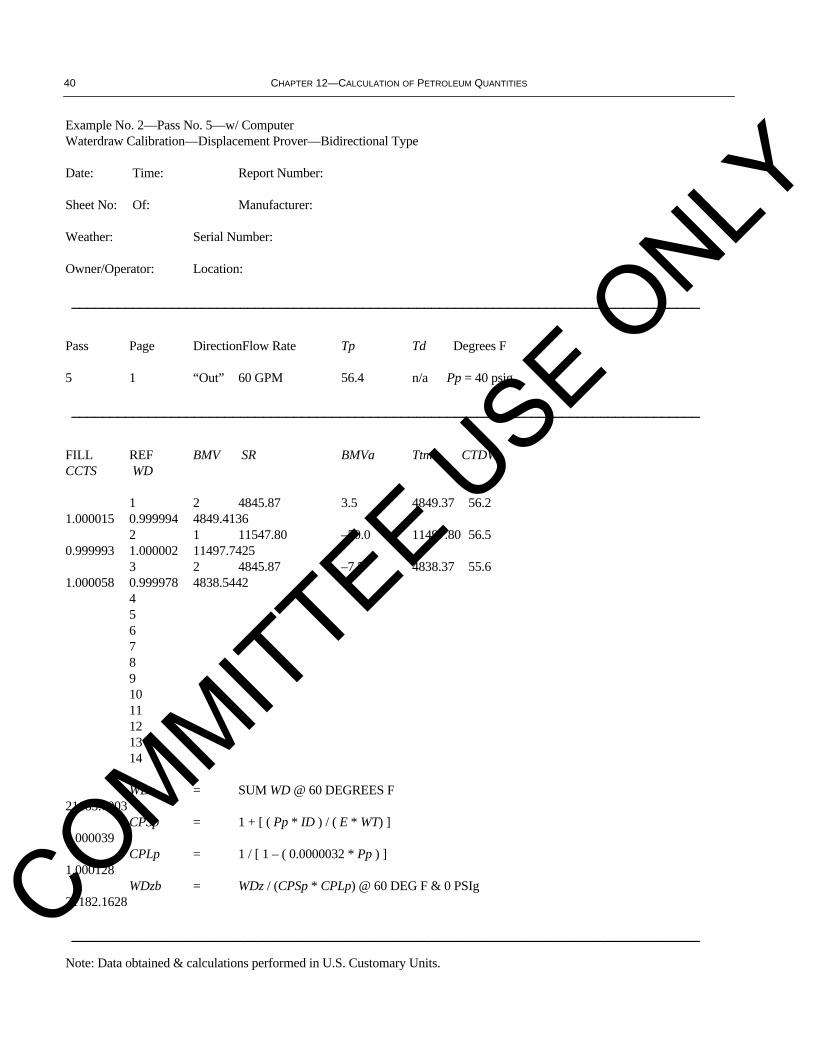
40 CHAPTER 12—CALCULATION OF PETROLEUM QUANTITIES
Example No. 2—Pass No. 5—w/ ComputerWaterdraw Calibration—Displacement Prover—Bidirectional Type
Date: Time: Report Number:
Sheet No: Of: Manufacturer:
Weather: Serial Number:
Owner/Operator: Location:
__________________________________________________________________________________
Pass Page DirectionFlow Rate Tp Td Degrees F
5 1 “Out” 60 GPM 56.4 n/a Pp = 40 psig
__________________________________________________________________________________
FILL REF BMV SR BMVa Ttm CTDWCCTS WD
1 2 4845.87 3.5 4849.37 56.21.000015 0.999994 4849.4136
2 1 11547.80 –50.0 11497.80 56.50.999993 1.000002 11497.7425
3 2 4845.87 –7.5 4838.37 55.61.000058 0.999978 4838.5442
4567891011121314
WDz = SUM WD @ 60 DEGREES F21185.7003 CPSp = 1 + [ ( Pp * ID ) / ( E * WT) ]1.000039 CPLp = 1 / [ 1 – ( 0.0000032 * Pp ) ]1.000128 WDzb = WDz / (CPSp * CPLp) @ 60 DEG F & 0 PSIg21182.1628
__________________________________________________________________________________
Note: Data obtained & calculations performed in U.S. Customary Units.
COMMITTEE USE O
NLY
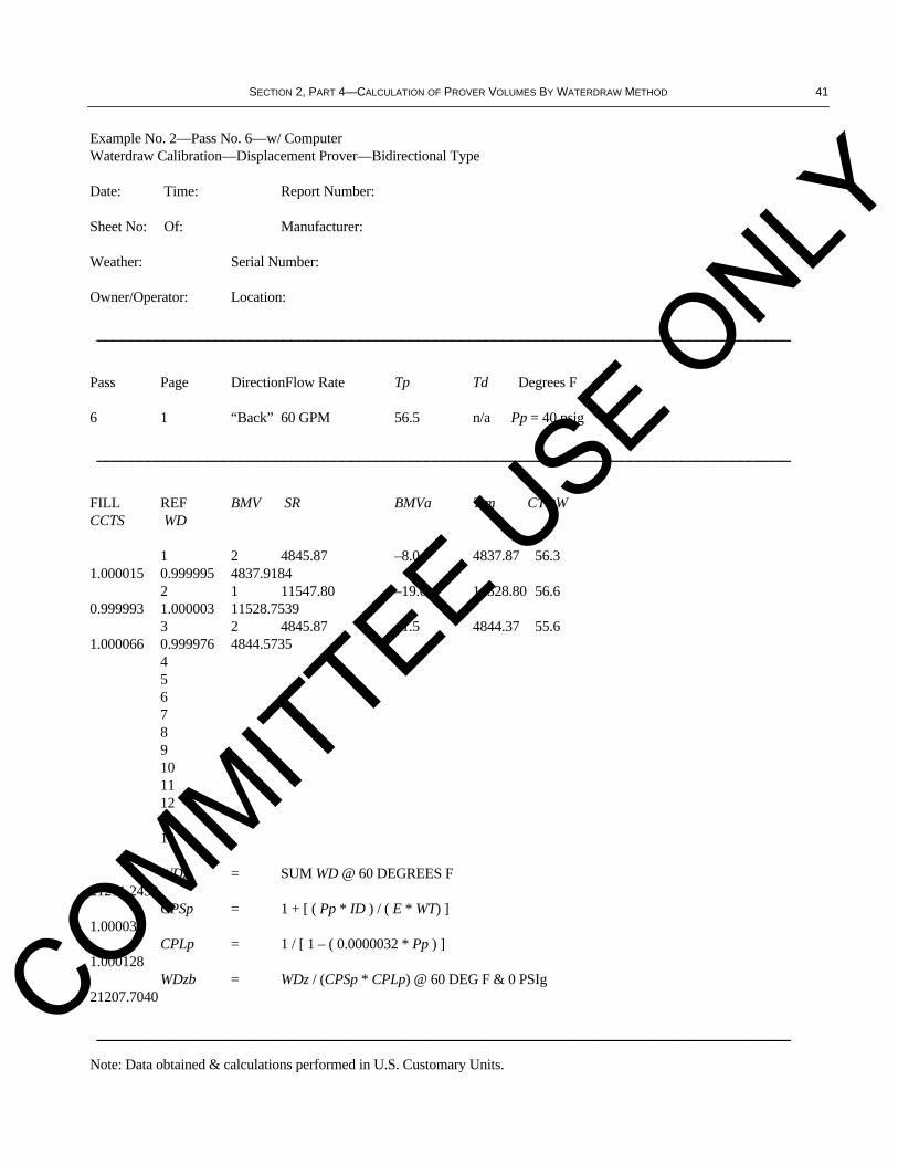
SECTION 2, PART 4—CALCULATION OF PROVER VOLUMES BY WATERDRAW METHOD 41
Example No. 2—Pass No. 6—w/ ComputerWaterdraw Calibration—Displacement Prover—Bidirectional Type
Date: Time: Report Number:
Sheet No: Of: Manufacturer:
Weather: Serial Number:
Owner/Operator: Location:
__________________________________________________________________________________
Pass Page DirectionFlow Rate Tp Td Degrees F
6 1 “Back” 60 GPM 56.5 n/a Pp = 40 psig
__________________________________________________________________________________
FILL REF BMV SR BMVa Ttm CTDWCCTS WD
1 2 4845.87 –8.0 4837.87 56.31.000015 0.999995 4837.9184
2 1 11547.80 –19.0 11528.80 56.60.999993 1.000003 11528.7539
3 2 4845.87 –1.5 4844.37 55.61.000066 0.999976 4844.5735
4567891011121314
WDz = SUM WD @ 60 DEGREES F21211.2458 CPSp = 1 + [ ( Pp * ID ) / ( E * WT) ]1.000039 CPLp = 1 / [ 1 – ( 0.0000032 * Pp ) ]1.000128 WDzb = WDz / (CPSp * CPLp) @ 60 DEG F & 0 PSIg21207.7040
__________________________________________________________________________________
Note: Data obtained & calculations performed in U.S. Customary Units.
COMMITTEE USE O
NLY
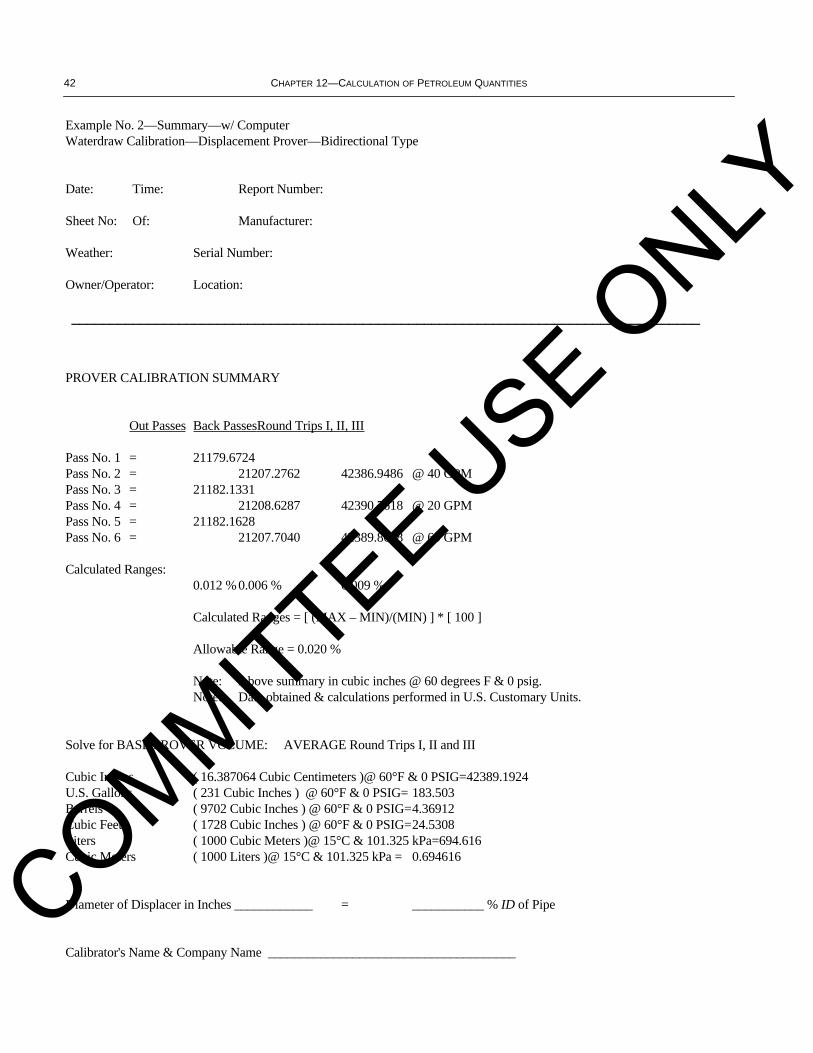
42 CHAPTER 12—CALCULATION OF PETROLEUM QUANTITIES
Example No. 2—Summary—w/ ComputerWaterdraw Calibration—Displacement Prover—Bidirectional Type
Date: Time: Report Number:
Sheet No: Of: Manufacturer:
Weather: Serial Number:
Owner/Operator: Location:
__________________________________________________________________________________
PROVER CALIBRATION SUMMARY
Out Passes Back PassesRound Trips I, II, III
Pass No. 1 = 21179.6724Pass No. 2 = 21207.2762 42386.9486 @ 40 GPMPass No. 3 = 21182.1331Pass No. 4 = 21208.6287 42390.7618 @ 20 GPMPass No. 5 = 21182.1628Pass No. 6 = 21207.7040 42389.8668 @ 60 GPM
Calculated Ranges:0.012 % 0.006 % 0.009 %
Calculated Ranges = [ (MAX – MIN)/(MIN) ] * [ 100 ]
Allowable Range = 0.020 %
Note: Above summary in cubic inches @ 60 degrees F & 0 psig.Note: Data obtained & calculations performed in U.S. Customary Units.
Solve for BASE PROVER VOLUME: AVERAGE Round Trips I, II and III
Cubic Inches ( 16.387064 Cubic Centimeters )@ 60°F & 0 PSIG=42389.1924U.S. Gallons ( 231 Cubic Inches ) @ 60°F & 0 PSIG= 183.503Barrels ( 9702 Cubic Inches ) @ 60°F & 0 PSIG=4.36912Cubic Feet ( 1728 Cubic Inches ) @ 60°F & 0 PSIG=24.5308Liters ( 1000 Cubic Meters )@ 15°C & 101.325 kPa=694.616Cubic Meters ( 1000 Liters )@ 15°C & 101.325 kPa = 0.694616
Diameter of Displacer in Inches ____________ = ___________ % ID of Pipe
Calibrator's Name & Company Name ______________________________________
COMMITTEE USE O
NLY

SECTION 2, PART 4—CALCULATION OF PROVER VOLUMES BY WATERDRAW METHOD 43
13.3 DISPLACEMENT PROVER—UNIDIRECTIONAL SMALL VOLUME PROVER DESIGN
The following example depicts the calculations and required documentation for a unidirectional small volume proverwaterdraw calibration.
COMMITTEE USE O
NLY
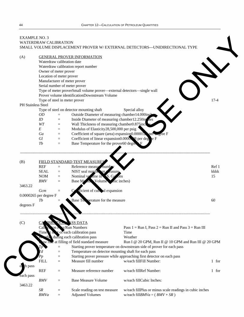
44 CHAPTER 12—CALCULATION OF PETROLEUM QUANTITIES
EXAMPLE NO. 3WATERDRAW CALIBRATIONSMALL VOLUME DISPLACEMENT PROVER W/ EXTERNAL DETECTORS—UNIDIRECTIONAL TYPE
(A) GENERAL PROVER INFORMATIONWaterdraw calibration date Waterdraw calibration report number Owner of meter proverLocation of meter proverManufacturer of meter proverSerial number of meter proverType of meter proverSmall volume prover—external detectors—single wallProver volume identificationDownstream VolumeType of steel in meter prover 17-4
PH Stainless SteelType of steel on detector mounting shaft Special alloyOD = Outside Diameter of measuring chamber14.000inchesID = Inside Diameter of measuring chamber12.250inchesWT = Wall Thickness of measuring chamber0.875inchesE = Modulus of Elasticity28,500,000 per psigGa = Coefficient of square (area) expansion0.0000120 per degree FGl = Coefficient of linear expansion0.0000008 per degree FTb = Base Temperature for the prover60 degrees F
----------------------------------------------------------------------------------------------------------------------------------------------------------------------------------------
(B) FIELD STANDARD TEST MEASURESREF = Reference measure number Ref 1SEAL = NIST seal number on measure kkkkNOM = Nominal volume in U.S. Gallons 15BMV = Base Measure Volume (cubic inches)
3463.22Gcm = Coefficient of cubical expansion
0.0000265 per degree FTb = Base Temperature for the measure 60
degrees F
----------------------------------------------------------------------------------------------------------------------------------------------------------------------------------------
(C) CALIBRATION PASS DATACalibration Pass/Run Numbers Pass 1 = Run I, Pass 2 = Run II and Pass 3 = Run IIITime at start of each calibration pass TimeWeather during each calibration pass WeatherFlow rate at filling of field standard measure Run I @ 20 GPM, Run II @ 10 GPM and Run III @ 20 GPMTp = Starting prover temperature on downstream side of prover for each passTd = Temperature on detector mounting shaft for each passPp = Starting prover pressure while approaching first detector on each passFILL = Measure fill number w/each fillFill Number: 1 for
each passREF = Measure reference number w/each fillRef Number: 1 for
each passBMV = Base Measure Volume w/each fillCubic Inches:
3463.22SR = Scale reading on test measure w/each fillPlus or minus scale readings in cubic inchesBMVa = Adjusted Volumes w/each fillBMVa = ( BMV + SR )
COMMITTEE USE O
NLY

SECTION 2, PART 4—CALCULATION OF PROVER VOLUMES BY WATERDRAW METHOD 45
Example No. 3—Prover and Measure InformationWaterdraw Calibration—Small Volume Displacement Prover w/ External Detectors—Unidirectional Type
Date: Report No.
Owner: Operator:
Calibration Site: Service Location:
Weather: Sheet No. 1 of:
__________________________________________________________________________________
Prover Manufacturer: ________________________________Small Volume ProverDisplacement Prover (UNI)
Volume Identification: ________________________________ Type of Prover:w/ External Detectors w/ 1-Wall
Serial Number: ______________________________________ Material:17-4 PH w/ Invar Rod
Cubical Coefficient of Expansion / Degree F: Gc = 0.0000180Square Coefficient of Expansion / Degree F: Ga = 0.0000120Linear Coefficient of Expansion / Degree F: Gl = 0.0000008Modulus of Elasticity per psi E = 28500000Outside Diameter of Prover (inches) OD = 14.000Wall Thickness of Prover (inches) WT = 0.875Inside Diameter of Prover (inches) ID = 12.250
__________________________________________________________________________________
Field Standard Test Measures:FILL = Number used to designate the order of recording the fillsREF = Reference number used to designate the measure being usedSEAL = Seal number installed by the calibration agency (e.g. NIST)BMV = Base Measure Volume of field standard test measure @ 60 deg FGcm = Cubical coefficient of thermal expansion per degree F
REF BMV Nominal SEAL GcmNo. cu. in. gallons No.
1 3463.22 15 kkkk0.0000265
__________________________________________________________________________________
Calib. Tech: Company:
Witnessed by: Company:
Witnessed by: Company: __________________________________________________________________________________
Downstream Volume
COMMITTEE USE O
NLY

46 CHAPTER 12—CALCULATION OF PETROLEUM QUANTITIES
Example No. 3—Pass No. 1—w/ ComputerWaterdraw Calibration—Small Volume Displacement Prover w/ External Detectors—Unidirectional Type
Date: Time: Report Number:
Sheet No: Of: Manufacturer:
Weather: Serial Number:
Owner/Operator: Location:
__________________________________________________________________________________
Pass Page DirectionFlow Rate Tp Td Degrees F
1 1 Unidirectional20 GPM 71.6 70.0 Pp = 35 psig
__________________________________________________________________________________
FILL REF BMV SR BMVa Ttm CTDWCCTS WD
1 1 3463.22 17.3 3480.52 71.21.000050 1.000150 3481.2161
234567891011121314
WDz = SUM WD @ 60 DEGREES F3481.2161 CPSp = 1 + [ ( Pp * ID ) / ( E * WT) ] 1.000017 CPLp = 1 / [ 1 – ( 0.0000032 * Pp ) ] 1.000112 WDzb = WDz / (CPSp * CPLp) @ 60 DEG F & 0 PSIg 3480.7671
__________________________________________________________________________________
Note: Data obtained & calculations performed in U.S. Customary Units.__________________________________________________________________________________
Calibration Tech: Company:
COMMITTEE USE O
NLY
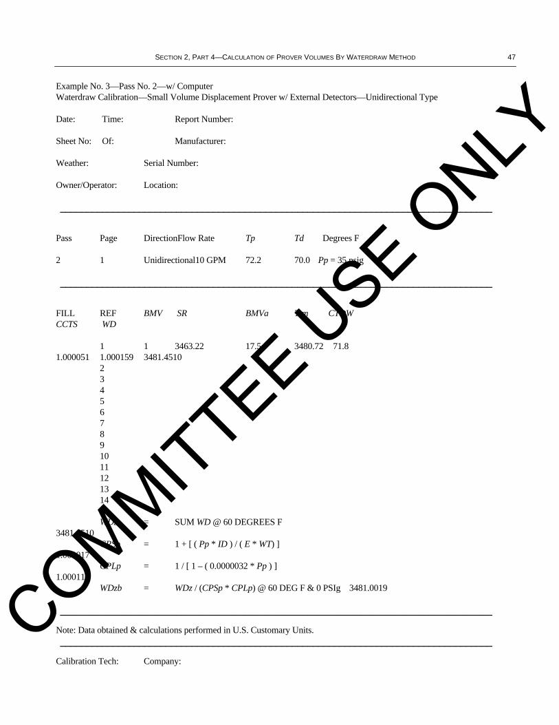
SECTION 2, PART 4—CALCULATION OF PROVER VOLUMES BY WATERDRAW METHOD 47
Example No. 3—Pass No. 2—w/ ComputerWaterdraw Calibration—Small Volume Displacement Prover w/ External Detectors—Unidirectional Type
Date: Time: Report Number:
Sheet No: Of: Manufacturer:
Weather: Serial Number:
Owner/Operator: Location:
__________________________________________________________________________________
Pass Page DirectionFlow Rate Tp Td Degrees F
2 1 Unidirectional10 GPM 72.2 70.0 Pp = 35 psig
__________________________________________________________________________________
FILL REF BMV SR BMVa Ttm CTDWCCTS WD
1 1 3463.22 17.5 3480.72 71.81.000051 1.000159 3481.4510
234567891011121314
WDz = SUM WD @ 60 DEGREES F3481.4510 CPSp = 1 + [ ( Pp * ID ) / ( E * WT) ] 1.000017 CPLp = 1 / [ 1 – ( 0.0000032 * Pp ) ] 1.000112 WDzb = WDz / (CPSp * CPLp) @ 60 DEG F & 0 PSIg 3481.0019
__________________________________________________________________________________
Note: Data obtained & calculations performed in U.S. Customary Units.__________________________________________________________________________________
Calibration Tech: Company:
COMMITTEE USE O
NLY

48 CHAPTER 12—CALCULATION OF PETROLEUM QUANTITIES
Example No. 3—Pass No. 3—w/ ComputerWaterdraw Calibration—Small Volume Displacement Prover w/ External Detectors—Unidirectional Type
Date: Time: Report Number:
Sheet No: Of: Manufacturer:
Weather: Serial Number:
Owner/Operator: Location:
__________________________________________________________________________________
Pass Page DirectionFlow Rate Tp Td Degrees F
3 1 Unidirectional20 GPM 72.3 70.0 Pp = 35 psig
__________________________________________________________________________________
FILL REF BMV SR BMVa Ttm CTDWCCTS WD
1 1 3463.22 17.2 3480.42 71.71.000077 1.000154 3481.2240
234567891011121314
WDz = SUM WD @ 60 DEGREES F3481.2240 CPSp = 1 + [ ( Pp * ID ) / ( E * WT) ] 1.000017 CPLp = 1 / [ 1 – ( 0.0000032 * Pp ) ]1.000112 WDzb = WDz / (CPSp * CPLp) @ 60 DEG F & 0 PSIg3480.7750
__________________________________________________________________________________
Note: Data obtained & calculations performed in U.S. Customary Units.__________________________________________________________________________________COMMITTEE U
SE ONLY

SECTION 2, PART 4—CALCULATION OF PROVER VOLUMES BY WATERDRAW METHOD 49
Example No. 3—Summary—w/ ComputerWaterdraw Calibration—Small Volume Displacement Prover w/ External Detectors—Unidirectional Type
Date: Time: Report Number:
Sheet No: Of: Manufacturer:
Weather: Serial Number:
Owner/Operator: Location:
__________________________________________________________________________________
PROVER CALIBRATION SUMMARY
Pass/Run No. I = 3480.7671 @ 20GPM
Pass/Run No. II = 3481.0019 @ 10GPM
Pass/Run No. III = 3480.7750 @ 20GPM
Calculated Range Percent=0.007%
Calculated Range Percent=[ (MAX – MIN)/(MIN) ] * [ 100 ]
Allowable Range Percent=0.020 %
Note: Above summary in cubic inches @ 60 degrees F & 0 psig.Note: Data obtained & calculations performed in U.S. Customary Units.
Solve for BASE PROVER VOLUME: AVERAGE Pass/Runs I, II and III
Cubic Inches ( 16.387064 Cubic Centimeters )@ 60°F & 0 PSIG=3480.8480U.S. Gallons ( 231 Cubic Inches )@ 60°F & 0 PSIG = 15.0686Barrels ( 9702 Cubic Inches ) @ 60°F & 0 PSIG = 0.358776Cubic Feet ( 1728 Cubic Inches ) @ 60°F & 0 PSIG = 2.01438Liters ( 1000 Cubic Meters )@ 15°C & 101.325 kPa= 57.0399Cubic Meters ( 1000 Liters )@ 15°C & 101.325 kPa = 0.0570399
Diameter of Displacer in Inches ____________ = ___________ % ID of Pipe
Calibrator's Name & Company Name ______________________________________COMMITTEE U
SE ONLY

50 CHAPTER 12—CALCULATION OF PETROLEUM QUANTITIES
13.4 OPEN TANK PROVER
The following example depicts the calculations and required documentation for an open tank prover waterdraw calibration.
COMMITTEE USE O
NLY
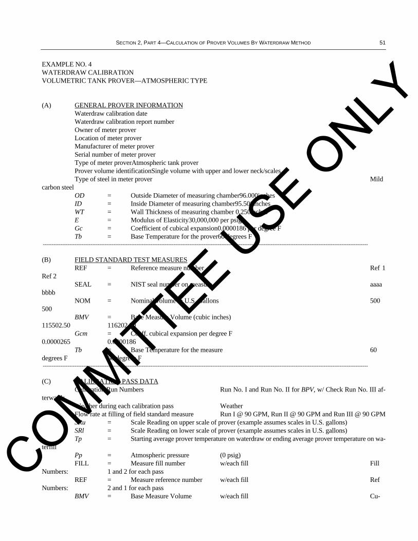
SECTION 2, PART 4—CALCULATION OF PROVER VOLUMES BY WATERDRAW METHOD 51
EXAMPLE NO. 4WATERDRAW CALIBRATIONVOLUMETRIC TANK PROVER—ATMOSPHERIC TYPE
(A) GENERAL PROVER INFORMATIONWaterdraw calibration date Waterdraw calibration report number Owner of meter proverLocation of meter proverManufacturer of meter proverSerial number of meter proverType of meter proverAtmospheric tank proverProver volume identificationSingle volume with upper and lower neck/scalesType of steel in meter prover Mild
carbon steelOD = Outside Diameter of measuring chamber96.000inchesID = Inside Diameter of measuring chamber95.500inchesWT = Wall Thickness of measuring chamber 0.250inchesE = Modulus of Elasticity30,000,000 per psigGc = Coefficient of cubical expansion0.0000186 per degree FTb = Base Temperature for the prover60 degrees F
----------------------------------------------------------------------------------------------------------------------------------------------------------------------------------------
(B) FIELD STANDARD TEST MEASURESREF = Reference measure number Ref 1
Ref 2SEAL = NIST seal number on measure aaaa
bbbbNOM = Nominal volume in U.S. Gallons 500
500BMV = Base Measure Volume (cubic inches)
115502.50 116202.20Gcm = Coeff. cubical expansion per degree F
0.0000265 0.0000186Tb = Base Temperature for the measure 60
degrees F 60 degrees F----------------------------------------------------------------------------------------------------------------------------------------------------------------------------------------
(C) CALIBRATION PASS DATACalibration Run Numbers Run No. I and Run No. II for BPV, w/ Check Run No. III af-
terwardsWeather during each calibration pass WeatherFlow rate at filling of field standard measure Run I @ 90 GPM, Run II @ 90 GPM and Run III @ 90 GPMSRu = Scale Reading on upper scale of prover (example assumes scales in U.S. gallons)SRl = Scale Reading on lower scale of prover (example assumes scales in U.S. gallons)Tp = Starting average prover temperature on waterdraw or ending average prover temperature on wa-
terfillPp = Atmospheric pressure (0 psig)FILL = Measure fill number w/each fill Fill
Numbers: 1 and 2 for each passREF = Measure reference number w/each fill Ref
Numbers: 2 and 1 for each passBMV = Base Measure Volume w/each fill Cu-
COMMITTEE USE O
NLY
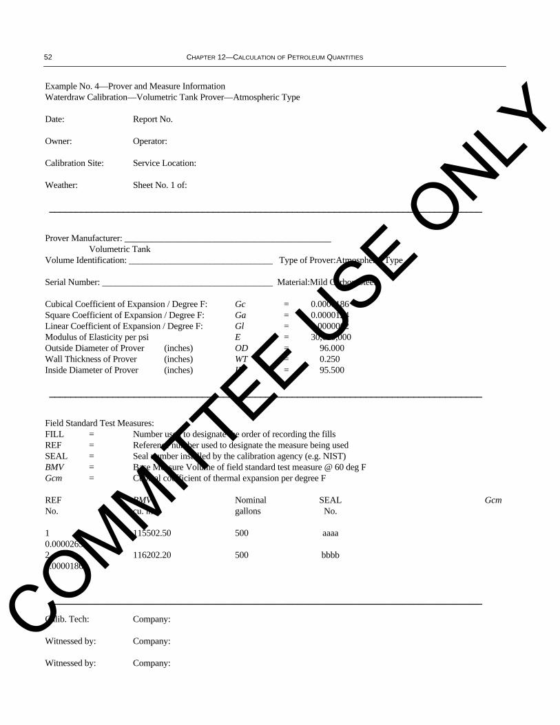
52 CHAPTER 12—CALCULATION OF PETROLEUM QUANTITIES
Example No. 4—Prover and Measure InformationWaterdraw Calibration—Volumetric Tank Prover—Atmospheric Type
Date: Report No.
Owner: Operator:
Calibration Site: Service Location:
Weather: Sheet No. 1 of:
__________________________________________________________________________________
Prover Manufacturer: ______________________________________________Volumetric Tank
Volume Identification: ________________________________ Type of Prover:Atmospheric Type
Serial Number: ______________________________________ Material:Mild Carbon Steel
Cubical Coefficient of Expansion / Degree F: Gc = 0.0000186Square Coefficient of Expansion / Degree F: Ga = 0.0000124Linear Coefficient of Expansion / Degree F: Gl = 0.0000062Modulus of Elasticity per psi E = 30,000,000Outside Diameter of Prover (inches) OD = 96.000Wall Thickness of Prover (inches) WT = 0.250Inside Diameter of Prover (inches) ID = 95.500
__________________________________________________________________________________
Field Standard Test Measures:FILL = Number used to designate the order of recording the fillsREF = Reference number used to designate the measure being usedSEAL = Seal number installed by the calibration agency (e.g. NIST)BMV = Base Measure Volume of field standard test measure @ 60 deg FGcm = Cubical coefficient of thermal expansion per degree F
REF BMV Nominal SEAL GcmNo. cu. in. gallons No.
1 115502.50 500 aaaa0.00002652 116202.20 500 bbbb0.0000186
__________________________________________________________________________________
Calib. Tech: Company:
Witnessed by: Company:
Witnessed by: Company:
COMMITTEE USE O
NLY

SECTION 2, PART 4—CALCULATION OF PROVER VOLUMES BY WATERDRAW METHOD 53
Example No. 4—Run No. 1—w/ ComputerWaterdraw Calibration—Volumetric Tank Prover—Atmospheric Type
Date: Time: Report Number:
Sheet No: Of: Manufacturer:
Weather: Serial Number:
Owner/Operator: Location:
__________________________________________________________________________________
Pass Page DirectionFlow Rate Tp Td Degrees F
1 1 Atmospheric90 GPM 70.2 n/a Pp = 0 psig
__________________________________________________________________________________
FILL REF BMV SR BMVa Ttm CTDWCCTS WD
1 2 116202.20 –300.0 115902.2070.40.999976 1.000003 115899.7660
2 1 115502.50 –280.0 115222.5070.60.999951 1.000091 115227.3388
345678910
WDz = SUM WD @ 60 DEGREES F231127.1048 CPSp = 1 + [ ( Pp * ID ) / ( E * WT) ]1.000000 CPLp = 1 / [ 1 – ( 0.0000032 * Pp ) ]1.000000 WDzb = WDz / (CPSp * CPLp) @ 60 DEG F & 0 PSIg 231127.1048__________________________________________________________________________________
Prover: Scale Reading Upper (SRu) inU.S. Gallons= 1000.60
Prover: Scale Reading Lower (SRl) inU.S. Gallons= –0.20
Prover: Indicated Volume (SRu – SRl) inU.S. Gallons= 1000.80__________________________________________________________________________________
COMMITTEE USE O
NLY
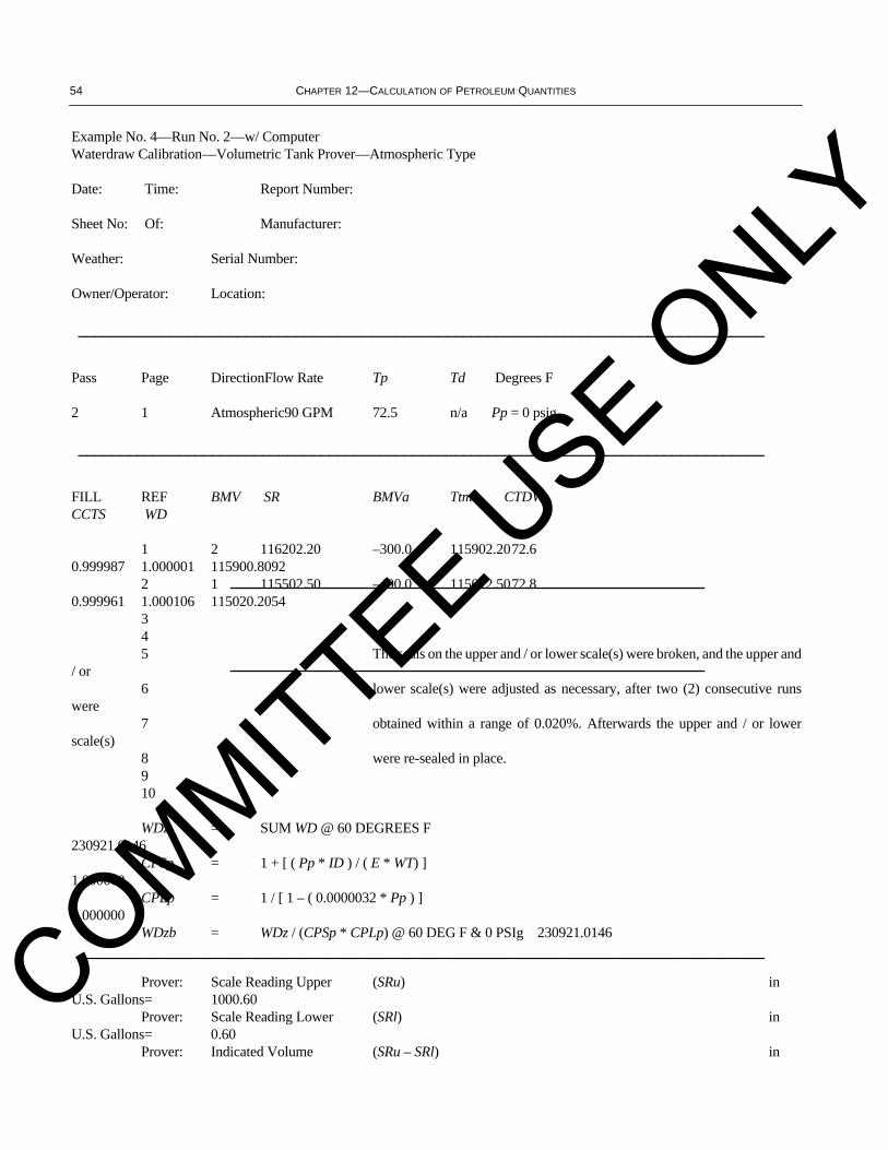
54 CHAPTER 12—CALCULATION OF PETROLEUM QUANTITIES
Example No. 4—Run No. 2—w/ ComputerWaterdraw Calibration—Volumetric Tank Prover—Atmospheric Type
Date: Time: Report Number:
Sheet No: Of: Manufacturer:
Weather: Serial Number:
Owner/Operator: Location:
__________________________________________________________________________________
Pass Page DirectionFlow Rate Tp Td Degrees F
2 1 Atmospheric90 GPM 72.5 n/a Pp = 0 psig
__________________________________________________________________________________
FILL REF BMV SR BMVa Ttm CTDWCCTS WD
1 2 116202.20 –300.0 115902.2072.60.999987 1.000001 115900.8092
2 1 115502.50 –490.0 115012.5072.80.999961 1.000106 115020.2054
34 5 The seals on the upper and / or lower scale(s) were broken, and the upper and
/ or6 lower scale(s) were adjusted as necessary, after two (2) consecutive runs
were7 obtained within a range of 0.020%. Afterwards the upper and / or lower
scale(s)8 were re-sealed in place.910
WDz = SUM WD @ 60 DEGREES F230921.0146 CPSp = 1 + [ ( Pp * ID ) / ( E * WT) ]1.000000 CPLp = 1 / [ 1 – ( 0.0000032 * Pp ) ]1.000000 WDzb = WDz / (CPSp * CPLp) @ 60 DEG F & 0 PSIg 230921.0146__________________________________________________________________________________
Prover: Scale Reading Upper (SRu) inU.S. Gallons= 1000.60
Prover: Scale Reading Lower (SRl) inU.S. Gallons= 0.60
Prover: Indicated Volume (SRu – SRl) in
COMMITTEE USE O
NLY
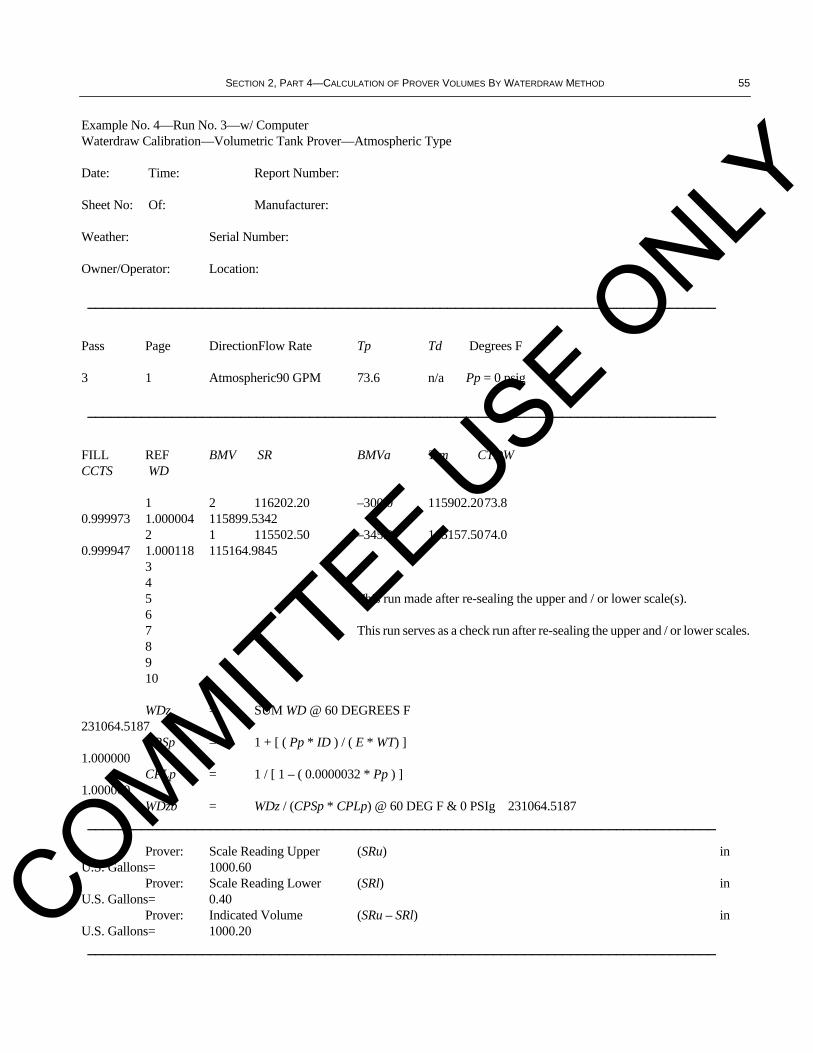
SECTION 2, PART 4—CALCULATION OF PROVER VOLUMES BY WATERDRAW METHOD 55
Example No. 4—Run No. 3—w/ ComputerWaterdraw Calibration—Volumetric Tank Prover—Atmospheric Type
Date: Time: Report Number:
Sheet No: Of: Manufacturer:
Weather: Serial Number:
Owner/Operator: Location:
__________________________________________________________________________________
Pass Page DirectionFlow Rate Tp Td Degrees F
3 1 Atmospheric90 GPM 73.6 n/a Pp = 0 psig
__________________________________________________________________________________
FILL REF BMV SR BMVa Ttm CTDWCCTS WD
1 2 116202.20 –300.0 115902.2073.80.999973 1.000004 115899.5342
2 1 115502.50 –345.0 115157.5074.00.999947 1.000118 115164.9845
345 This run made after re-sealing the upper and / or lower scale(s).67 This run serves as a check run after re-sealing the upper and / or lower scales.8910
WDz = SUM WD @ 60 DEGREES F231064.5187 CPSp = 1 + [ ( Pp * ID ) / ( E * WT) ] 1.000000 CPLp = 1 / [ 1 – ( 0.0000032 * Pp ) ] 1.000000 WDzb = WDz / (CPSp * CPLp) @ 60 DEG F & 0 PSIg 231064.5187__________________________________________________________________________________
Prover: Scale Reading Upper (SRu) inU.S. Gallons= 1000.60
Prover: Scale Reading Lower (SRl) inU.S. Gallons= 0.40
Prover: Indicated Volume (SRu – SRl) inU.S. Gallons= 1000.20__________________________________________________________________________________
COMMITTEE USE O
NLY
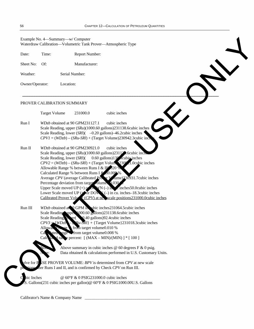
56 CHAPTER 12—CALCULATION OF PETROLEUM QUANTITIES
Example No. 4—Summary—w/ ComputerWaterdraw Calibration—Volumetric Tank Prover—Atmospheric Type
Date: Time: Report Number:
Sheet No: Of: Manufacturer:
Weather: Serial Number:
Owner/Operator: Location:
__________________________________________________________________________________
PROVER CALIBRATION SUMMARY
Target Volume 231000.0 cubic inches
Run I WDzb obtained at 90 GPM231127.1 cubic inchesScale Reading, upper (SRu)(1000.60 gallons)231138.6cubic inchesScale Reading, lower (SRl)( –0.20 gallons)–46.2cubic inchesCPV1 = (WDzb) – (SRu-SRl) + (Target Volume)230942.3cubic inches
Run II WDzb obtained at 90 GPM230921.0 cubic inchesScale Reading, upper (SRu)(1000.60 gallons)231138.6cubic inchesScale Reading, lower (SRl)( 0.60 gallons)138.6cubic inchesCPV2 = (WDzb) – (SRu-SRl) + (Target Volume)230921.0cubic inchesAllowable Range % between Runs I & II0.020 %Calculated Range % between Runs I & II0.009 %Average CPV (average Calibrated Prover Volume)230931.7cubic inchesPercentage deviation from target volume:–0.030 %Upper Scale moved UP (+) or DOWN (–) in cu. inches50.0cubic inchesLower Scale moved UP (+) or DOWN (–) in cu. inches–18.3cubic inchesCalibrated Prover Volume (CPV) at new scale positions231000.0cubic inches
Run III WDzb obtained at 90 GPM in cubic inches231064.5cubic inchesScale Reading, upper(1000.60 gallons)231138.6cubic inchesScale Reading, lower( 0.40 gallons)92.4cubic inchesCPV3 = {WDzb} – (SRu-SRl} + {Target Volume}231018.3cubic inchesAllowable range % from target volume0.010 %Calculated range % from target volume0.008 %Calculated range percent: [ (MAX – MIN)/(MIN) ] * [ 100 ]
Note: Above summary in cubic inches @ 60 degrees F & 0 psig.Note: Data obtained & calculations performed in U.S. Customary Units.
Solve for BASE PROVER VOLUME: BPV is determined from CPV at new scalepositions after Runs I and II, and is confirmed by Check CPV on Run III.
Cubic Inches @ 60°F & 0 PSIG231000.0 cubic inchesU.S. Gallons(231 cubic inches per gallon)@ 60°F & 0 PSIG1000.00U.S. Gallons
Calibrator's Name & Company Name _____________________________________
COMMITTEE USE O
NLY

To better serve you, please refer to this code when ordering: H M 4 2 108 792
Date:
(Month, Day, Year)
❏ API Member (Check if Yes)API Related Publications Order Form
Invoice To – ❏ Check here if same as “Ship To”
Company
Name/Dept.
Address
City State/Province
Zip Country
Customer Daytime Telephone No.
Fax No.(Essential for Foreign Orders) (Essential for Foreign Orders)
❏ Payment Enclosed $
❏ Payment By Charge Account:❏ MasterCard ❏ Visa ❏ American Express
Account No.
Name (As it appears on Card)
Expiration Date
Signature
❏ Please Bill MeP.O. No.
Customer Account No.
State Sales Tax – The American Petroleum Institute is required to collect sales tax on publicationsmailed to the following states: AL, AR, CT, DC, FL, GA, IL, IN, IA, KS, KY, ME, MD, MA, MI, MN, MO, NE, NJ, NY,NC, ND, OH, PA, RI, SC, TN, TX, VT, VA, WV, and WI. Prepayment of orders shipped to these states should includeapplicable sales tax unless a purchaser is exempt. If exempt, please print your state exemption number andenclose a copy of the current exemption certificate.
Exemption Number State
Shipping and Handling – All orders are shipped via UPS or First Class Mail in the U.S. and Canada.Orders to all other countries will be sent by Airmail.
Rush Shipping Charge – Federal Express, $10 in addition to customer providing Federal Expressaccount number: ________________________. UPS Next Day, $10 plus the actual shipping costs (1-9items). UPS Second Day, add $10 plus the actual shipping costs (1-9 items).
Rush Bulk Orders – 1-9 items, $10. Over 9 items, add $1 each for every additional item. NOTE: Shippingon foreign orders cannot be rushed without Federal Express account number.
Bill and Ship Orders – U.S. and Canada, $4 per order handling fee, plus actual shipping costs. All othercountries, for Airmail (standard service) add 25% of order value. All other countries, for UPS Next Day, add anadditional 10% of order value.
Mail Orders: American Petroleum Institute, Order Desk, 1220 L Street, N.W., Washington, DC 20005-4070Fax Orders: (202) 962-4776 Phone Orders: (202) 682-8375
Quantity Order No. Title Unit Price Total
Subtotal
State Sales Tax (see above)
Rush Shipping Charge (see left)
Shipping and Handling (see left)
Total (in U.S. Dollars)
Ship To – (UPS will not deliver to a P.O. Box)
Company
Name/Dept.
Address
City State/Province
Zip Country
Customer Daytime Telephone No.
Fax No.
Pricing and availability subject to change
without notice.
PREPAID AND CREDIT CARD ORDERS ARE NOT CHARGED FOR SHIPPING AND HANDLING TO U.S. AND CANADIAN DESTINATIONS
H30083
H30084
H30102
H05033
H06022
H30125
H30126
H07022
H30181
H13021
$ 40.00
$ 40.00
$ 40.00
$ 50.00
$ 45.00
$ 35.00
$ 35.00
$ 35.00
$ 35.00
$ 55.00
MPMS Ch. 4.3, Small Volume Provers
MPMS Ch. 4.4, Tank Provers
MPMS Ch. 5.2, Measurement of Liquid Hydrocarbons by Displacement Meters
MPMS Ch. 5.3, Measurement of Liquid Hydrocarbons by Turbine Meters
MPMS Ch. 6.2, Loading Rack and Tank Truck Metering Systems for Non-LPG Products
MPMS Ch. 6.5, Metering Systems for Loading and Unloading Marine Bulk Carriers
MPMS Ch. 6.6, Pipeline Metering Systems
MPMS Ch. 7.2, Temperature-Dynamic Temperature Determination
MPMS Ch. 9.1, Hydrometer Test Method for Density, Relative Density (Specification Gravity)
MPMS Ch. 13.2, Statistical Methods of Evaluating Meter Proving Data
COMMITTEE USE O
NLY

The American Petroleum Institute provides additional resourcesand programs to industry which are based on API Standards. For more information, contact:
• Training and Seminars Ph: 202-682-8490Fax: 202-682-8222
• Inspector Certification Programs Ph: 202-682-8161Fax: 202-962-4739
• American Petroleum Institute Ph: 202-962-4791Quality Registrar Fax: 202-682-8070
• Monogram Licensing Program Ph: 202-962-4791Fax: 202-682-8070
• Engine Oil Licensing and Ph: 202-682-8233Certification System Fax: 202-962-4739
• Petroleum Test Laboratory Ph: 202-682-8064Accreditation Program Fax: 202-962-4739
In addition, petroleum industry technical, patent, and businessinformation is available online through API EnCompass™. Call212-366-4040 or fax 212-366-4298 to discover more.
To obtain a free copy of the APIPublications, Programs, and ServicesCatalog, call 202-682-8375 or fax yourrequest to 202-962-4776. Or see theonline interactive version of the catalog on ourWorld Wide Web site – http://www.api.org.
Helping YouGet The JobDone Right.COMMITTEE U
SE ONLY

PC-01200—12/97—2C ( )
COMMITTEE USE O
NLY
Additional copies available from API Publications and Distribution:(202) 682-8375
Information about API Publications, Programs and Services is available on the World Wide Web at: http://www.api.org
Order No.: H12042
COMMITTEE USE O
NLY