
An Integrated Finite Strip Solution for Dynamic Analysis of Continuous Multi-span Bridges
10
CSCE 2013 General Conference - Congrès général 2013 de la SCGC Montréal, Québec May 29 to June 1, 2013 / 29 mai au 1 juin 2013 GEN-349-1 An Integrated Finite Strip Solution for Dynamic Analysis of Continuous Multi-span Bridges Zhenyuan Shen 1 , Moe M. S. Cheung 2 , Hamidreza Naderian 3 , Elena Dragomirescu 3 1 Department of Civil and Environmental Engineering, Hong Kong University of Science and Technology, Hong Kong 2 Western China Earthquake and Hazards Mitigation Research Centre, Sichuan University, Chengdu, China 3 Department of Civil Engineering, University of Ottawa, Canada Abstract: The finite strip method is one of the most efficient methods for structural analysis of bridges, reducing the time required for analysis without affecting the degree of accuracy. Finite strip method is therefore an ideal platform for the traditional time-consuming dynamic analysis of long span bridges. Current practice of using finite strip method is limited to analysis of the bridge super-structure subjected to simulated boundary conditions over the pier supports. Consequently, the interactions between the bridge deck (super-structure) and piers (sub-structure) cannot be modeled using conventional methods. In this regard, the current study introduces an integrated analytical solution for multi-span, continuous slab-on- girder and box girder bridges by modeling the bridge deck, the piers and the bearings together, using spline finite strip method (SFSM). The Column Strip (CS) is developed to model the cantilever-behaved piers as strip elements. In addition, a special transition section is developed to combine the deck and the piers in the finite strip environment, and the bearings are modeled as special boundary conditions for the transition section. By representing the whole bridge as a single integrated system, the actual dynamic behavior of the bridge was studied using Pseudo Excitation Method (PEM), which is a fast complete quadratic combination algorithm using power spectral density matrix for random responses. The complete modeling of a bridge using SFSM and the application of PEM suggest that the dynamic analysis of a complicated continuous long span structure can be performed in minimal time. 1. Introduction Quasi-static numerical analysis using Finite Element Method (FEM) has been one of the most widely adopted approaches for the study and design of long span bridges in the past few decades (Cook et al, 1989). With the ever increasing span lengths and successful application of light-weight composite materials in bridges, the dynamic characteristics of these structures have become significant and the conventional approach is no longer sufficient. However, the formulation of a FEM model and setting up of boundary conditions of a three dimensional (3D) bridge for dynamic analysis is very complicated and time consuming, and it makes the dynamic analysis of long span bridges inconvenient in practice. Besides, the convergence rate of the conventional FEM in dynamic problems is usually slow, since the nonlinearities associated with the flexible bridge structures leads to significant redistribution of internal forces. One of the solutions for improving the convergence rate is to use very small elements throughout the structure, resulting in a large number of degrees of freedom.
Transcript of An Integrated Finite Strip Solution for Dynamic Analysis of Continuous Multi-span Bridges
CSCE 2013 General Conference - Congrès général 2013 de la SCGC
Montréal, Québec
May 29 to June 1, 2013 / 29 mai au 1 juin 2013
GEN-349-1
An Integrated Finite Strip Solution for Dynamic Analysis of Continuous Multi-span Bridges
Zhenyuan Shen1, Moe M. S. Cheung2, Hamidreza Naderian3, Elena Dragomirescu3
1 Department of Civil and Environmental Engineering, Hong Kong University of Science and Technology, Hong Kong
2 Western China Earthquake and Hazards Mitigation Research Centre, Sichuan University, Chengdu, China 3 Department of Civil Engineering, University of Ottawa, Canada
Abstract: The finite strip method is one of the most efficient methods for structural analysis of bridges, reducing the time required for analysis without affecting the degree of accuracy. Finite strip method is therefore an ideal platform for the traditional time-consuming dynamic analysis of long span bridges. Current practice of using finite strip method is limited to analysis of the bridge super-structure subjected to simulated boundary conditions over the pier supports. Consequently, the interactions between the bridge deck (super-structure) and piers (sub-structure) cannot be modeled using conventional methods. In this regard, the current study introduces an integrated analytical solution for multi-span, continuous slab-on-girder and box girder bridges by modeling the bridge deck, the piers and the bearings together, using spline finite strip method (SFSM). The Column Strip (CS) is developed to model the cantilever-behaved piers as strip elements. In addition, a special transition section is developed to combine the deck and the piers in the finite strip environment, and the bearings are modeled as special boundary conditions for the transition section. By representing the whole bridge as a single integrated system, the actual dynamic behavior of the bridge was studied using Pseudo Excitation Method (PEM), which is a fast complete quadratic combination algorithm using power spectral density matrix for random responses. The complete modeling of a bridge using SFSM and the application of PEM suggest that the dynamic analysis of a complicated continuous long span structure can be performed in minimal time. 1. Introduction Quasi-static numerical analysis using Finite Element Method (FEM) has been one of the most widely adopted approaches for the study and design of long span bridges in the past few decades (Cook et al, 1989). With the ever increasing span lengths and successful application of light-weight composite materials in bridges, the dynamic characteristics of these structures have become significant and the conventional approach is no longer sufficient. However, the formulation of a FEM model and setting up of boundary conditions of a three dimensional (3D) bridge for dynamic analysis is very complicated and time consuming, and it makes the dynamic analysis of long span bridges inconvenient in practice. Besides, the convergence rate of the conventional FEM in dynamic problems is usually slow, since the nonlinearities associated with the flexible bridge structures leads to significant redistribution of internal forces. One of the solutions for improving the convergence rate is to use very small elements throughout the structure, resulting in a large number of degrees of freedom.

GEN-349-2
In this regard, this paper provides a very efficient, integrated framework for all types of dynamic analyses in long span bridges. The efficiency comes from the dramatic reduction in formation time, and the degrees-of-freedom associated with the structure using the finite strip method, and the application of a very robust and efficient Pseudo Excitation Method (PEM), for dynamic analysis of the structure.
Finite strip method is a well-known numerical method in structural analysis and has been well-recognized as one of the most efficient tools for analysis of bridge super-structures due to its semi-analytical nature as well as its pre-set boundary conditions (Cheung et al, 1996). Early versions of the finite strip method, developed by the second author and a group of researchers in the 1960s, were restricted to regular prismatic structures only. However, the robustness of the approach attracted many bridge engineers to extend the application in the past few decades. Since the development of B3 spline function by Prenter (1975) and afterwards the novelty of the Spline Finite Strip Method by Fan (1982), the finite strip method has been extended for analysis of more complex structures and problems. In spite of the large number of publications on the use of finite strip method in structural analysis, the application of existing finite strip method in seismic analysis is restricted to the bridge super-structures or bridges with assumed pier conditions only. Due to modeling by a continuously differentiable smooth series in the longitudinal direction in the finite strip method, difficulties are encountered in combining different types of structural components in different directions. Therefore, the analytical model developed using the finite strip method is limited to super-structures without piers. The piers of the bridge are normally replaced by certain assumed boundary conditions, and this assumption is reasonable only when the stress distribution along the girders and slab of the bridge super-structures is required. An alternative solution in considering the pier effect is to combine the finite strip (FS) bridge deck with piers modeled by other types of elements, such as the boundary element, and the interactions between the bridge deck and the piers can be obtained via an iterative process. Nevertheless, this approach can be effective for static/quasi-static analysis only. When complicated dynamic analysis such as non-uniform seismic analysis is being considered, the ground excitations are transmitted from the piers to the super-structure and the dynamic characteristics of the piers play an important role in the prediction of the bridge responses.
Therefore, in order to achieve an efficient dynamic analysis framework with high accuracy, it is necessary to integrate the bridge deck, the piers and the bearings in the FS environment. In this regard, the authors have developed the Column Strip (CS) method to describe the piers in a FS formulation. In addition, a transition section is developed to model the bearing condition and to combine the piers and the bridge deck in the FS environment. 2. Development of the Flat Shell Strip and Column Strip
The CS described in this section is developed particularly for modeling of cantilever-behaved piers. To maintain compatibility and uniqueness throughout the whole structure, the more general B3 spline finite strip function in the longitudinal direction is adopted as the basis in the development of the column strip’s displacement field. In the transverse direction, a cubic Hermite polynomial is adopted to represent the vertical displacement variation, while linear interpolation is applied for in-plane displacements. For a conventional B3 spline finite strip, in order to interpolate an arbitrary function ( )f y by the spline functions,
( )f y is divided into several sections, known as knots. For an unequally spaced spline function ( )m
y!
with the center at my y= , as shown in Figure 1, where the B3 spline function is defined as per Eq. 1
[1]
2
1 2 1
2 1
3 1
4 1 2
2
0
( )
0
m
m m
m m
m
m m
m m
m
y y
f y y y
f y y yy
f y y y
f y y y
y y
"
" "
"
+
+ +
+
<
# < # <
! = # <
# <
#
where
GEN-349-3
[2]
( )
( )( )( )
( )( )
( )( )( )( )
( )( )
( )( )( )( )
( )
( )( )( )
3
2
1
1 2 2 1 2
3
2 2 1
2 1
2 1 1 1 1 1 2
3
2 2 1
3 4
1 2 1 1 1 2 1
3
2
4
2 1 2 2 1
m
m m m m m m
m m m
m m m m m m m m
m m m
m m m m m m m m
m
m m m m m m
y yf
y y y y y y
y y y yf f
y y y y y y y y
y y y yf f
y y y y y y y y
y yf
y y y y y y
"
+ " " " "
+ " "
+ " + " " " "
+ " +
+ " + " + + +
+
+ " + + +
"=
" " "
" "= "
" " " "
" "= "
" " " "
"=
" " "
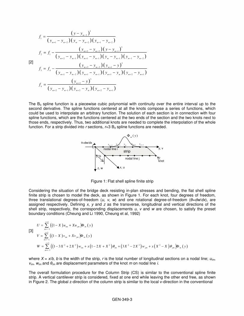
The B3 spline function is a piecewise cubic polynomial with continuity over the entire interval up to the second derivative. The spline functions centered at all the knots compose a series of functions, which could be used to interpolate an arbitrary function. The solution of each section is in connection with four spline functions, which are the functions centered at the two ends of the section and the two knots next to those ends, respectively. Thus, two additional knots are needed to complete the interpolation of the whole function. For a strip divided into r sections, r+3 B3 spline functions are needed.
Figure 1: Flat shell spline finite strip
Considering the situation of the bridge deck resisting in-plan stresses and bending, the flat shell spline finite strip is chosen to model the deck, as shown in Figure 1. For each knot, four degrees of freedom, three translational degrees-of-freedom (u, v, w) and one rotational degree-of-freedom (θ=dw/dx), are assigned respectively. Defining x, y and z as the transverse, longitudinal and vertical directions of the shell strip, respectively, the corresponding displacements u, v and w are chosen, to satisfy the preset boundary conditions (Cheung and Li 1990, Cheung et al, 1992)
[3]
( )( ) ( )
( )( ) ( )
( ) ( ) ( ) ( )( ) ( )
1
1
1
1
12 3 2 2 3 2
1
1
1
1 3 2 1 2 3 2
r
im jm mm
r
im jm mm
r
im im jm jm mm
U X u Xu y
V X v Xv y
W X X w x X X X X w x X X y$ $
+
= "
+
= "
+
= "
= " + !
= " + !
= " + + " + + " + " !
∑
∑
∑
where X = x/b, b is the width of the strip, r is the total number of longitudinal sections on a nodal line; uim, vim, wim and θim are displacement parameters of the knot m on nodal line i.
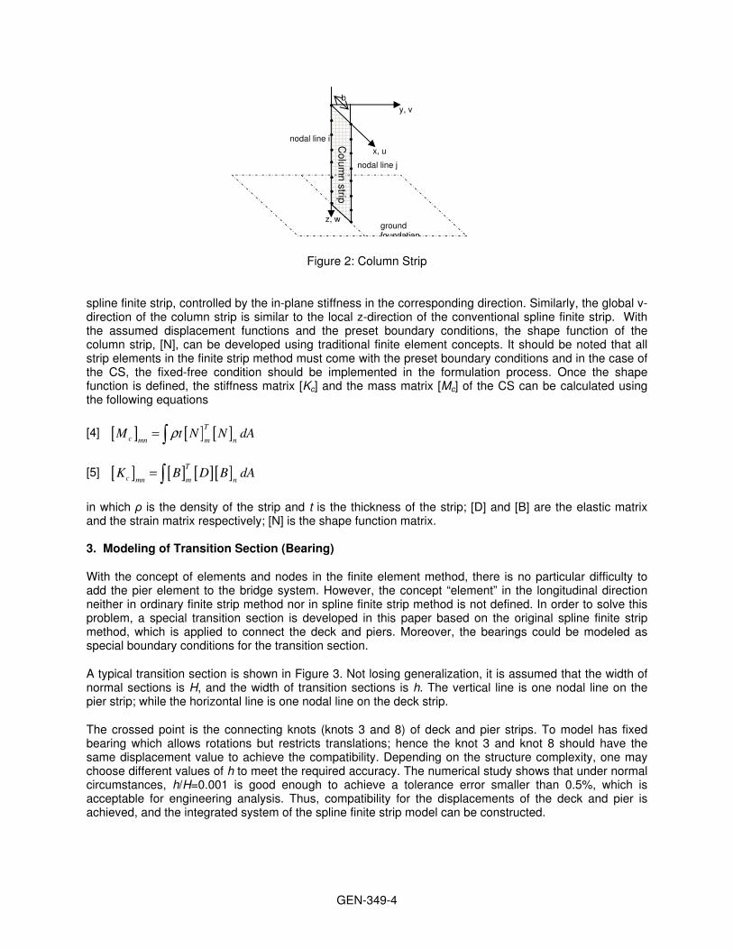
The overall formulation procedure for the Column Strip (CS) is similar to the conventional spline finite strip. A vertical cantilever strip is considered, fixed at one end while leaving the other end free, as shown in Figure 2. The global z-direction of the column strip is similar to the local v-direction in the conventional
y, v
x, u z, w
θ=dw/dx
b nodal line j
nodal line i
knot
strip
my 1my + 2my +1my "2my "
( )m y!
GEN-349-4
Figure 2: Column Strip
spline finite strip, controlled by the in-plane stiffness in the corresponding direction. Similarly, the global v-direction of the column strip is similar to the local z-direction of the conventional spline finite strip. With the assumed displacement functions and the preset boundary conditions, the shape function of the column strip, [N], can be developed using traditional finite element concepts. It should be noted that all strip elements in the finite strip method must come with the preset boundary conditions and in the case of the CS, the fixed-free condition should be implemented in the formulation process. Once the shape function is defined, the stiffness matrix [Kc] and the mass matrix [Mc] of the CS can be calculated using the following equations
[4] [ ] [ ] [ ]T
c mn m nM t N N dA%= ∫
[5] [ ] [ ] [ ][ ]T
c mn m nK B D B dA= ∫
in which ρ is the density of the strip and t is the thickness of the strip; [D] and [B] are the elastic matrix and the strain matrix respectively; [N] is the shape function matrix. 3. Modeling of Transition Section (Bearing)
With the concept of elements and nodes in the finite element method, there is no particular difficulty to add the pier element to the bridge system. However, the concept “element” in the longitudinal direction neither in ordinary finite strip method nor in spline finite strip method is not defined. In order to solve this problem, a special transition section is developed in this paper based on the original spline finite strip method, which is applied to connect the deck and piers. Moreover, the bearings could be modeled as special boundary conditions for the transition section.
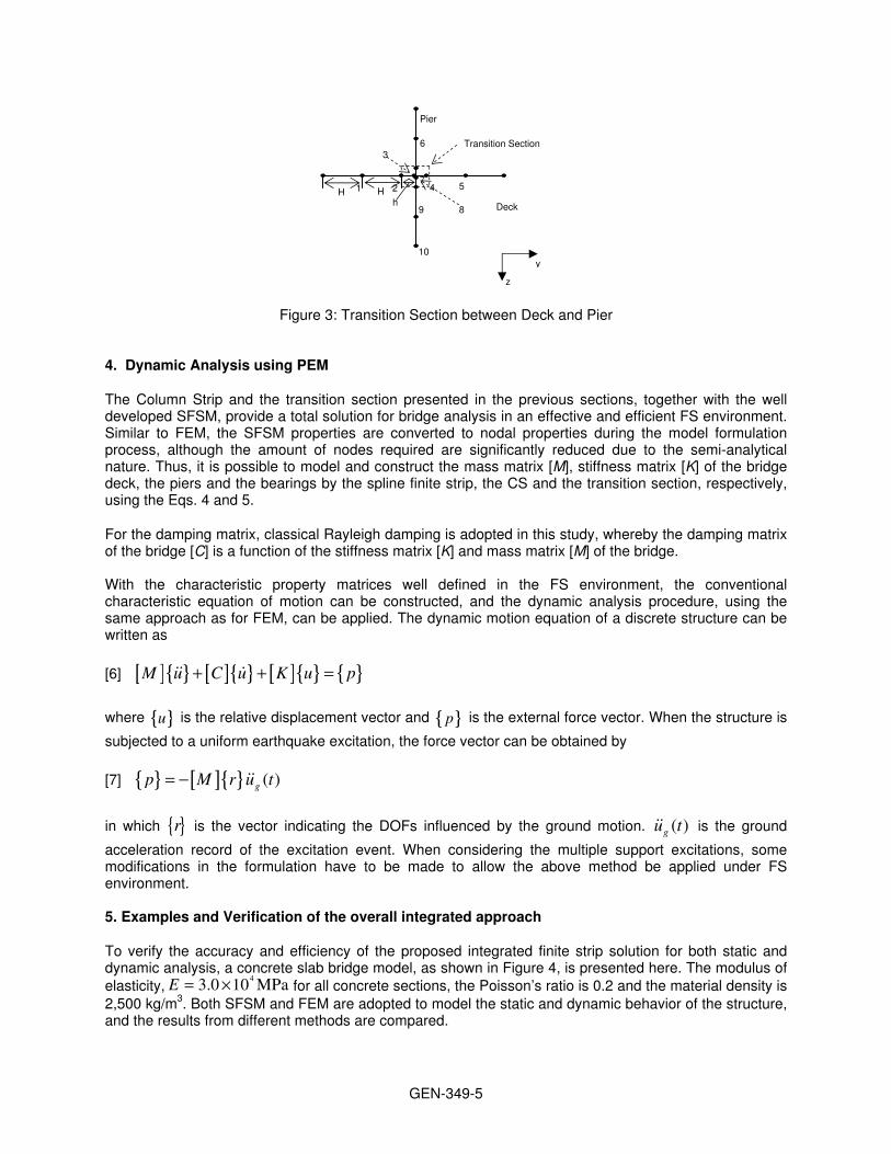
A typical transition section is shown in Figure 3. Not losing generalization, it is assumed that the width of normal sections is H, and the width of transition sections is h. The vertical line is one nodal line on the pier strip; while the horizontal line is one nodal line on the deck strip.
The crossed point is the connecting knots (knots 3 and 8) of deck and pier strips. To model has fixed bearing which allows rotations but restricts translations; hence the knot 3 and knot 8 should have the same displacement value to achieve the compatibility. Depending on the structure complexity, one may choose different values of h to meet the required accuracy. The numerical study shows that under normal circumstances, h/H=0.001 is good enough to achieve a tolerance error smaller than 0.5%, which is acceptable for engineering analysis. Thus, compatibility for the displacements of the deck and pier is achieved, and the integrated system of the spline finite strip model can be constructed.
y, v
x, u
z, w
b
nodal line j
nodal line i
ground foundation
Co
lum
n strip
GEN-349-5
Figure 3: Transition Section between Deck and Pier
4. Dynamic Analysis using PEM
The Column Strip and the transition section presented in the previous sections, together with the well developed SFSM, provide a total solution for bridge analysis in an effective and efficient FS environment. Similar to FEM, the SFSM properties are converted to nodal properties during the model formulation process, although the amount of nodes required are significantly reduced due to the semi-analytical nature. Thus, it is possible to model and construct the mass matrix [M], stiffness matrix [K] of the bridge deck, the piers and the bearings by the spline finite strip, the CS and the transition section, respectively, using the Eqs. 4 and 5.
For the damping matrix, classical Rayleigh damping is adopted in this study, whereby the damping matrix of the bridge [C] is a function of the stiffness matrix [K] and mass matrix [M] of the bridge. With the characteristic property matrices well defined in the FS environment, the conventional characteristic equation of motion can be constructed, and the dynamic analysis procedure, using the same approach as for FEM, can be applied. The dynamic motion equation of a discrete structure can be written as
[6] [ ]{ } [ ]{ } [ ]{ } { }M u C u K u p+ + =&& &
where { }u is the relative displacement vector and { }p is the external force vector. When the structure is
subjected to a uniform earthquake excitation, the force vector can be obtained by
[7] { } [ ]{ } ( )gp M r u t= " &&
in which { }r is the vector indicating the DOFs influenced by the ground motion. ( )gu t&& is the ground
acceleration record of the excitation event. When considering the multiple support excitations, some modifications in the formulation have to be made to allow the above method be applied under FS environment. 5. Examples and Verification of the overall integrated approach
To verify the accuracy and efficiency of the proposed integrated finite strip solution for both static and dynamic analysis, a concrete slab bridge model, as shown in Figure 4, is presented here. The modulus of elasticity,
43.0 10 MPaE = & for all concrete sections, the Poisson’s ratio is 0.2 and the material density is
2,500 kg/m3. Both SFSM and FEM are adopted to model the static and dynamic behavior of the structure, and the results from different methods are compared.
1 2
3
4 5
6
7
9
10
8
H H h
Transition Section
Deck
Pier
y
z

GEN-349-6
(a)
(b)
Figure 4: A Simple Slab Bridge: (a) Structural Layout; (b) Analysis Information
For the integrated SFSM, a full bridge model is constructed using B3 spline finite strip for the deck, CS for the pier and transition elements for the bearings. The deck is divided into four equal strips, while the pier is divided into two CSs. Each deck strip is composed of 32 sections as well as two additional transition sections. Each pier strip is composed of 4 sections, as well as one transition section. For FEM, the mass and stiffness of the bridges is constructed with five degrees-of-freedom shell elements throughout the structure. A shell element is derived from a combination of an in-plane element with translation in the x and y directions, and a bending element with translation in the z direction, plus bending above x and y directions. The deck is meshed with 32 by 4 elements, and the pier is meshed with 4 by 2 elements.
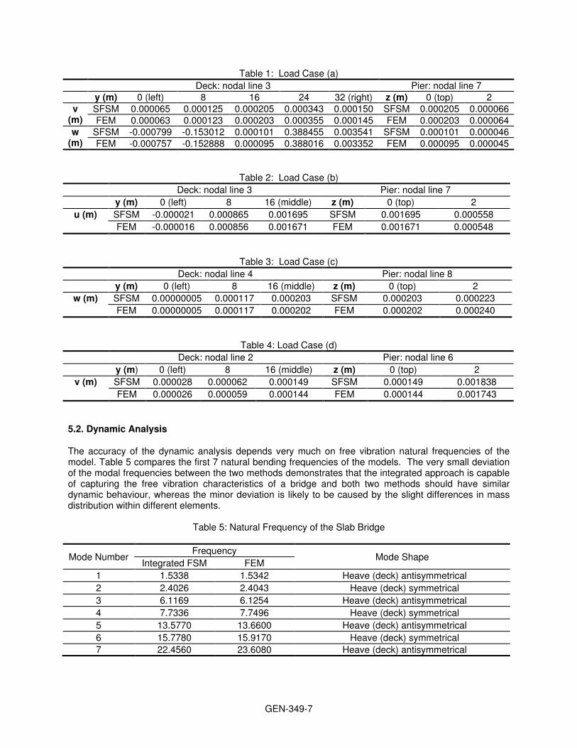
5.1. Static Analysis For the static analysis, the ability of the transition element to transfer loading between the deck strip and the CS is assessed. Four load cases, with constant 1,000kN point forces acting on different structure components and in different directions, are assigned to the models as shown in Figure 4(b). The vertical and horizontal drifts along different nodal lines, determined from both numerical methods, are summarized in Tables 1 to 4. It was noticed that the displacement calculated from the integrated approach agrees well with the FEM results for all loading conditions, which indicates that the proposed approach can successfully model a full bridge structure in the FS environment, taking the pier-bearing-deck interaction into consideration.
GEN-349-7
Table 1: Load Case (a)
Deck: nodal line 3 Pier: nodal line 7 y (m) 0 (left) 8 16 24 32 (right) z (m) 0 (top) 2
v (m)
SFSM 0.000065 0.000125 0.000205 0.000343 0.000150 SFSM 0.000205 0.000066 FEM 0.000063 0.000123 0.000203 0.000355 0.000145 FEM 0.000203 0.000064
w (m)
SFSM -0.000799 -0.153012 0.000101 0.388455 0.003541 SFSM 0.000101 0.000046 FEM -0.000757 -0.152888 0.000095 0.388016 0.003352 FEM 0.000095 0.000045
Table 2: Load Case (b)
Deck: nodal line 3 Pier: nodal line 7
y (m) 0 (left) 8 16 (middle) z (m) 0 (top) 2
u (m) SFSM -0.000021 0.000865 0.001695 SFSM 0.001695 0.000558
FEM -0.000016 0.000856 0.001671 FEM 0.001671 0.000548
Table 3: Load Case (c)
Deck: nodal line 4 Pier: nodal line 8
y (m) 0 (left) 8 16 (middle) z (m) 0 (top) 2
w (m) SFSM 0.00000005 0.000117 0.000203 SFSM 0.000203 0.000223
FEM 0.00000005 0.000117 0.000202 FEM 0.000202 0.000240
Table 4: Load Case (d)
Deck: nodal line 2 Pier: nodal line 6
y (m) 0 (left) 8 16 (middle) z (m) 0 (top) 2
v (m) SFSM 0.000028 0.000062 0.000149 SFSM 0.000149 0.001838
FEM 0.000026 0.000059 0.000144 FEM 0.000144 0.001743
5.2. Dynamic Analysis
The accuracy of the dynamic analysis depends very much on free vibration natural frequencies of the model. Table 5 compares the first 7 natural bending frequencies of the models. The very small deviation of the modal frequencies between the two methods demonstrates that the integrated approach is capable of capturing the free vibration characteristics of a bridge and both two methods should have similar dynamic behaviour, whereas the minor deviation is likely to be caused by the slight differences in mass distribution within different elements.
Table 5: Natural Frequency of the Slab Bridge
Mode Number Frequency
Mode Shape Integrated FSM FEM
1 1.5338 1.5342 Heave (deck) antisymmetrical
2 2.4026 2.4043 Heave (deck) symmetrical
3 6.1169 6.1254 Heave (deck) antisymmetrical
4 7.7336 7.7496 Heave (deck) symmetrical
5 13.5770 13.6600 Heave (deck) antisymmetrical
6 15.7780 15.9170 Heave (deck) symmetrical 7 22.4560 23.6080 Heave (deck) antisymmetrical
GEN-349-8
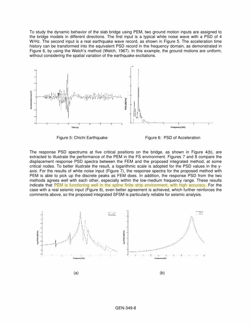
To study the dynamic behavior of the slab bridge using PEM, two ground motion inputs are assigned to the bridge models in different directions. The first input is a typical white noise wave with a PSD of 4 W/Hz. The second input is a real earthquake wave record, as shown in Figure 5. The acceleration time history can be transformed into the equivalent PSD record in the frequency domain, as demonstrated in Figure 6, by using the Welch’s method (Welch, 1967). In this example, the ground motions are uniform, without considering the spatial variation of the earthquake excitations.
Time (s)
Acc
eler
atio
n (m
/s2 )
Frequency (Hz)PS
D(d
B/Hz
)
Figure 5: Chichi Earthquake Figure 6: PSD of Acceleration
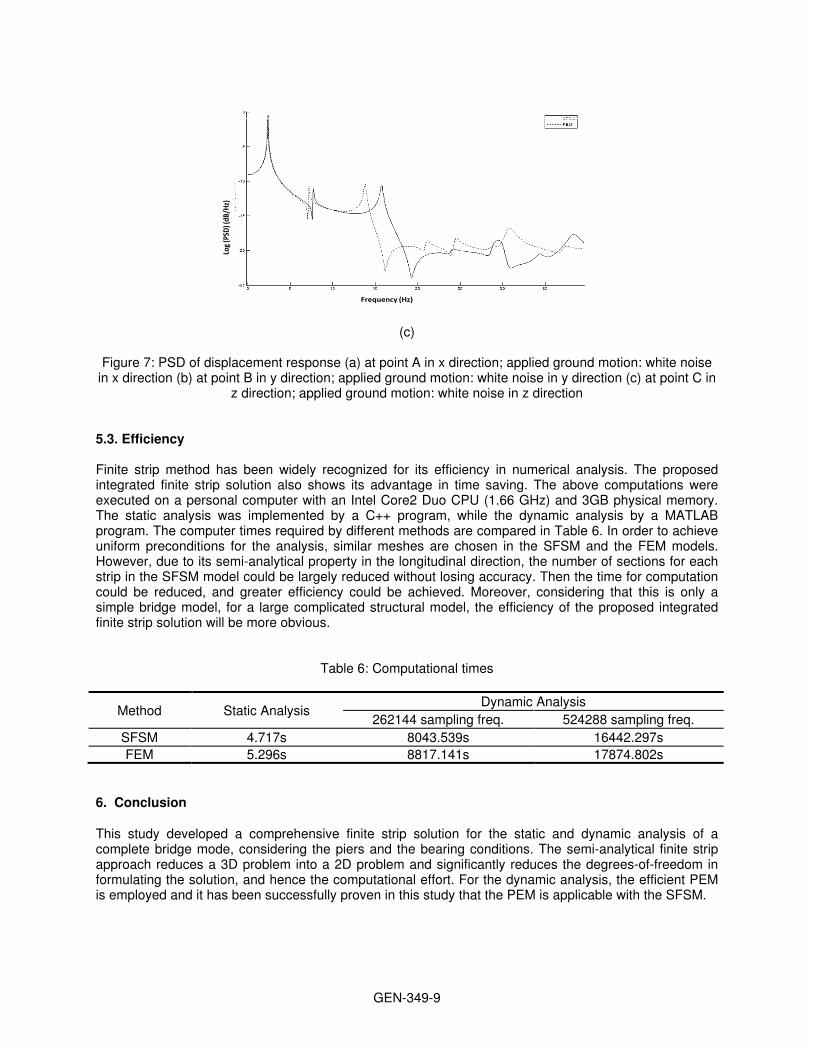
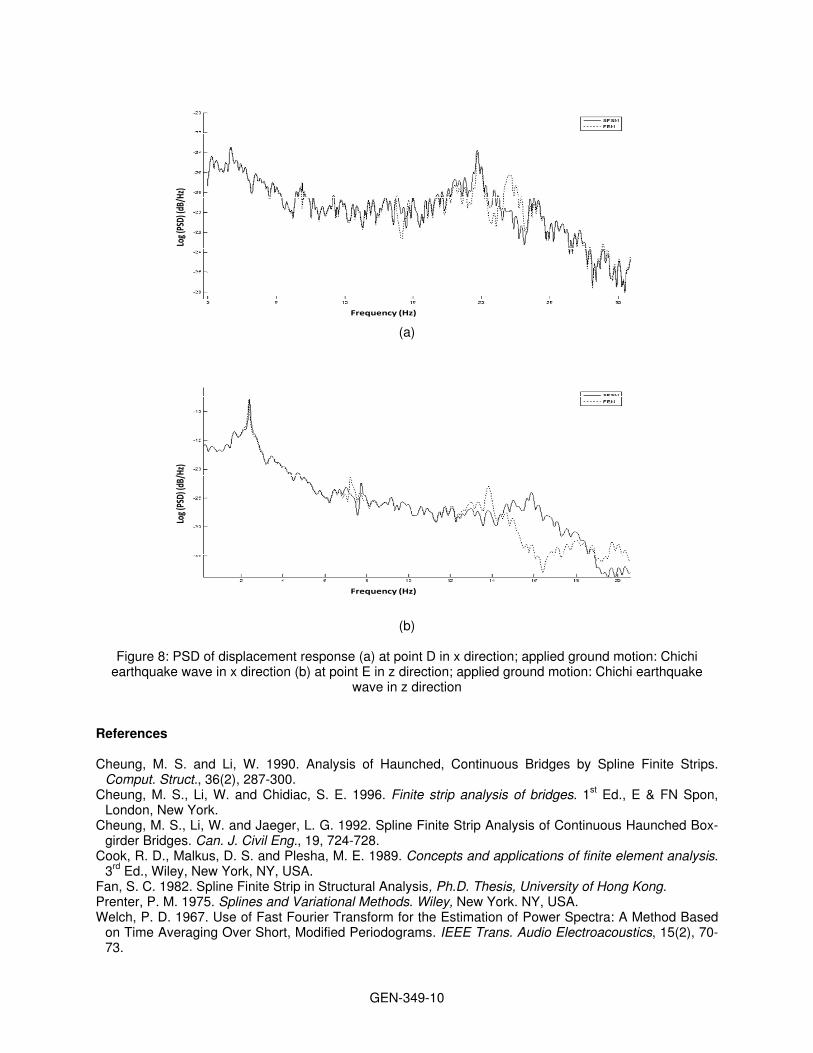
The response PSD spectrums at five critical positions on the bridge, as shown in Figure 4(b), are extracted to illustrate the performance of the PEM in the FS environment. Figures 7 and 8 compare the displacement response PSD spectra between the FEM and the proposed integrated method, at some critical nodes. To better illustrate the result, a logarithmic scale is adopted for the PSD values in the y-axis. For the results of white noise input (Figure 7), the response spectra for the proposed method with PEM is able to pick up the discrete peaks as FEM does. In addition, the response PSD from the two methods agrees well with each other, especially within the low-medium frequency range. These results indicate that PEM is functioning well in the spline finite strip environment, with high accuracy. For the case with a real seismic input (Figure 8), even better agreement is achieved, which further reinforces the comments above, so the proposed integrated SFSM is particularly reliable for seismic analysis.
Frequency (Hz)
Log
(PSD
) (dB
/Hz)
Frequency (Hz)
Log
(PSD
) (dB
/Hz)
(a) (b)
Hamidreza Naderian
GEN-349-9
Frequency (Hz)
Log (
PSD)
(dB/
Hz)
(c) Figure 7: PSD of displacement response (a) at point A in x direction; applied ground motion: white noise
in x direction (b) at point B in y direction; applied ground motion: white noise in y direction (c) at point C in z direction; applied ground motion: white noise in z direction
5.3. Efficiency Finite strip method has been widely recognized for its efficiency in numerical analysis. The proposed integrated finite strip solution also shows its advantage in time saving. The above computations were executed on a personal computer with an Intel Core2 Duo CPU (1.66 GHz) and 3GB physical memory. The static analysis was implemented by a C++ program, while the dynamic analysis by a MATLAB program. The computer times required by different methods are compared in Table 6. In order to achieve uniform preconditions for the analysis, similar meshes are chosen in the SFSM and the FEM models. However, due to its semi-analytical property in the longitudinal direction, the number of sections for each strip in the SFSM model could be largely reduced without losing accuracy. Then the time for computation could be reduced, and greater efficiency could be achieved. Moreover, considering that this is only a simple bridge model, for a large complicated structural model, the efficiency of the proposed integrated finite strip solution will be more obvious.
Table 6: Computational times
Method Static Analysis Dynamic Analysis
262144 sampling freq. 524288 sampling freq.
SFSM 4.717s 8043.539s 16442.297s
FEM 5.296s 8817.141s 17874.802s
6. Conclusion
This study developed a comprehensive finite strip solution for the static and dynamic analysis of a complete bridge mode, considering the piers and the bearing conditions. The semi-analytical finite strip approach reduces a 3D problem into a 2D problem and significantly reduces the degrees-of-freedom in formulating the solution, and hence the computational effort. For the dynamic analysis, the efficient PEM is employed and it has been successfully proven in this study that the PEM is applicable with the SFSM.
GEN-349-10
Frequency (Hz)
Log (
PSD)
(dB/
Hz)
(a)
Frequency (Hz)
Log (
PSD)
(dB/
Hz)
(b)
Figure 8: PSD of displacement response (a) at point D in x direction; applied ground motion: Chichi earthquake wave in x direction (b) at point E in z direction; applied ground motion: Chichi earthquake
wave in z direction
References Cheung, M. S. and Li, W. 1990. Analysis of Haunched, Continuous Bridges by Spline Finite Strips.
Comput. Struct., 36(2), 287-300. Cheung, M. S., Li, W. and Chidiac, S. E. 1996. Finite strip analysis of bridges. 1st Ed., E & FN Spon,
London, New York. Cheung, M. S., Li, W. and Jaeger, L. G. 1992. Spline Finite Strip Analysis of Continuous Haunched Box-
girder Bridges. Can. J. Civil Eng., 19, 724-728. Cook, R. D., Malkus, D. S. and Plesha, M. E. 1989. Concepts and applications of finite element analysis.
3rd Ed., Wiley, New York, NY, USA. Fan, S. C. 1982. Spline Finite Strip in Structural Analysis, Ph.D. Thesis, University of Hong Kong. Prenter, P. M. 1975. Splines and Variational Methods. Wiley, New York. NY, USA. Welch, P. D. 1967. Use of Fast Fourier Transform for the Estimation of Power Spectra: A Method Based
on Time Averaging Over Short, Modified Periodograms. IEEE Trans. Audio Electroacoustics, 15(2), 70-73.