
A METHOD OF GENERATING PANORAMIC STREET STRIP ...
8
* Corresponding author A METHOD OF GENERATING PANORAMIC STREET STRIP IMAGE MAP WITH MOBILE MAPPING SYSTEM Chen Tianen a *, Kohei Yamamoto a , Kikuo Tachibana a a PASCO CORP. R&D CENTER, 2-8-10 Higashiyama Meguro-Ku, Tokyo 153-0043, JAPAN – (tnieah3292, kootho1810, kainka9209)@pasco.co.jp Commission I, ICWG I/VA KEY WORDS: Mobile Mapping System, Omni-Directional Camera, Laser Point Cloud, Street-Side Map, Image Stitching ABSTRACT: This paper explores a method of generating panoramic street strip image map which is called as “Pano-Street” here and contains both sides, ground surface and overhead part of a street with a sequence of 360° panoramic images captured with Point Grey’s Ladybug3 mounted on the top of Mitsubishi MMS-X 220 at 2m intervals along the streets in urban environment. On-board GPS/IMU, speedometer and post sequence image analysis technology such as bundle adjustment provided much more accuracy level position and attitude data for these panoramic images, and laser data. The principle for generating panoramic street strip image map is similar to that of the traditional aero ortho-images. A special 3D DEM(3D-Mesh called here) was firstly generated with laser data, the depth map generated from dense image matching with the sequence of 360° panoramic images, or the existing GIS spatial data along the MMS trajectory, then all 360° panoramic images were projected and stitched on the 3D-Mesh with the position and attitude data. This makes it possible to make large scale panoramic street strip image maps for most types of cities, and provides another kind of street view way to view the 360° scene along the street by avoiding the switch of image bubbles like Google Street View and Bing Maps Streetside. 1. INTRODUCTION Much more efforts have been invested into large scale urban 3D model construction from vision-based 3D modelling (Baillard et al., 1999; El-Hakim, 2002; Bentrah et al., 2004a; Surendra et al., 2014) and fusion 3D laser point clouds with images (Frueh et al., 2005; Zhao and Shibasaki, 2001; Stamos and Allen, 2000) for these applications such as navigation, driving direction pre-visualizations and augmented reality as demonstrated in Google Earth or Microsoft Virtual Earth in the last decades, but the progress on the street view level is not so remarkable and the achieved results are still on the level of research. The reasons may be that the ground environments of the urban streets are tens of times much more complex, and often lack textured areas, contain repetitive structures, moving cars and pedestrians, many occlusions, strong lighting changes, and cast shadows. These properties make the above two methods difficult in the sense of finding enough reliable point matches between overlapping images and extracting key skeleton points from 3D laser point clouds for following 3D model construction. To create visually pleasing modes at a high level of detail in urban environments, an enormous amount of manual work, such as importing the geometry obtained from construction plans, polylines, points or selecting primitive shapes and correspondence points for image-based modelling or complex data acquisition are involved. In fact, like aero ortho-images in GIS, a panoramic street strip image map is also a low-cost, shortcut and useful GIS data to meet the basic requirements of the above applications and these applications such as virtual travel and architectural walkthroughs to some extent. It could be also suitable for registration, transmission, visualization of street landscapes, and displayed on the internet to provide users a visual seamless immersive summary of a city. Two kinds of low-cost, shortcut and functionary methods to provide users much more detail immersive street scenes are systems such as Google Street View and Microsoft Live Street- Side that enable users to virtually visit cities by navigating between immersive 360° panoramic images (Vincent 2007), or bubbles, and multi-perspective strip panoramas that can provide a visual summary of a city street with a long image strip constructed a sequence video images along the street (Román et al. 2004; Román and Lensch 2006; Agarwala et al. 2006; Rav-Acha et al. 2008). The former could provide a photorealistic impression from a particular viewpoint inside a bubble by panning and zooming the bubble or the image, but they do not provide a good visual sense of a larger aggregate such as a whole city block or longer street and need vast amount of geo-registered panoramic imagery. Navigating such photo collections is laborious and similar to hunting for a given location on foot: walk “along” the street, (e.g., jumping from bubble to bubble in Street View) looking around, until you find the location of interest. Since automatically geo-located addresses and/or GPS readings are often off by several meters or more especially in urban settings, visually searching for a location is often needed. Within a bubble, severe foreshortening of a street side from such a distance makes recognition almost impossible. Furthermore, a huge data size is inevitable to archive an entire city. The latter could provide a useful visual summary of all the landmarks along a city street using a long image strip The International Archives of the Photogrammetry, Remote Sensing and Spatial Information Sciences, Volume XLI-B1, 2016 XXIII ISPRS Congress, 12–19 July 2016, Prague, Czech Republic This contribution has been peer-reviewed. doi:10.5194/isprsarchives-XLI-B1-537-2016 537
-
Upload
khangminh22 -
Category
Documents
-
view
3 -
download
0
Transcript of A METHOD OF GENERATING PANORAMIC STREET STRIP ...

* Corresponding author
A METHOD OF GENERATING PANORAMIC STREET STRIP IMAGE MAP WITH
MOBILE MAPPING SYSTEM
Chen Tianen a *, Kohei Yamamoto a, Kikuo Tachibana a
a PASCO CORP. R&D CENTER, 2-8-10 Higashiyama Meguro-Ku, Tokyo 153-0043, JAPAN – (tnieah3292, kootho1810,
kainka9209)@pasco.co.jp
Commission I, ICWG I/VA
KEY WORDS: Mobile Mapping System, Omni-Directional Camera, Laser Point Cloud, Street-Side Map, Image Stitching
ABSTRACT:
This paper explores a method of generating panoramic street strip image map which is called as “Pano-Street” here and contains
both sides, ground surface and overhead part of a street with a sequence of 360° panoramic images captured with Point Grey’s
Ladybug3 mounted on the top of Mitsubishi MMS-X 220 at 2m intervals along the streets in urban environment. On-board
GPS/IMU, speedometer and post sequence image analysis technology such as bundle adjustment provided much more accuracy
level position and attitude data for these panoramic images, and laser data. The principle for generating panoramic street strip
image map is similar to that of the traditional aero ortho-images. A special 3D DEM(3D-Mesh called here) was firstly generated
with laser data, the depth map generated from dense image matching with the sequence of 360° panoramic images, or the existing
GIS spatial data along the MMS trajectory, then all 360° panoramic images were projected and stitched on the 3D-Mesh with the
position and attitude data. This makes it possible to make large scale panoramic street strip image maps for most types of cities,
and provides another kind of street view way to view the 360° scene along the street by avoiding the switch of image bubbles like
Google Street View and Bing Maps Streetside.
1. INTRODUCTION
Much more efforts have been invested into large scale urban
3D model construction from vision-based 3D modelling
(Baillard et al., 1999; El-Hakim, 2002; Bentrah et al., 2004a;
Surendra et al., 2014) and fusion 3D laser point clouds with
images (Frueh et al., 2005; Zhao and Shibasaki, 2001; Stamos
and Allen, 2000) for these applications such as navigation,
driving direction pre-visualizations and augmented reality as
demonstrated in Google Earth or Microsoft Virtual Earth in the
last decades, but the progress on the street view level is not so
remarkable and the achieved results are still on the level of
research. The reasons may be that the ground environments of
the urban streets are tens of times much more complex, and
often lack textured areas, contain repetitive structures, moving
cars and pedestrians, many occlusions, strong lighting changes,
and cast shadows. These properties make the above two
methods difficult in the sense of finding enough reliable point
matches between overlapping images and extracting key
skeleton points from 3D laser point clouds for following 3D
model construction. To create visually pleasing modes at a high
level of detail in urban environments, an enormous amount of
manual work, such as importing the geometry obtained from
construction plans, polylines, points or selecting primitive
shapes and correspondence points for image-based modelling
or complex data acquisition are involved. In fact, like aero
ortho-images in GIS, a panoramic street strip image map is
also a low-cost, shortcut and useful GIS data to meet the basic
requirements of the above applications and these applications
such as virtual travel and architectural walkthroughs to some
extent. It could be also suitable for registration, transmission,
visualization of street landscapes, and displayed on the internet
to provide users a visual seamless immersive summary of a city.
Two kinds of low-cost, shortcut and functionary methods to
provide users much more detail immersive street scenes are
systems such as Google Street View and Microsoft Live Street-
Side that enable users to virtually visit cities by navigating
between immersive 360° panoramic images (Vincent 2007), or
bubbles, and multi-perspective strip panoramas that can
provide a visual summary of a city street with a long image
strip constructed a sequence video images along the street
(Román et al. 2004; Román and Lensch 2006; Agarwala et al.
2006; Rav-Acha et al. 2008).
The former could provide a photorealistic impression from a
particular viewpoint inside a bubble by panning and zooming
the bubble or the image, but they do not provide a good visual
sense of a larger aggregate such as a whole city block or longer
street and need vast amount of geo-registered panoramic
imagery. Navigating such photo collections is laborious and
similar to hunting for a given location on foot: walk “along” the
street, (e.g., jumping from bubble to bubble in Street View)
looking around, until you find the location of interest. Since
automatically geo-located addresses and/or GPS readings are
often off by several meters or more especially in urban settings,
visually searching for a location is often needed. Within a
bubble, severe foreshortening of a street side from such a
distance makes recognition almost impossible. Furthermore, a
huge data size is inevitable to archive an entire city.
The latter could provide a useful visual summary of all the
landmarks along a city street using a long image strip
The International Archives of the Photogrammetry, Remote Sensing and Spatial Information Sciences, Volume XLI-B1, 2016 XXIII ISPRS Congress, 12–19 July 2016, Prague, Czech Republic
This contribution has been peer-reviewed. doi:10.5194/isprsarchives-XLI-B1-537-2016
537
generated with slit or line scanning mechanism (Zheng and
Tsuji, 1992; Gupta and Hartley, 1997) and image patch
stiching or video mosaicking mechanism (Zheng et al., 2004;
Zhu et al., 2004). Kopf et al. (2010) provided a street slide
which dynamically combines the aspects of the immersive
nature of bubbles and the overview properties of the multi-
perspective strip panoramas. As the user slides sideways, the
multi-perspective panorama is dynamically constructed and
rendered to simulate either a pseudo perspective or hyper-
perspective view of the street side from a distance by aligning
and overlaying perspective projections of dropped resolution
bubble images oriented towards the street side. Unfortunately,
because all of the source imagery is compressed into a single
flat summary, they lack the spatial geographic information as
the traditional ortho-images generated from aero and satellite
images.
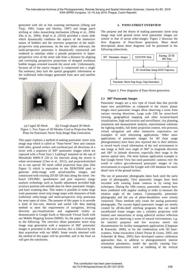
(a) Caged 3D Mesh (b) Trough-shaped 3D Mesh
Figure 1. Two Types of 3D Meshes Used as Projection Base
Plans for Panoramic Street Strip Image Map Generation.
This paper explores a method of making panoramic street strip
image map which is called as “Pano-Street” here and contains
both sides, ground surface and overhead part all directions of a
street with a sequence of 360° panoramic images which are
captured with a Point Grey’s Ladybug3 mounted on the top of
Mitsubishi MMS-X 220 at 2m intervals along the streets in
urban environment (Chen et al., 2012), and projected/stitched
on to one special 3D mesh called projection base plan (See
Figure 1) which is equivalent to the DEM/DSM used to
generate ortho-image with aerial/satellite images, and
constructed with existing 2D/3D GIS data along the street. On-
board GPS/IMU, speedometer and post sequence image
analysis technology such as bundle adjustment provided high
accuracy position and attitude data for these panoramic images,
and laser scanning data. This makes it possible to make large
scale panoramic street strip image maps with characters of both
traditional ortho-image and multi-perspective strip panorama
for most types of cities. The purpose of this paper is to provide
a kind of low-cost, shortcut and useful GIS data making
method to meet the requirements of navigation, driving
direction pre-visualizations and augmented reality as
demonstrated in Google Earth or Microsoft Virtual Earth with
our Mobile Mapping System (MMS). So, the paper is arranged
as the following. The overview about panoramic street strip
image map generation with a sequence of 360° panoramic
images is presented in the next section, this is followed by the
data acquisition with our MMS. Some results obtained with
the method of this paper will be provided, and in the final we
will give the conclusion.
2. PANO-STREET OVERVIEW
The purpose and the theory of making panoramic street strip
image map with ground street level panoramic images are
similar to that of aerial ortho-images. Figure 2 illustrates the
flow diagrams of Pano-Street generation. More detail
descriptions about these diagrams will be presented in the
following subsections.
Figure 2. Flow diagrams of Pano-Street generation.
2.1 360° Panoramic Images
Panoramic images are a new type of visual data that provide
many new possibilities as compared to the classic planar
images since panoramic images allow observing a scene from
various viewing directions. Large scale GIS for street-level
viewing, geographical mapping and other location-based
visualizations, high end security and surveillance, city planning,
simulation and measurement analysis, entertainment solutions
for lighting models, full dome projection content, tele-presence,
virtual navigation and other immersive experiences are
examples of such interesting applications. Other more
applications of panoramic images for 3D close range
photogrammetry have been also reported due to their abilities
to record much visual information of the real environment in
one image at field view angle of 360° in longitude direction
and 180° in latitude direction, especially their usage in the
narrow spatial sites. The most famous application example is
that Google Street View has used panoramic cameras over the
world to collect geo-referenced panoramic images of city
environments to expand the Google web GIS database for more
detail view of the ground surface.
The use of panoramic photographs dates back until the early
years of photography. First panoramic images have been
recorded with rotating frame cameras or by swing lens
techniques. During the 19th century, panoramic cameras have
been combined with angular reading in order to measure the
rotation angle of the camera. Consequently, panoramic
photography and the use of photo-theodolites were closely
connected. These methods only create the analog panoramic
photographs. The current digital panoramic images are mostly
created by off-the-shelf stitching programs that can match
uncalibrated frame images into a cylindric projection with
limited user interactions or using spherical surface reflection
mirror just for observing a scene of natural environments, e.g.
for touristic purposes and low accuracy metric site
documentation for facility management applications (Chapman
& Kotowski, 2000), or for the combination with 3D laser-
scanners. Some researchers (Amiri Parian & Gruen, 2005; and
Schneider & Maas, 2005) have developed camera calibration
approaches that, in addition to photogrammetric interior
orientation parameters, model the specific rotating line-
scanning characteristics such as tumbling of the vertical
The International Archives of the Photogrammetry, Remote Sensing and Spatial Information Sciences, Volume XLI-B1, 2016 XXIII ISPRS Congress, 12–19 July 2016, Prague, Czech Republic
This contribution has been peer-reviewed. doi:10.5194/isprsarchives-XLI-B1-537-2016
538
rotation axis. A more detailed view on the history of panorama
photogrammetry can be extracted from Luhmann (2005).
With the emergence of high resolution panoramic cameras such
as Point Grey’s Ladybug3 and Ladybug5, much more attentions
of these will be put on their photogrammetric processes such as
image matching, DEM and ortho-photo generation, aerial
triangulation, map compilation, stereoscopic viewing, and 3D
model texture mapping. This will cause another research and
application great mass fervor in photogrammetry field (Chen et
al., 2012).
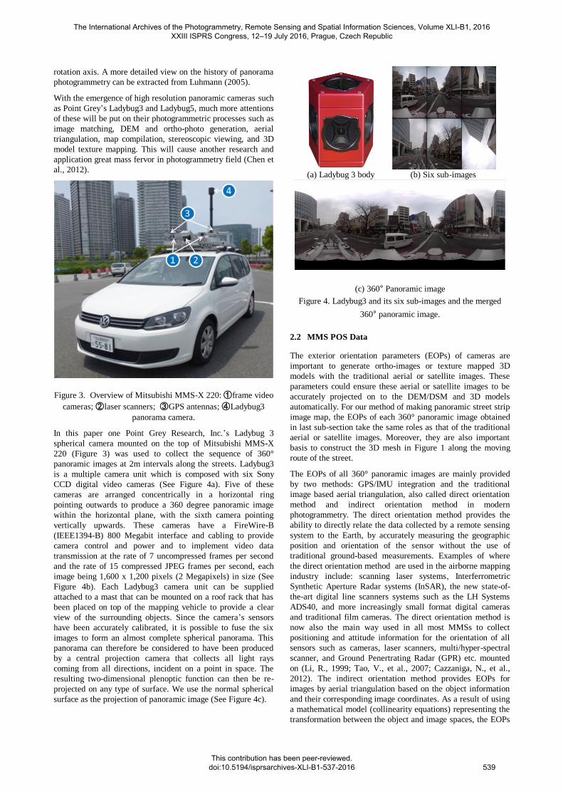
Figure 3. Overview of Mitsubishi MMS-X 220: ①frame video
cameras; ②laser scanners; ③GPS antennas; ④Ladybug3
panorama camera.
In this paper one Point Grey Research, Inc.’s Ladybug 3
spherical camera mounted on the top of Mitsubishi MMS-X
220 (Figure 3) was used to collect the sequence of 360°
panoramic images at 2m intervals along the streets. Ladybug3
is a multiple camera unit which is composed with six Sony
CCD digital video cameras (See Figure 4a). Five of these
cameras are arranged concentrically in a horizontal ring
pointing outwards to produce a 360 degree panoramic image
within the horizontal plane, with the sixth camera pointing
vertically upwards. These cameras have a FireWire-B
(IEEE1394-B) 800 Megabit interface and cabling to provide
camera control and power and to implement video data
transmission at the rate of 7 uncompressed frames per second
and the rate of 15 compressed JPEG frames per second, each
image being 1,600 x 1,200 pixels (2 Megapixels) in size (See
Figure 4b). Each Ladybug3 camera unit can be supplied
attached to a mast that can be mounted on a roof rack that has
been placed on top of the mapping vehicle to provide a clear
view of the surrounding objects. Since the camera’s sensors
have been accurately calibrated, it is possible to fuse the six
images to form an almost complete spherical panorama. This
panorama can therefore be considered to have been produced
by a central projection camera that collects all light rays
coming from all directions, incident on a point in space. The
resulting two-dimensional plenoptic function can then be re-
projected on any type of surface. We use the normal spherical
surface as the projection of panoramic image (See Figure 4c).
(a) Ladybug 3 body (b) Six sub-images
(c) 360° Panoramic image
Figure 4. Ladybug3 and its six sub-images and the merged
360° panoramic image.
2.2 MMS POS Data
The exterior orientation parameters (EOPs) of cameras are
important to generate ortho-images or texture mapped 3D
models with the traditional aerial or satellite images. These
parameters could ensure these aerial or satellite images to be
accurately projected on to the DEM/DSM and 3D models
automatically. For our method of making panoramic street strip
image map, the EOPs of each 360° panoramic image obtained
in last sub-section take the same roles as that of the traditional
aerial or satellite images. Moreover, they are also important
basis to construct the 3D mesh in Figure 1 along the moving
route of the street.
The EOPs of all 360° panoramic images are mainly provided
by two methods: GPS/IMU integration and the traditional
image based aerial triangulation, also called direct orientation
method and indirect orientation method in modern
photogrammetry. The direct orientation method provides the
ability to directly relate the data collected by a remote sensing
system to the Earth, by accurately measuring the geographic
position and orientation of the sensor without the use of
traditional ground-based measurements. Examples of where
the direct orientation method are used in the airborne mapping
industry include: scanning laser systems, Interferrometric
Synthetic Aperture Radar systems (InSAR), the new state-of-
the-art digital line scanners systems such as the LH Systems
ADS40, and more increasingly small format digital cameras
and traditional film cameras. The direct orientation method is
now also the main way used in all most MMSs to collect
positioning and attitude information for the orientation of all
sensors such as cameras, laser scanners, multi/hyper-spectral
scanner, and Ground Penertrating Radar (GPR) etc. mounted
on (Li, R., 1999; Tao, V., et al., 2007; Cazzaniga, N., et al.,
2012). The indirect orientation method provides EOPs for
images by aerial triangulation based on the object information
and their corresponding image coordinates. As a result of using
a mathematical model (collinearity equations) representing the
transformation between the object and image spaces, the EOPs
The International Archives of the Photogrammetry, Remote Sensing and Spatial Information Sciences, Volume XLI-B1, 2016 XXIII ISPRS Congress, 12–19 July 2016, Prague, Czech Republic
This contribution has been peer-reviewed. doi:10.5194/isprsarchives-XLI-B1-537-2016
539

are determined, providing a relationship between the image
coordinates and the global (or local) mapping coordinate. The
combined bundle adjustment usually facilitates not only EOP
determination, but may also involve rectification of the camera
interior orientation parameters such as focal length, location of
the principle point, coefficients of appropriate models
representing lens distortion. Unfortunately, the significant part
of the aerial triangulation cost is associated with the
establishment of ground control points (GCPs), which might be
prohibitive in case of mapping of remote areas. The indirect
orientation method is only used in our MMS for system
calibration and compensation of the errors in measurements
obtained from GPS/IMU integration in urban areas where
signal from satellites is often blocked by high buildings, trees
and other objects. More detail will be described in other paper
about the MMS indirect orientation method which is a
combined aerial triangulation method with MMS 360°
panoramic images and the obtained GPS/IMU information as
initial values of EOPs, only brief description about direct
orientation method is introduced here.
The navigation component of our MMS provides position and
orientation information for direction orientation method, and is
composed with three roof-mounted GNSS receivers arranged in
a triangular pattern, an IMU, and an odometer (Figure 3). The
calculation of MMS position and orientation information is
based on integration of data from the GNSS receivers, IMU,
and odometer using standard GPS data processing software
such as GrafNav. This is a little different from the POS data
processing for airborne mapping systems where the GNSS
receivers work well most within the platform moving time. The
integration of GPS/IMU and odometer allows to achieve the
required accuracy even in areas where the GNSS positioning
alone is unreliable or entirely impossible. This happens mostly
in urban areas where signal from satellites is often blocked by
high buildings, trees and other objects.
The absolute system position calculated using the GNSS
technology serves for compensating errors in measurements
obtained from the inertial measurement unit. On the other hand,
the relatively stable position (in a short-term scope)
determined by IMU can be used to overcome areas where GPS
fails. Additional information is received from odometers
measuring speed and distance travelled depending on the
rotation of wheels of the vehicle. There are two trajectory
calculation methods that became widely used in practice,
referred to mostly as loosely and tightly coupled. Both methods
utilize Kalman’s filters while when the loosely coupled method
is applied, the path is pre-calculated using the GNSS
differential method first. This path is then used when
processing IMU data to update position and speed. When the
tightly coupled method is used, the GNSS/INS data is
processed simultaneously, making it possible to use at least
two satellites for a phase update, which means a great
advantage in difficult conditions with limited satellite signal
reception.
Typically, GPS serves as the main positioning sensor by
measuring ranges and range rates from a GPS receiver's
antenna to the GPS satellites. Antenna-to-satellite inter-
visibility is a must. The accuracy degradation of the GPS
solution is due to poor satellite spatial distribution, loss of lock,
and satellite signal blockage. In addition, even by introducing
multi-antenna configurations, the frequency of attitude
determination may be too low (say, only 10 Hz), which limits
their use for some systems such as LIDAR (light detection and
ranging) and other applications with expected high dynamics.
On the other hand, an INS acts as the main attitude sensor. The
INS typically consists of three orthogonal accelerometers and
three orthogonal gyroscopes. The accelerometer and gyroscope
triads are parallel and establish the INS coordinate system. The
three accelerometers sense the body-frame linear accelerations
while the gyroscopes sense the body-frame angular velocities
with minimum time delay. The estimation of the relative
position and attitude is accomplished by integrating the sensed
signals after being transformed to the appropriate
computational coordinate frame.
For short time intervals, the integration of acceleration and
angular rate results in extremely accurate velocity, position,
and attitude with almost no noise or time lags. However,
because the navigation information is obtained by integration,
they exhibit low frequency drift. To obtain accurate navigation
information over all frequencies, the INS navigation solution
should be updated periodically using external measurements.
For this purpose, GPS velocities and positions are used as
update measurements, which complement the INS output in an
ideal way.
Also, other navigational aids, such as odometers, inclinometers,
or barometers, may provide additional observations for some
subset of the navigational state. The successful use of an MMS
critically depends on both the accuracy and the continuity of
the navigation solution. A perfect MMS is, therefore, one that
can operate without interruption in areas where a discontinuity
in the data from one or more of the navigational sensors is
expected.
2.3 3D Mesh Data Generation along MMS Trajectory
To stitch all 360° panoramic images captured with MMS into a
long 360° image strip along the city street, a kind of 3D mesh
data illustrated in Figure 1, which represent the street scenes
and act the similar role of the traditional DEM/DSM (Digital
Elevation Model, Digital Surface Model) used to generate top-
down ground ortho-image with airborne images and satellite
images in photogrammetry, should be constructed and taken as
the projection base plane of the panoramic street strip image
map to be generated here.
The 3D mesh data may be a flat, curved, parametric, complex,
or irregular surface. It may be parallel to the street, parallel to
the associated path segment, and/or parallel to the direction of
movement of the MMS as the 360° panoramic images are
collected. According to the different quality requirements for
the panoramic street strip image map and the environmental
conditions of the street, the 3D mesh data could be generated
from laser scanned point cloud data, stereo-image matched
point cloud, mono/stereo measured 2D/3D vector data, existing
2D/3D GIS vector-based or raster-based data, or simply
simulated regular or irregular tunnel-shaped (Figure 1a) or
trough-shaped (Figure 1b) 3D model along MMS trajectory or
city street center line by distance to the curb of the street or the
front of the building facades on two sides of the street. Since
the street scenes contains varying depths and many
obstructions, it is not possible to always obtain perfect
representation of the ground street scenes for 3D mesh data as
the traditional DEM/DSM used to generate top-down ground
ortho-image with airborne images and satellite images in
photogrammetry even if the complete knowledge of the
The International Archives of the Photogrammetry, Remote Sensing and Spatial Information Sciences, Volume XLI-B1, 2016 XXIII ISPRS Congress, 12–19 July 2016, Prague, Czech Republic
This contribution has been peer-reviewed. doi:10.5194/isprsarchives-XLI-B1-537-2016
540
geometry and appearance of the scenes is available. Moreover,
the MMS trajectory and its moving direction are always
changeable to avoid obstacles such as the slow moving or
parked vehicles or pedestrians, this also increases the
uncertainty of the 3D mesh data created automatically along
the MMS trajectory. The varying scales and resolutions on the
360° ground panoramic images caused by the varying depths of
street scenes also make it much more difficult to generate a
homogeneous quality and seamless mosaiced panoramic street
strip image than to generate top-down ground ortho-image with
airborne images, satellite images, and the ground DEM/DSM
in photogrammetry.
To simplify the creation of the 3D mesh data and increase the
practicability of the generation of the panoramic street strip
image map, an average depth for the street scenes and a 3D
surface at the average depth illustrated in Figure 1 are
determined based on the street center line, laser scanned point
cloud data, the existing 2D/3D GIS vector-based or raster-
based data, and the MMS 360° ground panoramic images.
Figure 5 illustrates the section to create the 3D mesh data in
the whole process for the panoramic street strip image map
generation.
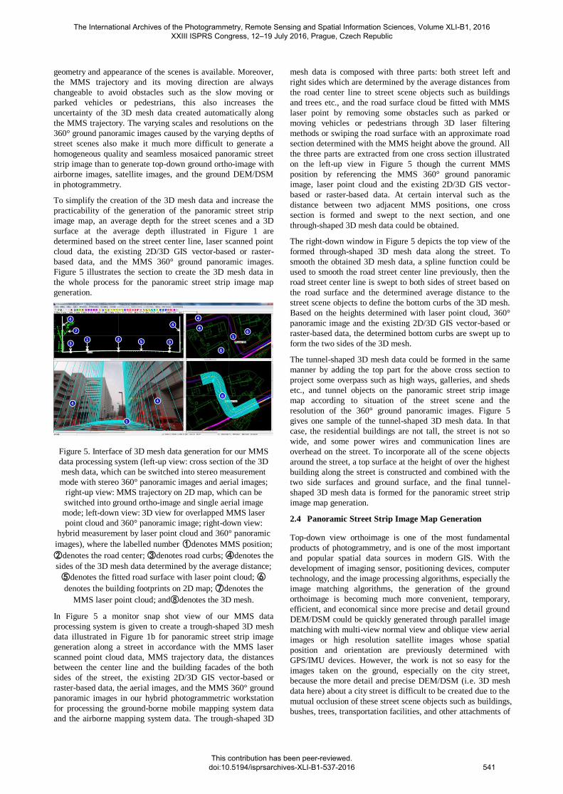
Figure 5. Interface of 3D mesh data generation for our MMS
data processing system (left-up view: cross section of the 3D
mesh data, which can be switched into stereo measurement
mode with stereo 360° panoramic images and aerial images;
right-up view: MMS trajectory on 2D map, which can be
switched into ground ortho-image and single aerial image
mode; left-down view: 3D view for overlapped MMS laser
point cloud and 360° panoramic image; right-down view:
hybrid measurement by laser point cloud and 360° panoramic
images), where the labelled number ①denotes MMS position;
②denotes the road center; ③denotes road curbs; ④denotes the
sides of the 3D mesh data determined by the average distance;
⑤denotes the fitted road surface with laser point cloud; ⑥
denotes the building footprints on 2D map; ⑦denotes the
MMS laser point cloud; and⑧denotes the 3D mesh.
In Figure 5 a monitor snap shot view of our MMS data
processing system is given to create a trough-shaped 3D mesh
data illustrated in Figure 1b for panoramic street strip image
generation along a street in accordance with the MMS laser
scanned point cloud data, MMS trajectory data, the distances
between the center line and the building facades of the both
sides of the street, the existing 2D/3D GIS vector-based or
raster-based data, the aerial images, and the MMS 360° ground
panoramic images in our hybrid photogrammetric workstation
for processing the ground-borne mobile mapping system data
and the airborne mapping system data. The trough-shaped 3D
mesh data is composed with three parts: both street left and
right sides which are determined by the average distances from
the road center line to street scene objects such as buildings
and trees etc., and the road surface cloud be fitted with MMS
laser point by removing some obstacles such as parked or
moving vehicles or pedestrians through 3D laser filtering
methods or swiping the road surface with an approximate road
section determined with the MMS height above the ground. All
the three parts are extracted from one cross section illustrated
on the left-up view in Figure 5 though the current MMS
position by referencing the MMS 360° ground panoramic
image, laser point cloud and the existing 2D/3D GIS vector-
based or raster-based data. At certain interval such as the
distance between two adjacent MMS positions, one cross
section is formed and swept to the next section, and one
through-shaped 3D mesh data could be obtained.
The right-down window in Figure 5 depicts the top view of the
formed through-shaped 3D mesh data along the street. To
smooth the obtained 3D mesh data, a spline function could be
used to smooth the road street center line previously, then the
road street center line is swept to both sides of street based on
the road surface and the determined average distance to the
street scene objects to define the bottom curbs of the 3D mesh.
Based on the heights determined with laser point cloud, 360°
panoramic image and the existing 2D/3D GIS vector-based or
raster-based data, the determined bottom curbs are swept up to
form the two sides of the 3D mesh.
The tunnel-shaped 3D mesh data could be formed in the same
manner by adding the top part for the above cross section to
project some overpass such as high ways, galleries, and sheds
etc., and tunnel objects on the panoramic street strip image
map according to situation of the street scene and the
resolution of the 360° ground panoramic images. Figure 5
gives one sample of the tunnel-shaped 3D mesh data. In that
case, the residential buildings are not tall, the street is not so
wide, and some power wires and communication lines are
overhead on the street. To incorporate all of the scene objects
around the street, a top surface at the height of over the highest
building along the street is constructed and combined with the
two side surfaces and ground surface, and the final tunnel-
shaped 3D mesh data is formed for the panoramic street strip
image map generation.
2.4 Panoramic Street Strip Image Map Generation
Top-down view orthoimage is one of the most fundamental
products of photogrammetry, and is one of the most important
and popular spatial data sources in modern GIS. With the
development of imaging sensor, positioning devices, computer
technology, and the image processing algorithms, especially the
image matching algorithms, the generation of the ground
orthoimage is becoming much more convenient, temporary,
efficient, and economical since more precise and detail ground
DEM/DSM could be quickly generated through parallel image
matching with multi-view normal view and oblique view aerial
images or high resolution satellite images whose spatial
position and orientation are previously determined with
GPS/IMU devices. However, the work is not so easy for the
images taken on the ground, especially on the city street,
because the more detail and precise DEM/DSM (i.e. 3D mesh
data here) about a city street is difficult to be created due to the
mutual occlusion of these street scene objects such as buildings,
bushes, trees, transportation facilities, and other attachments of
The International Archives of the Photogrammetry, Remote Sensing and Spatial Information Sciences, Volume XLI-B1, 2016 XXIII ISPRS Congress, 12–19 July 2016, Prague, Czech Republic
This contribution has been peer-reviewed. doi:10.5194/isprsarchives-XLI-B1-537-2016
541
buildings and roads at different depths and heights along the
street.
Different from the top-down view aerial images and satellite
images, there are much more complex structures, textureless
areas, frequent varying depths and scales, and occlusions in the
ground 360° panoramic images. To simplify the work of
generating panoramic street strip image, the 3D mesh data has
been simplified in last subsection and divided into different
sections according to the ground 360° panoramic images along
the MMS trajectory (① in Figure 5), the stitching process can
start from the first captured ground 360° panoramic image
which corresponds to the first section of 3D mesh at the same
distance interval as that of two neighbouring 360° panoramic
images along the MMS trajectory, and thus the steps to
generate the panoramic street strip image could be taken as
following.
Two side parts and the top part of the panoramic street strip
image are firstly formed with the similar principle of aerial or
satellite orthoimage generation by correlating the 3D mesh data
and the ground 360° panoramic images and their positions and
orientations through the following photogrammetric collinear
equation:
) 1 (
ZZ
YY
XX
Rλ
W
V
U
S
S
S
where, (X,Y,Z) means the ground coordinates of one point on
the 3D mesh, (U,V,W) means the point’s spherical coordinates
on the corresponding ground 360° panoramic image, λmeans
the scale from (X,Y,Z) to (U,V,W), (XS,YS,ZS) means the
position of the image, and R means the rotation matrix
constructed with the image’s orientation angles. (U,V,W) can
be obtained through the following coordinate transformation
from the 2D panoramic image plane coordinate (α, β) to the
3D sphere surface coordinate (U,V,W):
) 2 (
cosβ
sinα sinβ
cosα sinβ
W
V
U
Since the ground 360° panoramic images have certain ground
overlaps, a portion of the 3D mesh may correspond to several
ones among these ground 360° panoramic images. An
optimization sampling strategy could be taken to assign the
color values for the pixel in the panoramic street strip image
like the true or near true ground orthoimage generation with
aerial images in photogrammetry. In that process, the direct
above or nadir view aerial image is selected to remove the
deformation caused by undulating ground and its center part is
cut and as the main composition pasted on the ground
orthoimage. The seam locations, occlusion parts, and leak
portions would be mended with other direction view images.
For the ground 360° panoramic images, the one corresponding
to or roughly in front of the 3D mesh section depicted in Figure
5 is selected as the main composition pasted on the panoramic
street strip image. This ensures the measurability of the
panoramic street strip image, and makes it easy to remove the
local deformed effect caused by perspective obstruction in the
street scene, especially the object displacement on the seams of
the panoramic street strip image.
The seam line process may be the key step in photogrammetric
orthoimage generation and image mosaic in computer vision
field. Although the multi-band fusion method (Burt and
Adelson, 1983) is relatively mature and could provide perfect
resolution for this problem, it is still computing cost. In our
process, the weighted averaging of pixels in the ground 360°
panoramic image overlap regions is still used when the street
scene become simple or in the regions where the 3D surfaces
are flat. These regions are detected by multi-view image
matching in our system and selected as the seamline areas
between the neighbouring ground 360° panoramic images. The
final result we will obtain is a straight arranged panoramic
image strip with correct topological relationship of ground
scene objects along the trajectory of MMS, the parts on the
image strip corresponding to the curved sections of the street
may be covered by several ground 360° panoramic images, and
should be deformed and straighten, and the weighted averaging
of pixels in the ground 360° panoramic image overlap regions
is needed.
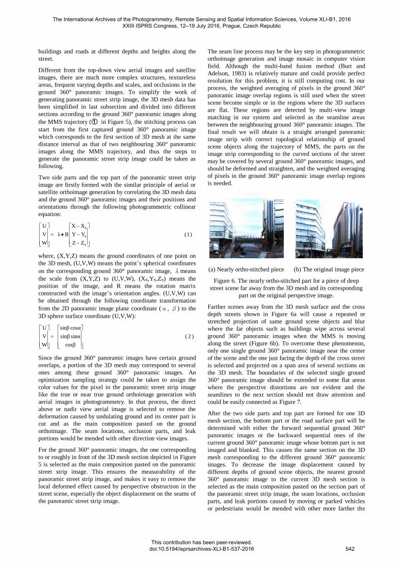
(a) Nearly ortho-stitched piece (b) The original image piece
Figure 6. The nearly ortho-stitched part for a piece of deep
street scene far away from the 3D mesh and its corresponding
part on the original perspective image.
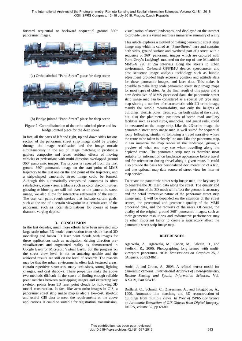
Farther scenes away from the 3D mesh surface and the cross
depth streets shown in Figure 6a will cause a repeated or
stretched projection of same ground scene objects and blur
where the far objects such as buildings wipe across several
ground 360° panoramic images when the MMS is moving
along the street (Figure 6b). To overcome these phenomenon,
only one single ground 360° panoramic image near the center
of the scene and the one just facing the depth of the cross street
is selected and projected on a span area of several sections on
the 3D mesh. The boundaries of the selected single ground
360° panoramic image should be extended to some flat areas
where the perspective distortions are not evident and the
seamlines to the next section should not draw attention and
could be easily connected as Figure 7.
After the two side parts and top part are formed for one 3D
mesh section, the bottom part or the road surface part will be
determined with either the forward sequential ground 360°
panoramic images or the backward sequential ones of the
current ground 360° panoramic image whose bottom part is not
imaged and blanked. This causes the same section on the 3D
mesh corresponding to the different ground 360° panoramic
images. To decrease the image displacement caused by
different depths of ground scene objects, the nearest ground
360° panoramic image to the current 3D mesh section is
selected as the main composition pasted on the section part of
the panoramic street strip image, the seam locations, occlusion
parts, and leak portions caused by moving or parked vehicles
or pedestrians would be mended with other more farther the
The International Archives of the Photogrammetry, Remote Sensing and Spatial Information Sciences, Volume XLI-B1, 2016 XXIII ISPRS Congress, 12–19 July 2016, Prague, Czech Republic
This contribution has been peer-reviewed. doi:10.5194/isprsarchives-XLI-B1-537-2016
542
forward sequential or backward sequential ground 360°
panoramic images.
(a) Ortho-stitched “Pano-Street” piece for deep scene
(b) Bridge jointed “Pano-Street” piece for deep scene
Figure 7. Contradistinction of the ortho-stitched piece and its
bridge jointed piece for the deep scene.
In fact, all the parts of left and right, up and down sides for one
section of the panoramic street strip image could be created
through the image rectification and the image mosaic
simultaneously in the aid of image matching to produce a
gapless composite and fewer residual effects of moving
vehicles or pedestrians with multi-direction overlapped ground
360° panoramic images. The process is repeated from the first
ground 360° panoramic image on the start point of MMS
trajectory to the last one on the end point of the trajectory, and
a strip-shaped panoramic street image could be formed.
Although this automatically composited panorama is often
satisfactory, some visual artifacts such as color discontinuities,
ghosting or blurring are still left over on the panoramic street
image, we also allow for interactive refinement of the result.
The user can paint rough strokes that indicate certain goals,
such as the use of a certain viewpoint in a certain area of the
panorama, such as local deformations for scenes at large
dramatic varying depths.
3. CONCLUSION
In the last decades, much more efforts have been invested into
large scale urban 3D model construction from vision-based 3D
modelling and fusion 3D laser point clouds with images for
these applications such as navigation, driving direction pre-
visualizations and augmented reality as demonstrated in
Google Earth or Microsoft Virtual Earth, but the progress on
the street view level is not so amazing notable and the
achieved results are still on the level of research. The reasons
may be that the urban environments often lack textured areas,
contain repetitive structures, many occlusions, strong lighting
changes, and cast shadows. These properties make the above
two methods difficult in the sense of finding enough reliable
point matches between overlapping images and extracting key
skeleton points from 3D laser point clouds for following 3D
model construction. In fact, like aero ortho-images in GIS, a
panoramic street strip image map is also a low-cost, shortcut
and useful GIS data to meet the requirements of the above
applications. It could be suitable for registration, transmission,
visualization of street landscapes, and displayed on the internet
to provide users a visual seamless immersive summary of a city.
This article explores a method of making panoramic street strip
image map which is called as “Pano-Street” here and contains
both sides, ground surface and overhead part of a street with a
sequence of 360° panoramic images which are captured with
Point Grey’s Ladybug3 mounted on the top of one Mitsubishi
MMS-X 220 at 2m intervals along the streets in urban
environment. On-board GPS/IMU device, speedometer and
post sequence image analysis technology such as bundle
adjustment provided high accuracy position and attitude data
for these panoramic images, and laser data. This makes it
possible to make large scale panoramic street strip image maps
for most types of cities. As the final result of this paper and a
new derivative of MMS processed data, the panoramic street
strip image map can be considered as a special 3D type strip
map sharing a number of characteristic with 2D ortho-image,
mainly the simple measurability, not only the heights of
buildings, electric poles, trees, etc. on both sides of the street,
but also the planimetric positions of some road ancillary
facilities such as road curbs, manholes, and guard rails, could
be measured on the image strip. Like the 2D ortho-image, the
panoramic street strip image map is well suited for sequential
route following, similar to following a travel narrative where
the route to be taken is clearly line out. Like the panorama map,
it can immerse the map reader in the landscape, giving a
preview of what one may see when travelling along the
depicted route. The panoramic strip map is therefore most
suitable for information on landscape appearance before travel
and for orientation during travel along a given route. It could
also provide the basis for personalized documentation of a trip,
and one optional map data source of street view for internet
map service.
To create the panoramic street strip image map, the key step is
to generate the 3D mesh data along the street. The quality and
the precision of the 3D mesh will affect the geometric accuracy
and the detail immersive nature of the panoramic street strip
image map. It will be depended on the situation of the street
scenes, the perceptual and geometric quality of the MMS
processed data, and the requests of the users. Of course, the
quality of the original ground 360° panoramic images, such as
their geometric resolutions and radiometric performance may
be other important factor to create a satisfactory affect the
panoramic street strip image map.
REFERENCES
Agarwala, A., Agarwala, M., Cohen, M., Salesin, D., and
Szeliski, R., 2006. Photographing long scenes with multi-
viewpoint panoramas. ACM Transactions on Graphics 25, 3
(August), pp.853-861.
Amiri, J. and Gruen, A., 2005. A refined sensor model for
panoramic cameras. International Archives of Photogrammetry,
Remote Sensing and Spatial Information Sciences, Vol.
XXXIV, Part 5/W16.
Baillard, C., Schmid, C., Zisserman, A., and Fitzgibbon, A.,
1999. Automatic line matching and 3D reconstruction of
buildings from multiple views. In Proc of ISPRS Conference
on Automatic Extraction of GIS Objects from Digital Imagery,
IAPRS, volume 32, pp.69-80.
The International Archives of the Photogrammetry, Remote Sensing and Spatial Information Sciences, Volume XLI-B1, 2016 XXIII ISPRS Congress, 12–19 July 2016, Prague, Czech Republic
This contribution has been peer-reviewed. doi:10.5194/isprsarchives-XLI-B1-537-2016
543
Bentrah, O., Paparoditis, N., and Pierrot-Deseilligny, M.,
2004a. Stereopolis: An image based urban environments
modeling system. In MMT 2004. The 4th International
Symposium on Mobile Mapping Technology, Kunming, China.
Burt P.J. and Adelson E.H., 1983. A Multiresolution Spline
with Application to Image Mosaics. ACM Trans. On Graphics,
2(4), pp.217-236.
Cazzaniga, N.E., Pagliari, D., Pinto, L., 2012. Photogrammetry
for Mapping Underground Utility Lines with Ground
Penertrating Radar in Urban Areas. International Archives of
Photogrammetry, Remote Sensing and Spatial Information
Sciences, Volume XXXIX-B1, 2012, XXII ISPRS Congress, 25
August - 01 September 2012, Melbourne, Australia, pp.297-
302.
Chapman, D., Kotowski, R., 2000. Methodology for the
Construction of Large Image Archives of Complex Industrial
Structures. Publikationen der DGPF, Band 8, Essen 1999.
Chen, T., Yamamoto, K., Chhatkuli, S., and Shimamura, H.,
2012. Panoramic Epipolar Image Generation for Mobile
Mapping System. International Archives of the
Photogrammetry, Remote Sensing and Spatial Information
Sciences, Volume XXXIX-B5, 2012, XXII ISPRS Congress, 25
August - 01 September 2012, Melbourne, Australia, pp.459-
464.
El-Hakim, S., 2002. Semi-automatic 3d reconstruction of
occluded and unmarked surfaces from widely separated views.
In ISPRS Commission V Symposium on Close Range
Visualization Techniques, pp.143-148.
Frueh, C., Jain, S., and Zakhor, A., 2005. Data processing
algorithms for generating textured 3d building facade meshes
from laser scans and camera images. Int. J. Comput. Vision,
61(2): pp.159-184.
Gupta, R., Hartley, R., 1997. Linear pushbroom cameras, IEEE
PAMI, 19(9), pp.963-975.
Kopf, J., Chen, B., Szeliski, R., Cohen, M. 2010. Street Slide:
Browsing Street Level Imagery. ACM Trans. Graph. 29, 4,
Article 96(July 2010).
Li,R.X.,1999. Mobile Mapping- An Emerging Technology for
Spatial Data Acquisition. The Ohio State University.
Luhmann, T. ,2005. A historical review on panorama imagery,
International Archives of Photogrammetry, Remote Sensing
and Spatial Information Sciences, Vol. XXXIV, Part 5/W16.
Rav-Acha, A., Engel, G., and Peleg, S. 2008. Minimal aspect
distortion (MAD) mosaicing of long scenes. International
Journal of Computer Vision 78, 2-3 (July), pp.187-206.
Román, A., and Lensch, H.P.A. 2006. Automatic
multiperspective images. In Eurographics Symposium on
Rendering, pp.83-92.
Román, A., Garg, G., and Levoy, M. 2004. Interactive design
of multi-perspective images for visualizing urban landscapes.
In IEEE Visualization 2004, pp.537-544.
Schneider, D., Maas, H.-G. ,2005. Application and accuracy
potential of a strict geometric model for rotating line cameras.
International Archives of Photogrammetry, Remote Sensing
and Spatial Information Sciences, Vol. XXXIV, Part 5/W16.
Stamos, I. and Allen, P., 2000. 3d model construction using
range and image data. In Computer Vision and Pattern
Recognition, pp.531-536.
Surendra, P.S., Kamal, J., and Mandla, V.R., 2014. A New
Approach Towards Image Based Virtual 3D City Modelling by
Using Close Range Photogrammetry. ISPRS Annals of the
Photogrammetry, Remote Sensing and Spatial Information
Sciences, Volume II-5, ISPRS Technical Commission V
Symposium, 23-25 June 2014, Riva del Garda, Italy, pp.328-
337.
Tao, V., Li, J., 2007. Advances in mobile mapping technology. ISPRS Book Series No. 4; Taylor & Francis: London, UK, 176 pages.
Vincent, L. 2007. Taking online maps down to street level.
Computer 40, 12 (December), pp.118-120.
Zhao, H. and Shibasaki, R., 2001. Reconstructing textured cad
model of urban environment using vehicle-borne laser range
scanners and line cameras. In ICVS '01: Proceedings of the
Second International Workshop on Computer Vision Systems,
pp.284-297.
Zheng, J., and Tsuji, S., 1992. Panoramic Representation for
route recognition by a mobile robot, IJCV, 9(1), pp.55-76.
Zheng, J. Y., Zhou, Y., Shi, M., 2004. Scene tunnels for
seamless virtual tour, 12th ACM Multimedia, pp.448-451.
Zhu, Z., Hanson, A., Riseman, E. M., 2004. Generalized
parallel-perspective Stereo Mosaics from Airborne Video.
IEEE PAMI 26(2): pp.226-237.
The International Archives of the Photogrammetry, Remote Sensing and Spatial Information Sciences, Volume XLI-B1, 2016 XXIII ISPRS Congress, 12–19 July 2016, Prague, Czech Republic
This contribution has been peer-reviewed. doi:10.5194/isprsarchives-XLI-B1-537-2016
544