
Hope Creek Generating Station - Nuclear Regulatory ...
595
David F Garchow Vice President-Technical Support PSEG Nuclear LLC PO Box 236, Hancocks Bridge, NJ 08038-1236 tel: 856 339.3250 fax: 856.339.1070 o PSEG N U( b wr L(C NOV 16 ZOO0 LR-N00-0456 United States Nuclear Regulatory Commission Document Control Desk Washington, DC 20555 Gentlemen: UPDATED FINAL SAFETY ANALYSIS REPORT, REVISION 11 HOPE CREEK GENERATING STATION DOCKET NO. 50-354 PSEG Nuclear LLC hereby submits Revision No. 11 to the Hope Creek Generating Station Updated Final Safety Analysis Report (UFSAR) in accordance with the requirements of 1OCFR50.71 (e). Revision No. 11 to the Hope Creek UFSAR contains identified text, table and figure changes required to reflect the plant configuration as of May 24, 2000, six months prior to this submittal. In addition, there are corrections of typographical errors and general editorial changes. Details regarding each change are attached to facilitate your review. The previous revision to the Hope Creek UFSAR was issued on September 30, 1999. Should there be any questions regarding this submittal, please do not hesitate to contact us. '2 1' PSE&G CONTROL COPY # / / / - H FIS - R -(:) 61
-
Upload
khangminh22 -
Category
Documents
-
view
1 -
download
0
Transcript of Hope Creek Generating Station - Nuclear Regulatory ...
David F Garchow Vice President-Technical Support
PSEG Nuclear LLC PO Box 236, Hancocks Bridge, NJ 08038-1236 tel: 856 339.3250 fax: 856.339.1070
o PSEG N U( b wr L(CNOV 16 ZOO0
LR-N00-0456
United States Nuclear Regulatory Commission Document Control Desk Washington, DC 20555
Gentlemen:
UPDATED FINAL SAFETY ANALYSIS REPORT, REVISION 11 HOPE CREEK GENERATING STATION DOCKET NO. 50-354
PSEG Nuclear LLC hereby submits Revision No. 11 to the Hope Creek Generating Station Updated Final Safety Analysis Report (UFSAR) in accordance with the requirements of 1OCFR50.71 (e).
Revision No. 11 to the Hope Creek UFSAR contains identified text, table and figure changes required to reflect the plant configuration as of May 24, 2000, six months prior to this submittal. In addition, there are corrections of typographical errors and general editorial changes. Details regarding each change are attached to facilitate your review.
The previous revision to the Hope Creek UFSAR was issued on September 30, 1999.
Should there be any questions regarding this submittal, please do not hesitate to contact us.
'2
1'
PSE&G CONTROLCOPY #
/ / /
- H FIS -R -(:) 61
Document Control Desk 2 LR-NOO-0456
Attachments: - Affidavit - Summary of Hope Creek UFSAR Revision 11 Changes - Insertion Instructions - Hope Creek UFSAR Revision No. 11
C Document Control Desk - Original & ten copies
Mr. Hubert J. Miller, Administrator - Region I U. S. Nuclear Regulatory Commission 475 Allendale Road King of Prussia, PA 19406
Mr. R. Ennis, Licensing Project Manager - HC U. S. Nuclear Regulatory Commission One White Flint North 11555 Rockville Pike Mail Stop 14E21 Rockville, MD 20852
Mr. J. Schoppy, Hope Creek (X24) USNRC Senior Resident Inspector
Mr. K. Tosch, Manager, IV Bureau of Nuclear Engineering PO Box 415 Trenton, NJ 08625
Document Control Desk 3 LR-NOO-0456
/rbd
BC (w/o attachments): President & CNO - PSEG Nuclear (X04) Senior Vice President & Chief Administrative Officer (N19) Vice President - Operations (X10) Vice President - Maintenance (X10) Vice President - Plant Support (X10) Director - QA/NT/EP (12Q) Manager - Licensing (N21) Program Manager - NRB (N38) J. Keenan, Esq. (N21)
(w/ attachments except Hope Creek UFSAR Revision No. 11): Records Management Microfilm File Nos. 1.2.1, 2.1.3
REF: LR-NOO-0456
STATE OF NEW JERSEY ) SS.
COUNTY OF SALEM )
D. F. Garchow, being duly sworn, states that he is Vice President - Technical Support of PSEG Nuclear LLC, that he is authorized on the part of said Company to sign and file with the Nuclear Regulatory Commission this certification; and that in accordance with 1OCFR50.71(e)(2), the information contained in the attached letter and Updated Final Safety Analysis Report accurately presents changes made since the previous submittal, necessary to reflect information and analyses submitted to the Commission or prepared pursuant to Commission requirement, and contains an identification of changes made under the provisions , FR50.59 but not pre sly submitted to the Commission.
Subscribed and Sworn to before me
this /& th day of November 16, 2000
SI/Ann Shimp
Notary Public of New Jer y
My Commission expires on
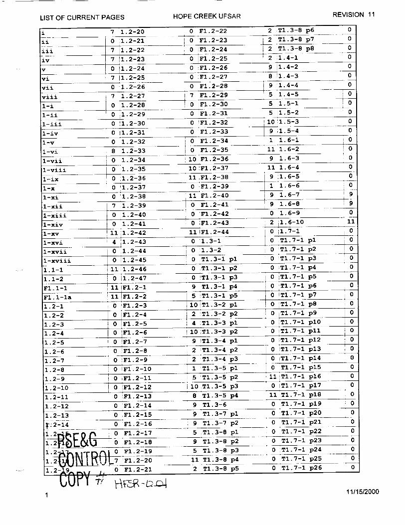
LIST OF CURRENT PAGES HOPE CREEK UFSAR REVISION 11
S7 1.2-20 0 F1.2-22 2 Tl.3-8 p6 0
ii 0 :1.2-21 0 'Fl. 2-23 2 TI.3-8 p7 0
iii 7 1.2-22 0 IF1.2-24 2 T1.3-8 p8 0
iv 7 1.2-23 0 IF1.2-25 2 1.4-1 0
v 0 1.2-24 0 iF1.2-26 9 i1.4-2 0
vi3 7 '1.2-25 0 F1.2-27 8 11.4-3 0
vii 0 1.2-26 0 F1.2-28 9 1.4-4 0
viii 7 i1.2-27 7 'Fl.2-29 5 1.4-5 0
1-i 0 1.2-28 0 IF1.2-30 5 1.5-1 0o
1-u 0 1.2-29 0 Fl.2-31 5 1. 5-2 0
1-iii 0 11.2-30 0 'Fl.2-32 1011.5-3 0
1-iv 0 11.2-31 0 F1.2-33 9 1.5-4 0
1-v 0 1.2-32 0 oF1.2-34 1 1.6-1 0
1-vi 8 1.2-33 0 IF1.2-35 11 1.6-2 0 1-vii 0 1.2-34 10 F1.2-36 9 1.6-3 0
1-viii 0 1.2-35 10 1F1.2-37 11 1.6-4 0
1-ix 0 1.2-36 11 F1.2-38 9 1.6-5 0
1-x 0 1.2-37 0 F1.2-39 1 1.6-6 0
1-xi 0 1.2-38 11 F1.2-40 9 1.6-7 9
1-xii 7 1.2-39 0 IF1.2-41 9 11.6-8 9
1-xiii 0 1.2-40 0 F1.2-42 0 1.6-9 0
1-xiv 0 1.2-41 0 IF1.2-43 2 1.6-10 11
1-xv 11 1.2-42 11 IF1.2-44 0 11.7-1 0
1-xvi 4 '1.2-43 0 1.3-1 0 T1.7-1 pl 0
1-xvii 0 1.2-44 0 1.3-2 0 'T1.7-1 p2 0
1-xviii 0'1.2-45 0 1T1.3-1 pl 0 TI.7-1 p3 0
1.1-1 11 1.2-46 0 IT1.3-1 p2 0 TI.7-1 p4 0
1.1-2 0 1.2-47 0 'T1.3-1 p3 0 IT1.7-1 p5 0
F.I-I -! FI.2-1 9 TI.3-1 p4 0 T1.7-1 p6 0
Fl.l-la 111F1.2-2 5 iT1.3-1 p5 0 'T1.7-1 p 7 0
1.2-1 0 'F1.2-3 10!T1.3-2 pl 0 T1.7-1 p8 0
1.2-2 0 IF1.2-4 2 IT1.3-2 p2 0 T1.7-1 p 9 0
1.2-3 0 F1.2-5 4 T1.3-3 pl 0 TI.7-1 plO 0
1.2-4 0 F1.2-6 10 iTi.3-3 p2 0 TI.7-1 pll 0
1.2-5 0 F1. 2-7 9 iT1.3-4 pl 0 T1.7-1 p12 0 S. i TI.71 p12ý
1.2-6 0 F1.2-8 2 T1.3-4 p2 0 TI.7-1 p13 0
1.2-7 0 ,F1.2-9 2 T1.3-4 p 3 0 T1.7-1 p14 0
1.2-8 0 IF1.2-10 1 TI.3-5 pl 0 TI.7-1 p15 0
1.2-9 J 0 F1.2-11 5 T1.3-5 p2 111 T.7-1 p16 0
1.2-10 i 0 IF1.2-12 10 T1.3-5 p3 0 T1.7-1 p17 0
1.2-11 0 F1.2-13 8 T1.3-5 p4 11 T1.7-1 p18 0
1.2-12 0 Fl.2-14 9 T1.3-6 0 IT1.7-1 p1 9 o 0
1.2-13 0 FI.2-15 9 TI.3-7 pl 0 T1.7-1 p20 0
v.2-14 0 ýF1.2-16 , 9 T1.3-7 p2 0 T1. 7-1 p2 1 0
1 .2 0-0 g' F1.2-17 5 T1.3-8 pl 0 T1.7-1 p22 0
1.Yi•_•i_•LU 0 F 1.2-18 9 •T1.3-8 p2 0 T1.7-1 p23 0
1.2•0-rj F1.2-1 9 5 T1.3-8 p 3 0 T1.71 p2 4 0
.2 0 11 T1.3-8 p4 0 T1.7-1 p25
1"2-A9 0 F1.2-21 2 T1.3-8 p5 1 0 'T1.7-1 p26 0
11/15/2000I
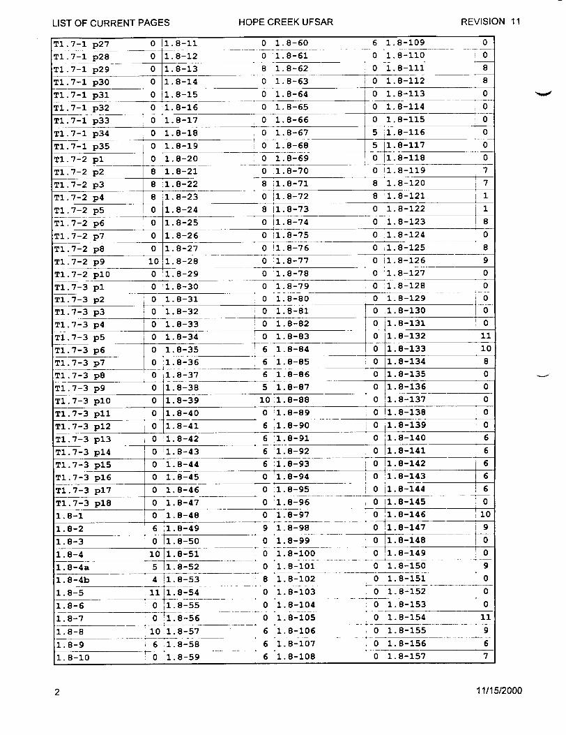
TI.7-1 p27 0 ý1.8-11 0 1.8-60 6 1.8-109 0
Tl.7-1 p 2 8 0 1.8-12 0 1.8-61 0 1.8-110 0
TI.7-1 p 2 9 0 1.8-13 8 1.8-62 0 1.8-111 8
TI.7-1 p30 0 1.8-14 0 1.8-63 1 0 1.8-112 8
T1.7-1 p 3 1 0 1.8-15 0 1.8-64 0 1.8-113 0
T1.7-1 p 3 2 0 1.8-16 0 1.8-65 0 1.8-114 0
T1.7-1 p 3 3 0 1.8-17 0 1.8-66 0 1.8-115 0
T1.7-1 p3 4 0 1.8-18 0 1.8-67 5 1.8-116 0
TI.7-1 p 3 5 0 1.8-19 0 1.8-68 5 11.8-117 0
T1.7-2 pl 0 1..8-20 0 1.8-69 0 1.8-118 0
T1.7-2 p 2 8 :1.8-21 0 1.8-70 0 1.8-119 7
TI.7-2 p 3 8 11.8-22 8 1..8-71 8 1.8-120 7
T1.7-2 p 4 8 1.8-23 0 1.8-72 8 1.8
TI.7-2 p5 0 1.8-24 8 ý1.8-73 0 1.8-122 1
T1.7-2 p 6 0 1.8-25 0 ý1.8-74 0 1.8-123 8
T1.7-2 p 7 0 1.8-26 0 11.8-75 0 1.8-124 0
TI.7-2 p8 0 1.8-27 0 i1.8-76 0 ;1.8-125 8
TI.7-2 p9 10 1.8-28 0 1.8-77 0 11.8-126 9
TI.7-2 plO 0 1.8-29 0 1.8-78 0 1.8-127 0
T1.7-3 pl 0 1.8-30 0 1.8-79 0 1.8-128 0
T1.7-3 p 2 0 1.8-31 0 1.8-80 0 1.8-129 0
T1.7-3 p 3 0 1.8-32 0 1.8-81 0 1.8-130 0
T1.7-3 p 4 0 1.8-33 0 1.8-82 0 1.8-131 o
T1. 7-3 p5 0 1.8-34 0 1.8-83
T1. 7-3 p 6 0 1.8-35 6 1.8B-84 1
T1.7-3 p 7 0 1.8-36 6 1.8-85 0 1.8-134 8
T1.7-3 p8 0 1.8-37 6 1.8-86 0 1.8-135 0
T1. 7-3 p 9 0 1.8-38 5 1.8-87 0 1.8-136 0
TI.7-3 plo 0 1.8-39 10 1.8-88 0 1.8-137 0
TI.7-3 p11 0 1.8-40 0 1.8-89 0 11.8-138 0
TI.7-3 p 12 0 1.8-41 6 1.8-90 0 11.8-139 0
TI.7-3 p 13 0 1.8-42 6 01.8-91 0 '1.8-140 6
T1.7-3 p1 4 0 1.8-43 6 1.8-92 0 1.8-141 6
TI.7-3 p 15 0 1.8-44 6 ý1.8-93 0 1.8-142 6
T1.7-3 p 1 6 0 1.8-45 0 1.8-94 0 1.6-143 6
T1.7-3 p 17 0 1.8-46 0 1.8-95 , 0 1."8-144 6
TI.7-3 p 1 8 0 1.8-47 0 1.8-96 0 1.8-145 0
1.8-1 0 ý1.8-48 01.8-97 0 1.8-146 10
1.8-2 6 01.8-49 9 1.8-98 0 i1.8-147 9
1.8-3 0 1.8-50 0 1.8-99 0 !1.8-148 0
1.8-4 101.8-51 0 1.8-100 0 '1.8-149 0
1.8-4a 5 !1.8-52 0 1.8-101 0 1.8-150 9
1.8-4b 4 1.8-53 8 1.8-102 0 1.8-151 0
1.8-5 11 1.8-54 0 1.8-103 0 1.8-152 0
1.8-6 0 1.8-55 0 1.8-104 0 1.8-153 0
1.8-7 0 11.8-56 0 1.8-105 0 1.8-154 11
1.8-8 10 1.8-57 6 1.8-106 0 1.8-155 9
1.8-9 6 1.8-58 6 1.8-107 0 1.8-156 6
1.8-10 o 1.8-59 6 1.8-108 0 1.8-157 7
11/15/2000
HOPE CREEK UFSAIR REVISION 11LIST OF CURRENT PAGES
2

LIST OF CURRENT PAGES HOPE CREEK UFSAR REVISION 11
1.8-158 0 1.10-31 4 1.10-80 8 T1.11-1 p3 0
1.8-159 0 1.10-32 0 1.10-888 0T1.11-1 p4 0
T1.8-1 pl 0 1.10-33 0 1.10-82 0 T1.11-1 p5 0
TI.8-1 p2 0 1.10-34 8 1.10-83 0 'Tl.11-1 p6 0
T1.8-1 p3l 0 1.10-35 0 1.10-84 0 ýT1.11-1 p7 0
TI.8-1 p4 0 1.10-36 0 1.10-85 8 IT1.11-1 p81 0
T.8-1 p5 0 1.10-37 0 1.10-86 08 T1.11-1 p91 0
Tl.8-1 0 1.10-38 0 1.10-87 , 0 T1.11-1 pl1 0
T1.8-1 p1 0 1.10-46 0 1.10-88 0 T1.11-1 pll 0
T1.8-1 p2 0 1.10-47 4 1.10-89 0 1Tl.11-1 p19 0
TI.8-1 p3 0 8 1.10-48 0 1.10-97 9, T1.11-I p12 0
T1.8-1 p0 1.10-49 0 1.10-98 0 ýT1.11-1 p 1 4 0
T1.1-1 pl0 0 1.10-40 0 !1.10-99 0 T1.11-1 p22 0
"1.10-2 0 '1.10-51 0 1. 10-10 0 T1.11-1 p2 3 0
1l.10-3 9 1. 10-452 1.10-101 0 .T1. 11-1 p247 0
T1.0-4 pl8 0 1.10-43 0 1.10-92 0 T1.11-1 p25 0
T1.10-5p 0 1.10-44 4 1.10-93 0 IT1.11-1 p16 0
T1.18-3 0 1.10-45 0 1.10-914 0 TI.11-1 p27 0
1.1-7 0 1.10-46 0 1.10-95 0 IT1.11-1 p28 0
1.10-8 8 1.10-57 8 1.10-916 0 T1.11-1 p2 9 0
1.10-9 0 1.10-58 0 1.10-107 8 9T1.11-1 p2 0 0
1.10-1 8 1. 10-59 7 1.10-108 0 Tl.11-1 p3 1 0
1.10-11 8 1.10-60 0 1.10-198 8 1.12-I21 0 1.10-1 10 1.10-56 1 0 1.10-102 0 T1.12-1 p25 0
1.10-1 3 0 11.10-52 0 1.10-101 0 T1.11-1 p23 0 1.10-14 6 . 10-63 0 1.10-11 0 1.12-4 0 1.10-1 4 1.10-4 0 51.10-113 0 1.12-5 0
1.10-16 0 i1.10-654 8 1.10-114 0 T.1.12-1p6 0
1.10-6 9 '1.10-55 8 1.10-104 0 T1.11-1 p27 0
1.10-7 8 1.10-56 0 1.10-105 0 T1.11-1 p208 -8
1.10-8 8 1.10-57 8 01.10-106 0 1T1.12-1 p29 0
1.10-9 9 1.10-58 01 1.10-107 0 11-1 p30 0
1.10-21 8 1.10-0 I0 1.10-108 0 T1.11-1 p31 0 1.10-11 8 1.10-59 0 01
1.10-22 9 1.10-61 0 1.10-120 0 1.12-12
1.10-23 0 1.10-72 0 1.10-121 0 1.12-3 0
1.10-124 1.10-63 8 1.10-112 0 1.12-14 0
1.10-15 8 1.10-64 0 1.10-113 0 1.12-5 0
1.10-26 1.10-65 8 1.10-124 0 1.12-16 0
1.10-17 8 1.10-66 0 i.110-115 0 1.12-7 ' 7
1.10-18 0 1.10-67 0 81.10-114 0 1.12-18 0
1.10-19 0 1.10-68 0 T1.10-1 1 5 I 0 1.12-9
1.10-30 0 1.10-679 0 1.10-11 i 0 1.12-20 7
1.10-1/ 8 1.510-/ 0 0.10-119 0 11.12-90 110-22 9 1.10-71 0 1.10-120 0 1i.12-120
1.10-24 8 11.10-73 8 1.10-122 0 11.12-14 0
1.10-26 9 11.10-75 8 1.10-124 0 11.12-16 0
1.10-27 8 101.10-76 0 A1.10-125 1.12-17 7
1.10-28 80 1.10-77 0 1.11-12 0 1.12-18 ,0
1.10-29 0 ý1.10 --778i 0 ýT1.11-1 pl0 11.12-18 7
1.10-'39 0 8.07 0 T1.11-1 p2 0 11.12-20 7
,) 11/15/2000O
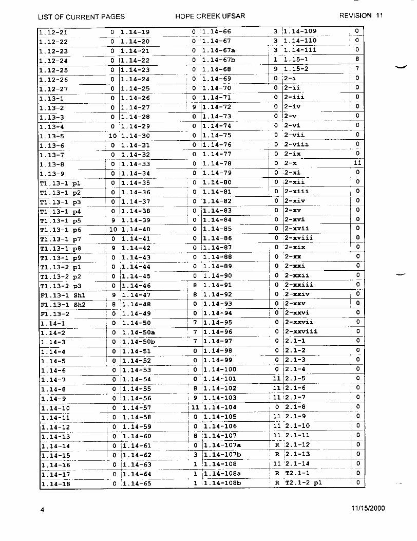
1.12-21 0 1.14-19 0 H 1.E14-66 3 US1.R14-109 0 1.12-22 0 1.14-20 0 1.14-67 3 1.14-110 0
1.12-23 0 1.14-21 0 1.14-67a 3 1.14-111 0
1.12-24 0 11.14-22 0 1.14-67b 1 1.15-1 8
1.12-25 0 1.14-23 0 1.14-68 9 1.15-2 7
1.12-26 0 1.14-24 0 1.14-69 0 ý2-i 0
1.12-27 0 1.14-25 0 1.14-70 0 2-i 0
1.13-1 0 1.14-26 0 :1.14-71 0 2-iii 0
1.13-2 0 1.14-27 9 1.14-72 0 2-iv 0
1.13-3 0 11.14-28 0 1.14-73 0 12-v 0
1.13-4 0 1.14-29 0 1.14-74 0 2-vi 0
1.13-5 10 1.14-30 0 1.14-75 0 2-vii 0
1.13-6 0 1.14-31 0 1.14-76 0 2-viii 0
1.13-7 0 1.14-32 0 1.14-77 0 2-ix 0
1.13-8 0 11.14-33 0 1.14-78 0 2-x 11
1.13-9 0 1.14-34 0 1.14-79 0 2-xi 0
T1.13-1 pl 0 1.14-35 0 1.14-80 0 2-xii 0
TI.13-1 p 2 0 1.14-36 0 1.14-81 0 2-xiii 0
TI.13-1 p 3 0 1.14-37 1 0 1.14-82 0 j2-xiv 0
T1.13-1 p 4 0 1.14-38 0 1.14-83 0 2-xv 0
T1.13-1 p 5 9 1.14-39 i 0 1.14-84 0 02-xvi 0
T1.13-1 p6 10 1.14-40 0 1.14-85 0
T1.13-1 p7 0 1.14-41 0 1.14-86 0 2-xviii 0
T1.13-1 p8 9 1.14-42 0 :1.14-87 0 '2-xix o
T1.13-1 p9 0 o1.14-43 0 1.14-88 0 o2-xx 0
T1. 13-2 pl 0 1.14-44 0 1.14-89 0 2-xxi 0
T1.13-2 p2 0 i1.14-45 0 1.14-90 1 0 2-xxii 0
T1.13-2 p 3 0 11.14-46 8 1.14-91 I 0 2-xxiii 0
F1.13-1 Shl 9 1.14-47 8 1.14-92 0 2-xxiv 0
Fl.13-1 Sh2 8 1.14-48 0 :;1.14-93 0 12-nxv ,0
Fl.13-2 0 1.14-49 0 1.14-94 0 o2-xxvi 0
1.14-1 0 1.14-50 7 1.14-95 0 2-xxvii 0
1.14-2 0 !1.14-50a 7 1.14-96 0 2-xxviii 0
1.14-3 0 1.14-50b 1 7 1.14-97 0 2.1-1 0
1.14-4 0 11.14-51 0 1.14-98 0 2.1-2 0
1.14-5 0 1.14-52 0 1.14-99 0 2.1-3 0
1.14-6 0 1.14-53 0 1.14-100 0 2.1-4 0
1.14-7 0 11.14-54 0 1.14-101 11 2.1-5 0
1.14-8 0 :1.14-55 8 1.14-102 11 2.1-6 0
1.14-9 0 1.14-56 9 1.14-103 1i2.1-7 0
1.14-10 0 11.14-57 11 1.14-104 0 2.1-8 0
1.14-11 0 1.14-58 0 1.14-105 !11 2.1-9 0
1.14-12 0 1.14-59 11 2.1-10 0
1.14-13 0 1.14-60 .8 :1.14-107 11 2.1-11 0
1.14-14 0 i1.14-61 0 ý1.14-107a R ý2.1-12 0
1.14-15 I 0 11.14-62 3 __1.14-107b R i2.1-13 0
1.14-16 0 11.14-63 1 !1.14-108 11 '2.1-14 0
1.14-17 0 1.14-64 1.14-108a R T2.1-1 0
1.14-18 0 1.14-65 1 1.14-108b R T2.1-2 pl 0
11/15/2000
HOPE CREEK UFSAR REVISION 11LIST OF CURRENT PAGES
4
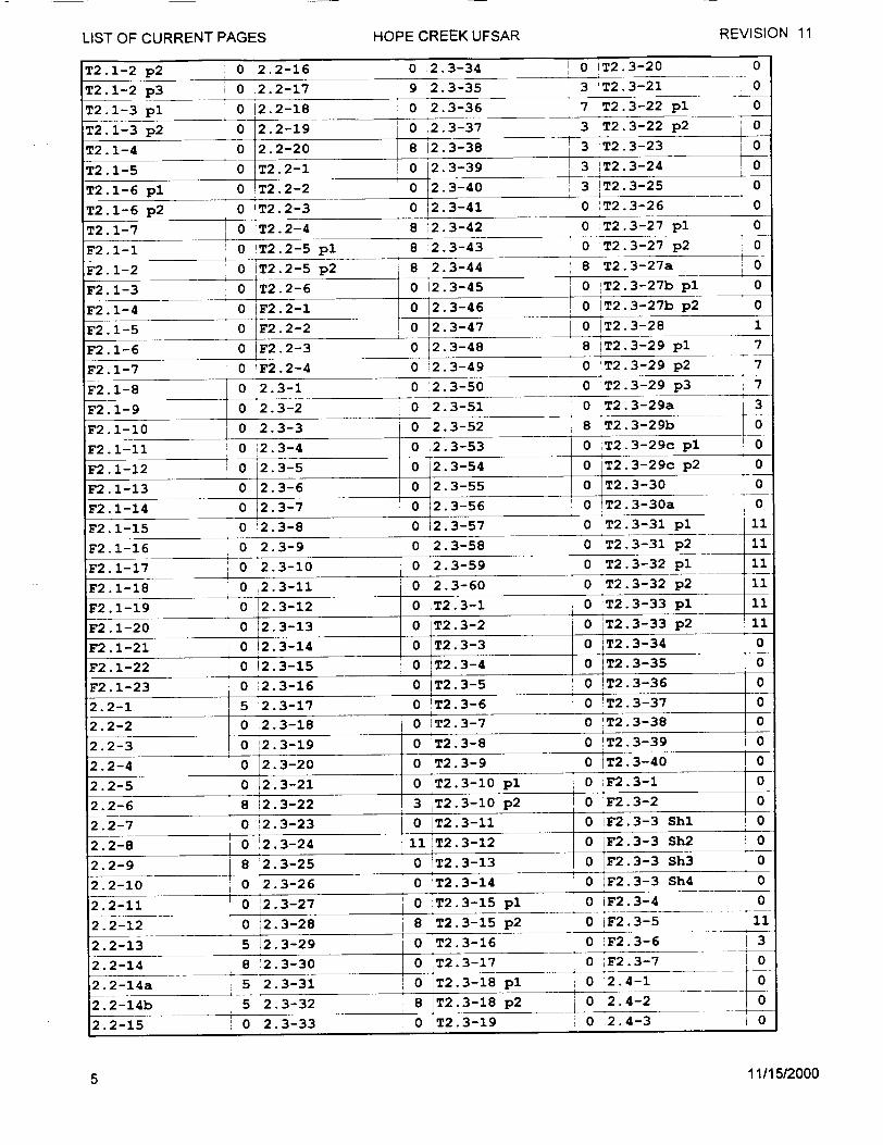
T2.1-2 p2 0 2.2-16 0 2.3-34 , 0 IT2.3-20 0
T2.1-2 p 3 0 2.2-17 9 2.3-35 3 'T2.3-21 0
T2.1-3 pl 0 ý2.2-18 0 2.3-36 7 T2.3-22 pl 0
T2.1-3 p 2 0 2.2-19 0 2.3-37 3 T2.3-22 p 2 0
T2.1-4 0 2.2-20 8 12.3-38 3 T2.3-23 0
T2.1-5 0 T2.2-1 0 2.3-39 3 'T2.3-24 0
T2.1-6 p1 0 T2.2-2 0 52.3-40 3 iT.3-25 0
T2.1-6 p2 0 IT2.2-3 0 2.3-41 0 3T2.3-26 0
T2.1-7 0 rT2.2-4 8 ý2.3-42 0 T2.3-27 pl 0
F2.1-1 0 'T2.2-5 pl 8 i2.3-43 0 T2.3-27 p 2 0
F2. 1-2 0 iT2.2-5 p 2 8 :2.3-44 8 T2.3-27a 0
F2.1-3 0 T2.2-6 0 12.3-45 2.3-27b p1 0
F2.1-4 0 TF2.2-1 0 12.3-46 0 IT2.3-27b p 2 0
F2.1-5 0 F2.2-2 0 12.3-47 , 0 IT2.3-28 1
F2.1-6 0 F2.2-3 0 2.3-48 8 IT2.3-29 pl 7
F2.1-7 0 'F2.2-4 0 '2.3-49 0 'T2.3-29 p2 7
F2.1-8 0 2.3-1 0 2.3-50 0 T2.3-29 p3 7
F2.1-9 0 !2.3-2 0 2.3-51 0 T2.3-29a 1 3
F2.1-10 1 0 2.3-3 0 2.3-52 8 T2.3-29b 0
F2.1-11 0 ;2.3-4 0 2.3-53 0 ,T2.3-29c pl 0
F2.1-12 0 2.3-5 0 2.3-54 0 T2.3-29c p 2 0
F2.1-13 0 2.3-6 0 2.3-55 0 T2.3-30 0
F2.1-14 0 2.3-71 0 T2.3-56 0 ýT2.3-30a I 0
F2.1-15 0 12.3-8 0 T2.3-57 0 T2.3-31 pl 11
2.2-5 0 2.3-9 0 2.3-58 0 T2.3-31 p2 11
F2.1-17 0 2.3-10 I 0 2.3-59 0 T2.3-32 pl 11
F2.1-18 0 2.3-11 0 T2.3-60 0 T2.3-3 S2 11
F2.1-19 0 2.3-12 0 T2.3-13 0 T2.3-3S3 pl0
F2.1-20 0 12.3-13 0 T2.3-21 0 lT2.3-33 p2 01
F2.1-21 0 12.3-14 0 T2.3-3 0 T2.3-34 0
F2.1-22 0 12.3-158 0 T2.3-4 0 T2.3-35 0 F2.1-23 0 i2.3-16 0 T•2.3-59 i 0 lT2.3-36 0
2.2-1 5 !2.3-17 0 IT2.3-6 0 '2.3-3 3
2.2-1 8 2.3-30 0 iT2.3-7 0 !T2.3-37 0 2.2-3 0 :2.3-19 0 iT2.3-8 0 !T2.3-39 i 0
2.- 2.3-20 0 lT2.3-8 T.34
2.2-5 0 5 2.3-31 ,0 T2.3-1 p1 0 ;F2.3-1 0
2.2-4 5 12.3-22 8 iT2.3-19 p2 0 lT2.3-2 0
2.2-5 0 2.3-23 0 T2.3-11 0 F2.3-3 0 2.2-8 0 12.3-24 11 T2.3-i012 0 iF2.3-3S2 0
2.- 82 0 2 31 0 iF2.3-3 shz 0 2.2-10 0 23-26 0 'T2.3-141 23- h 2.2-11! 0 ý23-24:11 T2.3-152p 0 iF2.3-3 h4 0
2.2-12 0 82.3-28 1 8 T•2.3-153p 0 i F2. 3-5 113 221 5 12.3-29 0 'T2.3-16 0 F2333h
2.2-14 8 '233 0 iý T231 F .
2.2-14a 5 2.3-31 1ý 0 'T2.3-15 pl 0 F2.4-1 _
2.2-14b 5 2.3-328' 8 ýT2.3-15 p2 0 iF2.3-5 01
2.2-14a 0 2.3-33 0 !T2.3-189l 0 2.4-3 0
11/15/2000
REVISION 11LIST OF CURRENT PAGES HOPE CREEK UFSAR
5

2.4-4 0 '2.4-53 0 T2.4-3 pl 0 F2.4-12 0
2.4-5 0 2.4-54 1 0 ýT2.4-3 p 2 0 F2.4-13 0
2.4-6 0 2.4-55 0 T2.4-4 pl 0 iF2.4-14 0
2.4-7 0 '2.4-56 0 T2.4-4 p 2 0 lF2.4-15 0
2.4-8 0 2.4-57 0 'T2.4-5 0 IF2.4-16 0
2.4-9 0 2 80 T2.4-6 p1 0 F2.4-17 0
2.4-10 0 '2.4-59 8 T2.4-6 p2 0 lF2.4-18 0
2.4-11 0 12.4-60 0 T2.4-7 0 :F2.4-19 0
2.4-12 0 2.4-61 0 T2.4-8 0 F2.4-20 0
2.4-13 8 2.4-62 0 T2.4-9 0 F2.4-21 0
2.4-14 0 ,2.4-63 8 T2.4-10 pl 8 F2.4-22 0
2.4-15 0 2.4-64 0 T2.4-10 p 2 8 F2.4-23 0
2.4-16 8 2.4-65 0 T2.4-aiF2.4-24 0
2.4-17 8 2.4-66 0 T2.4-11 0 F2.4-25 8
2.4-18 0 ý2.4-67 0 T2.4-11a 0 F2.4-26 0
2.4-19 0 12.4-68 8 T2.4-12 0 F2.4-27 0
2.4-20 0 2.4-69 8 T2.4-13 0 _F2.4-28 0
2.4-21 0 2.4-70 8 T2.4-14 pl 8 'F2.4-29 0
2.4-22 0 2.4-71 0 T2.4-14 p 2 8 !F2.4-30 0
2.4-23 0A2.4-72 0 !T2.4-14 p 3 8 F2.4-31 0
2.4-24 0 12.4-73 0 IT2.4-14 p 4 8 F2.4-32 0
2.4-25 0 ;2.4-74 0 T2.4-15 0 'F2.4-33 0
2.4-26 0 2.4-75 8 T2.4-16 pl 0 iF2.4-34 0
2.4-27 8 2.4-76 0 lT2.4-16 p 2 0 IF2.4-35 0
2.4-28 8 .2.4-77 9 T2.4-16 p 3 0 F2.4-36 0
2.4-29 0 2.4-78 0 T2.4-17 p1 0 F2.4-37 0
2.4-30 8 i2.4-79 0 T2.4-17 p2 0 F2.4-38 0
2.4-31 0 12.4-80 4 T2.4-17 p3 0 :F2.4-39 0
2.4-32 0 i2.4-81 0 T2.4-18 p1 0 F2.4-40 0
2.4-33 0 12.4-82 4 T2.4-18 p 2 0 'F2.4-41 0
2.4-34 0 ý2.4-83 8 T2.4-19 0 F2.4-42 0
2.4-35 8 2.4-84 0 T2.4-20 pl 8 'F2.4-43 0
2.4-36 0 i2.4-85 0 T2.4-20 p 2 8 F2.4-44 0
2.4-37 8 2.4-86 0 T2.4-21 pl 8 ý2.5-1 0
2.4-38 T 9 2.4-87 0 T2.4-21 p 2 8 2.5-2 0
2.4-39 8 2.4-88 8 T2.4-22 pl 8 ý2.5-3 0
2.4-40 0 2.4-89 1 0 T2.4-22 p 2 8 2.5-4 0
2.4-41 0 2.4-90 0 ;T2.4-23 8 2.5-5 0
2.4-42 0 2.4-91 8 ýF2.4-1 0 2.5-6 8
2.4-43 0 2.4-92 0 F2.4-20
2.4-44 9 2.4-93 0 F2.4-32.5
2.4-45 0 2.4-94 8 0F2.4-4 0 ! 0
2.4-46 9 2.4-95 0 F2.4-5 0 2.5-10 0
2.4-47 0 2.4-96 0 F2.4-6 0 2.5-11 0
2.4-48 0 2.4-97 8 F2.4-7 0 2.5-12 0
"2.4-49 8 12.4-98 0 F2.4-8 0 2.5-13 0
2.4-50 0 lT2.4-1 8 F2.4-9 0 2.5-14 8
2.4-51 0o T2.4-2 pl 0 F2.4-10 0 2.5-15 0
2.4-52 0 !T2.4-2 p 2 0 iF2.4-11 0 2.5-16 0
11/15/2000
HOPE CREEK UFSAR REVISION 11LIST OF CURRENT PAGES
6
2.5-17 0 2.5-66 0 2.5-113 0 2.5-160 0
2.5-18 0 2.5-67 0 2.5-114 0 2.5-161 0
2.5-19 0 2.5-68 0 2.5-115 0 2.5-162 0
2.5-20 0 2.5-69 0 12.5-116 0 2.5-163 0
2.5-21 0 2.5-70 0 12.5-117 0 !2.5-164 0
2.5-22 0 2.5-71 8 12.5-118 0 2.5-165 0
2.5-23 0 '2.5-72 0 2.5-119 0 2.5-166 0
2.5-24 0 2.5-73 0 2.5-120 0 2.5-167 0
2.5-25 0 2.5-74 0 12.5-121 0 2.5-168 0
2.5-26 0 2.5-75 0 2.5-122 0 12.5-169 0
2.5-32 0 2.5-81 0 2.5-128 0 .2.5-175 0
2.5-23 0 2.5-78 0 2.5-129 0 2.5-176 0
2.5-23 0 0 2.5-123 0 2.5-177 0
2.5-35 0 i2.5-78 0 .2.5-123 0 2.5-178 0
2.5-36 0 12.5-85 0 2.5-127 0 2.5-179 0
2.5-37 0 12.5-86 0 2.5-123 8 0 2.5-178 0
2.5-38 0 i2.5-87 0 2.5-134 0 2.5-181 0
2.5-33 0 2.5-82 0 02.5-129 0 12.5-176 0
2.5-34 0 2.5-83 0 2.5-130 0 T2.5-177 0
2.5-35 0 2.5-84 0 12.5-131 0 T2.5-178 0
2.5-36 0 2.5-85 0 12.5-132 1 T2.5-179 0
2.5-37 0 2.5-86 0 2.5-133 10 12.5-180 0
2.5-38 4 0 2.5-94 0 2.5-134 1 1 2.5-p81 0
2.5-39 0 12.5-88 0 12.5-135 0 T2.5-182 0
2.5-40 0 2.5-89 0 .2.5-136 0 lT2.5-1 pl 0
2.5-41 0 2.5-90 0 2.5-137 0 T2.5-1 p2 0
2.5-42 0 ý2.5-91 0 2.5-138 0 IT2.5-6 p3 0
2.5-43 0 2.5-92 0 2.5-139 01 T2.5-1 p4 0
2.5-44 0 i2.5-93 0 2.5-139a 0 ;T2.5-2 pl 0
2.5-L53 0 2.5-94 0 2.5-139b 1 1T2.5-2 p 2 0
2.5-46 I 0 2.5-95 0 2.5-148 0 T2.5-3 0
2.5-47 0 2.5-96 0 2.5-141 0 T2.5-41 0 ii
2.5-56 0 2.5-103 0 ý2.5-150 0 ýT2.5-11p 0
2.5-49 0 2.5-98 0 2.5-151 0 T2.5-6 pl 0
2.5-50 0 2.5-99 0 2.5-144 0 T2.5-6 p2 0
2.5-51 0 2.5-100 0 12.5-145 0 IT2.5-7 4 0
2.5-52 0 2.5-i01 0 1"2.5-146 0 iT2.5-8 pl 0
2.5-53 0 2.5-101a 1 i2.5-147 0 !T2.5-8 p2 0 2.5-54 0'2.5-101b: 1 2.5-148 0 'T2.5-9 0 2.5-55 02.5-102 0 1.5-149 i0 IT2.5-10 0
2.5-56 0 2.5-103 0 12.5-150 0 *T2.5-11 pl 0
2.5-57 0 2.5-104 0 2.5-151 0 T2.5-11 p 2 0 2.5-58 0 2.5-105 0 2.5-152 !0 :T2.5-11 p3o
2.5-59 0 2.5-106 0 2.5-153 0 iT2.5-11 p4 0
2.5-60 0 2.5-112 0 2.5-154 0 'T2.5-12 pl 0 2.5-61 0 ý2.5-108 i0 2.5-155 0 T2.5-12 p2 o 2.5-62 0 12.5-109 'I0 '2.5-156 0 i T2. 5-13 pl i0
2.5-63 0 112.5-110 0 2.5-157 0 T2.-13 p)2 o0 2.-40ý. -1 0 2.5-158 !0 !T2.5-14 0
[2.5-65 0 .2.5-112 0 "2.5-159 !0 'T2.5-15 0
11/15/2000
REVISION 11LIST OF CURRENT PAGES HOPE CREEK UFSAR
7

LIST OF CURRENT PAGES HOPE CREEK UFSAR REViSION 11T2.5-16 0 F2.5-36
T2.5-17 0 F2. 5-37
T2.5-18 0 F2.5-38
T2.5-19 0 F2.5-39
T2.5-20 0 F2.5-40
T2.5-21 0 F2.5-41
T2.5-22 0 F2.5-41
T2.5-23 0 F2.5-41
T2.5-24 0 ýF2.5-41
F2.5-1 0 F2. 5-42
F2.5-2 0 F2. 5-42
F2.5-3 0 F2.5-42
F2.5-4 0 F2.5-42
F2.5-5 0 iF2.5-43
F2.5-6 0 ýF2.5-44
F2.5-7 0 FF2.5-45
F2.5-8 0 :F2.5-46
F2.5-9 0 F2. 5-47
F2.5-10 0 F2.5-48
F2.5-10a 0 F2.5-49
F2.5-11 0 F2.5-50
F2.5-11a 0 lF2.5-50
F2.5-12 0 IF2.5-50
F2.5-13 0 iF2.5-50
F2.5-14 0 F2.5-50
F2.5-15 0 F2.5-50
F2.5-16 0 F2-.5-50
F2.5-17 0 F2.5-50
F2.5-18 0 F2.5-50
F2.5-19 0 PF2.5-50
F2.5-20 0 PF2.5-50
F2.5-21 0 F2.5-50
0 F2.5-50 Sh5lSh2
Sh3
Sh4
Sh5
Sh6
Sh7
Sh8
Sh9
0 !F2.5-50 Sh52
0 F2.5-50
0 F2.5-50
0 F2.5-50
0 F2.5-50
0 F2.5-50
0 F2.5-50
0 IF2.5-50 0 F2.5-50
Shl00 Shl01
Sh53 ý 0 F2.5-50 Sh102 Sh54 i 0 .F2.5-50 Sh103
Sh55 0 52.5-50 sh104
Sh56 0 F2.5-50 Shl05
Sh57 0 F2.5-50 Sh106
Sh58 0 !F2.5-50 Shl07
0 0
0
0
0
0
0
0
Shl0 0 F2.5-50 Sh59 0 F2.5-50 ShI08 0
Shl 0 ýF2.5-50 Sh60 0 F2.5-50 Shl09 0
Sh12 0 F2.5-50 Sh6l 0 F2.5-50 Shll0 0
F2.5-22 0 F2.5-50 Shl3 0 F2.5-50 Sh62
F2.5-23 0 F2.5-50 Sh14 0 F2.5-50 Sh63
F2.5-24 0 F2.5-50 ShlS 0 F2.5-50 Sh64
F2.5-25 0 F2.5-50 Shl6 0 F2.5-50 Sh65
F2.5-26 0 F2.5-50 Sh17 0 F2.5-50 Sh66
F2.5-26a 0 F2.5-50 Shl8 0 F2.5-50 Sh67
F2.5-27 0 F2.5-50 Shl9 0 F2.5-50 Sh68
F2.5-28 0 IF2.5-50 Sh20 0 F2.5-50 Sh69
F2.5-28a 0 F2.5-50 Sh2l 10 F2.5-50 Sh7
F2.5-28b 0 F2.5-50 Sh22 0 F2.5-50 Sh7l
F2.5-28 0 F2.5-50 Sh23 0 F2.5-50 Sh72
F2.5-90 0 F2.5-50 Sh24 0 F2.5-50 Sh73
F2.5-31 0 F2.5-50 Sh25 0 F2.5-50 Sh74
F2.5-32 0 F2.5-50 Sh26 0 F2.5-50 Sh75
F2.5-33 0 F2.5-50 Sh27 0 F2.5-50 Sh76
F2.5-34 0 F2.5-50 Sh28.. 0 "F2.5-50 Sh77
F2.5-35 0 F2.5-50 Sh299 0 F2.5-50 Sh78
0 F2.5-50 Shlll U 0 F2.5-50 Sh112 0
0 F2.5-50 Shll3 0
o F2.5-50 Shll4 o
0 F2.5-50 Shl14 0
o F2.5-50 Shll6 0
0 F2.5-50 Sh117 0
0 F2.5-50 Shll8 0
o0 F2.5-50 Shll9 0
0 F2.5-50 Sh120 0
o F2.5-50 Shl2l 0
o F2.5-50 Shl22 0
0 F2.5-50 Shl23 0
0 F2.5-50 Sh124 0
0 F2.5-50 Sh125 0
"o F2.5-50 Sh126 0
0 F2.5-50 Sh127 0
11/15/20008
0 F2.5-50 Sh30 0 F2.5-50 Sh79 0
0 F2. 5-50 Sh3l 0 F2.5-50 Sh8O 0
0 F2.5-50 Sh32 0 F2.5-50 Sh8l 0
0 F2.5-50 Sh33 0 !F2.5-50 Sh82 0
0 F2.5-50 Sh34 0 iF2.5-50 Sh83 0
Shl 0 IF2 5-50 Sh35 0 F2.5-50 Sh84 0
Sh2 0 F2.5-50 Sh36 0 F2.5-50 Sh85 0
Sh3 0 'F2.5-50 Sh37 0 F2.5-50 Sh86 0
Sh4 0 F2.5-50 Sh38 0 F2.5-50 Sh87 0
Shl 0 F2.5-50 Sh39 0 IF2.5-50 Sh88 0
Sh2 0 F2.5-50 Sh4O 0 F2.5-50 Sh89 0
Sh3 0 F2.5-50 Sh4l 0 IF2.5-50 Sh90 0
Sh4 0 ;F2.5-50 Sh42 0 F2.5-50 Sh91 0
0 F2.5-50 Sh43 0 F2.5-50 Sh92 0
0 F2.5-50 Sh44 0 ;F2.5-50 Sh93 0
0 F2.5-50 Sh45 0 F2.5-50 Sh94 0
0 iF2.5-50 Sh46 0 F2.5-50 Sh95 0
0 F2.5-50 Sh47 0 F2.5-50 Sh96 0
0 F2.5-50 Sh48 0 F2.5-50 Sh97 0
0 F2.5-50 Sh49 0 F2.5-50 Sh9B 0
Shl 0 F2.5-50 Sh50 0 F2.5-50 Sh99 0
REVISION 11HOPE CREEK UFSARLIST OF CURRENT PAGES

REVISION 11
LIST OF CURRENT PAGES HOPE CREEK UFSARF2.5-50 Sh128 0 PF2.5-50 Sh177 0 F2.5-75 Shl 0 3-vi 0
F2.5-50 Sh129 0 PF2.5-50 Sh178 0 F2.5-75 Sh2 0 13-vii 0
F2.5-50 Sh130 0 PF2.5-50 Sh179 0 F2.5-76 Shl 0 3-viii 0
F2.5-50 Sh131 0 PF2.5-50 Sh180 0 F2.5-76 Sh2 0 3-ix 0
F2.5-50 Sh132 0 PF2.5-50 Sh181 0 IF2.5-77 Shl 0 3-x 0
F2.5-50 Sh133 0 IF2.5-50 Sh182 0 F2.5-77 Sh2 0 3-xi 0
F2.5-50 Sh134 0 F2.5-50 Sh183 0 PF2.5-78 Shl 0 3-xii 0
P2.5-50 Sh135 0 PF2.5-50 Sh184 0 F2.5-78 Sh2 0 ý3-xiii 0
F2.5-50 Shl36 0 :F2.5-50 Sh185 0 F2.5-79 Shl 0 3-xiv 0
F2.5-50 Sh137 0 PF2.5-50 Sh186 0 F2.5-79 Sh2 0 3-xv 0 F2.5-50 Sh138 0 :F2.5-50 Sh187 0 iF2.5-80 Shl i0 3-xvi i0
F2.5-50 Sh139 0 iF2.5-50 Sh.188 0 F.5-80 Sh2 0 ;3-xvii 0
F2.5-50 ýSh140 0 F2.5-50 Sh189 0 lF2.5-81 Shl 0 13"xviii 0
F2.5-50 Sh141 0 F2.5-51 0 F2.5-81 Sh2 0 ý3-xix 0
F2.5-50 Sh142 0 IF2.5-52 i0 F2.5-82 Shl !0 3-xx 0
F2.5-50 Sh143 0 'F2.5-53 0 IF2.5-82 Sh2 0 3-xxi 0
F2.5-50 Sh144 0 IF2.5-54 0 iF2.5-83 Shl 0 3-xxii 0
F2.5-50 Sh145 0 1F2.5-55 0 F2.5-83 Sh2 0 3-xxiii 0
F2.5-50 Sh146 0 F2.5-56 0 ýF2.5-84 Shi 0 3-xxiv 0
F2.5-50 Sh147 0 F2.5-57 0 F2.5-84 Sh2 0 ,3-xxv 0
F2.5-50 Shl47 0 F2.5-57 0 F2.5-84 Sh2 0 3-xxvi 0
F2.5-50 Sh149 0 IF2.5-59 0 IF2.5-85 Sh2 0 3-xxvii 0
F2.5-50 Sh150 0 F2.5-60 0 F2.5-86 Shl 0 '3-xxviii 0
F2 1-A 5 10 i 0 iF2.5-61 0 IF2.5-86 Sh2 0 13-xxix 0
F2.5-50 Sh152 0 IF2.5-62 0 ýF2.5-87 Shi 03-xxx 0
F2.5-50 Sh153 0 IF2.5-63 0 F2.5-87 Sh2 0 13-xxxi 0
F2.5-50 Sh154 0 F2.5-64 Shi 0 F2.5-88 Sh2 0 3-xxxii 0
F2.5-50 Sh155 0 F2.5-64 Sh2 0 F2.5-88 Sh2 0 3-xxxiii 0
F2.5-50 Sh156 0 F2.5-64 Sh3 0 IF2.5-89 Sh2 0 - 3-xxxiv 0
F2.5-50 Sh157 0 F2.5-65 Sh3 0 F2.5-89 Sh2 0 3-xxxv 0
F2.5-50 Sh158 0 iF2.5-65 Sh2 0 F2.5-90 Sh2 0 3-xxxvi 0
F2.5-50 Sh159 0 F2.5-65 Sh3 0 IF2.5-90 Sh2 0 3-xxxvii 0
F2.5-50 Sh165 0 F2.5-66 0 F2.5-91 Sh2 0 3-xxxviii 0
F2.5-50 Shl6l 0 :F2.5-67 Shi 0 iF2.5-91 Sh2 0 13-xxxix 0
F2.5-50 Shl62 0 F2.5-67 Sh2 0 lF2.5-92 Shl 0 ,3-xL 0
F2.5-50 Sh163 0 IF2.5-68 Shl 0 IF2.5-92 Sh2 0 13-xLi 0
F2.5-50 Sh164 0 F2.5-68 Sh2 0 IF2.5-93 Shl 0 3-xLii 0
F2.5-50 Sh165 0 IF2.5-69 Sh 0 F2.5-93 Sh2 0 3-xliii 0
F2.5-50 Sh163 0 'F2.5-69 Sh2 0 F2.5-94 Sh2 0 3-xLiV 0
F2.5-50 Sh167 0 F2.5-70 Sh2 0 F2.5-94 Sh2 0 3-xLv 0
F2.5-50 Sh168 0 iF2.5-70 Sh2 0 F2.5-95 Shi 0 3-xLvi 0
F2.5-50 Sh169 0 F2.5-71 Shl 0 F2.5-95 Sh2 0 '3-xLvii 0
F2.5-50 Sh167 0 IF2.5-71 Sh2 0 PF2.5-96 Shl 0 3-xLviii 0
F2.5-50 Shl7l 0 'F2.5-72 Shl 0 iF2.5-96 Sh2 0 3-xLix 0
F2.5-50 Sh172 0 F2.5-72 Sh2 0 3-i 0 3-L 0
F2.5-50 Sh173 0 F2.5-73 Shl 0 F-9 h 0 3-Li 0
F2.5-50 Sh174 0 F2.5-73 Sh2 0 iF 9 0 3-Lii 0
F2.5-50 Sh175 0 ýF2.5-74 Sh2 0 3-iv 0 3.1-1 0
F2.5-50 Sh176 0 PF2.5-74 Sh2 0 '3-v 0 3.1-2 0
11/15/20009
HOPE CREEK UFSARLIST OF CURRENT PAGES
LIST OF CURRENT PAGES HOPE CREEK UFSAR REVISION 110 3.1-52 0 IT3.2-1 p12
!0 3.1-53 0 T3.2-1 p13
0 3.1-54 0 T3.2-1 p14
0 3.1-55 0 T3.2-1 p15
0 3.1-56 0 T3.2-1 p16
03.1-57 0 T3.2-1 1i.15 1
9 ý3.1-580 !3.1-59 0 73.1-60 0 3.1-61 9 3.1-62
0 3.1-63 0 3.1-64
0 3.1-65 0 3.1-66
0 'T3.2-1 pl8
8 13.4-10 8 13.4-11
8 '3.4-128 3.4-138 3.4-14
8 T3.4-1
8 T3.4-2 pl 8 *T3.4-2 p2
0 T3.2-1 p 2 0 8 T3.4-2 p
0 T3.2-1 p 2 1 8 T3.4-2 p
0 T3.2-1 p 2 2 8 T3.4-2 p 0 T3.2-1 p 2 3 8 6T3.4-2 p
0 T3.2-1 p2 4
0 T3.2-1 p 2 5
111T3.2-1 p26
0
11
0
0
0
0 0
0
0
'3 •4 ?5 •6
8 IT3.4-3
8 IT3.4-48 1F3.4-1
1 0 3.1-67 0 3.1-68 0 3.1-69
0 ý3.1-700 3.1-710 13.1-72
0 3.1-73 0 !3.1-740 3.1-757 3.1-760 3.1-770 3.1-78 0 3.1-79
S0 3.1-80
S0 i3.1-81
0 TI3.2-1 p2 7
0 iT3.2-1 p2 8
0 ýT3.2-1 p2 9
0 ýT3.2-1 p3 09 IT3.2-1 p3l9 T3.2-1 p32
0 T3.2-1 p 3 3
0 'T3.2-1 p 3 4
0 T3.2-1 p 3 5
0 T3.2-1 p 3 6
0 T3.2-1 p37
11 T3.2-1 p 38
11 T3.2-1 p3 9
8 F3.4-2 0
8 F3.4-3 Shl 7
8 F3.4-3 Sh2 5 9 F3.4-3 Sh3 8
8 F3.4-3 Sh4 7
8 F3.4-48 3.5-18 ý3.5-2
8 3.5-38 i3.5-488
1 880 T3.2-1 p40
0 IT3.2-1 p41 8
3.5-53.5-6
3.5-73.5-83.5-9
0
0 0
0
8 0
9 11 0
0
3.1-33 0 13.1-82 11 ýT3.2-1 p 4 2 11 3.5-10 0
3.1-34 0 13.1-83 0 IT3.2-2 pl 0 3.5-11 0
3.1-35 0 T3.1-84 0 T3.2-2 p 2 0 3.5-12 0 3 1 3 o 0 . -3T
3.1-36 0 3.1-85 I0 T3.2-3 7 3.5-13
3.1-37 9 .3.2-15- 0 3.3-1 0 3.5-14 0
3.1-38 0 3.2-2 0 3.3-2 0 3.5-15 8
3.1-39 0 '3.2-3 0 i3.3-3 0 13.5-16 0
3.1-40 11 3.2-4 0 'T3.3-1 0 3.5-17 0
3.1-41 i 0 T'3.2-1 pl 9 T3.3-2 pl 0 13.5-18 8
3.1-42 9 T3.2-1 p 2 8 'T3.3-2 p2 7 ý3.5-19 0
3.1-43 0 T3.2-1 p 3 8 '3.4-1 0 .3.5-20 0
3.1-44 8 T3.2-1 p 4 8 3.4-2 0 3.5-21 0
3.1-45 0 :T3.2-1 p5 8 3.4-3 0 3.5-22 0
3.1-46 0 iT3.2-1 p6 8 3.4-4 0 3.5-23 0
3.1-47 0 T3.2-1 p 7 8 3.4-5 0 3.5-24 0
3.1-48 0 T3.2-1 p8 8 3.4-6 0 3.5-25 0
3.1-49 0 T3.2-1 p9 10 3.4-7 0 3.5-26 0
3.1-50 0 T3.2-1 plO 8 3.4-8 0 3.5-27 0
3.1-51 0 'T3.2-1 pll 11 3.4-9 0 3.5-28 0
11/15/2000
3.1-3
3.1-4 3.1-53.1-6
3.1-7
3.1-8
0
0 9
3.1-9 3.1-10 3.1-11 3.1-12 3.1-13 3.1-14
3.1-15 3.1-16 3.1-17
0
0
3.1-18 3.1-19
3.1-20 3.1-21 3.1-22 3.1-23 3.1-24 3.1-25 3.1-26 3.1-273.1-283.1-29 3.1-30 3.1-31 3.1-32
10
I I
-
------------------ i
LIST OF CURRENT PAGES HOPE CREEK UFSAR REVISION 11
0 T3.2-1 p19

LIST OF CURRENT PAGES HOPE CREEK UFSAR REVISION 11
3.5-29 0 IT3.5-13 p2 0 3.6-12 0 3.6-61 0 3.-3 8 lT.i3p 3.6-13 0 i 3. 6-62 0
3.5-31 0 IT3.5-13 p3 0 '.-40ý.66
3.5-32 0 IT3.5-13 p8 0 3.6-15 0 3.6-64 0
3.5-33 0 ,T3.5-13 p6 0 !3.6-16 0 3.6-65 0 3.5-34 0 T3.5-13 p7 0 3.6-17 8 13.6-66 0
1 13.6 70 3.5-35 0 T3.5-13 p8::ý 0:36-1ý8 ý 01 -7
35-36 0 !T3. 5-13 p9 1 0 3.6-19 0 1.6-68 0
I I
3.5-37 0 IF3.5-1 0 3.6-20 0 3.6-69 0
"3.5-38 0 F3.5-2 10 3.6-21
3.5-39 0 F3.5-3 10 3.6-22 0 3.6-71 8
3.5-40 0 1F3.5-4 110 3.6-23 0 '3.6-72 0
3.5-41 0 F3.5-5 10 3.6-24 0 3.6-73 0
3.5-42 0 F3.5-6 3.6-25 0 3.6-74 0
3.5-40 0 T3.5-7 10 3.6-26 0 3.6-75 0
3.5-44 0 F3.5-8 10 3.6-27 0 3.6-76 0
3.5-45 0 F3.5-9 10 3.6-28 0 3.6-77 0
3.5-46 8 ýF3.5-10 10 3.6-29 0 3.6-78 0
3.5-47 0 F3.5-11 10 3.6-30 0 3.6-79 0
3.5-48 8 IF3.5-12 0 13.6-31 0 3. 6-80 0
3.5-49 0 F3.5-13 0 3.6-32 0 3.6-81 0
3.5-50 8 'F3. 5-14 0 13.6-33 0 3.6-82 0
3.5-51 0 F3.5-15 0 3.6-34 0 3.6-83 0
3.5-52 0 F3.5-16 0 3.6-35 0 3.6-84 0
3.5-53 8 F3.5-17 0 3.6-36 0 ;3.6-85 0
3.5- 54 0 F3.5-18 0 3.6-37 0 3.6-86 0
3.5-55 0 F3.5-19 0 3.6-38 0 3.6-87 0
3.5-56 0 F3.5-20 0 3.6-39 0 3.6-83 0
3.5-57 0 'F3.5-21 0 3.6-40 0 13.6-89 0
3.5-58 0 8 F3.5-17 0 3.6-41 0 3.6-90 0
3.5-59 0 IF3.5-23 0 3.6-42 0 3.6-91 0
3.5-61 0 2F3.5-25 0 13.6-38
T3.5- 0F3.5- S26 0 813.6-49 T.61p
i0 T3.6-7 T3.5-1. p1 0 'F3.6-1 0 T3.6-88 0
I 11/5/00
T3.5 -257 0 !F3.5-218• 0 '3. 6-47 0 T3. 6-189 0
T3.5-58 p2 0 J•F3.5-22 0h 8 3.6-48 0 T. 6-90 0l
T3.5-59 0 'F3.5-29 Sh 8 i3. 6-49 0 T3. 6-29p 0 T3.5-60 i 83. 6-24 0 3.6-51 0 T3.6-49 0
T.- 0 3i- 13.6-52 0 T3. 6-93 p20 T3.5-67 0 1F3.6-24 0 365 364p
T.-0 36503.6-545 0 iT3. 6-5 pl1 T3.5-I9p 0 F3.6-26 0 i 6-50T.-5p1 T3.5-10p ' 0 F3.6-27 i0 3.6-46 0 T3. 6-6 p2
T3.5-11 pl1 0 F3.6-28 0 13.6-57 0 iT3. 6-6a p37
T3.5-11 p2 0 F3.6-29 0h 8'3.6-58 0 iT3.6-7 pl0
T3.5-12 0 13.6-10 0 !3. 6-59 0 T3.6-8 6
.T3.5-13 p 0 3.6-21 0 3.6-60 0 •T3.6-4a p6
T3. -6 1.6- '0 1.6-2 !T .6 4 p i111520
LIST OF CURRENT PAGES HOPE CREEK UFSAR REVISION 11T3. 6-9
T3.6-10 pl
T3.6-10 p2
T3.6-11
T3. 6-12
T3. 6-13
T3. 6-14
8 :F3.6-16 Sh3
7 F3. 6-17
7 F3.6-18 I 2 iF3.6-19
0 1F3.6-20
5 F3.6-21
7 F3.6-22
2 3.7-10 2 3.7-11
0 3.7-12
1 3.7-13
1 3.7-14
1 3.7-15
0 3.7-16
0 F3.6-23
0 F3.6-24
7 F3.6-25
0 F3.6-26
0 F3.6-27 Shl
0 F3.6-27 Sh2
7 F3.6-28
7 IF3.6-29
7 F3.6-30
0 F3.6-31 Sh2
T3. 6-15
T3.6-16
T3. 6-17
T3. 6-17
T3. 6-18
T3. 6-19
T3. 6-20
T3. 6-21
T3.6-22
T3.6-22
T3. 6-23
T3. 6-24
T3.6-25 0 F3.6-33
T3.6-26 0 F3.6-34
T3.6-27 7 F3.6-35
T3.6-28 11 F3.6-36
T3.6-29 0 F3.6-37
F3.6-1 Shl 0 F3.6-38
F3.6-1 Sh2 0 F3.6-39
F3.6-1 Sh3 0 F3.6-40
F3.6-1 Sh4 0 iF3.6-41
F3.6-1 Sh5 0 F3.6-42
0 ýF3.6-43
0 F3.6-44
0 IF3.6-45
0 F3.6-46
0 F3.6-47
0 F3 .6- 4 8 Shl
0- 73.6- 4 8 Sh2
0 F3.6-48 Sh3
0 F3.6-48 Sh4
0 3.7-17
-1 3.7-18
1 3.7-19
0 13.7-20
7 ý3.7-21
7 ý3.7-22
0 13.7-23 0 ý3.7-24
7 3.7-25
7 3.7-26
7 3.7-27
0 3.7-28
0 3.7-29
0 3.7-30
0 3.7-31
0 3.7-32
0 F3.7-1
00 F3.7-2
0 F3.7-3
0 F3.7-4
0 oF3.7-5
0 FI3.7-6
0 ýF3.7-7
0 F3.7-8
0 F3.7-9
0 IF3.7-10
0 F3.7-11
0 F3.7-12
0 IF3.7-13
0 :F3.7-14
0 F3.7-15
8 F3.7-16
7 3.7-33 0 F3.7-17
0 13.7-34 o0 F3.7-18
0 3.7-35 0 F3.7-19
0 3.7-36 8 F3.7-20
0 3.7-37
0 3.7-38
0 ý3.7-39
0 3.7-40
0 3.7-41
1 3.7-42
1 3.7-43
0 3.7-44
0 3.7-45
0 3.7-46
0 3.7-47
0
0
0
0
0
0
0
0
0
0
0
0
0
0
0
0
0
_0
0
0 F3.7-21
0 F3.7-22
0 :F3.7-23
0 IF3.7-240 lF3.7-25
0 IF3.7-26
0 IF3.7-27
0 F3.7-28
0 F3.7-29
0 iF3.7-30
0 F3.7-31
F3.6-8. U 0 h.6-4 0 .748 u F3.7-32
F3.6-9 i 0 IF3.6-48 Sh6 0 3.7-49 0 F3.7-33
F3.6-10 Shl 0 3.7-1 0 3.7-50 0 F3.7-34
0
0
0 o
+--0
F3.6-10 Sh2
F3.6-11
F3.6-12
F3. 6-13
F3.6-14
F3. 6-15
F3.6-16 Sh2
F3.6-16 Sh2
7 37-2
o !3.7-3
o ý3.7-4
0 13.7-5
8 13.7-6
7 3.7-7
2 3.7-8 0 3.7-9
0 13.7-51
0 3.7-52
0 3.7-53
0 3.7-540 ý3.7-55
0 3.7-56
0 3.7-57
0 ýT3.7-1 pl
0 ýF3.7-35
0 IF3 7-36
0 F3.7-37
0 F3.7-38
0 F3.7-39
10 F3.7-400 F3.7-41
0 ýF3.7-42
11/15/2000
7 ýF3.6-31 Sh2
0 'F3. 6-32
pl
p2
pl
p2
Sh6
Sh7
Shl
Sh2
F3. 6-1
F3. 6-1
F3. 6-2
F3. 6-2
F3. 6-3
F3. 6-4
F3.6-5
F3. 6-6
F3. 6-7
0
0 0
'0
~0 -40ý
0
A TTB"J i,• •A'•
12
8 lT3.7-1 p 2 0
0 T3.7-2 0
0 ýT3.7-3 0
0 T3.7-4 0
8 T3.7-5 0
0 T3.7-6 0
0 T3.7-7 0
I
÷
REVISION 11LIST OF CURRENT PAGES HOPE CREEK UFSAR
REVISION 11
0F3.7-72 0 F3.7-121 0 ý3.8-6
F3.7-73 0 F3.7-122 0 !3.8-7
F3.7-74 0 PF3.7-123 0 3.8-8
F3.7-75 0 F3.7-124 0 3.8-9
F3.7-76 0 F3.7-125 0 3.8-10 F3.7-77 0 iF3.7-126 !0 3.8-11
SF3.7-78 0 ýF3.7-127 ]0 3.8-12
F3. 7-79 0 1F3.7-128 0 j3.8-13
F3.7-80 0 'F3.7-129
F3.7-81 0 'F3.7-130
0 :3.8-14
0 !3.8-15
F3.7-82 0 iF3.7-131 0 3.8-16
F3.7-83 0 F3.7-132 0 3.8-17
F3.7-84 0 JF3.7-133 0 3.8-18 (
F3.7-85 1 0 IF3.7-134 0 3.8-19 C
F3.7-86 0 iF3.7-135 0 !3.8-20 C
F3.7-87 0 F3.7-136 0 3.8-21
F3.7-88 0 F3.7-137 0 3.8-22
F3.7-89 0 !F3.7-138 0 3.8-23
F3.7-90 0 iF3.7-139 0 3.8-24
F3.7-91 0 IF3.7-140 0 3.8-25
) 3.8-73 0
0 i3.8-74 0
11/15/200013
I
I
LIST OF CURRENT PAGES HOPE CREEK UFSAR
F3.7-43 0 IF3.7-92 0 IF3.7-141 0 038-30
F3.7-44 0 !F3.7-93 0 iF3.7-142 0 i3.8-27 0
F3.7-45 0 F3.7-94 0 F3.7-143 0 13.8-28 0
F3.7-46 0 iF3.7-95 0 F3.7-144 0 ý3.8-29 0
F3.7-47 0 IF3.7-961 0 [F3.7-145 0 3.8-30 0
F3.7-48 0 oF3.7-97 0 F3.7-146 0 3.8-31 0
0 37 0 3.8-37
F3.7-50 0 F3.7-98 0 F3.7-147 0 3.8-33 0
F3.7-51 0 F3.7-910 0 F3.7-1489 0 .3.8-34 0
F3.7-52 0 !F3.7-101 0 F3.7-150 0 3.8-345 0
F3.7-53 0 F3.7-1012 0 F3.7-151 0 3.8-46 0
F3.7 -54 0 F3.7-103 0 IF3.7-150 03* 3.6-47 0
F3.7-55 0 F3.7-104 0 F3.7-151 0 3.8-38 0
F3.7-56 0 F3.7-105 0 ;F3.7-152 0 3.8-39 0
F3.7-57 0 !F3.7-106 0 IF3.7-153 0 3.8-50 0
F3.7 -58 0 F3.7-I05 0 F3.7-156 0 3.8-51 0
F3.7-5971 0 F3.7-106 0 F3.7-155 0 13.8-42 0 F3. 7-60 0 F3.7-109 0 ýF3.7-156 0 13.8-43 110
0 '.-30
F3.7-591I 0 IF3.7-1108 0 ýF3.7-156a .03.8-44 !
F3.7-62 0 F3.7-111 0 !F3.7-158 3.8-45 10
F3.7 -63 0 1F3.7-110 0 ýF3.7-157a 0 13. 8-46 0
F3.7-62 0 F3.7-1131 0 :F3.7-160 0 3.8-47 0
F3.7-65 0 F3.7-112 7 0 F3-159 10 3.8-48 0
F3.7-66 0 IF3.7-113 0 lF3.7-160 0 3.8-45 0 F3.7-67 0 IF3.7-I14 0 iF3.7-16 0 3.8-50 0
F3. 7-687 0 IF3.7-I16 0 13.8-2 3 !3.8- 50 01
F3.7-69 0 F3.7-118 0 3.8-3 i 3.8-52i 0
F3.7-70 0 :F3.7-119 0 3.8-4 ;0 !3.8-53 !0
F3.7-71 0 iF3.7-120 0 13.8-5 0 3.8-54 0
i 0 13.8B-55 01 0 13.8-56
I J
LIST OF CURRENT PAGES HOPE CREEK UFSAR REVISION 113.8-75 0 T3.8-18 p 2
3.8-76 0 'T3.8-19
3.8-77 0 ýT3.8-20
3.8-78 0 F3. 8-1
3.8-79 0 F3.8-2
3.8-80 0 F3.8-3
3.8-81 0 F3.8-4
3.8-82 0 F3.8-5
3.8-83 0 F3.8-6
3.8-84 0 F3.8-7
3.8-85 0 F3.8-8
3.8-86 0 F3.8-9
3.8-87 0 F3.8-10
3.8-88 8 F3. 8-11
3.8-89 0 F3. 8-12
T3.8-1 pl 0 F3. 8-13
T3.8-1 p 2 0 F3.8-14
T3.8-2 pl 0 F3.8-15
T3.8-2 p 2 0 F3.8-16
T3.8-2 p 3 0 F3.8-17
T3.8-3 pl 0 IF3.8-18
T3.8-3 p 2 0 F3.8-19
T3.8-3 p 3 0 F3.8-20
T3.8-4 p1 0 F3.8-21
T3.8-4 p 2 0 F3.8--22
T3.8-5 pl 0 F3.8-23
T3.8-5 p 2 0 F3.8-24
T3.8-6 0 F3.8-25
T3.8-7 pl 0 F3.8-26
T3.8-7 p2 0F3.8-27
T3.8-8 0 F3.8-28
T3.8-9 0 F3.8-29
T3.8-10 1 0 F3.8-30 T3.8-11 0 F3.8-31
T3.8-12 pl 0 !F3.8-32
T3.B-12 n2 0 F3.8-33
T3.8-13 pl 0 F3.8-34
T3.8-13 p 2 0 IF3.8-35
T3.8-14 0 JF3.8-36
T3.8-15 pl 0 :F3.8-37
T3.8-15 p2 0 F3.8-38
T3.8-15 p 3 0 F3.8-39
T3.8-15 p 4 0 F3.8-40
T3.8-15 p5 F3.8-41
T3.8-15 p6 0 F3.8-42
T3.8-16 pl oF3.8-43
T3.8-16 p2 0 F3.8-43
T3.8-17 0 F3.8-44
T3. 8-18 pl 0 F3.8-45
0 3.9-21
0 13.9-22 0 3.9-23 0 3.9-24
0 3.9-25
0 3.9-26
0 3.9-27
0 3.9-28
0 3.9-29
0 3.9-30
"0 3.9-31
0 3.9-32
0 3.9-33
0 3.9-34
0 3.9-35
0
0
0
0
0
0
0
0
0
0
0
0
0
Shl
Sh2
3.9-36
3.9-37
3.9-38
"3.9-39 3.9-40
3.9-41
3.9-42
3.9-43
3.9-44
3.9-45
3.9-46
3.9-47
3.9-48
0 3.9-70
0 3.9-71
0 3.9-72
0 3.9-73
0 3.9-74
0 3.9-75
8 3.9-76
8 3.9-77
0 3.9-78
0 3.9-79
0 3.9-80
0 3.9-81
0 13.9-82
0 .3.9-83
0 13.9-84
0 13.9-85 0 39-86
0 13.9-87
0 ý3.9-88
0 ý3.9-89
0 3.9-90
0 3.9-91
0 3.9-92
0 3.9-93
0 3.9-94
11 3.9-95
0 3.9-96
0 3.9-97
0 0
1
0
0
0
0
1
0
'0
0
0
0
9
o
0
o
0
0
0
0
0
0
0
o
11/15/2000
0 F3.8-46 0 3.9-49 0
0 3.9-1 0 3.9-50 0
0 3.9-2 0 3.9-51 0
0 13.9-3 0 3.9-52 0
0 3. 9-4 0 3.9-53 0
S3. 9-5 0 3.9-54 0
0 3. 9-6 0 !3.9-55 0
0 3.9-7 0 i3.9-56 0
0 3. 9-8 0 ý3.9-57 0
0 3.9-9 0 3.9-58 0
0 3.9-10 0 3.9-59 0
0 3.9-11 0 3.9-60 0
0 3.9-12 0 3.9-61 0
0 3.9-13 0 3.9-62 0
0 3.9-14 0 3.9-63 0
0 3.9-15 0 3.9-64 0
0 3.9-16 0 3.9-65 0
0 3.9-17 0 3.9-66 0
0 3.9-18 0 3.9-67 0
o 3.9-19 8 3.9-68 0
0 3.9-20 0 3.9-69 0
HOPE CREEK UFSAR REVISION 11LIST OF CURRENT PAGES
r---
14
3.9-98 0 C3.E9-145 0 T3.H9-4i p5 0 UT3.A9-4cc pl 0 3.9-99 0 3.9-146 9 T3.9-4i p6 0 T3.9-4cc p2 0
3.9-100 0 3.9-147 0 T3.9-4j pl 8 T3.9-4cc p 3 0
3.9-101 1 0 13.9-148 0 1T3.9-4j p 2 8 !T3.9-4dd 0
3.9-102 0 13.9-149 0 T3.9-4j p3 8 T3.9-4ee 11
3.9-103 0 3.9-150 0 lT3.9-4j p 4 8 T3.9-5 pl 0
3.9-104 0 3.9-151 0 ýT3. 9-4j p 5 8 1T3.9-5 p 2 0
3.9-105 0 3.9-152 0 T3.9-4j p 6 8 'T3.9-5 p3 0
3.9-106 0 '3.9-153 0 T3.9-4j p 7 8 T3.9-5 p 4 0
3.9-107 0 3.9-154 0 T3.9-4k pl 0 T3.9-5 p 5 0
3.9-108 0 3.9-155 0 T3.9-4k p 2 0 T3.9-6 pl 0
3.9-109 i 8 3.9-156 0 T3.9-4k p 3 7 T3.9-6 p 2 0
3.9-110 0 13.9-157 0 T3.9-4k p 4 7 T3.9-6 p 3 0
3.9-111 03.9-158 0 T3. 9-4L p1 7 T3.9-6 p4 0
3.9-112 8 3.9-159 0 'T3.9-4L p2 7 jT3.9-6 p 5 0
3.9-113 0 3.9-160 4 :T3.9-4L p3 7 T3.9-6 p6 0
3.9-114 0 3.9-161 4 T3.9-4L p4 7 T3.9-6 p7 0
3.9-115 0 3.9-162 0 T3.9-4L p5 7 IT3.9-6 p8 0
3.9-116 0 3.9-163 0 'T3.9-4L p 6 7 T3.9-7 pl 0
3.9-117 0 3.9-164 11 iT3.9-4L p7 7 T3.9-7 p 2 0
3.9-118 0 T3.9-1 pl 0 T3.9-4m 0 T3.9-8 0
3.9-119 0 rT3.9-1 p 2 0 T3.9-4n pl 0 T3.9-9 pl 0
3.9-120 8 T3.9-1 p 3 0 T3.9-4n p 2 0 T3.9-9 p2 0
3.9-121 8 T3.9-2 0 T3.9-4n p 3 0 lT3.9-10 0
3.9-122 8 T3.9-3 0 T3.9-4o 0 T3.9-11 p1 0
3.9-123 0 T3.9-4 p1 0 T3.9-4p 0 lT3.9-11 p2 0
3.9-124 0 T3.9-4 p2 0 T3.9-4q p1 0 T3.9-12 0 3.9-125 0 T3.9-4a p 1 0 T3.9-4q p2 0 T3.9-13 0 3.9-125 0 T3.9-4a pl 0 !T3.9-4q p2 0 T3.9-1p 0
3.9-126 0 iT3.9-4a p2 0 T3.9-4q p3 0 T3.9-14 pl 0
3.9-127 1IT3.9-4b pl 0 T3.9-4r pl 0 T3.9-14 p2 0
3.9-128 1 T3. 9-4b p2 0 T3.9-4r p2 0 T3.9-15 0 3.9-129 1 IT3. 9-4b p3 0 1 T3. 9-4s pl 0 T3. 9-16 0
3.9-130 0 T3.9-4b p 4 0 'T3.9-4s p 2 0 T3.9-17 pl 0
3.9-131 1 lT3.9-4c pl 0 IT3.9-4s p 3 0 T3.9-17 p 2 0
"3.9-L32 0 T3.9-4c p2 0 T3.9-4t p1 0 T3.9-17 p3 0
3.9-133 0 T3.9-4c p 3 0 ýT3.9-4t p 2 0 T3.9-17 p 4 0
3.9-134 1 T3.9-4d p 1 2 0T3.9-4t p 3 0 T3.9-18 p 1 0
3.9-134a 1 T3.9-4d p 2 2 'T3.9-4u 0 T3.9-18 p 2 0 3.9-134a 1 !T3.9-4d p3 0 !T3.9-4up 1 0 T3.9-18 p3 9
3.9-134b 1 T3.9-4d p3 0 1T3.9-4v pl 0 T3.9-18 p3 9
3.9-135 1 T3.9-4e p2 7 T3.9-4v p2 0 T3.9-18 p4 0 3.9-136 '1 T3. 9-4e p2 7 T3.9-4v p3 0 T3. 9-18 p5 i6
3.9-137 0 *T3.9-4f 7 T3.9-4v p 4 0 T3.9-18 p6 9
3.9-138 8 'T3.9-4g 7 'T3.9-4w pl 0 T3.9-19 pl 0
3.9-139 0 T3.9-4h 7 'T3.9-4w p 2 0 T3.9-19 p 2 0
3.9-140 0 T3.9-4i pl 8 T3.9-4x 0 IT3.9-20 pl 0 3.9-141 0 9-4i pla 8 T3. 9-4y 0 T3.9-20 p 2 0
3.9-142 0 'T3.9-4i p 2 0 T3.9-4z 0 :T3.9-21 pl 0
3.9-143 0 iT3.9-4i p 3 0 T3.9-4aa 0 lT3.9-21 p 2 0
3.9-144 0 iT3.9-4i p 4 0 T3.9-4bb 0 iT3.9-22 pl 0
11/15/2000
REVISION 11HOPE CREEK UFSARLIST OF CURRENT PAGES
15
LIST OF CURRENT PAGES HOPE CREEK UFSAR REVISION 11T3. 9-22
T3. 9-22
T3. 9-22
T3. 9-23
T3. 9-23
T3. 9-24
T3. 9-25
T3.9-26
T3. 9-27
T3. 9-27
T3. 9-27
T3. 9-28
T3. 9-29
F3.9-1
F3. 9-2
F3. 9-3
F3. 9-4
F3. 9-5
F3. 9-6
F3. 9-7
F3. 9-8
F3. 9-9
F3.9-10
F3.9-11
F3. 9-12
F3. 9-13
F3.9-14
F3.9-15
F3.9-16
3.10-1
3.10-2
3.10-3
3.10-4
3.10-5
3.10-6
3.10-7
3.10-8
3.10-9
3.10-10
3.10-11
3.10-12
3.10-13
3.10-14
3.10-15
3.10-16
T3.10-1
T3.10-1
T3.10-2
T3.10-2
0 13.11-3b 5 T3A-1 p5 0 F3C-1 0
0 13.11-4 5 T3A-1 p 6 0 3D-i 0
0 3.11-5 5 !TIV-1 pl 0 3D-2 0
0 3.11-6 0 TIV-1 p 2 0 T3D-1 0
0 3.11-7 0 TIV-2 pl 0 1T3D-2 0
0 3.11-8 0 TIV-2 p 2 0 T3D-3 0
0 3.11-9 7 App 3B 11 T3D-4 0
0 13.11-10 7 3B-i 0 !T3D-5 0
0 3.11-11 0 3B-ii 0 F3D- 0
0 3.11-12 5 13B-1 9 ;F3D-2 0
0 3.11-13 0 !3B-2 0 3E-1,0
0 3.11-14 0 '3B-3 9 3E-2 0
0 3.11-15 0 3B-4 [ 0 3E-3 8
0 13.11-16 0 3B-5 0 '3E-4 0
0 13.11-17 5 3B-6 0 T3E-1 0
0 '3.11-18 5 3B-7 0 T3E-2 0 ___________________________________-
0 3.11-19
0 T3.11-1
0 T3.11-2
0 IT3.11-3 pl
0 !T3.11-3 p20 IT3.11-3 p 3
5 3B-8
5 3B-9
5 ý3B-100 ý3B-11
5 3B-12
1 5 3B-13
0
0
T3E-3
3F-1
00
,80 13F-2U iF-i iu
- -- - I 0 T3F-1 U
i0 o3G-10 "T3.1-3 p
11/15/2000
p 2 0 :T3.10-2 p 3 0 F3.11-5 5 3B-20 0
p 3 0 T3.10-2 p 4 0 3A-i 0 3B-21 0
p 4 0 T3.10-2 p 5 0 3A- 1 0 3B-22 0
pl 0 T3.10-2 p 6 0 3A-2 0 13B-23 0
p 2 0 T3.10-3 pl 0 3A-3 0 3B-24 8
0 T3.10-3 p 2 0 3A-4 0 3B-25 0
9 T3.10-3 p 3 0 3A-5 0 3B-26 0
0 T3.10-3 p 4 0 3A-6 0 3B-27 0
pl 0 IT3.10-3 p5 7 13A-7 0 3B-28 0
p 2 0 T3.10-4 pl. 0 3A-8 0 TV-I pl 0
p 3 0 T3.10-4 p 2 0 !3A-9 0 TV-I p 2 0
0 T3.10-4 p3 0 3A-10 0 TV-i p 3 0
0 T3.10-4 p 4 0 3A-11 0 'FII-1 0
0 F3.10-1 0 3A-12 0 ýFII-2 0
0 F3.10-2 0 3A-13 0 FII-3 0
0F3.10-3 0 3A-14 0 FVI-I 0
0 F3.10-4 0 3A-15 0 -FVI-2 0
9 3.11-1 0 IT3A-1 pl 0 FVII-1 0
0 3.11-2 5 T3A-1 p 2 0 3C-1 0
0 3.11-3 5 T3A-1 p 3 0 3C-2 0
0 13.11-3a 5 T3A-1 p 4 0 13C-3 0
pl p2
pl p2
16
HOPE CREEK UIFSAR REVISION 11LIST OF CURRENT PAGES
IT3.11-3 p4 0 3B-14 0 3G-2 0
0 !T3.11-3 p5 5 -3B-15 0 'F3G-1 0
0 F3.11-1 5 3B-16 0 F3G-2 0
0 F3.11-2 5 3B-17 0 3H-1 8
0 F3.11-3 5 3B-18 0 3H-2 0
0 F3.11-4 5 !3B-19 0 3H-3 0
01 8
i 0 3F-3 1
101 0 T3F-I0
LIST OF CURRENT PAGES HOPE CREEK UFSAR REVISION 11
3H-4 0 4.4-1 11 4.6-6 0 iF4.6-3 10 3H-5 - 10 4.4-2 11 4.6-71 0 F4.6-4 1
T3H-I pl 0 ý4.4-3 0 14.6-8 1 F4.6-5 S3
T3H-1 p2 0 4.4-4 110 4.6-9 01 F4. 6-6 Shl 10
F3H-I 0 '4.4-5 0 4.6-10 0 F4.6-6 Sh2 2
31-1 0 4.4-6 1 i4.6-11 0 F4.6-7 Shl 0
3I-2 0 i4.4-6a 1 14.6-12 0 'F4.6-7 Sh2 3
3I-3 0 4.4-6b 11 4.6-13 81 F4.6-7 Sh3 0
T31-1 0 14.4-7 11 i4.6-14 0 5F4.6-7 S8 0
4-i 0 14.4-8 0 14.6-15 0 5F4.6-8 0
4-ii 0 4.4-9 11 4.6-16 0 F4.6-9 0
4-iii 1 4.4-10 11 4.6-17 0 F4 6-10 3
4-iv 0 T4.4-11 i 11 4.6-18 0 5-vi 0
4-v 1 T4.4-4 pl 11 4.6-19 0 5-ii 8
41-vi 0 T4.4-5 0 4.6-20 8 5-iii 0
4.1-5~~ 0 T4.4-6 p12 .- 6
4-vii 0 T4.4-6 p3 0 4.6-21 0 '5-iv 0
4.1-1 11,T4.4-2 11 04.6-22 085-v 0
4.1-2 7 FT4.4-3 11 4.6-23 0 5-vi 0 4.1-3 1ýl1 T4.4-4 1l1 4.6-24 o 5-vii 0
4.1-4 0 ýT4.4-5 0 4.6-25 0 5.-vi4 0
4. 1-50 T4.4-6 pl 0 4.6-26 8 51-ix 8
4.1-6 0 T4.4-6 p2 0 4.6-27 0 !5-x6 0
4.1-7 0 !T4.4-6 p3 04.6-8 0 5-76
4.1-8 0 1T4.4-7 0 4.6-29 0 i5-xii 8
4.1-9 0 F4.4-1 0 4.6-30 0 5-xiii 11
4.1-10 0 iF4.4-2 0 4.6-31 0 15-xiv S6
4.1-11 0 1F4.4-3 0 '4.6-32 0 5.1-1 0
4.2-12 014.4-4 0 4.6-33 0 5.1-2 0
4.1-13 0 F4.4-5 0 4.6-34 0 o5.1-3 0ho
4.1-14 0 4.5-1 0 4.6-35 7105.1-4 0
4.31-25 014.5-12 4.6-36 10 5.1-5 0
4.1-16 0 4.5-3 0 4.6-37 0 5.1-6 0
4.1-17 0 14.5-4 0 4.6-38 0 5.1-7 0
4.1-18 1114.5-5 0 14.6-39 0 iF5.1-1 0
4.1-19 11 4.5-6 0 4.6-40 0 'F5.1-2 0
4.1-20 7 4.5-7 0 4.6-41 8 :F5.1-3 Shl11
4.1-21 0 14.5-8 0 4.6-42 8 iF5.1-3 Sh2 11 4.2-1 11 4.5-9 8 4.6-13 I 5.1-4 Sh2 11
4.2-2- 4.4. -1 6-4 4. - I F5.1-5
43-L ll !4.5-11 8 14.6-45 7 1F.
4.3-2 11 4.5-12 a 8 4.6-46 0 15.2-1 !9
-4-.3 -3 0 4.5-13 8 '4.6-47 !0 5.2-2 0
"4.- ll4.-1 0 14.6-48 11 5.2-3 7 -0
T4.3-1 0 14.5-15 8 1.6-49 0 i 2
T-4 .3 -:2 0 14.6-1 ' 04.6-50 0 15.2-5 11
T4.3-3 0 4.6-2 0 F4.6-51 0 '5.2-6 11 Fi4. 3 -1 i0 4.6-3 i8 :4.6-52 0 5.2-7 0
F4.3-2 ! 0 ;4 64104.66 - 0 5.2-8 To 0
F4.3-3 0 i4.6-5 0 F4.6-2 0 5.2-9 11
-17 11/15/2000
I!
LIST OF CURRENT PAGES HOPE CREEK UFSAR REVISION 115.2-10 5.2-11
5.2-12 5.2-13
5.2-14 5.2-15 5.2-16 5.2-17
5.2-18 5.2-19 5.2-20 5.2-21
5.2-22 5.2-23
5.2-24 5.2-25 5.2-26
5 .2-27 5.2-28
5.2-29 5.2-30 5.2-31 5.2-32 5.2-33 5.2-34 5.2-35
5.2-36 5.2-37 5.2-38 5.2-39 5.2-40 5.2-41 5.2-42 5.2-43
5.2-44
5.2-45
5.2-46
5.2-47
5.2-48
5.2-49
5.2-50
5.2-51
5.2-52
5.2-53
5.2-54
5.52-55 5.2-56 5.2-57
5.2-58
1_i0 IT5.2-2 pl 1o0 T5.2-2 p 2
11 T5.2-2 p3
0 ITs.2-2 p 4
0 ýT5.2-2 p5 11 ýT5.2-2 p6 11 T5.2-2 p 7
9 T5.2-2 0 T5.2-2
p8
p 9
0 T5.2-2 plO
0 T5.2-2 p120 T5.2-2 p12
0 5.2-59 10 5.2-60
0 5.2-61 0 5.2-62 0 5.2-63
0 15.2-64 10 ~2-65
6 5.2-66 0 5.2-67
8 5.2-68 0 !5.2-69
0 !5.2-70 0 5.2-71
10 5.2-72 10 5.2-73 0 5.2-74 0 5.2-75
10 5.2-76 0 5.2-77 0 T5.2-1
9 5.3-3 0 5.4-9 0
0 '5.3-4 0 5.4-10 0
0 5.3-5 8 5.4-11 0
1 5.3-6 8 5.4-12 0
0 53-78 5.4-13 0
0 L5.3-8 8 5.4-14 8
0 15.3-9 0 5.4-15 0
0 '5.3-10 0 5.4-16 0
0 !5.3-11 8 5.4-17 0
9 5.3-11a 8 !5.4-18 0
0 5.3-11b0 5.3-12
5 5
i5.4-19 i5.4-20
8 T5.2-2 p13 9 5.3-13 0 5.4
0 T5.2-3 0 5.3-14 0 5.4
0 T5.2-4 0 5.3-15 0 5.4
8 lT5.2-5 0 5.3-16 0 5.4
8 JT5.2-6 0 5.3-17 8 5.4
0 iT5.2-7 pl 0 5.3-18 8 5.4-
4 ýT5.2-7 p28 IT5.2-7 p3
0 !T5.2-7 p40 T5.2-7 p5
9 ,T5.2-7 p 6
9 T5.2-7 9 T5.2-7 0 T5.2-7 0 T5.2-7
p 7
p8
p 9
pl 0
8 T5.2-7 pll
0 5.3-190 5.3-20
9 5.3-210 15.3-22
-21 -22
0 8 0 0
-23 0 -24 0
-25 0 -26 0
0 5.4-270 5.4-28 00 ]5.4-29 1
0 -5.4-30 1
0 15.3-23 0 15.4-31
0 5.3-24 0 5.4-32
0 5.3-25 0 5.4-33
0 5 3-26 0 5.4-34
0 ý5.3-27 0 5.4-35
0 15.3-28 0 5.4-36
0 T5.2-7 p 1 2 0 15.3-29 0 !5.4-37
0 0
0 0
1 0
11
11/15/200018
0 T5.2-8 10 5.3-30 0
0 T5.2-9 11 5.3-31 8
0 T5.2-10 0 5.3-32 0
0 T5.2-11 0 5.3-33 0
0 F5.2-1 0 5.3-34 8
0 F5.2-2 0 F5.3-1A 8
0 F5.2-3 0 F5.3-1B 8
0 F5.2-4 0 F5.3-1C T 8
0 F5.2-5 0 ýF5.3-2 8
0 F5.2-5 0 F5.3-3 0
0 F5.2-7 0 iF5.3-4 0
0 F5.2-8 0 :F5.3-5 0
0 F5.2-9 0 5.4-1 0
0 F5.2-10 0 5.4-2 0
0 F5.2-11 0 5.4-3 0
0 F5.2-12 0 5.4-4 0
0 F5.2-13 0 5.4-5 0
6 F5.2-14 0 5.4-6 0
11 5.3-1 0 5.4-7 0
9 5.3-2 0 5.4-8 0
-
-
REVISION 11LIST OF CURRENT PAGES HOPE CREEK UFSAR
LIST OF CURRENT PAGES HOPE CREEK UFSAR REVISION 11
5.4-38 0 F5.4-4 0 T5A-10 0 6-xxiii 0
5.4-39 0 F5.4-5 0 T5A-11 0 16-xxiv 0
5.4-40 0 iF5.4-6 0 lT5A-12 0 6-xxv 0
5.4-41 8 IF5.4-7 0 T5A-13 0 6-xxvi 0
5.4-42 8 6F5.4-8 11 TA-14 0 6-xxvi. 6
5.4-43 8 F5.4-9 8 T5A-15 0 6-xxviii 0
5.4-44 8 F5.4-10 Shl 0 T5A-16 0 16-xxix 0
5.4-45 8 F5.4-10 Sh2 0 T5A-17 0 6.0-1 0
5.4-46 8 IF5.4-11 0 ýT5A-18 0 6.0-2 0
5.4-47 9 IF5.4-12 0 T5A-19 8 T6.0-1 p1 0
5.4-48 9 F5.4-13 Shl 10 T5A-20 0 T6.0-1 p2 0
5.4-49 9 lF5.4-13 Sh2 10 T5A-21 5 6.1-1 0
5.4-50 10 F5.4-14 11 T5A-22 0 6.1-2 0
5.4-51 10 IF5.4-15 11 ýT5A-23 0 6.1-3 0
5.4-52 8 1F5.4-15D 11 'TSA-24 5 6.1-4 0
5.4-53 11 F5.4-16 11 T5A-25 0 16.1-5 0
5.4-54 11IF5.4-16A 11 T5A-26 pl 0 16.1-6 0
5.4-55 11 F5.4-16B 11 T5A-26 p 2 0 6.1-7 0
5.4-56 0 F5.4-17 8 F5A-I 5 16.1-8 0
5.4-57 8 IF5.4-18 Shl 10 1F5A-2 5 6.1-9 0
5.4-58 0 F5.4-18 Sh2 10 F5A-3 5 6.1-10 0
5.4-59 i 0 F5.4-19 11 F5A-4 5 T6.1-1 pl 0
5.4-60 0 F5.4-20 7 !F5A-5 5 T6.1-1 p 2 0
5.4-61 4 ýF5.4-21 0 F5A-6 5 T6.1-1 p 3 0
5.4-61a I 4 5A-1 0 F5A-7 0 T6.1-1 p 4 0
5.4-61b 2 5A-2 5 6-i 0 T6.1-2 pl 0
5.4-62 11 15A-3 8 6-ii 0 T6.1-2 p 2 0
5.4-63 9 5A-4 8 6-iii 0 T6.1-2 p 3 0
5.4-64 0 5A-5 8 6-iv 0 T6.1-2 p 4 0
5.4-65 0 5A-6 0 6-v 0 lT6.1-2 p5 0
5.4-66 11,5A-7 0 6-vi 0 iT6.1-2 p 6 0
5.4-67 0 15A-8 8 6-vii i 0 T6.1-2 p7 0
5.4-68 0 15A-9 8 6-viji i 0 IT6.1-2 p8 0
5.4-69 0 5A-10 8 6-ix 0 ,T6.1-2 p9 0
5.4-70 0 5A-10a 5 6-x 0 T6.1-2 plO 0
5.4-71 0 !5A-10b 5 6-xi 9 T6.1-2 pll 0
5.4-72 0 5A-11 i 8 6-xii 0 T6.1-2 p12 0
5.4-73 0 T5A-1 pl 8 16-xiii 0 'T6.1-2 p13 0
5.4-74 0 IT5A-1 p2 8 6-xiv 0 T6.1-2 p 1 4 0
T54- pl 0 TA2p 86 i0T6.1-2 p165
K5.4-75 0 iT5A-2 pl 8 6-xv
8 T61-p10
T5.4-1 0 0T5A-6 0 6-xvi 6 T6.1-2 p17 0
5.4- T5A- 0 6-xvii 6 T6.1- p 0 T5.4-1 p3 0 ýT5A-4 pl ' 6-ia6I613p
T5.4-2 99 1T5A-4 p2 8 6-_xviib I T6.1-3 p2 0 T5.4-3 i7 T5A-5 86vii 6 IT6.1-3 p3 0
F5.4-1 0 T5A-6 0 6-xix 6 T6.1-4 pl 0
F5.4-2 shl 9 T5A-7 .... -- 6-x.x 0 IiT6.1-4 p2 0
F5.4-2 Sh2 9 iT5A-8 0 6-xxi, 0 JT6.1-4 p3 0
F5.4-3 0 lT5A-9 0 6-xxii 0 16.2-1 0
19 11/15/2000
LIST OF CURRENT PAGES HOPE CREEK UFSAR REVISION 116.2-2 0 6.2-49
6.2-3 0 6.2-50
6.2-4 0 6.2-51
6.2-5 0 6.2-52
6.2-6 11 6.2-53
6.2-7 0 6.2-53a
6.2-8 0 6.2-53b
6.2-9 0 6.2-54
6.2-10 0 6.2-55
6.2-11 0 6.2-56
6. 2-12 0 6.2-57
6.2-13 0 16.2-58
6.2-14 0 !6.2-59
6.2-15 0 6.2-6
6.2-16 06.2-61
6.2-17 0 ý6.2-62
6.2-18 0 6.2-63
6.2-19 0 6.2-64
6.2-20 0 6.2-65
6.2-21 0 6.2-66
6.2-22 11 6.2-67
6.2-23 0 6.2-68
6.2-24 0 6.2-69
6.2-25 0 6.2-70
6.2-26 0 6.2-71
6.2-27 0 6.2-72
6.2-28 0 6.2-73
6.2-29 0 6.2-74
6.2-30 0 :6.2-75
6.2-31 0 16.2-76
6.2-32 0 16.2-77
6.2-33 11 6.2-77a
6.2-34 0 6.2-77b
6.2-35 0 6.2-78
6.2-36 0 6.2-78a
6.2-37 0 6.2-78b
6.2-38 0 6.2-79
6.2-39 11 6.2-79a
6.2-40 i11 6.2-79b
6.2-41 11 6.2-80
6.2-41a R 6.2-81
6.2-41b R 6.2-82
6.2-42 0 6.2-83
6.2-43 0 6.2-84
6.2-44 0 6.2-85
6.2-45 10 6.2-86
6.2-46 0 6.2-87
6.2-47 9 6.2-88
6.2-48 0 6.2-89
0 16.2-90
7 !6.2-91
7 6.2-92
7 6.2-93
9 6.2-94
11 6.2-95
1 6.2-96
0 6.2-97
0 6.2-97a
8 6.2-97b
8 6.2-98
0 6.2-98a
3 16.2-98b
0 16.2-99
0 6.2-100
0 6.2-101
8 6.2-102
8 6.2-103
8 16.2-104
0 6.2-104a
0 6.2-104b
0 6.2-105
0 6.2-106
0 6.2-107
3 6.2-108
8 6.2-109
0 6.2-110
0 6.2-111
0 6.2-112
0 6.2-113
1 6.2-114
1 6.2-115
1 6.2-116
5 6.2-117
5 6.2-118
5 6.2-119
5 6.2-120
5 6.2-121
5 6.2-122
0 6.2-123
0 6.2-124
0 6.2-125
8 6.2-126
9 6.2-127
9 6.2-128
9 6.2-129
9 6.2-130
9 6.2-131
9 6.2-132
7 6.2-133
1 lT6.2-1 pl
0 !T6.2-1 p 2
0 iT6.2-2 pl
1 ýT6.2-2 p 2
0 lT6.2-2 p 3
0 T6.2-3 pl
3 T6.2-3 p 2
2 T6.2-4 pl 2 T6.2-4 p 2
1 T6.2-5 pl
1 T6.2-5 p 2
1 T6.2-6
1 'T6.2-7 pl
0 T6.2-7 p 2
0 T6.2-8
0 T6.2-9
0 T6.2-10
2 T6.2-11
2 T6.2-11
1i
9
ii 0
11
0
0 11
0
0
0
0
0
00
0
0
0
0
0- -
pl p2
2 iT6.2-12 pl
0 ýT6.2-12 p2
0 T6.2-13 pl
0
9
0 T6.2-13 p 2 0
0 T6.2-13a 9 I11 T6.2-14 0
0 T6.2-14a pl 0
0 T6.2-14a p 2 0
0 T6.2-15 pl 10
0 T6.2-15 p 2 10
0T6.2-15 p 3 0
0 T6.2-15 p 4 10
0 T6.2-16 pl 8
0 T6.2-16 pla 8
0 T6.2-16 p 2 9
9 T6.2-16 p2a 8
9 ýT6.2-16 p 3 8
9 T6.2-16 p3a 8
7 !T6.2-16 p4 9
7 ýT6.2-16 p4a 8
9 T6.2-16 p 5 8
9 T6.2-16 p5a 8
7 T6.2-16 p 6 8
"9 T6.2-16 p6a 8
9 T6.2-16 p7 8
8 T6.2-16 p7a 8
"o T6.2-16 p8 9
0 T6.2-16 p8a 9
0 T6.2-16 p9 8
11/15/2000
HOPE CREEK UFSAR REVISION 11LIST OF CURRENT PAGES
20
LIST OF CURRENT PAGES HOPE CREEK UFSAR REVISION 11
T6.2-16 p9a 8 !T6.2-17 p3 2 IF6.2-I 0 iF6.2-27 Sh2l 9
T6.2-16 plO 8 !T6.2-17 p3a 2 F6.2-2 0 F6.2-27 Sh22 9
T6.2-16 plOa 8 T6.2-18 pl 0 F6.2-3 0 F6.2-27 Sh23 0
T6.2-16 pll 8 T6.2-18 p 2 0 !F6.2-4 0 !F6.2-27 Sh24 0 T6.2-16 pila 8 T6.2-19 p1 0 F6.2-5 0 IF6.2-27 Sh25 0
T6.2-16 p 1 2 8 T6.2-19 p2 0 F6.2-6 0 lF6.2-27 Sh26 0
T6.2-16 pl2a 8 T6.2-20 pl 0 F6.2-7 0 'F6.2-27 Sh27 0
T6.2-16 p 1 3 8 'T6.2-20 p 2 0 ,F6.2-8 0 F6.2-27 Sh28 1 0
T6.2-16 pl3a 8 T6.2-21 pl 11 F6.2-9 11 iF6.2-27 Sh29 0 T6.2-16 p1 4 8 T6.2-21 p2 0 F6.2-10 0 F6.2-27 Sh3T 7 T6.2-16 p14a 8 IT6.2-21a 11 F6.2-10 0 IF6.2-27 Sh3i 9
T6.2-16 p1 5 8 T6.2-22 p1 7 PF6.2-12 0 ;F6.2-27 Sh32 9
T6.2-16 pl5a 8 T6.2-22 p2 7 IF6.2-13 0 iF6.2-27 Sh33 0
T6.2-16 p 1 6 8 T6.2-22 p3 0 PF6.2-14 0 F6.2-27 Sh34 0
T6.2-16 pl6a 8 ]T6.2-23 7 F6.2-15 0 F6.2-27 Sh35 9 T6.2-16 p 1 7 6 8 T6.2-24 p1 8 IF6.2-16 0 F6.2-27 Sh36 0
T6.2-16 pl7a 8 T6.2-24 p2 9 F6.2-17 0 F6.2-27 Sh37 0 T621 p1 622 l8l62-60'622 h
T6.2-16 p1 8 8 T6.2-24 p 3 9 F6.2-18 0 PF6.2-27 Sh38 7
-76 - -2 1 622 39F.- - 0 ýF6.2-27 Sh39 7
T6.2-16 p18a 8 T6.2-24 p 4 7 F6.2-19 06.2-27 Sh39 0
T6.2-16 p 1 9 8 lT6.2-24 p5 7 F6.2-20 I 2 F6.2-27 Sh40 0
T6.2-16 pl9a 8 T6.2-24 p 6 4 F6.2-21 5 IF6.2-27 Sh4l 0
T6.2-16 p 2 0 8 T6.2-24 p7 4 !F6.2-22 1 F6.2-27 Sh42 0
T6.2-16 p20a 8 T6.2-24 p 8 4 F6.2-23 2 F6.2-27 Sh431 0
T6.2-16 p 2 1 8 T6.2-24 p9 4 iF6.2-24 9 F6.2-27 Sh44 0
T6.2 6.2-24 plO 4 F6.2-25 8 F6.2-27 Sh45 0
T6.2-16 p2 2 8 T6.2-24 pll 4 iF6.2-26 1 PF6.2-27 Sh46 0
T6.2-16 p22a 8 T6.2-24 p12 4 F6.2-26a 0 F6.2-27 Sh47 0
T6.2-16 p 2 3 8 T6.2-24 p13 4 F6.2-26b 0 F6.2-27 Sh48 9
T6.2-16 p23a 8 T6.2-24 p14 4 F6.2-26c 0 F6.2-27 Sh49 0
T6.2-16 p 2 4 8 ,T6.2-24 p15 4 F6.2-27 Shl 7 F6.2-28 Shl 0
T6.2-16 p24a 8 *T6.2-24 p16 4 F6.2-27 Sh2 8 F6.2-28 Sh2 8
T6.2-16 p25 8 T6.2-24 p17 7 IF6.2-27 Sh3 8 F6.2-29 10
T6.2-16 p25a 8 T6.2-25 pl 8 0F6.2-27 Sh4 8 F6.2-30 i0 T6.2-16 p2 6 8 'T6.2-25 p2 8 iF6.2-27 Sh5 9 F6.2-31 0
T6.2-16 p26a 8 T6.2-26 pl 0 F6.2-27 Sh6 7 F6.2-3240
T6.2-16 p27 8 IT6.2-26 p2 9 F6.2-27 Sh7 0 F6.2-33 0
T6.2-16 p27a 8 ;T6.2-26 p3 0 PF6.2-27 Sh8i 9 F6.2-34 0 !M.2-16 p 28 8 lT6.2-27 8 'F6.2-27 Sh9 0 'F6.2-35 !b0
T6.2-16 p28a 18 T6.2-28 0 pF6.2-27 Shl0 2 F6.2-36 S T62-1l6 p28b 9 ',T6.2-29 0 iF6.2-27 Shll 0 IF6.2-37 0
T6.2-16 p28c 8 !T6.2-30 p 7 i 0 6.2-27 Shi2 0 F6.2-38 0 T6.2-16 p29 8 IT6.2-30 p2 0 !F6.2-27 ShI3 7 F6.2-39 0
T6.2-16 p30 0 lT6.2-30 p3 8 0 F6.2-27 Shl4 0 P6.2-40 S0 T621'pl 0T6.2-30 p4 !0 IF6.2-27 Shl5 8 ýF6.2-41 11
T6.2-16 p32 ,0 T6.2-30 p5 0 ;IF6.2-27 Sh16 9 IF6.2-42 Shl 1 0 T6.2-16 p33 . . 1 :T6.2-30 p6 7 iF6.2-27 Shl7 0 F6.2-42 Sh -. 0
T6.2-16 p33a 1 IT6.2-30 p7 7 -46.2-27 Shl8 0 F6.2-42 Sh3 0
T6.2-17 pl 0 T6.2-30 p8 6 'F6.2-27 Sh19 0 IF6.2-43 Shl 0
T6.2-17 p 2 0 T6.2-30 p 9 0 F6.2-27 Sh20 9 !F6.2-43 Sh2 0
. 11/15/2000zI

LIST OF CURRENT PAGES HOPE CREEK UFSAR REVISION 11F6.2-44
F6.2-45
F6.2-45
F6.2-46
F6.2-46
F6.2-47
F6.2-47
F6.2-47
F6.2-48
F6.2-48
F6 .2-49
F6.2-50
6.3-1
6.3-2
6.3-3
6.3-4
6.3-5
6.3-6
6.3-7
6.3-8
6.3-9
6.3-10
6.3-11
6.3-12
6.3-13
6.3-14
6.3-15
6.3-16
6.3-17
6.3-18
6.3-19
6.3-20
6.3-21
6.3-22
6.3-23
6.3-24
6.3-25
6.3-26
6.3-27
6.3-28
6.3-29
6.3-30
6.3-31
6.3-32
6.3-33
6.3-34
6.3-35
6.3-36
6.3-37
11 F6.3-11
11 F6.3-12 Shl
11 F6.3-12
I 0 F6.3-12
8 F6.3-13
0 F6.3-14
11 F6.3-15
11 F6.3-16
9 F6.3-17
S0 F6.3-58
11 F6.3-59
Sh2 - 8 F6.3-60
Sh3 9 F6.3-61
0 F6.3-62
0 6.4-1
0 6.4-2
0 6.4-3
0 6.4-3a
0 !6.3-38 0 !F6.3-18
Shl 0 16.3-39 0 F6.3-19
Sh2 0 !6.3-40 0 F6.3-20
Shl 0 6.3-41 9 F6.3-21
Sh2 0 6.3-42 0 F6.3-22
Shl 0 6.3-43 9 F6.3-23
Sh2 0 16.3-44 0 F6.3-24
Sh3 0 6.3-45 9 F6.3-25
Shl 0 6.3-46 7 F6.3-26
Sh2 9 6.3-47 0 F6. 3-27
0 6.3-48 0 ýF6.3-28
0 6.3-49 0 F6.3-29
9 6.3-50 7 F6.3-30
0 6.3-51 11 F6.3-31
11 T6.3-1 pl 0 F6.3-32
0 T6.3-1 p 2 2 iF6.3-33
0 T6.3-2 pl 0 F6.3-34
10 T6.3-2 p 2 0 F6.3-35
S10 T6.3-2 p 3 0 F6.3-36
0 T6.3-2 p 4 2 F6.3-37
0 T6.3-2 p5 0 F6.3-38
11 T6.3-2 p6 0 F6.3-39
5 T6.3-3 9 :F6.3-40
0 iT6.3-4 9 F6.3-41
0 T6.3-5 pl 9 F6.3-42
9 T6.3-5 p 2 0 F6.3-43
2 T6.3-5 p3 0 F6.3-44
0 T6.3-5 p4 9 F6.3-45
0 T6.3-6 0 iF6.3-46
0 T6.3-7 9 IF6.3-47
10 F6.3-1 10 !F6.3-48
0 F6.3-2 11 iF6.3-49
0 F6.3-3 0 F6.3-50
0F6.3-4 0 IF6.3-51
0 !F6.3-5 0 iF6.3-52
0 ýF6.3-6 6 F6.3-53
11 F6.3-7 11 F6.3-54
11 F6.3-8 0 F6.3-55
0 !F6.3-9 0 F6.3-56
0 iF6.3-10 0 F6.3-57
C
C
6.4-22 8
6.4-23
0 6.4-24
! 0 6.4-25
0 6.4-26
I 0 6.4-27
0
0
0
0
6
S0 6.4-28 6 0 6.4-29 6
0 6.4-30 0
0 6.4-31 0 ýT6.4-1
6
pl 2
0 IT6.4-1 p 2 0
0 'T6.4-2 0
0 !T6.4-3 6
0 TT6.4-4 0
0 T16.4-5 0
0 T6.4-6 0
0 iF6.4-1 10
0 lF6.4-2 10
0 6.5-1 0
0 6.5-2 *00 6.5-3 10
0 6.5-4 00 6.5-5 0
0 6.5-6 0
0 6.5-7 0
0 6.5-8 0
0 ý6.5-9 0
5 6.5-10 0
5 6.5-11 0
11/15/2000
0 6.4-3b 5
0 16.4-4 2
0 6.4-5 0
0 6.4-6 2
0 6.4-7 0
0 6.4-8 9
0 6.4-9 0
0 6.4-10 0
0 6. 4-11 8
0 6.4-12 0
0 6.4-13 0
0 6.4-19 0 0 6.4-16 0
0 64-17 0
0 6.4-18 0
0 16.4-19 0 0 '6.4-20 0 0 6.4-21 0
22
LIST OF CURRENT PAGES HOPE CREEK UFSAR REVISION 11
0 0
LIST OF CURRENT PAGES HOPE CREEK UFSAR REVISION 11
T6.5-1 pl 0 iT6.8-i p 3 0 6B-1 0 IF6B-6 Sh3 0
T6.5-1 p2 0 T6.8-2 pl 0 6B-2 0 'F6B-6 Sh4 0
T6.5-1 p3 0 T6.8-2 p2 0 ý 6B-3 0 F6B-6 Sh5 0
T6.5-2 0 lT6.8-2 p3 10 16B-4 0 *F6B-6 Sh6 0
T6.5-3 pl 0 T6.8-3 pl 0 6B-5 0 IF6B-6 Sh7 0
T6.5-3 p 2 0 ýT6.8-3 p 2 0 i6B-6 0 IF6B-6 Sh8 0
T6.5-4 pl 8 T6.8-4 0 6B-7 0 F6B-7 Shl 0
T6.5-4 p2 8 T6.8-5 pl 8 T6B-1 0 F6B-7 Sh2 0
T6.5-4 p 3 0 'T6.8-5 p 2 8 T6B-2 pl 0 !F6B-7 Sh3 0
6.6-1 9 T6.8-5 p3 0 T6B-2 p 2 0 :F68-7 Sh4 0
6.6-2 9 IT6.8-6 pl 0 IT6B-2 p 3 0 F6B-7 Sh5 0
6.6-3 9 T6.8-6 p 2 0 T6B-3 0 F6B-7 Sh6 0
6.6-4 10 T6.8-6 p 3 0 ! T6B-4 0 F6B-7 Sh7 0
6.7-1 0 T6.B-6 p4 0 T6B-5 0 F6B-7 Sh8 0
6.7-2 8 T6.8-6 p5 0 T6B-6 pl 0 F6B-8 0
6.7-3 0 T6.8-6 p 6 0 lT6B-6 p 2 0 F6B-9 0
6.7-4 0 :T6.8-6 p 7 0 T6B-6 p 3 0 F6B-10 0
6.7-5 0 T6.8-6 p8 0 T6B-7 p1 0 F6B-11 0
6.7-6 9 IT6.8-6 p9 0 IT6B-7 p 2 0 ýF6B-12 0 6.7-7 0 6A-1 7 !T6B-7 p 3 0 IF6B-13 0 6.7-8 0 6A-2 7 !T6B-7 p 4 0 IF6B-14 0
6.7-9 0 6A-3 7 lT6B-7 p5 0 i6C-1 0
6.7-10 0 16-4 7 T6B-7 p 6 0 16C-2 _
6.7-11 0 6A-5 7 T6B-7 p7 0 7T6c-1 0
6.7-12 0 6A-6 7 T6B-7 p8 0 7 T6C-2 0
T6.7-1 pl 0 6A-7 7 T6B-7 p9 0 7-i 0
T6.7-1 p2 0 6A-18 7 T6B-7 pl0 0 7-ii 0
T6.7-1 p3 0 16A-19 7 iT6B-7 pll 0 7-iii 0
T6.7-1 p4 0 6A-10 7 6B-p12 0 7-iv 0
6.8-15 0 66A- 7 T6B-7 p13 0 7-v 6
F6.7-1 10 6A-12 7 FT6B-8 0 i7-vi 8
6.8-1 0 6A-13 7 F6B-1 0 7-vii 8
6.8-2 11 16A-14 7 'F6E-2 0 7-viii
6.8-3 0 6A-15 7 iF6B-3a 0o 7-ix 4
6.8-4 6 6A-16 p7 F6B-3bh 0 7.
6.8-51 0 '6A-17 7 F6B-4 Shl 0 7-xi 0
6.8-6 0 16A-18 7 F6B-4 Sh2 0 17-xii 0
6.8-7 0 F6A-19 7 F6B-4 Sh3 0 7-xiii 9
6.8-8 0 !6A-20 7 IF6B-4 Sh4 0 7.1-7 0 6.- 6A p17 F6B-4 Sh0:7.1-20
6.8-1 0 IT6A-I p7 7 F6B-4 Sh6 0 t7.1-3 8
6.8-11 0 T6A-2 7 F6B-5 Shl 0 7.1-4 0
6. 8-1 2 0 jT6A-3 0 F6B-5 Sh2 0 7.1-5 0 6.8-13 0 IF6A-1 7 lF6B-5 Sh3 0 7.1-6 0
6.8-15 0 F6A-3 7 1 0Sh5 0 07 1-8 7 6.8-16 0 F6A-4 7 'F6B-5 Sh6 0 !7.1-9 7
T6.8-1 pl 0 ýF6A- 7 F6B-6 Shl 0 17.1-10 7
T6.8B-1 p2 0 ýF6A-6 i7 F6B-6 Sh2 0 7.1-11 0
23 11/15/2000

LIST OF CURRENT PAGES
7 .1-12
7.1-13
7 .1-14
7 .1-15
7.1-16
7.1-17
7.1-19 0 7.1-68
7.1-20 0 7.1-69
7.1-21 0 7.1-70
7.1-22 0 T7.1-1
7.1-23 7 T7.1-1
7.1-24 0 T7.1-1
7.1-25 0 T7 1-2
7.1-26 0 7 =1-2
7.1-27 0 T7 .1-2
7.1-28 0 T7.i-2
7.1-29 0 T7. 1-2
7.1-30 0 T7. 1-2
7.1-31 0 'T7.1-3
7.1-32 0 T7.1-3
7.1-33 0 T7.1-3
7.1-34 8 T7.1-3
7.1-35 8 ýT7.1-3
7.1-36 8 'T7.1-4
7.1-37 8 iT7.1-4
7.1-38 8 ýT7.1-4
7.1-39 8 'T7.1-4
7.1-40 8 T7.1-4
7.1-41 8 F7.1-1
7.1-42 0 F7.1-2
7.1-43 0 F7.1-3
7.1-44 0 F7.1-4
7.1-45 0 F7.1-5
7.1-46 0 F7.1-6
7.1-47 0 F7.1-7
7.1-48 0 F7.1-8
7.1-49 0 F7.1-9
7.1-50 0 F7. 1-1(
7.1-51 0 7.2-1
p3
p 4
p 5
p6
pl p2
p 3
p 4
8 :7.2-26
8 7.2-27
8 7.2-28
8 ý7.2-29
8 7.2-30
8 7.2-31
0 7.3-22
0 7.3-23
0 7.3-24
0 7.3-25
10 7.3-26
0
08 '7.2-32
8 7.2-33
8 7.2-34p 5
pl p2
0 7.2-35
0 7.2-36
0 7.2-37p 3
7.3-27
7.3-27a
o
0 7
4
0
4
4
8 7.3-27b 4
0 7.3-28 4
0 17.3-29 0
0 7.3-30 0
9 7.3-31 0
p4 0 7.2-38 0 !7.3-32 0
p5 0 7.2-39 0 '7.3-33 0
0 17.2-40 0 '7.3-34 10
0 '7.2-41 0 7.3-35 0
0 17.2-42 0 7.3-36 10
0 i7.2-43 0 '7.3-37 10
oIT7.2-1 pl 7 7.3-38 0
0 Tý7.2-1 p 2 0 7.3-39 10
0 iT7.2-2 7 7.3-40 10
1 0 T7.2-3 8 17.3-41 0
i 0 IF7.2-I Shl 3 '7.3-42 0
0 0 F7.2-1 Sh2 10:7.3-43 0
0 IF7.2-1 Sh3 S10 7.3-44 0
7.1-52 0 7.2-2 0 IF7.2-1 Sh4 10,7.3-45 0
7.1-53 0 7.2-3 0 F7.2-1 Sh5 5 7.3-46 8 7.1-54 0 7.2-4 0 F7.2-2 1 7.3-47 0
7.1-55 0 7.2-5 8 7.3-1 0 7.3-48 0
"7.1-56 0 7.2-6 8 7.3-2 0 !7.3-49 0
7.1-57 0 7.2-7 11 7.3-3 0 ý7.3-50 0
7.1-58 0 7.2-8 11 7.3-4 9 17.3-51 0
7.1-59 0 7.2-9 1 0 7.3-5 10 7.3-52 7
7.1-60 0 7.2-10 0 7.3-6 10,71.3-53 0
11/15/2000
0 7.1-61
0 !7.1-62
0 7.1-63
0 7.1-64
1 !7.1-65
1 7.1-66
0 7.1-677.1-180 7.2-18 0 !7.3-14 0
0 7.2-19 7 !7.3-15 0
0 7.2-20 0 7.3-16 0
pl 0 7.2-21 8 7.3-17 0
p2 0 7.2-22 0 7.3-18 8
p3 0 7.2-23 0 7.3-19 0
p1 8 7.2-24 8 7.3-20 0
p2 8 7.2-25 0 7.3-21 0
0 0
0
0
0 7.2-11 0 7.3-7
0 :7.2-12 1 7.3-8
0 7.2-13 0 7.3-9
0 7.2-14 r0 7.3-10
9 7.2-15 7 i7.3-11
0 7.2-16 7 17.3-12
0 i7.2-17 0 7.3-13
24
0
0
0
HOPE CREEK UFSAR REVISION 11
LIST OF CURRENT PAGES HOPE CREEK UFSAR REVISION 11
7.3-54 0 7.3-103 0 iT7.3-14 p1 0 F7.3-8 Shl3 0
7.3-55 0 i7.3-104 8 T7.3-14 p2 r 0 F7.3-9 4
7.3-56 0 7.3-105 0 T7.3-15 pl 8 !F7.3-10 8
7.3-57 1 9 7.3-106 0 T7.3-15 pla 10 F7.3-11 0
7.3-58 8 7.3-107 0 T7.3-15 p2 10 F7.3-12 0
7.3-59 0 7.3-108 0 T7.3-15 p2a 10 iF7.3-13 0
7.3-60 0 7.3-109 0 ýT7.3-16 pl 8 F7.3-14 Shl 0
7.3-61 . 0 7.3-110 9 :T7.3-16 p2 8 F7.3-14 Sh2 0
7.3-62 0 7.3-111 0 T7.3-17 8 F7.3-14 Sh3 0
7.3-63 0 7.3-112 0 F7.3-1 Shl 5 IF7.3-14 Sh4 0
7.3-64 5 7.3-113 0 F7.3-1 Sh2 5 F7.3-14 Sh5 0
7.3-65 9 ;7.3-114 10 IF7.3-1 Sh3 4 F7.3-15 Shl 0
7.3-66 0 7.3-115 0 lF7.3-1 Sh4 10 iF7.3-15 Sh2 0
7.3-67 9 '73-16 57.3-1 Sh5 6 ýF7.3-16 Shi 9
7.3-68 9 17.3-117 5 F7.3-1 Sh6 4 F7.3-16 Sh2 6 7.3-68 9 7.3-117 I5 ýF7.- 3 -1 2Sh6 Y- F.-1 h
7.3-69 1 7.3-118 5 F7.3-2 Shi 0 F7.3-16 Sh3 0
7.3-70 0 7.3-I18a 5 F7.3-2 Sh2 8 IF7.3-16 Sh4 0
7.3-71 0 7.3-118b 5 ýF7.3-2 Sh3 8 F7.3-16 Sh5 0
7.3-72 8 7.3-119 0 !F7.3-2 Sh4 8 F7.3-16 Sh6 0
7.3-73 8 7.3-120 0 F7.3-2 Sh5 8 1F7.3-16 Sh7 0
7.3-74 11 7.3-121 0 F7.3-2 Sh6 9 F7.3-16 Sh8 ' 0
7.3-75 0 7.3-122 0 F7.3-3 Shl 5 F7.3-16 Sh9 0
7.3-76 0 !7.3-123 0 F7.3-3 Sh2 5 ]F7.3-16 Shl0 8
7.3-77 0 7.3-124 0 ýF7.3-3 Sh3 3 F7.3-17 Shl 8
7.3-78 0 7.3-125 0 'F7.3-3 Sh4 3 F7.3-17 Sh2 I 0
7.3-79 0 .7.3-126 0 F7.3-4 Shl 8 iF7.3-17 Sh3 0
7.3-80 0 7.3-127 0 F7.3-4 Sh2 0 F7.3-18 Shl 5
7.3- 0 7.3-128 ' 0 'F7.3-4 Sh3 0 IF7.3-18 Sh2 0
7.3-82 0 !7.3-129 0 F7.3-5 Shl 6 IF7.3-18 Sh3 0
7.3-83 9 7.3-130 0 F7.3-5 Sh2 9 iF7.3-18 Sh4 5
7.3-84 1 0 ;T7.3-1 0 IF7.3-6 Shl 0 *F7.3-18 Sh5 ,i 0
7.3-85 0 T7.3-2 0 F7.3-6 Sh2 8 F7.3-18 Sh6 10
7.3-86 0 T7.3-3 0 F7.3-6 Sh3 8 iF7.3-18 Sh7 0
7.3-87 0 T7.3-4 0 F7.3-7 Shl 10 1F7.3-19 Shl 9
7.3-88 8 T7.3-5 pl 0 F7.3-7 Sh2 5 F7.3-19 Sh2 0 7.3-89 0 1 T7. 3-5 p2 !0 F7.3-7 Sh3 4 F7.3-19 Sh3 o
7.3-90 0 'T7.3-6 pl 7 iF7.3-7 Sh4 5 F7.3-20 Shl 1 0
7.3-91 0 T7.3-6 p2 0 IF7.3-8 Shl 0 'F7.3-20 Sh2 4 7.3-D2 0 lT7.3-7 0 --- OF7.3-8 Sh2 - 0 'F7.3-20 Sh3 9
7.3-D3 0 T7.3-8 0 F7.3-8 Sh3 F7.3-20 Sh4 5 7.3-94 [0 IT7.3-9 pl 0 F7.3-8 Sh4 0 F7.3-20 Sh5 6
7.3-95 !0 :T7.3-9 p2 0 F7.3-8 Sh5 9 F7.3-20 Sh6 0
7.3-96i 0 T7.3-9 p3 0 ýF7.3-8 Sh6 0 F7.3-20 Sh7l 8
7__3-97 0 !T7.3-10 pl 0 ! 8Sh7 10F 7.3-98 0 IT7.3-I0 p2 0 F7.3-8 Sh8 6 'F7.3-20 Sh9 8
7.3-99 0 IT7.3-I0 p3 0 F7.3-8 Sh9 8 F7.3-20 Shl 0 0
7.3-100 0 T7.3-11 0 F7.3-8 Shl0 0 !F7.3-20 Sh11 6
7.3-101 0 T7.3-12 0 F7.3-8 Sh11 8 ýiF7.3-20 Sh12 6
7.3-102 I0 T7. 3-13 0 F7.3-8 Sh12 8 iF7.3-20 Sh13 8
S= 11/15/20004u
LIST OF CURRENT PAGES HOPE CREEK UFSAR REVISION 11F7.3-20 Shl4 8 F7.3-27
F7.3-20 Sh15 F8 7.3-27
F7.3-20 Shl7 0 F7.3-28 F7.3-21 Shi 0 F7.3-28
F7.3-21 Sh2 0 F7.4-1
F7.3-21 Sh3 0 7.4-2
F7.3-21 Sh4 0 7.4-3
F7.3-21 Sh5 1 7.4-4 F7.3-21 Sh6 0 7.4-5
F7.3-21 Sh7 0 7.4-6
F7.3-21 Sh8 0 7.4-7
F7.3-21 Sh9 0 7.4-8
F7.3-21 Shl0 0 7.4-9
F7.3-21 Shl2 0 7.4-10
F7.3-21 Shl2 1 7.4-11 F7.3-22 Sh2 0 7.4-12
F7.3-22 Sh2 0 7.4-13
F7.3-22 Sh3 0 7.4-14
F7.3-23 Sh2 5 7.4-15
F7.3-23 Sh2 1 7.4-16
F7.3-23 Sh3 5 7.4-17
F7.3-23 Sh4 6 7.4-18
F7.3-23 Sh5 5 7.4-19
F7.3-23 Sh- 0 7.4-20
F7.3-24 Sh2 0 7.4-21
F7.3-24 Sh2 9 7.4-22
F7.3-24 Sh3 0 7.4-23
F7.3-24 Sh4 3 7.4-24
F7.3-24 Sh5 0 7.4-25
F7.3-25 Sh2 0 7.4-26
F7.3-25 Sh2 0 7.4-27
F7.3-25 Sh3 i0 7.4-28
F7.3-26 Shi 0 7.4-29
F7.3-26 Sh2 I 07.4-30
F7.3-26 Sh3 0 7.4-31
F7.3-26 Sh4 10 7.4-32
F7.3-26 Sh5 10 7.4-33
F7.3-26 Sh6 10 17.4-34
F7.3-26 Sh7 10 7.4-35
F7.3-26 Sh8 10 7.4-36
F7.3-27 Shl 0 7.4-37
F7.3-27 Sh2 0 7.4-38
F7.3-27 Sh3 0 7.4-39
F7.3-27 Sh4 0 7.4-40
F7.3-27 Sh5 0 7.4-41
F7.3-27 Sh6 0 7.4-42
F7.3-27 Sh7 0 7.4-43
F7.3-27 Sh8 0 7.4-44
Sh9 0 7.4-45
ShlO 0 7.4-46
Shi 6 7.4-47
Sh2 0 7.4-48
Sh3 0 7.4-49
0 oT7.4-1
0 ýT7.4-2
0 ýT7.4-2
0 !T7.4-2
0 T7.4-2
0 T7.4-2
0 T7.4-3
0 T7.4-3
9 T7.4-3
0 T7.4-3
0 T7.4-3
0 T7.4-3
0 T7.4-3
0 ýT7.4-3
0 IT7.4-3
0 !F7.4-1
0 F7.4-1
0 F7.4-1
0 F7.4-1
0 F7.4-1
8 F7.4-2
11 F7.4-2
8 F7.4-2
0 F7.4-2
0 IF7.4-2
0 F7.4-2
0 F7.4-2
0 F7.4-2
0 ;F7.4-2
0 F7.4-3
0 F7. 4-3
0 F7. 4-4
0 F7.4-4
0 F7.4-4
0 F7.4-4
0 7.5-1
0 7.5-2
0 7.5-3
0 7.5-4
0 7.5-5
0 7.5-6
0 7.5-7
0 7.5-8
0 7.5-9
p1
p2
p 3
p 4
p 5
pl p2
p 3
p 4
p 5
p 6
p 7
p8
p 9
Shl
Sh2
Sh3
Sh4
Sh5
Shl
Sh2
Sh3
Sh4
Sh5
Sh6
Sh7
Sh8
Sh9
Shl
Sh2
Shl
Sh2
Sh3
Sh4
11/15/2000
0 7.5-10 0
0 '7.5-11 0
0 7.5-12 2
6 7.5-13 0
0 7.5-14 8
0 7.5-15 0
0 7.5-16 8
0 7.5-17 10
0 7.5-18 7
0 ý7.5-19 8
0 ý7.5-20 0
0 ý7.5-21 8
0 17.5-22 8
0 7.5-23 10
0 '7 5-24 10
0 7.5-25 0
0 7.5-26 0
0 17.5-27 0
0 7.5-28 0
0 7.5-29 0
5 T7.5-1 pl 8
5 T7.5-1 pla 8
8 IT7.5-1 p 2 11
10 T7. 5-1 p2a 8
5 T7. 5-1 p 3 8
9 !T7.5-1 p3a 8
9 T7. 5-1 p 4 8
9 T7.5-1 p4a 8
8 T7.5-1 p5 8
0 T7.5-1 p5a 8
8 T7.5-1 p 6 8
9 T7. 5-1 p6a 8
8 T7. 5-1 p 7 8
0 IT7.5-1 p7a 8
5 lT7.5-1 p8 8
5 IT7.5-1 p8a 8
3 r7.5-1 p9 8
0 'T7.5-1 p9a 8
0 !T7.5-1 plO 8
1 'T7.5-1 plOa 8
0 T7.5-1 pll 8
0 T7.5-1 plla 8
0 ýT7.5-1 p 1 2 11
0 T7.5-1 pl2a 8
0 T7.5-1 p 1 3 8
0 T7.5-1 pl3a 8
11 T7.5-1 p 1 4 8
i T7.5-1 pl4a 8
11 T7.5-1 p 1 5 8
HOPE CREEK UFSAR REVISION 11LIST OF CURRENT PAGES
26
LIST OF CURRENT PAGES HOPE CREEK UFSAR REVISION 11
T7.5-1 pl5a 8 7.6-27 0 T7.6-1 0 7.7-12 0
T7.5-1 p1 6 8 7.6-28 0 1T7.6-2 p 07.7-13 0
T7.5-1 pl6a 8 17.6-29 0 T7.6-2 p2 0 7.7-14 9
T7.5-1 p 17 8 7.6-30 0 ,T7.6-3 0 7.7-15 0
T7.5-1 p17a 8 7.6-31 0 T7.6-4 0 7.7-16 0
T7.5-1 p 1 8 8 7.6-32 0 T7.6-5 p1 0 7.7-17 0
T7.5-1 p18a 8 7.6-33 0 T7.6-5 p 2 0 7.7-18 0
T7.5-I p19 , 8 7.6-34 0 lT7.6-5 p 3 0 17.7-19 0
T7.5-1 pl9a 8 7.6-35 0 T7.6-6 3 7.7-20 0
T7.5-1 p 2 0 8 7.6-36 1 T7.6-7 9 !7.7-21 11
T7.5-1 p20a 8 17.6-37 7 F7.6-1 0 7.7-22 11
T7.5-1 p 2 1 8 7.6-38 0 F7.6-2 Shl 0 ý7.7-23 9
T7.5-1 p2la 8 '7.6-39 0 F7.6-2 Sh2 0 7.7-24 9
T7.5-1 p 2 2 0 7.6-40 0 F7.6-3 0 7.7-25 9
T7.5-1 p 2 3 0 7.6-41 6 iF7.6-4 0 !7.7-26 0
F7.5-1 10 7.6-42 6 IF7.6-5 0 '7.7-27 1 0
F7.5-2 Shl 0 7.6-43 0 F7.6-6 0 7.7-28 0
F7.5-2 Sh2 10 7.6-44 0 F7.6-7 Shl 6 7.7-29 0
F7.5-3 0 7.6-45 3 F7.6-7 Sh2 5 7.7-30 0
7.6-1 0 7.6-46 0 F7.6-7 Sh3 5 '7.7-31 0
7.6-2 0 7.6-47 0 F7.6-7 Sh4 6 '7.7-32 0
7.6-3 0 17.6-48 0 F7.6-7 Sh5 5 17.7-33 0
7.6-4 7 7.6-49 0 F7.6-7 Sh6 9 7.7-34 7 1 0-- C --5 7.6-5 9 7.6-54 1 F7.6-7 Sh7 5 7.7-35 2
7. 6-1 9 7.6-55 1 F7.6-8 Shl 5 !7.7-36 7
7.6-7 0 7.6-50b 1 iF7.6-8 Sh2 9 7.7-437j 7
7.6-81 0 7.6-51 0 F7 6-8 Sh3 5 7.7-38 7
7.6-9 09 7.6-52 0 'F7.6-8 Sh 5 !7.7-39 7
7.6-10 0 7.6-53 0 F7.6-8 Sh50 5 7.7-40 7
7.6-11 9 7.6-54 0 F7.6-8 Sh6 5 7.7-41 2
7.6-12 9 7. 6-55 F7.6-8 S7 5 7.7-42 2
7.6-13 90 7.6-56 0 F7.6-8 Sh9 5 !7.7-43 0
7.6-14 0 7.6-57 0 F7. 6-8 Sh9 5 7.7-44 0
7.6-15 9 7. 6-58 0 F7. 6-9 0 7.7-45 0
7.6-16 0 !7.6-59 0 F7.6-30 0 7.7-46 0
7.6-17 0 '7.6-60 0 !F7.6-41 7 7.7-47 0
7.6-22 6 '7.6-67 0 F7.76-52 117.7-548 0
7.6-18a 9 7.6-62 0 F7.6-13 9 7.7-49 0 7. 6-18b 9 7.6-63 0 7.7-1 0 l7.7-50 0
7.6-19 0 17.6-64 0 17.7-2 0 7.7-51 0
7.6-20 0 7.6-65 0 7.7-31 0 7.7-52 0
7.6-21 03 7.6-66 0 7.7-4 0 7.7-53 0
7.6-22 6 !7.6-67 0 17.7-5 i200 7. 6-22a 6 7.6-68 0 '7.7-6 11 17.*7-55 8
7. 6-22b 6 !7. 6-69 i0 '7.7-7 0 7.7-55a 81
7.6-23 !3 7. 6-70 0 7.7-8 9 7.7-55b 8
7/.6-24-- 0 7.6-71 0 7.7-9 9 7.7- 56 0
7.6-25 0 i7. 6-72 0 [7.7-10 11i17.7-57 0
.7.6-26 0 i7. 6-73 0 '7.7-11 0 7.7-58 11 i
^• 11/15/2000z,.,
LIST OF CURRENT PAGES HOPE CREEK UFSAR REVISION 117.7-59
7 .7-60
7.7-61
7.7-62
7.7-63
7.7-64
7.7-65
7 .7-66
T7.7-1
T7.7-2
T7.7-2
T7.7-3
T7.7-3
T7.7-4
T7.7-5
F7 .7-1
F7. 7-1
F7.7-1
F7.7-1
F7.7-1
F7.7-1
F7.7-1
F7.7-2
F7.7-3
F7.7-4
F7.7-5
F7.7-6
F7.7-7
F7.7-8
8-i
8-3i
8-iii
8-iv
8-v
8 -vi
8-vii
8-viii
8-ix
8.1-1
8.1-2
8.1-3
8.1-4
8.1-5
8.1-6
8.1-7
8.1-8
8.1-9
8.1-10
8. 1-11
0 8.1-48
6 i8.1-49
0 ý8.1-50
10 T8.1-1
0 T8.1-2 pl
0 T8.1-2 p 2
0 8.3-250 8.3-26
0 8.3-27
0 8.3-28
o 8.3-29 o 8.3-30
0 T8.1-2 p3 11 8.3-31
0 F8.1-1 0 8. 3-32
0 F8.1-2 0 8.3-33
0 8.2-1 10 8.3-34
0 8.2-2 10 8.3-35
0 B.2-3 0 8.3-36
8 8.2-4 0 8.3-36a
11 8.1-12 0 8.2-5
9 8.1-13 0 8.2-6
0 8.1-14 0 8.2-7
0 8.1-15 0 8.2-8
0 8.1-16 0 8.2-9
9 8.1-17 0 18.2-10
9 8.1-18 0 8.2-11
0 8.1-19 0 8.2-12
0 !8.1-20 0 18.2-13
pl 0 18.1-21 0 T8.2-1
p 2 0 8.1-22 0 F8.2-1
p1 0 8.1-23 0 F8.2-2
p2 0 8.1-24 0 8.3-1
8 8.1-25 0 8.3-2
8 8.1-26 0 8.3-3
Shl 5 8.1-27 0 8.3-4
Sh2 9 8.1-28 0 8.3-5
Sh3 I 5 ý8.1-29 0 0!8.3-6
Sh4 5 8.1-30 6 8.3-7
Sh5 5 8.1-31 8 8.3-8
Sh6 5 ý8.1-32 8 8.3-9
Sh7 5 8. 1-33 8 ý8.3-10
9 8.1-34 0 8.3-11
0 8.1-35 0 8.3-12
0 8.1-36 0 8.3-13
0 8.1-37 0 8.3-14
0 8.1-38 8 8.3-15
7 8.1-39 0 8.3-16
0 8.1-40 0 8.3-17
0 i8.1-41 0 8.3-18
0 8.1-42 8 18.3-19
0 8.1-43 0 8.3-20
0 8.1-44 r 0 8.3-21
0 8.1-45 0 18.3-22
0 8.1-46 1 8.3-23
9 8.1-47 0 8.3-2411 8.3-72 0
11 T8.3-1 pl 0
0 T8.3-1 p2 0
0 T8.3-1 p 3 0
0 T8.3-1 p 4
I 0 T8.3-1 p50 T8.3-1 p 6
0 T8.3-1 p 7
0 T8.3-1 p 8
0 T8.3-1 p9 1 ýT8.3-1 plO
1 IT8.3-2 pl
1 T8.3-2 p 2
0
0
1
0
0 11
0
0 S0
11/15/2000
i 0 8.3-36b 1
i 0 8.3-37 0
0 8.3-38 0
108.3-39 8
10 !8.3-40 9
10 8.3-41 0
7 8.3-42 0
0 8.3-43 0
0 8.3-44 0
0 8.3-45 0
10 8.3-46 0
10 8.3-47 0
0 18.3-48 o
7 8.3-49 0
11 8. 3-50 6
11 8.3-51 6
11 8. 3-52 8
0 8. 3-53 0
7 8.3-54 0
0 8.3-55 0
11 8.3-56 0
0 8.3-57 0
0 8.3-58 0
0 8.3-59 11
0 :8.3-60 9
0 8.3-61 11
1 i8.3-62 0
0 '8.3-63 0
8 8.3-64 0
0 8.3-65 10
8 8.3-66 0
9 18.3-67 0
28
0 18.3-68 0o
0 8.3-69 11
0 !8.3-70 0
1118.3-71 0
HOPE CREEK UFSAR REVISION 11LIST OF CURRENT PAGES
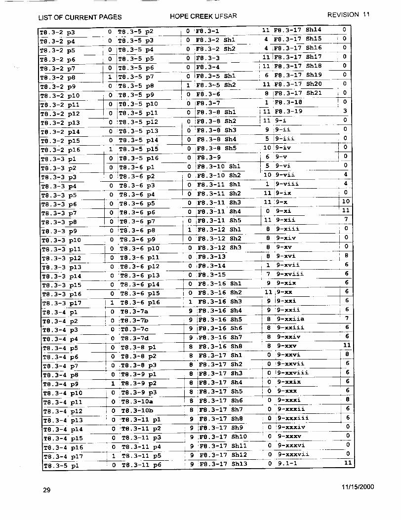
REVISION 11
LIST OF CURRENT PAGES HOPE CREEK UFSART8.3-2 p 3 0 T8.3-5 p 2 0 FP8.3-1 11 F8.3-17 Shl4 0
T8.3-2 p 4 0 T8.3-5 p 3 0 F8.3-2 Shl 4 F8.3-17 Shl5 0
T8.3-2 p5 0 IT8.3-5 p 4 0 PF8.3-2 Sh2 4 iF8.3-17 Sh16 0
T8.3-2 p 6 0 T8.3-5 p5 0 F8.3-3 11i F8.3-17 Shl7 0
T8.3-2 p 7 0 T8.3-5 p 6 0 IF8.3-4 11 F8.3-17 ShiB 0
T8.3-2 p8 1 T8.3-5 p 7 0 F8.3-5 Shl 6 F8.3-17 Shl9 0
T8.3-2 p 9 - 0 !T8.3-5 p8 1 !F8.3-5 Sh2 11 F8.3-17 Sh20 0
T8.3-2 plO 0 ýT8.3-5 p 9 0 F8.3-6 8 IF8.3-17 Sh2l 0
T8.3-2 pll 0 T8.3-5 plO 0 IF8.3-7 1 F8.3-18 0
T8.3-2 p 1 2 0 T8.3-5 pll 0 F8.3-8 Shl 11 F8.3-19 3
T8.3-2 p 1 3 0 !T8.3-5 p 1 2 0 F8.3-8 Sh2 11 9-i 0
T8.3-2 p14 0 T8.3-5 p13 0 PF8.3-8 Sh3 9 9-ii 0
T8.3-2 p 1 5 0 T8.3-5 p14 r 0 'F8.3-8 Sh4 5 ý9-iii 0
T8.3-2 p 1 6 1 T8.3-5 p 1 5 0 IF8.3-8 Sh5 10 9-iv 0
T8.3-3 pl 0 ýT8.3-5 p 1 6 0_ F8.3-9 6 9-v 0 T8.3-3 p 2 0 T.3-6 p1 0 F8.3-10 Shl 5 9-vi 0
T8.3-3 p3 0 lT8.3-6 p 2 0 F8.3-10 Sh2 10 9-vii 4
T8.3-3 p4 0 T8.3-6 p3 0 F8.3-11 Shl 1 9-viii 4
T8.3-3 p5 0 T8.3-6 p4 0 PF8.3-11 Sh2 11 9-ix 0
T8.3-3 p6 0 T8.3-6 p5 0 IF8.3-lI Sh3 11 9-x 10
T8.3-3 p 7 0 T8.3-6 p6
T8.3-3 p 8 0 T8.3-6 p7
T8.3-3 p 9 0 IT8.3-6 p8
0 =F8.3-1I Sh4
0 F8.3-11
1 F8.3-12
0 9-xi
Sh5 11 9-xii 7
Shl 8 9-xiii 0
T8.3-3 plO 0 T8.3-6 p9 0 F8.3-12 Sh2 8 9-xiv 0
T8.3-3 pll 0 T8.3-6 plO 0 ;F8.3-12 Sh3 8 9-xv 0
T8.3-3 p12 0 ýT8.3-6 pll 0 PF8.3-13 8 9-xvi 8
T8.3-3 p13 0 ýT8.3-6 p12 0 F8.3-14 1 9-xvii 6
T8.3-3 p14 0 T8.3-6 p13 0 F8.3-15 7 9-xviii 6
T8.3-3 p15 0 T8.3-6 p14 0 F8.3-16 Shl 9 9-xix 6
0 T8.3-6 p15
T8.3-3 p 1 7 1 iT8.3-6 p16
T8.3-4 pl 0 jT8.3-7a
T8.3-4 p 2 0 'T8.3-7b
T8.3-4 p 3
T8.3-4 p 4
T8.3-4 p 5
T8.3-4 D6
0 :T8.3-7c
0 T8.3-7d
0 T8.3-8 pl
0 oT8.3-8 p2
0 IF8.3-161 IF8.3-16
9 PF8.3-16 Sh4
9 F8.3-16 Sh5
9 F8.3-16 Sh6
Sh2 11 9-xx 6
Sh3 9 9-xxi 6
9 '9-xxii 6
8 9-xxiia 7 8 9-xxiii 6
9 PF8.3-16 Sh7 8 19-xxiv 6 8 F8.3-16 Sh8 8 j9-xxv 11
8 PF8.3-17 Shi 0 9-xxvi 8T8.3-4 p7 -p 8 6T8.3-4 p7 0 'T8.3-8 p3 8 F8.3-17 Sh2 0 9-xxvii 6 iT8.3-4 p8 0 •T8.3-9 pl 8 F8.3-17 Sh3 i0 19-xxviii =!6
T8.3-4 p9 1 T8.3-9 p2 8 IF8.3-17 Sh4 0 9-xxix 6
T8.3-4 plo 0 iT8.3-9 p3 8 F8.3-17 Sh5 0 9-xxx 6
T8.3-4 pll 0 T8.3-10a 8 PF8.3-17 Sh6 0 19-xxxi 8
12 8 F8.3-17 Sh7
T8.3-4 p13 0 T8.3-11 pl 9 F8.3-17 Sh8 0 19-xxxiii 6
T8.3-4 p14 0 ýT8.3-11 p2 9 F8.3-17 Sh9 0 9-xxxiv 0
T8.3-4 p15 0 T8.3-11 p 3 9 F8.3-17 Shl0 0 9-xxxv 0
T8.3-4 p 1 6 0 T8.3-11 p 4 9 F8.3-17 Shl1 0 9-xxxvi 0
T8.3-4 p 1 7 1 T8.3-11 p 5 9 F8.3-17 Shl2 0 9-xxxvii 0
T8.3-5 pl 0 T8.3-11 p 6 9 IF8.3-17 Shl3 0 i9.1-1 11
11/15/200029
T8.3-3 p16
o l •-xxxii 6-T8.3-4 p S0 IT8.3-10b
11
I i
Ii
i
i
12
LIST OF CURRENT PAGES HOPE CREEK UFSAR
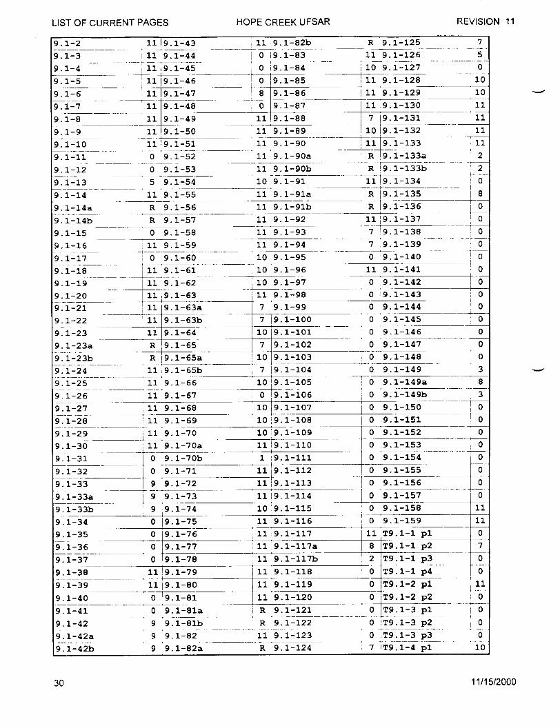
LIST OF CURRENT PAGES HOPE CREEK UFSAR REVISION 119.1-2
9.1-3
9.1-4 9.1-5
9.1-6
9.1-7
9.1-8
9.1-9
9.1-10
9.1-11
9.1-12
9.1-13
9.1-14
9.1-14a
9.1-14b
9.1-15
9.1-16 9.1-17
9.1-18
9.1-19
9.1-20
9.1-21
9.1-22
9.1-23
9. 1-23a
9. 1-23b
9. 1-24
9. 1-25
9. 1-26
9.1-27
9. 1-28
9.1-29
9.1-30
9.1-31
9.1-32
9.1-33b
9.1-33a
9.1-33b
9.1-34
9.1-35
9.1-36
9.1-37
9.1-38
9.1-39
9.1-40
9.1-41
9.1-42
9. 1-42a
9. 1-42b
11 9.1-55 11 9.1-91a
R 9.1-56 11 9.1-91b
R 9.1-57 11 9.1-92
0 9.1-58 11 9.1-93
11 9.1-59 11 9.1-94
0 9. 1-60 10 9.1-95
11 9.1-61 10 9.1-96
111 9 1-62 10 9.1-97
11 9.1-63 11 9.1-98
11i 9.1-43
1ii 9.1-44
11 9.1-45
11 19.1-46
11 9.1-47
11 9.1-48 11 9.1-49
11 9.1-50
11 9.1-51
0 9.1-52
0 9.1-53
5 9.1-54
0 :9.1-143
11 9 1-63a 7 9.1-99 0 9.1-144
11 9.1-63b 7 !9.1-100 0 9.1-145
11 9.1-64 10 9.1-101 0 9.1-146
R 19.1-65 7 9.1-102 0 9.1-147
R 9.1-65a 10 9.1-103 0 9.1-148
11 9.1-65b 7 19.1-104 0 9.1-149
11 9.1-66 10 19.1-105 0 9.1-149a
11 9.1-67 0 19.1-106 0 9.1-149b
11 9.1-68
11 9.1-69
11 9.1-70
11 9.1-70a
0 9.1-70b
0 9.1-71
10 19.1-107
10 19.1-108
10 '9.1-109
1119.1-110
1 '9.1-111
11 19.1-112
9.1-72 11 19.1-113
9.1-73 11 19.1-114
9 9.1-74
0 19.1-75
0 19.1-76
0 19.1-77
0 ý9.1-78
11 !9.1-79
11 9.1-80
0 9.1-81
0 9.1-81,
9 9.1-81]
9 9.1-82
9 9.1-82.
10 9.1-115
11 9.1-116
11 i9.1-117
11 9.1-117a
11 9.1-117b
11 9.1-118
0 9.1-150
0 ý9.1-151
0 9.1-1520 .9.1-153
0 9.1-154
0 9.1-155
0 9.1-156
0 9.1-1570 9.1-158
'!0 9.1-159
11 T9.1-1 pl
8 T9.1-1
2 ýT9.1-1
p2
p3
0 ýT9.1-l p4
11 9.1-119 0 T9.1-2
11 9.1-120 0 IT9.1-2
R 9.1-121 0 ýT9.1-3
R 9.1-122 0 IT9.1-3
11 9.1-123 0 T9.1-3
R 9.1-124 7 T9.1-4
p 1
p2
pl p2
p 3
pl
11/15/2000
7
5
0
10
11 9.1-82b
0 19.1-83
0 19. 1-84 !0 19.1-85
8 9.1-86
0 9. 1-87
119 .1-88
11 9.1-89
11 9.1-90
11 9.1-90a
11 9.1-90b
10 9.1-91
9
9
0
0
0
0
0
3
8
3
+--1o
0
0
0
0
11
0
0
0
10
0 10
a
b
a
30
R 9.1-125
11 9.1-126
110 9.1-127
11 9. 1-128
11 9.1-129
11 9.1-130
- 7 19.1-131
10 9.1-132
1•1 9. 1--133
R 9.1-133a
R i9.1-133b
11 9.1-134
R 19.1-135
R 19.1-136
11 9.1-137
7 9.1-138
7 9.1-139
0 9.1-140
11 9.1-141
0 9.1-142
10
11
11
11
11
2
2
0
8
0
0
0
0
0
0
'0
0 . .
SJ
i
I
HOPE CREEK UFSAR REVISION 11LIST OF CURRENT PAGES
]
-
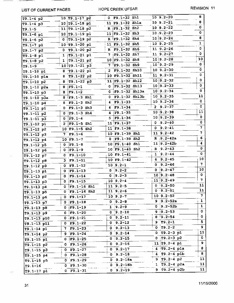
LIST OF CURRENT PAGES HOPE CREEK UFSAR REVISION 11
T9.1-4 p2 10T9.1-17 p2 10 F9.1-32 Shl 10 9.2-20 8
T9.1-4 p3 10 T9.1-18 pl 11 F9.1-32 Shla 10 9.2-21 8
T9.1-5 pi 1T9.1-18 p2 R iF9.1-32 Sh2 10 9.2-22 0
T9.1-6 pl 1 T9.I-1 p2 10 F9.1-32 Sh3 10 9.2-23 0
T9.1-6 10 61-1 p3 7 F9.1-32 Sh4 10 i9.2-24 0
T9.1-7 pl 8 IT9.1-20 pl 2 11 F9.1-32 Sh5i 10 9.2-25 0
T9.1-7 p2 0 lT9.1-20 p 2 0R F9.1-32 Sh6 1L 9.2-26 0
T9.1-8 pl 1 lT9.1-21 p l 7 lF9.1-32 Sh7 11 9.2-27 0
T9.1-8 p2 8 9.1-1 p20 F9.1-32 Sh8 10 19.2-28 10
T9.1-9 10 p8T9.1-21 p3 7 F9.1-32 Sh9 10 9.2-29 0
T9.1-10 pl 8 1T9.1-22 pl 2 F9.1-32 Shl0 10 9.2-30 1
T9.1-10 pla 8 T9.1-22 S2 4i F9.1-32 Sh11 __ 11 9.2-31_0
T9.1-10 p2 8 !T9.1-22 p3 4 F9.1-32 Sh4 2 i0 9.2-32 0
T9.1-10 p 2 a 8 F9.1-1 0 F9.1-32 Sh 3 10 9.2-33 0
T9.1-10 p 3 8 F9.1-2 0 IF9.1-32 Shl3a 10,9.2-34 0
T9.1-10 p3a 8 IF9.1-3 Shl 0 1F9.1-32 Shl3b 10 9.2-35 11
T9.1-10 p4 8 F9.1-3 Sh2 14 F9.1-33 10 9.2-36 0
T9.1-11 pl 0 F9.1-3h3 4 F9.1-34 2 9.2-37 0 T91-1i p 2 0 F9.1-34 4 F9.1-35 10 9.2-38 0
T9.1-11 p 3 0 F9.1-4 5 F9.1-36 10 19.2-39 0
T9.1-12 pl 2 F1 SF 9.1-S19.-37 0 9.2-40 0
T9.1-12 p2 I0 F9.1-5 Sh2 11 F9.1-38 0 9.2-41 7
T9.1-12 p3 7 iF9.1-6 10 F9.1-39 Shl 11 9.2-42 7
T9.1-12 p4 i0 F9.1-71 0 iF9.1-39 Sh2 R 9.2-42a 6
T9.1-12 p5 0 jF9.1-8 10 F9.1-40 Shl 1119.2-42b 1
T9.1-12 p6 0 :F9.1-9 10 F9.1-40 Sh2 R 9.2-43 0
T9.1-12 p7 0 F9.1-10 10 F9.1-41 81 9.2-44 0 T9.1-12!1 p89.9.2-41
T9.1-12 p 1 3 I F9.1-11 90 69.2-5
T9.1-12 p9 0 F9.1-12 1049.2-1 0 9.2-46 7
T9.1-13 pl 0 lF9.1-13 0 19.2-2 0 9.2-47 10
T9.1-13 p2 0 IF9.1-14 0 9.2-3 10 9.2-48 0 T9.1-13 p3 0 IF9.1-15 1 0 !9.2-4 11ii19.2-49 7
T9. 1 -13 p4 0 !F9.1-16 Shl 11 9.2-5 0 9.2-50 llI
T9.1-13 p5 0 IF9.1-16 Sh2 11 9.2-6 0 19.2-51 ,11
T9.1-13 p6 0 iF9.1-17 110'9.2-7 1 0 9.2-52 ,7
T9.1-13 p7 0 F9.1-18 0 19.2-8 9 9.2-52ab 1
T9.1-13 p8 0 1F9.1-19 1 ý9.2-9 0 9.2-52b 1 T9.1-13 p9 0 IF9.1-20 0 !,9.2-10 9 9.2-53 0
T9.1-13 pl0 0 ;F9.1-21 ;0 9.2-11 8 ý9.2-54 o
T9.1-13 pll 0 iF9.1-22 0 19.2-12 9 !T9.2-1 5
T9.1-14 pl 7 'F9.1-23 i0 19.2-13 0 :T9.2-2 9
T9.1-14 p2 9 IF9.1-24 0 ý9.2-14 0:1 iT9.2-3 pl 11
T9.1-15 pl 0 lF9.1-25 0 !9.2-15 0 ýT9.2-3 p2 0
T9.1-15 p2 0 !F9.1-26 i 0 '9.2-16 11 T9.2-4 pl 9
T9.1-5 p3 iF91-27 0 '9.2-17 4 IT9.2-4 pla8
T9.1-15 p4 0 lF9.1-28 0 9.2-18 4 T9.2-4 plb 8
T9.1-15 p5 0 !:F9.1-29 0 9.2-18a. 9 T9.2-4 p2 11
T9.1-16 0 'F9.1-30 0 9.2-18b 1 T9.2-4 p2a 11
T9.1-17 pl- 0 F9.1-31 0.. 0-9.2-1•9- 9 'T9.2-4 p2b 11
31 11/15/2000

LIST OF CURRENT PAGES
T9.2-4 p2c 11 9.3-10b
T9.2-5 p1 0 9.3-11
T9.2-5 p2 0 9.3-12
T9.2-6 pl 7 9.3-13
T9.2-6 p 2 6 9.3-14
T9.2-7 10 9.3-15
T9.2-8 10 9.3-16
T9.2-9 pl 11 9.3-17
T9.2-9 p 2 11 9.3-18
F9.2-1 0 9.3-19
F9.2-2 11 9.3-20
F9.2-3 1119.3-21
F9.2-4 Shl 11 9.3-22
F9.2-4 Sh2 11 9.3-23
F9.2-4 Sh3 9 9.3-24
F9.2-5 11 9.3-25
F9.2-6 Shl 4 9.3-26
F9.2-6 Sh2 10 19.3-27
F9.2-7 8 9.3-28
F9.2-8 9 9.3-29
F9.2-9 10 9.3-30
F9.2-10 10 9.3-31
F9.2-11 Shl 10 9.3-32
F9.2-11 Sh2 0 9.3-33
F9.2-12 0 9.3-34
F9.2-13 Shl 11 9.3-35
F9.2-13 Sh2 6 9.3-36
F9.2-14 Shl !10 9.3-37
F9.2-14 Sh2 6 9.3-38
2 9.3-57
10 9.3-58
0 9.3-59
0 9.3-59a
0 9.3-59b
0 9.3-60
0 9.3-61
0 9.3-62
2 9.3-62a
0 !9.3-62b
0 !9.3-63
2 19.3-64
10 i9.3-65
2 19.3-65a
0 9.3-65b
0 9. 3-66
0 ýT9.3-1
0 T9.3-1 i
2 T9.3-1
0 T9.3-1 I
0 T9.3-1 p
0 iF9.3-8
0 F9.3-9
1 F9.3-10
1 F9.3-11
1 F9.3-11
0 F9.3-12
0 F9.3-12
11 F9.3-12
3 F9.3-12
3 !F9.3-13
11 F9.3-14
0 F9.3-14
3 F9.3-14
5 F9.3-14
3 F9.3-15
0 9.4-1
1 • 3 19.4-2
2 ... 3 19.4-3
3 3 9.4-4
4 3 9.4-5
5 3 *9.4-6
0 T9.3-2 9 9.4-7
0 T9.3-3 pl 11 9.4-8
7 T9.3-3 p 2
9 T9.3-3
0 T9.3-4
11 T9.3-4
11 T9.3-5
p 3
pl p2
pl11 T9.3-5 p 2
9 9.4-9 9 9.4-10
8 9.4-11
8 9.4-12
8 9.4-13
0 9.4-14
0 0 0
0
0
10
0
0
0
F9.2-14 Sh3 8 19.3-39
F9.2-14 Sh4 10 !9.3-40
F9.2-15 Shl 10 9.3-41
F9.2-15 Sh2 10 9.3-42
F9.2-15 Sh3 8 !9.3-43
F9.2-16 11 9.3-44
F9.2-17 9 9.3-45
9.3-1 9 9.3-46
9.3-2 3 9.3-46a
9.3-3 4 9. 3-46b
9.3-4 4 9 .3-47
9.3-5 4 9.3-48
9.3-5a 3 9.3-49
9.3-5b 3 9.3-50
9.3-6 0 9.3-51
9.3-7 9 9.3-52
9.3-8 0 9.3-53
9.3-9 9 9.3-54
9.3-10 9 9.3-55
9.3-10a 2 9.3-56
7 T9.3-6
0 T9.3-6
11 T9.3-6
8 T9.3-6
11 T9.3-7
11 T9.3-8
0 T9.3-8
8 F9.3-1
2 F9.3-2
2 F9.3-3
8 F9.3-4
0 F9.3-4
0 F9.3-4
0 F9.3-5
1 F9.3-5
0 F9. 3-6
9 F9.3-6
1 F9.3-7
0 F9.3-7
0 F9.3-7
pl p2
p 3
p 4
pl p2
Shl
Sh2
Sh3
Shl
Sh2
Shl
Sh2
Shl
Sh2
Sh3
11 9.4-15
11 9.4-16
11 9.4-17
11 9.4-18
9 9.4-19
11 ý9.4-20
7 19.4-21
11 19.4-22
10 9. 4-23
10 9.4-24
11 !9.4-25
8 9.4-26
11 9.4-27
10 9.4-28
10 9.4-28a
0 9.4-28b
0 9.4-29
11 9.4-30
3 9.4-31
11 9.4-32
11/15/2000
0 o 0
0
0
0
0
0
~t0 to
1
7
0
0 0
HOPE CREEK UFSAR REVISION 11
6 1
0
Shl 10
Sh2 6
Shl O 0
Sh2 10
Sh3 10
Sh4 8
8
Shl 10
Sh2 3
Sh3 0
Sh4 8
5
9
8
0
0
0
P
P P
32
LIST OF CURRENT PAGES HOPE CREEK UFSAR REVISION 11
9.4-33 0 9.4-82 0 IT9.4-10 pla 8 F9.4-9 Shl 10
9.4-34 0 9.4-83 1 IT9.4-10 p 2 8 IF9.4-9 Sh2 10
9.4-35 0 9.4-83a 1 .4-10 p2a 10 ýF9.4-10 10
9.4-36 0 9.4-83b 1 T9.4-11 pa 0 F9.4-11 10
9.4-37 0 9.4-84 0 T9.4-11 p2 0 F9.4-12 10
9.4-38 0 9.4-85 0 T9.4-12 p1 0 ,F9.4-13 2
9.4-39 0 19.4-86 11 T9.4-12 p 2 0 F9.4-14 8
9.4-40 0 '9.4-87 11i T9.4-12 p 3 0 :F9.4-15 Shl 9
9.4-41 0 9.4-88 11 T9.4-12 p 4 0 F9.4-15 Sh2 8
9.4-42 0 9.4-89 11 IT9.4-12 p 5 0 F9.4-16 Shl 9
9J4-43 0 9. 4-90 0 T9.4-12 p 6 0 :F9.4-16 Sh2 3
9.4-44 0 9.4-91 0 T9.4-12 p 7 0 F9.4-17 0
9.4-45 0 9.4-92 0 T9.4-12 p8 0 F9.4-18 10
9.4-46 0 19.4-93 0 T9.4-12 p 9 0 IF9.4-19 8
9.4-47 0 19.4-94 0 lT9.4-13 0 9.5-1 0
9.4-48 0 9.4-95 0 T9.4-14 pl 0 9.5-2 0
9.4-49 0 9.4-96 8 T9.4-14 p 2 0 9.5-3 0
9.4-50 0 i9.4-97 0 T9.4-15 8 9.5-4 11
9.4-51 0 9.4-98 0 T9.4-16 pl 0 9.5-5 2
9.4-52 0 9.4-99 8 !T9.4-16 p 2 11 9.5-6 0
9.4-53 0 9.4-100 8 T9.4-16 p3 0 9.5-7 8
9.4-54 10 9.4-101 8 1T9.4-17 pl 0 9.5-8 7
9.4-55 0 [9.4-102 8 T9.4-17 p2 0 9.5-9 0
9.4-56 0 T9.4-1 p1 2 T9.4-18 0 9.5-10 0
9.4-57 0 ýT9.4-1 p 2 0 :T9.4-19 0 9.5-11 0
9.4-58 0 lT9.4-1 p 3 0 'T9.4-20 p1 0 9.5-12 0
9.4-59 0 T9.4-2 p1 0 T9.4-20 p2 0 9.5-13 9
9.4-60 0 T9.4-2 p2 0 T9.4-20 p3 8 :9.5-14 0
9.4-61 0 T9.4-2 p3 0 T9.4-20 p4 8 9.5-15 0
9.4-62 0 lT9.4-3 pl 10 T9.4-20 p5 0 9.5-16 0
9.4-63 0 T9.4-3 p2 0 T9.4-21 pl 0 9.5-17 0
9.4-64 9 T9.4-4 0 jT9.4-21 p 2 0 i9.5-18 0
9.4-65 0 T9.4-5 i 0 IT9.4-21 p 3 0 !9.5-19 0
9.4-66 0 oT9.4-6 p1 T9.4-22 p1 9.5-20 0
9.4-67 0 'T9.4-6 p 2 0 1T9.4-22 p 2 0 9.5-21 0
9.4-68 '0 T9.4-6 p 3 0 T9.4-22 p 3 0 9.5-22 0
9.4-69 0 JT9.4-6 p4 0 T9.4-22 p4 0 9.5-23 0
9.4-70 0 T9.4-6 p5 0 !T9.4-22 p5 0 9.5-24 0
9.4-71 0 !T9.4-6 p6 0 F9.4-1 10 9.5-25 0
9.4-72 0 IT9.4-6 p7 0 lF9.4-2 8 9.5-26 0
9.4-73 0 'T9.4-6 p8 0 lF9.4-3 1019.5-27 0
9.4-74 0 'T9.4-6 p9 0 iF9.4-4 8 1 9.5-28 6
9.4-75 0 JT9.4-6 plO 0 IF9.4-5 10 9.5-29 7
9.4-76 0 lT9.4-7 p1 1 :F9.4-6 Shi 10 9.5-30 0
9.4-77 0 T9.4-7 p2 0 IF9.4-6 Sh2 0 9.5-31 0
9.4-78 8 T9.4-8 10 F9.4-6 Sh3 8 9.5-32 0
9.4-79 0 T9.4-9 p1 8 F'9.4-7 2 9.5-33 0
9.4-80 0 T9.4-9 pla 8 F9.4-8 Shl 3 9.5-34 0
9.4-81 1 T9.4-10 pl 9 iF9.4-8 Sh2 3 9.5-35 0
33 11/15/2000
LIST OF CURRENT PAGES HOPE CREEK UFSAR REVISION 119.5-36
9.5-37
9.5-38
9.5-39
9.5-40
9.5-40a
9.5-40b
9.5-41
9.5-42
9.5-43
9.5-44
9.5-45
9.5-46
9.5-47
9.5-48
9.5-48a
9. 5-48b
9.5-49
9.5-50
9.5-51
9.5-52
9.5-53
9.5-54
9.5-55
9.5-56
9.5-57
9.5-58
9.5-59
9.5-60
9.5-61
9. 5-61a
9. 5-61b
9.5-62
9.5-63
9.5-64
9.5-65
9.5-66
9.5-67
9.5-68
9.5-69
9.5-70
9.5-71
9.5-72
9.5-73
9.5-73a 9.5-73b 9.5-74
9.5-75
9.5-76
0 9.5-110
0 9.5-111
0 9.5-112
10 19.5-159
6 9.5-160
6 9.5-161
0 9.5-113 9 9.5-162
2 9.5-114 9 9.5-163
2 9.5-115 0 9.5-164
2 9.5-116 0 9.5-165
0 9.5-117 0 9.5-166
6 9.5-118 7 9.5-167
0 9.5-119 0 9.5-168
0 ý9.5-77 8 9.5-120
7 19.5-78 9 9.5-121
2 :9.5-78a 9 9.5-122
0 19.5-78b 9 9.5-123
2 9.5-79 9 9.5-124
2 9.5-80 9 19.5-125
2 9.5-81 0 19.5-12E
8 T9.5-82 0 9.5-127
8 9.5-83 0 9.5-128
9 9.5-84 0 9.5-12S
3 9.5-85 0 9.5-13C
9 9.5-86 9 9.5-131
5 9.5-87 11 9.5-132
7 9.5-88 8 9.5-13"
5 9.5-89 1 8 9.5-134
5 !9.5-90 7 9.5-13E
5 ý9.5-90a i 1 9.5-13E
0 9.5-90b 1 9.5-137
0 9.5-91 0 19.5-13E
11 9.5-92 9 9.5-13S
0 9.5-93 9 9.5-14C
0 9.5-94 0 9.5-141
0 9.5-95 7 9.5-142
0 9.5-96 0 9.5-14-
0 9.5-97 0 9.5-144
8 9.5-98 0 9.5-14!
0 9.5-99 0 9.5-14E
0 !9.5-100 0 9.5-14'
8 19.5-101 1 9.5-14E
4 19.5-102 3 9.5-14S
8 19.5-102a 1 9.5-15(
9 9.5-102b 1 9.5-151
8 9.5-103 3 ý9.5-15i
8 9.5-104 1 19.5-15.'
0 9.5-105 0 9.5-154
2 9.5-106 0 9.5-15!
0 9.5-107 0 9.5-15(
4 9.5-108 0 19.5-15'
0 19.5-109 0 9.5-15E
0 9.5-179
0 9.5-180
0 9.5-181
0 9.5-182
0 9.5-183
0 T9.5-1 pl
0 T9.5-1 p 2
0 1T9.5-2 pl
0 T9.5-2 p 2
0 T9.5-2 p 3
0 T9.5-2 p 4
0 T9.5-2 p5
0 [T9.5-2 p 6
0 ýT9.5-2 p 7
0 iT9.5-2 pB
0 T9.5-3 pl
0 T9.5-3 pla
6 T9.5-3 p 2
0 T9.5-3 p 3
0 T9.5-3 p 4
0 T9.5-3 p5
0 T9.5-4 pl
0 7
0
2
0
2
9
7
8
8
9i 8
10
0 T9.5-4 p 2 0
0 T9.5-4 p 3 0
0 T9.5-5 pl
8 T9.5-5 p 2
0 T9.5-6 pl
0 ýT9.5-6 p 2
0 'T9.5-7
10 T9.5-8 pl
3 !T9.5-8 p 2
3 ýT9.5-9 pl
0 T9.5-9 p2 0 T9.5-10
0 !T9.5-11 pl
0 IT9.5-11 p 2
0 iT9.5-11 p 3
0
0 0
0 0
00
0
0
0
0
0 0_
11/15/200034
9 19.5-169
7 9.5-170
8 9.5-171
9 9.5-172
0 9.5-173
7 !9.5-173a
9 9. 5-173b
0 9.5-174
0 9.5-175
0 9.5-176
0 9.5-177 0 9.5-178
? 8
HOPE CREEK UFSAIR REVISION 11LIST OF CURRENT PAGES
0 11
11
0
1 1
1
0
0 0 0
0
0
S8
0
S4
0
9
0
2
T9.5-11 p4 0 'T9.5-28 5 IF9.5-37 6 9A-34 0
T9.5-12 pl 0 T9.5-20 0 IF9.5-38 6 9A-35 0
T9.5-12 p2 0 T9.5-30 9 F9.5-39 6 19A-36 0
T9.5-12 p3 0 F9.5-1 9 F9.5-40 2 9A-37 0
T9.5-13 pl 0 lF9.5-2 8 F9.5-41 0 9A-3 7
T9.5-13 p 2 0 lF9.5-3 8 F9.5-42 6 9A-39 0
T9.5-14 p 0 F9.5-4 5 F9.5-43 8 9A-40 0
T9.5-15 8 0F9.5-5 9 F9.5-44 8 9A-41 0
T9.5-16 4 pF9.5-6 5 IF9.5-45 2 9A-42 2
T9.5-17 pl 0 F9.5-7 8 F9.5-46 0 9A-43 11
T9.5-17 p2 0 FF9.5- F9.5-47 0 9A-44 6
T9.5-17 p3 0 iF9.5-1 1 9.5-48 0 9A-45 8
T9.5-17 p4 0 F9.5-10 9 9A-i 6 19A-46 0
T9.5-17 p5 0 F9.5-11 15 9A-ii 0 9A-47 0
T9. 5-17 p6 0 F9.5-12 1 9A-iii 7 19A-48 0
T9.5-17 p7 0 ýF9.5-12a 6 19A-iv 8 9A-49 1
T9.5-17 p8 0 F9.5-13 08 9A-1 0 9A-50 0
T9.5-17 p9 0 F9.5-14 10 9A-2 0 9A-51 0
T9.5-17 p 2 0 11 F9.5-15 9 S9A-3 0 9A-52 0
T9.5-17 p 3 l 8 F9.5-16 S2 9A-4 0 9A-53 0
T9.5-17 p12 3 F9.5-17 8 19A-5 0 9A-54 6
T9.5-18 pl 0 F9.5-18 h0 19A-61 0 19A-55 0
T9.5-18 p2 0 'F9.5-19 10 19A-73 0 9A-56 0
T9.5-19 pl 0 F9.5-20 80 19A-81 0 9A-57 0
T9.5-19 p 2 0 F9.5-21 Shl 10 9A-9 0 !9A-58
T9.5-19 p 3 0 -F9.5-21 Sh2 0 19A-10 0 '9A-59 0
T9.5-19 p 4 0 F9.5-21 Sh3 1019A-11 0 19A-640 0
T9.5-19 p5 3 F9.5-21a Shl 2 9A-12 0 9A-61 2
T9.5-20 p15 0F9.5-21a Sh2 2 9A-13 0 9A-61a 0
T9.5-21 pl 9 F9.5-22 8 19A-14 0 89A-61b 2
T9.5-21 p2 9 IF9.5-23 Shl 0 19A-15 0 !9A-62 0
T9.5-21 p3 08 F9.5-23 Sh2 0 19A-216 0 '9A-63 0
T9.5-21 p4 0 iF9.5-24 Shl 6 19A-17 0 9A-64 0
T9.5-22 5 F9.5-24 Sh2 10 9A-18 03 9A-65 8
T9.5-23 pl 0 F9.5-25 S0 9A-19 0 9A-66 0
T9.5-23 p2 0 F9.5-26 Shl 6 9A-20 8 9A-67 0
T9.5-23 p3 11 F9.5-26 Sh2 6 9A-21 07 9A-68 0
T9.5-23 p4 0 IF9.5-27 Shl 6 9A-22 0 9A-69 0 T9.5-24 5 :F9.5-27 Sh2 6 19A-23 01A7
T9.5-25 pl 9 !F9.5-28 10 9A-24 0 9A-71 8 T9.5-25 p2 0 IF9.5-29 Shl 6 19A-25 0 ý9A-72 0
T9.5-25 p3 0 tF.-9Sh2 !I0 9A-26 8 i9A-73 0
T9.5-26 i5 IF9.5-30 8 9A-27 0 9A-74 0
T9.5-27 pl 11 IF9.5-31 8 19A-28 0 19A-75 0
T9.5-27 p2 11 F9.5-32 8 19A-29 0 0:9A-76 8
T9.5-27 p3 11 F9.5-33 6 9A-30 10 9A-77 0
T9.5-27 p4 11 F9.5-34 1 9A-31 10 9A-78 0
T9.5-27 p5 11 F9.5-35 6 9A-32 0 9A-79 0
T9.5-27 p6 11 F9.5-36 9 9A-33 6 9A-80 0
11/15/2000
REVISION 11LIST OF CURRENT PAGES HOPE CREEK UFSAR
35
LIST OF CURRENT PAGES HOPE CREEK UFSAR REVISION 110 0
0
0
0
9
9A-81
9A-82
9A-83
9A-84
9A-84a
9A-84b
9A-85
9A-86
9A-87
9A-88
9A-89
9A-90
9A-91
9A- 92
9A-93
9A-94
9A- 95
9A-96
9A-97
9A-98
9A-99
9A-100
9A-101
9A-102
9A-103
9A-104
9A-105
9A-106
9A-107
9A-108
T9A-1 pl
T9A-1 p 2
T9A-1 p 3
T9A-1 p 4
T9A-1 p5
T9A-1 p 6
T9A-1 p 7
T9A-1 p 8
T9A-1 p 9
T9A-1 plO
T9A-1 pll
T9A-1 p12
T9A-1 p13
T9A-1 p14
T9A-1 p15
T9A-1 p16
T9A-1 p 1 7
T9A-1 pl8
T9A-1 p 1 9
8 T9A-1 p 4 8
8 !T9A-1 p49
8 T9A-1 p50
8 T9A-1 p51
8 !T9A-1 p52
8 T9A-1 p 5 3
8 T9A-1 p 5 4
7 T9A-1 p 5 5
T9A-2 pl
8 T9A-2 p2
T9A-2 p 3
8 T9A-2 p4
8 T9A-2 p5
8 T9A-2 p6
8 T9A-2 p7
8 ýT9A-2 p8
8 T9A-2 p9
8 T9A-2 plO
8 T9A-2 p9
0 IT9A-1 p 2 0 8 T9A-2 p12 0 iTgA-8 p13
0 T9A-1 p 2 1 8 T9A-2 p 1 3 0 iT9A-8 p14
0 T9A-1 p 2 2 8 T9A-2 p 1 4 0 T9A-8 p15
3 T9A-1 p22a 8 T9A-2 p 1 5 0 T9A-8 p16
3 'T9A-1 p 2 3 !11 T9A-2 p 1 6 0 T9A-8 p17
3 T9A-1 p23a 1 8 T9A-3 pl 0 T9A-8 p18
7 T9A-1 p 2 4 8 !T9A-3 p 2 0 T9A-8 p19
7 T9A-1 p 2 5 7 ýT9A-3 p 3 0 T9A-8 p20
7 T9A-1 p 2 6 8 IT9A-3 p 4 i 10 T9A-8 p21
7 T9A-1 p 2 7 8 |T9A-3 p5 0 ýT9A-8 p22
+ 6 T9A-1 p 2 8 8 T9A-3 p6 0 T9A-8 p23
0 T9A-1 p 2 9 8 T9A-3 p 7 0 T9A-8 p24
0 ýT9A-1 p 3 0 8 T9A-3 p 8 0 T9A-8 p25
o lT9A-1 p 3 1 7 T9A-3 p 9 0 T9A-8 p26
o ýT9A-1 p 3 2 7 T9A-3 plO 0 T9A-9 pl
0 T9A-1 p 3 3 8 T9A-3 pll 0 T9A-9 p2
0 T9A-1 p 3 4 8 T9A-3 p 1 2 0 T9A-9 p3
8 T9A-1 p 3 5 8 T9A-3 p 1 3 0 T9A-9 p4
10 T9A-1 p 3 6 11 T9A-3 p 1 4 6 T9A-9 p5
i 10 T9A-1 p 3 7 7 iT9A-3 p 1 5 0 :T9A-9 p6
0 T9A-I p 3 8 11 T9A-3 p 1 6 6 iT9A-9 p7
0 0ý9A-1 p 3 9 11 T9A-3 p1 7 0 T9A-9 p8
0oT9A-1 p4 0 11 T9A-4 p1 8 T9A-9 p9
0 ýT9A-1 p 4 1 11 T9A-4 p 2 0 T9A-9 plO
9 T9A-1 p 4 2 11 T9A-5 pl 9 T9A-9 pll
0 'T9A-1 p 4 3 11 T9A-5 p 2 9 T9A-9 p12
2 T9A-1 p 4 4 11 T9A-5 p 3 0 T9A-9 p13
2 T9A-1 p 4 5 8 T9A-5 p 4 0 T9A-9 p14
2 T9A-1 p 4 6 11 T9A-6 pl 11 T9A-9 p15
2 T9A-1 p 4 7 11 T9A-6 p 2 0 T9A-9 p16
11 T9A-6 p 3 2 T9A-9 p 1 7 11
7 'T9A-6 p4 0 T9A-9 p 1 8 0
8 T9A-6 p4a 2 T9A-9 p 1 9 0
8 T9A-6 p 5 0 T9A-9 p 2 0 9
8 IT9A-6 p6 0 T9A-9 p 2 1 0
8 IT9A-6 p 7 0 T9A-9 p 2 2 8
11 T9A-7 2 T9A-9 p 2 3 0
11 T9A-8 pl 7 T9A-9 p 2 4 1
0 T9A-8 p 2 0 T9A-9 p25 7
6 'T9A-8 p 3 0 T9A-9 p26 1
0 T9A-8 p 4 0 !T9A-9 p 2 7 1
0 T9A-8 p5 0 lT9A-10 pl
0 T9A-8 p 6 0 T9A-10 p2
0 T9A-8 p 7 0 'T9A-10 p2a
1 !T9A-8 p 8 0 T9A-10 p3
0
0
0
0
T9A-8 p9
T9A-8 plO
T9A-8 pll
T9A-8 p12
0 T9A-10
2 T9A-10
0 T9A-10
0 T9A-10
p 4
p 5
p6
p 7
7
0
0
0
0
7
7
11/15/2000
0
0
7
0
2
0
7
7
0
0
0
0
0
0
0
0
0
0
0
0
0
0
0
36
HOPE CREEK UFSAR REVISION 11LIST OF CURRENT PAGES
: A ! ... . ..
LIST OF CURRENT PAGES HOPE CREEK UFSAR REVISION 11
T9A-12 p 22 0 lT9A-25 p5 0 IT9A-46 11 T9A-77 p 2 8
T9A-12 p 2 3 0 T9A-25 p3 8 jT9A-47 26 ilT9A-77 p3O 8
T9A-12 p 24 0 T9A-14 p 7 2 ýT9A-48 07 T9A-77 p4l 11
T9A-12 p 2 5 0 'T9A-25 p8 0 T9A-34 p --- 2 IýT9A-7 81
T9A-12 2 0 T9A-25 p3 2 'T9A-50 821 T9A-79 01 1
T9A-12 p 2 7 0 'T9A-26 4 2 IT9A-31 831 T9A-60 8l1
T9-A-12 p 28 0 T9A-27 85 9T9A-52 04 1T9A-61 021
T -9A-12 p39 0 IT9A-28 8l 7,T9A-53 05 llT9A-8 831
T9A-12 p30 0 T9A- p29 8 'T9A-34 06 1T9A-83 p41
T9A-12 p 3 1 0 T9A- p30 2 'T9A-55 07 7T9A-84 8
T9A-12 p 3 2 0I9A-15p41 0 T9A-35 0l T9A-85 8
T9A-12 p 3 3 0 -T9A-32 p 1 2 T-5 21 T9A-86 8
T9A-12 p39 0 T9A-32 p 7 7 IT9A-60 p4 01 T9A-92
T9A-12 p40 0 T9A-33 p 1 7 T9A-60 p 54 T9A-93 8
T9A-12 p 4 1 0 T9A-33 p2 1 T9A-60 p 6 0 IT9A-94 8
T9A-12 p 42 0 T9A-33 p3 11T9A-60 p7 0? T9A-695
T9A-13 p14 6 T9A-33 p4 11T9A-60 8 0 T9A-72 0
37-1 11/15/2000 '9A399 T9-7
LIST OF CURRENT PAGES HOPE CREEK UFSAR REVISION 11T9A-97 pl 0 F9A-19 .
T9A-97 p 2 -8 rF9A-20
T9A-97 p 3 8 F9A-21 ,
T9A-97 p 4 8 IF9A-21 1
T9A-98 6 F9A-22
T9A-99 pl 0 IF9A-23
T9A-99 p 2 8 F9A-24
T9A-99 p 3 8 F9A-25
T9A-99 p 4 8 F9A-26
T9A-99 p5 8 F9A-27
T9A-100 pl 11 F9A-28
T9A-100 p 2 11 F9A-29
T9A-100 p 3 5 F9A-30
T9A-100 p 4 11 F9A-31
T9A-100 p5 3 F9A-32
T9A-100 p6 1 5 F9A-33
T9A-100 p7 5 F9A-34
T9A-101 p1 11 F9A-35
T9A-101 p 2 11 F9A-36
T9A-101 p3 5 ýF9A-37
T9A-101 p 4 11 lFMA-38
T9A-101 p5 3 F9A-39
T9A-101 p6 3F9A-40
T9A-101 p7 3 :F9A-41
T9A-102 11 F9A-42
T9A-103 7 F9A-43
T9A-104 7 F9A-44
F9A-1 10 9B-1
F9A-2 0 9B-2
F9A-3 !10 9B-3
F9A-4 Shi 0 9B-4
F9A-4 Sh2 0 F9B-1
F9A-5 8 ýF9B-2
F9A-6 10 10-i
F9A-7 6 110-ii
F9A-8 0 10-iii
F9A-9 0 10-iv
F9A-10 0 10-v
F9A-11 Shl 0 lo-vi
F9A-11 Sh2 0 10.1-1
F9A-12 0 10.1-2
F9A-13 0 10.1-3
F9A-14 0 10.1-4
F9A-15 0 T10.1-1
F9A-16 9 F10.1-1
F9A-17 0 F10.1-2
F9A-18 0 10.2-1
F9A-19 Shi 11 10.2-2
F9A-19 Sh2 0 10.2-3
,h3
Shl
Sh2
11 0 8
0 8
8
8 0 0 8 8 0 0 0
9 8
8 8
8 8
10 5 6
9 5
5
0 0 0
0
0 0
0
0
0
0
6
6
0
0
0
0
0
0
0
0 0 0
10.2-4 10.2-5 10.2-6
10.2-7
10.2-8
10.2-9
10.2-1o
10. 2-11 10. 2-1; 10. 2-1 10. 2-14 10.2-15 10. 2-1i
10. 2-1
ITI0.2-2
FI0. 2-; F10. 2-2
SF10. 2FI0.2-4 FI0. 2-5
)F10. 2F10. 2FI0.2-@ FI0.2-• FI0.2-I
FI0.2-I F10.3-1 F10.2
10.3-1 ÷10.3-2
10.3-3 10.3-4
TI0.3-5 F10.3-6
10.4-1 10.4-2 10.4-3 10.4-4 10.4-5 10.4-6 10.4-7 "10.4-8 "10.4-9 10 .4-1
10.4-1
10.4-1 "10.4-1
0 10.4-37
0 110.4-38 7
0 10.4-39 0
0 :10.4-40 0
0 10.4-41 0
0 10.4-42
10 :10.4-43 0
0 10.4-44 0
10 T10.4-1 pl 0
0 T10.4-1 p 2 0
0 IT10.4-2 pl 0
0 T10.4-2 p 2 0
0 T10.4-2 p 3 0
8 T10.4-3 0
0 T10.4-4 0
9 T1o.4-5 0
10 T10.4-6 0
0 T10.4-7 pl 6
"0 T10.4-7 p 2 0
0 T10.4-7 p 3 0
0 1
2
3
11/15/2000
0 10.4-14
0 10.4-15
11 10.4-16
8 10.4-17
0 10.4-18 8 10.4-19
0 10.4-20
0 10.4-21 11 10. 4-22
3 0 10.4-22a
0 10.4-22b
0 10.4-23 6 8 I10.4-24
11 10.4-25
L 0 10.4-26 211 10.4-27
L 0 !10.4-28
0 I10.4-29
3 110.4-30
11 10.4-31
0 10.4-32
6 0 10.4-33 7 0 10.4-34
8 0 10.4-34a
9 10 10.4-34b
10 0 10.4-34c
11 9 10.4-34d
12 0 10.4-35
0 110.4-36
0
0
0 0 0 0
0
0 0 1
1
1
0 3
11
0 10 10
8
6 6 9
10
10
10
10
10
10 10
REVISION 11LIST OF CURRENT PAGES HOPE CREEK UFSAR
38
LIST OF CURRENT PAGES HOPE CREEK UFSAR REVISION 11
T10.4-7 p4 0 T11.1-5 10 T11.2-11 p3 11 T11.3-2 p2 0
T10.4-7 p 5 0 'IT11.1-6 0 Tl1.2-12 pl 8 T11.3-3 pl 0
T10.4-7 p 6 0 FII.1-1 0 T11.2-12 p 2 0 T11.3-3 p2 0
T10.4-8 0 Fl1.1-2 0 T11.2-12 p 3 0 !T11.3-4 pl 0
F10.4-1 9 Fli.1-3 0 T11.2-12 p 4 8 T11.3-4 p 2 0
F10.42 111111.2-1 11TII.2-13 pl 11!T11.3-5 pl 8
F10.4-3 Shl 11 11.2-2 0 T11.2-13 p 2 0 T11.3-5 p2 0
F10.4-3 Sh2 11 11.2-3 0 T11.2-13 p 3 0 T11.3-6 pl 0
F10.4-4 Shl 1111.2-4 0 T11.2-13 p 4 0 T11.3-6 p 2 0
F10.4-4 Sh2 11'11.2-5 0 T11.2-13 p5 0 T11.3-6 p 3 0
F10.4-5 Shl 11 11.2-6 11 T11.2-14 pl 11 T11.3-6 p4 0
F10.4-5 Sh2 8 11.2-7 11IT11.2-14 p2 11 Tll.3-6 p 5 0
F10.4-5 Sh3 11i11.2-8 11 F11.2-1 Shl 8 T11.3-6 p 6 0
F10.4-6 11 11.2-9 11 F11.2-1 Sh2 9 T11.3-6 p 7 0
F10.4-7 Shl 9 11.2-10 7 F11.2-2 Shl 11 T11.3-6 p8 0
F10.4-7 Sh2 8 '11.2-11 0 F11.2-2 Sh2 5 T11.3-6 p 9 0
F10.4-8 10 11.2-12 1i1F11.2-3 10 T11.3-7 0
11-i 7 11.2-13 11 F11.2-4 Shl 6 T11.3-8 pl 0
11-i 11 11.2-14 11 F11.2-4 Sh2 6 IT11.3-8 p 2 0
11-iii 0 11.2-15 11IF11.2-4 Sh3 8 F11.3-1 0
11-iv 0 T11.2-1 pl 11 Fll.2-5 Shl 11IF11.3-2 9
11-v 0 T11.2-1 p2 0 F11.2-5 Sh2 11 F11.3-3 5
11-vi4 0 T11.2-1 p 3 0 F11.2-6 0 F11.3-4 11
11-vii 6 T11.2-1 p 4 0 11.3-1 8 F11.3-5 11
11-viii 8 T11.2-2 pl 0 '11.3-2 8 F11.43-6 0
11.1-1 0 T11.2-2 p 2 0 11.3-3 7 IF11.3-7
11.1-2 0 T11.2-3 pl 0 11.3-4 0 11.4-1 11
11.1-3 0 T11.2-3 p 2 0 11.3-5 0 11.4-2 10
11.1-4 0 T11.2-3 p3 0 11.3-6 0 11.4-3
11.1-5 8 T11.2-3 p4 0 11.3-7 0 11.4-4 11
11.1-6 0 1 T.l.2-4 pl 0 ý11.3-8 0 11.4-4a R
11.1-7 0 T11.2-4 p2 0 11.3-9 0 11.4-4b1 R
11.1-8 p10 T11.2-5 pl 0 11.3-10 0 11.4-5 11
11.1-9 0 T11.2-5 p2 0 11.3-11 0 221.4-6 11
11.1-10 0 T11.2-6 pl 1 11.3-12 0 11.4-7 31
11.1- 1 0 T11.2-6 p2 0 11.3-13 8 11.4-8 11 11.1-12 0 'T11.2-7 pl 11:11.3-14 0 11.4-9 11
11.1-13 0 T11. 2-7 p2 11111. 3-15 0 111.4-10 r 1
11. 1--14 0 711. 2-8 pl 01i.3-16 9 111. 4-11 1
HE -1-15 0 T11.2-8 p2 0 11.3-17 0 11.4-11a R
11.1-16 0 T11.2-9 pl 0 11.3-18 0 11.4-11b pR 111170T11.2-9 p2 0 11.3-19 1 111.4-12 11
11.1-18 i0 T11.2-10 pl 11,11.3-20 9 11 . 47-1 3 ý 11
T11.1-1 pl 0 IT11.2-10 p2 11 11.3-21 8 !11.4-14 111
T111p0 TII.2-10 p3 11i1.3-22 6 Ii1.4-15 11
Tl1.1-2 0 [T11.2-10 p4 1141l.3-23 8 ý11.4-16 10 T11.1-3 0 !T11.2-10 p5 0 1.11.3-24 8 T11.4-1 pl 0
TII.1-4 pl 0 T11.2-11 pl 0 T11.3-1 0 T11.4-1 p2 i0
T11.1-4 p 2 0 T11.2-11 p 2 0 T11.3-2 pl 0 T11.4-1 p 3 10
39 11/15/2000
LIST OF CURRENT PAGES HOPE CREEK UFSAR REVISION 11T11.4-1 p4 0 11.5-21 0 12-xx 0 12.2-19 0
T11.4-1 p5 0 11.5-22 8 12-xxi 0 12.2-20 0
T11.4-1 p6 0 11.5-23 2 12-xxii 0 T12.2-1 pl 0
T11.4-1 p7 0 11.5-23a 2 12-xxiii 0 T12.2-1 p 2 0
T11.4-2 11 11.5-23b 2 12-xxiv 0 T12.2-2 pl 0
T11.4-3 pl 11 11.5-24 0 12-xxv 0 T12.2-2 p 2 0
T11.4-3 p 2 0 11.5-25 2 12-xxvi 8 T12.2-3 0
T11.4-4 11 11.5-25a 2 12. 1-1 10 T12.2-4 0
T11.4-5 pl 11 11.5-25b 2 ý12.1-2 10 T12.2-5 0
T11.4-5 p 2 11 11.5-26 0 112.1-3 10 T12.2-6 0
T11.4-5 p 3 111;11.5-27 7 12.1 -4 10 T12.2-7 p1 0
T11.4-6 pl 1 11.ý5-27a 5 ý12.1-5 8 ýT12.2-7 p 2 0
T11.4-6 p 2 11 11.5-27b 5 ý12.1-6 0 T12.2-8 0
T11.4-6 p 3 11 11.5-28 11 12.1-7 0 T12.2-9 p1 0
T11.4-7 pl 11 11.5-29 9 p312.1-8 0 ,T12.2-9 p 2 0
T11.4-7 p 2 11 T11.5-1 pl 1012. 1-9 0 T12.2-10 10
T11. 4-8 0 rTl1.5-1 p 2 10 12.1-10 0 T12.2-11 0
T11.4-9 pl 0 T11.5-1 p 3 10 12.1-11 8 T12.2-12 pl 0
T11. 4-9 p 2 0 T11.5-1 p 4 10 12.1-12 0 T12.2-12 p 2 0
FII 4-1 10 T11.5-1 p5 11 12.1-13 0 T12.2-13 pl 0
F11 4-2 8 T11. 5-1 p6 11 12.1-14 1 T12.2-13 p 2 0
F1I 4-3 6 T11.5-2 7 12.1-15 8 T12.2-14 pl 0
F11 4-4 10 T11.5-3 pl 11 12.1-16 10 T12.2-14 p 2 0
F1I 4-5 6 T11.5-3 p 2 11 12.1-17 10 T12.2-15 pl 0
F11 4-6 5 Fll.5-1 Shl 10 12.1-18 1 T12.2-15 p 2 0
F11.4-7 5 F11.5-1 Sh2 10 12.1-19 8 T12.2-16 pl 0
F11.4-8 6 Fii.5-2 8 12.1-20 8 T12.2-16 p 2 0
F11.4-9 10 Fll.5-3 Shl 10 T12.1-1 0 T12.2-17 pl 0
F11.4-10 11 IFII.5-3 Sh2 4 T12.1-2 0 :T12.2-17 p 2 0
11.5-1 0 F11.5-3 Sh3 8 12.2-1 0 T12.2-18 pl 0
11.5-2 0 112-i 0 12.2-2 0 T12.2-18 p2 0
11 .5-3 0 12-ii 0 12.2-3 0 T12.2-19 pl 0
11.5-4 11 12-iii 1 112.2-4 0 T12.2-19 p2 0
11.5-5 11 12-iv 0 12.2-5 0 T12.2-20 pl 0
11.5-6 0 12-v 0 12.2-6 5 T12.2-20 p 2 0 11.5-7 0 12-vi 0 12.2-6a 5 T12.2-21 p1 0 11.5-8 11 12-vii 0 i12.2-6b 5 T12.2-21 p2 0
115- 111 -i 1 . -6 1 . -1p
11.5-9 7 12-viii 0 12.2
11.5-10 10 12-ix 0 12.2
11.5-11 10 12-x 0 12.2
11.5-12 7 12-xi 0 ý12.2
11.5-13 0 12-xii 0 12.2
11.5-14 7 12-xiii 0 12.2
11.5-15 9 1l2-xiv 0 12.2
11.5-16 0 12-xv 0 12.2
11.5-17 0 12--vi 7 12.2
11.5-18 5 1i2-xvii 6 12.2
0 ý12-xviii
1 12-xix
0 12.2-17
0 12.2-18
0 ;T12.2-22 pl-7
-8 0 T12.2-22 p2
0 T12.2-23 pl
11 T12.2-23
11 T12.2-24
0
0
0
p2
pl0 T12.2-24 p 2
7 T12.2-25 pl
0 T12.2-25 p 2
0 T12.2-26 pl
0 T12.2-26 p 2
0 T12.2-27
0 ;T12.2-27pl p2
0
0
0
S1010
110 10
0
0
11/15/2000
11.5-19
11.5-20
.i
HOPE CREEK UFSAR REVISION 11LIST OF CURRENT PAGES
40

LIST OF CURRENT PAGES HOPE CREEK UFSAR REVISION 11
T12.2-28 0 T12.2-56 pl 0 T12.2-82 p 2 0 T12.2-I11 pl 10
T12.2-29 pl 0 T12.2-56 p 2 0 T12.2-83 pl 0 T12.2-111 p 2 10
T12.2-29 p 2 0 IT12.2-57 pl 0 IT12.2-83 p2 0 T12.2-112 pl 10
T12.2-30 p1 0 T12.2-57 p2 0 T12.2-84 0 ýT12.2-112 p 2 10
T12.2-30 p2 0 IT12.2-58 pl 0 T12.2-85 pl 0 T12.2-113 pl 10
T12.2-31 0 T12.2-58 p2 0 T12.2-85 p 2 0 T12.2-113 p 2 10
T12. 2-32 0 IT12.2-59 p1 0 T12.2-86 p1 0 T12.2-114 p
1 10
T12.2-33 0 'T12.2-59 p 2 0 T12.2-86 p 2 0 T12.2-114 p 2 10
T12.2-34 0 T12.2-60 0 T12.2-87 p1 10 T12.2-115 p1 10
T12.2-35 p1 0 T12.2-61 p1 0 T12.2-87 p2 10 T12.2-115 p2 10
T12.2-35 p2 0 T12.2-61 p2 0 ,T12.2-88 10 T12.2-116 p1 10
T12.2-36 p2 0 T12.2-62 p2 0 T12.2-89 10 T12.2-116 p2 ,10
T12.2-36 pl 0 T12.2-62 p 2 0 T12.2-89 10 T12.2-116 p2 10
T12.2-370 T12.2-9 10 T12.2-117 p 2 10 T12.2-36 p1 0 T12.2-63 p2 0 T12.2-91 p2 ---------p
T12.2-38 p2 0 T12.2-63 p1 0 IT12.2-91 p1 10 T12.2-118 p 2 0
T12.2-38 p1 0 T12.2-64 p 2 0 T12.2-92 p2 0 IT12.2-118 p 1 0
T12.2-39 p 2 0 T12.2-65 pl 0 iT12.2-93 0 T12.2-119 p 2 0
T12.2-40 0 T12.2-65 p2 0 1T12. 2 -94 0ý T12.-119 p3 0
T12.2-41 0 T12.2-66 p1 0 T12.2-95 0 T12.2-120 p1 0
T12.2-42 pl 0 !T12.2-66 p 2 0 T12.2-96 0 IT12.2-120 p2 0
T12.2-42 p2 0 T12.2-67 pl 0 T12.2-97 0 iT12.2-121 0
T12.2-42 p3 0 T12.2-67 p 2 0 T12.2-98 p1 0 T12.2-122 pl 0
T12.2-43 p1 0 T12.2-68 pl 0 T12.2-98 p2 0 IT12.2-122 p2 0
T12.2-43 p2 0 T12.2-66 p 2 0 T12.2-99 p1 11'T12.2-123 p1 0
T12.2-44 p1 0 'T12.2-69 pl 0 T12.2-99 p2 0 T12.2-121 p2 0
T12.2-44 p 2 0 T12.2-69 p 2 0 T12.2-100 p1 0 T12.2-124 pl 10
T12.2-45 pl 0 T12.2-70 pl 0 T12.2-100 p2 0 T12.2-124 p 2 10
T12.2-45 p 2 0 T12.2-70 p 2 0 T12.2-101 pl 11 T12.2-125 pl 0
T12.2-46 pl 0 T12.2-71 pl 0 T12.2-101 p2 0 T12.2-125 p 2 0
T12.2-46 p2 0 IT12.2-71 p 2 0 'T12.2-00 p1 0 IT12.2-124 p1 10
T12.2-47 p1 0 ýT12.2-72 p1 0 T12.2-102 p
2 0 ýT12.2-126 p2 10
T12.2-47 p 2 f0T12.2-72 p2 0 T12.2-103 p1 11IT12.2-127 p1 10
T12.2-48 pl 0 T12.2-73 pl 11 T12.2-103 p 2 0 T12.2-127 p 2 10
T12.2-48 p2 0 T12.2-73 p 2 0 IT12.2-104 pl 11 T12.2-128 pl 10
T12.2-49 p 1 0 T12.2-74 p1 T12.2-104 p2 0 T12.2-128 p 2 10
T12.2-49 p 2 0 T12.2-75 p1 11 T12.2-105 pl 0 IT12.2-129 0
T12.2-50 pl 0 -T12.2-75 p2 0 T12.2-105 p 2 0 'T12.2-130 p1 0
T12.2-50 p2 I0 T12.2-76 11IT12.2-106 - 0 IT12.2-130 p2 0
T12.2-51 p1 0 T12.2-77 p1 0 IT12.2-107 p5 11 T12.2-131 p1 0
T12.2-51 p2 0 T12.2-77 p2 0 'T12.2-1078p 10. T12.2-133 p2 0
T12.2-52 p2 0 IT12.2-72 p2 0 T12.2-107 p4 IIT12.2-1327 p2 d 0
T12.2-54 p1 0 T12.2-73 pl 0 T12.2-107 p1 10 T12.2-133 p3 0
T12.2-54 p 2 0 T12.2-73 p 2 0 T12.2-108 p 2 10 T12.2-133 p4 o
T12.2-54 pl 0 T12.2-80 p2 0 T12.2-105 p1 10 T12.2-133 p5 0
T12.2-54 p2 0 T12.2-80 p2 ii T12.2-I06 2 0 IT12.2-130 p4 0
T12.2-55 p2 0 T12.2-82 p1 0 T12.2-110 p 2 10 T12.2-133 p6 0
41 11/15/2000
LIST OF CURRENT PAGES HOPE CREEK UFSAR REVISION 11T12.2-134
T12.2-135 pl
T12.2-135 p 2
T12.2-135 p3
T12.2-136 pl
T12.2-136 p2
T12.2-136 p3
T12.2-137
T12.2-138 pl
T12.2-138 p2
T12.2-139 pl
T12.2-139 p2
T12.2-140 pl
T12.2-140 p2
T12.2-140 p3
T12.2-141
T12.2-142
T12.2-143 pl
T12.2-143 p2
T12.2-144 pl
T12.2-144 p2
T12.2-145
12.3-1
12.3-2
12.3-3
12.3-4
12.3-5
12.3-6
12.3-7
12.3-8
12 .3-9
0 12.3-55
0 ýT12.3-1
12.3-10 0 T12.3-2 pl
12.3-11 0 T12.3-2 p2
12.3-12 0 T12.3-3 pl
12.3-13 0 T12.3-3 p2
12.3-14 0 T12.3-3a pl
12.3-15 8 ýT12.3-3a p2
12.3-16 6 T12.3-3a p3
12.3-17 10!T12.3-4 pl
12.3-18 10'T12.3-4 p2
12.3-19 7 ýT12.3-5
12.3-20 0 T12.3-6
12.3-21 0 T12.3-7 pl
12.3-22 0 T12. 3-7 p2
12.3-23 1 T12.3-7 p3
12.3-23a 1 T12.3-8 pl
12.3-23b 1 T12.3-8 p2
12.3-24 0 T12.3-9 pl
12.3-25 0 T12. 3-9 p2
0 '12.3-26
S112.3-27 0 12.3-28 0 12.3-29
o 12.3-30 0 112.3-31
0 12.3-32
0 12.3-34
0 12.3-35
0 12.3-36
0 12.3-37
0 12.3-38
0 12.3-39
0 12.3-40
0 12.3-41
0 12.3-42
0 12.3-43
0 12.3-44
0 12.3-45
0 12.3-46
7 12.3-47
0 12.3-48
0 12.3-49
0 12.3-50
0 12.3-51
0 12.3-52
0 '12. 3-53
0 o12. 3-54
6 F12.3-19 ii F12.3-66
0 F12.3-20 11 F12.3-66
0 F12.3-21 10 F12.3-67
0 F12.3-22 0 F12.3-68
0 F12.3-23 0 F12.3-69
8 F12.3-24 0 F12.3-70
0 F12.3-25
0 F12.3-26
0 F12.3-27
0 F12.3-28
0 F12.3-29
0 F12.3-30
0 F12.3-31
0 T12.3-9 p 3
0 T12.3-9 p 4
10 T12.3-10
0 F12.3-1
0 F12. 3-2
0 F12.3-3
8 F12. 3-4
7 F12. 3-5
0 F12. 3-6
0 F12. 3-7
8 F12. 3-8
0 F12.3-9
0 F12. 3-10
3 F12. 3-11
0 F12. 3-12
0 F12. 3-13
0 F12. 3-14
0 F12.3-15
10 F12. 3-16
10 F12. 3-17
Shl 1 8Sh2 8
ý10 10
10
10
1o 8
8
0 F12.3-71
0 12.4-1
0 12.4-2
0 12.4-3 8
810 12.4-4
0
0
12.4-5 12.4-6
8
0
0 F12.3-32 2 12.4-7 8
0 F12.3-33 0 12.4-8 8
0 F12. 3-34 0 12.4-9 8
0 F12.3-35 0 112.4-10 8
0 F12.3-36
0 F12.3-37
0 112.4-11
0 12.4-12
0 F12.3-38 0 !12.4-13
0 F12.3-39 0 T12.4-1
0 F12.3-40 0 T12.4-2
0 F12.3-41 0 'T12.4-3
0 F12.3-42 0 T12.4-4 pl
0 F12.3-43 0 T12.4-4 p2
0 F12.3-44 0 T12.4-5
6 F12.3-45 .. T12.4-6 pl
6 F12.3-46 0 T12.4-6 p2
0 00 0-0 0
8 8 8
8 8
F8 S8
11/15/200042
6 F12.3-47
6 F12.3-48
0 F12.3-49
5 F12.3-50
5 F12.3-51
5 F12.3-52
9 F12.3-53
5 F12.3-54
5 F12.3-55
5 F12.3-56
5 F12.3-57
9 F12.3-57a
6 F12.3-58
6 F12.3-59
5 F12.3-60
5 F12.3-61
5 F12.3-62
5 F12.3-63
10 F12.3-64 Shl
10 F12.3-64 Sh2
0 0
0
0
0
10
8
0
0
0
0
0
10
0
10
10
10
10
I J
I
LIST OF CURRENT PAGES HOPE CREEK UFSAR REVISION 11
11 F12.3-18 11 F12.3-65
REVISION 11
LIST OF CURRENT PAGES HOPE CREEK UFSART12.4-7 pl 8 12.5-31
T12.4-7 p2 8 !T12.5-1
T12.4-8 pl
T12.4-8 p2
T12.4-8 p3
8 ýT12.5-2
8 IF12.5-i
8 F12.5-2
8 F13.1-1
0 F13.1-2
0 F13.1-3
8 F13.1-4
1 IF13.1-5
8 13.5-24 9
i 1013.5-25 4
10 F13.5-1 0
9 13.6-1 0
9 113A-1
T12.4-9 8 F12.5-3 0 F13.1-6 10 13B-1 4
T12.4-10 p:1 8 F12.5-4 8 F13.1-6a 1 0 T13C-1 4
T12.4-10 p 2 8 F12.5-5 9 !F13.1-6b 9 13D-1 4
T12.4-11 pl 8 13-i 9 F13.1-6c 8 13E-1 4
T12.4-11 p 2 8 [13-ii 4 F13.1-6d 9 13F-1 4
T12.4-12 pl 8 13-iii 9 F13.1-6e 5 13G-1 4
T12.4-12 p2 8 13-iv 8 F13.1-7 9 13H-1 4 TI2.4-12 p2
T12.4-12 p3 8 13-v 9 F13.1-8
T12.4-13 8 ý13.1-1 10 )F13.1-9 4 13J-1 4
T12.4-14 8 '13.1-2 10'F13.1-10 4 13K-1 4
T12.4-15 11 13.1-3 11 13.2-1 4 13L-1 9
T12.4-16 11113.1-4 11 13.2-2 8 14-i 0
T12.4-17 11 13.1-5 1 0 13.2-3 8 '14-ii 0
F12.4-1 11 13.1-6 10 13.2-4 4 14-iii 0
12.5-1 10 13.1-7 10 13.2-5 4 14-iv 0 12.51 i 13.-7 0:13.2- 14ivU
1013.1-812.5-2
12.5-3 12 .5-4
10 13.1-9
10 13.1-10
1 9 13.2-6i10 13.2-7
11 13.2-8
4 14.1-1
4 !14.2-1
10 14.2-2 [Q
12.5-5 10 13.1-11 11 F13.2-1 ' 4 14.2-3 0
12.5-6 10 13.1-12 10 13.3-1 0 14.2-4 0
12.5-7 10 13.1-13 8 :13.4-1 9 14.2-5 0
12.5-8 8 13.1-14 8 ;13.5-1 10 14.2-6 0
12.5-9 1 13.1-15 8 13.5-2 10 14.2-7 0
12.5-10 8 13.1-16 8 13.5-3 10 0'14.2-8 0
12.5-11 9 13.1-17 8 13.5-4 10 !14.2-9 0
12.5-12 8 13.1-18 10 13.5-5 10 i14.2-10 0
12.5-13 8 '13.1-19 11 13.5-6 10 14.2-11 0
12.5-14 0 13.1-20 10;13.5-7 10 114.2-12 0
12.5-15 0 13.1-21 10113.5-8 10 14.2-13 0
12.5-16 8 13.1-22 9 113.5-9 10 14.2-14 0
12.5-17 8 13.1-23 13.5-10 10 14.2-15 0
12.5-18 8 113.1-24 9 !13.5-11 110 114.2-16 0
12.5-19 8 !13.1-25 9 13.5-12 10414.2-17 0
12.5-20 13.1-26 8 13.5-13 9014.2-23
12.5-21 9 :13.1-27 8 13.5-14 14 14.2-19 2
12.5-22 8 13.1-28 9 !13.5-15 4 14.2-20 0 12.5-23 8 '13.1-29 10loý641422
12.5-24 1 13.1-30 10 13.5-17 4 14.2-26 12.5-25 11 13.1-31 9 9'13.5-18 9 14.2-23 0
12.5-26 9 1,13.1-32 9 13.5-19 10,14.2-24 0
12.5-27 10 13.1-33 9 13.5-20 4 14.2-25o
1.-8813.1-34 1 0 13.5-21 9 14.2-26 0
12.5-29 8 T13.1-1 pl 10 13.5-22 9 14.2-27 0
12.5-30 8 T13.1-1 p 2 1 9 13.5-23 9 14.2-28 0
11/15/200043
8 F12.5-1
Sk I ,
L
T
HOPE CREEK UFSARLIST OF CURRENT PAGES
8 1131-1 4
1 0A
I 01 10 113.2-7L o
LIST OF CURRENT PAGES
14.2-29 0 14.2-78
14.2-30 0 14.2-79
14.2-31 0 14.2-80
14.2-32 0 14.2-81
14.2-33 0 14.2-82
14.2-34 0114.2-83
14.2-35 0 14.2-84
14.2-36 1 0 14.2-85
14.2-37 0 114.2-86
14.2-38 0 14.2-87
14.2-39 0 14.2-88
14.2-40 0 14.2-89
14.2-41 0 14.2-90
14.2-42 0 14.2-91
14.2-43 0 14.2-92
14.2-44 0 14.2-93
14.2-45 0 114.2-94
14.2-46 0 ý14.2-95
14.2-47 0 114.2-96
14.2-48 0 14.2-97
14.2-49 0 14.2-98
14.2-50 0 14.2-99
14.2-51 0 14.2-100
14.2-52 0 14.2-101
14.2-53 0 14.2-102
14.2-54 0 14.2-103
14.2-55 0 14.2-104
14.2-56 0 14.2-105
14.2-57 0 14.2-106
14.2-58 0!14.2-107
14.2-59 0 114.2-108
14.2-60 0 14.2-109
14.2-61 0 14.2-110
14.2-62 0 14.2-111
14.2-63 0 14.2-112
14.2-64 0 14.2-113
14.2-65 0 (ý14 .2 -114
14.2-66 0 14.2-115
14.2-67 0 14.2-116
14.2-68 0 14.2-117
14.2-69 0 :14.2-118
14.2-70 0 114.2-119
14.2-71 0 114.2-120
14.2-72 0 '14.2-121
14.2-73 0 14.2-122
14.2-74 0 14.2-123
14.2-75 0 14.2-124
14.2-76 0 14.2-125
14.2-77 0 14.2-126
0 14.2-127
0 14.2-128
0 14.2-129
0 14.2-130
0 14.2-131
0 ;14.2-132
0 i14.2-133
0 114.2-134
0 14.2-135
0 14.2-136
0 14.2-137
0 14.2-138
0 14.2-139
0 14.2-140
0 14.2-141
0 14.2-142
0 14.2-143
0 14.2-144
0 14.2-145
0 ý14.2-146
0 14.2-147
0 14.2-148
0 14.2-149
0 14.2-150
0 14.2-151
0 14.2-152
0 14.2-153
0 14.2-154
0 14.2-155
0 14.2-156
0 14.2-157
0 14.2-158
o 14.2-159 0 14.2-160
0 14.2-161
0 '14.2-162
0 14.2-163
0 14.2-164
0 14.2-165
0 14.2-166
0 14.2-167
0 14.2-168
0 14.2-169
0 14.2-170
0 14.2-171
"0 14.2-172
0 14.2-173
0 14.2-174
0 14.2-175
0
0
11
0 14.2-176 0 14.2-177
0 14.2-178
0 14.2-179
0 14.2-180
0 14.2-181
11 14.2-182 0 14.2-183
0 ý14.2-184
9 !14.2-185
0 14.2-186
0 14.2-187
0 14.2-188
0 14.2-189
S14.2-190
1114.2-191 0 14.2-192
0 14.2-193 T 0 14.2-194
0 14.2-195
0 14.2-196
0T014.2-197
0 14.2-198
0 14.2-199 0
0 14.2-200 0
0 14.2-201 0
0 14.2-202 0
0 14.2-203 0
0 14.2-204 0
0 114.2-205 0
0 114.2-206 0
0 114.2-207 0
0 114.2-208 7
0 14.2-209
0 14.2-210 S00 14.2-211 0
0 14.2-212 0
0 14.2-213 0
0 14.2-214 0
0 114.2-215 0
0 114.2-216 0
0 114.2-217 0
0 14.2-218 0
0 14.2-219 0
0 14.2-220 0
0 14.2-221 0
0 14.2-222 0
0 14.2-223 0
0 14.2-224 0
11/15/200044
0
0 0
0
0
0
0
0
0
0
0
0
0
0
0
0
0
HOPE CREEK UFSAR REVISION 11

LIST OF CURRENT PAGES HOPE CREEK UFSAR REVISION 11
14.2-225 0 F15.0-1 0 15.2-15 11 :F15.2-7 0
14.2-226 0 F15.0-2 11 15.2-16 11 F15.2-8 0
14.2-227 0 15.1-1 11 15.2-17 11 F15.2-9 0
F14.2-1 0 15. 1-2 ll 15.2-18 11 F15.2-10 0
F14.2-2 0 ý15.1-3 11 15.2-19 0 F15.2-11 0
F14.2-3 0 15.1-4 11 15.2-20 0 15.3-1 11
F14.2-4 0 15.1-5 11 !15.2-21 11 15.3-2 11
F14.2-5 0 i15.1-6 11,15.2-22 11 15.3-3 0
15-i 0 15.1-7 11 15.2-23 11 15.3-4 11
15-ii 7 15.1-8 11115.2-24 - 11 15.3-5 11
15-iii 0 15.1-9 11 15.2-25 0 .15.3-6 11
15-iv 0 15.1-10 11'15.2-26 11,15.3-7 11
15-v 0 15.1-11 11 15.2-27 0 15.3-8 11
15-vi 7 115.1-12 011 15.2-28 0 15.3-9 11
15-vii' 0 15.1-13 11115.2-29 1015.3-10 11
15-viii 0 '15.1-14 11 15.2-30 10 115.3-11 0i
15-ix 0 ;15.1-15 11 15.2-31 10 15.3-12 01
15-x 0 15.1-16 01 15.2-32 0 115.3-13 01
15-xi 0 15.2-2 ' i15.2-33 0 15.3-14 0
15-xii 0 15.1-18 0 15.2-34 11 15.3-15 0
15-xiii 0 1115.1-19 111i15.2-35 0 15.3-16 0
15-xiv 11 '15.1-20 11 15.2-36 01 15.3-17 11
15.1- 15 11 15.-21 11 15.2-37 -0 T
T150-xv 10 0115.-1 i 1.2-38 11T15.3
T15- vii 0 T15.1-2 11 i15.2-39 10 T15.3-3 0 15-xviii 0 IT15.1-3 111115.2-40 i10,F15.3-1 0 15-xix 0 T15.1-4 0 i15.2-41 10 F15.3-2 0 15-xx i0 IT15.1-5 !0 15.2-42 0 F15.3-3 0
15-xxi 1 'T15.1-61 0 15.2-43 10 15.4-1 11
15-xxii pi F15.1-13 0 15.2-44 10 15.4-2 11 15-xxiii 0 ýF15.1-2 11J i5.2-45 0 15.4-3 9
15-xxiv 0 iF15.1-3 Ii i15.2-46 11115.4-4 9
15-xxv 0 !F15.1-4 0 ,T15.2-1 0 115.4-5 11
15-xxvi. 0 '15.2-1 11 T15.2-2 11 15.4-6 11
15-xxvii 0 15.2-21 11 T15.2-3 0 15.4-7 0
15-xxviii 0+15.2-3 0 IT15.2-4 11 15.4-8 11 15-xix 0115.2-4 I ii1.-5 i0 15.4-9 l i
15.0-1 11 15.2-5 1111T15.2-6 0 115.4-10 Ill
T15.0-1 pl 11'15.2-6 11 ýT15.2-7 0 ý15.4-11o
T15.0-1 p2 0 l1.27IiýT15.2-8 1 015.4-12, ill
T15.0-1 p3 11A i5.2-8 1iiiT15.2-9 0 15.4-13 11
T15.0-2 11 15.2-8a R IT15.2-10 2 15.4-14 11
T1.- T111.28 5.2-11 0 15.4-15 11
T15.0-3 p2 8 15.2-9 !11,F15.2-1 0 115.4-16 ]11
-T15.0--3 p-3 i 0 15.2-10 11 F15.2-2 11 1.41 111
T15.0-3 p4 0 .15.2-11 l111F15.2-3 0 115.4-18 •11 T15.0-4 11 15.2-12 0F52411115.4-19 11
T15.0-5 pl 9 ;15.2-13 0 IF15.2-5 i 0 1i15.4-20 11
T15.)-5 p2 0 i15.2-14 ii :F15.2-6 0 IT15.4-1 0
,• = 11/15/2000.+;j
LIST OF CURRENT PAGES HOPE CREEK UFSAR REVISION 11T15.4-2 11 15.6-24
T15.4-3 11 15.6-25
T15.4-4 11 15.6-26
T15.4-5 11 15.6-27
T15.4-6 7 15.6-28
T15.4-7 7 :15.6-29
T15.4-8 7 115.6-30
T15.4-9 7 115.6-31
T15.4-10 7_ýT15.6-1
T15.4-11 7 -T15.6-2 p1
T15. 4-12 7 ýT15. 6-2 p2
T15. 4-13 7 T15. 6-2 p3
T15. 4-14 7 T15. 6-3
T15. 4-15 7 T15. 6-4
T15. 4-16 7 T15.6-5
T15. 4-17 11 T15.6-6 pl
F15. 4-1 11 T15.6-6 p2
F15.4-2 0O T15. 6-7 p1
F15.4-3 11 T15.6-7 p2
F15.4-4 7 1T15.6-7 p3
15.5-1 11 T15.6-8
15.5-2 11 T15.6-9
15.5-3 11 T15.6-10
15.5-4 11 T15.6-11
T15.5-1 0 T15.6-12 pl
F15.5-1 0 IT15.6-12 p2
15.6-1 11 T15.6-12 p3
15.6-2 0 T15.6-12 p4
15.6-3 0 T15.6-13
15.6-4 0 T15.6-14
15.6-5 0 T15.6-15
15.6-6 8 T15.6-16
15.6-7 11 T15.6-17
15.6-8 0 T15.6-18
15.6-9 11 T15.6-19
15.6-10 0 T15.6-20
15.6-11 0 T15.6-21
15.6-12 0 T15.6-22 p1
15.6-13 0 T15.6-22 p2
15.6-14 11 T15.6-22 p3
15.6-15 0 T15.6-23
15.6-16 0 ,T15.6-24
15.6-17 0 F15.6-1
15.6-18 0 F15.6-2
15.6-19 0 F15.6-3
15.6-20 0 F15.6-4
15.6-21 6 F15.6-5
15.6-22 10 F15.6-6
15.6-23 0 F15.6-7
0 F15. 6-8
10 F15. 6-9
11 F15. 6-10
0 F15. 6-11
o 15.9-5 0 15.9-6 0 15.9-7
0 15.9-8
11 F15.6-12 0 15.9-9
0 F15. 6-13 0 15.9-10
0 15.7-1 11 15.9-11
11i15.7-2 0 15.9-12
0 15.7-3 0 !15.9-13
0 15. 7-4 11 15.9-14
0 15.7-5 0 15.9-15
0 15.7-6 1 15.9-16
0 15.7-7 1 15.9-17
0 15.7-7a 1 15.9-18
0 15.7-7b 1 15.9-19
2 15.7-8 1 15.9-20
0 15.7-9 1 15.9-21
0 15.7-10 0 15.9-22
0 15.7-11 1 15.9-23
0 15.7-12 1 15.9-24
0 15.7-13 0 15.9-25
0 15.7-14
0 T15.7-1
0 T15.7-2
11 '15.9-26 0
0 15.9-27 0
0 15.9-28 0
0 T15.7-3 0 15.9-29 0
0 T15.7-4 0 15.9-30 0
0 T15.7-5 pl 0 15.9-31 3
0 T15.7-5 p 2 0 i15.9-32 3
0 !T15.7-5 p 3 0 i15.9-33 0
T15.7-5 p4 0 15.9-34 0 ýT15.7-6 0 15.9-35 0
0 T15.7-7
0 T15.7-8
0 T15.7-9
0 T15.7-10
0 T15.7-11
2 T15.7-12
0 F15.70 i15.8-1
0 15.8-2
0 [15.8-3
0 15.8-4
0 15.8-5
0 15.9-36o1 593 0 115.9-38
0 15.9-39
0
0 0
0
o '15.9-40 0 0 15.9-41 0
I 0 15.9-42 0
11 15.9-43 0
11 15.9-44 0
'00 15.9-45
0 J15.9-46 0
1
0 15.9-47 0
0
0 0
0
10
10
0 15.8-6 0 !15.9-48
0 15.8-7 11 15.9-49
0 15.9-1 0 15.9-50
0 15.9-2 0 15.9-51
0 15.9-3 0 15.9-52
0 15.9-4 0 15.9-53
11/15/2000
]
46
0 0
0
0
0
0
0
0
0
0
0
0
0
0
0
0
0
0
0o
0
I
€
I
0
I
HOPE CREEK UFSAR REVISION 11LIST OF CURRENT PAGES
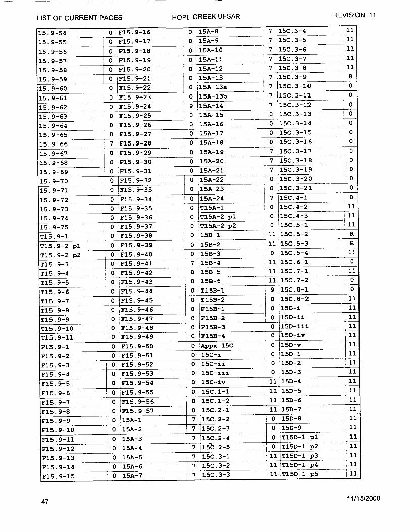
REVISION 11
LIST OF CURRENT PAGES HOPE CREEK UFSAR15.9-54 0 F15.9-16 0 15A-8 7 15C 3-4 11
15.9-55 0 F15.9-17 0 15A-9 7 15C 3-5 11
15.9-56 0 F15.9-18 0 15.A-10 l7O15c.3-6 11
15.9-57 0 F15.9-19 0 15A-11 7 15C.3-7 11
15.9-58 0 F15.9-20 0 15A-12 7 15C.3-8 11
15.9-59 0 F15.9-21 0 1A-133-9
15.9-60 0 F15.9-22 0 15A-13a 7 i15C.3-10 0
15.9-61 0 F15.9-23 0 15A-13b 715C.3-31 0
15.9-62 0 F15.9-24 9 15A-14 7 115C.3-12 0
15.9-63 0 F15.9-25 0 15A-15 0 15C.3-13 0
15.9-64 0 F15.9-26 0 15A-16 0 15C.3-14 0
15.9-65 0 F15.9-27 0 15A-17 0 15C.3-15 0
15.9-66 7 F15.9-28 0 i5A-lB 0 15C.3-16 0 15.9-660 F15.9-289 5-8• 1C31
15.9-67 0 F15.929 0 15A-19 7 15C.3-17 0
15.9-68 0 F15 9-30 0 15A-20 7 15C.3-18 0
15 Q-6Q 0 F15.9-31 0 15A-21 7 15C.3-19 i 0
15.9-70 0 1F15.9-32 0 15A-22 0 15C. 3-20
15.9-71 0 F15.9-33 0 15A-23 0 15C.3-21
15.9-72 0 ýF15.9-34 0 15A-24 7 15C.4-1
15.9-73 0 F15.9-35 0 T15A-1 0 15C.4-2
15.9-74 0 F15.9-36 0 T15A-2 pl 0 115C.4-3
0 0
0
11
ili
15.9-75 0 F15.9-37 0 T15A-2 p2 0 115C.5-1
T15.9-1 0 F15.9-38 0 i15B-1 11 15C. 5-2 R
T15. 9-2 pl 0 F15.9-39 0 !15B-2 1 I 15C.55-3 R
T15.9-2 p2 0 F15.9-40 0 i153-3 0 115C.5-4 11
T15. )- 0 F15.9-41 7 115B-4 11 15C.6-1 0
T15. 9-4 0 F15.9-42 0 15B-5 11215C.7-1 11
T15. 9-5 0 F15.9-43 0 15B-6 1115C.7-2 0
T15 9-6 0 F15.9-44 0 T15B-I 9 15C.8-1 0
T15. 9-7 0 F15.9-45 0 FT5B-2 0 15C.--2 11
T15. 9-8 0 'iF15.9-46 0 F15B-4 0 15D-i 11
T15. 9-9 0 F15.9-47 0 pF15B-2C 0 15D-ii 11
T15.9-10 0 F15.9-48 0 F15B-3 0 11D-ii 11 T15. 9-11 0 IF5 94 0 IFI5B-4 i0 15D-iv
0FI5.9-49p ii
iF15. 9-1 o FI5.9-50 0 ýAppx 15C 0 15D-v i
F15.9-2 0 F15.9-51 0 l5C-i 0 T15D-Ip2II F15. 9-3 0 :F15.9-52 0 1l5C-ii 0 '15D-2 I
F15. 9-4 0 F15. 9-53 0 15C-iii 0 ý 15D-3 i
F15.9-5 0 :F15. 9-54 0 15C-iv 11 i15D-4 11
F15.9-6 0 iF15. 9-55 •:0 15C. 1-1 11 15- 11
F15.9D-7 :0 F15. 9-56 0 "15C. 1-2 11i 15D-6 11~i
F15. 9-8 0 F15.9-57 0 15C.2-1 11 ii15D-7 11 F15. 9-9 0 0.15A-1 7 .!15C.2-2 0 ,"15D-8 111
F15. 9-10 0 15A-2 7 i15C. 2-3 0 15D- 9 11
F15. 9-11 ,0 ý15A-3 7 I15C. 2-4 0 'TI5D-I pl 11
F15.9-12 0 ý15A-4 7 1l15C. 2-5 i0 T15D-1 p2 11 F15.9-13 0 15A-5 7 15C.3-1 11IT15D-1 p3 11
F15.9-14 0 15A-6 7 15C.3-2 11'T15D-1 p4 11
-F15.9-15 0 15A-7 7 15C.3-3 11 T15D-1 p5 11
11/15/200047
HOPE CREEK UFSARLIST OF CURRENT PAGES
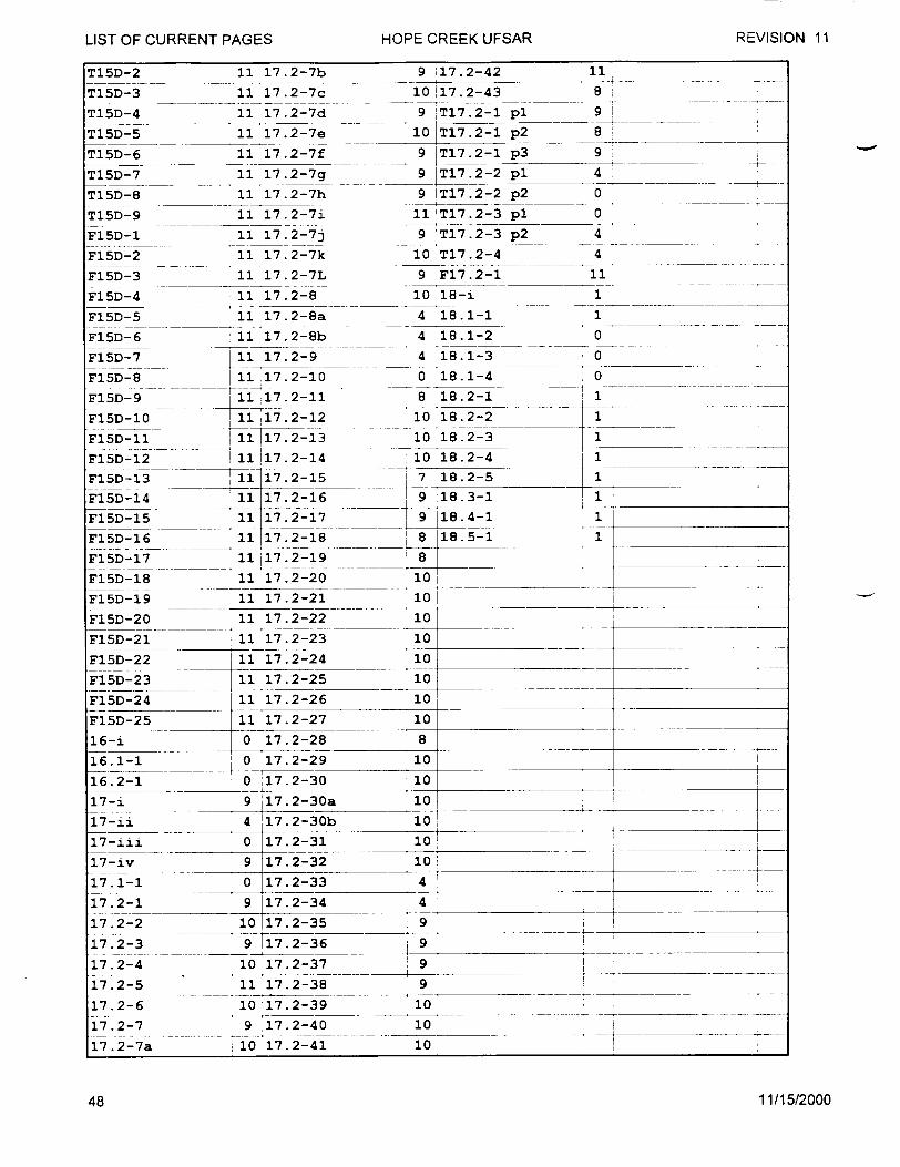
LIST OF CURRENT PAGES HOPE CREEK UFSAR REVISION 11T15D-2
T15D-3
TI5D--4
Ti5D-5
T15D-6
T15D-7
T15D-8
T15D-9
F15D-1
F71 5D- --2
F15D-3
F15D-4
F15D-5
F15D-6
F15D-7
F15D-8
F15D-9
FI5D-10
Fl5D-II
F15D-12
Fl5D-13
F15D-14
F15D-15
F15D-16
F15D-17
FI5D-18
F15D-19
F15D-20
F15D-21
F15D-22
F15D-23
F15D-24
F15D-25
16-i
16.1-1
16.2-1
17-i
17-ii
17-iii
17-iv
17.1-1
17.2-1
17.2-2
17.2-3
17.2-4
17.2-S
17.2-6
17.2-7
17.2-7a
11 17.2-7b
11 17.2-7c
11 17.2-7d
11 17.2-7e
11 17.2-7f
11 17.2-7g
11 17.2-7h
11 17.2-7i
11 17.2-7j
11 17.2-7k
11 17.2-7L
11 17.2-8
11 17.2-8a
11 17.2-8b
11 17.2-9
11 17.2-10
11 17.2-11
i117.2-12 !111!17.2-1-3
1117.2-13 11 17.2-14
11 17.2-15
11 17.2-16 11 17.2-17
11 172-18
11 17.2-19
11 17.2-20
11 17.2-21
11 17.2-22
11 17.2-23
11 17.2-24
11 17.2-25
11 17.2-26
11 17.2-27
0 17.2-28 o 017.2-29
9 ý17.2-42
10 117.2-43
9 T17.2-1
10 T17.2-1
9 IT17.2-1
9 IT17.2-2
9 IT17.2-2
11 IT17.2-3
9 T17.2-3
10 T17.2-4
9 F17.2-1
10 18-i
4 18.1-1
4 18.1-2
4 18.1-3
0 18.1-4 0
8 18.2-1
10 18.2-21
10 18.2-3 1
10 18.2-4 1
7 18.2-5 1
9 18.3-1 1
9 118.4-1 1
8 118.5-1 1
8
I01
10
10
10
10
10
10
10
8
10
100 :17.2-30
9 ý17.2-30a
4 17.2-30b
0 17.2-31 9 17.2-32
0 17.2-33
9 17.2-34
10 17.2-35
9 117.2-36
10 17.2-37
11 17.2-38
10 17.2-39
9 17.2-40
10 17. 2-41
10
1010
10
4
4 -.9
9
9
9
10
10
10
11/15/2000
11
8
pl 9
p2 8
p3 9
pl 4
p 2 0
pl 0
p2 4
4 11
1
1
0
0
T
REVISION 11LIST OF CURRENT PAGES HOPE CREEK UFSAR
i I
48
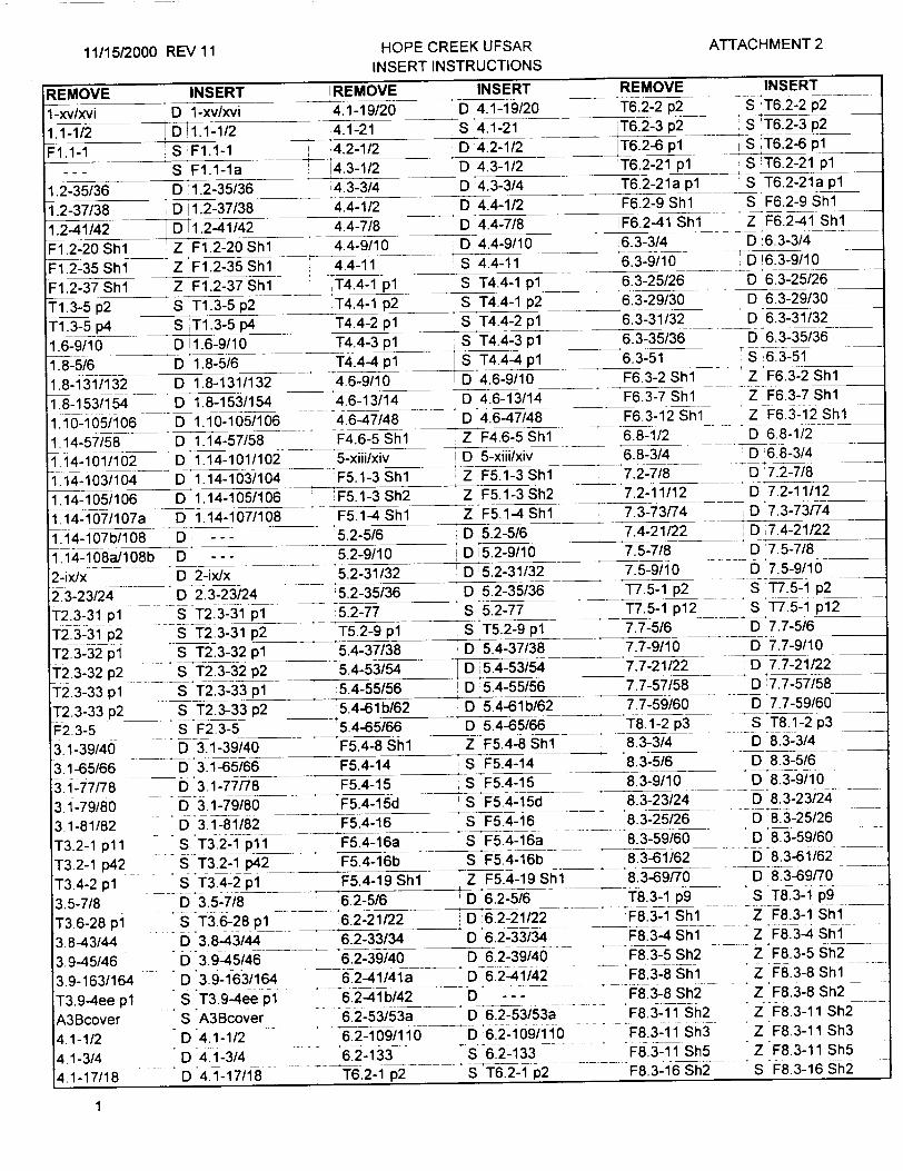
11/15/2000 REV 11 HOPE CREEK UFSAR ATTACHMENT 2
INSERT INSTRUCTIONS
REMOVE INSERT IREMOVE INSERT REMOVE INSERT
1-xv/xvi D 1-xv/xvi 4.1-19/20 D 4.1-19/20 T6.2-2 p2 S •T6.2-2 p2
1.1-1/2 D 1.1-1/2 4.1-21 S 4.1-21 :iT6.2-3 p2 S T6.2-3 p2
F1.1-1 S F1.1-1 4.2-1/2 D 4.2-1/2 iT6.2-6 pl S T6.2-6 pl
--- S F1.l-la '4.3-1/2 0D 4.3-1/2 'T6.2-21 pl S T6.2-21 pl
1.2-35/36 D 1.2-35/36 14.3-3/4 D 4.3-3/4 T6.2-21a pl S T6.2-21a p1
1.2-37/38 D 1.2-37/38 4.4-1/2 D 4.4-1/2 F6.2-9 Shl S F6.2-9 Shl
1.2-41/42 D 1.2-41/42 4.4-7/8 D 4.4-7/8 F6.2-41 Sh 1i Z F6.2-41 Shi
F1.2-20 Shl Z F1.2-20 Shl 4.4-9/10 0 4.4-9/10 6.3-3/4 D 6.3-3/4
F1.2-35 Shl Z F1.2-35 Shl 4.4-11 S 14.4-11 6.3-9/10 D 63-9/10
F1.2-37 Shl Z F1.2-37 Shl IT4.4-1 pl S T4.4-1 pl 6.3-25/26 D 6.3-25/26
T1.3-5 p2 S T1.3-5 p2 T4.4-1 p2 S T4.4-1 p2 6.3-29/30 D 6.3-29/30 T1.3-5 p4 S ýT1.3-5 p4 T4.4-2 pl S T4.4-2 pl 6.3-31/32
1.6-9/10 D 11.6-9/10 T4.4-3 pl S T4.4-3 pl 16.3-35/36 D 6.3-35/36
1.8-5/6 D 1.8-5/6 T4.4-4 pl S T4.4-4 pl 6.3-51 S 6.3-51
1.8-131/132 D 1.8-131/132 4.6-9/10 0 4.6-9/10 F6.3-2 Shl- Z F6.3-2 Shl
1.8-153/154 D 1.8-153/154 4.6-13/14 D 4.6-13/14 F6.3-7 Shl Z F6.3-7 Shl
1.10-105/106 D 1.10-105/106 4.6-47/48 D 4.6-47/48 __ .F6.3-12 Shl. .Z F6.3-12 Shl
1.14-57/58 D 1.14-57/58 F4.6-5 Shl Z F4.6-5 Shl 6.8-1/2 0 6.8-1/2
1.14-101/102 D 1.14-101/102 5-xiii/xiv D 15-xiii/xiv '6.8-3/4 D 6.8-3/4
1.14-103/104 D 1.14-103/104 F5.1-3 Shl Z F5.1-3 Shl 7.2-7/8 D 7.2-7/8
1.14-105/106 D 1.14-105/106 F5.1-3 Sh2 Z F5.1-3 Sh2 7.2-11/12 D 7.2-11/12
1.14-107/107a D 1.14-107/108 F5.1-4 Shl Z F5.1-4 Shl 7.3-73/74 D 7.3-73/74
1.14-107b/108 0D -.-- 5.2-5/6 D 5.2-5/6 '7.4-21/22 D 17.4-21/22
1.14-108a/108b D - -- 5.2-9/10 0 35.2-9/10 7.5-7/8 D 7.5-7/8
2-ixJx D 2-ix/x 5.2-31/32 D 5.2-31/32 7.5-9/10 D 7.5-9/10
2.3-23/24 D 2.3-23/24 5.2-35/36 D 5.2-35/36 T7.5-1 p2 S 77.5-1 p2
T2.3-31 pl -ST2.3-31 pl -- 5.2-77 S 5.2-77 T7.5-1 p1 2 S 1"7.5-1 p1 2
T2.3-31 p2 S T2.3-31 p2 T5.2-9 pl S T5.2-9 pl 7.7-5/6 D 7.7-5/6
T2.3-32 pl S T2.3-32 pl 5.4-37/38 D 5.4-37/38 7.7-9/10 D 7.7-9/10 T2.3-32 p2 S T2.3-32 p2 5.4-53/54 D 5.4-53/54 7.7-21/22 D 7.7-21/22 T2.3-33 p1 S T2.3-33 pl 5.4-55/56 D 5.4-55/56 7.7-57/58 'D 7.7-57/58
T2.3-33 p2 S T2.3-33 p2 5.4-61b/62 D 5.4-61b/62 7.7-59/60 D 7.7-59/60
F2.3-5 S F2.3-5 5.4-65/66 D 5.4-65/66 T8.1-2 p3 _S T8.1-2 p3
3.1-39/40 0 3.1-39/40 F5.4-8 Shl Z F5.4-8 Shl 8.3-3/4 D 8.3-3/4
3.1-65/66 D 3.1-65/66 F5.4-14 S F5.4-14 118.3-5/6 D 8.3-5/6
3.1-77/78 0 3.1-77/78 F5.4-15 S F5.4-15 8.3-9/10 D 8.3-9/10
3.1-79/80 D 3.1-79/80 F5.4-15d S F5.4-15d 8.3-23/24 D 8.3-23/24
3.1-81/82 D .3.1-81/82 F5.4-16 S F5.4-16 8.3-25/26 D 8.3-25/26
T3.2-1 pll S T3.2-1 pll F5.4-16a S F5.4-16a 8.3-59/60 D 8.3-59/60
T3.2-1 p42 S T3.2-1 p42 F5.4-16b S F5.4-16b 8.3-61/62 D 8.3-61/62__ _
T3.4-2 pl S T3.4-2 pl F5.4-19 Shl Z F5.4-19 Shl 8.3-69/70 0 8.3-69/70
3.5-7/8 D 3.5-7/8 6.2-5/6 D 6.2-5/6 _T8.3-1 p9 S T8.3-1 p9
T3.6-28 p1 S T3.6-28 pl 6.2-21/22 0 ,6.2-21/22 'F8.3-1 Shl Z F8.3-1 Shl
3.8-43/44 D 3.8-4-3/44 6.2-33/34 D 6.2-33/34 F8.3-4 Shl Z -7.F8.3-4 Shl.
3.9-45/46 D 3.9-45/46 6.2-39/40 D 6.2-39/40 F8.3-5 Sh2 Z F8.3-5 Sh2
3.9-163/164 D 3.9-163/164 6.2-41/41a D 6.2-41/42 F8.3-8 Shl Z F8.3-8 Shi
T3.9-4ee pl " T3.9-4ee pl 6.2-41b/42 D --- F8.3-8 Sh2 Z -F8.3-8 Sh2
A3Bcover S A3Bcover 6.2-53/53a D 6.2-53/53a F8.3-11 Sh2 Z F8.3-11 Sh2
4.1-1/2 D 4.1-1/2 6.2-109/110 D 6.2-109/110 F8.3-11 Sh3 Z .F8.3-11 Sh3
4.1-3/4 D 4.1-3/4 6.2-133 S 6.2-133 F8.3-11 Sh5 Z F8.3-11 Sh5
4.1-17/18 D 4.1-17/18 T6.2-1 p2 S T6.2-1 p2 F8.3-16 Sh2 S F8.3-16 Sh2
1

11/15/2000 REV 11 HOPE CREEK UFSAR INSERT INSTRUCTIONS
ATTACHMENT 2
REMOVE INSERT I REMOVE
9-xi/xii 0D 9-xi/xii 9.1-159 9-xxv/xxvi 0 9-xxv/xxvi T9.1-2 pl
9.1-1/2 D 9.1-1/2 T9.1-5p1 9.1-3/4 D 9.1-3/4 ;T9.1-18 pl 9.1-5/6 D ,9.1-5/6 T9.1-18 p2
9.1-7/8 D 9.1-7/8 T9.1-19 pl
9.1-9/10 D 9.1-9/10 T9.1-19 p2
9.1-13/14 D i9.1-13/14 T9.1-20 pl
9.1-14a/14b 0D --- " T9.1-20 p2 9.1-15/16 0 9.1-15/16 T T9.1-22 p3
9.1-17/18 D 9.1-17/18 F9.1-5 Shl
9.1-19/20 0 9.1-19/20 F9.1-5 Sh2
9.1-21/22 D 9.1-21/22 F9.1-16 Shl
9.1-23123a D 9.1-23/24 F9.1-16 Sh2
9.1-23b/24 D --- F- F9.1-39 Sh 1
9-125/26 _D9.1-25/26 F9.1-39 Sh2
9.1-27/28 D 9.1-27/28 F9.1-40 Shi
9.1-29/30 D 9.1-29/30 F9.1-40 Sh2
9.1-37/38 D 9.1-37/38 9.2-3/4
9.1-39/40 D 9.1-39/40 9.2-15/16
9.1-43/44 D 9.1-43/44 9.2-35/36
9.1-49/50 D 9.1-49/50 9.2-37/38
9.1-51/52 0 D9.1-51/52 9.2-49/50
9.1-53/54 _D 9.1-53/54 9.2-51/52
9.1-55/56 0 9.1-55/56 T9.2-3 pl
9.1-57/58 ... D 9.1-57/58 T9.2-4 p2
9.1-59/60 D 9.1-59/60 T9.2-4 p2a
9.163/63a D 9.1-63/63a T9.2-4 p2b 9.10a/70b D 9.1-70a/70b T9.2-4 p_2c
9.1-71/72 D 9.1-71/72 T9.2-9 pl
9.1-73/74 0 9.1-73/74 T9.2-9 p2
9.1-75/76 _D 9.1-75/76 F9.2-2 Sh1
9.1-77/78 • D 9.1-77/78 F9.2-3 Shl
9.1-79/80 D 9.1-79/80 F9.2-4 Shl
9.1-81/81a D 9.1-81/82 F9.2-4 Sh2
9.1-81b/82 D --- F9.2-5 Shl
9.1-82/82a --- F9.2-13Shl
9.1-82a/82b D --- F9.2-16 Shl
9.1-83/84 _D_9.1-83/84 . 9.3-35/36
9.1-85/86 D 9.1-85/86 9.3-37/38
9.1-87/88 D 9.1-87/88 9.3-41/42
9.1-89/90 0D 9.1-89190 9.3-43/44
9.1-90a/90b D -- - 9.3-61/62
9.1-91/91a D 9.1-9192 .W 3-63/64
9.1-91b/92 - - T9.3-3 pl
9.1-95/96 D 9.1-95/96 T9.3-6 pl
9.1-1171117a D 9.1-117/117a T9.3-6 p2
9.1-129/130 D 9.1-129/130 T9.3-6 p3
9.1-131/132 0D9.1-131/132 T9.3-6 p4
9.1-133/133a- D 9.1-133/133a T9.3-8 pl
9.1-157/158 D 9.1-157/158 F9.3-1 Shl
2
INSERT S 9.1-159 S iT9.1-2 pl S T9.1-5 pl
__S T9.1-18 pl S--_S T9.1-19 pl
.-S --S T9.1-20 pl S --
S T9.1-22 p3
Z F9.1-5 Shl SZ
F9.1-5Sh2 Z F9.1--16 Shl
Z F9.1-16 Sh2 S F9.1-39 Shl is -S F9.1-40 Shl S
D 9.2-3/4 D 9.2-15/16 oD 9.2-35136 D 9.2-37/38 D 9.2-49/50 D 9.2-51/52 S T9.2-3 pl ST9.2-4 p2 S T9.2-4 p2a S T9.2-4 p2b S.T9.2-4 p2c S T9.2-9 pl S T9.2-9 p2 Z -F9.2-2 Shl Z F9.2-3 Shi "Z F9.2-4 Shi Z F9.2-4 Sh2 Z F9.2-5 Shl Z F9.2-13 Shl Z F9.2-16 Shl o 9.3-35/36 D 9.3-37/38 D-9.3-4,1/42 D 9.3-43/44 D 9.3-61/62 D 9.3-63/64 "S T9.3-3 pl S T9.3-6 pl S T9.3-6 p2 S T9.3-6 p3
S T9.3-6 p4
S T9.3-8 pl Z F9.3-1 Shl
REMOVE i INSERT lF9.3-4 Shl Z F9.3-4 Sh1
F9.3-4Sh3 S F9.3-4 Sh3
F9.3-7 Shl Z F9.3-7 Shl
F9.3-7 Sh3 Z F9.3-7 Sh3
9.4-85/86 D 9.4-85/86
9.4-87/88 D9.4-87/88
9.4-89/90 D 9.4-89/90
T9.4-16 p2 S T9.4-16 p2
19.5-3/4 D 19.5-3/4
9.5-51/52 D 9.5-51/52
9.5-87/88 D 9.5-87/88
9.5-169/170 -D 9.5-169/170 19.5-171/172 D 9.5-171/172 IT9.5-17 pl0 S T9.5-17 plO
T9.5-23 p3 -S T9.5-23 p3
T9.5-27 pl " S-T9.5-27 pl
T9.5-27 p2 S T9.5-27 p2
'T9.5-27 p3 S T9.5-27 p3
'T9.5-27 p4 5T9.5-27 p4
T9.5-27 p5 ST9.5-27 p5
T9.5-27 p6 S T9.5-27 p6
SF9.5-16 Shl Z F9.5-16 Shl
- -9A-43/44 D0 9A-43/44
T9A-1 p23 S T9A-1 p23
"T9A-1 p36 - S T9A-1 p36
T9A-1 p38 ,S T9A-1 p38_
_T9A-1 p39 S T9A-1 p39
T9A-1 p40 S !T9A-1 p40
T9A-1 p41 S T9A-1 p41
T9A-1 p42 S T9A-1 p42
T9A-1 p43 ST9A-1 p43
T9A-1 p44 S iT9A-1 p44
T9A-1 p46 S T9A-1 p46
T9A-1 p47 S T9A-1 p47
T9A-1 p48 S T9A-1 p48
'T9A-1 p54 S T9A-1 p54 ___
T9A-1 p55 S T9A-1 p55
" 'T9A-6pl S "T9A-6pl
T9A-9 p17 S T9A-9 p17__ _
T9A-32 p2 IS -T9A-32 p2 T9A-32 p3 S T9A-32 p3
' .T9A-32 p4 S T9A-32 p4 T9A-32 p5 S T9A-32 p5 T9A-32 p6 S T9A-32 p6 T9A-33 p2 S T9A-33 p2 T9A-33 p3 - S T9A-33 p3 T9A-33 p4 S T9A-33 p4 "T9A-33 p5 S ST9A-33 p5 "T9A-33 p6 S T9A-33 p6
"T9A-34 p2 "S T9A-34 p2 "T9A-34 p3 S T9A-34 p3

11/15/2000 REV 11 HOPE CREEK UFSAR INSERT INSTRUCTIONS
ATTACHMENT 2
REMOVE INSERT REMOVE !INSERT
T9A-34 p4 S T9A-34 p4 'Tl1.2-1 pl S Tl1.2-1 pl
T9A-34 p-5 S T9A-34 p5 T11.2-7 pl S T11.2-7 pl
T9A-34 p6 S T9A-34 p6 T11.2-7 p2 S T11.2-7 p2
T9A-35 p2 S T9A-35 p2 Tl1.2-10 pl S T11.2-10 pl
T9A-35 p3 S T9A-35 p3 Ti 1.2-10 p2 S Ti 1.2-10 p2
T9A-35 p4 S T9A-35 p4 !T11.2-10 p3 S TT11.2-10 p3
T9A-35 p5 S 'T9A-35 p5 'Tl1.2-10 p4 S Tl1.2-10 p4
T9A-35 •6 S T9A-35 p6 Ti 1.2-11 p3 S T1 1.2-11 p3
T9A-43p 1 S T9A-43pl Tll.2-13pl S Tll.2-13 pl
T9A-44 p1 S T9A-44 pl Tl1.2-14 pl S Tl1.2-14 pl
T9A-45 p1 S T9A-45 pl T11.2-14 p2 S Tl1.2-14 p2
T9A-46pl S T9A-4611 Fll.2-2Shl Z Fl1.2-2 Shl
T9A-60pll S lT9A-60p11 F11.2-5 Shl Z Fl1.2-5 Shl
T9A-60 p13 S T9A-60 p13 Fl1.2-5 Sh2 Z Fl1.2-5 Sh2___
T9A-61 pl S T9A-61 _1 F11.3-45Shl Z F11.3-4Shl
T9A-61 p2 S T9A-61 p2 F11.3-5 Shl Z F11.3-5 Shl
T9A-61 p4 S T9A-61 p4 - 11.4-1/2 0 11.4-1/2
T9A-75 p2 S T9A-75 p2 11.4-3/4 D 11.4-3/4
T9A-77 p4 S T9A-77 p4 11.4-4a/4b 0 -- _
T9A-1C00 p1 S T9A-100 pl 11.4-5/6 D 11.4-5/6
T9A-100 p2 S T9A-100 p2 11.4-7/8 D 11.4-7/8
T9A-100 p4 - S T9A-100 p4 11.4-9/10 D 11.4-9/10
T9A-101 p1 S T9A-101 pl 11.4-11/11a __D _11.4-11/12
T9A-101 p2 S T9A-101 p2 11.4-llb/12
T9A-101 p4 S T9A-101 p4 .. 11.4-13/14 D 11.4-13/14
T9A-102p1 . S T9A-102 pl 11.4-15/16 0 O 11.4-15/16
F9A-19 Shl Z F9A-19 Shl T11.4-2 p:1 S T11.4-2 p1
F9A-19 Sh3 Z F9A-19 Sh3 - T11.4-3 p-1 T11.4-3 p1
10.2-5/6 0D 10.2-5/6 T11.4-4 p1 S Tl1.4-4 pl __
10.2-11/12 D 10.2-11/12 Tll.4-5 p1 S Tl1.4-5 p1
10.2-17 S 10.2-17 Tl1.4-5 p2 S Tl1.4-5p2
T10.2-2 S T10.2-2 Tl1.4-5 p3 S Tll1.4-5 p3
F10.2-3 Shl -- Z 10.2-3 ShIl T11.4-6 pl S T11.4-6 pl
F10.2-4 Shl Z F10.2-4 Shl Tl1.4-6 p2 S Tl1.4-6 p2
10.4-25/26 D 10.4-25/26 Tl1.4-6 p3 S Tll.4-6 p3
F10.4-2 Shl Z F10.4-2 Shi T11.4-7 p1 S T11i.4-7 p1
F10.4-3 Shl Z F1 .4-3Sh1 1 -T11.4-7 p2 " S T11.4-7 p2
F10.4-3 Sh2 Z F10.4-3-Sh2 F11.4-10_Shl Z Fl1.4-10 Shl
F10.4-4 Shl Z.F10.4-4 Shl 11.5-3/4 D 11.5-3/4
F10.4-4 Sh2 Z F1o.4-4 h2 11.5-5/6 0-11.5-5/6 F10.4-5 Shl Z F10.4-5 Shl 11.5-7/8 0 11.5-7/8
F10.4-5 Sh3 Z F10.4-5 Sh 3 11.5-27b/28 D 11.5-27b/28
F10.4-6 Shl Z F10.4-6 Shl Tl1.5-1 p5 S Tl1.5-1 p5
11-i/i D 11-i/ii Tl1.5-1 p6 S T11.5-1 p6
11.2-1/2 "D11.2-1/2 Tl1.5-3-pl ST-• i1.5-3pl
11.2-5/6 D 11.2-5/6 - - T11.5-3Pp2 STl1.5-3p2
11.2-7/8 "D'11.2-7/8 12.2-9/10 D 12.2-9/10
11.2-9/10 D 11.2-9/10 12.2-11/12 0D12.2-11/12
11.2-11/12 D 11.2-11/12 T12.2-73 pl S T12.2-73 pl
11.2-13/14 D 11.2-13/14 T12.2-74 pl SJT12.2-74 pl
11.2-15 S 11.2-15 T12.2-75 pl S 1T2.2-75 pl
3
REMOVE INSERT T12.2-76 pl S T12.2-76 p1
T12.2-77 pl S T12.2-77 pl
T12.2-99 pl S T12.2-99 pl T12.2-101 pl S T12.2-101 pl T12.2-103 pl S T12.2-103 pl
T12.2-104 pl S T12.2-104 pl T12.2-107 p2 S T12.2-107 p2
T12.2-107 p3 S Ti 2.2-107 p3
T12.2-107 p5 - S T12.2-107 p5
12.3-45/46 D 12.3-45/46
T12.4-15 pl S T12.4-15 pl
T12.4-16 pl S T12.4-16 pl T12.4-17 pl S T12.4-17 pl
F12.4-1 Shl Z F12.4-1 Shl
12.5-25/26 D 12.5-25/26 13.1-3/4 D 13.1-3/4
13.1-9/10 D 13.1-9/10 13.1-11/12 D 13.1-11/12 13.1-19/20 D 13.1-19/20
14.2-133/134 D 14.2-133/134 14.2-141/142 D 14.2-141/142
14.2-177/178 D 14.2-177/178 14.2-179/180 D 14.2-179/180
15-xiiill5xiv 0 15-xiii/15xiv 15-xv/xvi D 15-xv/xvi
1 5-xxilxxi Dl 5-xxi/xxii 15.0-1 S 15.0-1 T15_5.0-1 pl S T15.0-1 pl T15.0-1 p3 S T15.0-1 p3
T15.0-2 pl S T15.0-2 pl T15.0-3 pl S iT15.0-3 pl Ti5.0-4 p-1 S T15.0-4 pl F1_5.0-2 SF15.0-2
15.1-1/2 D 15.1-1/2 '15.1-3/4 D 15.1-3/4 15.1-5/6 D 15.1-5/6
15.1-7/8 D 15.1-7/8 15.1-9/10 D , 15.1-9/10
15.1-11/12 D 15.1-11/12
15.1-13/14 D 15.1-13/14 15.1-15/16 D 15.1-15/16 15.1-17/18 D15.1-17/18
"15.1-19/20 D 15.1-19/20 15.1-21 S 15.1-21 T15.1-2 pl S T15.1-2 pl T15.1-3 pl S T15.1-3 p1
"F15.1-2 S F15.1-2 F15.1-3 S F15.1-3 "15.2-1/2 D 15.2-1/2
"15.2-3/4 D 15.2-3/4 "15.2-5/6 D 15.2-5/6
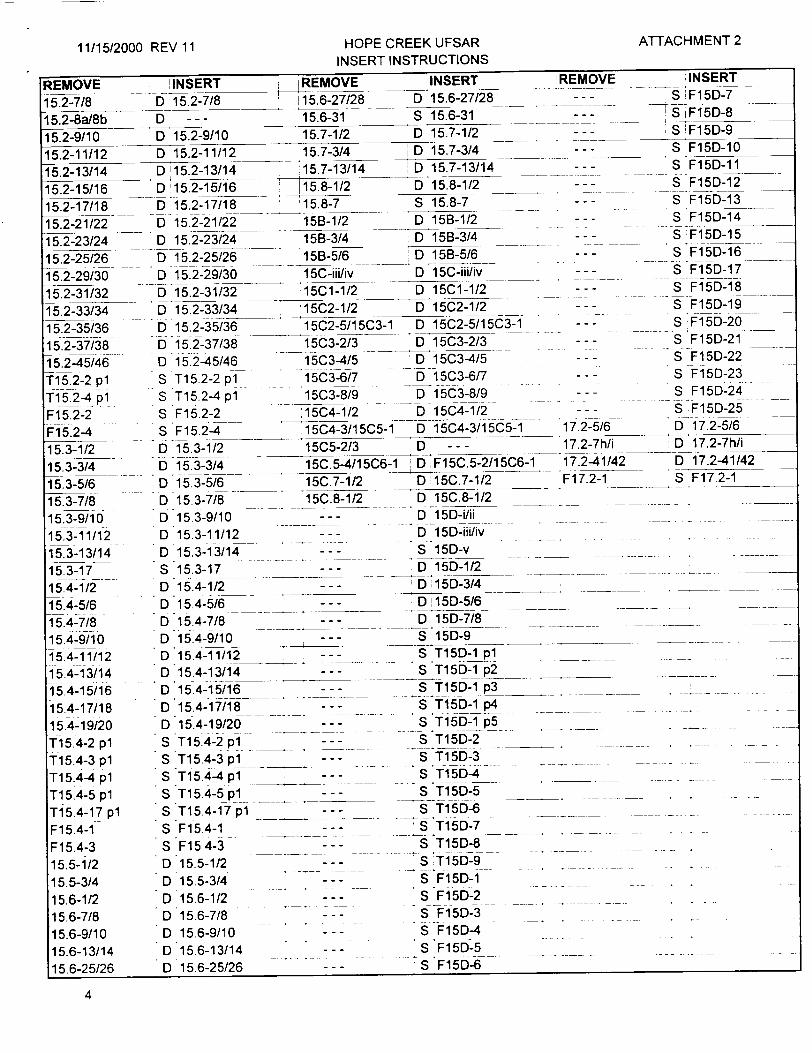
11/15/2000 REV 11ATTACHMENT 2HOPE CREEK UFSAR
INSERT INSTRUCTIONS
INSERT IREMOVE INSERT REMOVE
D_ 15.2-7/8 15.6-27/28 0 15.6-27/28 __ -
D --- 15.6-31 S 15.6-31 --
D 15.2-9/10 15.7-1/2 D 15.7-1/2 --
D 15.2-11/12 15.7-3/4 D 15.7-3/4 --
D 15.2-13/14 157-13/14 0 15.7-13/14 - -
D 15.2-15/16 15.8-1/2 0 15.8-1/2 - -
D 15.2-17/18 '15.8-7 S 15.8-7 --
D 15.2-21/22 15B-1/2 D 15B-1/2
D 15.2-23/24 15B-3/4 D 15B-3/4 - -
D 15.2-25/26 15B-5/6 D 15B-5/6
D 15.2-29/30 15C-iii/iv 0 15C-iii/iv - -
D 15.2-31/32 15C1-1/2 D 15C1-1/2 - -
D 15.2-33/34 '15C2-1/2 D 15C2-1/2 --
D 15.2-35/36 15C2-5/15C3-1 D 15C2-5/15C3-1 --
D 15.2-37/38 15C3-2/3 D 15C3-2/3 . -
D 15.2-45/46 15C3-4/5 D 15C3-4/5
S T15.2-2 pl 15C3-6/7 D 15C3-6/7 - --
S T15.2-4 pl 15C3-8/9 D 15C3-8/9
S F15.2-2 15C4-1/2 D 15C4-1/2
S F15.2-4 15C4-3/15C5-1 D 15C4-3/15C5-1 ____ 17.2-5/6
D 15.3-1/2 15C5-2/3 D -- - 17.2-7h/i
D 15.3-3/4 ___15C.5-4/15C6-1 D FlF5C.5-2/15C6-1 17.2-41/42
D 15.3-5/6 ___15C.7-1/2 D 15C.7-1/2 F17.2-1
D 15.3-7/8 15C.8-1/2 D 15C.8-1/2
0 15.3-9/10 D--- 15D-i/ii _
15.2-25/26 15.2-29/30 15.2-31/32 15.2-33/34
5ý.2-35/36 15.2-37/38 1 5.2-45/46 Ti 5.2-2 pl T15.2-4 pl F15.2-2 F15.2-4 15.3-1/2 15.3-3/4 15.3-5/6 15.3-7/8 15.3-9/10 15.3-11/12 15.3-13/14 15.3-17 15.4-1/2 15.4-5/6 15.4-7/8 15.4-9/10 15.4-11/12 1 5.4-13/1 4 15.4-15/16 15.4-17/18 15.4-19/20 T15.4-2 pl T15.4-3 pl Ti 5.4-4 pl Ti 5.4-5 pl Ti 5.4-17 pl F 15.4-1 F15.4-3 15.5-1/2 15.5-3/4 15.6-1/2 15.6-7/8 15.6-9/10 15.6-13/14 15.6-25/26
D 15D-iii/iv S 15D-v D 15D-1/2 D 15D-3/4 D 15D-5/6 D 15D-7/8
S 15D-9 S T15D-1 pl S T15D-1 p2 __
S T15D-1 p3 S T15D-1 p4
S *T15D-2p -S Ti5D-32 . . . ..
S T15D-4
S T15D-5 ___
S T15D-7 S T15D-8 S T l 5D-9
-. S F15D-1 S F15D-2 S F15D-3 "S F15D-4 S F15D-5
S F15D-6
D 15.3-11/12
D 15.3-13/14 S 15.3-17 D 15.4-1/2 "D 15.4-5/6 D 15.4-7/8 "D 15.4-9/10
D 15.4-11/12 D 15.4-13/14 o 15.4-15/16 D 15.4-17/18 D 15.4-19/20 S T15.4-2 pl S T15.4-3 p1 S T15.4-4 pl S T15.4-5 pl S T15.4-17 pl S F15.4-1 S F15.4-3 D 15.5-1/2 D 15.5-3/4
D 15.6-1/2 D 15.6-7/8 D 15.6-9/10 D 15.6-13/14 D 15.6-25/26
4
;INSERT S ýF15D-7 S F15D-8 S F15D-9
S F15D-10 S .F15D-11 S F15D-12
S F15D-13 S F15D-14 S F15D-15
S Fl 5D-16 S F15D-17 S F15D-18
S F15D-19 S F15D-20-S F15D-21 S F15D-22 S F15D-23 S F15D-24 IS F15D-25 0 17.2-5/6 D 17.2-7h/i D 17.2-41/42 S F17.2-1
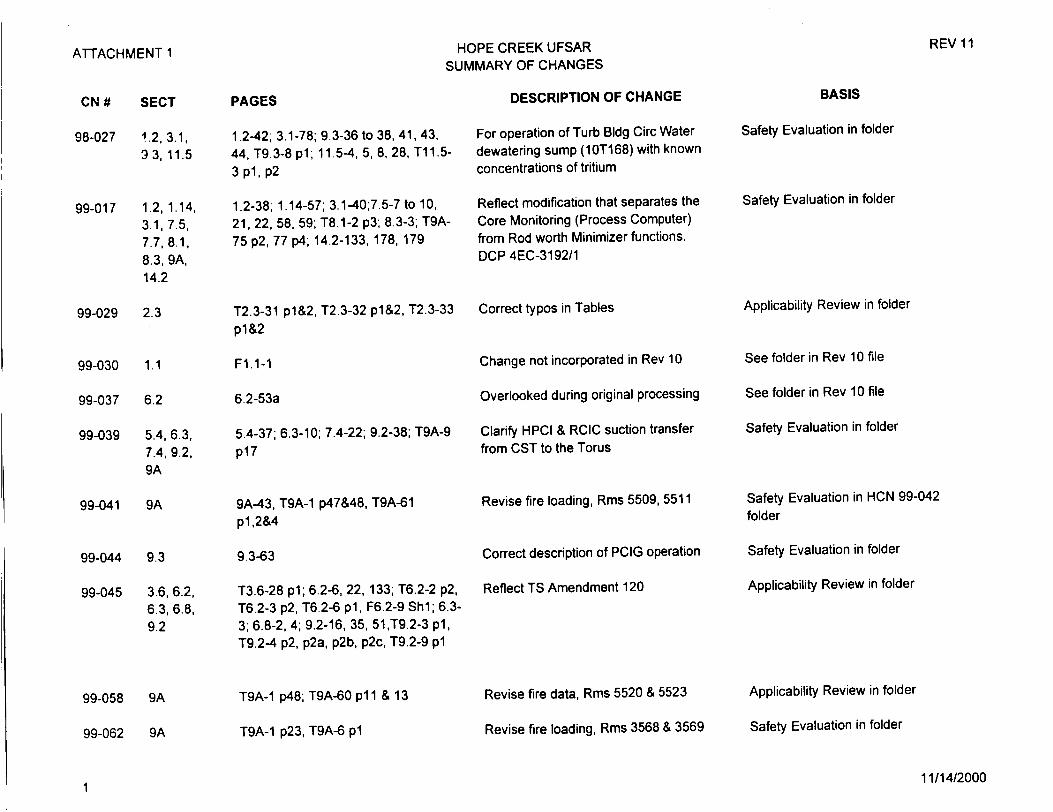
ATTACHMENT 1
CN #
98-027
SECT
12 3.1,
93, 11.5
99-017 1.2, 1.14, 3.1, 7.5, 7.7, 8.1, 8.3, 9A, 14.2
99-029 2.3
99-030 1.1
99-037 6.2
99-039 5.4, 6.3, 7.4, 9.2, 9A
99-041 9A
99-044
99-045
9.3
3.6,6.2, 6.3,6.8, 9.2
PAGES
1.2-42; 3.1-78; 9.3-36 to 38, 41, 43,
44, T9.3-8 pl; 11.5-4, 5, 8, 28, Tl1.53 pl, p2
1.2-38; 1.14-57; 3.1-40;7.5-7 to 10,
21, 22, 58, 59; T8.1-2 p3; 8.3-3; T9A
75 p2, 77 p4; 14.2-133, 178, 179
T2.3-31 pl&2, T2.3-32 pl&2, T2.3-33
p1&2
F1.1-1
6.2-53a
5.4-37; 6.3-10; 7.4-22; 9.2-38; T9A-9
p1 7
9A-43, T9A-1 p47&48, T9A-61
pl,2&4
9.3-63
T3.6-28 pl; 6.2-6, 22, 133; T6.2-2 p2,
T6.2-3 p2, T6.2-6 pl, F6.2-9 Shl; 6.3
3; 6.8-2, 4; 9.2-16, 35, 51,T9.2-3 pl,
T9.2-4 p2, p2a, p2b, p2c, T9.2-9 pl
LOPE CREEK UFSAR MMARY OF CHANGES
DESCRIPTION OF CHANGE
For operation of Turb Bldg Circ Water dewatering sump (10T168) with known concentrations of tritium
Reflect modification that separates the
Core Monitoring (Process Computer) from Rod worth Minimizer functions. DCP 4EC-3192/1
Correct typos in Tables
Change not incorporated in Rev 10
Overlooked during original processing
Clarify HPCI & RCIC suction transfer from CST to the Torus
Revise fire loading, Rms 5509, 5511
Correct description of PCIG operation
Reflect TS Amendment 120
REV 11
BASIS
Safety Evaluation in folder
Safety Evaluation in folder
Applicability Review in folder
See folder in Rev 10 file
See folder in Rev 10 file
Safety Evaluation in folder
Safety Evaluation in HCN 99-042
folder
Safety Evaluation in folder
Applicability Review in folder
T9A-1 p48; T9A-60 pi1 & 13
T9A-1 p23, T9A-6 pl
Revise fire data, Rms 5520 & 5523
Revise fire loading, Rms 3568 & 3569
Applicability Review in folder
Safety Evaluation in folder
99-058
99-062
9A
9A
111/14/2000

ATTACHMENT 1
CN #
99-063
99-064
99-066
99-067
99-069
99-070
99-072
99-074
99-075
00-001
SECT
8.3, 9A
12.5
12.3, 12.4
9.1
17.2
8.3
13.1
1.3, 1.8, 3.1, 3.2, 5.4, 9.2, 11.0,11.2, 11.4, 11.5, 12.2, 14.2
13.1
11.2
REV 11
PAGES
8.3-59, 61, F8.3-8 Shl&2; F9A-19 Shl&3
12.5-25
F12.3-18 Shl, F12.3-19 Shl, F12.320 Shl; T12.4-15 pl, T12.4-16 p1 T12.4-17 pl, F12.4-1 Shl
9.1-38, 39, 49, 50
17.2-7i, 42
F8.3-16 Sh 2 of 8
13.1-3,4
T1.3-5 p2&4; 1.8-154; 3.1-66; T3.2-1 p 1 &42; 5.4-62; 9.2-50, 51, T9.2-9 p2; 1 1-ii; 11.2-1, 6 to 9, 12 to 14, T11.2-7 pl&2, T11.2-10 pl to4, T11.2-14 pl&2, F11.2-5 Shl&2; 11.41, 4, 4a, 4b, 5 to 11, 11a&b, 12 to 15, T11.4-2 pl, T11.4-3 pl, T11.4-4 pl, T11.4-5 pl, 2&3, T11.4-6 p1l, 2&3, T11.4-7 pl&2, F11.4-10 Shl; T11.5-1 p5&6; 12.2-10, 11, T12.2-73 pl, T12.2-74 pl, T12.2-75 pl, T12.2-76 pl, T12.2-77 pl, T12.2-99 pl, T12.2101 pl, T12.2-103 pl, T12.2-104 pl, T12.2-107 p2,3&5; 14.2-142
13.1-19
11.2-15, T11.2-1 pl, T11.2-11 p3, T11.2-13 pl
11/14/2000
HOPE CREEK UFSAR UMMARY OF CHANGES
DESCRIPTION OF CHANGE
125VDC battery upgrade (4EC-3674)
Modify whole body count commitment
Show dose for operation of Hydrogen Water Chemistry Sys at 35 scfm injection rate (DCP 4EC-3611)
Revise SFP water chem. requirements
Change "audit schedule" to "audit plan"
Correct typo on figure
Org. change/transfer of responsibility
Revise to reflect the abandonment of the Radwaste Evaporators (DCP 4EC-3634, pkgs 1 & 2)
Clarify title due to reorganization
Account for tritium in Turbine Bldg sump per NUREG-0016 values
BASIS
Safety Evaluation in folder
Safety Evaluation in folder
Safety Evaluation in folder
Safety Evaluation in folder
Appl Review & 50.54a in folder
Applicability Review in folder
Safety Evaluation in folder
Safety Evaluation in folder
Applicability Review in folder
Applicability Review in folder
2

ATTACHMENT 1
CN# SECT
00-002 5.0, 5.4, 6.3
00-003 9.0, 9.1, 9.5, 12.3
00-004
00-005
00-007
00-008
00-009
00-010
00-011
2.0, 2.3
3.8
8.3
9.4
4.6, 7.2, 15.4
13.1, 17.2
15.2, 15C
00-012 3.1,3.9, 4.1, 4.2, 4.3, 4.4
PAGES
5-xiii; 5.4-53 to 55, F5.4-14; 6.329&30, F6.3-12 Shl
9-xi, 9-xxv; 9.1-1 to 10, 14, 14a, 14b, 16, 18 to 23, 23a&b, 24 to 30, 43, 51, 52, 53, 55 to 58, 72, 75 to 79, 81a&b, 82, 82a&b, 83, 85, 90, 90a&b, 91, 91a&b, 92, 96, 117,131 to 133, 158, 159, T9.1-5 pl, T9.1-18 pl&2, T9.119 pl&2, T9.1-20 pl&2, T9.1-22 p3, F9.1-39 Shl&2, F9.1-40 Shl&2; 9.54; 12.3-46
2-x; 2.3-24, F2.3-5
3.8-43
T8.3-1 p9 of 10
9.4-86 to 89, T9.4-16 p2
4.6-9, 48; 7.2-7, 8, 12; 15.4-2, 5
13.1-10, 11; 17.2-5, F17.2-1
15.2-6, 15C.3-4
3.1-79, 82; 3.9-46, 164, T3.9-4ee pl; 4.1-1, 3, 18, 19, 21; 4.2-1, 2; 4.3-1, 2, 4; 4.4-1, 2, 7, 9, 10, 11, T4.4-1 pl&2, T4.4-2 pl, T4.4-3 pl, T4.4-4 p1
HOPE CREEK UFSAR 3UMMARY OF CHANGES
DESCRIPTION OF CHANGE
Revise RHR NPSH discussion.
Receipt of ABB fuel
Correct Met Tower discrepancies
Abandon SW trash rack in-place
Change stroke times for new MOVs
Implement TS Amend 120 - Rm Coolers
Shutdown Margin Demonstrations
QA Org Change
Clarify power load unbalance circuitry
Intro. ABB fuel design & analyt. method
REV 11
BASIS
Safety Evaluation in folder
Safety Evaluation in folder
Applicability Review in folder
Safety Evaluation in folder
Safety Evaluation in folder
Applicability Review in folder
Safety Evaluation in folder
Safety Eval & 50.54a in folder
Applicability Review in folder
Safety Evaluation in folder
11/14/20003
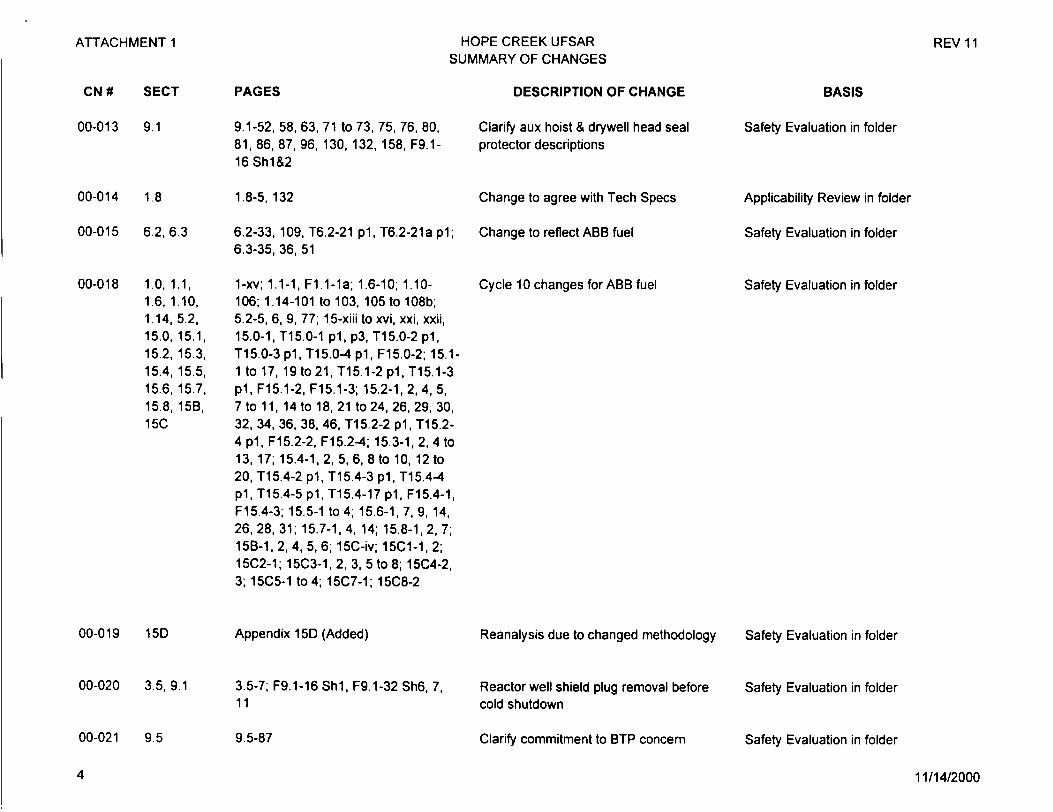
ATTACHMENT 1
CN # SECT
00-013 9.1
00-014 1.8
00-015 6.2,6.3
00-018 1.0, 1.1, 1.6, 1.10, 1.14, 5.2. 15.0, 15.1, 15.2, 15.3, 15.4, 15.5, 15.6, 15.7, 15.8, 15B, 15C
00-019 15D
00-020 3.5, 9.1
00-021 9.5
HOPE CREEK UFSAR SUMMARY OF CHANGES
PAGES
9.1-52, 58, 63, 71 to 73, 75, 76, 80, 81, 86, 87, 96, 130, 132, 158, F9.116 Shl&2
1.8-5, 132
6.2-33, 109, T6.2-21 pl, T6.2-21a pl; 6.3-35, 36, 51
1-xv; 1.1-1, F1.1-1a; 1.6-10;, 1.10
106; 1.14-101 to 103, 105 to 108b; 5.2-5, 6, 9, 77; 15-xiii to xvi, xxi, xxii, 15.0-1, T15.0-1 pl, p3, T15.0-2 pl, T15.0-3 pl, T15.0-4 pl, F15.0-2; 15.11 to 17, 19 to 21, T15.1-2 pl, T15.1-3 p1, F15.1-2, F15.1-3; 15.2-1, 2, 4, 5, 7 to 11, 14 to 18, 21 to24, 26, 29, 30, 32, 34, 36, 38, 46, T15.2-2 pl, T15.24 pl, F15.2-2, F15.2-4; 15.3-1, 2, 4 to 13, 17; 15.4-1, 2, 5, 6, 8 to 10, 12 to 20, T15.4-2 pl, T15.4-3 pl, T15.4-4 pl, T15.4-5 pl, T15.4-17 pl, F15.4-1, F15.4-3; 15.5-1 to4; 15.6-1, 7, 9, 14, 26, 28, 31; 15.7-1, 4, 14; 15.8-1, 2, 7; 15B-1, 2, 4, 5, 6; 15C-iv; 15C1-1, 2; 15C2-1; 15C3-1, 2, 3, 5 to 8; 15C4-2, 3; 15C5-1 to4; 15C7-1; 15C8-2
Appendix 15D (Added)
3.5-7; F9.1-16 Shl, F9.1-32 Sh6, 7, 11
9.5-87
DESCRIPTION OF CHANGE
Clarify aux hoist & drywell head seal protector descriptions
Change to agree with Tech Specs
Change to reflect ABB fuel
Cycle 10 changes for ABB fuel
Reanalysis due to changed methodology
Reactor well shield plug removal before cold shutdown
Clarify commitment to BTP concern
BASIS
Safety Evaluation in folder
Applicability Review in folder
Safety Evaluation in folder
Safety Evaluation in folder
Safety Evaluation in folder
Safety Evaluation in folder
Safety Evaluation in folder
11/14/2000
REV 11
4

ATTACHMENT 1
CN #
00-022
SECT
3.4,9.5, 9A
00-023 7.5
00-024 5.4
PAGES
T3.4-2 pl; T9.5-17 p10; T9A-1 p54, p55; T9A-100 pl, p2, p4; T9A-101 pl, p2, p4; T9A-102 pl
T7.5-1 p2
5.4-66
HOPE CREEK UFSAR SUMMARY OF CHANGES
DESCRIPTION OF CHANGE
Add handsets & speakers in SWIS (DCP 80000916)
Add note for calibration range for the suppression pool water temperature recorders
Correct MS line temperature between RV & MSIVs to agree with Table T1.3-1 p4
REV 11
BASIS
Safety Evaluation in folder
Applicability Review in folder
Applicability Review in folder
00-025
00-026
7.7
10.4
00-027 9.5, 9A
00-028
00-029
00-030
8.3, 9.5
4.6
7.3, 9.2
00-031 1.2, 8.3
00-033
00-034
5
8.3
9.1
7.7-5,6
10.4-25
9.5-51; T9A-1 p38 to p44, p46; T9A32 p2 to p6; T9A-33 p2 to p6; T9A-34 p2 to p6; T9A-35 p2 to p6; T9A-43 pl; T9A-44 pl; T9A-45 pl; T9A-46 pl
8.3-24, 25, 26; T9.5-23 p3
4.6-13
7.3-74; 9.2-4
1.2-36; 8.3-3, F8.3-1 Shl, F8.3-3 Shl
8.3-3, 4, 5, 9, 69, F8.3-1 Shl
T9.1-2 p1
Describe bypass Rod Control self-test
Clarify CW pipe testing (DCP 800011642)
Smoke detector descriptions
Correct to agree with other Sections
Allow CRD system operation in manual
Revise nomenclature of SW pump lubrication head tank (DCP 80011053)
Replace Main Transformer (DCP 80012185)
Miscellaneous clarifications
Correct to agree with Section 9.1.3.1
Safety Evaluation in folder
Applicability Review in folder
Safety Evaluation in folder
Applicability Review in folder
Safety Evaluation in folder
Safety Evaluation in folder
Safety Evaluation in folder
Applicability Review in folder
Applicability Review in folder
11/14/2000
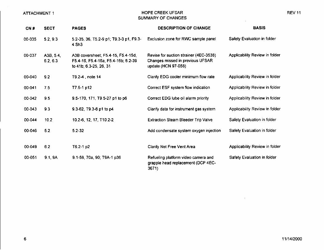
ATTACHMENT 1
CN# SECT PAGES
00-035 5.2, 9.3 5.2-35, 36, T5.2-9 pl; T9.3-3 pl, F9. 4 Sh3
00-037 A3B, 5.4, A3B coversheet; F5.4-15, F5.4-15d, 6.2, 6.3 F5.4-16, F5.4-16a, F5.4-16b; 6.2-39
to 41b; 6.3-25, 26, 31
00-040 9.2 T9.2-4, note 14
00-041 7.5 T7.5-1 p12
00-042 9.5 9.5-170, 171. T9.5-27 p1 to p6
00-043 9.3 9.3-62, T9.3-6 pl to p4
00-044 10.2 10.2-6, 12, 17, T10.2-2
00-046 5.2 5.2-32
00-049
00-051
6.2
9.1, 9A
T6.2-1 p2
9.1-59, 70a, 90; T9A-1 p36
HOPE CREEK UFSAR SUMMARY OF CHANGES
DESCRIPTION OF CHANGE
3- Exclusion zone for RWC sample panel
Revise for suction strainer (4EC-3538) Changes missed in previous UFSAR update (HCN 97-058)
Clarify EDG cooler minimum flow rate
Correct ESF system flow indication
Correct EDG lube oil alarm priority
Clarify data for instrument gas system
Extraction Steam Bleeder Trip Valve
Add condensate system oxygen injection
Clarify Net Free Vent Area
Refueling platform video camera and grapple head replacement (DCP 4EC3671)
REV 11
BASIS
Safety Evaluation in folder
Applicability Review in folder
Applicability Review in folder
Applicability Review in folder
Applicability Review in folder
Applicability Review in folder
Safety Evaluation in folder
Safety Evaluation in folder
Applicability Review in folder
Safety Evaluation in folder
11/14/20006
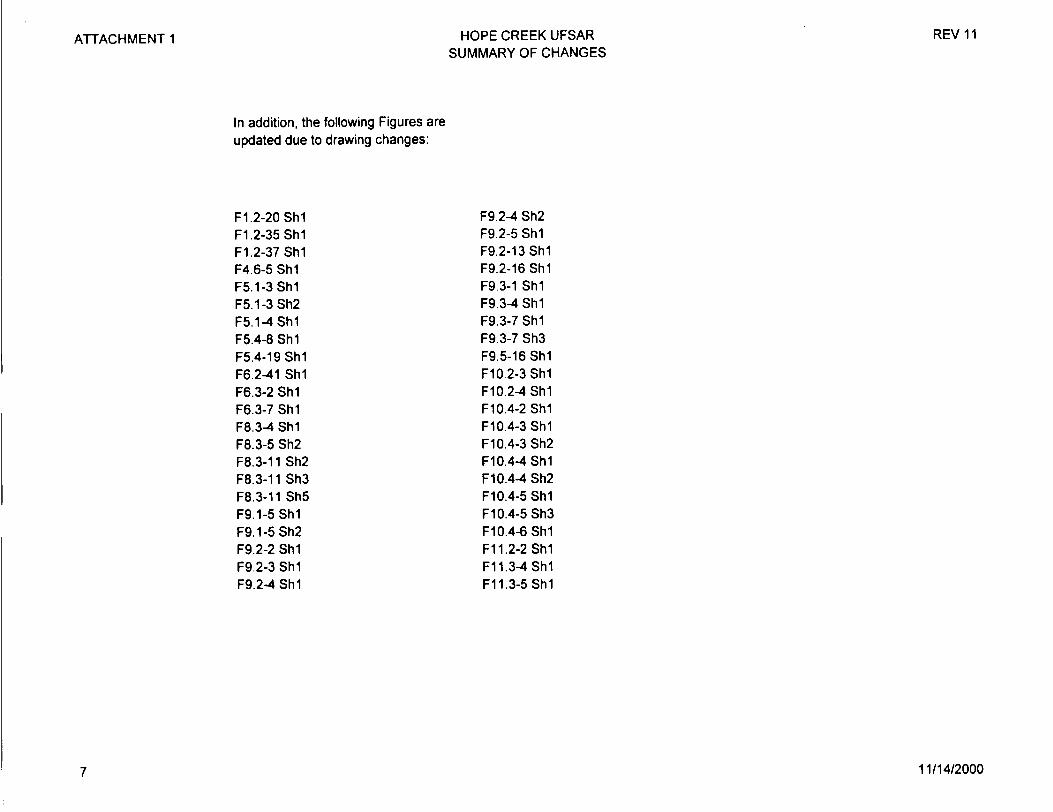
ATTACHMENT 1 REV 11HOPE CREEK UFSAR SUMMARY OF CHANGES
In addition, the following Figures are updated due to drawing changes:
F1.2-20 Shl F1.2-35 Shl F1.2-37 Shl F4.6-5 Shl F5.1-3 Shl F5.1-3 Sh2 F5.1-4 Shl F5.4-8 Shl F5.4-19 Shl F6.2-41 Shl F6.3-2 Shl F6.3-7 Shl F8.3-4 Shl F8.3-5 Sh2 F8.3-11 Sh2 F8.3-11 Sh3 F8.3-11 Sh5 F9.1-5 Sh1 F9.1-5 Sh2 F9.2-2 Shl F9.2-3 Shl F9.2-4 Shl
F9.2-4 Sh2 F9.2-5 Shl F9.2-13 Shl F9.2-16 Shl F9.3-1 Shl F9.3-4 Shl F9.3-7 Shl F9.3-7 Sh3 F9.5-16 Shl F10.2-3 Shl F10.2-4 Shl F10.4-2 Shl F10.4-3 Shl F10.4-3 Sh2 F10.4-4 Shl F10.4-4 Sh2 F10.4-5 Shl F10.4-5 Sh3 F10.4-6 Shl F11.2-2 Shl F11.3-4 Shl F11.3-5 Shl
11/14/20007
LIST OF FIGURES
Figure
1.1-1
1.1-la
1.2-1
1.2-2
1.2-3
1.2-4
1.2-5
1.2-6
1.2-7
1.2-8
1.2-9
1.2-10
1.2-11
1.2-12
1.2-13
Equipment Location
el 54'-0"
Equipment Location
el 77'-0"
Equipment Location
el 102'-0"
Turbine Building Plan
Turbine Building Plan
Turbine Building Plan
1-xvHCGS-UFSAR Revision 11
November 24, 2000
I
Title
Heat Balance at Rated Power
Heat Balance at Rated Power (Used in ABB Analysis)
Site Plan
General Arrangement Plan el 54'-0"
General Arrangement Plan el 77'-0"
General Arrangement Plan el 102'-0"
General Arrangement Plan el 120'-0" & 132'-0"
General Arrangement Plan el 137'-0" & 145'-0"
General Arrangement Plan el 153'-0" & 162'-0"
General Arrangement Plan el 171' & 201'
General Arrangement Sections A-A & B-B
General Arrangement Sections C-C & D-D
General Arrangement Sections E-E & F-F
1.2-14
Figure
1.2-15
1.2-16
1.2-17
1.2-18
1-xviHCGS -UFSAR Revision 4
April 11, 1992
I
1.2-19
1.2-20
1.2-21
1.2-22
1.2-23
1.2-24
1.2-25
LIST OF FIGURES (Cont)
Title
Equipment Location Turbine Building Plan el 120'-0"
Equipment Location Turbine Building Plan el 137'-0"
Equipment Location Turbine Building Plan el 171'-0"
Equipment Location Service Radwaste
Plan el 54'-0"
Equipment Location Service & Radwaste Area
Plan el 77'-0" & 871-0"
Equipment Location Service & Radwaste Area
Plan el 102'-0"
Equipment Location Service & Radwaste Area Plan el 124'-0"
Equipment Location Service & Radwaste Area Plan el 137'-0"
Equipment Location Service & Radwaste Area Plan el 153'-0" &
155 -3"
Equipment Location Service & Radwaste Areas Plans at el 65'
0", 66'-0', 68'-6", 69'-0" 70'-0", 75'-0", and el. 82'-0"
Equipment Location Service and Radwaste Area Plan, el 172'
0"
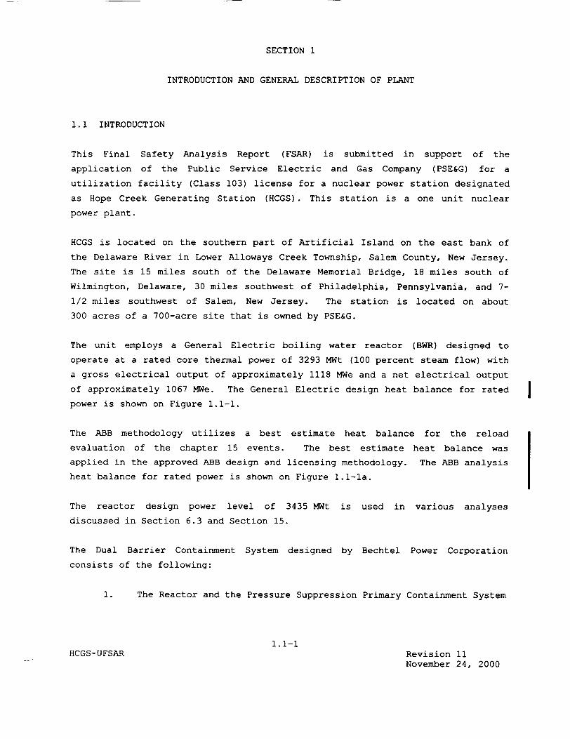
SECTION 1
INTRODUCTION AND GENERAL DESCRIPTION OF PLANT
1.1 INTRODUCTION
This Final Safety Analysis Report (FSAR) is submitted in support of the
application of the Public Service Electric and Gas Company (PSE&G) for a
utilization facility (Class 103) license for a nuclear power station designated
as Hope Creek Generating Station (HCGS). This station is a one unit nuclear
power plant.
HCGS is located on the southern part of Artificial Island on the east bank of
the Delaware River in Lower Alloways Creek Township, Salem County, New Jersey.
The site is 15 miles south of the Delaware Memorial Bridge, 18 miles south of
Wilmington, Delaware, 30 miles southwest of Philadelphia, Pennsylvania, and 7
1/2 miles southwest of Salem, New Jersey. The station is located on about
300 acres of a 700-acre site that is owned by PSE&G.
The unit employs a General Electric boiling water reactor (BWR) designed to
operate at a rated core thermal power of 3293 MWt (100 percent steam flow) with
a gross electrical output of approximately 1118 MWe and a net electrical output
of approximately 1067 MWe. The General Electric design heat balance for rated
power is shown on Figure 1.1-1.
The ABB methodology utilizes a best estimate heat balance for the reload
evaluation of the chapter 15 events. The best estimate heat balance was
applied in the approved ABB design and licensing methodology. The ABB analysis
heat balance for rated power is shown on Figure 1.1-la.
The reactor design power level of 3435 MWt is used in various analyses
discussed in Section 6.3 and Section 15.
The Dual Barrier Containment System designed by Bechtel Power Corporation
consists of the following:
1. The Reactor and the Pressure Suppression Primary Containment System
1.1-1 HCGS-UFSAR Revision 11
November 24, 2000
2. The Reactor Building.
The primary containment is a steel shell, shaped like a light bulb, enclosed in
reinforced concrete, and interconnected to a torus type steel suppression
chamber. The design employs the drywell/pressure suppression features of the
BWR/Mark I containment concept. The Reactor Building completely houses the
reactor, the primary containment, and fuel handling and storage areas. To the
extent that it limits the release of radioactive materials to the environs, the
Reactor Building is capable of containing any radioactive materials that might
be released to it, subsequent to the occurrence of a postulated loss-of-coolant
accident (LOCA), so that the offsite doses are below the reference values
stated in 10CFRI00.
Condenser cooling is provided by water circulated through a natural draft
cooling tower.
Fuel loading of the HCGS is scheduled for January, 1986. Therefore, receipt of
the operating license is required by that date. Based on such receipt,
commercial operation of the HCGS is scheduled for June 1986.
1.1-2 HCGS-UFSAR Revision 0
April 11, 1988
4. Provide condensate where required for miscellaneous equipment in
the radwaste and Reactor Buildings.
Makeup water to the condensate storage tanks (CSTs) is provided by the
demineralized water storage tank.
1.2.4.3.11 Condensate Pre-filter System
The function of the Condensate Pre-filter system is to remove insoluble
impurities, primarily iron, from the condensate upstream of the deep bed
demineralizers.
The Condensate Pre-filter System consists of four vessels operated in parallel
with a 33% bypass valve. The filter system is designed to operate at 100%
condensate flow with a filter flux flow of approximately 0.27 gpm/ft 2 with all
four filter vessels in service. The Condensate Pre-filter System is designed
to remove iron to less than lppb. Automatic valves operated by the Condensate
Pre-filter control system remove the individual filter vessels from the process
stream and backwash the filter media. Backwash water is collected in a header
and directed to the Backwash Receiving Tank (BWRT). The BWRT is pumped to the
radwaste system.
1.2.4.4 Electrical Systems and Instrumentation and Control
Four independent Class 1E 208/120 V ac power systems are provided. Each is
dedicated to its own instrumentation channel. Control power supply for
Class 1E 4.16-kV and 480 V switchgear is supplied from the corresponding
channel 125 V dc system. Starters in the MCCs derive their control power from
the control power transformers located in the starter cubicle.
1.2.4.4.1 Electrical Power Systems
1.2.4.4.1.1 Generation and Transmission Systems
The main generator is a 1300 MVA, 1800 rpm, 0.90 power factor, 25,000 V, three
phase, 60 hertz, 0.50 scr, 75 psig hydrogen cooled synchronous machine. The
stator is water cooled. The generator is connected directly to the turbine
shaft. Excitation is from a shaft driven alternator and stationary rectifier
banks. The generator neutral is grounded through a 75-kVA, single phase,
14,400 120/240 V distribution transformer. The main generator unit is
connected to the PSE&G 500-kV switchyard through three
1.2-35 HCGS-UFSAR Revision 10
September 30, 1999

single phase 24 500-kV main stepup transformers. The Hope Creek 500-kV
switchyard is tied to the Pennsylvania New Jersey Maryland interconnected power
network by three physically independent aerial transmission lines.
1.2.4.4.1.2 Electric Power Distribution Offsite AC Systems Power Supply
Arrangement of the switchyard provides a reliable and redundant offsite
auxiliary power supply. Power from the 500 kV switchyard to a 13.8-kV ring bus
is fed through two physically independent paths.
The 13.8-kV ring bus feeds both Class 1E and non Class 1E ac and dc power
systems. The Class 1E power system supplies all safety related equipment and
some non Class 1E loads that are important for plant operation. The non
Class 1E power system applies to the balance of plant equipment. The Class 1E
ac system consists of four independent load groups. Each load group includes
4.16 kV switchgear, 480 V unit substations, 480 V MCCs, and 120 V control and
instrument power panels. The vital ac instrumentation and control power supply
systems include dc battery systems and static inverters.
1.2.4.4.2 Nuclear System Process Control and Instrumentation
1.2.4.4.2.1 Reactor Manual Control System
The Reactor Manual Control System provides the means by which control rods are
positioned from the main control room for power control. The system operates
valves in each hydraulic control unit to change control rod position. Only one
control rod can be manipulated at a time. The Reactor Manual Control System
includes logic that restricts control rod movement (rod block) under certain
conditions as a backup to procedural controls.
1.2-36 HCGS-UFSAR Revision 11
November 24, 2000
1.2.4.4.2.2 Recirculation Flow Control System
The Recirculation Flow Control System controls the speed of the reactor
recirculation pumps. Adjusting the pump speed changes the coolant flow rate
through the core. This effects changes in core power level.
1.2.4.4.2.3 Neutron Monitoring System
The Neutron Monitoring System (NMS) is a system of in-core neutron detectors
and out-of-core electronic monitoring equipment. The system provides
indication of neutron flux, which can be correlated to thermal power level for
the entire range of flux conditions that can exist in the core. The source
range monitors (SRMs) and the intermediate range monitors (IRMs) provide flux
level indications during reactor startup and low power operation. The local
power range monitors (LPRMs) and average power range monitors (APRMs) allow
assessment of local and overall flux conditions during power range operation.
The traversing in core probe system (TIP) provides a means to calibrate the
individual LPRM sensors. The NMS provides inputs to the reactor manual control
system to initiate rod blocks if preset flux limits are exceeded, and inputs to
the RPS to initiate a scram if other limits are exceeded.
1.2.4.4.2.4 Refueling Interlocks
A system of interlocks that restricts movement of refueling equipment and
control rods when the reactor is in the refueling and startup modes is provided
to prevent an inadvertent criticality during refueling operations. The
interlocks back up procedural controls that have the same objective. The
interlocks affect the refueling platform, refueling platform hoists, fuel
grapple, and control rods.
1.2-37 HCGS-UFSAR Revision 0
April 11, 1988
1.2.4.4.2.5 Reactor Vessel Instrumentation
In addition to instrumentation for the nuclear safety systems and engineered
safety features (ESFs), instrumentation is provided to monitor and transmit
information that can be used to assess conditions existing inside the reactor vessel and the physical condition of the vessel itself. This instrumentation
monitors reactor vessel pressure, water level, coolant temperature, reactor
core differential pressure, coolant flow rates, and reactor vessel head inner
seal ring leakage.
1.2.4.4.2.6 Process Computer System
An online process computer is provided to monitor and log process variables and
to make certain analytical computations. An off-line computer program, which
duplicates the process computer core evaluation functions, may be used in the
event the online system is unavailable.
1.2.4.4.3 Power Conversion Systems Process Control and Instrumentation
1.2.4.4.3.1 Pressure Regulator and Turbine Generator Control
The pressure regulator maintains control of the turbine control and turbine
bypass valves to allow proper generator and reactor response to system load demand changes while maintaining the nuclear system pressure essentially
constant.
The turbine generator speed load controls act to maintain the turbine speed
(generator frequency) constant and respond to load changes by adjusting the reactor recirculation flow control system and pressure regulator setpoint.
1.2-38HCGS-UFSAR Revision 11
November 24, 2000
I
The fuel pool filter demineralizer subsystem is also used by the Torus Water
Cleanup (TWC) System.
1.2.4.6.4 Station Service Water System
The Station Service Water System (SSWS) consists of two redundant trains that
provide river water to cool the SACS heat exchangers and the Reactor
Auxiliaries Cooling System (RACS) heat exchangers.
1.2.4.6.5 Ultimate Heat Sink (UHS)
The ultimate heat sink (UHS) for HCGS engineered safety equipment is the
Delaware River. The UHS provides the required cooling water for the startup,
normal operation, accident, or shutdown conditions of the reactor.
During normal operation, the UHS is designed to dissipate heat by discharging
heated water into the circulating water system. This system dissipates this
heat and the heat rejected in the main condenser to the atmosphere by a natural
draft cooling tower by evaporation, with the overflow going to the Delaware
River.
During LOCA or LOP conditions, the UHS provides the necessary reliable heat
sink for the safeguard equipment. The cooling tower is not essential for the
safe shutdown of the plant.
1.2.4.6.6 Raw Water Treatment Plant and Makeup Water Treatment System
A Makeup Water Treatment System is provided to furnish a supply of treated water suitable for plant use.
1.2.4.6.7 Potable and Sanitary Wastewater System
The Potable and Sanitary Wastewater System provides water for drinking, makeup,
and sanitary services.
1.2-41HCGS-UFSAR Revision 0
April 11, 1988
1.2.4.6.8 Plant Chilled Water System
The plant CWS is designed to provide a means of cooling both the fresh air
supply and air recirculation to building HVAC systems.
1.2.4.6.9 Process Sampling System
The Process Sampling System furnishes process information that is required to monitor plant and equipment performance and changes in operating parameters.
Representative liquid and gas samples are taken automatically and/or manually
during normal plant operation for laboratory or online analyses.
A post accident sampling system is provided to obtain representative samples of
the reactor coolant and the suppression pool water in accordance with the
Regulatory Guide 1.97 requirements. The system has the capability to sample
the primary containment atmosphere, the reactor building atmosphere, and the
torus atmosphere.
1.2.4.6.10 Plant Equipment and Floor Drainage
The Plant Equipment and Floor Drainage Systems include both radioactive and
nonradioactive drains. Radioactive drains contain potentially radioactive
materials and are pumped to the radwaste system for cleanup, reuse, or
disposal. Nonradioactive drain materials are treated to remove oil prior to discharge to the Delaware River. The Turbine Building Circulating Water
Dewatering Sump may be contaminated with low levels of tritium from certain
supply ventilation HVAC drains.
1.2.4.6.11 Service and Instrument Air Systems
The Service Air System supplies filtered, oil free, compressed air for plant
operation and services.
The Instrument Air System supplies filtered, dried, and oil free compressed air
for air operated instruments.
1.2-42 HCGS-UFSAR Revision 11
November 24, 2000
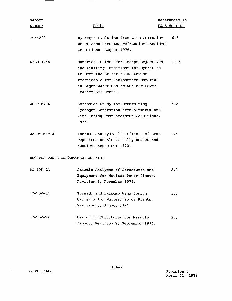
Report
Number
FC-4290
WASH-1258
WCAP-8776
WAPD-TM-918
Referenced in
FSAR SectionTitle
Hydrogen Evolution from Zinc Corrosion
under Simulated Loss-of-Coolant Accident
Conditions, August 1976.
Numerical Guides for Design Objectives
and Limiting Conditions for Operation
to Meet the Criterion as Low as
Practicable for Radioactive Material
in Light-Water-Cooled Nuclear Power
Reactor Effluents.
Corrosion Study for Determining
Hydrogen Generation from Aluminum and
Zinc During Post-Accident Conditions,
1976.
Thermal and Hydraulic Effects of Crud
Deposited on Electrically Heated Rod
Bundles, September 1970.
BECHTEL POWER CORPORATION REPORTS
BC-TOP-4A
BC-TOP-3A
BC-TOP- 9A
Seismic Analyses of Structures and
Equipment for Nuclear Power Plants,
Revision 3, November 1974.
Tornado and Extreme Wind Design
Criteria for Nuclear Power Plants,
Revision 3, August 1974.
Design of Structures for Missile
Impact, Revision 2, September 1974.
1.6-9HCGS-UFSAR Revision 0
April 11, 1988
6.2
11.3
6.2
4.4
3.7
3.3
3.5

Referenced in
FSAR SectionTitle
Report
Number
BN-TOP-1
ABB COMBUSTION ENGINEERING REPORTS:
CENPD-300-P-A Reference Safety Report for Boiling
Water Reactor Reload Fuel, July 1996
4.1, 4.2, 4.3,
4.4, 6.2, 6.3,
15.1, 15.2,
15.4, 15.6,
15.8
CENPD-284-P-A
CENPD-287-P-A
CENPD-288-P-A
CENPD-389-P-A
Control Rod Drop Accident Analysis
Methodology for Boiling Water Reactors:
Summary and Qualification
Fuel Assembly Mechanical Design
Methodology for Boiling Water Reactors
ABB Seismic/LOCA Evaluation Methodology
for Boiling Water Reactor Fuel
1OX10 SVEA Fuel Critical Power
Experiment and CPR Correlation
- SVEA 96+
15.4
3.9
3.9
4.4
1.6-10HCGS-UFSAR Revision 11
November 24, 2000
Testing Criteria for Integrated
Leakage Rate Testing of Primary
Containment Structures for Nuclear
Power Plants, November 1972.
Design for Pipe Break Effects,
Revision 2, May 1974.
Subcompartment Pressure Analyses
Revision 0, July 1976.
Seismic Analysis Piping System,
Revision 3, January 1976.
BN-TOP-2
BN-TOP-4
BP-TOP-I
6.2
3.6, 3.8
3.6
3.7
motor, after closure of the SDG circuit breaker. The RHR motor because the two
unit substation transformers remain connected to the diesel generator bus all
the time, the voltage will dip below 75 percent of rated voltage upon the
closure of the generator breaker for a DBA or loss of offsite power (LOP). This
voltage dip is due to the excitation current inrush while the transformers are
energized and lasts for approximately six cycles. The first motor load applied
in the RHR circuit breaker has a closing permissive from the bus undervoltage
relays. With the current setting of these relays (set to dropout at 70 percent
and to pickup at 78 percent) the RHR motor circuit breaker will close when
permitted. It takes 4.5 cycles for this circuit breaker to close. During this
interval the generator has recovered its voltage in excess of 90 percent. This
will be verified during the preoperational tests described in Section
14.2.12.1.30.
Compliance with Position C.6 of Regulatory Guide 1.9 is discussed in
Section 1.8.1.108.
The order of testing specified in Regulatory Position C.14 is not applicable to
Hope Creek. The Hope Creek order of testing is as described in the Hope Creek
Technical Specifications.
For further discussion of onsite power systems, see Section 8.3.
1.8.1.10 Conformance to Regulatory Guide 1.10, Revision 1, January 2, 1973:
Mechanical (Cadweld) Splices in Reinforcing Bars of Category I
Concrete Structures
Although Regulatory Guide 1.10 was withdrawn by the NRC on July 21, 1981, HCGS
complies with it.
The original Cadweld testing program in the Preliminary Safety Analysis Report
(PSAR) was based on using only sister splices. The program was later revised
before the start of construction to conform with the Regulatory Guide using a
combination of production and sister splices. When newer technical criteria
for Cadwelding developed, the architect/engineer revised the program to delete
the tensile test frequency requirements for each splicing crew. The new
criteria conformed to the requirements of ANSI N45.2.5, 1978, as
1.8-5 HCGS-UFSAR Revision 11
November 24, 2000
endorsed by Regulatory Guide 1.94. However, the letter dated August 5, 1981,
NRC to PSE&G, from R. L. Tedesco to R. L. Mittl, requested that the sample
frequency requirements of this guide be implemented. Since November 30, 1981,
HCGS has been in complete compliance with this Regulatory Guide.
For further discussion, see Section 3.8.6.
1.8.1.11 Conformance to Regulatory Guide 1.11 (Safety Guide 11), Revision 0,
February 1, 1971: Instrument Lines Penetrating Primary Reactor
Containment
HCGS complies with Regulatory Guide 1.11, except as noted below.
Containment pressure sensing lines are not provided with an automatic or
remotely operated isolation valve as specified in Position C.l.c of Regulatory
Guide 1.11. Sensing lines are not isolated automatically upon a containment
isolation signal because the pressure sensors provide a Reactor Protection
System (RPS) signal. The capability for remote operation is not useful to the
operator because remote indication of failure of a specific line is not
available. However, these lines are provided with manual isolation valves for
local operation and are checked for leakage during normal instrumentation
calibrations.
For further discussion of containment isolation provisions, see Section 6.2.4.
1.8.1.12 Conformance to Regulatory Guide 1.12, Revision 1, April 1974:
Instrumentation for Earthquakes
HCGS complies with ANSI N18.5-1974, as endorsed and modified by Regulatory
Guide 1.12, subject to the clarification that the response-spectrum recorders
required by Paragraph C.l.c are not supplied as discrete instruments. Instead,
triaxial time history accelerographs are provided, at the required locations,
with a multichannel magnetic tape recorder and a response spectrum
1.8-6 HCGS-UFSAR Revision 0
April 11, 1988
measurement. The switching device or bistable is an electronic switch located
in main or remote panels.
Because Regulatory Guide 1.105 does not differentiate between the types of
bistable actuation (mechanical or electronic), HCGS requested suppliers to
demonstrate by test, preferably during the tests performed to comply with
IEEE 323, that their electronic switch is not subject to unacceptable drift.
Position C.5 also requires that securing devices be under administrative
control. If securing devices are required, based upon test results,
administrative control consists of control of access to areas within the plant
where these devices are located.
See Section 1.8.2 for the NSSS assessment of this Regulatory Guide.
1.8.1.106 Conformance to Regulatory Guide 1.106, Revision 1, March 1977:
Thermal Overload Protection for Electric Motors on Motor Operated
Valves
Although Regulatory Guide 1.106 is not applicable to HCGS, per its
implementation section, HCGS complies with it.
See Section 1.8.2 for the NSSS assessment of this Regulatory Guide.
1.8.1.107 Conformance to Regulatory Guide 1.107, Revision 1, February 1977:
Qualifications for Cement Grouting for Prestressing Tendons in
Containment Structures
Regulatory Guide 1.107 is not applicable to HCGS.
1.8-131HCGS-UFSAR Revision 0
April 11, 1988
1.8.1.108 Conformance to Regulatory Guide 1.108, Revision 1, August 1977:
Periodic Testing of Diesel Generator Units Used as Onsite Electric
Power Systems at Nuclear Power Plants
HCGS complies with Regulatory Guide 1.108, with the following exception:
1. During the preoperational test phase, following the diesel 24-hour
full load test, the proper design accident loading sequence will be
demonstrated by the test described in Section 14.2.12.1.47. This
test will verify the ability of the SDG to start and accept the
sequenced design loads as specified in Table 8.3-1. This test will
provide ECCS flows to the reactor vessel.
2. The criteria regarding sustained load levels of 100 percent and 110 percent can be demonstrated when those significant parameters
being measured have stabilized to acceptable values. Although the
100 percent load level should be maintained for 22 hours followed by a 110 percent load level for 2 hours, reduced run times at 110 percent load levels are not regarded as an inadequate
demonstration as defined by Position C.2.c provided: Runtime is
sufficient to stabilize significant parameters being measured at the
110 percent load level and additional runtime (continuous beyond
22 hours) at the 100 percent load level is available to the diesel
generator's load-carrying capability on an extended basis to
compensate for the reduced runtime at the 110 percent load level.
3. For periodic testing required by the Hope Creek Technical
Specifications, the test per this regulatory position will be
performed during shutdown, except as noted in item 4. This test will
simulate, separately, a loss of offsite power, and a loss of offsite
power plus a LOCA condition, to verify the SDGs' ability to start and
accept the sequence design loads.
4. For periodic testing required by the Hope Creek Technical
Specifications, exception to regulatory position C.2.a. (5) is taken
with respect to simulating a loss of offsite power (regulatory
position C.2.a.(1)) and demonstrating the proper operation for
design-accident-loading-sequence to design-load requirement
1.8-132 HCGS-UFSAR Revision 11
November 24, 2000
Based on parametric analyses, an adequate design margin exists to compensate
for the effects of the reduced dead load factor.
See Section 3.8.3 for discussion of the design of concrete structures.
1.8.1.143 Conformance to Regulatory Guide 1.143, Revision 1, October 1979:
Design Guidance for Radioactive Waste Management Systems,
Structures, and Components Installed in Light Water Cooled Nuclear
Power Plants
Although Regulatory Guide 1.143 is not applicable to HCGS, per its
implementation section, HCGS complies with it, with the clarifications stated
below.
Positions C.1.1.2, C.2.1.2, C.3.1.2, and Table 1 of Regulatory Guide 1.143
require that all material specifications for pressure-retaining components
within the radioactive process boundary conform to ASME B&PV Code, Section II.
In addition, they require that piping materials conform to both the ASME and
the identical ASTM specification, and they permit substitution of
manufacturers' standards, instead of the ASME specification, in the case of
pump materials. Although Regulatory Guide 1.143 does not explicitly address
in-line process components, sight flow glasses, Y-strainers, and steam traps
procured by the architect/engineer, and the orifice plates and conductivity
elements in the NSSS scope of supply do not have certificates of compliance for
the materials specified. Also, the records of shop inspection, required by
Table 1, for the Y-strainers and the steam traps are not available from the
supplier.
Nevertheless, the quality assurance measures taken provide the reasonable
assurance needed to protect the health and safety of the public and that of
plant operating personnel.
Position C.1.2.1 requires that the designated high liquid level conditions
should actuate alarms both locally and in the control
1.8-153 HCGS-UFSAR Revision 0
April 11, 1988
room. For all tanks, a high liquid level condition actuates an alarm in the radwaste control room only. There are no local alarms since the tank rooms are
controlled areas and normally unmanned.
Position C.4.3 requires that process lines should not be less than 3/4 inch (nominal). The crystallizer concentrates and slurry waste transfer lines to the extruder/evaporators are 1/2 inch nominal, in order to maintain acceptable flow velocities to prevent settling in the lines**. The fluid flowrates are on
the order of one (1) gpm as shown in Table 11.4-7 and on Figure 11.4-9.
1.8.1.144 Conformance to Regulatory Guide 1.144, Revision 1, September 1980:
Auditing of Quality Assurance Programs for Nuclear Power Plants
Although NRC Regulatory Guide 1.144 was withdrawn by the NRC on July 31, 1991, HCGS commitments, as stated below, are not affected by this withdrawal.
HCGS complies with Regulatory Guide 1.144 during the operations phase. The following exception is identified for those audits conducted under the cognizance of the Nuclear Review Board as described in Section 17.2 by an independent consultant. These audit reports shall be forwarded to the CNO and management positions responsible for the areas audited within 60 days after the
completion of the audit exit meeting.
Hope Creek compliance with Regulatory Guide 1.144 during the design construction phase is described in Section 16 of the Hope Creek PSAR
Revision 6, (October 22, 1994) of the UFSAR.
and
and
** Note: Crystallizer and Extruder Evaporators are abandoned in place.
1.8-154 HCGS-UFSAR Revision 11
November 24, 2000
I
I
As a result of the task force reviews, a number of concerns were identified
regarding the adequacy of certain features of small break LOCA models,
particularly the need to confirm specific model features (e.g., condensation
heat transfer rates) against applicable experimental data. These concerns, as
they applied to each light water reactor (LWR) vendor's models, were documented
in the task force reports for each LWR vendor. In addition to the modeling
concerns identified, the task force also concluded that, in light of the TMI-2
accident, additional systems verification of the small break LOCA model as
required by 11.4 of Appendix K to 10CFR Part 50 was needed. This included
providing predictions of Semiscale Test S-07-10B, LOFT Test (L3-1), and
providing experimental verification of the various modes of single-phase and
two-phase natural circulation predicted to occur in each vendor's reactor
during small break LOCAs.
Based on the cumulative staff requirements for additional small break LOCA
model verification, including both integral system and separate effects
verification, the staff considered model revision as the appropriate method for
reflecting any potential upgrading of the analysis methods.
The purpose of the verification was to provide the necessary assurance that the
small break LOCA models were acceptable to calculate the behavior and
consequences of small primary system breaks. The staff believes that this
assurance can alternatively be provided, as appropriate, by additional
justification of the acceptability of present small break LOCA models with
regard to specific staff concerns and recent test data. Such justification
could supplement or supersede the need for model revision.
The specific staff concerns regarding small break LOCA models are provided in
the analysis sections of the B&O Task Force reports for each LWR vendor. These
concerns should be reviewed in total by each holder of an approved emergency
core cooling system model and addressed in the evaluation as appropriate.
1.10-105 HCGS-UFSAR Revision 0
April 11, 1988

The recent tests include the entire Semiscale small break test series and LOFT
Test (L3-1) and (L3-2). The staff believes that the present small break LOCA
models can be both qualitatively and quantitatively assessed against these
tests.
Other separate effects tests (e.g., Oak Ridge National Laboratory core uncovery
tests) and future tests, as appropriate, should also be factored into this
assessment.
Based on the preceding information, a detailed outline of the proposed program
to address this issue should be submitted. In particular, this submittal
should identify 1) which areas of the models, if any, the licensee intends to
upgrade, 2) which areas the licensee intends to address by further
justification of acceptability, 3) test data to be used as part of the overall
verification/upgrade effort, and 4) the estimated schedule for performing the
necessary work and submitted this information for staff review and approval.
Response
General Electric provided information concerning the NRC's small break model concerns in a meeting between GE and the NRC staff held on June 18, 1981 and
subsequent documentation included in a letter from R.H. Bucholz (GE) to D.G. Eisenhut (NRC) dated June 26, 1981. Based on its review of this information, the NRC staff has prepared a safety evaluation report (SER) that concludes the test data comparisons and other information submitted by GE
acceptably demonstrate that the existing GE small break model is in compliance with 10CFR50, Appendix K and, therefore, no model changes are required.
ABB CENP's LOCA methodology and its qualification are described in Reference 1
(see below). Although there is no specific response to II.K.3.30, the report includes a comparison to large and small break LOCA tests and the NRC's
approval for Application of the methodology to both small and large break
LOCAs.
Response Reference
1. ABB Atom, "Boiling Water Reactor Emergency Core Cooling System Evaluation model: Code Description and Qualification", ABB Atom Report RPB 90-93-P-A, October 1991.
1.10-106 HCGS-UFSAR Revision 11
November 24, 2000

withdrawal. Thus, the RWM and the Manual Control System (RMCS) are not safety
related. The safety action required for the continuous control rod drop
incident (a reactor scram) is provided by the safety related intermediate range
monitor (IRM) subsystem of the Neutron Monitoring Systems (NMS). If the
setpoint that trips a core flux scram is reached during a flux transient,
the IRM will both block further rod withdrawal and initiate a scram.
Furthermore, a second safety related NMS scram trip, supplied by the APRM, can
terminate the core power transient.
The RWM does not interface with safety-related systems. Refueling interlocks
are not considered safety-related.
The rod block monitor is designed to prohibit erroneous withdrawal of a control
rod during operation at core high power levels. This prevents local fuel
damage under permitted bypass and/or detector chamber failure in the local
power range monitor (LPRM), and prevents local fuel damage during a single rod
withdrawal error. Local fuel damage poses no significant threat relative to
radioactive release from the plant.
Although the RBM does not perform a safety-related function, in the interest of
plant economics and availability, it is designed to meet certain salient design
principles of a safety system. These include the following:
1. Redundant, separate, and isolated RBM channels.
2. Redundant, separate, and isolated rod selection information,
including isolated contacts for each rod selection pushbutton
providing input to each RBM channel.
3. Independent, isolated RBM level readouts and status displays from
the RBM channel.
1.14-57 HCGS-UFSAR Revision 11
November 24, 2000
4. A mechanical barrier between Channels A and B of the manual bypass
switch.
5. Multiple manual RBM channel bypass prohibited by switch design.
6. Independent, separate, isolated rod block signals from the RBM
channels to the RMCS circuitry.
7. Fail safe design, since loss of power initiates a rod block.
8. Initiation of a rod block by trip of either RBM channel
The RBM interfaces with the following safety-related systems:
1. LPRM: Separate, isolation LPRM amplifier signal
information is provided to each RBM channel.
2. Flow Signal: Separate and electrically isolated recirculation
flow inputs are provided to the RBM for trip
reference.
3. APRM System: Independent, separate, and isolated APRM
reference signals are supplied to each RBM
channel for trip reference.
1.14.1.65 MSIV Leakage Control System, LRG I/ICSB-11
1.14.1.65.1 Issue
We identified a single failure to the MSIV Leakage Control System which could
lead to possible failure of the system during testing or operation.
1.14-58 HCGS-UFSAR Revision 0
April 11, 1988
1.14.1.106 Loads Assessment of Fuel Assembly Components, LRG I/CPB-I
1.14.1.106.1 Issue
Appendix A to SRP 4.2 provides guidance for the analysis of Fuel Assembly
Components and Acceptance Criteria for Fuel Assembly Response to externally
applied forces. The applicant's fuel assembly capability should be assessed
accordingly.
1.14.1.106.2 Response
The potential for fuel lift for HCGS is negligibly small. Screening
calculations performed were based on linear seismic and annulus pressurization
analyses and comparisons of HCGS bounding limits (net holdown forces) to those
for previously analyzed BWR/4 and small vessel BWR/5 plants. Although the fuel
lift analysis is intrinsically non-linear, the negligibly small results justify
the adequacy of the linear analyses.
The methodology and acceptance criteria used to evaluate fuel assembly
components to externally applied forces are described in references 1 and 2.
Both references contain NRC's acceptance of the methodology for determining the
dynamic response to external loading conditions.
1.14.1.106.3 Response References
1. ABB Combustion Engineering, " Fuel Assembly Mechanical Design Methodology
for Boiling Water Reactors," CENPD-287-P-A, July 1996.
2. ABB Combustion Engineering, " ABB Seismic / LOCA Evaluation Methodology
for Boiling Water Fuel," CENPD-288-P-A, July 1996.
1.14.1.107 Combined Seismic and LOCA Loads Analysis on Fuel, LRG II/2-CPB
1.14.1.107.1 Issue
Appendix A to SRP 4.2 provides guidance for the analysis of Fuel Assembly
Components and Acceptance Criteria for Fuel Assembly Response to externally
applied forces. The applicant's fuel assembly capability should be assessed
accordingly.
1.14.1.107.2 Response
See response to LRG Issue No. 106, Section 1.14.106.
1.14-101 HCGS-UFSAR Revision 11
November 24, 2000
1.14.1.108 Nonconservatism in the Models For Fuel Cladding Swelling and
Rupture, LRG I/CPB-2 and LRG II/1-CPB
1.14.1.108.1 Issue
The procedures proposed in NUREG-0630 introduce additional conservatism in the models for fuel cladding swelling and rupture during a loss-of-coolant
accident. To assure the degree of swelling and incidence of rupture are not underestimated as required by Appendix K of 10CFR50.46, supplemental
calculations to the current ECCS analyses should be performed. If the swelling is underestimated, the bundle cooling may be overestimated, and the peak
cladding temperature may be nonconservative.
1.14.1.108.2 Response
The HCGS unique ECCS calculations were prepared utilizing a cladding rupture
temperature model modified for temperatures less than 1600*F. The NRC staff
found this model acceptable with respect to the criteria in NUREG-0630 as evidenced by a supplementary safety evaluation report accepting GE's fuel cladding ballooning and rupture model (see References in Section 1.14.108.2.1).
In reference to ABB fuel, the models for fuel clad swelling and rupture during
a loss-of-coolant accident are described in reference 2. The NRC staff found this model acceptable with respect to the criteria in NUREG-0630 when appropriate bias is applied, as is discussed in the SER which is included in
Reference 2.
1.14.1.108.2.1 Reference
1. Letter from H. Bernard (NRC) to G. G. Sherwood (GE), "Supplementary
Acceptance of Licensing Topical Report NEDE-20566 P," MFN 067-82,
May 11, 1982.
2. ABB Combustion Engineering, "BWR ECCS Evaluation model: Supplement to Code
Description and Qualification," CENPD-293-P-A, July 1996.
1.14.1.109 Fuel Rod Cladding Ballooning and Rupture
1.14.1.109.1 Issue
The procedures proposed in NUREG-0630 introduce additional conservatism in the
models for fuel cladding swelling and rupture during a loss-of-coolant
accident. To assure the degree of swelling and incidence of rupture are not
underestimated as required by
1.14-102 HCGS-UFSAR Revision 11
November 24, 2000
Appendix K of 1OCFR50.46, supplemental calculations to the current ECCS
analyses should be performed. If the swelling is underestimated, the bundle
cooling may be overestimated, and the peak cladding temperature may be
nonconservative.
1.14.1.109.2 Response
See response to LRG Issue No. 108, Section 1.14.1.108.
1.14.1.110 High Burnup Fission Gas Release, LRG II/4-CPB
1.14.1.110.1 Issue
An NRC enhancement factor should be applied to calculated fission gas releases
at burnups greater than 20,000 MWd/t because General Electric's GEGAP III model
may underpredict these releases. If the release of low thermal conductivity
fission gas is underestimated, the calculated gap conductance will be
overestimated, and the peak cladding temperature (PCT) calculation will be
nonconservative.
1.14.1.110.2 Response
Application of the NRC's enhancement factor is not necessary. The NRC staff has
approved the taking of credit for the calculated PCT margin and for changes in
the ECCS evaluation model to offset any operating penalties due to high burnup
fission gas release (see Reference 1).
Application of the NRC's enhancement factor to fission gas release calculation
for ABB fuel is not necessary. The NRC has approved the fission gas release
calculation described in reference 2 up to a rod average burnup of 50 GWD/MTU.
1.14.1.110.2.1 Response Reference
1. letter from L. R. Tubenstein (NRC) to T. M. Novack (NRC), "General Electric
ECCS Analysis at High Burnup", October 22, 1981.
2. ABB Combustion Engineering, "Fuel Rod Design Methods for Boiling Water
Reactors, "CENPD-285-P-A, July 1996.
1.14.1.111 Channel Box Deflection, LRG II/3-CPB and LRG I/CPB-3
1.14.1.111.1 Issue
General Electric report NEDO-21354 describes a channel creep deflection
phenomena that may interfere with control rod insertion. Long term channel
deflection occurs when fuel channels are radiated to high exposures or are
located in a region of the core that has a
1.14-103 HCGS-UFSAR Revision 11
November 24, 2000
gradient in fast neutron flux. The resulting bulge (caused by long term creep)
or bow (caused by differential deflection of the channels) reduces the size of
the gap available for control rod insertion.
A program to detect the onset interference between the channel box and the
control blade is required. NEDO-21354 describes a control rod settling
friction test, which can be used to measure the interference of the channel with the control blades. This testing should be included in the program or an
alternative proposed.
1.14.1.111.2 Response
HCGS will adopt the following guidelines to minimize the potential for and to
detect the onset of channel bowing:
1. Records should be kept of channel location and exposure for each operating
cycle.
2. Channels should not reside in the outer row of the core for more than two
operating cycles.
3. Channels that reside in the periphery (outer row) for more than one cycle
should be oriented such that a different side faces the core edge for each
successive peripheral cycle.
4. Channels that reside in the outer row of the core for three or more cycles
should not be shuffled inward.
5. At the beginning of each fuel cycle, the combined outer row residence time
for any two channels in any control rod cell should not exceed four
peripheral cycles.
At the beginning of each fuel cycle, a control rod friction test shall be
performed for those cells exceeding the above general guidelines or containing fuel channels with exposure greater than 36,000 MWd/T (associated fuel bundle
exposures). After the scram
1.14-104 HCGS-UFSAR Revision 0
April 11, 1988
speed surveillance test on each rod required by BWR/4 Standard Technical
Specification 4.1.3.2.a, each control rod meeting the above conditions will be
allowed to settle a total of two notches, one notch at a time, from the fully
inserted position.
Total control rod friction is acceptable if the rod settles, under its own
weight, to the next notch within approximately 10 seconds. If the rod settles
too slowly, a rod block alarm will actuate, indicating possible impending
channel/rod interference. The results of this test will be considered
acceptable if no rod block alarm is received. This testing will give an early
indication of this interference and will prompt an investigation into the
source of the friction. If necessary, corrective action will be completed
before startup after the next core alteration.
This control rod settling friction test, along with the one notch control rod
movement requirement of Standard Technical Specification Section 4.1.3.1.2.a,
provides an equivalent level of safety as the test described in NEDO-21354. The
settling test provides adequate assurance of the scram function. The amount of
friction detectable by this test is approximately 250 lbs. Control rod drive
(CRD) tests indicate that the CRD will tolerate a relatively large increase in
driveline friction (350 lbs) while its performance still remains within
technical specification limits. The control rod is in its most constrained,
highest friction location when it is fully inserted. The ability of the blade
to settle from this position demonstrates that the total drive line friction is
less than the weight of the blade (250 lbs).
In the future, analytic channel lifetime prediction methods, benchmarked by
periodic deflection measurements of a sample of the highest duty fuel channels,
could be used to assure clearance between control blades and fuel channels
without additional testing.
In lieu of friction testing, fuel channel deflection measurements may be used
to identify the amount of remaining channel lifetime for channels
exceeding 36,000 MWd/T (associated fuel bundle exposures).
The introduction of SVEA-96+ fuel will not invalidate the HCGS guidelines for
minimizing the potential for and the detection of channel bowing.
1.14-105 HCGS-UFSAR Revision 11
November 24, 2000
1.14.1.112 Water Side Corrosion of Fuel Cladding Due to Copper in the
Feedwater, LRG I/CPB-4 and LRG II/5-CPB
1.14.1.112.1 Issue
Copper-bearing materials in such feedwater equipment as the main condenser
tubes or the feedwater heater tubes can lead to high fuel cladding corrosion
rates if the copper-ion concentrations in the feedwater are above industry
guideline recommendations. Corrosion can be satisfactorily controlled with deep
bed demineralizers and supplemental surveillance to determine if cladding
corrosion is occurring.
1.14.1.112.2 Response
The HCGS feedwater heater tubes are made of stainless steel. The main
condenser tubes are made of titanium, and the tube sheets are aluminum bronze.
The condensate demineralizer system is designed to maintain adequate feedwater chemistry quality. In cases where industry guideline recommendations are not
satisfied for feedwater chemistry quality parameters, an evaluation will be
performed to document potential impacts and justify the new limit.
1.14.1.113 Cladding Water Side Corrosion, LRG II/5-CPB
1.14.1.113.1 Issue
Copper-bearing materials in such feedwater equipment as the main condenser tubes or the feedwater heater tubes can lead to high fuel cladding corrosion
rates if the copper ion concentrations in the feedwater are above about 2 ppb.
Corrosion can be satisfactorily controlled with deep bed demineralizers and
supplemental surveillance to determine if cladding corrosion is occurring.
1.14.1.113.2 Response
See response to LRG Issue No. 112, Section 1.14.1.112.
1.14-106 HCGS-UFSAR Revision 11
November 24, 2000
1.14.1.114 Instrumentation to Detect Inadequate Core Cooling, LRG-II/6-CPB
1.14.1.114.1 Issue
As a response to TMI Action Plant Item II.F.2, the NRC staff has asked
licensees to provide descriptions of any additional instrumentation for an
unambituous, easy to interpret indication of inadequate core cooling.
1.14.1.114.2 Response
The HCGS design does not include the use of in-core thermocouples or any other
additional instrumentation for the detection of inadequate core cooling. PSE&G
endorses the position of the BWR Owners Group that a diverse parameter used to
monitor the adequacy of core cooling would not provide a significant benefit
and that the existing design is adequate.
1.14.1.115 Rod Withdrawal Transient Analysis, LRG II/7-CPB
1.14.1.115.1 Issue
In the BWR/6 design, the total core power input to the rod withdrawal limiter
is determined from first stage turbine readings. However, if the turbine
bypass valve is open, the core power may be underestimated by as much as the
bypass capacity; and restrictions on the use of the rod withdrawal limiter may
be violated.
1.14.1.115.2 Response
This issue is not applicable to HCGS. In the BWR/4 design, the rod block
monitor serves the functions of the rod withdrawal limiter in the BWR/6. The
total core power input, used in the nulling and bypass circuits, is provided by
the reference, average power range monitors rather than turbine first stage
pressure. Therefore, the position of the turbine bypass valves has no effect
on the operation of the rod block monitor.
1.14-107
HCGS-UFSAR Revision 11 November 24, 2000

1.14.1.116 Fuel Analysis for Mislocated or Misoriented Bundles, LRG II/8-CPB
1.14.1.116.1 Issue
Another misloading event that is sometimes limiting, especially for reloaded
cores, is an assembly misorientation event. Since Clinton has a C lattice
core, the only effect of misorientation is presumably on the R-factor for the
tilted bundle. The NRC staff asked the applicants to comment on the size of
this effect and its consequences.
1.14.1.116.2 Response
HCGS has a C lattice core and the misoriented bundle loading error, i.e.,
rotated 1800, is of minor consequences. The C lattice configuration has equal
size water gaps on all four sides of the bundle, therefore the effect of re
distribution of pin power on R-factor for misoriented bundle is small. Similar
to the D lattice, the bundle in a C lattice configuration would tilt axially due to the channel buttons at the top of the fuel assembly and the R-factor
increases slightly for the C lattice.
The effect of a misoriented bundle on the R-factor and CPR has been analyzed
for a C lattice core. The results show increases in R-factor and A CPR.
However, the magnitude of the A CPR is less than that calculated for the
limiting transient. Therefore the misoriented bundle event is not limiting CPR
event.
Following the introduction of ABB fuel, the mislocated and misoriented bundle
accidents are evaluated prior to each reload.
1.14.1.117 Discrepancy in Void Coefficient Calculation, LRG II/9-CPB
1.14.1.117.1 Issue
Using two different calculation approaches, void worths differing by a factor
of two are calculated. For example, in the Perry FSAR, data from Table 4.3-3,
Reactivity and Control Fraction for Various Reactor States, gives a value
of 0.074 (after subtracting 0.012 for the Doppler effects) while the result of
integrating the curve shown on Figure 4.3-24 is approximately 0.03.
1.14-108 HCGS-UFSAR Revision 11
November 24, 2000
LIST OF TABLES (Cont)
Table Title
2.3-11 Onsite Diurnal Temperature Variations, January 1977
December 1981
2.3-12 Temperature Means and Extremes, January 1977 - December 1981
2.3-13 Wilmington NWS Temperature Means and Extremes
2.3-14 Onsite Dew Point Temperature Means and Extremes,
January 1977 - December 1981
2.3-15 Onsite Hourly Dew Point Temperature Frequency Distributions,
January 1977 - December 1981
2.3-16 Onsite Diurnal Dew Point Temperature January 1977 - December
1981
2.3-17 Onsite Relative Humidity Means and Extremes January 1977
December 1981
2.3-18 Onsite Hourly Relative Humidity Frequency Distributions,
January 1977 - December 1981
2.3-19 Onsite Diurnal Relative Humidity Variations, January 1977
December 1981
2.3-20 Wilmington NWS Diurnal Relative Humidity Variations
2.3-21 Onsite Hourly Absolute Humidity Means and Extremes,
January 1977 - December 1981
2-ix HCGS-UPSAR Revision 0
April 11, 1988
LIST OF TABLES (Cont)
Table Title
2.3-22 Onsite Hourly Absolute Humidity Frequency Distribution,
January 1977 - December 1981
2.3-23 Onsite Diurnal Absolute Humidity Variations, January 1977
December 1981
2.3-24 Wilmington NWS Precipitation Means and Extremes
2.3-25 Wilmington NWS Snowfall Means and Extremes
2.3-26 Mean Numbers of Days at Wilmington NWS with Fog, Haze,
and/or Smoke
2.3-27 Comparison of Onsite and Wilmington NWS Stability Frequency
Distributions
2.3-27a Delta Temperature Stability Distribution 300 to 33 Ft, 1977
to 1981, Counts/(Percent)
2.3-27b Delta Temperature Stability Distribution 150 to 33 Ft, 1977
to 1981, Counts/(Percent)
2.3-28 300-33 Ft. Onsite Temperature Inversion Persistence,
January 1977 - December 1981
2.3-29 Meteorological Instrumentation
2.3-29a Data Acquisition System Hardware
2.3-29b System Measurement Error
2.3-29c Artificial Island Digital Data Acquisition System Accuracies
2-x HCGS-UFSAR Revision 11
November 24, 2000
northeast of the HCGS. The Woodstown Station is located 17 miles northeast of
the HCGS.
The statistics indicate that the Wilmington precipitation data has the greatest
standard deviation and standard error. The means do not show good agreement in
precipitation data from Wilmington and onsite data.
Further analysis shows that during the year 1980 precipitation data was not
collected during July and August due to an instrument equipment problem.
Difference of more than five inches in a year is not unusual as shown in the
table. The greatest difference between Wilmington and the three other stations
occurred in 1978. Wilmington precipitation was 11.74 inches higher than
observed at Glassboro and 6.84 inches higher than observed at Woodstown. The
distance from Woodstown to Glassboro is 10 miles. The largest difference in
observed precipitation between Woodstown and Glassboro is in 1981 (6.21
inches).
These differences in observed precipitation can be attributed to spatial
differences between stations, frequency and intensity of localized convective
storms (generally observed during the summer months) and the accuracy of
precipitation measurements. NWS stations observed precipitation to 0.01 inches
while onsite data was to the nearest 0.10 inches. The onsite rain gauge has
been replaced with instrumentation that has an accuracy of 0.01 inches.
Precipitation data changes with distance in areas where localized short lived
convective storms occur. The higher the frequency of occurrence, the greater
the precipitation differences between stations. Precipitation data is not a
good measure of representativeness between stations such as HCGS and Wilmington
NWS Station. On a larger scale, almost approaching synoptic, measured
parameters such as wind direction and speed, absolute humidity and
2.3-23 HCGS-UFSAR Revision 0
April 11, 1988
stability provide a more precise measure of representativeness between
stations.
Since snowfall is not measured at the site, the Wilmington NWS records are
presented. Monthly and annual means, as well as the monthly and 24-hour
maximum snowfall, are given in Table 2.3-25. February had the highest mean
monthly snowfall of 6.4 inches. The maximum monthly snowfall of 27.5 inches
occurred in February 1979. The maximum 24-hour snowfall of 22.0 inches was
recorded in December 1909.
2.3.2.1.5 Fog and Haze
Table 2.3-26 presents the monthly and annual summary of fog, haze, and/or
smoke for Wilmington. At Wilmington, between 1965 and 1974, light fog
(visibility less than 7.0 miles) occurs on an average of 156 days per year and
is rather evenly distributed throughout the year, with the exception of a
slight relative minimum during the winter, as indicated in Reference 2.3-29.
Heavy fog, (visibility less than or equal to 0.25 miles), is far less frequent,
occurring on an average of 34 days per year.
Haze and/or smoke is reported on an average of 167 days per year, as found in
Reference 2.3-29. Most of these days are between June and September.
2.3.2.1.6 Atmospheric Stability
Determinations of atmospheric stability are made from the temperature
difference measured between the 300 to 33-foot and the 150 to 33-foot levels on
the onsite tower. These temperature difference data are grouped into seven
stability classes, A through G, according to the NRC lapse rate criteria shown
in Reference 2.3-30.
Delta temperature stability distributions for the 300 to 33 ft and 150 to
33 ft intervals in the Artificial Island meteorological tower
2.3-24 HCGS-UFSAR Revision 11
November 24, 2000
5. Change in neutron leakage due to moderator change from boiling to
cold
6. Change in rod worth as boron affects the neutron migration length.
The redundancy and capabilities of the reactivity control systems satisfy the
requirements of Criterion 26.
For further information, see the following sections:
1. Fuel mechanical design - Section 4.2
2. RPS - Section 7.2
3. ESF system - Section 7.3
4. Systems required for safe shutdown - Section 7.4
5. All other instrumentation systems required for safety - Section 7.6
6. Control systems not required for safety - Section 7.7.
3.1.2.3.8 Criterion 27 - Combined Reactivity Control Systems
Capability
The reactivity control systems shall be designed to have a combined capability,
in conjunction with poison addition by the ECCS of reliably controlling
reactivity changes to assure that under postulated accident conditions, and
with appropriate margin for stuck rods, the capability to cool the core is
maintained.
3.1-39 HCGS-UFSAR Revision 0
April 11, 1988
3.1.2.3.8.1 Evaluation for Criterion 27
There is no credible event that requires combined capability of the control rod
system and poison additions by the SLC system. The primary reactivity control
system for the BWR during postulated accident conditions is the control rod
system. Abnormalities are sensed, and, if protection system limits are reached, corrective action is initiated through an automatic scram. High integrity of the protection system is achieved through the combination of logic arrangement, actuator redundancy, power supply redundancy, and physical
separation. High reliability of reactor scram is further achieved by separation of scram and manual control circuitry, individual control units for
each control rod, and fail-safe design features built into the CRD system.
Response by the RPS is prompt, and the total scram time is short.
In operating the reactor, there is a spectrum of possible control rod worths,
depending on the reactor state and on the control rod pattern chosen for operation. Control rod withdrawal sequences and patterns are selected to
achieve optimum core performance and low individual rod worths. The rod worth minimizer prevents rod withdrawal other than by the preselected rod withdrawal
pattern. This function provides the operator with an effective backup control rod monitoring routine that enforces adherence to established startup,
shutdown, and low power level operations. As a result of this carefully planned procedure, prompt shutdown of the reactor can be achieved with scram insertion of fewer than half of the many independent control rods. If accident
conditions require a reactor scram, this can be accomplished rapidly with appropriate margin for the unlikely occurrence of malfunctions such as stuck
rods.
The reactor core design assists in maintaining the stability of the core under
accident conditions, as well as during power operation. The fuel temperature
or Doppler coefficient, moderator void coefficient, and moderator temperature
coefficient are reactivity
3.1-40 HCGS-UFSAR Revision 11
November 24, 2000
3. The operability of the systems as a whole and, under conditions as
close to design as practical, the performance of the full
operational sequence that brings the systems into operation,
including operation of applicable portions of the protection
system, the transfer between normal and emergency power sources,
and the operation of associated systems.
3.1.2.4.14.1 Design Conformance to Criterion 43
The FRVS is operated periodically to verify the operability and performance of
major active components, such as fans, filters, dampers, motors, pumps, and
valves, as well as the structural integrity of the unit. See Section 8.3.1 for
a discussion of the testing of the auxiliary power system.
The leaktightness of the high efficiency particulate air
measured by the dioctyl-phthalate (DOP) test, and is done
Section 10 of ANSI N510. For further discussion of
Section 6.5 and 6.8.
(HEPA) filters is
in accordance with
this testing, see
Each loop of the Combustible Gas Control System is designed for periodic
pressure and operability testing. For a further discussion of the combustible
gas control system, see Section 6.2.5.
The design of the containment atmosphere cleanup systems meets the requirements
of GDC 43.
3.1.2.4.15 Criterion 44 - Cooling Water
A system to transfer heat from structures, systems, and components important to
safety to an ultimate heat sink shall be provided. The system safety function
shall be to transfer the combined heat load of these structures, systems, and
components under normal operating and accident conditions.
3.1-65 HCGS-UFSAR Revision 0
April 11, 1988
Suitable redundancy in components and features, and suitable interconnections,
leak detection, and isolation capabilities shall be provided to assure that, assuming a single failure: for Onsite Electric Power System operation, assuming offsite power is not available, and for Offsite Electric Power System operation, assuming onsite power is not available, the system safety function
can be accomplished.
3.1.2.4.15.1 Design Conformance to Criterion 44
The Station Service Water System (SSWS) provides cooling water from the Delaware River to the Safety Auxiliaries Cooling System (SACS) and the Reactor Auxiliaries Cooling System (RACS) heat exchangers for the removal of excess heat from all structures, systems, and components that are necessary to maintain safety during all normal and accident conditions. These include the SDGs and room coolers; the fuel pool heat exchangers; the RHR pump seal and motor bearing coolers; the main control room chillers; the core spray pump compartment unit coolers; the RCIC pump compartment unit coolers; the HPCI pump compartment unit coolers; the RHR heat exchangers and pump compartment unit coolers; and the FRVS cooling coils; the Reactor Water Cleanup (RWCU) System pumps; the RWCU system non-regenerative heat exchangers; reactor recirculation pump seal coolers; the reactor recirculation pump motor oil coolers; the CRD pump seal coolers; reactor building equipment drain sump coolers; the feed gas cooler condensers; the concentrated waste tanks; the waste evaporator condensers**; the recombiner cooler condenser; the phase separator coolers; the feed gas compressor aftercoolers; the gaseous radwaste compressor aftercoolers;
and the emergency air compressor heat exchanger.
The SSWS and SACS are designed to Seismic Category I requirements. Redundant safety-related components served by the systems are supplied through redundant supply headers and returned through redundant discharge or return lines. Electric power for operation of redundant safety-related components is supplied from separate independent offsite and redundant onsite standby power sources.
No
** NOTE: Waste Evaporator Condensers are abandoned in place.
3.1-66 HCGS-UFSAR Revision 11
November 24, 2000
conditions can be expected to impose unusual operational limitations upon the
release of such effluents to the environment.
3.1.2.6.1.1 Design Conformance to Criterion 60
Waste handling systems have been incorporated in the plant design for
processing and/or retention of radioactive wastes from normal plant operations,
to ensure that the effluent releases to the environment are as low as is
reasonably achievable and within the limits of 10CFR20, 10CFR50, and applicable
regulations for normal operations and any transient situation that might
reasonably be anticipated. The plant is also designed with provisions to
prevent radioactive releases during accidents from exceeding the limits of
10CFR100 dosage level guidelines for potential accidents of exceedingly low
probability of occurrence. Consistent with Regulatory Guide 1.21, all releases
will be reported.
The principal gaseous effluents from the plant during normal operation are the
noncondensable gases from the condenser air ejectors. The activity level of
waste gas effluents is substantially reduced by holdup of noble gases from the
gaseous radwaste system in ambient temperature charcoal decay beds and
subsequent release at plant exhaust ducts. The effluent from this system is
continuously monitored and controlled and the system is shut down and isolated
in the event of abnormally high radiation levels.
Liquid radioactive wastes are collected in waste collector tanks, treated on a
batch basis through filters and demineralizers or evaporators depending on
stream chemistry, and then either returned to the plant systems or released in
a controlled manner to the environment. Radioactive liquid waste system
tankage and evaporator capacity is sufficient to handle any expected transient
in processing liquid waste volume. All discharges to the environment are
routed through a process monitor and a monitoring station that continuously
monitor and record the activity of the waste, rate of flow, and provide an
alarm to the operator in the event of high
3.1-77 HCGS-UFSAR Revision 0
April 11, 1988

activity level. The process monitor also isolates the system and terminates
the discharge.
The Turbine Building Circulating Water Dewatering Sump (CWDWS) collects
condensation through drains from certain ventilation units. These drains may contain low levels of tritium. The CWDWS pumps discharge to the cooling tower. Discharges are routed through a radiation monitor to continuously monitor
discharges. The radiation monitor trips the sump pumps on high gamma activity
levels to terminate the discharge. A composite sampler is used to obtain
samples during discharge in accordance with UFSAR Table 11.5-3.
Solid wastes, including spent resins, filter sludges, filter cartridges, evaporator bottoms, and contaminated tools and equipment, are collected, packaged, and shipped offsite in shielded and reinforced containers that meet
applicable NRC and Department of Transportation requirements.
The design of the Waste Disposal System meets the requirements of Criterion 60.
For further discussion, see the following sections:
1. General plant description - Section 1.2
2. Detection of leakage through RCPB - Section 5.2.5
3. Containment systems - Section 6.2
4. Liquid waste systems - Section 11.2
5. Gaseous waste systems - Section 11.3
6. Solid waste system - Section 11.4
7. Process and effluent radiological monitoring and sampling systems
Section 11.5
8. Accident analysis - Section 15
9. Technical specifications
3.1-78HCGS-UFSAR Revision 2 0
November 24, 2000
3.1.2.6.2 Criterion 61 - Fuel Storage and Handling and Radioactivity Control
The fuel storage and handling, radioactive waste, and other systems that may
contain radioactivity shall be designed to ensure adequate safety under normal
and postulated accident conditions. These systems shall be designed:
1. With a capability to permit appropriate periodic inspection and
testing of components important to safety.
2. With suitable shielding for radiation protection.
3. With appropriate containment, confinement, and filtering systems.
4. With a residual heat removal capability having reliability and
testability that reflects the importance to safety of decay heat
and other residual heat removal.
5. To prevent significant reduction in fuel storage coolant inventory
under accident conditions.
3.1.2.6.2.1 Design Conformance to Criterion 61
The fuel storage pool has adequate water shielding for stored spent fuel.
Adequate shielding for transporting fuel is also provided. Liquid level
sensors are installed in the surge tank and the fuel pool to detect low pool
water level. The Reactor Building is designed to meet Regulatory Guide 1.13
criteria as follows:
1. New fuel storage - New fuel can be placed in dry storage in the new
fuel storage vault located inside the reactor building. The
storage vault provides adequate shielding for radiation protection.
The geometry and administratively controlled loading pattern of the storage racks preclude accidental criticality mentioned in the Criterion 62 evaluation. The new fuel storage racks do
3.1-79 HCGS-UFSAR Revision 11
November 24, 2000

not require any special inspection and testing for nuclear safety
purposes. New fuel can also be stored in the spent fuel pool.
2. Spent fuel handling and storage - Irradiated fuel is stored
submerged in the spent fuel storage pool located in the reactor building in high density racks. Fuel pool water is circulated
through the fuel pool cooling and
cleanup system to maintain fuel pool water temperature, purity, water clarity, and water level. Storage rack geometry and materials preclude accidental criticality mentioned in the
Criterion 62 evaluation.
3. Radioactive waste systems - The radioactive waste systems provide
all equipment necessary to collect, process, and prepare for disposal of all radioactive liquid, gas, and solid wastes produced
as a result of reactor operation.
Liquid radwastes are classified, contained, and treated as high or
low conductivity, chemical, detergent, sludges, or concentrated wastes. Processing includes filtration, ion exchange, evaporation,
and dilution. The accumulated wet solid wastes are dewatered and
the concentrates evaporated prior to being solidified and packaged in steel drums. Compactible dry solid radwastes are compressed and
packaged in steel drums or other suitable containers. Gaseous
radwastes are processed, delayed, monitored, recorded, controlled, and released in such a way that radiation doses to persons outside the controlled area are below those allowed by applicable
regulations.
Accessible portions of the spent fuel pool area and radwaste areas
have sufficient shielding to maintain dose rates within the limits
set forth in 10CFR20 and 10CFR50. The radwaste area is designed to
preclude accidental
3.1-80 HCGS-UFSAR Revision 0
April 11, 1988
release to the environment of radioactive materials that exceed the
limits allowed by these regulations.
The radwaste systems are used on a routine basis and do not require
specific testing to ensure operability. Radiation monitors check
performance during operation.
The fuel storage and handling and radioactive waste systems are
designed to ensure adequate safety under normal and postulated
accident conditions. The design of these systems meets the
requirements of Criterion 61.
For further discussion, see the following sections:
1. RHR system - Section 5.4.7
2. Containment systems - Section 6.2
3. Fuel storage and handling - Section 9.1
4. Heating Ventilating, and Air Conditioning (HVAC) Systems
Section 9.4
5. Radioactive waste management - Chapter 11
6. Radiation protection - Chapter 12.
3.1.2.6.3 Criterion 62 - Prevention of Criticality in Fuel Storage
and Handling
Criticality in the Fuel Storage
physical systems or processes,
configurations.
and Handling System
preferably by use
shall be prevented by
of geometrically safe
3.1-81HCGS-UFSAR Revision 0
April 11, 1988

3.1.2.6.3.1 Design Conformance to Criterion 62
Plant fuel handling and storage facilities are provided to preclude accidental
criticality for new and spent fuel. Criticality in the new fuel storage vault
is prevented by the geometric configuration and loading patterns of the storage
rack. Criticality in the spent fuel pool is prevented by geometric
configuration and material construction of the storage racks. Fuel elements
are limited by rack design to only top loading and fuel assembly positions.
The new and spent fuel racks are Seismic Category I components.
New fuel is placed in dry storage in the top-loaded new fuel storage vault.
This vault contains a drain to prevent the accumulation of water. The new fuel
storage vault racks located inside the reactor building and the
administratively controlled loading patterns are designed to prevent an
accidental critical array, even if the vault becomes flooded or subjected to
seismic loadings.
The new fuel vault assembly spacing in the administratively controlled loading
pattern limits the effective multiplication factor of the ABB SVEA 96+ fuel
array to a level that is well within the acceptance criteria of 0.98 and 0.95
for dry and wet conditions respectively at 5.00 weight percent U-235
enrichment. New fuel storage is discussed in Section 9.1.1. New fuel can also
be stored in the spent fuel pool.
Spent fuel is stored underwater in the spent fuel pool. The racks in which
spent fuel assemblies are placed are designed and arranged to ensure
subcriticality in the storage pool. Spent fuel storage is discussed in
Section 9.1.2.
Refueling interlocks include circuitry that senses conditions of the refueling
equipment and the control rods. These interlocks reinforce operational
procedures that prohibit making the reactor critical. The Fuel Handling System
is designed to provide a safe, effective means of transporting and handling
fuel and is designed to minimize the possibility of mishandling or
maloperation.
3.1-82 HCGS-UFSAR Revision 11
November 24, 2000
is either:
- removed from the safety-related areas,
- secured in place, or
- evaluated (if not secured)
before reactor operation to ensure that it does not become dislodged and
present a missile hazard.
3.5.1.2 Internally Generated Missiles (Inside Primary Containment)
There are three general sources of postulated missiles inside the primary
containment:
1. Rotating component failure
2. Pressurized component failure
3. Gravitationally generated missiles.
3.5.1.2.1 Rotating Component Failure Missiles
The most substantial pieces of Nuclear Steam Supply System (NSSS) rotating
equipment are the recirculation pumps and motors. This potential missile
source is covered in detail in Reference 3.5-1.
It is concluded in Reference 3.5-1 that destructive pump overspeed can result
in certain types of potential missiles, but that no damage is possible to any
safety-related equipment because these missiles cannot escape from the interior
of either the pump or the motor.
With regard to evaluation of the probabilistic consequences of pump impeller
missiles ejected from pipe breaks, it is concluded in Attachment 3 of
Reference 3.5-1 that no damage is possible to the primary containment, any
major piping system, or an inboard MSIV. No damage would occur because
trajectories of postulated missiles do not intersect these systems.
Other rotating components inside the primary containment, such as fans, do not
have sufficient energy to move the masses of their
3.5-7HCGS-UFSAR Revision 11
November 24, 2000
rotating parts through the housings in which they are contained, and therefore
are not considered missile hazards.
3.5.1.2.2 Pressurized Component Failure Missiles
It is concluded that potential internal missiles generated by pressurized
components inside the primary containment are not considered credible for the
reasons given in Section 3.5.1.1.2. Thermowells and unrestrained piping are
not considered potential missiles.
3.5.1.2.3 Gravitationally Generated Missiles
Equipment and components installed in the primary containment are designed so
that they do not present gravitational missile hazards to safety-related
structures, systems or component during or after a SSE. This is achieved for
safety-related equipment by Seismic Category I design and for nonsafety-related
equipment by Seismic Category II/I design, as discussed in Section 3.2.
Temporary equipment is either removed from the containment, or is secured in
place before reactor operation to ensure that it does not become dislodged and
present a missile hazard.
3.5.1.3 Turbine Missiles
A conservative analysis has been performed to evaluate the probability of
damage from all trajectory turbine missiles to safety-related components. The
probability of unacceptable damage to safety-related components due to turbine
missiles is conservatively calculated to be 5.5x1OE- 7 per year for the turbine
generator system. An assessment of the conservatism of this analysis indicates
that a more realistic estimate of the damage probability is on the order of
1.OxlOE- 7 per year. Based on these low probabilities, the turbine missile
hazard is not considered a design basis for HCGS.
3.5-8 HCGS-UFSAR Revision 0
April 11, 1988
the facility to support the northern section of the Auxiliary Building
radwaste/service area.
3.8.4.1.5 Station Service Water System (SSWS) Intake Structure
The Station Service Water System (SSWS) intake structure, as shown on
Figures 1.2-40 and 1.2-41, houses four service water pumps and associated
equipment, such as ice barriers, trash racks, traveling screens, and oil
skimmer walls.
The SSWS intake structure is a reinforced concrete structure supported on a
reinforced concrete foundation mat, as described in Section 3.8.5. The mat is
founded on top of a tremie concrete plug, which is in turn founded on, and
keyed into, the Vincentown Formation.
Bearing walls are designed as shear walls to resist and transfer lateral loads
to the foundation mat, and thus through the tremie plug into the Vincentown
Formation. All floors and the roof of the intake structure are of reinforced
concrete and are designed to act as diaphragms that transmit lateral loads to
the shear walls. There are no concrete masonry unit walls in the SSWS intake
structure.
3.8.4.1.6 Condensate Storage Tank Dike
The condensate storage tank dike, as shown on Figure 3.8-36, is located in the
yard adjacent to the Reactor Building. It is designed to contain the total
volume of the condensate storage tank. The dike walls and foundation slab are
provided with waterstops to prevent spillage from infiltrating into the
surrounding soil.
3.8.4.1.7 Non-Seismic Category I Structures
3.8.4.1.7.1 Turbine Building
The Turbine Building design is shown on Figures 1.2-12 through 1.2-17.
3.8-43 HCGS-UFSAR Revision 11
November 24, 2000
The building houses the turbine generator unit and its attendant auxiliary equipment, including condensers, condensate pumps, moisture separators, air
ejectors, feedwater heaters, reactor feed pumps, motor generator sets for reactor recirculation pumps, recombiners, interconnecting piping and valves,
and switchgear. Two 220 ton overhead cranes, described in Section 9.1.5, are
provided above the operating floor to service the turbine generator unit.
The building enclosure consists of exterior walls of reinforced concrete to Elevation 102 feet. Except where shielding is required, the enclosure above Elevation 102 feet is accomplished with precast concrete panels to Elevation
125 feet 6 inches and with insulated metal siding from Elevation 125 feet 6 inches to the roof. The roof has a nominal Elevation of 200 feet and consists of cellular metal decking, insulating board, and built-up roofing
material.
Vertical loads are supported by reinforced concrete walls and structural steel
columns. Generally, interior reinforced concrete walls and structural steel columns extend from the top of the base mat to Elevation 137 feet.
Floor slabs are reinforced concrete supported by structural steel framing. They are designed to act as diaphragms to resist lateral loads and transfer them to the shear walls. The reinforced concrete shear walls transfer the lateral loads to the reinforced concrete foundation mat, which dissipates them into the
Vincentown Formation.
In the turbine generator bay, structural steel rigid frames spanning the eastwest direction support roof loads, east-west lateral loads, and crane loads. North-south lateral loading is generally resisted by steel bracing and
transferred into the shear walls at elevation 137 feet.
The turbine generator is supported by a free standing, reinforced concrete pedestal founded on the base mat and flush with the operating floor at Elevation 137 feet. The operating floor framing is supported on vibration
damping pads that are in turn supported by
3.8-44 HCGS-UFSAR Revision 0
April 11, 1988

3.9.1.4.6 Main Steam and Recirculation Piping
For main steam and recirculation system piping, elastic analysis methods are
used for evaluating faulted loading conditions. The equivalent allowable
stresses using elastic techniques are obtained from the ASME B&PV Code,
Section III, Appendix F, Rules for Evaluation of Faulted Conditions, and these
are above elastic limits. Additional information on the main steam and
recirculation piping is presented in Tables 3.9-4e through 3.9-4h.
3.9.1.4.7 Nuclear Steam Supply System Pumps, Heat Exchangers, and Turbine
The recirculation, Emergency Core Cooling System (ECCS), reactor core isolation
cooling (RCIC), and standby liquid control (SLC) pumps; the residual heat
removal (RHR) heat exchangers; and the RCIC turbine were analyzed for the
faulted loading conditions identified in Section 3.9.3.1. In all cases,
stresses are within the elastic limits. The analytical methods, stress limits,
and allowable stresses are discussed in Sections 3.9.2.3 and 3.9.3.1.
3.9.1.4.8 Control Rod Drive Housing Supports
Examples of the calculated stresses, and the allowable stress limits for the
faulted condition for the CRD housing supports, are shown in Table 3.9-4cc.
3.9.1.4.9 Fuel Storage Racks
Examples of the calculated stresses and stress limits for the faulted
conditions for the new fuel storage racks are shown in Table 3.9-4u.
3.9.1.4.10 Fuel Assembly (Including Channel)
GE boiling water reactor (BWR) fuel assembly (including channel) design bases,
analytical methods, and evaluation results, including
3.9-45HCGS-UFSAR Revision 0
April 11, 1988
those applicable to the faulted conditions, are contained in References 3.9-10
and 3.9-11. The acceleration profiles are summarized in Table 3.9-4ee.
Specific analysis of ABB fuel is performed to demonstrate compliance with
applicable design criteria. The ABB fuel Assembly (including channel) design
bases and analytical methods are described in Reference 3.9-24 and 3.9-25.
3.9.1.4.11 Refueling Equipment
Refueling and servicing equipment important to safety are classified as
essential components, per the requirements of 10CFR50, Appendix A. This
equipment, and other equipment whose failure would degrade an essential component, are defined in Section 9.1 and are classified as Seismic Category I.
These components are subjected to an elastic, dynamic, finite element analysis
to generate loadings. This analysis uses appropriate seismic floor response
spectra and combines loads at frequencies up to 33 hertz in three directions.
Imposed stresses are generated and combined for normal, upset, and faulted
conditions. Stresses are compared, depending on the specific safety class of the equipment, to industrial codes; ASME, ANSI or industrial standards, or AISC
allowables. The calculated and allowable stresses are summarized in Table 3.9
4u.
3.9.1.4.12 Non-NSSS Seismic Category I System Components
The stress allowables of Appendix F of the ASME B&PV Code, Section III, in
effect at the award of each purchase order, were used for Code components. For
non-Code components, allowables were based on tests or accepted standards
consistent with those in Appendix F of the Code.
Dynamic loads for components loaded in the elastic range were calculated using
dynamic load factors, time history analysis, or any other method that assumes
elastic behavior of the component.
The limits of the elastic range are defined in paragraph 1323 of Appendix F of
the ASME B&PV Code, Section III for the Code components. The local yielding
due to stress concentration is assumed not to affect the validity of the
assumptions of elastic behavior. The stress allowables of Appendix F for
3.9-46 HCGS-UFSAR Revision 11
November 24, 2000
3.9-10
3.9-11
3.9-12
3.9-13
3.9-14
3.9-15
3.9-16
3.9-17
3.9-18
3.9-163HCGS-UFSAR Revision 0
April 11, 1988
General Electric, "BWR Fuel Channel Mechanical Design and
Deflection," NEDE-21354-P, September 1976.
General Electric, "BWR Fuel Assembly Evaluation of Combined Safe
Shutdown Earthquake (SSE) and Loss-of-Coolant Accident (LOCA)
Loadings," NEDE-21175-P, November 1976 and NEDE-21175-3-P, July
1982.
General Electric, "Assessment of Reactor Internals Vibration in
BWR/4 and BWR/5 Plants," NEDE-24057-P (Class III) and NEDO-24057
(Class I), November 1977.
General Electric, "Design and Performance of General Electric
Boiling Water Reactor Main Steam Line Isolation Valves," APED 5750,
March 1969.
General Electric, Atomic Power Equipment Department, "Design and
Performance of GE BWR Jet Pumps," APED-5460, July 1968.
H.H. Moen, "Testing of Improved Jet Pumps for the BWR/6 Nuclear
System," NEDO-10602, General Electric, Atomic Power Equipment
Department, June 1972.
General Electric, "Analytical Model for Loss-of-Coolant Analysis in
Accordance with 10 CFR 50, Appendix K," NEDO-20566, April 1977.
General Electric, "Boiling Water Reactor Feedwater Nozzle/Sparger
Final Report," NEDO-21821, March 1978.
Letter from W.G. Gang (GE) to R. Bosnak (NRC) dated January 15,
1981 on the subject of "GE Position on Fatigue Analysis."
3.9-19
3.9-20
3.9-21
3.9-22
3.9-23
3.9-24
3.9-25
HCGS-UFSAR
Letter from R. J. Bosnack (NRC) to W.G. Gang (GE) dated February
19, 1981 on the subject of "Fatigue Analysis."
Letter from R.B. Johnson (GE) to R. Bosnak (NRC) dated June 29,
1981 on the subject of "GE Position on Fatigue Analysis."
Gerard, G. and H. Becker, "Handbook of Structural Stability - Part III, Buckling of Curved Plates and Shells," NACA Technical Note
3783, Washington DC, 1957.
R.L. Mittl, PSE&G, to W. Butler, NRC, "Hope Creek IST Program
Revision 0", dated July 12, 1985.
C. McNeill, PSE&G, to E. Adensam, NRC, "Leak Rate Testing Reactor
Coolant Boundary Valves", dated January 8, 1986.
ABB Combustion Engineering Nuclear Power, "Fuel Assembly Mechanical Design Methodology for Boiling Water Reactors", CENPD-287-P-A, July
1996.
ABB Combustion Engineering Nuclear Power, "ABB Seismic / LOCA
Evaluation Methodology for Boiling Water Fuel", CENPD-288-P-A,
July 1996.
3.9-164Revision 11 November 24, 2000
SECTION 4
REACTOR
This section was prepared using the latest approved revision of the topical
reports "General Electric Standard Application for Reactor Fuel" (GESTAR II)
including the "United States Supplement," NEDE-24011-P-A and NEDE 24011-P-A-US
and the "Reference Safety Report for Boiling Water Reactor Reload Fuel,"
(CENPD-300-P-A). Applicable sections of these reports are referenced as noted
in Sections 4.1 through 4.4. Reference is made to standardized information
contained in the topical reports, consistent with the NRC overall
standardization philosophy.
4.1 SUMMARY DESCRIPTION
The reactor assembly includes the reactor vessel, its internal components of
the core, shroud, steam separator and dryer assemblies, and jet pumps. Also
included in the reactor assembly are the control rods, control rod drive (CRD)
housings, and the control rod drives. Figure 3.9-2 shows the arrangement of
reactor assembly components. A summary of the important design and performance
characteristics is given in Section 1.3. Loading conditions for reactor
assembly components are presented in Section 3.9.
4.1.1 Reactor Vessel
The reactor vessel design and description are covered in Section 5.3.
4.1.2 Reactor Internal Components
The major reactor internal components are the core (including the fuel,
channels, control blades, and in-core instrumentation), the core support
structure (including the shroud, top guide, and core plate), the shroud head
and steam separator assembly, the steam
4.1-1 HCGS-UFSAR Revision 11
November 24, 2000
dryer assembly, the feedwater spargers, the core spray spargers, and the jet
pumps. Except for the Zircaloy in the reactor core, these reactor internals
are stainless steel or other corrosion resistant alloys. Of the preceding
components, the fuel assemblies (including fuel rods and channel), control
blades, in-core instrumentation, shroud head and steam separator assembly, and
steam dryer assembly are removable when the reactor vessel is opened for
refueling or maintenance.
4.1.2.1 Reactor Core
4.1.2.1.1 General
The design of the boiling water reactor (BWR) core, including fuel, is based on
the proper combination of many design variables and operating experience. These
factors contribute to the achievement of high reliability.
Important features of the reactor core arrangement are as follows:
1. The bottom entry cruciform control rods consist of boron carbide (B 4C) and/or hafnium as the absorbing material. The control rods
have been irradiated for many years and accumulated thousands of
hours of service in operating BWRs without significant failure.
2. Fixed, in-core fission chambers provide continuous power range
neutron flux monitoring. A guide tube in each in-core assembly
provides for a traversing ion chamber for calibration and axial
detail. Source and intermediate range detectors are located in
core and are axially retractable. The in-core location of the
startup and source range instruments provides coverage of the large
reactor core and provides an acceptable signal to noise ratio and
neutron to gamma ratio. All in-core instrument
4.1-2 HCGS-UFSAR Revision 7
December 29, 1995
leads enter from the bottom and the instruments are in service
during refueling. In-core instrumentation is discussed in
Section 7.7.
3. Experience at operating plants has shown that the operator, using
the in-core flux monitoring system, can maintain the desired power
distribution within a large core by proper control rod scheduling.
4. The channels provide a fixed flow path for the boiling coolant,
serve as a guiding surface for the control rods, and protect the
fuel during handling operations.
5. Mechanical reactivity control permits criticality checks during
refueling and provides maximum plant safety. At any time in its
operating history, the core is designed to be subcritical with any
one control rod fully withdrawn.
6. The selected control rod pitch represents a practical value of
individual control rod reactivity worth, and allows adequate
clearance between control rod drive (CRD) mechanisms below the
pressure vessel for ease of maintenance and removal.
4.1.2.1.2 Core Configuration
The reactor core is arranged as an upright circular cylinder containing a large
number of fuel cells and is located within the reactor vessel. The coolant
flows upward through the core. The core arrangement (plan view) and the
lattice configuration are given in Section 4.3.
4.1-3 HCGS-UFSAR Revision 11
November 24, 2000
I

4.1.2.1.3 - Fuel Assembly Description
Descriptions of the fuel assembly and the fuel rods are referenced in
Section 4.2.
4.1.2.1.4 Fuel Assembly Support and Control Rod Location
A few peripheral fuel assemblies are supported by the core plate. Otherwise,
individual fuel assemblies in the core rest on fuel support pieces mounted on
top of the control rod guide tubes. Each guide tube, with its fuel support
piece, bears the weight of four fuel assemblies and is supported by a CRD
penetration nozzle in the bottom head of the reactor vessel. The core plate
provides lateral support and guidance at the top of each control rod guide
tube.
The top guide, mounted inside the shroud, provides lateral support and guidance
for each fuel assembly. The reactivity of the core is controlled by cruciform
control rods and their associated Mechanical Hydraulic Drive System. The
control rods occupy alternate spaces between fuel assemblies. Each independent
CRD enters the core from the bottom, accurately positions its associated
control rod during normal operation, and yet exerts approximately 10 times the
force of gravity to insert the control rod during the scram mode of operation.
Bottom entry allows optimum power shaping in the core, ease of refueling, and
convenient CRD maintenance.
4.1.2.2 Shroud
Information on the shroud is contained in Section 3.9.5.
4.1.2.3 Shroud Head and Steam Separator Assembly
Information on the shroud head and steam separator assembly is contained in
Section 3.9.5.
4.1-4 HCGS-UFSAR Revision 0
April 11, 1988

4.1.4.1.10.3 History of Use
This program was developed by Y. R. Rashid, as discussed in Reference 4.1-11,
in 1971. It underwent extensive program testing before it was put on
production status.
4.1.4.1.10.4 Extent of Application
This program is used by the GE nuclear energy component in the channel cross
section mechanical analysis.
4.1.4.1.11 ANSYS
4.1.4.1.11.1 Program Description
ANSYS is a general purpose, finite element computer program designed to solve a
variety of problems in engineering analysis.
The ANSYS program features the following capabilities:
1. Structural analyses (including static elastic, plastic and creep,
dynamic, seismic, and dynamic plastic) and large deflection and
stability analyses
2. One dimensional fluid flow analyses
3. Transient heat transfer analyses including conduction, convection,
and radiation with direct input to thermal stress analyses
4. An extensive finite element library, including gaps, friction
interfaces, springs, cables (tension only), direct interfaces
(compression only), curved elbows, etc. Many of the elements
contain complete plastic, creep, and swelling capabilities
4.1-17HCGS-UFSAR Revision 0
April 11, 1988
5. Geometry plotting for all elements in the ANSYS library, including
isometric and perspective views of three dimensional structures
6. Restart capability for several analyses types with an option for
saving the stiffness matrix, once it is calculated for the
structure, and using it for other loading conditions.
4.1.4.1.11.2 Program Version and Computer
The program is maintained by Swanson Analysis Systems, Inc., of Pittsburgh,
Pennsylvania and is supplied to GE for use on the Honeywell 6000.
4.1.4.1.11.3 History of Use
The ANSYS program has been used for productive analyses since early 1970. Users
now include the nuclear, pressure vessel, piping, mining, structures, bridge,
chemical, and automotive industries, as well as many consulting firms.
4.1.4.1.11.4 Extent of Application
ANSYS is used extensively by the GE nuclear energy component for elastic and
elastic plastic analysis of the RPV, core support structures, and reactor
internals.
4.1.4.2 Fuel Rod Thermal Design Analyses
Fuel rod thermal design analyses are described in Section 2 of GESTAR II
(Reference 4.1-1) and section 3 of Reference 4.1-12.
4.1.4.3 Reactor Systems Dynamics
The analysis techniques and computer codes used in reactor systems dynamics are
described in Section 4 of References 4.1-10, 4.1-10A,
4.1-18HCGS-UFSAR Revision 11
November 24, 2000
I
and 4.1-10B and reference 4.1-12. Section 4.4.4 provide results of the
stability analysis for the Reactor Coolant System (RCS).
4.1.4.4 Nuclear Engineering Analysis
The analysis techniques are described and referenced in Section 3 of
Reference 4.1-1 and section 4 of Reference 4.1-12.
4.1.4.5 Neutron Fluence Calculations
Vessel neutron fluence calculations are carried out using a one-dimensional,
discrete ordinates, Sn transport code with general anisotropic scattering.
This code is a modification of a widely used discrete ordinates code that
solves a wide variety of radiation transport problems. The program solves both
fixed source and multiplication problems. Slab, cylinder, and spherical
geometries are allowed with various boundary conditions. The fluence
calculations incorporate, as an initial starting point, neutron fission
distributions prepared from core physics data as a distributed source.
Anisotropic scattering is considered for all regions. The cross sections are
prepared with l/E-flux weighted, P matrices for anisotropic scattering, but do
not include resonance self shielding factors. Fast neutron fluxes at locations
other than the core midplane are calculated using a two dimensional, discrete
ordinates code. The two dimensional code is an extension of the one
dimensional code.
4.1.4.6 Thermal Hydraulic Calculations
Descriptions of the thermal hydraulic models are given in Section 4 of
Reference 4.1-1 and section 5 of reference 4.1-12.
4.1-19HCGS-UFSAR Revision 11
November 24, 2000
I
I
I
4.1.5 References
4.1-1
4.1-2
4.1-3
4.1-4
4.1-5
4.1-6
4.1-7
4.1-8
HCGS-UFSAR
"General Electric Standard Application for Reactor Fuel," including
the "United States Supplement," NEDE-24011-P-A and NEDE-24011-P-A
US, latest approved revisions.
L. Beitch, "Shell Structures Solved Numerically by Using a Network
of Partial Panels," AIAA Journal, Volume 5, No. 3, March 1967.
E. L. Wilson, "A Digital Computer Program For the Finite Element
Analysis of Solids With Non-Linear Material Properties," Aerojet
General Technical Memo No. 23, Aerojet General, July 1965.
I. Farhoomand and E. L. Wilson, "Non-Linear Heat Transfer Analysis
of Axisymmetric Solids," SESM Report SESM71-6, University of
California at Berkeley, Berkeley, California, 1971.
J. E. McConnelee, "Finite-Users Manual," General Electric TIS
Report DF 69SL206, March 1969.
R. W. Clough and C. P. Johnson, "A Finite Element Approximation For
the Analysis of Thin Shells," International Journal of Solid
Structures, Vol. 4, 1968.
"A Computer Program For the Structural Analysis of Arbitrary Three
Dimensional Thin Shells," Report No. GA-9952, Gulf General Atomic,
1969.
A. B. Burgess, "User Guide and Engineering Description of HEATER
Computer Program," General Electric, NEDE-20731-02 March 1974.
4.1-20 Revision 7 December 29, 1995
4.2 FUEL SYSTEM DESIGN
The format of this section corresponds to Standard Review Plan 4.2 in NUREG
0800. Most of the information is presented by reference to GESTAR II
(Ref. 4.2-1) and Reference 4.2-5.
4.2.1 Design Bases
References to design bases are given in Subsection A.4.2.1 of GESTAR II
(Ref. 4.2-1) and Reference 4.2-5.
4.2.2 Description and Design Drawings
References to the fuel system description and design drawings are given in
Subsection A.4.2.2 of GESTAR II (Ref. 4.2-1) and Reference 4.2-5.
4.2.2.1 Reactivity Control Assembly (Control Rods)
The control rod descriptions are given in Ref. 4.2-2, Ref. 4.2-3 and Ref.4.2-4.
4.2.2.2 Reactivity Control Assembly Evaluation
The control rod evaluations are given in Ref. 4.2-2, Ref. 4.2-3 and Ref. 4.2-4.
4.2.3 Design Evaluation
Compliance with the design bases is discussed in Subsection A.4.2.3 of
GESTAR II (Ref. 4.2-1) and Reference 4.2-5, with the exception that Paragraphs
4.2.3.2.9 and 4.2.3.3.5 appear as below.
4.2-1 HCGS-UFSAR Revision 11
November 24, 2000
4.2.3.2.9 Mechanical Fracturing Evaluation
All mechanical breaking under normal operation and abnormal
operational transients is bounded by the analysis for LOCA plus SSE
given in Section 3.9.1.4.10.
4.2.3.3.5 Structural Deformation Evaluation
Results of the Hope Creek specific SSE plus LOCA analysis are
documented in Section 3.9.1.4.10.
4.2.4 Testing, Inspection and Surveillance Plans
Descriptions of General Electric fuel assembly testing, inspection, and
surveillance are referenced in Subsection A.4.2.4 of GESTAR II (Ref. 4.2-1). Descriptions of ABB fuel assembly testing, inspection, and surveillance are
provided in section 9 of reference 4.2-6.
4.2.5 REFERENCES
4.2-1 "General Electric Standard Application for Reactor Fuel," including
the "United States Supplement," NEDE-24011-P-A and NEDE-24011-P-A
US, latest revision.
4.2-2 "BWR/4 and BWR/5 Fuel Design", NEDE-20944-P-1 (Proprietary) and
NEDO-20944-1, October 1976, and "Amendment 1," January 1977.
4.2-3 "Topical Report - ASEA-ATOM BWR Control Blades for US BWRs"
UR 85-225A including Supplement 1A, 2 and 3, ASEA-ATOM, Vasteras, Sweden, October 1985.
4.2-4 "ABB BWR Generic Control Rod Design Methodology," CENPD-290-P,
ABB/CE Nuclear Operations, Feb, 1994.
4.2-5 ABB Combustion Engineering Nuclear Power, " Reference Safety
Report for Boiling Water Reactor Reload Fuel," CENPD-300-P-A,
July 1996.
4.2-6 ABB Combustion Engineering Nuclear Power, " Fuel Assembly
Mechanical Design Methodology for Boiling Water Reactors," CENPD
287-P-A, July 1996.
4.2-2 HCGS-UFSAR Revision 11
November 24, 2000
4.3 NUCLEAR DESIGN
Most of the information of Section 4.3 is provided in the licensing topical
report, GESTAR II (Reference 4.3-1) and Reference 4.3-3. The subsection
numbers in Section 4.3 directly correspond to the subsection numbers of
Appendix A of GESTAR II. Any additions or differences are given below for each
applicable subsection.
4.3.1 Design Bases
4.3.2 Description
4.3.2.1 Nuclear Design Description
The nuclear design description in GESTAR II is referenced in Subsection
A.4.3.2.1 of Reference 4.3-1 except for the reference (initial) core loading
pattern, which is shown in Figure 4.3-1. The initial core uses barrier fuel
bundles of four different average enrichments with natural uranium, non-barrier
type bundles on the periphery of the core. These bundles are described in
GESTAR II (Reference 4.3-1).
The ABB nuclear design methodology is described in Reference 4.3-3.
4.3.2.2 Power Distribution
Power distribution is referenced in Subsection A.4.3.2.2 of Reference 4.3-1 and
section 4.2-3 of reference 4.3-3.
4.3.2.3 Reactivity Coefficient
4.3.2.4 Control Requirements
4.3.2.4.1 Shutdown Reactivity
Information on shutdown reactivity is referenced in Subsection A.4.3.2.4.1 of
Reference 4.3-1 and section 4.2-4 of Reference 4.3-3, except for the cold
shutdown margin for the reference initial core loading pattern, which is given
in Table 4.3-3.
4.3-1HCGS-UFSAR Revision 11
November 24, 2000
I
I
I
I

4.3.2.4.2 Reactivity Variations
I
HCGS-UFSAR Revision 11 November 24, 2000
Information on reactivity variations is referenced in Subsection A.4.3.2.4.2 of
Reference 4.3-1. The combined effects of the individual constituents of
reactivity are accounted for in each Keff in Table 4.3-3.
4.3.2.5 Control Rod Patterns and Reactivity Worths
Control rod patterns and reactivity worths are discussed in Reference 4.3-3
4.3.2.6 Criticality of Reactor During Refueling
4.3.2.7 Stability
4.3.2.7.1 Xenon Transients
4.3.2.7.2 Thermal Hydraulic Stability
4.3.2.8 Vessel Irradiations
The neutron fluxes at the vessel have been calculated using the one
dimensional, discrete ordinates, transport code described in Section 4.1.4.5.
The discrete ordinates code is used in a distributed source mode with
cylindrical geometry. The geometry describes six regions from the center of
the core to a point beyond the vessel. The core region is modeled as a
single, homogenized cylindrical region. The coolant water region between the
fuel channel and the shroud is described as containing saturated water at 550IF
and 1050 psi. The material compositions for the stainless steel in the shroud
and the carbon steel in the
4.3-2

vessel contain the mixtures, by weight, specified in the ASME material
specifications for ASME SA240, 304L and ASME SA533 Grade B, respectively. In
the region between the shroud and the vessel, the presence of the jet pumps is
ignored (for conservatism). A simple diagram showing the regions, dimensions,
and weight fractions is shown on Figure 4.3-2.
The flux variation as a function of angular position around the vessel is
calculated using a two dimensional, discrete ordinates code. In this program,
a 45-degree angular segment of the core, shroud, and vessel is described.
This model includes the fuel bundle pattern and powers. The flux is
calculated at the inside diameter of the vessel. This calculation is used to
obtain the maximum flux and the angular location of the maximum flux.
The distributed source used for this analysis is obtained from the gross radial
power description. The distributed source at any point in the core is the
product of the power from the power description and the neutron yield from
fission. By using the neutron energy spectrum, the distributed source is
obtained for position and energy. The integral over position and energy is
normalized to the total number of neutrons in the core region. The core
region is defined as a one centimeter thick disk with no transverse leakage.
The power in this core region is set equal to the maximum power in the axial
direction. The radial power distribution is shown on Figure 4.3-3.
The neutron fluence is determined from the calculated flux by assuming that the
plant is operated 90 percent of the time at 90 percent power level for 40
years, or equivalent to 1 x 10⁹ full-power seconds. The calculated fluxes and
fluence are shown in Table 4.3-1. The calculated neutron flux leaving the
cylindrical core is shown in Table 4.3-2.
4.3-3 HCGS-UFSAR Revision 0
April 11, 1988
4.3.3 Analytical Methods
4.3.4 Changes
4.3.5 References
4.3-1
4.3-2
4.3-3
HCGS-UFSAR
"General Electric Standard Application for Reactor Fuel," including
the "United States Supplement," NEDE-24011-P-A and NEDE-24011-P-A
US, latest revision.
"BWR/4 and BWR/5 Fuel Design," NEDE-20944-1 (Proprietary) and NEDO
20944-1, October 1976, and "Amendment 1," January 1977.
ABB Combustion Engineering Nuclear Power, "Reference Safety Report
for Boiling Water Reactor Reload Fuel," CENPD-300-P-A, July 1996.
4.3-4 Revision 11 November 24, 2000
I
4.4 THERMAL AND HYDRAULIC DESIGN
Most of the information in Section 4.4 for General Electric Fuel is provided in
the licensing topical report GESTAR II (Reference 4.4-1). The section numbers
in Section 4.4 directly correspond to subsection numbers of Appendix A of
GESTAR II. Information on the Thermal and hydraulic design for ABB fuel is
provided in Reference 4.4-6 and 4.4-7. The differences are discussed below.
4.4.1 Design Bases
The thermal and hydraulic design bases for GE fuel are referenced in
Section A.4.4.1 of Reference 4.4-1. The design steady state operating limit
for the minimum critical power ratio (MCPR) and the linear heat generation rate
(LHGR) are given in Table 4.4-1. The thermal and hydraulic design bases for
ABB fuel is provided in Section 5.2 of Reference 4.4-6.
4.4.2 Description of Thermal and Hydraulic Design of The Reactor Core
A description of the thermal and hydraulic design of the reactor core for GE
fuel is referenced in Section A.4.4.2 of Reference 4.4-1. Any additions or
differences are given in the appropriate section below. ABB thermal and
hydraulic design methods are described in section 5 of Reference 4.4-6.
An evaluation of plant performance from a thermal and hydraulic standpoint is
provided in Section 4.4.3.
4.4.2.1 Summary
A summary of the thermal and hydraulic design parameters for the initial core
is given in Table 4.4-1.
4.4.2.2 Critical Power Ratio
4.4.2.3 Linear Heat Generation Rate
4.4-1HCGS-UFSAR Revision 11
November 24, 2000
I
I
I
I
I
4.4.2.4 Void Fraction Distribution
The core average and maximum exit void fractions in the initial core at rated condition are given in Table 4.4-1. The axial distribution of core void
fractions for the average radial channel and the maximum radial channel (end of
node value) for the initial core are given in Table 4.4-2. The core average
and maximum exit value are also provided. Similar distributions for steam
quality are provided in Table 4.4-3. The core average axial power distribution
used to produce these tables is given in Table 4.4-4.
4.4.2.5 Core Coolant Flow Distribution and Orificing Pattern
4.4.2.6 Core Pressure Drop and Hydraulic Loads
4.4.2.7 Correlation and Physical Data
GE has obtained substantial amounts of physical data in support of the pressure drop and thermal hydraulic loads. This information is given in Appendix B of Reference 4.4-1 where responses are provided to NRC questions on Section 4 of
GESTAR II.
4.4.2.8 Thermal Effects of Operational Transients
4.4.2.9 Uncertainties in Estimates
4.4.2.10 Flux Tilt Considerations
The inherent design characteristics of the BWR are particularly well suited to handle perturbations due to flux tilt. The stabilizing nature of the moderator void coefficient effectively damps oscillations in the power distribution. In
addition to this damping, the in-core instrumentation system and the associated on-line computer provide the operator with prompt and reliable power
distribution information. Thus, the operator can readily use control rods or
other means to limit effectively the undesirable effects of flux tilting.
Because of these features
4.4-2 HCGS-UFSAR Revision 11
November 24, 2000
flow has reached approximately 20 percent. An interlock prevents low power,
high recirculation flow combinations that create recirculation pump and jet
pump NPSH problems.
Reactor power increases as the operating state moves from point 2 to point 3,
due to the inherent flow control characteristics of the BWR. Once the
feedwater interlock is cleared, the operator can manually increase
recirculation flow in each loop until the operating state reaches point 3, the
lower limit of the flow control range. At point 3, the operator can switch to
simultaneous recirculation pump control. Thermal output can then be increased
by either control rod withdrawal or recirculation flow increase. For example,
the operator can achieve 50 percent power in the ways indicated by points 4 or
5. With a slight rod withdrawal and an increase of recirculation flow to rated
flow, point 4 can be achieved. If, however, it is desired to maintain low
recirculation flow, 50 percent power can be achieved by withdrawing control
rods until point 5 is reached. The recirculation system master controller is
limited, and these limits establish the operating state, as discussed in
Section 7.7. The operating map is shown on Figure 4.4-1 with the designated
expected flow control range.
The curve labeled "100 percent rod line" represents a typical steady state
power flow characteristic for a fixed rod pattern. It is slightly affected by
xenon, core leakage flow assumptions (Reference 4.4-1), and reactor vessel
pressure variations. However, for this example, these effects have been
neglected.
Normal power range operation is along or below the rated flow control line. If
load following response is desired in either direction, plant operation near
90 percent power provides the most capability. If maximum load pickup
capability is desired, the nuclear system can be operated near point 6, with
fast load response available all the way up to point 7, rated power.
The large negative operating reactivity and power coefficients are inherent in
the BWR. They provide important advantages as follows:
4.4-7 HCGS-UFSAR Revision 11
November 24, 2000
1. Good load following with well damped behavior and little undershoot
or overshoot in the heat transfer response
2. Load following with recirculation flow control
3. Strong damping of spatial power disturbances.
Design of the single cycle BWR plant includes the ability to follow load demand
over a reasonable range without requiring operator action. This load following
capability is accomplished by automatic variation of reactor recirculation
flow. The plant responds to ramp load changes at a rate of up to 30 percent
per minute without changes in control rod settings.
The reactor power level can be controlled automatically by flow control over
approximately 35 percent of the power level on the rated rod line. Load
following is accomplished by varying the recirculation flow to the reactor. A
load demand signal from the turbine control system is used to command the
automatic load following mode of operation. This method of power level control
takes advantage of the reactor negative void coefficient. To increase reactor
power, it is necessary to increase the recirculation flow rate that sweeps some
of the voids from the moderator, causing an increase in core reactivity. As
the reactor power increases, more steam is formed and the reactor stabilizes at
a new power level with the transient excess reactivity balanced by the new void
formation. No control rods are moved to accomplish this power level change.
Conversely, when a power reduction is required, it is necessary only to reduce
the recirculation flow rate. When this is done, more voids in the moderator
automatically decrease the reactor power level to that commensurate with the
new recirculation flow rate. Again, no control rods are moved to accomplish
the power reduction.
Varying the recirculation flow rate (flow control) is more advantageous,
relative to load following, than using control, rod positioning. Flow
variations perturb the reactor uniformly in the
4.4-8 HCGS-UFSAR Revision 0
April 11, 1988
horizontal planes and ensure a flatter power distribution and reduced transient
allowances. As flow is varied, the power and void distributions remain
approximately constant at the steady state end points for a wide range of flow
variations. After adjusting the power distribution by positioning the control
rods at a reduced power and flow, the operator can then bring the reactor to
rated conditions by increasing flow, with the power distribution remaining
approximately constant. Section 7.7 describes how recirculation flow is
varied.
4.4.3.6 Thermal and Hydraulic Characteristics Summary Table
The thermal hydraulic characteristics are provided in Table 4.4-1 for the
initial core, and in tables of Section 5.4 for other portions of the RCS.
4.4.4 Evaluation
See Section A.4.4.4 of Reference 4.4-1. The results of the cycle 1 stability
analysis are given in Table 4.4-7 and Figures 4.4-2 through 4.4-5.
4.4.5 Testing and Verification
See Section A.4.4.5 of Reference 4.4-1 for testing and verification.
4.4.6 Instrumentation Requirements
The reactor vessel instrumentation monitors the key reactor vessel operating
parameters during planned operations. This ensures sufficient control of the
parameters. The reactor vessel sensors are discussed in Sections 7.5, 7.6, and
7.7.
4.4-9HCGS-UFSAR Revision 11
November 24, 2000
I

4.4.7 SRP Rule Review
Acceptance criterion 11.8 of SRP Section 4.4 specifies, in part, that the
effects of crud should be accounted for in the thermal hydraulic design, and
also that process monitoring provisions be capable of detecting a three percent
pressure drop in the reactor coolant flow.
In general, the critical power ratio (CPR) is not affected as crud accumulates
on fuel rods (References 4.4-2 and 4.4-3). Therefore, no modifications to GEXL
or ABBD2.0 are made to account for crud deposition. For pressure drop
considerations, the amount of crud assumed to be deposited on the fuel rods and
fuel rod spacers is greater than is actually expected at any point in the fuel
lifetime. This crud deposition is reflected in a decreased flow area,
increased friction factors, and increased spacer loss coefficients, the effect
of which is to increase the core pressure drop by approximately 1.7 psi, an
amount which is large enough to be detected in monitoring of core pressure
drop. It should be noted that assumptions made with respect to crud deposition
in core thermal hydraulic analyses are consistent with established water
chemistry requirements. More detailed discussion of crud (service induced
variations) and its uncertainty is found in Section III of Reference 4.4-4.
4.4.8 References
4.4-1 General Electric Standard Application for Reactor Fuel," including
the "United States Supplement," NEDE-24011-P-A and NEDE-24011-P-A
US, latest revision.
4.4-2 R.V. McBeth, R. Trenberth, and R. W. Wood, "An Investigation Into the
Effects of Crud Deposits on Surface Temperature, Dry Out, and
Pressure Drop, with Forced Convection Boiling of Water at 69 Bar in
an Annular Test Section," AEEW-R-705, 1971.
4.4-10 HCGS-UFSAR Revision 11
November 24, 2000
4.6.1.2.3.1 Index Tube
The index tube must withstand the locking and unlocking action of the collet
fingers. A compatible bearing combination must be provided that is able to
withstand moderate misalignment forces. Large tensile and column loads are
applied during scram operation. The reactor environment limits the choice of
materials suitable for corrosion resistance. To meet these varied
requirements, the index tube is made from an annealed, single phase, nitrogen
strengthened, austenitic stainless steel. The wear and bearing requirements
are provided by Malcomizing the completed tube. To obtain suitable corrosion
resistance, a carefully controlled process of surface preparation is employed.
4.6.1.2.3.2 Coupling Spud
The coupling spud is made of Inconel X-750 that is aged for maximum physical
strength and for the required corrosion resistance. Because misalignment tends
to cause chafing in the semispherical contact area, the part is protected by a
thin chromium plating (electrolized). This plating also prevents galling of
the threads attaching the coupling spud to the index tube.
4.6.1.2.3.3 Collet Fingers
Inconel X-750 is used for the collet fingers, which must function as leaf
springs when cammed open to the unlocked position. Colmonoy 6 hard facing
provides a long wearing surface, adequate for design life, for the area
contacting the index tube and unlocking cam surface of the guide cap.
4.6.1.2.3.4 Seals and Bushings
Graphitar 14 is selected for seals and bushings on the drive piston and stop
piston. The material is inert and has a low friction coefficient when water
lubricated. Because some loss of Graphitar 14 strength is experienced at
higher temperatures, the
4.6-9 HCGS-UFSAR Revision 11
November 24, 2000
drive is supplied with cooling water to hold temperatures below 2500 F. The
Graphitar 14 is relatively soft, which is advantageous when an occasional
particle of foreign matter reaches a seal. The resulting scratches in the seal
reduce sealing efficiency until worn smooth, but the drive design can tolerate
considerable water leakage past the seals into the reactor vessel.
4.6.1.2.3.5 Summary
All drive components exposed to reactor vessel water are made of austenitic
stainless steel except the following:
1. Seals and bushings on the drive piston and stop piston are
Graphitar 14.
2. All springs and members requiring spring action (collet fingers,
coupling spud, and spring washers) are made of Inconel X-750.
3. The ball check valve is a Haynes Stellite cobalt base alloy.
4. Elastomeric O-ring seals are ethylene propylene.
5. Metal piston rings are Haynes 25 alloy.
6. Certain wear surfaces are hard faced with Colmonoy 6.
7. Nitriding (by a proprietary new Malcomizing process) and chromium
plating are used in certain areas where resistance to abrasion is
necessary.
8. The drive piston head is made of ARMCO 17-4 PH.
Pressure containing portions of the drives are designed and fabricated in
accordance with requirements of the ASME B&PV Code, Section III.
4.6-10 HCGS-UFSAR Revision 0
April 11, 1988
2. Accumulator charging pressure - Accumulator charging pressure is
established by precharging the nitrogen accumulator to a precisely
controlled pressure at a known temperature. During a scram, the
scram inlet and outlet valves open and permit the stored energy in
the accumulators to discharge into the drives. The resulting
pressure decrease in the charging water header allows the CRD drive
water pump to run out, i.e., allows the flow rate to increase
substantially, into the CRDs via the charging water header. To
prevent prolonged pump operation at run out conditions, a flow
element upstream of the accumulator charging header senses the high
flow and provides a signal to the manual/auto flow control station.
The flow controller allows for automatic or manual closing of the
of the flow control valve downstream of the accumulator charging
header.
Pressure in the charging header is monitored with a local pressure
indicator and a main control room high pressure alarm.
During normal operation, the flow control valve is operated to
maintain a constant system flow rate. This flow is used for drive
flow and drive cooling.
3. Drive water pressure - Drive water pressure required in the drive
water header is maintained by the drive/cooling pressure control
valve, which is manually adjusted from the main control room. A
flow of approximately 6 gpm (the sum of the flow rate required to
insert and withdraw a control rod) normally passes from the drive
water header through two solenoid operated stabilizing valves
(arranged in parallel) into the cooling water header. The flow
through one stabilizing valve equals the drive insert flow; that
through the other stabilizing valve equals the drive withdrawal
flow. When operating a drive, the required flow is diverted to
that drive by closing the
4.6-13 HCGS-UFSAR Revision 11
November 24, 2000
appropriate stabilizing valve, and at the same time opening the
drive direction control and exhaust solenoid valves. Thus, flow
through the drive/cooling pressure control valve is always
constant.
Flow indicators for the drive water header and the line downstream
from the stabilizing valves allow the flow rate through the
stabilizing valves to be adjusted when necessary. Differential
pressure between the reactor vessel and the drive water header is
indicated in the main control room.
4. Cooling water header - The cooling water header is located
downstream from the drive/cooling pressure control valve. The
drive/cooling pressure control valve is manually adjusted from the
main control room to produce the required drive/cooling water
pressure balance.
The flow through the flow control valve is virtually constant.
Therefore, once adjusted, the drive/cooling pressure control valve
maintains the correct drive water pressure and cooling water
pressure, independent of reactor vessel pressure. Changes in the
setting of the pressure control valve are required only to adjust
for changes in the cooling requirements of the drives, as the drive
seal characteristics change with time. Cooling water flow is
indicated in the main control room. Differential pressure between
the reactor vessel and the cooling water header is indicated in the
main control room. Although the drives can function without
cooling water, seal life is shortened by long term exposure to
reactor temperatures. The temperature of each drive is indicated
and recorded, and excessive temperatures are annunciated in the
main control room.
5. Exhaust water header - The exhaust water header connects to each
HCU and provides a low pressure plenum and
4.6-14 HCGS-UFSAR Revision 0
April 11, 1988
Hydraulic supply subsystem pressures can be observed from instrumentation in
the main control room. Scram accumulator pressures can be observed on the
nitrogen pressure gauges.
4.6.3.1.4 Acceptance Tests
Criteria for acceptance of the individual CRD mechanisms and the associated
control and protection systems are incorporated in specifications and test
procedures covering three distinct phases: preinstallation, after installation
and prior to startup, and during startup testing.
The preinstallation specification defines criteria and acceptable ranges of
such characteristics as seal leakage, friction, and scram performance under
fixed test conditions, which must be met before the component can be shipped.
The after installation, prestartup tests discussed in Chapter 14 include normal
and scram motion and are primarily intended to verify that piping, valves,
electrical components, and instrumentation are properly installed. The test
specifications include criteria and acceptable ranges for drive speed, timer
settings, scram valve response times, and control pressures. These are tests
intended more to document system condition rather than to test system
performance.
As fuel is placed in the reactor, the startup test procedure discussed in
Section 14 is followed. The tests in this procedure are intended to
demonstrate that the initial operational characteristics meet the limits of the
specifications over the range of primary coolant temperatures and pressures
from ambient to operating. The detailed specifications and procedures follow
the general pattern established for such specifications and procedures in BWRs
presently under construction and in operation.
4.6-47 HCGS-UFSAR Revision 0
April 11, 1988
4.6.3.1.5 Surveillance Tests
The surveillance requirements for the CRD system are described below:
1. Sufficient control rods are withdrawn, following core alterations
(fuel movement, control rod replacement, control rod shuffling) to
measure Shutdown Margin (SDM) and ensure that the core can be made
subcritical at any time in the subsequent fuel cycle with the most
reactive operable control rod fully withdrawn and all other
operable rods fully inserted.
2. Each partially or fully withdrawn control rod is exercised one
notch at least once each week. In the event that operation is
continuing with one immovable control rod, this test is performed
at least once each day.
The weekly control rod exercise test serves as a periodic check
against deterioration of the control rod system and also verifies
the ability of the CRD to scram. If a rod can be moved with drive
pressure, it may be expected to scram, since higher pressure is
applied during scram. The frequency of exercising the control
rods, under the conditions of one immovable control rod, provides
even further assurance of the reliability of the remaining control
rods.
3. The coupling integrity is verified for each withdrawn control rod
as follows:
a. When the rod is first withdrawn, observe discernible response
of the nuclear instrumentation
b. When the rod is fully withdrawn the first time, observe that
the drive will not go to the over-travel position.
4.6-48 HCGS-UFSAR Revision 11
November 24, 2000
LIST OF FIGURES (Cont)
Figure Title
5.4-4 Operating Principle of Jet Pump
5.4-5 Core Flooding Capability of Recirculation System
5.4-6 Main Steam Line Flow Restrictors
5.4-7 Main Steam Isolation Valve
5.4-8 Reactor Core Isolation Cooling
5.4-9 RCIC Pump and Turbine System
5.4-10 RCIC Process Diagram
5.4-11 Vessel Coolant Temperature vs Time (Two Heat Exchangers Available)
5.4-12 Vessel Coolant Temperature vs Time (One Heat Exchanger Available)
5.4-13 Residual Heat Removal System
5.4-14 Deleted j 5.4-15 RHR Suction Strainer Details
5.4-16 RHR Suction Strainer Installation Detail
5.4-17 Reactor Water Cleanup
5.4-18 Reactor Water Cleanup System Process Diagram and Data
5-xiii HCGS-UFSAR Revision 11
November 24, 2000
LIST OF FIGURES (Cont)
Figure
5.4-19
5.4-20
5.4-21
5A- 1
5A- 2
5A-3
5A-4
5A- 5
5A- 6
5A- 7
HCGS-UFSAR
Title
Filter/Demineralization System
Filter/Demineralization System Process Diagram
NF Jurisdictional Boundary Between Pipe Supports and Supporting
Structure
CVN Energy vs. Fracture Area - Shell Course S2B
CVN Energy vs. Fracture Area - Shell Course S3B
CVN Energy vs. Fracture Area - Shell Course S4A
CVN Energy vs. Fracture Area - Shell Course S5A
CVN Energy vs. Fracture Area - Shell Course S5B
CVN Energy vs. Fracture Area - Shell Course $5C
Weld Procedure for Surveillance Test Plate
5-xivRevision 6 October 22, 1994
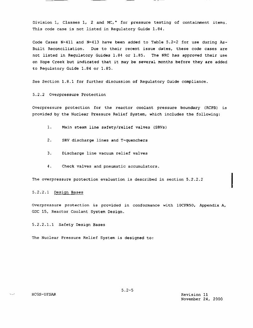
Division 1, Classes 1, 2 and MC," for pressure testing of containment items.
This code case is not listed in Regulatory Guide 1.84.
Code Cases N-411 and N-413 have been added to Table 5.2-2 for use during As
Built Reconciliation. Due to their recent issue dates, these code cases are
not listed in Regulatory Guides 1.84 or 1.85. The NRC has approved their use
on Hope Creek but indicated that it may be several months before they are added
to Regulatory Guide 1.84 or 1.85.
See Section 1.8.1 for further discussion of Regulatory Guide compliance.
5.2.2 Overpressure Protection
Overpressure protection for the reactor coolant pressure boundary (RCPB) is
provided by the Nuclear Pressure Relief System, which includes the following:
1. Main steam line safety/relief valves (SRVs)
2. SRV discharge lines and T-quenchers
3. Discharge line vacuum relief valves
4. Check valves and pneumatic accumulators.
The overpressure protection evaluation is described in section 5.2.2.2 j 5.2.2.1 Design Bases
Overpressure protection is provided in conformance with 10CFR50, Appendix A,
GDC 15, Reactor Coolant System Design.
5.2.2.1.1 Safety Design Bases
The Nuclear Pressure Relief System is designed to:
5.2-5 HCGS-UFSAR Revision 11
November 24, 2000
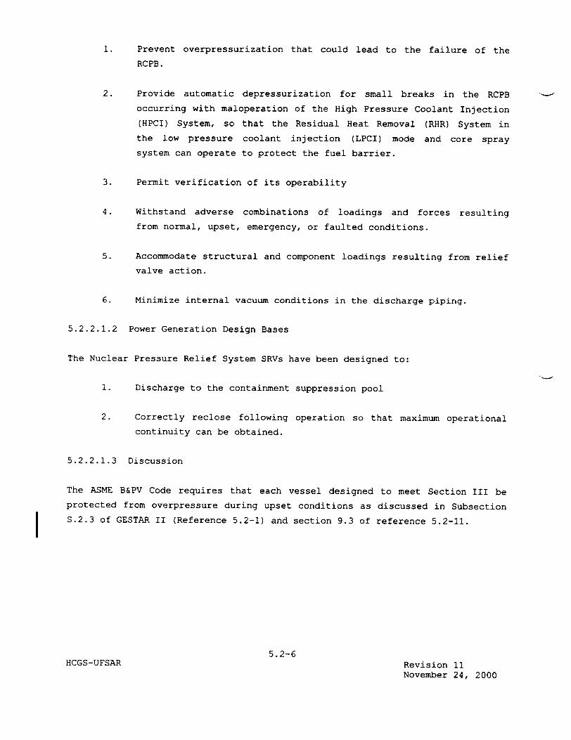
1. Prevent overpressurization that could lead to the failure of the
RCPB.
2. Provide automatic depressurization for small breaks in the RCPB
occurring with maloperation of the High Pressure Coolant Injection
(HPCI) System, so that the Residual Heat Removal (RHR) System in
the low pressure coolant injection (LPCI) mode and core spray system can operate to protect the fuel barrier.
3. Permit verification of its operability
4. Withstand adverse combinations of loadings and forces resulting
from normal, upset, emergency, or faulted conditions.
5. Accommodate structural and component loadings resulting from relief
valve action.
6. Minimize internal vacuum conditions in the discharge piping.
5.2.2.1.2 Power Generation Design Bases
The Nuclear Pressure Relief System SRVs have been designed to:
1. Discharge to the containment suppression pool
2. Correctly reclose following operation so that maximum operational
continuity can be obtained.
5.2.2.1.3 Discussion
The ASME B&PV Code requires that each vessel designed to meet Section III be protected from overpressure during upset conditions as discussed in Subsection
S.2.3 of GESTAR II (Reference 5.2-1) and section 9.3 of reference 5.2-11.
5.2-6 HCGS-UFSAR Revision 11
November 24, 2000
I
5.2.2.2 Design Evaluation
The overpressure protection evaluation is performed on a cycle specific basis
with NRC approved methodology. The cycle-specific evaluation is presented in
Appendix 15D. (Reference 5.2-10)
The results of the overpressurization event presented in this section are from
the original safety evaluation performed prior to cycle 1. However, despite
this event being considered cycle-specific, the overpressurization event has
been found to exhibit only a small dependence upon changes in core
configuration. Therefore, it is generally acceptable to treat the results
within this section to be typical for this event. Appendix 15D confirms that
the peak pressures are within the acceptable requirements.
5.2.2.2.1 Method of Analysis
The model used to analyze overpressurization is referenced in Subsection
A.5.2.2.2 of Reference 5.2-1.
The typical valve characteristic, as modeled, is shown on Figure 5.2-1. The
associated turbine bypass, turbine control, and MSIV characteristics are also
simulated in the model.
5.2.2.2.2 System Design
A parametric study was conducted to determine the required steam flow capacity
of the SRVs under operating conditions, based on the following assumptions.
5.2.2.2.2.1 Operating Conditions
1. Operating power = 3435 MWt (104.3 percent of nuclear boiler rated
power)
2. Vessel dome pressure <1020 psig
3. Steam flow = 14.864xi06 lbm/h (105 percent of nuclear boiler rated
steam flow)
These conditions are the most severe because maximum stored energy exists at
these conditions. At lower power conditions, the transients would be less
severe.
5.2-9 HCGS-UFSAR Revision 11
November 24, 2000
expected to be conservative relative to actual operation. In addition, the
nominal high pressure scram setpoint is expected to be set at 1037 psig
(analytical upper limit of 1071 psig). A study has been performed for a
typical BWR to investigate the effects of increasing the initial reactor
pressure relative to the initial value used in the overpressure protection
analysis on the peak system pressure. The conclusion made was that increasing
the initial operating pressure results in an increase of the peak system
pressure which is less than half the initial pressure increase as shown in
Figure 5.2-14 for the overpressure design transient (i.e., all MSIV closure
with indirect high neutron flux scram). The same general trend is expected to
exist for HCGS. Since there is a significant margin (135 psi by comparing the
peak vessel pressure of 1204 psig with the ASME code limit of 1375 psig) for
HCGS, no safety concern would result from the assumption of initial dome
pressure.
5.2.2.2.2.2 Transients
The Overpressure Protection System accommodates the most severe pressurization
event, which is referenced in Subsection A.5.2.2.2 of Reference 5.2-1. The results of the sizing transients are shown on Figure 5.2-2. Table 5.2-5 lists
the sequence of events for the MSIV closure event with flux scram and with the
installed SRV capacity.
5.2.2.2.2.3 Scram
The scram reactivity curve and control rod driven scram motion are shown on
Figure 5.2-3.
5.2.2.2.2.4 SRV Transient Analysis Specifications
Valve groups and setpoints of the SRVs are as follows:
1. Valve group: 3
5.2-10 HCGS-UFSAR Revision 0
April 11, 1988

The effluent from the condensate treatment system is pumped through
the feedwater heater trains and enters the reactor vessel at an
elevated temperature. As required, a dilute suspension of zinc
oxide and iron in water is injected into the reactor feedwater at
the suction of the reactor feedwater pumps to inhibit the corrosion
of stainless steel and control RCS Co-60 transport to reduce the
buildup of Co-60 on the reactor coolant pressure boundary piping
and components. Iron and zinc concentrations will be maintained
within fuel warranty limits and EPRI guideline recommendations.
During normal plant operation, boiling occurs in the reactor,
decomposition of water takes place due to radiolysis, and oxygen
and hydrogen gas are formed. Due to steam generation, stripping of
these gases from the water phase takes place, and the gases are
carried with the steam through the turbine to the condenser. The
oxygen level in the steam, resulting from this stripping process,
is typically observed to be about 20 ppm (see Table 5.2-8). At the
condenser, deaeration takes place and the gases are removed from
the process by means of steam jet air ejectors (SJAEs). The
deaeration is completed to a level of approximately 20 ppb
(0.02 ppm) oxygen in the condensate.
The dynamic equilibrium in the reactor vessel water phase,
established by the steam gas stripping and the principally
radiolytic formation rates, corresponds to a nominal value of
approximately 200 ppb (0.2 ppm) of oxygen at rated operating
conditions. Slight variations around this value have been observed
as a result of differences in neutron flux density, core flow, and
recirculation flow rate.
5.2-31 HCGS-UFSAR Revision 10
September 30, 1999
A Reactor Water Cleanup System (RWCS) is provided for removal of
impurities resulting from fission products and activated corrosion
products formed in the primary system. The cleanup process
consists of filtration and ion exchange and serves to maintain a
high level of water purity in the reactor coolant.
Typical chemical parametric values for the reactor water are listed
in Table 5.2-8 for various plant conditions.
Additional water input to the reactor vessel originates from the
control rod drive (CRD) cooling water. The CRD water is of
approximately feedwater quality. Separate filtration for
purification and removal of insoluble corrosion products takes
place within the CRD system prior to entering the drive mechanisms
and reactor vessel.
With the exception of condensate system oxygen injection, no other
inputs of water or sources of oxygen are present during normal
plant operation. During plant conditions other than normal
operation, additional inputs and mechanisms are present as outlined
in the following section.
2. Plant conditions outside normal operation During periods of plant
conditions other than normal power production, transients take
place, particularly with regard to the oxygen levels in the primary
coolant. Oxygen levels in the primary coolant deviate from normal
during plant startup, plant shutdown, hot standby, and during
reactor venting and depressurization. The hotwell condensate will
absorb oxygen from the air when vacuum is broken on the condenser.
Prior to startup and input of feedwater to the reactor, vacuum is
established in the condenser, and deaeration of the condensate
takes place by means of mechanical vacuum pump and SJAE operation
and condensate recirculation. During these plant conditions,
continuous
5.2-32 HCGS-UFSAR Revision 11
November 24, 2000
exceed the nominal value of 8 ppm. As temperature
increases and oxygen solubility decreases accordingly,
the oxygen concentration will be maintained at this
maximum value or reduced below it, depending on
available removal mechanisms, i.e., diffusion, steam
stripping, flow transfer, or degassing.
Depending on the location, configuration, etc, such as
dead legs or stagnant water, inventories may contain
approximately 8 ppm dissolved oxygen or some other
value below this maximum limitation.
Conductivity of the reactor coolant is continuously
monitored. These measurements provide reasonable
assurance for adequate surveillance of the reactor
coolant.
The relationship of chloride concentration to specific
conductance, measured at 25 0C for chloride compounds such as
sodium chloride and hydrochloric acid, can be calculated as
shown on Figure 5.2-10. Values for these compounds
essentially bracket values of other common chloride salts or
mixtures at the same chloride concentration. Surveillance
requirements are based on these relationships.
In addition to this program, limits, monitoring, and sampling
requirements are imposed on the condensate, condensate
treatment system, and feedwater by warranty requirements and
specifications. Thus, a
5.2-35 HCGS-UFSAR Revision 11
November 24, 2000

total plant water quality surveillance program is
established, ensuring that off-specification conditions are
quickly detected and corrected.
The sampling frequency when reactor water has a low specific
conductance is adequate for calibration and routine audit
purposes. When specific conductance increases and higher
chloride concentrations are possible, or when continuous
conductivity monitoring is unavailable, increased sampling is
provided. (See HCGS Technical Specifications.)
For the higher than normal limits of <1 pmho/cm, more
frequent sampling and analyses are invoked by the coolant
chemistry surveillance program.
c. Water Purity During a Condenser Leakage
The maximum impurity level is set by a condenser leak rate
that can be operationally accommodated by the demineralizer
units. The loading time or exhaustion rate is longer than
the time required to regenerate the resin beds of all the
other operating demineralizers.
5.2.3.2.2.1 Compliance with Regulatory Guide 1.56
For a discussion of general compliance with Regulatory Guide 1.56 (including
commitment revision number and scope), see Section 1.8.
5.2-36 HCGS-UFSAR Revision 11
November 24, 2000

continuous downward slope, from the upstream side of the
check valve to the turbine exhaust drain pot and downstream
of the check valve to the suppression pool.
n. Vacuum breaker isolation valves (E51-HV-F062 and E51-HV-F084)
- Open or close against pressure differential of 200 psi at a
minimum rate of 12 in./min.
o. Vacuum relief valves (E51-PSV-F063 and E51-PSV-F064) - Open
with minimum pressure drop of less than 0.5 psi across the
valve seat.
p. Steam warmup line isolation valve, (E51-HV-F076) - opens or
closes against full pressure with a minimum rate of
12 in./min.
10. Rupture disk assemblies (E51-PSE-DO01, E51-PSE-D002) - Used for
turbine casing protection, including a mated vacuum support to
prevent the rupture disk from reversing under a vacuum.
Rupture pressure is 150 psig - 10 psig.
Flow capacity is 60,000 lb/h at 165 psig.
11. CST requirements - Total reserve storage of 135,000 gallons for
both HPCI and RCIC systems (see Section 9.2.6.21).
12. RCIC piping water temperature - The maximum water temperature
range for continuous system operation does not exceed 140 0 F.
However, due to potential short term operation at higher
temperatures, piping expansion calculations were based on 170 0 F.
13. Turbine exhaust vertical reaction force - The turbine exhaust
sparger is capable of withstanding a vertical
5.4-37HCGS-UFSAR Revision 11
November 24, 2000
I

pressure unbalance of 20 psi. This pressure unbalance is due to
turbine steam discharge below the suppression pool water level.
14. Ambient conditions - For normal plant operation, temperature is 60
to 106'F, with relative humidity at 90%. Under isolation
conditions, temperatures reach 148°F with 100 percent relative
humidity.
15. RCIC jockey pump
Flow rate 20 gpm
Process fluid temperature 120OF
Total dynamic head 232 feet
BHP 10 hp
Design pressure 150 psig
Design temperature 120°F
5.4.6.2.3 Applicable Codes and Classifications
The RCIC system components within the drywell up to and including the outer
isolation valves are designed in accordance with ASME B&PV Code, Section III, Class 1. The RCIC system is also designed as Seismic Category I. The RCIC system and CST component classifications are given in Table 3.2-1.
5.4.6.2.4 System Reliability Considerations
To ensure that the RCIC operates when necessary and in time to prevent
inadequate core cooling, the power supply for the system is taken from immediately available energy sources of high reliability. In the event of the loss of offsite power (LOP), dc battery supplies ensure that system operation
is not affected. Added assurance is given by the capability for periodic testing during station operation. The RCIC system instrumentation has been designed so that failure of a single initiating sensor neither prevents system
start nor falsely starts the system.
5.4-38 HCGS-UFSAR Revision 0
April 11, 1988

and maximum shutoff head. The pump pressure vessel is carbon steel;
the shaft and impellers are stainless steel. A comparison between
the available and the required net positive suction head (NPSH) can
be obtained from the representative pump characteristic curve
provided on Figure 6.3-13. Available NPSH is calculated according
to Regulatory Guide 1.1. Additional information can be found in
Section 6.3.
2. Heat exchangers - The RHR system heat exchangers are sized on the
basis of the duty for the shutdown cooling mode, i.e., Mode D of the
process data. All other uses of these exchangers require less
cooling surface.
Flow rates are 10,000 gpm (rated) on the shell side and 9000 gpm
(rated) on the tube side, which is the SACS water side. Rated inlet
temperatures are 125*F shell side and 85°F tube side. The overall
heat transfer coefficient is 375 Btu/h-ft -2F. The exchangers
contain 3550 square feet of effective surface. The design
temperature range of both the shell and tube sides is 32 to 470°F.
Design pressure is 450 psig on both sides. Fouling factors are
0.0005 shell side and 0.0005 tube side. The construction materials
are carbon steel for the pressure vessel with 304L stainless steel
tubes and stainless steel clad tube sheet.
3. Valves - All of the directional valves in the system are gate,
globe, and check valves designed for nuclear service. The injection
valves, reactor coolant isolation valves, and pump minimum flow
valves are high speed valves, as operation for LPCI injection or
vessel isolation requires. Valve pressure ratings, as necessary,
provide the control or isolation function, i.e., all vessel
isolation valves are rated as ASME B&PV Code, Section III, Class 1
nuclear valves rated at the same pressure as the primary system.
5.4-53 HCGS-UFSAR Revision 11
November 24, 2000

4. ECCS and containment cooling portions of the RHR system:
a. The ECCS portions of the RHR system include those sections
described through mode A-I of Figure 6.3-12. The route includes
suppression pool suction strainers, suction piping, RHR pumps,
discharge piping, injection valves, and drywell piping into the
vessel nozzles and core region of the reactor vessel.
b. Suppression pool cooling components include pool suction
strainers, suction piping, pumps, heat exchangers, and pool
return lines.
c. Containment spray components are the same as pool cooling except
that the spray headers replace the pool return lines.
5. RHR suction strainers - Each of the four 24-inch RHR pump suction
nozzles penetrates the torus wall at a point on the circumference 30
degrees up from the bottom of the pool. The suction nozzles extend
6 inches beyond the torus interior surface, and the strainers are
mounted on top of the nozzle penetration end. Each upgraded
strainer is designed to accommodate the maximum expected amount of
debris at a flow of 10,500 gpm. At these limiting conditions
strainer head loss will be within acceptable limits so as to
maintain a positive NPSH margin. See Section 6.3.2.2.4 for a full
discussion of NPSH. The strainer mesh is sized to screen out all
particles greater than 0.125 inches in diameter. Particles equal to
or smaller than 0.125 inches in diameter do not impair RHR pump, heat exchanger, drywell spray, and suppression pool spray
performance.
The minimum height of the suppression pool water level above the
centerline of the strainer base is 11 feet 6 1/2 inches.
5.4-54 HCGS-UFSAR Revision 11
November 24, 2000
The RHR suction strainer details are shown on Figures 5.4-15 and
5.4-16.
5.4.7.2.3 Controls and Instrumentation
Controls and instrumentation for the RHR system are described in Sections 7.3.1
and 7.4.1.
The RHR system incorporates relief valves to prevent the components and piping
from inadvertent overpressure conditions. The relief valve setpoint, capacity,
and method of collection are shown in Table 5.4-2.
5.4.7.2.4 Applicable Codes and Classifications
The quality group classification and corresponding applicable codes and
standards that apply to the design of the RHR system are discussed in
Section 3.2.
5.4.7.2.5 Reliability Considerations
The RHR system includes the redundancy requirements discussed in
Section 5.4.7.1.5. Two completely redundant loops are provided to remove
residual heat, each powered from a separate emergency bus. With the exception
of the common shutdown suction line, all mechanical and electrical components
are separate. Either loop is capable of shutting down the reactor within a
reasonable length of time.
5.4-55 HCGS-UFSAR Revision 11
November 24, 2000
The following design is incorporated to assure that systems connected to the
RHR system do not degrade the reliability of the RHR system:
1. LPCI initiation causes automatic recovery of all required system
automatic valves from any other mode to their LPCI alignment.
2. Valves are provided to isolate RHR from various other systems by the
following methods:
a. Normally closed manually operated valves are provided which require the operator to follow operating and maintenance
guidelines.
b. Normally closed remote manually motor operated valves are
provided with position indication lights in the control room.
c. Simple check valves in series with normally open stop check
valves are provided.
Electrical separation is described in Section 8.1.4.
5.4.7.2.6 Manual Action
1. RHR (shutdown cooling mode) - In shutdown operation, when the vessel
pressure is 100 psig or less, the RHR pump in the loop selected for shutdown cooling is started, the appropriate test return valve EllHV-F024, is opened and the loop flushed for approximately five
minutes with torus water.
After flushing, the RHR pump is secured, Ell-HV-F004 and F024 are
shut, and Ell-HV-F006 is opened. When reactor pressure is less than
82 psig EIl-HV-F009 is opened, the RHR pump is started and EII-HV
F015 is throttled for 3000
5.4-56HCGS-UFSAR Revision 0
April 11, 1988
THIS PAGE INTENTIONALLY BLANK
5. 4-61bHCGS-UFSAR Revision 2
April 11, 1990
The filter demineralizer units shown on Figures 5.4-19 and 5.4-20 are pressure
precoat type filters using premixed Ion exchange resin and binder. The vendor
verifies resin capacity and size prior to shipment. Spent resins are
nonregenerable and are sluiced from the filter demineralizer units to a
backwash receiving tank, from which they are transferred to the solid waste
management system for disposal. To prevent resins from entering the reactor if
there is failure of a filter demineralizer resin support, a strainer is
installed in the effluent line of each filter demineralizer unit. High
differential pressure across the strainers and filter demineralizer vessels is
annunciated locally and in the main control room. If the differential pressure
across a filter demineralizer vessel, or its respective effluent strainer,
continues to increase beyond the alarm setpoint, the affected filter
demineralizer unit is automatically isolated.
The backwash and precoat cycle for a filter-demineralizer unit is entirely
automatic to preclude human operational errors, such as inadvertent opening of
valves that would initiate a backwash or contaminate reactor coolant with
resins. The filter demineralizer piping configuration is arranged to ensure
that transfers are complete and crud traps are eliminated. A bypass line is
provided around the filter demineralizer units.
If there is low flow or loss of flow in the system, flow is maintained through
each filter demineralizer vessel by its own holding pump to prevent loss of
filter resin.
Sample points are provided in the common influent header and in each effluent
line of the filter demineralizer units for continuous indication and recording
of system conductivity to ensure that the reactor coolant quality is within
limits, and as a check of filter demineralizer effectiveness. High
conductivity is annunciated in the control room. The control room alarm set
points for conductivity at the inlet and outlet of the filter demineralizers
are 1.0 lmho/cm and 0.1 lmho/cm, respectively. The
5.4-62 HCGS-UFSAR Revision 11
November 24, 2000
5.4.8.4 SRP Rule Review
SRP 5.4.8 acceptance criterion II.l.a requires that reactor water purity be
maintained in accordance with Regulatory Guide 1.56 and the Technical
Specifications for water chemistry. Additionally, the RWCU should provide
demineralization of reactor water at approximately 1 percent of the main steam
flow rate. While this rate is feasible with parallel pumps in operation,
normal operation of the RWCU maintains water purity in accordance with
Regulatory Guide 1.56 using less than 1 percent of the main steam flow rates.
5.4.9 Main Steam Lines and Feedwater Lines
5.4.9.1 Safety Design Bases
To satisfy the safety design bases, the main steam and feedwater lines have
been designed:
1. To accommodate operation stresses such as those resulting from
internal pressures and safe shutdown earthquake (SSE) loads, without
a failure that could lead to the release of radioactivity in excess
of the 10CFR100 guidelines
2. With suitable access to permit inservice testing and inspections.
5.4.9.2 Power Generation Design Bases
To satisfy the design bases:
1. The main steam lines have been designed to conduct steam from the
reactor vessel over the full range of reactor power operation.
2. The feedwater lines have been designed to conduct water to the
reactor vessel over the full range of reactor power operation.
5.4-65HCGS-UFSAR Revision 0
April 11, 1988
5.4.9.3 Description
The main steam and feedwater piping are shown on Figure 5.1-3.
5.4.9.3.1 Main Steam Lines
The main steam lines extend from the reactor vessel up to and including the
outboard main steam isolation valve (MSIV), and include connected piping of 2
1/2-inch nominal diameter or larger, up to and including the first valve that
is either normally closed or capable of automatic or remote manual closure
during all modes of reactor operation. The portion of the piping from the outboard MSIV up to and including the main steam stop valve (MSSV) is a part of
the main steam supply system (Section 10.3), but it is discussed here since it
performs a safety function. The MSSV serves as the third MSIV on a long term
basis, as discussed in Section 6.2.4.
The main steam lines consist of four 26-inch pipes that penetrate the primary containment. Each line includes a steam flow restrictor and two MSIVs. The
design pressure and temperature between the reactor vessel and the outboard
MSIV of the main steam piping is 1250 psig and 575*F. Seismic Category I
design requirements are placed on the main steam lines from the reactor vessel
up to and including the MSSV and connected piping of 2-1/2-inch or larger
nominal diameter, up to and including the first isolation valve in the
connected piping.
The materials used in the main steam lines up to the MSSV are in accordance with the applicable code and supplementary requirements described in
Sections 3.2 and 5.2.3. The general requirements of the nuclear steam supply
control system are described in Section 7.
5.4.9.3.2 Feedwater Lines
The feedwater lines consist of two 24-inch outside diameter pipes that
penetrate the primary containment. Each 24-inch line branches into three 12
inch lines that connect to the reactor
5.4-66 HCGS-UFSAR Revision 11
November 24, 2000
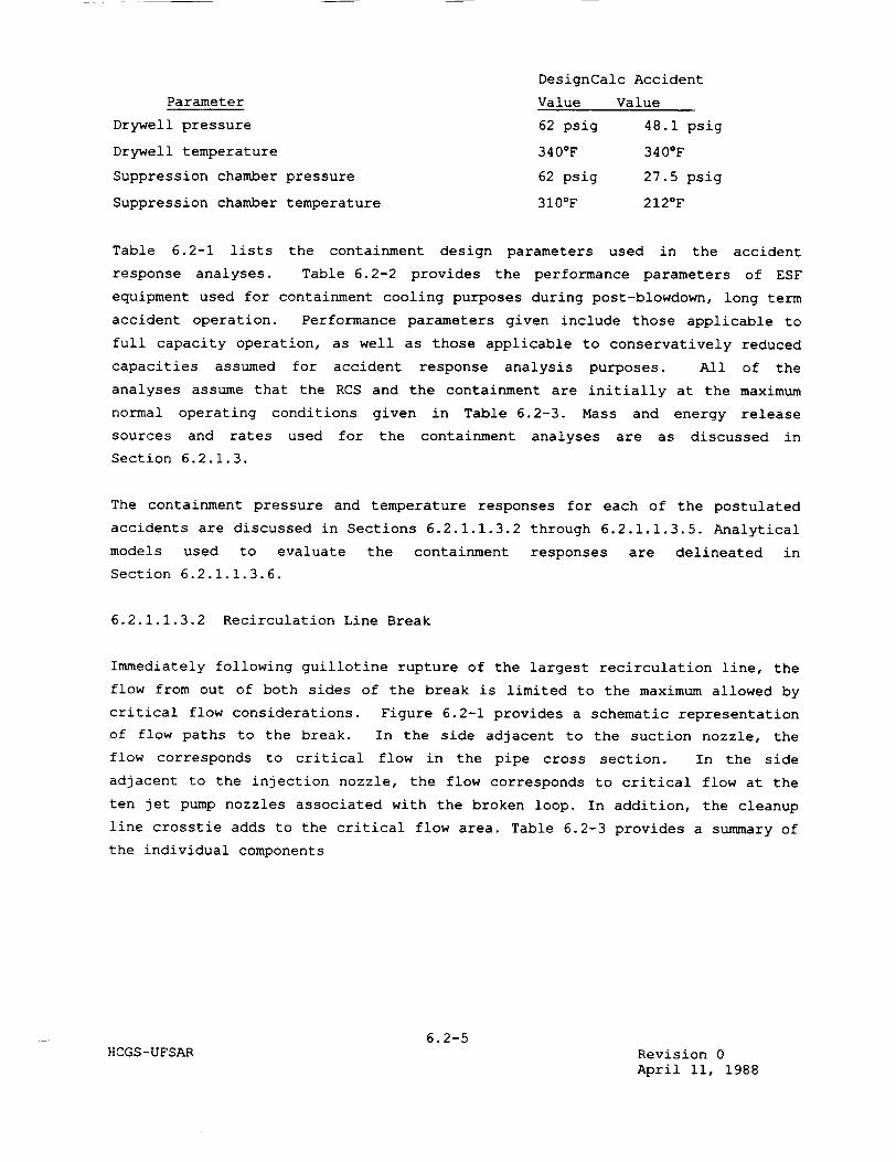
DesignCalc Accident
Parameter Value Value
Drywell pressure 62 psig 48.1 psig
Drywell temperature 340°F 340°F
Suppression chamber pressure 62 psig 27.5 psig
Suppression chamber temperature 310°F 212°F
Table 6.2-1 lists the containment design parameters used in the accident
response analyses. Table 6.2-2 provides the performance parameters of ESF
equipment used for containment cooling purposes during post-blowdown, long term
accident operation. Performance parameters given include those applicable to
full capacity operation, as well as those applicable to conservatively reduced
capacities assumed for accident response analysis purposes. All of the
analyses assume that the RCS and the containment are initially at the maximum
normal operating conditions given in Table 6.2-3. Mass and energy release
sources and rates used for the containment analyses are as discussed in
Section 6.2.1.3.
The containment pressure and temperature responses for each of the postulated
accidents are discussed in Sections 6.2.1.1.3.2 through 6.2.1.1.3.5. Analytical
models used to evaluate the containment responses are delineated in
Section 6.2.1.1.3.6.
6.2.1.1.3.2 Recirculation Line Break
Immediately following guillotine rupture of the largest recirculation line, the
flow from out of both sides of the break is limited to the maximum allowed by
critical flow considerations. Figure 6.2-1 provides a schematic representation of flow paths to the break. In the side adjacent to the suction nozzle, the flow corresponds to critical flow in the pipe cross section. In the side
adjacent to the injection nozzle, the flow corresponds to critical flow at the
ten jet pump nozzles associated with the broken loop. In addition, the cleanup line crosstie adds to the critical flow area. Table 6.2-3 provides a summary of
the individual components
6.2-5 HCGS-UFSAR Revision 0
April 11, 1988

of the total effective blowdown area. The total effective blowdown area for
the recirculation line break is given on Figure 6.2-2.
1. Assumptions for reactor blowdown - The response of the RCS during
the blowdown period of the accident is analyzed using the following
assumptions:
a. The initial conditions for the recirculation line break accident are such that the system energy is maximized and the
system mass is minimized. That is:
(1) The reactor is operating at 102 percent of rated
thermal power. maximizes the post-accident decay heat.
(2) The Safety Auxiliaries Cooling System (SACS) water
temperature is at its maximum value.
(3) The suppression pool mass is at the low water level for
the long term analysis and at the high water level for
the short term analysis.
(4) The suppression pool temperature is at its maximum
normal value.
I
b. The recirculation line is considered to be severed
This results in the most rapid coolant
depressurization of the vessel, with coolant being
from both ends of the break.
instantly.
loss and
discharged
c. Reactor power generation ceases at the time of accident
initiation because of void formation in the core region.
Reactor scram also occurs in less than 1 second from receipt
of the high drywell pressure signal. The time difference
between accident initiation and reactor scram is negligible.
6.2-6HCGS-UFSAR Revision 11
November 24, 2000
the suppression chamber at a rate dependent upon the size of the
steam leak. Once all of the noncondensable gas in the drywell is
carried over to the suppression chamber, short-term pressurization
of the suppression chamber ceases, and the system reaches
equilibrium. The drywell contains only superheated steam, and
continued blowdown of reactor steam condenses in the suppression
pool. The suppression pool temperature continues to increase until
the RHR heat exchanger heat removal rate is equal to the decay heat
release rate.
2. Recovery operations - The reactor operator is alerted to the
incident by the high drywell pressure signal and by the reactor
scram. For the purpose of evaluating the duration of the superheat
condition in the drywell, it is assumed that the operator's
response is to shut down the reactor in an orderly manner using the
main condenser, while limiting the reactor cooldown rate to 100°F
per hour. This results in the RCS being depressurized within
6 hours. At this time, the blowdown flow to the drywell ceases,
and the superheat condition is terminated. If the plant operator
elects to cool down and depressurize the RCS more rapidly than
100*F per hour, the duration of the drywell superheat condition is
shorter.
3. Drywell design temperature considerations - For drywell design
purposes, it is assumed that there is a blowdown of reactor steam
for the 6-hour cooldown period. The corresponding design
temperature is determined by finding the combination of RCS
pressure and drywell pressure that produces the maximum superheat
temperature. The maximum drywell steam temperature occurs when the
RCS is at approximately 450 psia. Thus, for design purposes, it is
assumed that the drywell is at 50 psia, with a resultant
temperature of 340 0 F.
6.2-21 HCGS-UFSAR Revision 0
April 11, 1988
6.2.1.1.3.6 Accident Analysis Models
1. Short term pressurization model - The analytical models, assumptions, and methods used to evaluate the containment response during the reactor blowdown phase of a LOCA are described in References 6.2-2 through 6.2-4. These references used the
proprietary computer code SHEX, as described in reference 6.2-27.
2. Long term response model - The analytical model used in evaluating
the long term response to a LOCA is based on the mass and energy balance of the reactor vessel, drywell, suppression pool, and suppression chamber atmosphere. Auxiliary systems that are connected to the primary systems are also modeled. The two major auxiliary systems that have the greatest impact on the long term response are the emergency core cooling and pool cooling functions
of the RHR system.
The governing equations are integrated numerically, enabling the evaluation of the thermodynamic histories of both the primary and
containment systems.
3. Analytical assumptions - The key assumptions employed in the model
are as follows:
a. The drywell free space is composed of a uniform mixture of
steam, air, and liquid droplets.
b. Flow through the vents is adiabatic.
c. The temperature of the suppression chamber atmosphere is equal to the temperature of the suppression pool.
d. No credit is taken for heat losses to the drywell wall,
suppression chamber walls, and internal structures.
6.2-22 HCGS-UFSAR Revision 11
November 24, 2000
6.2.1.2 Containment Subcompartments
The containment subcompartments considered for HCGS are the RPV shield annulus
and the drywell head region. The modeling procedures and considerations are
presented in Appendix 6B.
6.2.1.3 Mass and Energy Release Analyses for Postulated Loss-of-Coolant
Accidents
This section presents information concerning the transient energy release rates
from the RCS to the containment following a LOCA. Where the ECCS enters into
the determination of energy released to the containment, the single failure
criterion is applied in order to maximize the energy release to the containment
following a LOCA.
The impact of ABB fuel on the mass and energy release rates following a LOCA
was evaluated and shown to be bounded by the Cycle 1 analysis. The analysis
described below was performed in support of Cycle 1 and remains bounding.
6.2.1.3.1 Mass and Energy Release Data
Table 6.2-9 provides the mass and enthalpy release data for the recirculation
line break. Blowdown steam and liquid flow rates approach zero in
approximately 48 seconds and do not change significantly during the remainder
of the 24-hour period following the accident. Figure 6.2-16 shows the blowdown
flow rates for the recirculation line break graphically. These data are
employed in the containment pressure temperature response analyses discussed in
Section 6.2.1.1.
Table 6.2-10 provides the mass and enthalpy release data for the main steam
line break. Blowdown steam and liquid flow rates approach zero in
approximately 80 seconds and do not change significantly during the remainder
of the 24-hour period following the accident. Figure 6.2-17 shows the vessel
blowdown flow rates for the main steam line break as a function of time after
the postulated rupture. This information is employed in the containment
pressure temperature response analyses discussed in Section 6.2.1.1.
6.2-33 HCGS-UFSAR Revision 11
November 24, 2000
6.2.1.3.2 Energy Sources
The RCS conditions prior to the line break are presented in Tables 6.2-3 and
6.2-4. Reactor blowdown calculations for containment response analyses are
based on these conditions during a LOCA.
The energy
following:
released to the containment during a LOCA is comprised of the
1. Stored energy in the reactor system
2. Energy generated by fission product decay
3. Energy from fuel relaxation
4. Sensible energy stored in the reactor structures
5. Energy being added by the ECCS pumps
6. Metal water reaction energy.
Following each postulated accident, the stored energy in the reactor system and
the energy generated by fission product decay is released. The rate of release
of core decay heat for the evaluation of the containment response to a LOCA is
provided in Table 6.2-11 as a function of time after accident initiation.
Following a LOCA, the sensible energy stored in the RCS metal is transferred to
the recirculating ECCS water and thus contributes to the suppression pool and
containment heatup.
Figure 6.2-18 shows the temperature transients of the various RCS structures
that contribute to this sensible energy transfer. Figure 6.2-19 shows the
variation of the sensible heat content of the reactor vessel and internal
structures during a recirculation line break accident based on the temperature
transient responses.
6.2-34 HCGS-UFSAR Revision 0
April 11, 1988
coolant injection (LPCI) mode is automatically initiated from Emergency Core
Cooling System (ECCS) signals, and the RHR system is realigned for containment
cooling by the plant operator after the reactor vessel water level has been
recovered. Refer to containment functional design in Section 6.2.1 for further
details. The RHR and SACS water pumps are already operating. Containment
cooling is initiated in RHR loop A or B by manually closing the heat exchanger
bypass valve, opening the SACS water valve at the heat exchanger, closing the
LPCI injection valve, and opening the suppression pool return valve. In the
event that a single failure has occurred, and the action that the plant
operator is taking does not result in system initiation, the operator places
the other totally redundant system into operation by following the same
initiation procedure. If the operator chooses to use the containment spray,
(s)he must close the LPCI injection valve and open the spray valves. The
containment spray water establishes a closed loop to the suppression pool via
the downcomers.
Preoperational tests are performed to verify individual component operation,
individual logic element operation, and system operation up to the drywell
spray spargers. A sample of the sparger nozzles are bench tested for flow rate
versus pressure drop to evaluate the original hydraulic calculations. Finally,
the spargers are tested by air and visually inspected to verify that all
nozzles are clear. Refer to Section 5.4.7 for further discussion of
preoperational testing.
6.2.2.2.2 Effects of Insulation on System Performance
6.2-39 HCGS-UFSAR Revision 11
November 24, 2000

I Fiberglass blanket sections covered with 22-gauge, 304 stainless steel jacketing insulate structures, equipment and piping within the primary containment. This form of insulation was analyzed with respect to creating a debris clogging problem for containment cooling operation after a LOCA as set forth in USNRC Bulletin 96-03 and NUREG/CR-6224. The BWR Owner's Group ECCS Suction Strainer Committee has studied the performance of the materials during a simulated design basis accident (DBA). The results of the study have been submitted to the NRC as Utility Resolution Guidance for ECCS Suction Strainer Blockage Report, NRC Project 691. As indicated in the study:
1. The quantity of Drywell Insulation and other debris sources during a LOCA has been determined. These and other segments of insulation that are subjected to the violent forces of a component rupture, jet impingement,
or pipe whip could be expected to become potential clogging debris.
2. The methodology for debris transport and settling has been established.
The path for insulation to enter the suppression pool is through the vent pipes and the downcomer ring header. The jet deflectors prevent debris
from entering the vent pipes directly. Floor grating, structural steel,
and components in the drywell will retain insulation debris and restrict
it from reaching the floor or the vent pipes. A portion of the
insulation debris generated will be transported to the suppression pool.
The openings at the jet deflectors will prevent all but smaller fragments
from entering the vent pipes.
Some of the insulation debris that is transported to the suppression pool
is fast settling, the remainder settles more slowly. After the initial
blowdown, the insulation debris that reaches the suppression pool begins
to settle to the bottom. The flow velocity created by the ECCS pump
operation for the bulk of the suppression pool is very low, therefore
only a portion of the insulation debris in the suppression pool will
collect on the ECCS strainers. The strainers are located above the
bottom of the suppression pool and the velocities generated at the bottom
of the suppression pool are not sufficient to reentrain insulation that
has settled except very near the strainers. An evaluation of the
transport and accumulation of postulated debris was performed in
accordance with the guidelines of NRC Bulletin 96-03 NUREG/CR-6224. The
flow restriction caused by the insulation accumulation on the strainers
in this analysis does not adversely effect operation of the ECCS pumps.
6.2-40 HCGS-UFSAR Revision 11
November 24, 2000
3. If some fibers do pass through the 0.1225-inch strainer mesh, the study has shown that pump function and spray nozzle performance are not
affected. Particles of this size or smaller will not impair the safe
function of the suppression pool cooling or drywell spray modes of the
RHR system.
Details of suction strainer attachment to the strainer nozzles are
provided in Section 5.4.7.
The NRC staff has completed its review of this issue (NRC Project 691, "ECCS
Suction Strainer Blockage"), which is contained in Safety Evaluation by the
Office of Nuclear Reactor Regulation Related to NRC Bulletin 96-03, BWR Owners
Group Topical Report NFOO-32686, "Utility Resolution Guidance for ECCS Suction
Strainer Blockage". Based on the findings of this review, this issue is
considered closed for HCGS.
6.2.2.3 Design Evaluation of the Containment Cooling Function
In the event of the postulated LOCA, the short term energy release from the
reactor primary system is dumped to the suppression pool. Subsequent to the
accident, fission product decay heat results in a continuing energy input to
the pool. The containment cooling modes remove this energy, which is input to
the Primary Containment System, thus resulting in acceptable suppression pool
temperatures and containment pressures.
6.2-41HCGS-UFSAR Revision 11
November 24, 2000 I
To evaluate the adequacy of the RHR system, the following sequence of events is
assumed:
1. With the reactor initially operating at 102 percent of rated
thermal power a LOCA occurs.
2. An LOP occurs and one standby diesel generator (SDG) fails to start
and remains out of service during the entire transient. This is the
worst single failure.
3. Only three RHR pumps are activated and operated as a result of
there being no offsite power and minimum onsite power. Section 6.3
describes the ECCS equipment.
4. After 10 minutes, it is assumed that the plant operators activate
one RHR heat exchanger in order to start containment heat removal.
Once containment cooling has been established, no further operator
actions are required.
6.2.2.3.1 Summary of Containment Cooling Analysis
When calculating the long term, post-LOCA suppression pool temperature
transient, it is assumed that the initial suppression pool temperature and the
RHR heat exchanger SACS water temperature are at their maximum values. This
assumption maximizes the heat sink temperature to which the containment heat is
rejected and thus maximizes the containment temperature. In addition, the RHR
heat exchanger is assumed to be in the maximum design fouled condition at the
time the accident occurs. Section 5.4.7 discusses sizing of the heat
exchangers to account for fouling. This conservatively minimizes the heat
exchanger heat removal capacity. The resultant suppression pool temperature
transient is described in Section 6.2.1.1.3.2 and is shown on Figure 6.2-9.
Even with the degraded conditions outlined above, the maximum temperature is
maintained below the design limit specified in Section 6.2.2.1.
6.2-42 HCGS-UFSAR Revision 0
April 11, 1988
13. HPCI and RCIC Turbine Auxiliary Steam Supply - These lines contain
a temporary spool piece that is removed during normal operation and
replaced by a blind flange so that any leakage through the flange
is into the reactor building enclosure.
14. Instrument Gas Supply to and Suction from Drywell - A positive air
seal is maintained through the operation of the primary containment
instrument gas system.
6.2.3.2.4 Access Doors
Access doors to secondary containment (Reactor Building) are provided with
position indication and are monitored in the control room. See Table 6.2-28
for a list of Reactor Building openings.
6.2.3.3 Design Evaluation
The design evaluation of the Reactor Building Ventilation System is given in
Sections 6.8 and 9.4.2. The high energy lines within the reactor building are
identified and pipe ruptures are analyzed in Section 3.6.
The post-LOCA pressure transient for the design basis reactor building
inleakage has been analyzed to determine the length of time, following a LOCA,
for the pressure to reduce from atmospheric to minus 0.25 inches water gauge. The results of this analysis for the slowest responding compartment in the
reactor building are shown on Figure 6.2-26a.
The design basis analysis was based on the initial conditions,
6.2-53 HCGS-UFSAR Revision 9
June 13, 1998
I
design, and thermal characteristics listed in Tables 6.2-12, 6.2-13, and 6.2
13a. Further details of the FRVS design and operation are provided in
Section 6.8. Heat transfer to the outside environment is assumed to be zero.
The reactor building is considered to be in thermal equilibrium at the
beginning of the pressure transient. This includes heat load contributions
from the primary containment. Since the drawdown of the Reactor Building
pressure by the FRVS is completed within approximately the first 375 seconds
following a LOCA, there is insufficient time for the temperature transient
associated with the LOCA to propagate through the 3-foot-thick
6.2-53a HCGS-UFSAR Revision 11
November 24, 2000
2. Radiolytic decomposition of water in the reactor vessel and the
suppression pool
3. Corrosion of metal and paints in the primary containment
4. Release of free hydrogen already in the reactor coolant at the
time of the LOCA.
6.2.5.3.1 Metal Water Reaction
As a result of a LOCA, fuel cladding temperatures rise beginning after blowdown
and continuing until core reflood. Zirconium reacts with steam according to
the following reaction from Reference 6.2-14:
Zr + 2H 20 -- > ZrO2 + 2H2
Thus, for each mole of zirconium that reacts, 2 moles of free hydrogen are
produced. The extent of the metal water reaction and associated hydrogen
generation depends strongly on the course of events assumed for the accident
and on the effectiveness of emergency cooling systems, since the metal water
reaction is highly temperature dependent. Regulatory Guide 1.7 conservatively
states that the amount of hydrogen assumed to be generated by metal water
reaction in determining the performance requirements for combustible gas
control systems should be five times the maximum amount calculated in
accordance with Appendix K of 10CFR50, but no less than the amount that would
result from reaction of all the metal in the outside surfaces of the cladding
cylinders surrounding the fuel (excluding the cladding surrounding the plenum
volume) to a depth of 0.00023 inch.
In accordance with Appendix K, calculations have determined that the maximum
core wide metal-water reaction is 0.09 weight percent. Five times this
calculated value is 0.45 weight percent. Based on the current core design, a
reaction that results in a cladding penetration depth of 0.00023 inch is
equivalent to 0.83
6.2-109 HCGS-UFSAR Revision 11
November 24, 2000
weight percent reaction. Therefore, since the metal-water reaction based
0.00023-inch penetration depth is greater than five times the value calculated
in accordance with Appendix K, the former value is used as the basis for
determining the amount of hydrogen generated by the metal-water reaction.
The analysis assumes that the hydrogen from the metal-water reaction is
generated during the first 2 minutes after the beginning of the accident. The
hydrogen thus evolved is assumed to mix homogenously with the drywell
atmosphere.
6.2.5.3.2 Radiolysis
Water is decomposed into free hydrogen and oxygen by the absorption of energy
emitted by fission products contained in fuel and those mixed with the LOCA
water. The quantities of hydrogen and oxygen that are produced by radiolysis
are functions of both the energy of ionizing radiation absorbed by the LOCA
water and the net hydrogen and oxygen radiolysis yields, G(H2 ) and G(O2),
pertaining to the particular physical chemical state of the irradiated water.
As recommended in Regulatory Guide 1.7, the net yields of hydrogen and oxygen
from radiolysis of all LOCA water are conservatively assumed to be
0.5 molecule/100 eV for hydrogen and 0.25 molecule/100 eV for oxygen.
The total fission product decay power is taken from Branch Technical Position
(BTP) ASB-9-2, Residual Decay Energy for Light Water Reactors for Long Term
Cooling, conservatively assuming a 1095-day reactor operating time for fission
product buildup. The results are comparable to those of proposed American
Nuclear Society (ANS) Standard 5.1. The fission product distribution after the
accident and the fractions of fission product radiation energy assumed to be
absorbed by the LOCA water are listed in Table 6.2-20. The rates of energy
absorption by the LOCA water are shown on Figure 6.2-38.
6.2-110 HCGS-UFSAR Revision 0
April 11, 1988
prevents automatic initiation and successful operation of less than
one of the following combinations of ECCS equipment:
a. Three LPCI loops, one core spray loop, and the ADS and HPCI,
i.e., single standby diesel generator (SDG) failure
b. Four LPCI loops, two core spray loops, and the ADS, i.e.,
HPCI failure.
5. In the event of the failure of a pipe that is part of the ECCS, no
single active component failure in the ECCS prevents automatic
initiation and successful operation of less than one of the
following combinations of ECCS equipment:
a. Three LPCI loops and the ADS, i.e., single SDG failure and
core spray injection line failure
b. Two LPCI loops, one core spray loop, and the ADS and HPCI,
i.e., single SDG failure and LPCI injection line failure.
6. Long term (10 minutes after initiation signal) cooling requires the
removal of reactor core decay heat via the Safety Auxiliaries
Cooling System (SACS). In addition to the RCPB failure that
initiated the loss of coolant event, the system can sustain one
failure, either active or passive, and still have at least one low
pressure ECCS injection loop (LPCI or core spray) operating for
vessel makeup, and all required SACS water flow to the residual
heat removal (RHR) heat exchanger operating for heat removal.
6.3-3 HCGS-UFSAR Revision 11
November 24, 2000
I
7. Offsite power is the preferred source for the ECCS network.
However, onsite standby power is provided with sufficient
redundancy and capacity so that all the above requirements are met,
even if offsite power is not available.
8. The diesel load configuration is one RHR (LPCI) pump and one core
spray pump connected to a single SDG (typical for four SDGs).
9. Systems that interface with, but are not part of, the ECCS are
designed and operated such that failure(s) in the interfacing systems do not propagate to, and/or affect the performance of, the
ECCS.
10. Non-Class 1E systems interfacing with the Class 1E buses are
automatically shed from the Class 1E buses when a LOCA signal
exists.
11. Each subsystem of the ECCS, including flow rate and sensing networks, is capable of being tested during shutdown. All active
components are capable of being tested during plant operation, including logic required to automatically initiate component
action.
12. Provisions for testing the ECCS network components (electronic, mechanical, hydraulic, and pneumatic, as applicable) are designed
in such a manner that they are an integral and nonseparable part of
the system.
6.3.1.1.3 ECCS Requirements for Protection from Physical Damage
The ECCS piping and components are protected against damage from the effects of movement, thermal stresses, a LOCA, and the safe shutdown earthquake (SSE).
6.3-4HCGS-UFSAR Revision 0
April 11, 1988

sequence for starting of the ECCS subsystems is provided in Table 6.3-1.
Electric power for operation of the ECCS is from the preferred offsite power
supply. Upon loss of the preferred source, operation is from the onsite
standby power supply. Four standby diesel generators (SDGs) supplying
individual ac buses have sufficient redundancy and capacity so that operation
of any three units satisfies minimum ECCS requirements. One core spray pump
and one residual heat removal (RHR)/low pressure coolant injection (LPCI) pump
are powered by each ac bus. Section 8.3 contains a more detailed description
of the power supplies for the ECCS.
See Section 3.11 for a discussion of environmental qualification of ECCS
equipment and components.
6.3.2.2.1 High Pressure Coolant Injection System
The High Pressure Coolant Injection (HPCI) System consists of a steam turbine
driven, constant flow pump assembly and associated system piping, valves,
controls, and instrumentation. The P&IDs for HPCI, Figures 6.3-1 and 6.3-2,
show the system components and their arrangement. The HPCI system process
diagram, Figure 6.3-3, shows the design operating modes of the system.
The HPCI equipment is installed in the Reactor Building. Suction piping comes
from both the condensate storage tank (CST) and the suppression chamber.
Injection water is piped to the reactor vessel via the core spray loop A
sparger and feedwater sparger A. Steam supply for the turbine is piped from
main steam line C in the drywell. This piping is provided with an isolation
valve on each side of the containment. Controls for valve and turbine
operation are provided in the main control room. Valve position indication and
instrumentation alarms are also displayed in the main control room. The
controls and instrumentation of the HPCI system are described in Section 7.3.
6.3-9 HCGS-UFSAR Revision 0
April 11, 1988

The HPCI system ensures that the reactor core is not uncovered if there is a
small break in the reactor coolant pressure boundary (RCPB) that does not
result in rapid depressurization of the reactor vessel. This permits the plant
to be safely shut down, by maintaining sufficient reactor vessel water
inventory while the reactor vessel is depressurized. The HPCI system continues
to operate until the reactor vessel is depressurized to the point at which LPCI
and/or core spray system operation can maintain core cooling. The HPCI system
also fulfills the objectives of the non-ECCS Reactor Core Isolation Cooling
(RCIC) System, in the event RCIC becomes isolated or otherwise inoperative. The
HPCI system head flow characteristics assumed for loss-of-coolant accident
(LOCA) analyses are shown on Figures 6.3-4 and 6.3-5.
The HPCI system is designed to pump water into the reactor vessel over a wide
range of pressures in the reactor vessel. Initially, demineralized water from
the CST is used instead of water from the suppression chamber. This provides reactor grade water to the reactor vessel. A total reserve storage of
135,000 gallons is available from the CST for use by the HPCI and RCIC systems
(see Section 9.2.6.2.1). During HPCI/RCIC system stand-by mode, if the water level in the CST drops below the reserved storage volume, suction source will
be manually transferred to the torus. If the systems are operating, suction
path will auto-transfer upon a low CST level. The minimum required suppression
chamber water volume is approximately 118,000 ft 3(Technical Specification
minimum during cold shutdown conditions is 57,232 ft 3). Water from either
source is pumped into the reactor vessel through a core spray sparger and a
feedwater sparger, to obtain proper mixing with the reactor hot water or steam.
The minimum HPCI flow available, 5600 gpm, was used in the accident analysis for simulation of the flow over the high pressure range, with 2000 to 3000 gpm
injecting through the core spray sparger and the remainder through the
feedwater sparger. When the vessel pressure drops below the shutoff head of
the core spray system, it will inject water into the reactor vessel and the total flow of the HPCI/CS system will be a minimum of 6250 gpm at 105 psid.
This is the combined HPCI/CS flow shown in Figure 6.3-5. Any additional
HPCI/CS flow above the assumed minimums is conservatively ignored in the LOCA
calculations presented in Section 6.3.3.
6.3-10 HCGS-UFSAR Revision 11
November 24, 2000
At reactor pressures above the core spray system capability (>289 psid), all
flow will be from the HPCI system. At reactor pressures less than 289 psid,
line flow will be provided by both systems; but in no case will this flow be
less than core spray alone. As vessel pressure falls to the HPCI minimum rated
case (150 psig), more of the core spray line flow will come from the core spray
pump and less from the HPCI pump. HPCI will then pump a greater proportion of
its total flow into the feedwater.
The core spray pumps are located in the Reactor Building below the water level
in the suppression chamber to ensure positive suction head to the pumps. Pump
NPSH requirements are met by providing adequate suction head and adequate
suction line size. Available NPSH is calculated using the assumptions of
Regulatory Guide 1.1 and the following data:
1. Each core spray pump is operating at a maximum flow of 4015 gpm.
2. Pump suction is from the suppression chamber, which is at its
minimum normal operating water level of Elevation 71 feet.
3. Suppression chamber water is at its maximum temperature (for the
given operating mode) of 212°F.
4. The free space in the suppression chamber is at atmospheric
pressure.
5. The pump suction strainers (in the suppression chamber) are fouled
uniformly with containment debris, both preexisting and that which
was generated following a DBLOCA, based upon the criteria set forth
in the USNRC Bulletin 96-03 and NUREG/CR-6224.
6. The centerline of the pump suction is at Elevation 55.6 feet.
7. NPSH = hs - hf + ha - hvp
6.3-25 HCGS-UFSAR Revision 11
November 24, 2000
where:
I
6.3-26Revision 11 November 24, 2000
HCGS-UFSAR
hs = static head = (71 feet - 55.6 feet) = 15.4 feet
hf = friction head loss = 5.12 feet
ha = atmospheric pressure head = 35.38 feet
hvp = vapor pressure (head loss) = 35.38 feet
NPSH = 10.28 feet
Minimum required NPSH for the core spray pumps is 10 feet (see Figure 6.3-8).
Pump characteristic curves are given on Figure 6.3-10.
Each Core Spray System injection loop incorporates relief valves to protect the
components and piping from inadvertent overpressure conditions. One relief valve, located at the discharge of the pumps, is set at 500 psig, with a
capacity of 100 gpm at 10 percent accumulation. Relief valves located at the suction of each pump are set at 100 psig, with a capacity of at least 10 gpm at 10 percent accumulation.
Provisions included in the Core Spray System that permit system testing are:
1. Full flow test lines to route suppression chamber water back to the
suppression chamber, without entering the RPV.
2. A test line supplying water from the CST to the core spray pump suction, for testing discharge capacity to the RPV during normal
plant shutdown.
3. Instrumentation to indicate system performance during test
operations.
I

The RHR pumps, and equipment used for LPCI, are described in Section 5.4.7,
which also describes the other functions served by the same pumps if they are
not needed for the LPCI function. The RHR heat exchangers are not associated
with the emergency core cooling function. The heat exchangers are discussed in
Section 6.2.2.
The pumps used for LPCI are located in the Reactor Building below the water
level in the suppression chamber to ensure positive suction head to the pumps.
Pump NPSH requirements are met by providing adequate suction head and adequate
line size. Available NPSH for the LPCI function is calculated using the
assumptions of Regulatory Guide 1.1 and the following data:
1. Each pump is operating at its maximum flow rate.
2. Pump suction is from the suppression chamber, which is at its
minimum normal operating water level of Elevation 71 feet.
3. Suppression chamber water is at its maximum temperature (for the
given operating mode) of 212*F.
4. The free space in the suppression chamber is at atmospheric
pressure.
5. The pump suction strainers (in the suppression chamber) are fouled
uniformly with containment debris, both preexisting and that which was generated following a DBLOCA, based upon the criteria set forth
in USNRC Bulletin 96-03 and NUREG/CR-6224.
6. The datum line for calculation of NPSH is the pump suction center
line elevation of 55 ft. 9 in.
7. NPSH = hs - hf + ha - hvp
using data from the limiting case ("D" pump):
hs = static head = (71 feet - 55.8 feet) = 15.2 feet
6.3-29 HCGS-UFSAR Revision 11
November 24, 2000

I
All active LPCI components are capable of individual functional testing
normal plant operation. Except as indicated below, the LPCI control
design provides automatic alignment from test to operating mode if
initiation is required. The exceptions are as follows:
during
system
system
6.3-30HCGS-UFSAR Revision 11
November 24, 2000
I
hf = friction head loss = 5.2 feet
ha = atmospheric pressure head = 35.38 feet
hvp = vapor pressure (head loss) = 35.38 feet
NPSH = 10.0 feet
Minimum required NPSH for the RHR pumps is provided by the manufacturer's pump
curves, and is shown on Figure 6.3-12. A representative pump characteristic
curve is given on Figure 6.3-13.
Provisions included in the LPCI system that permit system testing are:
1. Full flow test lines to route suppression chamber water back to the
suppression chamber, without entering the RPV
2. Instrumentation to indicate system performance during test
operations
3. Motor operated valves and check valves capable of manual operation
for test purposes
4. Shutdown cooling lines taking suction from the recirculation system
to permit testing of the RHR discharge into the RPV after normal
plant shutdown
5. Drains to leak test the major system valves.
1. Closure of any of the motor operated pump suction valves in the
suction lines from the suppression chamber requires operator action
to reopen them. Indication of the status of these valves is
provided in the main control room.
2. Parts of the system that are bypassed or deliberately rendered
inoperative are indicated automatically or manually in the main
control room.
6.3.2.2.5 ECCS NPSH Margin and Vortex Formation
NPSH calculations for ECCS pumps, such as the calculation in the previous
section, have shown adequate margin to ensure capability of proper pump
operation under accident conditions. This capability is verified during
preoperational testing and by post-modification testing and engineering
analysis. The geometries of the RHR, core spray and HPCI suction strainer and
piping in the torus have been evaluated and the resulting Froude numbers are
less than 0.8 for all strainers. Tests have shown that no air core vortices or
air withdrawal are observed for BWR Mark I geometries where the Froude number
is less than 0.8. Therefore the HCGS design avoids the formation of air core
vortices and possible air ingestion.
6.3.2.2.6 ECCS Discharge Line Fill Network
A requirement of the ECCS is that cooling water flow to the RPV be initiated
rapidly when the system is called upon to perform its function. This quick
start system characteristic is provided by quick opening valves, quick start
pumps, and standby power sources. The lag between the signal to start the pump
and the initiation of flow into the RPV can be minimized by keeping the ECCS
pump discharge lines full. Additionally, if these lines are empty when the
systems are called upon, the large momentum forces associated with accelerating
fluid into a dry pipe could cause physical damage to the piping. Therefore,
the ECCS discharge line fill network is designed to maintain the ECCS pump
discharge lines in a filled condition.
6.3-31 HCGS-UFSAR Revision 9
June 13, 1998
Since the ECCS discharge lines are elevated above the water level in the suppression chamber, check or stop-check valves are provided near the pumps to prevent backflow from emptying the lines into the suppression chamber. Past experience shows that these valves may leak slightly, producing a small backflow that could eventually empty the discharge piping. To ensure that this leakage from the discharge lines is replaced and the lines are always kept full, makeup flow is provided by the ECCS discharge line fill network.
The fill network consists of three independent jockey pump loops, as shown on Figures 6.3-1, 6.3-2, and 5.4-13. Two of the pump loops serve the low pressure ECCS pump (LPCI and core spray) discharge lines; the third pump loop serves the HPCI pump discharge line. Each jockey pump, and its respective controls and instrumentation, is powered from a separate Class 1E electrical channel. Physical separation is provided by locating two of the jockey pumps in separate RHR pump compartments, and the third jockey pump in the HPCI equipment compartment. The fill network is safety-related and designed to Seismic Category I criteria, but is not considered an integral part of the ECCS. Nonetheless, a single failure of an active component in the fill network will not prevent the ECCS from performing its intended function.
Each of the jockey pumps operates continuously to maintain the ECCS pump discharge lines above atmospheric pressure, so that entrapped air pockets can be released through the piping high point vents during surveillance testing of the fill network. The jockey pumps serving the low pressure ECCS injection lines take suction from two different RHR pump suppression chamber suction lines. Jockey pump protection (from overheating) is provided by continuously
recirculating this flow back to the suppression chamber via the RHR pump full flow test lines. The jockey pump serving the HPCI system takes its suction from the HPCI pump suction and recirculates flow back to the HPCI pump suction
piping.
Controls for operation of the jockey pumps are provided in the main control room. Instrumentation is also provided to assist the
6.3-32 HCGS-UFSAR Revision 0
April 11, 1988
The component supports that protect the ECCS against damage from movement and
from seismic events are discussed in Section 5.4.14. The methods used to
provide assurance that thermal stresses do not cause damage to the ECCS are
described in Section 3.9.3.
6.3.2.7 Provisions for Performance Testing
Periodic system and component testing provisions for the ECCS are described in
Section 6.3.2.2 as part of the individual system descriptions.
6.3.2.8 Manual Actions
The ECCS is actuated automatically and requires no operator action during the
first 10 minutes following the accident.
During the long term cooling period (after 10 minutes), the operator takes
action, as specified in Section 6.2.2.2, to place the Containment Cooling
System into operation. Placing the Containment Cooling System into operation
is the only manual action that the operator needs to accomplish during the
course of the LOCA.
The operator has multiple instrumentation available in the main control room to
assist him in assessing the post-LOCA conditions. This instrumentation
indicates reactor vessel pressure and water level, and primary containment
pressure, temperature, and radiation levels, as well as indicating the
operation of the ECCS. ECCS flow indication is the primary parameter available
to assess proper operation of the system. Other indications, such as position
of valves, status of circuit breakers, and essential power bus voltage, are
also available to assist the operator in determining system operating status.
The instrumentation and controls for the ECCS are discussed in Section 7.3.
Monitoring instrumentation available to the operator is discussed in more
detail in Section 5 and Section 6.2.
Consideration has been given to the unlikely possibility that manual valves in
the ECCS might be left in the wrong position and remain undetected when an
accident occurs. Many of the manual valves in the ECCS are vent, drain, or
test connection valves, which are normally closed and capped. Administrative
controls, such as prestartup valve lineup checks, suffice to reasonably ensure
that such valves will not degrade ECCS performance. In other cases, two
isolation valves are provided in series to minimize the possibility of inter or
6.3-35 HCGS-UFSAR Revision 11
November 24, 2000
intra system leakage. Position indication of manual valves that are in the
main flowpaths of the ECCS, and that are inaccessible during normal plant
operation, is provided in the main control room. Proper administrative
controls and/or surveillance testing are relied upon to ensure the position of
the remaining valves.
6.3.2.9 TMI Action Plans
See Section 1.10 for a discussion of TMI Task Action Plan requirements
applicable to HCGS.
6.3.3 Performance Evaluation
The performance of the Emergency Core Cooling System (ECCS) is determined
through application of the 10CFR50, Appendix K evaluation models, and
demonstrated conformance to the acceptance criteria of 10CFR50.46. The analytical models are documented in Section S.2.5.2 of GESTAR II (Reference 6.3-3). The effects of known changes or errors on the calculated
limiting peak cladding temperature transient applicable to HCGS have also been
estimated in accordance with 10 CFR 50.46(a) (3) (i).
An application of reload fuel from a different fuel vendor introduces different
ECCS performance evaluation methodology. However, the analysis is performed in
a manner that maintains the validity of the design basis analysis based on GESTAR II (Reference 6.3-3) and described in this Section 6.3.3. Equivalent
information of Section 6.3.3 for the different fuel and methodology can be
found in Reference 6.3-10.
The ECCS performance is evaluated for the entire spectrum of break sizes for
postulated LOCAs. The accidents, as listed in Section 15, for which ECCS
operation is required are:
1. Section 15.6.6 - Feedwater piping break
2. Section 15.6.4 - Spectrum of boiling water reactor (BWR) steam
system piping failures outside of containment
6.3-36 HCGS-UFSAR Revision 11
November 24, 2000

6.8 FILTRATION, RECIRCULATION, AND VENTILATION SYSTEM
The Filtration, Recirculation, and Ventilation System (FRVS) consists of two
subsystems that are required to perform post-accident, safety-related functions
simultaneously. These subsystems are:
1. Recirculation system - The FRVS Recirculation System is an
Engineered Safety Feature (ESF) System, located inside the Reactor
building, that reduces offsite doses significantly below 10CFR100
guidelines during a loss-of-coolant accident (LOCA), refueling
accident, or high radioactivity in the Reactor Building. Upon
Reactor Building isolation, the FRVS Recirculation System is
actuated and recirculates the Reactor Building air through filters
for cleanup. This subsystem is the initial cleanup system before
discharge is made via the FRVS ventilation subsystem to the
outdoors.
2. Ventilation system - The FRVS Ventilation System is an ESF system,
located inside the Reactor Building, that maintains the building at
a negative pressure with respect to the outdoors. The system takes
suction from the discharge duct of the FRVS Recirculation System
and discharges the air through filters to the outdoors via a vent
at the top of the Reactor Building.
6.8.1 FRVS Recirculation System
6.8.1.1 Design Bases
The FRVS Recirculation System is designed to accomplish the following
objectives:
1. Recirculates and filters the air in the Reactor Building following
a LOCA, or other high radioactivity accident, to reduce the
concentration of radioactive halogens and
6.8-1 HCGS-UFSAR Revision 0
April 11, 1988
particulates potentially present in the Reactor Building. See
Figure 9.4-3 for design airflow rates in the Reactor Building. The
circulating rate is approximately 3.0 percent of Reactor Building
free volume per minute.
2. Maintain air flow from the low to the high contamination areas.
3. Cools the air in the reactor building to limit its expansion and
reduce its temperature to the maximum average of 140*F and to the
maximum localized of 148*F during a LOCA, with the exception of
pipe chase 4329, which reaches a maximum of 151*F.
4. Ensures that failure of any component of the system, assuming loss
of offsite power (LOP), cannot impair the ability of the system to
perform its safety function.
5. Remains intact and functional in the event of a safe shutdown
earthquake (SSE).
6. Automatically starts in response to any one of the following
signals within one minute:
a. High drywell pressure
b. Low reactor pressure vessel (RPV) water level (level 2)
c. Refueling floor exhaust duct high radioactivity
d. Reactor Building exhaust air high radioactivity
e. Manual PCIS initiation
The FRVS recirculation units can also be started manually from the
main control room
6.8-2HCGS-UFSAR Revision ii
November 24, 2000
I
7. The design bases employed for sizing the filters, fans, and
associated ductwork are as follows:
a. Each filter train is sized and specified for treating
incoming air at 30,000 cfm at 140*F.
b. The system capacity is maintained with all filters fully
loaded (dirty), and Reactor Building atmosphere at maximum
calculated relative humidity.
c. The high efficiency particulate air (HEPA) filter bank has an airflow rating of 30,000 cfm ±10 percent with maximum airflow resistance of 1 inch water gauge when clean and 3 inches
water gauge when dirty. The filter bank is considered to
warrant a 99 percent removal efficiency for particulates in
the accident dose evaluation when the filter bank is tested
and meets the criteria of Section C.5.c of Regulatory Guide
1.52-1978 using Section 10 of ANSI N510-1980.
d. Each charcoal adsorber is assigned a decontamination
efficiency of 95 percent removal efficiency for radioactive
iodine as elemental iodine (I 2), and 95 percent removal
efficiency for radioactive iodine as methyl iodide (CH3 1)
when passing through the charcoal at 70 percent relative
humidity and 30°C.
e. Each operating equipment train contains the amount of charcoal required to adsorb the inventory of fission products
calculated to be released from the primary containment during
a LOCA, with adequate margin to prevent charcoal ignition.
6.8.1.2 System Description
The FRVS Recirculation System is an ESF system located inside the Reactor
Building. This system consists of six 25 percent capacity
6.8-3 HCGS-UFSAR Revision 0
April 11, 1988
recirculation fans and filter trains connected to ducts, controls, and
instrumentation. It is connected in parallel with the Reactor Building
Ventilation System (RBVS), to the extensive supply and exhaust duct network
within the Reactor Building. All six FRVS recirculation units include fan
inlet vanes and isolation dampers, moisture separators to recirculate the
Reactor Building air, electric heating coils, high efficiency particulate air
(HEPA) filters, charcoal filters, HEPA afterfilters, and water cooling coils.
Upon a LOCA signal, all six FRVS recirculation units start with the two units
designed as standby manually stopped and re-aligned to "Auto" mode. Four of
the six FRVS recirculation units recirculate the Reactor Building air for at
least 10 minutes after a LOCA signal. Cooling provided by the four operating
FRVS recirculation units limits the expansion and temperature of the Reactor
Building air following a LOCA. The cooling coils are provided with water from
the Safety Auxiliaries Cooling System (SACS). One of the two 100 percent SACS
cooling water loops supplies water to the three cooling coils while the
redundant loop supplies the three remaining coils. Assuming one Safety
Auxiliaries Cooling System (SACS) cooling water loop fails after 10 minutes,
three FRVS recirculating cooling coils operate to maintain Reactor Building
space temperatures below 148'F maximum and 140*F average except as noted in
paragraph 6.8.1.1.3, above.
The airflow diagram for the FRVS Recirculation System is shown on Figure 9.4-3.
The instruments and controls are shown on Figure 9.4-4. The system design
parameters are provided in Table 6.8-1.
The quality group classification and corresponding applicable codes and
standards that apply to the design of the FRVS system are discussed in
Section 3.2.
Compliance of the system design with Regulatory Guide 1.52 is described in
Section 1.8 and Tables 6.8-2 and 6.8-5.
6.8-4 HCGS-UFSAR Revision 11
November 24, 2000
1. A means to standardize the readout assembly to an onsite standard;
2. The capability to troubleshoot a failed trip unit; and
3. A means to perform a functional test procedure on a trip unit that
is equivalent to the acceptance test procedure originally performed
on the trip unit when it left the factory. This procedure will be
performed any time a trip unit is repaired.
Sensor logic trip channel inputs to the RPS, causing reactor scram, are
discussed in the following paragraphs.
7.2.1.1.1 Neutron Monitoring System
Neutron flux is monitored to initiate a reactor scram when predetermined limits
are exceeded.
Neutron Monitoring System (NMS) instrumentation is described in Section 7.6.
The NMS sensor channels are part of the NMS and not the RPS; however, the NMS logics are part of the RPS. Each NMS intermediate range monitor (IRM) logic
receives its signal from one IRM channel and each average power range monitor
(APRM) logic receives its signal from one APRM channel. The output logics of
the APRM and IRM are combined to actuate a logic of one of the four RPS trip
logic channels.
The NMS logics are arranged so that failure of any one logic cannot prevent the initiation of a high neutron flux trip or high thermal trip. There are eight NMS logics associated with the RPS. Each RPS trip logic channel receives
inputs from two NMS logics.
The RPS circuitry can be configured to provide an additional level of protection by allowing for a reactor scram from a single source range monitor
(SRM), IRM, or APRM. These noncoincident neutron monitoring trips are normally
bypassed and are only required during certain control rod withdrawals when
adequate shutdown margin has not been demonstrated. They are bypassed by
installing shorting links in the RPS circuitry. With these shorting links
installed, SRMs are not capable of initiating a reactor scram while the IRMs
and APRMs are capable of initiating a reactor scram based on coincident RPS
logic.
7.2-7 HCGS-UFSAR Revision 11
November 24, 2000
The NMS trip logic contacts for IRM and APRM can be bypassed by selector switches located in the main control room. APRM channels A, C, and E bypasses are controlled by one selector switch and channels B, D, and F bypasses are controlled by a second selector switch. Each selector switch will bypass only
one APRM channel at any time.
IRM channels A, C, E, and G and channels B, D, F, and H are bypassed in the
same manner as the APRM channels.
Bypassing either an APRM or an IRM channel will not inhibit the NMS from
providing protective action where required.
7.2.1.1.1.1 Intermediate Range Monitors
The IRMs monitor neutron flux between the upper portion of the SRM range to the lower portion of the APRM range. The IRM detectors are positioned in the core
by remote control from the main control room.
The IRM is divided into two groups with four IRM channels in each group. Two IRM channels are associated with each of the trip channels of the RPS. The
arrangement of IRM channels allows one IRM channel in each group to be
bypassed.
Each IRM channel includes four trip circuits. One trip circuit is used as an instrument trouble trip. It operates on one of the three following conditions:
7.2-8Revision 11 November 24, 2000
HCGS-UFSAR
protects the core from exceeding thermal and/or hydraulic limits that result
from pressure increases during events that occur when the reactor is operating
below rated power and flow.
Reactor pressure is monitored by four redundant pressure transmitters, each of
which provides a reactor high pressure signal input to its corresponding RPS
trip logic channel.
Diversity is provided by monitoring different sets of independent reactor
vessel variables, i.e., main steam isolation valve (MSIV) closure, main stop
valve closure, and turbine control valve fast closure.
7.2.1.1.3 Reactor Vessel Low Water Level
Decreasing water level while the reactor is operating at power decreases the
reactor coolant inventory. If excessive water level decrease occurs, fuel
damage could result as steam voids form around fuel rods. A reactor scram
reduces the fission heat generation within the core.
Reactor vessel water level is monitored by four redundant differential pressure
transmitters, each of which provides a reactor vessel low water level signal
input to its corresponding RPS trip logic channel at reactor vessel reference
level 3, as shown on Figure 5.1-4.
Diversity of reactor scram initiation for breaks in the reactor coolant
pressure boundary (RCPB) is provided by high drywell pressure trip signals.
7.2.1.1.4 Main Stop Valve Position
A turbine trip initiates closure of the main stop valve, which can result in a
significant addition of positive reactivity to the core as the reactor vessel
pressure rise causes steam voids to collapse. The main stop valve closure trip
initiates a reactor scram earlier
7.2-11HCGS-UFSAR Revision 0
April 11, 1988
than either the NMS trip or reactor vessel high pressure trip to provide the required safety margin below core thermal hydraulic limits for this abnormal operational transient. The reactor scram counteracts the addition of positive reactivity caused by the increasing pressure by rapidly inserting negative
reactivity with the control rods.
Although the reactor vessel high pressure scram, in conjunction with the pressure relief system, is adequate to preclude overpressurizing the nuclear
system, the main stop valve closure scram provides additional safety margin to
the reactor vessel pressure limit.
Main stop valve closure inputs to the RPS originate from eight redundant valve stem position switches mounted on the four main stop valves. Each switch opens before the valve is closed more than specified in the Technical Specifications
and provides positive indication of closure. Each switch provides an input signal to one of the four RPS trip logic channels. The logic is arranged so that closure of three or more valves is required to initiate a reactor scram. The switches are arranged so that no single failure can prevent a main stop
valve closure scram.
Diversity of reactor scram initiation for increases in reactor vessel pressure due to termination of steam flow by main stop valve or turbine control valve closure is provided by reactor vessel high pressure trip and NMS trip signals.
The main stop valve closure scram trip is automatically bypassed if the turbine first stage pressure, as sensed by four pressure transmitters, is less than that corresponding to about 30 percent of rated reactor power. The bypass is automatically removed above about 30 percent of rated reactor power.
7.2.1.1.5 Turbine Control Valve Position
Generator load rejection with reactor power above approximately 30 percent or a
turbine trip automatically initiates a fast closure
7.2-12 HCGS-UFSAR Revision 11
November 24, 2000
High-high SSW strainer differential pressure is
alarmed in the main control room.
The SSW strainer main backwash valves can also
be manually opened or closed from the main
control room.
If SSW strainer main backwash valve control is
taken out of automatic, a valve close signal is
initiated and locked in and a common loop
trouble alarm for the associated SSWS loop is
annunciated in the main control room.
SSW strainer main backwash valve motor and SSW
strainer drive motor conditions of overload or
control power failure are also alarmed in the
main control room.
See Figure 7.3-20, SSWS Logic Diagram.
(4) SSW pump lube water system
(a) SSW pump lube water system function - The SSW
pump lube water system provides strained water
from each SSWS supply loop for lubricating the
bottom bearings of each SSW pump.
(b) SSWS pump lube water system operation - The SSW
pumps bottom bearings are lubricated by
7.3-73HCGS-UFSAR Revision 8
September 25, 1996
I

strained water from each SSWS supply loop
header. At system startup a resultant low lube water pressure condition will initiate an open
signal to a solenoid valve that allows water jfrom one of two lube water reservoirs to be used
for pump lubrication. SSW pump lube water
pressure for each SSW pump is indicated on its respective remote control cabinet. When the
lube water reservoir reaches a low level setpoint, a level switch energizes a low level alarm on the lube water reservoir remote control
cabinet. Water is supplied to the reservoir via
a local fill connection. When the reservoir is filled to a high level setpoint, a high level
switch deenergizes the reservoir inlet solenoid valve to shut off the water supply. In the
event of an abnormal high reservoir level, another high level switch on the reservoir will
actuate an alarm on the lube water reservoir remote control cabinet. Both high and low
reservoir level alarms are transmitted to the main control room as a remote control cabinet
trouble alarm. Lube water reservoir level is indicated on the remote control cabinet. The lube water reservoir level controls and its
remote control cabinet are nonsafety-related.
b. The second portion of an SSWS loop
(1) Emergency makeup loop
(a) Emergency makeup loop function - The emergency makeup loops provide a path for SSWS water to
reach the RHR, fuel pool
7.3-74 HCGS-UFSAR Revision 11
November 24, 2000
Auxiliary Building, approximately a 2 minute walk. Access to the room is
obtained by use of the security system card reader. Upon gaining access, the
operator will determine the status of the reactor plant by observing the
instrumentation displays provided on the RSP.
Once the operator has ascertained current reactor plant conditions, (s)he may
then transfer control of the equipment to the RSP. The four Class 1E safety
channels and non-Class 1E channel are individually transferred with dedicated
transfer switches. Transfer to the RSP will initiate a hot shutdown lineup
with protective isolation. The transferred circuits will become inoperable
from the main control room. RSP transfer is alarmed in the main control room
to alert the operator in the event of an inadvertent or unauthorized RSP
takeover.
In addition to the five channelized transfer switches, there are dedicated
transfer switches for each of the large pumps and compressors. These transfer
switches may be used to manually sequence the loading of the SDGs from the RSP,
in the event of the emergency load sequencer.
If reactor water level dropped sufficiently to cause an automatic startup of
the RCIC system prior to RSP takeover, the operator should verify proper
operation of the system. If the RCIC system is not operating, the operator
will manually start up the RCIC system and place it in operation. The operator
will maintain reactor water level between the normal high and low alarm levels
with the RCIC system.
The reactor is now in a stable, hot shutdown condition with reactor pressure
being maintained by manual or automatic cycling of safety/ relief valves (which
discharge to the suppression pool) and reactor level being maintained by the
RCIC system.
From this condition, taking the reactor to cold shutdown involves manual
cycling of the safety/relief valves to cool the reactor by
7.4-21 HCGS-UFSAR Revision 8
September 25, 1996
discharging reactor steam to the suppression pool, thereby removing the decay
heat generated by the reactor core.
The RCIC system is used to make up for reactor water inventory loss due to cooldown until steam pressure is too low to maintain the RCIC turbine in
operation.
The operator has sufficient instrumentation available to monitor the cooldown rate and will perform the cooldown at a rate not to exceed the maximum
allowable cooldown rate for the reactor vessel.
A 135,000 gallon reserve capacity is maintained in the CST for HPCI and RCIC
use (see Section 9.2.6.2.1). This reserve will allow over 3 hours of RCIC operation at the design flow rate of 600 gpm. Three hours of RCIC operation is adequate to cool the reactor from the operating temperature to the RHR shutdown
cooling initiation temperature, assuming a maximum cooldown rate of 1000 F/h.
CST low-low level is displayed at the RSP by the illumination of an indicating lamp. The signal for this lamp originates from one of the two low-low level
switches used to provide automatic RCIC pump suction switchover to the suppression pool in the event of a low CST level during normal operation (see
Section 7.4.1.1.2). Automatic RCIC pump suction switchover is not provided when operating from the RSP and if further RCIC operation is desired, RCIC pump
suction must be manually shifted to the suppression pool. The RHR system can be used in the suppression pool cooling mode to control temperature of the
suppression pool water.
Once reactor pressure has been lowered to the point where the RCIC turbine can
no longer maintain operation (approximately 100 psig), the RHR system (Loop B) will be shifted from the suppression pool cooling mode to the shutdown cooling
mode. This places the RHR heat exchanger directly into the reactor coolant flow loop. Reactor temperature is now maintained by controlling the amount of
reactor coolant flow that passes through the RHR heat exchanger by adjusting
the bypass flow around the heat exchanger. See Section 5.4.7.2.6.
If offsite power is not available, the above procedure is modified as follows:
Once reactor pressure has been lowered to the point where the RCIC turbine can
no longer maintain operation (approximately 100 psig) the alternate shutdown
cooling mode described in Section 15.2.9 is used. The alternate shutdown
cooling mode in lieu of RHR B shutdown cooling mode uses the LPCI mode of RHR or Core Spray to fill up the reactor until the steam lines are flooded. One or more SRVs are opened so water flows out the relief valve and back to the
suppression pool.
7.4-22 HCGS-UFSAR Revision 11
November 24, 2000

7.5.1.3.3 Plant Computer Systems
7.5.1.3.3.1 Plant Computer Systems Identification
The objective of the Plant Computer Systems (PCS) is to provide monitoring
functions and data to aid in effective and safe operation of the nuclear power
plant during normal and emergency operating conditions.
The Plant Computer Systems include:
1. Process Computer
2. Meteorological/Radiation Monitoring System (RMS) Computer
3. Emergency Response Facility Data Acquisition System (ERFDAS)
4. Control Room Integrated Display System (CRIDS).
The Plant Computer Systems are not Class 1E and do not perform any safety
related function. However, the systems do present information to the operator
during all plant conditions using data acquired from both Class 1E and non
Class 1E circuits. Where the computer input/output is connected to Class 1E
circuits, isolation devices are provided. These isolation devices are designed
and qualified as required by Regulatory Guide 1.97 and IEEE 279-1971.
7.5.1.3.3.2 PCS Functions
The Plant Computer Systems provide:
1. Real time monitoring and alarming for the primary and secondary
plant equipment and systems
2. Guidance functions to aid plant operations
7.5-7 HCGS-UFSAR Revision 11
November 24, 2000
I
3. Meteorological/radiation calculations
4. Performance and efficiency calculations for the primary and
secondary plant
5. Sequence of events recording
6. Collection and reporting of current
immediate use and long term records
7. CRT displays to provide syste
graphic/alphanumeric display data
and historical data for
m diagrams and other
8. Safety Parameter Display System (SPDS) as defined by BWR Owner's
Group (see Section 7.5.1.3.3.4)
9. Information to the Technical Support Center (TSC), and Emergency
Offsite Facility (EOF) (see Section 7.5.1.3.3.4).
7.5.1.3.3.3 PCS Operation
The Control Room Integrated Display Computer System (CRIDS) has access, via
common memory and data links, to the Process, RMS, and ERFDAS Computer Systems.
This enables the CRIDS to pool and present all information required by main
control room personnel using its CRTs and line printer. The Process and RMS
computer systems each have a CRT in the main control room which can be used to
obtain additional information if required.
In addition to the main control room, information is provided to the following
areas from the Plant Computer Systems:
1. Technical Support Center (TSC)
a. RMS
7.5-8HCGS-UFSAR Revision 11
November 24, 2000
I I
b. CRIDS
2. Health Physicist Station - RMS
3. Reactor Engineer Station - Process
4. Emergency Offsite Facility (EOF) - RMS
The availability of the Plant Computer Systems will not compromise plant
availability or safety. Computer availability meets SPDS requirements.
7.5.1.3.3.4 Emergency Response Facilities
HCGS will use the computer systems to meet emergency response facilities (ERF)
requirements according to the guidelines detailed in Supplement 1 to NUREG
0737, Requirements for Emergency Response Capability, October, 1982. The SPDS
graphics will be as defined by the BWR Owners' Group.
The same displays and integrated data base will be available in the TSC via two
CRTs.
A data link from HCGS to the training center will provide remote access to RMS
information for the EOF.
7.5.1.3.4 Post-Accident Monitoring Instrumentation
Post-accident monitoring displays are designed to monitor plant variables
before, during, and following a design basis accident (DRA).
Instrumentation provided for the monitoring of post-accident conditions is
qualified for operation in environmental and seismic conditions specified in
Sections 3.10 and 3.11. Displayed
7.5-9Revision 2 0 November 24, 2000
I
I
HCGS-UFSAR
parameters listed in Table 7.5-1 are furnished in accordance with criteria of
Regulatory Guide 1.97, Revision 2.
7.5.1.3.5 Startup and Transient Monitoring System
7.5.1.3.5.1 Design Basis
A General Electric Transient Analysis Recording System (GETARS I) is being
installed at HCGS and will serve as the Startup and Transient Monitoring System
(STMS) for the purpose of monitoring plant parameters and recording data in
support of the Power Ascension Test Program.
The STMS, a revised version of the GE "STARTREC" computer system, consists of a
Validyne high speed data acquisition system interfaced with a Hewlett-Packard
(H-P) minicomputer capable of high speed data acquisition and processing. The
system uses a high speed digital tape unit for long term storage, a hard disc
memory unit for short term storage, and a Versatec printer plotter for hardcopy
output.
Fully configured, the system is capable of real time monitoring, processing,
and storage of up to 500 digital and analog points at a rate of up to 100 times
per second each.
7.5.1.3.5.2 System Description
For the purpose of discussion, the STMS will be divided into the following four
basic elements:
1. Class 1E remote Multiplexers and associated wiring (these devices
shall be the isolation device for Class 1E to non-Class lE
interfaces)
2. Non-Class IE Remote Multiplexers and associated wiring
3. Data Acquisition Sub-multiplexers and Master Receiver Unit
7.5-10 HCGS-UFSAR Revision 0
April 11, 1988

This is approximately 200 microseconds.
Loop B
ACTION TIME REQUIRED (MICROSECONDS)
A. Find AC peak 8504.8
B. 5 test words sent (5 x 102.4) 512.0
C. 5 scans (5 x 102.4) 512.0
D. Full scan (operator follow and scan word) 37888.0
E. Get first test ack word 204.8
F. Total for test "0" of 1st HCU 47621.6
G. Total (no errors) (3 x line F) 142864.8
This is approximately 143 milliseconds.
Loop C
ACTION TIME REQUIRED (MICROSECONDS)
A. Test one rod 143000
B. Advance thru unused idents 1600
Subtotal 144600
C. Times 185 rods 26751000
D. Adv. thru unused idents/half cycles 8200
Total 26759200
E. Times 2 half cycles, equals 53518400
This is within the range of 41 to 253 seconds.
Note: If the system detects errors as it performs its checks,
additional checks will be done automatically, raising the total
time for Loop C.
If an HCU fails a test or the return digital word is altered by electrical
noise, Loop B automatically performs additional self test checks. If these
tests obtain satisfactory results, the loops proceed as usual, but if a preset
number of errors are detected, the system stops all rod motion by removing the
ac-power supply to the CRD control valves. Operator action is then necessary
to restore the system to normal operation.
The rod selection circuitry is arranged so that a rod selection is sustained
until either another rod is selected or separate action is taken to revert the
7.7-5 HCGS-UFSAR Revision 11
November 24, 2000
selection circuitry to a no rod selection condition. Initiating movement of the selected rod prevents the selection of any other rod until the movement
cycle of the selected rod has been completed. Reversion to the no-rod-selected
condition is not possible (except for loss of control circuit power) until any
moving rod has completed the movement cycle.
The self-test function can be placed in a manual mode of operation by means of
the Test Address generator Manual/Auto switches on the Fault map card. In the manual test mode, a rod motion inhibit signal is sent to the Analyzer to
prevent operator rod motion commands from being sent to the HCUs, and the Rod Bypassed indicator is illuminated on the Rod Select module. Only the rod
location displayed on the Test Address indicator is being tested. The scan
sub-loop is still active and HCU status data will continue to be updated and
displayed in the control room. This mode can be used for diagnosis of selftest errors or to bypass multiple faults while maintaining other logic control
outputs functional, such as refueling bridge interlocks.
Likewise, the scan function can also be placed in a manual mode of operation by means of the Scan Address generator Manual/Auto control switches on the Fault
map card. In the Manual Scan mode, a rod motion inhibit signal is sent to the Analyzer to prevent operator rod motion commands from being sent to the HCUs,
and the Rod Bypassed indicator is illuminated on the Rod Select module. Only the rod location displayed on the Scan Address indicator is being polled and the self-test sub-loop is stopped. This mode can be used for diagnosis of
self-test errors or to bypass multiple faults while maintaining other control logic outputs functional, such as refueling bridge interlocks.
The direction in which the selected rod moves is determined by the position of
four switches located on the main reactor control panel. These four switches,
"insert," "withdraw," "continuous insert," and "continuous withdraw" are pushbuttons that return by spring action to a contact open position.
1. Rod motion insert cycle - The following is a description of the
operation of the RMCS during the insert cycle. The cycle is
described in terms of the insert, withdraw, and settle commands
from the RMCS.
With a control rod selected for movement, depressing the "insert"
switch and then releasing the switch energizes the insert command
for a limited time. Just as the insert command is removed, the
settle command is automatically energized and remains energized for
a
7.7-6 HCGS-UFSAR Revision 11
November 24, 2000
worth minimizer prevents both notch insertion and continuous insertion.
The APRM and RBM rod block settings are varied as a function of recirculation
flow. Analyses show that the selected settings are sufficient to avoid both
RPS action and control rod withdrawal error. Mechanical switches in the SRM
and IRM detector drive systems provide the position signals used to indicate
that a detector is not fully inserted. The rod block from the scram discharge
volume high water level uses two nonindicating float switches installed on each
scram discharge volume. Two additional float switches provide main control
room annunciation of increasing level before the rod block level is reached.
1. Rod block functions - The following discussion describes the
various rod block functions and explains the intent of each
function. The instruments used to sense the conditions for which a
rod block is provided are discussed in the following sections.
Figure 7.7-2 shows all the rod block functions on a logic
functional control diagram. The rod block functions provided
specifically for refueling situations are described in
Section 7.7.1.4.
a. With the mode switch in the "shutdown" position, no control
rod can be withdrawn. This enforces compliance with the
intent of the shutdown mode.
b. The circuitry is arranged to initiate a rod block regardless
of the position of the mode switch for the following
conditions:
(1) Any APRM upscale rod block alarm - The purpose of this
rod block function is to avoid conditions that would
require RPS action if allowed to proceed. The APRM
upscale rod block alarm setting is selected to initiate
a rod block before the APRM high neutron flux scram
setting is reached.
7.7-9 HCGS-UFSAR Revision 9
June 13, 1998
I

(2) Any APRM inoperative alarm - This ensures that no
control rod is withdrawn unless the average power range
neutron monitoring channels are either in service or
correctly bypassed.
(3) Scram discharge volume high water level - This ensures
that no control rod is withdrawn unless enough capacity
is available in the scram discharge volume to
accommodate a scram. The setting is selected to
initiate a rod block earlier than the scram that is
initiated on scram discharge volume high water level.
(4) Scram discharge volume high water level scram trip
bypassed - This ensures that no control rod is withdrawn while the scram discharge volume high water level scram
function is out of service.
(5) The rod worth minimizer (RWM) can initiate a rod insert block and a rod withdrawal block. The purpose of these
functions is to reinforce procedural controls that limit the reactivity worth of control rods under lower power
conditions. The rod block trip settings are based on
the allowable control rod worth limits established for the design basis rod drop accident. Adherence to prescribed control rod patterns is the normal method by
which this reactivity restriction is observed.
(6) Not Used (7) Rod position information system malfunction - This
ensures that no control rod can be
7.7-10 HCGS-UFSAR Revision 11
November 24, 2000
7.7.1.1.5 Rod Worth Minimizer (RWM) Subsystem to the RMCS
The RWM operation reduces the consequences of the postulated rod drop accident
to an acceptable level by constraining control rod movement to predetermined
patterns and sequences. See Section 4.3 for a description of the permissible
control rod withdrawal sequences.
7.7.1.1.5.1 RWM Inputs and Outputs
For the RWM to perform its constraining function, it receives inputs from the
following sources:
1. The Rod Position Information System (RPIS) - The RPIS communicates
the numerical position of each rod, its "full in" or "full out"
status.
2. The RMCS Rod Drive Control System (RDCS) - The RDCS communicates the
identity of the selected rod.
3. Main Steam Flow - The main steam flow signal
for the RWM blocking and alarm functions.
level, as indicated by the main steam flow,
not necessary and are automatically bypassed.
is used as a permissive
Above a certain power
the RWM rod blocks are
4. The Reactor Engineer programs the RWM with the rod sequence which will be used by the operator to withdraw or insert control rods.
7.7-21HCGS-UFSAR Revision 11
November 24, 2000
I
5. Operator display selections - These selections determine what
information the RWM will display.
The RWM provides the following outputs:
a. Two interlocks to the RDCS
(1) Rod insert permission
(2) Rod withdrawal permission
b. RWM indications
(1) Rod insert block
(2) Rod withdrawal block
(3) Insert and Withdraw Errors
(4) Power level below or above the LPSP
(5) Rod Group Selected
All signals leaving or entering the Process Computer, RPIS, and RDCS are
buffered to minimize the chance of failures within one system adversely
affecting another.
7.7.1.1.5.2 RWM Equipment
7.7.1.1.5.2.1 RWM Program
The RWM is a stand-alone unit which contains the RWM program. Reactor
Engineering accesses the RWM program from the RWM unit and programs in a rod by
rod sequence derived from the Banked Position Withdrawal Sequence (BPWS) or an
improved version such as the Reduced Notch Worth Procedure.
7.7-22 HCGS-UFSAR Revision 11
November 24, 2000
6. Independent, separate, isolated rod block signals from the RBM channels
to the RMCS circuitry.
7. Failsafe design; loss of power initiates a rod block.
8. A trip of either RBM channel initiates a rod block.
The RBM interfaces with the following:
1. LPRM: Separate, isolated LPRM amplifier signal information is provided
to each RBM channel.
2. Flow Signal: Separate and electrically isolated recirculation flow
inputs are provided to the RBM for trip reference.
3. APRM System: Independent, separate, isolated APRM reference signals
are supplied to each RBM channel for trip reference.
7.7.2.2 Reactor Manual Control System
A failure modes and effects analysis has not been performed on the Reactor
Manual Control System (RMCS) because it is a nonsafety-related plant
operational control system. All inputs to the RMCS from other systems that
provide rod motion inhibiting interlocks are optically isolated to electrically
segregate the RMCS from the interfacing systems. Therefore, there is no direct
coupling of the RMCS with any protection system.
To provide high reliability, the RMCS has been designed with certain inherent
features described below:
1. Data transmission, storage, comparison (tests), and HCU control are
time based per the RMCS master clock, which oscillates at a period
of 0.4 microseconds. Each subsystem within the RMCS that must
process received data for transfer to other subsystems and the
internal logic that is generated for data transfer and internal
decisions
7.7-57 HCGS-UFSAR Revision 0
April 11, 1988
are "triggered" by the master clock. Faults that modify the frequency of transmission, i.e., logic gate failure (either on/off
or intermittent), will cause errors that are indicated by the fault
mapping subsystem and cause rod blocks. Because the system is
dynamic, changes in the frequency of transmitted and received pulses (data) facilitate fault detection from the rod select module
to the HCU solenoid valve.
2. Rod motion is inhibited if a comparison error exists between the
rod select command with the HCU selection acknowledgement (also
time based) and the interpretation of that command from the HCU.
3. HCU operation is directly dependent upon continuous receipt of the
command word (time based). Faults either inhibit power to the
solenoid valves, or the rod motion timer senses a change relative
to the motion expected and inhibits further actions.
4. The rod worth minimizer subsystem (RWM) consists of an operator
panel and a RWM unit which contains the RWM program. This program
has the identification of all rod groups and logic control information required to prevent movement of rods into unacceptable
rod patterns. This logic is programmable.
5. The RWM acts to prevent the withdrawal of an out of sequence
control rod, to prevent continuous control rod withdrawal errors
during reactor startup, and to minimize the core reactivity
transient during a rod drop accident. The consequences of a rod withdrawal error in the startup range were generically analyzed,
demonstrating that the licensing basis criterion for fuel failure
is still satisfied even when the RWM fails to block rod
7.7-58 HCGS-UFSAR Revision 11
November 24, 2000
withdrawal. Thus, the RWM, which is a subsystem of the nonsafety
related RMCS, is not safety-related. The safety action required for
the control rod drop incident (a reactor scram) is provided by the
safety-related intermediate range monitor (IRM) subsystem of the
Neutron Monitoring Systems (NMS). If the core flux scram trip
setpoint is reached during a flux transient, the IRM will both block
further rod withdrawal and initiate a scram. Furthermore, a second
safety-related NMS scram trip, supplied by the average power range
monitor (APRM), can terminate the core power transient.
6. The following diagnostics are provided:
"o Fault map to locate system faults from self test or normal
operation.
"o Self test feature that scans all logic memory (permanent and
temporary locations) and, on error detection, will transfer
that information to the fault mapping subsystem. Self test
is manual or automatic.
"o System Diagnostic is used to test the RWM program by applying
and then removing insert and withdraw blocks.
7.7.2.3 Rod Worth Minimizer
The Rod Worth Minimizer (RWM) acts to prevent withdrawal of an out of sequence
control rod; to prevent continuous control and withdrawal errors during reactor
startup; and to minimize the core reactivity transient during a rod drop
accident. The consequences of a rod withdrawal error in the startup range are
analyzed in Section 15.4, demonstrating that the licensing basis criterion for
fuel failure is still satisfied even when the RWM fails to block rod
withdrawal. Thus, the RWM, which is a subsystem of the Reactor Manual Control
System (RMCS), is not safety related. The safety action required for the
continuous control rod drop accident (a reactor scram) is provided by the
safety related intermediate range monitor (IRM) subsystem of the Neutron
Monitoring Systems (NMS). If the core flux scram trip setpoint is reached
during a flux transient, the IRM will both block further rod withdrawal and
initiate a scram. Furthermore, a second
7.7-59 HCGS-UFSAR Revision 11
November 24, 2000
safety-related NMS scram trip, supplied by the average power range monitor
(APRM), can terminate the core power transient.
I The RWM does not interface with safety related systems.
7.7.2.4 Common Power Source, Sensor or Sensor Line Failure
Two analyses (see References 7.7-2 and 3) were conducted based on the General Electric methodology for answering NRC concerns for common power source failures and common sensor or sensing line failures. This methodology, which received NRC concurrence via reports for the Grand Gulf, Shoreham, and WNP-2
projects, was used for the Hope Creek project.
The outline of the methodology for the common power source analysis is as
follows:
1. Identify all non safety grade control systems that have the potential for affecting the critical reactor parameters of water level, pressure, or
power.
2. Review these control systems at the component level, and identify the effects of the loss of power on each system component and the subsequent interactions with other components and systems.
3. Generate bus trees denoting the bus hierarchy and cascading configuration
of all power buses that supply components of the control systems under
study.
4. Perform a combined effects analysis. Evaluate the failure of each power
bus (e.g. load center, motor control center) starting with the lowest level source common to multiple control systems and working up each bus
tree to the highest common power level. At each level examine the effects of the single bus failure and the consequences of cascading bus
failures on all control system components.
7.7-60 HCGS-UFSAR Revision 9
June 13, 1998
the normal power supply is restored, transfer of the bus from the alternate
power supply source to the normal power supply source is manually initiated by
the control room operator. These infeed breakers to each bus are interlocked
such that only one can be closed at any one time.
The onsite non-Class 1E ac system distributes power at 7.2 kV, 4.16 kV, 480 V,
and 208/120 V.
The 7.2-kV system supplies power to large auxiliary loads, such as the motor
generator sets for the reactor recirculation pumps, condensate pumps, station
air compressors and water chillers. The non-Class 1E 4.16-kV system feeds
large auxiliary motor loads, single ended and double ended unit substations. A
tie circuit breaker is provided for each of the double ended unit substations.
Interlocks are provided so that the tie breaker can be closed only if one of
the infeed breakers of the double ended unit substation is open.
The 480 V unit substations feed 480 V motor control centers (MCC), motors of
100 to 250 horsepower rating, and 480 V power panels. MCCs supply power to
motors of up to 75 horsepower rating, battery chargers, 480/277 V power
distribution panels, and 480 and 208/120 V power distribution panels.
Uninterruptible power supply (UPS) panels of 120 V ac supply the security
system, public address system, Process computer, BOP computer, etc. As a
design enhancement to improve the reliability of certain non-safety related
control circuits, 120V AC UPS are provided to the select Control Cabinets
considered critical for stable power operation associated with Feedwater
Heaters, Service Air, Safety Auxiliary Cooling, Reactor Recirc. System MG Sets
and Off-Gas Systems. The distribution panels feed miscellaneous loads such as
lighting, space heaters, and unit heaters.
The non-Class 1E equipment ratings are listed below:
1. Transformers
a. Main stepup transformer: 3-1 *, phases A&B 362.5/406 MVA
each and phase C 360/403.2 MVA, FOA 55 0 C/650 C, 24.0-500.13
GNDY/288.75 kV; impedance 16 percent nominal on 362.5 MVA
base phases A&B, 360 MVA bas phase C, NLTC +7.5 percent to
2.5 percent in 2-1/2 percent step
8.3-3 HCGS-UFSAR Revision 11
November 24, 2000

b. Station power transformer: 4-3 *, 42/56/70 MVA each,
OA/FOA/FOA, 65 0C, 500 GNDY/288.7-14.4 kV, impedance 5.1
percent nominal on 42 MVA base NLTC ±5 percent in 2-1/2
percent step
c. Station service transformers: 2-3 *, 15/20/25 MVA, OA/FOA/FOA
55°C, and 16.8/22.4/28.0 MVA, OA/FOA/FOA 65 0 C, 13.8-7.2
GNDY/4.16 kV, impedance 5.5 percent on 15 MVA base. HV-LTC=
-15 percent to +5 percent
4-3 C, 17.41/23.21/29 MVA, OA/FOA/FOA 55 0 C and
19.5/26/32.5 MVA, OA/FOA/FOA 65-C, 13.8-4.16 GNDY/2.4 W,
impedance 7.7 percent on 17.41 MVA base. HV-LTC= -15 percent
to +5 percent
2-3 *, 14.7/19.6 MVA OA/FA 55-C, 16.5/21.95 MVA OA/FA 65-C,
13.8-4.16 GNDY/2.4 kV, impedance 5.14 percent nominal on 14.7
MVA base, HV-LTC= -15 percent to +5 percent
d. Station lighting and power transformer: 2-3 *, 500 kVA,
13,800-208 V GNDY/120 V
e. Island substation transformer: 2-3 *, 12/16 MVA, OA/FA 65oC,
13.8-13.8 kV Y/7970 V, impedance 5.89 percent (SLP3), 5.94
percent (SLP4) on 12 MVA base at 13.8 kV.
2. Switchgear
a. 7.2-kV switchgear: 1200/2000 A continuous rating, 500 MVA 3
* class, 35,000 A interrupting rating at 8250 V (maximum
rated voltage)
b. 4.16-kV switchgear: 1200/2000 A continuous rating 350 MVA
3 * class, 42,400 A interrupting rating at 4760 V (maximum
rated voltage)
8.3-4 HCGS-UFSAR Revision 11
November 24, 2000
3.
4.
8.3-5HCGS-UFSAR Revision 11
November 24, 2000
c. 13.8-kV switchgear: 1200 A continuous rating, 19,300 A short
circuit current (symmetrical) rating
480-V unit substations
a. Transformers:
(1) 1000 kVA, 3 *, 4160-480 GNDY/277 V
(2) 1500 kVA, 3 4, 4160-480 GNDY/277 V
b. Bus: 2000 A continuous rating for 1000 kVA unit substations,
3200 A continuous rating for 1500 kVA unit substations
c. Breakers (metal clad): 30,000 A
480 V Motor control centers (MCCs)
a. Horizontal bus: 800 A continuous rating, 42,000 A bracing
b. Vertical bus: 300 A continuous rating, 42,000 A bracing
c. Breakers (molded case); 150 A and 250 A frame sizes,
25,000 A, symmetrical rms interrupting rating
120 V instrument ac distribution panels
1. Buses: 225 A continuous rating, 10,000 A bracing
2. Breakers (molded case): size shown on Figure 8.3-11,
10,000 A interrupting rating
5.
I
6. AC and computer distribution panels
a. Buses: 225 A continuous rating, 10,000 A bracing
b. Fuses: 10,000 A interrupting rating
8.3.1.1.2 Class 1E AC Power System
The Class 1E power system supplies all Class 1E loads that are needed for safe
and orderly shutdown of the reactor, maintaining the plant in a safe shutdown condition, and mitigating the consequences of an accident. In addition to
Class 1E loads, the Class 1E system supplies power, through isolation devices,
to a limited number of non-Class 1E loads that are important to the integrity
of the power generating equipment. Isolation between Class 1E power supply buses and the non-Class 1E loads is achieved by tripping the Class 1E breaker
under LOCA condition. This is in accordance with IEEE 384-1981,
Paragraph 7.1.2.2. These non-Class 1E loads are listed in Table 8.3-1.
The Class 1E ac power system distributes power at 4.16 kV, 480 V, and
208/120 V. The Class 1E power system is divided into four independent
channels. Each power system channel supplies power to loads in its own load group. Each Class 1E 4.16 kV bus is provided with connections to the two
offsite power sources. One of these sources is designated as the normal source and the other as the alternate source for the bus. In addition to these two
connections to the offsite power, each of the 4.16-kV Class 1E buses is connected to its dedicated standby diesel generator (SDG). These SDGs serve as
the standby electric power source for their respective channels in case both
the normal and alternate power supplies to a bus are lost.
8.3.1.1.2.1 Power Supply Feeders
Each Class 1E 4.16-kV bus is provided with a normal and an alternate offsite
power supply feeder and one SDG feeder. Each
8.3-6 HCGS-UFSAR Revision 0
April 11, 1988
separate Seismic Category I rooms or are spatially separated by a predetermined
safety distance or barrier in the reactor and auxiliary buildings to ensure
physical and electrical separation. Electrical equipment separation is
discussed in Section 8.1.4.14.
8.3.1.1.2.6 Class 1E Equipment Ratings
1. 4.16-kV switchgear
a. Bus: 1200 A continuous rating, 350 MVA, 3 phase
b. Circuit breakers: 1200 A continuous rating,rated short
circuit current at rated maximum voltage - 42,400 A.
2. 480 V unit substations
a. Transformers: 4160-480 GNDY/277 V, 1333 kVA, nominally 9.0
percent impedance, 3 +, AA, 80°C rise, ventilated dry-type.
b. Circuit breakers: 800 A frame
interrupting rating 30,000 A
c. Bus rating: 2000 A continuous
3. 480 V MCC buses
a. Continuous current rating
(1) Main horizontal: 800 A
(2) Vertical: 300 A
b. Short circuit withstand capability:
symmetrical, minimum
8.3-9HCGS-UFSAR
size rms, symmetrical
25,000 A rms
Revision 11 November 24, 2000
I

c. Circuit breakers (molded case): 480 V, interrupting rating,
25,000 A rms symmetrical
d. 120 V ac distribution panels
a. Buses: 225 A continuous rating, 10,000 A bracing
b. Breakers: 100 A frame size, 10,000 A interrupting rating.
5. 120 V ac UPS panels
a. Buses: 225 A continuous rating, 10,000 A bracing
b. Fuses: 10,000 A interrupting rating.
8.3.1.1.2.7 Automatic Load Shedding and Sequential Loading
Load shedding of the loads off the Class 1E buses is achieved by tripping the 4.16-kV breakers as described below:
1. Upon LOP, undervoltage relays monitoring the voltage on the
Class 1E buses, trip all the breakers on their respective buses except the two breakers on each bus, which supply power to 480 V
unit substations.
2. Upon the occurrence of a LOCA, the 480 V unit substation breakers
feeding the non-Class 1E loads are tripped.
The load shedding of non-Class 1E loads connected to Class 1E unit substation
busses occurs upon a loss of offsite power and upon LOCA. During a LOP without LOCA condition, each Class 1E electrical bus has undervoltage relays that energize auxiliary relays which trip the non-Class 1E loads except for MCCs connected to the Class 1E buses. The emergency load sequencer has no
electrical interconnection with the load shedding of the non-Class 1E loads.
8.3-10 HCGS-UFSAR Revision 0
April 11, 1988
Type qualification tests shall be performed in accordance with Regulatory
Guide 1.9, Revision 2, and IEEE 387-1977.
Indicating lights for the following modes for each SDG are provided in the main
control room:
1. Start
2. Stop
3. Ready for auto-start
4. Running loaded
5. Running not loaded
6. Engine locked out for maintenance
7. Control in local
8. Control in remote
9. Regulator in auto
10. Regulator in manual
11. Governor in droop mode
12. Governor in isochronous mode.
Electrical metering instruments are provided both in the main control room and
at each generator remote control panel for surveillance of the following SDG
parameters:
1. Field voltage
2. Field current
8.3-23 HCGS-UFSAR Revision 0
April 11, 1988
3. Voltage
4. Current
5. Frequency
6. Watts
7. Vars.
The following abnormal diesel engine conditions are individually annunciated at remote engine control panel:
1. Annunciator ground
2. Crankcase pressure high
3. Jacket water keep warm temperature high
4. Jacket water keep warm temperature low
5. Jacket water expansion tank level high
6. Jacket water expansion tank filling
7. Lube oil temperature low
8. Lube oil keep warm temperature high
9. Lube oil keep warm temperature low
10. Rocker arm lube oil tank level high
11. Lube oil filter differential pressure high
8.3-24 HCGS-UFSAR Revision 11
November 24, 2000

12. Lube oil strainer differential pressure high
13. Fuel oil filter differential pressure high
14. Fuel oil strainer differential pressure high
15. Engine in local control
16. Fuel oil day tank level high
17. Fuel oil storage tank 1 level low
18. Fuel oil storage tank 1 level Low-Low
19. Fuel oil transfer system not in auto
20. Fuel oil transfer pump 1 malfunction
21. Fuel oil storage tank 2 level low
22. Fuel oil storage tank 2 level Low-Low
23. Engine locked out for maintenance
24. Fuel oil transfer pump 2 malfunction
25. Remote emergency takeover
26. Barring device engaged
27. Loss of ac control power
28. Any control switch not in automatic/off
29. Start failure crankshaft rotating
30. Start failure crankshaft not rotating
31. Combustion air temperature high
8.3-25 HCGS-UFSAR Revision 11
November 24, 2000
32. Jacket water pressure low
33. Jacket water temperature high
34. Jacket water temperature low
35. Jacket water expansion tank level low
36. Rocker arm lube oil pressure low
37. Lube oil temperature high
38. Lube oil makeup tank level low
39. Crankcase lube oil level high
40. Crankcase lube oil level low
41. Lube oil pressure low pretrip
42. Lube oil pressure low shutdown
43. Starting air pressure low
44. Fuel oil pressure low
45. Fuel oil day tank level low
46. Engine overspeed
47. Emergency stop
48. Loss of dc control power.
Alarms 1 through 26 are grouped as low priority alarms, and 27 through 48 are
grouped as high priority alarms.
All of the above conditions are alarmed as a common trouble alarm on one window
in the main control room for all four SDG engines.
8.3-26 HCGS-UFSAR Revision 11
November 24, 2000

systems is supplied from batteries and battery chargers of the corresponding load group channel. There are two 250 V dc systems. One is associated with
the high pressure coolant injection (HPCI) system and the other is associated with the Reactor Core Isolation Cooling (RCIC) System.
8.3.2.1.2.1 Class 1E DC System Equipment Rating
1. 125 V dc system
a. Battery
4 - 60 lead calcium cells, 1885 ampere hour at 8-hour rate
2 - 60 lead calcium cells, 577 ampere hour at 8-hour rate.
b. Battery chargers: ac input 480 V, 3 *, 60 hertz, dc output
200 A continuous rating.
c. Switchgear
d. Bus: 1600 A continuous rating, 25,000 A short circuit bracing
e. Breakers: 800 A frame size, 25,000 A interrupting capacity
2. 250 V dc system
a. HPCI system battery: 120 lead calcium cells, 825 ampere hour at
8-hour rate
b. RCIC system battery: 120 lead calcium cells, 330 ampere hour at
8-hour rate.
8.3-59HCGS-UFSAR Revision 11
November 24, 2000
I
c. Battery chargers: ac input 480 V, 3 *, 60 hertz, dc output,
50 A continuous rating.
d. MCC
(1) Bus
(a) Main horizontal bus: 600 A continuous rating, 10,000 A
short circuit bracing
(b) Vertical bus: 300 A continuous rating, 10,000 A short
circuit bracing
(2) Breakers
Molded case breakers:
interrupting capacity
150 A frame size,
The Class 1E dc system is designed to operate under a range of voltages which
are dependent on the status of the battery charger/battery. Under normal
operating condition with the battery charger supplying the operating loads and
a float charge to the battery, the dc system voltage will be 132 to 135 V for
the 125 V system (264 to 270 V for the 250 V system). While the battery is
being equalize charged, the dc system voltage will be 140 V for the 125 V
system (280 V for the 250 V system). And when the battery is the sole source
for supplying the loads, the dc system voltage which is initially at 132 to 135 V or 264 to 270 V will eventually decrease to 108 or 210 V for the 125 or 250 V
nominal system, respectively at the end of the discharge period. The operating
voltage can then be defined as 108 or 210 V minimum to 140 or 280 V maximum,
depending on whether the system is 125 or 250 V nominal system.
The equipment and components of the power supply portion, i.e., battery,
battery charger and switchgear assembly are designed and qualified to operate
over this voltage range.
8.3-60HCGS-UFSAR Revision 9
June 13, 1998
10,000 A
The equipment and components of the load portion are designed and qualified to
operate over the applicable voltage range expected at the loads based on system
voltages defined above.
8.3.2.1.2.2 Class 1E Batteries
A 125 V battery consists of a set of 60 shock absorbing, clear plastic cells of
the lead calcium type. Four of the six batteries are rated at 1885 ampere hour
and the remaining two at 577 ampere hour at an 8-hour discharge rate.
Each Class 1E battery bank has sufficient capacity to independently supply the
required loads for 4 hours without support from battery chargers. This time
interval is sufficient to ensure that the Class 1E instrument ac power supply
is uninterrupted during a loss of offsite power, because the battery chargers
will be reenergized from Class 1E 480 V motor control centers once the standby
diesel generators are started.
The battery capacity is 25 percent greater than required. This margin is
consistent with the battery replacement criterion of 80 percent rated capacity given in IEEE 450-1975 and is in addition to a minimum 5 percent design margin
allowed for load growth and/or for less than optimum operating condition of the
battery.
8.3.2.1.2.3 Class 1E Battery Chargers
The battery chargers are full-wave, silicon controlled rectifiers. The
chargers are suitable for float charging their respective lead calcium
batteries. The chargers operate from a 480 V 3 phase, 60 hertz power supply. The chargers are supplied from MCCs of the same channel as the battery system
channel it supplies.
Battery chargers associated with a battery are capable of supplying the largest
combined demand of the various continuous steady-state loads plus charging
capacity to restore the battery
8.3-61 HCGS-UFSAR Revision 11
November 24, 2000

from the charge state at the completion of their design duty cycle (design
minimum charge) to the fully charged state within 12 hours.
Tables 8.3-7 through 8.3-10 show various transient and steady state battery
loads grouped into specific time increments. The listed load levels are not
continuous steady state loads for the entire time period listed. The indicated
load levels are maximum current levels experienced during that particular time
increment, and some are of a shorter duration than the actual time increment in
which they appear.
Loads which are not considered as continuous steady state loads are momentary
loads such as switchgear control operations, motor operated valve operations,
motor starting currents and various inrush currents. Momentary loads are
supplied from the battery when such loads exceed the maximum output of the battery charger. In addition, inverters are not considered as continuous
steady state loads because they are normally supplied from AC power sources and
not from the battery charger.
8.3.2.1.2.4 Class 1E Battery Loads
The loads supplied by each Class 1E battery system, along with its length of
operation during a loss of all ac power, are shown in Tables 8.3-7 through 8.3
10 and Figure 8.3-16.
Loads are divided among different battery systems so that each system serves loads that are identical and redundant, are different from but redundant to
plant safety, or are backup equipment to the ac driven equipment.
8.3.2.1.2.5 Separation and Ventilation
For each Class 1E dc system, the battery bank, chargers, and dc switchgear are
located in separate compartments of the Seismic Category I Auxiliary Building.
The battery compartments are ventilated by a system that is designed to
preclude the possibility
8.3-62 HCGS-UFSAR Revision 0
April 11, 1988
at dc switchgear, battery charger, and battery monitors indicate
the exact cause of trouble, which includes the following:
(1) DC bus undervoltage
(2) DC ground
(3) Battery circuit unavailability
(4) Battery charger output under and overvoltage
(5) Battery charger high voltage shutdown
(6) Deleted
(7) Battery charger ac power failure
(8) DC output circuit breaker open.
Except for the ±24 V dc system, the dc systems are ungrounded; thus,
a single fault does not cause immediate loss of the faulted system.
The ±24 V dc system is grounded in the Control Room.
Each battery charger has an input ac and output dc circuit breaker
for isolation. Each battery charger is designed to prevent the ac
supply from becoming a load on the battery due to a power feedback as
a result of the loss of ac power to the chargers. Each Class 1E dc
system is designed to meet the Seismic Category I requirements, as
stated in Section 3.10. The batteries, battery chargers, and other
components of the dc power system are housed in the Auxiliary
Building, which is a Seismic Category I structure.
The periodic testing and surveillance requirements for the Class 1E
batteries are discussed in Section 16.
8.3-69HCGS-UFSAR Revision 11
November 24, 2000
I I
8.3.2.3 Physical Identification of Safety-Related Equipment
Physical identification of safety-related equipment is discussed in
Section 8.3.1.1.2.8.
8.3.3 Fire Protection for Cable Systems
The measures employed for the prevention of and protection against fires in
electrical cable systems are described in Section 9.5.1.
Cable derating and cable tray fill are described in Section 8.3.1.1.7. Electrical equipment and cabling is arranged to minimize the propagation of fire from one separation group to another. Section 8.1.4.14 discusses the separation of Class 1E equipment including cable trays. Where the separation
distances listed in Section 8.1.4.14 cannot be provided for nonhazard, limited hazard, and hazard areas, a barrier or a combination of barriers with details
as shown on Figures 4 through 7 of IEEE 384-1981 will be provided.
8.3.4 SRP Rule Review
Regulatory Guide 1.75 is listed in Table 8-1 of SRP 8.1 as acceptance criteria
for physical independence of electric systems and as such is indicated to apply also to SRP Sections 8.3.1 and 8.3.2. For specific tray separation requirements Regulatory Guide 1.75 refers to IEEE 384, which requires a minimum vertical separation distance of 3 feet between redundant Class 1E cable trays
in the cable spreading room.
The Hope Creek Generating Station (HCGS) separation criteria, however, allows a minimum 18-inch vertical separation between redundant cable trays in the cable spreading room. The reason for this difference is that regulatory guidelines
for the physical separation of redundant cable trays were not available during the conceptual design stage of HCGS. As the station design progressed, the
number of cables requiring routing through the
8.3-70 HCGS-UFSAR Revision 0
April 11, 1988
LIST OF TABLES (Cont)
Table Title
9.1-14 Hope Creek Polar Crane Special Lifting Device Factors of Safety
9.1-15 Reactor Building Polar Crane Failure Modes and Effects Analysis
9.1-16 Spent Fuel Pool Liner Drain Lines
9.1-17 Decay Heat and Evaporation Rates for Loss of Spent Fuel Pool
Cooling
9.1-18 Deleted
9.1-19 Deleted
9.1-20 Deleted
9.1-21 Single-Failure-Proof Lifting Devices and Associated Heavy Load
Lift Points
9.1-22 Polar Crane Load Drop Analysis Comparison Against NUREG-0612
Evaluation Criteria
9.2-1 Station Service Water System
9.2-2 Delaware River Water Levels
9-xi HCGS-UFSAR Revision 11
November 24, 2000

LIST OF TABLES (Cont)
Table Title
9.2-3 STACS Equipment Design Parameters
9.2-4 STACS Flowrates and Heat Loads for Various Modes of Operation
9.2-5 Domestic Water System Design Parameters
9.2-6 Turbine Building Chilled Water System Design Parameters
9.2-7 Auxiliary Building Control Room Chilled Water System Design
Parameters
9.2-8 Auxiliary Building Safety-Related Panel Room Chilled Water System
Design Parameters
9.2-9 Reactor Auxiliaries Cooling System Components
9.3-1 Compressed Air Systems Design Parameters
9.3-2 Process Sampling Points
9.3-3 BWR Sample Points - Capabilities and Design Data
9.3-4 Plant Drainage Systems Component Description
9.3-5 Standby Liquid Control System Operating Pressure/Temperature
Conditions
9.3-6 Containment Instrument Gas System Design Parameters
9.3-7 Range and Accuracy for Onsite Analysis
9.3-8 Radiologically Controlled Areas of the Plant Which Contain Non
Radioactive Drainage Systems
9-xii HCGS-UFSAR Revision 7
December 29, 1995
LIST OF FIGURES (Cont)
Figure Title
9.1-30 Reactor Building Polar Crane Auxiliary Load Block Arrangement
9.1-31 Reactor Building Polar Crane Main Hook Exclusion Area
9.1-32 Safe Load Path Drawing (el. 102) Reactor Building Polar Crane
10H200
9.1-33 Safe Load Path Drawing (el. 102) Personnel Air Lock and
Recirculation Pump Motor Hoists
9.1-34 Safe Load Path Drawing (el. 54) HPCI Pump and Turbine Hoists
1AH211, 1BH211
9.1-35 Safe Load Path Drawing (el. 102) Table 9.1-10 Items 7, 8, 39, 40,
41
9.1-36 Safe Load Path Drawing (el. 102) Diesel Generator Cranes 1AH400,
1BH400, 1CH400, lDH400
9.1-37 Safe Load Path Drawing Intake Structure Gantry Crane 0OH300
9.1-38 Spent Fuel Pool Liner Leakage Collection System Typical Drainage
Details
9.1-39 Deleted
9.1-40 Deleted
9.1-41 Shielded Fuel Transfer Chute and Strongback
9.1-42 Safe Load Path Drawing (el. 132) CRD Transfer Cask Jib Crane
1OH205
9-xxv HCGS-UFSAR Revision 11
November 24, 2000
LIST OF FIGURES (Cont)
Figure Title
9.2-1 Flow Diagram of Station Service Water
9.2-2 Service Water System
9.2-3 Service Water System
9.2-4 Safety Auxiliaries Cooling, Reactor Building
9.2-5 Safety Auxiliaries Cooling, Auxiliary Building
9.2-6 Turbine Auxiliaries Cooling
9.2-7 Figure Deleted
9.2-8 Fresh Water Pretreatment
9.2-9 Domestic Water System Miscellaneous Buildings
9.2-10 Domestic Water System
9.2-11 Building Sewage Auxiliary Building, Technical Support Center
(Reactor Building) and Yard
9.2-12 Sewage Treatment Plant Flow Sheet
9.2-13 Condensate & Refueling Water Storage and Transfer
9.2-14 Chilled Water System
9.2-15 Auxiliary Building Control Area Chilled Water System
9-xxvi HCGS-UFSAR Revision 8
September 25, 1996

SECTION 9
AUXILIARY SYSTEMS
9.1 FUEL STORAGE AND HANDLING
9.1.1 New Fuel Storage
The new fuel storage facility provides specially designed dry, clean storage
space for new fuel assemblies with or without channels. The facility is
located at the refueling floor elevation adjacent to the spent fuel pool.
New fuel can be stored in the new fuel storage racks. These racks provide a
safe and effective means of storage and handling of nuclear fuel from the time
it reaches the plant in a nonirradiated condition until it enters the spent
fuel pool. The racks also provide a clean location for the storage of unused,
new channels.
9.1.1.1 Design Bases
The design bases for the new fuel storage are as follows:
1. The new fuel storage racks provide storage spaces for up to 230
fuel assemblies and are designed to withstand all credible static
and dynamic loadings.
2. The racks are designed to protect the fuel assemblies and bundles
from excessive physical damage, which may cause the release of
radioactive materials in excess of 10CFR20 and 10CFR100
requirements, caused by impacting from either fuel assemblies,
bundles, or other equipment.
3. The racks are constructed in accordance with the quality assurance
requirements of 10CFR50, Appendix B.
9.1-1HCGS-UFSAR Revision 11
November 24, 2000
I
I
I
4. The new fuel storage racks are categorized as Seismic Category I.
5. The new fuel storage racks and the reinforced concrete structure of
the new fuel storage vault are designed to remain functional
following a safe shutdown earthquake (SSE).
6. The new fuel storage racks are designed and maintained with
sufficient spacing between new fuel assemblies to ensure that when
racks are loaded to their administrative limits, the array
satisfies the subcriticality requirements.
7. Failures of systems or structures not designed to Seismic
Category I standards, and located in the vicinity of the new fuel
storage facility, do not cause a decrease in the subcriticality
provided.
8. General compliance or alternate assessment for Regulatory
Guide 1.13, which provides design criteria for the building
containing the new fuel storage vault, may be found in
Section 9.1.2.
9. The design of the new fuel storage racks, the design of any
associated loading templates, and the implementation of
administrative controls are such that a fuel assembly cannot be
inserted anywhere other than designated storage locations.
10. The biases between the calculated results and experimental results,
as well as the uncertainty involved in the calculations, are taken
into account as part of the
9.1-2 HCGS-UFSAR Revision 11
November 24, 2000

calculational procedure to ensure that the subcriticality
requirements are met.
11. New fuel storage racks are designed and arranged so that the fuel
assemblies can be handled efficiently during refueling operations.
9.1.1.2 New Fuel Storage Facility Description
The new fuel storage facility is a reinforced concrete vault. The new fuel
rack arrangement is shown on Figure 9.1-1.
The new fuel storage racks contain 23 sets of castings arranged in three tiers.
Each tier of castings is supported by two box beams, which are attached to
embedment plates in the walls of the new fuel storage vault. Each of the
23 sets of castings can hold up to 10 fuel assemblies. The minimum center to I center spacing between fuel assemblies within the row in a casting is 7 inches.
The minimum center to center spacing between fuel assemblies in adjacent rows
is 12.25 inches.
The subcriticality requirements may limit the number of assemblies and the
loading pattern in the new fuel storage racks. In such cases, loading
templates will be used to allow the insertion of fuel assemblies only in
approved locations. These templates are basically metal sheets with holes
uncovering the approved locations. If loading templates do not cover the
entire New Fuel Vault, then administrative controls will be used to prevent
insertion in locations not covered by the loading templates.
The fuel assemblies or channels are loaded into the rack through the top.
Each hole has adequate clearance for inserting or withdrawing a fuel assembly,
channeled or unchanneled. Sufficient guidance is provided to preclude damage
to the fuel assemblies.
9.1-3 HCGS-UFSAR Revision 11
November 24, 2000

The lower casting supports the weight of the fuel assembly and restricts
lateral movement; the center and top castings restrict only lateral movement of
the fuel assembly. The design of the racks prevents accidental insertion of
the fuel assembly in a position not intended for the fuel. This is achieved by
abutting the sides of each casting to the adjacently installed casting. In
this way, the only spaces in the assembly are those intended for fuel
insertion.
The floor of the new fuel storage vault is sloped to a drain located at the low point. This drain removes any water that may be accidentally and unknowingly introduced into the vault. The drain is part of the equipment drain subsystem of the liquid radwaste system.
The new fuel storage vault is provided with a solid, segmented cover to prevent
the entry of foreign objects or substances into the vault. The cover is
constructed of 4 steel plates. Underneath this cover, there are 13 separate
grating; each covers a maximum of 2 rows of castings. With the gratings
installed, no fuel can be inserted into the castings.
The radiation monitoring equipment for the new fuel storage area is described
in Section 12.3.4.
9.1.1.3 Safety Evaluation
9.1.1.3.1 Criticality Control
The calculations of Keff are based upon the geometrical arrangements of the
fuel array. Subcriticality does not depend upon the presence of neutron absorbing materials.
Either GE or ABB fuel assemblies may be inserted into the new fuel storage
array.
9.1.1.3.1.1 GE Fuel
HCGS was granted an exemption to 10CFR70.24 for GE fuel as documented in SNM License No. 1953 dated August 21, 1985. When the Construction Permit was converted to an Operating License, the SNM license was terminated but the exemption conditions were made part of the Operating License. Additional conditions were added to the exemption at this time to cover the new fuel storage vault. All conditions pertaining to criticality control are listed below.
9.1-4 HCGS-UFSAR Revision 11
November 24, 2000
I. No more than a total of three (3) fuel assemblies shall be out of approved shipping containers or fuel assembly storage racks at any one time.
2. The above three (3) fuel assemblies as a group shall maintain a minimum edge-to-edge spacing of twelve (12) inches from the shipping container array and the storage rack array.
3. New fuel assemblies, when stored in their shipping containers, shall be stacked no more than three (3) containers high.
4. Within a stack of shipping containers, each level shall be separated by a nominal two (2) inches.
5. All sources of water capable of providing a spray or mist shall be removed from the area during loading or unloading of assemblies in the new fuel storage vault.
6. No more than one (1) cover shall be removed from the array of assemblies during loading and unloading of assemblies in the new fuel storage vault.
7. All fuel vault covers shall be over the array of assemblies when the vault is unattended.
8. The Keff of new fuel in the new fuel storage racks, when flooded
with pure water, shall not exceed 0.95, at a 95 percent probability, 95 percent confidence level.
9. The Keff of fuel in the spent fuel storage racks, when flooded
with pure water, shall not exceed 0.95, at a 95 percent probability, 95 percent confidence level.
9.1.1.3.1.2 ABB Fuel
HCGS complies with 10CFR70.24 for ABB fuel through 10CFR70.24(d) which allows holders to alternately show compliance with 10CFR50.68(b). All conditions pertaining to criticality control are listed below.
1. No more than a total of three (3) new fuel assemblies shall be out of metal shipping containers or fuel storage racks at any one time.
2. The above three (3) new fuel assemblies as a group shall maintain a minimum edge-to-edge spacing of twelve (12) inches from any other fuel storage location containing fuel.
3. No more than one hundred (100) full metal shipping containers shall be stacked in a shipping container array.
4. A shipping container array shall not be within twelve (12) feet of any neutron source of Special Nuclear Material (SNM) quantities.
5. New fuel assemblies, when stored in their shipping containers, shall be stacked no more than five (5) containers high.
6. The Keff of new fuel in the new fuel storage racks, when flooded
with pure water, shall not exceed 0.95, at a 95 percent probability, 95 percent confidence level.
7. The Keff of new fuel in the new fuel storage racks, when filled
with low density hydrogenous fluid providing optimum moderation, shall not exceed 0.98, at a 95 percent probability, 95 percent confidence level.
8. The Keff of fuel in the spent fuel storage racks, when flooded
with pure water, shall not exceed 0.95, at a 95 percent probability, 95 percent confidence level.
9.1-5 HCGS-UFSAR Revision 11
November 24, 2000
9.1.1.3.2 New Fuel Rack Design
The design of the new fuel rack is as follows:
1. The new fuel storage vault contains 23 sets of castings, each of which may contain up to 10 fuel assemblies. Each casting set consists of three levels of individual castings which support the fuel assemblies along their length. A maximum of 230 fuel assemblies can be stored.
2. The storage racks provide an individual storage compartment for each fuel assembly and are secured to the vault wall through associated hardware. The fuel assemblies are stored in a vertical position.
3. The weight of the fuel assembly is carried by the lower casting. The middle and upper castings restrict lateral movement.
4. The new fuel storage racks are made of aluminum. Materials used for construction are specified in accordance with the latest issue of applicable ASTM specifications. The material choice is based on a consideration of the susceptibility of various metal combinations to electrochemical reaction. When considering the susceptibility of metals to galvanic corrosion, aluminum and stainless steel are relatively close together insofar as their coupled potential is concerned. Therefore, stainless steel fasteners are used in the aluminum racks to minimize galvanic corrosion.
5. The minimum center to center spacing for the fuel assembly between rows is 12.25 inches. The minimum center to center spacing within the rows is 7 inches. Fuel assembly placement between rows is not possible.
6. Lead in and lead out guides at the top of the racks provide guidance of the fuel assembly during insertion or withdrawal.
7. The rack is designed to withstand the impact force of 3960 footpounds, while maintaining the safety design basis. This impact force could be generated by the vertical free fall of a fuel assembly from the height of 6 feet.
8. The storage rack is designed to withstand the pull-up force of 4000 pounds and a horizontal force of 1000 pounds. There are no readily available forces in excess of 1000 pounds. The racks are designed with lead outs to prevent sticking. However, in the event of a stuck fuel assembly, the maximum lifting force of the fuel handling platform grapple, assuming limit switches fail, is 3000 pounds.
9. The storage rack is designed to withstand horizontal combined seismic loads up to 3 gravities.
10. The fuel storage rack is designed to handle nonirradiated, low emission radioactive fuel assemblies. The expected radiation levels are well below the design levels.
9.1-6 HCGS-UFSAR Revision 11
November 24, 2000

11. The fuel storage rack is fabricated from noncombustible materials.
Plant procedures and inspection ensure that combustible materials
are restricted from this area. The elimination of combustible
materials and fluids negates the need for fire protection.
12. Loading templates, if used, are made of aluminum.
9.1.1.4 Tests and Inspections
The new fuel storage facility does not require any special periodic testing or
inspection for nuclear safety purposes.
9.1.2 Spent Fuel Storage
The spent fuel storage facility provides specially designed underwater storage
space for the spent fuel assemblies. The general arrangement of the spent fuel
storage pool is shown on Figure 9.1-2.
Spent fuel is stored in storage racks in the spent fuel pool. These racks
provide a safe and effective means for storage, cooling, and handling of spent
fuel, from the time it is transferred to the spent fuel pool from the reactor,
until it is ready for offsite transfer. The spent fuel is moved underwater and
placed in the spent fuel storage racks via the reactor well cavity and through
the fuel transfer canal.
New fuel can be stored temporarily in storage racks in the spent fuel pool
prior to transfer to the reactor.
9.1.2.1 Design Bases
The design bases for spent fuel storage are as follows:
1. The spent fuel storage facility is designed to store spent fuel assemblies in a subcritical array so that a keff less than or equal
to 0.95 is maintained under normal and abnormal storage conditions,
when the spent fuel storage racks are fully loaded with fuel of the
highest anticipated enrichment and flooded with nonborated water.
9.1-7 HCGS-UFSAR Revision 11
November 24, 2000
a. Normal storage conditions exist when the fuel storage racks
are located in the pool and are covered with about 25 feet
of water for radiation shielding, and with the maximum
number of fuel assemblies or bundles in their design storage
position.
b. An abnormal storage condition may result from accidental
dropping of a fuel bundle, or from damage caused by the
horizontal movement of fuel handling equipment without first
disengaging the fuel from the hoisting equipment.
2. Not used.
3. The racks are designed to protect the fuel assemblies from physical
damage caused by impact from fuel assemblies. The rack design
would prevent the release of radioactive materials in excess of
10CFR20 and 10CFR100 allowances under normal and abnormal storage
conditions.
4. The racks are constructed in accordance with the QA requirements of
10CFR50, Appendix B.
9.1-8HCGS-UFSAR Revision 11
November 24, 2000
I
I
5. The spent fuel storage racks are constructed in accordance with
Seismic Category I requirements. The applicable code for the
design of racks is ASME Section III, Subsection NF.
6. Spent fuel storage space is provided in the fuel storage pool to
accommodate up to 4006 fuel assemblies.
7. Spent fuel storage racks are designed and arranged so that the fuel
assemblies can be handled efficiently during refueling operations.
8. The spent fuel storage facility and all piping connections are
designed to prevent a loss of cooling water from the spent fuel
pool that could uncover the stored fuel.
9. The spent fuel storage facility is designed to prevent criticality
of stored fuel under adverse environmental and postulated fuel
handling accident conditions.
10. Shielding for the stored spent fuel assemblies is designed to
protect plant personnel from exposure to direct radiation greater
than that permitted for continuous occupational exposure during
normal operations.
11. The spent fuel storage facility is designed to remain functional
during and following a safe shutdown earthquake (SSE).
12. Failures of systems or structures not designed to Seismic
Category I standards and located in the vicinity of the spent fuel
storage facility do not cause a decrease in the subcriticality
provided.
13. The spent fuel pool is designed to withstand thermal stresses
resulting from the pool water boiling.
9.1-9 HCGS-UFSAR Revision 11
November 24, 2000

I
Revision 2 0 November 24, 2000
14. The rack design prevents accidental insertion of fuel assemblies
between adjacent racks.
15. The spent fuel storage facility is designed so that failure of
structures, systems, or components that are not Seismic Category I
will not result in a loss of function of the facility.
16. The spent fuel storage area is designed for fuel having an average
U235 enrichment of 3.945 weight percent.
The following design bases for the spent fuel and new fuel storage facilities
are discussed in the sections indicated below:
1. Seismic and system quality group classifications - Sections 3.2.1
and 3.2.2
2. Protection against dynamic effects associated with postulated
rupture of piping - Section 3.6
3. Seismic design - Section 3.7
4. Design of Seismic Category I structures - Section 3.8
5. Environmental design of mechanical and electrical equipment
Section 3.11
6. Fire Protection System - Section 9.5.1.
9.1.2.2 Spent Fuel Storage Facility Description
9.1.2.2.1 General Description
Spent fuel storage racks located in the spent fuel pool are provided for
storing spent fuel discharged from the reactor vessel. These are top entry
racks designed to maintain the spent fuel in a space
9.1-10HCGS-UFSAR
The source of a liner leak can be identified to the extent that leakage from an
individual drain line will be due to a source within the liner leakage area
corresponding to that line, as shown in Table 9.1-16. Any leakage will be
detected by the periodic visual observation of each drain hub that is required
by station procedures. Liner leakage can also be detected from the main
control room by observing an increased frequency of operation of the normal
fuel pool water makeup system or of the reactor building floor drain sump
pumps.
If a leak is not detected by the above methods, and is of magnitude greater
than the normal makeup system, the fuel pool skimmer surge tanks low-low level
alarm in the main control room will signal the leak. Fuel pool low level is
also alarmed in the main control room, and serves as a backup to surge tank
low-low level for detection of a liner leak.
The liner is not within the jurisdiction of ASME Section XI and is, therefore,
not subject to the HCGS inservice inspection program. The appropriate level of
inspection is provided by the station administrative procedures, which require
visual inspection of the drain lines. Because the leak detection channels
behind the wall and floor liner plates are not designed to be pressure tight,
and because the leak detection piping cannot be isolated and pressurized, no
tests of the leak detection system are planned.
Control rod storage hangers on the spent fuel pool walls provide storage for 62
control rods.
9.1.2.2.2.2 High Density Spent Fuel Storage Racks
High density spent fuel storage racks in the fuel pool store spent fuel
transferred from the reactor vessel. These are top entry racks.
9.1-13 HCGS-UFSAR Revision 5
May 11, 1993

The spent fuel storage racks are of freestanding design and are not attached to
either the fuel pool wall or the fuel pool liner plate. The racks are
constructed of stainless steel, and the neutron absorber is Boral. See Figure
9.1-3 for design details of a typical rack and the special rack.
All parts of the spent fuel racks, except the adjusting screws in the feet of each module and the poison material, are made from ASTM A240, Type 304L, stainless steel. The adjusting screws are made from ASTM A564, Type 630
stainless steel with H1100 heat treatment. Heat treatment scale is removed.
Boral is the poison material.
Thin (0.024 inch thick) outer canister sheets hold the Boral tightly against
the 0.090 inch thick inner canister walls, for the Cimcorp/Par Racks and (.06" thick) outer canister sheets with .060" thick inner walls for the Holtec Racks.
The outer canisters are spot welded to the inner canisters along the bottom and
both vertical sides of the outer canister. The top edge of each outer canister is seam welded to the inner canister. The poison vents are shown on Figure
9.1-3.
See Appendix 9B for a description of the design, analysis, and construction of
the spent fuel storage racks.
The spent fuel pool has been designed for, and now provides, a storage capacity
for 3976 fuel assemblies, plus 30 multipurpose cavities for storage of control
rods, control rod guide tubes, and sources
Irradiated components and tools can be stored in the spent fuel pool under
procedural control.
The spent fuel storage pool and associated fuel handling area is located within the Reactor Building which serves as a low leakage barrier to provide
atmospheric isolation.
9.1.2.2.2.3 Refueling Area Cavities
As shown on Figure 9.1-2, the cask loading pit and the reactor well are
adjacent to the spent fuel pool. The dryer and separator pool
9.1-14 HCGS-UFSAR Revision 11
November 24, 2000
is adjacent to the reactor well. Like the spent fuel pool, these cavities are
lined with stainless steel plate and are provided with liner leakage collection
systems. The reactor well and the cask loading pit are connected to the spent
fuel pool by fuel transfer canals approximately 4-feet wide. Each canal is provided with two gates and concrete plugs to prevent loss of water from the
spent fuel pool during periods when the adjacent cavity is not filled with
water.
The cask loading pit is designed to permit the underwater loading of spent fuel
assemblies into spent fuel shipping casks. The pit can be drained of water
during periods when cask loading operations are not being performed. The spent fuel shipping cask can be decontaminated either in the cask loading pit or in
the cask washdown area on the refueling floor adjacent to the cask loading pit.
The reactor well is a circular cavity located directly above the primary
containment. Removal of the drywell head and reactor vessel head provides
direct access from the reactor well to the inside of the reactor vessel. The
reactor well is filled with water during transfer of fuel assemblies from the reactor vessel to the spent fuel pool. Seals are provided at the bottom of the
reactor well between the drywell and reactor well wall and between the reactor
vessel and the drywell to prevent water leakage.
The dryer and separator pool provides for storage of the steam dryer and steam
separator when they are removed from the reactor vessel. The dryer and separator pool is connected to the reactor well to permit underwater transfer
of components between the two cavities. Concrete seal plugs are provided to
minimize water loss during normal and abnormal storage conditions when the
reactor well is not filled with water. Gaskets are attached to the horizontal
surfaces of the seal plugs to further reduce water loss.
9.1.2.2.2.4 Other Features
9.1-15 HCGS-UFSAR Revision 0
April 11, 1988
The Spent Fuel Pool Area Ventilation System is discussed in Section 9.4.2.
The area radiation and airborne radioactivity monitoring instrumentation is
described in Section 12.3.4.
9.1.2.3 Safety Evaluation
9.1.2.3.1 Criticality Control
Geometrically safe configurations of fuel stored in the spent fuel array, and
poison materials, are employed to ensure that Keff will not exceed 0.95 under
any normal or abnormal storage condition. To ensure that the design criteria
are met, the following normal and abnormal spent fuel storage conditions are
analyzed:
1. Normal positioning of fuel assemblies in the spent fuel storage
array
2. Eccentric positioning of fuel assemblies in the spent fuel storage
array
3. Not used
4. Moving or placing a fuel bundle along the outside of storage racks
5. Spent fuel bundle falling onto the rack with spent fuel
9.1.2.3.2 High Density Spent Fuel Rack Design Criteria
The principal design criteria of the spent fuel racks are as follows:
1. Up to 4006 fuel assemblies may be stored in the fuel pool.
9.1-16 HCGS-UFSAR Revision 11
November 24, 2000
2. The storage racks provide an individual storage compartment for
each fuel assembly. The fuel assemblies are stored in a vertical
position with the lower tie plate engaged in a captive slot in the
lower fuel rack support plate.
3. The weight of the fuel assembly is held by the lower rack support
plate.
4. The spent fuel storage racks are made from 304L stainless steel.
5. The center to center spacing for the fuel assembly within the rows
is shown on Figure 9.1-3. Fuel assembly placement between rows is
not possible.
6. The racks are designed to withstand the impact force due to the
postulated accidental drop of a fuel assembly. A first scenario
impact force of 40 kips applied at the top of the rack is generated
by the vertical free fall of a fuel assembly from a height of
6 feet. A second scenario impact force of 49.6 kips applied at the
lower rack support plate is generated by the vertical fall of a
fuel assembly through the height of a storage compartment in
addition to the 6 feet free fall height.
7. The storage rack is designed to withstand a pull-up force of
4000 pounds and a horizontal force of 1000 pounds. There are no
readily available forces in excess of 1000 pounds. In the event of
a stuck fuel assembly, the maximum lifting force of the fuel
handling platform grapple, assuming limit switches fail, is
3000 pounds.
8. The maximum stress in the fully loaded rack in a faulted condition
is 30.45 Ksi versus an allowable of 36.18 Ksi. This stress occurs
at the ball joint of the foot pad and height adjusting screws.
9.1-17 HCGS-UFSAR Revision 0
April 11, 1988

9. The spent fuel storage racks also have the capability of storing
control rod guide tubes, control rods, and sources. When the spent
fuel is stored in the spaces provided for storing the above, the
K does not exceed 0.95. eff
10. Several design features reduce the possibility of heavy objects
dropping into the fuel pool. The main and auxiliary hoists of the
Reactor Building polar crane are single failure proof. In
addition, the main hoist is physically prevented from traveling in
the truncated segment shown on Figure 9.1-31 by mechanical stops on
the girders of the polar crane. The crane design is discussed in
Section 9.1.5. The removable guardrail and the four-inch curb
around the refueling cavities further limit the possibility of
heavy objects dropping into the fuel pool.
11. The fuel storage pool has water shielding for the stored spent
fuel. Liquid level sensors are installed to detect a low pool
water level. Makeup water is available to ensure that the fuel
will not be uncovered should a leak occur.
12. Since the fuel racks are made of noncombustible material and are
stored underwater, there is no potential fire hazard. The large
water volume also protects the spent fuel storage racks from
potential pipe breaks and associated jet impingement loads.
9.1-18 HCGS-UFSAR Revision 11
November 24, 2000
THIS PAGE IS INTENTIONALLY BLANK
9.1-19HCGS-UFSAR Revision 11
November 24, 2000
THIS PAGE IS INTENTIONALLY BLANK
9.1-20HCGS-UFSAR Revision 11
November 24, 2000
THIS PAGE IS INTENTIONALLY BLANK
9.1-21HCGS-UFSAR Revision 11
November 24, 2000
THIS PAGE IS INTENTIONALLY BLANK
9.1-22HCGS-UFSAR Revision 11
November 24, 2000
THIS PAGE IS INTENTIONALLY BLANK
9.1-23HCGS-UFSAR Revision 11
November 24, 2000

THIS PAGE IS INTENTIONALLY BLANK
9.1-24HCGS-UFSAR Revision 11
November 24, 2000
THIS PAGE IS INTENTIONALLY BLANK
9.1-25HCGS-UFSAR Revision 11
November 24, 2000

THIS PAGE IS INTENTIONALLY BLANK
9.1-26HCGS-UFSAR Revision 11
November 24, 2000

THIS PAGE IS INTENTIONALLY BLANK
9.1-27HCGS-UFSAR Revision 11
November 24, 2000

THIS PAGE IS INTENTIONALLY BLANK
9.1-28HCGS-UFSAR Revision 11
November 24, 2000

THIS PAGE IS INTENTIONALLY BLANK
9.1-29HCGS-UFSAR Revision 11
November 24, 2000
9.1.2.4 Spent Fuel Rack Inservice Inspection
In order to continually assure the adequacy of the poison material, test
coupons are provided for a Boral surveillance program. Forty-five coupons are
installed in high radiation areas of the spent fuel pool. However, because
stainless steel spent fuel racks with Boral poison material are already in use
in other BWR fuel pools, a Boral surveillance program is not planned at HCGS.If
information from these lead plants indicates any problem with the Boral,a
surveillance program can then be initiated.
9.1.2.4.1 Test Coupon Description and Installation
Details of test coupon description and installation will be provided prior to
fuel load.
9.1.2.5 SRP Rule Review
In SRP Section 9.1.2, Acceptance Criterion II.1 requires conformance
9.1-30 HCGS-UFSAR Revision 11
November 24, 2000
design flow rate of 1400 gpm, to the Safety Auxiliaries Cooling System (SACS)
at its maximum temperature of 95°F.
The heat exchangers are arranged in parallel. Fuel pool heat exchanger inlet
and outlet temperatures are monitored and recorded by the Control Room
Integrated Display System (CRIDS).
9.1.3.2.2.4 Fuel Pool Filter Demineralizer System
The cleanup loop of the FPCC system includes a Filter Demineralizer System
located in the Auxiliary Building. The Filter Demineralizer System consists of
two vessels, located separately in shielded cells, and two holding pumps. One
of the vessels, including its holding pump, normally serves as a spare. The
holding pumps and the equipment common to the two vessels, including the resin
tank with agitator, dust evacuator, and resin eductor, and the associated
piping, valves, and instrumentation, are located in a separate room adjacent to
the vessel cells.
The Filter Demineralizer System also services the torus water cleanup system
for the purification of suppression pool water.
The stainless steel filter demineralizer vessels are of the pressure precoat
type. A tube nest assembly consisting of the tube sheet, clamping plate,
filter elements, and support grid is inserted as a unit between the flanges of
the vessel. The filter elements are stainless steel and are mounted vertically
in the vessel. Air scour connections are provided below the tube sheet, and
vents are provided in the upper head of each vessel. The filter elements are
installed and removed through the top of each vessel. The holding elements are
designed to be coated with powdered ion exchange resin as the filtering medium.
9.1-37 HCGS-UFSAR Revision 0
April i1, 1988
Fuel pool water quality is maintained in accordance with applicable industry guidelines (e.g., EPRI BWR Water Chemistry Guidelines, fuel vendor
specifications).
The spent fuel pool demineralizer will be operated as required to maintain radiation levels ALARA on the refueling platform.
The pressure drop across the demineralizer is continuously monitored and when the differential pressure increases to a predetermined level the ion exchange media will be replaced. Typically this level is 30 psid.
9.1-38 HCGS-UFSAR Revision 11
November 24, 2000
The effluent water of the FPCC is continuously monitored by online conductivity
instrumentation. In addition, grab samples of the FPCC influent and effluent
water will be analyzed periodically in accordance with station procedures.
The filter demineralizers are designed to be backwashed periodically with water
to remove resin and accumulated sludge from the holding elements. Service air
pressure loosens the material from the holding elements and the backwash slurry
drains through the gravity drainline to the waste sludge phase separator in the
solid waste management system.
The resin tank provides adequate volume for one precoating of one filter
demineralizer vessel.
The resin eductor transfers the precoat mixture of resin to the holding pump
suction line at a flow rate of 4 gpm.
The holding pumps are designed to recirculate a uniform mixture of resin
through the filter demineralizer vessel being precoated at a flow rate of
1.5 gpm/ft 2 of filter element surface area, and to automatically start and
maintain the precoat material on the filter elements when the system flow rate
falls below the value necessary to keep the precoat on the elements.
A resin strainer in the effluent stream of each filter demineralizer limits the
migration of filter medium particles that pass through the filter elements.
The strainer is capable of withstanding a
9.1-39HCGS-UFSAR Revision 11
November 24, 2000

differential pressure greater than the shutoff head of the fuel pool cooling
pumps.
9.1.3.2.2.5 Torus Water Cleanup Pump
One single stage, horizontal, motor driven, centrifugal recirculation pump is
provided for the torus water cleanup system.
The pump motor is started and stopped manually from the filter demineralizer
panel. The pump is automatically stopped on low suction flow and alarmed in
the radwaste control room.
9.1.3.2.3 System Operation
The FPCC system is designed to operate continuously during reactor power
operation and refueling. It removes decay heat from the fuel pool, except when
storage of a full core unload in the spent fuel pool is necessary, and it
includes equipment to maintain the purity of the water in the system. The RHR
system operates in parallel with the FPCC system to remove the maximum heat
load, which is due to a full core unload. The heat removal capacity of the
FPCC system is shown in Table 9.1-2. The fuel pool water is continuously
recirculated in a closed loop. The water flows from the pool surface through
recirculation overflow weirs and wave suppression scuppers to the surge tanks.
Overflow weirs and skimmer drains in the reactor well, and skimmer drains in
the dryer and separator pool route FPCC system recirculation flow to the surge
tank when any of these volumes are flooded. The FPCC pumps take suction from
the surge tanks, circulate the water through the heat exchangers and filter
demineralizer, and discharge it through diffusers located at the bottom of the
fuel pool, reactor well, and cask pool.
A total of seven diffusers, four in the fuel pool, two in the reactor well, and
one in the cask pool, distribute the cooled fuel pool return water efficiently
and with minimal turbulence. The diffusers minimize stratification of both
temperature and contamination. Two of the diffusers in the fuel pool
distribute
9.1-40 HCGS-UFSAR Revision 0
April 11, 1988
The cask pool is filled via the refueling fill line and drained through a condensate demineralizer or the fuel pool filter demineralizers in the same manner as the refueling volume is filled and drained. Filling of the cask pool is normally done prior to spent fuel loading into the cask, and draining is
normally accomplished after cask loading.
The FPCC system design heat load is 16.lxlO Btu/h. This is the decay heat expected from 16 consecutive refuelings. The FPCC system's maximum heat load
is 34.2xi06 Btu/h. This is the decay heat expected if it becomes necessary to unload the entire core from the reactor (equivalent of 3 refuelings with high decay heat) and store it in the pool, which already contains spent fuel from 13 previous refuelings. For this core unload design condition, an RHR heat exchanger is operated in parallel with the FPCC system. The RHR system is only interconnected when the reactor is shut down, and larger than normal batches of spent fuel, such as a full core load, are stored in the pool. The RHR interconnection is also required in the case of an FPCC system cooling loop line leak. The interconnecting piping between RHR and the FPCC system is designated Seismic Category I and is independent of the FPCC piping, except at the surge tank outlet header. Normal makeup to the fuel pool is provided from
the non-Seismic Category I CST.
To prevent loss of FPCC system cooling due to system water loss, and an unlikely condition where normal makeup is lost, a 2-inch Seismic Category I emergency fuel pool water makeup line from SSWS loop A ties into one of the FPCC return lines immediately upstream of the point where it enters the fuel pool. A redundant 2-inch line from SSWS loop B ties similarly into the other return line. These Seismic Category I emergency makeup lines meet the requirements of Regulatory Guide 1.13. In addition to the above, a 2-inch fire
hose fill connection located in the auxiliary building and tied into the
9.1-43 HCGS-UFSAR Revision 11
November 24, 2000
makeup line from SSWS loops A and B provides the supplementary water makeup
from a reliable source, such as a tank truck or fire main. To prevent
inadvertent admission of river water, each SSWS loop is separated from the FPCC
return lines by two normally closed, key locked, motor operated butterfly
valves. The pipe between the butterfly valves is normally empty and
continuously drained. In addition, the pipe between the butterfly valves is
equipped with a high pressure alarm that detects the presence of water
resulting from leaks or inadvertent operation of an outboard butterfly valve.
The Torus Water Cleanup System is designed to be manually initiated and
operated intermittently, as necessary, to maintain suppression pool water
quality within the following limits:
Conductivity •3 Pmho/cm at 25°C
Chloride (Cl) •0.5 ppm
pH 6.0 •pH •8.0
Suspended solids •1 ppm
During normal operation, the torus water cleanup pump takes suction from the
suppression pool and circulates the water through the fuel pool Filter
Demineralizer System and back to the suppression pool. One torus water cleanup
pump, with a design capacity equal to the filter demineralizer design flow rate
of 700 gpm is provided to perform this function. Operation of the torus water
cleanup system is periodically initiated per operating procedures, or when
samples indicate that the suppression pool water quality is no longer within
the specified limits and when the filter demineralizer is available. The torus
water cleanup system is also designed to be used for partially draining the
suppression pool if it is ever necessary. In this mode of operation, the torus
water cleanup pump takes suction from the torus and circulates the water
through a fuel pool filter demineralizer and to the CST. Operator action is
necessary to terminate torus water cleanup operation, except on low pump
suction flow.
9.1-44 HCGS-UFSAR Revision 0
April 11, 1988

for computer monitoring of bearing vibration. Bearing temperature is sensed at
two locations and recorded in the computer. Suction and discharge pressures
are computer-monitored and recorded in the CRIDS.
A temperature element is located in the FPCC system pumps' common discharge
line to measure heat exchanger inlet temperature. This temperature is
indicated, recorded, and alarmed in the MCR, and is indicated on the RSP. A
temperature element is located in the outlet line of each heat exchanger to
measure heat exchanger outlet temperature. These three temperatures are
monitored and recorded in the CRIDS.
Differential pressure and conductivity measurement is used for each filter
demineralizer unit to determine when backwash is required. Additional
differential pressure, pressure, flow, and temperature instrumentation are
provided to monitor the system status.
Each Spent Fuel Pool Filter Demineralizer (SFPFD) is equipped with an online
specific conductivity cell on the effluent stream. These online instruments
are connected to a recorder.
The effluent conductivity provides a qualification indicator of fuel pool water
purity on a rapid basis.
9.1-49HCGS-UFSAR Revision 11
November 24, 2000
Reactor well water level is monitored in the CRIDS, and an annunciator alarm is provided in the MCR to indicate a low reactor well water level during refueling. An interlock trips the refueling water transfer pumps on low reactor well level when the well is draining back to the CST after fuel transfer.
The torus water cleanup pump is started and stopped from the FPCC filter demineralizer panel and the pump is stopped automatically by low suction flow. Low suction flow is alarmed on the FPCC filter demineralizer panel. A pressure indicator is located in the pump discharge line.
9.1.3.6 SRP Rule Review
Acceptance Criterion II.l.d.(4) of SRP 9.1.3 limits the water temperature in
the fuel pool to 140*F at the maximum heat load with the normal cooling system
operating in a single active failure condition.
The bulk water temperature in the fuel pool could reach 152°F if one FPCC pump
was not available or 174°F if one FPCC pump and one FPCC heat exchanger were
not available with a maximum normal heat load of 16.1 x 10⁶ BTU/hr. The radiological consequences of the fuel pool temperature reaching 152°F and 174*F have been evaluated. The resultant doses will not exceed 10CFR20 limits at the site boundary. However, the RHR System can be manually aligned to provide supplemental cooling. The performance of the demineralizer will not be
affected up to a water temperature of 165*F and there will only be a 10%
reduction in performance with a water temperature of 175°F.
With the above system configuration it has been conservatively estimated that after 90 days the fuel pool heat load will be such
9.1-50 HCGS-UFSAR Revision 11
November 24, 2000
that only one fuel pool heat exchanger is required for fuel pool cooling.
The fuel pool heat loads are calculated based on NUREG-0800, Standard Review
Plan, Section 9.1.3 and Branch Technical Position ASB 9-2 except for the
following:
1. For HCGS "annual refueling" means 18 month refueling.
2. The decay time is assumed to be 8 days for calculating the normal heat
load and 10 days for the maximum heat load. (1)
Table 9.1-2 describes the basis for calculating the normal and maximum
heat loads.
These times are somewhat longer than recommended in SRP 9.1.3, but are
consistent with the times presented in "BWR Servicing and Refueling
Improvement Program - Phase 1 Summary Report" (NEDG 21860, September,
1978).
9.1.4 Fuel Handling System
9.1.4.1 Design Bases
The Fuel Handling System is designed to provide a safe and effective means for
transporting and handling fuel from the time it reaches the plant until the
time it leaves the plant after post-irradiation cooling. Safe handling of fuel
includes design considerations for maintaining occupational radiation exposures
as low as reasonably achievable (ALARA) during transportation and handling.
The Fuel Handling System is capable of handling GE and ABB fuel.
Design criteria for major Fuel Handling System equipment are provided in
Tables 9.1-5 through 9.1-7, which list the essential classification, code
classification, and seismic category. Where applicable, the appropriate ASME,
ANSI, industrial, and electrical codes are identified. Additional design
criteria are shown below and expanded further in Section 9.1.4.2.
9.1-51 HCGS-UFSAR Revision 11
November 24, 2000
The transfer of new fuel assemblies between the uncrating area, the new fuel
inspection stand (if used), and the new fuel storage vault, is accomplished
using the Reactor Building crane auxiliary or main hoist equipped with a general purpose grapple (GE fuel) or ABB J-Hook (ABB fuel).
The Reactor Building crane auxiliary hoist is used with a general purpose grapple to transfer new fuel (GE and ABB) from the new fuel vault to the fuel storage pool. From this point on, the fuel will be handled by the telescoping
fuel grapple on the refueling platform.
The refueling platform is classified Seismic Category 1 from a structural standpoint. It is designed in accordance with the applicable requirements of 10CFR50, Appendix A and B. Allowable stress due to safe shutdown earthquake
(SSE) loading is 120 percent of yield or 70 percent of ultimate, whichever is least. A dynamic analysis is performed on the structures using the response
spectrum method, with dynamic load contributions resulting from each of three orthogonal directions combined by the root mean square procedure.
Working loads of the platform structures are in accordance with Reference 9.12. All parts of the hoist systems are designed to have a safety factor of
five, based on the ultimate strength of the material. A redundant load path is incorporated in the fuel hoists so that no single component failure could result in a fuel bundle drop. To maintain relative stiffness of the platform, limitations are imposed on deflection of the main structures. Welding of the platform is in accordance with AWS D14-1 or ASME B&PV Code, Section IX. Gears and bearings meet specifications in Reference 9.1-3 and ANSI B3.5. Materials
used in construction of load bearing members are to ASTM specifications. For personnel safety, OSHA Part 1910-179 is applied. Electrical equipment and
controls meet References 9.1-6 and 9.1-7.
The two general purpose grapples and the telescoping fuel grapple have redundant hooks and an indicator that confirms positive grapple engagement. The ABB J Hook meets the single-failure proof guidelines of NUREG-0612 Section
5.1.6.
9.1-52 HCGS-UFSAR Revision 11
November 24, 2000
The telescoping fuel grapple is used for lifting and transporting fuel bundles.
It is designed as a telescoping grapple that can extend to the proper work
level and, in its fully retracted state, still maintain adequate shielding over
fuel by keeping it in the water.
To preclude the possibility of raising radioactive material out of the water,
the cables on the auxiliary hoists incorporate an adjustable, removable stop
that will jam the hoist cable against some part of the platform structure to
prevent hoisting when the free end of the cable is at a preset distance below
water level. A removable bar stop on the operator cab floor physically
prevents the main fuel hoist grapple from swinging up and out of the water if
it accidentally comes in contact with the fuel pool wall. In addition, the
grapple and auxiliary hoist designs include redundant electrical interlocks to
prevent fuel or other radioactive material from being raised above the preset
limits.
Both the main trolley-mounted and the auxiliary trolley-mounted auxiliary
hoists are provided with a geared rotary limit switch that provides normal up
and down limit stops. In addition, a stop block fastened to the hoist cable
operates a safety limit switch if the normal up limit should fail.
If the motor is not stopped by either up limit, the stop block will jam against
the hoist and trip the motor upon
1. The load cell sensing a jam (load >500 pounds), or
2. Stalling of the hoist motor.
In either event, there will be no resulting impact load on the cable because
the block stops against the energy absorbing portion of the hoist (i.e., the
spring-loaded plate or the pivoted sheave arm).
Procedures require that each cable is inspected prior to every refueling
outage.
9.1-53 HCGS-UFSAR Revision 11
November 24, 2000
Provision of a separate cask loading pool, capable of being isolated from the
fuel storage pool, eliminates the potential accident of dropping a cask and
rupturing the fuel storage pool. Refer to Section 15 for consideration of this
accident.
As described in Section 9.1.4.6, in the event a light load must be handled over
stored fuel, a single failure-proof handling system will be used.
9.1.4.2 System Description I The following paragraphs describe the use of the major tools and servicing
equipment and address safety aspects of the design.
9.1.4.2.1 Spent Fuel Cask
The spent fuel cask is used to transport spent fuel assemblies from the cask
pit to a fuel storage facility other than the spent fuel pool or a fuel
reprocessing facility. The cask can also be used for offsite shipment of irradiated reactor components, such as control rod blades and in-core monitors.
The maximum loaded weight and, hence, the capacity of the cask, is determined
by the 125-ton maximum critical load lifting capacity of the Reactor Building crane. The maximum loading height of 19 feet 9 inches, i.e., the height of the
open cask in the storage pit, is chosen equal to the distance from the bottom
of the transfer canal to the cask pit floor. This maximum cask height permits fuel in transit from the spent fuel racks to remain at a minimum of 8 feet
10 inches below the water surface at all times, to ensure adequate shielding.
The cask is designed to dissipate the maximum allowable heat load from
contained irradiated fuel by natural convection, at least from the time the
cask pit is drained until the cooling system on the transport vehicle is
connected.
The design allows underwater replacement of the lid and other operations that
might otherwise pose unacceptable radiation hazards
9.1-54 HCGS-UFSAR Revision 10
September 30, 1999

to personnel. Further, decontamination considerations are incorporated in the
design. The cask design meets all applicable regulations of the Department of
Transportation and 10CFR, Part 71, with respect to shipping large quantities of
fissile materials.
No specific type of cask has been chosen. Over the lifetime of the plant,
several different sizes and models that the fuel handling facilities can
accommodate may be used. However, the capacity of the Reactor Building crane
and the cask pit dimensions are based on a 10-foot-diameter, 125-ton cask.
9.1.4.2.2 Cask Crane
The Reactor Building polar crane handles casks. The crane design is discussed
in Section 9.1.5.
9.1.4.2.3 Fuel Servicing Equipment
The fuel servicing equipment described below has been designed in accordance
with the criteria listed in Table 9.1-5.
9.1.4.2.3.1 Fuel Preparation Machine
The fuel preparation machine, shown on Figure 9.1-7, is mounted on the wall of
the fuel storage pool. It can be used for stripping reusable channels from
the spent fuel and for rechanneling the new fuel. The machine can also be used
with the fuel inspection fixture to provide an underwater inspection
capability.
The fuel preparation machine consists of a work platform, a frame, and a
movable carriage. The frame and movable carriage are located below the normal
water level in the fuel storage pool, thus providing a water shield for the
fuel assemblies being handled. All parts remain underwater when the fuel preparation machine removes and installs channels. The carriage on the fuel
preparation machine
9.1-55 HCGS-UFSAR Revision 11
November 24, 2000
has permanently installed mechanical uptravel stops to prevent raising the
active fuel above the safe water shield level of 8 feet below the surface. The
movable carriage is operated by a foot pedal controlled, air operated hoist.
9.1.4.2.3.2 New Fuel Inspection Stand
The new fuel inspection stand can serve as a support for the new fuel bundles
undergoing receiving inspection and provides a working platform for technicians
engaged in performing the inspection.
The new fuel inspection stand consists of a vertical guide column (fuel support
structure), a lift unit to position the work platform at any desired level,
bearing seats, and upper clamps to hold the fuel bundles in position.
9.1.4.2.3.3 (Section Deleted)
9.1.4.2.3.4 Channel Handling Tool
The channel handling tool is used in conjunction with the fuel preparation
machine to remove, install, and transport fuel channels in the fuel storage
pool.
I
9.1-56HCGS-UFSAR Revision 11
November 24, 2000
I
I9.1.4.2.3.5 Fuel Pool Sipper
The fuel pool sipper provides a means of isolating a fuel assembly in
demineralized water in the fuel pool in order to concentrate any leaking
fission products in relation to a controlled background.
9.1.4.2.3.6 Fuel Inspection Fixture
The fuel inspection fixture is used in conjunction with the fuel preparation
machine to permit remote inspection of fuel elements. The fuel inspection
fixture permits the rotation of the fuel assembly in the carriage and, in
conjunction with the vertical movement of the carriage, provides complete
access for inspection.
9.1-57HCGS-UFSAR Revision 11
November 24, 2000
9.1.4.2.3.7 Channel Gauging Fixture
The channel gauging fixture is a go/no-go gauge used to evaluate the condition
of a new channel for GE fuel, prior to channeling.
9.1.4.2.3.8 General Purpose Grapple
The general purpose grapple, shown on Figure 9.1-14, is a handling tool
generally used with the fuel. The grapple can be attached to the Reactor
Building crane auxiliary or main hoist, to either of the jib crane hoists, or
to the auxiliary hoists on the refueling platform.
9.1.4.2.3.9 Fuel Grapple
The fuel grapple, shown on Figure 9.1-13, is a telescoping mast with a double
hook grapple head. The grapple lifts and orients fuel bundles for core and
spent fuel rack placement. It is a triangular, open sectioned mast,
constructed of tubular stainless steel. The grapple mounts on the refueling
platform, which is discussed in Section 9.1.4.2.7.1.
9.1.4.2.3.10 ABB J-Hook
The ABB J-Hook is a handling tool used to lift new ABB fuel assemblies. It is
attached to the Reactor Building crane auxiliary hoist. The ABB J-Hook is used
prior to channeling when the transport handle is removed and the bail handle
attached.
9.1-58HCGS-UFSAR Revision 11
November 24, 2000
I

Nylon bearing pads provide section-to-section guidance on the mast. A dual
wire rope cable hoist provides vertical motion and a redundant load path. It
is mounted on the main trolley of the refueling platform. A rocker arm and
clevis assembly provides hoist cable attachment to the innermost grapple
section and allows load equalization on the hoist wire rope. The double hook
redundant) grapple head features one proximity switch and one air cylinder.
The proximity switch wiring and interlocks prevent the accidental raising of a
fuel bundle when hooks are not engaged. The fuel grapple is equipped with an
internally mounted camera system for closeup viewing of the fuel assembly and
reactor core.
9.1.4.2.4 Servicing Aids
General area underwater lights are provided with a suitable reflector for
illumination.
A radiation hardened, underwater television camera is provided. The camera is
lowered into the reactor vessel or fuel storage pool to assist in the
inspection and/or maintenance of these areas.
A general purpose, portable, plastic viewing aid floats on the water surface to
provide better visibility. The brightly colored sides of the viewing aid allow
the operator to observe the aid should it accidentally fill with water and
sink.
9.1-59HCGS-UFSAR Revision 11
November 24, 2000
9.1.4.2.5 Reactor Vessel Servicing Equipment
The essential and code classifications, and the seismic category for this
equipment, are listed in Table 9.1-6, and descriptions of the equipment follow
below.
9.1-60 HCGS-UFSAR Revision 10
September 30, 1999
9.1.4.2.5.5 RPV Head Nut and Washer Storage Ring
The reactor pressure vessel (RPV) head nut and washer storage ring is used for
transporting and storing the head nuts and washers. The RPV head nut and washer
storage ring is also referred to as the circular head nut and washer rack. The
circular nut rack will be transported to and from the vessel head using the
auxiliary or main hoist and slings per Section 9.1.5.1.14. The slings are
designed for a safety factor of at least 5, the nut rack is designed using
Reference 9.1-2 as a guide.
9.1.4.2.5.6 Head Stud Rack
The head stud rack is used for transport and storage of studs. It is suspended
from the Reactor Building crane auxiliary or main hook when lifting studs from
the reactor well to the refueling floor.
The rack is made of aluminum to resist corrosion.
9.1.4.2.5.7 Dryer/Separator Sling Assembly
The Dryer/Separator Sling Assembly (DSSA) is a lifting device used for
underwater transport of the steam dryer or the shroud head with the steam
separator between the reactor vessel and the storage pool. The DSSA is
comprised of the four 50 ton capacity Kevlar slings, shackles and links, a 250
ton capacity shackle, a cruciform shaped Dryer/Separator strongback and 4
turnbuckles. When lifting the separator with the cavity flooded, the main hook
and the redundant hook block of the Reactor Building crane must be just below
the normal water level. To keep the hook dry, a nylon fabric reinforced rubber
Hook Boot is installed on the hook before attaching the slings.
9.1-63HCGS-UFSAR Revision 11
November 24, 2000
I
I
The DSSA is a "special lifting devices" which satisfies the guidelines of ANSI
N14.6-1978, "Standard for Special Lifting Devices for Shipping Containers
Weighing 10,000 pounds (4500 kg) or more for Nuclear Materials." The Kevlar
slings also satisfy the guidelines of ANSI/ASME B30.9-1984, "Slings", which
includes a section on fabric slings. Each sling, shackle and link is designed
to have an ultimate strength five (5) times greater than the rated working
load. Each sling, shackle and link is load tested (proof tested) at two times
the rated working load (50 tons). The proof tests are observed and documented
by a qualified QC inspector. The slings are fabricated as commercial items but
reclassified (dedicated) through the QC observed and documented proof test and
through on-site maintenance and storage. The Hook Boot is non-safety related.
Its sole purpose is to isolate the main hook from the contaminated cavity
water.
9.1-63aHCGS-UFSAR Revision 7
December 29, 1995
of the grapple over core or rack locations. The platform control system
includes interlocks to verify the grapple load, prevent unsafe operation over
the vessel during control rod movements, and limit vertical travel of the
grapple. The Service Pole Caddy System (SPCS) is mounted on the side of the
refueling platform opposite the fuel handling grapple. The SPCS provides a
single location for storage of most of the rigid poles used for in-vessel
services, a pole assembly station and a 500 pound capacity hoist for support of
the poles. The SPCS will not be used for fuel or control rod handling. Two
1000-pound capacity auxiliary hoists, one main trolley mounted and one
auxiliary trolley mounted, assist with such nonfuel-handling activities as
local power range monitor (LPRM) replacement, fuel support replacement, jet
pump servicing, and control rod replacement. When the main hoist retracts to
the normal up uptravel stop, the grapple provides a minimum of approximately 8
feet of water shielding over the active fuel during transit. Uptravel is
limited in accordance with Technical Specification limitations. The fuel
grapple hoist has a redundant load path, so that no single component failure
will result in a fuel bundle drop.
9.1-70a HCGS-UFSAR Revision 11
November 24, 2000
I

THIS PAGE INTENTIONALLY BLANK
9.1-70bHCGS-UFSAR Revision 1
April 11, 1989

9.1.4.2.7.2 Refueling Equipment Service Tools
The fuel grapple installation sling assists in assembling or removing the fuel grapple from the refueling platform. The two unequal length sling cables
support the grapple at its storage position angle. The capacity of each cable is 2600 pounds. The reactor building crane auxiliary or main hoist transports
the fuel grapple installation sling.
The service platform sling assists in transporting the service platform and service platform support assembly to and from the RPV flange. The sling
consists of three cables with safety hooks at the platform end and a common eye
that attaches to the reactor building crane auxiliary or main hook. The sling
capacity is 14,400 pounds.
The general purpose grapple sling consists of a loop that attaches to the
reactor building crane auxiliary or main hook and a threaded adapter that attaches to the general purpose grapple. The single cable sling capacity is
1000 pounds.
The sling assembly for the circular head nut washer rack transports the rack from its storage location on the refueling floor to the vessel head prior to
detensioning and from the vessel head to its storage location after tensioning.
The sling assembly consists of slings per Section 9.1.5.1.14 attached to the reactor building crane auxiliary or main hook. The total sling capacity is 20 I tons.
9.1.4.2.8 Storage Equipment
The essential and code classifications, as well as the seismic category for
this equipment, are listed in Table 9.1-8, and descriptions of the equipment
follow below.
9.1-71 HCGS-UFSAR Revision 11
November 24, 2000
Specially designed equipment racks are provided. Sections 9.1.1 and 9.1.2
contain descriptions of the new and spent fuel storage racks.
9.1.4.2.8.1 Defective Fuel Storage Containers
Not used.
9.1.4.2.8.2 Channel Storage Rack
The channel storage rack provides underwater storage for irradiated and
nonirradiated fuel channels during fuel preparation (channeling and
dechanneling) tasks. The rack rests on a platform and bracket support between
the two fuel preparation machines on the working (north) wall of the fuel pool.
The rack includes lifting lugs at the top that enable the reactor building
polar crane, plus a sling, to move it if desired. Underwater storage ensures
adequate shielding for the irradiated channels. The spaces in the channel
storage rack have center posts that prevent accidental insertion of a fuel
assembly into a space.
9.1.4.2.8.3 In-Vessel Rack
During refueling or reactor servicing operations, the in-vessel rack provides
temporary storage in the reactor vessel for one complete fuel cell (four fuel
assemblies, one control rod, one fuel support) plus one blade guide. A
mechanical latch closes and causes an orange flag to appear when an individual
fuel assembly or control rod is seated in its vertical storage channel. The
orange flag provides confirmation to the operator on the refueling platform
that the component is properly seated.
I
9.1-72HCGS-UFSAR Revision 11
November 24, 2000
The in-vessel rack rests on the edge of the core shroud by means of support
legs on the rack bottom plate that prevent inward rack movement. Two lateral
guides that bear against the RPV inner wall prevent outward movement. A clamp
mechanism that captures a steam dryer and shroud head guide rod locks the rack
in position. Stainless steel weights beneath the fuel support storage box
counterbalance the rack. The empty rack weighs 575 pounds. The reactor
building crane auxiliary or main hoist, plus a grapple and a sling, transports
the in-vessel rack between the reactor vessel and the refueling floor.
9.1.4.2.9 Under-Reactor Vessel Servicing Equipment
The function of the under reactor vessel servicing equipment is to:
1. Remove and install CRDs
2. Service thermal sleeves
3. Install and remove the neutron detectors.
Table 9.1-9 lists the equipment and tools required for servicing. Of the
equipment listed, the equipment handling platform and the CRD handling
equipment are electrically powered.
9.1.4.2.9.1 Control Rod Drive Servicing Tools
The CRD servicing tools assist in disassembly or reassembly of the control rod
drives.
9.1.4.2.9.2 Control Rod Drive Hydraulic System Tools
The CRD hydraulic system tools assist rod drive disassembly or reassembly, as
well as testing such CRD performance characteristics as trip time, internal
drive friction, continuous insert and withdrawal, or jogging operation.
9.1-73HCGS-UFSAR Revision 11
November 24, 2000
I
9.1.4.2.9.3 Control Rod Drive Handling Equipment
The CRD handling equipment assists with the removal from and installation of
the CRDs in their housings. This equipment is designed in accordance with the
requirements of Reference 9.1-2 and References 9.1-6 through 9.1-8. All
lifting components are equipped with adequate brakes or gearing to prevent
uncontrolled movement upon loss of power or component failure.
9.1.4.2.9.4 Equipment Handling Platform
The equipment handling platform provides a working surface for equipment and
personnel performing work in the under vessel area. It is a polar platform
capable of 3600 rotation. This equipment is designed in accordance with the
applicable requirements of References 9.1-2, 9.1-7, and 9.1-9.
9.1.4.2.9.5 (Section Deleted)
9.1.4.2.9.6 (Section Deleted)
9.1.4.2.9.7 In-Core Flange Seal Test Plug
The in-core flange seal test plug is used to determine the pressure integrity
of the in-core flange O-ring seal. It is constructed of noncorrosive material.
9.1.4.2.9.8
HCGS-UFSAR
(Section Deleted)
9.1-74Revision 10 September 30, 1999
I

9.1.4.2.10 Description of Fuel Transfer
9.1.4.2.10.1 Arrival of Fuel on Site
New fuel arrives on site by truck. Each truck carries a number of wood crates.
Each wood crate consists of an outer wooden overpack and an inner metal
shipping container containing the new fuel. The metal shipping container is
also referred to as the "MSC" or "new fuel inner box". Both the inner and
outer containers are reusable. There are two methods that can be used to
transport the fuel to the Reactor Building at grade, elevation 102 feet, below
the Reactor Building equipment hatches.
1. The truck enters the Reactor Building through the receiving bay door on the
south side of the building, and parks below the Reactor Building equipment
hatches. The crate top covers are removed.
2. The crates are off loaded from the truck outside the Reactor Building
receiving bay door on the south side off the building. The crate top covers
are removed and the metal shipping containers are removed from the crates.
The metal shipping containers are transported to the Reactor Building
through the receiving bay door. They are placed below the Reactor Building
equipment hatches.
Once the fuel is in the Reactor Building, the pressure tight receiving bay door
is closed to establish secondary containment. The Reactor Building crane
auxiliary or main hoist then raises the metal shipping containers from
elevation 102 feet up to the refueling floor, elevation 201 feet.
Handling of new fuel on the refueling floor is illustrated on Figure 9.1-18.
Transfer of the bundles between the metal shipping container (C) and the new
fuel inspection stand (D), and/or the new fuel storage vault (E), is
accomplished using the Reactor Building crane auxiliary or main hoist. The
fuel bundle cannot be handled horizontally without support, so the lid of the
metal shipping container is removed, bundle hold-down devices are installed,
and the container is placed in an almost vertical position prior to the bundles
being removed. The upending stand is used to secure the inner container in a
near vertical position while the bundles are removed.
9.1-75 HCGS-UFSAR Revision 11
November 24, 2000
The auxiliary hoist, with a general purpose grapple, transfers new fuel from
the new fuel vault or inspection stand to the spent fuel pool. From this point
on, the fuel is handled by the fuel telescoping grapple on the refueling
platform.
New fuel inspection can either take place in the new fuel inspection stand
(both GE and ABB fuel) or the new fuel vault (ABB fuel).
The new fuel inspection stand holds one or two GE bundles in the vertical
position. The inspectors ride up and down on the inspection stand platform and
manually rotate the bundles on their axes. This permits the inspectors to see
all visible bundle surfaces. After receiving inspection, the auxiliary or main
hoist transfers the new fuel assemblies into the new fuel storage racks or to
the spent fuel pool.
In the new fuel vault, the ABB fuel is inspected as it is lowered into a new
channel. The inspectors stand in the new fuel vault next to the fuel bundle as
it is lowered. This permits the inspectors to see all visible bundle surfaces.
New fuel can be carried over both stored new fuel and stored spent fuel at a
height greater than three feet above the stored fuel. Figure 1.2-32 shows a
plan view of the fuel storage facilities.
A new fuel assembly is normally 4.5 to 5.5 feet above the stored fuel when the
assembly passes over the new fuel vault curb on its way into or out of the new
fuel racks. The following features minimize the effects of dropping a new fuel
assembly onto stored new fuel:
a. Plant procedures require that when it is moved to (or from) the new
fuel racks the assembly is lowered (or raised) close to the vault
wall. Because the closest approach (nearest edge) of a new fuel
cell is more than 9 inches from the wall the assembly is not
directly over the stored fuel when it is lowered (or raised). The
lowest assembly is then moved horizontally to its storage location.
b. A segmented grating as wide as the two castings below (about 24
inches wide) is located above two 10 cell new fuel rack castings.
Only the grating segments that do not expose more than 20 fuel
assemblies at a time may be removed to permit access to the desired
storage locations.
c. The new fuel racks are designed to withstand a 6 foot fuel bundle
drop, with no adverse effect on criticality.
9.1-76 HCGS-UFSAR Revision 11
November 24, 2000
Plant procedures prohibit carrying any object weighting more than a fuel
assembly over stored new fuel.
Plant procedures require that when a new fuel assembly is moved to the spent
fuel racks the assembly is lowered close to the spent fuel pool wall after it
passes over the pool curb. Because the closest approach of a spent fuel rack
to the north wall of the spent fuel pool is 32.5 inches and to the northernmost
10.5 feet of the west wall is 16.5 inches, the assembly is not directly over
the stored fuel when it is lowered. The lowered assembly is then moved
horizontally to its storage location. The spent fuel racks are designed to
withstand a 6 foot fuel bundle drop with no adverse effect on criticality.
Paragraph 9.1.1.3.2.g reflects a 6 foot drop.
As discussed in Section 9.1.5.6, the fuel pool gates are routinely handled over
the spent fuel pool. A single failure proof handling system lifts the gates
and any other nonroutine heavy loads that must be carried over the spent fuel
pool. Therefore, objects heavier than a fuel bundle will not be dropped onto
stored spent fuel.
New fuel must be channeled before it is ready to be loaded into the reactor
core. Either new channels can be used or spent fuel can be dechanneled and the
channels reused.
The new fuel assemblies are either unloaded from the new fuel vault or removed
from the new fuel inspection stand and transported to the fuel racks in the
spent fuel pool. If they are not yet channeled, then channeling will take
place in the spent fuel pool. Channeling new fuel is usually done concurrently
with dechanneling spent fuel (unless new channels are used). The two fuel
preparation machines are located in the spent fuel pool. One is normally used
to dechannel spent fuel and the other to channel new fuel. Using a jib crane
and the general purpose grapple, a spent fuel assembly is transported to a fuel
preparation machine. The channel is unbolted from the assembly. The channel
handling tool is fastened to the top of the channel, and the fuel preparation
machine carriage is lowered to remove the fuel from the channel. The channel
is then positioned over a new fuel assembly located in the other fuel
preparation machine, and the process is reversed. The channeled new fuel is
stored in the spent fuel pool storage racks, ready for transfer to the reactor.
I 9.1-77
HCGS-UFSAR Revision 11 November 24, 2000

I Prior to the plant shutdown for refueling, all equipment is placed in
readiness. All tools, grapples, slings, strongbacks, and stud tensioners are
given a thorough check and any defective or well worn parts are replaced. Air
hoses on grapples are routinely leak tested. Crane cables are routinely
inspected. All necessary maintenance and interlock checks are performed to
reduce the chance of an extended outage due to equipment failure.
The in-core flux monitors, in their shipping container, are ready on the
refueling floor, and the channeled new fuel and replacement control rods are
ready in the fuel pool.
9.1.4.2.10.2 Refueling Activities
A typical plant refueling and servicing flow diagram is shown on Figure 9.1-16.
Figure 9.1-17 shows a plan view of the refueling floor. Fuel handling
activities are described below and illustrated on Figures 9.1-18 through 9.1
20. Component drawings of the principal fuel handling equipment are shown on
Figures 9.1-7 through 9.1-15 and 9.1-41. The plant's refueling and servicing
activities described and illustrated herein provide the predominant work
sequence for a typical refueling outage. When constrained by prevailing
operating conditions, minor variations in the work sequence are permissible, as
authorized by approved Station Procedures.
Fifteen refueling floor service boxes - located on the refueling floor around
the perimeters of the fuel pool, reactor well, dryer and separator pool, cask
pool, cask washdown area, and RPV head washdown area - provide service
condensate, demineralized water, service air, and 120 V electrical power for
the various fuel handling tasks. One of the boxes includes a 480 V electrical
power outlet for the RPV service platform.
The fuel handling process takes place primarily on the refueling floor above
the reactor. The principal locations and equipment are shown on Figure 9.1
17. The reactor, fuel pool, and shipping cask pool are connected to each other
by slots, as shown at (A) and (B).
9.1-78 HCGS-UFSAR Revision 11
November 24, 2000
Slot (A) is open during reactor refueling, and slot (B) is open during spent
fuel shipping. At other times, the slots are closed by means of redundant
watertight gates and concrete shield blocks.
The refueling platform uses a grapple on a telescoping mast for lifting and
transporting fuel assemblies. The telescoping mast can extend to the proper
work level and, in its fully retracted state, maintain adequate water shielding
over the fuel being handled.
The reactor refueling procedure is illustrated on Figure 9.1-19. The refueling
platform (G) moves over the fuel pool, lowers the grapple on its telescoping
mast (H), and engages the bail on a new fuel assembly that is in the fuel
storage rack. The platform lifts the assembly clear of the rack, moves it
through the fuel transfer canal (A), through the shielded fuel transfer chute
(R), and over the appropriate empty fuel location in the core (J). The mast
then lowers the assembly into that location, and the grapple releases the bail.
The operator then moves the platform until the grapple is over a spent fuel
assembly that is to be removed from the core. The assembly is grappled,
lifted, and moved through the shielded fuel transfer chute (R) and the fuel
transfer canal (A) to the spent fuel pool. There, it is placed in one of the
fuel preparation machines (K) to be dechanneled or directly in the appropriate
empty fuel location in the spent fuel storage rack.
If the spent fuel assembly is to be dechanneled, then an operator, using a long
handled wrench, removes the screws and springs from the top of the channel.
The channel is held in place while the carriage on the fuel preparation
machine lowers the fuel assembly out of its channel. The channel is then moved
aside by the channel handling boom (L), and the refueling platform grapple
carries the bundle and places it in a spent fuel storage rack. The channel
handling boom moves the channel to storage.
In actual practice, channeling and dechanneling are performed in several
sequences, depending on whether a new or used channel is installed on a new
fuel assembly. The channel storage rack,
9.1-79 HCGS-UFSAR Revision 11
November 24, 2000
conveniently located between the fuel preparation machines, provides temporary
storage of the channels that are reused.
To preclude the possibility of raising spent fuel assemblies out of the water,
the hoist incorporates redundant electrical limit switches and interlocks that
prevent hoisting above the preset limit. In addition, the cables on the
auxiliary hoists incorporate adjustable mechanical stops that jam the hoist
cable against the hoist structure, which prevents further hoisting, if the
limit switch interlock system fails.
A number of other tasks that comprise the overall refueling procedure occur
before, during, and after actual fuel transfer between the reactor and fuel
pool. The following paragraphs describe the main tasks.
The reactor is shut down according to a prescribed procedure. During cooldown,
the RPV is vented and filled to above flange level to equalize cooling. The
inert nitrogen atmosphere is purged from the drywell and suppression chamber.
The Reactor Building crane, with appropriate slings, removes the six reactor
well shield plugs and places them on the refueling floor.
This operation is followed by removal of dryer separator pool plugs and the
refueling channel slot plugs. Shield plugs are removed and placed in the
positions shown on Figure 9.1-17 (Figure 9.1-32 Sheet 3 of 13 for slot plugs).
After removal of the reactor well shield plugs, the work to unbolt the drywell
head begins. The drywell head is attached by removable studs. The studs are
unscrewed from their captive nuts and removed.
The RPV head strongback is attached to the unbolted drywell head, and the head
is then lifted by the Reactor Building crane to its storage space on the j refueling floor.
9.1-80 HCGS-UFSAR Revision 11
November 24, 2000
IWhen the drywell head has been removed, an array of piping that must be
serviced is exposed. The vent piping that penetrates the reactor well is
removed, and the penetrations are made watertight. Vessel head piping and head
insulation is removed and transported to storage on the refueling floor.
Water level in the vessel is always brought to flange level to provide
shielding before the RPV head is removed.
After removal of all the vessel head nuts and washers, the head strongback,
transported by the Reactor Building crane, is attached to the vessel head, and
the head is transported to the refueling floor. Pedestals keep the vessel head
elevated to facilitate inspection and O-ring replacement.
The Reactor Building polar crane main hoist transports the shielded fuel
transfer chute from its storage position on the refueling floor to its
shielding position between the reactor vessel and the fuel transfer canal,
utilizing the transfer chute strongback and slings. The strongback is
disconnected from the transfer chute and stored on the refueling floor, and the
reactor well and storage pool are flooded in preparation for dryer and
separator removal and MSLP installation.
9.1-81 HCGS-UFSAR Revision 11
November 24, 2000

The Dryer/Separator Sling Assembly (DSSA) is lowered by the Reactor Building
crane and attached to the dryer using an assembly of rigid poles and an end
effect tool, the DSSA is attached to the dryer. The dryer is then transferred
to the storage pool.
Working from the SPC work station, the separator is unbolted. The DSSA is
lowered into the cavity by the Reactor Building crane and attached to the
separator using an assembly of rigid poles and an end effect tool. The
separator is then transferred to the storage pool.
The four Main Steam Lines are plugged from inside the reactor vessel using the
REM*Light MSLP assemblies. The assemblies are supported by an auxiliary hoist
on the refueling platform and installed using an assembly of rigid poles and an
end effect tool.
The gates isolating the fuel pool from the reactor well are then removed,
thereby interconnecting the fuel pool, the reactor well, and the
dryer/separator storage pool. The actual refueling of the reactor then begins.
During reactor operation, the off-gas activity is monitored.
rise in activity is noted, the fuel sipping of the
If a substantial
9.1-82HCGS-UFSAR Revision 11
November 24, 2000I
reactor core may be performed during the next refueling outage in accordance
with the technique discussed in Section 9.1.4.2.6.13. The fuel sampler rests
on the channels of a four bundle fuel cell array in the core. The in-core
sampling technique is discussed in Section 9.1.4.2.6. If a leaking bundle is
found, it is taken to the fuel pool.
During a normal outage, approximately 33 percent of the fuel is removed from
the reactor vessel, 33 percent of the fuel is shuffled in the core (generally
from peripheral to center locations), and new fuel is installed to replace the
removed spent fuel. The actual fuel handling is done with the fuel grapple,
which is an integral part of the refueling platform. The platform runs on
rails over the fuel pool and the reactor well. In addition to the fuel
grapple, the refueling platform is equipped with two auxiliary hoists that are
used with various grapples to service other reactor internals.
To move fuel, the fuel grapple is aligned over the fuel assembly, lowered, and
attached to the fuel assembly bail. The fuel assembly is raised out of the
core, moved through the refueling channel to the fuel pool, positioned over the
storage rack, and lowered to storage. Fuel is shuffled in the core, and new
fuel is moved from the storage pool to the reactor vessel in a similar manner.
The following steps, when performed, return the reactor to operating condition.
The activities are the reverse of those described in the preceding sections.
Deviations from this sequence are permissible, as constrained by operating
conditions, when authorized by approved Station Procedures. Many steps are
performed in parallel instead of in series, as listed here:
- Verify the core position of each fuel assembly to ensure the desired
core configuration has been attained.
- Test the CRD System by performing timing, friction and scram tests.
- Remove and store the four steam line plugs.
- Replace and rebolt the separator.
- Replace the steam dryer.
- Install the fuel pool gates.
- Drain the dryer separator storage pool and reactor well to the level
of the RPV flange.
- Remove the shielded fuel transfer chute.
- Remove the RPV flange protector and drywell seal surface covering.
- Open the drywell vents; install the vent piping.
- Decontaminate the reactor well and the dryer/separator storage pool.
9.1-83 HCGS-UFSAR Revision 11
November 24, 2000
IReplace the vessel studs.
- Install the reactor vessel head.
- Replace the refueling channel slot plugs.
- Install the vessel head piping and insulation. - Replace the dryer/separator pool plugs.
- Hydrotest the vessel, if necessary.
Install the drywell head.
9.1-84 HCGS-UFSAR Revision 10
September 30, 1999
Provide an inert atmosphere in the drywell and above the suppression
pool
- Install the reactor well shield plugs
Begin the startup tests that will bring the reactor to full power
operation. Increase the power gradually in a series of steps until
the reactor is operating at rated power. At specific steps during
the approach to power, calibrate the in-core flux monitors.
9.1.4.2.10.3 Departure of Fuel from Site
Spent fuel is ready for offsite shipment after it has been stored in the spent
fuel pool for at least 6 months. When spent fuel is shipped, it is placed in a
cask, as shown on Figure 9.1-20. The refueling platform grapples a fuel bundle
in the storage rack in the fuel pool, lifts it, carries it through slot (B)
into the shipping cask pool, and lowers it into the cask, (M). When the cask
is loaded, the Reactor Building crane sets the cask cover (N) on the cask, and
then lifts the cask out of the pool. The cask is then decontaminated and
lowered through the open hatchways, (P), to the truck at grade level.
Provision of a separate cask loading pool capable of being isolated from the
fuel storage pool eliminates the potential accident of dropping the cask and
rupturing the fuel storage pool.
The shipper of HCGS spent fuel will be chosen later, when reprocessing becomes
available. The fuel cask(s) to be used will then be known. The sequence
outlined below describes tasks that will be performed when a cask arrives
onsite for spent fuel shipment:
1. Drive the truck carrying the cask into the reactor building at grade,
Elevation 102 feet. Close doors to maintain secondary containment.
9.1-65 HCGS-UFSAR Revision 11
November 24, 2000
2. Remove road dust with a rough wash.
3. Remove the outer cask pool gate and move it to its storage hanger in
the fuel pool, using the Reactor Building crane auxiliary or main
hoist.
4. Lift the cask with the Reactor Building crane from the truck to the
cask washdown area on the refueling floor, Elevation 201 feet.
5. Support the cask with the Reactor Building crane and perform any
additional washdown desired.
6. Lower the cask into the pool and release the lifting yoke.
7. Remove the cask closure heads and store them on the refueling floor.
8. Flood the cask pool.
9. Remove the inner cask pool gate and store it in the fuel pool.
10. Load the fuel into the cask using the refueling platform grapple.
11. Replace the inner head.
12. Replace the inner cask pool gate.
13. Drain the cask pool.
14. Replace the outer cask pool gate.
15. Replace the outer head.
9.1-86 HCGS-UFSAR Revision 11
November 24, 2000

16. Lift the cask from the pool, transfer it to the cask washdown area,
and support it with the reactor building crane.
17. Decontaminate the cask with a rough wash
18. Drain the water from the cask, helium pressure test the inner head
seal, and pressurize the cask interior with helium to 1 atmosphere
19. Finish the cask decontamination
20. Lower the cask to the truck
21. Perform the final health physics survey before the truck leaves the
building.
9.1.4.2.11 Jib Crane
Two portable 1000-pound capacity jib cranes handle fuel and other components
around the fuel pool and in the open reactor. The cranes mount in any of the
three permanent floor sockets along the north fuel pool wall or in the RPV
service platform socket. The reactor building crane transports the jib crane
between sockets. A nearby refueling floor service box supplies power and
service air to the jib crane. The service air supplies piston operated tools
that are attached to the hoist cable. A pendant controlled motor rotates the
boom through a 3550 arc. The pendant controlled motorized trolley travels the
length of the boom. The hoist contains single, stainless steel, nonlubricated, nonspinning cable with a threaded sleeve at the end for tool attachment.
9.1-87HCGS-UFSAR Revision 11
November 24, 2000
I
9.1.4.3 Safety Evaluation - Fuel Handling System
The Fuel Handling System complies with GDC 2, 3, 4, 5, 61, and 62 and
applicable portions of 10CFR50, as well as Regulatory Guides 1.13 and 1.29.
None of the light load handling (LLH) devices have redundant interlocks and
limit switches. However, the effects of an accidental collision in the spent
fuel pool by an LLH device would be less than the effects of the fuel handling
accident described in Section 15.7.4.
The LLH devices that could be involved in accidental pool wall collisions are
the refueling platform grapple, the two refueling platform auxiliary hoists,
the hoist on the SPCS, the two fuel pool jib cranes, and the channel handling
boom.
Failure of any of the light load handling systems (LLHS) equipment poses no
hazard greater than the effects of the fuel handling accident analyzed in
Section 15.7.4. Functional checks will be done for all active LLHS equipment
before each use. Visual inspection will be done for all passive LLHS equipment
before each use. The checks and inspections will incorporate the guidance of
the individual operation and maintenance manuals. The procedures that require
these checks and inspections will be prepared for each LLH device before fuel
load. The procedures will address appropriate corrective action to be taken
when degraded conditions are detected.
A system level, qualitative type failure mode and effects analysis relative to
this system is discussed in Section 15.9.6.
9.1.4.3.1 Spent Fuel Cask
The design of the spent fuel cask includes single failure proof load attachment
points. The cask lifting yoke is also single failure proof. Section 9.1.5
includes the safety evaluation for the single failure proof Reactor Building
crane. Therefore, the design
9.1-88 HCGS-UFSAR Revision 7
December 29, 1995
of the spent fuel cask handling system precludes a cask drop due to a single
failure.
9.1.4.3.2 New and Spent Fuel Storage
The safety evaluations of the storage of new and spent fuel are discussed in Sections 9.1.1 and 9.1.2, respectively.
9.1.4.3.3 Fuel Servicing Equipment
Section 9.1.4.2.3 includes discussions of the safety aspects of the fuel servicing equipment. Failure of any of the fuel servicing equipment listed in Table 9.1-5 poses no hazard greater than the effects of the fuel handling
accident analyzed in Section 15.
9.1.4.3.4 Servicing Aids
Section 9.1.4.2.4 includes discussions of the safety aspects of the servicing aids. Failure of any of the servicing aids poses no hazard greater than the
effects of the refueling accident.
9.1.4.3.5 Reactor Vessel Servicing Equipment
Section 9.1.4.2.5 includes discussions of the safety aspects of some of the reactor vessel servicing equipment. Failure of any of the vessel servicing equipment listed in Table 9.1-6, except the dryer and separator sling, head strongback, or service platform, poses no hazard greater than the effects of
the refueling accident.
Safety evaluation of the dryer and separator sling, head strongback, and service platform is provided in Section 9.1.5.
9.1.4.3.6 In-Vessel Servicing Equipment
Section 9.1.4.2.6 includes discussions of the safety aspects of the in-vessel servicing equipment. Failure of any of the in-vessel
9.1-89HCGS-UFSAR Revision 10
September 30, 1999
I

servicing equipment poses no hazard greater than the effects of the refueling
accident.
9.1.4.3.7 Refueling Equipment
Section 9.1.4.2.7 includes discussions of the safety aspects of the refueling
equipment. The most severe failure of the refueling equipment would be a
failure of the refueling platform and its associated fuel grapple, which would
cause a fuel assembly to be dropped onto the reactor core. This fuel handling
accident is analyzed in Section 15.
The refueling platform is designed to prevent it from toppling into the pools
during a safe shutdown earthquake (SSE). The grapple used for fuel movement is
on the end of a telescoping mast. The grapple is 6 feet 6 inches below the
water surface. Uptravel is limited in accordance with Technical Specification
limitations. The grapple is hoisted by redundant wire rope cables inside of
the mast and is lowered by gravity. A digital readout is displayed to the
operator, showing the exact coordinates of the grapple over the core.
The mast is suspended and gimbaled from the trolley, near its top, so that the
mast can be swung about the axis of platform travel, in order to remove the
grapple from the water for servicing and for storage.
The grapple has two hooks operated by a single air cylinder. Engagement is
indicated to the operator. Interlocks prevent grapple disengagement until a
"slack cable" signal from the lifting cables indicates that the fuel assembly
is seated.
Each grapple hook includes a hook engaged switch. The switches are wired in
series and interlocked with the grapple loaded switch to prevent inadvertently
raising a fuel assembly when either hook is not engaged. A "hook engaged"
light on the refueling platform control console provides positive indication to
the operator that the grapple hooks are properly attached to the fuel assembly
lift bail. The hook-engaged switches include protective covers that prevent
accidental actuation. The fuel hoist includes a solid-state electronic load
cell with load readout in the operator's cab and a pressure-actuated slack
cable switch to provide accurate slack cable sensing.
9.1-90 HCGS-UFSAR Revision 11
November 24, 2000
The control console master switch causes immediate hoist brake actuation when
it is moved to the neutral position. This feature prevents load drift that
would occur with a regenerative brake design. The design of the couplings of
the industrial motor to the speed reducer employs conservative torque values.
In addition, a redundant 150-percent-capacity load brake is attached directly
to the hoist drum opposite the motor gearbox end. This brake prevents a load
drop due to a motor gearbox coupling failure. An emergency stop button
instantly actuates this brake.
In addition to the main hoist on the trolley, there is an auxiliary hoist on
the trolley, another hoist on its own monorail and a fourth hoist on the
Service Pole Caddy. These four hoists are precluded from operating
simultaneously because control power is available to only the SPC hoist and one
of the others at a time. The two auxiliary hoists have load cells with
interlocks, which prevent the hoists from moving any thing as heavy as a fuel
bundle. The hoist on the SPC has a reach of only 20 feet, capacity of only 500
pounds and no tools which can engage the bails on fuel or control blades. The
two auxiliary hoists have electrical interlocks that prevent the lifting of
their loads higher than 6 feet underwater. Adjustable mechanical jam stops on
the cables back up these interlocks.
The two auxiliary hoists have electrical interlocks that prevent the lifting of
their loads higher than 6 feet underwater. Adjustable mechanical jam stops on
the cables back up these interlocks.
The shielded fuel transfer chute, in its shielding position in the reactor
vessel cavity and in its storage position on the refueling floor, has been
analyzed for Seismic II/I to be safe against sliding or tipping over into the
RPV or other safety-related equipment during a safe shutdown earthquake (SSE).
In the event of a fuel assembly drop, the top edges of the transfer chute walls
are above the center of gravity of a fuel bundle, thereby preventing the fuel
bundle from falling out of the transfer chute and exposing personnel in the
drywell below to very high radiation dose rates.
Safety evaluation of the transfer chute lift is provided in Section 9.1.5.
9.1-91 HCGS-UFSAR Revision 11
November 24, 2000
9.1.4.3.8 Jib Crane
The jib crane hoist cable incorporates an adjustable removable stop that jams the cable against the crane structure when the end of the cable is a preset distance below the water level. This prevents raising a fuel assembly or other radioactive material out of the water accidentally. The crane includes two full capacity brakes and two sets of redundant uptravel limit switches. The first two independently adjustable uptravel limit switches automatically stop the hoist approximately 8 feet below the refueling floor level. Depressing the momentary contact uptravel override push button on the pendant, simultaneously with the normal hoist push button, enables continued hoisting past the first set of limit switches. A second set of two independent uptravel limit switches automatically cuts hoist power at the maximum uptravel limit.
A mechanical force gage automatically stops the hoist on an overload signal of
1000 ± 50 pounds. Two additional normally closed switches, that are set to
open at 400 ± 50 pounds, are wired in parallel with the force gage for
connection to the service platform receptacle.
9.1.4.4 Inspection and Testing Requirements
9.1.4.4.1 Inspection
Refueling and servicing equipment is subject to the quality assurance
requirements of 10CFR50, Appendix B. Components defined as essential to
safety, such as the RPV head strongback and the refueling platform, have an
additional set of engineering specified "quality requirements," which identify
safety-related features requiring specific quality assurance verification of
compliance to drawing requirements.
Prior to shipment, every essential component item is reviewed by quality
assurance personnel. Conformance with design requirements is noted on a
summary product quality checklist. Issuance of this list verifies that all
quality requirements have been met, and that confirmation is on record in the
product's historical file.
9.1.4.4.2 Testing
Qualification testing is performed on refueling and servicing equipment
prototypes prior to multiunit production. Test specifications are defined by
the responsible design engineer and may include sequence of operations, load
capacity, and life cycle
9.1-92
HCGS-UFSAR Revision 11 November 24, 2000
One of the refueling floor service boxes provides the power connection to the
platform. A receptacle on the platform supplies power to the jib crane. A
switch on the platform control panel controls power to the two 1/2-horsepower
drive wheel motors.
9.1.4.5.4 Jib Crane
Jib crane instrumentation and controls are discussed in Section 9.1.4.3.8.
9.1.4.5.5 Radiation Monitoring
The radiation monitoring equipment for the refueling and servicing equipment is
evaluated in Section 7.6.1.
9.1.4.5.6 Communication System
Communication between the refueling floor and the main control room, or other
plant areas, is discussed in Section 9.5.2.
9.1.4.6 SRP Rule Review
In SRP Section 9.1.4, Acceptance Criteria 11.3 and 4 refer to Regulatory
Guide 1.13, Position C.3, which requires that interlocks be provided to prevent
cranes from passing over stored fuel when fuel handling is not in progress.
At HCGS, only the main hoist of the Reactor Building polar crane is physically
restricted from traveling over the spent fuel pool. The 10-ton auxiliary hoist
has no such travel restriction. Restricting its travel over the fuel pool is
not part of the polar crane design basis. Instead, the alternative crane
design basis of a single failure proof auxiliary hoist, described in
Section 9.1.5.3.1, is used. No loads are required to be routinely handled over
the fuel pool when fuel handling is not in progress. In the event a light load
must be handled over stored fuel, a single failure proof handling system will
be used.
9.1-95 HCGS-UFSAR Revision 0
April 11, 1988

Acceptance Criterion 3 in this SRP section refers to ANS 57.1, which, in
Paragraph 6.2.1.1(a), requires that the auxiliary fuel handling crane be
provided with an underload interlock that is actuated upon a reduction in load
while lowering to prevent any further downward travel.
At HCGS, the polar crane functions as the auxiliary fuel handling crane. It
does not have an underload interlock, since it was purchased prior to the time
ANS Standard 57.1 was issued. Reliance on the following aspects of design and
operation will assure safe load lowering in compliance with the intent of the
underload interlock requirement. In the unlikely event of a reduction in load,
visual observation and operator action would be used to stop downward travel. The safety latch on the auxiliary and main hook prevents a sling from accidentally slipping off the hook. Also, a single failure proof handling
system will be used to the maximum extent practical for loads lowered in the
pool over stored fuel.
Acceptance Criterion 5 in this SRP section refers to Subsection III, Item 6,
which requires that the maximum potential kinetic energy capable of being
developed by any load handled above stored spent fuel, if dropped, is not to
exceed the kinetic energy of one fuel assembly and its associated handling tool when dropped from the height at which it is normally handled above the spent
fuel pool storage racks.
At HCGS, light loads handled by the fuel pool jib cranes and the polar crane
could exceed the maximum potential energy stated in this acceptance criterion.
Normal light loads would include a blade guide, fuel support casting, control
rod, or a control rod guide tube. There are no other items which are expected
to be carried over the pool which have significant kinetic energy compared to a
fuel assembly.
Since each of the listed items weighs considerably less than a fuel bundle, and
is carried at no higher elevation, the consequences of a
9.1-96 HCGS-UFSAR Revision 11
November 24, 2000
37. SACS pumps hoist
Fifteen-ton design capacity monorails, de-rated to 4-tons working
capacity, are provided above the SACS pumps to accommodate hoists
for removal of the pump motors. One monorail serves pumps A and C
in SACS loop A, and the other serves pumps B and D in loop B. The
monorails are located above Elevation 102 feet in the Reactor
Building. The top of each rail is at Elevation 126 feet 10.75
inches. Because dedicated SACS pump hoists were not purchased,
they will be borrowed from other locations when needed.
38. SACS heat exchanger hoist
Two parallel 5-ton capacity monorails at one end of each SACS heat
exchanger are designed to accommodate hoists for removal of the
heat exchanger end covers. One set of monorails serves both SACS
loop A exchangers, and the other set serves the loop B exchangers.
The monorails are located above Elevation 102 feet in the Reactor
Building. The top of each rail is at Elevation 127 feet 1 1/2
inches. Because dedicated SACS heat exchanger hoists were not
purchased, they will be borrowed from other locations when needed.
39. Recombiner system hoists (00H318, 10H318)
These 1-1/2 (00H318) and 2-1/2 (10H318) ton capacity chain operated
monorail hoists are located above elevation 67 feet 3 inches in the
service and radwaste area of the Auxiliary Building. Each hoist
removes the valve operator from one of the control valves in the
feed lines to the off gas recombiners, carries it to the hatch in
the valve cell, and lowers it to a maintenance cart in the access
corridor at Elevation 54 feet. Each valve operator weighs 943
pounds.
9.1-117 HCGS-UFSAR Revision 11
November 24, 2000
40. Feedwater flow straightner hoists (10-H-225, 10-H-226, 10-H-227,
and 10-H-228)
These 4-ton-capacity, hand-operated monorail hoists are located
above Elevation 137 feet in room 1504 in the Turbine Building. They
are used to move the feedwater system flow straighteners to allow
for their inspection.
41. CRD transfer cask jib crane (10H205)
This 1 ton jib crane is above elevation 132 feet in the Reactor
Building and is located in the CRD maintenance room (4408). The crane is equipped with a dedicated electric, wire rope hoist
mounted to a motorized trolley assembly which allows the hoist to traverse the boom. Travel stops are provided at each end of the
boom to limit hoist travel. The jib crane is designed to lift a loaded CRD transfer cart, using a load leveling device, from the
CRD removal and repair room (4326) on elevation 102'-0" to the CRD maintenance room (4408) on elevation 132'-0" in the Reactor
Building.
42. SW Strainers Trolley Beam Hoists
There are two 4-ton capacity trolley beams, one in each active bay,
connected to roof framing steel and situated diagonally between strainer and roof hatch. A trolley beam is used in conjunction
with a lug located above the center of each strainer, along with
the SWIS Gantry Crane (00H500), to rig strainer items (cover and body separately). The trolley beam can be removed/rotated to
service either strainer in the bay. The bottom of each trolley
beam is at Elev. 116' - 1-1/2, and above floor Elev. 93' - 0. Hoists will be borrowed from other locations when needed.
9.1-117a HCGS-UFSAR Revision 8
September 25, 1996

The RPV head stud rack has a single lifting point. The lift point satisfies
the single failure proof guidelines of NUREG-0612, Section 5.1.6(3) (b). The
stud rack is lifted by a sling selected to meet the single failure proof
guidelines of NUREG-0612, Section 5.1.6(1) (b), as clarified by FSAR Section
9.1.5.1.14. The stud rack is handled as close to the refueling floor as is
practical, and is only carried over the RPV while the head is on. The RPV head
stud rack is not carried over the spent fuel pool. A load drop is not
considered credible because of the single failure proof handling system.
The flux monitor shipping crate is carried over the refueling floor by slings
selected to meet the single failure proof guidelines of NUREG-0612, Paragraph
5.1.6(1) (b), as clarified by FSAR Section 9.1.5.1.14. The shipping crate is
not carried over the RPV or spent fuel pool. An analysis of a postulated drop
against the four evaluation criteria of NUREG-0612, Section 5.1, is provided in
Table 9.1-23.
The 4'x 4'-6" hatch cover and the 10'xlO' hatch cover are carried over the
refueling floor by slings selected to meet the single failure proof guidelines
of NUREG-0612, Section 5.1.6(l) (b), as clarified by FSAR Section 9.1.5.1.14.
The hatch covers are not carried over the RPV or the spent fuel pool. The lift
points on the hatch covers satisfy the single failure proof guidelines of NUREG-0612, Section 5.1.6(3) (a). A postulated heavy load drop is not
considered credible due to the single failure proof design.
The refueling bellows guard ring is carried over the refueling floor by a
single-failure proof sling selected to meet the guidelines of NUREG-0612,
Section 5.1.6(1) (b), as clarified by FSAR Section 9.1.5.1.14. The guard ring is not carried over the spent fuel pool and is only carried over the RPV when the RPV head is on. An analysis of a postulated drop against the four
evaluation criteria of NUREG-0612, Section 5.1, is provided in Table 9.1-22.
9.1-129 HCGS-UFSAR Revision 10
September 30, 1999
The fuel pool jib cranes are carried over the reactor vessel when the RPV head
is off, but only when the RPV service platform is in place on the RPV flange. A
conventional sling, selected in accordance with NUREG-0612, Paragraph
5.1.6(1) (b) (ii), as clarified by FSAR Section 9.1.5.1.n., is used to lift the
jib crane. The load used to select the sling is two times the sum of the
maximum static plus dynamic loads. The dynamic load is assumed to be 0.25W,
where W equals the weight of the jib crane. The load used is, therefore,
2(W±0.25W). The jib crane design has a single lift point with a design safety
factor of 10 times the maximum combined concurrent static and dynamic load with
respect to material ultimate strength as required by NUREG-0612, Paragraph
5.1.6(3) (b). The jib crane handling system, therefore, meets the single
failure proof guidelines of NUREG-0612, Section 5.1.6. A postulated heavy load
drop is not considered credible due to the single failure proof design.
The dryer separator staircases are not carried over the RPV or spent fuel pool.
They are carried over the refuel floor and into the dryer separator pit by a
sling selected to meet the single failure proof guidelines of NUREG 0612,
Section 5.1.6(3) (b) as clarified by FSAR Section 9.1.5.1.14. A load drop is
not considered credible because of the single failure proof handling system.
9.1.5.3.2.9 Channel Handling Boom Crane
The channel handling boom crane is carried over the refueling floor by a sling
selected to meet the single failure proof guidelines of NUREG-0612, Section
5.1.6(1) (b) as clarified by FSAR Section 9.1.5.1.14.
The channel handling boom crane is not carried over the RPV or spent fuel pool.
The lift point on the channel handling boom satisfies the single failure proof
guidelines of NUREG-0612, Section 5.1.6(3) (b). A load drop is not considered
credible because of the single failure proof handling system.
9.1.5.3.2.10 New Fuel Inner Box Lifting Sling
The inner box lifting sling is used to lift the metal shipping container out of
the wood crate, and from the new fuel receiving area at Elevation 102 feet up
to the new fuel inspection area at Elevation 201 feet. The sling consists of a
single ring for attachment to the polar crane, and
9.1-130 HCGS-UFSAR Revision 11
November 24, 2000
four stainless steel wire rope legs with safety swivel hooks for attachment to
the four lifting lugs on the metal shipping container. The sling is a special
lifting device according to the definition in Section 1.2 of NUREG-0612.
Although not originally specified to be designed in accordance with ANSI N14.6
1978, as necessary for strict compliance with Paragraph 5.1.6(l) (a) of NUREG
0612, the sling was provided by GE under appropriate quality assurance
requirements and quality control procedures for the specific dedicated
application of lifting the metal shipping container. These quality
requirements include a certificate of inspection for the sling, and liquid
penetrant inspection of the ring and the swivel hooks.
The calculated inner box lifting sling factors of safety versus yield and
ultimate strengths are provided in Table 9.1-14. The factors are greater than
the 6 versus yield and 10 versus ultimate strength values required by Paragraph
5.1.6(1) (a) of NUREG-0612 for a single failure proof single load path special
lifting device.
The critical (load bearing) components of the inner box lifting sling are the
ring, splicing sleeves (8), wire ropes (4), and swivel hooks (4). Repair or
replacement of these components, if necessary, will be done under controlled
conditions.
The metal shipping container has four lift points. A single lift point
failure will not result in uncontrolled lowering of the load. The calculated
factor of safety under the maximum combined concurrent static and dynamic load
after taking a single lift point failure meets the value of 5 versus ultimate
required by Paragraph 5.1.6(3) (a) of NUREG-0612 for a single failure proof
design. The sling/lift point combination is listed in Table 9.1-21 along with
the other single failure proof combinations for the polar crane.
9.1-131 HCGS-UFSAR Revision 11
November 24, 2000
9.1.5.3.2.11 New Fuel Inner Box Tilting Sling
The inner box tilting sling is used to raise the metal shipping container from
a horizontal to a vertical position. The sling lifts the metal shipping
container several inches off of the floor when it is inserted and removed from
the new fuel upending stand. Except for these lifts it does not bear the full
weight of the metal shipping container. The sling consists of a single ring
for attachment to the polar crane, and two stainless steel wire rope legs with
safety swivel hooks for attachment to two of the lifting lugs on the metal
shipping container. A non load bearing spreader bar holds the two wire ropes
apart. The sling is a special lifting device according to the definition in
Section 1.2 of NUREG-0612.
Although not originally specified to be designed in accordance with ANSI N14.6
1978, as necessary for strict compliance with Paragraph 5.1.6(l) (a) of NUREG
0612, the sling was provided by GE under appropriate quality assurance
requirements and quality control procedures for the specific dedicated
application of tilting and lifting the metal shipping container. These quality
requirements include a certificate of inspection for the sling, and liquid
penetrant inspection of the ring and the swivel hooks.
The calculated inner box tilting sling factors of safety versus yield and
ultimate strengths are provided in Table 9.1-14. The factors for the ring are
greater than the 6 versus yield and 10 versus ultimate values required by
Paragraph 5.1.6(1) (a) of NUREG-0612 for a single failure proof single load path
special lifting device. The factors for the hooks are greater than 5 versus
yield strength, and greater than 10 versus ultimate strength. The holding
strength of the splicing sleeves and the breaking strength of the wire ropes
provide factors greater than 5 which are comparable to the factors versus yield
and ultimate strength that are specified in ANSI N14.6.
The critical (load bearing) components of the inner box tilting sling are the
ring, splicing sleeves (4), wire ropes, and swivel
9.1-132 HCGS-UFSAR Revision 11
November 24, 2000
hooks. Repair or replacement of these components, if necessary, will be done
under controlled conditions.
The tilting sling tilts the metal shipping container from a horizontal to a
vertical position by two of its four lift points. It raises the metal shipping
container off of the refueling floor when it is inserted and removed from the
new fuel upending stand. When the box is raised off the floor, neither the
sling nor the lift points meet the single-failure proof criteria of NUREG-0612.
Because the box is not carried over the fuel pool or the open reactor, the
first three evaluation criteria of Section 5.1 of NUREG-0612 (doses <25 percent
of 10CFR100, Keff :0.95, water cover over fuel) are satisfied. If the metal
shipping container is accidentally dropped, it would not penetrate the
refueling floor and would not cause spalling on the elevation below the
refueling floor. Safe shutdown capability would be maintained. Therefore,
the fourth evaluation criterion of Section 5.1 of NUREG-0612 (retained safe
shutdown capability) is also satisfied. Table 9.1-23 provides a summary
evaluation of a postulated load drop versus the four guideline criteria of
Section 5.1 of NUREG-0612.
9.1.5.3.2.12 Shielded Fuel Transfer Chute Strongback and Slings
The shielded fuel transfer chute strongback is a special lifting device as
defined by NUREG-0612, Section 5.1.1.4. The design factors of safety versus
yield and ultimate strengths are provided in Table 9.1-14. The transfer chute
strongback design meets the single-failureproof guidelines of NUREG-0612,
Section 5.1.6(1) (a).
The transfer chute has four lift points. The lift points meet the single
failureproof guidelines of NUREG-0612, Section 5.1.6(3) (a).
Four slings connect the transfer chute strongback to the main hook. These
slings are single-failureproof slings selected in accordance with NUREG-0612,
Section 5.1.6(i)(b), as clarified by FSAR Section 9.1.5.1.14. In the
configuration in which they will be utilized, the slings have safety factors of
13 against their ultimate strength and 8 against their yield strength.
9.1-133 HCGS-UFSAR Revision 11
November 24, 2000
Therefore, all elements of the transfer chute lift satisfy the singlefailureproof guidelines of NUREG-0612, Section 5.1.6.
To install the transfer chute in its shielding location, the transfer chute must be transported with the RPV head off, since one end of the transfer chute is supported from the RPV lower flange. Since the purpose of the transfer chute is to provide shielding while fuel is being transferred to or from the RPV, the transfer chute must be transported at the beginning of refueling,
before fuel is unloaded, and at the end of refueling, after fuel is reloaded. Also, the transfer chute must be transported by the Reactor Building polar
crane main hoist, since its weight of 23 tons exceeds the auxiliary hoist's 10ton capacity. Due to the main hook travel restrictions (shown on Figure 9.131), the necessity of storing the transfer chute beyond a 20-foot radius of the reactor centerline, and insufficient support within a 20-foot radius of the reactor centerline to temporarily set the transfer chute down for rehooking after rotating the crane, it is necessary to transport the transfer chute directly over the RPV to reach the shielding location. However, a postulated heavy-load drop into the fuel-loaded RPV is not considered credible due to the single-failureproof design of all elements of the lift.
9.1.5.3.2.13 Dryer/Separator Lower Pool Plug Lifting Strongback
The dryer/separator lower pool plug lifting strongback is a special lifting device as defined by NUREG-0612, Section 5.1.1.4. The design factors of safety versus yield and ultimate strengths are provided in Table 9.1-14. The plug lifting strongback design meets the single failureproof guidelines of NUREG
0612, Section 5.1.6(1) (a).
The strongback lifting device utilizes the polar crane and the shield plug sling. The stresses in the polar crane and the plug sling due to the increased load caused by the lifting strongback were calculated. From these calculations
it was determined that they complied with the criteria of NUREG-0612, Section
5.1.6(1) (a)
9.1-133a HCGS-UFSAR Revision 2
April 11, 1990

hoist has no travel restriction. Preventing its travel over the fuel pool is
not an auxiliary hoist design basis. Instead, the alternative basis of a single-failure proof hoist described in Section 9.1.5.3.1 is used. No loads
are required to be routinely handled over the fuel pool when fuel handling is not in progress. The fuel pool gates are the only heavy loads routinely
handled over the pool when fuel handling is in progress. A single failure
proof handling system lifts the gates, and any other nonroutine heavy loads
that must be carried over the spent fuel pool.
Acceptance Criterion 2 also refers to NUREG-0612, which, in Paragraph 5.1.1(1),
states that load paths should be clearly marked on the floor in the areas where
heavy loads are to be handled.
At HCGS, load paths are not painted on the floor. They are omitted to avoid
possible operator confusion in areas such as the refueling floor where multiple paths would cross. The paths are defined in the specific load handling procedures and shown on equipment layout load path drawings that are
incorporated in the procedures. Deviations from defined load paths require written alternative procedures approved by the plant safety review committee.
Because opaque plastic sheets may be taped to the floor where the potential for
radioactive contamination exists, polar crane load paths painted on the refueling floor (Elevation 201 feet) may not be visible. The alternative
method that is used at HCGS for the polar crane is to make a person other than the crane operator (i.e., a signalman) responsible for assuring that the load
path is followed. The signalman inspects the load path before the lift to ensure that it is clear, reviews the specific load handling procedure before
the lift, and provides direction to the crane operator to ensure that the prescribed path is followed. The specific load handling procedures clearly
define the duties and responsibilities of the operator, the signalman, and any
other members of the load handling party.
9.1-157 HCGS-UFSAR Revision 0
April 11, 1988
The appropriate polar crane load path is temporarily marked with rope or
pylons to provide a visual reference for the operator. If it is not possible
to temporarily mark the load path, permanent or temporary match marks are used
to assist in positioning the bridge and/or trolley for the lift. The method of
marking the load path is defined in each specific load handling procedure.
The Reactor Building polar crane is the only non-exempt cab-operated crane at
HCGS. Other non-exempt cranes, except for the main steam tunnel underhung
crane, are simple hoists on monorails where the load path cannot vary. Most
lifts are short lifts where movement is limited to one coordinate axis in
addition to the vertical. As described in Section 9.1.5.2.2(6), each of the
monorails for the main steam tunnel underhung crane is mounted on end trucks
that provide the capability for load movement in both coordinate axes in
addition to the vertical. For these non-exempt, non-cab operated monorail
hoists the specific load handling procedures define whether a signalman is used
and whether the load path will be marked.
Acceptance Criterion 2 also refers to ANS 57.1, which in Paragraph 6.2.1.1(a)
requires that the auxiliary fuel handling crane be provided with an underload
interlock that is actuated upon a reduction in load while lowering, to prevent
any further downward travel.
At HCGS, the polar crane functions as the auxiliary fuel handling crane. It
does not have an underload interlock since it was purchased before ANS 57.1 was
issued. The fuel pool gates are the only heavy loads normally handled over the
fuel pool. A single failure proof handling system lifts the gates, and any
other nonroutine heavy loads that must be carried over the spent fuel pool.
9.1.6 References
9.1-1 Deleted
9.1-158 HCGS-UFSAR Revision 11
November 24, 2000
The SSWS components are designed in accordance with the seismic category and
NRC quality groups outlined in Section 3.2. For a description of the SSWS
equipment, see Table 9.2-1.
SSWS pumps and associated equipment are located in a Seismic Category I intake
structure. Piping is routed through the yard to the reactor building where the RACS and SACS heat exchangers are located. A schematic flow diagram and P&ID
of the SSWS are shown on Figures 9.2-1, -2, and -3.
9.2.1.4 System Operation
9.2.1.4.1 Normal Operation
During normal plant operation, two station service water pumps, one in each loop, are required. The second pump in each loop is on standby and starts when
the operating pump in that loop fails.
River water flows through a common trash rack before going into separate pump sumps. Each sump is provided with traveling screens to prevent large debris
from passing further into the system. Lateral sluices are provided between sumps so that a pump can also draw water from adjacent sumps. The spray water
booster pumps provide the proper pressure for cleaning the TWS.
A self-cleaning strainer downstream of each station service water pump continuously backwashes via a backwash valve. When the associated SSW pump is running, the main backwash valve opens. When the SSW pump is not running, the
main backwash valve closes.
Strainer effluent is continuously supplied as a bearing lubricant to all station service water pumps, whether operating or idle. The lube water leaves
the pumps from the bottom bearings to the pump sumps.
The strainer high point vent valve is normally open. The vent is hard piped to the backwash line just downstream of the backwash valve to provide continuous venting of the strainer. During a Loss of Power (LOP) the possibility exists
that air can be ingested into the strainer thru the open backwash valve due to
the negative pressure transient following SSWS pump trip. The normally open
strainer vent valve provides the capability to continuously vent any air which
is entrained in the strainer.
9.2-3 HCGS-UFSAR Revision 10
September 30, 1999
The hard piped strainer high point vent configuration cannot be used to vent
and drain the strainer/piping. A new high point vent is provided in each
strainer backwash line just upstream of the isolation valve at the common 10"
fiberglass header. This vent provides the capability to drain both the
backwash line and the strainer.
Lubrication reservoir supply water for bearing lubrication during initial pump
startup and periods of low lubrication water pressure.
The strained station service water discharges through each redundant supply
header to the designated SACS heat exchangers and through crosstie valves to
RACS heat exchangers.
The effluent from the heat exchangers discharges through seismic lines and then
to a common, non-Seismic Category I header located outside of the Reactor
Building. Water from the header discharges to the cooling tower discharge
canal and serves as makeup for the Circulating Water System.
River water level is indicated in the main control room.
Two temperature sensors are located at opposite ends of the intake structure
inlet. The average river temperature from these sensors is indicated in the
main control room. Temperature sensors are also located on the discharge of
each service water pump strainer. The service water pump strainer discharge
temperatures are indicated in the main control room, from which the average
river water temperature can be calculated.
9.2.1.4.2 Shutdown Operation
During a normal shutdown, all four station service water pumps are required
initially to supply cooling water to the four SACS and two RACS heat
exchangers. For long term normal shutdown, only two station service water
pumps are required to cool two SACS and two RACS heat exchangers.
Unavailability of one station service water loop extends the required shutdown
time, but the remaining loop is sufficient to bring the plant to cold shutdown.
When the cooling tower is drained for maintenance, the effluent from the
associated heat exchangers can be diverted to the blowdown line via the bypass
line, or the intake structure via the de-icing water line.
9.2-4 HCGS-UFSAR Revision 11
November 24, 2000

6. RHR pump room coolers
7. High pressure coolant injection (HPCI) pump room coolers
8. Reactor core isolation cooling (RCIC) pump room coolers
9. Core spray pump room coolers
10. Filtration, Recirculation, and Ventilation System (FRVS)
coolers
11. Class 1E equipment chillers
12. Control room chillers
13. Containment instrument gas compressor coolers.
14. Post accident sampling station (PASS)
The TACS loop cools the following equipment:
1. Station service air compressors
2. Secondary condensate pump motor bearing coolers
3. Main turbine lube oil coolers
4. Electrohydraulic control (EHC) hydraulic fluid coolers
5. Generator stator coolers
6. Generator hydrogen coolers
7. Reactor recirculation pump motor generator set coolers
8. Reactor feed pump turbine (RFPT) lube oil coolers
9.2-15HCGS-UFSAR Revision 0
April 11, 1988
9. Isophase bus coolers
10. Alterrex air cooler
11. Process sampling cooler
12. Mezzanine pipe chase coolers
13. Condenser compartment coolers
14. Turbine Building chillers.
15. Heating system condensate coolers
The minimum required STACS flow rates to the various heat exchangers and
coolers under different modes of operation are listed in Table 9.2-4.
The SACS loop coolant supply temperature is continuously monitored and
controlled to the normal operating temperature range by modulating the SACS
heat exchanger bypass valves. In the event of excessive temperature rise, the
heat exchanger bypass valves are automatically closed to provide maximum
cooling. The bypass is opened by manual initiation. The outlet SACS
temperature from the SACS heat exchangers is 95*F maximum and 32°F minimum
during normal operating conditions, and up to 100°F post-accident. Operability
of the safety-related control room and 1E panel room chillers is assured by a
back-up air/nitrogen gas bottle supply which is provided to maintain SACS flow
control through the chiller condenser (see Section 9.2.7.2.3.).
Each SACS loop is equipped with its own Demineralizer Loop. SACS Demineralizer
Loop A has Demineralizer Tank 1AT-203, while SACS Demineralizer Loop B has
Demineralizer Tank 1BT-203. Demineralizer Loop A taps off of SACS Pump AP-210
discharge and Loop B taps off of SACS Pump DP-210 discharge. SACS water
passing through either Demineralizer Loop is then returned to SACS at the
suction of its respective pump, (i.e. just downstream of the SACS Heat
Exchanger outlet). The Demineralizer Tanks remove impurities, reduce the
conductivity, and minimize corrosion of the SACS water.
Demineralized water in the system is the process for corrosion inhibition. A
chemical addition tank, which is isolated from the rest of the system by a
normally closed Seismic Category I valve, is provided if, in the future, an
additional means for corrosion inhibition is warranted.
9.2-16 HCGS-UFSAR Revision 11
November 24, 2000
The plant may be shut down under normal conditions with an average river water
temperature as high as 88.0°F. The plant may be safely shut down under
Technical Specifications permitted configurations with an average river water
temperature as high as 89.0 0 F. This temperature limit will ensure that the
normal SACS operating temperature limit of 95.0*F can be maintained while
supplying the non-safety related TACS loads. These maximum river temperatures
are extreme conditions derived from an assessment of system margins using
abnormal system alignments and flows for the design assessment parameters. It
is expected that the average river water temperature will rarely, if ever,
reach this maximum.
9.2.6 Condensate and Refueling Water Storage and Transfer System
9.2.6.1 Design Bases
The condensate and refueling water storage and transfer system has no safety
related function, except for that of supplying condensate to the suction line
of the high pressure coolant injection (HPCI) and the reactor core isolation
cooling (RCIC) pumps. The system is designed to perform the following
functions:
1. Supply water to fill the reactor well, the dryer/separator storage
pool via the reactor well, and the spent fuel cask storage pool
during refueling operations, and provide storage for this water
when refueling is completed.
2. Provide the capability to demineralize the refueling water by
pumping it through the condensate demineralizers, or fuel pool
filter demineralizers and condensate demineralizer, and return it
to the condensate storage tank (CST).
3. Supply condensate for various services in the radwaste system and
supply makeup, flush, or seal water for plant systems and
equipment.
4. Supply condensate to the suctions of the HPCI, RCIC, core spray,
and control rod drive (CRD) pumps.
9.2-35 HCGS-UFSAR Revision 11
November 24, 2000
5. Provide a minimum storage capacity of 135,000 gallons for the RCIC
and HPCI pumps.
6. Provide storage and makeup for the condensate system by
transferring water to and from the CST under the action of the
level controls on the condenser hotwells.
7. Provide storage for recovered condensate from the radwaste system.
8. Provide the capability to drain the reactor well through the
condensate demineralizer and back to the CST.
9. Provide the capability for the HPCI and RCIC to recycle water
during their test modes.
The seismic category, quality group classification, and corresponding codes and
standards that apply to the design of the condensate and refueling water
storage facilities are discussed in Section 3.2.
9.2.6.2 System Description
The Condensate Storage System shown on Figure 9.2-13 consists of the following:
1. One atmospheric CST with a capacity of 500,000 gallons
2. Two 100 percent capacity horizontal centrifugal condensate transfer
pumps, rated at 600 gpm
3. Two 100 percent capacity horizontal centrifugal condensate transfer
jockey pumps, rated at 50 gpm
4. Two 100 percent capacity horizontal centrifugal refueling water
pumps, each rated at 1500 gpm
9.2-36 HCGS-UFSAR Revision 0
April 11, 1988
5. Interconnecting piping, valves, instruments, and controls
6. Connections for a future oxygen control system.
The condensate and refueling water storage and transfer system is designed for
radioactivity concentration not exceeding 1.OxlO-3 pCi/cc.
9.2.6.2.1 Condensate Storage Tank
The CST is the normal source of water for the HPCI and RCIC pumps for both
operational use and testing. The CST also supplies water to the core spray
pumps for testing.
Normally, condensate transfer between the CST and the refueling cavity is
accomplished by the condensate system. However, if maintenance is required on
the condenser hotwell during shutdown, the two refueling water pumps can be
used to transfer water from the CST to the reactor well and the dryer/separator
storage pool.
The refueling water pumps are started and stopped manually during refueling
operation. Pump A can be controlled from either the main control room or from
a remote control panel. Pump B can only be started at the remote control
panel. The pumps are run in parallel.
When refueling is complete, the water in the reactor well and the
dryer/separator storage pool is cleaned by the fuel pool filter demineralizer
system and is then pumped by the refueling water pumps to the CST through the
condensate demineralizer. Condensate makeup for the CST is supplied by the
demineralized water transfer pumps taking suction from the demineralized water
storage tank. The refueling water pumps also serve as backup pumps for main
condensate transfer pumps during plant normal operation.
The CST provides water to fill the spent fuel cask storage pool. This water
can be returned to the tank by the refueling water
9.2-37 HCGS-UFSAR Revision 0
April 11, 1988
pumps through the condensate demineralizers. In addition, it stores the water
that is used to fill the reactor well and the dryer/separator storage pool.
The condensate transfer pumps also take suction from the CST to provide water for various services in the Radwaste Building, the Reactor Building, and for
backwashing the condensate and the fuel pool filter demineralizers.
Condensate transfer jockey pump A or B continuously pressurizes the transfer
system. If the discharge pressure of the lead pump decreases, the other pump will start. If the header pressure of both jockey pumps continues to drop, the
condensate transfer pump A or B will start automatically. Each of these pumps
is controlled from the remote control panel.
The CST is maintained at a minimum storage of about 360,000 gallons of water
during normal operation. The first 157,000 gallons (between 360,000 and 203,000 gallons) serves two functions: 1) it acts as a surge volume for the condensate system by receiving rejected condensate from and making up any
deficiency in that system under the action of the level controls in the condenser hotwells, and 2) it provides water to various plant operations via
the condensate transfer system. The next 135,000 gallons (between 203,000 and 68,000 gallons) are reserved to meet the RCIC and HPCI pump requirements.
Below 68,000 gallons, the HPCI and RCIC suction path is transferred to the
torus.
9.2.6.3 Safety Evaluation
The CST is located outdoors and is provided with freeze protection. It is made
of stainless steel and resists corrosion effectively.
The CST is surrounded by a Seismic Category I dike capable of containing the
total volume of water within the tank.
Before any water that collects within the retaining walls is drained, it is
monitored for radiation. If the reading is above the acceptable level, the water is pumped by a portable pump to the liquid radwaste system. If the
reading is below acceptable level, the water is drained to the storm sewer.
9.2-38 HCGS-UFSAR Revision 11
November 24, 2000
9.2.8.1 Design Bases
The RACS is designed to:
1. Meet non-Seismic Category I criteria, with the following exception:
a. Containment penetrations and the containment isolation valves, which are designed to Seismic Category I requirements and ASME B&PV Code, Section III, Class 2.
2. Remove the maximum anticipated heat loads developed by the components served by the system over the full range of the normal plant operating conditions and ambient temperature conditions.
3. Permit corrosion inhibition to prevent long-term corrosion and
organic fouling of the system's piping.
4. Serve as a barrier between potentially radioactive systems and the
SSWS.
9.2.8.2 System Description
The RACS consists of three 50-percent-capacity cooling water pumps with two 50-percent-capacity heat exchangers, one expansion tank, one chemical addition tank, and associated valves, piping, and controls, as shown on Figures 9.2-16 and 9.2-17. Major equipment design parameters are summarized in Table 9.2-9.
The RACS system provides demineralized cooling water to nonessential equipment, located in the Reactor Building enclosure, the radwaste area, and the
Turbine Building, that can carry radioactive fluids or that require a clean water supply to minimize long-term corrosion. The system is monitored
continuously to detect
9.2-49HCGS-UFSAR Revision 7
December 29, 1995
I
any radioactive inleakage from the equipment being cooled. If this occurs a
process radiation monitor will alarm in the control room and, as described in
UFSAR section 9.2.1.5, operator action will be required to isolate the Service
Water System from RACS.
During normal operation, two RACS pumps and two heat exchangers are in service.
During normal operation, the RACS furnishes cooling water to the following
equipment:
1. Reactor Water Cleanup System (RWCU) pumps seal coolers
2. RWCU nonregenerative heat exchangers
3. Reactor recirculation pump seal coolers
4. Reactor recirculation pump motor oil coolers
5. Control rod drive (CRD) pump seal coolers
6. Reactor Building equipment drain sump coolers
7. Off-gas system feed gas cooler condensers
8. Concentrated waste tanks
9. Deleted
10. Reactor Building sampling station cooler
11. Deleted
12. Deleted
I
9.2-50HCGS-UFSAR Revision 11
November 24, 2000
13. Deleted
14. Emergency instrument air compressor heat exchanger
15. Breathing air compressor coolers
16. Off-gas system glycol refrigeration machine
17. Off-gas system charcoal compartment refrigeration machine
18. Deleted
19. Deleted
The demineralized water is circulated throughout the closed loop by the RACS
pumps, which are rated at 3400 gpm at 136-foot head. The capacity of cooling
water required by each component is set by a manual throttling valve on the
cooling water outlet of each unit. RACS pump CP209 serves as a standby to RACS
pumps AP209 and BP209 during normal operation and normal shutdown modes. In the
event that one of the operating pumps fails, RACS pump CP209 can be manually
started to preclude the need to isolate the waste evaporator condenser. The
inlet water temperature to all serviced equipment is 95*F maximum and 401F
minimum. The inlet SSWS temperature to the RACS heat exchangers is 89.0°F
maximum and 31°F minimum. The maximum outlet SSWS temperature from the RACS
heat exchangers is 105.5°F. The RACS pump motors for AP209 and BP209 are
connected to Class iE-supplied buses and, upon LOP without occurrence of a
loss-of-coolant accident (LOCA), both RACS pumps restart automatically. In
this mode, the RACS system supplies cooling water to the following equipment:
1. Reactor recirculation pump seal coolers
2. Reactor recirculation pump motor oil cooler
3. CRD pump thrust bearing and gear box oil coolers
9.2-51 HCGS-UFSAR Revision 11
November 24, 2000
I
I
4. Emergency instrument air compressor heat exchangers
5. RWCU pump coolers
6. Drywell coolers.
The RACS Reactor Building isolation valves will close automatically on LOP signal. During an LOP, RACS supplies cooling water to the emergency air compressor. The RACS cooling water supply lines for the emergency air compressor are located upstream of the Reactor Building isolation valves. For this reason, no operator action is required to supply RACS cooling to the
emergency air compressors during an LOP.
The RACS has connections to supply cooling water to the drywell coolers as a
backup to the chilled water system. This backup is automatic following LOP
without LOCA.
The expansion tank is connected to the suction side of the pumps and placed at the highest point in the system to accommodate thermal expansion and contraction of the cooling water due to temperature variation, and provides ample net positive suction head (NPSH) to the RACS pumps. The expansion tank has a capacity of 640 gallons. It also provides necessary makeup water as required. The RACS supply and makeup water are furnished from the Demineralized Water System. A RACS deep bed demineralizer system is used to
purify the water for corrosion control.
The RACS pumps, heat exchangers, chemical addition tank, and expansion tank
are located in the Reactor Building.
Valves and piping for the RACS are designed to ANSI Power Piping Code B31.1,
except for the primary containment penetrations and isolation valves.
9.2-52 HCGS-UFSAR Revision 7
December 29, 1995
Post-Accident Sampling System Instrumentation
1. Radiation monitors for the liquid and gas sample trays are
displayed on the sample station control panel to verify that sample
conditions are acceptable for taking samples.
An area radiation monitor near the sample station informs operators
of abnormally high activity. The display for this monitor is on
the sample station control panel.
-I
2. The post-accident sample station is equipped with a 0.1 cm
conductivity cell. The conductivity meter has a linear scale with
a six position range selector switch to give conductivity ranges of
0-3, 0-10, 0-30, 0-100, 0-300, and 0-1000 micromho/cm when using -1
the 0.1 cm cell. This conductivity measurement system will be
used to determine the primary coolant or suppression pool
conductivity.
3. Remote operated valves located within the sample station enclosure
have status lights indicating valve positions. These lights are
located on the sample station control panel with their respective
remote-manual switches.
4. Sample line isolation valves located in the Reactor Building and
the Auxiliary Building have their control switches and position
indicators on two remote control panels that receive a permissive
signal originating from a keylock switch in the main control room.
Computer inputs are provided whenever these isolation valves are
not 100 percent closed. See the logic diagram on Figure 9.3-6.
5. A mimic of the sample system is provided on the sample station
control panel for ease of operator understanding and system
control.
9.3-35 HCGS-UFSAR Revision 0
April 11, 1988
9.3.2.5.2
6. Gas sample temperature, flow, and pressure indicators are located in the sample station to verify a proper gas sample. The process
variables for the liquid samples, e.g., temperature, pressure,
conductivity, and flow rate, are displayed on the sample station
control panel.
7. High liquid level in the gas cooler drain trap will alarm on the
sample station control panel.
9.3.2.6 SRP Rule Review
In SRP Section 9.3.2, Revision 2, Acceptance Criterion II.5.a implies that the PASS should have the capability for verifying dissolved oxygen concentration in
the reactor coolant. The PASS was designed prior to the issuance of SRP
Section 9.3.2, Revision 2, and Regulatory Guide 1.97, Revision 2, which both now call for verification of dissolved oxygen.
During a meeting between GE and the NRC staff on May 2, 1984, GE agreed to include the capability for a dissolved gas grab sample in the PASS. The
accuracies of the dissolved oxygen and dissolved total gas measurements was accepted by the NRC staff in a letter from W.V. Jonhston (NRC) to G.G. Sherwood
(GE) dated July 7, 1984.
9.3.3 Equipment and Floor Drainage Systems
The plant equipment and floor drainage systems consist of the radioactive and nonradioactive waste drainage and collection systems. The radioactive and
nonradioactive drainage systems are segregated to prevent transfer of
radioactive contamination to the nonradioactive liquid wastes and uncontrolled
access areas. The exception to this is the Turbine Building Circulating Water Dewatering Sump. This sump collects drainage from equipment and floor drains which are potentially contaminated with tritium from the supply HVAC units in
the Auxiliary and Turbine Buildings.
The nonradioactive waste drainage systems consist of the normal waste, oily
waste, chemical (acid/caustic) waste, sanitary, and plant storm drainage
systems. The radioactive waste drainage systems consist of the clean radwaste
(CRW), dirty radwaste (DRW),
9.3-36 HCGS-UFSAR Revision 11
November 24, 2000
high conductivity radwaste (ARW), decontamination radwaste (DECRW), detergent
radwaste (DERW), and oily radwaste (ORW) drainage systems. All of the radwaste
drainage systems shown in detail on Figure 9.3-7 collect and transfer
potentially radioactive liquid wastes.
The equipment and floor drainage systems are provided throughout the plant to
collect liquid wastes from their sources and transfer them to sumps or tanks
following selective collection.
The liquid radwaste is segregated based on its radioactivity and chemical
purity, and then transferred to the appropriate radwaste management system for
processing, recycle, or discharge.
9.3.3.1 Design Bases
The plant radioactive and nonradioactive drainage systems meet the following
design bases:
1. The radioactive equipment and floor drainage systems serve the
following major structures:
1. Reactor Building
2. Drywell
3. Turbine Building
4. Auxiliary Building.
2. Nonradioactive drainage systems are provided for the collection and
disposal of storm drainage, sanitary drainage, oily waste,
acid/caustic wastes, and normal waste.
3. An additional drainage system is provided for the lower basement
level of the Turbine Building for
9.3-37 HCGS-UFSAR Revision 11
November 24, 2000
the collection and disposal of circulating water system waste to
the circulating water return piping to the cooling tower. The
drainage system also collects condensate and associated area
equipment and floor drains from HVAC units which include Reactor
Building ventilation, Service Area, Technical Support Center, and
the Turbine Building Supply Units. This system is potentially
contaminated with tritium from the supply HVAC systems which
condense moisture from steam leaks.
4. The equipment drain system is designed to receive a drain maximum
allowable equipment leakage of 25 grams as stipulated in the
Technical Specification for the drywell and Reactor Building,
without overflowing.
5. To prevent backflow into the engineered safety features (ESF)
equipment rooms, check valves are provided in each floor drain line
from those rooms. Seismic Category I level switches, designed in accordance with IEEE 279 and 308, alarm in the main control room upon high water level in the ESF equipment room.
6. Vent lines from the sumps in the Auxiliary and Turbine Buildings
containing potentially radioactive wastes are connected to and
processed by high efficiency particulate air (HEPA) and charcoal
filtration systems prior to release to the plant vent. The only
exception to this is the Turbine Building Circulating Water
Dewatering Sump which is described in Section 9.3.3.1.3.
7. The capacity of the drywell and Reactor Building CRW sumps and
sump pumps is designed to receive equipment leakage at the plant
specification rate without overflow. Each sump, excluding the emergency sump in the Turbine Building, has a duplex pump
arrangement. The backup pump starts after the water level rises
above the first pump start level. The lead pump is alternated
with each pump down cycle.
8. If the sump level for the equipment and floor drain sumps in the
drywell and the equipment drain sumps in the reactor building exceeds preset high levels, an alarm is annunciated in the main
control room. The level alarms for the other sumps are
annunciated in the radwaste control room.
9.3-38 HCGS-UFSAR Revision 11
November 24, 2000

filter demineralizers; and chemistry laboratory drains. The
wastes are collected by floor drains and by hard piped
connections to equipment drain funnels and are conveyed to the
chemical waste tank in the auxiliary building.
e. The DERW system collects potentially radioactive liquid waste
from the controlled laundry facilities, controlled lavatory,
personnel showers, and decontamination areas. In addition,
other miscellaneous sources of high conductivity, low activity
water (e.g. mop water, water from decontamination projects,
etc.) may be deposited in the detergent waste subsystem. The
drainage is collected by floor drains and by hard piped
connections to the laundry equipment drain funnels and is
conveyed to the Liquid Radwaste System detergent drain tank
located in the Auxiliary Building.
f. The ORW system collects potentially radioactive, oil water
mixtures from the reactor feed pump rooms, motor generator set
rooms, lube oil reservoir area, lube oil storage tank areas,
mezzanine/air equipment area, and lube oil reservoir rooms for
the reactor feed pump turbine (RFPT). The drainage is
collected by floor drains and equipment drain funnels and is
conveyed to the oil water separator located in the Turbine
Building. The oil phase is discharged to 55-gallon drums, and
the clarified effluent water is conveyed to the DRW drainage
system in the Turbine Building.
g. The Turbine Building Circulating Water Dewatering Sump
collects drainage that is potentially contaminated with
tritium and discharges it to the cooling tower basin.
2. Nonradioactive liquid waste systems:
a. Oily waste drainage systems collect liquid wastes from the
nonradioactive equipment areas in which oil is expected to be
present. These areas include the circulating water pumphouse,
Diesel Generator Building, transformer areas, oil circuit
breaker areas, and Auxiliary Buildings.
9.3-41 HCGS-UFSAR Revision 11
November 24, 2000
b. The acid waste drainage system collects liquid wastes
containing nonradioactive chemicals and corrosive substances
from equipment and floor drains in the sodium hypochlorite and
sulphuric acid/caustic storage tank areas, diesel building
HVAC units and chillers, and corridors outside diesel building
battery rooms on elevation 163'.
c. Sanitary drainage systems collect liquid wastes from all plant
plumbing fixtures, with the exception of the lavatory basins
and showers in the personnel decontamination area.
d. Storm drainage systems collect water from precipitation on
enclosure roofs, areaways, the ground, and paved and unpaved
surfaces outside the buildings.
e. The normal waste system collects liquid wastes from the
nonradioactive equipment and floor drains. Condensate
drainage from four Radwaste Area Supply units may also be
collected by the normal waste system.
Oily, acid, and normal wastes drain to the low volume waste water collection and treatment system in the yard. Storm wastes drain to the Delaware River.
Sanitary wastes drain to the sewage treatment plant for treatment and
discharge.
There are some areas in the Hope Creek plant which contain both radioactive and non-radioactive drains. In those areas of the plant where nonradioactive
drainage located in radiologically controlled areas, or are connected to a radioactive drainage system, the appropriate physical barriers and system
operating procedures are provided to preclude the inadvertent transfer of
contaminants to nonradioactive drainage systems. Table 9.3-8 lists areas in the plant where these physical barriers and plant procedures are employed. Hence, Hope Creek has no potential problems with radioactive fluid entering
non-radioactive drains as a result of excessive flow or pluggage of the
radioactive drains or pipe failures.
9.3.3.3 Component Description
All plumbing and drainage systems are installed in accordance with ANSI B31.1,
National Standard Plumbing Code, and applicable local and state codes. Major
components and design parameters are listed in Table 9.3-4.
9.3-42 HCGS-UFSAR Revision 8
September 25, 1996
In potential high radioactivity areas, the collection system piping for liquid waste is of carbon steel, except for the ARW, DECRW, and DERW systems, which
have stainless steel piping.
The fabrication and installation of the piping provides for a uniform slope, inducing waste to flow in the piping at a velocity of not less than 2 ft/s. Equipment drainage piping is terminated not less than 6 inches above the finished floor or drain funnel at each location that collects the discharge
from equipment.
All floor drains are installed with rims flush to the low point elevation of the finished floor. Floor drains in potentially radioactive areas are welded directly to the collection piping and provided with a threaded assembly inlet to allow insertion of a threaded plug of the same material, used to seal the floor drains when the drainage systems are pressure tested.
Inlets to all drainage systems, except in areas of potential radioactivity, are provided with a vented P-trap water seal to minimize entry of vermin, foul odors, and toxic, corrosive, or flammable vapors. Vent lines to the outside atmosphere are provided downstream of the P-traps to prevent excessive backpressures that could cause blowout or siphoning of the water seal. They are not normally installed on inlets in areas of potential radioactivity in order to reduce the potential for accumulation of radioactive solids.
Cleanouts are provided, when practical, in all collection system piping where
the change in direction of horizontal runs is 90° and at maximum intervals of 50 feet. Cleanouts for the potentially radioactive collection systems are
welded directly to the piping.
Potentially radioactive collection sumps are provided with a fitted checker plate cover for convenient maintenance access. The Turbine Building
Circulating Water Dewatering Sump, described in Section 9.3.3.1.3, is the only exception to this. All sumps except for the drywell are recessed in concrete at the lowest elevation of the area served. The drywell sumps are located below the reactor pressure vessel (RPV) pedestal. The
9.3-43 HCGS-UFSAR Revision 11
November 24, 2000
radwaste sumps in the Turbine and Auxiliary Buildings are fitted with a 2-inch
vent pipe to exhaust potential sump gases to a ducted, filtered exhaust system.
The drywell and Reactor Building sumps vent back into their respective
enclosures.
The drywell and Reactor Building equipment drain sumps are provided with
cooling coils using Reactor Auxiliaries Cooling System (RACS) water to keep the
wastes at their normal operating temperature of 140 0 F.
9.3.3.4 System Operation
The equipment and floor drainage systems' wastes are selectively collected and
drain directly to the area collection point by gravity. After collection in
area sumps, the liquid radwaste is pumped to the radwaste collection tanks for
processing by the appropriate treatment subsystems. The sump pumps start
automatically when a preset high water level is reached. They stop at a preset
low water level. Leaks inside the drywell drain to the drywell floor sump,
except for the reactor recirculation pump seal leakoffs, which are routed to
the drywell equipment sump. After a preset level is reached in the emergency
sump in the turbine building and an alarm is annunciated, the sump contents are
analyzed for radioactivity before discharge. The only exception to the above
treatment of radwaste is the Turbine Building Circulating Water Dewatering
Sump. This is described in Section 9.3.3.2.1.g.
The Sanitary Drainage System collects liquid wastes and entrained solids
discharged by plumbing fixtures, with the exception of lavatory basins and
showers in the personnel decontamination area and conveys them to the sewage
treatment plant.
The Storm Drainage System collects water from precipitation on enclosure roofs,
areaways, paved and unpaved surfaces, and irrigation runoffs outside the
buildings, and conveys them to the Delaware River.
9.3-44 HCGS-UFSAR Revision 11
November 24, 2000
4. Provisions are made so that the PCIGS may be connected to the Plant
Instrument Air System, discussed in Section 9.3.1, for maintenance
activities. Instrument air into the Instrument Gas System is
admitted through a remote manually actuated, normally closed valve.
5. All safety-related portions of the PCIGS are classified Seismic
Category I and have a quality group classification commensurate
with required functions as discussed in Section 3.2.
6. Cooling water is available for the intercoolers, aftercoolers, and
compressors from the Safety Auxiliaries Cooling System (SACS),
discussed in Section 9.2.2, during all modes of operation.
7. Safety-related portions of the PCIGS have been qualified for
service under the seismic and environmental conditions postulated
to exist during and following postulated accidents. This is
discussed in Sections 3.9 and 3.11.
8. Containment isolation is provided as discussed in Section 6.2.4.
9.3.6.2 System Description
The PCIGS is shown schematically on Figure 9.3-11. The
parameters are listed in Table 9.3-6.
The PCIGS consists of two redundant compressor trains.
an inlet filter, compressor, intercooler and moisture
and moisture separator, dryer prefilter,
9.3-61 HCGS-UFSAR
major equipment design
Each train consists of
separator, aftercooler
Revision 0 April 11, 1988
dryer, outlet filter, and receiver. All of the above equipment is located in
the Reactor Building.
Each compressor train, as previously noted, has its own dual-tower, heatless,
desiccant dryer. During operation, one tower is removing moisture from the gas while the other tower is regenerating with dry gas. The gas used by the
regenerating tower is returned to the compressor intake. The two towers are
alternated on a timed cycle.
The system is designed to meet the requirements of ANSI MC11-I, 1976,
pertaining to the quality of the instrument gas. Further details can be found
in Table 9.3-6.
The PCIGS outlet filter removes 0.3 micrometer particles with a 98 percent
efficiency. The system is designed to permit preventive or corrective maintenance on one compressor, dryer and filter train without affecting system
operability.
Inlet screens have been provided at the drywell intake and each of the postLOCA intakes to preclude any loose debris from entering the compression trains.
9.3.6.2.1 Normal Operation
During normal operation, the two trains are interconnected downstream of the
receivers isolation valves that terminate the two safety-related headers inside
the drywell. Suction is taken from the drywell through a common suction line and intake screen. One compressor is selected to operate in the lead mode.
This compressor automatically starts and stops to meet the system demand. The
other compressor operates in the lag mode, starting when the demand exceeds the capacity of the lead compressor or the lead compressor fails to start. Cooling water flow from the SACS system is controlled by a motor-operated valve that
opens when the compressor starts and closes when the compressor stops.
9.3-62 HCGS-UFSAR Revision 11
November 24, 2000
4. The drywell/suppression chamber vacuum relief valves
5. All other gas operated valves inside primary containment.
9.3.6.2.2 Loss of Offsite Power Operation
The Containment Instrument Gas System will be manually loaded onto the SDG
approximately 30 minutes after an LOP. No changes to the system valve
positions or modes for compressor operation are made to the system after
restarting. If drywell temperature increases enough to affect PCIG
temperatures, the compressor suction will be manually transferred from the
drywell to the Reactor Building air space. All valves that could require a
source of gas before the compressors are restarted are provided with individual
accumulators to ensure operability.
9.3.6.2.3 Loss-of-Coolant Accident Operation
A high drywell pressure signal signifying a possible LOCA trips the
compressors. The LOCA signal also closes all of the primary containment
isolation valves, the intertie line isolation valves, and the valves at the
termination of the two safety-related headers inside the drywell. The plant
operators will then have the capability of restarting the compressors and
overriding the LOCA signal to the supply header containment isolation valves.
Both trains of the containment instrument gas system are switched to the lead
mode of operation following the LOCA signal. The suction from the drywell is
isolated and each compressor takes suction from inside the Reactor Building
through its own suction line and intake screen. The isolation valves on the
interties and on the TIP and vacuum relief valve supply lines will remain
closed.
The services that will be supplied during a LOCA by the PCIGS are:
1. The SRVs used by the Automatic Depressurization System (ADS),
discussed in Section 6.3
2. The MSIV Sealing System, discussed in Section 6.7.
9.3-63 HCGS-UFSAR Revision 11
November 24, 2000
Valves such as the SRVs, which may be required immediately following the LOCA but before restarting the PCIGS, are provided with local accumulators to ensure
availability.
9.3.6.3 Safety Evaluation
The PCIGS system serves a safety-related function by providing a reliable gas supply to the SRVs including the ADS valves, and by supplying the sealing medium to the MSIV leakage control system. The ADS valves are used whenever the alternate shutdown cooling flowpath is used or when long term reactor vessel venting is desired. The MSIV leakage control system will be, and the
ADS valves can be, used during the post-LOCA time period.
The safety-related portions of the system are designed to Seismic Category I criteria and ASME B&PV Code, Section III. The compressor is not "N"-stamped
but was designed, tested, and fabricated to the intent of ASME B&PV Code, Section III, Class 2, and Regulatory Guide 1.48. The components and their respective Code classifications are shown in Table 3.2-1. Failure of the nonsafety-related portions of the system will not impair the ability of the
system to fulfill its safety-related functions.
The system is housed within the Reactor Building. Protection from the following phenomena is provided as described in the following referenced
sections:
1. Wind and tornado protection - Section 3.3
2. Flood protection - Section 3.4
3. Missile protection - Section 3.5. In addition, each compressing
train is housed in its own compartment to preclude damage from
missiles generated by the other compressing train.
9.3-64 HCGS-UFSAR Revision 0
April 11, 1988
fans are started by handswitches located on the local
panel.
5. Switchgear room cooling systems - These are safety-related systems.
Each of the four switchgear rooms is provided with one Seismic
Category I, full capacity air cooling unit that has a centrifugal
supply fan, a tornado protection check damper at its outside air
intake duct, a low efficiency filter, and two 100 percent capacity
chilled water cooling coils. The air cooling unit can be isolated
by the automatic outside air shutoff damper and by manual dampers
located in the discharge and return ducts. A mixture of outside
air and return air enters the switchgear room unit cooler for
processing. The conditioned air is supplied to the switchgear
room, battery charger room, battery room, and SDG control room of
each respective SDG. Cooling coils are supplied with chilled water
from the safety-related control area chilled water system. Chilled
water piping is arranged so that one coil in each unit receives
chilled water from loop A, and the other coil receives chilled
water from loop B. During LOP, the cooling units are automatically
connected to Class 1E power from the respective SDG that they
serve. Each unit cooler can be started by a handswitch located at
the local panel.
The low flow switch for each fan actuates an alarm at the local
panel, and in the main control room upon loss of airflow, and stops
the operating fan. Alarms are also provided for high pressure
differential across the filter and for high or low return air
temperature.
6. Diesel area Class 1E panel room supply system - This system is
safety-related and supplies conditioned air to the four battery
rooms, nine inverter rooms, and two heating, ventilating and air
conditioning (HVAC) rooms at Elevation 163 feet, and the elevator
machine room at
9.4-85 HCGS-UFSAR Revision 0
April 11, 1988

Elevation 178 feet. It is composed of two 100 percent capacity
HVAC units. One unit runs while the other is on standby. The
standby unit will automatically start upon failure of the operating
unit. Outside air for each unit is taken from a separate Seismic
Category I plenum. Each unit has a low and a high efficiency
filter, an electric heating coil, a chilled water coil, and a
centrifugal supply fan provided with automatic inlet vanes. The outside air return duct and discharge air ducts are provided with automatic shutoff dampers. The outside air duct is also provided with a tornado protection check damper. A flow controller is
provided that ensures a constant air volume. The cooling coil is
supplied with chilled water from the auxiliary building control
area chilled water system. Water piping is arranged so that the coil of one unit receives chilled water from loop A and the coil of
the other unit receives chilled water from loop B. During LOP, the
units are automatically connected to emergency Class 1E power from the SDG. Each unit cooler can be started by a handswitch located
at the local panel.
The low flow switch actuates a local alarm upon loss of airflow and
starts the standby units. Local alarms are also provided for high
pressure differential across the filter and high or low discharge
air temperature. The return air temperature is indicated on the computer in the main control room.
7. SDG Room Recirculation System - This is a safety-related system.
Each of the four SDG rooms is provided with two fans and two coil assemblies. Under ordinary operating conditions, these coolers are
fully redundant, each capable of providing 100% of the cooling
requirement for the SDG rooms. During periods of operation when the ultimate heat sink temperature is elevated such that the post
accident SACS temperature will exceed 95 0 F, both coolers are
required to be available for service.
Each cooling coil receives its water supply from the Safety
Auxiliaries Cooling System (SACS), either from loop A or from loop B. The fans are connected to the Class 1E power supply from
the respective SDG they serve. The system is designed to cool and
recirculate the
9.4-86 HCGS-UFSAR Revision 11
November 24, 2000
air in the SDG rooms. The SACS water supply is throttled through
control valves at the inlet to the coils at a flow rate that is
dependent upon the cooling requirements.
Assuming the single failure of one source of cooling water (which
is SACS water), the plant operators will manually realign the
cooling source to the unaffected loop to provide cooling water for
all four diesel generator HVAC systems. During periods of
operation when the ultimate heat sink temperature is elevated such
that the post-accident SACS temperature will exceed 95*F, with one
inoperable SACS loop, the valves controlling the SACS cooling water
to the SDG room coolers are aligned to 25% open. This will ensure
both that adequate cooling occurs in the SDG rooms, and that there
is sufficient remaining flow to satisfy all safety-related loads
cooled by SACS.
SDG room recirculation systems are normally interlocked to start
with the respective SDG. They may be manually started from
handswitches located at the local panel. The "auto lead" fan runs
when the SDG runs or room temperature is high. The "auto standby"
fan runs if the "auto lead" fan fails, or when the SDG runs and room temperature is high. The operating fan continues to run for
45 minutes after the SDG stops running.
The low flow switch across the operating fan actuates an alarm upon
loss of airflow and stops the operating fan. An alarm is also
provided for high or low room air temperature. The room
temperature is displayed and alarmed in the main control room.
8. Battery room supply - Electric duct heaters are provided for all
battery rooms. Those heaters that serve safety-related battery
rooms are safety-related. Those heaters that serve nonsafety
related battery rooms are nonsafety-related.
The duct heaters, controlled by individual thermostats, normally
provide a 77*±3*F room air temperature. During LOP, duct heaters
for safety-related battery rooms are automatically connected to
emergency Class 1E power.
9.4-87 HCGS-UFSAR Revision 11
November 24, 2000

9. Unit heaters - Unit heaters with electric coils are controlled by
individual thermostats. Each thermostat with a built-in handswitch
is normally set at 60 0 F to provide heat to the heating and
ventilating equipment rooms and the corridors.
9.4.6.3 Safety Evaluation
Each of the SDG area safety-related ventilation systems (diesel area battery
room exhaust, switchgear room cooling, diesel area Class 1E panel room supply,
and SDG room recirculation), is located within the Seismic Category I tornado
and missile protected Auxiliary Building. These safety-related ventilation
systems are designed to Seismic Category I requirements, except for the space
high temperature switches and main control room annunciators.
During normal plant operation, the SDG area ventilation systems operate, as
follows, to maintain the equipment integrity:
1. The Diesel Area Supply System operates continuously to provide
filtered and tempered outdoor air to maintain satisfactory ambient
conditions.
2. The Diesel Area Exhaust System exhausts air continuously from all
spaces supplied by the diesel area supply system.
3. The Switchgear Room Cooling System runs continuously to provide
cooling and ventilation for the switchgear room, SDG control room,
battery room, and battery charger room. Each cooler has two
independent cooling coils.
4. The Battery Room Exhaust Systems exhaust air continuously from the
battery rooms.
5. The Diesel Area Class 1E Panel Recirculation System runs
continuously to provide cooling and ventilation for the control
equipment room, inverter rooms, and battery rooms at
Elevation 163 feet. This system is composed of two 100 percent
capacity HVAC units. If one unit fails, the redundant unit
automatically starts.
9.4-88
HCGS-UFSAR Revision 11 November 24, 2000
6. The battery room electric duct heaters operate only if the room
temperature in the battery room drops below
77 0 F ± 3 0 F.
7. The unit heaters run only when the room temperature drops to 60 0 F.
8. The SDG room recirculation system operates concurrently with the
diesel engines to provide continuous cooling to the SDG rooms.
Each of the four SDG rooms is provided with two cooling units. If
the lead unit fails, the second unit automatically starts.
In the event of a loss-of-coolant accident (LOCA), all systems continue to
operate as outlined above unless shut down by the control room operator.
Upon LOP, the diesel area supply system, diesel area exhaust system, and the
nonsafety-related battery room exhaust fans stop running. The safety-related
battery room exhaust fans battery room duct heaters (except the duct heaters
for nonsafety-related battery rooms), Class 1E panel supply unit, and the
switchgear room cooling fans continue to run on Class 1E power. The diesel
generator room recirculating system is actuated automatically when its
respective SDG is energized, and the unit heaters stop running.
The SDG area corridor and SDG rooms will be above the 40°F alarm set point of
the SDG area supply ventilation due to the large thermal capacitance of the SDG
corridor and the SDG rooms. The residual heat in the corridor and the SDG
rooms, including the SDG keepwarm systems, will allow the operation and/or
maintenance personnel time to:
1. restore normal SDG area heating system,
2. raise and maintain SDG room temperature using portable heating
systems.
9.4-89 HCGS-UFSAR Revision 11
November 24, 2000
If in the unlikely event the standby diesel engine keepwarm system fails and
the system temperatures fall to the low temperature point, an alarm will be
sounded in the control room. Operating/maintenance personnel will be
dispatched to investigate and remedy the problem. If the engine keepwarm
system is unable to be placed back into service and/or the HVAC fails to keep
the room at the proper temperature, the engine can be started to maintain
temperatures in the standby range, until corrective maintenance is completed.
It is not anticipated that the diesel engines would not start or operate at
temperatures below the specified low temperature. Similar equipment has
performed successfully in much more severe climates.
For a failure modes and effects analysis, see Table 9.4-17. Evaluation of the
safety-related SDG ventilation systems with respect to the following is
discussed in the following sections:
1. Protection from wind and tornado effects - Section 3.3
2. Flood protection - Section 3.4
3. Missile protection - Section 3.5
4. Protection against dynamic effects associated with the postulated
rupture of piping - Section 3.6
5. Environmental design - Section 3.11
6. Fire protection - Section 9.5.1.
The SDG area nonsafety-related ventilation systems (diesel area supply, diesel
area exhaust, nonsafety-related diesel area battery room exhaust, duct heaters,
and unit heaters) have no impact on safety-related functions. Failure of these
systems does not compromise any safety-related system or component or prevent a
safe shutdown of the plant. All nonsafety-related systems have Seismic
9.4-90HCGS-UFSAR Revision 0
April 11, 1988

in a header of one of the automatic sprinkler systems does not impair the
backup hose racks, which are fed from a different header of the inplant loop,
as shown on Figures 9.5-13 through 9.5-15. In addition, an onsite fire pumper
shared by HCGS and Salem is available.
9.5.1.1.4 Failure or Inadvertent Operation
FPS components are designed so that a failure or inadvertent operation does not
result in loss of function of plant structures or systems important to safety,
except as noted in Section 9.5.1.6.30.
Wet standpipe systems and headers supplying the automatic water extinguishing
system are normally pressurized. Wet pipe sprinkler systems are pressurized
entirely. The FPS water system design pressure and temperature of 175 psig and
90°F, respectively, are within the guidelines specified in NUREG-0800,
Section 3.6.2, for systems that do not require pipe whip protection.
Except for the piping from the tank to the master control valve, the carbon
dioxide system piping is not pressurized during normal plant operation. The
pressurized piping to the master control valve is located outdoors for the tank
serving the safety-related areas and in the Turbine Building for the tank
serving the turbine areas.
Piping located over safety-related equipment is supported such that it will not
fall during a seismic event, i.e., safe shutdown earthquake (SSE), and,
therefore, not impair safety-related equipment through impact. Any loss of
water from the piping will not impair safety-related equipment operation.
Charged fire suppression piping located in safety-related areas meets the
guidelines specified in Section 3.6.1 for moderate energy systems outside
containment. For further details, see Section 3.6.1.
9.5-3 HCGS-UFSAR Revision 0
April 11, 1988
Automatic carbon dioxide fire suppression systems serving safety-related
equipment/areas have seismically qualified components to avoid inadvertent
discharge of medium during a seismic event.
The FPSs are designed to retain their original design capability for natural
phenomena of less severity and greater frequency than the most severe natural
phenomena (approximately once in 10 years), e.g., tornadoes, hurricanes,
floods, ice storms, or small intensity earthquakes, that are characteristic of
the geographic region. Since the barge docking area is remotely located from
all plant buildings, an oil barge accident will not effect the FPSs. For
additional service environmental evaluations, see Sections 3.3, 3.4, and 3.5.1.
Lightning arrestors have been provided on the electrical distribution system to
prevent damage and fires in the plant due to lightning.
9.5.1.1.5 Fire Protection Program Implementation
The fire protection program for all plant areas within the security perimeter
will be fully operational prior to fuel load.
9.5.1.1.6 Power Supply for Detection and Suppression System Control Panels
Power supply for the detection and suppression system control panels is
provided with a secondary power supply. The fire protection status panel in
the main control room, the control panels for the early warning fire and smoke
detection, and water and CO2 suppression systems are provided with ac power
from a non-Class 1E inverter. The inverter is fed by non-Class 1E batteries
and non-Class 1E motor control centers (MCC's) backed by
9.5-4HCGS-UFSAR Revision 11
November 24, 2000
I
remote from areas containing safety-related systems, and are separated by 3
hour fire barriers with Class A fire doors.
The condenser area, secondary condensate pump area, RFPT lube oil reservoir and
purifier rooms, and RFPT rooms are protected with wet pipe sprinkler systems.
The lube oil storage room and the main turbine lube oil reservoir and purifier
room are protected by a water spray system.
9.5.1.2.26 Diesel Generator Area Fire Protection
The diesel generators are separated from each other and other areas of the
plant by 3-hour fire barriers with Class A fire doors.
One 550-gallon capacity diesel generator fuel oil day tank is located in each
diesel generator room. An automatic fixed carbon dioxide total flooding
system, actuated by thermal detector, is provided in each diesel generator
room. Manual water hose stations are provided as a backup fire suppression
system. Early warning ionization and infrared detectors that alarm locally and
annunciate in the main control room are provided in each diesel generator room.
Each fuel oil day tank is provided with a dike which surrounds the floor area
under the tank. The dike area is also below the equipment access grating that
surrounds the diesel generator. Three sides of the dike are made of a 6 inch
channel that is bolted to the floor with a neoprene oil resistant gasket. The
fourth side is the east wall of the diesel generator room. The floor area
within the dike is sloped to a sump area located in the middle of the dike
area. No drain is provided to drain the dike area or the sump. However, the
dike has sufficient capacity to hold 110 percent of the contents of the fuel
oil day tank.
Each diesel generator room drains via normally closed isolation valves to a
common drainage sump pump basin that has a sump pump capable of discharging
100 gpm.
9.5-51 HCGS-UFSAR Revision 11
November 24, 2000
The normal ventilation system can be used for manual smoke venting. Each
supply and return duct is provided with ETL operated fire dampers which are
used to isolate the room when the carbon dioxide total flooding system is
actuated.
9.5.1.2.27 Diesel Fuel Oil Storage Area Fire Protection
Two 26,500-gallon diesel fuel oil storage tanks are located in each storage
tank room at floor Elevation 54 feet of the diesel building. There are four
storage tank rooms, containing a total of 212,000 gallons of storage in the
Auxiliary Building diesel area. Each room is enclosed by 3-hour rated fire walls and can hold the contents of both tanks. The diesel area is separated
from the control area by 3-hour rated fire walls. The diesel generators are
located above the diesel fuel oil storage tanks at floor Elevation 102 feet of
the Diesel Building.
Separating floors have a fire resistance rating of 3 hours. Drains are provided to remove possible oil spills and water discharge to a safe location
during manual firefighting operation.
An automatic carbon dioxide total flooding system actuated by thermal detectors
and a manually actuated deluge sprinkler system are provided in each diesel
fuel oil storage tank room. Manual water hose stations are provided as a
backup fire suppression system. Early warning flame and smoke detection is
provided.
Even though the CO2 system is not safety-related, the CO2 systems serving the
diesel generator fuel oil storage vaults have seismically qualified components, such as the control panel, master and selector valves, thermal detectors,
electro-manual pilot cabinets, and pushbutton stations, to avoid inadvertent
discharge of CO2 during a seismic event. (Reference Section 9.5.1.1.4 and
Figure 9.5-17)
To prevent inadvertent discharge of water from the manual deluge systems during
a seismic event, the outside screw and yoke gate
9.5-52 HCGS-UFSAR Revision 0
April 11, 1988
9.5.1.6.22 Paragraph C.6.c.(4)
Paragraph C.6.c. (4) requires that provisions be made to supply water at least to standpipes and hose connections for manual firefighting in areas containing equipment required for safe plant shutdown in the event of a safe shutdown earthquake (SSE). The firewater piping serving such hose stations should be analyzed for SSE loading, and should be provided with supports to ensure system pressure integrity.
AT HCGS, the hose station standpipes and the firewater piping feeding the standpipes inside the plant buildings meet the requirements of ANSIOB31.1, but the piping is not analyzed for SSE loadings, and therefore, is not Seismic Category I. No cross connection is provided to a normal Seismic Category I water system, such as the Station Service Water System (SSWS).
HCGS is designed to meet the requirements of Appendix R to 10CFR50, to the extent noted in Appendix 9A, with regards to safe shutdown of the plant. Separation of safe shutdown equipment and cables meets these requirements, and a fire following an SSE that affects one shutdown division will not prevent safe shutdown using the other division.
Since HCGS is not located in an area of high seismic activity, the fire protection piping system, as presently designed and installed, is considered adequate.
9.5.1.6.22a Paragraph C.6.d
Paragraph C.6.d requires that in addition to the guidelines of NFPA 12A and 12B, preventive maintenance and testing of Halon systems, including checkweighing of cylinders, be done quarterly.
At HCGS the Halon systems are tested and maintained in accordance with the guidelines of NFPA 12A, which requires that the Halon quantity and pressure in the cylinders be checked on a semi-annual basis. This frequency is considered adequate for the systems at HCGS.
9.5.1.6.22b Paragraph C.6.f
Paragraph C.6.f requires that portable fire extinguishers be provided in accordance with the guidelines of NFPA 10. Based on a hazard classification of ordinary hazard involving both Class A and B hazards, NFPA 10 requires portable fire extinguishers for both Class A and B protection. At HCGS, portable fire extinguishers with a Class B:C rating only are provided in many areas. Class A protection is provided by the standpipe and fire hose station system. Class B:C fire extinguishers are acceptable during the early stages of Class A fire development involving the type of hazards expected in plant areas. Beyond this
stage, fire development is expected to exceed the capability of the fire extinguisher, necessitating the use of a fire hose station. Therefore, the lack of portable fire extinguishers with a Class A rating for the type of hazards in the plant is considered to be acceptable.
NFPA 10 also establishes maximum travel distances to portable fire extinguishers. These requirements are based on the assumption that the building occupants would be responsible for fire suppression activities.
9.5-87 HCGS-UFSAR Revision 11
November 24, 2000
Building occupants at HCGS are not required nor expected to extinguish fires.
Fire suppression is provided by the fire brigade responding from outside the
area. As such, the travel distance between a hazard and the installed fire
extinguishers is not considered to be a factor for fire suppression activities
as performed by the fire brigade. Therefore, as applied to HCGS, the travel
distances contained in NFPA 10 are only used for guidance.
9.5.1.6.23 Paragraph C.7.a.(l).(C)
Paragraph C.7.a.(1).(C) requires that fire detection systems with backup
general area fire detection capability be provided for each fire hazard in
primary containment.
At HCGS, no FPS is provided in the containment drywell since it is inerted with
nitrogen gas.
9.5.1.6.24 Paragraph C.7.b
Paragraph C.7.b requires that ventilation system openings between the control
and peripheral rooms be provided with automatic smoke dampers that close upon
operation of the fire detection or suppression system.
HCGS uses fire dampers in lieu of automatic smoke dampers in the return air
ducts of the peripheral rooms. In the event of fire in one of these rooms, the
fire dampers would close when the temperature reaches 165 0 F. Prior to this
occurrence, however, the smoke detectors in the peripheral rooms will notify
operations personnel in the main control room portable fire extinguishers are
in the area for control and extinguishment of the fire. Should the amount of
smoke become excessive to threaten habitability, the control room would have to
be evacuated and safe shutdown performed from the remote shutdown panel.
Paragraph C.7.b also states that the peripheral rooms in the control room
complex should have automatic water suppression.
At HCGS, the peripheral rooms in the main control room complex do not have
automatic water suppression. The rooms are provided with fire water hose
stations, automatic smoke detection, and portable fire extinguishers.
The peripheral rooms are separated from the main control room and the shift
supervisor's room by a 1-hour rated fire barrier. The
9.5-88 HCGS-UFSAR Revision 8
September 25, 1996
Evaluation of the SDG lubrication system with respect to the following areas is
discussed in separate FSAR sections as listed:
1. Protection against wind and tornado effects - Section 3.3
2. Flood design - Section 3.4
3. Missile protection - Section 3.5
4. Protection against dynamic effects associated with the postulated
rupture of piping - Section 3.6
5. Environmental design - Section 3.11
6. Fire protection - Section 9.5.1.
9.5.7.4 Tests and Inspection
The SDGLS is preoperationally tested in accordance with the requirements of
Section 14 and periodically tested in accordance with the requirements of
Section 16.
Surveillance testing demonstrates diesel engine operability and includes
performance monitoring of the diesel engine lubricating oil system. The
installed strainer and filter will remove sediment or other deleterious
material. Strainer or filter cleaning will be performed at the onset of
increased differential pressure across the strainer or filter. Residue will be
analyzed to determine:
1. The source of lube oil contamination
2. The need for lube oil replacement
3. The need for cleaning the engine lube oil sump
The monthly diesel engine operability surveillance test required by Technical
Specifications will require visual examination of a sample
9.5-169HCGS-UFSAR Revision 0
April 11, 1988

of the lube oil. This will verify that the lube oil heat exchanger is intact
and water contamination of the oil has not occurred.
9.5.7.5 Instrument Application
Local and remote indicators, alarms, and pressure relief valves are provided to
monitor the system's process and to protect system components. There is only
one trouble alarm annunciator window provided in the main control room for the
four SDGS. The CRT is used to identify the problem SDG and indicate whether it
is a high priority or low priority alarm. All the alarms are individually
annunciated at the SDG remote control panel.
The following functions are alarmed at the SDG remote control
common high priority trouble alarm at the main control room CRT:
panel and as a
1. Lube oil temperature, high
2. Lube oil makeup tank level, low
3. Crankcase lube oil level, high
4. Crankcase lube oil level, low
5. Lube oil pressure, low
6. Rocker arm lube oil pressure, low
The following functions are alarmed at the SDG remote control panel, and as a
low priority trouble alarm on the main control room CRT:
1. Lube oil temperature, low
2. Keep warm temperature, high
3. Keep warm temperature, low
4. Rocker arm lube oil reservoir level, high
9.5-170HCGS-UFSAR Revision 11
November 24, 2000
I

I5. Lube oil strainer differential pressure, high
6. Lube oil filter differential pressure, high
7. Crankcase pressure, high.
The lube oil keep warm heater will not start unless the lube oil keep warm pump
is started. A lube oil low pressure signal trips the SDG and related generator
circuit breaker. The alarm system is discussed in Section 8.3.1.
Lube oil system leakage is detected by decreasing level in the lube oil makeup
tank. Low level in the makeup tank is annunciated at the remote engine control
panel. External leakage would be visibly evident. Internal leakage would be
evident in the diesel generator exhaust. Lube oil seepage from the crankcase is
prevented by the crankcase vacuum system as described in Section 9.5.7.2. Lube
oil system leakage will be controlled by proper maintenance at intervals
recommended in the manufacturers operation and maintenance manuals.
The Instrumentation and Control Department will perform calibration checks and
calibrations on the instrumentation, controls, sensors, and alarms of the
diesel engine lubrication oil system. The calibration checks and calibrations
will be performed in accordance with written procedures. The equipment and
surveillance frequency is summarized in Table 9.5-26.
Diesel engine lubrication system operator alarm responses
Table 9.5-27.
FSAR Section 9.5.7.5 discusses system interlocks.
9.5-171 HCGS-UFSAR
are summarized in
Revision 11 November 24, 2000
9.5.8 Standby Diesel Generator Combustion Air Intake Exhaust System
The standby diesel generator (SDG) combustion air intake and exhaust system
supplies combustion air to the SDGs and exhausts the combustion products to the
atmosphere. The SDG combustion air intake and exhaust system is safety-related.
9.5.8.1 Design Bases
The SDG combustion air intake and exhaust system is designed to:
1. Be capable of supplying adequate combustion air and disposing of
resultant exhaust products to permit continuous full load operation
of the SDGs.
2. Remain functional during and after a safe shutdown earthquake
(SSE).
3. Ensure that the single failure of any component does not result in
the loss of more than one SDG.
4. Permit testing of active system components during plan operation.
5. Withstand hurricanes, tornadoes, floods, and missiles.
6. The combustion air intake and exhaust system complies with IEEE
Standard 387, standard criteria for diesel generator units applied
as standby power supplies for nuclear generating stations.
The SDG combustion air intake and exhaust system is designed to Seismic
Category I requirements. The quality group classification and corresponding
codes and standards that apply to the design of the system are discussed in
Section 3.2. Compliance with Regulatory Guides 1.9, 1.115, and 1.117 is
discussed in Section 1.8.
9.5-172 HCGS-UFSAR Revision 0
April 11, 1988
extinguishers. Addition of a fixed suppression system covering the
cable tray areas can be detrimental to the solid state logic and may
compound a safe shutdown from the main control room (requiring use of
the RSP) and therefore result in a decrease in plant safety.
The alternate shutdown capability provides assurance that one train of
equipment necessary to achieve hot and subsequent cold shutdown is free
of fire damage. Since the fire load is low and accessible for manual
suppression, the addition of a fixed fire suppression system required
by III.G.3 will not enhance fire protection safety above that provided
by the existing configuration.
b. An exemption from Appendix R, Section III.G.3 requirement for a fixed
suppression system is requested for the main control room, fire area
CD46. This fire area encompasses rooms 5509, 5510 and 5511, the watch
engineers room, main control room and ready room, respectively.
Fire area CD46, room 5510, contains both safe shutdown divisions of
panels, control cable, and instrumentation cable. This area is
continuously staffed. The safe shutdown cable is not exposed, but is
contained below the MCR panels. Transient combustibles are
administratively controlled. Alternate shutdown capabilities are
provided in the Remote Shutdown Panel. The RSP controls can achieve and
maintain hot and subsequent cold shutdown independently from a
postulated fire or effects of a fire in the MCR. Fire area CD46 is
defined by 1-hour and 3-hour fire barrier walls and 3-hour fire barrier
floor and ceiling. The in-situ combustibles are limited to paper,
carpeting, rubber hoses and similar transient materials. The equivalent
burn time is less than 6.2 minutes. This fire area has ionization
detection. Detectors are also located in the main console and vertical
board 1OC650, 1OC651,
9A-43 HCGS-UFSAR Revision 11
November 24, 2000
respectively. Suppression can be handled by portable
extinguishers and/or water hose. In the unlikely event a fire
occurs in the control console pit area beneath the control console
which can not be handled by portable extinguishers and/or water
hose, a fixed pipe, manually actuated, halon suppression system is
installed. The bottles are mounted in the Computer Room and piped
through the Control Room wall. High pressure hoses are used to
connect the cylinder piping with the piping within the console.
The HVAC is manually turned off during halon use.
The alternate shutdown capability provides assurance that one
train of equipment necessary to achieve hot and subsequent cold
shutdown is free of fire damage. This is not a large quantity of
combustibles and the area is continually staffed. Therefore, the
addition of a fixed fire suppression system required by III.G.3
will not enhance fire protection safety above that provided by the
existing configuration.
c. An exemption from the requirements of Appendix R, Section III.G.3 for a fixed suppression is requested for the 1E panel room, fire
area CD61. This fire area is at Elevation 163 ft-6 in. of the
Auxiliary Building Diesel area and encompasses room 5605.
Fire Area CD61 contains logic cabinets for the main control room
and the radiation monitoring system computer. Figure 9A-13 shows
the equipment layout of this room. Both divisions of redundant logic and instrumentation are in panels therein. The panels have
less than 20 feet of separation between redundant divisions. All
cable are bottom entry. The in situ and transient combustibles in
this area consist of the RMS computer and its peripheral
equipment, paper, and a small amount of cable. The computer,
peripherals, and its
9A-44 HCGS-UFSAR Revision 6
October 22, 1994

steam lines and is composed of nine valves operated by individual hydraulic
cylinders. When the valves are open, steam flows from the chest, through the
valve seat, out the discharge casing, and through connecting piping to the
pressure breakdown assemblies, where, as discussed in Section 10.4.4, a series
of orifices is used to further reduce the steam pressure before the steam
enters the condenser.
Two of the functions of the CIVs are to protect the turbine against overspeed
from stored steam in the crossaround piping and in moisture separators
following turbine trip and to throttle and balance steam flow to the low
pressure turbines. Each valve is composed of an intercept valve and an
intermediate stop valve incorporated into a single casing. The two valves have
separate operating mechanisms and controls. The intercept valve is a
positioning valve and the intermediate stop valve is an open-closed valve. Both
valves, however, are capable of fast closure. The valves are located as close
to the turbine as possible to limit the amount of uncontrolled steam available
as an overspeed source.
During normal plant operation, the intercept valves are open. The intercept
valves are capable of opening against maximum crossaround pressure and of
controlling turbine speed during blowdown following a load rejection. The
intermediate stop valves also remain open for normal operation, and they trip
closed by actuation of the emergency governor or by operation of the master
trip. They provide backup protection if the intercept valves or the normal
control devices fail.
10.2.2.4 Extraction System Check Valves
The energy contained in the extraction and feedwater heater system can be of
sufficient magnitude to cause overspeed of the turbine generator following an
electrical load rejection or
10.2-5 HCGS-UFSAR Revision 0
April 11, 1988

turbine trip. Check valves are installed where necessary to prevent high
energy steam from entering the turbine under these conditions.
After a turbine trip, power assisted (spring to close) check valves (bleeder
trip valves) protect the turbine from excessive overspeed by preventing
flashing condensate in the extraction lines and feedwater heaters from entering
the high and low pressure turbines. These check valves are provided in the
extraction lines from the low pressure turbines to feedwater heaters 3 and 4,
and the steam seal evaporator, and in the extraction lines from the high
pressure turbine to feedwater heater 6.
The power assisted check valves to feedwater heaters 3 and 4 are also provided
with motor operators that may be used to provide positive closure if required.
These motor operators have no automatic functions and are not required for
turbine overspeed protection. When not required, these motor operators may be
disabled.
The source of extraction steam to feedwater heater 5 is the exhaust of the high
pressure turbine, so check valves are not required in the extraction piping to
these feedwater heaters.
The small amount of low energy steam contained in the short run of extraction
piping to feedwater heaters 1 and 2, which are located in the condenser neck,
does not contain enough energy to overspeed the turbine. Thus, check valves
are not required in the extraction piping to these feedwater heaters. The
extraction system check valves are shown on Figure 10.2-4.
10.2.2.5 Control System
The Turbine Generator Control System is a GE Mark I Electrohydraulic Control
(EHC) System. A block diagram of the Turbine Control System is shown on
Figure 10.2-6. The speed control unit produces a speed/acceleration error
signal that is determined by comparing the desired speed from the reference
speed circuit with the actual speed of the turbine for steady state conditions.
For step changes in speed, an acceleration reference circuit takes over to
either accelerate or decelerate the turbine at a selected rate to the new
speed. There is no limit to the
10.2-6 HCGS-UFSAR Revision 11
November 24, 2000
It is highly improbable that a single disruption will cause a malfunction in
both the mechanical overspeed trip and the electrical overspeed trip. This is
due to the physical and functional independence of the mechanical overspeed
trip, which actuates via the hydraulic fluid supply system, and the electrical
overspeed trip, which actuates via the signal from the speed trip relay.
When the mechanical overspeed trip is being tested, using the overspeed
governor lockout device, the electrical overspeed trip protects the turbine
against overspeed.
An additional feature of the protective system that will minimize the
likelihood of an overspeed condition is the power/load unbalance circuitry
(Figure 10.2-12). Generator load is sensed by means of three current
transformers and is compared with the turbine power input which is sensed by
the turbine intermediate pressure sensor. Control valve action will occur only
when the power load unbalance is approximately 40 percent or greater while the
generator current (load) is lost at a rate equivalent to going from rated to
zero in approximately 35 msec. or less.
There are four steam lines at the high pressure stage. Each line is provide
with one stop valve in series with one control valve. Steam from the high
pressure stage flows to the moisture separators and then to the three low
pressure stages. Each of the six low pressure lines has a combined intercept
valve that consists of a stop valve in series with a control valve, in one
housing. All of the above valves close within 0.2 seconds on turbine trip.
Assuming a single failure within the above system of 20 valves in case of a
turbine overspeed trip signal, the turbine will be successfully tripped.
The diversity of devices shown on Table 10.2-1 ensures that stable operation
following a turbine trip proceeds from the requirement that both the stop
valves and the combined intercept valves close in a turbine trip, thereby
preventing steam from the main steam
10.2-11 HCGS-UFSAR Revision 0
April 11, 1988

line from entering the turbine and preventing the expansion of steam already in
the high pressure stage and in the moisture separator. An additional provision
is made to automatically isolate the major steam extraction lines from the
turbine by power assisted check valves. Closure times of the check valves have
been calculated at less than two seconds, and are in accordance with the
turbine manufacturer's recommendations.
Any postulated accident, including the effects of high or moderate energy pipe
failures, that results in a loss of hydraulic pressure or loss of the
electrical signal to the mechanical trip valve or the lockout valve will result
in the closure of the main stop valves, control valves, and combined
intermediate valves, thereby preventing a turbine overspeed condition.
As documented in the Hope Creek Safety Evaluation Report, the discussion
provided in this section has been reviewed and found acceptable in lieu of an
analytical failure mode and effect analysis of the turbine overspeed protection
system. The diversity of devices shown on Table 10.2-1, along with the
addition of Table 10.2-2, illustrates that a minimum of two independent lines
of defense is employed for protection against overspeed and that no single
failure of any device or steam valve can disable the turbine overspeed trip
from functioning.
In addition, turbine missiles generated by a failure of the overspeed
protection systems would have a low probability of affecting any safety-related
systems; turbine missile analysis is discussed in Section 3.5.1.3.
10.2.3 Turbine Disk Integrity
10.2.3.1 Materials Selection
Turbine wheels and rotors for turbines operating with light water reactors
(LWRs) are made from vacuum melted or vacuum degassed NiCrMoV alloy steel by
processes that minimize the occurrence of flaws and provide adequate fracture
toughness. Tramp elements are controlled to the lowest practical
concentrations consistent with
10.2-12 HCGS-UFSAR Revision 11
November 24, 2000
Failure of the system does not compromise any safety-related system or
component or prevent a safe shutdown of the plant. The CWS has no safety
related function and is not required to be operable following a LOCA.
A postulated complete rupture of one of the expansion joints in the system does
not adversely affect any safety-related system. Nonsafety-related Turbine
Building equipment in the flooded area is mounted on 3-foot high pedestals.
The opening and closing rates of the circulating water pump discharge valves
have been arranged to minimize system transients when a pump is started,
stopped, or tripped.
10.4.5.4 Tests and Inspection
The condenser is tested as described in Section 10.4.1. The pumps, butterfly
valves, and expansion joints are all tested by their respective manufacturers
before shipment. The performance of the pumps is tested after installation.
Circulating water piping sections are shop tested by their manufacturers in
accordance with American Water Works Association (AWWA) standards.
The system is preoperationally tested in accordance with the requirements of
Section 14.
10.4.5.5 Controls and Instrumentation
Pressure relief valves, local and remote indicators, and alarms are provided to
monitor the system performance and protect system components. Level elements
are located upstream and downstream of the screens in the pump bay. These
initiate high and low level alarms. A differential level switch alarms upon
high level differential across the screens, indicating that they require
cleaning. These alarms are displayed in the main control room.
10.4-25 HCGS-UFSAR Revision 11
November 24, 2000
The cooling tower is provided with a Gravity Blowdown System to the estuary.
Basin water level is controlled by the use of a weir. The cooling tower has a
deicing control system to prevent freezing in the cooling tower fill. The
tower also has the capability to bypass 60 percent of the design flow directly
into its basin.
Pump motor bearing and stator temperatures, pump and motor vibrations, and lube
water supply are monitored. Any irregularity is alarmed in the main control
room by means of a common system trouble alarm.
Temperature elements are installed at the inlet and outlet of each condenser
pass to monitor the circulating water temperature.
10.4.6 Condensate Cleanup System
10.4.6.1 Design Bases
The Condensate Demineralizer System has no safety-related functions and is
designed to maintain the condensate at the required purity by removal of the
following contaminants:
1. Corrosion products that occur in the main steam and turbine
extraction piping, feedwater heater shells, drains, condenser, and
condensate piping.
2. Suspended and dissolved solids that can be introduced by small
condenser leaks.
3. Fission and activation products that are entrained in reactor steam
and are retained in the condensate leaving the condenser hotwell.
4. Solids carried into the condenser by makeup water and miscellaneous
drains.
10.4-26 HCGS-UFSAR Revision 0
April 11, 1988

SECTION 11
RADIOACTIVE WASTE MANAGEMENT
TABLE OF CONTENTS
Section Title Page
11.1 SOURCE TERMS 11.1-1
ii.I.i Fission Products 11.1-2
11.1.1.1 Noble Radiogas Fission Products 11.1-2
11.1.1.2 Radiohalogen Fission Products 11.1-7
11.1.1.3 Other Fission Products 11.1-9
11.1.1.4 Nomenclature 11.1-10
11.1.2 Activation Products 11.1-11
11.1.2.1 Coolant Activation Products 11.1-11
11.1.2.2 Noncoolant Activation Products 11.1-11
11.1.3 Tritium 11.1-11
11.1.4 Fuel Fission Production Inventory 11.1-15
and Fuel Experience
11.1.4.1 Fuel Fission Product Inventory 11.1-15
11.1.4.2 Fuel Experience 11.1-15
11.1.5 Process Leakage Sources 11.1-16
11.1.6 References 11.1-17
11.2 LIQUID WASTE MANAGEMENT SYSTEMS 11.2-1
11.2.1 Design Bases 11.2-2
11.2.2 System Description 11.2-5
11.2.2.1 System Operation 11.2-6
11.2.2.2 Process Equipment Description 11.2-9
11.2.3 Radioactive Releases 11.2-12
11.2.4 Estimated Doses 11.2-15
11.3 GASEOUS WASTE MANAGEMENT SYSTEMS 11.3-1
11.3.1 Design Bases 11.3-1
11.3.2 System Description 11.3-3
11.3.2.1 Off-gas System 11.3-3
11-i HCGS-UFSAR Revision 7
December 29, 1995
TABLE OF CONTENTS (Cont)
Section Title Page
11.3.2.2 Other Radioactive Gas Release Paths 11.3-18
11.3.3 Radioactive Releases 11.3-21
11.3.4 Estimated Doses 11.3-22
11.3.5 SRP Rule Review 11.3-23
11.3.6 References 11.3-24
11.4 SOLID WASTE MANAGEMENT SYSTEM 11.4-1
11.4.1 Design Bases 11.4-1
11.4.1.1 Design Objectives 11.4-1
11.4.1.2 Design Criteria 11.4-2
11.4.2 System Description 11.4-4
11.4.2.1 General 11.4-4
11.4.2.2 Resin Slurries 11.4-5
11.4.2.3 Concentrates 11.4-6
11.4.2.4 Solidification, Packaging, and Drum 11.4-8
Handling
11.4.2.5 Trash 11.4-15
11.4.2.6 Portable Dewatering System 11.4-15
11.4.2.7 Low Level Radwaste Storage Facility 11.4-16
11.4.3 References 11.4-16
11.5 PROCESS AND EFFLUENT RADIOLOGICAL 11.5-1
MONITORING AND SAMPLING SYSTEMS
11.5.1 Design Bases 11.5-1
11.5.1.1 Design Objectives 11.5-2
11.5.1.2 Design Criteria 11.5-5
11.5.2 System Description 11.5-8
11.5.2.1 Class 1E Radiation Monitoring Systems 11.5-11
11.5.2.2 Non-Class 1E Radiation Monitoring Systems 11.5-15
11.5.3 Effluent Monitoring and Sampling 11.5-27
11.5.4 Process Monitoring and Sampling 11.5-28
11-ii HCGS-UFSAR Revision 11
November 24, 2000
11.2 LIQUID WASTE MANAGEMENT SYSTEM
The Liquid Waste Management System (LWMS) is designed to collect, store,
process, and dispose of or recycle all radioactive or potentially radioactive
liquid waste generated by plant operation or maintenance.
The LWMS consists of three process subsystems, each for collecting, storing,
processing, monitoring, and disposal of specific types of liquid wastes in
accordance with their conductivity, chemical composition, and radioactivity.
These systems are:
1. Equipment drain (high purity waste)
2. Floor drain (low purity waste)
- Regenerant waste (high conductivity waste)
- Chemical waste (decontamination solution waste and chemistry lab
drains)
3. Detergent drain waste (laundry waste and personnel decontamination
drains).
These systems are shown on Figures 11.2-1, 11.2-2, 11.2-3, and 11.2-4.
Equipment locations are shown on drawings provided in Section 1.2. The
Radioactive Waste Drainage System, a major input source to the LWMS, is
described in Section 9.3.3. The equipment and Floor Drainage Collection System
in shown on Figure 9.3-7.
Sufficient treatment capability is available to process liquid waste to meet
demineralized water quality requirements for plant reuse (conductivity value of
•1.0 .mho/cm at 25 0 C). Liquid wastes that cannot be processed to meet the
quality requirement for reuse are released with excess water. Excess water is
11.2-1 HCGS-UFSAR Revision 11
November 24, 2000

released in a controlled and monitored manner into the cooling tower blowdown
line for dilution and then discharged to the Delaware River.
The process and effluent radiological monitoring and sampling systems for the
LWMS are described in Section 11.5. The LWMS has no safety-related function.
11.2.1 Design Bases
Design bases for the LWMS are as follows:
1. The system has the capability to process the maximum anticipated
quantities of liquid waste without impairing the operation or
availability of the plant during both normal and expected
occurrence conditions, satisfying the requirements of 10CFR20 and
10CFR5O.
2. Alternate process routes, subsystem crossties, and adequate storage
volumes are included in the system design to provide for
operational and anticipated surge waste volumes, which could occur
during refueling, abnormal leakage, decontamination activities, and
equipment maintenance.
3. The system is designed so that no potentially radioactive liquids
can be discharged to the environment unless they have been
processed, monitored, and diluted by mixing with the cooling tower
blowdown release. This results in offsite radiation exposures on
an annual average basis within the limits of 10CFR20 and 10CFR50.
4. The LWMS design meets the requirements of General Design Criteria
(GDC) 60 and 61 and Regulatory Guides 1.21, 1.26, and 1.143 to the
extent described in Section 1.8.1.143.
11.2-2 HCGS-UFSAR Revision 0
April 11, 1988
minimize the potential for uncontrolled release due to operator error or
equipment malfunction.
Control, monitoring, and sampling of radioactive release in accordance with GDC
60 and 64 of 10CFR50, Appendix A are discussed in Sections 11.2.3 and 11.5.
A summary of the design parameters for major components is provided in
Table 11.2-10.
11.2.2 System Description
The Liquid Waste Management System (LWMS) collects, monitors, processes,
stores, and disposes of the potentially radioactive liquid wastes collected
throughout the plant. Sources of waste influent are:
1. Floor drains in controlled access areas that may generate
potentially radioactive waste.
2. Tanks and sumps that collect potentially radioactive wastes.
3. Piping and equipment that contain potentially radioactive wastes.
Plant drainage systems are discussed in Section 9.3.3.
These potentially radioactive liquid wastes are collected in tanks located in
the Auxiliary Building. System components are designed and arranged in
shielded enclosures to minimize exposure to plant personnel during operation,
inspection, and maintenance. Tanks, processing equipment, pumps, valves, and
instruments that may contain radioactivity are located in controlled access
areas.
11.2-5 HCGS-UFSAR Revision 0
April 11, 1988
The LWMS normally operates on a batch basis. Protection against accidental
discharge is provided by detection and alarm of abnormal conditions and by
administrative controls.
The LWMS is divided into several subsystems, so that the liquid wastes from
various sources can be segregated and processed separately, based on the most
economical and efficient process for each specific type of impurity and
chemical content. Cross connections between subsystems provide additional
flexibility in processing the wastes by alternate methods and provide
redundancy if one subsystem is inoperative.
11.2.2.1 System Operation
11.2.2.1.1 Equipment Drain Processing Subsystem
The waste collector tanks in the equipment drain subsystem receive waste inputs
from the clean radwaste (CRW) sumps in the plant and from other inputs listed
in Table 11.2-7. These waste inputs have a high chemical purity and are
processed on a batch basis through a precoat filter and a mixed bed
demineralizer. Cross connections with the floor drain subsystem allow
processing through the floor drain filter and demineralizer.
The processed wastes are collected in one of the two waste sample tanks for
chemical and radioactivity analysis. If acceptable, the tank contents are
returned to the condensate storage tank (CST) for plant reuse. A recycle
routing from the waste sample tank allows the sampled water that does not meet
demineralized water quality requirements to be pumped back to a waste collector
tank for additional processing by filtration and demineralization, or to the
waste surge tank for transfer to and processing in the regenerant waste
subsystem. If the plant condensate inventory is high, the sampled waste water
is discharged to the cooling tower blowdown line for dilution prior to
discharge to the Delaware River.
11.2-6 HCGS-UFSAR Revision 11
November 24, 2000

Additional collection capacity is also provided by a waste surge tank tied to the common inlet header of the waste collector tanks.
11.2.2.1.2 Floor Drain Processing System
The floor drain collector tanks receive low purity waste inputs from various
floor drain, dirty radwaste (DRW), sumps in each plant enclosure and other
inputs listed in Table 11.2-7. j The floor drain subsystem consists of two floor drain collector tanks, a
precoat filter, a mixed bed demineralizer train, and two sample tanks. The
wastes collected in the floor drain collector tank are processed on a batch
basis. Cross connections with the equipment drain subsystem also allow
processing through the waste filter and demineralizer train.
The floor drain sample tanks collect the processed wastes, so that a sample may
be taken for chemical and radioactivity analysis before discharge. The
discharge path depends on the water quality, cooling tower blowdown
availability, and plant water inventory. The treated floor drains may be
discharged from the plant to the Delaware River after mixing with the cooling
tower blowdown. Off standard quality water can be recycled to the floor drain
collector tanks or to the waste neutralization tanks. If the treated wastes
meet the standards for demineralized water used in the plant, and if the water
inventory permits their recycle, the processed floor drain waste can be
discharged to the CST for plant reuse.
11.2.2.1.3 Regenerant Waste Processing Subsystem
The regenerant waste subsystem collects wastes from
11.2-7 HCGS-UFSAR Revision 11
November 24, 2000
I I
I
Revision 11 November 24, 2000
the high conductivity drain sumps in the radwaste area of the Auxiliary
Building and the Turbine Building. These wastes are collected in the waste
neutralizer tanks where they are neutralized before being processed through the
floor drain system.
A bypass of both waste evaporators is provided to allow for processing of waste
collected in the waste neutralizer tanks (by a portable radwaste system. In
addition, the high conductivity drain sump can be discharged to the floor drain
sump via a temporary hose, for processing waste in the floor drain processing
system.
11.2.2.1.4 Chemical Waste Processing Subsystem
Chemical wastes collected in the chemical waste tank consist of laboratory
wastes, decontamination solutions, and sample rack drains. After accumulating
in the chemical waste tank, these wastes are neutralized to a pH value of 7 to
10.
A cross connection with the floor drain subsystem allows the
11.2-8
I
HCGS-UFSAR
chemical wastes to be processed through the floor drain system. The chemical
waste tank can be drained to the central radwaste high conductivity sump.
11.2.2.1.5 Detergent Waste Processing Subsystem
Detergent containing waste water from the controlled laundry and personnel
decontamination facilities throughout the plant is collected in the double
compartmented detergent drain tank. In addition, other miscellaneous sources
of high conductivity, low activity water (e.g. mop water, water from
decontamination projects, etc.) may be deposited in the detergent waste
subsystem. The detergent wastes are processed by filtration.
The effluent from the detergent drain filter is monitored for radioactivity and
discharged to the cooling tower blowdown for dilution and controlled release to
the Delaware River.
11.2.2.2 Process Equipment Description
The major components of the LWMS are described in the following paragraphs.
11.2.2.2.1 Pumps
Three types of pumps used in the LWMS are as follows:
1. Sump pumps - The LWMS sump pumps are vertical centrifugal, with a
cast iron casing, stainless steel 316L shaft, and bronze impellers,
with a packing seal. High conductivity sump pumps are all
stainless steel. Each sump is provided with two pumps. All the
sump pumps except the drywell and Reactor Building sump pumps are
controlled from the radwaste main control panel.
11.2-9Revision 11 November 24, 2000
I
I
HCGS-UFSAR
2. Process pumps - The LWMS process pumps are horizontal centrifugal,
manufacturer-standard with a stainless steel ASA-351 casing and
stainless steel A561 shaft, and are provided with mechanical seals.
3.Metering pumps - Neutralization chemicals, buffering compounds, and
body feed of filter aid to the filters in the LWMS are added with
reciprocating positive displacement pumps.
11.2.2.2.2 Tanks
Tanks are sized to accommodate the expected volumes of waste generated in the
five subsystems mentioned in Section 11.2.2.1. The tanks are constructed of
stainless steel to provide a low corrosion rate during normal operation. They
are provided with mixing eductors or air spargers. All radwaste tanks are
vented to the radwaste tank vent filtration unit and discharged to the south
plant vent. The liquid radwaste tanks are designed in accordance with API 620
code for 0 to 15 psig storage tanks.
11.2.2.2.3 Filters
Filters for the LWMS are as follows:
1. Equipment and floor drain filters - The waste collector and floor
drain filters are pressure type with filter elements. Depending on
the type of filter element used, these filters can be operated in
either a non-precoat or in a precoat mode. Both filters are
provided with a common precoat tank and filter aid tank (for body
feed), but with individual pumps. An individual filter holding
pump is also provided for each filter.
The filter precoat needs to be changed when the differential
pressure across the filter exceeds a preset limit and initiates an
alarm. The precoat is then backwashed to the waste sludge phase
separator.
11.2-10 HCGS-UFSAR Revision 7
December 29, 1995
2. Detergent drain filter - The detergent drain process uses a
cartridge filter that is replaced when the differential pressure
across the filter exceeds a preset limit and initiates an alarm.
The filter vessels are constructed of stainless steel and are designed in
accordance with ASME B&PV Code, Section VIII, Division 1. Each filter is
located in a separate, shielded room to minimize exposure to personnel during
operation and routine maintenance.
11.2.2.2.4 Demineralizers
The equipment and floor drain demineralizers are mixed-bed type. The strong
acid and base mixed bed resin gel type (1:1 ratio by volume) is regenerated
when the effluent conductivity exceeds a preset conductivity limit, as well as
upon high differential pressure. Exhausted resins are sluiced to the radwaste
demineralizer regeneration system for resin regeneration and reuse.
The carbon steel demineralizer vessels are rubber lined. Fine mesh strainers
are provided in the vessel discharge and in the downstream piping to prevent
resin fines from being carried over to the sampling tanks.
When the resins cannot effectively be regenerated, they are discharged to the
spent resin tank for radioactivity decay and then transferred to the SWMS for
solidification and offsite disposal.
Each demineralizer vessel is located in a separate shielded room to minimize
exposure to personnel during operation and routine maintenance. The
demineralizer vessel is designed per ASME B&PV Code, Section VIII, Division I.
11.2-11HCGS -UFSAR Revision 0
April 11, 1988

A bypass of both waste evaporators is provided to allow for processing of the
waste collected in the waste neutralizer tanks by a portable radwaste system.
11.2.3 Radioactive Releases
During liquid processing by the Liquid Waste Management System (LWMS),
radioactive contaminants are removed so that the bulk of the liquid is restored
to demineralized water quality, which is either returned to the condensate
storage tank (CST) or discharged to the environment via the cooling tower
blowdown line. The radioactivity removed from the liquid wastes is
concentrated in the filter media and ion exchange resins. If the liquid is
recycled to the plant, it meets the purity requirements for CST makeup, as
discussed in Section 9.2.3. If the liquid is discharged, the activity
concentration is consistent
11.2-12 HCGS-UFSAR Revision 11
November 24, 2000
I
with the discharge criteria of 10CFR20. Tritiated water that is discharged
from the systems is consistent with the discharge criteria of 10CFR20.
The resulting doses from radioactive effluents are within the guideline values
of Appendix I of 10CFR5O. In addition to the radioactivity limitations on
releases, water quality standards for discharge and heat content may
necessitate recycling of the water rather than discharging.
The processed liquid radwaste that is not recycled in the plant is discharged
into the cooling tower blowdown line on a batch basis at flow rates up to
176 gpm for the low purity waste subsystem and 25 gpm for the laundry drain
waste subsystem. I
11.2-13HCGS-UFSAR Revision 11
November 24, 2000
I Flow control valves are set to control the discharge flow. Therefore, the
actual flow could be substantially less.
The expected monthly average total cooling tower blowdown flow of 1.9E4 gpm
dilutes the above discharge rates by at least a factor of 100 for the low
purity waste, and 750 for the detergent drain waste streams. The instrument
used to measure the cooling tower blowdown flow is an ultrasonic level gage
located near the cooling tower basin weir. The level gage measures the level
in the basin and converts the height above the weir into cooling tower blowdown
flow. This signal is transmitted to the LR-RMS local radiation processor where
it is combined with the measurement from the radiation element in the LWMS
discharge line to calculate the final diluted concentration. When the cooling
tower blowdown flow is below the minimum setpoint, the signal initiates the
closing of the LWMS discharge line isolation valve. This dilution occurs
within the site boundary and is used in determining specific activity
concentrations for the releases. It does not include the near field dilution
of 10 assumed in the calculation of doses. These design basis concentrations
and a comparison to 1988 10CFR20 limits are given in Table 11.2-12.
The buried discharge line from the LWMS to the cooling tower blowdown line is
shown on Figure 11.2-6. No actual leak detection methods have been employed
but several design measures have been implemented to preclude leakage or the
consequences of any leakage. These measures include: the use of stainless
steel piping, sampling the radwaste tanks prior to discharge, discharging only
neutral (pH 6 to 9) liquids to minimize the internal pipe corrosion process,
hydrostatically testing the pipe prior to burying, burying the pipe in granular
bedding or sandcrete, and supplying the piping with impressed current cathodic
protection to preclude external galvanic type corrosion.
11.2-14 HCGS-UFSAR Revision 11
November 24, 2000
11.4 SOLID WASTE MANAGEMENT SYSTEM
The Solid Waste Management System (SWMS) collects and processes wet and dry
radioactive wastes generated by the plant, packages and monitors the resultant
solid radioactive product, and provides temporary storage facilities prior to
offsite shipment and permanent disposal. The SWMS does not have any safety
related function. Process and effluent radiological monitoring systems are
discussed in Section 11.5.
Automatic fire protection sprinkler systems are provided for the solid radwaste
areas. Details of the Fire Protection System are provided in Section 9.5.1.
11.4.1 Design Bases
11.4.1.1 Design Objectives
The design objectives of the Solid Waste Management System (SWMS) are to:
1. Provide collection, processing, packaging, and storage of resin and
filter media slurries, and dry trash resulting from normal plant
operations without limiting the operation or availability of the
plant.
2. Provide reliable means for handling solid wastes and allow system
operation while maintaining radiation exposure to plant personnel
as low as is reasonably achievable (ALARA).
3. Package solid wastes in DOT-approved containers for offsite
shipment and burial.
4. Prevent the release of significant quantities of radioactive
materials to the environment so as to keep
11.4-1 HCGS-UFSAR Revision 11
November 24, 2000
the overall exposure to the public well within 10CFR20 limits and
in accordance with the limits specified in lOCFR50.
11.4.1.2 Design Criteria
1. Redundant and backup equipment, alternate process schemes, and
interconnections are designed into the system to provide for
operational occurrences such as refueling, abnormal leak rates,
decontamination activities, equipment downtime, maintenance, and
repair.
2. Equipment compartments, drainage, ventilation, and components are
designed to reduce maintenance, equipment downtime, leakage, and
gaseous releases of radioactive materials to the atmosphere and to
improve system operations.
3. The SWMS is designed to package the wet and dry types of
radioactive solid waste for offsite shipment and burial, in
accordance with the requirements of applicable NRC and DOT
regulations, including 10CFR61 and 71 and 49CFR170 through 178.
This results in radiation exposures to individuals and the general
population well within the limits of 10CFR20 and 50.
4. The seismic and quality group classification and corresponding
codes and standards that apply to the design of the SWMS components
and piping, and the structures housing the system are discussed in
Section 3.2.
5. The expected and maximum radionuclide activity inventories of the
SWMS components containing significant amounts of radioactive
material are set forth in Tables 11.4-5, 11.4-6, and 11.4-9.
11.4-2 HCGS-UFSAR Revision 0
April 11, 1988
a. Expected flow rates for streams shown on Figure 11.4-10 are
set forth in Table 11.4-7.
b. The design basis of the solid waste management system are set
forth in Table 11.4-1.
6. Temporary storage space for over one month's volume of solidified
waste, plus contingency, is provided in the Auxiliary Building.
There is temporary storage capability for 233 55-gallon drums of
solidified waste in the Auxiliary Building. In addition, there is
temporary storage capability for 63 100-ft3 boxes of compacted
waste in the Auxiliary Building. There is also capacity to store
up to 65,750 ftE3 of packaged radwaste that meets DOT and NRC
shipping requirements.
7. All atmospheric collection and storage tanks are provided with an
overflow connection at least the size of the largest inlet
connection. The overflow is routed to the nearest drainage system
compatible with its purity and chemical content. Each tank room is
designed to contain the maximum liquid inventory in the event that
the tank ruptures.
8. Compliance with Regulatory Guide 1.143, Revision 1, October 1979,
"Design Guidance for Radioactive Waste Management Systems,
Structures, and Components Installed in Light-Water-Cooled Nuclear
Power Plants" is set forth in Section 1.8.1.143.
9. Remote control means are provided for flushing process lines and
associated equipment exposed to radioactive material as set forth
in Figures 11.4-1 through 11.4-9.
11.4-3 HCGS-UFSAR Revision 7
December 29, 1995
11.4.2 System Description
I I I
Piping and instrument diagrams for solid radwaste management are shown on
Figures 11.4-1 through 11.4-9. Layout of the packaging, storage, and shipment
areas of the Solid Waste Management System
11.4-4HCGS-UFSAR Revision 11
November 24, 2000
11.4.2.1 General
The Solid Waste Management System (SWMS) collects and packages wet and dry
types of solid radioactive waste in preparation for eventual shipment offsite
to a licensed burial site.
The SWMS accepts dry solid trash, powdered and bead resin, and filter media
slurries from the waste sludge phase separator, cleanup phase separator, and
the spent resin tank.
Dry trash is sorted and stored for shipment offsite.
A bypass of the SWMS is provided upstream of the crystallizer and centrifuge
feed tank. This bypass enables the processing of solid wastes by a portable
system, as discussed in Section 11.4.2.6.I
I
I

are shown on Figures 1.2-20, 1.2-21, and 1.2-22. Equipment and floor drainage
systems are discussed in Section 9.3.3.
11.4.2.2 Resin Slurries
The SWMS receives filter media, waste sludge and/or resin slurries from the
waste sludge phase separator, the cleanup phase separators and the spent resin
tank. These slurries are pumped from the solid radioactive waste collection
subsystem directly to the portable dewatering system.
11.4-5HCGS- UFSAR Revision 11
November 24, 2000
I
A bypass of the SWMS is provided upstream of the centrifuge feed tank. This
bypass enables the processing of resins by a portable system, as discussed in
Section 11.4.2.6, should the downstream portion of SWMS become unavailable for
any reason.
11.4.2.3 Deleted
11.4-6Revision 11
November 24, 2000
HCGS-UFSAR
A bypass of the SWMS is provided upstream of the crystallizer. This bypass
enables the processing of concentrates by a portable system, as discussed in
Section 11.4.2.6.
11.4-7Revision 11 November 24, 2000
I
HCGS-UFSAR
11.4.2.4 Solidification, Packaging, and Drum Handling
11.4.2.4.1
11.4.2.4.2
HCGS-UFSAR
Deleted
Deleted
11.4-8
Revision 11 November 24, 2000
THIS PAGE INTENTIONALLY BLANK
11.4-9HCGS-UFSAR Revision 11
November 24, 2000
11.4.2.4.3 Deleted
11.4-10HCGS-UFSAR Revision 11
November 24, 2000
11.4.2.4.4 Deleted
11.4-11HCGS-UFSAR Revision 11
November 24, 2000
11.4.2.4.5 Air Handling/Filtration System
An Air Handling/Filtration System is provided to exhaust and filter any vapors
from the drum filling area. Any vapors present are drawn into a vent hood
installed around the extruder/evaporator discharge port. A vent hood exhaust
blower provides the necessary draft. This exhaust blower is located downstream
of the filter train to ensure that the filter train operates at a negative
pressure relative to its environment. The filter train consists of a mesh
separator, a HEPA filter, and two charcoal filters followed by another HEPA
filter. Air from this system is exhausted to the north plant vent.
11.4.2.4.6 Deleted
11.4-12Revision 11 November 24, 2000
I
HCGS-UFSAR
11.4.2.4.7 Bridge Crane
The storage area bridge crane has a 7.5-ton capacity and will perform the
functions of moving filled radwaste containers within the storage area,
unloading of the conveyor, removal of the shipping cask lid, and loading of the
truck.
Redundancy is provided through the use of independent motors for low and high
speed crane movements. In the event of a complete power failure in the area,
eyelets are provided on the bridge for acceptance of a hook from a winch type
retrieval unit. Provisions for a hand crank on the hoist drive also have been
made for manual operation of the crane hoist. Ease of manual release of hoist,
trolley, and bridge brakes, including electrical release of bridge brakes, is
provided by an override switch located on the control panel.
11.4.2.4.8 Remote Operation and Viewing Capability
Due to the need to observe operations occurring in radiation exposure areas,
means of remote observation are provided by a Closed Circuit Television (CCTV)
System. This system is supplemented by use of the shield window at the
cap/swipe station.
CCTV cameras provide visual access to the following areas:
1. Two pan, tilt and zoom cameras for viewing the drum conveyor.
I 11.4-13
HCGS-UFSAR Revision 11 November 24, 2000
2. Two pan tilt and zoom cameras, one in each drum storage area.
3. One fixed-focus camera with crosshair indicator mounted on overhead
crane for viewing target plates to assist in drum grab alignment and
drum placement in storage.
4. Two pan, tilt and zoom cameras for viewing truck bay drum loading
area.
5. Four CCTV monitors with selector controls
monitor.
Cameras in vent head area or high radiation areas
All other cameras to be high performance solid state
for viewing cameras on any
to be radiation resistant.
video cameras.
11.4.2.4.9 Electrical/Control System
Controls for the overhead crane, monorail, and CCTV system, as well as four
CCTV monitors, are included in this console.
11.4-14 HCGS-UFSAR Revision 11
November 24, 2000
I I
11.4.2.5 Trash
The low level dry waste materials, i.e. clothing, plastics, and HEPA filters,
are processed by a hydraulically operated box compactor. Containers of
approximately 100 cubic feet made of metal and/or plywood lined with galvanized
steel are used for storing and shipping the compacted trash. The box compactor
is equipped with an external HEPA filtration system to provide a negative air
flow into the container during the compacting operation.
Noncompactible trash, i.e., tools and components, is packaged in a suitable
sized container which meets DOT requirements.
11.4.2.6 Portable Dewatering System
Permanent flanged connnections are provided on the south wall of the RWMS truck
bay to enable processing of concentrates, filter media, waste sludge and/or
resin slurries by a Portable Dewatering System. This provides maximum system
flexibility and minimizes radiation exposure in the event that key portions of
the SWMS become unavailable for any reason. These flanged connections may also
be used to connect portable filtration equipment for processing liquid
radwaste.
The following SWMS flanged connections are provided in the truck bay:
1. Concentrates feed
2. Resin/sludge feed
3. Decant return
4. Condensate supply
5. Service air supply
11.4-15 HCGS-UFSAR Revision 11
November 24, 2000
6. Vent filter connection
Space is provided outside the truck bay, (to the west) for a temporary control
panel with an adjacent 480 V ac power supply connection. Check valves are
supplied in all feed/supply lines.
11.4.2.7 Low Level Radwaste Storage Facility
The Low Level Radwaste Storage Facility (LLRSF) is located on the Hope Creek
site (see Figure 1.2-1). It will be used as an interim storage facility for
Salem and Hope Creek low level radwaste when this waste cannot be shipped to a
radwaste disposal facility. The facility is designed to store the waste from
Salem and Hope Creek for 5 years. A maximum of 67,750 ft3 of waste can be
stored in the facility.
The facility has been designed in accordance with the guidelines provided in
Generic Letter 81-38.
This facility can be used to support normal radwaste and radioactive material
handling activities for Hope Creek and Salem stations (excluding wet waste
processing). Examples of these activities are: prestaging waste packages
awaiting shipment, accomplishing radioactive shipments using handling equipment
and shielding capabilities; performing radiography; storing and working on
contaminated equipment and supplies; and other activities with appropriate
radiation protection controls applied.
11.4.3 References
11.4-1 Werner & Pfleiderer, "Radwaste Volume Reduction and Solidification
System," Topical Report No. WPC-VRS-001, Revision 1, May 1978.
11.4-2 Public Service Electric & Gas Company Hope Creek Generating
Station, Process Control Program, Revision 0, July 1985 (as
submitted to W. Butler (NRC) from R.L. Mittl (PSE&G) in a letter
dated August 21, 1985).
11.4-16 HCGS-UFSAR Revision 10
September 30, 1999
1. Process stream monitors - Main steam line RMS
2. Gaseous process stream monitors
a. Refueling floor exhaust (RFE) RMS
b. Reactor Building exhaust (RBE) RMS
3. Air inlet stream monitors - Control room ventilation (CRY) RMS
4. Other - Drywell atmosphere post-accident (DAPA) RMS
11.5.1.1.2 Non-Class 1E Radiation Monitoring Systems
The main objective of non-Class 1E RMSs is to provide operating personnel with
measurement of the content of radioactive material in all effluent (release
points) and major process streams. This provides compliance with station
operating technical specifications by providing gross radiation concentration
monitoring and collection of halogens and particulates on filters for the
gaseous effluents, as required by Regulatory Guide 1.21. Additional objectives
are to actuate the Liquid Radwaste System discharge isolation valve if
predetermined radiation values are exceeded. Capabilities for grab sampling
have been provided at certain radiation monitor locations, to allow
determination of specific radionuclide content during normal operation and
during post-accident conditions.
The RMSs provided to meet these objectives are:
1. Gaseous effluent monitors
a. North plant vent (NPV) RMS
b. South plant vent (SPV) RMS
11.5-3HCGS -UFSAR Revision 0
April 11, 1988

C. Filtration, recirculation, and ventilation system vent
(FRVSV) RMS
2. Liquid effluent streams
a. Cooling tower blowdown (CTB) RMS
b. Liquid radwaste (LR) RMS
c. Turbine Building Circulating Water (TBCW) RMS
3. Gaseous process monitors
a. Off-gas (OG) RMS
b. Off-gas treatment (OGT) RMS
4. Gaseous ventilation monitors
a. Reactor Building Ventilation System exhaust (RBVSE) RMS
b. Turbine Building exhaust (TBE) RMS
c. Turbine Building compartment exhaust (TBCE) RMS
d. Radwaste Exhaust System (RES) RMS
e. Radwaste area exhaust (RAE) RMS
f. Gaseous radwaste area exhaust (GRAE) RMS
g. Technical support center ventilation (TSCV) RMS
h. Drywell leak detection (DLD) RMS
11.5-4 HCGS-UFSAR Revision 11
November 24, 2000
5. Liquid process monitors
a. Reactor Auxiliaries Cooling System (RACS) RMS
b. Safety Auxiliaries Cooling System (SACS) RMS
c. Heating steam condensate, waste (HSCW) RMS
d. Heating steam condensate, decontamination (HSCD) RMS
11.5.1.2 Design Criteria
11.5.1.2.1 Class 1E Radiation Monitoring Systems
The design criteria for the nuclear safety-related radioactivity monitoring
systems that initiate protective action are that the systems:
1. Are protected against or designed to withstand the effect of
natural phenomena, e.g., earthquakes without loss of capability to
perform their functions.
2. Perform their intended safety function in environments resulting
from normal and postulated accident conditions, as required.
3. Meet the reliability, testability, independence, and failure mode
requirements of ESF systems.
4. Provide continuous indication on main control room panels for
normal operation and, where appropriate, during abnormal operation.
5. Permit checking of the operational availability of each channel
during reactor operation with provision for calibration function
and instrument checks.
11.5-5 HCGS-UFSAR Revision 11
November 24, 2000
I
6. Provide redundancy and independence to assure a high probability of
accomplishing their safety functions in the event of anticipated
operational occurrences.
7. Initiate prompt protective action prior to exceeding plant
technical specification limits.
8. Annunciate increasing radiation levels indicative of abnormal
conditions.
9. Insofar as practical, provide self-monitoring of components to the
extent that power failure or component malfunction causes alarm
annunciation in the main control room.
10. Register full scale output if measured radiation levels exceed full
scale.
11. Have sensitivities and ranges compatible with anticipated radiation
levels and technical specification limits
12. Monitor a sample representative of the bulk stream or volume.
13. Provide access for grab sampling where appropriate.
The applicable GDC of 10CFR5O, Appendix A are 63 and 64. Implementation of
these GDCs is addressed in Sections 11.5.3 and 11.5.4. The systems meet the
design requirements for Seismic Category I systems, along with the quality
assurance requirements of 10CFR5O, Appendix B.
The Class 1E Drywell Atmosphere Post Accident (DAPA) RMS provides Class 1E
indication and non-Class 1E alarms on the main control room located
display/keyboard/printer (DKP) unit. The applicable design criteria for the
DAPA-RMS are 1, 2, 3, 4 and 10 described above.
11.5-6 HCGS-UFSAR Revision 0
April 11, 1988
11.5.1.2.2 Non-Class 1E Radiation Monitoring Systems
The design criteria for non-Class 1E RMSs are that the systems:
1. Provide continuous indication of radiation values in the main
control room for normal operation and, where appropriate, during
abnormal operation.
2. Annunciate increasing radiation values indicative of abnormal
conditions.
3. Insofar as practical, provide self-monitoring of components to the
extent that power failure or component malfunction causes
annunciation, and initiation of isolation, where appropriate.
4. Monitor a sample representative of the bulk stream or volume.
5. Have provisions for calibration, function and instrumentation
checks.
6. Have sensitivities and ranges compatible with anticipated radiation
values and technical specification limits.
7. Register full scale output if radiation values exceed full scale.
8. Provide access for grab sampling where appropriate.
9. Initiate automatic closure of valve prior to exceeding the normal
operation limits specified in the Technical Specifications or
predetermined concentrations (see system descriptions as
applicable).
10. Provide recording as applicable.
11.5-7HCGS -UFSAR Revision 0
April 11, 1988
The RMS that monitors the discharge from the liquid radwaste treatment systems
has provisions to alarm and to initiate automatic closure of the waste
discharge valve prior to exceeding the normal operation limits specified in
Technical Specifications. The RMS that monitors the discharge from the Turbine
Building Circulating Water Dewatering Sump has provisions to alarm and to
initiate sump pump trips prior to exceeding the normal operation limits
specified in Technical Specifications.
The applicable GDC of 10CFRSO, Appendix A, are GDCs 60, 63, and 64, as well as
Regulatory Guide 1.21.
11.5.2 System Descriptions
The RMSs consist of detectors; distributed microprocessors that are local
radiation processors (LRP); a redundant computer system (central radiation
processors (CRP)) that is located in the upper control equipment room; and
display/keyboard/printers (DKP) that are located in the main control room, RMS
computer room, technical support center, and health physics offices. The
Class 1E RMSs are channel independent and use the display/control stations
located in the main control room RMS panel in addition to the DKP.
The LRPs process the detector data, determine if alarm setpoints have been
exceeded, and perform appropriate control functions, as required. They also
transmit channel status and count rates via redundant communication paths to
the CRP. The Class 1E LRP processors transfer data through qualified Class 1E
to non-Class 1E isolators into the CRP data base for storage. The RMS data are
also transferred to the Control Room Integrated Display System (CRIDS) computer
via a redundant data link.
The alarms for all RMS monitors (Class 1E and non-Class 1E) are locally
displayed at the LRP and on each DKP. Additionally, all Class 1E alarms are
visually and audibly displayed on separate non-Class 1E radiation trouble
annunciators with the necessary isolation from the Class 1E equipment.
Successive alarms will be reannunciated by the reflash function. The DKPs have
a
11.5-8 HCGS-UFSAR Revision 11
November 24, 2000

THIS PAGE INTENTIONALLY BLANK
11. 5-27bHCGS -UFSAR Revision 5
May 11, 1993
2. Liquid effluents:
a. Cooling tower blowdown (11.5.2.2.4)
b. Liquid radwaste (11.5.2.2.5)
c. Turbine Building Circulating Water (11.5.2.2.20)
A sample is provided for laboratory analysis. Table 11.5-3 describes
the radiological sampling and analysis program to be conducted.
11.5.4 Process Monitoring and Sampling
The requirements of GDC 60 (10CFR50, Appendix A) are implemented by means of
automatic termination of liquid effluents and manual termination of treated
off-gas when excessive radioactive materials are detected by radiation
monitoring systems. Radiation monitoring systems that provide automatic
control of effluents or process streams are identified with their control
functions in Table 11.5-2.
The requirements of GDC 63, (10CFR50, Appendix A)
radioactivity concentrations in radioactive fuel
process systems by the following monitoring RMS:
are implemented by monitoring
storage and radioactive waste
1. Refueling floor exhaust (11.5.2.1.2)
2. Reactor Building exhaust (11.5.2.1.3)
3. Radwaste Exhaust System (11.5.2.2.11)
4. Radwaste area exhaust (11.5.2.2.12)
5. Gaseous radwaste area exhaust (11.5.2.2.13).
Multiple locations exist for obtaining grab samples of various process and
effluent streams. The locations where samples may be
11.5-28 HCGS-UFSAR Revision 11
November 24, 2000
I
12.2.1.2.15 Reactor Building Source Descriptions
A listing and detailed description of the shielding design radiation sources
for the Reactor Building are shown in Table 12.2-42.
12.2.1.3 Service and Radwaste Areas of the Auxiliary Building
The numerous plant radioactive wastes are collected and processed, safely
inside the service and radwaste areas of the auxiliary building. Radioactive
wastes are in liquid, gaseous, and solid phases. Each type of radwaste, and
its associated radiation sources, is contained and handled in a specific manner
to ensure maximum radiation protection and minimum plant contamination.
Detailed system and equipment descriptions are provided in Sections 11.2, 11.3,
and 11.4.
12.2.1.3.1 Liquid Radwaste System
The liquid radwastes are collected and contained inside the service and
radwaste areas from the following systems: fuel pool cleanup, equipment drain,
floor drain, chemical waste, condensate, decontamination, and reactor water
cleanup. Further processing will be accomplished in the solidification and
volume reduction system discussed in Section 12.2.1.3.3. The liquid radwaste
system shielding design sources are radioisotopes, including fission and
corrosion products, present in the reactor coolant. The components of the
Liquid Radwaste System contain varying amounts of radioactivity, depending on
the origin of the handled radwaste and the system and equipment design.
The concentrations of radioisotopes used for the shielding design for pipes,
pumps, tanks, filters, demineralizers and evaporators, and equipment and floor
drain sumps are listed in Tables 12.2-43 through 12.2-86. Shielding for each
component of the Liquid Waste Management System is based on reactor coolant
radioactivity concentrations given in Tables 12.2-7 through 12.2-11.
12.2-9 HCGS-UFSAR Revision 0
April 11, 1988
12.2.1.3.2 Off-gas Treatment System
Radioactive off-gases are contained and processed in the Off-gas Treatment
System. The major radiation sources of this system, located in the service and
radwaste areas of the Auxiliary Building, are found in the off-gas recombiner
cells and the Off-gas Charcoal Treatment System.
The shielding design radiation source terms for the recombiner and charcoal
treatment system components are based on the expected transit times for N16,
noble gases, and the formation and accumulation of noble gas daughter products.
Eighty percent of the N16 and 100 percent noble gases are assumed to be
removed from the main condensers by the steam jet air ejectors. These gases
pass from the steam jet air ejector to the recombiner equipment and to the
charcoal treatment system. The charcoal treatment system functions to filter,
as well as to delay, the release of the radioactive offgases. Off-gas release
to the environment is through the plant north vent. The shielding design
source terms for the piping, recombiner components, and charcoal treatment
system equipment are presented in Tables 12.2-87 through 12.2-97.
12.2.1.3.3 Deleted
12.2-10HCGS-UFSAR Revision 2 0
November 24, 2000

Service and Radwaste Area Ventilation Systems
Components of the ventilation system inside the service and radwaste areas that
contain sources of radioactivity are the radwaste exhaust and the Reactor
Building vent system filters. Tables 12.2-106 and 12.2-35 show the exhaust air
filter shielding design radiation source terms.
12.2.1.4 Turbine Building
12.2.1.4.1 Main Steam and Power Conversion Systems
Radiation sources for piping and equipment that contain main steam are based on
the radioisotopes carried into the main steam from the reactor coolant. The
sources include fission product gases and halogens, particulate fission and
corrosion products, and gaseous activation products as discussed in
Section 12.2.1.1.3. Steam density variations and steam transit times through
equipment and pipes are factored into the shielding source term evaluation to
account for volumetric dilution effects, radiological decay, and daughter
product generation. Tables 12.2-108 through 12.2-115 show the shielding design
radiation source terms for the following major components that contain main
steam as the dominant source: moisture separators, crossaround piping,
feedwater heaters, drain
12.2-11 HCGS-UFSAR Revision 11
November 24, 2000
12.2.1.3.4
coolers, steam seal evaporator, reactor feed pump turbines (RFPT), and the
steam packing exhaust condenser.
12.2.1.4.2 Condensate and Feedwater Systems
The radiation sources in the condensate and feedwater systems are based on
decayed main steam radioactivity. See Section 12.2.1.1.3. Eighty percent of
the N16 and 100 percent of the noble gases are assumed to be removed from the
condensate and feedwater systems by the main condenser air removal system. The
radiation sources in the hotwell are shown in Table 12.2-116. They are
negligible as radiation sources in the remainder of the condensate and
feedwater systems. The hotwell is designed for a 3-minute holdup of
condensate, and therefore N16 radioactivity at the condenser outlet is
negligible. Particulate fission products, activated corrosion products, and
the particulate daughter products from the decay of fission product gases in
transit through the turbine and condenser are the inlet radiation sources to
the condensate system. Tables 12.2-117 through 12.2-123 provide the shielding
design radiation source terms for the condensate pumps and their associated
piping, the condensate filter demineralizers, the resin mix and hold tank, the
anion and cation regeneration tanks, the ultrasonic resin cleaner, and the
shielding design radiation source terms for the feedwater system.
12.2.1.4.3 Steam Jet Air Ejector System
The steam jet air injectors (SJAEs) are the only major equipment of the plant
Off-gas Treatment System located inside the Turbine Building. Shielding design
radiation sources in the Off-gas Treatment System are developed from noble
gases and other noncondensable gases removed from the main condenser, and the
radioactivity entering with the extraction steam to the SJAEs. The extraction
steam radioactivity entering is based on the main steam radioactivity, as
described in Section 12.2.1.1.3, and decayed for the expected transit time to
the SJAE system. Eighty percent of the N16 and 100 percent of the noble gases
are assumed to be
12.2-12 HCGS-UFSAR Revision 0
April 11, 1988
2. New fuel storage: two detectors are installed to provide area
radiation monitoring
3. At HCGS, area monitors are provided in accordance with GDC 63 of
10CFR5O Appendix A.
Acceptance Criteria II.B.17 of standard review plan 12.3 - 12.4
provides criteria for the establishment of locations for fixed
continuous area gamma radiation monitors. The specific document
referenced is ANSI/ANS-HPSSC-6.8.1-1981. The locations and numbers
of monitors used at HCGS are not in full compliance with this
standard. The location of these monitors is in the vicinity of
personnel access areas only. These locations are based on the dose
assessment and operating experiences from other nuclear power
plants. In addition, these locations were finalized prior to the
issuance of this standard and provide an acceptable method of
monitoring area radiation levels.
Acceptance Criterion II.4.b.3 requires ventilation monitors to be
placed upstream of the high efficiency particulate air (HEPA)
filters. Discussion on the ventilation monitors is provided in
Section 12.3.4.2.2.
Acceptance Criterion II.4.a.3, of the standard review plan 12.3
12.4, provides criteria for on-scale readings of dose rates for
normal and anticipated operational occurrences and accidents. The
on-scale reading ranges designed for the monitors at HCGS do not in
all cases comply with this standard. The general area and airborne
ventilation monitors do not have post accident functions. Only a
few selected monitors, located in vital areas such as the plant
control room and the technical support center, have post accident
functions and are designed in compliance. (Also see Section 11.5.)
Acceptance Criteria II.4.a.8 and II.4.b.7 of the standard review
plan 12.3 - 12.4 provide criteria for emergency power. The HCGS
12.3-45 HCGS-UFSAR Revision 10
September 30, 1999
design is not in compliance with the standards. None of these
monitors in question have any safety-related functions and are not
on emergency power.
Acceptance Criteria II.4.e of Standard Review Plan 12.3-12.4
identifies the requirements to provide instrumentation capable of
monitoring accidental criticality in accordance with the
requirements of 10CFR70.24(a) (1), Regulatory Guide 8.12 and ANSI
Standard N16.2. Based upon NRC evaluation of the information
presented in the Hope Creek Special Nuclear Material (SNM) License
Application dated May 23, 1985, PSE&G has been granted exemption to
IOCFR70.24 as documented in the Hope Creek SNM License No. 1953
dated August 21, 1985. When the Special Nuclear Material License
expired, the exemption conditions were incorporated into the
Operating License in SSER 5. These conditions are specific to GE
fuel only.
12.3.4.1.4 System Description (Area Radiation Monitoring)
The Area Radiation Monitoring System detects, measures, and indicates ambient
gamma radiation fluxes at various locations in the plant. It also provides
audible and visual alarms in areas monitored, and in the main control room if
the gamma radiation exceeds a specified limit. Local indicator units (LIUs)
indicate the gamma flux in the area monitored. An indication is provided by a
main control room annunciator if there is an alarm or a malfunction in any area
monitor.
Each area radiation monitoring channel consists of a detector and LIU that
provide radiation flux indication and alarm at or near the detector location.
Radiation indication and trip status are indicated on the CRT of the
display/keyboard/ printer (DKP) and indicated on the CRID's CRT located in the
main control room. The
12.3-46 HCGS-UFSAR Revision 11
November 24, 2000

Small quantities of sealed or unsealed sources may be stored for convenience in
shielded cabinets, caves, or safes in secured areas. Such sources are used in
the chemistry laboratories, instrument calibration facilities counting rooms,
or when checking instruments' response throughout the plant.
12.5.3.4 Whole-Body Counting
Whole body counting is normally performed on personnel recently exposed to
radioactivity who begin employment on site. Annual recounts may be performed.
Whole body counts may be performed when nasal or facial contamination is
discovered, after a suspected internal exposure, or as determined necessary by
a Radiation Protection Supervisor.
In addition to whole-body counting, urinalysis and fecal analysis may be used
for a more definite analysis of actual internally deposited radioactive
material.
12.5.3.5 Control of Access and Stay Time in Radiological Areas
The security checkpoint at the fence line perimeter is a continuously staffed
central guardhouse. Individuals assigned a TLD ensure that the proper TLD is
worn upon entering the Protected Area. Any individual without clearance to
enter the restricted area must be accompanied by a person who is authorized to
do so. The training, retraining, and testing requirements for unescorted
access are provided in Section 12.5.3.6.
12.5-25HCGS-UFSAR Revision 11
November 24, 2000
I
12.5.3.5.1 Control of Radiation and High Radiation Areas
Radiation, high radiation, and very high radiation areas are identified by posted radiation signs. Supplemental signs may be used to inform individuals of requirements for entry in addition to RWP requirements. Where appropriate,
yellow and magenta rope or tape is used to limit access or to divert personnel
to a specific control point for access. RWPs are used to describe work activities in an area, to prescribe radiation protection clothing and equipment, and to document entry and exit of each individual. Station procedures describe the purpose and application of the RWPs. Administrative
guidelines for personnel exposure are established by procedure. The initial administrative control level is nominally 2000 mrem per year, which is less
than the exposure dose limits in 10CFR20. Deviation from these guidelines must be requested and approved. Procedures provide the steps for approval of dose extensions. Additionally, entry to high radiation areas and very high radiation areas is normally controlled by locked doors or gates. Keys for these high radiation doors are under administrative control of the radiation protection supervision and the operations superintendent. Each key used and the individual using the key are recorded. Certain work activities exposed to high dose rates may be monitored continuously to prevent personnel from inadvertently exceeding the recommended stay time determined at the start of such work. Personnel are advised to observe the reading on their electronic
dosimeter frequently.
12.5.3.5.2 Contamination Control
Radioactive contamination can exist in radiologically controlled areas. Access to contaminated areas is confined to specific locations. Floor coverings
called step off pads define these locations. Personnel wishing to enter contaminated areas must review the RWP to determine the radiation protection
clothing required. The RWP or related survey data sheets contain stay time
determining information based on actual or potential airborne
12.5-26 HCGS-UFSAR Revision 9
June 13, 1998

13.1.1.2.1.2 Vice President - Operations
The Vice President - Operations provides management direction and control over
the activities of the operating nuclear units and their services, as shown on
Figure 13.1-3. The Vice President - Operations is responsible for the safe,
efficient, and reliable operation of the Salem and Hope Creek Generating
Stations. The Vice President - Operations is responsible for maintaining
compliance with the operating licenses, assuring the prompt reporting of
unusual station events, and the implementation of effective corrective actions.
The Vice President - Operations evaluates plant safety-related activities and
assures that required support is available (to include health physics,
dosimetry, and RP instrument calibration). In addition, the Vice President
Operations develops the stations' operating and maintenance budgets,
administers cost controls, analyzes manpower needs, and provides the
administrative procedures required to support station operations.
The Hope Creek Operations organization chart is provided as Figure 13.1-6. A
detailed description of the functional groups within the Hope Creek Operations
organization is provided in Section 13.1.2.
13.1.1.2.1.3 Vice President - Maintenance
The Vice President - Maintenance manages, directs and controls all maintenance
and related programmatic activities for the Salem and Hope Creek stations and
other NBU facilities in accordance with the facility licenses and applicable
regulations. The Vice President - Maintenance is responsible for ensuring that
department personnel accomplish their work safely and efficiently in support of
plant availability and reliability. Specific responsibilities of the
Maintenance Department include:
1. performing electrical, mechanical, and instrument and
controls maintenance
2. implementing and managing plant modification installation and
testing activities
3. performing facilities and yard maintenance
4. providing measuring and test equipment repair and calibration
services
13.1-3HCGS-UFSAR Revision 11
November 24, 2000
5. managing related programs including:
preventive maintenance program predictive maintenance program valve programs Nuclear Repair Program Maintenance Engineering support
6. developing and approving maintenance procedures
The Code Assurance Specialist shall review and approve specifications for Code Q-Listed materials, equipment and services to ensure they meet QA program requirements.
7. ensuring that maintenance personnel are properly trained and qualified
8. providing monitoring and oversight of NBU maintenance
activities
13.1.1.2.1.4 Vice President - Plant Support
The Vice President - Plant Support manages and directs those departments whose
activities support the day-to-day functioning of the operating nuclear units.
These activities include work management, station planning, outage planning,
loss prevention, fire protection, industrial safety, and providing oversight
of contract maintenance services. The Vice President - Plant Support is also responsible for implementing and maintaining the Nuclear Security Program and
the site access program to include badging, fitness for duty qualifications
and background investigations.
13.1-4 HCGS-UFSAR Revision 11
November 24, 2000
13.1.1.2.1.7 Director - Quality, Nuclear Training and Emergency Preparedness
The Director - Quality, NT and EP provides management direction and control of
functions that assess the safe operation of the nuclear stations, quality of work performed by support personnel, and compliance of all departments with
Quality Assurance Program and nuclear safety requirements, company policies,
regulatory commitments, and other governmental regulations. The Director
Quality, NT and EP advises NBU management regarding the overall quality and safety of plant operations and makes recommendations for improvement, as
appropriate.
The Director - Quality, NT and EP is responsible for coordinating, managing,
and directing all departmental training programs offered through the Nuclear
Training Center. The Director - Nuclear Training Center develops, implements, and evaluates training programs in accordance with management objectives, NRC
guidelines, and industry standards and practices. The Director - Nuclear Training Center provides comprehensive training programs for personnel assigned
to the operating stations and the Nuclear Operations Services Department. In
addition, the Director - NTC oversees the conduct of site access training. The Director also provides services to support the stations in the areas of j instrument calibration, and chemistry. The Nuclear Training Program is briefly
described in Section 13.2 of the UFSAR.
The Director is responsible for managing the Emergency Preparedness program by
ensuring it meets all NRC regulatory requirements, management objectives, and industry standards. The Director is responsible for ensuring Emergency Plan
implementing procedures which potentially decrease the effectiveness of the Emergency Plan in accordance with 10CFR50.54(8) are presented to SORC. The Emergency Plan is briefly described in Section 13.3 of the UFSAR.
The Director is responsible for providing support to ensure the Nuclear Review
Board (NRB) can perform its function and provide management oversight of onsite
and offsite review activities within the Nuclear Business Unit.
The Quality, Nuclear Training and Emergency Preparedness departments are shown
on Figure 17.2-1. A detailed description of the PSE&G Nuclear Operational
Quality Assurance Program is provided in Section 17.2. A brief functional description of the departmental positions reporting to the Director - Quality,
NT and EP is provided below.
13.1-9 HCGS-UFSAR Revision 10
September 30, 1999
1. The Program Manager - Nuclear Review Board
The Program Manager - NRB is responsible for providing NRB support
and management oversight of the NRB subcommittees. The Program
Manager is also responsible for reviewing industry operating
experiences and disseminating that information to the appropriate
departments.
2. Manager - Emergency Preparedness and Instructional Technology
(Manager - EP & IT)
The Manager - EP & IT provides the functional responsibility for the Emergency Preparedness and the Instructional Technology programs. The Manager will provide overall direction, monitoring,
and oversight of the combined groups. The Manager will direct and
supervise the activities of Emergency Preparedness and the
Instructional Technologist. The Manager will be responsible for
developing and maintaining programs and providing station support
in the two areas.
The Manager will be responsible for providing leadership, guidance,
and facilitation of station work teams on evaluating and improving
training programs. These improvements will be accomplished by
receiving, analyzing, and dispositioning operating experience and
trends information related to Emergency Preparedness and Training,
thereby increasing individual and workplace performance.
Additional responsibilities for directing the Emergency
Preparedness program are described in the approved Emergency Plan.
3. Supervisor - Corrective Action
The Supervisor - CA will provide direction, monitoring and
oversight of the Corrective Action Group activities. Additional
responsibilities for corrective action are described in Section
17.2.1.1.1.
4. Manager - Quality Assessment
The Manager - Quality Assessment is responsible for implementation
13.1-10 HCGS-UFSAR Revision 11
November 24, 2000
of the independent assessment program at the Salem/Hope Creek
stations, including the audit, assessment, programmatic controls,
and Quality Verification (QV) functions.
5. Manager - Employee Concerns
The Manager - Employee Concerns is responsible for coordinating the
Employee Concerns Program (ECP). The Manager - Employee Concerns
is responsible for the evaluation and resolution of employee
concerns brought to the ECP pertaining to nuclear safety, nuclear
quality, or harassment or intimidation issues.
6. Nuclear Training Manager
The Nuclear Training Manager is responsible for promoting and
overseeing the development, design and implementation of operator
and technical/maintenance training programs for both Hope Creek and
Salem Generating Stations' personnel. The manager is responsible
for the training programs under the control of the Technical
Training/Services Manager and the Operations Training Manager as
described below.
7. Technical Training/Services Manager
The Technical Training/Services Manager is responsible for the
Technical training programs for the NBU, managing major training
projects such as INPO Accreditation, managing the Technical
training staff, and for providing technical services involving
areas of instrument calibration, and chemistry for both stations.
8. Operations Training Manager
The Operations Training Manager is responsible for the Operator
Training program for Salem and Hope Creek, managing major training
projects such as INPO Accreditation and simulator testing, and
managing the operations training staff and training consultants.
13.1-11
HCGS-UFSAR Revision 12 November 24, 2000
13.1.1.3 Qualifications for Management Personnel
For staffing the technical support organization, PSE&G uses qualification
requirements similar to those of other major engineering firms, which consist
primarily of individuals having college degrees or the equivalent experience in
the appropriate science or engineering discipline. In certain instances,
technicians who, by virtue of formal education, training programs, or experience, have acquired special expertise in particular areas are involved in
providing technical support. In keeping with responsible management practices,
the capabilities of individuals and necessary supervision are appropriately
considered in making personnel assignments. The positions of Manager - Quality
Assessment and engineering managers under the Vice President - Technical
Support which correspond to the Engineer in Charge, meet or exceed the
qualifications of ANSI/ANS 3.1-1981.
13.1-12HCGS-UFSAR Revision 10
September 30, 1999
the station, this individual provides the management direction and control of
the day-to-day plant operations. In the event of an unexpected contingency,
the succession of authority and responsibility for the overall operation is in
the following order:
1. Operations Manager
2. Operations Superintendent - Assistant Operations Manager
3. Operations Superintendent - Staff
4. Designated Maintenance Department Lead
13.1.2.2.1 Overall Station Management
The Vice President - Operations reports directly to the CNO/PNBU and is
responsible for the overall management, direction, and control of station
activities. In fulfilling these responsibilities this individual ensures the
safe and efficient operation of HCGS. These functions include, but are not
limited to, general administration, liaison activities with regulatory and
other agencies, approving and implementing programs and procedures, and acting
on matters pertaining to company policies and practices. This individual is
responsible for ensuring compliance with the requirements of the Technical
Specifications, facility operating license, and all other applicable government
regulations.
The Vice President - Operations also ensures the station's commitment to the
PSE&G Operational Quality Assurance Program by maintaining close liaison with
the Manager - Quality Assessment.
13.1.2.2.2 Operations Department
The Operations Department is responsible for safe and efficient plant
operation. The Operations Manager reports to the Vice President - Operations
and is responsible for managing, directing, and controlling the department's
activities. The
13.1-19 HCGS-UFSAR Revision 11
November 24, 2000
Operations Manager ensures that plant operation complies with the facility operating license, Technical Specifications, and all government regulations and company policies. This individual ensures that a properly trained, licensed, and nonlicensed staff is available to provide safe and efficient operation which, in turn, ensures plant availability and reliability.
Administratively, the Operations Manager is responsible for the approval of all operating procedures and the review of conditions adverse to quality as reported in the corrective action program, reportable occurrences, and other correspondence.
The Operations Manager interfaces with the necessary and appropriate departments and personnel in the performance of Operations Department activities. The Operations Organization is shown in Figure 13.1-6a.
The Operations Manager is assisted by the following:
1. Operations Superintendents who directs activities of the operating shift crews;
2. Operations Superintendent - Work Management who directs the operation of the Work Control Center and other Operations segments interfacing with the Nuclear Maintenance Department;
3. Operations Superintendent - Staff who provides technical, special projects, and administrative support for the Operations Department and station. I
Any of the above superintendents may assume the authority and responsibility of the department in the absence of the Operations Manager provided they meet the qualifications. These superintendents assist the Operations Manager in the implementation of the Operations Manager's responsibilities by directing and controlling the work of the department. One of the Operations superintendents will be designated as the Assistant Operations Manager to perform Technical
Specification functions.
Reporting to the Operations Superintendent - Assistant Operations Manager are the Operations Superintendents, who provide routine direction to the operating shift.
The functions of the Operations Superintendent - Work Management include:
1. Establishing programs and interfaces with individual shifts.
13.1-20 HCGS-UFSAR Revision 10
September 30,1999
portions of the system can be operated from the remote shutdown panel.
4. Acceptance Criteria
a. Remote shutdown system valves, and controls, designated in
Section 7.4.1.4, and Table 7.4-2 can be operated from the
remote shutdown panel.
b. Transfer of control of equipment to the remote shutdown panel
disconnects control from the main control room and causes an
alarm in the main control room.
14.2.12.1.55 Process Computer
1. Objectives
To verify the input/output list of the process computer and its
relationship to the scan, log, and alarm program.
2. Prerequisites
a. All component tests completed.
b. Ac electrical power available.
c. Computer diagnostic tests completed.
d. The scan, log, and alarm (SLA) program has been entered into
the process computer.
14.2-133HCGS-UFSAR Revision 11
November 24, 2000
I
3. Test Method
a. Check that each analog and digital input point has the
correct printout range, alarm, and engineering units.
b. Check that each analog and digital sensor input has the
correct polarity and signal conditioning.
4. Acceptance Criteria
a. Each analog and digital input terminates at the correct location as specified by the process computer input/output
list.
b. Each analog and digital point is printed out in ranges,
alarms, and units as specified by the process computer
input/output list.
14.2.12.1.56 Post Accident Sampling
1. Objectives
a. To verify the Post Accident Sampling System (PASS) has the capability of providing samples of reactor coolant and
containment atmosphere.
b. To verify the interlocks and logic associated with PASS.
c. Alarms shall function in accordance with the system
electrical schematics and the G. E. Preoperational Test
Procedure.
2. Prerequisites
a. All component tests completed.
14.2-134 HCGS-UFSAR Revision 0
April 11, 1988
4. Acceptance Criteria
a. Controls, trips, and interlocks function as specified in the
system electrical schematics.
b. Remote operated valves operate as specified in the system
electrical schematics.
c. Mechanical equipment operation, including the recombiner and
charcoal absorbers refrigeration subsystem meet the vendor
technical instruction manual.
14.2.12.1.61 Liquid Radwaste
1. Objectives
a. To verify the operation of the five process subsystems,
including equipment drains, floor drains, regenerant waste,
chemical waste, and detergent drain waste.
b. Alarms shall function in accordance with the system
electrical schematics.
2. Prerequisites
a. Component tests are completed.
b. Ac and dc electrical power is available.
c. The following support systems are available:
(1) Instrument air
(2) Service air
14.2-141HCGS-UFSAR Revision 0
April 11, 1988
(3) Heating steam
(4) Condensate makeup
(5) Reactor auxiliaries cooling.
d. All applicable instrumentation has been calibrated.
3. Test Method
a. Check controls, logic, and interlocks.
b. Demonstrate the ability of filters to be precoated, backwashed, recirculated, and placed in normal operation.
c. Demonstrate the ability to transfer solids to the high integrity container after the RWCU phase separators have been decanted, using representative waste streams.
d. Demonstrate that the filters and demineralizers produce acceptable water quality, using representative waste streams.
e. Demonstrate flow capacities and flow paths of liquid radwaste
components and subsystems.
f. Demonstrate the isolation features of the waste stream in conjunction with the process radiation monitoring system.
14.2-142HCGS-UFSAR Revision 11
November 24, 2000
I
3. Test Method
Core power is maintained at the specified level for a sufficient
time to allow equilibrium conditions to be established. The
process computer or an off-line calculation will compute the
average heat flux and gain adjustment factor for each LPRM. Each
LPRM is calibrated in accordance with the calibration procedure.
4. Acceptance Criteria
Level 2:
Each LPRM reading should meet the requirements of the General
Electric startup test specifications.
14.2.12.3.10 Average Power Range Monitor Calibration
1. Objective
The test objective is to calibrate the APRM.
2. Prerequisite
The core is in a steady state condition at the desired power level
and core flow rate. Instrumentation used to determine core thermal
power has been calibrated.
3. Test Method
A heat balance
channel reading
determined from
are calibrated
Specifications.
is taken at selected power levels. Each APRM
is adjusted to agree with the core thermal power as
the heat balance. In addition, the APRM channels
at the frequency required by the Technical
14.2-177HCGS-UFSAR Revision 0
April 11, 1988
4. Acceptance Criteria
Level 1:
a. The APRM channels must be calibrated to read equal to or
greater than the actual core thermal power.
b. Technical specification limits on APRM scram and rod block
must not be exceeded.
c. In the startup mode, all APRM channels must produce a scram
at less than or equal to the thermal power setpoint required
by technical specification.
Level 2:
With the above criteria met, the APRMs are considered accurate if
they agree with the heat balance or the minimum value required
based on TPF, MLHGR, and fraction of rated power to within the
limits specified in the GE startup test specifications.
14.2.12.3.11 Process Computer
1. Objective
The test objective is to verify the performance of the process
computer under plant operating conditions.
2. Prerequisites
Computer calculational programs have been verified using simulated
input conditions. The computer room HVAC is operational and plant
data is available for computer processing.
14.2-178HCGS-UFSAR Revision 11
November 24, 2000
I

3. Test Method
During plant heatup and ascension to rated power, the NSSS and the
balance-of-plant system process variables sensed by the computer
become available. The validity of these variables is verified and
the results of performance calculations of the Process computer and
the balance-of-plant (BOP) are checked for accuracy.
4. Acceptance Criteria
Level 2:
a. The process computer performance codes calculating the
minimum critical power ratio (MCPR), linear heat generation
rate (LHGR), and maximum average planar linear heat
generation rate (MAPLHGR), and an independent method of
calculation shall not differ in their results by more than
the value specified in the GE startup test specification.
b. The LPRM gain adjustment factors calculated by the
independent method and the process computer shall not differ
by more than the value specified in the GE startup test
specification.
14.2.12.3.12 Reactor Core Isolation Cooling System
1. Objective
The test objective is to verify the proper operation of the RCIC
over its required operating pressure range.
2. Prerequisite
Fuel loading has been completed and sufficient nuclear heat is
available to operate the RCIC pump.
14.2-179 HCGS-UFSAR Revision 11
November 24, 2000
Instrumentation has been installed and calibrated.
3. Test Method
The RCIC system is to be tested in two ways:
a. By flow injection into a test line leading to the condensate
storage tank (CST), and
b. By flow injection directly into the reactor vessel.
The set of CST injection tests consist of manual and automatic mode
starts at 150 psig and near rated reactor pressure conditions. The
pump discharge pressure during these tests is throttled to be
approximately 100 psi to 250 psi above the reactor pressure to
simulate the largest expected pipeline pressure drop. This CST
testing is done to demonstrate general system operability and for
speed controller tuning verification.
Reactor vessel injection tests follow to perform and verify the
flow controller tuning and to demonstrate automatic starting from a
hot condition.
After all final controller and system adjustments have been
determined, a defined set of demonstration tests must be performed.
Two consecutive reactor vessel injections starting from cold
conditions in the automatic mode must satisfactorily be performed
to demonstrate system reliability and a set of CST injections are
done to provide a benchmark for comparison with future surveillance
tests. "Cold" is defined as a minimum 72 hours without any kind of
RCIC operation. Data will be taken to determine the RCIC high
steam flow isolation trip setpoint while injecting at rated flow to
the reactor vessel.
14.2-180 HCGS-UFSAR Revision 0
April 11, 1988
LIST OF TABLES
Table Title
15.0-1 Results Summary of Transient Events
Applicable to BWRs
15.0-2 Summary of Accidents
15.0-3 Input Parameters and Initial Conditions for Transients
15.0-4 Deleted
15.0-5 Nonsafety-Grade Systems/Components Assumed in Transient Analyses
15.1-1 Sequence of Events for Loss of Feedwater Heating - Control
Automatic Flow
15.1-2 Deleted
15.1-3 Deleted
15.1-4 Sequence of Events for Pressure Regulator Failure to 130 Percent
15.1-5 Sequence of Events for Inadvertent Safety/Relief Valve Opening
15.1-6 Sequence of Events for Inadvertent RHR Shutdown Cooling Operation
15-xiii HCGS-UFSAR Revision 11
November 24, 2000
LIST OF TABLES (Cont)
Table Title
15.2-1 Sequence of Events for Generator Load Rejection With Bypass
15.2-2 Deleted
15.2-3 Sequence of Events for Turbine Trip
15.2-4 Deleted
15.2-5 Sequence of Events for Main Steam Isolation Valve Closure
15.2-6 Typical Rates of Decay for Condenser Vacuum
15.2-7 Sequence of Events for Loss of Condenser Vacuum
15.2-8 Trip Signals Associated with Loss of Condenser Vacuum
15.2-9 Sequence of Events for Loss of All Grid Connections
15.2-10 Sequence of Events for Loss of Feedwater Flow
15.2-11 Sequence of Events for Failure of RHR Shutdown Cooling
15.3-1 Sequence of Events for a Trip of One Recirculation Pump
15.3-2 Sequence of Events for a Trip of Two Recirculation Pumps
15-xiv HCGS-UFSAR Revision 11
November 24, 2000

LIST OF TABLES (Cont)
Table Title
15.3-3 Sequence of Events for Recirculation Pump Seizure
15.4-1 Sequence of Events for Abnormal Startup of Idle Recirculation Loop
Pump
15.4-2 Deleted
15.4-3 Deleted
15.4-4 Deleted
15.4-5 Deleted
15.4-6 Control Rod Drop Accident Evaluation Parameters
15.4-7 Deleted
15.4-8 Deleted
15.4-9 Deleted
15.4-10 Control Rod Drop Accident (Design Basis Analysis): Radiological
Effects
15.4-11 Deleted
15-xv HCGS-UFSAR Revision 11
November 24, 2000
LIST OF TABLES (Cont)
Table Title
15.4-12 Deleted
15.4-13 Deleted
15.4-14 Deleted
15.4-15 Deleted
15.4-16 Deleted
15.4-17 Deleted
15.5-1 Sequence of Events for Inadvertent HPCI Pump Startup
15.6-1 Sequence of Events for Instrument Line Break
15.6-2 Instrument Line Break Accident - Parameters Tabulated for
Postulated Accident Analysis
15.6-3 Instrument Line Failure (Realistic Analysis) Activity
Airborne in Instrument Line Break Structure
15.6-4 Instrument Line Failure (Realistic Analysis) Activity
Released to Environment
15.6-5 Instrument Line Failure Radiological Effects
(Realistic Analysis)
15-xvi HCGS-UFSAR Revision 11
November 24, 2000
LIST OF FIGURES
Figure Title
15.0-1 Scram Position and Reactivity Characteristics
15.0-2 Deleted
15.1-1 Loss of 100OF Feedwater Heating, Auto Flow Control
15.1-2 Deleted
15.1-3 Deleted
15.1-4 Pressure Regulator Failure
15.2-1 Generator Load Rejection Trip, Reactor Scram Bypass-On
15.2-2 Deleted
15.2-3 Turbine Trip, Reactor Scram, Bypass and RPT-On
15.2-4 Deleted
15.2-5 Three-Second Closure of All Main Steam Line Isolation Valves
with Position Switch Reactor Trip
15.2-6 Loss of Condenser Vacuum at 2 Inches per Second
15.2-7 Loss of All Grid Connections
15-xxi HCGS-UFSAR Revision 11
November 24, 2000
LIST OF FIGURES (Cont)
Figure Title
15.2-8 Loss of All Feedwater Flow
15.2-9 ADS/RHR Cooling Loops
15.2-10 Activity C1 Alternate Shutdown Cooling Path Utilizing RHR
Loop B
15.2-11 Activity C2 Alternate Shutdown Cooling Path Utilizing RHR
Loop A
15.3-1 Trip of One Recirculation Pump
15.3-2 Trip of Two Recirculation Pumps
15.3-3 Recirculation Pump Seizure
15.4-1 Deleted
15.4-2 Abnormal Startup of Idle Recirculation Loop Pump
15.4-3 Deleted
15.4-4 Leakage Path Model for Rod Drop Accident
15.5-1 Inadvertent HPCI Pump Startup
15.6-1 Leakage Path for Instrument Line Break
15.6-2 Steam Flow Schematic for Steam Break Outside Containment
15-xxii HCGS-UFSAR Revision 11
November 24, 2000
15.1 DECREASE IN REACTOR COOLANT TEMPERATURE
15.1.1 Loss of Feedwater Heating
The loss of feedwater heating (LOFH) event is considered a potentially limiting
event and is re-analyzed for each reload. The results of the re-analysis of the LOFH event are presented in Appendix 15D (Reference 15.1-4).
The re-analysis of the LOFH event is performed with the assumption of operation in the manual flow control mode. The manual flow control mode is more limiting
so the LOFH event with automatic flow control mode operations is not re
analyzed.
15.1.1.1 Identification of Causes and Frequency Classification
15.1.1.1.1 Identification of Causes
Feedwater heating can be lost in at least two ways:
1. The steam extraction line valve to a heater is closed
2. Feedwater flow is bypassed around portions of the heaters.
The first case produces a gradual cooling of the feedwater. In the second case, the feedwater bypasses the heater and no heating of that feedwater
occurs. The maximum number of feedwater heaters that can be isolated or bypassed by a single event represents the most severe transient for analysis
considerations. This transient is analyzed by assuming that a conservative
decrease in feedwater temperature occurs. The decrease in feedwater temperature will cause an increase in core inlet subcooling. This increases core power due to the negative void reactivity coefficient. The transient can occur with the reactor in either the automatic or manual control mode. In
automatic control, some compensation of core power is realized by modulation of core flow, so the transient is less severe than in manual control.
15.1.1.1.2 Frequency Classification
The probability of this transient is considered low enough to warrant it being
categorized as an infrequent incident. However, because of the lack of a
sufficient frequency data base, this transient is analyzed as an incident of
moderate frequency.
This event is analyzed under worst-case conditions, which assumes a
conservative decrease in feedwater temperature at rated power.
15.1-1 HCGS-UFSAR , 11
November 24, 2000
The probability of occurrence of this event is regarded as small.
15.1.1.2 Sequence of Events and Systems Operation
15.1.1.2.1 Sequence of Events
Table 15.1-1 and Figure 15.1-1 represent the sequence of events and the effect
on various parameters, respectively, for this transient while assuming
operation in the automatic flow control mode. The results presented in the
aforementioned table and figure is representative of cycle 1 and are not
representative of the currently loaded core. The results are considered
typical.
The sequence of events and the system response of the LOFH event in the manual
flow control mode are presented in Appendix 15D.
15.1.1.2.1.1 Identification of Operator Actions
In the automatic flow control mode, the reactor settles out at a lower
recirculation flow with no change in steam output. An average power range
monitor (APRM) neutron flux or thermal power alarm alerts the operator that
control rods should be inserted to return to the rated flow control line, or to
reduce flow if in the manual mode. If reactor scram occurs, as it does in
manual flow control mode, the operator will monitor the reactor water level and
pressure controls and turbine-generator auxiliaries during coastdown.
15.1.1.2.2 Systems Operation
In establishing the expected sequence of events and simulating the plant
performance, it was assumed that normal functioning occurred in the plant
instrumentation and controls, plant protection, and Reactor Protection Systems
(RPSs).
The high simulated thermal power scram is the primary protection system action
in mitigating the consequences of this event.
Operator intervention requiring the activation of engineered safety features
(ESF) is not expected for either of these transients.
15.1-2 HCGS-UFSAR Revision 11
November 24, 2000

15.1.1.2.3 The Effect of Single Failures and Operator Errors
This transient leads to an increase in reactor power level. Single failures
are not expected to result in a more severe transient than analyzed. See
Section 15.9 for a detailed discussion of this subject.
15.1.1.3 Core and System Performance
15.1.1.3.1 Mathematical Model
The mathematical model for the loss of feedwater heating event with operation
in the automatic flow control mode is described in section 15.1.3.3.1.
The predicted dynamic behavior has been determined using a computer-simulated
analytical model of a generic direct cycle boiling water reactor (BWR). The
computer simulated analytical model for the loss of feedwater heating event
with operation in the manual flow control mode is described in reference 15.1
3.
The loss of feedwater heating (LOFH) event is evaluated with the core simulator
described in Reference 15.1-3. The core simulator described in reference 15.1
3 provides a realistic three-dimensional simulation of the nuclear, thermal and
hydraulic conditions in a boiling water reactor.
The LOFH event will be analyzed in accordance with the description provided in
section 7.5.5 of reference 15.1-3.
15.1-3HCGS-UFSAR Revision 11
November 24, 2000
I
15.1.1.3.2 Input Parameters and Initial Conditions
The analysis for this event in manual flow control mode have been performed
with the plant conditions tabulated in Appendix 15D.
The analysis for this event in automatic flow control mode have been performed,
unless otherwise noted, with plant conditions tabulated in Table 15.0-3. The
input parameters and initial conditions described below are only applicable to
the automatic flow control mode for cycle 1.
The plant is assumed to be operating at 105 percent of nuclear boiler rated
(NBR) steam flow and at thermally limited conditions. Both automatic and
manual modes of core flow control are considered.
The same void reactivity coefficient conservatism used for pressurization
transients is applied since a more negative value conservatively increases the
severity of the power increase. The values for both the feedwater heater time
constant, and the feedwater time volume between the heaters and the spargers,
are adjusted to reduce the time delays since they are not critical to the
calculation of this transient. The transient is simulated by programming a
change in feedwater enthalpy corresponding to a 100°F loss in feedwater
heating.
15.1-4HCGS-UFSAR Revision 11
November 24, 2000
15.1.1.3.3 Results
The results regarding the automatic flow control mode presented below are
representative of cycle 1. These results are considered bounded by the reload
licensing analysis.
In the automatic flow control mode, the recirculation flow control system
responds to the power increase by reducing core flow so that steam flow from
the reactor vessel to the turbine remains essentially constant. To maintain
the initial steam flow with the reduced inlet temperature, reactor thermal
power increases above the initial value. The reactor power peak heat flux is
118.8 percent NBR (113.9 percent of its initial power), which is below the flow
referenced APRM thermal power scram setting. The core flow is reduced to
approximately 93.6 percent of rated flow. The minimum critical power ratio
(MCPR) reached in automatic control mode is greater than for the more limiting
manual flow control mode.
The increased core inlet subcooling aids thermal margins, and smaller power
increase makes this transient less severe than the manual flow control case
given below. If a scram occurs, the results become very similar to the manual
flow control case. This transient is illustrated on Figure 15.1-1.
In manual mode, no compensation is provided by core flow, and thus the power
increase is greater than in the automatic mode. A trip may occur on high APRM
neutron flux. If the core power does not reach the scram setpoint, a new
steady state operating condition is achieved. Vessel steam flow increases and
the initial system pressure increase is slightly larger than when in the
automatic flow control mode. The transient responses of the key plant
variables for this mode of operation are shown in Appendix 15D.
This transient is less severe from lower initial power levels for two main
reasons:
1. Lower initial power levels have initial MCPR values greater than
the limiting initial value assumed.
15.1-5 HCGS-UFSAR Revision 11
November 24, 2000
2. The magnitude of the power rise decreases with lower initial power
conditions.
Therefore, transients from lower power levels are less severe.
15.1.1.3.4 Considerations of Uncertainties
Important factors such as reactivity coefficient, trip characteristics, and magnitude of the feedwater temperature change are assumed to be at their worst values, so that any deviations seen in the actual plant operation reduce the
severity of the event.
15.1.1.4 Barrier Performance
As noted above, and shown on Figures 15.1-1 and in Appendix 15D, the consequences of this transient do not result in any temperature or pressure transient in excess of the criteria for which the fuel, pressure vessel, or containment are designed; therefore, these barriers maintain their integrity and function as designed.
15.1.1.5 Radiological Consequences
Since this transient does not result in any additional fuel failures, or any release of primary coolant to either the reactor building or to the environment, there are no radiological consequences associated with this
transient.
15.1.2 Feedwater Controller Failure - Maximum Demand
The feedwater controller failure - Maximum Demand event is considered a potentially limiting event and is re-analyzed for each reload. The results of the re-analysis of this event are presented in Appendix 15D (Reference 15.1-4).
15.1.2.1 Identification of Causes and Frequency Classification
15.1.2.1.1 Identification of Causes
This transient is postulated on the basis of a single failure of a control device, specifically one that can affect an increase in reactor coolant inventory by increasing the feedwater flow. The
15.1-6 HCGS-UFSAR Revision 11
November 24, 2000
most severe applicable transient is a feedwater controller failure during
maximum flow demand. The feedwater controller is forced to its upper limit at
the beginning of the transient.
15.1.2.1.2 Frequency Classification
This transient is considered to be an incident of moderate frequency.
15.1.2.2 Sequence of Events and Systems Operation
15.1.2.2.1 Sequence of Events
With excess feedwater flow, the reactor water level rises to the high level
reference point, at which time the feedwater pumps and the main turbine are
tripped and a scram is initiated. The sequence of events are presented in
Appendix 15D.
15.1.2.2.1.1 Identification of Operator Actions
The operator will:
1. Observe that high level feedwater pump trip has terminated the
transient
2. Switch the feedwater controller from auto to manual control in
order to try to regain a correct output signal
3. Identify causes of the failure and report all key plant parameters
during the transient.
15.1.2.2.2 Systems Operation
To properly simulate the expected sequence of events, the analysis of this
transient assumes normal functioning of plant
15.1-7 HCGS-UFSAR Revision 11
November 24, 2000
I
instrumentation and controls, plant protection, and Reactor Protection Systems (RPSs). Important system operational actions for this transient are high level
tripping of the main turbine, main stop valve reactor trip initiation, recirculation pump trip (RPT), and low water level initiation of the Reactor
Core Isolation Cooling (RCIC) System and the High Pressure Coolant Injection (HPCI) System to maintain long term water level control following tripping of
feedwater pumps.
15.1.2.2.3 The Effect of Single Failures and Operator Errors
In Table 15.1-3, the first sensed event to initiate automatic corrective action to the transient is the vessel high water level (L8) trip. Multiple level sensors are used to sense and detect when the water level reaches the level 8 (LB) setpoint. At this point in the logic, a single failure does not initiate
or prevent a turbine trip signal. Turbine trip signal transmission, however, is not built to single failure criterion. The result of a failure at this point would have the effect of delaying the pressurization. High levels in the turbine moisture separators result in a trip of the unit before high moisture levels enter the low pressure turbine. However, if excessive moisture enters
the turbine, it causes vibration to the point where the operator may manually
trip the unit.
Reactor trip signals from the turbine are designed such that a single failure neither initiates nor impedes a scram initiation. See Section 15.9 for a
detailed discussion of this subject.
15.1.2.3 Core and System Performance
15.1.2.3.1 Mathematical Model
The predicted dynamic behavior has been determined using a computer simulated, analytical model of a generic direct cycle BWR. The feedwater controller failure - maximum demand event is analyzed by ABB as a fast transient as
described in section 7.3 of reference 15.1-3. The generic fast transient methodology is described in section 7.4 of Reference 15.1-3. This methodology
is applied to the feedwater controller failure - maximum demand event.
15.1-8 HCGS-UFSAR Revision 11
November 24, 2000
PAGE INTENTIONALLY LEFT BLANK.
15.1-9HCGS-UFSAR Revision 11
November 24, 2000
15.1.2.3.2 Input Parameters and Initial Conditions
These analyses have been performed, unless otherwise noted, with the plant
conditions as shown in Appendix 15D.
A description of the plant initial conditions and assumptions are presented in
section 7.4.5.2 of reference 15.1-3.
15.1.2.3.3 Results
The results of the feedwater controller failure - maximum demand event are
presented in Appendix 15D.
15.1.2.3.4 Consideration of Uncertainties
All systems used for protection in this transient were assumed to have the most
conservative allowable response, e.g., relief valve setpoints, scram control
rod travel time, and reactivity
15.1-10 HCGS-UFSAR Revision 11
November 24, 2000
characteristics. Expected plant behavior is therefore expected to lead to a
less severe transient.
15.1.2.4 Barrier Performance
As noted above, the consequences of this transient do not result in any
temperature or pressure transient in excess of the criteria for which the fuel,
pressure vessel, or containment are designed. Therefore, these barriers
maintain their integrity and function as designed.
15.1.2.5 Radiological Consequences
While this transient does not result in fuel failure, it does result in the
discharge of normal coolant activity to the suppression pool via SRV operation.
Because this activity is contained in the primary containment, there is no
exposure to operating personnel. This transient does not result in an
uncontrolled release to the environment, so the plant operator can choose to
leave the activity bottled up in the containment or discharge it to the
environment under controlled release conditions. If purging of the containment
is chosen, the release is in accordance with established technical
specification limits.
15.1.3 Pressure Regulator Failure - Open
The pressure regulator failure in the open position event is considered a non
Limiting event. Therefore it is not required to be re-analyzed as a part of
the ABB reload licensing analysis for Hope Creek, unless the disposition for
this event changes (Reference 15.1-4).
The results referenced within this section are representative of cycle 1.
These results are considered bounded by the reload licensing analysis.
15.1.3.1 Identification of Causes and Frequency Classification
15.1.3.1.1 Identification of Causes
The total steam flow rate to the main turbine resulting from a pressure
regulator malfunction is limited by a maximum flow limiter imposed at the
turbine controls. This limiter is set to limit maximum steam flow to
approximately 130 percent nuclear boiler rated (NBR).
15.1-11 HCGS-UFSAR Revision 11
November 24, 2000

If either the controlling pressure regulator or the backup regulator fails to
the open position, the turbine control valves can be fully opened, and the
turbine bypass valves can be partially opened until the maximum steam flow is
established.
15.1.3.1.2 Frequency Classification
This transient disturbance is categorized as an incident of moderate frequency.
15.1.3.2 Sequence of Events and Systems Operation
15.1.3.2.1 Sequence of Events
Table 15.1-4 lists the sequence of events for Figure 15.1-4.
The above results are representative of cycle 1. These results are considered
bounded by the reload licensing analysis.
15.1.3.2.1.1 Identification of Operator Actions
When regulator trouble is preceded by spurious or erratic behavior of the
controlling device, it may be possible for the operator to transfer operation
to the backup controller in time to prevent the full transient. Water level
would reach high level (L8) to trip the turbine and feedwater pump and cause
the reactor to scram. Once the turbine trip occurs, the pressure increases to
the point where the main steam safety/relief valves (SRVs) open. The operator
will:
1. Verify that all rods are in their fully inserted position.
2. Monitor reactor water level and pressure.
3. Monitor turbine coastdown and break vacuum before the loss of steam
seals, and check turbine auxiliaries.
4. Observe that the reactor pressure relief valves open at their
setpoint.
15.1-12HCGS-UFSAR Revision 11
November 24, 2000
I
5. Observe that reactor core isolation cooling (RCIC) and high
pressure coolant injection (HPCI) initiate on low water level.
6. Secure both HPCI and RCIC when reactor pressure and level are under
control.
7. Monitor reactor water level and continue cooldown per the normal
procedure.
8. Complete the scram report and initiate a maintenance survey of
pressure regulator before reactor restart.
15.1.3.2.2 Systems Operation
To simulate the expected sequence of events properly, the analysis of this
transient assumes normal functioning of plant instrumentation and controls,
plant protection, and Reactor Protection Systems (RPSs), except as otherwise
noted.
HPCI and RCIC system functions are initiated when the vessel water level
reaches the L2 setpoint. Normal startup and actuation can take up to 30
seconds before full flow is realized. If these events occur, they follow
sometime after the primary concerns of fuel thermal margin and overpressure
effects have occurred, and are less severe than those already experienced by
the system.
15.1.3.2.3 The Effect of Single Failures and Operator Errors
This transient leads to a loss of pressure control such that the increased
steam flow demand causes a depressurization. Instrumentation for pressure
sensing of the turbine inlet pressure is designed to accommodate the effects of
single failure for initiation of main steam line isolation valve (MSIV)
closure.
Reactor scram sensing, originating from limit switches on the MSIVs, is
designed to accommodate the effects of single failure.
It is therefore concluded that the basic phenomenon of pressure decay is
adequately terminated. See Section 15.9 for a detailed discussion of this
subject.
15.1.3.3 Core and System Performance
15.1.3.3.1 Mathematical Model
15.1-13
HCGS-UFSAR Revision 11 November 24, 2000
The predicted dynamic behavior has been determined using a computer-simulated analytical model of a generic direct cycle boiling water reactor (BWR). This model is described in detail in Reference 15.1-1. It has been verified through extensive comparison of its predicted results with actual BWR test data.
The nonlinear, computer-simulated, analytical model is designed to predict associated transient behavior of this reactor. Some of the significant
features of the model are:
1. A point kinetic model is assumed with reactivity feedbacks from control rods (absorption), voids (moderation), and Doppler (capture) effects.
2. The fuel is represented by three four-node cylindrical elements, each enclosed in a cladding node. One of the cylindrical elements is used to represent core average power and fuel temperature conditions, providing the source of Doppler feedback. The other two are used to represent "hot spots" in the core to simulate peak fuel center temperature and cladding temperature.
3. Four primary system pressure nodes are simulated. The nodes represent the core exit pressure, vessel dome pressure, steam line pressure at a point representative of the main steam safety/relief valve (SRV) location, and turbine inlet pressure.
4. The active core void fraction is calculated from a relationship between core exit quality, inlet subcooling, and pressure. This relationship is generated from multinode core steady state calculations. A second order void dynamic model with the void boiling sweep time calculated as a function of core flow and void conditions is also used.
5. Principle controller functions, such as feedwater flow, recirculation flow, reactor water level, pressure, and load demand are represented together with their dominant nonlinear characteristics.
6. The ability to simulate necessary RPS functions is provided.
15.1.3.3.2 Input Parameters and Initial Conditions
This transient is simulated by setting the controlling regulator output to a high value, which causes the turbine control valves to open fully and the turbine bypass valves to open partially. Since the controlling and backup regulator outputs are gated by a high value gate, the effect of such a failure in the backup regulator is exactly the same. A regulator failure with 130 percent steam flow was simulated as a worst case since 130 percent is the normal maximum flow limit.
This analysis has been performed, unless otherwise noted, with the plant
conditions listed in Table 15.0-3.
15.1-14 HCGS-UFSAR Revision 11
November 24, 2000
15.1.3.3.3 Results
The results presented below are representative of cycle 1. These results are
considered bounded by the reload licensing analysis.
Figure 15.1-4 shows the response of important nuclear system variables for this
transient. The water level rises to the L8 trip setpoint in 5.4 s and
initiates trip of the main and feedwater turbines. Closure of the main stop
valves (MSVs) initiates a scram and recirculation pump trip (RPT). After the
pressurization resulting from the MSV closure, pressure again drops and
continues to drop until turbine inlet pressure is below the low turbine
pressure isolation setpoint, when the main steam line isolation finally
terminates the depressurization.
A reactor L8 trip limits the duration and severity of the depressurization so
that no significant thermal stresses are imposed on the reactor coolant
pressure boundary (RCPB). After the rapid portion of the transient is
complete, the nuclear system SRVs operate intermittently to relieve the
pressure rise that results from decay heat generation. No significant
reductions in fuel thermal margins occur. Because the rapid portion of the
transient results in only momentary depressurization of the nuclear system, and
because the SRVs operate only to relieve the pressure increase caused by decay
heat, the RCPB is not threatened by high internal pressure for this pressure
regulator malfunction.
15.1.3.3.4 Consideration of Uncertainties
If the maximum flow limiter were set higher or lower than normal, a faster or
slower loss in nuclear steam pressure results. The rate of depressurization
may be limited by the bypass capacity. For example, the turbine valves open to
the wide open state, admitting slightly more than the rated steam flow. With
the limiter in this analysis set to fail at 130 percent, we would expect
something less than 25 percent to be bypassed. This is therefore not a
limiting factor on this plant. If the rate of depressurization does change, it
is terminated by the low turbine inlet pressure trip setpoint.
Depressurization rate has a proportional effect upon the voiding action of the
core. If it is not large enough, the L8 trip setpoint may not be reached. Then
a turbine and feedwater pump trip will not occur in the transient. In this
case, the turbine inlet pressure will drop below the pressure isolation
setpoint, and the expected transient will conclude with an isolation of the
main steam lines. The reactor will be shut down by the scram initiated from
the MSIV closure.
15.1-15
HCGS-UFSAR Revision 11 November 24, 2000
15.1.3.4 Barrier Performance
Barrier performance analyses were not required, since the consequences of this
transient do not result in any temperature or pressure transient in excess of
the criteria for which fuel, pressure vessel, or containment are designed. Peak
pressure in the bottom of the vessel reaches 1142 psig, which is below the ASME
B&PV Code limit of 1375 psig for the RCPB.
15.1.3.5 Radiological Consequences
While this transient does not result in fuel failure, it does result in the
discharge of normal coolant activity to the suppression pool via SRV operation.
Because this activity is contained in the primary containment, there is no
exposure to operating personnel. This transient does not result in an
uncontrolled release to the environment, so the plant operator can choose to
leave the activity bottled up in the containment or discharge it to the
environment under controlled release conditions. If purging of the containment
is chosen, the release is in accordance with established technical
specification units. and, at the worst, only results in a small increase
15.1.4 Inadvertent Main Steam Relief Valve Opening
The inadvertent main steam relief valve opening event is considered a non
Limiting event. Therefore it is not required to be re-analyzed as a part of
the ABB reload licensing analysis for Hope Creek, unless the disposition for
this event changes (Reference 15.1-4).
15.1.4.1 Identification of Causes and Frequency Classification
15.1.4.1.1 Identification of Causes
Cause of inadvertent main steam safety/relief valve (SRV) opening is attributed
to malfunction of the valve or an operator initiated opening. Opening and
closing circuitry at the individual valve level, as opposed to groups of
valves, is subject to a single failure event. It is therefore postulated that
a failure occurs, and the transient is analyzed accordingly. Detailed
discussion of the valve design is provided in Section 5.
15.1-16 HCGS-UFSAR Revision 11
November 24, 2000
15.1.4.1.2 Frequency Classification
This transient is categorized as an infrequent incident, but due to a lack of a comprehensive data basis, it is analyzed as an incident of moderate frequency.
15.1.4.2 Sequence of Events and Systems Operation
15.1.4.2.1 Sequence of Events
Table 15.1-5 lists the sequence of events for this transient.
15.1.4.2.1.1 Identification of Operator Actions
The plant operator must "reclose" the valve and check that reactor and turbine
generator output return to normal. If the valve cannot be closed, plant
shutdown must be initiated.
15.1.4.2.2 Systems Operation
This event assumes normal functioning of normal plant instrumentation and
controls, specifically the operation of the pressure regulator and level
control systems.
15.1.4.2.3 The Effect of Single Failures and Operator Errors
Failure of additional components, e.g., pressure regulator, feedwater flow
controller, is discussed in Section 15.9.
15.1.4.3 Core and System Performance
15.1.4.3.1 Mathematical Model
The reactor model briefly described in Section 15.1.3.3.1 was previously used
to simulate this event in earlier FSARs. This model is discussed in detail in
Reference 15.1-1. It has been
15.1-17HCGS-UFSAR Revision 11
November 24, 2000
I
determined that this transient is not limiting from a core performance
standpoint. Therefore, a qualitative presentation of results is included
below.
15.1.4.3.2 Input Parameters and Initial Conditions
It is assumed that the reactor is operating at an initial power level
corresponding to 105 percent nuclear boiler rated (NBR) steam flow conditions
when an SRV is inadvertently opened.
15.1.4.3.3 Qualitative Results
The opening of an SRV allows steam to be discharged into the suppression
chamber. The sudden increase in the rate of steam flow leaving the reactor
vessel causes a mild depressurization transient.
The pressure regulator senses the nuclear system pressure decrease and closes
the turbine control valve far enough to stabilize reactor vessel pressure at a
slightly lower value, and reactor power settles at nearly the initial power
level. Thermal margins decrease only slightly through the transient, and no
fuel damage results from the transient. Minimum critical power ratio (MCPR) is
essentially unchanged, and therefore the safety limit margin is unaffected.
15.1.4.4 Barrier Performance
As discussed above, the transient resulting from an inadvertent SRV opening is
a mild depressurization that is within the range of normal load following, and,
therefore, has no significant effect on RCPB and containment design pressure
limits.
15.1.4.5 Radiological Consequences
While this transient does not result in fuel failure, it does result in the
discharge of normal coolant activity to the
15.1-18HCGS-UFSAR Revision 0
April 11, 1988
suppression chamber via SRV operation. Because this activity is contained in
the primary containment, there are no exposures to operating personnel. This
transient does not result in an uncontrolled release to the environment. So,
the plant operator can choose to leave the activity bottled up in the
containment or discharge it to the environment under controlled release
conditions. If purging of the containment is chosen, the release is in
accordance with the established technical specification limits.
15.1.5 Spectrum of Steam System Piping Failures Inside and Outside of
Containment in a PWR
This event is not applicable to boiling water reactor (BWR) plants.
15.1.6 Inadvertent RHR Shutdown Cooling Operation
The inadvertent RHR shutdown cooling operation event is considered a non
Limiting event. Therefore it is not required to be re-analyzed as a part of
the ABB reload licensing analysis for Hope Creek, unless the disposition for
this event changes (Reference 15.1-4).
15.1.6.1 Identification of Causes and Frequency Classification
15.1.6.1.1 Identification of Causes
At design power conditions, no conceivable malfunction in the shutdown cooling
system can cause temperature reduction.
If the reactor were critical or near critical in startup or cooldown
conditions, a very slow increase in reactor power can result. A shutdown
cooling malfunction leading to a moderator temperature decrease can result from
misoperation of the cooling water controls for the residual heat removal (RHR)
heat exchangers. The resulting temperature decrease causes a slow insertion of
positive reactivity into the core. If the operator does not control the power
level, a high neutron flux reactor scram terminates the transient without
violating fuel thermal limits and without any measurable increase in nuclear
system pressure.
15.1-19 HCGS-UFSAR Revision 11
November 24, 2000
15.1.6.1.2 Frequency Classification
Although no single failure can cause this transient, it is conservatively
categorized as a transient of moderate frequency.
15.1.6.2 Sequence of Events and Systems Operation
15.1.6.2.1 Sequence of Events
A shutdown cooling malfunction leading to a moderator temperature decrease
could result from misoperation of the cooling water controls for RHR heat
exchangers. The resulting temperature decrease causes a slow insertion of
positive reactivity into the core. Scram occurs before any thermal limits are
reached if the operator does not take action. The sequence of transients for
this event is shown in Table 15.1-6.
The above results are representative of cycle 1. These results are considered
bounded by the reload licensing analysis.
15.1.6.2.2 System Operation
A shutdown cooling malfunction causing a moderator temperature decrease must be
considered in all operating states. However, this transient is not considered
while at power operation, since the nuclear system pressure is too high to
permit operation of the RHR shutdown cooling mode.
No unique safety actions are required to avoid unacceptable safety results for
transients as a result of a reactor coolant temperature decrease induced by
misoperation of the shutdown cooling heat exchangers. In startup or cooldown
operation, where the reactor is at or near critical, the slow power increase
resulting from the cooler moderator temperature is controlled by the operator
in the same manner normally used to control power in the source or intermediate
power ranges.
15.1-20 HCGS-UFSAR Revision 11
November 24, 2000
15.2 INCREASE IN REACTOR PRESSURE
15.2.1 Pressure Regulator Failure - Closed
The pressure regulator failure in the closed position event is considered a
non-Limiting event. Therefore it is not required to be re-analyzed as a part
of the ABB reload licensing analysis for Hope Creek, unless the disposition for
this event changes (Reference 15.2-2).
15.2.1.1 Identification of Causes and Frequency Classification
15.2.1.1.1 Identification of Causes
Two identical pressure regulators are provided to maintain primary system
pressure control. They independently sense pressure just upstream of the main
stop valves and compare it to two separate setpoints to create proportional
error signals that produce each regulator output. The output of both
regulators feeds into a high value gate. The regulator with the highest output
controls the turbine control valves (TCV). The lowest pressure setpoint gives
the largest pressure error and thereby the largest regulator output. The
backup regulator is set 5 psi higher, yielding a slightly smaller error and a
slightly smaller effective output of the controller.
It is assumed for purposes of this transient analysis that a single failure
occurs that erroneously causes the controlling regulator to close the turbine
control valves and thereby increases reactor pressure. If this occurs, the
backup regulator takes control.
15.2.1.1.2 Frequency Classification
This event is treated as a moderate frequency event.
15.2.1.2 Sequence of Events and System Operation
15.2.1.2.1 Sequence of Events
A postulated failure of the primary or controlling pressure regulator in the
closed mode, as discussed in Section 15.2.1.1.1, causes the turbine control
valves to close momentarily. The
15.2-1 HCGS-UFSAR Revision 11
November 24, 2000
pressure increases because the reactor is still generating the initial steam
flow. The backup regulator reopens the valves and reestablishes steady state
operation above the initial pressure equal to the setpoint difference of 5 psi.
15.2.1.2.1.1 Identification of Operator Actions
The operator will verify that the backup regulator assumes proper control.
15.2.1.2.2 Systems Operation
Plant instrumentation and controls are assumed to function normally.
event requires no protection system or safeguard systems operation.This
15.2.1.2.3 The Effect of Single Failures and Operator Errors
The assumed one regulator failure produces a slight pressure increase in the
reactor until the backup regulator gains control.
15.2.1.3 Core and System Performance
The disturbance is mild, similar to a pressure setpoint change, and no significant reductions in fuel thermal margins occur. This transient is much
less severe than the generator and turbine trip transients described in
Sections 15.2.2 and 15.2.3.
15.2-2HCGS-UFSAR Revision 11
November 24, 2000
I
I
15.2.1.3.1 Mathematical Model
Only qualitative evaluation is provided.
15.2.1.3.2 Input Parameters and Initial Conditions
Only qualitative evaluation is provided.
15.2.1.3.3 Results
Response of the reactor during this regulator failure is such that pressure at
the turbine inlet increases quickly, less than 2 seconds, due to the sharp
closing action of the turbine control valves that reopen when the backup
regulator gains control. This pressure disturbance in the vessel is not
expected to exceed flux or pressure scram setpoints.
15.2.1.3.4 Consideration of Uncertainties
All systems used for protection in this event are assumed to have the most
conservative allowable response, e.g., relief setpoints, scram stroke time, and
control rod worth characteristics. Expected plant behavior is, therefore,
expected to reduce the actual severity of the transient.
15.2.1.4 Barrier Performance
Since the consequences of this event do not result in any temperature or
pressure transient, as shown by Table 15.0-1, in excess of the criteria for
which the fuel, pressure vessel, or containment are designed, these barriers
maintain their integrity and function as designed.
15.2.1.5 Radiological Consequences
Since this event does not result in any fuel failures, or any release of
primary coolant to either the Reactor Building or to
15.2-3HCGS-UFSAR Revision 0
April 11, 1988
the environment, there are no radiological consequences associated with this
event.
15.2.2 Generator Load Rejection
The generator load rejection event is considered a potentially limiting event and is re-analyzed for each reload. The results of the re-analysis of the generator load rejection event are presented in Appendix 15D (Ref. 15.2-2).
The re-analysis of the generator load rejection event is performed with the failure of the main steam bypass system. This event without the operability of the main steam bypass system is more limiting, so the generator load rejection with main steam bypass system operable is not re-analyzed (Ref. 15.2-2).
15.2.2.1 Identification of Causes and Frequency Classification
15.2.2.1.1 Identification of Causes
Fast closure of the turbine control valves is initiated whenever there is an electrical grid disturbance resulting in significant loss of electrical load on the generator. The TCVs are required to close as rapidly as possible to prevent excessive overspeed of the turbine generator rotor. Closure of the turbine control valves causes a sudden reduction in steam flow, which results in an increase in system pressure and reactor shutdown.
15.2.2.1.2 Frequency Classification
15.2.2.1.2.1 Generator Load Rejection
This event is categorized as an incident of moderate frequency.
15.2.2.1.2.2 Generator Load Rejection with Bypass Failure
This event is categorized as an infrequent incident with the following
characteristics:
1. Frequency of 0.0036/plant year
2. Mean time between events (MTBE) of 278 years.
Thorough searches of domestic plant operating records have revealed three instances of bypass failure during 628 bypass system operations. This gives a probability of bypass failure of 0.0048/event. Combining the actual frequency
of a generator load
15.2-4 HCGS-UFSAR Revision 11
November 24, 2000
rejection with the failure rate of the bypass yields a frequency of a generator
load rejection with bypass failure of 0.0036 event/plant year.
15.2.2.2 Sequence of Events and System Operation
15.2.2.2.1 Sequence of Events
15.2.2.2.1.1 Generator Load Rejection - Turbine Control Valve Fast Closure
A loss of generator electrical load from high power conditions produces the
sequence of events listed in Table 15.2-1.
The sequence of events listed in Table 15.2-1 and the results in Figure 15.2-1,
which are referred to in the Table 15.2-1, are representative of cycle 1.
These results are considered bounded by the reload licensing analysis.
15.2.2.2.1.2 Generator Load Rejection with Failure of Bypass
A loss of generator electrical load at high power with bypass failure produces
the sequence of events listed in Appendix 15D.
15.2.2.2.1.3 Identification of Operator Actions
In the event of generator load rejection, the operator will:
1. Verify proper bypass valve performance
2. Observe that the feedwater/level controls have maintained a
satisfactory reactor water level
3. Observe that the pressure regulator is maintaining the desired
reactor pressure
4. Record peak power and pressure
5. Verify main steam safety/relief valve (SRV) operation.
15.2-5 HCGS-UFSAR Revision 11
November 24, 2000

15.2.2.2.2 System Operation
I
15.2.2.2.2.1 Generator Load Rejection with Bypass
To properly simulate the expected sequence of events, this analysis assumes normal functioning of plant instrumentation and controls, plant protection, and
Reactor Protection Systems (RPS), unless otherwise stated.
Generator load rejection causes turbine control valve fast closure which initiates a scram signal for power levels greater than 40 percent nuclear boiler rated (NBR). In addition, recirculation pump trip (RPT) is initiated. Both of these trip signals satisfy the single failure criterion, and credit is
taken for these protection features.
The pressure relief system, which operates the SRVs independently when system pressure exceeds SRV instrumentation setpoints, is assumed to function normally during the time period analyzed.
15.2.2.2.2.2 Generator Load Rejection with Failure of Bypass
This operation is similar to that described in Section 15.2.2.2.2.1, except that failure of the main turbine bypass valves is assumed for the entire
transient.
15.2.2.2.3 The Effect of Single Failures and Operator Errors
Mitigation of pressure increase, the basic nature of this transient, is
accomplished by the RPT function. Turbine control valve trip scram and RPT are designed to satisfy the single failure criterion. An evaluation of the most limiting single failure, i.e., failure of the bypass system, was considered in this event. Details of single failure analysis can be found in Section 15.9.
15.2-6
HCGS-UFSAR Revision 11 November 24, 2000

15.2.2.3 Core and System Performance
15.2.2.3.1 Mathematical Model
The computer model described in Section 15.1.2.3.1 is used to simulate this
event when the bypass is failed.
The computer model described in Section 15.2.4.3.1 is used to simulate this
event when the bypass is not failed.
15.2.2.3.2 Input Parameters and Initial Conditions
These analyses have been performed, unless otherwise noted, with plant
conditions as shown in Appendix 15D.
A description of the plant initial conditions and assumptions are presented in
section 7.4.3.2 of reference 15.2-3.
The turbine Electrohydraulic Control System (EHC) detects load rejection before
a measurable speed change takes place.
The closure characteristics of the turbine control valves are assumed such that
the valves operate in the partial arc mode and utilize the full stroke closure
time, from fully open to fully closed, of 0.15 seconds.
Auxiliary power is normally independent of any turbine-generator overspeed
effects and is continuously supplied at rated frequency as automatic fast
transfer to auxiliary power supplies normally occurs. For the purposes of worst-case analysis, the reactor recirculation pumps are assumed to be tripped
by the RPT system.
The reactor is operating in the manual flow control mode when load rejection
occurs. Results do not significantly differ if the plant is operating in the
automatic flow control mode.
The bypass valve opening characteristics are simulated using the specified
delay together with the specified opening characteristic required for bypass
system operation.
Events caused by low water level (L2) trips, including closure of main steam
isolation valves (MSIVs) and initiation of the high pressure coolant
injection (HPCI) and Reactor Core Isolation
15.2-7 HCGS-UFSAR Revision 11
November 24, 2000
Cooling (RCIC) Systems, are not included in the simulation. If these events
occur, they will follow sometime after the primary concerns of fuel margin and
overpressure effects have passed and are expected to result in effects less
severe than those already experienced by the reactor system.
15.2.2.3.3 Results
15.2.2.3.3.1 Generator Load Rejection with Bypass
The results presented below are representative of cycle 1. These results are
considered bounded by the reload licensing analysis.
Figure 15.2-1 shows the results of the generator trip from 104.3-percent rated
power. Peak neutron flux rises to 148.7 percent. The average surface heat
flux peaks at 100.6 percent of its initial value, and minimum critical power
ratio (MCPR) does not significantly decrease below its initial value.
15.2.2.3.3.2 Generator Load Rejection with Failure of Bypass
The results of the generator load rejection with failure of bypass are
presented in Appendix 15D.
15.2.2.3.4 Consideration of Uncertainties
The full-stroke closure time of the turbine control valve of 0.15 seconds is
conservative. Typically, the actual closure time is more like 0.2 seconds.
Clearly, the less time the valve takes to close, the more severe the
pressurization effect.
Changing from full-arc to partial-arc turbine control results in the load
rejection event being slightly less severe (0.01 to 0.02 delta CPR decrease).
This results because all control valves are fractionally closed initially in
the full mode and thus, during the load rejection, the steam flow is shut off
sooner than it would be with partial-arc control. For this reason, the load
rejection, with full-arc control, bounds the partial-arc control condition.
All systems used for protection in this event are assumed to have the most
conservative allowable response, e.g., relief setpoints, scram stroke time, and
control rod worth characteristics.
15.2-8 HCGS-UFSAR Revision 11
November 24, 2000
Therefore, anticipated plant behavior is expected to reduce the actual severity
of the transient.
15.2.2.4 Barrier Performance
15.2.2.4.1 Generator Load Rejection
Peak pressure remains within normal operating range and no threat to the
barrier exists.
15.2.2.4.2 Generator Load Rejection with Failure of Bypass
The results presented in Appendix 15D show that the peak nuclear system
pressure is well below the reactor coolant pressure boundary (RCPB) pressure
limit of 1375 psig.
15.2.2.5 Radiological Consequences
While this event does not result in fuel failures, it does result in the
discharge of normal coolant activity to the suppression pool via SRV operation.
Since this activity is contained in the primary containment, there is no
exposure to operating personnel. Also, since this event does not result in an
uncontrolled release to the environment, the plant operator can choose to hold
the activity in the containment or discharge it to the environment under
controlled release conditions. If purging of the containment is chosen, the
release will be in accordance with established Hope Creek Technical
Specification limits.
15.2-9 HCGS-UFSAR Revision 11
November 24, 2000
I
15.2.3 Turbine Trip
The turbine trip event is considered a potentially limiting event and is re
analyzed for each reload. The results of the re-analysis of the turbine trip
event are presented in Appendix 15D (Reference 15.2-2).
The re-analysis of the turbine trip event is performed with the failure of the
main steam bypass system. This event without the operability of the main steam
bypass system is more limiting, so the turbine trip with main steam bypass
system operable is not re-analyzed (Reference 15.2-2).
15.2.3.1 Identification of Causes and Frequency Classification
15.2.3.1.1 Identification of Causes
A variety of turbine or nuclear system malfunctions can initiate a turbine
trip. Some examples are moisture separator drain tank high levels, operational
lock-out, loss of control fluid pressure, low condenser vacuum, and reactor
vessel high water level.
15.2.3.1.2 Frequency Classification
15.2.3.1.2.1 Turbine Trip
This transient is categorized as an incident of moderate frequency. In
defining the frequency of this event, turbine trips that occur as a byproduct
of other transients, such as loss of condenser vacuum or reactor vessel high
level trip events, are not included. However, spurious low condenser vacuum or
high reactor vessel level trip signals that cause an unnecessary turbine trip
are included. To get an accurate event by event frequency breakdown, this type
of division of initiating causes is required.
15.2.3.1.2.2 Turbine Trip with Failure of the Bypass
This transient disturbance is categorized as an infrequent incident. Frequency
is expected to be as follows:
1. Frequency of 0.0064/plant year
2. Mean time between events of 156 years.
As discussed in Section 15.2.2.1.2.2, the probability of bypass failure is
0.0048 per event. Combining this with the turbine trip
15.2-10 HCGS-UFSAR Revision 11
November 24, 2000
frequency of 1.22 events per plant year yields the frequency of 0.0064 per
plant year.
15.2.3.2 Sequence of Events and Systems Operation
15.2.3.2.1 Sequence of Events
15.2.3.2.1.1 Turbine Trip
Turbine trip at high power produces the sequence of events listed in
Table 15.2-3.
The sequence of events listed in Table 15.2-3 and the results in Figure 15.2-3,
which are referred to in the Table 15.2-3, are representative of cycle 1.
These results are considered bounded by the reload licensing analysis.
15.2.3.2.1.2 Turbine Trip with Failure of the Bypass
Turbine trip at high power with bypass failure produces the sequence of events
listed in Appendix 15D.
15.2.3.2.1.3 Identification of Operator Actions
In the event of a turbine trip, the operator will:
1. Monitor and maintain reactor water level at the required level.
2. Check the turbine for proper operation of all auxiliaries during
coastdown.
3. Depending on conditions, initiate normal operating procedures for
cooldown of the core, or maintain pressure for restart purposes.
4. Put the Reactor Protection System (RPS) mode switch in the startup
position before the reactor pressure decays to <850 psig.
15.2-11 HCGS-UFSAR Revision 11
November 24, 2000

5. Secure the Reactor Core Isolation Cooling (RCIC) and High Pressure
Coolant Injection (HPCI) System operation if automatic initiation
occurs due to low water level.
6. Monitor control rod drive (CRD) positions and insert both the intermediate range monitors (IRMs) and source range monitors
(SRMs).
7. Investigate the cause of the trip, make repairs as necessary, and
complete the scram report.
8. Cool down the reactor per standard procedure if a restart is not
intended.
15.2.3.2.2 Systems Operation
15.2.3.2.2.1 Turbine Trip
All plant control systems maintain normal operation unless specifically
designated to the contrary.
Main stop valve closure initiates a reactor scram by position signals to the
RPS. Credit is taken for successful operation of the RPS.
Main stop valve closure initiates recirculation pump trip (RPT), thereby
terminating the jet pump drive flow.
The pressure relief system, which operates the main steam safety relief valves (SRVs) independently when system pressure exceeds the SRVs' instrumentation
setpoints, is assumed to function normally during the time period analyzed.
15.2-12HCGS-UFSAR Revision 0 April 11, 1988
15.2.3.2.2.2 Turbine Trip with Failure of the Bypass
This event occurs as described in Section 15.2.3.2.2.1, except that failure of
the main turbine bypass system is assumed for the entire transient time period
analyzed.
15.2.3.2.2.3 Turbine Trip at Low Power with Failure of the Bypass
This event occurs as described in Section 15.2.3.2.2.1, except that failure of
the main turbine bypass system is assumed.
It should be noted that below 30 percent nuclear boiler rated (NBR) power
level, a MSV scram trip inhibit signal, derived from the first stage pressure
of the turbine, is activated. This prevents the MSV trip scram signal from
scramming the reactor, provided the bypass system functions properly. In other
words, the bypass would be sufficient at this low power to accommodate a
turbine trip without the necessity of shutting down the reactor. All other
protection system functions remain operational, as before, and credit is taken
for those protection system trips.
15.2.3.2.3 The Effect of Single Failures and Operator Errors
15.2.3.2.3.1 Turbine Trips at Power Levels Greater Than 30 percent
Mitigation of pressure increase, the basic nature of this transient, is
accomplished by the RPS function. MSV closure trip scram and recirculation
pump trip (RPT) are designed to satisfy the single failure criterion.
15.2.3.2.3.2 Turbine Trips at Power Levels Less Than 30 Percent NBR
This event occurs as described in Section
closure trip scram is normally inoperative.
by high flux, high pressure, etc, these also
reactor if a single failure occurs.
15.2-13HCGS-UFSAR
15.2.3.2.3.1, except RPT and MSV
Since protection is still provided
continue to function and scram the
Revision 0 April 11, 1988
15.2.3.3 Core and Svstem Performance
15.2.3.3.1 Mathematical Model
The computer model described in Section 15.1.2.3.1 was used to simulate these
events when the bypass is failed.
The computer model described in Section 15.2.4.3.1 is used to simulate this
event when the bypass is not failed.
15.2.3.3.2 Input Parameters and Initial Conditions
These analyses were performed, unless otherwise noted, with plant conditions as
shown in Appendix 15D.
A description of the plant initial conditions and assumptions are presented in
section 7.4.4.2 of reference 15.2-3.
The full stroke closure time of the MSV is 0.1 second.
A reactor scram is initiated by position switches on the MSVs when the valves
are less than 90 percent open. This MSV scram trip signal is automatically
bypassed when the reactor is below 30 percent NBR power level.
Reduction in core recirculation flow is initiated by position switches on the
MSVs, which actuate trip circuitry that trips the recirculation pumps.
15.2.3.3.3 Results
15.2.3.3.3.1 Turbine Trip
The results presented below are representative of cycle 1. These results are
considered bounded by the reload licensing analysis.
A turbine trip with the bypass system operating normally is simulated at
105 percent NBR steam flow conditions on Figure 15.2-3.
Neutron flux increases rapidly because of the void reduction caused by the
pressure increase. However, the flux increase is limited to 132.1 percent NBR
by the scram initiated by the MSV trip and the RPT system. Peak fuel surface
heat flux does not exceed 100.3 percent of its initial value. Minimum critical
power ratio (MCPR) remains above the safety limit.
15.2-14 HCGS-UFSAR Revision 11
November 24, 2000
15.2.3.3.3.2 Turbine Trip with Failure of Bypass
The results of the turbine trip with failure of bypass are presented in
Appendix 15D.
15.2.3.3.3.3 Turbine Trip with Bypass Valve Failure, Low Power
This transient is less severe than a similar one at high power. Below
30 percent of rated power, the MSV closure, turbine control valve closure
scrams and the RPT are automatically bypassed. At these lower power levels,
turbine first stage pressure is used to initiate the scram logic bypass. The
scram that terminates the transient is initiated by high neutron flux or high
vessel pressure. The bypass valves are assumed to fail. Therefore, system
pressure increases until the pressure relief setpoints are reached. At this
time, because of the relatively low power of this transient event, relatively
few SRVs open to limit reactor pressure.
15.2.3.3.4 Considerations of Uncertainties
Uncertainties in these analyses involve protection system settings, system
capacities, and system response characteristics. In all cases, the most
conservative values are used in the analyses. For example:
15.2-15HCGS-UFSAR Revision 11
November 24, 2000
1. Slowest allowable control rod scram motion is assumed.
2. Scram worth shape for all-rods-out conditions is assumed.
3. Minimum specified SRVs capacities are used for overpressure
protection.
4. Analytical setpoints of the SRVs are approximately 1 percent higher
than the valves' specified setpoints.
15.2.3.4 Barrier Performance
15.2.3.4.1 Turbine Trip
Peak pressure in the bottom of the vessel reaches 1180 psig, which is below the
ASME B&PV Code limit of 1375 psig for the RCPB. Vessel dome pressure does not
exceed 1153 psig. The severity of turbine trips from lower initial power
levels decreases to the point where a scram can be avoided if auxiliary power
is available from an external source and the steam flow is within the bypass
capability.
15.2.3.4.2 Turbine Trip with Failure of the Bypass
The SRVs open and close sequentially as the stored energy is dissipated and the
pressure falls below the setpoints of the valves. The results presented in
Appendix 15D show that the peak nuclear system pressure remains below the RCPB
pressure limit of 1375 psig.
15.2.3.4.2.1 Turbine Trip with Failure of Bypass at Low Power
Qualitative discussion is provided in Section 15.2.3.3.3.3.
15.2-16Revision 11 November 24, 2000
HCGS-UFSAR

15.2.3.5 Radiological Consequences
While this event does not result in fuel failure, it does result in the
discharge of normal coolant to the suppression pool via SRVs. Since this
activity is contained in the primary containment, there is no exposure to
operating personnel. Since this event also does not result in an uncontrolled
release to the environment, the plant operator can choose to hold the activity
in the containment or discharge it to the environment under controlled release
conditions. If purging of the containment is chosen, the release is in
accordance with established Hope Creek Technical Specification limits.
15.2.4 Main Steam Isolation Valve Closures
The main steam isolation valve closure events are considered a non-Limiting
event. Therefore it is not required to be re-analyzed as a part of the ABB
reload licensing analysis for Hope Creek, unless the disposition for this event
changes (Reference 15.2-2).
The results referenced within this section are representative of cycle 1.
These results are considered bounded by the reload licensing analysis.
15.2.4.1 Identification of Causes and Frequency Classification
15.2.4.1.1 Identification of Causes
Various steam line and nuclear system malfunctions or operator actions can
initiate main steam isolation valve (MSIV) closure. Examples are low steam
line pressure, high steam line flow, low water level, or manual action.
15.2.4.1.2 Frequency Classification
15.2.4.1.2.1 Closure of All MSIVs
This event is categorized as an incident of moderate frequency. To define the
frequency of this event as an initiating event and not as the byproduct of
another transient, only the following contribute to the frequency:
1. Manual action (intended or inadvertent)
2. Spurious signals, such as low pressure, low reactor water level,
and low condenser vacuum
15.2-17 HCGS-UFSAR Revision 11
November 24, 2000

3. Equipment malfunctions, such as faulty valves.
Depending on reactor conditions, closure of one MSIV may cause immediate
closure of all the other MSIVs. If this occurs, it is also included in this
event category. During the MSIV closure, position switches on the valves
provide a reactor scram if the valves in three or more main steam lines are
less than 90 percent open, (See Note 1, Table 15.2-5) except for interlocks
that permit proper plant startup. However, protection system logic permits the
test closure of one MSIV without initiating scram from the position switches.
15.2.4.1.2.2 Closure of One MSIV
This event is categorized as an incident of moderate frequency. One MSIV may
be manually closed for testing purposes. (The MSIVs are tested weekly at five
percent closure and quarterly at 100 percent closure.) Operator error or
equipment malfunction may cause a single MSIV to be inadvertently closed. If
reactor power is greater than about 80 percent when this occurs, a high flux
scram or high steam line flow isolation may result. If all MSIVs close as a
result of the single closure, the event is considered a closure of all MSIVs.
15.2.4.2 Sequence of Events and Systems Operation
15.2.4.2.1 Sequence of Events
Table 15.2-5 lists the sequence of events for Figure 15.2-5.
The above results are representative of cycle 1. These results are considered
bounded by the reload licensing analysis.
15.2.4.2.1.1 Identification of Operator Actions
The following is the sequence of operator actions expected during the course of
the event, assuming no restart of the reactor. In this case, the operator
will:
15.2-18HCGS-UFSAR Revision 11
November 24, 2000
I
15.2.4.3 Core and System Performance
15.2.4.3.1 Mathematical Model
The predicted dynamic behavior has been determined using a computer simulated,
analytical model of a generic direct cycle BWR. This model is described in
detail in Reference 15.1-2. This computer model has been improved and verified
through extensive comparison of its predicted results with boiling water
reactor (BWR) test data.
The non-linear computer simulated analytical model is designed to predict
associated transient behavior of this reactor. Some of the significant
features of the model are:
1. An integrated one dimensional core model that includes a detailed
description of hydraulic feedback effects, axial power shape
changes and reactivity feedbacks.
2. The fuel is represented by an average cylindrical fuel and cladding
node for each axial location in the core.
3. The steam lines are modeled by eight pressure nodes incorporating
mass and momentum balances, which will predict any wave phenomenon
present in the steam line during pressurization transient.
4. The core average axial water density and pressure distribution is
calculated using a single channel to represent the heated active
flow and a single channel to represent the bypass flow. A model,
representing liquid and vapor mass, and energy conservation and
mixture momentum conservation, is used to describe the thermal
hydraulic behavior. Changes in the flow split between the bypasses
and active channel flow are accounted for during transient events.
5. Principal controller functions such as feedwater flow,
recirculation flow, reactor water level, and pressure and load
demand are represented together with their dominant non-linear
characteristics.
6. The ability to simulate necessary reactor protection system
functions is provided.
15.2.4.3.2 Input Parameters and Initial Conditions
These analyses have been performed, unless otherwise noted, with plant
conditions as tabulated in Table 15.0-3.
15.2-21 HCGS-UFSAR Revision 11
November 24, 2000

The MSIVs close in 3 to 5 seconds. The worst case, which is the 3-second
closure time, is assumed in this analysis.
Position switches on the MSIVs initiate a reactor scram when the valves are less than 90 percent open (See Note 1, Table 15.2-5). Closure of these valves
inhibits steam flow to the feedwater turbines terminating feedwater flow.
Because of the loss of feedwater flow, water level within the vessel decreases
sufficiently to initiate trip of the recirculation pump and to initiate the
HPCI and RCIC systems.
15.2.4.3.3 Results
The results presented below are representative of cycle 1. These results are
considered bounded by the reload licensing analysis.
15.2.4.3.3.1 Closure of All MSIVs
Figure 15.2-5 shows the changes in important nuclear system variables for the simultaneous isolation of all main steam lines while the reactor is operating at 105 percent of nuclear boiler rated (SBR) steam flow. Due to the nonlinear valve characteristics, the initial movement of the valves would not cause any significant pressurization while the conservative scram reactivity has
contributed enough to prevent neutron flux from increasing. Therefore, the neutron flux stays below the initial level of 104.3 percent throughout the
whole event.
15.2.4.3.3.2 Closure of One MSIV
To prevent a scram, only one isolation valve at a time is permitted to be closed for testing purposes. Normal test procedure requires an initial power reduction to the range 80 to 90 percent of design conditions in order to avoid high flux scram, high pressure scram, or full isolation from high steam flow in the live lines. With a 3-second closure of one MSIV during 104.3 percent of
rated power conditions, the steam flow disturbance raises vessel pressure and reactor power enough to initiate a high neutron flux scram. This transient is considerably milder than closure of all MSIVs at full power. No quantitative analysis is furnished for this event. No significant change in thermal margins is experienced and no fuel damage occurs. Peak pressure remains below SRV
setpoints.
As described in Section 15.9, inadvertent closure of one or all of the MSIV
while the reactor is shut down produces no significant transient. Closures
during plant heatup, operating state D, will be less severe than those in the maximum power cases discussed in Section 15.2.4.3.3.1.
15.2-22
HCGS-UFSAR Revision 11 November 24, 2000
15.2.4.3.4 Consideration of Uncertainties
Uncertainties in these analyses involve protection system settings, system
capacities, and system response characteristics. In all cases, the most
conservative values are used in the analyses. For example:
1. Slowest allowable control rod scram motion is assumed.
2. Scram worth shape for all-rods-out conditions is assumed.
3. Minimum specified SRVs' capacities are used for overpressure protection.
4. Analytical setpoints of the SRVs are assumed to be about one percent higher than the specified setpoints.
15.2.4.4 Barrier Performance
15.2.4.4.1 Closure of All MSIVs
The SRVs begin to open approximately 3 seconds after the start of isolation.
The valves close sequentially as the stored heat is dissipated but continue to
intermittently discharge the steam resulting from decay heat. Peak pressure at
the vessel bottom reaches 1207 psig, clearly below the pressure limits of the
reactor coolant pressure boundary (RCPB). Peak pressure in the main steam line
is 1165 psig.
15.2.4.4.2 Closure of One MSIV
No significant effect is imposed on the RCPB, since if closure of the valve
occurs at an unacceptably high operating power level, a flux or pressure scram
results. The main Turbine Bypass System continues to regulate system pressure
via the other three "live" steam lines.
15.2.4.5 Radiological Consequences
While this event does not result in fuel failures, it does result in the
discharge of normal coolant to the suppression pool via SRVs. Since this
activity is contained in the primary containment, there is no exposure to
operating personnel. Since this event also does not result in an uncontrolled
release to the environment, the plant operator can choose to hold the activity
in the containment or discharge it to the environment under controlled release
conditions. If purging of the containment is chosen, the release will be in
accordance with established Hope Creek Technical Specification limits.
15.2-23 HCGS-UFSAR Revision 11
November 24, 2000
15.2.5 Loss of Condenser Vacuum
The main steam isolation valve closure events are considered a non-Limiting event. Therefore it is not required to be re-analyzed as a part of the ABB reload licensing analysis for Hope Creek, unless the disposition for this event changes (Reference 15.2-2).
The results referenced within this section are representative of cycle 1. These results are considered bounded by the reload licensing analysis.
15.2.5.1 Identification of Causes and Frequency Classification
15.2.5.1.1 Identification of Causes
Various system malfunctions that can cause a loss of condenser vacuum due to single equipment failure are designated in Table 15.2-6.
15.2.5.1.2 Frequency Classification
This event is categorized as an incident of moderate frequency.
15.2.5.2 Sequence of Events and Systems Operation
15.2.5.2.1 Sequence of Events
Table 15.2-7 lists the sequence of events for the loss of condenser vacuum transient, shown on Figure 15.2-6.
The above results are representative of cycle 1. These results are considered
bounded by the reload licensing analysis.
15.2.5.2.1.1 Identification of Operator Actions
In the event of loss of condenser vacuum, the operator will:
1. Monitor and maintain reactor water level at the required level.
2. Check the turbine for proper operation of all auxiliaries during
coastdown.
3. Depending on conditions, initiate normal operating procedures for cooldown, or maintain pressure for restart purposes.
15.2-24 HCGS-UFSAR Revision 11
November 24, 2000

4. Put the Reactor Protection System (RPS) mode switch in the startup
position before the reactor pressure decays to <850 psig.
5. Secure the high pressure coolant injection (HPCI) and reactor core
isolation cooling (RCIC) operation if automatic initiation occurred
due to low reactor vessel water level.
6. Monitor control rod drive (CRD) positions and insert both the
intermediate range monitors (IRMs) and source range monitors
(SRMs).
7. Investigate the cause of the trip, make repairs as necessary, and
complete the scram report.
8. Cooldown the reactor per standard procedure if a restart is not
intended.
15.2.5.2.2 Systems Operation
In establishing the expected sequence of events and simulating the plant
performance, it was assumed that the plant instrumentation and controls, plant
protection, and reactor protection systems were functioning normally.
Trip functions initiated by sensing main turbine condenser vacuum pressure are
designated in Table 15.2-8.
15.2.5.2.3 The Effect of Single Failures and Operator Errors
This event does not lead to a general increase in reactor power level. Power
increase is mitigated by the scram.
Failure of the integrity of the Off-gas Treatment System is considered an
accident situation and is described in Section 15.7.1.
15.2-25HCGS-UFSAR Revision 0
April 11, 1988
Single failures do not effect the vacuum monitoring and turbine trip devices
that are redundant. Further discussion of the effects of a single failure is
presented Section 15.9.
15.2.5.3 Core and System Performance
15.2.5.3.1 Mathematical Model
The computer model described in Section 15.2.4.3.1 was used to simulate this
transient event.
15.2.5.3.2 Input Parameters and Initial Conditions
This analysis was performed with plant conditions as tabulated in Table 15.0-3,
unless otherwise noted.
The main stop valve (MSV) full stroke closure time is 0.1 second.
A reactor scram is initiated by position switches on the MSVs when the valves
are less than 90 percent open. This MSV trip scram signal is automatically
bypassed when the reactor is below 30 percent nuclear boiler rated (NBR) power
level.
The analysis presented here is a hypothetical case with a vacuum decay rate of
2 inches of mercury per second. Thus, the bypass system is available for
several seconds, because the bypass is signaled to close at a vacuum level of
about 10 inches of mercury less than the MSV closure.
15.2.5.3.3 Results
The results presented below are representative of cycle 1. These results are
considered bounded by the reload licensing analysis.
Using this rate of vacuum decay conditions, the turbine bypass valve and main
steam isolation valve (MSIV) closure would follow main turbine and feedwater
turbine trips about 5 seconds after the trips initiate the transient. This
transient, therefore, is similar to a normal turbine trip with bypass. The
effect of MSIV closure tends to be minimal, since the closure of MSVs and the
15.2-26 HCGS-UFSAR Revision 11
November 24, 2000
15.2.6 Loss of AC Power
The loss of AC power event is considered a non-Limiting event. Therefore it is
not required to be re-analyzed as a part of the ABB reload licensing analysis
for Hope Creek, unless the disposition for this event changes (Reference 15.2
2).
The results referenced within this section are representative of cycle 1.
These results are considered bounded by the reload licensing analysis.
15.2.6.1 Identification of Causes and Frequency Classification
15.2.6.1.1 Identification of Causes
15.2.6.1.1.1 Loss of Auxiliary Power
Loss of auxiliary power to the station auxiliary power buses can be caused by
any one of the following:
1. Loss of the two interconnections between the 500-kV switchyard at
Hope Creek and the 13.8-kV ring bus.
2. Failure of station power and station service transformers such that
none of the buses is energized. Section 8.3 discusses the
electrical distribution.
The loss of auxiliary-power event is the same as the loss of all gridconnections event, because of the HCGS switchyard design. Section 8.1
discusses the switchyard design. Hence, the loss of ac power event will only be discussed in terms of loss of all grid-connection event consequences.
15.2.6.1.1.2 Loss of All Grid Connections
The loss of all grid connections can result from major shifts in electrical
loads, loss of loads, lightning, storms, wind, etc, which contribute to
electrical grid instabilities. These instabilities cause equipment damage if
unchecked. Protective relay schemes automatically disconnect electrical
sources and loads to mitigate damage and regain electrical grid stability.
15.2.6.1.2 Frequency Classification
The loss of all grid connections is categorized as an incident of moderate
frequency.
15.2-29 HCGS-UFSAR Revision 11
November 24, 2000
15.2.6.2 SeQuence of Events and Systems Operation
15.2.6.2.1 Sequence of Events
Table 15.2-9 lists the sequence of events for loss of all grid connections.
Figure 15.2-7 provides the results of the events analysis.
The above results are representative of cycle 1. These results are considered
bounded by the reload licensing analysis.
15.2.6.2.1.1 Identification of Operator Actions
In the event of loss of ac power, the operator will:
1. Maintain the reactor water level by use of the Reactor Core
Isolation Cooling (RCIC) and High Pressure Coolant Injection (HPCI)
Systems.
2. Control reactor pressure by use of the main steam safety/relief
value (SRVs).
3. Verify that the turbine dc oil pump is operating satisfactorily to
prevent turbine bearing damage.
4. Verify proper switching and loading of the standby diesel
generators.
The following is the sequence of operator actions expected during the course of
the events when no immediate restart is assumed. In this case, the operator
will:
1. Verify all the rods are in, following the scram.
2. Check that the standby diesel generators (SDGs) start and carry the
vital loads.
3. Check that both RCIC and HPCI systems start when the reactor vessel
level drops to the initiation point after the SRV opens.
15.2-30 HCGS-UFSAR Revision 11
November 24, 2000
I
4. Break the vacuum before the loss of sealing steam occurs.
5. Check turbine generator auxiliaries during coastdown.
6. When both the reactor pressure and level are under control, secure
both HPCI and RCIC systems as necessary.
7. Continue cooldown per the applicable procedures.
8. Complete the scram report and survey the maintenance requirements.
15.2.6.2.2 Systems Operation
The loss of all grid connections, unless otherwise stated, assumes and takes
credit for normal functioning of plant instrumentation and controls, plant
protection, and RPS.
The reactor is subjected
all grid connections.
systems, assuming loss
simulation sequence:
to a complex sequence of events when the plant loses
Estimates of the responses of the various reactor
of all grid connections, provide the following
1. A generator load rejection occurs at time t=O, which immediately
forces the turbine control valves (TCVs) closed and causes a scram.
2. The reactor recirculation pumps are tripped at reference time t=O
with normal coastdown times.
3. Independent main steam isolation valve (MSIV) closure is initiated
due to loss of power.
4. At approximately 2 seconds the feedwater pump trips are initiated.
15.2-31HCGS-UFSAR Revision 10
September 30, 1999
I
Operation of the HPCI and RCIC system functions is not simulated in this analysis. Their operation occurs after fuel thermal margin and overpressure effects are of concern.
15.2.6.2.3 The Effect of Single Failures and Operator Errors
Loss of all grid connections leads to a reduction in power level due to rapid recirculation pump coastdown and pressurization due to MSIV closure after the reactor scram. Failures in protection systems have been considered, and satisfy the single failure criteria. No change in analyzed consequences is expected. See Section 15.9 for details on single failure analysis.
15.2.6.3 Core and System Performance
15.2.6.3.1 Mathematical Model
The computer model described in Section 15.2.4.3.1 was used to simulate this event.
Operation of the RCIC or HPCI system is not included in the simulation of this transient.
15.2.6.3.2 Input Parameters and Initial Conditions
The loss of all grid connections event has been performed, unless otherwise noted, with plant conditions as tabulated in Table 15.0-3 and under the assumed systems constraints described in Section 15.2.6.2.2.
15.2.6.3.3 Results
The results presented below are representative of cycle 1. These results are considered bounded by the reload licensing analysis.
Figure 15.2-7 shows graphically the simulated loss of all grid connections transient. The results are similar to the load rejection discussed in Section 15.2.2. Peak neutron flux reaches 120.6 percent of nuclear boiler rated (NBR) power while fuel surface heat flux peaks at 100.1 percent of
initial value.
15.2-32 HCGS-UFSAR Revision 11
November 24, 2000
15.2.6.3.4 Consideration of Uncertainties
The most conservative characteristics of protection features are assumed. Any
actual deviations in plant performance are expected to make the results of this
event less severe.
Operation of the RCIC or HPCI systems is not included in the simulation of the
first 50 seconds of this transient. Startup of these pumps occurs in the
latter part of this time period and has no significant effect on the results of
this transient.
The trip of the feedwater turbines may occur earlier than simulated if the
inertia of the condensate and booster pumps is not sufficient to maintain
feedwater pump suction pressure above the low suction pressure trip setpoint.
The simulation assumes sufficient inertia and thus the feedwater pumps are not
tripped until 2 seconds after MSIV closure.
Following main steam line isolation, the reactor pressure is expected to
increase until the SRV setpoints are reached. During this time, the SRVs
operate in a cyclic manner to discharge the decay heat to the suppression pool.
15.2.6.4 Barrier Performance
For the loss of all grid connection event, the SRVs open in the pressure relief
mode of operation as the pressure increases beyond their setpoints. The
pressure at the bottom of the vessel is limited to a maximum value of
1198 psig, well below the vessel pressure limit of 1375 psig.
15.2.6.5 Radiological Consequences
While this event does not result in fuel failure, it does result in the
discharge of normal coolant to the suppression pool via SRVs. Since this
activity is contained in the primary containment, there is no exposure to
operating personnel. Since
15.2-33 HCGS-UFSAR Revision 0
April 11, 1988
this event also does not result in an uncontrolled release to the environment, the plant operator can choose to hold the activity in the containment or discharge it to the environment under controlled release conditions. If purging of the containment is chosen, the release will be in accordance with established Hope Creek Technical Specification limits.
15.2.7 Loss of Feedwater Flow
The loss of feedwater flow event is considered a non-Limiting event. Therefore it is not required to be re-analyzed as a part of the ABB reload licensing analysis for Hope Creek, unless the disposition for this event changes
(Reference 15.2-2).
The results referenced within this section are representative of cycle 1. These results are considered bounded by the reload licensing analysis.
15.2.7.1 Identification of Causes and Frequency Classification
15.2.7.1.1 Identification of Causes
A loss of feedwater flow could occur from pump failures, feedwater controller failures, operator errors, or Reactor Protection System (RPS) trips, such as a high vessel water level, L8, trip signal.
15.2.7.1.2 Frequency Classification
This transient is categorized as an incident of moderate frequency.
15.2.7.2 Sequence of Events and Systems Operation
15.2.7.2.1 Sequence of Events
Table 15.2-10 lists the sequence of events for Figure 15.2-8.
The above results are representative of cycle 1. These results are considered bounded by the reload licensing analysis.
15.2.7.2.2 Identification of Operator Actions
In the event of loss of feedwater flow, the operator will:
1. Ensure reactor core isolation cooling (RCIC) and high pressure
coolant injection (HPCI) actuation so that water inventory is maintained in the reactor vessel.
15.2-34 HCGS-UFSAR Revision 11
November 24, 2000
2. Monitor and control reactor water level and pressure.
3. Monitor turbine generator auxiliaries during shutdown.
The following is the sequence of operator actions expected during the course of
the event when no immediate restart is assumed. The operator will:
1. Verify that all rods are in, following the scram.
2. Verify HPCI and RCIC initiation.
3. Verify that the main steam safety/relief valves (SRVs) open on
reactor high pressure.
4. Verify that the reactor recirculation pumps trip on reactor low-low
level.
5. Secure HPCI when reactor level and pressure are under control.
6. Continue operation of the RCIC system until decay heat diminishes
to a point where the RHR system can be put into service.
7. Monitor the turbine coastdown and break the vacuum as necessary.
8. Complete the scram report and survey the maintenance requirements.
15.2.7.2.3 System Operation
Loss of feedwater flow results in a proportional reduction of vessel inventory
causing the vessel water level to drop. The first corrective action is the low level, L3, scram actuation. RPS responds in about 1 second after this trip to
scram the
15.2-35 HCGS-UFSAR Revision 0
April 11, 1988

reactor. The low level, L3, scram function meets the single failure criterion.
Containment isolation, when it occurs, would also initiate a main steam
isolation valve (MSIV) position scram signal as part of the normal isolation
event. The reactor, however, is already scrammed and shut down by this time.
15.2.7.2.4 The Effect of Single Failures and Operator Errors
This event results in a lowering of vessel water level. Key corrective efforts
to shut down the reactor are automatic and are designed to satisfy the single
failure criterion. Therefore, any additional failure in these shutdown methods
would not aggravate or change the simulated transient. See Section 15.9 for
details.
The potential exists for a single SRV failing to close once it is opened. This
is discussed in Section 15.1.4. Either the HPCI or RCIC system is capable of
maintaining adequate core coverage and provides long term inventory control.
15.2.7.3 Core and System Performance
15.2.7.3.1 Mathematical Model
The computer model described in Section 15.1.3.3.1 is used to simulate this
event.
15.2.7.3.2 Input Parameters and Initial Conditions
These analyses have been performed with plant conditions as tabulated in
Table 15.0-3.
15.2.7.3.3 Results
I
The results presented below are representative of cycle 1.
considered bounded by the reload licensing analysis.
These results are
The results of this transient simulation are shown on Figure 15.2-8. Feedwater
flow terminates at approximately
15.2-36HCGS-UFSAR Revision 11
November 24, 2000
I

5 seconds after initiation of the accident. Subcooling decreases, causing a
reduction in core power level and pressure. As power level is lowered, the
turbine steam flow starts to drop off because the pressure regulator is
initially attempting to maintain pressure for approximately 7 seconds. Water
level continues to drop until the vessel level, L3, scram setpoint is reached,
whereupon the reactor is shut down. When water level drops to L2, the
recirculation system is also tripped, and HPCI and RCIC system operation is
initiated. Minimum critical power ratio (MCPR) remains considerably above the
safety limit since increases in heat flux are not experienced.
15.2.7.3.4 Considerations of Uncertainties
End of cycle scram characteristics are assumed.
This transient is more severe at high power conditions, because the rate of
water level decrease is greater and the amount of stored and decay heat to be
dissipated is higher.
Operation of the RCIC or HPCI systems is not included in the simulation of the
first 50 seconds of this transient since startup of these pumps occurs in the
latter part of this time period. Therefore, these systems have no significant
effect on the results of this transient, except as discussed in
Section 15.2.7.2.3.
15.2.7.4 Barrier Performance
Peak pressure in the bottom of the vessel reaches 1059 psig, which is below the
ASME B&PV Code limit of 1375 psig for the RCPB. Vessel dome pressure does not exceed 1020 psig. The consequences of this event do not result in any
temperature or pressure transient in excess of the criteria for which the fuel,
pressure vessel, or containment are designed. These barriers maintain their
integrity and function as designed.
15.2-37 HCGS-UFSAR Revision 0
April 11, 1988
15.2.7.5 Radiological Consequences
While this event does not result in fuel failure, it does result in the
discharge of normal coolant to the suppression pool via SRVs. Since this
activity is contained in the primary containment, there is no exposure to
operating personnel. Since this event also does not result in an uncontrolled
release to the environment, the plant operator can choose to hold the activity
in the containment or discharge it to the environment under controlled release
conditions. If purging of the containment is chosen, the release will be in
accordance with established Hope Creek Technical Specification limits.
15.2.8 Feedwater Line Break
Feedwater line break is discussed in Section 15.6.6.
15.2.9 Failure of RHR Shutdown Cooling
The Failure of RHR Shutdown Cooling event is considered a non-Limiting event.
Therefore it is not required to be re-analyzed as a part of the ABB reload
licensing analysis for Hope Creek, unless the disposition for this event
changes (Reference 15.2-2).
Normally, in evaluating component failure considerations associated with the
RHR system shutdown cooling mode, active pumps or instrumentation (all of which
are redundant for safety system portions of the RHR system) would be assumed to
be the likely failed equipment. For purposes of worst case analysis, the
single recirculation loop suction valve to the redundant RHR loops is assumed
to fail or a loss of offsite power (LOP) isolates the RHR system shutdown
cooling from the reactor vessel. This failure or the LOP would, of course,
still leave four complete RHR loops for low pressure coolant injection (LPCI)
and four Core Spray pumps, or two RHR loops for LPCI plus four Core Spray pumps
and two RHR loops for pool and containment cooling minus the normal RHRS
shutdown cooling loop connections.
15.2.9.1 Identification of Causes and Frequency Classification
15.2.9.1.1 Identification of Causes
The plant is operating at 105 percent nuclear boiler rated (NBR) steam flow
when a loss of offsite power (LOP) occurs, causing
15.2-38 HCGS-UFSAR Revision 11
November 24, 2000
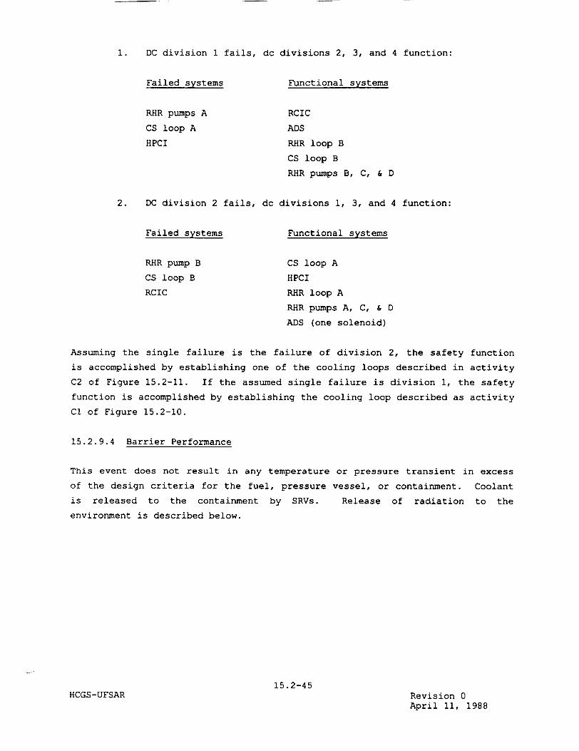
1. DC division 1 fails, dc divisions 2, 3, and 4 function:
Failed systems
RHR pumps A
CS loop A
HPCI
Functional systems
RCIC
ADS
RHR loop B
CS loop B
RHR pumps B, C, & D
2. DC division 2 fails, dc divisions 1, 3, and 4 function:
Failed systems
RHR pump B
CS loop B
RCIC
Functional systems
CS loop A
HPCI
RHR loop A
RHR pumps A, C, & D
ADS (one solenoid)
Assuming the single failure is the failure of division 2, the safety function
is accomplished by establishing one of the cooling loops described in activity
C2 of Figure 15.2-11. If the assumed single failure is division 1, the safety
function is accomplished by establishing the cooling loop described as activity
Cl of Figure 15.2-10.
15.2.9.4 Barrier Performance
This event does not result in any temperature or pressure transient in excess
of the design criteria for the fuel, pressure vessel, or containment. Coolant
is released to the containment by SRVs. Release of radiation to the
environment is described below.
15.2-45HCGS-UFSAR Revision 0
April 11, 1988

15.2.9.5 Radiological Consequences
While this event does not result in fuel failure, it does result in the
discharge of normal coolant activity to the suppression pool via SRV operation.
Since this activity is contained in the primary containment, there are no
exposures to operating personnel. Since this event also does not result in an
uncontrolled release to the environment, the plant operator can choose to hold
the activity in the containment or discharge it to the environment under controlled release conditions. If purging of the containment is chosen, the
release will be in accordance with established Hope Creek Technical
Specification limits.
15.2.10 References
15.2-1
15.2-2
15.2-3
HCGS-UFSAR
Fukushima, T. Y, "HEX01 User Manual," NEDE-23014, July 1976.
Nuclear Fuel Section Design Input File, "Application of the Generic ABB Reload methodology to Hope Creek Generating Station,"
HCA.5-0026.
ABB Combustion Engineering Nuclear Power, "Reference Safety
Report for Boiling Water Reactor Reload Fuel," ABB Report CENPD
300-P-A (proprietary), July 1996.
15.2-46Revision 11 November 24, 2000
15.3 DECREASE IN REACTOR COOLANT SYSTEM FLOW RATE
15.3.1 Reactor Recirculation Pump Trip
The reactor recirculation pump trip events are considered a non-Limiting event.
Therefore it is not required to be re-analyzed as a part of the ABB reload
licensing analysis for Hope Creek, unless the disposition for this event
changes (Reference 15.3-2).
The results referenced within this section are representative of cycle 1.
These results are considered bounded by the reload licensing analysis.
15.3.1.1 Identification of Causes and Frequency Classification
15.3.1.1.1 Identification of Causes
A reactor recirculation pump motor can be tripped by design, for reducing
reactor coolant pressure boundry (RCPB) effects, and randomly by unpredictable
operational failures. Intentional tripping will occur in response to:
1. Reactor vessel water level (L2) setpoint trip
2. Turbine control valve fast closure or main stop valve closure
3. Failure to scram at high pressure setpoint trip
4. Motor branch circuit overcurrent protection
5. Motor overload protection
6. Suction block valve not fully open.
Random tripping will occur in response to:
1. Operator error
2. Loss of electrical power source to the pumps
3. Equipment or sensor failures and malfunctions that initiate the
above intended trips.
15.3-1 HCGS-UFSAR Revision 11
November 24, 2000

15.3.1.1.2 Frequency Classification
15.3.1.1.2.1 Trip of One Reactor Recirculation Pump
This transient event is categorized as one of moderate frequency.
15.3.1.1.2.2 Trip of Two Reactor Recirculation Pumps
This transient event is categorized as one of moderate frequency.
15.3.1.2 Sequence of Events and Systems Operation
15.3.1.2.1 Sequence of Events
The results below are representative of cycle 1. These results are considered
bounded by the reload licensing analysis.
15.3.1.2.1.1 Trip of One Reactor Recirculation Pump
Table 15.3-1 lists the sequence of events for Figure 15.3-1.
15.3.1.2.1.2 Trip of Two Reactor Recirculation Pumps
Table 15.3-2 lists the sequence of events for Figure 15.3-2.
15.3.1.2.2 Identification of Operator Actions
15.3.1.2.2.1 Trip of One Reactor Recirculation Pump
Since no scram occurs, no immediate operator action is required. As soon as
possible, the operator should verify that no operating limits are being
exceeded and reduce flow of the operating pump to conform to the single pump
flow criteria. Also, the operator will determine the cause of failure prior to
returning the system to normal and follow the restart procedure.
15.3.1.2.2.2 Trip of Two Reactor Recirculation Pumps
Tripping of two reactor recirculation pumps will cause a reactor water level
swell that will trip the main turbine. This in turn
15.3-2 HCGS-UFSAR Revision 11
November 24, 2000
will cause a reactor scram. The operator will ascertain that the reactor has
been scrammed. The operator should regain control of reactor water level
through reactor core isolation cooling (RCIC) operation, monitoring reactor
water level and pressure control after shutdown. When both reactor pressure
and level are under control, the operator may secure both high pressure coolant
injection (HPCI) and RCIC, as necessary. The operator will also determine the
cause of the trip before returning the system to normal.
15.3.1.2.3 Systems Operation
15.3.1.2.3.1 Trip of One Reactor Recirculation Pump
Tripping a single reactor recirculation pump does not require any protection
system or safeguard system operation. This analysis assumes normal functioning
of plant instrumentation and controls.
15.3.1.2.3.2 Trip of Two Reactor Recirculation Pumps
Analysis of this event assumes normal functioning of both the plant
instrumentation and controls and the plant protection and reactor protection
systems.
Specifically this transient takes credit for vessel level (LB) instrumentation
to trip the turbine. Reactor shutdown relies on scram trips from the turbine.
High system pressure is limited by the main steam safety/relief valve (SRV)
operation.
15.3.1.2.4 The Effect of Single Failures and Operator Errors
15.3.1.2.4.1 Trip of One Reactor Recirculation Pump
Since no corrective action is required per Section 15.3.1.2.3.1, no additional
effects of single failures need be discussed. If additional single active
failures (SAFs) or single operator errors (SOEs) are assumed (for envelope
purposes the other pump is assumed
15.3-3 HCGS-UFSAR Revision 0
April 11, 1988
tripped), then the following two pump trip analysis is provided. Refer to
Section 15.9 for specific details.
15.3.1.2.4.2 Trip of Two Reactor Recirculation Pumps
Table 15.3-2 lists the reactor vessel level (L8) trip event as the first response to initiate corrective action in this transient. The high level (L8) is intended to prohibit moisture carryover to the main turbine. Multiple level sensors are used to sense and detect when the water level reaches the L8 setpoint. At this point, a single failure will neither initiate nor impede a turbine trip signal. Turbine trip signal logic circuitry, however, is not designed to meet single failure criterion. The result of a failure at this point would have the effect of delaying the pressurization. However, high moisture levels entering the turbine can cause vibration, which may lead to the
operator manually tripping the unit.
Scram signals from the turbine trip are designed such that a single failure will neither initiate nor impede a reactor scram initiation. See Section 15.9
for specific details.
15.3.1.3 Core and System Performance
15.3.1.3.1 Mathematical Model
The nonlinear, dynamic model described briefly in Section 15.1.3.3.1 is used to
simulate this event.
15.3.1.3.2 Input Parameters and Initial Conditions
These analyses have been performed, unless otherwise noted, with plant
conditions tabulated in Table 15.0--3.
Pump motors and pump rotors are simulated with minimum specified rotating
inertias.
15.3-4 HCGS-UFSAR Revision 11
November 24, 2000
15.3.1.3.3 Results
The results presented below are representative of cycle 1. These results are
considered bounded by the reload licensing analysis.
15.3.1.3.3.1 Trip of One Reactor Recirculation Pump
Figure 15.3-1 shows the results of losing one recirculation pump. The tripped
loop diffuser flow reverses in approximately 4.3 seconds. However, the ratio
of diffuser mass flow to pump mass flow in the active jet pumps increases
considerably and produces approximately 14.8 percent of normal diffuser flow.
Minimum critical power ratio (MCPR) remains above the operating limit, thus, the fuel thermal limits are not violated. During this transient, level swell
is not sufficient to cause turbine trip and scram.
15.3.1.3.3.2 Trip of Two Reactor Recirculation Pumps
Figure 15.3-2 shows graphically this transient with minimum specified rotating
inertia. MCPR remains unchanged at the operating limit. No scram is initiated
directly by pump trip. The vessel water level swell due to rapid flow
coastdown is expected to reach the high level trip, thereby shutting down the
main turbine and feed pump turbines and causing a reactor scram. Subsequent
events, such as main steam line isolation and initiation of RCIC and HPCI
systems occurring late in this event, have no significant effect on the
results.
15.3.1.3.4 Consideration of Uncertainties
Initial conditions chosen for these analyses are conservative and tend to force
analytical results to be more severe than expected under actual plant
conditions.
Actual pump and pump-motor drive line rotating inertias are expected to be
somewhat greater than the minimum design values assumed in this simulation.
Actual plant deviations regarding inertia are expected to lessen the severity
as analyzed. Minimum design
15.3-5 HCGS-UFSAR Revision 11
November 24, 2000

inertias were used as well as the least negative void coefficient, since the
primary interest is in the flow reduction.
15.3.1.4 Barrier Performance
15.3.1.4.1 Trip of One Reactor Recirculation Pump
The results shown on Figure 15.3-1 indicate a basic reduction in system
pressures from the initial conditions. Therefore, the RCPB barrier is not
threatened.
15.3.1.4.2 Trip of Reactor Two Recirculation Pumps
The results shown on Figure 15.3-2 indicate peak pressures stay well below the
1375 psig limit allowed by the applicable code. Therefore, the RCPB barrier is
not threatened.
15.3.1.5 Radiological Consequences
While the consequence of this transient does not result in fuel failure, it
does result in the discharge of normal coolant activity to the suppression
chamber via SRV operation. Since this activity is contained in the primary
containment, there will be no exposures to operating personnel. Because this
transient does not result in an uncontrolled release to the environment, the
plant operator can choose to leave the activity in the primary containment or
discharge it to the environment under controlled release conditions. If
purging of the containment is chosen, the release will be in accordance with
established technical specification limits.
15.3.2 Recirculation Flow Control Failure - Decreasing Flow
The recirculation flow control failure - decreasing flow events are considered
a non-Limiting event. Therefore it is not required to be re-analyzed as a part
of the ABB reload licensing analysis for Hope Creek, unless the disposition for
this event changes (Reference 15.3-2).
The results referenced within this section are representative of cycle 1.
These results are considered bounded by the reload licensing analysis.
15.3.2.1 Identification of Causes and Frequency Classification
15.3.2.1.1 Identification of Causes
Two causes of recirculation flow control failure are:
15.3-6 HCGS-UFSAR Revision 11
November 24, 2000
1. Failure of an individual recirculation motor generator set
controller (one per loop), or the positioning control of an
individual scoop tube actuator, can result in a rapid flow decrease
in only one recirculation loop.
2. A downscale failure of the master flow controller, or an excessive
manual speed demand setpoint change, can generate a zero flow
demand signal to both recirculation flow control loops.
15.3.2.1.2 Frequency Classification
This transient is categorized as an incident of moderate frequency.
15.3.2.2 Sequence of Events and Systems Operation
15.3.2.2.1 Sequence of Events
The results presented below are representative of cycle 1. These results are
considered bounded by the reload licensing analysis.
15.3.2.2.1.1 Failure of One Controller - Closed
The sequence of events for this transient is similar to, and is less severe
than, that listed in Table 15.3-1 for the trip of one reactor recirculation
pump.
15.3.2.2.1.2 Master Controller Failure - Closed
The sequence of events for this transient is similar to, and can never be more
severe than, that listed in Table 15.3-2 for the trip of both reactor
recirculation pumps.
15.3.2.2.1.3 Identification of Operator Actions
The operator will verify that no operating limits are being exceeded. The
operator will also determine the cause of the trip prior to returning the
system to normal.
15.3-7HCGS-UFSAR Revision 11
November 24, 2000
I
15.3.2.2.2 Systems Operation
Normal plant instrumentation and control is assumed to function. Credit is
taken for scram in response to vessel high water level (LB) turbine trip if it
occurs. This credit applies to both the single and master controller failure
events.
15.3.2.2.3 The Effect of Single Failures and Operator Errors
The single failure and operator error considerations for these events are the
same as discussed in Section 15.3.1.2.4 on reactor recirculation pump trips.
Failure of one motor-generator set, and, thus, a recirculation pump trip (RPT),
or the failure of a master controller, and, thus, two RPTs, would be the
envelope cases for additional single active failures (SAFs) or single operator
errors (SOEs). Refer to Section 15.9 for specific details.
15.3.2.3 Core and System Performance
15.3.2.3.1 Mathematical Model
The nonlinear dynamic model described briefly in Section 15.1.3.3.1 is used to
simulate these transient events.
15.3.2.3.2 Input Parameters and Initial Conditions
These analyses have been performed, unless otherwise noted, with the plant
conditions listed in Table 15.0-3. The lower negative void coefficient in
Table 15.0--3 was used for these analyses.
15.3.2.3.3 Results
The results presented below are representative of cycle 1. These results are
considered bounded by the reload licensing analysis.
In the case of zero demand to both controllers, each individual motor generator
set speed controller has an error limiter that limits the maximum rate of
change of speed in each loop. Thus, this transient can never be more severe
than the simultaneous trip of both reactor recirculation pumps, evaluated in
Section 15.3.1.3.3.2.
15.3-8 HCGS-UFSAR Revision 11
November 24, 2000
In the case of failure of one controller, the scoop tube positioners are
designed so that the flow change rate limit is determined by the individual
stroking rate, which is approximately 25 percent per second. This case is
similar to the trip of one reactor recirculation pump, described in Section
15.3.1.3.3.1, and is less severe than the transient that results from the
simultaneous trip of both reactor recirculation pumps.
15.3.2.3.4 Consideration of Uncertainties
Initial conditions chosen for these analyses are conservative and tend to force
analytical results to be more severe than otherwise expected. These analyses,
unlike the pump trip series, are unaffected by deviations in pump, pump motor,
and driveline inertias, since it is the flow controllers that cause rapid
recirculation decreases.
15.3.2.4 Barrier Performance
The reactor coolant pressure boundary (RCPB) barrier performance considerations
for these transients are the same as discussed in Section 15.3.1.4 on
recirculation pump trips.
15.3.2.5 Radiological Consequences
The radiological consequences for these transients are the same as discussed in
Section 15.3.1.5.
15.3.3 Reactor Recirculation Pump Shaft Seizure
The Reactor Recirculation Pump Shaft Seizure accident is considered a non
Limiting event. Therefore it is not required to be re-analyzed as a part of
the ABB reload licensing analysis for Hope Creek, unless the disposition for
this event changes (Reference 15.3-2).
The results referenced within this section are representative of cycle 1.
These results are considered bounded by the reload licensing analysis.
15.3.3.1 Identification of Causes and Frequency Classification
The seizure of a reactor recirculation pump is considered a design basis
accident (DBA). It has been evaluated as a very mild accident in relation to
other DBAs, such as a loss-of-coolant accident (LOCA). The analysis has been
conducted with consideration to a
15.3-9 HCGS-UFSAR Revision 11
November 24, 2000
single or double loop operation. A detailed discussion is given in
Section S.2.5.5 of GESTAR II (Reference 15.3.1).
The seizure event postulated certainly would not be the mode of failure of the
pump. Safe shutdown components, e.g., electrical breakers, protective
circuits, would preclude an instantaneous seizure event.
15.3.3.1.1 Identification of Causes
The case of reactor recirculation pump seizure represents the extremely
unlikely event of instantaneous stoppage of the pump motor shaft of one
recirculation pump. This event produces a very rapid decrease of core flow as
a result of the large hydraulic resistance introduced by the stopped rotor.
15.3.3.1.2 Frequency Classification
This event is considered a limiting fault, but results in effects that can
easily satisfy an event of greater probability, i.e., infrequent incident
classification.
15.3.3.2 Sequence of Events and Systems Operations
15.3.3.2.1 Sequence of Events
Table 15.3-3 lists the sequence of events for Figure 15.3-3.
The above results are representative of cycle 1. These results are considered
bounded by the reload licensing analysis.
15.3.3.2.1.1 Identification of Operator Actions
The operator will first make certain that the reactor scrams with the turbine
trip resulting from reactor water level swell. The operator will then regain
control of reactor water level through high pressure coolant injection (HPCI)
and reactor core isolation cooling (RCIC) operation, or by restart of a
feedwater pump. The operator must also monitor reactor water level and
pressure after shutdown.
15.3-10 HCGS-UFSAR Revision 11
November 24, 2000
15.3.3.2.2 Systems Operation
To properly simulate the expected sequence of
accident assumes normal functioning of plant
plant protection, and Reactor Protection Systems
events, the analysis of this
instrumentation and controls,
(RPSs).
Operation of safe shutdown features, though not included in this simulation, is expected to be used in order to maintain adequate water level.
15.3.3.2.3 The Effect of Single Failures and Operator Errors
Single failures in the scram logic, originating via the high vessel level (L8) trip, are similar to the considerations in Section 15.3.1.2.4.2.
Refer to Section 15.9 for further details.
15.3.3.3 Core and System Performance
15.3.3.3.1 Mathematical Model
The nonlinear dynamic model described briefly in Section 15.1.3.3.1 is used to
simulate this event.
15.3.3.3.2 Input Parameters and Initial Conditions
This analysis has been performed, unless otherwise noted,
tabulated in Table 15.0-3.with plant conditions
For the purpose of evaluating consequences to the fuel thermal limits, this transient event is assumed to occur as a consequence of an unspecified, instantaneous stoppage of one recirculation pump shaft while the reactor is operating at 105 percent of nuclear boiler rated (NBR) steam flow. Also, the reactor is assumed to be operating at thermally limited conditions.
15.3-11 HCGS-UFSAR Revision 11
November 24, 2000
I
The void coefficient is adjusted to the most conservative value, that is, the
least negative value in Table 15.0-3.
15.3.3.3.3 Results
The results presented below are representative of cycle 1. These results are
considered bounded by the reload licensing analysis.
Figure 15.3-3 presents the results of the accident. Core coolant flow drops
rapidly, reaching its minimum value of 53.6 percent in approximately
1.6 seconds. Minimum critical power ratio (MCPR) does not decrease
significantly before fuel surface heat flux begins dropping enough to restore
greater thermal margins. The level swell produces a trip of the main and
feedwater turbines and main stop valve closure, reactor scram, and
recirculation pump trip (RPT). Since, after the time at which MCPR occurs,
heat flux decreases much more rapidly than the rate at which heat is removed by
the coolant, the scram conditions impose no threat to thermal limits.
Additionally, the bypass valves and momentary opening of some of the safety/
relief valves (SRVs) limit the pressure well within the range allowed by the
ASME B&PV Code. Therefore, the reactor coolant pressure boundary (RCPB) is not
threatened by overpressure.
15.3.3.3.4 Considerations of Uncertainties
Considerations of uncertainties are discussed in Section 15.0.3.3.
15.3.3.4 Barrier Performance
After the opening of bypass valves and after a turbine trip, the pressure well
is limited within the range allowed by the ASME B&PV Code. Therefore, the RCPB
barrier is not threatened by overpressure.
15.3.3.5 Radiological Consequences
The radiological consequences of this accident are the same as discussed in
Section 15.3.1.5.
15.3-12 HCGS-UFSAR Revision 11
November 24, 2000
15.3.3.6 SRP Rule Review
Evaluation of SRP 15.3.3 is included in Section 15.3.4.6.
15.3.4 Reactor Recirculation Pump Shaft Break
The reactor recirculation pump shaft break accident is considered a non
Limiting event. Therefore it is not required to be re-analyzed as a part of
the ABB reload licensing analysis for Hope Creek, unless the disposition for
this event changes (Reference 15.3-2).
15.3.4.1 Identification of Causes and Frequency Classification
The breaking of the shaft of a reactor recirculation pump is considered a
design basis accident (DBA). It has been evaluated as a very mild accident in
relation to other DBAs, such as a loss-of-coolant accident (LOCA). The
analysis has been conducted with consideration to a single or double loop
operation.
This postulated event is bounded by the more limiting case of recirculation
pump seizure. Quantitative results for this more limiting case are presented
in Section 15.3.3.
15.3.4.1.1 Identification of Causes
The case of reactor recirculation pump shaft breakage represents the extremely
unlikely event of instantaneous stoppage of the pump motor operation of one
recirculation pump. This event produces a very rapid decrease of core flow as
a result of the break of the pump shaft.
15.3.4.1.2 Frequency Classification
This event is considered a limiting fault, but results in effects that can
easily satisfy an event of greater probability, i.e., infrequent incident
classification.
15.3-13HCGS-UFSAR Revision 11
November 24, 2000
15.3.4.2 Sequence of Events and Systems Operations
15.3.4.2.1 Sequence of Events
A postulated instantaneous break of the pump motor shaft of one reactor recirculation pump, as discussed in Section 15.3.4.1.1, will cause the core flow to decrease rapidly, resulting in water level swell in the reactor vessel. When the vessel water level reaches the high water level setpoint, L8, main turbine trip and feedwater pump trip will be initiated. Subsequently, reactor scram and the remaining recirculation pump trip (RPT) will be initiated due to the turbine trip. Eventually, the vessel water level will be controlled by high pressure coolant injection (HPCI) and reactor core isolation cooling
(RCIC) flow.
15.3.4.2.1.1 Identification of Operator Actions
The operator will first make certain that the reactor scrams as a result of the turbine trip due to reactor water level swell. The operator will then regain control of reactor water level through HPCI and RCIC operation or by restart of a feedwater pump. The operator must also monitor reactor water level and pressure after shutdown.
15.3.4.2.2 Systems Operation
Normal operation of plant instrumentation and control is assumed. This event takes credit for vessel water level (L8) instrumentation to scram the reactor and trip the main turbine and feedwater pumps. High system pressure is limited by the safety/relief valve (SRV) system operation.
Operation of HPCI and RCIC systems is expected in order to maintain adequate
water level control.
15.3-14 HCGS-UFSAR Revision 0
April 11, 1988
15.4 REACTIVITY AND POWER DISTRIBUTION ANOMALIES
15.4.1 Rod Withdrawal Error - Low Power
The rod withdrawal error - low power events are considered a non-Limiting
event. Therefore it is not required to be re-analyzed as a part of the ABB
reload licensing analysis for Hope Creek, unless the disposition for this event
changes (Reference 15.4-4).
15.4.1.1 Control Rod Removal Error During Refueling
15.4.1.1.1 Identification of Causes and Frequency Classification
The event considered here is inadvertent criticality due to the complete
withdrawal or removal of the most reactive rod during refueling. The
probability of the initial causes alone is considered low enough to warrant
being categorized as an infrequent incident, since there is no postulated set
of circumstances that results in an inadvertent rod withdrawal error (RWE)
while in the refueling mode.
15.4.1.1.2 Sequence of Events and Systems Operation
15.4.1.1.2.1 Initial Control Rod Removal or Withdrawal
During refueling operations, safety system interlocks ensure that inadvertent
criticality does not occur because a control rod has been removed or withdrawn
in coincidence with another control rod.
15.4.1.1.2.2 Fuel Insertion With Control Rod Withdrawn
To minimize the possibility of loading fuel into a cell containing no control
rod, it is required that all control rods be fully inserted when fuel is being
loaded into the core. This requirement is supplemented by refueling interlocks
on rod withdrawal and movement of the refueling platform. When the mode switch is in the "refuel" position, the interlocks prevent the platform from being moved over the core if a control rod is withdrawn and fuel is on the hoist.
Likewise, if the refueling platform is over the core and fuel is on the hoist,
control rod motion is blocked by the interlocks.
15.4-1 HCGS-UFSAR Revision 11
November 24, 2000
15.4.1.1.2.3 Second Control Rod Removal or Withdrawal
When the platform is not over the core, or fuel is not on the hoist, and the
mode switch is in the "refuel" position, only one control rod can be withdrawn.
Any attempt to withdraw a second rod results in a rod block by refueling
interlocks. Since the core is designed to meet shutdown requirements with the
highest worth rod withdrawn, the core remains subcritical even with one rod
withdrawn.
15.4.1.1.2.4 Control Rod Removal Without Fuel Removal
Finally, the design of the control rod does not physically permit the upward
removal of the control rod without the simultaneous or prior removal of the
four adjacent fuel bundles. This precludes any hazardous condition.
15.4.1.1.2.5 Identification of Operator Actions
No operator actions are required to mitigate this event since the plant design
as discussed above prevents its occurrence.
15.4.1.1.2.6 Effect of Single Failure and Operator Errors
If any one of the operations involved in initial failure or error is followed
by any other single active failure (SAF) or single operator error (SOE), the
necessary safety actions are taken, e.g., rod block or scram, automatically
prior to limit violation. Refer to Section 15.9 for details.
15.4.1.1.3 Core and System Performances
Since the probability of inadvertent criticality during refueling is precluded,
the core and system performances are not analyzed. The withdrawal of the
highest worth control rod during refueling does not result in criticality. This
is demonstrated by performing shutdown margin checks. See reference 15.4-5 for
a
15.4-2HCGS-UFSAR Revision 11
November 24, 2000
I
15.4.1.2.2.2 Effects of Single Failure and Operator Errors
If any one of the operations involves an initial failure or error and is
followed by another SAF or SOE, the necessary safety actions are automatically
taken, e.g., rod blocks, prior to any limit violation. Refer to Section 15.9
for details.
15.4.1.2.3 Core and System Performance
The performance of the RWM or a second qualified verifier prevents erroneous
selection and withdrawal of an out of sequence control rod. The core and
system performance is not affected by such an operator error.
No mathematical models are involved in this event. The need for input parameters or initial conditions is not required as there are no results to
report. Consideration of uncertainties is not appropriate.
15.4.1.2.4 Barrier Performance
An evaluation of the barrier performance is not made for this event since there
is no postulated set of circumstances for which this error could occur.
15.4.1.2.5 Radiological Consequences
An evaluation of the radiological consequences is not required for this event since no radioactive material is released from the fuel.
15.4.2 Rod Withdrawal Error - At Power
The rod withdraw error at power event is considered a potentially limiting
event and is re-analyzed for each reload. The results of the re-analysis of
the rod withdraw error at power event are presented in Appendix 15D (Reference
15.4-5).
This event and the analysis methodology is described in Reference 15.4-5.
The limiting rod pattern and results from the rod withdraw error at power event
are presented in Appendix 15D.
15.4-5 HCGS-UFSAR Revision 11
November 24, 2000
I 15.4.3 Control Rod Maloperation (System Malfunction or Operator
Error)
This event is covered by the evaluation cited in Sections 15.4.1 and 15.4.2.
As a result this event is less severe than the rod withdraw error analyzed for
the reload, so the control rod maloperation event is not re-analyzed in the
standard ABB reload licensing analysis process.
15.4.4 Abnormal Startup of Idle Recirculation Pump
The abnormal startup of an idle recirculation pump event is considered a non
Limiting event. Therefore it is not required to be re-analyzed as a part of
the ABB reload licensing analysis for Hope Creek, unless the disposition for
this event changes (Reference 15.4-4).
The results referenced within this section are representative of cycle 1.
These results are considered bounded by the reload licensing analysis.
15.4.4.1 Identification of Causes and Frequency Classification
15.4.4.1.1 Identification of Causes
Abnormal startup of an idle recirculation pump results directly from the
operator's manual initiation of pump operation. It assumes that the remaining
loop is already operating.
15.4.4.1.2 Frequency Classification
15.4.4.1.2.1 Normal Restart of Recirculation Pump at Power
This transient is categorized as an incident of moderate frequency.
15.4.4.1.2.2 Abnormal Startup of Idle Recirculation Pump
This transient is categorized as an incident of moderate frequency.
15.4.4.2 Sequence of Events and Systems Operation
15.4.4.2.1 Sequence of Events
Table 15.4-1 lists the sequence of events for Figure 15.4-2.
The results referenced above are representative of cycle 1. These results are
considered bounded by the reload licensing analysis.
15.4-6 HCGS-UFSAR Revision 11
November 24, 2000
15.4.4.2.1.1 Operator Actions
The normal sequence of operator actions expected in starting the idle loop is
as follows. The operator will:
1. Adjust rod pattern as necessary for new power level following idle
loop start.
2. Determine that the idle recirculation pump suction valve is open,
the discharge block valve is closed, and the coupler in the idle
loop is in the starting position; if not, place them in this
configuration.
3. Readjust flow of the running loop downward to less than half of
rated flow.
4. Determine that the temperature difference between the two loops is
no more than 50°F.
5. Start the idle loop pump.
6. Open the discharge valve by using the manual jogging sequence or
auto circuitry; monitor reactor power.
7. Adjust the loop flow to match the operating loop flow.
8. Readjust power, as necessary, to satisfy plant requirements per
standard procedure.
15.4.4.2.2 Systems Operation
This event assumes normal functioning of plant instrumentation and controls,
plant protection systems, and the Reactor Protection System (RPS). In
particular, credit is taken for high neutron flux scram to terminate the
transient. No engineered safety feature (ESF) action occurs as a result of the
transient.
15.4-7 HCGS-UFSAR Revision 0
April 11, 1988
15.4.4.2.3 The Effect of Single Failures and Operator Errors
This transient leads to a quick rise in reactor power level. Corrective action
first occurs in the high neutron flux trip and, as part of the RPS, it is
designed to single failure criteria. Therefore, shutdown is ensured. Operator
errors are of no concern here since the automatic shutdown events rapidly
follow the postulated failure. See Section 15.9 for details.
15.4.4.3 Core and System Performance
15.4.4.3.1 Mathematical Model
The nonlinear dynamic model described briefly in Section 15.1.3.3.1 is used to
simulate this event.
15.4.4.3.2 Input Parameters and Initial Conditions
Unless otherwise noted, this analysis has been performed with plant conditions
tabulated in Table 15.0-3.
One recirculation loop is idle and filled with cold water at 1000 F. Normal
procedure, when starting an idle loop with one pump already running, requires
heating the idle recirculation loop to within 50°F of core inlet temperature
prior to loop startup.
The active recirculation loop is operating with about 82.4 percent of normal
rated diffuser flow going across the active jet pumps.
The core is receiving 38 percent of its normal rated flow. The remainder of
the coolant flows in the reverse direction through the inactive jet pumps.
Reactor power is 55 percent of nuclear boiler rated (NBR). Normal procedures
require startup of an idle loop at a lower power.
15.4-8HCGS-UFSAR Revision 11
November 24, 2000
I
The idle recirculation pump suction valve is open, but the pump discharge valve
is closed.
The idle pump fluid coupler is at a setting that approximates 50 percent
generator speed demand.
15.4.4.3.3 Results
The results presented below are representative of cycle 1.
considered bounded by the reload licensing analysis.
These results are
The transient response to the incorrect startup of a cold, idle recirculation
loop is shown on Figure 15.4-2. Shortly after the pump starts, a surge in flow
from the started jet pump diffusers causes the core inlet flow to rise sharply.
A short duration neutron flux peak reaches the APRM neutron flux setpoint at 10
seconds, and reactor scram is initiated. The neutron flux peaks at
396.3 percent of NBR. Surface heat flux follows the slower response of the
fuel and peaks at 80.5 percent of NBR. Nuclear system pressures do not
increase significantly above initial. The water level does not reach either
the high or low level setpoints.
15.4.4.3.4 Consideration of Uncertainties
End of cycle scram characteristics are assumed, and the more negative void
coefficient listed in Table 15.0-3 is used.
15.4.4.4 Barrier Performance
No evaluation of barrier performance is required for this event since no
significant pressure increases are incurred during this transient. See Figure
15.4-2.
15.4.4.5 Radiological Consequences
An evaluation of the radiological consequences is not required for this event
since no radioactive material is released.
15.4-9 HCGS-UFSAR Revision 11
November 24, 2000
I
15.4.5 Recirculation Flow Control Failure with Increasing Flow
The recirculation flow control failure with increasing flow event is considered a potentially limiting event and is re-analyzed for each reload. The results
of the re-analysis of the recirculation flow control failure with increasing
flow event are presented in Appendix 15D (Reference 15.4-4).
15.4.5.1 Identification of Causes and Frequency Classification
15.4.5.1.1 Identification of Causes
Failure of the master flow controller can cause a speed increase for both recirculation pumps. However, both individual speed controllers have error limiters so that this case is less severe than the failure (maximum demand) of
one of the motor generator set speed controllers.
15.4.5.1.2 Frequency Classification
This transient is classified as an incident of moderate frequency.
15.4.5.2 Sequence of Events and Systems Operation
15.4.5.2.1 Sequence of Events
The sequence of events for the recirculation flow control failure with
increasing flow event are listed in Appendix 15D.
15.4.5.2.1.1 Identification of Operator Actions
Initial action by the operator will include:
1. Transfer of flow control to manual and reduction to minimum flow.
2. Identification of the cause of failure.
Reactor pressure is controlled as required, depending on whether a restart or
cooldown is planned. In general, the corrective action is to hold reactor
pressure and condenser vacuum for restart after
15.4-10 HCGS-UFSAR Revision 11
November 24, 2000
I
I

the malfunctioning flow controller has been repaired. The following is the
sequence of operator actions expected during the course of the event, assuming
restart. The operator will:
1. Observe that all rods are fully inserted.
2. Check the reactor water level and maintain above low level (L2)
trip to prevent main steam isolation valves (MSIVs) from isolating.
3. Switch the reactor mode switch to the "startup" position.
4. Continue to maintain condenser vacuum and turbine seals.
5. Transfer the recirculation flow controller to the manual position
and reduce the setpoint to zero.
6. Survey maintenance requirements and complete the scram report.
7. Monitor the turbine coastdown and auxiliary systems.
8. Establish a restart of the reactor according to the normal
procedure.
15.4.5.2.2 Systems Operation
The analysis of this transient assumes normal functioning of plant
instrumentation and controls, and the Reactor Protection System (RPS).
Operation of engineered safety features (ESFs) is not expected.
15.4.5.2.3 The Effect of Single Failures and Operator Errors
This transient leads to a quick rise in reactor power level, which results in a
high neutron flux scram. See Section 15.9 for
15.4-11 HCGS-UFSAR Revision 0
April 11, 1988

details. Operator errors are of no concern here in view of the fact that
automatic shutdown events rapidly follow the postulated failure.
15.4.5.3 Core and System Performance
15.4.5.3.1 Mathematical Model
The computer simulated analytical model is described in section 7.5 of
reference 15.4-5.
The recirculation flow control failure with increasing flow event is evaluated
with the core simulator described in Reference 15.4-5. The core simulator
described in reference 15.4-5 provides a three-dimensional simulation of the
nuclear, thermal and hydraulic conditions in a boiling water reactor.
15.4.5.3.2 Input Parameters and Initial Conditions
This analysis has been performed, unless otherwise noted, with plant conditions
tabulated shown in Appendix 15D.
A description of the plant initial conditions and assumptions are presented in
section 7.5.3.2 of reference 15.4-5.
15.4.5.3.3 Results
Appendix 15D shows the results of the transient. The changes in nuclear system
pressure are not significant with regard to overpressure. Pressure decreases
over most of the transient. The rapid increase in core coolant flow causes an
increase in neutron flux, which initiates a reactor average power range monitor
(APRM) high flux scram.
15.4-12HCGS-UFSAR Revision 11
November 24, 2000
I
I

15.4.5.3.4 Considerations of Uncertainties
Some uncertainties in void reactivity characteristics, scram time, and worth
are expected to be more optimistic and will therefore produce less severe
consequences than those simulated.
15.4.5.4 Barrier Performance
This transient results in a very slight increase in reactor vessel pressure, as
shown in Appendix 15D, and therefore represents no threat to the reactor
coolant pressure boundary (RCPB).
15.4.5.5 Radiological Consequences
An evaluation of the radiological consequences is not required for this event
since no radioactive material is released.
15.4.6 Chemical and Volume Control System Malfunctions
Not applicable to boiling water reactors (BWRs). This is a pressurized water
reactor (PWR) event.
15.4.7 Misplaced Bundle Accident
The misplaced bundle accident is considered potentially limiting; therefore, it
is re-analyzed for each reload. The results of the re-analysis of the
misplaced bundle accident are presented in Appendix 15D (Reference 15.4-4).
15.4.7.1 Identification of Causes and Frequency Classification
15.4.7.1.1 Identification of Causes
The event discussed in this section is the improper loading of a fuel bundle
and subsequent operation of the core. Three errors must occur for this event
to take place in the initial core loading. First, a bundle must be loaded into
a wrong location in the core. Second, the bundle that was supposed to be
loaded where
15.4-13HCGS-UFSAR Revision 11
November 24, 2000
I
I

the mislocation occurred would have to be overlooked and also loaded in an
incorrect location. Third, the misplaced bundles would have to be overlooked
during the core verification performed following initial core loading.
15.4.7.1.2 Frequency of Occurrence
This event occurs when a fuel bundle is loaded into the wrong location in the core. It is assumed the bundle is misplaced to the worst possible location,
and the plant is operated with the mislocated bundle. This event is
categorized as an infrequent incident based on an expected frequency of 0.004 events per operating cycle, which is based upon past experience. The only misloading events that have occurred in the past were in reload cores where only two errors are necessary. Therefore, the frequency of occurrence for initial cores is even lower since three errors must occur concurrently.
15.4.7.2 Sequence of Events and Failure Analysis
15.4.7.2.1 Sequence of Events
The postulated sequence of events for the misplaced bundle accident is
presented in Appendix 15D.
Fuel loading errors, undetected by in-core instrumentation following fueling operations, may result in undetected reductions in thermal margins during power operations. No detection is assumed, and therefore, no corrective operator
action or automatic protection system function occurs.
15.4.7.2.2 Effect of Single Failure and Operator Errors
This analysis represents the worst case, i.e., operation of a misplaced fuel bundle with three SAFs or SOEs, and there are no additional operator errors that could make this accident more severe. Refer to Section 15.9 for further
details.
15.4-14 HCGS-UFSAR Revision 11
November 24, 2000

15.4.7.3 Core and System Performance
Analysis methods for this event are discussed in Section 8.5 of Reference 15.4
5.
Core performance are described in Appendix 15D.
15.4-15 HCGS-UFSAR Revision 11
November 24, 2000
I
(PAGE INTENTIONALLY LEFT BLANK)
15.4-16 HCGS-UFSAR Revision 11
November 24, 2000

15.4.7.4 Barrier Performance
An evaluation of the barrier performance is not made for this event since it is
a very mild and highly localized event. No change in the core pressure will be
observed.
15.4.7.5 Radiological Consequences
An evaluation of the radiological consequences is not required for this event
since no radioactive material is released.
15.4.8 Spectrum of Rod Ejection Accidents
This is not applicable to BWRs.
15.4-17HCGS-UFSAR Revision 11
November 24, 2000

15.4.9 Control Rod Drop Accident
The control rod drop accident (CRDA) is considered potentially limiting; therefore, it is re-analyzed for each reload. The results of the re-analysis of the CRDA are presented in Appendix 15D. (Reference 15.4-4)
15.4.9.1 Identification of Causes and Frequency Classification
The causes and frequency of the control drop accident (CRDA) are described in Reference 15.4-6.
15.4.9.2 Sequence of Events and System Operations
A description of the sequence of events and operation of the system during a CRDA is provided in Reference 15.4-6.
15.4.9.3 Core and System Performance
15.4.9.3.1 Mathematical Model
The analytical methods, assumptions, and conditions for evaluating the excursion aspects of the CRDA are described in detail in Reference 15.4-6.
15.4.9.3.2 Input Parameters and Initial Conditions
The input parameters and conditions for the CRDA are described in Reference 15.4-6.
15.4.9.3.3 Results
The radiological evaluations are based on the assumed failure of 850 fuel rods. The number of rods that exceed the damage threshold is less than 850 for all plant operating conditions or core exposures provided the peak enthalpy is less than the 280 cal/g design limit.
The results of the compliance check calculation, as shown in Appendix 15D, indicate that the maximum incremental rod worth is well below the worth required to cause a CRDA that would result is 280 cal/g peak fuel enthalpy. The conclusion is that the 280 cal/g design limit is not exceeded, and the assumed failure of 850 fuel rods for the radiological evaluation is conservative.
15.4.9.4 Barrier Performance
An evaluation of the barrier performance was not made for this accident since it is a highly localized event with no significant change in the gross core temperature or pressure.
15.4-18 HCGS-UFSAR Revision 11
November 24, 2000

15.4.9.5 Radiological Consequences
The analysis is based on conservative assumptions described in Reference 15.4-6
which are considered to be acceptable to the NRC for the purpose of determining
adequacy of the plant design to meet 10CFR100 guidelines. This analysis is
referred to as the Design Basis Analysis.
15.4.9.5.1 Design Basis Analysis
The specific models and assumptions used for this evaluation are described in
Reference 15.4-6. Specific parametric values used in the valuation are
presented in Appendix 15D.
15.4.9.5.1.1 Fission Product Release from Fuel
The failure of 850 fuel rods is used for this analysis. The mass fraction of
the fuel in the damaged rods that reaches or exceeds the initiation temperature
of fuel melting, taken as 2842 0 C, is estimated to be 0.0077.
The failed fuel is assumed to be operating at 0.12 MWt/rod. In order to
calculate the correct activity release from the fuel, a peaking factor of 1.59
is applied to the fuel pin powers to determine the fission product inventories
of the damaged rods.
Fuel reaching melt conditions is assumed to release 100 percent of the noble
gas inventory and 50 percent of the iodine inventory. The remaining fuel in
the damaged rods is assumed to release 10 percent of both the noble gas and
iodine inventories.
A maximum equilibrium inventory of fission products in the core is based on
1000 days of continuous operation at 3458 MWt (105 percent core power). No
delay time is considered between departure from the above power condition and
initiation of the accident.
15.4.9.5.1.2 Fission Product Transport to the Environment
The transport pathway for this analysis, as shown in Figure 15.4-4, consists of
carryover with steam to the turbine condenser, and subsequent release of some
or all of the fission product activity to the environment following holdup and
decay in the Gaseous Waste Management System (GWMS). The Main Steam Isolation Valves (MSTVs) are not assumed to close due to main steam line high radiation
following the CRDA.
15.4-19 HCGS-UFSAR Revision 11
November 24, 2000
Of the activity reaching the condenser, 100 percent of the noble gases and 10 percent of the iodines remain airborne and available for leakage. Iodine removal is due to partitioning and plateout. 100 percent of the noble gases are assumed to enter the GWMS, and are released to the environment via the normal offgas release point after holdup in the system. All of the iodine which enters the offgas treatment system is retained indefinitely and does not contribute to the offsite does.
If the GWMS is unavailable, the transport pathway reduces to leakage of the airborne activity from the condenser. It is assumed that the condenser is isolated, and that the activity airborne in the condenser leaks from the Turbine Building at ground level directly to the environment at a rate of 1.0 percent a day. No credit is taken for holdup and decay in the Turbine Building. Radioactive decay is accounted for during residence in the condenser, and is neglected after release to the environment. The release continue for 24 hours and then terminates.
15.4.9.5.1.3 Radiological Results
Site boundary doses based on a Hope Creek specific atmospheric dispersion factor were calculated using the results presented in Reference 15.4-3.
The calculated doses from the design basis analysis are presented in Table 15.4-10.
15.4.9.5.1.4 Main Control Room
Main control room habitability for the CRDA is bounded by the analysis for the design basis loss-of-coolant accident (LOCA) and is addressed in Section 6.4.
15.4.10 References
15.4-1 C. J. Paone "Bank Position Withdrawal Sequence," NEDO-21231, September 1976.
15.4-2 General Electric, "General Electric Standard Application For Reactor Fuel," including the "United States Supplement," NEDE240111-P-A-7, and NEDE-24011-P-A-7-US.
15.4-3 General Electric, "Safety Evaluation for Eliminating the Boiling Water Reactor Main Steam Isolation Valve Closure Function and SCRAM Function of the Main Steam Line Radiation Monitor," NEDO-31400A, May 1987.
15.4-4 Nuclear Fuel Section Design Input File, "Application of the Generic ABB Reload methodology to Hope Creek Generating Station," HCA.5-0026.
15.4-5 ABB Combustion Engineering Nuclear Power, "Reference Safety Report for Boiling Water Reactor Reload Fuel," ABB Report CENPD-300-P-A (proprietary), July 1996.
15.4-6 ABB Combustion Engineering Nuclear Power, "Control Rod Drop Accident Analysis Methodology for Boiling Water Reactors: Summary and Qualification," ABB Report CENPD-284-P-A (proprietary), July 1996.
15.4-20 HCGS-UFSAR Revision 11
November 24, 2000

15.5 INCREASE IN REACTOR COOLANT INVENTORY
15.5.1 Inadvertent High Pressure Coolant Injection Startup
The inadvertent high pressure coolant injection startup event is considered a
non-Limiting event. Sensitivity studies have shown that the inadvertent high
pressure coolant injection startup event is similar to the loss of feedwater
heating event. The loss of feedwater heating event bounds the inadvertent high
pressure coolant injection startup event. Therefore it is not required to be
re-analyzed as a part of the ABB reload licensing analysis for Hope Creek,
unless the disposition for this event changes (Reference 15.5-1)
The results referenced within this section are representative of cycle 1.
These results are considered bounded by the reload licensing analysis.
15.5.1.1 Identification of Causes and Frequency Classification
15.5.1.1.1 Identification of Causes
Manual startup, i.e., operator error, of the High Pressure Core Injection
(HPCI) System is postulated for this analysis.
15.5.1.1.2 Frequency Classification
This transient disturbance is categorized as an incident of moderate frequency.
15.5.1.2 Sequence of Events and Systems Operation
15.5.1.2.1 Sequence of Events
Table 15.5-1 lists the sequence of events for Figure 15.5-1.
15.5.1.2.1.1 Identification of Operator Actions
The operator will, upon indication that the HPCI has commenced operation, check reactor water level and drywell pressure. If conditions are normal, the operator will shut down the system.
15.5.1.2.2 System Operation
To properly simulate the expected sequence of events, the analysis of this
event assumes normal functioning of plant instrumentation and controls;
specifically, the reactor pressure regulator and reactor vessel level control
that respond automatically to this event.
15.5-1 HCGS-UFSAR Revision 11
November 24, 2000
Required operation of engineered safety features (ESFs), other than what is
described, is not expected for this transient event.
The system is assumed to be in the manual flow control mode of operation.
15.5.1.2.3 The Effect of Single Failures and Operator Errors
Inadvertent operation of the HPCI results in a mild pressurization. Corrective
action by the pressure regulator and/or level control is expected to establish
a new stable operating state. The effect of a single failure in the pressure
regulator is to aggravate the transient, depending upon the nature of the
failure. Pressure regulator failures are discussed in Sections 15.1.3 and
15.2.1.
A single failure in the level control system will cause the RPV level to rise
or fall by improper control of the feedwater system. Increasing water level
will trip the turbine and automatically trip the HPCI system. This sequence is
already described in the failure of feedwater controller with increasing flow.
Decreasing RPV level will automatically initiate a scram at L3 level and will
have results similar to loss of feedwater control with decreasing flow.
15.5.1.3 Core and System Performance
15.5.1.3.1 Mathematical Model
The detailed nonlinear dynamic model described briefly in Section 15.1.3.3.1 is
used to simulate this transient.
15.5.1.3.2 Input Parameter and Initial Conditions
This analysis has been performed, unless otherwise noted, with plant conditions
as tabulated in Table 15.0-3.
15.5-2
Revision 11 November 24, 2000
I
HCGS-UFSAR
The water temperature of the HPCI system was assumed to be 400 F with an
enthalpy of 11 Btu/lb.
Inadvertent startup of the HPCI system was chosen to be analyzed because it
provides the greatest auxiliary source of cold water into the vessel.
15.5.1.3.3 Results
The results presented below are representative of cycle 1. These results are
considered bounded by the reload licensing analysis.
Figure 15.5-1 shows the simulated transient event for the manual flow control
mode. It begins with the introduction of cold water into the feedwater
sparger. Within 1 second, the full HPCI flow is established at approximately
21.8 percent of the rated feedwater flow rate. No delays were considered
because they are not relevant to the analysis.
Addition of cooler water to the core causes the neutron flux to increase to
118.7 percent of rated at approximately 16 seconds, and the plant parameters
begin to stabilize.
15.5.1.3.4 Consideration of Uncertainties
Important analytical factors, including the reactivity coefficient and HPCI
flow temperature, are assumed to be at the worst conditions so that any
deviations in the actual plant parameters will produce a less severe transient.
15.5.1.4 Barrier Performance
Figure 15.5-1 indicates a slight pressure reduction from initial conditions;
therefore, no further evaluation is required, since reactor coolant pressure
boundary pressure margins are maintained.
15.5.1.5 Radiological Consequences
Since no activity is released during this event, a detailed evaluation is not
required.
15.5-3 HCGS-UFSAR Revision 11
November 24, 2000
15.5.2 Chemical Volume Control System Malfunction (or Operator Error)
This section is not applicable to boiling water reactors (BWRs).
15.5.3 Increase in Reactor Coolant Inventory BWR Transients
These events are discussed and considered in Sections 15.1 and 15.2.
15.5.4 References
15.5-1 Nuclear Fuel Section Design Input File, "Application of the Generic
ABB Reload methodology to Hope Creek Generating Station," HCA.5-0026.
15.5-4HCGS-UFSAR Revision 11
November 24, 2000
I

15.6 DECREASE IN REACTOR COOLANT INVENTORY
15.6.1 Inadvertent Safety/Relief Valve Opening
This event is discussed and analyzed in Section 15.1.4.
15.6.2 Instrument Line Pipe Break
The Instrument Line Pipe Break accident is considered a non-Limiting event.
Therefore it is not required to be re-analyzed as a part of the ABB reload
licensing analysis for Hope Creek, unless the disposition for this event
changes (Reference 15.6-5).
This event involves the postulation of a small break in a steam or liquid line
inside or outside the primary containment but within a controlled release
structure. To bound the event, it is assumed that a small instrument line,
instantaneously and circumferentially, breaks at a location where the break may
not be able to be isolated and where immediate detection is not automatic or
apparent.
This event is far less limiting than the postulated events in Sections 15.6.4,
15.6.5, and 15.6.6.
This postulated event represents the envelope evaluation for small line failure
inside and outside primary containment, relative to sensitivity to detection.
It is summarized in Tables 15.6-1 through 15.6-5 and shown on Figure 15.6-1.
15.6.2.1 Identification of Causes and Frequency Classification
15.6.2.1.1 Identification of Causes
There is no specific event or circumstance identified that results in the
failure of an instrument line. These lines are designed to applicable
engineering codes and standards, and to appropriate seismic and environmental
requirements. Flow control check valves and flow limiting orifices are also
provided for each instrument line that penetrates the primary containment.
However, for the purpose of evaluating the consequences of a small line
rupture, the failure of an instrument line is assumed to occur.
15.6-1 HCGS-UFSAR Revision 11
November 24, 2000
15.6.2.1.1.1 Event Description
A circumferential rupture of an instrument line that is connected to the
Reactor Coolant System is postulated to occur outside the primary containment
but inside the Reactor Building. This failure results in the release of
reactor coolant to the Reactor Building until the reactor pressure vessel (RPV)
is depressurized. This event could also occur in the drywell. However, the
associated effects from this would not be as significant as those from a
failure in the Reactor Building.
15.6.2.1.2 Frequency Classification
This event is categorized as a limiting fault, as defined in Section 15.0.3.
15.6.2.2 Sequence of Events and Systems Operation
15.6.2.2.1 Sequence of Events
The sequence of events for this accident is shown in Table 15.6-1.
15.6.2.2.1.1 Identification of Operator Actions
The operator will isolate the affected instrument line. Depending on which
line is broken, the operator will determine whether to continue plant operation
until a scheduled shutdown can be made or to proceed with an immediate, orderly
plant shutdown and initiate the Filtration, Recirculation, and Ventilating
System (FRVS).
As a result of increased radiation, temperature, humidity, and
fluid within the Reactor Building, operator action can be initiated
by any one or any combination of the following:
1. Operator comparing readings with several instruments monitoring the
same process variable such as reactor level, jet pump flow, steam
flow, and steam pressure
15.6-2 HCGS-UFSAR Revision 0
April 11, 1988
Regulatory Guide 1.3, as discussed in Appendix 15A. The calculated doses for
the realistic analysis are presented in Table 15.6-5.
15.6.3 Steam Generator Tube Failure
This section is not applicable to the direct cycle boiling water reactor (BWR).
15.6.4 Steam System Piping Break Outside containment
The steam system piping break outside containment accident is considered a non
Limiting event. Therefore it is not required to be re-analyzed as a part of
the ABB reload licensing analysis for Hope Creek, unless the disposition for
this event changes (Reference 15.6-5).
It is assumed that the main steam line instantaneously and circumferentially
breaks at a location downstream of the outboard isolation valve as discussed in
Section 3.6.1. The plant is designed to immediately detect such an occurrence,
initiate isolation of the broken line, and actuate the necessary protective
features. This postulated event represents the envelope evaluation of steam
line failures outside primary containment. This accident is summarized in
Tables 15.6-6 through 15.6-11 and on Figure 15.6-2.
15.6.4.1 Identification of Causes and Frequency Classification
15.6.4.1.1 Identification of Causes
These lines are designed to applicable engineering codes and standards and to
appropriate seismic and environmental requirements. However, for the purpose
of evaluating the consequences of the event, main steam line break is
postulated without the cause being identified.
15.6.4.1.2 Frequency Classification
This event is categorized as a limiting fault.
15.6-7Revision 11 November 24, 2000
HCGS-UFSAR
15.6.4.2 Sequence of Events and Svstems Operation
15.6.4.2.1 Sequence of Events
Accidents that result in the release of radioactive materials directly outside
primary containment are the results of postulated breaches in the reactor
coolant pressure boundary (RCPB) or the steam power conversion system boundary.
A break spectrum analysis for the complete range of reactor conditions
indicates that the limiting fault event for breaks outside the primary
containment is a complete severence of one of the four main steam lines. The
sequence of events and approximate times required to reach the events are given
in Table 15.6-6.
Normally the operator maintains the vessel inventory and core cooling with the
reactor core isolation cooling (RCIC) system. Following main steam isolation
valve (MSIV) closure, the RCIC system initiates automatically on a signal of
low water level. The core is covered throughout the accident, and there is no
fuel damage. Without taking credit for the RCIC water makeup capability, and
assuming high pressure coolant injection (HPCI) system failure, the Automatic
Depressurization System (ADS) will automatically actuate at low water level,
L1, to reduce reactor pressure. The subsequent actuations of the low pressure
ECCS systems will reestablish water level above the core and terminate the
accident without fuel damage.
15.6.4.2.2 Systems Operation
The postulated break of one of the four main steam lines outside the
containment results in mass loss from both ends of the break. The flow from
the upstream side is initially limited by the flow restrictor upstream of the
inboard isolation valve. Flow from the downstream side is initially limited by
the total area of the flow restrictors in the three unbroken lines. Subsequent
15.6-8 HCGS-UFSAR Revision 0
April 11, 1988
closure of the main steam isolation valves (MSIVs) further limits the flow when
the valve area becomes less than the limiter area and finally terminates the
mass loss when full closure is reached.
A discussion of the responses of the plant, the Reactor Protection System
(RPS), and engineered safety features (ESF) is given in Sections 6.3, 7.3, and
7.6.
15.6.4.2.3 The Effect of Single Failures and Operator Errors
The effect of single failures has been considered in analyzing this event.
Emergency Core Cooling System (ECCS) aspects are covered in Section 6.3.
break detection and isolation considerations are defined in Sections 7.3
7.6. Refer to Section 15.9 for further details.
The
The
and
15.6.4.3 Core and System Performance
Quantitative results, including mathematical models, input parameters,
consideration of uncertainties, for this event are given in Section 6.3.
temperature and pressure transients resulting from this accident
insufficient to cause fuel damage.
and
The
are
15.6.4.3.1 Input Parameters and Initial Conditions
Refer to Section 6.3 for initial conditions.
15.6.4.3.2 Results
There is no fuel damage as a consequence of this accident.
Refer to Section 6.3 for ECCS analysis or Reference 15.6-6. I
15.6-9HCGS -UFSAR Revision 11
November 24, 2000
15.6.4.3.3 Considerations of Uncertainties
Sections 6.3 and 7.3 contain discussions of the uncertainties associated with
the performance of the ECCS and the containment isolation system, respectively.
15.6.4.4 Barrier Performance
Since this break occurs outside the primary containment, barrier performance
within the containment envelope is not applicable. Details of the results of
this event can be found in Section 6.2.3.
The following assumptions and conditions are used in determining the mass loss
from the nuclear system from the inception of the break to full closure of the
MSIVs:
1. The reactor is operating at the full power level given in
Table 15.0-3.
2. Nuclear system pressure is 1060 psia and remains constant during
MSIV closure.
3. An instantaneous circumferential break of the main steam line
occurs.
4. Isolation valves start to close at 0.5 second on a high steam flow
signal and are fully closed at 5.5 seconds.
5. The Moody critical flow model, Reference 15.6-1, is applicable.
6. Level rise time is conservatively assumed to be 1 second. Mixture
quality is conservatively taken to be a constant 7 percent (steam
weight percentage) during mixture flow.
15.6-10 HCGS-UFSAR Revision 0
April 11, 1988

The amount of activity released to the environment is presented in Table 15.6
9.
15.6.4.5.1.3 Radiological Results
Dose conversion factors for iodine are taken from Regulatory Guide 1.109 and
breathing rates during the accident are taken from Regulatory Guide 1.3 as
presented in Appendix 15A. The whole body dose is calculated using the dose
conversion factors for the semi-infinite cloud model discussed in Regulatory
Guide 1.109. The calculated doses for the design basis analysis are presented
in Table 15.6-9.
15.6.4.5.2 Realistic Analysis
The specific models and assumptions used are described in Reference 15.6-2.
Specific values of parameters used in the evaluation are presented in
Table 15.6-7.
15.6.4.5.2.1 Fission Product Release from Fuel
There is no fuel rod damage as a consequence of
activity released to the environment is that
liquid discharged from the break.
this event; therefore, the only
associated with the steam and
15.6.4.5.2.2 Fission Product Transport to the Environment
No preaccident iodine spike is assumed in this analysis. As indicated in the
design basis analysis, the worst case break is assumed to release 99,480 pounds
of blowdown. This is assumed to be composed of 42,080 pounds of steam with an
iodine concentration of 2 percent of that in the reactor coolant and
57,400 pounds of reactor coolant with iodine concentration as presented in
Table 15.A-2. Since the temperature of the liquid portion would be less than
2120 F, none of that liquid would flash to steam. It is assumed that 10 percent
of the iodine in the water becomes airborne.
15.6-13 HCGS-UFSAR Revision 0
April 11, 1988
Because of the short half-life of N-16, the off site radiological effects from
this isotope are of no major concern and are not considered in the analysis.
Based on the above considerations, the amount of activity available for
atmospheric dispersion is presented in Table 15.6-10.
15.6.4.5.2.3 Radiological Results
The dose calculation methods are identical with those used in the design basis
analysis. The calculated doses for this event are presented in Table 15.6-11.
15.6.5 Loss-of-Coolant Accident Resulting from the Spectrum of Postulated
Piping Breaks Within the Reactor Coolant Pressure Boundary Inside
Primary Containment
This event involves the postulation of a spectrum of piping breaks inside
primary containment varying in size, type, and location. The break type
includes steam and/or liquid process system lines. This event is also
coincident with a safe shutdown earthquake (SSE).
The Loss-of-Coolant Accident resulting from a spectrum of postulated piping
breaks within the reactor coolant pressure boundary inside primary containment
is critical in determining the ECCS performance's compliance with the
IOCFR50.46. The IOCFR50.46 compliance is re-evaluated for each reload
application. The results of the re-evaluation are discussed in Appendix 15D.
The event has been analyzed quantitatively in Sections 6.2, 6.3, 7.1, 7.3, and
8.3. Therefore, the following discussion provides only new information not
presented in the other subject sections. All other information is covered by
cross-references.
The postulated event represents the envelope evaluation for liquid or steam
line failures inside primary containment. It is summarized in Tables 15.6-12
through 15.6-22 and on Figure 15.6-3.
15.6-14 HCGS-UFSAR Revision 11
November 24, 2000
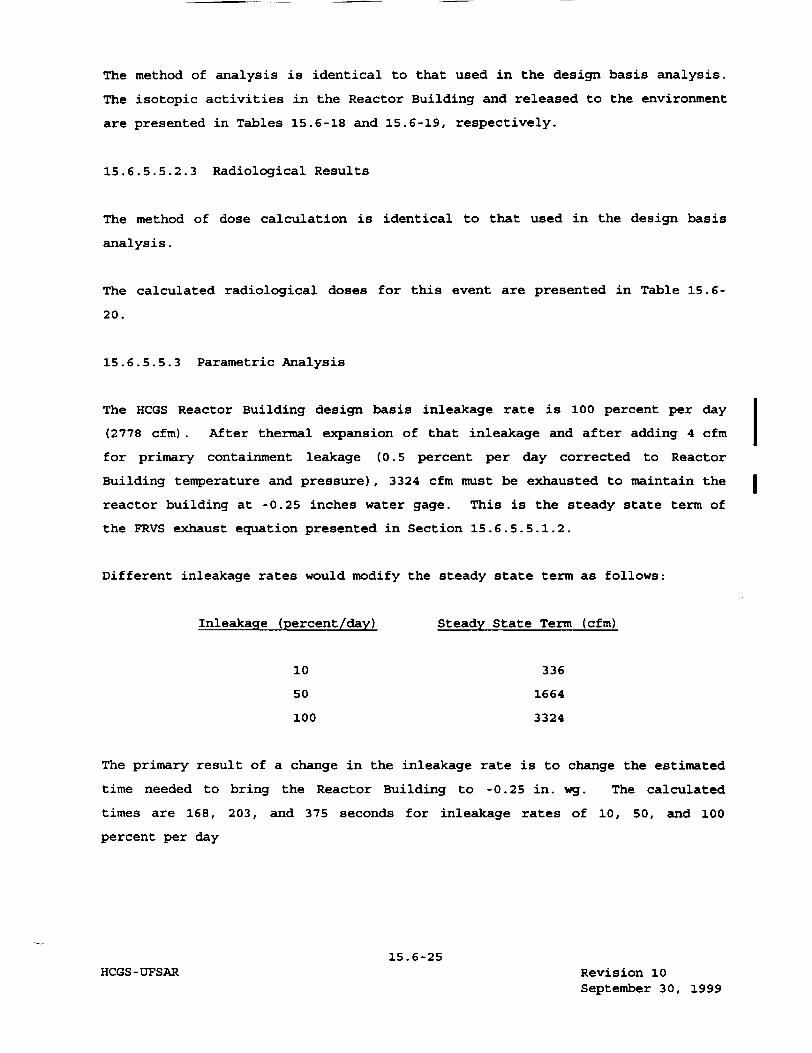
The method of analysis is identical to that used in the design basis analysis.
The isotopic activities in the Reactor Building and released to the environment
are presented in Tables 15.6-18 and 15.6-19, respectively.
15.6.5.5.2.3 Radiological Results
The method of dose calculation is identical to that used in the design basis
analysis.
The calculated radiological doses for this event are presented in Table 15.6
20.
15.6.5.5.3 Parametric Analysis
The HCGS Reactor Building design basis inleakage rate is 100 percent per day
(2778 cfm). After thermal expansion of that inleakage and after adding 4 cfm
for primary containment leakage (0.5 percent per day corrected to Reactor
Building temperature and pressure), 3324 cfm must be exhausted to maintain the
reactor building at -0.25 inches water gage. This is the steady state term of
the FRVS exhaust equation presented in Section 15.6.5.5.1.2.
Different inleakage rates would modify the steady state term as follows:
Inleakage (percent/day)
10
50
100
Steady State Term (cfm)
336
1664
3324
The primary result of a change in the inleakage rate is to change the estimated
time needed to bring the Reactor Building to -0.25 in. wg. The calculated
times are 168, 203, and 375 seconds for inleakage rates of 10, 50, and 100
percent per day
15.6-25Revision 10 September 30, 1999
I I
HCGS-UFSAR
respectively. (For analysis purposes 175, 225, and 400 seconds are used
respectively.) Figure 15.6-4 through 15.6-7 present calculated doses at the
site boundary (SB) and low population zone (LPZ) versus drawdown time. Figure
15.6-8 presents a graph of drawdown time versus inleakage rate. Finally,
Figures 15.6-9 through 15.6-12 present calculated doses at the SB and LPZ
versus inleakage rates.
15.6.6 Feedwater Line Break - Outside Primary Containment
The feedwater line break outside primary containment accident is considered a
non-Limiting event. Therefore it is not required to be re-analyzed as a part of the ABB reload licensing analysis for Hope Creek, unless the disposition for
this event changes (Reference 15.6-5).
To evaluate pipe breaks in a large liquid process line outside primary
containment, the failure of a feedwater line is assumed. The postulated break
of the feedwater line, representing the largest liquid line outside the primary
containment, provides the design basis for this event. The break is assumed to
be instantaneous, circumferential, and external to the outermost isolation
valve.
A more limiting event from a core performance evaluation standpoint (feedwater
line break inside containment) has been quantitatively analyzed in Section 6.3.
Therefore, the following discussion provides new information not presented in
Section 6.3.
15.6.6.1 Identification of Causes and Frequency Classification
15.6.6.1.1 Identification of Causes
A feedwater line break is assumed without the cause being identified. The
subject piping is designed to applicable engineering codes and standards, and
to appropriate seismic and environmental requirements.
15.6.6.1.2 Frequency Classification
This event is categorized as a limiting fault.
15.6-26 HCGS-UFSAR Revision 11
November 24, 2000

15.6.6.2 Seauence of Events and Systems Ooeration
15.6.6.2.1 Sequence of Events
The sequence of events is shown in Table 15.6-21.
15.6.6.2.1.1 Identification of Operator Actions
Since automatic actuation and operation of the Emergency Core Cooling System
(ECCS) is a system design basis, no operator actions are required to mitigate
this accident. However, in accordance with procedural requirements, the
operator will perform the actions listed below:
1. The operator will determine that a line break has occurred and will
implement emergency instructions.
2. The operator will ensure that the reactor is shut down and that the
Reactor Core Isolation Cooling (RCIC) System and/or the High
Pressure Core Injection (HPCI) System are operating normally.
3. The operator will shut down the feedwater system and deenergize any
electrical equipment damaged by water from the feedwater system in
the Turbine Building.
4. The operation will begin normal reactor cooldown measures.
5. When the reactor pressure has decreased below 100 psig, the
operator will initiate the Residual Heat Removal (RHR) System in
the shutdown cooling mode to continue cooling down the reactor.
15.6-27HCGS-UFSAR Revision 0
April 11, 1988
15.6.6.2.2 Systems Operations
It is assumed that the plant instruments and controls are functional. Credit
is taken for vessel isolation and actuation of the ECCS.
15.6.6.2.3 The Effect of Single Failures and Operator Errors
The feedwater line outside the containment is a special case of the LOCA break
spectrum considered in detail in Section 6.3. The general single failure
analysis is discussed in detail in Section 6.3.3.3. Since the feedwater line
break outside the primary containment can be isolated, either the RCIC system
or the HPCI system can provide adequate flow to the vessel to maintain core
cooling and prevent fuel rod cladding failure. A single failure in either the
HPCI system or the RCIC system would not prevent sufficient flow to keep the
core covered with water. See Section 6.3 and Section 15.9 for detailed
description of the analysis.
15.6.6.3 Core and System Performance
15.6.6.3.1 Results
The feedwater line break outside the containment is less limiting than either
the steam line break outside the containment, the analysis of which is
presented in Sections 6.3.3 and 15.6.4, or the feedwater line break inside the
containment, the analysis of which is presented in Sections 6.3.3 and 15.6.5.
It is less limiting than the analyses presented in Sections 6.3.3 and 15.6.5.
For reload applications, sensitivity studies have demonstrated that there are
no significant changes to the core thermal hydraulic conditions due to the
introduction of new reload core condition or fuel design. Therefore, this
event is not evaluated as a part of the standard ABB reload licensing analysis
process.
The reactor vessel is isolated on low-low-low (Li) water level. The RCIC
system and the HPCI system restore the reactor water level to the normal
elevation. The fuel is covered throughout the transient, and there are no
pressure or temperature transients sufficient to cause fuel damage.
15.6-28 HCGS-UFSAR Revision 11
November 24, 2000
15.7 RADIOACTIVE RELEASE FROM SUBSYSTEMS AND COMPONENTS
15.7.1 Gaseous Radwaste Subsystem Leak or Failure
SRP 15.7.1, Waste Gas System Failure, has been deleted. However, Branch
Technical Position (BTP) ETSB 11-5, which is an attachment to SRP Section 11.3
(Gaseous Waste Management Systems), addresses the requirements for a postulated
waste gas system failure.
For this class of accidents, the release of radioactive gases is limited by the
design requirements for the systems, as specified in Section 11.3 and
Regulatory Guide 1.143, and by the radiological effluent technical
specifications (RETS) limits.
The systems and components addressed in this postulated accident are not
impacted by cycle-to-cycle changes in the reactor core. Therefore, this event
is not re-evaluated as a part of the standard ABB reload licensing analysis
process. (Reference 15.7-6)
15.7.1.1 Identification of Causes
An evaluation of events that could cause a gaseous radwaste system leak or
failure indicates that a hydrogen explosion within the process boundary or a
seismic event more serious than the system is designed to withstand could cause
a gaseous radwaste system leak. These are events that could cause a gross
system failure, such as a rupture of a tank or rupture of a line. Operator
errors or system malfunctions resulting in a slower uncontrolled release of
activity within the system are also feasible but are bounded by the
consequences of the assumed gross system failure.
15.7.1.2 Frequency Classification
This event is categorized as a limiting fault.
15.7.1.3 Sequence of Events
The sequence of events following this failure is shown in Table 15.7-1.
15.7-1 HCGS-UFSAR Revision 11
November 24, 2000
15.7.1.4 Identification of Operator Actions
A failure of an active component of the gaseous radwaste treatment system is
assumed to occur. This event results in the activity normally processed by the
waste gas system being released to the Turbine or Auxiliary Building, and
subsequently, released through the ventilation system to the environment. For
this event, the release is assumed to be to the Turbine Building.
The operator initiates a normal shutdown of the reactor to reduce gaseous
activity being discharged and to isolate the waste gas system component. The
operator initiates evacuation of the area, as needed. Radiation protection
personnel will survey the evacuated area prior to reentry.
15.7.1.5 System Operation
In the gaseous radwaste leak or failure analysis, no credit is taken for the
operation of plant and Reactor Protection Systems (RPSs), or of the engineered
safety features (ESFs). Credit is, however, taken for the functioning of
normally operating plant instruments and controls, i.e., gaseous release points
to the atmosphere are monitored.
15.7.1.6 Effect of Single Failures and Operator Errors
After the initial system gross failure, the inability of the operator to
isolate a system can affect the analysis. However, the seismic event that is
assumed to occur beyond the present plant design basis for non-safety equipment
causes a turbine trip that leads to a load rejection. This initiates a scram
and negates a need for the operator to initiate a reactor shutdown via system
isolation.
15.7-2 HCGS-UFSAR Revision 0
April 11, 1988
15.7.1.7 Core and System Performance
The system failure does not directly affect the reactor core or the Nuclear
Steam Supply System (NSSS) safety performance.
15.7.1.8 Barrier Performance
The release of radioactive gases occurs outside the primary containment.
Therefore, it does not involve any barrier integrity aspects.
15.7.1.9 Radiological Consequences
The instructions provided in BTP ETSB 11-5 were followed in this section.
Specifically, the BWR-GALE code uses inputs specified in Table 11.2-1, except
3 that the Krypton and Xenon dynamic adsorption coefficients used are 0.1193 cm
/g rather than their normal valves of 18.5 and 330.0, respectively. This
results in Kryption and Xenon holdup times of 0.02 days, as specified in
ETSB 11-5. The results from the GALE code are then used in manual
calculations, as specified in ETSB 11-5. The X/Q value used is the 0-2 hour
design basis site boundary value (1.9E-4 s/m3 ). The releases to the
environment are presented in Table 15.7-2. The result of the dose calculations
is presented in Table 15.7-3.
15.7.2 Liquid Radwaste System Failure (Release to Atmosphere)
An analysis to show that the atmospheric release of activity from liquid
radwaste tanks complies with 10CFR100 limits is no longer required.
15.7.3 Postulated Radioactive Releases Due to Liquid Radwaste Tank Failure
A detailed analysis of the effects of a liquid radwaste tank failure is not
required. As indicated in Sections 11.2.1, 11.3.1, and 11.4.1; the liquid,
gaseous, and solid waste management systems are
15.7-3 HCGS-UFSAR Revision 0
April 11, 1988

designed to meet the appropriate requirements of loCFR5o (including General
Design Criterion 60). As indicated in Sections 2.4.1 and 2.4.13, there are no
potable water supplies which can be affected by a liquid release at HCGS.
Therefore, the acceptance criteria of SRP 15.7.3, Rev. 2, July 1981 are
satisfied and no detailed analysis is required.
15.7.4 Fuel Handling Accident
In the ABB reload licensing methodology, the fuel handling accident is reanalyzed for each reload that introduces a new fuel design. This event is not re-analyzed for a specific reload unless a new fuel design is introduced or a modification is made to the fuel handling equipment that can increase the severity of the event. (Reference 15.7-6)
The analysis presented in this section is representative of the original safety analysis of the HCGS. The aforementioned analysis determines if the results presented in this section are conservatively bounding for each fuel design. Appendix 15D presents the results.
15.7.4.1 Identification of Causes
The fuel handling accident is assumed to occur as a consequence of a failure of
the fuel assembly lifting mechanism, resulting in the dropping of a raised fuel
assembly onto other fuel assemblies. A variety of events which qualify for the
class of accidents termed "fuel handling accidents" has been investigated. The
accident that produces the largest number of ruptured spent fuel rods is the
drop of a spent fuel assembly into the reactor core when the reactor vessel
head is off.
15.7.4.2 Frequency Classification
This event is categorized as a limiting fault.
15.7.4.3 Sequence of Events
The most severe fuel handling accident from a radiological viewpoint is the
dropping of a fuel assembly onto the top of the core. The sequence of events
is given in Table 15.7-4.
15.7.4.4 Identification of Operator Actions
In the event of a fuel handling accident, the operator verifies that the
Reactor Building doors are closed and that the Filtration, Recirculation, and
Ventilation System (FRVS) is operational.
15.7-4 HCGS-UFSAR Revision 11
November 24, 2000
The activity released to the environment is presented in Table 15.7-11.
15.7.4.9.2.3 Radiological Results
The doses are calculated using the method described in the design basis
analysis. The calculated doses for the realistic analysis are presented in
Table 15.7-12.
15.7.5 Spent Fuel Cask Drop Accident
The spent fuel cask is equipped with redundant sets of lifting lugs and yokes
compatible with the single failure proof Reactor Building crane thus preventing
a cask drop due to a single failure. Therefore, the analysis of the spent fuel
cask drop is not performed. Refer to Section 9.1.4.2.2 for a description of
the Reactor Building crane and the interlocks that prevent moving the spent
fuel cask over the fuel pool.
15.7.6 References
15.7-1 P. P. Stancavage and E. J. Morgan, "Conservative Radiological
Accident Evaluation - The CONACO 1 Code, NEDO-21143, March 1976."
15.7-2 D. Nguyen, "Realistic Accident Analysis for General Electric
Boiling Water Reactor - The RELAC Code and User's Guide," NEDO
21142, to be issued.
15.7-3 N. R. Horton, W. A. Williams, J. W. Holtzclaw, "Analytical Methods
for Evaluating the Radiological Aspects of the General Electric
Boiling Water Reactor, APED 5756, March 1969."
15.7-4 General Electric, "General Electric BWR Thermal Analysis Basis
(GETAB); Data, Correlation, and Design Application," NEDO-10958 and
NEDE-10958, November 1973.
15.7-13 HCGS-UFSAR Revision 0
April 11, 1988
15.7-5
15.7-6
HCGS -UFSAR
U.S. Nuclear Regulatory Commission, "Branch Technical Position
ETSB 11-5," Rev. 0, Postulated Radioactive Releases Due to a Waste
Gas System Leak or Failure (NUREG-0800, Revision 2), July 1981.
Nuclear Fuel Section Design Input File, "Application of the
Generic ABB Reload methodology to Hope Creek Generating Station,"
HCA. 5-0026.
15.7-14 Revision 11 November 24, 2000
15.8 ANTICIPATED TRANSIENTS WITHOUT SCRAM
An ATWS evaluation is performed for each plant modification that has the
potential to challenge the ATWS event acceptance criteria. The ABB methodology
for plant modification consisting of the introduction of an ABB fuel design is
described below.
Each new ABB fuel design introduced is confirmed to comply with the design
characteristics of the core assumed in the licensing basis ATWS analysis. ABB
fuel designs are generally demonstrated to be less limiting than fuel designs
assumed in the plant licensing basis ATWS analysis. (Reference 15.8-2 and
15.8-3)
The following is a generic description of how the Hope Creek Generating Station
complies with the ATWS rules.
15.8.1 Requirements
The issue of postulated failure to scram the reactor following an anticipated
transient, i.e., an anticipated transient without scram (ATWS), has been under
consideration by the NRC. As a result of its assessment, the NRC has required
the recirculation pump trip (RPT) feature for the boiling water reactor (BWR).
It should be noted that the NRC has determined that the probability of an ATWS
event is acceptably small, and that any additional plant modifications for ATWS
need not satisfy the requirements for a design basis accident.
The HCGS emergency operating procedures will be developed from the BWR Owners'
Group Generic Emergency Procedure Guidelines. ATWS events are covered in these
guidelines. The Hope Creek Generating Station Emergency Operating Procedure,
OP-EO.ZZ-101, Reactor Control, contains the necessary actions to be taken
during an ATWS event. Training programs for reactor operators, senior reactor
operators, and shift technical advisers will incorporate the bases and
philosophy of the GE/BWR Owners' Group generic emergency operating procedures
until such time as the HCGS emergency operating procedures are developed.
15.8-1 HCGS-UFSAR Revision 11
November 24, 2000
15.8.2 Plant Capabilities
The Hope Creek Generating Station (HCGS) design uses diverse, highly redundant,
and very reliable scram systems. This includes the normal scram systems, plus
the electrically diverse Alternate Rod Insertion (ARI) System. Each of these
systems is frequently tested and would insert the control rods even if multiple
component failures should occur, thus making the probability of an anticipated
transient without scram (ATWS) event extremely remote.
The ATWS recirculation pump trip (RPT) feature prevents reactor vessel
overpressure and possible short term fuel damage for the most limiting
postulated ATWS event. Subsequent to an ATWS event for which the ARI system
does not insert the control rods, the long term shutdown of the reactor can be
accomplished by either manual insertion of the control rods, or simultaneous
two pump injection of sodium pentaborate solution into the vessel.
PSE&G has voluntarily committed to incorporate in the Hope Creek plant the
features described in Section 15.8.3, in order to bound possible future NRC
requirements for ATWS. Both PSE&G and GE view these added features as
providing acceptable resolution to the ATWS issue.
15.8.3 Equipment Description
This section describes the equipment and control logic added or modified
exclusively for ATWS prevention or mitigation. The description covers design
and functional requirements and references that contain more detailed
information.
15.8.3.1 Redundant Reactivity Control System
The Redundant Reactivity Control System (RRCS) determines that a transient is
underway that exceeds expected operating parameters. After deciding that ATWS
mitigation is the appropriate action, the RRCS activates ATWS prevention
equipment. The RRCS uses transient detection sensors for high vessel dome
pressure and low vessel water level, and the actuation logic to initiate ARI,
RPT, the Standby Liquid Control (SLC) System, and feedwater runback.
The RRCS consists of two completely redundant divisions. Each division is
initiated automatically by the ATWS detection sensors, which are independent of
the Reactor Protection System (RPS)
15.8-2 HCGS-UFSAR Revision 11
November 24, 2000
APPENDIX 15B
SPECIAL ANALYSIS
15B.1 INTRODUCTION
An analysis of the transient caused by continuous control rod withdrawal in the
startup range (Section 15.4.1.2) was performed to demonstrate that the
licensing-basis criterion for fuel failure will not be exceeded when an out of
sequence control rod is withdrawn at the maximum allowable normal drive speed.
The sequence and timing assumed in this special analysis is shown in Table 15B
1.
The rod worth minimizer (RWM) constraints on rod sequence will prevent the
continuous withdrawal of an out of sequence rod. This analysis was performed
to demonstrate that, even for the unlikely event where the RWM fails to block
the continuous withdrawal of an out of sequence rod, the licensing basis
criterion for fuel failure is still satisfied.
The methods and design basis used for performing the detailed analysis for this
event are similar to those previously approved for the control rod drop
accident (CRDA) (References 15B-1, 15B-2, and 15B-3). Additional, simplified
point model kinetics calculations were performed to evaluate the dependence of
peak fuel enthalpy on the control blade worth.
Evaluation of this event for ABB fuel is based on the ABB Control Rod Drop
Accident Methodology in Reference 15B-5.
The licensing basis criterion for fuel failure is that the contained energy of
a fuel pellet located in the peak power region of the core shall not exceed 170
cal/g-UO2 •
15B-1HCGS-UFSAR Revision 11
November 24, 2000
15B.2 METHODS OF ANALYSIS - GENERAL ELECTRIC FUEL
Since the rod worth calculations using the approved design-basis methods
(References 15B-1, 15B-2, and 15B-3) use three dimensional geometry, it is not
practical to do a detailed analysis of this event by parameterizing control rod
worths. Therefore, the methods of analysis employed were to perform a detailed
evaluation of this event for a typical BWR and control rod worth
(1.6 percent AK) and to use a point model kinetics calculation to evaluate the
results over the expected ranges of out of sequence control rod worths. The
detailed calculations are performed to demonstrate 1) the consequences of this
event over the expected power operating range and 2) the validity of the
approximate point-model kinetics calculation. The point model kinetics
calculation demonstrates that the licensing criterion for fuel failure is
easily satisfied over the range of expected out of sequence control rod worths.
These methods are described in
more detail below.
The methods used to perform the detailed calculation are identical to those
used to perform the design basis CRDA with the following exceptions:
1. The rod withdrawal rate is 3.6 ips (0.3 fps) rather than the blade
drop velocity of 3.11 fps. Although faster withdrawal rates are
possible, it would require the failure of the associated control
rod drive mechanism or hydraulic control unit (as described in
Section 4.6.2) in addition to the assumed failure of the RWM. If
the associated control rod drive mechanism or hydraulic control
unit were assumed to be the worst single failure, then the RWM
would terminate the event prior to the full rod withdrawal, or even
prior to control rod movement.
2. Scram is initiated either by the intermediate range monitor (IRM)
or by a 15 percent power scram initiated by the average power range
monitor (APRM) in the startup range. The IRM system is assumed to
be in the worst bypass condition allowed by technical
specifications.
3. The blade being withdrawn is inserted along with remaining drives
at technical specification insertion rates upon initiation of the
scram signal.
15B-2 HCGS-UFSAR Revision 11
November 24, 2000
Examination of a number of rod withdrawal transients in the low power startup
range using a two-dimensional R/Z model has shown clearly that a higher fuel
enthalpy addition would result from transients starting at the 1 percent power
level rather than from lower power levels. The analysis further shows that for
continuous rod withdrawal from these initial power levels (I percent range),
the APRM 15 percent power-level scram is likely to be reached as soon as the
degraded (worst bypass condition) IRM scram. Consequently, credit is taken for
either the IRM or APRM 15 percent power scram in meeting the consequences of
this event. The transients for this response were initiated at 1 percent of
power and were performed using the APRM 15 percent power scram.
An initial point kinetics calculation was run to determined the time required
to scram based on an APRM scram setpoint of 15 percent power and an initial
power level of 1 percent. From this time and the maximum allowable rod
withdrawal speed, itis possible to show the degree of rod withdrawal before
reinsertion due to the scram. From this information, Figure 15B-1, showing the
modified effective reactivity shape, was constructed.
The point model kinetics calculations use the same equations employed in the
adiabatic approximation described on Page 4-1 of Reference 15B-1. The rod
reactivity characteristics and scram reactivity functions are input identically
to the adiabatic calculations, and the Doppler reactivity is input as a
function of core average fuel enthalpy. The Doppler reactivity feedback
function used in the point model kinetics calculations was derived from the
detailed analysis of the 1.6 percent rod worth case described above. This is a
conservative assumption for higher rod worths since the power peaking and hence
spatial Doppler feedback will be larger for higher rod worths. As will be seen
in the results section, maximum enthalpies resulted from cases initiated at
1 percent of rated power. In this power range, the APRM will initiate scram at
15 percent of power; hence, the APRM 15 percent power scram was used for these
calculations thereby eliminating the
15B-3 HCGS-UFSAR Revision 0
April 11, 1988
need to perform the spatial analysis required for the IRM scram. All other inputs are consistent with the detailed transient calculation.
The point model kinetics calculations result in core-average enthalpies. peak enthalpies were calculated using the following equation:
The
h = h + (P/A) (h - h), o T f o
where:
h
h 0
h f
(P/A) =
T
= final peak fuel enthalpy,
initial fuel enthalpy,
final core average fuel enthalpy, and
total peaking factor (radial peaking) x
(axial peaking) x (local fuel pin peaking)q.
For these calculations, the radial and axial peaking factors were obtained as a function of rod worth from the calculations performed in Section 3.6 of Reference 15B-2 and are shown in Figure 15B-2. It was conservatively assumed that no power flattening due to Doppler feedback occurred during the course of the transient.
15B.3 RESULTS - GENERAL ELECTRIC FUEL
The reactivity insertion resulting from moving the control rod is shown in Figure 15B-1 for the point model kinetics calculations. The core-average power versus time and the global peaking factors from Section 3.6 of Reference 15B-2 are shown in Figures 15B-3 and 15B-2, respectively. The results of the point model kinetics calculation are summarized in Table 15B-2 along with the results
of the detailed analysis.
15B-4 HCGS-UFSAR Revision 11
November 24, 2000I
From Figure 15B-3 and Table 15B-2, it is shown that the core average energy
deposition is insensitive to control rod worth; therefore, the only change in
peak enthalpy as a function of rod worth will result from differences in the
global peaking, which increases with rod worth. Comparison of the global
peaking factors shown in Figure 15B-2 with the values used in the detailed
calculation demonstrates that the Reference 15B-2 values are reasonable for
their application in this study. For all cases, the peak fuel enthalpy is well
below the licensing basis criterion of 170 cal/g.
Cases 4 and 5 of Table 15B-2 show that the point model kinetics calculations
give conservative results relative to the detailed evaluations. The primary
difference is that the global peaking will flatten during the transient due to
Doppler feedback. This is accounted for in the detailed calculation, but the
point model kinetics calculations conservatively assumed that the peaking
remains constant at its initial value.
The differences in core-average and peak enthalpy between cases 1 and 5 are due
to the fact that for case 1 the scram was initiated by the APRM 15 percent
power scram setpoint; whereas, in case 5 the scram was initiated by the IRMs.
As can be seen by Figure 15B-4, this would occur at a core average power of
21 percent. Since the APRM trip point will be reached first, it is reasonable
to take credit for the APRM scram.
15B.4 EVALUATION FOR ABB FUEL
The control rod drop accident sensitivity studies in Reference 15B-5
demonstrate that the peak fuel enthalpy in an ABB 10xl0 fuel design core for
control rod drop worths up to 1.5 mk will be less than 100 cal/gm for the
implied hydraulic conditions for this event as described in Table 15B-1 and
section 15B.2.
These sensitivity studies assumed a dropped rod velocity of 3.11 fps (greater
than 0.3 fps) and assumed that the scram occurs at 120% of rated power
(ignores the IRM flux scram). The effects of a higher withdrawal speed and a
later scram add substantial conservatism to the event described in section
15B.2.
15B-5 HCGS-UFSAR Revision 11
November 24, 2000
Furthermore, ABB evaluation of peak dropped control rod worths from configurations within the banked position control sequence for core designs containg ABB 10X10 fuel at HCGS and similar reactors yield maximum integrated control rod worths in the range of 0.3 to 0.8 mk. Therefore, integrated control rod worths are expected to be much less than 1.5 mk.
Consequently, it is concluded that substantial margins to the peak fuel enthalpy limit of 170 cal/g are available for continuous withdrawal of a control rod in the startup range for Hope Creek as described in Section 15B.1
and 15B.2 for ABB 10X10 fuel.
15B.5 CONCLUSIONS
The above evaluations of continuous withdrawal of a control rod in the startup range indicate that the peak fuel enthalpies due to the continuous withdrawal of an out of sequence rod in the startup range will be much less than the licensing basis criterion of 170 cal/gm. In light of the conservative nature of these evaluations and the markedly different fuel designs and vendor methodologies, the substantial margins to 170 cal/gm limit support a generic conclusion that the peak fuel enthalpy associated with continuous withdrawal of a control rod in the startup range in the HCGS core will remain below 170
cal/gm.
15B.5 REFERENCES
15B-1 C. J. Paone, et al, "Rod Drop Accident Analysis For Large Boiling Water Reactors", NEDO-10527, March 1972.
15B-2 R. C. Stirn, et al, "Rod Drop Accident Analysis For Large Boiling Water Reactors", NEDO-10527, Supplement 1, July 1972.
15B-3 R. C. Stirn, "Rod Drop Accident Analysis For Large Boiling Water Reactors, Addendum No. 2, Exposed Cores", NEDO-10527, Supplement 2,
January 1973.
15B-4 R. C. Stirn, J. F. Klapproth, "Continuous Rod Withdrawal Transient
in the Startup Range", NEDO-23842, April 1978.
15B-5 ABB Combustion Engineering Nuclear Power, "Control Rod Drop Accident Analysi Methodology for Boiling Water Reactors: Summary
and qualification," ABB Report CENPD-284-P-A (proprietary), July
1996.
15B-6 HCGS-UFSAR Revision 11
November 24, 2000

LIST OF TABLES
TITLE
Input Parameters and Initial Conditions
Sequence of Events for Figure 15.C.3-1,
Feedwater Controller Failure, Maximum
Demand
Sequence of Events for Figure 15.C.3-2,
Generator Load Rejection with Bypass
Failure
Summary of Transient Peak Value and
CPR Results
15.C-iiiHCGS-UFSAR Revision 0
April 11, 1988
NUMBER
15.C. 3-1
15. C. 3-2
PAGE
15.C.3-9
15.C.3-3
15.C.3-4
15.C.3-11
15.C.3-12
15.C.3-13
LIST OF FIGURES
TITLE
Illustration of Single Recirculation
Loop Operation Flows
Feedwater Controller Failure - Maximum
Demand, 75% Power/60% Core Flow
Generator Load Rejection with Bypass
Failure, 75% Power/60% Core Flow
PAGE
15.C.2-5
15.C.3-14,15,
16,17
15.C.3-18,19
20,21
Deleted
15.C-ivHCGS-UFSAR Revision 11
November 24, 2000
NUMBER
15.C.2-1
15.C.3-1
15.C.3.2
I 15.C. 5-1
15.C RECIRCULATION SYSTEMS SINGLE-LOOP OPERATION
15. C. 1 INTRODUCTION AND SUMMARY
Single-loop operation (SLO) at reduced power is highly desirable in the event
recirculation pump or other component maintenance renders one loop inoperative.
To justify single-loop operation, accidents and abnormal operational transients
associated with power operations, as presented in Sections 6.2 and 6.3 and the
main text of Chapter 15.0, were reviewed for the single-loop case with only one
pump in operation. This appendix presents the results of the safety evaluation
for the operation of the Hope Creek Generating Station (HCGS) with single
recirculation loop inoperable. This safety evaluation was performed for GE and
ABB fuel in Hope Creek. The analysis shows that the transient consequences for
SLO (ACPR) are bounded by the full power analysis results given in the FSAR.
The conclusion drawn from the transient analysis results presented in this
report is applicable to reload cycle operation.
Increased uncertainties in the core total flow and Traversing In-Core Probe
(TIP) readings result in an incremental increase in the Minimum Critical Power
Ratio (MCPR) fuel-cladding integrity safety limit during single-loop operation.
No increase in rated MCPR operating limit and no change in the power or flow
dependent MCPR limit is required because all abnormal operational transients
analyzed for single-loop operation indicated that there is more than enough
MCPR margin to compensate for this increase in MCPR safety limit. The
recirculation flow rate dependent rod block and scram setpoint equation given
in Chapter 16 (Technical Specifications) are adjusted for one-pump operation.
15.C.I-I
HCGS - UFSAR Revision 11 November 24, 2000
Thermal-hydraulic stability was evaluated for its adequacy with respect to
General Design Criteria 12 (10CFR50, Appendix A). It is shown that this
stability criterion is satisfied during SLO. It is further shown that the
increase in neutron noise observed during SLO is independent of system
stability margin.
To prevent potential control oscillations from occurring In the recirculation
flow control system, the operation mode of the recirculation flow control
system must be restricted to operation in the manual control mode for single
loop operation.
The Maximum Average Planar Linear Heat Generation Rate (MAPLMGR) for single
loop operation is reduced to accommodate the impact of SLO on the LOCA
analysis.
The impact of single-loop operation on the FSAR specifications for containment
response including the containment dynamic loads was evaluated. It was
confirmed that the containment response under SLO is within the present design
values.
The impact of single-loop operation on the Anticipated Transient Without Scram
(ATWS) analysis was evaluated. It is found that all ATWS acceptance criteria
are met during SLO.
The fuel thermal and mechanical duty for transient events occurring during SLO
is found to be bounded by the fuel design bases. The Average Power Range
Monitor (APRM) fluctuation should not exceed a flux amplitude of ±15% of rated
and the core plate-differential pressure fluctuation should not exceed 3.2 psi
peak to peak to be consistent with the fuel rod and assembly design bases.
A recirculation pump drive flow limit is imposed for SLO. The highest drive
flow that meets acceptable vessel internal vibration criteria is the drive
flow limit for SLO. The pump speed at Hope Creek Generating Station should be
limited to 90% of rated under single-loop operating conditions.
15.C.1-2 HCGS-UFSAR Revision 11
November 24, 2000
15.C.2 MCPR FUEL CLADDING INTEGRITY SAFETY LIMIT
Except for core total flow and TIP reading, the uncertainties used in the
statistical analysis to determine the MCPR fuel cladding integrity safety limit
are not dependent on whether coolant flow is provided by one or two
recirculation pumps. A 6% core flow measurement uncertainty has been
established for single-loop operation (compared to 2.5% for two-loop
operation). At shown below, this value conservatively reflects the one standard
deviation (one sigma) accuracy of the core flow measurement system documented
in Reference 15.C.8-1.
The random noise component of the TIP reading uncertainty was revised for
single recirculation loop operation to reflect the operating plant test results
given in Subsection 15.C.2.2. This revision resulted in a single-loop operation
process computer effective TIP uncertainty of 6.8% of initial cores and 9.1%
for reload cores. Comparable two-loop process computer uncertainty values are
6.3% for initial cores and 8.7% for reload cores. This represents a 4.6%
increase in process computer determination relative assembly power.
The net effect of these two revised uncertainties is an incremental increase in
the required MCPR fuel cladding integrity safety limit.
15.C.2.1 Core Flow Uncertainty
15.C.2.1.1 Core Flow Measurement During Single-Loop Operation
The jet pump core flow measurement system is calibrated to measure core flow
when both sets of jet pumps are in forward flow; total core flow is the sum of
the indicated loop flows. For single-loop operation, however, some inactive jet
pumps will be backflowing (at active pump speeds above approximately 40%).
Therefore, the measured flow in the backflowing jet pumps must be subtracted
from the measured flow in the active loop to obtain the total core flow. In
addition, the jet pump coefficient is different for reverse flow than for
forward flow, and the measurement of reverse flow must be modified to account
for this difference.
15.C.2-1 HCGS-UFSAR Revision 11
November 24, 2000
In single-loop operation, the total core flow is derived by the following
formula:
Total Corej Active Loop 1 F Inactive Loop 1
Flow Indicated Flowj Indicated FlowJ
The coefficient C (=0.95) is defined as the ratio of "Inactive Loop True
Flow" to "Inactive Loop Indicated Flow". "Loop Indicated Flow" is the flow
measured by the jet pump "single-tap" loop flow summers and indicators, which
are set to read forward flow correctly.
The 0.95 factor was the result of a conservative analysis to appropri-ately
modify the single-tap flow coefficient for reverse flow. * If a more exact,
less conservative, core flow is required, special in-reactor cali-bration tests
can be made. Such calibration tests would involve: calibrating core support
plate AP versus core flow during one-pump and two-pump operation along with
100% flow control line and calculating the correct value of C based on the core
support plate AP and the loop flow indicator readings.
15.C.2.1.2 Core Flow Uncertainty Analysis
The uncertainty analysis procedure used to establish the core flow uncertainty
for one-pump operation is essentially the same as for two-pump operation with
some exceptions. The core flow uncertainty analysis is described in Reference
15.C.8-1. The analysis of one-pump core flow uncer-tainty is summarized below.
*The analytical expected value of the "C" coefficient for HCGS is 0.84.
15.C.2-2 HCGS-UFSAR Revision 0
April 11, 1988
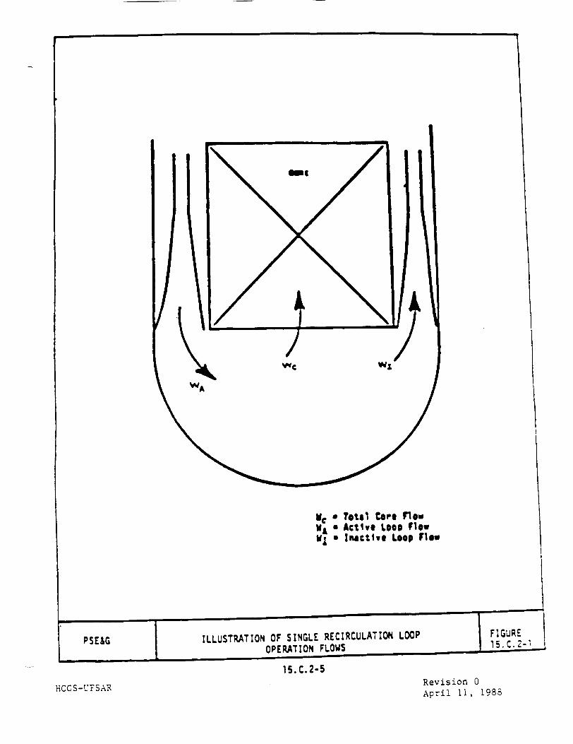
Me a Total core flow VA a Active LOOP Flov M a Inactive Loop f.lo
ILLUSTRATION OF SINGLE RECIRCULATION LOOP OPERATION FLOWS
15. C.2-5
HCGS-UFSARRevision 0 April 11, 1988

15.C.3 MCPR OPERATING LIMIT
15.C.3.1 Abnormal Operational Transients
Operating with one recirculation loop results in a maximum power output which is about 30% below that which is attainable for two-pump operation. Therefore,
the consequences of abnormal operational transients from one-loop operation will be considerably less severe than those analyzed for two-loop operation.
For pressurization, flow increase, flow decrease, and cold water injection
transients, the results presented in Chapter 15 bound both the thermal and
overpressure consequences of one-loop operation.
The consequences of flow decrease transients are bounded by the full power analysis. A single pump trip from one-loop operation is less severe than a two
pump trip from full power because of the reduced initial power level.
The worst flow increase transient results from a recirculation flow controller failure, and the worst cold water injection transient results from the loss of
j feedwater heating. For the former event, the impact on CPR is derived assuming
both recirculation loop controllers fail. This condition produces the maximum
possible power increase and hence maximum ACPR for transients initiated from less than rated power and flow. During operation with only one recirculation
loop, the flow and power increase associated with this failure with only one loop will be less than that associated with both loops; therefore, the impact on CPR of the worst flow increase event derived with the two-pump assumption is
conservative for single-loop operation.
The latter event, loss of feedwater heating, is generally the most severe cold
water event with respect to increase in core power. This power increase is caused by positive reactivity insertion from increased core inlet subcooling
and it is relatively insensitive to initial power level. A generic statistical
loss of feedwater heater analysis using different
15.C.3-1 HCGS-UFSAR Revision 11
November 24, 2000

initial power levels and other core design parameters concluded one-pump
operation with lower initial power level is conservatively bounded by the full
power two-pump analysis. The conclusions regarding the consequences of the
inadvertent restart of the idle recirculation pump in Chapter 15.4.4 are still
applicable for single-loop operation.
Assessments of the relative impact on the limiting pressurization transients
for single-loop and two-loop conditions show that the consequences for single
loop conditions are bounded by the two-loop results. The following sections
provide examples of these assessments and confirm the generic nature of the
conclusions.
15.C.3.1.l Feedwater Controller Failure - Maximum Demand (Cycle 1)
This event is postulated on the basis of a single failure of a master feedwater
control device, specifically one which can directly cause an increase in
coolant inventory by increasing the total feedwater flow. The most severe
applicable event is a feedwater controller failure during maximum flow demand.
The feedwater controller is assumed to fail to its upper limit at the beginning
of the event.
A feedwater controller failure during maximum flow demand at 75% power and 60%
flow during single recirculation loop operation produces the sequence of events
listed in Table 15.C.3-2. Figure 15.C.3-1 shows the changes in important
variables during this transient.
The computer model described in Reference 15.C.8-2 was used to simulate this
event.
The analysis has been performed with the plant conditions tabulated in
Table 15.C.3-1. with the initial vessel water level at Level 4 (instead of
normal water level) for conservatism. By lowering the initial water level, more
cold feedwater will be injected before Level 8 is reached resulting in higher
heat fluxes.
15.C.3-2
HCGS-UFSAR Revision 11 November 24, 2000

The safety analysis condition is at 75% rated thermal power and 60% rated core flow, which represents single recirculation loop operation at 100% pump speed
on the 105% rod line. End of cycle (all rod out) scram characteristics are
assumed. The safety-relief valve action is conservatively assumed to occur with
higher than nominal setpoints. The transient is simulated by programming an
upper limit failure in the feedwater system such that 159% of rated feedwater
flow occurs at the reactor dome pressure of 973 psig, and 135% of rated
feedwater flow would occur at the design pressure of 1060 psig.
The simulated feedwater controller transient is shown in Figure 15.C.3-1. The
high water level turbine trip and feedwater pump trip are initiated at
approximately 6.1 seconds. Scram occurs simultaneously from stop valve closure,
and limits the neutron flux peek and fuel thermal transient. The turbine bypass system opens to limit peak pressures in the steam supply system. Events caused
by low water level trips, including initiation of HPCS and RCIC core cooling
system functions are not included in the simulation. Should these events occur,
they will follow sometime after the primary effects have occurred, and are
expected to be less severe than those already experienced by the system.
Table 15.C.3-4 gives a summary of the transient analysis results. The
calculated MCPR is 1.17, which is well above the safety limit MCPR of 1.07 so
no fuel failure due to boiling transition is predicted. The peak vessel
pressure predicted is 1121 psig and is will below the ASME limit of 1375 psig.
15.C.3.1.2 Generator Load Rejection with Bypass Failure (Cycle 1)
Fast closure of the turbine control valves (TCV) is initiated wherever
electrical grid disturbances occur which result in significant loss of electrical load on the generator. The turbine control valves are required to
close as rapidly as possible to prevent excessive overspeed of the turbine
generator (T-G) rotor. Closure of the main turbine control valves will increase
system pressure.
15.C.3-3 HCGS-UFSAR Revision 11
November 24, 2000

A loss of generator electrical load with bypass failure at 75% power and 60%
flow during single recirculation loop operation produces the sequence of events
listed in Table 15.C.3-3. Figure 15.C.3-2 shows the changes in important
variables during this transient.
I Generator load rejection causes turbine control valve (TCV) fast closure which
initiates a scram trip signal for power levels greater than 40% NB rated. In
addition, recirculation pump trip is initiated. Both of these trip signals
satisfy single failure criterion and credit is taken for these protection
features.
The pressure relief system which operates the relief valves independently when
system pressure exceeds relief valve instrumentation setpoints is assumed to
function normally during the time period analyzed.
All plant control systems maintain normal operation unless specifically
designated to the contrary.
The computer model described in Reference 15.C.8-2 was used to simulate this
event.
The analysis has been performed with the plant conditions tabulated in
Table 15.C.3-1, except that the turbine bypass function is assumed to fail.
The safety analysis condition is at 75% rated thermal power and 60% rated core
flow, which represents single recirculation loop operation at 100% pump speed
on the 105% rod line.
The turbine electro-hydraulic control system (EMC) power/load unbalance device
detects load rejection before a measurable speed change takes place.
The closure characteristics of the turbine control valves are assumed such that
the valves operate in the full arc (FA) mode and have a full stroke closure
time, from fully open to fully closed, of 0.15 second.
15.C.3-4
HCGS-UFSAR Revision 11 November 24, 2000
Auxiliary Power would normally be independent of any turbine-generator overspeed effects and continuously be supplied at rated frequency as automatic
fast transfer to auxiliary power supplies occurs.
The simulated generator load rejection with bypass failure is shown in Figure
15.C.3-2.
Events caused by low water level trips, including initiation of HPCI and RCIC core cooling system functions are not included in this simulation. If these events occur, they will follow sometime after the primary concerns of fuel margin and overpressure effects have passed, and will result in effects less severe than those already experienced by the reactor system, and will provide long-term reactor inventory control.
Table 15.C.3-4 summarizes the transient analysis results. The peak neutron flux reaches about 120% of rated and average surface heat flux peaks at about 104% of its initial value. The peak vessel pressure predicted is 1162 psig and is well below the ASME limit of 1375 psig. The calculated MCPR is 1.16 which is considerably above the cycle 1 safety limit MCPR of 1.07.
15C.3.1.3 Evaluation for ABB Fuel
The impact of pressurization transients for single-loop operation (SLO) conditions relative to two-loop conditions has also been evaluated for the limiting pressurization events in a mixed 8X8-4 and SVEA-96+ core. These calculations were performed with the ABB licensing analysis methodology in Reference 15.C.8-10. The calculations show that MCPR operating limits established by the limiting two loop transients are conservatively applicable to transients initiated from SLO conditions. This conclusion accommodates the fact that the SVEA-96+ and 8x8-4 SLMCPR for SLO is increased by an increment appropriate to accommodate the increased SLO uncertainties discussed in Section 15.C.2. These results provide further confirmation that MCPR operating limits establishes by the limiting pressurization events based on the two loop evaluations will conservatively protect the fuel during postulated limiting pressurization transients initiated from SLO conditions.
15.C.3-5 HCGS-UFSAR Revision 11
November 24, 2000

Appendix 15D provides more information on the SLO analysis that is performed
during the reload.
15.C.3.1.4 Summary and Conclusions
The discussion in section 15C.3.1.1 through 15.C.3.1.4 illustrate conclusion
that the operating limit MCPRs is established by pressurization transients for
two-pump operation are also applicable to single-loop operation conditions.
For pressurization, Table 15.C.3-4 indicates that the peak pressures are well
below the ASME code value of 1375 psig. Hence, it is concluded that the
pressure barrier integrity is maintained under single-loop operation. I 15.C.3.2 Rod Withdrawal Error
The rod withdrawal error at rated power is given in the FSAR. These analyses
are performed to demonstrate, even if the operator ignores all instrument
indications and the alarm which could occur during the course of the transient,
the rod block system will stop rod withdrawal at a minimum critical power ratio
(MCPR) which is higher than the fuel cladding integrity safety limit.
Modification of the rod block equation (below) and lower power assures the MCPR
safety limit is not violated.
One-pump operation results in backflow through 10 of the 20 jet pumps while the
flow is being supplied into the lower plenum from the 10 active jet pumps.
Because of the backflow through the inactive jet pumps, the present rod block
equation was conservatively modified for use during one-pump operation because
the direct active-loop flow measurement may not indicate actual flow above
about 40% core flow without correction.
A procedure has been established for correcting the rod block equation to
account for the discrepancy between actual flow and indicated flow in the
active loop. This preserves the original relationship between rod block and
actual effective drive flow when operating with a single-loop.
15.C.3-6
HCGS-UFSAR Revision 11 November 24, 2000

The two-pump rod block equation is:
RB = mW + RB 1 0 0 - m(100)
The one-pump equation becomes:
RB = mW + RB1 0 0 - m(100) - mAW
where
AW
RB
m
W
RB1 0 0
difference between two-loop and single-loop effective
drive flow at the same core flow. This value is
expected to be 8% of rated (to be determined by PSE&G).
- power at rod block in %;
- flow reference slope for the rod block monitor (RBM)
- drive flow in % of rated.
top level rod block at 100% flow.
If the rod block setpoint (RB 1 0 0 ) is changed, the equation must be recal
culated using the new value.
The APRM trip settings are flow biased in the same manner as the rod block
monitor trip setting. Therefore, the APRM rod block and scram trip settings are
subject to the same procedural changes as the rod block monitor trip settings
discussed above.
15.C.3-7 HCGS-UFSAR Revision 11
November 24, 2000I
15.C.3.3 Operatincr MCPR Limit
For single-loop operation, the operating, MCPR limit remains unchanged from the
normal two-loop operation limit. Although the increased uncertainties in core
flow and TIP readings resulted in an incremental increase in MCPR fuel cladding
integrity safety limit during single-loop operation (Section 15.C.2), the
results in Section 15.C.3 indicate that there is more than enough MCPR margin
during single-loop operation to compensate for this increase in safety limit.
For single-loop operation at lower flows, the steady-state operating MCPR limit
is established by reduced flow operating MCPRs. This ensures the 99.9%
statistical limit requirement is always satisfied for any postulated abnormal
operational occurrence.
Since the maximum core flow runout during single loop operation is only about
60% of rated, the current reduced flow MCPRs which are generated based on the
flow runout up to rated core flow are also adequate to protect the flow runout
events during single-loop operation.
15.C.3-8HCGS-UFSAR Revision 11
November 24, 2000 I
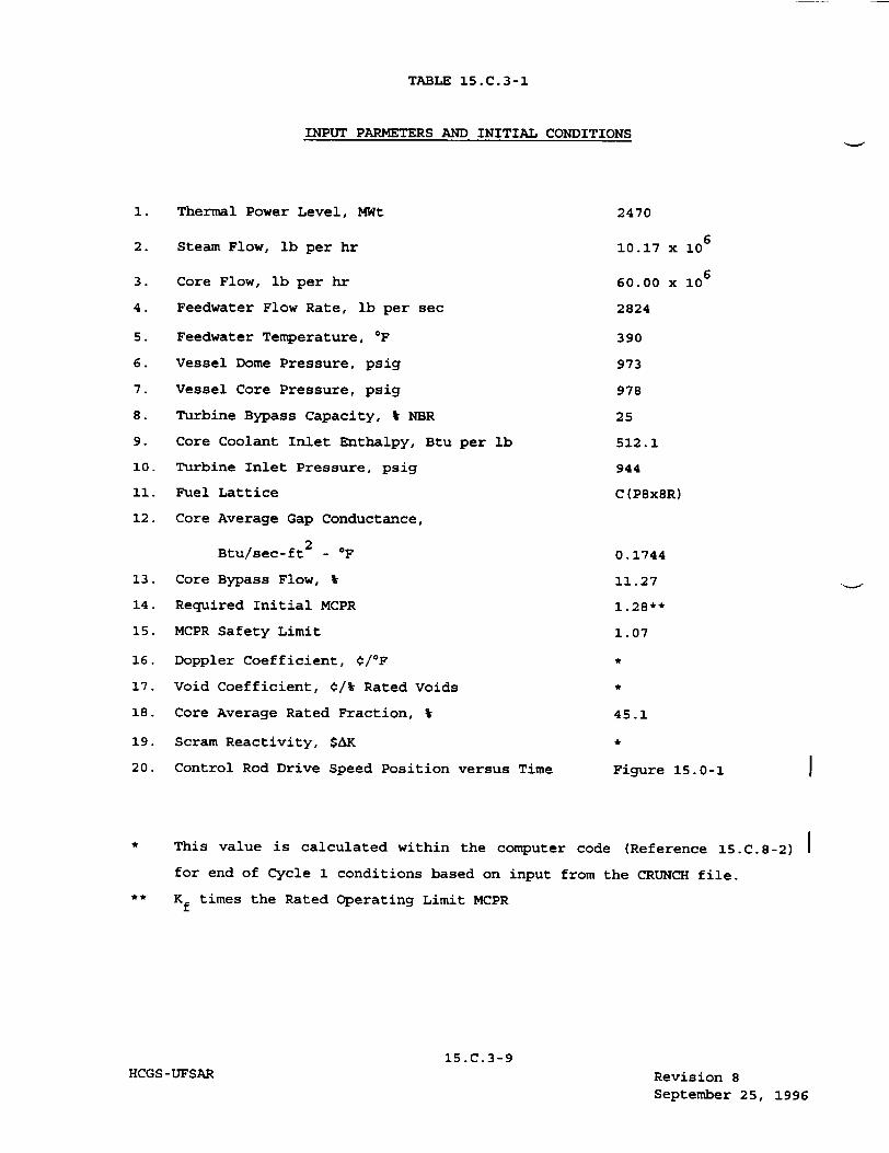
TABLE 15.C.3-1
INPUT PARMETERS AND INITIAL CONDITIONS
1. Thermal Power Level, MWt
2. Steam Flow, lb per hr
3. Core Flow, lb per hr
4. Feedwater Flow Rate, lb per sec
5. Feedwater Temperature, OF
6. Vessel Dome Pressure, psig
7. Vessel Core Pressure, psig
8. Turbine Bypass Capacity, V NBR
9. Core Coolant Inlet Enthalpy, Btu per lb
10. Turbine Inlet Pressure, psig
11. Fuel Lattice
12. Core Average Gap Conductance,
Btu/sec-ft -_F
13. Core Bypass Flow, W
14. Required Initial MCPR
15. MCPR Safety Limit
16. Doppler Coefficient, ¢/ 0 F
17. Void Coefficient, €/t Rated Voids
18. Core Average Rated Fraction, t
19. Scram Reactivity, $AK
20. Control Rod Drive Speed Position versus Time
2470
10.17 x 10⁶
60.00 x 10⁶
2824
390
973
978
25
512.1
944
C (P8x8R)
0.1744
11.27
1.28**
1.07
45.1
Figure 15.0-1
This value is calculated within the computer code (Reference 15.C.8-2)
for end of Cycle 1 conditions based on input from the CRUNCH file.
** Kf times the Rated Operating Limit MCPR
15.C.3-9 HCGS-UFSAR Revision 8
September 25, 1996
I
15.C.4 STABILITY ANALYSIS
15.C.4.1 Phenomena
The primary contributing factors to the stability performance with one
recirculation loop not in service are the power/flow ratio and the
recirculation loop characteristics. As forced circulation with only one
recirculation loop in operation, the reactor core stability is influenced by
the inactive recirculation loop. As core flow increases in SLO, the inactive
jet pump forward flow decreases because the driving head across the inactive
jet pumps decreases with increasing core flow. The reduced flow in the inactive
loop reduces the resistance that the recirculation loops impose on reactor core
flow perturbations thereby adding a destabilizing effect. At the same time the
increased core flow results in a lower power/flow ratio which is a stabilizing
effect. These two countering effects result in slightly decreased stability
margin (higher decay ratio) initially as core flow is increased (from minimum)
in SLO and then an increase in stability margin (lower decay ratio) as core
flow is increased further and reverse flow in the inactive loop is established.
As core flow is increased further during SLO and substantial reverse flow
is established in the inactive loop an increase in jet pump flow, core flow and
neutron noise is observed. A cross flow is established in the annular downcomer
region near the jet pump suction entrance caused by the reverse flow of the
inactive recirculation loop. This cross flow interacts with the jet pump
suction flow of the active recirculation loop and in-creases the jet pump flow
noise. This effect increases the total core flow noise which tends to drive the
neutron flux noise.
To determine if the increased noise is being caused by reduced stabil-ity
margin as SLO core flow was increased, an evaluation was performed which
phenomenologically accounts for single-loop operation effects on stability, as
summarized in Reference 15.C.8-3. The model predictions were initially
15.C.4-1 HCGS-UFSAR Revision 0
April 11, 1988
compared with test data and showed very good agreement for both two-loop and
single-loop test conditions. An evaluation was performed to determine the
effect of reverse flow on stability during SLO. With increasing reverse flow,
SLO exhibited slightly lower decay ratios than two-loop operation. However, at
core flow conditions with no reverse flow, SLO was slightly less stable. This
is. consistent with observed behavior in stability tests at operating BWRs
(Reference 15.C.8-4).
In addition to the above analyses, the cross flow established during reverse
flow conditions was simulated analytically and shown to cause an increase in the individual and total jet pump flow noise, which is consis-tent with test
data (Reference IS.C.8-3). The results of these analyses and tests indicate
that the stability characteristics are not significantly different from two
loop operation. At low core flow, SLO may be slightly less stable than two-loop
operation but as core flow is increased and reverse flow is established the stability performance is similar. At higher core flow with substantial reverse
flow in the inactive recirculation loop, the effect of cross flow on the flow
noise results in an increase in system noise (jet pump, core flow and neutron
flux noise).
15.C.4.2 Compliance to Stability Criteria
Compliance with the stability licensing criteria set forth in 10CFR50 Appendix A, General Design Criterion (GDC-12), is achieved by either preventing
stability-related neutron flux oscillations or detecting and suppressing the
oscillations prior to exceeding Specified Acceptable Fuel Design Limits. The BWR Owners' Group (BWROG) has developed long-term solutions, which incorporate
either prevention or detection and suppression features, or a combination of
both features, to ensure compliance with GDC-12. Methodologies have been
developed to support the licensing of these long-term solutions.
The BWROG has also developed guidelines (Reactor Stability Interim Corrective
Actions) for the licensee to use prior to the licensee's successful
implementation of a Long Term Stability Solution. These guidelines expand the
interim corrective actions identified in NRC Bulletin 88-07, Supplement 1.
15.C.4-2 HCGS-UFSAR Revision 11
November 24, 2000

The expanded guidelines primarily accommodate the experience gained from plant
stability events as well as conclusions based on recent analytical studies
supporting the Long Term Stability solution. Based on the communications
between the NRC and the BWROG, these guidelines fully satisfy the Bulletin 88
07, Supplement 1, requirements.
HCGS has implemented Reactor Stability Interim Corrective Actions based on the
BWROG's recommendations to reduce the potential for unacceptable oscillations
associated with the single-loop operation prior to the implementation of the
Long Term Stability Solution.
15.C.4-3HCGS-UFSAR Revision 11
November 24, 2000

15.C.5 LOSS-OF-COOLANT ACCIDENT ANALYSES
If two recirculation loops are operating and a pipe break occurs in one of the
two recirculation loops, the pump in the unbroken loop is assumed to
immediately trip and begin to coast down. The decaying core flow due to the
pump coastdown results in very effective heat transfer (nucleate boiling)
during the initial phase of the blowdown. Typically, nucleate boiling will be
sustained during the first 5 to 9 seconds after the accident, for the design
basis accident (DBA).
If only one recirculation loop is operating, and the break occurs in the
operating loop, continued core flow is provided only by natural circulation
because the vessel is blowing down to the reactor containment through both
sections of the broken loop. The core flow decreases more rapidly than in the
two-loop operating case, and the departure from nucleate boiling for the high
power node might occur 1 or 2 seconds after the postulated accident, resulting
in more severe cladding heatup for the one-loop operating case.
In addition to changing the blowdown heat transfer characteristics, losing recirculation pump coastdown flow can also affect the system inventory and
reflooding phenomena. Of particular interest are the changes in the high-power
node uncovery and reflooding times, the system pressure and the time of rated
core spray for different break sizes. One-loop operation results in small
changes in the high-power node uncovery times and times of rated spray. The
effect of the reflooding times for various break sizes is also generally small.
Analyses single recirculation loop operation using the models and assumptions
documented in References 15.C.8-9 or 15.C.8-10, as appropriate, are performed
for HCGS. Using the appropriate methods, limiting pipe breaks are identified.
The single loop LOCA evaluation results in maximum planar linear heat
generation rate (MAPLHGR) curves specific to single loop operation which assume
that LOCA acceptance criteria in IOCFR50.46 are satisfied.
15.C.5-1 HCGS-UFSAR Revision 11
November 24, 2000
FIGURE 15.C.5-1 HAS BEEN DELETED
*V
15.C. 5-2HCGS-UFSAR Revision 11
November 24, 2000
15.c.6 •CONTArNMENT ANALYSrS
The range of power/flow conditions which are included in the SLO operating domain for Hope Creek were investigated to determine if there would be any impact on the FSAR specifications for containment response, Including the containment dynamic loads. The SLO operating conditions were confirmed to be within the range of operating conditions which have previously been considered in defining the containment pressure and temperature response, and containment dynamic loads for two-loop operation. Therefore, the containment response for Hope Creek with single-loop operation has been confirmed to be within the present design values.
15.C.6-1
HCGS-LrFSARRevision 0 April 11, 1988
k
1 f
MISCELLANEOUS IMPACT EVALUATION
15.C.7.1 Anticipated Transient Without Scram (ATWS) Impact Evaluation
The principal difference between single-loop operation (SLO) and normal
two-loop operation (TLO) affecting Anticipated Transient Without Scram (ATWS)
performance is that of initial reactor conditions. Since the SLO initial power
flow condition is less than the rated condition used for TLO ATWS analysis, the
transient response is less severe and therefore bounded by the TLO analyses.
It is concluded that if an ATWS event were initiated at HCGS from the SLO
conditions, the results would be less severe than if it were initiated from
rated conditions.
15.C.7.2 Fuel Mechanical Performance
Component pressure differential and fuel rod overpower values for
anticipated operational occurrences initiated from SLO conditions have been
found to be bounded by those applied in the fuel rod and assembly design bases.
It is observed that due to the substantial reverse flow established
during SLO both the Average Power Range Monitor (APRM) noise and core plate
differential pressure noise are slightly increased. An analysis has been
carried out to determine that the APRM fluctuation should not exceed a flux
amplitude of ±15% of rated and the core plate differential pressure fluc
tuation should not exceed 3.2 psi peak to peak to be consistent with the fuel
rod and assembly design bases.
15.C.7-1 HCGS-UFSAR Revision 11
November 24, 2000
is. C. 7
15.C.7.3 Vessel Internal Vibration
Vibration tests for SLO were performed during the startup of two BWR 4-251
plants. An extensive vibration test was conducted at a prototype BWR 4-251
plant, Browns Ferry 1, the results of which are used as a standard for
comparison. A confirmatory vibration test was performed at the Peach Bottom 2
& 3 plants.
The Browns Ferry 1 test data demonstrates that all instrumented vessel
internals components vibrations are within the allowable criteria. The highest
measured vibration in terms of percent criteria for single-loop operation was
70%. This was measured at a jet pump riser brace during cold flow conditions at
100% of rated pump speed.
The Peach Bottom vibration test data shows that vessel internals vibration
levels are within the allowable criteria for all test conditions. The highest
measured vibration in terms of percent criteria for single-loop operation was
96%. This was measured at a jet pump elbow location during 68% power condition
at 92% of rated pump speed. This vibration amplitude is the highest, in terms
of percent criteria, experienced in vessel internals for the BWR 4-251 plants
studied.
The conclusion is that under all operating conditions, the vibration level is
acceptable. However, due to the high vibration levels recorded, it is
recommended that Hope Creek not perform single-loop operation with pump speed
exceeding 90% of rated pump speed. The same recommendation has been accepted by
the Browns Ferry and Peach Bottom plants.
This analysis is conservative because the criteria is developed by assuming
that the plant operates on a steady state single loop operations throughout the
plant life.
15-C.7-2 HCGS-UFSAR Revision 0
April 11, 1988
15.C. 8
15.C.8-1
I5.C. 8-2
15.C. 8-3
15.C.8-4
15-C-8-5
15i.C. 8-6
15.C. 8-7
15.C.8-8
HCGS -UFSAR
REFERENCES
"General Electric BWR Thermal Analysis Basis (GETAB); Data,
Correlation, and Design Application", NEDO-10958-A, January 1977.
"Qualification of the One-Dimensional Core Transient Model for
Boiling Water Reactors", NEDO-24154, October 1978.
Letter, H.C. Pfefferlen (GE) to C.O. Thomas (NRC), "Submittal of
Response to Stability Action Item from NRC Concerning Single-Loop
Operation," September 1983.
S.F. Chen and R.O. Niemi, "Vermont Yankee Cycle 8 Stability and
Recirculation Pump Trip Test Report", General Electric Company,
August 1982 (NEDE-25445, Proprietary Information).
G.A. Watford, "Compliance of the General Electric Boiling Water
Reactor Fuel Designs to Stability Licensing Criteria", General
Electric Company, October 1984 (NEDE-22277-P-I, Proprietary
Information).
"General Electric Standard Application for Reload Fuel", General
Electric Company, April 1983 (NEDE-24011-P-A-6).
"BWR Core Thermal Hydraulic Stability". General Electric Company,
February 10, 1984 (Service Information Letter-380, Revision 1).
Letter, C.O. Thomas (NRC) to H.C. Pfefferlen (GE), "Acceptance
for Referencing of Licensing Topical Report NEDE-24011, Rev. 6,
Amendment 8, Thermal Hydraulic Stability Amendment to GESTAR II,"
April 24, 1985.
15.C.8-1
Revision 0 April 11, 1988
REFERENCES (Cont'd)
15.C.8-9
15.C.8-10
15.C.8-11
HCGS-UFSAR
"General Electric Company Analytical Model for Loss-of-Coolant
Analysis in Accordance with 10CFR5O Appendix K Amendment No. 2
One Recirculation Loop Out-of-Service", NEDO-20566-2 Revision 1,
July 1978.
ABB Combustion Engineering Nuclear Power, "Reference Safety
Report for Boiling Water Reactor Reload Fuel," ABB Report
CENPD-300-P-A (proprietary), July 1996.
Latest BWROG recommendations for "interim Stability Solution".
15.C.8-2 Revision 11 November 24, 2000
15.C.8
APPENDIX 15D
CYCLE 10 RELOAD ANALYSIS RESULTS
TABLE OF CONTENTS
15D.1 INTRODUCTION AND PURPOSE
15D .2 RELOAD METHODOLOGY
15D.3 RELOAD ANALYSIS RESULTS
15D.3.1 Loss of Feedwater Heating
15D.3.1.1 Initial Conditions
15D.3.1.2 Sequence of Events
15D.3.1.3 Results
15D.3.2 Feedwater Controller Faili
15D.3.2.1 Initial Conditions
15D.3.2.2 Sequence of Events
15D.3.2.3 Results
15D.3.3 Generator Load Rejection,
15D.3.3.1 Initial Conditions
15D.3.3.2 Sequence of Events
15D.3.3.3 Results
15D.3.4 Turbine Trip, No Bypass
15D.3.5 Rod Withdrawal Error
15D.3.5.1 Initial Conditions
15D.3.5.2 Sequence of Events
15D.3.5.3 Results
15D.3.6 Recirculation Flow Contro:
15D.3.6.1 Initial Conditions
ire - Maximum Demand
No Bypass
L Failure with Increasing Flow
15D-i
HCGS-UFSAR Revision 11 November 24, 2000
15.D-1
15.D-1
15.D-2
15.D-2
15.D-2
15.D-2
15.D-3
15 .D-3
15 .D-3
15 .D-3
15 .D-3
15 .D-3
15.D-3
15.D-4
15.D-4
15 .D-4
15 .D-4
15.D-4
15.D-4
15.D-5
15.D-5
15.D-5
TABLE OF CONTENTS (cont)
15D.3.6.2 Sequence of Events 15.D-5
15D.3.6.3 Results 15.D-5
15D.3.7 Loss of Coolant Accident 15.D-6
15D.3.8 Misplaced Bundle Accident 15.D-6
15D.3.8.1 Mislocated Bundle 15.D-6
15D.3.8.2 Misoriented Bundle 15.D-6
15D.3.9 Control Rod Drop Accident 15.D-6
15D.3.10 Fuel Handling Accident 15.D-7
15D.3.11 Shutdown Without Control Rods 15.D-7
15D.3.12 Core Thermal-Hydraulic Stability 15.D-7
15D.3.13 ASME Over-Pressurization 15.D-8
15D.3.14 Anticipated Transient Without Scram 15.D-8
15D.4 Single Loop Operation 15.D-8
15D.5 References 15.D-8
15D-ii
HCGS-UFSAR Revision 11
November 24, 2000
LIST OF TABLES
Table Title
15D-1 INPUT PARAMETERS AND INITIAL CONDITIONS FOR RELOAD LICENSING
ANALYSIS
15D-2 RESULT SUMMARY FOR LOSS OF FEEDWATER HEATING MANUAL CONTROL
15D-3 SEQUENCE OF EVENTS FOR FEEDWATER CONTROLLER FAILURE MAXIMUM DEMAND
15D-4 SEQUENCE OF EVENTS FOR GENERATOR LOAD REJECTION WITHOUT BYPASS
OPERATION
15D-5 ROD WITHDRAWAL ERROR SUMMARY
15D-6 RESULT SUMMARY FOR RECIRCULATION CONTROL FLOW FAILURE WITH
INCREASING FLOW
15D-7 SEQUENCE OF EVENTS FOR MISPLACED BUNDLE ACCIDENT
15D-8 MISLOCATED FUEL ASSEMBLY RESULTS
15D-9 MISORIENTED FUEL ASSEMBLY RESULTS
15D-iii
HCGS-UFSAR Revision 11
November 24, 2000
LIST OF FIGURES
Figure Title
15D.1 APRM Flux and Core Average Heat Flux (FWCF at 102% Power /
105% Flow)
15D.2 Core Inlet Subcooling and Steam Dome Pressure (FWCF at 102%
Power / 105% Flow)
15D.3 Total Core and Drive Flow (FWCF at 102% Power / 105% Flow)
15D.4 Vessel Steam Flow and Turbine Steam Flow (FWCF at 102% Power /
105% Flow)
15D.5 Feedwater Flow and Water Level (FWCF at 102% Power / 105%
Flow)
15D.6 Recirculation Pump Speed (FWCF at 102% Power / 105% Flow)
15D.7 APRM Flux and Core Average Heat Flux (FWCF at 65% Power / 105%
Flow)
15D.8 Core Inlet Subcooling and Steam Dome Pressure (FWCF at 65%
Power / 105% Flow)
15D.9 Total Core and Drive Flow (FWCF at 65% Power / 105% Flow)
15D.10 Vessel Steam Flow and Turbine Steam Flow (FWCF at 65% Power /
105% Flow)
15D.11 Feedwater Flow and Water Level (FWCF at 65% Power / 105% Flow)
15D.12 Recirculation Pump Speed (FWCF at 65% Power / 105% Flow)
15D-iv
HCGS-UFSAR Revision 11 November 24, 2000

Appendix 15D
Cycle 10 Reload Analysis Results
15D.1 INTRODUCTION AND PURPOSE
During each reload, fresh fuel assemblies are loaded into the core. A change
in fuel design and core configuration has the potential to affect the results
of the Section 15 events. Therefore an analysis of the potentially limiting
events is performed on a cycle-to-cycle basis. This analysis is known as the
reload licensing analysis. This appendix to Section 15 represents the
results of cycle specific reload licensing analysis.
The purpose of this appendix is to summarize the cycle specific reload
licensing analysis. This appendix is referenced throughout Section 15 for
the results of the appropriate events. It is also referenced in Section 5.2.2.
15D.2 RELOAD METHODOLOGY
The NRC approved ABB generic reload methodology is documented in a topical
report prepared by ABB Combustion Engineering Nuclear Operations entitled,
"Reference Safety Report for Boiling Water Reactor Reload Fuel." (Reference 15D.5-1) The specific application of the generic ABB methodology to Hope
Creek is documented in reference 15D.5-2.
The ABB reload methodology consists of performing an evaluation of the
potentially limiting events. The potentially limiting events in the ABB methodology can be divided into three groups: Anticipated Operational
Occurrences, Design Basis Accidents and Special Events. The Anticipated Operational Occurrences are:
* Loss of Feedwater Heating (LOFH):
* Feedwater Controller Failure Maximum Demand (FWCF):
* Generator Load Rejection, No Bypass(GLRNB):
* Turbine Trip, No Bypass (TTNB):
* Rod Withdrawal Error at Power (RWE):
* Recirculation Flow Control Failure
with Increasing Flow:
The design basis accidents are:
"* Loss of Coolant Accident (LOCA):
"* Misplaced Bundle Accident (Mislocated or Misoriented):
"* Control Rod Drop Accident (CRDA):
"* Fuel Handling Accident:
See Section 15.1.1
See Section 15.1.2
See Section 15.2.2
See Section 15.2.3
See Section 15.4.2
See Section 15.4.5
See Section 15.6.5
See Section 15.4.7
See Section 15.4.9
See Section 15.7.4
15D-1
HCGS - UFSAR Revision 11 November 24, 2000

The special events are:
"* Shutdown without Control Rods: (none identified) "* Core Thermal-Hydraulic Stability: (none identified) "* ASME Over-Pressurization: See Section 5.2.2 "* Anticipated Transient Without Scram (ATWS): See Section 15.8
In addition to the aforementioned events ABB will re-confirm that the results of events evaluated for two recirculation loop operations bound the single recirculation loop configuration, or specific single loop operation limits are established.
15D.3 RELOAD ANALYSIS RESULTS
The results of the cycle 10 reload analysis results are presented within this section. The reload licensing analysis was performed by ABB with approved methodology for reload applications. The results contained herein are obtained from reference 15D.5-3.
15D.3.1 Lose of Feedwater Heating
The description of the Loss of Feedwater Heating (LOFH) is found in section 15.1.1.
The results presented in this section assume that the plant is operating in manual flow control mode.
15D.3.1.1 Initial Conditions
The analysis has been performed with the conditions tabulated in Table 15D-1.
The values tabulated in Table 15D-1 represent analysis assumptions, which were established as conservative design input for this event as described in the ABB methodology (Reference 15D.5-1). These parameters are not necessarily based on the values that would be observed during normal operation, but the values do establish a plant model that establishes the most limiting conditions for the determination of the power distribution limits.
15D.3.1.2 Sequence of Events
The LOFH event is analyzed with a three-dimensional core simulator (see section 15.1.1.3.1). This is a conservative steady state analysis for the determination of the appropriate power distribution limits during the event. Since, it is not a dynamic simulation, no sequence of events is available.
The event can be initiated by closure of an extraction line to a feed water heater or by bypassing one or more feedwater heaters. No subsequent operator action to mitigate plant response to the loss of feedwater heating is assumed.
15D-2 HCGS-UFSAR Revision 11
November 24, 2000

15D.3.1.3 Results
The initiation of the LOFH event is an assumed 110OF reduction in feedwater
temperature. The analysis results for the LOFH in the manual flow control
mode are summarized in Table 15D-2: (Reference 15D.5-3)
15D.3.2 Feedwater Controller Failure - Maximum Demand
The description of the Feedwater Controller Failure - Maximum Demand (FWCF)
is found in section 15.1.2.
15D.3.2.1 Initial Conditions
The analysis has been performed with the conditions tabulated in Table 15D-1.
The values tabulated in Table 15D-1 represent analysis assumptions, which
were established as conservative design input for this event as described in
the ABB methodology (Reference 15D.5-1). These parameters are not
necessarily based on the values that would be observed during normal
operation, but the values do establish a plant model that establishes the
most limiting conditions for the determination of the power distribution limits.
The FWCF event has the potential to be the limiting event at rated and off
rated power conditions. Consequently, the FWCF event is simulated at various power levels, while the core flow is assumed at the maximum allowable value.
This analysis approach will establish appropriate limits on core power
distributions for the FWCF rated power case while taking into consideration
any power dependent effects that may need to be incorporated into the limitations on core power distributions.
15D.3.2.2 Sequence of Events
The sequences of events for the FWCF analysis are listed in Table 15D-3.
15D.3.2.3 Results
The analysis results for the FWCF events are presented in Figure 15D-1
through Figure 15D-18. These figures present the transient variation of various important system parameters (Reference 15D.5-3).
15D.3.3 Generator Load Rejection, No Bypass
The description of the Generator Load Rejection, No Bypass (GLRNB) is found in section 15.2.2.
15D.3.3.1 Initial Conditions
The analysis has been performed with the conditions tabulated in Table 15D-1.
The values tabulated in Table 15D-1 represent analysis assumptions, which were established as conservative design input for this event as described in
the ABB methodology (Reference 15D.5-1). These parameters are not
15D-3 HCGS-UFSAR Revision 11
November 24, 2000

necessarily based on the values that would be observed during normal operation, but the values do establish a plant model that establishes the most limiting conditions for the determination of the power distribution limits.
15D.3.3.2 Sequence of Events
The sequence of events for the GLRNB analysis is listed in Table 15D-4.
15D.3.3.3 Results
The analysis results for the GLRNB are presented in Figure 15D-19 through Figure 15D-24. These figures present the transient variation of various important system parameters (Reference 15D.5-3).
15D.3.4 Turbine Trip, No Bypass
The description of the Turbine Trip, No Bypass (TTNB) is found in section 15.2.3.
The TTNB event is similar to the GLRNB event. Although the two events have different initiating faults, the TTNB event parameter responses follow the same trend as the GLRNB event response. The evaluation for cycle 10 has shown that the TTNB is bounded by the GLRNB event; consequently, cycle specific results were not produced for the TTNB event. The plant response following a potentially limiting TTNB event will be similar to the licensing analysis GRLNB event illustrated in Figures 15D-19 through 15D-24.
15D.3.5 Rod Withdrawal Error
The description of the Rod Withdrawal Error (RWE) is found in section 15.4.2.
15D.3.5.1 Initial Conditions
The analysis has been performed with the conditions tabulated in Table 15D-1.
The values tabulated in Table 15D-1 represent analysis assumptions, which were established as conservative design input for this event as described in the ABB methodology (Reference 15D.5-1). These parameters are not necessarily based on the values that would be observed during normal operation, but the values do establish a plant model that establishes the most limiting conditions for the determination of the power distribution limits.
The limiting rod pattern for the determination of the MCPR power distribution limit based on the Rod Withdrawal Error event is shown in Figure 15D-25.
15D.3.5.2 Sequence of Events
The RWE event is analyzed with a three-dimensional core simulator (see section 15.4.2). This is a conservative steady state analysis for the determination of the appropriate power distribution limits during the event.
15D-4 HCGS-UFSAR Revision 11
November 24, 2000
Since, it is not a dynamic simulation, no sequence of events is available.
An operator is assumed to erroneously select and continuously withdraw a
control rod at its maximum withdrawal rate at rated conditions until rod
withdrawal is terminated by the Rod Block Monitor system.
15D.3.5.3 Results
A summary of the results is listed in Table 15D-5 (Reference 15D.5-5).
15D.3.6 Recirculation Flow Control Failure with Increasing Flow
The description of the Recirculation Flow Control Failure with Increasing
Flow is found in section 15.4.5.
15D.3.6.1 Initial Conditions
The analysis has been performed with the conditions tabulated in Table 15D-1.
The values tabulated in Table 15D-1 represent analysis assumptions, which
were established as conservative design input for this event as described in
the ABB methodology (Reference 15D.5-1). These parameters are not
necessarily based on the values that would be observed during normal
operation, but the values do establish a plant model that establishes the
most limiting conditions for the determination of the power distribution
limits.
This event has the potential to be the limiting event at off-rated power and
flow conditions. Consequently, this event is simulated at various off-rated
power flow conditions. This analysis approach will establish the power
distribution limits for this event rated power case while taking into
consideration any flow dependent effects that may need to be incorporated
into the power distribution limits.
15D.3.6.2 Sequence of Events
The recirculation flow control failure with increasing flow event is analyzed
with a three-dimensional core simulator (see section 15.1.1.3.1). This is a
conservative steady state analysis for the determination of the appropriate
power distribution limits during the event. Since, it is not a dynamic
simulation, no sequence of events is available.
The recirculation loop flow controller is assumed to fail in a manner, which
results in an increase in recirculation loop flow. The core flow increase is
assumed to be sufficiently gradual to avoid plant hardware protective action
to mitigate the severity of the transient. The limiting condition of maximum
power just below the level at which plant hardware protective action would be
initiated at maximum flow is assumed to be achieved.
15D.3.6.3 Results
The analysis results for the recirculation flow control failure with
increasing flow are presented in Table 15D-6.
15D-5
HCGS-UFSAR Revision 11 November 24, 2000
15D.3.7 Loss of Coolant Accident
The description of the loss of coolant accident (LOCA) is found in section 15.6.5.
The LOCA is a design bases accident. The results of the HCGS LOCA ECCS analysis for ABB SVEA-96+ fuel are summarized in Reference 15D.5-4.
The consequences of a design basis LOCA are evaluated for each unique reload fuel design to support the establishment of core operating limits for that fuel design. This evaluation establishes appropriate Maximum Average Planar Linear Heat Generation rate (MAPLHGR) limits for the reload fuel (Reference 15D.5-5). The operation of the core within these established MAPLHGR limits ensures that the ECCS LOCA requirements are met. The MAPLHGR operating limits for reload fuel is presented and controlled in the cycle's Core Operating Limit Report (COLR).
15D.3.8 Misplaced Bundle Accident
The description of the Misplaced Bundle Accident is found in section 15.4.7.
The ABB reload licensing methodology analyzes two events in this category: the mislocated bundle and the misoriented bundle. (Reference 15D.5-1)
15D.3.8.1 Mislocated Bundle
This design basis accident involves the mislocation of a fuel assembly into the wrong core location and the subsequent operation of the reactor with the mislocated assembly.
The sequence of events for the mislocated bundle accident is presented in Table 15D-7.
The results of the mislocated bundle accident are presented in terms of cycle Operating Limit MCPR in Table 15D-8. (Reference 15D.5-5)
15D.3.8.2 Misoriented Bundle
This design basis event involves the misorientation (rotation) of a fuel assembly relative to the orientation assumed in the reference core design.
The sequence of events for the mislocated bundle accident is presented in Table 15D-7.
The results of the misoriented bundle accident are presented in terms of cycle Operating Limit MCPR in Table 15D-9. (Reference 15D.5-5)
15D.3.9 Control Rod Drop Accident
The description of the Control Rod Drop Accident is described in 15.4.9.
The control rod drop accident (CRDA) was analyzed in accordance with the
15D-6 HCGS-UFSAR Revision 11
November 24, 2000
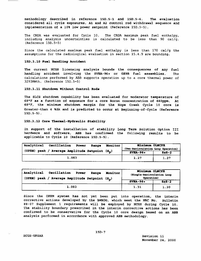
methodology described in reference 15D.5-1 and 15D.5-6. The evaluation considered all cycle exposures, Al and A2 control rod withdrawal sequence and implementation of a 10% low power setpoint (Reference 15D.5-5).
The CRDA was evaluated for Cycle 10. The CRDA maximum peak fuel enthalpy, including analysis uncertainties is calculated to be less than 90 cal/g. (Reference 15D.5-5)
Since the calculated maximum peak fuel enthalpy is less than 170 cal/g the assumptions for the radiological evaluation in section 15.4.9 are bounding.
15D.3.10 Fuel Handling Accident
The current HCGS licensing analysis bounds the consequences of any fuel handling accident involving the SVEA-96+ or GE9B fuel assemblies. The calculations performed by ABB supports operation up to a core thermal power of 3293MWth. (Reference 15D.5-5)
15D.3.11 Shutdown Without Control Rods
The SLCS shutdown capability has been evaluated for moderator temperature of 68 0 F as a function of exposure for a core Boron concentration of 660ppm. At 68 0 F, the minimum shutdown margin for the Hope Creek Cycle 10 core is Greater-than 4 %Ak and is predicted to occur at Beginning-of-Cycle (Reference 15D.5-5).
15D.3.12 Core Thermal-Hydraulic Stability
In support of the installation of stability Long Term Solution Option III hardware and software, ABB has confirmed the following results to be applicable to Cycle 10 (Reference 15D.5-5).
Analytical Oscillation Power Range Monitor Minimum OLMCPR (Two-Recirculation Loop Operation)
(OPRM) peak / Average Amplitude Setpoint (Sp) SVEA-96+ 8x8-2
1.083 1.27 1.27
Minimum OLMCPR Analytical Oscillation Power Range Monitor (i Oi i oP
(Singlo-Recirculation Loop
(OPRM) peak / Average Amplitude Setpoint (Sp) operation) SV'EA-96÷ 8x8-2
1.083 1.31 1.30
Since the OPRM system has not yet been put into operation, the interim corrective actions developed by the BWROG, which meet the NRC No. Bulletin 88-07 Supplement 1 requirements will be employed by HCGS during Cycle 10. The stability boundary prescribed in the interim corrective actions has been confirmed to be conservative for the Cycle 10 core design based on an ABB analysis performed in accordance with approved ABB methodology.
15D-7 HCGS-UFSAR Revision 11
November 24, 2000

15D.3.13 ASME Over-Pressurization
The ASME over-pressurization analysis is performed to evaluate the vessel pressure safety limit. The basis for this event is described in section 5.2.2.
MSIV closure was found to be the most limiting in terms of vessel pressure. The results are summarized as follows:
"* Maximum Vessel Pressure 1259 psia "* Maximum Steam Dome Pressure 1232 psia "* Maximum Steam Line Pressure 1232 psia
The scram on MSIV position is not credited for this event. The maximum pressures during the event are below the ASME code limit 1375 psig, which is 110% of the reactor vessel design pressure. Furthermore the maximum steam dome pressure predicted during the event is below the Technical Specification steam dome pressure safety limit of 1325 psig. (Reference 15D.5-5)
15D.3.14 Anticipated Transient Without Scram
The compliance of the anticipated transient without scram (ATWS) event is described in section 15.8. The ABB reload methodology generically adopts the plant specific ATWS licensing basis. The ABB evaluation results has shown that the ATWS events generally depend only on the core average response. (Reference 15D.5-2)
The introduction of SVEA-96+ fuel assemblies into HCGS has been confirmed for cycle 10 not to adversely impact the core average response during a postulated ATWS. (Reference 15D.5-5)
15D.4 Single Loop Operation
ABB has confirmed that the basis for single loop operation (SLO) presented in Appendix 15C remains valid for the current cycle. The confirmation involves an analysis at 75% of rated power at 50% rated core flow. The initial conditions are consistent with the heat balance specified in reference 15D.57.
15D.5 References
15D.5-1 ABB Combustion Engineering Nuclear Power, Reference Safety Report for Boiling Water Reactor Reload Fuel, ABB Report CENPD-300-P-A (proprietary), July 1996.
15D.5-2 Nuclear Fuel Section Design Input File, "Application of the Generic ABB Reload methodology to Hope Creek Generating Station," HCA.50026.
15D-8 HCGS-UFSAR Revision 11
November 24, 2000
3. Review of engineering documents such as equipment specifications for
inclusion of QA requirements.
4. Review and approve specifications for Q-listed materials, equipment, and
services.
5. Review of procurement documents for insertion of QA requirements.
6. Conduct of supplier surveys, audits and surveillances.
7. Evaluation of prospective and existing Supplier QA Programs.
8. Monitoring/auditing of nuclear fuel fabrication.
9. Review of NBU fuel specifications for inclusion of QA requirements.
10. Perform material evaluation activities on items subject to the QA
Program.
Responsibilities of the Manager - Emergency Preparedness, and Instructional
Technology (Manager - EP & IT) are described in Section 13.1.1.2.1.4.2.
Responsibilities of the Supervisor - Corrective Action include the following:
1. Administration of the Corrective Action Program.
2. Overall management of the trending of Corrective Action reports, related
to human, organizational, and programmatic performance.
3. Providing trend data reports to management. I Responsibilities and authorities of the Manager - Quality Assessment include
the following:
1. The authority and responsibility to stop work, through the issuance of a
Stop Work Order, when significant conditions adverse to quality requires
such action.
2. The freedom and authority to directly access the CNO/PNBU if the need for
such access exists for any issue under his responsibility, including
those related to non-QA areas under the control of the Director
Quality, NT, and EP.
3. The responsibility and authority for verifying complance with established
requirements of the QA program through document reviews, inspections,
assessments and audits of non-QA areas under the control of the Director
-Quality, NT, and EP. This includes the authority to interpret QA
program requirements during conduct of the above activities.
4. Development and implementation of the QA Audit and Assessment Program.
5. Performing assessments of contractor activities and evaluation of
emergent contractor programs and procedures.
17.2-5 HCGS-UFSAR Revision 11
November 24, 2000
6. Planning, scheduling and performing functional area surveillances/
assessments conducted within the Nuclear Business Unit.
I 7. Preparation and maintenance of the QA/NSR Department Manual, the QA
program description in the UFSAR, and the Operational QA Program
description in the Nuclear Administrative Procedures Manual.
8. Review of the Nuclear Administrative Procedures Manual for compliance
with the Operational QA Program.
9. Performing review of selected NBU lower tier administrative and
implementing procedures through periodic assessment and inspection. 10. Conducting QA Program orientation for NBU personnel and administering the
training and certification program for QA personnel involved in
inspection, assessments, and auditing activities, maintaining the QA
training plan, and maintaining QA training records.
11. Review of new regulatory requirements for QA program impact.
12. Verify compliance with the procedures that implement the commitment
management program by review of selected commitments through periodic
assessment and inspection activities.
13. Conduct performance based inspections of selected Code related activities, observe and perform selected testing, and review selected weld procedures for inclusion of QA requirements.
14. Perform pre-implementation review and closure review for compliance with
Inspection Hold Point (IHP) requirements for selected design change
packages by periodic assessment and inspection.
15. Performing performance based inspections.
16. Implementation of the onsite independent review.
17. Monitoring/auditing of nuclear fuel installation.
18. Monitor the ability of the PA group to continuously function
independently as delineated under the responsibilities of the PA Manager
and perform periodic audits of PA review functions. The following provides guidance on the conduct and content of the subject audits:
- conduct interviews, surveys, etc., of selected personnel who are
involved in procurement or procurement assessment activities or
who are in a position to observe these activities
- observe selected procurement and procurement assessment
activities
- assess selected reviews, evaluations, surveys, audits, and
surveillances conducted by PA personnel.
17.2-6 HCGS-UFSAR Revision I0
September 30, 1999

c. Proposed changes to Technical Specifications or Facility Operating
Licenses.
d. Violations of applicable statutes, codes, regulations, orders,
Technical Specifications, license requirements, or of internal
procedures or instruction having nuclear safety significance.
e. Significant operating abnormalities or deviations from normal and
expected performance of plant equipment that affect nuclear safety.
f. Reportable events required by IOCFR50.73.
g. All recognized indication of an unanticipated deficiency in some
aspect of design or operation of structures, systems, or components
that could affect nuclear safety.
h. Reports and meeting minutes of the SORC.
The NRB will utilize as necessary, the operating experience feedback (OEF)
program to review current plant and industry concerns and perform special
studies and investigations.
Assessments/audits shall be performed by QA or by specially selected groups or
individuals, including independent consultants, who have no immediate
responsibility for the activity they assess and do not, while performing the
assessment, report to a management representative who has immediate
responsibility for the activity being assessed. Final audit reports shall be
reviewed by the NRB.
The audits shall include:
a. The conformance of facility operation to provisions contained
within Technical Specifications and applicable license conditions.
b. The performance, training, and qualifications of the entire
facility staff.
c. The results of actions taken to correct deficiencies occurring in
facility equipment, structures, systems, or method of operation
that affect nuclear safety.
d. The performance of activities required by the Operational Quality
Assurance Program to meet the Criteria of Appendix B to 10CFR50.
17.2-7h HCGS-UFSAR Revision 9
June 13, 1998

e. Any other area of facility operation considered appropriate by the Director - Quality, NT, and EP or the CNO/PNBU.
f. The facility Fire Protection Program and implementing procedures.
g. An assessment of the Fire Protection and Loss Prevention Program
implementation using an outside independent fire protection consultant.
h. The radiological environmental monitoring program and the results
thereof.
i. The OFFSITE DOSE CALCULATION MANUAL and implementing procedures.
j. The PROCESS CONTROL PROGRAM and implementing procedures for processing and packaging of radioactive wastes.
k. The performance of activities required by the Quality Assurance Program for effluent and environmental monitoring.
The audit plans shall be reviewed at least annually by the NRB to ensure that
they are being performed in accordance with this section of the UFSAR.
Records of NRB reviews and minutes of NRB meetings shall be maintained. Reports of reviews, meeting minutes and audit reports shall be prepared and distributed as indicated below:
a. Minutes of each NRB meeting and a report of NRB reviews performed shall be prepared and forwarded to the CNO/PNBU within 30 days
following the meeting.
b. Audit reports shall be forwarded to the CNO/PNBU and management positions responsible for the areas audited within 30 days after completion of the audit exit meeting for those audits conducted by the QA Department and within 60 days after completion of the audit for those audits conducted by an independent consultant.
17.2-7i HCGS-UFSAR Revision 11
November 24, 2000

Responses to CAQ corrective action documents are required to include:
1. Identification of deficiency
2. Action taken to correct deficiency
Line management is responsible for dispositioning action requests within their
areas of responsibility.
For significant conditions adverse to quality, plant management is responsible
for ensuring timely response. The QA Department is involved in the review of selected SCAQs and provides oversight to assure timely follow-up and close out
through assessment and inspection activities.
Proper implementation of corrective action is verified through surveillance,
inspection, assessment or audit, as appropriate.
The appropriate general manager or director is responsible for assuring that
conditions adverse to quality are promptly identified and corrected for all activities involving station operation, maintenance, testing, refueling, and
modification.
Administrative procedures that govern station activities covered by the QA
program provide for the timely discovery and correction of nonconformances.
This includes receipt of defective material, failure or malfunction of equipment, deficiencies or deviations of equipment from design performance, and deviations from procedures. In cases of significant conditions adverse to quality, the cause of the condition is determined, and measures are established to preclude recurrence. Such events, together with corrective action taken,
are documented and reported as described in Section 17.2.15. Corrective action is initiated by the responsible department head.
QA closely monitors station conditions requiring corrective action.
Repetitive deficiencies, procedure or process violations at the station that
are not classified as operational incidents or reportable occurrences, or
nonconformances under the QA program, are documented via the issuance of an action request. This request provides a formal administrative vehicle to alert
management of conditions adverse to quality that require corrective action.
17.2-41 HCGS-UFSAR Revision 10
September 30, 1999

17.2.17 Quality Assurance Records
Records necessary to demonstrate that activities important to quality have been
performed in accordance with applicable requirements are identified and
maintained in accordance with Regulatory Guide 1.88, as noted in
Section 17.2.2. Records shall be considered valid only when authenticated by
authorized personnel. Record types as a minimum, comply with applicable
technical specification requirements and include operating logs, maintenance
and modification procedures and related inspection results and reportable
occurrences.
The Nuclear Business Unit is responsible for the permanent storage of station records. The retention period for records; permanent storage location; and
methods of control, identification, and retrieval are specified by
administrative procedure. Individual station department heads are responsible
for submitting applicable department records to the designated location for
retention.
17.2.18 Audits
Audits of PSE&G and supplier organizations that implement the QA program are
performed by QA and PA to verify compliance with the applicable portions of the program, through personnel interview, observation of activities in process, and review of applicable documents and records as required. Performance based
assessment should be an integral part of the auditing program and should
evaluate activities on the basis of their effect on the safe and reliable operation of the facility. An audit plan is developed to identify the audits
to be performed and their frequency. A dominant factor in the audit plan development is performance in the subject area. The audit plans are revised so that weak or declining areas receive increased audit coverage and strong areas
receive less, consistent with the audit frequency requirements of the Code of
Federal Regulations and the UFSAR. Audits of the selected aspects of
operational phase activities are performed with a frequency commensurate with
safety significance and in a manner to assure that at least biennial (2 years) audits of safety related activities are performed. A list of operational phase
activities subject to the audit program is provided in section 17.2.1.1.2.3 and
in Table 17.2-1.
Audits are conducted by audit teams comprised of a certified lead auditor and
certified auditors, and technical specialists (when deemed necessary).
17.2-42 HCGS-UFSAR Revision 11
November 24, 2000