Preliminary design of four optional long bridge solutions for the Western Scheldt Crossing,...
8
IABSE Conference Kolkata 2013: Long Span Bridges and Roofs 1 Preliminary Design of Four Optional Long Bridge Solutions for the Western Scheldt Crossing, Netherlands Ryszard A. DANIEL Senior Consultant/Specialist by the Ministry of Infrastructure and Environment, Division of Infrastructure, Utrecht, the Netherlands [email protected] Ryszard Daniel, born in 1949, received MSc. in civil engineering from Silesia Univ. of Techn. and PhD. from Gdansk Univ. of Techn. He is a designer, project leader, consultant, reviewer and author of many publications in civil engineering, particularly in the field of bridges and hydraulic structures. Summary Two structural systems dominate the choice of a very long span bridge nowadays – the suspension and cable-stayed bridge, both with one or more main spans and in steel or concrete version. Yet, the combination of these possibilities leaves the designer with quite many options. The question which option represents the best choice has been studied in details as part of the Western Scheldt Crossing project in the Netherlands. This paper presents the conclusions of that study and the comparative conceptual designs of four final bridge options. The results can be indicative for prospective studies on long span bridge crossings in other projects. Keywords: Long span bridge, suspension bridge, cable-stayed bridge, navigable clearance, pylon, main span, multiple span, suspension cable, anchor block, bridge girder. 1. Introduction Netherlands is a country with the most compact network of both roads and waterways in Europe. These networks are of vital importance to the Netherlands’ economy, the big part of which directly or indirectly serves the freight transport from and into the member states of the European Union. The crossings of roads and waterways are, obviously, of prior concern too – in particular when not only Dutch but also foreign vital interests are involved. In the 1990’s, a project of the Western Scheldt river crossing was carried on. The river provides the main access to the Belgian harbour of Antwerp, one of the biggest harbours in Europe. As the crossing was to be located near the city of Terneuzen, i.e. downstream of Antwerp, the combined bridge-tunnel option was considered. It was meant to provide an unlimited navigation clearance for the largest vessels above the tunnel section – and a limited but still large clearance under the bridge (Fig. 1). This idea was an option to the entire tunnelling that finally won the competition for other than technical reasons. Nonetheless, the performed studies and designs of the bridge delivered many valuable conclusions. Several of them are still valid now and will be presented in this paper. Fig. 1: Situation sketch (a) and a bird view (b) of the intended bridge-tunnel crossing
Transcript of Preliminary design of four optional long bridge solutions for the Western Scheldt Crossing,...

IABSE Conference Kolkata 2013: Long Span Bridges and Roofs 1
Preliminary Design of Four Optional Long Bridge Solutions
for the Western Scheldt Crossing, Netherlands
Ryszard A. DANIEL Senior Consultant/Specialist by the Ministry of Infrastructure and Environment, Division of Infrastructure, Utrecht, the Netherlands [email protected]
Ryszard Daniel, born in 1949, received MSc. in civil engineering from Silesia Univ. of Techn. and PhD. from Gdansk Univ. of Techn. He is a designer, project leader, consultant, reviewer and author of many publications in civil engineering, particularly in the field of bridges and hydraulic structures.
Summary Two structural systems dominate the choice of a very long span bridge nowadays – the suspension and cable-stayed bridge, both with one or more main spans and in steel or concrete version. Yet, the combination of these possibilities leaves the designer with quite many options. The question which option represents the best choice has been studied in details as part of the Western Scheldt Crossing project in the Netherlands. This paper presents the conclusions of that study and the comparative conceptual designs of four final bridge options. The results can be indicative for prospective studies on long span bridge crossings in other projects. Keywords: Long span bridge, suspension bridge, cable-stayed bridge, navigable clearance, pylon, main span, multiple span, suspension cable, anchor block, bridge girder.
1. Introduction Netherlands is a country with the most compact network of both roads and waterways in Europe. These networks are of vital importance to the Netherlands’ economy, the big part of which directly or indirectly serves the freight transport from and into the member states of the European Union. The crossings of roads and waterways are, obviously, of prior concern too – in particular when not only Dutch but also foreign vital interests are involved. In the 1990’s, a project of the Western Scheldt river crossing was carried on. The river provides the main access to the Belgian harbour of Antwerp, one of the biggest harbours in Europe. As the crossing was to be located near the city of Terneuzen, i.e. downstream of Antwerp, the combined bridge-tunnel option was considered. It was meant to provide an unlimited navigation clearance for the largest vessels above the tunnel section – and a limited but still large clearance under the bridge (Fig. 1). This idea was an option to the entire tunnelling that finally won the competition for other than technical reasons. Nonetheless, the performed studies and designs of the bridge delivered many valuable conclusions. Several of them are still valid now and will be presented in this paper.
Fig. 1: Situation sketch (a) and a bird view (b) of the intended bridge-tunnel crossing

IABSE Conference Kolkata 2013: Long Span Bridges and Roofs 2
2. Four bridge options As the river width section to be bridged equalled more than 2 km and the navigation requirements did not allow for many pillars in that section, only the long span bridge systems could be taken into account. This included suspension bridges and cable-stayed bridges. Other systems, even if feasible in technological sense, were considered economically not competitive for this project. The study on possible longitudinal profiles of the crossing resulted in four options: two with suspension bridges and two with cable-stayed bridges (Fig. 2):
1. Single main span suspension bridge; 2. Double main span suspension bridge; 3. Steel cable-stayed bridge of three middle spans; 4. Concrete cable-stayed bridge of four middle spans.
Fig. 2: Four bridge system solutions for the Western Scheldt crossing (preliminary studies) All these options satisfied the navigation requirements by providing either one 400 m wide or two 250 m wide ship passages. Though the Western Scheldt is a tidal river in that area, the requirements of proper navigation draught and overhead clearance did not present a major problem too. The inclusion of a double main span suspension bridge option caused, however, some discussion. This system was generally not favoured at that time due to the high horizontal loads on the middle pylon.
In Fig. 3, the horizontal and vertical loads from each of the two cables are compared for a single and double main span suspension bridge. The extreme horizontal load on the middle pylon of the double main span bridge proved to be 12,5 times higher than that on the single main span bridge pylon.
Fig. 3: Cable loads atop pylons of the single and double main span suspension bridge

IABSE Conference Kolkata 2013: Long Span Bridges and Roofs 3
Despite that, the double main span suspension bridge still proved to be feasible and there was no ground for ruling it out in this project. Today, this conclusion does not surprise any more, as we know that long, double main span suspension bridges become a reality. At least two bridges of this system undoubtedly prove it: the recently opened Jiangsu Taizhou Bridge and the Anhui Maanshan Bridge, both over the Yangtze River. The Chinese engineers have taken the leading position in the realization of this idea [1]. For the discussed project, a more detailed comparison between the single and double main span suspension bridge has been presented on the IABSE Conference in Venice in 2010 [2]. The current paper aims at comparing the main parameters, performances and structural details of all the four bridge options considered.
3. Design specifications The Western Scheldt crossing was intended to provide a road traffic connection between the South Beveland peninsula and the Zeeland Flanders – two lands in the Rhine, Meuse and Scheldt delta in the Dutch province of Zeeland. The crossing had to enable single lane road traffic in both directions. Additionally, service lanes had to be provided on both sides of the road. In the bridge design, these service lanes had, however, to be considered as second traffic lanes in terms of both geometry and variable loads. On a suspension bridge, e.g., the specified road cross-section was as follows (Fig. 4):
The design traffic load was of the so-called class 60, according to the Dutch code NEN 6788, which was the highest design traffic load on public road bridges in the Netherlands. The wind loads, high at that location, were specified in accordance with the same code. Obviously, these loads were not only relevant for the static stability but also for the bridge dynamic behaviour, in particular the wind induced vibrations. The vibrations of different components – like the main girder, hangers and stay cables – were subject to thorough feasibility studies. Due to the intensive navigation of large vessels, thorough attention was also paid to the risk of ship collision on bridge piers. The collision loads had to be considered at the most critical level for the structure. Their design values were related to the number of bridge piers as follows:
• 2 piers: 110 MN on each pier; • 3 piers: 130 MN on each pier; • 4 piers: 140 MN on each pier; • 5 piers: 150 MN on each pier.
The transition between the bridge and the tunnel required an island in the middle section of the river crossing. All the four options required different dimensions of this island. Therefore, the total length of the bridge was not determined in the project specifications. It was left free for tender conceptual designs. However, an evident island location was the existing so-called middle plate in the riverbed. The plate and the existing navigation conditions strongly indicated that the total length of the bridge part of the crossing should be between 2000 and 2500 m. Other most relevant design conditions for the bridge part of the crossing were as follows:
• Required safety factor for main cables, hangers and cable stays: 2,25; • Failure of one hanger or cable stay may not cause functional failure; • Sea level rising in the coming 100 years: 0.60 m; • Required navigable width: one opening of 400 m or at least 2 openings of 250 m each; • Navigation overhead clearance: at least +43.0 m above the normal sea level; • Free navigable draught: at least -10.00 m under the normal sea level; • Required total service life of the bridge: minimum 100 years.
Fig. 4: Road cross-section on the bridge

IABSE Conference Kolkata 2013: Long Span Bridges and Roofs 4
Fig.
5:
Four
bri
dge
optio
ns fo
r the
Wes
tern
Sch
eldt
cro
ssin
g (fi
nal d
esig
n)
IABSE Conference Kolkata 2013: Long Span Bridges and Roofs 5
4. Reference designs The Netherlands’ Ministry of Transport, Public Works and Water Management and the authorities of the Zeeland Province decided to put up the project for tender in a design-and-build (D&B) contract. However, the size and the unique character of the project required a thorough investigation of all possible options prior to tendering. In order to investigate the feasibility, costs, construction time, risks and other implications, detailed analyses and design drawings were performed. Fig. 5 presents the side views of the 4 bridge options, along with their principal geometrical arrangements. Obviously, the division into bridge spans, pylon heights, hanger and cable-stay spacing etc. reflect the views of 1990’s. These views have slightly changed since then, e.g. a number of suspension and cable-stayed bridges with larger spans have been constructed. These changes are, however, not big when the ‘main stream’ of large bridge projects is considered, not only the current record holders. In this view, the comparison of the Western Scheldt bridge designs remains indicative for the system selection of large bridges today. Following is a short description of the four bridge designs.
4.1 Suspension bridges (of one and two main spans) The single main span suspension bridge was originally designed with a main span of only 1050 m, and later – as a sub-option – for the spans of 495 + 1360 + 495 m. The reason for this sub-option was the completion of geological and nautical surveys. They both indicated that a longer distance between the pylons would improve the soil and navigation conditions at that particular location. This advantage did not apply to the double main span suspension bridge, in which the middle pylon could hardly be moved aside. The original option with the spans of 385 + 1050 + 385 m is better suitable for comparative purposes, because its total length does not deviate much from the other three bridge designs. The discussion in this paper refers, therefore, to that option. The system and the general arrangement of the single main span bridge can be called ‘classical’ for the European suspension bridge design views. A single box girder has a proven, aerodynamically stable shape and is preferable to braced truss girders. The pylons are of steel, ‘classically’ shaped and rigidly fixed to the concrete piers. The main cable sag is 1/10 of the main span. The hangers run vertically, which is usually preferred to inclined hangers of the so-called Nielsen system due to less tensile load variation. The main cable saddles, both atop the pylons and by approaching the anchor blocks, are of cast steel and proven geometry. The abutments witch anchor blocks reach about 80 m into the approaching dike cores (Fig. 6). The piers carrying the single span bridge pylons were designed in two optional versions:
• Solid transverse foundations carried by a large number of concrete piles, 22 – 25 m long, and constructed on artificial islands;
• Cylindrical multi-chamber box-caissons, filled with sand and resting directly on the locally excavated riverbed.
In case of the single main span bridge, the first option will be assumed for the comparisons in this paper. It better reflects the character of horizontal pier loads that are predominately generated by a vessel collision and directed laterally to the bridge axis. The advantages of the second option are clear for the double main span bridge, where the middle pier also carries high horizontal load and moment in the bridge longitudinal direction. This resulted in a design of a large diameter concrete pier with a few rings of concentric hollow chambers. That pier was supposed to be prefabricated ashore, floated to its destination, there submerged and filled with sand. Once the prefabrication dock was there, it was logical to use it for the two side piers as well, which is the reason why their shape is similar. An additional advantage of this method was the shorter construction time. The side pylons of the single and double main span suspension bridge also show shape differences. While the steel pylons of the single span bridge are – for economical reasons – braced, those of the double main span bridge are not. Their smaller height made the advantage of bracing insignificant. For aesthetical reasons, both bridges would probably deserve unbraced pylons. The cross-sections of the side pylons, girders, main cables and hangers are comparable for both bridges. Therefore, the respective details shown in Fig. 6 apply to a large extent to both suspension bridge options. As predicted in section 2, a spectacular difference appeared in the shaping of the middle pylon. Due to the high loads in the bridge longitudinal direction (see Fig. 3), slender shaping was not an option. Instead, an A- and λ- (or reversed Y-) shapes were considered. The λ-shape appeared to be a more

IABSE Conference Kolkata 2013: Long Span Bridges and Roofs 6
Fig. 6: Single main span suspension bridge – details Fig. 7: Pylons of the double main span suspension bridge
IABSE Conference Kolkata 2013: Long Span Bridges and Roofs 7
economical choice (Fig. 7) [3]. The middle pylon does not look very heavy in Fig. 7 only because for aesthetical reasons thicker plates rather than larger sections were chosen. In fact, it still weights 2100 tons, compared to 1400 tons of the side pylon of the same bridge and 1800 tons of the much higher pylon of the single main span bridge, see Table 1 further in this paper.
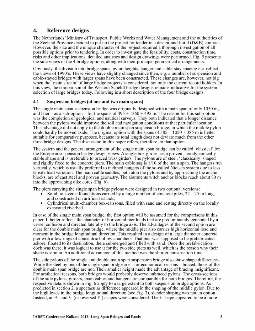
4.2 Cable stay bridges (of steel and concrete) The two cable-stayed bridges (Fig. 8) – one of steel, and one of concrete superstructure – reflect the advance of this system in the 1990’s, with the Normandy Bridge as the pioneering achievement. The division into spans, pylon heights and other arrangements do not differ much from that design. The designs of the multiple cable-stayed bridges for the Western Scheldt crossing proceeded, in a sense, the design of the Millau Viaduct [3] of about the same total length, slightly shorter spans and much higher pylons. The reason for the longer spans was, obviously, the navigation.
Fig. 8: Concrete and steel cable stay bridges – details The navigation profile differed in both options. The steel bridge offered one 400 m wide navigable opening; the concrete bridge offered two 250 m wide openings. As the number of piers was larger than in the suspension bridges, prefabrication was the best choice. The piers were to be constructed in a dock and floated to their destination in the way as for the double suspension bridge. Their size was smaller but the shape was similar. On their tops, lighter pillars were designed to carry 4-column pylons – of steel for the steel bridge and of post-tensioned concrete for the concrete bridge.
IABSE Conference Kolkata 2013: Long Span Bridges and Roofs 8
The stay cables were to be built of stranded strings, the cable diameters varying between 125 and 180 mm, depended on their location. The cable anchorages in the pylons and the girders were to be adjustable suited for construction within a number of commercially available anchoring systems. Other components – with the exception of the post-tensioned girder in the concrete cable-stayed bridge – showed large similarities with the suspension bridges.
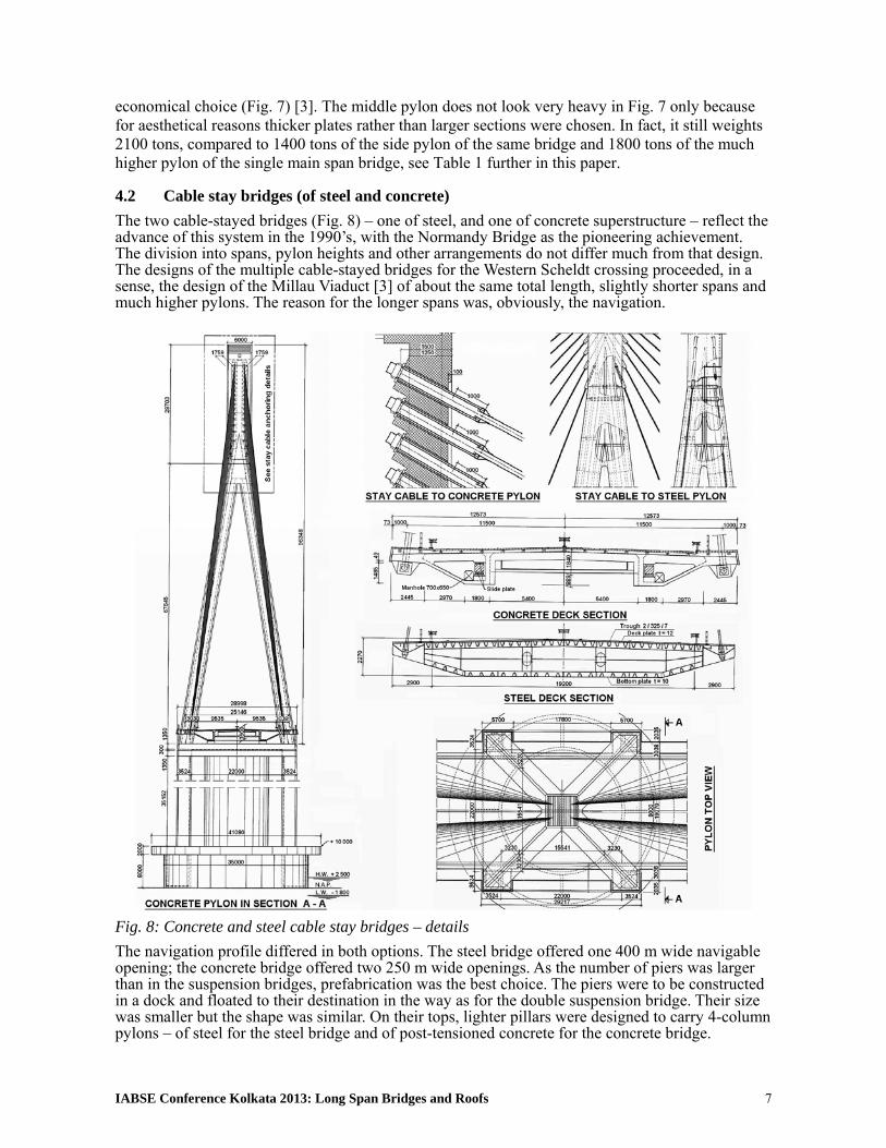
5. Conclusions from comparative designs The first conclusion from the completed designs was that the double main span suspension bridge was a feasible option. What had only been a presumption on the beginning of the study, was now certain. In Table 1, the quantities of basic materials are compared for the four bridge options under consideration. Cost estimations are not presented because the unit prices have changed since then. Nevertheless, the cost differences were not large. The single span suspension bridge appeared to be the cheapest, followed by its double span option, the steel and the concrete cable-stayed bridge.
Table 1. Comparison of material quantities for the four bridge options considered
Item Unit Single suspension bridge
Double suspension bridge
Steel cable-stayed bridge
Concrete cable-stayed bridge
Bridge spans m 1050 + 2x385 2x720 + 2x265 500 + 2x440 + 2x160 4x360 + 2x160 Navigable width m 400 2 x 250 400 2 x 250 Main girder: 1. Material - construction steel construction steel construction steel prestr. concrete 2. Quantity ton 14 500 15 800 17 500 82 000 Suspension: 1. HS steel, main cables ton 2 x 3250 2 x 2560 - - 2. HS steel, suspenders ton 2 x 85 2 x 60 2 x 750 2 x 1900 3. Constr. and cast steel ton 624 746 220 560 Pylons: 1. Material - construction steel construction steel construction steel prestr. concrete 2. Quantity ton 2 x 1800 2100 + 2 x 1400 7 500 42 000 Piers and foundations: 1. Material - reinf. concrete reinf. concrete reinf. concrete reinf. concrete 2. Quantity ton 45.000 124.000 163.000 206.000 3. Type of foundation - base slab + piles caisson caisson caisson Anchor blocks and approaching bridges: 1. System lengths m 2x (50+20+44) 2x (50+20+44) 2x (54+52) + 49 2x (54+52+39+39)2. Material - reinf. concrete reinf. concrete reinf. concrete reinf. concrete 3. Quantity ton 152.000 152.000 34.000 44.000 Soil and sand replacements: 1. Removal m3 2.870.000 3.090.000 3.170.000 3.270.000 2. Supply m3 880.000 300.000 1.300.000 390.000
As expected, both suspension bridges required large quantities of high-strength steel, but this paid back in lighter pylons and, particularly, piers. This relation was opposite in the cable-stayed bridges. In favour of the latter were also the advantages of prefabrication. Generally speaking, the designers were somewhat surprised by the competitive performances of both the double main span suspension bridge and the two cable-stayed bridges, considering the length of the river crossing. However, a number of large bridge projects of the millennium break and later confirmed this competitiveness.
References [1] GE Y.J., XIANG H.F., “Bridging capacity innovations on cable-supported bridges”,
proceedings of the 4th International Conference on Bridge Maintenance, Safety and Management, Seoul, July 2008, Taylor & Francis Group, London, 2008, 19 p.
[2] DANIEL R.A., DOOREN F.J. van, MEIJER R.H. de, Comparison of a Single and Double Main Span Suspension Bridge for the Western Scheldt Crossing, proceedings of the IABSE Symposium “Large Structures and Infrastructures…”, Venice, September 2010, 8 p.
[3] VIRLOGEUX M., “Millau Viaduct, France”, Structural Engineering International, February 2005, vol. 15, no. 1.