
Effect of electrode material in micro-electrical discharge ...
17
Indian Journal of Engineering & Materials Sciences Vol. 25, February 2018, pp. 42-58 Effect of electrode material in micro-electrical discharge machining of micro-holes drilled in shape memory alloys Mohammed Sarvar Rasheed a,b , Mustufa Haider Abidi b * & Abdulrahman M Al-Ahmari b a Baynounah Institute of Science and Technology, Abu Dhabi Vocational Education Training Institute, Mohammed Bin Zayed City, Abu Dhabi, UAE b Princess Fatima Alnijris’s Research Chair for Advanced Manufacturing Technology (FARCAMT Chair), Advanced Manufacturing Institute, King Saud University, Riyadh, Saudi Arabia Received 30 March 2016; accepted 25 May 2017 Machining of advanced engineering materials is a major problem faced by the industry. Electrical discharge machining (EDM) provides a solution to this problem, and it is utilized for machining of such electrically conductive materials. Micro- EDM (µEDM) technology is used to drill micro-holes in various components in the aerospace industry and automotive industry. Such holes need to have good surface finish and good dimensional accuracy. It is difficult to maintain a high accuracy and good surface finish at such a minute level. Therefore, this work tries to solve this issue by conducting an experimental study in which micro-holes are drilled in the Ni-Ti shape memory alloy (SMA) and stainless steel (SS) using µEDM. The effect of the electrode material on micro-holes is investigated. Surface characteristics and dimensional accuracy of the machined micro-holes are evaluated based on micrographs obtained by scanning electron microscopy (SEM). The results reveal that the material removal rate (MRR), surface finish, and dimensional accuracy are significantly affected by the machining parameters (i.e., discharge energy (pulse voltage and capacitance) in R–C circuit during machining), tool electrode material, and type of hole to be drilled (through hole or blind hole). In addition, fine surface finish is also dependent on the electrical and thermal properties of the electrode material. Keywords: Micro-holes, Micro-EDM (µEDM), Shape memory alloys Micromachining techniques are used in manufacturing where parts are to be made of micro size to save space, material, energy, and cost. In the micromachining field, the selection of appropriate technique depends upon the size and shape, aspect ratio, and material properties of the objects 1 . Micromachining processes such as photolithography, chemical vapor deposition, and etching cannot be employed to machine electrically conductive materials. In addition, mechanical drilling, electron beam machining, and laser machining cannot produce micro-features with good surface finish and dimensional accuracy 2 . Among the micromachining techniques, micro-electrical discharge machining (µEDM) has benefits such as providing economical machining, producing a high aspect ratio, and having the ability to produce complex shapes in all kinds of electro-conductive materials with good surface finish 3 . Electrical discharge machining (EDM) is also known as spark machining, and removes the material without any physical contact among the work-piece and the tool electrode. It removes material using repetitive pulse discharges obtained from an electric pulse generator with dielectric fluid flowing between the work-piece and tool electrode. Each generated spark melts and vaporizes the material from both the work-piece and tool electrode, leading to material removal. The discharge current causes heating of the dielectric, work-piece, and tool electrode. The dielectric forms a plasma channel of partially ionized gas, and this channel acts as a heat source and heats up the work-piece beyond its melting temperature; the material is removed and solidifies because of the dielectric cooling effect. µEDM is a subset of EDM, which operates at miniature level. The characteristics that differentiate µEDM from macro-EDM are the size of the tool electrode and the discharge energy. The plasma size is larger by several orders of magnitude in macro-EDM and axes movement resolutions, which are in micron levels 4 . µEDM can be used to machine almost burr-free micro-holes (having a range from a few hundred microns to 5 µm) ————— *Corresponding author (E-mail: [email protected]; [email protected])
-
Upload
khangminh22 -
Category
Documents
-
view
2 -
download
0
Transcript of Effect of electrode material in micro-electrical discharge ...
Indian Journal of Engineering & Materials Sciences Vol. 25, February 2018, pp. 42-58
Effect of electrode material in micro-electrical discharge machining of micro-holes drilled in shape memory alloys
Mohammed Sarvar Rasheeda,b, Mustufa Haider Abidib* & Abdulrahman M Al-Ahmarib
aBaynounah Institute of Science and Technology, Abu Dhabi Vocational Education Training Institute, Mohammed Bin Zayed City, Abu Dhabi, UAE
bPrincess Fatima Alnijris’s Research Chair for Advanced Manufacturing Technology (FARCAMT Chair),
Advanced Manufacturing Institute, King Saud University, Riyadh, Saudi Arabia
Received 30 March 2016; accepted 25 May 2017
Machining of advanced engineering materials is a major problem faced by the industry. Electrical discharge machining (EDM) provides a solution to this problem, and it is utilized for machining of such electrically conductive materials. Micro-EDM (µEDM) technology is used to drill micro-holes in various components in the aerospace industry and automotive industry. Such holes need to have good surface finish and good dimensional accuracy. It is difficult to maintain a high accuracy and good surface finish at such a minute level. Therefore, this work tries to solve this issue by conducting an experimental study in which micro-holes are drilled in the Ni-Ti shape memory alloy (SMA) and stainless steel (SS) using µEDM. The effect of the electrode material on micro-holes is investigated. Surface characteristics and dimensional accuracy of the machined micro-holes are evaluated based on micrographs obtained by scanning electron microscopy (SEM). The results reveal that the material removal rate (MRR), surface finish, and dimensional accuracy are significantly affected by the machining parameters (i.e., discharge energy (pulse voltage and capacitance) in R–C circuit during machining), tool electrode material, and type of hole to be drilled (through hole or blind hole). In addition, fine surface finish is also dependent on the electrical and thermal properties of the electrode material.
Keywords: Micro-holes, Micro-EDM (µEDM), Shape memory alloys
Micromachining techniques are used in manufacturing where parts are to be made of micro size to save space, material, energy, and cost. In the micromachining field, the selection of appropriate technique depends upon the size and shape, aspect ratio, and material properties of the objects1. Micromachining processes such as photolithography, chemical vapor deposition, and etching cannot be employed to machine electrically conductive materials. In addition, mechanical drilling, electron beam machining, and laser machining cannot produce micro-features with good surface finish and dimensional accuracy2. Among the micromachining techniques, micro-electrical discharge machining (µEDM) has benefits such as providing economical machining, producing a high aspect ratio, and having the ability to produce complex shapes in all kinds of electro-conductive materials with good surface finish3. Electrical discharge machining (EDM) is also known as spark machining, and removes the material
without any physical contact among the work-piece and the tool electrode. It removes material using repetitive pulse discharges obtained from an electric pulse generator with dielectric fluid flowing between the work-piece and tool electrode. Each generated spark melts and vaporizes the material from both the work-piece and tool electrode, leading to material removal. The discharge current causes heating of the dielectric, work-piece, and tool electrode. The dielectric forms a plasma channel of partially ionized gas, and this channel acts as a heat source and heats up the work-piece beyond its melting temperature; the material is removed and solidifies because of the dielectric cooling effect. µEDM is a subset of EDM, which operates at miniature level. The characteristics that differentiate µEDM from macro-EDM are the size of the tool electrode and the discharge energy. The plasma size is larger by several orders of magnitude in macro-EDM and axes movement resolutions, which are in micron levels4. µEDM can be used to machine almost burr-free micro-holes (having a range from a few hundred microns to 5 µm)
————— *Corresponding author (E-mail: [email protected]; [email protected])
RASHEED et al.: µ-EDM OF MICRO-HOLES DRILLED IN SHAPE MEMORY ALLOYS 43
and complex 3D cavities5. The shape of the machined surface is a replica of the tool electrode. µEDM is mainly chosen because of its high efficiency and accuracy, especially for the machining of difficult-to-machine materials regardless of their hardness, such as metals, metallic alloys, graphite, and some selected ceramics6. Preview of µ-EDM
In recent years, the increasing demand of micro-parts and advances in applications in numerous industries such as automotive, aerospace, bio-medical, and Microelectromechanical systems (MEMS) has made µEDM one of the most favorable manufacturing techniques for producing micro-parts. µEDM is one of the most competent techniques to create simple and intricate shapes, cavities, and 3D micro-contours. A large amount of research is currently underway to make this process more efficient. µEDM is the key process for drilling micro-holes (diameter less than 200 µm) in diesel and gasoline injection nozzles7-9. Turbine blades have micro-holes for cooling, which are drilled by µEDM10. µEDM is also used for producing inkjet nozzles11. Sato et al.12 used µEDM to drill holes on inkjet nozzles for the first time.
Recent research has mainly focused on improving the process by measures such as obtaining high aspect ratio micro-holes13,14, reducing the difference in diameter of tapered micro-holes at the entrance and exit15, improving the geometrical shape and size, and improving the surface quality of micro-holes16. Han et al.17 performed experimental studies on sub-micron size machining using µEDM and investigated the factors affecting the machining process. The minimum diameter obtained in their study was approximately 2.8 µm17. Egashira et al.18 performed EDM of sub-micron holes using the ultra-small diameter tungsten electrode with a diameter of 1 µm and Si electrode with diameter less than 0.15 µm. These holes are the smallest reported holes drilled by EDM. Masuzawa et al.13 developed a µEDM system for drilling of deep holes with diameter of 100 µm and depth of 1000 µm for industrial applications. Yan et al.19 drilled micro-holes having a diameter of 150 µm and a depth of 500 µm on borosilicate glass by combining µEDM with Micro-Ultrasonic Machining USM (µUSM). Reynaerts et al.20 reported a µEDM process for drilling micro-holes having a diameter of 160 µm and a depth of 380 µm. Rajurkar et al.21 reported that µEDM can drill holes and shafts
up to diameters as small as 5 µm as well 3D micro-slots. Masuzawa et al.5,22,23 successfully produced micro-pins, micro-nozzles, micro-slots, and 3D contours using wire electrical discharge machining (WEDM) and electroforming process.
Liu et al.24 examined the fabrication of micro-holes in high nickel alloys using µEDM. Yan et al.25 described the features of micro-holes drilled using µEDM with a copper electrode, and studied the effects of different machining parameters on the quality of micro-holes. Garn et al.26 examined the effect of vibration on the electrical discharges in the µEDM process in which tungsten carbide electrode with a diameter of 0.085 mm was selected to drill micro holes. Jahan et al.27 studied the features of micro-holes produced by µEDM and the impact of machine factors on the performance of µEDM of tungsten carbide to achieve accurate micro-holes with good surface finish and circularity. Tak et al.28 compared the dimensional accuracy of micro-holes drilled on tungsten carbide (WC) by varying the discharge conditions. Jahan et al.29 compared the drilling capability of µEDM by producing deep-holes in cement carbide (WC–Co) and austenitic stainless steel (SUS 304). Zou et al.30 studied the effect of porous structure on the performance of µEDM process. A higher material removal rate, and tool wear rate was achieved in case of porous material when compare with solid material. It was also reported that the pore size affects the material removal rate significantly.
Fu et al.31 studied the effect of electrode material, and dielectric type on the tool wear rate for the drilling process using µEDM. Tungsten, and tungsten carbide tools were compared using two types of dielectrics, that were deionized water, and machining oil. It was concluded that tool wear for both types of electrodes was much higher in case of machining oil. It was also reported that increase in federate results in increase tool wear rate increases with machining feed, and the tungsten carbide electrode’s tool wear rate was always higher than tungsten electrode. Dong et al.32, studied the µEDM process for drilling good surface quality micro-holes in Be-Cu alloys. The effect of different electrode diameters and dielectric types was studied. The multi-diameter electrode provided the flexibility to perform finishing operation with the same tool. The blend of kerosene with deionized water as a dielectric performed superior to other dielectrics in terms of surface quality of drilled
44 INDIAN J. ENG. MATER. SCI., FEBRUARY 2018
holes. A comparison study was made between dry-EDM process and conventional EDM process for drilling the micro-holes in Si3N4-TiN. It was revealed that dry-EDM process has certain advantages in terms of small recast and white layers and sharp edges, however, machining time is high33. Chu et al.34 conducted experiments to study the plasma channel expansion in µEDM process. A comprehensive plasma model was developed that include the breakdown and the expansion stages. Then the theoretical model based on this was generated which was further validated by experiments34. Experiments were conducted to study the effect of tool electrode diameter on the µEDM process. With the increase of tool electrode diameter, MRR, TWR, and Taper rate were different. Larger tool diameter results into higher MRR, and more TWR due to area effect35.
Shape memory alloy (SMA) is a special type of advanced engineering material, which has the ability to remember its shape or the pseudo plasticity. Shabalovskaya36 reported that SMA has several exceptional properties such as high mechanical strength, wear resistance, hardness, high efficiency in converting thermal energy into mechanical energy, and excellent biocompatibility. SMA is used in a broad range of applications in various fields. Otsuka and Kakeshita37 proposed that Ni-Ti-based SMAs are widely used in industrial applications such as sensors, actuators, and couplings in the aerospace industry and MEMS. Ni-Ti-based SMA is used for diminutive grippers, micro-valves, and pumps. Stoeckel38 proposed bio-medical applications besides industrial applications such as wires for minimal invasive surgery or super-(pseudo-) elastic devices for cardio-vascular systems (e.g., self-expandable stents). Lin et al.39 reported that SMAs are extremely responsive to stress, thermal influences, and mechanical tension. It is hard to machine SMA by conventional processes because of its low thermal conductivity and elastic modulus. There are several issues in conventional machining of SMA caused by the high ductility and severe strain hardening of the material, such as increase in wear and tear of the cutting tool and poor quality of the machined surfaces. In addition to mechanical machining, there are other micromachining techniques including electrochemical machining, electron beam machining, ion beam machining, ultrasonic machining, µEDM, and laser machining. However, the shaping of SMA is mostly
realized by either μEDM or laser machining. Theisen et al.40 machined Ni-Ti SMAs using EDM with Cu–W electrode in the hydrocarbon based dielectric fluid.
Although a number of studies and investigations have been made on EDM of various materials, very few have considered the µEDM of micro-holes in hard-to-cut materials, especially SMAs. Since both the process and material are costly, it is important to find parameters that will result in a better output. This paper presents an experimental study of micro-holes drilled on an advanced engineering material: Ni-Ti based SMA. The results are compared with those obtained using stainless steel. The comparison aims to demonstrate the capability of the process in machining advanced materials with the accuracy as obtained in machining common materials. Micro-holes of 100 µm diameter are drilled using brass and tungsten alloys as tool electrodes. The responses such as material removal rate (MRR) and dimensional accuracy at different discharge energy levels with identical input process parameters are studied. The topography of machined surface is also studied based on scanning electron microscope (SEM) micrographs. Experimental Details
Experimental setup A special experimental setup was used to study the
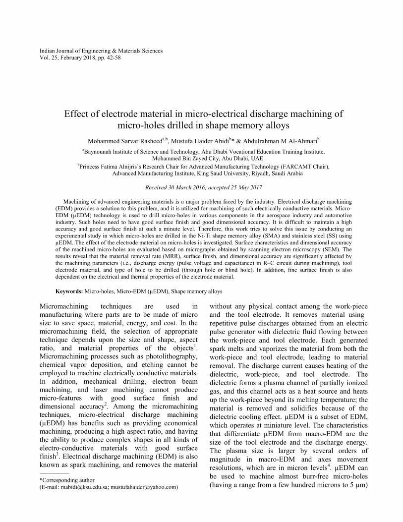
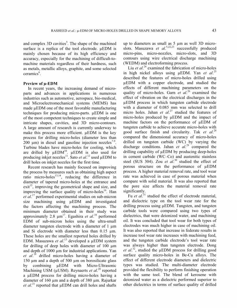
μEDM process. The apparatus consists of a tabletop electro-discharge machine integrated with microscope lenses. The advantage of this setup is that preliminary investigation of the micro-holes can be carried out without removing the work-piece from the worktable. Hence, if any further improvements are required, the machining can be continued from the same position, thus resulting in a better accuracy. Figure 1 shows the line diagram of the micro electro-discharge machine. Figure 2 shows the resistor–capacitor (RC) circuit of the machine’s power supply unit.
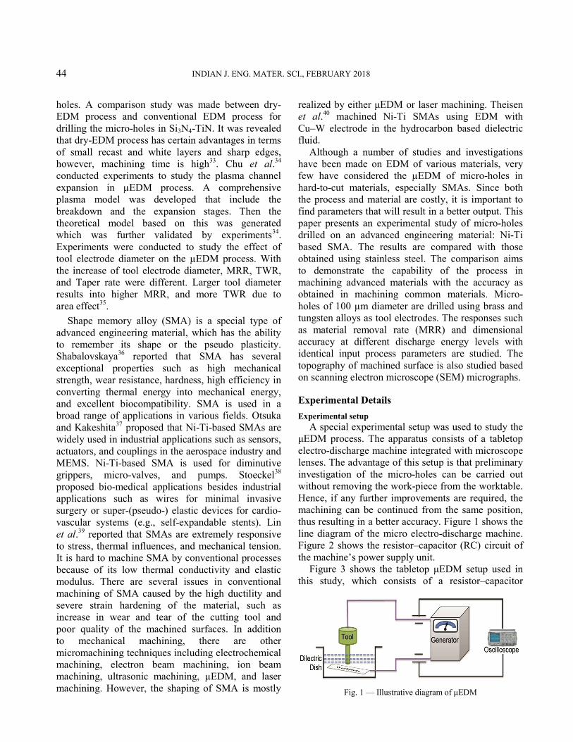
Figure 3 shows the tabletop μEDM setup used in this study, which consists of a resistor–capacitor
Fig. 1 — Illustrative diagram of μEDM
RASHEED et al.: µ-EDM OF MICRO-HOLES DRILLED IN SHAPE MEMORY ALLOYS 45
generator. The resistor–capacitor generator is able to generate pulses in the duration ranging from a few tens of nanoseconds to a few microseconds. The voltage level can be varied from 45 V to 120 V. The setup is attached with an optical microscope, which provides the option to assess the micro-hole without removing the work-piece from the setup. Kerosene is used as the dielectric fluid, although there are many other options available in the market. The feature of the inverted polarity of the tool electrode offers significant benefits. In the case of the conventional EDM, because of the polarity effect, the tool (i.e., electrode) is charged as an anode, which results in a high MRR and low tool wear. However, in μEDM, short pulse durations are used; therefore, this effect is reversed, and the tool is charged as a cathode.
Experimentation
Sample preparation and micro-hole machining The work-piece materials used are stainless steel
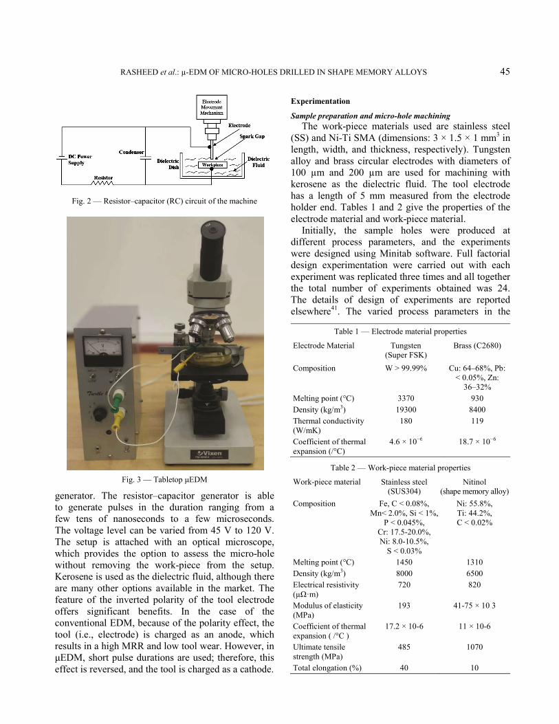
(SS) and Ni-Ti SMA (dimensions: 3 × 1.5 × 1 mm3 in length, width, and thickness, respectively). Tungsten alloy and brass circular electrodes with diameters of 100 µm and 200 µm are used for machining with kerosene as the dielectric fluid. The tool electrode has a length of 5 mm measured from the electrode holder end. Tables 1 and 2 give the properties of the electrode material and work-piece material.
Initially, the sample holes were produced at different process parameters, and the experiments were designed using Minitab software. Full factorial design experimentation were carried out with each experiment was replicated three times and all together the total number of experiments obtained was 24. The details of design of experiments are reported elsewhere41. The varied process parameters in the
Fig. 2 — Resistor–capacitor (RC) circuit of the machine
Fig. 3 — Tabletop μEDM
Table 1 — Electrode material properties
Electrode Material Tungsten (Super FSK)
Brass (C2680)
Composition W > 99.99% Cu: 64–68%, Pb: < 0.05%, Zn:
36–32% Melting point (°C) 3370 930 Density (kg/m3) 19300 8400 Thermal conductivity (W/mK)
180 119
Coefficient of thermal expansion (/°C)
4.6 × 10⁻⁶ 18.7 × 10⁻⁶
Table 2 — Work-piece material properties
Work-piece material Stainless steel (SUS304)
Nitinol (shape memory alloy)
Composition Fe, C < 0.08%, Mn< 2.0%, Si < 1%,
P < 0.045%, Cr: 17.5-20.0%, Ni: 8.0-10.5%,
S < 0.03%
Ni: 55.8%, Ti: 44.2%, C < 0.02%
Melting point (°C) 1450 1310 Density (kg/m3) 8000 6500 Electrical resistivity (µΩ·m)
720 820
Modulus of elasticity (MPa)
193 41-75 × 10 3
Coefficient of thermal expansion ( /°C )
17.2 × 10⁻⁶ 11 × 10-6
Ultimate tensile strength (MPa)
485 1070
Total elongation (%) 40 10
46 INDIAN J. ENG. MATER. SCI., FEBRUARY 2018
present studies are given in Table 3. Then the micro-holes drilled under different pulse energies and pulse forms were observed using the oscilloscope by varying the electrical parameters. Initially, the micro-hole roundness was assessed by an optical microscope (MitutoyoHyper MF High Accuracy Microscope) and a digital microscope (MitutoyoMF Series 176). Surface roughness was measured using Talysurf CCI-900. For microstructure analysis, the work-pieces were prepared using the metallographic technique. The diameters of the micro-holes machined were determined using the Joel JSM-5600 scanning electron microscope (SEM).
Results and Discussion In this study, the optimal machining conditions
used for machining Ni-Ti based SMA (500 µm thickness) are 200 µm diameter brass electrode, discharge energy of 7.525 µJ at 100 V, 4.816 µJ at 80 V, 2.375 µJ at 100 V, and 1.52 µJ at 80 V, suggested by Rasheed et al.41 After a series of experiments it was found that below 80 V, the machining is very slow, and above 100 V the surface finish and hole quality suffers. Therefore, for the machine 80 V and 100 V are two better voltage values for the machine. The performance indicators are MRR, dimensional accuracy, and surface quality of the drilled micro-holes. In this work, deep holes were drilled with negative polarity of the electrode. The electrode dressing is conducted in reverse, i.e., positive polarity, as it helps in more material removal at a faster rate. In the μEDM process, after drilling each micro-hole, the electrode is dressed because it becomes tapered. The discharged energy for different levels of voltage and capacitance is given Table 4.
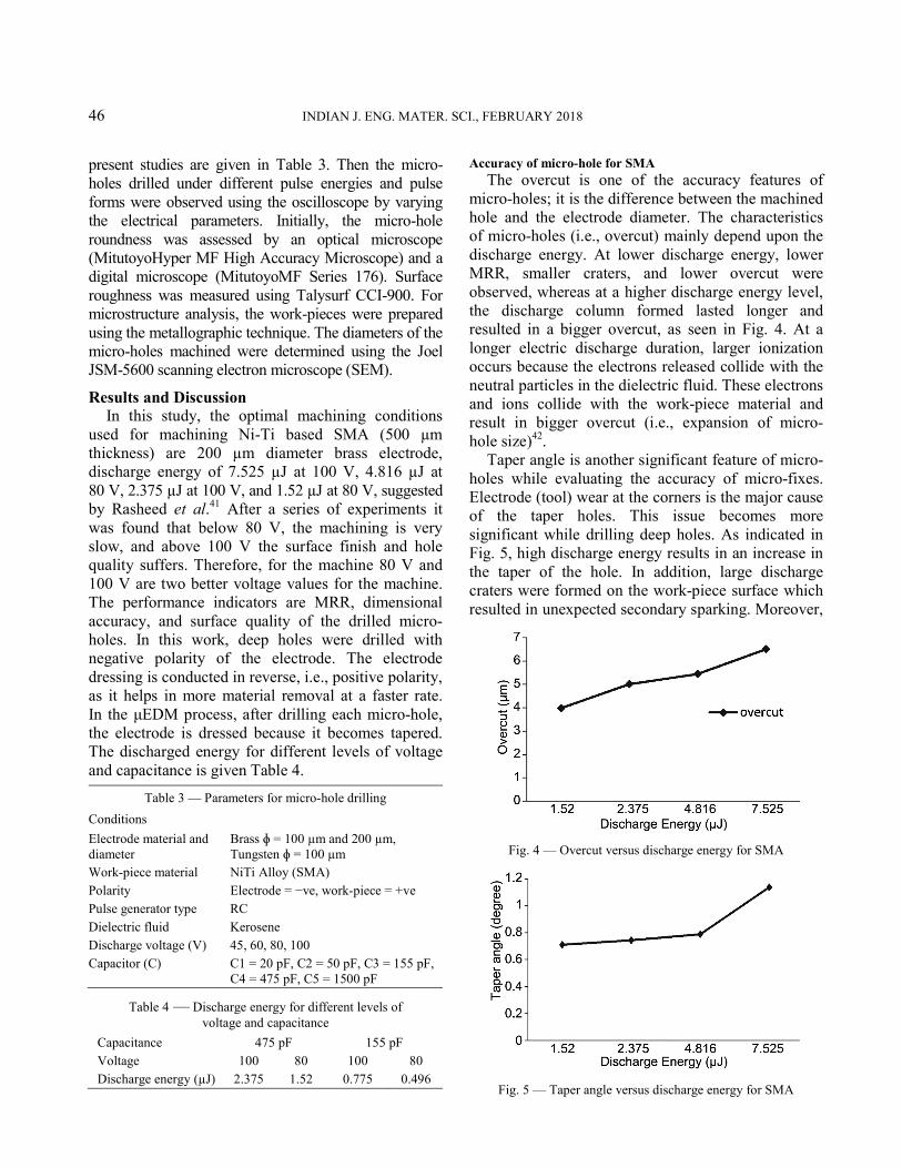
Accuracy of micro-hole for SMA The overcut is one of the accuracy features of
micro-holes; it is the difference between the machined hole and the electrode diameter. The characteristics of micro-holes (i.e., overcut) mainly depend upon the discharge energy. At lower discharge energy, lower MRR, smaller craters, and lower overcut were observed, whereas at a higher discharge energy level, the discharge column formed lasted longer and resulted in a bigger overcut, as seen in Fig. 4. At a longer electric discharge duration, larger ionization occurs because the electrons released collide with the neutral particles in the dielectric fluid. These electrons and ions collide with the work-piece material and result in bigger overcut (i.e., expansion of micro- hole size)42.
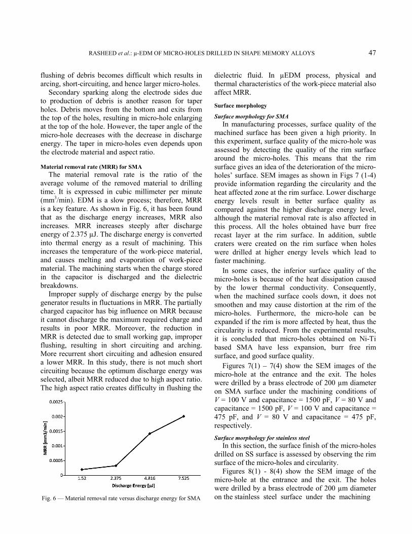
Taper angle is another significant feature of micro-holes while evaluating the accuracy of micro-fixes. Electrode (tool) wear at the corners is the major cause of the taper holes. This issue becomes more significant while drilling deep holes. As indicated in Fig. 5, high discharge energy results in an increase in the taper of the hole. In addition, large discharge craters were formed on the work-piece surface which resulted in unexpected secondary sparking. Moreover,
Table 3 — Parameters for micro-hole drilling
Conditions
Electrode material and diameter
Brass ɸ = 100 µm and 200 µm, Tungsten ɸ = 100 µm
Work-piece material NiTi Alloy (SMA) Polarity Electrode = −ve, work-piece = +ve Pulse generator type RC Dielectric fluid Kerosene Discharge voltage (V) 45, 60, 80, 100 Capacitor (C) C1 = 20 pF, C2 = 50 pF, C3 = 155 pF,
C4 = 475 pF, C5 = 1500 pF
Table 4 — Discharge energy for different levels of voltage and capacitance
Capacitance 475 pF 155 pF Voltage 100 80 100 80 Discharge energy (µJ) 2.375 1.52 0.775 0.496
Fig. 4 — Overcut versus discharge energy for SMA
Fig. 5 — Taper angle versus discharge energy for SMA
RASHEED et al.: µ-EDM OF MICRO-HOLES DRILLED IN SHAPE MEMORY ALLOYS 47
flushing of debris becomes difficult which results in arcing, short-circuiting, and hence larger micro-holes.
Secondary sparking along the electrode sides due to production of debris is another reason for taper holes. Debris moves from the bottom and exits from the top of the holes, resulting in micro-hole enlarging at the top of the hole. However, the taper angle of the micro-hole decreases with the decrease in discharge energy. The taper in micro-holes even depends upon the electrode material and aspect ratio. Material removal rate (MRR) for SMA
The material removal rate is the ratio of the average volume of the removed material to drilling time. It is expressed in cubic millimeter per minute (mm3/min). EDM is a slow process; therefore, MRR is a key feature. As shown in Fig. 6, it has been found that as the discharge energy increases, MRR also increases. MRR increases steeply after discharge energy of 2.375 µJ. The discharge energy is converted into thermal energy as a result of machining. This increases the temperature of the work-piece material, and causes melting and evaporation of work-piece material. The machining starts when the charge stored in the capacitor is discharged and the dielectric breakdowns.
Improper supply of discharge energy by the pulse generator results in fluctuations in MRR. The partially charged capacitor has big influence on MRR because it cannot discharge the maximum required charge and results in poor MRR. Moreover, the reduction in MRR is detected due to small working gap, improper flushing, resulting in short circuiting and arching. More recurrent short circuiting and adhesion ensured a lower MRR. In this study, there is not much short circuiting because the optimum discharge energy was selected, albeit MRR reduced due to high aspect ratio. The high aspect ratio creates difficulty in flushing the
dielectric fluid. In µEDM process, physical and thermal characteristics of the work-piece material also affect MRR.
Surface morphology
Surface morphology for SMA In manufacturing processes, surface quality of the
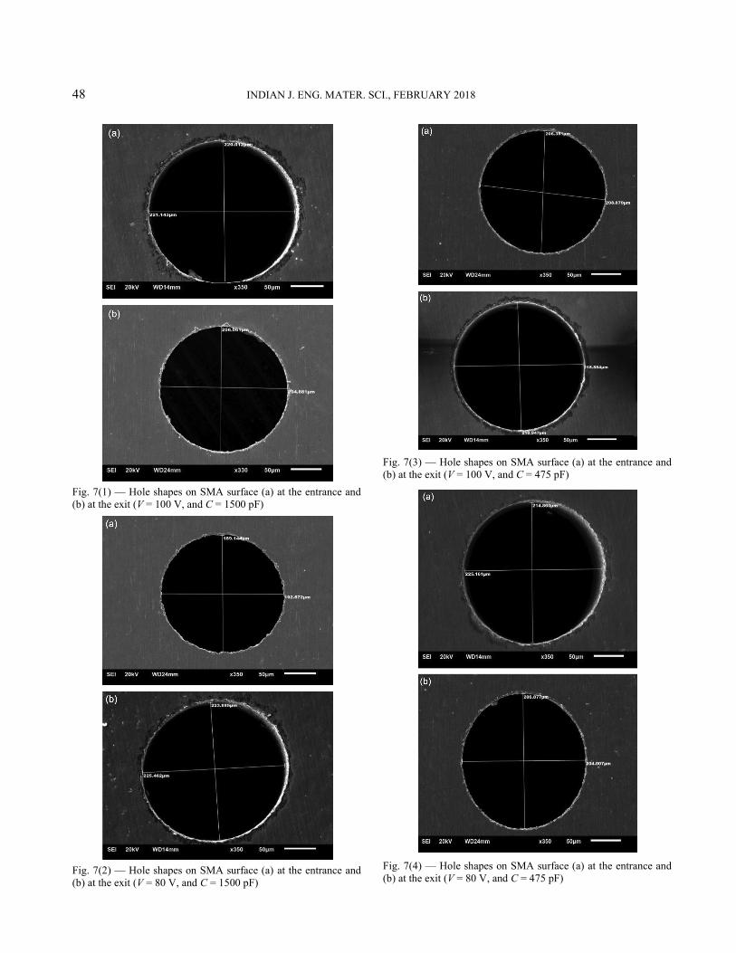
machined surface has been given a high priority. In this experiment, surface quality of the micro-hole was assessed by detecting the quality of the rim surface around the micro-holes. This means that the rim surface gives an idea of the deterioration of the micro-holes’ surface. SEM images as shown in Figs 7 (1-4) provide information regarding the circularity and the heat affected zone at the rim surface. Lower discharge energy levels result in better surface quality as compared against the higher discharge energy level, although the material removal rate is also affected in this process. All the holes obtained have burr free recast layer at the rim surface. In addition, subtle craters were created on the rim surface when holes were drilled at higher energy levels which lead to faster machining.
In some cases, the inferior surface quality of the micro-holes is because of the heat dissipation caused by the lower thermal conductivity. Consequently, when the machined surface cools down, it does not smoothen and may cause distortion at the rim of the micro-holes. Furthermore, the micro-hole can be expanded if the rim is more affected by heat, thus the circularity is reduced. From the experimental results, it is concluded that micro-holes obtained on Ni-Ti based SMA have less expansion, burr free rim surface, and good surface quality.
Figures 7(1) – 7(4) show the SEM images of the micro-hole at the entrance and the exit. The holes were drilled by a brass electrode of 200 µm diameter on SMA surface under the machining conditions of V = 100 V and capacitance = 1500 pF, V = 80 V and capacitance = 1500 pF, V = 100 V and capacitance = 475 pF, and V = 80 V and capacitance = 475 pF, respectively.
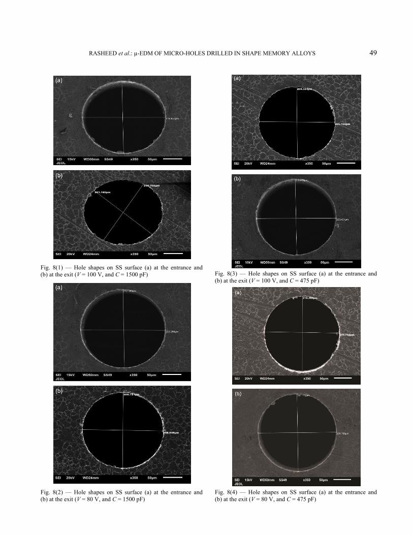
Surface morphology for stainless steel In this section, the surface finish of the micro-holes
drilled on SS surface is assessed by observing the rim surface of the micro-holes and circularity.
Figures 8(1) - 8(4) show the SEM image of the micro-hole at the entrance and the exit. The holes were drilled by a brass electrode of 200 µm diameter on the stainless steel surface under the machining
Fig. 6 — Material removal rate versus discharge energy for SMA
48 INDIAN J. ENG. MATER. SCI., FEBRUARY 2018
Fig. 7(1) — Hole shapes on SMA surface (a) at the entrance and (b) at the exit (V = 100 V, and C = 1500 pF)
Fig. 7(2) — Hole shapes on SMA surface (a) at the entrance and (b) at the exit (V = 80 V, and C = 1500 pF)
Fig. 7(3) — Hole shapes on SMA surface (a) at the entrance and (b) at the exit (V = 100 V, and C = 475 pF)
Fig. 7(4) — Hole shapes on SMA surface (a) at the entrance and (b) at the exit (V = 80 V, and C = 475 pF)
RASHEED et al.: µ-EDM OF MICRO-HOLES DRILLED IN SHAPE MEMORY ALLOYS 49
Fig. 8(1) — Hole shapes on SS surface (a) at the entrance and (b) at the exit (V = 100 V, and C = 1500 pF)
Fig. 8(2) — Hole shapes on SS surface (a) at the entrance and (b) at the exit (V = 80 V, and C = 1500 pF)
Fig. 8(3) — Hole shapes on SS surface (a) at the entrance and (b) at the exit (V = 100 V, and C = 475 pF)
Fig. 8(4) — Hole shapes on SS surface (a) at the entrance and (b) at the exit (V = 80 V, and C = 475 pF)
50 INDIAN J. ENG. MATER. SCI., FEBRUARY 2018
conditions of V = 100 V and C = 1500 pF, V = 80 V and C = 1500 pF, V = 100 V and C = 475 pF, and V = 80 V and C = 475 pF, respectively.
The surface quality of the micro-holes is found better at smaller discharge energy levels. At higher energy levels, the spatter around the micro-holes is more than the one at smaller energy levels. Based on Fig. 7 (1-4) and Fig. 8 (1-4), it can be concluded that the surface quality of the micro-holes produced on Ni-Ti based SMA are better than those produced on stainless steel. Therefore, it can be concluded that µEDM is an efficient process to obtain micro holes of better quality in difficult-to-cut material, such as Ni-Ti based SMA.
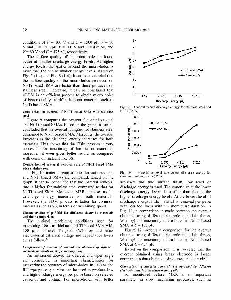
Comparison of overcut of Ni-Ti based SMA with stainless steel
Figure 9 compares the overcut for stainless steel and Ni-Ti based SMAs. Based on the graph, it can be concluded that the overcut is higher for stainless steel compared to Ni-Ti based SMA. Moreover, the overcut increases as the discharge energy increases for both materials. This shows that the EDM process is very successful for machining of hard-to-cut materials, moreover, it even gives better results as compared with common material like SS.
Comparison of material removal rate of Ni-Ti based SMA with stainless steel
In Fig. 10, material removal rates for stainless steel and Ni-Ti based SMAs are compared. Based on the graph, it can be concluded that the material removal rate is higher for stainless steel compared to that for Ni-Ti based SMA. Moreover, MRR increases as the discharge energy increases for both materials. However, the EDM process is better for common materials such as SS, in terms of machining speed.
Characteristics of µ-EDM for different electrode materials and their comparison
The optimal machining conditions used for machining 100 µm thickness Ni-Ti based SMA with 100 µm diameter Tungsten (W)-alloy and brass electrodes at different voltage and capacitance levels are as follows37:
Comparison of overcut of micro-holes obtained by different electrode materials on shape memory alloy
As mentioned above, the overcut and taper angle are considered as important characteristics for measuring the accuracy of micro-holes. In µEDM, the RC-type pulse generator can be used to produce low and high discharge energy per pulse based on selected capacitor and voltage. For micro-holes with better
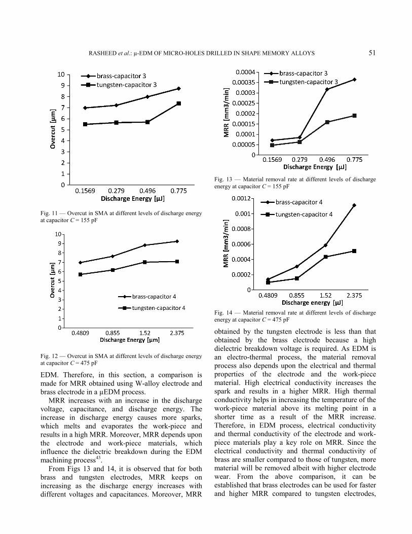
accuracy and fine surface finish, low level of discharge energy is used. The crater size at the lower discharge energy levels is smaller than that at the higher discharge energy levels. At the lowest level of discharge energy, little material is removed per pulse with less tool wear within a short pulse duration. In Fig. 11, a comparison is made between the overcut obtained using different electrode materials (brass, W-alloy) for machining micro-holes in Ni-Ti based SMA at C = 155 pF.
Figure 12 presents a comparison for the overcut obtained using different electrode materials (brass, W-alloy) for machining micro-holes in Ni-Ti based SMA at C = 475 pF.
Based on the comparison, it is revealed that the overcut obtained using brass electrode is larger compared to that obtained using tungsten electrode.
Comparison of material removal rate obtained by different electrode materials on shape memory alloy
As mentioned before, MRR is an important parameter in slow machining processes, such as
Fig. 9 — Overcut versus discharge energy for stainless steel and Ni-Ti (SMA)
Fig. 10 — Material removal rate versus discharge energy for stainless steel and Ni-Ti (SMA)
RASHEED et al.: µ-EDM OF MICRO-HOLES DRILLED IN SHAPE MEMORY ALLOYS 51
EDM. Therefore, in this section, a comparison is made for MRR obtained using W-alloy electrode and brass electrode in a µEDM process.
MRR increases with an increase in the discharge voltage, capacitance, and discharge energy. The increase in discharge energy causes more sparks, which melts and evaporates the work-piece and results in a high MRR. Moreover, MRR depends upon the electrode and work-piece materials, which influence the dielectric breakdown during the EDM machining process43.
From Figs 13 and 14, it is observed that for both brass and tungsten electrodes, MRR keeps on increasing as the discharge energy increases with different voltages and capacitances. Moreover, MRR
obtained by the tungsten electrode is less than that obtained by the brass electrode because a high dielectric breakdown voltage is required. As EDM is an electro-thermal process, the material removal process also depends upon the electrical and thermal properties of the electrode and the work-piece material. High electrical conductivity increases the spark and results in a higher MRR. High thermal conductivity helps in increasing the temperature of the work-piece material above its melting point in a shorter time as a result of the MRR increase. Therefore, in EDM process, electrical conductivity and thermal conductivity of the electrode and work-piece materials play a key role on MRR. Since the electrical conductivity and thermal conductivity of brass are smaller compared to those of tungsten, more material will be removed albeit with higher electrode wear. From the above comparison, it can be established that brass electrodes can be used for faster and higher MRR compared to tungsten electrodes,
Fig. 11 — Overcut in SMA at different levels of discharge energy at capacitor C = 155 pF
Fig. 12 — Overcut in SMA at different levels of discharge energy at capacitor C = 475 pF
Fig. 13 — Material removal rate at different levels of discharge energy at capacitor C = 155 pF
Fig. 14 — Material removal rate at different levels of discharge energy at capacitor C = 475 pF

52 INDIAN J. ENG. MATER. SCI., FEBRUARY 2018
sacrificing the surface quality and dimensional accuracy of micro-holes.
Comparison of tool wear rate (TWR) obtained by different electrode materials on shape memory alloy
In any machining process, tool consumption rate is of vital importance. In µEDM, the wear of the tool electrode is responsible for the shape and dimensional inaccuracy of the holes produced. In this study, volumetric tool wear rate (TWR) of two electrode materials (brass and tungsten) was calculated. Figure 15 shows the tool wear rate of brass and tungsten electrodes at different energy levels.
It can be seen that for the brass electrode the TWR increases as the discharge energy increases and then at higher energy levels it changes slightly. However, in the case of tungsten electrode, initially the TWR is lower at lower energy levels because of higher machining time at low energy levels, where the initial supply current is lower and it prevents the sparks taking place continuously, resulting in discontinuous discharging. Generally, the tool wear rate increases with an increase in discharge energy levels and this increase in the discharge energy increases the crater size and more material is removed both from the work-piece and the tool electrode. Thus, as the discharge energy increases, TWR also increases accordingly. As the melting point of tungsten is three times of that of brass, the TWR of the tungsten electrode is lower than that of the brass material. In addition to the melting point, thermal conductivity of brass is lower than that of tungsten, which also results in higher TWR of brass.
Comparison of surface roughness obtained from different electrode materials on shape memory alloy
In manufacturing process, the most important thing to be taken into account after machining is the surface roughness. This is defined as the surface irregularities
on the machined area due to different reasons. In µEDM, the surface obtained after machining consists of a large number of small craters in micro to nano size which are randomly distributed all over the machined surface. In micro-EDM, the electric sparks produce high temperature between the work-piece and the tool electrode which melts the material. The surface roughness mainly depends upon the working parameters such as discharge energy (capacitance and discharge voltage). Surface roughness is characterized by the discharge craters and melting drops. From Fig. 16, it can be seen that with an increase in discharge energy the surface roughness also increases. It is observed that with the increase in the discharge energy, the crater size also increases with uneven distribution of craters along machined surface, thus leading to noticeable surface roughness.
Figure 17 presents the SEM images of the cross-sections of micro-holes produced at different energy levels. It can be seen that the Ra (Ra is the average of a set of individual measurements of a surfaces peaks and valleys) value obtained using the tungsten electrode is smaller, and the minimum Ra value obtained is 0.086 µm and the maximum Ra is 0.1151 µm. The minimum and maximum Ra values obtained using the brass electrode are 0.0993 µm and 0.1349 µm, respectively. From the above results, tungsten electrodes can be used for better surface finish when MRR is not a criterion.
Comparison of surface quality obtained from different electrode materials on shape memory alloy
As mentioned previously, for micro-holes, surface quality is mainly determined based on the crater size. The holes with smaller and uniform distribution of craters are considered as good surface finish quality. Based on the experimental study, it can be concluded
Fig. 15 — Tool wear rate at different levels of discharge energy
Fig. 16 — Surface roughness obtained at different discharge energy levels

RASHEED et al.: µ-EDM OF MICRO-HOLES DRILLED IN SHAPE MEMORY ALLOYS 53
that smaller crater sizes are obtained at lower discharge energy levels with a smaller amount of material removal per pulse. To attain a better surface quality, the resistor–capacitance generator should provide low discharge energy by supplying low voltage and capacitance.
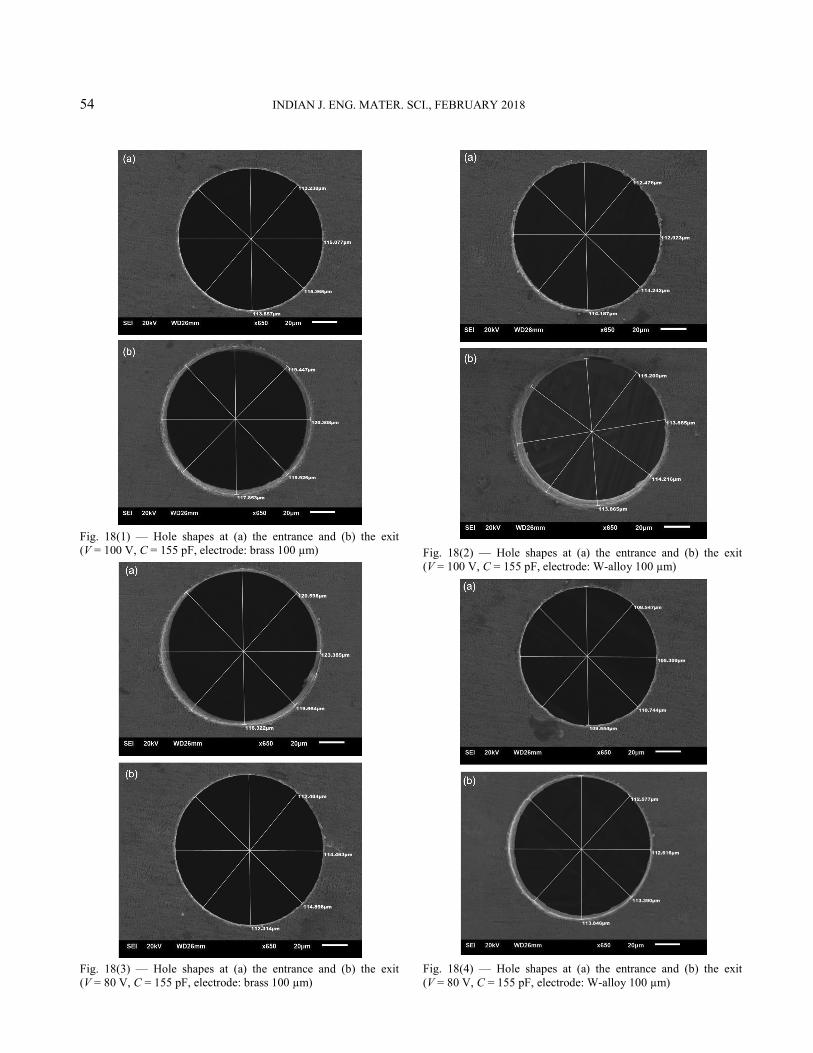
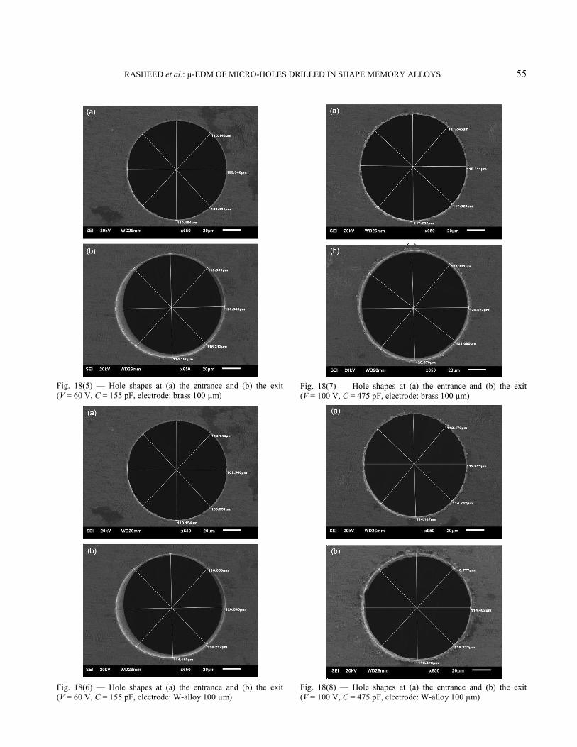
In this study, from Figs 18 (1-12) it can be seen that both electrodes at lower discharge energy levels results in better surface quality with a small crater size and in turn decreases the surface roughness. It is also revealed that there might be non-uniform distribution of carter size, which is because of the non-uniform energy supplied by the pulse generator. Hence, at low voltages the gloss is reduced because of non-uniform distribution of craters. When the craters are non-uniformly distributed, a dull and low glossy surface is observed. The reasons for the non-uniformity of the crater size are in the RC-type generators. The machining occurs only when the dielectric breakdowns and the capacitor discharges the charge stored in it. If the dielectric disintegrates before the capacitor is fully charged, it will result in
lower discharge energy and cause non-uniform distribution of craters. However, at higher energy levels when the capacitor is fully charged and then the breakdown of dielectric occurs only, there will be less chance of non-uniformity of craters. At lower discharge energy levels, the energy per pulse is low and causes short circuiting and arcing because of the small working gap between the tool electrode and the work-piece. Flushing of the dielectric will be improper when the working gap is small, leading the debris to stick to the electrode material and resulting in non-uniformity of crater formation around the rim of the hole. In addition, low thermal and electrical conductivities of the electrode and work-piece materials used can be another reason for the non-uniformity.
Therefore, from the above results it can be concluded that the SMA surface machined by the tungsten electrode has better uniformity of craters with good surface finish albeit the material removal rate is lower as compared to those using the brass electrode.
Fig. 17 — Comparison of surface roughness at different energy levels: (a) tungsten electrode at 0.49 µJ, (b) tungsten electrode at 1.52 µJ, (c) brass electrode at 0.49 µJ and (d) brass electrode at 1.52 µJ
54 INDIAN J. ENG. MATER. SCI., FEBRUARY 2018
Fig. 18(1) — Hole shapes at (a) the entrance and (b) the exit (V = 100 V, C = 155 pF, electrode: brass 100 µm)
Fig. 18(3) — Hole shapes at (a) the entrance and (b) the exit (V = 80 V, C = 155 pF, electrode: brass 100 µm)
Fig. 18(2) — Hole shapes at (a) the entrance and (b) the exit (V = 100 V, C = 155 pF, electrode: W-alloy 100 µm)
Fig. 18(4) — Hole shapes at (a) the entrance and (b) the exit (V = 80 V, C = 155 pF, electrode: W-alloy 100 µm)
RASHEED et al.: µ-EDM OF MICRO-HOLES DRILLED IN SHAPE MEMORY ALLOYS 55
Fig. 18(5) — Hole shapes at (a) the entrance and (b) the exit (V = 60 V, C = 155 pF, electrode: brass 100 µm)
Fig. 18(6) — Hole shapes at (a) the entrance and (b) the exit (V = 60 V, C = 155 pF, electrode: W-alloy 100 µm)
Fig. 18(7) — Hole shapes at (a) the entrance and (b) the exit (V = 100 V, C = 475 pF, electrode: brass 100 µm)
Fig. 18(8) — Hole shapes at (a) the entrance and (b) the exit (V = 100 V, C = 475 pF, electrode: W-alloy 100 µm)
56 INDIAN J. ENG. MATER. SCI., FEBRUARY 2018
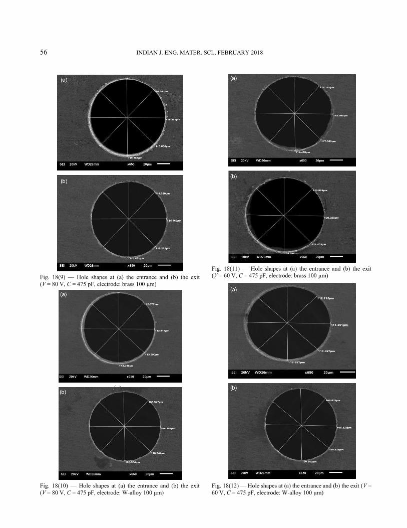
Fig. 18(9) — Hole shapes at (a) the entrance and (b) the exit (V = 80 V, C = 475 pF, electrode: brass 100 µm)
Fig. 18(10) — Hole shapes at (a) the entrance and (b) the exit (V = 80 V, C = 475 pF, electrode: W-alloy 100 µm)
Fig. 18(11) — Hole shapes at (a) the entrance and (b) the exit (V = 60 V, C = 475 pF, electrode: brass 100 µm)
Fig. 18(12) — Hole shapes at (a) the entrance and (b) the exit (V = 60 V, C = 475 pF, electrode: W-alloy 100 µm)

RASHEED et al.: µ-EDM OF MICRO-HOLES DRILLED IN SHAPE MEMORY ALLOYS 57
Conclusions The experimental investigation of micro-holes on
Ni-Ti based SMA using µEDM is conducted using different electrode materials and a comparative study is carried out on the performance of different electrode materials. Based on this investigation the following conclusions are drawn:
(i) The MRR and accuracy of the micro-holes basically depend upon different machining parameters such as discharge energy (i.e., discharge voltage and capacitance of the RC-type pulse generator) and the electrical and thermal properties of the material.
(ii) In µEDM of SMA, fine surface finish can be obtained at a lower energy level with lower voltage and capacitance of the RC-type pulse generator.
(iii) Micro-holes produced on SMA are found to be superior in terms of circularity, burr-free surface, small heat affected zone, and good surface quality at the rim of the holes. It is also observed that overcut and hole expansion are less in SMA as compared to those in SS. However, the MRR is higher in stainless steel.
(iv) In the µEDM process of SMA, it is determined that the tungsten electrode is best for fine surface finish with a small crater size and less tool wear, while the MRR is smaller as compared to the brass electrode.
(v) It is observed that the MRR, overcut, and taper angle which basically depend upon the discharge energy, voltage and capacitance are larger with the brass electrode in µEDM of SMA. In addition, these performance indicators also depend upon the melting point, evaporation point, and thermal and electrical conductivities of the electrode and work-piece materials.
(vi) In general, it can be concluded that in µEDM of Ni-Ti based SMA, brass electrodes can be used for higher material removal when surface quality is not a criterion, whereas tungsten electrodes can be used when the surface quality is of more importance.
Acknowledgments The authors are grateful to the Deanship of
Scientific Research, King Saud University for funding through Vice Deanship of Scientific Research Chairs.
References 1 Yu Z Y, Rajurkar K P & Shen H, CIRP Ann - Manuf
Technol, 51 (2002) 359-362. 2 Al-Ahmari A M A, Rasheed M S, Mohammed M K &
Saleh T, Mater Manuf Process, 31 (2016) 447-455. 3 Endo T, Tsujimoto T & Mitsui K, Prec Eng, 32 (2008)
269-277. 4 Masuzawa T, CIRP Ann - Manuf Technol, 49 (2000)
473-488. 5 Yu Z Y, Masuzawa T & Fujino M, CIRP Ann - Manuf
Technol, 47 (1998) 169-172. 6 Puertas I, Luis C J & Álvarez L, J Mater Process Technol,
153-154 (2004) 1026-1032. 7 Potz D, Christ W & Dittus B, in Thermo-and Fluid-dynamic
Processes in Diesel Engines, edited by Whitelaw J H W, Payri F & Desantes J M, (Springe), 2000, p. 133-142.
8 Zhang L, Tong H & Li Y, Prec Eng, 39 (2015) 100-106. 9 D’Urso G & Merla C, Prec Eng, 38 (2014) 903-914. 10 Guitrau E B, The EDM Handbook 1997, (Hanser Publications),
1997. 11 Allen D M & Lecheheb A, J Mater Process Technol,
58 (1996) 53-66. 12 Sato T, Mizutani T, Yonemochi K & Kawata K, Prec Eng,
8 (1986) 163-168. 13 Masuzawa T, Tsukamoto J & Fujino M, CIRP Ann - Manuf
Technol, 38 (1989) 195-198. 14 Hourmand M, Sarhan A A D & Noordin M Y, Measurement,
97 (2017) 64-78. 15 Diver C, Atkinson J, Helml H J & Li L, J Mater Process
Technol, 149 (2004) 296-303. 16 Jeong Y H & Min B K, Int J Mach Tools Manuf, 47 (2007)
1817-1826. 17 Han F, Yamada Y, Kawakami T & Kunieda M, Prec Eng,
30 (2006) 123-131. 18 Egashira K, Morita Y & Hattori Y, Prec Eng, 34 (2010)
139-144. 19 Yan B H, Wang A C, Huang C Y & Huang F Y, Int J Mach
Tools Manuf, 42 (2002) 1105-1112. 20 Reynaerts D, Heeren P H & Brussel H V, Theory, Sensors
Actuators, A60 (1997) 212-218. 21 Rajurkar K P & Yu Z Y, CIRP Ann - Manuf Technol,
49 (2000) 127-130. 22 Masuzawa T, Kuo C L & Fujino M, CIRP Ann - Manuf
Technol, 43 (1994) 189-192. 23 Kuo C L, Masuzawa T & Fujino M, Proc IEEE Micro
Electro Mechanical Systems, 1991, p. 80-85. 24 Liu H-S, Yan B-H, Huang F-Y & Qiu K-H, J Mater Process
Technol, 169 (2005) 418-426. 25 Yan B H, Huang F Y, Chow H M & Tsai J Y, J Mater
Process Technol, 87 (1999) 139-145. 26 Garn R, Schubert A & Zeidler H, Prec Eng, 35 (2011)
364-368. 27 Jahan M P, Wong Y S & Rahman M, J Mater Process
Technol, 209 (2009) 3956-3967. 28 Tak H-S, Ha C-S, Kim D-H, Lee H-J, Lee H-J & Kang M-C,
Trans Nonferrous Met Soc China, 19 (2009) s114-s118. 29 Jahan M P, Wong Y S & Rahman M, Int J Adv Manuf
Technol, 46 (2010) 1145-1160. 30 Zou R, Yu Z, Li W, Guo M & Li J, J Mater Process Technol,
232 (2016) 43-51.

58 INDIAN J. ENG. MATER. SCI., FEBRUARY 2018
31 Fu Y, Miyamoto T, Natsu W, Zhao W & Yu Z, Procedia CIRP, 42 (2016) 516-520.
32 Dong S, Wang Z, Wang Y & Liu H, Procedia CIRP, 42 (2016) 257-262.
33 Uhlmann E, Schimmelpfennig T-M, Perfilov I, Streckenbach J & Schweitzer L, Procedia CIRP, 42 (2016 ) 173-178.
34 Chu X, Zhu K, Wang C, Hu Z & Zhang Y, Mater Manuf Process, 31 (2016) 381-390.
35 Liu Q, Zhang Q, Zhu G, Wang K, Zhang J & Dong C, Mater Manuf Process, 31 (2016) 391-396.
36 Shabalovskaya S A, Bio-med Mate Eng, 12 (2002) 69-109. 37 Otsuka K & Kakeshita T, MRS Bull, 27 (2011) 91-100. 38 Stoeckel D, Minimally Invasive Therapy Allied Technol,
9 (2000 ) 81-88.
39 Lin H C, Lin K M & Chen Y C, J Mater Process Technol, 105 (2000) 327-332.
40 Theisen W & Schuermann A, Mater Sci Eng A, 378 (2004) 200-204.
41 Rasheed M S, Abidi M H, El-Tamimi A M & Al-Ahmari A M, Adv Mater Res, 816-817 (2013) 173-179.
42 Klimkin V F, Super high-speed anode pre-breakdown phenomena in liquid dielectrics under uniform fields. Conduction and Breakdown in Dielectric Liquids,1993, ICDL '93, IEEE 11th International Conference on. 1993, p. 299-303.
43 Mahardika M, Tsujimoto T & Mitsui K, Int J Mach Tools Manuf, 48 (2008) 746-760.