
Performance of a PV–wind hybrid system for hydrogen production
Upload
independentCategory
view
4download
0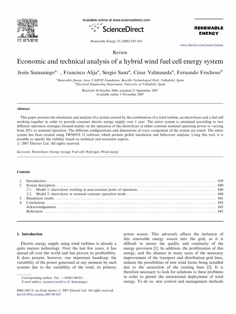
ARTICLE IN PRESS
0960-1481/$ - se
doi:10.1016/j.re
�CorrespondE-mail addr
Renewable Energy 33 (2008) 839–845
www.elsevier.com/locate/renene
Review
Economic and technical analysis of a hybrid wind fuel cell energy system
Jesus Samaniegoa,�, Francisco Alijaa, Sergio Sanza, Cesar Valmasedaa, Fernando Frechosob
aRenewable Energy Area, CARTIF Foundation, Boecillo Technological Park, Valladolid, SpainbElectrical Engineering Department, University of Valladolid, Spain
Received 30 October 2006; accepted 21 September 2007
Available online 5 November 2007
Abstract
This paper presents the simulation and analysis of a system created by the combination of a wind turbine, an electrolyser and a fuel cell
working together in order to provide constant electric energy supply over 1 year. The entire system is simulated according to two
different operation strategies focused mainly on the operation of the electrolyser at either constant nominal operating power or varying
from 20% to nominal operation. The different configurations and dimensions of every component of the system are tested. The entire
system has been created using TRNSYS 15 software which permits global simulation and behaviour analysis. Using this tool, it is
possible to specify the viability based on technical and economic aspects.
r 2007 Elsevier Ltd. All rights reserved.
Keywords: Electrolyser; Energy storage; Fuel cell; Hydrogen; Wind energy
Contents
1. Introduction . . . . . . . . . . . . . . . . . . . . . . . . . . . . . . . . . . . . . . . . . . . . . . . . . . . . . . . . . . . . . . . . . . . . . . . . . . . . . . . 839
2. System description . . . . . . . . . . . . . . . . . . . . . . . . . . . . . . . . . . . . . . . . . . . . . . . . . . . . . . . . . . . . . . . . . . . . . . . . . . . 840
2.1. Model 1: electrolyser working at non-constant point of operation . . . . . . . . . . . . . . . . . . . . . . . . . . . . . . . . . . . . . 840
2.2. Model 2: electrolyser at nominal constant operation mode . . . . . . . . . . . . . . . . . . . . . . . . . . . . . . . . . . . . . . . . . . 840
3. Simulation results . . . . . . . . . . . . . . . . . . . . . . . . . . . . . . . . . . . . . . . . . . . . . . . . . . . . . . . . . . . . . . . . . . . . . . . . . . . 841
4. Conclusions . . . . . . . . . . . . . . . . . . . . . . . . . . . . . . . . . . . . . . . . . . . . . . . . . . . . . . . . . . . . . . . . . . . . . . . . . . . . . . . 845
Acknowledgements . . . . . . . . . . . . . . . . . . . . . . . . . . . . . . . . . . . . . . . . . . . . . . . . . . . . . . . . . . . . . . . . . . . . . . . . . . 845
References . . . . . . . . . . . . . . . . . . . . . . . . . . . . . . . . . . . . . . . . . . . . . . . . . . . . . . . . . . . . . . . . . . . . . . . . . . . . . . . . 845
1. Introduction
Electric energy supply using wind turbines is already aquite mature technology. Over the last few years, it hasspread all over the world and has proven its profitability.It does present, however, one important handicap: thevariability of the power generated at any moment by suchsystems due to the variability of the wind, its primary
e front matter r 2007 Elsevier Ltd. All rights reserved.
nene.2007.09.023
ing author. Tel.: +34983 548 911.
ess: [email protected] (J. Samaniego).
power source. This adversely affects the inclusion ofthis renewable energy source into the grid, as it isdifficult to ensure the quality and continuity of theenergy provision [1]. In addition, the proliferation of thisenergy, and the absence in many cases of the necessaryimprovement of the transport and distribution grid lines,reduces the possibilities of new wind farms being installeddue to the saturation of the existing lines [2]. It istherefore necessary to look for solutions to these problemsin order to permit the unrestricted deployment of windenergy. To do so, new control and management methods

ARTICLE IN PRESSJ. Samaniego et al. / Renewable Energy 33 (2008) 839–845840
are needed, as well as alternative applications for this kindof energy.
One of the main options for overcoming these problemsis the storage and later use of the energy generated by thewind farm, enabling the control of the energy supplied atany moment independently of the strength of the wind.Due to the current difficulties for storing electrical energy,it is necessary to look for new methods of electrical energystorage.
An interesting process to achieve this goal is hydrogenproduction through an electrolysis process using theelectrical energy from the wind turbine, storing the hydrogenat high pressure and then re-converting it to electrical energyusing a fuel cell [3–9]. By means of this process, continuouselectrical energy generation would be possible over longperiods of time, something which is impossible when usingthe energy produced by the wind turbines directly ondemand. Taking this issue into account, many authors linkthe expansion of the energy system to wind energygeneration and hydrogen production from cheap and cleanelectricity obtained from the wind [1,3–5]. Nevertheless, suchsystems are still undergoing research and development,which means it is necessary to study adequate strategies ofoperation in order to achieve an efficient management of theenergy generated [8,10].
Based on these concepts, this work develops andanalyses a system made up of a wind turbine to extractthe energy from the wind, and a subsystem oriented tohydrogen production, storage and reutilisation in order toprovide a constant electrical power supply over longperiods of time. The subsystem consists of a set ofelectrolysers to exploit the energy from the wind turbineduring periods of over-production, converting it tohydrogen, which is stored at high pressure and laterreconverted into electrical energy by a fuel cell when extrapower is needed, over and above that provided directly bythe wind power, in order to maintain the power constantalongside the demand.
2. System description
Two models of the hybrid wind–hydrogen system havebeen developed based on HYDROGEMS, a library madeup of technical hydrogen energy models developed at theInstitute for Energy Technology [11], compatible withTRNSYS, a transient system simulation program [12].Both systems have the same global strategy which is tosupply a constant electrical power over a whole year, whileone of them operates the electrolyser at constant nominaloperating power and the other within a range varying from20% to nominal. Both models of the system permit an in-depth analysis of their performance and technical viabilityassociated with economic aspects.
The first step for both models is the choice of theelectrical power to be supplied over the year. This dependson forecasting the wind present in the place to be simulatedand the type of wind turbines to be used at this place,
which are both inputs to the model. The operation strategyof the whole system is based on the best exploitation of theexcess energy produced by the wind farm over and abovethe constant amount to be supplied on demand, storing itin hydrogen form. This treatment of the extra energy isconditioned by several control criteria based mainly on thelimited capacity of the hydrogen vessels and the excess ofpower generated by the wind turbine at any particularmoment.
2.1. Model 1: electrolyser working at non-constant point of
operation
In this operation mode, the electrolyser starts workingwhen the power generated by the wind turbine exceeds thepower demand by 20% of the electrolyser nominal powerplus the power needed to run the hydrogen compressor.The main aspect of this operation mode is that the excessenergy from the wind turbine in its entirety is used toproduce hydrogen, as long as none of the controls ortechnical characteristics of the electrolyser prevent itsoperation. On the other hand, its main disadvantage isthat there are many interruptions in the operation of theelectrolyser, thus lowering its performance, reducing itsuseful life and decreasing the purity of the hydrogenproduced. This disadvantage appears when using analkaline electrolyser, which is the case for the presentsystem, because it shows a better performance in constantoperation [13]. On the other hand, this is not a big problemwhen using a PEM electrolyser, although this is much moreexpensive, which limits its use when high power handling isrequired, as is our case.There are several states and variables to be managed
during the operation of the system. One is the electricalpower generated by the wind turbine, which determines theexcess energy to be used in the electrolyser. The other isthe necessary power generated by the fuel cell to fulfil thedemand. In order to control the start/stop of the electro-lyser, its nominal operating power and the level in thehydrogen vessels are taken into account. The operation ofthe fuel cell is managed according to the extra power neededto cover the demand while the amount of stored hydrogen issufficient to ensure the safe operation of the fuel cell and,when the hydrogen level is too low, that the fuel cell must bestopped according to a standard procedure.This model, despite its disadvantages regarding the
operation and performance of the electrolyser, provides agood basis for the analysis of the behaviour of itscomponents and their sizing according to the primeobjectives (Fig. 1).
2.2. Model 2: electrolyser at nominal constant operation
mode
This system tries to overcome the inconvenience ofthe continuous start/stop of the electrolyser presentedpreviously by ensuring the constant operation of the

ARTICLE IN PRESS
Fig. 1. System model for non-constant operation mode of the electrolyser (black connectors carry power; colour connectors carry main control signals).
Fig. 2. System model for constant operation mode of the electrolyser (black connectors carry power; colour connectors carry main control signals).
J. Samaniego et al. / Renewable Energy 33 (2008) 839–845 841
electrolyser at its nominal power over long periods of time,while also maintaining constant power supply to the load.Focusing on this purpose, a set of batteries have beenlinked to the system between the power conditioning andthe electrolyser to stabilise and guarantee the electricalpower by feeding the electrolyser during its periods ofoperation. In this case, the control system is similar to thecontrol of the system presented above. Now, however, it ismore complex due to the optimal managing of the excessenergy with new control signals for the batteries and newways to improve the energy use. It should be pointed outthat the electrolyser is only turned on when the batteriesare charged over 95%, and that it stays on until thecharging level of the batteries is too low to continue. Then,when the electrolyser is off, the excess energy generated isused to charge the batteries. During the operation of theelectrolyser, the excess energy is used as follows:
�
If the excess is greater than the power required by theelectrolyser, the rest of the power is used to charge thebatteries if they are under the charging limit, and if not,it will be lost. � If the excess is lower than the power required by theelectrolyser, the rest of the power needed to operate theelectrolyser is supplied by the batteries.
� And finally, if there is no power excess from the windturbine, all the energy needed to operate the electrolyseris supplied by the batteries.
When the constant demand is not covered by the windturbine production, the rest of the power needed to cover
the demand is supplied by the PEM fuel cell, if permittedby the level in the hydrogen storage vessels (Fig. 2).
3. Simulation results
Both models have been simulated with variations in theconstant power demand and the quantity of equipmentintegrated into the system according to the results ofprevious simulations and the prime objective. The char-acteristics of the equipment used in this system arepresented in Table 1:Modifications performed during the simulation period
were:
�
Electrolyser: Its nominal power was modified from 220to 660 kW varying the number of electrolyser stacks. � Hydrogen vessel: Its capacity was modified from 200 to1000m3, always at 200 bar.
� PEM fuel cell: Its nominal power was modified, varyingthe number of stacks to equal the power demand,ensuring supply even without wind.
� Batteries: The capacity was modified from 4166 to11804 kWh in order to minimise electrolyser interrup-tions.
� Electrical demand: Its constant power value was changedfrom 50 to 250 kW.
The wind data inserted in the simulations were registeredover 12 months from 2002 to 2003 in La Murallameteorological station situated in Galicia, Spain [14].

ARTICLE IN PRESSJ. Samaniego et al. / Renewable Energy 33 (2008) 839–845842
Before carrying out the system simulation, the constantpower demand and the configuration of all the parametersmust be chosen. The result of the simulation is thebalance over 12 months of the energy and power of theglobal system and each of its components. The hydrogenproduced, stored and consumed, and the calorificenergy generated by the electrolysis process and by thePEM fuel cell are obtained as secondary data. Besidesthis technical data an economic assessment for eachsimulation is also obtained, taking into account the initial
Table 1
Technical characteristics of the equipment
Characteristics
Wind turbine � Model Gamesa G52
� Nominal power: 850 kW
Electrolyser � Model GHW
� Electrodes area: 0.25m2
� Nominal pressure: 30 bar
� Snack cells: 70
� Nominal power: 220 kW
Vessel � Capacity: 200–1000m3
� Pressure: 200 bar
Fuel cell � PEM
� Cell area: 500 cm2
� PEM membrane area: 320 cm2
� Number of cells: 100
Batteries (only in the second model) � Tudor model, 28 GroE 2800
� Capacity of each battery:
2800Ah
� Nominal voltage of the cell: 2.3V
� Charge efficiency: 0.7
Fig. 3. Power balance with the electr
investment according to the size of the equipment [13,15],the earnings due to the electrical energy sold to the demand[16] and the excess hydrogen stored at the end of thesimulation [17,18].Figs. 3 and 4 show an example of the results obtained
from the simulation of each model considering theoperation modes described above: Fig. 3 presents thepower balance of the system operating in non-constantelectrolyser mode and Fig. 4 in constant electrolyseroperation mode. These figures show a period of 200 hextracted from a whole year simulation for the sameconfiguration in both cases: electrical demand of 100 kW,single electrolyser, 850m3 hydrogen vessel capacity withthe electrical power supply from the wind turbine changingaccording to the real data registered at the meteorologicalstation. In order to cover the constant electrical demand atevery moment over 1 year, all the equipment had to besized in excess, resulting in huge energy wastage over longperiods.Figs. 5 and 6 present the amount of hydrogen and
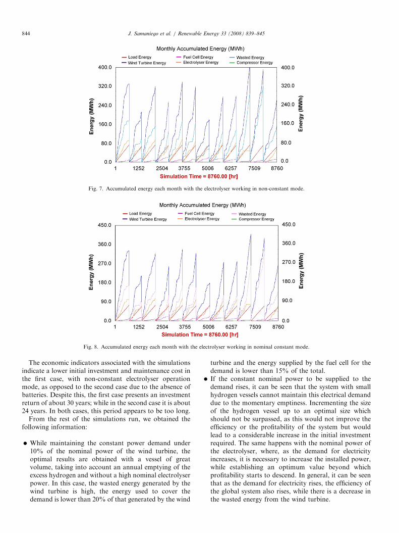
oxygen produced by the electrolyser and the hydrogenconsumed by the fuel cell over 1 month in the samesimulation as in the previous figures. It also shows the levelof the hydrogen vessel.Figs. 7 and 8 show the balance of accumulated energy
per month in each system.A detailed monthly energy accumulation analysis
provides interesting indicators concerning the behaviourof each system. In both cases, the percentage of energygenerated by the wind turbine and used to cover theconstant electrical demand is 24.15% and the percentage ofthe demand covered by the fuel cell is 18%. The differencesbetween both systems appear in the amount of energy fromthe wind turbine used to produce hydrogen. In the firstcase, with the electrolyser working in non-constantoperation mode, this percentage is 23%, while in the
olyser at non-constant operation.

ARTICLE IN PRESS
Fig. 5. Production and consumption of H2 and hydrogen vessel level with the electrolyser working in non-constant mode.
Fig. 6. Production and consumption of H2 and hydrogen vessel level with the electrolyser working in nominal constant mode.
Fig. 4. Power balance with the electrolyser working at nominal constant operation mode.
J. Samaniego et al. / Renewable Energy 33 (2008) 839–845 843
second case, with the batteries and electrolyser working inconstant mode, it surpasses 28%. Finally, it should bepointed out that a great amount of energy generated by the
wind turbine was wasted just because it was not possibleto use it: in the first case this was 56% and in the secondcase 52%.
ARTICLE IN PRESS
Fig. 7. Accumulated energy each month with the electrolyser working in non-constant mode.
Fig. 8. Accumulated energy each month with the electrolyser working in nominal constant mode.
J. Samaniego et al. / Renewable Energy 33 (2008) 839–845844
The economic indicators associated with the simulationsindicate a lower initial investment and maintenance cost inthe first case, with non-constant electrolyser operationmode, as opposed to the second case due to the absence ofbatteries. Despite this, the first case presents an investmentreturn of about 30 years; while in the second case it is about24 years. In both cases, this period appears to be too long.
From the rest of the simulations run, we obtained thefollowing information:
�
While maintaining the constant power demand under10% of the nominal power of the wind turbine, theoptimal results are obtained with a vessel of greatvolume, taking into account an annual emptying of theexcess hydrogen and without a high nominal electrolyserpower. In this case, the wasted energy generated by thewind turbine is high, the energy used to cover thedemand is lower than 20% of that generated by the windturbine and the energy supplied by the fuel cell for thedemand is lower than 15% of the total.
� If the constant nominal power to be supplied to thedemand rises, it can be seen that the system with smallhydrogen vessels cannot maintain this electrical demanddue to the momentary emptiness. Incrementing the sizeof the hydrogen vessel up to an optimal size whichshould not be surpassed, as this would not improve theefficiency or the profitability of the system but wouldlead to a considerable increase in the initial investmentrequired. The same happens with the nominal power ofthe electrolyser, where, as the demand for electricityincreases, it is necessary to increase the installed power,while establishing an optimum value beyond whichprofitability starts to descend. In general, it can be seenthat as the demand for electricity rises, the efficiency ofthe global system also rises, while there is a decrease inthe wasted energy from the wind turbine.

ARTICLE IN PRESSJ. Samaniego et al. / Renewable Energy 33 (2008) 839–845 845
�
If the constant power demand surpasses 30% of thewind turbine nominal power, stable supply overthe whole year is not possible, independently of thecapacity of the hydrogen vessel or the electrolyser’snominal power. Another important observation is:the best economic results and the shortest investmentreturn are achieved when the constant power demandis kept under 17% of the nominal power of thewind turbine, even when the electrolyser is operatingin constant mode, despite higher initial investment(due to the batteries). If the constant demand isfixed at over 20% of the nominal wind turbine power,the best results are obtained by operating the electro-lyser in non-constant mode, but this implies excessnominal power. � The development of these systems requires a high initialinvestment and an investment return period alwayslonger than 21 years.
4. Conclusions
Two systems have been created and modelled combininga wind turbine, an electrolyser system, an intermediatehydrogen storage system and a fuel cell. These systemshave been simulated with the same aim: to maintaina constant power demand. The difference between bothsystems is established in the way the electrolyseris operated: with constant or non-constant nominalpower mode. The simulations carried out demonstratethe technical viability of these systems, while at thesame time showing the low profitability rates and theexcessively long investment return period, due to the highprices of all elements involved. Presumably, the evolutionof the technologies involved, combined with the useof alternative and new materials and the deploymentof the hydrogen economy, will lead to the systemspresented here becoming competitive within a relativelyshort period of time.
Acknowledgements
This work has been funded by Biovent, a company ofCastilla y Leon, whose major partner is Iberdrola, and bythe Economic Development Agency of Castilla y Leonthrough its Technical Development Program.
References
[1] Gonzalez A, McKeogh E, Gallachoir BO. The role of hydrogen in
high wind energy penetration electricity systems: the Irish case.
Renew Energy 2003;29:471–89.
[2] Brey Sanchez J. El proyecto RES2H2 como demostracion de la
integracion de fuentes de energıa renovables con el vector Hidrogeno,
Greencell. Jornadas de Presentacion de la Asociacion Espanola del
Hidrogeno. Madrid, Noviembre 2002.
[3] Agbossou K, Kelouwani S, Anouar A, Kolhe M. Energy manage-
ment of hydrogen-based stand-alone renewable energy system by
using boost and buck converters. In: Proceedings of the Industry
Applications Conference, 39th IAS Annual Meeting, Conference
Record of the 2004 IEEE, vol. 4, 3–7 October 2004. p. 2786–93.
[4] Sherif SA, Barbir F, Veziroglu TN. Wind energy and the hydrogen
economy-review of the technology. Sol Energy 2005;78:647–60.
[5] Agbossou K, Doumbia M, Anouar A. Optimal hydrogen production
in a stand-alone renewable energy system. In: Proceedings of the
Industry Applications Conference, 40th IAS Annual Meeting,
Conference Record of the 2005, vol. 4, 2–6 October 2005. p. 2932–6.
[6] Agbosossou K, Kolhe M, Hamelin J, Bose T. Performance of a
stand-alone renewable energy system based on energy as hydrogen.
IEEE Trans Energy Convers 2004;19(3).
[7] Iqbal MT. Modeling and control of a wind fuel cell hybrid energy
system. Renew Energy 2003;28:223–37.
[8] Khan MJ, Iqbal MT. Dynamic modeling and simulation of a small
wind-fuel cell hybrid energy system. Renew Energy 2005;30:421–39.
[9] Bechrakis DA, McKeogh EJ, Gallagher PD. Simulation and
operational assessment for a small autonomus wind–hydrogen energy
system. Energy Convers Manage 2006;47:46–59.
[10] Batista H, Mantz RJ, Garelli F. Power conditioning for a wind-
hydrogen energy system. J Power Sources 2006;155(2):478–86.
[11] Ullebeg O, Glockner R. Hydrogems. Hydrogen energy models. In:
Proceedings of the WHEC 2002—14th World Hydrogen Energy
Conference, 9–13 June 2002, Montreal.
[12] Klein SA, et al. TRNSYS: a transient system simulation program.
Manual v15. Madison: Solar Energy Laboratory, University of
Wisconsin; 2000.
[13] Grimsmo LN, Korpaas M, Gjengedal T, Moller-Holst S. A study of
stand-alone wind and hydrogen system. In: Proceedings of the Nordic
Wind Power Conference, 1–2 March 2004, Chalmers University of
Technology.
[14] /http://www.siam-cma.org/meteoroloxia/S. MeteoGalicia. Consel-
leria de Medio Ambiente e Desenvolvemento Sostenible. Xunta de
Galicia, Spain.
[15] Glockner R, Kloed C, Nyhammer F, Ulleberg O. Wind/hydrogen
systems for remote areas a norwegian case study. In: Proceedings of
the WHEC 2002—14th World Hydrogen Energy Conference, 9–13
June, Montreal.
[16] Royal Decree 436/2004, 12 March. Metodologıa para la actualizacion
y sistematizacion del regimen jurıdico y economico de la actividad de
produccion de energıa electrica en regimen especial. Spain: Economy
Ministry.
[17] Liu E. Large scale wind hydrogen systems. GE Global Research,
September 2003.
[18] Amos WA. Costs of storing and transporting hydrogen. NREL/TP-570-
25106, November 1998.
Copyright © 2022 FDOKUMEN