Modeling, control and power management of hybrid photovoltaic fuel cells with battery bank supplying...
10
Modeling, control and power management of hybrid photovoltaic fuel cells with battery bank supplying electric vehicle Zahra Mokrani, Djamila Rekioua, Toufik Rekioua* Laboratoire LTII, Universite de Bejaia, 06000 Bejaia, Algeria article info Article history: Received 22 February 2014 Received in revised form 26 March 2014 Accepted 27 March 2014 Available online xxx Keywords: Hybrid power system Photovoltaic Fuel cells Battery Power management Electric vehicle abstract In this paper, modeling, control and power management (PM) of hybrid Photovoltaic Fuel cell/Battery bank system supplying electric vehicle is presented. The HPS is used to pro- duce energy without interruption. It consists of a photovoltaic generator (PV), a proton exchange membrane fuel cell (PEMFC), and a battery bank supplying an electric vehicle of 3 kW. In our work, PV and PEMFC systems work in parallel via DC/DC converter and the battery bank is used to store the excess of energy. The mathematical model topology and it power management of HPS with battery bank system supplying electric vehicle (EV) are the significant contribution of this paper. Obtained results under Matlab/Simulink and some experimental ones are presented and discussed. Copyright ª 2014, Hydrogen Energy Publications, LLC. Published by Elsevier Ltd. All rights reserved. Introduction Hybrid power systems are used to supply loads and ensure load demand without interruption. We can use different sources, conventional ones as coal, natural gazes, fossils fuels,. or renewables ones as solar, wind, hydraulic,. [1e13]. In addition to energy, a hybrid system may also include a DC or AC converters, a storage system, and a control system for power management. All these components can be connected in different architectures. The electric vehicle in the auto- motive field is the cleanest and most environmentally friendly transport solution. Also, it overcomes the noise since there is almost none noise. In fact, an electric car is really ecological if the electrical energy consumed is produced from renewable energy sources as solar, wind, hydro,.. However, these renewable sources are intermittent, why a storage system must be inserted. Generally we use batteries. Electric vehicles with batteries already exist and are have autonomy less than 200 km. These last years, manufacturers are interested to hydrogen or fuel cell vehicle which can have autonomy of 400e800 km depending on car models, and which produces less carbon dioxide (g/km). A fuel cell works as a battery. It stores energy but as hydrogen. It react hydrogen with the oxygen in the air to obtain water and energy. However, extracting hydrogen from air or water requires twice as much energy as the use of battery in electric vehicle, thus the cost of hydrogen production is high. It will be interesting to use another source of energy as solar. The present work is dedicated to a study of hybrid photo- voltaic/Fuel Cells system supplying an electric vehicle with bat- tery bank. The advantages of each source used, allow us to obtain * Corresponding author. E-mail addresses: [email protected], [email protected] (T. Rekioua). Available online at www.sciencedirect.com ScienceDirect journal homepage: www.elsevier.com/locate/he international journal of hydrogen energy xxx (2014) 1 e10 Please cite this article in press as: Mokrani Z, et al., Modeling, control and power management of hybrid photovoltaic fuel cells with battery bank supplying electric vehicle, International Journal of Hydrogen Energy (2014), http://dx.doi.org/10.1016/ j.ijhydene.2014.03.215 http://dx.doi.org/10.1016/j.ijhydene.2014.03.215 0360-3199/Copyright ª 2014, Hydrogen Energy Publications, LLC. Published by Elsevier Ltd. All rights reserved.
-
Upload
wwwuniv-bejaia -
Category
Documents
-
view
1 -
download
0
Transcript of Modeling, control and power management of hybrid photovoltaic fuel cells with battery bank supplying...
ww.sciencedirect.com
i n t e r n a t i o n a l j o u r n a l o f h yd r o g e n e n e r g y x x x ( 2 0 1 4 ) 1e1 0
Available online at w
ScienceDirect
journal homepage: www.elsevier .com/locate/he
Modeling, control and power management ofhybrid photovoltaic fuel cells with battery banksupplying electric vehicle
Zahra Mokrani, Djamila Rekioua, Toufik Rekioua*
Laboratoire LTII, Universite de Bejaia, 06000 Bejaia, Algeria
a r t i c l e i n f o
Article history:
Received 22 February 2014
Received in revised form
26 March 2014
Accepted 27 March 2014
Available online xxx
Keywords:
Hybrid power system
Photovoltaic
Fuel cells
Battery
Power management
Electric vehicle
* Corresponding author.E-mail addresses: [email protected], t_rek
Please cite this article in press as: Mokranwith battery bank supplying electric vj.ijhydene.2014.03.215
http://dx.doi.org/10.1016/j.ijhydene.2014.03.20360-3199/Copyright ª 2014, Hydrogen Ener
a b s t r a c t
In this paper, modeling, control and power management (PM) of hybrid Photovoltaic Fuel
cell/Battery bank system supplying electric vehicle is presented. The HPS is used to pro-
duce energy without interruption. It consists of a photovoltaic generator (PV), a proton
exchange membrane fuel cell (PEMFC), and a battery bank supplying an electric vehicle of
3 kW. In our work, PV and PEMFC systems work in parallel via DC/DC converter and the
battery bank is used to store the excess of energy. The mathematical model topology and it
power management of HPS with battery bank system supplying electric vehicle (EV) are the
significant contribution of this paper. Obtained results under Matlab/Simulink and some
experimental ones are presented and discussed.
Copyright ª 2014, Hydrogen Energy Publications, LLC. Published by Elsevier Ltd. All rights
reserved.
Introduction
Hybrid power systems are used to supply loads and ensure
load demand without interruption. We can use different
sources, conventional ones as coal, natural gazes, fossils
fuels,. or renewables ones as solar, wind, hydraulic,. [1e13].
In addition to energy, a hybrid system may also include a DC
or AC converters, a storage system, and a control system for
power management. All these components can be connected
in different architectures. The electric vehicle in the auto-
motive field is the cleanest andmost environmentally friendly
transport solution. Also, it overcomes the noise since there is
almost none noise. In fact, an electric car is really ecological if
the electrical energy consumed is produced from renewable
energy sources as solar, wind, hydro,.. However, these
[email protected] (T. Rekiou
i Z, et al., Modeling, conehicle, International Jo
15gy Publications, LLC. Publ
renewable sources are intermittent, why a storage system
must be inserted. Generally we use batteries. Electric vehicles
with batteries already exist and are have autonomy less than
200 km. These last years, manufacturers are interested to
hydrogen or fuel cell vehicle which can have autonomy of
400e800 km depending on car models, and which produces
less carbon dioxide (g/km). A fuel cell works as a battery. It
stores energy but as hydrogen. It react hydrogen with the
oxygen in the air to obtain water and energy. However,
extracting hydrogen from air or water requires twice as much
energy as the use of battery in electric vehicle, thus the cost of
hydrogen production is high. It will be interesting to use
another source of energy as solar.
The present work is dedicated to a study of hybrid photo-
voltaic/Fuel Cells system supplying an electric vehicle with bat-
terybank.Theadvantagesofeachsourceused, allowus toobtain
a).
trol and power management of hybrid photovoltaic fuel cellsurnal of Hydrogen Energy (2014), http://dx.doi.org/10.1016/
ished by Elsevier Ltd. All rights reserved.
Nomenclature
Af frontal surface area of the vehicle, m2
Cd aerodynamic drag coefficient
C10 rated capacity, A h
Eb voltage source, V
ENerst voltage Nerst, V
Fr total force, N m
fro rolling resistance force constant
Ftire rolling resistance force, N m
G solar radiation, W/m2
Ipv output-terminal current, A
Iph diode-current, A
Ish shunt-leakage current, A
Isc short circuit current, A
I0 saturation current of the diode, A
Impp maximum current at PPM, A
K Boltzmann constant, J/K
m vehicle total mass, kg
nb number of cells
Pmpp maximum power point, W
PPV photovoltaic power, W
q electron charge, C
r tire radius, m
Rb internal resistance, U
Rs series resistance, U
Rsh shunt resistance, U
Tj temperature cells, K
Tjref reference temperature of the PV cell, K
TPEMFC absolute operating temperature of the stack, K
Uact activation overvoltage, V
Uconc concentration or diffusion over-voltage, V
Uohm resistive or ohmic over-voltage, V
V vehicle speed, m/s
Vmpp maximum voltage at PPM, V
Voc open circuit voltage, V
VPEMFC fuel cell voltage, V
Greek letters
asc temperature coefficient of short-current, A/K
ai constants
b road slope angle, �
boc voltage temperature coefficient, V/K
DT heating of the accumulator, K
rair air density
Abbreviations
AC alternate current
DC direct current
DTC direct Torque control
EV electric vehicle
FC fuel cell
FLC fuzzy logic controller
HPS hybrid power system
IM induction motor
MPP maximum power point
PEMFC proton exchange membrane fuel cell
PM power management
PV photovoltaic panels
RFOC rotor flux oriented control
SFOC stator oriented control
i n t e r n a t i o n a l j o u r n a l o f h y d r o g e n en e r g y x x x ( 2 0 1 4 ) 1e1 02
a cheaper and less polluting EV.We use in our case an induction
motor (IM) of 3 kW as propulsion of the EV. To kept the DC bus
voltage at a constant value when the speed of the rotor varies,
different control techniques can be used as stator oriented con-
trol (SFOC), rotor flux oriented control (RFOC), Direct Torque
Control (DTC), Fuzzy logic controller (FLC),.. In ourwork, the IM
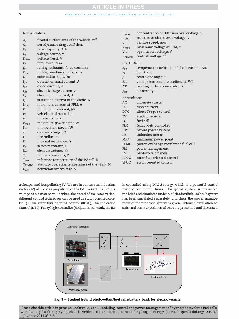
Fig. 1 e Studied hybrid photovoltaic/fuel
Please cite this article in press as: Mokrani Z, et al., Modeling, conwith battery bank supplying electric vehicle, International Joj.ijhydene.2014.03.215
is controlled using DTC Strategy, which is a powerful control
method for motor drives. The global system is presented,
modeledandsimulatedunderMatlab/Simulink. Eachsubsystem
has been simulated separately, and then, the power manage-
ment of the proposed system is given. Obtained simulation re-
sults and some experimental ones are presented and discussed.
cells/battery bank for electric vehicle.
trol and power management of hybrid photovoltaic fuel cellsurnal of Hydrogen Energy (2014), http://dx.doi.org/10.1016/
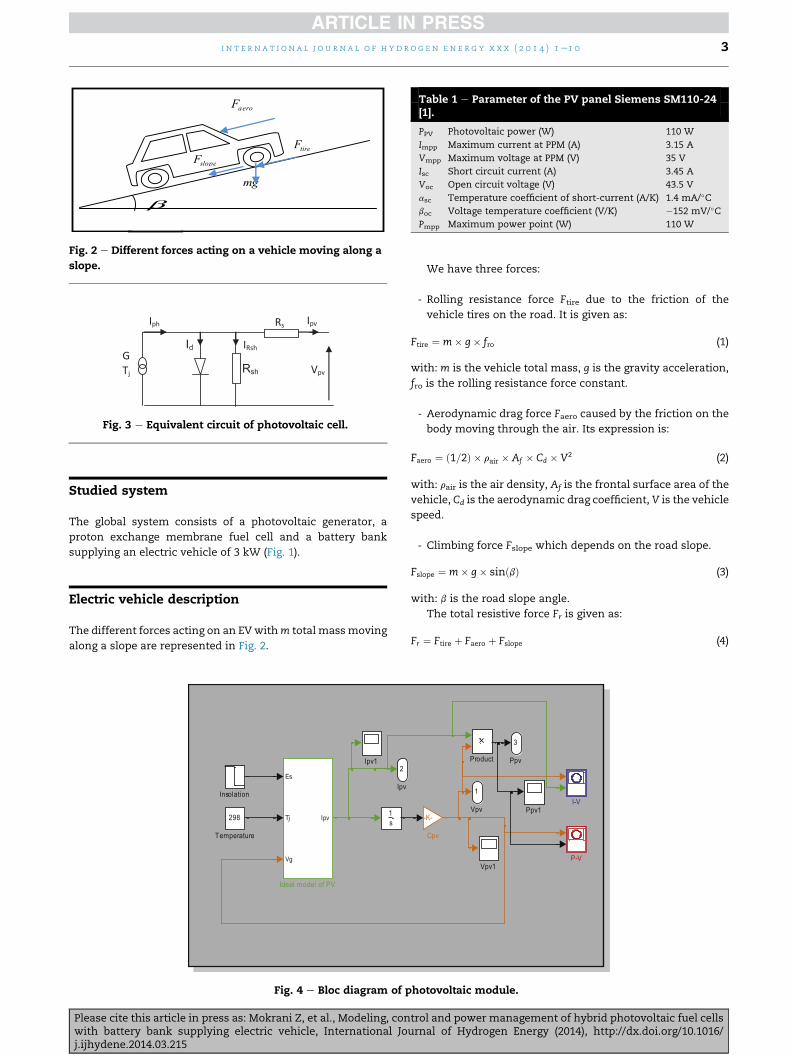
Fig. 2 e Different forces acting on a vehicle moving along a
slope.
Fig. 3 e Equivalent circuit of photovoltaic cell.
Table 1 e Parameter of the PV panel Siemens SM110-24[1].
PPV Photovoltaic power (W) 110 W
Impp Maximum current at PPM (A) 3.15 A
Vmpp Maximum voltage at PPM (V) 35 V
Isc Short circuit current (A) 3.45 A
Voc Open circuit voltage (V) 43.5 V
asc Temperature coefficient of short-current (A/K) 1.4 mA/�Cboc Voltage temperature coefficient (V/K) �152 mV/�CPmpp Maximum power point (W) 110 W
i n t e r n a t i o n a l j o u r n a l o f h yd r o g e n e n e r g y x x x ( 2 0 1 4 ) 1e1 0 3
Studied system
The global system consists of a photovoltaic generator, a
proton exchange membrane fuel cell and a battery bank
supplying an electric vehicle of 3 kW (Fig. 1).
Electric vehicle description
The different forces acting on an EVwithm total massmoving
along a slope are represented in Fig. 2.
Fig. 4 e Bloc diagram of p
Please cite this article in press as: Mokrani Z, et al., Modeling, conwith battery bank supplying electric vehicle, International Joj.ijhydene.2014.03.215
We have three forces:
- Rolling resistance force Ftire due to the friction of the
vehicle tires on the road. It is given as:
Ftire ¼ m� g� fro (1)
with: m is the vehicle total mass, g is the gravity acceleration,
fro is the rolling resistance force constant.
- Aerodynamic drag force Faero caused by the friction on the
body moving through the air. Its expression is:
Faero ¼ ð1=2Þ � rair � Af � Cd � V2 (2)
with: rair is the air density, Af is the frontal surface area of the
vehicle, Cd is the aerodynamic drag coefficient, V is the vehicle
speed.
- Climbing force Fslope which depends on the road slope.
Fslope ¼ m� g� sinðbÞ (3)
with: b is the road slope angle.
The total resistive force Fr is given as:
Fr ¼ Ftire þ Faero þ Fslope (4)
hotovoltaic module.
trol and power management of hybrid photovoltaic fuel cellsurnal of Hydrogen Energy (2014), http://dx.doi.org/10.1016/
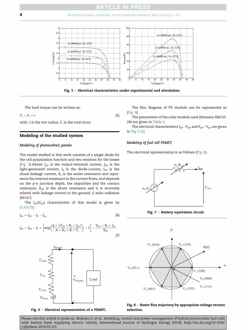
Fig. 5 e Electrical characteristics under experimental and simulation.
i n t e r n a t i o n a l j o u r n a l o f h y d r o g e n en e r g y x x x ( 2 0 1 4 ) 1e1 04
The load torque can be written as:
Tr ¼ Fr � r (5)
with: r is the tire radius, Fr is the total force.
Fig. 7 e Battery equivalent circuit.
Modeling of the studied system
Modeling of photovoltaic panels
The model studied in this work consists of a single diode for
the cell polarization function and two resistors for the losses
(Fig. 3).where: Ipv is the output-terminal current, Iph is the
light-generated current, Id is the diode-current, Ish is the
shunt-leakage current, Rs is the series resistance and repre-
sents the internal resistance to the current flows, and depends
on the p-n junction depth, the impurities and the contact
resistance, Rsh is the shunt resistance and it is inversely
related with leakage current to the ground, G solar radiation
(W/m2).
The Ipv(Vpv) characteristic of this model is given by
[1,4,9,13]:
Ipv ¼ Iph � Id � IRsh(6)
Ipv ¼ Iph � I0 ��exp
�q� �
Vpv þ Rs � Ipv�
A�Ns � K� Tj
�� 1
�� Vpv þ Rs � Ipv
Rsh
(7)
Fig. 6 e Electrical representation of a PEMFC.
Please cite this article in press as: Mokrani Z, et al., Modeling, conwith battery bank supplying electric vehicle, International Joj.ijhydene.2014.03.215
The bloc diagram of PV module can be represented as
(Fig. 4):
The parameters of the solar module used (Siemens SM110-
24) are given in Table 1.
The electrical characteristics IpveVpv and PpveVpv are given
in Fig. 5 [1].
Modeling of fuel cell PEMFC
The electrical representation is as follows (Fig. 6).
Fig. 8 e Stator flux trajectory by appropriate voltage vectors
selection.
trol and power management of hybrid photovoltaic fuel cellsurnal of Hydrogen Energy (2014), http://dx.doi.org/10.1016/
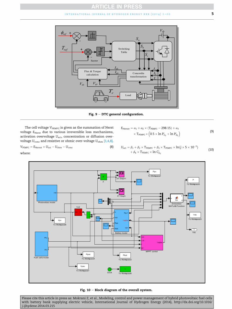
Fig. 9 e DTC general configuration.
i n t e r n a t i o n a l j o u r n a l o f h yd r o g e n e n e r g y x x x ( 2 0 1 4 ) 1e1 0 5
The cell voltage VPEMFC is given as the summation of Nerst
voltage ENerst due to various irreversible loss mechanisms,
activation overvoltage Uact, concentration or diffusion over-
voltage Uconc and resistive or ohmic over-voltage Uohm [1,4,8].
VPEMFC ¼ ENernst þ Uact � Uohm � Uconc (8)
where:
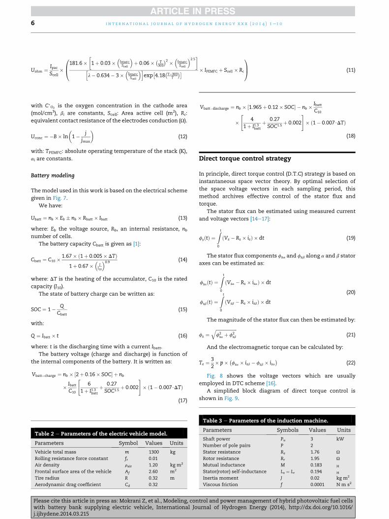
Fig. 10 e Block diagram o
Please cite this article in press as: Mokrani Z, et al., Modeling, conwith battery bank supplying electric vehicle, International Joj.ijhydene.2014.03.215
ENernst ¼ a1 þ a2 � ðTPEMFC � 298:15Þ þ a3� (9)
� TPEMFC � 0:5� ln P�O2þ ln P�H2
Uact ¼ b1 þ b2 � TPEMFC þ b3 � TPEMFC � ln�j� 5� 10�3
�þ b4 � TPEMFC � ln C�
O2
(10)
f the overall system.
trol and power management of hybrid photovoltaic fuel cellsurnal of Hydrogen Energy (2014), http://dx.doi.org/10.1016/
Uohm ¼ IpacScell
�
0B@181:6�
�1þ 0:03�
�IPEMFCScell
þ 0:06� �
T303
�2 � �IPEMFCScell
2:5�
hl� 0:634� 3�
�IPEMFCScell
iexp
�4:18
�T�303
T
�� � IPEMFC þ Scell � Rc
1CA (11)
i n t e r n a t i o n a l j o u r n a l o f h y d r o g e n en e r g y x x x ( 2 0 1 4 ) 1e1 06
with C�O2
is the oxygen concentration in the cathode area
(mol/cm3), bi are constants, Scell: Area active cell (m2), Rc:
equivalent contact resistance of the electrodes conduction (U).
Uconc ¼ �B� ln
�1� j
jmax
�(12)
with: TPEMFC: absolute operating temperature of the stack (K),
ai are constants.
Battery modeling
Themodel used in this work is based on the electrical scheme
given in Fig. 7.
We have:
Ubatt ¼ nb � Eb � nb � Rbatt � Ibatt (13)
where: Eb the voltage source, Rb, an internal resistance, nbnumber of cells.
The battery capacity Cbatt is given as [1]:
Cbatt ¼ C10 � 1:67� ð1þ 0:005� DTÞ1þ 0:67�
�II10
0:9 (14)
where: DT is the heating of the accumulator, C10 is the rated
capacity (I10).
The state of battery charge can be written as:
SOC ¼ 1� QCbatt
(15)
with:
Q ¼ Ibatt � t (16)
where: t is the discharging time with a current Ibatt.
The battery voltage (charge and discharge) is function of
the internal components of the battery. It is written as:
Vbatt�charge ¼ nb � ½2þ 0:16� SOC� þ nb
� IbattC10
"6
1þ I1:3batt
þ 0:27SOC1:5
þ 0:002
#� ð1� 0:007$DTÞ
(17)
Table 2 e Parameters of the electric vehicle model.
Parameters Symbol Values Units
Vehicle total mass m 1300 kg
Rolling resistance force constant fr 0.01
Air density rair 1.20 kg m2
Frontal surface area of the vehicle Af 2.60 m2
Tire radius R 0.32 m
Aerodynamic drag coefficient Cd 0.32
Please cite this article in press as: Mokrani Z, et al., Modeling, conwith battery bank supplying electric vehicle, International Joj.ijhydene.2014.03.215
Vbatt�discharge ¼ nb � ½1:965þ 0:12� SOC� � nb � IbattC10" #
� 4
1þ I1:3batt
þ 0:27SOC1:5
þ 0:002 � ð1� 0:007$DTÞ
(18)
Direct torque control strategy
In principle, direct torque control (D.T.C) strategy is based on
instantaneous space vector theory. By optimal selection of
the space voltage vectors in each sampling period, this
method archives effective control of the stator flux and
torque.
The stator flux can be estimated using measured current
and voltage vectors [14e17]:
fsðtÞ ¼Z t
0
ðVs � Rs � isÞ � dt (19)
The stator flux components fsa and fsb along a and b stator
axes can be estimated as:
fsaðtÞ ¼Z t
0
ðVsa � Rs � isaÞ � dt
fsbðtÞ ¼Z t
0
ðVsb � Rs � isbÞ � dt
(20)
The magnitude of the stator flux can then be estimated by:
fs ¼ffiffiffiffiffiffiffiffiffiffiffiffiffiffiffiffiffiffiffif2sa þ f2
sb
q(21)
And the electromagnetic torque can be calculated by:
Te ¼ 32� p� �
fsa � isb � fsb � isa�
(22)
Fig. 8 shows the voltage vectors which are usually
employed in DTC scheme [16].
A simplified block diagram of direct torque control is
shown in Fig. 9.
Table 3 e Parameters of the induction machine.
Parameters Symbols Values Units
Shaft power Pu 3 kW
Number of pole pairs P 2
Stator resistance Rs 1.76 U
Rotor resistance Rr 1.95 U
Mutual inductance M 0.183 H
Stator(rotor) self-inductance Ls ¼ Lr 0.194 H
Inertia moment J 0.02 kg m2
Viscous friction f 0.0001 N m s2
trol and power management of hybrid photovoltaic fuel cellsurnal of Hydrogen Energy (2014), http://dx.doi.org/10.1016/
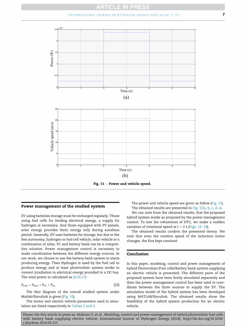
Fig. 11 e Power and vehicle speed.
i n t e r n a t i o n a l j o u r n a l o f h yd r o g e n e n e r g y x x x ( 2 0 1 4 ) 1e1 0 7
Power management of the studied system
EV using batteries storage must be recharged regularly. Those
using fuel cells for feeding electrical energy, a supply for
hydrogen is necessary. And those equipped with PV panels,
solar energy provides them energy only during sunshine
period. Generally, EV uses batteries for storage, but due to the
less autonomy, hydrogen or fuel cell vehicle, solar vehicle or a
combination of solar, FC and battery bank can be a competi-
tive solution. Power management control is necessary to
make coordination between the different energy sources. In
our work, we choose to use the battery bank system to starts
producing energy. Then Hydrogen is used by the fuel cell to
produce energy and at least photovoltaic system works to
convert irradiation to electrical energy provided to a DC bus.
The total power is calculated as [9,10,17]:
Pload ¼ Pbatt þ PFC þ Ppv (23)
The bloc diagram of the overall studied system under
Matlab/Simulink is given (Fig. 10).
The motor and electric vehicle parameters used in simu-
lation are listed respectively in Tables 2 and 3.
Please cite this article in press as: Mokrani Z, et al., Modeling, conwith battery bank supplying electric vehicle, International Joj.ijhydene.2014.03.215
The power and vehicle speed are given as follow (Fig. 11).
The obtained results are presented in Fig. 12(a, b, c, d, e).
We can note from the obtained results, that the proposed
hybrid system works as proposed by the power management
control. To test the robustness of DTC, we make a sudden
variation of rotational speed at t ¼ 2 s (Figs. 13e18).
The obtained results confirm the presented theory. We
note that even the rotation speed of the induction motor
changes, the flux kept constant.
Conclusion
In this paper, modeling, control and power management of
hybrid Photovoltaic/Fuel cells/Battery bank system supplying
an electric vehicle is presented. The different parts of the
proposed system have been firstly simulated separately and
then the power management control has been used to coor-
dinate between the three sources to supply the EV. The
simulation model of the hybrid system has been developed
using MATLAB/Simulink. The obtained results show the
feasibility of the hybrid system production for an electric
vehicle.
trol and power management of hybrid photovoltaic fuel cellsurnal of Hydrogen Energy (2014), http://dx.doi.org/10.1016/
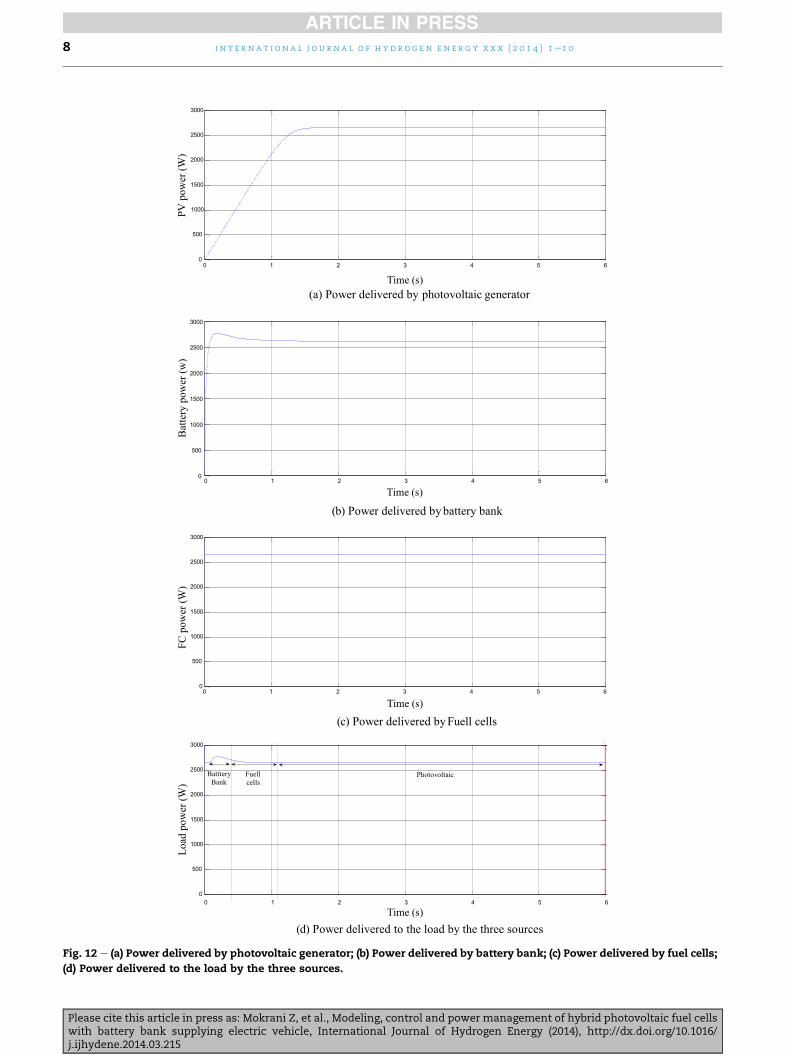
Fig. 12 e (a) Power delivered by photovoltaic generator; (b) Power delivered by battery bank; (c) Power delivered by fuel cells;
(d) Power delivered to the load by the three sources.
i n t e r n a t i o n a l j o u r n a l o f h y d r o g e n en e r g y x x x ( 2 0 1 4 ) 1e1 08
Please cite this article in press as: Mokrani Z, et al., Modeling, control and power management of hybrid photovoltaic fuel cellswith battery bank supplying electric vehicle, International Journal of Hydrogen Energy (2014), http://dx.doi.org/10.1016/j.ijhydene.2014.03.215
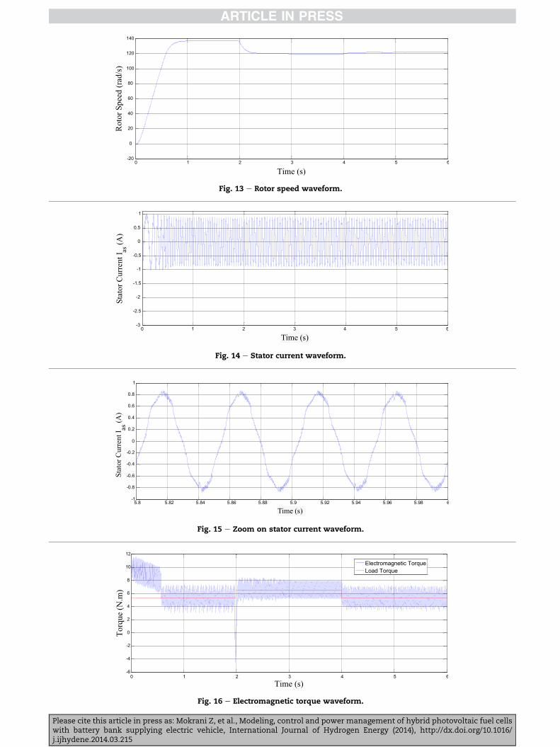
Fig. 13 e Rotor speed waveform.
Fig. 14 e Stator current waveform.
Fig. 15 e Zoom on stator current waveform.
Fig. 16 e Electromagnetic torque waveform.
Please cite this article in press as: Mokrani Z, et al., Modeling, control and power management of hybrid photovoltaic fuel cellswith battery bank supplying electric vehicle, International Journal of Hydrogen Energy (2014), http://dx.doi.org/10.1016/j.ijhydene.2014.03.215
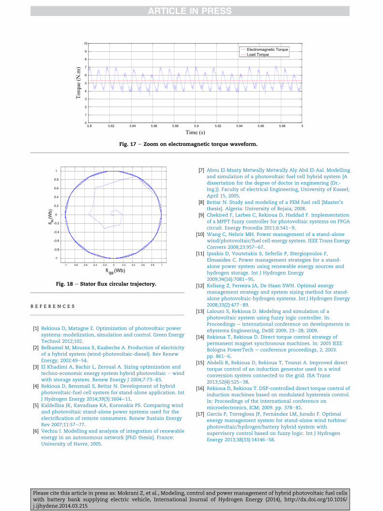
Fig. 17 e Zoom on electromagnetic torque waveform.
Fig. 18 e Stator flux circular trajectory.
r e f e r e n c e s
[1] Rekioua D, Matagne E. Optimization of photovoltaic powersystems: modelization, simulation and control. Green EnergyTechnol 2012;102.
[2] Belhamel M, Moussa S, Kaabeche A. Production of electricityof a hybrid system (wind-photovoltaic-diesel). Rev RenewEnergy; 2002:49e54.
[3] El Khadimi A, Bachir L, Zeroual A. Sizing optimization andtechno-economic energy system hybrid photovoltaic e windwith storage system. Renew Energy J 2004;7:73e83.
[4] Rekioua D, Bensmail S, Bettar N. Development of hybridphotovoltaic-fuel cell system for stand-alone application. IntJ Hydrogen Energy 2014;39(3):1604e11.
[5] Kaldellisa JK, Kavadiasa KA, Koronakis PS. Comparing windand photovoltaic stand-alone power systems used for theelectrification of remote consumers. Renew Sustain EnergyRev 2007;11:57e77.
[6] Vechiu I. Modelling and analysis of integration of renewableenergy in an autonomous network [PhD thesis]. France:University of Havre; 2005.
Please cite this article in press as: Mokrani Z, et al., Modeling, conwith battery bank supplying electric vehicle, International Joj.ijhydene.2014.03.215
[7] Abou El-Maaty Metwally Metwally Aly Abd El-Aal. Modellingand simulation of a photovoltaic fuel cell hybrid system [Adissertation for the degree of doctor in engineering (Dr.-Ing.)]. Faculty of electrical Engineering, University of Kassel;April 15, 2005.
[8] Bettar N. Study and modeling of a PEM fuel cell [Master’sthesis]. Algeria: University of Bejaia; 2008.
[9] Chekired F, Larbes C, Rekioua D, Haddad F. Implementationof a MPPT fuzzy controller for photovoltaic systems on FPGAcircuit. Energy Procedia 2011;6:541e9.
[10] Wang C, Nehrir MH. Power management of a stand-alonewind/photovoltaic/fuel cell energy system. IEEE Trans EnergyConvers 2008;23:957e67.
[11] Ipsakis D, Voutetakis S, Seferlis P, Stergiopoulos F,Elmasides C. Power management strategies for a stand-alone power system using renewable energy sources andhydrogen storage. Int J Hydrogen Energy2009;34(16):7081e95.
[12] Keliang Z, Ferreira JA, De Haan SWH. Optimal energymanagement strategy and system sizing method for stand-alone photovoltaic-hydrogen systems. Int J Hydrogen Energy2008;33(2):477e89.
[13] Lalouni S, Rekioua D. Modeling and simulation of aphotovoltaic system using fuzzy logic controller. In:Proceedings e international conference on developments ineSystems Engineering, DeSE 2009, 23e28; 2009.
[14] Rekioua T, Rekioua D. Direct torque control strategy ofpermanent magnet synchronous machines. In: 2003 IEEEBologna PowerTech e conference proceedings, 2; 2003.pp. 861e6.
[15] Abdelli R, Rekioua D, Rekioua T, Tounzi A. Improved directtorque control of an induction generator used in a windconversion system connected to the grid. ISA Trans2013;52(4):525e38.
[16] Rekioua D, Rekioua T. DSP-controlled direct torque control ofinduction machines based on modulated hysteresis control.In: Proceedings of the international conference onmicroelectronics, ICM; 2009. pp. 378e81.
[17] Garcıa P, Torreglosa JP, Fernandez LM, Jurado F. Optimalenergy management system for stand-alone wind turbine/photovoltaic/hydrogen/battery hybrid system withsupervisory control based on fuzzy logic. Int J HydrogenEnergy 2013;38(33):14146e58.
trol and power management of hybrid photovoltaic fuel cellsurnal of Hydrogen Energy (2014), http://dx.doi.org/10.1016/