DMM14 U (UL, ULD) - AKG
259
DMM14 U (UL, ULD) 2 BEDIENUNGSANLEITUNG Vor Inbetriebnahme des Gerätes lesen! 67 USER INSTRUCTIONS Read the manual before using the equipment! 131 MODE D’EMPLOI Lire cette notice avant d’utiliser le système! 194 MODO DE EMPLEO ¡Consulte el manual antes de utilizar el equipo! REFERENCE FOR DIGITAL AUTOMATIC MICROPHONE MIXER
-
Upload
khangminh22 -
Category
Documents
-
view
1 -
download
0
Transcript of DMM14 U (UL, ULD) - AKG

DMM14 U (UL, ULD)
2 BEDIENUNGSANLEITUNG Vor Inbetriebnahme des Gerätes lesen!
67 USER INSTRUCTIONS Read the manual before using the equipment!
131 MODE D’EMPLOI Lire cette notice avant d’utiliser le système!
194 MODO DE EMPLEO ¡Consulte el manual antes de utilizar el equipo!
REFERENCE FOR DIGITAL AUTOMATIC MICROPHONE MIXER

INHALT
DMM14 MANUAL 2
1 ALLGEMEINES 51.1 Zweck des Manuals 5
1.2 Aufbewahrung des Manuals 5
1.3 Haftung 5
1.4 Gewährleistung 5
2 LIEFERUMFANG 62.1 Verpackungsinhalt 6
2.2 Optionales Zubehör 6
3 SICHERHEIT UND UMWELT 73.1 Sicherheit 7
3.2 Vorausgesetzte Kenntnisse und
Verantwortungsbereiche der Bediener/
Anwender 8
3.3 Erklärung der verwendeten Symbole 8
3.4 Bestimmungsgemäße Verwendung 9
3.5 Bestimmungswidrige Verwendung 9
3.6 Umwelt 9
4 KONFORMITÄTSERKLÄRUNG 9
5 GERÄTEBESCHREIBUNG 105.1 Kurzbeschreibung 10
5.2 Technische Daten 10
5.3 Frontseite: Beschreibung der
Bedienelemente 12
5.3.1 Drehregler für Eingangskanäle 12
5.3.2 Bedienmodus / SYSTEM CONTROL 13
5.3.3 Drehregler für Stereo-Ausgänge 13
5.3.4 Aussteuerungsanzeige für Stereo-
Ausgänge 13
5.3.5 Stereo-Kopfhörer-Ausgang 13
5.4 Rückseite: Beschreibung der
Bedienelemente 14
5.4.1 Eingängskanäle 15
5.4.2 Gain-Regler 16
5.4.3 Phantomspeisung 16
5.4.4 Stereo Summen-Ausgangskanal 18
5.4.5 Stereo-Record-Ausgang 18
5.4.6 Serielle Steuerung über RS232 19
5.4.7 USB-Anschluss 19
5.4.8 LAN-Anschluss 20
5.4.9 Gerätekaskadierung 20
5.4.10 Dante™-Netzwerk 21
5.5 Automix-Algorithmus 22
5.5.1 Dynamische Pegelanpassung 22
5.5.2 Best Mic On 22
5.5.3 Noise Detect 22
5.6 Gerätekaskadierung 23
6 MONTAGE UND ANSCHLUSS 246.1 Montage 24
6.2 Geräte kaskadieren (optional) 24
6.3 Mikrofone und Zusatzgeräte
anschließen 24
6.4 Gerät an Netz anschließen 25
7 FUNKTIONSBESCHREIBUNG 267.1 Bedienkonzept 26
7.2 Drehregler bedienen 26
7.2.1 Anzeige der Audiopegel /
VU Funktion 27
7.3 SYSTEM CONTROL 27
7.3.1 Funktionen von SYSTEM CONTROL 27
7.3.2 Funktionen der Eingangskanäle 28
7.3.3 Funktionen der Ausgangskanäle 28
7.3.4 Funktionen des Stereo-Kopfhörer-
Ausgangs (Ausgang für Monitoring) 28
7.4 DSP Funktionen 29
7.4.1 LEVEL 29
7.4.2 TREBLE 30

INHALT
DMM14 MANUAL 3
7.4.3 BASS 31
7.4.4 LOW CUT 33
7.4.5 LIMITER 35
7.4.6 COMPRESSOR 37
7.4.7 AUTOMIXING 38
7.4.8 PRIORITY 39
7.4.9 PAN / BALANCE 40
7.4.10 DELAY 42
7.4.11 ROUTING TO REC 43
7.4.12 ROUTING TO USB 44
7.4.13 EQUALIZER 45
7.4.14 PRESET 46
7.5 LOCKED 48
8 BEDIENUNG DES GERÄTES 498.1 SYSTEM CONTROL: Parameter am
Gerät ändern 49
8.2 Mikrofone am DMM14 U (UL, ULD)
konfigurieren 49
8.3 Ein-/Ausgänge abhören 50
8.4 Geräte kaskadieren 51
8.5 Zuspielung über USB und Dante™ 52
8.5.1 Zuspielung bearbeiten 52
8.6 Phantomspeisung aktivieren 52
8.7 Presets verwenden 53
8.7.1 Preset auswählen 53
8.7.2 Preset programmieren 53
8.7.3 Preset löschen 54
8.8 MUTE verwenden 54
8.8.1 MUTE aktivieren 54
8.8.2 MUTE deaktivieren 54
8.9 ROUTING TO OUT aktivieren 55
8.9.1 Für einen Eingangskanal 55
8.9.2 Für mehrere Eingangskanäle 55
8.10 ROUTING TO OUT deaktivieren 55
8.11 LOCKED aktivieren/deaktivieren 56
8.11.1 Drehregler SYSTEM CONTROL
sperren 56
8.11.2 Drehregler SYSTEM CONTROL
entsperren 56
8.11.3 Gesamtes Gerät sperren 57
8.11.4 Gesamtes Gerät entsperren 57
8.11.5 Einzelne Kanäle entsperren 57
8.11.6 Einzelne Kanäle sperren 58
8.12 Konfigurationsdatenkopieren 59
8.12.1 Einzelwerte kopieren 59
8.12.2 Alle Werte kopieren 59
8.13 Rücksetzen auf Werkseinstellungen 61
9 FEHLERBEHEBUNG 63

IMPRESSUM
DMM14 MANUAL 4
Herausgeber AKG Acoustics GmbH
Laxenburger Straße 254
1230 Wien
Österreich
Tel: +43 (0)1 86654-0
Fax: +43 (0)1 86654-8800
AKG ACOUSTICS, U.S.
8500 Balboa Blvd. Dock 15
Northridge, CA 91329
U.S.A.
Tel: +1 818 920-3224
Copyright © 2015 AKG Acoustics GmbH
Alle Rechte vorbehalten.
Die in dieser Anleitung enthaltenen Informationen, beigelegten Zeichnungen und Fotos sind geistiges Eigentum der AKG Acoustics GmbH.
Bei Wahrung des Urheberrechtes dürfen ohne ausdrückliche schriftliche Erlaubnis der Firma AKG Acoustics GmbH weder diese Dokumentation noch Teile davon für irgend-welche Zwecke in irgendeiner Form mit irgendwelchen Mitteln, elektronisch oder mecha-nisch, mittels Fotokopie, durch Aufzeichnung oder mit Informationsspeicherungs- und Informationswiedergewinnungssystemen reproduziert oder übertragen werden. Jede Weitergabe an Dritte ist untersagt. Auf Verlangen ist dieses Manual an uns zurückzuerstatten.
FCC Statement Note: This equipment has been tested and found to comply with the limits for a Class B digital device, pursuant to part 15 of the FCC Rules. These limits are designed to provide reasonable protection against harmful interference in a residential installation. This equipment generates, uses and can radiate radio frequency energy and, if not installed and used in accordance with the instructions, may cause harmful interference to radio communications. However, there is no guarantee that interference will not occur in a particular installation. If this equipment does cause harmful interference to radio or television reception, which can be determined by turning the equipment off and on, the user is encouraged to try to correct the interference by one or more of the following measures:
• Reorient or relocate the receiving antenna.
• Increase the separation between the equipment and receiver.
• Connect the equipment into an outlet on a circuit different from that to which the receiver is connected.
• Consult the dealer or an experienced radio/TV technician for help.
This device complies with Part 15 of the FCC Rules. Operation is subject to the following two conditions: (1) this device may not cause harmful interference, and (2) this device must accept any interference received, including interference that may cause undesired operation.
Shielded cables and I/O cords must be used for this equipment to comply with the relevant FCCregulations.Changesormodificationsnotexpresslyapprovedbythepartyresponsiblefor compliance could void the user’s authority to operate this equipment.
Aktualisierung DiesesManualkannohneVorankündigunggeändertwerdenundstelltkeineVerpflichtungseitens der Firma AKG Acoustics GmbH dar.
Version 1.0
Ausgabedatum Juli 2015/DE
07/15/5061697

ALLgemeines
DMM14 MANUAL 5
1 Allgemeines
1.1 Zweck des Manuals
Das vorliegende Manual soll Sie befähigen, das Gerät:
• sicher zu bedienen• laut bestimmungsgemäßer Verwendung nutzen zu können.
1.2 Aufbewahrung des Manuals
Drucken Sie dieses Manual aus und bewahren Sie es sorgfältig auf oder hinterlegen Sie es elektronisch an einem leicht zugänglichen Ort.
Geben Sie dieses Manual an nachfolgende Besitzer weiter.
Das vorliegende Manual ist ein wesentlicher Bestandteil des Gerätes.
1.3 Haftung
AKG Acoustics GmbH übernimmt keine Haftung, wenn:
• das Gerät für andere Zwecke eingesetzt wird, als unter Bestimmungsgemäße Verwendung beschrieben ist.
• durch unsachgemäße Bedienung Schaden entsteht• nicht zugelassene bzw. nicht vorschriftsmäßige Änderungen durch-
geführt werden.• Schaden durch nicht aktuell gehaltene Dokumente entsteht.
1.4 Gewährleistung
AKG Acoustics GmbH übernimmt keine Gewährleistung für Schäden, wenn
• durch unsachgemäße Bedienung Schaden entsteht.• nicht zugelassene bzw. nicht vorschriftsmäßige Änderungen durch-
geführt werden.• Schaden durch nicht aktuell gehaltene Dokumente entsteht.
Haftung
Gewährleistung

LieferUmfAng
DMM14 MANUAL 6
2 Lieferumfang
2.1 Verpackungsinhalt
Kontrollieren Sie, ob die Verpackung alle unten angeführten Teile enthält. Falls etwas fehlt, wenden Sie sich bitte an Ihren AKG-Händler.
• 1 x DMM14 U, DMM14 UL oder DMM14 ULD• 1 x Quick Start Guide• 1 x IEC EU Standard Netzkabel• 1 x IEC US Standard Netzkabel• 1 x Gegensteckklemmen
2.2 Optionales Zubehör
OptionalesZubehörfindenSieaufwww.akg.com. Ihr Händler berät Sie gerne.
Verpackungsinhalt
Optionales Zubehör

sicherheit UnD UmweLt
DMM14 MANUAL 7
3 Sicherheit und Umwelt
3.1 Sicherheit
Achtung: Beschädigungsgefahr
• Schützen Sie das Gerät vor
- direkter Sonneneinstrahlung - starker Staub- und Feuchtigkeitseinwirkung - Regen - Vibrationen oder Schlägen.
• Schütten Sie keine Flüssigkeiten auf das Gerät und lassen Sie keine sonstigen Gegenstände durch die Lüftungsschlitze in das Gerät fallen.
• Stellen Sie keine mit Flüssigkeit gefüllten Gefäße auf das Gerät.
• Das Gerät darf nur in trockenen Räumen eingesetzt werden.
• Das Gerät darf nur von autorisiertem Fachpersonal geöffnet, gewar-tetundrepariertwerden.ImInnerendesGehäusesbefindensichkeinerlei Teile, die vom Laien gewartet, repariert oder ausgetauscht werden können.
• Prüfen Sie vor Inbetriebnahme des Gerätes, ob die für das integrier-te Netzteil angegebene Betriebsspannung der Netzspannung am Einsatzort entspricht.
• Betreiben Sie das Gerät ausschließlich an einer Netzspannung zwischen 100 und 240 V AC. Andere Stromarten und Spannungen könnten das Gerät ernsthaft beschädigen!
• Brechen Sie den Betrieb der Anlage sofort ab, wenn ein fester Gegenstand oder Flüssigkeit in das Geräteinnere gelangen sollte. Ziehen Sie in diesem Fall sofort das Netzkabel aus der Steckdose und lassen Sie das Gerät von unserem Kundendienst überprüfen.
• Ziehen Sie das Netzkabel bei längerer Nichtverwendung aus der Steckdose. Beachten Sie, dass bei angestecktem Netzkabel das Gerät nicht vollständig vom Netz getrennt wird, wenn Sie es aus-schalten.
• Stellen Sie das Gerät nicht in der Nähe von Wärmequellen wie z.B. Radiatoren, Heizungsrohren, Verstärkern, usw. auf.
Sicherheit

sicherheit UnD UmweLt
DMM14 MANUAL 8
• Verlegen Sie zur Vermeidung von Störungen bzw. Einstreuungen sämtliche Leitungen, speziell die der Mikrofoneingänge, ge-trennt von Starkstromleitungen und Netzleitungen. Bei Verlegung in Schächten oder Kabelkanälen achten Sie darauf, die Übertragungsleitungen in einem separaten Kanal unterzubringen.
• Reinigen Sie das Gerät nur mit einem feuchten, aber nicht nas-sen Tuch. Ziehen Sie unbedingt das Netzkabel vorher aus der Steckdose! Verwenden Sie keinesfalls scharfe oder scheuernde Reinigungsmittel sowie keine, die Alkohol oder Lösungsmittel enthalten, da diese den Lack sowie Kunststoffteile beschädigen können.
• Verwenden Sie das Gerät nur für die im Manual beschriebenen Anwendungen. Für Schäden infolge unsachgemäßer Handhabung oder missbräuchlicher Verwendung kann AKG keine Haftung über-nehmen.
3.2 Vorausgesetzte Kenntnisse und Verantwortungsbereiche der Bediener/Anwender
• QualifiziertesFachpersonalistaufgrundseinerfachlichenAusbildung, Schulung und Erfahrung befähigt, Risiken zu erken-nen und Gefährdungen zu vermeiden, die bei der Nutzung des Produkts auftreten.
3.3 Erklärung der verwendeten Symbole
Achtung: Beschädigungsgefahr
Nichtbefolgen der Anweisung kann das Gerät schädigen.
Warnung: Gefahr durch Stromschlag
Gefährliche Situation: Nichtbefolgen der Anweisung kann zu geringfügiger oder mässiger Verletzung führen.
Beschreibt nützliche Informationen und AnwendungshinweisefüreineneffizientenBetriebdesGerätes

KonformitätserKLärUng
DMM14 MANUAL 9
Gibt Hinweis auf weiterführende Informationen und Downloads im Internet.
Beschreibt Informationen zur fachgerechten Entsorgung der beschriebenen Komponenten.
3.4 Bestimmungsgemäße Verwendung
Der Digitale Automatische Mikrofonmischer DMM14 U (UL, ULD) U (UL, ULD) ist ausschließlich zum Mischen von Audiosignalen konzipiert.
3.5 Bestimmungswidrige Verwendung
Jegliche Verwendung, die nicht unter Bestimmungsgemäße Verwendung erwähnt ist, ist bestimmungswidrig.
3.6 Umwelt
• Die Verpackung ist recyclierbar. Entsorgen Sie die Verpackung in einem dafür vorgesehenen Sammelsystem.
• Wenn Sie das Gerät verschrotten, trennen Sie Gehäuse, Elektronik und Kabel und entsorgen Sie alle Komponenten gemäß den dafür geltenden Entsorgungsvorschriften.
4 Konformitätserklärung
Dieses Produkt entspricht den in der Konformitätserklärung angegebenen Normen. Sie können die Konformitätserklärung auf www.akg.com oder per E-Mail an [email protected] anfordern.

gerätebeschreibUng
DMM14 MANUAL 10
5 Gerätebeschreibung
5.1 Kurzbeschreibung
Der DMM14 U (UL, ULD) ist ein 19“ Digitaler Automatischer Mikrofonmischer. Die interne Signalverarbeitung erfolgt digital und auf vier (Stereo-) Summenschienen. Die Ein- und Ausgänge sind analog und digital verfügbar.
Das Gerät verfügt über 12 symmetrische Mono-Eingangskanäle, die als Mikrofoneingang oder als Line-Eingang (für z.B. Empfänger drahtloser Mikrofone)konfiguriertwerdenkönnen.
Ausgangsseitig besitzt das Gerät einen symmetrischen Summen-Ausgang, einen Stereo-Record-Ausgang und einen Stereo Kopfhörer-Ausgang.
Das Gerät verfügt über eine USB-Schnittstelle, die sowohl als Ein- als auch als Ausgang verwendet werden kann.
Die Steuerung kann über LAN und Dante™-Netzwerk (optional) erfolgen.
Das Gerät verfügt über ein Weitbereichs-Netzteil und wird mit dem mitge-lieferten Netzkabel an das Stromnetz angeschlossen.
Neben vielen DSP Funktionen zur Signalverarbeitung verfügt der DMM14 U (UL, ULD) auch über innovative Automatik-Mischfunktionen.
Falls die 12 symmetrischen Eingänge für die Anwendung nicht ausreichen, können bis zu zehn DMM14 U (UL, ULD) kaskadiert werden.
5.2 Technische Daten
Allgemein
Abmessungen Standardgehäuse für Rackmontage, 1 HE
483 (B) x 45 (H) x 220 (T) mm
Gewicht (mit Verpackung) 2,9 kg
Zulässige Umgebungstemperatur
0 °C ... 50 °C
Luftfeuchtigkeit in Betrieb 10 % ... 90 %, nicht kondensierend
Schutzklasse I
Kurzbeschreibung
Allgemein

gerätebeschreibUng
DMM14 MANUAL 11
Netzteil
Eingangsspannung 100 ... 240 V AC
Netzfrequenz 50 ... 60 Hz
Leistungsaufnahme max. 75 Watt
Ausgangsspannungen 24 V
Symmetrische Eingänge – Vorverstärker
Gain 0 dB ... 60 dB
Eingangspegel max. +20 dBu
Gleichtaktunterdrückung >70 dB
Dynamik >120 dB
Signal-/Rauschabstand (S/N) >90 dB
Eingangsimpedanz >8kΩ
Äquivalentes Eingangsrauschen -127 dBu
Symmetrische Eingänge – Phantomspeisung
Phantomspannung 48 V DC
Versorgungsstrom je Eingang max. 10 mA
Einspeisewiderstände 2x6,8kΩ
Symmetrische Eingänge – Analog Digital Wandler
Datenformat 24 Bit
Sample Frequenz 48 kHz
Recording und Summen-Ausgang
Ausgangspegel max. +20 dBu
Dynamik >110 dB
Signal-/Rauschabstand (S/N) >90 dB
Lastimpedanz min. <100Ω
Digital Analog Wandlung für Recording, Monitoring und Summen-Ausgang
Datenformat 24 Bit
Sample Frequenz 48 kHz
Netzteil
Eingänge
Ausgänge

gerätebeschreibUng
DMM14 MANUAL 12
5.3 Frontseite: Beschreibung der Bedienelemente
An der Frontseite sind insgesamt neun Drehregler vorhanden.
Abbildung 1: Frontseite des DMM14 U (UL, ULD)
Die folgende Tabelle beschreibt die Bedienelemente an der Frontseite des DMM14 U (UL, ULD):
Nr. Beschreibung
1 bis 12 Mikrofon- oder Line-Eingänge
13 Bedienmodus / SYSTEM CONTROL
14, 16 Stereo-Ausgänge 1 und 2
15, 17 Aussteuerungsanzeige für Stereo-Ausgänge 1 und 2
18 Stereo-Kopfhörer-Ausgang
19 Buchse für Kopfhöreranschluss
Mit den Drehreglern werden die Parameter der gewählten Audio-Funktion beeinflusst.
5.3.1 Drehregler für Eingangskanäle
Der DMM14 U (UL, ULD) verfügt über 12 symmetrische Eingangskanäle zum Anschließen von niederohmigen, dynamischen Mikrofonen oder Kondensatormikrofonen und anderen Signalquellen, z.B. Empfänger für drahtlose Mikrofone. Für jeden Eingangskanal ist ein Drehregler vorhan-den (1 bis 12).
Jeder Eingangskanal verfügt über eine grüne LED ON und eine rote LED PEAK.
ON leuchtet, wenn im Automatikmodus der Eingangskanal priorisiert ist. Ist die Automix-Funktion abgeschaltet, so leuchtet ON dauerhaft.
PEAK leuchtet, wenn das Signal an einem Eingangskanal in die Nähe der maximalen Aussteuergrenze kommt. In diesem Fall ist der Pegel zurück zu drehen,oderdieEingangsempfindlichkeitzuändern.
Frontseite Bedienelemente
8 910
1115
76
51
8 910
1112
1314
15
76
51
PRIORITYPAN / BALANCE
DELAY
ROUTE TO REC
ROUTE TO USB
EQUALIZER
PRESET
IN USB / DANTE
AUTOMIXING
COMPRESSOR
LIMITER
LOW CUT
BASS
TREBLE
LEVEL
LOCKED
OUT 2
SYSTEM CONTROL
HEADPHONE
-50 -40 -30 -20 -10 -5 0 +5 dB
L
R
8 910
1115
76
54
32
1
OUT 1
-50 -40 -30 -20 -10 -5 0 +5 dB
L
R
8
ON PEAK
910
1112
1314
15
76
54
32
1
IN 11EQ 8.0 kHz
8
ON PEAK
910
1112
1314
15
76
54
32
1
IN 9EQ 4.0 kHz
8
ON PEAK
910
1112
1314
15
76
54
32
1
IN 7EQ 2.0 kHz
8
ON PEAK
910
1112
1314
15
76
54
32
1
IN 5 / DANTE 3EQ 1.0 kHz
8
ON PEAK
910
1112
1314
15
76
54
32
1
IN 3 / DANTE 1EQ 500 Hz
8
ON PEAK
910
1112
1314
15
76
54
32
1
IN 1 / USB LEQ 250 Hz
8
ON PEAK
9
1314
15
7
32
1
IN 2 / USB REQ 350 Hz
8
ON PEAK
9
1314
15
7
32
1
IN 4 / DANTE 2EQ 700 Hz
8
ON PEAK
9
1314
15
7
32
1
IN 6 / DANTE 4EQ 1.4 kHz
8
ON PEAK
9
1314
15
7
32
1
IN 8EQ 2.8 kHz
8
ON PEAK
9
1314
15
7
32
1
IN 10EQ 5.6 kHz
8
ON PEAK
910
1112
1314
15
7
32
1
IN 12EQ 11.3 kHz
1 2 4 6 8 10 12 15 173 5 7 9 11 13 1614 18 19
Drehregler Eingänge
LED ON
LED PEAK

gerätebeschreibUng
DMM14 MANUAL 13
DieEingangsempfindlichkeitwirdmittelsderGain-RegleranderRückseitean das angeschlossene Gerät angepasst.
5.3.2 Bedienmodus / SYSTEM CONTROL
Der DMM14 U (UL, ULD) verfügt über zahlreiche Funktionen wie Lautstärke, Höhenbereiche, Bass, Auto-Mischfunktionen usw. Diese Funktionen werden am Drehregler SYSTEM CONTROL (13) ausgewählt.
5.3.3 Drehregler für Stereo-Ausgänge
Die Drehregler für die Stereo-Ausgangskanäle sind mit OUT 1 (14) und OUT 2 (16) beschriftet. Mit diesem Drehregler werden folgende Parameter amAusgangskanalbeeinflusst:
• Lautstärke• Höhenbereich• Bassbereich• Begrenzungsverhalten• Balance und Delay
5.3.4 Aussteuerungsanzeige für Stereo-Ausgänge
Die Aussteuerungsanzeige (15, 17) unter dem Drehregler für die Stereo-Ausgangskanäle zeigt die Ausgangspegel in dB an.
5.3.5 Stereo-Kopfhörer-Ausgang
Am Stereo-Kopfhörer-Ausgang (18) können sowohl Ein- als auch Ausgänge abgehört werden.
SYSTEM CONTROL
Drehregler Ausgänge
Aussteuerungs-anzeige
Kopfhörer Ausgang

gerätebeschreibUng
DMM14 MANUAL 14
5.4 Rückseite: Beschreibung der Bedienelemente
AnderRückseitebefindensichu.a.dieBuchsenfürdieEingangskanäleund Ausgangskanäle sowie der Netzanschluss.
Abbildung 2: Rückseite des DMM14 U (UL, ULD)
*nur verfügbar bei DMM14 ULD **nur verfügbar bei DMM14 UL und DMM14 ULD
Die folgende Tabelle beschreibt die Bedienelemente an der Rückseite des DMM14 U (UL, ULD):
Nr. Beschreibung
1, 5, 6, 10, 11, 15, 18, 22, 23, 27, 28, 32
Eingangskanäle
2, 4, 7, 9, 12, 14, 19, 21, 24, 26, 29, 31
Gain-Regler
3, 8, 13, 20, 25, 30 Phantomspeisung
16, 33 Ausgangskanal Stereo Links
17, 34 Ausgangskanal Stereo Rechts
35 Stereo-Record-Ausgang
36 Dante™: *nur verfügbar bei DMM8 ULD
37 Expansionsbuchsen
38 Serielle Steuerung (RS232)
39 USB-Schnittstelle
40 Modular Jack (RJ-45)-Buchse: **nur verfügbar bei DMM8 UL und DMM8 ULD
Rückseite Bedienelemente
OUT2/L OUT2/R REC (OUT) IN - EXPANSION - OUT RS232
DANTE
USB LAN
L
R
IN 7 IN 8Off
PHANT. PWROn
IN 1 IN 2Off
PHANT. PWROn
IN 9 IN 10Off
PHANT. PWROn
IN 3 IN 4Off
PHANT. PWROn
IN 11 IN 12Off
PHANT. PWROn
IN 5 IN 26Off
PHANT. PWROn
OUT1/L OUT1/R
33 34 35 36* 38 39 40** 41 42 4320
19 2118 22
3 42 51
2524 2623 27
897 106
3029 3128 32
131412 1511
37
16 17

gerätebeschreibUng
DMM14 MANUAL 15
Nr. Beschreibung
41 Phoenix-Klemme (Erdung / Fernregelung)
42 Netzanschluss
43 Netzschalter
5.4.1 Eingängskanäle
Abbildung 3: Eingangskanal
Die 12 symmetrischen Eingangskanäle (1, 5, 6, 10, 11, 15, 18, 22, 23, 27, 28, 32) sind über 3-polige Phoenix-Buchsen zu erreichen. Diese sind mit IN 1 bis IN 12 beschriftet. Mit den Drehreglern IN 1 bis IN 12 an der Frontseite werdendieEingangspegelbeeinflusst.
Zwischen zwei Phoenix-BuchsenbefindetsicheinSchalterfürdiePhantomspannung und für jeden Kanal ein Gain-Regler.
Die Belegung ist über der Buchse IN 3 gekennzeichnet mit:
• Pin 1 = a• Pin 2 = b• Pin 3 = _|_
Eingangskanäle
IN 1Off
PHANT. PWROn

gerätebeschreibUng
DMM14 MANUAL 16
5.4.2 Gain-Regler
Abbildung 4: Gain‑Regler
NebenjedemEingangskanalbefindetsichderdazugehörigeGain-Regler(2,4, 7, 9, 12, 14, 19, 21, 24, 26, 29, 31) zur Einstellung des Eingangspegels. Die Gain-Regler sind mit integriertem Schalter bei Linksanschlag ausgestat-tet.
Bei Linksanschlag ist der Eingangspegel auf 0 dB angewählt. Bei Drehung im Uhrzeigersinn kann die Verstärkung um max. 57 dB angehoben werden.
5.4.3 Phantomspeisung
Abbildung 5: Phantomspeisung
Das Gerät ist mit sechs Schaltern für die Phantomspeisung (3, 8, 13, 20, 25, 30) ausgestattet.
Der jeweilige Schiebeschalter aktiviert die Phantom-Speisespannung von +48 V für die Eingänge links und rechts des jeweiligen Schiebeschalters.
Der Schiebeschalter ist mit PHANT. PWR beschriftet. Es werden immer zwei Eingangskanäle gleichzeitig aktiviert. Die Phantomspeisung ist aktiviert wenn sich der Schiebeschalter in der Position Onbefindet.
Der jeweilige Schiebeschalter aktiviert die Phantom-Speisespannung von +48 V für die Eingänge links und rechts des jeweiligen Schiebeschalters.
Gain-Regler
IN 1 IN 2Off
PHANT. PWROn
0 dB0 dB 57 dB57 dB
Phantomspeisung
IN 1 IN 2Off
PHANT. PWROn

gerätebeschreibUng
DMM14 MANUAL 17
Erde/Ground Verbindung
Abbildung 6: Phoenix‑Klemme
Mit einer Phoenix-Klemme lässt sich das Gehäuse mit dem 0 V-Potential der Spannungsversorgung verbinden.
Das 0 V-Potential nur mit der Erdung brücken (Werkseinstellung) oder zu der zentralen Systemerde führen, da die Phantomspeisung sonst keinen Bezugspunkt besitzt und diese nicht funktioniert.
Analoge Steuerung
Abbildung 7: Phoenix‑Klemme
Es besteht die Möglichkeit, über ein lineares 50 kΩ Potentiometer am VCA Eingang die Gesamt-Lautstärke zu variieren.
Abbildung 8: VCA
Am VCA Eingang wird das lineare Potentiometer wie oben gezeigt ange-schlossen. Mit einer Drehung des Potentiometers, wird der Widerstand am VCA Eingang verändert. Dieser Wert wird eingelesen und die Lautstärke ent-
VCA
VCAPoti 50klin.

gerätebeschreibUng
DMM14 MANUAL 18
sprechend angepasst. Stellung links bedeutet 0%, Stellung rechts bedeutet 100%.
Der Ausgangspegel ist abhängig vom Summenregler und Fernpegelregler. Der Fernpegelregler wirkt auf beide Summen gleich.
5.4.4 Stereo Summen-Ausgangskanal
Abbildung 9: Stereo Summen‑Ausgangskanal
Das Gerät verfügt über zwei symmetrische Stereo Summen-Ausgangskanäle (16, 17, 33, 34). Sie sind über vier 3-polige Phoenix-Buchsen zugänglich. Die Ausgänge sind mit OUT 1/L und OUT 1/R bzw. OUT 2/L und OUT 2/R beschriftet.
Mit dem Drehregler OUT 1 bzw. OUT 2 an der Frontseite können Einstellungen am Ausgangspegel des jeweiligen Stereo-Ausgangskanals vorgenommen werden.
Die Zuordnung einzelner Kanäle zu den symmetrischen Summen-Ausgängenistfreikonfigurierbar.
5.4.5 Stereo-Record-Ausgang
Abbildung 10: Stereo‑Record‑Ausgang
Um ein Stereo-Aufnahmegerät anzuschließen sind zwei, mit REC (OUT) (35) bezeichnete Cinch-Buchsen vorhanden. Die Zuordnung einzelner Kanäle zumunsymmetrischenStereo-Record-Ausgangistfreikonfigurierbar.
Stereo-Ausgang
OUT1/L OUT1/R
Stereo–Record-Ausgang
REC (OUT)
L
R
gerätebeschreibUng
DMM14 MANUAL 19
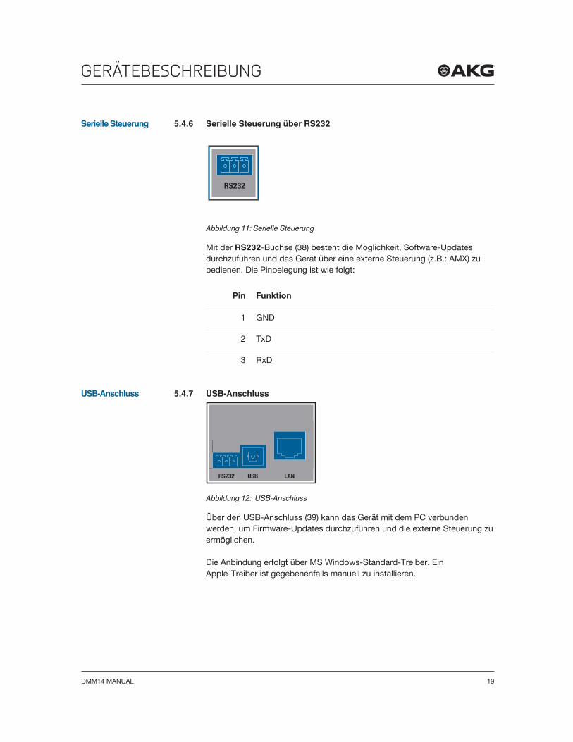
5.4.6 Serielle Steuerung über RS232
Abbildung 11: Serielle Steuerung
Mit der RS232-Buchse (38) besteht die Möglichkeit, Software-Updates durchzuführen und das Gerät über eine externe Steuerung (z.B.: AMX) zu bedienen. Die Pinbelegung ist wie folgt:
Pin Funktion
1 GND
2 TxD
3 RxD
5.4.7 USB-Anschluss
Abbildung 12: USB‑Anschluss
Über den USB-Anschluss (39) kann das Gerät mit dem PC verbunden werden, um Firmware-Updates durchzuführen und die externe Steuerung zu ermöglichen.
Die Anbindung erfolgt über MS Windows-Standard-Treiber. Ein Apple-Treiber ist gegebenenfalls manuell zu installieren.
Serielle Steuerung
RS232
USB-Anschluss
IN - EXPANSION - OUT RS232 USB LAN

gerätebeschreibUng
DMM14 MANUAL 20
5.4.8 LAN-Anschluss
Abbildung 13: LAN‑Anschluss
Mit dem LAN-Anschluss (40) besteht die Möglichkeit, Software-Updates durchzuführen und das Gerät über eine externe Steuerung (z.B.: AMX) zu bedienen.
Des Weiteren besteht die Möglichkeit einer Fernsteuerung und Ferndiagnose mittels eines Webservers.
DieserWebserverstellteineeinfacheundfunktionaleBedienoberflächedar, die mittels Browser aufgerufen werden kann und den Zugriff über LAN-Infrastruktur erlaubt.
Eine gleichzeitige Bedienung über die Frontseite des Automischers und über den Webserver ist möglich: Dabei werden jedoch die Eingaben über den Webserver bevorzugt behandelt.
Der Automischer wird ein Protokoll bereitstellen, womit die Möglichkeit be-steht, den Automischer mittels einer externen Software oder APP via WLAN anzusteuern.
Diese Applikationen können nach Art und Umfang der Programmierung we-sentlich mehr Funktionen bereitstellen und entsprechend dem Endgerät eine grafischaufwendigereOberflächebereitstellen.
5.4.9 Gerätekaskadierung
Abbildung 14: Expansion
LAN-Anschluss
IN - EXPANSION - OUT RS232 USB LAN
Kaskadierung
OUT R REC (OUT) IN - EXPANSION - OUT RS232 USB LAN
L
R

gerätebeschreibUng
DMM14 MANUAL 21
Über die 8-poligen Modular Jacks (RJ-45)-Buchsen (37) können bis zu 10 Geräte zusammen geschlossen werden.
Übertragen werden die Audio-Summe sowie das Statussignal für den Automix-Algorithmus.
Die Audio-Übertragung über die Kaskadierung erfolgt in 24Bit. Die Rauschwerte verschlechtern sich dadurch nicht.
5.4.10 Dante™-Netzwerk
Abbildung 15: Dante™
Das Gerät DMM14 ULD ist mit einer 8-poligen Modular Jack (RJ-45)-Buchse mit der Aufschrift DANTE (19) ausgestattet.
Alle Eingangs- und Ausgangskanäle werden somit automatisch auf das Dante™-Netzwerk geroutet.
Die Eingangskanäle werden nach der Signalbearbeitung (Höhen, Tiefen,…) und nach dem Automix-Algorithmus auf das Dante™-Netzwerk als Direct-Out Signale geroutet.
Die Ausgangssummen werden vor dem Balance-Steller, vor Volume-Out und vor Limiter auf das Dante™-Netzwerk als Direct-Out Signale geroutet.
Einstellungen müssen über die Dante™-Empfängereinheit (z.B. Mischpult) vorgenommen werden.
Im Falle einer Kaskadierung von Automischern ist zu beachten, dass über das Dante™-Netzwerk immer nur die Kanäle übertragen werden, die lokal an einem Automischer verfügbar sind. Sollten zusätzlich auch die Eingangskanäle eines weiteren, kaskadierten Gerätes benötigt werden, muss dieses Gerät ebenfalls über eine eigene Dante™-Schnittstelle verfü-gen.
Sollen mehrere Geräte auch im Automix betrieben werden, müs-sen diese zusätzlich über die Kaskadierung verbunden werden:
Dante™-Netzwerk
REC (OUT) IN - EXPANSION - OUT RS232
DANTE

gerätebeschreibUng
DMM14 MANUAL 22
Neben den Summensignalen werden nämlich auch Steuersignale des Automix-Algorithmus übertragen.
5.5 Automix-Algorithmus
Der Automix-Algorithmus des Geräts beinhaltet 3 Grundfunktionen, anhand derer bewertet wird, um welchen Wert ein Eingangssignal gedämpft wird und welchen Ausgangspegel das Ausgangssignal hat. Folgende Funktionen bzw.ParameterfließenindenAutomix-Algorithmusein:
• Dynamische Pegelanpassung• Best Mic On• Noise Detect
5.5.1 Dynamische Pegelanpassung
Es wird laufend die Summe aller Eingangskanäle bestimmt. Dieser Wert gilt als Referenzwert.
Liegt der Pegel eines Eingangskanals sehr nahe oder über dem Referenzwert, so wird dieser Kanal als dominant bewertet und eine geringe Dämpfung erfahren. Liegt der Pegel eines Eingangskanals weit unter dem Referenzwert, so wird dieser als Umgebungsgeräusch bewertet und eine starke Dämpfung erfahren.
Wird ein Kanal als nicht mehr dominant bewertet, so fährt dieser mit 1 dB / Sekunde herunter und alle andern nicht dominanten Kanäle mit der gleichen Zeitkonstante nach oben, so dass in Summe der Ausgangspegel gleichbleibt. Das Hochregeln eines Kanals dauert zwischen 3 ms und 5 ms.
5.5.2 Best Mic On
Bei zwei, örtlich nahe gelegenen Mikrofonen entsteht der Nachteil, dass KammfiltereffektedurchAuslöschungvonFrequenzanteilenauftretenkön-nen. Um diese unnatürlich dumpfen oder hohlen Signale zu unterdrücken, wird nur der Mikrofonkanal mit dem größten Pegel als dominant bewertet und eingeschaltet.
5.5.3 Noise Detect
Dauerhaft vorhandene Störsignale, dessen Amplitude groß genug sind, um als dominant bewertet zu werden, jedoch eine zu geringe Pegel- und Frequenzänderungen haben, werden als nicht dominant bewertet.
Störsignale wie Lüfter- und Klimaanlagengeräusche werden erkannt und nicht als Aufschaltkriterium für die Mikrofonkanäle herangezogen.
Algorithmus für Automix
Pegelanpassung
Best Mic On
Noise Detect

gerätebeschreibUng
DMM14 MANUAL 23
5.6 Gerätekaskadierung
Sollte die Anzahl der Eingangskanäle eines einzigen Gerätes nicht ausrei-chen, können bis zu 10 Geräte zusammengeschlossen werden.
Das Gerät verfügt über zwei 100 MBit/s-Ethernet-Schnittstellen. Diese dienen zur Steuerdaten- und Audio-Kommunikation zwischen kaskadierten Geräten.
Somit lässt sich ein Automisch-System realisieren mit:
• 60 Eingangskanälen• 20 Ausgangskanälen • 10 Stereo-Kopfhörer-Ausgängen
Die Summenschienen für OUT, REC-OUT und HEADPHONE sind dem gesamten System aller kaskadierten Geräte zugänglich. Jedes Gerät addiert seine Eingangskanäle auf die Summenschienen, die über die Ethernet-Schnittstelle übertragen werden. Jedes Gerät kann die Summenschienen abhören und ausgeben.
Der Automix-Algorithmus überträgt seine Steuerdaten ebenfalls über diese Schnittstelle. Daher funktioniert der Automix-Algorithmus systemweit.
Expansion für Kaskadierung

montAge UnD AnschLUss
DMM14 MANUAL 24
6 Montage und Anschluss
Für die Montage und den Anschluss des DMM14 U (UL, ULD) sind folgende Schritte notwendig:
1. Montage
2. Geräte kaskadieren (optional)
3. Mikrofone und Zusatzgeräte anschließen
4. Gerät an Netz anschließen
6.1 Montage
Für die Montage des Gerätes gehen Sie so vor:
Schritt Beschreibung
1 Montieren Sie das Gerät im 19“-Rack, dazu 4 passende Rackschrauben verwenden.
Darauf achten, dass das Gerät fest im Rack verschraubt ist.
Alternativ kann das Gerät auf einem festen Untergrund positi-oniert werden.
6.2 Geräte kaskadieren (optional)
Achtung: Beschädigungsgefahr
Anschluss ausschließlich von autorisiertem Fachpersonal durchführen las-sen!
Es ist nicht zulässig das erste Gerät der Kaskade mit dem letzten zu verbin-den.
Zur Verkabelung der einzelnen Geräte über die Expansionsbuchten siehe 8.4 Geräte kaskadieren auf Seite 51
6.3 Mikrofone und Zusatzgeräte anschließen
Lesen Sie für das Anschließen auch die Bedienungsanleitungen Ihrer Mikrofone und Zusatzgeräte.

montAge UnD AnschLUss
DMM14 MANUAL 25
Schließen Sie die Mikrofone und Zusatzgeräte an der Rückseite des DMM14 U (UL, ULD) folgendermaßen an:
Schritt Beschreibung
1 Mikrofone und andere Signalquellen (z.B. Empfänger für drahtlose Mikrofone) an die IN - Eingangskanäle anschließen
2 Ausgangskanäle OUT 1/L, OUT 2/L und OUT 1/R , OUT 2/R mit einem Mischpult oder Verstärker verbinden
3 Cinch-Buchsen des Stereo-Record-Ausganges REC (OUT) mit einem Aufnahmegerät verbinden
6.4 Gerät an Netz anschließen
Achtung: Beschädigungsgefahr
Gerät erst an das Stromnetz anschließen, wenn alle Audioverbindungen hergestellt sind!
Darauf achten, dass Eingangsspannung des DMM14 U (UL, ULD) mit Netzspannung übereinstimmt.
Zum Anschließen des Gerätes an das Netz gehen Sie so vor:
Schritt Beschreibung
1 Netzanschlusskabel mit der entsprechenden Buchse auf der Rückseite des DMM14 U (UL, ULD) verbinden
2 Netzanschlusskabel in eine Netzsteckdose stecken

fUnKtionsbeschreibUng
DMM14 MANUAL 26
7 Funktionsbeschreibung
7.1 Bedienkonzept
Das Gerät wird anhand der insgesamt 16 Drehregler auf der Frontplatte be-dient. Diese sind beschriftet mit IN 1 bis IN 12, SYSTEM CONTROL, OUT 1, OUT 2 und HEADPHONE.
Die Drehregler an den Eingängen werden jeweils von einem LED-Kranz mit 15 gelben LEDs, einer grünen LED und einer roten LED umgeben. Der Drehregler SYSTEM CONTROL und die Drehregler an den Ausgängen wer-den von 15 gelben LEDs umgeben. Die Aussteuerungsanzeige unterhalb der Ausgänge besitzt 6 grüne, eine gelbe und eine rote LED.
Die LED-Kränze dienen zur Visualisierung der Drehreglerstellung oder Anzeige von Signalpegeln.
7.2 Drehregler bedienen
Abbildung 16: Drehregler
• Drehen Sie die Drehregler im oder gegen den Uhrzeigersinn um Änderungen an Ein- und Ausgängen sowie Funktionseinstellungen vorzunehmen. Diese Änderungen werden am LED-Kranz um den Drehregler dargestellt. Ausgangspunkt und Schrittweiten am LED-Kranz sind je nach Funktion unterschiedlich.
• Durch kurzes Drücken auf den Drehregler SYSTEM CONTROL wird die Anzeige an den LED-Kränzen auf VU Meter, die Anzeige des tatsächlich anliegenden Audiopegels, umgeschaltet. Solange der VU Meter Modus aktiv ist, blinkt die LEVEL-LED am Drehregler SYSTEM CONTROL. Ein weiteres Drücken auf den Drehregler SYSTEM CONTROL deaktiviert den VU Meter Modus.
Drehregler
8
ONPEAK
9 10 11
1213
14
15
7
6
54
32
1
IN 2

fUnKtionsbeschreibUng
DMM14 MANUAL 27
7.2.1 Anzeige der Audiopegel / VU Funktion
Bei gewählter Funktion LEVEL wird an den LED-Kränzen der Ein- und Ausgänge der eingestellte Pegel angezeigt.
7.3 SYSTEM CONTROL
Der Drehregler SYSTEM CONTROL bietet die Möglichkeit, verschiedene Funktionen am Gerät zu wählen.
Abbildung 17: SYSTEM CONTROL
Zum Wählen der Funktionen und der Einstellung der Parameter siehe 8.1 SYSTEM CONTROL: Parameter am Gerät ändern auf Seite 49
7.3.1 Funktionen von SYSTEM CONTROL
Folgende Funktionen können über SYSTEM CONTROL angewählt werden:
• Level• Treble• Bass• Low Cut• Limiter• Compressor• Automixing• Priority• Pan / Balance• Delay• Routing To REC• Routing To USB• Equalizer• Preset
SYSTEM CONTROL
PRIORITYPAN / BALANCE
DELAY
ROUTE TO REC
ROUTE TO USB
EQUALIZER LOW
EQUALIZER HIGH
PRESET
IN USB / DANTE
AUTOMIXING
COMPRESSOR
LIMITER
LOW CUT
BASS
TREBLE
LEVEL
LOCKED
SYSTEM CONTROL
Funktionen für SYSTEM CONTROL

fUnKtionsbeschreibUng
DMM14 MANUAL 28
Weiter genannte Funktionen können durch Drücken von einzelnen Drehreglern oder Kombinationen von mehreren angewählt werden:
• Routing To Out 1• Routing To Out 2• Monitoring• Mute
7.3.2 Funktionen der Eingangskanäle
DieEingangskanälekönneninfolgendenFunktionenbeeinflusstwerden:
• Level• Treble• Bass• Low Cut• Compressor• Automixing• Priority• Pan• Routing To Out 1• Routing To Out 2• Routing To Rec• Routing To USB• Monitoring• Mute
7.3.3 Funktionen der Ausgangskanäle
DieAusgangskanälekönneninfolgendenFunktionenbeeinflusstwerden:
• Level• Treble• Bass• Limiter• Balance• Delay• Equalizer• Monitoring• Mute
7.3.4 Funktionen des Stereo-Kopfhörer-Ausgangs (Ausgang für Monitoring)
Eine Ausnahme bildet hier der Drehregler HEADPHONE. Der Stereo-Kopfhörer-AusgangbefindetsichimmerinderFunktionLEVEL, unabhängig von der Stellung des SYSTEM CONTROL Drehreglers.
Funktionen der Eingangskanäle
Funktionen der Ausgangskanäle

fUnKtionsbeschreibUng
DMM14 MANUAL 29
7.4 DSP Funktionen
Im Folgenden werden die einzelnen Funktionen in deren Bedienung und Wirkungsweise erklärt.
7.4.1 LEVEL
Abbildung 18: LEVEL Funktion
In der Funktion LEVELkönnenalleEin-undAusgangskanälebeeinflusstwerden.
Eine Drehung des Drehreglers im Uhrzeigersinn erhöht die Lautstärke. Eine Drehung gegen den Uhrzeigersinn verringert diese.
DieEinstellmöglichkeitreichtvon-∞bis+15dB(akustischeRückmeldung).Die Einstellung erfolgt in bedarfsgerechten Schrittweiten.
Bei + 15dB leuchtet der komplette LED-Kranz und es erfolgt keine akusti-sche Rückmeldung mehr.
Von -12 dB bis +15 dB ist die einstellbare Schrittweite 1 dB pro Raster. 3 dB entsprechendemAufleuchteneinerLED.Von-12dBbis-∞istdieeinstell-bareSchrittweite3dB.9dBentsprechendemAufleuchteneinerLED.
Abbildung 19: Detail LEVEL
DSP Funktionen
LEVELPRIORITY
PAN / BALANCE
DELAY
ROUTE TO REC
ROUTE TO USB
EQUALIZER
PRESET
IN USB / DANTE
AUTOMIXING
COMPRESSOR
LIMITER
LOW CUT
BASS
TREBLE
LEVEL
LOCKED
SYSTEM CONTROL
8
ON PEAK
910
1112
1314
15
76
54
32
1
LEVEL Detail LEVEL
-57 dB
-48 dB
-39 dB
-30 dB
-21 dB
-12 dB
-9 dB
+15 dB
+12 dB
+9 dB
+6 dB
+3 dB
0 dB
-3 dB
-6 dB
8 910
1112
13
76
54
3
-8
dB
-7
dB
-6
dB
-5
dB -
4 dB
-3
dB -2
dB
-1 d
B 0
dB
+1 dB
+2 dB
+3 dB

fUnKtionsbeschreibUng
DMM14 MANUAL 30
ZumleichterenAuffindender0dB-PositionleuchtetdieentsprechendeLED (Nr. 10) heller als die übrigen LED-Felder, wobei erst nach dem dritten Rasten,nachdemAufleuchtendiesesLED-Feldesder0dB-Pegelerreichtwird (siehe Detail LEVEL)
Durch Drücken auf den Drehregler SYSTEM CONTROL in der Funktion LEVEL wird die Anzeige der Ein- und Ausgangskanäle von Verstärkungsanzeige auf Aussteuerungsanzeige umgeschaltet.
7.4.2 TREBLE
Abbildung 20: TREBLE Funktion
In der Funktion TREBLEkönnenalleEin-undAusgangskanälebeeinflusstwerden.
Abbildung 21: Skalierung des LED‑Kranzes der Funktion TREBLE
Mit der Funktion TREBLE lässt sich der Höhenbereich des Audiosignals anheben oder absenken. Das Filter ist als Höhen-Shelving-Filter 1. Ordnung ausgeführt. Die Grenzfrequenz liegt bei 10 kHz.
Die Regelmöglichkeit reicht von -14 dB bis +14 dB. Bei linearer Einstellung leuchtet nur die mittlere obere LED (0 dB). Je weiter der Drehregler nach links gedreht wird, desto mehr LEDs leuchten auf der linken Seite auf.
TREBLEPRIORITY
PAN / BALANCE
DELAY
ROUTE TO REC
ROUTE TO USB
EQUALIZER
PRESET
IN USB / DANTE
AUTOMIXING
COMPRESSOR
LIMITER
LOW CUT
BASS
TREBLE
LEVEL
LOCKED
SYSTEM CONTROL
8
ON PEAK
910
1112
1314
15
76
54
32
1-14 dB
-12 dB
-10 dB
-8 dB
-6 dB
-4 dB
-2 dB
+14 dB
+12 dB
+10 dB
+8 dB
+6 dB
+4 dB
+2 dB
0 dB
TREBLE

fUnKtionsbeschreibUng
DMM14 MANUAL 31
Je weiter der Drehregler nach rechts gedreht wird, desto mehr LEDs leuch-ten auf der rechten Seite auf.
Die einstellbare Schrittweite beträgt 2 dB pro Raster, dies entspricht dem AufleuchteneinerLED.
Abbildung 22: Regelmöglichkeit der TREBLE Funktion
7.4.3 BASS
Abbildung 23: BASS Funktion
-18
+16
-16
-14
-12
-10
-8
-6
-4
-2
-0
+2
+4
+6
+8
+10
+12
+14
dBr A
20 20k50 100 200 500 1k 2k 5k 10kHz
BASSPRIORITY
PAN / BALANCE
DELAY
ROUTE TO REC
ROUTE TO USB
EQUALIZER
PRESET
IN USB / DANTE
AUTOMIXING
COMPRESSOR
LIMITER
LOW CUT
BASS
TREBLE
LEVEL
LOCKED
SYSTEM CONTROL

fUnKtionsbeschreibUng
DMM14 MANUAL 32
In der Funktion BASSkönnenalleEin-undAusgangskanälebeeinflusstwerden.
Mit der Funktion BASS lässt sich der Tiefenbereich des Audiosignals anheben oder absenken. Das Filter ist als Bass-Shelving-Filter 1. Ordnung ausgeführt. Die Grenzfrequenz liegt bei 100 Hz.
Die Regelmöglichkeit reicht von -14 dB bis +14 dB. Bei linearer Einstellung leuchtet nur die mittlere obere LED (0 dB). Je weiter der Drehregler nach links gedreht wird, desto mehr LEDs leuchten auf der linken Seite auf.
Je weiter der Drehregler nach rechts gedreht wird, desto mehr LEDs leuchten auf der rechten Seite auf.
Abbildung 24: Skalierung des LED‑Kranzes der BASS Funktion
8
ON PEAK
910
1112
1314
15
76
54
32
1-14 dB
-12 dB
-10 dB
-8 dB
-6 dB
-4 dB
-2 dB
+14 dB
+12 dB
+10 dB
+8 dB
+6 dB
+4 dB
+2 dB
0 dB
BASS

fUnKtionsbeschreibUng
DMM14 MANUAL 33
Die einstellbare Schrittweite beträgt 2 dB pro Raster, dies entspricht dem AufleuchteneinerLED.
Abbildung 25: Regelmöglichkeit der BASS Funktion
7.4.4 LOW CUT
Abbildung 26: LOW CUT Funktion
In der Funktion LOW CUTkönnenalleEingangskanälebeeinflusstwerden.
Mit der Funktion LOW CUT lassen sich tieffrequente Störgeräusche un-terdrücken. Das Low-Cut-Filter ist als Hochpass 2. Ordnung ausgeführt.
-14
+14
-12
-10
-8
-6
-4
-2
+0
+2
+4
+6
+8
+10
+12
dBr A
20 20k50 100 200 500 1k 2k 5k 10kHz
LOW CUTPRIORITY
PAN / BALANCE
DELAY
ROUTE TO REC
ROUTE TO USB
EQUALIZER
PRESET
IN USB / DANTE
AUTOMIXING
COMPRESSOR
LIMITER
LOW CUT
BASS
TREBLE
LEVEL
LOCKED
SYSTEM CONTROL
fUnKtionsbeschreibUng
DMM14 MANUAL 34
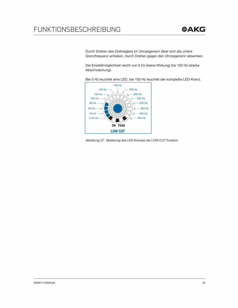
Durch Drehen des Drehreglers im Uhrzeigersinn lässt sich die untere Grenzfrequenz anheben, durch Drehen gegen den Uhrzeigersinn absenken.
Die Einstellmöglichkeit reicht von 0 Hz (keine Wirkung) bis 150 Hz (starke Abschwächung).
Bei 0 Hz leuchtet eine LED, bei 150 Hz leuchtet der komplette LED-Kranz.
Abbildung 27: Skalierung des LED‑Kranzes der LOW CUT Funktion
8
ON PEAK
910
1112
1314
15
76
54
32
10-20 Hz
40 Hz
60 Hz
80 Hz
100 Hz
120 Hz
140 Hz
300 Hz
280 Hz
260 Hz
240 Hz
220 Hz
200 Hz
180 Hz
160 Hz
LOW CUT

fUnKtionsbeschreibUng
DMM14 MANUAL 35
Die einstellbare Schrittweite beträgt 20 Hz pro Raster, dies entspricht dem AufleuchteneinerLED.
Abbildung 28: Regelmöglichkeit der LOW CUT Funktion
7.4.5 LIMITER
Abbildung 29: LIMITER Funktion
In der Funktion LIMITERkönnenalleAusgangskanälebeeinflusstwerden.
-14
+15
-13-12-11-10-9-8-7-6-5-4-3-2-1-0+1+2+3+4+5+6+7+8+9
+10+11+12+13+14
dBr A
20 20k50 100 200 500 1k 2k 5k 10kHz
LIMITERPRIORITY
PAN / BALANCE
DELAY
ROUTE TO REC
ROUTE TO USB
EQUALIZER
PRESET
IN USB / DANTE
AUTOMIXING
COMPRESSOR
LIMITER
LOW CUT
BASS
TREBLE
LEVEL
LOCKED
SYSTEM CONTROL
fUnKtionsbeschreibUng
DMM14 MANUAL 36
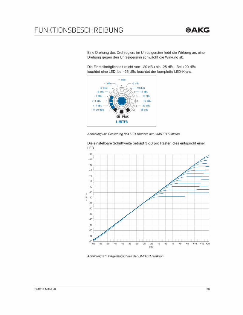
Eine Drehung des Drehreglers im Uhrzeigersinn hebt die Wirkung an, eine Drehung gegen den Uhrzeigersinn schwächt die Wirkung ab.
Die Einstellmöglichkeit reicht von +20 dBu bis -25 dBu. Bei +20 dBu leuchtet eine LED, bei -25 dBu leuchtet der komplette LED-Kranz.
Abbildung 30: Skalierung des LED‑Kranzes der LIMITER Funktion
Die einstellbare Schrittweite beträgt 3 dB pro Raster, dies entspricht einer LED.
Abbildung 31: Regelmöglichkeit der LIMITER Funktion
8
ON PEAK
910
1112
1314
15
76
54
32
1+17-20 dBu
+14 dBu
+11 dBu
+8 dBu
+5 dBu
+2 dBu
-1 dBu
-25 dBu
-22 dBu
-19 dBu
-16 dBu
-13 dBu
-10 dBu
-7 dBu
-4 dBu
LIMITER
-60
+20
-55
-50
-45
-40
-35
-30
-25
-20
-15
-10
-5
+0
+5
+10
+15
dBu
-60 +20-55 -50 -45 -40 -35 -30 -25 -20 -15 -10 -5 +0 +5 +10 +15dBu

fUnKtionsbeschreibUng
DMM14 MANUAL 37
7.4.6 COMPRESSOR
Abbildung 32: COMPRESSOR Funktion
In der Funktion COMPRESSORkönnenalleEingangskanälebeeinflusstwerden.
Die Ratio (Kompressionsverhältnis) des Kompressors ist fest eingestellt. Sie hat einen Wert von 1:2. Eine Drehung des Drehreglers im Uhrzeigersinn hebt die Wirkung an, eine Drehung gegen den Uhrzeigersinn schwächt die Wirkung ab.
Die Einstellmöglichkeit reicht von +20 dBu bis -25 dBu. Bei +20 dBu leuchtet eine LED, bei -25 dBu leuchtet der komplette LED-Kranz.
Abbildung 33: Skalierung des LED‑Kranzes der COMPRESSOR Funktion
COMPRESSORPRIORITY
PAN / BALANCE
DELAY
ROUTE TO REC
ROUTE TO USB
EQUALIZER
PRESET
IN USB / DANTE
AUTOMIXING
COMPRESSOR
LIMITER
LOW CUT
BASS
TREBLE
LEVEL
LOCKED
SYSTEM CONTROL
8
ON PEAK
910
1112
1314
15
76
54
32
1+17-20 dBu
+14 dBu
+11 dBu
+8 dBu
+5 dBu
+2 dBu
-1 dBu
-25 dBu
-22 dBu
-19 dBu
-16 dBu
-13 dBu
-10 dBu
-7 dBu
-4 dBu
COMPRESSOR

fUnKtionsbeschreibUng
DMM14 MANUAL 38
Die einstellbare Schrittweite beträgt 3 dBu pro Raster, dies entspricht einer LED.
Abbildung 34: Regelmöglichkeit der COMPRESSOR Funktion
7.4.7 AUTOMIXING
Abbildung 35: AUTOMIXING Funktion
-40
+20
-37.5-35
-32.5-30
-27.5-25
-22.5-20
-17.5-15
-12.5-10-7.5
-5-2.5+0
+2.5+5
+7.5+10
+12.5+15
+17.5
dBr
A
-40 +20-35 -30 -25 -20 -15 -10 -5 +0 +5 +10 +15dBu
T
AUTOMIXINGPRIORITY
PAN / BALANCE
DELAY
ROUTE TO REC
ROUTE TO USB
EQUALIZER
PRESET
IN USB / DANTE
AUTOMIXING
COMPRESSOR
LIMITER
LOW CUT
BASS
TREBLE
LEVEL
LOCKED
SYSTEM CONTROL

fUnKtionsbeschreibUng
DMM14 MANUAL 39
In der Funktion AUTOMIXINGkönnenalleEingangskanälebeeinflusstwerden.
Abbildung 36: Regelmöglichkeit der AUTOMIXING Funktion
Mit einer Drehung eines Drehreglers im Uhrzeigersinn wird die Automatik-Mischfunktionen für den jeweiligen Kanal eingeschaltet. (LED-Kranz leuchtet komplett) Eine Drehung gegen den Uhrzeigersinn schaltet die Automatik-Mischfunktionen aus. (nur eine LED leuchtet).
Durch Drücken auf den Drehregler wird die Funktion ebenfalls ein- bzw. ausgeschaltet.
7.4.8 PRIORITY
Abbildung 37: PRIORITY Funktion
Diese Funktion kann nur an einem einzigen Eingangskanal aktiv sein.
In der Funktion PRIORITY kann bestimmt werden, welcher Eingangskanal als Priority-Kanal fungiert. Der Priority-Kanal erfährt dann in Zusammenhang
8
ON PEAK
910
1112
1314
15
76
54
32
1
8
ON PEAK
910
1112
1314
15
76
54
32
1
off on
AUTOMIXING
PRIORITYPRIORITY
PAN / BALANCE
DELAY
ROUTE TO REC
ROUTE TO USB
EQUALIZER
PRESET
IN USB / DANTE
AUTOMIXING
COMPRESSOR
LIMITER
LOW CUT
BASS
TREBLE
LEVEL
LOCKED
SYSTEM CONTROL

fUnKtionsbeschreibUng
DMM14 MANUAL 40
mit der Funktion AUTOMIXING einen Vorteil in der Signalbewertung von 6 dB.
Abbildung 38: Regelmöglichkeit der PRIORITY Funktion
Mit einer Drehung eines Drehreglers im Uhrzeigersinn wird die Funktion für den jeweiligen Kanal eingeschaltet. (LED-Kranz leuchtet komplett). Eine Drehung gegen den Uhrzeigersinn schaltet die Funktionen aus (nur eine LED leuchtet).
Durch Drücken auf den Drehregler wird die Funktion ebenfalls ein- bzw. ausgeschaltet.
Ein Einschalten der PRIORITY Funktion an einem Eingangskanal bewirkt ein Ausschalten der Funktion an dem vorher aktivierten Kanal.
7.4.9 PAN / BALANCE
Abbildung 39: PAN / BALANCE Funktion
8
ON PEAK
910
1112
1314
15
76
54
32
1
8
ON PEAK
910
1112
1314
15
76
54
32
1
off on
PRIORITY
PAN / BALANCEPRIORITY
PAN / BALANCE
DELAY
ROUTE TO REC
ROUTE TO USB
EQUALIZER
PRESET
IN USB / DANTE
AUTOMIXING
COMPRESSOR
LIMITER
LOW CUT
BASS
TREBLE
LEVEL
LOCKED
SYSTEM CONTROL

fUnKtionsbeschreibUng
DMM14 MANUAL 41
In der Funktion PAN / BALANCE können alle Eingangskanäle im Panorama beeinflusstwerden,alleAusgangskanäleinihrerBalance.
Abbildung 40: Skalierung des LED‑Kranzes der PAN / BALANCE Funktion
Als Balance wird die Zuordnung eines Summensignals auf den Ausgang bezeichnet.
Bei linearer Einstellung leuchtet nur die mittlere obere LED (0 dB). Diese LED (0 dB) gilt auch als Ausgangspunkt für eine Drehung im oder gegen den Uhrzeigersinn. Je weiter der Drehregler nach links gedreht wird, desto mehr LEDs leuchten auf der linken Seite auf. Je weiter der Drehregler nach rechts gedreht wird, desto mehr LEDs leuchten auf der rechten Seite auf.
Soll der linke Ausgangskanal eines Stereo-Ausgangs nicht mehr ausgege-ben werden, so ist der Balance-Regler nach rechts zu stellen.
Bei Mono-Eingängen wird das Signal standardmäßig gleich auf Stereo-Links und -Rechts zugeteilt. Soll der Eingang nur links zugeteilt werden, so ist der Drehregler des Eingangs, bei aktiver PAN-Funktion, auf links zu stellen.
Die einstellbare Schrittweite beträgt 6 dB pro Raster, dies entspricht dem AufleuchteneinerLED.
8
ON PEAK
910
1112
1314
15
76
54
32
1R MIN
R -36 dB
R -30 dB
R -24 dB
R -18 dB
R -12 dB
R -6 dB
L MIN
L -36 dB
L -30 dB
L -24 dB
L -18 dB
L -12 dB
L -6 dB
0 dB
PAN (IN) / BALANCE (OUT)

fUnKtionsbeschreibUng
DMM14 MANUAL 42
7.4.10 DELAY
Abbildung 41: DELAY Funktion
In der Funktion DELAY können der Ausgang OUT 1 und OUT 2 beeinflusstwerden. Es lassen sich mit dieser Funktion die Ausgänge zeitlich verzögern.
Abbildung 42: Skalierung des LED‑Kranzes der DELAY Funktion
Die Einstellmöglichkeit reicht von 0 m bis 75 m. Bei 0 m leuchtet eine LED, bei 75 m leuchtet der komplette LED-Kranz.
Die einstellbare Schrittweite beträgt 1 m pro Raster. 5 m entsprechen dem AufleuchteneinerLED.
DELAYPRIORITY
PAN / BALANCE
DELAY
ROUTE TO REC
ROUTE TO USB
EQUALIZER
PRESET
IN USB / DANTE
AUTOMIXING
COMPRESSOR
LIMITER
LOW CUT
BASS
TREBLE
LEVEL
LOCKED
SYSTEM CONTROL
8
ON PEAK
910
1112
1314
15
76
54
32
10-5 m
10 m
15 m
20 m
25 m
30 m
35 m
75 m
70 m
65 m
60 m
55 m
50 m
45 m
40 m
DELAY

fUnKtionsbeschreibUng
DMM14 MANUAL 43
7.4.11 ROUTING TO REC
Abbildung 43: ROUTING TO REC Funktion
In der Funktion ROUTING TO RECkönnenalleEingangskanälebeeinflusstwerden.
Abbildung 44: Regelmöglichkeit der Funktion ROUTING TO REC
Mit einer Drehung eines Drehreglers im Uhrzeigersinn wird die Funktion für den jeweiligen Kanal eingeschaltet (LED-Kranz leuchtet komplett). Eine Drehung gegen den Uhrzeigersinn schaltet die Funktion aus (nur eine LED leuchtet).
Durch Drücken auf den Drehregler wird die Funktion ebenfalls ein- bzw. ausgeschaltet.
Ein Einschalten legt diesen Eingangskanal auf die Summenschiene OUT 1.
ROUTING TO RECPRIORITY
PAN / BALANCE
DELAY
ROUTE TO REC
ROUTE TO USB
EQUALIZER
PRESET
IN USB / DANTE
AUTOMIXING
COMPRESSOR
LIMITER
LOW CUT
BASS
TREBLE
LEVEL
LOCKED
SYSTEM CONTROL
8
ON PEAK
910
1112
1314
15
76
54
32
1
8
ON PEAK
910
1112
1314
15
76
54
32
1off on
ROUTING TO REC
fUnKtionsbeschreibUng
DMM14 MANUAL 44
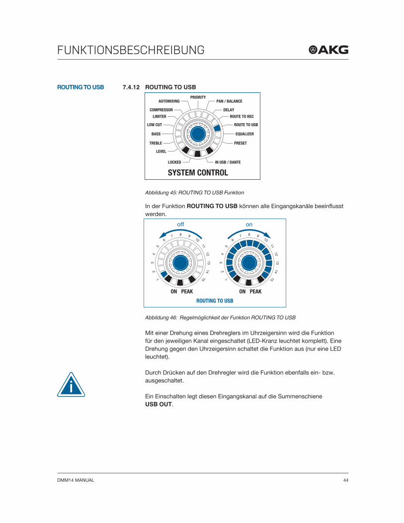
7.4.12 ROUTING TO USB
Abbildung 45: ROUTING TO USB Funktion
In der Funktion ROUTING TO USBkönnenalleEingangskanälebeeinflusstwerden.
Abbildung 46: Regelmöglichkeit der Funktion ROUTING TO USB
Mit einer Drehung eines Drehreglers im Uhrzeigersinn wird die Funktion für den jeweiligen Kanal eingeschaltet (LED-Kranz leuchtet komplett). Eine Drehung gegen den Uhrzeigersinn schaltet die Funktion aus (nur eine LED leuchtet).
Durch Drücken auf den Drehregler wird die Funktion ebenfalls ein- bzw. ausgeschaltet.
Ein Einschalten legt diesen Eingangskanal auf die Summenschiene USB OUT.
ROUTING TO USBPRIORITY
PAN / BALANCE
DELAY
ROUTE TO REC
ROUTE TO USB
EQUALIZER
PRESET
IN USB / DANTE
AUTOMIXING
COMPRESSOR
LIMITER
LOW CUT
BASS
TREBLE
LEVEL
LOCKED
SYSTEM CONTROL
8
ON PEAK
910
1112
1314
15
76
54
32
1
8
ON PEAK
910
1112
1314
15
76
54
32
1off on
ROUTING TO USB

fUnKtionsbeschreibUng
DMM14 MANUAL 45
7.4.13 EQUALIZER
Abbildung 47: EQUALIZER Funktion
Die Funktion EQUALIZER beeinflusstdieAusgängeOUT 1 und OUT 2: Die Einstellung erfolgt gleichermaßen für linken und rechten Kanal.
Es lässt sich eine Raumentzerrung in 12 Bändern durchführen.
Durch Drücken auf Drehregler OUT 1 wird die Einstellung für OUT 1 akti-viert, durch Drücken auf Drehregler OUT 2, die Einstellung für OUT 2.
Die Anhebung bzw. Absenkung der Bänder erfolgt über die 12 Drehregler der Eingangskanäle. Die Einstellung lässt sich um +/-14dB variieren. Bei linearer Einstellung leuchtet nur die mittlere obere LED. Bei einer Drehung gegen den Uhrzeigersinn leuchten immer mehr LEDs links von der mittleren. Bei einer Drehung im Uhrzeigersinn leuchten immer mehr LEDs rechts von der mittleren.
Abbildung 48: Skalierung des LED‑Kranzes der EQUALIZER Funktion
Die Einstellung erfolgt in 2 dB-Schritten.
EQUALIZERPRIORITY
PAN / BALANCE
DELAY
ROUTE TO REC
ROUTE TO USB
EQUALIZER
PRESET
IN USB / DANTE
AUTOMIXING
COMPRESSOR
LIMITER
LOW CUT
BASS
TREBLE
LEVEL
LOCKED
SYSTEM CONTROL
8
ON PEAK
910
1112
1314
15
76
54
32
1-57 dB
-48 dB
-39 dB
-30 dB
-21 dB
-12 dB
-9 dB
+15 dB
+12 dB
+9 dB
+6 dB
+3 dB
0 dB
-3 dB
-6 dB
EQUALIZER

fUnKtionsbeschreibUng
DMM14 MANUAL 46
Die Mittenfrequenzen der Teilbänder sind im ½-Oktav-Abstand angeordnet.
Abbildung 49: Regelmöglichkeit der EQUALIZER Funktion
7.4.14 PRESET
Abbildung 50: PRESET Funktion
EsbestehtdieMöglichkeit,12unterschiedlicheGerätekonfigurationenbzw.Geräte-Presets (LEVEL, TREBLE, BASS, … , EQUALIZER) im Gerät abzu-speichern und wieder zu laden.
-16
+16
-15-14-13-12-11-10-9-8-7-6-5-4-3-2-1+0+1+2+3+4+5+6+7+8+9
+10+11+12+13+14+15
dBr A
20 20k50 100 200 500 1k 2k 5k 10kHz
PRESETPRIORITY
PAN / BALANCE
DELAY
ROUTE TO REC
ROUTE TO USB
EQUALIZER
PRESET
IN USB / DANTE
AUTOMIXING
COMPRESSOR
LIMITER
LOW CUT
BASS
TREBLE
LEVEL
LOCKED
SYSTEM CONTROL

fUnKtionsbeschreibUng
DMM14 MANUAL 47
Dazu wird die Funktion PRESET am SYSTEM CONTROL angewählt. Neben den 12 Geräte-Presets gibt es noch einen Arbeits-Preset: Alle Änderungen in den Einstellungen wirken sich zunächst nur auf diesen Preset aus. Um Änderungen dauerhaft zu speichern, muss der Arbeits-Preset unter einem der verfügbaren Geräte-Presets gespeichert werden. Mit dem Laden eines Geräte-Presets wird der Arbeits-Preset überschrieben und ist sofort aktiv. Nach dem Neustart des Geräts ist der letzte Arbeits-Preset mit den zuletzt vorgenommen Einstellungen aktiv.
Die 12 Eingangsdrehregler bieten Zugang zu den Presets, sowie deren Konfiguration.
Abbildung 51: PRESET‑Konfigurationen
Leuchtet an einem LED-Kranz nur LED 1, so ist dieser Speicherplatz nicht konfiguriert(sieheAbbildung 51, Inkrementgeber IN 3 / 15).
Leuchten alle LEDs und die rote PEAK-LED, so ist dieser Speicherplatz belegt und ausgewählt (siehe Abbildung 51, Inkrementgeber IN 1 / 13).
Leuchtet nur LED 1 und die rote PEAK-LED, so ist dieser Speicherplatz be-legt aber nicht ausgewählt (siehe Abbildung 51, Inkrementgeber IN 2 / 14).
Siehe dazu 8.7 Presets verwenden auf Seite 53.
8
ON PEAK
910
1112
1314
15
76
54
32
1
IN 1 / USB LEQ 250 Hz
8
ON PEAK
910
1112
1314
15
76
54
32
1
IN 3 / DANTE 1EQ 500 Hz
8
ON PEAK
910
1112
1314
15
76
54
32
1
IN 2 / USB REQ 350 Hz

fUnKtionsbeschreibUng
DMM14 MANUAL 48
7.5 LOCKED
Abbildung 52: LOCKED Funktion
In der Funktion LOCKED werden durch Sperren die Drehregler oder das gesamte Gerät vor unsachgemäßer Bedienung geschützt.
Siehe dazu 8.11 LOCKED aktivieren/deaktivieren auf Seite 56
LOCKEDPRIORITY
PAN / BALANCE
DELAY
ROUTE TO REC
ROUTE TO USB
EQUALIZER
PRESET
IN USB / DANTE
AUTOMIXING
COMPRESSOR
LIMITER
LOW CUT
BASS
TREBLE
LEVEL
LOCKED
SYSTEM CONTROL
beDienUng Des gerätes
DMM14 MANUAL 49
8 Bedienung des Gerätes
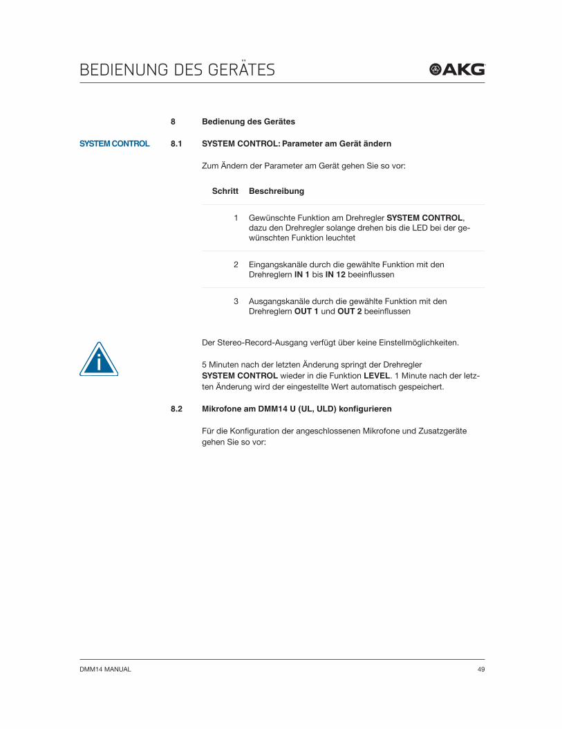
8.1 SYSTEM CONTROL: Parameter am Gerät ändern
Zum Ändern der Parameter am Gerät gehen Sie so vor:
Schritt Beschreibung
1 Gewünschte Funktion am Drehregler SYSTEM CONTROL, dazu den Drehregler solange drehen bis die LED bei der ge-wünschten Funktion leuchtet
2 Eingangskanäle durch die gewählte Funktion mit den Drehreglern IN 1 bis IN 12beeinflussen
3 Ausgangskanäle durch die gewählte Funktion mit den Drehreglern OUT 1 und OUT 2 beeinflussen
Der Stereo-Record-Ausgang verfügt über keine Einstellmöglichkeiten.
5 Minuten nach der letzten Änderung springt der Drehregler SYSTEM CONTROL wieder in die Funktion LEVEL. 1 Minute nach der letz-ten Änderung wird der eingestellte Wert automatisch gespeichert.
8.2 Mikrofone am DMM14 U (UL, ULD) konfigurieren
FürdieKonfigurationderangeschlossenenMikrofoneundZusatzgerätegehen Sie so vor:
SYSTEM CONTROL

beDienUng Des gerätes
DMM14 MANUAL 50
Schritt Beschreibung
1 Schiebe-Schalter und Gain-Regler auf der Rückseite des DMM14 U (UL, ULD) betätigen
• Wählen Sie die Verstärkung der Eingangssignale zwischen 0 dB und +57 dB.
• Eine höhere Verstärkung der Eingangssignale ist für Mikrofone mit geringem Ausgangspegel geeignet.
• Für Mikrofone mit hohem Ausgangspegel wird eine gerin-gere Verstärkung empfohlen.
• Wenn Sie Kondensatormikrofone verwenden, stellen Sie fest, welche Speisespannung oder Speisegeräte diese benötigen.
• Wenn Ihre Kondensatormikrofone für Phantomspeisung geeignet sind, schalten Sie die Phantomspeisung ein. Stellen Sie dazu den Schiebe-Schalter PHANT. PWR auf ON.
2 Gerät mit Netzschalter einschalten
Achtung: Beschädigungsgefahr
Schalten Sie bei Verwendung von drahtlosen Mikrofonen die Phantomspeisung an jenen Eingängen aus, an denen Sie einen Empfänger angeschlossen haben, um Schäden am Empfänger zu vermeiden.
8.3 Ein-/Ausgänge abhören
Zum Abhören von Ein- bzw. Ausgängen gehen Sie so vor:
Schritt Beschreibung
1 Drehregler HEADPHONE gedrückt halten und durch Drücken eines oder mehrerer Drehregler Abhörquelle wählen
• Sie werden in Mono gleichzeitig auf linken und rechten Kopfhörerkanal geschaltet.
2 Abhörquelle wechseln, dazu auf eine andere Abhörquelle drücken.
• Die vorherige Abhörquelle wird abgeschaltet

beDienUng Des gerätes
DMM14 MANUAL 51
Bei Eingängen können mehrere Quellen abgehört werden.
Der Ausgang kann nur einzeln, aber in Stereo abgehört werden.
Der Ausgang REC (OUT) kann nicht abgehört werden.
8.4 Geräte kaskadieren
Achtung: Beschädigungsgefahr
Anschluss ausschließlich von autorisiertem Fachpersonal durchführen las-sen!
Es ist nicht zulässig das erste Gerät der Kaskade mit dem letzten zu verbin-den.
Zur Verkabelung der einzelnen Geräte mit den Expansionsbuchten gehen Sie so vor:
Schritt Beschreibung
1 Geräte in folgender Weise mittels CAT5+ Verbindungskabel zusammenschließen:
OUT R REC (OUT) IN - EXPANSION - OUT RS232 USB LAN
L
R
OUT R REC (OUT) IN - EXPANSION - OUT RS232 USB LAN
L
R
OUT R REC (OUT) IN - EXPANSION - OUT RS232 USB LAN
L
R
Zur Kaskadierung empfehlen wir ausschließlich Kabel aus dem AKG-Zubehör zu verwenden.

beDienUng Des gerätes
DMM14 MANUAL 52
Alle Geräte sind für den Anwender hinsichtlich ihrer Funktion und ihrem Verhalten gleichgestellt. Bei der Kaskadierung bleiben alle Funktionen der Einzelgeräte erhalten.
8.5 Zuspielung über USB und Dante™
8.5.1 Zuspielung bearbeiten
Um Eingangssignale über USB bzw. Dante™ zuzuspielen gehen Sie so vor:
Schritt Beschreibung
1 Drehregler SYSTEM CONTROL zweimal kurz drücken (Doppelklick)
• Die 12 Eingangsregler werden in Ihrer Bedienung umge-schaltet.
• Die LED IN USB bzw. IN USB/DANTE leuchtet dauerhaft auf
• Änderungen an den Eingangsreglern wirken nicht mehr auf die 12 analogen Eingänge, sondern auf die digitalen Eingänge 13 bis 24
• Die weitere Bedienung ist gleich wie auf der analogen Ebene
Die Eingänge vom USB Port belegen dabei die Kanäle 13 (IN1 / USB L) und 14 (IN 2 / USB R), bei Geräten ohne Dante™-Schnittstelle sind die digitalen Eingänge 15 bis 24 ohne Funktion und inaktiv.
Bei Geräten mit Dante™-Schnittstelle sind die weiteren digitalen Eingangskanäle ab Kanal 15 wie folgt belegt:
• IN3 / DANTE 1• IN4 / DANTE 2• usw.
Alle digitalen Eingänge haben dieselben Funktionalitäten der Signalverarbeitung wie die analogen Eingänge.
8.6 Phantomspeisung aktivieren
Das 0 V-Potential nur mit der Erdung brücken (Werkseinstellung) oder zur zentralen Systemerde führen, da die Phantomspeisung sonst keinen Bezugspunkt besitzt und diese nicht funktioniert.
Zuspielung über USB und Dante™
beDienUng Des gerätes
DMM14 MANUAL 53
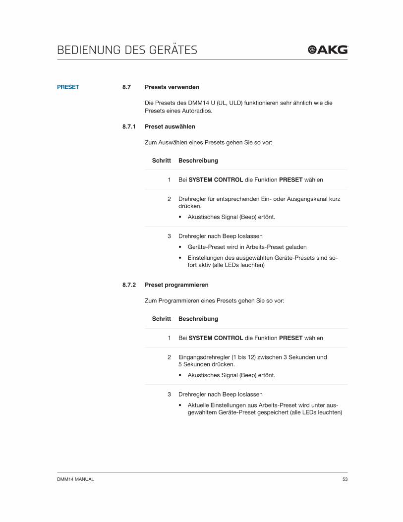
8.7 Presets verwenden
Die Presets des DMM14 U (UL, ULD) funktionieren sehr ähnlich wie die Presets eines Autoradios.
8.7.1 Preset auswählen
Zum Auswählen eines Presets gehen Sie so vor:
Schritt Beschreibung
1 Bei SYSTEM CONTROL die Funktion PRESET wählen
2 Drehregler für entsprechenden Ein- oder Ausgangskanal kurz drücken.
• Akustisches Signal (Beep) ertönt.
3 Drehregler nach Beep loslassen
• Geräte-Preset wird in Arbeits-Preset geladen
• Einstellungen des ausgewählten Geräte-Presets sind so-fort aktiv (alle LEDs leuchten)
8.7.2 Preset programmieren
Zum Programmieren eines Presets gehen Sie so vor:
Schritt Beschreibung
1 Bei SYSTEM CONTROL die Funktion PRESET wählen
2 Eingangsdrehregler (1 bis 12) zwischen 3 Sekunden und 5 Sekunden drücken.
• Akustisches Signal (Beep) ertönt.
3 Drehregler nach Beep loslassen
• Aktuelle Einstellungen aus Arbeits-Preset wird unter aus-gewähltem Geräte-Preset gespeichert (alle LEDs leuchten)
PRESET
beDienUng Des gerätes
DMM14 MANUAL 54
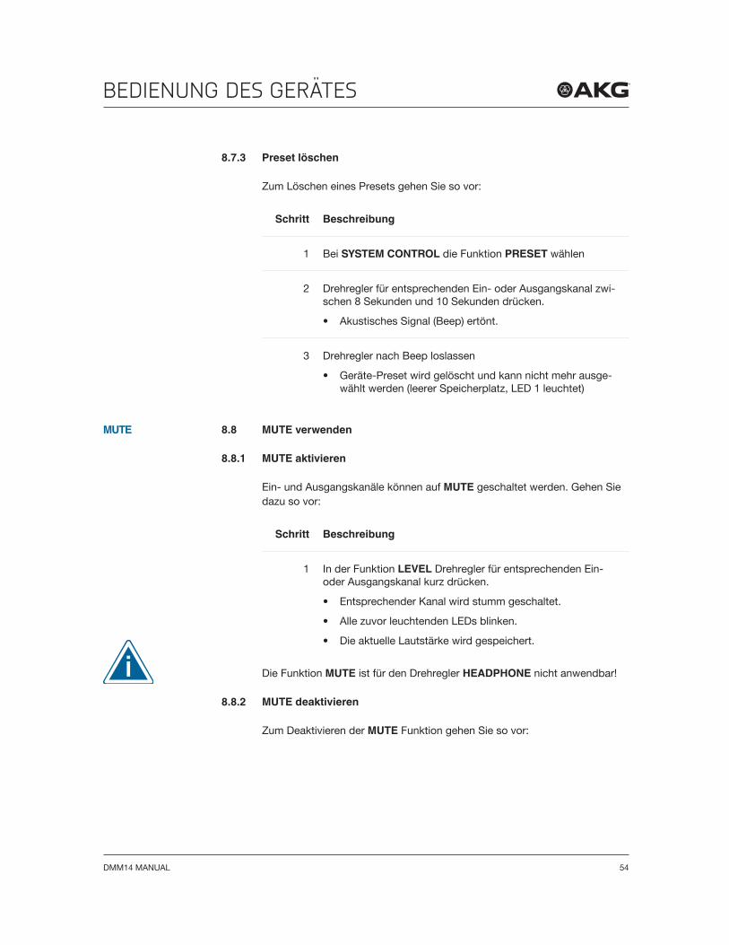
8.7.3 Preset löschen
Zum Löschen eines Presets gehen Sie so vor:
Schritt Beschreibung
1 Bei SYSTEM CONTROL die Funktion PRESET wählen
2 Drehregler für entsprechenden Ein- oder Ausgangskanal zwi-schen 8 Sekunden und 10 Sekunden drücken.
• Akustisches Signal (Beep) ertönt.
3 Drehregler nach Beep loslassen
• Geräte-Preset wird gelöscht und kann nicht mehr ausge-wählt werden (leerer Speicherplatz, LED 1 leuchtet)
8.8 MUTE verwenden
8.8.1 MUTE aktivieren
Ein- und Ausgangskanäle können auf MUTE geschaltet werden. Gehen Sie dazu so vor:
Schritt Beschreibung
1 In der Funktion LEVEL Drehregler für entsprechenden Ein- oder Ausgangskanal kurz drücken.
• Entsprechender Kanal wird stumm geschaltet.
• Alle zuvor leuchtenden LEDs blinken.
• Die aktuelle Lautstärke wird gespeichert.
Die Funktion MUTE ist für den Drehregler HEADPHONE nicht anwendbar!
8.8.2 MUTE deaktivieren
Zum Deaktivieren der MUTE Funktion gehen Sie so vor:
MUTE

beDienUng Des gerätes
DMM14 MANUAL 55
Schritt Beschreibung
1 Drehregler für entsprechenden Ein- oder Ausgangskanal kurz drücken.
• MUTE Funktion für entsprechenden Kanal wird deaktiviert.
• Die zuvor gespeicherte Lautstärke wird angewandt.
8.9 ROUTING TO OUT aktivieren
8.9.1 Für einen Eingangskanal
Auf den Ausgang OUT können alle Eingangskanäle geroutet werden. Gehen Sie dazu so vor:
Schritt Beschreibung
1 Drehregler OUT drücken und gedrückt halten
Gleichzeitig Drehregler des gewünschten Eingangkanals drücken
• Entsprechender Eingangskanal wird auf die Summenschiene OUT geroutet.
8.9.2 Für mehrere Eingangskanäle
Zum Routen mehrerer Eingangskanäle auf OUT, gehen Sie so vor:
Schritt Beschreibung
1 Drehregler OUT drücken und gedrückt halten
Drehregler der gewünschten Eingangkanäle drücken
• Entsprechende Eingangskanäle werden auf die Summenschiene OUT geroutet.
8.10 ROUTING TO OUT deaktivieren
Zum Deaktivieren der Funktion ROUTING TO OUT gehen Sie so vor:
ROUTING TO OUT

beDienUng Des gerätes
DMM14 MANUAL 56
Schritt Beschreibung
1 Drehregler des gewünschten Eingangkanals drücken
• ROUTING TO OUT wird für den entsprechenden Eingangskanal deaktiviert.
8.11 LOCKED aktivieren/deaktivieren
Mit der Funktion LOCKED können folgende Elemente gesperrt werden:
• Drehregler SYSTEM CONTROL• Gesamtes Gerät• Einzelne Kanäle
8.11.1 Drehregler SYSTEM CONTROL sperren
Zum Sperren des Drehreglers SYSTEM CONTROL gehen Sie so vor:
Schritt Beschreibung
1 Drehregler SYSTEM CONTROL länger als 3 Sekunden drü-cken
• Die LED LOCKED leuchtet.
• Ein Drehen des Drehreglers hat keine Funktion mehr.
• AlleanderenDrehreglerbefindensichinderFunktionLEVEL und können nach wie vor bedient werden.
8.11.2 Drehregler SYSTEM CONTROL entsperren
Zum Entsperren des Drehreglers SYSTEM CONTROL gehen Sie so vor:
Schritt Beschreibung
1 Drehregler SYSTEM CONTROL länger als 3 Sekunden drücken
• Sperrung des Drehreglers ist aufgehoben.
• Die LED LOCKED leuchtet nicht mehr.
• DerDrehreglerbefindetsichinderGrundstellungLEVEL.
LOCKED
Drehregler sperren
Drehregler entsperren

beDienUng Des gerätes
DMM14 MANUAL 57
8.11.3 Gesamtes Gerät sperren
Zum Sperren des gesamten Gerätes gehen Sie so vor:
Schritt Beschreibung
1 Drehregler SYSTEM CONTROL gleichzeitig mit Drehregler OUT länger als 3 Sekunden drücken
• Die LED LOCKED leuchtet.
• Die ursprünglichen Einstellungen werden gespeichert.
• Ein Drehen des Drehreglers hat keine Funktion mehr.
• AlleanderenDrehreglerbefindensichinderFunktionLEVEL und können nach wie vor bedient werden.
8.11.4 Gesamtes Gerät entsperren
Zum Entsperren des gesamten Gerätes gehen Sie so vor:
Schritt Beschreibung
1 Drehregler SYSTEM CONTROL gleichzeitig mit Drehregler OUT länger als 3 Sekunden drücken
• Sperrung des Drehreglers ist aufgehoben.
• Die LED LOCKED leuchtet nicht mehr.
• DieDrehreglerbefindensichinderGrundstellungLEVEL.
8.11.5 Einzelne Kanäle entsperren
Zum Entsperren einzelner Kanäle gehen Sie so vor:
Gerät sperren
Gerät entsperren
Kanäle entsperren
beDienUng Des gerätes
DMM14 MANUAL 58
Schritt Beschreibung
1 Gesamtes Gerät sperren, dazu Drehregler SYSTEM CONTROL gleichzeitig mit Drehregler OUT länger als 3 Sekunden drücken
• Die LED LOCKED leuchtet.
• Die ursprünglichen Einstellungen werden gespeichert.
• Ein Drehen des Drehreglers hat keine Funktion mehr.
• AlleanderenDrehreglerbefindensichinderFunktionLEVEL und können nach wie vor bedient werden.
2 Sperrung des gewünschten Kanals aufheben, dazu Drehregler des gewünschten Kanals länger als 3 Sekunden drücken
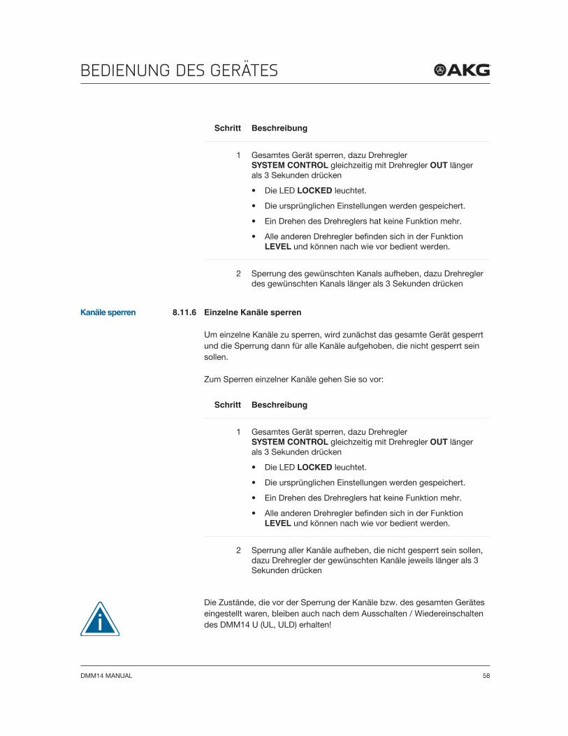
8.11.6 Einzelne Kanäle sperren
Um einzelne Kanäle zu sperren, wird zunächst das gesamte Gerät gesperrt und die Sperrung dann für alle Kanäle aufgehoben, die nicht gesperrt sein sollen.
Zum Sperren einzelner Kanäle gehen Sie so vor:
Schritt Beschreibung
1 Gesamtes Gerät sperren, dazu Drehregler SYSTEM CONTROL gleichzeitig mit Drehregler OUT länger als 3 Sekunden drücken
• Die LED LOCKED leuchtet.
• Die ursprünglichen Einstellungen werden gespeichert.
• Ein Drehen des Drehreglers hat keine Funktion mehr.
• AlleanderenDrehreglerbefindensichinderFunktionLEVEL und können nach wie vor bedient werden.
2 Sperrung aller Kanäle aufheben, die nicht gesperrt sein sollen, dazu Drehregler der gewünschten Kanäle jeweils länger als 3 Sekunden drücken
Die Zustände, die vor der Sperrung der Kanäle bzw. des gesamten Gerätes eingestellt waren, bleiben auch nach dem Ausschalten / Wiedereinschalten des DMM14 U (UL, ULD) erhalten!
Kanäle sperren

beDienUng Des gerätes
DMM14 MANUAL 59
8.12 Konfigurationsdaten kopieren
Mit der Kopierfunktion können einzelne oder mehrere Einstellungswerte (LEVEL, TREBLE, BASS, LOWCUT, LIMITER und COMPRESSOR) eines Eingangs auf einen oder mehrere andere Eingänge kopiert werden.
8.12.1 Einzelwerte kopieren
Zum Kopieren einzelner Werte von einem Kanal auf einen oder mehrere andere gehen Sie so vor:
Schritt Beschreibung
1 Gewünschte Funktion am Drehregler SYSTEM CONTROL wählen
2 Drehregler drücken, dessen Wert kopiert werden soll, an-schließend sofort den Drehregler drücken, bis zu dem der Kopiervorgang vorgenommen werden soll
3 Beide Drehregler gedrückt halten (ca. 4 Sekunden) bis ein akustisches Signal ertönt (Beep) und die betroffenen LED-Kränze einmal kurz aufblinken.
• Wert wurde auf die ausgewählten Kanäle übertragen.
Der Kopiervorgang wird bei sämtlichen Drehreglern angewandt, die sich zwischendenbeidenausgewähltenbefinden.
8.12.2 Alle Werte kopieren
Zum Kopieren aller Werte von einem Kanal auf einen oder mehrere andere gehen Sie so vor:
Schritt Beschreibung
1 Drehregler drücken, dessen Werte kopiert werden sollen, anschließend sofort den Drehregler drücken, bis zu dem der Kopiervorgang vorgenommen werden soll
Konfigurationen kopieren

beDienUng Des gerätes
DMM14 MANUAL 60
Schritt Beschreibung
2 Beide Drehregler gedrückt halten (ca. 8 Sekunden) bis ein akustisches Signal ertönt (Beep-Beep) und die betroffenen LED-Kränze einmal kurz aufblinken.
• Werte wurden auf die ausgewählten Kanäle übertragen.
Der Kopiervorgang ist in beide Richtungen möglich (IN 1 bis IN 12 und IN 12 bis IN 1).
Die folgenden Abbildungen visualisieren den Kopiervorgang.
Abbildung 53: Drehregler auswählen (Quelle)
Abbildung 54: Kopierbereich definieren (Ziel)
Abbildung 55: Drehregler gedrückt halten
8
ON PEAK
910
1112
1314
15
76
54
32
1
IN 12
8
ON PEAK
910
1112
1314
15
76
54
32
1
IN 11
8
ON PEAK
910
1112
1314
15
76
54
32
1
IN 10
8
ON PEAK
910
1112
1314
15
76
54
32
1
IN 3 ...
8
ON PEAK
910
1112
1314
15
76
54
32
1
IN 2
8
ON PEAK
910
1112
1314
15
76
54
32
1
IN 1
8
ON PEAK
910
1112
1314
15
76
54
32
1
IN 12
8
ON PEAK
910
1112
1314
15
76
54
32
1
IN 11
8
ON PEAK
910
1112
1314
15
76
54
32
1
IN 10
8
ON PEAK
910
1112
1314
15
76
54
32
1
IN 3 ...
8
ON PEAK
910
1112
1314
15
76
54
32
1
IN 2
8
ON PEAK
910
1112
1314
15
76
54
32
1
IN 1
8
ON PEAK
910
1112
1314
15
76
54
32
1
IN 12
8
ON PEAK
910
1112
1314
15
76
54
32
1
IN 11
8
ON PEAK
910
1112
1314
15
76
54
32
1
IN 10
8
ON PEAK
910
1112
1314
15
76
54
32
1
IN 3 ...
8
ON PEAK
910
1112
1314
15
76
54
32
1
IN 2
8
ON PEAK
910
1112
1314
15
76
54
32
1
IN 1
blinken blinken blinken blinken

beDienUng Des gerätes
DMM14 MANUAL 61
Abbildung 56: Kopiervorgang abgeschlossen
8.13 Rücksetzen auf Werkseinstellungen
Abbildung 57: Rücksetzen auf Werkseinstellungen
Um das gesamte Gerät auf Werkseinstellungen zurückzusetzen gehen Sie so vor:
Schritt Beschreibung
1 Gerät einschalten
Warten, bis Startsequenz des Automischers abgeschlossen ist (ca. 15 Sekunden).
2 Drehregler SYSTEM CONTROL drücken und bis Schritt 5 gedrückt halten
3 Gerät durch Netzschalter abschalten
4 Gerät nach kurzer Wartezeit wieder einschalten
Warten, bis Startsequenz des Automischers abgeschlossen ist (ca. 15 Sekunden).
8
ON PEAK
910
1112
1314
15
76
54
32
1
IN 12
8
ON PEAK
910
1112
1314
15
76
54
32
1
IN 11
8
ON PEAK
910
1112
1314
15
76
54
32
1
IN 10
8
ON PEAK
910
1112
1314
15
76
54
32
1
IN 3 ...
8
ON PEAK
910
1112
1314
15
76
54
32
1
IN 2
8
ON PEAK
910
1112
1314
15
76
54
32
1
IN 1
Rücksetzen auf Werkseinstellung
+
PRIORITYPAN / BALANCE
DELAY
ROUTE TO REC
ROUTE TO USB
EQUALIZER
PRESET
IN USB / DANTE
AUTOMIXING
COMPRESSOR
LIMITER
LOW CUT
BASS
TREBLE
LEVEL
LOCKED
SYSTEM CONTROL

beDienUng Des gerätes
DMM14 MANUAL 62
Schritt Beschreibung
5 Drehregler SYSTEM CONTROL loslassen
• Das Gerät ist auf die Werkseinstellungen zurückgesetzt und kann für eine neue Systemkonstellation eingestellt werden.
Durch das Rücksetzen auf Werkseinstellungen gehen alle gespeicherten Einstellungen verloren!

fehLerbehebUng
DMM14 MANUAL 63
9 Fehlerbehebung
WARNUNG: Stromschlaggefahr
ImGerätbefindensichungeschützteKontakteundLeitungen,diebeiBerührung zu schweren Verletzungen durch Stromschlag führen können.
• Das Gerät darf für die Fehlerbehebung nur von autorisiertem Fachpersonal geöffnet werden.
FEHLER MÖGLICHE URSACHE BEHEBUNG
Kein Ton Netzanschlusskabel ist nicht an Gerät angeschlossen
Netzanschlusskabel an Gerät anschlie-ßen
Netzschalter ausgeschaltet Netzschalter einschalten
Gerät ist nicht an Verstärker ange-schlossen
Ausgangskanal mit Verstärker verbin-den
Mikrofon bzw. Zusatzgerät ist nicht an Gerät angeschlossen
Mikrofon bzw. Zusatzgerät mit Gerät verbinden
Lautstärkeregler sind auf Minimum gestellt
Lautstärkeregler aufdrehen
Lautstärkeregler sind auf MUTE gestellt MUTE-Schaltung durch Drücken des Drehreglers aufheben
Vorverstärkung ist nicht korrekt einge-stellt
Gain-Regler auf der Rückseite auf korrekte Vorverstärkung stellen
Phantomspeisung ist ausgeschaltet Phantomspeisung für Kondensatormikrofone einschalten
externes Potentiometer auf Minimum gestellt
externes Potentiometer aufdrehen
Kein Ton bei Sinuseinspeisung
Automix-Algorithmus unterdrückt gleichbleibendes Signal
Kanal vom Automix-Algorithmus aus-nehmen

fehLerbehebUng
DMM14 MANUAL 64
FEHLER MÖGLICHE URSACHE BEHEBUNG
Verzerrte Signalwiedergabe
Vorverstärkung ist nicht korrekt einge-stellt
GainRegler auf der Rückseite auf kor-rekte Vorverstärkung stellen
Lautstärkeregler sind zu weit aufge-dreht
Lautstärke zurückregeln
Eingangssignal hat zu hohen Pegel Eingangssignal dämpfen
Falls ein Fehler trotz dieser Anweisungen weiter besteht, melden Sie sich bei AKG Acoustics GmbH, oder Ihrem AKG-Händler.

DMM14 MANUAL 65
FEHLER MÖGLICHE URSACHE BEHEBUNG
Verzerrte Signalwiedergabe
Vorverstärkung ist nicht korrekt einge-stellt
GainRegler auf der Rückseite auf kor-rekte Vorverstärkung stellen
Lautstärkeregler sind zu weit aufge-dreht
Lautstärke zurückregeln
Eingangssignal hat zu hohen Pegel Eingangssignal dämpfen
Falls ein Fehler trotz dieser Anweisungen weiter besteht, melden Sie sich bei AKG Acoustics GmbH, oder Ihrem AKG-Händler.

DMM14 MANUAL 66

INHALT
DMM14 MANUAL 67
1 GENERAL 701.1 Purpose of the manual 70
1.2 Retention of the manual 70
1.3 Liability 70
1.4 Warranty 70
2 SCOPE OF SUPPLY 712.1 Packing unit 71
2.2 Optional accessories 71
3 SAFETY AND ENVIRONMENT 723.1 Safety 72
3.2 Required knowledge and areas of
responsibility of the operators/users 73
3.3 Explanation of the symbols used 73
3.4 Correct use 74
3.5 Incorrect use 74
3.6 Environment 74
4 DECLARATION OF CONFORMITY 74
5 DESCRIPTION 755.1 Summary 75
5.2 Technical data 75
5.3 Front: Description of the controls 77
5.3.1 Controls for input channels 77
5.3.2 Operating mode / SYSTEM CONTROL 78
5.3.3 Control for stereo outputs 78
5.3.4 Modulation display for stereo outputs 78
5.3.5 Stereo headphone output 78
5.4 Rear: Description of the controls 79
5.4.1 Inputs 80
5.4.2 Gain control 81
5.4.3 Phantom power 81
5.4.4 Stereo master bus output channel 83
5.4.5 Stereo record output 83
5.4.6 Serial control via RS232 84
5.4.7 USB port 84
5.4.8 LAN port 85
5.4.9 Expansion/cascading 85
5.4.10 Dante™ network 86
5.5 Automix algorithm 86
5.5.1 Dynamic level adjustment 87
5.5.2 Best Mic On 87
5.5.3 Noise Detect 87
5.6 Expansion/cascading 87
6 INSTALLATION AND CONNECTION 896.1 Installation 89
6.2 Cascade devices (optional) 89
6.3 Connecting microphones and
accessories 89
6.4 Connect to the mains power supply 90
7 FUNCTIONAL DESCRIPTION 917.1 Control concept 91
7.2 Operation of the rotary knobs 91
7.2.1 Display of the audio level / VU
function 92
7.3 SYSTEM CONTROL 92
7.3.1 SYSTEM CONTROL functions 92
7.3.2 Input channel modes 93
7.3.3 Output channel modes 93
7.3.4 Functions of the stereo headphone
output (monitoring output) 93
7.4 DSP functions 94
7.4.1 LEVEL 94
7.4.2 TREBLE 95
7.4.3 BASS 97
7.4.4 LOW CUT 99
7.4.5 LIMITER 101
7.4.6 COMPRESSOR 103

INHALT
DMM14 MANUAL 68
7.4.7 AUTOMIXING 104
7.4.8 PRIORITY 105
7.4.9 PAN / BALANCE 106
7.4.10 DELAY 108
7.4.11 ROUTING TO REC 109
7.4.12 ROUTING TO USB 110
7.4.13 EQUALIZER 111
7.4.14 PRESET 112
7.5 LOCKED 114
8 OPERATING THE DEVICE 1158.1 SYSTEM CONTROL: Changing
parameters on the device 115
8.2 Configuringmicrophonesonthe
DMM14 U (UL, ULD) 115
8.3 Monitoring the inputs/outputs 116
8.4 Cascading devices 117
8.5 Feed via USB and Dante™ 118
8.5.1 Processing the feed 118
8.6 Activating phantom power 118
8.7 Using presets 118
8.7.1 Selecting a preset 118
8.7.2 Programming a preset 119
8.7.3 Deleting a preset 119
8.8 Using MUTE 120
8.8.1 Activating MUTE 120
8.8.2 Deactivating MUTE 120
8.9 Activating ROUTING TO OUT 121
8.9.1 For an input 121
8.9.2 For multiple inputs 121
8.10 Deactivating ROUTING TO OUT 121
8.11 Activate/deactivate LOCKED 121
8.11.1 Locking the SYSTEM CONTROL
rotary knob 122
8.11.2 Unlocking the SYSTEM CONTROL
rotary knob 122
8.11.3 Locking the complete unit 122
8.11.4 Unlocking the complete unit 123
8.11.5 Unlocking individual channels 123
8.11.6 Locking individual channels 123
8.12 Copyingconfigurationdata 124
8.12.1 Copying individual values 124
8.12.2 Copying all values 125
8.13 Resetting the factory settings 126
9 TROUBLESHOOTING 128
IMPRESSUM
DMM14 MANUAL 69
Publisher AKG Acoustics GmbH
Laxenburger Straße 254
1230 Wien
Austria
Tel: +43 (0)1 86654-0
Fax: +43 (0)1 86654-8800
AKG ACOUSTICS, U.S.
8500 Balboa Blvd. Dock 15
Northridge, CA 91329
U.S.A.
Tel: +1 818 920-3224
Copyright © 2015 AKG Acoustics GmbH
All rights reserved.
The information contained in this manual, including any drawings and photos provided, are the intellectual property of AKG Acoustics GmbH.
In accordance with copyright law, it is not permitted for this documentation or parts thereof to be reproduced or transmitted for any purpose in any form using any means, whether electronic or mechanical, by photocopying, recording or using information storage and infor-mation processing systems without the express, written consent of AKG Acoustics GmbH. Forwarding to third parties is not permitted. This manual should be returned to us on request.
FCC Statement Note: This equipment has been tested and found to comply with the limits for a Class B digital device, pursuant to part 15 of the FCC Rules. These limits are designed to provide reasonable protection against harmful interference in a residential installation. This equipment generates, uses and can radiate radio frequency energy and, if not installed and used in accordance with the instructions, may cause harmful interference to radio communications. However, there is no guarantee that interference will not occur in a particular installation. If this equipment does cause harmful interference to radio or television reception, which can be determined by turning the equipment off and on, the user is encouraged to try to correct the interference by one or more of the following measures:
• Reorient or relocate the receiving antenna.
• Increase the separation between the equipment and receiver.
• Connect the equipment into an outlet on a circuit different from that to which the receiver is connected.
• Consult the dealer or an experienced radio/TV technician for help.
This device complies with Part 15 of the FCC Rules. Operation is subject to the following two conditions: (1) this device may not cause harmful interference, and (2) this device must accept any interference received, including interference that may cause undesired operation.
Shielded cables and I/O cords must be used for this equipment to comply with the relevant FCCregulations.Changesormodificationsnotexpresslyapprovedbythepartyresponsiblefor compliance could void the user’s authority to operate this equipment.
Updates Thismanualmaybemodifiedwithoutpriornoticeanddoesnotrepresentanyobligationonthe part of AKG Acoustics GmbH.
Version 1.0
Publication date July 2015/EN
07/15/ 5061697

generAL
DMM14 MANUAL 70
1 General
1.1 Purpose of the manual
This manual is intended to enable you to:
• operate the equipment safely.• use the equipment correctly.
1.2 Retention of the manual
Print out this manual and keep it carefully or store it electronically at an easily accessible location.
Pass this manual on to subsequent owners.
This manual is an important part of the equipment.
1.3 Liability
AKG Acoustics GmbH accepts no liability, if:
• The equipment is used for purposes other than those described under correct usage.
• Damage is incurred due to incorrect operation• Unauthorizedornon-permittedmodificationshavingbeencarried
out.• Damage due to out of date documentation.
1.4 Warranty
AKG Acoustics GmbH accepts no liability for damage, if
• incorrect operation.• Unauthorizedornon-permittedmodificationshavingbeencarried
out.• Damage due to out of date documentation.
Liability
Warranty

scope of sUppLy
DMM14 MANUAL 71
2 Scope of supply
2.1 Packing unit
Check that the package contains all the parts given below. If anything is missing, please contact your AKG dealer.
• 1 x DMM14 U, DMM14 UL or DMM14 ULD• 1 x Quick Start Guide• 1 x IEC EU standard mains cable• 1 x IEC US standard mains cable• 1 x mating plug terminal
2.2 Optional accessories
Optional accessories can be found at www.akg.com. Your dealer will be happy to advise.
Packing unit
Optional accessories

sAfety AnD environment
DMM14 MANUAL 72
3 Safety and environment
3.1 Safety
Caution: Risk of damage
• Protect the equipment against
- direct sunlight - theimpactofsignificantdustandhumidity - rain - vibrations or knocks.
• Do not spill any liquids on the equipment and do not allow any other objects to drop through the ventilation slits into the equipment.
• Donotplaceanycontainersfilledwithliquidontheequipment.
• The equipment must only be used in dry rooms.
• The equipment must only be opened, serviced and repaired by authorized personnel. The equipment contains no user-serviceable parts.
• Before connecting the equipment to power, check that the AC mains voltage stated on the integrated power adapter is identical to the AC mains voltage available where the equipment will be used.
• Only operate the equipment on a mains voltage between the 100 and 240 V AC. Using adapters with different output voltage or cur-rent types may cause serious damage to the equipment.
• If any solid or liquid should get into the equipment, shut down the system immediately. Disconnect the power cable from the power outlet at once and have the equipment checked by our customer service department.
• If the equipment is not going to be used for a longer time, discon-nect the mains cable from the power outlet. Please note that if you switch the equipment off while leaving the mains cable plugged in, it is not fully isolated from the power network.
• Do not place the equipment near heat sources such as radiators, heatingducts,amplifiers,etc.
Safety

sAfety AnD environment
DMM14 MANUAL 73
• To avoid hum or interference, route all audio lines, particularly those connected to the microphone inputs, away from power lines of any type. If you use cable ducts, be sure to use separate ducts for the audio lines.
• Clean the equipment with a moistened (not wet) cloth only. Be sure to disconnect the power adapter from the power outlet beforehand. Never use caustic or scouring cleaners or cleaning products con-taining alcohol or solvents since these may damage the enamel and plastic parts.
• Only use the equipment for the applications described in this manual. AKG cannot accept any liability for damages resulting from improper handling or misuse.
3.2 Required knowledge and areas of responsibility of the operators/users
• Qualifiedexpertpersonnelareabletodeterminerisksandavoidhazards when using the product, based on their professional train-ing, education and experience.
3.3 Explanation of the symbols used
Caution: Risk of damage
Not following the instructions may damage the equip-ment.
Warning: Hazard due to electric shock
Hazardous situation: Not following the instructions may result in minor or serious injury.
Describes useful information and application notes for efficientoperationoftheequipment.
Provides reference to more in-depth information and downloads online.
DecLArAtion of conformity
DMM14 MANUAL 74
Describes information on the correct disposal of the components described.
3.4 Correct use
The Digital Automatic Microphone Mixer DMM14 U (UL, ULD) U (UL, ULD) is designed solely for mixing audio signals.
3.5 Incorrect use
Any use not given under correct use is regarded as incorrect.
3.6 Environment
• The packaging is recyclable. Dispose of the packaging in an appro-priate recycling collection system.
• In case of scrapping the equipment, separate the housing, electron-ics and cables and dispose of all the components in accordance with the appropriate waste disposal regulations.
4 Declaration of Conformity
This product conforms to the standards listed in the Declaration of Conformity. You can download the Declaration of Conformity at www.akg.com or request it by email from [email protected].

Description
DMM14 MANUAL 75
5 Description
5.1 Summary
The DMM14 U (UL, ULD) is a 19" Digital Automatic Microphone Mixer. Internal signal processing takes place digitally and on four master buses (stereo). The inputs and outputs are available as analog and digital.
It has 12 balanced mono inputsthatcanbeconfiguredasmicrophoneinputs or line inputs (e.g. for wireless microphone receivers).
On the output side it has one balanced master output, one stereo record-ing output and one stereo headphone output.
It has a USB port that can be used as both an input and an output.
Inputs and outputs are controlled via LAN and Dante™ networks (optional).
The device has a wide-range power supply unit and is connected to the power network using the mains cable supplied.
In addition to multiple DSP digital signal processing functions, the DMM14 U (UL, ULD) also has innovative automatic mixing functions.
Up to ten DMM14 U (UL, ULD) can be cascaded if the twelve balanced inputsarenotsufficientforyourapplication.
5.2 Technical data
General
Dimensions Standard housing for rack mounting, 1 HU
483 (W) x 45 (H) x 220 (D) mm
Weight (with packaging) 2.9 kg
Permissible ambient tempera-ture
0 °C ... 50 °C
Air humidity in operation 10 % ... 90 %, non-condensing
Protection rating I
Summary
General

Description
DMM14 MANUAL 76
Power adapter
Input voltage 100 ... 240 V AC
Mains frequency 50 ... 60 Hz
Max. power intake 75 Watt
Output voltages 24 V
Balanced inputs – Preamplifier
Gain 0 dB ... 60 dB
Max. input level +20 dBu
Common mode rejection >70 dB
Dynamics >120 dB
Signal-to-noise ratio (S/N) >90 dB
Input impedance >8kΩ
Equivalent input noise -127 dBu
Balanced inputs – Phantom power
Phantom voltage 48 V DC
Max. supply current per input 10 mA
Infeed resistors 2x6.8kΩ
Balanced inputs – Analog/digital converters
Data format 24 Bit
Sample frequency 48 kHz
Recording and total output
Max. output level +20 dBu
Dynamics >110 dB
Signal-to-noise ratio (S/N) >90 dB
Min. load impedance <100Ω
Digital/analog conversion for recording, monitoring and totals output
Data format 24 Bit
Sample frequency 48 kHz
Power adapter
Inputs
Outputs

Description
DMM14 MANUAL 77
5.3 Front: Description of the controls
There is a total of nine controls on the front.
Figure 1: Front of the DMM14 U (UL, ULD)
The following table describes the controls on the front of the DMM14 U (UL, ULD):
No. Description
1 to 12 Microphone or line inputs
13 Operating mode / SYSTEM CONTROL
14, 16 Stereo outputs 1 and 2
15, 17 Modulation display for stereo outputs 1 and 2
18 Stereo headphone output
19 Socket for headphone connection
The parameters of the selected audio functions are changed using the controls.
5.3.1 Controls for input channels
The DMM14 U (UL, ULD) has 12 balanced input channels to connect low ohm, dynamic microphones or capacitor microphones and other signal sources, e.g. receivers for wireless microphones. There is a control for each input channel (1 to 12).
Each input channel has a green LED ON and a red LED PEAK.
ON is lit when the input channel is prioritized in automatic mode. If the Automix function is switched off, ON is lit continuously.
PEAK is lit if the signal on an input channel comes close to the maximum modulation limit. In this case, the level should be reduced or the input sensi-tivity changed.
Front controls
8 910
1115
76
51
8 910
1112
1314
15
76
51
PRIORITYPAN / BALANCE
DELAY
ROUTE TO REC
ROUTE TO USB
EQUALIZER
PRESET
IN USB / DANTE
AUTOMIXING
COMPRESSOR
LIMITER
LOW CUT
BASS
TREBLE
LEVEL
LOCKED
OUT 2
SYSTEM CONTROL
HEADPHONE
-50 -40 -30 -20 -10 -5 0 +5 dB
L
R
8 910
1115
76
54
32
1
OUT 1
-50 -40 -30 -20 -10 -5 0 +5 dB
L
R
8
ON PEAK
910
1112
1314
15
76
54
32
1
IN 11EQ 8.0 kHz
8
ON PEAK
910
1112
1314
15
76
54
32
1
IN 9EQ 4.0 kHz
8
ON PEAK
910
1112
1314
15
76
54
32
1
IN 7EQ 2.0 kHz
8
ON PEAK
910
1112
1314
15
76
54
32
1
IN 5 / DANTE 3EQ 1.0 kHz
8
ON PEAK
910
1112
1314
15
76
54
32
1
IN 3 / DANTE 1EQ 500 Hz
8
ON PEAK
910
1112
1314
15
76
54
32
1
IN 1 / USB LEQ 250 Hz
8
ON PEAK
9
1314
15
7
32
1
IN 2 / USB REQ 350 Hz
8
ON PEAK
9
1314
15
7
32
1
IN 4 / DANTE 2EQ 700 Hz
8
ON PEAK
9
1314
15
7
32
1
IN 6 / DANTE 4EQ 1.4 kHz
8
ON PEAK
9
1314
15
7
32
1
IN 8EQ 2.8 kHz
8
ON PEAK
9
1314
15
7
32
1
IN 10EQ 5.6 kHz
8
ON PEAK
910
1112
1314
15
7
32
1
IN 12EQ 11.3 kHz
1 2 4 6 8 10 12 15 173 5 7 9 11 13 1614 18 19
Rotary knobs for inputs
LED ON
LED PEAK

Description
DMM14 MANUAL 78
Theinputsensitivityismodifiedusingthegainregulatorontherearoftheconnected equipment.
5.3.2 Operating mode / SYSTEM CONTROL
The DMM14 U (UL, ULD) has numerous functions such as volume, tre-bles, bass, auto-mixer functions etc. These functions are selected on the SYSTEM CONTROL (13).
5.3.3 Control for stereo outputs
The controls for the stereo output channels are labeled OUT 1 (14) and OUT 2 (16). This control is used to change the following parameters on the output channel:
• Volume• Treble range• Bass range• Limitation response• Balance and delay
5.3.4 Modulation display for stereo outputs
The modulation display (15, 17) under the control for the stereo output chan-nels shows the output level in dB.
5.3.5 Stereo headphone output
Both inputs and outputs can be picked up on the stereo headphone out-put (18).
SYSTEM CONTROL
Rotary knobs for outputs
Modulation display
Headphone output

Description
DMM14 MANUAL 79
5.4 Rear: Description of the controls
On the rear are the sockets for the input channels and output channels as well as the mains connection, etc.
Figure 2: Rear of the DMM14 U (UL, ULD)
*only available with DMM14 ULD **only available with DMM14 UL and DMM14 ULD
The following table describes the controls on the rear of the DMM14 U (UL, ULD):
No. Description
1, 5, 6, 10, 11, 15, 18, 22, 23, 27, 28, 32
Input channels
2, 4, 7, 9, 12, 14, 19, 21, 24, 26, 29, 31
Gain control
3, 8, 13, 20, 25, 30 Phantom power
16, 33 Stereo output channel, left
17, 34 Stereo output channel, right
35 Stereo record output
36 Dante™: *only available with DMM8 ULD
37 Expansion sockets
38 Serial control (RS232)
39 USB port
40 Modular jack (RJ-45) socket: **only available for DMM8 UL and DMM8 ULD
Rear controls
OUT2/L OUT2/R REC (OUT) IN - EXPANSION - OUT RS232
DANTE
USB LAN
L
R
IN 7 IN 8Off
PHANT. PWROn
IN 1 IN 2Off
PHANT. PWROn
IN 9 IN 10Off
PHANT. PWROn
IN 3 IN 4Off
PHANT. PWROn
IN 11 IN 12Off
PHANT. PWROn
IN 5 IN 26Off
PHANT. PWROn
OUT1/L OUT1/R
33 34 35 36* 38 39 40** 41 42 4320
19 2118 22
3 42 51
2524 2623 27
897 106
3029 3128 32
131412 1511
37
16 17

Description
DMM14 MANUAL 80
No. Description
41 Phoenix terminal (ground / remote control)
42 Mains connection
43 Mains switch
5.4.1 Inputs
Figure 3: Input
The 12 balanced input channels (1, 5, 6, 10, 11, 15, 18, 22, 23, 27, 28, 32) can be accessed via 3-pin Phoenix sockets. These are labeled IN 1 to IN 12. The input levels can be controlled with the rotary knobs IN 1 to IN 12 on the front panel.
A switch for the phantom power and a gain control for every channel is located between two phoenix sockets.
The assignment is labeled via socket IN 3 with:
• Pin 1 = a• Pin 2 = b• Pin 3 = _|_
Input channels
IN 1Off
PHANT. PWROn

Description
DMM14 MANUAL 81
5.4.2 Gain control
Figure 4: Gain controller
The associated gain control is located next to every input channel (2, 4, 7, 9, 12, 14, 19, 21, 24, 26, 29, 31) to set the input level. The gain controls are equipped with integrated switch for the left side stop.
The input level is set at 0 dB when the left end stop is reached. By turning the control clockwise the gain can be increased by max. 57 dB.
5.4.3 Phantom power
Figure 5: Phantom power
The device is equipped with six switches for phantom power (3, 8, 13, 20, 25, 30).
The corresponding slide switch activates the phantom power supply of +48 V for the inputs located on the left and right.
The slide switch is labeled PHANT. PWR. Two input channels are always activated simultaneously. The phantom power is activated when the slide switch is in the On position.
The corresponding slide switch activates the phantom power supply of +48 V for the inputs located on the left and right.
Gain controller
IN 1 IN 2Off
PHANT. PWROn
0 dB0 dB 57 dB57 dB
Phantom power
IN 1 IN 2Off
PHANT. PWROn

Description
DMM14 MANUAL 82
Ground connection
Figure 6: Phoenix terminal
A Phoenix terminal connects the housing to the 0 V potential of the power supply.
Only bridge the 0 V potential with the grounding (factory setting) or connect it to the central system ground, as otherwise the phantom power has no reference point and will not function.
Analog control
Figure 7: Phoenix terminal
A linear 50 kΩ potentiometer at the VCA input, labeled "VCA" and "", allows you to vary the master volume.
Figure 8: VCA
The linear potentiometer is connected to the VCA input as shown above. The resistance at the VCA input is changed by turning the potentiometer This value is input and the volume is changed accordingly The left setting signifies0%whiletherightsettingsignifies100%.
VCA
VCAPoti 50klin.

Description
DMM14 MANUAL 83
The output level depends on the master control and the remote level control. The remote level control has the same effect on both masters
5.4.4 Stereo master bus output channel
Figure 9: Stereo master output
The equipment has two balanced master outputs (16, 17, 33, 34). They are accessible via four 3-pin Phoenix sockets. The outputs are labeled OUT 1/L and OUT 1/R or OUT 2/L and OUT 2/R .
The OUT 1 or OUT 2 control on the front can be used to make settings on the output level of the corresponding stereo output channel.
The allocation of individual channels to the balanced master outputs is freely configurable.
5.4.5 Stereo record output
Figure 10: Stereo record output
Two RCA jacks, labeled REC (OUT) (35) are available for connecting stereo recording equipment. The allocation of the individual channels to the unbal-ancedstereorecordingoutputcanbeconfiguredasdesired.
Stereo output
OUT1/L OUT1/R
Stereo record output
REC (OUT)
L
R

Description
DMM14 MANUAL 84
5.4.6 Serial control via RS232
Figure 11: Serial control
The RS232 socket (38) permits software updates to be carried out and to operate the device via an external control (e.g.: AMX). The pin assignment is as follows:
Pin Function
1 GND
2 TxD
3 RxD
5.4.7 USB port
Figure 12: USB port
The USB port (39) can be used to connect the device to a PC to perform firmwareupdatesandpermitexternalcontrol.
The connection is established via a standard MS Windows driver. An Apple driver needs to be installed manually if required.
Serial control
RS232
USB port
IN - EXPANSION - OUT RS232 USB LAN

Description
DMM14 MANUAL 85
5.4.8 LAN port
Figure 13: LAN port
The LAN port (40) permits software updates to be carried out and to operate the device via an external control (e.g.: AMX).
Remote control and remote diagnostics are also possible via a web server.
This web server provides a simple and functional user interface that can be opened via a browser and that permits access via LAN infrastructure.
Simultaneous operation via the front panel of the automixer and via the web server is possible: it is preferable for the inputs to be handled via the web server, however.
The automixer is provided with protocol allowing it to be actuated via exter-nal software or wirelessly via APP.
These applications can add considerably more functions depending on the programming type and scope, and provide a more complex graphic inter-face depending on the terminal.
5.4.9 Expansion/cascading
Figure 14: Expansion
The 8-pin (RJ-45) modular jacks (37) can be used to connect up to 10 devic-es.
The audio master and the status signal for the automix algorithm are trans-mitted.
LAN port
IN - EXPANSION - OUT RS232 USB LAN
Cascading
OUT R REC (OUT) IN - EXPANSION - OUT RS232 USB LAN
L
R

Description
DMM14 MANUAL 86
The audio transmission via cascading is carried out in 24Bit. This does not impair the noise values.
5.4.10 Dante™ network
Figure 15: Dante™
The DMM14 ULD is equipped with an 8-pin (RJ-45) modular jack labeled DANTE (19).
All inputs and outputs are thereby automatically routed to the Dante™ network.
The inputs are routed to the Dante™ network after signal processing (treble, bass,…) and after the automix algorithm as direct-out signals.
The output masters are routed before the balance regulator, before volume out and before limiter to the Dante™ network as direct out signals.
Settings must be made via the Dante™ receiver unit (e.g. mixing desk).
When cascading automixers, note that only the channels available locally on an automixer can be transmitted via the Dante™ network. If in addition the inputs of another, cascaded device are required, this device must also have a standalone Dante™ interface.
If multiple devices are also to be operated in the automix, these must also beconnectedviacascading:Specifically,inadditiontothemastersignals,the control signals of the automix algorithm are also transmitted.
5.5 Automix algorithm
The unit's automix algorithm has 3 basic functions which assess the amount by which an input signal is to be attenuated and the output signal's output level.Thefollowingfunctionsandparametersflowintotheautomixalgo-rithm:
• Dynamic level adjustment• Best Mic On
Dante™ network
REC (OUT) IN - EXPANSION - OUT RS232
DANTE
Algorithm for Automix

Description
DMM14 MANUAL 87
• Noise Detect
5.5.1 Dynamic level adjustment
The master of all input channels is determined on an ongoing basis. This value is used as the reference value.
If the input channel level is very close or over the reference value, this chan-nel will be assessed as dominant and will be slightly attenuated. f the input channel level is well below the reference value, this is assessed as ambient noise and be severely attenuated.
If a channel is no longer assessed as dominant, this falls at 1 dB/second and all other nondominant channels increase with the same constant so that the master output level remains constant. The upward adjustment of a channel takes between 3 ms and 5 ms.
5.5.2 Best Mic On
With two microphones that are positioned close together there is the disadvantagethatcombfiltereffectsmayarisebycancelingthefrequencycomponents To suppress these unnaturally dull or hollow signals, only the microphone channel with the highest level is assessed as dominant and switched on.
5.5.3 Noise Detect
Permanently present interfering signals, whose amplitude are large enough to be assessed as dominant, but whose level and frequency changes are too low, are not assessed as dominant.
Interfering signals such as noise from fans and air-conditioning units are recognized and not used as activation criteria for microphone channels.
5.6 Expansion/cascading
Up to ten devices can be cascaded if the number of inputs on a single de-vicearenotsufficient.
The device has two 100 MBit/s Ethernet ports. These are used to exchange control data and audio communication between cascaded devices.
This means that an automixing system can be realized with:
• 60 inputs• 20 outputs
Level adjustment
Best Mic On
Noise Detect
Expansion for cascading

Description
DMM14 MANUAL 88
• 10 stereo headphone outputs
The master buses for OUT, REC-OUT and HEADPHONE are accessible to the entire system of cascaded devices. Every unit adds its input channels to the master buses, which are transferred via the Ethernet interface. Every unit can monitor and output the master buses.
The automix algorithm also transfers its control data via this interface. This allows the automix algorithm to function system-wide.

instALLAtion AnD connection
DMM14 MANUAL 89
6 Installation and connection
The following steps are required for installation and connection of the DMM14 U (UL, ULD):
1. Installation
2. Cascade devices (optional)
3. Connect microphones and accessories
4. Connect to the mains power supply
6.1 Installation
To install the device, proceed as follows:
Step Description
1 Mount the device into your 19" rack using 4 appropriate rack bolts.
Ensure that the device is securely screwed onto the rack.
Alternatively, the device can be positioned on a stable sur-face.
6.2 Cascade devices (optional)
Caution: Risk of damage
It is only permitted for this connection to be carried out by authorized, qual-ifiedpersonnel.
Itisnotpermittedtoconnectthefirstdeviceinthecascadetothelastdevice.
For the cabling of the individual devices via the expansion sockets, see 8.4 Cascading devices on page 117
6.3 Connecting microphones and accessories
Read the operating instructions for your microphones and accessories for connection.

instALLAtion AnD connection
DMM14 MANUAL 90
Connect the microphones and accessories to the rear of the DMM14 U (UL, ULD) as follows:
Step Description
1 Connect microphones and other signal sources (e.g. receivers for wireless microphones) to the IN inputs
2 Connect outputs OUT 1/L, OUT 2/L and OUT 1/R , OUT 2/R toamixingdeskoramplifier
3 Connect the RCA jacks on the stereo recording output REC (OUT) to a recording device
6.4 Connect to the mains power supply
Caution: Risk of damage
Do not connect the unit to the power network until you have established all the audio connections!
Ensure that the input voltage on the DMM14 U (UL, ULD) corresponds to the mains voltage.
To connect the device to the mains, proceed as follows:
Step Description
1 Connect the mains power supply cable to the appropriate socket on the rear panel of the DMM14 U (UL, ULD)
2 Plug the power supply cable into a mains socket

fUnctionAL Description
DMM14 MANUAL 91
7 Functional description
7.1 Control concept
The device is controlled using the total of 16 rotary knobs on the front panel. These are labeled IN 1 to IN 12, SYSTEM CONTROL, OUT 1, OUT 2 and HEADPHONE.
The rotary knobs on the inputs are each surrounded by an LED ring with 15 yellow LEDs, one green LED and one red LED. The SYSTEM CONTROL rotary knobs and the rotary knobs on the outputs are surrounded by 15 yellow LEDs. The control display under the outputs has 6 green, one yellow and one red LED.
The LED rings help to visualize the rotary knob setting or display signal levels.
7.2 Operation of the rotary knobs
Figure 16: Rotary knob
• Turn the rotary knob clockwise or counter-clockwise to make changes to inputs and outputs and function settings. These chang-es are shown on the LED ring around the rotary knob. The starting point and the increments on the LED ring will vary according to the function.
• Briefly pressing the SYSTEM CONTROL rotary knob switches the display on the LED rings to VU meter, the display of the actual audio level present. When the VU meter mode is activated, the LEVELLEDflash-es on the SYSTEM CONTROL rotary knob. Pressing the SYSTEM CONTROL rotary knob again deactivates the VU meter mode.
Rotary knob
8
ONPEAK
9 10 11
1213
14
15
7
6
54
32
1
IN 2

fUnctionAL Description
DMM14 MANUAL 92
7.2.1 Display of the audio level / VU function
With the LEVEL function selected, the level set is displayed on the LED rings on the inputs and outputs.
7.3 SYSTEM CONTROL
The SYSTEM CONTROL rotary knob provides the option of selecting various functions on the device.
Figure 17: SYSTEM CONTROL
For selecting the functions and setting parameters, see 8.1 SYSTEM CONTROL: Changing parameters on the device on page 115
7.3.1 SYSTEM CONTROL functions
The following functions can be selected via the SYSTEM CONTROL:
• Level• Treble• Bass• Low Cut• Limiter• Compressor• Automixing• Priority• Pan / Balance• Delay• Routing To REC• Routing To USB• Equalizer• Preset
SYSTEM CONTROL
PRIORITYPAN / BALANCE
DELAY
ROUTE TO REC
ROUTE TO USB
EQUALIZER LOW
EQUALIZER HIGH
PRESET
IN USB / DANTE
AUTOMIXING
COMPRESSOR
LIMITER
LOW CUT
BASS
TREBLE
LEVEL
LOCKED
SYSTEM CONTROL
SYSTEM CONTROL modes
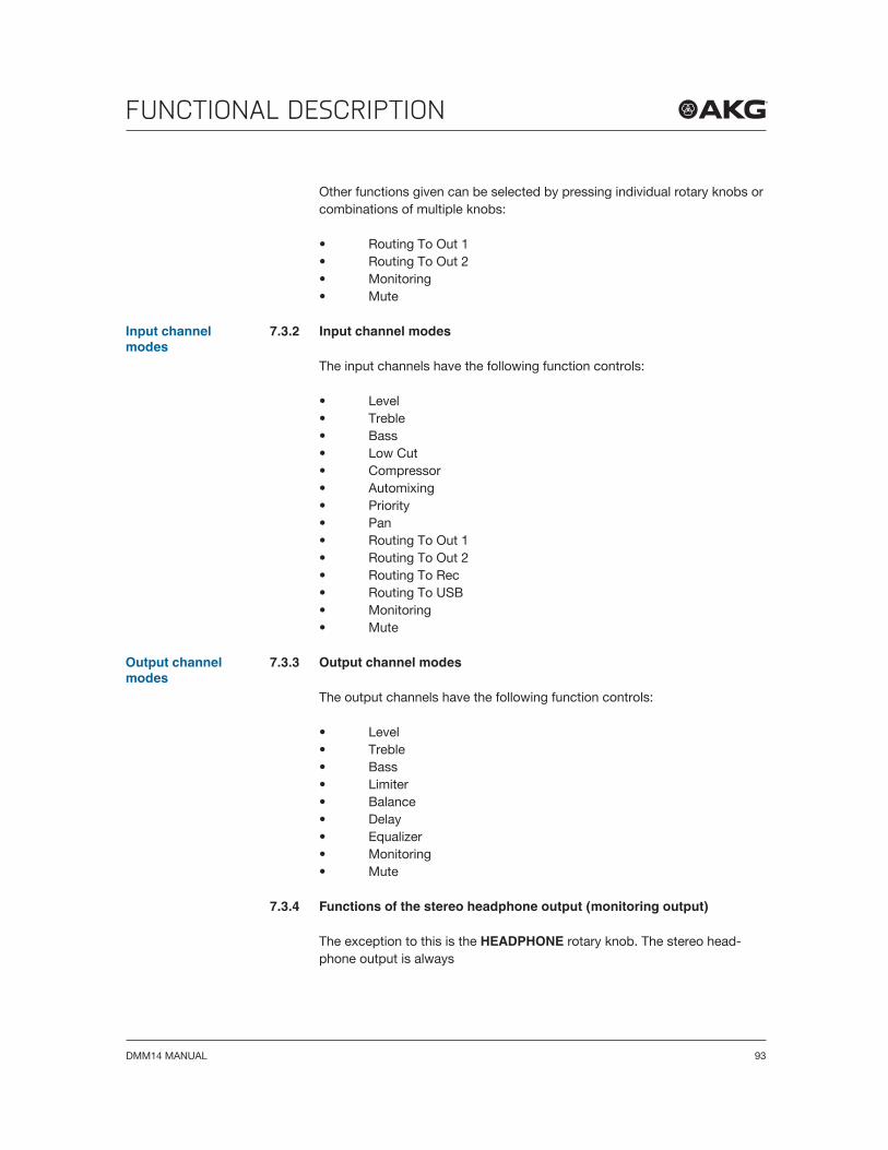
fUnctionAL Description
DMM14 MANUAL 93
Other functions given can be selected by pressing individual rotary knobs or combinations of multiple knobs:
• Routing To Out 1• Routing To Out 2• Monitoring• Mute
7.3.2 Input channel modes
The input channels have the following function controls:
• Level• Treble• Bass• Low Cut• Compressor• Automixing• Priority• Pan• Routing To Out 1• Routing To Out 2• Routing To Rec• Routing To USB• Monitoring• Mute
7.3.3 Output channel modes
The output channels have the following function controls:
• Level• Treble• Bass• Limiter• Balance• Delay• Equalizer• Monitoring• Mute
7.3.4 Functions of the stereo headphone output (monitoring output)
The exception to this is the HEADPHONE rotary knob. The stereo head-phone output is always
Input channel modes
Output channel modes

fUnctionAL Description
DMM14 MANUAL 94
located in the LEVEL mode, regardless of the SYSTEM CONTROL rotary knob setting.
7.4 DSP functions
Given below are explanations of the individual functions and their operation and effects.
7.4.1 LEVEL
Figure 18: LEVEL function
All the input and output channels can be controlled in the LEVEL mode.
Turning the rotary knob clockwise increases the volume. Turning it count-er-clockwise decreases the volume.
Thesettingsrangefrom-∞to+15dB(acousticfeedback).Theadjustmenttakes place in the appropriate increments.
At + 15dB the entire LED ring is illuminated and the acoustic feedback is no longer provided.
DSP functions
LEVELPRIORITY
PAN / BALANCE
DELAY
ROUTE TO REC
ROUTE TO USB
EQUALIZER
PRESET
IN USB / DANTE
AUTOMIXING
COMPRESSOR
LIMITER
LOW CUT
BASS
TREBLE
LEVEL
LOCKED
SYSTEM CONTROL

fUnctionAL Description
DMM14 MANUAL 95
The adjustable increments are equal to 1 dB per click from -12 dB to +15 dB. One LED equals 3 dB. The adjustable increments are equal to 3 dB per clickfrom-12dBto-∞.OneLEDequals9dB.
Figure 19: LEVEL detail
OneLED(no.10)isbrighterthantheotherLEDfieldstohelpyoufindthe0dBpositionmoreeasily;theLEDfieldilluminatesassoonasthe0dBlevelis reached (after the third click, see "Level" detail).
Pressing the SYSTEM CONTROL rotary knob in the LEVEL function switch-esthedisplayoftheinputsandoutputsfromamplificationtomodulation.
7.4.2 TREBLE
Figure 20: TREBLE function
8
ON PEAK
910
1112
1314
15
76
54
32
1LEVEL Detail LEVEL
-57 dB
-48 dB
-39 dB
-30 dB
-21 dB
-12 dB
-9 dB
+15 dB
+12 dB
+9 dB
+6 dB
+3 dB
0 dB
-3 dB
-6 dB
8 910
1112
13
76
54
3
-8
dB
-7
dB
-6
dB
-5
dB -
4 dB
-3
dB -2
dB
-1 d
B 0
dB
+1 dB
+2 dB
+3 dB
TREBLEPRIORITY
PAN / BALANCE
DELAY
ROUTE TO REC
ROUTE TO USB
EQUALIZER
PRESET
IN USB / DANTE
AUTOMIXING
COMPRESSOR
LIMITER
LOW CUT
BASS
TREBLE
LEVEL
LOCKED
SYSTEM CONTROL
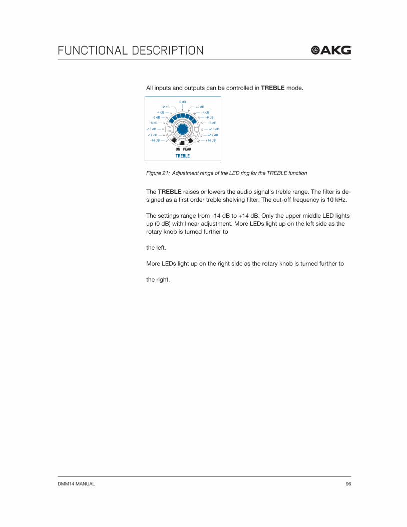
fUnctionAL Description
DMM14 MANUAL 96
All inputs and outputs can be controlled in TREBLE mode.
Figure 21: Adjustment range of the LED ring for the TREBLE function
The TREBLEraisesorlowerstheaudiosignal'streblerange.Thefilterisde-signedasafirstordertrebleshelvingfilter.Thecut-offfrequencyis10kHz.
The settings range from -14 dB to +14 dB. Only the upper middle LED lights up (0 dB) with linear adjustment. More LEDs light up on the left side as the rotary knob is turned further to the left.
More LEDs light up on the right side as the rotary knob is turned further to the right.
8
ON PEAK
910
1112
1314
15
76
54
32
1-14 dB
-12 dB
-10 dB
-8 dB
-6 dB
-4 dB
-2 dB
+14 dB
+12 dB
+10 dB
+8 dB
+6 dB
+4 dB
+2 dB
0 dB
TREBLE

fUnctionAL Description
DMM14 MANUAL 97
The adjustable increments are equal to 2 dB per click and also correspond to one LED.
Figure 22: Adjustment range for the TREBLE function
7.4.3 BASS
Figure 23: BASS function
All the input and output channels can be controlled in the BASS mode.
-18
+16
-16
-14
-12
-10
-8
-6
-4
-2
-0
+2
+4
+6
+8
+10
+12
+14
dBr A
20 20k50 100 200 500 1k 2k 5k 10kHz
BASSPRIORITY
PAN / BALANCE
DELAY
ROUTE TO REC
ROUTE TO USB
EQUALIZER
PRESET
IN USB / DANTE
AUTOMIXING
COMPRESSOR
LIMITER
LOW CUT
BASS
TREBLE
LEVEL
LOCKED
SYSTEM CONTROL

fUnctionAL Description
DMM14 MANUAL 98
The BASSraisesorlowerstheaudiosignal'sbassrange.Thefilterisde-signedasafirstorderbassshelvingfilter.Thecut-offfrequencyis100Hz.
The settings range from -14 dB to +14 dB. Only the upper middle LED lights up (0 dB) with linear adjustment. More LEDs light up on the left side as the rotary knob is turned further to the left.
More LEDs light up on the right side as the rotary knob is turned further to the right.
Figure 24: Adjustment range of the LED ring for the BASS function
8
ON PEAK
910
1112
1314
15
76
54
32
1-14 dB
-12 dB
-10 dB
-8 dB
-6 dB
-4 dB
-2 dB
+14 dB
+12 dB
+10 dB
+8 dB
+6 dB
+4 dB
+2 dB
0 dB
BASS

fUnctionAL Description
DMM14 MANUAL 99
The adjustable increments are equal to 2 dB per click and also correspond to one LED.
Figure 25: Adjustment range for the BASS function
7.4.4 LOW CUT
Figure 26: LOW CUT function
All the input channels can be controlled in the LOW CUT function.
The LOW CUT function suppresses low-frequency interference noise. he lowcutfilterisdesignedasasecondorderhigh-passfilter.Thecut-offfre-
-14
+14
-12
-10
-8
-6
-4
-2
+0
+2
+4
+6
+8
+10
+12
dBr A
20 20k50 100 200 500 1k 2k 5k 10kHz
LOW CUTPRIORITY
PAN / BALANCE
DELAY
ROUTE TO REC
ROUTE TO USB
EQUALIZER
PRESET
IN USB / DANTE
AUTOMIXING
COMPRESSOR
LIMITER
LOW CUT
BASS
TREBLE
LEVEL
LOCKED
SYSTEM CONTROL

fUnctionAL Description
DMM14 MANUAL 100
quency can be raised by turning the rotary knob in a clockwise direction and lowered by turning it counter-clockwise.
The settings range from 0 Hz (no effect) to 150 Hz (severe attenuation).
One LED is illuminated at 0 Hz, while the entire LED ring is illuminated at 150 Hz.
Figure 27: Adjustment range of the LED ring for the LOW CUT function
8
ON PEAK
910
1112
1314
15
76
54
32
10-20 Hz
40 Hz
60 Hz
80 Hz
100 Hz
120 Hz
140 Hz
300 Hz
280 Hz
260 Hz
240 Hz
220 Hz
200 Hz
180 Hz
160 Hz
LOW CUT

fUnctionAL Description
DMM14 MANUAL 101
The adjustable increments are equal to 20 Hz per click and also correspond to one LED.
Figure 28: Adjustment range for the LOW CUT function
7.4.5 LIMITER
Figure 29: LIMITER function
All the output channels can be controlled in the LIMITER mode.
-14
+15
-13-12-11-10-9-8-7-6-5-4-3-2-1-0+1+2+3+4+5+6+7+8+9
+10+11+12+13+14
dBr A
20 20k50 100 200 500 1k 2k 5k 10kHz
LIMITERPRIORITY
PAN / BALANCE
DELAY
ROUTE TO REC
ROUTE TO USB
EQUALIZER
PRESET
IN USB / DANTE
AUTOMIXING
COMPRESSOR
LIMITER
LOW CUT
BASS
TREBLE
LEVEL
LOCKED
SYSTEM CONTROL
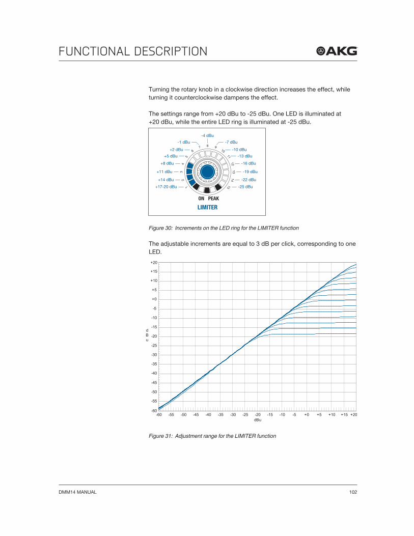
fUnctionAL Description
DMM14 MANUAL 102
Turning the rotary knob in a clockwise direction increases the effect, while turning it counterclockwise dampens the effect.
The settings range from +20 dBu to -25 dBu. One LED is illuminated at +20 dBu, while the entire LED ring is illuminated at -25 dBu.
Figure 30: Increments on the LED ring for the LIMITER function
The adjustable increments are equal to 3 dB per click, corresponding to one LED.
Figure 31: Adjustment range for the LIMITER function
8
ON PEAK
910
1112
1314
15
76
54
32
1+17-20 dBu
+14 dBu
+11 dBu
+8 dBu
+5 dBu
+2 dBu
-1 dBu
-25 dBu
-22 dBu
-19 dBu
-16 dBu
-13 dBu
-10 dBu
-7 dBu
-4 dBu
LIMITER
-60
+20
-55
-50
-45
-40
-35
-30
-25
-20
-15
-10
-5
+0
+5
+10
+15
dBu
-60 +20-55 -50 -45 -40 -35 -30 -25 -20 -15 -10 -5 +0 +5 +10 +15dBu

fUnctionAL Description
DMM14 MANUAL 103
7.4.6 COMPRESSOR
Figure 32: COMPRESSOR function
All the input channels can be controlled in the COMPRESSOR mode.
Thecompressorratioisfixed.Ithasavalueof1:2.Turningtherotaryknobin a clockwise direction increases the effect, while turning it counterclock-wise dampens the effect.
The settings range from +20 dBu to -25 dBu. One LED is illuminated at +20 dBu, while the entire LED ring is illuminated at -25 dBu.
Figure 33: Increments on the LED ring for the COMPRESSOR function
COMPRESSORPRIORITY
PAN / BALANCE
DELAY
ROUTE TO REC
ROUTE TO USB
EQUALIZER
PRESET
IN USB / DANTE
AUTOMIXING
COMPRESSOR
LIMITER
LOW CUT
BASS
TREBLE
LEVEL
LOCKED
SYSTEM CONTROL
8
ON PEAK
910
1112
1314
15
76
54
32
1+17-20 dBu
+14 dBu
+11 dBu
+8 dBu
+5 dBu
+2 dBu
-1 dBu
-25 dBu
-22 dBu
-19 dBu
-16 dBu
-13 dBu
-10 dBu
-7 dBu
-4 dBu
COMPRESSOR

fUnctionAL Description
DMM14 MANUAL 104
The adjustable increments are equal to 3 dBu per click, corresponding to one LED.
Figure 34: Adjustment range for the COMPRESSOR function
7.4.7 AUTOMIXING
Figure 35: AUTOMIXING function
-40
+20
-37.5-35
-32.5-30
-27.5-25
-22.5-20
-17.5-15
-12.5-10-7.5
-5-2.5+0
+2.5+5
+7.5+10
+12.5+15
+17.5
dBr
A
-40 +20-35 -30 -25 -20 -15 -10 -5 +0 +5 +10 +15dBu
T
AUTOMIXINGPRIORITY
PAN / BALANCE
DELAY
ROUTE TO REC
ROUTE TO USB
EQUALIZER
PRESET
IN USB / DANTE
AUTOMIXING
COMPRESSOR
LIMITER
LOW CUT
BASS
TREBLE
LEVEL
LOCKED
SYSTEM CONTROL

fUnctionAL Description
DMM14 MANUAL 105
All the input channels can be controlled in the AUTOMIXING mode.
Figure 36: Adjustment range for the AUTOMIXING function
The automatic mixing function for the relevant channel is switched on by turning a rotary knob in the clockwise direction. (Entire LED ring is illuminat-ed) Turning the rotary knob counterclockwise switches the automatic mixing function off. (Only one LED is illuminated)
Pressing the rotary knob also switches the function on or off.
7.4.8 PRIORITY
Figure 37: PRIORITY function
This function can only be active on one single input.
8
ON PEAK
910
1112
1314
15
76
54
32
1
8
ON PEAK
910
1112
1314
15
76
54
32
1
off on
AUTOMIXING
PRIORITYPRIORITY
PAN / BALANCE
DELAY
ROUTE TO REC
ROUTE TO USB
EQUALIZER
PRESET
IN USB / DANTE
AUTOMIXING
COMPRESSOR
LIMITER
LOW CUT
BASS
TREBLE
LEVEL
LOCKED
SYSTEM CONTROL

fUnctionAL Description
DMM14 MANUAL 106
The PRIORITY mode allows you to select which input channel will function as the priority channel. The priority channel then receives a 6 dB advantage in the signal detection in connection with the AUTOMIXING mode.
Figure 38: Adjustment range for the PRIORITY function
The function for the relevant channel is switched on by turning a rotary knob in the clockwise direction. (Entire LED ring is illuminated). Turning the rotary knob counter-clockwise switches the functions off (only one LED is illumi-nated).
Pressing the rotary knob also switches the function on or off.
Switching on the PRIORITY function on an input channel turns off the func-tion on the previously activated channel.
7.4.9 PAN / BALANCE
Figure 39: PAN / BALANCE function
The PAN / BALANCE mode allows all the input channels in the panorama and the balance of
8
ON PEAK
910
1112
1314
15
76
54
32
1
8
ON PEAK
910
1112
1314
15
76
54
32
1
off on
PRIORITY
PAN / BALANCEPRIORITY
PAN / BALANCE
DELAY
ROUTE TO REC
ROUTE TO USB
EQUALIZER
PRESET
IN USB / DANTE
AUTOMIXING
COMPRESSOR
LIMITER
LOW CUT
BASS
TREBLE
LEVEL
LOCKED
SYSTEM CONTROL
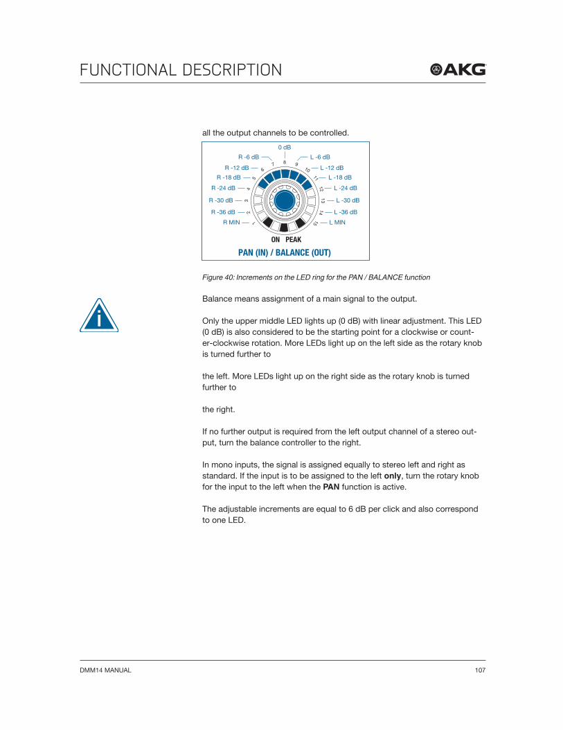
fUnctionAL Description
DMM14 MANUAL 107
all the output channels to be controlled.
Figure 40: Increments on the LED ring for the PAN / BALANCE function
Balance means assignment of a main signal to the output.
Only the upper middle LED lights up (0 dB) with linear adjustment. This LED (0 dB) is also considered to be the starting point for a clockwise or count-er-clockwise rotation. More LEDs light up on the left side as the rotary knob is turned further to the left. More LEDs light up on the right side as the rotary knob is turned further to the right.
If no further output is required from the left output channel of a stereo out-put, turn the balance controller to the right.
In mono inputs, the signal is assigned equally to stereo left and right as standard. If the input is to be assigned to the left only, turn the rotary knob for the input to the left when the PAN function is active.
The adjustable increments are equal to 6 dB per click and also correspond to one LED.
8
ON PEAK
910
1112
1314
15
76
54
32
1R MIN
R -36 dB
R -30 dB
R -24 dB
R -18 dB
R -12 dB
R -6 dB
L MIN
L -36 dB
L -30 dB
L -24 dB
L -18 dB
L -12 dB
L -6 dB
0 dB
PAN (IN) / BALANCE (OUT)

fUnctionAL Description
DMM14 MANUAL 108
7.4.10 DELAY
Figure 41: DELAY function
The DELAY function is used to control outputs OUT 1 and OUT 2. The outputs can be delayed using this function.
Figure 42: Increments on the LED ring for the DELAY function
The settings range from 0 m to 75 m. One LED is illuminated at 0 m, while the entire LED ring is illuminated at 75 m.
The adjustable increments are equal to 1 m per click. 5 m is equal to one LED.
DELAYPRIORITY
PAN / BALANCE
DELAY
ROUTE TO REC
ROUTE TO USB
EQUALIZER
PRESET
IN USB / DANTE
AUTOMIXING
COMPRESSOR
LIMITER
LOW CUT
BASS
TREBLE
LEVEL
LOCKED
SYSTEM CONTROL
8
ON PEAK
910
1112
1314
15
76
54
32
10-5 m
10 m
15 m
20 m
25 m
30 m
35 m
75 m
70 m
65 m
60 m
55 m
50 m
45 m
40 m
DELAY

fUnctionAL Description
DMM14 MANUAL 109
7.4.11 ROUTING TO REC
Figure 43: ROUTING TO REC function
All the input channels can be controlled in the ROUTING TO REC mode.
Figure 44: Adjustment range for the ROUTING TO REC function
The function for the relevant channel is switched on by turning the rotary knob in the clockwise direction (entire LED ring is illuminated). Turning the rotary knob counter-clockwise switches the function off (only one LED is illuminated).
Pressing the rotary knob also switches the function on or off.
Switching this on sets the input channel to the OUT 1 master bus.
ROUTING TO REC PRIORITY
PAN / BALANCE
DELAY
ROUTE TO REC
ROUTE TO USB
EQUALIZER
PRESET
IN USB / DANTE
AUTOMIXING
COMPRESSOR
LIMITER
LOW CUT
BASS
TREBLE
LEVEL
LOCKED
SYSTEM CONTROL
8
ON PEAK
910
1112
1314
15
76
54
32
1
8
ON PEAK
910
1112
1314
15
76
54
32
1
off on
ROUTING TO REC

fUnctionAL Description
DMM14 MANUAL 110
7.4.12 ROUTING TO USB
Figure 45: ROUTING TO USB function
All the input channels can be controlled in the ROUTING TO USB mode.
Figure 46: Adjustment range for the ROUTING TO USB function
The function for the relevant channel is switched on by turning the rotary knob in the clockwise direction (entire LED ring is illuminated). Turning the rotary knob counter-clockwise switches the function off (only one LED is illuminated).
Pressing the rotary knob also switches the function on or off.
Switching this on sets the input channel to the USB OUT master bus.
ROUTING TO USB PRIORITY
PAN / BALANCE
DELAY
ROUTE TO REC
ROUTE TO USB
EQUALIZER
PRESET
IN USB / DANTE
AUTOMIXING
COMPRESSOR
LIMITER
LOW CUT
BASS
TREBLE
LEVEL
LOCKED
SYSTEM CONTROL
8
ON PEAK
910
1112
1314
15
76
54
32
1
8
ON PEAK
910
1112
1314
15
76
54
32
1
off on
ROUTING TO USB

fUnctionAL Description
DMM14 MANUAL 111
7.4.13 EQUALIZER
Figure 47: EQUALIZER function
The EQUALIZER function controls outputs OUT 1 and OUT 2: The adjust-ment is the same for the left and right channel.
The room equalization can be performed in 12 bands.
Pressing the OUT 1 rotary knob activates the setting for OUT 1 while press-ing the OUT 2 rotary knob activates the setting for OUT 2.
The raising or lowering of the bands is performed by the 12 rotary knobs for the input channels. The adjustment range extends from -14 dB to +14dB. Only the upper middle LED lights up with linear adjustment. More LEDs light up on the left side as the rotary knob is turned further to the left. More LEDs light up on the right side as the rotary knob is turned further to the right.
Figure 48: Increments on the LED ring for the EQUALIZER function
EQUALIZERPRIORITY
PAN / BALANCE
DELAY
ROUTE TO REC
ROUTE TO USB
EQUALIZER
PRESET
IN USB / DANTE
AUTOMIXING
COMPRESSOR
LIMITER
LOW CUT
BASS
TREBLE
LEVEL
LOCKED
SYSTEM CONTROL
8
ON PEAK
910
1112
1314
15
76
54
32
1-57 dB
-48 dB
-39 dB
-30 dB
-21 dB
-12 dB
-9 dB
+15 dB
+12 dB
+9 dB
+6 dB
+3 dB
0 dB
-3 dB
-6 dB
EQUALIZER

fUnctionAL Description
DMM14 MANUAL 112
The adjustment takes place in 2 dB increments.
The center frequencies of the sub-bands are assigned at half-octave intervals.
Figure 49: Adjustment range for the EQUALIZER function
7.4.14 PRESET
Figure 50: PRESET function
-16
+16
-15-14-13-12-11-10-9-8-7-6-5-4-3-2-1+0+1+2+3+4+5+6+7+8+9
+10+11+12+13+14+15
dBr A
20 20k50 100 200 500 1k 2k 5k 10kHz
PRESETPRIORITY
PAN / BALANCE
DELAY
ROUTE TO REC
ROUTE TO USB
EQUALIZER
PRESET
IN USB / DANTE
AUTOMIXING
COMPRESSOR
LIMITER
LOW CUT
BASS
TREBLE
LEVEL
LOCKED
SYSTEM CONTROL

fUnctionAL Description
DMM14 MANUAL 113
Itispossiblestoreandload12differentdeviceconfigurationsordevicepresets (LEVEL, TREBLE, BASS, … , EQUALIZER).
To do this, the PRESET function is selected on the SYSTEM CONTROL. In addition to the 12 device presets, there is also a work preset: All changes in the settings initially only have an effect on that preset. To store changes permanently, the work preset must be stored under one of the available device presets. Loading a device preset overwrites the work preset and makes it active immediately. After re-starting the device, the last work preset becomes active with the last settings made.
The12inputrotaryknobsprovideaccesstothepresets,andtheirconfigu-ration.
Figure 51: PRESET configurations
IfonlyLED1lightsonanLEDring,thisstoragelocationisnotconfigured(see Figure 51, encoder IN 3 / 15).
If all LEDs and the red PEAK LED are lit, this storage location is assigned and selected (see Figure 51, encoder IN 1 / 13).
If only LED 1 and the red PEAK LED are on, this storage location is assigned but not selected (see Figure 51, encoder IN 2 / 14).
For more information, see 8.7 Using presets on page 118.
8
ON PEAK
910
1112
1314
15
76
54
32
1
IN 1 / USB LEQ 250 Hz
8
ON PEAK
910
1112
1314
15
76
54
32
1
IN 3 / DANTE 1EQ 500 Hz
8
ON PEAK
910
1112
1314
15
76
54
32
1
IN 2 / USB REQ 350 Hz

fUnctionAL Description
DMM14 MANUAL 114
7.5 LOCKED
Figure 52: LOCKED function
In LOCKED mode the rotary knobs or the entire unit are protected against improper use by means of locking.
For more information, see 8.11 Activate/deactivate LOCKED on page 121
LOCKEDPRIORITY
PAN / BALANCE
DELAY
ROUTE TO REC
ROUTE TO USB
EQUALIZER
PRESET
IN USB / DANTE
AUTOMIXING
COMPRESSOR
LIMITER
LOW CUT
BASS
TREBLE
LEVEL
LOCKED
SYSTEM CONTROL
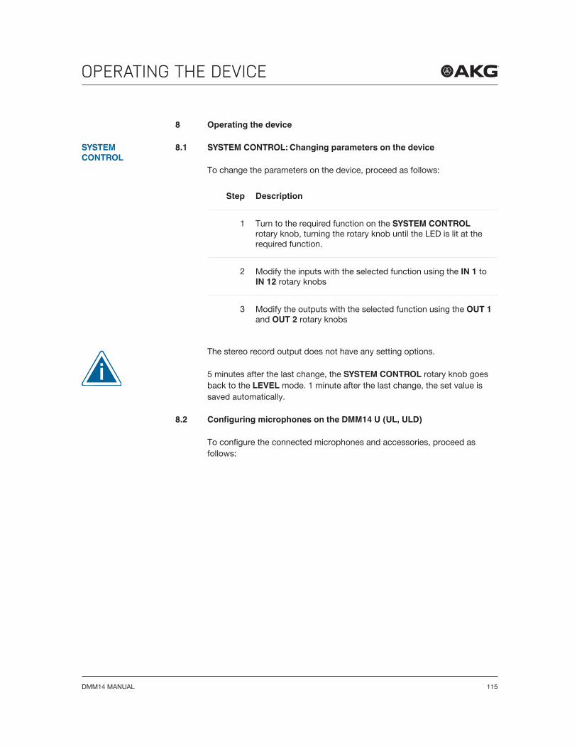
operAting the Device
DMM14 MANUAL 115
8 Operating the device
8.1 SYSTEM CONTROL: Changing parameters on the device
To change the parameters on the device, proceed as follows:
Step Description
1 Turn to the required function on the SYSTEM CONTROL rotary knob, turning the rotary knob until the LED is lit at the required function.
2 Modify the inputs with the selected function using the IN 1 to IN 12 rotary knobs
3 Modify the outputs with the selected function using the OUT 1 and OUT 2 rotary knobs
The stereo record output does not have any setting options.
5 minutes after the last change, the SYSTEM CONTROL rotary knob goes back to the LEVEL mode. 1 minute after the last change, the set value is saved automatically.
8.2 Configuring microphones on the DMM14 U (UL, ULD)
Toconfiguretheconnectedmicrophonesandaccessories,proceedasfollows:
SYSTEM CONTROL

operAting the Device
DMM14 MANUAL 116
Step Description
1 Press the slider switch and gain control on the rear of the DMM14 U (UL, ULD)
• Selecttheamplificationoftheinputsignalsbetween0dBand +57 dB.
• Higheramplificationoftheinputsignalsissuitableformicrophones with a low output level.
• Loweramplificationisrecommendedformicrophoneswitha high output level.
• If you are using capacitor microphones, determine which supply voltage or supply devices these require.
• If your capacitor microphones are suitable for phantom power, switch the phantom power on. To do this, switch the PHANT. PWR slider switch to ON.
2 Switch on the device with the main power switch
Caution: Risk of damage
When using wireless microphones, switch off the phantom power on the in-puts where you have connected a receiver to avoid damage to the receiver.
8.3 Monitoring the inputs/outputs
To monitor the inputs and outputs, proceed as follows:
Step Description
1 Hold down the HEADPHONE rotary knob and press to select one or more monitoring source rotary knob
• They are switched in mono simultaneously to the left and right headphone channel.
2 Change monitoring source by pressing on another monitoring source.
• The previous monitoring source is switched off.
With inputs, multiple sources can be monitored.
The output can be monitored individually and in stereo.

operAting the Device
DMM14 MANUAL 117
The REC (OUT) output cannot be monitored.
8.4 Cascading devices
Caution: Risk of damage
It is only permitted for this connection to be carried out by authorized, qual-ifiedpersonnel.
Itisnotpermittedtoconnectthefirstdeviceinthecascadetothelastdevice.
To cable the individual devices with the expansion sockets, proceed as follows:
Step Description
1 Cascade the devices as follows using CAT5+ connection cables:
OUT R REC (OUT) IN - EXPANSION - OUT RS232 USB LAN
L
R
OUT R REC (OUT) IN - EXPANSION - OUT RS232 USB LAN
L
R
OUT R REC (OUT) IN - EXPANSION - OUT RS232 USB LAN
L
R
For cascading we recommend using only cables from the AKG range of accessories.
All devices are equivalent for the user in terms of their function and re-sponse. In cascading, all functions of the individual devices are retained.

operAting the Device
DMM14 MANUAL 118
8.5 Feed via USB and Dante™
8.5.1 Processing the feed
To feed the input signals via USB or Dante™, proceed as follows:
Step Description
1 Press the SYSTEM CONTROLrotaryknobtwicebriefly(dou-ble-click)
• The 12 input controls are switched over for operation.
• The LEDs IN USB and IN USB/DANTE are permanently lit
• Changes to the input controls no longer affect the 12 ana-log inputs; only digital inputs 13 to 24
• The remaining operation is the same as on the analog level
The inputs from USB Port are assigned to channels 13 (IN1 / USB L) and 14 (IN 2 / USB R), for devices without Dante™ interface the digital inputs 15 to 24 are without function and inactive.
For devices with Dante™ interface, the remaining digital input channels from channel 15 are assigned as follows:
• IN3 / DANTE 1• IN4 / DANTE 2• etc.
All digital inputs have the same signal processing functionalities as the analog inputs.
8.6 Activating phantom power
Only bridge the 0 V potential with the grounding (factory setting) or connect it to the central system ground, as otherwise the phantom power has no reference point and will not function.
8.7 Using presets
The presets on the DMM14 U (UL, ULD) function in a very similar way to the presets on a car radio.
8.7.1 Selecting a preset
To select a preset, proceed as follows:
Feed via USB and Dante™
PRESET

operAting the Device
DMM14 MANUAL 119
Step Description
1 With SYSTEM CONTROL, select the PRESET function
2 Brieflypresstherotaryknobforthecorrespondinginputoroutput.
• An acoustic signal (beep) is sounded.
3 Release the rotary knob after the beep
• Device preset is loaded to work preset
• Settings for the selected device preset are active immedi-ately (all LEDs lit)
8.7.2 Programming a preset
To program a preset, proceed as follows:
Step Description
1 With SYSTEM CONTROL, select the PRESET function
2 Press input rotary knobs (1 to 12) for between 3 and 5 sec-onds.
• An acoustic signal (beep) is sounded.
3 Release the rotary knob after the beep
• The current settings from the work preset are stored under the selected device preset (all LEDs lit)
8.7.3 Deleting a preset
To delete a preset, proceed as follows:
Step Description
1 With SYSTEM CONTROL, select the PRESET function

operAting the Device
DMM14 MANUAL 120
Step Description
2 Press the rotary knob for the corresponding input or output for between 8 and 10 seconds.
• An acoustic signal (beep) is sounded.
3 Release the rotary knob after the beep
• The device preset is deleted and cannot be selected (emp-ty storage location, LED 1 lit)
8.8 Using MUTE
8.8.1 Activating MUTE
Inputs and outputs can be switched to MUTE. Proceed as follows:
Step Description
1 In the LEVELfunction,brieflypresstherotaryknobforthecorresponding input or output.
• The corresponding channel is muted.
• AllLEDspreviouslylitwillflash.
• The current volume is stored.
The MUTE function cannot be used for the HEADPHONE rotary knob!
8.8.2 Deactivating MUTE
To deactivate the MUTE function proceed as follows:
Step Description
1 Brieflypresstherotaryknobforthecorrespondinginputoroutput.
• MUTE function for the corresponding channel is deactivat-ed.
• The volume previously stored is applied.
MUTE

operAting the Device
DMM14 MANUAL 121
8.9 Activating ROUTING TO OUT
8.9.1 For an input
All inputs can be routed to the OUT output. Proceed as follows:
Step Description
1 Press and hold the OUT rotary knob
Press the rotary knobs on the required input simultaneously
• The corresponding input is routed to the OUT master bus.
8.9.2 For multiple inputs
To route multiple inputs to OUT, proceed as follows:
Step Description
1 Press and hold the OUT rotary knob
Press the rotary knob of the required inputs
• The corresponding inputs are routed to the OUT master bus.
8.10 Deactivating ROUTING TO OUT
To deactivate the ROUTING TO OUT function, proceed as follows:
Step Description
1 Press the rotary knob of the required input
• ROUTING TO OUT is deactivated for the corresponding input.
8.11 Activate/deactivate LOCKED
The following elements can be locked using the LOCKED function:
• SYSTEM CONTROL rotary knob• Complete unit• Individual channels
ROUTING TO OUT
LOCKED

operAting the Device
DMM14 MANUAL 122
8.11.1 Locking the SYSTEM CONTROL rotary knob
To lock the SYSTEM CONTROL rotary knob, proceed as follows:
Step Description
1 Press the SYSTEM CONTROL rotary knob for longer than 3 seconds
• The LOCKED LED is lit.
• Turning the rotary knob has no function.
• All other rotary knobs are in LEVEL mode and can still be operated.
8.11.2 Unlocking the SYSTEM CONTROL rotary knob
To unlock the SYSTEM CONTROL rotary knob, proceed as follows:
Step Description
1 Press the SYSTEM CONTROL rotary knob for longer than 3 seconds
• The rotary knob lock is removed.
• The LOCKED LED is no longer lit.
• The rotary knob is in the basic LEVEL position.
8.11.3 Locking the complete unit
To lock the complete unit, proceed as follows:
Step Description
1 Press the SYSTEM CONTROL rotary knob at the same time as the OUT rotary knob for longer than 3 seconds
• The LOCKED LED is lit.
• The original settings are stored.
• Turning the rotary knob has no function.
• All other rotary knobs are in LEVEL mode and can still be operated.
Lock rotary knob
Unlock rotary knob
Lock unit
operAting the Device
DMM14 MANUAL 123
8.11.4 Unlocking the complete unit
To unlock the complete unit, proceed as follows:
Step Description
1 Press the SYSTEM CONTROL rotary knob at the same time as the OUT rotary knob for longer than 3 seconds
• The rotary knob lock is removed.
• The LOCKED LED is no longer lit.
• The rotary knobs are in the basic LEVEL position.
8.11.5 Unlocking individual channels
To unlock individual channels, proceed as follows:
Step Description
1 Lock the complete unit, to do this press the SYSTEM CONTROL rotary knob at the same time as the OUT rotary knob for longer than 3 seconds
• The LOCKED LED is lit.
• The original settings are stored.
• Turning the rotary knob has no function.
• All other rotary knobs are in LEVEL mode and can still be operated.
2 Remove the lock on the required channel by pressing the rotary knob for the required channel for longer than 3 seconds
8.11.6 Locking individual channels
Tolockindividualchannels,thecompleteunitislockedfirstandthelockisthen removed for all channels that are not to be locked.
To lock individual channels, proceed as follows:
Unlock unit
Unlock channels
Lock channels

operAting the Device
DMM14 MANUAL 124
Step Description
1 Lock the complete unit, to do this press the SYSTEM CONTROL rotary knob at the same time as the OUT rotary knob for longer than 3 seconds
• The LOCKED LED is lit.
• The original settings are stored.
• Turning the rotary knob has no function.
• All other rotary knobs are in LEVEL mode and can still be operated.
2 Remove the lock on all channels by pressing the rotary knob for the required channels for longer than 3 seconds.
The status conditions that were set before the channels or the complete unit was locked, are retained even after the DMM14 U (UL, ULD) is switched of and back on!
8.12 Copying configuration data
The copy function can be used to copy individual or multiple settings (LEVEL, TREBLE, BASS, LOWCUT, LIMITER and COMPRESSOR) on an input to one or more other inputs.
8.12.1 Copying individual values
To copy individual values from one channel to one or more other channels, proceed as follows:
Step Description
1 Select the required function on the SYSTEM CONTROL rotary knob
2 Press the rotary knob with the value to be copied, then straight away press the rotary knob up to which the copy process is to be carried out
Copy configurations

operAting the Device
DMM14 MANUAL 125
Step Description
3 Keep both rotary knobs pressed down (approx. 4 seconds) until an acoustic signal is sounded (beep) and the affected LEDringsflashoncebriefly.
• Value was transmitted to the selected channels.
The copying process is applied to all rotary knobs that located between the two selected knobs.
8.12.2 Copying all values
To copy all values from one channel to one or more other channels, proceed as follows:
Step Description
1 Press the rotary knob with the values to be copied, then straight away press the rotary knob up to which the copy process is to be carried out
2 Keep both rotary knobs pressed down (approx. 8 seconds) until an acoustic signal is sounded (beep beep) and the affect-edLEDringsflashoncebriefly.
• Values were transmitted to the selected channels.
The copy process is possible in both directions (IN 1 to IN 12 and IN 12 to IN 1).
The following diagrams visualize the copy processs.
Figure 53: Select rotary knobs (source)
8
ON PEAK
910
1112
1314
15
76
54
32
1
IN 12
8
ON PEAK
910
1112
1314
15
76
54
32
1
IN 11
8
ON PEAK
910
1112
1314
15
76
54
32
1
IN 10
8
ON PEAK
910
1112
1314
15
76
54
32
1
IN 3 ...
8
ON PEAK
910
1112
1314
15
76
54
32
1
IN 2
8
ON PEAK
910
1112
1314
15
76
54
32
1
IN 1

operAting the Device
DMM14 MANUAL 126
Figure 54: Define copy range (target)
Figure 55: Keep the rotary knobs pressed down
Figure 56: Complete copy process
8.13 Resetting the factory settings
Figure 57: Resetting the factory settings
To reset the factory settings for the entire device, proceed as follows:
8
ON PEAK
910
1112
1314
15
76
54
32
1
IN 12
8
ON PEAK
910
1112
1314
157
6
54
32
1
IN 11
8
ON PEAK
910
1112
1314
15
76
54
32
1
IN 10
8
ON PEAK
910
1112
1314
15
76
54
32
1
IN 3 ...
8
ON PEAK
910
1112
1314
15
76
54
32
1
IN 2
8
ON PEAK
910
1112
1314
15
76
54
32
1
IN 1
8
ON PEAK
910
1112
1314
15
76
54
32
1
IN 12
8
ON PEAK
910
1112
1314
15
76
54
32
1
IN 11
8
ON PEAK
910
1112
1314
15
76
54
32
1
IN 10
8
ON PEAK
910
1112
1314
15
76
54
32
1
IN 3 ...
8
ON PEAK
910
1112
1314
15
76
54
32
1
IN 2
8
ON PEAK
910
1112
1314
15
76
54
32
1
IN 1
flashing flashing flashing flashing
8
ON PEAK
910
1112
1314
15
76
54
32
1
IN 12
8
ON PEAK
910
1112
1314
15
76
54
32
1
IN 11
8
ON PEAK
910
1112
1314
15
76
54
32
1
IN 10
8
ON PEAK
910
1112
1314
15
76
54
32
1
IN 3 ...
8
ON PEAK
910
1112
1314
15
76
54
32
1
IN 2
8
ON PEAK
910
1112
1314
15
76
54
32
1
IN 1
Reset to factory settings
+
PRIORITYPAN / BALANCE
DELAY
ROUTE TO REC
ROUTE TO USB
EQUALIZER
PRESET
IN USB / DANTE
AUTOMIXING
COMPRESSOR
LIMITER
LOW CUT
BASS
TREBLE
LEVEL
LOCKED
SYSTEM CONTROL

operAting the Device
DMM14 MANUAL 127
Step Description
1 Switch on the device
Wait until the start sequence of the automixer is complete (approx. 15 seconds).
2 Press the SYSTEM CONTROL rotary knob and keep pressed until step 5
3 Switch off the device at the mains
4 Switch the device back on after a short waiting time
Wait until the start sequence of the automixer is complete (approx. 15 seconds).
5 Release the SYSTEM CONTROL rotary knob
• The device's factory settings have now been restored and anewsystemconfigurationcannowbesetup.
Resetting the factory settings deletes all of the stored settings!

troUbLeshooting
DMM14 MANUAL 128
9 Troubleshooting
WARNING: Risk of electric shock
There are unprotected contacts and cables within the unit that could cause serious injury from electric shock on contact.
• Theunitisonlypermittedtobeopenedbyauthorized,qualifiedpersonnel for troubleshooting purposes.
PROBLEM POSSIBLE CAUSE REMEDY
No sound Power supply cable is not connected to unit
Connect power supply cable to unit
Power switch off Turn power switch to on position
Deviceisnotconnectedtoamplifier Connectoutputchanneltoamplifier
Microphone or auxiliary equipment not connected to unit
Connect microphone or auxiliary de-vice to unit
Volume control set to minimum Turn up volume control
Volume controls set to MUTE Cancel MUTE by pressing the rotary knob
Pre-amplificationnotsetcorrectly Set gain control on rear panel to cor-rectpre-amplification
Phantom power is switched off Switch on phantom power for con-denser microphone
External potentiometer set to minimum Turn up external potentiometer
No sound with sinu-soidal feed
Automix algorithm suppressing con-stant signal
Exclude channel from automix algo-rithm
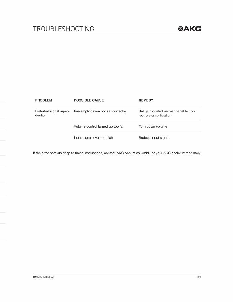
troUbLeshooting
DMM14 MANUAL 129
PROBLEM POSSIBLE CAUSE REMEDY
Distorted signal repro-duction
Pre-amplificationnotsetcorrectly Set gain control on rear panel to cor-rectpre-amplification
Volume control turned up too far Turn down volume
Input signal level too high Reduce input signal
If the error persists despite these instructions, contact AKG Acoustics GmbH or your AKG dealer immediately.
9 Troubleshooting
WARNING: Risk of electric shock
There are unprotected contacts and cables within the unit that could cause serious injury from electric shock on contact.
• Theunitisonlypermittedtobeopenedbyauthorized,qualifiedpersonnel for troubleshooting purposes.
PROBLEM POSSIBLE CAUSE REMEDY
No sound Power supply cable is not connected to unit
Connect power supply cable to unit
Power switch off Turn power switch to on position
Deviceisnotconnectedtoamplifier Connectoutputchanneltoamplifier
Microphone or auxiliary equipment not connected to unit
Connect microphone or auxiliary de-vice to unit
Volume control set to minimum Turn up volume control
Volume controls set to MUTE Cancel MUTE by pressing the rotary knob
Pre-amplificationnotsetcorrectly Set gain control on rear panel to cor-rectpre-amplification
Phantom power is switched off Switch on phantom power for con-denser microphone
External potentiometer set to minimum Turn up external potentiometer
No sound with sinu-soidal feed
Automix algorithm suppressing con-stant signal
Exclude channel from automix algo-rithm

DMM14 MANUAL 130

INHALT
DMM14 MANUAL 131
1 GÉNÉRALITÉS 1341.1 Objectif de ce document 134
1.2 Conservation de ce document 134
1.3 Responsabilité 134
1.4 Garantie 134
2 LIVRAISON 1352.1 Contenu de l'emballage 135
2.2 Accessoires en option 135
3 SÉCURITÉ ET ENVIRONNEMENT 1363.1 Sécurité 136
3.2 Connaissances présupposées
et domaine de responsabilité de
l'utilisateur 137
3.3 Explication des symboles 137
3.4 Utilisation conforme 138
3.5 Utilisation non conforme 138
3.6 Environnement 138
4 DÉCLARATION DE CONFORMITÉ 138
5 DESCRIPTION DU SYSTÈME 1395.1 Description abrégée 139
5.2 Spécificationstechniques 139
5.3 Face avant : Description des contrôles 141
5.3.1 Régulateurs rotatifs des canaux
d'entrée 141
5.3.2 Mode de fonctionnement/SYSTEM
CONTROL 142
5.3.3 Régulateurs rotatifs des sorties stéréo 142
5.3.4 Contrôle de niveau des sorties stéréo 142
5.3.5 Sortie Casque stéréo 142
5.4 Face arrière : Description des
contrôles 143
5.4.1 Canaux d'entrée 144
5.4.2 Régulateur de gain 145
5.4.3 Alimentation fantôme 145
5.4.4 Canal de sortie de somme stéréo 147
5.4.5 Sortie Enregistrement stéréo 147
5.4.6 Commande sérielle (RS232) 148
5.4.7 Prise USB 148
5.4.8 Prise LAN 149
5.4.9 Mise en cascade de systèmes 149
5.4.10 Réseau Dante™ 150
5.5 Algorithme Automix 150
5.5.1 Adaptation de niveau dynamique 151
5.5.2 Best Mic On 151
5.5.3 Détection de bruit 151
5.6 Mise en cascade de systèmes 151
6 MONTAGE ET RACCORDEMENT 1536.1 Montage 153
6.2 Mettre les systèmes en cascade
(option) 153
6.3 Brancher les microphones et
instruments 153
6.4 Brancher le système sur le courant 154
7 DESCRIPTION DU FONCTIONNEMENT 155
7.1 Manipulation 155
7.2 Utilisation des régulateurs rotatifs 155
7.2.1 Affichageduniveauaudioetdela
fonction VU 156
7.3 SYSTEM CONTROL 156
7.3.1 Fonctions du SYSTEM CONTROL 156
7.3.2 Fonctions des canaux d'entrée 157
7.3.3 Fonctions des canaux de sortie 157
7.3.4 Fonctions de la sortie Casque stéréo
(sortie de contrôle) 157
7.4 Fonctions DSP 158

INHALT
DMM14 MANUAL 132
7.4.1 LEVEL 158
7.4.2 TREBLE 159
7.4.3 BASS 160
7.4.4 LOW CUT 162
7.4.5 LIMITER 164
7.4.6 COMPRESSOR 165
7.4.7 AUTOMIXING 167
7.4.8 PRIORITY 168
7.4.9 PAN / BALANCE 169
7.4.10 DELAY 170
7.4.11 ROUTING TO REC 171
7.4.12 ROUTING TO USB 172
7.4.13 EQUALIZER 173
7.4.14 PRESET 174
7.5 LOCKED 176
8 MANIPULATION DU SYSTÈME 1778.1 SYSTEMCONTROL:Modifierles
paramètres du système 177
8.2 Configurerlesmicrophonesdu
DMM14 U (UL, ULD) 177
8.3 Écouter les entrées et sorties 178
8.4 Mettre les systèmes en cascade 179
8.5 Transmission par USB et Dante™ 180
8.5.1 Modifierlatransmission 180
8.6 Activer l'alimentation fantôme 180
8.7 Utiliserlesprofils 180
8.7.1 Sélectionnerunprofil 181
8.7.2 Programmerunprofil 181
8.7.3 Supprimerunprofil 181
8.8 Utiliser MUTE 182
8.8.1 Activer MUTE 182
8.8.2 Désactiver MUTE 182
8.9 Activer ROUTING TO OUT 183
8.9.1 Pour un canal d'entrée 183
8.9.2 Pour plusieurs canaux d'entrée 183
8.10 Désactiver ROUTING TO OUT 183
8.11 Activer/Désactiver LOCKED 184
8.11.1 Verrouiller le régulateur rotatif
SYSTEM CONTROL 184
8.11.2 Déverrouiller le régulateur rotatif
SYSTEM CONTROL 184
8.11.3 Verrouiller le système 185
8.11.4 Déverrouiller le système 185
8.11.5 Déverrouiller certains canaux 185
8.11.6 Verrouiller certains canaux 186
8.12 Copierdesdonnéesdeconfiguration 187
8.12.1 Copier des valeurs 187
8.12.2 Copier toutes les valeurs 187
8.13 Réinitialiseràlaconfigurationd'usine 189
9 RÉSOLUTION DES ERREURS 190

IMPRESSUM
DMM14 MANUAL 133
Éditeur AKG Acoustics GmbH
Laxenburger Straße 254
1230 Vienne
Autriche
Tél : +43 (0)1 86654-0
Fax : +43 (0)1 86654-8800
AKG ACOUSTICS, U.S.
8500 Balboa Blvd. Dock 15
Northridge, CA 91329
U.S.A.
Tél : +1 818 920-3224
Copyright © 2015 AKG Acoustics GmbH
Tous droits réservés.
Les informations de ce mode d'emploi, les schémas, et les photos annexes sont la propriété intellectuelle de la société AKG Acoustics GmbH.
Dans le cadre du respect du droit d'auteur, il est interdit, sans autorisation préalable expresse et écrite de la société AKG Acoustics GmbH, de reproduire ou de transmettre toute ou partie de cette documentation, quelles qu'en soient les raisons, les formes ou les moyens, que ce soit électroniquement, mécaniquement, par photocopies, enregistrement ou dispositifs de stockage et de récupération d'informations. Il est interdit de la transmettre à un tiers. Elle doit nous être retourné sur demande.
FCC Statement Note: This equipment has been tested and found to comply with the limits for a Class B digital device, pursuant to part 15 of the FCC Rules. These limits are designed to provide reasonable protection against harmful interference in a residential installation. This equipment generates, uses and can radiate radio frequency energy and, if not installed and used in accordance with the instructions, may cause harmful interference to radio communications. However, there is no guarantee that interference will not occur in a particular installation. If this equipment does cause harmful interference to radio or television reception, which can be determined by turning the equipment off and on, the user is encouraged to try to correct the interference by one or more of the following measures:
• Reorient or relocate the receiving antenna.
• Increase the separation between the equipment and receiver.
• Connect the equipment into an outlet on a circuit different from that to which the receiver is connected.
• Consult the dealer or an experienced radio/TV technician for help.
This device complies with Part 15 of the FCC Rules. Operation is subject to the following two conditions: (1) this device may not cause harmful interference, and (2) this device must accept any interference received, including interference that may cause undesired operation.
Shielded cables and I/O cords must be used for this equipment to comply with the relevant FCCregulations.Changesormodificationsnotexpresslyapprovedbythepartyresponsiblefor compliance could void the user’s authority to operate this equipment.
Mise à jour Ce mode d'emploi peut être mis à jour sans préavis et n'engage en aucune façon la société AKG Acoustics GmbH.
Version 1.0
Date d'édition Juillet 2015/FR
07/15/5061697

générALités
DMM14 MANUAL 134
1 Généralités
1.1 Objectif de ce document
Cette documentation est destinée à vous permettre :
• de manipuler ce système en toute sécurité• d'utiliser ce système de façon conforme.
1.2 Conservation de ce document
Imprimez ce mode d'emploi et conservez.le précautionneusement ou enre-gistrez-le électroniquement sur un support facile d'accès.
Remettez ce mode d'emploi au propriétaire suivant.
Ce mode d'emploi est un composant essentiel du système.
1.3 Responsabilité
AKG Acoustics GmbH ne serait être tenu responsable des conséquences des situations suivantes :
• Utilisation du système pour un objectif autre que ceux compris dans l'Utilisation conforme.
• Une manipulation inappropriée de ce système.• Desmodificationsnonautoriséesoueffectuéesdefaçonincorrecte.• Une documentation non mise à jour.
1.4 Garantie
AKG Acoustics GmbH n'assume aucune garantie pour les dommages cau-sés par
• Une manipulation inappropriée du système.• Desmodificationsnonautoriséesoueffectuéesdefaçonincorrecte.• Une documentation non mise à jour.
Responsabilité
Garantie

LivrAison
DMM14 MANUAL 135
2 Livraison
2.1 Contenu de l'emballage
Contrôlez l'exhaustivité de la livraison. Adressez-vous à votre fournisseur AKG si elle est incomplète.
• 1 DMM14 U, DMM14 UL ou DMM14 ULD• 1 Guide rapide• 1 câble d'alimentation CEI EU standard• 1 câble d'alimentation CEI US standard• 1 Pince de maintien
2.2 Accessoires en option
Vous trouverez des accessoires en option à télécharger du site www.akg.com. Votre revendeur vous conseillera avec plaisir.
Contenu de l'emballage
Accessoires en option

sécUrité et environnement
DMM14 MANUAL 136
3 Sécurité et environnement
3.1 Sécurité
Attention : Risque d'endommagement
• Protégez votre système
- de l'ensoleillement direct - de la poussière et de l'humidité - de la pluie - des vibrations et des coups.
• Ne renversez pas de liquide sur le système et ne laissez rien tomber dans les fentes d'aération.
• Ne posez pas de récipient contenant du liquide sur le système.
• Le système ne doit être utilisé qu'en lieu sec.
• L'ouverture et les interventions de maintenance ou de réparation sont réservées aux professionnels autorisés. L'intérieur du boîtier ne contient aucune pièce pouvant être entretenue, réparée ou rempla-cée par un non-professionnel.
• Avantlamiseenservicedevotresystème,vérifiezquelatensiondeservice du réseau d'alimentation du site correspond à celle de son bloc d'alimentation intégré.
• Le système ne doit être utilisé qu'avec une tension réseau entre 100 et 240 V AC. Les autres types de courant ou tensions pourraient endommager le système.
• Éteignez immédiatement le système si un objet ou du liquide devait pénétrer à l'intérieur. Débranchez alors immédiatement le câble réseau de sa prise et laissez contrôler le système par notre Service Client.
• Débranchez aussi le câble réseau de la prise si vous n'utilisez pas le système sur une longue période. N'oubliez pas que, même mis hors service, un système dont le câble d'alimentation est toujours branché n'est pas complètement isolé du réseau.
• Ne placez pas le système près d'une source de chaleur, radiateur, conduitedechauffage,amplificateur,etc.
Sécurité

sécUrité et environnement
DMM14 MANUAL 137
• Pour éviter les pannes et perturbations électriques, séparez les câbles, en particulier ceux des entrées de microphone des câbles à courant fort et d'alimentation réseau. Si vous effectuez le câblage en gaines ou en canaux à câbles, placez les câbles de transmission dans un canal séparé.
• Nettoyez le système avec un chiffon humide, mais non mouillé. Débranchez auparavant le câble réseau de la prise. N'utilisez pas de détergent abrasifs ou acides ou contenant de l'alcool ou des solvants qui pourraient abîmer le revêtement et les composants en plastiques.
• N'utilisez le système que pour ce quoi il a été conçu. AKG ne sau-rait être tenu responsable des dommages induits par une utilisation non conforme ou une manipulation inappropriée.
3.2 Connaissances présupposées et domaine de responsabilité de l'utilisateur
• LetermeSpécialistesqualifiésdésignelespersonnesqui,enraisonde leurs formations, professionnelles et continues et leur expéri-ence, ont la capacité de détecter les risques et d'éviter les dangers liés à l'utilisation du produit.
3.3 Explication des symboles
Attention : Risque d'endommagement
Ne pas suivre les instructions risque d'endommager le système.
Avertissement Dangers liés aux chocs électriques
Situation dangereuse : Ne pas suivre les instruc-tions risque d'occasionner des blessures légères ou moyennes.
Indique des indications et conseils utiles pour une utili-sationefficacedusystème

DécLArAtion De conformité
DMM14 MANUAL 138
Indique des informations et des téléchargements Internet complémentaires.
Indique des informations relatives à l'élimination correcte des composants décrits.
3.4 Utilisation conforme
Le mixeur de microphone numérique automatique DMM14 U (UL, ULD) U (UL, ULD) est réservé au mixage de signaux audio.
3.5 Utilisation non conforme
Toute utilisation autre que l'utilisation ci-dessus sera considéré comme non conforme.
3.6 Environnement
• L'emballage du système est recyclable. Éliminez toujours l'embal-lage en l'envoyant à un système de collecte adapté.
• Pour éliminer le système, séparez le boîtier, les circuits électro-niques et les câbles et éliminez tous les composants selon les consignes d'élimination en vigueur.
4 Déclaration de conformité
Ce produit satisfait les normes listées dans la déclaration de conformité. Vous trouverez la déclaration de conformité à l'adresse http://www.akg.com. Vous pouvez la demander par e-mail en écrivant à [email protected].

Description DU système
DMM14 MANUAL 139
5 Description du système
5.1 Description abrégée
Le DMM14 U (UL, ULD) est un mixeur de microphone numérique automa-tique 19". Le traitement des signaux interne est numérique et sur quatre sorties de somme stéréo. Les entrées et sorties sont disponibles en version analogique ou numérique.
Le système est doté de 12 canaux d'entrée mono symétriques,configu-rables comme entrées de microphone ou de ligne (pour le récepteur d'un microphonesansfil,parex.).
Côté sortie, le système dispose de trois sorties : Somme symétrique, Enregistrement stéréo et Casque stéréo.
Le système est doté d une prise USB, pouvant servir en entrée ou en sortie.
La commande se fait par LAN et réseau Dante™ (en option).
Le mixeur dispose d'un module d'alimentation à plage élargie et est bran-ché au réseau électrique par le câble d'alimentation livré.
En plus des nombreuses fonctions DSP de traitement des signaux, le DMM14 U (UL, ULD) dispose de fonctionnalités de mixage automatique innovatrices.
Siles12entréessymétriquesnesuffisentpas,ilestpossibledemettrejusqu'à dix DMM14 U (UL, ULD) en cascade.
5.2 Spécifications techniques
Généralités
Dimensions Boîtier standard pour montage en rack, 1 UH
483 (l) x 45 (h) x 220 (p) mm
Poids(avec emballage) 2,9 kg
Température ambiante auto-risée
0°C ... 50°C
Humidité environnante en fonctionnement
10% ... 90%, sans condensation
Description abrégée
Généralités

Description DU système
DMM14 MANUAL 140
Généralités
Indice de protection I
Module d'alimentation
Tension d'entrée 100 ... 240 V AC
Fréquence de réseau 50 ... 60 Hz
Consommation max. 75 Watt
Tensions de sortie 24 V
Entrées symétriques - Préampli
Gain 0 dB ... 60 dB
Niveau d'entrée max. +20 dBu
Réjection en mode commun >70 dB
Dynamique >120 dB
Ratio signal-bruit (S/N) >90 dB
Impédance d'entrée >8kΩ
Bruit à l'entrée équivalent. -127 dBu
Entrées symétriques - Alimentation fantôme
Tension fantôme 48 V CC
Tension d'alimentation max. par entrée 10 mA
Résistances d'alimentation 2x6,8kΩ
Entrées symétriques - Convertisseur Analogique/Numérique
Format de données 24 Bit
Fréquence d'échantillonnage 48 kHz
Enregistrement et Sortie de somme
Niveau de sortie max. +20 dBu
Dynamique >110 dB
Ratio signal-bruit (S/N) >90 dB
Généralités
Module d'alimentation
Entrées
Sorties

Description DU système
DMM14 MANUAL 141
Enregistrement et Sortie de somme
Impédance de charge min. <100Ω
Conversion Numérique/Analogique pour enregistrement, contrôle et sortie de somme
Format de données 24 Bit
Fréquence d'échantillonnage 48 kHz
5.3 Face avant : Description des contrôles
Neuf régulateurs rotatifs sont placés sur la face avant.
Illustration 1 : Face avant du DMM14 U (UL, ULD)
Le tableau suivant décrit les contrôles de la face avant du DMM14 U (UL, ULD) :
N° Description
1 à 12 Entrées microphone et de ligne
13 Mode de fonctionnement/SYSTEM CONTROL
14, 16 Sorties stéréo 1 et 2
15, 17 Sorties stéréo 1 et 2
18 Sortie Casque stéréo
19 Prise de connexion du casque
Cesrégulateursrotatifsmodifientlesparamètresdesfonctionsaudiosélec-tionnées.
5.3.1 Régulateurs rotatifs des canaux d'entrée
Le DMM14 U (UL, ULD) est doté de 12 canaux d'entrée symétriques pour brancher des microphones dynamique à faible valeur ohmique, des micro-phones à condensateur ou d'autres sources de signaux, comme le récep-teurd'unmicrophonesansfil.Ilyaunrégulateurrotatifparcanald'entrée(1à 12).
Sorties
Contrôles Face avant
8 910
1115
76
51
8 910
1112
1314
15
76
51
PRIORITYPAN / BALANCE
DELAY
ROUTE TO REC
ROUTE TO USB
EQUALIZER
PRESET
IN USB / DANTE
AUTOMIXING
COMPRESSOR
LIMITER
LOW CUT
BASS
TREBLE
LEVEL
LOCKED
OUT 2
SYSTEM CONTROL
HEADPHONE
-50 -40 -30 -20 -10 -5 0 +5 dB
L
R
8 910
1115
76
54
32
1
OUT 1
-50 -40 -30 -20 -10 -5 0 +5 dB
L
R
8
ON PEAK
910
1112
1314
15
76
54
32
1
IN 11EQ 8.0 kHz
8
ON PEAK
910
1112
1314
15
76
54
32
1
IN 9EQ 4.0 kHz
8
ON PEAK
910
1112
1314
157
6
54
32
1
IN 7EQ 2.0 kHz
8
ON PEAK
910
1112
1314
15
76
54
32
1
IN 5 / DANTE 3EQ 1.0 kHz
8
ON PEAK
910
1112
1314
15
76
54
32
1
IN 3 / DANTE 1EQ 500 Hz
8
ON PEAK
910
1112
1314
15
76
54
32
1
IN 1 / USB LEQ 250 Hz
8
ON PEAK
9
1314
15
7
32
1
IN 2 / USB REQ 350 Hz
8
ON PEAK
9
1314
15
7
32
1
IN 4 / DANTE 2EQ 700 Hz
8
ON PEAK
9
1314
15
7
32
1
IN 6 / DANTE 4EQ 1.4 kHz
8
ON PEAK
9
1314
15
7
32
1
IN 8EQ 2.8 kHz
8
ON PEAK
9
1314
15
7
32
1
IN 10EQ 5.6 kHz
8
ON PEAK
910
1112
1314
15
7
32
1
IN 12EQ 11.3 kHz
1 2 4 6 8 10 12 15 173 5 7 9 11 13 1614 18 19
Régulateurs rotatifs Entrées

Description DU système
DMM14 MANUAL 142
Chaque canal d'entrée est doté d'une LED verte ON et d'une LED rouge PEAK.
ON s'allume si le canal d'entrée a la priorité en mode Automatique. Si cette fonction Automix est désactivée, ON est toujours allumé.
PEAK s'allume, lorsque le signal au niveau d'un canal d'entrée se rapproche du seuil de contrôle maximal. Diminuez alors le niveau avec le régulateur ou modifiezlasensibilitéd'entrée.
Cette dernière est adapté avec le régulateur de gain au dos du système connecté.
5.3.2 Mode de fonctionnement/SYSTEM CONTROL
Le DMM14 U (UL, ULD) dispose de nombreuses fonctionnalités comme Volume, Plages d'aiguës, Basses, Automix, sélectionnées avec le régulateur rotatif SYSTEM CONTROL (13).
5.3.3 Régulateurs rotatifs des sorties stéréo
Les régulateurs rotatifs des canaux de sortie stéréo sont repérés d'un OUT 1 (14) et d'un OUT 2(16).Cerégulateurmodifientlesparamètresducanal de sortie.
• Volume• Plage d'aiguës• Plage de basses• Comportement à proximité des seuils• Balance et retard
5.3.4 Contrôle de niveau des sorties stéréo
Le contrôle de niveau (15, 17) sous le régulateur rotatif des canaux de sortie stéréoafficheleniveaudesortieendB.
5.3.5 Sortie Casque stéréo
La sortie Casque stéréo (18) permet d'entendre les entrées et les sorties.
LED ON
LED PEAK
SYSTEM CONTROL
Régulateurs rotatifs Sorties
Contrôle de niveau
Sortie Casque

Description DU système
DMM14 MANUAL 143
5.4 Face arrière : Description des contrôles
La face arrière contient les prises d'alimentation, des canaux d'entrée et des canaux de sortie.
Illustration 2 : Face arrière du DMM14 U (UL, ULD)
*Sur DMM14 ULD seulement **Sur DMM14 UL et DMM14 ULD seulement
Le tableau suivant décrit les contrôles de la face arrière du DMM14 U (UL, ULD) :
N° Description
1, 5, 6, 10, 11, 15, 18, 22, 23, 27, 28, 32
Canaux d'entrée
2, 4, 7, 9, 12, 14, 19, 21, 24, 26, 29, 31
Régulateur de gain
3, 8, 13, 20, 25, 30 Alimentation fantôme
16, 33 Canal de sortie stéréo à gauche
17, 34 Canal de sortie stéréo à droite
35 Sortie Enregistrement stéréo
36 Dante™ : *sur DMM8 ULD seulement
37 Douille d'extension
38 Commande sérielle (RS232)
39 Prise USB
40 Douille Jack modulaire (RJ-45) : **sur DMM8 UL et DMM8 ULD seulement
Contrôles Face arrière
OUT2/L OUT2/R REC (OUT) IN - EXPANSION - OUT RS232
DANTE
USB LAN
L
R
IN 7 IN 8Off
PHANT. PWROn
IN 1 IN 2Off
PHANT. PWROn
IN 9 IN 10Off
PHANT. PWROn
IN 3 IN 4Off
PHANT. PWROn
IN 11 IN 12Off
PHANT. PWROn
IN 5 IN 26Off
PHANT. PWROn
OUT1/L OUT1/R
33 34 35 36* 38 39 40** 41 42 4320
19 2118 22
3 42 51
2524 2623 27
897 106
3029 3128 32
131412 1511
37
16 17

Description DU système
DMM14 MANUAL 144
N° Description
41 Borne Phoenix (mise à la terre/régulation à distance)
42 Raccord réseau
43 Interrupteur réseau
5.4.1 Canaux d'entrée
Illustration 3 : Canal d'entrée
Les 12 canaux d'entrée symétriques (1, 5, 6, 10, 11, 15, 18, 22, 23, 27, 28, 32) sont accessibles par douilles tripolaires Phoenix. Elle sont repérées de IN 1 à IN 12. Les régulateurs rotatifs IN 1 à IN 12delafaceavantmodifientles niveaux d'entrée.
Un interrupteur est placé entre deux douilles Phoenix pour la tension fan-tôme et chaque canal a un régulateur de gain.
L'affectation des broches est repérée au-dessus de la douille IN 3 :
• Broche 1 = a• Broche 2 = b• Broche 3 = _|_
Canaux d'entrée
IN 1Off
PHANT. PWROn

Description DU système
DMM14 MANUAL 145
5.4.2 Régulateur de gain
Illustration 4 : Régulateur de gain
Chaque canal d'entrée est doté à son côté d'un régulateur de gain (2, 4, 7, 9, 12, 14, 19, 21, 24, 26, 29, 31) pour ajuster le niveau d'entrée. Les régula-teurs de gain sont munis d'un interrupteur en butée gauche.
Le niveau d'entrée est de 0 dB en butée gauche. Il peut être amené à son maximum de 57 dB en tournant le régulateur vers la droite.
5.4.3 Alimentation fantôme
Illustration 5 : Alimentation fantôme
Le système est doté de six interrupteurs d'alimentation fantôme (3, 8, 13, 20, 25, 30).
L'interrupteur coulissant active la tension d'alimentation fantôme de +48 V pour les entrées à sa gauche et à sa droite.
L'interrupteur coulissant est repéré d'un PHANT. PWR. Le système active toujours deux canaux d'entrée simultanément. L'alimentation fantôme est activée lorsque l'interrupteur coulissant est sur On.
L'interrupteur coulissant active la tension d'alimentation fantôme de +48 V pour les entrées à sa gauche et à sa droite.
Régulateur de gain
IN 1 IN 2Off
PHANT. PWROn
0 dB0 dB 57 dB57 dB
Alimentation fantôme
IN 1 IN 2Off
PHANT. PWROn

Description DU système
DMM14 MANUAL 146
Mise à la terre
Illustration 6 : Borne Phoenix
La borne Phoenix sert à relier le boîtier au potentiel 0 V de l'alimentation en tension.
Ne ponter le potentiel 0 V qu'avec la mise à la terre (réglages d'usine) ou vers la mise à la terre centrale, sinon l'alimentation fantôme n'a pas de point de référence et ne fonctionne pas.
Commande analogique
Illustration 7 : Borne Phoenix
Un potentiomètre linéaire 50 kΩ peut être installé à l'entrée V AC du volume général.
Illustration 8 : V AC
Le potentiomètre linéaire est branché à l'entrée V AC comme illustré ci-des-sus.Tournezlepotentiomètrepourmodifierlarésistanceàl'entréeVAC.Cette valeur est prise en compte et le volume adapté en conséquence. La positiondegauchesignifie0%,cellededroite100%.
VCA
VCAPoti 50klin.

Description DU système
DMM14 MANUAL 147
Le niveau de sortie dépend du régulateur de somme et du régulateur de niveaudistant.Lerégulateurdeniveaudistantinfluencelesdeuxsommesde la même façon.
5.4.4 Canal de sortie de somme stéréo
Illustration 9 : Canal de sortie de somme stéréo
Le système est doté de deux canaux de sortie de somme stéréo symé-triques (16, 17, 33, 34). Il est accessible par quatre douilles tripolaires Phoenix. Les sorties sont repérées par OUT 1/L et OUT 1/R ou OUT 2/L et OUT 2/R .
Les régulateurs rotatifs OUT 1 ou OUT 2 delafaceavantserventàmodifierles réglages du niveau de sortie du canal de sortie stéréo.
Laconfigurationdel'affectationdechaquecanalàunesortiedesommesymétrique est libre.
5.4.5 Sortie Enregistrement stéréo
Illustration 10 : Sortie Enregistrement stéréo
Deux prises Cinch repérées d'un REC (OUT) (35) servent à brancher un appareild'enregistrementstéréo.Laconfigurationdel'affectationdechaquecanal à une sortie Enregistrement stéréo asymétrique est libre.
Sortie stéréo
OUT1/L OUT1/R
Sortie Enregistrement stéréo
REC (OUT)
L
R
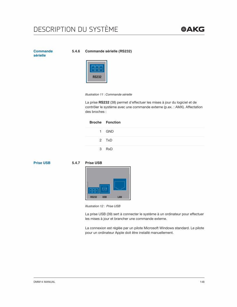
Description DU système
DMM14 MANUAL 148
5.4.6 Commande sérielle (RS232)
Illustration 11 : Commande sérielle
La prise RS232 (38) permet d'effectuer les mises à jour du logiciel et de contrôler le système avec une commande externe (p.ex. : AMX). Affectation des broches :
Broche Fonction
1 GND
2 TxD
3 RxD
5.4.7 Prise USB
Illustration 12 : Prise USB
La prise USB (39) sert à connecter le système à un ordinateur pour effectuer les mises à jour et brancher une commande externe.
La connexion est réglée par un pilote Microsoft Windows standard. Le pilote pour un ordinateur Apple doit être installé manuellement.
Commande sérielle
RS232
Prise USB
IN - EXPANSION - OUT RS232 USB LAN

Description DU système
DMM14 MANUAL 149
5.4.8 Prise LAN
Illustration 13 : Prise LAN
La prise LAN (40) permet d'effectuer les mises à jour du logiciel et de contrôler le système avec une commande externe (p.ex. : AMX).
Elle assure aussi la liaison pour la commande et le diagnostic à distance par un serveur web.
Ce dernier offre une interface d'utilisation simple et fonctionnelle géré dans un navigateur et permet l'accès à le système au travers du réseau LAN.
La commande peut se faire de la face avant du mixeur automatique et du serveurweb:Cependant,cetteconfigurationdonnelaprioritéauxsaisieseffectuées avec le serveur web.
Le mixeur automatique génère un protocole permettant de le contrôler en Wi-Fi avec un logiciel externe ou une application.
Ces applications peuvent, en fonction du type et de la complexité de la programmation, offrir plus de fonctions et, suivant le système utilisé, une interface d'utilisation graphique plus élaborée.
5.4.9 Mise en cascade de systèmes
Illustration 14 : Extension
Les prises jack 8-pôles modulaires (RJ-45) (37) assurent la réunion de 10 systèmes au maximum.
La somme audio et le signal d'état pour l'algorithme Automix sont transmis.
Prise LAN
IN - EXPANSION - OUT RS232 USB LAN
Mise en cascade
OUT R REC (OUT) IN - EXPANSION - OUT RS232 USB LAN
L
R
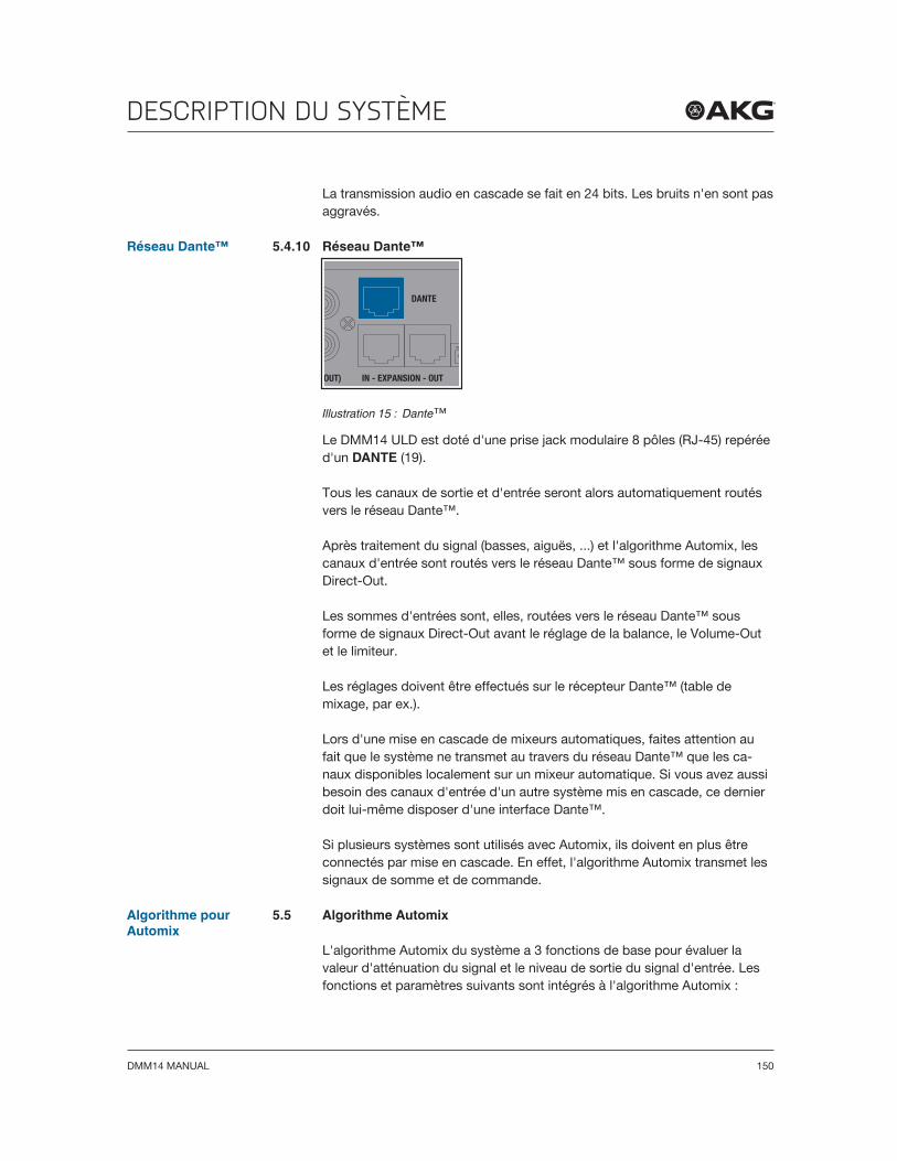
Description DU système
DMM14 MANUAL 150
La transmission audio en cascade se fait en 24 bits. Les bruits n'en sont pas aggravés.
5.4.10 Réseau Dante™
Illustration 15 : Dante™
Le DMM14 ULD est doté d'une prise jack modulaire 8 pôles (RJ-45) repérée d'un DANTE (19).
Tous les canaux de sortie et d'entrée seront alors automatiquement routés vers le réseau Dante™.
Après traitement du signal (basses, aiguës, ...) et l'algorithme Automix, les canaux d'entrée sont routés vers le réseau Dante™ sous forme de signaux Direct-Out.
Les sommes d'entrées sont, elles, routées vers le réseau Dante™ sous forme de signaux Direct-Out avant le réglage de la balance, le Volume-Out et le limiteur.
Les réglages doivent être effectués sur le récepteur Dante™ (table de mixage, par ex.).
Lors d'une mise en cascade de mixeurs automatiques, faites attention au fait que le système ne transmet au travers du réseau Dante™ que les ca-naux disponibles localement sur un mixeur automatique. Si vous avez aussi besoin des canaux d'entrée d'un autre système mis en cascade, ce dernier doit lui-même disposer d'une interface Dante™.
Si plusieurs systèmes sont utilisés avec Automix, ils doivent en plus être connectés par mise en cascade. En effet, l'algorithme Automix transmet les signaux de somme et de commande.
5.5 Algorithme Automix
L'algorithme Automix du système a 3 fonctions de base pour évaluer la valeur d'atténuation du signal et le niveau de sortie du signal d'entrée. Les fonctions et paramètres suivants sont intégrés à l'algorithme Automix :
Réseau Dante™
REC (OUT) IN - EXPANSION - OUT RS232
DANTE
Algorithme pour Automix

Description DU système
DMM14 MANUAL 151
• Adaptation de niveau dynamique• Best Mic On• Détection de bruit
5.5.1 Adaptation de niveau dynamique
Le système calcule en continu la somme de tous les canaux d'entrée. Cette valeur sert de référence.
Si le niveau du canal d'entrée est proche ou au-dessus de cette référence, le canal est déclaré dominant et légèrement atténué. Si le niveau du canal d'entrée est bien en-dessous de cette référence, il est considéré comme un bruit de fond et très atténué.
Si un canal n'est plus déclaré comme dominant, il est atténué à 1 dB/seconde, les autres, non dominants, étant relevés au même rythme pour maintenir leur somme du niveau de sortie. L'augmentation d'un canal dure en général entre 3 et 5 ms.
5.5.2 Best Mic On
La proximité de deux microphones a pour conséquence négative la géné-ration d'effets de peigne par suppression de fréquences. Pour éviter ces signaux étouffés ou creux, seul le canal du microphone ayant le niveau le plus élevé est déclaré dominant et activé.
5.5.3 Détection de bruit
Sil'amplitudedesignauxparasitespersistantsestsuffisammentfortepourqu'ils soient considérés comme dominants, alors que les changements de leurs fréquences et niveaux sont très faibles, ils sont déclarés non-domi-nants.
Le système détecte les signaux parasites de type bruits de climatisation ou de ventilateur et les exclut de ses critères de déclenchement des canaux de microphone.
5.6 Mise en cascade de systèmes
Silenombredescanauxd'entréed'unsystèmenesuffisentpas,ilestpos-sible de mettre jusqu'à 10 en cascade.
Le système est doté de deux interfaces Ethernet 100 Mbits. Elles servent à la transmission des données de commande et audio entre les systèmes mis en cascade.
Adaptation de niveau
Best Mic On
Détection de bruit
Extension pour mise en cascade

Description DU système
DMM14 MANUAL 152
Vous pouvez ainsi créer un système de mixeurs automatiques avec :
• 60 canaux d'entrée• 20 canaux de sortie • 10 sorties de casque stéréo
Les sorties de somme pour OUT, REC-OUT et HEADPHONE sont acces-sibles au système de tous les systèmes mis en cascade. Chaque système ajoute ses canaux d'entrée aux sorties de somme transmises par l'inter-face Ethernet. Chaque système peut écouter et transmettre les sorties de somme.
L'algorithme Automix transmet aussi ses données de commande par cette interface. C'est pourquoi il peut fonctionner tout au long du système.

montAge et rAccorDement
DMM14 MANUAL 153
6 Montage et raccordement
Étapes du montage et du raccordement du DMM14 U (UL, ULD) :
1. Montage
2. Mettre les systèmes en cascade (option)
3. Brancher les microphones et instruments
4. Brancher le système sur le courant
6.1 Montage
Montage du système :
Étape Description
1 Fixez le système dans le rack 19" avec 4 vis.
Faitesattentionàcequ'ilsoitsolidementfixé.
Vous pouvez aussi le poser sur un sol solide.
6.2 Mettre les systèmes en cascade (option)
Attention : Risque d'endommagement
Le raccordement est réservé au spécialistes autorisés.
Ne raccordez pas le premier système de la cascade au dernier.
Pour effectuer le câblage de chaque système au moyen de sa douille d'extension, voir la section 8.4 Mettre les systèmes en cascade, page 179
6.3 Brancher les microphones et instruments
Tenez compte aussi pour cette opération des instructions de leurs manuels d'utilisation.
Raccordement des microphones et instruments aux prises de la face arrière du DMM14 U (UL, ULD) :

montAge et rAccorDement
DMM14 MANUAL 154
Étape Description
1 Branchez les microphones et les autres sources de signaux (lerécepteurd'unmicrophonesansfil,parex.)aucanauxd'entrée IN
2 Connectez les canaux de sortie OUT 1/L, OUT 2/L et OUT 1/R , OUT 2/R àunetabledemixageouunamplificateur
3 Connectez les douilles Cinch de la sortie Enregistrement sté-réo REC (OUT) à un système d'enregistrement
6.4 Brancher le système sur le courant
Attention : Risque d'endommagement
Ne branchez le système au réseau électrique que lorsque toutes les liaisons audio sont établies.
Faites attention à ce la tension d'entrée du DMM14 U (UL, ULD) corres-ponde bien à la tension du réseau.
Branchement du système :
Étape Description
1 Connectez le câble réseau à la douille correspondante sur la face arrière du DMM14 U (UL, ULD)
2 Branchez le câble réseau à une prise de courant.
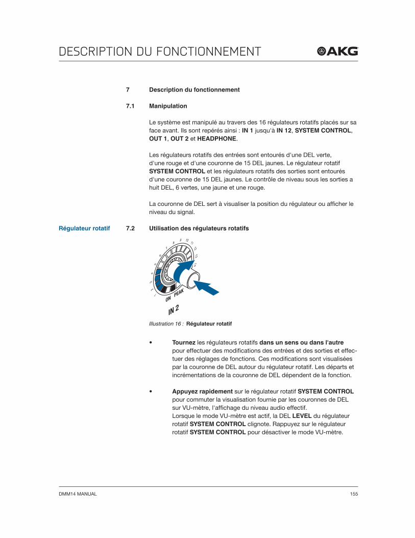
Description DU fonctionnement
DMM14 MANUAL 155
7 Description du fonctionnement
7.1 Manipulation
Le système est manipulé au travers des 16 régulateurs rotatifs placés sur sa face avant. Ils sont repérés ainsi : IN 1 jusqu'à IN 12, SYSTEM CONTROL, OUT 1, OUT 2 et HEADPHONE.
Les régulateurs rotatifs des entrées sont entourés d'une DEL verte, d'une rouge et d'une couronne de 15 DEL jaunes. Le régulateur rotatif SYSTEM CONTROL et les régulateurs rotatifs des sorties sont entourés d'une couronne de 15 DEL jaunes. Le contrôle de niveau sous les sorties a huit DEL, 6 vertes, une jaune et une rouge.
LacouronnedeDELsertàvisualiserlapositiondurégulateurouafficherleniveau du signal.
7.2 Utilisation des régulateurs rotatifs
Illustration 16 : Régulateur rotatif
• Tournez les régulateurs rotatifs dans un sens ou dans l'autre poureffectuerdesmodificationsdesentréesetdessortieseteffec-tuerdesréglagesdefonctions.Cesmodificationssontvisualiséespar la couronne de DEL autour du régulateur rotatif. Les départs et incrémentations de la couronne de DEL dépendent de la fonction.
• Appuyez rapidement sur le régulateur rotatif SYSTEM CONTROL pour commuter la visualisation fournie par les couronnes de DEL surVU-mètre,l'affichageduniveauaudioeffectif. Lorsque le mode VU-mètre est actif, la DEL LEVEL du régulateur rotatif SYSTEM CONTROL clignote. Rappuyez sur le régulateur rotatif SYSTEM CONTROL pour désactiver le mode VU-mètre.
Régulateur rotatif
8
ONPEAK
9 10 11
1213
14
15
7
6
54
32
1
IN 2

Description DU fonctionnement
DMM14 MANUAL 156
7.2.1 Affichage du niveau audio et de la fonction VU
Lorsque la fonction LEVEL est sélectionnée, les couronnes DEL des entrées etsortiesaffichentleniveauréglé.
7.3 SYSTEM CONTROL
Le régulateur rotatif SYSTEM CONTROL sert à sélectionner différentes fonctions du système.
Illustration 17 : SYSTEM CONTROL
La sélection des fonctions et le réglage des paramètres sont détaillés dans la section 8.1 SYSTEM CONTROL : Modifier les paramètres du système, page 177
7.3.1 Fonctions du SYSTEM CONTROL
Fonction disponibles du SYSTEM CONTROL :
• Level• Treble• Bass• Low Cut• Limiter• Compressor• Automixing• Priority• Pan / Balance• Delay• Routing To REC• Routing To USB• Égaliseur• Preset
SYSTEM CONTROL
PRIORITYPAN / BALANCE
DELAY
ROUTE TO REC
ROUTE TO USB
EQUALIZER LOW
EQUALIZER HIGH
PRESET
IN USB / DANTE
AUTOMIXING
COMPRESSOR
LIMITER
LOW CUT
BASS
TREBLE
LEVEL
LOCKED
SYSTEM CONTROL
Fonctions pour SYSTEM CONTROL

Description DU fonctionnement
DMM14 MANUAL 157
Appuyez sur les autres régulateurs rotatifs, seuls ou en combinaison, pour sélectionner les fonctions suivantes :
• Routing To Out 1• Routing To Out 2• Contrôle• Mute
7.3.2 Fonctions des canaux d'entrée
Lescanauxd'entréesontmodifiésparlesfonctionssuivantes:
• Level• Treble• Bass• Low Cut• Compressor• Automixing• Priority• Pan• Routing To Out 1• Routing To Out 2• Routing To Rec• Routing To USB• Contrôle• Mute
7.3.3 Fonctions des canaux de sortie
Lescanauxdesortiesontmodifiésparlesfonctionssuivantes:
• Level• Treble• Bass• Limiter• Balance• Delay• Égaliseur• Contrôle• Mute
7.3.4 Fonctions de la sortie Casque stéréo (sortie de contrôle)
Exception : le régulateur rotatif HEADPHONE. La sortie Casque stéréo est toujours sur LEVEL, indépendamment de la position du régulateur rotatif SYSTEM CONTROL.
Fonctions des canaux d'entrée
Fonctions des canaux de sortie

Description DU fonctionnement
DMM14 MANUAL 158
7.4 Fonctions DSP
Manipulation et fonctionnement des fonctions :
7.4.1 LEVEL
Illustration 18 : Fonction LEVEL
La fonction LEVEL s'applique à tous les canaux d'entrée et de sortie.
Tournez le régulateur rotatif vers la droite pour augmenter le volume. Tournez-le dans l'autre sens pour le diminuer.
Plagederéglage:-∞à+15dB(signalacoustiquedeconfirmation).Leréglagesefaitparpasdéfinisselonlebesoin.
À +15 dB, la couronne de DEL est complètement allumée et le système n'émetplusaucunsignalacoustiquedeconfirmation.
De -12 à +15 dB, le réglage se fait par pas de 1 dB par cran. Une DEL s'allumetoutesles3dB.De-∞à-12dB,leréglagesefaitparpasde3dBpar cran. Une DEL s'allume toutes les 9 dB.
Illustration 19 : Détail LEVEL
Fonctions DSP
LEVELPRIORITY
PAN / BALANCE
DELAY
ROUTE TO REC
ROUTE TO USB
EQUALIZER
PRESET
IN USB / DANTE
AUTOMIXING
COMPRESSOR
LIMITER
LOW CUT
BASS
TREBLE
LEVEL
LOCKED
SYSTEM CONTROL
8
ON PEAK
910
1112
1314
15
76
54
32
1
LEVEL Detail LEVEL
-57 dB
-48 dB
-39 dB
-30 dB
-21 dB
-12 dB
-9 dB
+15 dB
+12 dB
+9 dB
+6 dB
+3 dB
0 dB
-3 dB
-6 dB
8 910
1112
13
76
54
3
-8
dB
-7
dB
-6
dB
-5
dB -
4 dB
-3
dB -2
dB
-1 d
B 0
dB
+1 dB
+2 dB
+3 dB

Description DU fonctionnement
DMM14 MANUAL 159
Pour faciliter la visualisation de la position 0 dB, sa DEL (n° 10) est plus claire que les autres. Attention, ce niveau 0 dB n'est atteint que lorsque le troisième cran est atteint après allumage de la DEL (voir Détail LEVEL).
Appuyez sur le régulateur rotatif SYSTEM CONTROL en fonction LEVEL pourbasculerl'affichagedescanauxd'entréeetdesortied'AmplificationàContrôle de niveau.
7.4.2 TREBLE
Illustration 20 : Fonction TREBEL
La fonction TREBEL s'applique à tous les canaux d'entrée et de sortie.
Illustration 21 : Incrémentation de la couronne de DEL de la fonction TREBEL
La fonction TREBLEsertàréglerlesaiguësdusignalaudio.Lefiltreestde type Shelving High (plateau haut) de niveau 1. Le seuil de fréquence est 10 kHz.
Plage de réglage : -14 à +14 dB. En mode Linéaire, seule la DEL du milieu (0 dB) s'allume. Si vous tournez le régulateur rotatif vers la gauche, les DEL de gauche s'allument en conséquence.
Si vous tournez le régulateur rotatif vers la droite, les DEL de gauche s'allu-ment en conséquence.
TREBLEPRIORITY
PAN / BALANCE
DELAY
ROUTE TO REC
ROUTE TO USB
EQUALIZER
PRESET
IN USB / DANTE
AUTOMIXING
COMPRESSOR
LIMITER
LOW CUT
BASS
TREBLE
LEVEL
LOCKED
SYSTEM CONTROL
8
ON PEAK
910
1112
1314
15
76
54
32
1-14 dB
-12 dB
-10 dB
-8 dB
-6 dB
-4 dB
-2 dB
+14 dB
+12 dB
+10 dB
+8 dB
+6 dB
+4 dB
+2 dB
0 dB
TREBLE
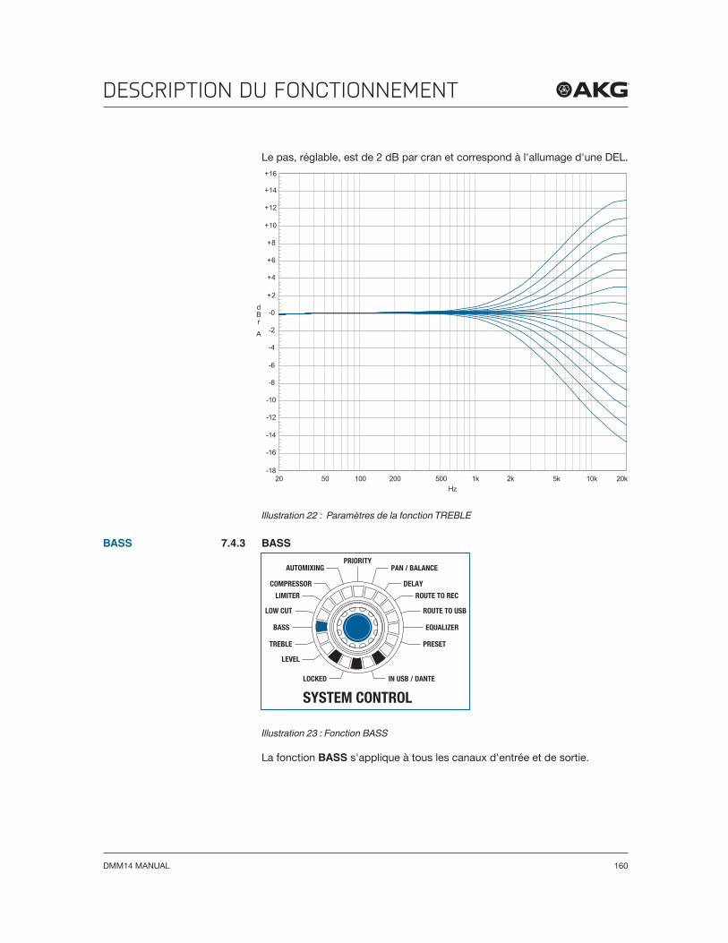
Description DU fonctionnement
DMM14 MANUAL 160
Le pas, réglable, est de 2 dB par cran et correspond à l'allumage d'une DEL.
Illustration 22 : Paramètres de la fonction TREBLE
7.4.3 BASS
Illustration 23 : Fonction BASS
La fonction BASS s'applique à tous les canaux d'entrée et de sortie.
-18
+16
-16
-14
-12
-10
-8
-6
-4
-2
-0
+2
+4
+6
+8
+10
+12
+14
dBr A
20 20k50 100 200 500 1k 2k 5k 10kHz
BASSPRIORITY
PAN / BALANCE
DELAY
ROUTE TO REC
ROUTE TO USB
EQUALIZER
PRESET
IN USB / DANTE
AUTOMIXING
COMPRESSOR
LIMITER
LOW CUT
BASS
TREBLE
LEVEL
LOCKED
SYSTEM CONTROL

Description DU fonctionnement
DMM14 MANUAL 161
La fonction BASSEsertàréglerlesbassesdusignalaudio.Lefiltreestdetype Shelving Low (plateau bas) de niveau 1. Le seuil de fréquence est 100 Hz.
Plage de réglage : -14 à +14 dB. En mode Linéaire, seule la DEL du milieu (0 dB) s'allume. Si vous tournez le régulateur rotatif vers la gauche, les DEL de gauche s'allument en conséquence.
Si vous tournez le régulateur rotatif vers la droite, les DEL de gauche s'allument en conséquence.
Illustration 24 : Incrémentation de la couronne de DEL de la fonction BASS
8
ON PEAK
910
1112
1314
15
76
54
32
1-14 dB
-12 dB
-10 dB
-8 dB
-6 dB
-4 dB
-2 dB
+14 dB
+12 dB
+10 dB
+8 dB
+6 dB
+4 dB
+2 dB
0 dB
BASS

Description DU fonctionnement
DMM14 MANUAL 162
Le pas, réglable, est de 2 dB par cran et correspond à l'allumage d'une DEL.
Illustration 25 : Paramètres de la fonction BASS
7.4.4 LOW CUT
Illustration 26 : Fonction LOW CUT
La fonction LOW CUT s'applique à tous les canaux d'entrée.
La fonction LOW CUT sert à éliminer les bruits parasites de basse fré-quence.LefiltreestdetypePasshigh(passe-haut)deniveau2.Tournezlerégulateur rotatif vers la droite pour augmenter le seuil de fréquence mini-mal, vers la gauche pour le diminuer.
-14
+14
-12
-10
-8
-6
-4
-2
+0
+2
+4
+6
+8
+10
+12
dBr A
20 20k50 100 200 500 1k 2k 5k 10kHz
LOW CUTPRIORITY
PAN / BALANCE
DELAY
ROUTE TO REC
ROUTE TO USB
EQUALIZER
PRESET
IN USB / DANTE
AUTOMIXING
COMPRESSOR
LIMITER
LOW CUT
BASS
TREBLE
LEVEL
LOCKED
SYSTEM CONTROL

Description DU fonctionnement
DMM14 MANUAL 163
Plage de réglage : 0 Hz (aucun effet) à 150 Hz (atténuation forte)
À 0 Hz, une DEL est allumée. À 150 Hz, la couronne de DEL est complète.
Illustration 27 : Incrémentation de la couronne de DEL de la fonction LOW CUT
Le pas, réglable, est de 20 Hz par cran et correspond à l'allumage d'une DEL.
Illustration 28 : Paramètres de la fonction LOW CUT
8
ON PEAK
910
1112
1314
15
76
54
32
10-20 Hz
40 Hz
60 Hz
80 Hz
100 Hz
120 Hz
140 Hz
300 Hz
280 Hz
260 Hz
240 Hz
220 Hz
200 Hz
180 Hz
160 Hz
LOW CUT
-14
+15
-13-12-11-10-9-8-7-6-5-4-3-2-1-0+1+2+3+4+5+6+7+8+9
+10+11+12+13+14
dBr A
20 20k50 100 200 500 1k 2k 5k 10kHz
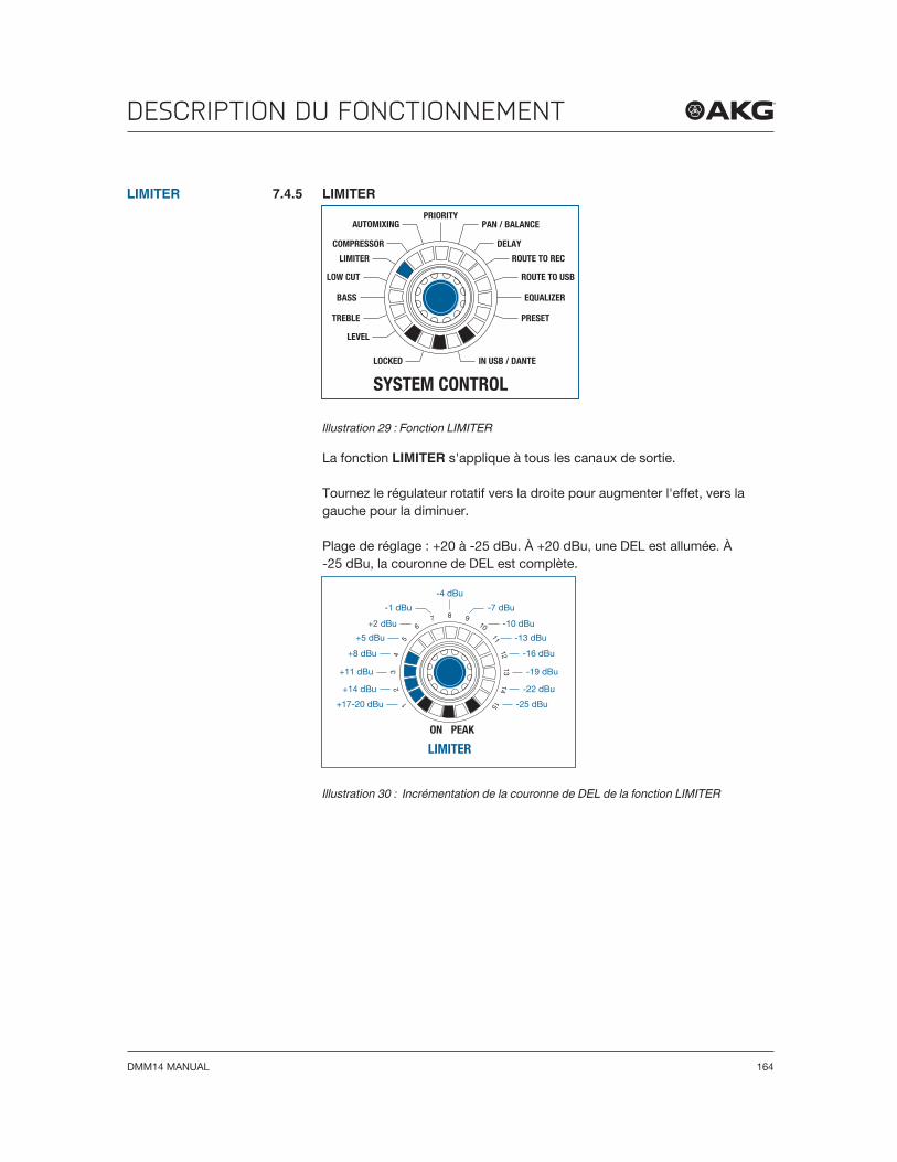
Description DU fonctionnement
DMM14 MANUAL 164
7.4.5 LIMITER
Illustration 29 : Fonction LIMITER
La fonction LIMITER s'applique à tous les canaux de sortie.
Tournez le régulateur rotatif vers la droite pour augmenter l'effet, vers la gauche pour la diminuer.
Plage de réglage : +20 à -25 dBu. À +20 dBu, une DEL est allumée. À -25 dBu, la couronne de DEL est complète.
Illustration 30 : Incrémentation de la couronne de DEL de la fonction LIMITER
LIMITERPRIORITY
PAN / BALANCE
DELAY
ROUTE TO REC
ROUTE TO USB
EQUALIZER
PRESET
IN USB / DANTE
AUTOMIXING
COMPRESSOR
LIMITER
LOW CUT
BASS
TREBLE
LEVEL
LOCKED
SYSTEM CONTROL
8
ON PEAK
910
1112
1314
15
76
54
32
1+17-20 dBu
+14 dBu
+11 dBu
+8 dBu
+5 dBu
+2 dBu
-1 dBu
-25 dBu
-22 dBu
-19 dBu
-16 dBu
-13 dBu
-10 dBu
-7 dBu
-4 dBu
LIMITER

Description DU fonctionnement
DMM14 MANUAL 165
Le pas, réglable, est de 3 dB par cran et correspond à l'allumage d'une DEL.
Illustration 31 : Paramètres de la fonction LIMITER
7.4.6 COMPRESSOR
Illustration 32 : Fonction COMPRESSOR
La fonction COMPRESSOR s'applique à tous les canaux d'entrée.
Le ratio (taux de compression) du compresseur est réglé en usine. Sa valeur est 1:2. Tournez le régulateur rotatif vers la droite pour augmenter l'effet, vers la gauche pour la diminuer.
-60
+20
-55
-50
-45
-40
-35
-30
-25
-20
-15
-10
-5
+0
+5
+10
+15
dBu
-60 +20-55 -50 -45 -40 -35 -30 -25 -20 -15 -10 -5 +0 +5 +10 +15dBu
COMPRESSORPRIORITY
PAN / BALANCE
DELAY
ROUTE TO REC
ROUTE TO USB
EQUALIZER
PRESET
IN USB / DANTE
AUTOMIXING
COMPRESSOR
LIMITER
LOW CUT
BASS
TREBLE
LEVEL
LOCKED
SYSTEM CONTROL

Description DU fonctionnement
DMM14 MANUAL 166
Plage de réglage : +20 à -25 dBu. À +20 dBu, une DEL est allumée. À -25 dBu, la couronne de DEL est complète.
Illustration 33 : Incrémentation de la couronne de DEL de la fonction COMPRESSOR
Le pas, réglable, est de 3 dB par cran et correspond à l'allumage d'une DEL.
Illustration 34 : Paramètres de la fonction COMPRESSOR
8
ON PEAK
910
1112
1314
15
76
54
32
1+17-20 dBu
+14 dBu
+11 dBu
+8 dBu
+5 dBu
+2 dBu
-1 dBu
-25 dBu
-22 dBu
-19 dBu
-16 dBu
-13 dBu
-10 dBu
-7 dBu
-4 dBu
COMPRESSOR
-40
+20
-37.5-35
-32.5-30
-27.5-25
-22.5-20
-17.5-15
-12.5-10-7.5
-5-2.5+0
+2.5+5
+7.5+10
+12.5+15
+17.5
dBr
A
-40 +20-35 -30 -25 -20 -15 -10 -5 +0 +5 +10 +15dBu
T

Description DU fonctionnement
DMM14 MANUAL 167
7.4.7 AUTOMIXING
Illustration 35 : Fonction AUTOMIXING
La fonction AUTOMIXING s'applique à tous les canaux d'entrée.
Illustration 36 : Paramètres de la fonction AUTOMIXING
Tournez vers la droite le régulateur rotatif d'un canal pour activer les fonc-tions de mixage automatique sur ce canal. (la couronne de DEL est complè-tement allumée) Tournez-le dans l'autre sens pour les désactiver. (une seule DEL est allumée)
Appuyer sur le régulateur rotatif active/désactive aussi la fonction.
AUTOMIXINGPRIORITY
PAN / BALANCE
DELAY
ROUTE TO REC
ROUTE TO USB
EQUALIZER
PRESET
IN USB / DANTE
AUTOMIXING
COMPRESSOR
LIMITER
LOW CUT
BASS
TREBLE
LEVEL
LOCKED
SYSTEM CONTROL
8
ON PEAK
910
1112
1314
15
76
54
32
1
8
ON PEAK
910
1112
1314
15
76
54
32
1
off on
AUTOMIXING

Description DU fonctionnement
DMM14 MANUAL 168
7.4.8 PRIORITY
Illustration 37 : Fonction PRIORITY
Cette fonction ne peut être activée que sur un seul canal d'entrée.
La fonction PRIORITYdéfinitlecanald'entréeayantpriorité.Lecanalprioritaire est avantagé de 6 dB dans l'évaluation de signal en combinaison avec la fonction AUTOMIXING.
Illustration 38 : Paramètres de la fonction PRIORITY
Tournez vers la droite le régulateur rotatif d'un canal pour activer la fonction sur ce canal. (la couronne de DEL est complètement allumée) Tournez-le dans l'autre sens pour la désactiver (une seule DEL est allumée).
Appuyer sur le régulateur rotatif active/désactive aussi la fonction.
L'activation de la fonction PRIORITY sur un canal d'entrée la désactive au niveau du canal précédemment prioritaire.
PRIORITYPRIORITY
PAN / BALANCE
DELAY
ROUTE TO REC
ROUTE TO USB
EQUALIZER
PRESET
IN USB / DANTE
AUTOMIXING
COMPRESSOR
LIMITER
LOW CUT
BASS
TREBLE
LEVEL
LOCKED
SYSTEM CONTROL
8
ON PEAK
910
1112
1314
15
76
54
32
1
8
ON PEAK
910
1112
1314
15
76
54
32
1
off on
PRIORITY

Description DU fonctionnement
DMM14 MANUAL 169
7.4.9 PAN / BALANCE
Illustration 39 : Fonction PAN / BALANCE
La fonction PAN / BALANCE s'applique à tous les canaux d'entrée pour en modifierl'effetPanoramaetàtouslescanauxdesortiepourenréglerlabalance.
Illustration 40 : Incrémentation de la couronne de DEL de la fonction PAN / BALANCE
La balance désigne l'attribution d'un signal de somme à une sortie.
En mode Linéaire, seule la DEL du milieu (0 dB) s'allume. Cette DEL (0 dB) sert aussi de point de départ pour la rotation du régulateur. Si vous tour-nez le régulateur rotatif vers la gauche, les DEL de gauche s'allument en conséquence. Si vous tournez le régulateur rotatif vers la droite, les DEL de gauche s'allument en conséquence.
Si le canal de sortie de gauche d'une sortie stéréo ne doit plus être trans-mis, tournez le régulateur vers la droite.
Le signal des entrées mono est également répartit sur stéréo gauche et droite. Si le signal d'entrée ne doit être affecté qu'au canal de gauche,
PAN / BALANCEPRIORITY
PAN / BALANCE
DELAY
ROUTE TO REC
ROUTE TO USB
EQUALIZER
PRESET
IN USB / DANTE
AUTOMIXING
COMPRESSOR
LIMITER
LOW CUT
BASS
TREBLE
LEVEL
LOCKED
SYSTEM CONTROL
8
ON PEAK
910
1112
1314
15
76
54
32
1R MIN
R -36 dB
R -30 dB
R -24 dB
R -18 dB
R -12 dB
R -6 dB
L MIN
L -36 dB
L -30 dB
L -24 dB
L -18 dB
L -12 dB
L -6 dB
0 dB
PAN (IN) / BALANCE (OUT)

Description DU fonctionnement
DMM14 MANUAL 170
tournez le régulateur rotatif de cette entrée vers la gauche, avec la fonction PAN activée.
Le pas, réglable, est de 6 dB par cran et correspond à l'allumage d'une DEL.
7.4.10 DELAY
Illustration 41 : Fonction DELAY
La fonction DELAY s'applique aux sorties OUT 1 et OUT 2. Cela permet de retarder la transmission du signal des sorties.
Illustration 42 : Incrémentation de la couronne de DEL de la fonction DELAY
Plage de réglage : 0 à 75 m. À 0 m, une DEL est allumée. À 75 m, la cou-ronne de DEL est complète.
Le pas, réglable, est de 1 m par cran. Une DEL s'allume toutes les 5 m.
DELAYPRIORITY
PAN / BALANCE
DELAY
ROUTE TO REC
ROUTE TO USB
EQUALIZER
PRESET
IN USB / DANTE
AUTOMIXING
COMPRESSOR
LIMITER
LOW CUT
BASS
TREBLE
LEVEL
LOCKED
SYSTEM CONTROL
8
ON PEAK
910
1112
1314
15
76
54
32
10-5 m
10 m
15 m
20 m
25 m
30 m
35 m
75 m
70 m
65 m
60 m
55 m
50 m
45 m
40 m
DELAY

Description DU fonctionnement
DMM14 MANUAL 171
7.4.11 ROUTING TO REC
Illustration 43 : Fonction ROUTING TO REC
La fonction ROUTING TO REC s'applique à tous les canaux d'entrée.
Illustration 44 : Paramètres de la fonction ROUTING TO REC
Tournez vers la droite le régulateur rotatif d'un canal pour activer la fonction sur ce canal (la couronne de DEL est complètement allumée). Tournez-le dans l'autre sens pour la désactiver (une seule DEL est allumée).
Appuyer sur le régulateur rotatif active/désactive aussi la fonction.
Activer la fonction met ce canal d'entrée sur la sortie de somme OUT 1.
ROUTING TO RECPRIORITY
PAN / BALANCE
DELAY
ROUTE TO REC
ROUTE TO USB
EQUALIZER
PRESET
IN USB / DANTE
AUTOMIXING
COMPRESSOR
LIMITER
LOW CUT
BASS
TREBLE
LEVEL
LOCKED
SYSTEM CONTROL
8
ON PEAK
910
1112
1314
15
76
54
32
1
8
ON PEAK
910
1112
1314
15
76
54
32
1
off on
ROUTING TO REC

Description DU fonctionnement
DMM14 MANUAL 172
7.4.12 ROUTING TO USB
Illustration 45 : Fonction ROUTING TO USB
La fonction ROUTING TO USB s'applique à tous les canaux d'entrée.
Illustration 46 : Paramètres de la fonction ROUTING TO USB
Tournez vers la droite le régulateur rotatif d'un canal pour activer la fonction sur ce canal (la couronne de DEL est complètement allumée). Tournez-le dans l'autre sens pour la désactiver (une seule DEL est allumée).
Appuyer sur le régulateur rotatif active/désactive aussi la fonction.
Activer la fonction met ce canal d'entrée sur la sortie de somme USB OUT.
ROUTING TO USBPRIORITY
PAN / BALANCE
DELAY
ROUTE TO REC
ROUTE TO USB
EQUALIZER
PRESET
IN USB / DANTE
AUTOMIXING
COMPRESSOR
LIMITER
LOW CUT
BASS
TREBLE
LEVEL
LOCKED
SYSTEM CONTROL
8
ON PEAK
910
1112
1314
15
76
54
32
1
8
ON PEAK
910
1112
1314
15
76
54
32
1
off on
ROUTING TO USB

Description DU fonctionnement
DMM14 MANUAL 173
7.4.13 EQUALIZER
Illustration 47 : Fonction EQUALIZER
La fonction EQUALIZER s'applique aux sorties OUT 1 et OUT 2. Le réglage est le même pour les deux canaux.
Le système peut effectuer une compensation de pièce sur 12 bandes.
Appuyez sur le régulateur rotatif OUT 1 pour activer le réglage OUT 1 et sur le régulateur rotatif OUT 2 pour activer le réglage OUT 2.
Les 12 régulateurs rotatifs des canaux d'entrée servent à augmenter/diminuer les bandes. Le réglage apporte une variation de +/-14 dB. En mode Linéaire, seule la DEL du milieu s'allume. Tourner le régulateur vers la gauche fait s'allumer les DEL de gauche en conséquence. Tourner le régulateur vers la droite fait s'allumer les DEL de droite en conséquence.
Illustration 48 : Incrémentation de la couronne de DEL de la fonction EQUALIZER
Le réglage se fait par pas de 2 dB.
EQUALIZERPRIORITY
PAN / BALANCE
DELAY
ROUTE TO REC
ROUTE TO USB
EQUALIZER
PRESET
IN USB / DANTE
AUTOMIXING
COMPRESSOR
LIMITER
LOW CUT
BASS
TREBLE
LEVEL
LOCKED
SYSTEM CONTROL
8
ON PEAK
910
1112
1314
15
76
54
32
1-57 dB
-48 dB
-39 dB
-30 dB
-21 dB
-12 dB
-9 dB
+15 dB
+12 dB
+9 dB
+6 dB
+3 dB
0 dB
-3 dB
-6 dB
EQUALIZER

Description DU fonctionnement
DMM14 MANUAL 174
Les fréquences moyennes des bandes sont ordonnées en écart de ½-oc-tave.
Illustration 49 : Paramètres de la fonction EQUALIZER
7.4.14 PRESET
Illustration 50 : Fonction PRESET
Vouspouvezdéfinir,enregistreretchargerdanslesystèmejusqu'à12pro-filsdesystèmedifférents(LEVEL, TREBLE, BASS, … , EQUALIZER).
-16
+16
-15-14-13-12-11-10-9-8-7-6-5-4-3-2-1+0+1+2+3+4+5+6+7+8+9
+10+11+12+13+14+15
dBr A
20 20k50 100 200 500 1k 2k 5k 10kHz
PRESETPRIORITY
PAN / BALANCE
DELAY
ROUTE TO REC
ROUTE TO USB
EQUALIZER
PRESET
IN USB / DANTE
AUTOMIXING
COMPRESSOR
LIMITER
LOW CUT
BASS
TREBLE
LEVEL
LOCKED
SYSTEM CONTROL

Description DU fonctionnement
DMM14 MANUAL 175
Sélectionnez pour cela la fonction PRESET du régulateur SYSTEM CONTROL.Ces12profilss'ajoutentàunprofilditdetravail.Lesmodificationsderéglagesnes'appliquenttoutd'abordqu'àceprofil.Pourlespérenniser,enregistrezceprofildetravaildansundesprofilsexistants.Sivouschargezunprofil,ilestactivéetécraselesréglagesduprofildetravail.Auredémarrage,lesystèmeestchargédudernierprofildetravailactivée, avec ses réglages les plus récents.
Les12régulateursrotatifsd'entréepermettentd'afficherlesprofilsetdemodifierleurparamètres.
Illustration 51 : Configurations de profils
Si seule la DEL 1 d'une couronne de DEL est allumée, l'espace de stockage n'estpasconfiguré(voirIllustration 51, générateur d'incréments IN 3/15).
Si toutes les DEL de la couronne et la DEL rouge PEAKsont allumées, l'es-pace est occupé et sélectionnée (voir Illustration 51, générateurs d'incré-ments IN 1 / 13).
Si seule la DEL 1 de la couronne et la DEL rouge PEAKsont allumées, l'espace est occupé et non sélectionnée (voir Illustration 51, générateurs d'incréments IN 2 / 14).
Voir aussi la section 8.7 Utiliser les profils, page 180.
8
ON PEAK
910
1112
1314
15
76
54
32
1
IN 1 / USB LEQ 250 Hz
8
ON PEAK
910
1112
1314
15
76
54
32
1
IN 3 / DANTE 1EQ 500 Hz
8
ON PEAK
910
1112
1314
15
76
54
32
1
IN 2 / USB REQ 350 Hz

Description DU fonctionnement
DMM14 MANUAL 176
7.5 LOCKED
Illustration 52 : Fonction LOCKED
La fonction LOCKED verrouille les régulateurs rotatifs ou le système pour éviter toute manipulation inappropriée.
Voir aussi la section 8.11 Activer/Désactiver LOCKED, page 184.
LOCKEDPRIORITY
PAN / BALANCE
DELAY
ROUTE TO REC
ROUTE TO USB
EQUALIZER
PRESET
IN USB / DANTE
AUTOMIXING
COMPRESSOR
LIMITER
LOW CUT
BASS
TREBLE
LEVEL
LOCKED
SYSTEM CONTROL

mAnipULAtion DU système
DMM14 MANUAL 177
8 Manipulation du système
8.1 SYSTEM CONTROL : Modifier les paramètres du système
Modificationdesparamètresdusystème:
Étape Description
1 Sélectionnez la fonction en tournant le régulateur rotatif SYSTEM CONTROL jusqu'à ce que la DEL de la fonction choisie s'allume
2 Réglez la fonction au niveau des canaux d'entrée avec les régulateurs rotatifs IN 1 à IN 12.
3 Réglez la fonction au niveau des canaux d'entrée avec les régulateurs rotatifs OUT 1 à OUT 2.
La sortie Enregistrement stéréo ne peut être réglée.
5minutesaprèsladernièremodification,lerégulateurrotatifSYSTEM CONTROL revient automatiquement sur LEVEL. 1 minute après la dernièremodification,lavaleurrégléeestautomatiquementenregistrée.
8.2 Configurer les microphones du DMM14 U (UL, ULD)
Configurationdesmicrophonesetinstrumentsbranchés:
SYSTEM CONTROL

mAnipULAtion DU système
DMM14 MANUAL 178
Étape Description
1 Réglez l'interrupteur coulissant et le régulateur de gain sur la face arrière du DMM14 U (UL, ULD)
• Plage de réglage : 0 à +57 dB.
• L'augmentationdel'amplificationdusignald'entréeestadaptée aux microphones avec un niveau de sortie faible.
• Pour les microphone à fort niveau de sortie, choisissez une amplificationfaible.
• Si vous utilisez des microphones à condensateur, détermi-nez les systèmes ou la tension d'alimentation dont ils ont besoin.
• Si vos microphones à condensateur sont compatibles avec l'alimentation fantôme, activez celle-ci. Mettez pour cela l'interrupteur coulissant PHANT. PWR sur ON.
2 Allumez le système avec l'interrupteur
Attention : Risque d'endommagement
Pour ne pas endommager les récepteurs si vous utilisez des microphones sansfil,désactivezl'alimentationfantômedechaqueentréeàlaquelleunrécepteur est branché.
8.3 Écouter les entrées et sorties
Écoute des entrées et sorties :
Étape Description
1 Appuyez sans relâcher le régulateur rotatif HEADPHONE et appuyez en même temps un ou plusieurs autres régulateurs de source d'écoute
• Les canaux de casque gauche et droit seront simultané-ment mis sur mono.
2 Appuyez sur un autre régulateur pour changer de source.
• La source précédemment sélectionnée est désactivée
Au niveau des entrées, vous pouvez écouter plusieurs sources.

mAnipULAtion DU système
DMM14 MANUAL 179
La sortie ne peut être écoutée que seule, mais alors en stéréo.
La sortie REC (OUT)ne peut être écoutée.
8.4 Mettre les systèmes en cascade
Attention : Risque d'endommagement
Le raccordement est réservé au spécialistes autorisés.
Ne raccordez pas le premier système de la cascade au dernier.
Câblage des systèmes avec les douilles d'extension :
Étape Description
1 Réunissez comme suit les systèmes avec le câble de connexion CAT5+ :
OUT R REC (OUT) IN - EXPANSION - OUT RS232 USB LAN
L
R
OUT R REC (OUT) IN - EXPANSION - OUT RS232 USB LAN
L
R
OUT R REC (OUT) IN - EXPANSION - OUT RS232 USB LAN
L
R
Pour effectuer une mise en cascade, nous vous conseillons de n'utiliser que les câbles accessoires AKG.
Les fonctions et le comportement des systèmes sont identiques pour l'utili-sateur. Chaque système garde toutes ses fonctions s'il est mis en cascade.

mAnipULAtion DU système
DMM14 MANUAL 180
8.5 Transmission par USB et Dante™
8.5.1 Modifier la transmission
Transmission des signaux d'entrée par USB et Dante™ :
Étape Description
1 Appuyez deux fois rapidement sur le régulateur rotatif SYSTEM CONTROL (clic double)
• Les 12 régulateurs d'entrée sont commutés sur manipula-tion.
• Les DEL IN USB ou IN USB/DANTE s'allument en continu.
• Lesmodificationseffectuéessurlesrégulateursd'entréene s'appliquent plus aux 12 entrées analogiques, mais aux entrées numériques 13 à 24.
• La manipulation est alors la même que pour les entrées analogiques.
Les entrées du port USB occupent les canaux 13 (IN1 / USB L) et 14 (IN 2 / USB R). Pour les systèmes sans interface Dante™, les entrées numé-riques 15 à 24 son sans fonction et inactives.
Pour les systèmes avec interface Dante™, les canaux d'entrée à partir du canal 15 sont attribués de la façon suivante :
• IN3 / DANTE 1• IN4 / DANTE 2• etc.
Les fonctionnalités de traitement des signaux des entrées numériques et analogiques sont identiques.
8.6 Activer l'alimentation fantôme
Ne ponter le potentiel 0 V qu'avec la mise à la terre (réglages d'usine) ou vers la mise à la terre centrale, sinon l'alimentation fantôme n'a pas de point de référence et ne fonctionne pas.
8.7 Utiliser les profils
LesprofilsduDMM14U(UL,ULD)fonctionnentdefaçonsimilaireàceuxd'un autoradio.
Transmission par USB et Dante™
PRESET

mAnipULAtion DU système
DMM14 MANUAL 181
8.7.1 Sélectionner un profil
Sélectiond'unprofil:
Étape Description
1 Sélectionnez, sur SYSTEM CONTROL, la fonction PRESET
2 Appuyez un court instant sur le régulateur rotatif du canal d'entrée ou de sortie correspondant.
• Un signal acoustique (bip) retentit.
3 Relâchez le régulateur rotatif après le bip.
• Leprofildusystèmesechargeenprofildetravail.
• Lesréglagesduprofilsélectionnésontactifsimmédiate-ment (toutes les DEL s'allument).
8.7.2 Programmer un profil
Programmationd'unprofil:
Étape Description
1 Sélectionnez, sur SYSTEM CONTROL, la fonction PRESET
2 Appuyez entre 3 et 5 secondes sur le régulateur rotatif d'en-trée (1 à 12).
• Un signal acoustique (bip) retentit.
3 Relâchez le régulateur rotatif après le bip.
• Lesréglagesduprofildetravailsontenregistrésdansleprofildusystèmesélectionné(touteslesDELs'allument).
8.7.3 Supprimer un profil
Suppressiond'unprofil:

mAnipULAtion DU système
DMM14 MANUAL 182
Étape Description
1 Sélectionnez, sur SYSTEM CONTROL, la fonction PRESET
2 Appuyez entre 8 et 10 secondes sur le régulateur rotatif du canal d'entrée ou de sortie correspondant.
• Un signal acoustique (bip) retentit.
3 Relâchez le régulateur rotatif après le bip.
• Leprofildusystèmeestsuppriméetnepeutplusêtresélectionné (espace de stockage vide, DEL 1 s'allume).
8.8 Utiliser MUTE
8.8.1 Activer MUTE
Vous pouvez commuter sur MUTE les canaux d'entrée et de sortie. Procédure :
Étape Description
1 Dans la fonction LEVEL, appuyez un court instant sur le régu-lateur rotatif du canal d'entrée ou de sortie correspondant.
• Le canal est alors muet.
• Toutes les DEL allumées auparavant se mettent à cligno-ter.
• Le volume d'avant MUTE est enregistré.
La fonction MUTE ne peut être utilisée pour le régulateur rotatif HEADPHONE.
8.8.2 Désactiver MUTE
Désactivation de la fonction MUTE :
MUTE

mAnipULAtion DU système
DMM14 MANUAL 183
Étape Description
1 Appuyez un court instant sur le régulateur rotatif du canal d'entrée ou de sortie correspondant.
• La fonction MUTE du canal correspondant est désacti-vée.
• Le volume enregistré avant MUTE est utilisé.
8.9 Activer ROUTING TO OUT
8.9.1 Pour un canal d'entrée
Tous les canaux d'entrée peuvent être routés sur la sortie OUT. Procédure :
Étape Description
1 Appuyez sans relâcher sur le régulateur rotatif OUT
Appuyez simultanément sur le régulateur rotatif du canal d'entrée choisi
• Le canal d'entrée est routé sur la sortie de somme OUT.
8.9.2 Pour plusieurs canaux d'entrée
Routage de plusieurs canaux d'entrée sur OUT :
Étape Description
1 Appuyez sans relâcher sur le régulateur rotatif OUT
Appuyez sur le régulateur rotatif des canaux d'entrée choisis.
• Les canaux d'entrée sont routés sur la sortie de somme OUT.
8.10 Désactiver ROUTING TO OUT
Désactivation de la fonction ROUTING TO OUT :
ROUTING TO OUT

mAnipULAtion DU système
DMM14 MANUAL 184
Étape Description
1 Appuyez sur le régulateur rotatif du canal d'entrée choisi.
• ROUTING TO OUT est désactivé pour le canal d'entrée correspondant.
8.11 Activer/Désactiver LOCKED
La fonction LOCKED sert à verrouiller les éléments suivants :
• Régulateur rotatif SYSTEM CONTROL• Le système• Certains canaux
8.11.1 Verrouiller le régulateur rotatif SYSTEM CONTROL
Verrouillage du régulateur rotatif SYSTEM CONTROL :
Étape Description
1 Appuyez plus de 3 secondes sur le régulateur rotatif SYSTEM CONTROL
• La DEL LOCKED s'allume.
• Tourner le régulateur rotatif n'a plus aucun effet.
• Tous les autres régulateurs rotatifs sont sur LEVEL et disponibles.
8.11.2 Déverrouiller le régulateur rotatif SYSTEM CONTROL
Déverrouillage du régulateur rotatif SYSTEM CONTROL :
Étape Description
1 Appuyez plus de 3 secondes sur le régulateur rotatif SYSTEM CONTROL
• Le verrouillage du régulateur rotatif est annulé.
• La DEL LOCKED est éteinte.
• Le régulateur rotatif est en position initiale LEVEL.
LOCKED
Verrouiller un régulateur rotatif
Déverrouillez un régulateur rotatif
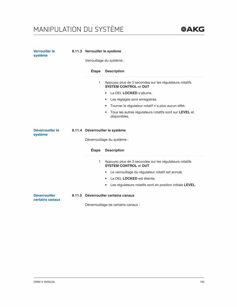
mAnipULAtion DU système
DMM14 MANUAL 185
8.11.3 Verrouiller le système
Verrouillage du système :
Étape Description
1 Appuyez plus de 3 secondes sur les régulateurs rotatifs SYSTEM CONTROL et OUT
• La DEL LOCKED s'allume.
• Les réglages sont enregistrés.
• Tourner le régulateur rotatif n'a plus aucun effet.
• Tous les autres régulateurs rotatifs sont sur LEVEL et disponibles.
8.11.4 Déverrouiller le système
Déverrouillage du système :
Étape Description
1 Appuyez plus de 3 secondes sur les régulateurs rotatifs SYSTEM CONTROL et OUT
• Le verrouillage du régulateur rotatif est annulé.
• La DEL LOCKED est éteinte.
• Les régulateurs rotatifs sont en position initiale LEVEL.
8.11.5 Déverrouiller certains canaux
Déverrouillage de certains canaux :
Verrouiller le système
Déverrouiller le système
Déverrouiller certains canaux
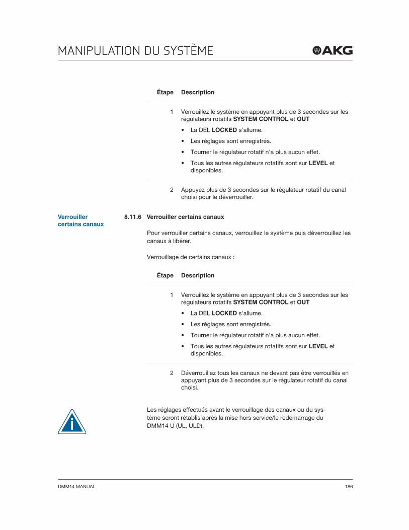
mAnipULAtion DU système
DMM14 MANUAL 186
Étape Description
1 Verrouillez le système en appuyant plus de 3 secondes sur les régulateurs rotatifs SYSTEM CONTROL et OUT
• La DEL LOCKED s'allume.
• Les réglages sont enregistrés.
• Tourner le régulateur rotatif n'a plus aucun effet.
• Tous les autres régulateurs rotatifs sont sur LEVEL et disponibles.
2 Appuyez plus de 3 secondes sur le régulateur rotatif du canal choisi pour le déverrouiller.
8.11.6 Verrouiller certains canaux
Pour verrouiller certains canaux, verrouillez le système puis déverrouillez les canaux à libérer.
Verrouillage de certains canaux :
Étape Description
1 Verrouillez le système en appuyant plus de 3 secondes sur les régulateurs rotatifs SYSTEM CONTROL et OUT
• La DEL LOCKED s'allume.
• Les réglages sont enregistrés.
• Tourner le régulateur rotatif n'a plus aucun effet.
• Tous les autres régulateurs rotatifs sont sur LEVEL et disponibles.
2 Déverrouillez tous les canaux ne devant pas être verrouillés en appuyant plus de 3 secondes sur le régulateur rotatif du canal choisi.
Les réglages effectués avant le verrouillage des canaux ou du sys-tème seront rétablis après la mise hors service/le redémarrage du DMM14 U (UL, ULD).
Verrouiller certains canaux

mAnipULAtion DU système
DMM14 MANUAL 187
8.12 Copier des données de configuration
La fonction de copie sert à dupliquer vers une ou plusieurs autres en-trées les réglages (LEVEL, TREBLE, BASS, LOWCUT, LIMITER et COMPRESSOR) d'une entrée.
8.12.1 Copier des valeurs
Copie d'une valeur d'un canal vers un ou plusieurs autres canaux.
Étape Description
1 Choisissez la fonction sur le régulateur rotatif SYSTEM CONTROL
2 Appuyez sur le régulateur rotatif source de la valeur puis im-médiatement sur celui vers lequel cette valeur doit être copiée
3 Maintenez les deux régulateurs rotatifs appuyés env. 4 se-condes jusqu'à ce que vous entendiez un bip et voyiez les couronnes de DEL clignoter une fois.
• La valeur a été copiée.
La copie sera appliquée à tous les régulateurs rotatifs placés entre ceux sélectionnés.
8.12.2 Copier toutes les valeurs
Copie de toutes les valeurs d'un canal vers un ou plusieurs autres canaux.
Étape Description
1 Appuyez sur le régulateur rotatif source des valeurs puis im-médiatement sur celui vers lequel elles doivent être copiées
2 Maintenez les deux régulateurs rotatifs appuyés env. 8 se-condes jusqu'à ce que vous entendiez un double bip et voyiez les couronnes de DEL clignoter une fois.
• Les valeurs ont été copiées.
La copie va dans les deux sens (IN 1 à IN 12 et IN 12 à IN 1).
Copier des configurations

mAnipULAtion DU système
DMM14 MANUAL 188
Les illustrations suivantes vous aident à visualiser la copie.
Illustration 53 : Sélectionner le régulateur rotatif (source)
Illustration 54 : Définir les valeurs à copier (cible)
Illustration 55 : Maintenir les deux régulateurs appuyés
Illustration 56 : Copie terminée
8
ON PEAK
910
1112
1314
15
76
54
32
1
IN 12
8
ON PEAK
910
1112
1314
15
76
54
32
1
IN 11
8
ON PEAK
910
1112
1314
15
76
54
32
1
IN 10
8
ON PEAK
910
1112
1314
15
76
54
32
1
IN 3 ...
8
ON PEAK
910
1112
1314
15
76
54
32
1
IN 2
8
ON PEAK
910
1112
1314
15
76
54
32
1
IN 1
8
ON PEAK
910
1112
1314
15
76
54
32
1
IN 12
8
ON PEAK
910
1112
1314
15
76
54
32
1
IN 11
8
ON PEAK
910
1112
1314
15
76
54
32
1
IN 10
8
ON PEAK
910
1112
1314
15
76
54
32
1
IN 3 ...
8
ON PEAK
910
1112
1314
15
76
54
32
1
IN 2
8
ON PEAK
910
1112
1314
15
76
54
32
1
IN 1
8
ON PEAK
910
1112
1314
15
76
54
32
1
IN 12
8
ON PEAK
910
1112
1314
15
76
54
32
1
IN 11
8
ON PEAK
910
1112
1314
15
76
54
32
1
IN 10
8
ON PEAK
910
1112
1314
15
76
54
32
1
IN 3 ...
8
ON PEAK
910
1112
1314
15
76
54
32
1
IN 2
8
ON PEAK
910
1112
1314
15
76
54
32
1
IN 1
clignoter clignoter clignoter clignoter
8
ON PEAK
910
1112
1314
15
76
54
32
1
IN 12
8
ON PEAK
910
1112
1314
15
76
54
32
1
IN 11
8
ON PEAK
910
1112
1314
15
76
54
32
1
IN 10
8
ON PEAK
910
1112
1314
15
76
54
32
1
IN 3 ...
8
ON PEAK
910
1112
1314
15
76
54
32
1
IN 2
8
ON PEAK
910
1112
1314
15
76
54
32
1
IN 1

mAnipULAtion DU système
DMM14 MANUAL 189
8.13 Réinitialiser à la configuration d'usine
Illustration 57 : Réinitialiser à la configuration d'usine
Réinitialisationàlaconfigurationd'usinedusystème
Étape Description
1 Allumez le système
Attendez que sa séquence de démarrage soit terminée (env. 15 secondes)
2 Appuyez sur le régulateur rotatif SYSTEM CONTROL sans le relâcher jusqu'à l'étape 5
3 Éteignez le système avec l'interrupteur
4 Rallumez-le après un court instant
Attendez que sa séquence de démarrage soit terminée (env. 15 secondes)
5 Relâchez le régulateur rotatif SYSTEM CONTROL
• Lesystèmeaétéréinitialiséàsaconfigurationd'usine,quevouspouvezdenouveaumodifier.
Laréinitialisationàlaconfigurationd'usineécrasetouslesréglagesenregis-trés.
Réinitialisation à la configuration d'usine
+
PRIORITYPAN / BALANCE
DELAY
ROUTE TO REC
ROUTE TO USB
EQUALIZER
PRESET
IN USB / DANTE
AUTOMIXING
COMPRESSOR
LIMITER
LOW CUT
BASS
TREBLE
LEVEL
LOCKED
SYSTEM CONTROL

résoLUtion Des erreUrs
DMM14 MANUAL 190
9 Résolution des erreurs
ATTENTION : Risque de choc électrique
Le système contient des contacts et câbles électriques non protégés. Les toucher peut entraîner un choc électrique responsable de blessures graves.
• Le système ne peut être ouvert pour réparation que par des profes-sionnels autorisés.
ERREUR ORIGINE POSSIBLE SOLUTION
Pas de son Le câble de raccordement au réseau n'est pas branché sur le système
Branchez le câble de raccordement au réseau sur le système
Interrupteur réseau éteint Allumez l'interrupteur réseau
Le système n'est pas branché sur l'amplificateur
Raccordez le canal de sortie à l'ampli-ficateur
Le microphone ou l'instrument n'est pas raccordé au système.
Raccordez le microphone ou l'instru-ment au système
Les régulateurs rotatifs de volume sont au minimum
Augmentez lentement le volume
Les régulateurs rotatifs de volume sont mis sur MUTE
Annulez le MUTE en appuyant sur le régulateur rotatif
Le préampli n'est pas réglé correcte-ment.
Rétablissezlabonneconfigurationdurégulateur de gain sur la face arrière du système
L'alimentation fantôme est désactivée Activez l'alimentation fantôme du mi-crophone à condensateur
Le potentiomètre externe est au mini-mum
Augmentez le potentiomètre
Pas de son en alimen-tation sinusoïdale
L'algorithme Automix supprime le signal continu
Retirez le canal de l'algorithme Automix

résoLUtion Des erreUrs
DMM14 MANUAL 191
ERREUR ORIGINE POSSIBLE SOLUTION
Distorsion des si-gnaux
Le préampli n'est pas réglé correcte-ment.
Rétablissezlabonneconfigurationdurégulateur de gain sur la face arrière du système
Les régulateurs rotatifs de volume sont trop forts
Diminuez le volume
Le niveau du signal d'entrée est trop haut
Atténuez le signal d'entrée
Si une erreur persiste malgré les instructions précédentes, contactez AKG Acoustics GmbH ou votre revendeur AKG.
9 Résolution des erreurs
ATTENTION : Risque de choc électrique
Le système contient des contacts et câbles électriques non protégés. Les toucher peut entraîner un choc électrique responsable de blessures graves.
• Le système ne peut être ouvert pour réparation que par des profes-sionnels autorisés.
ERREUR ORIGINE POSSIBLE SOLUTION
Pas de son Le câble de raccordement au réseau n'est pas branché sur le système
Branchez le câble de raccordement au réseau sur le système
Interrupteur réseau éteint Allumez l'interrupteur réseau
Le système n'est pas branché sur l'amplificateur
Raccordez le canal de sortie à l'ampli-ficateur
Le microphone ou l'instrument n'est pas raccordé au système.
Raccordez le microphone ou l'instru-ment au système
Les régulateurs rotatifs de volume sont au minimum
Augmentez lentement le volume
Les régulateurs rotatifs de volume sont mis sur MUTE
Annulez le MUTE en appuyant sur le régulateur rotatif
Le préampli n'est pas réglé correcte-ment.
Rétablissezlabonneconfigurationdurégulateur de gain sur la face arrière du système
L'alimentation fantôme est désactivée Activez l'alimentation fantôme du mi-crophone à condensateur
Le potentiomètre externe est au mini-mum
Augmentez le potentiomètre
Pas de son en alimen-tation sinusoïdale
L'algorithme Automix supprime le signal continu
Retirez le canal de l'algorithme Automix

DMM14 MANUAL 192

DMM14 MANUAL 193

INHALT
DMM14 MANUAL 194
1 GENERALIDADES 1971.1 Objeto del manual 197
1.2 Conservación del manual 197
1.3 Responsabilidad 197
1.4 Garantía 197
2 VOLUMEN DE SUMINISTRO 1982.1 Contenido del embalaje 198
2.2 Accesorios opcionales 198
3 SEGURIDAD Y MEDIO AMBIENTE 1993.1 Seguridad 199
3.2 Conocimientos requeridos y
áreas de responsabilidad para los
operarios/usuarios 200
3.3 Significadodelossímbolos
empleados 200
3.4 Uso previsto 201
3.5 Uso indebido 201
3.6 Medio ambiente 201
4 DECLARACIÓN DE CONFORMIDAD 201
5 DESCRIPCIÓN DEL EQUIPO 2025.1 Descripción breve 202
5.2 Datos técnicos 202
5.3 Parte frontal: Descripción de los
controles 204
5.3.1 Controles giratorios de los canales
de entrada 204
5.3.2 Modo de
control / SYSTEM CONTROL 205
5.3.3 Controles giratorios de las salidas
estéreo 205
5.3.4 Indicador de modulación para
salidas estéreo 205
5.3.5 Salida estéreo para auriculares 205
5.4 Parte posterior: Descripción de los
controles 206
5.4.1 Canales de entrada 207
5.4.2 Controles de ganancia 208
5.4.3 Alimentación fantasma 208
5.4.4 Canal de salida compuesto estéreo 210
5.4.5 Salida de grabación estéreo 210
5.4.6 Control serie mediante RS232 211
5.4.7 Conexión USB 211
5.4.8 Conexión LAN 212
5.4.9 Conexión de equipos en cascada 212
5.4.10 Red Dante™ 213
5.5 Algoritmo de mezcla automática 214
5.5.1 Ajuste dinámico de nivel 214
5.5.2 Best Mic On 214
5.5.3 Noise Detect 214
5.6 Conexión de equipos en cascada 215
6 MONTAJE Y CONEXIÓN 2166.1 Montaje 216
6.2 Conexión de equipos en cascada
(opcional) 216
6.3 Conexión de micrófonos y
dispositivos adicionales 216
6.4 Conexión del equipo a la red 217
7 DESCRIPCIÓN DE FUNCIONES 2187.1 Sistema de manejo 218
7.2 Manejo de los controles giratorios 218
7.2.1 Visualización del nivel de audio /
función VU 219
7.3 SYSTEM CONTROL 219
INHALT
DMM14 MANUAL 195
7.3.1 Funciones de SYSTEM CONTROL 219
7.3.2 Funciones de los canales de entrada 220
7.3.3 Funciones de los canales de salida 220
7.3.4 Funciones de la salida estéreo
para auriculares (salida para
monitorización) 221
7.4 Funciones DSP 221
7.4.1 LEVEL 221
7.4.2 TREBLE 222
7.4.3 BASS 224
7.4.4 LOW CUT 226
7.4.5 LIMITER 228
7.4.6 COMPRESSOR 230
7.4.7 AUTOMIXING 231
7.4.8 PRIORITY 232
7.4.9 PAN / BALANCE 233
7.4.10 DELAY 235
7.4.11 ROUTING TO REC 236
7.4.12 ROUTING TO USB 237
7.4.13 EQUALIZER 238
7.4.14 PRESET 239
7.5 LOCKED 241
8 MANEJO DEL EQUIPO 2428.1 SYSTEMCONTROL:Modificación
de parámetros del equipo 242
8.2 Configuracióndemicrófonosenel
DMM14 U (UL, ULD) 242
8.3 Audición de entradas y salidas 243
8.4 Conexión de equipos en cascada 244
8.5 Reproducción mediante USB y
Dante™ 245
8.5.1 Procesamiento de la reproducción 245
8.6 Activación de la alimentación
fantasma 246
8.7 Empleo de programas 246
8.7.1 Selección de programas 246
8.7.2 Programación de programas 247
8.7.3 Eliminación de programas 247
8.8 Empleo de MUTE 248
8.8.1 Activación de MUTE 248
8.8.2 Desactivación de MUTE 248
8.9 Activación de ROUTING TO OUT 249
8.9.1 Para un canal de entrada 249
8.9.2 Para varios canales de entrada 249
8.10 Desactivación de ROUTING TO OUT 249
8.11 Activación / desactivación de
LOCKED 250
8.11.1 Bloqueo del control giratorio
SYSTEM CONTROL 250
8.11.2 Desbloqueo del control giratorio
SYSTEM CONTROL 250
8.11.3 Bloqueo del equipo completo 251
8.11.4 Desbloqueo del equipo completo 251
8.11.5 Desbloqueo de canales individuales 252
8.11.6 Bloqueo de canales individuales 252
8.12 Copiadedatosdeconfiguración 253
8.12.1 Copia de valores individuales 253
8.12.2 Copia de todos los valores 253
8.13 Recuperación de los ajustes de
fábrica 255
9 SUBSANACIÓN DE ERRORES 257

IMPRESSUM
DMM14 MANUAL 196
Editor AKG Acoustics GmbH
Laxenburger Straße 254
1230 Viena
Austria
Tfno.: +43 (0)1 86654-0
Fax: +43 (0)1 86654-8800
AKG ACOUSTICS, U.S.
8500 Balboa Blvd. Dock 15
Northridge, CA 91329
U.S.A.
Tfno.: +1 818 920-3224
Copyright © 2015 AKG Acoustics GmbH
Todos los derechos reservados.
La información contenida en este manual de instrucciones, así como los dibujos y fotografías adjuntos, son propiedad intelectual de AKG Acoustics GmbH.
En salvaguarda de los derechos de propiedad intelectual no deberá reproducirse ni comu-nicarse,totaloparcialmente,estadocumentación,conningúnfin,deningúnmodoyporningún medio, ya sea electrónico o mecánico, mediante fotocopia, grabación o sistemas de registro y reproducción de información, sin el permiso expreso por escrito de la empresa AKG Acoustics GmbH. Se prohíbe toda transmisión a terceros. Si así lo solicitamos, deberá devolvernos este manual.
FCC Statement Note: This equipment has been tested and found to comply with the limits for a Class B digital device, pursuant to part 15 of the FCC Rules. These limits are designed to provide reasonable protection against harmful interference in a residential installation. This equipment generates, uses and can radiate radio frequency energy and, if not installed and used in accordance with the instructions, may cause harmful interference to radio communications. However, there is no guarantee that interference will not occur in a particular installation. If this equipment does cause harmful interference to radio or television reception, which can be determined by turning the equipment off and on, the user is encouraged to try to correct the interference by one or more of the following measures:
• Reorient or relocate the receiving antenna.
• Increase the separation between the equipment and receiver.
• Connect the equipment into an outlet on a circuit different from that to which the receiver is connected.
• Consult the dealer or an experienced radio/TV technician for help.
This device complies with Part 15 of the FCC Rules. Operation is subject to the following two conditions: (1) this device may not cause harmful interference, and (2) this device must accept any interference received, including interference that may cause undesired operation.
Shielded cables and I/O cords must be used for this equipment to comply with the relevant FCCregulations.Changesormodificationsnotexpresslyapprovedbythepartyresponsiblefor compliance could void the user’s authority to operate this equipment.
Actualización Estemanualpuedeserobjetodemodificacionessinprevioaviso,ynosuponeningunaobli-gación para la empresa AKG Acoustics GmbH.
Versión 1.0
Fecha de publicación Julio de 2015/Alemania
07/15/5061697

generALiDADes
DMM14 MANUAL 197
1 Generalidades
1.1 Objeto del manual
El presente manual tiene por objeto capacitar al usuario para
• manejar el equipo de modo seguro• y emplearlo conforme al uso previsto.
1.2 Conservación del manual
Imprima este manual y consérvelo cuidadosamente o guárdelo en formato electrónico en un lugar de fácil acceso.
Entregue este manual a los posteriores propietarios del equipo.
El presente manual es parte integrante del equipo.
1.3 Responsabilidad
AKG Acoustics GmbH declina toda responsabilidad en los siguientes casos:
• Empleodelequipoconunafinalidaddistintaaladescritacomousoprevisto.
• Daños debidos a un manejo incorrecto del equipo.• Ejecucióndemodificacionesnoautorizadasoindebidas.• Daños por falta de actualización de la documentación.
1.4 Garantía
AKG Acoustics GmbH declina toda garantía en los siguientes casos:
• Daños debidos a un manejo incorrecto del equipo.• Ejecucióndemodificacionesnoautorizadasoindebidas.• Daños por falta de actualización de la documentación.
Responsabilidad
Garantía

voLUmen De sUministro
DMM14 MANUAL 198
2 Volumen de suministro
2.1 Contenido del embalaje
Compruebe que el embalaje contenga todas las piezas descritas a conti-nuación. Si faltase algo, póngase en contacto con su distribuidor de AKG.
• 1 x DMM14 U, DMM14 UL o DMM14 ULD• 1 x Guía de inicio rápido• 1 x Cable de alimentación IEC estándar UE• 1 x Cable de alimentación IEC estándar EE.UU.• 1 x Borne de conexión
2.2 Accesorios opcionales
Encontrará accesorios opcionales en www.akg.com. Consulte a su distribui-dor.
Contenido del embalaje
Accesorios opcionales

segUriDAD y meDio Ambiente
DMM14 MANUAL 199
3 Seguridad y medio ambiente
3.1 Seguridad
Atención: Peligro de desperfectos
• Proteja el equipo frente a
- la radiación solar directa, - el polvo y la humedad intensos, - la lluvia - y vibraciones o impactos.
• No derrame líquidos sobre el equipo ni permita que penetre ningún otro objeto en el mismo a través de las rendijas de ventilación.
• No coloque ningún recipiente con líquidos sobre el equipo.
• El equipo sólo deberá emplearse en lugares secos.
• El equipo sólo deberá ser abierto, mantenido y reparado por perso-nal técnico autorizado. En el interior de la carcasa no hay ninguna pieza que pueda ser mantenida, reparada o sustituida por personas sin conocimientos especiales.
• Antes de poner en servicio el equipo, compruebe que la tensión de la red del lugar de aplicación se corresponda con la tensión de funcionamiento indicada para el adaptador de corriente integrado.
• Utilice el equipo exclusivamente con una tensión de red de entre 100 y 240 V CA. ¡Otros tipos de corriente y tensiones pueden dañar gravemente el equipo!
• Apague inmediatamente el sistema en caso de penetración de sólidos o líquidos en el interior del equipo. Para ello, extraiga inme-diatamente el cable de alimentación del enchufe y solicite a nuestro servicio de atención al cliente una inspección del equipo.
• En caso de inactividad prolongada, extraiga el cable de alimen-tación del enchufe. Tenga en cuenta que, con el cable de alimen-tación conectado, el equipo no se encontrará completamente desconectado de la red aunque lo apague.
• No coloque el equipo cerca de fuentes de calor como radiadores, tubosdecalefacción,amplificadores,etc.
Seguridad

segUriDAD y meDio Ambiente
DMM14 MANUAL 200
• Para evitar perturbaciones o interferencias, tienda todos los cables, y particularmente los de las entradas de micrófonos, separados de los cables de alimentación y de red. Si tiende los cables en conduc-tos o canales para cables, coloque los cables de transmisión en un canal separado.
• Limpie el equipo exclusivamente con un paño húmedo, pero no mojado. ¡Extraiga siempre el cable de alimentación del enchufe! No utilice en ningún caso productos de limpieza agresivos o cáusticos ni que contengan alcohol o disolvente, ya que podrían dañar la pintura y las piezas de plástico.
• Emplee el equipo únicamente para las aplicaciones descritas en el presente manual. AKG declina toda responsabilidad por daños causados por un manejo inadecuado o erróneo.
3.2 Conocimientos requeridos y áreas de responsabilidad para los operarios/usuarios
• Debido a su formación técnica, adiestramiento y experiencia, el personaltécnicocualificadoestácapacitadoparareconocerries-gos y evitar peligros relacionados con el uso del producto.
3.3 Significado de los símbolos empleados
Atención: Peligro de desperfectos
El incumplimiento de las instrucciones puede provocar daños al equipo.
Advertencia: Peligro de electrocución
Situación peligrosa: El incumplimiento de las instruccio-nes puede provocar lesiones leves o graves.
Señala información e indicaciones de aplicación útiles paraunempleoeficientedelequipo.

DecLArAción De conformiDAD
DMM14 MANUAL 201
Contiene referencias a información adicional y descar-gas de Internet.
Aporta información relativa a una eliminación adecuada de los componentes descritos.
3.4 Uso previsto
El mezclador automático digital de micrófonos DMM14 U (UL, ULD) U (UL, ULD) está diseñado exclusivamente para mezclar señales de audio.
3.5 Uso indebido
Se considerará indebido todo uso no mencionado como previsto.
3.6 Medio ambiente
• El embalaje es reciclable. Deseche el embalaje en un sistema de recogida de residuos previsto para ello.
• Si desguaza el equipo, separe la carcasa, los elementos electró-nicos y los cables, y deseche cada componente conforme a las normas vigentes de eliminación de residuos.
4 Declaración de conformidad
Este producto cumple las normas indicadas en la declaración de conformi-dad. Puede consultar la declaración de conformidad en http://www.akg.com o solicitarla por correo electrónico a [email protected].

Descripción DeL eqUipo
DMM14 MANUAL 202
5 Descripción del equipo
5.1 Descripción breve
El DMM14 U (UL, ULD) es un mezclador de micrófonos digital automático de 19". El procesamiento interno de señales se efectúa de modo digital y en cuatro buses de mezcla (estéreo). Dispone de entradas y salidas tanto analógicas como digitales.
El equipo dispone de 12 canales de entrada mono balanceados que puedenconfigurarsecomoentradasdemicrófonooentradasdelínea(p.ej.,para receptores de micrófonos inalámbricos).
En cuanto a salidas, el equipo dispone de una salida compuesta balancea-da, una salida de grabación estéreo y una salida estéreo para auricula-res.
El equipo dispone de una interfaz USB que puede emplearse como entrada y como salida.
El control puede efectuarse a través de las redes LAN y Dante™ (opcional).
El equipo dispone de un adaptador de corriente de amplio rango y se conecta a la red de alimentación mediante el cable de red suministrado.
Además de numerosas funciones DSP para procesamiento de señales, el DMM14 U (UL, ULD) dispone de innovadoras funciones automáticas de mezcla.
Si las 12 entradas balanceadas no bastan, pueden conectarse hasta un máximo de diez DMM14 U (UL, ULD) equipos en cascada.
5.2 Datos técnicos
Generalidades
Dimensiones Carcasa estándar para montaje en rack, 1 HE
483 (an) x 45 (al) x 220 (pr) mm
Peso (con embalaje) 2,9 kg
Temperatura ambiente per-mitida
0 °C ... 50 °C
Descripción breve
Generalidades
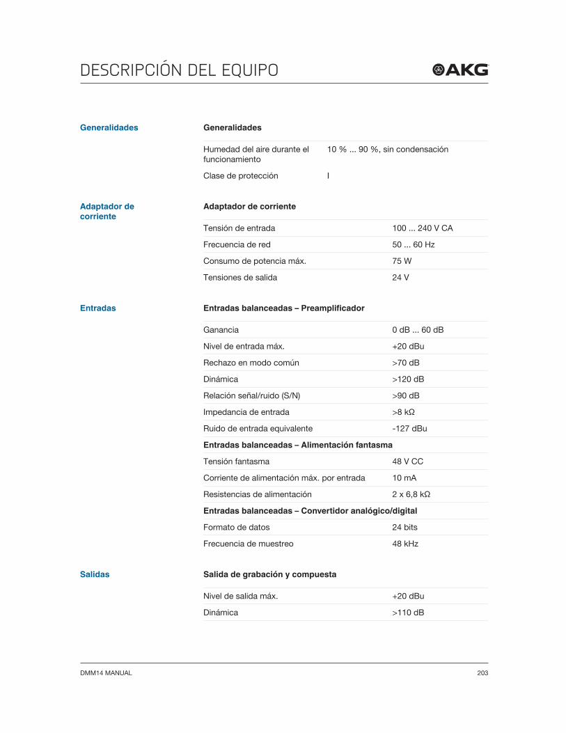
Descripción DeL eqUipo
DMM14 MANUAL 203
Generalidades
Humedad del aire durante el funcionamiento
10 % ... 90 %, sin condensación
Clase de protección I
Adaptador de corriente
Tensión de entrada 100 ... 240 V CA
Frecuencia de red 50 ... 60 Hz
Consumo de potencia máx. 75 W
Tensiones de salida 24 V
Entradas balanceadas – Preamplificador
Ganancia 0 dB ... 60 dB
Nivel de entrada máx. +20 dBu
Rechazo en modo común >70 dB
Dinámica >120 dB
Relación señal/ruido (S/N) >90 dB
Impedancia de entrada >8kΩ
Ruido de entrada equivalente -127 dBu
Entradas balanceadas – Alimentación fantasma
Tensión fantasma 48 V CC
Corriente de alimentación máx. por entrada 10 mA
Resistencias de alimentación 2x6,8kΩ
Entradas balanceadas – Convertidor analógico/digital
Formato de datos 24 bits
Frecuencia de muestreo 48 kHz
Salida de grabación y compuesta
Nivel de salida máx. +20 dBu
Dinámica >110 dB
Generalidades
Adaptador de corriente
Entradas
Salidas

Descripción DeL eqUipo
DMM14 MANUAL 204
Salida de grabación y compuesta
Relación señal-ruido (S/N) >90 dB
Impedancia de carga mín. <100Ω
Conversión analógico/digital para grabación, monitorización y salida compuesta
Formato de datos 24 bits
Frecuencia de muestreo 48 kHz
5.3 Parte frontal: Descripción de los controles
En la parte frontal se encuentran un total de nueve controles giratorios.
Figura 1: Parte frontal del DMM14 U (UL, ULD)
La siguiente tabla incluye una descripción de los controles de la parte fron-tal del DMM14 U (UL, ULD):
N.º Descripción
1 a 12 Entradas de micrófono o de línea
13 Modo de control / SYSTEM CONTROL
14, 16 Salidas estéreo 1 y 2
15, 17 Indicador de modulación para salidas estéreo 1 y 2
18 Salida estéreo para auriculares
19 Toma de conexión de auriculares
Loscontrolesgiratoriospermitenmodificarlosparámetrosdelafuncióndeaudio seleccionada.
5.3.1 Controles giratorios de los canales de entrada
El DMM14 U (UL, ULD) dispone de 12 canales de entrada balanceados para conectar micrófonos dinámicos de baja impedancia o micrófonos de condensador y otras fuentes de señales, como por ejemplo receptores de
Salidas
Controles delanteros
8 910
1115
76
51
8 910
1112
1314
15
76
51
PRIORITYPAN / BALANCE
DELAY
ROUTE TO REC
ROUTE TO USB
EQUALIZER
PRESET
IN USB / DANTE
AUTOMIXING
COMPRESSOR
LIMITER
LOW CUT
BASS
TREBLE
LEVEL
LOCKED
OUT 2
SYSTEM CONTROL
HEADPHONE
-50 -40 -30 -20 -10 -5 0 +5 dB
L
R
8 910
1115
76
54
32
1
OUT 1
-50 -40 -30 -20 -10 -5 0 +5 dB
L
R
8
ON PEAK
910
1112
1314
15
76
54
32
1
IN 11EQ 8.0 kHz
8
ON PEAK
910
1112
1314
15
76
54
32
1
IN 9EQ 4.0 kHz
8
ON PEAK
910
1112
1314
15
76
54
32
1
IN 7EQ 2.0 kHz
8
ON PEAK
910
1112
1314
15
76
54
32
1
IN 5 / DANTE 3EQ 1.0 kHz
8
ON PEAK
910
1112
1314
15
76
54
32
1
IN 3 / DANTE 1EQ 500 Hz
8
ON PEAK
910
1112
1314
15
76
54
32
1
IN 1 / USB LEQ 250 Hz
8
ON PEAK
9
1314
15
7
32
1
IN 2 / USB REQ 350 Hz
8
ON PEAK
9
1314
15
7
32
1
IN 4 / DANTE 2EQ 700 Hz
8
ON PEAK
9
1314
15
7
32
1
IN 6 / DANTE 4EQ 1.4 kHz
8
ON PEAK
9
1314
15
73
21
IN 8EQ 2.8 kHz
8
ON PEAK
9
1314
15
7
32
1
IN 10EQ 5.6 kHz
8
ON PEAK
910
1112
1314
15
7
32
1
IN 12EQ 11.3 kHz
1 2 4 6 8 10 12 15 173 5 7 9 11 13 1614 18 19
Controles giratorios de entradas

Descripción DeL eqUipo
DMM14 MANUAL 205
micrófonos inalámbricos. Cada canal de entrada dispone de un control giratorio (1 a 12).
Cada canal de entrada dispone de un LED verde ON y un LED rojo PEAK.
El LED de ON se ilumina cuando se ha concedido prioridad al modo auto-mático del canal de entrada en cuestión. Si la función de mezcla automática se encuentra desactivada, el LED ON se iluminará de modo continuo.
El LED PEAK se ilumina cuando la señal de un canal de entrada se aproxi-ma al límite máximo de modulación. En este caso deberá reducirse el nivel o modificarselasensibilidaddeentrada.
La sensibilidad de entrada se ajusta al equipo conectado mediante el con-trol de ganancia de la parte posterior.
5.3.2 Modo de control / SYSTEM CONTROL
El DMM14 U (UL, ULD) dispone de numerosas funciones, tales como de vo-lumen, tratamiento de agudos y graves, funciones de mezcla automáticas, etc. Estas funciones se seleccionan mediante el control giratorio SYSTEM CONTROL (13).
5.3.3 Controles giratorios de las salidas estéreo
Los controles giratorios de las salidas estéreo están marcados con las leyendas OUT 1 (14) y OUT 2 (16). Estos controles giratorios permiten modi-ficarlossiguientesparámetrosdelcanaldesalida:
• Volumen• Agudos• Graves• Modo de limitación• Balance y retardo
5.3.4 Indicador de modulación para salidas estéreo
El indicador de modulación (15, 17) situado bajo el control giratorio de los canales de salida estéreo muestra el nivel de salida en dB.
5.3.5 Salida estéreo para auriculares
La salida estéreo para auriculares (18) permite escuchar tanto salidas como entradas.
LED ON
LED PEAK
SYSTEM CONTROL
Controles giratorios de salidas
Indicador de modulación
Salida de auriculares

Descripción DeL eqUipo
DMM14 MANUAL 206
5.4 Parte posterior: Descripción de los controles
En la parte posterior se encuentran, entre otros elementos, las tomas de los canales de entrada y de salida, así como la conexión a red.
Figura 2: Parte posterior del DMM14 U (UL, ULD)
*sólo disponible en DMM14 ULD **sólo disponible en DMM14 UL y DMM14 ULD
La siguiente tabla incluye una descripción de los controles de la parte posterior del DMM14 U (UL, ULD):
N.º Descripción
1, 5, 6, 10, 11, 15, 18, 22, 23, 27, 28, 32
Canales de entrada
2, 4, 7, 9, 12, 14, 19, 21, 24, 26, 29, 31
Control de ganancia
3, 8, 13, 20, 25, 30 Alimentación fantasma
16, 33 Canal de salida estéreo izquierdo
17, 34 Canal de salida estéreo derecho
35 Salida estéreo de grabación
36 Dante™: *sólo disponible en DMM8 ULD
37 Tomas de expansión
38 Controlador serie (RS232)
39 Interfaz USB
40 Jack modular hembra (RJ 45): **sólo disponible para DMM8 UL y DMM8 ULD
Controles traseros
OUT2/L OUT2/R REC (OUT) IN - EXPANSION - OUT RS232
DANTE
USB LAN
L
R
IN 7 IN 8Off
PHANT. PWROn
IN 1 IN 2Off
PHANT. PWROn
IN 9 IN 10Off
PHANT. PWROn
IN 3 IN 4Off
PHANT. PWROn
IN 11 IN 12Off
PHANT. PWROn
IN 5 IN 26Off
PHANT. PWROn
OUT1/L OUT1/R
33 34 35 36* 38 39 40** 41 42 4320
19 2118 22
3 42 51
2524 2623 27
897 106
3029 3128 32
131412 1511
37
16 17

Descripción DeL eqUipo
DMM14 MANUAL 207
N.º Descripción
41 Borne Phoenix (puesta a tierra / control remoto)
42 Conexión a red
43 Interruptor de red
5.4.1 Canales de entrada
Figura 3: Canal de entrada
Los 12 canales de entrada balanceados (1, 5, 6, 10, 11, 15, 18, 22, 23, 27, 28, 32) se encuentran accesibles mediante conectores hembra Phoenix de 3 polos. Éstos están marcados con las leyendas IN 1 a IN 12. Los controles giratorios IN 1 a IN 12delapartefrontalpermitenmodificarlosnivelesdeentrada.
Entre cada dos conectores hembra Phoenix se encuentra un interruptor para la corriente fantasma y un controlador de ganancia para cada canal.
La asignación se indica en la toma IN 3 del siguiente modo:
• Pin 1 = a• Pin 2 = b• Pin 3 = _|_
Canales de entrada
IN 1Off
PHANT. PWROn

Descripción DeL eqUipo
DMM14 MANUAL 208
5.4.2 Controles de ganancia
Figura 4: Controles de ganancia
Junto a cada canal de entrada se encuentra su control de ganancia corres-pondiente (2, 4, 7, 9, 12, 14, 19, 21, 24, 26, 29, 31), con el que se controla su nivel de entrada. Los controles de ganancia están equipados con un interruptor integrado en su tope izquierdo.
En el tope izquierdo, el nivel de entrada seleccionado es de 0 dB. Girando el botónenelsentidodelasagujasdelrelojesposibleajustarlaamplificaciónhasta un máximo de 57 dB.
5.4.3 Alimentación fantasma
Figura 5: Alimentación fantasma
El equipo está equipado con seis interruptores para alimentación fantasma (3, 8, 13, 20, 25, 30).
Cada interruptor activa la tensión de alimentación fantasma de +48 V para las entradas a la izquierda y a la derecha del mismo.
El interruptor está marcado con la leyenda PHANT. PWR. Siempre se acti-van dos canales de entrada a la vez. La alimentación fantasma se encuentra activada cuando el interruptor deslizante se encuentra en posición On.
Cada interruptor activa la tensión de alimentación fantasma de +48 V para las entradas a la izquierda y a la derecha del mismo.
Controles de ganancia
IN 1 IN 2Off
PHANT. PWROn
0 dB0 dB 57 dB57 dB
Alimentación fantasma
IN 1 IN 2Off
PHANT. PWROn

Descripción DeL eqUipo
DMM14 MANUAL 209
Conexión a tierra/ground
Figura 6: Borne Phoenix
Un borne Phoenix permite conectar la carcasa al potencial de 0 V del sumi-nistro de tensión.
Sólo puentee el potencial 0 V con la conexión a tierra (ajuste de fábrica) o con el sistema central de puesta a tierra, ya que de lo contrario la alimenta-ción fantasma no tendrá ningún punto de referencia y no funcionará.
Control analógico
Figura 7: Borne Phoenix
Existelaposibilidaddemodificarelvolumentotalmedianteunpotencióme-tro lineal de 50 kΩ en la entrada VCA.
Figura 8: VCA
En la entrada VCA, el potenciómetro lineal se encuentra conectado tal y comosemuestraarriba.Girandoelpotenciómetrosemodificalaresistenciade la entrada VCA. Este valor se detecta, y el volumen se ajusta consecuen-
VCA
VCAPoti 50klin.
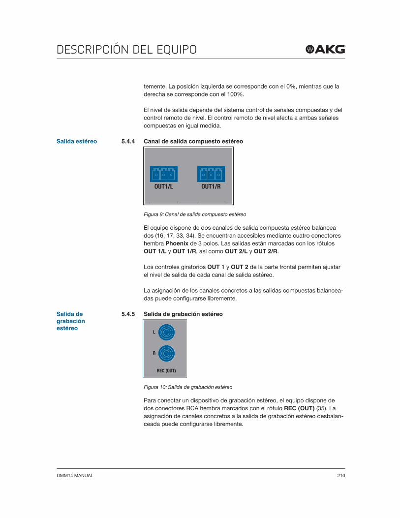
Descripción DeL eqUipo
DMM14 MANUAL 210
temente. La posición izquierda se corresponde con el 0%, mientras que la derecha se corresponde con el 100%.
El nivel de salida depende del sistema control de señales compuestas y del control remoto de nivel. El control remoto de nivel afecta a ambas señales compuestas en igual medida.
5.4.4 Canal de salida compuesto estéreo
Figura 9: Canal de salida compuesto estéreo
El equipo dispone de dos canales de salida compuesta estéreo balancea-dos (16, 17, 33, 34). Se encuentran accesibles mediante cuatro conectores hembra Phoenix de 3 polos. Las salidas están marcadas con los rótulos OUT 1/L y OUT 1/R, así como OUT 2/L y OUT 2/R.
Los controles giratorios OUT 1 y OUT 2 de la parte frontal permiten ajustar el nivel de salida de cada canal de salida estéreo.
La asignación de los canales concretos a las salidas compuestas balancea-daspuedeconfigurarselibremente.
5.4.5 Salida de grabación estéreo
Figura 10: Salida de grabación estéreo
Para conectar un dispositivo de grabación estéreo, el equipo dispone de dos conectores RCA hembra marcados con el rótulo REC (OUT) (35). La asignación de canales concretos a la salida de grabación estéreo desbalan-ceadapuedeconfigurarselibremente.
Salida estéreo
OUT1/L OUT1/R
Salida de grabación estéreo
REC (OUT)
L
R

Descripción DeL eqUipo
DMM14 MANUAL 211
5.4.6 Control serie mediante RS232
Figura 11: Control serie
El conector hembra RS232 (38) permite realizar actualizaciones de software y controlar el equipo mediante un controlador externo (p. ej., AMX). Los pines están asignados del siguiente modo:
Pin Función
1 GND
2 TxD
3 RxD
5.4.7 Conexión USB
Figura 12: Conexión USB
La conexión USB (39) permite conectar el equipo a un ordenador para reali-zaractualizacionesdefirmwareyposibilitarelcontrolexterno.
La conexión se realiza mediante controladores estándar de Windows. En caso necesario, deberá instalarse manualmente un controlador para Apple.
Control serie
RS232
Conexión USB
IN - EXPANSION - OUT RS232 USB LAN

Descripción DeL eqUipo
DMM14 MANUAL 212
5.4.8 Conexión LAN
Figura 13: Conexión LAN
La conexión LAN (40) permite realizar actualizaciones de software y contro-lar el equipo mediante un controlador externo (p. ej., AMX).
También existe la posibilidad de controlar y diagnosticar el equipo de modo remoto mediante un servidor web.
Este servidor web dispone de una interfaz de usuario sencilla y funcional a la que puede accederse mediante navegador web, y que permite el acceso mediante infraestructura LAN.
Es posible manejar el dispositivo al mismo tiempo mediante los controles de su parte frontal y mediante el servidor web. Sin embargo, en estos casos se concede prioridad a las órdenes impartidas mediante el servidor web.
El mezclador automático proporciona un protocolo que permite controlarlo vía WLAN mediante un programa o una APP externa.
En función del tipo y del alcance de la programación, estas aplicaciones pueden proporcionar bastantes más funciones y, en consecuencia, una superficiegráficamáscomplejaasusterminales.
5.4.9 Conexión de equipos en cascada
Figura 14: Expansión
Mediante los jack modulares hembra de 8 polos (RJ-45) (37) es posible conectar entre sí un máximo de 10 dispositivos.
Conexión LAN
IN - EXPANSION - OUT RS232 USB LAN
Conexión en cascada
OUT R REC (OUT) IN - EXPANSION - OUT RS232 USB LAN
L
R

Descripción DeL eqUipo
DMM14 MANUAL 213
En tal caso, se transmitirán tanto una señal compuesta de audio como la señal de estado del algoritmo de mezcla automática.
En caso de conexión en cascada, la transmisión de audio se llevará a cabo en formato de 24 bits. Esto no empeorará los valores de ruido.
5.4.10 Red Dante™
Figura 15: Dante™
El equipo DMM14 ULD está equipado con un conector jack modular hem-bra de 8 polos (RJ 45) con la leyenda DANTE (19).
De este modo, todos los canales de entrada y salida se dirigen automática-mente a la red Dante™.
Tras el procesamiento de la señal (agudos, graves...) y el algoritmo de mez-cla automática, los canales de entrada se dirigen a la red Dante™ en forma de señales de salida directa.
Las salidas compuestas se dirigen a la red Dante™ en forma de señales de salida directa antes del ajuste de balance, del ajuste de volumen de salida y del limitador.
Los ajustes deben llevarse a cabo mediante la unidad de recepción de Dante™ (p. ej., mesa de mezclas).
En caso de conexión en cascada de mezcladores automáticos, deberá tenerse en cuenta que la red Dante™ siempre transmitirá únicamente los canales que se encuentren disponibles de modo local en un mezclador automático. Si también se requieren los canales de entrada de un segundo equipo conectado en cascada, éste deberá disponer de su propia interfaz Dante™.
Si el mezclador automático controla varios dispositivos, éstos deberán conectarse adicionalmente mediante la conexión en cascada: además de las señales compuestas, también se transmitirán las señales de control del algoritmo de mezcla automática.
Red Dante™
REC (OUT) IN - EXPANSION - OUT RS232
DANTE
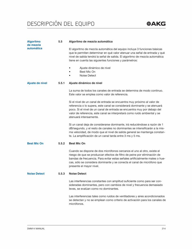
Descripción DeL eqUipo
DMM14 MANUAL 214
5.5 Algoritmo de mezcla automática
El algoritmo de mezcla automática del equipo incluye 3 funciones básicas que le permiten determinar en qué valor atenuar una señal de entrada y qué nivel de salida tendrá la señal de salida. El algoritmo de mezcla automática tiene en cuenta las siguientes funciones y parámetros:
• Ajuste dinámico de nivel• Best Mic On• Noise Detect
5.5.1 Ajuste dinámico de nivel
La suma de todos los canales de entrada se determina de modo continuo. Este valor se emplea como valor de referencia.
Si el nivel de un canal de entrada se encuentra muy próximo al valor de referencia o lo supera, este canal se considerará dominante y se atenuará poco. Si el nivel de un canal de entrada se encuentra muy por debajo del valor de referencia, este canal se interpretará como ruido ambiental y se atenuará intensamente.
Si un canal deja de considerarse dominante, irá reduciéndose a razón de 1 dB/segundo,yelrestodecanalesnodominantesseintensificaránalamis-ma velocidad, de modo que el nivel de salida general se mantenga constan-te.Laamplificacióndeuncanaltardaentre3msy5ms.
5.5.2 Best Mic On
Cuando se dispone de dos micrófonos cercanos el uno al otro, existe el riesgodequeseproduzcanefectosdefiltrodepeineporeliminacióndebandasdefrecuencia.Paraevitarestasseñalesartificialmentematesohue-cas, sólo se considera dominante y se conecta el canal de micrófono que presente el mayor nivel.
5.5.3 Noise Detect
Lasinterferenciasconstantesconamplitudsuficientecomoparasercon-sideradas dominantes, pero con cambios de nivel y frecuencia demasiado leves, se evalúan como no dominantes.
Las interferencias tales como ruidos de ventiladores y aires acondicionados se detectan y no se emplean como criterio de activación para los canales de micrófonos.
Algoritmo de mezcla automática
Ajuste de nivel
Best Mic On
Noise Detect
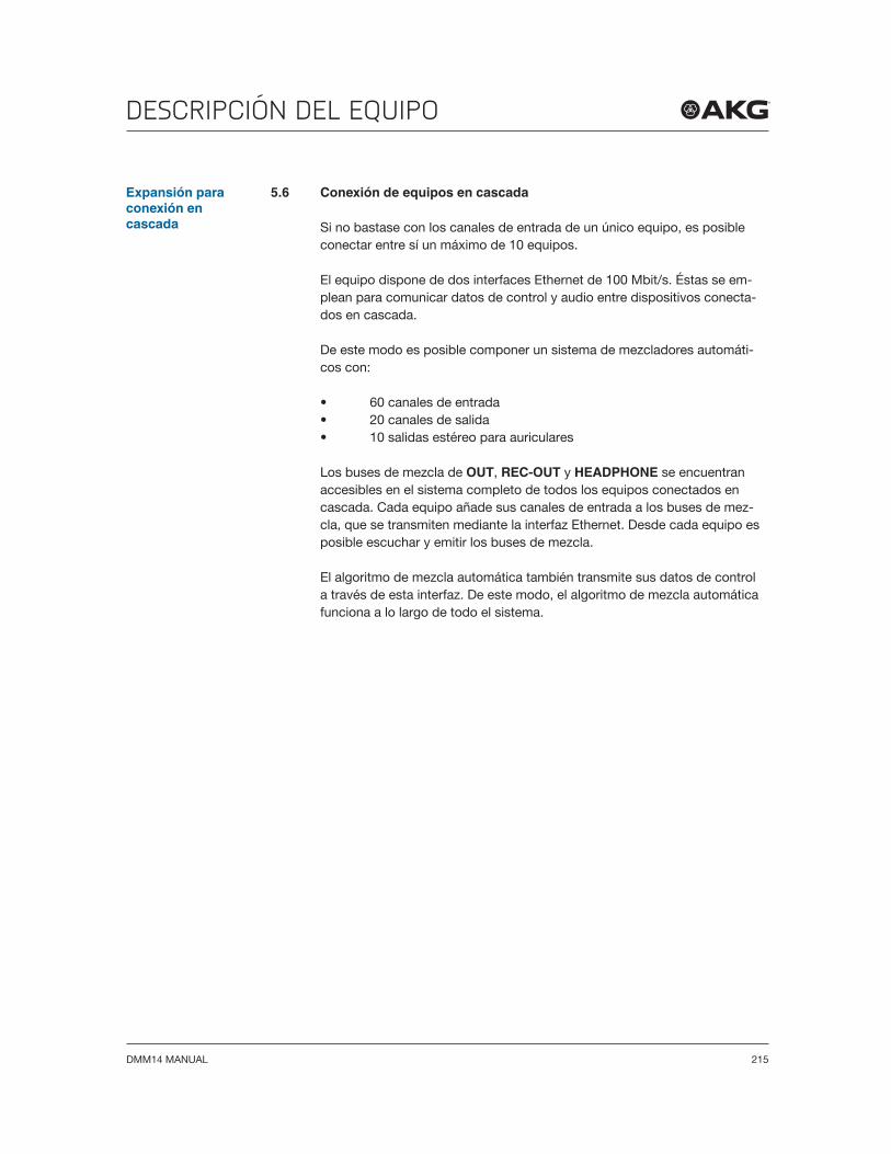
Descripción DeL eqUipo
DMM14 MANUAL 215
5.6 Conexión de equipos en cascada
Si no bastase con los canales de entrada de un único equipo, es posible conectar entre sí un máximo de 10 equipos.
El equipo dispone de dos interfaces Ethernet de 100 Mbit/s. Éstas se em-plean para comunicar datos de control y audio entre dispositivos conecta-dos en cascada.
De este modo es posible componer un sistema de mezcladores automáti-cos con:
• 60 canales de entrada• 20 canales de salida • 10 salidas estéreo para auriculares
Los buses de mezcla de OUT, REC-OUT y HEADPHONE se encuentran accesibles en el sistema completo de todos los equipos conectados en cascada. Cada equipo añade sus canales de entrada a los buses de mez-cla, que se transmiten mediante la interfaz Ethernet. Desde cada equipo es posible escuchar y emitir los buses de mezcla.
El algoritmo de mezcla automática también transmite sus datos de control a través de esta interfaz. De este modo, el algoritmo de mezcla automática funciona a lo largo de todo el sistema.
Expansión para conexión en cascada

montAje y conexión
DMM14 MANUAL 216
6 Montaje y conexión
Para la instalación y la conexión del DMM14 U (UL, ULD) es necesario se-guir los siguientes pasos:
1. Montaje
2. Conexión de equipos en cascada (opcional)
3. Conexión de micrófonos y dispositivos adicionales
4. Conexión del equipo a la red
6.1 Montaje
Para instalar el equipo, proceda del siguiente modo:
Paso Descripción
1 Monte el equipo en un rack de 19", empleando para ello 4 tornillos para rack adecuados.
Asegúrese de que el equipo se encuentre bien atornillado al rack.
Otra opción consiste en colocar el equipo sobre una base estable.
6.2 Conexión de equipos en cascada (opcional)
Atención: Peligro de desperfectos
¡Solicite la conexión únicamente a personal técnico autorizado!
No se permite conectar el último equipo de la cascada con el primero.
Consulte el modo de conexión de los equipos individuales a las tomas de expansión en 8.4 Conexión de equipos en cascada en la página 244
6.3 Conexión de micrófonos y dispositivos adicionales
Para realizar la conexión, lea también los manuales de usuario de sus micró-fonos y dispositivos adicionales.

montAje y conexión
DMM14 MANUAL 217
Conecte los micrófonos y dispositivos adicionales del siguiente modo a la parte posterior del DMM14 U (UL, ULD):
Paso Descripción
1 Conecte los micrófonos y otras fuentes de señales (p. ej., receptores para micrófonos inalámbricos) a los canales de entrada IN
2 Conecte los canales de salida OUT 1/L, OUT 2/L y OUT 1/R , OUT 2/R aunamesademezclasoamplificador
3 Conecte los conectores RCA hembra de la salida estéreo para auriculares REC (OUT) a un dispositivo de grabación
6.4 Conexión del equipo a la red
Atención: Peligro de desperfectos
¡No conecte el equipo a la red de alimentación hasta que no se hayan reali-zado todas las conexiones de audio!
Asegúrese de que la tensión de entrada del DMM14 U (UL, ULD) coincida con la tensión de la red.
Para conectar el equipo a la red, proceda del siguiente modo:
Paso Descripción
1 Conecte el cable de conexión a red a la toma correspondiente de la parte posterior del DMM14 U (UL, ULD)
2 Enchufe el cable de conexión a red a una toma de corriente

Descripción De fUnciones
DMM14 MANUAL 218
7 Descripción de funciones
7.1 Sistema de manejo
El equipo se maneja mediante un total de 16 controles giratorios situados en su panel delantero. Éstos se encuentran marcados con los rótulos IN 1 a IN 12, SYSTEM CONTROL, OUT 1, OUT 2 y HEADPHONE.
Los controles giratorios de las entradas se encuentran rodeados por cír-culos de 15 LEDs amarillos, uno verde y uno rojo. Los controles giratorios SYSTEM CONTROL y los controles giratorios de las salidas se encuentran rodeados por 15 LEDs amarillos. El indicador de modulación de debajo de las salidas posee 6 LEDs verdes, uno amarillo y uno rojo.
Los círculos de LEDs sirven para visualizar la posición de los controles gira-torios y para mostrar los niveles de las señales.
7.2 Manejo de los controles giratorios
Figura 16: Controles giratorios
• Gire los controles giratorios en el sentido de las agujas del reloj oenelsentidocontrarioparamodificarlasentradasysalidas,así como para ajustar funciones. Los cambios se mostrarán en el círculo de LEDs en torno al control giratorio. El punto de partida y el progreso del círculo de LEDs varía de una función a otra.
• Mediante una pulsación corta del control giratorio SYSTEM CONTROL se cambia el modo de visualización de los círculos de LEDs a vúmetro, un indicador del nivel real de audio disponible. Mientras el modo de vúmetro se encuentre activo, el LED LEVEL del control giratorio SYSTEM CONTROL parpadeará. Volviendo a pulsar el control giratorio SYSTEM CONTROL es posible desactivar el modo vúmetro.
Controles giratorios
8
ONPEAK
9 10 11
1213
14
15
7
6
54
32
1
IN 2

Descripción De fUnciones
DMM14 MANUAL 219
7.2.1 Visualización del nivel de audio / función VU
Con la función LEVEL seleccionada, en los círculos de LEDs de las entra-das y salidas se mostrará el nivel ajustado.
7.3 SYSTEM CONTROL
El control giratorio SYSTEM CONTROL permite seleccionar diversas funciones del equipo.
Figura 17: SYSTEM CONTROL
Para más información sobre cómo seleccionar las funciones y ajustar los parámetros, consulte 8.1 SYSTEM CONTROL: Modificación de paráme-tros del equipo en la página 242
7.3.1 Funciones de SYSTEM CONTROL
Mediante SYSTEM CONTROL es posible seleccionar las siguientes funcio-nes:
• Level• Treble• Bass• Low cut• Limiter• Compressor• Automixing• Priority• Pan / Balance• Delay• Routing To REC• Routing To USB• Equalizer
SYSTEM CONTROL
PRIORITYPAN / BALANCE
DELAY
ROUTE TO REC
ROUTE TO USB
EQUALIZER LOW
EQUALIZER HIGH
PRESET
IN USB / DANTE
AUTOMIXING
COMPRESSOR
LIMITER
LOW CUT
BASS
TREBLE
LEVEL
LOCKED
SYSTEM CONTROL
Funciones para SYSTEM CONTROL

Descripción De fUnciones
DMM14 MANUAL 220
• Preset
Las funciones indicadas a continuación pueden seleccionarse pulsando controles giratorios individuales o combinaciones de varios de ellos:
• Routing To Out 1• Routing To Out 2• Monitoring• Mute
7.3.2 Funciones de los canales de entrada
Loscanalesdeentradapuedenmodificarseconlassiguientesfunciones:
• Level• Treble• Bass• Low cut• Compressor• Automixing• Priority• Pan• Routing To Out 1• Routing To Out 2• Routing To Rec• Routing To USB• Monitoring• Mute
7.3.3 Funciones de los canales de salida
Loscanalesdesalidapuedenmodificarseconlassiguientesfunciones:
• Level• Treble• Bass• Limiter• Balance• Delay• Equalizer• Monitoring• Mute
Funciones de los canales de entrada
Funciones de los canales de salida

Descripción De fUnciones
DMM14 MANUAL 221
7.3.4 Funciones de la salida estéreo para auriculares (salida para monitorización)
El control giratorio HEADPHONE supone una excepción. La salida estéreo para auriculares se encuentra siempre en la función LEVEL, independiente-mente de la posición del control giratorio SYSTEM CONTROL.
7.4 Funciones DSP
A continuación se explicará el manejo y el modo de funcionamiento de cada función.
7.4.1 LEVEL
Figura 18: Función LEVEL
La función LEVEL se aplica a todos los canales de entrada y salida.
Girando el control giratorio en el sentido de las agujas del reloj se aumen-ta el volumen. Girándolo en el sentido contrario a las agujas del reloj, se reduce.
Elrangodeajusteestácomprendidoentre-∞y+15dB(señalacústica).Elajuste se lleva a cabo a pasos graduados de un modo práctico.
A +15dB se ilumina todo el círculo de LEDs, y no se emite ninguna señal acústica más.
Funciones DSP
LEVELPRIORITY
PAN / BALANCE
DELAY
ROUTE TO REC
ROUTE TO USB
EQUALIZER
PRESET
IN USB / DANTE
AUTOMIXING
COMPRESSOR
LIMITER
LOW CUT
BASS
TREBLE
LEVEL
LOCKED
SYSTEM CONTROL

Descripción De fUnciones
DMM14 MANUAL 222
De -12 dB a +15 dB, el ajuste se realiza a pasos de 1 dB por sección. Cada 3dBseiluminaunLED.De-12dBa-∞,elajusteserealizaapasosde3dB. Cada 9 dB se ilumina un LED.
Figura 19: Detalle de LEVEL
Para que sea posible encontrar con más facilidad la posición de 0 dB, el LED correspondiente (n.º 10) brilla con más intensidad que el resto de los LEDs, no alcanzándose el nivel de 0 dB hasta la tercera división tras encen-derse este LED (véase Detail LEVEL)
Si pulsa el control giratorio SYSTEM CONTROL en la función LEVEL, el in-dicadordeloscanalesdeentradaysalidapasarádeindicarlaamplificacióna indicar la modulación.
7.4.2 TREBLE
Figura 20: Función TREBLE
8
ON PEAK
910
1112
1314
15
76
54
32
1LEVEL Detail LEVEL
-57 dB
-48 dB
-39 dB
-30 dB
-21 dB
-12 dB
-9 dB
+15 dB
+12 dB
+9 dB
+6 dB
+3 dB
0 dB
-3 dB
-6 dB
8 910
1112
13
76
54
3
-8
dB
-7
dB
-6
dB
-5
dB -
4 dB
-3
dB -2
dB
-1 d
B 0
dB
+1 dB
+2 dB
+3 dB
TREBLEPRIORITY
PAN / BALANCE
DELAY
ROUTE TO REC
ROUTE TO USB
EQUALIZER
PRESET
IN USB / DANTE
AUTOMIXING
COMPRESSOR
LIMITER
LOW CUT
BASS
TREBLE
LEVEL
LOCKED
SYSTEM CONTROL

Descripción De fUnciones
DMM14 MANUAL 223
Con la función TREBLEesposiblemodificartodosloscanalesdeentradaysalida.
Figura 21: Escala del círculo de LEDs de la función TREBLE
Con la función TREBLEesposibleamplificaroreducirlosagudosdelaseñaldeaudio.Elfiltroesunfiltroshelvingdeagudosdeprimerorden.Lafrecuencia límite es de 10 kHz.
La señal puede ajustarse de -14 dB a +14 dB. En caso de ajuste lineal, sólo se iluminará el LED central superior (0 dB). Cuanto más hacia la izquierda se gire el control giratorio, más LEDs se encenderán en el lado izquierdo.
Cuanto más hacia la derecha se gire el control giratorio, más LEDs se en-cenderán en el lado derecho.
8
ON PEAK
910
1112
1314
15
76
54
32
1-14 dB
-12 dB
-10 dB
-8 dB
-6 dB
-4 dB
-2 dB
+14 dB
+12 dB
+10 dB
+8 dB
+6 dB
+4 dB
+2 dB
0 dB
TREBLE

Descripción De fUnciones
DMM14 MANUAL 224
El ajuste se lleva a cabo a pasos de 2 dB por sección, lo que equivale al encendido de un LED.
Figura 22: Rango de ajuste de la función TREBLE
7.4.3 BASS
Figura 23: Función BASS
Con la función BASSesposiblemodificartodosloscanalesdeentradaysalida.
-18
+16
-16
-14
-12
-10
-8
-6
-4
-2
-0
+2
+4
+6
+8
+10
+12
+14
dBr A
20 20k50 100 200 500 1k 2k 5k 10kHz
BASSPRIORITY
PAN / BALANCE
DELAY
ROUTE TO REC
ROUTE TO USB
EQUALIZER
PRESET
IN USB / DANTE
AUTOMIXING
COMPRESSOR
LIMITER
LOW CUT
BASS
TREBLE
LEVEL
LOCKED
SYSTEM CONTROL

Descripción De fUnciones
DMM14 MANUAL 225
Con la función BASSesposibleamplificaroreducirlosgravesdelaseñaldeaudio.Elfiltroesunfiltroshelvingdegravesdeprimerorden.Lafrecuen-cia límite es de 100 Hz.
La señal puede ajustarse de -14 dB a +14 dB. En caso de ajuste lineal, sólo se iluminará el LED central superior (0 dB). Cuanto más hacia la izquierda se gire el control giratorio, más LEDs se encenderán en el lado izquierdo.
Cuanto más hacia la derecha se gire el control giratorio, más LEDs se encenderán en el lado derecho.
Figura 24: Escala del círculo de LEDs de la función BASS
8
ON PEAK
910
1112
1314
15
76
54
32
1-14 dB
-12 dB
-10 dB
-8 dB
-6 dB
-4 dB
-2 dB
+14 dB
+12 dB
+10 dB
+8 dB
+6 dB
+4 dB
+2 dB
0 dB
BASS

Descripción De fUnciones
DMM14 MANUAL 226
El ajuste se lleva a cabo a pasos de 2 dB por sección, lo que equivale al encendido de un LED.
Figura 25: Rango de ajuste de la función BASS
7.4.4 LOW CUT
Figura 26: Función LOW CUT
Con la función LOW CUTesposiblemodificartodosloscanalesdeentrada.
Con la función LOW CUT es posible suprimir interferencias de baja frecuen-cia.Elfiltrolowcutesunfiltrodepasoaltodesegundoorden.Girandoelcontrol giratorio en el sentido de las agujas del reloj es posible elevar el
-14
+14
-12
-10
-8
-6
-4
-2
+0
+2
+4
+6
+8
+10
+12
dBr A
20 20k50 100 200 500 1k 2k 5k 10kHz
LOW CUTPRIORITY
PAN / BALANCE
DELAY
ROUTE TO REC
ROUTE TO USB
EQUALIZER
PRESET
IN USB / DANTE
AUTOMIXING
COMPRESSOR
LIMITER
LOW CUT
BASS
TREBLE
LEVEL
LOCKED
SYSTEM CONTROL

Descripción De fUnciones
DMM14 MANUAL 227
límite inferior de frecuencia, y girando el botón en el sentido contrario a las agujas del reloj, reducirlo.
El rango de ajuste está comprendido entre 0 Hz (sin efecto) hasta 150 Hz (atenuación intensa).
A 0 Hz se ilumina un LED, y a 150 Hz se ilumina todo el círculo de LEDs.
Figura 27: Escala del círculo de LEDs de la función LOW CUT
8
ON PEAK
910
1112
1314
15
76
54
32
10-20 Hz
40 Hz
60 Hz
80 Hz
100 Hz
120 Hz
140 Hz
300 Hz
280 Hz
260 Hz
240 Hz
220 Hz
200 Hz
180 Hz
160 Hz
LOW CUT

Descripción De fUnciones
DMM14 MANUAL 228
El ajuste se lleva a cabo a pasos de 20 Hz por sección, lo que equivale al encendido de un LED.
Figura 28: Rango de ajuste de la función LOW CUT
7.4.5 LIMITER
Figura 29: Función LIMITER
Con la función LIMITEResposiblemodificartodosloscanalesdesalida.
-14
+15
-13-12-11-10-9-8-7-6-5-4-3-2-1-0+1+2+3+4+5+6+7+8+9
+10+11+12+13+14
dBr A
20 20k50 100 200 500 1k 2k 5k 10kHz
LIMITERPRIORITY
PAN / BALANCE
DELAY
ROUTE TO REC
ROUTE TO USB
EQUALIZER
PRESET
IN USB / DANTE
AUTOMIXING
COMPRESSOR
LIMITER
LOW CUT
BASS
TREBLE
LEVEL
LOCKED
SYSTEM CONTROL

Descripción De fUnciones
DMM14 MANUAL 229
Girando el control giratorio en el sentido de las agujas del reloj, el efecto aumenta; girándolo en el sentido contrario, el efecto disminuye.
El rango de ajuste está comprendido entre +20 dBu y -25 dBu. A +20 dBu se ilumina un LED, y a -25 dBu se ilumina todo el círculo de LEDs.
Figura 30: Escala del círculo de LEDs de la función LIMITER
El ajuste se lleva a cabo a pasos de 3 dB por sección, lo que equivale a un LED.
Figura 31: Rango de ajuste de la función LIMITER
8
ON PEAK
910
1112
1314
15
76
54
32
1+17-20 dBu
+14 dBu
+11 dBu
+8 dBu
+5 dBu
+2 dBu
-1 dBu
-25 dBu
-22 dBu
-19 dBu
-16 dBu
-13 dBu
-10 dBu
-7 dBu
-4 dBu
LIMITER
-60
+20
-55
-50
-45
-40
-35
-30
-25
-20
-15
-10
-5
+0
+5
+10
+15
dBu
-60 +20-55 -50 -45 -40 -35 -30 -25 -20 -15 -10 -5 +0 +5 +10 +15dBu

Descripción De fUnciones
DMM14 MANUAL 230
7.4.6 COMPRESSOR
Figura 32: Función COMPRESSOR
Con la función COMPRESSOResposiblemodificartodosloscanalesdeentrada.
Larazóndecompresióndelcompresorestáajustadademodofijo.Tieneunvalor de 1:2. Girando el control giratorio en el sentido de las agujas del reloj, el efecto aumenta; girándolo en el sentido contrario, el efecto disminuye.
El rango de ajuste está comprendido entre +20 dBu y -25 dBu. A +20 dBu se ilumina un LED, y a -25 dBu se ilumina todo el círculo de LEDs.
Figura 33: Escala del círculo de LEDs de la función COMPRESSOR
COMPRESSORPRIORITY
PAN / BALANCE
DELAY
ROUTE TO REC
ROUTE TO USB
EQUALIZER
PRESET
IN USB / DANTE
AUTOMIXING
COMPRESSOR
LIMITER
LOW CUT
BASS
TREBLE
LEVEL
LOCKED
SYSTEM CONTROL
8
ON PEAK
910
1112
1314
15
76
54
32
1+17-20 dBu
+14 dBu
+11 dBu
+8 dBu
+5 dBu
+2 dBu
-1 dBu
-25 dBu
-22 dBu
-19 dBu
-16 dBu
-13 dBu
-10 dBu
-7 dBu
-4 dBu
COMPRESSOR

Descripción De fUnciones
DMM14 MANUAL 231
El ajuste se lleva a cabo a pasos de 3 dBu por sección, lo que equivale a un LED.
Figura 34: Rango de ajuste de la función COMPRESSOR
7.4.7 AUTOMIXING
Figura 35: Función AUTOMIXING
-40
+20
-37.5-35
-32.5-30
-27.5-25
-22.5-20
-17.5-15
-12.5-10-7.5
-5-2.5+0
+2.5+5
+7.5+10
+12.5+15
+17.5
dBr
A
-40 +20-35 -30 -25 -20 -15 -10 -5 +0 +5 +10 +15dBu
T
AUTOMIXINGPRIORITY
PAN / BALANCE
DELAY
ROUTE TO REC
ROUTE TO USB
EQUALIZER
PRESET
IN USB / DANTE
AUTOMIXING
COMPRESSOR
LIMITER
LOW CUT
BASS
TREBLE
LEVEL
LOCKED
SYSTEM CONTROL

Descripción De fUnciones
DMM14 MANUAL 232
Con la función AUTOMIXINGesposiblemodificartodosloscanalesdeentrada.
Figura 36: Rango de ajuste de la función AUTOMIXING
Girando el control giratorio en el sentido de las agujas del reloj se activan las funciones de mezclado automático del canal correspondiente. (Se ilumina todo el círculo de LEDs) Girando el botón en el sentido contrario al de las agujas del reloj se desactivan las funciones de mezclado automático. (Sólo se ilumina un LED).
Pulsando el control giratorio también se activa y desactiva la función.
7.4.8 PRIORITY
Figura 37: Función PRIORITY
Esta función puede encontrarse activada en un único canal de entrada al mismo tiempo.
8
ON PEAK
910
1112
1314
15
76
54
32
1
8
ON PEAK
910
1112
1314
15
76
54
32
1
off on
AUTOMIXING
PRIORITYPRIORITY
PAN / BALANCE
DELAY
ROUTE TO REC
ROUTE TO USB
EQUALIZER
PRESET
IN USB / DANTE
AUTOMIXING
COMPRESSOR
LIMITER
LOW CUT
BASS
TREBLE
LEVEL
LOCKED
SYSTEM CONTROL

Descripción De fUnciones
DMM14 MANUAL 233
La función PRIORITY permite determinar el canal de entrada prioritario. El canal prioritario, en combinación con la función AUTOMIXING, obtiene una ventaja de 6 dB en el procesamiento de la señal.
Figura 38: Rango de ajuste de la función PRIORITY
Girando el control giratorio en el sentido de las agujas del reloj se activa la función para el canal correspondiente. (Se ilumina todo el círculo de LEDs). Girándolo en el sentido contrario al de las agujas del reloj, las funciones se desactivan (sólo se ilumina un LED).
Pulsando el control giratorio también se activa y desactiva la función.
Al activar la función PRIORITY en un canal de entrada se desactiva en el canal en que estuviese activada previamente.
7.4.9 PAN / BALANCE
Figura 39: Función PAN / BALANCE
8
ON PEAK
910
1112
1314
15
76
54
32
1
8
ON PEAK
910
1112
1314
15
76
54
32
1
off on
PRIORITY
PAN / BALANCEPRIORITY
PAN / BALANCE
DELAY
ROUTE TO REC
ROUTE TO USB
EQUALIZER
PRESET
IN USB / DANTE
AUTOMIXING
COMPRESSOR
LIMITER
LOW CUT
BASS
TREBLE
LEVEL
LOCKED
SYSTEM CONTROL
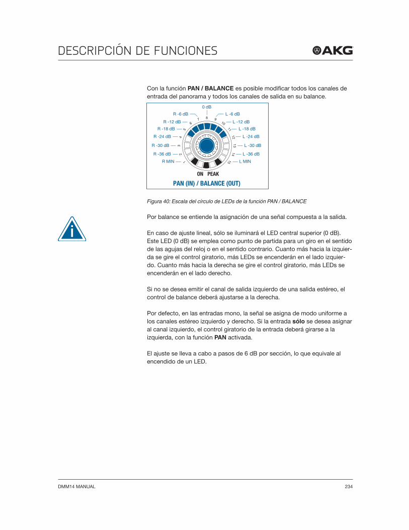
Descripción De fUnciones
DMM14 MANUAL 234
Con la función PAN / BALANCEesposiblemodificartodosloscanalesdeentrada del panorama y todos los canales de salida en su balance.
Figura 40: Escala del círculo de LEDs de la función PAN / BALANCE
Por balance se entiende la asignación de una señal compuesta a la salida.
En caso de ajuste lineal, sólo se iluminará el LED central superior (0 dB). Este LED (0 dB) se emplea como punto de partida para un giro en el sentido de las agujas del reloj o en el sentido contrario. Cuanto más hacia la izquier-da se gire el control giratorio, más LEDs se encenderán en el lado izquier-do. Cuanto más hacia la derecha se gire el control giratorio, más LEDs se encenderán en el lado derecho.
Si no se desea emitir el canal de salida izquierdo de una salida estéreo, el control de balance deberá ajustarse a la derecha.
Por defecto, en las entradas mono, la señal se asigna de modo uniforme a los canales estéreo izquierdo y derecho. Si la entrada sólo se desea asignar al canal izquierdo, el control giratorio de la entrada deberá girarse a la izquierda, con la función PAN activada.
El ajuste se lleva a cabo a pasos de 6 dB por sección, lo que equivale al encendido de un LED.
8
ON PEAK
910
1112
1314
15
76
54
32
1R MIN
R -36 dB
R -30 dB
R -24 dB
R -18 dB
R -12 dB
R -6 dB
L MIN
L -36 dB
L -30 dB
L -24 dB
L -18 dB
L -12 dB
L -6 dB
0 dB
PAN (IN) / BALANCE (OUT)

Descripción De fUnciones
DMM14 MANUAL 235
7.4.10 DELAY
Figura 41: Función DELAY
Con la función DELAYesposiblemodificarlassalidasOUT 1 y OUT 2. Con esta función es posible añadir un retardo a las salidas.
Figura 42: Escala del círculo de LEDs de la función DELAY
El rango de ajuste se encuentra comprendido entre 0 m y 75 m. A 0 m se ilumina un LED, y a 75 m se ilumina todo el círculo de LEDs.
El ajuste se lleva a cabo a pasos de 1 m por sección. Cada 5 m se ilumina un LED.
DELAYPRIORITY
PAN / BALANCE
DELAY
ROUTE TO REC
ROUTE TO USB
EQUALIZER
PRESET
IN USB / DANTE
AUTOMIXING
COMPRESSOR
LIMITER
LOW CUT
BASS
TREBLE
LEVEL
LOCKED
SYSTEM CONTROL
8
ON PEAK
910
1112
1314
15
76
54
32
10-5 m
10 m
15 m
20 m
25 m
30 m
35 m
75 m
70 m
65 m
60 m
55 m
50 m
45 m
40 m
DELAY

Descripción De fUnciones
DMM14 MANUAL 236
7.4.11 ROUTING TO REC
Figura 43: Función ROUTING TO REC
Con la función ROUTING TO RECesposiblemodificartodosloscanalesdeentrada.
Figura 44: Rango de ajuste de la función ROUTING TO REC
Girando el control giratorio en el sentido de las agujas del reloj se activa la función para el canal correspondiente (el círculo de LED se ilumina entero). Girándolo en el sentido contrario al de las agujas del reloj, la función se desactiva (sólo se ilumina un LED).
Pulsando el control giratorio también se activa y desactiva la función.
Al activarla, conecta este canal de entrada al bus de mezcla OUT 1.
ROUTING TO REC PRIORITY
PAN / BALANCE
DELAY
ROUTE TO REC
ROUTE TO USB
EQUALIZER
PRESET
IN USB / DANTE
AUTOMIXING
COMPRESSOR
LIMITER
LOW CUT
BASS
TREBLE
LEVEL
LOCKED
SYSTEM CONTROL
8
ON PEAK
910
1112
1314
15
76
54
32
1
8
ON PEAK
910
1112
1314
15
76
54
32
1off on
ROUTING TO REC

Descripción De fUnciones
DMM14 MANUAL 237
7.4.12 ROUTING TO USB
Figura 45: Función ROUTING TO USB
Con la función ROUTING TO USBesposiblemodificartodosloscanalesdeentrada.
Figura 46: Rango de ajuste de la función ROUTING TO USB
Girando el control giratorio en el sentido de las agujas del reloj se activa la función para el canal correspondiente (el círculo de LED se ilumina entero). Girándolo en el sentido contrario al de las agujas del reloj, la función se desactiva (sólo se ilumina un LED).
Pulsando el control giratorio también se activa y desactiva la función.
Al activarla, conecta este canal de entrada al bus de mezcla USB OUT.
ROUTING TO USB PRIORITY
PAN / BALANCE
DELAY
ROUTE TO REC
ROUTE TO USB
EQUALIZER
PRESET
IN USB / DANTE
AUTOMIXING
COMPRESSOR
LIMITER
LOW CUT
BASS
TREBLE
LEVEL
LOCKED
SYSTEM CONTROL
8
ON PEAK
910
1112
1314
15
76
54
32
1
8
ON PEAK
910
1112
1314
15
76
54
32
1off on
ROUTING TO USB

Descripción De fUnciones
DMM14 MANUAL 238
7.4.13 EQUALIZER
Figura 47: Función EQUALIZER
Con la función EQUALIZEResposiblemodificarlassalidasOUT 1 y OUT 2. El ajuste se lleva a cabo de modo uniforme para el canal izquierdo y el canal derecho.
Permite ecualizar a 12 bandas.
Al pulsar el control giratorio OUT 1, esta función se activa para OUT 1, mientras que, si se pulsa el control giratorio OUT 2, ésta se activa para OUT 2.
Laamplificaciónoatenuacióndelasbandassellevaacabomediantelos12controles giratorios de los canales de entrada. El rango de ajuste se encuentra comprendido entre +14 dB y -14 dB. En caso de ajuste lineal, sólo se iluminará el LED central superior. Girando un control giratorio en el sentido contrario al de las agujas del reloj, van encendiéndose cada vez más LEDs a la izquierda del central. Al girarlo en el sentido de las agujas del reloj, irán encendiéndose cada vez más LEDs a la derecha del central.
Figura 48: Escala del círculo de LEDs de la función EQUALIZER
EQUALIZERPRIORITY
PAN / BALANCE
DELAY
ROUTE TO REC
ROUTE TO USB
EQUALIZER
PRESET
IN USB / DANTE
AUTOMIXING
COMPRESSOR
LIMITER
LOW CUT
BASS
TREBLE
LEVEL
LOCKED
SYSTEM CONTROL
8
ON PEAK
910
1112
1314
15
76
54
32
1-57 dB
-48 dB
-39 dB
-30 dB
-21 dB
-12 dB
-9 dB
+15 dB
+12 dB
+9 dB
+6 dB
+3 dB
0 dB
-3 dB
-6 dB
EQUALIZER

Descripción De fUnciones
DMM14 MANUAL 239
El ajuste se lleva a cabo a pasos de 2 dB.
Las frecuencias medias de las subbandas se encuentran separadas a una distancia de ½ octava.
Figura 49: Rango de ajuste de la función EQUALIZER
7.4.14 PRESET
Figura 50: Función PRESET
-16
+16
-15-14-13-12-11-10-9-8-7-6-5-4-3-2-1+0+1+2+3+4+5+6+7+8+9
+10+11+12+13+14+15
dBr A
20 20k50 100 200 500 1k 2k 5k 10kHz
PRESETPRIORITY
PAN / BALANCE
DELAY
ROUTE TO REC
ROUTE TO USB
EQUALIZER
PRESET
IN USB / DANTE
AUTOMIXING
COMPRESSOR
LIMITER
LOW CUT
BASS
TREBLE
LEVEL
LOCKED
SYSTEM CONTROL

Descripción De fUnciones
DMM14 MANUAL 240
Esposibleguardar12configuracionesoprogramasdiferentesparaelequi-po (LEVEL, TREBLE, BASS, … , EQUALIZER) y volver a cargarlos siempre que se desee.
Para hacerlo, seleccione la función PRESET en el SYSTEM CONTROL. Además de los 12 programas del equipo, se dispone también de un pro-grama provisional al que se aplican primero todos los cambios realizados en los ajustes. Para guardar los cambios de modo permanente, es nece-sario guardar el programa provisional en uno de los programas del equipo disponibles. Al cargar un programa del equipo, éste sobrescribe el progra-ma provisional y se encuentra activo de inmediato. Tras reiniciar el equipo se encontrará activo el último programa provisional con los últimos ajustes realizados.
Los 12 controles giratorios de las entradas sirven para acceder a los programasyconfigurarlos.
Figura 51: Configuraciones de PRESET
SienuncírculodeLEDssóloseiluminaelLED1,significaráqueesteespa-ciodememoriaseencuentrasinconfigurar(véaseFigura 51,codificadorincremental IN 3 / 15).
Si todos los LEDs y el LED rojo con la leyenda PEAK se encuentran encen-didos,significaráqueesteespaciodememoriaseencuentraocupadoyseleccionado (véase Figura 51,codificadorincrementalIN 1 / 13).
Si se ilumina sólo el LED 1 y el LED rojo con la leyenda PEAK,significaráque este espacio de memoria se encuentra ocupado pero no seleccionado (véase Figura 51,codificadorincrementalIN 2 / 14).
Véase 8.7 Empleo de programas en la página 246.
8
ON PEAK
910
1112
1314
157
6
54
32
1
IN 1 / USB LEQ 250 Hz
8
ON PEAK
910
1112
1314
15
76
54
32
1
IN 3 / DANTE 1EQ 500 Hz
8
ON PEAK
910
1112
1314
15
76
54
32
1
IN 2 / USB REQ 350 Hz

Descripción De fUnciones
DMM14 MANUAL 241
7.5 LOCKED
Figura 52: Función LOCKED
La función LOCKED permite proteger el equipo frente a un uso indebido bloqueado los controles giratorios o el equipo al completo.
Véase 8.11 Activación / desactivación de LOCKED en la página 250
LOCKEDPRIORITY
PAN / BALANCE
DELAY
ROUTE TO REC
ROUTE TO USB
EQUALIZER
PRESET
IN USB / DANTE
AUTOMIXING
COMPRESSOR
LIMITER
LOW CUT
BASS
TREBLE
LEVEL
LOCKED
SYSTEM CONTROL

mAnejo DeL eqUipo
DMM14 MANUAL 242
8 Manejo del equipo
8.1 SYSTEM CONTROL: Modificación de parámetros del equipo
Paramodificarparámetrosdelequipo,procedadelsiguientemodo:
Paso Descripción
1 Seleccione la función deseada en el control giratorio SYSTEM CONTROL girándolo hasta que se encienda el LED correspondiente a dicha función
2 Modifiqueloscanalesdeentradaconlafuncióndeseadamediante los controles giratorios IN 1 a IN 12
3 Modifiqueloscanalesdesalidaconlafuncióndeseadame-diante los controles giratorios OUT 1 y OUT 2
La salida de grabación estéreo no dispone de opciones de ajuste.
Alcabode5minutostraslaúltimamodificación,elcontrolgiratorioSYSTEM CONTROL vuelve a saltar a la función LEVEL. Al cabo de 1 minu-to tras el último cambio, el valor ajustado se guardará automáticamente.
8.2 Configuración de micrófonos en el DMM14 U (UL, ULD)
Paraconfigurarlosmicrófonosydispositivosadicionalesconectados,pro-ceda del siguiente modo:
SYSTEM CONTROL

mAnejo DeL eqUipo
DMM14 MANUAL 243
Paso Descripción
1 Accione el interruptor deslizante y el control de ganancia de la parte posterior del DMM14 U (UL, ULD)
• Seleccionelaamplificacióndelasseñalesdeentradaentre 0 dB a +57 dB.
• Cuanto menor sea el nivel de salida del micrófono, mayor deberáserlaamplificacióndelasseñalesdeentrada.
• Para micrófonos con nivel de salida elevado se recomien-daunamenoramplificación.
• Si emplea micrófonos de condensador, averigüe qué tensión de alimentación o dispositivos de alimentación necesitan.
• Si sus micrófonos de condensador son aptos para ali-mentación fantasma, conecte la alimentación fantasma. Para ello, ponga el interruptor deslizante PHANT. PWR en posición ON.
2 Encienda el equipo con el interruptor de red
Atención: Peligro de desperfectos
En caso de uso de micrófonos inalámbricos, desconecte la alimentación fantasma de la entrada a la que haya conectado el receptor para evitar que éste se dañe.
8.3 Audición de entradas y salidas
Para escuchar entradas o salidas, proceda del siguiente modo:
Paso Descripción
1 Mantenga pulsado el control giratorio HEADPHONE y selec-cione las fuentes de sonido que desea escuchar pulsando uno o varios controles giratorios
• Se activarán al mismo tiempo en mono en los canales izquierdo y derecho de los auriculares

mAnejo DeL eqUipo
DMM14 MANUAL 244
Paso Descripción
2 Para cambiar de fuente de sonido, pulse el control giratorio de otra fuente.
• La fuente anterior se desactivará
En el caso de las entradas, se pueden escuchar varias fuentes.
La salida sólo puede escucharse individualmente, pero en estéreo.
La salida REC (OUT) no puede escucharse.
8.4 Conexión de equipos en cascada
Atención: Peligro de desperfectos
¡Solicite la conexión únicamente a personal técnico autorizado!
No se permite conectar el último equipo de la cascada con el primero.
Para conectar los equipos individuales a las tomas de expansión, proceda del siguiente modo:

mAnejo DeL eqUipo
DMM14 MANUAL 245
Paso Descripción
1 Conecte entre sí los equipos mediante cables de conexión CAT5+ del siguiente modo:
OUT R REC (OUT) IN - EXPANSION - OUT RS232 USB LAN
L
R
OUT R REC (OUT) IN - EXPANSION - OUT RS232 USB LAN
L
R
OUT R REC (OUT) IN - EXPANSION - OUT RS232 USB LAN
L
R
Para realizar la conexión en cascada, recomendamos emplear exclusiva-mente cables del catálogo de accesorios de AKG.
Desde el punto de vista del usuario, todos los equipos funcionarán y se comportarán de modo idéntico. Al conectarlos en cascada se mantendrán todas las funciones de los equipos individuales.
8.5 Reproducción mediante USB y Dante™
8.5.1 Procesamiento de la reproducción
Para reproducir las señales de entrada vía USB o Dante™, proceda del siguiente modo:
Reproducción mediante USB y Dante™

mAnejo DeL eqUipo
DMM14 MANUAL 246
Paso Descripción
1 Pulse dos veces brevemente el control giratorio SYSTEM CONTROL (doble clic)
• Los 12 controles de entrada cambiarán su asignación.
• A continuación, el LED IN USB o IN USB/DANTE se ilumi-nará de modo permanente
• Los cambios realizados en los controles de entrada ya no afectarán a las 12 entradas analógicas, sino a las entradas digitales 13 a 24
• A partir de ahí, el manejo es idéntico al de las entradas analógicas
Las entradas del puerto USB ocupan los canales 13 (IN1 / USB L) y 14 (IN 2 / USB R); en equipos sin interfaz Dante™, las entradas 15 a 24 no funcionan y se encuentran inactivas.
En equipos con interfaz Dante™, los canales de entrada digitales a partir del número 15 se encuentran asignados del siguiente modo:
• IN3 / DANTE 1• IN4 / DANTE 2• etc.
Todas las entradas digitales disponen de las mismas funciones de procesa-miento de señal que las entradas analógicas.
8.6 Activación de la alimentación fantasma
Sólo puentee el potencial 0 V con la conexión a tierra (ajuste de fábrica) o con el sistema central de puesta a tierra, ya que de lo contrario la alimenta-ción fantasma no tendrá ningún punto de referencia y no funcionará.
8.7 Empleo de programas
Los programas del DMM14 U (UL, ULD) funcionan de un modo muy similar al de los de la radio de un coche.
8.7.1 Selección de programas
Para seleccionar un programa, proceda del siguiente modo:
PRESET

mAnejo DeL eqUipo
DMM14 MANUAL 247
Paso Descripción
1 En SYSTEM CONTROL, seleccione la función PRESET
2 Pulse brevemente el control giratorio del canal de entrada o salida correspondiente.
• Se emitirá una señal acústica (pitido).
3 Cuando oiga el pitido, suelte el control giratorio.
• El programa del equipo se cargará sobre el programa provisional.
• Los ajustes del programa del equipo seleccionado se activarán inmediatamente (todos los LEDs se encontrarán encendidos)
8.7.2 Programación de programas
Para programar un programa, proceda del siguiente modo:
Paso Descripción
1 En SYSTEM CONTROL, seleccione la función PRESET
2 Pulse un control giratorio de entrada (1 a 12) entre 3 y 5 segundos.
• Se emitirá una señal acústica (pitido).
3 Cuando oiga el pitido, suelte el control giratorio.
• Los ajustes actuales del programa provisional se guar-darán en el programa del equipo seleccionado (todos los LEDs se iluminarán)
8.7.3 Eliminación de programas
Para eliminar un programa, proceda del siguiente modo:

mAnejo DeL eqUipo
DMM14 MANUAL 248
Paso Descripción
1 En SYSTEM CONTROL, seleccione la función PRESET
2 Mantenga pulsado el control giratorio del canal de entrada o salida correspondiente entre 8 y 10 segundos.
• Se emitirá una señal acústica (pitido).
3 Cuando oiga el pitido, suelte el control giratorio.
• El programa del equipo se borrará y ya no podrá seleccio-narse (espacio de memoria vacío; LED 1 encendido)
8.8 Empleo de MUTE
8.8.1 Activación de MUTE
La función MUTE puede activarse tanto para los canales de entrada como para los de salida. Para hacerlo, proceda del siguiente modo:
Paso Descripción
1 En la función LEVEL, pulse brevemente el control giratorio del canal de entrada o salida correspondiente.
• El canal correspondiente se silenciará.
• Todos los LEDs que estuvieran encendidos parpadearán.
• El volumen actual se guardará.
¡La función MUTE no puede aplicarse al control giratorio HEADPHONE!
8.8.2 Desactivación de MUTE
Para desactivar la función MUTE, proceda del siguiente modo:
MUTE

mAnejo DeL eqUipo
DMM14 MANUAL 249
Paso Descripción
1 Pulse brevemente el control giratorio del canal de entrada o salida correspondiente.
• La función MUTE del canal correspondiente se desacti-vará.
• El volumen guardado previamente se aplicará.
8.9 Activación de ROUTING TO OUT
8.9.1 Para un canal de entrada
Todos los canales de entrada pueden dirigirse a la salida OUT. Para hacer-lo, proceda del siguiente modo:
Paso Descripción
1 Pulse el control giratorio OUT y manténgalo pulsado
Al mismo tiempo, pulse el control giratorio del canal de entra-da deseado
• El canal correspondiente se dirigirá al bus de mezcla OUT.
8.9.2 Para varios canales de entrada
Para dirigir varios canales de entrada a OUT, proceda del siguiente modo:
Paso Descripción
1 Pulse el control giratorio OUT y manténgalo pulsado
Pulse los controles giratorios de los canales deseados
• Los canales de entrada correspondientes se dirigirán al bus de mezcla OUT.
8.10 Desactivación de ROUTING TO OUT
Para desactivar la función ROUTING TO OUT, proceda del siguiente modo:
ROUTING TO OUT

mAnejo DeL eqUipo
DMM14 MANUAL 250
Paso Descripción
1 Pulse el control giratorio del canal de entrada deseado
• ROUTING TO OUT se desactivará para el canal de entra-da correspondiente.
8.11 Activación / desactivación de LOCKED
Con la función LOCKED es posible bloquear los siguientes elementos:
• Control giratorio SYSTEM CONTROL• Equipo completo• Canales individuales
8.11.1 Bloqueo del control giratorio SYSTEM CONTROL
Para bloquear el control giratorio SYSTEM CONTROL, proceda del siguien-te modo:
Paso Descripción
1 Mantenga pulsado el control giratorio SYSTEM CONTROL durante más de 3 segundos
• El LED LOCKED se encenderá.
• Ahora, si se gira este control giratorio, no ocurrirá nada.
• El resto de controles giratorios se encontrarán en la fun-ción LEVEL y podrán seguir usándose como antes.
8.11.2 Desbloqueo del control giratorio SYSTEM CONTROL
Para desbloquear el control giratorio SYSTEM CONTROL, proceda del siguiente modo:
LOCKED
Bloqueo de controles giratorios
Desbloqueo de controles giratorios

mAnejo DeL eqUipo
DMM14 MANUAL 251
Paso Descripción
1 Mantenga pulsado el control giratorio SYSTEM CONTROL durante más de 3 segundos
• El bloqueo del control giratorio se desactivará.
• El LED LOCKED se apagará.
• El control giratorio se encontrará en la posición básica, LEVEL.
8.11.3 Bloqueo del equipo completo
Para bloquear el equipo completo, proceda del siguiente modo:
Paso Descripción
1 Mantenga pulsados al mismo tiempo los controles giratorios SYSTEM CONTROL y OUT durante más de 3 segundos
• El LED LOCKED se encenderá.
• Los ajustes previos se guardarán.
• Ahora, si se gira este control giratorio, no ocurrirá nada.
• El resto de controles giratorios se encontrarán en la fun-ción LEVEL y podrán seguir usándose como antes.
8.11.4 Desbloqueo del equipo completo
Para desbloquear el equipo completo, proceda del siguiente modo:
Paso Descripción
1 Mantenga pulsados al mismo tiempo los controles giratorios SYSTEM CONTROL y OUT durante más de 3 segundos
• El bloqueo del control giratorio se desactivará.
• El LED LOCKED se apagará.
• Los controles giratorios se encontrarán en la posición básica, LEVEL.
Bloqueo del equipo
Desbloqueo del equipo

mAnejo DeL eqUipo
DMM14 MANUAL 252
8.11.5 Desbloqueo de canales individuales
Para desbloquear canales individuales, proceda del siguiente modo:
Paso Descripción
1 Bloquee el equipo completo pulsando al mismo tiempo los controles giratorios SYSTEM CONTROL y OUT durante más de 3 segundos
• El LED LOCKED se encenderá.
• Los ajustes previos se guardarán.
• Ahora, si se gira este control giratorio, no ocurrirá nada.
• El resto de controles giratorios se encontrarán en la fun-ción LEVEL y podrán seguir usándose como antes.
2 Desbloquee el canal deseado manteniendo pulsado el control giratorio del mismo durante más de 3 segundos
8.11.6 Bloqueo de canales individuales
Para bloquear canales individuales, bloquee previamente el equipo com-pleto y desbloquee a continuación todos los canales que no desee tener bloqueados.
Para bloquear canales individuales, proceda del siguiente modo:
Paso Descripción
1 Bloquee el equipo completo pulsando al mismo tiempo los controles giratorios SYSTEM CONTROL y OUT durante más de 3 segundos
• El LED LOCKED se encenderá.
• Los ajustes previos se guardarán.
• Ahora, si se gira este control giratorio, no ocurrirá nada.
• El resto de controles giratorios se encontrarán en la fun-ción LEVEL y podrán seguir usándose como antes.
Desbloqueo de canales
Bloqueo de canales

mAnejo DeL eqUipo
DMM14 MANUAL 253
Paso Descripción
2 Desbloquee todos los canales que no desee tener bloqueados manteniendo pulsados los controles giratorios de los mismos durante más de 3 segundos
¡Los ajustes realizados antes de bloquear los canales o el equipo completo se conservarán incluso si usted apaga y reinicia su DMM14 U (UL, ULD)!
8.12 Copia de datos de configuración
Con la función de copia es posible copiar uno o varios valores de ajuste (LEVEL, TREBLE, BASS, LOWCUT, LIMITER y COMPRESSOR) de una entrada a una o varias entradas distintas.
8.12.1 Copia de valores individuales
Para copiar valores individuales de un canal a uno o varios canales distin-tos, proceda del siguiente modo:
Paso Descripción
1 Seleccione la función deseada con el control giratorio SYSTEM CONTROL
2 Pulse el control giratorio cuyo valor desee copiar y, a conti-nuación, pulse inmediatamente el control giratorio hasta el cual desee aplicar el proceso de copia
3 Mantenga pulsados ambos controles giratorios (aprox. 4 segundos) hasta que suene una señal acústica (pitido) y los círculos de LEDs correspondientes parpadeen una vez.
• El valor se aplicará a los canales seleccionados.
El proceso de copia se aplicará a todos los controles giratorios que se en-cuentren entre los dos seleccionados.
8.12.2 Copia de todos los valores
Para copiar todos los valores de un canal a uno o varios canales distintos, proceda del siguiente modo:
Copia de configuraciones

mAnejo DeL eqUipo
DMM14 MANUAL 254
Paso Descripción
1 Pulse el control giratorio cuyos valores desee copiar y, a continuación, pulse inmediatamente el control giratorio hasta el cual desee aplicar el proceso de copia
2 Mantenga pulsados ambos controles giratorios (aprox. 8 segundos) hasta que suene una señal acústica (dos pitidos) y los círculos de LEDs correspondientes parpadeen una vez.
• Los valores se aplicarán a los canales seleccionados.
El proceso de copia puede efectuarse en ambas direcciones (de IN 1 a IN 12 y de IN 12 a IN 1).
Lassiguientesfigurasilustranelprocesodecopia.
Figura 53: Seleccionar el control giratorio (origen)
Figura 54: Definir el área de copia (destino)
Figura 55: Mantener pulsados los controles giratorios
8
ON PEAK
910
1112
1314
15
76
54
32
1
IN 12
8
ON PEAK
910
1112
1314
15
76
54
32
1
IN 11
8
ON PEAK
910
1112
1314
15
76
54
32
1
IN 10
8
ON PEAK
910
1112
1314
15
76
54
32
1
IN 3 ...
8
ON PEAK
910
1112
1314
15
76
54
32
1
IN 2
8
ON PEAK
910
1112
1314
15
76
54
32
1
IN 1
8
ON PEAK
910
1112
1314
15
76
54
32
1
IN 12
8
ON PEAK
910
1112
1314
15
76
54
32
1
IN 11
8
ON PEAK
910
1112
1314
15
76
54
32
1
IN 10
8
ON PEAK
910
1112
1314
15
76
54
32
1
IN 3 ...
8
ON PEAK
910
1112
1314
15
76
54
32
1
IN 2
8
ON PEAK
910
1112
1314
15
76
54
32
1
IN 1
8
ON PEAK
910
1112
1314
15
76
54
32
1
IN 12
8
ON PEAK
910
1112
1314
15
76
54
32
1
IN 11
8
ON PEAK
910
1112
1314
15
76
54
32
1
IN 10
8
ON PEAK
910
1112
1314
15
76
54
32
1
IN 3 ...
8
ON PEAK
910
1112
1314
15
76
54
32
1
IN 2
8
ON PEAK
910
1112
1314
15
76
54
32
1
IN 1
parpadear parpadear parpadear parpadear

mAnejo DeL eqUipo
DMM14 MANUAL 255
Figura 56: Proceso de copia finalizado
8.13 Recuperación de los ajustes de fábrica
Figura 57: Recuperación de los ajustes de fábrica
Para recuperar los ajustes de fábrica en todo el equipo, proceda del siguien-te modo:
Paso Descripción
1 Encienda el equipo
Espereaquefinalicelasecuenciadearranquedelmezcladorautomático (aprox. 15 segundos).
2 Pulse el control giratorio SYSTEM CONTROL y manténgalo pulsado hasta el paso 5
3 Apague el equipo con el interruptor de red
4 Al cabo de unos instantes, vuelva a encender el equipo
Espereaquefinalicelasecuenciadearranquedelmezcladorautomático (aprox. 15 segundos).
8
ON PEAK
910
1112
1314
15
76
54
32
1
IN 12
8
ON PEAK
910
1112
1314
15
76
54
32
1
IN 11
8
ON PEAK
910
1112
1314
15
76
54
32
1
IN 10
8
ON PEAK
910
1112
1314
15
76
54
32
1
IN 3 ...
8
ON PEAK
910
1112
1314
15
76
54
32
1
IN 2
8
ON PEAK
910
1112
1314
15
76
54
32
1
IN 1
Recuperación de ajustes de fábrica
+
PRIORITYPAN / BALANCE
DELAY
ROUTE TO REC
ROUTE TO USB
EQUALIZER
PRESET
IN USB / DANTE
AUTOMIXING
COMPRESSOR
LIMITER
LOW CUT
BASS
TREBLE
LEVEL
LOCKED
SYSTEM CONTROL

mAnejo DeL eqUipo
DMM14 MANUAL 256
Paso Descripción
5 Suelte el control giratorio SYSTEM CONTROL
• El equipo se ajustará a los ajustes de fábrica y podrá ajus-tarse a un nuevo sistema.
¡Al recuperar los ajustes de fábrica se borrarán todos los ajustes guardados!

sUbsAnAción De errores
DMM14 MANUAL 257
9 Subsanación de errores
ADVERTENCIA: Peligro de electrocución
En el interior del equipo hay contactos y cables sin aislar que pueden provo-car graves lesiones por electrocución en caso de contacto.
• Para la subsanación de errores, el equipo sólo deberá ser abierto por personal técnico autorizado.
ERROR POSIBLE CAUSA SOLUCIÓN
Ausencia de sonido El cable de conexión a red no está conectado al equipo
Conecte al equipo el cable de cone-xión a red
Interruptor de red desconectado Conecte el interruptor de red
El equipo no está conectado al ampli-ficador
Conectarelcanaldesalidaalamplifi-cador
El micrófono o dispositivo adicional no está conectado al equipo
Conecte el micrófono o dispositivo adicional al equipo
Los controles de volumen están ajusta-dos al mínimo
Aumente el volumen
Los controles de volumen están ajusta-dos a MUTE
Desactive la función MUTE pulsando el control giratorio
Lapreamplificaciónnoestácorrecta-mente ajustada.
Ajustelapreamplificacióncorrectacon el control de ganancia de la parte posterior del equipo
La alimentación fantasma está desac-tivada
Active la alimentación fantasma para micrófonos de condensador
Potenciómetro externo ajustado al mínimo
Suba el nivel del potenciómetro exter-no
Ausencia de sonido con alimentación sinusoidal
El algoritmo de mezcla automática suprime señales constantes
Retirar el canal del algoritmo de mezcla automática

sUbsAnAción De errores
DMM14 MANUAL 258
ERROR POSIBLE CAUSA SOLUCIÓN
Reproducción distor-sionada de la señal
Lapreamplificaciónnoestácorrecta-mente ajustada.
Ajustelapreamplificacióncorrectacon el control de ganancia de la parte posterior del equipo
Los controles de volumen están ajusta-dos a un nivel excesivo
Baje el volumen
La señal de entrada tiene un nivel demasiado elevado
Atenúe la señal de entrada
Si el error persiste a pesar de seguir estas instrucciones, póngase en contacto con AKG Acoustics GmbH o con su distribuidor de AKG.

DMM14 MANUAL 259