High Voltage Intelligent Power Device 【HV-IPD】 Application ...
Upload
khangminh22Category
view
1download
0
Electricity North West Limited. Registered in England & Wales. Registered No. 2366949. Registered Office: Borron Street, Stockport, SK1 2JD
Electricity Policy Document 282 Issue 8 October 2020
Distribution System Design - HV Network
Contents
1 Introduction
2 Scope
3 Definitions
4 HV Network and Distribution Substations
5 Documents Referenced
6 Keywords
Appendices A and B
Approved for issue by the Technical Policy Panel © 2020 Electricity North West Limited. All Rights Reserved The copyright of this document, which contains information of a proprietary nature, is vested in Electricity North West Limited. The contents of this document may not be used for purposes other than that for which it has been supplied and may not be reproduced, either wholly or in part, in any way whatsoever. It may not be used by, or its contents divulged to, any other person whatsoever without the prior written permission of Electricity North West Limited.

Electricity North West Limited. Registered in England & Wales. Registered No. 2366949. Registered Office: Borron Street, Stockport, SK1 2JD


EPD282 I8 Issue 8 30/10/20 PT EPD282 Page i of iii © 2020 Electricity North West Limited
Issue and Amendment Summary
Amendment No. Date
Brief Description and Amending Action
0
05/11/99
Issue 1 Prepared by: DSD Authorised by:
1
10/04/00
Issue 1 Minor amendment to 4.5.1 to aid clarity Prepared by: MK Authorised by: MK
0
02/07/02
Issue 2 Updated to new UU Template. Norweb replaced by United Utilities. Updated to latest UU organisation. Inclusion of Pad Mounted & Compact Transformers. New clauses 4.1.4.4 and 4.5.15 added. Clarification on use of ‘R’ Form and latest ‘R’ Form included. Further definitions added. Figure 1 amended to show Pad Mounted & Compact transformers and clarify the application of overhead line isolation. Section 4 re-ordered. Various modifications to text. Decision tree diagrams added in Appendices C, D & E. Prepared by: P. Leather. Authorised by:
1
10/03/03
Issue 2 Amended to conform with ESQCR 2002. Also to define preferred substation types, clarify the restriction on the re-use of unprotected transformers, include the use of ASLs and EFIs. Prepared by: P. Leather. Authorised on behalf of the Standards Steering Group by Paul Whittaker:
2
19/07/04
Issue 2 Updated to new Template. Rules for the maintenance of continuity and availability amended. Tees on underground ‘first-legs’ no longer permitted. Section on Mixed Networks added. ‘R’ Form amended. Other re-organisation and clarification. Prepared by: P Leather Approved by the Standards Steering Group and signed on its behalf by Paul Whittaker:
3
24/05/06
Issue 2 Reference to new cost apportionment rules added. Use of additional circuit breakers and remote control/automation to improve performance of circuits with large numbers of customers included. Use of circuit breakers extended to include distribution transformer circuits. Requirements for groups of transformers clarified. Other minor amendments and clarifications. Prepared by: P Leather Approved by the Technical Policy Panel and signed on its behalf by Simon Rushton.

EPD282 I8 Issue 8 30/10/20 PT EPD282 Page ii of iii © 2020 Electricity North West Limited
Amendment No. Date
Brief Description and Amending Action
4
02/03/07
Issue 2 Requirements for the use of Totem Pole transformers and connections for single HV customers clarified. References to P2/5 updated to P2/6. Requirements for the use of live-line jumpers amended. Prepared by: P Leather Approved by the Technical Policy Panel and signed on its behalf by Simon Rushton.
0
02/04/08
Issue 3 Company name changed. Security requirement for primary busbars included. Accommodation for “primary” type switchgear specified. Ratings of air-break switches clarified. Security requirements for cable closures added. Prepared by: P Leather Approved by the Technical Policy Panel and signed on its behalf by Simon Rushton.
0
15/07/09
Issue 4 ‘R’ Form revised (sub section 4.1.3). Guidance on treatment of Maximum Capacities (sub-section 4.1.6) added. Requirements for Network Performance (sub-section 4.2) expanded. Other consequent amendments. All new underground mains to be 300mm2 aluminium (sub-section 4.5.2.2). Further restriction on the use of radial branches (sub-section 4.5.3). Requirements for the sectionalising of overhead lines clarified (sub-sections 4.6.9 and 4.6.10). Prepared by: P Leather Approved by the Technical Policy Panel and signed on its behalf by Simon Rushton.
0
13/01/10
Issue 5 Practice separated from policy and moved to CP282. Use of teed and looped in new connections clarified. Prepared by: P Leather Approved by the Technical Policy Panel and signed on its behalf by Simon Rushton.
1
23/06/10
Issue 5 Further clarification in the use of teed and looped-in connections. Prepared by: P Leather Approved by the Technical Policy Panel and signed on its behalf by Simon Rushton.

EPD282 I8 Issue 8 30/10/20 PT EPD282 Page iii of iii © 2020 Electricity North West Limited
Amendment No. Date
Brief Description and Amending Action
2
19/01/11
Issue 5 Further amendment to the use of teed and looped connections. Prepared by: P Leather Approved by the Technical Policy Panel and signed on its behalf by Paul Whittaker:
3
13/4/11
Issue 5 Subsection 4.4.2 brought in from CP282 and expanded. Limit of fault rating of DOEFs emphasised (4.4.5). Prepared by: P Leather Approved by the Technical Policy Panel and signed on its behalf by Paul Whittaker:
4
04/10/12
Issue 5 Subsection 4.5.2 (Cable Duties and Sizes) amended to allow use of greater use of 95mm2 cable Prepared by: P Twomey Approved by the Technical Policy Panel and signed on its behalf by Paul Whittaker
5
08/08/13
Issue 5 Subsection 4.2.7 added to protect transfer capacity of interconnectors between Primary Substations. Prepared by: P Twomey Approved by the Technical Policy Panel and signed on its behalf by Paul Whittaker

EPD282 I8 Issue 8 30/10/20 PT EPD282 Page iv of iii © 2020 Electricity North West Limited
Amendment No. Date
Brief Description and Amending Action
0
21/01/15
Issue 6 Subsection 4.6.11 added to provide design guidance on Undergrounding for Visual Amenity. This includes clarification of requirements for sectionalising circuits; maximum cable length in an operational section; requirements for test van access. Prepared by: P Twomey Approved by the Technical Policy Panel and signed on its behalf by Paul Whittaker
0
28/02/20
Issue 7 Subsection 4.4.7 added prohibiting the use of above ground cable joints in substations. Prepared by: P Twomey Approved by the Policy Approval Panel and signed on its behalf by Paul Turner.
0
30/10/20
Issue 8 Document merged with CP282. Radial branch enclosure changed in Typical Overhead Network in Appendix A2. Prepared by: P Twomey Approved by the Policy Approval Panel and signed on its behalf by Paul Turner. For Review purposes: Text imported from CP282 highlighted yellow New text highlighted Blue


EPD282 I8 Issue 8 30/10/20 PT EPD282 Page 1 of 10 © 2020 Electricity North West Limited
DISTRIBUTION SYSTEM DESIGN - HV NETWORK
1. INTRODUCTION
The general principles contained within this Electricity Policy Document (EPD) shall be applied to all new work on the 11kV and 6.6kV networks (Network) owned and operated by Electricity North West Limited (Electricity North West). The decision as to whether existing Networks shall be brought into line with this EPD when reinforcements or material alterations are carried out (including asset replacement work and new connections) will depend on individual circumstances and each case shall be actively considered.
This document is one of the following suite of documents relating to Network Design.
(a) EPD279 - Distribution System Design - General Requirements
(b) EPD280 - Distribution System Design - 132kV Network
(c) EPD281 - Distribution System Design - 33kV Network
(d) EPD282 - Distribution System Design - HV Network
(e) EPD283 - Distribution System Design - Low Voltage Network
This document shall be read in conjunction with EPD279.
2. SCOPE
This EPD describes the general distribution network design principles, at 11kV and 6.6kV, that shall be used by the staff of Electricity North West Limited (Electricity North West), as service provider, and any Independent Connection Provider. It will assist network designers in discharging their responsibilities for compliance with The Electricity Safety, Quality and Continuity Regulations 2002, Electricity Distribution Licence - Condition 5, The Distribution Code and appropriate safety legislation. These design principles shall be applied to the designs of all new work, but not necessarily retrospectively, beyond the requirements of EPD279, subsection 4.7.1. and subsection 4.3.6 of this document.
3. DEFINITIONS
For the purpose of this document the following definitions apply:
ASL - Automatic Sectionalising Links
CI - Customer Interruptions
CML - Customer Minutes Lost
CP - Code of Practice
Distribution Substation
- HV/LV substation
DNO - Distribution Network Operator
DOEF - HV Drop Out Expulsion Fuse
ENA - Energy Networks Association
EPD282 I8 Issue 8 30/10/20 PT EPD282 Page 2 of 10 © 2020 Electricity North West Limited
EPD - Electricity Policy Document
ER - Engineering Recommendation
GROND - Graphical Representation Of Network Data - a software network design tool, with facilities for the optimisation of network performance
HV - For the purposes of this EPD, 11kV or 6.6kV
IDNO - Independent Distribution Network Operator
LV - Low Voltage - a voltage less than 1000V
NOP - Normally Open Point
RC - Remotely Controlled or Remote Control (according to the context). This may include automation.
repair-time risk
- the possibility that, in the event of a single fault occurring on the Network, the connection of a customer, or a group of customers is interrupted for a period of time, during which essential repairs are carried out. In defining what constitutes a repair, the breaking or making of overhead line jumpers, for example, is to be considered to be repair work, while the removal or insertion of LV links or fuses is not.
Substations & Transformers
The Electricity Safety, Quality and Continuity Regulations 2002 define “substation” as:
“any premises or enclosed part thereof which contains equipment for either transforming or converting energy to or from high voltage (other than transforming or converting solely for the operation of switching devices or instruments) or for switching, controlling or regulating energy at high voltage, but does not include equipment mounted on a support to any overhead line;”
The above definition is used in this EPD. Compact and Pad Mounted Transformers, therefore, fall within this definition.
Compact Substation Ground Mounted Transformer with Integral HV ‘On Load’ Isolation by means of either a switch-fuse or circuit breaker with feeder earthing facility and LV fuses, enclosed in one cabinet. The design is NOT enclosed by a fence, GRP or other housing.
Pad Mounted Substation Ground Mounted Transformer with Integral HV ‘Off Circuit’ Isolation and HV and LV fuses, enclosed in one cabinet. The design is NOT enclosed by a fence, GRP or other housing.
Unit Substation A Ground Mounted Transformer with individual HV Switchgear and LV Fuse Board all enclosed within a GRP housing, building or perimeter fence.
Primary Substation 33/11kV or 33/6.6kV substation with all the equipment enclosed within a building or perimeter fence. For the purposes of this EPD a 132kV/11kV Bulk Supply Point shall be treated within the definition of a Primary substation.
Totem Pole Transformer A pole mounted transformer that is connected via an HV cable and not connected to any overhead conductors. (The support to a Totem Pole Transformer should be regarded in every respect as being a support to an overhead line.)

EPD282 I8 Issue 8 30/10/20 PT EPD282 Page 3 of 10 © 2020 Electricity North West Limited
4. HV NETWORK AND DISTRIBUTION SUBSTATIONS
4.1 General
4.1.1 The HV Network shall be developed on the basis of feeders between different busbar sections of the same or different Primary Substations. These shall normally operate open as a radial network. By this means, a first-circuit outage of any one section of primary busbar shall be sustainable at any time, all demand being restorable by switching (including, where necessary, manual switching). Exceptions to this might arise, where individual customers, in order to reduce the cost of their connections, have opted for lower levels of security. Where such an option is granted, the security of connection of other customers shall, nevertheless, comply with this EPD and with EPD279 - Distribution System Design - General Requirements.
4.1.2 Network designers shall consider the optimisation of network performance, when designing any alteration to, extension of or replacement of network equipment in the HV Network. The procedure, which shall be followed in all cases, is detailed further in subsection 4.2.
4.1.3 All designs shall provide facilities for the connection of mobile generation.
4.1.4 The Network shall be designed to accommodate faults and planned outages. Particularly in considering fault conditions, it is important to limit the need to check and monitor loading conditions, and the number of switching operations required for restoration. All the load (at the time of the maximum demand, with the network running normally) on any one circuit shall be transferable via no more than two normally open points, between that circuit and (an) immediately adjacent circuit(s). With all other circuits running normally, the transfer of load in this way shall be immediately accommodated without exceeding the distribution rating of the alternative circuit(s). Where distribution ratings are not available, cyclic ratings shall be applied. (In practice, depending on the location of any particular fault, the load transferred may exclude that connected to a single substation, a single operational section of an overhead main line or a single radial branch.)
4.1.5 It is undesirable to expand the feeding areas of existing 6.6kV Networks.
4.1.6 Networks with non-standard voltages (ie other than 11kV or 6.6kV) shall not be extended.
4.1.7 The design criteria for the provision of a ‘temporary’ connection shall be the same as for a ‘permanent’ connection.
4.1.8 The rules set out in the Distribution Licence concerning the apportionment of the costs of connection and any associated reinforcement shall be adhered to.
4.1.9 When considering the replacement or refurbishment of assets, it is not always appropriate that this should be done on an entirely like-for-like basis. Accordingly, any such proposal, which for reasons of policy or simple expedient, exceeds the cost of replacement with modern equivalents, requires a specific cost justification and the approval of the appropriate Asset Replacement Manager, Electricity North West.
4.2 Incorporating Network Performance Optimisation into Design
In order to minimise CI and CML and the associated disruptive effects to customers the following design principles shall be applied.
4.2.1 Designs shall generally ensure that no more than 200 customers are disconnected for the repair time of a single cable or overhead line fault.

EPD282 I8 Issue 8 30/10/20 PT EPD282 Page 4 of 10 © 2020 Electricity North West Limited
4.2.2 Where major work (extension (including new connection), refurbishment, reconfiguration or replacement) on the HV Network is proposed, the benefits of including RC shall be considered. RC shall be included as part of the work, wherever justified by the benefits, whenever any of the following trigger criteria prevail:
• switchgear is to be added to the Network;
• a distribution transformer is to be replaced or added to the Network;
• an overhead line is to be substantially rebuilt or reconductored; or
• a group of 50 or more customers is to be connected.
4.2.3 RC shall be incorporated into automation schemes where the capabilities of the Network Management System permit.
4.3 Remote Control
Where the requirements of subsection 4.2.2 above are satisfied, the benefits of installing RC as described in subsections 4.3.1.1 to 4.3.1.6 shall be applied:
4.3.1 At a new substation where 200 customers or more are (to be) connected, both incoming and outgoing HV switches shall be RC.
4.3.2 Where 50 or more customers are to be added to an existing ground-mounted substation, such that it then connects 200 customers or more, both incoming and outgoing HV switches shall be fitted with RC, subject to the suitability and life-expectancy of the switchgear.
4.3.3 Where 50 or more customers are to be added to an existing ground-mounted substation, such that the substation then connects fewer than 200 customers, but the substation is part of a series of two or more electrically adjacent substations with an aggregate of 200 customers or more, but without any RC, both incoming and outgoing HV switches shall be fitted with RC. Alternatively, where it is expedient, RC may be applied to another substation within the same series.
4.3.4 Any new auto-recloser or line switch shall be RC.
4.3.5 Where any operational overhead section, within which work is to be done, connects 50 or more customers the switchgear at both ends of the section and at the origin, within the section, of any radial branch-line of 2km or longer shall be fitted with RC.
4.3.6 Asset Replacement
4.3.6.1 Where plant at an existing ground-mounted substation with fewer than 200 customers is to be replaced (switchgear or transformer), and the substation is part of a series of two or more electrically adjacent substations with an aggregate of 200 customers or more, but without any RC, consideration may be given to the benefits of installing RC. RC may be installed on both incoming and outgoing HV switches if network performance improvements make it economic to do so.
4.3.6.2 At a replanted substation (replaced switchgear or transformer) with 200 or more customers, consideration shall be given to the economic benefits of installing RC to both incoming and outgoing HV switches.

EPD282 I8 Issue 8 30/10/20 PT EPD282 Page 5 of 10 © 2020 Electricity North West Limited
4.2.4 Performance Improvement for Circuits with Large Numbers of Customers
4.4.1 No HV feeder, operating radially, from a Primary substation shall connect more than 2500 customers. For this purpose, the number of connected customers shall include all the end-user customers of any embedded network, including those operated by licensed DNOs, IDNOs and by managers of multiple occupancy buildings, where the end-users’ connections are individually metered.
4.4.2 As a general rule, no new proposal shall cause any significant detriment to continuity or availability for the existing customers.
4.4.3 See also the requirement for the inclusion of RC in subsection 4.4.3.
4.4.4 Where work is proposed, which would increase the number of customers connected via a single circuit breaker at a primary substation to more than 2000, the Network shall be reconfigured or reinforced to ensure that no more than 1500 customers are connected between RC switches, as follows:
• all NOPs (one or two) shall have RC fitted;
• other switch(es) (e.g. half-way) may have RC fitted (A suitable design tool, such as GROND, shall be used to determine the optimum position for these RC devices.);
• customers may be transferred to other circuits, provided that the expected performance of those circuits is not substantially worse. (It might be expedient to improve the performance of the alternative circuits.)
4.4.5 Similarly, where work is proposed on a circuit, which is downstream of a primary substation circuit breaker, connects more than 1000 customers and has suffered an average of more than 5 faults per year over the previous three years, the benefit of the application of RC to a switch or circuit breaker shall be assessed. As a minimum, the mid-point position of the circuit and any relevant NOP shall be considered for the application of RC. A suitable design tool, such as GROND, shall be used to determine the optimum position for these RC devices.
4.4.6 Notwithstanding the requirement of subsection 4.2.3, circumstances might arise in which it is expedient to mitigate the risk of CI and CML, by splitting a feeder into two or more RC zones, as described in 4.2.2.1 and 4.2.2.2, rather than by reducing the total number of customers connected. Such a proposal shall be supported by a risk assessment and the written approval of the Strategic Planning Manager, Network Strategy and Technical Support.
4.5 Normally Open Points
4.5.1 Normally open points shall not be fixed through any individual connection agreement.
4.5.2 Notwithstanding the requirement of 4.2.7.1, auto change over on dedicated customer feeders (paid for by the customer) is acceptable, ie if no other customers are connected to these feeders.

EPD282 I8 Issue 8 30/10/20 PT EPD282 Page 6 of 10 © 2020 Electricity North West Limited
4.5.3 To improve customer security of supply, interconnecting HV circuits have been installed between selected Primary Substations. These interconnectors provide transfer capacity between Primary Substation busbars, typically to be used following the loss of a Primary transformer or transformers. They are not distribution feeders. No new demand connection shall reduce the transfer capability of these interconnectors in either direction. Any exceptions shall be referred to the Strategic Network Planning Policy Manager, Electricity North West. For clarity these circuits shall be highlighted as interconnectors on the ‘R’ form “Request for Alteration to the HV System” electronic diagrams.
4.5.4 The position of normally open points shall be the responsibility of the Strategic Planning Manager. In determining the position of a normally open point the following criteria shall be considered:
• The requirement of subsection 4.2.4
• Minimisation of customer interruptions
• Minimisation of restoration times
• Reducing load to defer reinforcement
• Minimisation of Network losses
4.5.5 Subject to subsection 4.2.4 and to any arrangement with a customer for the provision of auto-changeover facilities (see subsection 4.5.2.), the positions of normally open points shall be established and, where appropriate, altered to suit Network requirements, including those for fault performance and fault level.
4.6 Application of Remote Control to Existing Switchgear
In considering the application of RC to existing switchgear, account shall be taken of the outstanding life-expectancy and suitability of the switchgear. Switchgear, which is otherwise in sound condition, shall not be replaced, merely to enable the application of RC.
4.7 Existing RC
Where RC facilities for post-fault restoration exist and network alterations are proposed, the new proposal shall take into account the need to maintain the effectiveness of the post-fault restoration scheme. For example, if a new proposal for an alteration to a feeder requires a change in the position of the normally open point away from a RC switch, the new proposal shall include the provision of a RC facility at the new normally open point.
4.8 Customer Security
Where a customer, or a group of customers, is willing to pay for the provision of enhanced security by means of either unit or directional protection, applied to a closed ring, or RC on a radial circuit, there shall be no detriment to the likely availability of any other part of that ring or radial circuit. This may, for example, require the provision of additional circuit breakers and/or RC, also at the expense of the customer(s), in order to limit restoration times or the size of a load group.

EPD282 I8 Issue 8 30/10/20 PT EPD282 Page 7 of 10 © 2020 Electricity North West Limited
4.9 Fault Repairs and Security Performance
4.9.1 In order to limit the complexity of cable sections, for the purposes of fault location, subsection 4.14.3.4 shall be adhered to. It is important to bear in mind the potential difficulties in gaining access to cables for the purposes of fault location, both from the point of view of getting vehicles to site and that of making and removing earthing and test connections to pole-top terminations, especially while other pole-top connections remain live. Particular difficulties apply, where more than one cable is terminated on a section pole or terminal pole, and these situations should be avoided, where reasonably practicable.
4.9.2 With a view to minimising CI and CML during the isolation, fault-location, repair and restoration of a faulted cable section, consideration shall be given to the need to establish a Point of Isolation (PoI) between a cable and any customers connected via an overhead line section. This is to allow for the restoration of those customers, either by switching or the connection of mobile generation. Such a PoI shall preferably be restorable with both sides live, e.g. a suitable line-switch or live-line jumpers. In assessing the benefit of such a facility, account shall be taken of the need for phasing out the circuit after repair.
4.9.3 Particular consideration shall be given to the security of overhead networks, downstream of short lengths of cable (cable closures) between terminal poles or at the origins of radial branches. Wherever an economic case can be made, based on a risk assessment, alternative HV connection, via a normally open switch, shall be made, downstream of a cable closure. Alternatively, facilities shall be installed for the connection of mobile generation at a ground-mounted substation downstream of a cable closure. Where such facilities do not exist, such installation shall be included in any work to connect additional or increased transformer capacity downstream of a cable closure.
4.9.4 Where pad-mounted and compact substations are connected on an underground radial branch from an overhead line the connection to the line shall be via DOEF mounts, normally fitted with solid links, or via ASLs arranged to trip all phases. Following any outage, the associated underground cables shall be energised from this point, in accordance with the procedure detailed in CP606.
4.9.5 RC shall be included in designs, in accordance with subsection 4.2.1.
4.10 Radial Branches
4.10.1 For the purpose of calculating the aggregate transfomer capacity connected to a radial branch, transformers of 200kVA rating and above, each connecting only a single customer, may be ignored, provided that the limits defined in ENA ER P2/7 for any group of customers at single-circuit risk are not exceeded. In assessing the number of customers at repair-time risk and the limits of transformer capacity, account shall be taken of any normally available capacity of the LV Network (available post-fault), at the time of maximum demand, to feed all or part of the demand on a transformer, during the repair time of a fault.
4.10.2 During a phased development, it may be expedient to connect one or more substations to a radial branch, on the basis that such an arrangement is temporary and that the likely outcome is that the branch will become interconnected, as the development proceeds. The maximum number of customers on the branch at repair-time risk shall, nevertheless, not exceed 200.
4.10.3 Notwithstanding the requirements of subsection 4.5.3.1, every opportunity shall be taken to loop-in an existing tee-connected substation, where the load and number of customers are approaching or are expected exceed the limits defined in subsection 4.5.3.3.

EPD282 I8 Issue 8 30/10/20 PT EPD282 Page 8 of 10 © 2020 Electricity North West Limited
4.11 Interconnection of Single Transformer Primary Sites
When technical and financial benefits can be demonstrated, a single-transformer primary substation may be operated, with security provided via interconnection on the HV Network. Such interconnection may be operated in parallel, with suitable protection and tap-change control, or may be normally open, with auto-close. This interconnection shall be subject to the requirements of subsection 4.5.3 above.
4.12 Substations
4.12.1 Ground mounted unit substations, compact and pad-mounted substations shall be designed and equipped in accordance with ES352 - Distribution Substations.
The preferred types of Distribution Substation are as follows: a) Unit Substation; b) Compact Substation; c) Pad Mounted Substation; d) building or chamber provided by a developer.
For each new substation to be installed, one of these types shall be used, unless Local Authority Planning or other restrictions dictate otherwise. Where the choice of substation type is influenced by a customer or developer, account shall be taken of future maintenance costs.
Pad-mounted substations are intended for use in low load density rural and semi-rural situations. It is intended that such installations should not be fenced.
4.12.2 The standard of accommodation for certain equipment designed only for use indoors, shall comply with the appropriate sections of CP351 - Civil Design aspects of Primary Substations and ES366 - Heating and Lighting Installations in Primary Substations. In particular, temperature and humidity control shall be provided. This requirement shall not be compromised by any power transformer being accommodated within the switchroom, since then ventilation would be required for cooling. In order to limit battery size, any switchgear shall preferably be specified with 30V DC auxiliaries, rather than 110V (notwithstanding the preference for 110V in ES313). In such cases, the design of any protection scheme shall be approved by the Protection Policy Manager, prior to the manufacture of switchgear. Typical equipment requiring this standard of accommodation is as follows:
• switchgear, generally complying with ES313 - 6.6kV and 11kV Single Busbar Indoor Switchgear (Cable Connected);
• certain protection relays;
• batteries and chargers; and
• pilot-cable terminations.
4.12.3 Where, in order to provide the necessary functionality of switchgear or protection, it is necessary to use switchgear generally complying with ES313 - 6.6kV and 11kV Single Busbar Indoor Switchgear (Cable Connected), each panel, except any connecting only local transformers or single customers, of such switchgear shall be equipped with RC with the same functionality, as if the switchgear formed part of a primary switchboard.
4.12.4 Transformers in urban and suburban locations frequented by the general public, for example on housing estates, shall be ground-mounted. The risks associated with pole-mounted equipment in such environments are unacceptable.

EPD282 I8 Issue 8 30/10/20 PT EPD282 Page 9 of 10 © 2020 Electricity North West Limited
4.12.5 A totem pole transformer shall be used only where a suitable ground mounted installation cannot reasonably be accommodated, e.g. in rural and semi-rural locations, where other safety risks and environmental impact are acceptable. A written justification, which shall include a risk assessment covering safety, quality of supply and environmental aspects of the design, shall also be prepared. It is recognised that similar risks will apply to totem pole transformers as to transformers mounted on overhead line supports. It shall also be noted that DOEF mounts are not rated for live operation where the fault level exceeds 7.88kA.
4.12.6 Pole mounted transformer installations shall be designed and equipped in accordance with current practice.
4.12.7 Above ground cable joints inside substations are not permitted.
4.12.8 Switchgear
4.12.8.1 The use of ground mounted circuit breakers shall be limited to the control of: -
(a) All HV circuits directly from Primary substation busbars.
(b) Feeder circuits which require additional types of protection.
(c) Connections to certain customers metered at HV.
(d) Overhead line Networks where ground mounted auto-reclose facilities may be incorporated, see EPD321.
(e) Breaking up feeders as might be required by subsection 4.2.3.
(f) Distribution transformers. Where a circuit breaker is used for this purpose, the 15m maximum length of cable, referred to in 4.4.7.4 does not apply.
4.12.8.2 The use of pole mounted reclosing equipment shall be as described in EPD321 - Automatic Reclosing of Overhead Lines.
4.12.8.3 Where a recloser cannot be used as a point of isolation, an adequately rated disconnector shall be provided on the normal feed side immediately adjacent to the recloser.
4.12.8.4 A switchfuse shall not be used except to protect a single ground-mounted transformer. In this arrangement, the length of HV cable between the switchfuse and the transformer shall be kept to a minimum and shall not exceed 15m.
4.12.9 Pad-Mounted Substations
4.12.9.1 If, exceptionally, pad-mounted substations are to be used in small housing estates or industrial estates, they shall be surrounded by fencing or enclosed in a housing, of a type appropriate to the situation. A written justification, which shall include a risk assessment covering both safety and quality of supply aspects of the design, shall also be prepared.
4.12.9.2 A pad-mounted or compact substation shall be connected by all three cores of an 11kV 95mm2 triplex cable. (Single-phase pad-mount transformers will have provision for the termination of all three live cores.)
4.12.9.3 If only one single-phase pad mounted substation is connected, triplex cable shall be installed to the transformer and all three cores shall be energised (unless only two phases are available at the point of connection, in which case the unused core shall remain disconnected).

EPD282 I8 Issue 8 30/10/20 PT EPD282 Page 10 of 10 © 2020 Electricity North West Limited
4.12.9 Earth-Fault Passage Indicators
Earth fault passage indicators are no longer specified for new switchgear. Existing indicators may remain on the Network, as long as they continue to function.
4.12.10 Transformers
4.4.9.1 The maximum 11kV/LV or 6.6kV/LV transformer size to be installed or adopted for use on the Network shall be 1000kVA.
4.4.9.2 Each 11kV/LV or 6.6kV/LV transformer in a substation shall have its own means of protection at HV and at LV. Where this protection is remote from the transformer, a local load-breaking, fault-making device shall provide a means of isolation.
4.12.9.1 For asset replacement, fault and similar work, existing protection located remotely from the transformer may be retained if it can be demonstrated that this protection adequately protects the transformer and LV terminal zone. Further guidance on this assessment is described in CP331 and CP258.
4.12.9.2 A pole mounted transformer that has a low-level LV ‘take off’ (ie without LV fuses at high level) shall have its own local HV protection to cover the LV connections
4.13 Cable Networks
4.13.1 A typical HV underground network arrangement is shown in Figure A1 - Appendix A.
4.13.2 Cable Duties and Sizes
4.13.2.1 All new cables shall be suitable for 11kV non-effectively earthed working. Care shall be exercised in designing HV Networks to ensure that cable duties are within their safe working ratings.
4.13.2.2 Aluminium cored cable, having a cross-section of 95mm2, may be used for any of the following, where the fault level throughout its length is not expected to exceed 9kA, taking into account any reasonably foreseeable reinforcement
a) a new connection to or from an overhead line, or where an overhead line forms part of the circuit between points of isolation, provided that the current rating of the cable does not limit the rating of the circuit;
b) a new connection between a transformer and its local switchgear;
c) a short - less than 100m - diversion or repair, of a cable with an equivalent or smaller current rating.
d) for 11kV networks, a connection to switchgear where the composition of the existing circuit is predominately 95mm2 Al / 0.06in2 Cu or less and where the switchgear ‘tails’ are less than 30 metres in length
or
e) for radial 11kV networks and circuits that do not form any interconnection between primaries, asset replacement of small section cables of 0.04in2 Cu or less where it can be demonstrated that the current carrying capacity and voltage performance of the 95mm2 cable under normal and abnormal conditions is adequate to provide all supplied domestic customers with a simultaneous maximum demand of 6kW.
30/10/20

EPD282 I8 Issue 8 30/10/20 PT EPD282 Page 11 of 10 © 2020 Electricity North West Limited
However, all other new cables shall have a cross-section of 300mm2 aluminium.
4.13.3 New HV Connections
4.13.3.1 Except as prohibited by 4.13.3.4 below, a single cable, connected as a tee, shall be used to connect:
a) a substation with only one HV end-user customer, unless the customer is to pay the additional cost of a switched alternative connection;
b) a pad-mounted or compact transformer, where the number of customers, at repair-time risk, is not expected to exceed 200; or
c) any other distribution substation, where the number of customers, at repair-time risk, is not expected to exceed 200 and where the distance to the substation from the point of connection on the existing Network, measured along the proposed cable route, exceeds 250m.
Nevertheless, account shall be taken of EPD279, subsection 4.6.
4.13.3.2 Accordingly, duplicate connections shall be used to connect a new substation:
a) such that the two cables are laid in a common trench not exceeding 250m in length (loop-in);.
b) where, because of the loading of the Network, the two cables need to take different routes, such that the total length of excavation for the installation of new cable would not exceed 250m; or
c) where otherwise the number of customers at repair-time risk is expected to exceed 200.
4.13.3.3 The transformers connected between points of isolation shall be limited to a maximum of five transformers (pad-mounted and compact added together). The number of customers expected to be connected via a radial branch and at repair-time risk shall not exceed 200.
4.13.3.4 No new radial teed branch shall be connected to the first cable section directly connected to a primary substation. This takes into account the current designs of primary switchgear, which do not permit work on the busbars, with the circuits live. Any proposal for an interconnected teed branch connected to a first cable section from a primary substation shall take account of busbar outages.
4.13.4 Interconnected Tees
Not more than four addresses (not counting pole-mounted transformers and pad-mounted substations), connected via continuous underground cable, shall be involved in an interconnected circuit. Thus, an underground circuit may have a maximum of four interconnected ends, or three interconnected ends and one radial branch.
4.14 Overhead Networks
4.14.1 A typical HV overhead network arrangement is shown in Figure A2 - Appendix A.
4.14.2 All work on overhead lines shall be planned in accordance with EPD473.
4.14.3 Distribution Networks designed for rural areas shall make full use of automatic reclosing as laid down in EPD321 - Automatic Reclosing of Overhead Lines, and designed to cover as much of the overhead Network as practicable.

EPD282 I8 Issue 8 30/10/20 PT EPD282 Page 12 of 10 © 2020 Electricity North West Limited
4.14.4 No more than 20km of total HV line length, including radial branch lines, shall be included in any one protection zone.
4.14.5 Overhead Networks shall be designed to facilitate live line working methods for construction and maintenance and thereby reduce CML.
4.14.6 Approved ‘live-line’ connectors, in accordance with ES400O2 and ES400O3, shall be used to facilitate the maintenance of pole-mounted switchgear, ie reclosers and oil-immersed sectionalisers. Consideration shall be given also to the use of approved ‘live-line’ connectors for cable terminations and other items of plant where there is a significant benefit.
4.14.7 Where type-tested ratings for overhead-line air-break switchgear are available, these may be relied on. Otherwise, guidance may be obtained from ENA ER G18, or, in the case of DOEF mounts, CP606, S15. In particular, it shall be noted that DOEF mounts are not rated for live operation where the fault level exceeds 7.88kA. Designs shall include a statement, detailing any operational restrictions to be applied to any such switchgear, affected by the proposal, in order that the correct label will be applied, in accordance with Distribution Safety Rules Explanatory Note 7. Further consideration may need to be given to designs, taking account of the capability of DOEF mounts to make and break transformer magnetising currents. Where the aggregate of transformer nameplate rating in a section of line exceeds 315kVA, isolation might need to be by fully rated load-breaking fault-making switchgear, or the section may be sub-divided, using DOEF mounts fitted with solid links or ASLs, allowing restoration in stages, section by section. Isolation points between operational sections shall be positioned such as to optimise CI and CML, through the use of a suitable design tool (e.g. GROND).
4.14.8 The security of short lengths of cable (cable closures) connected between terminal poles or at the origins of radial branch lines requires special consideration. See subsection 4.2.7.3.
4.14.9 When fuses are applied to HV overhead radial branches, their ratings shall be limited to a maximum of 25A at 11kV and a maximum of 40A at 6.6kV.
4.14.10 The maximum connected transformer nameplate ratings for fused radial branches, based on the above fuse sizes, are as follows:
11kV 3 Wire 500kVA (25A)
11kV 2 Wire 300kVA (25A)
6.6kV 3 Wire 500kVA (40A)
6.6kV 2 Wire 300kVA (40A)

EPD282 I8 Issue 8 30/10/20 PT EPD282 Page 13 of 10 © 2020 Electricity North West Limited
4.14.11 Main Lines
4.14.11.1 A line (or part of a line) shall be considered to be a main line, if it is interconnected, ie switching enables it to be energised from either end, via different primary substation circuit breakers. All main lines shall be divided into an appropriate number of operational sections, by fully rated load-breaking fault-making switchgear.
4.14.11.2 Connections from main lines protected by auto-reclose schemes (See EPD321.) shall be via load-breaking fault-making switchgear , ASLs or DOEF mounts fitted with solid links. Connections from other main lines may alternatively be via DOEF mounts fitted with fuses.
4.14.11.3 No operationally continuous part of a main line (albeit that such a part might include one or more sections with jumpers) may have more than seven ends. For this purpose an end is a recloser, a sectionaliser, a switch, a set of links or fuses, or a solidly connected transformer. A branch, within an autoreclose scheme, controlled by a sectionaliser or ASLs within one span of the tee-off position, may be discounted. For example, this would permit a length of line between two switching points, with up to five transformers, connected via solid links.
4.14.11.4 For the purposes of 4.14.7.5 and 4.14.7.6, each operational section of a main line shall include any branch, which connects only one transformer.
4.14.11.5 The total route length of each operational section shall not exceed 5km.
4.14.11.6 The connections within each operational section shall be limited to a total of 200 customers at repair-time risk and 500kVA of transformer capacity (aggregate name-plate rating).
4.14.12 Radial Branch Lines
4.14.12.1 A line shall be considered to be a radial branch line, if it may be energised from only one point and connects more than one transformer. All radial branches shall have means of isolation as close as practicable to their origins and be divided into an appropriate number of operational sections. Switching points between operational sections shall be positioned such as to optimise CI and CML, through the use of a suitable design tool.
4.14.12.2 Pole mounted transformers connected to radial branches shall be connected without local means of isolation, unless such means of isolation includes ASLs, deployed as part of an auto-reclose scheme. Radial branches not forming part of an auto-reclose scheme shall have group-fusing applied as close as practicable to their origins.
4.14.12.3 No operational section of radial branch shall be more than 5km total route length.
4.14.12.4 No operationally continuous part of a radial branch (albeit that such a part might include one or more sections with jumpers) may have more than seven ends. For this purpose an end is a recloser, a sectionaliser, a switch, a set of links or fuses, or a solidly connected transformer, and includes the source end. A sub-branch, within an autoreclose scheme, controlled by a sectionaliser or ASLs within one span of the tee-off position, may be discounted. For example, this would permit a length of line between two switching points, with up to five solidly connected transformers.
4.14.12.5 The number of customers at repair-time risk directly connected to an operational section shall not exceed 200.
4.14.12.6 The transformer capacity (aggregate name-plate rating) directly connected to an operational section shall not exceed 500kVA.

EPD282 I8 Issue 8 30/10/20 PT EPD282 Page 14 of 10 © 2020 Electricity North West Limited
4.14.12.7 When making a connection to a 3-wire line every effort shall be made to balance single phase loads. The decision shall take into account the existing distribution of connections.
4.14.13 Remote Control
Where the requirements of subsection 4.2.2 are satisfied, remote control shall be installed.
4.14.14 Undergrounding for Visual Amenity
4.14.14.1 Electricity North West may replace parts of an overhead network with underground cable for visual amenity reasons, typically in Areas of Outstanding Natural Beauty and National Parks. The design of such replacements shall take into account the performance and operability of the network, in particular:
a) the requirements of 4.2.4 apply
b) Network shall not be made non-compliant with the requirements of 4.14.7 and 4.14. Where any existing network is not in line with the requirements of 4.14.7 and 4.14.8, consideration shall be given to making the network fully compliant as part of the undergrounding scheme.
c) The maximum aggregate length of underground cable in an operational section shall be 3km. Any exceptions to this rule shall be referred to the Policy and Standards Planning Policy Manager
d) Where pole mounted transformers become cable fed, consideration shall be given to relocating the pole to facilitate access with Electricity North West’s fault location and test van. Typically this will be within 40 metres of a roadway or metalled drive and preferably have sufficient space to park a test van and generator without impeding access.
e) Consideration shall be given to installation of additional air break switches or suitable overhead line arrangements to sectionalise main lines. Where possible remote control shall be fitted to newly installed devices
f) Consideration shall be given to installing additional links or fuses on radial branch lines to provide additional isolation facilities.
4.15 Mixed Networks
4.15.1 A typical HV mixed network arrangement is shown in Figure A3 - Appendix A.
4.15.2 Where circuits comprise mixtures of underground and overhead sections, the general principles outlined in sections 4.5 and 4.6 apply. In particular, circuits shall be divided into operational sections, by fully rated load-breaking fault-making switchgear, ASLs or DOEF mounts fitted with links or fuses, as appropriate, such that the number of connections within an operational section shall be limited to 5. The aggregate number of customers at repair-time risk connected within an isolatable operational section shall not exceed 200. The aggregate transformer capacity (aggregate name-plate rating) connected within an isolatable operational section shall not exceed 500kVA.
4.15.3 Where a length of overhead network fed from a predominantly underground network exceeds 2km in aggregate (excluding any cable closures) the line shall be separately protected.
4.15.4 Not more than four addresses (not counting pole-mounted transformers and pad-mounted substations), shall be involved in an interconnected circuit. Thus, a mixed circuit may have a maximum of four interconnected ends in ground-mounted substations, or three interconnected ends and one radial branch.

EPD282 I8 Issue 8 30/10/20 PT EPD282 Page 15 of 10 © 2020 Electricity North West Limited
4.15.5 Where sections of overhead line are replaced with underground cable for visual amenity, principles described in section 4.14.11 shall apply.
5. NETWORK DEVELOPMENT – GUIDANCE FOR ELECTRICITY NORTH WEST PLANNERS
5.1 Limiting the Expansion of 6.6kV Networks
Where a 6.6kV Network requires extensive reinforcement or replacement, an alternative scheme for changing over to 11kV shall be examined. Where such a scheme shows long term economical, technical and operational advantages, then consideration would be given by the Strategic Planning Manager, Engineering and Technical.
5.2 Adjacent Networks with Phase-Angle Differences
Where work is proposed at or near the interface between networks of different phasing, consideration shall be given to the need to minimise operational difficulties.
5.3 Load-related Reinforcement
Account shall be taken of the possible need for load-related reinforcement. Proposals for other work shall be co-ordinated with any relevant proposal for such reinforcement. The Reinforcement Planning Manager, Engineering and Technical shall be consulted, if any proposal for the alteration of a circuit or its loading:
• would leave any part of that circuit loaded at more than 95% of its distribution rating, either during normal running, or alternative running due to a first circuit outage;
• would leave any point on that circuit operating with a voltage outside statutory limits during normal running;
• directly affects an interconnector, whose transfer capacity is significantly restricted by small section cable or line; or
• directly affects a circuit, which includes switchgear already operating at or above its fault rating.
EPD282 I8 Issue 8 30/10/20 PT EPD282 Page 16 of 10 © 2020 Electricity North West Limited
6. PROTECTION
6.1 Protection of the HV Network shall be in accordance with EPD350 - Protection for 132/33/11kV Systems and other related EPDs and CPs.
6.2 Unit Protection
6.2.1 If unit protection is fitted to the existing Network it shall be retained where economic to do so. Assessments shall use the appropriate level of Cost Benefit Analysis. Where it is not economic to do so, alternative systems (e.g. RC or automation) installed such as to provide similar performance in terms of CI and CML. As a general rule, no new proposal shall cause any significant detriment to continuity or availability of supply to existing customers.
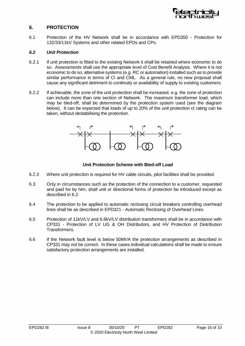
6.2.2 If achievable, the zone of the unit protection shall be increased, e.g. the zone of protection can include more than one section of Network. The maximum transformer load, which may be bled-off, shall be determined by the protection system used (see the diagram below). It can be expected that loads of up to 20% of the unit protection ct rating can be taken, without destabilising the protection.
Unit Protection Scheme with Bled-off Load
6.2.3 Where unit protection is required for HV cable circuits, pilot facilities shall be provided.
6.3 Only in circumstances such as the protection of the connection to a customer, requested and paid for by him, shall unit or directional forms of protection be introduced except as described in 6.2.
6.4 The protection to be applied to automatic reclosing circuit breakers controlling overhead lines shall be as described in EPD321 - Automatic Reclosing of Overhead Lines.
6.5 Protection of 11kV/LV and 6.6kV/LV distribution transformers shall be in accordance with CP331 - Protection of LV UG & OH Distributors, and HV Protection of Distribution Transformers.
6.6 If the Network fault level is below 50MVA the protection arrangements as described in CP331 may not be correct. In these cases individual calculations shall be made to ensure satisfactory protection arrangements are installed.

EPD282 I8 Issue 8 30/10/20 PT EPD282 Page 17 of 10 © 2020 Electricity North West Limited
7. DOCUMENTS REFERENCED
Non-Electricity North West Documents
The following documents, legislation and ENA publication, cannot be supplied by Electricity North West to external parties:
Electricity Safety, Quality and Continuity Regulations 2002
ENA Engineering Recommendation P2/7 - Security of Supply
Electricity North West Published Documents
Distribution Code
Electricity Distribution Licence
The following documents are available from Electricity North West:
Distribution Safety Rules - Issued only to Authorised Persons
EPD279 Distribution System Design - General Requirements
EPD280 Distribution System Design -132kV Network
EPD281 Distribution System Design - 33kV Network
EPD283 Distribution System Design - Low Voltage Network
EPD321 Automatic Reclosing of Overhead Lines
EPD473 Policy for Overhead Line Standards - Design, Construction, Refurbishment, Selection and Classification
ES313 6.6kV and 11kV Single Busbar Indoor Switchgear (Cable Connected)
ES352 Distribution Substations
ES400O2 Overhead Lines of Compact Covered Construction for 11/6.6kV: Design& Construction
ES400O3 Bare Wire Overhead Lines on Wood Poles: Design & Construction
6. KEYWORDS
Design; Network; Planning; Policy; System; 11kV; 6.6kV

EP
D282.d
oc
Issue6
30/1
0/2
0
PT
E
PD
282
Page A
1 o
f 3
©
2020 E
lectric
ity N
orth
West L
imite
d
AP
PE
ND
IX A
33kV
33kV 33kV
11/6.6kV 11/6.6kV
11/6.6kV
1000
1000
1000 1000
1000 800 500
500 500
500
500 315 315 315
315
315
315 500
315
315
50
PAD
500
0.1
0.1 0.1 0.1 0.1 0.1 0.1 0.1
0.1
18
5
0.1
0.1
95
18
5
185
18
5
30
0
0.1
95
300 300 300 300 300 300
18
5
1. U’ground Cable Largest size cable for all new work (4.5.2.2) No radials (4.5.3)
2. Radial Tee Single substation with single customer (except during development) or all pad and compact: Max 200 customers Max 500kVA (4.5.3.2)
3. Customers Max 2000 per circuit (4.2.1)
50
50
100
100
200
PAD
PAD
PAD
PAD
95
95
95
4. Radial Tee with Pad and Compact S/Ss Max 5 substations Max 200 customers Max 500kVA (4.5.3.2)
5. Complexity Max 4 addresses
Max 1 radial (4.5.4)
6. Radial Tee Max 1 T-joint between ring switches (4.5.3.4)
7. Transformer Rating Max 1000kVA (4.4.8.1)
Figure A1 - Typical HV Underground Network Arrangement
8. Remote Control Include with any new work on circuit, if justified by benefits - customer numbers. (4.2.2)
RC
RC RC
9. New Substation with RC If > 200 customers, RC on both switches. (4.2.2)
315
M

EP
D282.d
oc
Issue6
30/1
0/2
0
PT
E
PD
282
Page A
2 o
f 3
©
2020 E
lectric
ity N
orth
West L
imite
d
25
Figure A2 - Typical 11/6.6kV Overhead Network Arrangement
33kV 33kV
11/6.6kV 11/6.6kV
PAD 10. Protection Zone
Max 20km (4.6.4)
PAD
11. Main Line Section Max 5km (excluding radial branches) (4.6.9.4) Max 200 customers Max 500kVA transformer aggregate rating (4.6.7.5)
ASL
12. Group Fusing For spur line not part of auto-reclose scheme (4.6.8.2)
13. PMT Fusing On main line without auto-reclose (4.6.7.2)
14. Live-line Connectors For all PMTs on radial branch lines (4.6.6)
15. Single-phase Loads To be as balanced as possible (4.6.9)
PAD
16. Remote Control of NOP Include with any new work on circuit, if justified by benefits - customer numbers. (4.2.2; 4.6.10)
PAD
RC
200
95
PAD
PAD
200
200
200
100 100
100
100
50
50 50
50
50
50
50 50
50 50
50
50
50
50
50
50
50
25
25
25
25
25
25
25
16
16
16 16
16
16
16
95
95
95
95
32
100SCA
10
0S
CA
R
17. Radial Branch Section Max 5km (4.6.8.3) Max 200 customers (4.6.8.5) Max 500kVA transformer aggregate rating (4.6.8.6)

Figure A3 - Typical 11/6.6kV Mixed Network Arrangement
11/6.6kV 11/6.6kV
PAD
200
200
100 100
50
50
50
50
25 25
16
95
95
100SCA
10
0S
CA
R
GVR
70
200
100 100
100
1000
500
500
315
18. Isolatable Section Max 5km o/h Max 200 customers Max 500kVA transformer aggregate (4.6.8)
19. Single Circuit Risk Max 1MW group demand (4.6.8.6)
20. Complexity Max 4 s/s addresses, excl. PMTs and pads (4.5.4) Max 1 radial (4.5.3.4)
21. Main Line Connection Via switchgear, DOEF mounts, with links or ASLs (4.6.7.2)
185 185
95
100
50
25
16 32
PAD
100
50 50
100 25 32
315
315
22. Point of Isolation 23. Where economically practicable (4.7.6)
32
95 95
95
95
ASL
100SCA
24. Remote Control of NOP Include with any new work on circuit, if justified by benefits. (4.2.2; 4.6.10)
RC RC
32
PAD
100

33kV
33kV
50
Copyright © 2022 FDOKUMEN