
Contents - Schoolplannet
110
Page 1 of 110 Physics’s Notes Contents 17. MOTION OF A PARTICLE ........................................................................................ 5 17.1: Introduction .................................................................. 5 17.2: Equations of Uniformly Accelerated Motion ................... 5 17.3: Graphs .......................................................................... 8 17.4: Non-linear Motion ......................................................... 9 18. VECTORS ................................................................................................................... 11 18.1: Vector Addition ........................................................... 11 18.2: Resolution of Vectors................................................... 11 19. MOMENTUM AND COLLISIONS .......................................................................... 13 19.1: Collisions .................................................................... 13 19.2: Case of Gun and Bullet ................................................. 14 19.3: Rocket Propulsion ....................................................... 14 20. NEWTON’S LAWS OF MOTION ........................................................................... 16 20.1: The laws ..................................................................... 16 20.2: Body in a Lift ............................................................... 17 20.3: Ticker – Timer Experiments ........................................ 17 21. FRICTION .................................................................................................................. 20 22. FLUID FLOW ............................................................................................................ 22 22.1: Streamline and Turbulent Flow ................................... 22 22.2: Relationship between Pressure, Velocity and Closeness of streamlines 22 22.3: Viscosity ..................................................................... 23 23. REFRACTION AT PLANE SURFACES ................................................................. 24 23.1: Laws of Refraction ....................................................... 24 23.2: Some effects of Refraction............................................ 25 23.3: Total Internal Reflection .............................................. 26 23.4: PRISMS ....................................................................... 28 24. DISPERSION OF LIGHT ......................................................................................... 30 24.1: Dispersion by a prism .................................................. 30 24.2: Recombination of the colours of the spectrum.............. 30 24.3: Light filters ................................................................. 31 24.4: Primary and Secondary colours ................................... 31 24.5: Mixing coloured pigments (paints) .............................. 32 25. LENSES ....................................................................................................................... 33
-
Upload
khangminh22 -
Category
Documents
-
view
1 -
download
0
Transcript of Contents - Schoolplannet
Page 1 of 110
Physics’s Notes
Contents 17. MOTION OF A PARTICLE ........................................................................................ 5
17.1: Introduction .................................................................. 5
17.2: Equations of Uniformly Accelerated Motion ................... 5
17.3: Graphs .......................................................................... 8
17.4: Non-linear Motion ......................................................... 9
18. VECTORS ................................................................................................................... 11
18.1: Vector Addition ........................................................... 11
18.2: Resolution of Vectors ................................................... 11
19. MOMENTUM AND COLLISIONS .......................................................................... 13
19.1: Collisions .................................................................... 13
19.2: Case of Gun and Bullet ................................................. 14
19.3: Rocket Propulsion ....................................................... 14
20. NEWTON’S LAWS OF MOTION ........................................................................... 16
20.1: The laws ..................................................................... 16
20.2: Body in a Lift ............................................................... 17
20.3: Ticker – Timer Experiments ........................................ 17
21. FRICTION .................................................................................................................. 20
22. FLUID FLOW ............................................................................................................ 22
22.1: Streamline and Turbulent Flow ................................... 22
22.2: Relationship between Pressure, Velocity and Closeness of streamlines 22
22.3: Viscosity ..................................................................... 23
23. REFRACTION AT PLANE SURFACES ................................................................. 24
23.1: Laws of Refraction ....................................................... 24
23.2: Some effects of Refraction............................................ 25
23.3: Total Internal Reflection .............................................. 26
23.4: PRISMS ....................................................................... 28
24. DISPERSION OF LIGHT ......................................................................................... 30
24.1: Dispersion by a prism .................................................. 30
24.2: Recombination of the colours of the spectrum .............. 30
24.3: Light filters ................................................................. 31
24.4: Primary and Secondary colours ................................... 31
24.5: Mixing coloured pigments (paints) .............................. 32
25. LENSES ....................................................................................................................... 33

Page 2 of 110
Physics’s Notes
25.1: Introduction ................................................................ 33
25.2: Images by a Converging lens ........................................ 34
25.3: Images formed by Diverging lenses .............................. 35
25.4: Determination of Focal length of a Converging lens ...... 35
25.5: Applications of lenses .................................................. 37
25.6: Defects of vision and their correction ........................... 40
26. MAGNETISM PART1 .............................................................................................. 41
26.1: Permanent and Temporary Magnets ............................ 41
26.3: Magnetic Poles and First Law of Magnetism ................. 41
26.4: Methods of Magnetising a Steel Bar .............................. 42
26.5: Induced Magnetism ..................................................... 43
26.6: Demagnetization ......................................................... 43
26.7: Magnetic Properties of Iron and Steel........................... 44
26.8: Magnetic Fields ........................................................... 44
26.9: Magnetic Shielding ...................................................... 46
26.10: The Domain Theory of Magnetism ............................. 47
26.11: Care for Magnets ....................................................... 47
27. MAGNETIC EFFECT OF CURRENT ..................................................................... 48
27.1: Fields due to Different Arrangements Conductors ........ 48
27.2: Electromagnets ........................................................... 49
28. INTRODUCTION TO ELECTRICITY ................................................................... 52
28.1 Origin of Electric Charge ............................................... 52
28.2: Sources of Electricity ................................................... 53
28.4: Conductors and Insulators ........................................... 53
29. ELECTRIC CHARGE ................................................................................................ 54
29.1: Charging by Rubbing ................................................... 54
29.2: Negative and Positive Charge ....................................... 54
29.3: Electrostatic Induction ................................................ 54
29.4: The Gold Leaf Electroscope .......................................... 55
29.5: Hollow conductors ...................................................... 57
30.6: Distribution of Charge over a Conductor ...................... 57
29.7: Action of Points ........................................................... 58
29.8: ELECTRIC FIELDS ........................................................ 59
30. CELL AND BATTERIES .......................................................................................... 60
30.1: The simple cell ............................................................ 60

Page 3 of 110
Physics’s Notes
30.2: The dry Leclanche’ cell ................................................ 61
30.3: The lead-acid cell ......................................................... 62
30.4: Alkaline Cell ................................................................ 63
31. FURTHER ELECTRIC CIRCUITS .......................................................................... 64
31.1: Electric Current ........................................................... 64
31.2: Electric Circuit............................................................. 64
31.3: More Electrical Symbols Used in Circuits ...................... 64
31.4: Mechanism of Conduction ............................................ 65
31.5: Potential Difference (p.d) ............................................. 65
31.6: Resistance ................................................................... 66
31.7: Ohm’s law ................................................................... 66
31.8: Arrangements of Cells ................................................. 68
31.8: Arrangements of Resistors ........................................... 68
31.9: Arrangements of Loads in a Circuit .............................. 71
31.10: Galvanometers .......................................................... 73
31.11: Connection of Ammeters and Voltmeters in Circuits ... 74
31.12: Electrical Energy and Power ...................................... 75
31.13: Domestic Power Installation Circuits ......................... 77
32. MODERN PHYSICS .................................................................................................. 79
32.1: ELECTRONS ................................................................ 79
32.2: X-RAYS ........................................................................ 82
32. 3: ATOMIC AND NUCLEAR STRUCTURE .......................... 83
32.4: RADIOACTIVITY .......................................................... 84
33. HEAT CAPACITY AND CHANGE OF STATE ..................................................... 88
33.1: HEAT CAPACITY .......................................................... 88
33.2: LATENT HEAT ............................................................. 89
33.3: Effect of Pressure on Melting ....................................... 93
33.4: VAPOURS .................................................................... 93
33.5: Dependence of Boiling Point on External Pressure ....... 94
34. THE GAS LAWS ........................................................................................................ 97
34.1: Boyle’s Law ................................................................. 97
34.2: Charles’s Law .............................................................. 97
34.3: Pressure Law .............................................................. 99
35. FORCE ON A CURRENT-CARRYING CONDUCTOR ...................................... 101
35.1: Introduction .............................................................. 101

Page 4 of 110
Physics’s Notes
35.2: The Simple D.C Motor ................................................ 101
35.3: The Moving-Coil Loud Speaker .................................. 103
35.4: The Moving-Coil Galvanometer .................................. 103
36. ELECTROMAGNETIC INDUCTION ................................................................... 104
36.1: Laws of Electromagnetic Induction ............................ 104
36.2: Self Induction ............................................................ 104
36.3: Mutual Induction ....................................................... 105
36.4: The Transformer ....................................................... 105
36.5: The Simple Alternating Current Generator (dynamo) . 107
36.6: Rectification of Alternating Current ........................... 108
36.7: Advantages of A.C over D.C ........................................ 109
ANSWERS TO NUMERICAL EXERCISES ................................................................ 110

Page 5 of 110
Physics’s Notes
17. MOTION OF A PARTICLE
17.1: Introduction
Displacement This is the distance moved in a specified direction. So, displacement is a vector because it is specified as a magnitude together with direction. On the other hand, distance is a scalar. Speed Speed is the rate of change of distance with time. Its SI unit is m s-1. It is a scalar since it is specified by magnitude only. Velocity This is the rate of change of displacement. It is a vector, since it is specified by both magnitude and direction. A particle is said to move with uniform velocity if its displacement changes by equal amounts in equal time intervals. Acceleration This is the rate of change of velocity with time. Its SI unit is m s-2. A particle is said to move with uniform acceleration if its velocity changes by equal amounts in equal time intervals.
17.2: Equations of Uniformly Accelerated Motion
If a body, originally moving with a velocity u accelerates uniformly at a rate a m s-2, then its velocity, v, after time t seconds is given by Final velocity = initial velocity + increase in velocity v = u + at …………………………………. (1) The displacement, s, of the particle during this time is given by Displacement = Average velocity x time s = ½(u + v) x t But from above, v = u + at s = (u + at + u)t
𝒔 = 𝒖𝒕 + 𝟏
𝟐𝒂𝒕𝟐 … … … … … … … … … (2)
Also, from (1)𝑡 =v − u
𝑎
s =(𝑢 + 𝑣)
2
(𝑣 − 𝑢)
a
v2= u2 + 2as ………… ……………………….. (3) (1), (2) and (3) are known as equations of uniformly accelerated motion Example A particle initially moving with a velocity of 5 m s-1, accelerates uniformly at 4 m s-1. Find: (i) The velocity of the particle after 8 s.
Page 6 of 110
Physics’s Notes
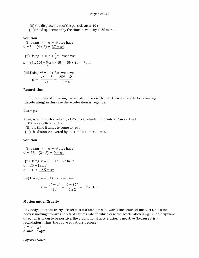
(ii) the displacement of the particle after 10 s. (iii) the displacement by the time its velocity is 25 m s-1. Solution (i) Using v = u + at , we have v = 5 + (4 x 8) = 37 m s-1
(ii) Using s =ut + 1
2at2 we have
s = (5 x 10) + (1
2 x 4 x 10) = 50 + 20 = 70 m
(iii) Using v2 = u2 + 2as, we have
s = v2 − u2
2a =
252 − 52
2 x 4
Retardation If the velocity of a moving particle decreases with time, then it is said to be retarding (decelerating) in this case the acceleration is negative. Example A car, moving with a velocity of 25 m s-1, retards uniformly at 2 m s-2. Find: (i) the velocity after 8 s. (ii) the time it takes to come to rest (iii) the distance covered by the time it comes to rest. Solution (i) Using v = u + at , we have v = 25 − (2 x 8) = 9 m s-1 (ii) Using v = u + at , we have 0 = 25 − (2 x t) t = 12.5 m s-1 (iii) Using v2 = u2 + 2as, we have
s = v2 − u2
2a =
0 − 252
2 x 2 = 156.3 m
Motion under Gravity Any body left to fall freely accelerates at a rate g m s-2 towards the centre of the Earth. So, if the body is moving upwards, it retards at this rate, in which case the acceleration is –g. i.e if the upward direction is taken to be positive, the gravitational acceleration is negative (because it is a retardation). Thus, the above equations become: v = u − gt h =ut− ½gt2

Page 7 of 110
Physics’s Notes
andv2 = u2− 2gh However, if the downward direction is chosen to be positive, the gravitational acceleration is then positive. Examples 1. A particle is projected vertically upwards with a velocity of 20 m s-1. Find: (i) the greatest height the particle attains (ii) the time taken to attain the greatest height (iii) the velocity and direction of motion after 3 s of motion (iv) the height 3 s after projection [Take g to be 10 ms-2] Solution (i) At the highest point the velocity of the particle is zero Let h = greatest height Then, using v2 = u2 – 2gh, we have 0 = 202 – 2 x 10h h =20 m (ii) Using v = u − gt , where t is the time required, we have 0 = 20 – 10t t = 2 s (iii) Using v = u − gt , where v is the velocity after 3 s, we have v = 20 – 10 x 3 = -10 m s-1 Since we chose the upward direction to be positive, the negative sign implies that the particle is moving downwards.
(iv) Using h =ut−1
2gt2 , we have
h = 20 x 3 −1
2 x 10 x 32 = 15 m
2. A stone is released from the top of a tree and hits the ground after 3 s. Find: (i) the height of the tree (ii) the velocity with which it hits the ground Solution (i) We may take the downward direction as positive. So, the acceleration is g = 10 m s-2. Using h
= ut + 1
2gt2 , where u = 0, we have
h = 0 + 1
2 x 10 x 32 = 45 m
(ii) Using v = u + gt , we have v = 0 + 10 x 3 = 30 m s-1

Page 8 of 110
Physics’s Notes
17.3: Graphs
1. Displacement –Time Graphs The gradient of a displacement-time graph gives the velocity of the particle. 2. Velocity – Time Graphs
(i) The gradient of a velocity-time graph gives the acceleration of the particle. (ii) The area under the curve between any two time instants gives the distance covered by the particle between the two time instants
Example
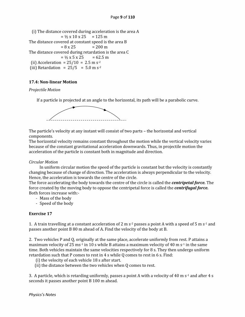
A car starting from rest at P accelerates uniformly for 10 s to a velocity 25 ms-1. It then moves at this constant velocity for 8 s before retarding uniformly for 5 s so as to stop at Q. Sketch the velocity-time graph for the car’s motion between points P and Q and find (i) the distance covered during each of the parts of the journey described. (ii) the acceleration of the car (iii) the retardation of the car Solution
Time
Vel
oci
ty
(b) Accelerating uniformly
Time
Vel
oci
ty
(b) Retarding uniformly
Time
Dis
pla
cem
ent
(a) Moving with constant
velocity
Time
Dis
pla
cem
ent
(b) Accelerating
uniformly
Time
Vel
oci
ty
(a) Moving with constant velocity
A B C
Time /s
v /ms-1
25
10 8 5
Page 9 of 110
Physics’s Notes
(i) The distance covered during acceleration is the area A = ½ x 10 x 25 = 125 m The distance covered at constant speed is the area B = 8 x 25 = 200 m The distance covered during retardation is the area C = ½ x 5 x 25 = 62.5 m (ii) Acceleration = 25/10 = 2.5 m s-2 (iii) Retardation = 25/5 = 5.0 m s-2
17.4: Non-linear Motion
Projectile Motion If a particle is projected at an angle to the horizontal, its path will be a parabolic curve. The particle’s velocity at any instant will consist of two parts – the horizontal and vertical components. The horizontal velocity remains constant throughout the motion while the vertical velocity varies because of the constant gravitational acceleration downwards. Thus, in projectile motion the acceleration of the particle is constant both in magnitude and direction. Circular Motion In uniform circular motion the speed of the particle is constant but the velocity is constantly changing because of change of direction. The acceleration is always perpendicular to the velocity. Hence, the acceleration is towards the centre of the circle. The force accelerating the body towards the centre of the circle is called the centripetal force. The force created by the moving body to oppose the centripetal force is called the centrifugal force. Both forces increase with:-
- Mass of the body - Speed of the body
Exercise 17 1. A train travelling at a constant acceleration of 2 m s-2 passes a point A with a speed of 5 m s-1 and passes another point B 80 m ahead of A. Find the velocity of the body at B. 2. Two vehicles P and Q, originally at the same place, accelerate uniformly from rest. P attains a maximum velocity of 25 ms-1 in 10 s while B attains a maximum velocity of 40 m s-1 in the same time. Both vehicles maintain the same velocities respectively for 8 s. They then undergo uniform retardation such that P comes to rest in 4 s while Q comes to rest in 6 s. Find: (i) the velocity of each vehicle 18 s after start. (ii) the distance between the two vehicles when Q comes to rest. 3. A particle, which is retarding uniformly, passes a point A with a velocity of 40 m s-1 and after 4 s seconds it passes another point B 100 m ahead.

Page 10 of 110
Physics’s Notes
Find (i) the acceleration of the particle (ii) how far the particle is from B when it comes to rest. 4. The table below shows the distance, x, in metres covered after time, t, in seconds for a moving particle.
t/s 0 2 4 6 8 10 x/m 4 14 24 34 44 54
Plot a graph of distance against time and find the speed of the particle. 5. The table below shows the velocity v ms-1 attained after time t seconds for a particle.
t/s 0 2 4 6 8 10 12 14 16 18 v/m s-2 5 13 21 29 39 39 39 27 15 3
Draw the velocity-time graph for the motion and describe the motion of the particle during its motion. Find: (i) The distance covered throughout the journey (ii) the acceleration of the particle (iii) the retardation (iv) the distance moved while accelerating (v) the time that will have elapsed when it stops 6. A particle is projected vertically upwards with a velocity of 30 m s-1. Find: (i) the time taken for the particle to attain the greatest height. (ii) the displacement of the particle 5 s after projection.

Page 11 of 110
Physics’s Notes
18. VECTORS Quantities like displacement, velocity, force, acceleration, etc are vector quantities. A vectorquantity is one specified as a magnitude together with a direction. On paper it is represented as a line with an arrow. Addition or subtraction of such quantities is carried out vectorially.
18.1: Vector Addition
The sum of a number of vectors is known as the resultant of the vectors involved. It is a single vector having the same effect as the vectors involved. Imagine two vectors a andb which are perpendicular to each other. Their resultant, c is given by c =a + b The magnitude of c is PR, and by Pythagoras theorem PR2 = PQ2 + QR2 PR =PQ2 + QR2 Examples
1. Two forces of 3N and 4N, at right angles, act at a point. Find their resultant. Solution
The resultant, R = (32 + 42) = 5N at an angle as shown
tan = 3
4
= 36.9o 2. A man who can swim at 2 m s-1 in still water swims directly across a river that flows at 1 m s-1. What is the resultant velocity of the man? Solution
The resultant velocity, v =(22 + 12) = 2.24 m s-1 at an angle
= tan−1 (1
2) = 26.6o
18.2: Resolution of Vectors
A vector may be expressed in terms of two vectors that are perpendicular to each other. When this is done, the vector is said to have been resolved into two vectors. The two vectors so obtained are known as components of the vector. For example:
Q b
a c
R
P
4N
3N R
1 ms-1
2 ms-1 v

Page 12 of 110
Physics’s Notes
Imagine a vector P, along OA is resolved into components acting OB
and OC. The component acting along OB has magnitude P cos and that along OC P cos.
Example A force of 8N is resolved into components that make angles of 60o and 30o with the force. Find the magnitude of the components. Solution
Magnitude of component at 60o = 8 cos 60o = 4N Magnitude of component at 30o = 8 sin 60o = 6.93 N
Exercise 18 1. Determine the resultant of each the following combinations of forces acting at a point (a) (b) (c)
60o
B
C
P
A
O
4 N 9 N
3 N
4 N
5 N
2 N 14 N

Page 13 of 110
Physics’s Notes
19. MOMENTUM AND COLLISIONS Any moving body is said to possess momentum. Linear momentum of a body is the product of the body’s mass and its velocity. It is a vector quantity. A body of mass m moving with a velocity v has momentum equal to mv. Application of a force to a body can change its momentum. The SI unit of momentum is kg ms-1.
19.1: Collisions
When bodies collide, each body experiences a force from the other. So, the momentum of each body changes. However, as long as no other force participates in the impact, the changes in momentum are such that the total momentum of the bodies remains the same. Law of Conservation of Momentum If no external force acts on a system of colliding bodies, the total momentum of the bodies remains constant. This may be summarised as follows: Total momentum after collision = total momentum before collision Suppose a body of mass m1 moving with a velocity u1 collides directly with another of mass m2 originally moving with a velocity u2. Then the total momentum before collision = m1u1 + m2u2. If the respective velocities of m1 and m2 after collision are v1 and v2, the total momentum after collision = m1v1 + m2v2. So, according to the above law m1u1 + m2u2 = m1v1 + m2v2 Examples 1. A particle P of mass 1 kg moving with a velocity of 2 m s-1 is knocked directly from behind by another particle Q of mass 2 kg moving at 4 m s-1. If the velocity of P increases to 4.5 m s-1, find the new velocity of Q. Solution m1 = 1 kg, u1= 2 m s-1, v1 = 4.5 m s-1 m2 = 2 kg, u2= 4 m s-1, v2 = ? Total momentum after collision = total momentum before collision m1v1 + m2v2= m1u1 + m2u2 (1 x 4.5) + 2 x v2 = (1 x 2) + (2 x 4) 4.5 + 2v2 = 2 + 8 v2= 2.75 m s-1 2. A ball X of mass 1 kg moving with a velocity of 3 m s-1 collides directly with another ball Y of mass 2 kg moving at 2 m s-1 in the opposite direction. If Y reverses at 1 m s-1, find the new velocity and direction of motion of X after collision. Solution Let the initial direction of X be positive and its mass m1. m1 = 1 kg, u1= 3 m s-1, v1 = ?

Page 14 of 110
Physics’s Notes
m2 = 2 kg, u2= -2 m s-1, v2 = 1 m s-1 m1v1 + m2v2= m1u1 + m2u2 (1 x v1) + (2 x 1) = (1 x 3) + (2 x -2) v1 = 3 – 4 – 2 = -3 m s-1 The negative sign means that X reverses at 3 m s-1 3. An arrow of mass 100 g moving at a velocity of 16 m s-1 horizontally enters a block of wood of mass 540 g lying at rest on a smooth surface. Find the common velocity after impact. Solution m1 = 100 g, u1= 16 m s-1, v1 = v2 = v m2 = 540 g, u2= 0 (m1 + m2)v = m1u1 + m2u2 (100 + 540)v = 100 x 16 v = 2.5 m s-1
19.2: Case of Gun and Bullet
Before the bullet is fired, the total momentum of gun and bullet is zero. Therefore even when the bullet is fired, the total momentum must remain zero, since the total momentum is conserved. This is why when the bullet moves forward, the gun must move backwards (recoil) with an equal but negative momentum. Example A gun of mass 4 kg fires a bullet of mass 50 g at a velocity of 200 m s-1. Find the recoil velocity of the gun. Solution The recoil momentum of the gun must equal to the forward momentum of the bullet. Let the recoil velocity be V. Then, 4000V = 50 x 200 V = 2.5 m s-1
19.3: Rocket Propulsion
Experiment :To Demonstrate Rocket Propulsion
- Inflate a balloon and seal its opening by twisting it. - Tape a drinking straw lengthwise along one side of the balloon - Run a string through the straw. - Attach one end of the string to any rigid stationary object - Pull the string taut and attach its other end to another stationary object across the room (or you
may have a colleague hold the other end of it)
Cellotape
Balloon
Drinking straw Taut string

Page 15 of 110
Physics’s Notes
- Once the setup is complete, untie the twist and release the balloon. What is your observation?
- Repeat the experiment but this time incline the string so that the twisted end of the balloon is lowermost before releasing it.
Explanation: When the balloon is opened the air molecules gain momentum in the direction of the exit at a certain rate. This results in creation of a force pushing the balloon in the opposite direction. So, it is propelled on. Relation of the Observations to Rocket Movement When the fuel of the rocket is burnt, the molecules of the products gain tremendous kinetic energy and collide with the walls of the combustion chamber. Due to the high rate of change of momentum, a force is created on the walls of the combustion chamber. Now, on the rear there is an opening. So the molecules colliding with the wall in the forward direction create a forward force which is not balanced since the backward direction is open. This way the rocket experiences a net force in the forward direction and is propelled forward. Exercise 19 1. A car of mass 1500 kg moving with velocity of 25 m s-1 collides directly with another car of mass 1400 kg at rest so that the two stick and move together. Find their velocity. 2. A bullet of mass 30 g is fired into a stationary block of wood of mass 480 g lying on a smooth horizontal surface. If the bullet gets embedded in the block and the two move together at a speed of 15 m s-1. Find: (i) the speed of the bullet before it hits the block. (ii) the kinetic energy lost. 3. A moving ball A of mass 200 g collides directly with a stationary ball B of mass 300 g so that A bounces with a velocity of 2 m s-1 while B moves forward with a velocity of 3 m s-1. Calculate the initial velocity of A. 4. A particle X of mass 2 kg originally moving with a velocity of 3 m s-1 collides directly with another particle Y of mass 2 kg which is moving at a velocity of 2 m s-1 in the opposite direction so that the velocity of X becomes 1 m s-1 after the impact. Find the velocity of Y after the impact. 5. A bullet of mass 40 g is fired with a velocity of 200 m s-1 from a gun of mass 5 kg. What is the recoil velocity of the gun?
Burnt gases
Forward motion
Burning fuel

Page 16 of 110
Physics’s Notes
20. NEWTON’S LAWS OF MOTION
20.1: The laws
Law 1 Every body continues in its state of rest or of uniform motion in a straight line unless compelled by some external force to act otherwise. This law implies that if a body is to change speed or direction of motion, a force must be applied to it. Law 2 The rate of change of momentum of a body is directly proportional to the applied force and occurs in the direction of the force. Law 2 enables us to find a mathematical relation between force, mass and rate of change of velocity. Suppose a constant net force F acts on a mass m so that the velocity of m changes from u to v in time t. Then, from law 2
𝐹𝑜𝑟𝑐𝑒𝐶ℎ𝑎𝑛𝑔𝑒𝑖𝑛𝑚𝑜𝑚𝑒𝑛𝑡𝑢𝑚
𝑇𝑖𝑚𝑒𝑡𝑎𝑘𝑒𝑛
𝐹𝑚𝑣 − 𝑚𝑢
𝑡Type equation here.
𝐹𝑚(𝑣 − 𝑢)
𝑡
But v – u = a, the acceleration t F ma Or F =kma, where k is a constant If F is measured in N, the mass in kg and the acceleration a in ms-2 , then the value of k is 1. Thus F = ma Examples 1. A resultant force of 6N acts on a body of mass 2 kg. What is the acceleration of the body? Solution Net force (F) = Mass(m) x acceleration(a) a = F/m = 6/2 = 3 m s-2
2. Two forces 10N and 6N act on a particle of mass 5 kg as shown. Find the acceleration of the particle. Solution Since the forces act along the same line in opposite directions, the net force on the particle is (10 – 6) = 4N in the direction of the bigger force.
5kg 6N 10N

Page 17 of 110
Physics’s Notes
Acceleration, a = F/m = 4/5 = 0.8 m s-2 Law 3 To every action there is an equal and opposite reaction. This means, for example, that when a body of mass m rests on a horizontal support, it exerts a force equal to mg on the support, where g is the gravitational acceleration. The support exerts an upward force R on the body
R = mg
20.2: Body in a Lift
When a body of mass m is placed on the floor of a lift, the body experiences a reaction R from the floor. If the lift is stationary, or not accelerating, the net force on the body is zero. in this case the normal reaction R is just equal to the weight mg of the body
(a) Lift Accelerating Downwards In this case there is a net downward force. So the reaction R, experienced on
the floor, is less than the weight mg. Now, the net force = mass x acceleration mg - R = ma R= mg – ma = m(g – a)
If the lift is left to fall freely, then a = g and R = 0 (b) Lift Accelerating Upwards This time there is a net upward force. So, the reaction R is greater than the
weight mg, i.e the body appears to weigh more. Net force = mass x acceleration R - mg = ma R= mg + ma = m(g + a)
20.3: Ticker – Timer Experiments
A ticker-timer makes it possible to measure the acceleration of a moving body. A tape, attached to the body whose motion is being studied, is passed beneath a carbon paper above which is a point that rocks on it at regular time intervals. This way, dots are printed on the tape at regular time intervals.
R =mg
mg
R
mg
m
R
mg
m
a
R
mg
m
a
Pulling force Tape Ticker Carbon paper
Trolley

Page 18 of 110
Physics’s Notes
If the body is moving with constant velocity, the dots are equally spaced along the tape. If the body is accelerating, the dot spacing progressively increases. What is the dot pattern if the body is retarding? By using different values of the pulling force on the trolley, it can be shown that
𝒂 F where F = acceleration a = acceleration m = mass of the body By altering the mass loaded on the trolley, but maintaining the same pulling force, it can be shown
that 𝒂𝟏
𝒎
Calculation of Acceleration from Tape dots If the frequency of the ticker is, say 50 Hz, it prints 50 dots in 1 s. so, the time interval between adjacent dots is 1/50 = 0.02 s. The usual practice is to consider the distance occupied by 10 spaces. The first few dots are ignored because they are too close to be distinguished from each other. The distances x1 and x2 occupied by successive 10 dot-spaces are measured. Now, the time taken by a 10 dot-space = 10 x 0.02 = 0.2 s average velocity over the distance x1 = x1/0.2 And the average velocity over distance x2 = x2/0.2
Hence, change in velocity in 0.2 s = 𝑥2
0.2−
𝑥1
0.2 =
𝑥2 − 𝑥1
0.2
Now, the acceleration = Change in velocity
Time =
𝑥2 − 𝑥1
0.22
Example
In a ticker-timer experiment the distance occupied by a 6-dot space on the tape is 5.1 cm, while the adjacent 6-dot space occupies 6.3 cm. find the acceleration of the body to which the tape is attached, if the ticker frequency is 50 Hz. Solution
Direction of motion
Constant
Speed Acceleratin
g
Retarding
10 spaces Time = 0.2s
10 spaces Time = 0.2s
x1 x2

Page 19 of 110
Physics’s Notes
Time taken by 6-dot space = 6 x 1 = 0.12 s 50
Acceleration = 6.3 − 5.1
(0.12 x 012)=
1.2
0.0144= 83.3 cm s−1
Inertia and its Role
Inertia is a body’s resistance to its state of rest or motion. It is proportional to a body’s mass and it accounts for the following observations:
- When a vehicle suddenly stops, passengers lurch forward because they tend to continue with the forward movement.
- When a vehicle starts off, the passengers jerk backwards – since they tend to remain at rest Exercise 20 1. A force of 100 N acts on a body and produces an acceleration of 2 m s-2. What is the mass of the body? 2. A car of mass 1200 kg moving with a velocity of 50 m s-1 is retarded uniformly to rest in 10 s. What is the retarding force? 3. A block of mass 40 kg is pulled from rest along a horizontal surface by a rope connected to one face of the block as shown below. Given that the tension is 200 N and that the frictional force between the block and the horizontal surface is140 N, find (i) the acceleration of the block. (ii) the distance moved in 5.0 s 4. A particle of mass 4 kg is acted on by a system of forces as shown below.Find the acceleration of the particle. 5. A cylinder contains 10 kg of compressed gas. The valve is opened and after 20 s the mass of gas remaining in the cylinder is 4 kg. If the gas flows out of the nozzle at an average speed of 25 m s-1, find the average force exerted on the cylinder.
40 kg 200 N
140 N
50 N
4 kg 30 N
10 N

Page 20 of 110
Physics’s Notes
21. FRICTION This is a force which opposes relative motion of two surfaces in contact. It comes into existence the moment a surface is pulled or pushed to slide over another. For example, suppose a force P is applied to pull a body B over a surface. Then an equal opposing force (friction) F comes into existence between the surfaces. As the force P is increased, the frictional force F increases equally. However, eventually the frictional force reaches a maximum value. Any increase in the pull P now moves the block. The maximum frictional force reached is called the limiting frictional force for the setup. It bears a relationship to the normal reaction offered by the supporting surface to the block. If the surface is horizontal, the normal reaction is equal to the weight of the block. In chapter 3 we discussed the advantages and disadvantages of friction and ways of reducing friction. Disadvantages of Friction Friction:
- wears out surfaces - causes unnecessary noise - produces unnecessary heat - slows motion - reduces efficiency of machines
Friction can be reduced by
(i) lubrication of the surfaces in contact. (ii) using smooth surfaces Advantages of Friction Friction makes it possible for:
- one to write - one to walk - a moving vehicle to brake - knife to be sharpened - a match stick to produce fire
Experiment: To Investigate the Relationship between the Limiting Frictional Force and the Normal Reaction
- A block B is weighed and placed on a horizontal surface
B F P
Spring balance
B
b
R
W
P = F

Page 21 of 110
Physics’s Notes
- The block is then pulled with a horizontal spring balance and when it is at the point of beginning to slide, the reading, P, on the spring balance is noted.
- A weight b is added to the block. The total weight, W, of the B plus what is added, is found and B is pulled to find the new value of P.
- The procedure is repeated for several other weights added and a table as shown below is filled.
Total weight, W/N
P/N
P W
The ratio P/W is found to be constant. Now, P is equal to the limiting frictional force and W is equal to the normal reaction. So, the limiting frictional force is directly proportional to the normal reaction. The ratio P/W is known as the coefficient of static friction between the two surfaces. Alternatively, plot a graph of P against W and find its slope. The slope is equal to the coefficient of friction. Kinetic Friction Even when the surfaces are actually sliding over each other, a frictional force exists between them, known as the kinetic frictional force. It is slightly lower than the limiting frictional force and is also directly proportional to the normal reaction but is independent of the speed with which the surfaces are sliding over each other. Summary of behaviour of Solid Friction
- Friction opposes relative motion of surfaces in contact. - The maximum (limiting) friction force is directly proportional to the normal reaction but
independent of the area of contact. - The kinetic frictional force is independent of the relative speed between the two surfaces but
dependent on the normal reaction. Example A box of weight 20N rests on a horizontal floor. A minimum horizontal force of 6N is required to move the box along the floor. If a weight of 10N is added to the box, find the minimum horizontal force required to move the block. Solution The minimum force required is the limiting frictional force. Let F be the required force in the second case. Then, F F = 6 20 + 10 20 F = 9N

Page 22 of 110
Physics’s Notes
22. FLUID FLOW
22.1: Streamline and Turbulent Flow
When a water tap is opened slightly, the water oozes out slowly in form of a thin smooth orderly stream. As the tap is opened further, eventually the water flows fast and the order disappears. Thus, by changing the velocity, the flow changes from one kind to another. The orderly flow is termed the streamline flow. In such flow the liquid molecules move in layers and do not cross from layer to another. This happens at low speeds of flow. The disorderly flow at high speeds is termed as turbulent flow. Here the liquid no longer flows in layers and the movement of the molecules is in all directions. Demonstration of Streamline and Turbulent Flow
- A transparent tank, fitted with a horizontal transparent tube is filled with water from a tap. Tap A controls the rate of flow through the horizontal tube while tap B opens for the coloured liquid.
- Tap A is opened, first slightly and then B is opened to release some coloured liquid. - Tap A is progressively opened further.
Observation: At first a thin coloured line is seen in the horizontal tube. This is streamline flow. However, as A is opened further, the coloured line disappears and instead the colour fills the whole tube. The flow has now become turbulent.
22.2: Relationship between Pressure, Velocity and Closeness of streamlines A streamline is a path where molecules have steady speed and each molecule retraces the path of the one directly ahead of it. Where the streamlines are close, the velocity of the fluid is high but the pressure is low, and vice versa. This was discovered by a scientist known as Bernoulli. The diagram below shows air flowing past an object. The shape of the object makes the air above it to flow faster and at reduced pressure than that passing below. So the streamlines above are closer.
Low pressure region
Higher pressure region
Object Object
Transparent tank
Coloured water
Jet
Tap B
Tap A
Clear water
Transparent tube
Thin coloured line
Page 23 of 110
Physics’s Notes
This principle is applied: - when a plane is taking off from the runway. - in carburetors - in sprayers, etc
22.3: Viscosity
In Liquids When a liquid is flowing, the different layers of its molecules do not move at the same velocity. This means that the adjacent planes of molecules are sliding (rubbing) over each other. The molecules adjacent to the walls of the container are held stationary because of adhesion. The further away from the walls the molecules are the higher is their velocity. The intermolecular attraction creates a force that opposes sliding of the planes of liquid molecules. This is known as the viscous force. The viscous force resists flow of a fluid and the movement of an object through a fluid. It increases with velocity. To prove this, stir a liquid in a beaker, first slowly and then increase the speed. At higher speeds the force opposing the motion of the stirrer is greater. A liquid with high viscosity flows very slowly. You may compare water with oil. Which one has higher viscosity? High viscosity liquids are used as lubricants. Viscosity decreases as the temperature of the liquid rises. In gases
In a gas the intermolecular attraction is negligible but the molecules collide frequently with each other and with any object that is moving through the gas. The momentum transfers involved bring about viscosity in a gas. Fall of Objects through the Atmosphere
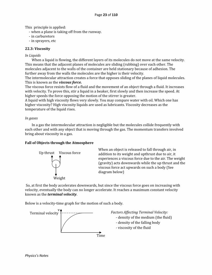
When an object is released to fall through air, in addition to its weight and upthrust due to air, it experiences a viscous force due to the air. The weight (gravity) acts downwards while the up thrust and the viscous force act upwards on such a body (See diagram below)
So, at first the body accelerates downwards, but since the viscous force goes on increasing with velocity, eventually the body can no longer accelerate. It reaches a maximum constant velocity known as the terminal velocity. Below is a velocity-time graph for the motion of such a body.
Factors Affecting Terminal Velocity:
- density of the medium (the fluid)
- density of the falling body
- viscosity of the fluid
Up thrust Viscous force
Weight
Terminal velocity
Time
v

Page 24 of 110
Physics’s Notes
23. REFRACTION AT PLANE SURFACES Light is a wave. When it crosses from one medium to another, of different optical density, its speed changes. If the incident light meets the boundary obliquely, a change of direction occurs. Refraction is the change in speed of light commonly resulting in change of direction as light crosses from one medium to another of different optical density. Terms
AO is the incident ray OB is the refracted ray NN is the normal iis the incident angle r is the angle of refraction
23.1: Laws of Refraction
1. The incident and refracted rays are on opposite sides of the normal at the point of incidence and all three are in the same plane.
2. Snell’s law: The ratio of the sine of the angle of incidence to the sine of the angle of refraction is a constant for a given pair of media.
Experiment: To Investigate Snell’s Law - Draw a straight line SSon a plain sheet of paper. - Draw a normal ON and other lines at angles to ON of 20o, 30o, 40o, 50o and 60o. - Fix a plain sheet paper on a soft board.
- Place a ruler along SSand a rectangular glass block carefully in contact with it. - While holding the block firmly in position transfer the ruler to the lower edge of the block. - Now remove the glass block and draw the line TT along the ruler. - Without moving the ruler place back the glass block carefully in contact with the ruler. - Stick pins P1 and P2 along one of the lines as far apart as possible.
S O S
P1
P2 i
N
r
T A T P3
P4
S O S
T T
N
A
i air O
glass r
Refracted ray
N
N B

Page 25 of 110
Physics’s Notes
- While looking through the block, stick pins P3and P4 so that all the pins appear to be in line. - Remove the block and draw a line through P3and P4 to meet TTat point A. - Join O to A and measure angle r. - Repeat the procedure for all lines drawn earlier and fill the table.
𝑖/o 𝑟/o sin 𝑖 sin 𝑟 sin 𝑖
sin 𝑟
20 30 40 50 60
The values in the column for the ratio of sin i to sin r are the same within experimental errors. This is Snell’s law. Refractive Index
The constant 𝑆𝑖𝑛𝑖
𝑆𝑖𝑛𝑟 for a ray passing from one medium to another is called the refractive index of the
second medium with respect to the first.
i. e𝒏 = 𝑺𝒊𝒏𝒊
𝑺𝒊𝒏𝒓
What is the refractive index of the glass of the block in the previous experiment?
23.2: Some effects of Refraction
1. Apparent bending of a stick
Rays of light from end B bend away from their normals, as shown in the diagram below, and appears to come from Bas they enter the eye. B is thus the image of B by refraction. The same reasoning applies to any point on the immersed part of the stick. So the stick appears bent.
2. Apparent shallowness of a transparent medium.
Rays of light from a point O at the bottom bend away from their normals as they cross from glass to air and appear to come from I as they enter the eye. So the bottom appears to be at I.
𝑅𝑒𝑓𝑟𝑎𝑐𝑡𝑖𝑣𝑒𝑖𝑛𝑑𝑒𝑥, 𝑛 = 𝑅𝑒𝑎𝑙𝑑𝑒𝑝𝑡ℎ
𝐴𝑝𝑝𝑎𝑟𝑒𝑛𝑡𝑑𝑒𝑝𝑡ℎ
Real depth
I Apparent depth
Air
Water (or glass)
Air
Water
A
B
B

Page 26 of 110
Physics’s Notes
23.3: Total Internal Reflection
Imagine a ray of light AO travelling from a dense medium to a less dense one e.g from glass to air. While the main ray is refracted along OB, a fraction of it is reflected along OC inside the glass.
As the angle of incidence ig is increased, ia also increases until a certain value of ig= c is reached when the ray fails to emerge but instead moves along the boundary. Under these conditions the angle of incidence, c, in the the denser medium for which the angle of refraction is 90o is called the critical angle. When the angle of incidence ig is increased beyond c, all the light is reflected into the same medium. This behavior is known as total internal reflection. It always occurs whenever the angle of incidence in the denser medium is greater than the critical angle.
Relation between Critical Angle and Refractive Index
𝑅𝑒𝑓𝑟𝑎𝑐𝑡𝑖𝑣𝑒𝑖𝑛𝑑𝑒𝑥, 𝑛 = 𝑆𝑖𝑛𝑖𝑎
𝑆𝑖𝑛𝑖𝑔
When ig =c, ia = 90o
Therefore 𝑛 = 𝑆𝑖𝑛 90
𝑆𝑖𝑛𝐜
𝒏 = 𝟏
𝒔𝒊𝒏𝐜
Example:
Find the critical angle of a medium of refractive index 1.55. Solution
𝑠𝑖𝑛𝐜 = 1
𝑛=
1
1.55= 0.645
Therefore, c =40.20
Air
Glas
s
O ia
A C
B
cc
Air
Glas
s
O
ia
igig
A C
B
Air
Glass O
ia
A C
B
igig

Page 27 of 110
Physics’s Notes
The fish’s Eye view As long as the water surface is calm a fish has a full view of everything above the water. Multiple Images in Thick Mirrors When an incident ray OA meets the front surface of the mirror, a small fraction of it is reflected there giving rise to a faint image I1. The main ray is refracted and then reflected on the back surface and as it emerges it is refracted to give rise to the main image I2. At each emergence a small fraction of the ray is internally reflected and this results in a series of faint images in a line. The mirage
This is an illusion on a shiny day in which a pool of water appears to exist at a short distance ahead. On a hot day the air closest to the ground is hot. The cooler layers of air are progressively experienced upwards.
Warm air
Hot air
cc cc
Field of view
O
A
I1 I2 I3

Page 28 of 110
Physics’s Notes
A ray of light from the sky progressively bends away from the normal as it passes through warmer layers of decreasing refractive index until it becomes parallel to the ground. After this it proceeds to bend progressively upwards and on entering the eye it appears to come from the ground. So the ground appears like water reflecting the sky.
23.4: PRISMS A prism is a solid with plane faces and of uniform cross-section. The diagram shows a cross-section of a prism. An incident ray OB is refracted at B and then at C as it emerges. The net result is that the ray bends towards the base of the prism as it passes through it. Prisms can be arranged to cause total internal reflection. The diagrams below show different arrangements of a right angled prism.
Diagrams (i) and (iii) show the prism turning the image round. So, it is acting as an erecting prism. The Prism Periscope
Optical fibre
This is also an application of total internal reflection. It is a very fine glass rod of diameter of about 125µm with a central glass core surrounded by a coating of smaller refractive index.
O
B C
Right-angled prisms
125μm
Cladding
Core
(i) (ii)
(iii)

Page 29 of 110
Physics’s Notes
A beam of light entering one end of the core is totally internally reflected several times until it comes out at the other end. Optical fibre is used in transmission of signals and data. It can also be used to examine the inside of a tract. Exercise 23 1. A ray of light enters glass at angle of incidence
of 45o. If the refractive index of glass is 1. 5, determine the angle .
2.
A ray of light travelling from glass, of refractive index 1.55, to air emerges as shown in the diagram. Determine the angle .
3.
A ray of light enters a prism, whose material is of refractive index 1.53, at an angle incidence of 48o. Calculate the angles marked and .
4.
The diagram shows a ray of light crossing a glass-water boundary at an angle incidence of 42o in the glass. Given that the respective refractive indices of glass and water are 1.50 and 1.33, calculate the angle x.
Air
Glass
30o
Air
Glass
45o
60o r 48o
60o
Water
Glass
x
42o

Page 30 of 110
Physics’s Notes
24. DISPERSION OF LIGHT White light consists of seven colours, each having its own wavelength (and therefore frequency). So when white light crosses a boundary between two media of different optical densities, each colour is refracted to a different angle. Therefore the beam that proceeds consists of a series of coloured lights arranged in order from one side to the other. The phenomenon is known as dispersion. i.e. dispersion is the splitting up of (white) light into its constituent colours. The band that displays these colours in their order is known as the spectrum of the incident light.
24.1: Dispersion by a prism The colour with the shortest wavelength is deviated most while that with the longest wavelength is least deviated. Exercise Arrange the colours in the spectrum of white light beginning with one of shortest wavelength. Production of Pure Spectrum A pure spectrum is one in which the colours of the spectrum DO NOT overlap. This may be obtained using a spectrometer. The arrangement of the slit with the lens C is called a collimator. The slit is at the principal focus of the collimator lens C. So the light emerging from C is a parallel beam, and this is purpose of the collimator. The prism disperses the light into its constituent colours, the lens T focuses each colour to a different position, thus producing a pure spectrum.
24.2: Recombination of the colours of the spectrum If all the colours in the spectrum of white light are reflected to the same place on a white screen, in a dark room, a white patch is formed.
White light
r v r
v
Slit
Light source
Lens
Collimator
Prism
C
T
Red
Violet

Page 31 of 110
Physics’s Notes
This explains why when a disc with sectors coloured with colours of the spectrum of white light appears white when rotated at high speed. In this case, due to persistence of vision, the brain perceives all the colours as though they are arriving at the same time.
Colour of objects in white light An object appears coloured in white light because it absorbs all other colours and appears the colour it reflects. E.g. if white light falls on a body which looks red, the object is reflecting red and absorbing all the other colours. The energy of the absorbed light is converted into heat. A black body absorbs all the colours of white light and reflects none.
24.3: Light filters A light filter is a material that transmits only a particular colour of light and absorbs the rest e.g a blue filter will transmit only blue. This means that if the incident light lacks blue, no light will be transmitted through the filter.
24.4: Primary and Secondary colours
A primary colour of light is one that cannot be obtained by mixing any two or more colours. Examples are: red, blue and green. Secondary colours are those obtained by mixing other colours e.g.
- Blue + green = cyan - Red + green = yellow - Red + blue = magenta
This is colour mixing by addition When the three primary light colours: red, blue and green are mixed, white light is obtained. Therefore the following combinations result in white light as shown.
- Red + cyan = white - Blue + yellow = white - Green + magenta = white
Two colours that are mixed to give white light are known as complementarycolours. The following diagram summarises the situation.
Blue filter
White Blue
R O Y G B I
V
White patch Screen
Plane mirrors

Page 32 of 110
Physics’s Notes
Colour of yellow petals Yellow petals reflect, yellow, red and green at the same time and whole combination still looks yellow. This is known as compound yellow. This is why in green light the yellow petals look green because they reflect green and in red light they look red. Appearance of objects in coloured light
Exercise A red object looks red in white light but it looks black in green light. Why? Fill the following table.
Incident light Colour of object Appearance of object
White blue
Yellow Green
Magenta Green
Cyan Magenta
Yellow Cyan
24.5: Mixing coloured pigments (paints)
When yellow paint is mixed with blue paint the resulting paint looks green. This is because yellow paint reflects pure yellow, red and green and absorbs blue. The blue paint also is not pure but reflects blue, green and absorbs red and yellow. The only colour they both reflect is green. So the mixture looks green. Red, yellow and blue have been removed from the reflected light. Hence, this is known as colour mixing by subtraction.
Red
Blue Green
M Y W
C
M = magenta C = cyan Y = yellow W = white

Page 33 of 110
Physics’s Notes
25. LENSES
25.1: Introduction (a) Converging Lenses (b) Diverging Lenses A lens has two surfaces, each surface being part of a sphere with its own centre. The centre of each surface is called the centre of curvature. The centre of curvature is the centre of a sphere of which the concerned surface of the lens is part. Terms
Principal axis This is a line passing through the centres of curvature. Principal focus This is a point to which all rays originally parallel and close to the principal axis converge (for a converging lens)or from which they appear to emerge (for a diverging lens) after passing through the lens. A lens has two principal foci, one on either side.
Biconvex Plano convex Converging meniscus
Biconcave Plano concave Diverging meniscus
(i) Biconvex (ii) Biconcave
C1 C2 C1 C2
(i) Biconvex
C1 F C2
C1 F C2
(ii) Biconcave

Page 34 of 110
Physics’s Notes
Focal length This is the distance between the optical centre and the principal focus. Ray Diagrams The following rules can be applied when constructing ray diagrams for lenses:
1. Rays parallel to the principal axis pass through the principal focus after refraction. 2. Rays through the principal focus emerge parallel to the principal axis after refraction. 3. Rays through the optical centre are not deviated.
25.2: Images by a Converging lens
1. Object between the Lens and F
The image is: (i) virtual (ii) erect (iii) magnified (iv) on same side as object
2. Object at F The image is at infinity 3. Object between F and 2F
The image is (i) Beyond 2F (ii) Real (iii) Inverted (iv) magnified
The image is: real, inverted, beyond 2F on the opposite of the lens and it is magnified 4. Object at 2F
The image is: (i) at 2F (ii) real (iii) inverted (iv) same size as object
I F O F
2F O F F I
F F
2F F F I

Page 35 of 110
Physics’s Notes
5. Object beyond 2F The image is: (i) between F and 2F (ii) real (iii) inverted (iv) diminished
6. Object at Infinity
The image is: (i) real (ii) at F (iii) inverted (iv) diminished
25.3: Images formed by Diverging lenses
The image is: (i) virtual (ii) erect (iii) diminished (iv) on same side of lens as the object
25.4: Determination of Focal length of a Converging lens 1. Simple Method(using a distant object)
- A white screen is placed behind the lens that is facing an open window - A white screen is placed behind the lens that is facing an open window - The distance between the lens and the screen is adjusted until a sharp image of a distant object
is formed on the screen. - The distance between the two is measured and it is equal to the focal length.
F I F
O F I
O 2F F F I 2F
Inverted image
f
Screen

Page 36 of 110
Physics’s Notes
2. Using an Illuminated Object and Plane Mirror
- The plane mirror is placed facing the lens, which is supported in a holder. - On the opposite side of the lens is placed a white screen having a hole with wire gauze in it. - The wire gauze is illuminated from behind and the position of the screen is adjusted until a
sharp image of the gauze is formed on the screen. - The distance between the screen and the lens gives the focal length of the lens.
3. Using a Pin and Plane Mirror
- A plane mirror is placed on a bench facing up and the lens is placed on top of it.
- A horizontal optical pin, O, is held above the lens on a stand. - The height of the pin is adjusted while looking from above it,
until the object pin and its image, I, are in the same position (this is so when there is no parallax between the two)
- The distance between the pin and the lens gives the focal length of the lens.
4. By Measurement of Object and Image Distances
- Illuminated wire gauze, mounted in a hole in a screen, is placed on one side of the lens at some distance, u.
- A white screen is placed on the opposite side of the lens. - The distance of the white screen is adjusted until a sharp image of the wire gauze is formed on
it. - The distance, v, between the screen and the lens is measured. - The procedure is repeated using various distances, u, and a table, as shown below is filled.
White screen
Plane mirror
f
Lens
Light bulb
u v
Screen
with gauze
White screen
Plane mirror
O
f
I

Page 37 of 110
Physics’s Notes
u/cm v/cm 1
u/cm−1
1
v/cm−1
-
-
-
-
-
-
-
-
-
-
-
-
-
-
-
-
-
-
-
-
- A graph of 1 𝑉⁄ against 1 𝑢⁄ is plotted. Its intercept gives 1 𝑓⁄ , where f is the focal length of the
lens. So f can be calculated. Power of a lens This is defined as the reciprocal of its focal length in metres. The unit of power of a lens is the dioptre (D) e.g for a lens of focal length 25cm, the power is
1
0.25 = 4 D
25.5: Applications of lenses
The Projector The light source is a small but very bright (it may be a carbon electric arc or a quartz iodine lamp) situated at the centre of curvature of a concave mirror. This mirror reflects back light would otherwise be wasted. The condenser concentrates the light onto the slide. The light goes through the slide to the projection lens which forms an inverted magnified image of the slide. To form a sharp image on the screen, the projection lens is mounted on a sliding tube so that it may be moved to and fro for this purpose. The size of the image depends on the distance between the slide and the projection lens i.e. for a larger image, the lens should be moved towards the slide while the screen is moved further away.
Concave mirror
Slide
Condenser Projection lens
Screen
Inverted magnified image
Light source

Page 38 of 110
Physics’s Notes
The Camera The main parts of the camera ad their functions can be summarised in the following table.
PART FUNCTION
Diaphragm Regulates the amount of light reaching the film
Focusing ring Adjusts the distance between the lens and the film for
focusing
Shutter Opens for light through the lens to reach the film and
determines for to how long it does so.
Lens For a real image of an object on the film.
Film Keeps records of the image that was formed.
The eye The pupil is the opening for the light to enter the eye. Its size is adjusted by the iris and this way it controls the amount of light reaching the lens. The ciliary muscles vary the focal length of the lens by either compressing it or stretching it so as to focus the images on to the retina for different object distances. The alteration of the focal length by the ciliary muscles is known as accommodation. The retina sends the signals through the optic nerve to the brain for interpretation.
Film
Shutter
Focusing ring
Diaphragm
Lens
Diaphragm adjusting ring
Sclerotic
Choroid
Retina Vitreous humour
Optic nerve
Lens
Iris
Cornea
Ciliary muscles
Aqueous humour

Page 39 of 110
Physics’s Notes
Microscope
A microscope is an instrument for viewing near objects. 1. Simple Microscope(The magnifying glass)
When the object is placed between a converging lens and its principal focus, the arrangement becomes a simple microscope.
2. The compound microscope This uses two lenses and in normal adjustment it forms a magnified image at near point. The small object O is placed between Fo and 2Fo of the objective. The objective forms the intermediate image I1 of O. Then I1 acts as the object for the eyepiece, which forms the final magnified image I2. Telescope
A telescope is used for viewing distant objects. It also uses two lenses and in normal adjustment it forms the final magnified image at infinity.
I F O
Magnified virtual image
2Fo O Fo I2 I1 Fo Fe
Objective Eyepiece
Fo,F
Objective Eyepiece Rays from a point on a distant object

Page 40 of 110
Physics’s Notes
25.6: Defects of vision and their correction
A normal eye is capable of accommodating for clear vision of objects at infinity down up to about 25cm. 1. Long Sight (i) Defect (ii) Correction The eye ball is too short, i.e the distance between the lens and the retina is too short. The eye can accommodate for far objects but not for near ones. Rays from the near point would meet after the retina. (See figure (i) above) Correction: – It is corrected by use of a converging lens so that now the rays from a near point converge at the retina. (See figure (ii) above) 2. Short sight The eye ball is too long, i.e the distance between the lens and the retina is too long. The eye can accommodate for near objects but not for very distant ones. Rays from a very distant object meet before the retina. Correction:- A diverging lens is used to correct this defect as shown in figure (ii).
(i) Defect (ii) Correction

Page 41 of 110
Physics’s Notes
26. MAGNETISM PART1
A magnet is a piece of ferromagnetic material which has a property of attracting other metals like iron, nickel and cobalt. There are two main classes of magnets, namely: (i) Natural magnets e.g lodestone occurring naturally (consists of Fe3O4) (ii) Artificial magnets – made artificially. These may be either permanent or temporary.
26.1: Permanent and Temporary Magnets
Permanent Magnets Permanent magnets are made of steel or cobalt and retain magnetism for a long time. They may be made in any shape and they are used in loud speakers, moving-coil instruments, microphones, etc. Temporary Magnets These are made by passing a current through a wire wound round a piece of soft iron. These are known as electromagnets and remain magnetised only when the current is flowing in the coil. They are applied in: electric bells, relays, solenoid switches, contactors, etc.
26.3: Magnetic Poles and First Law of Magnetism
Magnetic poles are points where the resultant attractive force appears to be concentrated. A freely suspended bar magnet rests in the north-south position. The end pointing north is the North pole while that pointing south the South pole
The magnetic axis is the axis of a bar magnet about which its magnetism is symmetrical. The magnetic meridian is a vertical plane pcontaining the magnetic axis of a freely suspended magnet at rest under the action of the earth’s magnetic field.
The First Law of Magnetism Like pole repel, unlike poles attract. Testing the Polarity of a Magnet Both poles of the magnet are brought, in turn, near to the known poles of a suspended magnet.
Soft iron
Magnetic axis
Magnetic meridian

Page 42 of 110
Physics’s Notes
Repulsion confirms like poles. Attraction cannot be relied on for this test because any pole will attract even a mere ferromagnetic material.
26.4: Methods of Magnetising a Steel Bar
1. TOUCH METHOD
(a) Single Touch Method: (or single stroke method) The bar is stroked from one end to the other several times using one pole of a magnet, lifting high the pole at the end of each stroke. The end where the stroking pole descends acquires a like pole and where it leaves acquires an unlike pole. You can test this.
(b) Divided Touch Method(Double stroke) Two unlike poles are used to stroke the bar simultaneously from the centre (or from the ends). If like poles are used for stroking, consequentpoles are obtained as shown in the diagram below. 2. USING ELECTRICITY This is the best method.
S NN S
Steel bar inside solenoid
S N
N S
Bar magnet
Steel bar being magnetised
N S
Page 43 of 110
Physics’s Notes
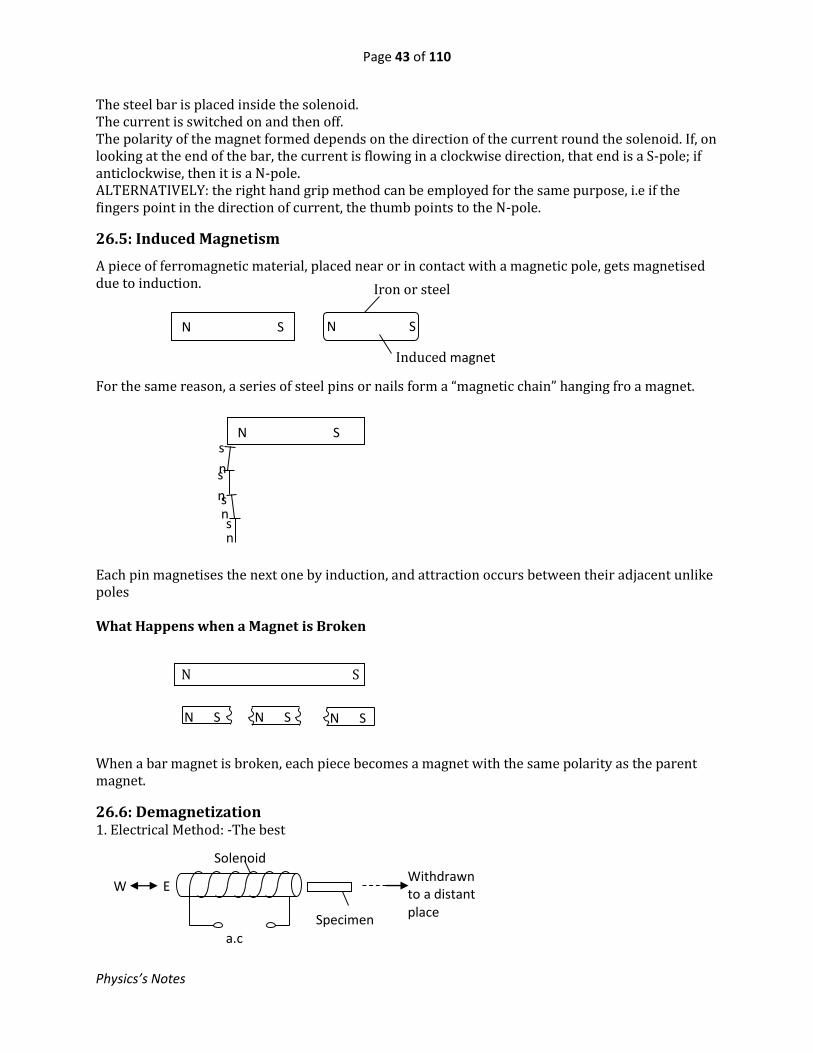
The steel bar is placed inside the solenoid. The current is switched on and then off. The polarity of the magnet formed depends on the direction of the current round the solenoid. If, on looking at the end of the bar, the current is flowing in a clockwise direction, that end is a S-pole; if anticlockwise, then it is a N-pole. ALTERNATIVELY: the right hand grip method can be employed for the same purpose, i.e if the fingers point in the direction of current, the thumb points to the N-pole.
26.5: Induced Magnetism
A piece of ferromagnetic material, placed near or in contact with a magnetic pole, gets magnetised due to induction. For the same reason, a series of steel pins or nails form a “magnetic chain” hanging fro a magnet. Each pin magnetises the next one by induction, and attraction occurs between their adjacent unlike poles What Happens when a Magnet is Broken When a bar magnet is broken, each piece becomes a magnet with the same polarity as the parent magnet.
26.6: Demagnetization 1. Electrical Method: -The best
N S s
n s
n s
n n s
n n
N S N S N S
N S
Specimen
a.c
supply
Solenoid Withdrawn to a distant place
W E
N S N S
Iron or steel
Induced magnet
Page 44 of 110
Physics’s Notes
- The magnet is placed in a solenoid lying in the E – W direction and an alternating current through the solenoid is switched on.
- While the current is still on, the specimen is withdrawn to a distant place. 2. By Heating The magnet is heated to redness and then allowed to cool while lying in an E – W direction . This method is not recommended because heat would spoil the steel. 3. By hitting
26.7: Magnetic Properties of Iron and Steel
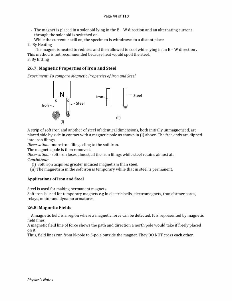
Experiment: To compare Magnetic Properties of Iron and Steel A strip of soft iron and another of steel of identical dimensions, both initially unmagnetised, are placed side by side in contact with a magnetic pole as shown in (i) above. The free ends are dipped into iron filings. Observation:- more iron filings cling to the soft iron. The magnetic pole is then removed. Observation:- soft iron loses almost all the iron filings while steel retains almost all. Conclusion:-
(i) Soft iron acquires greater induced magnetism than steel. (ii) The magnetism in the soft iron is temporary while that in steel is permanent. Applications of Iron and Steel Steel is used for making permanent magnets. Soft iron is used for temporary magnets e.g in electric bells, electromagnets, transformer cores, relays, motor and dynamo armatures.
26.8: Magnetic Fields
A magnetic field is a region where a magnetic force can be detected. It is represented by magnetic field lines. A magnetic field line of force shows the path and direction a north pole would take if freely placed on it. Thus, field lines run from N-pole to S-pole outside the magnet. They DO NOT cross each other.
N Steel Iron
S S
N N
(i)
Iron Steel
(ii)

Page 45 of 110
Physics’s Notes
Neutral Point
A neutral point is a point at which the resultant magnetic flux density is zero. At the neutral point the magnetic force is zero. Examples: Earth’s Magnetism: The earth behaves as though it contained a short bar magnet at its centre, with its north pole in the southern hemisphere and the south pole in the northern hemisphere.
N S
S N N S X
X = neutral point
S
X
N S
S N
X
N S
N S
X

Page 46 of 110
Physics’s Notes
So above the earth’s surface the earth’s magnetic lines of force run from South to North. The magnetic axis is at an angle to the Earth’s axis of rotation. When a bar magnet is freely suspended, it rests with its axis along the Earth’s magnetic field. So it rests in the N – S direction and at the equator it is horizontal.
The angle, , between the magnetic meridian and the geographic meridian is known as the magnetic declination. The angle between the direction of the earth’s magnetic flux and the horizontal is called the angle of dip (or inclination). It is easier for the magnetic lines of force to go through soft iron than air. So the field lines squeeze within the piece of soft iron.
26.9: Magnetic Shielding
This may be applied in order to: (i) protect a device from a magnetic field in the surroundings. This is done by placing the
device in a soft iron enclosure. (ii) prevent the magnetic field in one place from spreading to the surroundings. In this case the
magnetic field is enclosed by soft iron.
S
N
Earth’s magnetic N-pole
Geographic N-pole
Magnetic
equator
X
X
N
S
(i)Magnetic Field due to a Bar magnet in the Earth’s Field
(ii)Soft Iron Bar in Earth’s Field
The magnetic lines of force circulate
through the soft iron ring without reaching
the outside
Soft
iron
S N
The magnetic lines of force pass through the soft iron and never reach the inside of the enclosure
Device

Page 47 of 110
Physics’s Notes
26.10: The Domain Theory of Magnetism
In ferromagnetic materials the atomic magnets group themselves and in a single group, known as a magnetic domain, all the atomic magnets align in one direction. If the material is unmagnetised, the domains face different directions. When magnetised, the domains turn round and align in the same direction. See the illustrations below.
26.11: Care for Magnets 1. Bar magnets should be kept in pairs side by side with their ends facing opposite polarity and soft iron keepers are placed at their ends.
1. Magnets should NOT be banged or heated. Test Yourself
1. What is a magnet?
2. What is an electromagnet?
3. What is a magnetic field?
4. What is a magnetic pole?
5. Describe how consequent poles may be formed in a steel bar
6. When testing for polarity of a magnet, why is attraction NOT a
conclusive observation?
7. What is a neutral point?
8. When magnetising a steel bar by stroking, how are polarities
determined?
9. Why is soft iron used in an electric bell and not steel?
N S
S N
Soft iron keeper
Wooden separator
Magnetised Unmagnetised

Page 48 of 110
Physics’s Notes
27. MAGNETIC EFFECT OF CURRENT
27.1: Fields due to Different Arrangements of Conductors
Movement of charge creates a magnetic field around the path of charge. Straight Wire
In a wire, current is due to the flow of electrons.For a straight wire the magnetic field lines due to the current is a pattern of concentric circles. Iron filings can be used to map out the pattern; and the direction of the field can be established using the right-hand grip rule. i.e by gripping the conductor, with the thumb lying along the conductor and pointing in the direction of the current, the fingers point in the direction of the field. Solenoid Recall that the polarity of the magnet formed depends on the direction of the current round the solenoid. If, on looking at the end of the bar, the current is flowing in a clockwise direction, that end is a S-pole; if anticlockwise, then it is a N-pole. ALTERNATIVELY: the right hand grip method can be employed for the same purpose, i.e if the fingers point in the direction of current, the thumb points to the N-pole.
Straight wire
Magnetic field lines
Magnetic field lines

Page 49 of 110
Physics’s Notes
Hoop of Wire (Unlike Currents) Narrow coil Like Currents X = neutral point Look at all these diagrams. Since the magnetic lines of force behave as though they are trying to spread out and also stretch, it can be established that conductors carrying current in opposite directions repel each other, and those carrying current in the same direction attract each other.
27.2: Electromagnets
An electromagnet is formed when current is passed through a coil wound round a soft iron bar. The soft iron bar behaves as a magnet only as long as current is flowing. When it is switched off, the bar loses magnetism. The polarity of the electromagnet depends on the direction of current The strength of the electromagnet depends on: (i) The magnitude of the current: The higher the current the stronger theelectromagnet. (ii) The number of turns of the coil: The greater the number, the stronger theelectromagnet for a given current.
Conductors carrying currents in opposite directions
X
Conductors carrying currents
in the same direction
S N N S
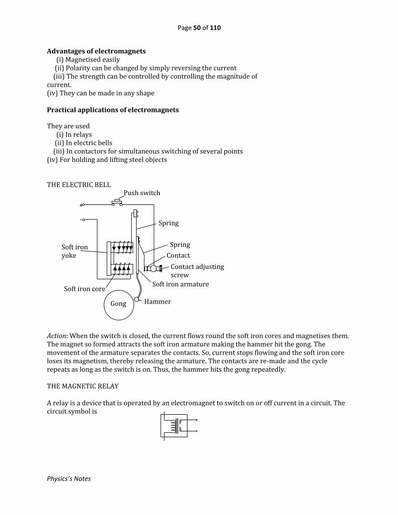
Page 50 of 110
Physics’s Notes
Advantages of electromagnets (i) Magnetised easily (ii) Polarity can be changed by simply reversing the current (iii) The strength can be controlled by controlling the magnitude of current. (iv) They can be made in any shape Practical applications of electromagnets
They are used (i) In relays (ii) In electric bells (iii) In contactors for simultaneous switching of several points (iv) For holding and lifting steel objects THE ELECTRIC BELL Action: When the switch is closed, the current flows round the soft iron cores and magnetises them. The magnet so formed attracts the soft iron armature making the hammer hit the gong. The movement of the armature separates the contacts. So, current stops flowing and the soft iron core loses its magnetism, thereby releasing the armature. The contacts are re-made and the cycle repeats as long as the switch is on. Thus, the hammer hits the gong repeatedly. THE MAGNETIC RELAY A relay is a device that is operated by an electromagnet to switch on or off current in a circuit. The circuit symbol is
Spring Soft iron yoke
Push switch
Spring
Contact adjusting screw
Contact
s
Hammer
Soft iron core Soft iron armature
Gong
+
-

Page 51 of 110
Physics’s Notes
When the current in the coil is switched on, the electromagnet is energized and attracts the soft iron armature whose movement closes the contact for the circuit being switched on. A relay facilitates a more efficient way of switching of a circuit it is designed to operate, especially where:- - manual switching may cause undesirable effects. - the switching action is a response to a certain condition in the circuit or elsewhere.
Test Yourself
1. Describe how the direction of a magnetic field due to a current can be established.
2. What is an electromagnet?
3. In which ways can the strength of an electromagnet can be increased?
4. Describe how the polarities of an electromagnet can be established.
5. State the advantages of an electromagnet over a permanent one.
6. Explain why soft iron and not steel is used in electromagnets.
7. In a relay, what could happen if steel instead of soft iron was used for the core?
8. List the parts of an electric bell stating the function of each.
Coil terminals
To circuit
being switched
Coil Soft iron core
Soft iron armature
Contacts
Springy metals

Page 52 of 110
Physics’s Notes
28. INTRODUCTION TO ELECTRICITY
28.0 Why Should we Study Electricity? The discovery of electricity led to better means of solving life’s problems. We need to study it so as to: (i) learn the various ways of producing it (ii) make the best use of it economically (ii) be made aware of its dangers so as to devise means of minimizing risks. Electricity is a form of energy caused by electric charges. It may be used: (i) as a source of heat (ii) as a source of light (iii) for running machines (iv) in communication equipment (v) in many electronic devices Advantages of Electricity - it is time-saving - it is ordourless - it is clean – no smoke or soot - not much physical effort is required when using it - no naked flame – so less risk of fire
28.1 Origin of Electric Charge
Matter is made up of atoms. An atom consists of a central part called the nucleus surrounded by electrons. Parts of an Atom: (i) Neutrons – these are found in the nucleus, are heavy and carry no charge. (ii) Protons - also found in the nucleus, are heavy and carry positive charge (iii) Electrons- these occupy the remaining outer part of the atom, have negligible mass, carry negative charge and are continuously moving in orbits round the nucleus. The charge on an electron is of the same magnitude as that on a proton and a neutral atom has the same number of electrons as the protons. Electrons can easily be lost or gained by an atom. The result of a loss or gain of electrons is known as electric charge. Thus, electric charge is a surplus or deficiency of electrons on a body.
Electron Outer orbit
Nucleus
Inner orbit

Page 53 of 110
Physics’s Notes
28.2: Sources of Electricity Any arrangement that acts to separate the negative and positive charges and avails them is termed a source of electricity. The following are examples of such:
1. Friction – rubbing of two materials 2. Chemical reaction e.g. in cells 3. Magnetism – When a conductor is moved across a magnetic field e.g. in a dynamo 4. Thermo junction – When ends of two different metals are fused together, they form a
thermo junction.
5. Pressure – When pressure is applied to a crystal of quartz, the crystal acts as a source of electricity between its opposite faces.
6. Light – Photoelectric effect. Certain materials, when struck by light, produce electricity.
28.3: Conductors and Insulators A conductor is a substance that allows electric charge to flow through it. The opposite of this is called an insulator. The following are some of the conductors starting with the best
- Silver – the best but costly - Copper - Aluminium - Brass – an alloy of zinc and copper. It is widely used for making terminals - Iron and steel - Tungsten
However, good insulators also find application in electric circuits. For example they are used to prevent:
- short circuits - electric shocks - electrical leakages
Test Yourself
1. What part of the atom is responsible for enabling bodies to acquire electric charge? 2. What is meant by electric charge? 3. Distinguish between a conductor and an insulator of electricity. 4. What is an electric circuit? 5. Could an insulator be of any use in an electric circuit? Explain. 6. What is an electric current? 7. State the basic parts of an electric circuit. 8. When connecting an electric circuit, what must be avoided that could be dangerous to the circuit? Explain. 9. What is the use of a fuse in an electric circuit?
Copper Constantan
Thermojunction

Page 54 of 110
Physics’s Notes
29. ELECTRIC CHARGE We have already discussed what electric charge is and its origin.
29.1: Charging by Rubbing
When a perspex ruler is rubbed with fur (or hair) and held over small pieces of say paper, the paper pieces are seen to jump up and down while some stick to the ruler. Other pairs of materials producing similar results include: ebonite rubbed with fur, glass rubbed with silk, etc. This is due to acquisition of electric charge. During rubbing electrons move from one of the materials and join the other e.g. in the case of ebonite and fur, electrons move from the fur and join the ebonite. Charging by rubbing is possible only with insulators because any charge deposited on any part does not flow away.
29.2: Negative and Positive Charge
When ebonite was rubbed with fur, the experimenters arbitrary called the charge acquired by the ebonite negative and since then any charge similar to it is negative. The charge acquired by a glass rod rubbed with silk was called positive. First law of electrostatics Like charges repel while unlike charges attract.
29.3: Electrostatic Induction
This is possible in conductors. It is the effect that when a charge is brought near a conductor electrons are caused to pile towards one side of the conductor. This leaves the other side with a positive charge. For example, suppose a positively charged body B is brought near a conductor MN
In this case the positive charge on the body B draws the electrons to end N leaving end M positively charged and making N negatively charged. If now the charged body B is withdrawn, the charge is redistributed to make the body neutral all over again.
Exercise Draw a diagram showing the charge distribution when B is negatively charged. Electrostatic induction provides a very efficient method of charging conductors. Charging a conductor by induction Suppose a conductor C is to be charged negatively. Then, the inducing charge to be used must be positive.
M
N
B
Inducing charge
(i)
C C
(ii) Electrons flow from the earth
C C
(iii) Conductor remains with negative charge
C
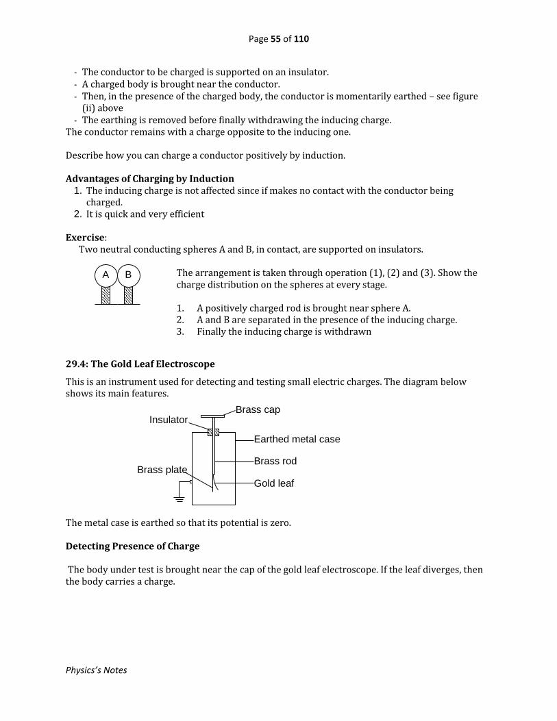
Page 55 of 110
Physics’s Notes
- The conductor to be charged is supported on an insulator. - A charged body is brought near the conductor. - Then, in the presence of the charged body, the conductor is momentarily earthed – see figure
(ii) above - The earthing is removed before finally withdrawing the inducing charge.
The conductor remains with a charge opposite to the inducing one. Describe how you can charge a conductor positively by induction. Advantages of Charging by Induction
1. The inducing charge is not affected since if makes no contact with the conductor being charged.
2. It is quick and very efficient Exercise: Two neutral conducting spheres A and B, in contact, are supported on insulators.
The arrangement is taken through operation (1), (2) and (3). Show the charge distribution on the spheres at every stage.
1. A positively charged rod is brought near sphere A. 2. A and B are separated in the presence of the inducing charge. 3. Finally the inducing charge is withdrawn
29.4: The Gold Leaf Electroscope
This is an instrument used for detecting and testing small electric charges. The diagram below shows its main features. The metal case is earthed so that its potential is zero. Detecting Presence of Charge The body under test is brought near the cap of the gold leaf electroscope. If the leaf diverges, then the body carries a charge.
A B
Brass cap Insulator
Earthed metal case
Brass rod
Gold leaf
Brass plate

Page 56 of 110
Physics’s Notes
Explanation: If, for example, the body is positively charged, electrons are attracted from the gold leaf and the brass plate and accumulate on the cap. This leaves both the brass plate and the leaf with like charge (positive in this case). So the leaf is repelled and it diverges.
Exercise Draw a gold leaf electroscope and the charge distribution when a negatively charged body is near the cap. Testing the sign of the charge on a body - The gold leaf electroscope is first given a known charge
( positive or negative) - The charged body is then brought near the cap.
If the leaf diverges further, then this confirms that the charge on the body is of the same sign as that on the electroscope. If, however, the leaf collapses it does not necessarily mean the body carries an opposite charge since even a neutral conductor produces similar results.
Charging a gold leaf electroscope Charging by induction can be used to charge an electroscope. This is necessary before the electroscope is used for testing a charge. Suppose it is to be charged positively. Then a negatively charged rod is to be used as the inducing charge. See figure below. Testing the Sign of Charge on a Body The body under test is brought near the cap of a gold leaf electroscope charged with a charge of known sign. Increase in divergence of the leaf indicates that the charge on the body is of the same sign as that on the electroscope.
Body
(ii) The cap is momentarily earthed
(iii) Finally the inducing charge is withdrawn
(i) A negative inducing charge brought near the cap

Page 57 of 110
Physics’s Notes
Effects of Bringing a Neutral Conductor near the Cap of a Charged Electroscope
Suppose the electroscope is positively charged. When a neutral conductor is brought near the cap, electrostatic induction occurs in the conductor so that the side near the cap acquires a negative charge. This repels some electrons from the cap to the metal plate and the leaf, thus reducing the positive charge there. This results in reduction of the divergence of the leaf. As the conductor is lowered further the divergence of the leaf decreases until it is zero. Now, all the positive charge on the plate and cap is completely neutralized. Lowering the conductor beyond this point makes the leaf to begin diverging again. This is because some negative charge begins existing on the plate and leaf causing repulsion again.
29.5: Hollow conductors
Inside a hollow conductor the net charge is always zero. If such a conductor is charged, the charge dwells only on the outside. See fig (i) If a charge is enclosed in a conductor, it induces an equal but opposite charge on the inside surface of the conductor so that still the total charge inside is zero. See fig (ii). The outside will have the charge of the enclosed body. If the enclosed body touches the inside wall of the conductor, both the body and the inside surface of the conductor will be completely neutralized but the outside will remain charged
30.6: Distribution of Charge over a Conductor
When a conductor is charged, the charge is NOT uniformly distributed over its surface. The more curved the part of a charged conductor is the greater the charge per unit area of that part provided the part has a convex surface. For example, see the figure below.
(ii) Charge placed inside a hollow conductor
(iii) Body touching the inside
Neutral conductor
(i) Charged hollow conductor

Page 58 of 110
Physics’s Notes
The pointed part has the highest charge concentration.
29.7: Action of Points
1. Spraying Action (Corona Discharge)
Suppose a pointed conductor A is charged positively. Most of the charge concentrates at the tip creating an intense electric field there. This ionises the air there. The negative ions are attracted to the tip and are neutralised while the positive ions are repelled. The net result is that positive charge is being sprayed from the tip into the air. This is known as corona discharge. 2. Collection Action Imagine a positively charged body X is brought near the tip of a neutral pointed conductor Y
Electrostatic induction occurs in Y such that negative charge dwells at the tip (which is near X) and the positive charge on the blunt remote end. The positive ions are attracted to the tip (which is highly negatively charged) and are neutralised as they also neutralise the negative charge there. Simultaneously the negative ions are attracted to X and are neutralised as they also neutralise the positive charge on X. The positive charge induced on Y remains. The net result is that Y has collected the positive charge that was on X leaving X neutral. Precautions in Electrostatic Experiments The following should be avoided:
- Sharp points or edges - Dirt and damp conditions - Naked flame in the vicinity
The Lightning Conductor A lightning conductor is an application of collection of the action of points. It consists of a thick copper strip whose lower end is connected to a copper plate buried in the ground while its upper end is in form of pointed spikes.
A
Y
X
Conductor
Insulating stand

Page 59 of 110
Physics’s Notes
Action: When a cloud, charged say negatively, passes above the spikes, electrostatic induction occurs in the copper strip the electrons being repelled to the buried plate and hence to the ground while the spikes remain positively charged. The charge concentrates at the tips of the spikes causing a high electric field there which results in ionisation of the air around. The positive ions so formed are repelled to the cloud to partially neutralize it while the negative ions are attracted to the spikes thereby neutralising them also. The net result is that negative charge has been safely passed from the cloud to the ground through the copper strip.
29.8: ELECTRIC FIELDS
An electric field is a region where an electric force is experienced. It can be represented by electrostatic lines of force. An electrostatic line of force through a point indicates the path and direction a point positive charge would take if placed there. The following are examples: These lines emanate from a positive charge and end onto a negative. They NEVER cross each other. A neutral point is a point where no net electric force can be experienced.
Negatively charged cloud
Positive ions in space charge
Negative ions
Highly charged spikes
Thick copper strip
Electrons flow to the earth
Copper plate underground
(i)Point positive charge (ii)Point negative charge
= Neutral point

Page 60 of 110
Physics’s Notes
Parallel plates
30. CELL AND BATTERIES A cell is the basic unit in which a chemical reaction or other process produces electricity. A battery is a combination of cells connected in series and usually packed in a single container. The circuit symbols are as follows
30.1: The simple cell Action: - Zinc dissolves into the sulphuric acid in form of zinc ions, Zn2+, each zinc ion leaving two
electrons on the zinc plate. So the zinc plate becomes negatively charged. - Each zinc ion in solution displaces two hydrogen ions, H+, from the dilute sulphuric acid, to the
copper plate. The hydrogen ions gain electrons from the copper plate which therefore becomes positively charged; and bubbles of hydrogen gas are formed on it.
Charged Ball near a conducting plate
Conducting plate
Ball
Conventional current Electrons
H +
H +
SO42−
Zn2+
Copper Zinc
Hydrogen bubbles
Dilute sulphuric acid
(i) A cell (ii) A battery of three cells

Page 61 of 110
Physics’s Notes
- If a conductor is connected between the zinc and copper plates, electrons flow from zinc to copper while the processes in the solution continue. This constitutes a conventional current flowing from the copper to the zinc plate through the conductor.
As the cell works zinc sulphate solution is formed and the acid becomes more dilute. Faults of a simple cell 1. Local Action This is the dissolution of the zinc plate resulting in evolution of hydrogen gas. It is caused by the impurities in the zinc. Due to the impurities, minute local cells are formed within the zinc plate in which the impurities behave as the positive plate; and these ‘cells’ are in opposition to the main cell. Secondly, local action wastes away the zinc plate. To minimise local action, the zinc plate is cleaned with sulphuric acid and then smeared with mercury. The mercury extracts the pure zinc to the surface, thereby denying the impurities contact with the electrolyte. 2. Polarisation: This is the coating of the copper plate by the hydrogen gas. The hydrogen coating increases the internal resistance of the cell due to partial insulation of the copper plate and creation of back emf. It is minimised by adding to the electrolyte an oxidizing agent like potassium dichromate, which oxidizes the hydrogen to water and prevents its formation on the copper plate.
30.2: The dry Leclanche’ cell It consists of ammonium chloride jelly as the electrolyte. In the centre is a carbon rod the serves as the positive electrode, surrounded by a mixture of powdered carbon and manganese(IV) oxide. All is contained in a zinc can which is in contact with the aluminium jelly and serves as the negative electrode. As the cell works, zinc dissolves into the jelly as zinc ions leaving electrons on the zinc can. So the zinc becomes the negative plate and is gradually eaten away by the process. The ammonium jelly slowly turns into zinc chloride. Manganese (IV) oxide oxidizes the hydrogen to water. Limitations of this Cell: - Because the depolarizing action of the manganese (IV) oxide is slow, this cell cannot deliver a
large steady current.
Brass cap (+ve contact) Insulating top seal
Carbon rod (+ve)
Zinc can (-ve)
Insulating outer
cover
Cardboard disc
Ammonium
chloride jelly
Mixture of powdered carbon and manganese (IV) oxide
Negative contact made here
+

Page 62 of 110
Physics’s Notes
- Local action takes place even when the cell is not being used. So, such a cell cannot be kept for ever. It will still deteriorate on the shelf.
The table below summarises the parts and their functions:
PART FUNCTION
Brass cap Prevents mechanical wear of the carbon rod
Zinc Serves as the container of all the parts and is the
negative plate
Carbon rod Serves as the positive plate
Ammonium chloride Forms the electrolyte
Manganese(IV)oxide It is the oxidizing agent
Powdered carbon Reduce the internal resistance
Cardboard disc Prevents contact between the carbon rod the zinc can.
Insulating top seal prevents drying up of the jelly
Insulating outer
cover
Insulates the zinc can from haphazard contact with the
outside
Primary and secondary cells A primary cell is one that cannot be recharged when it has run down, for example the dry cell. A secondary cell can be recharged to work again once it runs down, for example the lead-acid cell, the alkaline cell.
30.3: The lead-acid cell It consists of two plates, one of lead and the other of lead (IV) oxide, separated from each other. The pair is dipped in dilute sulphuric acid. The lead plate is the negative electrode while the lead (IV) oxide one is the positive electrode. The plates have a grid-like structure in which the active materials are packed. As the cell works, both plates go on forming lead sulphate, which coats the plates. Water is also formed and therefore the acid becomes more dilute. When fully charged, the cell has a working emf of 2V; and the relative density of the acid is 1.25.
The relative density can be checked using a battery hydrometer. If the emf falls to 1.18V and the S.G to 1.15, the cell is said to have run down and therefore it MUST be recharged.
Lead
plate Lead (IV) oxide plate
Dilute
sulphuric acid

Page 63 of 110
Physics’s Notes
Care for the lead-acid cell
1. Too much current, e.g due to shorting of the terminals, should NEVER be drawn from the cell because this will cause swelling and bucking of the plates resulting in loosening and falling out of the active materials to the bottom of the cell.
2. If the electrolyte level goes low, NO ACID should be added, but only DISTILLED or PURIFIED water should be added to restore the level.
3. When the cell runs down, it should not be kept in this state for long because the lead sulphate on the plates will turn into a crystalline solid which cannot be reconverted to PbO2 and Pb respectively.
4. When recharging, the charging current should not be too high as this will result in loose deposition of the active materials on the plates.
5. Whether discharged or not, the cell should be charged regularly.
30.4: Alkaline Cell
In this cell the electrolyte is potassium hydroxide. The positive plate is made of nickel hydroxide while the negative plate is either of iron or cadmium. These are housed in a nickel-plated container. Advantages of Alkaline Cell:
- Has longer life than lead-acid cell - Large currents as would otherwise damage a lead-acid cell can be drawn from it without
harm. - May be left in uncharged state for months without harm.
Disadvantages of Alkaline Cell:
- Rather low emf, of 1.25 V and this emf falls continuously in use. - Expensive
Charging a cell or battery
A direct current source is used. The positive of the battery is connected to the positive of the charging source and negative to negative. The ammeter A indicates the current flowing through the battery. The charging current is adjusted by a rheostat R. When the battery is fully charged, oxygen is evolved from the positive plate while hydrogen is evolved from the negative plate and a mixture of these gases bubbles out of the electrolyte. Because of this: (i) the lids of the battery cells should be open when on charge. (ii) a naked flame should NEVER be brought near the vent of a fully charged cell, since the mixture of hydrogen and oxygen would explode.
D.C source
Battery
A R

Page 64 of 110
Physics’s Notes
31. FURTHER ELECTRIC CIRCUITS
31.1: Electric Current When charge flows from a point to another, its flow is referred to as an electric current. Electric current is measured in terms of the rate of flow of charge. The SI unit of current is the ampere (A) The instrument used to measure current is the ammeter. The circuit symbol of an ammeter is
31.2: Electric Circuit An electric circuit is a (complete) path for the flow of current. The basic parts of a circuit are: (i) Source of electricity e.g a cell, battery, etc (ii) Conductor(s) (iii) Load (consumer) – the part that converts the electric energy into other forms, e.g heater, bulb, radio, etc (iv) Switch (control device) In addition, many circuits have a fuse as a safety device. The following are examples of circuits: Connect up a circuit like the one shown above and use it to distinguish between an open circuit and a closed circuit.
(a) Short Circuit A short circuit is closed path of electricity with negligible load. It results in an excessive current in the circuit. It is undesirable and should be avoided because:
- it may cause a fire - it may damage parts of the circuit, e.g the insulation of the conductors may be destroyed - itoverdrains (overworks) the source, i.e too much current is drawn from the source.
In order to prevent the dangers that might be caused by a short circuit, a fuse is connected in the circuit. A fuse is usually a thin conducting wire , with a low melting point, which melts away when too much current passes through it.
31.3: More Electrical Symbols Used in Circuits
A
Switch Battery
Load
(a) Open Circuit
Battery
Load
(b) Closed Circuit
Switch V
Voltmeter Capacitor
OR
Filament lamp

Page 65 of 110
Physics’s Notes
31.4: Mechanism of Conduction
In a metal, conduction is facilitated by movement of free electrons. However, in an electrolyte both positive and negative ions do exist. When a p.d is applied to an electrolyte, by means of electrodes, the positive ions move to the negative electrode while the negative ions move to the positive electrode. This way an electrolyte conducts electricity. In a metallic conductor, as the electrons drift, they collide with the ions in the lattice so that the electrons’ movement is restrained. This behaviour is known as resistance of the conductor. Secondly, the collision by the electrons on the ions increases the kinetic energy of vibration of the ions. So, the temperature of a conductor rises as current passes through it. The increase in kinetic energy of the ions is independent of the direction of flow of the electron. Hence, the heating effect of a current is independent of the direction of current. Furthermore, the increase in kinetic energy of the ions makes it more difficult for the drift of electrons. Thus, at higher a temperature the resistance of a metallic conductor is higher.
31.5: Potential Difference (p.d)
We are already familiar with the term ‘electric charge’ from earlier discussion. An electric charge always sets up a force in a region surrounding it. If the electric force experienced at a point, say A, due electric charge is different from that experienced at another point B, then the two points are said to have a difference in their electric potentials. i.e there is a potential difference between points A and B. Sometimes the potential difference is referred to asvoltage. It is this potential difference that causes charge to flow from one point to another to constitute an electric current. Positive charge flows from a point of higher potential to that of lower potential. The unit for potential difference is the volt (V). The instrument used to measure p.d is the voltmeter. Electromotive force and Potential Difference When a source of electricity, e.g a cell, is used to do any work, it does so by driving charge through the components of the circuit. So the source spends energy. Electromotive force (emf) of a source is the amount of energy the source avails to drive one coulomb of electricity through all the components of the circuit including the source itself. It is also measured in volts.
Resistor Wires joined
OR
Wires Crossing
Transformer
Rheostat
Resistance Box
OR
Fuse Inductor

Page 66 of 110
Physics’s Notes
Difference between Emf and P.d In the circuit above each of the points A, B, C, D and E is at a different electric potential. Hence there is a potential difference between any pair of these points e.g the p.d across components X is the p.d between A and B. The emf of the source is the sum of all the potential differences round the whole circuit. Two points are said to have a potential difference of 1 volt if the work done in carrying a charge of one coulomb from one to the other is one joule.
31.6: Resistance This is the opposition to flow of charge. It is measured as the ratio of p.d across a component to the current through the component. For a metallic wire the resistance depends on:
1. Length of the wire R l 2. Thickness of the wire R1/A 3. Temperature of the wire
For a given material, the resistance increases with length and temperature of the conductor but decreases with increase in thickness (inversely proportional) Relation between current, p.d and resistance
𝑅𝑒𝑠𝑖𝑠𝑡𝑎𝑛𝑐𝑒 = 𝑃𝑜𝑡𝑒𝑛𝑡𝑖𝑎𝑙𝑑𝑖𝑓𝑓𝑒𝑟𝑒𝑛𝑐𝑒
𝐶𝑢𝑟𝑟𝑒𝑛𝑡
i. e 𝐑 = 𝐕
𝐈or𝐈 =
𝐕
𝐑 or 𝐕 = 𝐈𝐑
Internal Resistance of a Source
This is the resistance offered internally by the materials of the source itself. When a source is driving a current, a p.d exists across this internal resistance. This internal potential drop makes the terminal p.d become less than the emf. Let E = emf r = internal resistance I = current Then terminal p.d, V = E – Ir
31.7: Ohm’s law
The current passing through a wire at constant temperature is proportional to the potential difference between its ends. Ohm’s law DOES NOT apply to semiconductors, rectifiers or to gaseous conduction.
A Source E
X
B C D
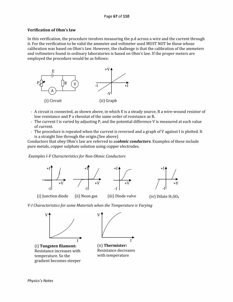
Page 67 of 110
Physics’s Notes
Verification of Ohm’s law
In this verification, the procedure involves measuring the p.d across a wire and the current through it. For the verification to be valid the ammeter and voltmeter used MUST NOT be those whose calibration was based on Ohm’s law. However, the challenge is that the calibration of the ammeters and voltmeters found in ordinary laboratories is based on Ohm’s law. If the proper meters are employed the procedure would be as follows:
- A circuit is connected, as shown above, in which E is a steady source, R a wire-wound resistor of low resistance and P a rheostat of the same order of resistance as R.
- The current I is varied by adjusting P, and the potential difference V is measured at each value of current.
- The procedure is repeated when the current is reversed and a graph of V against I is plotted. It is a straight line through the origin.(See above)
Conductors that obey Ohm’s law are referred to asohmic conductors. Examples of these include pure metals, copper sulphate solution using copper electrodes. Examples I-V Characteristics for Non-Ohmic Conductors V-I Characteristics for some Materials when the Temperature is Varying
E
R
A
V P
+V
+I -I
-V
(i) Circuit (ii) Graph
+I +I +I
+V +V +V
-I -I -I
(i) Junction diode (ii) Neon gas (iii) Diode valve
+I
+V -I
(iv) Dilute H2SO4
V
I
(i) Tungsten filament: Resistance increases with temperature. So the gradient becomes steeper
V
I (ii) Thermister: Resistance decreases with temperature

Page 68 of 110
Physics’s Notes
31.8: Arrangements of Cells
1. Series:
When cells are connected in series, their total emf is the algebraic sum of their emfs and total internal resistance is simply the sum of the individual internal resistances. For example, imagine three cells connected in series as shown below The equivalent emf, E = E1 + E 2 + E3
The equivalent internal resistance, r = r1 + r2 + r3 2. Parallel:
When identical cells are connected in parallel, the equivalent emf is equal to that of one cell and the internal resistant is that of one divided by the number of cells. For example, if 4 identical cells, each of emf 2V and internal resistance 0.8, are connected in parallel the equivalent emf = 2V, and the equivalent internal resistance, r = 0.8/4 = 0.2 The case of non-identical cells in parallel is beyond the scope of this book. Experiment to find internal resistance of a Cell
The circuit is set up as shown with the voltmeter to measure the terminal p.d and the ammeter A to register the current in the circuit. - The readings I of the ammeter, and V of the voltmeter, are noted. - The current is varied by adjusting the rheostat and several corresponding values of I and V are noted
A graph of V against I is plotted
The gradient of the graph , s = – r, where r is the internal resistance of the cell. So, r = -s The intercept of the graph on the V-axis gives the emf of the cell.
31.8: Arrangements of Resistors
1. SERIES:
Suppose resistances R1, R2 and R3 are connected in series.
V/V
E
I/A
E1 E2 E3 r1 r2 r3
E
Rheostat
V A
r
I R1 R2 R3
V1 V2 V3 V

Page 69 of 110
Physics’s Notes
Let the equivalent resistance be R and I the current flowing. The total p.d, V across the combination is given by V = IR But V = sum of p.d’s across R1, R2 and R3 = V1 + V2 + V3
= IR1 + IR2 + IR3 IR = IR1 + IR2 + IR3 R = R1 +R2 + R3
2. PARALLEL
Suppose resistances R1, R2 and R3 are connected in parallel to a p.d V. Then the main current I divides into currents I1, I2, and I3 as shown below.
Let R = equivalent resistance
Then I = V
R
But I = I1 + I2 + I3
i. eI =V
R1 +
V
R2 +
V
R3
𝟏
𝐑 =
𝟏
𝐑𝟏 +
𝟏
𝐑𝟐 +
𝟏
𝐑𝟑
Special Case of Two Resistors in Parallel If two resistors R1 and R2 are connected in parallel, show that the equivalent resistance, R, is given by
R = R1R2
R1 + R2
Examples 1. Find the current I in each of the circuits shown below. Assume the cell have negligible resistance.
Solution Equivalent emf, E = 1 + 2 = 3V Equivalent resistance, R = 2 + 1 + 3 = 6
Current, I = E
R=
3
6= 0.5 A
Solution Note that the 4V cell is opposing the other two. Equivalent emf, E = 2 + 3 – 4 = 1V Equivalent resistance, R = 5 + 3 = 8
Current, I = E
R=
1
8 = 0.125 A
R1
R2
R3
I
I1
I2
I3
V
1V 2V
2 3
I 1
(a)
2V 4V
5 3
I 3V
(b)
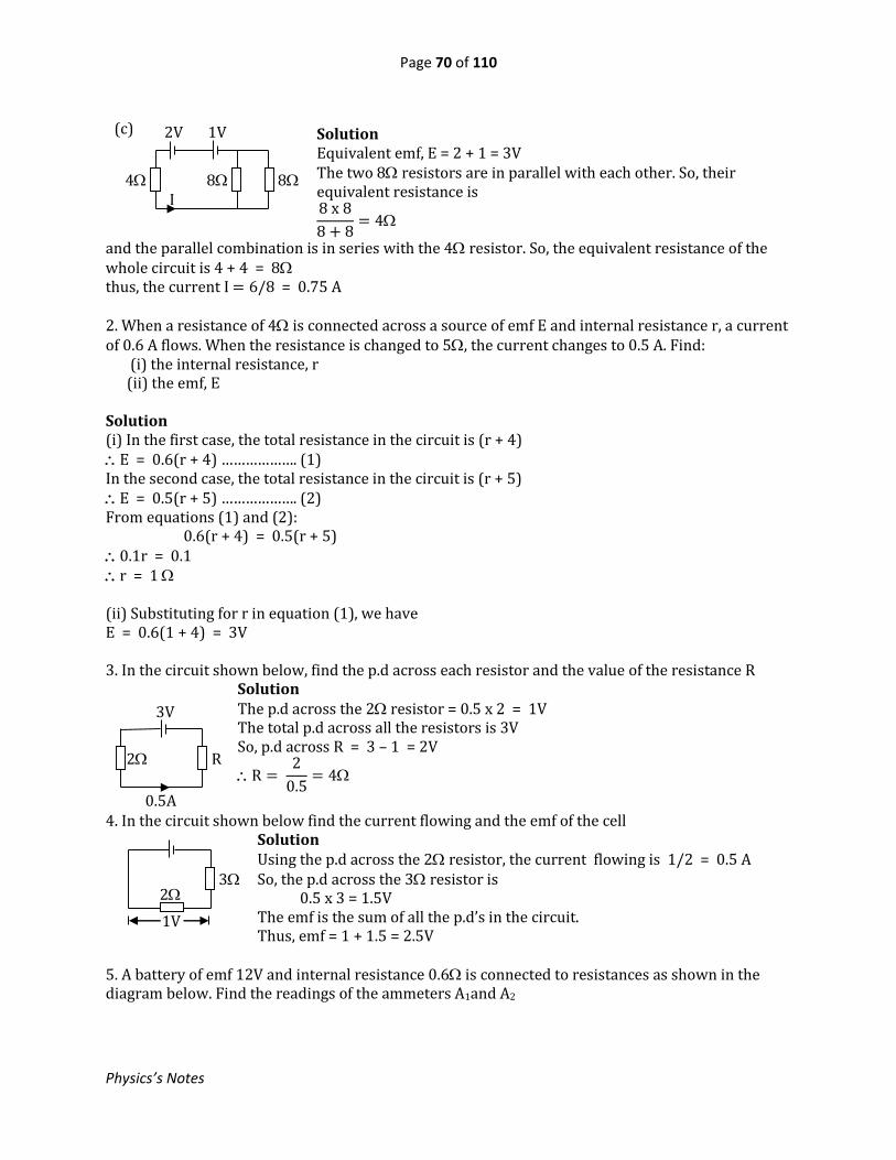
Page 70 of 110
Physics’s Notes
Solution Equivalent emf, E = 2 + 1 = 3V The two 8 resistors are in parallel with each other. So, their equivalent resistance is 8 x 8
8 + 8= 4
and the parallel combination is in series with the 4 resistor. So, the equivalent resistance of the whole circuit is 4 + 4 = 8 thus, the current I = 6/8 = 0.75 A
2. When a resistance of 4 is connected across a source of emf E and internal resistance r, a current of 0.6 A flows. When the resistance is changed to 5, the current changes to 0.5 A. Find: (i) the internal resistance, r (ii) the emf, E Solution (i) In the first case, the total resistance in the circuit is (r + 4) E = 0.6(r + 4) ………………. (1) In the second case, the total resistance in the circuit is (r + 5) E = 0.5(r + 5) ………………. (2) From equations (1) and (2): 0.6(r + 4) = 0.5(r + 5) 0.1r = 0.1 r = 1 (ii) Substituting for r in equation (1), we have E = 0.6(1 + 4) = 3V 3. In the circuit shown below, find the p.d across each resistor and the value of the resistance R
Solution The p.d across the 2 resistor = 0.5 x 2 = 1V The total p.d across all the resistors is 3V So, p.d across R = 3 – 1 = 2V
R = 2
0.5= 4
4. In the circuit shown below find the current flowing and the emf of the cell
Solution Using the p.d across the 2 resistor, the current flowing is 1/2 = 0.5 A So, the p.d across the 3 resistor is 0.5 x 3 = 1.5V The emf is the sum of all the p.d’s in the circuit. Thus, emf = 1 + 1.5 = 2.5V
5. A battery of emf 12V and internal resistance 0.6 is connected to resistances as shown in the diagram below. Find the readings of the ammeters A1and A2
2V 1V
4 8 8 I
(c)
2
V
3
1V
3V
2 R
0.5A
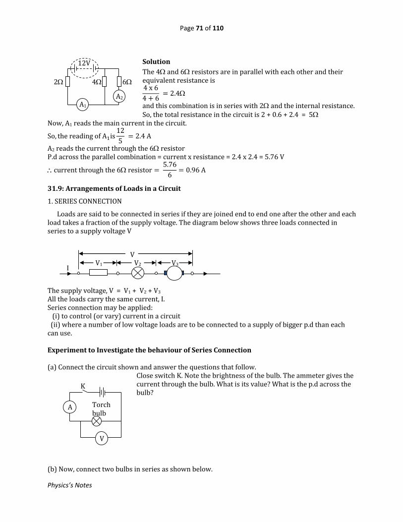
Page 71 of 110
Physics’s Notes
Solution
The 4 and 6 resistors are in parallel with each other and their equivalent resistance is 4 x 6
4 + 6 = 2.4
and this combination is in series with 2 and the internal resistance. So, the total resistance in the circuit is 2 + 0.6 + 2.4 = 5
Now, A1 reads the main current in the circuit.
So, the reading of A1is12
5 = 2.4 A
A2 reads the current through the 6 resistor P.d across the parallel combination = current x resistance = 2.4 x 2.4 = 5.76 V
current through the 6 resistor = 5.76
6= 0.96 A
31.9: Arrangements of Loads in a Circuit
1. SERIES CONNECTION
Loads are said to be connected in series if they are joined end to end one after the other and each load takes a fraction of the supply voltage. The diagram below shows three loads connected in series to a supply voltage V The supply voltage, V = V1 + V2 + V3 All the loads carry the same current, I. Series connection may be applied: (i) to control (or vary) current in a circuit (ii) where a number of low voltage loads are to be connected to a supply of bigger p.d than each can use. Experiment to Investigate the behaviour of Series Connection (a) Connect the circuit shown and answer the questions that follow.
Close switch K. Note the brightness of the bulb. The ammeter gives the current through the bulb. What is its value? What is the p.d across the bulb?
(b) Now, connect two bulbs in series as shown below.
12V
2 4 6
A1 A2
V1 V2 V3 V
I
Torch bulb
A
V
K
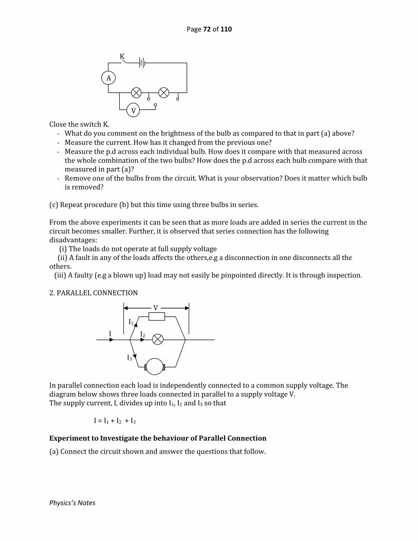
Page 72 of 110
Physics’s Notes
Close the switch K. - What do you comment on the brightness of the bulb as compared to that in part (a) above? - Measure the current. How has it changed from the previous one? - Measure the p.d across each individual bulb. How does it compare with that measured across
the whole combination of the two bulbs? How does the p.d across each bulb compare with that measured in part (a)?
- Remove one of the bulbs from the circuit. What is your observation? Does it matter which bulb is removed?
(c) Repeat procedure (b) but this time using three bulbs in series. From the above experiments it can be seen that as more loads are added in series the current in the circuit becomes smaller. Further, it is observed that series connection has the following disadvantages: (i) The loads do not operate at full supply voltage (ii) A fault in any of the loads affects the others,e.g a disconnection in one disconnects all the others. (iii) A faulty (e.g a blown up) load may not easily be pinpointed directly. It is through inspection. 2. PARALLEL CONNECTION
In parallel connection each load is independently connected to a common supply voltage. The diagram below shows three loads connected in parallel to a supply voltage V. The supply current, I, divides up into I1, I2 and I3 so that I = I1 + I2 + I3 Experiment to Investigate the behaviour of Parallel Connection
(a) Connect the circuit shown and answer the questions that follow.
I
I1
I2
I3
V
A
V
K
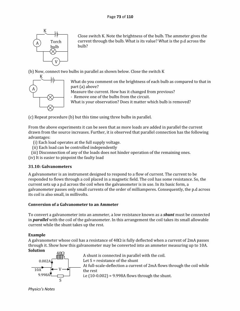
Page 73 of 110
Physics’s Notes
Close switch K. Note the brightness of the bulb. The ammeter gives the current through the bulb. What is its value? What is the p.d across the bulb?
(b) Now, connect two bulbs in parallel as shown below. Close the switch K
What do you comment on the brightness of each bulb as compared to that in part (a) above? Measure the current. How has it changed from previous? - Remove one of the bulbs from the circuit. What is your observation? Does it matter which bulb is removed?
(c) Repeat procedure (b) but this time using three bulbs in parallel. From the above experiments it can be seen that as more loads are added in parallel the current drawn from the source increases. Further, it is observed that parallel connection has the following advantages: (i) Each load operates at the full supply voltage. (ii) Each load can be controlled independently (iii) Disconnection of any of the loads does not hinder operation of the remaining ones. (iv) It is easier to pinpoint the faulty load
31.10: Galvanometers
A galvanometer is an instrument designed to respond to a flow of current. The current to be responded to flows through a coil placed in a magnetic field. The coil has some resistance. So, the current sets up a p.d across the coil when the galvanometer is in use. In its basic form, a galvanometer passes only small currents of the order of milliamperes. Consequently, the p.d across its coil is also small, in millivolts. Conversion of a Galvanometer to an Ammeter To convert a galvanometer into an ammeter, a low resistance known as a shunt must be connected in parallel with the coil of the galvanometer. In this arrangement the coil takes its small allowable current while the shunt takes up the rest. Example A galvanometer whose coil has a resistance of 40 is fully deflected when a current of 2mA passes through it. Show how this galvanometer may be converted into an ammeter measuring up to 10A. Solution
A shunt is connected in parallel with the coil. Let S = resistance of the shunt At full-scale-deflection a current of 2mA flows through the coil while the rest i.e (10-0.002) = 9.998A flows through the shunt.
V
40
0.002A
10A
9.998A
S
Torch bulb
A
V
K
A
K

Page 74 of 110
Physics’s Notes
Now, p.d across the shunt = p.d across the coil 9.998 S = 0.002 x 40
S = 0.002 x 40
9.998= 0.008
From this we can see that the effective resistance of an ammeter is negligible. This is why an ammeter is connected in series with the device carrying the current to be measured and does not practically affect the resistance of the circuit. Conversion of a Galvanometer to a Voltmeter To convert a galvanometer into a voltmeter, a high resistance, known as a multiplier, is connected in series with the coil of the galvanometer. The multiplier takes up most of the p.d while the coil takes up its small allowable p.d. Example A galvanometer whose coil has a resistance of 40 is fully deflected when a current of 2mA passes through it. Show how it can be converted into a voltmeter will full-scale deflection of 6V. Solution
A multimeter R is connected in series with the coil. At full-scale deflection, a p.d of 0.002 x 40 = 0.08V exists across the coil while the rest, i.e 6 – 0.08 = 5.92V is across the multiplier Thus 0.002R = 5.92
R = 5.92
0.002 = 2960
So, the total resistance of a voltmeter is high and this is why in practice a voltmeter is connected in parallel with the component whose p.d being measured and it draws negligible current.
31.11: Connection of Ammeters and Voltmeters in Circuits
An ammeter is used to measure current and is connected in series with the device carrying the current to be measured. For example, the diagram below shows connection of an ammeter, A, to measure a current, I, flowing through a device X. The current flows simultaneously through both the ammeter and X. On the other hand, a voltmeter is used to measure p.d and is always connected in parallel with the component whose potential difference is being measured. See the diagram below in which the voltmeter V is measuring the p.d across a device D
6V
40 0.002A R
5.92V 0.08V
A X I
D
V

Page 75 of 110
Physics’s Notes
31.12: Electrical Energy and Power
When a current flows through a component, the component converts electrical energy into other forms. If a voltage V drives a charge Q across a device D, the electrical energy delivered to D is given by Energy = voltage x charge delivered = VQ And this is the work done, W, by the voltage V in delivering the charge Q W = VQ If the process takes time t, then the electrical power delivered to D is
P = W
t. Thus, P =
VQ
t
But Q/t = I, where I is the current flowing through D. P = VI From this, W =VIt Electrical energy is measured in joules (J) and electrical power in watts (W) Other Formulas for Electrical Power: If the load is a passive resistor (one that converts all electrical energy into heat) of resistance R, then
𝐏 = 𝐈𝟐𝐑or𝐏 = 𝐕𝟐
𝐑
Examples 1. A current of 5A flows through a wire of resistance 30. Find the rate at which heat is dissipated in the wire. Solution Power, P = I2R = 52 x 30 = 750 W 2. A voltage of 100V is maintained across a wire of resistance 50 for 3 minutes. How much energy is delivered to the wire? Solution
Energy =V2
Rt =
1002
50 x 3 x 60 = 36000 W
3. A hot plate consumes electrical energy at a rate of 1500W when supplied from a source of 240V. Find the current flowing and the resistance of the hot plate. Solution Let the current be I. Then, using VI = P, we have
I =P
V=
1500
240= 6.25 A
Resistance, R = V
I =
240
6.25 = 38.4
D
V Q

Page 76 of 110
Physics’s Notes
The kilowatt-hour (kWh) One kilowatt-hour is the energy consumed at the rate of 1kW for a period of 1 hour. 1 kWh = 1000 x 60 x60 = 3,600,000 joules A kilowatt-hour is a commercial unit of electrical energy. Example A flat iron consumes electrical energy at a rate of 750W. How much energy in kWh does it consume in 8hours? Solution: Energy in kWh = number of kW x hours = 0.750 x 8 = 6 kWh Quotations on Appliances It is common to find a voltage and wattage marked on an appliance; e.g 240V, 1500W. This means that 240V is the optimum working voltage for the appliance; and when connected to this voltage, it consumes electrical energy at a rate of 1500W. A voltage greater than 240V would be unsafe for the appliance. Examples 1. An immersion heater is marked “240V, 800W”. Find (i) The resistance of its coil (ii) The energy it consumes in 2 hours when connected to a supply of 200V. Solution (i) Using P = V2/R, we have R = V2/P = 2402/800 = 72
(ii)Energy = power x time =V2
Rt =
2002
72 x 2 x 3600 = 4,000,000 W
2. Three identical bulbs, each marked 240V, 100W, are connected in series and the combination is connected to a 270V supply. Find the current drawn. Solution The resistance of each bulb = V2/P = 2402/100 = 576 So, the total resistance, R = 3 x 576 = 1728
and the current drawn = V
R =
270
1728 = 0.156 A
3. 200g of a liquid at 10C was heated to 40C by a current of 5A at 6V for 5minutes (i) Neglecting the heat losses, calculate the specific heat capacity of the liquid (ii) If some heat was being lost to the surroundings at a rate of 5W what would the temperature have been after the 5 minutes? Solution

Page 77 of 110
Physics’s Notes
V = 6V, I = 5A, t = 300 s, m = 0.2kg, 1 = 10oC, 2 = 40oC (i) Let c = specific heat capacity of the liquid Electrical energy supplied in 5 minutes = Heat gained by the liquid VIt= mc(2 - 1) 6 x 5 x 300 = 0.2 x c x (40 – 10)
c = 6 x 5 x 300
0.2 x 30 = 1500 J kg−1K−1
(ii) Let = final temperature when there is heat loss Then 6 x 5 x 300 = 0.2 x 1500 x ( – 10) + 5 x 5 x 60 25 x 300 = 300 - 3000 = 35oC
31.13: Domestic Power Installation Circuits
For domestic use the electricity supply is got from a single-phase, two-wire line. Precautions to Observe:
1. All circuits are connected in parallel with the supply to ensure that each circuit operates at full supply voltage.
2. Switches and fuses are fitted in the live wire in order to ensure that no part of the circuit in the appliances remains live when the appliance is switched off.
3. All appliances with conducting bodies must be earthed; i.e their bodies must be connected to the earth for safety.
4. All wires must be insulated Importance of Earthing
The purpose of earthing is to offer protection against earth-leakage currents. The earth connection provides an extremely low-resistance path for such a current. Take an example of an appliance A, in the diagram, having a metallic body. In case a fault occurs such that a live wire touches the body of the appliance, a heavy current flows to the earth and blows the fuse thereby cutting off the current supply. If the earth wire were absent, the whole body would remain live and shock anyone touching it.
N
L
Meter
Board’s fuse
Service cable
N L N L N L
30A 15A 5A
Consumer unit
A
Metallic body
Earth
Heavy current flows to earth Live wire
Fuse

Page 78 of 110
Physics’s Notes
Advantages of Electricity over Fuels as a Source of Energy
- It is time-saving - It is odourless - It is clean – no smoke or soot (It is environmental friendly) - Not much physical effort is required when using it - No naked flame – so less risk of fire
Test Yourself
1. Mention situations where series connection may be applied.
2. List the advantages of parallel connection over series connection.
3. You are provided with three resistors and a battery. Draw a circuit diagram to show how the
resistors may be connected to the battery so as draw maximum current from the battery.
Exercise 31 1. Two resistors of 5 and 14 are connected in series with a 10 volt battery of internal resistance of 1. Find the terminal p.d and the p.d across the 5 resistor. 2.
Find the effective resistance between points X and Y 3.
In the circuit the source has negligible internal resistance. Find the effective resistance in the circuit and the p.d across the 6 resistor.
4.
In the circuit the source has an emf of 12V and negligible internal resistance. Find the currents I1, I2 and I3.
5. The figure shows a battery of emf E and negligible internal resistance connected to a system of resistors. Find the emf E and the power dissipated in the 3 resistor.
6.
In the circuit shown, when switch S is open, the ammeter A reads 2A. when S is closed the ammeter reads 4A. Find the internal resistance of P and its emf
7. Four identical cells each of emf 1.5 V and internal resistance 0.2 are joined to form a battery.
Three identical lamps and a 2 resistor are connected to the battery as shown. If the current through each lamp is 0.5 A, find the reading of the voltmeter, V, and the resistance of each lamp.
8V
6 4 4
Y
4 6
X 10
I1 I2
6 4 I3
9A
E 6 3 2
P 6 3
A S
2 V

Page 79 of 110
Physics’s Notes
8. If 7.2 x 10⁶ J of electrical energy is converted to heat when a current of 8A through an electrical heater for 1 hour, find the p.d across the heater and the resistance of the heater. 9. A hot plate is rated 240V, 1200W. Find its resistance and the rate of working when connected to a supply of 200 V. 10. Find the cost of using three 100 W bulbs for 5 hours, if the cost of electrical energy is Sh. 350 per unit. 11. The coil of a galvanometer has a resistance of 20. It gives full scale deflection (f.s.d) when a current of 2 mA is passed through it. Calculate the resistance of: (i) a shunt that converts the galvanometer into an ammeter measuring up to 3A. (ii) a multiplier that converts the galvanometer into a voltmeter measuring p.ds up to 4V.
32. MODERN PHYSICS
32.1: ELECTRONS
32.1.1: Cathode Rays
Cathode rays are a stream of electrons accelerated by a potential difference The source of electrons is called the cathode and the electrode attracting them is the anode. So the cathode is connected to the negative while the anode to positive terminal of the supply. The space between the cathode and anode must be a vacuum. The cathode has to be heated to produce electrons. Thermionic emission is the release of electrons by a metal surface when it is heated. Properties of Cathode Rays
- Travel in straight lines - Are deflected by both magnetic and electric fields - Convey negative charge - Possess energy - Cause fluorescence of certain materials
Heater
Cathode Vacuum - + e.h.t
Cathode rays Anode

Page 80 of 110
Physics’s Notes
Showing that Cathode Rays Travel in Straight Lines Formation of a sharp shadow of the Maltese cross is evidence that cathode rays travel in straight lines Showing that Cathode Rays Convey Negative Charge Cathode rays are directed to enter Faraday’s case in the tube which is connected to a negatively charged gold leaf electroscope. Further divergence of the leaf confirms negative charge. In the diagram shown below, what property of cathode rays is being demonstrated? 32.1.2: Cathode Ray Oscilloscope (C.R.O)
Focusing and accelerating
anodes A1,A2
Fluorescent screen
Cathode
Heater
A1 A2 Y
Grid
X
Y X
+e.h.t
Graphite coating
Deflection system
Vacuum
Sharp shadow
Maltese cross
Fluorescent screen 4kV
- +
6V C
Vacuum
Heater Faraday’s cage
Anode
Already negatively charged
Cathode Vacuum
- + High voltage
4kV - +
N
B
S
C 6V
Anode
Electrons

Page 81 of 110
Physics’s Notes
The electron gun consists of a cathode, grid and a series of cylindrical anodes kept at a high positive potential with respect to the cathode. Action: The heater raises the temperature of the cathode, which thermionically emits electrons. The electrons go through a hole in the grid as the beam is accelerated by a series of anodes. These anodes also focus the beam into a spot as it strikes the fluorescent screen. The grid potential is made more negative than that of the cathode. So the grid controls the number of electrons reaching the screen and hence the brightness of the spot. When the fluorescent screen is struck by the electrons it emits light According to the voltage connected across them, the X plates deflect the electron beam horizontally
while the Y- plates deflect it vertically. If both the X- and Y-plates are switched off, the spot remains
stationary in the centre of the screen. A C.R.O is used for studying waveforms. The signal to be
studied is connected to the Y-plates.
Time base: This is a special circuit connected to the X-plates for the purpose of controlling the horizontal movement of the spot. Below are examples of the display on the screen:
32.1.3: Vacuum Diode
A diode is a device that allows the flow of current in
only one direction. A vacuum diode is one of such
devices. It works on the same principle as the C.R.O. It
consists of an anode and a cathode which is heated by
a filament. All these are housed in an evacuated glass
envelope.
Action: The heater raises the temperature of the cathode, which thermionically emits electrons. The electrons are accelerated to the anode by the high p.d between the cathode and anode and therefore a current I flows in the direction shown in the diagram. If the supply is reversed, the diode does not conduct any current, since the cool anode cannot now release electrons to flow the other way to the cathode. This way the device acts as a rectifier. 32.1.4: Photoelectricity
When ultraviolet light of high enough frequency is shone on a clean metal surface, some electrons are emitted from the surface. The light gives enough energy to the electrons to escape from the metal surface. The electrons so emitted are referred to as photoelectrons and the phenomenon is known as photoelectric effect.
Cathode
+h.t
-h.t
mA
Heater filament
Vacuum
Anode
6V
I
(iii) X-plate sweep and Y-
plate signal combined
(i) X-plate sweep switched on. (no signal on Y-plates)
(ii) a.c signal applied to Y-plates with X-plates switched off

Page 82 of 110
Physics’s Notes
Photoelectricity is applied in photo cells, which may be used in automatic cameras, burglar alarms, video cameras, sound reproduction from film tracks, etc. (However, another device called the photodiode is widely used in similar areas). The following observations can be explained by the photoelectric effect.
A zinc plate is first cleaned with emery paper, supported on an insulator and connected to the cap of a gold leaf electroscope. The zinc plate is given a positive charge by induction. In a dark room the plate is exposed to ultra-violet light, L. The divergence of the leaf is observed to remain the same.
The experiment is repeated when the zinc plate is negatively charged. This time the leaf slowly collapses. (See fig (ii) above)
Explanation: When the zinc plate is positively charged the photoelectrons emitted are attracted to the plate. So the charge on the plate remains the same – No change in divergence. With the zinc plate negatively charged, the photoelectrons are repelled away. So the plate loses charge and the leaf collapses.
32.2: X-RAYS
X-rays are produced when high-energy cathode rays (electrons) strike a metal target. They are electromagnetic in nature and therefore travel at the speed of light. The diagram above shows the main features of an X-ray tube. Features: It consists of a cathode and a tungsten target embedded in a thick copper anode. The anode has passages for a cooling liquid. All these are housed in an evacuated glass envelope. At the external end of the anode are cooling fins.
U-Vlamp Zn
Insulator
L
+
+
+
+
(i) Zinc plate positively
charged
L
Zn -
- -
-
(ii) Zinc plate negativelycharged
Cathode
Coolingliquid
Cooling fins
Lead shield Filament X-ray
High voltage
Low voltage
Anode Target
Vacuum
R

Page 83 of 110
Physics’s Notes
Action: Electrons are thermionically emitted by the cathode, which is heated by a current flowing in the filament from a low-voltage source. The emitted electrons are accelerated by a high voltage between the anode and the cathode. The electrons are focused onto a tungsten target. X-rays are thus produced. At the target, tremendous heat is produced- hence the need for tungsten of high-melting point. For the same reason, the anode is made of thick copper so that the heat generated can be conducted away as fast as possible. The circulating liquid in the anode and the fins improve the cooling action. Adjustments: - The penetrating power (or the hardness) of the X-rays is increased by raising the p.d between
the cathode and anode. - The intensity is increased by increasing the current flowing in the filament at the cathode when
the rheostat R is adjusted. NB: Hard X-rays are the high-frequency ones with high penetrating power and soft X-rays are the low frequency one with low penetrating power. Properties of X-Rays They:
- travel in straight lines - are NOT deflected by electric or magnetic fields - readily penetrate matter - affect photographic paper - eject electrons from matter
Applications of X-Rays They are used in:
- hospitals in radiography for producing photographs of internal parts of a body; and for destroying cancerous cells
- industry detecting flaws in products - crystallography for studying crystal structure.
Hazards and Safety Precautions X-rays of hardness higher than a certain value can damage cells. So, uncontrolled or unnecessary exposure should be avoided. For this reason, the X-ray tube is surrounded by a lead shield, leaving only a window for the required X-rays. (Lead is very effective in absorbing X-rays)
32. 3: ATOMIC AND NUCLEAR STRUCTURE
According to Bohr and Rutherford an atom consists of a central nucleus, in which the atom’s mass is concentrated, surrounded by electrons that orbit round the nucleus. The simplest atom is that of hydrogen. The nucleus is made up of protons and neutrons. Mass Number, A: This is the total number of protons and neutrons in the nucleus. Atomic Number, Z: This is the number of protons in the nucleus.

Page 84 of 110
Physics’s Notes
If N = number of neutrons Then, A = Z + N The number of protons, Z, determines the element to which the nucleus belongs. The protons are positively charged while the neutrons carry no charge. So the nucleus as a whole is positively charged. A neutral atom contains the same number of electrons as protons. Isotopes are elements having the same number of protons but different numbers of neutrons in their nuclei. So they are the same element. The nucleus of an element, say X is represented as 𝐗𝐳
𝐀 The following symbols are also used Proton p1
1 Neutron n0
1 Electron e−1
0 Nuclear Fission This is the splitting up of a nucleus into two nuclei of comparative mass due bombardment. Neutrons are usually used to bombard the nucleus for this purpose. Fission produces tremendous energy and nuclear reactors derive their energy from this process. Nuclear Fusion This is union of light nuclei to form heavier ones. This also leads to releases of great energy and it is believed to be the main source of the sun’s energy.
32.4: RADIOACTIVITY This is a spontaneous splitting up of the nuclei of elements. It occur naturally. Examples of radioactive elements include uranium, polonium, radium, etc. Types of Radiations Emitted in Radioactivity 1. Alpha Particles
- These are helium nuclei having relative atomic mass of about 4 and charge of +2e. - Therefore they are relatively heavy - They have least penetrating power and most of them are stopped by paper of ordinary
thickness - They are deflected by both magnetic and electric fields - They produce intense ionisation in a gas
2. Beta Particles These are fast-moving electrons and therefore carry negative charge.
- They have higher penetrating power than α-particles - They are more severely deviated by a magnetic field (because they are light) in a direction
opposite to that for α-particles. - They produce much less ionisation in a gas than α-particles.
3. Gamma Rays These are an electromagnetic radiation.
- They have very high penetrative power. - They are NOT deflected by a magnetic or electric field.

Page 85 of 110
Physics’s Notes
The behaviour of the three radiations in a magnetic field can be summarized by the following diagram. When a nucleus disintegrates by emission of an -particle, its mass number decreases by 4 and its atomic number by 2. For example, suppose a nucleus X disintegrates to a daughter nucleus Y with emission of an alpha particle.
X →𝑍A YZ−2
A−4 + He24
Parent daughter When a nucleus emits a -particle, its mass number remains constant but its atomic number increases by 1.
X →ZA YZ+1
A + e−10
Parent daughter
Some Applications of Radioactivity
Radioactivity is applied: - in agricultural research for producing genetically modified plants. - in industry as an alternative to X-rays for examining welded products - in investigation of liquid flow in chemical plants - in investigating wear of machinery - as a sterilizer – γ-rays kill bacteria, etc. - in carbon-dating for estimating age - as tracers in medical treatment
Background Radiation This is the low count rate that remains even though all radiations from the radioactive source have been absorbed. It is due to cosmic rays, radioactive minerals, radon in the atmosphere, etc. Half-Life This is the time taken for half the atoms in a given sample to disintegrate. The rate at which the nuclei decay is proportional to the number of atoms present. So, when the number of atoms falls to half, the rate of decay also falls to half and so on. The rate of decay is called the activity. A graph of the number of atoms against time or activity against time can be used to find half-life of a radioactive substance.
α-rays γ-rays
β-rays Radiation source

Page 86 of 110
Physics’s Notes
In general, if No is the initial number of atoms, then after n half-lives the number remaining is No
2n
Thus, the fraction remaining after n half-lives is f = 1
2n
Then,Amount remaining
Original amount =
1
2n
Examples 1. When a neutron bombards a sulphur atom, the following nuclear reaction takes place.
X16 34 + n0
1 → Yba
The nuclide, Y, decays by emission of an α-particle and a γ-ray. Find the final mass number and atomic number of the nuclide. Solution Mass number = 34 + 1 – 4 = 31 And atomic number = 16 + 0 – 2 = 14 2. Given 20 g of a radioactive sample of half-life 12 minutes, how much of it remains after 36 minutes Solution
Number of half-lives, n = 36
12 = 3
Amount remaining
Original amount =
1
23 =
1
8
Amount remaining = 1
8x 20 = 2.5 g
3. The activity of a radioactive source decreases from 1000 counts per minute to 125 counts per minute in 42 minutes. What is the half-life? Solution Let n = number of half-lives
Then, 2n = 1000
125 = 8
n = 3 So, 42 minute = 3 half-lives Half-life = 14 minutes
No
½No
¼No
T½2T½ Time
No. of atoms

Page 87 of 110
Physics’s Notes
4. A radioactive sample has half-life of 2500 years. How long does it take for three-quarters of the sample to decay? Solution
Fraction remaining = 1
4 =
1
2n
number of half-lives that elapsed, n = 2 So, this will be after 2 x 2500 = 5000 years. Carbon Dating This is the estimation of age of a substance by studying the count rate of a radioactive sample in the substance. Living plants absorb and contain a radioactive isotope of carbon having a half-life of about 5600 years. As long as the plant lives, the count rate of this isotope is constant. When a plant dies, it stops absorbing the carbon isotope, but radioactivity continues. So, the count rate falls accordingly. By determining the count rate of wood, its age can be estimated. Health Hazards and Safety Precautions
Exposure to radioactive sources may cause cancer. Strong doses even lead to burning of the skin and body tissues. Exposure may also lead to genetic abnormalities. Because of these hazards, radioactive substances: (i) should NEVER be handled directly (ii) should be transferred or stored in thick-walled lead containers. Exercise 32 1. A radioisotope atom decays by emitting a beta particle as shown in the equation below. Find the values if A and Z.
X 1124 → Yz
A + −1
0
2. The half-life of a radioactive element is 5 minutes. What fraction of the initial mass is left after 20 minutes? 3. The half-life of a radioactive substance is 30 minutes. Find how long it takes for the mass of the substance to reduce to one quarter of its original mass. 4. A radioactive sample of 32 g has a half-life of 5 days. How much of it will be left after 20 days? 5. A radioactive substance takes 48 hours for 93.75% of its mass to decay. Find its half-life. 6. The half-life of a radioactive substance is 12 s. How long will it take for a mass of 40 g of the substance to reduce to 5 g? 7. The count rate from a radioactive source is 74 counts per minute when the background rate is 10 counts per minute. Given that the half-life of the source is 4 days, find the count rate after 12 days.

Page 88 of 110
Physics’s Notes
8. The mass of a radioactive substance decays to an 8th of its original mass after 9 days. Find its half-life and the fraction of its original mass that will have decayed after 12 days. 9. The half-life of a radioactive substance is 18 days. Find the initial mass of the substance if 2 g of it remains after 72 days. 10. The half-life of a certain radioactive material is 1600 years. If it contains 2.7 x 1024 radioactive atoms, how many atoms will have decayed after 3200 years?
33. HEAT CAPACITY AND CHANGE OF STATE Heat may be understood in any of the following ways: - It the energy possessed by a substance due to the vibrations and spacing of its particles. - It is that energy which flows from one body to another due to a temperature difference between them. - It is that form of energy whose loss or gain leads to a temperature change.
33.1: HEAT CAPACITY
This is the quantity of heat required to raise the temperature of a given body by 1 K. Its unit is JK-1. Specific Heat Capacity
This is the amount of heat required to raise the temperature of unit mass of a substance through 1 K. The SI unit is is J kg-1 K-1. Quantity of Heat
When the temperature of a body changes, the quantity of heat transferred is given by: Quantity of heat transferred = mass x specific heat capacity x temperature change Let Q = quantity of heat transferred m = mass of substance c = specific heat capacity of the substance 1 = initial temperature 2 = final temperature Then ,Q = mc(2 - 1) Example A piece of copper of mass 50 g at 180oC is placed in a copper calorimeter of mass 60 g containing 40 g of water at 15oC. Ignoring losses, find the final steady temperature after stirring. [specific heat capacity of copper = 400 J kg-1 K-1, that of water = 4200 J kg-1 K-1]

Page 89 of 110
Physics’s Notes
Solution Let = the final temperature Heat given out by copper = heat gained by water and calorimeter 0.050 x 400(180 - ) = 0.040 x 4200( - 15) + 0.060 x 400( -15) 3600 - 20= 168 - 2520 + 24 - 360 212= 6480 = 30.6oC Experiment: To Determine the Specific Heat Capacity of a Solid - The solid is weighed to find its mass, m, and heated in boiling water for some time. - Meanwhile a calorimeter, with the stirrer, is weighed to determine its mass, mc - A suitable amount of water is poured into the calorimeter and the calorimeter is weighed again
to find the mass of water, mw, added. - The calorimeter with its contents is placed in its jacket. - The temperature, 1, of the water in the calorimeter is noted. - The temperature, 2, of the heated solid is noted, and the solid quickly transferred to the
calorimeter, which is then covered. - While stirring, the temperature of the contents of the calorimeter is observed and its maximum
value, 3, is noted. Calculations: Let c = specific heat capacity of the solid cc = specific heat capacity of the calorimeter material Heat lost by solid = heat gained by water and calorimeter mc(2 - 3) = mw cw(3 - 1) + mccc(3 - 1)
c = (m𝑤c𝑤 + mccc)(3 − 1)
m(2 − 3)
33.2: LATENT HEAT
Latent heat is the energy required by a substance to change its state at constant temperature. The heat supplied goes in doing work against the intermolecular forces to increase the molecules’ potential energy, but their kinetic energy remains the same. This is why there is no temperature change during change of state.
Water
Specimen
Heat
Thermometer
Stirrer
Calorimeter
Lagging

Page 90 of 110
Physics’s Notes
Specific Latent of Fusion This is the quantity of heat required to change unit mass of a substance from solid to liquid at constant temperature. Its SI unit is J kg-1. Experiment: To Determine the Specific Latent Heat of Fusion of Ice - A calorimeter, with stirrer, is weighed to determine its mass, mc. - Some water is poured in the calorimeter and it is weighed again to find the mass, mw, of the
water added. - The calorimeter is warmed to a few degrees, say 10oC, above room temperature and then fitted
in its jacket. - The temperature, 1, of the water is noted and small pieces of dry ice are added while stirring
until the temperature is as far below room temperature as it was above; the temperature, 2, is noted. (Such procedure compensates for any heat transfer that would affect the accuracy of the result).
- The calorimeter is weighed once again to find the mass, m, of the ice that was added. Calculation: The ice melted and the resulting water warmed from 0oC to 2 while the calorimeter and its contents cooled from 1 to 2. Let l = specific latent heat of fusion of ice cw = specific heat capacity of water cc = specific heat capacity of the material of the calorimeter Then, ml +mcw (2 – 0) = (mwcw + mccc)(1 - 2)
𝑙 = (m𝑤c𝑤 + mccc)(1 − 2) − m𝑐w2
m
Cooling Curve of a Pure Substance When liquid naphthalene is cooled while its temperature is noted with time the cooling curve obtained has the shape shown in (i) below. The curve in (ii) is one when solid naphthalene is heated to beyond melting. In the region A to B liquid naphthalene is cooling. From B to C the substance is freezing and giving up latent heat. There is no change of temperature. At C all the naphthalene has solidified. So, after C the solid is cooling.
E F G
Time (ii) (i)
A
B C
Time
Melting point

Page 91 of 110
Physics’s Notes
Specific Latent Heat of Vaporisation This is the quantity of heat required to change a unit mass of a substance from liquid to vapour at constant temperature. A liquid takes up latent heat whenever it evaporates. This explains why a body from which a liquid evaporates cools. The faster the evaporation, the greater the cooling effect. This explains the chilling effect experienced when one’s body is wetted with a volatile liquid like petrol, spirit, etc. In this case heat is absorbed from the body very fast. Demonstration of Cooling Caused by Evaporation
- A beaker, about one-third full of ether, is stood in a small pool of water on a flat piece of wood.
- Air is bubbled through the ether for some time. It is observed that the pool of water begins to freeze. Explanation: Bubbling causes rapid evaporation of the ether. Therefore the heat required to provide the latent heat of vaporisation of ether is absorbed rapidly from the liquid ether, causing it to cool below 0oC. So, heat is conducted through the walls of the beaker from the pool of water below it, and eventually the water cools to its freezing point.
Experiment: To Determine Latent Heat of Vaporisation of Water - A calorimeter is weighed to find its mass, mc. - Some water is poured in the calorimeter, which is weighed again to find the mass, mw, of the
water added. - The calorimeter with its contents is fitted into its jacket. - Water is boiled in a flask, as shown in the diagram, to generate steam for some time. - Then the temperature, 1, of the water in the calorimeter is noted and the steam is led into it. - After some minutes the calorimeter is disengaged and the new temperature, 2, of the water is
recorded. - The calorimeter is weighed once again to find the mass, m, of the steam condensed.
Let l = specific latent heat of vaporisation of water Then, ml +mcw(100 - 2) = (mwcw + mccc)(2 - 1)
𝑙 = (m𝑤c𝑤 + mccc)(2 − 1) − 𝑐w(100 −
2)
m
Ether Frozen water
Wood
Beaker Tube
Stirrer
Calorimeter
Lagging
Heat shield
Heat
Flask
Boiling water
Insulating stands
Thermometer

Page 92 of 110
Physics’s Notes
Effect of Pressure on Evaporation When the pressure acting on the surface of a liquid is increased the rate of evaporation DECREASES; and if the pressure is reduced the rate of evaporation increases. Thus, a vapour can be condensed by applying pressure and a liquid can be vaporized by reducing the pressure on it. Applications of Cooling by Evaporation – The refrigerator The compression circulates the refrigerant through the tubes. It sucks the fluid from the freezer and this lowers the pressure there, causing the fluid to evaporate. The evaporating fluid takes up heat from the surroundings, thus causing cooling. At the same time the compressor pumps the fluid into the condenser. The capillary tube ahead constrains the fluid flow, causing pressure to build up in the condenser. This causes the fluid to condense there, giving up its latent heat to the surroundings. The cooling fins help to take away the heat given up by the condensing fluid. The cycle continues, each time heat being extracted from the freezer and being given up in the condenser. Between the freezer and the compressor the fluid is in vapour form while between the condenser and freezer it is in liquid form. The Charcoal Refrigerator
Lagging
Compressor
Cooling fins
Condenser
Vap
ou
r
Freezer
Capillary tube
Liq
uid
Freezer
Insulating cover
Wire mesh Metallic tank
Wetted charcoal
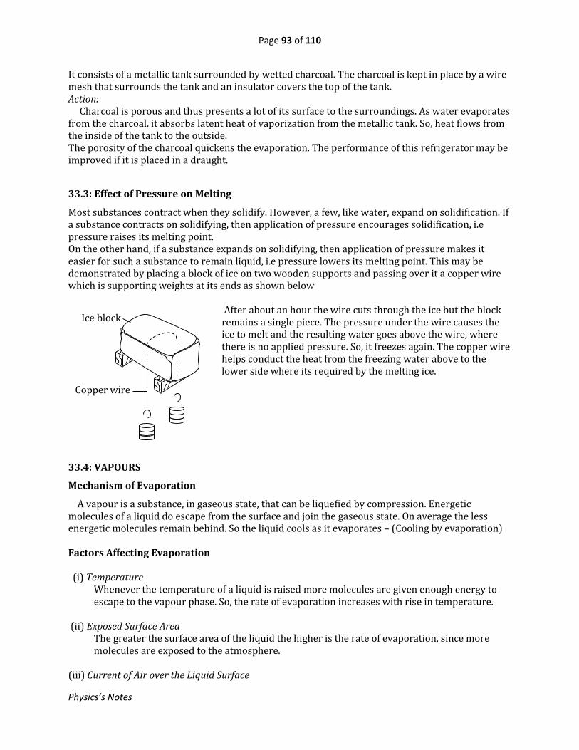
Page 93 of 110
Physics’s Notes
It consists of a metallic tank surrounded by wetted charcoal. The charcoal is kept in place by a wire mesh that surrounds the tank and an insulator covers the top of the tank. Action: Charcoal is porous and thus presents a lot of its surface to the surroundings. As water evaporates from the charcoal, it absorbs latent heat of vaporization from the metallic tank. So, heat flows from the inside of the tank to the outside. The porosity of the charcoal quickens the evaporation. The performance of this refrigerator may be improved if it is placed in a draught.
33.3: Effect of Pressure on Melting
Most substances contract when they solidify. However, a few, like water, expand on solidification. If a substance contracts on solidifying, then application of pressure encourages solidification, i.e pressure raises its melting point. On the other hand, if a substance expands on solidifying, then application of pressure makes it easier for such a substance to remain liquid, i.e pressure lowers its melting point. This may be demonstrated by placing a block of ice on two wooden supports and passing over it a copper wire which is supporting weights at its ends as shown below
After about an hour the wire cuts through the ice but the block remains a single piece. The pressure under the wire causes the ice to melt and the resulting water goes above the wire, where there is no applied pressure. So, it freezes again. The copper wire helps conduct the heat from the freezing water above to the lower side where its required by the melting ice.
33.4: VAPOURS
Mechanism of Evaporation
A vapour is a substance, in gaseous state, that can be liquefied by compression. Energetic molecules of a liquid do escape from the surface and join the gaseous state. On average the less energetic molecules remain behind. So the liquid cools as it evaporates – (Cooling by evaporation) Factors Affecting Evaporation (i) Temperature
Whenever the temperature of a liquid is raised more molecules are given enough energy to escape to the vapour phase. So, the rate of evaporation increases with rise in temperature.
(ii) Exposed Surface Area
The greater the surface area of the liquid the higher is the rate of evaporation, since more molecules are exposed to the atmosphere.
(iii) Current of Air over the Liquid Surface
Ice block
Copper wire

Page 94 of 110
Physics’s Notes
When an air current blows over the liquid, the liquid molecule in the gaseous state are carried away. This creates more space for more molecules to leave the liquid easily, increasing the rate of evaporation.
Vapour Pressure and Saturated Vapour Pressure Vapours, like any other gas, exert pressure. Gas pressure is due to bombardment of the container by the molecules of the gas. Thus, for a liquid in a closed container.continuously there some molecules which bombard the surface of the liquid and get absorbed back, i.e as molecules escape to vapour phase, others are re-joining the liquid. When the number of molecules escaping per second is equal to that of those re-joining the liquid then dynamic equilibrium has been achieved and the vapour above the liquid is said to besaturated. A saturated vapour is one that is in a state of dynamic equilibrium with its own liquid, i.e it is a vapour in contact with its own liquid in an enclosed space. (See diagrams below) Characteristics of a Saturated Vapour 1. Pressure of a saturated vapour is independent of volume.
When a saturated vapour is compressed, some vapour instead condenses to liquid reducing the vapour volume but leaving the vapour pressure the same. i.e the vapour portion decreases as that of the liquid increases. The other way round happens when a saturated vapour is expanded, still the pressure remaining the same.
2. Pressure of a saturated vapour increases with rise in temperature. Humidity in the Atmosphere This is the amount of water vapour actually present in the air. When the air is saturated with water, its humidity is 100%. The due point is the temperature at which air becomes saturated when cooled. Relative humidity is the ratio of saturated vapour pressure of water if the air were at the due point to the saturated vapour pressure of water at the present air temperature. Boiling and Evaporation
In both of these processes a liquid is turning to vapour, but the two differ as follows: - Boiling occurs at a fixed temperature while evaporation occurs at any temperature. - Boiling occurs throughout the liquid while evaporation occurs only on the surface of the
liquid.
33.5: Dependence of Boiling Point on External Pressure
A liquid boils at a temperature at which its saturated vapour pressure equals the external pressure. Since atmospheric pressure is lower at higher altitudes, it follows that the boiling point of a liquid is lower at higher altitudes. Raising the external pressure raises the boiling point of a liquid. The
(i) Unsaturated vapour
Liquid
Saturated vapour
(ii) Saturated vapour

Page 95 of 110
Physics’s Notes
following experiment demonstrates how the boiling point of a liquid can be lowered by reducing the pressure acting on the liquid surface. Explanation: When the flask is cooled by water from the tap, the water vapour inside condenses leaving a partial vacuum above the water. So water boils well below its boiling point. The Pressure Cooker This device works on the principle that at the boiling point of a liquid is raised when the external pressure is increased. When the water, containing the food to be cooked, is boiled water vapour is formed at a high rate. Because the space above the water surface is confined, the pressure acting on its surface increases. This raises the boiling point so that cooking occurs at a higher temperature than normal. The pressure does not rise indefinitely. When it reaches a certain value, steam escapes through the loading pin valve.
Air inside flask
is driven away
Round-bottomed
flask half-filled
with water
Heat
(i) Water boiled to drive away air before the cork is fitted
Cold water
(ii) Flask turned upside down under tap of cold water. Water is seen to boil under reduced pressure
Boiling water
Variable loading pin valve Safety valve
Aluminium container
Rubber seal
Temperatures above 100oC according to valve setting

Page 96 of 110
Physics’s Notes
Exercise 33 Where necessary, use: Specific capacity of copper = 400 J kg-1K-1 Specific capacity of water = 4200 J kg-1K-1 Specific latent heat of fusion of ice = 3.34 x 10⁵J kg-1
Specific latent heat of vaporisation of water = 2.26 x 10⁶ J kg-1
1. The specific heat capacity of a certain solution is 4000 J kg-1K-1. Calculate the quantity of heat required to raise the temperature of 800 g of the solution from -5oC to 25oC. 2. A 1000 W heater is used to warm 1 kg of a liquid from a temperature of 20oC. If after 10 s its temperature is found to be 45oC, what is the specific heat capacity of the liquid? 3. A heater was used to raise the temperature of 6 kg of water by 5 K. It was found that the same heater raised the temperature of 14 kg of a liquid L by 5 K in same time. Find the specific heat capacity of liquid L. 4. A copper block of mass 200 g is heated to a temperature of 140oC and then dropped into a copper calorimeter of mass 100 g which contains 250 g of water at 25oC. Neglecting heat losses, calculate the maximum temperature attained by the water. 5. A heater with power rating of 200 W is placed in 500 g of ice at 0oC. How long will it take to melt all the ice? 6. A copper calorimeter of mass 40 g contains 120 g of water at 15oC. Dry steam at 100oC is bubbled through the water in the calorimeter until the temperature of the water becomes 35oC. Find the mass of steam condensed. 7. The cooling system of a refrigerator extracts 600 J per second of heat. How long will it take to convert 500 g of water at 15oC into ice?

Page 97 of 110
Physics’s Notes
34. THE GAS LAWS In this chapter we shall deal with the relationship between pressure, volume and temperature of a fixed mass of gas. The relationship is governed by certain laws known as the gas laws.
34.1: Boyle’s Law The volume of a fixed mass of gas at constant temperature is inversely proportional to the pressure. Experiment: To Verify Boyle’s Law
The apparatus consists of a graduated tube, T, connected by rubber tubing to a reservoir, R. Dry air is trapped in the graduated tube over mercury as shown. If H is the atmospheric pressure in mm of mercury, then the pressure acting on the air in T is P = H + h. The pressure is varied by altering the position of the reservoir, each time noting the height h and the volume V of the air in T. A graph of P against 1/V is plotted. It is a straight line through the origin. Hence P 1/V. Thus, the results may be summarised as PV = C (a constant)
So, if a given mass of gas originally at a pressure P1 and volume V1, is compressed at constant temperature to a pressure P2 and volume V2, then P1V1 = P2V2 = constant NB: The air used must be dry because vapours generally do not obey the gas laws.
The following graphs also depict Boyle’s law.
34.2: Charles’s Law
The volume of a fixed mass gas at constant pressure is directly proportional to its absolute temperature.
h
Movable reservoir, R
mm scale
T
Rubber tubing
Trapped air
P
1/V
V
P
PV
P

Page 98 of 110
Physics’s Notes
Experiment: To Verify Charles’s Law
- A capillary tube, closed at one end is warmed to drive away any moisture from it and then its open end is dipped into mercury so that, on cooling, a little mercury is sucked in.
- A thermometer is fastened on the capillary tube and the trapped air column is immersed in a water bath.
- The temperature,, of the bath and the length l of the air column are measured and recorded.
- The temperature is varied by applying heat for an appropriate time.
- The heating is stopped and then, after stirring, the new values of and lare noted.
- The procedure is repeated for several different values of . Now, the absolute temperature of the air in the capillary tube is T = + 273 and, since the tube is of uniform cross-section, the length l is proportional to the volume of the trapped air. A graph of l against is plotted. It is a straight line, which when extrapolated, it cuts the temperature axis at -273oC, i.e at T = 0 K (since T = + 273)
Now, throughout the experiment the pressure on the trapped air was constant, being atmospheric plus that due to the weight of the mercury in the tube. Therefore the volume, V, is proportional to absolute temperature, T, at constant pressure. Examples 1. The volume of an air bubble at the bottom of a lake 80 m deep is 1.6 cm3. What will be its volume just below the surface if the atmospheric pressure is equivalent to a height of 10 m of water? Solution
P1 = 80 + 10 = 90 m of water, P2 = 10 m of water, V1 = 1.6 cm3, V2= ? P1V1 = P2V2
V2 = P1V1
P2 =
90 x 1.6
10 = 14.4 𝑐𝑚3
l
-273oC 0 K
Mercury
l
Heat
Capillary tube
Thermometer
Water bath

Page 99 of 110
Physics’s Notes
2. 800 cm3 of gas at 20oC is heated to 80oC at constant pressure. W hat will the new volume be? Solution V2
T2=
V1
T1
V2 = T2
T1V1 =
353 x 800
293 = 963.8 𝑐𝑚3
34.3: Pressure Law
The pressure of a fixed mass of gas at constant volume is directly proportional to its absolute temperature. Experiment: To Verify the Pressure Law - Dry air is trapped in a flask F by mercury in a rubber tubing which joins up with a reservoir R
and F is immersed in a water bath. - The position of R is adjusted until the mercury level at the trapped air is at mark X. The
temperature of the water bath and the mercury level difference h are recorded. - The temperature of the gas in F is varied by heating the bath.
- The heating is stopped and after stirring the reservoir
position is adjusted again to restore the mercury level to mark X. The new values of and h are recorded.
- The procedure is repeated for different values of . In each case the absolute temperature of the gas in F is T = + 273 and the pressure P = (H + h) mmHg, where H is the atmospheric pressure in mmHg. A graph of P against is plotted. It is a straight line which when extrapolated cuts the temperature axis at -273oC, i.e at T = 0 K (since T = +273).
Thus, the pressure, P, is directly proportional to the absolute temperature, T, at constant volume.
34.4: Relation between Pressure, Volume and Absolute temperature
From Boyle’s law PV = constant
From Charles′slaw V
T = constant
P
-273oC 0 K
h
R
mm scale
X
Heat
F F Dry air
Thermometer
Stirrer
Rubber tubing
Water bath

Page 100 of 110
Physics’s Notes
From pressure law P
T = constant
By combining the three equations we get PV
T = constant
Example
A balloon containing air at a pressure of 900 mmHg and temperature of 30oC occupies a volume of 1500 cm3. What will be its volume at s.t.p?
Solution
P1 = 900 mmHg, T1 = 303 K, V1 = 1500 cm3
P2 = 760 mmHg, T2 = 273 K, V2 = ? P2V2
T2 =
P1V1
T1
V2 = P1V1T2
T1P2 =
900 x 1500 x 273
303 x 760 = 1600 𝑐𝑚3
Exercise 34
1. The volume of a gas is 100 cm3 at a temperature of 27oC and a pressure of 3.0 x 10⁵ Pa. Find the volume of the gas at s.t.p. 2. A certain gas occupies a volume of 300 cm3 at a temperature of 17oC and a pressure of 1.0 x 10⁵ Pa. What will be its volume at 57oC if the pressure remains constant? 3. The diagram shows a horizontal tube of uniform cross-section closed at one end containing dry air which is trapped by a thread of mercury of length 12 cm. When the tube is inverted, the length of the air column becomes 23.8 cm. Calculate the atmospheric pressure.
20 cm 12cm
Mercury thread Air

Page 101 of 110
Physics’s Notes
35. FORCE ON A CURRENT-CARRYING CONDUCTOR (THE MOTOR PRINCIPLE)
35.1: Introduction
When a current is passed through a conductor which is lying across a magnetic field, the conductor experiences a force. This is because the current in the conductor creates its own magnetic field and the two fields then interact resulting in a force on the conductor. Because magnetic field lines act as though they are in tension and are repelling each other, it can be seen that the resultant field in this illustration pushes the conductor downwards. A d.c motor uses this principle to work. - The direction of the force depends on the direction of the current and that of the field - The magnitude of the force increases when any of these is increased:
(i) Magnitude of the current (ii) Length of the conductor (iii) Strength of the magnetic field Fleming’s Left Hand Rule
Fleming’s left hand rule helps establish the direction of the force if those of the field and current are known.
- The fore finger points in the direction of the field. - The middle finger points in the direction of the current. - The thumb points in the direction of the force.
35.2: The Simple D.C Motor
A motor converts electrical energy to mechanical energy.
Field
Current
Force
Magnetic pole pieces
A
B
C
D
N
S
Carbon brushes
Commutator
Y
X
Coil
R
Uniform field Field due to current Resultant
Force

Page 102 of 110
Physics’s Notes
Action: When the d.c supply is connected as shown, current flows through the coil in the direction ABCD. Using Fleming’s left hand rule it can be established that side AB is forced upwards while side CD downwards. So the coil rotates in the anticlockwise direction. The brushes X and Y remain stationary as the commutator rotates with the coil and when the coil plane is perpendicular to the field, the brushes are in the empty gaps of the commutator. However, momentum maintains the rotation until the commutator halves interchange connections to the brushes to maintain the same direction of rotation of the coil. The speed of the motor may be adjusted using rheostat R while the direction of rotation can be reversed by reversing one of the following (and not both at a go)
- the current - the magnetic field
The torque on the coil of the motor can be increased by increasing any of these: i) Number of turns of the coil ii) Magnitude of the current in the coil iii) Strength of the magnetic field iv) Area of the coil
Efficiency of the motor: Efficiency of a motor is the ratio of the useful mechanical power got out of the motor to the electrical power supplied to the motor The following reduce the efficiency of a motor to less than 100%:
i) Ohmic resistance of the coil ii) Friction at the brush contacts iii) Friction in the bearings
In practical motors the coil is wound over a laminated soft iron core because the soft iron concentrates the magnetic field into the area of the coil. N.B: A d.c motor can be made to generate d.c if instead it is mechanically run. Example
A d.c motor has an armature resistance of 5. If it draws a current of 10 A when connected to a supply of 220 V, calculate the power wasted in the windings and the efficiency of the motor. Solution Power wasted in windings = I2R = 102 x 5 = 500 W Power supplied to the motor = IV = 10 x 220 = 2200 W Useful mechanical power got out = 2200 – 500 = 1700 W
Efficiency = Useful power got out
Power suppliedx 100% =
1700
2200x 100 = 77.3%

Page 103 of 110
Physics’s Notes
35.3: The Moving-Coil Loud Speaker Action: The sound signal, in form of varying electric current, flows through the voice coil. Since the coil is placed in a magnetic field, it experiences a force that also keeps on changing in magnitude and direction according to the current. So the paper cone, fixed to the voice coil, keeps on moving to and fro in exactly the same way as the current, thus setting the air molecules vibrating to reproduce the sound. 35.4: The Moving-Coil Galvanometer Action When the galvanometer is connected for measurement, current enters the coil through one of the hairsprings and leaves by the other. - As the current flows in the coils, the opposite sides of the coil experience forces in opposite
directions so that the coil turns about an axis through the jeweled bearing. The direction of each force, and therefore of deflection of the coil, can be established using Fleming’s left hand rule.
- The extent to which the pointer is deflected is proportional to the magnitude of the current flowing in the coil. So a scale to read current is provided.
The sensitivity of the galvanometer can be increased by using: (i) a coil of large area (ii) a large number of turns in the coil (iii) a stronger magnet (iv) a weaker hairspring
Pointer
Soft iron cylinder
C
Hair spring
Permanent magnetic pole pieces
Coil
Jeweled bearing
N S
Scale
Hair spring
Metal casing
Soft iron pole plate
Voice coil
Soft iron core
Paper cone
Flexible leads to coil Tubular permanent magnet

Page 104 of 110
Physics’s Notes
36. ELECTROMAGNETIC INDUCTION This is the development of an emf due to movement of a conductor across a magnetic field or to variation of strength of a magnetic field experienced by a coil. In the case of a straight conductor the magnitude of the induced emf increases with (i) speed at which the conductor sweeps across the field. (ii) the length of the conductor actually sweeping through the magnetic field
In the case of a coil the emf increases with i) The number of turns ii) The area enclosed by the coil iii) The rate at which the strength of the magnetic field changes iv) Introduction of soft iron in the space enclosed by the coil. The direction of the induced emf depends on i) The direction of motion of the conductor relative to the field ii) In case of a coil, whether the strength of the field is increasing or decreasing.
36.1: Laws of Electromagnetic Induction
1. Faraday’s law The magnitude of induced emf is directly proportional to the rate of change of the magnetic flux linked with circuit. 2. Lenz’s law:
The induced emf is in such a direction as to oppose the change causing it
Fleming’s Right Hand Rule
This can be used to establish the direction of the emf induced in a straight conductor.
- Fore finger points in the direction of the field. - Middle finger points in the direction of the emf. - Thumb points in the direction of motion of the conductor.
36.2: Self Induction
This is the development of an emf in a coil due to variation of current in the coil itself. The following set-up can be used to demonstrate the phenomenon. A neon bulb is connected in parallel with a coil wound over a soft iron core and the combination is connected to a d.c source through a switch.
A neon bulb requires more than 120V to light. However, whenever the key is opened the neon bulb flashes. This is due to self induction in the coil. Explanation: When the switch is opened the current in the coil decays to zero at a very high rate. Likewise, the magnetic field due to the current changes very fast. Since the coil is in placed in the field, an emf is induced in the coil which is many times higher than the supply. Self induction is applied in a.c circuits to limit current. In practice the coils used may be called inductors, chokes, line filters, etc.
Field
Induced emf
Motion
Coil
S
Key 6V
Soft iron core
Neon lamp

Page 105 of 110
Physics’s Notes
36.3: Mutual Induction
This is development of an emf in a coil due to variation of current in a nearby coil. The set-up below can be used to demonstrate mutual induction.
Two separate coils, P and S, each wound on a soft iron core, are set up with no contact between them. When the key is closed the pointer of the galvanometer is seen to kick in a certain direction before returning to zero. On opening the key, the pointer kicks in the opposite direction before resting at zero. This is due to mutual induction between the two coils and all the laws of electromagnetic induction are obeyed. Explanation: As the current in the coil changes, the magnetic field induced in the core also changes accordingly. Since the other coil, S, is linked by the field, an emf is induced in S that drives an induced current through the galvanometer.
36.4: The Transformer
Mutual induction is applied in transformers. A transformer is used to step up or step down an alternating voltage It consists of two coils, namely (i) The primary coil, where the input voltage is connected (ii) The secondary coil, from which the output voltage is picked The coils are of insulated copper wire wound on a laminated soft iron core. The secondary and primary voltage, VP and Vs are related to the numbers of turns in the primary and secondary coils. Let Np = number of turns in the primary coil NS = number of turns in the secondary coil
Then 𝑽𝑺
𝑽𝑷=
𝑵𝑺
𝑵𝑷
If 𝑁𝑆 > 𝑁𝑃then 𝑉𝑆 > 𝑉𝑃 and the transformer is termed a step up If 𝑁𝑆 < 𝑁𝑃 then 𝑉𝑆 < 𝑉𝑃 and it is a step-down If Ip is the input current and Is the output current, then Input power =IpVp and output power = IsVs Assuming no power losses, IpVp =IsVs
Coil
S
Key
Soft iron core
Galvanometer
P S
Vp Vs
Laminated soft iron core
Primary coil Secondary coil

Page 106 of 110
Physics’s Notes
𝑉𝑝
𝑉𝒔 =
𝐼𝑠
𝐼𝑝
From this it can be seen that when a transformer steps up a voltage, the current is stepped down and vice versa. Examples 1. A transformer that steps down voltage from 240V to 12V has 3600 turns in the primary coil. Find the number of turns in the secondary coil. Solution 𝑉𝑆
𝑉𝑃=
𝑁𝑆
𝑁𝑃
𝑁𝑆 = 𝑉𝑆
𝑉𝑃𝑁𝑃 =
12x3600
240 = 180 turns
2. Electric power is generated at 11 kV and transformers are used to raise the voltage to 330 kV for transmission over long distances by means of cables. The output of the transformers is 3.96 MW and they are 90% efficient. Find: (i) the input current to the transformer, (ii) the output current to the cables. Solution
(i)The input power = 3.96
0.90= 4.4 MW
input current = Power
Voltage =
4.4 x 10⁶
11 x 103 = 400 A
(ii)The output current = Output power
Output voltage =
3.96 x 10⁶
330 x 103= 12 A
Losses in transformers and how they are minimised
1. Ohmic Loss: This is energy lost in form of heat in the resistance of the coil. It is minimised by using a low-resistance material for the coil – copper is used.
2. Eddy Current Loss: This is due to circulation of current induced in the core. It is minimised by using a laminated core.
3. Hysteresis Loss: This is energy lost due to forcing the magnetic field to reverse repeatedly and rapidly in the core. It is minimised by using a magnetically soft material for the core, i.e soft iron.
4. Flux Leakage: This loss is brought due to some magnetic field lines failing to go through the space enclosed by the secondary coil.

Page 107 of 110
Physics’s Notes
Role of Transformers in Power Transmission To distribute electricity to consumers wires are used and the wires have resistance, which increases with distance. So, some power is lost in form of heat in the resistance of the transmitting wires. In order to minimise power loss when transmitting to distant consumers, the transmission current is made small. This is achieved by stepping up the voltage. So a step-up transformer is used at the generation station and a step down at the consumer end as illustrated in the diagram above.
36.5: The Simple Alternating Current Generator (dynamo)
It consists of a rectangular coil that can turn about an axis in a magnetic field provided by magnetic pole pieces. The axis of rotation is perpendicular to the magnetic field. The ends of the coil are each connected to a slip ring. (See the diagram below) Action: As the coil is rotated the opposite side AB sweeps through the magnetic field in one direction while CD sweeps in the opposite direction. So the emfs induced in these sides add up in series to constitute the output emf at the terminals X and Y. AB and CD keep on exchanging the directions in which they cut the magnetic field. This makes the emf across X and Y to reverse periodically in magnitude and direction at the frequency of rotation of the coil. Thus the polarities at the terminals X and Y keep on alternating. The variation of the emf with time is indicated in the graph below. The magnitude of the emf depends on the following: (i) Frequency of rotation of the coil – the higher the frequency the higher the emf. (ii) The strength of the magnetic field in which the coil rotates (iii) The area enclosed by the coil – the larger the higher the emf
Magnetic pole pieces
Coil
Slip rings
X Y
Carbon brushes
A
B
C
D
N
S
+Eo
-Eo
emf
Time
Long distance
Generation station
Step-up transformer
Step-down transformer
Consumer

Page 108 of 110
Physics’s Notes
(iv) The number of turns in the coil – the greater the higher the emf (v) The angular position of the coil in relation to the field. In practical dynamos the coil is wound over a laminated soft iron core. This concentrates the magnetic field onto the area of the coil. The D.C Generator If the coil of a direct-current (d.c) motor is mechanically run, an emf with non-varying polarilties is generated. In this case it serves as a d.c. generator. The emf varies with time as shown below.
36.6: Rectification of Alternating Current
An alternating current changes periodically, both in magnitude and direction. There are many forms of alternating current, the simplest of which may be represented by a sine wave and hence referred to as sinusoidal. The process of making current flow in one direction is known as rectification and it is achieved by use of diodes. A diode is a component which allows current to flow only in one direction. The circuit symbol for a diode is The symbol indicates the direction in which the diode allows conduction of conventional current. Rectification may be done by allowing only one half of the cycle to flow, a process called half-wave
rectification, or by making both halves of the cycle to flow in the same direction – full-wave
rectification.
One diode is used. It allows flow of current during one half of the cycle and blocks the other half. The graph on the right hand side above shows how the output p.d, V, varies with time. (b) Full-Wave Rectification: (i) Bridge Rectifier (4 diodes are used)
Smoothening capacitor
D4
D1 D2
A.C Y
X
D3 C
+
-
Graph of V vs time
V
Time
(a) Half-Wave Rectification:
V
+
-
Emf
Time
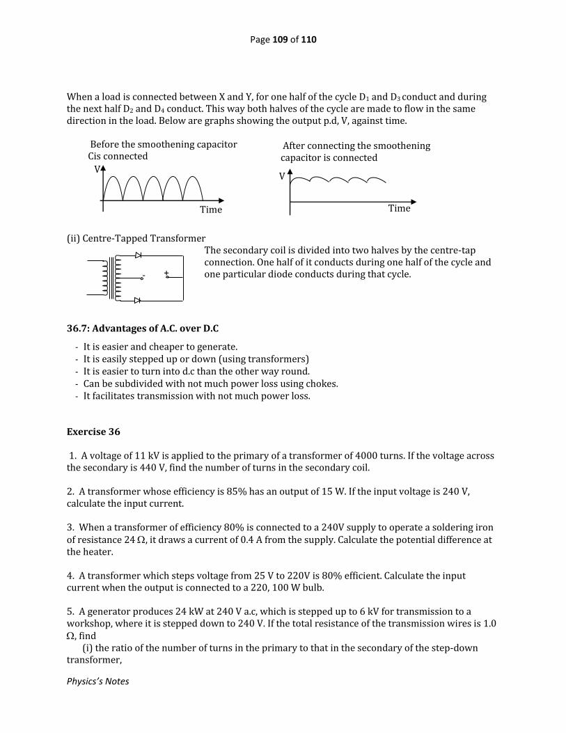
Page 109 of 110
Physics’s Notes
When a load is connected between X and Y, for one half of the cycle D1 and D3 conduct and during the next half D2 and D4 conduct. This way both halves of the cycle are made to flow in the same direction in the load. Below are graphs showing the output p.d, V, against time.
(ii) Centre-Tapped Transformer The secondary coil is divided into two halves by the centre-tap connection. One half of it conducts during one half of the cycle and one particular diode conducts during that cycle.
36.7: Advantages of A.C. over D.C
- It is easier and cheaper to generate. - It is easily stepped up or down (using transformers) - It is easier to turn into d.c than the other way round. - Can be subdivided with not much power loss using chokes. - It facilitates transmission with not much power loss.
Exercise 36 1. A voltage of 11 kV is applied to the primary of a transformer of 4000 turns. If the voltage across the secondary is 440 V, find the number of turns in the secondary coil. 2. A transformer whose efficiency is 85% has an output of 15 W. If the input voltage is 240 V, calculate the input current. 3. When a transformer of efficiency 80% is connected to a 240V supply to operate a soldering iron of resistance 24 , it draws a current of 0.4 A from the supply. Calculate the potential difference at the heater. 4. A transformer which steps voltage from 25 V to 220V is 80% efficient. Calculate the input current when the output is connected to a 220, 100 W bulb. 5. A generator produces 24 kW at 240 V a.c, which is stepped up to 6 kV for transmission to a workshop, where it is stepped down to 240 V. If the total resistance of the transmission wires is 1.0 , find (i) the ratio of the number of turns in the primary to that in the secondary of the step-down transformer,
- +
Before the smoothening capacitor Cis connected
V
Time
After connecting the smoothening capacitor is connected
V
Time

Page 110 of 110
Physics’s Notes
(ii) the power lost in the transmission wires assuming both transformers are 100% efficient. (iii) the power loss if the power were transmitted directly to the workshop without use of transformers.
ANSWERS TO NUMERICAL EXERCISES Ex. 17 1. 18.6 ms-12. (i) 25 ms-1, 40 ms-1 (ii) 265 m 3. (i) 7.5 ms-2 (ii) 6.7 m 4. 5 ms-15. (i) 486.8 m (ii) 4.5 ms-2 (iii) 6 ms-2 (iv) 168 m (v) 18.5 s 6. (i) 3 s (ii) 25 m Ex. 18 1. (a) 5 N (b) 5 N at 36.9o to the 4-N force (c) 13 N at 22.6o to the 14-N force Ex. 19 1. 12.9 ms-12. (i) 255 ms-1 (ii) 918 J 3.2.5 ms-14.1.0 ms-15.1.6 ms-1 Ex. 20 1. 50 kg 2.6000 N 3. (i) 1.5 ms-2 (ii) 18.75 m 4.12.5 ms-25. 7.5 N Ex. 23 1. 28.1o2.48.6o3.29o, 52o4. 49o Ex. 32 1. 2.5 V 2.5 3.8, 6V 4.2 A, 3 A, 5 A5.9 V, 27 W 6.2 , 16 V 7. 3 V, 3.6 8. 250 V, 31.25 9.48 , 833.3 W 10.Sh 525 11. (i) 0.0133 (ii) 1980 Ex. 33
1. 24, 12 2.1
163. 60 minutes 4.2 g 5.12 hours 6. 36 s
7. 18 min-18. 3 days, 80
819.32 g 10. 2.025 x 1024 atoms
Ex. 34 1. 96 kJ 2.400 J kg-1 K-13.1800 J kg-1 K-14.32.9oC 5. 835 s 6. 4.1 g 7. 330.8 s Ex. 35 1. 247.5 cm32.341.4 cm33. 75.2 cmHg Ex. 37 1. 160 2.0.0735 A 3. 42.9 V 4. 5 A 5. (i) 25:1 (ii) 16 W (iii) 10 kW