Contents - SDEC
79
1 / 79 Contents Chapter 1 General Information of Engine 1.1 General notices 1.2 Notices of fuel system 1.3 Outline drawing of diesel engine Chapter 2 Brief Introduction to Main Systems of Diesel Engine 2.1 Intake and exhaust system 2.2 Fuel system 2.3 Lubrication system 2.4 Cooling system 2.5 Electrical system Chapter 3 Service Requirements of Engine 3.1 Torque requirements of fasteners 3.2 Mounting and adjustment requirements and specifications of key components 3.3 Oiling and gluing requirements of main parts Chapter 4 Mounting and Adjustment of Main Components of Engine 4. Mounting requirements of parts and components 4.1 Mounting of cylinder liner 4.2 Mounting of camshaft bearing 4.3 Mounting of crankshaft 4.3.1 Mounting of main bearing 4.3.2 Mounting of crankshaft and main bearing cap 4.3.3 Mounting of bolts of main bearing cap 4.3.4 Inspection after mounting 4.4 Mounting of piston and connecting rod assembly 4.5 Mounting of piston oil cooling jet 4.6 Mounting of oil pump, front cover, rear gear housing, and oil seals 4.6.1 Mounting of oil pump 4.7 Mounting of tappet and camshaft 4.7.1 Mounting of tappet 4.7.2 Mounting of camshaft 4.7.3 Mounting of thrust plate and camshaft gear
-
Upload
khangminh22 -
Category
Documents
-
view
0 -
download
0
Transcript of Contents - SDEC
1 / 79
Contents Chapter 1 General Information of Engine 1.1 General notices
1.2 Notices of fuel system
1.3 Outline drawing of diesel engine
Chapter 2 Brief Introduction to Main Systems of Diesel Engine 2.1 Intake and exhaust system
2.2 Fuel system
2.3 Lubrication system
2.4 Cooling system
2.5 Electrical system
Chapter 3 Service Requirements of Engine 3.1 Torque requirements of fasteners
3.2 Mounting and adjustment requirements and specifications of key components
3.3 Oiling and gluing requirements of main parts
Chapter 4 Mounting and Adjustment of Main Components of Engine 4. Mounting requirements of parts and components
4.1 Mounting of cylinder liner
4.2 Mounting of camshaft bearing
4.3 Mounting of crankshaft
4.3.1 Mounting of main bearing
4.3.2 Mounting of crankshaft and main bearing cap
4.3.3 Mounting of bolts of main bearing cap
4.3.4 Inspection after mounting
4.4 Mounting of piston and connecting rod assembly
4.5 Mounting of piston oil cooling jet
4.6 Mounting of oil pump, front cover, rear gear housing, and oil seals
4.6.1 Mounting of oil pump
4.7 Mounting of tappet and camshaft
4.7.1 Mounting of tappet
4.7.2 Mounting of camshaft
4.7.3 Mounting of thrust plate and camshaft gear

2 / 79
4.8 Mounting of base plate, oil suction pipe, oil pan and oil dipstick of engine block
4.9 Mounting of cylinder head components and distribution mechanism
4.9.1 Mounting of cylinder head components
4.9.2 Mounting of valve spring
4.9.3 Mounting of cylinder head
4.9.4 Mounting of push rod and valve bridge
4.9.5 Mounting of intake and exhaust rocker arm shaft components
4.10 Mounting of oil pump
4.11 Mounting of air compressor
4.12 Mounting of fuel pipeline and filter
4.12.1 Mounting of fuel pipeline
4.12.2 Mounting of fuel filter
4.13 Mounting of injector
4.13.1 Mounting notices
4.13.2 Mounting process
4.14 Mounting of water pump
4.15 Mounting of flywheel housing and flywheel
4.15.1 Mounting of flywheel housing
4.15.2 Mounting of flywheel
4.16 Mounting of rear crankshaft oil seal
4.17 Mounting of oil cooler and filter
4.17.1 Mounting of oil cooler
4.17.2 Mounting of oil filter
4.18 Mounting of exhaust manifold and turbocharger
4.19 Mounting of common rail system components
Chapter 5 Operation and Maintenance of Diesel Engine 5.1 Selection and use of diesel fuel
5.2 Selection and use of lube oil
5.3 Selection and use of coolant
5.4 Starting of diesel engine
5.4.1 Normal starting
5.4.2 Cold start
5.4.3 Long-time shutting down or first starting and oil change
3 / 79
5.5 Operation of diesel engine
5.6 Shutting down of diesel engine
5.7 Running-in of new diesel engine or after engine overhaul
5.8 Maintenance schedule of diesel engine
Chapter 6 Engine Electronic Control System 6.1 Composition of electronic control system
6.2 Electronic control principle
6.3 Main control function of ECU
6.4 Control function of vehicle
6.5 Fault diagnosis
6.6 Wiring connector and definition
6.7 Plan of wiring
6.8 Resistance value measurement
6.9 Introduction to main sensors
4 / 79
Chapter 1 General Information of Engine
1.1 General notices 1) To disconnect the vehicle battery, the grounding circuit (negative) cable must be disconnected
before the positive cable. In case of two batteries, the two grounding circuit (negative) cables should be disconnected before the positive cables. To connect the battery, the positive cable should be connected before the negative cable.
2) The disconnected joints of fuel system and lubrication system must be protected from dust.
3) Unless otherwise instructed, the engine must rotate clockwise (observed from the front).
4) The operation under the engine hood must be careful and avoid the rotating pulley and driving belt.
5) It should be noticed that the parts of the engine that stops just now are very hot. To remove the expansion tank cover, coolant drainage pipe and drainage screw when the engine is still hot, especially very hot, the operation must be careful, avoid any burn and wait till the engine cools down.
6) Only the oil and antifreeze with the correct specifications and the permission of Shanghai Diesel Engine Co., Ltd. are allowed.
7) Many fastening bolts of this engine are pre-coated with thread adhesive for locking. Before those bolts are reused, the threads must be cleaned and re-coated with Loctite adhesive 270.
8) When working under the vehicle, more than one jack is required, and the vehicle must be underlaid by the hoister or other safe supports.
9) To mount an oil seal by a special tool, the surface of round hole of tool must be free of any burr that may damage the seal lip.
10) The safety glasses are required for the protection of eyes.
11) The gloves are required for the use of lube oil or grease.
12) Unless otherwise required by the operation procedure, the ignition switch must be OFF.
13) When working on the vehicle, the hand brake must be applied and the tires be blocked in front and back to avoid vehicle moving.
14) The working place of engine must be well ventilated in order to avoid CO poisoning.
15) No eating, drinking or smoking when working on the vehicle.
16) Before the on-vehicle maintenance and service, the finger ring, watch, loose jewelry or clothing must be taken off in order to avoid injury.
17) In order to avoid any burn, never touch the hot parts, such as parts of cooling system and exhaust system.
18) There are some safety-related key bolts on the engine, and if dismantled, those bolts must be renewed. Those key bolts are clearly indicated in this Manual.
19) The sensors and actuators (such as injectors) must not be connected with the external power.
20) Storage and handling of timing belt:
21) The timing belt must be coiled flatly, and not hooked.
22) Never take the timing belt out from its package before it is ready for mounting.

5 / 79
23) To coil or fold the belt, its bending diameter must be 25mm at least.
24) Never move the belt from the timing pulley with a crow bar; otherwise, the reinforced fiber in the belt may be damaged. Therefore, the belt must be moved manually.
25) Before the belt that can be reused is dismantled, its rotating direction must be ascertained in order to ensure the correct mounting.
26) The belt that is polluted by oil, fuel or other toxic fluid must be renewed, and not be cleaned.
27) If the belt is polluted, the corresponding pulley and timing pulley must be cleaned, and the pollutant source should be found and eliminated.
Notice: The solvent is prohibited for cleaning.
28) The timing pulley surface must be smooth in order to prolong the belt life. Therefore, before the belt is mounted, it is required to make sure that pulley surface is free of roughness or burr and can rotate freely.
1.2 Notices of fuel system: 1) Never disassemble the injectors.
2) Never maintain or repair any part of fuel system when the engine is running.
3) The diesel fuel flows from injection pump to injector through the high-pressure fuel pipe under the super-high pressure that may be up to 1600 bar (23,200 psi) so it is prohibited to loosen any high-pressure fuel pipe when the engine is running.
4) The leakage inspection must be careful because the injection of fuel into the skin under a high pressure may result in personal injury or death. Therefore, the contact with the injection mist of fuel must be avoided. The thick panel should be used for fuel leakage inspection. During maintenance of fuel system, the goggles and protective clothing are required.
5) No smoking or open flame is allowed when handling any fuel-related component or operating nearby. The fuel steam may be ignited, resulting in part damage and/or personal injury.
6) During handling or overhaul of parts of diesel fuel system, the parts must be kept clean because the fitting allowances of injector, oil pump, fuel pipeline and common-rail parts, etc are very small and the dust accumulation can worsen the abrasion or bring any trouble to the parts.
7) The fuel system must be washed/cleaned and then dried in air before dismantling.
8) The jet should be cleaned with cloth instead of steel wire brush.
9) After dismantling, all the exposed parts should be covered.
10) Before mounting, it is required to check every part for dust, grease or other pollutant, and do the necessary cleaning.
11) To mount the new parts, they should be lubricated properly with clean engine oil or diesel fuel.
6 / 79
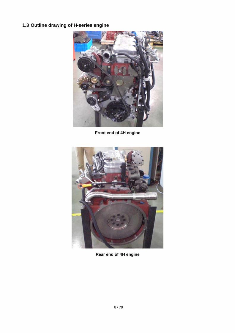
1.3 Outline drawing of H-series engine
Front end of 4H engine
Rear end of 4H engine
7 / 79
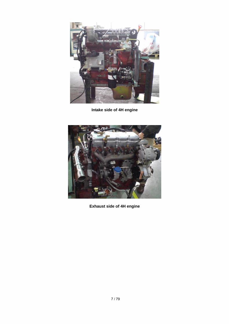
Intake side of 4H engine
Exhaust side of 4H engine
8 / 79
Chapter 2 Brief Introduction to Main Systems of Diesel Engine
2 Brief introduction to main systems of diesel engine
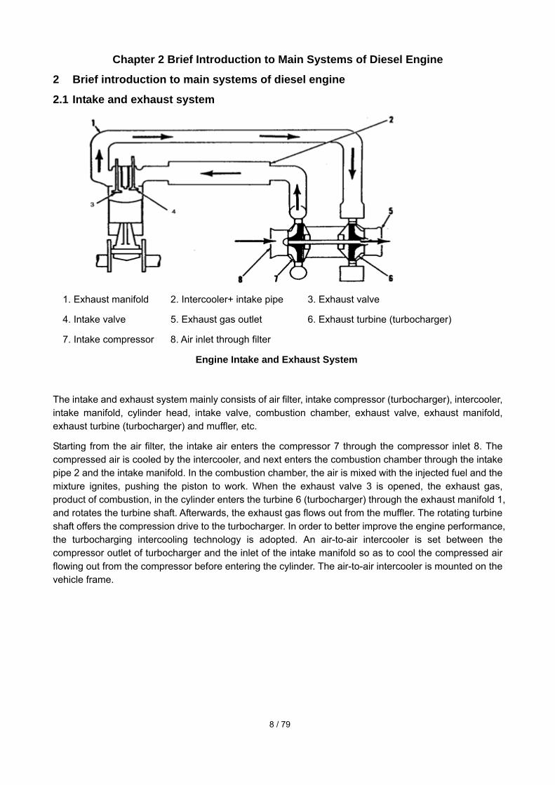
2.1 Intake and exhaust system
1. Exhaust manifold 2. Intercooler+ intake pipe 3. Exhaust valve
4. Intake valve 5. Exhaust gas outlet 6. Exhaust turbine (turbocharger)
7. Intake compressor 8. Air inlet through filter
Engine Intake and Exhaust System
The intake and exhaust system mainly consists of air filter, intake compressor (turbocharger), intercooler, intake manifold, cylinder head, intake valve, combustion chamber, exhaust valve, exhaust manifold, exhaust turbine (turbocharger) and muffler, etc.
Starting from the air filter, the intake air enters the compressor 7 through the compressor inlet 8. The compressed air is cooled by the intercooler, and next enters the combustion chamber through the intake pipe 2 and the intake manifold. In the combustion chamber, the air is mixed with the injected fuel and the mixture ignites, pushing the piston to work. When the exhaust valve 3 is opened, the exhaust gas, product of combustion, in the cylinder enters the turbine 6 (turbocharger) through the exhaust manifold 1, and rotates the turbine shaft. Afterwards, the exhaust gas flows out from the muffler. The rotating turbine shaft offers the compression drive to the turbocharger. In order to better improve the engine performance, the turbocharging intercooling technology is adopted. An air-to-air intercooler is set between the compressor outlet of turbocharger and the inlet of the intake manifold so as to cool the compressed air flowing out from the compressor before entering the cylinder. The air-to-air intercooler is mounted on the vehicle frame.
9 / 79
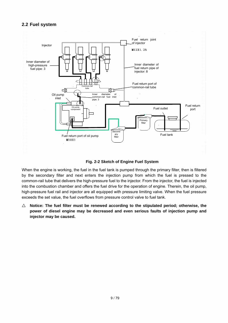
2.2 Fuel system
Fig. 2-2 Sketch of Engine Fuel System
When the engine is working, the fuel in the fuel tank is pumped through the primary filter, then is filtered by the secondary filter and next enters the injection pump from which the fuel is pressed to the common-rail tube that delivers the high-pressure fuel to the injector. From the injector, the fuel is injected into the combustion chamber and offers the fuel drive for the operation of engine. Therein, the oil pump, high-pressure fuel rail and injector are all equipped with pressure limiting valve. When the fuel pressure exceeds the set value, the fuel overflows from pressure control valve to fuel tank.
Notice: The fuel filter must be renewed according to the stipulated period; otherwise, the power of diesel engine may be decreased and even serious faults of injection pump and injector may be caused.
Injector
Inner diameter of high-pressure
fuel pipe: 3
Fuel return joint of injector
Inner diameter of fuel return pipe of injector: 8
Fuel return port of common-rail tubeCommon-rail
tube
Oil pump inlet
Inner diameter of common-rail fuel inletpipe: 3
Oil pump component
Fuel return port of oil pumpSecond
ary filter
Fuel outlet Fuel return
port
Primary filter
Fuel tank

10 / 79
2.3 Lubrication system
Oil path Sketch of Engine Lubrication System
In the lubrication system, the oil flow starts from the oil pump which delivers the oil from oil pan to oil cooler through an oil suction pipe. The cooled oil is filtered by the oil filter; and then enters the main oil gallery of engine, and next through various oil paths, the oil flows to crankshaft, main bearing, camshaft, piston, connecting rod, distribution mechanism, gear and other parts for lubrication, cooling and cleaning, etc.; at last, the oil returns to the oil pan. In case of blockage of oil filter, the oil enters the main oil path directly through the bypass valve. The oil of another path flows directly from the oil path on the oil filter holder to the impeller shaft and bearing of turbocharger through the oil inlet pipe of turbocharger for lubrication, cooling and cleaning, and then returns to the oil pan through the oil return pipe of turbocharger.
Turbocharger

11 / 79
Note: When the oil pump is mounted, the oil path hole of gear housing at the back end of main oil gallery on the intake side is connected to the high-pressure oil pump!
Main oil path on the exhaust side
Main oil path on the intake side
Sketch of oil path on cylinder headFrom the oil path in engine block and through the cylinder head mat (connecting the pathes in engine block and cylinder head), the oil flows from the oil path on rocker arm mat to the oil path on intake rocker arm, from the intake rocker arm shaft to the oil path on valve clearance adjusting bolt, from the intake rocker arm shaft to the oil path on intake valve ball pin, from the oil path on rocker arm mat to the oil path on exhaust rocker arm, to the oil path on exhaust rocker arm holder, from the exhaust rocker arm shaft to the oil path on valve clearance adjusting bolt, and from the exhaust rocker arm shaft to the oil path on exhaust valve ball pin.
Cylinder mat spreads the oil!
Oil pan
Main oil gallery
Oil filter
Oil cooler & filter assem
bly
Oil cooler
Bypass valve
Opening pressure 345
KPa
Piston cooling
nozzle
Cool and lubricate the piston and sm
all head of connectin g rod
Crankshaft
bearing
Supercharger
Cam
shaft bearing
Connecting
rod bearing
Air com
pression pum
p
Cylinder head
Cool and lubricate the rocker
arm and push rod, etc
Gear
housing
Oil gas
environment
Gas
Liquid
Oil pump
Working pressure 448~517 KPa
Pressure control valve
The air is discharged
outwards through the exhaust
manifold

12 / 79
2.4 Cooling system
Sketch of Engine Cooling System
The main function of cooling system is to take away the heat produced by the diesel engine, oil and related parts. The residual heat that is not taken away by the cooling system is taken away by exhaust gas or discharged to the air.
As shown in the sketch, after the water pump, the engine coolant enters the water cavity of oil cooler to cool the oil, and then enters the water jackets of engine block and cylinder head in order. After cooling the engine, the coolant enters the thermostat mounted at the water outlet of water jacket of cylinder head. When the temperature of the coolant is lower than the opening temperature of thermostat, the coolant flows to the water pump inlet directly; when the temperature of the coolant is equal to or higher than the opening temperature of thermostat, the coolant enters the radiator for cooling and then flows to the water pump inlet.
Coolant path in the cylinder head and engine block: water inlet of engine block → worm shell cavity of water pump → oil cooler cavity → water jacket of engine block → lower water jacket of cylinder head →
Water jacket of engine block Water jacket of engine block
Oil cooler
Air compressor
Water pump
Air heater
Radiator
Thermostat
Expansion tank
13 / 79
upper water jacket of cylinder head → water outlet pipe of cylinder head.
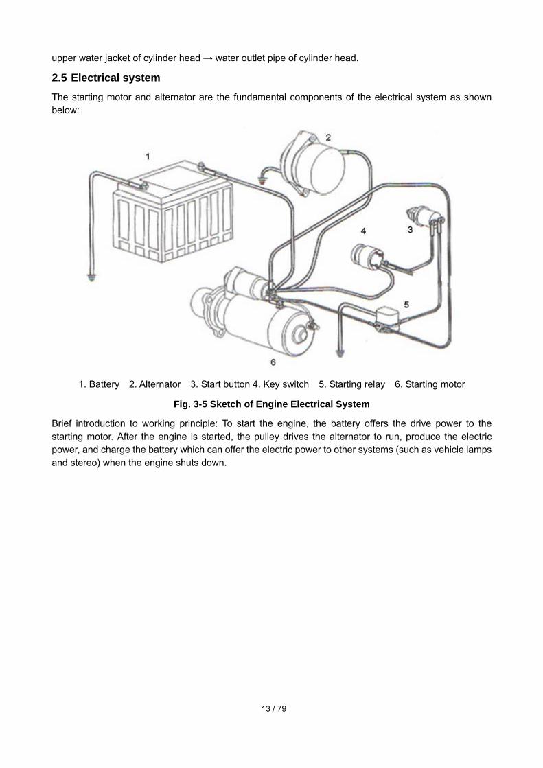
2.5 Electrical system The starting motor and alternator are the fundamental components of the electrical system as shown below:
1. Battery 2. Alternator 3. Start button 4. Key switch 5. Starting relay 6. Starting motor
Fig. 3-5 Sketch of Engine Electrical System
Brief introduction to working principle: To start the engine, the battery offers the drive power to the starting motor. After the engine is started, the pulley drives the alternator to run, produce the electric power, and charge the battery which can offer the electric power to other systems (such as vehicle lamps and stereo) when the engine shuts down.

14 / 79
Chapter 3 Service Requirements of Engine
3 Service requirements of engine
3.1 Torque requirements of fasteners 1) The tightening torques of key bolts of H-series engine are listed in Table 1.
Table 1 Tightening Torques of Key Bolts
S/N Designation Thread specification
Final tightening torque (Nm)
Tightening method
1
Bolts of main bearing cap
M14*1.5
85±5 Nm Turning angle:
120°±5°
1st step: 120Nm 2nd step: completely release3rd step: 60±5 Nm 4th step: 85±5 Nm Turning angle of 5th step: 120°±5°
2
Cylinder head bolts
M12*1.75
90±5 Nm Turning angle:
90°±5°
1st step: 90Nm 2nd step: completely release3rd step: 90Nm Turning angle of 4th step: 90°±5°
3
Connecting rod bolts M11×1.25 60±5 Nm Turning angle:
60°±3°
1st step: 30±5 Nm 2nd step: 60±5 Nm Turning angle of 3rd step: 60°±3°
4
Flywheel screws M12×1.25 30±5 Nm Turning angle:
60°±3°
Tightened by turns in two steps 1st step: 30±5Nm 2nd step: 60°±3°
5
Crankshaft belt pulley (with signal disc, with or without rubber vibration damper)
M12*1.25 50±5 Nm Turning angle:
90°±3°
1st step: 50±5 Nm Turning angle of 2nd step: 90°±3°
2) Tightening torques of main bolts of H-series engine are listed in Table 2.
Table 2 Tightening Torque of Main Bolts
S/N Designation Thread
specification Final tightening
torque (Nm) Tightening method
6 Mounting bolts of cooling jet
15N.m
7 Tightening nuts of fuel injection pump drive gear
M14×1.5 64±5 Nm

15 / 79
S/N Designation Thread
specification Final tightening
torque (Nm) Tightening method
Fastening bolts of camshaft gear
36 Nm
8 Thrust bolts of camshaft
24 Nm
9 Fastening nuts of fuel injection pump flange
M8 24±3 Nm
10 Fastening bolts of oil pump
24 Nm 1st step: 8 Nm 2nd step: 24Nm
11
Nuts of high-pressure fuel adaptor Fastening bolts of injector pressure plate Nuts of high-pressure fuel adaptor
15 Nm 30±3Nm 50 Nm
The nuts of high-pressure fuel pipe joint are tightened in two steps which are separated by the tightening of injector nuts.
12 Fastening nuts of injector harness
1.5 Nm
39 Nm (fuel rail to fuel adaptor)
13
Nuts of high-pressure fuel pipe
44Nm (fuel injection pump
to fuel rail)
14 Fastening bolts of engine block reinforcing plate
43 Nm
15 Fastening bolts of intake manifold cover
24 Nm
16 Bolts of front gear housing
24 Nm
17 Fastening bolts of flywheel housing
M10 M12
49 Nm 85 Nm
18 Bolts of rotation speed sensor
5 Nm
19 Camshaft phase sensor
4 Nm
20 Fastening bolts of exhaust manifold and turbocharger
M10 43±4 Nm
21 Fuel filter Rotated by 3/4 circle after
16 / 79
S/N Designation Thread
specification Final tightening
torque (Nm) Tightening method
contact
22 Fuel filter holder 90 Nm
23 Drain plug of oil pan 60±4 Nm
24 Fastening bolts of oil pan
28 Nm
25 Mounting bolts of valve rocker arm holder
36 Nm
26 Mounting bolts of middle cover and cylinder head cover
24 Nm
27 Tightening torque of mounting bolts of rear gear housing
M8 M10 M12
24 Nm 47 Nm 50 Nm
28 Tightening torque of mounting bolts of oil suction pipe
24 Nm
29 Rear bracket of engine 77 Nm
30 Fastening bolts of front bracket of engine (Grade 10.9)
115 Nm
31 Fastening nuts of drive gear of air compressor
120 Nm
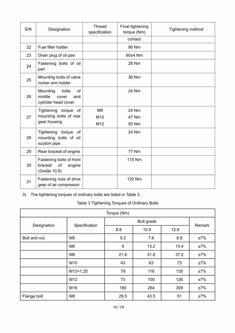
3) The tightening torques of ordinary bolts are listed in Table 3.
Table 3 Tightening Torques of Ordinary Bolts
Torque (Nm)
Bolt grade Designation Specification
8.8 10.9 12.9 Remark
Bolt and nut M5 5.2 7.6 8.9 ±7%
M6 9 13.2 15.4 ±7%
M8 21.6 31.8 37.2 ±7%
M10 43 63 73 ±7%
M12×1.25 79 116 135 ±7%
M12 73 100 126 ±7%
M16 180 264 309 ±7%
Flange bolt M8 29.5 43.5 51 ±7%

17 / 79
Torque (Nm)
Bolt grade Designation Specification
8.8 10.9 12.9 Remark
M10 58 85 98.5 ±7%
M12×1.25 62.5 91.8 106 ±7%
M12 112 ±7%
Stud bolt M10×1.25 44 65 76 ±7%
Hinge banjo bolt M10×1 50 ±7%
M12×1.5 50 ±7%
M14×1.5 80 ±7%
M16×1.5 80 ±7%
M18×1.5 100 ±7%
M22×1.5 100 ±7%
Plug M30×1.5 150 ±7%
Note: The above tightening torque is the experiential torque of clean and dry bolt, nut and thread. If the thread is coated with oil, the torque is decreased by 10%; in case of new electro-plated bolt, the torque is decreased by 20%; after the bolt is screwed into the aluminum thread completely, the torque is decreased by 10%.
4) The approximate tightening torques of ordinary plugs and standard bolts are listed in Table 4.
Table 4 Approximate Tightening Torques of Ordinary Plugs and Standard Bolts
Performance grade
8.8 10.9
Torque/Nm Torque /Nm Bolt diameter (mm) Cast iron Aluminum Cast iron Aluminum
6 9 7 14 11
8 25 18 32 25
10 40 30 60 45
12 70 55 105 80
14 115 90 160 125
16 180 140 240 190
18 230 180 320 250
5) The recommended tightening torques of tapered plugs are listed in Table 5.

18 / 79
Table 5 Recommended Tightening Torques of Tapered Plugs
Specification of plug Torque/N⋅m
Thread Outer diameter of valid
thread Cast iron or steel Aluminum
1/16 8.1 15 5
1/8 10.4 20 15
1/4 13.7 25 20
3/8 17.3 35 25
1/2 21.6 55 35
3/4 26.7 75 45
1 33.5 95 60
11/4 42.2 115 75
11/2 48.3 135 85
6) The recommended tightening torques of pipe joint nuts are listed in Table 6.
Table 6 Recommended Tightening Torques of Pipe Joint Nuts
Specification M12×1.25 M16×1.5 M18×1.5 M20×1.5 M24×1.5 M27×1.5
Torque N.m 15~20 30~40 35~45 40~50 55~65 65~75
7) The tightening torques of standard hose clamps (worm drive band type) are listed in Table 7.
Table 7 Tightening Torques of Standard Hose Clamps
Width of hose clamp Tightening torque of clamp initially mounted on a new hose/ N·m
16mm (0.625in) 7.560.5
13.5mm (0.531in) 4.560.5
8mm (0.312in) 0.960.2
Width of hose clamp Tightening torque for remounting/retightening/ N·m
16mm (0.625in) 4.5±0.5
13.5mm (0.531in) 3.0±0.5
8mm (0.312in) 0.7±0.2
Notice: The key and main torques of engine must conform to Tables 1 and 2 strictly, and other torques can refer to the data in the corresponding tables.
3.2 Mounting and adjusting requirements and specifications of key parts

19 / 79
Type 4/6 cylinders, 4 strokes, 4 valves, direct injection, common-rail fuel system, single-stage turbocharging intercooling (air-air intercooling), dry overhead cylinder liner, rear gear, SCR post-treatment
Bore 105
Stroke 124
Displacement 4L:4.3 7L:6.5
Rated power/ speed (kW/r/ming) 4L:132/2500 7L:192/2500
Max. torque/ speed 4L:630/1200-1800 7L:950/1200-1800
Injection sequence 4L:1-3-4-2 7L:1-5-3-6-2-4
Min. idle speed 700
Max. idle speed 2875
Cylinder head
Flatness 4L:0.08 7L:0.10
Valve
Valve sinking Intake: 0.59~1.09 Exhaust: 0.97~1.47
Tapered angle of valve Intake: 30° Exhaust: 45°
Round thickness of valve disc (min.)
Intake: 2.67 Exhaust: 3
Width of valve seal Intake: 1.79 Exhaust: 2.1
Clearance between valve stem and valve guide
Nominal diameter: 7 Max. clearance: 0.069
Valve arrangement (from front to back)
Intake+exhaust
Valve clearance Intake: 0.17~0.33 Exhaust: 0.42~0.58
Non-inlay valve guide
Machining height Intake: 9.85±0.5 Exhaust: 9.85±0.5
Valve spring
Free height 47.75
Bounce at mounting height 339.8±19N
Rocker arm
Fitting between rocker arm shaft and its hole
Nominal diameter: φ22 Max. fitting clearance: 0.062
Diameter of rocker arm shaft Intake: Φ21.971±0.006 Exhaust: Φ21.971±0.006
Tappet
Fitting between tappet and Nominal diameter: φ16
20 / 79
engine block Max. fitting clearance: 0.053
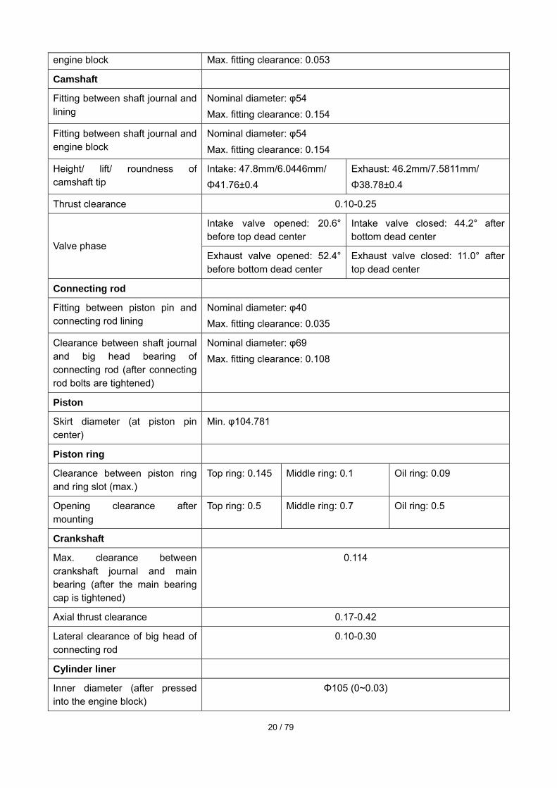
Camshaft
Fitting between shaft journal and lining
Nominal diameter: φ54 Max. fitting clearance: 0.154
Fitting between shaft journal and engine block
Nominal diameter: φ54 Max. fitting clearance: 0.154
Height/ lift/ roundness of camshaft tip
Intake: 47.8mm/6.0446mm/ Φ41.76±0.4
Exhaust: 46.2mm/7.5811mm/ Φ38.78±0.4
Thrust clearance 0.10-0.25
Intake valve opened: 20.6° before top dead center
Intake valve closed: 44.2° after bottom dead center
Valve phase Exhaust valve opened: 52.4° before bottom dead center
Exhaust valve closed: 11.0° after top dead center
Connecting rod
Fitting between piston pin and connecting rod lining
Nominal diameter: φ40 Max. fitting clearance: 0.035
Clearance between shaft journal and big head bearing of connecting rod (after connecting rod bolts are tightened)
Nominal diameter: φ69 Max. fitting clearance: 0.108
Piston
Skirt diameter (at piston pin center)
Min. φ104.781
Piston ring
Clearance between piston ring and ring slot (max.)
Top ring: 0.145 Middle ring: 0.1 Oil ring: 0.09
Opening clearance after mounting
Top ring: 0.5 Middle ring: 0.7 Oil ring: 0.5
Crankshaft
Max. clearance between crankshaft journal and main bearing (after the main bearing cap is tightened)
0.114
Axial thrust clearance 0.17-0.42
Lateral clearance of big head of connecting rod
0.10-0.30
Cylinder liner
Inner diameter (after pressed into the engine block)
Φ105 (0~0.03)

21 / 79
Gear train
Tooth clearance between oil pump gear and camshaft gear
0.08-0.25
Clearance between air compression pump gear and camshaft gear
0.08-0.25
Clearance between camshaft gear and crankshaft gear
0.08-0.25
Clearance between crankshaft gear and idle gear
0.15-0.25
Clearance between idle gear and oil pump drive gear
0.30-0.50
Oil pump
Clearance between rotor and housing
0.046~0.119
Clearance between rotor and seal panel
0.053~0.108
Clearance between inner and outer rotors
0.05~0.11
3.3 Oiling and gluing requirements of main parts
3.3.1 Application requirements of lube oil
Before mounting, the fitting surfaces of all the moveable friction pairs should be wiped clean with non-woven cloth or soft cloth and then covered with uniform and clean lube oil; some thread surfaces must be covered with clean lube oil, as listed in the following table.
Connecting shaft bearing (except the back), main bearing (except the back)
Main bearing bolts, connecting rod bolts, cylinder head bolts, flywheel fastening bolts
Section surface and journal of camshaft Tooth surface of every drive gear
Piston, piston pin, piston ring Seal ring of oil filter (upper)
Push rod, tappet, valve rod, rocker arm components All O-rings of oil
3.3.2 Parts in need of sealant
Before mounting, the following parts must be coated with the sealant of stipulated brand or the sealant with same performance.
(1) TONSAN 1591 between front/rear gear housings and engine block;
(2) TONSAN 1591 between flywheel housing and rear gear housing;
(3) TONSAN 1596 between cylinder head cover and labyrinth plate, except assembled part;
(4) TONSAN 1591 between intake pipe cover and cylinder head;

22 / 79
(5) TONSAN 1591 on the joint of oil pan, engine block and front/rear gear housing;
(6) TONSAN 1680 on the mounting surface of oil dipstick;
(7) TONSAN 1545/1567F on the joints of all screw plug pipes;
(8) TONSAN 1608/1662 on the surfaces surrounding all the inflatable bullheads;
(9) TONSAN 1262 on the fastening nuts of fan connecting disc;
(10) TONSAN 1262 on studs of fuel injection pump (on the gear housing);
(11) TONSAN 1767 heat-resistant adhesive on the bolts of exhaust manifold and turbocharger.
Notice: The seal surfaces of crankshaft journals at front and rear oil seal lips of crankshaft must be clean and dry without any residual oil.
The sealant with the same performance is allowed.
3.3.3 Other mounting requirements
1) During mounting, all the O-ring surfaces must be covered with proper Vaseline;
2) During mounting of bearing, no oil is allowed on the bearing back.
3) Before mounting, all the joints sealed with sealant or gaskets must be clean without any sundries or oil stain;
4) All the tightened bolts must be marked with tightening color;
5) After mounting and trial run of complete machine, the exposed joints of oil line, air line and water line should be protected.
23 / 79
Chapter 4 Mounting and Adjustment of Main Components of Engine
4 Mounting requirements of parts and components 4.1 Mounting of cylinder liner: Before the cylinder liner is mounted, the cylinder hole on the engine block
must be clean and dry without any sundries, water stain or oil stain. The engine block and cylinder liner are grouped and matched as shown in the following table. The grounding dimension is the average value of six distances to Positions 15, 105 and 185 on the top on two directions. The mixed mounting is prohibited. The grouping of engine block and liner is shown in Table 4-01.
Grouping Group 1 Group 2
Φ109.000~Φ109.015 (identification No.: A )
Φ109.016~Φ109.030 (identification No.: 1) Grouping
dimension of engine block Facing the exhaust side of engine, the identification number is at the left top corner
of engine block!
Φ108.996~Φ109.005 (identification color: white)
Part No.: S00008938
Φ109.006~Φ109.014 (identification color: blue)
Part No.: S00008939
Grouping dimension of cylinder liner
The identification color is on the support shoulder of cylinder liner!
Table 4-01
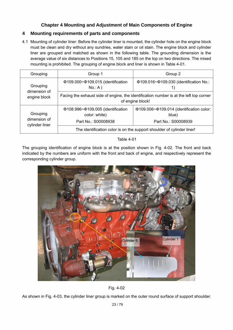
The grouping identification of engine block is at the position shown in Fig. 4-02. The front and back indicated by the numbers are uniform with the front and back of engine, and respectively represent the corresponding cylinder group.
Fig. 4-02
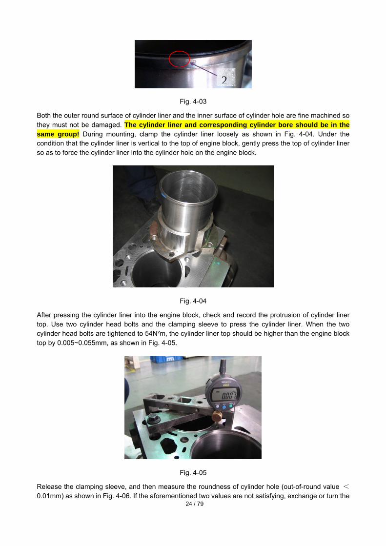
As shown in Fig. 4-03, the cylinder liner group is marked on the outer round surface of support shoulder.
Cylinder 6 Cylinder 1
24 / 79
Fig. 4-03
Both the outer round surface of cylinder liner and the inner surface of cylinder hole are fine machined so they must not be damaged. The cylinder liner and corresponding cylinder bore should be in the same group! During mounting, clamp the cylinder liner loosely as shown in Fig. 4-04. Under the condition that the cylinder liner is vertical to the top of engine block, gently press the top of cylinder liner so as to force the cylinder liner into the cylinder hole on the engine block.
Fig. 4-04
After pressing the cylinder liner into the engine block, check and record the protrusion of cylinder liner top. Use two cylinder head bolts and the clamping sleeve to press the cylinder liner. When the two cylinder head bolts are tightened to 54N²m, the cylinder liner top should be higher than the engine block top by 0.005~0.055mm, as shown in Fig. 4-05.
Fig. 4-05
Release the clamping sleeve, and then measure the roundness of cylinder hole (out-of-round value <0.01mm) as shown in Fig. 4-06. If the aforementioned two values are not satisfying, exchange or turn the
2

25 / 79
cylinder liner for remounting (if seriously out of round). To turn the cylinder liner, firstly take out the cylinder liner by special tool, change the direction, remount the cylinder liner by the aforementioned method, and then check the height and roundness of cylinder liner top higher than the engine block top.
Fig. 4-06
4.2 Mounting of camshaft bearing
Fig. 4-07
When mounting the camshaft bearing, use tools to ascertain the alignment between its oil hole and the oil hole on the engine block, ensure the axial position of camshaft bearing (not higher than the bearing holder hole), and make sure that the rolled joint of lining faces the place above the engine block, as shown in Fig. 4-07. After the camshaft bearing is pressed into the engine block, the dimension of inner hole of bearing should be Φ54.083 (0, +0.04) mm. The alignment of oil holes can be checked by the passing of aΦ3.2mm pole.
The H-series engine only has the last gear, i.e. only the gear near the rear gear housing is equipped with
26 / 79
camshaft lining.
4.3 Mounting of crankshaft 4.3.1 Mounting of main bearing: Before mounting, make sure that the bearing back is clean without chippings. When mounting the upper parts of main bearing and thrust main bearing into the engine block, and the lower parts of main bearing and thrust main bearing into the main bearing cap holder, make sure that the locating tongue of bearing is aligned with the locating slot, and the main bearing surface and the thrust surface of thrust main bearing are covered with clean oil (no oil on the bearing back).
Fig. 4-08
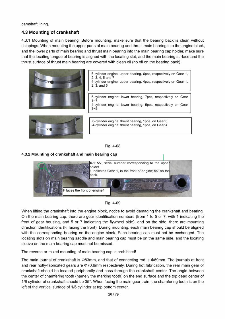
4.3.2 Mounting of crankshaft and main bearing cap
Fig. 4-09
When lifting the crankshaft into the engine block, notice to avoid damaging the crankshaft and bearing. On the main bearing cap, there are gear identification numbers (from 1 to 5 or 7, with 1 indicating the front of gear housing, and 5 or 7 indicating the flywheel side), and on the side, there are mounting direction identifications (F, facing the front). During mounting, each main bearing cap should be aligned with the corresponding bearing on the engine block. Each bearing cap must not be exchanged. The locating slots on main bearing saddle and main bearing cap must be on the same side, and the locating sleeve on the main bearing cap must not be missed.
The reverse or mixed mounting of main bearing cap is prohibited!
The main journal of crankshaft is Φ83mm, and that of connecting rod is Φ69mm. The journals at front and rear hotly-fabricated gears are Φ70.6mm respectively. During hot fabrication, the rear main gear of crankshaft should be located peripherally and pass through the crankshaft center. The angle between the center of chamfering tooth (namely the marking tooth) on the end surface and the top dead center of 1/6 cylinder of crankshaft should be 35°. When facing the main gear train, the chamfering tooth is on the left of the vertical surface of 1/6 cylinder at top bottom center.
F faces the front of engine!
X-1~5/7, serial number corresponding to the upper holder 1 indicates Gear 1, in the front of engine; 5/7 on the back.
6-cylinder engine: upper bearing, 6pcs, respectively on Gear 1, 2, 3, 4, 5 and 7 4-cylinder engine: upper bearing, 4pcs, respectively on Gear 1, 2, 3, and 5
6-cylinder engine: lower bearing, 7pcs, respectively on Gear 1~7 4-cylinder engine: lower bearing, 5pcs, respectively on Gear 1~5
6-cylinder engine: thrust bearing, 1pce, on Gear 6 4-cylinder engine: thrust bearing, 1pce, on Gear 4
27 / 79
4.3.3 Mounting of bolts of main bearing cap: To mount the bolts of main bearing cap, the support surfaces and threads of bolt heads should be covered with clean oil. The bolts of main bearing should be tightened in the stipulated order and in four steps.
1st step: 120 Nm
2nd step: completely release
3rd step: 60 Nm
4th step: 85±5Nm +turning angle 120°±5°
Notice: The bolts should be tightened from center to sides, and released from sides to center. Upon every tightening, the crankshaft should rotate for one circle at least.
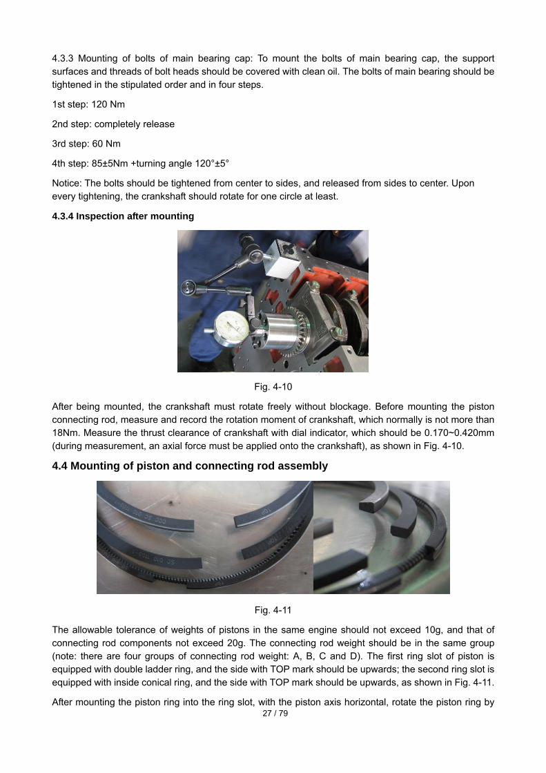
4.3.4 Inspection after mounting
Fig. 4-10
After being mounted, the crankshaft must rotate freely without blockage. Before mounting the piston connecting rod, measure and record the rotation moment of crankshaft, which normally is not more than 18Nm. Measure the thrust clearance of crankshaft with dial indicator, which should be 0.170~0.420mm (during measurement, an axial force must be applied onto the crankshaft), as shown in Fig. 4-10.
4.4 Mounting of piston and connecting rod assembly
Fig. 4-11
The allowable tolerance of weights of pistons in the same engine should not exceed 10g, and that of connecting rod components not exceed 20g. The connecting rod weight should be in the same group (note: there are four groups of connecting rod weight: A, B, C and D). The first ring slot of piston is equipped with double ladder ring, and the side with TOP mark should be upwards; the second ring slot is equipped with inside conical ring, and the side with TOP mark should be upwards, as shown in Fig. 4-11.
After mounting the piston ring into the ring slot, with the piston axis horizontal, rotate the piston ring by

28 / 79
180° so that it can move evenly in the ring slot by means of its deadweight. To mount the oil ring, the connection position of its inner support spring should be opposite to the oil ring opening. To assemble the piston ring group, a 30° angle should be formed between first piston ring opening and piston pin axis, and a 120° angle between first piston ring opening and opening of gas/oil ring in turn.
Fig. 4-12
Fig. 4-13
Before being mounted into the piston pin holder hole, the piston pin should be covered with proper clean oil. The inclined cut of connecting rod big head should be opposite to the cooling jet shunning cut of piston (i.e. the long side of connecting rod and the shunning pit are on the exhaust side of engine). The mounting holes on both ends of piston pin hole are equipped with circlip. Before the piston is mounted into the cylinder liner, the surface of inner hole of cylinder liner and the piston ring and skirt should be covered with proper clean oil.
Cooling jet shunning cut
Group No. of connecting rod
Matching No. side!
Matching No.

29 / 79
Fig. 4-14
The connecting rod bearing consists of two parts: upper and lower; the upper part is darker than the lower one. The part number is indicated on the bearing back. The part number of upper bearing is S00004365, and that of lower bearing is S00004366.
To mount the piston and connecting rod assembly, notice that the “←” mark on the piston top should be on the front of engine. To mount the connecting rod cap, the numbers of connecting rod body and its cap must be identical (or mounted as per the matching mark), and not exchanged. The joint between connecting rod bolt thread and connecting rod and the inner hole surface of connecting rod bearing should be oiled a little. The connecting rod bolts should be tightened in three steps as follows:
1st step: 30±5 Nm
2nd step: 60±5 Nm
3rd step: turning angle 60°±3°
Fig. 4-15
Every time after the piston and connecting rod assembly of a cylinder is mounted, the connecting rod should slide axially and freely on the crankshaft pin if the connecting rod big head is rotated. Meanwhile,
Arrow mark

30 / 79
the lateral clearance between connecting rod and crankshaft should be measured and recorded as shown in Fig. 4-15, which should be 0.10~0.33. After the piston and connecting rod are assembled properly, the crankshaft should rotate freely without blockage, and meanwhile, the return moment of crankshaft (before the cylinder head is mounted) and the protrusion of piston should be measured and recorded.
4.5 Mounting of piston oil cooling jet
Fig. 4-16
The piston oil cooling jet should be mounted by gentle hand pressing, not with hammer, and be aligned properly to ensure that the locating pin is engaged with the locating pin hole of the cylinder. The jet should be handled gently to avoid any slight bending because impact and friction with a hard object. The tightening torque of fastening bolt is 15N.m.
4.6 Mounting of oil pump, front and rear gear housings and oil seals 4.6.1 Mounting of oil pump: Before the oil pump is mounted, the inner rotor should rotate freely without blockage. After mounting the oil pump onto the engine block, tighten the fastening bolts of oil pump diagonally and evenly in two steps to 8Nm in the first step and 24±3Nm in the second step, check the running of oil pump for no blockage, check the clearance between pump and engine block which should be _______mm, check the lateral clearance of gear according to the following specifications: the clearance between crankshaft gear and idle gear is 0.15-0.25mm, and that between idle gear and oil pump drive gear is 0.30-0.50mm.
Fig. 4-17
Before gluing, clean the fitting joint with TONSAN high-efficiency detergent, and apply the sealant onto the joint between front/rear gear housing and engine block at the area (trace) stipulated on the drawing,
31 / 79
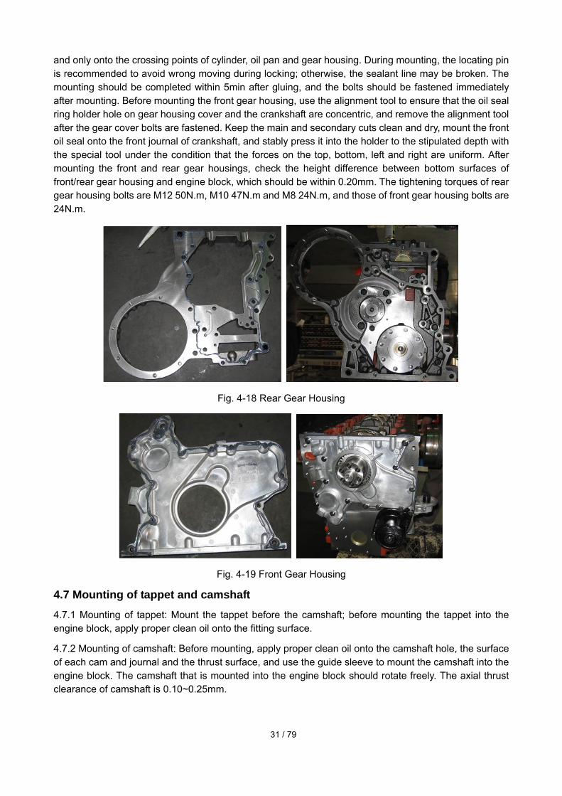
and only onto the crossing points of cylinder, oil pan and gear housing. During mounting, the locating pin is recommended to avoid wrong moving during locking; otherwise, the sealant line may be broken. The mounting should be completed within 5min after gluing, and the bolts should be fastened immediately after mounting. Before mounting the front gear housing, use the alignment tool to ensure that the oil seal ring holder hole on gear housing cover and the crankshaft are concentric, and remove the alignment tool after the gear cover bolts are fastened. Keep the main and secondary cuts clean and dry, mount the front oil seal onto the front journal of crankshaft, and stably press it into the holder to the stipulated depth with the special tool under the condition that the forces on the top, bottom, left and right are uniform. After mounting the front and rear gear housings, check the height difference between bottom surfaces of front/rear gear housing and engine block, which should be within 0.20mm. The tightening torques of rear gear housing bolts are M12 50N.m, M10 47N.m and M8 24N.m, and those of front gear housing bolts are 24N.m.
Fig. 4-18 Rear Gear Housing
Fig. 4-19 Front Gear Housing
4.7 Mounting of tappet and camshaft 4.7.1 Mounting of tappet: Mount the tappet before the camshaft; before mounting the tappet into the engine block, apply proper clean oil onto the fitting surface.
4.7.2 Mounting of camshaft: Before mounting, apply proper clean oil onto the camshaft hole, the surface of each cam and journal and the thrust surface, and use the guide sleeve to mount the camshaft into the engine block. The camshaft that is mounted into the engine block should rotate freely. The axial thrust clearance of camshaft is 0.10~0.25mm.

32 / 79
Fig. 4-20
4.7.3 Mounting of thrust plate and camshaft gear: Align the timing mark on the camshaft gear with that on the crankshaft gear. Check and record the tooth clearance between camshaft gear and crankshaft gear, which should be 0.08-0.25mm. The bolt tightening torque of camshaft thrust plate is 24N.m, and that of camshaft gear is 36N.m.
4.8 Mounting of base plate, oil suction pipe, oil pan and oil dipstick of engine block
Fig. 4-21
The protuberance of reinforcing plate should be outward (facing the oil pan), and the tightening torque of its fastening bolt is 43N.m. The gasket of oil suction pipe is dissymmetric so that during mounting, the gasket opening should be aligned with oil suction pipe and engine block. The tightening torque of its mounting bolt is 24N.m. Before mounting the oil pan, check that the bottom surfaces of front/rear gear housing and engine block meet the specifications (0.20mm), apply the sealant onto the three bottom surfaces, and mount the oil pan within 5min after gluing. After mounting, the sealant should dry in air for
Fuel supply pump gear
Camshaft gear Note: This picture shows the old type of camshaft gear. The gear of new type is matched with the fuel supply pump through the spots on two tooth end surfaces, not the spots on the tooth root surface as shown in the picture. Moreover, there are two spots on the end surfaces of corresponding teeth on the back. Those spots are mainly used to facilitate the gear matching during the separate change/dismantling, and ensure the correct matching.

33 / 79
more than 30min. The tightening torque of fastening bolts of oil pan is 28N.m, and their tightening sequence is shown in the picture (omitted). Apply the retaining agent (recommended width: 5mm) evenly onto the mounting surface of oil dipstick, make sure that the sealant line is complete and then mount the oil dipstick into the engine block hole immediately.
4.9.1 Mounting of cylinder head components: When mounting the intake and exhaust valves and their seats, notice the marks and make sure they are not mixed up. When mounting the valves, apply a little of CD-40 oil onto the valve stems and conical seal surfaces, and gently impact the conical joints with the valve seats in pair, observe that the contact line should be continuous in 360°, and meanwhile check the bottom protrusions of intake and exhaust valves into the bottom of cylinder head (valve sinking), which should be 0.59-1.09 mm for intake valve, and 0.97-1.47mm for exhaust valve.
4.9.2 Mounting of valve spring: Before mounting the valve spring, firstly mount the oil seal of valve stem with special tool, and then press the valve collet into the upper holder of valve spring. Afterwards, use the plastic or wooden hammer to knock the valve stem top to check if the valve collet is mounted properly (not use a metal device to knock the valve stem top or use a hammer to knock the top edge of valve).
Fig. 4-22 Fig. 4-23
4.9.3 Mounting of cylinder head: Apply a little of oil onto the cylinder head bolt threads, and pre-tighten the cylinder head bolts in four steps according to the sequence stipulated in the picture. Torque of those bolts: 1st step: 90Nm; 2nd step: completely release; 3rd step: 90Nm, final turning angle: 90°±5°.
4.9.4 Mounting of push rod and valve bridge
Apply a little of clean oil onto the spherical end and socket of push rod, and then mount the push rod; apply proper clean oil onto the intake and exhaust valve bridges, and then mount them onto the tops of intake and exhaust valve stems respectively.
4.9.5 Mounting of intake and exhaust rocker arm shaft assemblies: Firstly apply proper clean oil onto the intake and exhaust rocker arm shaft assemblies, then release the valve adjusting screws on them completely, place the ball head of adjusting screw into the spherical socket of push rod, tighten the fastening bolt of rocker arm shaft, adjust the valve clearance, and retighten the locknut on the valve adjusting screw. The clearance of intake valve should be 0.25±0.08mm, and that of exhaust valve be 0.50±0.08mm.
With Cylinder 1 at top dead center, adjust the clearances of valves 1, 2, 3, 6, 7 and 10. With Cylinder 6 at top dead center, adjust the clearances of valves 4, 5, 8, 9, 11 and 12.

34 / 79
4.10 Mounting of oil pump
Fig. 4-24
The oil pump needs timing with the crankshaft. Before mounting, notice to make sure that Cylinder 1 of diesel engine is at top dead center. Insert the O-ring into the mounting surface of oil pump flange, connect the transition flange of oil pump with the fuel injection pump by two M8 bolts, mount another O-ring onto the transition flange, and apply a little of clean oil onto the O-ring. The O-ring must not be twisted or compressed in the slot. (Considering that in future, the fuel injection pump may be changed under the condition that the flywheel housing is not dismantled, the following step can be added as the case may be: after mounting, turn the fuel injection pump shaft to form a counterclockwise angle of 102° (135° for Cylinder 6) between the key slot and the vertical centerline of oil pump), and draw a mark on the flange edge; in the future change, firstly ensure Cylinder 1 at top dead center of ignition, then adjust and align the key slot of fuel injection pump with the mark on the flange, next mount the drive gear of oil pump, and finally complete the mounting and control the phase.) Gently mount the fuel injection pump and transition flange assembly into the gear housing, and notice not to damage the O-ring in this course. Before mounting the oil pump drive gear and tightening the fastening nut of drive gear, check that the timing marks of oil pump gear and camshaft gear are aligned. Check and record the tooth clearance between oil pump gear and camshaft gear, which should be 0.08~0.25mm. The tightening torque of fastening nut of gear is 64±5N.m. Note: The oil pump gear can be firstly mounted onto the oil pump together with the transition flange, and the mounting sequence should be noticed: the transition gear should be mounted before the oil pump drive gear.
For a new type of transition flange with scale mark, as shown in Fig. 4-24, before mounting, turn the crankshaft to move Cylinder 1 to the top dead center, then align the 0-mark on the fuel supply pump gear with the scale mark on the flange, and finally align the 0-mark on the oil pump gear with the ·· mark on the camshaft gear end.
4.11 Mounting of air compressor If the air compressor needs timing, notice the alignment of timing marks of drive gear and camshaft
gear. The torque of fastening nut of drive gear is 160Nm. Note: in case of current air compression pump, the alignment with camshaft gear is not necessary during mounting.
4.12 Mounting of fuel pipeline and filter 4.12.1 Mounting of fuel pipeline: when mounting the high-pressure and low-pressure fuel pipelines, tighten them manually instead of forcefully, and then screw down them with tools in order to avoid a higher mounting stress. When tightening the high-pressure fuel pipe from fuel rail to jet, make sure that the fuel rail is loose; after tightening the fuel supply pipe of injector and the high-pressure fuel pipe,
35 / 79
tighten the fastening bolts of fuel rail. The fuel return joint of injector on one side of cylinder head is a check valve which must be mounted correctly. The tightening torque of nut of high-pressure fuel pipe between oil pump and fuel rail should be 35N.m.
4.12.2 Mounting of fuel filter: Lubricate the O-ring with clean oil, mount the filter onto its holder, tighten the filter till the gasket touches the filter holder surface, and then re-tighten the fuel filter by 3/4 circle.
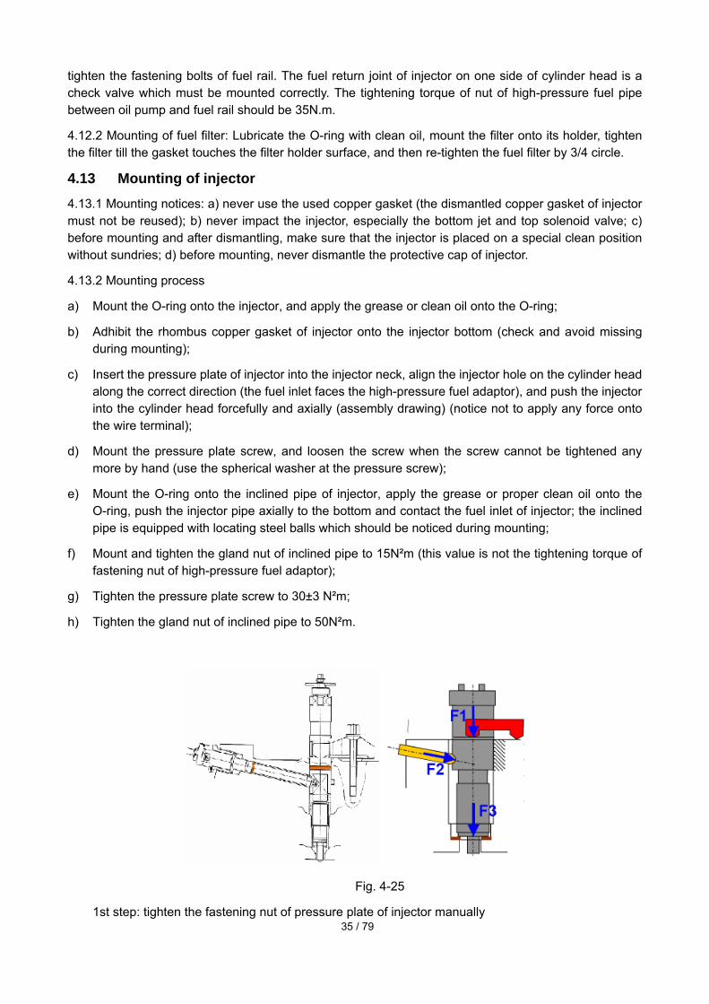
4.13 Mounting of injector 4.13.1 Mounting notices: a) never use the used copper gasket (the dismantled copper gasket of injector must not be reused); b) never impact the injector, especially the bottom jet and top solenoid valve; c) before mounting and after dismantling, make sure that the injector is placed on a special clean position without sundries; d) before mounting, never dismantle the protective cap of injector.
4.13.2 Mounting process
a) Mount the O-ring onto the injector, and apply the grease or clean oil onto the O-ring;
b) Adhibit the rhombus copper gasket of injector onto the injector bottom (check and avoid missing during mounting);
c) Insert the pressure plate of injector into the injector neck, align the injector hole on the cylinder head along the correct direction (the fuel inlet faces the high-pressure fuel adaptor), and push the injector into the cylinder head forcefully and axially (assembly drawing) (notice not to apply any force onto the wire terminal);
d) Mount the pressure plate screw, and loosen the screw when the screw cannot be tightened any more by hand (use the spherical washer at the pressure screw);
e) Mount the O-ring onto the inclined pipe of injector, apply the grease or proper clean oil onto the O-ring, push the injector pipe axially to the bottom and contact the fuel inlet of injector; the inclined pipe is equipped with locating steel balls which should be noticed during mounting;
f) Mount and tighten the gland nut of inclined pipe to 15N²m (this value is not the tightening torque of fastening nut of high-pressure fuel adaptor);
g) Tighten the pressure plate screw to 30±3 N²m;
h) Tighten the gland nut of inclined pipe to 50N²m.
Fig. 4-25
1st step: tighten the fastening nut of pressure plate of injector manually

36 / 79
2nd step: tighten the connection nut to 15 N·m
3rd step: tighten the fastening nut of pressure plate of injector to 23±2 26±1 N·m
4th step: tighten the connection nut to 5553± 2 N·m
Acquire the QR information from QR unit, and record the QR value of injector of each cylinder; (record and store the QR information of injector of each cylinder in order), notice to protect the wire pole of solenoid valve and the upper code card. When mounting the middle cover of cylinder head, make sure that its gasket is enough for overlapping. To mount the injector harness, tighten the wire pole bolt of injector to (1.25~1.75) N², notice to avoid the contact between two wire connectors of injector and make sure no interference between solenoid valve wire and such moveable part as rocker arm. After the harnesses inside the cylinder head is mounted, locate and fasten those harnesses with strap onto the harness support. The connector slot side of harness inside the cylinder should be upward. After the cylinder head cover is mounted, turn the vehicle for circles, and then check if any part of distribution mechanism impacts or rubs with the inner side face of cover.
4.14 Mounting of water pump Mount the seal ring into the slot on the water pump, tighten two bolts by turns to the stipulated torque (30N.m), and rotate the water pump pulley which should run freely without blockage.
4.15 Mounting of flywheel housing, rear oil seal and flywheel
Fig. 4-26
4.15.1 Mounting of flywheel housing: Apply the sealant onto the flywheel housing back, mount the flywheel housing within 5min after gluing, and tighten the fastening bolts of flywheel housing diagonally to 49 N²m for M10 and 85N.m for M12. After mounting the flywheel housing, check the radial flounce of rear inner locating ring against crankshaft centerline and the end flounce of flywheel housing plane against crankshaft centerline, which should not exceed 0.30mm.
4.15.2 Mounting of rear crankshaft oil seal: Keep the main and secondary cuts of rear oil seal of crankshaft clean and dry, mount the rear oil seal onto the rear flange shaft journal of crankshaft, and press it into its holder to the stipulated depth stably by the special tool; the forces on top, bottom, left and right should be uniform.
4.15.3 Mounting of flywheel: To mount the flywheel screws, their threads and support surfaces should be oiled a little. The flywheel screws should be tightened as per the sequence shown in the picture and in two steps by turns: 1st step: 30±5N²m; 2nd step: 60°±3°. After the flywheel is mounted, check that the flounce of clutch joint surface against the crankshaft centerline should not exceed 0.20mm, and the radial flounce of clutch bearing hole not exceed 0.15mm.

37 / 79
4.16 Mounting of oil cooler and filter 4.16.1 Mounting of oil cooler: The tightening torque of fastening bolt is 24N.m.
4.16.2 Mounting of oil filter: Mount the filter onto the filter holder, tighten the filter till the gasket touches the filter holder surface, and after contact, further tighten the filter for 3/4 circle to 1 circle.
4.17 Mounting of exhaust manifold and turbocharger
Fig. 4-27
All the fastening bolt threads of exhaust system should be covered with heat-resistant and anti-sticking compound. To tighten the fastening bolts of exhaust manifold, the bolts in the smaller path should be tightened first, and the rest bolts should be tightened as per the sequence shown in the picture (omitted). The tightening torque of those bolts is 43N.m. To mount the corrugated stainless steel return pipe of turbocharger, the O-ring should be covered with uniform grease and then inserted into the mounting hole on the engine block. After mounting, the O-ring should be checked for cut edge. After the turbocharger is mounted, 50~60ml clean oil should be filled through the oil inlet of turbocharger.
4.18 Mounting of common rail system components
Fig. 4-28
1. The sensors of electronic-control, high-pressure and common-rail diesel engine include the intake pressure/temperature sensor, water temperature sensor, fuel temperature sensor, rotation speed sensor, phase sensor, fuel pressure sensor, ambient sensor or ambient temperature sensor, etc.
2. To mount the intake temperature sensor, water temperature and fuel temperature sensor, it is

38 / 79
required to use a tightening spanner to apply a moment onto the nut instead of the plastic connector.
3. To mount the intake pressure/temperature sensor, apply proper grease onto the O-ring, rotate and press in the O-ring, check the O-ring for cut edge, and tighten the fastening screw.
4. To mount the rotation speed sensor, notice to avoid the radial interference between sensor and signal disc (a clearance of 1.2 mm±0.5mm should be guaranteed).
5. Mount the phase sensor onto the front gear housing chamber, and the signal disc onto the camshaft tail. During mounting, apply proper grease onto the O-ring, then rotate and press in the O-ring, and next check the O-ring for cut edge; tighten the fastening screw.
6. The ECU of every electronic-control engine should match the engine one by one. Considering the differences in both the QR code information of 6 injectors of every engine and the ex-work number of engine, the random exchange is prohibited during packing, assembling and service.
7. The ECU hardware is supplied by Denso Company, and the ECU data is stored and managed according to the use requirements of QR/EOL system of the company.
8. The harnesses of electronic-control engine are selected and mounted according to the matching requirements of vehicle.
9. The mounting of harness should conform to the drawing strictly (if a harness is required upon delivery, it should be fastened according to the drawing).
10. The plugs of sensors on engine harness are coupler plugs, which must not be forced into the wrong position.

39 / 79
Chapter 5 Operation and Maintenance of Diesel Engine
5 Use of diesel engine The correct operation of engine is good for not only its normal operation and good performance, but also the extension of its life and the reduction of use cost. The correct fuel, oil and coolant as well as the correct operation procedures should be used according to this chapter.
5.1 Selection and use of fuel The sulfur content of diesel fuel directly influences the emission of diesel engine. The sulfur content of diesel fuel of diesel engine should be lower than 0.05%; the brand of diesel fuel used by the diesel engine should be determined according to the ambient temperature. The diesel fuel with a low condensation point is recommended for winter and that with a high condensation point for summer. The specifications of fuel used by the diesel engine should conform to the provisions of GB/T 19147-2003. The applicable region of fuel band should refer to GB/T 19147-2003. Users can select the fuel according to the suggestions in the following table: -35# diesel fuel for ambient temperature -27 .
Relation between Diesel fuel Brand and Applicable Minimum Air Temperature
Diesel fuel brand 0# -10# -20# -35#
Cetane number 50 50 45 43
Condensation point ( ) 0 -10 -20 -35
Applicable min. air temperature (working air temperature of diesel fuel, )
Above 4
Above -5
Above -14
Above -29
Notice: The diesel fuel must be kept very clean, and not polluted by dust or sundries. Before being filled into the fuel tank, the diesel fuel should be placed statically for more than 72 hours, and the upper layer is recommended for use. This is vital for the prevention of early wear of fuel injection pump plunger. Moreover, both lubrication and cooling of shaft and bearing of fuel supply pump of H-series engine are realized by diesel fuel so the use requirements of diesel fuel are higher.
5.2 Selection and use of oil In order to ensure the normal operation and long life of diesel engine and to improve the emission of diesel engine, the special “Shangchai” CH-4 lube oil should be used. In case that “Shangchai” oil is inapplicable, the lube oil meeting the requirements of API is recommended: CH-4 multi-stage oil.
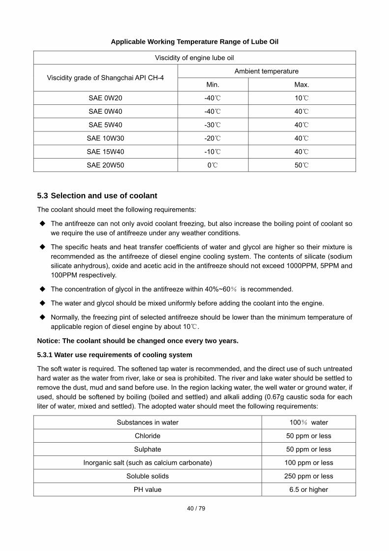
The appropriate oil viscidity grade is determined according to the minimum ambient temperature when the diesel engine is cold and the maximum ambient temperature when the diesel engine is running.
The data in the minimum temperature column in the following table should be used to determine the oil viscidity needed by the starting of a cold diesel engine. The data in the maximum temperature column in the following table should be used to select the oil viscidity for the expected maximum operating temperature.
40 / 79
Applicable Working Temperature Range of Lube Oil
Viscidity of engine lube oil
Ambient temperature Viscidity grade of Shangchai API CH-4
Min. Max.
SAE 0W20 -40 10
SAE 0W40 -40 40
SAE 5W40 -30 40
SAE 10W30 -20 40
SAE 15W40 -10 40
SAE 20W50 0 50
5.3 Selection and use of coolant The coolant should meet the following requirements:
The antifreeze can not only avoid coolant freezing, but also increase the boiling point of coolant so we require the use of antifreeze under any weather conditions.
The specific heats and heat transfer coefficients of water and glycol are higher so their mixture is recommended as the antifreeze of diesel engine cooling system. The contents of silicate (sodium silicate anhydrous), oxide and acetic acid in the antifreeze should not exceed 1000PPM, 5PPM and 100PPM respectively.
The concentration of glycol in the antifreeze within 40%~60% is recommended.
The water and glycol should be mixed uniformly before adding the coolant into the engine.
Normally, the freezing pint of selected antifreeze should be lower than the minimum temperature of applicable region of diesel engine by about 10 .
Notice: The coolant should be changed once every two years.
5.3.1 Water use requirements of cooling system
The soft water is required. The softened tap water is recommended, and the direct use of such untreated hard water as the water from river, lake or sea is prohibited. The river and lake water should be settled to remove the dust, mud and sand before use. In the region lacking water, the well water or ground water, if used, should be softened by boiling (boiled and settled) and alkali adding (0.67g caustic soda for each liter of water, mixed and settled). The adopted water should meet the following requirements:
Substances in water 100% water
Chloride 50 ppm or less
Sulphate 50 ppm or less
Inorganic salt (such as calcium carbonate) 100 ppm or less
Soluble solids 250 ppm or less
PH value 6.5 or higher
41 / 79
5.3.2 Antifreeze requirements
The glycol should be used as antifreeze. The relation between the mixing ratio of antifreeze and the antifreezing temperature is as follows:
Antifreezing temperature Concentration of antifreeze
To -15 30% antifreeze+70% water
To -23 40% antifreeze+ 60% water
To -37 50% antifreeze+ 50% water
To -51 60% antifreeze+ 40% water
For most of weathers, the recommended proportion of water and glycol is 50:50. The acceptable concentration of glycol in antifreeze should be 40~60%. Normally, the freezing point of selected antifreeze should be lower than the minimum air temperature of working region of diesel engine by about 10 . The freezing point of antifreeze can be checked exactly by a refraction meter or the test paper which is especially used to measure the freezing point of antifreeze.
Notice: The use of 100% antifreeze as coolant is prohibited.
Notice: drain and renew the coolant every 77,000km, 2000h or 2 years (please confirm) (whichever comes first) in order to remove the deleterious chemical deposits. The use of 100% antifreeze as coolant is prohibited. The antifreezes of different brands must not be mixed. When it is necessary to change the antifreeze type, the cooling system should be cleaned before the new antifreezing coolant mixture is added. When filling the antifreeze, the contact with skin or eye should be avoided so as to avoid injury.
5.4 Starting of diesel engine Before operating the engine, the oil, fuel and coolant with suitable specifications should be selected according to the specific operation environment and conditions. Before starting, the following tasks are required:
1) Check the diesel engine and starting system, and timely solve the trouble if any;
2) Check if the oil pressure gauge, temperature/pressure gauge, warning lamp and other instruments are normal.
3) Check if the maintenance indicator of air filter has red plunger.
Notice: Never start the engine without air filter, so as to avoid its early wear.
4) Check if the oil level is within the stipulated scope.
5) Check if the cooler fluid level is within the stipulated scope.
6) If there is any air in the fuel system because the diesel engine is out of use for days, or the fuel filter is justly renewed, the fuel system should be oiled and exhausted.
7) Check if the electric start circuit is normal.
8) All safety protectors must be mounted in place.
9) Check if the accelerator pedal moves freely.
5.4.1 Normal starting
Notices for normal starting of diesel engine:

42 / 79
Disengage the diesel engine and power train or engage the transmission gear at neutral gear.
Turn on the electrical switch and mechanical controller.
To start the vehicle, it is unnecessary to press the throttle (different from the traditional diesel engine with mechanical pump).
(1) The oil pressure gauge of diesel engine must show a reading within 15s after starting. If no oil pressure is shown within 15s, shut down the vehicle immediately and find out the cause according to Chapter 6 in order to avoid damaging the diesel engine.
(2) After the hot start of engine, the load can be added after 3-5min idle running. No acceleration or loading is allowed immediately after the diesel engine starts.
(3) After the cold start of diesel engine, firstly idle the engine (at 700rpm) for 3~5min, and accelerate the engine when the oil pressure is higher than 70kPa to ensure that each bearing is well lubricated and the oil pressure is stable. After the oil pressure becomes stable, the engine can be loaded and the load can be increased gradually. The acceleration and loading are prohibited immediately after the diesel engine is started.
(4) When the diesel engine is running idly, check if the operation of every instrument is normal.
Notice: The idle running of diesel engine should not last for a long time; otherwise, the diesel engine may be damaged because during idle running, the combustion chamber temperature is low, and the fuel cannot be burnt completely, resulting in the carbon deposit in the cylinder, the blockage of injector jet and the seizure of piston ring and valve. If the coolant temperature is lower than 60 , the fuel can dilute the oil.
5.4.2 Cold start
At a temperature above -15°, the diesel engine can be started smoothly without any preheating. According to the different matching requirements of vehicles, in winter when the temperature is lower, the intake air preheater is used as auxiliary starter. The operation of intake air preheater is controlled by ECU. When starting the engine, according to the coolant temperature, the ECU can determine if the intake air needs heating, so as to benefit the cold start of engine. Usually, it is prohibited to start the engine in the course of preheating because the starting will stop the preheating. The incomplete intake air preheating can affect the starting effect. The preheating lamp gets on when the intake air is being preheated, and flashes when the preheating stops. Refer to Section 5.4 for details.
5.4.3 First starting after long-time shutting down and oil change
To start the engine after the oil is changed or the shutting-down lasts for more than 30 days, the lubrication system must be fully oiled. Turn the vehicle, guide the oil to each frication pair, and start the engine after the engine control module shows the minimum oil pressure.
(1) Bleed the air in the fuel system.
(2) Release the accelerator pedal to avoid the ignition and starting of diesel engine.
(3) Rotate the crankshaft with starting motor till the oil pressure gauge shows the pressure.
(4) Press the accelerator pedal.
(5) Start the diesel engine according to the normal or cold start procedures.
5.5 Operation of diesel engine At a speed lower than the maximum torque, the continuous running of the diesel engine at idle
speed (accelerator pedal pressed to the bottom) can last for 1min at most.

43 / 79
Regularly check the oil pressure gauge and coolant temperature gauge; for the oil pressure and coolant temperature, refer to Section 2.3.3 (main technical parameters); in case of abnormality, shut down the vehicle to check the engine.
Notice: The continuous running of diesel engine with the coolant temperature lower than 60 or
higher than 100 will damage the engine.
If the diesel engine is too hot, it is required to decelerate and/ gear down till the engine temperature becomes normal; otherwise, check and repair the engine according to “Troubleshooting”, and contact Shangchai service station.
When driving downward on a steep slope, it is required to use the transmission gear and brake to control the speeds of both vehicle and diesel engine; when driving upward on a steep slope, a suitable transmission gear should be engaged in order to avoid the backward hauling and overspeed running of diesel engine because of vehicle rushing.
Notice: The overspeed running of diesel engine (the rotation speed is higher than no-load permissible maximum speed) may damage the engine.
There are obvious symptoms for the occurrence of many engine faults which can be foreknown through listening and watching so the engine faults can be eliminated by proper measures, and the serious accidents of diesel engine can be avoid; when necessary, it is required to timely contact the local office or authorized sales service supplier of Shangchai Company in order to get the technical instructions or professional service.
Typical symptoms of engine faults:
Engine flameout
Engine vibration
Abnormal engine sound
Sudden change in water temperature and oil pressure of engine
Black smoking of engine
Insufficient power
Higher oil consumption
Higher fuel consumption
Three leakages (leakages of oil, fuel and coolant)
5.6 Shutting down of diesel engine Before stopping the engine, it is required to unload and decelerate the engine gradually, run the engine at a high/low speed for 3-5min, and decrease the speed of turbocharger a lot, which are good for diesel engine and turbocharger. The “acceleration – flameout –neutral sliding” running of diesel engine is prohibited. If the diesel engine will be out of use for some time, the engine should be well protected according to Chapter 8 “Saving of engine”.
5.7 Running-in of new diesel engine or after engine overhaul The new or overhauled diesel engine should not run with full load before running-in; otherwise, the operation reliability and service life of the engine may be affected.

44 / 79
5.8 Maintenance schedule of diesel engine The maintenance periods and contents of diesel engines of this series are listed in the following table. Users should perform the periodic service and maintenance according to this table. If the diesel engine often operates in a region with a temperature lower than -18 or higher than 38 or in a dusty area, or in case of frequent vehicle stop, the maintenance period should be shortened properly.
Maintenance contents
Routine maintenance
or oiling
Every 2.5 weeks, 50 hours or 2000km
Every 3 months,
250 hours or
10,000km
Every 6 months,
500 hours or
19,000km
Every 12 months,
1000 hours or
38,000km
Every 2 years,
2000 hours or
77000km
Check the engine periphery
Check the fuel tank
Check the maintenance indicator of air filter
Check the oil level
Check the coolant level
Check the oil and water separator
Check the transmission belt
Check the cooling fan
Check the air filter
Check the intake system
Check the air bleed of fuel system
Check the belt tensioner bearing
Check the

45 / 79
Maintenance contents
Routine maintenance
or oiling
Every 2.5 weeks, 50 hours or 2000km
Every 3 months,
250 hours or
10,000km
Every 6 months,
500 hours or
19,000km
Every 12 months,
1000 hours or
38,000km
Every 2 years,
2000 hours or
77000km
tension of belt
Check the fan transmission bearing
Check the thermostat
Check the injector
Adjust the valve clearance
Adjust the exhaust braking
Change the oil and oil filter
Change the diesel fuel filters (primary and secondary)
Change the coolant
Change the drive belt of accessory
Change the harness strap
Check the water pump
Turbocharger
Note: The primary filter of diesel fuel should be changed periodically depending on the fuel quality, and the filter element should be changed in case of dirty fuel, insufficient power or flameout of diesel engine.

46 / 79
Chapter 6 Engine Electronic Control System
6.1 Composition of electronic control system The engine electronic control system consists of sensors, actuators, controllers and harnesses. The sensors include various sensors and switches. See Fig. 6-1.
Fig. 6-1
6.1.1 Sensors Sensors: crankshaft angle sensor NE, camshaft angle sensor G, intake pressure/temperature sensor TMAP, common-rail pressure sensor Pc, fuel temperature sensor THL, coolant temperature sensor THW, accelerator pedal sensor FPP, vehicle speed sensor, oil pressure sensor OPS and so on.
Switches: idle confirmation switch IVS, clutch switch, neutral switch, diagnosis switch and so on.
6.1.2 Actuators Actuator: SCV valve on fuel supply pump, TWV valve on injector, exhaust braking relay, preheating relay, SVS lamp, cruise lamp and so on.
6.1.3 Controllers Controller: engine ECU.
6.1.4 Harnesses Harnesses: engine harness and vehicle harness.
6.2 Electronic control principle The engine ECU is the control center of a system. According to the electronic signals from various sensors, the position of electronic accelerator pedal and the states of various switches, and through calculation, the ECU sends commands to the oil pumps, injectors, various relays and indicators and other actuators, and requires them to act as required, so as to perform the operator’s intent.
6.2.1 Introduction to functions of sensors, switches and actuators Electronic accelerator pedal: through the electronic signals, feed the driver’s operation intent to
ECU and inform ECU of the driver’s wish about the engine running state.
Various switches: inform ECU of some states of vehicle, such as clutch, transmission gear and coolant level, etc; some switches can feed back the driver’s operation intents, such as cruise, idle speed -up, brake, exhaust braking, PTO-on, dual condition –on, shutting-down and so on.
Crankshaft speed (NE) sensor: offer ECU the crankshaft speed and position signals.
Various sensors
Electronic accelerator pedal
Various switches
Solenoid valve of injector
Solenoid valve of fuel supply pump
Various relays
Various indicator lamps

47 / 79
Camshaft position (G) sensor: offer ECU the camshaft speed signal and cylinder detection signal.
Common-rail pressure sensor: offer ECU the pressure signal of high-pressure fuel rail.
Oil pressure sensor: offer ECU the oil pressure signal.
Water temperature sensor: offer ECU the coolant temperature signal.
Fuel temperature sensor: offer ECU the fuel temperature signal.
Intake temperature sensor: offer ECU the intake temperature signal.
Intake pressure sensor: offer ECU the intake pressure signal.
Ambient temperature sensor: offer ECU the ambient temperature signal.
Fuel inlet pressure sensor: offer ECU the fuel inlet pressure signal.
Electronic fan speed sensor: off ECU the electronic fan speed signal.
Injector: inject the fuel as required by ECU.
Fuel metering valve: a key part of high-pressure oil pump, used to control the rail pressure exactly.
Electronic fan clutch: control the engagement and disengagement of fan clutch.
In-cylinder braking solenoid valve: an oil path switch controlling the braking time inside the cylinder.
Various relays: control the operation of various electrical devices through the connection and disconnection of relay, such as ECU power-on and power-off delay, starter operation, intake air heating and exhaust braking, etc.
Various lamps: reflect the working states of engine, such as intake air heating indicator lamp, engine, malfunction indicator lamp, OBD lamp, cruise indicator lamp, dual condition indicator lamp and water-in-fuel indicator lamp, etc.
6.2.2 Introduction to working principle of fuel supply pump Composition of fuel supply pump: the common-rail system of H-series engine is equipped with HP3 fuel supply pump which mainly consists of fuel supply pump unit (eccentric cam, ring cam and plunger), pump head, SCV (suction control valve), fuel temperature sensor, rotor-type fuel transfer pump and step valve, etc, as shown in Fig. 6-2.

48 / 79
Fig. 6-2
Working principle of fuel supply pump: by controlling the power-on time of engine ECU to SCV (duty cycle), this pump controls the fuel flow on the high-pressure plunger (transfer quantity of fuel transfer pump). The SCV is a linear solenoid valve. During the current streaming, the internal needle valve can move according to the duty cycle. The SCV is normal open. The higher the actual current is, the smaller the opening of suction valve is, as shown in Fig. 6-3; the smaller the actual current is, the bigger the opening of suction valve is, as shown is Fig. 6-4. This needle valve controls the fuel flow according to the blockage of fuel path in the valve. Such control ensures the fuel rail pressure target by sucking the necessary fuel so that the drive load of fuel transfer pump is decreased.
Fig. 6-3 Fig. 6-4
6.2.3 Introduction to working principle of injector Structure of injector: the injector is a split unit, as shown in Fig. 6-5. It mainly consists of fuel connection pipe (including the slit filter), injector body, TWV valve, jet coupler, injector spring, control piston, QR code plate and so on.
Fig. 6-5
Needle valve
Opening – small
Needle valve
Opening – big

49 / 79
Fig. 6-6
Working principle of injector: according to the signal from ECU, and through TWV and metering hole, the injector controls the injection, and injects the high-pressure fuel in the common-rail tube into the engine combustion chamber at the optimum injection timing, amount and rate. The injector controls the piston to transfer the control room pressure to the jet needle, so as to control the opening and closing of needle valve. Refer to Fig. 6-6.
6.2.4 Introduction to working principle of common-rail tube Composition of common-rail tube assembly: common-rail tube, pressure limiter and rail pressure sensor, etc.
The main function of common-rail tube assembly is to store and distribute the high-pressure fuel to each injector. When the system pressure is higher than the set value of pressure limiter, the pressure limiter enables the pressure limiting so as to ensure the safety of high-pressure series.
6.3 Main control function of ECU
6.3.1Control the electromagnetic clutch fan Controlled by ECU, the electromagnetic clutch fan, as shown in Fig. 6-7, can realize the closed-loop control of fan speed with the engine coolant (or oil) temperature as the feedback signal, the speed signal from fan speed sensor as the ECU input signal, and the electromagnetic clutch as the actuator. When the engine water temperature is too high, the ECU drives the electromagnetic clutch of fan and engages the clutch to accelerate the fan and ensure the maximum engine cooling and heat disperse; when the engine water temperature is lower, the ECU drives the electromagnetic clutch of fan and disengages the clutch to decelerate or stop the fan, lower the power consumption of engine driving the fan, decrease the engine heat disperse, increase the water temperature properly and thus reduce the fuel consumption.
Fuel rail pressure sensor
Fuel rail
Fuel transfer pump
Measuring hole
Control room
Control piston
Jet needle
Jet

50 / 79
Fig. 6-7
Advantages of electromagnetic clutch fan: comparing with the rigid fan, switch-type clutch fan and silicon-oil clutch fan, the electromagnetic clutch fan has three advantages: firstly, its speed is well controlled and its noise is low; secondly, its speed is controlled dependent on the cooling demands, the electromagnetic clutch has a fast response and a short delay so the temperature control becomes easier; finally, the fan speed control depending on the cooling demands can reduce the power consumption of fan and the fuel consumption to the maximum degree.
6.3.2 Control the intake air preheating grid. When the ambient temperature is lower, it is more difficult to start the engine. In order to improve the cold start performance of diesel engine, a intake air preheating grid is added on the intake pipe of diesel engine to preheat the air entering into the engine before starting the engine, and thus to make the gas entering into the diesel engine more easier to burn. The intake air preheating grid has a higher power and a higher current so it cannot be controlled by ECU directly. When the starting of diesel engine is controlled by ECU, based on the ambient temperature, the ECU determines if the intake air preheating is needed; when the intake air preheating is needed, the control pin of ECU produces a high level, the preheating relay switch circuit is connected, and the preheating relay starts to work. After the successful starting, the control pin of ECU produces a low level, the relay is disconnected, and the preheating stops. The duration of intake air preheating is completely under the ECU logic control. The wiring diagram of preheater and its relay is as shown in the following Fig. 6-8.
Fig. 6-8
6.3.3 Control the starter. The Shangchai H-series diesel engine is equipped with the single-wire starting motor whose circuit
Intake heating relay
To power source 24V
Heating wire

51 / 79
diagram is as shown in Fig. 6-9. The starting relay is supplied by the vehicle manufacturer. The high-side drive end of relay is connected with the positive pole of battery through the starting switch, and its low-side drive end is controlled by the ECU pin, and affected by the drive capability of ECU pin. The maximum drive current should be lower than the rating by 1A.
Fig. 6-9
6.4 Control function of vehicle The vehicle functions of ECU mainly consists of starting control, cruise control, vehicle speed control, PTO (auxiliary power output) control, idle speed control, exhaust braking control, intake air heating control, multi-power switch, malfunction indicator lamp and GPS locking, etc.
6.4.1 Starting control Starting control function: restrict the working conditions of starting motor and avoid damaging the starting system by the non-standard operation by means of ECU control strategies. To realize the starting protection function of ECU, it is required to transfer the starting relay signal to ECU through vehicle harness, and then control the operation of starting relay through ECU.
(1) Starting protection of vehicle state: The vehicle can be started only when the neutral gear is engaged or the clutch is pressed. If any gear is engaged and the clutch is released, the turning of starting switch does not work.
(2) Starting speed protection: The starting speed protection mainly involves the following three cases:
A. The starting is prohibited when the engine speed is higher than a set value (such as 50rpm).
B. During starting, the starting switch does not work when the engine speed is higher than a set value (such as 450rpm) and the starting relay is disconnected.
C. The starting relay does not work within some time (such as 2.02s) after the rotation speed drops to a set value (such as 50rpm).
(3) Continuous starting protection: If the initial starting is not successful, it is needed to wait for a while (such as 2.02s) for restarting in order to avoid damaging the starting motor by the frequent starting, and also avoid the return failure of starting switch after starting because the long-time operation of starting motor may damage the motor.
(4) Starting time protection: If one starting lasts for a time more than a set value (such as 24s), the starting relay will be disconnected and the starting motor will stop in order to avoid burning the starting motor because of overcurrent.
Starting relay
Starting switch
Positive pole of power source
To output port of starting relay
To positive pole of battery

52 / 79
(5) Preheating control: If the coolant temperature is lower, the intake air preheating needs restarting after the engine power is on. The preheating is controlled by ECU. Usually, the engine starting is not allowed in the course of preheating because the incomplete intake air preheating may affect the starting effect.
(6) External starting and shutting-down: When the vehicle is static, the engine can be started and shut down outside the cab in order to facilitate the vehicle service.
6.4.2 Cruise control The cruise function is a function designed to relieve the driver’s fatigue when the vehicle is running for a long time. When the accelerator pedal is not pressed, the driver can use the cruise switch to drive the vehicle at the set speed. The cruise controller usually consists of main switch, main indicator lamp, cruise operation lamp and another three groups of switches.
6.4.2.1 Cruise switch
The main cruise switch is a request switch enabling the cruise mode. Another three groups of switches have two optional states: State 1: resume, set and cancel; State 2: cruise speed up/down, reset/cancel. The two states are described in the following:
① Functions of three kinds of switches in State 1:
A. Cruise resume: press the switch 1 to resume the cruise state in case of cruise interruption;
B. Cruise set: press the switch 2 to enable the cruise during cruise preparation;
C. Cruise cancel: press the switch 3 or press the switches 1 and 2 together to cancel the cruise state.
② Functions of three kinds of switches in State 2:
A. Increase the cruise speed: press the switch 1 to increase the cruise speed;
B. Decrease the cruise speed: press the switch 2 to decrease the cruise speed;
C. Reset/cancel: press the switch 3 to cancel the cruise state.
6.4.2.2 Cruise entrance
A. Press the main cruise switch to enter the cruise preparation stage and at this moment the main cruise indicator lamp comes on.
B. State 1: In the cruise preparation stage, when the vehicle speed is higher than the minimum cruise speed, press the cruise speed set/speed-down switch to enable the cruise operation, and at this moment the cruise operation lamp comes on.
C. State 2: In the cruise operation stage, press the cruise speed up/down switch to accelerate/decelerate the vehicle speed.
6.4.2.3 Cruise quitting
A. In the cruise operation stage, one of following actions can disable the cruise operation and enable the cruise preparation: press the cruise cancel switch, brake the vehicle or use the auxiliary braking, press the clutch pedal and engage the neutral gear.
B. Regardless of cruise state or mode, press the main cruise switch to quit the cruise mode and at this moment the vehicle speed is controlled by throttle, etc.
6.4.2.4 Cruise resuming
After the vehicle quits the cruise state and enters the cruise preparation stage, press the cruise setting

53 / 79
switch to resume the cruise state.
6.4.2.5 Cruise disabling: any one of following cases may disable the cruise:
A. Wrong rotation speed signal;
B. Wrong camshaft angle sensor signal;
C. Wrong braking or wrong auxiliary braking signal;
D. Wrong cruise switch;
E. Wrong clutch signal, etc.
6.4.3 Vehicle speed control According to the requirements of vehicle manufacturer or end user, the maximum speed of vehicle can be restricted. The vehicle restriction can improve the driving safety, and especially for the operating customers, is good for the reduction of operation risks. To realize the vehicle speed control, the vehicle speed signal should be delivered to ECU.
6.4.4 PTO control The PTO working mode (Power Take Off) is mainly used for the machine delivering the power outwards when the engine speed is constant, such as automobile crane and concrete mixer, etc. The specific data under PTO mode can be revised within the PTO range of engine according to the users’ requirements. The PTO device mainly consists of PTO switch and PTO accelerator pedal, etc. After the PTO switch is turned on, the fuel and speed of auxiliary PTO device can be controlled by means of PTO accelerator pedal. When the following conditions are met, the PTO mode is enabled:
A. PTO throttle is lower than the set value (such as 5%);
B. The engine is running and the starting switch is off;
C. The vehicle speed is lower than the set value (such as 30km/h);
D. The water temperature is normal;
E. The neutral is engaged;
F. The fault affecting the PTO function does not happen.
G. The PTO switch is on.
Quit the PTO mode if the PTO switch is off or the conditions enabling the PTO mode are not met.
6.4.5 Idle speed control The idle speed control is divided into automatic control and manual control. The automatic control means the automatic control of engine idle speed by ECU according to the input signal; the manual control means the control of idle speed by the driver through the corresponding switch.
6.4.5.1 Automatic control of idle speed
In case of no manual control request of idle speed, ECU can adjust the engine idle speed automatically. The automatic control of idle speed mainly involves the following situations:
A. It automatically controls the idle speed according to the coolant temperature so as to warm up the vehicle fast. This function is valid only upon neutral gear.
B. Idle speed-up request with AC on;

54 / 79
C. Idle speed-up request upon exhaust warming-up or bus warming-up;
D. Idle speed-up request of automatic transmission gear;
E. Boarding idle speed;
F. Support idle speed;
G. Idle speed target on the nameplate.
6.4.5.2 Manual control of idle speed
Upon neutral gear, the idle speed control knob can change the engine idle speed within a set range. In case of engine overheat or neutral gear off, the manual control of idle speed is invalid.
6.4.5.3 Idle speed target
Under the automatic idle speed control state, the target speed is the maximum one among various idle speed-up request targets. The priority of manual control is higher than the automatic control. Under the manual control state, the automatic control is invalid, and the target speed is the maximum one between manual control target speed and other idle speed-up request targets.
6.4.6 Exhaust braking The exhaust braking consisting of exhaust butterfly valve braking and inter-cylinder braking can be used for auxiliary braking, auxiliary warming-up and auxiliary shutting-down. When the vehicle is operating, through the exhaust braking, a high back pressure can be established in the exhaust manifold so as to consume the crankshaft energy and realize the auxiliary braking. After the vehicle is started, the control on exhaust braking is helpful to reduce the warming up time; when the ECU power is off and the vehicle shuts down, the exhaust braking can stop the vehicle fast and reduce the torsional vibration.
6.4.6.1 Exhaust butterfly valve braking
Through controlling the butterfly valve mounted on the vehicle exhaust manifold, the exhaust butterfly valve braking blocks the exhaust flow, increases the engine exhaust back pressure, boosts the braking power and thus realizes the auxiliary braking. The exhaust butterfly valve unit consists of exhaust braking switch, indicator lamp, exhaust butterfly valve and so on. The exhaust braking switch signal and exhaust butterfly valve relay should be connected to ECU. The enabling conditions of exhaust butterfly valve braking include:
A. The exhaust braking switch is on;
B. The engine speed is higher than the set value (such as 1100rpm);
C. The neutral signal is 0 (the neutral is not engaged);
D. The clutch signal is 1 (the clutch pedal is not pressed);
E. Fuel injection quantity and throttle opening signal are lower than the set value;
F. The exhaust braking system has no fault, and there is no request to interrupt the exhaust braking;
G. Not PTO working mode;
H. ABS is not enabled.
Besides the above conditions, the butterfly valve braking can also be enabled during auxiliary warming-up and shutting-down. Unless under the warming up or shutting down state, one of following situations can quit the exhaust butterfly valve braking:
A. The exhaust braking switch is off;

55 / 79
B. The engine speed is lower than the set value (some models have no such quitting condition);
C. The neutral is engaged or the clutch pedal is pressed;
D. The accelerator pedal is pressed (the fuel injection quantity or throttle opening is more than the set value);
E. The exhaust braking system is faulted, or there is a request to interrupt the exhaust braking;
F. PTO working mode;
G. ABS is enabled.
The brake of compression and release type is used to change the engine exhaust phase, and opens the exhaust valve when the compression stroke is about to end so that the energy produced by the air inside the engine compression cylinder is discharged to the exhaust system, the energy cannot return to the piston, increasing the braking power during back hauling of engine and realizing the auxiliary braking. The exhaust braking switch signal and the in-cylinder braking signal should be delivered to ECU. The in-cylinder braking of engine can be applied separately or together with the exhaust butterfly valve braking. To enable the in-cylinder braking, both the enabling conditions of exhaust butterfly valve braking and the following conditions have to be met:
A. The fuel injection quantity is lower than the set value (such as -10mm3/st);
B. The engine speed is within the set range (for example, higher than 1000rpm but lower than 3000rpm);
C. The water temperature is within the set range (for example, higher than 20 but lower than 100 );
With reference to the above conditions, the inter-cylinder braking is invalid during auxiliary warming-up. When the exhaust butterfly valve braking conditions or the in-cylinder braking conditions are not met, the in-cylinder braking will quit automatically.
6.4.7 Intake air heating In the cold weather, the engine can enable the automatic intake air preheating for the cold start of vehicle. This device consists of PTC electrical heater, relay and indicator lamp, etc. According to the coolant temperature, it determines if the air entering the engine cylinder needs heating. After the key switch is turned on, ECU checks the water temperature signal automatically. If the water temperature is lower than a set value (such as -10 ), the engine enters the intake air preheating stage automatically: close the preheating relay, the PTC pre-heater starts to work and meanwhile the preheating indicator lamp comes on. When the preheating completes, the preheating lamp flashes; at this moment, the engine can be started normally.
6.4.8 Multi-power switch The multi-power switch can change the engine output torque. By means of this switch, the engine can produce a big torque when the vehicle is heavily loaded, and produce a small torque when the vehicle is lightly loaded, so as to optimize the engine operating condition and reduce the fuel consumption. For the actual power switching, certain restriction conditions have to be met, such as the restrictions on vehicle speed, rotation speed, fuel injection quantity and accelerator pedal opening. The purpose is to ensure the stable transition and safe running during power switching.
6.4.9 Fault diagnosis lamp The fault diagnosis lamps are divided into SVS lamps (Service Vehicle Soon) and MIL lamps (Malfunction Indicator Lamp). If a SVS lamp comes on, the engine has a electronic control fault; the MIL lamp is to indicate the faults related to the engine emission (used for the OBD control required by China
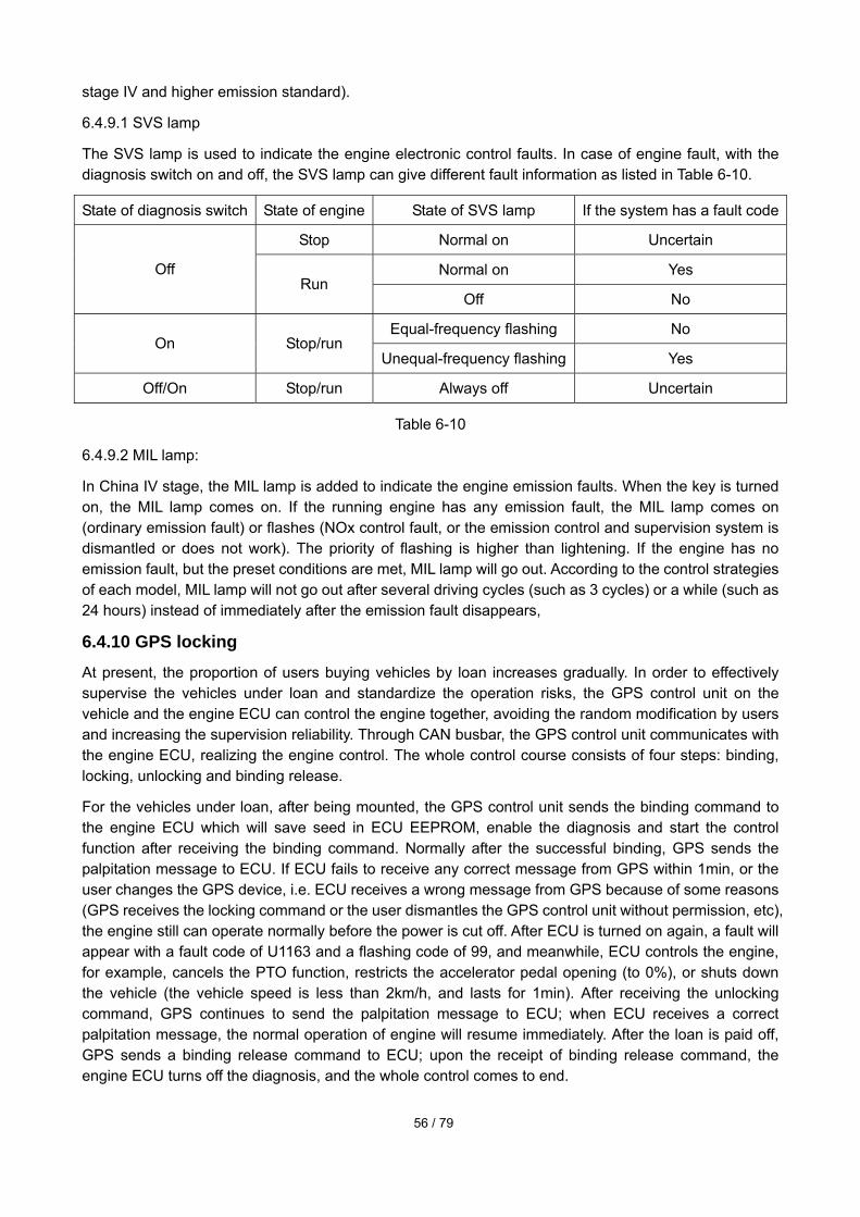
56 / 79
stage IV and higher emission standard).
6.4.9.1 SVS lamp
The SVS lamp is used to indicate the engine electronic control faults. In case of engine fault, with the diagnosis switch on and off, the SVS lamp can give different fault information as listed in Table 6-10.
State of diagnosis switch State of engine State of SVS lamp If the system has a fault code
Stop Normal on Uncertain
Normal on Yes Off Run
Off No
Equal-frequency flashing No On Stop/run
Unequal-frequency flashing Yes
Off/On Stop/run Always off Uncertain
Table 6-10
6.4.9.2 MIL lamp:
In China IV stage, the MIL lamp is added to indicate the engine emission faults. When the key is turned on, the MIL lamp comes on. If the running engine has any emission fault, the MIL lamp comes on (ordinary emission fault) or flashes (NOx control fault, or the emission control and supervision system is dismantled or does not work). The priority of flashing is higher than lightening. If the engine has no emission fault, but the preset conditions are met, MIL lamp will go out. According to the control strategies of each model, MIL lamp will not go out after several driving cycles (such as 3 cycles) or a while (such as 24 hours) instead of immediately after the emission fault disappears,
6.4.10 GPS locking At present, the proportion of users buying vehicles by loan increases gradually. In order to effectively supervise the vehicles under loan and standardize the operation risks, the GPS control unit on the vehicle and the engine ECU can control the engine together, avoiding the random modification by users and increasing the supervision reliability. Through CAN busbar, the GPS control unit communicates with the engine ECU, realizing the engine control. The whole control course consists of four steps: binding, locking, unlocking and binding release.
For the vehicles under loan, after being mounted, the GPS control unit sends the binding command to the engine ECU which will save seed in ECU EEPROM, enable the diagnosis and start the control function after receiving the binding command. Normally after the successful binding, GPS sends the palpitation message to ECU. If ECU fails to receive any correct message from GPS within 1min, or the user changes the GPS device, i.e. ECU receives a wrong message from GPS because of some reasons (GPS receives the locking command or the user dismantles the GPS control unit without permission, etc), the engine still can operate normally before the power is cut off. After ECU is turned on again, a fault will appear with a fault code of U1163 and a flashing code of 99, and meanwhile, ECU controls the engine, for example, cancels the PTO function, restricts the accelerator pedal opening (to 0%), or shuts down the vehicle (the vehicle speed is less than 2km/h, and lasts for 1min). After receiving the unlocking command, GPS continues to send the palpitation message to ECU; when ECU receives a correct palpitation message, the normal operation of engine will resume immediately. After the loan is paid off, GPS sends a binding release command to ECU; upon the receipt of binding release command, the engine ECU turns off the diagnosis, and the whole control comes to end.

57 / 79
6.5 Fault diagnosis
6.5.1 Flashing rules of SVS lamp
Fig. 6-11
When the system has no fault code and the diagnosis switch is turned on, the SVS lamp flashes with equal frequency. When the system has any fault and the diagnosis switch is turned on, the SVS lamp flashes with unequal frequency, namely flashing code. The flashing codes are shown in order and in turns from small to big. Taking the flashing codes 11, 14, 16 and 12 for example, the flashing sequence is 11-12-14-16—11-12-14-16 repeatedly till the diagnosis switch is turned off. The number, digit, code and circulation time of flashing code are distinguished by time interval, as shown in Fig. 6-11.
6.5.2 Fault code table
S/N Fault code Flashing
code Definition
1 P0563 26 The battery voltage is too high.
2 P0562 26 The battery voltage is too low.
3 P0642 24 The voltage of power supply circuit 1 of sensor is too low.
4 P0643 24 The voltage of power supply circuit 1 of sensor is too high.
5 P0652 24 The voltage of power supply circuit 2 of sensor is too low.
6 P0653 24 The voltage of power supply circuit 2 of sensor is too high.
7 P0118 11 The water temperature sensor signal is too high.
8 P0117 11 The water temperature sensor signal is too low.
9 P0116 11 The water temperature sensor is disabled.
10 P0113 16 The intake temperature sensor signal is too high.
11 P0112 16 The intake temperature sensor signal is too low.
12 P0073 17 The ambient temperature sensor signal is too high.
13 P0072 17 The ambient temperature sensor signal is too low.
14 P0183 14 The fuel temperature sensor signal is too high.
15 P0182 14 The fuel temperature sensor signal is too low.
16 P0193 67 The common-rail pressure sensor signal is too high.
17 P0192 67 The common-rail pressure sensor signal is too low.
18 P0191 67 The common-rail pressure sensor signal is constant.
19 P2229 15 The atmospheric pressure sensor signal is too high.
20 P2228 15 The atmospheric pressure sensor signal is too low.
21 P2227 15 The atmospheric pressure sensor is disabled.

58 / 79
S/N Fault code Flashing
code Definition
22 P0238 37 The intake pressure sensor signal is too high.
23 P0237 37 The intake pressure sensor signal is too low.
24 P0236 37 The intake pressure sensor is disabled.
25 P0122 22 The signal of accelerator pedal sensor #1 is too low.
26 P0123 22 The signal of accelerator pedal sensor #1 is too high.
27 P0222 22 The signal of accelerator pedal sensor #2 is too low.
28 P0223 22 The signal of accelerator pedal sensor #2 is too high.
29 P0121 22 The accelerator pedal sensor #1 is normal open.
30 P0221 22 The accelerator pedal sensor #2 is normal open.
31 P0120 22 The accelerator pedal sensor #1 is normal closed.
32 P0220 22 The accelerator pedal sensor #2 is normal closed.
33 P2120 22 The signals of accelerator pedal sensor #1 and #2 are disabled.
34 P0103 17 The air flow sensor signal is too high.
35 P0102 17 The air flow sensor signal is too low.
36 P0101 17 The air flow sensor is disabled.
37 P0227 23 The PTO pedal sensor signal is too low.
38 P0228 23 The PTO pedal sensor signal is too low.
39 P1143 44 The idle speed signal is too high.
40 P1142 44 The idle speed signal is too low.
41 P0523 18 The oil pressure sensor signal is too high.
42 P0522 18 The oil pressure sensor signal is too low.
43 P2542 95 The pressure sensor signal of fuel filter is too high.
44 P2541 95 The pressure sensor signal of fuel filter is too low.
45 P1681 28 The exhaust braking valve output is open or short to ground.
46 P1682 28 The exhaust braking valve output is short to power source.
47 P1683 29 The solenoid valve output of in-cylinder braking #1 is open or short to ground.
48 P1684 29 The solenoid valve output of in-cylinder braking #1 is short to power source.
49 P1685 29 The solenoid valve output of in-cylinder braking #2 is open or short to ground.
50 P1686 29 The solenoid valve output of in-cylinder braking #2 is short to power source.

59 / 79
S/N Fault code Flashing
code Definition
51 P1687 85 The retarder solenoid valve of transmission gear is open or short to ground.
52 P1688 85 The retarder solenoid valve of transmission gear is short to power source.
53 P0541 25 The preheating relay is short to ground.
54 P0542 25 The preheating relay is open or short to power source.
55 P0616 4 The starting relay is short to ground.
56 P0615 4 The starting relay output is open or short to power source.
57 P2148 57 The common end COM1 of injector is short to power source.
58 P2147 57 The common end COM1 of injector is short to ground.
59 P2146 57 The common end COM1 of injector is open.
60 P2151 58 The common end COM2 of injector is short to power source.
61 P2150 58 The common end COM2 of injector is short to ground.
62 P2149 58 The common end COM2 of injector is open.
63 P0201 51 The electromagnetic coil of Cylinder 1 injector is open.
64 P0205 55 The electromagnetic coil of Cylinder 5 injector is open.
65 P0203 53 The electromagnetic coil of Cylinder 3 injector is open.
66 P0206 56 The electromagnetic coil of Cylinder 6 injector is open.
67 P0202 52 The electromagnetic coil of Cylinder 2 injector is open.
68 P0204 54 The electromagnetic coil of Cylinder 4 injector is open.
69 P0611 59 The capacitance charging circuit becomes disabled because of undercharge.
70 P0200 59 The capacitance charging circuit becomes disabled because of overcharge.
71 P0263 61 The Cylinder 1 fuel regulator is enabled.
72 P0275 65 The Cylinder 5 fuel regulator is enabled.
73 P0269 63 The Cylinder 3 fuel regulator is enabled.
74 P0278 66 The Cylinder 6 fuel regulator is enabled.
75 P0266 62 The Cylinder 2 fuel regulator is enabled.
76 P0272 64 The Cylinder 4 fuel regulator is enabled.
77 P0629 74 SCV output is short to power source.
78 P0627 75 SCV output is open or short to ground.
79 P1190 75 The fuel supply pump control valve (fuel suction control valve) is stuck.

60 / 79
S/N Fault code Flashing
code Definition
80 P2293 79 The fuel supply pump is protected.
81 P1217 79 The fuel supply pump is changed.
82 P1218 77 The fuel supply pump is disabled (insufficient flow)
83 P0093 78 The common-rail pressure sensor is disabled (including fuel leakage).
84 P1219 77 The pressure limiter is on.
85 P1089 69 The common-rail pressure exceeds the upper limit.
86 P0088 68 The common-rail pressure exceeds the maximum limit.
87 P1221 93 The common-rail pressure is lower than the lower control limit of target value.
88 P1602 2 The QR code is not inputted.
89 P0602 2 The QR code is wrong.
90 P1601 2 The definition of QR code is wrong.
91 P0607 2 The CPU is faulted.
92 P0606 2 The main CPU is faulted.
93 P0336 13 The pulse number of crankshaft angle sensor is wrong.
94 P0337 13 The crankshaft angle sensor has no pulse signal.
95 P0342 12 The camshaft angle sensor has no pulse signal.
96 P0341 13 The pulse number of camshaft angle sensor is wrong.
97 P0385 13 The sensors of camshaft angle and crankshaft angle have no pulse signal.
98 P0503 21 The signal frequency of vehicle speed sensor is too high.
99 P0502 21 The input signal of vehicle speed sensor signal is short or open.
100 P0501 21 The vehicle speed sensor signal is disabled.
101 P2163 42 The idle switch is stuck and normal open.
102 P2109 42 The idle switch is stuck and normal closed.
103 P0617 45 The starter switch is short to power source.
104 P0301 61 The Cylinder 1 fuel supply system is faulted.
105 P0302 65 The Cylinder 2 fuel supply system is faulted.
106 P0303 63 The Cylinder 3 fuel supply system is faulted.
107 P0304 66 The Cylinder 4 fuel supply system is faulted.
108 P0305 62 The Cylinder 5 fuel supply system is faulted.
109 P0306 64 The Cylinder 6 fuel supply system is faulted.
110 P1530 46 The engine shutting-down switch is stuck and normal open.
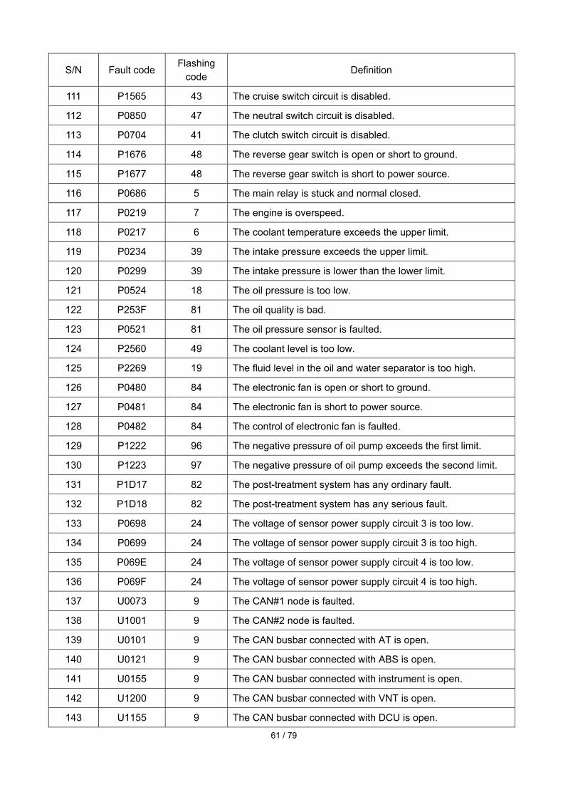
61 / 79
S/N Fault code Flashing
code Definition
111 P1565 43 The cruise switch circuit is disabled.
112 P0850 47 The neutral switch circuit is disabled.
113 P0704 41 The clutch switch circuit is disabled.
114 P1676 48 The reverse gear switch is open or short to ground.
115 P1677 48 The reverse gear switch is short to power source.
116 P0686 5 The main relay is stuck and normal closed.
117 P0219 7 The engine is overspeed.
118 P0217 6 The coolant temperature exceeds the upper limit.
119 P0234 39 The intake pressure exceeds the upper limit.
120 P0299 39 The intake pressure is lower than the lower limit.
121 P0524 18 The oil pressure is too low.
122 P253F 81 The oil quality is bad.
123 P0521 81 The oil pressure sensor is faulted.
124 P2560 49 The coolant level is too low.
125 P2269 19 The fluid level in the oil and water separator is too high.
126 P0480 84 The electronic fan is open or short to ground.
127 P0481 84 The electronic fan is short to power source.
128 P0482 84 The control of electronic fan is faulted.
129 P1222 96 The negative pressure of oil pump exceeds the first limit.
130 P1223 97 The negative pressure of oil pump exceeds the second limit.
131 P1D17 82 The post-treatment system has any ordinary fault.
132 P1D18 82 The post-treatment system has any serious fault.
133 P0698 24 The voltage of sensor power supply circuit 3 is too low.
134 P0699 24 The voltage of sensor power supply circuit 3 is too high.
135 P069E 24 The voltage of sensor power supply circuit 4 is too low.
136 P069F 24 The voltage of sensor power supply circuit 4 is too high.
137 U0073 9 The CAN#1 node is faulted.
138 U1001 9 The CAN#2 node is faulted.
139 U0101 9 The CAN busbar connected with AT is open.
140 U0121 9 The CAN busbar connected with ABS is open.
141 U0155 9 The CAN busbar connected with instrument is open.
142 U1200 9 The CAN busbar connected with VNT is open.
143 U1155 9 The CAN busbar connected with DCU is open.
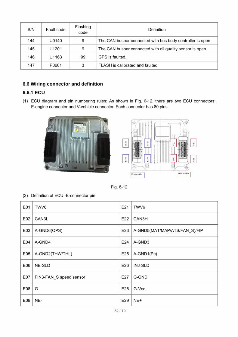
62 / 79
S/N Fault code Flashing
code Definition
144 U0140 9 The CAN busbar connected with bus body controller is open.
145 U1201 9 The CAN busbar connected with oil quality sensor is open.
146 U1163 99 GPS is faulted.
147 P0601 3 FLASH is calibrated and faulted.
6.6 Wiring connector and definition
6.6.1 ECU (1) ECU diagram and pin numbering rules: As shown in Fig. 6-12, there are two ECU connectors:
E-engine connector and V-vehicle connector. Each connector has 80 pins.
Fig. 6-12
(2) Definition of ECU -E-connector pin:
E01 TWV6 E21 TWV6
E02 CAN3L E22 CAN3H
E03 A-GND6(OPS) E23 A-GND5(MAT/MAP/ATS/FAN_S)/FIP
E04 A-GND4 E24 A-GND3
E05 A-GND2(THW/THL) E25 A-GND1(Pc)
E06 NE-SLD E26 INJ-SLD
E07 FIN3-FAN_S speed sensor E27 G-GND
E08 G E28 G-Vcc
E09 NE- E29 NE+
Engine side Vehicle side

63 / 79
E10 FIN1- E30 FIN1+
E11 FIN2- E31 FIN2+
E12 ADE11 E32 ADE1(Pc)
E13 ADE1(Pc) E33 ADE2(THL)
E14 ADE3(MAP) E34 ADE4(MAT)
E15 ADE5(THW) E35 ADE6(OPS)
E16 ADE12 E36 ADE13
E17 ADE14 E37 ADE7 (air temperature ATS)
E18 ADE8 E38 ADE9
E19 ADE10 (fuel inlet pressure FIP) E39 SWE3
E20 SWE2 (fuel inlet pressure switch) E40 SWE1
E41 TWV4 E61 TWV4
E42 TWV2 E62 TWV2
E43 COMMON2 E63 COMMON2
E44 TWV5 E64 TWV5
E45 TWV3 E65 TWV3
E46 TWV1 E66 TWV1
E47 COMMON1 E67 COMMON1
E48 A-Vcc2(MAP/FIP/FAN_S) E68 A-Vcc1(Pc/OPS)
E49 TURBO (PRD+) E69 A-VAF
E50 NE (MRE) E70 AUX1 (PRD-)
E51 SCV-Lo E71 SCV-Lo
E52 SCV-Hi E72 SCV-Hi
E53 PCV2 E73 PCV2

64 / 79
E54 PCV1 E74 PCV1
E55 PWR-PCV E75 PWR-PCV
E56 PWR ACT2 E76 FAN_SOLELOID fan relay
E57 PWR ACT2 E77 PWR-ACT2
E58 OUTE4 E78 OUTE3- relay of in-cylinder braking valve 2
E59 OUTE2- relay of in-cylinder braking valve 1 E79 OUTE1
E60 OUTE6 E80 OUTE5
(3) Definition of ECU-V-connector pin:
V01 +BF V21 +BF
V02 PWR-ACT1 V22 OUTV4
V03 OUTV1 (main relay) V23 OUTV1 (main relay)
V04 OUTV2 (exhaust braking relay) V24 OUTV5 (preheating relay)
V05 OUTV3 (starting relay) V25 S-OUT8 (emission indicator lamp MIL)
V06 S-OUT6 (multi-switch status lamp) V26S-OUT7 (oil and water separator indicator lamp)
V07 S-OUT4 (preheating indicator lamp) V27 S-OUT5 (cruise main lamp)
V08 S-OUT2 (cruise working indicator lamp) V28 S-OUT3 (exhaust braking lamp)
V09 S-OUT11 (fault inspection lamp SVS) V29 SWV8 (brake lamp switch)
V10 SWV6 (auxiliary brake high/low switch, inside
the cylinder) V30 SWV7 (level switch)
V11 SWV4 (neutral switch) V31 SWV5 (PTO switch)
V12 SWV2 (starting switch signal) V32 SWV3 (engine shutting-down switch)
V13 SWV1(ignition switch) V33 SWV1 (ignition switch signal)
V14 VS (vehicle speed sensor) V34 TAC1 (to engine tachometer)
V15 P-OUT1 V35 FIN5

65 / 79
V16 CAN1L V36 CAN1H
V17 CAN2L V37 CAN2H
V18 +B V38 +B
V19 BATT V39 P-GND
V20 CASE-GND V40 GND
V41 SWV25 (diagnosis switch) V61 SWV26 (towing switch)
V42 SWV23 V62 SWV24 (coolant level switch)
V43 SWV21 (cruise deceleration switch) V63SWV22 (oil and water separation sensor switch)
V44 SWV19 (cruise main switch) V64 SWV20 (cruise acceleration switch)
V45 A-GND10 (FPP1) V65 A-GND11 (FPP2)
V46 A-GND12 (FPP-PTO/IDLE adj.) V66 A-GND13
V47 ADV1 (FPP1) V67 ADV2 (FPP2)
V48 ADV3 (idle speed control knob) V68 ADV4 (FPP-PTO)
V49 ADV5 V69 ADV5 (multi-state switch)
V50 A-Vcc10 (FPP1) V70 ADV7
V51 A-Vcc11 (FPP2) V71 A-Vcc12 (FPP-PTO/IDLE adj.)
V52 SWV17 (heater switch) V72 SWV18 (reverse switch)
V53 SWV15 (cruise pause switch) V73 SWV16 (dual torque switch)
V54 SWV13 (AC switch) V74 SWV14
V55 SWV11 (clutch switch) V75 SWV12 (brake switch)
V56 SWV9 (exhaust braking switch) (outside the cylinder)
V76 SWV10 (idle confirmation switch)
V57 CAN-SLD V77 KWP2000 (idle diagnosis wire –K wire)
V58 +B V78 +B

66 / 79
V59 P-GND V79 P-GND
V60 GND V80 P-GND
6.6.2 Coolant sensor
Fig. 6-13
6.6.3 Fuel temperature sensor
Fig. 6-14
6.6.4 Intake pressure and temperature sensor
Fig. 6-15
E15-THW E05-GND
E33-THL E05-GND
E23-GND
E34-MAT
E14-MAP
E48-Vcc

67 / 79
6.6.5 Common-rail pressure sensor
Fig. 6-16
6.6.6 Crankshaft angle sensor
Fig. 6-17
6.6.7 Camshaft angle sensor
Fig. 6-18
E27-GND
E08-G
E28-Vcc
E68-Vcc
E25-GND
E13-Pc
E09-NE-
E29-NE+
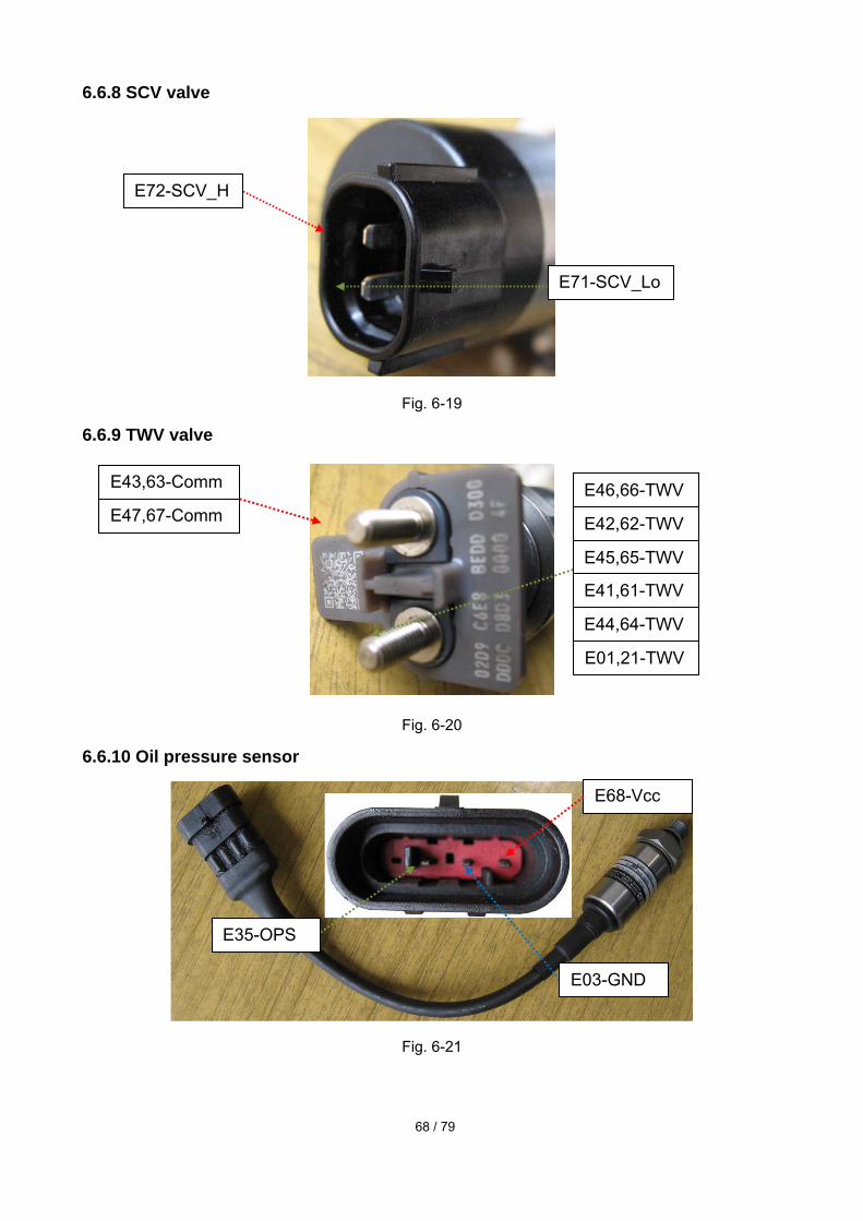
68 / 79
6.6.8 SCV valve
Fig. 6-19
6.6.9 TWV valve
Fig. 6-20
6.6.10 Oil pressure sensor
Fig. 6-21
E68-Vcc
E03-GND
E35-OPS
E72-SCV_H
E71-SCV_Lo
E43,63-Comm
E47,67-CommE46,66-TWV
E42,62-TWV
E45,65-TWV
E41,61-TWV
E44,64-TWV
E01,21-TWV

69 / 79
6.6.11 Ambient temperature sensor (corresponding harness connector)
Fig. 6-22
6.6.12 Injector connector (engine harness side)
Fig. 6-23
E37-ATS
Back
E23-GND
E47-comm1
Front
E44-TWV
E46-TWV
MiddleE43-comm2
E47-comm1 E01-TWV6
E45-TWV3
E43-comm2
E41-TWV
E42-TWV

70 / 79
6.8 Resistance value measurement
6.8.1 SCV. NO1: temperature:__about 25 _, measured resistance: _ _8____Ω.
NO2: temperature:________, measured resistance: ________Ω.
NO3: temperature:________, measured resistance: ________Ω.
6.8.2 TWV.
NO1: temperature:________, measured resistance: ________Ω.
NO2: temperature:________, measured resistance: ________Ω.
NO3: temperature:________, measured resistance: ________Ω.
6.8.3 THL.
NO1: temperature: __about 25_, measured resistance: __2.609__kΩ.
NO2: temperature: ________, measured resistance: ________ Ω.
NO3: temperature: ________, measured resistance: ________ Ω.
NO4: temperature: ________, measured resistance: ________ Ω.
NO5: temperature: ________, measured resistance: ________ Ω.
NO6: temperature: ________, measured resistance: ________ Ω.
NO7: temperature: ________, measured resistance: ________ Ω.
NO8: temperature: ________, measured resistance: ________ Ω.
6.8.4 NE.
NO1: temperature:_about 25___, measured resistance: __126.6_Ω.
NO2: temperature:________, measured resistance: ________Ω.
NO3: temperature:________, measured resistance: ________Ω.
6.8.5 THW.
NO1: temperature: __about 25__, measured resistance: __2.559_ kΩ.
NO2: temperature: ________, measured resistance: ________ Ω.
NO3: temperature: ________, measured resistance: ________ Ω.
NO4: temperature: ________, measured resistance: ________ Ω.
NO5: temperature: ________, measured resistance: ________ Ω.
NO6: temperature: ________, measured resistance: ________ Ω.
NO7: temperature: ________, measured resistance: ________ Ω.
NO8: temperature: ________, measured resistance: ________ Ω.
6.8.6 G. (Note: X^Y, X: red pen; Y: black pen)
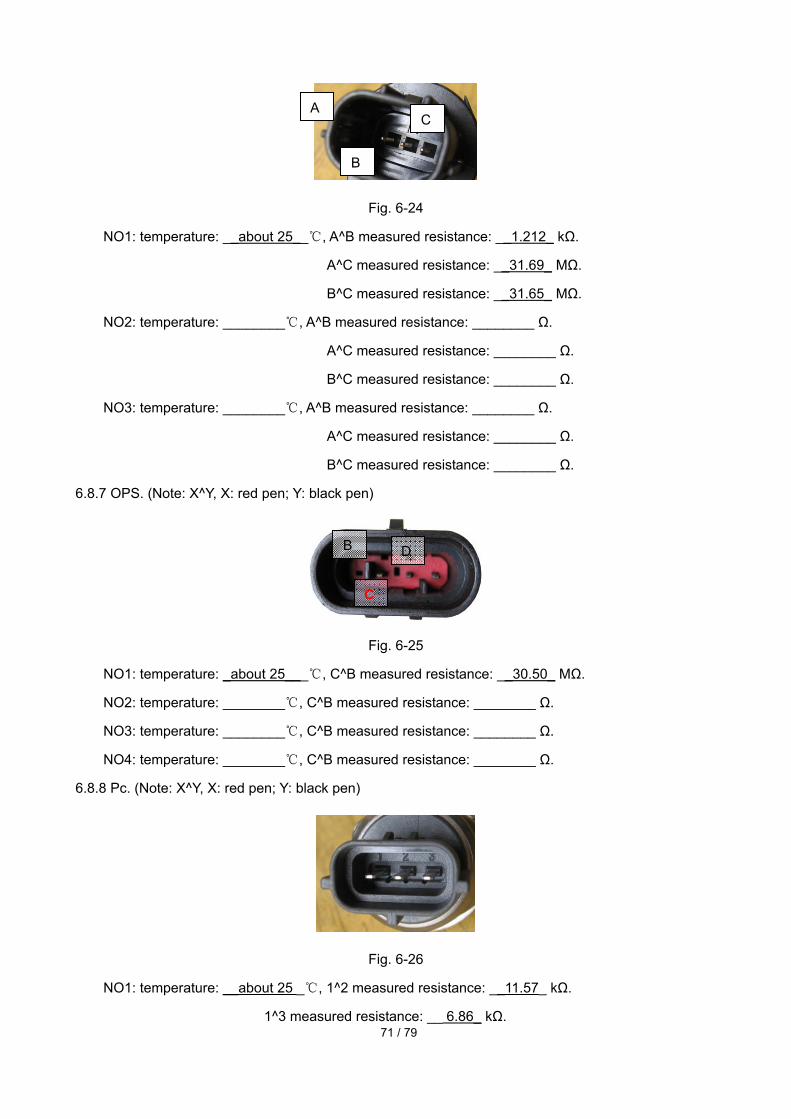
71 / 79
Fig. 6-24
NO1: temperature: __about 25__, A^B measured resistance: __1.212_ kΩ.
A^C measured resistance: __31.69_ MΩ.
B^C measured resistance: __31.65_ MΩ.
NO2: temperature: ________, A^B measured resistance: ________ Ω.
A^C measured resistance: ________ Ω.
B^C measured resistance: ________ Ω.
NO3: temperature: ________, A^B measured resistance: ________ Ω.
A^C measured resistance: ________ Ω.
B^C measured resistance: ________ Ω.
6.8.7 OPS. (Note: X^Y, X: red pen; Y: black pen)
Fig. 6-25
NO1: temperature: _about 25___, C^B measured resistance: __30.50_ MΩ.
NO2: temperature: ________, C^B measured resistance: ________ Ω.
NO3: temperature: ________, C^B measured resistance: ________ Ω.
NO4: temperature: ________, C^B measured resistance: ________ Ω.
6.8.8 Pc. (Note: X^Y, X: red pen; Y: black pen)
Fig. 6-26
NO1: temperature: __about 25 _, 1^2 measured resistance: __11.57_ kΩ.
1^3 measured resistance: __ 6.86_ kΩ.
A C
B
B D
C
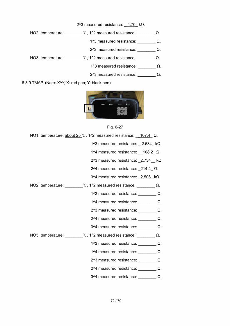
72 / 79
2^3 measured resistance: _ 4.70_ kΩ.
NO2: temperature: ________, 1^2 measured resistance: ________ Ω.
1^3 measured resistance: ________ Ω.
2^3 measured resistance: ________ Ω.
NO3: temperature: ________, 1^2 measured resistance: ________ Ω.
1^3 measured resistance: ________ Ω.
2^3 measured resistance: ________ Ω.
6.8.9 TMAP. (Note: X^Y, X: red pen; Y: black pen)
Fig. 6-27
NO1: temperature: about 25 , 1^2 measured resistance: __107.4_ Ω.
1^3 measured resistance: _ 2.634_ kΩ.
1^4 measured resistance: __108.2_ Ω.
2^3 measured resistance: _2.734__ kΩ.
2^4 measured resistance: _214.4_ Ω.
3^4 measured resistance: _2.506_ kΩ.
NO2: temperature: ________, 1^2 measured resistance: ________ Ω.
1^3 measured resistance: ________ Ω.
1^4 measured resistance: ________ Ω.
2^3 measured resistance: ________ Ω.
2^4 measured resistance: ________ Ω.
3^4 measured resistance: ________ Ω.
NO3: temperature: ________, 1^2 measured resistance: ________ Ω.
1^3 measured resistance: ________ Ω.
1^4 measured resistance: ________ Ω.
2^3 measured resistance: ________ Ω.
2^4 measured resistance: ________ Ω.
3^4 measured resistance: ________ Ω.
1 4
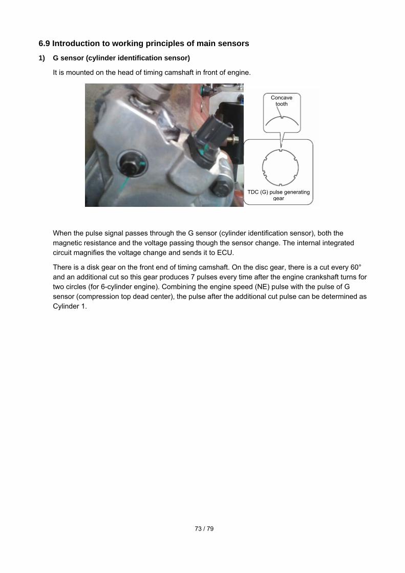
73 / 79
6.9 Introduction to working principles of main sensors
1) G sensor (cylinder identification sensor)
It is mounted on the head of timing camshaft in front of engine.
When the pulse signal passes through the G sensor (cylinder identification sensor), both the magnetic resistance and the voltage passing though the sensor change. The internal integrated circuit magnifies the voltage change and sends it to ECU.
There is a disk gear on the front end of timing camshaft. On the disc gear, there is a cut every 60° and an additional cut so this gear produces 7 pulses every time after the engine crankshaft turns for two circles (for 6-cylinder engine). Combining the engine speed (NE) pulse with the pulse of G sensor (compression top dead center), the pulse after the additional cut pulse can be determined as Cylinder 1.
Concave tooth
TDC (G) pulse generating gear

74 / 79
When mounting the G sensor, adjust the thickness of gaskets, and make sure that the air gap between sensor bottom and signal tooth top is 0.4-0.8mm. ECU offers it a 5V working voltage.
If the G sensor is disabled, the engine is hard to start and the system sends out a fault code.
P0342: The camshaft angle sensor has no pulse signal.
P0385: The camshaft angle and crankshaft angle sensors have no pulse signal.
2) Common-rail pressure sensor (PC sensor)
The common-rail pressure sensor (Pc sensor) is mounted on the top of common-rail fuel. It can detect the fuel pressure of common-rail tube, and then send a signal to ECU. This sensor is a
Pressure limiter Common-rail tube
Rail pressure sensor
* For a 6-cylinder engine (for reference)
Cylinder identification sensor (TDC (6) sensor)
*TDC (G) pulse Cylinder 6 TDC (G) standard pulse Cylinder 1 TDC (G) pulse
Cylinder 1 identification TDC (G) pulse
* Engine speed pulse
Cylinder 1 standard pulse of engine speed Cylinder 6 standard pulse of engine speed

75 / 79
semiconductor sensor which uses the piezoelectric effect produced by the resistance change when a pressure is applied onto the silicon element.
The voltage of rail pressure sensor increases with the rising of pressure. The ECU offers it a 5V working voltage.
When the rail pressure sensor is disabled, the default rail pressure is 48Mpa when the engine is starting and idling.
When the rail pressure sensor is disabled, the default maximum rail pressure of the system is 80Mpa.
When the rail pressure sensor is disabled, ECU limits some power and the system sends out a fault code.
P0193 The common-rail pressure sensor signal is too high.
P0192 The common-rail pressure sensor signal is too low.
P0191 The common-rail pressure sensor signal is constant.
P1089 The common-rail pressure exceeds the upper limit.
P0088 The common-rail pressure exceeds the highest limit.
3) NE sensor (rotation speed)
The NE sensor is mounted on the signal disc in front of engine.
Sensor wiring diagram Output voltage Common-rail pressure characteristics
Output
voltage Fuel rail pressure

76 / 79
Through detecting the 56 signal cuts on the signal disc, the NE sensor detects the crankshaft angle and engine speed signals. The sensor unit is MPU (electromagnetic induction) type. When the 56 signal cuts on the signal disc pass by the sensor, the magnetic field of the coil inside the sensor can change and produce the AC voltage which can be detected by the engine ECU same as a detection signal.
Tooth missing and concave tooth part
Engine speed pulse generating gear
TDC (G) pulse generating gear
Concave tooth
Circuit diagram
Appearance of gear
Crankshaft position sensor (engine speed NE sensor)
Cylinder identification sensor (TDC (G) sensor)
Engine ECU
Pulse diagram (for information)
* TDC (G) pulse Cylinder 6 TDC (G) standard pulse Cylinder 1 TDC (G) pulse
Cylinder 1 identification TDC (G) pulse
* Engine speed pulse
Cylinder 1 standard pulse of engine speed Cylinder 6 standard pulse of engine speed
TDC (G) input circuit
Engine speed input circuit
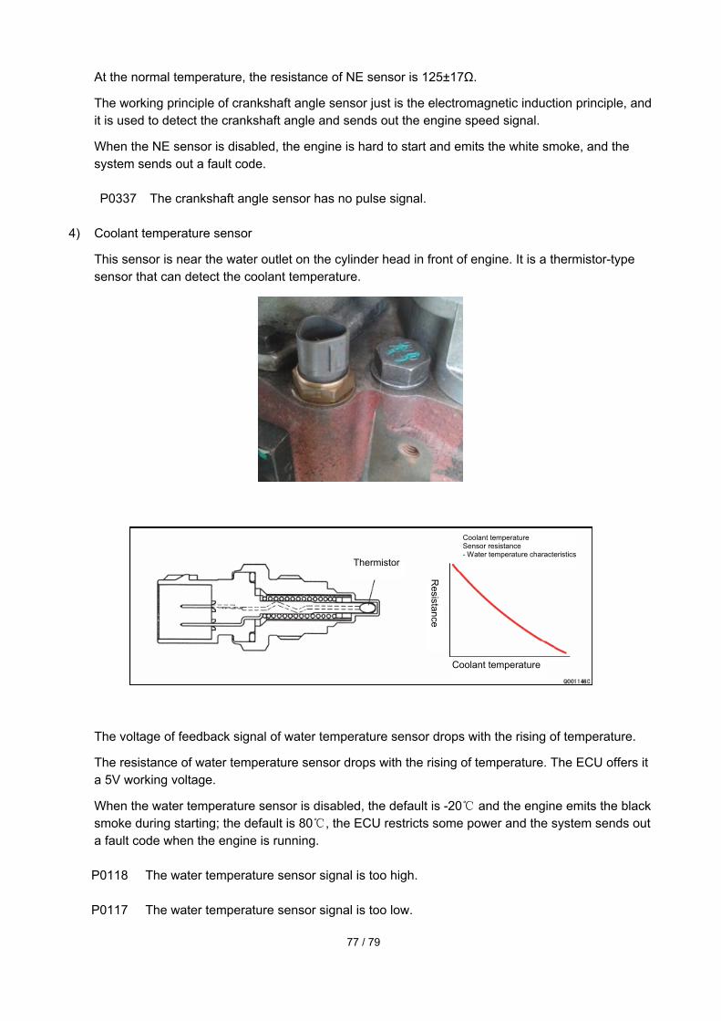
77 / 79
At the normal temperature, the resistance of NE sensor is 125±17Ω.
The working principle of crankshaft angle sensor just is the electromagnetic induction principle, and it is used to detect the crankshaft angle and sends out the engine speed signal.
When the NE sensor is disabled, the engine is hard to start and emits the white smoke, and the system sends out a fault code.
P0337 The crankshaft angle sensor has no pulse signal.
4) Coolant temperature sensor
This sensor is near the water outlet on the cylinder head in front of engine. It is a thermistor-type sensor that can detect the coolant temperature.
The voltage of feedback signal of water temperature sensor drops with the rising of temperature.
The resistance of water temperature sensor drops with the rising of temperature. The ECU offers it a 5V working voltage.
When the water temperature sensor is disabled, the default is -20 and the engine emits the black
smoke during starting; the default is 80, the ECU restricts some power and the system sends out a fault code when the engine is running.
P0118 The water temperature sensor signal is too high.
P0117 The water temperature sensor signal is too low.
Thermistor
Coolant temperature Sensor resistance - Water temperature characteristics
Coolant temperature
Resistance

78 / 79
5) Fuel temperature sensor
The fuel temperature sensor is mounted on the HP3 fuel transfer pump.
This is a thermistor-type sensor that can detect the fuel temperature. In the HP2, HP3 and HP4 systems, this sensor is mounted on the fuel transfer pump unit.
The fuel temperature sensor can revise the fuel injection quantity according to the fuel temperature change. ECU offers it a 5V working voltage.
The voltage of feedback signal of fuel temperature sensor drops with the rising of temperature.
When the fuel temperature sensor is disabled, the default of electronic system is 120°, and the system sends out a fault code.
P0183 The fuel temperature sensor signal is too high.
P0182 The fuel temperature sensor signal is too low.
Thermistor
Resistance
Resistance-
Temperature
characteristics
Temperature

79 / 79
6) Intake pressure/ temperature sensor
The intake pressure/ temperature sensor is mounted at the air inlet of intake manifold in front of engine.
The intake pressure/ temperature sensor can measure the changes in the intake branch pressure and intake temperature, and thus revise the fuel injection quantity.
The voltage fed back by the intake pressure sensor increases with the rising of intake pressure. ECU offers it a 5V working voltage.
When the intake pressure sensor is disabled, the system default is 92kpa, the ECU restricts the fuel injection quantity and thus reduces the power, and meanwhile, the system sends out a fault code.
P0238 The intake pressure sensor signal is too high.
P0237 The intake pressure sensor signal is too low.
P0236 The intake pressure sensor is disabled.
P0113 The intake temperature sensor signal is too high.
P0112 The intake temperature sensor signal is too low.