contents - Jofrab
185
-
Upload
khangminh22 -
Category
Documents
-
view
1 -
download
0
Transcript of contents - Jofrab

HOW TO USE THIS MANUAL
This manual describes effective maintenance procedurefor the S-Five manufactured by DAELIM Motor Co., Ltd.To ensure safety and optimal operating conditions of thevehicle, carry out regular inspections according to themaintenance schedule (Section 2).Sections 1 through 2 provide information on overallvehicle; section 3, assembly and disassembly proceduresfor external components, and section 4 describesmaintenance procedure for the engine, frame and electricalsystems.To facilitate use of this manual, each page starts withdisassembly and system diagrams, service information,and troubleshooting guide. If you cannot find the cause oftrouble, refer to Section 18: Troubleshooting.
Contents of this manual and specifications aresubject to change without prior notice forimprovement of vehicle quality.No part of this publication may be reproducedwithout written permission of DAELIM Motor Co.,Ltd.,
CONTENTS
SERVICE INFORMATION
INSPECTIONS/ADJUSTMENTS
EXTERNAL PARTS
LUBRICATION SYSTEM
FUEL SYSTEM
ENGINE REMOVAL/INSTALLATION
KICK STARTER/ CONTINUOUSLY VARIABLE TRANSMISSION
CYLINDER HEAD/CYLINDER/PISTON
TRANSMISSION/CRANKSHAFT/CRANK CASE
FRONT WHEEL/FRONT FORK/STEERING
REAR WHEEL/BRAKE/SUSPENSION
BRAKE SYSTEM
GE
NE
RA
LE
NG
INE
FRA
ME
ELE
CTR
ICA
L S
YS
TEM BATTERY/CHARGING SYSTEM
STARTING SYSTEM
LIGHTS/METER/SWITCHES
IGNITION SYSTEM
1
2
3
4
5
6
7
8
9
10
11
12
13
14
15
16
WIRING DIAGRAM 17
TROUBLESHOOTING 18

1-1
1. SERVICE INFORMATION
GENERAL SAFETY 1-1SERVICE RULES 1-1CAUTION WHEN WIRING 1-5SERIAL NUMBER LOCATION 1-9MAINTENANCE INFORMATION 1-10
TWIST TORQUE 1-14SPECIALIZED TOOLS 1-16LUBRICATION OIL 1-17SYMBOLS 1-18WIRING DIAGRAM 1-19
GENERAL SAFETYWARNING1. Do not run the engine for a long time in closed or not well-ventilated area because the exhaust gas contains toxic
substances such as carbon monoxide, hydrocarbon, nitric oxide.2. The battery fluid(lean sulfuric acid) is extremely toxic. It is dangerous if skin is exposed to it or if it enters into the eye.
Be careful in handling. When exposed to the battery fluid, wash it with water and get a medical check up.(store thebattery fluid in a safe place to avoid touching by the children)
3. Pay attention not to be burned and always put on the protection gears because the engine or the muffler is hot right afterengine stops.
4. Gasoline is extremely flammable. Maintenance must performed in the place free of the open fire or electric spark.5. When more than two person are working, always pay attention to other worker’s action and alway have safety in mind.6. The skin exposed to used engine oil can be a major reason of the skin cancer. Pay attention not to exposed and wash
carefully with soap and water after handling.7. If compressed air is used to clean the brake, dust scattered in the air can be breathed in by workers. Please take action not
to scatter dust in the brake cleaner, etc.8. Flammable nitrogen gas is generated during charging the battery so charging must be performed in well-ventilated area
and free of the open fire and spark.
SERVICE RULES1. Parts and lubrication oil must be DAELIM genuine or
recommended parts.2. Before maintenance, remove deposit or dust from the
chasis.
1

1-2
SERVICE INFORMATION
9. Check to see if the rubber part is worn out when removing it and replace it if necessary. Some rubber part is weak to gasoline and kerosene, so pay attention not tosoak with gasoline or oils.
10. Recommended grease must be applied to or filled inthe specified place.
7. Align the bolts to uniform the tightening points beforetightening them when you don’t know the bolt length.
8. Bolts, nuts and pieces must be tightened from the biggerdiameter to the smaller one, from inside to outside anddiagonally with the specified torque.
5. Clean the parts after the overhaul and before the test andremove the cleaning oil with compressed air. Apply oilto seal face during installation.
6. Check necessary place and measure necessary dataduring installation. When installing, return to the statebefore removing.
3. Store the parts of each system discriminatively to installeach part in the right place.
4. After removing gasket, O-ring, piston pin clip and cotterpin, always replace them with the new one. Whenremoving the snap ring, it can be easily missed aftertransformation or installation.

1-3
SERVICE INFORMATION
11. Maintenance needed to use the specialized tools mustperformed with the right tool.
12. Never reuse the ball bearing removed with the ballapplied pressure when removing press-fitted thebearing.
13. Check the smooth rotation of inner or outer race of the ball bearing by rotating it manually.
• Replace the ball bearing having excessive axial/longitudinal hanging.
• Wipe the ball bearing likely to have hanging withcleaning oil.(except double-sided sealed type ballbearing)
• Replace the ball bearing of which press-fitted part isslacked at the case or shaft.
14. Pay attention to installation direction in case of thesingle-sided sealed ball bearing. Install the open-direction or double-sided sealed bearing in the waythat the face marked with manufacturer and sizeshould direct to the outer axle.
15. When blowing the ball bearing with compressed airafter cleaning, keep the race from rotating. High speedrotation of the race may damage the bearing. Prior toinstallation, apply oil or grease to the bearing.
16. Install the snap ring so that chamfered side directs tothe load-applied side. After installation, check theproper installation by rotating the snap ring.
17. Check each part for proper tightening and operationafter installation.
18. The brake fluid and coolant can damage the paintedplastic or rubber parts. Keep these parts fromcontacting with them and wash these parts with waterin case of contact.
’
1-4
SERVICE INFORMATION
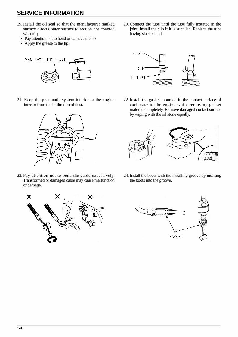
21. Keep the pneumatic system interior or the engine interior from the infiltration of dust.
22. Install the gasket mounted in the contact surface ofeach case of the engine while removing gasketmaterial completely. Remove damaged contact surfaceby wiping with the oil stone equally.
19. Install the oil seal so that the manufacturer markedsurface directs outer surface.(direction not coveredwith oil)
• Pay attention not to bend or damage the lip• Apply the grease to the lip
20. Connect the tube until the tube fully inserted in thejoint. Install the clip if it is supplied. Replace the tubehaving slacked end.
23. Pay attention not to bend the cable excessively.Transformed or damaged cable may cause malfunctionor damage.
24. Install the boots with the installing groove by insertingthe boots into the groove.
’
1-5
SERVICE INFORMATION
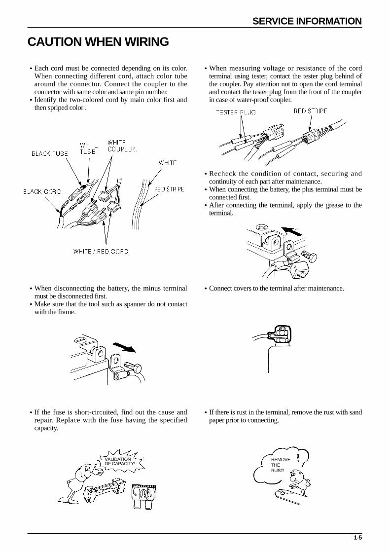
•Each cord must be connected depending on its color.When connecting different cord, attach color tubearound the connector. Connect the coupler to theconnector with same color and same pin number.
•Identify the two-colored cord by main color first andthen spriped color .
•When measuring voltage or resistance of the cordterminal using tester, contact the tester plug behind ofthe coupler. Pay attention not to open the cord terminaland contact the tester plug from the front of the couplerin case of water-proof coupler.
•Recheck the condition of contact, securing andcontinuity of each part after maintenance.
•When connecting the battery, the plus terminal must beconnected first.
•After connecting the terminal, apply the grease to theterminal.
•When disconnecting the battery, the minus terminalmust be disconnected first.
•Make sure that the tool such as spanner do not contactwith the frame.
•Connect covers to the terminal after maintenance.
•If the fuse is short-circuited, find out the cause andrepair. Replace with the fuse having the specifiedcapacity.
•If there is rust in the terminal, remove the rust with sandpaper prior to connecting.
CAUTION WHEN WIRING
VALIDATIONOF CAPACITY!
REMOVETHERUST!

1-6
SERVICE INFORMATION
•Insert the lock of the coupler until the lock is fullysecured.
•Turn off the main switch before connecting/dis-connecting.
•Release the lock to disconnect the lock of the coupler.•The lock of the coupler has two types according to
releasing method(press type and pull type) so release itproperly according to the shape.
- Typical releasing method of the coupler is illustrated inthe following.
•When disconnecting the coupler, disconnect it whileholding the coupler body. Pull while holding the wireharness cord and do not remove the coupler connection.
•Release the lock by inserting the coupler slightly andthen narrowing connection to remove the coupler.
•Pay attention not to damage the vinyl cover of thecoupler.
•Check to see if there is bended terminal and secure it toavoid disconnecting.
•If the wire harness coating is damaged, repair bywinding vinyl tape or replace it.
•Prior to connecting the connector, make sure that thecover is not damaged and the mess terminal is notopened.

1-7
SERVICE INFORMATION
•Wire band must be secured firmly in the specifiedlocation of the frame. In case of aluminium band,secure the wire harness to the coated part.
•Secure the wire harness firmly using the clamp.
•Insert the connector until the vinyl cover is fullyinserted into the terminal.
•The opening of the vinyl cover must face at the grounddirection but in case of the plain connector, the drainingopening must face at the sky direction.
•When removing T-start, broaden the groove of T-startusing the wiring driver and release the torque.
•Connect the harness and the hose to T-start and theninsert until the groove is locked.
•When removing T-start from the frame, replace it withthe new one.
•In case of the weld clamp, do not clamp in the weldedpart.
•When clamping the wire harness, make sure that theharness is not contacted with the shaft or rotating part.
•When clamping the wire, pay attention not to contactwith hot part.
•The wire harness must be routed without contactingwith the end of the lamp or any sharp edge.
•The wire harness must be routed without contactingwith the end of the bolt or the piece.

1-8
SERVICE INFORMATION
•If necessary, lock the wire harness properly. •When mounting parts, make sure that the wire harnessis not pressed by the parts.
•In case that the wire harness is contacted with the end orthe sharp edge, protect both parts with tube or tape.
•The wire must not hang down or be pulled excessively.
•Do not twist the wire harness. •Wire the wire harness not to be pulled or expandedwhen the handle is turned to the right or the leftcompletely. Avoid excessive bending or chewing andinterference with the engine.
•Prior to using the tester, please read the manual care-fully and understand the contents.
•When testing the resistance of the tester, the zeroadjustment must be performed before testing.
•Do not drop or throw the parts especiallysemiconductor contained parts because these parts maybe damaged by the impact of the drop.
NOT TO PULL!
Is this measurement range orconfiguration in accord
with the manual?
1-9
SERVICE INFORMATION
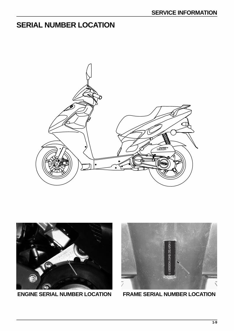
SERIAL NUMBER LOCATION
ENGINE SERIAL NUMBER LOCATION FRAME SERIAL NUMBER LOCATION
1-10
SERVICE INFORMATION
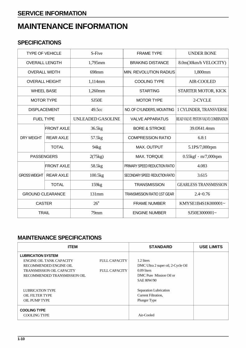
MAINTENANCE INFORMATION
SPECIFICATIONS
MAINTENANCE SPECIFICATIONS
TYPE OF VEHICLE
OVERALL LENGTH
OVERALL WIDTH
OVERALL HEIGHT
WHEEL BASE
MOTOR TYPE
DISPLACEMENT
FUEL TYPE
FRONT AXLE
REAR AXLE
TOTAL
PASSENGERS
FRONT AXLE
REAR AXLE
TOTAL
GROUND CLEARANCE
CASTER
TRAIL
S-Five
1,795mm
698mm
1,114mm
1,260mm
SJ50E
49.5cc
UNLEADED GASOLINE
36.5kg
57.5kg
94kg
2(75kg)
58.5kg
100.5kg
159kg
131mm
26。
79mm
FRAME TYPE
BRAKING DISTANCE
MIN. REVOLUTION RADIUS
COOLING TYPE
STARTING
MOTOR TYPE
NO. OF CYLINDERS, MOUNTING
VALVE APPARATUS
BORE & STROKE
COMPRESSION RATIO
MAX. OUTPUT
MAX. TORQUE
PRIMARY SPEED REDUCTION RATIO
SECONDARY SPEED REDUCTION RATIO
TRANSMISSION
TRANSMISSION RATIO 1ST GEAR
FRAME NUMBER
ENGINE NUMBER
UNDER BONE
8.0m(30km/h VELOCITY)
1,800mm
AIR-COOLED
STARTER MOTOR, KICK
2-CYCLE
1 CYLINDER, TRANSVERSE
READ VALVE PISTON VALVE COMBINATION
39.0X41.4mm
6.8:1
5.1PS/7,000rpm
0.55kgf·m/7,000rpm
4.083
3.615
GEARLESS TRANSMISSION
2.4~0.76
KMYSE1B4S1K000001~
SJ50E3000001~
DRY WEIGHT
GROSS WEIGHT
ITEM STANDARD
LUBRICATION SYSTEMENGINE OIL TANK CAPACITY FULL CAPACITYRECOMMENDED ENGINE OILTRANSMISSION OIL CAPACITY FULL CAPACITYRECOMMENDED TRANSMISSION OIL
LUBRICATION TYPEOIL FILTER TYPEOIL PUMP TYPE
COOLING TYPECOOLING TYPE
1.2 litersDMC Ultra 2 super oil, 2-Cycle Oil0.09 litersDMC Pure Mission Oil or SAE 80W/90
Separation LubricationCurrent Filtration,Plunger Type
Air-Cooled
USE LIMITS
1-11
SERVICE INFORMATION
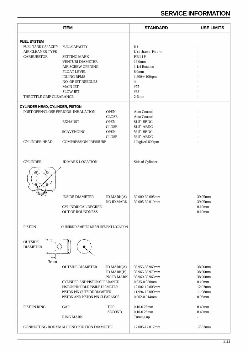
ITEM STANDARD
FUEL SYSTEMFUEL TANK CAPACITY FULL CAPACITYAIR CLEANER TYPECARBURETOR SETTING MARK
VENTURI DIAMETERAIR SCREW OPENINGFLOAT LEVELIDLING RPMSNO. OF JET NEEDLES MAIN JETSLOW JET
THROTTLE GRIP CLEARANCE
CYLINDER HEAD, CYLINDER, PISTONPORT OPEN/CLOSE PERIODS INHALATION OPEN
CLOSEEXHAUST OPEN
CLOSE SCAVENGING OPEN
CLOSECYLINDER HEAD COMPRESSION PRESSURE
CYLINDER ID MARK LOCATION
INSIDE DIAMETER ID MARK(A)NO ID MARK
CYLINDRICAL DEGREEOUT OF ROUNDNESS
PISTON OUTSIDE DIAMETER MEASUREMENT LOCATION
OUTSIDEDIAMETER
OUTSIDE DIAMETER ID MARK(A)ID MARK(B)NO ID MARK
CYLINDER AND PISTON CLEARANCEPISTON PIN HOLE INSIDE DIAMETERPISTON PIN OUTSIDE DIAMETERPISTON AND PISTON PIN CLEARANCE
PISTON RING GAP TOPSECOND
RING MARK
CONNECTING ROD SMALL END PORTION DIAMETER
6ℓUrethane FoamPB11P16.0mm1 1/4 Rotation8.0mm1,800±100rpm4#75#382-6mm
Auto ControlAuto Control81.5。BBDC81.5。ABDC56.5。BBDC56.5。ABDC10kgf/-600rpm
Side of Cylinder
39.000-39.005mm39.005-39.010mm--
38.955-38.960mm38.965-38.970mm38.960-38.965mm0.035-0.050mm12.002-12.008mm11.994-12.000mm0.002-0.014mm
0.10-0.25mm0.10-0.25mmTurning up
17.005-17.017mm
-----------
-------
39.05mm39.05mm0.10mm0.10mm
38.90mm38.90mm38.90mm0.10mm12.03mm11.98mm0.03mm
0.40mm0.40mm-
17.03mm
USE LIMITS
3mm
1-12
SERVICE INFORMATION
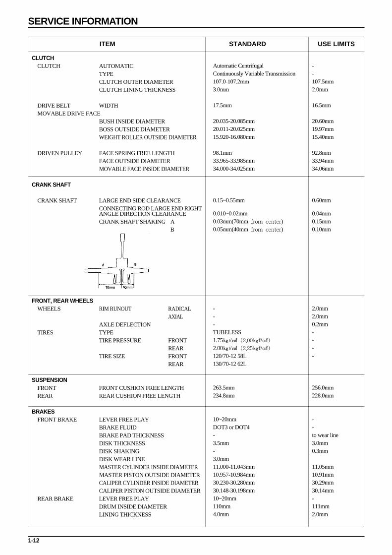
ITEM STANDARD
CLUTCHCLUTCH AUTOMATIC
TYPECLUTCH OUTER DIAMETERCLUTCH LINING THICKNESS
DRIVE BELT WIDTHMOVABLE DRIVE FACE
BUSH INSIDE DIAMETERBOSS OUTSIDE DIAMETERWEIGHT ROLLER OUTSIDE DIAMETER
DRIVEN PULLEY FACE SPRING FREE LENGTHFACE OUTSIDE DIAMETERMOVABLE FACE INSIDE DIAMETER
CRANK SHAFT
CRANK SHAFT LARGE END SIDE CLEARANCECONNECTING ROD LARGE END RIGHT ANGLE DIRECTION CLEARANCECRANK SHAFT SHAKING A
B
FRONT, REAR WHEELSWHEELS RIM RUNOUT RADICAL
AXIALAXLE DEFLECTION
TIRES TYPETIRE PRESSURE FRONT
REARTIRE SIZE FRONT
REAR
SUSPENSIONFRONT FRONT CUSHION FREE LENGTHREAR REAR CUSHION FREE LENGTH
BRAKESFRONT BRAKE LEVER FREE PLAY
BRAKE FLUIDBRAKE PAD THICKNESSDISK THICKNESSDISK SHAKINGDISK WEAR LINEMASTER CYLINDER INSIDE DIAMETERMASTER PISTON OUTSIDE DIAMETERCALIPER CYLINDER INSIDE DIAMETERCALIPER PISTON OUTSIDE DIAMETER
REAR BRAKE LEVER FREE PLAYDRUM INSIDE DIAMETERLINING THICKNESS
Automatic CentrifugalContinuously Variable Transmission107.0-107.2mm3.0mm
17.5mm
20.035-20.085mm20.011-20.025mm15.920-16.080mm
98.1mm33.965-33.985mm34.000-34.025mm
0.15~0.55mm
0.010~0.02mm0.03mm(70mm from center)0.05mm(40mm from center)
---TUBELESS1.75f/ (2.00f/)
2.00f/ (2.25f/)
120/70-12 58L130/70-12 62L
263.5mm234.8mm
10~20mmDOT3 or DOT4-3.5mm-3.0mm11.000-11.043mm10.957-10.984mm30.230-30.280mm30.148-30.198mm10~20mm110mm4.0mm
--107.5mm2.0mm
16.5mm
20.60mm19.97mm15.40mm
92.8mm33.94mm34.06mm
0.60mm
0.04mm0.15mm0.10mm
2.0mm2.0mm0.2mm----
256.0mm228.0mm
--to wear line3.0mm0.3mm
11.05mm10.91mm30.29mm30.14mm-111mm2.0mm
USE LIMITS

1-13
SERVICE INFORMATION
ITEM STANDARD
B8HSA
0.6~0.7mm
BTDC 17。±2。/1,800rpm
over 120V
over 120V
over 1.5V
0.1-0.5Ω
6.5-9.5
2.6±1.25
500Ω±20%
100Ω±20%
AC
12V-9.5A/5,000rpm
0.8Ω±20%
0.55Ω±20%
Semi-conductor
12.6-13.6V/5,000rpm
14.0-15.0V/5,000rpm
6.3-7.1Ω
5.5-6.5Ω
12V-35/35W
12V-5/21W
12V-16W×2
12V-10W×2
12V-5W
12V-5W
12V-1.7W×2
14V-3W
14V-3W
14V-3W×2
7A
MF BATTERY
12V-3AH
13.0-13.2V
0.4A/5h
4A/0.5h
USE LIMITS
IGNITION SYSTEM
SPARK PLUG STANDARD
PLUG GAP
IGNITION TIMING F MARK
PEAK VOLTAGE IGNITION COIL(PRIMARY VOLTAGE)
EXCITE COIL
PULSE GENERATOR
IGNITION COIL RESISTANCE VALUES(20)
PRIMARY COIL
SECONDARY COIL(PLUG CAP CONNECTION)
SECONDARY COIL(PLUG CAP DISCONNECTION)
EXCITE COIL RESISTANCE VALUE(20)
PLUSE GENERATOR RESISTANCE VALUE(20)
CHARGING SYSTEM, AC GENERATOR
AC GENERATOR TYPE
OUTPUT
CHARGING COIL RESISTANCE VALUE(20)
LIGHTING COIL RESISTANCE VALUE(20)
REGULATOR/RECTIFIER TYPE
CONTROL VOLTAGE LAMP SIDE
CHARGING SIDE
REGISTER RESISTANCE VALUE REGISTER(6.7Ω 5W)
REGISTER(5.9Ω 30W)
LIGHTS, METER, SWITCHES
LIGHTS, BULBS HEADLIGHT
TAIL/STOP LIGHT
WINKER LIGHTS FRONT
REAR
POSITION LAMP
LICENSE LAMP
METER LIGHTS
HIGH BEAM PILOT
OIL PILOT
WINKER PILOTS
FUSE
BATTERY
TYPE
CAPACITY
TERMINAL VOLTAGE(20)
CHARGING CURRENT/STANDARD
CHARGING CURRENT/RAPID

1-14
SERVICE INFORMATION
TWIST TORQUESTANDARD TWIST TORQUE
ENGINE PARTS
TYPE
5mm BOLT, NUT
6mm BOLT, NUT
8mm BOLT, NUT
10mm BOLT, NUT
12mm BOLT, NUT
TWIST TORQUE
0.5f·m
1.0f·m
2.2f·m
3.5f·m
5.5f·m
TYPE
5mm SCREW
6mm SCREW
6mm SCREW FLANGE BOLT, NUT
8mm SCREW FLANGE BOLT, NUT
10mm SCREW FLANGE BOLT, NUT
TWIST TORQUE
0.4f·m
0.9f·m
1.2f·m
2.7f·m
4.0f·m
TWIST PART
FLY WHEEL NUT
DRIVE FACE NUT
CYLINDER HEAD BOLT
SPARK PLUG
DRIVEN FACE NUT
CLUTCH OUTER NUT
OIL LEVEL CHECK BOLT
EXHAUST PIPE JOINT NUT
MUFFLER BRACKET BOLT
CRANK CASE BOLT
NUMBER
1
1
4
1
1
1
1
2
2
6
TWIST TORQUE
4.0f·m
5.5f·m
1.0f·m
1.4f·m
5.5f·m
4.0f·m
1.3f·m
1.2f·m
3.3f·m
1.0f·m
REFERENCESCREW DIAMETER (mm)
10
12
6
14
28
10
8
6
8
6
Bolts not appearing in the following table are tightened using standard torque.
1-15
SERVICE INFORMATION
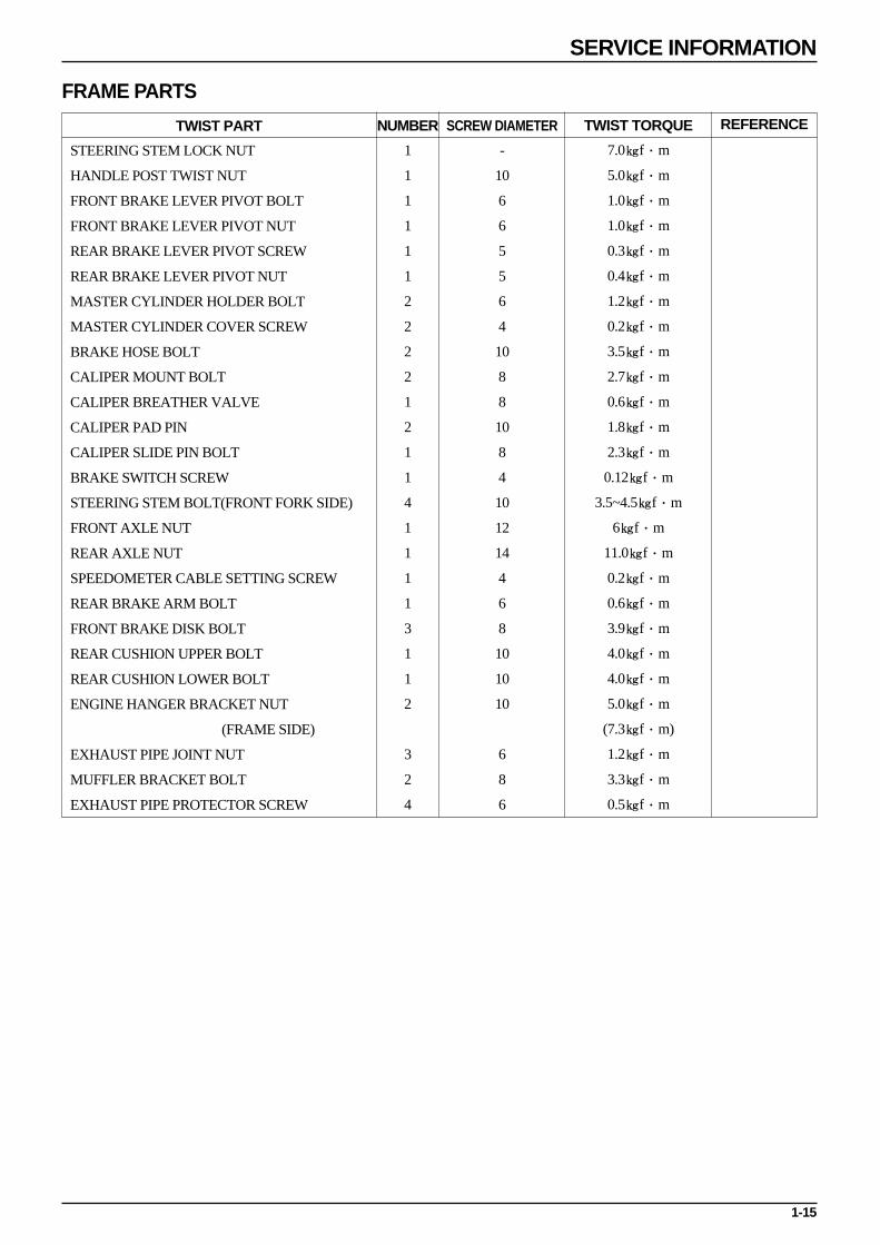
FRAME PARTS
TWIST PART
STEERING STEM LOCK NUT
HANDLE POST TWIST NUT
FRONT BRAKE LEVER PIVOT BOLT
FRONT BRAKE LEVER PIVOT NUT
REAR BRAKE LEVER PIVOT SCREW
REAR BRAKE LEVER PIVOT NUT
MASTER CYLINDER HOLDER BOLT
MASTER CYLINDER COVER SCREW
BRAKE HOSE BOLT
CALIPER MOUNT BOLT
CALIPER BREATHER VALVE
CALIPER PAD PIN
CALIPER SLIDE PIN BOLT
BRAKE SWITCH SCREW
STEERING STEM BOLT(FRONT FORK SIDE)
FRONT AXLE NUT
REAR AXLE NUT
SPEEDOMETER CABLE SETTING SCREW
REAR BRAKE ARM BOLT
FRONT BRAKE DISK BOLT
REAR CUSHION UPPER BOLT
REAR CUSHION LOWER BOLT
ENGINE HANGER BRACKET NUT
(FRAME SIDE)
EXHAUST PIPE JOINT NUT
MUFFLER BRACKET BOLT
EXHAUST PIPE PROTECTOR SCREW
NUMBER
1
1
1
1
1
1
2
2
2
2
1
2
1
1
4
1
1
1
1
3
1
1
2
3
2
4
TWIST TORQUE
7.0f·m
5.0f·m
1.0f·m
1.0f·m
0.3f·m
0.4f·m
1.2f·m
0.2f·m
3.5f·m
2.7f·m
0.6f·m
1.8f·m
2.3f·m
0.12f·m
3.5~4.5f·m
6f·m
11.0f·m
0.2f·m
0.6f·m
3.9f·m
4.0f·m
4.0f·m
5.0f·m
(7.3f·m)
1.2f·m
3.3f·m
0.5f·m
REFERENCESCREW DIAMETER
-
10
6
6
5
5
6
4
10
8
8
10
8
4
10
12
14
4
6
8
10
10
10
6
8
6

1-16
SERVICE INFORMATION
SPECIALIZED TOOLS
TOOL NAME
FLOAT LEVEL GAUGE
BEARING DIRVER
BEARING REMOVER
REMOVER HANDLE
REMOVER WEIGHT
DRIVER HANDLE A
OUTER DRIVER 24×26mm
CLUTCH SPRING COMPRESSOR
SOCKET WRENCH 39mm
CLUTCH CENTER HOLDER
UNIVERSAL HOLDER
CRANK ASSEMBLY
DRIVER HANDLE A
OUTER DRIVER 37×40mm
DRIVER PILOT, 17mm
UNIVERSAL BEARING PULLER
CRANK CASE PULLER
CRANK ASSEMBLY
OUTER DRIVER 52×55mm
DRIVER PILOT 20mm
DRIVER HANDLE A
CRANK ASSEMBLY
LOCK NUT WRENCH A
LOCK NUT WRENCH B
BALL RACE REMOVER
OUTER DRIVER, 42×47mm
DRIVER HANDLE A
SHOCK ABSORBER COMPRESSER
COMPRESSER SCREW ASS’Y
SPRING COMPRESSER ATTACHMENT
SPRING COMPRESSER ATTACHMENT
UNIVERSAL HOLDER
A.G.G ROTOR PULLER
TOOL NO.
07401-001000
07945-GC80000
07936-3710300
07936-3710100
07741-0010201
07749-0010000
07746-0010700
07960-KM10000
0723-03900
07724-0050001
07725-0030000
0740-00001
0749-0010000
07746-0010200
07746-0040400
0755-00001
0751-00003
0740-00001
07746-0010400
07746-0040500
07749-0010000
0740-00001
07916-1870101
07916-KM10000
07946-GA70000
07746-0010300
07749-0010000
07GM-0010000
079GME-0010100
07967-GA70102
07JME-GW20100
07725-0030000
0750-00006
USAGE
Carburetor Oil Level Measurement
Change of Driven Face Outer Bearing
Disassembly of Driven Face Needle Bearing
Assembly of Driven Face Needle Bearing
Disassembly/Assembly of Clutch/Driven Face
Disassembly/Assembly of Driven Pulley/Driven Face
Disassembly/Assembly of Clutch/Driven Pulley
Assembly of Drive Shaft
Assembly of Drive Shaft Bearing
Disassembly of Crank Shaft Bearing
Disassembly of R/L Crank Case, Crank Shaft
Disassembly of R.Crank Case, Crank Shaft
Assembly of Crank Shaft Bearing
Assembly of R/L Crank Shaft Oil Seal
Disassembly of Top Cone Race
Assembly of Ball Race
Disassembly/Assembly of Rear Cushion
Disassembly/Assembly of Fly Wheel
Disassembly of Fly Wheel
CHAPTER
5
7
9
10
11
13

1-17
SERVICE INFORMATION
LUBRICATION OIL
ENGINE PARTS
APPLICATION AREAS
CRANK CASE JOINING FACE
CRANK CASE REVOLUTION PART
CYLINDER BIG REVOLUTION PART, FRICTION PART
TRANSMISSION(FINAL REDUCTION)
KICK SPINDLE BUSH
STARTER PINION
STARTER DRIVE GEAR OPERATION PART
MOVEABLE DRIVEN FACE
(DRIVEN FACE OPERATION PART)
OIL PUMP DRIVE GEAR
CAUTIONARY SUGGESTIONS
Capacity : 0.09ℓ
Capacity : 5.0~5.6g
OIL TYPE
Gasket Fluid(TB 1215)
Ultra-2 Super, 2-Cycle Oil
(Separation Lubrication Use)
SAE 80W/90
Multi-Purpose Grease
Molybdenum Grease
FRAME PARTS
APPLICATION AREAS
FRONT WHEEL DUST SEAL EDGES
FRONT PIVOT ARM BUSH FRICTION FACE
FRONT PIVOT ARM SEAL EDGES
REAR BRAKE CAM AXLE PART, CAM PART
WHOLE AREA OF REAR BRAKE CAM DUST SEAL
REAR BRAKE ANCHOR PIN AXLE PART
FRONT BRAKE OIL SEAL EDGES
FRONT BRAKE CAM AXLE PART, CAM PART
WHOLE AREA OF FRONT BRAKE CAM DUST SEAL
SPEEDOMETER GEAR/PINION INSIDE DIAMETER PART, AXLE PART, GEAR TEETH PART
BALL RACE, BEARING REVOLUTION PART
HANDLE GRIP INSIDE AXLE PART
CAUTIONARY SUGGESTIONS OIL TYPE
Multi-Purpose Grease
Adhesives ROYAL BOND 1300

SYMBOL
CAUTION
NOTE
SYMBOL
1-18
SERVICE INFORMATION
SYMBOLSThe following symbols appear in this manual and offer cautionary suggestions which need to be heeded when performingmaintenance work on the vehicle.
CAUTION
Indicates special caution needed.
Possibility of resulting in serious
malfuctioning of vehicle if ignored.
The following symbols indicate needed lubrication steps, the changing of parts, and required specialized tools, etc. whenperforming maintenance.
CAUTION
Use recommended cushion oil.
Use Specialized Tool.
Use Option Tool. These tools are needed for the part, see part list for tool number.
Indicates reference page. This particular symbol indicates chapter 3 page 1.
Indicates needed application of oil. When a designated brand is not listed, use the designated or
suggested engine oil when this symbol appears.
Indicates needed application of a molybdenum solution. The molybdenum solution is made by
mixing molybdenum grease with engine oil at a 1:1 ratio.
Indicates needed application of a multi purpose grease. (NLG 1 #2 using a lithium soap base)
Example brand: Shell Albania EP-2(Fire-proof Shell Oil)
Indicates needed application of molybdenum grease.
(containing over 3% of emulsified molybdenum, NCG 1 #2)
Indicates needed application of molybdenum paste.
(containing over 40% of emulsified molybdenum, NLG 1 #2)
Indicates needed application of silicon grease.
Indicates needed application of an antilock substance.
When a designated brand is not listed, use a medium-strength brand.
Indicates needed application of a sealant.
Indicates new part needed every time when disassembled.
Indicates brake fluid needed. Use recommended DOT3 or DOT4 brake fluid.
CAUTION
Indicates an important step or operation.
Possibility of resulting in minor
malfuctioning or damage to part if ignored.
Indicates general caution. Caution needed to
be taken when performing the maintenance
operation or in the handling of part.
Special grease, etc. that do not correspond to the above are indicated without using symbols.
( 3-1)
SYMBOL
WARNING

1-19
SERVICE INFORMATION
WIRING DIAGRAM
TUBELE
SS
TIREAPPL. KOREA
FUEL UNIT CONNECTING COUPLER
R/L TAIL STOP RR. WINKER
AUTO BY STARTER 5W 6.7ΩOIL TANK
FUEL TANK
WIRE HARNESS
A.C.GENERATOR
THIS SECTION SHOULD NOT
BE PROJECTED THAN THE FRONT
OF THE FRAME AND NOT HAVE ANY
LOOSENESS.
BATTERY ASS'Y
ROLL THE HES. CLAMPWITH THE CORD SECURELY.
I/G COIL
ROLL THE HES. CLAMPWITH THE CORD SECURELY.
SEAT LOCK CABLE
COMBI LOCK S/WCONNECTING COUPLER
COMBI LOCK S/W
REGULATE RECTIFIER
HEADLIGHT TIE-DOWN COUPLER
ROLL THE HES. CLAMPWITH THE CORD SECURELY.
RESISTER CONNECTING COUPLER
HORN COMP
TIGHT AT THE SAME TIME WITH THE HORN.FRAME EARTH
CDI UNIT ASS'Y
STARTER REALY ASS' Y
PRESS TO ATTACH THE SEL. SECTION TO THE PIPE.
FR. BRAKE HOSE
SPEEDOMETER CORD
THROTTLE CABLE
LIGHTING S/W UNIT
WINKER REALY DIMMER S/W UNIT
WINKER S/W UNIT
HORN S/W UNIT
HAZARD S/W UNIT
RR. STOP S/W CONNECTOR
SPEEDOMETER CABLE
SPEEDOMETER CORD
HORN COMP
FR. BRAKE HOSE
SEAT LOCK CABLE
COMBI LOCK S/W
RR.STOP S/W CONNECTOR
THROTTLE CABLE
FRAME EARTH
TIGHT AT THE SAME TIME WITH THE HORN.
RESISTOR
30W 5.6Ω
RR. BRAKE CABLE
SPEEDOMETER ASS'Y
STARTER S/W UNIT
RR. BRAKE CABLE
SPEEDOMETER CABLE

1-20
SERVICE INFORMATION
FRAME EARTH TERMINAL
HEADLIGHT CONNECTING COUPLER TIE-DOWN COUPLER
TIE-DOWN COUPLER
LIGHT COMP. CONNECTING CONNECTOR
RESISTER CONNECTING CONNECTOR
AUTO BY STARTER S/W CORD 5W 6.7Ω
REGULATE RECTIFIER
COMBI LOCK S/W
WIRE HARNESS
SPEEDOMETER CORD
OIL PUMP CABLETHROTTLE CABLE
AUTO BY STARTER CORD
THROTTLE CABLE
BATTERY ASS'Y
THIS SECTION SHOULD NOT
BE PROJECTED THAN THE FRONT
OF THE FRAME AND NOT HAVE ANY
LOOSENESS.
AUTO BY STARTER 5W 6.7Ω
FR. BRAKE HOSE
RESISTER
RR. BRAKE CABLE
ROLL THE HES. CLAMPWITH THE CORD SECURELY.
ROLL THE HES. CLAMPWITH THE CORD SECURELY.
SEAT LOCK CABLE
THROTTLE CABLE
RR. BRAKE CABLE
OIL PASS TUBE
SEAT LOCK CABLE
OIL TUBE
FUEL VENT TUBE
FUEL STRAINER
FUEL AUTO COCK ASS'Y
NEGATIVE PRESSURE TUBE
FUEL TUBE
RESISTER
II
VV
30W 5.6Ω
SIDE STAND SWITCH
1-21
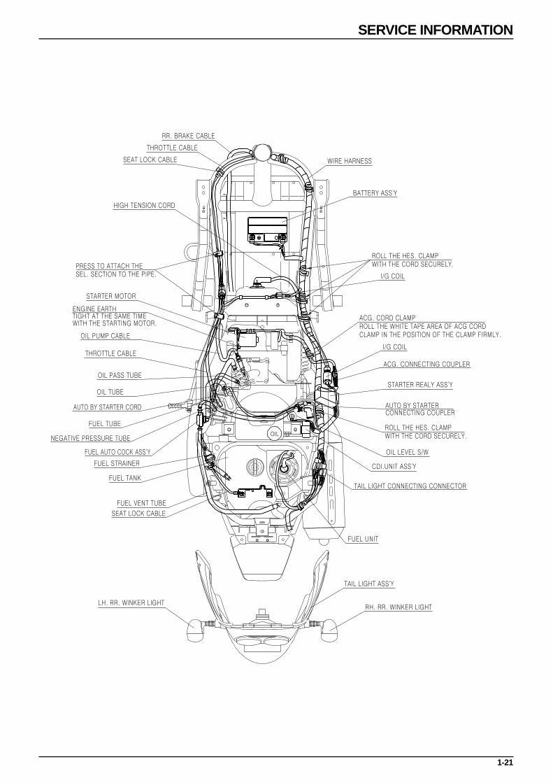
SERVICE INFORMATION
RR. BRAKE CABLE
THROTTLE CABLE
SEAT LOCK CABLE
HIGH TENSION CORD
STARTER MOTOR
OIL PUMP CABLE
THROTTLE CABLE
OIL PASS TUBE
OIL TUBE
AUTO BY STARTER CORD
FUEL TUBE
NEGATIVE PRESSURE TUBE
FUEL AUTO COCK ASS'Y
FUEL STRAINER
FUEL TANK
FUEL VENT TUBE
SEAT LOCK CABLE
LH. RR. WINKER LIGHTRH. RR. WINKER LIGHT
TAIL LIGHT ASS'Y
FUEL UNIT
TAIL LIGHT CONNECTING CONNECTOR
CDI.UNIT ASS'Y
OIL LEVEL S/W
AUTO BY STARTER CONNECTING COUPLER
ACG. CONNECTING COUPLER
ACG. CORD CLAMPROLL THE WHITE TAPE AREA OF ACG CORD CLAMP IN THE POSITION OF THE CLAMP FIRMLY.
I/G COIL
I/G COIL
BATTERY ASS'Y
WIRE HARNESS
STARTER REALY ASS'Y
ENGINE EARTH TIGHT AT THE SAME TIME WITH THE STARTING MOTOR.
PRESS TO ATTACH THE SEL. SECTION TO THE PIPE.
ROLL THE HES. CLAMPWITH THE CORD SECURELY.
ROLL THE HES. CLAMPWITH THE CORD SECURELY.

MEMO
2-1
2. INSPECTIONS/ADJUSTMENTS
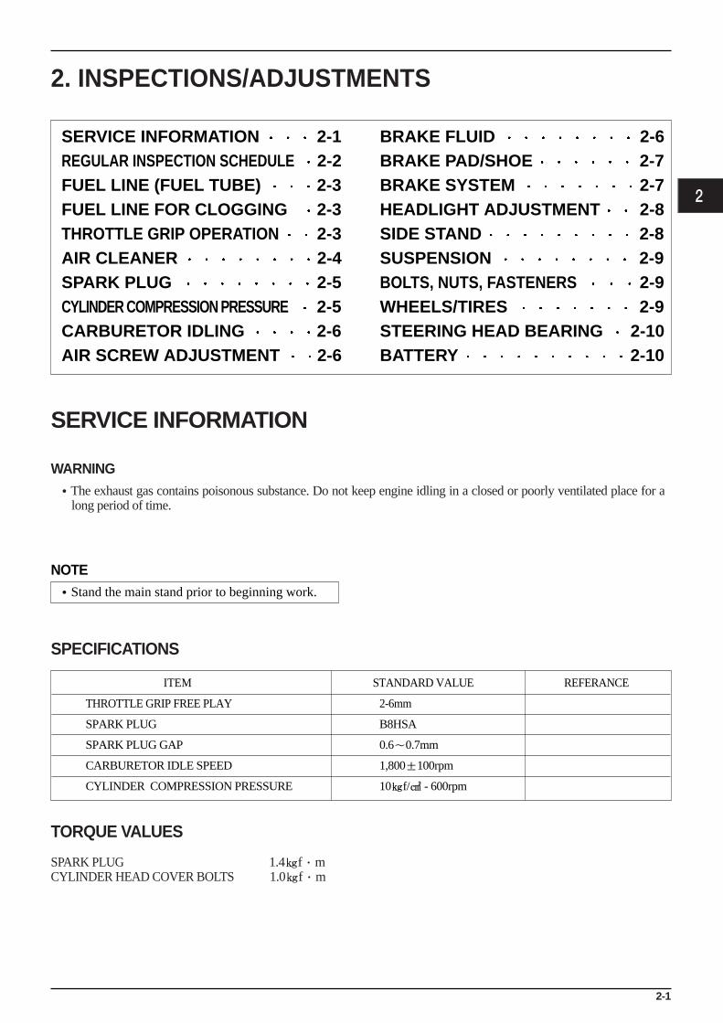
SERVICE INFORMATION
WARNING•The exhaust gas contains poisonous substance. Do not keep engine idling in a closed or poorly ventilated place for a
long period of time.
SPECIFICATIONS
TORQUE VALUES
SPARK PLUG 1.4f·mCYLINDER HEAD COVER BOLTS 1.0f·m
2
SERVICE INFORMATION 2-1REGULAR INSPECTION SCHEDULE 2-2FUEL LINE (FUEL TUBE) 2-3FUEL LINE FOR CLOGGING 2-3THROTTLE GRIP OPERATION 2-3AIR CLEANER 2-4SPARK PLUG 2-5CYLINDER COMPRESSION PRESSURE 2-5CARBURETOR IDLING 2-6AIR SCREW ADJUSTMENT 2-6
BRAKE FLUID 2-6BRAKE PAD/SHOE 2-7 BRAKE SYSTEM 2-7HEADLIGHT ADJUSTMENT 2-8SIDE STAND 2-8SUSPENSION 2-9 BOLTS, NUTS, FASTENERS 2-9WHEELS/TIRES 2-9STEERING HEAD BEARING 2-10BATTERY 2-10
ITEM STANDARD VALUE REFERANCE
THROTTLE GRIP FREE PLAY 2-6mm
SPARK PLUG B8HSA
SPARK PLUG GAP 0.6〜0.7mm
CARBURETOR IDLE SPEED 1,800±100rpm
CYLINDER COMPRESSION PRESSURE 10f/ - 600rpm
NOTE•Stand the main stand prior to beginning work.
2-2
INSPECTIONS/ADJUSTMENTS
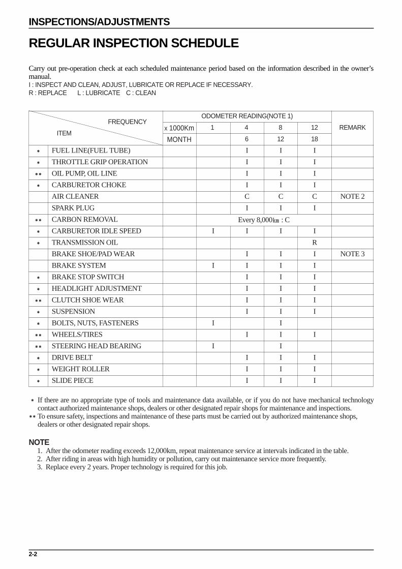
REGULAR INSPECTION SCHEDULE
Carry out pre-operation check at each scheduled maintenance period based on the information described in the owner’smanual.I : INSPECT AND CLEAN, ADJUST, LUBRICATE OR REPLACE IF NECESSARY.R : REPLACE L : LUBRICATE C : CLEAN
* If there are no appropriate type of tools and maintenance data available, or if you do not have mechanical technologycontact authorized maintenance shops, dealers or other designated repair shops for maintenance and inspections.To ensure safety, inspections and maintenance of these parts must be carried out by authorized maintenance shops,dealers or other designated repair shops.
NOTE1. After the odometer reading exceeds 12,000km, repeat maintenance service at intervals indicated in the table.2. After riding in areas with high humidity or pollution, carry out maintenance service more frequently.3. Replace every 2 years. Proper technology is required for this job.
*
*
*
*
*
*
*
*
*
*
*
*
FUEL LINE(FUEL TUBE)
THROTTLE GRIP OPERATION
OIL PUMP, OIL LINE
CARBURETOR CHOKE
AIR CLEANER
SPARK PLUG
CARBON REMOVAL
CARBURETOR IDLE SPEED
TRANSMISSION OIL
BRAKE SHOE/PAD WEAR
BRAKE SYSTEM
BRAKE STOP SWITCH
HEADLIGHT ADJUSTMENT
CLUTCH SHOE WEAR
SUSPENSION
BOLTS, NUTS, FASTENERS
WHEELS/TIRES
STEERING HEAD BEARING
DRIVE BELT
WEIGHT ROLLER
SLIDE PIECE
NOTE 2
NOTE 3
I
I
I
I
I
I
I
I
C
I
I
I
I
I
I
I
I
I
I
I
I
I
I
I
I
C
I
I
I
I
I
I
I
I
I
I
I
I
I
I
I
I
I
I
C
I
I
R
I
I
I
I
I
I
I
I
I
I
Every 8,000 : C
FREQUENCYODOMETER READING(NOTE 1)
6 12 18
1 4 8 12 REMARKITEM
x 1000Km
MONTH

FUEL LINE(FUEL TUBE) Remove the luggage box.( 3-3) Check the fuel tube of the fuel auto cock connected to
the fuel tank and carburetor. If the fuel tube is cranked,damaged or leaks, replace it.
FUEL LINE FOR CLOGGING
NOTE•Refer to section 2 for fuel filter inspection.
Check the fuel tank cap and/or fuel tank breather tubefor clogging.
Visually inspect the fuel strainer for contamination.Check the fuel flow with the fuel strainer installed andwith the strainer removed.Replace the fuel strainer if it is excessively contaminatedor if the fuel flow is not smooth.
CAUTION•Note the installation direction of the fuel strainer. Be
sure to install it as shown in the drawing, i.e., withthe cup facing down. Fuel flows even though thestrainer is installed upside down, but it contaminatesthe inner wall of the strainer and prevents visualinspection of the strainer.
Remove the fuel valve lock nut and check the fuelstrainer screen for contamination. Tighten the lock nutto the specified torque.
THROTTLE GRIP OPERATION Check if the throttle grip operates smoothly in any
steering position If the throttle grip does not operate properly, lubricate
the throttle cable. If the throttle grip does not operate properly, check the
throttle cable for aging, damage or kinking. Check the throttle grip free play.
FREE PLAY : 2~6mm
2-3
INSPECTIONS/ADJUSTMENTS
FUEL TUBE
FUEL AUTO COCK
FUEL STRAINER
FUEL TANK
(Inner walls getcontaiminated,making visuali n s p e c t i o ndifficult.)

For adjustment, loosen the lock nut and turn adjuster. After adjusting, tighten lock nut. After adjustment is
completed, recheck the throttle grip free play.
AIR CLEANER Loosen the 5 setting screw assembled to the air cleaner
case cover, and then remove the air cleaner case cover.
Remove the air cleaner element. Wash away any accumulated dust or dirt, by gently
squeezing it in non flammable or high flash pointsolvent.
WARNING•Using gasoline or low flash point solvents for
cleaning parts may result in a fire or explosion.
CAUTION•Cleaning the element with gasoline or any acid,
alkaline, or organic, volatile type oil may causeimproper ignition, deterioration of the element, or aloosening of the element adhesive.
Be sure to allow the element to dry thoroughly before applying oil. Otherwise, the oil will be diluted by the and the filtering ability of the filter will be much less effective.
Spread clean #80~90 gear oil on the element, rubbing inthoroughly over the surface with both hands, and then squeeze out any excess oil.
CAUTION•Using air filter oil when riding in extremely dusty
conditions prevents premature engine wear due todust/dirt drawn into the engine. Apply air filter oil tothe entire surface of the element and rub it with bothhands to saturate the element with oil. Squeeze outexcess oil.
2-4
INSPECTIONS/ADJUSTMENTS
LOCK NUTADJUSTER
AIR CLEANER COVER
WASHER SCREW
AIR CLEANER ELEMENT

SPARK PLUG Remove the plug maintenance cover. Remove the spark plug cap and disassemble the plug.
Check the plug for damage, contamination or deposits. If the spark plugs are severely contaminated or
damaged, raplace with new ones. If the plugs can bereused after removing only the carbon, use plug cleanerand wire brush to clean the plugs.
Always use a feeler gauge to check the gap.
SPARK PLUG GAP : 0.6~0.7mm
CAUTION•Make sure there is no dirt or debris on the seat of the
spark plug hole before inserting the spark plug.•To prevent damage to the cylinder head, hand-tighten
the spark plug before using a wrench to tighten to thespecified torque.(torque : 14kgf·m)
•Do not overtighten the spark plug.
CYLINDER COMPRESSION PRESSURE Start and warm up the engine. Remove the plug maintenance cover. Stop engine, and remove the spark plug cap and spark
plug. Install a compression gauge. Open the throttle completely, and crank the engine with
the starter motor until the gauge reading rising.
NOTE•The maximum reading is usually reached within 4~7
seconds.
COMPRESSION PRESSURE : 13.8kg/cm2
If the pressure is low, check the following:-Leakage from the cylinder head gasket-Piston/cylinder worn
If pressure is high, check the following:-Carbon deposits on the piston head, and cylinder head.
TOOL : COMPRESSION GAUGE
2-5
INSPECTIONS/ADJUSTMENTS
PLUG MAINTENANCE COVERSPARK PLUG CAP
COMPRESSION GAUGE

BRAKE HOSE BOLTMASTER CYLINDER
CARBURETOR IDLING
Stand the vehicle on the main stand. Heat the engine to make accurate idling inspection and
adjustment. Verify all engine adjustments satisfy specifications.
Make adjustments, if necessary. Turn the throttle stop screw and make adjustments to
prescribed idling speed.
AIR SCREW ADJUSTMENTNOTE•The air screw is factory pre-set. Adjustment is not
necessary unless the carburetor is overhauled or anew air screw is installed.
•Tightening the air screw against its seat will damagethe seat.
Turn the air screw clockwise until it seats lightly thenback it out to the specification given. This is an initialsetting prior to the final air screw adjustment.
Rev the engine up slightly from the idle speed andmake sure that engine speed rises and returns smoothly.
Adjust by turning the air screw in or out within a 1/4turn if necessary. If the engine cannot be adjusted byturning the air screw within a 1/4 turn, check for otherengine problems.
CAUTION•Excessive air screw adjustment may cause the engine
sticking and deteriorate the starting performance.
BRAKE FLUID Remove the brake fluid cover. Check the oil level inside the front brake reservoir. If
the oil level is near the lower limit line, remove thereservoir diaphragm and fill DOT 3 and DOT 4 brakefluid to the top limit line.
If the brake fluid reaches the lower limit line, check theentire brake system for leaks.
CAUTION•Brake fluid will damage painted, plastic or rubber
parts.•Mixing incompatible fluids can impair braking
efficiency.•Foreign materials can clog the system, causing a
reduction or complete loss of braking ability.•A leak in the brake system can lead to reduced
braking effiency and possible loss of braking ability.
2-6
INSPECTIONS/ADJUSTMENTS
THROTTLE STOP SCREW
AIR SCREW
THROTTLE STOP SCREW
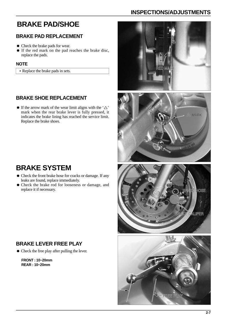
BRAKE PAD/SHOE
BRAKE PAD REPLACEMENT
Check the brake pads for wear. If the red mark on the pad reaches the brake disc,
replace the pads.
NOTE•Replace the brake pads in sets.
BRAKE SHOE REPLACEMENT
If the arrow mark of the wear limit aligns with the ‘’mark when the rear brake lever is fully pressed, itindicates the brake lining has reached the service limit.Replace the brake shoes.
BRAKE SYSTEM Check the front brake hose for cracks or damage. If any
leaks are found, replace immediately. Check the brake rod for looseness or damage, and
replace it if necessary.
BRAKE LEVER FREE PLAY Check the free play after pulling the lever.
FRONT : 10~20mmREAR : 10~20mm
2-7
INSPECTIONS/ADJUSTMENTS
RED MARK
MARK
BRAKE CALIPER
BRAKE HOSE
FREE PLAY

REAR BRAKE FREE PLAY ADJUSTMENT
Turn the adjuster nut to adjust the free play. After initial adjustment, check the operation of the rear
brake light switch. Make additional adjustments, ifnecessary.
HEADLIGHT ADJUSTMENT Adjust the headlight beam level by operating the
adjusting screw located on the upper side of the frontfender.
NOTE•Adjust the beam level according to local laws and
regulations.
•Improper beam level adjustment may blindoncoming drivers, or may incorrectly light the roadahead.
SIDE STAND Erect the main stand. Pull the lower end of the side stand, and see if it moves
freely. If the side stand does not move smoothly, apply grease
to the pivot area. If the side stand moves too freely, check the side stand
spring. Check the axial movement of the side stand.
Check the side stand ignition cut-off switch :-Put the side stand up.-Start the engine.-Lower the side stand. The engine should stop as you put the side stand down.
If there is a problem with the system, check the sidestand switch.
2-8
INSPECTIONS/ADJUSTMENTS
ADJUSTER NUT
ADJUSTER LEVER
SIDE STAND SPRING

SUSPENSIONNOTE•Do not ride motor cycle with an unsatisfactory
suspension. Loose or worn suspension parts will leadto deterioration in the vehicle’s safety and operationefficiency.
FRONT WHEEL Hold the brake lever, and compress the front cushion
up and down several times to check the operatingconditions.
Check the front fork for oil leakage, parts damage orlooseness.
REAR WHEEL Compress the near cushion up and down several times
to check the operating conditions. Check the rear fork for oil leakage, parts damage or
looseness.
BOLTS, NUTS, FASTENERS Check all nuts and bolts of the frame during the regular
maintenance to check if they meet the prescribedtorque value.
Check all pins, clips, hose clamps and cable stays.
WHEELS/TIRESNOTE•Check the tire pressure when the tires have been
cooled off. Check the tread (the part making contactwith the road surface) and side for wear, cracks ordamage. Replace damaged tires.
STANDARD PRESSURE
2-9
INSPECTIONS/ADJUSTMENTS
TIRE PRESSURE GAUGE
FRONT WHEEL1.75(175)
2.00(200)
REAR WHEEL2.00(200)
2.25(225)
ITEMDRIVER ONLY
DRIVER AND A PASSENGER
f/ (kpa)

Check the tread depth at the tire center. If the tread depth has reached the service limit, replace
the tire.SERVICE LIMIT :4.0mm
7.5mm
STEERING HEAD BEARING
NOTE•Check the cable if it interferes with the handle
operation.
Lift the front wheel and check if the handle moves rightand left smoothly. If the handles move heavily, check ifthe cable or electric cord interferes with the handle. Ifthe hadle moves satisfactorily, adjust the steering headbearing.
BATTERY Remove a tapping screw securing the battery cover
from the floor panel. Check if the terminal is loose. If the terminal is loose, check and clean the contacting
surface and then tighten it. Apply grease thinly after tightening. If the terminal is rusted, remove the battery, pour warm
water and clean with the wire brush.
- FULL CHARGING VOLTAGE : 13.0~13.2V- LOW CHARGING VOLTAGE : LESS THAN 12.3V
NOTE•Check the charging condition using the voltmeter.•Pay attention not to transform the battery terminal.•Never remove the filler cap.
2-10
INSPECTIONS/ADJUSTMENTS
TAPPING SCREW
BATTERY COVER
DIGTAL TESTER

3-1
3. EXTERNAL PARTS
SERVICE INFORMATION
NOTE This section describes external parts removal/installation. Do not apply unreasonable force when disassembling covers, to prevent possible damage. A muffler is hot. Do not service it immediately after the engine is stopped.
3
SERVICE INFORMATION 3-1MAINTENANCE PRECEDURE 3-2LUGGAGE BOX 3-3PLUG MAINTENANCE COVER/CENTER COVER 3-3 REAR CARRIER 3-3BODY COVER 3-3TAILLIGHT BASE 3-4FLOOR SIDE COVER 3-4FLOOR PANEL 3-4ENGINE HANGER SIDE COVER 3-5
FRONT COVER 3-5FRONT FENDER 3-5INNER BOX 3-5FRONT UNDER COVER 3-6FRONT HANDLE COVER 3-6REAR HANDLE COVER 3-6MUFFLER 3-7REAR FENDER 3-7REAR WHEEL MUD GUARD 3-8UNDER COVER 3-8
3-2
EXTERNAL PARTS
10
11
15
12
5
6
9713
8
14
3
2
14
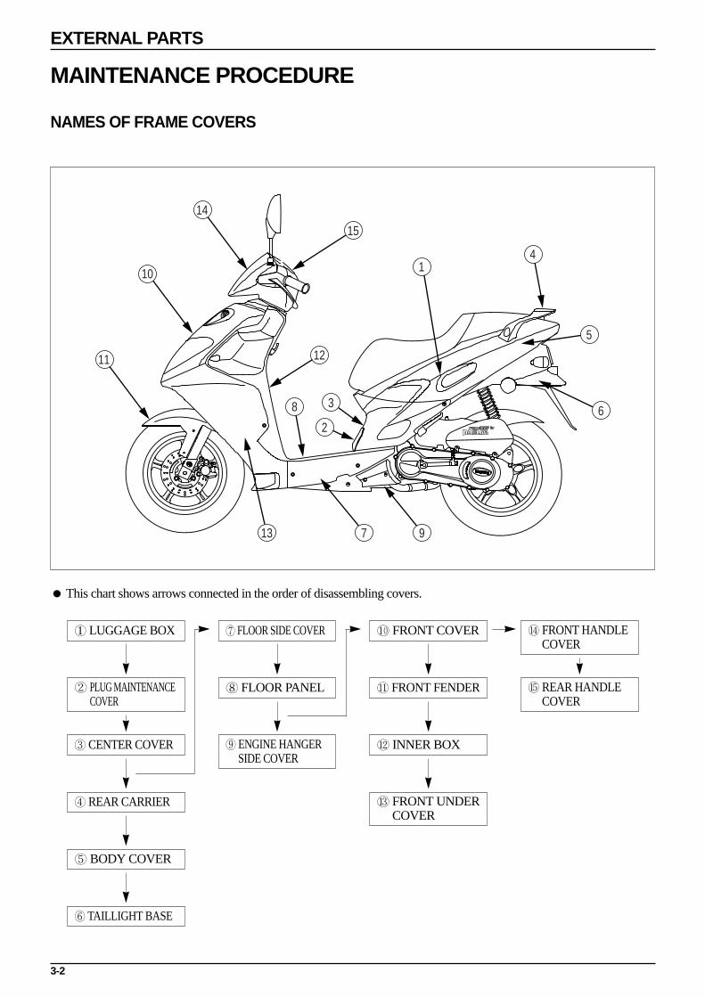
MAINTENANCE PROCEDURE
NAMES OF FRAME COVERS
This chart shows arrows connected in the order of disassembling covers.
① LUGGAGE BOX
② PLUG MAINTENANCECOVER
③ CENTER COVER
④ REAR CARRIER
⑤ BODY COVER
⑥ TAILLIGHT BASE
⑦ FLOOR SIDE COVER
⑧ FLOOR PANEL
⑨ ENGINE HANGERSIDE COVER
⑩ FRONT COVER
⑪ FRONT FENDER
⑫ INNER BOX
⑬ FRONT UNDERCOVER
⑭ FRONT HANDLECOVER
⑮ REAR HANDLECOVER

3-3
EXTERNAL PARTS
WASHER BOLT FLANGE BOLT
SPECIAL SCREW
SPECIAL SCREW
TAPPING SCREW
SPECIAL BOLT
BODY COVER CLIP
SPECIAL SCREW
LUGGAGE BOX Release the seat lock using the main key to open the
seat. Loosen 4 washer bolts and 2 flange bolts. Remove the oil tank cap and the fuel tank cap.
NOTE•Luggage box can be removed with the seat.
Remove the luggage box. Install in the reverse order of removal.
CAUTION•Install the oil tank cap and the fuel tank cap
temporarily to prevent the foreign material fromentering after removing the luggage box.
PLUG MAINTENANCE COVER/CENTER COVER Release the seat lock using the main key to open the
seat. Loosen the washer bolt securing the luggage box. Loosen the special screw to remove the plug
maintenance cover. Loosen 2 tapping screw securing the floor panel. Loosen 2 special screw (R/L) securing the body cover. Remove the center cover.
CAUTION•If removal is difficult, recheck each connection and
then try removing again.
Install in the reverse order of removal.
REAR CARRIER Loosen 3 special bolts securing the top of the body
cover. Remove the rear carrier. Install in the reverse order of removal.
CAUTION•Pay attention not to break of damage the rear carrier
when installing or removing.
BODY COVER Remove the luggage box. ( 3-3) Remove the center cover. ( 3-3) Remove the rear carrier. ( 3-3) Loosen 2 special screw (R/L) securing the frame body. Loosen 2 body cover clip (R/L) securing the tail light
base. Remove the body cover. Install in the reverse order of removal.

BODY COVER CLIP
TAILLIGHT WIRINGWASHER BOLT
WASHER SCREW
FLOOR PANEL CAP
WASHER BOLT
3-4
EXTERNAL PARTS
TAILLIGHT BASE Remove the luggage box. ( 3-3) Remove the center cover. ( 3-3) Remove the rear carrier. ( 3-3) Remove the body cover. ( 3-3) Loosen 2 washer bolt securing the frame. Loosen 2 body cover clip securing the rear fender. Disconnect the taillight wiring. Remove the taillight base. Install in the reverse order of removal.
FLOOR SIDE COVER Loosen the 2 washer screw located in the side of the
R,L floor side cover. Loosen the tapping screw (R/L) securing the lower and
rear end of the floor panel. Pull the front part of the floor side cover to remove the
floor panel. Remove the floor side cover. Install in the reverse order of removal.
FLOOR PANEL Remove the plug maintenance cover. ( 3-3 ) Remove the center cover. ( 3-3) Loosen the tapping screw securing the battery cover to
remove the battery cover. Disconnect the battery wiring to remove the battery. Remove the floor side cover. Remove the floor panel cap A and B.
Loosen the 4 washer bolts securing the floor panel. Remove the floor panel from the connecting groove of
the inner box by lifting the rear part of the panelslightly.
Draw the floor panel moving it to the right and left toremove it.
Install in the reverse order of removal.

3-5
EXTERNAL PARTS
WASHER SCREW
SETTING SCREW
SPECIAL BOLT
SPECIAL SCREW
SPECIAL SCREW
SETTING SCREW
TAPPING SCREW
ENGINE HANGER SIDE COVER Loosen the 2 washer screw securing the engine hanger
side cover. Install in the reverse order of removal.
FRONT COVER Loosen the upper cover set screws (R/L) securing the
inner box.
Loosen the upper cover set screws (R/L) securing thefront under cover.
Loosen the special bolt securing the front of the frontcover.
Draw the upper part of the front cover to remove it. Disconnect the head light wiring and remove the front
cover. Install in the reverse order of removal.
NOTE
•Check for proper alignment of the connection (hook)before performing installation.
FRONT FENDER Loosen the flange bolts (R/L) securing the front fork. Remove the front fender. Install in the reverse order of removal.
INNER BOX Remove the center cover. ( 3-3) Remove the floor side cover. ( 3-4) Remove the floor panel. ( 3-4) Remove the front cover. ( 3-5) Loosen the tapping screws (R/L) securing the front
under cover. Loosen the special bolts securing the right and left
sides of the front cover. Turn the main key cover slightly to release the locking
and remove the cover. Remove the cover set screw securing the back holder,
take off the joint part of the front under cover andremove the inner box.
Install in the reverse order of removal.
FLANGE BOLT
FLANGE BOLT
TAPPING SCREW
TAPPING SCREW
TAPPING SCREW
MASTER CYLINDER
TAPPING SCREW
TAPPING SCREW
TAPPING SCREW
SPEEDOMETER CABLE
3-6
EXTERNAL PARTS
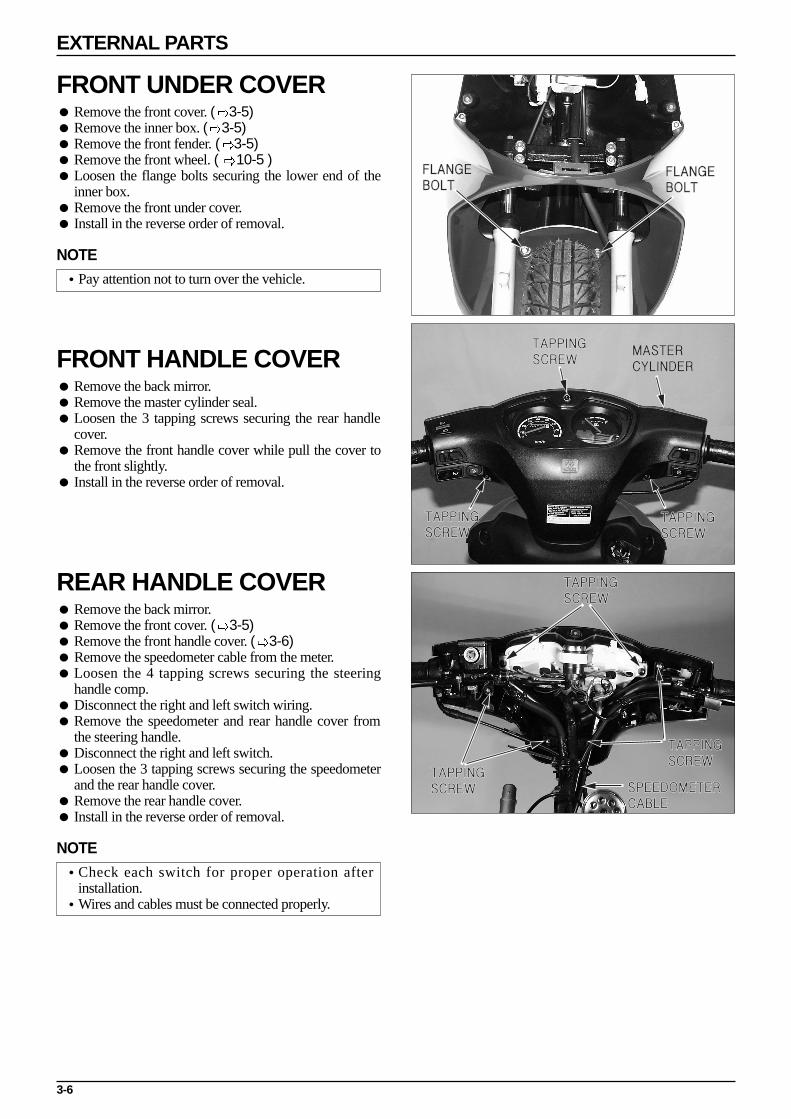
FRONT UNDER COVER Remove the front cover. ( 3-5) Remove the inner box. ( 3-5) Remove the front fender. ( 3-5) Remove the front wheel. ( 10-5 ) Loosen the flange bolts securing the lower end of the
inner box. Remove the front under cover. Install in the reverse order of removal.
NOTE•Pay attention not to turn over the vehicle.
FRONT HANDLE COVER Remove the back mirror. Remove the master cylinder seal. Loosen the 3 tapping screws securing the rear handle
cover. Remove the front handle cover while pull the cover to
the front slightly. Install in the reverse order of removal.
REAR HANDLE COVER Remove the back mirror. Remove the front cover. ( 3-5) Remove the front handle cover. ( 3-6) Remove the speedometer cable from the meter. Loosen the 4 tapping screws securing the steering
handle comp. Disconnect the right and left switch wiring. Remove the speedometer and rear handle cover from
the steering handle. Disconnect the right and left switch. Loosen the 3 tapping screws securing the speedometer
and the rear handle cover. Remove the rear handle cover. Install in the reverse order of removal.
NOTE•Check each switch for proper operation after
installation.•Wires and cables must be connected properly.
3-7
EXTERNAL PARTS
FLANGE BOLT
FLANGE BOLT
FLANGE NUT
FLANGE NUT
WASHER BOLT
WASHER BOLT
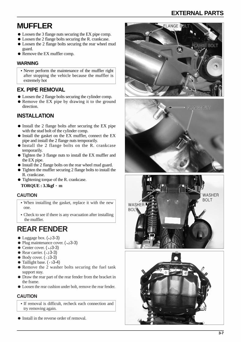
MUFFLER Loosen the 3 flange nuts securing the EX pipe comp. Loosen the 2 flange bolts securing the R. crankcase. Loosen the 2 flange bolts securing the rear wheel mud
guard. Remove the EX muffler comp.
WARNING•Never perform the maintenance of the muffler right
after stopping the vehicle because the muffler isextremely hot
EX. PIPE REMOVAL Loosen the 2 flange bolts securing the cylinder comp. Remove the EX pipe by drawing it to the ground
direction.
INSTALLATION
Install the 2 flange bolts after securing the EX pipewith the stud bolt of the cylinder comp.
Install the gasket on the EX muffler, connect the EXpipe and install the 2 flange nuts temporarily.
Install the 2 flange bolts on the R. crankcasetemporarily.
Tighten the 3 flange nuts to install the EX muffler andthe EX pipe.
Install the 2 flange bolts on the rear wheel mud guard. Tighten the muffler securing 2 flange bolts to install the
R. crankcase. Tightening torque of the R. crankcase.
TORQUE : 3.3kgf··m
CAUTION•When installing the gasket, replace it with the new
one.
•Check to see if there is any evacuation after installing the muffler.
REAR FENDER Luggage box. ( 3-3) Plug maintenance cover. ( 3-3) Center cover. ( 3-3) Rear carrier. ( 3-3) Body cover. ( 3-3) Taillight base. ( 3-4) Remove the 2 washer bolts securing the fuel tank
support stay. Draw the rear part of the rear fender from the bracket in
the frame. Loosen the rear cushion under bolt, remove the rear fender.
CAUTION•If removal is difficult, recheck each connection and
try removing again.
Install in the reverse order of removal.

REAR WHEEL MED GUARD Loosen the 2 flange bolts securing the EX muffler. Loosen the flange bolt securing the air cleaner. Loosen the flange bolt securing the inlet pipe. Remove the rear wheel mud guard. Install in the reverse order of removal.
NOTE•Never perform the maintenance of the muffler right
after stopping the vehicle because the muffler isextremely hot.
UNDER COVER Remove the floor side cover. ( 3-4) Remove the engine hanger side cover. ( 3-5) Loosen the 2 R/L setting screws securing the frame. Remove the under cover. Install in the reverse order of removal.
FLANGE BOLT
REAR WHEEL MUD GUARD
UNDER COVER
SETTING SCREW
EXTERNAL PARTS
3-8
4-1
4. LUBRICATION SYSTEM
SERVICE INFORMATION
CAUTION·Remove air from oil tube and oil pump if the oil tube is taken off or if air enters the oil tube.
If the oil tube is disassembled, remove the air in the oil pass tube. Maintenanace on the oil pump is done without the engine being removed from the vehicle. When disassembling the oil pump, do not allow foreign substances from entering the engine or oil pump. Do not disassemble the oil pump assembly. If the oil tube is disassembled, place a tube clip or band on the oil tube to prevent oil from leaking out.
TROUBLESHOOTING
Overheating or engine clogging
Faulty adjustment of oil pump(insufficient amount pumped). Bad quality of engine oil. Engine oil not being injected or blocked, bent strainer screen or oil tube. Entering of air in oil tube system. Faulty oil pump. Engine oil not being supplied from oil tank.
-Blocked oil tank cap air hole-Blocked oil strainer screen
Excess exhaust smoke, accumulation of carbon on spark plug
Faulty adjustment of oil pump(over-pumped amount). Bad quality of engine oil.
4
SERVICE INFORMATION 4-1
TROUBLESHOOTING 4-1
OIL SYSTEM DRAWING 4-2
OIL PUMP DISASSEMBLY/ASSEMBLY 4-3
OIL PUMP INSPECTION/ADJUSTMENT 4-3
OIL PUMP BLEEDING 4-4
ENGINE OIL LEVEL INSPECTION 4-6
TRANSMISSION OIL INSPECTION 4-7
OIL TANK DISASSEMBLY 4-8
LUBRICATION POINTS 4-9

4-2
LUBRICATION SYSTEM
OIL SYSTEM DRAWING
OIL TANK
OIL TUBE
CARBURETOR
OIL PASS TUBEOIL PUMP
OIL PUMP CONTROL CABLE
OIL PUMP ANCHOR PLATE

OIL PUMP DISASSEMBLY/ASSEMBLY Remove the luggage box. ( 3-3) Remove the rear wheel mud guard. ( 3-8 ) Remove the air cleaner. ( 5-4 ) Remove the carburetor. ( 5-4 ) Loosen the oil pump cable stay bolt to remove the oil
pump anchor plate. Disconnect the oil control cable from the oil pump. Remove the inlet pipe. ( 5-9)
Remove the oil tube in the oil pump side. Remove the oil pass tube. Loosen the flange bolt securing the oil pump. Remove the setting plate of the oil pump. Remove the oil pump. Install in the reverse order of removal.
CAUTION•When assembling/disassembling the oil pump, do
not allow foreign substances from entering theengine and oil tube by cleaning around the oil pump.
•If the air enters into the oil line, it may cause faultylubrication or engine sticking. Always remove the airin the oil line after maintenance.
• Pay attention not to damage the O-ring whenassembling the oil pump.
OIL PUMP INSPECTION/ADJUSTMENT Remove the oil pump. Rotate the shaft and check for proper rotation. Check the gear for wear, damage and leak of each seal. If the oil comes out from the outlet of the oil pump
after connecting the oil tube (which is connectingbetween the tank and the oil pump) to the inlet androtating the shaft in the driving direction, consider theoil pump is in good condition.
4-3
LUBRICATION SYSTEM
FLANGE BOLT
OIL ANCHOR PLATE
INLET PIPE
OIL PUMP CONTROL CABLE
OIL PASS TUBE
OIL TUBE
SETTING PLATE
OIL PUMP

ADJUSTMENTCAUTION•Perform after inspection and adjustment of throttle
cable.
Check to see if the matching mark of the oil pump
body and control lever are aligned in a state where
the throttle grip is completely rotated. Adjustment is performed by loosening the oil pump
control cable lock nut and turning the control nut. While the engine is running, slightly open the throttle
and check to see if the control lever operates together
with the increase in engine rpms.
CAUTION•Do not adjust the control lever matching mark to the
closed side of the oil pump body matching mark. Ifthis is done, the amount of pumped oil is reduced,negatively affecting the engine.
•Make sure that the open axis stays within an 1mm sphere.
The following occurs when the oil pump is adjusted incorrectly.
-When the oil pump lever is excessively opened :Emitting of white exhaust gas or starting problems.
-When the oil pump lever is insufficiently opened :Clogging of engine.
NOTE•If the oil pump cable stay bolt is removed, apply the
screw locking compound to the bolt thread.
OIL PUMP BLEEDING
CAUTION•Air infiltration in the oil pass may cause the engine
sticking. Always remove the air in the oil pass aftermaintenance.
•When disassembling the oil tube, air can be enterinto the oil tube and the oil pump because of the oilleaking in the oil tube. Remove the air completely.
•Do not allow foreign substances from entering the oilpass.
4-4
LUBRICATION SYSTEM
CONTROLLEVER
CABLE STAY NUT
OIL PUMP CABLE STAY NUT
CONTROLLEVER
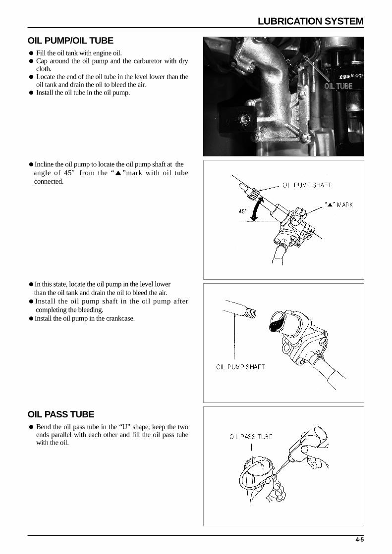
OIL PUMP/OIL TUBE Fill the oil tank with engine oil. Cap around the oil pump and the carburetor with dry
cloth. Locate the end of the oil tube in the level lower than the
oil tank and drain the oil to bleed the air. Install the oil tube in the oil pump.
Incline the oil pump to locate the oil pump shaft at the angle of 45。from the “”mark with oil tube connected.
In this state, locate the oil pump in the level lower than the oil tank and drain the oil to bleed the air.
Install the oil pump shaft in the oil pump after completing the bleeding.
Install the oil pump in the crankcase.
OIL PASS TUBE Bend the oil pass tube in the “U” shape, keep the two
ends parallel with each other and fill the oil pass tubewith the oil.
4-5
LUBRICATION SYSTEM
OIL TUBE
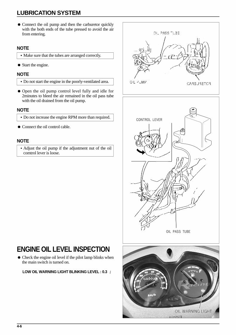
Connect the oil pump and then the carburetor quicklywith the both ends of the tube pressed to avoid the airfrom entering.
NOTE•Make sure that the tubes are arranged correctly.
Start the engine.
NOTE•Do not start the engine in the poorly-ventilated area.
Open the oil pump control level fully and idle for2minutes to bleed the air remained in the oil pass tubewith the oil drained from the oil pump.
NOTE•Do not increase the engine RPM more than required.
Connect the oil control cable.
NOTE•Adjust the oil pump if the adjustment nut of the oil
comtrol lever is loose.
ENGINE OIL LEVEL INSPECTION Check the engine oil level if the pilot lamp blinks when
the main switch is turned on.
LOW OIL WARNING LIGHT BLINKING LEVEL : 0.3
4-6
LUBRICATION SYSTEM
CONTROL LEVER
OIL PASS TUBE
OIL WARNING LIGHT
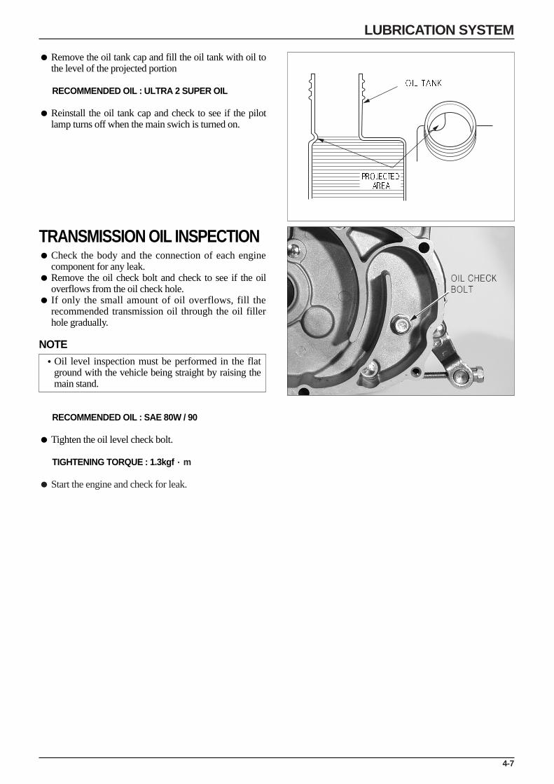
Remove the oil tank cap and fill the oil tank with oil tothe level of the projected portion
RECOMMENDED OIL : ULTRA 2 SUPER OIL
Reinstall the oil tank cap and check to see if the pilotlamp turns off when the main swich is turned on.
TRANSMISSION OIL INSPECTION Check the body and the connection of each engine
component for any leak. Remove the oil check bolt and check to see if the oil
overflows from the oil check hole. If only the small amount of oil overflows, fill the
recommended transmission oil through the oil fillerhole gradually.
NOTE•Oil level inspection must be performed in the flat
ground with the vehicle being straight by raising themain stand.
RECOMMENDED OIL : SAE 80W / 90
Tighten the oil level check bolt.
TIGHTENING TORQUE : 1.3kgf·m
Start the engine and check for leak.
4-7
LUBRICATION SYSTEM
OIL CHECK BOLT
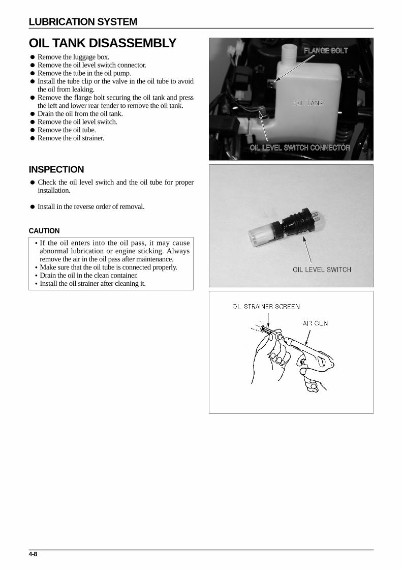
OIL TANK DISASSEMBLY Remove the luggage box. Remove the oil level switch connector. Remove the tube in the oil pump. Install the tube clip or the valve in the oil tube to avoid
the oil from leaking. Remove the flange bolt securing the oil tank and press
the left and lower rear fender to remove the oil tank. Drain the oil from the oil tank. Remove the oil level switch. Remove the oil tube. Remove the oil strainer.
INSPECTION Check the oil level switch and the oil tube for proper
installation.
Install in the reverse order of removal.
CAUTION
•If the oil enters into the oil pass, it may causeabnormal lubrication or engine sticking. Alwaysremove the air in the oil pass after maintenance.
•Make sure that the oil tube is connected properly.•Drain the oil in the clean container.•Install the oil strainer after cleaning it.
4-8
LUBRICATION SYSTEM
OIL TANK
FLANGE BOLT
OIL LEVEL SWITCH CONNECTOR
OIL LEVEL SWITCH
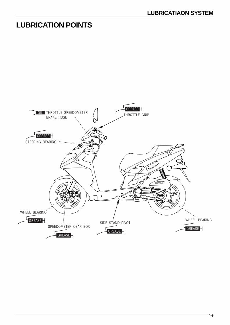
LUBRICATION POINTS
LUBRICATIAON SYSTEM
THROTTLE GRIP
STEERING BEARING
WHEEL BEARING
SPEEDOMETER GEAR BOXSIDE STAND PIVOT
WHEEL BEARING
THROTTLE SPEEDOMETERBRAKE HOSE
GREASEGREASE
GREASE
GREASE
GREASE
GREASEOIL
4-9

FUEL SYSTEM
5-0
CARBURETOR
FUEL STRAINER
FUEL TUBEAUTO COCK
FUEL TANK

SERVICE INFORMATION
GENERAL SAFETY
WARNING Gasoline is extremely flammable. Avoid fire in the work place, also paying particular attention to sparks. Furthermore,
the evaporated (gasified) gasoline is highly explosive. Work in a well-ventilated areas. Exhaust gas contains poisonous substance. Do not keep engine running for a long period of time in a closed, or poorly
ventilated area.
CAUTION Do not excessively bend or twist cable. Distorted or damaged cable may lead to mechanical malfunctions. Pay particular attention to the position of O-ring. Replace with new ones when disassembled. If it is desired to store a vehicle for a period longer than 1 month, drain gasoline out of the carburetor float chamber.
Gasoline left in the float chamber will be deteriorated causing the slow jet to be clogged with deposits, and idling maybecome unstable.
SPECIFICATIONS
FUEL TANK CAPACITY : 5.8ℓRESERVE FUEL CAPACITY: 1.7ℓ
CARBURETOR
TOOL
FLOAT LEVEL GAUGE
5-1
5. FUEL SYSTEM
5
SERVICE INFORMATION 5-1TROUBLESHOOTING 5-2FUEL TANK 5-3AIR CLEANER REMOVAL 5-4AIR CLEANER ELEMENTDISASSEMBLY 5-4
ITEM
TYPE/THROTTLE BORE
VENTURI DIAMETER
MAIN JET No.
SLOW JET No.
STANDARD
PB11P
16mm OR EQUIVALENT
#75
#38
ITEM
PILOT SCREW OPENING
FLOAT LEVEL
IDLING SPEED
THROTTLE GRIP FREE PLAY
STANDARD
1, 1/4 RETURNS
8.0mm
1,800±100rpm
2-6mm
CARBURETOR REMOVAL/INSTALLATION 5-4CARBURETOR INSPECTION 5-6THROTTLE VALVE 5-7FUEL AUTO COCK 5-8
INLET PIPE REED VALVE 5-9

5-2
FUEL SYSTEM
TROUBLESHOOTING
The vehicle does not start.
No gasoline in fuel tank. Fuel is not coming out of carburetor. Too much fuel is flowing into cylinder. No spark emitted from spark plug. Air cleaner is blocked. Suction system is experiencing secondary intake of air. Using low quality gasoline. Starter is damaged. Throttle cable is working improperly. Fuel tank is functioning improperly.
Idle is unstable and engine turns off after starting.
Starter is damaged. Ignition system is damaged. Using low qualty gasoline. Suction system is experiencing secondary intake of air. Idle is adjusted improperly. Air screw is adjusted improperly. Compression pressure is low. Air/Fuel mixture is either too lean or rich. Carburetor is blocked.
Mis-firing occurs when driving at high speeds.
Ignition system is damaged. Mixture is too lean.
Back firing
Ignition system is damaged. Mixture is too lean.
Insufficient power and high fuel consumption.
Air cleaner is blocked. Ignition system is damaged. Mixture is too rich.
Air/Fuel mixture is extremely lean
Fuel jet is blocked. Float valve is damaged. Oil level is low. Bad ventilation of air in tank cap. Fuel strainer screen is blocked. Fuel tube is bent, creased or blocked. Suction system is receiving secondary suction of air.
Air/Fuel mixture is extremely rich.
Air jet is blocked. Float valve is damaged. Oil level is too high. Starter is damaged. Air cleaner is blocked.
5-3
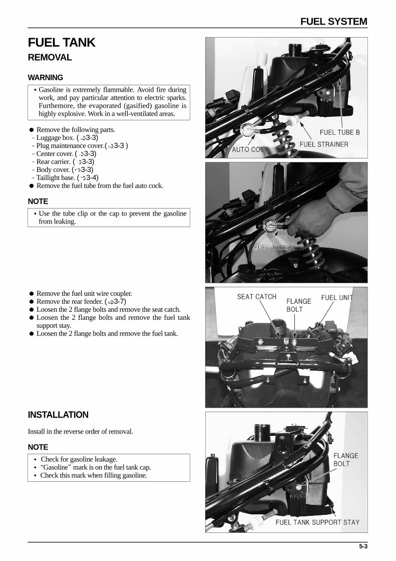
FUEL SYSTEM
FUEL TUBE B
AUTO COCKFUEL STRAINER
FUEL TUBE A
FUEL UNITSEAT CATCHFLANGE BOLT
FLANGE BOLT
FUEL TANK SUPPORT STAY
FUEL TANK REMOVAL
WARNING•Gasoline is extremely flammable. Avoid fire during
work, and pay particular attention to electric sparks.Furthemore, the evaporated (gasified) gasoline ishighly explosive. Work in a well-ventilated areas.
Remove the following parts.- Luggage box. ( 3-3)- Plug maintenance cover.( 3-3 )- Center cover. ( 3-3)- Rear carrier. ( 3-3)- Body cover. ( 3-3)- Taillight base. ( 3-4) Remove the fuel tube from the fuel auto cock.
NOTE•Use the tube clip or the cap to prevent the gasoline
from leaking.
Remove the fuel unit wire coupler. Remove the rear fender. ( 3-7) Loosen the 2 flange bolts and remove the seat catch. Loosen the 2 flange bolts and remove the fuel tank
support stay. Loosen the 2 flange bolts and remove the fuel tank.
INSTALLATION
Install in the reverse order of removal.
NOTE• Check for gasoline leakage.•“Gasoline”mark is on the fuel tank cap.• Check this mark when filling gasoline.

5-4
FUEL SYSTEM
FLANGE BOLT
WASHER BOLT
WASHER SCREW
AIR CLEANER ELEMENT
CONNECTING BEND
CARBURETOR
CARBURETOR INSULATOR
CARBURETOR INSULATOR
FLANGE BOLT
AIR CLEANER REMOVAL Loosen the air cleaner connecting bend screw pin. Loosen the 2 bottom air cleaner washer bolts. Loosen the top rear fender flange bolt. Remove the air cleaner from the carburetor. Install in the reverse order of removal.
AIR CLEANER ELEMENT DISASSEMBLY Loosen the 5 air cleaner cover washer screws. Remove the air cleaner cover. Remove the air cleaner element. Install in the reverse order of disassembly.
CARBURETOR REMOVAL/INSTALLATION
NOTE•Keep the fire away.•Open the drain screw to drain the gasoline in the
carburetor chamber.
Remove the luggage box. ( 3-3) Remove the plug maintenance cover. ( 3-3) Remove the center cover. ( 3-3) Remove the air cleaner. ( 5-4) Remove the wiring coupler of the auto by starter. Remove the oil pass tube. Remove the throttle valve set. Remove the 2 flange bolts securing the inlet pipe. Remove the carburetor insulator. Remove the carburetor. Install in the reverse order of removal.
NOTE•Install the carburetor after aligning the throttle valve
cutaway and the throttle stop screw.•Tighten the top set correctly so that it is not released.

5-5
FUEL SYSTEM
WASHER SCREW
AUTO BY STARTERSET PLATE
AIR SCREW
THROTTLESTOPSCREW
GASKET
O-RING
FLOAT PIN
FLOAT
FLOATVALVE
FLOATCHAMBER
AUTO BYSTARTER COVER
AUTO BYSTARTER
FLOAT LEVEL GAUGE
MAIN JET
THROTTLE STOP SCREW
AIR SCREWWASHER
O-RING
SLOW JET
FLOAT VALVE
FLOAT
CARBURETOR DISASSEMBLY/ASSEMBLY
Remove the auto by starter cover. Loosen the 2 washer screws Remove the auto by starter set plate. Remove the auto by starter. Remove the auto by starter O-ring. Assemble in the reverse order of disassembly.
NOTE•Install the auto by starter in the carburetor body after
applying grease to the starter O-ring and then tightenfirmly with set plate piece.
FLOAT CHAMBER/FLOAT/JET DISASSEMBLY/ASSEMBLY Loosen the 2 float chamber screws.
INSPECTION
Check the float valves and seats for cracks or damage. Check the float valve operation. Check the float valve level.
FLOAT LEVEL : 8mm
Remove the main jet, needle jet holder, and needle jet,and remove the slow jet.
Remove the air screw, spring, washer, O-ring. Remove the throttle stop screw, spring, O-ring.

5-6
FUEL SYSTEM
AIR GUN
CARBURETOR CLEANING After removing all parts, blow open air and fuel
passages in the carburetor body with compressed air.
CAUTION•Cleaning the air and fuel passages with a piece of
wire will damage the carburetor body or fuel pump.
Assemble in the reverse order of disassembly.
CAUTION•Tightening air screw against its seat will damage the
seat.
NOTE•Be sure to install the needle jet with the smaller hole
toward the float chamber.•Install the air screw and its O-ring and washer in the
order as shown in the drawing. If the air screw andcarburetor body are replaced with the new ones,adjustment is necessary.
CARBURETOR INSPECTION Connect an ohmmeter to the auto bystarter wire
connector terminals and measure the resistance. If theresistance is greatly out of specification, it indicates afaulty PTC in the auto bystarter. Replace the autobystarter.
NOTE•The auto by starter might be normal if the resistance
is only slightly out of specification. However, be sureto check all related parts for trouble.
•Refer to the Model Specific manual for specifiedresistance.
Remove the carburetor and let it cool down for 30minutes. Insert a vinyl tube into the fuel enricheningcircuit and blow into the tube.
Air should flow into the circuit. If air does not flow into the circuit, replace the auto
bystarter.

5-7
FUEL SYSTEM
Connect the battery to the auto bystarter terminals andwait for 5 minutes.
Insert a vinyl tube into the fuel enrichening circuit andblow into the tube.
Air should not flow into the circuit. If air flows into thecircuit, replace the auto bystarter.
Check the resister if the auto bystarter is normal butengine is still hard to start.
If there is a broken wire in the resister, current will notflow to the PTC and the auto bystarter will not operate.
If there is a shorted wire in the resister, current of ahigher voltage than specified will reach the PTC. Thiswill cause the fuel enrichening circuit to close too soon,and starting will be difficult.
THROTTLE VALVEDISASSEMBLY Remove the throttle valve. Remove the throttle cable. Remove the throttle valve spring. Remove the needle clip. Remove the seal cap. Remove the clip. Remove the jet needle.
ASSEMBLY
Install the jet needle into the throttle valve and securewith the retainer.
Route the throttle cable through the spring andcompress the spring fully.
Attach the throttle cable end to the bottom of thethrottle valve and thread the throttle cable through theslot in the valve.
Align the cutout in the throttle valve with the throttlestop screw on the carburetor body and install the valveon the carburetor.
NOTE•Be sure that the throttle valve cutaway is toward the
air cleaner case side as it determines the volume ofair for fuel mixture.
Operate the valve after installing the throttle valve.

5-8
FUEL SYSTEM
PRESSURE TUBE
FUEL AUTO COCK
FUEL TUBE
FUEL AUTO COCK REMOVAL/INSTALLATION Remove the luggage box. (3-3) Remove the plug maintenance cover. (3-3) Remove the center cover. (3-3) Remove the rear carrier. (3-3) Remove the body cover. (3-3) Remove the fuel tube A, B connected to the carburetor. Remove the inlet pipe negative pressure tube. Remove the fuel tube A, B connected to the fuel tank. Remove the flange bolt securing the fuel auto cock and
the frame. Remove the fuel auto cock. Install in the reverse order of removal.
INSPECTION
WARNING•Gasoline is extremely flammable and is explosive
under certain conditions.
Keep flames and sparks away from gasoline and wipeup spilled gasoline at once.
CAUTION•Be sure to remove the diaphragms from the fuel auto
valve before using compressed air to blow out the airpassages. Compressed air wil damage thediaphragms or may force them off the aluminumlink.
Disconnect the fuel line and place it in a cleancontainer as shown.
NOTE•Place a clean container under the fuel tube.•Refer to the Model Specific manual for replacement.
Connect the fuel auto valve vacuum tube to thevacuum pump and apply vacuum. Be sure that the fuelflows out smoothly. If the vacuum does not remainsteady, it indicates the diaphragm is incorrectlyinstalled or damaged. If the vacuum remains steady, butthe fuel flow is not smooth, it indicates a clogged filteror incorrectly installed diaphragm.
If the fuel flows without the vacuum applied, thediaphragm is incorrectly installed.

5-9
FUEL SYSTEM
REAR WHEEL MUD GUARD
FLANGE BOLT
FLANGE BOLT
REED VALVE
SEAT
REED STOPPER
REED VALVE
INLET PIPE•REED VALVEREMOVAL/INSTALLATION Remove the luggage box. (3-3) Remove the air cleaner. (5-4) Remove the carburetor. (5-4) Remove the negative pressure tube connected to the
inlet pipe. Remove the oil pump cable. (4-3) Remove the rear wheel mud guard. (3-8) Remove the inlet pipe securing 4 flange bolts
connected to the L crank case. Remove the oil pump anchor plate. Remove the inlet pipe. Remove the reed valve. Install in the reverse order of removal.
NOTE•Do not remove the reed valve and replace the
assembly if necessary.•Keep the foreign material from entering into the
engine by cleaning around the needle valve.
INSPECTION Check the reed valve for fatigue or damage and replace
the reed valve assembly if necessary. Check the reed valve seat for cracks, damage and
clearance from the reed and replace the reed valveassembly if necessary.
NOTE•Be sure to replace the reed valve as an assembly.
Disassembling or bending the reed stopper will causeengine trouble.

ENGINE REMOVAL/INSTALLATION
6-0

6-1
6. ENGINE REMOVAL/INSTALLATION
SERVICE INFORMATION
GENERAL SAFETY
NOTE•Use a jack to remove or install the engine. Support the motorcycle with a jack firmly, taking precautions not to
damage the frame, engine, cable or harness.•Attach tape to the frame to protect it during the engine removal or installation.
The following works can be carried out without removing the engine from the vehicle body.-TRANSMISSION (SECTION 9)-A.C. GENERATOR (SECTION 13)-KICK STARTER/ CONTINUOUSLY VARIABLE TRANSMISSION (SECTION 7)-CYLINDER HEAD/ CYLINDER/ PISTON (SECTION 8)-CARBURETOR (SECTION 5)-OIL PUMP (SECTION 4)
Items to be worked after removing engine-CRANKSHAFT, CRANKSHAFT BEARING, CRANK CASE BEARING.
TORQUE VALUES :
ENGINE HANGER BOLT (ENGINE) : 5.0f·m(FRAME) : 7.3f·m
6
SERVICE INFORMATION 6-1ENGINE REMOVAL/INSTALLATION 6-2ENGINE HANGER LINK REMOVAL 6-3

6-2
ENGINE REMOVAL/INSTALLATION
CAP TOP
NEGATIVE PRESSURE TUBE
OIL TUBE
ADJUSTER NUT
REAR CUSHION
BODY COVER CLIP
ENGINE HANGER U NUT
ENGINE REMOVAL/INSTALLATION Remove the luggage box. (3-3 ) Remove the plug maintenance cover. (3-3 ) Remove the center cover. (3-3 )Disconnect the AC generater coupler. (13-7 )Disconnect the carburetor auto bystarter coupler.Remove the spark plug cap.Remove the oil pump cable.Remove the oil tube connected to the oil pump.Remove the negative pressure tube connected to the
inlet pipe.Remove the fuel tube connected to the carburetor.Loosen the carburetor cap top, remove the throttle valve.
Loosen the rear brake adjust nut, remove the brake arm joint B and rear brake cable.
Remove the bottom rear cushion under bolt. Loosen the engine hanger U-nut. Loosen the engine hanger flange bolt. Remove the engine. (with the muffler and rear wheel
attached)
NOTE•Take action to prevent oil from leaking (Install the
clip in the oil tube)•Take precautions not to damage the engine when
removing the engine from the chasis.
Remove the muffler. (3-7 ) Remove the rear wheel. (11-3 ) Install in the reverse order of removal.
NOTE•Take precautions not to damage wiring and cable.•Take precautions not to damage the threded part of
bolts.•Arrange the cable, tubes and wiring in the right
positions.

6-3
ENGINE REMOVAL/INSTALLATION
U NUT
ENGINE HANGER LINK
Check the following after the engine is assembled.-Electric systems.-Adjust of the rear brake free play.-Inspection of the throttle cable operation.-Inspection of the oil pump cable operation.
ENGINE HANGER LINK REMOVAL Remove the luggage box. (3-3 ) Remove the center cover. (3-3 ) Loosen the frame U-nut. Remove the frame flange bolt. Remove the engine hanger link. Install in the reverse order of removal.
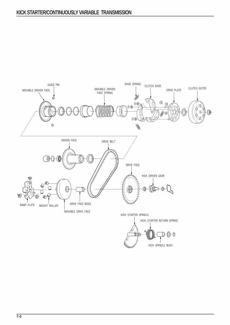
7-0
KICK STARTER/CONTINUOUSLY VARIABLE TRANSMISSION
MOVABLE DRIVEN FACE
GUIDE PIN
DRIVEN FACE
RAMP PLATE WEIGHT ROLLER
MOVABLE DRIVE FACE
DRIVE FACE BOSS
DRIVE FACE
KICK STARTER SPINDLE
KICK DRIVEN GEAR
KICK STARTER RETURN SPRING
KICK SPINDLE BUSH
DRIVE BELT
MOVABLE DRIVENFACE SPRING
SHOE SPRINGCLUTCH SHOE
DRIVE PLATECLUTCH OUTER
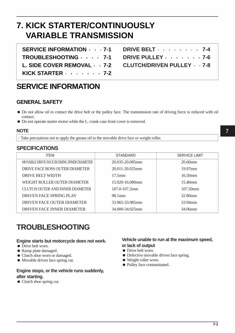
7-1
7. KICK STARTER/CONTINUOUSLYVARIABLE TRANSMISSION
SERVICE INFORMATION
GENERAL SAFETY
Do not allow oil to contact the drive belt or the pulley face. The transmission rate of driving force is reduced with oilcontact.
Do not operate starter motor while the L. crank case front cover is removed.
NOTE·Take precautions not to apply the grease oil to the movable drive face or weight roller.
SPECIFICATIONS
7
SERVICE INFORMATION 7-1TROUBLESHOOTING 7-1L. SIDE COVER REMOVAL 7-2KICK STARTER 7-2
ITEM STANDARD SERVICE LIMIT
MOVABLE DRIVE FACE BUSHING INNER DIAMETER 20.035-20.085mm 20.60mm
DRIVE FACE BOSS OUTER DIAMETER 20.011-20.025mm 19.97mm
DRIVE BELT WIDTH 17.5mm 16.50mm
WEIGHT ROLLER OUTER DIAMETER 15.920-16.080mm 15.40mm
CLUTCH OUTER AND INNER DIAMETER 107.0-107.2mm 107.50mm
DRIVEN FACE SPRING PLAY 98.1mm 32.80mm
DRIVEN FACE OUTER DIAMETER 33.965-33.985mm 33.94mm
DRIVEN FACE INNER DIAMETER 34.000-34.025mm 34.06mm
TROUBLESHOOTING
Engine starts but motorcycle does not work. Drive belt worn. Ramp plate damaged. Clutch shoe worn or damaged. Movable driven face spring cut.
Engine stops, or the vehicle runs suddenly,after starting. Clutch shoe spring cut.
Vehicle unable to run at the maximum speed,or lack of output Drive belt worn. Defective movable driven face spring. Weight roller worn. Pulley face contaminated.
DRIVE BELT 7-4DRIVE PULLEY 7-6CLUTCH/DRIVEN PULLEY 7-8

L. SIDE COVER REMOVAL Remove the 13 flange bolts securing L. side cover. Remove the rear brake cable clamp. Remove the L. side cover gasket. Remove the dowel pin. Install in the reverse order of removal.
NOTE·Install the new gasket and dowel pin after removing
the gasket of the crankcase surface.·Align the bolts to uniform the tightening location
before tightening then when you don’t know the boltlength.
·Tighten the bolts diagonally with specified tighteningtorque.TORQUE : 1.0kgf·m
KICK STARTER REMOVAL Remove the L. side cover. ( 7-2 ) Remove the kick starter ratchet and the thrust washer
while rotating the kick starter arm. Loosen the flange bolt securing the kick starter arm,
remve the kick starter arm. Remove the 14mm external circlip. Remove the kick spindle washer. Remove the kick starter spindle. Remove the kick spindle spring, bush.
INSPECTION Inspect wear and damage of the kick starter spindle and
gear portion. Inspect damage to return spring. Inspect defects and damage of the kick starter spindle
bushing. Inspect wear and damage of the kick starter ratchet. Inspect damage to friction spring.
7-2
KICK STARTER/CONTINUOUSLY VARIABLE TRANSMISSION
FLANGE BOLTL. SIDE COVER
KICK STARTER ARM
KICK DRIVEN GEARKICK STARTER SPINDLE
RETURN SPRING
KICK STARTER SPINDLE
KICK SPINDLE BUSH
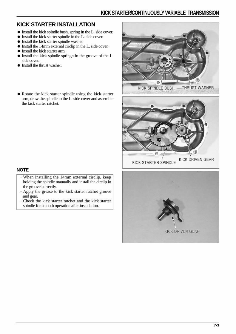
KICK STARTER INSTALLATION Install the kick spindle bush, spring in the L. side cover. Install the kick starter spindle in the L. side cover. Install the kick starter spindle washer. Install the 14mm external circlip in the L. side cover. Install the kick starter arm. Install the kick spindle springn in the groove of the L.
side cover. Install the thrust washer.
Rotate the kick starter spindle using the kick starterarm, draw the spindle to the L. side cover and assemblethe kick starter ratchet.
NOTE·When installing the 14mm external circlip, keep
holding the spindle manually and install the circlip inthe groove correctly.
·Apply the grease to the kick starter ratchet grooveand gear.
·Check the kick starter ratchet and the kick starterspindle for smooth operation after installation.
7-3
KICK STARTER/CONTINUOUSLY VARIABLE TRANSMISSION
THRUST WASHERKICK SPINDLE BUSH
KICK STARTER SPINDLEKICK DRIVEN GEAR
KICK DRIVEN GEAR

DRIVE BELT REMOVAL Remove the L. side cover. ( 7-2 ) Hold the clutch outer using the universal holder and
remove the nut. Remove the clutch outer.
TOOL: UNIVERSAL HOLDER
CAUTION·Use the special tool when loosening the lock nut.
Holding the rear wheel or rear brake will damage thefinal reduction system.
Squeeze the drive belt into the pulley groove as shownso that it slackens enough to remove the driven pulleyfrom the drive shaft.
Loosen the drive face setting nut 12mm with the clutchcenter holder.
TOOL: CLUTCH CENTER HOLDER
Remove the driven pulley/ clutch with the drive belt inplace.
Remove the drive belt from the driven pulley grooveand drive pulley groove.
7-4
KICK STARTER/CONTINUOUSLY VARIABLE TRANSMISSION
L. SIDE COVER
DRIVE FACE
DRIVE BELTDRIVEN PULLEY
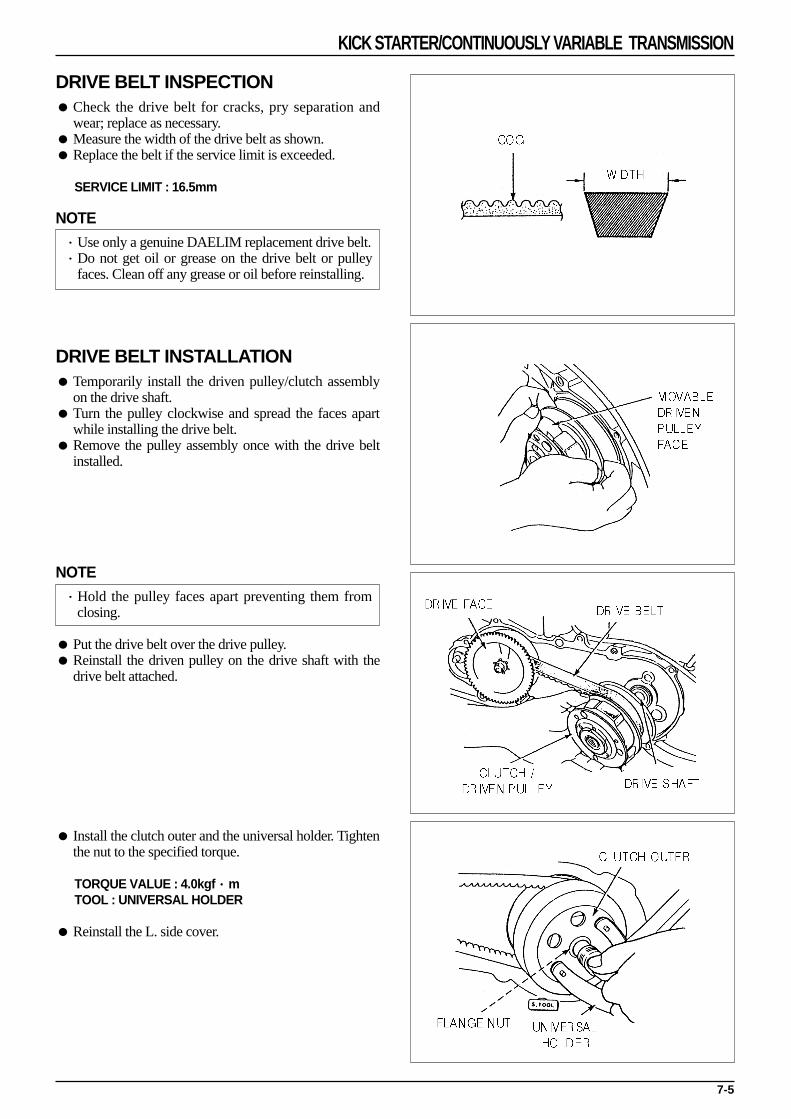
DRIVE BELT INSPECTION Check the drive belt for cracks, pry separation and
wear; replace as necessary. Measure the width of the drive belt as shown. Replace the belt if the service limit is exceeded.
SERVICE LIMIT : 16.5mm
NOTE·Use only a genuine DAELIM replacement drive belt.·Do not get oil or grease on the drive belt or pulley
faces. Clean off any grease or oil before reinstalling.
DRIVE BELT INSTALLATION Temporarily install the driven pulley/clutch assembly
on the drive shaft. Turn the pulley clockwise and spread the faces apart
while installing the drive belt. Remove the pulley assembly once with the drive belt
installed.
NOTE·Hold the pulley faces apart preventing them from
closing.
Put the drive belt over the drive pulley. Reinstall the driven pulley on the drive shaft with the
drive belt attached.
Install the clutch outer and the universal holder. Tightenthe nut to the specified torque.
TORQUE VALUE : 4.0kgf·mTOOL : UNIVERSAL HOLDER
Reinstall the L. side cover.
7-5
KICK STARTER/CONTINUOUSLY VARIABLE TRANSMISSION

DRIVE PULLEY REMOVAL Remove the L. side cover. (
7-2 ) Hold the drive face using the clutch center holder and
remove the nut and washer.
TOOL : CLUTCH CENTER HOLDER
Remove the drive face.
If the drive pulley holder cannot be used, remove thecooling fan at the right side of the crankshaft, and holdthe flywheel with the universal holder.
TOOL : UNIVERSAL HOLDER
MOVABLE DRIVE FACE DISASSEMBLY Remove the dirve face. (
7-6 ) Remove the drive belt. (
7-4 ) Remove the movable drive face.
Remove the ramp plate and weight rollers from themovable drive face.
7-6
KICK STARTER/CONTINUOUSLY VARIABLE TRANSMISSION
L. SIDE COVER
MOVABLE DRIVE FACE
RAMP PLATE
DRIVE FACE BOSS
WEIGHT ROLLER

MOVABLE DRIVE FACE INSPECTION The weight rollers push on the movable drive pulley
face (by centrifugal force); worn or damaged weightrollers will interfere with this force.
Check the rollers for wear or damage and replace asnecessary.
Measure the O.D. of each roller, replace if the servicelimit is exceeded.
SERVICE LIMIT : 15.4mm
Check the drive face boss for wear or damage andreplace as necessary.
Measure the O.D of the drive face boss. Replace theboss if the service limit is exceeded.
Measure the I.D. of the drive face. Replace it if theservice limit is exceeded.
Movable drive face boss outer diameter
SERVICE LIMIT : 19.97mm
Movable drive face inner diameter
SERVICE LIMIT : 20.6mm
MOVABLE DRIVE FACE ASSEMBLY/INSTALLATION Install the weight roller on the movable drive face. Install the ramp plate. Pack the inside of the movable drive face with the
specified amount of grease. Install the movable drive face boss.
NOTE·Do not get the grease on the pulley face. Remove any
misplaced grease with a degreasing agent.
Install the movable face assembly on the crankshaft.
7-7
KICK STARTER/CONTINUOUSLY VARIABLE TRANSMISSION
MOVABLE DRIVE FACE
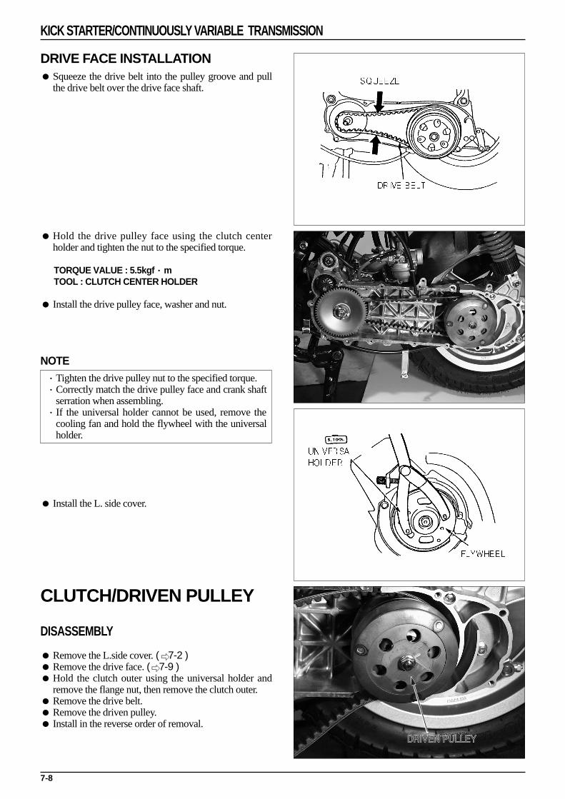
DRIVE FACE INSTALLATION Squeeze the drive belt into the pulley groove and pull
the drive belt over the drive face shaft.
Hold the drive pulley face using the clutch centerholder and tighten the nut to the specified torque.
TORQUE VALUE : 5.5kgf·mTOOL : CLUTCH CENTER HOLDER
Install the drive pulley face, washer and nut.
NOTE·Tighten the drive pulley nut to the specified torque.·Correctly match the drive pulley face and crank shaft
serration when assembling.·If the universal holder cannot be used, remove the
cooling fan and hold the flywheel with the universalholder.
Install the L. side cover.
CLUTCH/DRIVEN PULLEY
DISASSEMBLY
Remove the L.side cover. (
7-2 ) Remove the drive face. (
7-9 ) Hold the clutch outer using the universal holder and
remove the flange nut, then remove the clutch outer. Remove the drive belt. Remove the driven pulley. Install in the reverse order of removal.
7-8
KICK STARTER/CONTINUOUSLY VARIABLE TRANSMISSION
DRIVEN PULLEY

28mm SPECIAL NUT DISASSEMBLY
The clutch/driven face are assembled toward the clutchspring compressor.
CAUTION·Make sure that the boss portions of the clutch/driven
face are matched with the clutch spring compressorhole.
TOOL : CLUTCH SPRING COMPRESSOR
Fix the clutch spring compressor with a vice, etc. Disassemble the 28mm special nut with a socket
wrench. Disassemble the clutch driven face form theclutch spring compressor.
TOOL : CLUTCH SPRING COMPRESSORSOCKET WRENCH 39×41mm
Assembly is done in the reverse order of disassembly.
Remove the seal collar from the driven pulley. Remove the guide pins and guide pin rollers and the
movable driven pulley face.
NOTE·Some guide pin can be separated to the roller and the
pin.
Remove the O-ring and oil seals from the movabledriven face.
INSPECTION
Clutch outer
Measure the I.D. at shoe contact surface of the clutchouter. Replace the outer if the service limit is exceeded.
SERVICE LIMIT : 107.5mm
7-9
KICK STARTER/CONTINUOUSLY VARIABLE TRANSMISSION

Clutch Shoe Inspection
Measure the thickness of each shoe ; replace if theservice limit is exceeded.
SERVICE LIMIT : 2.0mm
Movable Driven Face Spring Inspection
Measure the free length of the driven pulley spring andreplace if the service limit is exceeded.
SERVICE LIMIT : 92.8mm
Driven Face Inspection Check the following;
-Both faces for damage or excessive wear.-Guide pin groove for damage or deformation.
Replace damaged or worn parts an necessary. Measure the O.D. of the driven face and the I.D. of the
movable driven face. Replace either part if the servicelimit is exceeded.
Driven face outer diameter service limit : 33.94mmMovable driven face inner diameter service limit : 34.06mm
Driven Face Bearing Inspection
Check the inner bearing oil seal (if installed) fordamage; replace as necessary.
Check the needle bearing for damage or excessive playand replace as necessary.
Turn the inner race of the outer bearing with yourfinger. Check that the bearing turns smoothly andquietly, and that the bearing outer race fits securely.Replace the bearing if necessary.
7-10
KICK STARTER/CONTINUOUSLY VARIABLE TRANSMISSION

CLUTCH SHOE REPLACEMENT
Remove the E-clip and washers, then remove theclutch shoes and shoe springs from the drive plate.
NOTE·Some models use one retainer plate instead of three
washers.
Check the shoe springs for damage or loss of tension.
Check the damper rubbers for damage or deformation;replace as necessary.
Apply a small amount of grease on the pivot pins.
Install new clutch shoes on the pivot pins and pushthem into place.
Use a small amount of grease on the pivot pin and keepgrease off of the brake shoes. Replace the brake shoesif there is any grease on them.
CAUTION·Grease or oil damages clutch shoes and can lead to a
loss of engaging ability.
Use pliers to hook the springs to the shoes.
7-11
KICK STARTER/CONTINUOUSLY VARIABLE TRANSMISSION

Install the E-clip and washers or retainer plate into thepivot pins.
NOTE·Apply only to the belt type gearless transmission.·Wipe the grease came out from the pivot pin
thoroughly.
DRIVEN FACE BEARING REPLACEMENT
Remove the inner bearing
NOTE·If the driven face has an oil seal at inner bearing side,
remove the oil seal first.·If a ball bearing is used oh the inside, remove the
snap ring first then remove the bearing.
Remove the snap ring then drive out the outer bearingtoward the inner bearing side.
Drive a new outer bearing into place with the sealedend toward the outside. Install the snap ring securely.
NOTE·Apply the specified amount of specified grease as
shown.GREASE APPLICATION : 5.0~5.5g
Install in a new inner bearing
NOTE·Install the bearing with the sealed side facing out.·Install the needle bearing using a hydraulic press.
Install the ball bearing by driving it in or using ahydraulic press.
Install the snap ring into the groove in the driven face. Install a new oil seal with the lip toward the bearing (if
required).
7-12
KICK STARTER/CONTINUOUSLY VARIABLE TRANSMISSION

CLUTCH/DRIVEN PULLEY ASSEMBLY Install new oil seals and O-rings on the movable driven
pulley face.
Lubricate the inside of the movable face with thespecified amount of grease.
GREASE APPLICATION : 5.0~5.5g
Install the movable face on the driven pulley face. Install the guide pins, or guide pins and guide pin
rollers.
Install the seal collar.
Assemble the driven pulley, spring and clutch in theclutch spring compressor. Compress the assembly byturning the tool handle until the lock nut can beinstalled.
Clamp the clutch spring compressor in a vise andtighten the lock nut to the specified torque using thelock nut wrench.
TORQUE VALUE : 4.0kgf·m
Remove the spring compressor. Install the clutch/driven pulley and drive belt onto the
dirve shaft.
TOOL : CLUTCH SPRING COMPRESSORSOKET WRENCH 39mm
7-13
KICK STARTER/CONTINUOUSLY VARIABLE TRANSMISSION

8-0
CYLINDER HEAD/CYLINDER/PISTON
CYLINDER HEAD BOLT
CYLINDER HEAD
CYLINDER HEAD GASKET
TOP RING
SECOND RING
EXPANDER
STOPPER PIN
PISTON PIN
NEEDLE BEARING
CYLINDER GASKET
PISTON CLIP
CYLINDER

8-1
8. CYLINDER HEAD/CYLINDER/PISTON
SERVICE INFORMATION
GENERAL SAFETY Take precautions not to damage the joint part with a driver when removing the cylinder, or not to damage the cooling
pin by striking the cylinder too hard. Take precautions not to damage the inside of the cylinder or the exterior part of the piston. Check parts after disassembling, and clean and dry with an air hose prior to taking measurements.
SPECIFICATIONS
TROUBLESHOOTING
Comperssion low Worn cylinder or piston rings Leaking valve seats
Excessive smoke Worn cylinder or piston Improper installation of piston rings Scored or scratched piston or cylinder wall
Overheating Excessive carbon build-up on the piston combustion Incorrect spark plug
Knocking or abnormal noise Worn piston and cylinder Excessive carbon build-up Low octane fuel
8
SERVICES INFORMATION 8-1TROUBLESHOOTING 8-1FAN COVER, SHROUD REMOVAL 8-2CYLINDER HEAD/ CYLINDER/ PISTON 8-3
ITEM
CYLINDER
PISTON,
PISTON PIN,
PISTON RING
CYLINDER TO PISTON CLEARANCE
STANDARD VALUE SERVICE LIMIT
Inner diameter 39.000-39.005mm 39.05mm
Cylindricality - 0.10mm
Out of roundness - 0.10mm
Piston skirt outer diameter 38.955-38.970mm 38.90mm
Piston pin hole inner diameter 12.002-12.008mm 12.03mm
Piston pin outer diameter 11.994-12.000mm 11.98mm
0.002-0.014mm 0.03mm
Unit : mm(in)
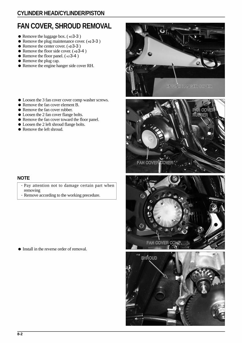
8-2
CYLINDER HEAD/CYLINDER/PISTON
ENGINE HANGER COVER
FAN COVER COVER
FAN COVER RUBBER
FAN COVER COMP.
SHROUD
FAN COVER, SHROUD REMOVALRemove the luggage box. ( 3-3 ) Remove the plug maintenance cover. ( 3-3 ) Remove the center cover. ( 3-3 ) Remove the floor side cover. ( 3-4 ) Remove the floor panel. ( 3-4 ) Remove the plug cap. Remove the engine hanger side cover RH.
Loosen the 3 fan cover cover comp washer screws. Remove the fan cover element B. Remove the fan cover rubber. Loosen the 2 fan cover flange bolts. Remove the fan cover toward the floor panel. Loosen the 2 left shroud flange bolts. Remove the left shroud.
NOTE·Pay attention not to damage certain part when
removing·Remove according to the working precedure.
Install in the reverse order of removal.
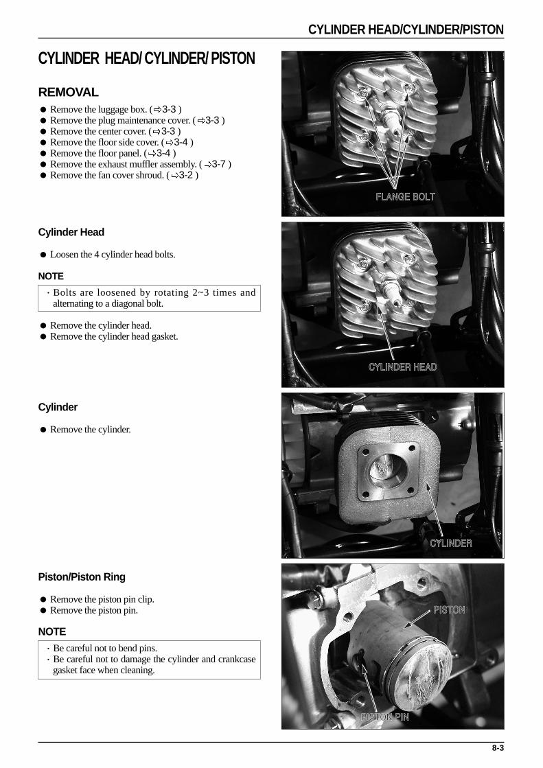
8-3
CYLINDER HEAD/CYLINDER/PISTON
FLANGE BOLT
CYLINDER HEAD
CYLINDER
PISTON PIN
PISTON
CYLINDER HEAD/ CYLINDER/ PISTON
REMOVAL Remove the luggage box. ( 3-3 ) Remove the plug maintenance cover. ( 3-3 ) Remove the center cover. ( 3-3 ) Remove the floor side cover. ( 3-4 ) Remove the floor panel. ( 3-4 ) Remove the exhaust muffler assembly. ( 3-7 ) Remove the fan cover shroud. ( 3-2 )
Cylinder Head
Loosen the 4 cylinder head bolts.
NOTE
·Bolts are loosened by rotating 2~3 times andalternating to a diagonal bolt.
Remove the cylinder head. Remove the cylinder head gasket.
Cylinder
Remove the cylinder.
Piston/Piston Ring
Remove the piston pin clip. Remove the piston pin.
NOTE·Be careful not to bend pins.·Be careful not to damage the cylinder and crankcase
gasket face when cleaning.
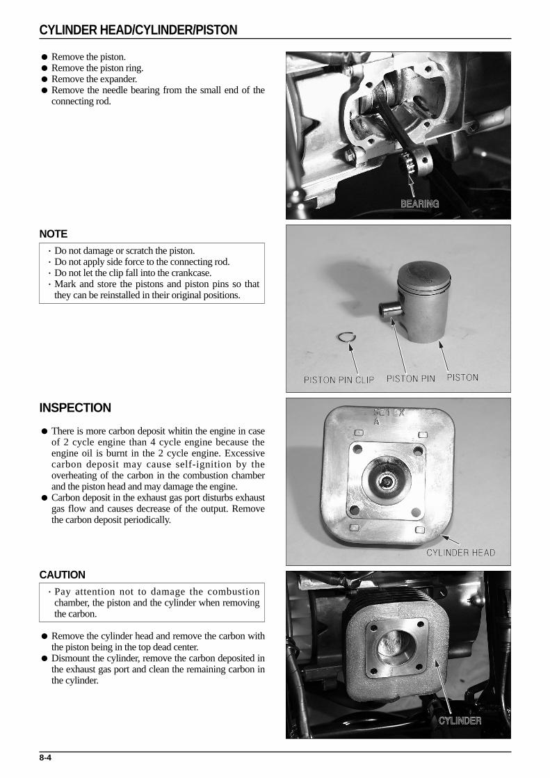
8-4
CYLINDER HEAD/CYLINDER/PISTON
BEARING
PISTON PIN CLIP PISTONPISTON PIN
CYLINDER HEAD
CYLINDER
Remove the piston. Remove the piston ring. Remove the expander. Remove the needle bearing from the small end of the
connecting rod.
NOTE·Do not damage or scratch the piston.·Do not apply side force to the connecting rod.·Do not let the clip fall into the crankcase.·Mark and store the pistons and piston pins so that
they can be reinstalled in their original positions.
INSPECTION
There is more carbon deposit whitin the engine in caseof 2 cycle engine than 4 cycle engine because theengine oil is burnt in the 2 cycle engine. Excessivecarbon deposit may cause self-ignition by theoverheating of the carbon in the combustion chamberand the piston head and may damage the engine.
Carbon deposit in the exhaust gas port disturbs exhaustgas flow and causes decrease of the output. Removethe carbon deposit periodically.
CAUTION·Pay attention not to damage the combustion
chamber, the piston and the cylinder when removingthe carbon.
Remove the cylinder head and remove the carbon withthe piston being in the top dead center.
Dismount the cylinder, remove the carbon deposited inthe exhaust gas port and clean the remaining carbon inthe cylinder.

8-5
CYLINDER HEAD/CYLINDER/PISTON
Cylinder Wear Inspection Inspect the cylinder wall for scratches and wear.
NOTE
·Inspect the area near T.D.C (Top Dend Center)carefully. This area is especially subject to wear dueto the possibility of borderline lubrication fro heatand top ring compression.
Measure and record the cylinder I.D. at the three levelsin both an X and Y axis.
Take the maximum reading to determine the cylinderwear.
NOTE
·Avoid the intake and exhaust ports when measuring.
Measure the piston O.D.
SERVICE LIMIT : 39.05mm
Calculate the piston-to-cylinder clearance. Take themaximum reading to detemine the clearance.
Piston Outer Diameter Inspection
Measure and record the piston O.D. 90。to the pistonpin bore and at the point specified in the ModelSpectific manual, near the bottom of the piston skirt.
Replace the piston if the service limit is exceeded.
SERVICE LIMIT : 38.90mm
Calculate the piston-to-cylinder clearance
Install the needle bearing and piston pin in theconnecting rod small end and check for excessive play.
If the piston pin I.D. is over the service limit, thecrankshaft must be replaced. Measure the I.D. of theconnecting rod small end.

8-6
CYLINDER HEAD/CYLINDER/PISTON
Piston Pin Inspection
Measure the piston pin O.D. at three points. Replace the piston pin if the service limit is exceeded.
SERVICE LIMIT : 11.98mm
Piston Pin Bore Inspection
Measure the piston pin bore I.D. in an X and Y axis.Take the maximum reading to determine the I.D.
Replace the piston if the I.D. is over the service limit.
SERVICE LIMIT : 12.03mm
PISTON/PISTON RING INSTALLATION
Clean the piston ring grooves. Lubricate the piston rings and ring grooves with clean
2-stroke oil. Install the piston rings on the piston with the marks
facing up.
NOTE
·Do not confuse the top and second rings. Be sure toinstall them in the proper grooves.
·Some 2-stroke engines use an expander ring behindthe second ring.
In 2-stroke engines, theh piston has stopper pins thathold the piston rings away from the intake and exhaustports.
Align the piston ring end gaps with the stopper pins. Check the fit of each ring in tis groove by pressing the
ring into the groove. Make sure that it is flush with thepiston at several points around the ring.
If the ring rides on the stopper pin, it is damaged duringassembly.
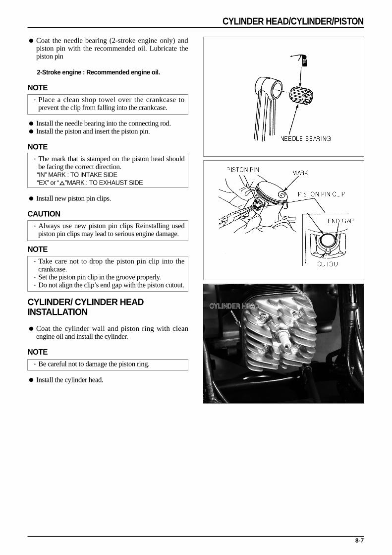
8-7
CYLINDER HEAD/CYLINDER/PISTON
CYLINDER HEAD
Coat the needle bearing (2-stroke engine only) andpiston pin with the recommended oil. Lubricate thepiston pin
2-Stroke engine : Recommended engine oil.
NOTE·Place a clean shop towel over the crankcase to
prevent the clip from falling into the crankcase.
Install the needle bearing into the connecting rod. Install the piston and insert the piston pin.
NOTE·The mark that is stamped on the piston head should
be facing the correct direction.“IN” MARK : TO INTAKE SIDE“EX” or “”MARK : TO EXHAUST SIDE
Install new piston pin clips.
CAUTION·Always use new piston pin clips Reinstalling used
piston pin clips may lead to serious engine damage.
NOTE·Take care not to drop the piston pin clip into the
crankcase.·Set the piston pin clip in the groove properly.·Do not align the clip’s end gap with the piston cutout.
CYLINDER/ CYLINDER HEADINSTALLATION
Coat the cylinder wall and piston ring with cleanengine oil and install the cylinder.
NOTE·Be careful not to damage the piston ring.
Install the cylinder head.

9-0
TRANSMISSION/CRANKSHAFT/CRANKCASE
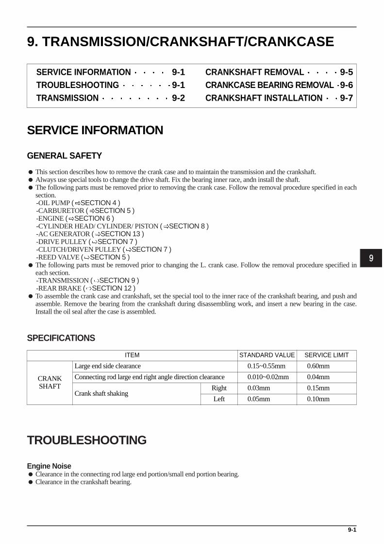
9-1
9. TRANSMISSION/CRANKSHAFT/CRANKCASE
SERVICE INFORMATION
GENERAL SAFETY
This section describes how to remove the crank case and to maintain the transmission and the crankshaft. Always use special tools to change the drive shaft. Fix the bearing inner race, andn install the shaft. The following parts must be removed prior to removing the crank case. Follow the removal procedure specified in each
section.-OIL PUMP ( SECTION 4 )-CARBURETOR ( SECTION 5 )-ENGINE ( SECTION 6 )-CYLINDER HEAD/ CYLINDER/ PISTON ( SECTION 8 )-AC GENERATOR ( SECTION 13 )-DRIVE PULLEY ( SECTION 7 )-CLUTCH/DRIVEN PULLEY ( SECTION 7 )-REED VALVE ( SECTION 5 )
The following parts must be removed prior to changing the L. crank case. Follow the removal procedure specified ineach section.-TRANSMISSION ( SECTION 9 )-REAR BRAKE ( SECTION 12 )
To assemble the crank case and crankshaft, set the special tool to the inner race of the crankshaft bearing, and push andassemble. Remove the bearing from the crankshaft during disassembling work, and insert a new bearing in the case.Install the oil seal after the case is assembled.
SPECIFICATIONS
TROUBLESHOOTING
Engine Noise Clearance in the connecting rod large end portion/small end portion bearing. Clearance in the crankshaft bearing.
9
SERVICE INFORMATION 9-1TROUBLESHOOTING 9-1TRANSMISSION 9-2
CRANKSHAFT REMOVAL 9-5CRANKCASE BEARING REMOVAL 9-6CRANKSHAFT INSTALLATION 9-7
0.15~0.55mm
0.010~0.02mm
0.03mm
0.05mm
0.60mm
0.04mm
0.15mm
0.10mm
ITEM
CRANKSHAFT
Large end side clearance
Connecting rod large end right angle direction clearance
Crank shaft shakingRight
Left
STANDARD VALUE SERVICE LIMIT

TRANSMISSION
DISASSEMBLY Remove the L. side cover. ( 7-2 )Remove the continuously variable transmission.
( SECTION 7 ) Remove the exhaust muffler. ( 3-7 ) Remove the rear wheel. ( 11-3) Install the oil sump under the cover of transmission. Loosen the 6 transmission cover flange bolts. Remove the transmission cover. Remove the mission cover guide ruber. Remove the drive shaft from the transmission cover by
using a hydraulic press.
NOTE·Take precautions not to damage the cover joints.
Remove the oil seal of the drive shaft.
Remove the final shaft gear. Remove the thrust washer. Remove the countershaft. Remove the counter shaft gear. Remove the side washer.
INSPECTION
Inspect the drive shaft for wear or damage.
9-2
TRANSMISSION/CRANKSHAFT/CRANKCASE

Inspect the final shaft for wear or damage.
Inspect the countershaft for wear or damage.
Bearing Inspection
Manually turn the bearing inner race installed insidethe transmission cover, and check if the race is turningsmoothly.
Verify the outer race is accurately installed in the case. Replace the bearing, if necessary.
NOTE·Install the bearing with the carved mark directing to
the outside.
Use special tools to push in the bearing into the case.
TOOLS : DRIVER HANDLE AOUTER DRIVER 52X55mmDRIVER PILOT 20mm
Check the L. crank case oil seal for wear or damage.
9-3
TRANSMISSION/CRANKSHAFT/CRANKCASE
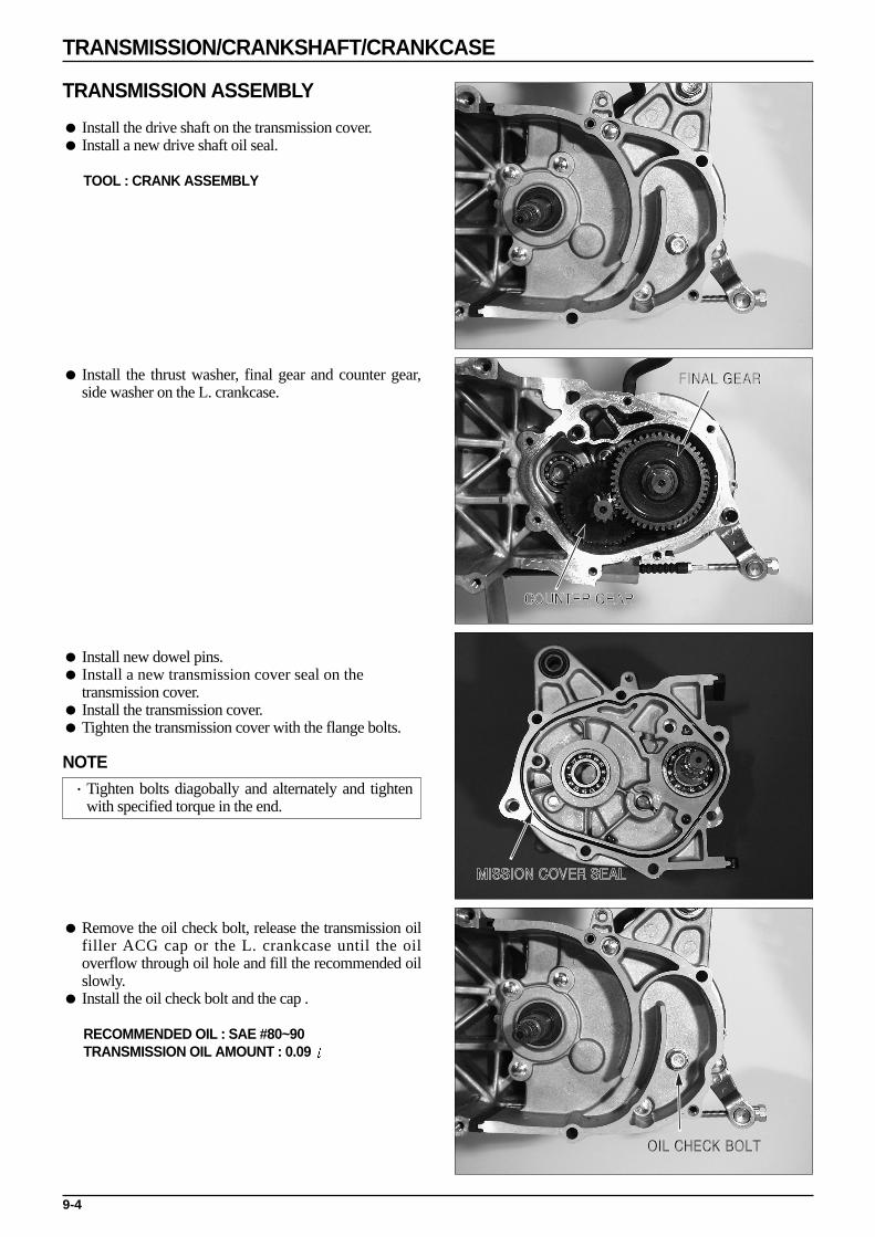
TRANSMISSION ASSEMBLY
Install the drive shaft on the transmission cover. Install a new drive shaft oil seal.
TOOL : CRANK ASSEMBLY
Install the thrust washer, final gear and counter gear,side washer on the L. crankcase.
Install new dowel pins. Install a new transmission cover seal on the
transmission cover. Install the transmission cover. Tighten the transmission cover with the flange bolts.
NOTE·Tighten bolts diagobally and alternately and tighten
with specified torque in the end.
Remove the oil check bolt, release the transmission oilfiller ACG cap or the L. crankcase until the oiloverflow through oil hole and fill the recommended oilslowly.
Install the oil check bolt and the cap .
RECOMMENDED OIL : SAE #80~90TRANSMISSION OIL AMOUNT : 0.09
9-4
TRANSMISSION/CRANKSHAFT/CRANKCASE

CRANKSHAFT REMOVAL Loosen the 6 R. crankcase flange bolts.
Secure a crankcase puller on the R. crankcase andremove the R. crankcase from the L. crankcase.
TOOL : CRANKCASE PULLER(0751-00003)
Secure a crankcase puller on the L. crankcase and removethe crankshaft from the L. crankcase.
NOTE·Be careful not to distort the mating surface of the
crank case during disassembly.·Do not force to disassemble by pounding on the
crankshaft.
TOOL : CRANKCASE PULLER(0751-00003)
Remove the oil seal from the R. and L. crankcases. Remove the dowel pin.
CRANKSHAFT BEARING REMOVAL If the radial ball bearing is left on the crankshaft,
remove the bearings out of the crankshaft using abearing puller.
TOOL : UNIVERSAL BEARING PULLER(0755-00001)
CRANKSHAFT INSPECTION
Place the crankshaft on a stand or V-block, and checkthe journal vibration.
SERVICE LIMIT : RIGHT SIDE 0.1mmLEFT SIDE 0.1mm
9-5
TRANSMISSION/CRANKSHAFT/CRANKCASE
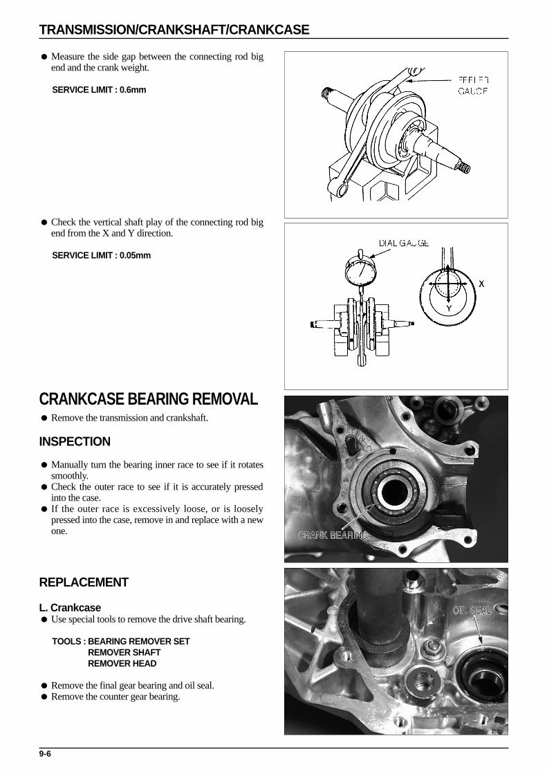
Measure the side gap between the connecting rod bigend and the crank weight.
SERVICE LIMIT : 0.6mm
Check the vertical shaft play of the connecting rod bigend from the X and Y direction.
SERVICE LIMIT : 0.05mm
CRANKCASE BEARING REMOVAL Remove the transmission and crankshaft.
INSPECTION
Manually turn the bearing inner race to see if it rotatessmoothly.
Check the outer race to see if it is accurately pressedinto the case.
If the outer race is excessively loose, or is looselypressed into the case, remove in and replace with a newone.
REPLACEMENT
L. Crankcase Use special tools to remove the drive shaft bearing.
TOOLS : BEARING REMOVER SETREMOVER SHAFTREMOVER HEAD
Remove the final gear bearing and oil seal. Remove the counter gear bearing.
9-6
TRANSMISSION/CRANKSHAFT/CRANKCASE
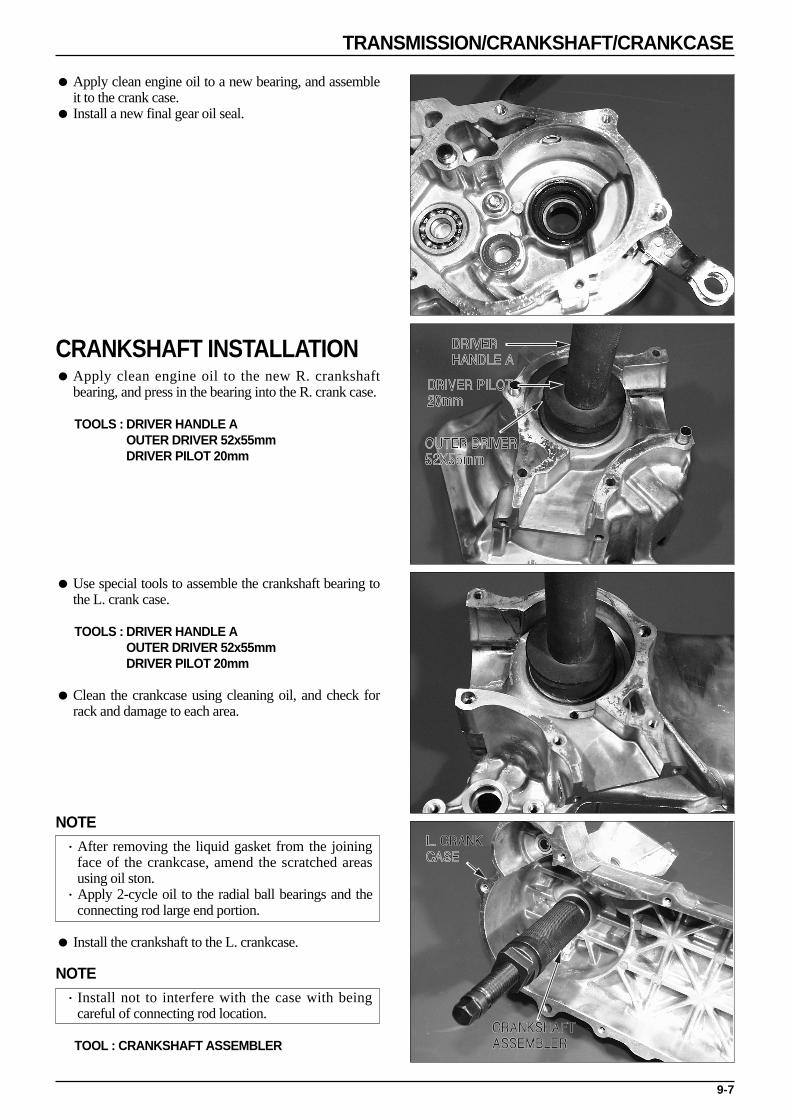
Apply clean engine oil to a new bearing, and assembleit to the crank case.
Install a new final gear oil seal.
CRANKSHAFT INSTALLATION Apply clean engine oil to the new R. crankshaft
bearing, and press in the bearing into the R. crank case.
TOOLS : DRIVER HANDLE AOUTER DRIVER 52x55mmDRIVER PILOT 20mm
Use special tools to assemble the crankshaft bearing tothe L. crank case.
TOOLS : DRIVER HANDLE AOUTER DRIVER 52x55mmDRIVER PILOT 20mm
Clean the crankcase using cleaning oil, and check forrack and damage to each area.
NOTE·After removing the liquid gasket from the joining
face of the crankcase, amend the scratched areasusing oil ston.
·Apply 2-cycle oil to the radial ball bearings and theconnecting rod large end portion.
Install the crankshaft to the L. crankcase.
NOTE·Install not to interfere with the case with being
careful of connecting rod location.
TOOL : CRANKSHAFT ASSEMBLER
9-7
TRANSMISSION/CRANKSHAFT/CRANKCASE
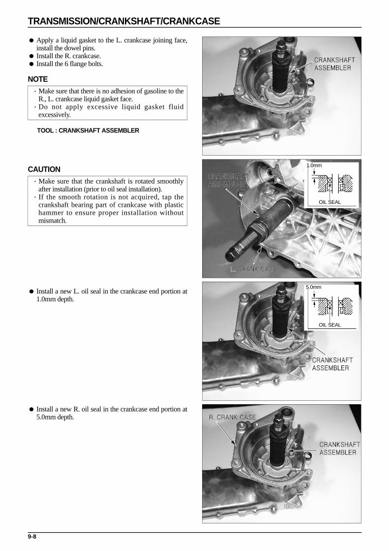
Apply a liquid gasket to the L. crankcase joining face,install the dowel pins.
Install the R. crankcase. Install the 6 flange bolts.
NOTE·Make sure that there is no adhesion of gasoline to the
R., L. crankcase liquid gasket face.·Do not apply excessive liquid gasket fluid
excessively.
TOOL : CRANKSHAFT ASSEMBLER
CAUTION·Make sure that the crankshaft is rotated smoothly
after installation (prior to oil seal installation). ·If the smooth rotation is not acquired, tap the
crankshaft bearing part of crankcase with plastichammer to ensure proper installation withoutmismatch.
Install a new L. oil seal in the crankcase end portion at1.0mm depth.
Install a new R. oil seal in the crankcase end portion at5.0mm depth.
9-8
TRANSMISSION/CRANKSHAFT/CRANKCASE
OIL SEAL
OIL SEAL
1.0mm
5.0mm

MEMO
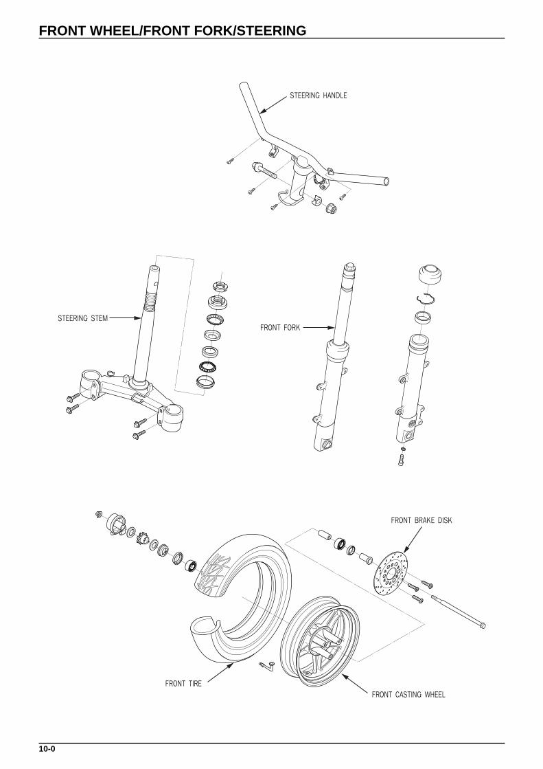
10-0
FRONT WHEEL/FRONT FORK/STEERING
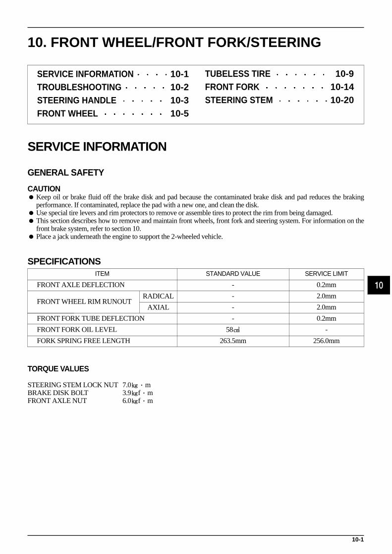
10-1
10. FRONT WHEEL/FRONT FORK/STEERING
SERVICE INFORMATION
GENERAL SAFETY
CAUTION Keep oil or brake fluid off the brake disk and pad because the contaminated brake disk and pad reduces the braking
performance. If contaminated, replace the pad with a new one, and clean the disk. Use special tire levers and rim protectors to remove or assemble tires to protect the rim from being damaged. This section describes how to remove and maintain front wheels, front fork and steering system. For information on the
front brake system, refer to section 10. Place a jack underneath the engine to support the 2-wheeled vehicle.
SPECIFICATIONS
TORQUE VALUES
STEERING STEM LOCK NUT 7.0·mBRAKE DISK BOLT 3.9f·mFRONT AXLE NUT 6.0f·m
10
SERVICE INFORMATION 10-1TROUBLESHOOTING 10-2STEERING HANDLE 10-3FRONT WHEEL 10-5
FRONT AXLE DEFLECTION - 0.2mm
FRONT WHEEL RIM RUNOUT- 2.0mm
- 2.0mm
FRONT FORK TUBE DEFLECTION - 0.2mm
FRONT FORK OIL LEVEL 58 -
FORK SPRING FREE LENGTH 263.5mm 256.0mm
RADICAL
AXIAL
ITEM STANDARD VALUE SERVICE LIMIT
TUBELESS TIRE 10-9FRONT FORK 10-14STEERING STEM 10-20

TROUBLESHOOTING
Hard steering Steering bearing adjustment nut too tight. Faulty steering stem bearings. Damaged steering stem bearings. Insufficient tire pressure.
Steers to one side or does not track straight Unevenly adjusted right and left shock absorbers. Bent front forks. Bent front axle : wheel installed incorrectly.
Front wheel wobbling Bent rim. Worn front wheel bearings. Faulty tire. Axle nut not tightened properly. Wheel out of balance.
Soft suspension Weak fork springs. Insufficient fluid in front forks.
Hard suspension Incorrect fluid weight in front forks. Front fork air pressure incorrect. Bent fork tubes. Clogged fluid passage. Clogged anti-dive orifice.
Front suspension noise Worn slider or guide bushings. Insufficient fluid in forks. Loose front fork fasteners. Lack of grease in speedometer gear box.
10-2
FRONT WHEEL/FRONT FORK/STEERING
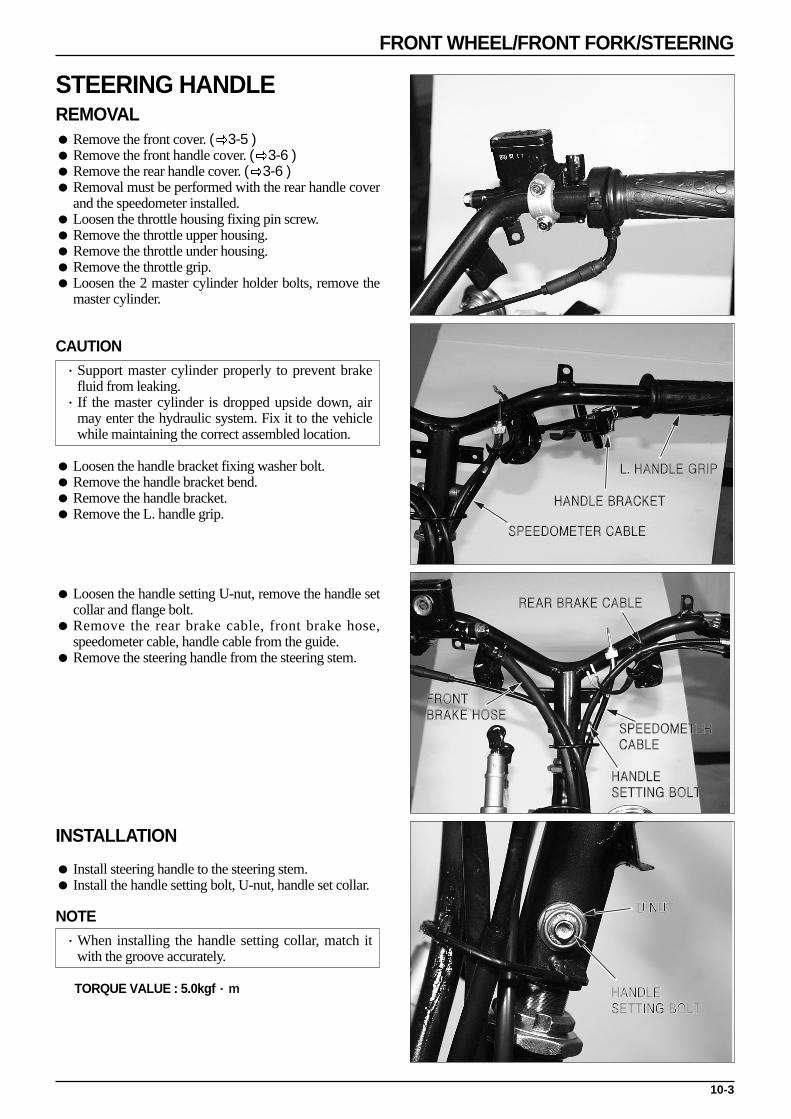
10-3
FRONT WHEEL/FRONT FORK/STEERING
STEERING HANDLEREMOVAL Remove the front cover. ( 3-5 ) Remove the front handle cover. ( 3-6 ) Remove the rear handle cover. ( 3-6 ) Removal must be performed with the rear handle cover
and the speedometer installed. Loosen the throttle housing fixing pin screw. Remove the throttle upper housing. Remove the throttle under housing. Remove the throttle grip. Loosen the 2 master cylinder holder bolts, remove the
master cylinder.
CAUTION·Support master cylinder properly to prevent brake
fluid from leaking.·If the master cylinder is dropped upside down, air
may enter the hydraulic system. Fix it to the vehiclewhile maintaining the correct assembled location.
Loosen the handle bracket fixing washer bolt. Remove the handle bracket bend. Remove the handle bracket. Remove the L. handle grip.
Loosen the handle setting U-nut, remove the handle setcollar and flange bolt.
Remove the rear brake cable, front brake hose,speedometer cable, handle cable from the guide.
Remove the steering handle from the steering stem.
INSTALLATION
Install steering handle to the steering stem. Install the handle setting bolt, U-nut, handle set collar.
NOTE·When installing the handle setting collar, match it
with the groove accurately.
TORQUE VALUE : 5.0kgf·m

10-4
FRONT WHEEL/FRONT FORK/STEERING
Install the rear brake cable, front brake hose,speedometer cable to the handle cable guide.
Apply DAELIM Bond A to the inside surface of thegrip and to the clean surface of the left handle bar. Wait3~6 minutes and install the grip.(Bond A :ROYAL BOND 1300)
NOTE·Clean the bonding surface to avoid oil, grease or
gasoline from attatching.·Leave it for minimum 1 hour until the bond is dried.·Use the bond according to the bond manual enclosed
and install the grip while rotating it before the bond isdried completely.
Align the positioning pin with the handle hole andinstall the L. handle bracket.
TORQUE : 1.2kgf·m
Clean the throttle grip surface, apply the grease andinstall the grip.
Connect the throttle cable to the groove of the grip. Tighten the pin screws after assembling the under and
upper throttle housings.
NOTE·Check the throttle grip for smooth operation and
adjust the free play to 2~6mm.
Match the master cylinder with the punch mark of thehandle, install it with the mark in the master cylinderholder facing upwards or front and tighten the rear orfront first.
NOTE·Check to see if the cylinder is passing each cable and
wire harness directly and make sure that there is anyinterference by rotating the handle to the right andleft.
Install the rear handle cover. ( 3-6 ) Install the front handle cover. ( 3-6 ) Install the front cover. ( 3-5 )

10-5
FRONT WHEEL/FRONT FORK/STEERING
FRONT WHEEL REMOVAL Remove screws from the speedometer gear box, and
separate the speedometer cable.
NOTE·Loosen axle nuts. Support bottom of engine with a
jack until the front wheel is lifted.
Loosen the axle nut. Remove the front axle. Remove the front wheel.
NOTE·Do not operate brake lever after the front wheel is
removed.
Remove the speedometer gear box.
INSPECTION
Check the front axle for deflection. Place the front axleon a V-block, and measure deflection with a dial gauge.
SERVICE LIMIT : 0.2mm
Place the front wheel on an inspection stand. Slowlyturn the wheel, and check the rim runout with a dialgauge.
SERVICE LIMIT : Radial 2.0mmAxial 2.0mm
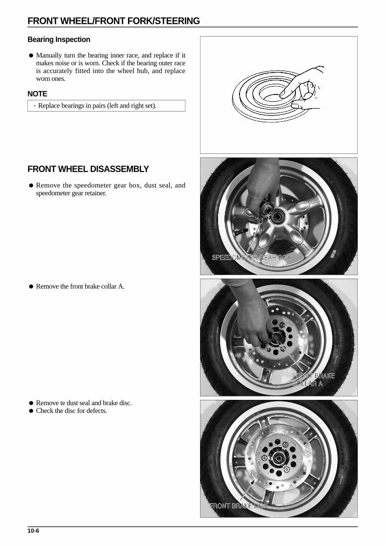
10-6
FRONT WHEEL/FRONT FORK/STEERING
Bearing Inspection
Manually turn the bearing inner race, and replace if itmakes noise or is worn. Check if the bearing outer raceis accurately fitted into the wheel hub, and replaceworn ones.
NOTE·Replace bearings in pairs (left and right set).
FRONT WHEEL DISASSEMBLY
Remove the speedometer gear box, dust seal, andspeedometer gear retainer.
Remove the front brake collar A.
Remove te dust seal and brake disc. Check the disc for defects.

10-7
FRONT WHEEL/FRONT FORK/STEERING
WHEEL BEARING REPLACEMENT
Install the bearing remover head and the remover shafton the wheel, and remove the bearing and distancecollar.
NOTE·Always replace bearings in pairs, and never use old
bearings.
TOOLS : BEARING REMOVER HEADBEARING REMOVER
Apply sufficient amount of grease to the bearing. Insert the right bearing with its seal surface facing
outside. Do not tilt the bearing. Insert accurately. Upon assembling the distance collar, insert the left
bearing with its seal surface facing outside.
TOOLS : DRIVERATTACHMENT, 32x35mmPILOT, 15mm
CAUTION·The bearing inserted in the last must be inserted until
it contacts with the distance collar.
·Excessively inserted bearing can cause damage theopposite side bearing.
SPEEDOMETER GEAR REPLACEMENT
Remove the speedometer gear and washer from thespeedometer gear box.
Check the gear for wear or damage. Install the washer. Apply grease to the speedometer gear prior to
assembling.

10-8
FRONT WHEEL/FRONT FORK/STEERING
FRONT WHEEL ASSEMBLY
Apply grease to the right side dust seal rim. Install the right side dust seal. Install the brake disk. Install disk bolts.
TORUE VALUE : 3.9kgf·m
Install the front brake collar A.
Align the wheel hub tangs with the slots of thespeedometer gear retainer, and assemble thespeedometer gear box seal.

10-9
FRONT WHEEL/FRONT FORK/STEERING
Apply grease to the dust seal rim. Install the dust seal, and align the tangs of the
speedometer gear retainer with the gear groove toassemble the speedometer gear box.
TUBELESS TIRE
REMOVAL
Remove the wheel.
NOTE·Single brake disk type : To prevent damage to the
disk, place the wheel on the level surface with thedisk facing up.
·Double brake disk type : Remove one disk first, thenplace the wheel on the level surface with the otherdisk facing up.
Remove the valve cap and bleed air by pressing thevalve core.
Remove the valve core after bleeding air completely. Remove the valve stem nut and push the valve stem
lightly. If a bead stopper is installed, loosen the lock nut and
push the bead stopper down. Collapse in the bead with a tire bead breaker. If no tire bead breaker is available, step on the side wall
to collapse the bead.
NOTE·Do not step on the rim.
Collapse the bead into the rim center and slide the tireout of position.
NOTE·Tire can be easily removed once the beads are
collapsed completely.
Apply a mild detergent solution to the rim and tiremating surfaces.
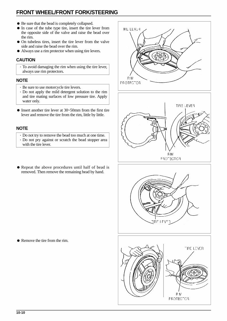
10-10
FRONT WHEEL/FRONT FORK/STEERING
Be sure that the bead is completely collapsed. In case of the tube type tire, insert the tire lever from
the opposite side of the valve and raise the bead overthe rim.
On tubeless tires, insert the tire lever from the valveside and raise the bead over the rim.
Always use a rim protector when using tire levers.
CAUTION·To avoid damaging the rim when using the tire lever,
always use rim protectors.
NOTE·Be sure to use motorcycle tire levers.·Do not apply the mild detergent solution to the rim
and tire mating surfaces of low pressure tire. Applywater only.
Insert another tire lever at 30~50mm from the first tirelever and remove the tire from the rim, little by little.
NOTE·Do not try to remove the bead too much at one time.·Do not pry against or scratch the bead stopper area
with the tire lever.
Repeat the above procedures until half of bead isremoved. Then remove the remaining bead by hand.
Remove the tire from the rim.
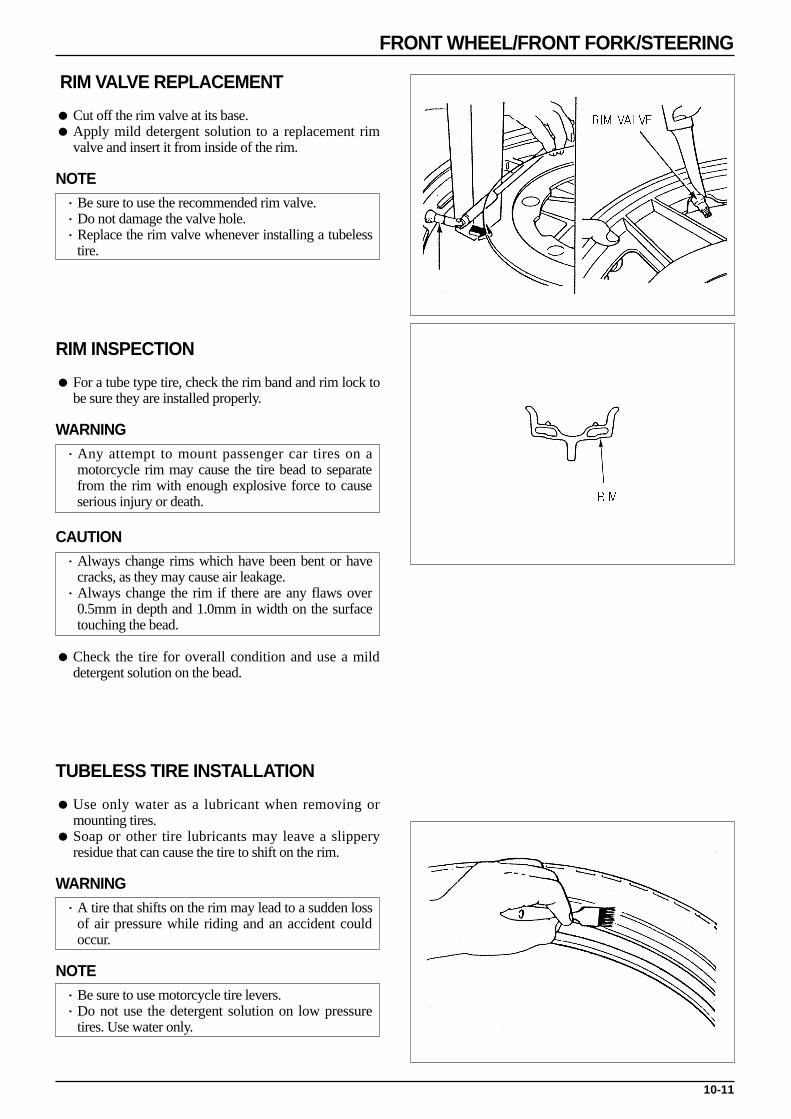
10-11
FRONT WHEEL/FRONT FORK/STEERING
RIM VALVE REPLACEMENT
Cut off the rim valve at its base. Apply mild detergent solution to a replacement rim
valve and insert it from inside of the rim.
NOTE·Be sure to use the recommended rim valve.·Do not damage the valve hole.·Replace the rim valve whenever installing a tubeless
tire.
RIM INSPECTION
For a tube type tire, check the rim band and rim lock tobe sure they are installed properly.
WARNING·Any attempt to mount passenger car tires on a
motorcycle rim may cause the tire bead to separatefrom the rim with enough explosive force to causeserious injury or death.
CAUTION·Always change rims which have been bent or have
cracks, as they may cause air leakage.·Always change the rim if there are any flaws over
0.5mm in depth and 1.0mm in width on the surfacetouching the bead.
Check the tire for overall condition and use a milddetergent solution on the bead.
TUBELESS TIRE INSTALLATION
Use only water as a lubricant when removing ormounting tires.
Soap or other tire lubricants may leave a slipperyresidue that can cause the tire to shift on the rim.
WARNING·A tire that shifts on the rim may lead to a sudden loss
of air pressure while riding and an accident couldoccur.
NOTE·Be sure to use motorcycle tire levers.·Do not use the detergent solution on low pressure
tires. Use water only.
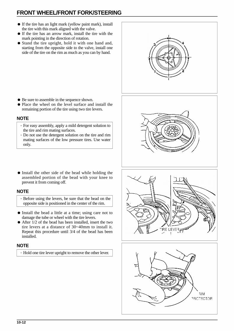
10-12
FRONT WHEEL/FRONT FORK/STEERING
If the tire has an light mark (yellow paint mark), installthe tire with this mark aligned with the valve.
If the tire has an arrow mark, install the tire with themark pointing in the direction of rotation.
Stand the tire upright, hold it with one hand and,starting from the opposite side to the valve, install oneside of the tire on the rim as much as you can by hand.
Be sure to assemble in the sequence shown. Place the wheel on the level surface and install the
remaining portion of the tire using two tire levers.
NOTE·For easy assembly, apply a mild detergent solution to
the tire and rim mating surfaces.·Do not use the detergent solution on the tire and rim
mating surfaces of the low pressure tires. Use wateronly.
Install the other side of the bead while holding theassembled portion of the bead with your knee toprevent it from coming off.
NOTE·Before using the levers, be sure that the bead on the
opposite side is positioned in the center of the rim.
Install the bead a little at a time; using care not todamage the tube or wheel with the tire levers.
After 1/2 of the bead has been installed, insert the twotire levers at a distance of 30~40mm to install it.Repeat this procedure until 3/4 of the bead has beeninstalled.
NOTE·Hold one tire lever upright to remove the other lever.
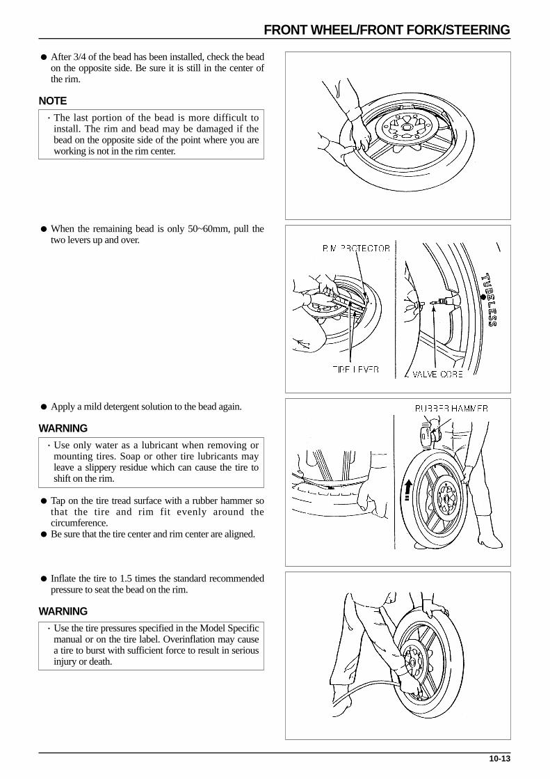
10-13
FRONT WHEEL/FRONT FORK/STEERING
After 3/4 of the bead has been installed, check the beadon the opposite side. Be sure it is still in the center ofthe rim.
NOTE·The last portion of the bead is more difficult to
install. The rim and bead may be damaged if thebead on the opposite side of the point where you areworking is not in the rim center.
When the remaining bead is only 50~60mm, pull thetwo levers up and over.
Apply a mild detergent solution to the bead again.
WARNING·Use only water as a lubricant when removing or
mounting tires. Soap or other tire lubricants mayleave a slippery residue which can cause the tire toshift on the rim.
Tap on the tire tread surface with a rubber hammer sothat the tire and rim fit evenly around thecircumference.
Be sure that the tire center and rim center are aligned.
Inflate the tire to 1.5 times the standard recommendedpressure to seat the bead on the rim.
WARNING·Use the tire pressures specified in the Model Specific
manual or on the tire label. Overinflation may causea tire to burst with sufficient force to result in seriousinjury or death.

10-14
FRONT WHEEL/FRONT FORK/STEERING
NOTE·For tubeless tires, you may hear a loud sound as the
bead seats onto the rim. This is normal.·For tubeless tires, if air leaks out from between the
rim and bead, let the wheel stand with the valve atthe bottom and put air in while pushing down on thetire.
Check that the tire bead seats on the tire rim securelyand the rim line of the tire is concentric with the rim.
Adjust the tire pressure to the specified pressure. Check the wheel balance.
FRONT WHEEL INSTALLATION
Insert the front wheel between the front forks. Insert the disk, taking precautions not to damage the
pad, and assemble the wheel. Align the slots of the speedometer gear with the tangs
of the left fork slider. Insert the front axle into the speedometer gear box and
the wheel hub.
Install the axle nut. Assemble the speedometer cable, and tighten with
screws. Place the front wheel on the ground, and tighten the
axle nut to the prescribed torque.
TORQUE VALUE : 6.0kgf·m
FRONT FORK REMOVAL
Remove the front cover. ( 3-5 ) Remove the front fender. ( 3-5 ) Remove the front brake caliper. ( 12-7 ) Remove the front wheel. ( 10-5 ) Loosen the front brake hose stay bolt, remove the L.
fork. Remove the speedometer cable from R. fork
speedometer cable guide. Loosen the R. fork securing bolt, remove the
speedometer cable and guide.
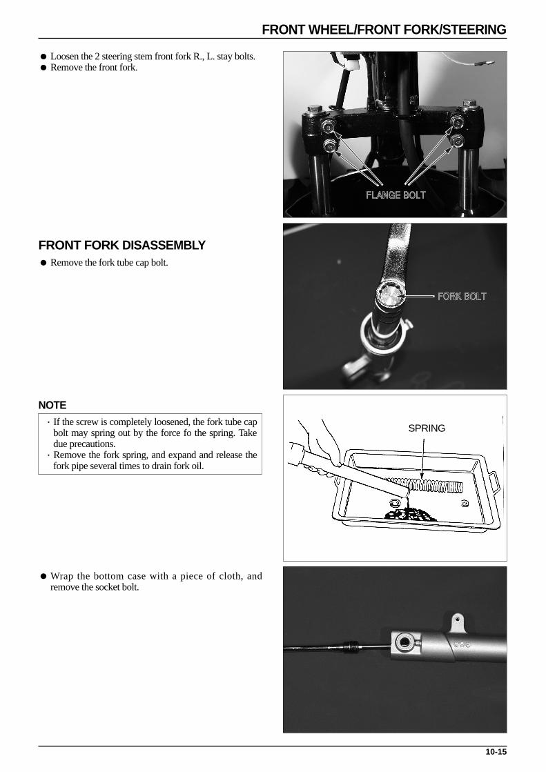
10-15
FRONT WHEEL/FRONT FORK/STEERING
Loosen the 2 steering stem front fork R., L. stay bolts. Remove the front fork.
FRONT FORK DISASSEMBLY Remove the fork tube cap bolt.
NOTE·If the screw is completely loosened, the fork tube cap
bolt may spring out by the force fo the spring. Takedue precautions.
·Remove the fork spring, and expand and release thefork pipe several times to drain fork oil.
Wrap the bottom case with a piece of cloth, andremove the socket bolt.
SPRING
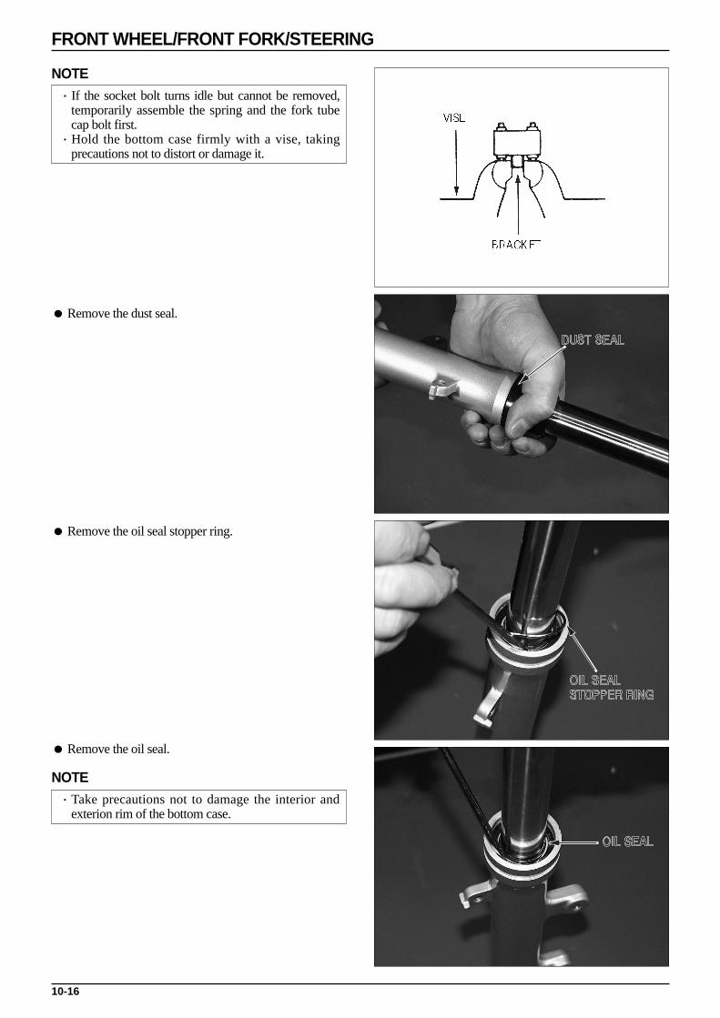
10-16
FRONT WHEEL/FRONT FORK/STEERING
NOTE·If the socket bolt turns idle but cannot be removed,
temporarily assemble the spring and the fork tubecap bolt first.
·Hold the bottom case firmly with a vise, takingprecautions not to distort or damage it.
Remove the dust seal.
Remove the oil seal stopper ring.
Remove the oil seal.
NOTE·Take precautions not to damage the interior and
exterion rim of the bottom case.

10-17
FRONT WHEEL/FRONT FORK/STEERING
Remove the fork tube from the bottom case. Remove the piston and rebound spring from the fork
tube.
FRONT FORK INSPECTION
Place the fork spring on a level place, and measure thefree length.
If the free length deviates from the service limit,replace the spring with a new one.
Check components for damage or abnormal wear.Replace defective parts with new ones.
SERVICE LIMIT : 256.0mm
Place the fork tube on a V-block, and measuredeflection with a dial gauge.
SERVICE LIMIT : Replace if the deflection is greaterthan 0.2mm
Check the slider bush contact face. If the slider bush is extensively damaged, replace the
bottom case.
FRONT FORK ASSEMBLY
Wash parts with clean oil prior to assembling. Assemble the rebound spring and thd fork piston to the
fork tube. Assemble the fork tube to the bottom case.

10-18
FRONT WHEEL/FRONT FORK/STEERING
Wrap the bottom case with a piece of cloth, and fix it tothe vise.
Apply screw locking agent to the socket bolt thread,and assemble the socket bolt to the fork piston.
TORQUE VALUE : 2.0kgf·m
NOTE·When a vise is used to hold the bottom case, do not
insert the case itself but insert the bracket.
Apply ATF to a new oil seal. Assemble the oil seal to the bottom case. Insert the oil seal with special tools until the attachment
groove of the bottom case set ring is exposed.
TOOLS : FORK SEAL DRIVERFORK SEAL DRIVER BODY
Install the set ring. Accurately assemble the set ring to the bottom case.
Install the dust seal. Fill a prescribed amount of automatic transmission
fluid(ATF) into the fork tube.
CAPACITY : 58cm3
Slowly press the fork tube 2-3 times to discharge air.
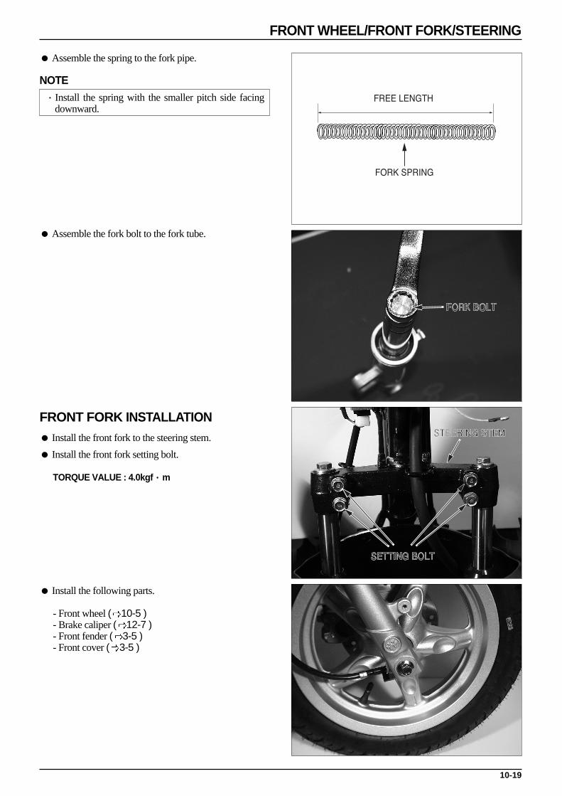
10-19
FRONT WHEEL/FRONT FORK/STEERING
Assemble the spring to the fork pipe.
NOTE·Install the spring with the smaller pitch side facing
downward.
Assemble the fork bolt to the fork tube.
FRONT FORK INSTALLATION Install the front fork to the steering stem.
Install the front fork setting bolt.
TORQUE VALUE : 4.0kgf·m
Install the following parts.
- Front wheel ( 10-5 )- Brake caliper ( 12-7 )- Front fender ( 3-5 )- Front cover ( 3-5 )

10-20
FRONT WHEEL/FRONT FORK/STEERING
STEERING STEM REMOVAL Front cover ( 3-5 ) Front fender ( 3-5 ) Front handle cover/rear handle cover ( 3-6 ) Steering handle ( 10-3 ) Front wheel ( 10-5 ) Front brake caliper ( 12-7 ) Front fork ( 10-14 )
Loosen the steering stem lock nut. Remove the speedometer cable and front brake hose
from the steering stem bracket. Loosen the steering top cone race. Remove the steering stem.
NOTE·Place steel ball in a pan to prevent from being lost.
Check the steel ball, cone race, and ball race for wearor damage. Replace worn or damaged ones.
Remove the steering steel ball/ upper steering ball race/steering bottom cone race.

10-21
FRONT WHEEL/FRONT FORK/STEERING
Remove the upper ball race/ steering bottom cone race.
TOOL : BALL RACE DRIVER
NOTE·Check all of the races and balls for damage or
abnormal wear and replace as necessary.·If the vehicle has been involved in a collision, the
steering stem may be damaged.
STEERING STEM INSTALLATION
Insert the upper/under ball race into the steering headpipe.
Using a steering stem driver, drive the steering stembottom cone race into the steering stem.
Insert the ball race after applying grease thereto.
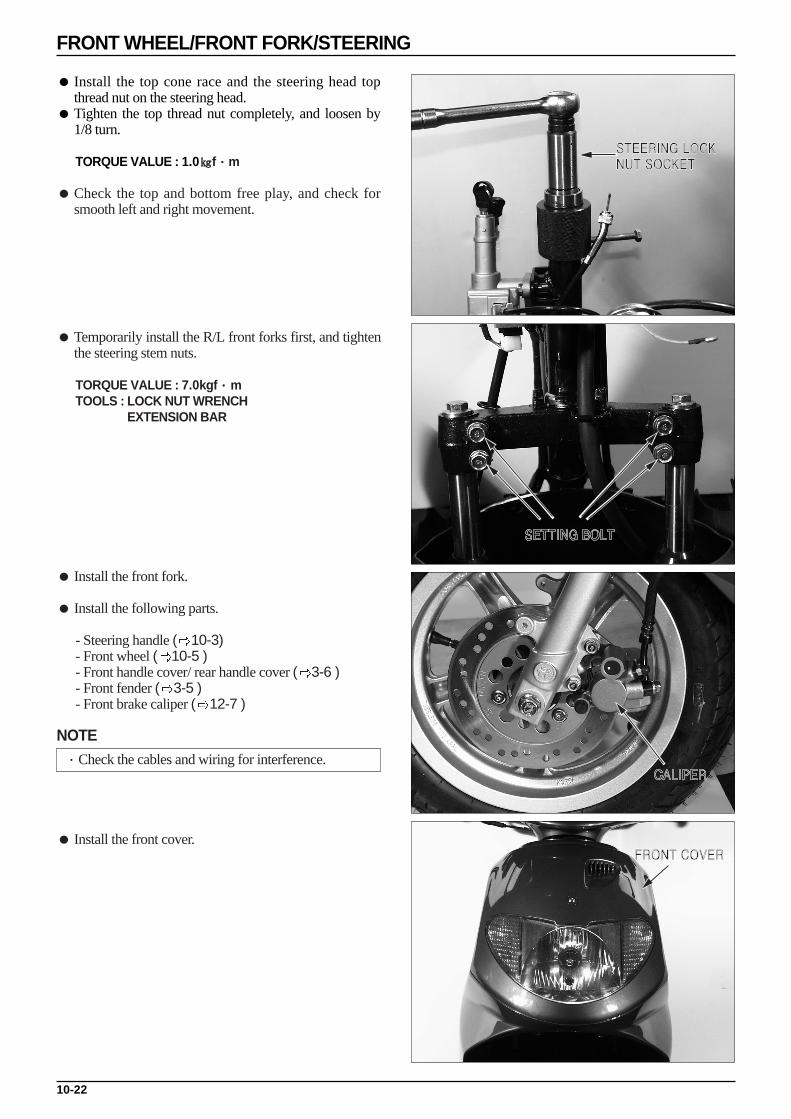
10-22
FRONT WHEEL/FRONT FORK/STEERING
Install the top cone race and the steering head topthread nut on the steering head.
Tighten the top thread nut completely, and loosen by1/8 turn.
TORQUE VALUE : 1.0f·m
Check the top and bottom free play, and check forsmooth left and right movement.
Temporarily install the R/L front forks first, and tightenthe steering stem nuts.
TORQUE VALUE : 7.0kgf·mTOOLS : LOCK NUT WRENCH
EXTENSION BAR
Install the front fork.
Install the following parts.
- Steering handle ( 10-3)- Front wheel ( 10-5 )- Front handle cover/ rear handle cover ( 3-6 )- Front fender ( 3-5 )- Front brake caliper ( 12-7 )
NOTE·Check the cables and wiring for interference.
Install the front cover.

11-1
11. REAR WHEEL/BRAKE/SUSPENSION
SERVICE INFORMATION
GENERAL SAFETY
If the brake drum or lining is contaminated with oil, braking power will be lost. If contaminated with oil, clean the brakedrum, and replace the brake shoe.
Inhaled asbestos fibers have been found to cause respiratory disease and cancer. Never use an air hose or dry brush to clean brake assemblies. Use a brake cleaner, designed to minimize the hazard caused by airborne asbestos fibers.
SPECIFICATIONS
TORQUE VALUES :
AXLE SHAFT RUN OUT 10.0~12.0f·mREAR CUSHION UPPER BOLT 3.5~4.5f·mREAR CUSHION LOWER BOLT 3.5~4.5f·m
11
SERVICE INFORMATION 11-1
TROUBLESHOOTING 11-2
REAR WHEEL 11-3
ITEM STANDARD VALUE SERVICE LIMIT
AXLE SHAFT RUN OUT - 0.2 mm
REAR WHEEL RIM RUNOUT- 2.0 mm
- 2.0 mm
REAR BRAKE DRUM INNER DIAMETER 110.0~110.3mm 111.0mm
REAR BRAKE LINING THICKNESS 4.0 mm 2.0 mm
REAR CUSHION SPRING FREE LENGTH 234.8mm 228.0mm
RADICAL
AXIAL
REAR BRAKE 11-4
REAR CUSHION 11-6

TROUBLESHOOTING
Wobble or vibration in motorcycle Tire pressure incorrect Faulty tire Bent rim Loose wheel bearing Swing arm bushing worn Wheel out of balance
Soft suspension Weak springs Rear damper improperly adjusted, oil leakage
Hard suspension Rear damper improperly adjusted Bent shock absorber rod
Suspension noise Loose fasteners Worn shock
11-2
REAR WHEEL/BRAKE/SUSPENSION

REAR WHEEL REMOVAL Support the motor cycle on the main stand. Loosen the rear brake adjuster, and remove the brake
cable. Remove the brake arm joint B.
Remove the muffler. ( 3-7 ) Remove the rear wheel mud guard. Loosen the rear wheel U nut. Remove the washer. Remove the rear wheel.
INSPECTION
Turn the wheel, and check the rim for wobbles.
SERVICE LIMIT : Radical 2.0mmAxial 2.0mm
INSTALLATION
Insert the rear wheel over the final shaft.
11-3
REAR WHEEL/BRAKE/SUSPENSION
ADJUST NUTBRAKE ARM JOINT B
REAR WHEEL
U NUT
DIAL GUAGE
FINAL SHAFT
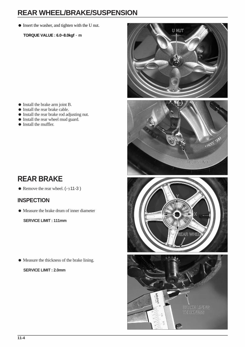
Insert the washer, and tighten with the U nut.
TORQUE VALUE : 6.0~8.0kgf·m
Install the brake arm joint B. Install the rear brake cable. Install the rear brake rod adjusting nut. Install the rear wheel mud guard. Install the muffler.
REAR BRAKE Remove the rear wheel. ( 11-3 )
INSPECTION
Measure the brake drum of inner diameter
SERVICE LIMIT : 111mm
Measure the thickness of the brake lining.
SERVICE LIMIT : 2.0mm
11-4
REAR WHEEL/BRAKE/SUSPENSION
U NUT
ADJUST NUT
REAR WHEEL
X
Y
BRAKE LINING THICKNESS
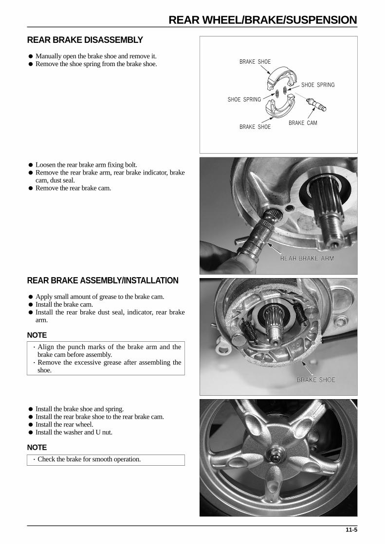
REAR BRAKE DISASSEMBLY
Manually open the brake shoe and remove it. Remove the shoe spring from the brake shoe.
Loosen the rear brake arm fixing bolt. Remove the rear brake arm, rear brake indicator, brake
cam, dust seal. Remove the rear brake cam.
REAR BRAKE ASSEMBLY/INSTALLATION
Apply small amount of grease to the brake cam. Install the brake cam. Install the rear brake dust seal, indicator, rear brake
arm.
NOTE·Align the punch marks of the brake arm and the
brake cam before assembly.·Remove the excessive grease after assembling the
shoe.
Install the brake shoe and spring. Install the rear brake shoe to the rear brake cam. Install the rear wheel. Install the washer and U nut.
NOTE·Check the brake for smooth operation.
11-5
REAR WHEEL/BRAKE/SUSPENSION
BRAKE SHOE
BRAKE SHOEBRAKE CAM
SHOE SPRING
SHOE SPRING
REAR BRAKE ARM
BRAKE SHOE
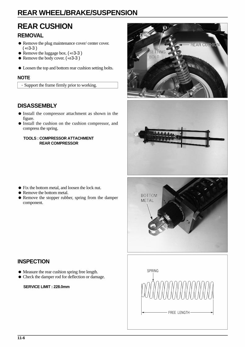
REAR CUSHION REMOVAL Remove the plug maintenance cover/ center cover.
( 3-3 ) Remove the luggage box. ( 3-3 ) Remove the body cover. ( 3-3 )
Loosen the top and bottom rear cushion setting bolts.
NOTE·Support the frame firmly prior to working.
DISASSEMBLY Install the compressor attachment as shown in the
figure. Install the cushion on the cushion compressor, and
compress the spring.
TOOLS : COMPRESSOR ATTACHMENTREAR COMPRESSOR
Fix the bottom metal, and loosen the lock nut. Remove the bottom metal. Remove the stopper rubber, spring from the damper
component.
INSPECTION
Measure the rear cushion spring free length. Check the damper rod for deflection or damage.
SERVICE LIMIT : 228.0mm
11-6
REAR WHEEL/BRAKE/SUSPENSION
REAR CUSHION
SETTINGBOLT
BOTTOM METAL
FREE LENGTH
SPRING

REAR CUSHION ASSEMBLY/INSTALLATION
Assemble the spring, spring guide, and stopper rubber.
NOTE·Install the spring with its narrow pitch side facing
upward
Apply thread locking agent to the lock nut, and installthe rear cushion compressor attachment on the damperrod.
Fix the upper joint, and tighten the lock nut.
TORQUE VALUE : 4.0kgf·mTOOLS : REAR CUSHION COMPRESSOR
REAR CUSHION COMPRESSOR ATTACHMENT
Install the rear cushion. Tighten the top and bottom of the cushion with bolt.
TORQUE VALUE : UPPER SIDE 3.5kgf·mLOWER SIDE 3.5kgf·m
11-7
REAR WHEEL/BRAKE/SUSPENSION
REAR CUSHION

BRAKE SYSTEM
12-0

12-1
12. BRAKE SYSTEM
HYDRAULIC DISK BRAKE
Braking power unsatisfactory Air in the brake system. Moisture in brake fluid Brake pad and disk contaminated. Caliper piston seal worn Master cylinder piston seal worn Brake pad worn Caliper inside contaminated Unsatisfactory caliper sliding part operation Lopsided wear of brake pad and disk Low brake fluid level Clogged brake fluid line Disk bent or distorted Caliper piston seized or worn Master cylinder piston seized or worn Disk worn Master cylinder inside contaminated Brake lever bent
Hard brake lever movement or unsatisfactoryreturn Brake system clogged Caliper piston seized or worn Unsatisfactory caliper sliding part operation Brake fluid line clogged Caliper piston seal worn Master cylinder piston seized or worn Brake lever bent
Brake drag Brake pad and disk contaminated Improper wheel alignment Lopsided wear of brake pad and disk Disk bent or distorted Unsatisfactory caliper sliding part operation Hydraulic system contaminated with dust.
SERVICE INFORMATION
GENERAL SAFETY
Do not allow foreign material to enter the system when replenishing brake fluid. To prevent chemical changes, do not mix different types of brake fluid. Do not use the old brake fluid again. Brake fluid can cause damage to painted, plastic, and rubber surfaces. Take precaution not to allow parts to be
contaminated by the brake fluid. Do not reuse sealing washers. Clean the disassembled parts with brake fluid, and check for any clogged passage with compressed air. Bleed the brake hose after removing it.
TROUBLESHOOTING
12
SERVICE INFORMATION 12-1TROUBLESHOOTING 12-1BRAKE FLUID/BLEEDING 12-3BRAKE PAD REPLACEMENT 12-4
BRAKE DISK INSPECTION 12-6BRAKE CALIPER 12-7MASTER CYLINDER 12-9

12-2
BRAKE SYSTEM
MECHANICAL DRUM BRAKE
Poor brake performance Improperly adjusted brake Worn brake linings Worn brake drum Worn brake cam Improperly installed brake linings Brake cable sticking/needs lubrication Contaminated brake linings Contaminated brake drum Worn brake shoes at cam contact areas Improper engagement between brake arm and camshaft serrations
Brake lever hard or slow to return Worn/broken return spring Improperly adjusted brake Sticking brake drum due to contamination Worn brake shoes at cam contact areas Brake cable sticking/needs lubrication Worn brake cam Improperly installed brake linings
Brake squeaks Worn brake linings Worn brake drum Contaminated brake linings Contaminated brake drum
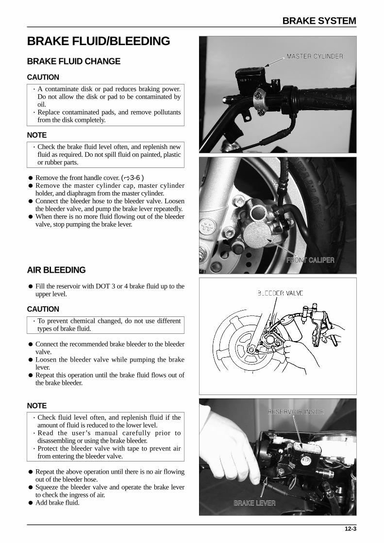
12-3
BRAKE SYSTEM
MASTER CYLINDER
FRONT CALIPER
BRAKE LEVER
RESERVOIR INSIDE
BRAKE FLUID/BLEEDING
BRAKE FLUID CHANGE
CAUTION·A contaminate disk or pad reduces braking power.
Do not allow the disk or pad to be contaminated byoil.
·Replace contaminated pads, and remove pollutantsfrom the disk completely.
NOTE·Check the brake fluid level often, and replenish new
fluid as required. Do not spill fluid on painted, plasticor rubber parts.
Remove the front handle cover. ( 3-6 ) Remove the master cylinder cap, master cylinder
holder, and diaphragm from the master cylinder. Connect the bleeder hose to the bleeder valve. Loosen
the bleeder valve, and pump the brake lever repeatedly. When there is no more fluid flowing out of the bleeder
valve, stop pumping the brake lever.
AIR BLEEDING
Fill the reservoir with DOT 3 or 4 brake fluid up to theupper level.
CAUTION·To prevent chemical changed, do not use different
types of brake fluid.
Connect the recommended brake bleeder to the bleedervalve.
Loosen the bleeder valve while pumping the brakelever.
Repeat this operation until the brake fluid flows out ofthe brake bleeder.
NOTE·Check fluid level often, and replenish fluid if the
amount of fluid is reduced to the lower level.·Read the user’s manual carefully prior to
disassembling or using the brake bleeder.·Protect the bleeder valve with tape to prevent air
from entering the bleeder valve.
Repeat the above operation until there is no air flowingout of the bleeder hose.
Squeeze the bleeder valve and operate the brake leverto check the ingress of air.
Add brake fluid.
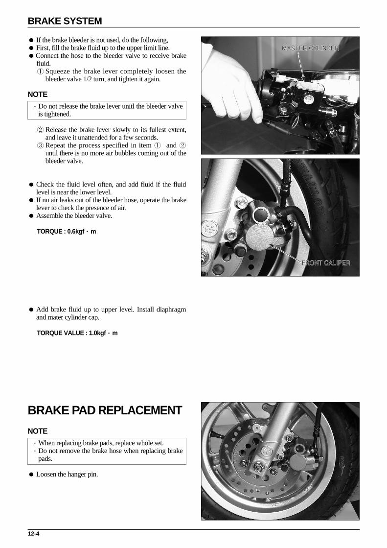
12-4
BRAKE SYSTEM
MASTER CYLINDER
FRONT CALIPER
If the brake bleeder is not used, do the following, First, fill the brake fluid up to the upper limit line. Connect the hose to the bleeder valve to receive brake
fluid.① Squeeze the brake lever completely loosen the
bleeder valve 1/2 turn, and tighten it again.
NOTE·Do not release the brake lever unitl the bleeder valve
is tightened.
② Release the brake lever slowly to its fullest extent,and leave it unattended for a few seconds.
③ Repeat the process specified in item ① and ②until there is no more air bubbles coming out of thebleeder valve.
Check the fluid level often, and add fluid if the fluidlevel is near the lower level.
If no air leaks out of the bleeder hose, operate the brakelever to check the presence of air.
Assemble the bleeder valve.
TORQUE : 0.6kgf·m
Add brake fluid up to upper level. Install diaphragmand mater cylinder cap.
TORQUE VALUE : 1.0kgf·m
BRAKE PAD REPLACEMENT
NOTE·When replacing brake pads, replace whole set.·Do not remove the brake hose when replacing brake
pads.
Loosen the hanger pin.
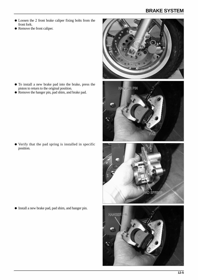
12-5
BRAKE SYSTEM
HANGER PIN
PAD
PAD SPRING
HANGER PIN
Loosen the 2 front brake caliper fixing bolts from thefront fork.
Remove the front caliper.
To install a new brake pad into the brake, press thepiston to return to the original position.
Remove the hanger pin, pad shim, and brake pad.
Verify that the pad spring is installed in specificposition.
Install a new brake pad, pad shim, and hanger pin.

12-6
BRAKE SYSTEM
HANGER PIN
BRAKE DISK
DIAL GAUGE
Install the brake caliper into the left front fork.
NOTE·Be careful not to damage the brake pad.
Tighten the caliper braket bolt.
TORQUE : 2.7kgf·m
Tighten the hanger pin.
BRAKE DISK INSPECTION
Measure the thickness of the disk.
SERVICE LIMIT : 3.0mm
NOTE·Measure the brake disk thickness at the several
points and replace if the smallest measurement is lessthen the specified service limit.
Check the brake disk for bent and twist.
SERVICE LIMIT : 0.4mm
NOTE·Replace the brake disk if the disk for damage or
cracks.

12-7
BRAKE SYSTEM
FRONT BRAKE CALIPER
OIL BOLT
OIL BOLT
BRAKE HOSE
AIR GUN
CALIPER
PISTON SEAL
DUST SEAL
BRAKE CALIPER
REMOVAL
Remove the brake oil bolts and the brake hose from thebrake caliper.
Remove the caliper from the L. front fork and removethe pad spring, hanger pin and brake pad.
CAUTION·Pay attention not to let the brake fluid adhere to the
parts because it can damage the painted surface.·Wind the hose joint with cloth to prevent the brake
fluid from leaking.·Clean the removed parts with the brake fluid and
make sure that the each port isn’t clogged with thecompressed air.
·Keep the removed parts in order to avoid dust fromadhering.
DISASSEMBLY
Remove the slide pin, the L. bracket, the pin bush, theboot and the pin boot, and the pin bolt from the caliper.
If there is any wear or damage in the boot, replace itwith the new one.
Wind the caliper with cloth to prevent the piston orbrake fluid from leaking.
Remove the piston from the caliper while blowing thelow-pressure air in the opening of the brake hose.
CAUTION·Never use the high-pressure air or bring the air gun
too close.·Never touch the inside of the caliper
Disassemble the piston seal and the dust seal
NOTE·Pay attention not to damage the inner surface of the
caliper.
Clean the piston and the inside of the caliper andremove the oil from the seal groove.

12-8
BRAKE SYSTEM
CALIPER
CYLINDER GAUGE
PISTONDUST SEAL
SLIDE PIN
PIN BUSH
LH. BRACKET
PAD SPRING
PISTON SEAL
BRAKE CALIPER INSPECTION
Caliper Cylinder
Check the caliper cylinder bore for scoring, scratchesor other damage.
Measure the caliper cylinder I.D. in X and Y axis atserveral points.
Replace the caliper cylinder if the largest measurementis beyond the specified service limit.
SERVICE LIMIT : 27.10 mm
Caliper Piston
Measure the caliper piston O.D. in X and Y axis atseveral points.
Replace the caliper piston of the smallest measurementis less than the specified service limit.
SERVICE LIMIT : 26.84 mm
BRAKE CALIPER ASSEMBLY/INSTALLATION
Clean the piston seal and the dust seal with the brakefluid and install them in the caliper. Install the piston inthe caliper with the groove side of the piston facing thepad.
NOTE·Make sure that each part is free from dust or dirt
before reassembly.·Replace the dust seals and piston seals as a set
whenever they are removed.·When cleaning with the brake fluid, use the specified
brake fluid.
Apply the silicone grease to the pin bush. Connect the pin bush to the portion of the caliper. Install the pad spring in the caliper. Install the caliper pin bolt and the slide pin in the
caliper. Install the brake pad and the hanger pin in the caliper.

12-9
BRAKE SYSTEM
MASTER CYLINDER
MASTER CYLINDER
FRONT STOP SWITCH
MASTER CYLINDER HOLDER
PISTON BOOT
CIR CLIP
MASTER CYLINDER SET
Connect the brake hose to the caliper, and install 2sealing washers and the brake hose bolt.
TORQUE : 3.5kgf·m
Install the slide pin cap. Fill the brake fluid, and bleed air.
MASTER CYLINDERREMOVAL
Remove the back mirror. Remove the front handle cover. ( 3-6 ) Remove the rear handle cover. ( 3-6 ) Disconnect the front brake switch wire. Drain the brake fluid. Remove the brake hose from the master cylinder.
CAUTION·Brake fluid causes damage to the painted, plastic or
rubber parts. Do not spill fluid on these parts.·If contaminated, gently wipe off the fluid with a
piece of cloth or wash in water. Close hose jointsproperly to prevent leakage of brake fluid.
·Clean the disassembled parts with brake fluid, anduse compressed air to verify each passage is notclogged.
·Do not allow the disassembled parts to becontaminated by waste material or dust.
Remove the master cylinder holder, and lift out themaster cylinder.
DISASSEMBLY
Remove the front stop switch. Remove the piston boot, cir clip from the master
cylinder.
TOOL : SNAP RING PLIERS

12-10
BRAKE SYSTEM
MASTER CYLINDER HOLDER
PISTON BOOT
CIR CLIP
MASTER CYLINDER SET
Remove the washer, piston, spring from the mastercylinder.
Clean the master cylinder, reserve, master piston withthe recommended brake fluid.
MASTER CYLINDER INSPECTION
Check the piston periphery for kink or scratch. Check the primary and secondary cups for wear. Measure the O.D of the master pin
SERVICE LIMIT : 10.90 mm
NOTE·If there is any leak of fluid when installing new
piston, it may indicate the side wear of the cylinderby the direction of the piston contacting face. In thiscase, the master cylinder must be replaced also.
Check the master cylinder for scores, scratches or nicksand replace if necessary.
Measure the master cylinder I.D. in X and Y axis atseveral points.
SERVICE LIMIT : 11.08 mm
MASTER CYLINDER ASSEMBLY/INSTALLATION
CAUTION·Replace the piston, spring, cups and snap ring as a
set.·Be sure that each part is free from dust or dirt before
reassembly.·When cleaning with the brake fluid, use the specified
brake fluid.
Coat the piston cup with the fresh brake fluid andinstall it on the piston. Install the spring with its largerdiameter end toward the master cylinder.

12-11
BRAKE SYSTEM
MASTER CYLINDER
MASTER CYLINDER
Install the primary cup with its concaved side towardthe inner side of the master cylinder.
Install the snap ring.
TOOL : SNAP RING PLIERS
CAUTION·When installing the cups, do not allow the lips to turn
inside out. (Refer to the drawing.)·Note the installation direction of the snap ring.·Be certain that the snap ring is seated firmly in the
groove.
Install the rubber boot in the groove properly.
Install the master cylinder to the handle bar.
NOTE·Install the holder with its “UP” mark facing upwards,
and align the holder joint with the punch mark on thehandle bar.
·Tighten the holder upper bolt first.
Install the brake hose to the master cylinder with 2 newsealing washers and the hose bolt.
TORQUE VALUE : 3.5kgf·m
Connect the brake stop swtich wire. Fill the brake fluid, and bleed air. Install the rear handle cover. ( 3-6 ) Install the front handle cover. ( 3-6 ) Install the back mirror.

MEMO
13-1
13. BATTERY/CHARGING SYSTEM
SERVICE INFORMATION
WARNING·Do not place flammable materials near battery when charging. This can be a fire hazard as hydrogen gas is created
during charging battery.·Do not allow battery acid to come into contact with clothes, skin or eyes. Battery acid contact can cause burns or loss of
eye sight. If contact occurs, thoroughly clean with water, and if acid enters eyes, flush with water and see a doctor.·If battery acid gets on clothing, as it can seep through or make a hole through the clothing and make its way to the skin,
make sure to change clothing that has come into contact with battery acid and wash the battery acid from the clothes.
CAUTION·This vehicle has a maintenance-free(MF) battery. Because MF batteries use different charging equipment, take special
care when performing maintenance and especially when replacing parts. Not all regular battery equipment iscompatible with MF batteries.
·When charging the battery, remove the battery from the frame and do not open stopper.·There is the possibility of damaging the regulator/rectifier, etc. if the terminal or coupler is separated/connected when
electricity is over flowing through the electrical devices. Make sure to turn the main switch OFF when performingmaintenance to the charging equipment.
If the battery is allowed to repeatedly lose all its charge, is repeatedly over-charged, or if it is left in an un-charged state,the battery can be damaged, its life can be reduced, or it can lose some of its strength. It is important to note here that thebattery will naturally last 2-3 years of noromal use, and although it will re-charge, its load is reduced, leading to a loss inbattery strength.
It is possible for the battery to become overcharged from battery body load. If a battery cell becomes short-circuited andif a state develops where voltage is not created between the terminals, the regulator will not operate and excessivevoltage will develops where voltage is not created between the terminals, the regulator will not operate and excessivevoltage will develop in the battery and normal cell electrolytes will decrease.
If the vehicle is not used for a long period, make sure to chage the battery every three months. If not so, the batteryability to store electricity is reduced.
A new MF battery will not necessarily be ready for use in the vehicle with only the adding of battery acid. Make sure tocharge battery after the adding of battery water in the following instances :-When open voltage (voltage between terminals) does not reach 12.4V after the adding of battery water : charge untilopen voltage reaches at least 12. 8V.
-When battery acid temperature is under 0 : charge normally for 2-3 hours. See the part location drawing for the location of charging system parts. ( 13-2 ) Follow the trouble shooting for charging equipment inspection. ( 13-3 ) The charging equipment may ofter appear to be malfunctioning if the couplers or connectors are incorrectly attached.
Make sure to check these connections before starting maintenance work on the charging equipment.
13
SERVICE INFORMATION 13-1CHARGING DEVICES LOCATION 13-2TROUBLESHOOTING 13-3BATTERY REMOVAL/INSTALLATION 13-4BATTERY INSPECTION 13-4
CHARGING SYSTEM INSPECTION 13-4HEADLIGHT VOLTAGE INSPECTION 13-6REGULATOR/RECTIFIER INSPECTION 13-6A.C. GENERATOR 13-7RESISTER INSPECTION 13-9

CHARGING DEVICE LOCATION
13-2
BATTERY/CHARGING SYSTEM
TUBELE
SS
TIREAPPL. KOREA
BATTERYFUSE
RESISTER
REGULATOR/ RECTIFIER
A.C.GENERATOR
WHITE
YELLOW
GREEN
GREEN
BATTERYLIGHTING SWITCH
REGULATOR/RECTIFIER
BROWN BROWN GREEN / BLACK
RESISTER5W 6.7
RESISTER30W 5.9
HEADLIGHT(12V 35/35W)
METERLIGHT(12V 1.7WX2)
AUTO-BYSTARTER
WHITEBLUE
PINK
DIMMER SWITCH
RED
7A FUSE
A.C.GENERATOR

13-3
BATTERY/CHARGING SYSTEM
TROUBLESHOOTINGBattery is Overcharged Headlight bulb is out. No headlignt beam wire. Headlight register is damaged (disconnected). Lighting switch is connected incorrectly. Regulator/rectifier is not grounded or connected incorrectly.
Problems with the Charging System
Measure battery voltage leakage. Inspect the body of the register/rectifier.
Battery is damaged.
Wire harness is short-circuited.Coupeler is connected incorrectly.
Short-circuited harness.Damaged main switch.
Regulator/rectifier is damaged.
Check the AC generator charging coil
Inspact the AC generator charging/lighting coil
Damaged regulator/ rectifier(darkened headlight)
Damaged headlight register.
Damaged regulator/ rectifier.
Damaged Battery
Check charge level.
Check the voltage of the regulator/rectifierbattery lines and the ground line.
Check the changing coil with the regulator/rectifier coupler charging coil.
Check the lighting coil at the regulator/rectifier coupler lighting coil line.
Check the headlight lighting control voltage.
Inspect the headlight register.
Inspect the body of the register/rectifier.
NORMAL
ABNORMAL
ABNORMAL
NORMAL
AC generator coupler connected incorrectly.
Damaged charging coil.ABNORMAL
NORMAL
AC generator coupler connected incorrectly.
Damaged charging/lighting coil.ABNORMAL
NORMAL
ABNORMAL
ABNORMAL
ABNORMAL
ABNORMAL
ABNORMAL
ABNORMAL
OVER 15V
OVER 14~15VUNDER 14V
NORMAL
NORMAL
NORMAL
NORMAL
NORMAL
NORMAL
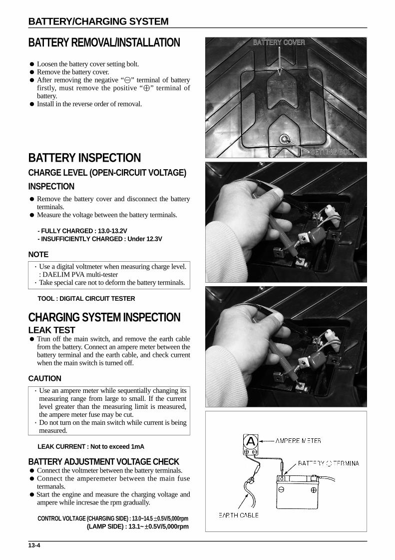
13-4
BATTERY/CHARGING SYSTEM
BATTERY REMOVAL/INSTALLATION
Loosen the battery cover setting bolt. Remove the battery cover. After removing the negative “⊖” terminal of battery
firstly, must remove the positive “⊕” terminal ofbattery.
Install in the reverse order of removal.
BATTERY INSPECTIONCHARGE LEVEL (OPEN-CIRCUIT VOLTAGE)INSPECTION Remove the battery cover and disconnect the battery
terminals. Measure the voltage between the battery terminals.
- FULLY CHARGED : 13.0-13.2V- INSUFFICIENTLY CHARGED : Under 12.3V
NOTE·Use a digital voltmeter when measuring charge level.
: DAELIM PVA multi-tester·Take special care not to deform the battery terminals.
TOOL : DIGITAL CIRCUIT TESTER
CHARGING SYSTEM INSPECTIONLEAK TEST Trun off the main switch, and remove the earth cable
from the battery. Connect an ampere meter between thebattery terminal and the earth cable, and check currentwhen the main switch is turned off.
CAUTION·Use an ampere meter while sequentially changing its
measuring range from large to small. If the currentlevel greater than the measuring limit is measured,the ampere meter fuse may be cut.
·Do not turn on the main switch while current is beingmeasured.
LEAK CURRENT : Not to exceed 1mA
BATTERY ADJUSTMENT VOLTAGE CHECK Connect the voltmeter between the battery terminals. Connect the amperemeter between the main fuse
termanals.Start the engine and measure the charging voltage and
ampere while incresae the rpm gradually.
CONTROL VOLTAGE (CHARGING SIDE) : 13.0~14.5 0.5V/5,000rpm(LAMP SIDE) : 13.1~ 0.5V/5,000rpm
BATTERY COVER
SETTING BOLT
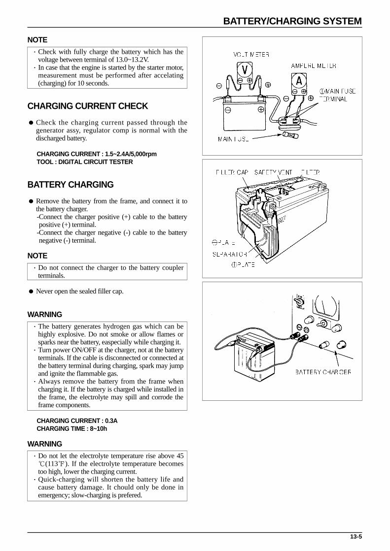
NOTE·Check with fully charge the battery which has the
voltage between terminal of 13.0~13.2V.·In case that the engine is started by the starter motor,
measurement must be performed after accelating(charging) for 10 seconds.
CHARGING CURRENT CHECK
Check the charging current passed through thegenerator assy, regulator comp is normal with thedischarged battery.
CHARGING CURRENT : 1.5~2.4A/5,000rpmTOOL : DIGITAL CIRCUIT TESTER
BATTERY CHARGING
Remove the battery from the frame, and connect it tothe battery charger.-Connect the charger positive (+) cable to the batterypositive (+) terminal.
-Connect the charger negative (-) cable to the batterynegative (-) terminal.
NOTE·Do not connect the charger to the battery coupler
terminals.
Never open the sealed filler cap.
WARNING·The battery generates hydrogen gas which can be
highly explosive. Do not smoke or allow flames orsparks near the battery, easpecially while charging it.
·Turn power ON/OFF at the charger, not at the batteryterminals. If the cable is disconnected or connected atthe battery terminal during charging, spark may jumpand ignite the flammable gas.
·Always remove the battery from the frame whencharging it. If the battery is charged while installed inthe frame, the electrolyte may spill and corrode theframe components.
CHARGING CURRENT : 0.3ACHARGING TIME : 8~10h
WARNING·Do not let the electrolyte temperature rise above 45(113). If the electrolyte temperature becomestoo high, lower the charging current.
·Quick-charging will shorten the battery life andcause battery damage. It chould only be done inemergency; slow-charging is prefered.
13-5
BATTERY/CHARGING SYSTEM

HEADLIGHT VOLTAGE INSPECTION Remove the front cover. ( 3-5)
CAUTION·Check voltage with the headlight coupler connected.
After starting the engine, place the dimmer switch toHI and check the voltage between the blue (+) andgreen (-) wires of the headlight coupler.
CAUTION·Measurement is performed in AC area.
CONTROL VOLTAGE : 12.6~13.6V/5,000rpm
If voltage is incorrect, check the regulator/rectifier.
REGULATOR/RECTIFIER INSPECTION
HARNESS CIRCUIT INSPECTION
Remove the front cover. ( 3-5 ) Remove the 4P coupler of the regulator/rectifier and
inspect the wiring circuit in the main harness sideterminal.
REGULATOR/RECTIFIER INSPECTION
If the inspection of the harness side proves to besatisfactory, check the regulator/rectifier coupler forfaulty connection, and measure the resistance betweenthe terminals of the regulator/rectifier.
13-6
BATTERY/CHARGING SYSTEM
REGULATOR RECTIFIER COUPLER
ITEM
BATTERY WIRE
CHARGING
COIL
LIGHTING
COIL
Voltage between red “⊕” and green “⊖”.
※ Resistance between white wire and
earth wires. Disconnect the starter.
※ Resistance between yellow wire and
earth wires. Disconnect dimmer
switch connection
Damaged, disconnected main fuse/harness.
AC generator (charging, lighting coil
coupler connection damage) resister(6.7Ω
5W) headlight lighting circuit.
There must be battery voltage.
0.4~1.0Ω(20)
0.2~0.8Ω(20)
MEASUREMENT LOCATION LEVEL AREAS OF INSPECTION IF INCORRECT
A L B E
A ∞ 3-50 ∞
L ∞ ∞ 5-100
B ∞ ∞ ∞
E ∞ 5-100 ∞
Inspect ※ part after at least 10 minutes later.
RESISTANCE VALUETester ⊕
Tester ⊖
(20) Unit :
(BATEERY TERMINAL)
TERMINAL ARRANGEMENT
(LAMP TERMINAL)
(EARTH TERMINAL)(CHARGING TERMINAL)
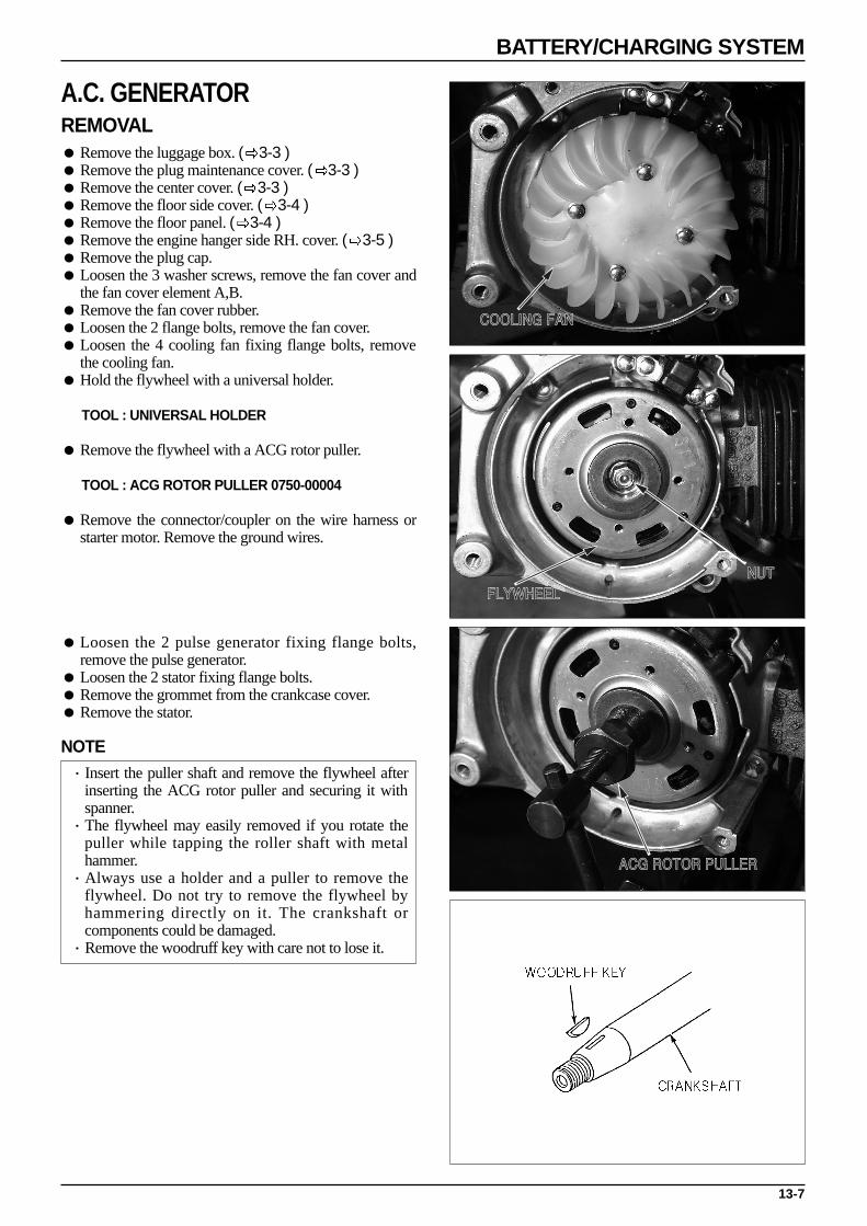
A.C. GENERATOR REMOVAL Remove the luggage box. ( 3-3 ) Remove the plug maintenance cover. ( 3-3 ) Remove the center cover. ( 3-3 ) Remove the floor side cover. ( 3-4 ) Remove the floor panel. ( 3-4 ) Remove the engine hanger side RH. cover. ( 3-5 ) Remove the plug cap. Loosen the 3 washer screws, remove the fan cover and
the fan cover element A,B. Remove the fan cover rubber. Loosen the 2 flange bolts, remove the fan cover. Loosen the 4 cooling fan fixing flange bolts, remove
the cooling fan. Hold the flywheel with a universal holder.
TOOL : UNIVERSAL HOLDER
Remove the flywheel with a ACG rotor puller.
TOOL : ACG ROTOR PULLER 0750-00004
Remove the connector/coupler on the wire harness orstarter motor. Remove the ground wires.
Loosen the 2 pulse generator fixing flange bolts,remove the pulse generator.
Loosen the 2 stator fixing flange bolts. Remove the grommet from the crankcase cover. Remove the stator.
NOTE·Insert the puller shaft and remove the flywheel after
inserting the ACG rotor puller and securing it withspanner.
·The flywheel may easily removed if you rotate thepuller while tapping the roller shaft with metalhammer.
·Always use a holder and a puller to remove theflywheel. Do not try to remove the flywheel byhammering directly on it. The crankshaft orcomponents could be damaged.
·Remove the woodruff key with care not to lose it.
13-7
BATTERY/CHARGING SYSTEM
COOLING FAN
FLYWHEEL
NUT
ACG ROTOR PULLER
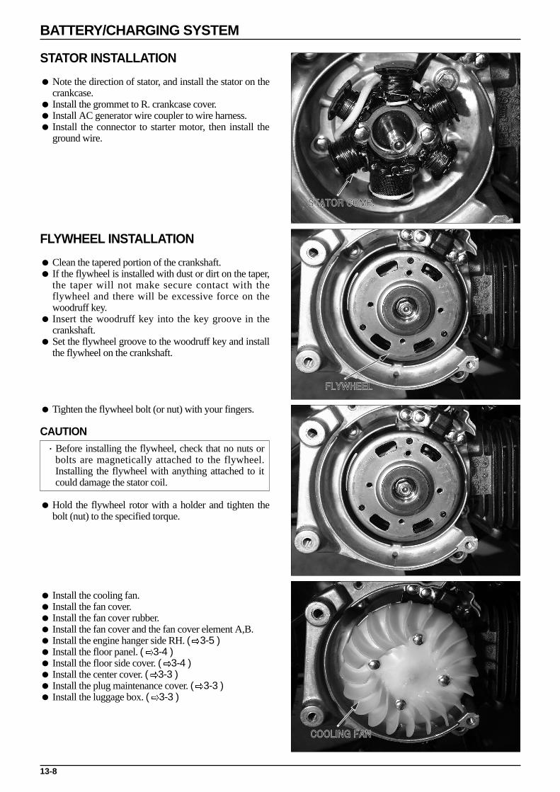
STATOR INSTALLATION
Note the direction of stator, and install the stator on thecrankcase.
Install the grommet to R. crankcase cover. Install AC generator wire coupler to wire harness. Install the connector to starter motor, then install the
ground wire.
FLYWHEEL INSTALLATION
Clean the tapered portion of the crankshaft. If the flywheel is installed with dust or dirt on the taper,
the taper will not make secure contact with theflywheel and there will be excessive force on thewoodruff key.
Insert the woodruff key into the key groove in thecrankshaft.
Set the flywheel groove to the woodruff key and installthe flywheel on the crankshaft.
Tighten the flywheel bolt (or nut) with your fingers.
CAUTION·Before installing the flywheel, check that no nuts or
bolts are magnetically attached to the flywheel.Installing the flywheel with anything attached to itcould damage the stator coil.
Hold the flywheel rotor with a holder and tighten thebolt (nut) to the specified torque.
Install the cooling fan. Install the fan cover. Install the fan cover rubber. Install the fan cover and the fan cover element A,B. Install the engine hanger side RH. ( 3-5 ) Install the floor panel. ( 3-4 ) Install the floor side cover. ( 3-4 ) Install the center cover. ( 3-3 ) Install the plug maintenance cover. ( 3-3 ) Install the luggage box. ( 3-3 )
13-8
BATTERY/CHARGING SYSTEM
STATOR COMP.
FLYWHEEL
COOLING FAN

A.C. GENERATOR(CHARGING COIL)INSPECTIONNOTE·This test is done with the starter mounted to the
engine.
Remove the luggage box. ( 3-3 ) Disconnect the AC generator coupler. ( 3-3 ) Measure the resistance of the charging coil (between
the white wire and ground) and the lighting coil(between the yellow wire and ground).
STANDARD RESISTANCE (20)BETWEEN WHITE WIRE AND GROUND : 0.3~1.2ΩBETWEEN YELLOW WIRE AND GROUND : 0.1~1.0Ω
RESISTER INSPECTION Remove the front cover. ( 3-5 ) Measure the resistance between the register lead wire
and ground.
STANDARD VALUE (20)RESISTER (6.7Ω 5W) GREEN/BLACK/BODY GROUND : 6.3~7.1ΩRESISTER (5.9Ω 30W)PINK/BODY GROUND : 5.6~6.5Ω
NOTE·Problems with the resister are caused by operational
problems of the starter.
13-9
BATTERY/CHARGING SYSTEM
ACG COUPLER

MEMO

14-1
14. IGNITION SYSTEM
SERVICE INFORMATION
GENERAL SAFETY
Refer to the malfunction diagnosis when inspecting ignition devices. Because the ignition devices have installed electrical advancer devices, it is impossible to adjust ignition timing. Be careful when handling the ignition devices as they can become easily damaged if dropped or bumped. Also, do not
disconnect or connect the connectors and couplers when the main swtich is turned ON as excessive electric current cancause damage in the unit. Always perform maintenance work on the ignition devices with the main switch turned OFF.
Ignition devices can often appear to be malfuctioning when the couplers or connectors are disconnected. Check theseconnections before working on.
Use recommended spark plug. Using incorrect spark plug may make the engine run badly or damage the engine. This manual gives explanations on inspections to receive peak voltage. As inspections for coil resistance values are also
included, it may be difficult to make a correct determination. Conduct inspection on the main swtich by referring to the wiring diagram continuity chart. ( chapter 16 )
14
SERVICE INFORMATION 14-1IGNITION DEVICES LOCATION 14-2TROUBLESHOOTING 14-3IGNITION SYSTEM INSPECTION(PEAK VOLTAGE MEASUREMENT) 14-4IGNITION COIL 14-5
EXCITE COIL INSPECTION 14-6PULSE GENERATOR INSPECTION 14-6IGNITION TIMING INSPECTION 14-7CDI UNIT 14-7SIDE STAND IGNITION CUT-OFF SWITCH 14-8

IGNITION DEVICES LOCATION
14-2
IGNITION SYSTEM
SPARK PLUG
IGNITION
MAIN SWITCH
II
VV
SIDE STAND SWITCH
BLUE / YELLOW
PULSE GENERATOR
AC GENERATOR
MAIN SWITCH
SIDE STAND SWITCH
IGNITION COIL
SPARK PLUG
BLACK / YELLOW
BLACK / WHITE
BLACK / RED
GREEN
CDI UNIT

TROUBLESHOOTINGSpark plug does not emit sparks.
14-3
IGNITION SYSTEM
ABNORMAL STATE POSSIBLE CAUSES (START FROM 1 AND GO THROUGH LIST IN ORDER)
1. Using a tester with a low internal resistance.2. Cranking speed is low.- Battery is low or kick power is weak.
3. Influence of tester sampling time (normal state if measured anumber of times and shows over the set voltage).
4. Problem in ignition system wiring (disconnected, damaged).5. Ignition coil is damaged.6. Excite coil is damaged (measure peak voltage).7. CDI unit is damaged (when no porblems in 1~6 and spark plug
does not emit sparks)
1. Adaptor is connected incorrectly.2.Main switch damaged.3. CDI unit coupler is connected incorrectly.4. CDI unit ground wire disconnection.5. Damage to excite coil (measure peak voltage).6. Pulse generator is damaged (measure peak voltage).7. Peak voltage adaptor is damaged.8. CDI unit is damaged (when no problems in 1~7 and no sparks
emitted from spark plug).
1. Damage to spark plug or leakage of ignition coil secondary current.2. Damaged ignition coil.
1. Using a tester with a low internal resistance.2. Cranking speed is too low.- Battery is insufficiently charged or kick power is weak.
3. Influence of tester sampling time (normal state if measured anumber of times and shows over the set voltage)
4. Excite coil is damaged (when 1~3 is okay).
1. Peak voltage adaptor is damaged.2. Excite coil is damaged.
1. Using a tester with a low internal resistance.2. Cranking speed is too low.- Battery is insufficiently charged or kick power is weak.
3. Influence of tester sampling time (normal state if measured anumber of times and shows over the set voltage).
4. Pulse generator is damaged (when 1~3 is okay).
1. Maximum voltage adaptor is damaged.2. Pulse generator is damaged.
Maximum voltage is low.
No, or almost no peak voltage.
Spark plug peak voltage is normal butspark plug does not emit sparks.
Peak voltage is low.
No, or almost no peak voltage.
Maximum voltage is low.
No, or almost no maximum voltage.
IGN
ITIO
N C
OIL
PR
IMA
RY
VO
LTA
GE
EX
CIT
E C
OIL
PU
LSE
GE
NE
RA
TO
R

14-4
IGNITION SYSTEM
IGNITION SYSTEM INSPECTION(PEAK VOLTAGE MEASUREMENT)NOTE·When sparks are not emitted from spark plug, after
checking for disconnection in wires and looseness,measure peak voltage for each wire.
Connect the peak voltage adaptor to the digital tester.
DAELIM PVA MULTI TESTER
IGNITION COIL PRIMARY VOLTAGENOTE·Make sure each wire is correctly connected to ensure
correct measurement.·Inspect when there is cylinder compression pressure
and with the spark plug cap securely connected to thespark plug.
Remove the luggage box. ( 3-3 ) With the ignition coil wire connected, contact the peak
voltage adaptor to the initial wire adaptor terminal(black/yellow) and ground (on vehicle body.). Turn themain swtich ON, operate the starter motor, andmeasure the ignition coil initial side peak voltage.
CONTACT POINTS : BLACK/YELLOW TERMINAL “⊕⊕”-BODY EARTH “⊖⊖”PEAK VOLTAGE : OVER 120V
CAUTION·When measuring voltage, do not touch the metal part
of the handle rod as there is the danger of receivingan electric shock.
EXCITE COIL
CAUTION·Assemble the spark pug to the cylinder head, inspect
in a state having compression pressure.
Remove the luggage box. ( 3-3 ) Remove the CDI unit. ( 14-7 ) Remove the coupler from the CDI unit contact the peak
voltage adaptor to the excite coil wire (black/red andgreen) of the harness side coupler.
Operate the starter motor and measure the excite coilpeak voltage.
CONTACT POINTS : BLACK/RED TERMINAL “⊕⊕”-BODY EARTH “⊖⊖”PEAK VOLTAGE : OVER 120V
CAUTION·When measuring voltage, do not touch the metal part
of the handle rod as there is the danger of recievingan electric shock.

14-5
IGNITION SYSTEM
IGNITION COIL
FIXING SCREW
PULSE GENERATORNOTE·Inspect with the spark plug assembled and while
there is compression pressure.
Remove the CDI unit. ( 14-7 ) Remove the coupler from the CDI unit and connect the
peak voltage adaptor to the pulse generator wire (blue/yellow and green) of harness coupler.
Operate the starter motor and measure the peak voltageof the pulse generator coil.
CONTACT POINTS : BLUE/YELLOW TERMINAL “⊕⊕”-BODY EARTH“⊖⊖”PEAK VOLTAGE : OVER 1.5V
CAUTION·When measuring voltage, do not touch the metal part
of the handle rod as there is the danger of receivingan electric shock.
Perform the following inspections if measured peakvoltage in the CDI unit coupler portion is abnormal.
Disconnect the AC generator cord coupler and connectthe adaptor.
In the same manner as with the unit coupler side, measure peak voltage and compare with the first peak voltage.
When the measured value in the unit side is abnormaland normal in the pulse generator side, the problem iseither incorrect coupler connection or disconnection ofthe wire harness.
When both measurements are abnormal, this indicatesa problem with the pulse generator. Refer to themalfunction diagnosis are go through each step.
IGNITION COIL
REMOVAL/INSTALLATION
Remove the luggage box. ( 3-3 ) Remove the plug maintenance cover. Remove the spark plug cap. Loosen the ignition coil fixing bolt. Disconnect the ignition coil wire. Remove the ignition coil. Install in the reverse order of removal.
CAUTION·Arrange the cords in the right place.

14-6
IGNITION SYSTEM
INSPECTION (RESISTANCE MEASUREMENT)
Remove the luggage box. ( 3-3 ) Measure primary coil resistance between the green and
black/yellow terminals.
STANDARD VALUE : 0.1~0.5Ω(20)
Measure the secondary coil resistance between the plugcap and green wire terminals.
RESISTANCE VALUE(SPARK PLUG CAP CONNECTION) : 6.5~9.5(20)
The coil which the resistance value indicate“∞”(disconnection) remove the plugcap, and measurethe resistance of secondary coil.
Measure the resistance between the high tension code and green code terminals.
RESISTANCE VALUE : 2.6 1.25(20).
EXCITE COIL INSPECTION
NOTE·Assembly the spark plug to the cylinder head, and
inspect in an state having compression pressure.
Remove the luggage box. ( 3-3 ) Remove the connection of the AC Generator wire
connector (black/red), measure the resistance betweenthe terminal of AC generator and body earth.
STANDARD VALUE : 500Ω 20 (20)
PULSE GENERATOR INSPECTION
NOTE·The inspection of pulse generator is performed in a
state assembling to the engine.
Remove the luggage box. ( 3-3 ) Remove the connection of the AC generator 6P
coupler, and measure the resistance between the blue/yellow of starter and green code.
STANDARD VALUE : 100Ω 20 (20)
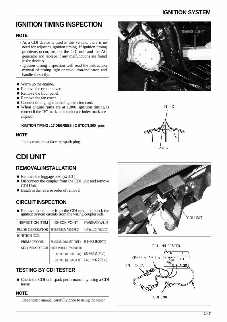
14-7
IGNITION SYSTEM
TIMING LIGHT
CDI UNIT
IGNITION TIMING INSPECTIONNOTE·As a CDI device is used in this vehicle, there is no
need for adjusting ignition timing. If ignition timingproblems occur, inspect the CDI unit and the ACgenerator and replace if any malfunctions are foundin the devices.
·Ignition timing inspection well read the instructionmanual of timing light or revolution-indicator, andhandle it exactly.
Warm up the engine. Remove the center cover. Remove the floor panel. Remove the fan cover. Connect timing light to the high-tension cord. When engine rpms are at 1,800, ignition timing is
correct if the “F” mark and crank case index mark are aligned.
IGNITION TIMING : 17 DEGREES 2 BTDC/1,800 rpms
NOTE·Index mark must face the spark plug.
CDI UNITREMOVAL/INSTALLATION
Remove the luggage box. ( 3-3 ) Disconnect the coupler from the CDI unit and remove
CDI Unit. Install in the reverse order of removal.
CIRCUIT INSPECTION
Remove the coupler from the CDI unit, and check theignition system circuits from the wiring coupler side.
TESTING BY CDI TESTER
Check the CDI unit spark performance by using a CDItester.
NOTE·Read tester manual carefully prior to using the tester.
INSPECTION ITEM
PULSE GENERATOR
IGNITION COIL
-PRIMARYCOIL
-SECONDARY COIL
BLUE/YELLOW AND GREEN
BLACK/YELLOW AND GREEN
GREEN AND HIGH-TENSION CORD
(ATTACH THE PLUG CAP)
(DETACH THE PLUG-CAP)
100Ω±20%(20)
0.1~0.5Ω(20)
6.5~9.5KΩ(20)
2.6±1.25KΩ(20)
CHECK POINT STANDARD VALUE
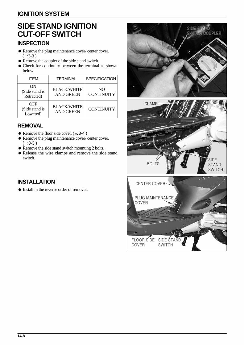
IGNITION SYSTEM
SIDE STAND IGNITIONCUT-OFF SWITCHINSPECTION Remove the plug maintenance cover/ center cover.
( 3-3 ) Remove the coupler of the side stand switch. Check for continuity between the terminal as shown
below:
REMOVAL Remove the floor side cover. ( 3-4 ) Remove the plug maintenance cover/ center cover.
( 3-3 ) Remove the side stand switch mounting 2 bolts. Release the wire clamps and remove the side stand
switch.
INSTALLATION Install in the reverse order of removal.
14-8
SIDE STANDSWITCH COUPLER
BOLTSSIDESTAND SWITCH
CLAMP
FLOOR SIDE COVER
SIDE STAND SWITCH
CENTER COVER
PLUG MAINTENANCECOVER
ON(Side stand is
Retracted)
OFF(Side stand is
Lowered)
NO CONTINUITY
CONTINUITY
BLACK/WHITEAND GREEN
BLACK/WHITEAND GREEN
ITEM TERMINAL SPECIFICATION
15-1
15. STARTING SYSTEM
SERVICE INFORMATION
GENERAL SAFETY
WARNING·When performing maintenance on the starter motor and related parts, turn the main switch to OFF. There is the
danger of the starter motor unexpectedly operating if the main switch is not turned to OFF.
First check connection with battery and battery charge level before beginning maintenance on the starter motor. It is possible for the starter motor coil to become damaged if the starter is operated when the engine does not turn over.
15
SERVICE INFORMATION 15-1STARTING DEVICES LOCATION 15-2TROUBLESHOOTING 15-3
STARTER MOTOR 15-4STARTER RELAY INSPECTION 15-7STARTER PINION GEAR INSPECTION 15-7

STARTING DEVICES LOCATION
15-2
STARTING SYSTEM
TUBELE
SS
TIREAPPL. KOREA
BATTERY
STARTER RELAY
FUSE 7A
MAIN SWITCH
STARTER SWITCH
STARTER MOTOR
RED/WHITE
YELLOW/RED GREEN/YELLOW
GREEN/YELLOW
BATTERY
FRONT STOPSWITCH
STARTERRELAY
MAIN SWITCHRED
GREEN
GREEN
BLACK
FUSE
REAR STOP SWITCHSTARTERSWITCH
STARTERMOTOR

15-3
STARTING SYSTEM
TROUBLESHOOTING
Starter motor does not rotate (No response from starter motor). Check to see if the fuse is burned out.
With the main switch turned to ON, squeezethe brake lever. In this state push the starterbutton and check if a clicking noise then anoperating noise is emitted from the starterrelay.
Remove the starter motor “⊕” wire, connectit to the battery “⊕” terminal and check tosee if the starter motor rotates (because alarge amount of current flows in this test, donot use thin wire).
Incorrect starter motorconnection
Incorrect wise or coupler connection.
Incorrect connection with the switch terminals or harness disconnection.
Damaged main or starter switch.
Incorrect connection with coupler connector.
Disconnection in starter switch wire.
Loose or poor contact at starter relay switch connector.
Faulty starter relay switch.
Remove the coupler from the starter replayand inspect the relay coil ground wire.
Check the starter relay voltage in the starterrelay coupler with the coupler connected.
Check the operation of the starter relay.
CLICKS
NO CLICK. ROTATES
DOES NOT ROTATE
CONTINUITY.
VOLTAGE MEASURED.
NO CONTINUITY.
NO VOLTAGE.
NORMAL
ABNORMAL
Weak rotational power in starter motor (Does not turn over engine). Battery is insufficiently charged. Incorrect connection of battery terminal cord. Damaged starter motor. Ground wire is connected incorrectly Brush is damaged or worn.
Starter motor if free-wheeling Motor terminals are connected backwards. Starter pinion is damaged or operating incorrectely.
Starter motor is normal but does not turn engine over. Engine is malfunctioning so the crank shaft is not rotating. Incorrect meshing of gears in starter pinion.
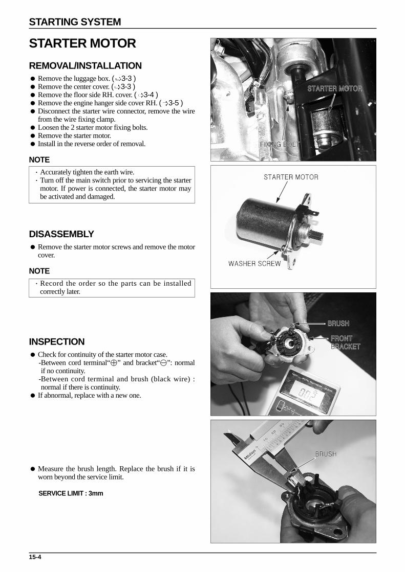
STARTER MOTOR
REMOVAL/INSTALLATION Remove the luggage box. ( 3-3 ) Remove the center cover. ( 3-3 ) Remove the floor side RH. cover. ( 3-4 ) Remove the engine hanger side cover RH. ( 3-5 ) Disconnect the starter wire connector, remove the wire
from the wire fixing clamp. Loosen the 2 starter motor fixing bolts. Remove the starter motor. Install in the reverse order of removal.
NOTE·Accurately tighten the earth wire.·Turn off the main switch prior to servicing the starter
motor. If power is connected, the starter motor maybe activated and damaged.
DISASSEMBLY Remove the starter motor screws and remove the motor
cover.
NOTE·Record the order so the parts can be installed
correctly later.
INSPECTION Check for continuity of the starter motor case.
-Between cord terminal“⊕” and bracket“⊖”: normalif no continuity.
-Between cord terminal and brush (black wire) :normal if there is continuity.
If abnormal, replace with a new one.
Measure the brush length. Replace the brush if it isworn beyond the service limit.
SERVICE LIMIT : 3mm
15-4
STARTING SYSTEM
FIXING BOLT
STARTER MOTOR
WASHER SCREW
STARTER MOTOR
FRONTBRACKET
BRUSH
BRUSH

Check the commutator for :-Damage or abnormal wear. → Replace with a newone.
-Discoloration of the commutator bar. → Replace witha new one.
-Metallic debris between commutator bars.→ Clean itoff.
Check for continuity between pairs of commutatorbars.
Make a continuity check between individualcommutator bars and the armature shaft.
There should be no continuity.
Check the bearings.-Do not rotate smoothly. → Replace with a new one.-Loose bearing. → Replace with a new one.
STARTER MOTOR ASSEMBLY Carefully insert the armature shaft into the front
bracket. Align the front bracket notch with the brush.
CAUTION·The sliding surcfaces of the brushes can be damaged
if they are not installed properly.
15-5
STARTING SYSTEM
COMMUTATOR
COMMUTATOR BARS
BEARING
FRONT BRACKET

Insert the brush spring into the brush holder and installthe front bracket.
NOTE·Insert the brush spring with care so that it does not
lean in the holder.
Apply grease to both ends of the armature shaft.
Install the starter motor cover.
NOTE·The coil may be damaged if the magnet pulls the
armature against the case.
Align the front bracket with the cover. Tighten the washer screw.
15-6
STARTING SYSTEM
BRUSH HOLDER
GREASE
STARTER MOTOR COVER
WASHER SCREW

STARTER RELAY INSPECTION
Remove the luggage box. ( 3-3 ) When battery voltage is applied between the starter
relay green/yellow wire and yellow/red terminals, thereshould be continuity between the red and red/whiteterminals. The terminals are distinguished by thecorresponding wire color of the wire harness connector.
STARTER PINION GEAR INSPECTION
Remove the L. side cover. ( 7-2 ) Remove the drive face. ( 7-6 ) Remove the starter pinion gear. Install in the reverse order of removal.
INSPECTION
Wear or damage to the pinion, reduction gears.→ Replace with a new one.
Worn journals.→ Replace with a new one.
Check if the pinion gear moves smoothly along theaxis.
Pinion gear does not move smoothly. → Replace witha new one.
15-7
STARTING SYSTEM

MEMO

16-1
16. LIGHTS/METER/SWITCHES
TROUBLESHOOTING
Fuel meter indicator malfunctioning Coupler separated. Harness disconnected. Float operation malfuction. Fuel unit damaged. Meter damaged.
Fuel meter needle unstable Coupler loose. Fuel unit damaged. Meter damaged.
Headlight hi-lo not operating Bulb malfunction. Dimmer switch damaged.
Oil indicator light not operating(when there is oil). Burned out fuse. Battery insufficiently charged. Main swtich damaged. Meter damaged. Oil level switch damaged. Loose connector. Harness disconnection.
Oil indicator does not turn off (when oil is out) Oil level switch damaged. Green/red wire joined.
SERVICE INFORMATION
GENERAL SAFETY
Refer to tester owner’s manuals when performing continuity inspections. Refer to wiring diagram (chapter 17) for switch continuity. After inspecting and/or performing maintenance work make sure the wires and cables are properly placed and
connected.
16
SERVICE INFORMATION 16-1TROUBLESHOOTING 16-1FUEL UNIT 16-2OIL LEVEL SWITCH 16-3MAIN SWITCH 16-3
HANDLE SWITCH INSPECTION 16-4FRONT STOP SWITCH INSPECTION 16-4BULBS REPLACEMENT 16-5METER REPLACEMENT 16-7HORN INSPECTION 16-7
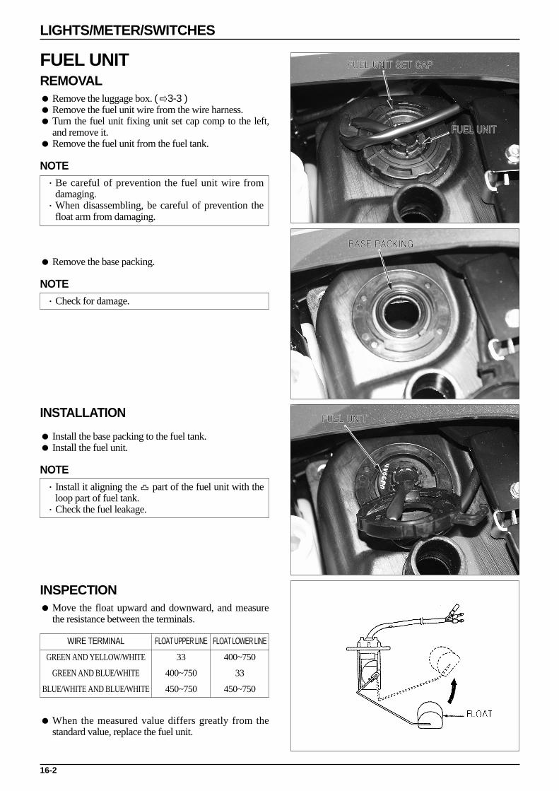
FUEL UNIT REMOVAL Remove the luggage box. ( 3-3 ) Remove the fuel unit wire from the wire harness. Turn the fuel unit fixing unit set cap comp to the left,
and remove it. Remove the fuel unit from the fuel tank.
NOTE·Be careful of prevention the fuel unit wire from
damaging.·When disassembling, be careful of prevention the
float arm from damaging.
Remove the base packing.
NOTE·Check for damage.
INSTALLATION
Install the base packing to the fuel tank. Install the fuel unit.
NOTE·Install it aligning the part of the fuel unit with the
loop part of fuel tank.·Check the fuel leakage.
INSPECTION Move the float upward and downward, and measure
the resistance between the terminals.
When the measured value differs greatly from thestandard value, replace the fuel unit.
16-2
LIGHTS/METER/SWITCHES
FUEL UNIT SET CAP
FUEL UNIT
BASE PACKING
FUEL UNIT
WIRE TERMINAL
GREEN AND YELLOW/WHITE
GREEN AND BLUE/WHITE
BLUE/WHITE AND BLUE/WHITE
FLOAT UPPER LINE
33
400~750
450~750
FLOAT LOWER LINE
400~750
33
450~750

OIL LEVEL SWITCH REMOVAL/INSTALLATION Remove the luggage box. ( 3-3 ) Remove the oil level switch wire. Remove the oil level switch from the oil tank. Install in the reverse order of remeval.
NOTE·Disassemble after adjusting the oil level.
INSPECTION Move the float to farthest extreme up and down and
check the continuity of the terminals. It’s normal state if there is no continuity when the float
is up, but continuity when it is down.
MAIN SWITCH REMOVAL/ INSTALLATION Remove the front cover. ( 3-5 ) Remove the inner box. ( 3-5 ) Disconnect the main switch coupler. Remove the seat lock cable. Loosen the 2 screws and remove the main switch. Install in the reverse order of removal.
INSPECTION
Inspect continuity of each terminal.
16-3
LIGHTS/METER/SWITCHES
OIL LEVELSWITCH
MAINSWITCH
IG E BA1 BA2
BLACK/WHITE GREEN RED BLACK
TERMINAL
ON
OFF
LOCK
COLOR

HANDLE SWITCH INSPECTION
Remove the front handle cover. ( 3-6 ) Remove the handle switch coupler, connector, and
inspect continuity of each terminal. If abnormal, inspect the switch.
FRONT STOP SWITCH INSPECTION
Remove the front handle cover. ( 3-6 ) Remove the black wire and green/yellow wire
terminals inside the speedometer assembly, and checkthe following.-When the brake lever is pulled - continuity.-When the brake lever is released - no continuity.
16-4
LIGHTS/METER/SWITCHES
STARTER SWITCH
LIGHTING SWITCH
WINKER SWITCH
HORN SWITCH HAZARD SWITCH
DIMMER SWITCH
FRONT STOP SWITCH
HI LO HL
BROWN WHITE BLUE
LO
N
HI
COLOR
DIMMER SWITCH
R L WR
SKYBLUE
ORANGE GRAY
FREE
PUSH
COLOR
HAZARD SWITCH
R L WR
SKY BLUE ORANGE GRAY
L
N
R
COLOR
WINKER SWITCH
BROWN YELLOW PINK
OFF
(N)
PO
(N)
H
COLOR
LIGHTING SWITCH
ST E
YELLOW/RED GREEN
FREE
PUSH
COLOR
STARTER SWITCH
HO BAT
LIGHT GREEN BLACK
FREE
PUSH
COLOR
HORN SWITCH
HL C1 TL RE
BROWN/ WHITE

BULBS REPLACEMENT
HEADLIGHT BULB
Remove the front cover. ( 3-5 ) Remove the headlight rubber cover. Push down on the socket and turn to the left. Replace with new bulb.
NOTE·Before replacing the bulb, be sure to check the
swtiches for loose connection of the connectors.
Install in the reverse order of removal.
WARNING·Headlight bulbs become very hot while the headlight
is ON, and remain hot for a while after they areturned OFF.
·Be sure to turn the ignition switch OFF and let thebulb cool down before replacement.
CAUTION·If you touch the bulb with your bare hands, clean it
with a cloth moistened with denatured alcohol toprevent early bulb failure.
·Be sure to install the dust cover after replacing thebulb.
FRONT WINKER BULB Remove the front cover. ( 3-5 ) Remove the bulb from the socket, replace with new bulb. Install in the reverse order of removal.
16-5
LIGHTS/METER/SWITCHES
HEADLIGHT COVER
HEADLIGHT BULB
WINKER BULB

REAR WINKER BULB REPLACEMENT Press the winker lens groove and open the winker lens
using plain screwdriver. Remove the bulb from the socket, replace with new bulb. Install in the reverse order of removal.
NOTE·Pay attention not to damage the lens.·Do not apply excessive force when removing the
lens.
TAILLIGHT BULB REPLACEMENT Loosen the 2 pan screws, remove the tail light lens. Replace the tail stop light bulb with the new one.
NOTE·Pay attention not to damage the tail light lens when
removing it.
METER BULB REPLACEMENT
Remove the front handle cover. ( 3-6 ) Remove the bulb socket, replace with new bulb.
METERS REPLACEMENT Remove the front cover. ( 3-5 ) Remove the front handle cover. ( 3-6 ) Remove the front/rear stop swtich wire. Remove the speedometer cable from the meter. Loosen the 4 steering handle tapping screws. Remove the speedometer coupler connected to the wire
harness Remove the speedometer wiring from the steering
handle cable guide. Remove the speedometer and the gear handle cover
assemblied from the steering handle.
16-6
LIGHTS/METER/SWITCHES
REAR WINKER
TAIL LIGHT LENS
BULB
SPEEDOMETER

Roose the 3 tapping screws securing the speedometerand the rear handle cover.
Disconnect the R/L wiring. Remove the speedometer assembly. Install in the reverse order of removal.
NOTE·Check the each switch for proper operation.·The wire and cable must be connected accurately.
HORN INSPECTION Remove the front cover. ( 3-5 ) Remove the horn wiring, and connect a fully charged
12V battery. Check the sound quality for anyabnormalities.
16-7
LIGHTS/METER/SWITCHES
HORN
MEMO

17-1
17. WIR
ING
DIA
GR
AM
17
Y/R
PU
SH
FR
EE
CO
RD
CO
LOR
CO
RD
CO
LOR
Br/W
L
EG
ST
HI
N LO
HL
HI
WC
OR
DC
OLO
RG
rS
BO
LO
R N L
RL
HO
RN
LG
B/R
L/Y
R/W
L/Y
B/Y
B/W
B/R
R/W
MO
TE
RS
TA
RT
ER
30W 5.9
5W 6.7
M
AU
TO
AC
G
YG
L/Y
B/R
W
UN
IT B
/SC
DI
W
RE
G/R
EC
RE
LAY
G/B
ST
AR
T
G/YY/R
RR/W
G/B
R RFUSE 7A
FR
AM
E E
AR
TH
G
CO
MB
S/W
12V 3A
H
G
R
G
BA
TT
ER
Y
RY
G/BG/B
YG
W
Y Y
G
B/Y
Y/W
G
G
SP
AR
K P
LUG
CO
LOR
CO
MB
GR
OU
ND
/MA
RK
ING
LIGH
T G
RE
EN
SK
Y B
LUE
YRW G L B
OR
AN
GE
OY
ELLO
W
WH
ITE
GR
EE
N
RE
D
BLU
E
GR
AY
PIN
KPG
R
LG SB
BLA
CK
BR
BR
OW
N
SBGO G
GIGN
. CO
IL
G
Br
G/Y
Rr.LH
..WIN
KE
R(12V
10W)
Rr.R
H.W
INK
ER
(12V 5W
/21W)
TA
IL/ST
OP
LIGH
T
(12V 10W
)
Y/W
FU
EL
L/W
G
UN
IT
G/R
G
OIL
S/W
LEV
EL
G
L/W
WR
PU
SH
CO
RD
CO
LOR
FR
EE
LGB
HO
BA
T
CO
LOR
CO
RD
OG
rS
B RL
PU
SH
FR
EE
R
LOC
K
IG
OF
F
ON
EB
A1
BA
2
RC
OR
DC
OLO
RB
/WG
B
IG
EBA2
BA1
SIDE STAND S/W
Br
GB
rG
(12V 5W
)LIC
EN
SE
LAM
P
IG
E
R R
B/WBG
BB/W
G
G
B/W
G
B/W
SBO
SB
BrO G G/Y
CO
LOR
PU
SH
CO
RD
B/W
FR
EE
IG
G E
RE
LAY
WIN
KE
R
O
WIN
KE
R S
/WH
OR
N S
/W
GRSB
DIM
ME
R S
/W
L
WBR/W
G
ST
AR
T S
/W
Br
Y/R
YPY
Br/W
LIGH
T S
/WHA
ZA
RD
S/W O
GRSB
BR
CO
LOR
CO
RD
Br/W
YP
(N)
OF
F
C1
HL
TL
RE
Po
H (N)
6P MINE
GG/Y BY
Y/W
G/R
Y/ROBr
SB
L/WP LG
6P MINE
GG/Y Y B
Y/R S
B
Y/W
L/W
G/R
Br
OP LG
HIG
H B
EA
M P
ILOT
(14V3W
)
(14V3W
)
OIL P
ILOT
ME
TE
RF
UE
L
PILO
TLH
. WIN
KE
R
(14V3W
)
LG
G/R
Y/W
L/W
OG
(12V 16W
)F
r.LH.W
INK
ER
BR G
12V 5W
PO
SIT
ION
LAM
P
GO
GRB
W G L
W LG
BLG
G
Br
SB
SB
OO B
r
HE
AD
LIGH
T 12V
35W/35W
SB
G
(12V 16W
)F
r.RH
.WIN
KE
R
W G L
ST
AR
T S
/WD
IMM
ER
S/W
WIN
KE
R S
/WH
OR
N S
/WC
OM
B S
/WH
AZ
A R
D S
/WS
IDE
ST
AN
D S
/WLIG
HT
S/W
PILO
T
(12V1.7W
)S
PE
ED
OM
ET
ER
(14V3W
)
RH
. WIN
KE
R
(12V1.7W
)S
PE
ED
OM
ET
ER
FR
. ST
OP
S/W
B
G/Y
G SB
G Br
G Br
G/Y
G/YB
RR
. ST
OP
S/W
B
SP
EE
DO
ME
TE
R
B
B
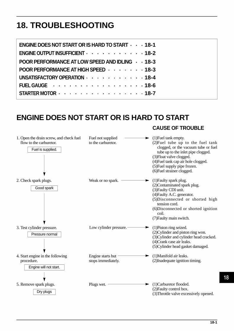
18. TROUBLESHOOTING
ENGINE DOES NOT START OR IS HARD TO STARTCAUSE OF TROUBLE
(1)Fuel tank empty.(2)Fuel tube up to the fuel tank
clogged, or the vacuum tube or fueltube up to the inlet pipe clogged.
(3)Float valve clogged.(4)Fuel tank cap air hole clogged.(5)Fuel supply pipe frozen.(6)Fuel strainer clogged.
(1)Faulty spark plug.(2)Contaminated spark plug.(3)Faulty CDI unit.(4)Faulty A.C. generator.(5)Disconnected or shorted high
tension cord.(6)Disconnected or shorted ignition
coil.(7)Faulty main switch.
(1)Piston ring seized.(2)Cylinder and piston ring won.(3)Cylinder and cylinder head cracked.(4)Crank case air leaks.(5)Cylinder head gasket damaged.
(1)Manifold air leaks.(2)Inadequate ignition timing.
(1)Carburetor flooded.(2)Faulty control box.(3)Throttle valve excessively opened.
1. Open the drain screw, and check fuelflow to the carburetor.
2. Check spark plugs.
3. Test cylinder pressure.
4. Start engine in the followingprocedure.
5. Remove spark plugs.
Fuel not suppliedto the carburetor.
Weak or no spark.
Engine starts butstops immediately.
Plugs wet.
18-1
Fuel is supplied.
Good spark
Pressure normal
Dry plugs
Engine will not start.
18
Low cylinder pressure.
ENGINE DOES NOT START OR IS HARD TO START 18-1
ENGINE OUTPUT INSUFFICIENT 18-2
POOR PERFORMANCE AT LOW SPEED AND IDLING 18-3POOR PERFORMANCE AT HIGH SPEED 18-3UNSATISFACTORY OPERATION 18-4FUEL GAUGE 18-6STARTER MOTOR 18-7

18-2
TROUBLESHOOTING
ENGINE OUTPUT INSUFFICIENT
CAUSE OF TROUBLE
(1) Air cleaner clogged.(2) Insufficient fuel supply.(3) Fuel tank cap air hole clogged.(4) Muffler clogged.
(1) Faulty CDI unit.(2) Faulty A.C generator.
(1) Cylinder and piston ring worn.(2) Cylinder head gasket damaged.(3) Cylinder and cylinder head cracked.
(1) Unsatisfactory carburetormaintenance.
(1) Unsatisfactory plug maintenance.(2) Plugs with incorrect heat value
used.(3) Rich fuel mixture.
(1) Cylinder or piston worn.(2) Lean fuel mixture.(3) Poor quality fuel used.(4) Carbon deposit inside the
combustion chamber excessive.(5) Ignition timing incorrect.
(1) Carbon deposit inside thecombustion chamber excessive.
(2) Poor quality fuel used.(3) Lean fuel mixture.
1. Gently accelerate engine.
2. Check ignition timing.
3. Press the kick starter pedal to checkthe cylinder pressure.
4. Check the carburetor for clogging.
5. Remove spark plugs.
6. Check for engine overheating.
7. Accelerate suddenly or run at.
Engine speed does notincrease sufficiently.
Abnormal
Low
Clogged.
Contaminated ordiscolored.
Overheated.
Engine knocks.
Engine speed increases.
Normal
Not clogged.
Not contaminated or discolored.
Normal
Not overheated.
Engine does not knock.
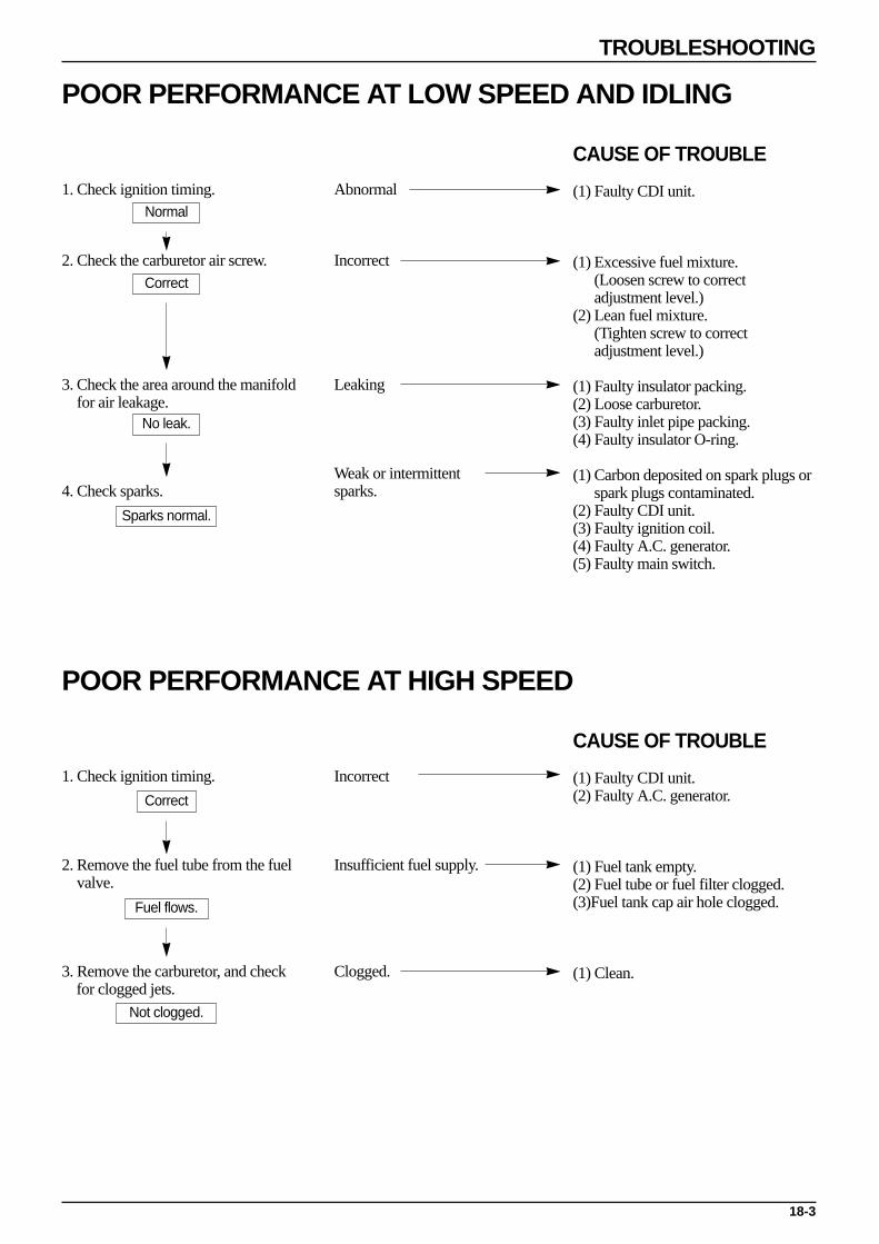
18-3
TROUBLESHOOTING
POOR PERFORMANCE AT LOW SPEED AND IDLING
CAUSE OF TROUBLE
(1) Faulty CDI unit.
(1) Excessive fuel mixture.(Loosen screw to correctadjustment level.)
(2) Lean fuel mixture.(Tighten screw to correctadjustment level.)
(1) Faulty insulator packing.(2) Loose carburetor.(3) Faulty inlet pipe packing.(4) Faulty insulator O-ring.
(1) Carbon deposited on spark plugs orspark plugs contaminated.
(2) Faulty CDI unit.(3) Faulty ignition coil.(4) Faulty A.C. generator.(5) Faulty main switch.
1. Check ignition timing.
2. Check the carburetor air screw.
3. Check the area around the manifoldfor air leakage.
4. Check sparks.
Abnormal
Incorrect
Leaking
Weak or intermittentsparks.
Normal
Sparks normal.
Correct
No leak.
POOR PERFORMANCE AT HIGH SPEED
CAUSE OF TROUBLE
(1) Faulty CDI unit.(2) Faulty A.C. generator.
(1) Fuel tank empty.(2) Fuel tube or fuel filter clogged.(3)Fuel tank cap air hole clogged.
(1) Clean.
1. Check ignition timing.
2. Remove the fuel tube from the fuelvalve.
3. Remove the carburetor, and check for clogged jets.
Incorrect
Insufficient fuel supply.
Clogged.
Correct
Fuel flows.
Not clogged.

18-4
TROUBLESHOOTING
UNSATISFACTORY OPERATION
CAUSE OF TROUBLE
(1) Drive belt worn or slips.(2) Ramp plate damaged.(3) Drive face spring damaged.(4) Clutch lining came off.(5) Driven pulley shaft spline damaged.(6) Faulty transmission.(7) Transmission seized.
(1) Shoe spring damaged.(2) Clutch outer and weight seized.(3) Pivot seized.
(1) Drive belt worn or slips.(2) Weight roller worn.(3) Drive pulley bearing seized.(4) Weak drive face spring.(5) Drive pulley bearing worn or seized.
(1) Drive belt worn or slips.(2) Weight roller worn.(3) Drive pulley bearing worn.
(1) Oil or grease spilled on the drive belt and inside pulley.(2) Drive belt worn.(3) Weak drive face spring.(4) Driven pulley bearing worn or seized.
Check tire pressure.
CAUSE OF TROUBLE
(1) Steering head adjuster excessively tightened.(2) Steering cone race or steel ball damaged.
(1) Excessive wheel bearing play.(2) Rim bent.(3) Axle nut loose.
(1) Front wheel and rear wheel not aligned.(2) Front fork bent.
1. Engine starts but motorcycle does not move.
2. Vehicle moves slow, engine starts but stopsimmediately.
3. Engine weak at start.
4. Engine weak at high speed.
5. Abnormal noise or odor.
POOR MECHANICAL PERFORMANCE
1. Steering is heavy.
2. Wheels wobbling.
3. Motorcycle pulls to one side.
CLUTCH DRIVE/DRIVEN PULLEY

18-5
TROUBLESHOOTING
CAUSE OF TROUBLE
(1) Brake shoe worn.(2) Brake cam worn.(3) Shoe and cam contact surface worn.(4) Brake drum worn.
(1) Brake shoe worn.(2) Foreign matter in the brake lining.(3) Brake drum and shoe contact surface curved.
(1) Brake wire defective or expanded.(2) Only part of the brake shoe makes contact with the
brake drum.(3) Clay or moisture inside the brake drum.(4) Brake lining contaminated by grease or oil.
1. If the arrow were mark and the brakepanel mark match with each other.
2. Brake noise.
3. Poor braking.
POOR BRAKE PERFORMANCE Check brake adjustment.
CAUSE OF TROUBLE
(1) Cushion spring weak.(2) Overloaded.(3) Damper oil leaks.
(1) Fork pipe or cushion rod bent.
(1) Sliders stuck.(2) Cushion stopper rubber damaged.
1. Suspension excessively soft.
2. Suspension excessively hard.
3. Noise from the suspension.
POOR FRONT/REAR SUSPENSION PERFORMANCE Check tire pressure.

18-6
TROUBLESHOOTING
FUEL GAUGE
CAUSE OF TROUBLE
(1) Fuse cut.(2) Battery weak or totally discharged.(3) Faulty ignition swtich.(4) Faulty terminal connection.(5) Wire harness damaged.
(1) Faulty float.
(1) Balance coil damaged or shorted.
(1) Terminal loose.(2) Faulty terminal connection.
(1) Balance coil/lead shorted ordamaged.
GAUGE READING INACCURATE (IGNITION SWTICH ON)
1. Operate the turn signal to check thebattery circuit.
2. Remove the fuel level sensor, andmove float to check the status ofoperation.Float up : Full positionFloat down : Empty position
3. Short-circuit the tank unit terminalon the wire harness side.
4. Terminal joints loose or faultyconnection.
Signal continuouslyoperates dim or does notoperate at all.
Needle moves.
Needle not moving.
Unsatisfactory
Signal operates satisfactorily.
Check
Needle not moving.
Needle not moving.
CAUSE OF TROUBLE
(1) Fuse cut.(2) Battery weak or totally discharged.(3) Ignition switch damaged or shorted.(4) Terminal loose of faulty connection.(5) Wire harness damaged.
(1) Faulty fuel level sensor connection.
(1) Damper oil inside the meterinsufficient.
(1) Faulty connection between thesliding arm and the resistance.
(1) Terminal connection loose or faultyconnection.
(1) Balance coil/lead shorted ordamaged.
GAUGE NEEDLE SHAKES OR VERTICALLY WOBBLES.(IGNITION SWTICH ON)1. Operate the turn signal to check the
battery circuit.
2. Remove the tank and operate thefloat.
3. Move the float rapidly. One up/downmotion per second.
4. Start the engine, and measure thefuel level sensor resistance.
5. Check each joint.
Signal continuouslyoperates dim or does notoperate at all.
Needle not moving.
Needle not moving.
Resistance changedsignificantly.
Unsatisfactory
Signal operates satisfactorily.
Satisfactory
Needle moving.
Needle moving.
Resistance not changed.
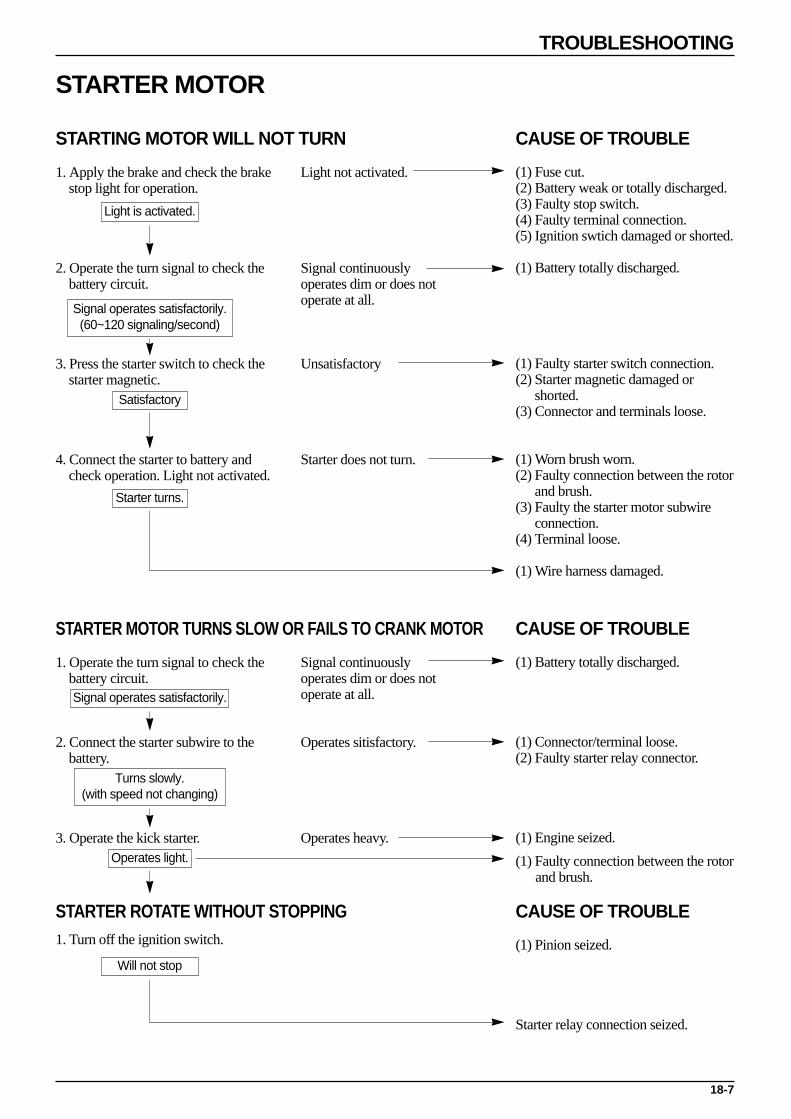
18-7
TROUBLESHOOTING
STARTER MOTOR
CAUSE OF TROUBLE
(1) Fuse cut.(2) Battery weak or totally discharged.(3) Faulty stop switch.(4) Faulty terminal connection.(5) Ignition swtich damaged or shorted.
(1) Battery totally discharged.
(1) Faulty starter switch connection.(2) Starter magnetic damaged or
shorted.(3) Connector and terminals loose.
(1) Worn brush worn.(2) Faulty connection between the rotor
and brush.(3) Faulty the starter motor subwire
connection.(4) Terminal loose.
(1) Wire harness damaged.
STARTING MOTOR WILL NOT TURN
1. Apply the brake and check the brake stop light for operation.
2. Operate the turn signal to check the battery circuit.
3. Press the starter switch to check the starter magnetic.
4. Connect the starter to battery and check operation. Light not activated.
Light not activated.
Signal continuouslyoperates dim or does notoperate at all.
Unsatisfactory
Starter does not turn.
Light is activated.
Signal operates satisfactorily.(60~120 signaling/second)
Satisfactory
Starter turns.
CAUSE OF TROUBLE
(1) Battery totally discharged.
(1) Connector/terminal loose.(2) Faulty starter relay connector.
(1) Engine seized.
(1) Faulty connection between the rotor and brush.
STARTER MOTOR TURNS SLOW OR FAILS TO CRANK MOTOR
1. Operate the turn signal to check the battery circuit.
2. Connect the starter subwire to the battery.
3. Operate the kick starter.
Signal continuouslyoperates dim or does notoperate at all.
Operates sitisfactory.
Operates heavy.
Signal operates satisfactorily.
Turns slowly.(with speed not changing)
Operates light.
CAUSE OF TROUBLE
(1) Pinion seized.
Starter relay connection seized.
STARTER ROTATE WITHOUT STOPPING1. Turn off the ignition switch.
Will not stop

MEMO

SERVICE MANUAL
2001. 3. PRINTED2001. 3. PUBLICATION NO COPY

SM40-0103-01E
HEAD OFFICE (FACTORY)#58, SUNG SAN-DONG, CHANGWON, KYUNGNAM, KOREATEL : (82-55) 239-7000 / FAX : (82-55) 239-7524
OVERSEAS SALES OFFICE#16-6, PIL-DONG 2KA, CHUNG-KU, SEOUL, KOREATEL : (82-2) 2274-3171 / FAX : (82-2) 2269-7997