INSTALLATION MANUAL TD-34 LV/HV - Entertron
64
Advanced Industrial Telemodem V.34 INSTALLATION MANUAL 6610-2203 www.westermo.com TD-34 LV/HV © Westermo Teleindustri AB • 2004 • REV.A Galvanic Isolation Transient Protection Balanced Transmission CE Approved
-
Upload
khangminh22 -
Category
Documents
-
view
0 -
download
0
Transcript of INSTALLATION MANUAL TD-34 LV/HV - Entertron

Advanced IndustrialTelemodem
V.34
INSTALLATION MANUAL6610-2203
www.westermo.com
TD-34
LV/HV
©W
este
rmo
Tele
indu
stri
AB
• 20
04 •
RE
V.A
GalvanicIsolation
TransientProtection
BalancedTransmission
CEApproved

2 6610-2203
Table of Contents
1. Introduction ................................................................................................................................................. 31.1 Functional description ............................................................................................................... 4
2. Safety ........................................................................................................................................................................ 52.1 Approvals .................................................................................................................................................. 62.2 Declaration of conformity ................................................................................................. 7
3. Specifications TD-34 LV and TD-34 HV ........................................... 8–9
4. Maintenance ............................................................................................................................................. 10
5. Installation ................................................................................................................................................... 105.1 Mounting /Removal ................................................................................................................ 105.2 Connections ........................................................................................................................... 11–17
5.2.1 Interface RS-232 9-pos D-sub .................................................................... 125.2.2 Interface RS-232, 9-pos screw terminal ....................................... 125.2.3 Interface RS-485/422, 4-pos screw terminal .......................... 135.2.4 Interface Leased Line ........................................................................................... 135.2.5 Interface Alarms .......................................................................................................... 135.2.6 Interface RJ-11, PSTN .......................................................................................... 13
5.3 Configuration ....................................................................................................................... 14–165.3.1 DIP switch settings TD-34 .................................................................... 14–16
5.4 LED Status Indicators ........................................................................................................ 17
6. AT Commands .......................................................................................................................... 18–42
7. Result Codes .................................................................................................................................. 43–44
8. S-registers ........................................................................................................................................... 45–52
9. Glossary .................................................................................................................................................. 53–55
10. Dialback application 1 ........................................................................................................... 56
11. Dialback application 2 ........................................................................................................... 57
12. Remote Access application ......................................................................................... 58
13. Schneider PLC application .......................................................................................... 59

36610-2203
1. IntroductionThe TD-34 is Westermo’s current top of the range analogue Telephone Modem intended foruse under the most extreme conditions.The TD-34 is the result of Westermo’s experienceand knowledge in the area of Industrial Telecommunication over more that 25 years. Highnoise environments, difficult configurations and customer-specific applications can easily besolved using TD-34 product.The philosophy for the TD-34 is based on quality and functionrather than optimizing for price. Nothing has been left to chance when designing this modem.The TD-34 is an asynchronous modem with RS-232 and RS-485/422 interfaces built-in as standard.The TD-34 can be used on standard PSTN “ Public Switched Telephone Network”or Leased Lines consisting of either 2 or 4-wires for line connection.The RS-485/422 interface can be configured as either end of line or intermediate using 2 or 4-wires.The Opto-isolated Alarm interface on TD-34 may be used either for dial up based on a certainevent or as indication from the remote end. Indication of the state of the alarms is providedon the front panel of the TD-34.
RS-232 2- or 4-wire leased line RS-232/422/485
TD-34TD-34
PSTN

4 6610-2203
1.1 Functional descriptionThe TD-34 has various interfaces that will cover most industrial applications.TD-34 is func-tionally complete industrial modem including alarm handling, leased line to PSTN redundancy,Industrial Temperature Range, RS-232/422/485 interfaces and a power supply interface with a wide input voltage range.All functional blocks are illustrated in the figure below.A more detailed description can be found under chapter 3. Specifications(page 8–9).
DP
CPUMemory
ROM & RAM
MCUConfig.
DIP-switch
RS-232 RS-422/485
LeasedLine
LeasedLine
LED’s
+5V
0IN Isolated
power supply
Telephone Line
TelephoneLine
Alarm in
Alarm out
Common
RS-232/V.24 RS-422/485
DAA
TTL
TTL TTL
DAA

56610-2203
2. SafetyGeneral:Before using this unit, read this manual completely and gather all information on theunit. Make sure that you understand it fully. Check that your application does notexceed the safe operating specifications for this unit.
Before installation, maintenance or modification work:Prevent damage to internal electronics from electrostatic discharges (ESD) by discharging your body to a grounding point (e.g. use of wrist strap).Prevent access to hazardous voltages by disconnecting the unit from AC/DC mains supply and all other electrical connections.
Installation:This unit should only be installed by qualified personnel.This unit should only be installed in a “restricted access area”, for example a lockable cabinet where access is restricted to service personnel only.This unit is intended for permanent connection to the AC/DC mains supply.The power supply wiring must be sufficiently fused, and if necessary it must be possi-ble to disconnect manually from the AC/DC mains supply. Ensure compliance tonational installation regulations.Units with the rated voltage exceeding 42.4 V peak or 60 VDC, are defined as class Iequipment with a protective earthing conductor terminal.Units with the rated voltage up to 42.4 V peak or 60 VDC, are defined as class IIIequipment and shall be separated from hazardous voltage by double or reinforcedinsulation.This unit uses convection cooling.To avoid obstructing the air flow around the unit,follow the spacing recommendations (see Installation section).
!
!
!

6 6610-2203
For TD-34 in US:
This equipment complies with Part 68 of the FCC rules and the requirements adopted by the ACTA. On one outer side of thisequipment is a label that contains, among other information, a product identifier in the format US:AAAEQ##TXXXX. Ifrequested, this number must be provided to the telephone company.
This equipment uses the following USOC jacks: RJ11C
A plug and jack used to connect this equipment to the premises wiring and telephone network must comply with the appli-cable FCC Part 68 rules and requirements adopted by the ACTA. A compliant telephone cord and modular plug is providedwith this equipment. It is designed to be connected to a compatible modular jack that is also compliant. See installationinstruction for details.
REN=0.9B.
The REN is used to determine the number of devices that may be connected to a telephone line. Excessive RENs on a telephone line may result in the devices not ringing in response to an incoming call. In most but not all areas, the sum ofRENs should not exceed five (5.0 ).To be certain of the number of devices that may be connected to a line, as determinedby the total RENs, contact the local telephone company.For products approved after July 23, 2001, the REN for this productidentifier that has the format US:AAAEQ##TXXXX.The digits represented by ## are the REN without a decimal point (e.g , 03 is a REN of 0.3). For earlier products, the REN is separately shown on the label.
If this terminal equipment,TD-34, causes harm to the the telephone network, the Telephone Company will notify you inadvance that temporary discontinuance of service may be be required. But if advance notice isn’t practical, the telephonecompany will notify the cutomer as soon as possible. Also, you will be advised of your right to file a complaint with the FCC if you believe it is necessary.
The telephone company may make changes in its facilities, equipment, operations or procedures that could affect the opera-tion of the equipment. If this happens the Telephone Company will provide advance notice in order for you to make necessarymodifications to maintain uninterrupted service.
If trouble is experienced with this equipment, for repair or warranty information, please contact Gross Automation (262)446-0000 (phone) / (262)446-0300 (fax) /[email protected] (e-mail). If the equipment is causing harm to the telephone network, the Telephone Company may request that you disconnect the equipment until the problem isresolved.
There are no user serviceable parts in this equipment.
Connection to party line service is subject to state tariffs. (Contact the state public utility commision, public service commisionor corporation commision for information.)
If your home has specially wired alarm equipment connected to the telephone line, ensure the installation of this TD-34 doesnot disable your alarm equipment. If you have questions about what will disable alarm equipment please consult your tele-phone company or a qualified installer.
Caution: To reduce the risk of fire, use only No. 26 AWG or larger telecommunication line cord.
Attention: Pour réduire le risque d’incendie, utiliser uniquement des conducteur de télé-communications 26 AWG ou de section supérieure.
2.1 Approvals
Conformity with the Directive 73/23/EEC (Low Voltage) has been assessed by application ofthe standard EN 60 950.Conformity with the Directive 89/336/EEC (Electromagnetic Compatibility) has been assessedby application of the standards EN55024:1998, EN61000-6-2:1999 andEN50082-1:1997.Conformity with the Directive 99/5/EEC (Radio Equipment & Telecommunications TerminalEquipment) has been assessed by application of the standards EN55024:1998, EN61000-6-2:1999, EN50082-1:1997,EN 60 950 and EN41003:1996.The TD-34 conforms to UL STD 1950, CS-03, FCC Part 68 and CAN/CSA STD 22.2 No 950-50.

76610-2203
2.2 Declaration of conformity

3. Specifications TD-34 LV and TD-34 HV
Model description TD-34 LV TD-34 HV
12–27 V AC ±10% 95–240 V AC ±10%
12–54 V DC ±10% 110–240 V DC ±10%
Frequency 48–62Hz 48–62 Hz
Fuse, F1 1.0 A F SMD 1.0 A SLittelfuse Wickman
Power consumption 3 W 50 mA
8 6610-2203
Power supply
Connector RJ-11 & Screw terminal
Topology 2-wire on RJ-11 Pin3 & Pin4 bus internally connectedto LL1 & LL2 on screw terminal
Line Modulation ITU-T V34 ( up to 33.6 kbit/s ),V32bis,V32,V23,V22bis,V22,V21, Bell212A, Bell103
Dial up Tone signals DTMF
Compression V42bis & MNP5
Error Correction V42 LAPM, MNP 2–4 & MNP-10
Isolation 1 500 Vrms to rest of electronics
PSTN Interface
Connector Screw terminal
Topology 2-wire on screw terminal LL3 & LL44-wire on screw terminal LL1, LL2, LL3 & LL4
Line Modulation ITU-T V34,V32bis,V32,V23 (1200/75),V22bis,V22,V21,Bell212A, Bell103
Compression V42bis & MNP5
Error Correction V42 LAPM, MNP 2-4 & MNP-10
Isolation 1 500 Vrms to rest of electronics
Leased Line Interface

96610-2203
Connector 9-pos D-sub and screw terminal
DTE Speed Up to 115.2 kbit/s
DTE Format Up to 11 bits
EIA RS-232-C/V24 Interface
Connector 2-wire (RS-485) 4-wire on 4-pos screw terminal
DTE Speed Up to 115.2 kbit/s
DTE Format Up to 11 bits
Special features Fail-safe, termination
EIA RS-422/485 Interface
Connector 3-position screw terminal AL1,AL2 & AL_COM
Supply Voltage AL1 10–60 V DC, 1 mA@10 V DC
Isolation AL1 1 500 Vrms to rest of electronics
Output AL2 Max 1 A, electromechanical relay
Isolation AL2 1 500 Vrms to rest of electronics
Alarm Interface
Power Yes
PSTN Interface Yes
Leased Line Interface Yes
RS-485/422 Yes
Transient protection
Indicators TD, RD, RTS, DTR, DCD, DSR, PWR, LINE,AL1,AL2
Operating Temperature –40 to +70°C
Altitude Up to 4 000 m above sea level
Humidity 0–95% RH, without condensation
IP-Classification IP20
Weight, kg 0.4
Dimensions, mm 55x100x128 (WxHxD)
Mounting On 35 mm DIN-rail
Miscellaneous

10 6610-2203
4. MaintenanceNo maintenance is required, as long as the unit is used as intended within the specified condi-tions.
5. Installation5.1 Mounting / Removal
Before mounting or removing the unit:
Prevent damage to internal electronics from electrostaticdischarges (ESD) by discharging your body to a groundingpoint (e.g. use of wrist strap).
Prevent access to hazardous voltages by disconnecting theunit from AC/DC mains supply and all other electrical connections.
MountingThis unit should be mounted on 35 mm DIN-rail which is horizontally mounted on a wall orcabinet backplate.This unit uses convection cooling.To avoid obstructing the airflow around the unit,use the following spacing rules. Recommended spacing 25 mm (1.0 inch) above/below and 10mm (0.4 inches) left/right the unit.Snap on mounting, see figure
RemovalPress down the black support at the back of the unit using a screwdriver, see figure.
10 mm *(0.4 inches)
CLICK!
!
25 mm
25 mm* Spacing (left/right) recommend-ed for full operating temperaturerange

116610-2203
9-pos. D-subRS-232
Alarms
LeasedLine
Lineconnection
RJ-11
Line connection
422/485
PowerconnectionLV/HV
9-pos. screw terminalRS-232
5.2 ConnectionsTD-34 Tele Modem family consist of two products:TD-34 LV and TD-34 HV.TD-34 LV has a 2-pos. power connector insensitive to polarity as shown by the symbol ≈ onthe front.The PE wire “protective earth” is not connected internally in TD-34. but may be connected for backwards compatibility.

12 6610-2203
Direction 9-pos. Name DescriptionDCE-DTE D-sub
O 1 DCD Data Carrier DetectO 2 RXD Receive DataI 3 TXD Transmit DataI 4 DTR Data Terminal Ready– 5 SG Signal GroundO 6 DSR Data Set ReadyI 7 RTS Request To SendO 8 CTS Clear To SendO 9 RI Ring Indicator
Direction 9-pos. Name DescriptionDCE-DTE screw terminal
– 1 SG Signal GroundO 2 DSR Data Set ReadyI 3 DTR Data Terminal ReadyO 4 DCD Data Carrier DetectO 5 CTS Clear To SendI 6 RTS Request To SendO 7 RXD Receive DataI 8 TXD Transmit Data– 9 RI Ring Indicator
5.2.1 Interface RS-232 9-pos D-sub
5.2.2 Interface RS-232, 9-pos screw terminal
54321
9876
5 4 3 2 19 8 7 6
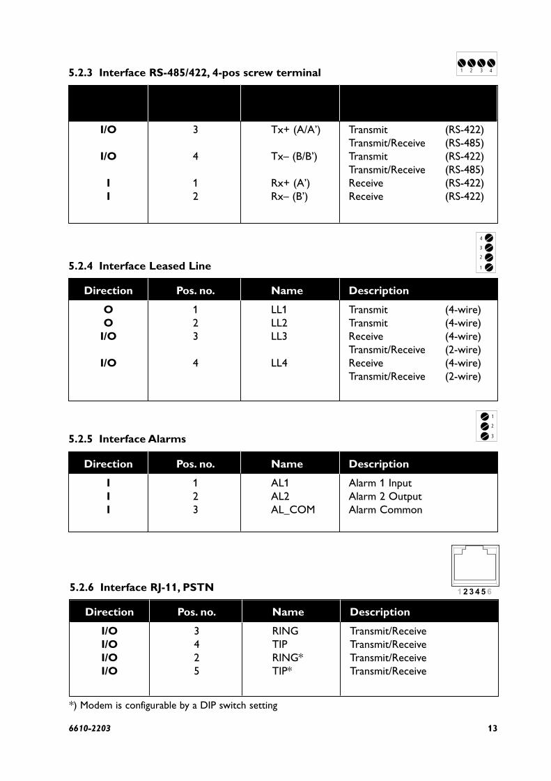
Direction 4-pos. Name Descriptionscrew terminal
I/O 3 Tx+ (A/A’) Transmit (RS-422)Transmit/Receive (RS-485)
I/O 4 Tx– (B/B’) Transmit (RS-422)Transmit/Receive (RS-485)
I 1 Rx+ (A’) Receive (RS-422)I 2 Rx– (B’) Receive (RS-422)
136610-2203
Direction Pos. no. Name Description
I/O 3 RING Transmit/ReceiveI/O 4 TIP Transmit/ReceiveI/O 2 RING* Transmit/ReceiveI/O 5 TIP* Transmit/Receive
5.2.6 Interface RJ-11, PSTN
*) Modem is configurable by a DIP switch setting
Direction Pos. no. Name Description
O 1 LL1 Transmit (4-wire)O 2 LL2 Transmit (4-wire)
I/O 3 LL3 Receive (4-wire)Transmit/Receive (2-wire)
I/O 4 LL4 Receive (4-wire)Transmit/Receive (2-wire)
5.2.4 Interface Leased Line
Direction Pos. no. Name Description
I 1 AL1 Alarm 1 InputI 2 AL2 Alarm 2 OutputI 3 AL_COM Alarm Common
5.2.5 Interface Alarms
5.2.3 Interface RS-485/422, 4-pos screw terminal
1
2
3
4
1 2 3 4
3
2
1

14 6610-2203
5.3 ConfigurationTD-34 can be configured via AT-commands on the service interface, or by a remote modem (ifthe TD-34 is set for remote configuration, see SW 4).
5.3.1 DIP-switch settingsDIP-switches are accessable under the lid on top/front of the unit. DIP-switches are used to configure the unit.
Warning!Prevent damage to internal electronics from electrostatic discharges (ESD) by discharging your body to a grounding point (e.g. use of wrist strap), before the lid on top/front of the unit is removed.
Warning! Do not open connected equipment.Prevent access to hazardous voltages by disconnecting the unit from AC/DC mainssupply and all other electrical connections.
NOTE! The change of DIP-switch settings are valid only after a power on.If configured by any other method during normal operation, this new configuration override the DIP-switch settings. However, after a new power on the DIP-switch settings have precedence.
!
!

156610-2203
SW 1DTE Speed and Formats
ON
1 2 3 4 5 6 7 8
ON
1 2 3 4 5 6 7 8
7E
ON
1 2 3 4 5 6 7 8
7O
ON
1 2 3 4 5 6 7 8
8N
ON
1 2 3 4 5 6 7 8
8E
ON
1 2 3 4 5 6 7 8
8O
ON
1 2 3 4 5 6 7 8
Direct Mode 8E or 8O
ON
1 2 3 4 5 6 7 8
Direct Mode 7E, 7O or 8N
ON
1 2 3 4 5 6 7 8
2 stop bits
ON
1 2 3 4 5 6 7 8
Auto detect
ON
1 2 3 4 5 6 7 8
300 bit/s
ON
1 2 3 4 5 6 7 8
600 bit/s
ON
1 2 3 4 5 6 7 8
1 200 bit/s
ON
1 2 3 4 5 6 7 8
2 400 bit/s
ON
1 2 3 4 5 6 7 8
4 800 bit/s
ON
1 2 3 4 5 6 7 8
9 600 bit/s
ON
1 2 3 4 5 6 7 8
19 200 bit/s
ON
1 2 3 4 5 6 7 8
38 400 bit/s
ON
1 2 3 4 5 6 7 8
57 600 bit/s
ON
1 2 3 4 5 6 7 8
115 200 bit/s
SW 2RS-422/485 & Alarm Services
ON
1 2 3 4 5 6 7 8
Enable RS-485ON
1 2 3 4 5 6 7 8
Enable RS-422ON
1 2 3 4 5 6 7 8
TerminateRS-422/485
ON
1 2 3 4 5 6 7 8
Enable I/O
7N

16 6610-2203
SW 4Special services
ON
1 2 3 4 5 6 7 8
Reliable mode disable \N0
ON
1 2 3 4 5 6 7 8
Remote configuration enable
ON
1 2 3 4 5 6 7 8
Dial-back PSTN enable(2-wire leased line)
ON
1 2 3 4 5 6 7 8
Dial-back answer
ON
1 2 3 4 5 6 7 8
PLC mode enableQ1E0&C1&K0&A1
ON
1 2 3 4 5 6 7 8
Abort disable&A1
ON
1 2 3 4 5 6 7 8
Auto retrain disable%E0
ON
1 2 3 4 5 6 7 8
Dial-back originate
SW 3Line Mode & Modulation
ON
1 2 3 4 5 6 7 8
Leased line(Dial-Up PSTN = Off)
ON
1 2 3 4 5 6 7 8
4-wire leased line mode (2-wire leased line mode = Off)
ON
1 2 3 4 5 6 7 8
Leased line answer (Originate = OFF)
ON
1 2 3 4 5 6 7 8
Not used
ON
1 2 3 4 5 6 7 8
Auto detect mode
ON
1 2 3 4 5 6 7 8
V.34, 33 600 bit/s
ON
1 2 3 4 5 6 7 8
V.34, 28 800 bit/s
ON
1 2 3 4 5 6 7 8
V.32, 9 600 bit/s
ON
1 2 3 4 5 6 7 8
V.32bis, 14 400 bit/s
ON
1 2 3 4 5 6 7 8
V.22bis, 2 400 bit/s
ON
1 2 3 4 5 6 7 8
V.22, 1 200 bit/s
ON
1 2 3 4 5 6 7 8
V.21, 300 bit/s
Factory settings
ON
1 2 3 4 5 6 7 8
SW1, SW2, SW3 and SW4
ON
1 2 3 4 5 6 7 8
V34, 19 200 bit/s

176610-2203
5.4 LED Status Indicators
PWR Power Indication. Flashes if an error is detected
DTR Data Terminal Ready modem signal
RTS Request To Send modem signal
TD Transmitted Data: Displays data received from the local RS-232/V.24 port
RD Received Data: Displays data leaving the modem on the RS-232/V.24 port
DCD Data Carrier Detect modem signal
LINE Modem is off-hook. Flashes if the dial-back function is in use
AL1 Alarm input active
AL2 Alarm output active

18 6610-2203
6. AT Commands
A – AnswerThe modem will go off-hook and attempt to answer an incoming call if correct conditions aremet. Upon successful completion of answer handshake, the modem will go on-line in answermode.The modem will enter the connect state after exchanging carrier with the remote modem.If no carrier is detected within a period specified in register S7, the modem hangs up.Any character entered during the connect sequence will abort the connection attempt.
Please also refer to AT&AnSyntax: ATAExamples:Result Codes: Please refer to Result codes (7)
&A – Ignore DTR characterThe modem normally aborts the connection negotiation if a character is received from DTEduring the connection phase.This command gives the user the option to let the modemignore incoming characters.The parameter value, if valid, is written to S14 bit 4.
Syntax: AT&A<value><value> = 0 Enable abort (default)
= 1 Disable abortExamples:Result Codes: OK <value> = (0-1)
ERROR Otherwise
B – ITU-T or BellWhen the modem is configured to allow either option, the modem will select Bell or CCITTmodulation for a line speed connection of 300 or 1200 bit/s according to the parameter sup-plied.Any other line speed will use a CCITT modulation standard.The parameter value, ifvalid, is written to S27 bit 6.
B0 Selects CCITT operation at 300 or 1200 bit/s during Call Establishment and a subsequent connection. (Default)
B1 Selects BELL operation at 300 or 1200 bit/s during Call Establishment and a subsequent connection.
\B – Transmit Break to RemoteIn non-error correction mode, the modem will transmit a break signal to the remote modemwith a length in multiples of 100 ms according to parameter specified.If a number in excess of 9 is entered, 9 is used.The command works in conjunction with the \K command. In error correction mode, the modem will signal a break through theactive error correction protocol, giving no indication of the length.
\B1-\B9 Break length in 100 ms units. (Default = 3.) (Non-error corrected mode only.)

196610-2203
%C – Enable/Disable Data CompressionEnables or disables data compression negotiation.The modem can only perform data compression on an error corrected link.
Syntax: AT&%C<value><value> = 0 Disables data compression. Resets S46 bit 1
1 Enables MNP 5 data compression negotiation.Resets S46 bit 1
2 Enables V.42 bis data compression. Sets S46 bit 13 Enables both V.42 bis and MNP 5 data
compression. Sets S46 bit 1. (Default)
&C – RLSD (DCD) controlThe modem controls the RLSD output in accordance with the parameter supplied.The parameter value, if valid, is written to S21 bit 5.
Syntax: AT&C<value><value> = 0 RLSD (DCD) remains ON at all times
= 1 RLSD (DCD) follows the state of the carrier (default)Examples:Result Codes: OK <value> = (0-1)
ERROR Otherwise
+CMGS – Send SMS messageThis command send a SMS message to a specified number.
Syntax: AT+CMGS=<num>AT+CMGS=?<num> SMS message receiver number
Examples: AT+CMGS=12345> 123> ABCCTRL^ZOKAT+CMGS=?+CMGS : (0-16 CHAR)OK
Result Codes: OK <num> = (0-16 CHAR)ERROR Otherwise

20 6610-2203
+CMGW – Store SMS in memoryThis command sets SMS message and number in memory.
Syntax: AT+CMGW=<index>,<num>AT+CMGW=?AT+CMGW?<index> Store SMS message in index [0,1]<num> Store SMS number in index [0,1]
Examples: AT+CMGW=1,12345> 123> ABCCTRL^ZOKAT+CMGW?SMS NUM0=SMS MSG0=SMS NUM1=12345SMS MSG1=123\rABCOKAT+CMGW=?OK
Result Codes: OK <index>,<num> = (0-1), (0-16 CHAR)ERROR Otherwise
+CMSS – Send SMS from memoryThis command send a SMS message with number and data stored within memory.
Syntax: AT+CMSS=<index>,<num>AT+CMSS=?<index> Send SMS message from index [0,1]<num> Send SMS with number instead of index [0,1] number
Examples: AT+CMSS=1OKAT+CMSS=1,123OKAT+CMSS=?+CMSS : (0-1),(1-16 CHAR)OK
Result Codes: OK <index>,<num> = (0-1), (0-16 CHAR)ERROR Otherwise
216610-2203
+CSCA – SMS provider and protocolThis command sets the provider and protocol parameters used for sending a SMS message.
Syntax: AT+CSCA=<provider>,<type>,<password>AT+CSCA=?AT+CSCA?<provider> SMS service provider number<type> SMS protocol type (0=NONE,1=UCP,2=TAP)<password> SMS password (only for TAP protocol)
Examples: AT+CSCA=12345,1
OKAT+CSCA?+CSCA : PROVIDER=12345, PROTOCOL=UCPOKAT+CSCA=?+CSCA : (0-16 CHAR), (0-2)OK
Result Codes: OK <provider>,<type>,<password> = (0-16 CHAR),(0-2), (0-8 CHAR)
ERROR Otherwise
+GCI – Country parametersThis extended syntax command selects and indicates the country of installation for themodem.This parameter selects the settings for any operational parameters that need to be adjusted for national regulations or telephone networks.
Syntax: AT+GCI=<value>AT+GCI=?AT+GCI?<value> = B5 Selects country code for America.
= FD Selects country code for Europé.Examples: AT+GCI=FD
OKAT+GCI?+GCI : FDOKAT+GCI= ?+GCI : (B5,FD)OK
Result Codes: OK <value> = (B5,FD)ERROR Otherwise

22 6610-2203
D – DialThis command directs the modem to go on-line, dial according to the string entered andattempt to establish a connection. If no dial string is supplied, the modem will go on-line andattempt the handshake in originate mode.
NOTE:If the ATD command is issued before the S1 register has cleared, the modem will respondwith the NO CARRIER result code.The modem will behave as a data modem and will attempt to connect to another datamodem.The modem will have up to the period of time specified by register S6 to wait for carrier and complete the handshake. If this time expires before the modem can complete thehandshake, the modem will go on-hook with the NO CARRIER response.This command willbe aborted in progress upon receipt of any DTE character before completion of the hand-shake.
Syntax: ATD<string><string>
Dial ModifiersThe valid dial string parameters are described below. Punctuation characters may be usedfor clarity, with parenthesis, hyphen, and spaces being ignored.The valid dial string parame-ters are described below. Punctuation characters may be used for clarity, with parenthe-ses, hyphen, and spaces being ignored.
0-9 DTMF digits 0 to 9.* The ’star’ digit (tone dialing only).# The ’gate’ digit (tone dialing only).
A-D DTMF digits A, B, C, and D. Some countries may prohibit sending of these digits during dialing.
L Re-dial last number: the modem will re-dial the last valid telephone number.The L must be immediately after the D with all the following charactersignored).
R This command will be accepted, but not acted on.S=n Dial the number stored in the directory (n = 0 to 3). (See &Z.)! Flash: the modem will go on-hook for a time defined by the value of S29.W Wait for dial tone: the modem will wait for dial tone before dialing the digits
following ”W“. If dial tone is not detected within the time specified by S6 orS7, the modem will abort the rest of the sequence, return on-hook, and gen-erate an error message.
@ Wait for silence: the modem will wait for at least 5 seconds of silence in thecall progress frequency band before continuing with the next dial stringparameter. If the modem does not detect these 5 seconds of silence beforethe expiration of the call abort timer (S7), the modem will terminate the callattempt with a NO ANSWER message. If busy detection is enabled, themodem may terminate the call with the BUSY result code. If answer tonearrives during execution of this parameter, the modem handshakes.
& Wait for credit card dialing tone before continuing with the dial string. If thetone is not detected within the time specified by S6 or S7, the modem willabort the rest of the sequence, return on-hook, and generate an error mes-sage.

236610-2203
, Dial pause: the modem will pause for a time specified by S8 before dialing thedigits following ”,”.
; Return to command state.Added to the end of a dial string, this causes themodem to return to the command state after it processes the portion of thedial string preceding the ”;”.This allows the user to issue additional AT com-mands while remaining off-hook.The additional AT commands may be placedin the original command line following the ”;” and/or may be entered on sub-sequent command lines.The modem will enter call progress only after anadditional dial command is issued without the ”;” terminator. Use ”H” toabort the dial in progress, and go back on-hook.
^ Toggles calling tone enable/disable: applicable to current dial attempt only.( ) Ignored: may be used to format the dial string.- Ignored: may be used to format the dial string.<i> Invalid character: will be ignored.<space> Ignored: may be used to format the dial string.
Examples:Result Codes: Please refer to reference manual
&D – DTR controlThis command interprets the ON to OFF transition of the DTR signal from the DTE in accordance with the parameter supplied.The parameter value, if valid, is written to S21 bits 3 and 4.Also, see S25.
Syntax: AT&D<value><value> = 0 DTR drop is interpreted according to the setting as
follows: DTR is ignored (assumed ON).Allows opera-tion with DTEs which do not provide DTR. (Default)
= 1 DTR drop is interpreted according to the setting asfollows: DTR drop is interpreted by the modem as ifthe asynchronous escape sequence had been entered.The modem returns to asynchronous command statewithout disconnecting.
= 2 DTR drop is interpreted according to the setting asfollows: DTR drop causes the modem to hang up.Auto-answer is inhibited.
= 3 DTR drop is interpreted according to the setting asfollows: DTR drop causes the modem to perform asoft reset as if the Z command were received.The &Ysetting determines which profile is loaded.
Examples:Result Codes: OK <value> = (0-3)
ERROR Otherwise

24 6610-2203
E – EchoThe modem enables or disables the echo of characters to the DTE according to the parameter supplied.The parameter value, if valid, is written to S14 bit 1.
Syntax: ATE<value><value> = 0 Disables command echo.
= 1 Enables command echo. (Default)Examples:Result Codes: OK <value> = (0-1)
ERROR Otherwise
%E – Enable/Disable Line Quality Monitor and Auto-Retrain orFallback/Fall ForwardControls whether or not the modem will automatically monitor the line quality and request aretrain (%E1) or fall back when line quality is insufficient or fall forward when line quality issufficient (%E2).The parameter value, if valid, is written to S41 bits 2 and 6.If enabled, the modem attempts to retrain for a maximum of 30 seconds.
%E0 Disable line quality monitor and auto-retrain.%E1 Enable line quality monitor and auto-retrain.%E2 Enable line quality monitor and fallback/fall forward. (Default)
Fallback/Fall Forward.When %E2 is active, the modem monitors the line quality (EQM).Whenline quality is insufficient, the modem will initiate a rate renegotiation to a lower speed withinthe V.34/V.32 bis/V.32 (TD-33) modulation speeds.The modem will keep falling back within thecurrent modulation if necessary until the speed reaches 2 400 bit/s (V.34) or 4 800 bit/s (V.32).Below this rate, the modem will only do retrains if EQM thresholds are exceeded. If the EQMis sufficient for at least one minute, the modem will initiate a rate renegotiation to a higherspeed within the current modulation speeds.The rate renegotiation will be done without aretrain if a V.32 bis connection is established.Speeds attempted during fallback/fall forward are those shown to be available in the ratesequences exchanged during the initial connection. Fallback/fall forward is available in errorcorrection and normal modes, but not in direct mode.
&F – Restore Factory Configuration (Profile)The modem loads the factory default configuration (profile).The factory defaults are identifiedfor each command and in the S-Register descriptions.A configuration (profile) consists of asubset of S-Registers.
Syntax: AT&F<value><value> = 0 Restore factory configuration 0.
= 1 Restore factory configuration 1= 2 Restore Westermo extended configuration.
Examples:Result Codes: OK <value> = (0-2)
ERROR Otherwise
256610-2203
&G – Select Guard ToneThe modem generates the guard tone selected by this command according to the parametersupplied (DPSK modulation modes only).The parameter value, if valid, is written to S23 bits 6and 7.
&G0 Disables guard tone. (Default).&G1 Disables guard tone.&G2 Selects 1 800 Hz guard tone.
This command may not be permitted in some countries.
*G – Password controlThis command controls whether or not the modem will handle Password and/or Call backfunctionality.Value is written to S14 bit 6.
Syntax: AT*G<value><value> = 0 Disables password control (default)
= 1 Enables password controlExamples:Result Codes: OK <value> = (0-1)
ERROR Otherwise
H – HangupThis command initiates a hang up sequence.
Syntax: ATH<value><value> = 0 The modem will release the line if the modem is cur-
rently on-line. Country specific, modulation specific,and error correction protocol specific (S38) processingis handled outside of the H0 command.
= 1 If on-hook go off-hook for S7 time.Examples:Result Codes: OK <value> = (0-1)
ERROR Otherwise
I – InformationThis command causes the modem to report the requested result according to the commandparameter.
Syntax: ATI<value><value> = 0-7 Please refer to reference manual
= 8 Switch settings= 9 Software version numbers (MCU and CS)
Examples: ATI8000 000 000 000OKATI94100-80504100-8040OK
Result Codes: OK <value> = (0-9)ERROR Otherwise

26 6610-2203
+ICF – Fixed DTE formatThis command specifies the data format between the DTE and the modem.
Syntax: AT+ICF=<value>AT+ICF=?AT+ICF?<value> Format (0-5,8-13)
Format: Auto 7N2 7E1 7O1 8N1 8E1 8O1 7E2 7O2 8N2 8E2 8O2
Value: 0 4,4 5,1 5,0 3,4 2,1 2,0 4,1 4,2 1,4 1,1 1,2
Examples: AT+ICF=3OKAT+ ICF?+ ICF : (3,4)OKAT+ ICF =?+ ICF : (0-5),(8-13)OK
Result Codes: OK<value> = (0-5),(8-13)ERROR Otherwise
+IPR – Fixed DTE baud rateThis command specifies the data rate between the DTE and the modem.
Syntax: AT+IPR=<value>AT+IPR=?AT+IPR?
<value> Baud rate (300–230400)Baud: 300, 600, 1200, 2400, 4800, 7200, 9600, 14400, 19200, 28800, 38400,
57600, 115200, 2304000 (will give auto selection)
Examples: AT+IPR=9600OKAT+IPR?+IPR : 9600OKAT+IPR=?+IPR : (0, 300, 600, 1200, 2400, 4800, 7200, 9600, 19200, 28800, 38400,
57600, 115200, 230400)OK
Result Codes: OK <value> = (0, 300–230400)ERROR Otherwise

276610-2203
\K – Break ControlControls the response of the modem to a break received from the DTE or the remotemodem or the \B command according to the parameter supplied.The parameter value, if valid,is written to S40 bits 3, 4, and 5.The response is different in three separate states.The first state is where the modem receives a break from the DTE when the modem is oper-ating in data transfer mode:
\K0 Enter on-line command mode, no break sent to the remote modem.\K1 Clear data buffers and send break to remote modem.\K2 Same as 0.\K3 Send break to remote modem immediately.\K4 Same as 0.\K5 Send break to remote modem in sequence with transmitted data. (Default)
The second case is where the modem is in the on-line command state (waiting for AT commands) during a data connection,and the \B is received in order to send a break to the remote modem:
\K0 Clear data buffers and send break to remote modem.\K1 Clear data buffers and send break to remote modem. (Same as 0.)\K2 Send break to remote modem immediately.\K3 Send break to remote modem immediately. (Same as 2.)\K4 Send break to remote modem in sequence with data.\K5 Send break to remote modem in sequence with data. (Same as 4.) (Default)
The third case is where a break is received from a remote modem during a non-error corrected connection:
\K0 Clears data buffers and sends break to the DTE.\K1 Clears data buffers and sends break to the DTE. (Same as 0.)\K2 Send a break immediately to DTE.\K3 Send a break immediately to DTE. (Same as 2.)\K4 Send a break in sequence with received data to DTE.\K5 Send a break in sequence with received data to DTE. (Same as 4.) (Default)
&K – Flow ControlDefines the DTE/DCE Flow Control.The parameter is written to S39 bits 0,1, and 2.
&K0 Disables flow control (Default).&K3 Enables RTS/CTS.&K4 Enables XON/XOFF.&K5 Enables transparent XON/XOFF.
-K – MNP Extended ServicesEnables or disables conversion of a V.42 LAPM connection to an MNP 10 connection.The parameter value, if valid, is written to S40 bits 0 and 1.
-K0 Disables V.42 LAPM to MNP 10 conversion. (Default)-K1 Enables V.42 LAPM to MNP 10 conversion.-K2 Enables V.42 LAPM to MNP 10 conversion; inhibits MNP Extended Services initiation
during V.42 LAPM answer mode detection phase.

28 6610-2203
%L – Report Line Signal LevelReturns a value which indicates the received signal level.The value returned is a direct indication of the receive level at the MDP, not at the telephone line connector.For example, 009 = –9 dBm, 043 = –43 dBm, and so on.
L – Speaker VolumeSets the speaker volume control.The parameter is written to S22 bits 0 and 1.
L0 Low VolumeL1 Low Volume (Default)L2 Medium Volume.L3 High Volume.
*L – Display Stored Passwords and Callback numbersThis commands displays stored Password and Callback numbers.
M – Speaker ControlSpeaker Control command.The parameter is written to S22 bits 2 and 3.
M0 Speaker is always offM1 Speaker is on during call establishment, but off when receiving a carrier. (Default)M2 Speaker is always on.
M3 Speaker is off when receiving a carrier and during dialing, but on during answering.

296610-2203
+MS – Select ModulationThis extended-format command selects the modulation and, optionally, enables or disablesautomode, specifies the lowest and highest receive rates, and, specifies the highest transmitrate using one to six subparameters.The command format is:+MS=<carrier>,<automode>,<min_tx_rate>,<max_tx_rate>,<min_rx_rate>,<max_rx_rate>Where<carrier> = A string which specifies the preferred modulation (automode enabled) or themodulation (automode disabled) to use in originating or answering a connection.The optionsare:
<carrier> Modulation Possible Rates (bit/s)V21 V.21 300V22 V.22 1 200V22B V.22 bis 2 400 or 1 200V23C V.23 1 200V32 V.32 9 600 or 4 800V32B V.32 bis 14 400, 12 000, 9 600, 7 200, or 4 800V34 V.34 33 600, 31 200, 28 800, 26 400, 24 000, 21 600, 19 200, 16 800, 14 400,
12 000, 9 600, 7 200, 4 800, or 2 400B103 Bell 103 300B212 Bell 212 1 200<automode>0 disable1 enable<min_xx_rate>, <max_xx_rate>
Min and max data rates depending on modulation used (see below).
Reporting Supported OptionsThe modem can send a string of information to the DTE consisting of supported optionsusing the following command:
+MS=?or For listing current configuration:+MS?

30 6610-2203
\N – Operating ModeThis command controls the preferred error correcting mode to be negotiated in a subsequent data connection.
\N0 Selects normal speed buffered mode (disables error-correction mode). (Forces &Q6.)\N1 Serial interface selected – Selects direct mode and is equivalent to &Q0 mode of
operation. (Forces &Q0.)\N2 Selects reliable (error-correction) mode.The modem will first attempt a LAPM
connection and then an MNP connection. Failure to make a reliable connectionresults in the modem hanging up. (Forces &Q5, S36=4, and S48=7.)
\N3 Selects auto reliable mode.This operates the same as \N2 except failure to make areliable connection results in the modem falling back to the speed buffered normalmode. (Forces &Q5, S36=7, and S48=7.)
\N4 Selects LAPM error-correction mode. Failure to make an LAPM error-correctionconnection results in the modem hanging up. (Forces &Q5 and S48=0.) Note:The -K1 command can override the \N4 command.
\N5 Selects MNP error-correction mode. Failure to make an MNP error-correction connection results in the modem hanging up. (Forces &Q5, S36=4, and S48=128.)
O – OnlineThis command determines how the modem will enter the on-line data mode. If the modem isin the on-line command mode, it enters the on-line data mode with or without a retrain.If the modem is in the off-line command mode (no connection), ERROR is reported.
Syntax: ATO<value><value> = 0 Enters on-line mode without retrain (Default)
= 1 Enters on-line mode with retrainExamples:Result Codes: OK <value> = (0-1)
ERROR Otherwise
*P – Store Password and Callback numberIt is possible to store 2 different Passwords and Callback numbers in the modem.This command works if command *G1 is used.The command format is:
*P0:Password#0:Callbacknumber#0*P1:Password#1:Callbacknumber#1
Password min. 6 characters max. 12 characters.Callback number up to 18 characters.If Password and Callback number is stored then the modem prompts the text ”PASSWORD:”before releasing the connection and dialing back after a time given in S13.If target is busy three retries will be executed.If no Callback number is stored then the modem prompts the text ”PASSWORD:” before switching into normal data transmission mode.If no Password is stored then the modem prompts ”CALLBACK NUMBER:” before releasingthe connection and dialing back after a time given in S13.

316610-2203
Q – QuietThe command enables or disables the sending of result codes to the DTE according to theparameter supplied.The parameter value, if valid, is written to S14 bit 2.
Syntax: ATQ<value><value> = 0 Quiet mode OFF (default)
= 1 Quiet mode ONExamples:Result Codes: OK <value> = (0-1)
ERROR Otherwise
&Q – Async ModeThis command is used to control the connection modes permitted. It is used in conjunctionwith S36 and S48. (Also, see \N).
&Q0 Selects direct asynchronous operation.The value 000b is written to S27 bits 3, 1,and 0, respectively.
&Q5 The modem will try to negotiate an error-corrected link.The modem can be config-ured using S36 to determine whether a failure will result in the modem returning on hook or will result in fallback to an asynchronous connection.The value 101b is written to S27 bits 3, 1 and 0 respectively (Default).
&Q6 Selects asynchronous operation in normal mode (speed buffering).The value 110b is written to S27 bits 3, 1 and 0, respectively.
%Q – Report Line Signal QualityReports the line signal quality. Returns the higher order byte of the EQM value. Based on theEQM value, retrain or fallback/fall forward may be initiated if enabled by %E1 or %E2.
S – S-RegisterSyntax: ATS<value>[<=num> | <?>]
<value> Register<=num> Set value num<?> Return register
Examples:Result Codes: Please refer to Results ()
&S – DSR OverrideThis command selects how the modem will control DSR.The parameter value, if valid,is written to S21 bit 6.
&S0 DSR will remain ON at all times. (Default)&S1 DSR will become active after answer tone has been detected and inactive
after the carrier has been lost.

32 6610-2203
V – Result formatThis command selects the sending of short-form or long-form result codes to the DTE.The parameter, if valid, is written to S14 bit 3.
Syntax: ATV<value><value> = 0 Short form result codes
= 1 Long form result codes (default)Examples:Result Codes: OK <value> = (0-1)
ERROR Otherwise
\V – Single Line Connect Message Enable
This command enables or disables the single line connect message format as follows:\V0 Connect messages are controlled by the command settings X,W, and S95. (Default)\V1 Connect messages are displayed in the single line format described below subject to
the command settings V (Verbose) and Q (Quiet). In Non-Verbose mode (V0), singleline connect messages are disabled and a single numeric result code is generated forCONNECT DTE.
When single line connect messages are enabled, there are no CARRIER, PROTOCOL,or COMPRESSION messages apart from the fields described below.
The single line connect message format is:CONNECT <DTE Speed></Modulation></Protocol></Compression></Line
Speed>/<Voice and Data>
Where:<DTE Speed> = DTE speed, e.g., 57 600.Modulation = “V34” for V.34 modulation.
“V32” for V.32 or V.32bis modulation.Note: Modulation is omitted for all other modulations.
Protocol = “NONE” for no protocol.“ALT” for Microcom Network Protocol.“LAPM” for LAP-M protocol.Compression = “CLASS5” for Microcom MNP5 compression.“V42BIS” for V.42bis compression.Note: Compression is omitted if protocol is NONE.
Line Speed = Asymmetric rates are displayed as /rate:TX/rate:RX, e.g., /1 200 TX/75 RX.Symmetric rates are displayed as a single DCE rate, e.g., 14 400.Voice and Data = Blank for Data mode only.LAPM-SREJ = Selective reject.

336610-2203
&V – System settings/statistics&V0 – Display Current Configuration and Stored Profiles Reports the current (active) configuration, the stored (user) profiles, and the first four stored telephone numbers.The stored profiles and telephone numbers are not displayed if the NVRAM is not operational as detected by the NVRAM test during reset processing.
ACTIVE PROFILE:B0 E1 L1 M1 N1 QO T V1 W0 X4 Y0 &C0 &D0 &G2 &K3 &Q5 &R1 &S0 &T4&X0 &Y0 S00:002 S01:000 S02:043 S03:013 S04:010 S05:008 S06:002 S07:030S08:002 S09:006 S10:014 S11:255 S12:050 S18:000 S25:005 S26:001 S36:007S37:000 S38:020 S46:138 S48:007 S95:000
STORED PROFILE 0:B0 E1 L1 M1 N1 QO T V1 W0 X4 Y0 &C0 &D0 &G2 &K3 &Q5 &R1 &S0 &T4&X0 S00:002 S02:043 S06:002 S07:030 S08:002 S09:006 S10:014 S11:095 S12:050S18:000 S36:007 S37:000 S40:105 S41:003 S46:138 S95:000
STORED PROFILE 1:B0 E1 L1 M1 N1 QO T V1 W0 X4 Y0 &C0 &D0 &G2 &K3 &Q5 &R1 &S0 &T4&X0 S00:002 S02:043 S06:002 S07:030 S08:002 S09:006 S10:014 S11:095 S12:050S18:000 S36:007 S37:000 S40:105 S41:003 S46:138 S95:000
TELEPHONE NUMBERS:0 = 1 =
&V1 – Displays the last connection statistics in the following format (shown with typical results):
TERMINATION REASON..........................LOCAL REQUESTLAST TX rate ....................................33 600 BIT/SHIGHEST TX rate...............................33 600 BIT/SLAST RX rate ....................................33 600 BIT/SHIGHEST RX rate...............................33 600 BIT/SPROTOCOL ...........................................LAPMCOMPRESSION ......................................V42BisLine QUALITY ....................................033Rx LEVEL ...........................................015Highest Rx State .............................67Highest TX State .............................67EQM Sum.............................................00C2RBS Pattern......................................FFRate Drop .........................................FFDigital Pad......................................NoneLocal Rtrn Count .............................00Remote Rtrn Count ...........................00Flex fail
RBS Pattern: Shows the number of least significant bits robbed per 6 bytes.Digital Pad: Shows if a pad was encountered and if so, what was the digital loss.Flex: Shows V.8bis information as follows:First byte: Octet 13 (second byte of manufacturer id, 94 = K56flex)Second byte: Octet 14 (Licensee code: 81 = Rockwell)Third byte: Octet 15 (manufacturer's product capabilities)Fourth byte: Octet 16 (K56flex version number)Fifth byte: Octet 17 (Rockwell pump code version number)Sixth byte: Octet 18 (x-law and controller version number)Bit 4: 0 Controller version
Syntax: AT&V<value><value> = 0 System settings
= 1 Last connection statisticsExamples:Result Codes: OK <value> = (0-1)
ERROR Otherwise

34 6610-2203
W – Connect Message ControlThis command controls the format of CONNECT messages.The parameter value, if valid, iswritten to S31 bits 2 and 3.
W0 Upon connection, the modem reports only the DTE speed (e.g., CONNECT 19 200).Subsequent responses are disabled. (Default)
W1 Upon connection, the modem reports the line speed, the error correction protocol,and the DTE speed, respectively. Subsequent responses are disabled.
W2 Upon connection, the modem reports the DCE speed (e.g., CONNECT 14 400).Subsequent responses are disabled.
&W – Store system settingsSaves the current (active) configuration (profile), including S-Registers, in one of the two userprofiles in NVRAM as denoted by the parameter value.This command will yield an ERRORmessage if the NVRAM is not operational as detected by the NVRAM test.The current configuration is comprised of a list of storable parameters illustrated in the &V command.These settings are restored to the active configuration upon receiving an Zn command or at power up (see &Yn command).
Syntax: AT&W<value><value> = 0 Store the current configuration as profile 0.
= 1 Store the current configuration as profile 1.Examples:Result Codes: OK <value> = (0-1)
ERROR Otherwise

356610-2203
*WCID – Caller ID / A-NumberThis command set and display Caller ID parameters and data.In Caller ID mode 3 and 4 the modem will wait for incoming call and then display the incom-ing number as a format or unformat string. In Caller ID mode 5 the modem will wait forincoming call and if the number match the A-Number stored in the modem, the modem willanswer the call.
Syntax: AT*WCIDAT*WCID=<mode>,<num>AT*WCID=?AT*WCID?<mode> = 0 Disabled
= 1 CID format after ring signal (not supported)= 2 CID unformat after ring signal (not supported)= 3 CID format before ring signal= 4 CID unformat before ring signal= 5 A-Number to answer
<num> A-Number (16 char)Examples: AT*WCID=1
OKAT*WCID (After RING)CALLER ID : 12345 OKAT*WCID=5,12345 (Modem will answer if incoming number is 12345)OK
AT*WCID=?*WCID : MODE=5,ANUM=12345 OKAT*WCID=?*WCID: (0-5),(0-16 CHAR)
OKResult Codes: OK <mode>,<num>=(0-5),(0-16 Characters)
ERROR Otherwise

36 6610-2203
*WDB – DialbackThis command set and display the dialback parameters and data.When the dialback function is configured and enabled the 2-wired leased line will have a PSTNbackup line. If the leased line connection is lost, the modem will try (number of retries) toreconnect before it will try to connect (to the number specified) on the PSTN line. If thereconnect time is set and the backup line is used, the modem will close the PSTN connectionafter the specified number of minutes and then try to connect on the 2-wired leased line.
Syntax: AT*WDB=<num>,<retries>,<time>AT*WDB=?AT*WDB?<num> Dialback number string (max 16 chars)< retries > Number of connect fails (0-9, 3 Default)< time > Time before reconnect (0-255, 0 Default = OFF)
Examples: AT*WDB =12345,3,1OKAT*WDB ?*WDB: NUMBER=12345, RETRIES=3, TIME=1OKAT*WDB =?*WDB: (0-16 CHAR),(0-9),(0-255)OK
Result Codes: OK <num>,<retries>,<time>=(0-16 Characters),(0-9).(0-255)ERROR Otherwise

376610-2203
*WIO – General IO listThis command handle the alarm IO (input and output).
Syntax: AT*WIO=<value>AT*WIO=?AT*WIO?AT*WIO!<value> IO output relay state (0=OPEN, 1=SHORT)
Examples: AT*WIO=0OKAT*WIO?*WIO : IN=0, OUT=0OKAT*WIO=?*WIO: (0,1)OKAT*WIO!IO TEST ('?' FOR HELP)? - HELP+/- - INC/DEC PULSE (10 MS)H - SET OUTPUT HIGHL - SET OUTPUT LOWS - START/STOP PULSES1..9 - PULSE BURSTV - VIEW IO DATAQ - QUIT TESTOK
Result Codes: OK <value> = (0,1)ERROR Otherwise

38 6610-2203
*WIOL – General IO listThis command set IO list entries with parameters and data.
Syntax:AT*WIOL=<entry>,<service>,<flag>,<timeout>,<priority>,<data1>,<data2>
AT*WIOL=?AT*WIOL?<entry> IO entry number<service> IO entry service(0=NONE, 1=DIAL, 2=SMS, 3=TEXT,
4=EMAIL, 5=OUT, 6=CMD, 7=TRANS)<flag> IO retry
(0=NO, 1=RETRY, 2=RETRY_3, 3=NEXT_OK,4=NEXT_ERR)
<timeout> IO timeout (0=NO, 1-255=MINUTES)<priority> IO timeout (0=NO, 1=PRIORITY)<data1> IO entry data field 1<data2> IO entry data field 2
Examples: AT*WIOL =1,2,2,0,12345,ABCDEFGOKAT*WIOL?# SERVICE FLAG TIME PRI DATA1 DATA21 DIAL NO 000 0 123452 SMS RETRY_3 000 1 123453 NONE NO 000 04 NONE NO 000 05 NONE NO 000 06 NONE NO 000 07 TEXT RETRY 005 1 123 ABC8 NONE NO 000 0OKAT*WIOL=?*WIOL : (1-8),(0-7),(0-4),(0-255),(0,1),(0-16 CHAR), (0-40 CHAR),OK
Result Codes: OK <entry>,<service>,<flag>,<timeout>,<priority>,<data1>,<data2> =(1-8),(0-7),(0-4),(0-255),(0,1),(0-16 Characters) ,(0-40 Characters)
ERROR Otherwise
396610-2203
*WIOD – General IO delete entryThis command delete an IO entry in the list.
Syntax: AT*WIOD=<index>[,<start,stop>]AT*WIOD=?<index> IO entry index[,<start,stop>] IO entry start,stop index
Examples: AT*WIOD=2OKAT*WIOD=3,7
OKAT*WIOD=?*WIO: (1-8)[,(1-8)]OK
Result Codes: OK <index>[,<start,stop>] = (1-8)[ (1-8,1-8)]ERROR Otherwise
*WIOP – General IO parametersThis command set the IO parameters.
Syntax: AT*WIOP=<t0>,<t1>,<type>,<trig>,<norm>AT*WIOP=?AT*WIOP?<t0> Min trig pulse time in 10 ms [0-255]<t1> Max trig pulse time in 10 ms [0-255]<type> Trig pulse type [0=NO, 1=LEVEL, 2=PULSE]<trig> Pulse trig type [0=NO, 1=HIGH, 2=LOW, 3=POS, 4=NEG]<norm> Normaly [0=NO, 1=OPEN, 2=SHORT, 3=DCD, 4=DTR]
Examples: AT*WIOP=5,10,1,1,3OKAT*WIOP=,,2,,OKAT*WIOP?*WIO :TMIN=5,TMAX= 10,TYPE=2,TRIG=1, NORM=3OK
Result Codes: OK <t0>,<t1>,<type>,<trig>,<norm> = (0-255), (1-255), (0-2),(0-4), (0-4)
ERROR Otherwise:
*WRAE – End remote accessThis command end the remote access session.
Syntax: AT*WRAEExamples:Result Codes: OK

40 6610-2203
*WRAP – Remote access passwordThis command set the remote access password.
Syntax: AT*WRAP=<password>AT*WRAP=?AT*WRAP?<password> Remote access password (6-16 char:s)
Examples: AT*WRAP=QWERTYOKAT*WRAP=?*WRAP : (6-12 CHAR)OK
Result Codes: OK <password>=(6-12 Characters)ERROR Otherwise
*WSYNC – LL synch parametersThis command set the leased line synchronization timeout parameters.
Syntax: AT*WSYNC=<dial>,<ans>,<sync>AT*WSYNC=?AT*WSYNC?<dial> LL sync dial timeout (0-255) in seconds<ans> LL sync ans timeout (0-255) in seconds<sync> LL sync timeout (0-255) in seconds
Examples: AT*WSYNC=50,50,50OK
Result Codes: OK <dial>,<ans>,<sync> = (0-255), (0-255), (0-255)ERROR Otherwise

416610-2203
X – Extended Result CodesThis command selects which subset of the result messages will be used by the modem toinform the DTE of the results of commands.Blind dialing is enabled or disabled by country parameters. If the user wishes to enforce dialtone detection, a "W" can be placed in the dial string (see D command). Note that the infor-mation below is based upon the default implementation of the X results table.
X0 Disables monitoring of busy tones unless forced otherwise by country requirements;send only OK, CONNECT, RING, NO CARRIER, ERROR, and NO ANSWER resultcodes. Blind dialing is enabled/disabled by country parameters. If busy tone detectionis enforced and busy tone is detected, NO CARRIER will be reported. If dial tonedetection is enforced or selected and dial tone is not detected, NO CARRIER will bereported instead of NO DIAL TONE.The value 000b is written to S22 bits 6, 5, and 4,respectively.
X1 Disables monitoring of busy tones unless forced otherwise by country requirements;send only OK, CONNECT, RING, NO CARRIER, ERROR, NO ANSWER, and CONNECT XXXX (XXXX = rate). Blind dialing enabled/disabled by country parame-ters. If busy tone detection is enforced and busy tone is detected, NO CARRIER willbe reported instead of BUSY. If dial tone detection is enforced or selected and dialtone is not detected, NO CARRIER will be reported instead of NO DIAL TONE.The value 100b is written to S22 bits 6, 5, and 4, respectively.
X2 Disables monitoring of busy tones unless forced otherwise by country requirements;send only OK, CONNECT, RING, NO CARRIER, ERROR, NO DIALTONE, NOANSWER, and CONNECT XXXX. If busy tone detection is enforced and busy toneis detected, NO CARRIER will be reported instead of BUSY. If dial tone detection isenforced or selected and dial tone is not detected, NO DIAL TONE will be reportedinstead of NO CARRIER.The value 101b is written to S22 bits 6, 5, and 4, respectively.
X3 Enables monitoring of busy tones; send only OK, CONNECT, RING, NO CARRIER,ERROR, NO ANSWER, and CONNECT XXXX. Blind dialing is enabled/disabled bycountry parameters. If dial tone detection is enforced and dial tone is not detected,NO CARRIER will be reported.The value 110b is written to S22 bits 6, 5, and 4,respectively.
X4 Enables monitoring of busy tones; send all messages.The value 111b is written to S22bits 6, 5, and 4, respectively. (Default)

42 6610-2203
Y – Long Space DisconnectThis command enables/disables the generation and response to long space disconnect.The parameter value, if valid, is written to S21 bit 7.
Y0 Disables long space disconnect. (Default)Y1 Enables long space disconnect. In non-error correction mode, the modem will send
a long space of four seconds prior to going on-hook. In non-error correction mode,the modem will respond to the receipt of a long space (i.e., a break signal greater than 1.6 seconds) by going on-hook.
&Y – Designate a Default Reset ProfileThis command selects which user profile will be used after a hard reset.
&Y0 The modem will use profile 0.&Y1 The modem will use profile 1.
Z – Software resetThe modem performs a soft reset and restores (recalls) the configuration profile according tothe parameter supplied. If no parameter is specified, zero is assumed.
Syntax: ATZ<value><value> = 0 Soft reset, profile 0
= 1 Soft reset, profile 1Examples:Result Codes: OK <value> = (0-1)
ERROR Otherwise
&Z=x – Store Telephone NumberThe modem can store up to two telephone numbers and each telephone number dial stringcan contain up to 34 digits.
&Zn=x n = 0 to 1 and x = dial string.

436610-2203
7. Result Codes0 OK A command line has been executed.1 CONNECT For X command values specifying no speed reporting, the modem has connected to the line and
either the line speed is 300 bit/s and line speed is enabled, or the DTE speed is 300 bit/s and DTE speed report-ing is enabled.
2 RING An incoming ring signal is detected on the line.3 NO CARRIER Sent when attempting to establish a call if:
1. Ringback is detected and later ceases but no carrier is detected within the period of time deter-mined by register S7, or
2. No ringback is detected within the period of time determined by register S7.Also sent when the modem auto-disconnects due to loss of carrier.
For X0, sent for the following conditions:1. If busy tone detection is enforced, busy or circuit busy has been detected.2. If dial tone detection is enforced or selected, dial tone has not been detected.
4 ERROR Sent during an attempt to execute a command line if any of the following conditions occur:1.The command line contains a syntax error.2.The modem cannot execute a command contained in the command line, i.e., the command does
not exist or is not supported.3.A command parameter within the command line is outside the permitted range.
For X0, X1, X2, and X3, this message is sent instead of DELAYED and BLACKLISTED.5 CONNECT 1 200 The modem has connected to the line and either the line speed is 1 200 bit/s and DCE speed
reporting is enabled, or the DTE speed is 1 200 bit/s and DTE speed reporting is enabled.6 NO DIALTONE For X2 and X4, the modem has been instructed to wait for dial tone during dialing but none is
received.7 BUSY For X3 and X4, if busy tone detection is enforced, the busy (engaged) signal is detected on the line when
the modem is attempting to originate a call.8 NO ANSWER The modem is attempting to originate a call if a continuous ringback signal is detected on the line
until the expiration of the timer S7.9 CONNECT 0600 The modem has connected to the line, the DTE speed is 600 bit/s, and DTE speed reporting
is enabled.10 CONNECT 2 400 The modem has connected to the line and either the line speed is 2 400 bit/s and DCE
speed reporting is enabled, or the DTE speed is 2 400 bit/s and DTE speed reporting is enabled.11 CONNECT 4 800 The modem has connected to the line and either the line speed is 4 800 bit/s and DCE
speed reporting is enabled, or the DTE speed is 4 800 bit/s and DTE speed reporting is enabled.12 CONNECT 9 600 The modem has connected to the line and either the line speed is 9 600 bit/s and DCE
speed reporting is enabled, or the DTE speed is 9 600 bit/s and DTE speed reporting is enabled.13 CONNECT 7 200 The modem has connected to the line at 7 200 bit/s and DCE speed reporting is enabled.14 CONNECT 12 000 The modem has connected to the line at 12 000 bit/s and DCE speed reporting is enabled.15 CONNECT 14 400 The modem has connected to the line at 14 400 bit/s and DCE speed reporting is enabled.16 CONNECT 19 200 The modem has connected to the line and either the line speed is 19 200 bit/s and DCE
speed reporting is enabled, or the DTE speed is 19 200 bit/s and DTE speed reporting is enabled.17 CONNECT 38 400 The modem has connected to the line, the DTE speed is
38 400 bit/s, and DTE speed reporting is enabled.18 CONNECT 57 600 The modem has connected to the line, the DTE speed is 57 600 bit/s, and DTE speed
reporting is enabled.19 CONNECT 115 200 The modem has connected to the line, the DTE speed is 115 200 bit/s, and DTE speed
reporting is enabled.22 CONNECT
75TX/1 200RXThe modem has established a V.23 originate connection and line speed reporting is enabled.
23 CONNECT1 200TX/75RXThe modem has established a V.23 answer connection and line speed reporting is enabled.
24 DELAYED For X4, sent when a call fails to connect and the number dialed is considered ’delayed’ due to country blacklisting requirements.
32 BLACKLISTED For X4, sent when a call fails to connect and the number dialed is considered ’blacklisted’.40 CARRIER 300 The modem has connected to the line at 0–300 bit/s and carrier reporting is enabled.
(See S95 and Xn.)44 CARRIER 1 200/75 The V.23 backward channel carrier is detected and carrier reporting is enabled.
(See S95 and Xn.)45 CARRIER 75/1 200 The V.23 forward channel carrier is detected and carrier reporting is enabled.
(See S95 and Xn.)46 CARRIER 1 200 The modem has connected to the line at 1200 bit/s and carrier reporting is enabled.
(See S95 and Xn.)47 CARRIER 2 400 The modem has connected to the line at 2400 bit/s and carrier reporting is enabled.
(See S95 and Xn.)

44 6610-2203
48 CARRIER 4 800 The modem has connected to the line at 4 800 bit/s and carrier reporting is enabled.(See S95 and Xn.)
49 CARRIER 7 200 The modem has connected to the line at 7 200 bit/s and carrier reporting is enabled.(See S95 and Xn.)
50 CARRIER 9 600 The modem has connected to the line at 9 600 bit/s and carrier reporting is enabled.(See S95 and Xn.)
51 CARRIER 12 000 The modem has connected to the line at 12 000 bit/s and carrier reporting is enabled.(See S95 and Xn.)
52 CARRIER 14 400 The modem has connected to the line at 14 400 bit/s and carrier reporting is enabled.(See S95 and Xn.)
53 CARRIER 16 800 The modem has connected to the line at 16 800 bit/s and carrier reporting is enabled.(See S95 and Xn.)
54 CARRIER 19 200 The modem has connected to the line at 19 200 bit/s and carrier reporting is enabled.(See S95 and Xn.)
55 CARRIER 21 600 The modem has connected to the line at 21 600 bit/s and carrier reporting is enabled.(See S95 and Xn.)
56 CARRIER 24 000 The modem has connected to the line at 24 000 bit/s and carrier reporting is enabled.(See S95 and Xn.)
57 CARRIER 26 400 The modem has connected to the line at 26 400 bit/s and carrier reporting is enabled.(See S95 and Xn.)
58 CARRIER 28 800 The modem has connected to the line at 28 800 bit/s and carrier reporting is enabled.(See S95 and Xn.)
59 CONNECT 16 800 The modem has connected to the line, the DTE speed is 16 800 bit/s and DTE speed reporting is enabled.
61 CONNECT 21 600 The modem has connected to the line, the DTE speed is 21 600 bit/s and DTE speed reporting is enabled.
62 CONNECT 24 000 The modem has connected to the line, the DTE speed is 24 000 bit/s and DTE speed reporting is enabled.
63 CONNECT 26 400 The modem has connected to the line, the DTE speed is 26 400 bit/s and DTE speed reporting is enabled.
64 CONNECT 28 800 The modem has connected to the line and either the line speed is 28 800 bit/s and DCEspeed reporting is enabled, or the DTE speed is 28 800 bit/s and DTE speed reporting is enabled.
66 COMPRESSION:CLASS 5The modem has connected to the line in MNP Class 5 and COMPRESSION message reporting is enabled.(See S95,Wn, and Xn.)
67 COMPRESSION:V.42 bisThe modem has connected to the line in V.42 bis and COMPRESSION message reporting is enabled.(See S95,Wn, and Xn.)
69 COMPRESSION:NONEThe modem has connected to the line without data compression and COMPRESSION message reporting isenabled. (See S95,Wn, and Xn.)
70 PROTOCOL: NONE The modem has connected to the line without any form of error correction and the PROTOCOL message reporting has been enabled.(See S95,Wn, and Xn.)
77 PROTOCOL: LAPM The modem has connected to the line in V.42 LAPM error correction mode and PROTOCOL message reporting has been enabled.(See S95,Wn, and Xn.)
78 CARRIER 31 200 The modem has connected to the line at 31 200 bit/s and carrier reporting is enabled.(See S95 and Xn.)
79 CARRIER 33 600 The modem has connected to the line at 33 600 bit/s and carrier reporting is enabled.(See S95 and Xn.)
80 PROTOCOL:ALT Sent when the modem has connected in the MNP mode of error correction, and PROTOCOL message reporting has been enabled.(See S95,Wn, and Xn.)
84 CONNECT 33 600 The modem has connected to the line, the DTE speed is 33 600 bit/s and the DTE speedreporting is enabled.
91 CONNECT 31 200 The modem has connected to the line DTE speed is 31 200 bit/s and the modem is toreport the DTE speed upon connecting.
456610-2203
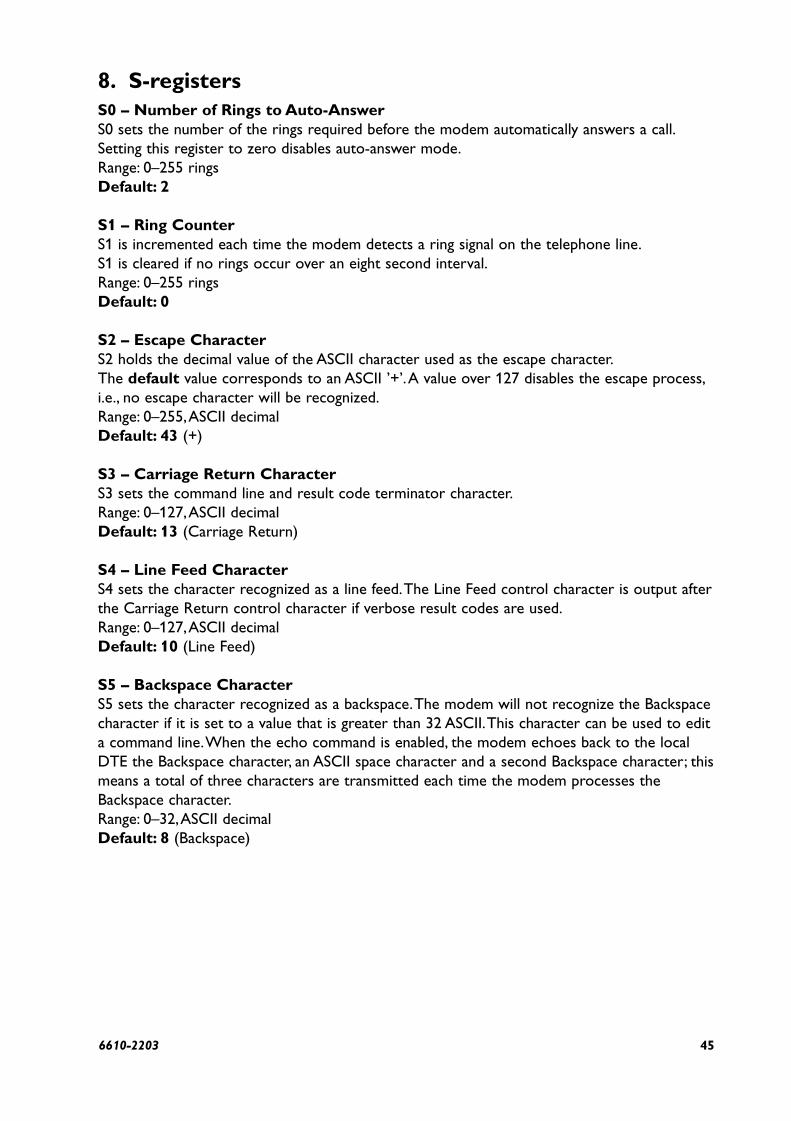
8. S-registersS0 – Number of Rings to Auto-AnswerS0 sets the number of the rings required before the modem automatically answers a call.Setting this register to zero disables auto-answer mode.Range: 0–255 ringsDefault: 2
S1 – Ring CounterS1 is incremented each time the modem detects a ring signal on the telephone line.S1 is cleared if no rings occur over an eight second interval.Range: 0–255 ringsDefault: 0
S2 – Escape CharacterS2 holds the decimal value of the ASCII character used as the escape character.The default value corresponds to an ASCII ’+’.A value over 127 disables the escape process,i.e., no escape character will be recognized.Range: 0–255,ASCII decimalDefault: 43 (+)
S3 – Carriage Return CharacterS3 sets the command line and result code terminator character.Range: 0–127,ASCII decimalDefault: 13 (Carriage Return)
S4 – Line Feed CharacterS4 sets the character recognized as a line feed.The Line Feed control character is output afterthe Carriage Return control character if verbose result codes are used.Range: 0–127,ASCII decimalDefault: 10 (Line Feed)
S5 – Backspace CharacterS5 sets the character recognized as a backspace.The modem will not recognize the Backspacecharacter if it is set to a value that is greater than 32 ASCII.This character can be used to edita command line.When the echo command is enabled, the modem echoes back to the localDTE the Backspace character, an ASCII space character and a second Backspace character; thismeans a total of three characters are transmitted each time the modem processes theBackspace character.Range: 0–32,ASCII decimalDefault: 8 (Backspace)

46 6610-2203
S6 – Wait Time before Blind Dialing or for Dial ToneSets the length of time, in seconds, that the modem will wait for dial tone when encounteringa “W” dial modifier before returning NO DIAL TONE result code.The modem always pauses for a minimum of 2 seconds, even if the value of S6 is less than 2seconds.Range: 2–60 secondsDefault: 4
S7 – Wait Time for Carrier, Silence, or Dial ToneS7operation is country dependent.1. Sets the length of time, in seconds, that the modem will wait for carrier before hanging up.
The timer is started when the modem finishes dialing (originate), or 2 seconds after goingoff-hook (answer). In originate mode, the timer is reset upon detection of answer tone ifallowed by country restrictions.
2. Sets the length of time, in seconds, that modem will wait for silence when encountering the@ dial modifier before continuing with the next dial string parameter.
Range: 1–255 secondsDefault: 50
S8 – Pause Time For Dial DelayS8 sets the time, in seconds, that the modem must pause when the “,” dial modifier is encoun-tered in the dial string.Range: 0–255 secondsDefault: 2
S9 – Carrier Detect Response TimeS9 is supported for backwards compatibility only. No value can be written. Responds withdefault value.Range: 6 tenths of a secondDefault: 6 (0.6 second)
S10 – Lost Carrier To Hang Up DelayS10 sets the length of time, in tenths of a second, that the modem waits before hanging upafter a loss of carrier.This allows for a temporary carrier loss without causing the localmodem to disconnect.When register S10 is set to 255, the modem functions as if a carrier isalways present.The actual interval the modem waits before disconnecting is the value in regis-ter S10 minus the value in register S9.Therefore, the S10 value must be greater than the S9 value or else the modem disconnectsbefore it recognizes the carrier.Range: 1–255 tenths of a secondDefault: 14 (1.4 seconds)
S11 – DTMF Tone DurationS11 operation is country dependent.Range: 50–255 millisecondsDefault: 95 (95 milliseconds)

476610-2203
S12 – Escape Prompt Delay (EPD)S12 defines the maximum period, in fiftieths of a second, allowed between receipt of the lastcharacter of the three escape character sequence from the DTE and sending of the OK resultcode to the DTE. If any characters are detected during this time, the OK will not be sent.Note that sending of the OK result code does not affect entry into command mode.Range: 0–255 1/50 of a secondDefault: 50 (1 second)
S13 – Callback delay timeS13 defines the time between the modem releasing the connection and dialing a stored call-back number.Range: 0–255 secondsDefault: 10 (10 seconds)
S14 – General Bit Mapped Options StatusS14 indicates the status of command options.Default: 138 (8Ah) (10001010b)Bit 0 This bit is ignored.Bit 1 Command echo (En)
0 = Disabled (E0)1 = Enabled (E1) (Default)
Bit 2 Quiet mode (Qn)0 = Send result codes (Q0) (Default)1 = Do not send result codes (Q1)
Bit 3 Result codes (Vn)0 = Numeric (V0)1 = Verbose (V1) (Default)
Bit 4 ReservedBit 5 Tone (T)
0 = Tone (T) (Default)Bit 6 Password (*Gn)
0 = Disabled (*G0) (Default)1 = Enabled (*G1)
Bit 7 Originate/Answer0 = Answer1 = Originate (Default)

48 6610-2203
S21 – V.24/General Bit Mapped Options StatusS21 indicates the status of command options.Default: 36 (24h) (00100100b)Bit 0 Reserved (0)Bit 1 Reserved (0)Bit 2 CTS behavior (&Rn)
0 = CTS tracks RTS (&R0)1 = CTS always on (&R1) (Default)
Bits 3–4 DTR behavior (&Dn)0 = &D0 selected (Default)1 = &D1 selected2 = &D2 selected 3 = &D3 selected
Bit 5 RLSD (DCD) behavior (&Cn)0 = &C0 selected1 = &C1 selected (Default)
Bit 6 DSR behavior (&Sn)0 = &S0 selected (Default)1 = &S1 selected
Bit 7 Long space disconnect (Yn)0 = Y0 (Default)1 = Y1
S22 Speaker/Results Bit Mapped Options StatusS22 indicates the status of commands options.Default: 117 (75h) (01110101b)Bits 0–1 Speaker volume (Ln)
0 = Off(L0)1 = Low(L1) (Default)2 = Medium(L2)3=High(L3)
Bits 2–3 Speaker Control (Mn)0 = Disabled (M0)1 = Off on carrier (M1) (Default)2 = Always on (M2)3= On during handshake
Bits 4-6 Limit result codes (Xn)0 = X04 = X15 = X26 = X37 = X4 (Default)
Bit7 Reserved

496610-2203
S25 – Delay To DTRS25 sets the length of time that the modem will ignore DTR for taking the action specified by&Dn. Its units are one hundredths of a second for other modes.Range: 0–255 (0.01 seconds)Default: 5 (0.05 seconds)
S29 – Flash Dial Modifier TimeS29 sets the length of time, in units of 10 ms, that the modem will go on-hook when itencounters the flash (!) dial modifier in the dial string.The time can be limited as it is a coun-try dependent parameter.Range: 0–255 10 ms intervalsDefault: 0 (0 ms)
S30 – Disconnect Inactivity TimerS30 sets the length of time, in tens of seconds, that the modem will stay online before discon-necting when no data is sent or received. In error-correction mode, any data transmitted orreceived will reset the timer. In other modes, any data transmitted will reset the timer.Range: 0–255 tens of seconds (0–2 550 seconds)Default: 0 (disabled)
S31 – Bit Mapped Options StatusS31 indicates bit mapped options status.Bit 0 Single line connect message enable/disable (\Vn)
0 = Messages controlled by S95,Wn and Vn (\V0) (Default)1 = Single line connect message (\V1)
Bit 1 Auto line speed detection (Nn)0 = Disabled (N0)1 = Enabled (N1) (Default)
Bits 2–3 Error correction progress messages (Wn)0 = DTE speed only (W0) 1 = Full reporting (W1) (Default)2 = DCE (line) speed only (W2)
Bits 4–5 Not used0 = (Default)
Bits 6–7 Reserved (Default = 11b)

50 6610-2203
S36 – LAPM Failure ControlDefault: 7 (00000111b)Bits 0–2 This value indicates what should happen upon a LAPM failure.These fallback optionsare initiated immediately upon connection if S48=128. If an invalid number is entered, the num-ber is accepted into the register, but S36 will act as if the default value has been entered.
0 = Modem disconnects.1 = Modem stays on-line and a Direct mode connection is established.2 = Reserved.3 = Modem stays on-line and a Normal mode connection is established.4 = An MNP connection is attempted and if it fails, the modem disconnects.5 = An MNP connection is attempted and if it fails, a Direct mode connection is
established.6 = Reserved.7 = An MNP connection is attempted and if it fails, a Normal mode connection is estab-
lished. (Default)Bits 3–7 Reserved
S38 – Delay Before Forced Hang UpS38 specifies the delay between the modem’s receipt of the H command to disconnect (or ON-to-OFF transition of DTR if the modem is programmed to follow the signal),and the disconnect operation.Applicable to error-correction connection only.This register canbe used to ensure that data in the modem buffer is sent before the modem disconnects.1. If S38 is set to a value between 0 and 254, the modem will wait that number of seconds for
the remote modem to acknowledge all data in the modem buffer before disconnecting. Iftime expires before all data is sent, the NO CARRIER result code will be issued to indicatethat data has been lost. If all data is transmitted prior to time-out, the response to the H0command will be OK.
2. If S38 is set to 255, the modem does not time-out and continues to attempt to deliver datain the buffer until the connection is lost or the data is delivered.
Range: 0–255 secondsDefault: 20
S39 – Flow Control Bit Mapped Options StatusDefault: 0Bits 0–2 Status of command options
0 = No flow control (Default)3 = RTS/CTS4 = XON/XOFF5 = Transparent XON
Bits 3–7 Reserved

516610-2203
S40 – General Bit Mapped Options StatusS40 indicates the status of command options.Default: 104 (68h) (01101000b)Bits 0–1 MNP Extended Services (-Kn)
0 = Disable extended services (-K0) (Default)1 = Enable extended services (-K1)2 = Enable extended services (-K2)
Bit 2 ReservedBits 3–5 Break Handling (\Kn)
0 = \K01 = \K12 = \K23 = \K34 = \K45 = \K5 (Default)
Bits 6–7 Reserved
S41 – General Bit Mapped Options StatusS41 indicates the status of command options.Default: 195 (C3h) (11000011b)Bits 0–1 Compression selection (%Cn)
0 = Disabled (%C0)1 = MNP 5 (%C1)2 = V.42 bis (%C2)3 = MNP 5 and V.42 bis (%C3) (Default)
Bits 2, 6 Auto retrain and fallback/fall forward (%En)Bit 6 Bit 2
0 0 = Retrain and fallback/fall forward disabled (%E0)0 1 = Retrain enabled (%E1)1 0 = Fallback/fall forward enabled (%E2) (Default)
Bit 3 ReservedBits 4–5 ReservedBit 7 Reserved
S46 – Data Compression ControlS46 controls selection of compression.The following actions are executed for the given values:Range: 136 or 138Default: 138
S46=136 Execute error correction protocol with no compression.S46=138 Execute error correction protocol with compression. (Default)

52 6610-2203
S48 – V.42 Negotiation ActionThe V.42 negotiation process determines the capabilities of the remote modem. However,when the capabilities of the remote modem are known and negotiation is unnecessary, thisprocess can be bypassed if so desired.Range: 0, 7, or 128 If an invalid number is entered, it is accepted into the S-Register, but S48will act as if 128 has been entered.Default: 7
S48=0 Disable negotiation; bypass the detection and negotiation phases; and proceed withLAPM.
S48=7 Enable negotiation. (Default)S48=128 Disable negotiation; bypass the detection and negotiation phases; and proceed at
once with the fallback action specified in S36. Can be used to force MNP.
S86 – Call Failure Reason CodeWhen the modem issues a NO CARRIER result code, a value is written to this S-Register tohelp determine the reason for the failed connection. S86 records the first event that con-tributes to a NO CARRIER message. Range: 0–24, the cause codes are:
S86= 0 Normal disconnect, no error occurred.S86= 4 Loss of carrier.S86= 5 V.42 negotiation failed to detect an error-correction modem at the other end.S86= 9 The modems could not find a common protocol.S86=12 Normal disconnect initiated by the remote modem.S86=13 Remote modem does not respond after 10 re-transmissions of the
same message.S86=14 Protocol violation.
S91 – PSTN Transmit Attenuation LevelS91 sets the transmit attenuation level for the PSTN mode.Range: 0 to 15Default: 12
S95 – Extended Result CodesA bit set to a 1 in this register will enable the corresponding result code regardless of the Wsetting.Default: 0Bit 0 CONNECT result code indicates DCE speed instead of DTE speed.Bit 1 Append/ARQ to CONNECT XXXX result code in error-correction mode (XXXX = rate).Bit 2 Enable +MCR: XXXX result code (XXXX = rate).Bit 3 Enable +ER: XXXX result code (XXXX = protocol identifier).Bit 4 Reserved.Bit 5 Enable +DR: result code (XXXX = compression type).Bit 6 Reserved.Bit 7 Reserved.

536610-2203
9. GlossaryASCIIA binary code system which defines 128 characters using different combinations of 1s and 0s.ASCII= American Standard Code for Information Interchange.
Asynchronous Data Transmission where the characters are transmitted one at a time, starting with a start bit and endingwith a stop bit.About 90–95% of all serial data communications are asynchronous.
Baud The number of data symbols transmitted every second. Often baud = bit/s. Sometimes a few data sym-bols can represent several bits since different coding are used to compress data.
BufferA memory for storing data for a short time, e.g. until the receiver is ready.
Byte A byte is a number of data bits (1s or 0s) which forms a character. Most often a character consistsof 7 or 8 bits.
DCEDescribes which direction the signals in the RS-232/V.24 contact have. Modems are often DCE.DCE = Data Communication Equipment.
DIN rail An installation rail which is used in apparatus cubicles to set up different equipment on a simple way.DIN = Deutsche Industri Norme.
DTE Same as DCE but the signals are directed on opposite directions.Terminals, PC’s and printers aremost often DTE. DTE = Data Terminal Equipment.
Data Compression and Error Correction.V.42 ITU-T’s error correction protocol incorporating LAPM. If the V.42 connection fails
then usually MNP will be tried.LAPM Link Access Procedure for Modems.An error correction method used in transmis-
sions via PTT modems.MNP Microcom Networking Protocol. Several methods for error correction and data
compression for PTT modems.MNP 1: Asynchronous Protocol, half duplex.MNP 2: Asynchronous Protocol, full duplex, Data is divided into blocks
(slower data rate).MNP 3: Synchronous Protocol, full duplex. Data in blocks
(higher speeds with no errors).MNP 4: Similar to 3, but with smaller data blocks allowing for faster data rates
with no errors.MNP 5: Level 4 with data compression, gives about double the data rate.MNP 10: Development of MNP5 with dynamic line monitoring and block size
adjustment, used on very bad lines (cellular phone connections).ARQ Automatic Repeat reQuest.When incorrect data is detected a request to retransmit
the data is made to the remote modem.V.42bis. Data Compression technique used by modems rather than MNP5, because it offers
better transmission on already compressed data.
54 6610-2203
Data RateIn modems this is often different to the baud rate. For instance the Data Rate of V.32bis is14 400bit/s and the baud rate is 2 400 symbols/second.
Direct ModeThe Data to be transmitted is sent directly to the data pump (the modem circuit). No compression,error correction or buffering occurs, allowing the data to be transmitted across the link unalteredby the modem.
Duplex Means that the communication is bi-directional. In half duplex, the devices take turns sending andreceiving. In full duplex, sending and receiving can take place simultaneously.
Hayes commands A set of commands for controlling PTT modems. Often referred to as the AT command set, since allcommands are started with AT. Most modems support these commands, but there are variations andcommands that are specific for a certain modem.
ISP Internet Service Provider.
LEDLight-Emitting Diode.A semi-conductor which emits light when it receives an electrical current.In modems they are used as indicators for data and status signals.
Modem Acronym of the words modulator and demodulator. Modulates or transforms the signal from computer equipment into electrical or acoustic signals for transmission.The receiver has a similar modem which retransforms the signal, demodulation.Modem Modulation StandardsV.21 300 bit/s, similar to Bell 103V.23 1 200/75 bit/s Split speed lineV.22 1 200 bit/s full duplex.V.22bis 2 400 bit/s full duplex.V.32 9 600 bit/s full duplex.V.32bis 14 400 bit/s full duplex.V.34 33 600 bit/s full duplex.
Modulation Techniques
DPSKDifferential Phase Shift Keying. Employed in data rates up to 4 800 bit/s.
FSKFrequency Shift Keying. Used in the lowest data rate standards.
QAMQuadrature Amplitude Modulation.A technique used for data rates up to 9 600 bit/s.
TCMTrellis Coded Modulation. Used in the high speed modulations.
556610-2203
NVRAMNon Volatile Random Access Memory. Consists most often by an EEPROM (Electronically Eraseableand Programmable memory). Used by the modem to store profile information and numbers evenwhen the unit has no power.
Normal ModeA non error corrected connection, where data is buffered.
Off HookLike picking up the receiver. Connecting to a line.
On HookLike hanging up the receiver. Disconnecting.
PSTNPublic Switched Telephone Network, i.e. a normal telephone line on which other subscribers can becalled.
ParityA mathematically derived bit which is added by the transmitter.The receiver checks it to detect anyerror in transmission. Occurring parities are even, odd and none.
REN Number The Ringer Equivalence Number (REN) is a way of measuring the load on the telephone line causedby the connected equipment.
RS-232/V.24 Signals
TDTransmitted Data. Data going from DTE to DCE.
RDReceived Data.The Data going from DCE to DTE.
RTSRequest To Send from DTE.
DSRData Set Ready.The DCE-equipment is powered and usable.
DTRData Terminal Ready.The DTE-equipment is powered and usable.
DCDData Carrier Detect.A signal from the DCE indicating that a carrier is present on the line.
Simplex Uni-directional communication.
Start bit Marks the start of a character at asynchronous communication.
Stop bit One or more stop bits marks the end of a character at asynchronous communication. Systems thatrequire more than one stop bit may have problems during communication via modems, sincemodems most often remove the second stop bit.

56 6610-2203
10. Dialback applications 1
TD-34 #1
2-wire leased line
#1 #4
TD-34 #2
PSTN
Equipment:2 pcs TD-34, 2-wire leased line, PSTN simulator, PC with terminal program, power supplies.
Switch settings:
TD-34 #1 TD-34 #2SW1 2, 3, 5, 6 ON 2, 3, 5, 6 ONSW2 All OFF All OFFSW3 All OFF All OFFSW4 All OFF 2 ON
AT commands: AT*WDB,AT*WSYNC
Application:Step 1: Configuration
Set switches on TD-34 #1 and #2Set switch SW3:5 OFF on TD-34 #1 and #2Power ON TD-34 #1 and #2AT*WDB=4,1,1 on TD-34 #1AT*WDB=2,0 on TD-34 #2Power OFF TD-34 #1 and #2Set switch SW3:5 ON on TD-34 #1 and #2
Step 2: DialbackPower ON TD-34 #1 and #2Wait for DCD on TD-34 #1 and #2Remove 2-wire leased line on TD-34 #2Wait for PSTN connectionInsert 2-wire leased line on TD-34 #2Wait for 2-wire leased line connection

576610-2203
11. Dialback applications 2
TD-34 #1
2-wire leased line
#1 #4
TD-34 #2 Modem #3
PSTN
Equipment:2 pcs TD-34, 1 pcs Modem, 2-wire leased line, PSTN simulator, PC with terminal program,power supplies.
Switch settings:
TD-34 #1 TD-34 #2 Modem #3SW1 2, 3, 5, 6 ON 2, 3, 5, 6 ON –SW2 All OFF All OFF –SW3 5 ON 5, 7 ON –SW4 3, 5, (8) ON (8) ON –
AT commands: AT*WDB,AT*WSYNC
Application:Step 1: Configuration
Set switches on TD-34 #1 and #2Set switch SW3:5 OFF on TD-34 #1Power ON TD-34 #1 and Moden #3Set Modem #3 with 9600, 8N1, auto modulationAT*WDB=4,1,1 on TD-34 #1Power OFF TD-34 #1 and Modem #3Set switch SW3:5 ON on TD-34 #1
Step 2: DialbackPower ON TD-34 #1, #2 and Modem #3Wait for DCD on TD-34 #1 and #2Remove 2-wire leased line on TD-34 #2Wait for PSTN connection (TD-34 # and Modem #3)
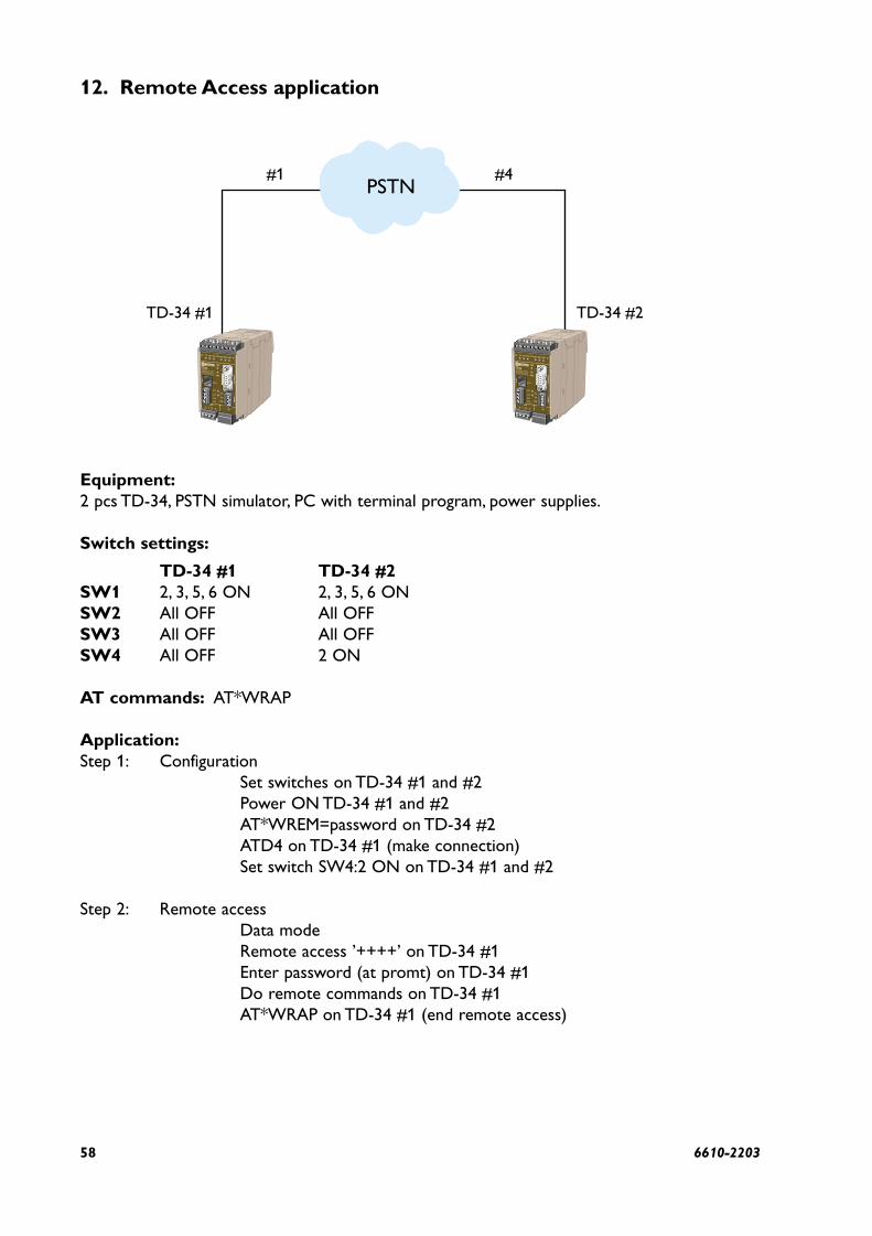
58 6610-2203
12. Remote Access application
TD-34 #1
#1 #4
TD-34 #2
PSTN
Equipment:2 pcs TD-34, PSTN simulator, PC with terminal program, power supplies.
Switch settings:
TD-34 #1 TD-34 #2SW1 2, 3, 5, 6 ON 2, 3, 5, 6 ONSW2 All OFF All OFFSW3 All OFF All OFFSW4 All OFF 2 ON
AT commands: AT*WRAP
Application:Step 1: Configuration
Set switches on TD-34 #1 and #2Power ON TD-34 #1 and #2AT*WREM=password on TD-34 #2ATD4 on TD-34 #1 (make connection)Set switch SW4:2 ON on TD-34 #1 and #2
Step 2: Remote accessData modeRemote access ’++++’ on TD-34 #1Enter password (at promt) on TD-34 #1Do remote commands on TD-34 #1AT*WRAP on TD-34 #1 (end remote access)
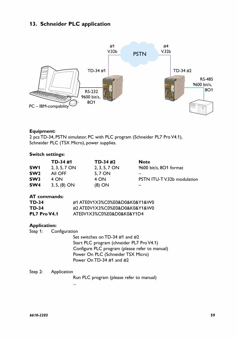
596610-2203
13. Schneider PLC application
TD-34 #1
PC – IBM-compability
#1V.32b
#4V.32b
RS-2329600 bit/s,
8O1
RS-4859600 bit/s,
8O1
TD-34 #2
PSTN
Equipment:2 pcs TD-34, PSTN simulator, PC with PLC program (Schneider PL7 Pro V4.1),Schneider PLC (TSX Micro), power supplies.
Switch settings:
TD-34 #1 TD-34 #2 NoteSW1 2, 3, 5, 7 ON 2, 3, 5, 7 ON 9600 bit/s, 8O1 formatSW2 All OFF 5, 7 ON –SW3 4 ON 4 ON PSTN ITU-T V.32b modulationSW4 3, 5, (8) ON (8) ON –
AT commands:TD-34 #1 ATE0V1X3%C0%E0&D0&K0&Y1&W0TD-34 #2 ATE0V1X3%C0%E0&D0&K0&Y1&W0PL7 Pro V4.1 ATE0V1X3%C0%E0&D0&K0&Y1D4
Application:Step 1: Configuration
Set switches on TD-34 #1 and #2Start PLC program (chneider PL7 Pro V4.1)Configure PLC program (please refer to manual)Power On PLC (Schneider TSX Micro)Power On TD-34 #1 and #2
Step 2: ApplicationRun PLC program (please refer to manual)...

60 6610-2203
OWN COMMENTS
.....................................................................................................................................................................................................................
.....................................................................................................................................................................................................................
.....................................................................................................................................................................................................................
.....................................................................................................................................................................................................................
.....................................................................................................................................................................................................................
.....................................................................................................................................................................................................................
.....................................................................................................................................................................................................................
.....................................................................................................................................................................................................................
.....................................................................................................................................................................................................................
.....................................................................................................................................................................................................................
.....................................................................................................................................................................................................................
.....................................................................................................................................................................................................................
.....................................................................................................................................................................................................................
.....................................................................................................................................................................................................................
.....................................................................................................................................................................................................................


T04
-027
7 •
6610
-220
304
.10
Mäl
artr
yck
AB
, E
skils
tuna
, S
wed
en
Application examples
TD-34
TD-34
240 V AC
+12 V DC
PSTN
–40°C
+70°C
4000 m
Westermo Teleindustri AB • SE-640 40 Stora Sundby, SwedenPhone +46 16 42 80 00 Fax +46 16 42 80 01
E-mail: [email protected] Web site: www.westermo.com
Westermo Teleindustri AB have distributors in several countries, contact us for further information.
Westermo Data Communications LtdUnit 14 Talisman Business Centre • Duncan RoadPark Gate, Southampton • SO31 7GAPhone: +44(0)1489 580 585 • Fax.:+44(0)1489 580586E-Mail: [email protected]
Westermo Data Communications GmbHGoethestraße 67, 68753 WaghäuselTel.: +49(0)7254-95400-0 • Fax.:+49(0)7254-95400-9E-Mail: [email protected]
Westermo Data Communications S.A.R.L.9 Chemin de Chilly 91160 CHAMPLANTél : +33 1 69 10 21 00 • Fax : +33 1 69 10 21 01E-mail : [email protected]
Subsidiaries


![[en]=> (LV-CAN200) - Teltonika Wiki](https://static.fdokumen.com/doc/165x107/63348b9f4e43a4bcd80d4495/en-lv-can200-teltonika-wiki.jpg)