The national income multiplier: Its theory its philosophy its utility
Upload
independentCategory
view
1download
0
Distributed Lagrange multiplier method for particulateflows with collisions
P. Singh a,*, T.I. Hesla b, D.D. Joseph b
a Department of Mechanical Engineering, New Jersey Institute of Technology,
University Heights, Newark, NJ 07102-1982, USAb Department of Aerospace Engineering and Mechanics, University of Minnesota, 107 Akerman Hall,
110 Union St. SE, Minneapolis, MN 55455, USA
Received 2 August 2001; received in revised form 25 November 2002
Abstract
A modified distributed Lagrange multiplier/fictitious domain method (DLM) that allows particles to
undergo collisions is developed for particulate flows. In the earlier versions of the DLM method for
Newtonian and viscoelastic liquids the particle surfaces were restricted to be more than one velocity elementaway from each other. A repulsive body force was applied to the particles when the distance between them
was smaller than this critical value. This was necessary for ensuring that conflicting rigid body motion
constraints from two different particles are not imposed at the same velocity nodes.
In the modified DLM method the particles are allowed to come arbitrarily close to each other and even
slightly overlap each other. When conflicting rigid body motion constraints from two different particles are
applicable on a velocity node, the constraint from the particle that is closer to that node is used and the
other constraint is dropped. An elastic repulsive force is applied when the particles overlap each other. In
our simulations, the particles are allowed to overlap as much as one hundredth of the velocity element size.The modified DLM method is implemented for both Newtonian and viscoelastic liquids.
Our simulations show that when particles are dropped in a channel, and the viscoelastic Mach number
(M) is less than one and the elasticity number (E) is greater than one, the particles form a chain parallel to
the flow direction. As in experiments, the new method allows particles in the chain to approximately touch
each other. The particles dropped in a Newtonian liquid, on the other hand, undergo characteristic
drafting, kissing and tumbling. During the touching phase, as in experiments, the two particles touch each
other. The modified method thus allows hydrodynamic forces to be fully resolved to within the tolerance of
the mesh and thus the extra artificial force in a security zone outside the particle which are used in all othermethods are not needed.
2003 Elsevier Science Ltd. All rights reserved.
International Journal of Multiphase Flow 29 (2003) 495–509www.elsevier.com/locate/ijmulflow
*Corresponding author. Tel.: +1-973-596-3326; fax: +1-973-642-4282.
E-mail addresses: [email protected] (P. Singh), [email protected] (D.D. Joseph).
0301-9322/03/$ - see front matter 2003 Elsevier Science Ltd. All rights reserved.
doi:10.1016/S0301-9322(02)00164-7
Keywords: Particulate flows; Finite element method; Direct numerical simulations; Viscoelastic fluid; Oldroyd-B fluid;
Particle collisions
1. Introduction
Collisions––or near-collisions––between particles present severe difficulties in direct simulationsof particulate flows. In point of fact, however, smooth particles cannot actually contact each otherin finite time in the continuous system (also see Leal, 1992). In light of this, the term ‘‘collision’’ issomewhat misleading––at least for smooth particles. However, since the gap width can becomeexceedingly small in certain situations, numerical truncation errors may allow actual contact (oreven overlap) to occur in simulations.Even near-collisions can greatly increase the cost of a simulation, because in order to simulate
the particle–particle interaction mechanism, the flow fields in the narrow gap between the con-verging particle surfaces must be accurately resolved. The element size required for this decreaseswith the gap width, leading to extremely small elements and greatly increased numbers of un-knowns to be solved for. Actual overlap can lead to overdetermined systems of equations, andmust thus be prevented at all costs.In numerical simulations to date (Glowinski et al., 1998; Singh et al., 2000; Huang et al., 1998;
Hu, 1996; Huang et al., 1997; Glowinski et al., 1997; Girault et al., 1999), this problem is avoidedby introducing an artificial repulsive force between particles which keeps the particle surfacesmore than one element apart from each other. In the standard distributed Lagrange multiplier/fictitious domain (DLM) method (Glowinski et al., 1998; Singh et al., 2000; Glowinski et al., 1997;Girault et al., 1999), this ensures that the differing rigid-body motion constraints of the twoparticles are not simultaneously imposed at any one velocity node, which would lead to a nu-merically overdetermined system of equations. In the arbitrary Lagrangian–Eulerian (ALE)method (Huang et al., 1998; Hu, 1996; Huang et al., 1997), it ensures that the element size doesnot become excessively small. The ALE method requires two layers of elements in the gap betweenthe converging surfaces.In this paper, we present a modification of the DLM finite-element scheme described in
(Glowinski et al., 1998; Singh et al., 2000) which allows particles to come arbitrarily close to eachother, and even overlap slightly. The basic idea, which is due to D.D. Joseph, is to simply drop oneof the conflicting rigid-body motion constraint terms in the equation of motion – the one cor-responding to the particle surface which is farther away from the node in question. This trickavoids overdetermined systems of equations, but is applicable only as long as the overlap of theparticles does not exceed one element. An elastic repulsive force is introduced to prevent particlesfrom overlapping more than that.The modified DLM method is verified by comparing the time dependent trajectories for two
circular particles falling in a channel for two different mesh refinements, and for two different timesteps. It is shown that the results are independent of the mesh resolution and the time step.It was discussed in (Glowinski et al., 1998; Singh et al., 2000; Fortes et al., 1987; Joseph et al.,
1987) that when two or more particles are dropped in a channel filled with a viscoelastic liquid theorientation of particles relative to the direction of flow is determined by the viscoelastic Mach
496 P. Singh et al. / International Journal of Multiphase Flow 29 (2003) 495–509
number M ¼ffiffiffiffiffiffiffiffiffiffiffiReDe
pand the elasticity number E ¼ De=Re. Here De ¼ Ukr=D is the Deborah
number, and Re ¼ qLUD=g is the Reynolds number, where kr is the relaxation time of the fluid, gis the zero shear viscosity of the fluid, U is the particle velocity, and D is the particle diameter.Specifically, when M < 1 and E > 1, the particles align themselves parallel to the flow direction.The distance between the particles of a chain may be very small. In fact, the particles may evenapproximately touch each other. On the other hand, when these conditions are not satisfied, orwhen the fluid is Newtonian, the particles undergo drafting, kissing and tumbling. Experimentsshow that during kissing the particles come very close to each other, and may even approximatelytouch each other.In the next section the strong and weak forms of governing equations as well as the modified
DLM scheme that allows particle–particle near collisions is presented. In the last section, wepresent several test cases to validate the scheme.
2. Computational scheme
The computational scheme we propose is a modification of the DLM finite-element schemedescribed in Glowinski et al. (1998) and Singh et al. (2000). In this scheme, the fluid flowequations are solved on the combined fluid–solid domain, and the motion inside the particleboundaries is forced to be rigid-body motion using a distributed Lagrange multiplier. The fluidand particle equations of motion are combined into a single combined weak equation of motion,eliminating the hydrodynamic forces and torques, which helps ensure stability of the time inte-gration. The time integration is performed using the Marchuk–Yanenko operator splittingmethod, which is first-order accurate. See Glowinski et al. (1998) and Singh et al. (2000) forfurther details.
2.1. Governing equations
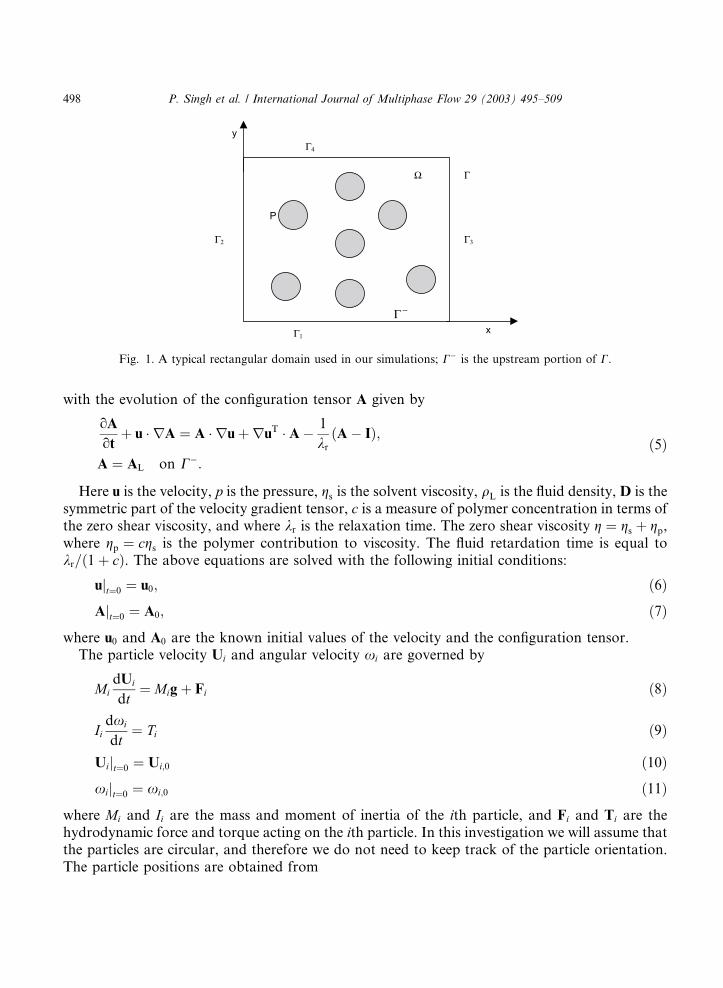
In this paper we will present results for two-dimensional flows. Let us denote the domaincontaining the Newtonian or viscoelastic fluid and N particles by X, and the interior of the ithparticle by PiðtÞ. For simplicity we will assume that the domain is rectangular with boundary C.The four sides of the domain will be denoted by C1, C2, C3, and C4 (see Fig. 1), and C will be usedto denote the upstream part of C. The viscoelastic fluid is modeled by the Oldroyd-B model. Thegoverning equations for the fluid-particle system are:
qLou
ot
þ u ru
¼ qLgrp þr c
krA
þr ð2gsDÞ in X n PðtÞ; ð1Þ
r u ¼ 0 in X n P ðtÞ; ð2Þ
u ¼ uL on C; ð3Þ
u ¼ Ui þ xi ri on oPiðtÞ; i ¼ 1; . . . ;N ; ð4Þ
P. Singh et al. / International Journal of Multiphase Flow 29 (2003) 495–509 497
with the evolution of the configuration tensor A given by
oA
otþ u rA ¼ A ruþruT A 1
krðA IÞ;
A ¼ AL on C:
ð5Þ
Here u is the velocity, p is the pressure, gs is the solvent viscosity, qL is the fluid density, D is thesymmetric part of the velocity gradient tensor, c is a measure of polymer concentration in terms ofthe zero shear viscosity, and where kr is the relaxation time. The zero shear viscosity g ¼ gs þ gp,where gp ¼ cgs is the polymer contribution to viscosity. The fluid retardation time is equal tokr=ð1þ cÞ. The above equations are solved with the following initial conditions:
ujt¼0 ¼ u0; ð6ÞAjt¼0 ¼ A0; ð7Þ
where u0 and A0 are the known initial values of the velocity and the configuration tensor.The particle velocity Ui and angular velocity xi are governed by
MidUi
dt¼ Migþ Fi ð8Þ
Iidxi
dt¼ Ti ð9Þ
Uijt¼0 ¼ Ui;0 ð10Þxijt¼0 ¼ xi;0 ð11Þ
where Mi and Ii are the mass and moment of inertia of the ith particle, and Fi and Ti are thehydrodynamic force and torque acting on the ith particle. In this investigation we will assume thatthe particles are circular, and therefore we do not need to keep track of the particle orientation.The particle positions are obtained from
Ω Γ
P
Γ1
Γ4
Γ2 Γ3
−Γx
y
Fig. 1. A typical rectangular domain used in our simulations; C is the upstream portion of C.
498 P. Singh et al. / International Journal of Multiphase Flow 29 (2003) 495–509
dXi
dt¼ Ui ð12Þ
Xijt¼0 ¼ Xi;0 ð13Þ
where Xi;0 is the position of the ith particle at time t ¼ 0.
2.2. Weak form of equations and finite-element discretization
The approach used for obtaining the weak form of the governing equations stated in theprevious section was described in Glowinski et al. (1998), Singh et al. (2000) and Glowinski et al.(1997). In obtaining this weak form, the hydrodynamic forces and torques acting on the particlescan be completely eliminated by combining the fluid and particle equations of motion into a singleweak equation of motion for the combined fluid-particle system. For simplicity, in this section wewill assume that there is only one particle. The extension to the many-particle case is straight-forward.The solution and variation are required to satisfy the strong form of the constraint of rigid
body motion throughout P ðtÞ. In the distributed Lagrange multiplier method this constraint isremoved from the velocity space and enforced weakly as a side constraint using a distributedLagrange multiplier term. It was shown in Glowinski et al. (1998) and Glowinski et al. (1997) thatthe following weak formulation of the problem holds in the extended domain:For a.e. t > 0, find u 2 W uC, A 2 W A, p 2 L20ðXÞ, k 2 KðtÞ, U 2 R2, and x 2 R, satisfying
ZX
qLdu
dt
g
vdx
ZXpr vdxþ
ZX2gsD½u : D½vdx
Z
Xv r c
krA
dxþ 1
qL
qd
M
dU
dt
g
Vþ I
dxdt
n
F0 V
¼ hk; v ðVþ n rÞiP ðtÞ for all v 2 W 0;V 2 R2; and n 2 R; ð14ÞZ
Xqr:udx ¼ 0 for all q 2 L2ðXÞ; ð15Þ
hl; u ðUþ x rÞiPðtÞ ¼ 0 for all l 2 KðtÞ; ð16ÞZ
X
oA
ot
þ u rA A ruruT Aþ 1
krðA IÞ
sdx ¼ 0 for all s 2 W A0; ð17Þ
ujt¼0 ¼ u0 in X; ð18Þ
Ajt¼0 ¼ A0 in X; ð19Þ
as well as the kinematic equations and the initial conditions for the particle linear and angularvelocities. Here F0 is the additional body force applied to the particles to limit the extent of overlap(see (27) below) and k is the distributed Lagrange multiplier
P. Singh et al. / International Journal of Multiphase Flow 29 (2003) 495–509 499
W uC ¼ fv 2 H 1ðXÞ2jv ¼ uCðtÞ on Cg;W 0 ¼ H 1
0 ðXÞ2;W A ¼ fA 2 H 1ðXÞ3jA ¼ ALðtÞ on Cg;W A0 ¼ fA 2 H 1ðXÞ3jA ¼ 0 on Cg;
L20ðXÞ ¼ q 2 L2ðXÞjZ
Xqdx
¼ 0
;
ð20Þ
and KðtÞ is L2ðP ðtÞÞ2, with h:; :iPðtÞ denoting the L2 inner product over the particle, where C is theupstream part of C. In our simulations, since the velocity and l are in L2, we will use the followinginner product
hl; viPðtÞ ¼ZP ðtÞ
ðl vÞdx: ð21Þ
In order to solve the above problem numerically, we will discretize the domain using a regularfinite element triangulation Th for the velocity and configuration tensor, where h is the mesh size,and a regular triangulation T2h for the pressure. The following finite dimensional spaces are de-fined for approximating W uC, W 0, W A, W A0, L2ðXÞ and L20ðXÞ:
WuC;h ¼ fvh 2 C0ðXXÞ2jvhjT 2 P1 P1 for all T 2 Th; vh ¼ uC;h on Cg;W0;h ¼ fvh 2 C0ðXXÞ2jvhjT 2 P1 P1 for all T 2 Th; vh ¼ 0 on Cg;
ð22Þ
L2h ¼ fqh 2 C0ðXXÞjqhjT 2 P1 for all T 2 T2hg;
L20;h ¼ fqh 2 L2hjZ
Xqh dx ¼ 0g;
ð23Þ
WAh ¼ fsh 2 C0ðXXÞ3jshjT 2 P1 P1 P1 for all T 2 Th; sh ¼ AL;h on Cg;WA0;h ¼ fsh 2 C0ðXXÞ3jshjT 2 P1 P1 P1 for all T 2 Th; sh ¼ 0 on Cg;
ð24Þ
where C is the upstream part of C. The particle inner product terms in (14) and (16) are dis-cretized using a triangular mesh similar to the one used in Singh et al. (2000).
2.3. Collisions and near-collisions
When there is more than one particle, the right-hand side of (14) becomes a sum of particleinner product terms, one for each particle, and there is a separate equation like (16) for eachparticle. If two particles overlap, the problem becomes overconstrained in the overlap region. Thetwo ‘‘copies’’ of (16) represent incompatible side constraints on u. And on the right-hand side of(14), the terms corresponding to the two overlapping particles represent two supposedly inde-pendent distributed Lagrange multipliers, associated with the respective rigid-body motion con-straints. But as just noted, these constraints are incompatible.In the finite-element discretized equations, the problem becomes overconstrained even before
the particles actually overlap. Specifically, it becomes overconstrained when two particles overlap
500 P. Singh et al. / International Journal of Multiphase Flow 29 (2003) 495–509
a single velocity element. The velocity field u is a single linear function on this element, but the twodiscretized ‘‘copies’’ of (16) are ‘‘trying’’ to force it to match two different rigid motions (in theportions of the element which overlap the respective particles).In Glowinski et al. (1998) and Singh et al. (2000), this situation was avoided by imposing a
particle–particle repulsive force strong enough to ensure that the particle–particle gap never be-comes so small that both particles intersect a single velocity element. In the modified DLMscheme described in this article we allow the particles to touch or slightly overlap, and eliminatethe inconsistency in the equations by the following strategy: if each particle inner product isrepresented by a nonsymmetric matrix, whose rows correspond to the nodes of the particle mesh,and whose columns correspond to the nodes of the velocity mesh, then for a given particle, we‘‘zero out’’ any column which corresponds to a velocity node which is closer to (the center of)another particle. In other words:(1) If v is a velocity test function corresponding to a given one of the three vertices of a velocityelement overlapped by two particles, we drop, from the right-hand side of (14), the particle in-ner product term corresponding to the particle whose center is farther from the given vertex.(2) In the ‘‘copy’’ of (16) corresponding to a given particle, if l is any particle test function forthat particles mesh and the velocity field u is expanded with respect to the global velocity basisfunctions, then we drop any nonzero terms corresponding to velocity nodes which are closer toanother particle.
A little reflection will convince the reader that the resulting equations are no longer overdeter-mined––even when two particles overlap––as long as the overlap is not too large.In our code, we impose a repulsive force when the particles overlap. In simulations, the re-
pulsive force is assumed to be large enough so that the overlap between the particles and the wallsis smaller than one hundredth of the velocity element size. The additional body force––which isrepulsive in nature––is added to (8). The particle–particle repulsive force is given by
FPij ¼
0 for di > 2RkðXi XjÞð2R di;jÞ for di < 2R
ð25Þ
where di;j is the distance between the centers of the ith and jth particles, R is the particle radiuswhich is assumed to be the same for all particles, Xi and Xj are the position vectors of the particlecenters, and k is the stiffness parameter. The repulsive force between the particles and the wall isgiven by
FWij ¼ 0 for di > 2R
kwðXi XjÞð2R diÞ for di > 2R
ð26Þ
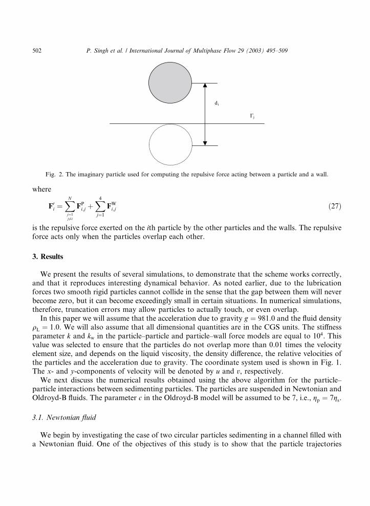
where di is the distance between the centers of the ith particle and the imaginary particle on theother side of the wall Cj, and kw is the stiffness parameter for particle wall collision (see Fig. 2).The above particle–particle repulsive forces and the particle–wall repulsive forces are added to (8)to obtain
MidUi
dt¼ Migþ Fi þ F0
i
P. Singh et al. / International Journal of Multiphase Flow 29 (2003) 495–509 501
where
F0i ¼
XNj¼1j6¼i
FPi;j þX4j¼1FWi;j ð27Þ
is the repulsive force exerted on the ith particle by the other particles and the walls. The repulsiveforce acts only when the particles overlap each other.
3. Results
We present the results of several simulations, to demonstrate that the scheme works correctly,and that it reproduces interesting dynamical behavior. As noted earlier, due to the lubricationforces two smooth rigid particles cannot collide in the sense that the gap between them will neverbecome zero, but it can become exceedingly small in certain situations. In numerical simulations,therefore, truncation errors may allow particles to actually touch, or even overlap.In this paper we will assume that the acceleration due to gravity g ¼ 981:0 and the fluid density
qL ¼ 1:0. We will also assume that all dimensional quantities are in the CGS units. The stiffnessparameter k and kw in the particle–particle and particle–wall force models are equal to 104. Thisvalue was selected to ensure that the particles do not overlap more than 0.01 times the velocityelement size, and depends on the liquid viscosity, the density difference, the relative velocities ofthe particles and the acceleration due to gravity. The coordinate system used is shown in Fig. 1.The x- and y-components of velocity will be denoted by u and v, respectively.We next discuss the numerical results obtained using the above algorithm for the particle–
particle interactions between sedimenting particles. The particles are suspended in Newtonian andOldroyd-B fluids. The parameter c in the Oldroyd-B model will be assumed to be 7, i.e., gp ¼ 7gs.
3.1. Newtonian fluid
We begin by investigating the case of two circular particles sedimenting in a channel filled witha Newtonian fluid. One of the objectives of this study is to show that the particle trajectories
Γj
di
Fig. 2. The imaginary particle used for computing the repulsive force acting between a particle and a wall.
502 P. Singh et al. / International Journal of Multiphase Flow 29 (2003) 495–509
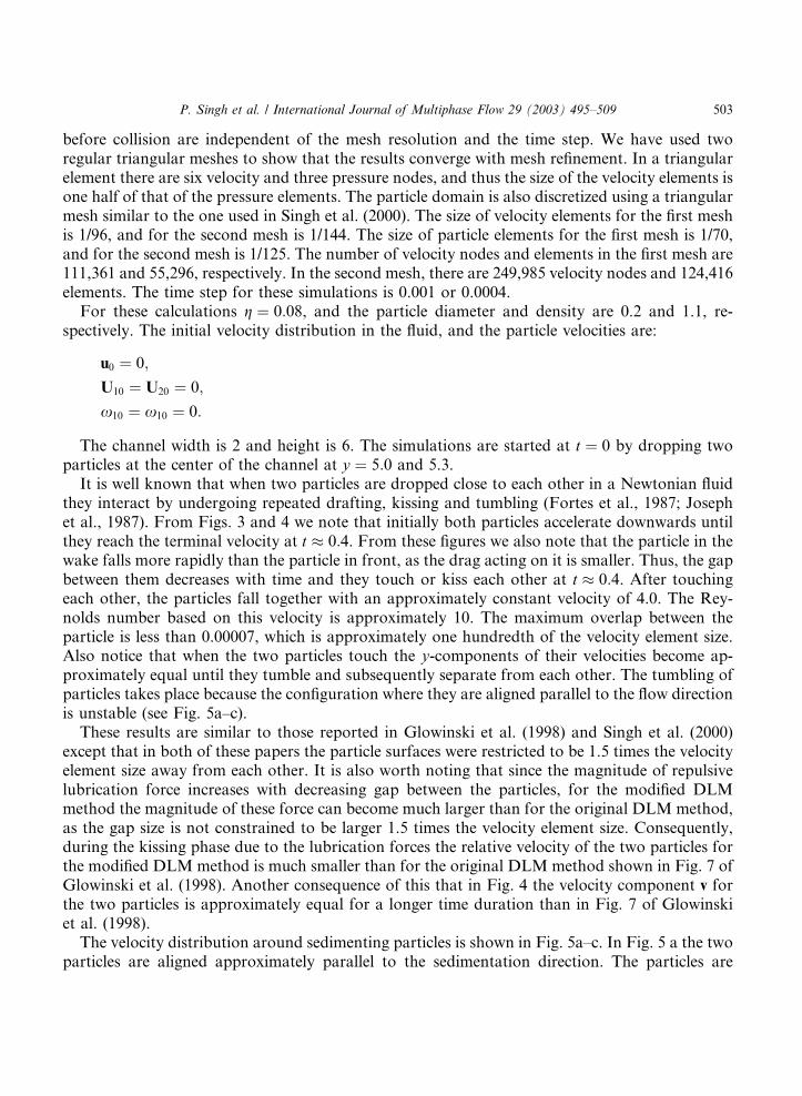
before collision are independent of the mesh resolution and the time step. We have used tworegular triangular meshes to show that the results converge with mesh refinement. In a triangularelement there are six velocity and three pressure nodes, and thus the size of the velocity elements isone half of that of the pressure elements. The particle domain is also discretized using a triangularmesh similar to the one used in Singh et al. (2000). The size of velocity elements for the first meshis 1/96, and for the second mesh is 1/144. The size of particle elements for the first mesh is 1/70,and for the second mesh is 1/125. The number of velocity nodes and elements in the first mesh are111,361 and 55,296, respectively. In the second mesh, there are 249,985 velocity nodes and 124,416elements. The time step for these simulations is 0.001 or 0.0004.For these calculations g ¼ 0:08, and the particle diameter and density are 0.2 and 1.1, re-
spectively. The initial velocity distribution in the fluid, and the particle velocities are:
u0 ¼ 0;U10 ¼ U20 ¼ 0;x10 ¼ x10 ¼ 0:
The channel width is 2 and height is 6. The simulations are started at t ¼ 0 by dropping twoparticles at the center of the channel at y ¼ 5:0 and 5.3.It is well known that when two particles are dropped close to each other in a Newtonian fluid
they interact by undergoing repeated drafting, kissing and tumbling (Fortes et al., 1987; Josephet al., 1987). From Figs. 3 and 4 we note that initially both particles accelerate downwards untilthey reach the terminal velocity at t 0:4. From these figures we also note that the particle in thewake falls more rapidly than the particle in front, as the drag acting on it is smaller. Thus, the gapbetween them decreases with time and they touch or kiss each other at t 0:4. After touchingeach other, the particles fall together with an approximately constant velocity of 4.0. The Rey-nolds number based on this velocity is approximately 10. The maximum overlap between theparticle is less than 0.00007, which is approximately one hundredth of the velocity element size.Also notice that when the two particles touch the y-components of their velocities become ap-proximately equal until they tumble and subsequently separate from each other. The tumbling ofparticles takes place because the configuration where they are aligned parallel to the flow directionis unstable (see Fig. 5a–c).These results are similar to those reported in Glowinski et al. (1998) and Singh et al. (2000)
except that in both of these papers the particle surfaces were restricted to be 1.5 times the velocityelement size away from each other. It is also worth noting that since the magnitude of repulsivelubrication force increases with decreasing gap between the particles, for the modified DLMmethod the magnitude of these force can become much larger than for the original DLM method,as the gap size is not constrained to be larger 1.5 times the velocity element size. Consequently,during the kissing phase due to the lubrication forces the relative velocity of the two particles forthe modified DLM method is much smaller than for the original DLM method shown in Fig. 7 ofGlowinski et al. (1998). Another consequence of this that in Fig. 4 the velocity component v forthe two particles is approximately equal for a longer time duration than in Fig. 7 of Glowinskiet al. (1998).The velocity distribution around sedimenting particles is shown in Fig. 5a–c. In Fig. 5 a the two
particles are aligned approximately parallel to the sedimentation direction. The particles are
P. Singh et al. / International Journal of Multiphase Flow 29 (2003) 495–509 503
touching each other. Fig. 5b shows the velocity distribution at t ¼ 0:625 when the particles arebeginning to tumble. The last figure in the sequence shows the velocity distribution when theparticles have separated from each other. These figures show that the velocity at the nodes that arecloser to the upper particle is constrained by the upper particle, and that for the nodes closer tothe lower particle is constrained by the lower particle. The method therefore allows the particles totouch as well as slightly overlap each other.In Figs. 3 and 4 we have shown the x and y-components of positions and velocities as a function
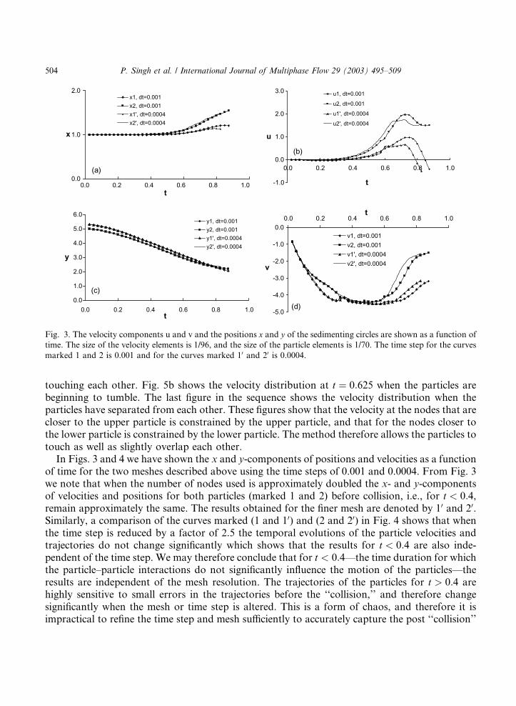
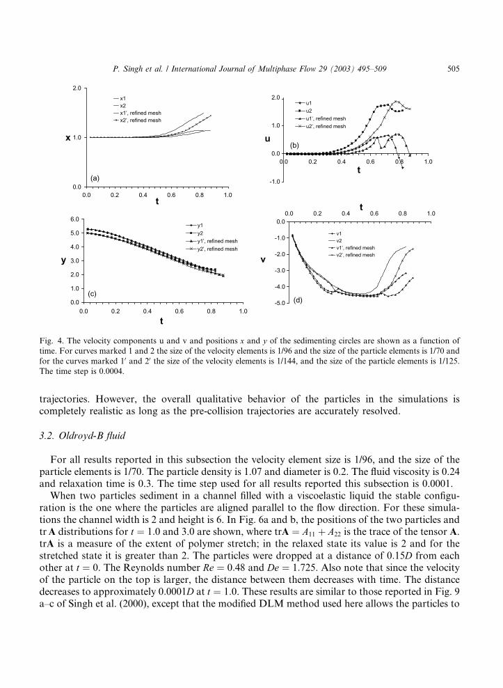
of time for the two meshes described above using the time steps of 0.001 and 0.0004. From Fig. 3we note that when the number of nodes used is approximately doubled the x- and y-componentsof velocities and positions for both particles (marked 1 and 2) before collision, i.e., for t < 0:4,remain approximately the same. The results obtained for the finer mesh are denoted by 10 and 20.Similarly, a comparison of the curves marked (1 and 10) and (2 and 20) in Fig. 4 shows that whenthe time step is reduced by a factor of 2.5 the temporal evolutions of the particle velocities andtrajectories do not change significantly which shows that the results for t < 0:4 are also inde-pendent of the time step. We may therefore conclude that for t < 0:4––the time duration for whichthe particle–particle interactions do not significantly influence the motion of the particles––theresults are independent of the mesh resolution. The trajectories of the particles for t > 0:4 arehighly sensitive to small errors in the trajectories before the ‘‘collision,’’ and therefore changesignificantly when the mesh or time step is altered. This is a form of chaos, and therefore it isimpractical to refine the time step and mesh sufficiently to accurately capture the post ‘‘collision’’
0.0
1.0
2.0
0.0
(a)
0.2 0.4 0.6 0.8 1.0t
x
x1, dt=0.001x2, dt=0.001x1', dt=0.0004x2', dt=0.0004
(b)
-1.0
0.0
1.0
2.0
3.0
0.0 0.2 0.4 0.6 0.8 1.0
t
u
u1, dt=0.001
u2, dt=0.001
u1', dt=0.0004
u2', dt=0.0004
(c)0.0
1.0
2.0
3.0
4.0
5.0
6.0
0.0 0.2 0.4 0.6 0.8 1.0t
y
y1, dt=0.001y2, dt=0.001y1', dt=0.0004y2', dt=0.0004
(d)-5.0
-4.0
-3.0
-2.0
-1.0
0.00.0 0.2 0.4 0.6 0.8 1.0
t
v
v1, dt=0.001v2, dt=0.001v1', dt=0.0004v2', dt=0.0004
Fig. 3. The velocity components u and v and the positions x and y of the sedimenting circles are shown as a function oftime. The size of the velocity elements is 1/96, and the size of the particle elements is 1/70. The time step for the curves
marked 1 and 2 is 0.001 and for the curves marked 10 and 20 is 0.0004.
504 P. Singh et al. / International Journal of Multiphase Flow 29 (2003) 495–509
trajectories. However, the overall qualitative behavior of the particles in the simulations iscompletely realistic as long as the pre-collision trajectories are accurately resolved.
3.2. Oldroyd-B fluid
For all results reported in this subsection the velocity element size is 1/96, and the size of theparticle elements is 1/70. The particle density is 1.07 and diameter is 0.2. The fluid viscosity is 0.24and relaxation time is 0.3. The time step used for all results reported this subsection is 0.0001.When two particles sediment in a channel filled with a viscoelastic liquid the stable configu-
ration is the one where the particles are aligned parallel to the flow direction. For these simula-tions the channel width is 2 and height is 6. In Fig. 6a and b, the positions of the two particles andtrA distributions for t ¼ 1:0 and 3.0 are shown, where trA ¼ A11 þ A22 is the trace of the tensor A.trA is a measure of the extent of polymer stretch; in the relaxed state its value is 2 and for thestretched state it is greater than 2. The particles were dropped at a distance of 0:15D from eachother at t ¼ 0. The Reynolds number Re ¼ 0:48 and De ¼ 1:725. Also note that since the velocityof the particle on the top is larger, the distance between them decreases with time. The distancedecreases to approximately 0:0001D at t ¼ 1:0. These results are similar to those reported in Fig. 9a–c of Singh et al. (2000), except that the modified DLM method used here allows the particles to
0.0
1.0
(a)
2.0
0.0 0.2 0.4 0.6 0.8 1.0t
x
x1x2x1’, refined meshx2’, refined mesh
(b)
-1.0
0.0
1.0
2.0
0.0 0.2 0.4 0.6 0.8 1.0
t
u
u1
u2
u1’, refined mesh
u2’, refined mesh
(c)0.0
1.0
2.0
3.0
4.0
5.0
6.0
0.0 0.2 0.4 0.6 0.8 1.0
t
y
y1
y2
y1’, refined mesh
y2’, refined mesh
(d)-5.0
-4.0
-3.0
-2.0
-1.0
0.00.0 0.2 0.4 0.6 0.8 1.0
t
v
v1v2v1’, refined meshv2’, refined mesh
Fig. 4. The velocity components u and v and positions x and y of the sedimenting circles are shown as a function oftime. For curves marked 1 and 2 the size of the velocity elements is 1/96 and the size of the particle elements is 1/70 and
for the curves marked 10 and 20 the size of the velocity elements is 1/144, and the size of the particle elements is 1/125.
The time step is 0.0004.
P. Singh et al. / International Journal of Multiphase Flow 29 (2003) 495–509 505

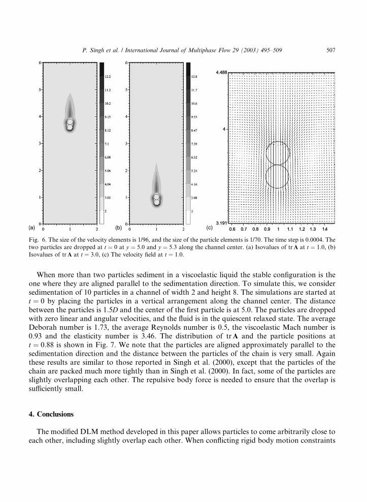
come closer to each other. Also notice that the distance between particles in Fig. 6 is comparableto that for experiments. From Fig. 6a and b, where we have shown the isovalues of trA, we notethat trA in front of the leading particle and around the particles is relatively large. This figure alsoshows that it takes some time for the fluid to relax back to the state of equilibrium. This gives riseto the characteristic streak lines that are indicative of the hyperbolic nature of the constitutiveequation for the stress. For this case since the viscoelastic Mach number is 0.9 and the elasticitynumber is 3.59, there is a strong tendency for the particles to align parallel to the falling direction.The velocity distribution around particles is shown in Fig. 6c.
0.7 0.8 0.9 1 1.1 1.2 1.33.164
(a) (b)
(c)
3.2
3.3
3.4
3.5
3.6
3.7
3.8
3.9
3.979
0.8 0.9 1 1.1 1.2 1.3 1.3852.611
2.7
2.8
2.9
3
3.1
3.2
3.3
3.4
3.467
0.909 5 1 1.1 1.2 1.3 1.4 1.5 1.599
1.5
1.6
1.7
1.8
1.9
2
2.1
2.2
2.296
Fig. 5. A magnified view of the velocity field near the particles is shown. For (a), (b) and (c), t ¼ 0:5, 0.625 and 0.878,respectively. The size of the velocity elements is 1/96, and the size of the particle elements is 1/70. The time step is 0.0004.
506 P. Singh et al. / International Journal of Multiphase Flow 29 (2003) 495–509
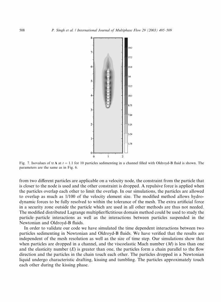
When more than two particles sediment in a viscoelastic liquid the stable configuration is theone where they are aligned parallel to the sedimentation direction. To simulate this, we considersedimentation of 10 particles in a channel of width 2 and height 8. The simulations are started att ¼ 0 by placing the particles in a vertical arrangement along the channel center. The distancebetween the particles is 1:5D and the center of the first particle is at 5.0. The particles are droppedwith zero linear and angular velocities, and the fluid is in the quiescent relaxed state. The averageDeborah number is 1.73, the average Reynolds number is 0.5, the viscoelastic Mach number is0.93 and the elasticity number is 3.46. The distribution of trA and the particle positions att ¼ 0:88 is shown in Fig. 7. We note that the particles are aligned approximately parallel to thesedimentation direction and the distance between the particles of the chain is very small. Againthese results are similar to those reported in Singh et al. (2000), except that the particles of thechain are packed much more tightly than in Singh et al. (2000). In fact, some of the particles areslightly overlapping each other. The repulsive body force is needed to ensure that the overlap issufficiently small.
4. Conclusions
The modified DLM method developed in this paper allows particles to come arbitrarily close toeach other, including slightly overlap each other. When conflicting rigid body motion constraints
Fig. 6. The size of the velocity elements is 1/96, and the size of the particle elements is 1/70. The time step is 0.0004. The
two particles are dropped at t ¼ 0 at y ¼ 5:0 and y ¼ 5:3 along the channel center. (a) Isovalues of trA at t ¼ 1:0, (b)Isovalues of trA at t ¼ 3:0, (c) The velocity field at t ¼ 1:0.
P. Singh et al. / International Journal of Multiphase Flow 29 (2003) 495–509 507
from two different particles are applicable on a velocity node, the constraint from the particle thatis closer to the node is used and the other constraint is dropped. A repulsive force is applied whenthe particles overlap each other to limit the overlap. In our simulations, the particles are allowedto overlap as much as 1/100 of the velocity element size. The modified method allows hydro-dynamic forces to be fully resolved to within the tolerance of the mesh. The extra artificial forcein a security zone outside the particle which are used in all other methods are thus not needed.The modified distributed Lagrange multiplier/fictitious domain method could be used to study theparticle–particle interactions as well as the interactions between particles suspended in theNewtonian and Oldroyd-B fluids.In order to validate our code we have simulated the time dependent interactions between two
particles sedimenting in Newtonian and Oldroyd-B fluids. We have verified that the results areindependent of the mesh resolution as well as the size of time step. Our simulations show thatwhen particles are dropped in a channel, and the viscoelastic Mach number (M) is less than oneand the elasticity number (E) is greater than one, the particles form a chain parallel to the flowdirection and the particles in the chain touch each other. The particles dropped in a Newtonianliquid undergo characteristic drafting, kissing and tumbling. The particles approximately toucheach other during the kissing phase.
Fig. 7. Isovalues of trA at t ¼ 1:1 for 10 particles sedimenting in a channel filled with Oldroyd-B fluid is shown. Theparameters are the same as in Fig. 6.
508 P. Singh et al. / International Journal of Multiphase Flow 29 (2003) 495–509
Acknowledgements
This work was partially supported by National Science Foundation KDI Grand Challengegrant (NSF/CTS-98-73236), New Jersey Commission on Science and Technology through theNew-Jersey Center for Micro-Flow Control under award number 01-2042-007-25, the Depart-ment of Basic Energy Science at DOE and the University of Minnesota Supercomputing Institute.
References
Fortes, A., Joseph, D.D., Lundgren, D.D., 1987. Nonlinear mechanics of fluidization of beds of spherical particles.
J. Fluid Mech. 177, 483–497.
Girault, V., Glowinski, R., Pan, T.-W., 1999. A fictitious domain method with distributed multiplier for the Stokes
problem. Applied nonlinear analysis. Sequeira, A., Beir~aao da Veiga, H., Videman, J. (Eds.), Kluwer Academic/Plenum Publishers, Dordrecht, The Netherlands, pp. 159–174.
Glowinski, R., Pan, T.W., Periaux, J., 1997. A Lagrange multiplier/fictitious domain method for the numerical
simulation of incompressible viscous flow around moving rigid bodies. C.R. Acad. Sci. Paris 324, 361–369.
Glowinski, R., Pan, T.W., Hesla, T.I., Joseph, D.D., 1998. A distributed Lagrange multiplier/ fictitious domain method
for particulate flows. Int. J. Multiphase Flows 25, 755–794.
Hu, H.H., 1996. Direct simulation of flows of solid-liquid mixtures. Int. J. Multiphase Flow 22, 335–352.
Huang, P.Y., Feng, J., Hu, H.H., Joseph, D.D., 1997. Direct simulation of the motion of solid particles in Couette and
Poiseuille flows of viscoelastic fluids. J. Fluid Mech. 343, 73–94.
Huang, P.Y., Hu, H.H., Joseph, D.D., 1998. Direct simulation of the sedimentation of elliptic particles in Oldroyd-B
fluids. J. Fluid Mech. 362, 297–325.
Joseph, D.D., Fortes, A., Lundgren, T., Singh, P., 1987. Nonlinear mechanics of fluidization of beds of spheres,
cylinders, and disks in water. In: Papanicolau, G. (Ed.), SIAM Advances in Multiphase Flow and Related Problems,
pp. 101–122.
Leal, L.G., 1992. Laminar Flow and Convective Transport Processes, Scaling Principles and Asymptotic Analysis.
Butterworth-Heinemann, Newton, MA.
Singh, P., Joseph, D.D., Hesla, T.I., Glowinski, R., Pan, T.W., 2000. Direct numerical simulation of viscoelastic
particulate flows. J. Non-Newton. Fluid Mech. 91, 165–188.
P. Singh et al. / International Journal of Multiphase Flow 29 (2003) 495–509 509
Copyright © 2022 FDOKUMEN