Topic 4: Particulate Controls – Baghouse
31
Topic 4: Particulate Controls – Baghouse
-
Upload
independent -
Category
Documents
-
view
2 -
download
0
Transcript of Topic 4: Particulate Controls – Baghouse

Topic 4: Particulate Controls – Baghouse

2

Oldest method
Fabric collectors use filtration to separate dust particulates from dusty gases.
They are one of the most efficient and cost effective , able to achieve more than 99% efficiency for very fine particulates.
Baghouse can be differentiate base on 1. Type of fabric 2. Cleaning mechanism(s)3. Equipment geometry4. Mode of operation
3

(a) bottom feed;
(b) top feed;
(c) exterior filtration.
The process can be continuous or intermittent

The number of bags in a baghouse may vary from less than a dozen to several thousand.
Baghouse with large number of bags generally will be separated into compartment for cleaning
The bags can be of woven or felted cotton, synthetic, or glass-fiber material in either a tube or envelope shape.
The fabric filter (bags) is capable of providing high collection efficiencies for particles as small as 0.1 µm and will remove a substantial quantity of those particles as small as 0.01µm.
5
Tube shape
Envelope shape

6
•Particles deposit on surface of fabric
•Woven fabric has low collection efficiency
•A dust cake would eventually forms; this, in
turn, acts predominantly as a sieving
mechanism.

7
Provide good to excellent
chemical resistance to
mineral acids, organic
acids, alkalis, and organic
solvents
Dust cake is minimal or
almost nonexistent and the
primary filtering mechanisms
are a combination of inertial
impaction, direct
interception, diffusion by
electrostatic force or
Brownian movement

Inertial impaction -A particle is so large that it is unable to quickly adjust to the abrupt changes in streamline direction near a filter fiber. The particle, due to its inertia, will continue along its original path and hit the filter fiber. Predominant when high gas velocities and dense fiber packing of the filter media is present.
8

Direct Interception –Interception occurs when a particle which is following a gas streamline comes within one particle radius of a filter fiber. The particle touches the fiber and is captured, thus being removed from the gas flow. Electrostatic forces –The presence of an electrostatic charge on the particles and the filter can increase dust capture.
9

Brownian movement – Gas moves in random zigzagging path known as Brownian motion. As the gas molecules collide with the dust particles (≤0.1 µm), they also start to move in similar way. The smaller a particle is and the slower the flow, the more time it will have to zigzag around, hitting and sticking to a filter fiber.
10

When the dust layer thickness reaches a level where flow through the system is hindered, bag cleaning is initiated. Cleaning can be done while the baghouse is still online (filtering) or in isolation (offline).
11

12
Gas-to-cloth ratio, G/C Filter medium Type of fabric Filtering Method Material of construction Temperature limitation Volume Dew point State or federal regulation Must be build as partner for process and not as restrictor

G/C describe how much a dirty gas passes through a given surface area of filter in a given time. It is also known as filteration velocity,
Vf
Vf = filtration velocity, ft/min (cm/sec)Q = volumetric air flow rate, ft3/min (cm3/sec)Ac = area of cloth filter, ft2 (cm2)
A high GC means a large volume of air passes through the fabric . A low GC means a small volume of air passes through the fabric
13
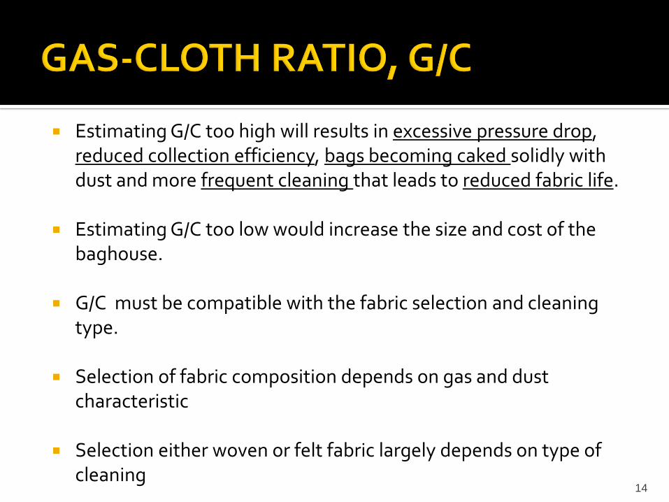
Estimating G/C too high will results in excessive pressure drop, reduced collection efficiency, bags becoming caked solidly with dust and more frequent cleaning that leads to reduced fabric life.
Estimating G/C too low would increase the size and cost of the baghouse.
G/C must be compatible with the fabric selection and cleaning type.
Selection of fabric composition depends on gas and dust characteristic
Selection either woven or felt fabric largely depends on type of cleaning
14

15

16
Over time, the depth of the dust layer increases,
the layer of the dust layer Dp can be calculated
from

The fabric (filter media) use would depends on:
Temperature
Corrosiveness
Hydrolysis
Dimensional stability
Cost
Some of fabric use
Cotton— low temperature capability; good flex abrasion resistance; still used in some low temperature applications.
17

Polypropylene— very sleek fabric; demonstrates good cakeresistance to blinding. Does not readily absorb moisture and goodselection for a low temperature, high moisture condition,production.
Polyester— very sturdy material; good resistance to acids andalkalies, slightly higher temperature capability thanpolypropylene. Costs about the same as polypropylene. Used inmost routine low temperature applications including quarry,woodworking, and sand handling operations.
Fiberglass— normally used in high temperature applications.Improvements in finishes and techniques of fabrication,installation, and operation have paid dividends in extended baglife. Fiberglass is the primary fabric used in the boiler market. Costis between polyester and Nomex.
18

Nomex— extremely sturdy material with respect to flex abrasion.Superior to glass in resistance to fluorides and abrasion. Goodtemperature capability. Poor acid resistance; not used in gasstreams containing SO2 and SO3. Costs about 2.5 times that ofpolypropylene and polyester. Used in asphalt, steel, carbon black,and cement industries.
Teflon— generally chemically inert and for that reason useful insevere environments. Very expensive, but the cost is usuallyjustified because of superior bag life. Used in the carbon blackindustry, lead smelting, coal-fired boilers, and various unusualapplications. Costs about 10 times that of polyester for the samesize and weight bag.
19

Pressure drop (∆p) is the resistance to air flow across the baghouse.
The higher the pressure drop, the higher the resistance to air flow.
The pressure drop is determined by measuring the difference in
total pressure at two points, usually the inlet and the outlet.
The total system pressure drop can be related to the size of the fan
that would push or pull the exhaust gas through the baghouse.
Pressure drop is usually expressed in mmHg or inH20.
The simplest equation used to predict pressure drop across a filter is
derived from Darcy's law governing the flow of fluids through
porous materials 20

Filter Pressure Drop, (∆p) = k1Vf
k1 = fabric resistance, inH2O/(ft/min) [cmH2O/(cm/sec)]
Vf = filtration velocity, ft/min (cm/sec)
k1 is the fabric resistance (also called drag) and is a function of exhaust gas viscosity
and filter characteristic such as thickness and porosity. Porosity describes the amount
of void volume in the filter
21
K2ci
t

Once there is a dust cake build up, the pressure drop
K2 = resistance of the cake, in. H2O/(lb/ft2-ft/min)[cm H2O/(g/cm2-cm/sec)]
Ci = dust concentration loading, lb/ft3(g/cm3)
Vf= filtration velocity, ft/min (cm/sec)
T = filtration time, min (sec)
The term k2 is the dust-fabric filter resistance coefficient and is determined experimentally. k2 depends on gas viscosity, particle density and dust porosity. The dust porosity is the amount
of void volume in the dust cake. The porosity is related to the permeability. k2 is also dependent on the size of the particles in the gas stream. If the particles are very
small (< 2µm) k2 is high. Filtration velocity also has an effect on k2. If k2 is high, then the pressure drop will tend to increase and the bags will have to be cleaned
more frequently. 22
K2ci
t

The total pressure drop, ∆pt equals the pressure drop across the
filter plus the pressure drop across the cake and structural pressure
drop is given as:
∆pt = ∆p (Filter) + ∆pc (Dust cake) + ∆ps
* ∆ps is structural pressure drop
23
K2ci
t

24
There is no one formula that can determine the collection efficiency of a baghouse.
Some theoretical formulas have been suggested, but these formulas contain numerous (3 to 4) experimentally determined coefficients.
E = 1- e-(jL +ft)
j = Constant base on fabric, ft-1
f = Constant based on cake, s-1
T = Time of operation to develop the cake
thickness, s
L = Fabric thickness, ft
E = Collection efficiency (dimensionless)

Vendors normally design and size the units strictly on experience Vendors may collect empirical data available for the source in
question or from a similar industry which is using a baghouse and conservatively apply it.
Or run a pilot unit on a slip stream and vary the G/C. The pilot plant should run for a few months in order to obtain data representative of a long-term operation.
A well designed, well maintained fabric filter that is operated properly generally collects particles from 0.5 to 100 µm at efficiencies of greater than 99%
The remaining design involves optimizing filtering velocity to balance capital costs vs operating costs
25

Very high collection efficiency with even the finest particles. These units usually have the capability of achieving efficiencies of 99% almost automatically— provided they are properly constructed and maintained in satisfactory operating condition.
Simple to operate
26

Consist of many moving parts and require frequent maintenance
May not be used readily in high temperatures unless special fabrics are used
The number of variables necessary to design a fabric filter is very large. A qualitative description of the filtration process is possible, although quantitatively the theories are far less successful.
27

A major malfunction will result in one or more of the following
identifying symptoms:
1. Abnormally high pressure drop across the collector
2. Visible emission of dust in the exhaust stack
3. Inadequate face velocity or “puffing” at pickup points and hoods
4. Lower-than-normal dust discharge
5. Loud or unusual noises
6. Severe corrosion of material
28

Typical causes of bag failure are :
1. High G/C abrasion
2. Metal-to-cloth abrasion
3. Chemical attack
4. Bag-to-bag abrasion
5. Inlet velocity abrasion (on inside-out cleaning)
6. Accidents
7. Upset conditions (e.g., temperature)
8. Thread mismatched
9. Cuff mismatched
10. Improper installation
29

30

31