LAGRANGE: LAser GRavitational-wave ANtenna at GEo-lunar Lagrange points
25
arXiv:1111.5264v2 [astro-ph.IM] 5 Dec 2011 LAGRANGE: LAser GRavitational-wave ANtenna at GEo-lunar Lagrange points J W Conklin 1 , S Buchman 1 , V Aguero 6 , A Alfauwaz 3 , A Aljadaan 3 , M Almajed 3 , H Altwaijry 3 , T Al-Saud 3 , K Balakrishnan 1 , R L Byer 1 , K Bower 5 , B Costello 5 , G D Cutler 1 , D B DeBra 1 , D M Faied 2 , C Foster 2 , A L Genova 2 , J Hanson 4 , K Hooper 5 , E Hultgren 1 , B Jaroux 2 , A Klavins 5 , B Lantz 1 , J A Lipa 1 , A Palmer 5 , B Plante 5 , H S Sanchez 2 , S Saraf 1 , D Schaechter 5 , T Sherrill 5 , K-L Shu 5 , E Smith 5 , D Tenerelli 5 , R Vanbezooijen 5 , G Vasudevan 5 , S D Williams 6 , S P Worden 2 , J Zhou 1 and A Zoellner 1 1 W.W. Hansen Experimental Physics Lab, Stanford University, Stanford, CA 94305 2 NASA Ames Research Center, Moffett Field, CA 94035 3 King Abdulaziz City for Science and Technology, Riyadh, Saudi Arabia 11442 4 CrossTrac Engineering, Inc. Sunnyvale, CA 94089 5 Lockheed Martin Space Systems Company, Palo Alto, CA 94304 6 SRI International, Menlo Park, CA 94025 E-mail: [email protected] Abstract. We describe a new space gravitational wave observatory design called LAGRANGE that maintains all important LISA science at about half the cost and with reduced technical risk. It consists of three drag-free spacecraft in the most stable geocentric formation, the Earth-Moon L3, L4, and L5 Lagrange points. Fixed antennas allow continuous contact with the Earth, solving the problem of communications bandwidth and latency. A 70 mm diameter AuPt sphere with a 35 mm gap to its enclosure serves as a single inertial reference per spacecraft, operating in “true” drag-free mode (no test mass forcing). This is the core of the Modular Gravitational Reference Sensor whose other advantages are: a simple caging design based on the DISCOS 1972 drag-free mission, an all optical read-out with pm fine and nm coarse sensors, and the extensive technology heritage from the Honeywell gyroscopes, and the DISCOS and Gravity Probe B drag-free sensors. An Interferometric Measurement System, designed with reflective optics and a highly stabilized frequency standard, performs the ranging between test masses and requires a single optical bench with one laser per spacecraft. Two 20 cm diameter telescopes per spacecraft, each with in- field pointing, incorporate novel technology developed for advanced optical systems by Lockheed Martin, who also designed the spacecraft based on a multi-flight proven bus structure. Additional technological advancements include the drag-free propulsion, thermal control, charge management systems, and materials. LAGRANGE sub- systems are designed to be scalable and modular, making them interchangeable with those of LISA or other gravitational science missions. We plan to space qualify critical technologies on small and nano satellite flights, with the first launch (UV-LED Sat) in 2013.
Transcript of LAGRANGE: LAser GRavitational-wave ANtenna at GEo-lunar Lagrange points

arX
iv:1
111.
5264
v2 [
astr
o-ph
.IM
] 5
Dec
201
1
LAGRANGE: LAser GRavitational-wave ANtenna
at GEo-lunar Lagrange points
J W Conklin1, S Buchman1, V Aguero6, A Alfauwaz3,
A Aljadaan3, M Almajed3, H Altwaijry3, T Al-Saud3,
K Balakrishnan1, R L Byer1, K Bower5, B Costello5,
G D Cutler1, D B DeBra1, D M Faied2, C Foster2,
A L Genova2, J Hanson4, K Hooper5, E Hultgren1, B Jaroux2,
A Klavins5, B Lantz1, J A Lipa1, A Palmer5, B Plante5,
H S Sanchez2, S Saraf1, D Schaechter5, T Sherrill5, K-L Shu5,
E Smith5, D Tenerelli5, R Vanbezooijen5, G Vasudevan5,
S D Williams6, S P Worden2, J Zhou1 and A Zoellner1
1 W.W. Hansen Experimental Physics Lab, Stanford University, Stanford, CA 943052 NASA Ames Research Center, Moffett Field, CA 940353 King Abdulaziz City for Science and Technology, Riyadh, Saudi Arabia 114424 CrossTrac Engineering, Inc. Sunnyvale, CA 940895 Lockheed Martin Space Systems Company, Palo Alto, CA 943046 SRI International, Menlo Park, CA 94025
E-mail: [email protected]
Abstract. We describe a new space gravitational wave observatory design called
LAGRANGE that maintains all important LISA science at about half the cost and
with reduced technical risk. It consists of three drag-free spacecraft in the most stable
geocentric formation, the Earth-Moon L3, L4, and L5 Lagrange points. Fixed antennas
allow continuous contact with the Earth, solving the problem of communications
bandwidth and latency. A 70 mm diameter AuPt sphere with a 35 mm gap to
its enclosure serves as a single inertial reference per spacecraft, operating in “true”
drag-free mode (no test mass forcing). This is the core of the Modular Gravitational
Reference Sensor whose other advantages are: a simple caging design based on the
DISCOS 1972 drag-free mission, an all optical read-out with pm fine and nm coarse
sensors, and the extensive technology heritage from the Honeywell gyroscopes, and
the DISCOS and Gravity Probe B drag-free sensors. An Interferometric Measurement
System, designed with reflective optics and a highly stabilized frequency standard,
performs the ranging between test masses and requires a single optical bench with
one laser per spacecraft. Two 20 cm diameter telescopes per spacecraft, each with in-
field pointing, incorporate novel technology developed for advanced optical systems by
Lockheed Martin, who also designed the spacecraft based on a multi-flight proven bus
structure. Additional technological advancements include the drag-free propulsion,
thermal control, charge management systems, and materials. LAGRANGE sub-
systems are designed to be scalable and modular, making them interchangeable with
those of LISA or other gravitational science missions. We plan to space qualify critical
technologies on small and nano satellite flights, with the first launch (UV-LED Sat) in
2013.

LAGRANGE: LAser GRavitational-wave ANtenna at GEo-lunar Lagrange points 2
1. Introduction
Stanford University, NASA Ames Research Center, Lockheed Martin, the King
Abdulaziz City for Science and Technology (KACST), and SRI International have
formed a collaboration (called SALKS) to develop a new space gravitational-wave
observatory mission concept, named LAGRANGE, which maintains all important LISA
science at reduced cost and with reduced technical risk. We achieve this goal by revisiting
all aspects of LISA for possible improvements, while structuring the new elements
to be modular and scalable, as well as interchangeable with baseline LISA systems.
We incorporate both new technologies developed after the LISA and LISA pathfinder
designs were baselined (UV-LEDs, non-transmissive optics, SRI thrusters, test mass
(TM) coatings and others), as well as older space qualified technologies from Honeywell
(1953), DISCOS (1972) [1], GP-B (2004) [2].
LAGRANGE comes close to meeting the LISA sensitivity below 10 mHz and
exceeds it at higher frequencies (see Fig. 1). An internal NASA cost analysis, cross
checked against previous mission data, gives a Rough-Order-of-Magnitude (ROM) cost
of $950M, with 30% margin, significantly less than the current LISA cost [3], while
including many technical advantages.
The three main elements of a space-based gravitational-wave observatory are 1) the
constellation and its orbit 2) the gravitational reference sensors, and 3) the metrology
system (see Table 1 for comparison of LAGRANGE to LISA). The following are the
discriminating improvements of LAGRANGE.
1. LAGRANGE consists of a triangular constellation of identical spacecraft (S/C)
and payload at the Earth-Moon (E-M) L3, L4, and L5 Lagrange points. This is the
most stable geocentric configuration. Launch of the three spacecraft with one small
propulsion module is possible on a Falcon 9 at a cost of $118M from NASA Launch
Services. Earth-based receivers are continuously in the field of view of fixed transmitters
on each spacecraft increasing the communication bandwidth by >100 from LISA and
greatly reducing data latency (minutes instead of days). From the experience with GP-B
and LIGO, the closest analogs to date, this large bandwidth is an absolute requirement
for mission success.
2. The single Gravitational Reference Sensor (GRS) is based on the Modular
Gravitational Reference Sensor (MGRS) concept developed by SALKS and consists of
a spherical test mass spinning at 3-10 Hz thus providing frequency separation from the
1 mHz to 1 Hz primary LAGRANGE bandwidth. Similar TMs have been successfully
flown on DISCOS, and GP-B. The MGRS is true drag-free with no forcing in any
direction, and has a 35 mm gap that can be increased if necessary. Caging by a single
screw mechanism was demonstrated on the DISCOS flight and is critical to the risk
reduction in LAGRANGE versus LISA. Magnetic spin-up and polhode damping were
demonstrated thoroughly in Honeywell gyroscopes.
3. The Interferometric Measurement System (IMS) consists of a single laser and
optics bench that incorporates only reflecting elements in the critical locations: gratings

LAGRANGE: LAser GRavitational-wave ANtenna at GEo-lunar Lagrange points 3
Table 1. Top-level LISA / LAGRANGE comparison.
LISA LAGRANGE
Number of spacecraft 3 3
Orbit heliocentric, 20◦ Earth trailing Earth-Moon L3, L4, L5
Wet launch mass ∼5,000 kg 2,070 kg
Arm length 5 Gm 0.67 Gm
IMS sensitivity 18 pm Hz−1/2 5 pm Hz−1/2
DRS accel. noise 3 fm/s2 Hz−1/2 3 fm/s2 Hz−1/2
Observation period 5 yr 5 yr
Telescopes / spacecraft 2 × 40 cm 2 × 20 cm
GRSs / spacecraft 2 1
Optics benches/spacecraft 2 1
Laser power/spacecraft 2 × 1.2 W 1 × 1 W
Controlled degrees of 19 7
freedom / spacecraft
Beam steering articulated in-field
optics & GRS pointing
and mirrors, while laser frequency stabilization is enhanced by high finesse optical
cavities and/or iodine molecular clocks. Two telescopes per S/C with in-field pointing
are designed to minimize path-length errors.
Significant cost reduction for LAGRANGE over LISA was achieved principally in
two ways: (a) by decreasing the per spacecraft mass and power by reducing payload
components (2 lasers, 2 GRSs, and 2 optics benches for LISA was reduced to 1 of each for
LAGRANGE), and (b) by using a geocentric orbit, which requires only one propulsion
module for all three spacecraft and reduces mission operations complexity by increasing
communications bandwidth.
There is incremental risk reduction in LAGRANGE due to an emphasis on
simplicity. In addition, the SALKS collaboration is implementing flight demonstrations
of critical technologies on small satellites and CubeSats [4]. These include charge
management, laser frequency stabilization, shadow and interferometric position
measurement, thrusters and caging mechanisms. The charge management flight (UV
LED Sat [5]) is scheduled for 2013.
The structure of this paper is as follows: we start with a very brief summary
of the science capabilities; follow with the design overview and science orbit; discuss
LAGRANGE specific details of the proposed instrument, focusing on the IMS and the
Disturbance Reduction System (DRS); describe the mission and spacecraft design, and
the cost estimate; closing with a discussion of TRLs.

LAGRANGE: LAser GRavitational-wave ANtenna at GEo-lunar Lagrange points 4
Figure 1. LAGRANGE strain sensitivity, and comparison with LISA requirements
and gravitational wave sources, adapted from [6].
2. Science Capabilities
The primary measurement band for LAGRANGE is 1 mHz to 1 Hz, where the strain
sensitivity is 3× 10⁻²⁰. The target astrophysical sources include:
(i) Massive black hole mergers in the range of 104 (MBH) to 107 (SMBH) solar masses
with orbit periods of 102 to 104 sec, giving signal-to-noise ratios (SNR) up to several
thousands out to z ∼ 15.
(ii) Merging of stellar mass compact objects with massive black holes (EMRI) with
signal periods of 102 to 103 seconds.
(iii) Stellar mass binaries within the Milky Way with orbital periods of 102 to 103
seconds.
Figure 1 shows the estimated LAGRANGE strain sensitivity (solid black curve)
in units of Hz−1/2, compared to the LISA requirement (dashed curve). Colored curves
and points represent the various known sources within the LAGRANGE bandwidth.
The green curve is the confusion noise from unresolved galactic binaries that dominates
instrumental noise between 5 × 10⁴ and 2 × 10³ Hz. All sources above the sensitivity
curve are detectable by LAGRANGE. The green points represent the frequencies and
strengths of known Galactic binaries; their height above the noise curve gives their SNR.
The purple, blue and red curves represent sources (two SMBH binaries, and an EMRI,
respectively) whose frequency evolves upward during LAGRANGE’s observation.
Sensitivity normal to the ecliptic plane is less than that of LISA due to the reduced
out-of-plane motion of the observatory. However, higher gravitational-wave harmonics
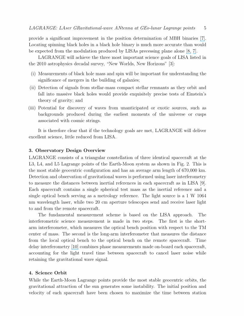
LAGRANGE: LAser GRavitational-wave ANtenna at GEo-lunar Lagrange points 5
provide a significant improvement in the position determination of MBH binaries [7].
Locating spinning black holes in a black hole binary is much more accurate than would
be expected from the modulation produced by LISAs precessing plane alone [8, 7].
LAGRANGE will achieve the three most important science goals of LISA listed in
the 2010 astrophysics decadal survey, “New Worlds, New Horizons” [3]:
(i) Measurements of black hole mass and spin will be important for understanding the
significance of mergers in the building of galaxies;
(ii) Detection of signals from stellar-mass compact stellar remnants as they orbit and
fall into massive black holes would provide exquisitely precise tests of Einstein’s
theory of gravity; and
(iii) Potential for discovery of waves from unanticipated or exotic sources, such as
backgrounds produced during the earliest moments of the universe or cusps
associated with cosmic strings.
It is therefore clear that if the technology goals are met, LAGRANGE will deliver
excellent science, little reduced from LISA.
3. Observatory Design Overview
LAGRANGE consists of a triangular constellation of three identical spacecraft at the
L3, L4, and L5 Lagrange points of the Earth-Moon system as shown in Fig. 2. This is
the most stable geocentric configuration and has an average arm length of 670,000 km.
Detection and observation of gravitational waves is performed using laser interferometry
to measure the distances between inertial references in each spacecraft as in LISA [9].
Each spacecraft contains a single spherical test mass as the inertial reference and a
single optical bench serving as a metrology reference. The light source is a 1 W 1064
nm wavelength laser, while two 20 cm aperture telescopes send and receive laser light
to and from the remote spacecraft.
The fundamental measurement scheme is based on the LISA approach. The
interferometric science measurement is made in two steps. The first is the short-
arm interferometer, which measures the optical bench position with respect to the TM
center of mass. The second is the long-arm interferometer that measures the distance
from the local optical bench to the optical bench on the remote spacecraft. Time
delay interferometry [10] combines phase measurements made on-board each spacecraft,
accounting for the light travel time between spacecraft to cancel laser noise while
retaining the gravitational wave signal.
4. Science Orbit
While the Earth-Moon Lagrange points provide the most stable geocentric orbits, the
gravitational attraction of the sun generates some instability. The initial position and
velocity of each spacecraft have been chosen to maximize the time between station

LAGRANGE: LAser GRavitational-wave ANtenna at GEo-lunar Lagrange points 6
Figure 2. Orbit design with 3 drag-free spacecraft at the Earth-Moon L3, L4, and L5
LAGRANGE points.
keeping maneuvers of < 1 m/s once every 6-12 months, performed using the on-board
micronewton propulsion system.
Table 2 compares the stability and orbital dynamics of the Earth-Moon L3, L4,
L5 orbit with that of LISA. Further improvement in the stability of the LAGRANGE
constellation is expected through simultaneous optimization of the initial conditions
for all three spacecraft, minimizing range rate and breathing angle variations. The
spacecraft at L3 follows a perturbed halo orbit, roughly 50,000 km in diameter and
canted with respect to the plane of the Moon’s orbit by ∼ 45◦. The spacecraft at L4
and L5 follow semi-periodic orbits as well, but with more complex geometries. One
of the alternatives under study is to place all three spacecraft in periodic orbits with
similar phases, thus reducing range rate variations.
The initial orbit design exhibits dynamics 5 to 10 times larger than LISA. Range
rates between spacecraft vary by ±150 m/s, as shown in Fig. 3. This means that if the
transmitted laser frequency is held constant, the on-board phase measurements must
accommodate heterodyne frequencies of .150 MHz, compared with < 20 MHz for LISA.
However, since the range rates to the two remote spacecraft exhibit large common mode
variations (see Fig. 3), tuning the laser frequency on each spacecraft to the mean of the
two known Doppler frequencies, reduces the heterodyne frequency to . 50 MHz. The
telescope must accommodate ± 2.5 deg of beam steering for the IMS to remain locked
to the remote spacecraft.

LAGRANGE: LAser GRavitational-wave ANtenna at GEo-lunar Lagrange points 7
0 50 100 150 200 250 300 350−200
−150
−100
−50
0
50
100
150
200
Time since deployment (days)
SC
−S
C R
elat
ive
spee
d (m
/s)
L4 − L5L3 − L5L3 − L4
Figure 3. LAGRANGE S/C-to-S/C range rates over 1 year.
Table 2. Comparison of E-M L3, L4, L5 and LISA orbits.
Parameter E-M L3, L4, L5 LISA
Nominal arm length 670,000 km 5,000,000 km
Max. arm length variation . 5 % 1%
Breathing angle range ± . 5 deg ±0.5 deg
Max. S/C-to-S/C range rate . 150 m/s 10 m/s
Variation of orbit plane 5 deg 60 deg
5. Interferometric Measurement System
5.1. Interferometry
The IMS has two main components: The short-arm interferometer determines the
distance from the optics bench to the mass center of the TM, and the long-arm
interferometer measures the distance between the optics benches on two spacecraft. The
combined TM-to-TM one-way measurement accuracy is estimated to be 8 pm Hz−1/2
(4 pm Hz−1/2 shot noise limit). While the internal interferometer measures distances
that vary by less than one wavelength (1 µm) during science operations, the external
interferometer must track laser phase over ∼ 1014 wavelengths and accommodate
Doppler shifts of . 150 MHz due to S/C-to-S/C range and range rate variations.
Both long and short-arm interferometers are supplied by a single 1 W Nd:YAG
Nonplanar Ring Oscillator (NPRO) laser that is fiber linked to the optical bench.
Once on the bench, all metrology is done with free-space optics. Two 20 cm aperture
telescopes per spacecraft send and receive laser light to and from the remote spacecraft.
LAGRANGE: LAser GRavitational-wave ANtenna at GEo-lunar Lagrange points 8
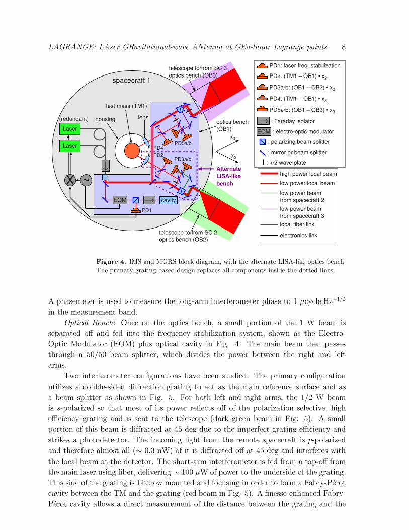
Figure 4. IMS and MGRS block diagram, with the alternate LISA-like optics bench.
The primary grating based design replaces all components inside the dotted lines.
A phasemeter is used to measure the long-arm interferometer phase to 1 µcycle Hz−1/2
in the measurement band.
Optical Bench: Once on the optics bench, a small portion of the 1 W beam is
separated off and fed into the frequency stabilization system, shown as the Electro-
Optic Modulator (EOM) plus optical cavity in Fig. 4. The main beam then passes
through a 50/50 beam splitter, which divides the power between the right and left
arms.
Two interferometer configurations have been studied. The primary configuration
utilizes a double-sided diffraction grating to act as the main reference surface and as
a beam splitter as shown in Fig. 5. For both left and right arms, the 1/2 W beam
is s-polarized so that most of its power reflects off of the polarization selective, high
efficiency grating and is sent to the telescope (dark green beam in Fig. 5). A small
portion of this beam is diffracted at 45 deg due to the imperfect grating efficiency and
strikes a photodetector. The incoming light from the remote spacecraft is p-polarized
and therefore almost all (∼ 0.3 nW) of it is diffracted off at 45 deg and interferes with
the local beam at the detector. The short-arm interferometer is fed from a tap-off from
the main laser using fiber, delivering ∼ 100 µW of power to the underside of the grating.
This side of the grating is Littrow mounted and focusing in order to form a Fabry-Perot
cavity between the TM and the grating (red beam in Fig. 5). A finesse-enhanced Fabry-
Perot cavity allows a direct measurement of the distance between the grating and the

LAGRANGE: LAser GRavitational-wave ANtenna at GEo-lunar Lagrange points 9
Figure 5. Primary IMS configuration using a diffraction grating as the reference
surface and beam splitter. The readout for the short-arm interferometer is not shown.
TM, without the use of a reference arm of a Michelson interferometer. The Pound
Drever-Hall (PDH) technique [11] allows the measurement to be made at frequencies
where the laser is quantum-noise-limited. A short-arm interferometer using a Littrow
mounted grating has been demonstrated in the lab at Stanford [12].
The primary interferometer configuration using a double-sided grating has several
advantages: (a) it provides a single, well defined reference surface that separates the
long and short arm interferometers, (b) it can be made from a thin, low CTE material
that reduces thermally induced path-length errors relative to transmissive optics where
much higher dn/dT effect are important, and (c) it greatly reduces the number of optical
components needed and decreases the size of the optics bench.
The back-up configuration is more LISA-like, utilizing a larger bench with bonded
optical components (see Fig. 4). A low power portion of the 1/2 W beam for each arm
is picked off and used in both the long and short-arm interferometers. The short-arm
interferometer is a Michelson interferometer, while the long-arm interferometer simply
interferes the local and received beams. A lens or mirror is used to focus the beam at
the center of the TM so that most of the light is reflected back to the interferometer.
On the frequency stabilization section of the bench, the low power laser pick-off is
fed through an EOM which adds rf tunable sidebands to the laser frequency. One of the
sidebands is then locked to a nominal 10 cm optical cavity, with a Free Spectral Range
(FSR) of 1.5 GHz. Locking is performed using PDH via ∼ 10 MHz sidebands added
to the main sidebands. The main rf sidebands are tuned with a maximum range of
FSR/2 in order to shift the carrier frequency by the same amount. Sideband locking for
frequency tunable stabilized lasers has been considered for LISA and demonstrated in a
laboratory envinronment [13]. This technique is optically more efficient than using an
Acousto-Optic Modulator (AOM). Initial tuning is performed during the initialization

LAGRANGE: LAser GRavitational-wave ANtenna at GEo-lunar Lagrange points 10
phase of the mission in order to set the laser frequency on each spacecraft to the optimal
offset. The offset can then be held constant or tuned continuously to accommodate any
changes in the cavities or Doppler rates to maintain optimal detection frequency and
receiver performance. Tuning the laser frequency offset to follow the mean Doppler
frequency of the two remote spacecraft reduces the heterodyne frequency measured by
the phase meter from . 150 MHz to . 50 MHz.
Phasemeter : The phasemeter measures the phase of the long-arm interferometer
beat note to 1 µcycle Hz−1/2 over the band 1 mHz to 1 Hz. The phasemeter uses a
high-speed analog to digital converter followed by a digital phase locked loop, as in
the LISA design [14]. The phasemeter has to accommodate a heterodyne frequency of
. 50 MHz, assuming continuously tuned laser frequency offsets. Improvements in the
LAGRANGE constellation orbit may reduce this range further.
Point-Ahead Angle Mechanism: A small actuator located on the optics bench (not
shown on Fig. 4) angles the output beam with respect to the input beam ∼ 7 µrad to
accommodate the distance that the remote spacecraft has traveled in 2.2 light sec. path
length variations must be less than 1 pm and beam jitter less than 20 nrad. The Point-
Ahead Angle Mechanism (PAAM) developed for LISA meets LAGRANGE requirements
[15].
5.2. Telescope
The main design challenges for the LAGRANGE telescopes are: a 5 deg field of regard
(FOR) to accommodate constellation geometrical changes, minimized entrance aperture
size to satisfy radiometric requirements, and 5 pm pathlength stability. Secondary
requirements are ∼ 1 mm internal beam size for compatibility with the metrology
system, implying a magnification of 200×, and minimized stray light.
The FOR and magnification combined dictate at least a two-stage design, and
minimizing stray light, leads to an off-axis un-obscured system that is within the
capabilities of recently flown design apertures, geometric tolerances, and wavefront
stability. Stage 1, shown in Fig. 6, is a 6:1 Three Mirror Anastigmat (TMA) that
relays the entrance pupil to a small steering mirror. It has nearly diffraction-limited
performance over the FOR, with a steering mirror located near its exit pupil to scan
over the Field of View (FOV) (physical motion of a single steering mirror is 15 deg). Such
steering mirrors can be designed to ensure no motion of the center of mass (CM) while
slewing, and back-to-back design will also ensure no change in CM and gravity gradient.
Optical Path Difference (OPD) induced by steering through the FOR is ∼ 100 pm/µrad
averaged over the field. Given a 5 deg/27.3 day (lunar orbital rate) field rate of change,
the expected OPD over 1,000 seconds is of order 3,600 pm, which is calibrated to 10−3
or compensated at the FOR mirror.
Stage 2 gives an additional 33× magnification and completes the 200× beam
expander. Design of this stage is relatively straightforward, since it has a narrow FOV
and the system is monochromatic. The un-obscured TMA is a spaceflight-proven optical

LAGRANGE: LAser GRavitational-wave ANtenna at GEo-lunar Lagrange points 11
Figure 6. Stage 1 of the LAGRANGE telescope.
design from (QuickBird [16], MTI [17]) and has been used successfully by Lockheed
Martin for lasercom applications. It may be possible to simplify the beam steering
design by taking advantage of advances in precision laser scanners based on acousto-
optic or electro-optic deflectors that can achieve precision beam steering without moving
parts [18, 19].
A low CTE composite metering structure, such as an M55J/954-3, combined with
mK temperature control achieved using heaters and temperature sensors, can be used
to control OPD changes due to thermal effects to the pm level.
The use of the off-axis TMA for space-based imaging has significant heritage, and
is considered TRL 9. Although mK temperature control, the use of very low CTE
composite telescope structures and pm pathlength monitoring have flight qualification
test heritage, the combination of the three to produce a pm-stable system is new
technology, and is TRL 4.
Each spacecraft has two identical telescopes. Both are actuated so that the fixed
high gain communications antenna remains nominally pointed at the Earth, and to
provide redundancy in case of failure.
During brief periods, twice per year, the line-of-sight to the remote spaceraft will
come within 5 deg of the sun. Existing flight-qualified narrow band filters are used to
block sunlight from entering the telescope and damaging the IMS. A thin, low CTE
window (or coating) is placed either at the front end of the telescope, which reduces
overall solar heating to the telescope, or at the back end, allowing for a much smaller
(∼ 1 cm) filter, or possibly at both locations.
5.3. Metrology Error Budget
A detailed error budget for the IMS has been compiled. It contains four main
contributions, each with several sub-entries. The main contributions and associated
errors at 3 mHz are: shot noise (4 pm Hz−1/2), optical path-length errors (5 pm Hz−1/2),
residual USO phase noise (3 pm Hz−1/2), and residual laser phase noise (3 pm Hz−1/2).
LAGRANGE: LAser GRavitational-wave ANtenna at GEo-lunar Lagrange points 12
The total error at 3 mHz is 8 pm Hz−1/2. The IMS error is nearly flat at higher
frequencies, and exhibits a 1/f 2 trend below 3 mHz.
The shot noise is limited by the laser output power (0.5 W), arm length
(670,000 km) and telescope aperture (20 cm), while the optical path length error is
dominated by the telescope design with its required 5 deg beam steering. The residual
USO phase noise calculation is based on the shot noise limit, the phasemeter error, a
heterodyne frequency of 50 MHz, and a fractional arm length difference of 5%. The
residual laser phase noise estimate assumes a USO clock Allan deviation of 5× 10⁻¹¹ at
4 sec (round-trip light travel time), an absolute arm length uncertainty of 10 m, and a
pre-stabilized laser frequency noise of 30 Hz Hz−1/2 at 3 mHz.
6. Disturbance Reduction System
The disturbance reduction system consists of the Modular Gravitational Reference
Sensor, which houses the test mass, drag-free and attitude control laws and micronewton
thrusters to keep the S/C centered on the test mass, and a thermal control system.
6.1. Modular Gravitational Reference Sensor
Based on experience with the successful drag-free satellites Triad I [1] and Gravity Probe
B [20], a spherical geometry was chosen for the LAGRANGE GRS. A spherical GRS
for LISA was proposed as early as 1998 [21, 22], and has advantages that outweigh its
disadvantages:
• No TM forcing or torquing: neither electrostatic support nor capacitive sensing is
required, reducing disturbances and complexity,
• Large TM-to-housing gap (35 mm): disturbances are reduced and spacecraft
requirements are relaxed,
• A long flight heritage [23]: Honeywell gyroscopes, Triad I and GP-B,
• Scalability: performance can be scaled up or down by adjusting TM and gap size,
• Simplicity: no cross coupling of degrees of freedom,
• A simple flight-proven caging mechanism.
This GRS concept, now called the Modular Gravitational Reference Sensor (MGRS)
has been under development for a wide range of applications since 2004 [24, 25]. The
primary components of the MGRS, shown in Fig. 7, include a spinning spherical TM,
a differential optical shadow sensor system for drag-free control, a caging (launch lock)
mechanism based on the flight-proven DISCOS design, magnetic coils for test mass
spin-up to 3-10 Hz and polhode damping, based on the Honeywell design, and a charge
control system based on the GP-B design but using modern LEDs as UV sources.
As an alternative, we note that the LISA Pathfinder GRS [26], the baseline for
LISA, is expected to demonstrate 3× 10⁻¹⁴ m/s Hz−1/2 above 1 mHz during the LISA
Pathfinder mission [27]. Assuming a successful flight demonstration, the Pathfinder

LAGRANGE: LAser GRavitational-wave ANtenna at GEo-lunar Lagrange points 13
Figure 7. (a) Modular Gravitational Reference Sensor isometric view, and (b) cross-
section with the test mass caged.
GRS could be utilized for LAGRANGE. A single LISA Pathfinder GRS per drag-free
spacecraft has been studied [28] and would principally require modifications to the
optical bench design.
Spinning Spherical Test Mass : The nominal test mass is a 2.9 kg, 70 mm
diameter sphere of 70%/30% Au/Pt. An alternate material is Berglide (2%/97.5%/0.5%
Be/Cu/Co), a common, well studied material, easier to fabricate with 10−6 magnetic
susceptance, but less dense by a factor > 2.
The TM must be round to . 30 nm, similar in roundness to the GP-B flight
rotors [29], and have a mass unbalance . 300 nm, 30 times larger than that of the
GP-B rotors. Internal axi-symmetric sections of the TM are hollowed out to produce
a moment of inertia difference ratio of 10%, while reducing the average density by 20%
[30]. The resulting polhode frequency is 0.3-1 Hz, at the high end of the LAGRANGE
science band. The hollow sections also allow the mass center to be moved within the
sphere through an iterative measurement/re-shaping procedure in order to meet the
mass unbalance requirement [30]. Laboratory measurement of the mass unbalance of a
50 mm spherical TM has been demonstrated to 200 nm [31]. For a GRS housing vented
to space, the pressure is 10−6 Pa, resulting in a spin-down time ∼ 4,000 years.
Interferometric measurement of the surface of a sphere has also been demonstrated
in the lab [12], and spinning of the sphere averages geometric irregularities, allowing
for determination of the mass center. A computationally simple and robust on-
board algorithm for determining the mass center to pm accuracy has been developed
analytically [32] and demonstrated numerically [33]. The TM external g

LAGRANGE: LAser GRavitational-wave ANtenna at GEo-lunar Lagrange points 14
no special markings or cut-outs, and pm-level knowledge of the sphere’s geometry is not
needed.
The TM spin axis is normal to the constellation plane (± 5 deg) to achieve
maximum averaging of geometric irregularities. Systematic measurement errors due
to the axisymmetric harmonics of the sphere’s geometry remain below 1 pm as long
as the out-of-plane spacecraft motion is < 3 µrad Hz−1/2 and the maximum rate is
< 0.6 µrad/s [32]. The former requirement is bounded by the < 10 nrad Hz−1/2 attitude
motion requirement for the IMS, and the latter is greater than the maximum attitude
rate (∼ 0.2 µrad/s) needed to maintain pointing throughout the orbit.
The TM is coated in a carbide compound (e.g. SiC or ZrC), which provides a
hard, conductive, and highly reflective surface. SiC and ZrC have quantum efficiencies
15-30% of that of gold, thus supporting UV charge control. A major advantage of these
coatings over gold is their low adhesion to other surfaces. The coating of the TM and
MGRS, which has no sensitive surfaces, are designed such that the TM can repeatedly
touch the housing wall in a µg environment without damaging the TM or housing or
sticking. This greatly simplifies the caging design and means that during low thrust
station keeping maneuvers (once every 6-12 months), the TM need not be re-caged, but
only spun down to a low level.
Shadow Sensor for Drag-free Control : The Differential Optical Shadow Sensor
(DOSS) requires two pairs of parallel beams for a three-dimensional position
measurement [34]. Four pairs are planned for redundancy. Superlumniscent LEDs
with a wavelength of 1550 nm are used for the light source. The target sensitivity is
1 nm Hz−1/2 over the drag-free control bandwidth. The low frequency noise floor is
improved with lock-in amplification and modulation of the beam power.
Caging : The function of the caging system is to secure the test mass during launch
and ascent when the satellite can be expected to experience high static accelerations
(up to 6 g [35]), random vibration up to 14.1 g rms [36], and shock up to 3000 g at
payload separation [35].
The caging mechanism for the MGRS is based on the flight proven design for
DISCOS, which applied a load of 43 g to the TM [37]. The caging system will passively
maintain a high compression pre-load until deployment in orbit when the TM will be
released with low residual velocity. The TM and housing are designed such that they will
contact several times with ∼ mm/s velocities, with no damage, until sufficient kinetic
energy is absorbed and the drag-free control system is able to capture the TM.
The test mass is clamped between two holding tubes, one of which is driven by a
trapezoidal jack screw (see Fig. 7). The surface finish for the holding tubes and the TM
will be of dissimilar materials to avoid residual adhesion. The jack screw is self-locking
to passively maintain compression force, and is driven by a piezoelectric motor which
is also self-locking. BeCu ring springs oppose the compression force of the jack screw,
such that at full load, the opposing surfaces that retain the springs will engage a limit
switch, and stop the jack screw.
LAGRANGE: LAser GRavitational-wave ANtenna at GEo-lunar Lagrange points 15
Spin-up Mechanism: The spin-up of the TM is performed with a rotating magnetic
field similar to the ones used in Honeywell gyroscopes [38]. Four magnetic coils separated
by 90 deg in the constellation plane are excited with ac currents to create the rotating
magnetic field and will perform spin-up within a few hours. Two additional magnetic
coils aligned normal to the constellation plane create a dc field for polhode damping
and spin-axis alignment (see Fig. 7). The TM can also be spun-down by reversing the
phase of the ac currents.
Charge Control : Charge management by UV photoemission using the 254 nm
line of an rf mercury source was successfully demonstrated by the GP-B mission in
2004-2005. Newer technology allows the use of commercially available LEDs operating
in the 240-255 nm range [39] as the UV source. These devices are fast switchable
(f > 100 MHz), allowing pulse timing to be synchronized to a control electrode. With
a 10 mA driving current, these LEDs are capable of generating 10 µW at 252 nm [40].
Electrons are generated through photoemission from the TM and control electrode. The
direction of charge transfer is selected by setting the phase between the UV-LED and
control electrode [39]. Measurement of the TM potential can be performed in several
ways, including the force modulation used in GP-B and contactless dc measurement of
the electric field. Passive charge management, relying on a virtual “wire” generated
by photoemission and without bias is also practical for the proposed low (∼ 5 pF)
capacitance MGRS. The power and mass per GRS are estimated at 2-3 W and 200-300 g,
respectively. A number of UV-LED models have successfully completed environmental
testing [40, 41].
6.2. Drag-free and Attitude Control
Three-axis drag-free translation control keeps the spacecraft centered on the TM to
within 2 nm Hz−1/2 in the measurement band. Each axis is controlled independently
(no cross-coupling). The drag-free position accuracy is limited by the DOSS
noise (1 nm Hz−1/2) and the dominant spacecraft disturbances, which are solar
radiation pressure at 1 AU (. 10−10 m/s2 Hz−1/2 [42]) and micronewton thruster noise
(3× 10⁻¹⁰ m/s2 Hz−1/2).
The 3-axis attitude control is completely independent from the drag-free control
and aligns the two telescopes to the two remote spacecraft using wavefront sensing as
in LISA. The remaining degree of freedom is accommodated by telescope beam steering
using the steering mirror mentioned above.
In addition to the 3 drag-free and 3 attitude degrees-of-freedom, there is the
telescope breathing angle control yielding a total of 7 controlled degrees-of-freedom for
each LAGRANGE spacecraft. This is significantly less than LISA which must control
a total of 19 degrees-of-freedom per spacecraft.

LAGRANGE: LAser GRavitational-wave ANtenna at GEo-lunar Lagrange points 16
Figure 8. SRI fabricated linear array version of the liquid metal ion source with 1
cm2 active area. Prototypes were operated > 30 hours, with multiple start/stop, and
even atmospheric exposure between runs to test device robustness and physics.
6.3. Micronewton Thrusters
Drag-free translational control and spacecraft pointing are both actuated by a
micronewton electric propulsion system. The requirements for precision and noise are
equivalent to those for LISA: 0.1 µNHz−1/2 thrust noise from 1 mHz to 1 Hz and 0.1 µN
thrust precision. Busek Colloid Micro-Newton Thrusters (CMNT) meet both of these
requirements. Further development is required to meet the 5 year lifetime goal [43, 44].
In addition to the Busek CMNTs, two Field Emission Electric Propulsion (FEEP)
systems have been investigated for LISA and LISA Pathfinder, a caesium slit FEEP [45]
and an indium needle FEEP [46], which was also considered for the GOCE mission [47].
However, no thruster has thus far demonstrated all requirements for noise, precision,
dynamic range in thrust and lifetime [27]. A significant effort in micronewton propulsion
technology development and testing is needed.
An attractive alternate thruster baselined for LAGRANGE is a scalable ion
propulsion concept based on micro-fabricated arrays of liquid metal ion sources,
currently under development at SRI International [48, 49]. Thrust is generated by
the acceleration and control of independently created ions and electrons, each generated
using arrays of micro-fabricated emission sites. The use of independent extraction and
acceleration electrodes enables very high mass efficiency (high specific impulse) and wide
dynamic range of thrust. This control approach allows smooth variation of thrust over
the full operating range.
Prototype ion sources have been operated in the 1-5 W range, and ion source
operation has been validated from 2,000 s to 10,000 s specific impulse. A prototype
ion source is shown in Fig. 8. Because of the lower operating voltages enabled by
microfabrication of ion emission sites, packaging, including control electronics and power
conversion, are expected to occupy < 10 cm2. Arrays of up to 160 emitters have been
tested, with prototypes able to handle up to 480 emitters; each emitter in such an array
is capable of approximately 1-10 nN of thrust and can be pulsed to produce pN-sec
impulse bits if each emission site is independently controlled.
The micro-fabricated scale of the elements results in rapid neutralization of the

LAGRANGE: LAser GRavitational-wave ANtenna at GEo-lunar Lagrange points 17
particle streams to permit high currents from such a small area device. Hence, this
developing technology can be scaled to arrays of arbitrary size to provide nanonewtons
to newtons of thrust while meeting all of the observatory propulsion requirements. For
example, this allows these thrusters to be used for both drag-free operations and for the
∼ 1 m/s station keeping maneuvers needed once every 6 to 12 months.
6.4. Thermal Control System
Spacecraft heating around the outside surface varies at the orbital period of 27.3 days.
The payload is kept nominally at 300 K, while the exterior sun-facing solar arrays heat
to roughly 350 K. The solar arrays are thermally isolated to keep exterior spacecraft
components stable to 1 K, and additional thermal control on the telescopes keeps them
stable to 1 mK.
The 27.3 day thermal cycle is 103 below the minimum science frequency of 1 mHz.
This greatly reduces the thermal impact on the science instrument, which requires
10 µKHz−1/2 temperature stability in the science band. To isolate the MGRS and optics
bench from the ∼ 1 K spacecraft temperature variations, a nominal thermal enclosure
consisting of a 2-4 alternating layers of highly conductive shields and vacuum spacing is
employed. Radiative heat transfer can be further reduced by coating with low emissivity
materials. Shiny gold coating reduces emissivity to ∼ 0.02 [50], 3.5 times less than a
rough surface. A thermal control system with < µK stability has been designed with
COMSOL for the low earth orbiting STAR spacecraft, validating the concept[51, 52].
6.5. Acceleration Noise Budget
A detailed acceleration noise budget has been compiled for the MGRS. The budget
contains 30 terms: 6 S/C-to-TM stiffness, 8 magnetic, 6 thermal, 4 electric, 4
Brownian, 1 cosmic ray, and 1 laser noise term. Calculation of each term in the
acceleration noise budget follows the methodology used for LISA [42, 28]. The resulting
composite acceleration amplitude spectral density is shown in Fig. 9 for three possible
configurations. The baseline design consists of an AuPt sphere, 70 mm in diameter with
a 35 mm gap between TM and housing (green curve in Fig. 9). Also shown are the
results the same geometry, but with a Berglide sphere (blue) and for an AuPt sphere
with a 100 mm gap (red), demonstrating the performance scalability of the MGRS.
The dominant acceleration noise contributions below 0.5 mHz are due to TM charge
and stray (patch) voltage interactions. Between 0.5 mHz and 2 mHz the composite noise
is dominated by TM-to-spacecraft gravitational interactions, and above 2 mHz by S/C
magnetic field fluctuations.
The TM-to-spacecraft gap size, d, is the most important design parameter with
respect to acceleration noise performance. Magnetic, Electric, and the largest of the
Brownian disturbances [53] are proportional to 1/(ρd) (ρ = TM density). The MGRS
gap size (35 mm) and TM density (2× 10⁴ kg/m2) are 1,000 and 10 times larger than
that of GP-B respectively. As a cross-check, we scale the acceleration noise performance

LAGRANGE: LAser GRavitational-wave ANtenna at GEo-lunar Lagrange points 18
10−4
10−3
10−2
10−1
100
10−15
10−14
10−13
10−12
frequency (Hz)
acce
lera
tion
nois
e (m
/sec
2 /Hz1/
2 )
BeCu, 35 mm gapAuPt, 35 mm gapAuPt, 100 mm gapLISA Requirement
Figure 9. Estimated MGRS acceleration noise performance for a 35 mm diameter
AuPt test mass with a 35 mm gap (green), with the gap increased to 100 mm (red),
and with a Berglide TM (blue). The LISA requirement is shown for comparison.
of GP-B (4 × 10⁻¹¹ m/s2 Hz−1/2 from 0.01 to 10 mHz [20]) by these ratios and obtain
for the MGRS, an acceleration noise of 4× 10⁻¹⁵ m/s2 Hz−1/2.
When constructing the acceleration noise budget, environmental requirements
below 1 mHz for spacecraft-to-TM stiffness, spacecraft temperature fluctuations, stray
voltages, TM charge, and spacecraft magnetic environment were relaxed relative to LISA
[42, 28], some by an order of magnitude in order to simplify the spacecraft and MGRS
design and reduce cost. This can be seen in Fig. 9 for example, where below 0.5 mHz
electrostatic disturbances, proportional to 1/d, dominate. The LAGRANGE gap size
(35 mm) is roughly 10× larger than that of LISA, and yet the LAGRANGE baseline
design (green curve in Fig. 9) is roughly equivalent to the LISA requirement (black,
dashed curve).
7. Spacecraft and Mission Design
7.1. Spacecraft Design
The LAGRANGE spacecraft is based on an existing Lockheed configuration that has
flown successfully many times. Indeed, Lockheed’s vast experience, with more than
950 spacecraft flown, adds confidence to the overall LAGRANGE mission success. The
spacecraft is a dodecagon structure ∼3 m in diameter and ∼0.7 m tall, consisting of
a compact equipment section with an inner diameter center bay which accommodates
the telescopes and payload. A fixed high gain antenna is mounted between the two
telescopes. To minimize the telescope and payload deformations, the spacecraft material

LAGRANGE: LAser GRavitational-wave ANtenna at GEo-lunar Lagrange points 19
will be thermally controlled in order to maintain a low thermal gradient and a high level
of thermal stability. The spacecraft equipment is mounted in the outer bays and oriented
to minimize pointing error. The solar arrays consist of fixed panels mounted on the outer
sides of the spacecraft structure. Radiators are located on the top and bottom of the
spacecraft for thermal control.
The total mass of each LAGRANGE vehicle is < 470 kg, including payload,
requiring < 500 W of power while transmitting data to the ground. The mass
estimate for each component has been evaluated and assigned a maturity rating, and a
contingency value assigned from Lockheed’s standard weight/power growth allocation
and depletion schedule based on history and experience from actual measurements of
flight hardware.
The spacecraft are designed for a minimum of five years of operation, easily
complying with the baseline LAGRANGE mission duration requirement.
7.2. Communications
Communications with each spacecraft is performed with a direct link to ground stations.
LAGRANGE will use the standard NASA ground network, consisting of 10-11 m
antennas located all over the Earth. The down-link rate is 1 Mbps and the up-link
rate 1 kbps, with a 9.6 ratio of received energy per-bit to noise-density. The transmitter
power is 10 watts and the half power beam width is >8 deg. An advantage of this design
is that it allows near continuous communications with all three spacecraft during the
initialization phase and other critical phases of the mission.
7.3. Mass and Power Budgets
Table 3 shows the mass and power requirements for each of the three spacecraft, as well
as the total wet launch mass, including the propulsion module and launch adapter. The
propulsion module carries 230 kg of bi-propellant with an Isp of 320 s. This provides a
total ∆v of 600 m/s to the three spacecraft stack plus an additional 30% margin.
The baseline launch vehicle is the Falcon 9 Block 2 with a 4.6 m diameter × 6.6
m tall fairing. The maximum launch mass for characteristic energy, C3 = 0 kg2/s2, is
2,500 kg. The total wet launch mass, < 2,070 kg, which includes 30% margin, makes up
only 80% of the total capacity of the Falcon 9. The mass, stack dimensions and C3 are
all consistent with the more energetic Atlas V 401 and possibly smaller, less expensive
launch vehicles.
7.4. Mission Design
The LAGRANGE mission is divided into four phases: (a) launch plus ∼ 6 month
cruise to the science orbits (after which the propulsion module is ejected), (b) Initial
Orbit Checkout (IOC), which includes starting drag-free operations and acquisition

LAGRANGE: LAser GRavitational-wave ANtenna at GEo-lunar Lagrange points 20
Table 3. Spacecraft and Payload mass and power budget.
Mass* (kg) Power** (W)
Spacecraft (× 3)
Payload 170 175
Spacecraft 300 325
Total spacecraft + payload 470 500
Propulsion module (× 1)
dry propulsion module 330
propellant 230
Launch adapter (× 1) 100
TOTAL < 2,070
* including 30% margin for payload and propulsion module, 14% margin for > TRL 6
Lockheed spacecraft
** including 30% margin for payload, 8% margin for spacecraft, while transmitting
Figure 10. Conceptual view of the three LAGRANGE spacecraft plus propulsion
module inside the Falcon 9 fairing.
of the signal from the remote spacecraft, (c) 5-year science observations, and (d) de-
commissioning at the end of the mission.
The three spacecraft are stacked together with a single propulsion module inside
the launch vehicle fairing as shown in Fig. 10. After separation from the launch vehicle
upper stage, the propulsion module brings all three spacecraft into a phasing orbit, which
lies in the plane of the Moon’s orbit with apogee at the lunar apogee (∼ 384,000 km)
and eccentricity to achieve a 33 day orbital period. This orbit is designed so that at
apogee, the propulsion module and 3 spacecraft return to the Moon’s orbit with a 60

LAGRANGE: LAser GRavitational-wave ANtenna at GEo-lunar Lagrange points 21
deg phase shift every 33 days. Every 66 days one of the three spacecraft is delivered
into its Lagrange point.
Two types of low thrust injections have been identified that can achieve this phasing
orbit: 1) The baseline is a direct launch to the Weak Stability Boundary (WSB) [54],
followed by a small ∆v to return to the Earth-Moon system, and then a lunar swing-
by; 2) the alternate is a direct launch into Trans-lunar Injection (TLI) [55] followed
by a lunar swing-by coupled with a larger ∆v from the propulsion module. The WSB
injection lasts 9 months, requiring a C3 of 0 kg2/s2 and a 600 m/s total ∆v from the
propulsion module, while the TLI injection takes only 6-7 months and requires a C3 of
−1.7 kg2/s2 and a 800 m/s total ∆v from the propulsion module.
After reaching the science orbit, the mission lifetime is planned to be 5 years, and
is limited only by the lifetime of the science instrument and the micronewton thrusters.
The Earth-Moon L3, L4, L5 orbit can be maintained indefinitely with ∼ 1 m/s ∆v
every 6-12 months for station keeping. During these maneuvers, the test mass must be
spun-down, but not re-caged for accelerations ∼ 10−5 m/s2.
LAGRANGE data analysis process would proceed as in LISA, although access to
the science data would occur closer to real-time compared with LISA due LAGRANGE’s
orbit and reduced data latency. Phase measurements from each spacecraft are combined
using TDI [10] and stored on public networks for analysis by remote science investigators.
Existing LISA data analysis methodologies [56] would directly apply to the LAGRANGE
data. The main difference would be the change of antenna pattern due to the different
orbit.
7.5. Order-of-Magnitude Cost Estimate
LAGRANGE cost is estimated in the medium range of $600M to $1B. A detailed and
conservative joint ARC and Lockheed Martin cost analysis puts the mission ROM cost
at $950M FY12, including 30% reserves. LM has orbited over 950 S/C, supporting
many relevant programs that have segments, subsystems or components similar to
LAGRANGE and were used to get actual cost data. The nonrecurring costs for the
development of 3 identical spacecraft with hardware elements at TRL 6 or greater have
been accounted for. The payload ROM cost was developed using a combination of
bottoms-up and analogies based on major components. ROM cost for the remaining
mission elements used a wrap factor applied to the base hardware costs (spacecraft and
payload), which accounts for systems engineering and testing by an industrial contractor
and government costs. The base hardware costs were modeled on similar size and
complexity missions and derived from the NASA ARC cost database of these missions.
Simplistically using the function describing the historical mission cost data we obtain
estimates in the $640M to $895M FY 11, depending on assumptions about the cost of
3 identical systems.
LAGRANGE: LAser GRavitational-wave ANtenna at GEo-lunar Lagrange points 22
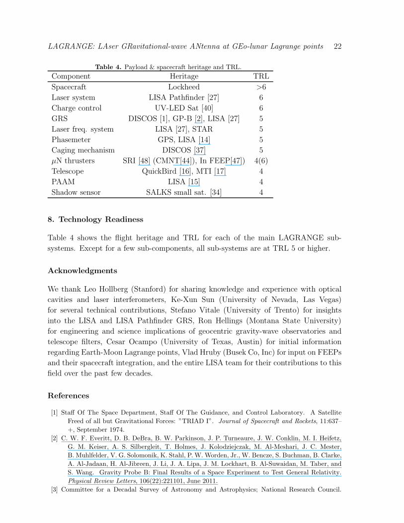
Table 4. Payload & spacecraft heritage and TRL.
Component Heritage TRL
Spacecraft Lockheed >6
Laser system LISA Pathfinder [27] 6
Charge control UV-LED Sat [40] 6
GRS DISCOS [1], GP-B [2], LISA [27] 5
Laser freq. system LISA [27], STAR 5
Phasemeter GPS, LISA [14] 5
Caging mechanism DISCOS [37] 5
µN thrusters SRI [48] (CMNT[44]), In FEEP[47]) 4(6)
Telescope QuickBird [16], MTI [17] 4
PAAM LISA [15] 4
Shadow sensor SALKS small sat. [34] 4
8. Technology Readiness
Table 4 shows the flight heritage and TRL for each of the main LAGRANGE sub-
systems. Except for a few sub-components, all sub-systems are at TRL 5 or higher.
Acknowledgments
We thank Leo Hollberg (Stanford) for sharing knowledge and experience with optical
cavities and laser interferometers, Ke-Xun Sun (University of Nevada, Las Vegas)
for several technical contributions, Stefano Vitale (University of Trento) for insights
into the LISA and LISA Pathfinder GRS, Ron Hellings (Montana State University)
for engineering and science implications of geocentric gravity-wave observatories and
telescope filters, Cesar Ocampo (University of Texas, Austin) for initial information
regarding Earth-Moon Lagrange points, Vlad Hruby (Busek Co, Inc) for input on FEEPs
and their spacecraft integration, and the entire LISA team for their contributions to this
field over the past few decades.
References
[1] Staff Of The Space Department, Staff Of The Guidance, and Control Laboratory. A Satellite
Freed of all but Gravitational Forces: ”TRIAD I”. Journal of Spacecraft and Rockets, 11:637–
+, September 1974.
[2] C. W. F. Everitt, D. B. DeBra, B. W. Parkinson, J. P. Turneaure, J. W. Conklin, M. I. Heifetz,
G. M. Keiser, A. S. Silbergleit, T. Holmes, J. Kolodziejczak, M. Al-Meshari, J. C. Mester,
B. Muhlfelder, V. G. Solomonik, K. Stahl, P. W. Worden, Jr., W. Bencze, S. Buchman, B. Clarke,
A. Al-Jadaan, H. Al-Jibreen, J. Li, J. A. Lipa, J. M. Lockhart, B. Al-Suwaidan, M. Taber, and
S. Wang. Gravity Probe B: Final Results of a Space Experiment to Test General Relativity.
Physical Review Letters, 106(22):221101, June 2011.
[3] Committee for a Decadal Survey of Astronomy and Astrophysics; National Research Council.

LAGRANGE: LAser GRavitational-wave ANtenna at GEo-lunar Lagrange points 23
New Worlds, New Horizons in Astronomy and Astrophysics. The National Academies Press,
Washington, D.C., 2010.
[4] S. P. Worden, T. Al-Saud, M. Almajed, H. Altwaijry, C. Braxmaier, S. Buchman, R. Byer,
M. Cruise, M. Daniels, D. DeBra, H. Dittus, J. Goebel, J. Hall, B. Jaroux, C. Laemmerzahl,
J. Lipa, A. Peters, and K.-X. Sun. Technology Development for Fundamental Physics on Small
Satellites. Micrograv 2010 White Paper for Fundamental Physical Science, 2010.
[5] K.-X. Sun, A. Alfauwaz, M. Alrufaydah, H. Altwaijry, K. Balakrishnan, S. Buchman, R. L. Byer,
J. W. Conklin, D. B. DeBra, J. Goebel, E. Hultgren, and A. Zoellner. Modular Gravitational
Reference Sensor (MGRS) Technology Development. In Proceedings of the 8th International
LISA Symposium, Journal of Physics Conference Series, 2011.
[6] R. Stebbins et al. Laser Interferometer Space Antenna (LISA) A Response to the Astro2010 RFI
for the Particle Astrophysics and Gravitation Panel, white paper. 2009.
[7] C. L. Wainwright and T. A. Moore. Observing the positions of spinning binary systems using
LISA. Physical Review D, 79(2):024022, January 2009.
[8] R. N. Lang and S. A. Hughes. Advanced localization of massive black hole coalescences with LISA.
Classical and Quantum Gravity, 26(9):094035, May 2009.
[9] P. Bender et al. LISA, Laser Interferometer Space Antenna for the detection and observation
of gravitational waves. LISA Pre Phase A Report, 233, Max-Plank-Institut fur Quantenoptik,
Garching, Germany, July 1998.
[10] J. W. Armstrong, F. B. Estabrook, and M. Tinto. Time-Delay Interferometry for Space-based
Gravitational Wave Searches. The Astrophysical Journal, 527:814–826, December 1999.
[11] R. W. P. Drever, J. L. Hall, F. V. Kowalski, J. Hough, G. M. Ford, A. J. Munley, and H. Ward.
Laser phase and frequency stabilization using an optical resonator. Applied Physics B: Lasers
and Optics, 31:97–105, 1983. 10.1007/BF00702605.
[12] G. S. Allen. Optical Sensor Design for Advanced Drag-free Satellites. PhD thesis, Stanford
University, 2009.
[13] J. C. Livas, J. I. Thorpe, K. Numata, S. Mitryk, G. Mueller, and V. Wand. Frequency-tunable pre-
stabilized lasers for LISA via sideband locking. Classical and Quantum Gravity, 26(9):094016,
May 2009.
[14] D. Shaddock, B. Ware, P. G. Halverson, R. E. Spero, and B. Klipstein. Overview of the LISA
Phasemeter. In S. M. Merkovitz & J. C. Livas, editor, Laser Interferometer Space Antenna: 6th
International LISA Symposium, volume 873 of American Institute of Physics Conference Series,
pages 654–660, November 2006.
[15] J. Pijnenburg, N. Rijnveld, and B. Sheard. Picometer stable scan mechanism for gravitational
wave detection in space: LISA PAAM. In 38th COSPAR Scientific Assembly, volume 38, pages
3758–+, 2010.
[16] J. W. Figoski. Alignment and test results of the QuickBird telescope using the Ball Optical System
Test Facility. In W. Roybal, editor, Society of Photo-Optical Instrumentation Engineers (SPIE)
Conference Series, volume 3785 of Society of Photo-Optical Instrumentation Engineers (SPIE)
Conference Series, pages 99–108, October 1999.
[17] R. R. Kay, S. C. Bender, T. D. Henson, D. A. Byrd, J. L. Rienstra, M. L. Decker, N. G. Rackley,
R. L. Akau, J. P. Claassen, R. E. Kidner, R. B. Taplin, D. M. Bullington, K. D. Marbach,
C. E. Lanes, C. K. Little, B. W. Smith, B. C. Brock, and P. G. Weber. Multispectral Thermal
Imager (MTI) payload overview. In M. R. Descour & S. S. Shen, editor, Society of Photo-Optical
Instrumentation Engineers (SPIE) Conference Series, volume 3753 of Society of Photo-Optical
Instrumentation Engineers (SPIE) Conference Series, pages 347–358, October 1999.
[18] M. T. Valentine, N. R. Guydosh, B. Gutierrez-Medina, A. N. Fehr, J. O. Andreasson, and S. M.
Block. Precision steering of an optical trap by electro-optic deflection. Optics Letters, 33:599,
March 2008.
[19] Y. Kremer, J.-F. Leger, R. Lapole, N. Honnorat, Y. Candela, S. Dieudonne, and L. Bourdieu.
A spatio-temporally compensated acousto-optic scanner for two-photon microscopy providing

LAGRANGE: LAser GRavitational-wave ANtenna at GEo-lunar Lagrange points 24
large field of view. Optics Express, 161:10066, June 2008.
[20] W. J. Bencze, D. B. DeBra, L. Herman, T. Holmes, G. M. Keiser, and C. W. F. Everitt. On-orbit
performance of the Gravity Probe B drag-free translation control system. In Proceedings of the
29th AAS Cuidance and Conrol Conference, 2006.
[21] D. B. DeBra. Design considerations for drag free satellites. In W. M. Folkner, editor, Laser
Interferometer Space Antenna, Second International LISA Symposium on the Detection and
Observation of Gravitational Waves in Space, volume 456 of American Institute of Physics
Conference Series, pages 199–206, December 1998.
[22] G. M. Keiser, S. Buchman, D. B. DeBra, and E. Gustafson. Advantages and Disadvantages of a
Spherical Proof Mass for LISA. Presented at COSPAR 2000.
[23] D. B. DeBra and J. W. Conklin. Measurement of drag and its cancellation. Classical and Quantum
Gravity, 28(9):094015, May 2011.
[24] S. Buchman, R. L. Byer, J. Hanson, D. B. DeBra, D. L. Klinger, S. D. Williams, L. D. Dewell, D. B.
Schaechter, N Pedreiro, and D. J. Tenerelli. Gravitational Reference Technologies: Critical for
U.S. Space Leadership, a white paper. 2004.
[25] K.-X. Sun, G. Allen, S. Buchman, R. L. Byer, J. W. Conklin, D. B. DeBra, D. Gill, A. Goh,
S. Higuchi, P. Lu, N. A. Robertson, and A. J. Swank. Progress in Developing the Modular
Gravitational Reference Sensor. In Laser Interferometer Space Antenna: 6th International LISA
Symposium, volume 873 of American Institute of Physics Conference Series, pages 515–521,
November 2006.
[26] R. Dolesi, D. Bortoluzzi, P. Bosetti, L. Carbone, A. Cavalleri, I. Cristofolini, M. Da Lio, G. Fontana,
V. Fontanari, B. Foulon, C. D. Hoyle, M. Hueller, F. Nappo, P. Sarra, D. N. A. Shaul, T. Sumner,
W. J. Weber, and S. Vitale. Gravitational sensor for LISA and its technology demonstration
mission. Classical and Quantum Gravity, 20:99, May 2003.
[27] F. Antonucci et al. LISA Pathfinder: mission and status. Classical and Quantum Gravity,
28(9):094001–+, May 2011.
[28] D. Gerardi, G. Allen, J. W. Conklin, K. Sun, D. DeBra, S. Buchman, P. Gath, W. Fichter, R. L.
Byer, and U. Johann. Advanced drag-free concepts for future space-based interferometers:
acceleration noise performance. ArXiv e-prints, October 2009.
[29] G. M. Keiser. Gravity Probe B. In Proceedings of the International School of Physics ”Enrico
Fermi”, Atom Optics and Space Physics, IOS Press.
[30] J. W. Conklin. Estimation of the Mass Center and Dynamics of a spherical test mass for
Gravitational Reference Sensors. PhD thesis, Stanford University, 2009.
[31] J.W. Conklin, K.-X. Sun, and D.B. DeBra. Sphere mass center determination by velocity
modulation. Precision Engineering, 35(3):464 – 472, 2011.
[32] J. W. Conklin, G. Allen, K-X. Sun, and D. B. DeBra. Determination of Spherical Test Mass
Kinematics with A Modular Gravitational Reference Sensor. Journal of Guidance, Control,
and Navigation, 31(6):1700–1707, November 2008.
[33] G. Allen, J. W. Conklin, K-X. Sun, D. B. DeBra, and R. L. Byer. Mass Center Position
Determination of a Spinning Sphere as part of a Modular Gravitational Reference Sensor. to
be submitted; preprint available at: https://spacegrav.stanford.edu/MGRS.
[34] A. Zoellner, E. Hultgren, M. Trittler, K.-X. Sun, and R. L. Byer. Integrated Differential Object
Shadow Sensor (DOSS) for Modular Gravitational Reference Sensor (MGRS). In Proceedings
of the 8th International LISA Symposium, Journal of Physics Conference Series, 2011.
[35] Falcon 9 Launch Vehicle Payload User’s Guide, Rev. 1. 2009.
[36] A. Harper, M. Ryschkewitsch, A. Obenschain, and R Day. General Environmental Verification
Standard (GEVS) for GSFC Flight Programs and Projects. April 2005.
[37] R. Hacker, J. Mathiesen, and D. B. DeBra. Caging Mechanism for a Drag-Free Satellite Position
Sensor. In Proceedings of the JPL 10th Aerospace Mechanism Symposium, page 125, April 1976.
[38] B. Lange. The Control and use of Drag-free Satellites. PhD thesis, Stanford University, 1964.
[39] K.-X. Sun, B. A. Allard, R. L. Byer, and S. Buchman. Charge management of electrically isolated

LAGRANGE: LAser GRavitational-wave ANtenna at GEo-lunar Lagrange points 25
objects via modulated photoelectric charge transfer, US patent US20080043397.
[40] K. Balakrishnan, E. Hultgren, J. Goebel, and K.-X. Sun. Space Qualification Test Results of Deep
UV LEDs for AC Charge Management. In 11th Spacecraft Charging Technology Conference,
poster presentation, September 2011.
[41] K.-X. Sun, N. Leindecker, S. Higuchi, J. Goebel, S. Buchman, and R. L. Byer. UV LED operation
lifetime and radiation hardness qualification for space flights. Journal of Physics Conference
Series, 154(1):012028–+, March 2009.
[42] Bonny L. Schumaker. Disturbance reduction requirements for LISA . Classical and Quantum
Gravity, 20:S239–S253, April 2003.
[43] J. Ziemer, T. M. Randolph, G. W. Franklin, V. Hruby, D. Spence, N. Demmons, T. Roy, E. Ehrbar,
J. Zwahlen, R. Martin, and W. Connolly. Delivery of colloid micro-newton thrusters for the space
technology 7 mission. In Proceedings of the 44th AIAA/ASME/SAE/ASEE Joint Propulsion
Conference and Exhibit, AIAA2008-4826, 2008.
[44] V. Hruby, D. Spence, N. Demmons, T. Roy, E. Ehrbar, J. Zwahlen, R. Martin, J. Ziemer,
T. M. Randolph, W. Connolly, S. Rhodes, and W. Tolman. ST7-DRS Colloid Thruster System
Development and Performance Summary. In Proceedings of the 44th AIAA/ASME/SAE/ASEE
Joint Propulsion Conference and Exhibit, AIAA2008-4826, 2008.
[45] F. Ceccanti, L. Paita, U. Cesari, M. DeTata, N. Giusti, P. Balducci, and M. DelPistoia. 3200
hours Endurance Testing of the LISA Pathfinder FT-150 Thruster. In Proceedings of the 31st
International Electric Propulsion Conference, AIAA-06-4826, 2009.
[46] C. Scharlemann, N. Buldrini, R. Killinger, M. Jentsch, A. Polli, L. Ceruti, L. Serafini, D. DiCara,
and D. Nicolini. Qualifciation test series of the indium needle feep micro-propulsion system for
lisa pathfinder. Acta Astronautica, 69(9-10):822 – 832, 2011.
[47] M. Tajmar, A. Genovese, and W. Steiger. Indium field emission electric propulsion microthruster
experimental characterization. Journal of propulsion and power, 20(2):211–218, 2004.
[48] V. M. Aguero. Experimental Results and Considerations on Use of Field Emission Devices in
Space. AIAA Joint Propulsion Conference Proceedings, AIAA 2001-3338, July 2001.
[49] V. M. Aguero. High Efficiency Ion Thruster. SRI final report for DARPA/TTO, Contract No.
MDA972-02-C-0073, 2003.
[50] M. Jin and S. Liang. An Improved Land Surface Emissivity Parameter for Land Surface Models
Using Global Remote Sensing Observations. Journal of Climate, 19:2867, 2006.
[51] S. Higuchi, K.-X. Sun, D. B. DeBra, S. Buchman, and R. L. Byer. Design of a highly stable and
uniform thermal test facility for MGRS development. Journal of Physics Conference Series,
154(1):012037, March 2009.
[52] A. Alfauwaz and K.-X. Sun. Design and Modeling of Highly Stable and Uniform Thermal Enclosure
for Precision Space Experiment. In Journal of Physics Conference Series, Proceedings of the
8th International LISA Symposium, 2011.
[53] A. Cavalleri, G. Ciani, R. Dolesi, A. Heptonstall, M. Hueller, D. Nicolodi, S. Rowan, D. Tombolato,
S. Vitale, P. J. Wass, and W. J. Weber. Increased Brownian Force Noise from Molecular Impacts
in a Constrained Volume. Physical Review Letters, 103(14):140601, October 2009.
[54] E. A. Belbruno, editor. Lunar capture orbits, a method of constructing earth moon trajectories
and the lunar GAS mission, May 1987.
[55] V. C. Clarke. Design of lunar and interplanetary ascent trajectories. AIAA Jounral, 1(7), July
1963.
[56] S. Babak, J. G. Baker, M. J. Benacquista, N. J. Cornish, J. Crowder, S. L. Larson, E. Plagnol, E. K.
Porter, M. Vallisneri, A. Vecchio, T. M. L. Data Challenge Task Force, K. Arnaud, L. Barack,
A. B laut, C. Cutler, S. Fairhurst, J. Gair, X. Gong, I. Harry, D. Khurana, A. Krolak, I. Mandel,
R. Prix, B. S. Sathyaprakash, P. Savov, Y. Shang, M. Trias, J. Veitch, Y. Wang, L. Wen, J. T.
Whelan, and t. Challenge-1B participants. The Mock LISA Data Challenges: from Challenge
1B to Challenge 3. Classical and Quantum Gravity, 25(18):184026, September 2008.