Extended Lunar Orbital Rendezvous Mission - NASA ...
306
SD 68-850-1 Extended Lunar Orbital Rendezvous Mission VOLUME I - TECHNICAL ANALYSIS SPACE DIVISION OF NORTH AMERICAN ROCKWELL CORPORATION
-
Upload
khangminh22 -
Category
Documents
-
view
0 -
download
0
Transcript of Extended Lunar Orbital Rendezvous Mission - NASA ...

SD 68-850-1
Extended Lunar Orbital Rendezvous Mission
VOLUME I - TECHNICAL ANALYSIS
SPACE DIVISION OF NORTH AMERICAN ROCKWELL CORPORATION

S D m850- 1 A STUDY OF AN EXTENDED LUNAR ORBITAL
RENDEZVOUS M I S S I O N (ELOR)
FINAL REPORT Volume 1
TECHNICAL ANALYSIS January 1969
~
Contract NAS2-4942
P r e p a r e d by
Study Manager
SPACE DIVISION NORTH AMERICAN ROCKWELL CORPORATION

SPACE DIVISION OF NORTH AMERICAN ROCKWELL CORPORATION
FORE WORD
This is Volume I of a three-volume repor t recording the resu l t s of a study of the Application of Data Derived under a Study of Space Mission Dura- tion Extension Problems to an Extended Lunar Orbital Rendezvous Mission, hereaf te r r e fe r r ed to as ELOR. follows :
The ti t les of the three volumes a r e a s
Volume I Technical Analysis
Volume I1 Supplemental Data
Volume I11 Summary of Results
This document contains a description of the technical analysis of the ELOR mission. Management Department of the Space Division, of the North American Rock- well Corporation.
The analysis was performed by the Systems Engineering
The study was performed for the Mission Analysis Division of the Office of Advance Resea rch and Technology (OART), National Aeronautics and Space Administration, Ames Research Center, Moffett F i e l d , California, under Contract NAS2-4942.
The work was per formed under the direction of Roy B. Carpenter , J r . , the Study Manager. following subcontractors and personnel thereof, who provided the data a t no cost to e i ther this study o r the ea r l i e r baseline study:
Substantial contributions were made to this study by the
1. A . C . Electronics A1 Lobinstine .
2 . Aerojet Generai* C. Teague
3 . A i r Research Division of Garre t t Corp. Joe Riley
4. A l l i s Chalmers* John Hallenbeck
5. Allison Division of G. M. 9J J . C . Schmid
6. Bell Aerospace Systems* T. P. Glynn
*Data supplied for baseline study.
SD 68-850-1

SPACE DIVISION OF NORTH AMERICAN ROCKWELL CORPORATION
7. Collins Radio R. Albinger
8. Dalmo Victor Gorp.* R.L. Straley
9 . Eagle Pi tcher Corp. Jeff Willson
10. General Time Gorp.*< F r e d Schultz
11. Grumman Aircraf t Corp. **< Hart Wagoner
12. Hamilton Standard Div. of UAC R. Gredorie
1 3 . Honeywell Corp. J e r r y Mullarky
14. ITT Industrial Prod. R. L. Weir
15. Marquardt Corp. 96
16. Motorola Corp
J . B . Gibbs
Bill Crook
17. Northrop -Ventura T . Kanacke
18. P r a t t and Whitney Div. of UAC Jay Steadman
19. Raytheon Mfg. Co. *< H . A . Prindle
20. RCA Corp (Camden and Burlington) J . Heavey/S. Holt
2 1 . Radiation Inc. Wally Adams
2 2 . Simmonds Precis ion Prod . zc W . E . Nelson
23. Westinghouse Corp. C . W. Chandler
The study was based on data derived f rom the baseline study, a company-funded effort , documented under NASA Contract NAS2-4214, and f rom the mission systems design derived by the Lockheed Missi les and Space Company (LMSC) under Contract NAS8-21006.
*Data supplied for baseline study.
-Work funded under NAS 9-6608
- iv -
SD 68-850-1

SPACE DIVISION OF NORTH AMERICAN ROCKWELL CORPORATION
CONTENTS
Section Page
ILLUSTRATIONS v i i TABLES . xi GENERAL ABBREVIATIONS . x v
1 INTRODUCTION . 1 1 .1 Background 1 1 . 2 Purpose and Objectives . 2 1 . 3 Study Approach . 3 1 . 4 Ground Rules and Assumptions . 5
2 MISSION REQUIREMENTS AND CONSTRAINTS 2. 1 ELOR Mission Description . 2 .2 Mission Timeline . 2. 3 Mission System Functional Requirements 2 .4 System Functional Duty Cycle Est imates 2. 5 Quiescent Mode Operations . 2 . 6 Mission Success/Crew Safety and Abort
2. 7 System Function Downtime Constraints 2. 8 Environmental Fac tors .
Cri te r ia .
9 9
2 4 24 42 42
47 48 5 9
3 ELOR MISSION SYSTEM . 6 3 3. 1 Design Approach . 6 3 3. 2 Command Module Configuration . 6 3 3. 3 Service Module Configuration . 72 3.4 LM Ascent Stage . 72
3.6 Lunar Shelter Interface . 76 3. 5 LM Descent Stage . 75
4 SYSTEMS ANALYSIS , 85 ' 4. 1 Command Module Systems . 85
4.2 Service Module Systems . 161 4. 3 Lunar Module Ascent Stage Systems . 201 4 .4 Lunar Module Descent Stage Systems . . 253
5 CONCLUSIONS AND RECOMMENDATIONS . . 277 5. 1 ELOR Mission Capability . . 277 5.2 Mission System Weight Inferences . . 286 5.3, Maintenance and Repair (M&R) Requirements
and Ramifications e . 286 5.4 Development Requirements and Constraints . 289
5.5 Conclusions 291 -
REFERENCES 293 0 . I . . . - v -
SD 68-850-1


SPACE DIVISION OF NORTH AMERICAN ROCKWELL CORPORATION
ILLUSTRATIONS
Figure
1-1 1-2 1-3 2-1 2 - 2
2 - 3
2-4
2 - 5
2 -6
2-7
2-8
2 - 9 2-10 2-11
2- 12
2-13
2-14
2-15
3-1
3 -2
3-3
Page
Study Logic, ELOR 4 Logic f o r Availability Analysis . 6 Identifying Crew-Sensitive Functions and Elements . 7 Apollo/ELOR Design Reference Mission Plan . 1 0 Functional Flow Logic, Top-Level Lunar Exploration
Second-Level Functional Flow, 6 . 0 - P e r f o r m Lunar
Third-Level Functional Flow, 6 .8 - CSM Unattended
Third-Level Functional Flow, 6. 10 - P e r f o r m LM
Third- Level Functional Flow, 6.11 - Conduct Lunar
Third-Level Functional Flow, 6. 18 - Transfer Crew
Third-Level Functional Flow, 6. 1 9 - CSM Departure
Space Mission Maintenance Activities and Considerations ’ 25
Second-Level Timeline, CSM Lunar Area Operations,
Second-Level Timeline, LEM Lunar Area Operations,
Effects of Dormancy Concept on the Probability of Safe
Cabin Depressurization/Pressurization Rates,
Carbon Dioxide Concentration a s a Function of Removal
Recommended ELOR Spacecraft Configuration as Modified
Recommended ELOR Commaad Module Modifications
Modification f o r Alternate ELOR Apollo SM (Fuel Cell
Missions 1 2
A r e a Operations , 13
Operations . 15
Storage Operations . 16
Base Operations . 17
to CSM . 19
Prepara t ions e 23
Top-Level Timeline, ELOR Mission . . 27
ELOR Mission . 28
ELOR Mission . t 29
Return, No Maintenance o r Repair . , 46
Apollo CSM . I 53
Function Downtime . . 56
f r o m Apollo Block I1 (SD RTG Concept) . . 65
(SD RTG Concept) . 67
Concept ) 75
- vii - SD 68-850-1

SPACE DIVISION OF NORTH AMERICAN ROCKWELL CORPORATION
Figure
3-4
3-5 4- 1
4- 2 4-3 4-4
4-5 4-6 4-7
4- 8
4-9
4-10 4-11 4-12 4-13 4-14 4-15 4-16
4-17
4-18 4-19 4-20
4-21 4-22 4-23
4- 24 4-25 4- 26
4-27
4-28
G ener a1 Arrangement, Three -Man, Ninety- Day Lunar
Inboard Profi le , Three-Man, Ninety-Day Lunar Module CSM Elec t r ica l Power System Block Diagram,
EPS Crew Safe-Return Logic . Apollo CSM Environmental Control System for ELOR . Reliability Diagram for Apollo ECS in Semiactive Status
G&N AV Modes G&N Ear th Ent ry Mode . Proposed ELOR Stabilization System (ESS), Dormant
Proposed ELOR Sun Sensor, Location, and
ELOR Quiescent-Phase Stability Control Reliability
Modified ESS and Resulting Reliability Logic Baseline ELOR Communications and Data Subsystem . Baseline ELOR C&D Subsystem Reliability Logic Diagram Up-Data Link, Function Requirements . Reliability T r e e , Up-Data Link . Central Timing Equipment, Functional Block Diagram Est imated CSM Power Requirements in Lunar Orbit
(LMSC Est imates) . Elec t r ica l Power Plant System ( E P P ) Schematic With
SM EPS Radiator Cooling . PC8B- 1 Cell Schematic Bootstrap Star t Data for PC8B-1 Power Plant Reaction Control System Schematic, Service Module
Posit ive Expulsion Tank Assembly . Positive Expulsion Tankage, Functional Block Diagram Reaction Control Engine Reliability a s a Function of
Service Module Reaction Control Quad Reliability Logic Command / Service Module Propulsion System Schematic Reliability Logic Diagrams fo r Engine Start and Steady-
Reliability Logic Diagram f o r Engine Shutdown Operations
Reliability Logic, Propellant Gaging Function
Module .
Functional Level .
for Ninety-Day Unmanned ELOR .
Mode Only ,
Charac ter i s t ics .
Logic . .
(SM RCS) .
Usage .
State Operations .
and Cost Per iods
Page
77 79
87 91 94
103 106 1 0 7
118
119
121 122 133 138 144 147 149
1 6 2
164 165 169
175 176 177
179 182 184
185
186 191
- viii - SD 68-850-1
SPACE DIVISION OF NORTH AMERICAN ROCKWELL CORPORATION
Figure
4-29
4-30 4-31
4- 32 4-33 4-34
4- 35
4-36 4- 37
4-38 4-39 4-40 4-41
4-42
4-43 4-44 4-45 4-46 4-47 4-48
5- 1 5 -2
5-3
Page
Antenna Subsystem (DSA), Reliability Logic f o r Ful l -Time Operation . . 194
ELOR Mission LM ECS Flow Diagram . . 205
Revitalization Section , , 207 RTG Heat Pipe . 210 Vehicle The rma l Prof i le , Storage Phase . , 211
Environmental Contr ol Subsystem, Atmosphere
Reliab il it y Log ic D ia g r am, LM - E C S , Heat - T r ans p o r t
P r i m a r y Guidance and Navigation Subsystem Block
Apollo LM Communications Functional Diagram . . 227 Proposed LM CSS Configuration and Interfaces fo r ELOR
Loop Modified f o r ELOR . 214
Diagram. . 217
Mission (Prel iminary) . 231 LM Vehicle Quiescent-Phase Checkout Configuration , . 235 LM/CM Command/Data Link . . 238 Typical Thermal Shield Support A/S Cabin , 248 Three-Man, Ninety-Day LM Quiescent-Storage Power
Profi le for One Lunation (28 Days), RTG/Battery Configuration * 257
Three-Man, Ninety-Day LM Stored Energy Requirement Versus RTG Output Power . 258
G ener at o r , Heat -Receiver Configuration . . 262 Proposed LM Quiescent-State Solar Ar ray . . 264 Candidate Descent Propulsion Tank Designs . . 269
SNAP-27 Power Supply . 259
Tank Feed Line Modification . * 270 Tank Helium Line Modification . * 271 Assessing ELOR Mission Safety , * 272 ELOR Mission Safe Return as Affected by Design
Concept and Stay-Time . . 285 ELOR Vehicle Development P r o g r a m 290
- ix - SD 68-850-1


SPACE DIVISION OF NORTH AMERICAN ROCKWELL CORPORATION
TABLES
Table Page
30 New Mission Functional Requirements CSM System Functional Requirements, Ninty-Day
LM System Functional Requirements Ninety-Day
Lunar Shelter Functions, CSM and LM for ELOR CSM Function Duty Cycle Es t imates , Operating
LM System Function Duty Cycle Es t imates ,
Abort Cr i t e r i a , CSM Dormant in Lunar Orbit Orbit Cr i t e r i a , LM Stored on Lunar Surface . Command Module Recommendations and Effects
Summary ,
Service Module Recommendations and Effects Summary
Lunar Module Ascent Stage Recommendations and Effects Summary
Lunar Module Descent Stage Recommendations and Effects Summary
En t ry Elec t r ica l Power Cri t ical Components Analysis .
Development Status of ECS Components Added to the LOR Configuration
(Part I) CM G&N System Functional Profile for Boost, Trans i t , and Entry .
(Part 11) CM G&N System Equipment Usage Times Based on ELOR Functional Requirements
CM G&N System Fai lure Rates CM G&N System Mission Probability of Success,
CM G&N ELOR Mission Probabili ty of Success,
CM G&N System Ps a s a Function of Various
Storage in Lunar Orbit
Storage on Lunar Surface .
Time in Hours
Operating Time in Hours ,
.
Normal Apollo Operational Concepts
Modified Standby Operations
Sparing Elements ,
2-1 2 - 2
32 2-3
33 34 2 -4
2 -5 36
2 -6 43 49 49
2 -7 2 -8 3-1
69 3 -2
71 3 -3
3-4 81
82 4-1
90 4-2
104 4-3
1 0 9 4-3
110 111 4-4
4-5 1 1 2
4-6 113
4-7 114
- xi - SD 68-850-1

SPACE DIVISION OF NORTH AMERICAN ROCKWELL CORPORATION
Tables
4- 8
4- 9
4-10 4-11 4 - 1 2
4-13 4-14 4-15 4- 16
4-17 4-18
4-19
4-20
4-21
4-22 4-23
4-24
4-25 4-26 4-27
4-28 4 -29 4-30 4-31 4-32
4-33 4-34 4-35
5-1
CM G&N System Subassembly Reliability Breakdown, Operation Only, LM Components as Spares for Return T r i p ,
Improvement Steps . Summary of CM G&N System Reliability,
ELOR Stabilization System Tradeoffs *
Apollo Block I1 C&D Subsystem Equipments , ELOR C&D Subsystem Reliability Improvement
C&D System Status Gross Failure Modes and Effects ELOR-ELS . Results of Reliability Analysis . Fuel Cell Assembly Relative Unreliability
Engine Reliability for Discrete Duty Cycles Estimates of Component Reliability for All
Mete or oid Shi elding Analy si s , 9 0 - Day
LM Qui e s c ent - Pha s e Temper atur e - C ont r o l
LM G&N System Equipment Usage Times Based
LM G&N System Fai lure Rates LM G&N ELOR Mission Probability of Success,
LM G&N System Probability of Success,
Summary of LM G&N System Reliability .
Anal y s i s
(Allis - Chalmer s Data) .
Per iods of SPS Engine Firing
ELORCSM . Requirements . on ELOR Functional Requirements .
.
. Normal Apollo Operational Concepts . Breakdown With Spares .
LM Communication Functions P e r Mission Phase . Quie scent - State Monitoring Points, Bit
PCM Low Bit Rate LM CSS Component Criticality . Summary of ELOR Communications Pa Alternatives Electr ical Energy Requirements, Descent Stage LM Three-Man, 90-Day Quiescent LM Requirements
Alternate RTG LM E P S Weight Est imates Weight Estimates for the Fuel-Cell System . Alternative LM QEPS Tradeoff Data . Command Module Requirements for Crew Safe
Requirements, LM Vehicle
for Electrical Power (LM QEPS) .
Re turn Assurance
- xii - SD 68-850-1
.
Page
114
115 123 137
139 141 155 156
171 180
187
197
208
219 221
221
222 223 226
233 236 243 244 254
255 256 265 266
27 9
SPACE DIVISION OF NORTH AMERICAN ROCKWELL CORPORATION
Tables Page
5-2
5 - 3
5 - 4 Return Assurance . 285
5-5 ELOR Concepts Weight Comparison . 287
Service Module Recommendations for Crew Safe
LM Ascent Stage Requirements for Crew Safe
LM Descent Stage Requirements for Crew Safe
Return Assurance . 280
Return Assurance . 283
- xiii - SD 68-850-1


SPACE DIVISION OF NORTH AMERICAN ROCKWELL CORPORATION
LIST O F ABBREVIATIONS
This foldout presents the abbreviations and symbols that a r e general in character and used throughout the report .
Those abbreviations and symbols that re la te to specific subsystems a r e covered by foldouts a t the end of the sections on major spacecraf t modules.
- xv - SD 68-850-1

SPACF, DIVISION OF NORTH AMERICAN ROCKWELL CORPORATION
NASA OART NR SD LMSC ELOR
DRM-.2A
KSC MTC M&R GSE EVA MSFN sc FMEA MTBF MCBF MTTR ISM
p90 PS Pa RTG R AES AAP CSM CM
GENERAL ABBREVIATIONS
National Aeronautics and Space Administration Office of Advanced Resea rch and Technology North American Rockwell Corporation Space Division of NR Lockheed Missi les and Space Co. Extended Lunar Orbital Rendezvous (Mission)
Design Reference Mission of Apollo.
Kennedy Space Center Maintenance Time Constraint Maintenance and Repair Ground Support Equipment Ext r ave hi cula r Ac ti vi t ie s Manned Space Flight Network Spacecraft Fa i lure Mode Effects Analysis Mean Time Before Fa i lure Mean Cycles Between Fa i lures Mean Time to Repair In-Space Maintenance ,, Probabili ty of 90-Day Stay and Safe Return. Probabili ty of Safe Crew Return. Probabili ty of an Abort Occurring. Radioisotope Thermoelectr ic Generator Reliability Apollo Extension System Apollo Applications P rogram Command Service Module as Integrated Unit Command Module
Used to refer to this study.
number of a .particular DRM. 2A is the
Systems of CM E PS Elec t r ica l Power System
- xvi - SD 68-850-1

ECS Environmental Control System G&N Guidance and Navigation System scs Stability Control System C&D Communications and Data System RCS Reaction Control System UDL Up-Data Link CTE Central Timing System ELS Earth Landing Sys tem
SM Service Module Systems of SM
EPP Electrical Power Plant RCS Reaction Control System SPS Service Module Propulsion System ADSA Apollo Deep-Space Antenna cs Cryogenic Storage System CSMS Command and Service Module Structure
LM Lunar Module LM-AS Lunar Module Ascent Stage Systems of LM-AS
AE P ECS G&N Guidance and Navigation scs Stability Control System RCS Reaction Control System cs APS Ascent Propulsion System
LM-DS Lunar Module Descent Stage Systems of LM-DS
Ascent Stage Electrical Power Environmental Contr ol Sys tem
Communications and Status Sys t em
QE P Quiescent Electrical Power DPS Descent Propulsion System DSS Descent Stage Structure
SPACE DIVISION OF NORTH AMERICAN ROCKWELL CORPORATION
1. INTRODUCTION
1 . 1 BACKGROUND
The extended space mission has been the subject of many studies, some All With
Unlike Apollo, many of the sys tem functions
with the moon a s an objective but most involving planetary exploration. had one thing in common: they were to be attempted well in the future. the Apollo project nearing fruition, however, the t ime has come to make plans for the next ma jo r effort, required for an extended mission a r e developed to the point where they will satisfy existing requirements . logical use of available hardware is an important s tep in the next space mis- sion milestone.
In an environment where economy is essent ia l ,
The key question is then "What can we do with what we have?" This study is aimed a t identifying the capabilities of existing space hardware a s applied to a specific extended-duration mis sion. a r e constrained by two basic factors :
Extended-mission durations
1. The ability to provide required consumables in a habitable environment
2. The increasing probability of a cr i t ical malfunction
The l a t e r fac tor has turned out to be the dominant one for the n e a r - t e r m missions, par t icular ly where efficient utilization of available technology is desired, Therefore , means of minimizing the malfunction hazard for a specific mission were given special consideration in this study,
Some of the activitiies which led to this study a re :
Availability concept development -NAS9- 3499 ( 1964-65)
I Apollo Extension System Studies-NAS9-5017 NR SD and NAS9-4983, Grumman (1965-66)
Availability applied to mission systems-SD Funded (1966-67)
- 1 -
. SD 68-850-1

SPACE DIVISION OF NORTH AMERICAN ROCKWELL CORPORATION
Availability applied to extended-life subsystems-Subcontractor Funded (1966-1967)
Documentation of SD and subcontractor studies -NAS2-4214 (1 966 - 1967)
Baseline Mission Study
Lockheed definition of the ELOR m i s sion-NAS8 - 2 1006
In pursuance of a planetary mission study under NAS9-3499, the avail- ability concept was developed by SD for application to extended manned missions. could be identified during the planning stages and dealt with in the sys t em design s o that the haza rd level could be reduced to any desired level.
It provided a mechanism through which the potential malfunction
The "availability concept" is a technique that facilitates the determination of an optimum sys tem and mission design. This is achieved through estab- l ishment of a safe and reasonable balance among sys tem and mission perform- ance, reliability, maintenance, operability, and controlled utilization. The resu l t is a mission sys tem with an exceptionally high probability that its functions will be available when and where required. t ical technique is presented in F igure 1-2 of Volume I.
The logic of this analy-
The extended lunar orbital rendezvous (ELOR) mission seems to present an economical candidate when compared with the more ambitious lunar o r planetary missions. studied an improved lunar cargo and personnel delivery sys tem (NAS8-21006) which resul ted in the definition of the ELOR mission. It provides for a three- m a n crew on the lunar surface for up to 90 days. The crew is to be housed in a d i rec t lander shel ter and the CSM and LM a r e to be dormant with a minimum of functions operating. The hardware requirements a r e based on maximum use of existing systems and minimum development cost.
The Lockheed Missiles and Space Company (LMSC)
A s in the contract NAS2-4942 effort, SD studies indicate that the ELOR miss ion as a personnel c a r r i e r , together with one of severa l logistic miss ions , provide a n a t t ract ive combination for extended lunar explorations using a minimum of new hardware. c a r r i e r .
The subject of this study is the ELOR personnel
1 . 2 PURPOSE AND OBJECTIVES
This study was conducted to establish the feasibility of the ELOR concept a s a .personnel del ivery sys tem for post- 1975 lunar exploration programs.
- 2 -
SD 68-850-1

SPACE DIVISION OF NORTH AMERICAN ROCKWELL CORPORATION
It is to define the sys tem hardware used f rom the Apollo program, identify new development requirements , define the recommended operational concept, and identify the associated support requirements. Uninhibited use of main- tenance and r epa i r technology is considered where i t is considered both desirable and feasible within the constraints established by the bas ic design. Modifications were to be held to an absolute minimum.
Specifically, the objectives included -
1. Testing the feasibility of extended duration manned space miss ions through application of the availability concept to mis s ion / sys t em de s igns . ELOR miss ion capability using contemporary hardwar e (Apollo command, se rv ice , and lunar modules).
Development of a quantitative assessment of the following fac tors as they affect achievement of a probability of safe r e tu rn of 0 .99 :
2,
. - -_ - ._ - ._ .
3 .
a.
b.
C .
d.
e .
f .
Space miss ion extension capability as a function of the opera- tional concept and through the application of maintenance and repa i r .
The quantity of maintenance and repa i r actions to be expected and prepared for .
The type of maintenance and r epa i r actions required of the c r e w as they affect extravehicular activit ies.
The weight penalty imposed on the mission sys tem by the necessity of having to per form maintenance actions o r by added redundancy.
The optimum operational concept as it affects c rew safe re turn.
The effects of potential design improvements.
4. Determination of the ramifications of the recommended concept into the development program.
1 .3 STUDY APPROACH
The study was conducted as indicated by the study logic of Figure 1 - 1. A sys t ems engineering approach was selected, even though subsystem requi re - ments were defined by the LMSC effort. A detailed independent analysis was
- 3 -
SD 68-850-1

SPACE DIVISION OF NORTH AMERICAN ROCKWELL CORPORATION
I
I
I I I I I I I I I I I I I I I I I I I I I I I
- 4 - SD 68-850-1

SPACE DIVISION OF NORTH AMERICAN ROCKWELL CORPORATION
accomplished through the functional flow process . A s a resu l t , functional requirements were derived by miss ion phase f r o m which duty cycles, down- time, and operational constraints were defined. The Apollo design re ference miss ion (DRM-2A) provided much of the required data.
These data, together with the data f rom the fo rmer SD study (NAS2- 4214), permit ted a complete definition of the mission requirements and con- s t ra in ts ; however, only the lunar area operations were s t r e s sed , since all other Phases a r e the same a s the Apollo mission.
The subcontractors previously l is ted were given these data and requested to -
1.
2.
Define the subsystem design details .
Conduct the availability analysis as defined by the logic in F igure 1 - 2 . t rea ted as i l lustrated i n Figure 1-3.
The crew-sensit ive functions a r e identified and
Upon completion of the subcontractor analysis and that conducted by SD, the subsystem data were compiled and r eas ses sed in terms of the effects on the overall mission. requir erne nt s defined.
A final concept was recommended and the support
1 .4 GROUND RULES AND ASSUMPTIONS
The study was based on the LMSC study "LOR Personnel Delivery, 3 Men up to 90 days, Operational 1975" mission as conducted under NAS8- 21006 and reported in June 1968 prel iminary report .
Da ta generated under NAS2-4214 (Reference 1-1) was used to
In addition, much of the systems data therein establish c rewmen capability, sys tems logic, maintenance technology, and potential a l ternate solutions. is direct ly applicable to the support requirements definition.
The following assumptions were applied:
1.
2.
3 .
4.
The miss ion actually provided 90 days in the lunar a r e a (a wors t ca se condition for operating systems) .
The Apollo profile (DRM-2A) was applicable to a l l mission phases except those in the lunar a rea .
A lunar shel ter was already successfully landed reasonably near the LM si te (within 1000-foot radius).
Abort m a y be required at any t ime and i s only constrained by the rendezvous window or the t ransear th injection window.
- 5 - SD 68-850-1

SPACE DIVISION OF NORTH AMERICAN ROCKWELL CORPORATION
TYPIC
5. Design goals mus t equal o r exceed Apollo c r i te r ia .
6. Maintenance and r epa i r were permitted where an identified requirement existed.
7 . Existing hardware m u s t be used to satisfy new functions required where possible.
8. The CSM was parked in a lunar orbit and rotates around the ro l l axis which is maintained perpendicular to the suns rays.
9. The LM and shel ter could be anywhere on the lunar surface.
10. The recommended LMSC designs (NAS8-21006) could be changed o r replaced where safety assurance could be improved.
11. The Apollo hardware was considered qualified for the DRM-2A.
ALTERNATE OPERATIONAL OPERATIONAL
EQUIPMENT IDENTIFY h PERFORM WEAK LINK MISSION
FOR MISSION CONTINGENCY ANALYSIS
TIME LINES (REITERATE AS NECESSARY) N O
PLOT EQUIPMENT USE
I
OTHER CONSIDERATIONS
PRELIMINARY
(Hz 0. 02. FOOD)
CONSIRAINTS
ADD IMPR0VT SYSTEM REDUNDANCY
DESIGN (FIRST ITERATION ONLY)
PERFORM
REDUNDANCY IRADEOFFS
DESIGN IMFUOVEMENT 4
SPARES, OTHER MATERIAL NEEDS
Figure 1 -2. Logic f o r Availability Analysis
- 6 - SD 68-850-1

S?ACE DIVISION OF NORTH AMERICAN ROCKWELL CORPORATION
R
r
- 7 - SD 68-850-1


SPACE DIVISION OF NORTH AMERICAN ROCKWELL CORPORATION
2. MISSION REQUIREMENTS AND CONSTRAINTS
2. 1 ELOR MISSION DESCRIPTION
The ELOR miss ion wil l be conducted in much the same manner as the usual Apollo LOR mission in a l l phases except those in the lunar area. lunar orbit injection to t r ansea r th injection, the missions profile will be- somewhat different, sented in Figure 2-1. The Apollo design reference mission, DRM-2A (Reference 2-1) was used as the baseline,
F r o m
A car ica ture of the proposed mission profile i s p re -
2. 1. 1 The Design Reference Mission
The miss ion begins with the rollout of the Saturn V space vehicle f rom the KSC Vert ical Assembly Building approximately 20 days pr ior to liftoff. Like the Apollo lunar mission, DRM-2A, a parking orbit of approximately 100 nautical mi l e s i s f irst established. Translunar injection establishes a f ree- re turn circumlunar t ra jectory, After as many as three midcourse correct ions and approximately 61 -1 /2 hours la te r , the lunar orbit inser t ion resul ts in a polar orbit of approximately 80 nautical miles above the lunar surf ac e.
After approximately 3- 1 / 2 orbi ts of about 2 hours each, the LM with the three astronauts aboard separa tes f r o m the CSM and initiates t ransfer orbit insertion approximately 23 minutes la ter . After coasting to per i - cynthion the powered descent is initiated at approximately l -3 /4 minutes p r io r to touchdown on the lunar surface. The outbound leg is completed a f t e r a total of t h ree days.
The LM remains on the lunar surface for the ent i re t ime the c rew is During the Apollo Mission, one man remains with the LM. on the surface,
During the ELOR Mission, it i s immediately placed in a quiescent mode.
Following the liftoff and powered ascent burn of the LM ascent engine, three t ransfer maneuvers and two midcourse correct ions, all using LM-RCS, a r e used to bring the LM to the terminal rendezvous maneuver, which begins about 2-1/4 hours a f te r lunar liftoff. Manual takeover for LM docking begins approximately 25 minutes l a t e r , and final LM-CSM contact occurs, The docking maneuver is completed within a single orbi t if the launch and rendez- vous windows coincide, otherwise some phasing may be required. During the next orbit , the LM is jettisoned, and t r ansea r th injection is accomplished during the subsequent orbit.
- 9 - SD 68-850-1

SPACE DIVISION OF NORTH AMERICAN ROCKWELL CORPORATION
I \
- 10 - SD 68-850-1

SPACE DIVISION OF NORTH AMERICAN ROCKWELL CORPORATION
The t r ansea r th coast phase has a duration of approximately 88 hours. During this phase, up to three midcourse correct ions may be accomplished. Entry occurs when the command module attains an altitude of approximately 400,000 feet above the ear th ' s surface. 12 minutes la te r and splashdown occurs about 15 minutes la ter . pickup of the command module takes place one hour la ter , thus completing the lunar landing mission.
The drogue parachutes a r e deployed A nominal
2. 1. 2 ELOR Mission Pecul iar i t ies
The a r e a of par t icu larconcern in this study i s the lunar a r e a operation, Function 6. 0 of Figure 2-2. These operations a r e expanded to the second and third levels i n Figures 2-3 through 2-7. ca l l f o r placing the CSM in a quiescent mode (Function 6. 2, Figure 2-4 ) in an 80-nautical-mile lunar polar orbit and all th ree crewmen descending to the lunar surface in a modified LM in the same manner as for Apollo.
ELOR operations in the lunar a r e a
Prior to leaving the CSM, the crew will don their spacesuits and se t up the CSM for the quiescent mode. to have a minimum of system functions operating. simulate the shelf or storage conditions the subsystems were designed for, p r ior to installation in the spacecraft . Under these conditions, available reliability data will provide an accurate measu re of the dormant-time effects.
These conditions ca l l f o r the spacecraf t The situation is to
The CSM conditions recommended include the following:
1. Internal temperature limited to between t40" and $100" F.
2. Internal p r e s s u r e limited to about 0, 5 psia.
3. Even external heating/cooling.
4. No extreme uncontrolled motion.
To satisfy the las t condition, it i s recommended that the CSM be placed in a slow spin mode around the ro l l axis (axis of symmetry), which should be perpendicular to the sun's rays to a s su re even heating of a l l exposed surfaces.
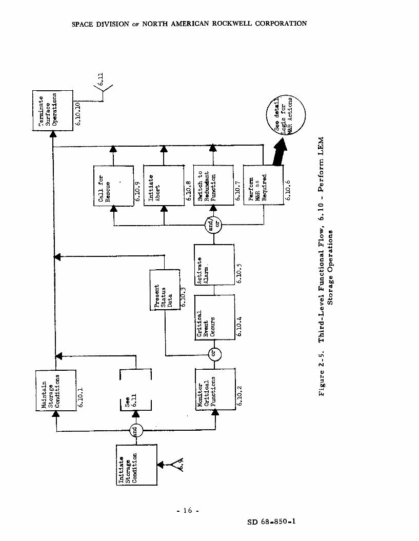
Upon arr iving on the surface, the crew wil l place the LM in i ts dormant s ta te , not to be reoccupied until departure, except in an emergency, activities a r e described by Function 6.10 and depicted in Figure 2-5.
These
- 11 - SD 68-850-1

SPACE DIVISION OF NORTH AMERICAN ROCKWELL CORPORATION
- 12 - SD 68d850-1

I
r- r,
tc \o .
t
A
R 9'

8
W U 2 m
c I
3 a
E k 0 w k
t I
0
\D
yr) I
N
a, k
2 G
I

SPACE DIVISION OF NORTH AMERICAN ROCKWELL CORPORATION
UI C
a
Id C
E
E
Q) k
- 15 - SD 68-850-1
SPACE DIVISION OF NORTH AMERICAN ROCKWELL CORPORATION
1
1
+- pi , -4
I
- 1 6 - SD 68-850-1

SPACE DIVISION OF NORTH AMERICAN ROCKWELL CORPORATION
N 4
u3 6, %;
A
q 0 4 m
I L
I
- 17 - SD 68-850-1


d I 0 In ca
I ca 9
n rn

SPACE DIVISION OF NORTH AMERICAN ROCKWELL CORPORATION
The LM stored s ta te is in some respects less severe on the systems than that of the CSM, because no stability control is required in the LM; however, the extreme contrast between the lunar-day heat and the lunar- night cold could present other problems. The LM storage cal ls fo r -
1. Internal temperature limited to between t 4 0 and $100 F.
2. Internal p r e s s u r e limited to about 0. 5 psia.
3. Prevention of fuel freezing.
Upon leaving the LM, the crew wi l l make provisions f o r monitoring i ts s ta tus , thenmove to, and activate, the lunar shel ter ,
The lunar shel ter i s planned to be sent ahead by direct lander. The
Abort requirements associated with the stay-time on the surface i s to be up to 90 days, shortened only if some unforeseen event requi res abort. lunar shel ter malfunctions o r the exploration program a r e considered beyond the scope of this study; however, the supporting functions a r e presented in Figure 2-6.
One additional requirement pertains to abort capability: The LM will be ready to abort as required, limited only by the constraints imposed by the CSM/ LM rendezvous window and any maintenance action considered to be a necessary pa r t of the mission concept. Fo rmer studies indicate the actual l imit w i l l be imposed by the rendezvous window f o r any nonequatorial landing site. Use of a lunar polar orbit i s recommended, since any point on the surface can be reached by a Saturn V mission; however, the rendezvous windows may be a s smal l a s 1. 5 hours in length and limited to two in any 30-day period.
The stay-time on the lunar surface i s to continue to 90 days if no situation occurs that cannot be circumvented by crew action and/or ear th- based command. To facil i tate notification of impending emergency, a status monitor and a la rm system is required for both the orbiting CSM and the s tored LM. the quiescent conditions, and control system. environmental conditions have exceeded their respective boundary values and/or when those functioning elements a r e degrading to the point where fai lure seems imminent.
These functions need only evaluate a few operating functions, They must indicate when the
Studies and tes t s have shown (Reference 2-2) that it i s safer and that
In s0m.e cases , this operational concept depends on mainte- it leads to a m o r e reliable mission when the systems a r e left off until they a r e required, nance and repa i r (M&R) actions to reestabl ish normal operations after the extended downtime in t ime to meet the mission commitment. Given that
- 21 - SD 68-850-1

SPACE DIVISION OF NORTH AMERICAN ROCKWELL CORPORATION
t ime is allowed for M&R activity pr ior to LM launch and/or CSM t r ansea r th injection, this operational concept should introduce no deleterious effects on mission success or crew safety. The CSM and LM status will be a s ses sed periodically, at l eas t once a day; and if malfunctions occur during the lunar s tay t ime on ei ther the CSM o r LM, every attempt will be made to offset the effect of the failure by use of the command link to the CSM or M&R action on the LM. anticipated that no abort will be attempted; in fact, M&R may be a s a f e r alternative, par t icular ly for the LM.
Where these actions can sat isfy the abort o r safety c r i t e r i a , i t is
At the end of the 90-day stay-period, or sooner if abort is required, the 3-man exploration par ty will shut down the lunar shel ter operations and re turn to the LM, conducting the functions as indicated in Figure 2-3. The first operation will involve activation and checkout of the LM; any cr i t ica l malfunctions a r e to be corrected (where possible) pr ior to launch. Provis - ions for the required spa res must be made in the LM or in conjunction with lunar shelter. These provisions a r e identified in Section V of this report .
The remainder of the LM mission to the point of rendezvous is expected to p rogres s a s normally planned for Apollo except for a potential wait in a lunar phasing orbit to permit compensation f o r g ross differences in the CSM/ LM orbi ta l parameters . tion 6. 16), however, there may be considerable difference in the required activities. and the ability of the LM crew o r MSFN to control i t via the command link, The alternatives a r e presented in Figure 2-7.
After the LM rendezvous with the CSM (Func-
The subsequent events depend on the kinematic s ta te of the CSM
If the CSM is stabilized as planned, a normal docking operation will be accomplished; however, if it remains in the spin mode o r is in uncon- trolled motion, other alternatives as indicated must be attempted. Fa i lure to gain access to the CSM would requi re rescue from ear th and the available t ime would greatly limit this alternative, Indications a r e that the CSM would not be undergoing any severe motion. Under the expected conditions, either the LM could synchronize with the CSM, or the E V A crewman could probably gain access and/or a r r e s t any motion to permit completion of the docking operation.
Once the c rew has t ransfer red to the CSM, a l l the fuel cel ls will be s tar ted up and other CSM functions subsequently activated and checked out as indicated in F igure 2-8. could be considered; however, for the purposes of this study M&R is con- s idered the most logical alternative where possible. involved are presented in Figure 2-9 and will be discussed in detail under a subs e quent section.
In the event of any malfunctions, four alternatives
The considerations
- 22 - SD 68-850-1

SPACE DIVISION OF NORTH AMERICAN ROCKWELL CORPORATION
- 23. - SD 68-850-1

SPACE DIVISION OF NORTH AMERICAN ROCKWELL CORPORATION
Once the CSM has been checked out and/or res tored to normal operating conditions, the LM can be jettisoned. will be accomplished as in the DRM when the injection window i s properly aligned,
Transear th injection (6. 21)
The mission subsequently will be completed as in the DRM.
2. 2 MISSION TIME LINE
The mission has been described in the pr ior section; the significant events a r e very much like those for Apollo except in the lunar a rea . timing provides the data necessary to identify specific functional require- ments and the associated duty cycle,
Event
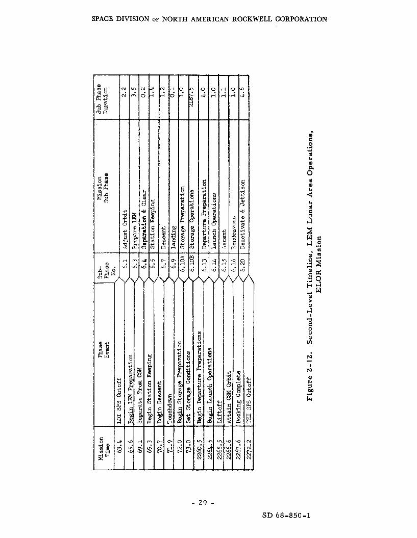
Figure 2- 10 provides the top-level mission timeline, while Figures 2-11 and 2-12 present the second- and third-level of activities for the CSM and LM, respectively, within the lunar a r e a operations. The phase duration for operations within the lunar a r e a a r e based on their maximum expected value, since such factors as descent, launch, and rendezvous windows can vary from hours to days depending on the selected site. In any case, it was assumed that the maximum time to be spent in the lunar a rea , Function 6 . 0 , would not exceed 90 days.
2.3 MISSION SYSTEM FUNCTIONAL REQUIREMENTS
NOTE: It was assumed that the mission functional require- ments f o r all phases, exclusive of lunar a r e a operations, 6 . 0, have been satisfied by the existing Apollo systems and w i l l remain substantially unchanged.
A s previously indicated, the systems engineering approach to definition of systems requirements has been applied to this study. It facilitates a logical approach to the definition of systems requirements. this analysis a r e tabulated by mission phase in Table 2-1 , along with an assessment of the potential source of the hardware that may satisfy these requirements. Again, only the new phases were assessed. These functional requirements a r e then grouped by conventional system designation and vehicle in Tables 2-2, 2-3, and 2-4.
2 . 3 . 1 The CSM Functional Requirements
The resul ts of
For the most par t , the following functions a r e additions, modifications, o r reapplications of the functions already existing within the CSM subsystems. (Numbers in parenthesis re fer to Table 2-2. )
(1) The stability control function will provide limited control of the CSM during the quiescent mode. Constraints a r e established by such factors as external temperature and resulting uneven heating, l imits on uncontrolled motion, the need to communicate with the ear th and lunar party, and LM
- 24 - SD 68-850-1


nn
c,
k rd
(I] a, .ri c, .ri
I
9 N
#.
m N
1

SPACE DIVISION OF NORTH AMERICAN ROCKWELL CORPORATION
c! 0 .d m m s d 0 I4 w
- 27 - SD 68-850-1

SPACE DIVISION OF NORTH AMERICAN ROCKWELL CORPORATION
c
c
c
1
Id k Q
Id Q)
2 k rd
I N
- 28 - SD 68-850-1
SPACE DIVISION OF NORTH AMERICAN ROCKWELL CORPORATION
- 29 - SD 68-850-1-

SPACE DIVISION OF NORTH AMERICAN ROCK WELL CORPORATION
Table 2-1. New Mission Functional Requirements (Sheet 1 of 2 )
Mission Phase
6.6 Initiate CSM storage functions
I 6. 7 LM descent operations
6. 8 CSM unattended operations
I
6. 9 LM landing operations
6. 10 P r e p a r e LM for s torage and LM storage ops.
6. 11 Lunar base operations (CSM and LM support only)
Functional Requirement
1. Monitor CSM system status 2. Exercise CSM remote controls 3. Observe CSM response 4. Set CSM for s torage mode 5. All other functions - normal 6. Third-man support
1. Relay CSM status to LM 2. Respond to LM commands 3. Provide s torage control
1. Monitor CSM status 2. All other functions - normal 3 . Third-man support
1. Course stability control 2. Internal temperature limiting 3 . External temperature limiting 4. Status assessment 5 . Status re lay t5 LM ~ ~ ~
6. Status re lay to Ear th 7. Internal p r e s s u r e limiting 8. Malfunction a l a r m 9. Redundancy control
10. Increased environment protection 11. Minimum electr ical power 12. Remote E. P. control ( s t a r t op. )
1. Third man support 2 . Increased landing A V 3. All other functions
1. 2. 3 . 4. 5 .
- 6. 7. 8. 9.
1. 2. 3. 4. 5. 6. 7. 8.
9.
Internal p r e s s u r e limiting Internal temp e r a tur e limiting Status a s s e s sment Status relay to lunar base Malfunction a la rm Redundant critical functions Electr ical power (descent) External temp. limiting (calibratioi Maintenance and repair provisions
Lunaa base shel ter CSM comm. link CSM status display LM link* LM status display” CSM command link Critical events a l a r m Maintenance and repair support for LM Earth communications link
6. 12 Terminate lunar base operations
2 1. CSM status display 2 . CSM command link 3. Earth communications link
Pot enti a1 Function Source
New New
New LM New
LM/CSM
Apollo/new Apollo/new Apollo lnew
New LM New
Apollo/new Apollo Apollo Apollo/new Apollo /new Apollo/new Apollo New Apollo /new Apollolnew Ap 0110 Apollo /new
New LM/new LM
LM LM
LM Existine
LM Modified or
New Xew
Kot a part oi this s t u d y
Not a par t of this s t u d y
- 30 - SD 68-850-1

SPACE DIVISION OF NORTH AMERICAN ROCKWELL CORPORATION
Functional Requirement
1. P r o p e r tempera ture res torat ion 2. CSM status display 3. CSM locat ion/ t ra jectory 4. Normal LM functions
1. CSM position/timing 2. Normal LM functions 3. Third m a n support
1. CSM positionftiming 2. Normal LM functions 3 . Third man support 4. Increased AV capability
Table 2-1. New Mission Functional Requirements (Sheet 2 of 2)
Pot entia Function So
New/LM New/LM LM LM
LM/new LM LM/new
New
New Mod, LM
Mission Phase
1. 2. 3. 4. 5. 6. 7. 8.
6. 13 P r e p a r e LM for departure
New New LM
New New New Apollo/new Apollo Apollo/new New New
I
6. 14 LM launch operations
1. 2. Minimum electr ical power 3 . EVA support sys tems 4. EVA manuevering unit
6.
1. Normal CSM functions 2. Maintenance and repair capability 3. CSM/LM interchangeability 4. Wait-in-orbit capability 5. Updatelregenerate computer
Close stability hold (remote control)
5. Normal Apollo/LM functions CSM provisions for EVA transfer
memory
6. 15 LM ascent operations
Ap oll o 1 new Apollo Apollo New
Apollo /new
Apollo New Apollo/LM/ New Ap 011 o /new
A ~ O L ~ ~ / L M
I
6. 16 Rendezvous operations (LM)
None required
No change from Apollo
6. 17 P r e p a r e CSM for docking
Apollo I1
6. 18 Crew t ransfer operations
6. 19 CSM departure preparations
6.20 Deactivate the LM
6. 21 Transear th injection
1. 2. 3.
CSM command link CSM status display Normal LM functions
LM/CSM command link Remote stability control change Remote position/velocity control* Internal temperature limiting Minimum electr ical power Internal p r e s s u r e limiting Malfunction a l a r m Redundancy control (remote)
I
*These may be handled a s a p a r t of the LM and Visual Inspections
- 31 - SD 68-850- 1

SPACE DIVISION OF NORTH AMERICAN ROCKWELL CORPORATION
Table 2 -2. CSM System Functional Requirements , Ninety-Day Storage in Lunar Orbit
System IFunction
1. Stability control
2. Internal tempera ture control
3. External temp. control (heat- shield and RCS)
4. Pressur iza t ion of cabin
5. Status a s s e s s m e n t
6. Remote control capability
7. Lunar orbit to sur face link
8. Elec t r ica l power supply
9. Maintenance and repa i r support
I O . Special facil i t ies [EVA support)
I I . Up-data reception
12. Increased environment protection
Requirements and Constraints ~ ~~~ ~ .~
1) Limi t spacecraf t instabil i ty to the safe l imi t s for the anboard equipment 2) Provide required stabil i ty for docking operation. .3) P e r m i t u s e oi orbi t to sucCace and Ear th comm. links. 4) Control orientation with r e s p e c t to sun f o r temp. cont.
: I ) L i m i t temp. excursions on cabin wal l to between t100"F to t40'F wall tempe. - = a h r e ' 2 ) Assure water-glycol temp. is within sage l imi t s ; i. e . , does not freeze. '3) Assure protection of s tab le platform (IMU), which is considered tempera ture sensit ive, even when I /
: I ) Assure even barbequing of heat shield to avoid unwarranted s t r e s s and ready access through hatch. :2) Assure RCS engines and fuel l ines do not freeze.
Maintain minimum requi red a tmospher ic p r e s s u r e to prevent decomposition of spacecraf t m a t e r i a l s t h l - t ~ u ~ l outgassing and sublimation, about 0 . 5 psia.
_____ ~~
~ ~ -
: I ) Assess cabin pressure . l2) Assess tempera ture i n c r i t i ca l areas and sys tems. [ 3 ) Assess S/C kinematics. (4) Assess hea t shield tempera ture in c r i t i ca l areas. (5) A s s e s s power plant status. 16) Assess fuel reserves, RCS, 0 2 , H2, et. al. 17) Provide for c r i t i ca l function Cailure alarm.
(1) Switch between redundant sys tems and functions thereof where cr i t ica l . ( 2 ) Provide att i tude and stabil i ty control for the docking function. (3) Provide emergency control of orb i ta l position and plane. (4) Initiate a predet. checkout or diagnostic routine on command.
[ I ) Relay a l a r m s to craw i n t i m e to facil i tate abort. 12) Relay s ta tus of sys tems cr i t ica l to safety to e a r t h and to sur face crew.
c,
~
.
Provide e lec t r ica l power for operating sys tems during storage. 1. 3 to 2 . 5 (LMSC data). Be capable of remote s t a r t up to fu l l power f o r rendezvous or i n c a s e of an impending failure ai an operating unit during the s torage cycle. Indicate when Iailure is imminent or probable. Minimum 2000 hours life.
Diagnostic routines to i so la te fa i lures i n c r i t i ca l sys tem [unctions. Spares complement to support r e p a i r of identified failures. Tools. EVA support system. Ability to u s e LM sys tem components.
E a s y access to CM in ter ior by one EVA crew m e m b e r , unassisted. Ready a c c e s s to 0 2 supply v ia a n umbilical a t point of ingress. Handholds on spacecraf t ex te r ior .
~
( I ) (2)
Update a n d l o r regenera te guidance computer memory. Provide link for remote control (command link) (a) from ear th , (b) from LM, (c) f rom lunar she l te r
(3) Provide timing data f rom earth.
[ 1) Meteoroid hazard. (2) Radiation hazard.
NOTE: All o thers s a m e a s Apollo.
- 32 - SD 68-850-1
SPACE DIVISION OF NORTH AMERICAN ROCKWELL CORPORATION
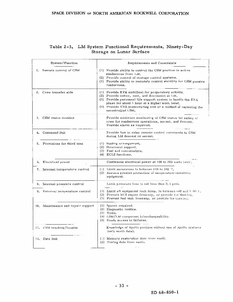
Table 2-3. LM System Functional Requirements, Ninety-Day Storage on Lunar Surface
System /Function
1. Remote control of CSM
2. Crew t ransfer a i d s
3 . CSM status monitor
4. Command link
5. Provisions for third man
6. Electr ical power
7. Internal temperature control ~~~ ~ ~~~~~~
8. Internal p r e s s u r e control
9 . External temperature control ~ ~~~
10. Maintenance and repa i r support
11. CSM tracking/ locator
12. Data link
Requirements and Constraints
(1)
(2) ( 3 )
Provide ability to control the CSM position in active rendesvous from LM. Provide control of storage control systems. Provide ability to remotely control stability for CSM passive r endeavous.
(1) ( 2 ) Provide te ther , reel , and disconnect a t LM. ( 3 )
(4)
Provide EVA umbilical for preparatory activity,
Provide personnel l i fe support system to handle the EVA phase for about 1 hour at a higher work level. Provide EVA manuevering unit or a method of capturing the uncontrolled CSM.
Provide minimum monitoring of CSM status for safety of crew for rendezvous operations, ascent , and descent. Provide a l a r m as required.
Provide link to relay remote control commands to CSM during LM descent o r ascent.
(1) Seating arrangement . (2) Structural support. ( 3 ) Fuel and consumables. (4) ECLS functions.
Continuous electr ical power a t 100 to 200 watts level. ~~~
( 1 ) ( 2 )
Limit excursions to between +40 to 100 F. Assume grea te r protection of temperature-sensiLivc equipment.
Limit pressure loss to not less t h a n 0. 5 psia.
( 1 ) Limit aft equipment rack temp. to between t 4 0 and -1 Inn I . (2) Prevent RCS engine freezeup, or provide lor tha\\-inc. ( 3 ) Prevent fuel tank freezeup, or provide for thawiny.
(1) Spares required. ( 2 ) Diagnostic routine. ( 3 ) Tools, ( 4) (5) Ready access to failures.
CSM/ LM component in te r c hang eabilit y .
Knowledge of Apollo position without use u f :\pollo systcnis (only ear th data).
(1) Memory restoration data f rom earth. ( 2 ) Timing data. from earth.
- 33 - SD 68-850-1

SPACE DIVISION OF NORTH AMERICAN ROCKWELL CORPORATION
Table 2-4. Lunar Shelter Functions, CSM and LM for ELOR
2. Alarm sys tems
3 . Remote control of CSM
I System/Function 1 Requirements and Constraints
(2) Provide an a l a rm system when the abort c r i t e r i a have been compromised,
Provide a method of notifying all lunar par ty personnel of impending emergency/ abort requirements created by CSM o r LM failures.
(1) Provide remote control of CSM redundant functions for those c r i t i ca l to CSM integrity and crew safe return.
(2) Provide ability to start up systems required for rendezvous.
(3) Provide startup control of the electr ical power source.
1. CSM status readout
~
4. Command link
5. LM Status
(1) Provide an indication of the s ta tus of l cr i t ica l orbiting CSM sys tems on at l eas t
a go-no-go basis.
Provide link to facilitate remote control of i tems under (3) above.
Monitor LM quiescent control by hard line, data link, or visual inspections.
(2) Internal temperature control should be available to l imit the wall/ equipment temperature to between about +40° and t100 OF t o maintain the storage conditions for which all Apollo equipment has been qualified. tion, the water-glycol loop must not be permitted to f reeze, and the IMU may have to be maintained to c loser tolerances to prevent i r reparable damage during the quiescent phase, (up to one hour per day), it and the te lemetry also must be cooled.
In addi-
During the period that S-Band equipment operates
- 34 - SD 68-850-1

SPACE DIVISION OF NORTH AMERICAN ROCKWELL CORPORATION
( 3 ) External heating must be controlled to a s su re somewhat uniform temperatures near the back face of the heat shield to prevent the RCS engines/ fuel f rom freezing and to prevent the space radiators f rom freezing o r inhibiting the flow of coolant. from an EVA situation, nothing can be tolerated that would inhibit the opening of the access hatches.
Because ingress to the CSM may be initiated
(4) Cabin pressur iza t ion w i l l be allowed to drop to 0. 5 psia a f te r LM separation and then maintained a t about that level until crew re turn and ingress. This procedure will prevent any mater ia l s f r o m outgassing, reduce the leakage loss , and reduce the f i re hazard. In fact , any leakage makeup could be provided by an iner t gas such a s helium o r nitrogen.
(5) Status assessment i s to be accomplished through use of a minimum number of sensors and a combination s ignal condi t ioner/alarm generator. The data to be a s ses sed a r e described in Table 2-5. sensors , a signal conditioner i s required to a s s e s s the sensor output, convert it to digital information, and initiate an a l a rm i f the values a r e outside the programmed boundaries.
In addition to the
(6) Remote control capability i s required to control the overall operational mode of the CSM while in the quiescent s ta te and to facilitate the re turn to tight stability control f o r the unmanned docking and separation activities. In addition, there must be some control over redundancy and any diagnostic requirement imposed by the need to identify fa i lures and make proper use of redundancy. activate the CSM sys tems upon command and to initiate any required velocity change necessary to facil i tate active docking when the LM is unable to perform the rendezvous action. docking action, which involves the LM RCS.
The control function a l so may be required to
This requirement does not include the final
(7) Communications link to the lunar surface and to ear th must re lay any a l a r m when the CSM i s within line-of-sight of the surface party or ear th MSFN and must provide the s ta tus data on at least a once-a-day basis on command from ei ther ear th o r the lunar surface.
(8) Elec t r ica l power is required to operate the quiescent control systems and permi t communications whenever required. Any failure must be such that it is predictable in t ime to take a compensating action pr ior to total loss. quiescent control concept. Where fuel cel ls a r e recommended, those on standby must be capable of being s ta r ted up from the remaining power sources; and at the end of the 90-day period, there must be sufficient power to a s s u r e a safe r e tu rn trip. during the quiescent s ta te to operate the coolant pumps. mus t demonstrate a life of about 2 , 500 hours.
The expected power level will vary considerably depending on the
Conditioned power may be required at intervals The power source
- 3 5 - SD 68-850-1

SPACE DIVISION OF NORTH AMERICAN ROCKWELL CORPORATION
0-
d d
0 - o m - m o o 0 0 0 0 0 0 0 0
" l o o 0 . . . . d d d - ' d N ' d d d d
m. - N
o o m r - N ~ O O O O O O O N m 0 . . . . 2 0 " - d d d d d d d d d i d d
v) a,
O N m C N m N d m O m O - N m 0 . . . . . . . . . . . . ~ m o - m - o w o m o o m. m -
N
O N * . . . m o -
N O 0 . . . m o o
O N " - i d - '
N m O . . . m o o m
N m O . . . m o o m
~____
N m O m o o m N . . . O N " -
d d -' 0 -
0 0 0
- N m . . . 0 0 0 . . .
r - m o .
- 36 - SD 68-850-1

SPACE DIVISION OF NORTH AMERICAN ROCK WELL CORPORATION
O N m F N O O O O O O O - N m 0
c I 0 - 4 - - .n n im 'ddddd- id m d d . . . .
o o o o o o o m o 0 0 0
0 0 d.o.ddddo.'n;d . . 0 0 0 0
m o o o . . . .
0 0 0 0 m o o o o o o m o 0 0 0
d d d d d d d d d d d n i d d d d
o o o o o o o m o 0 0 0
0 0 -.dddo.o.o.m.d . . 0 0 0 0
0 0 0 0 . . . .
N m N d . 0 0 m 0 - N m 0
0 0 N.m.o.-.N.-.o.*.d . . O N L n r -
c o o - - . . . .
N m
r r r r u u o o o m - 0 0 0 0 0 0 0 - m
O N Y I P - N O O O O O O O ~ N cI 0
N ' d d d d d d G d d d d . . . . m o - -
\D m
o ~ o * a . o - o o 0 0 0 . . . . . . . . . O N 0 0
W O O 0 0 0 0 - m - 0 0 0 d d d . . . . OI
N
N
V I 0 0 0 O m N b 0 . 0 - 0 0 0 0 0
0 0 0 0 d d d i A ' - ; d d d d d d . . . . 0.
N
-
m o o o 0 0 N b ' O . 0 - 0 0 0 0 0
d d d d d - ' d i d ' - ; d d d d d d OI
ni
- 37 - SD 68-850-1

SPACE DIVISION OF NORTH AMERICAN ROCKWELL CORPORATION
rn k =t
i2
E ls
d a,
.I4
a,
0" n
m o o o o N O O O O O O O 0 0 0 . . . . 0 0 0 0 d d d d d d d G d d d d
O N m P - N O O O O O L n O O N m 0
a i d - ' ; N ' m ' d d d d d i d d d d .n m
O N Y I P - N O O O O O N O - N m 0 . . . . - 0 - M N ' m ' d d d d d i d ai d d
.n m
m o o o o m o - o o m o o 0 0 0 . . . . 0 0 0 0 d d d d d - ' d d d d d d
0.
m o o o O l n O O O m N O O 0 0 0
0 0 0 0 . . . . d d d d d d d d d d d d
0.
N m C N 0 0 0 0 0 0 0 - N 0 0 . . . 0 - 3 ,.im'ddddd$d ai d d
.n
d 0
.rl c,
$. cr c Lo u . m I N
a, P id I3
d
O N m P - 0 0 0 0 0 0 0 0 0 N 0 0
0 0. 0 0 - - .n . . . . d d d d d d d d d ai d d - m o o o O L D N d O I O O O O 0 0 0 . . . . . . . . . . . . . . 0 0 0 0 0 0 0 - m - 0 0 0 0 d d
3
N
N m N L 1 0 0 m 0 4 N TTI 0 N.m.o.o.o.-.o.$o. ai . . O N m h . . . . 0 0 ' - 0 0
.n m
N O o O O O O L n - d. 0 0 0 0 0 0 . . . . 0 0 0 0 N ' d d d d d d d d 0: d d - 0 0 0 0 N m 0 0 0 0 m 0 - 7 0 0 . . . . . . . . . . . . . . . . 0 0 0 0 N m 0 0 0 3 0 e O 0. 0 0 *
t 0 0 0 0 0 d d d d u i d d d d 0 0 0 . . . . . . . - N m m d r - m w
- 38 - SD 6 8 - 8 5 0 - 1

SPACE DIVISION OF NORTH AMERICAN ROCKWELL CORPORATION
(9) Maintenance and repa i r support i tems a r e required to facil i tate implementation of the availability concept a s applied to the manned portions of the mission. The specific requirements include spares , tools, diagnostic equipment, and a data system.
(1 0 ) Special facil i t ies /EVA support a r e also required to facil i tate crew safety under the proposed operational concept. include such i tems a s spacesuit , maneuvering units, and spacecraf t design fea tures which facil i tate EVA activit ies and external maintenance.
These support functions,
(11) Up-data reception i s required to per form the functions normally expected of the Apollo up-data link and is of par t icular importance to th i s mission because the cent ra l t imer and the Apollo guidance computer wil l be shut down during the quiescent state. The data required include timing, computer memory update, and a channel f o r the command functions that dr ive the remote control ler o r activate the down-data transmissions.
(12) Increased environmental protection against meteroids may be required to meet the Apollo objectives f o r the 90-day mission. the r i s k of higher radiation levels must be considered, except the so la r heat previously referenced, will not materially affect the mission.
In addition, Other environments,
2 . 3 . 2 The LM Functional Requirements (Table 2-3)
(1) Remote control of the CSM from the LM, a s well a s f rom the ear th and lunar surface, may be a requirement to maximize mission success / crew safety. Paragraph 2.3. 1 (6).
The functions to be controlled a r e those referenced in
(2) Crew t ransfer aids a r e required to permi t EVA t ransfer of the crew to the CSM in the event they a r e unable to hard dock. Paragraph 2.3. 1 (10).
See
(3) CSM status monitoring of some form may be required to provide rudimentary information a s to the CSM condition after separation and pr ior to rendezvous. by the CSM while the LM i s in use. requirement.
In addition, i t must respond to any a la rm signal transmitted Again, the ear th link may satisfy this
44) A command link i s required to t ransmit the commands generated by the CSM remote controller, Function (1).
- 39 - SD 68-850-1

SPACE DIVISION OF NORTH AMERICAN ROCKWELL CORPORATION
(5) Provisions for a third crewman a r e required in the LM to bring the third man to the lunar surface. descr ibed in Reference (2,). f unc t i ons ,
This approach has been adequately These provisions include both space and support
(6) E lec t r ica l power i s required for the quiescent period a s well a s the periods of usage. on the use of paras i t ic heat. depending on the parasi t ic heat available from the power source. the power i s required to produce heat energy.
The expected power requirements will vary depending The power level required will vary considerably
Much of
(7) Internal tempera ture control will be required for the storage mode, which will l imit the wall and equipment temperature to between t40 and t100 F, the LM in-flight specifications. Under these conditions, however, the water tanks must be kept f r o m freezing, and perhaps some control of IMU internal temperatures must be maintained.
(8) Internal p r e s s u r e control of some form may be desirable during the quiescent mode. should be about 0. 5 psia.
As indicated for the CSM in Paragraph 2 . 3 . 1 (4), it This requirement i s not known to be f i rm.
(9) External temperature control may be required to prevent the RCS engines f rom freezing (or to thaw them out pr ior to usage) and to prevent the fuel tanks f rom freezing. The LM vehicle surface temperatures a r e expected to vary between t120 and -260 F according to Surveyor VI data (Reference 2-3).
(10) Maintenance and repa i r support w i l l be required to a s s u r e successful application of the availability concept to the s tored LM. nance can be performed any t ime the LM is on the lunar surface or in t rans i t ; however, only the systems involved in quiescent control and data handling need to be maintained until just p r ior to departure. ability with the shel ter systems i s a desirable feature. a r e specifically identified in a subsequent section. spa res , and diagnostic data. unless the work can be taken to the lunar shel ter ,
Mainte-
Interchange- These support i tems
They include tools, M&R actions will be limited to the box level
(11) A CSM tracking/locator of some form is required to aid the LM
Use crew in establishing the rendezvous data prior to launch from the lunar surface, and updating it during t rans i t without aid f rom ear th (MSFN). of ea r th tracking data should be the normal mode of operation and may be accomplished through use of the lunar base systems.
(12) Up-Data a r e required f rom ear th and p r io r to launch to r e s to re the LM guidance computer memory and reestablish the timing base after shutdown for the quiescent mode.
- 40 - SD 68-850-1

SPACE DIVISION OF NORTH AMERICAN ROCKWELL CORPORATION
2. 3. 3 Lunar Shelter Functional Requirements (Table 2-4)
NOTE: These sys tems a r e not a. pa r t of this study.
The lunar she l te r i s to be sent ahead of the ELOR mission to provide the living and work quar te rs for the extended stay-time. provide some support functions necessary to keep the exploration par ty aware of both the LM and CSM status.
In addition, i t w i l l
These required functions a r e a s follows:
(1) The CSM status board i s to provide a visual display of the CSM condition a s it orbi ts the moon. a day unless a c r i t i ca l situation was identified and/or when the abort c r i t e r i a were compromised. Paragraph 2 . 3 . 1 for data to be monitored.
It would probably be updated at least once
Data may come direct f rom the CSM o r via earth. See
(2) An a l a r m sys tem i s required to notify a l l lunar par ty members , regard less of where they a r e , of an impending emergency and/or the sub- sequent abort plans in t ime to respond safely. to situations c rea ted either by LM problems o r CSM problems.
The system must respond
(3) Remote control of the CSM i s required to maintain safe o r optimum storage conditions in the event of some fa i lures . should provide the following actions:
The remote-control link
1.
2.
3.
4.
5.
6.
(4)
Activate normal CSM stability control mode.
Command a status review.
Startup the standby fuel cells ,
Switch loads to any of the operating cells.
Shut down a malfunctioning ce l l i f used.
Switch to any redundant function of a system where failure can compromise the ability of the crew to re turn safely.
A Command link i s required to provide communications between the lunar surface and the orbiting CSM. consisting of the commands l isted above.
Digital data only will be transmitted,
(5) An LM status board i s required to monitor the LM in the quiescent mode. ra ther than dis turb the LM systems in the dormant state. be transmitted v ia hard lines o r on the VHF link, depending on whichever ,
proves to be the more reliable mode. a s an a la rm.
It is considered bet ter to monitor the functions from the shel ter These data may
Emergency situations must be relayed The data to be monitored a r e a s indicated under Paragraph2.3.2.
- 41 - SD 68-850-1

SPACE DIVISION OF NORTH AMERICAN ROCKWELL CORPORATION
2.4 SYSTEM FUNCTION DUTY CYCLE ESTIMATES
The command and serv ice modules a r e expected to function during the ELOR mission in much the same way and f o r the same periods a s the Apollo LOR mission, except during the lunar a r e a phases. for this and to determine the actual ELOR mission subsystem duty cycles, the Apollo design reference mission (DRM-2A), Reference 2-1, was modified to reflect the changes expected for ELOR. a r e reflected in ?able 2-5 for the CSM system.
To compensate
The result ing est imates
Modified duty cycle es t imates fo r the LM used in the ELOR mission a r e presented in Table 2-6. l e s s than those of the normal Apollo-LOR, except fo r the dormant control functions, because the systems a r e shut down immediately af ter landing, and the lunar shel ter provides the required functions while the crew is on the lunar surface.
These est imates a r e actually 25 to 30 percent
2.5 QUIESCENT MODE OPERATIONS
. The mode of operations employed during the CSM and LM dormant phase is of paramount importance to this study's objectives, since the '
mission duration (overall) is significantly longer (by a ra t io of more than 12 to 1) than that for which the Apollo CSM and LM were designed. As a resul t , specific action is required to minimize the hazard of fa i lure during, this period, To resolve this problem, it is necessary to understand the mechanics of fa i lure and take advantage of any potential control actions to reduce the fai lure hazard before other alternatives such a s maintenance a r e considered, A s a case in point, consider the data of Figure 2-13.
It i s well known from the basic reliability equation R = e-ht that a fa i lure hazard ( i t ) i s time dependent. cally the reliabil i ty would remain a s i t wa's when it was stopped, it would seem that any t ime the systems do not operate they do not accumulate t ime or become a hazard to crew safe return. however, t e s t s have shown that even in the quiescent state, some components may develop fai lures which a r e manifested when the system is turned on. In defining this situation, a recent study performed by Martin-Marietta concluded that, on the average, the fai lure hazard was reduced by a ra t io of 99 to 1 while the system was s tored in a normal ear th environment (Refer- ence 2-2).
If the clock can be stopped, theoreti- Therefore,
To a degree this i s t rue;
Under "controlled bench" conditions i t would be even less .
Given the foregoing and applying it to a comparison between the Apollo LOR and ELOR, it was found that the average failure hazard during ELOR lunar operations exhibited a factor of 55 less than fo r the Apollo mission if a l l equipment was shut down and the aforementioned dormant conditions were maintained. Fur ther , it has been shown that systems that a r e cycled on and off can be subject to.higher failure hazards than those operated only when
- 42 - SD 68-850-1

SPACE DIVISION OF NORTH AMERICAN ROCKWELL CORPORATION
* * * * u u u u 0 3 0 0 0 0 0 0 0 3 0 0 0 0 0 0
m o 0 0 0 0
3 N d +
m o o 0 O N N O N 4 3 0 0 L O 3 U l d 0 0 0 . . . . 0 0 0 0 0 o - d d d L o * d d d O * L d d 0- 0- 0.
3 0 0 0 O m N T ? N - N o O o - m - 0 0 0
0 0 0 0 0 - 0 3 - 0 0 0 3 - 3 0 0 0 0 0 . . . . . . . . . . . . . . . . . . . .
__
0 0
0 0 . .
0 0
0 0 . .
0 0
0 0 . .
W O O 0 O N 0 - N 3 0 0 0 0 0 0 0 0
o d d d d O . O * d d L d d d d d d d d 0-
N O 0 0 O - N T ? 0 0 3 0 - m ~ m 0 0 . . . o o o d d d d L d d d d d d L d d d 0
-c
N O 0 0 O L n O + N d N O O O - U I O 0
0 0 0 0 0 ~ 0 ~ 3 0 0 0 - - - 0 0 0 . . . . . . . . . . . . . . . . . . 0 3 N
0 3 tc . . .
o s -r o s tc . . .
- 3 . . o s N
c c
u .3
P k 0
s " 2 n c
c U
2
n" 3 m
U d a, V
t x
c .- +
6:
- 43 - SD 68-850-1

SPACE DIVISION OF NORTH AMERICAN ROCKWELL CORPORATION
L
n o 0 0 0 - o o o o m o o o o o o 0 0 0
d d d d d d d d v i d d d d d 0- d o\
S d d d
n o 0 0 0 - o + o o - o o o m o o 0 0 0
S d d d o - d d L o - d d o * ; L d d d d d d
m o o 0 0 - o o o o m o o o o o o 0 0 0
d 0. 0- d 0. 0' 0. d d 0- d d d 0. 0- d u- G d d d
m o o o O ~ N ~ N + U l O O O + U l O 0 0 0
d d d d d o * d L L d o * o m ~ L A o ~ d d d d ~ _ _ _ _ _ _ _ ~
O ~ N + N ~ m O O O + m O 0 0 0
O O O - - O O O N ~ ~ O O 0 0 0 . . . . . . . e . . . . . . . . m o o o
0 0 0 0 m . . .
- ~ _ _ _ _ _ ~ ~ _ _ ~
0 0 0 0
0 0 0 0 . . . .
0 0 0 0
m o o r - . . . . m o o - \D
0 0 0 0
0 0 0 0
- N M m . . . .
0 0 0 0 0 0 0 0 N 0 + m 0 0 0 0
d d d o ~ d o ~ d d d 3 ~ d d d d 0.
u u a l a , m v 1
N
U a, 0
0 W
0 0 0 0 0 0 0 0 0 0 0 0 0 0 0
3
- 44 - SD 68-850-1

SPACE DIVISION OF NORTH AMERICAN ROCKWELL CORPORATION
u a u n:
6 . u c C
c c
i t c: I-
0 0 0 d N 3 N 0 0 0 - m L C O O O 0 0 0 0
o. *. o. -. 3. o. o. o* o. o. -. d o. o. d d d d 0 0
d d d d d d d L L d d d i L L d d d d d
. . m o o o 0 m N V N - N O O O - m m 0 0 0
N
r o o 0 0 O m N d N - N O O O - r o m 0 0 0
d d d d d d o - L L d d d L 3 * ; d o - 0. ;;
- 0 0 0 0 0 0 0 0 0 0 0 0 0 3 r o m 0 0 0
0 0 0 0 . . . . . . o. o. o. o. o. o. o. o. *. -. -. o. o.
d & d L L d L < . $ L , d d d d
0 0
m o o t - N m N d N - O m O O - m m 0 0 0
m o o - . . . . . 9 m
N
m o o r N m N W N - O m 0 0 0 0 0 0 0 0 N.mo .*.*. o.~.~.o.o.o.o.o. o. . . G d d L 0 0 m 3
a
N ~~~
m o o o N 3 0 0 0 0 ~ ~ 0 0 0 0 0 0 0 0
d d d d d d d d 0. d d t-' i 0. 0. 0. 0. 0- 0. 0- m 3
N ~ ~
m o o o N ~ 0 0 0 0 m m 0 0 0 0 0 0 0 0
0 0 0 0 ddddddd t - ' r ndddd d d d . . . . m - N
m o o o N ~ 0 0 0 0 m m 0 0 0 0 0 0 0 0
d d d o ' d d d t - ~ ~ o * o * d o ~ d 0- d m d d d d 3
- 45 - SD 68-850-1

SPACE DIVISION OF NORTH AMERICAN ROCKWELL CORPORATION
0 99
.9
The ELOR Kission
CSM Quiescent
Normally Funckioning to Frovide the Quiescent
2000 1 4 m Total Mission Duration in Hours
The CSM Vehicle Svstems
Figure 2-13. Effects of Dormancy Concept on the Probabili ty of Safe Return, No Maintenance or Repair
- 46 - SD 68-850-1

SPACE DIVISION OF NORTH AMERICAN ROCKWELL CORPORATION
required. LM because s torage conditions must be maintained. provide the following basic c r i t e r i a for the quiescent mode design:
Obviously this effect cannot be attained for either the CSM o r the It does, however,
1. Operate the systems no more than is absolutely required.
2. Leave off a l l sys tems functions not required.
3. Per fo rm the detailed systems s ta tus checks pr ior to departure , but allow enough time to perform a l l required maintenance actions .
2.6 MISSION SUCCESS/CREW SAFETY AND ABORT CRITERIA
2. 6. 1 Definitions
Considerable misunderstanding exists regarding the meaning of mission success (MS), crew safe r e tu rn (CS), and abort c r i t e r i a (AC). Fo r this reason, it is necessary to define these t e r m s within the context of the ELOR mission. with mission objectives, since it is normally associated with missions and sys tems wherein fai lure of a system cannot be tolerated. With reference to the ELOR mission, i t is a lmost self-evident that fa i lures should be expected and, indeed, planned for because of the duration and the operational t ime f r a m e (1975). potential fa i lures and determination of the extent of preparation required.
The t e r m reliability (R) will not be used in this study in connection
A major objective of this study is the identification of
The following definitions a r e submitted for application to the ELOR mission:
1. Probability of Mission Success (P90 ). mission will be completed a s plannex and reflected in the timeline profile, That is, the full 90-day stay-time will be completed without compromising the abort c r i te r ia . Within this definition fai lures a r e permitted, provided that they a r e repaired and that they permit completion of the mission.
Pg0 i s the chance that the
2. Probabili ty of Crew Safe Return (Ps). crew w i l l re turn safely to ear th in spite of any circumstance which may a r i s e during any phase of the mission. These circumstances include mission success , u se of any backup modes, and any abort requirements , but not rescue. (Rescue requirements a r e a separa te category. )
Ps i s the chance that the
- 47 - SD 68-850-1

SPACE DIVISION OF NORTH AMERICAN ROCKWELL CORPORATION
3 . Safe Abort. The c r e w is returned to ea r th i n the CM pr io r to the scheduled time and is recovered safely a t a preselected recovery a r e a without exposure to any abnormal environments. This p r o - cedure is initiated when the abort c r i t e r i a have been exceeded and when one m o r e i r r epa rab le failure could lead to c rew los s .
4. Emergency Abort . r e tu rn to ea r th at the ea r l i e s t possible t ime. It may o r may not be i n l e s s t ime than that required f o r a safe abort . Under these conditions recovery can be anywhere on ear th i n the a r e a included between 45 degrees north latitude and 45 degrees south latitude. This form of abort is initiated only when catastrophic failure is imminent, no r epa i r s a r e possible, and the c rew is in immediate danger.
An emergency abort is c rea ted by the need to
2 . 6 . 2 Abort Cr i te r ia
The abort criteria fo r all the ELOR mission phases except the quies - cent phase is considered without exception to be the same as those imposed on the Block I1 configuration of the Apollo DRM-2A. phase; i. e . , L M dormant on the lunar surface o r the CSM i n lunar orbit , however, the basic approach must of necessity change. only quiescent control and te lemet ry will be functioning; therefore , fa i lures cannot occur i n the other sys tem functions -by definition. Fa i lures will only become apparent after the vehicle has been boarded and the systems have been activated; at this t ime maintenance and repair actions can be planned to compensate for failures.
During the quiescent
During this t ime,
Abort c r i t e r i a for the quiescent phases need only be addressed to the problem of maintaining the required state and/or not degrading abort cap- ability. Tables 2-7 and 2-8.
The resu l t s of this approach a r e reflected in the c r i te r ia of
2.7 SYSTEM FUNCTION DOWNTIME CONSTRAINTS
2.7. 1 Definitions and Causations
Since maintenance in space is a requirement for longer missions, one of the associated problems is identification of the system tolerance to m a l - function. To resolve this problem, i t is necessary to understand system operation when performance anomalies occur. seldom lead to complete sys tem failure; ra ther , there is the temporary lo s s of a function. In most of these cases , and for all cr i t ical functions, modern spacecraf t designs call for some fo rm of independent backup that will permit continued operation. Even with this amount of precaution, some situations
Individual malfunctions
- 48 - SD 68-850-1

SPACE DIVISION OF NORTH AMERICAN ROCKWELL CORPORATION
Table 2-7. Abort Cr i te r ia , CSM Dormant in Lunar Orbit
Sys tem
1. Elec t r ica l power
2 . ECLSS
3 . Commun,cations
4. Stability control
5. Guidance and navigation
6. Other
Abort Cr i te r ia
1. Loss of one fuel cell 2. Excessive 0 2 o r H2 usage/ loss
(fuel cell concept only)
1. No coolant circulation 2 . 3 . Loss of cabin p r e s s u r e
Out -of - tolerance internal tempera tures
1. Loss of command link 2 . Loss of all s ta tus data
1. Loss of stability control 2 . Loss of orientation/attitude control
and/or attitude reference
1. Loss of IMU temperature control (maybe)
1. Excessive heat-shield tempera ture stress
Table 2 - 8 . Orbit Cri ter ia , LM Stored on Lunar Surface
I System ~
1. Elec t r ica l power
2 . ECLSS
3 . Communication
4. Stability control
5. Guidance and navigation \
6. Others
Abort Cri ter ia
1. 2 .
1.
2 .
1. 2.
1.
1.
1.
Loss of e lectr ical power Excessive use o r loss of 0 2 (o r fuel)
Out -of - tolerance temperatures ,
Loss of cabin p re s su re internal o r external (fuel tanks)
Loss of communications with ear th Inability to monitor status
None
Loss of IMU temperature control (maybe)
None
- 49 - SD 68-850-1
SPACE DIVISION OF NORTH AMERICAN ROCKWELL CORPORATION
may a r i s e that would not pe rmi t performance of a given critical function until a r epa i r is made. constraints on miss ion sys tems design. These a r e the maintenance time constraints (MTC's). commitment o r to support the needs of the c rew,
It is these situations that establish the most c r i t i ca l
MTC's stem f r o m the need to per form a miss ion
It is logical to a s sume that a function is required during some specific par t of the miss ion or for a percentage of the total miss ion duration. Per- haps it is required randomly throughout the mission. logical to a s sume that the miss ion can proceed in a degraded mode, if only fo r a ve ry shor t period. periodic maintenance and the necessary repair o r replacement actions. The MTC, therefore , is defined as -
It is also just as
If this is t rue, that per iod can be used fo r both
A res t r ic t ion imposed on the total allowable elapsed t ime a miss ion sys tem function can be out of se rv ice before a situation is c rea ted that would resul t in ultimate lo s s of the miss ion spacecraft and/or crew.
It should be recognized that downtime constraints a r e not always de- sc r ibedby a single value defining a line of demarcation between life and death. Crew o r function degradation may be gradual so that the crew's ability to meet the situation is degraded gradually to the point of final inca- pacitation, In addition, not all c r ew members will react alike. This will become obvious f r o m the data that follow:
Downtime constraints , as they apply to the ELOR mission, have meaning only during the manned portions of the mission, o r as they affect the time available to abort f rom the lunar surface. Since the CSM vehicle has been qualified for the normal Apollo mission, the only phase of the mis- sion where the MTC has much significance is during the lunar a r e a opera- tions where the approach has changed substantially.
2 . 7 . 2 Spacecraft-Stability or Attitude -Control Constraints
Constraints are crea ted by the need to meet mission commitments A
Fur the r , c r ew personnel a r e limited in their ability to stable and orientable platform is needed for navigation, guidance, and con- duct of experiments. tolerate random and repetitive motion.
The attitude -control sys tems can fail in the following modes:
1. Under manned phases
a. Loss of ability to activate the sys tem o r any pa r t thereof resu l t s in random drift .
- 50 - SD 68-850-1

SPACE DIVISION OF NORTH AMERICAN ROCKWELL CORPORATION
2.
b. Fai lure of a reaction control engine resul ts in a runaway engine and an accelerating spin in at least one plane.
c. Fai lure of the propulsion engine nozzle (burn-through) resul ts in vector misalignment.
Under s tored phases, l o s s of ability to activate the spin system resul ts in loss of ability to change the spacecraft state; i. e . , loss of ability to go f rom the quiescent state slow roll to the stabilized mode o r vice versa .
Since the spacecraft is assumed to be operated i n two basic modes with respect to control -system problems, the associated control -system e m e r - gencies will be quite different.
Under manned phases, the spacecraft must maintain a given attitude The platform is used a s a reference and through use of a stable platform.
as a reaction control system for repositioning o r stopping motion. tem must work constantly throughout the mission to prevent random drift . The tighter the stability dead band, the more often the reaction control sys- tem will work. Loss of the system function leaves the spacecraft with an unchanged course vector, but uncontrolled in attitude. It can remain in this condition without ser ious effects for a considerable portion of a mission; eventually, however, communications, the heat shield, and the reentry o r heat-rejection capabilities may be affected. It is probable that the space- craft will eventually l'weather-vane" into the solar winds and remain semistable.
The sys -
If one of the reaction control je ts fails open, the roll ra te could build
This situation has been shown to be very unlikely for up. being the worst case . the Apollo CSM o r LM.
The rate will vary according to the axis involved, the axis of symmetry
Under the storage phase, complete loss of the roll control function will result in a slow buildup of the wobble around the roll axis and eventually a shifting of the actual roll axis to one through the centroid where it will tend to stabilize. craft , but could overs t ress some equipment. The time available before the wobble becomes excessive is a direct function of the established roll ra te . According to the LMSC data (Reference 1-2), i t will take 48 hours for the CSM to achieve a 20-degree half-angle wobble at the recommended 0 . 5 rpm roll rate. Furthermore, the time factor increases rapidly a s the initial roll rate is decreased. It would, therefore, seem desirable to es tab- l ish the CSM roll at as low a rate as i s compatible with other cr i ter ia . Since the fuel consumption goes down with roll ra te , the only l imit is that
This should not cause any immediate ha rm to the space-
- 51 - SD 68-850 -1

SPACE DIVISION OF NORTH AMERICAN ROCKWELL CORPORATION
established by the need for spin stability and barbecuing the vehicle. Fu r the r study is required in this a r e a .
2 . 7 . 3 Spacecraft Velocity Control, A Profi le Constraint
Midcourse correct ions a r e normally required at some time after t ranslunar injection and pr ior to a r r iva l . preclude midcourse cor rec t ion at a specific point in t ime; however, this requirement may not be very critical if the subsystem can be re turned to operational s ta tus . The data resulting f r o m severa l studies indicate tha t midcourse correct ions can be deferred f o r many hours . are expected to be less than 150 feet per second fo r delays up to 24 hour s f o r ear ly correct ions. in an aborted mission and a f r ee re turn.
Loss of subsystem functions may
The fuel penalt ies
Inability to apply a AV on the outbound leg would r e su l t
Earth-approach velocity correct ions are those made as the spacecraf t approaches the ea r th ' s sphere of influence, before its position is established relevant to the reent ry cor r idor . This is an activity that is a l so c r i t i ca l i n that it mus t be performed; however, there a r e about 15 hours during which the t a sk can be performed without appreciable penalty. Fai lure to make the correct ion could easi ly resul t in passing ear th o r overheating on reent ry ,
The ear th-en t ry phase requires the uninterrupted operation of a l l associated sys tem functions; thus, a very narrow cor r idor must be acquired and maintained by constant vernier control. Any downtime on the p a r t of a n associated function could easi ly resul t in l o s s of the mission and crew.
2 . 7 . 4 Atmospheric - P r e s s u r e Constraints
Atmospheric p re s su re is required to make the spacecraft habitable to P r e s s u r e below about 2 . 0 psia will eventually resul t in death because man.
body fluids vaporize at p r e s s u r e s somewhere below 1 . 5 psia. safe boundary, therefore , i s about 2 . 8 psia (or about 180 r u n of Hg) 0 2 pres - su re ; however, a t this p re s su re , man must be provided with pure oxygen for breathing. U.S. Air F o r c e tes t s .
The minimum
Limited exposure to vacuum m a y be possible, according to
Fa i lu re s in, o r l o s s of, the atmospheric control system are descr ibed under the oxygen subfunction. An additional failure mode is the accidental re lease of cabin p re s su re , which could be caused by a la rge meteoroid impingement o r by the blowout of an access hatch o r relief sys tem.
Under these conditions, the t ime to catastrophe cannot be rigidly se t at any specific value, since it is directly re la ted to the hole s ize . situation result ing f rom the most probable cause is reflected in the curve of F igure 2-14, where the t ime history of the internal pressure of the CSM
The
- 52 - SD 68-850-1

SPACE DIVISION OF NORTH AMERICAN ROCKWELL CORPORATION
I
5
4
3 - 2
1
Q
CABIhT PRESSURE BIR "
Minimum Pen& rat i on
--
\I I I I I Flooding, after Penetratiod. I I I I I 1 / mo I
1 111113 10 20 30 40
Time i n Minutes
Figure 2-14. Cabin Depressurization/Pressurization Rates , Apollo CSM
- 53 - SD 68-850-1

SPACE DIVISION OF NORTH AMERICAN ROCKWELL CORPORATION
is presented a s i t would r e su l t f r o m up to a one-half-inch meteoroid puncture. Under these conditions, there would be about ten minutes before the crew would encounter any deleterious effects. ability of occurrence, l e s s than one change in a mill ion with the proposed protection. Smaller s ize holes have a m o r e significant probability of occur - rence; however, the decompression r a t e s a r e much slower and because of the CM wall construction, will not penetrate below a 0. 127-inch particle s i ze r ega rd le s s of the velocity. (Reference 2.7), this s i ze has a probability of about 0.9993. The decompres- sion r a t e for this par t ic le leaves m o r e than 25 minutes before the unsafe p r e s s u r e level.
This hole s ize has a very low prob-
Using the NASA/Apollo penetration equation
2 . 7 . 5 Oxygen-System Constraints
The oxygen-system is designed to provide f o r the metabolic needs of the astronauts . pheric p re s su re .
In addition, the sys tem provides a portion of the a tmos- The total p r e s s u r e is normally expected to be 5 psia.
Loss of the oxygen-system functions can prevent the sys tem f r o m feeding oxygen to the cabin and /o r crew. tion can cause the oxygen p r e s s u r e to either increase o r decrease. Man is very flexible in his tolerance to wide variations in oxygen partial p r e s s u r e , See Reference 2 . 1. members can survive as long as the c rew module s t ruc ture can.
Loss of oxygen balance or regula-
If the 0 2 p re s su re builds up within the cabin, crew
Loss of the oxygen feed sys tem where the oxygen is not replenished would seem more hazardous oxygen at 5 psia a t the t ime the lo s s occurred and i f the cabin volume were 250 cubic fee t , the 0 2 par t ia l p re s su re would slowly drop off a s a function of c rew metabolic r a t e s . the following assumptions.
If the cabin a i r consisted of 100-percent
F o r this study, an est imate was made based on
1.
2.
3 .
4.
The leakage rat io is about 1 . 0 pound per day
P(actua1) x 0 . 2 5 psig at 5 .0 psia o r
Metabolic consumption is about 0. 74 cubic feet per hour a t 5 . 0 psia fo r each crew member , o r 0 . 3 3 l b / h r .
There are three c rew members working at a normal ra te and under normal temperature .
Hypoxia sets in at a n oxygen partial p re s su re below about 2 .8 psia, o r af ter a 20 -percent reduction in the available oxygen.
- 54 - SD 68-850-1

SPACE DIVISION OF NORTH AMERICAN ROCKWELL CORPORATION
These data indicate that the oxygen feed sys t em could be inoperative and down f o r r epa i r fo r about 2 . 0 hours for the CSM. by such f ac to r s as higher leak rates, increased work activity, and high tempera tures . However, it could be increased if the carbon-dioxide removal sys t em continued to operate and/or the emergency supplies o r backpacks were used.
This could be reduced
2 , 7 .6 Carbon-Dioxide -System Constraints
The carbon-dioxide reduction sys tem removes carbon dioxide f r o m the cabin atmosphere and keeps it below a partial p r e s s u r e of 4 mi l l imeters of m e r c u r y o r 0.11 percent by volume. The normal atmosphere contains only about 0 .03 percent. Man's average daily output is between 1.76 pounds ( o r 0 .61 cubic feet) and 2.25 pounds p e r hour, due to normal metabolic function, Under s t r e s s and high activity, this value will increase considerably.
Extensive tests and operational situations have provided data which relate man ' s performance under various conditions and carbon-dioxide con- centrations. There seems to be no sharp line between the safe zone and a fatal dose. Rather , performance is gradually degraded until the c rewman becomes unconscious.
The problems associated with lo s s of the carbon-dioxide reduction sys tem functions and the subsequent buildup of carbon dioxide a r e re la ted i n F igure 2-15. In this f igure, the buildup rate and the c r i t i ca l points are est imated f o r the minimum buildup r a t e (1. 75 pounds per hour) , an e s t i - mated cabin leak rate of 1 .0 pounds pe r day, and an ambient tempera ture of 75 F. In addition, the cabin initial atmospheric content is about 5 ps ia of oxygen, with carbon dioxide at between 3 . 5 and 4 . 0 mil l imeters of mercury .
The data indicate that the complete CM carbon-dioxide removal func- tion can be out of se rv ice for up to 8 . 0 hours with little perceptible degra- dation in performance, o r 6 . 0 hours in the smaller LM cabin. A f t e r this, the c r e w members will probably develop headaches and gradually become less and less efficient. A f t e r about 10 hours, they may become unconscious o r incapable of performing useful work. It can be said, therefore , that a reasonable downtime constraint for the CM carbon-dioxide removal function need not be any less than the 6 hours and could possibly be 8 hours , depend- ing on the final free volume of the CM and its associated leak rate .
- 55 - SD 68-850-1

SPACE DIVISION OF NORTH AMERICAN ROCKWELL CORPORATION
- 56 - SD'68 -850 -1

SPACE DIVISION OF NORTH AMERICAN ROCKWELL CORPORATION
2 . 7 . 8 T r a c e -Contaminant-Control Constraints
T r a c e contaminants (gases , vapors , aerosols , and particulates) stem f r o m two major sources: the equipment within the spacecraf t and the human body. The body is considered the grea tes t source of these contaminants via the metabolic p rocess . Under actual tests, approximately 100 contaminants have been isolated within the spacecraf t cabin, but neither the buildup rate nor the toxicity of the individual contributants has been identified.
If the trace-contaminant removal function fails and is down fo r any
However, the buildup rate is known to be
It is most certainly expected to be less
length of time, the contaminants will probably reach a point of equilibrium, probably above the toxic level. low-so low that, with caution in the material selection, it will take days f o r the levels t o r each a toxic state. than that associated with carbon-dioxide removal, which can, therefore , provide a n estimate of the lower boundary (worst ca se ) approximately 1Ohours.
2. 7 .9 Tempera ture -Control Constraints
The equipment tempera ture -control function is required to provide coolant through equipment heat-sinks in the f o r m of coldplates. removes the excess heat produced by the electr ical power source. two functions, the power-source cooling is the m o r e cr i t ical and will prob- ably f o r m t h e l imiting case . constraint .
It a lso Of the
Each loop will be t reated a s a separate constrai
The fuel ce l l s o r the RTG's, which a r e used to generate the electr ical power, are not 100-percent efficient; therefore, some of the fuel is con- ver ted into paras i t ic heat energy. F o r example, the amount generated depends on the operating level of the cells and the cell design, F o r the ELOR mission, this heat is to be used to control the internal temperature of the CM and L M during the quiescent phase. Any surplus is radiated into space. Loss of coolant circulation may cause the cabin to cool down to the point where the water and, later, the water-glycol could freeze. A m o r e immediate problem would result f rom overheating of the power source and the result ing necessi ty for manual shutdown and l o s s of e lectr ical power.
During the manned o r unmanned mission phases, the permissible down- t ime (MTC) for e lectr ical power source cooling has no absolute value, it var ies over a wide range with loading. Under wors t case, the fuel cells tem- pera ture r i s e s at the r a t e of 4 F p e r minute. However, there is adequate t ime f o r the c rew to take the necessary action o r for the status monitor to t r ansmi t the alarm to MSFN and they, in turn, to command a shutdown o r a switchover action. tu re , using the spacecraf t as a heatsink and radiator .
The RTG would stabilize at a higher than normal tempera-
- 57 - SD 68-850-1

SPACE DIVISION OF NORTH AMERICAN ROCKWELL CORPORATION
The CM cabin tempera ture (wall and equipment) is held a t 70 *5 F. During the unmanned phases, i t can wander between the wide limits of 100 F and 40 F a s measu red a t the inter ior walls. As a resul t , only g ross control is required during the quiescent phase.
Each crewman adds about 11,200 Btu per day to the c rew compartment in addition to the 22, 900 Btu contributed by the operating equipment, a la rge surplus of heat is generated, thermal balance i s maintained by radiating mos t of the hea t into space.
Since
During the quiescent phase, the only source of internal heat is the para- s i t ic hea t output f r o m the electr ical power source and i ts u se r s . This input amounts to an average of about 3000 Btu per hour for one fuel cell o r 4940Btu per hour for one SNAP-27 . This hea t mus t be distributed within the CSM to sat isfy the wall temperature c r i te r ia . keep the radiators and RCS engines f r o m freezing during barbecue; however, t es t s a r e required to verify this capability (Reference 2-5).
The solar radiation i s expected to
Heat lost through the Block I1 CM wall amounts to about 300 Btu per hour a t normal operating temperature (70 F). be permit ted to operate a t lower temperatures (as low a s 40 F), the lo s s is expected to be much l e s s per unit t ime, and perhaps none. external coating (paint color) can change this loss radically.
However, since the cabin m a y
A change in
Given that the available heat energy can be somewhat evenly distributed throughout the spacecraf t and that the foregoing est imates a r e reasonably accurate , two facts a r e evident.
1. The surplus heat, between 3000 and 5000 Btu per hour, m u s t be rejected or distributed to other par t s of the spacecraft to maintain them within the required l imits ,
2 . With fuel cel ls i n the SM as the sole e lectr ical power source, some of the surplus heat mus t be t ransfer red to the GM, since most heat-generating elements in the CM a r e not operating during the quiescent period. Conversely, with 2 RTG's in the CM, some heat will need to be t r ans fe r r ed to the SM.
The available downtime is l imited by the t ime required for the C M tempera ture to drop below the freezing level for the water s torage and/or the water-glycol at the lower ex t reme; and the t ime required to exceed the 100°F maximum a t the upper extreme. The data indicate that there should be m o r e than 24 hours to take a required compensating action. More study is requi red because of the complex nature of the controlling fac tors .
- 58 - SD 68-850-1

SPACE DIVISION OF NORTH AMERICAN ROCKWELL CORPORATION
2.8 ENVIRONMENTAL FACTORS
2. 8. 1 Considerations
The environmental factors associated with the ELOR mission will probably not change mater ia l ly f rom those applied to the Apollo mission except where the t ime factor changes. tial effects of these a reas :
The t ime factor changes the poten-
1. Vacuum
2 . Temperature variations
3. Radiation
4. Meteoroids
Fac tors 1 and 2 are covered under the individual subsystems, but radiation and meteoroids may m e r i t special considerations.
2. 8 .2 Penetrating Radiation
During a lunar mission a spacecraf t will be exposed to penetrating radiation. On the outbound and the inbound portions of the mission, the spacecraf t will pass through the ear th ' s radiation bel ts ; these will not change f rom Apollo 11. In space, there i s a finite probability that the spacecraft will be exposed to sporadic so la r f l a r e radiation. It i s estimated that the radiation exposure under a shield of one g ram per square centimeter of aluminum f rom two passages through the ear th ' s radiation belts would be 500 rads . Extrapolation of Apollo data provides an est imate of a probability of 0 . 0 0 7 of exposure to one o r more so la r f la re events which would produce a radiation exposure under a shield of 1 gm/cm2 of aluminum of 7x10³ rads during a 99 -day lunar mission. (Reference 2 -6)
2. 8 .3 Meteoroids
The Apollo spacecraf t was designed to limit the probability of a mete-
However, the oroid puncture to less than 0 ,001 for the 14-day mission? This is actually the system contribution to the probability of safe r e tu rn (Ps). ELOR mission i s up to 99 days in total duration, and obviously this Ps will be much l e s s a s it is affected by the t ime in the meteoroid environment.
As reflected in Reference 2 -7, NR/SD conducted a study of the potential affects of the meteoroid environment, and these data were used to estimate the potential effects of meteoroids on the CSM and LM. These effects a r e
*Based on the NASA meteoroid model as reflected in NASA/MSC Design Standards Bulletin # E 2 1 A dated February 1968.
- 5 9 - SD 68-850-1

SPACE DIVISION OF NORTH AMERICAN ROCKWELL CORPORATION
discussed under the i r respective headings in Section 4. analysis indicated that there is a very high probability of a command o r se rv ice module puncture and a resulting need to provide for its r epa i r and/or shielding.
The resu l t s of the
2 .8 .4 Component Technical Considerations
The addition of a 90-day s torage period to the ELOR spacecraf t Corn- ponents makes i t necessary to determine how component life will b e affected, Based upon the requirement that mos t components will not be operated dur - ing the quiescent period, there is no present concern for diminishing the life of any component o r significantly affecting the ope rating reliabil i ty. This is of course based on the p remise that maintenance of co r rec t t empera - t u re s and p r e s s u r e s will be accomplished. lem areas that m e r i t consideration:
The following are severa l prob-
Vacuum We 1 ding
Vacuum welding, known as cold welding, is the phenomena of fusion between two ultraclean metall ic sur faces loaded against each other while in a h a r d vacuum. rosion protection o r lubricity, thereby precluding clean surfaces which lead t o cold welding.
It is not a problem since most surfaces a r e t reated f o r c o r -
Outgassing
Outgassing is the evaporation of dissolved gases and solvents and products of decomposition f r o m the sur face and inter ior of mater ia l s . quantities of the outgassed constituents a r e dependent upon length of expo- s u r e and environment. The principal sources a r e nonmetallic mater ia l s such as plast ics , e las tomers , adhesives, lubricants, potting compounds and fabr ics .
The
Two problem a r e a s are prevalent with outgassing: (1) contamination of the cabin space with constituents having toxic, noxious, o r flammable propert ies and (2) the decay of physical and mechanical propert ies of the parent material such as the residual bond strength of an adhesive. have been conducted on all Apollo mater ia l s to determine their applicability to space hardware fabrication.
Tes t s
Other cabin materials are also tes ted to indicate their suitability in high-vacuum environments. those materials capable of producing significant toxic o r flammable products OF those whose mechanical propert ies deter iorate significantly due to off - gassing and oxidation of ball bearing lubricants, which has been a minor
The selection c r i t e r i a to date have eliminated
- 60 - SD 68-850-1

SPACE DIVISION OF NORTH AMERICAN ROCKWELL CORPORATION
problem in some areas. indicate that no future problems exist.
However, new lubricants and data now available
Corrosion
A l l Apollo heat exchangers and similar components are designed for a 4000 hour serv ice l ife. the quiescent mode is less cor ros ive and has fewer vibrations and p r e s s u r e fluctuations than the above design requirement, thus providing a design safety fac tor for possible cor ros ion problems.
During the 90-day miss ion period ( 2 , 1 6 0 hours) ,
Leakage
Where future extended tests show any significant leakage of fluids where ample r e s e r v e is not available in the sys tem, it should be possible to c a r r y additional fluids and top off the ascent stage sys tems p r io r to r e tu rn to the CSM. tanks o r nitrogen to the p re s su r i zed side of the water tank bladder. glycol coolant can a l so be added to the cooling loop and accumulators . two LOX ascent stage tanks each have shutoff valves which should not be opened until .the ascent mission phase. There is a l so significant oxygen p r e s s u r e on the downstream side of these two shutoff valves due to a con- nection to the descent stage LOX tank. By 1975 the Apollo missions should provide sufficient leakage data to allow proper precautionary measu res as required fo r a long miss ion such as ELOR.
GSE connections a r e available f o r adding water to the water Water/
The
- 61 - SD 68-850-1


SPACE DIVISION OF NORTH AMERICAN ROCKWELL CORPORATION
3.0 ELOR MISSION SYSTEM
3 .1 DESIGN APPROACH
As recommended in the LMSC study, the approach to satisfying the ELOR mission requirements is based on maximum utilization of Apollo pro- g r a m hardware; therefore , the Apollo command and serv ice module (CSM) and the lunar module (LM) were used as the baseline spacecraft , Modifica- t ions a r e suggested only where required to facil i tate moving the third man to the lunar surface and maintaining optimum quiescent conditions while either o r both vehicles a r e unmanned. In addition, no systems o r technologies that a r e not presently qualified o r in the process of being qualified f o r space application were considered for usage. were held to the minimum, being limited to only those required to a s s u r e a reasonable probability of c rew safe r e t u r n (P,) and the 90-day s tay time (P90)*
Changes in modules and sys tems
The ELOR spacecraf t launch configuration is essentially the s a m e a s that of Apollo 11, a s described in Reference 3.2. do not mater ia l ly affect the external appearance a s shown in F igure 3-1. flight profile i s basically that of Apollo, except for the 90-day quiescent mode.
The recommended changes The
Achieving the proposed mission is dependent on two basic factors:
1. The Apollo mission is both feasible and reliable,
2. The addition of the 90-day dormancy period does not impose any stress on the sys tems that exceeds their present qualification limits, during the quiescent phase remains the major exception.
The additional life requirement for components operating
These factors a r e expected to be satisfied for both the LM and the CSM. Operating sys tems and/or components, of course, will have to be tes ted to demonstrate the lifetime requirements; however, only the components involved in the quiescent-state control mode a r e affected.
3 . 2 COMMAND MODULE CONFIGURATION
The Block I1 command module (CM) will require little or no s t ruc tura l changes and only very minor modifications. Block I1 configuration a r e presented in Table 3-1.
The changes required for the These changes resu l t
- 63 - SD 68-850-1

SPACE DIVISION OF NORTH AMERICAN ROCKWELL CORPORATION
f r o m the functions added t o facil i tate the quiescent mode of operation during the unmanned phases of the lunar orbit , t ions , deletions, and modifications to the Block I1 CM a r e indicated in F igu re 3-2.
The location of t he proposed addi-
Two CSM concepts evolved f r o m the study, the one proposed by LMSC as the baseline mission through Reference 1 .2 and the one resulting f r o m the SD analysis. Both were analyzed insofar a s they affected safe re turn and its associated requirements . The differences in the two concepts evolve around the electr ical power source used and the result ing impact on CSM injected weight. out the mission; the SD concept suggests the possibility of using two modified SNAP-27 radioisotope thermoelec t r ic generators (RTG).
The LMSC concept recommended use of fuel cells through-
Table 3-1 ref lects the resulting requirements imposed on the CM by the ELOR mission using both the recommended SD concepts (2 RTG's) and the LMSC concept (fuel cells),, The proposed changes would increase the weight of the CM by up to 233. 9 pounds for the fuel-cell concept. weight data f r o m CM 107 (Reference 3-2), the CM weight would increase f r o m 12,519.9 pounds to 12,752.8 pounds; however, a slight plus o r minus var ia t ion can be expected in the included 87 pounds of ballast, depending on the result ing changes in "center of gravity" (CG) location.
Using the
T h e RTG concept would affect t he CM a s indicated i n F igure 3-2 by adding the two modified SNAP-27's and a heat exchanger to the outer per im- e t e r compartment. 100 pounds.
It would increase the CM weight by no more than
A s indicated by the sum of Table 3-1 and 3-2, for the R T G concept, only about 124 watts of e lectr ical power a r e expected to be required for the CSM (average); the peaks a r e not expected to exceed 191 watts during the simultaneous t ransmissions to the MSFN and the lunar surface. This requi re - ment could be lowered to about 155 i f the two peaks were staggered, which represents a considerable reduction in the lower level required for the fuel- cel l concept. The differences a r e due to the l e s s complex quiescent concept identified in Section 4 .2 .1 of this volume and the elimination of e lectr ical hea t e r s where new data indicate they a r e not required or where waste heat could be used instead. Fur ther the elimination of the hea ters required to support the fuel-cell system, a s well as its associated cryogenic storage and control functions, saved much electr ical power.
A detailed description of the resulting subsystems and changes a r e presented in the respective pa r t s of Section 4. 1 as indicated in Table 3-1.
- 64 - SD 68-850-1

rp ---

i
u a,
s
I
9 9
m 9 I
..

a \ \

a
F* 0
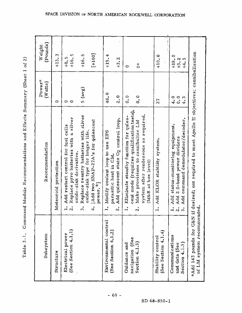
SPACE DIVISION OF NORTH AMERICAN ROCKWELL CORPORATION
d 0 4 u a, c, 0 k PI
0 k 0 a,
.rl
3
c, : e_
a,
c,
k
3 $ t;
n M ?i Y
0 0 L n
. . A N l4 '$
d * N
+ + 2 ;
0 0
0 0
. A N
-
0
0 . A f
.
N
- 69 - SD 68-850-1
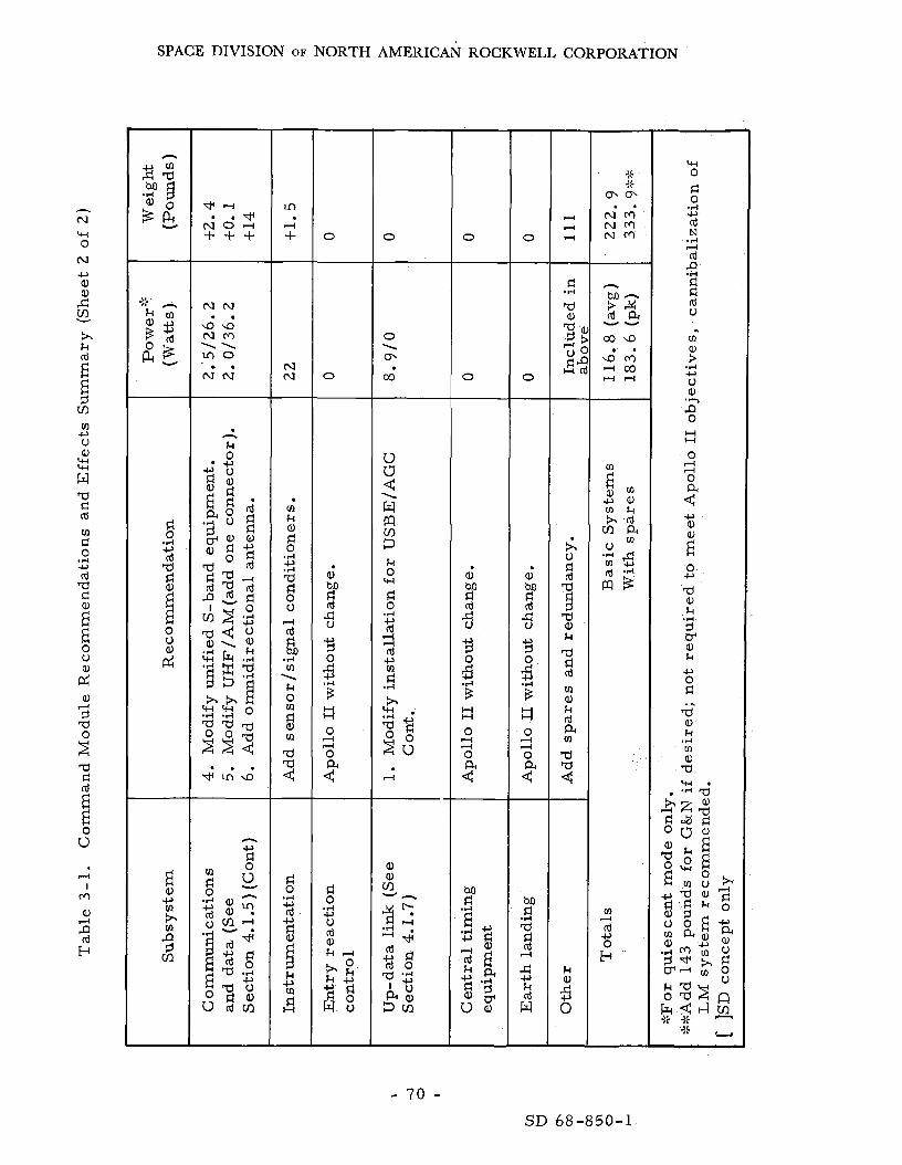
SPACE DIVISION OF NORTH AMERICAN ROCKWELL CORPORATION
-
m 4 + -
c\l ru -
m k
0 -4 c,
s 4 d 0 u d d
8l .rl m \ k 0 m d a, rn a a 4 -
d 0 .d c, d c, d
k c, m H d
0
0
a, M
3 do
6, ';
?
c, 3 0
H H
0 d d 0
d 0 .rl c, u rd e, k d
kc, % $ w u
0
0 \ rn co
-
0
0
0
-
0
a, M d d 9
6, B El
c, 3 0
.rl
0
0 4 d
2
M d 4 9 5 4
" k
-
5 1
2
3
a d 5
k a
(0
a, k rd a a a rn
4
k
; 0
rn d c, 0
4
E-l
- 70 - SD 68-850-1

SPACE DIVISION OF NORTH AMERICAN ROCKWELL CORPORATION
* LnLn N + N m + I
0 0 * + 0
-
0
m r- N +
0 0
T
t- M \D I
M r- v) Ln
03 LnLn Ln + + N I
- M > d
Ln 0
v
d o 0
0 N 3 --. 0
r-: -
0 0 0 0
k 0
E U u)
- 71 - SD 68-850-1

SPACE DIVISION OF NORTH AMERICAN ROCKWELL CORPORATION
3 .3 THE SERVICE MODULE CONFIGURATION
The service module (SM) configuration i s affected considerably by the differences in the power source concepts. no changes a r e required in the SM since the two RTG's a r e put into the CM a s indicated in Figure 3-2. extensive internal changes a re required in the SM (Figure 3-3). The differ- ences in the concepts have their g rea tes t impact on the overall weight of the injected SM and its development schedule.
When the RTG's a r e used, few o r
When the all-fuel-cell EPS concept is used,
Table 3-2 i s a list of the SM modification requirements and the i r impacts on the subsystem of the SM. the engine design i s disturbed. extensive a s discussed in the following paragraphs,
Neither the basic SM structure nor Beyond these changes, the differences a r e
The all-fuel-cell concept calls for replacement of the three present P& W cel ls with a longer life vers ion, one of t h ree to operate during the quiescent stage f o r a full 90 days. This concept requi res a much l a rge r fuel capacity, which may be achieved by replacement of t he cryogenic storage sys tem with a new and unqualified subcri t ical s torage system. 678 pounds for tankage and s t ruc tura l supports, H2 and 0 2 a r e required f o r operation of the fuel cel l for the 90-day period. In turn the addition of RCS fuels and oxidizer as well as propulsion fuel and oxidizer a r e required. meet the quiescent power requirement for the 90-day dormancy, even with the 258-pound weight saving derived f r o m use of the new cells.
This change adds about In addition, more cryogenic
About 5 , 156 pounds a r e added to the SM weight t o
The RTG concept calls for shutdown of a l l fuel cells (only two may be required) during the quiescent phase and use of two modified SNAP-27's f o r both electr ical power and paras i t ic heat. ted in the weight and P90. reduced below the Block I1 weight, to Ps i s improved substantially (per Section 4.2.1).
Results of this concept a r e reflec- The dry weight of the modified SM could b e
At the s a m e t ime, the EPS contribution
In addition to the RTG's , the recommended ment of the fuel cells with the improved version, increased meteoroid protection, and some minor result ing SM configuration is much safer than i ts somewhat l ighter. Fur thermore , examination of m a y show weight savings there a s well.
3 .4 LM ASCENT STAGE
concept calls for replace- addition of two sun sensors , plumbing changes . The Block I1 counterpart and the cryogenic requirements
NOTE: Much of the information used herein was provided by the Grumman Air craft Company through Reference 3 -2 e
- 72 - SD 68-850-1
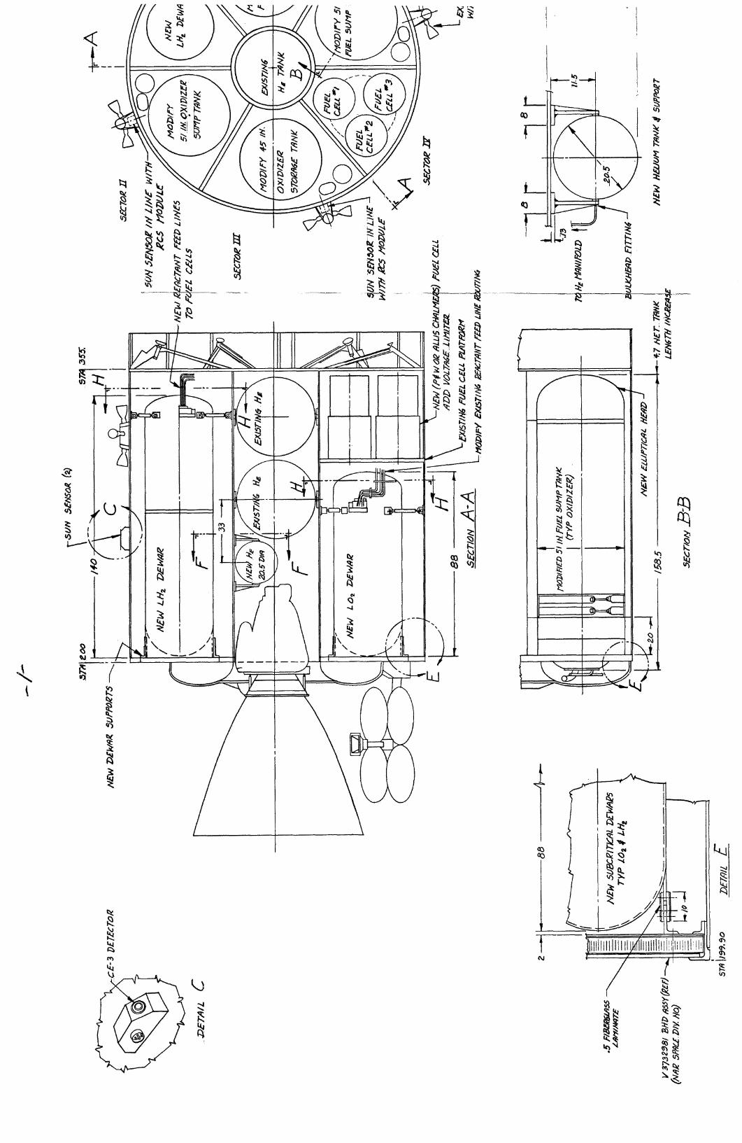
! i Q !- I I
Ir -7
p? a

d d a, u 4
d a,
I 0 rn
2 W
I h/
SPACE DIVISION OF NORTH AMERICAN ROCKWELL CORPORATION
The three-man ELOR LM concept provides a spacecraf t that is flown in a dual-launch mission mode, making a manned lunar landing and rendez- vous with a previously landed logistics vehicle, such as the LMSC early cargo stage of Reference 1-2. The LM has a ve ry l imited surface mission capability and remains dormant on the moon while the c rew is supported by the logistics vehicle payload. activates the LM, and an ascent and rendezvous with the unmanned CSM i s performed, mission capability:
At the end of the surface-mission phase, the crew
The proposed ELOR configuration provides the following
1. Lunar landing with a three-man crew nea r a previously landed unmanned logistics vehicle,
2. Quiescent, unmanned dormancy for a period up to 90 days,
3. Remote control of some functions of the unmanned CSM, which was left in lunar orbit,
4. Launch f rom the moon with the three-man crew (up to 100 pounds of payload optional), rendezvous, and dock to the unmanned CSM.
The ascent stage must be modified to accommodate the third crewman and the additional functions required to maintain equipment in a safe and ready state for the re turn t r ip , In addition, it should be ready for abort within a reasonable t ime, functions a r e depicted in Figures 3-4 and 3-5, i temized in Table 3-3 along with an assessment of the i r ramifications, and described i n detail in Section 4.3. The changes to the ascent stage a r e fa i r ly extensive in appear- ance, but a r e not expected to have a commensurate effect on the development program (see Section 5.3). expected to total 1366 pounds, with the required additional propellant and crewman.
Modifications required to accomplish these
The increase in ascent stage injected weight i s
The power consumption during the quiescent mode could be a s low as
The resul ts of these minimum requirements have a 20 watts average, the peaks going a s high a s 500 for very short intervals during the lunar night. profound effect on the selected power source a s reflected in Section 4. 4. 1. Details on the ascent stage subsystems and their modifications a r e p re - sented in Section 4.3.
3.5 LM DESCENT STAGE
NOTE: Much of the information used here in was provided by the Grumman Aircraf t Go. through Reference 3 -3 .
The descent stage of the LM vehicle is to be modified to handle the additional -.we’ight and the propulsion sys tem uprating that accompanies
- 75 - SD 68-850-1

SPACE DIVISION OF NORTH AMERICAN ROCKWELL CORPORATION
increased weight. the l a s t of which is the only new function:
The stage is required to provide three basic functions,
1. The acceleration force required for a soft touchdown.
2. A launch pad fo r the ascent stage when leaving the lunar surface.
3 . The electr ical power for the stay-period.
A detailed l i s t of the required changes by subsystem is given in Table 3-4 along with their ramifications. These changes are i l lustrated i n Figure 3 - 4 . The increase in stage weight i s substantial, amounting to over 5, 000 pounds, of which over 3 , 4 0 0 pounds i s fuel alone, These figures a r e considered to be on the pessimist ic side and may be reduced af ter a m o r e careful study of each influencing factor , Power consumption i s l imited to about 25 watts -that required to recharge the batteries af ter warmup cycles and/or status t ransmissions, Details of sys tem design proposed changes a r e presented in Section 4.4.
The proposed SNAP-27, bat ter ies and the associated heat-pipe instal-
The installation requires some study of the design integration prob- lation a r e new functions required to provide the quiescent- state e lectr ical power. lem. stage.
In addition, SNAP-27 waste heat output must be piped into the ascent
3.6 THE LUNAR SHELTER INTERFACE
3.6. 1 Interface Causations
As a par t of the 1975 mission concept a s defined by LMSC (Refer- ence 1 -2 ) , a shel ter is to be sent up ahead of the LM/CSM personnel c a r r i e r , while on the lunar surface, orbiting CSM or the dormant LM vehicle, some interface requirements a r e imposed on the lunar shelter by these vehicles. a r e created by the need to be aware of the status of both vehicle systems and to be able to initiate compensating action in the event of operational anomalies ,
It is to provide the living and working quar te rs for the personnel Since the re wi l l be no crewmen in either the
The interface requirements
These needs take the form of communications with the vehicle and status displays i n the shelter. The extent of status data handled by the shel ter as opposed to the MSFN is yet to be resolved and is beyond the scope of this study. requirements , particularly a s they could affect the lunar shel ter :
The following i s a f i r s t cut a t a list of the interface
- 76 - SD 68-850-1


B 0
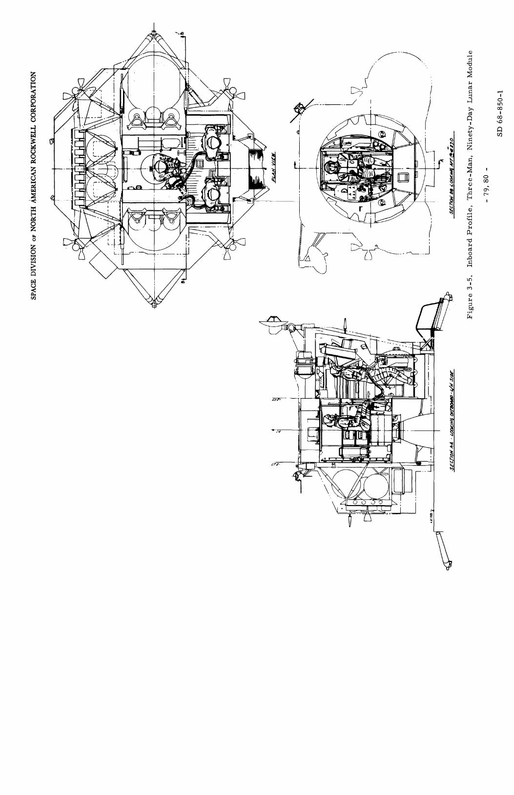
I Pi
l-l I 0 m co
I co 9

SPACE DIVISION OF NORTH AMERICAN ROCKWELL CORPORATION
T a b l e 3 - 3 . Lunar Module As c e n t S tage Recommenda t ions and Effects Summary
I S u b s y s t e m P o w e r * (Wat t s )
Weight A ( P o u n d s ) R e c o m m e n d a t i o n
1. R e p l a c e a s c e n t b a t t e r i e s wi th a l o n g e r - l i fe v e r s i o n ( s i l v e r - o x i d e , z i n c )
2. R e p l a c e p y r o b a t t e r i e s with d r y - c h a r g e
3. Modify p o w e r d i s t r ibu t ion . type .
0 .1
0
0
t 2 5
t 4
t 3 0
E l e c t r i c a l p o w e r (See Sec t ion 4 .3 . 1)
0 0
0 0 0
a. 6
3 t 1
t 3 0 t 4 t a +a
1. Add h e a t p ipe a s s e m b l y . 2. Add IMU/ASA by-pass . 3. Add r a d i a t o r and con t ro l s . 4. T h i r d s u i t u m b i l i c a l h o s e and man i fo ld . 5. Add squ ib va lve t o 0 2 and H2 6. Add L i OH c a n i s t e r and o t h e r s p a r e s .
c o n t r o l (See Sec t ion 4. 3. 2 )
Guidance and naviga t ion (See Sec t ion 4. 3. 3)
1. Send s p a r e components v i a d i r e c t l a n d e r i f d e s i r e d . Not n e c e s s a r y to m e e t Apollo ob jec t ives .
2. Make p r o v i s i o n to shut down IMU h e a t e r .
S t ab i l i t y c o n t r o l (See Sec t ion 4. 3. 4)
1. Add p r o g r a m coup le r a s s e m b l y . 2. P r o v i d e r e m o t e c o n t r o l s f o r CSM.
0. a 0
t 1 5 t 1 5
~~
Add h e a t e r s to thaw fue l l i n e s p r i o r t o l aunch f r o m l u n a r s u r f a c e .
t 4 Reac t ion c o n t r o l (See Sec t ion 4 . 3 . 5 )
C o m m u n i c a t i o n s (See Sec t ion 4. 3 . 6 )
1. Add c o m m a n d r e c e i v e r and decode r . 2. Add r e m o v e con t ro l m o n i t o r (of CSM).
8 . 2 0
t 2 5 t 1 0
A s c e n t p ropu l s ion (See Sec t ion 4. 3 .7 )
1. R e m o v e a l l p rope l l an t t ankage , 2. Add new p rope l l an t tankage .
0 0
- 142 t 1 7 0
S t r u c t u r e and c r e w p r o v i s i o n s (See Sec t ion 4. 3 .8 )
~~
1. 2. Add top -ha tch t h e r m a l cove r . 3. Add r a d i a t i o n pane l s u p p o r t s . 4. Modify a s c e n t p rope l l an t - t ank suppor t s . 5. Add t h i r d - m a n r e s t r a i n t a s s e m b l y . 6. Add c r e w t r a n s f e r and s u p p o r t s y s .
Modify t h e r m a l and m e t e o r o i d sh ie ld ing . t 1 0 8 t 1 3
t 5 t 1 5
t 3 t 8 0
I n s t r u m e n t a t i o n 1. 2 . Modify t r a n s d u c e r , 3. Modify SCEA/CWEA. 4. R e m o v e t a p e r e c o r d e r . 5. Add t h i r d - m a n functions. 6. R e m o v e TV and cable .
Add p rov i s ion f o r s t a t u s m o n i t o r . 1 .7 0 . 2 0 . 2 0 0
$10 t 5
t 1 0 - 2
t 2 5 -9
I Tota l s ( d r y ) T h i r d c r e w m a n and equip. 19. 8 47 5
2 90 O t h e r s I T h i r d c r e w m a n and equip.
Add p rope l l an t s - T o t a l i n j ec t ed weight
601
1366
‘::Quiescent p h a s e p o w e r only, ::::::With s p a r e s ind ica t ed i n r e s p e c t i v e sec t ion . [ ] R e q u i r e d j u s t p r i o r to launch only.
- 81 - SD 68-850-1

h k rd E E 3
zc)
m U u a, w w r.4 W s! cd s! 0
rd a s!
.rl U
8
2 E 0 u
a, M cd
vl rl a, u m a,
L,
L,
n a, 3 a 4
: k rd
3 I4
4 M a,
2 E-r
SPACE DIVISION OF NORTH AMERICAN ROCKWELL CORPORATION
C! 0
rd rn c
.d c,
; 2 E 0 u
E a, JJ m h m
-c) 3 vl
0 O d N O m M + m N 9 4- + + +
h
M 3 rd v
m N
a, w .rl 4 I M
m o r - m + + rl
0 0
. . . 4 N r n
O N 0 O N 0 * + d + +
0 0 0
m CI k
. . . d N M
-
r- 0 Ln 4
m N
h k m m 4
CI rd 0
I3
v o * d
+ M r l
M
. . 4 N
d
Ln 0 m
- 82 - SD 68-850-1

SPACE DIVISION OF NORTH AMERICAN ROCKWELL CORPORATION
3 . 6.2 Shelter Communications Provisions
1. Between CSM and shelter.
a. Command message generator (as in LM).
b. CSM status monitor/decoder.
c. CSM status display/alarm.
d. VHF complement of equipments, a s provided on LM.
e. Possible need for VHF antennas of 3 to 6 db gain ( requi res fur ther study) ,
f. Signal processor assembly.
2. Between LM and shelter.
a. LM status monitor/decoder.
b. LM status display/alarm.
c. VHF complement of equipments a s provided on LM. (Same complement as under Id above, and would be time-shared for CSM, LM, and EVA links, )
d. Signal processor assembly, LM (time-shared).
3 . Between shel ter and EVA crewman,
a. VHF complement. shared for CSM, LM and EVA links.)
(Same as under 1 and 2 above and time-
b. EVA antenna (vertically polarized single element).
c. Signal processor assembly, LM (time-shared).
4. Between shel ter and ear th MSFN.
a. S-band t ransce ivers similar to LM.
b. S-band erectable antenna as used with LM.
c. Solid-state S-band power amplifier. (Recommended for high reliability for extended 90-day usage. )
- 83 - SD 68-850-1

SPACE DIVISION OF NORTH AMERICAN ROCKWELL CORPORATION
d. Signal processor assembly, LM. (This i t e m would be t ime- shared among other links given above under 1, 2 and 3 . )
e. Data up-link assembly,
f. CSM status monitor and display/alarm. (Same units as under 1 above, but l isted h e r e to interface with S-band rece ivers for the case of CSM status relayed CSM/earth/shelter. This function could be accomplished via the up-data link with a few modifications o r as baseband signal replacing P R N range code. )
- 84 - SD 68-850-1

SPACE DIVISION OF NORTH AMERICAN ROCKWELL CORPORATION
4 . 0 SYSTEMS ANALYSIS
4 . 1 COMMAND MODULE SYSTEMS"
This section is a n analysis of the Apolla Block I1 commandmodule (CM) sys tems a s modified and applied to the ELOR Mission. on the ELOR sys tem functional requirements; the system description i s p re - sented only where required to reflect the differences between the ELOR concept and that of Apollo 11. see Reference 3 -1. on the SM electr ical power plant, two concepts for CSM power generation a r e considered: ner as Apollo Block 11, and the RTG concept using two o r three fuel cel ls and two radioisotope thermoelectr ic generators . r ec ommende d.
Details a r e presented
F o r details on the unchanged Apollo sys tems, As developed in the following analysis and in Section 4. 2 .1
the fuel-cell concept using three fuel cells in the same man-
The la t ter concept i s being
4. 1 . 1 Reentry Electr ical Power System
NOTE: Some of the information used herein was provided by the Westinghouse Electr ic Corporation through Reference 4-1, by ITT Industrial Products through Reference 4 - 2 , and by Eagle Pi tcher Company through Reference 4-3 ,
Functional Description
The electr ical power system is divided between the command and serv ice module. The command module is self-sufficient during the reent ry and recovery phases only, receiving i ts power from the reent ry and recovery bat ter ies , which a l so provide emergency power. The normal power source fo r the manned phases a r e the fuel cells for the fuel-cell concept, and the fuel cel ls and the RTG's in the RTG concept, The fuel cel ls a r e in the SM and a r e analyzed in detail in Section 4. 2. 1 . In the application of the RTG concept, the two RTG's a r e installed in the CM and a r e used to supply the needed power for the quiescent phase in lunar orbit , one fuel cell supplies the power for the quiescent phase.
4
In the fuel-cell concept,
The electr ical power subsystem (EPS) consists of the equipment and reactants required to supply the electr ical energy sources , power generation and controls, power conversion and conditioning, and power distribution to the electr ical buses (Figure 4-1). Power is supplied the command and
'A foldout sheet listing abbreviations used in Section 4.1 and their meanings is located at page 159.
- 85 - SD 68-850-1

SPACE DIVISION OF NORTH AMERICAN ROCKWELL CORPORATION
serv ice module (CSM) to fulfill a l l requirements and to the lunar module (LM) for operation of hea te r c i rcui ts af ter transposit ion and docking, can be functionally divided into four major categories:
The E P S
1. Energy s torage (cryogenics s torage and the entry, postlanding, and p y r ot e c hnic ba tt e r i e s) ,
2 .
3 .
Power generation (fuel-cell power plants and RTG's).
Power conversion (solid-state inver te rs and battery charger) .
4. Power distribution (d-c and a - c power buses, d-'c and a - c sensing circui ts , controls, and displays).
In general , the system operates in three modes: peak, average, and Peak loads occur during the short velocity changes, minimum-mission loads,
including boost, plemented by two of t h ree entry batteries. two of th ree inve r t e r s , th ree fuel-cell power plants, and a -c power is supplied by one o r two inverters . power during the quiescent state.
D-c power is supplied by three fuel cell power plants sup- A-c power i s processed through
During coast periods, d-c power is supplied by
The RTG's a r e active during all phases , providing the only
Energy Storage. The pr imary source of energy is provided by the cryogenic gas s torage system that provides fuel (H2) and oxidizer (02) to the power -generating system, ciated controls and plumbing a r e located in the serv ice module. reactants i s accomplished under controlled cryogenic temperature and p r e s - sures ; automatic and manual p re s su re control i s provided, of the reactants for repressurizat ion i s dependent on energy demand by the power -generating and/or environmental contr ol subsystems.
Two hydrogen and two ixygen tanks with-the a s so - Storage of
Automatic heating
A secondary source of energy storage is provided by five bat ter ies located in the CM. Three rechargeable entry and postlanding batteries supply sequencer -logic power a t all t imes; supplemental d-c power for peak loads; all operating power required for entry and postlanding; and when appropriately connected, either o r both pyro circui ts . Two pyro bat ter ies provide energy for activation of pyro devices when required,
'
Power Generation. Three Bacon-type fuel-cell power plants, gen- erating power through electrochemical reaction of H2 and 0 SNAP-27A supply pr imary d-c power to spacecraf t systems until CSM separation, For normal operation, a l l th ree power plants generate power, but two a r e adequate to complete the mission. Should two of the three ma l - function, one power plant with nonessential loads removed will insure suc- cessful mission completion, F o r details, see Section 4. 2. 1.
and/or the 2'
- 86 - SD 68-850-1

Id k M ld
b" ?-I I 0 v) 00
1 00 9
rn CI
@ 0 0 0 Z
0 n
c rn u . Q) k 3
iz"
I m
I -
- 1
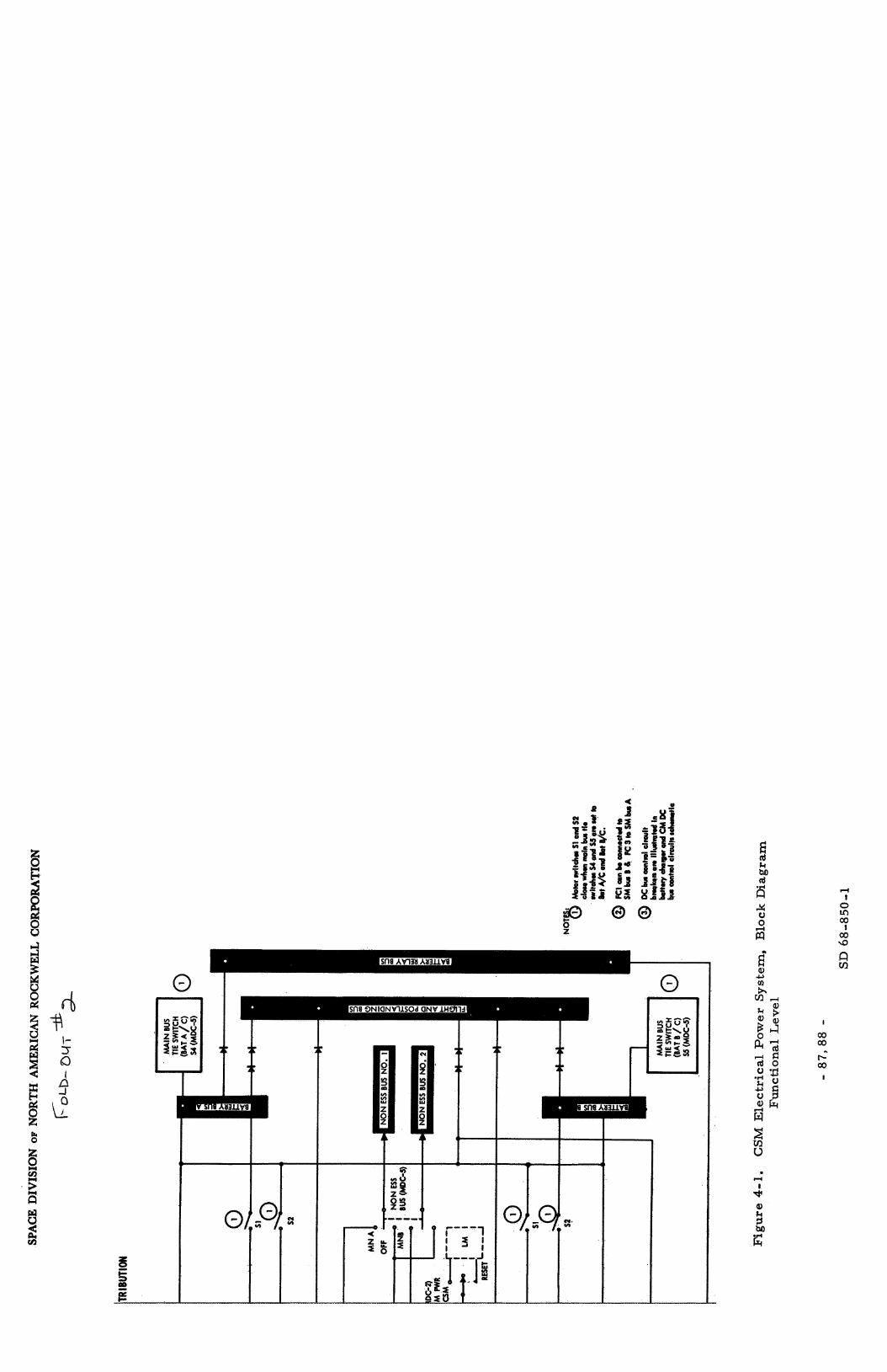
I CI m

SPACE DIVISION OF NORTH AMERICAN ROCKWELL CORPORATION
Power Conversion and Conditioning: P r i m a r y d-c power i s converted into a - c by solid-state static inver te rs that provide 115/200-volt, 4OO-cps, 3-phase, a - c power up to 1,250 volt-amperes each. A-c power i s connected by motor switch controls to two a -c buses for distribution to the a -c loads, One inver te r has the capacity to supply all spacecraft p r imary a -c power. One inver te r can power both buses while the two remaining inver te rs act a s redundant sources , separa te inver te r , the event of malfunctions, therefore , interlocked motorized switching circui ts a r e incorporated to prevent connection of two inver te rs to the same bus.
During velocity changes, each bus is powered by a Provisions a r e made for bus and/or inverter isolation in
Inverter outputs cannot be phase -synchronized;
A second conversion unit, the bat tery charger , a s s u r e s keeping the th ree entry and postlanding bat ter ies in a fully charged s ta te , s ta te device utilizing dc and a c to develop charging voltage.
It i s a solid-
Power Distribution, two redundant d-c buses in the SM, which a r e connected to two redundant buses in the CM. nonessential loads; a flight bus for servicing in-flight telecommunications equipment; two bat tery buses for distributing power to sequencers , gimbal motor controls, and servicing the battery relay bus for power distribution switching; and a flight and postlanding loads bus.
Distribution of d-c power i s accomplished via
Additional buses provided a r e two d-c buses for servicing
Three-phase a -c i s distributed via two redundant a -c buses, providing bus selection through switches in the a - c operated component circuits.
Power t o the lunar module i s provided through two redundant umbili- ca l s , which a r e manually connected after completion of transposition and docking. abort sensor assembly (ASA) and to cycling hea ters in the landing r ada r , rendezvous r a d a r , S-band antenna, and iner t ia l measurement unit (IMU). Power consumption with all hea te rs operating simultaneously is approxi- mately 309 watts,
An average of 81 watts dc i s provided to continuous hea ters in the
Sensing circui ts monitor bus voltages and provide a warning indica- tion of out-of -tolerance conditions. fuel-cell load o r reverse-cur ren t l imi t s a r e exceeded, when an inverter overvoltage occurs , o r when cur ren t l imits a r e exceeded,
They activate disconnect relays when
System Analysis
The reent ry electr ical power sys tem and the other component of the CM-EPS will remain substantially unchanged except fo r the following:
- 89 - SD 68-850-1

SPACE DIVISION OF NORTH AMERICAN ROCKWELL CORPORATION
Components
Bat ter ies (1 of 3)
1. Replace tLe reent ry / recovery bat ter ies with a silver-cadmium type already developed by Eagle P i tcher Co. (Reference 4-3).
AWeight Duty Cycle P S Spares (Pounds )
2300 h r 1 . 0 0 t33 .0 100 cy
2. Add new circui t b reake r s t o control the additional components added to the CSM.
397 h r
2374 h r Inverter (1 of 3 )
(1 of 2 each) Circuit b reake r s 169/2374 hr
< 5 0 cy
Totals
3.
4.
Replace pyrotechnic bat ter ies with a longer life si lver-oxide zinc type. Add radioisotope thermoelectr ic generators (SD concept only, s ee Section 4.2. I ) .
>o. 9999 0 0
0.9992 * 1 t52 .5
9 0.9999 0 0
= 0.999 1 t85. 5
The functional requirements have not changed, except for the extended life factor; and all components a r e expected to meet this requirement without change, Figure 4-2. units required for the quiescent mode,
The c rew safe re turn logic for the total EPS is as presented in The numbers above the blocks indicate the number of functioning
The circui t b reakers , normally considered a high-failure-hazard component, a r e not expected to present a problem since the number of use cycles are expected to be less than for the Apollo mission,
The EPS system contribution to the probability of safe re turn (P,) may exceed 0.999 with the aforementioned changes (see Table 4-1). remaining weakness is the inverter ; however, it may prove to be more reliable than present data supports, indicate that the inver te r may actually be better than now estimated; fur ther - more , it can easi ly be improved, In any event, one additional standby unit will exceed any requirement imposed by ELOR.
The one
Westinghouse data (Reference 4-1)
The fuel cel ls and RTG are discussed under Paragraph 4.2. I as par t of the service module,
Table 4- 1. Ent ry Elec t r ica l Power, Crit ical Components Analysis
Batter charger I (1 of 3 7 .

SPACE DIVISION OF NORTH AMERICAN ROCKWELL CORPORATION
cv k 0
rl
7- 0
ti N o\ o\ o\
.. a, * 0 z
N I e a, k 5 M
iz
- 91 - SD 68-850-1-
SPACE DIVISION OF NORTH AMERICAN ROCKWELL CORPORATION
4.1.2 Environmental Control Svstem (CM-ECS)
NOTE: Much of the information used here in was provided by the AiResearch Manufacturing Division of Garre t t through Reference 4-4.
Subs y s t em Des c ription
In addition to the normal Apollo requirements , the CM-ECS is to provide a means of controlling the CM quiescent-state environment fo r the 90-day unmanned lunar polar orbit, s o that at the end of this period, when the crew re tu rns , the ECS and other sys tems will be able to function in the normal manner for the re turn to ear th , The ECS, therefore , mus t provide the following functions:
1. Limit tempera ture excursions of the cabin wall to t 40 to 100 F.
2. Assure a water-glycol temperature within safe l imits ; i. e . , above the freezing point for this mixture.
3. P ro tec t equipment from damage due to freezing of contained water (drinking, wash and EPS by-products).
4. Maintain minimum required atmosphere p r e s s u r e to prevent decomposition of spacecraft ma te r i a l s through outgas sing and sublimation, about 0 . 5 psia . a r e expected t o be tolerable.
Variations of f rom 0 . 1 to 5 .0
5 . Assess cabin p r e s s u r e and cr i t ical temperatures; provide for critical-function failure a l a rms .
6 . Provide remote o r automatic control to switch redundant systems.
Detailed information concerning environmental heat loads imposed upon the CM cabin in te r ior and atmosphere throughout the 90-day mission is scant. However, based upon detailed information generated by NR/SD fo r the lunar mapping miss ion of the Apollo Extension System (AES), and l a t e r Apollo Applications P rogram (AAP), it is anticipated that there would be a cabin heat l o s s from the inter ior into space. The lunar mapping m i s - sion called f o r a lunar polar orbit, where the cabin heat load computed for this mi s s ion was - 1, 235 Btu/ h r (Reference 4- 5 ) . Extrapolation indicated that the ELOR loss could be as low as 300 Btu/hr . is expected to resu l t i n a continuous heat l o s s to space. substantiated by the AAP study, which gave the average equatorial lunar orbi t loads as -35 Btu /hr and the maximum as t115 Btu/hr for the CM.
The bulk of the mission This effect is
- 92 - S D 68-850-1

SPACE DIVISION OF NORTH AMERICAN ROCKWELL CORPORATION
The total of all e lectr ical loads within the command module is es t i - mated to be 284 watts, o r 970 Btu/hr. heat i s rejected to the cabin atmosphere o r the glycol heat-transport circuit. As revealed in recent Apollo thermal/vacuum te s t s , much of this heat is passively rejected to space via conduction through the vehicle s t ructure . These tes t s reveal cooler -than-expected cabin conditions, Therefore, active cooling of the cabin inter ior and atmosphere would not be required f o r this mission.
Not all of this electrically derived
Rather , a nominal amount of cabin heating would be required,
F igure 4-3 presents the skeletal schematic of the active elements of the CSM ECS for the quiescent lunar orbit mode. It i s noted that the heat source f o r the ECS glycol circuit is an intercooler heat exchanger thermally connecting the ECS and electr ical-power-system (EPS) circuits. positioning (Vernatherm) control valve bypasses fluid around the intercooler in o rde r t o l imit the ECS glycol temperature excursions. solenoid valves and two manual shutoff valves a r e used to provide the a l t e r - nate flow path into the intercooler exchanger, new design of the latching type. The shutoff valves a r e Apollo ECS Item 2.28 valves. The solenoid valves may be actuated remotely, whenever isolation of the ECS and EPS i s desired, Because of the expected cold environment conditions, the heat absorbed by the intercooler and in the active CM cold plates i s rejected passively in the r e s t of the inactive com- ponents of the loop. extensive inactive cold-plate network; in turn , some of this heat will be re jected to the cabin atmosphere.
A self-
Three ganged
The solenoid valves a r e a
Most of the heat rejection will probably occur in the
The other active component in the CSM glycol loop is the glycol pump. Here a new pump selector control has been added to monitor flow ra te and to automatically switch to the standby pump i f the pump fails. system status a l so is te lemetered by this control.
Pumping-
The secondary glycol circuit in the CM ECS i s s imilar ly connected t o the EPS through the intercooler, exchanger with passages for both ECS glycol fluids (this arrangement i s direct ly analogous to that of the suit c i rcui t heat exchanger, Item 1. 29). A second control valve and three more ganged solenoid valves a r e required, The circui t i s normally inactive, In emergencies , it may be activated remotely by turning on the glycol pump in the loop.
The intercooler i s a three-fluid
Cabin pressur iza t ion is maintained by two fixed-area bleed devices on the 1,’OOO-psi oxygen supply l ine. The bleed devices a r e new concepts andhave yet to be designed; severa l types a r e available commercially, however. Some of
- 93 - SD 68-850-1

SPACE DIVISION OF NORTH AMERICAN ROCKWELL CORPORATION
I
,
1
1
I w V Y >
v) 5
-41
I
t
- 94 - SD 68-850-1

SPACE DIVISION OF NORTH AMERICAN ROCKWELL CORPORATION
these employ labyrinth pas sages; others employ specially calibrated porous plates, Simple orifices a r e susceptible to plugging and thus a r e not usable, The flow to the cabin, in the range 0 . 1 to 0.25 l b of oxygen per day, is designed to equal the CM leakage at cabin p re s su res in the range 0 . 3 to 0 . 8 psia,
The r e s t of the Apollo oxygen supply system is turned off by means of a latching solenoid valve, the 90 days of manned operation, of the valve turns on the normal 5-psia supply system to r ep res su r i ze the cabin.
No power i s required for this valve during At the end of this t ime, remote activation
Glycol flow, at a tempera ture of approximately 75 F, provides thermal conditioning of water -containing components that might be damaged by f r eez - ing. c i rcui t heat exchanger (Item 1. 29 ) , and the water chil ler (Item 5. 14). The secondary evaporator (Item 2. 7 ) , whose glycol c i rcui t is normally off, i s kept above freezing by its proximity in the environmental control unit (ECU) package to the many glycol-containing components of the p r imary circuit ,
Included among such i tems are the evaporator (Item 2. 6), the sui t -
It is proposed that the water-valve panel in the ECU and the externally s tored water tanks be thermally conditioned by parasi t ic EPS heat and insulation, its own heater or by paras i t ic heat from the electr ical power source.
The potable water supply assembly can be kept f rom freezing by
All ECS controls, except the pump selector control, a r e off and control valves manually positioned. closed; the cabin heat exchanger valves a r e set to allow warm glycol to flow in the exchanger; and cabin fans a r e turned off, isolated by closure of the suit hose connectors. regulator is turned off, and the cyclic accumulators a r e placed in a standby mode. Both lithium hydroxide charges a r e removed from the C02 absorber canis ter (Item 1.15) and s tored t o prevent dehydration into LiO.
Water boiler back-pressure valves a r e
The suit circuit i s The suit-circuit demand
The water subsystem in the CM is turned off during the unmanned lunar orbit, be utilized during this t ime, This function would be to accept by-product water f rom the fuel cel ls and to either s tore it or vent it to space. of the relatively low reliability of the la t te r function, however, alternate a r rangements for water disposal a r e suggested. Water dumping now involves flowing water through many feet of tubing, f rom the SM to the CM water sub- system, to the overboard dump nozzle and, thus, poses considerable r i sk of freezing. use) is not required during this mission s tage, water dumping to space could be accomplished more reliably directly f rom the EPS in the SM. ample waste heat is available to ensure against freezing.
Potentially, only one of the functions of this subsystem could
Because
Since water s torage ( for c rew drinking or for ECS heat-rejection
Here,
- 95 - SD 68-850-1

SPACE DIVISION OF NORTH AMERICAN ROCKWELL CORPORATION
The ECS SM radiators a r e bypassed by use of the diver ter valve (Item 2 .36 ) in the CM. The heat rejection load of the ECS i s s o smal l that , without major modifications , the radiators would stagnate and either lower the total flow in the glycol circuit o r stop it entirely. low loads (1500 Btu /hr o r l e s s ) on the radiator system i s described in Reference 4.6. Radiator tempera tures may become ve ry low; but with the thermal control afforded by rolling the spacecraft in the sun's r ays , actual freezing of the panels i s not expected. fluid f rom the CM glycol c i rcui t in the event of meteoroid puncture of radiator tubes on the vehicle exter ior .
The effect of such
Because of these effects, the radiator circuit is turned off,
Isolation of the rad ia tors also precludes the loss of
Systems Analysis
Basic Considerations. One of the most important considerations i n this study was that of minimum change of existing Apollo Block I1 sys tems. Since this c r i te r ion was accompanied by considerably relaxed performance specifications for the 90-day unmanned lunar orbit , very few changes were necessary in the ECS.
In the a r e a of thermal control, however, some uncertainty exis ts regarding the requirements for the ECS, since detailed information i s lacking on the environmental load on the cabin inter ior . such loads r equ i r e s complex and t ime -consuming t ransient computations of (1) the radiant interchange of the vehicle and its environment and (2) the transient heat conduction in the vehicle s t ructure . tions must be c a r r i e d out over the ent i re lunar orbit stage of the mission. Such computations were not a par t of this study,
The generation of
Each of these computa-
Another cr i t ical design consideration i s the relatively high rel iabi l - ity goal, 0. 999, for the ECS for the 90-day unmanned lunar orbit, Most of the redundancies present in the Apollo ECS a r e set up for manual switching. For example, s i x regulators in the oxygen system all have manual provisions for turning off a regulator if a valve fails open, Obviously, such provisions a r e meaningless for unmanned operation, for many components, including the regulators , a r e approximately 3 to 10 fa i lures per l o 6 h r , which f a r exceeds the allowable 0.46 failures per 10 6 h r , use of many components during the semiactive operational stage
was ruled out. capability would have introduced considerable complexity into the systems. A good deal of effort was made to establish a separable and reliable system- operating configuration.
Because the basic failure ra tes
To provide redundancy and automatic (or remote) switching
- 96 - SD 68-850-1

SPACE DIVISION OF NORTH AMERICAN ROCKWELL CORPORATION
0 . 5-PSIA Pressurizat ion. A review of the capability of the Apollo ECS oxygen supply subsystem indicated that, because of reliability considerations for the unmanned 90-day lunar orbit , the cur ren t cabin pressurizat ion com- ponents could not, and need not, be used without substantial modification, Also, since the present 5. O-psia cabin p r e s s u r e regulator could not be modi- fied for use a t 0 . 5 ps ia , a new valve would have to be designed. situations prompted a cr i t ical evaluation of the 0 . 5 psia cabin pressurizat ion requirement . Curren t data indicate that p r e s s u r e levels of 0 . 1 psia a r e sufficient. ized f rom the manned orbiting laboratory a t 0 . 1 psia f o r 30 days. specification of 0 . 5 psia was considered to be a ta rge t value with a lower limit of approximately 0 . 1 psia . Below the burs t p r e s s u r e of the vehicle, t he re i s no expressed upper limit of cabin p re s su re . However, any such upper limit would r e su l t f rom requirements f o r the conservation of stored cryogenic oxygen. Presumably, enough oxygen would be ca r r i ed to main- ta in the cabin at 0. 5 psia for 90 days, based upon expected CM leakage ra tes at this p re s su re . Higher cabin p re s su res would resul t in grea te r leakage and thus requi re a l a r g e r quantity of s tored oxygen.
These
F o r example, the Gemini B capsule i s designed t o be p re s su r - The ELOR
It is expected that, by 1975, when extended missions a r e to be under- taken, CM leakage r a t e s will be well known and fair ly low. It has been assumed, therefore , that cabin pressurizat ion can be maintained within reasonable limits by a constant flow ra t e of oxygen into the CM inter ior . This flow ra te is normally se t equal to leakage r a t e s for between 0 . 5 to 0 . 7 psia cabin p r e s s u r e . CM, only the allocated quantity of cryogenic oxygen is used. r a t e s of twice that expected, the cabin p re s su re would be maintained a t approximately 0 . 25 psia . F o r lower-than-expected leakage, the cabin p re s - s u r e will simply be higher than 0 . 5, with no inc rease in the consumption ra te . s t ruc tura l integrity of the cabin would be maintained by the normal function of the cabin pressure- re l ie f valve (Item 3. 1).
The flow is to be limited s o that, even with a punctured For leakage
F o r extremely low leakage values (which a r e very unlikely), the
The method chosen to provide the constant oxygen pressurizat ion flow is by means of two constant-area res t r ic tors . Each res t r ic tor i s sized to give a flow of approximately 0. 0 1 lb pe r h r , the total flow being equivalent to the estimated leakage r a t e of 0. 48 lb per day. Complete plugging of one r e s t r i c to r still provides pressurizat ion a t 0 . 25 psia . be of two types, both commercially available. porous meta l plates; the other u ses labyrinth flow paths. reasonably tolerant to blockage by some particulate mat te r in the oxygen and considerably m o r e s o than orifice devices.
The res t r ic tor can
Both types a r e One type uses calibrated
- 97 - SD 68-850-1
SPACE DIVISION OF NORTH AMERICAN ROCKWELL CORPORATION
In normal ECS operation, the r e s t r i c to r s a r e turned off by means of a manual valve (Item 4. 26). of the oxygen supply sys tem is closed off by means of a latching solenoid valve. of the valve for the 90-day period.
In lunar orbit , th i s valve i s open, and the r e s t
A latching type of valve has been chosen to maintain reliable operation
Thermal Control. Study NAS8-21006 indicated that the electrical power sys tem parasi t ic load could be used as a heat source for the CM ECS heat- t ransport loop. allow hot glycol f r o m the EPS to flow into the ECS, with suitable tempera ture control valves to limit ECS glycol temperatures . The concept was studied in detail , and then finally abandoned in favor of the concept using an inter- cooler. The main difficulty with the interconnection of the circui ts is that of maintaining proper flow rates in both loops. The ECS flow is nominally 200 l b / h r , while the EPS flow i s l e s s than 110 l b / h r . and EPS pumps a r e variable-displacement types (centrifugal and vane types, respectively), interconnection of the circui ts would require an extensive development program to ensure proper operation of both circui ts while interconnected. Such a p rogram would involve the proper matching of pres - s u r e levels, a s well as p r e s s u r e drops; these pa rame te r s would be found t o va ry with the position of the thermal control valves.
The method chosen to be utilized was to physically
Since both the ECS
The thermal connection of the circui ts by use of an intercooler i s eminently simple and straightforward. Thermal control; that i s , selective heating of the ECS glycol, i s easily attained with a reliable, self-positioning, control valve. cuit without considering the complicated problem of fluid interchange. Reliability of the fuel-cell glycol loop would be maintained, since a leak in the ECS circui t could not affect the high-priority EPS. The only disadvantage i s the weight of the intercooler exchanger. The weight of the unit, designed f o r low-pressure drops i n each circui t , i s estimated t o be about 5 lb.
Each c i rcu i t may b e qualified independently of the other c i r -
The isolation valves a r e required t o separate and couple the two circui ts fo r the different operating modes. a r e of the latching solenoid type. This type of valve was chosen t o mee t the reliabil i ty requirement on the system. Normally, these valves would be required to operate through only one cycle i n the mission. Since no e lec t r i - cal cur ren t i s required during the 90-day period, a very low fai lure r a t e for these valves i s expected. Should the temperature-control valve fail i n t h e exchanger full-flow position and permi t intercooler-outlet temperatures above 80 F, the remote switching capability of these valves can be used to isolate the two c i rcu i t s . Periodic interconnection and disconnection could be used to maintain CM glycol temperature control in the event of such a fai lure .
These a r e in the interconnecting l ines and
- 98 - SD 68-850-1
SPACE DIVISION OF NORTH AMERICAN ROCKWELL CORPORATION
F o r the ea r th atmosphere entry portion of the mission, when the SM i s detached f rom the CM, backup for the solenoid valves i s provided by man- ual valves (Item 2. 28) . open; for the manned portion of the orbi t , the valves a r e closed.
F o r unmanned lunar orbit , these valves a r e normally
During the quiescent mode when the radiant heat loss f rom the vehicle skin exceeds the sum of the radiant heat absorption from the environment and the heat being generated in the CM itself (crew metabolic loads, com- p r e s s o r loads, C 0 2 absorption loads, and cabin fan loads a r e all absent; and electronic loads a r e greatly reduced), it i s c lear ly mandatory that some fo rm of heating be provided. The major reason for heating is to prevent freezing in , and thus possible damage of, components containing water . The flow of glycol in the temperature range of 55 to 75 F through such components provides sufficient heat to prevent freezing and maintain the desired cabin temper a tur e.
It is expected that cabin temperature will be no l e s s than t 4 0 " F require- ment throughout the mission. plished passively by conduction through the extensive cold-plate s t ructure . Although w a r m glycol will be circulating through the cabin heat exchanger, no convective heat t ransfer i s required f rom the unit, and the fans a r e turned off.
The actual heat t r ans fe r to the cabin i s accom-
Active heat-rejection devices of the CSM ECS a r e not needed for the low loads expected; therefore , both boi lers and the ECS radiators may be turned off. event of sustained low cabin tempera tures ; but the water feed t o the units and their control sys tems a r e turned off. sys tem i s bypassed, leaving stagnant glycol i n this portion of the system. Actual freezing i n the radiators of the CM lines i s not expected, even with low tempera tures . Continual barbecuing of the vehicle will limit the low tempera tures to above the freezing point of the 62 . 5 percent glycol mixture .
Glycol flows through the boilers to prevent freezing in them in the
The ent i re ECS CM radiator
If detailed thermal analyses should show potential freezing of stagnant l ines in the CSM, e lec t r ic blankets may be used to thaw the l ines when the sys tem is to be reactivated. preclude their l a t e r use , since selective orientation of the vehicle relative t o the sun could be used to thaw the panels. Damaging effects, i f any, of freezing the glycol fluid within components and l ines is, of course, an over riding consider ation.
Freezing i n the radiator panels would not
Cooling of those electronic components i n operation in the CM is accomplished by the flow of glycol at 55 to 75 F.
- 99 - SD 68-850-1

SPACE DIVISION OF NORTH AMERICAN ROCKWELL CORPORATION
The reliabil i ty of the glycol loop i s l imited pr imar i ly by the life of the glycol pumps, Life tes t s on the pumps indicate useful operating t imes of 6 , 0 0 0 h r , which exceeds the mission duration by near ly a factor of three. In the p r imary circuit , a backup glycol pump, which is presently activated manually, i s available. For ELOR, an automatic pump-selector control is provided. For even grea te r assurance of continued ECS functioning, should both pumps fail, or a single leakage failure i n the p r imary glycol c i rcui t occur, the control can activate the secondary CSM glycol loop. this loop requi res an additional s e t of glycol passages i n the intercooler exchanger. a tmo s phe r e c i r cula ti on being r equi r ed.
The use of
Cabin temperature control can be obtained passively without
In st r um entation and Monitoring . The following ins t r um entation additions to the cur ren t Apollo Block I1 ECS a r e recommended for extended lunar orbital missions:
1.
2 .
3 .
A second cabin-pressure t ransducer i s required to monitor the 0 . 5 psia cabin p re s su re , The cur ren t 0-to-17 psia cabin p r e s - s u r e t ransducer has a tolerance of *O, 425 psia, which i s not accurate enough for low-pressure monitoring. The new p res su re t ransducer should have a sensing range of 0 to 2 psia and a tolerance of about *O, 06 psia. These a r e commercially available.
A tempera ture sensor is required to monitor the control function of the temperature-control bypass valve on the ECS/EPS inter- cooler. ECS glycol loop could be subjected to tempera tures in the range of 100 to 120 F. outlet temperature will detect such a failure well before i t s effect would be evident f rom the present ECS instrumentation, ea r ly detection of such fai lure , coupled with the fact that the CM glycol loop has appreciable thermal capacitance, would probably allow the crew sufficient t ime to remotely switch to the secondary glycol loop and then, depending on the abort c r i te r ia , permit c rew re tu rn to the CM before damage occurs to c r i t i c a1 electronic s ,
Should this valve fail closed, it i s possible that the
The d i rec t monitoring of the control valve
The
A flow indicator is required f o r the automatic pump selector control, pump failure. two other ECS indicators.
This device would only have ON/OFF reading to signal Actual flow ra t e indications a r e available f rom
The normal Apollo ECS instrumentation readings, plus the above three measurements , would normally be te lemetered to earth. Selected te lemetry and a l a r m s to the lunar surface would include the three measure- ment, pump p res su res , glycol flow ra t e , cabin temperature , and electronic cold-plate tempera tures . show the following conditions:
Alarms indicating CSM ECS problems would
- 100 - SD 68-850-1

SPACE DIVISION OF NORTH AMERICAN ROCKWELL CORPORATION
1,
2.
3 .
4.
5.
6.
Fai lure of a glycol pump a s evidenced by (1) the flow indicator, (2) a low or z e r o pump pressure differential p re s su re , o r (3 ) a low reading f rom the cold-plate glycol flow ra te t ransducer ,
Loss of glycol determined by a bottomed glycol accumulator quantity t ransducer ,
Excessive cabin leakage as indicated by the cabin p re s su re sensor .
Malfunction of the intercooler temperature limiting control noted by glycol tempera tures over 8 0 F f rom the intercooler.
High (or low) electronic cold-plate tempera tures .
High (o r low) cabin temperatures ,
Remote Control. Provisions from MSFN o r the lunar surface should include the ability to select o r deactivate any of the three glycol pumps; and the operation of the three ganged solenoids in e i ther c i rcui t that permit glycol flow into the ECS/EPS intercooler. pump a lso i s automatic whenever the p r imary pump flow falls to a cer ta in level. function of the control.
The selection of the backup
Remote actuation of the pump selector control overr ides the automatic
The oxygen shutoff valve can be remotely controlled so that the cabin can be repressur ized by the emergency inflow valve (Item 4.22) pr ior t o c rew rendezvous with the CSM.
ECS Safety and the 90-Day Requirement
Because par t s of the ECS system operate throughout the 90-day quiescent phase a s well as the manned phases of the mission, i ts functions contribute to both Ps and P90. separately and then identify the interaction.
It is therefore necessary to evaluate each
The manned phases involve the Apollo Block I1 system functions only; however, they a r e required to operate about 175 hours , 2 5 percent l e s s than for the DRM. The resu l t i s that the system contribution to Ps should should approach Ps = 0. 9997, actually exceeding the expected DRM value, because the c rew leaves the CSM soon af ter a r r iva l in lunar orbit , No changes o r modifications are required for those functions not operating during the quiescent phase, the shutdown and s torage procedure presented in Appendix A i s followed,
This assumption is based on the premise that
- 101 - SD 68-850-1

SPACE DIVISION OF NORTH AMERICAN ROCKWELL CORPORATION
The quiescent phase involves use of only a small portion of the Block I1 system. logic of F igure 4-4. requirement and P90. figured t o achieve a P 9 0 of 0. 9995. the potential fa i lure modes of any significance.
The involved components a r e presented in the reliability
The system functions as i l lustrated have been con- The analysis takes into account a l l of
Fa i lure of this function mere ly affects the abort
The fai lure r a t e for each latching solenoid valve is taken t o be 0.05 x 10⁻⁶ fai lures per hour. these valves must undergo only a few operational cycles in the 90 days-and potentially only one cycle. (mean cycles between fa i lures ) , instead of MTBF, the value would be about 20 x 10-6 fa i lures per cycle. would be the same (0. 99989) a s that calculated f rom the hourly failure ra te ,
The reason for such a low value is that
If the fai lure r a t e were expressed in MCBF
The reliability for five cycles of operation
The pump selector control i s activated automatically whenever the flow indicator ceases to detect the proper glycol-circuit .flow ra te . control then selects the backup pump in the p r imary circuit ; i f this pump has al ready been in operation, the control selects the pump in the secondary circuit . The fai lure ra te for the automatic selector (10 x l o m 6 ) includes the flow indicator instrument. A backup, remotely controlled selector a l so is provided. in the event that two or more of the others failed during the dormant phase. The backup selector can override the automatic selector , Information that would be used to define the need to use the backup selector comes f rom the te lemetry of pump differential p res su re , o r cold-plate outlet glycol flow ra t e , o r both. i ts fa i lure r a t e (2 x 10⁻⁶ ) i s assumed to be lower than that of the automatic selector. Reliability of the remote control communications link, however, has not been considered here .
The
A spa re pump motor i s recommended for use af ter crew re turn
Since the backup selector does not depend on just one sensor ,
In each glycol circuit , the cr i t ical fa i lure-rate component is the The predominant failure of this
As discussed ea r l i e r , intercooler tempera ture control valve, type of self-positioning valve i s to j a m or stick. should this valve j a m with f u l l flow to the intercooler, the ECS glycol c i rcui t would potentially experience 100 to 120 F temperatuqes, which heat would be damaging to electronic components, ECS/EPS isolation valves would have to be remotely activated to isolate the circuits; then the secondary circuit would have to be used. is not fully accounted for in Figure 4-1. intermediate position might, however, require no remedial action.
With such a failure, the
This operation A jamming of the valve in an
Maintenance or repa i r i s not considered a requirement for the CM-
After re turn to the CM, the c rew could replace a faulty ECS since it i s impract ical during the quiescent mode and not indicated to be a requirement.
- 102 - SD 68-850-1
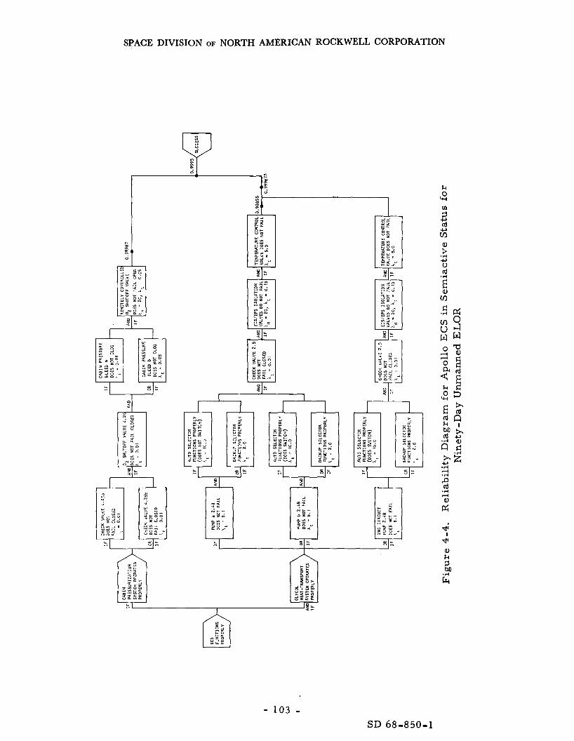
SPACE DIVISION OF NORTH AMERICAN ROCKWELL CORPORATION
'41' I
- 103 - SD 68-850-1

SPACE DIVISION OF NORTH AMERICAN ROCKWELL CORPORATION
pump motor if required, act ion for the whole sys tem, a spa re would add only 1. 5 pounds.
This task seems to be the only potential M&R
Recommendations and Conclusions
The system as here in defined will satisfy the ELOR requirements and provide a P 9 0 of 0.9995 and a Ps of 0. 9997. l imited to 2 2 . 6 pounds and the power consumption during the quiescent mode will be about 50 wat ts , No new technology i s required, although 10 new i tems a r e required, p ro cur ement cycle.
The weight increase i s
They a r e either available o r requi re a short
Table 4-2 gives the development status of those components used in the ELOR ECS in addition t o those in the Apollo ECS.
Table 4-2. Development Status of ECS Components Added to the LOR Configuration
Component
Oxygen shutoff valve, latching solenoid Oxygen shutoff valve remote actuator Oxygen shutoff valve, manual
Cabin pressurizat ion r e s t r ic tor
Cabin p re s su re t ransducer , 0 to 2 psia Suit - c i r cui t- exchanger water tank ECS/EPS intercooler heat exchanger Temperature contr ol valve, self- positioning
Temper a tur e t ransducer (Ve r na the rm)
ECS/EPS isolation valve, latching solenoid ECS/EPS isolation backup valve, manual
Isolation valve remote actuator Pump selector control Flow indicator
Number Required
1 1 1
2
1 1 1 2
1
6 4
1 1 1
Development Status
New New Qualified Apollo,
New, commercially
New New New New
Item 4. 26
available
Qualified Apollo, Item 8. 23
New Qualified Apollo,
New New New
Item 2. 28
- 104 - SD 68-850-1

SPACE DIVISION OF NORTH AMERICAN ROCKWELL CORPORATION
4. 1. 3 Guidance and Navigation
NOTE: Much of the information used here in has been provided by the A. C. Electronics Division of General’ Motors Corporation through Reference 4-7.
System Description
The guidance and navigation (G&N) sys t em is employed to provide a means of determining the spacecraft position and velocity vector with respec t to a given reference. local p r imary and ea r th p r imary via the communications link. Fo rmer studies indicate that ear th p r imary is the optimum mode for a l l mission phases except in the immediate vicinity of the moon or during ear th reentry,
Two basic operational modes of navigation a r e possible:
The G&N sys tem is expected to be the Apollo Block I1 system, which is composed of an optical navigation subsystem, a guidance computer, and an iner t ia l measurement unit. Apollo mission; therefore, the associated components formed the basis of this analysis , The optical subsystem possesses the ability to measu re the angle between a s t a r and the moon center, or some landmark thereon, and the capability of measuring the apparent angle subtended by a planet (s ta- diametr ic) . performing the necessary calculations to re la te the optically measured data to the position and velocity of the spacecraf t and, when required, to calculate the vehicle course correct ions required. The iner t ia l measurement unit ( N U ) provides a reference coordinate sys tem and monitors the accelerations applied to the vehicle.
These same functions a r e required for the
The guidance computer (CGC) is to have the capability of
The functional logic for the G&N velocity change functions a r e given in Figure 4-5. in Figure 4-6. impose somewhat different requirements . requirements are similar to those of the Apollo in all respects ; and the Apollo sys tem is expected to meet those needs or exceed them without change. The miss ion module system, which i s to facilitate velocity corrections only and to function under different c i rcumstances, is the sys tem studied in depth herein; the recommended operational concept is justified in Section 2. 1 of this report .
The functional logic for the earth-entry-mode sys tem i s given It will be noted that f rom these examples the different modules
The ear th entry module functional
The capability of the Apollo G&N system, using present operational concepts to meet the above requirement has a l ready been demonstrated for the Apollo mission, differences in miss ion profile a r e considered insignificant with respec t to normal operation.
- 105 - SD 68-850-1

SPACE DIVISION OF NORTH AMERICAN ROCKWELL CORPORATION
Fi
f c
- 106 - SD 68-850-1

SPACE DIVISION OF NORTH AMERICAN ROCKWELL CORPORATION
4
0
1
- 107 - SD 68-850-1

SPACE DIVISION OF NORTH AMERICAN ROCKWELL CORPORATION
Systems Analysis
Since the functional requirements f o r the ELOR mission were satisfied by the Apollo I1 system, the subsequent analysis cen ters around improving the contribution to safe r e tu rn and resolving any life problems. The G&N sys tem operates during the manned phases and only affects Ps. Variations in both operational concept and equipment affiliation were considered in an attempt to maximize Ps and life margin.
A Ps of about 0. 999 (much higher than Apollo) was set. The sys t em duty cycles will be about the same for the ELOR mission as for the present DRM; however, the sys tem functions do not attain reliabil i t ies of 0. 999 for the DRM. equipment fa i lure r a t e s andlor re turn usage t imes must be found to improve safe re turn.
It i s therefore apparent that some means of reducing the
There exists considerable latitude in choosing a sys tem configuration and operational concept depending on the acceptable reliability and the acceptable cost (additional equipment, changes in equipment and operational concept, reduced capability, etc. ) in achieving it. Possibil i t ies considered include -
1.
2.
3 .
4.
5.
Use of present Apollo equipment and operational concept.
Change of the operational concept to reduce equipment usage time.
Redesign or use of additional equipment to improve the failure r a t e .
Scavenging of LM equipment to improve the CM failure hazard for the r e tu rn tr ip.
Combinations of the above,
Using the previously defined G & N sys tem functional duty cycle a s a basis , the detailed equipment operational and standby times were developed and a r e presented in Table 4-3, P a r t s I and I1 respectively.
Additional G & N functions include optical subsystem usage for align- ment of the iner t ia l re fe rence and navigation during lunar orbit. computer operational time was added in the P repa re LM Phase ( 6 . 2 ) because an iner t ia l re fe rence was required and because the listed computer t ime was increased during the Departure Preparat ion Phase (6. 19) to allow for navigation.
CM
- 108 - SD 68-850-1

SPACE DIVISION OF NORTH AMERICAN ROCKWELL CORPORATION
Under present Apollo operational concepts, the iner t ia l subsystem (ISS) i s always in a t l ea s t the standby mode so heat is supplied to the iner t ia l instruments . 3, 200-cycle power supply for iner t ia l instrument suspension. supply requi res a timing reference f rom the computer meaning that the computer subsystem (CSS) must be in a t l eas t the standby mode also, Therefore , in the normal Apollo mission, the iner t ia l instrument hea ters and suspension and the computer t imer a r e never turned off,
In the CM system, the standby mode a l so energizes the This power
System operating and standby failure r a t e s were determined f r o m MIT IL Report E-1142 (Rev, 55) (Reference 4-8). subassembly failure r a t e s a r e shown in Table 4-4. not all display and monitoring equipment is included, even though many G&N sys t em signals might be displayed there. Only the display and key- boards (DSKY's) and the display and control (D&C) group a r e considered G&N equipment, The CM DSKY's a r e normally redundant, accounting for thelow failure ra te . The CM D&C group i s considered par t of the optical subsystem since i t i s mainly used during optics functions, while the LM D&C group i s mainly associated with iner t ia l subsystem functions.
These major subsystem and It should be noted that
Table 4-3 ( P a r t I). CM G&N System Functional Profile for Boost, Transit , and Entry
~ ~~
Mission Phase
1. 0 Prelaunch
2.0 Ascent
3. 0 Ea r th orbi t
5; 0 Translunar
6 . 0 Lunar orbit
7 . 0 Transear th
8. 0 En t ry
CM G&N System Operational Functions
Turn-on, warmup, checkout, vertical erection, optical azimuth alignment, and gyrocompas sing,
Monitor attitude and AV.
Monitor attitude and one alignment update,
Monitor injection attitude and AV; control attitude during transposition and docking; alignment, attitude control, and AV control for three mid- course correct ions; and alignment update, attitude control, and AV control for lunar orbit insertion.
None
Alignment, attitude control, and AV control for th ree midcourse correct ions; and attitude control and alignment update just pr ior to entry.
Ent ry c o n t ~ o l .
- 109 - SD 68-850-1

SPACE DIVISION OF NORTH AMERICAN ROCKWELL CORPORATION
Table 4-3 ( P a r t 11). CM G&N System Equipment Usage Times Based on ELOR Functional Requirements
CM Phase
1 . 0 Prelaunch 2 .0 Ascent 3 .0 E.O. 5 .0 Translunar 6 . 0 Lunar area 6 . 1 Adjust orbit 6.2 Prepare LM 6 . 4 Separate 6.6 CSM quiescent initiatioi 6.8 CSM unattended 6. 17 CSM activate 6.18 Transfer 6.19 Departure preparation 6.21 Transearth injection 7. 0 Transearth 8.0 Entry 9 .0 Recovery
Iuration (Hours)
100 0.2 1. 5
61.7 2208.8
2.2 3.5 0.2 1.4
2195.9 1. 0 0. 5 4. 0 0. 1
88.2 0.3
20. 0
Totals I 2480.7
ISS = Inertial subsystem CSS = Computer subsystem OSS = Optical subsystem
ISS Operational Equipment
4 0.2 1.5 3.5
2.2 3.5 0 0 0 1. 0 0. 5 4. 0 0. 1 3. 5 0. 3 0
24. 3
ISS Stand by
Equipment
4 0.2 1.5
61.7
2.2 3.5 0.2 1.4
2195.9 1.0 0.5 4 .0 0.1
88.2 0.3 0
2364.7
css Operational Equipment
4 0.2 1.5. 3.5
2.2 3.5 0 0 0 0 0 2.5 0.1 3.5 0.3 0
21.3
css Standby
Equipment
4 0.2 1.5
61.7
2.2 3.5 0.2 0.1 0 1. 0 0.5 4.0 0.1
88.2 0.3 0
167.5
-
oss
0. 1 0 0. 1 0. 8
1. 0 0.5 0 0 0 0 0 1.5 0 0.8 0 0
4. 8
-
-
-
The question of failure during dormancy was investigated, but the conclusions hold for any interval when the equipment is off or deenergized. Assuming no severe environmental s t r e s s e s on the equipment during the dormant period, the only possible cause for equipment failure would be an aging process ; i. e . , a continuation of a chemical o r physical reaction that had begun pr ior to dormancy. r a t e a s opposed to the constant r a t e applicable during the useful operating life of equipment. (See Section 2. 5) .
This effect implies a time-dependent failure
Considering comparable external environmental s t r e s s e s for operational and dormant periods, the dormant failure r a t e becomes extremely low, and the number of sys tem failures occurring during a 90-day quiescent period a r e considered insignificant.
- 110 - SD 68-850-1

SPACE DIVISION OF NORTH AMERICAN ROCKWELL CORPORATION
ICM guidance compu-
l(CGC) DSKY te r
Table 4-4. CM G&N System Fai lure Rates
Subassembly
I (css)
Operating A x 10-6
IMU and PIPA Elec
Power Servo Assy
Coupling Data Unit
Assy
(PSA)
(CDU)
129
110
155
Optical Assy PSA CDU D&C Group
94 77 9 1 2 .3
23 5
2.3
Standby A x 10-6
10 .2
6. 3
-
60. 5
-
The G&N sys tem function contribution to Ps for the mission can now be computed by combining the operational and standby reliabil i t ies of the various equipment groups only. tional concepts. operating throughout the miss ion even though (according to Table 4-3) the timing reference i s not continuously required for computations throughout the mission. mission Ps is only 0 . 82, which is considered too low,
The f i r s t computations a r e based on normal opera- The CM G&N sys tem computer clock i s assumed to be
The resu l t s appear in Table 4-5, where the contribution to
The Ps falls short of the goal mainly because of standby equipment The f i r s t and mos t obvious remedy would be to change the failures.
operational concept such that the computer need not be on when no computa- tions o r timing reference a r e functionally required (when only IMU heater power is needed). As presently mechanized, the suspension power would s t i l l be present with the M U heater power, but i t s frequency would not be accurate . The functionally required CSS standby equipment time, exclusive of suspension time when suspension is not rea l ly needed, is 167. 5 hours. Of this t ime, the CSS standby equipment is on alone for 146. 2 hours, and i t s Ps becomes 0 . 99. Fo r the overall system, Ps = 0.94.
The capability of updating computer t ime exists, but has not been used in the Apollo missions since the computer is never turned off. timing e r r o r will resu l t f r o m transmission f rom the ear th to the moon, but
Some
- 111 - SD 68-850-1
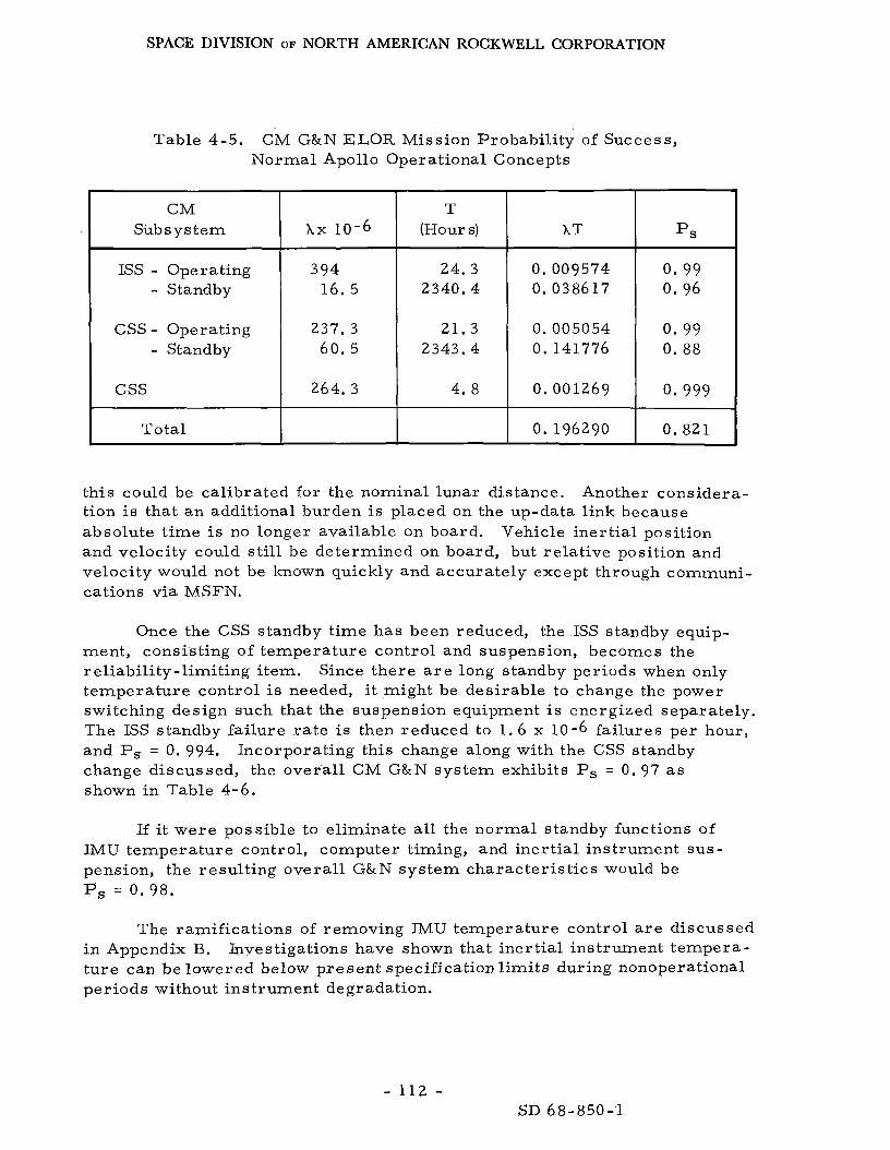
SPACE DIVISION OF NORTH AMERICAN ROCKWELL CORPORATION
Table 4-5. CM G&N ELOR Mission Probability of Success, Normal Apollo Operational Concepts
~~
CM Subs ys t em
ISS - Operating - Standby
CSS - Operating - Standby
css
Total
Ax 10-6
394 16. 5
237. 3 60 . 5
264. 3
T (Hours)
24. 3 2340.4
21.3 2343.4
4. 8
AT
0. 009574 0. 038617
0.005054 0. 141776
0.001269
0. 196290
P S
0.99 0. 96
0 . 9 9 0. 88
0.999
0. 821
this could be calibrated for the nominal lunar distance. tion is that an additional burden is placed on the up-data link because absolute t ime i s no longer available on board. and velocity could s t i l l be determined on board, but relative position and velocity would not be known quickly and accurately except through communi- cations via MSFN.
Another considera-
Vehicle inertial position
Once the CSS standby time has been reduced, the ISS standby equip- ment, consisting of temperature control and suspension, becomes the reliability-limiting i tem. Since there a r e long standby periods when only temperature control is needed, i t might be desirable to change the power switching design such that the suspension equipment i s energized separately. The ISS standby fai lure r a t e i s then reduced to 1.6 x 10⁻⁶ failures per hour, and Ps = 0. 994. Incorporating this change along with the CSS standby change discussed, the overall CM G&N sys tem exhibits Ps = 0. 97 as shown in Table 4-6.
If i t were possible to eliminate all the normal standby functions of I M U temperature control, computer timing, and inertial instrument sus - pension, the result ing overal l G&N sys tem character is tics would be Ps = 0. 9 8 .
The ramifications of removing IMU temperature control a r e discussed i n Appendix B. Investigations have shown that iner t ia l instrument tempera- tu re can be lowered below present specification limits during nonoperational per io d s without instrument degradation.
- 112 - SD 68-850-1

SPACE DIVISION OF NORTH AMERICAN ROCKWELL CORPORATION
Table 4-6. CM G&N ELOR Mission Probabili ty of Success, Modified Standby Operation
CM Subsys tem
ISS - Operating - Standby
CSS - Operating - Standby
css
I .Total
Fai lure Rate Ax 10
394.0 1 . 6
237.3 60. 5
264.3
T T (Hours) I- 2340.4
21.3 146.2
4. 8
AT
0.009574 0. 003585
0.005054 0.008845
0.001269
0. 028327
0.99 0.994
0.995 0. 99
0 .999
0. 97 ~
An al ternate approach to increase sys tem reliability i s to improve the operational fa i lure r a t e by some means. accomplished by redesign, redundancy, spa res and maintenance, or a combination of these approaches. appreciably reduce the overal l sys tem operational failure ra te . The recom- mended alternative is taking along additional equipment either redundantly or as spares . As indicated in Table 4-7, by sparing the f i r s t four i tems, the overal l sys tem Ps is 0. 99. limiting i tem, two spare computers and one each of the ISS subassemblies would increase the overall sys tem PS to over 0.993. sys tem components af ter rendezvous will accomplish much the same resu l t s .
This increase might be
Extensive redesign would be required to
Since the computer reliability was sti l l the
Planned use of LM
Reduction of usage t ime by eliminating all standby functions and the application of four spa res yields an overall sys tem Ps of 0. 999, which is well in excess of Apollo I1 est imates .
The possibility of scavenging LM equipment for the CM re turn t r ip is enhanced by the fact that the CM components most likely to fa i l a r e available when required in the LM and usable i n the CM with only slight modifications. The reliability breakdown, considering t ime before and af ter a spare is available, i s as shown i n Table 4-8. imal and m a y not be worth the problems of removing and t ransferr ing LM equipment to the CM i f they a r e not needed p r i o r to CM/LM separation.
It can be seen that the Ps gain is min-
Re commendations and Consluisons
The Apollo I1 concept i n the operational concept identified in the fore- going will satisfy the ELOR mission without any significant changes in design
- 113 - SD 68-850-1

SPACE DIVISION OF NORTH AMERICAN ROCKWELL CORPORATION
0.003135 0.023872 0.027007
0.002673 0.014745 0 : 017418
0.003767
0.005006
Table 4-7. C M G&N System Ps as a Function of Various Sparing Elements
0. 9969 0. 9764 0. 9733
0.9973 0. 9854 0. 9827
0.9962
0.9950
0.000049
0.000451
0.000370
0.000437
0.000011
0.99995
0. 9995
0.9996
0. 9996
0.99999
T (Hours)
:quivalent AT
Equivalent
PS .x 10-6 No. of Spares CM Subassembly
IMU and PIPA Elec Assy - Operating - Standby
129. 0 10.2
110 .0 6. 3
155. 0
235. 0 60. 6
2 . 3
94. 0
77. 0
91. 0
2 . 3
24 .3 2340.4
24.3 2340.4
24.3
21.3 2343.4
21 .3
4 . 8
4.8
4 . 8
4 . 8
0.000414
0.000183
0. 000007
0.009800
0. 000049
0.000451
0. 000370
0.000437
0.000011
0.9996
0.9998
0.99999
0.99
0.99995
0.9995
0.9996
0.9996
0.99999
0.99
PSA (ISS) - Operating - Standby
CDU (ISS)
CGC - Operating - Standby 0.141776 0. 8680
0.146782 I DSKY
Optical Assy
PSA (OSS)
CDU (OSS)
D&C
Total 0.196292 I O . 8215 4 0. 011722
Table 4-8. CM G&N System Subassembly Reliability Breakdown, Operational Only, LM Components a s Spares for Return Tr ip
CM Subassembly A x 10-6 T No. of Spares AT PS
IMU and PIPA Elec 129.0
110.0
155.0
235.0
2 . 3
94.0
77 .0
91.0
2.3
16.4 7.9
16 .4 7.9
16.4 7 .9
14.9 6 . 4
21.3
4 . 8
4 . 8
4 . 8
4 . 8
0 . 002116 0.000002
0 . 001804 0.000001
0.002542 0.000002
0.003502 0. 000003
0.000049
0.000451
0.000370
0.000437
0.000011
0.998 0.99999
0,998 0.99999
0.998 0.99999
0.997 0.99999
0.99995
0.9995
0.9996
0. 9996
0.99999
PSA (ISS)
CDU (ISS)
CGC
DSKY
Optical Assy
PSA (OSS)
CDU (OSS)
D&C
0. 99 Tot a1 4 0.011290
- 114 - SD 68-850-1

SPACE DIVISION OF NORTH AMERICAN ROCKWELL CORPORATION
o r new equipment. concepts possible. s p a r e s will provide a contribution to P, of about 0 . 999.
Table 4-9 is a summary of the various implementation Use of LM components and/or provision of up to four
’
Changes in the Apollo operational concept to reduce equipment usage t imes appear to offer the grea tes t promise for reliability performance improvement without the penalty of additional equipment o r extensive redesign. An additional burden m a y be placed on other systems; i. e . , shutdown of IMU heater power could impose restr ic t ions on the environmental control system, and shutdown of computer timing would requi re ground updates of absolute time. These a r e a s requi re fur ther thorough investigation before they can be implemented.
Special consideration was given to investigations of the effects of turning off the computer timing reference, iner t ia l instrument cooldown, and equipment failure during dormant periods.
The only development ramifications involve the M U heater. This study has assumed what available data seems to indicate, that they a r e not required for a quiescent mode, provided adequate warmup is provided pr ior to usage. This aspect m u s t b e demonstrated by t e s t ,
Table 4-9. Summary of CM G&N System Reliability, Improvement Steps
Configuration and Ope rational Concept Contribution
to Ps
0. 82
0.94 0. 94 0. 97
0. 98:: 0.99*
0.991k
0.993
0.999
hkApproximately that projected for Apollo I1 (See Reference 4 . 6).
Apollo Block I1 G&N system and operational
Reduced computer standby time. One spa re computer. Reduced computer standby and inertial instrument
suspension t imes. All equipment off during standby periods, One spare computer and one spare of each ISS
subassembly. Spares f r o m LM for re turn t r i p and all equipment
off in standby, Two spa re computers and one spare of each
ISS subassembly. One .spare computer, one spare of each ISS sub-
assembly, and all equipment off during standby.
concepts.
- 115 - SD 68-850-1
~
Weight Delta
(pounds)
0
0 $42
0
0 +142.8
+185.6
4-142.8

SPACE DIVISION OF NORTH AMERICAN ROCKWELL CORPORATION
4. 1 . 4 Stability Control System (CSM-SCS)
NOTE: Much of the information used herein was provided by the Honeywell Corporation through Reference 4-9. (The sys t em proposed herein involves the addition of a new function, ra ther than the Block I1 SCS, for the quiescent state. )
System Functions and Description
The SCS sys t em for the ELOR mission must per form two fair ly d iverse functions :
1. The stabil i ty control of the CSM-LM on the way to the moon and the CSM during the re turn t r ip , in the same manner as specified for Apollo I1 (Apollo Block I1 SCS unchanged).
2 . Provision of a minimum-control mode f o r the CSM while unattended in the lunar orbit quiescent mode (new function).
This study is specifically addressed to the la t te r requirement since,
The ability to per form the to-and-from aspects of the for the grea te r par t , the two functions can be separable in t e r m s of compo- nent requirements . mission remain unchanged by the new requirement .
The ELOR control phase begins with the CSM-LM vehicle established
At in lunar orbit . in which i t s longitudinal axis i s perpendicular to the solar line of sight. this point, vehicle attitude control i s established using Block I1 SCS minimum deadband attitude hold. All SCS devices a r e turned off except the Gyro Assembly No . 1 (GA No. l ) , Gyro Assembly No. 2 (GA No. 2), electronic control assembly (ECA), and reaction jet/engine control (RJ /EC) device, which continue to maintain vehicle attitude. command module to the LM, the astronauts arm the remote control function to be used in switching f r o m the SCS to the ELOR stabilization system (ESS) control of the CSM.
The combined vehicle i s astronaut-maneuvered to a position
Before moving f rom the
After LM separat ion f r o m the CSM, the quiescent mode i s commanded; and a slow rol l i s initiated through the ESS. pitch and yaw attitude control a r e established via the ESS; and all SCS devices except the reaction jet/engine control a r e turned off. 90-day lunar exploration period, the unattended CSM orbits the moon under ESS control. to the solar line-of-sight within *20 degrees in pitch and yaw while the rol l r a t e is maintained between 2 and 3 degrees per second. except the RJ /EC remain powered down during the quiescent mode, but can be reactivated by remote command if required.
When the desired ra te i s reached,
During the ensuing
The vehicle 's longitudinal axis i s maintained perpendicular
Al l SCS devices
- 116 - SD 68-850-1

SPACE DIVISION OF NORTH AMERICAN ROCKWELL CORPORATION
During the rendezvous phase, the manned LM returns to rendezvous with the unmanned CSM. and CSM control reestablished using SCS minimum deadband attitude hold. The SCS functions a s in Apollo I1 for the remainder of the mission.
P r i o r to docking, the ESS is remotely disabled
A functional block d iagram of the basic ESS is shown in Figure 4-7. The ESS consists of the present SCS RJ /EC device, a gyro electronics assembly (GEA), and two sun-sensor assemblies .
The sun senso r s a r e located on the SM periphery and provide pitch and yaw attitude information with respect to impinging solar radiation. An electrically caged gyro in the GEA provides a source of ro l l - ra te infor- mation to complete the list of ESS references.
Signals f r o m the sun sensors and gyro are processed by the GEA, which provides switching outputs to the R J / E C . The RJ /EC, in turn, fires the required serv ice module reaction je ts .
The nominal rol l r a t e i s established by summing a constant d-c voltage with the r a t e gyro ' s demodulated output. adjusted so that identical deadband and minimum impulse circui ts can be used in all channels. be enabled in each axis to permit limit-cycling a t low vehicle ra tes with attendant minimization of fuel consumption. descr ibed in detail in the following:
Each channel's amplifier gain i s
Only two reaction je ts (one plus and one minus) will
The functional blocks a r e
Each sun sensor contains two Ball Brothers Research Corporation CE-3 photoelectrical angular detectors a s shown in Figure 4-8. The sun senso r s will be mounted on the SM periphery and located so that the yaw sensor detects coning in the yaw axis and the pitch sensor does the same in pitch.
Output cur ren t of the CE-3 detector approximates a sinusoid as shown in F igure 4-8, with a maximum output when solar radiation is normal to the detector face. In combining two detectors a s shown in Figure 4-8, the out- put cur ren ts will be equal when solar radiation i s normal to the overall sensor o r a t a nominal 45 degrees to each detector. this position will resu l t in unequal detector outputs and a usable e r r o r signal. ze ro to a maximum and back to zero. however; since both outputs vary in unison.
Any deviation f rom
As the vehicle rotates , the individual detector outputs vary f rom This variation c rea tes no problem,
The r a t e BMAG (body-mounted attitude gyro) i s a heater less version of the GG248 BMAG used in the Apollo SCS, caged through circui ts s imilar to those used in the Apollo SCS.
- 117 - SD 68-850- 1

SPACE DIVISION OF NORTH AMERICAN ROCKWELL CORPORATION
1---- t---- I-- r--
I I
0 3 I 1 n* I I 1
rd x
a a,
I----- --
- 118 - SD 68-850-1

SPACE DIVISION OF NORTH AMERICAN ROCKWELL CORPORATION
PITCH SIlN SENSOR (SEE ENLARGED
CE-3 DETECTOR
YAW SUN SENSOR (SEE ENLARGED VIEW)
ELOR SUN SENSOR
Figure 4-8, Prop0se.d ELOR Sun Sensor, Location, and Characterist ics
- 119 - SD 68-850-1

SPACE DIVISION OF NORTH AMERICAN ROCKWELL CORPORATION
Each amplifier i s based on a Fairchi ld p709 integrated circuit . F ive r e s i s t o r s and two capaci tors will be used with each ~ 7 0 9 ,
The demodulator is a full-wave circui t s imi la r to those used in the Apollo SCS. capacitor.
It will consist of six r e s i s to r s , two t r ans i s to r s and one
The deadband and minimum-impulse circui ts are similar to those used in the SCS electronic control assembly (ECA).
Required power supply input i s 115-v, a -c , three-phase, 400-cps electr ical power. Power supply outputs a r e 26-v, a - c , three-phase, BMAG, spin-motor- excitation; 36-v, a -c , Phase- A, BMAG, signal-generator- excitation; 10-v, a - c , Phase-A, demodulator-reference; and *15-v, d -c control- electronics power and *15-v, d- c signal- conditioning power.
The RJ /EC i s modified to accept th ree additional switching inputs. Six r e s i s to r s and three t r ans i s to r s a r e added to switch the added inputs.
Each signal conditioner is of the type used in the Apollo SCS, but repackaging may be required.
Systems Analysis
SCS for the manned phases of ELOR will contribute to P,. Because that time is reduced to about 175 hours (25 percent below the Apollo DRM) the SCS contribution to P, should be about 0 . 997.
The quiescent-phase function contributes to the mission stay-time and the resulting P90 , fa i lure resu l t s in abort . This is a separate function.
Analysis of the proposed new basic ELOR control function (ESS) of Figure 4-9 indicates that the sys tem contribution to P 9 0 would approach 0 . 91, which i s too low. It i s a lso evidenced that the BMAG and its elec- tronics is the weakest link. will improve P 9 0 to better than 0. 97. Fur ther improvement i s required and may be achieved through redundant deadband minimum-impulse c i rcu i t ry and a redundant power supply function. These additions increase the function reliability such that the ESS contribution to P90 will reach about 0. 993. The logic for this function i s presented in Figure 4-10. tradeoff considerations a r e reflected in Table 4- 10.
Providing for a remotely selected spa re BMAG
The resul ts of these
These est imates a r e made with a parts-count approach to reliability analysis and a r e based upon Apollo high-reliability piece-par t failure ra tes and a knowledge of the quantity of each utilized in each specific subassembly.
- 1 2 0 - SD 68-850-1

SPACE DIVISION OF NORTH AMERICAN ROCKWELL CORPORATION
03 A
r- u) 6 gr
0 II
0:
a
- 121 - SD 68-850-1

SPACE DIVISION OF NORTH AMERICAN ROCKWELL CORPORATION
E
' 8 SUN OIFF. DIFF. ROLL ROLL R J E C SENSOR - AMP AMP AMP - OEMOD - ELECT. -
PITCH YAW PITCH VAW k = 0.075 k = 0.075 k = 0.0048 A = 0.0048 L = 0.0048 k = 0.0227 k = 0.0261
3
r RATE GYRO &ELECT. i C
POWER SUPPLY
DEADBAND DEADBAND DEADBAND a MIN & MIN & MIN
R = 0.99999 --+ .- - R = 0.9975 d p = 99991 .~ ___
D.C. I IMPULSE - IMPULSE - IMPULSE
I L = 0.1849 L = 0.1849 ) r= 0.1849 l a I I
= 0.2281 PITCH ROLL YAW I
I I I POWER
PITCH SUPPLY - D.C. )r = 0.1849 A = 0.2281
ROLL & AC P.S. i ' 3 3 8 9 2
RATE GYRO a ELECT.
a AC P.S. - - STBY d
k = 3.3892
c
R i = 0.9924 RJ AMP RJ AMP
LOGIC E * SUPPLY %2 PITCH YAW
= 0.2906 RJ AMP D *
4 R = 0.99957
RJ AMP
RJ AMP )r = 0.2906
YAW - A *
. ROLL
= 0.2906 D
R J E C RJ RJ AMP
SUPPLY P PITCH )r = 0.1091, )r = 0.2967 A = 0.290{ k = 0.2906 RJ AMP
-POWER - LOGIC - A +
Figure 4-10. Modified ESS and Resulting Reliability Logic
- 122 - SD 68-850-3

SPACE DIVISION OF NORTH AMERICAN ROCKWELL CORPORATION
No. 3: Basic ESS plus redundant BMAG, deadband minimum-impuls e
No. 4: Basic ESS plus redundant BMAG, deadband minimum- impul s e , power supply
Table 4- 10. ELOR Stabilization System Tradeoffs
0. 9830 16. 7 56 0 17. 5 (5 welded module s )
0.9924 20 . 6 662 27 . 0 (7 welded modules )
The gyro fa i lure r a t e of 2 . 8 percent per 1000 hours i s an average fai lure r a t e based on a 90-day mission. caused by spin-motor wearout character is t ics . for the sun sensor was obtained by applying a 1973 build growth r a t e to Honeywell's standard fai lure r a t e for a photo diode. to yield a pessimist ic estimate, so the actual value for P90 will approach o r exceed the des i red 0. 999 by the time the sys tem is qualified.
It includes allowances for time-dependency The predicted fai lure ra te
These data a r e known
Fur the r redundancy, such a s redundant sun sensors and a third BMAG, could be added to improve P90. considered unwarranted, since Ps i s not directly dependent upon the ESS reliability. Certain ESS fai lures , such a s a parameter shift beyond speci- fication, would degrade performance, but in many cases would not require mission termination. Other fa i lures , such a s a sun sensor failure, would requi re shutdown of the ELOR stabilization system. be scheduled in this instance with normal SCS control of the CSM during rendezvous. is calculated to be 0. 9992; thus, an ESS fai lure might shorten an ELOR mission, but would not compromise c rew safety.
The increase in cost and weight i s
A mission abort would
The P, for the SCS during the three-hour rendezvous period
- 123 - SD 68-850-1

SPACE DIVISION OF NORTH AMERICAN ROCKWELL CORPORATION
To satisfy the diagnostic and monitoring requirements the signal- conditioned outputs representing pitch attitude, yaw attitude, and rol l r a t e will provide a significant m e a s u r e of ESS performance on a continuing bases . In addition, where necessary , normal SCS signal conditioning can be remotely enabled to facilitate troubleshooting and fault analysis.
In-flight support requirements include-
1. Remote turn-on and turn-off of GA No. 1, GA No. 2, and ECA and electronic display assembly (EDA) in the SCS.
2 . Remote switchover f r o m SCS to ESS control and vice ve r sa .
3 . Remote enable and disable of the SM reaction je t s .
4. Remote selection of redundant components.
ELOR electronics weight, volume, and power consumption range f rom 13. 8 pounds, 518 cubic inches, and 14. 7 watts to 2 0 . 6 pounds, 662 cubic inches, and 27.0 watts in the approaches considered. computations a r e based on a GEA packaging concept similar to that used in the Block I1 SCS and a sun-sensor design a s shown in Figure 4-8. six welded modules would be contained in the GEA plus one or two heater less BMAG' s .
Weight and volume
Up to
Conclusions and Recommendations
In consonance with one LMSC recommendation, (NAS8-21006) the analysis indicates that spin stability is the best operational mode; however, the sys tem analysis indicates that the Apollo I1 SCS would not approach the des i red Ps (about 0.55). ESS that will meet the requirements with no m o r e than a 6.8-pound weight penalty. The required sys tem could be developed and qualified within two yea r s . without any changes and is expected to exceed the Apollo crew safety c r i te r ia ,
A much l e s s complex approach is to provide an
The Apollo I1 SCS will per form the translunar and t ransear th control
Maintenance and/or repa i r in the conventional sense is not recommended for this system, since the requirements for the SCS a r e l e s s stringent than for Apollo DRM; and the requirement for maintenance would be greatest when man is not available to per form i t . adaptive electronics is recommended in i t s place.
Therefore, a f o r m of self-healing or
- 124 - SD 68-850-1

SPACE DIVISION OF NORTH AMERICAN ROCKWELL CORPORATION
4. 1. 5 Communications and Data System (C&D)
NOTE: Much of the information used herein was provided by the Collins Radio Co . , through Reference 4-8.
Functional Requirements and Constraints
The ELOR mission consists of th ree basic mission segments as they affect the CSM C&D Subsystem. duration a s they affect the C&D functions a r e shown below:
These mission segments and the t ime
Segment A (manned t ranslunar phases) Segment B (unattended lunar orbit o r
Segment C (manned t rans ear th phases o r quiescent)
166.6 hr::
~
Total mission t ime 2480. 7 hr
The C&D functions and duty cycles for Segments A and C a r e identical
The with the corresponding phases of conventional Apollo DRM. functional requirements for these phases a r e the same a s for the DRM. effects on the mission should also be unchanged.
The resulting
This sys tem has little effect on the probability of safe re turn during the manned or unmanned phases . It does, however, affect the s tay- t ime and, therefore , P 9 0 and Pa. These mission-cr i t ical functions a r e l imited to those required to re lay status and commands permitting changes in opera- tional mode or redundancy switching. As a resul t , Segment B, the quiescent phase, requi res two new functions not included in Apollo 11. These functions, s ta tus monitoring and remote control, a r e required for the entire 90-day unattended orbi t period and will necessi ta te some modification of the present Apollo I1 subsystem. The basic requirements for these new functions are-
1 . Status monitoring shall be included to analyze the condition of a l l sys tem functions wherein a fa i lure would preclude safe rendezvous o r re turn to ear th . As a minimum, the sys t em would have to indicafe when a safe threshold i s approached and/or surpassed, providing enough warning (where main- tenance is not possible) for the c rew to return to the CSM and abort the missions o r repa i r and abort when possible. Status monitoring information is required a t the lunar surface o r LM during rendezvous and at the MSFN-MCC. It was estimated that up to forty normalized analog inputs must be monitored by the system.
- 125 - SD 68-850-1

SPACE DIVISION OF NORTH AMERICAN ROCKWELL CORPORATION
2. Remote control capability shal l be included to (1) provide switching between cr i t ical redundant systems and functions, (2) provide control for the docking function, ( 3 ) provide emergency control of orbital position and plane, and (4) initiate a detailed checkout or diagnostic routine. LM on the lunar surface or during rendezvous was assumed to have remote control capability for Items 1, 2 and 4 l is ted above while the MSFN-MCC can control Items 1, 3 and 4. Twenty ON-OFF type commands t ransmit ted at a relatively slow ra te were estimated to b e sufficient for the lunar sur face /LM remote control capability.
The
The major interface constraints involve-
1. Antenna subsystem interface constraints impose the major mission constraint on the CSM communications functions. A prel iminary investigation of the antenna problems has been made, since effective communications cannot be achieved without methods of alleviating the potential prob- lems. The high-gain S-band antenna will not be used during the unattended lunar orbit phase of the mission because of operational complexity ( see Section 4. 2 . 5). Therefore , all CSM-MSFN communications must be accommodated by the CSM S-band omnidirectional anten- nas . The CSM spin will c rea te problems for the CSM dormant-mode communication. means that no single CSM S-band and VHF omnidirec- tional antenna will be pointing a t the ear th o r the lunar surface for periods longer than an estimated 40 seconds; i. e . , within - 3 db points.
This rapid spin ra te
2 . It was assumed that a t l eas t th ree stations of the MSFN will be available to enable communications on a contin- uous bas is with at leas t one station for the entire CSM quiescent phase. These stations a r e expected to have 8 5 - foot - diameter antennas .
Baseline System Description
The Apollo I1 C&D sys tem provides a working subsystem on which an extensive amount of weight and reliability data (Table 4- 11) a r e available. This sys tem will provide suitable operating capability for these missions with only minor additions. for navigation, voice, and data communications between the CSM and the MSFN; voice, ranging, and data communications between the CSM and LM; and voice and data communications between the CSM and the extravehicular astronaut (EVA).
The Block I1 subsystem provides the capabilities
- 126 - SD 68-850- 1
SPACE DIVISION OF NORTH AMERICAN ROCKWELL CORPORATION
A block d iagram of a C&D subsystem configuration that can meet the The sys tem employs maxi- ELOR requirements i s shown in Figure 4- 11.
m u m utilization of existing Apollo Block I1 C&D subsystem equipment for all segments of the mission. a r e necessary to sat isfy the ELOR unattended lunar orbit functions a r e designated by the blocks having heavy outlines. a r e new additions to the subsystem, while others a r e slightly modified. other C & D subsystem equipments a r e unmodified and interfaced with other spacecraf t sys tems in a manner identical with normal Apollo Block I1 configurations.
Those equipments of the C&D subsystem that
Certain of these equipments All
Two new equipments, the status monitoring equipment (SME) and the command demodulator-decoder, a r e added to the subsystem along with modifications of the unified S-band equipment and the VHF/AM t ransmi t te r - rece iver . Several minor antenna subsystem components, such a s switches diplexers, and power dividers, and the up-data link sys tem a r e required for the remote-control concept, but a r e covered in other sections of this repor t .
The VHF recovery beacon has a single function to provide line-of-sight beacon t ransmission during earth-landing and recovery operations. s i s t s of a VHF amplitude modulated t ransmi t te r .
It con-
The VHF tr iplexer is a 3-channel passive f i l ter device. It provides the necessary isolation to permi t single-channel o r simultaneous 2- or 3-channel t ransmission and/or reception with a common antenna.
The .VHF/AM t ransmi t te r - receiver consists of two independent VHF/AM t ransmi t te rs and two independent VHF/AM rece ivers in a single package. One t ransmit ter and rece iver provide for t ransmission and reception of voice communications on a single preassigned frequency. and receiver provide fo r t ransmission and reception of voice communications on a second preassigned frequency. permit the rece ivers and t ransmi t te rs to be used i n any combination of the two channels for voice communications. reception of data (such as EVA biomedical) a t the same frequency. VHF/AM t ransmi t te r - rece iver a lso provides for the t ransmission and reception of ranging signals to and f r o m the LM.
The other t ransmit ter
External switching and the VHF tr iplexer
This unit a lso provides for the The
The digital ranging generator (DRG) provides for range measurements between the CSM and the LM during rendezvous. The DRG provides sequen- t ia l tones to the VHF/AM transmit ter - receiver , which t ransmits the ranging signal along with voice to the LM. transponds the ranging signal on the duplex frequency. The CSM’s DRG then receives the ranging signal and after internal processing provides a range readout to the command module computer and/or the entry monitor system.
The LM receives the composite signaland
- 127 - SD 68-850-1

SPACE DIVISION OF NORTH AMERICAN ROCKWELL CORPORATION
NOTE: Where the CSM i s unmanned during CSM-LM rendezvous, consideration should be given for interchanging the CSM- LM ranging functions.
The audio center consists of three electrically identical se t s of c i r - cuitry (stations), which enable parallel selection, isolation, gain control, and amplification of all spacecraft voice communications.
Each station i s operated f rom a remote- control panel, which provides each astronaut with independent audio control of common S-band, VHF/AM, and intercommunication circuits. microphone and earphone jacks. In the event of a station failure, the failed station microphone and earphones may be plugged into one, but not both, of the remaining stations. will produce a successful mission.
Each astronaut i s provided with individual
Because of this feature, two of the three stations
Unified S-band equipment (USBE) consists of two redundant S-band phase-locked transponders and one FM transmit ter . consists of a t ransmit ter , receiver, and power supply. The FM transmitter is electrically independent of the transponders. active at a given t ime; however, simultaneous operation of the FM trans- mit ter and one of the transponders is possible.
Each transponder
Only one transponder is
The S-band power amplifier consists of two 20-watt travelling-wave- tube power amplifiers with associated power supplies, control circuits, and a multiplexer mounted on a common chassis. o r bypass transmission in the PM mode. It also provides for amplified, but not bypassed, FM transmission. The multiplexer provides a receive signal f r o m the antenna and isolates the amplifiers so that PM andFMtransmissions a r e possible simultaneously or separately. emergency use only.
It provides for either amplified
The PM bypass mode i s for
The status-monitoring function requires use of the status monitoring equipment (SME), unified S-band equipment (USBE), VHF/AM transmit ter- receiver, VHF triplexer, and the associated VHF and S-band omnidirectional antennas. cri t ical parameters of the CSM while in the unattended orbit phase.:: forty normalized analog inputs can be accepted by the SME and compared with preestablished limits to a s ses s the status of the unattended CSM. detection of beyond specification condition, the SME activates the CSM to MSFN and CSM to lunar surface/LM data links for transmission of a l a rm and status information. unified S-band system (USBS), while the CSM to lunar surface/LM link will be accommodated by the existing VHF/AM transmit ter- receiver.
The SME provides the capability to continuously monitor selected Up to
Upon
The CSM-to-MSFN data link will be handled via the
~ ~~
(*)See Appendix J for a list of parameters now monitored.
- 128 - SD 68-850-1

SPACE DIVISION OF NORTH AMERICAN ROCKWELL CORPORATION
The SME is new equipment; details a r e presented in Appendix I (Volume 11). It consists of analog gates, analog-to-digital converter , pro-
. g r a m m e r , comparison circui t ry , synchronization generator, data modula- t o r s and a power supply. a t a rate of once per ten seconds by the SME and converted into an eight-bit word. reference words representing the upper and lower limit for each channel. The comparison ma t r ix will employ decoding logic to provide up to forty reference-word pa i r s , which will permit comparison of each analog input with an independent reference.
Each of the forty data channels will be sampled
The PCM encoded data will then be ser ia l ly compared with two
Upon detection of a malfunction, the SME will activate the data t r ans - mi t t e r s , and the se r i a l digital data s t r e a m of approximately 40 bits per second will be processed for t ransmission. The SME se r i a l data will biphase-modulate a 4. 7 kHz subca r r i e r for t ransmission to the MSFN via the USBS. LM transmission by frequency-shift keying (FSK) a data tone. may a l so se rve a s an audible a l a r m tone by frequency-dividing a processed f o r m of the tone.
The SME will a l so process the CSM status data for lunar -sur face / The FSK tone
The a.daptive sys tem data acquisition programmer (ASDAP) concepts, a s recommended by LMSC (Reference 1 - Z ) , a r e not implemented in the recommended SME. Basically, the ASDAP would continuously monitor CSM status points and t ransmi t status information upon detection of out-of- tolerance conditions, but a l so would periodically t ransmit status data i r respec t ive of the status of the monitoring points. for t ransmission would vary a s a function of mission duration and status of the monitoring points. phase the s ta tus , information would be transmitted frequently, perhaps once pe r hour , lengthen the t ransmission periods to once per day.
The period selected
During the initial portion of the unattended orbit
After a given period of successful operation, the ASDAP would
A major problem with the ASDAP concept i s lack of knowledge of when favorable t ransmission conditions exist; i. e . , when the CSM is not occulted by the moon. The G & N subsystem i s not operative and, therefore, cannot provide such information. One remedy for the problem would be to use the AGC f r o m the USBE’s S-band receiver a s an indication of when CSM-MSFN t ransmiss ion would be possible. the S-Band link, however, it would not be much m o r e difficult to activate the SME by means of an earth-originated command over the MSFN-to-CSM remote-control link when status data a r e desired. In addition, the lunar- sur face /LM may also activate either the CSM to lunar-surface/LM or the MSFN data links by i t s remote control capability; therefore, the ASDAP is not considered a safe’or optimum alternative.
Because this method depends on the use of
- 129 - SD 68-850- 1

SPACE DIVISION OF NORTH AMERICAN ROCKWELL CORPORATION
With the CSM-to-MSFN SME data link, the SME data will be t ransmit ted to ear th by means of a modified USBE as described in Appendix E. USBE modifications required for the remote-control a s well a s the status- monitoring functions a r e principally necessitated by the spin- stabilization requirements of the CSM.
The
The present Apollo S-band omnidirectional antennas consist of four flush-mounted antennas located a t approximately ninety-degree intervals around the command module. on an individual bas i s by the astronaut controlling the switching while observ- ing the received signal strength (AGC display on control panel). It i s assumed that communication with the spacecraf t is des i red on a near ly continuous bas is when possible; i. e . , when the spacecraft is not occulted by the moon. It i s estimated that l e s s than forty-percent communication availability would be possible i f only one of the four were continuously utilized. Communication on a continuous bas i s will requi re simultaneous use of the four CSM antennas. Phasing problems will a r i se i f the four antennas a r e directly tied together due to the antenna pat tern anticipated. If two diametr ical ly opposing antennas a r e interconnected, it is estimated that approximately seventy-percent com- munication availability would be possible. This availability would permit continuous communications between the spacecraf t and the MSFN for periods up to for ty seconds in duration, which should exceed the requirements.
The antennas a r e present ly selected manually
The r e c ommende d modification provide s continuous communication availability when both S-band receiver channels a r e operative by tying the two pa i rs of diametrically opposed antennas together with power dividers and by operating each of the present ly redundant rece ivers of the USBE from an independent pair of antennas. routed to an AGC signal comparator . that is receiving the bes t signal based upon an AGC signal character is t ic and switch the S-band PM exciter output to the corresponding pair of antennas. The comparator will a l so select the best received signal and route this to the SME fo r demodulation of the up-data subca r r i e r . receive channel will limit the communications coverage to 70 percent.
The AGC outputs of each receiver will be The comparator will select the receiver
Fai lure of any S-band
Acquisition of the up-link MSFN c a r r i e r requires a change in opera- tional procedure for the MSFN stations ( see Appendix D).
The existing S-band exciter power output is sufficient for adequate communication of the 40-bps SME data. the CSM to,MSFN SME data link is presented in Appendix E.
A circuit-quality calculation for
When in the ELOR mode, the recommended modification will reduce the sensitivity of the S-band receiver by 3. 5 to 4 db f r o m that of the normal
- 130 - SD 68-850-1

SPACE DIVISION OF NORTH AMERICAN ROCKWELL CORPORATION
omnidirectional antenna mode; however, the present omnidirectional command mode has sufficient margin to absorb this degradation.
The S-band omnidirectional antenna sys t em must be modified to pro- vide the antenna changes described previously. will be required for this modification along with two S-band diplexers/ power dividers. p r io r to departure to the LM a s shown in Figure 4-11. connect the diametrically opposing pa i rs of antennas through the S-band diplexer/power divider. other position normal omnidirectional antenna modes of operation will be obtained. in each omnidirectional antenna line due to the insertion loss of the added switch.
Four two-position switches
The switches will be manually set by the CSM astronauts This setting will
By setting the new two-position switches in the
Approximately one-half db of additional attenuation will be seen
The CSM to lunar-surface/LM SME data link will use the CSM's VHF/AM t ransmi t te r . fulfill the requirements with the modification described in Appendix I. The rece iver end must have a data demodulator and decommutator suitable for stripping the data f r o m the FSK tones and for processing and displaying the CSM status data.
The present VHF/AM t ransmi t te r can be used to
The CSM VHF antenna's sys tem must b e modified because the 0. 5 revolutions per minute will not permit continuous VHF antenna coverage when communicating with the lunar surface. consist of the two flush-mounted antennas located on diametrically opposite s ides of the serv ice module. Block I1 operations permit omnidirectional antenna selection manually, one a t a t ime. addition of th ree two-position manual R F switches and a power divider to permi t simultaneous operation of both antennas. The astronauts will se t the position of the switches (Figure 4-11) for ELOR operation. position, the no rma l Apollo modes of operation exist. Approximately 1 db of inser t ion loss in t ransmission path to one antenna and one half db in the other will resul t f rom this modification. quality calculation for the CSM- to-lunar-surface SME data link.
The present VHF antennas
The modification consists of the
In the other
Appendix F contains the circui t
The remote-control functions require the use of the USBE, VHF/AM t ransmi t te r - rece iver , V H F t r iplexer , command demodulator - decoder, SME, and associated antennas a s modified in Appendix I.
Remote control of the CSM by the MSFN will be via the normal S-band up-data link. The MSFN can t ransmi t ON-OFF commands and orbit-plane o r position information to the CSM. ment, the up-data link equipment (UDL) will be required for demodulation and decoding of earth-originated commands ( see Section 4. 1. 7).
In addition to the C&D subsystem equip-
- 131 - SD 68-850-1

SPACE DIVISION OF NORTH AMERICAN ROCKWELL CORPORATION
The lunar -sur face /LM remote control of the CSM will be by means of the VHF/AM link. be l imited to ON-OFF type commands, which will be received by the CSM's VHF/AM Receiver and routed to the Command Demodulator Decoder for demodulation, decoding and conditioning for driving external ON- O F F devices.
The lunar -sur face /LM remote-control capability will
Verification of commands received f r o m either the MSFN or LM may be accomplished by transmitt ing status data f r o m the SME to the command source. Use of the SME data link for command verification will limit the command ra te to approximately one command pe r ten seconds i f one SME channel is used. If additional SME channels a r e allocated, the command verification ra te can be increased. The alternative to using the SME data link for verification of MSFN originated commands is to use the existing method of up-data verification which i s by means of the low-bit-rate PCM channel over the coherent S-band link. With this method of verification, a command capability that i s identical to that used during the normal manned lunar mission modes of operation is provided. However, the S-band power amplifier, PCM te lemet ry equipment, and premodulation processor (PMP) a r e required for this method; and, unless fas te r command ra t e s a r e required, this method i s not recommended.
MSFN remote- control capability may be implemented through the existing S-band up-data channel with modifications to some equipment as s o - ciated with the function ( see Appendix I) . identical with the baseline Apollo sys tem in that ON-OFF type commands a s well a s digital information for the central timing equipment and guidance and navigation sys tem can be handled; however, the command ra te will be much slower because of the verification ra te described previously.
The command capability will be
The S-band transponder must have both rece ivers operative simultane- ously, each connected to diametrically opposing pa i rs of the S-band omni- directional antennas, to provide continuous antenna coverage during the spin stabilization of the CSM. directional antenna modifications previously described will se rve to fulfill the MSFN remote-control requirements a s well as the SME to MSFN data t ransmission function.
The S-band transponder and S-band omni-
The output of the USBE, a s selected by the AGC comparator will be routed to the SME. employed in the premodulation processor (PMP) will be incorporated into the status -monitoring equipment (SME).
An up-data demodulator s imilar to the module presently
The up-data demodulator was placed in the SME package mere ly for a convenient mounting location for the smal l module. la tor of the P M P was not used for severa l reasons including maintaining
The up-data demodu-
- 132 - SD 68-850- 1

e a - v = I c
5
*
a AJ m
u 0
Y O W C L L O c w
Y 5 m O Y C I o u L O
O L
u m -41"
c 0
c
LZ E u W h
Y a > x - - w N L o : 00 N x w

i
SPACE DIVISION OF NORTH AMERICAN ROCKWELL CORPORATION
the reliability goal for each segment of the mission and to conserve space- c raf t power by not wasting power on unnecessary P M P functions.
The UDL descr ibed in Section 4. 1. 7 must operate continuously (a t l ea s t in a standby condition). including the UDL, i s not satisfactory, the command decoder could interface with the SME to accept the demodulated USBE output and provide a l imited number of ON-OFF type commands. Another scheme for minimizing UDL ON-time could b e devised by using the USBE's AGC to activate the UDL.
If the reliability of the overall function,
Verification of the MSFN- originated up- commands may be handled by activation of the SME to MSFN data link. can be allocated to the UDL to accommodate the verification function. Normally the UDL sends an 8-bit parallel-data word to the PCM telemetry equipment to ascer ta in that an up-data message with the proper coding, address and, length had been received by the unit and that the command was executed. validation of the command with one SME data word. a command to activate the SME to MSFN data link must be executed before the des i red command can be sent by the MSFN. A circuit quality analysis for the MSFN-to-CSM remote-control link i s presented in Appendix G. Appendix D i s a discussion of some operational-ground- station procedures that m a y be required to a s su re that the CSM USBE receivers can acquire the MSFN up-link c a r r i e r signal and have sufficient time available f o r reception of commands before the CSM will turn another antenna toward ear th .
One data channel of the SME
This verification word can be processed in the SME to permi t If this method is used,
Lunar- sur face /LM remote-control capability may control the unattended CSM over the existing VHF/AM communications link as an optional backup mode. A l imited number of ON-OFF type commands may be accommodated by t ransmission of a command message of digital format by frequency-shift- key (FSK) modulating a subca r r i e r . of an encoder and modulator in the LM and a command demodulator-decoder in the CSM.
This concept requires incorporation
The existing VHF/AM receivers in the CSM will require minor modi- fications a s descr ibed in Appendix I. The CSM VHF antenna sys tem modifi- cation previously described for the SME-to-lunar-surface/LM data link will fulfill the requirements for this function also. The SME-to-lunar- surface / LM data link will be used for command message verification,
The command demodulator-decoder will consist of an FSK data demodulator, synchronizing circui t ry , digital command decoder, and twenty re lay d r ive r s . The up-link command will consist of a bilevel signal that will
- 1 3 5 - SD 68-850-1
SPACE DIVISION OF NORTH AMERICAN ROCKWELL CORPORATION
provide a self-synchronizing data message format . in a digital format with the f i r s t group of pulses of each message used for addressing the decoder for sys t em synchronization purposes . message coding i s not expected to be required, because the circui t quality i s quite good for this link. It i s proposed, however, to t ransmi t the com- mand word twice for each message . receipt of two command words and the synchronizing code before execution. The address will be 10 bits in length, while each command word will be 5 bits in length, result ing in a message length of 20 bi ts . r a t e of 20 bits per second i s assumed to be adequate for the link.
The commands will be
Complex
The decoder would requi re co r rec t
A t ransmission
The CSM-to-lunar sur face /LM SME data link is used for command The init ial command transmitted to the CSM preceding any verification.
other command message , mus t be for activation of the SME data link. The SME can provide a data channel for transmission of verification information such as acknowledgement of receipt, proper processing, and execution of a lunar - surface / LM- originated command.
A circuit quality es t imate fo r the lunar-surface/LM-to-CSM remote- control link is presented in Appendix H.
System Analysis
The analysis of the ELOR C&D system must consider the manned and unmanned phases separately. reported by Collins Radio in Reference 4. 11 and summarized in Table 4- 11.
The analysis was based on Apollo I1 data
The manned phases do not contribute to either Ps o r P90, because the mission could be completed without any communications s o long as the G & N continued to function; nevertheless , i t s probability of no failure for the manned phase (R. ) is bet ter than for the DRM because of the lower operating t ime. R. i s estimated to be bet ter than 0 . 99.
The quiescent-phase functions contribute to both P90 and Ps in that some potential fa i lures would either make rendezvous difficult o r would prevent status assessment . the quiescent cr i t ical functions.
The remainder of the analysis is devoted to
The following assumptions were also used in the analysis:
1. All C & D subsystem equipments used a r e cor rec t ly operating when the c rew leaves the CSM.
2. The ELOR quiescent mission t ime i s 2, 201 hours .
- 136 - SD 68-850-1

SPACE DIVISION OF NORTH AMERICAN ROCKWELL CORPORATION
3. The t r ansmi t t e r s of both the VHF/AM equipment and the USBE will operate for 24 hours for the f i r s t day plus 45 minutes pe r day thereaf ter for up to 90 days, yielding a total operating t ime of 90 hours during the lunar orbi t phase. Other equipment required for this phase will operate continuously with the excep- tion of a portion of the command demodulator-decoder, fo r which the estimated usage is 90 hours.
4. Reliability data in Collins Specification 514-0004, Rev. E, a r e valid.
The logic diagram for the quiescent phase i s shown in Figure 4-12. Table 4-12 shows the estimated P90 for each equipment of the subsystem and an overall subsystem P90 of 0 . 8 6 for the mission, which i s unsatisfactory.
The USBE is the mos t cr i t ical equipment in the system, mainly because of the fact that the two normally redundant rece ivers of the USBE a r e required to operate simultaneously to provide the des i red continuous communication capability.
Table 4-1 1. Apollo Block I1 C&D Subsystem Equipments:::
Equipment
VHF recovery beacon VHF t r iplexer (Note 1) VHF / AM transmi t te r - receiver Digital ranging generator Audio center ( three stations) Premodulation processor Data s torage equipment PCM telemetry equipment USBE P M transponder F M t ransmi t te r S-band power amplifier
~
Fai lure Rate (%/ 1 , 0 0 0 Hr)
0.109 0. 0067- 1.519 1.783 0. 51 0.665 4. 50 0. 111 (Note 1) 1 . 9 4 0.68 1 . 2 1
Weight (Pounds)
2 .3 1 . 6
12.2 7.0 7.5
11.4 40.0 42.7 31.6 (Note 2)
31.6 (Note 3)
Notes: 1, Fai lure r a t e reflects built-in redundancy, 2. 3. Includes two redundant amplifiers.
Includes two P M transponders and one F M transmit ter .
*Excludes resu l t s of ELOR modifications
- 137 - SD 68-850-1

SPACE DIVISION OF NORTH AMERICAN ROCKWELL CORPORATION
m m CDm m c n
I-- 0 Lo e m m . 0
L W O L s w aJ a a u 0 E- 0 - € 3 0 ma3 O U a J e ch
0 o o n
- 138 -
9 m d II h m
x
e x
PT
x
PT
x
oc x
PT
x
PT
II
CD
L n
e
m
cu
7
I-- a L aJ > 0
PT
SD 68-850-1

SPACE DIVISION OF NORTH AMERICAN ROCKWELL CORPORATION
m m .rl
x 8-l
4 c,
a,
a,
k a
d
E zl
E
2
H
c, *rl A
h
rd .4 I+
2 E a, * [o
h m P 1 ul
4 0
n
4 w N A
I * a, P Id b
8-l
00 m rn m m 0
0 0 0 0 0
0 0 0 0 0
9
00 o m m m o m 0 0 .
_ _ _ _ _ ~ ~
- 1 3 9 - SD 68-850-1
-
00 m m 0
* m m 0
SPACE DIVISION OF NORTH AMERICAN ROCKWELL CORPORATION
The first s tep taken in improving P90 was to examine the requirement for continuous communication between the CSM and MSFN throughout the quiescent phase, Although continuous communication may be desirable , it m u s t be recognized that, during the period when the CSM will be occulted by the moon, communication with the MSFN is not possible. period lasts approximately one half of the two-hour orbit. recourse other than to accept this physical limitation on communications. Because l e s s than continuous communication is actually required, the opera- tional procedure can be adjusted to conform with the physical constraints and communications planned only when possible. r ece ive r s can provide adequate communications, these rece ivers of the USBE and the S-band diplexers-power dividers can be considered in parallel , which would essentially be providing active redundancy for this portion of the sub- system, This technique would reduce communications capability to approxi- mately 240 degrees of the lunar orbi t if a fai lure in either receiver occured. Approximately 40 seconds of unbroken communications will be possible twice per revolution and will permi t t ransmiss ion of perhaps three frames of SME data and/or th ree o r four commands to be received during each 40-second period. The USBE P90 contribution will increase f r o m 0. 931 to 0. 9996, and the subsystem will be at least 0. 92.
This occulted There is no
Since either one of the two
The second s tep involves the status monitor equipment (SME) with reliabil i ty of 0. 95. internal standby redundancy. SME f r o m 0.95 to 0.998 and the subsystem P90 becomes 0.97.
To improve its reliability, it was necessary to provide This approach increases the reliability of the
The third s tep (Table 4-12) involves the command demodulator-decoder (CDD) with a f i r s t estimate for reliability of 0. 98. achieved by a n operational procedure. decoder when not in use would substantially reduce its duty cycle and not com- promise i ts function. be active fo r the f i rs t 24 hours plus 45 minutes per day thereafter, yielding a total of 90 hours . CDD and a P90 of 0. 98 for the overal l subsystem.
A gain in reliability i s Provisions to turn off par t of the
I t was est imated that this portion of the decoder would
This concept resulted in a reliability of 0. 995 for the
Since the ELOR C&D subsystem P90 is s t i l l not close to the des i red objective an overal l examination of the system with regard to rendezvous operations was undertaken, remote-control links was operating, there would be no reduction to P90 or P,, which allows the VHF/AM t ransmi t te r - rece iver and VHF triplexer to be considered in paral le l with the USBE and S-band diplexer-power dividers. Consequently, the combined reliability for the VHF/AM t ransmi t te r - rece iver , VHF tr iplexer , USBE, and S-band diplexer-power dividers is changed f r o m 0. 99 to 0. 9998, thereby giving a sys t em P90 of 0. 993.
It was found that, as long as one of the two
- 140 - SD 68-850-1

SPACE DIVISION OF NORTH AMERICAN ROCKWELL CORPORATION
Function
S-band voice Xmit and r c v
VHF/AM voice Xmit and r c v (CSM-MSFN)
To achieve Step 5 of Table 4-12, the command demodulator-decoder was redesigned to include some internal active redundancy ( see Appendix I).
r This modification resulted in an estimated sys tem P90 of 0. 994.
P resen t CSM Function Reliability P90 for ELOR P90 With Spare
0 .999 0.998 1 USBE 0.9999
0. 999998 0.9996 1 VHF/AM 0. 999998
T o achieve Step 6 and approximate the subsystem objectives, a second This addition would compli- VHF/AM transmit ter - rece iver could be added.
cate the design somewhat a s reflected in Appendix I; however, the r ecom- mendation is feasible and would permit achieving a sys tem P90 of about 0.998. accomplish near ly the same.
A spa re to be used for the re turn t r ip (manually changed) may
During the manned portions of the mission, M&R can be performed and m a y be required after the long quiescent period. Two required functions of the CSM fo r the manned portion of the flight and their presently specified and predicted Apollo Block I1 reliabil i ty requirements a r e shown in the f i r s t three columns of Table 4-13. impact included i s shown in the third column. reliabil i ty for these functions when a spare USBE and a VHF/AM Transmi t te r - Receiver is added to the subsystem.
The reliability of these functions with the ELOR The sixth column shows the
Table 4-13. C&D System Status
Present ly , no C&D subsystem function or equipment i s considered vital to c rew safety for the manned Apollo DRM; however, since S-band voice, a s well a s other functions such a s te lemetry and up-data a r e very desirable for manned portions of the mission, one complete USBE is recommended as a spa re ; this adds only 31. 6 pounds to the spares complement.
The UHF/AM t ransmi t te r - rece iver i s not recommended a s a spare , since it near ly approximates the requirement.
- 141 - SD 68-850-1

SPACE DIVISION OF NORTH AMERICAN ROCKWELL CORPORATION
Conclusions and Re commendations
The subsys tern configuration based upon maximum utilization of the present Apollo Block I1 CSM C&D subsystem requi res two new i tems of equipment, the status monitoring equipment and the command demodulator - decoder, along with modifications to the VHF/AM t ransmi t te r - rece iver and the unified S-band equipment. requirements and not introduce any development problem.
This configuration will satisfy the ELOR
The contribution to sat isfactory completion of the 90 days for the selected subsystem configuration is over 0 . 9 9 3 for the unattended lunar orbit phase of the miss ion and over 0. 99 for all phases. sys t em concept provides status monitoring and remote control capabilities between the CSM and lunar surface/LM and the CSM and manned spaceflight network (MSFN) during the unattended lunar orbit phase of the mission. reliability estimate was based upon cr i te r ia that (1) the mission is not affected by loss of one of the two remote-control o r status-monitoring links and ( 2 ) the mission is not affected by loss of communication capability between the CSM and MSFN for shor t periods (i. e . , a cycle of 40 seconds availability followed by a 20- second unavailability period of communications will be imposed for each half revolution of the CSM due to the spin-rate of once per two minutes.
The recommended sub-
The
Maintenance i s possible only during the manned phases, and one com-
This equipment adds only plete unified S-band equipment is required to provide sufficient subsystem reliability for the manned phases of the mission. 3 4 pounds to the mission. add a total of about 26 pounds, making a delta over Apollo Block I1 C&D weight of only 60 pounds. expected to be required; and whatever maintenance i s required can be ini- tiated on the basis of data a l ready available. qualification could be accomplished in about two years .
The modifications and new equipment required wi l l
No special monitor o r diagnostic equipment is
The required development and
4. 1.6 Reentrv Reaction Control Svstem (CM-RCS)
System Description
The CM-RCS i s used to provide for attitude control after service module separation, during the ear th reent ry (Phase 8 .0) . powered by nonthrottleable pressure- fed engines using hypergolic fuels and ablative chambers. dancy, The sys tem is controlled by the CM reaction control system, which has a manual backup capability a s well.
The system is
There a r e two individual systems operating in redun-
- 142 - SD 68-850-1

SPACE DIVISION OF NORTH AMERICAN ROCKWELL CORPORATION
System Analysis
The ELOR mission does not change the functional requirements imposed on the CM-RCS except to increase the t ime i t is exposed to space conditions in the dormant state. Because the CM-RCS it does not operate until reen t ry on Apollo, the s a m e is projected for ELOR; no decrease in reliabil i ty or Ps is expected. has been offset by isolating the helium f rom the fuel with squib valves, until r e quir e d.
The one potential failure mode, helium migration into fuels,
Conclusions and Recommendations
The Apollo I1 CM-RCS is satisfactory without any changes to the system o r profile activity. There i s , therefore , no effect on the maintenance con- cept, development schedule, o r support requirements. The sys tem contri- bution to Ps is expected to be about 0. 99997 a s is.
4. 1. 7 The Up Data Link (UDL)
NOTE: Much of the information used here in was provided by the - Motorola Corporation through Reference 4. 1 2 .
System Description
The p r imary function of the UDL i s to provide the data required to update the guidance computer and central t imer a s i t i s received f rom the MFSN. This function is particularly important because the recommended operational concept involves shutting down the guidance and navigation func - tions during the quiescent lunar orbit phase. operate intermittently throughout the quiescent phase to provide a remote- control channel that will demodulate and decode MFSN-originated commands generated to control this phase. See 4. 1 . 5-1 for details on this operation, The operation of this link i s cr i t ical to the mission in that a l l control func- tions mus t be processed through this sys tem during the unmanned phases. Fu r the r , it mus t provide the capability to re turn to the normal operating mode to facilitate the rendezvous and docking activity. A functional block diagram is presented in Figure 4-13.
In addition, the UDL mus t
Specifically, the UDL performs spacecraf t command and control func- tions by receiving the signal f r o m the communications link, processing the data, and transmitt ing the commands to the spacecraft functions serviced. The types of commands to be handled a r e expected to be much the s a m e as those used for Block I1 Apollo. command o r data and will include the following:
They will be coded by subsystem and type of
1. Real-t ime commands to control the operational mode of some spacecraf t subs ys tems functions.
- 143 - SD 68-850-1

SPACE DIVISION OF NORTH AMERICAN ROCKWELL CORPORATION
u) Q) C cn d k $0 7 k 0 k a m m
+I cn u I1 I X ? W d p c d
El .d
r
L d
- 144 - SD 68-850-1

SPACE DIVISION OF NORTH AMERICAN ROCKWELL CORPORATION
2 . Insertion of words into the guidance computer to update and/or modify s tored information. and ei ther an instruction or numerical data including updated t ra jectory. )
(Words consist of a storage address
3. Update timing.
4. Quiescent-mode control.
5. Redundancy control during quiescent phase.
The data provided by the ear th complex depends on the deep-space-net
This function i s particularly c r i t i ca l for the earth-approach phase tracking, which is to be the pr imary mode of navigation for most of the mission. where the on-board navigation capabilities a r e expected to be marginal.
System Analysis
The data used in the analysis of the UDL have been derived f r o m five These data a s su re a valid analysis to a other programs a s well a s Apollo.
high degree of confidence.
The Apollo UDL is expected to require l i t t le to no modification to meet the ELOR requirements . of the outputs. Section 4. 15-3.
The changes a r e external; that is, in the usage These changes a r e presented under the C&D subsystem,
Because the design remains basically unchanged, i t is only necessary to apply the UDL to the ELOR mission where the difference with reference to Apollo is in the t ime and life parameters . The life expectancy i s well within the existing UDL capability since it is 100-percent electronics, and wearout is not a problem.
The result ing reliabil i ty of a UDL in the Apollo configuration m a y be computed using a failure ra te of 1.076 percent per 1000 hours, as defined for the unit. 0. 97, which is too low. mission, which is not required.
The probability of no failure during the mission is therefore P, = This value is based on operation throughout the
Since the fai lure rate used is associated with elevated temperatures , the expected equipment temperature during the mission will be limited to a normal maximum of 70 F. the quiescent phase so that a new yet pessimist ic failuresrate may be achieved by applying a multiplier of 0 . 5 to the foregoing high-temperature failure ra te . It is es t imated that the result ing contribution to P, will be a t least 0. 99, st i l l operating full time.
Fur ther , it is expected to be much lower during
- 145 - SD 68-850-1

SPACE DIVISION OF NORTH AMERICAN ROCKWELL CORPORATION
A breakdown of the sys tem to subassembly levels is given in Fig- u r e 4-14. Although the fai lure r a t e s represent elevated temperature conditions. Relative magnitudes m a y be easily determined to establish subassemblies that have a higher probability of fa i lure than others ,
Respective failure r a t e s a r e shown in each block.
The four alternatives to be considered in attempting to mee t or exceed the des i red 0. 999 contribution to Ps a re -
1.
2 .
3 .
4.
Two UDL's operating in redundant fashion with paralleled output capability yield a contribution to Ps of about 0. 9999. represents a maximum estimated reliability, because additional c i rcu i t ry will be required in the UDL to allow outputs to be con- nected in redundant fashion. With this technique, no information or capability is lost in the switchover o r replacement process ,
This number
One spa re UDL in a standby redundant mode with paralleled output capability and manual o r automatic switching between the two o r , as a third alternative, replacement of the total UDL package. Either of these arrangements will increase the resulting contribu- tion to Ps to 0. 99995, which i s m o r e than adequate,
Reduction of operating time/USBE signal activation will resul t in a much lower duty cycle and, as a resul t , an improvement in the contribution to Ps which would be better than 0. 997 based on 22 hours of commands. This assumption is pessimist ic ; but because i t is an assumption, it may be a l e s s desirable alternative than Alternative 2 , which requi res no assumptions.
Maintenance and/or repa i r of the UDL can be accomplished a t two levels in i ts present form, with minor modifications; however, f o r the ELOR mission, M&R i s practical only af ter re turn to the CSM, Phase 6. 17. One sandwich assembly and/or three of the mother- boards contribute over 70 percent of the mission failure hazard. The spar ing concept could be established to work a t either o r both of these levels ; however, three of the sandwich boards must be spared to reduce the r i sk of no spare and reduce Ps to l e s s than one in a thousand. Four motherboards were required to accomplish the s a m e purpose; the motherboard i s rated at a lower level of assembly than the sandwich level. Of the two levels, the sandwich level m a y be the best selection, because one must be spared in either concept, and, in addition, the diagnostic requirements a r e fa r less.
- 146 - SD 68-850-1
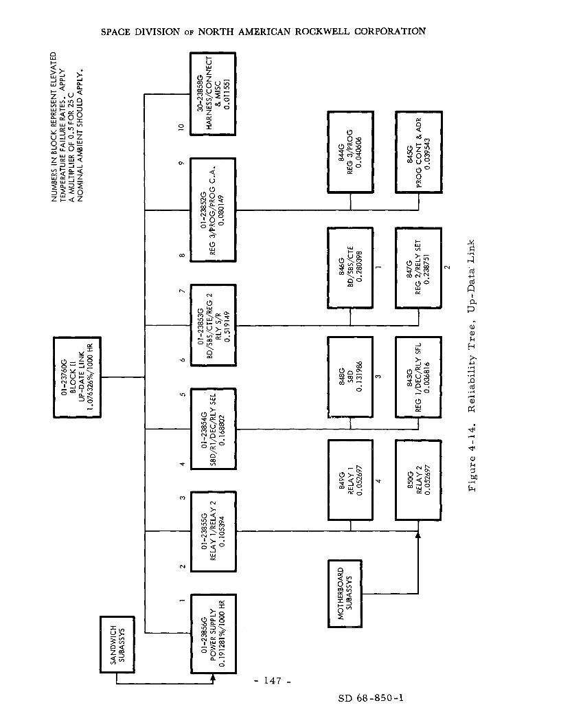
SPACE DIVISION OF NORTH AMERICAN ROCKWELL CORPORATION
SD 68-850-1

SPACE DIVISION OF NORTH AMERICAN ROCKWELL CORPORATION
Since M&R actions can only be implemented during the manned phases and would only be required af ter re turn f r o m the lunar surface, the result ing contribution to Ps could not exceed about 0. 998. Because a spare UDL with- out M&R, Option 2, will exceed any reasonable objective, this option without any planned M&R actions seems the obvious choice, it adds 19 pounds to the CM.
Conclusions and Re commendations
The Apollo I1 UDL will satisfy the ELOR-UDL requirement with minor modifications in the application of some c i rcu i t s for the command link activ- i t ies . One spare UDL is recommended with automatic o r switching on command f r o m the MSFN. craft and will require no additional tes t equipment, tools, o r other support i tems.
This spare will add only 19.0 pounds to the space-
4. 1. 8 Central Timing System
NOTE: Much of the information used in this section was provided by the Genera l Time Corporation through Reference 4.13.
Subs y s tern Description
The functions of the central timing equipment (CTE) a r e straightforward because it provides the m a s t e r t ime reference for a l l mission systems, outputs appear in two forms, t ime accumulation and frequency division. CTE is a single component of about a ten-inch cube; internally, it has four module boards and weighs about ten pounds. facil i tate navigation measurements and apply a thrust vector. updated via the up-data link system. impair crew abili ty to re turn safely; therefore, it is considered to be a c r iti cal function.
The The
The function is required to It may be
Complete loss of the function would
The CTE consists of four functional subsystems:
1. Power supply
2. Oscillator
3 . Frequency divider
4. Time accumulator
The CTE power supply subsystem consists of two separate identical pulsewidth-modulated power supplies, each capable of handling full load. The power supplies a r e fed by nominal 28-volt d -c l ines ( see the functional block diagram of F igure 4- 15. )
- 1 4 8 - SD 68-850-1

2 .I.
2 '2 .I. .I.
d
I - I
r I
I-
3, c
-@-
o b
t +I-
V Y 1 - 4
0 V
6
& I I
I 3 co co
.I* .I.
_I -I
V Y
" 3 0 U
I I
1 1 co 03 'I * .I.
co .I.
J
O L - L L
I r"
I I I
m I
I 1 I
0 V
2 - .I
E E 'C .I'
m I-
m -I
4 2;: 0 V
tttttf
I I-
0 u
+? Z Q
4
I I I L L # I
1 I ' I
A
2 0 -C .P 'I' 12 c
3
I I Q U
I
1 1
I 12 Z 2 4' .I. .I.
_I
,n n
si x 0 0
v 2 0 I- -
SPACE DIVISION OF NORTH AMERICAN ROCKWELL CORPORATION
The oscil lator i s a highly stable device and can operate in a p r imary o r In secondary mode.
Both signals a r e double, shaped, and fed to a divide-by-four major i ty logic network,
The p r imary mode i s an internal 1, 024-kHz oscil lator. . the secondary mode, the CTE i s driven by an external 1, 024-kHz signal,
The oscil lator output is 512 kHz.
The frequency divider is composed of successive two-out-of-three majori ty logic networks that divide the 512-kHz signal down to one Hz.
~~
The time accumulator subsystem i s composed of two se t s of outputs. The first of these is a s e r i a l t ime code output conforming to the IRIG B format; the second is a s e t of paral le l time-code outputs.
Subsystem Analysis
The reliabil i ty goals for the Apollo CTE have been established for the Apollo DRM under specific environmental conditions that a r e commensurate with the ELOR mission requirements . These requirements a r e a s follows:
1. For any se t of t ime-accumulator outputs, the probability shall be 0 , 9 9 9 .
2. F o r any single frequency-divider output, the probability shal l be 0.999999.
The CTE utilizes various types of internal redundancy to achieve the reliability goals and i s c r i t i ca l in that i t contributes to Ps. The power supply is a one-out-of-two paral le l arrangement whereby each power module is cap- able of handling the full load in the event of failure of the other.
The oscil lator section uti l izes diss imilar paral le l redundancy, This arrangement allows the internal c rys ta l oscillator to phaselock with an externally supplied signal of the same frequency. In the event of failure of the external signal, the internal oscil lator continues to provide the cor rec t signal to the frequency dividers without any loss of count.
The frequency divider section uses two-out-of-three majority vote The output f r o m the'oscil lator o r previous divider i s fed to three logic.
independent divider chains. frequencies and be in phase for a proper output for that divider stage to be present.
Any two of the three chains mus t have identical
Additional component par t redundancy is used in various circui ts to guard against shor t s o r opens, depending upon the cr i t ical i ty of the par t to successful c i rcui t operation.
- 151 - SD 68-850-1

SPACE DIVISION OF NORTH AMERICAN ROCKWELL CORPORATION
The subfunctional level reliability logic for the CTE is comparatively simple a s expressed by the logic diagram below. The reliability of the total
. function for the miss ion is a t l eas t that of the Apollo Mission, since the pro- posed duty cycle f o r the recommended operational concept i s only 163 hours versus a t l ea s t 190 f o r Apollo. The result ing estimated contribution to both crew safe re turn (P,) is a t l ea s t 0. 9998. Figure 4-15 is a functional picture of the redundant design.
The Ps i s sufficiently high s o that it i s considered unlikely that any maintenance will be required. as a unit ei ther by providing an on-board spa re o r by cannibalizing the LM. Cannibalization would be permissible , since the maintenance would most probably be requi red just after the docking in lunar orbit.
If i t were required, the CTE could be replaced
The CTE i s satisfactory as is for the ELOR mission and i s not expected to require any changes, only a life test .
Ac cumui B t i on 9999994 --_- __I_-.- --.-_ -
Reliability Logic, CTE, Subfunctional Level
4. 1. 9 Ea r th Landing System (ELS)
NOTE: Much of the information used herein was provided by the Northrop Ventura Company through Reference 4.14.
Sub sys tem De scription
During the lunar orbit phase, the ELS is in a dormant mode, with no functional requirements , The only requirement pr ior to ear th entry i s that the recovery sys tem be able to withstand exposure to the ELS compartment environment throughout the mission without nonrepairable degradation of operability o r nonrepairable degradation of sys tem performance to a point
- 152 - SD 68-850-1

SPACE DIVISION OF NORTH AMERICAN ROCKWELL CORPORATION
below specification levels. therefore cannot be tested in the conventional sense of the word pr ior to i ts intended mission.
The sys tem i s l imited to one use cycle and
This limitation applies to a normal o r abort profile.
The Apollo Block I1 increased capability ELS consists of-
1.
2.
3 .
4.
5.
6.
7 .
One forward heat shield m o r t a r assembly.
Two drogue chute m o r t a r assemblies .
Three pilot chute m o r t a r assemblies .
Three main parachute pack assemblies .
Three main parachute r i s e r assemblies .
Three main parachute retention assemblies .
Two sequence control lers (located in the crew compartment),
The forward heat shield m o r t a r assembly is permanently attached to The sequence control lers a r e installed within the the forward heat shield.
crew compartment, in the ELS compartment beneath the forward heat shield.
The remainder of the landing sys tem is stowed in bays
The ELS sys tem operation and design i s expected to be identical to that for the Apollo 11.
Systems Analysis
Since the only difference between the present Apollo mission and the ELOR mission is the extension of the lunar orbit phase, this factor governs the source of potential ELS problems. earth entry was considered to be 99 days for purpose of this study.
The total elapsed t ime f r o m launch to
Extended exposure to the lunar orbital environment requires analysis of the anticipated effects on the ear th landing system. which requi re examination include-
Specific problem a reas
1. The possibility that exposure to mission temperature and p res su re environments m a y degrade the sys tem textiles to an extent that sys tem performance is degraded.
2. The possibility of cold-welding of metall ic components.
- 153 - SD 68-850-1

SPACE DIVISION OF NORTH AMERICAN ROCKWELL CORPORATION
3. The possibility of the degradation of pyrotechnics f r o m exposure to the combined environments.
4. The possibility of functional degradation of plastics and e las tomers in the sys t em f rom exposure to the thermal/vacuum environment,
5. The possibility of sys tem degradation f r o m penetrating radiation and meteoroids .
These problem a r e a s have been analyzed in some detail by the Northrop Corporation Ventura Division; the resul ts a r e presented in Appendix W.
All data f r o m the Block I, Block 11, and increased capability tes t pro- g rams that were assessable to the qualified configuration were included in the final system reliabil i ty assessment . A tabulation of the data is also con- tained in Reference 4.15. Design factors were included in the calculations wherever the degradation was not included in the tes t procedure,
The normal ear th-en t ry flight mode af ter a 14-day Apollo mission was taken a s the baseline for this analysis. to 99 days, and the effects of this extension were estimated in the gross failure modes and effects analysis of Table 4-14.
The mission duration was extended
The resu l t s of the prel iminary reliability assessment of the Apollo ELS increased capability for ELOR and the Apollo DRM a r e shown in Table 4-15. The total ELS sys t em PS was found to be 0. 99993 a t the 50-percent confidence level. A 10-percent s t rength degradation due to extended lunar orbital s to r - age in a near vacuum was applied to all fabr ics in the earth-landing sys tem for the 90-day miss ion sys tem reliability calculations. An additional level of analytical detail m a y be found in Appendix R and Reference 4. 15.
Access to the ELS compartment would be very difficult to accomplish during the mission. F o r this reason, it i s considered that a capability for maintenance and/or repa i r of the ELS components within this compartment i s impractical fo r any mission phase af ter launch.
The sequence controller is accessible, being located in the crew com- partment; however, because of i ts redundancy and protection from the space environment, it is considered reliable enough not to require maintenance and/or repa i r during the mission.
- 154 - SD 68-850-1

SPACE DIVISION OF NORTH AMERICAN ROCKWELL CORPORATION
Table 4-14. Gross Fai lure Modes and Effects ELOR-ELS
Sys tem Function
Pilot Parachutes
Sequence Cont r 011 e r
Potential Fai lure Mode
Fai lure to f i re - minimized by redundant components.
Premature fir ing - major deleterious effect in p re s su re car t r idges. line cut ters , redundant f i rs t -s tage reefing l ines reduce the possibility of cr i t ical ea r ly d is r eef
In reefing
Fai lure of parachute - some limited effect, depending on geometry of separation dynamics: heat shield could fall into the command module and cause damage to the ELS.
Fai lure of one parachute - little effect because of redundancy; however, there is a possibility of the failed chute damaging remaining functioning chute,
Fa i lure of both drogues - major effect but low probability of occurrence.
Fai lure of one parachute - little effect since only two functioning parachutes a r e required for nominal landing velocity.
Fai lure of two o r m o r e parachutes - major effect but low probability of occurrence.
Same a s main chute.
Fa i lure of any one component - no effect due to complete redundancy,
Fa i lure of multiple components - possible major effects dependent upon their location.
- 1 5 5 - SD 68-850-1

SPACE DIVISION OF NORTH AMERICAN ROCKWELL CORPORATION
Sub as s embly
Sequence controller
Table 4- 15. Results of Reliability. Analysis
14-Day Mission Ps 99-Day Mission Ps
0.9994 0.9994
Retention assembly
Metal riser assembly
Forward heat shield m o r t a r assembly
1 . 0 0 0 0 0 0 1.000000
0.9999998 0.9999998
Drogue parachute m o r t a r assembly
~ ~~
Parachute subsystem PS I 0. 99993
Pilot pa r a chu te m o r t a r assembly
0.99993
Main parachute pack assembly
0.996
0.998
0. 998
0.997
0. 9956
0.998
0 . 998
0.997
Conclusions and Recommendations
I t is concluded that the Apollo Block I1 increased capability earth- landing system (ELS) is capable of meeting the 90-day life in lunar orbit requi red for the ELOR mission with a Ps of 0. 99993, provided the tempera- tu re (and to a l e s s e r extent the p re s su re ) environment within the ELS com- par tment is substantially the same as that specified for the present Apollo ELS.
The quiescent mode requirements for the ELS during the extended lunar orbital miss ion a r e substantially the s a m e a s f o r the Apollo DRM mission. The temperature environment within the ELS compartment should not depart significantly f r o m the limits specified for the present Apollo mission. P r e s s u r e s within the compartment, which a r e no lower than the presently specified 10-6 t o r r , would be desirable pr imar i ly because much of the avail- able vacuum tes t data is i n that range. Venting of the compartment should be held to the minimum pract ical level pr imar i ly to minimize the lo s s of textile finish. compartment can be tolerated.
It is questionable that minimum temperatures below -65 F in the Maximum temperatures above 120 F can be
- 156 - SD 68-850-1

SPACE DIVISION OF NORTH AMERICAN ROCKWELL CORPORATION
tolerated for shor t periods, but a higher temperature during a substantial portion of the miss ion would be undesirable. expected to be maintained without any special design, as a resu l t of the barbecue concept.
The required temperatures a r e
A temperature monitor may be desirable for the ELS compartment to a l e r t the crew on the lunar surface in the event compartment temperature departs f r o m the specification limits.
The following tes t s , analyses and developments a r e recommended.
1.
2.
3.
4.
5.
6.
7.
Tes ts to determine the functionality of the ent i re ELS sys tem af te r extended exposure to a thermal/vacuum environment.
Analysis and tes t s to better define the vacuum stability of landing sys tem texti les (particularly nylon) to an extended thermal/vacuum environment.
Analysis of nylon finish requirements and upgrading of textile specifications to a s s u r e the use of silicone oils with the highest pr'actical vapor p re s sure .
Tests to verify that cur ren t production methods provide a d ry lubricant coating to all s t rands of the s tee l r i s e r cables.
Tes ts to verify in- specification pyrotechnic function af ter a 99-day thermal /vacuum environment.
Analysis and tests to define the vacuum stability of pyrotechnic sea ls and components over an extended period of t ime,
Investigation of methods to provide redundant sealing of pyrotechnic units.
The analysis of the ability of the Apollo ELS to meet the ELOR 90-day quiescent i s based on a l imited amount of d i rec t evidence and on extrapolation of these available data. To a s su re a safe and successful extended lunar exploration program for the 1975 period, fur ther tes t s and analyses should be conducted. Faci l i t ies a r e available whereby the entire ELS can be sub- jected to an extended thermal/vacuum environment. This testing should be accomplished; then followed immediately by tes t s and evaluation of sys tem functionality.
- 157 - SD 68-850-1-

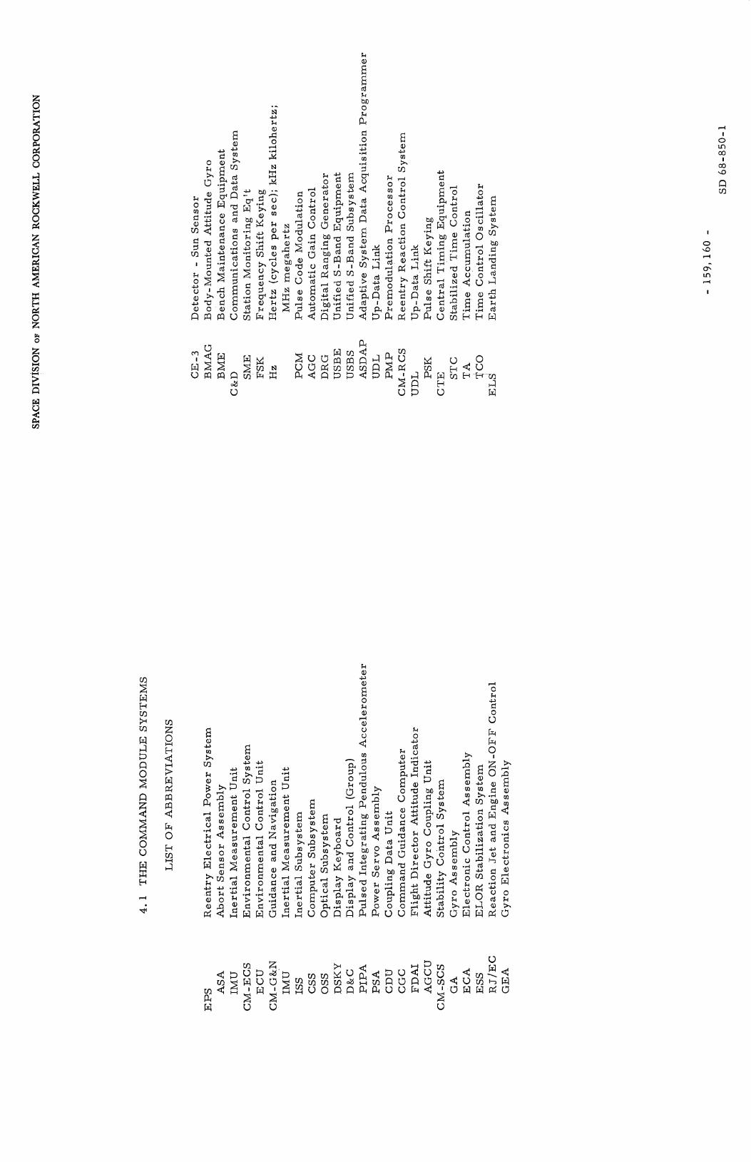
._ N c, t
k
E"
2
E cd k M 0
,-I
k 0 m d a, tn d 3 m
I
k 0 u a, c,
c,
a"
. . a,
E E d 0
a, u m
.d u .d m
d 0 k d 0 u d
c,
.d
d u rd
0
.d c,
E c,
3
E a,
k a, c,
E" 0 k a, d a, u u k
0 u
4 0 k d 0 u
Gi
c,
cr 0
h I
I 0 rn m I co s L7 u)
I
0 9
w u

SPACE DIVISION OF NORTH AMERICAN ROCKWELL CORPORATION
4.2 SERVICE MODULE SYSTEMS"
4. 2. 1 ,Elec t r ica l Power Plant (EPP)
NOTE: Much of the data used herein was provided by P r a t t and Whitney Aircraf t ( P & W ) through Reference 4- 13, by Allis-Chalmers Division (AC) of General Motors through Reference 4.17, o r by General Elec t r ic Company through Reference 4. 18.
Subsystem Description and Alternatives
The e lec t r ica l power plant (EPP) for the Apollo Block I1 is composed of t h ree P & W PC3A-2 fuel-cell modules (FCM) installed i n the serv ice module. They provide all the power requi red for all but the ear th-en t ry and recovery operations and a r e , therefore , c rew cr i t ical , contributing t o Ps as well as P90*
Because of the pecul iar nature of the ELOR mission, power requi re - ments va ry drast ical ly between the manned and unmanned phases. F o r this reason, one of the factors identified i n the SD study was the effectiveness of using a radioisotope thermoelec t r ic generator (RTG) for the EPP during the quiescent-state operations. one proposed by LMSC using three fuel cells and SD-proposed two fuel cells with the modified SNAP-27 RTG. this study and the resu l t s a r e reflected in the following paragraphs.
Two concepts become apparent for the EPP, the
Both of these concepts were analyzed i n
Two sys tems a r e under consideration by NASA for use in the post- Apollo miss ions , the 2. 5 kilowatt PC8B- 1 produced by Pratt and Whitney and the two-kilowatt capil lary matrix cell produced by Allis-Chalmers. F o r the Block I1 Apollo system, the P & W PC3A-2 will not sat isfy the ELOR mission requirements because of its life limits and, therefore , is rejected f rom fur ther consideration.
Although the P & W FCM was used herein for the analysis, the Allis-
Additional data on the P & W cell m a y be found in Appendix Y. Chalmers sys tem will per form equally well as demonstrated by the data in Appendix K. The All is-Chalmers fuel cell will requi re some modification.
The general requirements and assumptions considered i n the evalua- tion of the fuel cell sys tem (FCS) for the extended lunar orbital missions are as follows:
1. Three-powerplant installation.
2. Unattended lunar orbi t operation for 90 days.
A foldout sheet listing abbreviations used in Section 4.2 and their meanings is located a t page 199. *
- 161 - SD 68-850-1

SPACE DIVISION OF NORTH AMERICAN ROCKWELL CORPORATION
3. One powerplant operating during lunar orbi t phase ( F C concept only).
4. System power output (based on the LMSC study):
a. 1200 watts base load with peak power capability t o 2400 watts g ross power,
b. 530 watts minimum gross power.
5. Voltage regulation: 27-31 volts.
6. Powerplant endurance within voltage regulation: 2500 hours.
7. Remote r e s t a r t capability.
8 . Apollo Block I1 fuel-cell radiator ,
9. Present CSM fuel-cell envirionmental specifications.
10. Normal Apollo mission to and f r o m lunar a rea .
11. Crew safety o r Ps of about 0. 999 for system.
The power requirements during lunar -orbit operation a s provided by the LMSC study a r e shown i n F igure 4-16. fuel-cell power-plant sys t em t o provide this power, the limitation imposed on heat rejection by the present 40-square-foot Block I1 radiator configuration in the environment of lunar orbit has been considered.
In setting the configuration of the
J
0 a
E W J W
I J 1 MOOIFCATION
I I I 1 1 1 20 40 60 8090
RETURN TO MANNED CSM HOUSEKEEPING
MANNED CSM{= 11111111111111111111';; { IN PARKED MOM CONDITION
HOUSE KE E PI N CONDITION
Figure 4- 16. Est imated CSM Power Requirements i n Lunar Orbit (LMSC Est imates)
- 162 - SD 68-850-1

SPACE DIVISION OF NORTH AMERICAN ROCKWELL CORPORATION
The proposed FCM is capable of handling the full 2400-watt peak load i f the coolant supplied to it is within specified temperature limits. load peaks a r e of relatively shor t duration as anticipated (15 minutes o r l e s s ) , the one EPP can accommodate the anticipated surges in coolant r e t u r n tem- pera ture f r o m the Block I1 radiator . necessa ry t o supplement the fuel-cell heat-rejection capacity with a small sublimator.
If the
F o r peaks of longer duration, i t is
The proposed P & W FCM design weighs 151 pounds; the Allis-Chalmers cell weighs 1 0 pounds more. PC3A-2 components and offers a substantial decrease in installed weight and a n improvement in operating flexibility, endurance, and reliability over the Apollo Block I1 EPS. A schematic of the P & W power plant is shown in F ig - u r e 4-17; the Allis-Chalmers cell is more complex.
P & W makes use of existing flight-qualified
Both cells consists of four major subsystems, the power section, water - removal function, heat-removal function, and reactant-control func- tion, The P & W cell i s described in the following paragraphs.
The power section consists of the required number of unitized e lec- t rodes and'accompanying cooling plates assembled consecutively to f o r m a single stack (F igure 4-18). The electrodes and adjacent cooling plates a r e held i n position between end-plate assemblies by tie rods. connected i n se r i e s e lectr ical ly and a r e supplied with reactants and liquid coolant through internal paral le l manifolds,
The cel ls a r e
The operating power plant is self-controlling. During this period, it appears desirable to monitor performance and to have the capability of actuat- ing one of the standby units should the operating unit malfunction. mended pa rame te r s t o be monitored a re-
Recom-
1. Power plant voltage.
2. Power plant current .
3. Power section tempera ture .
4. Hydrogen condenser exit temperature .
All of these pa rame te r s a r e monitored in the present CSM fuel cell installation. below 27 volts, the power section tempera ture exceeds 250 F , o r the con- denser exit t empera ture exceeds 180 F.
Provision should be made for a n a l a r m in case the voltage goes
- 163 -
SD 68-850-1

SPACE DIVISION OF NORTH AMERICAN ROCKWELL CORPORATION
TO FROM RADIATOR RAD I AT0 R
Figure 4-17. Electr ical Power Plant System (EPP) Schematic
With SM EPS Radiator Cooling
- 164 - SD 68-850-1

SPACE DIVISION OF NORTH AMERICAN ROCKWELL CORPORATION
CATALYZED YLEc:3
TRA
Figure 4-18. PC8B-1 Cell Schematic
t i p PASSAGE
-FRAM€ fOR UNITIZE0 ELECTRODE
- 165 - SD 68-850-1
SPACE DIVISION OF NORTH AMERICAN ROCKWELL CORPORATION
Actuation of a cold standby unit is a simple process requiring no external power. The following s teps a r e involved:
1. Turn on pumps.
2. A r m in-line heater circuit .
3 . Turn on startup hea ters .
4. Turn off s tar tup hea ters upon reaching operating temperature .
The power plant i s now ready to be connected to the bus. During in-flight operation, a bootstrap o r se l f - s ta r t can be performed by energizing the pumps and the s tar tup heaters direct ly f r o m the dormant power plant. Ei ther the heatup can be completed p r io r t o placing the power plant on the bus ( a s descr ibed above) o r , depending on the selection of heater s ize , the main feed contactor can be closed af ter par t ia l heatup and the heaters placed i n para l le l with the spacecraf t load until the heating cycle i s completed. The simplicity of the s t a r t cycle makes remote activation easy to accomplish and requi res no special equipment beyond the four switching functions indicated.
The P & W water-removal subsystem per forms a s in the Apollo PC3A-2 FCM; product water i s removed f rom the cell stack by the r e c i r - culation of hydrogen. During passage a c r o s s the anode surface, a hydrogen flow i n excess of the consumption r a t e i s heated and acquires water vapor. The mixture i s transported to an F C 75-cooled heat exchanger, where the vapor i s condensed. The liquid water i s removed by a centrifugal separator and the remaining saturated hydrogen i s pumped back to the cell stack a f te r being mixed with the supplemental hydrogen required to sustain cell reaction. Because of advantages in t e rms of lower, greater durability, and higher reliability, brushless d-c motors a r e recommended for use in driving both the hydrogen pump and the coolant pump instead of the a -c motors now in use i n the PC3A-2. These motors a r e presently under development a t P&WA.
The P & W heat-removal subsystem removes the major portion of the waste heat generated within the cell stack is by circulation of a liquid coolant ( F C 75) through the cell stack. The coolant i s supplied to the stack at a con- t ro l led tempera ture level, heated during passage through the cel ls , cooled a t a n external heat sink, and pumped back to the cell stack i s maintained by a control valve, which regulates the ra te of heat-sink bypass flow, portion of the waste heat is a lso removed f r o m the cells by the recirculated hydrogen flow i n the water-removal subsystem, but this heat is rejected to
A l e s s e r
- 166 - SD 68-850-1

SPACE DIVISION OF NORTH AMERICAN ROCKWELL CORPORATION
the FC 75 loop within the power plant. complex, using helium as a second heat t ransfer medium.
The Allis-Chalmers approach i s m o r e
The data indicate that FC 75 coolant i s compatible with the serv ice Although module Block I1 radiator i n all operating thermal environments,
the specific heat of FC 75 i s considerably l e s s than that of aqueous ethylene glycol, the grea te r F C 75 circulation ra te required for proper power-plant control resul ts in a turbulent flow condition in the radiator passages and a consequent increase i n heat t r ans fe r above that obtained with the laminar flow of water-glycol. pe ra tu re s , which i s a favorable character is t ic for operation at low radiator r e tu rn tempera ture condition experienced during the quiescent phase. Appendix X for a supplemental cooling sys tem used i f batteries a r e not used i n the peak-load cycles of the CSM quiescent mode,
In addition, FC 75 exhibits a low viscosity at reduced t em-
See
The reactant -control subsystem provides the power plant with reactant gases conditioned to proper tempera ture and p r e s s u r e levels. hydrogen gases a r e supplied f rom an external supply to the power plant p r e - hea te r s , where they a r e temperature-conditioned. In turn, they pass to the cel ls through demand-type regulators that maintain a fixed operating pres- sure . The circulation sys t em ca r r i e s the reactant hydrogen to the hydrogen electrodes.
Oxygen and
Solenoid-operated vent valves a r e provided for periodic venting of accumulated impurit ies in the system. sat isfactory for the ELOR. during the quiescent mode,
The present Apollo purge schedule i s A t imer circuit will control automatic purging
Operation, Monitoring, and Control
During the unmanned period in lunar orbit , two of the three power plants a r e shut down on a cold standby condition. ation involving only the following steps :
Shutdown is a simple oper-
1. Open main feed contactor.
2. D i s a r m inline heater circuit .
3 . Turn off pumps.
- 167 - SD 68-850-1

SPACE DIVISION OF NORTH AMERICAN ROCKWELL CORPORATION
These s teps may be performed by the astronauts before they leave the command module, The units on cold standby require no monitoring, environmental control, o r maintenance provided all water i s removed.
Bootstrap, o r se l f - s ta r t , capability has been well established f r o m power -plant development t e s t experience to date. reach operating tempera ture is i n the range of 10 t o 30 minutes depending on the heater s ize . p e r f o r m a rapid off-line s t a r t , but other operational considerations such a s environment t empera tu re and the possibility of placing the heater i n paral le l with the bus load would affect the final selection. The total energy required f r o m the fuel cell during an in-flight s t a r t is l e s s 0 . 3 kilowatt-hours, typical s t a r t accomplished during sea- level testing of a P & W PC8B- 1 FCM i s indicated i n Figure 4-19. In this case, the heatup phase was com- pleted pr ior to placing the power plant on load.
The t ime required to
The desirable approach is t o use a high-energy heater t o
A
Weight and performance data for the P & W PC8B may be found i n Appendix Y; for the Allis-Chalmers cell , these data may be found i n Appendix K.
EPP Systems Analysis
Selection of an EPP for the ELOR mission depends on two factors , i ts ability to (1) meet the manned-phase requirements (the Apollo mission) and survive the dormant cycle and ( 2 ) provide the minimal power requirements for quiescent-phase operation. The Allis -Chalmers or P & W fuel cel ls will meet the functional requirements imposed by the manned phases of the mis- sion a s well as the reliability goals demonstrated for Apollo; therefore , no fur ther consideration of these phases is required,
The LMSC study indicated that about 1200 watts of average power and up to 2400 watts of peak power may be required for the CSM quiescent phase; however the resu l t s of this study indicate that these requirements may be much too pess imis t ic and that the actual requirements could be reduced to 124 watts average and 191 a t the peak periods. requirements is given i n Tables 3-1 and 3-2. Much of the saving comes f rom use of waste heat for heating requirements ra ther than electr ical power. is recognized that a m o r e detailed study is required to ver i fythese est imates , It is , however, evident that a decision cannot be made without resolving these differences.
A breakdown of these
It
Since the re is a wide divergence in potential requirements , two sys - t e m concepts a r e presented herein for the quiescent phase: the single fuel cell and the dual radioisotope thermoelectr ic e lectr ic (RTG) sys t em (2-SNAP- 27 derivative).
- 168 - SD 68-850-1

SPACE DIVISION OF NORTH AMERICAN ROCKWELL CORPORATION
0 COOLANY STACK INLET TEMP
0
'0 5 IO 15 20 25 30 36 40 TIME FROM START- MINUTES
Figure 4-19, Bootstrap Star t Data for PC8B-1 Power Plant
- 169 - SD 68-850-1

SPACE DIVISION OF NORTH AMERICAN ROCKWELL CORPORATION
The Single FCM for the quiescent modes could use either the P & W o r All is-Chalmers cell. Chalmers cell is provided i n depth along with i t s differences f rom the P & W cell.
A reliabil i ty and maintenance analysis of the Allis-
When a fuel-cell sys t em (FCS) i s in the standby mode, the thermal During hot standby all the components of the thermal
Except for extreme ambient loop must be active. loop and the heating controller will be active. t empera ture var ia t ions, the heaters will be cycling on and off to maintain tempera ture , and the coolant valve will remain closed. When a fuel-cell module (FCM) i s i n the cold-standby mode (the recommended quiescent mode), the water/glycol solution i n the thermal loop must be kept f r o m freezing, This necessity may requi re that the coolant pumps to be on and the coolant solenoid valve open.
The coolant pump is the most cr i t ical component of the thermal loop; therefore , each FCM has two coolant pumps. capacity to maintain the necessary coolant flow for the desired standby and operational FCM tempera ture .
Ei ther pump has sufficient
The remaining components i n the thermal loop plus the heating control electronics have a failure ra te of about 6 . 4 failures p e r million hours. es t imated fai lure r a t e s for the fuel-cell systems a r e presented in Appendix L and f o r m the basis of the subsequent analysis.
The
The 90-day Ps of the FCS with the present ly configured FCM’s (redun- dant fans for the All is-Chalmers sys tem and redundant coolant pumps) i s 0.9994. will be operable at the end of the 90-day lunar surface mission and will com- plete the return t r ip . made o r provisions for a fourth or return-home FCM should be made to enhance crew safety. The P & W cell i s more reliable, over ( 0 . 9996) because of the lack of fans and the helium heat- t ransfer medium.
This figure i s the probability that at least one of the three FCM’s
If two FCM failures should occur, a repair must be
Since reliabil i ty of both systems exceeds the goal of 0. 999, it i s not required that any spa re pa r t s be carr ied; however, i t i s possible with some redesign to provide the capability to replace some components of the Allis- Chalmers cell. three FCM’s for the r e tu rn t r i p to 0.99998 and decreases the chances of abort .
This added capability increases the availability of one of the
F o r a lunar orbit FCS consisting of two FCM’s ( a total of th ree including a re turn home FCM), configuration is the minimum requirement; i. e . , one operating FCM and one hot-standby FCM. The 90-day reliability
- 170 - SD 68-850-1

SPACE DIVISION OF NORTH AMERICAN ROCKWELL CORPORATION
of this FCS with the presently configured FCM's is 0.994 for the Allis- Chalmers cell. redundancy, the P, contribution increases to about 0.999. assumed to occur should two FCM's fail.
If the Allis-Chalmers FCM is redesigned to provide minimum Mission abort i s
To a s su re the availability of a second FCM for the return trip, the cell control assembly (EMCA) could be redesigned for in-space maintenance, and a spare should be car r ied for replacement. The probability that a t least one of the two FCM's, l e s s the EMCA, is operable a t the end of 90 days i s about 0. 999.
This value means that the availability of a second FCM for the return t r ip home is the same when either redundant redesigned EMCA's/FCM a r e employed or a spa re redesigned EMCA is car r ied for EVA maintenance. The advantage of the former is the increased probability of lunar orbit mission success. The advantage of the la t ter is l e s s electronics (three removable EMCA's versus four built-in EMCA's) and probably less redesign.
. - The most cr i t ical components a r e l isted in order of unreliability in
Table 4-16.
Table 4- 16. Fuel Cell Assembly Relative Unreliability (Allis-Chalmers Data)
C ornpone nt
Fans
EMCA
PC
WCC
Other s
WRA
WRV
PT
Others
Coolant Pump
Relative Unr eliabili ty
30:g (Allis-Chalmers cell only)
29
15
10
4
5. 5 3 :!:
2. 5
~
::A redundant fan and a redundant coolant pump a r e in the present Allis-Chalmers FCM, a r e used; these a r e redundant for fail-closed, but in sepies for fail-open having a failure rate approximately equal to a single valve.
Two water-removal valves
- 171 - SD 68-850-1
SPACE DIVISION OF NORTH AMERICAN ROCKWELL CORPORATION
The EMCA is the most c r i t i ca l component with a reliability of about 0.94; however, it can be considered for ISM. The other components have been excluded from ISM because of their relatively low failure ra te , the difficulty of ISM for fluid l ines, and the extent of redesign required. One spa re EMCA w i l l provide a contribution to Ps of about 0. 998 for the FCM; one m o r e (2 spa res ) increases Ps t o about 0. 99998. The spa res a r e only useful a f te r the crew re turn to the orbiting CSM, but they will permit com- promise of the Apollo abort c r i te r ia . can fail before abort is required. pletely s o that there i s usually more than ample t ime to take compensating action.
Under these conditions, two fuel cells Actually, the FCM's seldom fail com-
To determine FCS status, cer ta in data a r e required by the MSFN so that a new module may be remotely s ta r ted and the faulty one may be shut down. This action is repeated if other modules fail until only one module remains operable, and the mission i s immediately aborted. Diagnostic procedures will then be undertaken af ter the crew boards the CSM.
It is required to remotely determine when the module has degraded or is about to go beyond predetermined limits. be monitored remotely on the lunar surface:
The following quantities will
1.
2.
3.
4.
5.
6.
7.
module current.
bus voltage.
module temperature.
reactants pres sur e.
water vapor pressure .
:;c anis te r p re s su r e.
:::reactants over pressure ,
The following controls a r e required to remotely s t a r t up and shut down the modules:
1. Standby module 'Ion" (1 per module).
2. Module "off1' (1 per module).
3. Purge (1).
(?These are also required if the EMCA is designed for ISM.
- 172 - SD 68-850-1

SPACE DIVISION OF NORTH AMERICAN ROCKWELL CORPORATION
The fuel-cell module elements w i l l be energized by a switching device initiated by the "module on" command, which w i l l be designed a s a part of the EMCA.
The radioisotope thermoelectric generator, a s described in detail in Section 4. 4. 2, is a modified SNAP-27. 0. 9999 and wi l l not require any maintenance. Apollo program, average power required, together weigh only 85.4 pounds, about 1 / 2 the weight of one fuel-cell module, and this includes the fuel of the whole mission. When installed as recommended, adequate shielding exists to a s s u r e no contamination of the crew. save over 6,000 pounds and reduce the SM modifications required by a substantial amount. the RTG's provide all CSM electr ical power for the quiescent phase.
Its reliability without repa i r exceeds It is already qualified for the
Two SNAP-27's, which wi l l provide the SD-estimated
Use of this concept is expected to
Its reliability is the system contribution to P90 since
Conclusions and Recommendations
Either fuel-cell system wi l l meet the basic ELOR requirements; however, the data indicate that the P&W cel l is somewhat more reliable than the Allis-Chalmers version; about 0. 9996 ve r sus 0. 9994 for the system P S approach; however, it may be maintainable. It requi res some modification, whereas the PC8 does not, In any event, the Apollo I1 cells must be replaced with one o r the other.
The Allis-Chalmers cel l is slightly more complex in the heat t ransfer
If the SD power profile estimates a r e verified, i t i s recommended that one fuel-cell module be eliminated and a dual SNAP-27 designed with a heat exchanger s imilar to that recommended fo r the LM in Paragraph 4.4.2 be installed in the CM. This approach virtually l imits the CSM modifications to those required to instal l the RTG system and actually reduces the CSM injected weight to l e s s than that for Apollo 11. no l o s s of power during CSM quiescence.
Further , i t virtually guarantees
4. 2. 2 Reaction Control Subsystem (SM-RCS)
NOTE: Much of the information used herein was provided by the Marquardt Corporation through Reference 4.19, 4. 20, and 4. 21.
The SM-RCS for ELOR i s to be identical with that used i n the Apollo Block 11, except for the use of a n aluminized bladder in the positive expulsion tanks to prevent helium migration.
NOTE: Addition of both fuel and pressurant totaling about 145 pounds in required for the all fuel cell concept.
- 173 - SD 68-850-1

SPACE DIVISION OF NORTH AMERICAN ROCKWELL CORPORATION
The RCS hea ters recommended by LMSC a r e already a par t of the Block I1 design. As for the engines themselves, there a r e four self-contained engine quads, each completely independent from the others. A schematic of one quad i s presented i n Figure 4-20.
The SM-RCS per forms severa l functions for the ELOR mission, it must provide attitude and stability control a s for the Apollo mission; and, during the storage mode, they must spin and despin the CSM around the roll axis. In addition, it is required to damp out any axis wobble while maintaining the ro l l axis perpendicular to the sun's rays ,
The system operates the same as for the Apollo mission, except for If they a r e used, they would either be used continuously
Marquardt and SD data indicate that
the quad heaters. or be controlled by a thermostat. be turned on just p r ior to RCS usage. freezing wi l l not occur i f the vehicle and engines a r e moving with respect to the sun such that all the engines a r e warmed by the sun or by engine operation every few hours.
As a third alternative, they need only
The aluminized bladder should prevent potential helium migration; however, Bell Aerosystem tes t s have shown that the presence of helium in the fuel or oxidizer will not adversely affect engine operation ( see Reference 4 .22) . p ressurant and to offset the effects of any potential leakage and/or migration particularly for the a l l - F C concept.
Additional helium i s recommended to a s su re adequate
System Analysis
The SM-RCS may be analyzed in t e rms of i ts major constituents. Each quad is made up of fuel supply, helium supply, engines, and management elements, which a r e analyzed separately in the following paragraphs,
The fuel tanks a r e of the positive-expulsion design a s shown in Figure 4-21. Figure 4-22.
A functional diagram and description i s presented in
A s presently configured, the positive-expulsion tank (bladder type) is Depending loaded and pressur ized (suppression pressure) pr ior to launch.
upon tank application the p re s su re may be increased to its operating level either pr ior to or subsequent to launch. remains constant, permitting positive propellant expulsion on demand. Pulse-type flow is the normal requirement and is effected by operating a valve in the reaction-control thrust-chamber subsystem.
From this point, the pressure
Apollo mission
- 174 - SD 68-850-1

SPACE DIVISION OF NORTH AMERICAN ROCKWELL CORPORATION
TRANSDUCERS
1 HELIUM FILL I
TEST POINTS (2) I
FUEL OXIDtZER - TANKS (2) TO ENGINES TANKS !a
Figure 4-20. Reaction Control System Schematic, Service Module (SM-RCS)
- 175 - SD 68-850-1

SPACE DIVISION OF NORTH AMERICAN ROCKWELL CORPORATION
11
23 22 I
1.
2.
3.
4.
5.
6.
7.
8.
1'9.
10.
11. 12.
13.
14.
POSITIVE EXPULSION TANK ASSEMBLY
Diffuser Assy. Fuel 8339-471053-3 *nut cut off Ox. 8339- 471 054- 3 predelivery
Bolt 8271 - 47 1019- 1
Washer AN 960-C416L
Bladder
Fuel 8339-471080-1 OX. 8339- 47 1080- 3
Ring 8271-471117-1
Pad 8271-471249-1
Bolt 8271 -471114-1
Gasket 8271-471025-1
Gasket 462-4 (Test Only)
Gas Inlet Fitting (Test Only) 833
Boss End of Tank Assy.
Washer Assy. 8271-471144-1
Nut 8271-471021-3
Vent Line Assy. Fuel8339-471027-1 OX. 8339-471027-3
15. Eyelet 8271-471141-1
16. Mounting Flange
17. Bimetal Joint (6061 A1.Al. to 347 SLSt.)
18. Tank Shell Assy. (T16AL-4V Titanium) Fuel 8339-471110-1 OX. 8339- 47 11 10- 3
19. Bleed T h e Assy. Fuel 8339-471059-9 ,)ut cut off Ox. 8339-471059-11 prior to delivery
20. Bleed Tube Spacer
21. Nut 8271-471049-1 (Test Only)
22.
8339-471058-1
Retainer End of Diffuser Assy.
(Ret. Assy. 8339-471057-1)
23. Retainer Cone 8339-471057-5
24. "Outlet End" Cone 8339-471034-1
25.
26.
471026-
Diffuser Tube 8339-471036 (-1 Fuel: -3 Ox)
Elbow (Outlet) Tube W/O Nut 81 Sleeve 8339-471031-7
Figure 4 -2 1. Positive Expulsion Tank Assembly
- 176 - SD 6 8 - 8 5 0 - 1
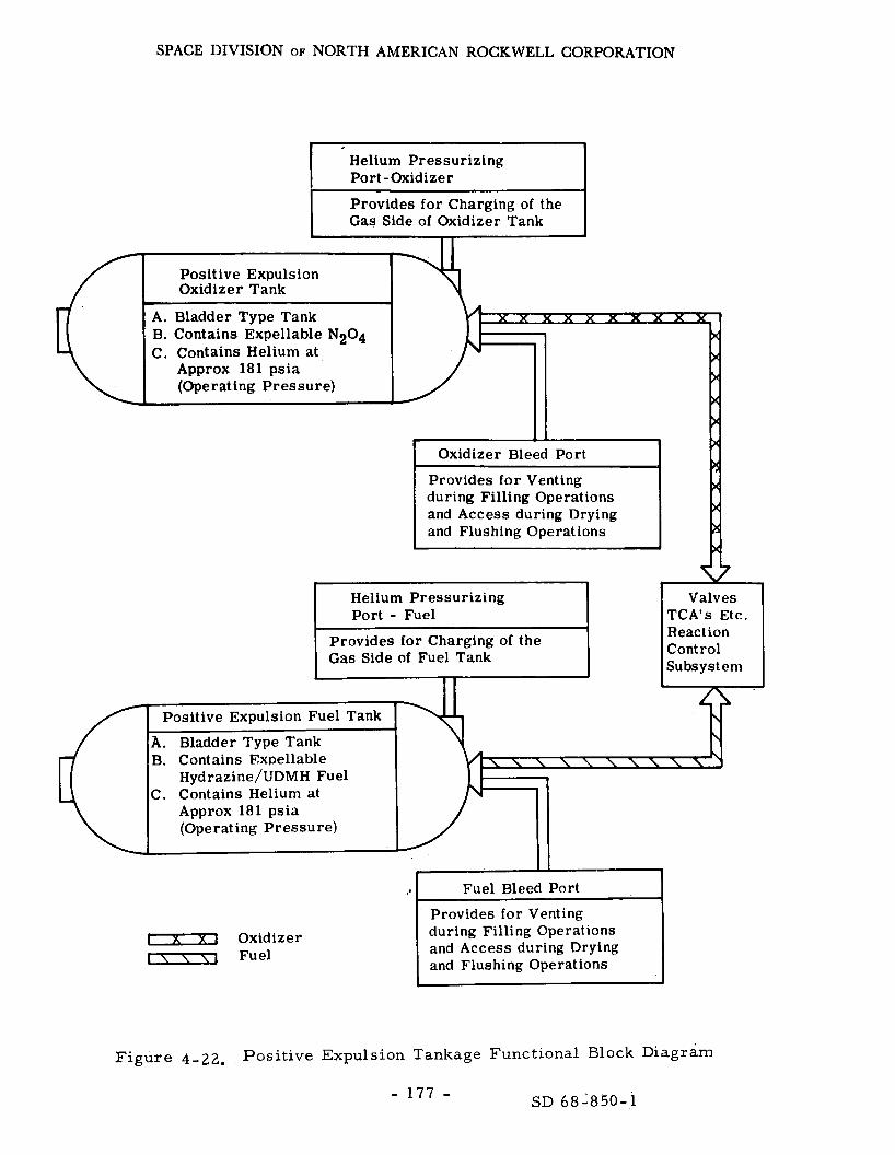
SPACE DIVISION OF NORTH AMERICAN ROCKWELL CORPORATION
B. Contains Expellable N204 C. Contains Helium at
Gas Side of Fuel
Hydrazine/UDMH Fuel C. Contains Helium at
Approx 181 psia (Ope rating Pressure)
Fuel Bleed Port
Provides for Venting [ X i Oxidizer -1 Fuel
during Filling Operations and Access during Drying and Flushing Operations
Figure 4-22. Positive Expulsion Tankage Functional Block Diagram
SD 68-850-1 - 177 -

SPACE DIVISION OF NORTH AMERICAN ROCKWELL CORPORATION
requirements include the tank assembly capability to perform satisfactorily for one cycle; i. e . , a propellant-loading ullage draining and complete expulsion to full bladder AP. different (slightly) configurations of the positive expulsion tank concept, their basic design i s the same.
Although the Apollo spacecraft contains s ix
A reliability analysis of the tank indicates that the bladder is the only component that has any significant effect on the estimated value. fa i lure ra tes for the tank and diffuser assembly fallout a r e insignificant in arr iving at the tank assembly reliability; therefore, tank assembly reliability i s p r imar i ly a function of the bladder failure hazard; and it has been demonstrated that, given a satisfactory leakage check and propellant loading, a successful full expulsion (pulsed or continuous) can be effected with a Ps of 0.998 at 90-percent confidence for each tank.
The
Since the major failure mode was helium migration, and this has been eliminated through use of the aluminized bladder, the reliability is known to be much higher, probably greater than 0.99999. verifying this position. impract ical and unnecessary for these tanks. replace the. quad as a unit, which i s considered unnecessary.
Test data s e e m to be Maintenance or repair of any kind i s considered
The only possibility i s to
The helium supply provides the pressurant for the fuel sys tem, both
The Apollo design wi l l provide a subsystem of Ps better than 0. 9998 f o r fuel and oxidizer. ing. ELOR without any changes. A redundant tank and common manifold to a l l quads would exceed 0. 99999.
There a r e two tanks fo r RCS quad with redundant plumb-
Details a r e s imilar to those for SM propulsion.
The RCS engines, the R-4D a s presently used for Apollo and other space programs, a r e considered adequate without change. NASA and Marquardt data indicate that the engine exceeds the life requirement by a substantial margin. As indicated in Figure 4-23, actual test data indicate that the reliability for the engine and resulting Ps wi l l be between 0. 999 and 0. 99999; therefore, the probability of losing control of one axis is l e s s than 1 x l o m 6 because of the redundant quad design.
F r o m the referenced data, it i s known that the burn-life and s t ructural capabilities of the R-4D Engine were much greater than the requirements for a given application; i. e. , large margins of safety so that engine reliability i s a function of the required number of ignitions. mode then becomes the failure of a valve to open or close, Fo r the R-4D valve design, no assessable fa i lures have been experienced in the extremely large number of tes ts encompassing more than two million engine firings and m o r e than 50 million valve cycles (Reference 4. 20).
The predominant failure
The resulting
- 178 - SD 68-850-1

SPACE DIVISION OF NORTH AMERICAN ROCKWELL CORPORATION
8 9 2 I 8 c 0 O. 0 7
I
8 -
22AUG 67
.90 .99 .999 .9999 ,99999 .999999 .9999999
. PROBABILITY OF MISSION SUCCESS-RELIABILITY -
Figure 4-23. Reaction Control 'Engine Reliability as a Function of Usage
- 179 - SD 68-850-1

SPACE DIVISION OF NORTH AMERICAN ROCKWELL CORPORATION
engine reliability i s presented in Figure 4-23 a s a function of the required duty cycle and number of ignitions. valve cycle t e s t s should m o r e accurately predict engine-reliability. unusual bumps r e su l t f rom use of s ix scale changes on the reliability absc issa ; one change was made f o r each nine units to enhance the accuracy in reading the reliability numbers. bility is a s expressed in Table 4-17.
The curve based on engine fir ings plus The
F r o m the upper curve, the engine re l ia -
Three factors affect engine life and the result ing mission reliability and safety; these a r e burn-time, space s torage, and number of ignitions.
The predicted burn-time limit of the molybdenum/molybdenum disilicide- coated combustion chamber and the cr i t ical burn-life-limiting component of the engine i s a function of maximum chamber temperature . Engine operates a t a maximum chamber tempera ture of 2,000 F. The p r e - dicted chamber life i s in excess of 1, 500 hours of cumulative usage; no application o r margin t e s t proposed to date would utilize even a small f r ac - tion of the engine's lifetime capability. s t ra ted by the supplier.
The R-4D
This capability has been demon-
The number of ignitions can also have a deleterious effect on engine life; this i s normally created by the occasional rough s ta r t ; however, since the beginning of the development program, t h e r e has never been a failure of any type in 1. 5 million firings. This is not considered a failure hazard since the recorded number of successful f ir ings is fa r in excess of any mission requirements.
Table 4- 17. Engine Reliability for Discrete Duty Cycles
Required Duty Cycle o r
Number of Ignitions
Demonstrated o r Achieved Engine Reliability
(50-Percent Confidence)
1,000
5, 000
1 0 , 0 0 0
50,000
100,000
0. 99998
0.9999
0. 9998
0 .999
0. 998
- 180 - SD 68-850-1

SPACE DIVISION OF NORTH AMERICAN ROCKWELL CORPORATION
Deep-space s torage capability was one of the important design c r i t e r i a for the engine. Materials and clamping loads in the hardware have a l l been selected to provide no degradation f rom any known s t r e s s over long periods of storage, with o r without engine firings. o rde r of one year has been demonstrated on the lunar orbi ter flights, the pas t program, the engines demonstrated ze ro valve leakage in extended space exposure, a s well a s no ill effects due to the complete space environ- ment (hard vacuum, micrometeori tes , o r solar radiation).
Space s torage capability on the During
During long-duration missions with intermittent engine operation and long off-times, it is possible to f reeze propellants in the lines leading to the engines. w i t h respec t to the sun so that a l l of the engines a r e warmed by the sun, o r by intermittent engine operation every few hours. may be avoided by using an electr ical heater that i s mounted on the engine injector head.
This condition may be prevented i f the lines a r e mounted in a plane
Fuel freezing in the lines
The hea ters can be used a s follows:
1. During long engine-off periods, the propellants can be allowed to f reeze in the lines. The heater is then turned on pr ior to engine use to thaw the propellant (applicable to LM engine only).
2. The heater can be left on continuously.
3. Thermostats can regulate the head temperature.
The ELOR concept for the CSM will preclude the need for quad heaters. Barbecuing the CSM wi l l prevent the fuel lines f rom freezing because of the adsorbed heat (its outer coating adsorbs heat). The engines a r e unaffected by the presence of dissolved helium pressurant in the propellant. in propellant supply p r e s s u r e and voltages have only a second-order effect on engine performance.
Variations
The high reliability of the engine plus the redundancy obtained f rom having a number of engines capable of performing the same control functions in the four engine quads eliminates the need for replacement par t s o r repair of an engine during a mission; yet in-flight maintenance possibilities based on the mos t likely failure modes a r e considered possible for the engine alone.
Calculating the reliability of an RCS quad, using available tes t data a s a lower boundary est imator and the mathematical model of Figure 4-24, the quad P, is expected to exceed 0. 9966 each. The probability of any three of the four working exceeds 0. 9999 and of any two of the four working exceeds 0.999999.
- 181 - SD 68-850-1
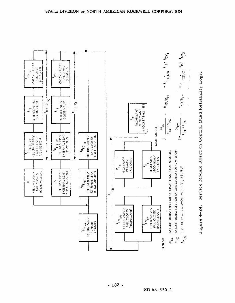
SPACE DIVISION OF NORTH AMERICAN ROCKWELL CORPORATION
L I:
I I I I I
H Jm
- 182 - SD 68-850-1

SPACE DIVISION OF NORTH AMERICAN ROCKWELL CORPORATION
4. 2. 3 Main ProDulsion Subsvstem
NOTE: Much of the information used in this section was provided by the Aerojet General Corporation through References 4 .23 and 4. 24.
Func tiona 1 D e s c r ip tion
The main CSM propulsion engine i s to be the Apollo serv ice module engine. The Block I1 sys tem will remain unchanged, except for the fuel and oxidizer s torage tanks, which may be increased in s ize to accommodate the increased fuel/oxidizer s torage requirements projected by LMSC. change involves the addition of 4. 7 inches in length and an elliptical head. The existing s t ruc ture will support the tanks with little change (F igure 3-3 ) .
This
The main requirements of the engine a r e to provide the necessary thrust for midcourse correction during the t ranslunar phase, t ra jectory correction during the approach, lunar orbi t capture, t ransear th injection, midcourse correct ion during the t ransear th phase, and retrofiring for ear th approach and reentry. mission is an average of nine cycles for a maximum total duration of 600 seconds, slightly more than that for Apollo, because of the la rger pay lo ad.
The total engine firing required for the complete
The subsystem schematic i s given in Figure 4-25 along with a list of functioning components.
Engine System Analysis
Reliability logic diagrams a r e presented in Figure 4-26 for engine s t a r t and steady- s ta te operations. Engine shutdown operations and coast periods a r e given in Figure 4-27. Associated with each component o r assembly identified in Figures 4-26 and 4-27 a r e a l l of the various pa r t s associated with its construction. into four valve assembl ies , each consisting of an actuator and the associated pair of bal l valves (one for fuel and the other f o r oxidizer), shafts, sea ls , spr ings, housing, and other related par ts . The gimbal actuators for pitch and yaw a r e considered separately. clutch assembl ies a r e individually identified. harne s s e s .
The bipropellant valve has been separated
In each actuator, the redundant motor- There a r e redundant e lectr ical
The reliability logic diagrams shown in Figures 4-26 and 4-27 provide A m o r e a reasonably rigorous basis f o r calculating the engine reliabilities.
detailed se t of logic diagrams for the lunar mission a r e presented in Reference 4. 23.
- 183 - SD 68-850-1

SPACE DIVISION OF NORTH AMERICAN ROCKWELL CORPORATION
REMOTE DlSCONNECl
RELIEF ASSEMBLY
FUELLINE ,
BLEED VALM
I
I- I ! OXIDIZER
I ~ A N K I
I
HEAT EXCHANGER
ASSEMBLY
Figure 4 - 25, Command/ Se rvice Module Propulsion Sys tem Schematic
- 184 - SD 68-850-1

SPACE DIVISION OF NORTH AMERICAN ROCKWELL CORPORATION
%r'-f $ 8
- 185 - SD 68-850-1
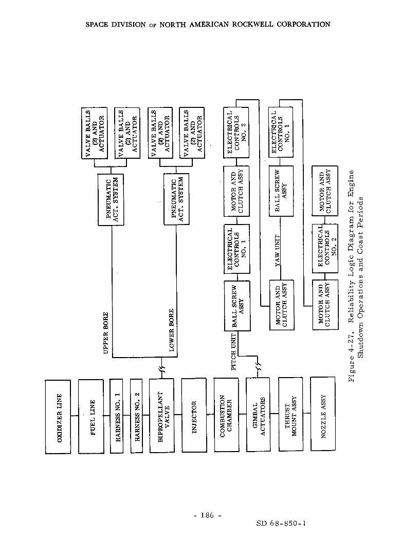
SPACE DIVISION OF NORTH AMERICAN ROCKWELL CORPORATION
- 186 - SD 68-850-1

SPACE DIVISION OF NORTH AMERICAN ROCKWELL CORPORATION
The engine contribution to Ps should be a s ses sed in both the active and passive phases, since the engine wi l l be dormant fo r a major pa r t of the mission. tion through the burn to the t ime p res su re is relieved and the feed sys tem is purged.
The active phases include the t ime f r o m fuel sys tem p res su r i za -
This phase is normally considered the most hazardous.
Reliability es t imates given in Reference 4. 23 for the lunar baseline missions a r e presented in Table 4- 18. a bas is for estimating reliabil i t ies for the baseline mission, which is related to the ratio of burn-time, 6 0 0 seconds for the ELOR mission versus 546 seconds for the Apollo DRM. to compensate for the increase in the projected CSM weight, l e s s than half the difference is required with the RTG-EPS concept.
These reliability es t imates provide
The slightly longer burn-time i s required
Table 4-18 . Estimates of Component Reliability for All Per iods of SPS Engine Fir ing
Component
Thrust mount
Nozzle extension
Combustion chamber
Injector
Propellant l ines
Gimbal actuator (each)
Pneumatic actuation system::<
Bipropellant valve
ELOR Mission Ps
0. 999052
0. 998887
0 .993596
0 .998959
0 . 9 9 6 6 3 4
0. 998541
0 .989623
0. 9.99524
>O. 996 I Single-Engine Total
(*) The reliability figures given for the pneumatic actuation sys tem a r e applicable to each of the two pneumatic sys - tems, which a r e functionally redundant; that is, failure
\ to supply pneumatic actuation pressure .
- 187 - SD 6 8 - 8 5 0 - 1

SPACE DIVISION OF NORTH AMERICAN ROCKWELL CORPORATION
The hot-fire engine reliability for the baseline mission would be at l ea s t 0. 996 without changes. however, i f it is deemed necessary to increase the engine hot-f i re reliabil i ty, the combustion chamber reliability may have to be improved before a signifi- cant increase in engine reliability could be achieved. A review of the hot-f i re t e s t history of engine combustion chambers indicates only two failures. In both cases , the chambers were tested to failure, one for a duration of 1 ,956.4 seconds, the other for 2,392.4 seconds. Both fai lures were of the wearout type, and a value of 0. 99999992 can be calculated a s the estimated probability’ of no wearout for the ELOR mission. Twenty-five chambers were tes ted for durations of a t least 750 seconds without the occurrence of any random-type failures. for the MTTF of about 27, 000 seconds, which resu l t s in a demonstrated random reliability of 0. 98 associated with the 600-second hot-fire duration specified for the proposed ELOR mission. adequate (perhaps overly conservative according to Reference 4. 24) design with respec t to wearout. The demonstrated random reliability is quite low because of lack of data. The t rue random reliability is known to be signifi- cantly higher, but cannot be demonstrated without accumulating m o r e t e s t data. Since no random failures have occurred up to the present t ime, there is no reason for recommending any change in design.
This level of reliability i s probably adequate;
These data can be used to obtain a median value
This t e s t experience indicates an
The passive engine phase of the proposed ELOR mission involves con- sideration of the effects of the prolonged coast period (about 90 days) on coast reliability. with a qualitative appraisal of the anticipated effects of the baseline mission, A s an aid in making the required qualitative judgments, i t was found helpful to per form a failure-mode cause-and-effect analysis (FMEA) of each com- ponent.
Reliability es t imates a r e given in Reference 4- 17 along
The FMEA analysis i s presented in Reference 4.24.
There i s a definite controversy over the effects of long-term exposure
The FMEA indi- to the space environment, and there a r e few data to verify any position. f a r , there have been no failures attributable to this effect. cates the potential effects; and, in each case , protective measures can be taken to prevent the problem. requiring a full-scale t e s t program. 90-day quiescent phase should present no deleterious effects to any of the engine components.
So
This question represents one of the a r e a s The supplier has indicated that the
- 188 - SD 68-850-1

SPACE DIVISION OF NORTH AMERICAN ROCKWELL CORPORATION
4. 2. 4 Main Propellant Tankage (Storage) Analysis
NOTE: Some of the information used herein was provided by the Allison Division of General Motors through Reference 4. 25.
The main propellant tankage i s required to s to re both the fuel and
Since the oxidizer in a liquid s ta te for the full mission duration. is to be accomplished during ear th approach and retrograde. engine is p r e s s u r e fed, helium will be used a s a pressurant to expel the liquids from the tanks af ter ullage control. Two tanks for oxidizer and two for fuel a r e provided in Block 11; this redundancy i s expected to be required in addition to two helium tanks. The operational concept involves re l ief of the helium p r e s s u r e during the long coast periods and activation jus t p r ior to igniting the engines. appropriate reaction control engines jus t p r io r to main engine ignition.
Final fuel depletion
Ullage control is accomplished through use of the
The reliability study for the Apollo tank program i s summarized in the Allison final design report , Reference 4. 26. is estimated to be 0. 9999998. The reliability estimate applies t o the actual use phase of the tank life; that is, a propellant tank which has passed al.1 inspections and acceptance tes ts and has been checked out in the vehicle has a 0. 9999998 probability of going through preparation, countdown, ear th launch, t ransfer , lunar orbit , and lunar landing without malfunction.
The Ps of the propellant tank
The r e liability es t imate and failure - mode failure - effect analysis indicated that the probability of fa i lure is nil for all modes of failure, with the exception of the burs t mode of the tank p res su re wall. This wall has a fai lure probability of 0. 262 x (negligible). The failure probability of the tank wall was calculated by the method of interference, using the proba- bil ist ic distributions of the tank s t r e s s and mater ia l strength.
The reliability es t imates for s torage tanks a r e always suspect because they a r e not amenable to calculation by the normally accepted methodology; i. e. , R f e - k t for s torage tanks. Rather, for the longer mission i n particu- l a r , this normal method resul ts in a very pessimist ic estimate, and the t rue value (all the other factors being considered) is always much higher. How- ever , to es tabl ish some boundary values, the value has been calculated and found to be 0. 9994 for the ELOR mission. P, is between 0.9994 and 0. 9999997 and known to be near the la t ter , s ince i t was calculated on the basis of s t rength-s t ress relationships.
Therefore, the expected value of
- 189 - SD 68-850-1
SPACE DIVISION OF NORTH AMERICAN ROCKWELL CORPORATION
Qualification tes t s and propellant s torage t e s t s have established the To substantiate the suitability suitability of tanks for the Apollo mission.
of this tankage for the longer duration mission, i t is recommended that the following testing be considered.
1. Long-term creep testing of titanium mater ia l specimens, including welded specimens.
2. Long-term s t r e s s corrosion testing of welded and nonwelded titanium specimens in each propellant.
3. Long-term storage of propellants in tanks a t design s t r e s s . tanks could be either ful l -scale tanks o r subscale tanks made by the same fabrication methods a s the Apollo tankage.
These
Propel lant Gaging Function Analysis
NOTE: Much of the information used herein was provided by Simmonds Prec is ion Products, Inc. , through Reference 4 .27 .
The propellant gaging function (PUGS) i s required to monitor fuel and In i t sp resen t f o r m it will meet the func- oxidizer consumption and/or loss.
tional requirements of the ELOR mission. dimensions of the selected fuel and oxidizer s torage tanks can influence the applicability of the sensor assembly in particular.
The potential variation in the
The Apollo PUGS is comprised of two fuel probes, two oxidizer probes, an oxidizer control valve, a control unit, and a display gage.
The PUGS function i s cr i t ical to crew safety because of the need for very accurate control of engine firing duration, which in turn, establishes the resulting velocity-vector changes. Its functions a r e therefore twofold, monitoring fuel and oxidizer remaining and responding to the burn t ime con- t r o l signals f rom the guidance functions.
The Apollo DRM calls for an on-time of 660 seconds, while the ELOR miss ion on-time is expected to be somewhat higher because of the change in operational mode. Circuits not energized, will have negligible effect upon the components of the sys tem i f they a r e not in the environment of the pro- pellants. Reliability data supports this position; and a s a resul t , reliability c r i t e r i a have been met with existing circuit configuration. factor is the sensor submerged in the propellant. The data indicate that the Ps of this function wi l l be about 0. 9999, which is the probability of one of the two senso r s in each tank functioning normally throughout the mission.
The limiting
- 190 - SD 68-850-1

SPACE DIVISION OF NORTH AMERICAN ROCKWELL CORPORATION
The only potential problem a r e a wi l l be in the use of servo motors , motor genera tors , motor tachometers , potentiometers, and gear t ra ins because of their lubricated bearings. In addition to the mission t ime of 95 days and s torage t ime p r io r to launch of possibly two to three yea r s , the bearing lubrication may migra te out of the bearings to some extent, Selec- tion of the proper bearing lubricant for the extended mission would be in o rde r , and does not pose a significant problem,
A detailed fai lure mode and effect analysis was performed and i s presented in Reference 4.28.
The data indicate that the PUGS w i l l produce satisfactory performance fo r the ELOR mission. the sensors , wi l l exceed 0. 9999. Because the environmental conditions of ELOR and Apollo a r e essentially the same, except for mission duration, the principal concern is that of propellant exposure for the sensors and valve. A review was made of t h e Apollo qualification tes t p rograms specifically to obtain propellant exposure information. been exposed to N2O4 for approximately 130 hours for a total of 5,200 valve- unit hours without evidence of deterioration. Each of four oxidizers and four fuel sensors was exposed for approximately 2,800 hours in i ts respect ive propellant for a total of 11, 200 fuel- o r oxidizer-sensor-unit hours.
Figure 4-28 indicates that the Ps of the weakest link,
Each of four oxidizer valves has
I Sec onda r y Sensors r 0.088 x low5
Valve
1.8 x 10-
Secondary Valve
Assembly
Figure 4-28. Reliability Logic, Propellant Gaging Function
- 191 - SD 68-850-1

SPACE DIVISION OF NORTH AMERICAN ROCKWELL CORPORATION
Propel lant Control Function Analysis
The propellant control function provides the means of moving both fuels and oxidizer f rom the s torage tanks (passive o r positive expulsion) to the engine proper.
A study of the Apollo Block I1 configurations, as applied to the ELOR mission, indicates that the same configuration will be directly applicable to any of the potential missions and spacecraf t configurations, with minor modifications to f i t the specific application and selected operational concept.
The helium-supply check-valve problem, the most prominent failure mode, was relieved by a change in operational concept. By relieving the p r e s s u r e in the sys tem during the long s torage phase, the operational duty cycle was reduced to l e s s than that of Apollo, and the probability of a failure (P,) was reduced to l e s s than 1 x This change in operational concept is not expected to introduce any problems; ra ther , it has further decreased the probability of failure in other components of the function.
The helium tank could fail in two modes by leakage and by burst . The effect of leakage, again the most prominent mode, i s reduced to insignifi- cance through use of a gate valve a t the outlet and by including a redundant source of helium. The probability of bursting a tank is very low.
4.2. 5 Deep Space Antenna (DSA) Subsystem
NOTE: Much of the information presented herein was provided by the Dalmo Victor Company through Reference 4. 29,
Subsystem Functions
The DSA i s required to provide high-data-rate communications between the CSM and the MSFN for a l l manned mission phases after translunar injec- tion and p r io r to CM/SM separation for reentry. The ELOR communication range will include distances up to that encountered on the Apollo DRM; and for that reason, the Apollo Block II DSA will per form the required functions. Since it mus t be used in conjunction with the up-data link and it affects P,, s o a l so will the DSA, to a degree. 28.6 db and a beamwidth of about six degrees. unsatisfactory f o r the rolling s torage mode and, therefore, have to be oper- a ted in a modified scanning mode i f used throughout the quiescent mode.
The DSA has a gain of approximately The beamwidth w i l l be
The scanning is accomplished through a two-axis gimbal that requires no power during standby o r launch and i s locked in any position by removing the e lec t r ica l power. The servo sys t em is a closed-loop sys tem that
- 192 - SD 68-850-1

SPACE DIVISION OF NORTH AMERICAN ROCKWELL CORPORATION
positions the gimbal anywhere between the k6.6-degree limits when com- manded, programs.
The system has been demonstrated to be reliable on several
The recommended operational concept does not exclude use of the DSA during the dormant mode because of the potential unreliability and its inaccessibility for repa i rs during that time; however, this alternative is analyzed to determine the r i sk , the problem, and the alternatives. It is recommended that the CM omnidirectional antennas be used and that a slower data ra te be enforced for the transmission of status information during this period. Omnidirectional antennas seem to provide the required function so long a s the t ime factor i s not cri t ical (See Section 4. 1. 5).
The functions required of the ELOR a r e identical with those of Apollo for a l l mission phases, except during the dormant mode. a r e covered in detail in Section 4. 1. 5. The system i s not crew crit ical and therefore only contribute to P90.
These functions
Sub system Analysis
The DSA is made up of three components as presented in the reliability
The logic of Figure 4-29. storage phase of the ELOR mission while operating full t ime o r stored. contribution to P 9 0 vE:ries radically for these two approaches:
It may be used in the two different modes during the
1 . For full t ime operations, P 9 0 = 0. 96 (2200 hours).
2. For stored mode, P 9 0 = 0.. 9991 (183 hours).
Before a decision is made regarding selection of the desired operating mode, it is desirable to review the reliability of the DSA and determine if the potential weak links could be resolved. that the electronic assembly and the antenna assembly share in the problem. Three of the five second-level functions a r e approximately equal, and a l l th ree would have to be considered to ra i se Ro substantially above 0. 99 for the full-time operations mode.
The logic of Figure 4-29 indicates
In the stored state, the DSA w i l l satisfy the mission cr i ter ia f o r safe re turn in that there i s a negligible deleterious affect on P 9 0 during this period; and the contribution to P90 will be better than 0. 999, or l e s s than chance in a thousand that the DSA will not operate when scheduled.
No additional development tes ts beyond the 2, 500-hour life tes t a r e expected to be necessary. operated in the recommended mode, and no maintenance actions a r e required o r recommended under these conditions. is not considered catastrophic, since the omnidirectional antenna can be used.
No modifications wi l l be required i f the DSA is
Fai lure to function when required
- 193 - SD 68-850-1

SPACE DIVISION OF NORTH AMERICAN ROCKWELL CORPORATION
- 194 - SD 68-850-1

SPACE DIVISION OF NORTH AMERICAN ROCKWELL CORPORATION
. .
4. 2.6 Cryogenic Storage
A cryogenic s torage (CS) function is required to provide the necessary reactants for fuel-cell operation throughout the mission. facil i t ies a r e provided for liquid hydrogen and liquid oxygen. concept provided a separate s torage facility for the reactants to be used during the quiescent phase of the mission; these were to be under subcri t ical (liquid) conditions. The s torage facil i t ies must provide for an additional fuel weight of about 2100 pounds, 250 pounds of which is liquid hydrogen. The subcrit ical s torage concept was recommended because it minimizes the launch weight and keeps it within the uprated Saturn V capability. However, to accommodate this volume of propellant, it is necessary to modify the Apollo SM a s depicted in F igure 3 - 3 . Sector I, and the oxygen tank occupies all the available space in Sector IV.
Separate s torage The NAS8-21006
The hydrogen storage is located in
Use of the subcrit ical Dewars are the limiting factor in the development of the ELOR concept. point where subcrit ical s torage has been demonstrated for extended missions. Feasibil i ty has been demonstrated and the technique has been used on the shor te r Gemini missions. It i s anticipated, however, that it will take between two and three yea r s to produce a qualified se t of tanks.
The s ta te of the technology has not developed to the
A reliabil i ty analysis of these tanks is impract ical at this time. Approximations made on the bas i s of other tank performance indicate that the chances of fa i lure wi l l be between one and one hundred pe r million, depending on the design margin applied.
It should be noted that this problem will not exist i f the SD proposed power source is acceptable. In that case, the Apollo cryogenics wi l l more than meet the ELOR mission requirement, and the injected weight of the cryogenic s torage sys tem will remain unchanged and a s safe a s Apollo II.
4.2. 7 Command and Service Module Structure (CSMS)
The CSMS remains virtually unchanged as a resu l t of the recommended mission configuration. since the loads have not changed mater ia l ly , neither w i l l the s t ruc tura l elements.
The functional requirements remain the s a m e and,
There a r e , however, two potential problems that would affect the CSMS, The CSM is normally designed they a re the meteoroid and radiation problems.
to a 0. 999 probability of no penetration o r deleterious effects to the heat shield; however, this value is for the 14-day mission. a r e t ime dependent, the ELOR mission must be reexamined.
Since these hazards In Section 2.8.2
- 195 - SD 68-850-1

SPACE DIVISION OF NORTH AMERICAN ROCKWELL CORPORATION
the potential radiation problem was dealt with. The data presented therein plus the absence of the crew f rom the orbiting CSM render this a safe r i sk .
The meteoroid situation is quite another mat te r . Table 4-19 presents a n evaluation of the meteoroid hazard projected for the ELOR CSM and the resulting compensating actions necessary to increase i t s contributions to Ps to over 0. 995. (See Pa rag raph 2. 8. 3 . ). Fai lure modes that constitute a hazard a r e defined in Appendix M. left in lunar polar orbi t for 90 days wi l l sustain some meteoroid damage in at least one of ten a r e a s , which could preclude safe re turn of the crew. required compensating actions (worst case) a r e a l so presented along with a conservative es t imate of the potential weight penalty.
The data indicate that the Apollo Block II
The
Maintenance or repa i r action wi l l resolve damage problems in a t least th ree of the ten a reas :
1. A patching kit can be provided to repa i r the heat shield pr ior to injection f rom lunar orbit , a s demonstrated by Reference 4. 30. The resu l t would be to eliminate this failure mode a s a significant h.az a r d.
2. The s a m e type of patching ki t could be used to repa i r either the EPS or ECS space radiators ; however, some provision must be made for replenishment of the lost fluid. Fur ther , if the EPS rad ia tors leaked, abort f rom the lunar surface would probably be required a s soon a s possible. Thicker tubing is also proposed.
Redundant design is already included in th ree of the potential a r eas :
1. The electr ical buss is completely redundant, and separate paths a r e used. harness useless .
Fur ther , a failure in one wi l l not render the ent i re No additional redundancy is required.
2. The propellant and RCS tankage a r e redundant; however, a punc- tu re would render the SM useless or compromise the P,. '
The remainder of the components must be protected by shielding a s indicated. 500 pounds.
The total result ing increase in weight is expected to be l e s s than Details a r e presented in Reference 4. 30.
- 196 - SD 68-850-1
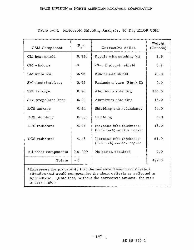
SPACE DIVISION OF NORTH AMERICAN ROCKWELL CORPORATION
Table 4-19. Meteoroid Shielding Analysis, 90-Day ELOR CSM
CSM Component
CM heat shield
CM windows
CM umbilical
SM electr ical buss
SPS tankage
SPS propellant l ines
RCS tankage
RCS plumbing
EPS radiators
ECS radiator s
A l l other components
Totals
p ::: S
0.996
-0
0. 98
0.95
0. 96
0. 99
0. 94
0.993
0. 92
0. 43
'0.999
Correct ive Action
Repair with patching kit
20-mil plug-in shield
Fiberglass shield
Redundant buss (Block II)
Aluminum shielding
Aluminum shielding
Shielding and redundancy
Shielding
Increase tube thickness (0. 12 inch) and/or repa i r
Increase tube thickness (0. 3 inch) and/or repa i r
No action required
Weight (Pounds)
2. 5
0. 8
10. 0
0. 0
335.0
15. 0
56. 0
5. 0
12.0
61. 0
0 . 0
497.3
:::Expresses the probability that the meteoroid would not c r ea t e a situation that would compromise the abort c r i t e r i a as reflected in Appendix M. (Note that, without the cor rec t ive actions, the risk is very high.)
- 197 - SD 68-850-1

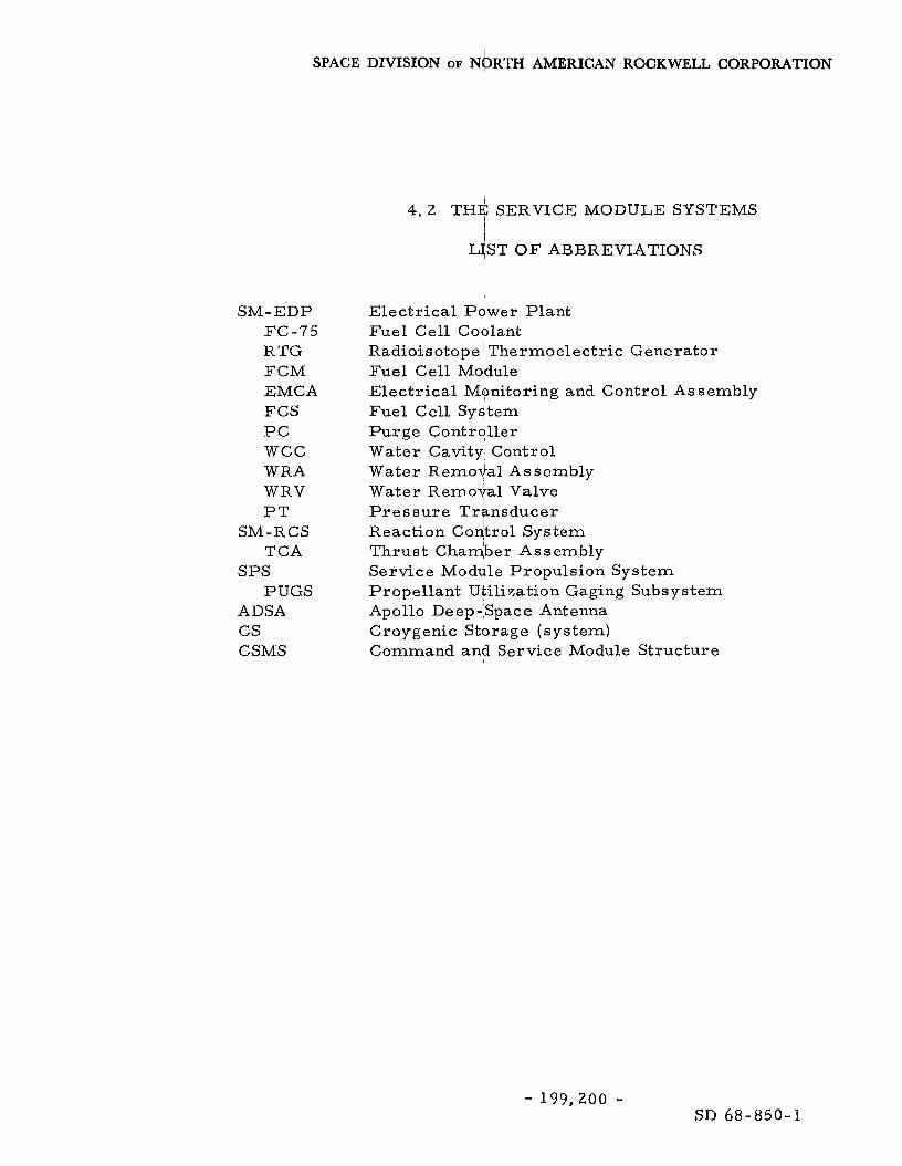
SPACE DIVISION OF NORZ'H AMERICAN ROCKWELL CORPORATION
SM-E'DP FC-75 RTG FCM EMCA FCS P C WCC WRA WRV P T
TCA
PUGS
SM-RCS
SPS
ADSA cs CSMS
4 . 2 THE SERVICE MODULE SYSTEMS
LJST O F ABBREVIATIONS
Electrical Power Plant Fuel Cell Coblant Radioisotope ' Thermoelectric Generator Fuel Cell Mddule Electrical Monitoring and Control Assembly Fuel Cell Sydtern Purge Contrdller W a t e r Cavity Control W a t e r Remodal Assembly W a t e r Removal V a l v e Pressure T r nsducer Reaction Coqtrol System Thrust Chadber Assembly Service Modjle Propulsion System Propellant Utilization Gaging Subsystem Apollo Deep-Space Antenna Croygenic Stbrage (system) Command anh Service Module Structure
B
- 199,200 - SD 68-850-1

SPACE DIVISION OF NORTH AMERICAN ROCKWELL CORPORATION
4 . 3 LUNAR MODULE ASCENT STAGE SYSTEMS':
NOTE: Some of the information used in this section was provided by the Grumman Aircraf t Engineering Corporation through Reference 3 . 2 and 4 . 3 7 .
This section presents the LM ascent stage subsystems analysis, Details a r e presented only where changes are projected beyond that for the lunar mission, The baseline design i s a s described in Reference 3 - 2 .
4. 3 . 1 Electr ical Power (AEP)
The electr ical power source for the ascent stage (AEP)is provided entirely by two silver-zinc batteries, which provided adequate life and reliability for the ascent phase of the LOR mission, but have a marginal life expectancy for the 90-day quiescent phase, even though little to no drain-charge cycles will be imposed on them. A s a resul t , it is recom- mended that they be replaced with the longer life si lver-oxide-zinc (AgOZn) bat ter ies where P, = 0.999 each (Reference 4 - 3 ) .
The AgOZn 90-day wet-life bat ter ies would increase weight by 16. 5 pounds. not included herein; however, the battery manufacturers s e e m to prefer the silver-oxide-zinc because of i t s simplicity, Furthermore, the 90-day wet-life concept provides a backup to the descent stage EPS.
Selection depends on other factors, such a s abort c r i te r ia ,
4. 3 .2 Environmental Control (LM ECS) and Thermal Design
NOTE: Some of the information used here in was pro- vided by Hamilton Standard through Reference 4 . 3 2 .
Functional Description
The LM ECS functions for ELOR can be subdivided into two c lasses , those associated with the taxi phase and those associated with the quiescent phase. fo r Apollo. has been added for this mission. situation in which minimum control is required.
Each imposes a need for modification of the basic LM ECS designed The taxi phase requi res provisions t o support a third man which
The quiescent phase presents a unique The p res su re suit circuit
*A foldout sheet listing abbreviations used in Section 4 . 3 and their meanings is located at page 251.
- 201 - SD 68-850-1

SPACE DIVISION OF NORTH AMERICAN ROCKWELL CORPORATION
i s held at about 0. 5 psia, although there is some question a s to whether it is required. the 0.5-psia p r e s s u r e level) , The wall temperature is held between about t40 and -100 F. which require any modification f o r the ELOR mission.
The cabin can be allowed t o leak without makeup (or maintain
The LM ECS consists of four subsystems, only two of These are-
1.
2.
3.
4.
The atmosphere- revitalization section (ARS) is to continuously supply oxygen t o the astronauts, provide oxygen cooling, remove products of metabolism f r o m the air, and r e tu rn reconditioned a i r to the astronauts fo r breathing and cooling, operations, the ARS operates a s a closed-loop system; otherwise, it operates a s an open-loop system supplying oxygen t o the cabin and reclaiming cabin a i r for removal of metabolic wastes and heat. (Modifications may be required to facilitate higher flow ra t e s ; some tes t data a r e required in this a rea . )
During suited
The heat- t ransport section (HTS) circulates ethylene glycol and water a s a coolant for electronic equipment, batteries, cabin a i r , and suit oxygen. The excess heat in this coolant loop i s rejected by means of a porous-plate sublimator into space. for 90-day operation a r e required.
Provisions
The water -management section (WMS) consists of three water tanks, a distribution manifold, and valves. This is the only water supply aboard the LM and is used f o r drinking, food preparation, portable life support system water supply, and supply fluid for the porous-plate sublimators of the HTS. supplies the needs during the descent and lunar stay-periods. Two smaller tanks a r e used only during the ascent phase.
The la rges t tank
The oxygen-supply and cabin-pressure -control section (OSS) controls the cabin oxygen p r e s sur e and supply, maintaining the p r e s s u r e at 4.8 for u se during suited operations. su re control functions required by metabolic consumption and vehicle leakage losses . Another function of this section i s to supply oxygen fo r recharging the oxygen tank of the PLSS. visions for the third man a r e to be added to this function. e t e r s used in the design of the LM ECS for the ELOR mission a r e as follows:
0 . 2 psia for u se in the cabin o r 3.8 0 .2 psia This section includes all p r e s -
P.ro- P a r a m -
Cabin temper atur e - Cabin relative humidity - Cabin p r e s s u r e -
55 to 80 F manual operation (manned ops)
40 to 80 percent 4.8 t 0. 2 p s i a
- 202 - SD 68-850-1

SPACE DIVISION OF NORTH AMERICAN ROCKWELL CORPORATION
Suit c i rcu i t p r e s s u r e
GO2 par t ia l p r e s s u r e Gas compo sition Suited heat loads (maximum)
Suited heat load (average)
Voltage supply available
- 4.8 t 0. 2 psia, normal 3.8 t 0. 2 psia , preparation for EVA
- 7.6 mm Hg. maximum - P u r e oxygen - 295 Btu/man-hr , sensible - 220 Btu/man-hr , latent - 515 Btu/man-hr, total
(714 possible) - 396 Btu/man-hr
(51 5 possible) - 25 to 31.5 vdc
Systems Analysis, The Three -Man Requirement
The ELOR miss ion makes it necessary to provide for a third astronaut Several considerations indicate that no design effort m a y in the LM vehicle.
be required to improve system performance. A comparison of the Apollo mission ve r sus the ELOR mission requirements for the LM ECS indicates th ree p r imary differences: provisions for a third astronaut, 90 -day quiescent phase, and shor te r period in which astronauts will actually be depending on the LM vehicle. An est imate of LM vehicle manned operation during the ELOR mission indicates a total operating t ime of about 30 hours, including descent, t r ans fe r to and re turn f rom the lunar shel ter , and ascent for the Apollo mission, this operating t ime is 48 hours o r 60 percent longer, Given equal metabolic heat loads for each man, t he re a r e fewer man-hours in the ELOR mission: i. e. , 90 versus 96. The shor te r mission also decreases the overal l requirements for heat rejection f rom the vehicle electronics and batteries. by supplying water to a porous plate sublimator, which allows ice to b e sublimated to space vacuum. the extended rendezvous period may require additional water (about 5. 3 pounds), but m o r e detailed metabolic profile data a r e required for final determination.
This heat is removed during manned operations
F o r the ELOR miss ion with three astronauts,
Other expendable supplies should be satisfactory, board of vehicle atmosphere would be for a shor te r period, and the number of PLSS miss ions (i. e. , required PLSS refil ls) may be less , depending on the lunar base concept. The analysis indicates that the capacity of LM expendables will be sufficient for the ELOR mission. include oxygen, food, water, lithium hydroxide (for carbon dioxide removal) , and activated charcoal.
Normal leakage over -
These expendables
Physically, the third astronaut will require umbilical connections to his p r e s s u r e suit. This requirement involves the addition of one o r two Item-138 flow-reversing and shut-off valves, depending on the integration concept. This valve requi res 33. 5 watts peak power and weighs 3. 51 pounds.
- 203 - SD 68 -850-1
SPACE DIVISION OF NORTH AMERICAN ROCKWELL CORPORATION
The WMS and OSS subsystems a r e completely suitable for th ree-man
The ma jo r question remaining i s the capacity of the ARS and HTS operation, in suits, subsystems to handle the equipment and metabolic cooling requirements of three-man operation in a satisfactory manner , ditions indicated that the three-man-sui ted mode would be the most severe ; therefore, this mode was selected for study, If the ARS and HTS could satisfactorily support this mission mode, then all other l e s s s eve re modes also could b e m e t satisfactorily.
The addition of one valve makes it possible to support t h ree m e n
A review of miss ion con-
P r i m a r y considerations a r e the flow to each suit and cabin humidity, Evaluations were made by using the Apollo LM computer program with the ELOR metabolic data. duced schematically in F igure 4-30. . The ma jo r p r e s s u r e drop in the ARS circui t i s found in the suits and the accompanying crossover valves. With three suits in paral le l , the p r e s s u r e drop ac ross each suit and accompany- ing valve is decreased slightly, m o r e volume flow than with the two suit configuration. suited and connected, each suit would receive 9. 5 cfm at about 54 F. flow is equivalent to that which the present command module ECS supplies to each suit during the basic Apollo mission; however it i s lower than.the present LM system capability. In addition, the existing ARS has the capa- bility to handle over 1, 500 Btu /hr of total metabolic load. If the individual maximum metabolic load of 515 Btu/hr is reached, the total metabolic rejection f o r the ARS would be 1, 545 Btu/hr . At these conditions, a cabin dew point in the range of 60 to 65 F is expected, There is also a capability of the LM system to allow for brief metabolic loads of 600 to 650 Btu /man- hour, prematurely exhausted and a refi l l charge wi l l be required. ear l ie r than normal. These higher metabolic loads a r e possible, but not expected, With th ree suited astronauts, periods of high work loads should be l imited to one man.
The resu l t s of the computations have been r ep ro -
In this condition, the fan passes slightly With th ree men
This
Under these higher metabolic loads, the lithium hydroxide would be
In any event the th i rd m a n is in no position to work.
Although m e n using the present space suits have had metabolic r a t e s of 1 , 0 0 0 Btu/man-hour, significantly better suits a r e already available than those used in the present Apollo program; and it is expected that, by- the 1975 ELOR mission, a metabolic r a t e of 500 Btulman-hour will represent a very high activity r a t e for zero-g o r lunar -g suited operations. ment is also possible in the design of suits to allow increased removal of latent heat f rom the astronaut 's skin surface, By 1975, these suit design improvements coupled with the capacity of the present LM ECS should minimize res t r ic t ions on work activity with three suited astronauts. tional study in th'is a r e a is desirable after some data a r e available f rom LM flights.
Improve-
Addi -
- 204 - SD 68-850-1

SPACE DIVISION OF NORTH AMERICAN ROCKWELL CORPORATION dc b
d 0 J w
SD 68-850-1

SPACE DIVISION OF NORTH AMERICAN ROCKWELL CORPORATION
To a s s u r e adequate c rew comfort during the hot-cabin ascent phase with the recommended suit flows, an oxygen suit inlet t empera ture of about 50 F is desirable. rejection capacity m a y be required. mentary heat rejection have been considered:
To maintain this tempera ture limit, increased heat- Three methods for providing supple-
1. Addition of a second water sublimator to the p r i m a r y heat t ranspor t section.
2. Use of the 20-square-foot radiator, which is added for temperature control sur ing lunar staytime.
3. Use of the existing emergency water boiler in the ARS.
The additional sublimator i s recommended since i t provides maximum flexibility in t e r m s of thermal load contingencies; however, it imposes a weight penalty of approximately 15 pounds. The 20 -square-foot radiator i s effective only when i t experiences a restr ic t ively low thermal environment. Such cannot be maintained for typical lunar ascent conditions, of the ARS emergency water boiler to provide the required supplementary heat rejection is marginal and may require the addition of a suit-heat- exchanger bypass valve (F igure 4-31). heated in the suit heat exchanger.
The capability
The oxygen flow would otherwise be
The cabin C 0 2 concentration can be contained within present l imits without hardware modifications. capacity of 40 man-hours and has sufficient volume and surface contact a r e a to absorb the C 0 2 produced by the three-man crew. Three cabin car t r idges a r e recommended for the ELOR LM: two for the descent postlanding check- out, prelaunch activation, and prelaunch checkout phases and one for the ascent phase, including orbital contingency.
The existing cabin LiOH car t r idge has a
The incorporation of the third suit connector in the loop may be accomplished either by integrating it directly into the loop o r by. using a portable manifold attached to one of the existing connections (Figure 4-31), Integration directly into the loop wi l l involve modification of the plumbing and packaging of the ARS. The use of a portable manifold, while not requiring an ARS modification, will impose a grea te r fan power requirement by v i r ture of an increased p r e s s u r e drop created by the addition of balancing orifices into the loop,
Appendix Q includes a power and weight summary for the expected ECS sys tem, (depending on concept) to allow suited operation for the third astronaut. Added to the weight of each of the th ree sublimators (Items 107, 209 and 224) is 0. 1 pound for porous plate covers to be installed during the 90-day s torage period,
Added t o the present LM ECS a r e one o r two Item-138 suit valves
Total sys tem weight excluding expendables i s 215.87 pounds.
- 206 - SD 68 -850 -1

- 207 -
SPACE DIVISION OF NORTH AMERICAN ROCKWELL CORPORATION
SD 68-850-1
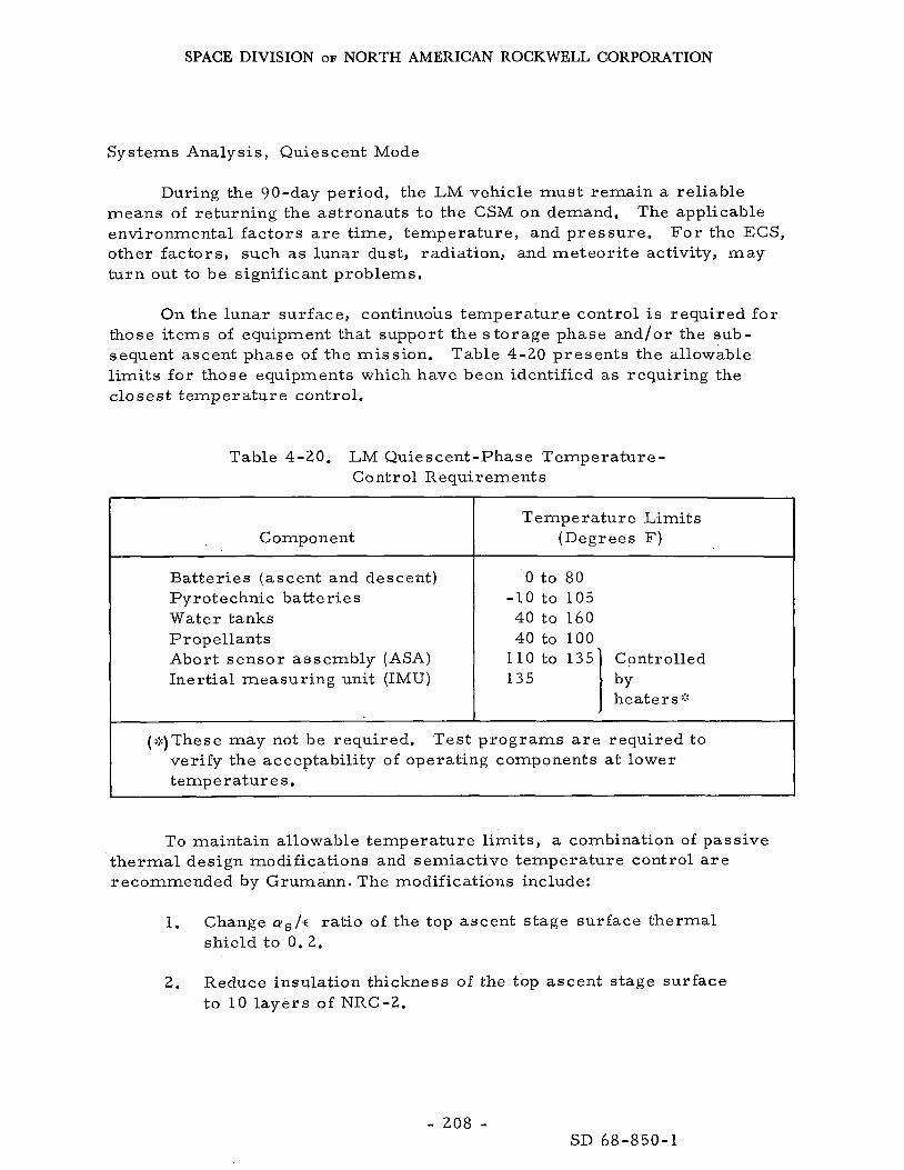
SPACE DIVISION OF NORTH AMERICAN ROCKWELL CORPORATION
Systems Analysis, Quiescent Mode
During the 90-day period, the LM vehicle mus t remain a reliable means of returning the astronauts to the CSM on demand. The applicable environmental factors a r e t ime, temperature , and pressure . F o r the ECS, other factors , such a s lunar dust, radiation, and meteor i te activity, m a y turn out to be significant problems,
On the lunar surface, continuous tempera ture control is required fo r those i tems of equipment that support the s to rage phase and/or the sub- sequent ascent phase of the mission. Table 4-20 presents the allowable limits fo r those equipments which have been identified a s requiring the closest temperature control,
Table 4-20. LM Quiescent-Phase Temperature- Cont r ol Requirement s
Component Temperature Limits
(Degrees F)
Batteries (ascent and descent) P y r o t e chni c ba tt e ri e s Water tanks Propellants Abort s enso r assembly (ASA) Inertial measuring unit (IMU)
0 to 80
40 to 160 40 to 100
-10 to 105
he at e r s :! 135
(:::)These may not be required, Tes t p rograms are required to ver i fy the acceptability of operating components a t lower temperatures .
To maintain allowable tempera ture l imits , a combination of passive the rma l design modifications and semiactive temperature control a r e recommended by Grumann. The modifications include:
1. Change aS/'c ratio of the top ascent stage surface thermal shield to 0.2.
2. Reduce insulation thickness of the top ascent stage surface to 10 l aye r s of NRC-2.
- 208 - SD 68-850-1

SPACE DIVISION OF NORTH AMERICAN ROCKWELL CORPORATION
3. Add a deployable thermal cover to the top docking tunnel.
4. Add 25 layers of NRC-2 insulation to the descent stage com- par tments containing the batteries and water tank.
5. Cover ascent engine a r e a with one layer of mylar ( 0 . 2 mil thick) to minimize heat leak,
Analysis of the vehicle thermal balance has been performed assuming these modifications for both lunar day and night conditions, conditions, intermittent active tempera ture control is required.
F o r both
During the night s torage phase, approximately 500 Btu/hr can be supplied to the vehicle by the waste heat of the electr ical power generator, whether fuel cel ls o r a radiosotope thermoelectr ic generator (RTG) is used, Since the RTG is recommended, it was used in this analysis, i s a schematic of a heat-pipe sys tem that is to t ransport waste heat f rom an RTG to selected positions on the vehicle. The heat i s t ransfer red by radia- tion f r o m the RTG to a heat exchanger, o r boiler, containing a volatile liquid. The heat vaporizes the liquid, which r i s e s in a pipe to a condensing section. and re turns by gravity to the boiler, The cold-condensing surface consists of tubes i n good thermal contact with the cabin wall, recommended for the liquid.
Figure 4-32,
The vapor condenses on the cold surface giving up i t s latent heat
Distilled water is
Control of the sys tem is provided by a valve that res t r ic t s the con- densate flow; the fluid i s trapped i n the heating panel and the boiler runs dry except for the amount of condensate returned by the control. tion 4.4. 2 for details on the SNAP-27 RTG. The electr ical performance and the l i fe of the generator i s affected by the tempera ture of the unit. addition of the heat-pipe boiler changes the external environment for which the SNAP-27 i s designed; therefore , the heat rejection fins of the RTG may r equi r e s ome mo di fic ation.
See Sec-
The
During the daytime portion of the quiescent phase, active heat rejection is required on an intermittent basis, to dissipate s t ructural heat load inputs f r o m the external environment and electr ical heat loads generated during vehicle status monitoring, Since the vehicle has no active cabin atmosphere tempera ture control during this phase, the main portion of the ascent stage the rma l load is radiated to the .aft equipment bay, Figure 4-33 i s a typical tempera ture and load profile of the s tored vehicle for both day and night cycles based on Surveyor VI data,
The ascent stage and descent stage s t ruc tura l temperatures a r e shown for worst-case decoupled locations, The cr i t ical elements, such as water
- 209 - SD 68-850-1

SPACE DIVISION OF NORTH AMERICAN ROCKWELL CORPORATION
Condensers
1I
Component Design
Condensers Four condensers mechanically attached inboard of thermal ahield to pressure shell webs,
k - 1
.Pi Sensors 1
I
0. Radiation heat transfer from localizd, area to remaining cabin. I
--To coolant Pump
/ Control
Inter stage Fittings
GSE
Ascent Stage Descent Stage
---- --- Connection Y
Control ---------
Boiler W-, I! II
- I I I I I I I I I . I I I I
, J
1/4 Tubing Insulated \
Boiler
p d i a
I 0 Mounted inboard of RTG in
Descent stage
RTO & Boiler ' 0 Radiation heat transfer between
.All dimensions in inches.
Radiation Absorption Surface a '= 0.9
0.75 dia 6 Fins, 0.030 x 0.375 x 12
RTG v- Figure 4 - 3 2 . RTG Heat Pipe
- 210 - SD 68-850-1
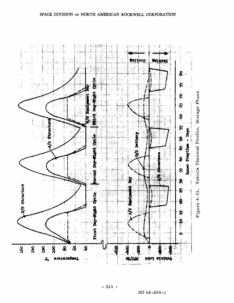
SPACE DIVISION OF NORTH AMERICAN ROCKWELL CORPORATION
- 211 - SD 68-850-1
SPACE DIVISION OF NORTH AMERICAN ROCKWELL CORPORATION
and propellant tanks, a r e coupled to the temperature control sys tems s o that the i r t empera ture l imits a r e maintained, r a t e of 500 Btu /hr i s required during the daylight phase.
A maximum heat rejection
The use of either radiators o r w a t e r sublimation has been considered a s the means of heat rejection. Using water sublimation, approximately 300 pounds of water is required during the lunar surface s torage phase, not including post-landing and prelaunch activities. An additional consideration is the inability of the water sublimator to operate below 1, 000 Btu/hr. Since the nominal heat rejection requirement i s expected to be 500 Btu/hr , use of the sublimator i s not the mos t attractive approach. As a resu l t of the potential complexity and associate water weight penalty, the use of radiators is recommended. into the existing LM heat t ranspor t loop i s capable of providing the heat rejection required. Figure 3 - 4 . radiator controls a r e required, since, during minimum-load cold-case conditions, heat provided by the RTG will maintain the radiator above i t s freezing point.
A 20-square-foot radiator integrated directly
The s t ruc tura l integration of the radiator i s shown in It i s rigidly attached to the top of the ascent stage. No
The requirements and procedure associated with establishing the LM ECS quiescent state and the reactivation procedure recommended by Hamilton Standard i s presented i n Appendix R.
Reliability and Maintenance Consider ations
In assess ing the reliability of the LM ECS and i t s contribution to the mission Ps, the hardware and i t s reliability can b e considered i n two categories: those used during the manned mission and those operated during the quiescent phase; however, these a r e not mutually exclusive categories; and, i n fact, many of the components of the heat loop are included i n both categories. In any event, their probabilities can be multiplied to estimate Ps i f they a r e estimated separately with regard to mission phase.
During the manned phases, the sys tem reliability and, therefore , i t s contribution to Ps wi l l remain virtually unchanged f rom that of the Apollo mission. Given a reasonably controlled quiescent state, the contributor to Ps should be somewhat better because of the 25-percent lower duty cycles on much of the equipment on the lunar surface,
Reliability calculations f rom the present Apollo program indicate that the LM ECS will have a reliability of 0, 998 based on the manned miss ion profile. 16 hours of c rew operations on the lunar surface a s a safety margin. calculations are based upon failure effects analyses of each component and a r e supported by limited-endurance testing and tes t data.
Crew safety i s 0. 9996, which includes an additional These
Since the
- 212 - SD 68-850-1

SPACE DIVISION OF NORTH AMERICAN ROCKWELL CORPORATION
LM ELOR operating t ime is to be only 30 hours for the manned phase versus 48 hours (maximum) for Apollo LM, the result ing LM ECS contribution to PS for the ELOR miss ion is expected to be higher than for Apollo in spite of the third crewman, Ps fo r manned phases is therefore es t imated to be over 0. 999 without any provision for maintenance.
The unmanned quiescent phase requires some functions to operate throughout the mission, Figure 4-34. They a r e , for the most par t , associated with the heat- t ransport loop. operating electronic equipment and the power source, i f required. This concept requires the use of i n I tem 290,pump during the 90-day s torage period, which will add about 540 operating hours , 150-hour l i fe , but t e s t s have been run for 2, 000 hours without failure. The pump package includes an al ternate pump and an emergency pump ( a three- unit package); thus a failure due to wear requires only a pump switchover. The reliability data indicate that the pump package still may be the weakest link i n spite of the internal redundancy and only a 25-percent duty cycle during quiescence on the lunar surface. followed by continuous operation for the lunar descent, ascent, and docking phases. exceeds the life requirement to which the assembly is presently qualified, the assembly would require requalification and/or provisions incorporated to permi t replacement on the lunar surface, Replacement may require (1) additional flexible l ines and disconnects on the fluid connections, ( 2 ) the addition of an electr ical disconnect replacing pressure-sensing pigtails, and (3 ) the use of a specialized tool for removal of partially inaccessible mounting bolts. package will increase the Ps to 0. 9999 f o r this function,
These a r e presented i n reliability logic fo rm in
These components operate to distribute the heat within the LM, cool
It is only qualified for
This duty cycle i s preceded and
Because the cumulative operating t ime based on this duty cycle
Provisions for replacement of the pump motor or the
The coolant accumulator i n the heat- t ransport section accommodates volumetr ic changes caused by tempera ture variations in the heat- t ransport section, maintains a head on the coolant fluid to prevent pump cavitation, and provides a small makeup supply. over the long-duration s torage phase may impose a requirement for additional accumulators for fluid makeup. to extending the operational requirements of the accumulator a r e diaphragm life, leakage ra tes , fatigue, permeabili ty variations, and effects of the water/glycol solution on the diaphragm. The accumulator i s located in the aft equipment bay a r e a of the ascent stage and is not considered a candidate for maintenance. r a i s e its contribution to P90 and Ps to well over 0.99999 and eliminate any fur ther concern,,
The nominal allowable leakage r a t e
Areas requiring additional study related
Provis ions fo r a refill o r a redundant accumulator will
Other components that may exer t some influence on the LM ECS effects on Ps involve the LiOH car t r idges and the fans. System life t e s t s a r e required,
- 213 - SD 68-850-1

SPACE DIVISION OF NORTH AMERICAN ROCKWELL CORPORATION
I
I-
I
--I
k A.
c, k
I
- 2 1 4 - SD 68-850-1
SPACE DIVISION OF NORTH AMERICAN ROCKWELL CORPORATION
Two types of LiOH car t r idges a r e used i n LM: one is used in the LM ECS and the other is used i n the portable life support sys tem (PLSS).
. only chemical change anticipated i n the car t r idges during long-duration s torage i s the eventual decomposition of LiOH to Liz0 and H20. i n turn, vaporizes, leaving a completely dehydrated canister. The r a t e at which this activity occurs i s a function of tempera ture and pressure . Generally, this dehydration is not considered to be a problem, because L i z 0 can be s tored indefinitely and i n itself can be used to absorb COz. cation, the Liz0 in the ECS will be rehydrated to LiOH by the metabolic water vapor produced by the crew; therefore no degradation i n P90 o r Ps i s expected.
The
The water,
In appli-
The suitability of allowing PLSS car t r idges to become dehydrated i s questionable. of C02 produced for a three-hour EVA, they a r e limited to the ra te a t which they can absorb it because of the very small quantity of LiOH present and the equally small oxygen flow ra t e that the PLSS delivers to the cartridge. The car t r idges must , therefore, be hydrated sufficiently to yield optimum absorption capability. ve ry low level by the liquid-cooled garment; therefore , the metabolic load cannot be considered a s a source of water and the car t r idge must be sufficiently hydrated p r io r to use. A solution is to s tore the car t r idges i n hermetical ly sealed containers and eliminate any effects on Ps.
While the car t r idges a r e la rge enough to absorb the quantity
During EVA, the latent metabolic load i s kept to a
The cabin and suit fans will not be operated during the quiescent- s torage phase; consequently, there is no requirement f o r increasing their operating life requirement. The fans are current ly designed with double- sealed bearings to minimize the possibility of lubricant loss and/or contamination, Tests must verify their effects on P,.
The remaining components a r e not expected to exer t significant influence on Ps.
Conclusions and Recommendations
The LM ECS will per form the ELOR mission with a Ps of about Some of the 0.999 if an RTG is used as the electr ical power source,
modifications required i n the Apollo design include the addition of a space radiator , one o r two No, 138 valves, an additional sublimator, a heat-pipe system, and an accumulator, Fur ther , provisions for the replacement of a pump o r motor a r e required,
To verify the assumptions made, a life test is required on the modified and, in par t icular , th,e quiescent control functions.
- 215 - SD 68-850-1

SPACE DIVISION OF NORTH AMERICAN ROCKWELL CORPORATION
4.3. 3 Guidance and Navigation Function, P / o Primary Guidance, Navigation and Control System
NOTE: Much of the information used here in was provided by AC Electronics through Reference 4 .7 .
System Description
The LM G&N sys tem function remains unchanged for the ELOR; the The only change in Apollo I1 sys tem will provide the required functions.
operational requirement i s the extended quiescent period. the sys t em will be completely off, and even the tempera ture control for the IMU and ASA wi l l be provided by power-system parasi t ic heat a s required.
During this period
Quiescent-state control is discussed under Paragraph 4. 1. 3 for the The argument developed for CM G&N applies to the LM G&N a s well, CM.
since the same sys tems and components a r e used,
The LM G&N i s composed of severa l subfunctions in addition to those function s imilar to the CM. i n functional block form in Figure 4-35. the landing radar .
These functions and their interfaces a r e presented Included a r e a rendezvous r ada r and
The landing r ada r per forms its functions pr ior to the extended lunar phase, i t s ELOR function is identical i n every way with that of the Apollo LOR mission and, therefore , requires no modifications o r life extension to meet the intent of the ELOR mission (See Reference 4. 3 2 ) .
The rendezvous radar a lso per forms identical functions on ELOR and Apollo; however, for ELOR it must first survive the 90-day quiescent phase since it i s used only on the re turn leg . During the quiescent phase, the sys tems wi l l be off; and the antenna, which i s a lso its heat sink, wi l l be pointed directly into deep space and held there by i t s own brake. should it be pointed toward any p a r t of the lunar surface since the acc-umulated heat could have a detrimental effect on the electronics.
In no case,
System Analysis (G&N)
Since the functional requirements for the LM G&N a r e satisfied by the Apollo I1 system, the subsequent analysis centers around meeting the rel iabi l i ty/safe re turn and quiescent life objectives. operational concept, redundancy, and sparing concept were considered in attempting to maximize Ps and achieve at leas t 0. 999 for the sys tem (this value is much higher than for Apollo). c r i t e r i a a r e much the same as used under Paragraph 4.1.3 for the CM system.
Variations in both
The considerations and selection
- 216 - SD 68-850-1

v) Lu
3 P
U
v)
2
f k m
Z U n*
n
E! v)
erc I- v)
I-' U
2
c c v: E f t
4 2
4

E
6 %
Id k M Id
0 r-l d
Fg I
A
0 E Ln 7
P n
aJ m co h 9
=t v1 v1
c,
m
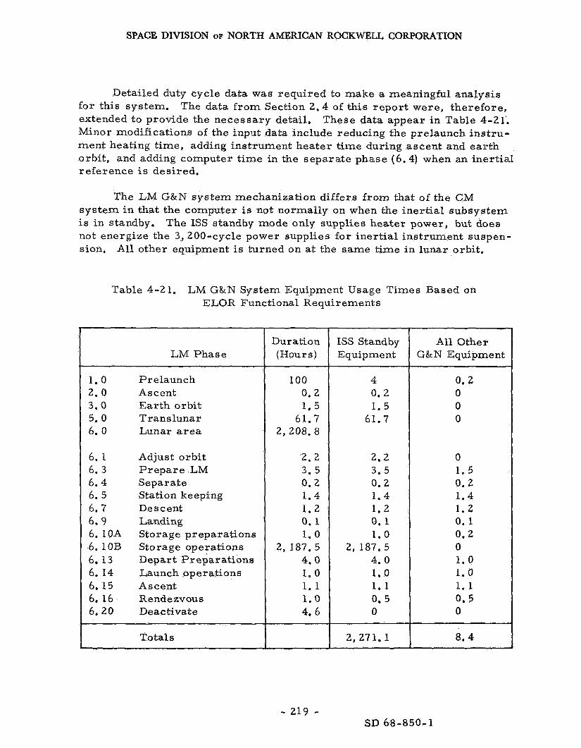
SPACE DIVISION OF NORTH AMERICAN ROGKWELL CORPORATION
Detailed duty cycle data was required to make a meaningful analysis for this system. The data f rom Section 2.4 of this r epor t were, therefore , extended to provide the necessary detail, These data appear i n Table 4-21’. Minor modifications of the input data include reducing the prelaunch ins t ru- ment heating t ime, adding instrument heater time during ascent and ea r th orbit , and adding computer t ime in the separate phase (6.4) when an iner t ia l reference is desired.
The LM G&N sys tem mechanization differs f rom that of the CM sys tem i n that the computer is not normally on when the iner t ia l subsystem is in standby. not energize the 3,200-cycle power supplies for iner t ia l instrument suspen- sion,
The ISS standby mode only supplies heater power, but does
All other equipment: is turned on at the same t ime in lunar orbit.
Table 4-21. LM G&N System Equipment Usage Times Based on ELOR Functional Requirements
Duration LM Phase I (Hours)
1.0 2 . 0 3.0 5.0 6. 0
6. 1 6. 3 6.4 6. 5 6.7 6.9 6.10A 6.10B 6 , 13 6. I 4 6. 15 6, 16 6.20
Prelaunch Ascent Ear th orbi t Translunar Lunar a r e a
Adjust o r bi t P r e p a r e LM Separate Station keeping Descent Landing Storage preparations Storage operations Depart Preparat ions Launch operations Ascent Rendezvous Deactivate
100 0.2 1.5
61.7 2, 208. 8
2.2 3.5 0.2 1.4 1 . 2 0.1 1 . 0
2, 187.5 4.0 1.0 1.1 1.0 4.6
Totals
ISS Standby Equipment
4 0.2 1.5
61.7
2.2 3.5 0 . 2 1.4 1.2 0.1 1.0
2, 187.5 4 .0 1.0 1 * 1 0. 5 0
2, 271. 1
Al l Other G& N Equipment
0.2 0 0 0
0 1.5 0.2 1.4 1.2 0.1 0.2 0 1.0 1.0 1.1 0 . 5 0
8.4
- 219 - SD 68-850-1

SPACE DIVISION OF NORTH AMERICAN ROCKWELL CORPORATION
The LM G&N sys tem operating and standby failure rates were obtained f rom the MIT repor t of Reference 4.8, a summary of which appears i n Table 4-22. The effects of the quiescent state on failure rate i s discussed i n Section 2.5 Fa i lures during these nonoperating periods are considered to present a ve ry low probability and are inconsequential to this study.
The reliability and result ing P, of the sys tem was first computed using the Apollo miss ion ground ru les , where the computer clock operates throughout the miss ion and the ISS is i n standby, i n Table 4-23, where the result ing P, is shown to be near ly 0.990 (some- what shor t of the des i red objective). attempting to maintain the DRM standby s ta te , an unnecessary operation for the ELOR Mission. period, the P, i s est imated to be 0. 993, which is better than the Apollo est imate ,
The resu l t s are reflected
The weaknesses are created by
However, with all equipments off during the quiescent
There a r e six subassemblies with reliabil i t ies of approximately 0.999; and i f an overal l sys t em P, of 0.999 i s required, at l ea s t five of these would have to be improved. obtained by eliminating the standby tempera ture control, five spa re sub- as s emblie s were considered.
F o r the sake of comparison with resul ts
The resulting overall LM G&N function P, = 0.999, the desired goal. Since the ISS PSA and the DSKY have the s a m e reliability, ei ther could be chosen for sparing. Table 4-24 a rb i t r a r i l y shows the PSA spared, but this decision would have to be based on relative ease of replacement of the two subassemblies e
R ec ommendatio ns and Conclusions
The LM G&N sys tem will per form the ELOR mission at the Apollo Ps without any significant changes. conditions a r e mos t desirable , par t icular ly for the IMU; however, i t seemed desirable to raise its contribution to Ps to nearly that of the other subsystem and reduce the need for MSFN backup. a r e l is ted in Table 4-25.
Tests on the sys tem under simulated
Some of the potential alternatives
As a minimum, the change i n operational concept is recommended since it will increase the sys tem P, to 0. 993 without modifications. function (G&N) P, i s still well over 0.999 because of the MSFN backup capability. al ternative, particularly, since they can a l so be used as backup spa res for the CSM.
The
The low weight penalty of using spa res may make it an attractive
However, the logistics aspect of the problem is yet to be resolved.
Only a 90-day cold-soak, heat-soak cycle t e s t is required for the rendezvous radar sys tem,
- 220 - SD 68-850-1

SPACE DIVISION OF NORTH AMERICAN ROCKWELL CORPORATION
Table 4-22. LM G & N System Fai lure Rates
Ope rating Ax
Standby Ax 10-6 Subassembly
IMU and P I P A e 1 e c t r oni c a s s embly
PSA CDU D&C group
129
110 155
1 . 2
Iner t ia l 395.2
Optical assembly PSA
38 1 . 3 3 I 3 9 e 3 3 I -
235
110
345 LM guidance
DSKY
CDU
computer - LGC
112 Rendezvous r a d a r coupling
Table 4-23. LM G & N ELOR Mission Probability of Success, Normal Apollo Operational Concepts
T (Hours) Ax l o m 6 LM Subsystem AT P S
ISS - Operating - Standby
css
oss
RR coupling
395.2 1. 6
345
39 .33
112
8.4 2262.7
8 .4
8 .4
8.4
0. 003320 0. 003620
0. 002898
0. 000330
0. 000941
0.997 0 .996
0.997
0.9997
0.999
Total 0.011109 0.99
- 221 - SD 68-850-1

SPACE DIVISION OF NORTH AMERICAN ROCKWELL CORPORATION
m PI
E-l A
a I 0 A
x A
k P
a, m
d
E
:
2
P 5 rn
d
- - O m $ o d - P A - o o o ~ ~ m o m o o o o ~ g o o o o
d d d d d d d d o '
d o 0
0 0 0 0 0 0 0
0 0 0 0 ~ 0 0 0 0
d A A O A O d 0 0
d c o o o N O Q d m 0 0 0 0
0 0 . .
N O * d m d tc m m o m m m m 0 * 0 d 0 d 0 0 0 0 0 0 0 0 0 0 0 0 0 0 0 0 0 0 0 0 0 0
8 $ O d Z N * . + . +
. . d d d 0 0 d d d d
Q N N
n cn 2 5 cl V
Y
V 3
n cn rn 0
4 Y
0 m N
0 0
0
l-4
Ln
m m 0 .
m 0 d d 4 0
0 .
A
c, cd 0
E-l
- 222 - SD 68-850-1

SPACE DIVISION OF NORTH AMERICAN ROCKWELL CORPORATION
Table 4-25. Summary of LM C&N System Reliability
LM G&N Function Ps
0.99
0.993
0.999
0.999
~ ~~~
Configuration and Operational Concept
Apollo LM G&N sys tem and operational con- cepts (no changes).
All equipment off during standby periods (operational change).
One spa re of each of the ISS subassemblies, the computer, and the R R CDU's.
One spa re of each of the ISS subassemblies , the computer, and the RR CDU's. All equipment off during standby.
4. 3.4 Stability Control Function, P a r t of the P r i m a r y Guidance, Navigation and Control Svstem
Functional Description
The LM SCS is divided functionally into two major sections, both of which a r e required throughout the manned phases, and must survive the 90-day ELOR quiescent phase. section (CES) and the abort guidance section (AGC).
These sections a r e the control electronics
The CES consists of seven separate subfunctions, three of which a r e redundant i n the Apollo configuration. The functions of this sys tem remain unchanged for the ELOR mission; however, the sys tem must survive the quiescent phase without i r reparable damage. The CES provides the signals to fire any combination of the sixteen thrus te rs of the reaction control sub- system. Its function is to maintain vehicle stability throughout the manned mission and facilitate attitude changes when required, off during the quiescent phase.
I t is to be completely
The AGS provides two subfunctions, which a r e available throughout the mission, but are used only in event of fa i lure in the G&N function o r a sub- function thereof, thereby providing an emergency abort capability, It p r o - vides an attitude reference for vehicle stability control and a backup stability control o r guidance i n the event of pr imary sys tem failure.
Systems Analysis and Conclusions
As is the c a s e with other LM sys tems which operate only during the manned phases , the reliability of these functions and, therefore, the
- 223 - SD 68-850-1

SPACE DIVISION OF NORTH AMERICAN ROCKWELL CORPORATION
contribution to PS should exceed the Apollo miss ion estimate. ment is a resu l t of the reduced duty cycle, about 30 hours ve r sus 48 hours. Ps, therefore , is about 0. 993.
This improve-
No maintenance should be required, although it would increase the probability of a successful rendezvous i f box replacement was planned, is not recommended. Additional tes t s , beyond that for Apollo are con- s idered unnecessary i f the Apollo miss ions do not encounter fa i lure i n these sys terns.
I t
4.3. 5 Reaction Control System (LM-RCS)
The LM RCS is essentially the same a s the SM RCS in its design, performance, and reliability. F o r details on both function and reliability data, s ee Section 4. 2. 2. es t imated to be grea te r than 0. 99997 for each engine. sys tem fai lure is negligible, less than 1 i n a million because of the redun - dancy within and between the RCS quads,
The ELOR Ps contribution by the LM RCS is The chance of a
Compared to the Apollo LM, it i s estimated that 50 pounds of additional RCS propellant is required for the ELOR mission, based on a proportioning of the vehicle weights and inertias. is current ly scheduled to be launched with full RCS propellant tanks; and, based on anticipated maximum RCS usage for a nominal lunar mission, there is a marg in of 125 pounds remaining a t the completion of the rendezvous and docking phase. RCS fuel augmentation, therefore, is not considered necessary.
This requirement is The Apollo LM
During the lunar night, it is possible fo r fuel to f reeze i n the LM RCS engine l ines; however, during this period, they a r e not used, it is not pract ical to maintain their temperature by means of the LM RCS engine hea ters because of the la rge electr ical energy requirement, I t is recommended that the present LM hea ters be turned off after landing and that the th rus t e r s be allowed to cool to equilibrium temperature (approxi- mately 0 to -20 F), propellant feed l ines during the prelaunch checkout to bring the thrus te rs up to operational tempera tures (approximately one hour would be required f o r this operation). Freezing of the fue l is possible during this period, and some separation of fuel constituents could occur. Discussions with the engine manufacturer (Marquardt) have indicated that the thrus te rs should operate satisfactorily under these conditions.
Fur ther ,
La rge r hea te r s (250-watt) have been added to thaw
(Reference 4-15)
All RCS sys tem components a r e exposed to propellants f rom the time These components a r e qualified for 44 days, and require of init ial loading.
t e s t s for the longer exposure time. The RCS p r e s s u r e regulator would
- 224 - SD 68-850-1

SPACE DIVISION OF NORTH AMERICAN ROCKWELL CORPORATION
operate i n the lock-up position throughout the lunar stay period, through the valve exceeds the specification value, the pressure- re l ie f valve could possibly actuate, result ing in loss of helium. shutoff valves is a potential means of minimizing this leakage,
If leakage
The addition of regulator
In summary , no additions o r modifications are projected for this system. ment for its contribution to Ps.
Fur ther , i t is expected to exceed by far any reasonable require-
4, 3.6 Communications (LM-CS) and Status System
NOTE: Some of the information used herein was pro.vided by RCA through Reference 4-34.
Functional Requirements
The LM CS is one of the m o r e mission-sensit ive subsystems of LM, since many of i t s functions a r e required to operate periodically throughout the 90-day quiescent period, abort (Pa ) and P90. during the pertinent mission phases a r e summarized in Table 4-26 and i l lustrated in F igure 4-36.
However, failure does not affect Ps, only The LM communication functions and links required
During the separate , station-keeping, and descent phases a require- ment exis ts for continual communications with both the CSM and ear th MSFN. A CSM status reception mode will enable the astronauts in the LM to de te r - mine the existence of any abnormal CSM conditions which could resul t in a decision to abort the mission. employed to help execute this s ta tus check and, i f necessary, reactivate the CSM to the degree of operational readiness appropriate for rendezvous in case of abort.
The command link to the CSM would be
The remaining VHF to and f rom the CSM and S-band to and f rom MSFN during these phases and landing are the standard LM requirements associated with the Apollo mission,
During the s torage preparat ion phase, the command and status reception links to and f r o m the CSM will be maintained i f the CSM is within line-of-sight (LOS) communication range, Normal LM S-band communica- tions with 'ear th will be required during this phase, except that there is no need for the ranging operation af ter the LM has landed,
- 225 - SD 68-850-1

SPACE DIVISION OF NORTH AMERICAN ROCKWELL CORPORATION
LM Coiniiiunication
Function a n d l o r Link
Table 4-26. LM Communication Funct ions P e r Mission Phase
1 . 0 6.3
P r e p a r e Pre launch LM
X(1) X(1)
Applicability of communication Function P e r P h a s e
:heckout
'HF link with CSM
Command t ransmiss ion CSM s ta tus r e c o p i t i o n Ranging back-up PCM data t ransmiss ion
;-band link with e a r t h
Data t ransmiss ion Voice t ransmiss ion P R N range code Xpond
Receive voice Receive PRN range C O d C
Receive U D L conuuands
rHF (EVA) +S-band (ear th)
6 .4
Separate
6. 5
stationkeeping
X X X(Z)
X X X
X
X
X
6 . 7
Jescent
6 .9
,anding
X X X
X
X
X
__ 6 . 10A
itorage P r e p
6. 15 ~
Lscent
X X X(2)
X X X
X
X
S
JOTES:
I )
2)
Checkout to be per formed for all LM comniunications functions prelaunch and those feasible during pr'cpare-LX1 and depart p r c p a r a t i ~ n .
Rangina via VHF is a proposed backup to the rendezvous radar and would presumably be employed only i L the radar ,,raIioncti~lnrd.
3 ) PCM data t ransmiss ion would be t ime-shared with ranginglconimands (which can be t ransmi t ted simnltaneously) and \vtml#l i lcci ir *mly d > r v ilir LM i s behind the moon, thus permitt ing communication with ear th . to ear th upon MSFN interrogation v ia up-data link to the CSM.
The CSM would receive and s torc these data IC,,- 5ubsequrnt tr.Ln-it
4) During the quiescent phase, th ree a l te rna te S-band communication provisions are considercd. ( S e e teat ior description (!(. : \ I l ~ ~ - m t c - ~ A, I:. ,,m! 1 . I
51 Checkcd-out to extent possible.
6)
7)
Links to CSM operated if the CSM is within line O L sight.
EVAILMIEVA links (using EVCS equipment) are established when the as t ronauts leave L A ? lor lhc she l te r ant1 upon rc l i i rn l u l l i c 1.11.
Alternates under consideration include R. F. v e r s u s cable for th i s link between LM and the sheller. sections o f this report .
T h o s o a l i c r n a l e s i i r ~ , l is<t ts -c , r ! i n >\:I>-<
HI This remote cont ro l capability is not a requirement, but i s a possible alternate to niamial mtcrventirm lor MLR; 1 1 \ \ c n 1 1 < 1 d ~ n A . ~ l c I h v 1 1 1
1,u:rrding the LM by as t ronauts until departure. type o u t p t from LM s ta lus lmoni tor unit.
VHF reception capability (aboard the Lhll for s u c h r u m m i l n d s ~ o u l d b r . t c . t l x - a l c . l lb.tsc.!
- 226 - SD 68- 850 - 1

SPACE DIVISION OF NORTH AMERICAN ROCKWELL CORPORATION
I
-.b I I I I
1 rn 2 u W
w a
-F * 'P
\ \ \
( 3 1 I 8 ' I
2; I
I
I I I I I I I I I I I I
SD 68-850-1

SPACE DIVISION OF NORTH AMERICAN ROCKWELL CORPORATION
During the period when the astronauts proceed f r o m the LM to the shel ter , i t i s expected that a requirement exists for continued voice com- munications between the astronauts and earth. This communication could be accomplished per the following procedure.
1.
2.
3.
4.
Two astronauts leave the LM equipped with EVC-1 and EVC-2 communications gear. This equipment would permi t the two astronauts to talk to each other and to ea r th v ia the LM on a VHF/S-band relay. The third astronaut would remain in the LM to operate the LM CSS as required to maintain this relay link.
The two astronauts would activate the shel ter CSS, which would have communications capabilities a t l eas t the equivalent of an LM CSS. the astronauts and ear th via the shelter.
This approach would establish communications between
The third astronaut would then complete deactivation of LM to the extent des i red and depart for the shelter.
This third astronaut would a l so be equipped with EVC-1 gear , and the other as t ronaut s imilar ly equipped (and a t the shel ter) would deactivate his EVC-1 gear. communicate with the second (equipped with the EVC-2 unit) while proceeding to the shelter.
Thus, the third astronaut would
This procedure would essentially be reversed upon completion of the 90-day period when the astronauts re turn to the LM for departure.
Three al ternate operational concepts a r e possible for activation of the LM CSS for t ransmiss ion of data to ear th during the quiescent phase.
Alternate A requi res t ransmiss ion of LM status data to ear th for a 3 - to 10-minute period every two hours. initiated automatically by an on-board programming capability. quent t ransmission r a t e appears excessive and resu l t s in a significant increase i n the probability of fa i lure of one o r m o r e components of the CSS. In addition, the environmental control sys tem will have high heat loads to dissipate to maintain the low fa i lure r a t e thermal l imits during the lunar
The t ransmiss ion would be This f r e -
days.
Alternate B is similar to A, but requires just one 10- to 15-minute period of t ransmiss ion of LM status data to ear th each day. the on-off cycling of c r i t i ca l CSS units by a 12-to-1 ratio with respect to Alternate A.
This lessens
- 228 - SD 68-850-1

SPACE DIVISION OF NORTH AMERICAN ROCKWELL CORPORATION
Alternate C consists of checkout of the overal l LM (most subsystems) approximately once every two weeks. would be accomplished as required using s p a r e s f rom the shelter. astronauts would board the LM to accomplish this check-out, and it is estimated that the LM CSS would be operated a maximum of four hours each t ime for a total of six t imes, This sys tem resu l t s in 24 hours of operations as contrasted with 182 hours for Alternate A. comprehensive evaluation of the ability of LM to per form the r e t u r n mission. If this mode is selected, i t is recommended that the check-out operations be accomplished during lunar day-night transit ion periods when the thermal environment would provide the leas t hazard to the LM CSS.
Replacement and/or repa i r of LM units Two
Fur ther , i t provides a
F o r any one of the three a l te rna tes , the low data ra te of 1. 6 kbps provided by the LM should be sufficient for LM-Earth data t ransmission. This mode minimizes use of the S-band power amplifiers.
Lunar -sur face exploratory missions will presumably be made by the astronauts f r o m the shel ter during the lunar stay, and a requirement wi l l exist for maintaining voice communications and monitoring the condition of the space suits. units and companion V H F t ransce ivers in the shel ter .
This communication can be accomplished with the E V C S
A requirement may exist for monitoring the LM periodically f rom the shel ter during the quiescent phase. astronaut boarding of LM if the monitoring indicated a need fo r same. The LM/ shel ter status-monitoring communication requirement can be satisfied by either R F o r a cabling arrangement utilizing the RCA sys t em presented in Reference 4. 35.
Control could be accomplished by
Appendix T summar izes the anticipated information bandwidth and communication range requirements for the different portions of the ELOR mission.
Functional Description and Alternatives
The prel iminary configuration proposed for the LM CSS (communication subsystem) for the ELOR mission is given in Figure 4-37. essentially that provided for the LM for the basic Apollo mission functions, except a s follows:
This CSS is
Intercom for Third Man. Since all three astronauts will be i n the LM for the descent, landing, s torage preparation, and depart preparat ion phases, the signal p rocesso r assembly (SPA) provisions should be expanded to permi t the third ast ronaut to participate in intercommunications and possibly voice t ransmiss ion/ reception. The la t te r , i f provided, could be t ime-shared between the commander and the pilot.
- 2 2 9 - SD 68-850-1

SPACE DIVISION OF NORTH AMERICAN ROCKWELL CORPORATION
Command Message Generator , A command message generator (new component) would be required for derivation of the commands to be sent to the CSM.
DRG (Digital Ranging Generator). A DRG would be desirable to provide ranging (CSM LM) capability as a back-up to the LM rendezvous radar . CSM for the basic Apollo mission. a companion transponder unit called the RTTA (Ranging Tone Transfer As sembly).
This demand involves two minor modifications to a unit now i n the The LM CSS for this mission contains
Since the CSM will be unmanned during the rendezvous period, the LM would have to contain the DRG f o r this ELOR mission, and the RTTA would be included as part of the CSM CSS. to be added to the LM. of CSM and LM would be interchanged for this ELOR mission. necessary that the computer associated with the navigation and guidance subsystem within LM be modified to accommodate the additional computa- tions required to a s s i s t in the overal l rendezvous operation based on the ranging data input.
A companion ranging display would have The ranging equipment exis ts , but the components
It is also
Status Monitor and Checkout, While on the lunar surface, the LM will be periodically monitored to determine i t s status, Because of the nature of the mission and the extended stay-time on the lunar surface, two types of checkout should be performed on the vehicle. detailed, extended monitor of the vehicle conducted by the c rew af ter the lunar landing and pr ior to ascent. The second type of checkout is a m o r e cu r so ry monitor of the vehicle during the quiescent phase of the mission. This function is new and requi res m o r e attention herein.
The f i r s t is a
The checkout conducted during the quiescent phase is designed pr imar i ly to ascer ta in the status of the vehicle, These interrogations a r e l imited to an examination of vehicle expendables and temperatures and pertinent pa rame te r s of assemblies active during the s torage phase; e. g . , hea te rs , ba t te r ies , RTG, coolant pumps, and instrumentation and communi- cation subsystems. Since all LM electronic assemblies a r e designed for a five-year shelf -life, the ninety-day dormancy will not have any appreciable effect on the performance, provided the specified tempera tures a r e maintained. F o r this reason, assemblies not required for the processing and transmitt ing of the data, will not be activated during these checkouts. The performance of the nonactive assemblies will be determined during the detailed checkout performed p r io r to ascent.
P a r a m e t e r s selected to be monitored during these interrogations ( l is ted inTable 4-27) provide for a g ross status evaluation of the vehicle and expendables but do not contain data for trouble-shooting. In the event
SD 68-850-1 - 230 -
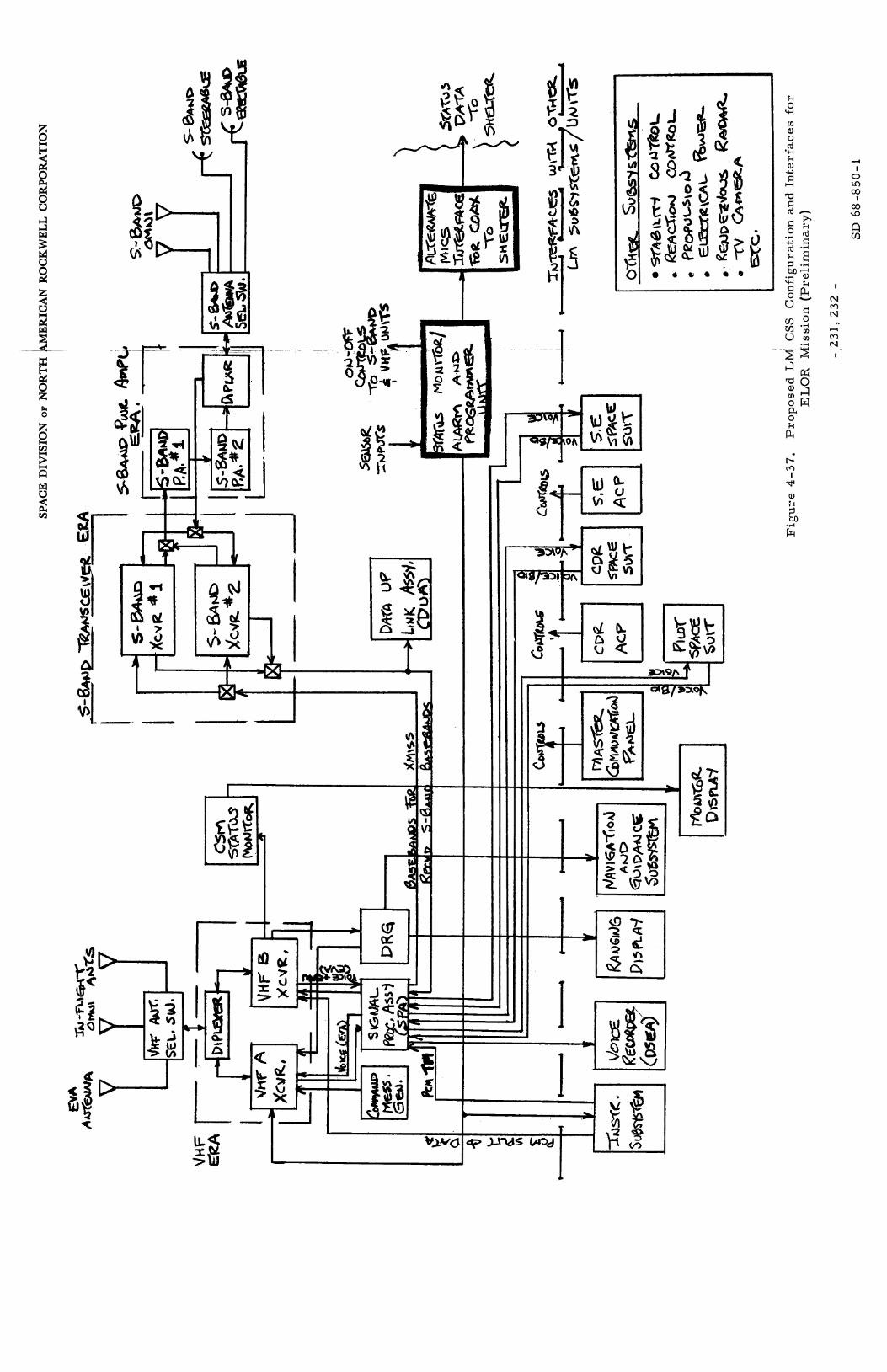
t
k
+I
m a V d
0
w
I I ' 1
L

SPACE DIVISION OF NORTH AMERICAN ROCKWELL CORPORATION
Table 4-27. Quiescent-State Monitoring Points, Bit Requirements, LM Vehicle
Subsystem
CN&C
Comm.
EPS
ECS
P r o pulsion
P a r arne t e r
IMU heater on IMU temperature ASA temperature RR tempera ture PIPA temperature
Transce iver power output Antenna electronics
Receiver ACC temperature
Battery voltage temperature cu r ren t
R T G voltage temperature cur ren t
Bus voltage
Coolant ternperatur e Pump delta-P Valve position indicator H 2 0 quantity Oxygen temperature
Glycol quantity p r e s sur e
Oxidizer p r e s s u r e temperature 1 quantity
tempe r a tur e quantity
Fuel p r e s sur e
He tempera ture p re s sur e
Number of M ea s ur eme nt s
1 1 1 1 1
2 1
2
9 9 9
1 2 1
2
2 2 4 2 2 2 1
3 3 1 3 3 1 3 3
Bits
1 8 8 8 8
16 8
16
72 72 72
8 16 8
16
16 16 4
16 16 16 a
24 24 8 24 24 8 24 24
- 233 - SD 68-850-1
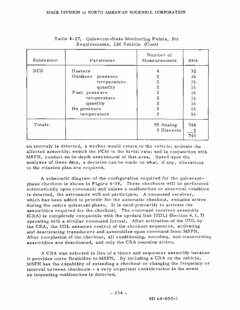
SPACE DIVISION OF NORTH AMERICAN ROCKWELL CORPORATION
Table 4-27. Quiescent-State Monitoring Points , Bit Requirements, LM Vehicle (Cont)
P a r a m e t e r
Heaters Oxidizer p re s su re
temperature quantity
temperature quantity
temperature
Fue l p r e s s u r e
He p res su re
Number of Measurements
93 Analog 5 Discrete
Bits
3 2 16 16 16 16 16 16 16 16
744 5
749 -
a n anomaly-is detected, a worker would re turn to the vehicle; activate the affected assembly; switch the PCM to the hi-bit ra te ; and in conjunction with MSFN, conduct an in-depth assessment of that area. analyses of these data, a decision can be made on what, if any, alterations to the mission plan a r e required.
Based upon the
A schematic diagram of the configuration required for the quiescent- phase checkout is shown in F igure 4-38. These checkouts will be performed automatically upon command; and unless a malfunction or abnormal condition is detected, the ast ronauts will not participate. A command receiver , which has been added to provide for the automatic checkout, remains active during the ent i re quiescent phase. It is used pr imar i ly to activate the assembl ies required for the checkout. (CRA) is completely compatible with the up-data link (UDL) (Section 4. 1. 7) operating with a similar command format , the CRA, the UDL assumes control of the checkout sequences, activating and deactivating t ransducers and assemblies upon command f rom MSFN. After completion of the checkout, all conditioning, encoding, and transmitting, assemblies are deactivated, and only the CRA remains active.
The command receiver assembly
After activation of the UDL by
A CRA was selected in l ieu of a t imer and sequencer assembly because it provides m o r e flexibility to MSFN. MSFN has the capability of extending a checkout or changing the frequency or interval between checkouts - a very important consideration in the event an impending malfunction i s detected.
By including a CRA on the vehicle,
- 2 3 4 - SD 68-850-1

SPACE DIVISION OF NORTH AMERICAN ROCKWELL CORPORATION
- 235 -
0
SD 68-850-1

SPACE DIVISION OF NORTH AMERICAN ROCKWELL CORPORATION
The signal-conditioning assemblies a r e to be modified s o that only one assembly requi res ac t iva t iw during checkout. blies associated with the pa rame te r s monitored during the checkout will be located in one assembly. PCM (1. 6 kbps) will be adequate for these checkouts. By using the low ra te and the erectable S-band antenna, the S-band power amplif iers will not have to reposition the erectable antenna every few days to ensure communication lockup.
The conditioning subassem-
Table 4-28 demonstrates that the low-bit-rate
Table 4 28. PCM Low-Bit Rate
S apacity
LM taxi utilization
Identification synchronization and t ime
Calibration and oscillation fai lure detection
Redundancy
Quie scent s torage monitoring
Total
Available for growth
Analog Signals
154
4
37
93
134
20
Disc re te Signals
368
72
1
120
5
198
170
Total Bits
1600
72
33
416
749
1270
3 3 0
Data Rate: 1 .6 kbps
Code: Phase - shift keyed
A / D Conversion: 8 bits
Resolution: 0.40 percent
Direct cabling between LM and the shel ter may be considered rather than an R F link for increased reliability. (The cabling would presumably be included a s pa r t of the shel ter payload equipment landed on the moon pr ior to the LM landing. ) Pre l iminary study indicates that the VHF link should be utilized ra ther than the cabling provisions, a s it eliminates the space and weight penalty of 1,000 feet of cable for the shelter payload. If however, other considerations and a detailed reliability analysis keep the cabling
- 236 - SD 68-850-1
SPACE DIVISION OF NORTH AMERICAN ROCKWELL CORPORATION
al ternate in contention, the RCA concept described in Reference 4-35 should be considered. The approach utilizes one coaxial cable between te rmina ls , and the data is t ransfer red via subca r r i e r s in an frequency- division modulator, time-division modulator, o r Combination system.
Command Module Remote Control, A remote-control command/data link with the CM has been included in the LM ELOR configuration to provide -
1. Control of the operational mode of the CSM while in the quiescent state (may not be required).
2. Changes i n attitude-control mode for final rendezvous and docking.
3. Initiating the quiescent-state control mode af ter LM departure.
Implementation of the command/data link requires the addition of a command generator and processor , a data processor , and a display console i n the LM and the addition of a receiver /UDL interface assembly and command distribution assembly in the CM. generated commands, i t is anticipated that the LM/CM command/data link will not use the S-band te lemetry link. recommended mode, a schematic diagram of the configuration is shown in F igure 4-39 .
To avoid conflict with ground
The VHF t ransce ivers a r e the
An al ternate approach would be to employ a UHF command data link. This configuration would requi re the addition of a UHF transceiver on the LM taxi and the CM, replacement of the in-flight VHF antenna with com- bination VHF/UHF antennas o r addition of simple UHF antennas, and modi- fication of the CM UDL to accept commands f rom the UHF receiver. In any of these configurations, i t is anticipated that the UDL in its present format will be retained because of i t s low probability of accepting a wrong command.
Commands a r e t ransmit ted to the CM on the VHF baseband utilizing a command format identical to that presently used on the LM. is a two-tone composite modulating signal; command information is con- tained on a 2-kJ3z tone and timing and synchronization is provided by a 1-kHz tone.
This format
CM status data will be t ransmit ted to the LM taxi on the VHF link Since the LM VHF transmit ter has
All the displays and controls
using the low-bit-rate PCM format. the capability of transmitt ing low-bit-rate PCM data, the CM may require modification to include a LM transmit ter , required for s ta tus monitoring and docking of the CM must be added to the LM display console, i n the display console into a format suitable for transmission.
The command processor converts commands generated Signal
- 237 - SD 68-850-1

SPACE DIVISION OF NORTH AMERICAN ROCKWELL CORPORATION
--- I
a VI .ri a
- 2 3 8 - SD 68-850-1

SPACE DIVISION OF NORTH AMERICAN ROCKWELL CORPORATION
conditioning subassemblies, analog-to-digital converters , and command addres s and word generators convert display panel switch c losures into voltage pulses, convert analog input signals to the c o r r e c t voltage range, and provide for ground isolation between assemblies . The analog multi- plexer converts analog input signals into 8-bit digital words. generator supplies vehicle and subsystem addresses and converts the input signals into the proper sequence of one and ze ro sub-bits for use by the UDL. and out-of-phase 2-kHz waveform. The programmer provides timing pulses to sequence the commands through the assembly. delay i n the t ransmiss ion of a command, the programmer init iates its sequences upon receipt of a command.
The command
The oscil lator generates the 1-kHz reference tone and an in-phase
To preclude any
The PCM data processor converts the 1.6-kbps PSK data t ra in into d iscre te and analog signals. those pa rame te r s selected for display. (D /A) reconsti tutes the analog signals, while the signal conditioner provides for ground isolation and impedance matching.
The decommutator culls bits constituting The digital-to-analog converter
The VHF/UDL interface assembly, located on the CM, shapes the composite modulated signal received by the VHF receiver into a format compatible with the encoder section of the UDL. the incoming signal and provides for ground isolation and impedance matching.
The assembly amplifies
This configuration is adequate for the LM mission if the LM-CM command/data link is l imited to attitude control commands and a limited monitor of CM subsystems, the link, such as providing for control and monitor of all subsystems and the ability to command and guide the CM to a lower orbit , would require redesign of many areas of the system,
Any significant expansion of the capability of
Specifically, i f complete monitoring of the CM by the LM is desired, the high bit r a t e (51. 2 kbps) will be required. This approach will eliminate the possibility of using the V H F t r ansmi t t e r s , since these assemblies cannot handle the high bit rate. t r ansmi t t e r s , modified to pe rmi t simultaneous t ransmission of commands to the CM and voice and data to MSFN o r develop new wide-band UHF t ransmi t te rs and receivers .
The link would then have to use the S-band
Subsystem performance f igures and duty-cycle es t imates a r e presented in Appendix U.
- 2 3 9 - SD 68-850-1

SPACE DIVISION OF NORTH AMERICAN ROCKWELL CORPORATION
In surnmary, the LM-VHF equipment would be used as follows:
1. During in-flight phases -
a. Simultaneous t ransmission of commands /ranging (VHFA) and reception (VHFB) of CSM status / ranging. communications of two types of information each way would be accomplished by the same technique used for simultaneous voice/ranging for the basic Apollo mission. )
(Simultaneous
~
b. Transmiss ion (VHF B ) of PCM split-phase data to the CSM pe r operation in a basic Apollo mission. would have to be t ime-shared, however, with the command/ ranging transmission. )
(This t ransmission
2. During lunar-stay phases - a. Transmiss ion of commands to the CSM and CSM status
reception during the quiescent preparat ion and depart preparat ion phases.
b. Relay t ransmission (VHF A) of voice (received via S-band f r o m MSFN) to the astronauts while they a r e proceeding to o r f r o m the she l te r , and reception (VHF B) of voice and EMU (extravehicular mobility unit) data f r o m the astronauts for re lay via S-band to MSFN. fl ict with the foregoing as they occur a t different times. )
(This requirement does not con-
c. Per iodic t ransmission (VHF A) of LM status data to the shelter o r an a l a r m whenever c r i t i ca l parameter l imits a r e exceeded. (Remote control could be provided, by use of a VHF B link she l te r /LM and a demodulator/decoder that could interface with the UDL. )
The 5-watt average output level for the VHF t ransmi t te r i s far in excess of the power level required for narrow-band data communications to the she l te r , which is expected to be no m o r e than 1,000 feet f rom the LM,
The companion VHF t ransce ivers would be required i n the shelter for communication with the astronauts (using EVCS) during lunar sur face exploration periods; therefore, the VHF link LM/shel ter does not impose an additional equipment requirement upon the shelter.
- 240 - SD 68-850-1

SPACE DIVISION OF NORTH AMERICAN ROCKWELL CORPORATION
Systems Analysis
The c r i te r ion used for determining redundancy, failure detection, and spa res provisions for the LM CSS proposed herein was that the probability of survival of the communications capability for the ELOR mission should be a t l eas t equal to that provided for the basic Apollo mission,
Since the operation of the communications subsystems is essentially identical during in-flight periods for the two missions, the reliability and maintainability analyses focused on the operational differences brought about by the extended lunar stay period, which affects the probability of abort (Pa) and P90.
The Apollo DRM called for nearly continuous LM communication for the 35-hour stay on the lunar surface. mission will require these same sys tems to operate for only a few hours while manned. Were i t not for the requirement to a s s e s s LM status, the reliability and, therefore , P 9 0 would be much higher for ELOR than for the Apollo mission; therefore i t i s obvious thatPgO is limited by the sys tems involved in quiescent-state monitoring. Since the sys tem does not affect c rew safety, it will have negligible effect on P,.
By way of contrast , the ELOR
Table 4-29 identifies possible losses of capability that could be c r i t i ca l (i. e . , causing mission abort o r otherwise hazardous) o r cause reduction in mission effectiveness, efforts should be such as to prevent such situations by ear ly detection and replacement with a spa re or to minimize their consequences, a lso identifies the fai lures that mus t be detected (1) immediately; ( 2 ) within some period, such a s a week; o r (3) before the end of lunar stay to permi t repair p r io r to departure , In addition, the maintenance t ime constraints a r e given to a s s i s t i n the identification of maintenance and rep,air procedures , sensors , alarms, etc. , needed during lunar stay.
Lunar -s tay maintenance and repa i r
The table
Fa i lure probabilities are summarized i n Appendix V for the individual subsystem components, electronic r ack assembl ies , and complete LM communications subsystem for both the basic Apollo and ELOR missions. Included on the three different concepts, corresponding to the A, B, and C al ternates for operation of the CSS during the quiescent phase described previously, a summary of the resu l t s is presented in Table 4-30. F r o m these data, Alternative B seems to be the most appropriate because i t requi res only two potential maintenance actions and provides the highest probability of no abor t and (P90 = 0.998) for the leas t weight on the lunar surface.
- 241 - SD 68-850-1


4 cd V .rl c, .d k u
k 0
w
.. $ A
3
x x h
4 Y
x h hhh h h h
2. x x x x x x x x N N N N N N v Y V Y v v
k 0 " a - 5
x x x x x
h n h n h
2. c.2.2.c. x x x x x x x x x x x
n
2. x x
N m
E 0 k rr

-
cd k a, c, .rl k
.rl
u c,
E a, V cd
a 4
2 h u .rl 4
2
2
n
cd a cd u .rl c, V a, u a,
a a, k
3 .d
: p:
a,
z
a,
2 z
h * x x x x x x x x x x i? x
x x x x x x x x x x x x x
n n h
4-44 .rl .rl .r(
h h h
c d c d c d a a a x x x V V V
h
-+ x x x x x x x x x xi? x
n n h
4 4 - h h h
x x x x x x x x x x x x x .rl *rl .A c d c d c d a a w Y V V x x x

SPACE DIVISION OF NORTH AMERICAN ROCKWELL CORPORATION
A It e r nat ive s
A
B
C
a AT Reliability Spares P
0.0171 0.98 3 0.998
0. 0137 0.99 2 0,998
0.0147 0.98 2 0.997
Conclusions and Recommendations
Based on fai lure probability analysis, s p a r e s recommended for the ELOR mission, Alternates A, B, and C a r e as follows:
Alternate A: EVC-1, EVC-2, SPA
Alternate B: EVC-1, EVC-2 (the recommended concept)
Alternate C: EVC-1, EVC-2
A space s torage moni tor /a la rm and programmer unit (SMAP) may also be required because of its c r i t i ca l function of monitoring LM status. failure must be detected quickly and cor rec ted s o that LM status monitoring can be restored,
I ts
The VHF ERA command message generator and DRG appear to be reliable and dormant during lunar stay; therefore , they need not be spared.
S-band capability is essential , but the existing redundancy appears adequate for the ELOR mission.
Packaging of shel ter CSS units should be identical with that of the LM CSS units whenever possible so they can s e r v e a s spa res for the LM i f . needed at the t ime of departure.
Fu r the r reliability and maintainability studies a r e recommended to consider detailed overal l mission and CSM. LM, shel ter operations in m o r e detail; to define the needed maintenance support equipment, procedure, s enso r s alarms; and to establish the validity of, o r necessary modifications to, the assumptions and ground ru les used in the analyses, In par t icular , the fa i lure-rate es t imates must be confirmed on the bas i s of tes t data derived under similar o r actual conditions conducted for a s imi la r period,
- 245 - SD 68-850-1

SPACE DIVISION OF NORTH AMERICAN ROCKWELL CORPORATION
Most of the components of the proposed LM communications subsystem a r e e i ther space-qualified or in the process of being space-qualified, as in the c a s e of the DRG. Exceptions a r e new units, which include:
1. Command message generator
2. CSM, status monitor
3. Storage monitor /alarm and p rogrammer unit
4.3. 7 Ascent Propulsion System
System Analysis
The addition of a third crewman to the vehicle requi res ascent propulsion augmentation to maintain existing Apollo re turn payload and rendezvous orbit requirements. can be s tored in modified tanks which will extend the ascent engine burn- t ime f rom 460 to 510 seconds. the engine to mee t the extended burn-time indicates that i t can do s o without modification. t imes well in excess of the expected 510-second ELOR burn-time.
Up to 750 pounds of additional propellant
Pre l iminary investigation of the ability of
Severa l LM development ascent engines have had total burn-
The increased pressurant for the l a rge r ascent tanks, i f required, could be provided by adding one RCS He tank to each ascent He pressurant leg.
The ascent pressurizat ion section is protected f rom propellant vapors by squib-actuated valves located just downstream of the helium check valves. These valves protect all pressurizat ion components until the ascent engine is fired. liquids, o r react ion products) is not expected to exer t a deleterious effect on the engine o r its life.
After ignition, exposure of these components to propellants (vapors,
A recommended approach for increasing the capacity of the ascent
A propellant tanks i s to convert the 49. 5-inch, diameter hemispherical heads into ellipsoidal shaped heads with a minimum-weight 1.414 a / b ratio. cylindrical seqment, 49. 5 inches in diameter by 14. 5 inches long, can be inser ted between the heads to maintain existing tank pickup locations. tanks (fuel and oxidizer) a r e capable of carryingup to 750 pounds of ex t r a propellant, all of which may not be required for ELOR. this approach is that no major vehicle s t ruc tura l reconfiguration is required.
These
The advantage of
- 246 - SD 68-850-1

SPACE DIVISION OF NORTH AMERICAN ROCKWELL CORPORATION
The use of large-diameter tanks i s considered impract ical , since the present oxidizer tank is within 3/4 inch of existing s t ruc ture , and any increase i n the diameter of the tank requires relocating i t outboard to c lear this structure. To maintain vehicle m a s s balance, a shift in the oxidizer tank dictates a corresponding shift of the fuel tank. The resulting growth and outboard shift of the tanks would require significant s t ruc tura l modifications.
The ascent engine would be enclosed with one layer of mylar (0. 2 mil This covering would thick) to minimize cabin heat leak through the engine.
be either removed pr ior to ascent or vaporized upon engine ignition. The propellants, components, and engine would be maintained at their normal LM tempera tures through general spacecraf t thermal control.
Sys tem Reliability and Qualification Status
The proposed inc rease in engine burn-time is less than 10 percent. This increase and other changes a r e not expected to impose any significant detrimental effects on the sys t em contribution to Ps, which should be in excess of 0. 995 without any f o r m of maintenance. (Reference 4-31)
Some components such as the p re s su re relief valves, engine valves, sensors , and plumbing, are exposed to propellants at a l l t imes; consequently, the increase in mission exposure t ime will require requalification to extend the a s su red exposure life limits.
4. 3. 8 Structure and Crew Systems
Micrometeoroid and Thermal Shields
The LM ascent stage has an outer aluminum alloy shield with a mini- mum thickness of 4 mils for micrometeoroid protection. a l so used as the outer thermal shield and operates in conjunction with a multiple radiation-foil insulation blanket. of 1 1/2-mil aluminized mylar with two external l aye r s of aluminized H-film, one on each side, for handling purposes. micrometeoroid shielding is supported f rom the base s t ruc ture by a s e r i e s of f iberglass standoffs as shown i n Figure 4-40. of aluminized mylar thermal shielding and thickening of the existing 4-mil outer thermal/micrometeoroid shield is desirable to reduce the probability of a meteroid function to below the Apollo c r i t e r i a and to decrease the heat loss through the thermal shield and, thereby, the electr ical power requi re - ments. These modifications have ve ry minor impact on cost and schedule.
This shield is
The blanket consis ts of 25 layers
This assembly of thermal/
Addition of ex t ra layers
- 247 - .
SD 68-850-1
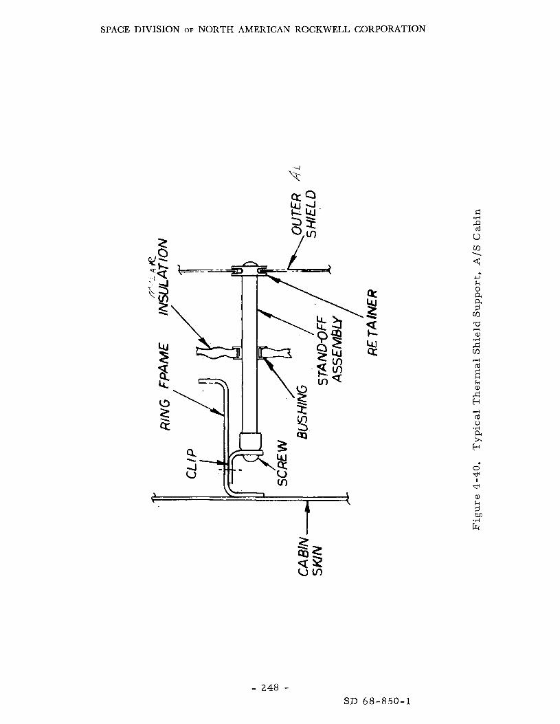
SPACE DIVISION OF NORTH AMERICAN ROCKWELL CORPORATION
Lu 2 8 4
- 248 -
0 a a 3 cn
V
a x .d
SD 68-850-1

SPACE IIIVISION OF NORTH AMERICAN ROCKWELL CORPORATION
Radiator Support
Active thermal control for the daytime periods of the 90-day s torage phase is accomplished by the addition of a 20-square-foot horizontal radiator (Figure 3-4). replaces the existing outer micrometeoroid shield. provide micrometeoroid protection as well a s thermal control. contamination-protection sheet installed on the radiator must be removed pr ior to activation of the radiator. A 32-inch-diameter hole in the center of the radiator permi ts the docking tunnel s t ruc ture to protrude above the radiator level. tunnel s t ruc ture and the upper ascent stage beams, effect on the s t ruc tura l reliability.
This radiator is located at the top of the ascent stage and The radiator would
A
A rigid support for the radiator is provided by the docking This support has no
Cabin Seals
The existing LM rivet , window, and hatch sea ls a r e capable of withstanding temperature variations grea te r than 0 to 200 F; and since the cabin tempera- t u re m u s t be held between 40 and 100 F f o r other components (40 F for water and 100 F for ba t te r ies ) , the cabin sea ls a r e not considered to be a problem a r e a even for the extended exposure time. Reliability i s also unaffected.
Crew Provis ions
Figure 3 - 5 is an inboard profile of the three-man augmented LM and shows the position of the third crewman. Structural changes for the new crew station include the addition of a seat on the ascent engine cover, side cabin s t ruc ture supports for res t ra in t system tiedowns, and a protective cushion in the a r e a of the upper docking tunnel. also provided for stowing an additional PLSS back-pack i n the forward cabin a rea , by the presence of the third crewman. expected to be such that the additional weight will have no measurable effect on the assessment of Ps for the ELOR mission.
New support s t ructure is
Again, no degradation in s t ruc tura l reliability will be created The s t ruc tura l design margins a r e
- 249 - SD 68-850-1


SPACE DIVISIO~ OF NORTH AMERICAN ROCKWELL CORPORATION
A E P LM-ECS
ARS HTS WMS PLSS oss ASA
LM-G&N IGA MGA OGA CGC RR LR
CES AGS
LM-SCS
LM-RCS LM-CSS
LOS PRN EMU RTTA R / T EVCS EVC DRG D/A A/D SPA CRA SMAP APS
4.3 THE LUNAR MODULE ASCENT STAGE SYSTEMS
I LIST O F ABBREVIATIONS
Ascent Electrical Power Environmental Control System Atmosphere Revitalization Section Heat Tr'ansport Section W a t e r dtanagement Section Portablk Life Support System Oxygen Supply Section Abort Sensor Assembly Guidance and Navigation System Inner Gimbal Angle Middle birnbal Angle Outer G'rnbal Angle Comma d Guidance Computer Rendez d ous Radar Landing Radar Stability Control System Control Electronics Section Abort Guidance Section Reaction Control System Commupcations and Status Systems
Pseudo Line O f r g h t andom N o i s e Extravehicular Mobility Unit Ranging Tone Transfer Assembly Receiver and Transmit ter Extravehicular Communications System Extravehicular Communications Digital t anging Generator Digital 40 Analog Analog ti0 Digital Signal P rocesso r Assembly Command Receiver Assembly Storage \Monitor /A la rm and P r o g r a m m e r A scent Propulsion Sy s tern
I
- 2 5 1 , 2 5 2 - SD 68-850-1

SPACE DIVISION OF NORTH AMERICAN ROCKWELL CORPORATION
4 . 4 LUNAR MODULE DESCENT STAGE SYSTEMS':'
NOTE: Some of the information used here in was provided by Grumman Aircraf t Engineering Corporation through References 3 . 3 and 4. 37.
This section i s an analysis of the lunar module descent stage (LM DS)
The aspects associated sys tems a s they a r e affected by the extended mission requirements. a r e presented only where changes were projected. with sys tems integration a r e presented in Section 3. 5.
Details
4.4. 1 Quiescent Elec t r ica l Power
NOTE: Much of the information used here in was provided by contributing subcontractors:
1. General Elec t r ic Co. through Reference 4 . 1 8
2. P r a t t and Whitney through Reference 4 .16
3 . Allis-Chalmers through References 4 .17 and 4 .36 .
Requirements
The LM electr ical power requirements f rom ear th launch to pre-ascent preparat ion are supplied by the descent stage section of the EPS, and the lunar -ascent power requirements a r e supplied by the ascent stage section. Thus, the modifications to the standard LM EPS configuration required #to implement a three-man 90-day LM, for the most par t , affect the descent stage EPS. The electr ical power required by the ascent stage for ascent f r o m the lunar surface, rendezvous, and docking a r e provided by bat ter ies and is discussed in Section 4. 3. 1.
The electr ical energy requirements for the descent stage power supply a r e given in Table 4-31. descent, and pre-ascent preparat ion a r e supplied by the descent bat ter ies . A minimum of three descent bat ter ies a r e ca r r i ed to supply the peak power requi red to support the lunar descent phase. The electr ical power require- ments for the quiescent phase a r e given in Table 4-32. F o r purposes of this analysis, the w o r s t c a s e for this phase is assumed to cover th ree lunar days (42 ea r th days), three lunar nights (42 e a r t h days), and s ix additional ea r th days of lunar nights, totaling 90 ear th days, The electr ical energy requirement for the 90-day quiescent phase is approximately 336 kw-hr.
I
The 12.8 kw-hr required for the ear th launch, lunar
*A foldout sheet listing abbreviations used in Section 4.4 and their meanings is located a t page 275.
- 253 - SD 68-850-1

SPACE DIVISION OF NORTH AMERICAN ROCKWELL CORPORATION
Table 4-31. Electr ical Energy Requirements, Descent Stage, LM
Mission Phase Energy
(Kilowatt-Hours)
Ea r th launch to transposit ion I Lunar descent and checkout
Lunar quiescent s torage P r e -ascent preparation
RTG o r solar cell a r r a y setup
Sub total (Excluding quiescent s torage)
Total
0. 68 8. 34 2.00
336.24 1. 80
12. 82
349. 06
The average power required i s expected to be between 75 and 114 watts depend- ing on whether o r not some or a l l of the projected hea ters a r e actually required.
The weight of an EPS configuration composed entirely of descent bat ter ies to provide this energy is approximately 4580 pounds. sys t em weight is prohibitively high, the following alternative configurations we r e considered:
Since such a
1. Radioisotope thermoelectr ic generator (RTG)(SNAP-27) and descent bat ter ies
2. Solar ce l l a r r a y and descent bat ter ies
3 . Fuel ce l l ( s ) and descent bat ter ies
Since ba t te r ies will satisfy the LM descent stage requirements for all phases except quiescence, the remainder of this analysis is devoted t o the quiescent lower function, which contributes to mission probability of abort , Pa, not safety Ps.
System Alternatives
The RTG Configuration. The RTG configuration consists of one SNAP-27 RTG plus eight LM descent bat ter ies modified t o provide 90-day wet-life operation and a l imited number of recharge cycles. As shown in Table 4-32, the average power for the RTG configuration is substantially lower during the lunar night than that fo r the solar a r r a y and fuel-cell configurations, because the R T G waste heat ( see Section 4.3.2) provides the 500-Btu/hr (148-watt) cabin-heat requirement , In the so la r a r r a y and fuel cell configurations, this heat m u s t be provided by electr ical hea te rs .
- 254 - SD 68-850-1

SPACE DIVISION OF NORTH AMERICAN ROCKWELL CORPORATION
a 4 - a g 3rd 2 5
n
3rd
a 4 c - m m m m m m m
w w w w w w w w % m o r l r - i d d c - m m d d d o d o l l i o o , m z I 4 m - i m 0 o o u
rl r l r l d >
c - m m m m m m m w w w w w w w w
m 1 o Y - 4 ~ d d C - m m d d d o d o d o o o h l o r l c J r l m 0 0 0
rl rl d Y - 4
m 0 o w c n c - m o m
c - m m m m m m M w w w W W C O a, W
Lo
M
w e i! E!
2
.rl 1 U
u rd a c C
rd u (u
0
a 1
B
6 r
r
2 u CI
C 0 0
0 C 0 W
rd
Y
U
5 -2 rd 0
- 255 - SD 68-850-1

SPACE DIVISION OF NORTH AMERICAN ROCKWELL CORPORATION
.
Components
RTG Descent bat ter ies Power control unit
Total
Figure 4-41 shows the electr ical power profile for a typical 28-day l ight-dark lunar cycle during the quiescent phase. ment is above the output power level of the RTG, the bat ter ies supply the difference in power; and when the power requirement is below the output power level of the RTG, the bat ter ies a r e recharged by the RTG. shows the total s tored energy requirement a s a function of RTG output power levels f r o m 65 watts to 90 watts.
When the power requi re -
Figure4-42
Weight Weight Number (Pounds ) Number (Pounds )
1 65 2 130 8 1, 264 3 524 1 30 1 30
10 1 ,359 9 684
The output power of a standard SNAP-27 RTG i s 67 to 71 watts. F r o m Figure 4-42, a 67-watt RTG requi res seven descent bat ter ies to supply the required peaking power. Another alternative is to use two SNAP-27's, which m a y reduce the required weight on the moon by m o r e than 500 pounds. RTG configurations are given in Table 4-33.
Another bat tery has been added for redundancy.
The weight of the alternate
Table 4-33. Alternate RTG LM EPS Weight Est imates
The SNAP-27 Radioisotope Thermoelectr ic Generator (RTG) (Fig- ure 4-43) was developed for the Apollo lunar-surface experiment package (ALSEP). Each generator output over the 90-day mission will be 70 watts, with a growth potential to over 100 watts. Actual tes t s have demonstrated stable operation in a simulated lunar environment for periods greater than one yea r , and the predicted reliabil i ty for the 90-day mission i s in excess of 0. 9999 ( see Appendix N) . The heat-rejection temperature of 490 F permits simple integration with thermal-energy distribution sys tems within the LM. The sys t em i s light and compact and has been qualified f o r the Apollo mission e nvi r onme nt s .
Regarding the operational concept, two approaches can be used t o adapt the cur ren t SNAP-27 sys tem to the ELOR mission. be t ransported to the lunar surface in a separate container in the manner planned for the ALSEP mission, o r the generator could be fueled before launch. the radioisotope fuel capsule to a s s u r e fuel containment in the event of a power
The fuel capsule could
In this configuration, r een t ry protection must be located directly on
- 256 - SD 68-850-1

SPACE DIVISION OF NORTH AMERICAN ROCKWELL CORPORATION
? w
9 d
- . * -5 J
I L
I 1
I I ,
I
8 rl
8 w 4
- 2 5 7 - SD 68-850-1
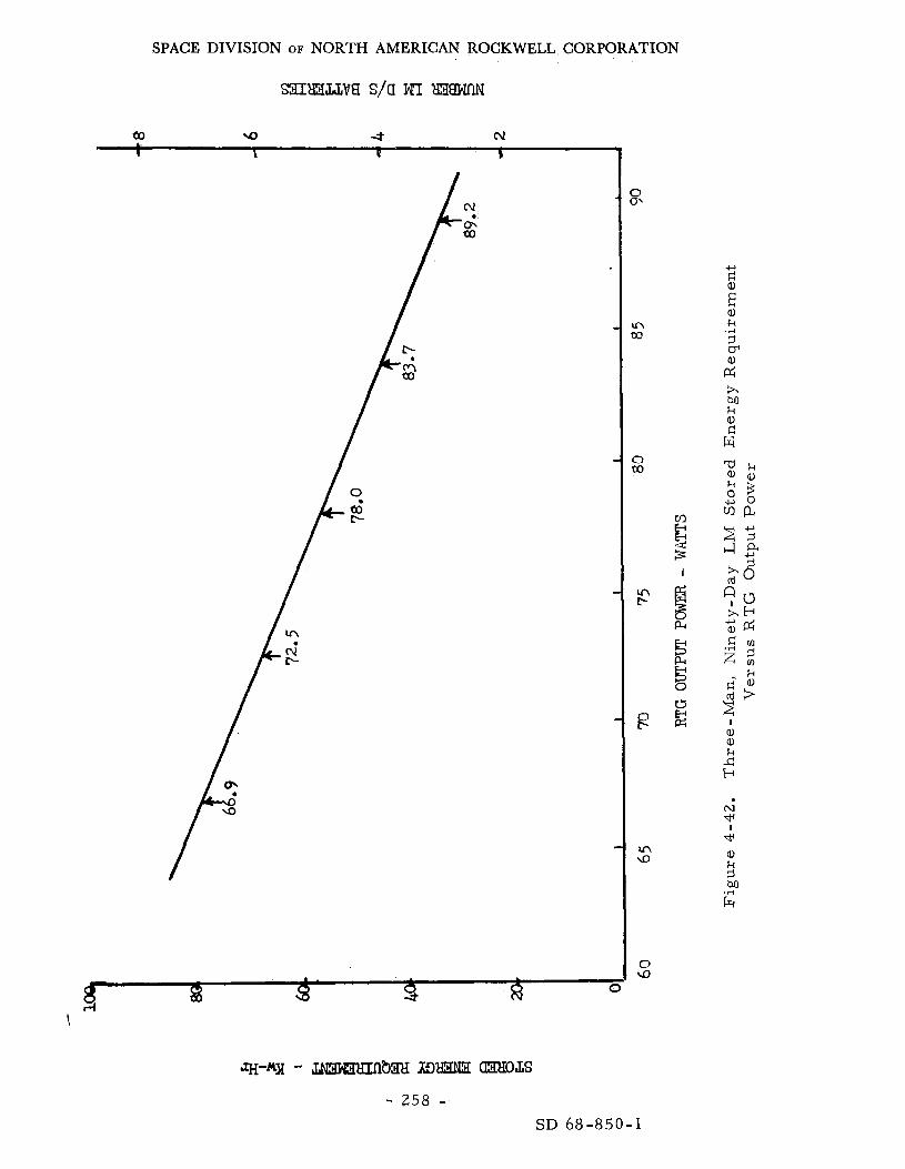
SPACE DIVISION OF NORTH AMERICAN ROCKWELL CORPORATION
. . . 8 8 3 R I
‘4
E 1
PI
5 E 0
i5
- 258 - SD 68-850-1

\ t L I
SPACE DIVISION OF NORTH AMERICAN ROCKWELL CORP~UTION
- 2 5 9 - SD 68-850-1

SPACE DIVISION OF NORTH AMERICAN ROCKWELL CORPORATION
sys tem reentry. The flexibility of the SNAP-27 RTG sys tem permits use of severa l integral fuel capsule/reentry sys tem combinations. Adequate space is available within the dimensions of the present , proven thermopile; there- fore , no thermopile design changes and requalification a r e required to adapt the SNAP-27 RTG sys t em for this approach.
The fueled launch approach eliminates the astronaut operations asso- ciated with generator fueling and effects a weight savings associated with the ground launch graphite fuel cask and i ts support s t ruc ture (approximately 15 to 20 pounds). control problem with respec t to both the generator and the LM during the t rans i t phase. In par t icu lar , during the ascent and ear th-orbi ta l portions of the mission, when the LM is inclosed by the SLA, the high effective sink tempera tures will requi re special precautions to prevent overheating of the thermopile and consequent damage to the elements. These precautions could include modification of the fin sys tem to increase the heat-rejection capability and/or shorting the generator to increase the Pe l t ie r cooling and, hence, lower the hot-junction temperature .
Offsetting these advantages i s the more difficult thermal
While this approach could be adopted without significant changes in the generator , the fuel capsule assembly would require redesign and requalifica- tion to incorporate and verify the reentry protection system. Thermal balance calculations involving the t rans i t phase would require updating, and the gen- e ra tor qualification p rogram would require repeating to verify the fueled hot-launch capability of the SNAP- 27 s t ructure .
The cur ren t separate- shipment concept eliminates the need for any changes, since all qualified equipment in the cu r ren t sys t em i s applicable. The ground-launch graphite fuel cask mounting location and arrangement i s retained so LM conditions a r e unchanged. a r e required to fuel the generator is not considered detrimental , particularly, in view of the fact that such operations will have been previously performed a s pa r t of the ALSEP program. F o r the ELOR mission, therefore , the cur- rent separately launched concept i s recommended.
The fact that astronaut operations
The unfueled generator could be placed in severa l positions for t rans- port; however, it is believed that minimum perturbation to the cur ren t LM design will resu l t f rom placing it in the scientific equipment bay. location has been assumed in the thermal and mechanical integration studies. ) If required, generator deployment can be accomplished by the astronaut after a r r iva l on the lunar surface.
(This
A s a final operational point, the generator will continue to deliver power long af ter the 90-day mission, and some consideration might be given for uses of this power; for example, storage power for the shelter to allow la te r use o r power for an ALSEP-type package deployed by the astronauts
- 260 - SD 6 8 - 8 5 0 - 1
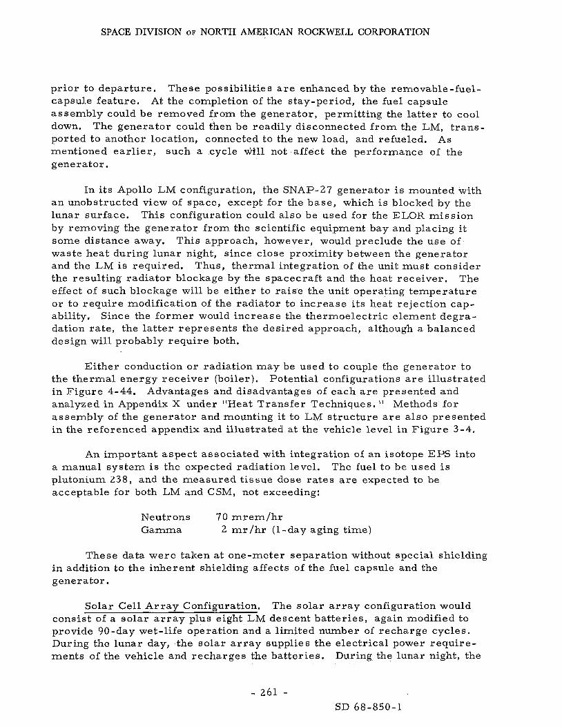
SPACE DIVISION OF NORTH AMERICAN ROCKWELL CORPORATION
pr ior to departure . These possibilities a r e enhanced by the removable-fuel- capsule feature , At the completion of the stay-period, the fuel capsule assembly could be removed f rom the generator , permitting the la t ter to cool down. ported to another location, connected to the new load, and refueled. As mentioned ea r l i e r , such a cycle wlll not affect the performance of the generator.
The generator could then be readily disconnected f r o m the LM, t r ans -
In i t s Apollo LM configuration, the SNAP-27 generator is mounted with an unobstructed view of space, except for the base , which i s blocked by the lunar surface, This configuration could also be used for the ELOR mission by removing the generator f r o m the scientific equipment bay and placing it some distance away. waste heat during lunar night, since close proximity between the generator and the LM is required. Thus, thermal integration of the unit mus t consider the result ing radiator blockage by the spacecraf t and the heat receiver . The effect of such blockage will be either to r a i se the unit operating temperature o r to requi re modification of the radiator to increase i ts heat rejection cap- ability. Since the fo rmer would increase the thermoelectr ic element degra- dation ra te , the l a t t e r represents the desired approach, although a balanced design will probably requi re both.
This approach, however, would preclude the use of
Ei ther conduction or radiation m a y be used to couple the generator to the thermal energy rece iver (boiler) . in F igure 4-44. Advantages and disadvantages of each a r e presented and analyzed in Appendix X under "Heat Transfer Techniques. " Methods for assembly of the generator and mounting i t to LM s t ruc ture a r e a l so presented in the referenced appendix and i l lustrated a t the vehicle level in F igure 3-4.
Potential configurations a r e i l lustrated
An important aspect associated with integration of an isotope EPS into a manual sys tem is the expected radiation level, plutonium 238, and the measured t issue dose rates a r e expected to be acceptable for both LM and CSM, not exceeding:
The fuel to be used is
Neutrons 70 m r e m / h r Gamma 2 mr/hr ( l -day aging t ime)
These data were taken a t one-meter separation without special shielding in addition to the inherent shielding affects of the fuel capsule and the generator.
Solar Cell A r r a y Configuration. The solar a r r a y configuration would consist of a so la r a r r a y plus eight LM descent bat ter ies , again modified to provide 90-day wet-life operation and a l imited number of recharge cycles. During the lunar day, the solar a r r a y supplies the electr ical power requi re - ments of the vehicle and recharges the bat ter ies . During the lunar night, the
- 261 - SD 68-850-1

SPACE DIVISION OF NORTH AMERICAN ROCKWELL CORPORATION
HEAT REC
EMF?. P RT OW
.R B O \ L € E m I
Figure 4-44.
-1 __ . .
Generator, Heat-Receiver Configuration
- 262 - SD 68-850-1

SPACE DIVISION OF NORTH AMERICAN ROCKWELL CORPORATION
bat ter ies supply the full e lectr ical power requirements and a l l heat energy. The energy required during the lunar night is 230 watts for 336 hours , o r approximately 77 kw-hr. Seven descent bat ter ies a r e required to provide this energy; another bat tery should be added for redundancy.,
The solar a r r a y mus t be capable of supplying the daylight load of 70 watts average plus recharging the bat ter ies . Assuming a bat tery charging efficiency of 75 percent, the solar a r r a y output must be 377 watts; moreover , the 377 watts m u s t be available immediately a t the beginning of, and through- out the entire, lunar day.
A fixed so lar a r r a y mounted flat on the lunar surface has an output power charac te r i s t ic which var ies essentially a s the cosine of the solar angle of incidence. solar a r r a y mus t either be continuously oriented normal to the sun o r have a m o r e complex geometr ical shape,
To provide the flat output power character is t ic required, the
The so la r - a r r ay a r e a required for an oriented a r r a y i s 70 square feet. The solar array area required for a fixed a r r a y depends on the geometrical shape used. F igure 4-45 shows a representative geometrical shape and the relative output power charac te r i s t ic a s a function of the sun angle during the lunar day. The design consis ts of two flat solar a r r a y s mounted in the shape of an A f r ame with a 60-degree included angle. the two sides of the f r a m e are normal to the east-west path of the sun ac ross the moon.
The a r r a y is deployed s o that
The a r e a required to provide 377 watts is 161 square feet.
The fixed a r r a y was selected in preference to the oriented a r r a y for reasons of reliability. is 214 pounds.
At 1. 33 lb / sq ft, the total weight of the solar a r r a y The weight of the total solar a r r a y configuration is-
1 solar cell a r r a y 8 descent bat ter ies 1 ,264 1 power control unit 30
214 lb
Total 1, 508 lb
The Fuel-Cel l Concept. The fuel cell concept can be satisfied by either the P r a t t & Whitney PC 10 o r the Allis-Chalmers orbital fuel cell developed for the Air Fo rce and reported in Reference 4-36.
The fuel-cell configuration would probably consist of three 200-watt fuel cel ls plus two AAP CGSS (cryogenic gas storage system) tanks for the reactants . In addition, th ree descent batteries would be required to supply the power during the lunar descent phase. As a resu l t of the boil-off char - ac te r i s t ics of the AAP CGSS tanks, i t is necessary to s tore 665 pounds of 0 2 and 47 pounds of H2 at the beginning of the mission to supply the required
- 2 6 3 - SD 68-850-1
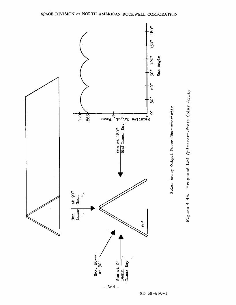
SPACE DIVISION OF NORTH AMERICAN ROCKWELL CORPORATION
/
- 264 -
x Id k
2
SD 68-850-1

SPACE DIVISION OF NORTH AMERICAN ROCKWELL CORPORATION
Function
3 fuel cel ls 2 CGSS tanks
H2 0 2
Coolant loop
Totals
reactants . genic tanks. H2 tank was completely unsuitable for the mission requirement, since al l of the H2 would boil off after approximately 30 days.
Some consideration was given to the use of the Block-I1 CSM cryo- It was found that the 0 2 tank was bare ly suitable and that the
Upper Boundary Lower Boundary Weigh t Weight
(Pounds) (Pounds )
90 140 56 0 80 66 5 120 47 60 56 20
1 ,418 42 0
The proposed P & W fuel-cell concept i s presented in Appendix 0. The proposed Allis-Chalmers concept is presented in Appendix P.
The weight of the fuel-cell configuration as it impacts the LM is directly dependent on the anticipated load profile. profiles projected in Reference 1-2 and those estimated by the SD team, a specific weight is impract ical a t this t ime. Table 4-34 are considered the upper and lower boundaries of the actual weights.
Because of the differences in the
However, those projected in
Table 4-34. Weight Es t imates for the Fuel-Cell System
To these weights m u s t be added that of the bat ter ies required for descent operations, unless the F C ' s a r e used in flight. about 474 pounds, the total FC EPS weight is probably between 894 and 1, 892 pounds.
Since three bat ter ies weigh
Conclusions and Recomrnenda tions
An analysis of the potential LM EPS configuration and the associated unknowns a s reflected in Table 4-35, leaves l i t t le doubt as to the most desirable EPS for the LM quiescentphase power, growth capability with respec t to cabin heat requirements , whereas the solar a r r a y and fuel cells have no growth margins at all and are very sensitive to e r r o r s in estimating load profile. tage in that the sys t em weight is strongly dependent on both the cabin heat
The RTG is the lightest and has high
The fuel- cell configuration has a further disadvan-
- 265 - SD 68-850-1

SPACE DIVISION OF NORTH AMERICAN ROCKWELL CORPORATION
leak and the cryogenic tank boiloff ra tes . the sys tem weight must be increased to compensate for the change. the reliability (P90 and Pa) of the fuel-cell concept a r e leas t desirable of all and perhaps marginal. promise safe re turn , but will necessitate ear ly abort ,
If ei ther of these factors i nc reases , Fu r the r ,
In any event, failure of this sys tem will not com-
Table 4-35. Alternative LM Quiescent Electr ical Power Tradeoff Data
System Concept
1. Fuel cel ls
2. RTG*
3. Solar ce l l s
4. Bat ter ies (all)
Weight Range (Pounds )
400 to 1, 900
700 to 1,300
1, 000 to 1, 500
about 4,600
(::)Recommended concept
Reliability P 9 0 and Pa
= o . 995
>o. 9999
3-0.9999
s o . 9999
Error S e ns i ti vi ty
Very high
Very low
High
Very high
Based on the foregoing data, i t is recommended that the RTG concept, in the fo rm of a SNAP-27 modified to provide ascent stage heating, be used for the LM descent stage EPS and that studies be initiated to complete the modifications and integration into the LM. tenance o r r epa i r to achieve the projected P,; however, if i t i s desired o r required, some maintenance can be accomplished, even in i ts present form.
This sys tem will require no main-
4. 4 .2 Descent Propulsion System
System Description
The descent propulsion sys tem consists of a single thrust chamber, two fuel tanks, and two oxidizer tanks with the associated propellant p re s - sur izat ion and feed control components. The engine i s a deep-throttling rocket with an ablatively cooled combustion chamber and a radiation-cooled nozzle, between 0 and 60 percent of full power. I ts functional diagram would appear much the same a s the CSM propulsion sys tem of F igure 4-25, except that the LM engine is gimbaled to provide *6" of pitch or rol l control during descent.
I t develops a maximum thrust of 10 , 500 pounds and is throttleable
- 266 - SD 68-850-1

SPACE DIVISION OF NORTH AMERICAN ROCKWELL CORPORATION
The following modifications to the Apollo LM configuration a r e required to compensate for the increased landed weight:
1. Additional propellant tankage is required for the increased propellant quantity.
2. Additional helium pressurant must be provided for the added propellant.
3 . The burn-t ime at maximum thrus t and the thrust level during the throttleable phases must be increased for the descent engine.
4. Structural beef-up of the descent stage and landing gear a r e required.
In o rde r t o establish descent propulsion design requirements, the LM has been assumed to have a separation weight of approximately 4 0 , 0 0 0 pounds and a propellant s torage capacity of 21, 500 pounds.
Systems Analysis
The descent propulsion i s not used af ter touchdown; consequently, the basic concern is associated with the need to provide additional propellant and engine burn- t ime.
Descent Propellant Tank Modifications. Two methods considered for providing the increased descent propellant quantity for the Augmented L M taxi miss ion a re -
1. Retain the four existing LM descent propellant tanks without modi- fications, and add two new cylindrical tanks mounted in two descent-stage corner quadrants.
2. Modify the existing descent tanks by changing the hemispherical end-domes to ellipsoidal ends and increasing the length and the diameter of the cylindrical section.
The six-tank configuration requi res modifications to the feed sys tem to balance the propellant flow throughout the system, provide the engine with the c o r r e c t mixture ra t io , and minimize propellant residuals. A simple or i f ice m a y not adequately balance the sys tem, in which case an active propellant utilization/propellant management sys t em may be required. Other considerations are that the two additional tanks require installation in the vehicle a t distances f rom the c. g. proportional to their weight in order to minimize m a s s unbalance, and that the new propellant tanks will subtract f r o m the usable payload volume, F o r these reasons , the modified four-tank configuration has been recommended for the augmented vehicle.
- 267 - SD 68-850-1

SPACE DIVISION OF NORTH AMERICAN ROCKWELL CORPORATION
Grumman studies of tank designs for the four-tank configuration indi- cate that the l ightest tank design capable of satisfying the requirements of the augmented miss ion i s a 52. O-inch-diameter, toroidal-head titanium tank. This tank, although the l ightest , i s m o r e complicated than other tanks con- s idered, because i t requi res a cylindrical tension s t ru t located a t the center of the tank (see F igure 4-46). To maintain the required accessibil i ty through the bottom of the tank, the tension s t ru t mus t be capable of being easily removed, with a threaded sleeve a t the top a s par t of the cover plate.
This capability can be accomplished by incorporating the s t ru t
An ellipsoidal-head titanium tank is competitive with the toroidal- head titanium tank up to the point where the major /minor diameter (a /b) ratio of the head is 1.414. an elliptical head whose geometry introduces compressive hoop loads, and the tank weight increases rapidly.
Beyond this point, further increase in volume requires
A study was conducted to determine if a 52-inch-diameter ellipsoidal head titanium tank ( a /b = 1.414) could be designed to yield a payload weight equal to the toroidal-head tank. LM tank length of 70.270 inches (effective length) mus t be increased to 73. 3 inches. By incorporating a machined feed-line elbow a t the bottom of the propellant tank and maintaining the existing elbow center line elevation, the tank can be lowered 1.184 inches (see Figure 4-47). 1.846 inches required to provide a tank length of 73. 3 inches i s obtained by extending the tank above the upper shear deck, which requires introduction of a 22-inch-diameter hole in the upper shear deck. The existing slope of the helium pressurizat ion line is maintained by relocating the helium pressuriza- tion inlet port below the top center of the tank (see Figure 4-48).
To accomplish this design, the present
The remaining
Descent Engine. To determine the ability of the LM descent engine to mee t the requirements of a propulsion augmented mission, a preliminary composite thrust profile was developed. This profile w a s established to define the maximum firing t ime at the fixed thrust point in conjunction with the maximum total f i r ing time. requirement , the thrust profile included an abort condition, which occurs a t a point la te in the nonthrotteable portion of the braking phase. requi res a n inc rease in the duration of the maximum-thrust phase during braking by approximately 100 seconds over the LM profile and provides higher t h rus t levels during final approach and landing.
To define a worst-case descent engine
This profile
Calculated data based on this new thrust profile indicate that the engine case tempera ture will increase in the combustion chamber and nozzle a rea over that result ing f r o m a nominal LM profile. pera tures a r e still below the specified temperature l imits . s ame margins a s the present LM, some ablative ma te r i a l mus t be added. P re l imina ry analysis of the throat indicates that no additional ablative mater ia l is required in this a r ea .
The result ing increased tem- To maintain the
- 268 - SD 68-850-1

SPACE DIVISION OF NORTH AMERICAN ROCKWELL CORPORATION
SD 68-850-1
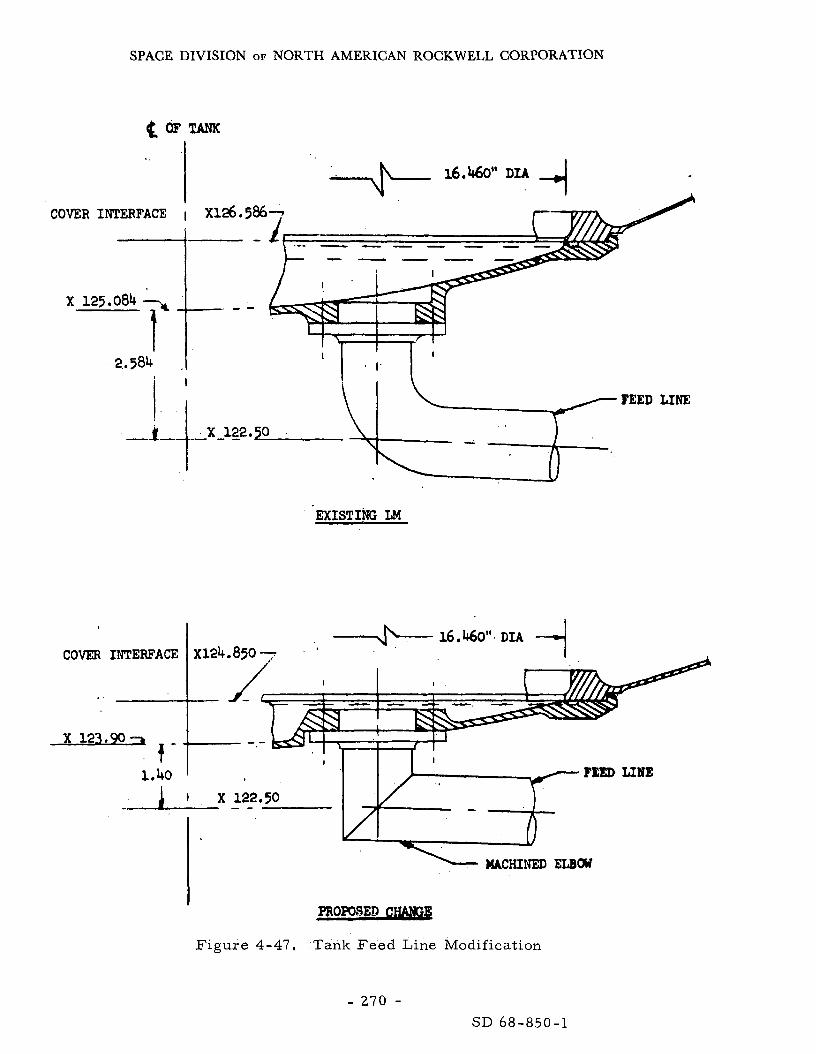
SPACE DIVISION OF NORTH AMERICAN ROCKWELL CORPORATION
COVER INTERFACE I X 1 2 6 . 5 8 6 7 r- /
X 125.084 7
2.. 584
EXISTING LM
16.460". DIA 4 COVER INTERFACE X124.850 -
I I I
1.40 ' T I
PROmBEB
Tank Feed Line Modification
I
Figure 4-47.
- 270 - SD 68-850-1
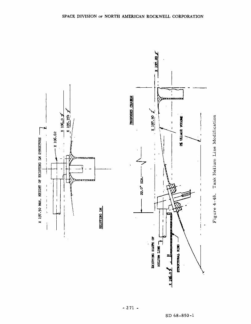
SPACE DIVISION OF NORTH AMERICAN ROCKWELL CORPORATION
I
\
"I
- 2 7 1 - SD 68-850-1

SPACE DIVISION OF NORTH AMERICAN ROCKWELL CORPORATION
An additional consideration in determining the ability of the LM descent engine to per form an augmented mission i s the s ta t ic stability of the vehicle while the engine is firing. required to cause the thrus t vector to pass through the center of gravity of the spacecraft . accounting for bearing alignment, th rus t vector alignment, and rigging e r r o r i s 5.33 degrees. required to null the effects of center-of-gravity offset. mus t be performed to determine if the remaining 3 .6 degrees of gimbal angle will adequately satisfy requirements for correct ing descent - engine -mount deflection, aiding in maneuvers , and in general , satisfying the dynamic requirements of the vehicle when the engine i s firing.
The parameter of in te res t i s the gimbal angle
The maximum gimbal angle available for control a f te r
Of this e r r o r , a s ta t ic offset angle of 1. 73 degrees i s Fur ther analysis
Descent Propellant Tank Pressurizat ion. The following ground ru les were used for determining helium requirements:
1. An ambient s t a r t bottle is not used.
2. 27, 500 pounds of propellant mus t be expelled, which is approxi- mately 700 pounds above the minimum guaranteed usable quantity.
3. Blowdown of the propellant tanks is not considered.
4. A maximum anticipated standby time of 131 hours i s used to estab- l i sh initial He loading.
5. He tank heat leak is 7. 5 Btu/hour.
Based on these ground rules , 55.6 pounds of He is sufficient to expel the 21, 500 pounds of propellant, that corresponds to this initial loading is 1 ,614 psia and occurs a t engine firing. With a He tank having an allowable operating p r e s s u r e of 1, 710 psia, an appreciable margin exists for design uncertainties, such a s loading tolerances and heat-leak variations. A detailed study was conducted to determine the effects of sys tem tolerances. cient to expel the total propellant load required for the augmented mission with all tolerances considered; however, the standby t ime must be reduced to 101 hours , which i s considered acceptable.
The maximum nominal He tank p res su re
The He tank could be loaded to a density suffi-
After landing, p re s su re in the descent tanks will slowly r i s e because It is estimated that the tank p res su re of heating of the cold He pressurant .
will increase to the level of the relief valve p re s su re setting within 24 hours. To prevent actuation of the relief valve, and uncontrolled tank venting, the LM has solenoid valves in se r i e s with squib valves to manually vent the tanks By venting to approximately 40 psi internal p re s su re , the danger of catas- trophic failure due to micrometeoroid penetration is eliminated. Based on
- 272 - SD 68-850-1

SPACE DIVISION OF NORTH AMERICAN ROCKWELL CORPORATION
the tank geometry and mater ia l , 40 psi is a conservative estimate of the p r e s s u r e level a t which no c rack propagation will occur if the tank is punctured.
The reliability of the descent propulsion sys tem and, therefore , its contribution to Ps will remain unchanged f r o m that estimated for Apollo Ps = 0. 998 (Reference 4-37). Since i t will not function af ter touchdown, maintenance wi l l not be required.
Conclusions and Recommendations
The descent propulsion sys t em wi l l requi re some modifications in t e r m s of propellant storage. requirements of the mission. and placement.
Beyond those, it wi l l meet the functional Work i s required in the a r e a of tank redesign
These a r e not considered one of the spacing problems,
4.4. 3 Descent Stage Structure
The modifications required to the DSS a r e created by-
1. The increased weight of the overall LM.
2. The additional fuel tankage.
3 . The addition of the electr ical power source.
To s t ructural ly accommodate the new propellant tanks, a 22 -inch- diameter hole i s provided in the upper shear deck of the descent stage. provision will necessi ta te redesign of this a r ea . will a l so require strengthening because of the heavier loads imposed.
This The vertical shear webs
The higher loads imposed because of the increased vehicle weight will requi re beef-up of the cross-sect ional a r e a s of the machined par ts , such as apex fittings, t ru s s supports, corner posts, capstr ips and top/bottom center f rames .
The descent stage should be near ly unaffected by the meteoroid hazard since i t is protected by the ascent stage.
Studies have indicated that the present LM landing gear configuration with a modera te amount of redesign can be used for a n augmented vehicle. In general , these modifications include the following: (1) increased density of crushable core , (2) increased thicknesses of s t ru ts and members , and (3 ) strengthening of selected joints. In defining these modifications, the
- 273 - SD 68-850-1

SPACE DIVISION OF NORTH AMERICAN ROCKWELL CORPORATION
present LM tempera ture profile a t landing was applied, based on Surveyor VI data that there may be a reduction in the maximum s t ruc tura l temperatures of the landing gear for the Apollo mission. This reduction could minimize the number of changes required.
There a r e indications
These modifications, a f te r qualification, a r e not expected to measurably affect the reliabil i ty of any s t ruc tura l member o r i t s contribution to Ps.
- 274 - SD 68-850-1

SPACE DIVISION OF NORTH AMERICAN ROCKWELL CORPORATION
4 . 4 THE L U ~ A R MODULE DESCENT STAGE SYSTEMS
i LIST O F ABBREVIATIONS
LM-QEP ALSEP S L A AAP - CGSS
DPS PU/PM F T P
DSS
Q u k s c ent Electr ical Power Ap 110 Lunar Surface Experiment Package
Apdllo Applications Program Cryogenic Gas Storage Subsystem Descent Propulsion System Propellant Utilization/Propellant Management Fixed Thrust Point Descent Stage Structure
Space i c raft Lunar Module Adapt e r
- 275,276 - SD 68-850-1

SPACE DIVISION OF NORTH AMERICAN ROCKWELL CORPORATION
5.0 CONCLUSIONS AND RECOMMENDATIONS
5.1 ELOR MISSION CAPABILITY
5. 1. 1 Estimating Reliability - The Baysian Approach
Estimating reliability in the classical sense has depended on the con- ventional statist ician who requi res much tes t data on the specific system, This i s an expensive and impract ical means of assessing modern space sys - t em r eli ability status .
Recently there has emerged a new and more pract ical approach to reliabil i ty estimation based on the logical application of all available appli- cable data; i t i s called Baysian statist ics. Briefly, it accepts all available tes t data, including those accumulated on pr ior systems, and takes into account the effects of modifications. been eliminated by design actions a r e no longer included in the system reliability estimate, systems reliability and subsequent safety. of the 1968 Annual Symposium on Reliability,)
As a result , fa i lure modes that have
The end resu l t is a more real is t ic estimate of mission (See the Minutes of Session 7A
This approachis used by SD in estimating space system reliability and safety because of i ts conformance to practical engineering principles and economic constraints. The implications on the ELOR Mission a r e self evi- dent; the data derived f rom the Apollo program se rves a s an a p r io r i index a s to the potential success of the ELOR, provided the aforementioned con- ditions a r e met ,
5. 1. 2 Evaluating ELOR Mission Effectiveness
Effectiveness has been used as a measure of accomplishment; but i t mus t be related to some tangible objectives o r another system. achieves maximum effectiveness when it permits accomplishment of the objective and all subobjectives within the allotted time. craf t (CSM/LM personnel delivery system) must therefore permit the full 9O-day stay on the lunar surface and return the three-man party safely to the appointed spot on the ear th ' s surface to achieve maximum effectiveness.
A mission
The ELOR space-
- 277 - SD 68-850-1

SPACE DIVISION OF NORTH AMERICAN ROCKWELL CORPORATION
Applying this definition to the ELOR mission, the measure of effectiveness has two factors:
1. Stay t ime, expressed as: the probability of completing the 90 days without a CSM o r LM fai lure requiring abort (P90).
2. Crew safety, expressed a s the pro.bability of c rew safe r e tu rn (Ps).
F r o m these the probability of having to abort o r leaving before the end of the 90 days (Pa) is:
P = 1 - P . a 90
Ps is not dependent on stay t ime because abort can be initiated at any t ime deemed necessary to a s su re crew safe return, constrained only by rendezvous/departure windows, longer the stay time, the grea te r the possibility of a crew-sensit ive failure,
I t is dependent on t ime in the sense that the
5. 1. 3 Command and Service Module Effectiveness
The CM sys tems were evaluated in Section 4. 1 of this report , the resu l t s a r e summarized in Table 5-1. and summarized i n Table 5-2. tions and the result ing mission potential i s expressed a s a function of t ime in Part A of F igure 5-1.
The SM was evaluated in Section 4. 2 The cumulative resu l t s of these recommenda-
The recommended design improvements r a i se s the Block I1 CSM P 9 0 to about 0 .65 . along with a minimum provision for maintenance would ra i se the CSM ELOR contribution to P 9 0 to greater than 0. 99 for the 90-day mission. remaining weakness i n the CSM i s the stability control function for the quiescent state. the 0 . 993, but bet ter data a r e required to make a final judgment. event, a fai lure will only affect the requirement to abort.
The addition of some switchable and automatic redundancy
The one
It was found that even this a r e a could be improved over In any
The result ing probability of having to abort (Pa) before the 90 days because of a command or service module fai lure i s expected to be l e s s than 0. 01, o r no grea te r than one chance i n 100 of having to abort an ELOR miss ion due to a CSM failure with the recommended configuration and support.
- 278 - SD 68-850-1
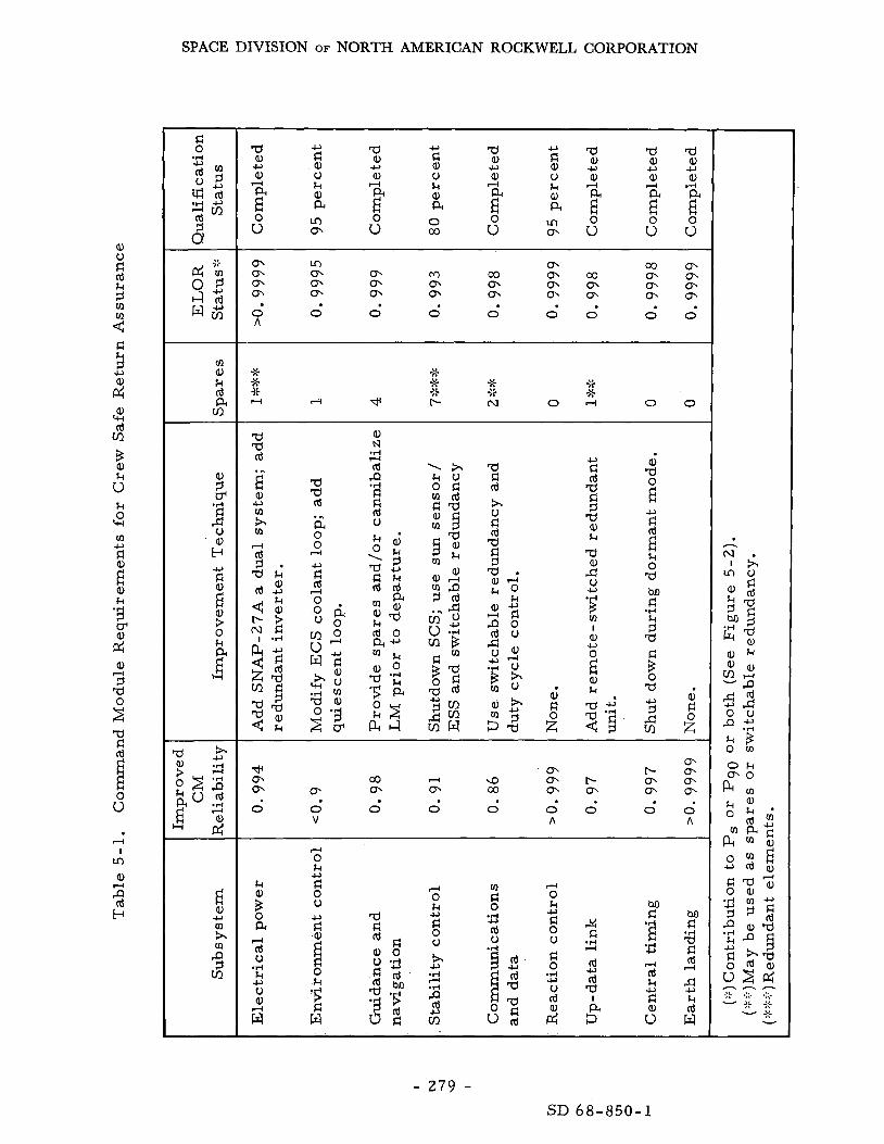
SPACE DIVISION OF NORTH AMERICAN ROCKWELL CORPORATION
m a, $4 d PI Cn
a a, a, c,
l-4
E" 0 u
c,
$ u k a, PI
m m
a a, a, +I
rl
E" 0 u
c,
t u k a, PI 0 co
a a, a, -c)
4
E" 0 u
~
U
t u k a, PI
m m
a a, a, c,
A
f 0 u
a a a a , U U
0 0 0 0 0 0 0 0 0 A
a, a 0 E -c)
! k
0 a M d
.I+
2 a $ 0 a 5 c,
rl 0 k
- 279 - SD 68-850-1

SPACE DIVISION OF NORTH AMERICAN ROCKWELL CORPORATION
a, u d rd
5 2 2 2
m
d
c)
a, +I cd m
a, k
3
u k 0 +I
z 0
rd a d
.rl c)
; E 0 V a, p: a, 3 a d
5 a, u > k a, VI
.rl
cv I
ln a, d
2 w
d 0
kl I4 lim
a, k Id a m
E a, c) m h rn P 3 VI
a a, a, c,
d r 0 u
a a, a, c)
d
i? 0 u
%
E
a, a, a 0 u
4 2
d
a a, a, c)
d
F 0
u
% a, a, c)
r(
F 0 u
u d a, u k a, a 0 co
c)
2 0 0 0 0 0 0 0
a a, k 3 CP a, k
.rl
24 a p: k 0 a, M s! Id 5 z”
a a, k 3
k
.rl
r 2 Ca p: 0 2
a a, k 3 CP a, k
.rl
24 a & 0 z
a a, k
3 .rl
5r 24 k
Ca p: 0 z
a
r 2
a, k
3
k
.d
a p: 0 z
a,
i k m a, a
.rl
c,
2 M s! + d c)
0 0 0 0 0 0 0 0
d 0 k d 0 u rl 0
u Id a, k
c)
.d c)
2 v1
d 0 .d m d 3 PI 0 k n
VI c
a, M Id k 0 u rn u d Id
a, a 0
d d
&
d 0 k d 0 u
s! rd
Q, a 0
u
c,
d d
2
a, M Id k 0 c) m u s! Q M 0 h k u
.d
a, k 3 c) s 2
k c) rn
VI
- 280 -
-
d 0
cd a d
.?I 4 2
; E 0 u a, k
u m
I4 2
6 a,
k 0
W c) 0 c
3 P
a a, u d 0 v
m a,
c)
n
6 k 0
W
a a, .rl
1.I: d rd 5 CP a, k cd
; 0) c) .d
a, m a, A w h
3k v
SD 68-850-1

SPACE DIVISION OF NORTH AMERICAN ROCKWELL CORPORATION
\
- 281 -
z 0
- Y I-
a- - m 0
0
C 0
SD 68-850-1
SPACE DIVISION OF NORTH AMERICAN ROCKWELL CORPORATION
5. 1.4 Lunar Module Effectiveness
The LM ascent and descent systems were evaluated in Sections 4. 3 and 4.4, respectively, and a r e summarized in Tables 5-3 and 5-4, respec- tively. The cumulative resu l t s of these recommendations a r e presented i n Figure 5-1, P a r t By where the various potential LM concepts a r e related to stay-time and P90. The unmodified Apollo LM i s very limited because of the battery life and is, therefore, not a ser ious contender, Using the SNAP-27 provided an EPS P 9 0 of near ly 1.0. Beyond that, as indicated in Table 5-3, the one remaining weakness i s i n the environmental control and, more specifically, the heat t ransport loop, the only operating function during the dormant mode. In that system, provisions f o r module replacement will resolve any other potential weaknesses.
The LM as recommended herein will meet the 90-day ELOR require- ment with a P 9 0 probability grea te r than 0 .99 . The probability of having to abort because of a LM sys tem fai lure i s expected to be l e s s than f o r the CSM because of the l e s s complex quiescent mode control; i t should not exceed Pa = 0.003. of having to abort because of a LM sys tem failure. par t of the communications system, the environmental control and electr ical power systems must operate. I ts contribution to Ps may be somewhat lower than the DRM because of increased sys tem complexity for the third man; however, planned maintenance can offset this.
That implies that there a r e only three chances i n one thousand This is because only a
5. 1. 5 Assessing Crew Safe Return
Since with the ELOR mission, as with the Apollo mission, abort can be initiated at nearly any t ime, being constrained only by the LM rendezvous window and the t ransear th departure window, The probability of safe re turn (P,) should approach or exceed the value extablished f o r Apollo; i. e . , 0 .999. It approaches that value based on the premise the systems supporting the manned phases, for the most pa r t , operate about 25 percent l e s s , and no deleterious effects a r e expected from the quiescent phase, actual value because of planned maintenance for potential system weaknesses,
It may exceed the
The situation can best be understood through analysis of the data a s presented in Figure 5-2. Note that the LM has only four functions which contribute to the probability of completing the 90 days without an uncom- pensated failure, two of which contribute some degradation to P,. remaining LM functions a r e not operated until departure.
The
The CSM has one more function and some additional complexity i n the others ; all of which add up to a slightly higher chance of abort (Pa = 0.01) . Again, two of the five functions contribute some degradation to P,.
- 282 - SD 68-850-1

SPACE DIVISION OF NORTH AMERICAN KOCKWELL CORPORATION
(0
a, k d a
v3
0 0 o\ m
0 0 0 0 0 0 A A
0 ,-I m I O N 0 ' 0
Di
a a, a d
; E 0 V a, k k 0 W
a,
> 2
a, k d a (0
d M 5 0 k
L3 a
2l
.r( E" Q)
Q
2 5 0 u
a a, k
5 @ a, k k a,
.r(
;f; k 0
e: 2 0 z
e: s a a d
E E 0 U aJ h k 0 cu a,
> 2
a,
Q d k m a, rn a, II x
d
.d
i c, 2 M C .r( + V U
-.-
d
\D m m 0 0
a, u)
d d a u
k $ 0 'd Id M d k 5 -d
d
c2 a, k
3 0- a, k k a, Id a,
w 0 C 0
Id d
,d
u
2
.d
U
I
.r( u
'E a, a, a L- O W
U
c,
4 J'.
Y
d 0
a, 3
-Y
U
2 c, C 0 V c, 0 C m a, 0 Q - Y
- 283 - SD 68-850-1

SPACE DIVISION OF NORTH AMERICAN ROCKWELL CORPORATION
d 0
w GI h,"
a, k rd a tn
E a, JJ (0
h rn P 9 tn
0 0 0
s! o a ,
-
hrn 0
a, 9
k rl 0 u rn a, k a,
Id P h d
4 2
c)
2 c,
.r(
c, c)
d
0
t- c\l
d 4 z tn M d .rl
3 JJ a a, u rl 0 0
V a, m d
; E 0 u a, k
rl rd E E 9 k
1 0 Q tn h
35 v
-
- 284 - SD 68-850-1

SPACE DIVISION OF NORTH AMERICAN ROCKWELL CORPORATION
0
9
a b 0 Q Y
0 w
Q v)
a
I
- 285
SD 68-850-1

SPACE DIVISION OF NORTH AMERICAN ROCKWELL CORPORATION
Regarding the functions affecting safe r e tu rn (Ps), as previously indicated, the combinations of the three modules without the effects of the quiescent state use must be Ps = 0. 999, the Apollo I1 objective. the total Ps is the product of the two, o r about Ps = 0.992 without provisions for additional maintenance. The repair kit for meteroid damage will r a i s e the Ps back up to, o r over, Ps = 0. 999. Additional maintenance provisioning could possibly real ize additional improvements.
Therefore,
The one constraining factor associated with the foregoing i s the launch To approach the Apollo DRM safety, i t may window f r o m the lunar surface.
be necessary to rendezvous with the orbiting CSM within a two-hour t ime f r a m e ; and with the CSM i n a lunar polar orbit, this m a y be impract ical for some s i tes on the surface. However, he re again, provisions for planned maintenance will permi t much longer delays, the amount depending on the failur e m e chani sm.
In summary, there a r e reasonably good data to support the estimate that sa fe re turn of the ELOR c rew can be accomplished with a risk that is the same, or better than that associated with the Apollo DRM.
5.2 MISSION SYSTEM WEIGHT INFERENCES
The ELOR miss ion sys tem imposes a requirement for an increase in the weight of the spacecraf t as it is injected into t ranslunar trajectory. comparison of the potential alternatives a s referenced to the Spacecraft 107 lunar mission spacecraf t is given in Table 5-5.
A
The recommended concept, involving the two SNAP-27's and two full ce l l concepts for the serv ice module, presents the l ightest and the safest alternative. It is expected to weigh only 106, 112 pounds, as injected, on the way to the moon. Saturn V booster capability and represents a modest uprating.
This weight is only about 4, 000 pounds over the present
The all-fuel-cell concept weights 111,400; over 5,000 pounds m o r e than the recommended concept and 9,000 m o r e than the Saturn V capability.
5 .3 MAINTENANCE AND REPAIR (M&R) REQUIREMENTS AND RAMIFICATIONS
5.3. 1 M&R fo r the CSM
Since the CSM i s in lunar polar orbit unattended, maintenance is not possible during the long quiescent phase. phase as fa r as Ps is concerned, since it l a s t s for about 2,200 hours.
This, however, is the m o r e cr i t ical It i s
- 286 - SD 68-850-1
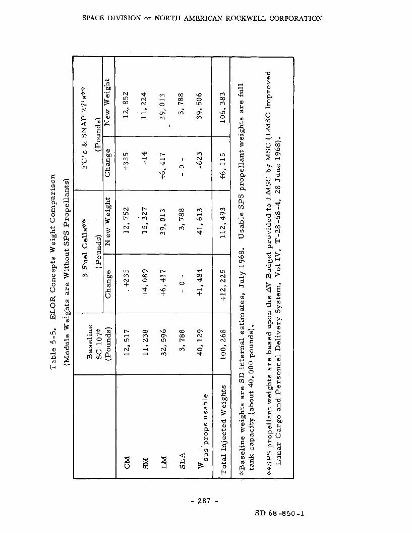
SPACE DIVISION OF NORTH AMERICAN ROCKWELL CORPORATION
m m r - * m o o 4 l o o + * N O W O *
' 7 . d a- + +
a,
2 z 0 P 0 k P
m N N
N
+ 4
-
03 9 N
0 0
n
4
- 287 - SD 68 -850 -1

SPACE DIVISION OF NORTH AMERICAN ROCKWELL CORPORATION
during this period that 'failures in operating systems can most likely occur. In contrast , mos t of the CSM functions a r e not required to operate during the quiescent phase; fa i lures which occur i n the nonoperating functions can be repaired after c rew re turn and pr ior to the t ransear th injection, provided they a r e planned for. functions were compensated for by either providing redundant elements o r switchable spares . Fur ther , crew safe re turn can be assured through use of a backup function that is activated from the ear th MSFN o r a lunar surface control function, orbiting CSM to make a repa i r and/or re turn to earth.
Potential fa i lures in the remaining quiescent-cri t ical
In these cases , the lunar par ty may have to abort to the
In the example used, the ELOR stability sys tem (ESS) establishes and maintains the slow ro l l and dampens out wobble. switchable spa res (c7 chances in 1, 000) , the CSM can be returned to the normal mode (Block 11) and abort initiated a s soon as possible without a ser ious detriment to Ps.
If i t fails after using the
The most pronounced weakness was found to be created by the meteoroid hazard, It was compensated for through some shielding (a form of redundancy) and planned repa i r . A patching kit is recommended for repair of the CM heat shield in par t icular , which will easily compensate for any real is t ic r i s k level.
There was a very high probability (0. 8) of some form of penetration.
The resu l t of the analysis for the CSM indicated that even though some fo rm of maintenance i s not practical for the longest mission phase, the com- bination of switchable redundancy, abort capability and 6 to 8 spares plus a repa i r kit amounting to l e s s than 200 pounds, to be used after crew return, will provide a Ps of 0. 99. Some of the spares could be eliminated through pro- visions to cannibalize the LM. CSM-ELOR could be safer missions than Apollo.
(See Tables 4-1 and 4-2). Theoretically,
5. 3. 2 M&R for the LM Vehicle
The LM vehicle i s i n a quiescent state either i n t ransi t to the moon o r while on the lunar surface, the combination of which makes up most of the ELOR mission. The time on the lunar surface, some 2, 200 hours, presents the grea tes t fa i lure hazard period, A s indicated in Tables 4-3 and 4-4, only 8 spa res were required to r a i se the P 9 0 f rom 0. 7 to over 0 .99 for the full 90 days. These spa res weigh l e s s than 200 pounds. Further , five of these a r e required for the G&N system, to be used just pr ior to launch. These same units could be used as spares for the CSM G & N system, eliminating about 140 pounds between the two vehicles, if the logistic problems could be worked out.
- 288 - SD 68-850-1

SPACE DIVISION OF NORTH AMERICAN ROCKWELL CORPORATION
The LM, although not specifically designed for maintenance, i s avail- able to the lunar par ty a t any t ime and i s , therefore, accessible for some fo rm of maintenance action. should c rea te an abort situation. alternative to make a repa i r . SNAP-27, which is an improbable situation. involves replacement a t the box level, which i s presently possible with little to no design changes.
For that reason, no LM sys tem emergency In most ca ses i t is expected to be a sa fer
The only possible exception i s with the Recommended maintenance
5.4 DEVELOPMENT REQUIREMENTS AND CONSTRAINTS
The ELOR mission does not cal l for a completely new development program and, in fact, i s not a very extensive departure f rom the Apollo design reference mission (DRM-2A). decreased by about 15 percent fo r the CSM and 3 3 percent for the LM. major differences a r e c rea ted by the need to maintain optimum storage conditions. Fur ther , the ramifications of the third man on the LM vehicle has created the most extensive changes and, therefore, the pacing factors for the ELOR development program.
The overall manned operations have The
The projected development program for the ELOR vehicles a r e pre- sented in Figure 5 - 3 . The LM vehicle i s expected to take about s ix months more than the CSM because of the more extensive modifications required to both the ascelit and descent s tages ,
The major problem a r e a i n the development cycle i s that introduced by the subcrit ical cryogenic s torage systems. If these a r e considered to be a requirement (not recommended by NR/SD), a two-year subsystem develop- ment program i s required to prepare them for vehicle integration. The resu l t i s that the ELOR development program would be stretched from a Conservative 3- 1 /2-year cycle to near ly 4-1 /2.
Some of the major development i tems to be considered include-
1.
2.
3.
4.
5.
6 .
Qualification of operating subsystems for the 90 days.
Manned rendezvous and docking of the LM to an unmanned CSM.
LM ascent and descent propellant tanks.
LM and CSM thermal control for the dormant phases,
LM and CSM environmental control modification.
New and modified subsystem fit and compatibility verification.
- 289 - SD 68-850-1

SPACE DIVISION OF NORTH AMERICAN ROCKWELL CORPORATION
E
0 a
I-I
- VI CL 0 0
s L
-
c k z a DC c3 0 DC CL
z
n
a
v) 0
w v)
I a,
z
J
E
0 n
L
r E
CL n
v) I I- z 0
z s - W z - I-
W --I 0 I W > I- v) W + z
-
n 3 0 Qc c3
- 2 9 0 - SD 68-850-1

SPACE DIVISION OF NORTH AMERICAN ROCKWELL CORPORATION
7.
8.
9.
New electr ical power source for both LM and CSM.
Status monitor for LM and CSM.
ELOR stability control for CSM.
10. CSM command demodulator /decoder.
The study identified the development of the Command Link for the manned rendezvous and dock of the LM to an unmanned command module as a long-lead- time i tern. will allow man-rating to be accomplished as a n additional task on one of the la t ter Apollo flights. to the proposed estimated program plan,
Ea r ly implementation of command link development
This would minimize cost and schedule implications
5 .5 CONCLUSIONS I
The study of the application of the data derived from a study of mission duration extension problems to the ELOR mission has shown that contemporary space sys tems can be used to meet the needs of some of the more conserva- tive extended missions. The extended lunar-orbital rendezvous mission i s brought well within the r ea lm of possibility through natural extensions of contemporary subsystems capability by application of recognized sys tems engineering processes such as operational control; fail-safe design; redundant functions; and, most effective of all, planned maintenance and repair .
Perhaps the most profound resul t of the study w a s associated with the fac t that provisions for as few as 15 repair o r replacement actions could r a i se the probability of completing the 90 days on the lunar surface without an abort to over 0.99 f rom about 0. 5. been specifically identified and a r e known to be feasible with l i t t le to no modi- fications to Block I1 configurations ( s e e Tables 5-1 through 5-4). the probability of safe re turn is expected to exceed that for Apollo 11.
These maintenance actions have
Fur ther ,
The ability to specifically identify required maintenance action before the miss ion and during the development phases is paramount to this mission concept. To this end, previous studies have contributed greatly, specifically, the baseline study, Reference 1-1. Further, Reference 5-1 is a summary of the resu l t s as they concern specific identification and location of potential maintenance actions; i t develops the logic associated with the process and demonstrates its applications.
The development requirements associated with the ELOR mission, as recommended by the Grumman/SD team involves a very modest program
- 291 - SD 68-850-1

SPACE DIVISION OF NORTH AMERICAN ROCKWELL CORPORATION
when related to the contemporary program. C and D) should not exceed 3 -1 / 2 years , and the pacing components vary with the selected concept, the LM stages requiring the mos t extensive modifications.
The development cycle (Phase
In conclusion, the miss ion is a s safe as Apollo; it is the most con- servative approach to extended lunar exploration; it can be implemented within the 1970-1975 t ime f rame, and it demonstrates the effectiveness of even the crudest form of maintenance planning on extended-mission safety,
- 292 - SD 68-850-1

SPACE DIVISION OF NORTH AMERICAN ROCKWELL CORPORATION
1 . 1
1 .2
2 .1
2 .2
2. 3
2 . 4
2. 5
2. 6
2. 7
3. 1
3.2
REFERENCES
A Study of Space Mission Duration Extention Problems , Vol. 1-4 (NAS2 -421 4). Space Division, North American Rockwell Corporation, SD 67-478 (30 October 1967).
Improved Lunar Cargo and Improved Delivery System, Vol. 1 -4 (NAS8-21006). Lockheed Missiles and Space Company, T28-68 (28 June 68).
Design Reference Mission I1 A, Apollo Mission Planning Task Force . NASA, MSC, P M 3/M-171/66 (30 October 1966) .
Dormant Operating and Storage Effects on Electronic Equipment Part Reliability. Martin Marietta Corporation fo r Rome Air Development Cente.r, RADC-TR 67-307 (July l-967).
Serveyor VI, a Pre l iminary Report. NASA/Office of Technical Utilization, NASA SP-166 (March 1968).
Bioastronautics Data Book. NASA Scientific and Technical Information Division, NASA SP-3006 (1964).
Final Report , Pre l iminarv Definition Phase . Apollo Extention Svstem, Thermal Analysis. Corporation, SID 65-1524 (December 1965).
Space Division, North American Rockwen
Final Report, Pre l iminary Definition Phase , Apollo Extention System, Structural Loads and Cr i te r ia . Space Division, North American Rockwell Corporation, SID 65-1530 (December 1965).
CSM Meteroid Shielding Analvsis Report, October 1965 Baseline Configuration. Space Division, North American Rockwell Corporation, STR 138 (October 1965)
Apollo Spacecraft and Systems Familiarization, Rockwell, APC-118 (15 August 1968).
North American
Apollo Status , Weights, Spacecraft 107, Space Division, North American Rockwell Corporation (July 1968),
- 293 - SD 68-850-1

SPACE DIVISION OF NORTH AMERICAN ROCKWELL CORPORATION
3 . 3
4.1
4.2
4.3
4 .4
4 .5
4.6
4.7
4. 8
4 . 9
4.10
4.11
Apollo Applications P rogram, Future Missions, Report on Three- Man 90-Day Augmented LM Taxi. Grumman Aircraf t Engineering Corporation, ARP325-6 (31 July 1968).
Le t te r , C. W. Chandler of Westinghouse Aerospace Defense and Marine Group to R.H. Reynolds of the North American Rockwell Space Division, dated 17 July 1968.
Probabili ty of Success Review Report fo r Extended Apollo Man Missions for NAA/S&ID Apollo Bat tery Charger . Products Div. , ITT-IPD P / N PR1038 (11 July 1968).
ITT Industrial
Le t te r , Neil R. Smith, Eagle P i tcher Co. t o R.H. Reynolds of the North Amer ican Rockwell Space Division, Dated 1 6 August 1968.
Environmental Control System for the Apollo Command and Service Modules f o r Extended Lunar Orbital Missions, AiResearch Manufacturing Division of Gar re t t Corporation, 68-4059 (August 2 , 1968).
Environmental Control and Life Support System for Apollo Applications Program. AiResearch Division of Garre t t Corporation, ,563414 (10 January 1966).
Radiator Design Analysis for Apollo Applications Programs. Aerospace Corporation, Design Information Release 353-DIR-0 1 (February 2 , 1967) .
L T V
Extended Lunar Orbital Missions Study, GMC (10 July 1968).
AC Electronics Division of
Systems Status Report. MIT Instrumentation Laboratory, E -1 142 (Rev 5 5 ) (February 1968).
Stabilization and Control System for the Extended Lunar Orbital Mission (ELOR) Final Report. Honeywell Corporation, 8-PM-001 (July 1968).
Study Report , Communications and Data Subsystem for an Apollo Extended Lunar Orbital Mission. ( 5 August 1968).
Collins Radio Company
Reliability Apportionment and Predictions fo r the Apollo Communications and Data System Block 11. CAD192-2 (December 1966) .
Collins Radio Company,
- 294 - SD 68-850-1
SPACE DIVISION OF NORTH AMERICAN ROCKWELL CORPORATION
4 .12
4 .13
4. le
4.15
4.16
4.17
4.18
4.19
4.20
4.21
4.22
4.23
4. 24
Application of the Up Data Link to a Manned Mars Mission. I n c . , Gov. Elec. Div., MJO-6211-147-1 (11 Sept. 67).
Motorola,
Central Timing Equipment, Extended Mission Study, General Time Corp. (October 1967).
Proposal f o r Extended Lunar Orbital Mission Study, Earth Landing System. (August 1 9 6 8) ,
Northrup Ventura Division of Northrup Corporation, NVP-6299
A Relibility Assessment of the Apollo Ea r th Landing System, Ventura Division of Northrup Corporation, Report Number NVP-6249 (1 968).
Northrup
Fuel Cells for Extended Lunar Orbital Mission, Aircraft , PWA-3474 (24 July 1968).
Pratt and Whitney
Fuel Cell Power Plant for Extended Lunar Orbital Missions, Chalmers , 418-1037 (August 15, 1968) .
Allis-
Application of SNAP-27 t o Extended Lunar Orbital Rendezvous Missions, General Electr ic Company, MSD (August 1968).
Reaction Control Engines for Long Duration Missions. Corporation MJR # l o 9 (31 August 1967).
Marquardt
Reliability Assessment of Marquardt’s Prec is ion Control Bipropellant Rocket Engine. Marquardt Corporation, MJRl11 (29 August 1967).
Fa i lure Probability Analysis, Failure Mode and Effects Analysis and Crit ical Items List for the R-4D Rocket Engine and Accesorv Equipment. Marquardt Corporation, MJR106 (10 August 1967).
Report of Mission Duration Extention Positive Expulsion Tank Study? Bell Aerosystems Corporation, 8500 -92701 6 (22 August 1967).
Manned Mars Flyby, Prel iminary SPS Engine Systems Study. Aerojet General Corporation, 3865-553 (October 1967).
Apollo Service Module Engine, Reliability Failure Rate Data, Mathmatical Models and Modes of Failure Analysis. Corporation, 3865-428 (December 1966).
Aerojet General
- 295 - SD 68-850-1

SPACE DIVISION OF NORTH AMERICAN ROCKWELL CORPORATION
4.25 Let te r , Mr. J. C. Schmid of Allison Div of GM to Mr . Roy B. Carpenter of the Space Division of North American Rockwell Corporation, 67-BA-034, dated 12 Sept 1967 , Subject: "Apollo Propelant Tankage Application t o the Mars Flyby Mission, ' I
4.26 Fina l Design Report f o r Apollo Propellant Tankage, Allison Division of GM, EDR-4722 (1966).
4. 27 Study to Determine the Feasibil i ty of Updating the PUGS Equipment f o r a 700-Day Mission. Simmonds Prec is ion Products, Inc . , E-726 (September 1967).
4. 28 Fa i lure Mode and Effect Analysis for the Propellant Utilization and Gaging System, Simmonds Precis ion Products , Inc. , 1-749 (7 October 1966).
4. 29 Extended Duration Mission Study of Apollo I1 CSM Antenna System, Dalmo Victor Company, R-DU-4535 (23 August 1967),
4. 30 Repair' of Leaks in an Aerospace Environment. Aeromechanics, ASD/AFSC/USAF, by G. E. Co, , ASD-TDR-62-1015 (February 1963).
F o r Directorate of
4 .3 1 Lunar Module Familiarization Manual, Grumman Aircraft Engineering CO., LMA 790-1.
4. 32 Lunar Module Environmental Control System Operation for the Extended Lunar Orbital Rendezvous Mission. Hamilton Standard Division of UAC (26 July 1968) .
4 .33 The Rendezvous Radar , RCA, Defense Electronics Products, 65-1138 (10 November 1965).
4. 34 Pre l iminary Study of LM Communications Subsystem Configuration and Reliability/Maintainability for the ELOR Mission, RCA, Defense Communications Systems Division (5 August 1968) .
4 .35 The Multiple External Communications System Concept. RCA Defense Communications System Division, Paper by L, Barneyet al. (Dec 1966).
4. 36 Orbital Fuel Cell, Allis-Chalmers for A i r F o r c e Propulsion Laboratory, AFAPL - TR -67 - 1 64 (March 1968).
4. 37 Apollo Extention Systems-Lunar Excursion Module Phase B Volume VI; Taxi Design Analysis Summary, Final Report , Engineering Company, CR 708785 (Dec 8 1965).
Grumman Aircraft
- 296 - SD 68-850-1

SPACE DIVISION OF NORTH AMERICAN ROCKWELL CORPORATION
5.1 Carpenter , Roy B. , J r . Space System Malfunction Isolation, Luck o r Logic, Vehicular Activity, Aug 8 , 1968, Los Vegas, Nevada,
2nd National Conference on Space Maintenance and Extra
- 297 - SD 68-850-1