Conceptual Visualization of Orbital Space Settlement Design
25
ISSN 2310-4090 2014. The Authors, International Journal of Scientific Footprints This is an open access article which permits use, distribution and reproduction in any medium, with the condition that original work is properly cited. Conceptual Visualization of Orbital Space Settlement Design Navdeep Sharma 1 , Aman Mahajan 1 Department of Physics, Guru Nanak Dev University, Amritsar- 143005, India Keywords: Space settlement designs; community design; agriculture torus; processing units, construction sequence; lunar base. Correspondence: Navdeep Sharma. Department of Physics, Guru Nanak Dev University, Amritsar- 143005, India E-mail: [email protected] Funding Information: No funding information provided . Received: October 2014; Accepted: December 2014 International Journal of Scientific Footprints 2014; 2(6):2 8 –52 Abstract The intent of this paper is to put forward a step in realizing an old age dream of human into reality of developing a permanent home in space. It explains the internal infrastructure on the space settlement ‘Lakshita’: -a mining hub in space. The community design has been proposed, with the aim of fulfilling the psychological and architectural requirements. The hybrid residential torus having circumference of 5,549 m and 177 m wide has been divided into two communities. Each community has 55% area reserved for residential purposes and 5% for tree lining. Public areas include educational institution, parks, health care division, sports division etc. Civic zone includes Lakshita Managing Association (LMA) headquarters, various control units and even emergency services. The agriculture torus having area of 500,000 m2 has been provided by taking one strip of width 145 m, and around 460,000 m2 area could be increased in future by providing another stack of 132 m wide positioned 30 m below the first stack. The original stack hosts areas for storage; research etc. in addition to food production area. Maximum volume of the central cylinder i.e. 5,086,800 m3 has been reserved for automated material refining and processing unit. It includes different processing units like crushing, separating, melting, distillation and glass fabricating units etc. Active Rack Isolation System has been suggested at various places in the settlement to avoid vibrations produced by industrial setup which has been provided inside the central cylinder. The construction sequence has been divided into six phases including establishment of lunar base in the first phase by sending the artificial habitats. It develops a standard approach towards establishing permanent human presence in space for the long-term survival of humanity. Introduction In the last century, man attempted to break the boundaries of Earth and stepped beyond the sky as well as beneath the sea. The major hurdle between man’s curiosity and universe has been gravitational pull. This restricts our act towards the space projects. Only in the last century, we have reached Moon, beating the barriers of the gravity. However, that was our first step towards the fulfilment of our lust of space travel. We need to develop human habitat to fulfil our dreams and to harness space reserves for the betterment of humanity.
-
Upload
independent -
Category
Documents
-
view
0 -
download
0
Transcript of Conceptual Visualization of Orbital Space Settlement Design

ISSN 2310-4090
2014. The Authors, International Journal of Scientific Footprints
This is an open access article which permits use, distribution and reproduction in any medium, with the condition that original work is properly cited.
Conceptual Visualization of Orbital Space Settlement Design
Navdeep Sharma1, Aman Mahajan
1Department of Physics, Guru Nanak Dev University, Amritsar- 143005, India
Keywords:
Space settlement designs; community design;
agriculture torus; processing units, construction
sequence; lunar base.
Correspondence:
Navdeep Sharma. De p a r t m e n t o f
P h ys i c s , G u r u Na n a k De v
Un i ve r s i t y , Am r i t s a r - 1 4 3 0 05 ,
In d i a
E-mail: [email protected]
Funding Information:
No funding information provided.
Received:
October 2014; Accepted: December 2014
International Journal of Scientific
Footprints 2014; 2(6):2 8 –52
Abstract
The intent of this paper is to put forward a step in realizing an old age dream of
human into reality of developing a permanent home in space. It explains the
internal infrastructure on the space settlement ‘Lakshita’:-a mining hub in
space. The community design has been proposed, with the aim of fulfilling the
psychological and architectural requirements. The hybrid residential torus
having circumference of 5,549 m and 177 m wide has been divided into two
communities. Each community has 55% area reserved for residential purposes
and 5% for tree lining. Public areas include educational institution, parks,
health care division, sports division etc. Civic zone includes Lakshita
Managing Association (LMA) headquarters, various control units and even
emergency services. The agriculture torus having area of 500,000 m2 has been
provided by taking one strip of width 145 m, and around 460,000 m2 area
could be increased in future by providing another stack of 132 m wide
positioned 30 m below the first stack. The original stack hosts areas for
storage; research etc. in addition to food production area. Maximum volume of
the central cylinder i.e. 5,086,800 m3 has been reserved for automated material
refining and processing unit. It includes different processing units like
crushing, separating, melting, distillation and glass fabricating units etc. Active
Rack Isolation System has been suggested at various places in the settlement to
avoid vibrations produced by industrial setup which has been provided inside
the central cylinder. The construction sequence has been divided into six
phases including establishment of lunar base in the first phase by sending the
artificial habitats. It develops a standard approach towards establishing
permanent human presence in space for the long-term survival of humanity.
Introduction
In the last century, man attempted to break the
boundaries of Earth and stepped beyond the
sky as well as beneath the sea. The major
hurdle between man’s curiosity and universe
has been gravitational pull. This restricts our
act towards the space projects. Only in the last
century, we have reached Moon, beating the
barriers of the gravity. However, that was our
first step towards the fulfilment of our lust of
space travel. We need to develop human
habitat to fulfil our dreams and to harness
space reserves for the betterment of humanity.

Int. j. sci. footpr. Sharma & Mahajan (2014)
For any kind of industrial setup in space, first
requirement is power, which can be harnessed
from abundant solar energy available in space
by using solar power satellites (SPS). By
2030, Japan is planning to send an SPS
capable of producing five gigawatt power in
geostationary orbit (Nagatomo, M., 1996). In
this project, they need to launch several
thousand tons of mass in space, for which
finance will be the major constraint. The cost
of construction can be reduced manifolds, if
we explore space resources (Space research
associates, 1986). For this we need to obtain
most of the components (e.g. Steel structures
to frame, Microwave transmitting antenna,
etc.) from orbit itself. Once we launch
thousands of people into orbit and build SPS
(Glaser, P. E., 1968), it will be easy to mine
asteroids and produce raw materials for
industrial processing.
In 1968, first time the term space architecture
was used by group of architects and industrial
designers lead by Raymond Loewy (Space
architect. org., 2009). This is one of the areas
that have not been discussed in detail with
regard to the space industry. One of the
important realizations in this field is to
systematize the construction and community
development of the new breed of habitat in
space. The objective of this paper is to discuss
sequential steps of building a space
settlement, which will act as a refining and
processing centre of mined materials. We are
considering space settlement Lakshita
(Sharma, N., Mahajan, A., 2013a) having
arrangement of two concentric torus around
the cylinder, as our unit of measurement
(Fig.1) because of its advantages of less
shielding mass, wobble control mechanism
and symmetric structure.
2. Design Considerations
The internal planning of structural
components of Lakshita for around 10,000
habitats situated at L5 of the Earth-Moon
system is as follows:
2.1 Residential Torus
We suggest combined torus structure of
normal and truncated shape i.e. hybrid torus
(Fig.2a) for residential purpose. Hybrid torus
incorporates the advantages of simple and
truncated torus, which will reduce the
instability and wobbliness of the settlement.
Moreover, in normal torus structure, nearly
half of the volume is wasted for construction
of down surface to prevent gravity
fluctuations. But, in a hybrid torus, vary less
space will be unused (nearly half than normal
torus) and moreover this lower region of
around 40.3 m thick could be utilized for
water pipeline, waste disposal track and
electrical wire system.

Int. j. sci. footpr. Sharma & Mahajan (2014)
The residential torus (Fig.2b) down surface as
calculated in Lakshita will be a 177 m wide
strip with a ceiling of 106.4 m amounting to a
down surface area of 1,000,000 m2 divided
into two communities that differs in
architectural theme in order to obtain diversity
and comforts. Each community will be
divided into different zones like residential,
civic centre, public domain, and recreational
area and administrative & finance sector being
shared between the two communities.
Lakshita’s headquarters, financial and
banking district has been introduced in
administrative and finance sector. The
reference for architectural considerations and
population distribution has been considered
from Indian modern town Chandigarh. The
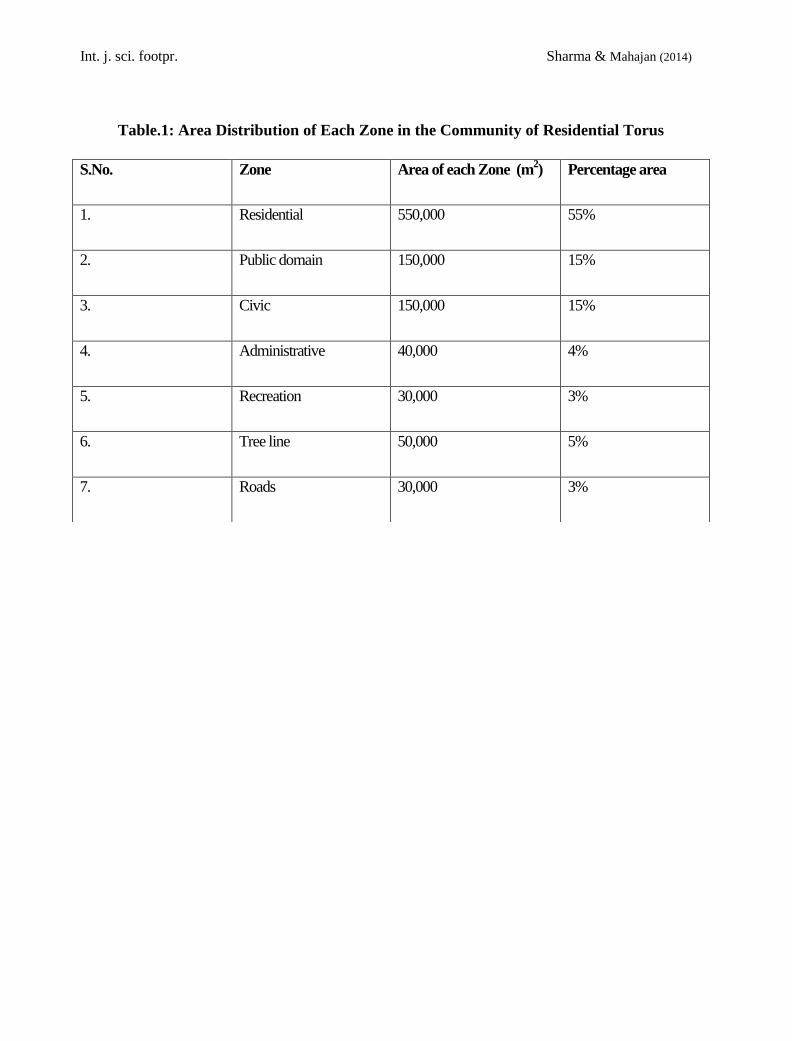
percentage area distribution of each zone will
be taken as explained in Table 1. In the
proposed community design, we have
introduced one main road of 17 m wide and
the length of each community is depicted in
the Fig. 3. More than 40% area will be left as
open space which includes recreation area and
green belt.
Residential Area (550,000 m2) will embrace
facilities like housing and parks. Parks will
have grass, flowers, small plants, and herbs
grown by the use of artificial soil and deep
flow technique (DFT). Since the
circumference of the down surface comes out
to be 5,549m, thus inhabitants will have to
cover maximum distance of around 2,500 m
to reach at the other end of community.
During the stay in space specially working in
the low gravity, it is obvious for persons to
face physiological and psychological
problems. To ease such problems and to
increase productivity and efficiency, certain
precautions and preparations have been
provided in Lakshita, in terms of atmosphere,
day and night cycle, rotation of the settlement,
line of sight etc. In addition to these
recommendations a tree lining (5 m each)
would be provided on both sides of the down
surface area of residential torus as the
residents won't feel suffocated in limited area.
Public Area (150,000 m2) constitutes
educational institutions, parks, library,
hospital and sports centre. Various games
(Sharma, N., Mahajan, A., 2013b) inside the
settlement just like Earth and outside the
settlement like Micro gravity football, Water
splash, Rope relay, and space swimming will
be planned for community. For outside games,
we can utilize the artificial habitats (Ref
sec.3.0) after the completion of mining
mission. It has been estimated that in the
beginning there will be around 200 children
(approximately 5% of the total population).
50,000 m2 areas will be allotted for education
hub in Lakshita which includes training centre

Int. j. sci. footpr. Sharma & Mahajan (2014)
for youngsters. This area will be sufficient
even for the extended population
requirements. Rest of the 100,000 m2 area
will be utilized for other remaining facilities
including sports centre, health facilities,
community centre etc.
Recreational Area (30,000 m2) will integrate
a lake and an amusement park. Various
exercising devices like cycle ergo meter,
treadmill and resistance exercising device will
be worked out by the residents working in the
low gravity environment to alleviate various
physiological problems associated with long
term living in low gravity region.
Civic Centre (150,000 m2) will incorporate
facilities like shopping centres, restaurants,
hotels, offices, fuel stations, service stations
etc. Fuel stations will get supply from the
storage areas (Ref. sec. 2.5) of the docking
ports and methane which is produced as a
byproduct of an aerobic digester deployed in
the agricultural torus will be used for
household purposes.
As proposed in Lakshita, the initial transient
population will be around 500, thus hotels will
have this much capacity to accommodate
visitors. Later on this number could be
increased according to the requirement.
Administrative Area (40,000 m2) comprises
of Law enforcement Centre for Communal
Welfare (LCCW), emergency services,
Lakshita Managing Association (LMA)
headquarters, food control centres and various
waste management and power distribution
units.
2.2 Agriculture torus
For short duration missions, pre-packaged
food and occasional fresh food
supplementation has been provided by Earth
e.g. for International space station (ISS)
habitats. But in case of space settlement, we
need to cultivate most of the food by using
soil less techniques. The food production will
require 500,000 m2 surface area. This
requirement could be fulfilled by providing
down surfaces at the centre 145 m wide in
agricultural torus. For fulfilling the additional
needs of visiting spacecrafts, extra area
460,000 m2 will be introduced by placing
another stack, 132 m wide located 30 m below
the first stack (Fig.4). It will embrace storage
of food products, food processing, animal
husbandry and plantation in addition with
backup production area. The percentage
distribution of agriculture area will be as
shown in the Fig 5. Processing units will
verify material before and after processing,
followed by packing the final products
according to the requirements. The delivery-
gate provided at the down surface will
distribute the packed material in the

Int. j. sci. footpr. Sharma & Mahajan (2014)
residential segments. A small research
laboratory will also be established in the torus
which will include research on growth of
plants and bio medical research.
Growing area will consist of different layers
stacked vertically above each other and
cultivated by NFT (Nutrient Film Technique)
(Winterborne, J., 2005). The important factors
that influence the growth of plants are the
nutrients (minerals which contain C, H, N, O,
P, S), the soil and the climatic conditions
(temperature, light, atmospheric composition).
The plants like potatoes, cabbage, cucumbers,
celery, broccoli, bell peppers, radish, beans,
carrots, beets, peas, corn, turnips, onions and
spinach will grow in a constant flow of
nutrient enriched solution having the primary
dissolved cations Ca2+, Mn2+ and K+, and
the major nutrient anions NO3-, SO2-4, and
H2PO4. For the macronutrients the commonly
used chemicals will include potassium nitrate,
calcium nitrate, potassium phosphate and
magnesium sulphate. Various micro nutrients
like Fe, Mn, Cu, Zn, B will be added to
hydroponics solutions to supply essential
elements.
It is known that soil formation will take
millions of years and moreover the cost to
import it is beyond limit. So, we suggest the
use of an artificial soil on Lakshita, which
contains two major types of nutrients:
macronutrients (C, H, O, N, P, S, K and Ca)
and micronutrients (C, Fe, Mn, B, Zn, Cu and
Ni). Most of these substances could be
obtained from the mining on the lunar base or
even household waste that results from intense
filtration of water. These fertilizers will be put
in tanks followed by transportation with the
elevators that connect different sectors. The
bacteria and worms present in these sectors
will make optimal conditions for the
decomposing process. This way, the nutrients
will improve the soil with organic substances
that have a smaller molecule, resulting in
more aired and improved fertile soil according
to the necessities of the settlement.
Since, red or blue light will be beneficial for
the photosynthesis process, so light will be
filtrated through glass of the corresponding
colour. Humidity and temperature will be
permanently controlled by the automatic
acclimatization system that responds to
plants’ necessities. We will be growing
peaches, oranges, bananas, pears,
strawberries, melons, apples, grapes, using
this technique.
We took into account the NASA studies from
1975 (Johnson, R. D. and Holbrow, C., 1975)
regarding the choice of diet, but we decided to
eliminate and/or replace some products. For
example, we considered that the presence of
large animals like the cow and bull would be

Int. j. sci. footpr. Sharma & Mahajan (2014)
too difficult to support, as these animals
require fields to graze on. The animals will
not be adaptable to low gravity environment,
as they may suffer major injuries like bone
breakage when fall. Its impact may cause
wobbling in the settlement, which could be
corrected only through the consumption of
precious fuel. Instead of these large animals,
we proposed sheep and goats, because we can
benefit from their milk, wool and meat.
Another inconvenient is the trout, a
pretentious fish that requires permanently
filtered, cool and running water. That is why
we proposed the carp and the tilapia that
breeds reproduce rapidly and don’t require
running water.
Another proposal is to cultivate the water lily
as it filtrate water; it loves polluted waters and
can be used to produce furniture. Farms will
be situated in the agricultural sectors, where
animals will receive a necessary surface in
order to live under optimal conditions.
We dropped the sugar plantations because that
would require pollination, but we will breed
bees instead, in order to use their honey as
sweetener, while the propolis is used as
preservative for the products that are stored in
the technological area, situated under the
agricultural zone. Before being stored in
aseptic, recyclable (to prevent tainting)
packages, the products are treated with
ultraviolet waves. The storage will be done in
vacuumed containers that prevent
deterioration and pests. To obtain an efficient
distribution system we use special pipe
network under the down surface in which the
packages are sent to the programmed
destinations.
2.3 Atmosphere / Climate / Weather
Control
To assure the good living conditions of the
people in Lakshita, a chemical composition
similar to the one on Earth will be chosen for
the settlement’s atmosphere. Nitrogen will be
used mostly to dilute the oxygen (as a buffer),
thus preventing instantaneous combustion or
lung problems. The necessary nitrogen for
Lakshita’s atmosphere will be brought from
Earth and will be maintained constant due to
the fact that in the breathing process the
nitrogen will not be consumed. The required
20% part of atmosphere as Oxygen will be
delivered partially from Earth and partially
will be obtained through the electrolysis of
water (resulted from reduction reaction of
silicates from or Ilmenite (FeTiO3) from
Moon). Successive heating would separate
hydrogen from the lunar soil at 600° C and it
would decompose into a mixture of iron and
rutile (TiO2) at 900°C. At 1525°C iron will
melt and leave behind rutile which will
decompose into titanium and O2 at 1640°C.

Int. j. sci. footpr. Sharma & Mahajan (2014)
Every 1000g of Ilemnite can produce 317.88g
of oxygen.
A person consumes a quantity of 0.25-3.6
litres of O2 per min and exhales 0.2-2.89 litres
per min. The composition of the atmosphere
must be kept constant, so the air in Lakshita
will be permanently passing through a process
of cleaning and refreshing. One of the
detection technique used will be Neonatal
Colorimetric Carbon Dioxide (NCCD)
detection membrane (Schmolzer, G. M. et al,
2011) having ph sensitive chemical indicator
that undergoes colorimetric changes in the
presence of carbon dioxide. The change in
color of the membrane depends upon the
concentration of carbon dioxide in contact.
The air will be absorbed from the residential
areas and taken to the agricultural area, where
plants will use the excess CO2 for
photosynthesis. On an average, a person
consumes 53 litres of O2 and a leaf can
produce 5 ml O2 per hour. On Lakshita only
the most productive plants will be grown,
regarding the photosynthesis each healthy tree
is having approximately 200,000 leaves hence
it will produce around one thousand liter of
O2. Therefore one tree will be sufficient for
approximately 18 persons to provide
necessary O2. Since we are suggesting 5 %
area in residential torus as green belt, which
turns around 50,000 m2, so we can plant
around 500 trees in this region to be sufficient
for around 9000 residents. Some animals that
will live in Lakshita will consume more
oxygen than the human being, so the oxygen
could be captured by using oxygen specific
molecular severs from agricultural zone and
sent to the residential torus.
Hyper High Efficiency Particulate Air
(HEPA) uses an aggregate of fibres to
disinfect air with an efficiency of 99.97 to ≥
99.98 % (removing particles as small as 0.003
microns). Sheets of thin Aluminum filter
fibres along with activated carbon slab and
zeolites would facilitate air purification.
(www.fastbrowser.net/Are-IQAir-MPPS-
HyperHEPAeric.htm)
NASA studies showed that the optimal living
conditions are at a temperature of 20-25 ºC, a
humidity of 40-60% and an atmospheric
pressure that can be smaller than the one on
Earth (0.5 atm) without affecting the
organisms. The air will be permanently
filtered and dehumidified with the help of a
dehumidifier, especially in the agricultural
sectors, where the humidity will be at higher
end (due to the perspiration of the plants),
which will be condensed and will be returned
to the water cycle of Lakshita. All these
actions will assure not only the constant
composition of the atmosphere, but also a
protection against bacteria and possible

Int. j. sci. footpr. Sharma & Mahajan (2014)
diseases and will be controlled by a system of
fans and thermal engines supervised by a
powerful, specialized network of computers
(Atmosphere and Climate Control Network).
This network will also monitor the level of
contamination of the air with toxic substances
with the help of gas chromatograph mass
spectrometer instruments. The toxic
substances will be eliminated with activated
charcoal, through catalytic oxidation or
advanced filtrations.
2.4 Central Cylinder
The heart of the Lakshita, i.e. central cylinder
will (Fig. 6) host different facilities like:-
control centre (763,020 m3) to control all the
activities of Lakshit including its rotation and
transportation, water storage area (254,340
m3), recreation / observatory (127,170 m3)
areas and power production distribution unit
(381,510 m3). Location of refining and
processing area in the central cylinder will
take full advantage of micro-g to deal with
processing of mined materials proficiently as
transportation cost reduces. 5,086,800 m3
volumes will assist the heavy industrial
activities in a better way. This includes
inspection chamber, cleaning unit, in addition
with their individual functioning unit. Storage
area will be provided around the centre of
each unit to store the resulting outcome of
previous procedure. Other than these, two
storage areas (1,271,700 m3 each) will be
provided on either sides of the cylinder near
docking ports. One part of processed materials
will be stored to fulfil the requirements of
Lakshita whereas the other part will be for
export, therefore enhancing the viable &
commercial aspects of Lakshita.
Broadly, the procedure of processing the
mined material will be divided into three
steps.
• Crushing and grinding of ores
• Effective separation of materials
• Smelting and refining chamber
The mined material including metals, volatiles
or even hydrocarbons that arrives at the
processing unit in central cylinder will be of
many sizes and shapes. These will be
unloaded, moved, stored, and managed by a
completely autonomous system known as
Load EXT system consisting of pair of
coordinating arms with rotating base and
Electro-adhesive Layered Conveyer Belt.
Material will be maneuverer automatically by
large robotic arms attached to the tracks on
the end of docks. The cargo will then be
passed on to the series of tracks from one
processing unit into other. At the entry of the
each unit inspection centre is provided
equipped with Laser technique to check the

Int. j. sci. footpr. Sharma & Mahajan (2014)
input material size and its physical properties.
In the beginning, it is necessary to crush and
grind the ores to provide one stream of
material of enhanced grade. Crushing centres
will be provided below the storage area. When
mined ores slides down from docks, it will be
directly moved into the storage area. Then it
passes to crushing unit through the conveyor
belts to reduce its size up to 100 microns.
Here 99% of energy used in crushing and
grinding the material will be converted into
heat. This unit will have various methods for
crushing the ores {Roll crushers with the
lower requirement of energy, Fluid energy
mills having 1 m diameter and handling
material up to 2 tons / hour (SME Mineral
Processing Handbook, 2011), Bowl-shaped
bearing will assist crushing having capacity of
25-45 tons per hour, Hammer mills for coal
grinding using hot gas for drying the coal};
the decision to use each one would be on the
basis of size, shape, and even chemical
compositions. The power consumed to each
crushing unit will be 30-55 KW for which it
will require motor of 60 horsepower (HP).
After being crushed, all the ores will pass over
the shaker to the sieve tray such that the ores
which are not crushed properly will be sent
back again after their detection through this
sieve tray. Sieve tray will be a division for
separation and crushing chamber as it will
decide the drifting of ores in powdered form.
Different separating divisions will be
established in the second part of the
processing unit like; electrostatic field
utilizing high voltage plate separators;
magnetic field division utilizing cross-belt
magnets; density difference division using air-
or hydro- cyclone; vaporization /
condensation; sublimation / deposition,; sizing
/ sieving. Ten drum types Magnetic separators
(http://www.gunt.de/networks/gunt/sites/s1/m
mcontent/produktbilder/08328000/Datenblatt/
08328000%202.pdf) made up of permanent
magnet will be installed in four units to
separate magnetic and non-magnetic material.
As the material will be allowed to shift over
the drum, powerful magnets will hold the
magnetic material to the revolving shell and
non-magnetic particles will fall without
deflection on the lower conveyor belt. Each
drum having diameter of 60 cm and length 1
m, with the capacity of 1 tone per hour will
rotate at 6000 rpm produces an average
magnetic intensity of 1500-2000 gauss at the
surface.
As all the PGM falls in the nonmagnetic
category thus they will be directed towards
the floatation machine and then the drying
tank used for drying wet ores. The ores of
PGM will be shifted to the spiral classifier for
final separation in the floatation machine

Int. j. sci. footpr. Sharma & Mahajan (2014)
working in four steps: Coarse separation,
Swept separation, Fine separation and
Floatation. The ores collected will be shifted
to drying tank and vibrated on shaker to get
fine form.
The materials will be further transferred to the
smelting and refining chamber. In this torii
mainly three procedures will take place: (a)
Steps-smelting (b) Leaching and (c)
Purification. For steps-smelting material will
be pushed in to the melting unit having fleet
of electric furnaces attaining the temperature
up to 1200°C
(http://www.jmrefining.com/page-
view.php?pagename=The-Process) in 12
hours cycle. From literature review (Robert &
Epstein, 1982; Levy, 1973; Kerridge, 1985) it
can be concluded that if one wishes to extract
water and carbon dioxide combined or
separately from mined materials we need to
heat that material at different temperatures. At
the end of each furnace filters will be
provided, through which filtrate will be
collected in the separate modules until the
silver based containing platinum and
palladium metals and iron based containing all
the five PGMs solidifies into ingots. Then the
material will be shifted to the next unit for
leaching. The metals will be converted into a
soluble form in the presence of aqueous
media. The concentration of nitric acid and
hydrochloric acid in ratio 1: 3 will be form
aqua regia by following the reaction:
HNO3 + 3 HCl NOCl + 2 [Cl] + 2 H2O
The formed aqua regia will react with the
material obtained from the smelting unit to
form PGM solution by following the reaction
given below:
Pt+6Cl-+4 NO3
- + 8 H
+ PtCl6
2- + 4 NO2 + 4 H2O
In final step the solution of PGM will be
pushed towards purification unit through
pipes for final product. In this unit solvent
extraction to separate metal from solution,
evaporation, dissolution, precipitation and
finally filtration will take place.
The organic constituents will be exhausted
into the space and particulate matter will be
collected in the HEPA filters for further
disposal. Vapour phase processes will include
heating and volatilization. In case of volatile
materials, grinding will not be required. If the
volatile materials will be in the form of
silicates, then only melting will be sufficient
for processing. If such materials will exist in
the form of minor components such as ice
balls the vaporization will be needed. Another
probability can be the chemical combinations,
like: water of hydration, ammonium or
carbonate compounds, then repeated heating
will be required. These materials would
certainly generate enough gases such as CO,

Int. j. sci. footpr. Sharma & Mahajan (2014)
CH4, N2, CO2, HCN, NO2, etc. Pressurized
flow of such gases will be arranged by the use
of a cold trap. Steam ejectors could be planted
as gas pumps could achieve compression
ratios of up to 10:1 (Perry’s Chemical
Engineer’s Handbook, McGraw Hill, 2008).
Processing unit will also have vacuum
distillation unit and glass fabrication unit etc.
for the final processing of the materials. These
processed materials will be carried to storage
areas, provided on both sides of the central
cylinder through elevators.
2.5 Docking Ports
The two docking port (with radius 130 m and
height 60 m) having volume 3.2 X 10⁶ m3
each intends to give all facilities like:
warehousing imports & exports, storage &
repair unit for space craft, elevators etc. will
ease the functioning of settlement (Fig. 7).
Any kind of repair of space ships including
repair of internal parts, healing the damaged
parts, mending any functional components
etc. (checking the fuel lines for cracks,
ensuring engine bays for adequate ventilation
to reduce the chance of vapor build up and
risk of explosion, replacement of internal
components e.g. Piston, valves etc.) will be
done in the spacecraft repair unit. Each
facility will be interlinked with connecting
spokes.
The dust removal chamber utilizing number of
equipments will be divided into two major
parts: a removable pressurized gas storage
tank and a handle with a gas exit nozzles. The
gas used will be carbon dioxide because it
contains heavier molecules; as a result, its
translational and rotational temperature
behaves similarly in free jet expansions. Once
positioned, the trigger will be pulled to allow
gas to flow from the tank to the gas exit
nozzles. On the front of the handle, there will
be three nozzles in a triangular configuration
with a common focal point. As gas will exit
into a zero pressure environment, it will
rapidly expand resulting in the removal of the
dust particles. The waste from the spaceships
will be disposed in the chamber consisting of
a maceration chamber for macerating the
material and an incinerated chamber for
converting the macerated material into
incinerated material. The leftover byproducts
will be transported through the elevators to
the industries for manufacturing various
chemicals.
2.6 Structural Isolation from Vibration-
Causing activities
Although down surface of residential torus
will be 810 m away from central processing
unit and is only connected through spokes
(ref. fig 1). Still there will be the some
probability that produced vibrations in

Int. j. sci. footpr. Sharma & Mahajan (2014)
processing and refining area may cause
certain disturbance in residential torus. Thus
we suggest placement of Active Rack
Isolation System (ARIS) at different locations
capable enough to detect and absorb even
very minute vibrations {frequencies greater
than 0.01 Hz, (The range of ARIS is 0.05 to
300 Hz)} (Fialho, I.J., Bushnell, G.S., 2002)
using a combination of sensors and actuators..
Moreover, use of Bisco medical silicones
between different parts of the settlement
further ensures isolation in a manageable way.
The proposed design will fulfil the qualitative
criterion of structure as explained in Table 2.
3. Construction planning of Lakshita
In space, there are natural resources (Lewis, J.
S., 1991) namely metallic nickel-iron alloy,
platinum, limonite, silicate minerals, hydrated
minerals, bituminous material and various
volatiles (including water, ammonia, carbon
dioxide, methane, ammonium compounds)
and non-metals, can be utilized as ores, in the
engineering sense. These have been identified
either in meteorites, in lunar soil (Taylor,
Jeffrey and Linda, M., 2003) or spectroscopic
ally in asteroids and comets (Mining the Sky,
1996). Even a relatively poor resource
asteroid contains fewer amounts of iron and
other volatiles in the form of hydrated
minerals, and oxygen. The present cost of
shipping fuel to low earth orbit (LEO) comes
out to be $2000 million per year (Kuck, 1995)
for boosting the communication satellites.
Thus the established space infrastructure will
act as refueling station for interplanetary
satellites and will be beneficial from
economical point.
For developing the mining station mankind
needs to be a space-capable (Gehrels T., ed.,
1994, Chapman, C. R., Morrison, D., 1994).
We suggest construction of multiple modules
in space separately and then assemble them
later. Weightlessness is the key difference in
space architecture and Earth based
architecture (We do not need anything to
support weight in space).
Initially, we need to send mining equipments
from Earth e.g. ore movers, grinders,
separators etc. and after that additional
equipments like solar smelter, gas collection
& refining, girders, rods, sheet metal, slag
processing, shaping, rock wool production, &
slag handling etc. could be manufactured on
the lunar surface from mined material. These
materials would also facilitate construction of
Lakshita. Carbon fibres and composite
materials can be incorporated as major
structure components because of their high
strength to weight ratio. Once the construction
of central cylinder is completed the processing
unit will be shifted from lunar base to
settlement location. The construction
Int. j. sci. footpr. Sharma & Mahajan (2014)
sequence of Lakshita will be divided into
following six phases:-
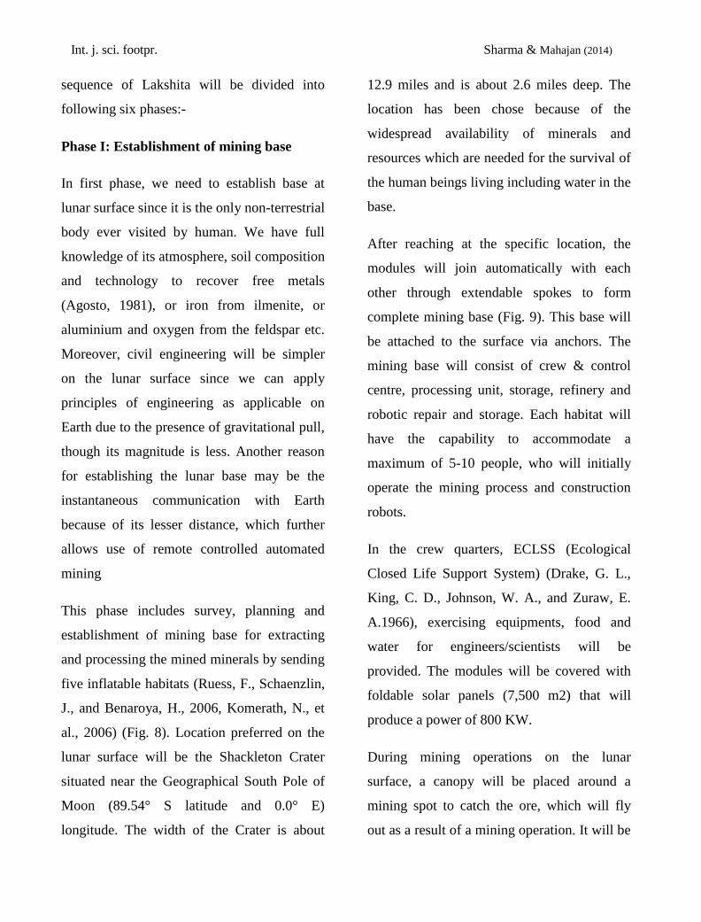
Phase I: Establishment of mining base
In first phase, we need to establish base at
lunar surface since it is the only non-terrestrial
body ever visited by human. We have full
knowledge of its atmosphere, soil composition
and technology to recover free metals
(Agosto, 1981), or iron from ilmenite, or
aluminium and oxygen from the feldspar etc.
Moreover, civil engineering will be simpler
on the lunar surface since we can apply
principles of engineering as applicable on
Earth due to the presence of gravitational pull,
though its magnitude is less. Another reason
for establishing the lunar base may be the
instantaneous communication with Earth
because of its lesser distance, which further
allows use of remote controlled automated
mining
This phase includes survey, planning and
establishment of mining base for extracting
and processing the mined minerals by sending
five inflatable habitats (Ruess, F., Schaenzlin,
J., and Benaroya, H., 2006, Komerath, N., et
al., 2006) (Fig. 8). Location preferred on the
lunar surface will be the Shackleton Crater
situated near the Geographical South Pole of
Moon (89.54° S latitude and 0.0° E)
longitude. The width of the Crater is about
12.9 miles and is about 2.6 miles deep. The
location has been chose because of the
widespread availability of minerals and
resources which are needed for the survival of
the human beings living including water in the
base.
After reaching at the specific location, the
modules will join automatically with each
other through extendable spokes to form
complete mining base (Fig. 9). This base will
be attached to the surface via anchors. The
mining base will consist of crew & control
centre, processing unit, storage, refinery and
robotic repair and storage. Each habitat will
have the capability to accommodate a
maximum of 5-10 people, who will initially
operate the mining process and construction
robots.
In the crew quarters, ECLSS (Ecological
Closed Life Support System) (Drake, G. L.,
King, C. D., Johnson, W. A., and Zuraw, E.
A.1966), exercising equipments, food and
water for engineers/scientists will be
provided. The modules will be covered with
foldable solar panels (7,500 m2) that will
produce a power of 800 KW.
During mining operations on the lunar
surface, a canopy will be placed around a
mining spot to catch the ore, which will fly
out as a result of a mining operation. It will be

Int. j. sci. footpr. Sharma & Mahajan (2014)
the main collection mechanism. When there's
enough ore in the canopy, it will be sealed off
and moved to the mining base.
Phase II: Construction of Central cylinder
(Fig. 10 a-b)
After sufficient availability of building
materials, the construction of framework of
central cylinder including docking ports,
refining and processing units will be initiated.
Then, this structure will be shifted to L5 for
the further sequential construction. Since
shifting the material from Earth to lunar
surface is more expansive in comparison to
shifting from Earth to L5 because of the lunar
gravity.
Phase III: Construction of spokes and
sliding cylinders (Fig. 10 c-d)
Under this phase the frame work of spokes
joining the torus will be build. Alongside the
completion of spokes framework of sliding
cylinders will take place. Then completion of
sliding cylinders will take place followed by
establishment of its internal facilities.
Phase IV: Construction of agriculture torus
(Fig. 10 e-f)
This phase will deal with the construction of
framework of agricultural torus followed by
completion of agricultural torus including
assembly of NFT tanks, construction of food
processing units and setting up research centre
in the agricultural region. Alongside the
framework of the residential torus will be
made.
Phase V: Construction of residential torus
(Fig. 10 -g)
This phase comprehend the completion of
residential torus including establishment of
residential, administrative, civic centre, public
domain and recreational zones. In this phase
houses will be constructed for initial
population of 4500 including children also. It
has been estimated that 80% of the population
will be young couples of the age between 22
years – 40 years, 5% will be children and rest
of the 15% will be single. Thus to rough
estimation of 2500 houses will be more than
sufficient at this stage. Later on as the
population requirements will increase (as
there is projection of 10,000 people within 25
years) the new houses could be constructed.
After the completion of residential torus
framework of lower docking cylinder will be
constructed.
Phase VI: Finishing phase (Fig. 10 h)
The last phase will be the finishing phase
including the completion of lower docking
cylinder accompanied by the construction and
assembly of reflecting mirror, antennas for
communication, solar panels and thrusters for

Int. j. sci. footpr. Sharma & Mahajan (2014)
rotation. For the completion of different
phases automated construction and assembly
devices will be required assisted by high-tech
robotic systems (Yoshimitsu, T., Kubota, T.,
Nakatani, I., Adachi, T. & Saito, H., 2003).
Business development in terms of economy
growth in the settlement will be based upon
the technology used in capturing and mining
of asteroid. The mining process will continue
even after the completion of settlement
construction. The trade of different processed
materials (an outcome of refining and
processing unit of settlement) with Earth will
start generating revenue. After the completion
of construction of settlement, the deployable
modules will be modified to make a movable
mining base. The modules will be shifted to
next destination to be mined. Out of five
modules two will be modified as stadium to
organize recreational activities like: zero-g
games for habitats.
4. on-Orbit Infrastructure
Relay satellites, solar power satellites (SPS),
and communication satellites will be used to
fulfil necessary tasks for Lakshita, such as
transmission of data, provision of power and
communication. Relay satellites will reflect
communications data to their destination. SPS
will be employed for the purpose of providing
power to ensue operations on Lakshita.
Communication satellites will transmit data
from Lakshita to lunar base and to other
locations, if required.
5. Conclusion
The construction of a space settlement
presents an opportunity to re-engage in the
quest for knowledge and also presents
incredible materials in return. Once we
establish a lunar base, we can start mining the
Moon followed by mining asteroids to extract
various resources which can be utilized to
construct Lakshita. All construction phases
will be planned at the location of the
settlement except first and second phases in
which construction of central cylinder will
take place. While designing the residential
area of Lakshita various architectural skills
like: line of sight, overhead clearance,
environment, connectivity, flexibility of
design etc. will be considered. The needs of
all age group inhabitants will be taken into
consideration while designing the
communities. In agricultural zone, area could
be increased for the growing demands by
adding another stack of 30 m down from the
central strip. In central cylinder maximum
percentage of volume will be provided for
refining and processing unit. This part will
include crushing units, separation units and
smelting and refining unit. Provision of
storage area will be considered on either sides

Int. j. sci. footpr. Sharma & Mahajan (2014)
of the cylinder, closer to port facilities. Water
storage area, power distribution and control
unit etc. will also be the part of central
cylinder. The dust removal units will be
introduced at the docking areas to prevent the
rest of the settlement of the dust coming from
the mined materials. On completion of
Lakshita, our future endeavors can be
extended to other probable places in space to
recover space-based materials from asteroids
and export them to Earth
References
[1] Adams, Constance 2002, (Aero) Space
Architecture takes flight. Houston, TX:
Space architect.org, Retrieved 2009-10-
14.
[2] Agosto, W.,Beneficiation and Powder
Metallurgical Processing of Lunar Soil
Metal, Space Manufacturing 4,
Proceedings of 5th Princeton AIAA
Conference, 1981.
[3] Chapman, C. R., Morrison, D., Impacts
on Earth by asteroids and comets,
Assessing the hazard, Nature, 367(6), 33-
39,1994.
[4] Drake, G. L., et al., Study of Life-
Support Systems for Space Missions
Exceeding One Year in Duration, The
Closed Life-Support System, Ames
Research Center, Moffett Field, CA,
,NASA SP-134, 1-74, 1966.
[5] Fialho, I.J., et al., Microgravity Flight
Characterization of the International
Space Station Active Rack Isolation
System, AIAA Microgravity
Measurements Group Meeting, The
World Space Congress; Houston, TX,
2002.
[6] Gehrels, T., ed., Hazards due to Comets
and Asteroids, University of Arizona
Press, 337-357, 1994.
[7] Glaser, P. E., Power from the Sun. It's
Future, Science, 162, 857-886, 1968.
[8] Johnson, R. D. and Holbrow, C., editors
1975, Space Settlements: A Design
Study. NASA SP-413.Retrieved
December 8, 2003:
[9] Kerridge, J. F., Carbon, Hydrogen, and
Nitrogen in Carbonaceous Chondrites:
Abundances and Isotopic Compositions
in Bulk Samples, Geochim. Cosmochim
Acta 49, 1707-1714,1985.
[10] Komerath, N., et al., System Design of
Large Space Structures Using Tailored
Force Fields, AIAA Space-2006.
[11] Kuck, D., The Exploitation of Space
Oases, in Princeton Conference on Space
Manufacturing, 1995.
[12] Levy, et al., The Organic Analysis of
the Murchison Meteorite, Geochim.
Cosmochim. Acta, 37, 475-483,1973.
[13] Lewis, J. S., Construction Materials
for an SPS Constellation in Highly

Int. j. sci. footpr. Sharma & Mahajan (2014)
Eccentric Earth Orbit, Space Power, 10
No 3 and 4, 353-362,1991.
[14] Mining the Sky: Untold Riches from
the Asteroids, Comets, and Planets.
Reading, MA: Addison-Wesley
Publishing, 1996.
[15] Nagatomo, M.,1996, An approach to
develop space solar power as a new
energy system developing countries,
56:1,; Solar energy 111: Tim Hornyak,
Farming solar energy in space (2008),
Scientific America, <http://
www.scientificamerican.com/article.cfm
?id=farming-solar-energy-in-space>,
2008, last accessed on 2009.
[16] Perry, R. & Green, D., Perry’s
Chemical Engineer’s Handbook, (8th
Edition), Mc Graw Hill,2008.
[17] Robert, F. & Epstein, S., The
Concentration and Isotopic Composition
of Hydrogen, Carbon, and Nitrogen in
Carbonaceous Meteorites, Geochim.
Cosmochim Acta, 46:81-95,1982.
[18] Ruess, F., Schaenzlin, J. & Benaroya,
H., Structural Design of a Lunar Habitat,
J. Aerospace Eng, 19(3), 133–157,2006.
[19] Schmolzer, G. M et al., Assessment of
flow waves and colorimetric CO2
detector for endotracheal tube placement
during neonatal resuscitation,
Resuscitation, 82 - 3, 307-312,2011.
[20] Sharma, N. & Mahajan, A., Lakshita -
Mining and research hub at L5,
Advances in space research, 52, 1063–
1071,2013a.
[21] Sharma, N. & Mahajan, A., Zero-g
games for space habitates, Research and
review: Journal of space science
technology, 2013b.
[22] SME Mineral Processing Handbook,
Society for Mining, Metallurgy, and
Exploration, Inc, 2011.
[23] Space research associates, Report of
satellite solar power system, 6, Space
power1 (1986).
[24] Taylor, Jeffrey & Linda M., Lunar
Prospecting, Advances in Space
Research, 31:11, 2403-2412,2003.
[25] Winterborne, J., Hydroponics: Indoor
Horticulture, Pukka Press, 113,2005.
[26] Yoshimitsu, T., et al., Micro-hopping
robot for asteroid exploration, Acta
Astronautica, 52, 441–446,2003.
[27] http://lifesci3.arc.nasa.gov/SpaceSettle
ment/75SummerStudy/Design.html.
[28] http://www.gunt.de/networks/gunt/site
s/s1/mmcontent/produktbilder/08328000/
Datenblatt/08328000%202.pdf
[29] http://www.jmrefining.com/page-
view.php?pagename=The-Process
[30] www.fastbrowser.net/Are-IQAir-
MPPS-HyperHEPAeric.htm.

Int. j. sci. footpr. Sharma & Mahajan (2014)
Figure 1: The Space Settlement- Lakshita
Figure 2a: Hybrid Torus

Int. j. sci. footpr. Sharma & Mahajan (2014)
Figure 2b: Residential Torus

Int. j. sci. footpr. Sharma & Mahajan (2014)
Figure 3: Community Design
Figure 4: Agriculture Torus

Int. j. sci. footpr. Sharma & Mahajan (2014)
Figure 5: Percentage Distribution of Agriculture Area
Figure 6: Central Cylinder

Int. j. sci. footpr. Sharma & Mahajan (2014)
Figure 7: Docking Cylinder
Figure 8: Artificial Habitat

Int. j. sci. footpr. Sharma & Mahajan (2014)
Figure 9: The Mining Base
Figure 10: Construction Sequence
Int. j. sci. footpr. Sharma & Mahajan (2014)
Table.1: Area Distribution of Each Zone in the Community of Residential Torus
S.No. Zone Area of each Zone (m2) Percentage area
1. Residential 550,000 55%
2. Public domain 150,000 15%
3. Civic 150,000 15%
4. Administrative 40,000 4%
5. Recreation 30,000 3%
6. Tree line 50,000 5%
7. Roads 30,000 3%

Int. j. sci. footpr. Sharma & Mahajan (2014)
Table 2: Qualitative Criterion for Settlement Design
S. No. Criterion Explanations
1. Long line of sight 180 m which will be more than 64 m (minimum required value).
2. Overhead clearance 106.4 m ceiling
3. Environment Healthy environment as 5 m tree lining will be provided
throughout the community. Moreover, initially the young couples
will be preferred of age between 22– 40, but with passage of time
community will be developed with the population of all ages.
4. External Views Windows will be provided in the structure.
5. Natural light Two circular reflecting mirrors at 45° and two frustum
shaped mirrors will be provided.
6. Connectivity The whole settlement will be connected with the spokes through
which elevators will be provided to connect different parts
of settlement.
7. External environment contact The settlement will be the closed structure. Thus only at the
docking ports residents will have external contact. Community
will plan recreational activities even outside the settlement .for the
residents like zero-g games.
8. Privacy Privacy of the habitats will be taken care as individual houses for
families will be provided. We are planning 2500 residences for
families and singles in initial stage.
9. Interior Luxuries interiors could be provided in order to allure the persons
to stay far away from their mother land.
10. Construction standard Modular
11. Flexibility in designing Initially designing and construction of community will be done for
the population of 4,500. Rest of the construction and designing
will be done afterwards.
12. Safety Water storage zone at the central cylinder will act like shelter for
habitats at the time of solar flares.