OMSU Series 3 Orbital Motor - BIBUS Hidrotos
24
Technical Information OMSU Series 3 Orbital Motor
-
Upload
khangminh22 -
Category
Documents
-
view
4 -
download
0
Transcript of OMSU Series 3 Orbital Motor - BIBUS Hidrotos

Technical InformationOMSU Series 3 Orbital Motor


Contents
Chapter 1: Code numbers........................................................................................ 5OMSU Series 3 code numbers.............................................................................................................................. 6
Chapter 2: Dimensions............................................................................................. 9OMSU dimensions.............................................................................................................................................. 10
Chapter 3: Connection dimensions, attached component .................................. 11
Chapter 4: Internal spline data for the component to be attached.................... 13Material: ............................................................................................................................................................. 14Hardening specification: .....................................................................................................................................14
Chapter 5: General data.........................................................................................17Drain connection on OMSU or attached component ......................................................................................... 18Installing OMSU................................................................................................................................................. 18Mounting............................................................................................................................................................. 18Direction of rotation............................................................................................................................................ 19Maximum tightening torque ...............................................................................................................................19Checking OMSU................................................................................................................................................. 19Exploded view OMSU........................................................................................................................................ 20OMSU spare parts list ........................................................................................................................................ 21
Orbital Motor | Contents | iii


Chapter
1Code numbers
Topics:
• OMSU Series 3 code numbers

OMSU Series 3 code numbersTable 1: Ultra-short motor
Withoutoutputshaft
OMSU 80 OMSU100
OMSU125
OMSU160
OMSU200
OMSU250
OMSU315
OMSU400
151F0578 151F0579 151F0580 151F0581 151F0582 151F0583 (*)
Table 2: Technical data
Motor size OMSU80
OMSU100
OMSU125
OMSU160
OMSU200
OMSU250
OMSU315
OMSU400
Geometricaldisplacement
cm3 80.5 100 125.7 159.7 200 250 314.9 393
Max. speed min-1 cont. 810 750 600 470 375 300 240 190
int. 1000 900 720 560 450 360 285 230
Max. torque daNm cont. 20 25 32 36 46 50 63 67
int.(1) 24 30 38 48 60 63 79 79
peak 26 32 40 51 65 72 90 98
Max. output kW cont. 16 17.5 17.5 16 14 12.5 11.5 10.5
int.(1) 19 21 21 21 17.5 15 13.5 12.5
Max. pressuredrop
bar cont. 175 175 175 160 160 140 140 120
int.(1) 210 210 210 210 210 175 175 140
peak(2)
225 225 225 225 225 200 200 175
Max. oil flow I/min cont. 65 75 75 75 75 75 75 75
int.(1) 80 90 90 90 90 90 90 90
Max. startingpressure withunloadedshaft
bar 12 10 10 8 8 8 8 8
(*) Please contact the sales Organization for the code numbers of these motors.(1) Intermittent operation: permissible values may occur for max. 10% of every minute.(2) Peak load: permissible values may occur for max. 1% of every minute.
Orbital Motor | Code numbers | 6

Motor size OMSU80
OMSU100
OMSU125
OMSU160
OMSU200
OMSU250
OMSU315
OMSU400
Min. startingtorque
daNm atmaxpressurecont.
15.5 19.5 24.5 28.5 35.5 39 49 53
Atmax.pressureint.(1)
19 23.5 30 37.5 47 49 61 61
Min. speed min-1 10 10 8 8 6 6 5 5
Max. Inletpressure
bar cont. 210 210 210 210 210 210 210 210
Int.(1) 250 250 250 250 250 250 250 250
peak(2)
300 300 300 300 300 300 300 300
Max. returnpressure withdrain line
bar cont. 140 140 140 140 140 140 140 140
Int.(1) 175 175 175 175 175 175 175 175
peak(2)
210 210 210 210 210 210 210 210
151-320.10
OMSU motors have built-in check valves.
(3) At speeds lower than those given, the motor cannot be expected to run evenly.(4) If no drain line is fitted, the built-in check valves ensure that the case pressure is equal to the pressure in the return
line. The max. case pressure for OMSU is dictated by the technical data of the component to be attached.
Orbital Motor | Code numbers | 7


Chapter
2Dimensions
Topics:
• OMSU dimensions

OMSU dimensions
D
E
R18
F
C
25.7
5452
70
max. 103
21 ±0.3 21 ±0.3
16 ±0.3 16 ±0.3
27 ±
0.6
5 ±0
.6
LL 2
L 3L 1
22 ±
0.6
7 ±0
.1
ø75 -0.04-0.12
ø104
A151-1826.11
C: Drain hole ø5 +0.2 -0.1
D: M10; 11 mm deep
E: G 1/2; 15 mm deep
Lmax L1 L2 L3
OMSU 80 105 14.0 63 22.0
OMSU 100 109 17.4 67 18.6
OMSU 125 113 21.8 71 14.2
OMSU 160 119 27.8 77 18.2
OMSU 200 126 34.8 84 21.2
OMSU 250 135 43.5 93 22.5

Chapter
3Connection dimensions, attached component
A151-1827.12
ø0.5 ±0.4
0.006
0.25 K
1.6
2.3 ±0.05
min. 15
min. ø4
46 ±0.3
19 ±1
K
B
CA
min
. ø4
ø29
±0.5
ø35
±0.5
min
. ø40
min
. ø11
0
ø75
+0.0
8+0
.02
+0.2
0
ø82.
8
+0.5 07.5
1.6
A: Hardened stop plate
B or C: oil circulation holes


Chapter
4Internal spline data for the component to be attached
Topics:
• Material:• Hardening specification:
The attached component must have internal splines corresponding to theexternal splines on the motor cardan shaft (see drawing below).

Material:Case hardening steel with a tensile strength corresponding at least to 20 MoCr4 (900 N/mm2).
See also SAE 8620 for further information on steel material.
Hardening specification:• On the surface: HV = 750 ±50• 7 ±2 mm under the surface: HV = 560
dl
D
DriDi
Dfi
So
Lo
Rmin
151-874.10
*Finished dimensions (when hardened)
Internal involute spline dataStandard ANS B92. 1-1970, class 5(corrected m • x = 0.8; m = 2.1166)
Table 3:
Fillet root side fit mm [in]
Number of teeth z 12
Pitch DP 12/24
Pressure angle D 30˚
Pitch dia. 25.4 [1.0]
Major dia. Dri 28.00-0.1 [1.100
-0.1]
Form dia. (min.) Dfi 27.6 [1.09]
Minor dia Di 23.00.033 0 [0.9055+ .00130]
Space width (circular) Lo 4.308 ±0.020 [0.1696 ±0.0008]
Tooth thickness (circular) So 2.341 [0.09217]
Fillet radius Rmin. 0.2 [0.008]
Max. measurement between pins* l 17.62+0.150 [0.7000
-0.06]
Orbital Motor | Internal spline data for the component to be attached | 14

Fillet root side fit mm [in]
Pin dia d 4.835 ±0.001 [0.1903 ±0.00004]
Orbital Motor | Internal spline data for the component to be attached | 15


Chapter
5General data
Topics:
• Drain connection on OMSU orattached component
• Installing OMSU• Mounting• Direction of rotation• Maximum tightening torque• Checking OMSU• Exploded view OMSU• OMSU spare parts list
Drain connection on OMSU or attached componentThe case pressure is released to the motor return pressure by the motor drain hole (ø 5 mm) and the incorporatedcheck valves.
A drain line ought to be used when pressure in the return line can exceed the permissible pressure on the shaft seal ofthe attached component.
The drain line can only be connected to the drain connection of the attached component, i.e. the OMSU motor has noexternal drain connection.
The drain line on the attached component allows oil to flow freely between component and the motor.
The drain line must be led to the tank in such a way that there is no risk of the motor and attached component beingdrained of oil during operational stop.
The maximum pressure in the drain line is limited by the attached component and its shaft seal.
Installing OMSUTo ensure that the splines connection of the cardan shaft receive sufficient oil, we recommended a conical sealingbetween shaft of the attached component and the motor intermediate plate as well as an oil circulation the attachedcomponent (see page 3). The conical sealing ring (code no. 633B9023) is supplied with the motor. We furtherrecommend O-ring seal between motor and the counter part. The O-ring (code no. 633B1396) is supplied with themotor.
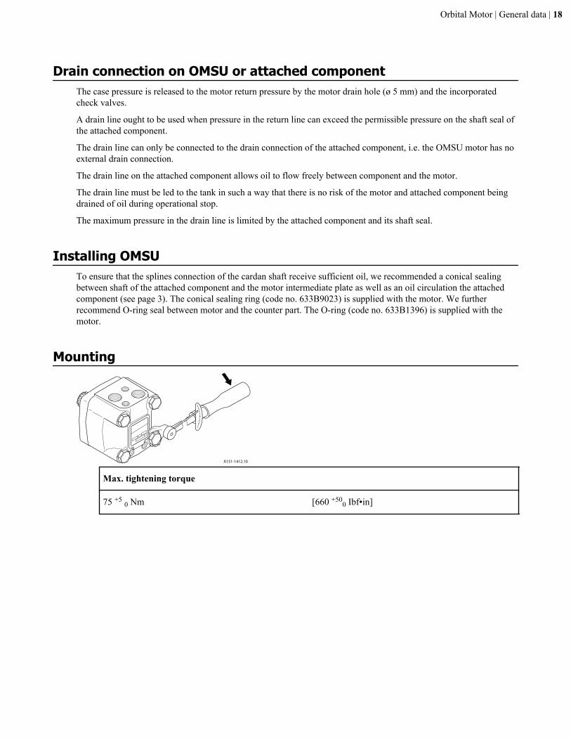
Mounting
A151-1412.10
Max. tightening torque
75 +5 0 Nm [660 +500 Ibf•in]
Orbital Motor | General data | 18

Direction of rotation
Maximum tightening torqueMaximum tightening torque
Screwed connection G 1/2 [7/8-14 UNF]
with steel washer 130 N•m [1150 lbf•in]
with aluminium washer 70 N•m [620 Ibf•in]
with cutting edge 130 N•m [1150 Ibf•in]
with O-ring Boss port 70 N•m [620 Ibf•in]
Checking OMSUIn order to make sure that the OMSU counterpart is correct, the drainflow should be messured on the first of each newapplication. Any subsequent modification of the counterpart should imply new checking. When the motor is fitted
Orbital Motor | General data | 19

onto the counter part with the correct tightening torque, the drain flow is messured at Q = 30 I/min and an oilviscosity of 35 mm2/s at differential pressure:
Motor Differential pressure
OMSU 80 - 160 140 bar
OMSU 200 110 bar
OMSU 250 90 bar
OMSU 315 70 bar
OMSU 400 55 bar
After minimum 5 min. of operation the drainflow shall be minimum 0.03 l/min and maximum 1.00 l/min at maximumpressure of bar 6 in the drain line during testing.
Exploded view OMSU
A151-1825.1122
21
20
19
1817
1615
14
13
12
89
10
11 6
1
2
34
5
6
7
6
Table 4: Tightening torque
Item 21: 75 - 80 Nm [660 - 705 lbf•in]
Orbital Motor | General data | 20

OMSU spare parts listTable 5: OMSU spare parts list
Item Spare parts Codenumber
Number permotor
1 Seal ring 633B9023 1
2 O-ring 74 x 3 mm NBR ISO 1629 633B1396 1
3 Screw M5
OMSU 80 L = 45 mm 681X1512 2
OMSU 100 L = 50 mm 681X1702 2
OMSU 125 L = 55 mm 681X9282 2
OMSU 160 L = 60 mm 681X1703 2
OMSU 200 L = 70 mm 681X0354 2
OMSU 250 L = 80 mm 681X0568 2
4 Intermidiate plate 151F1717 1
5 Cardan shaft
OMSU 80 l = 70 mm 11075495 1
OMSU 100 l = 73 mm 11077519 1
OMSU 125 l = 78 mm 11077838 1
OMSU 160 l = 84 mm 11075528 1
OMSU 200 l = 91 mm 11077921 1
OMSU 250 l = 99.5 mm 11077919 1
6 O-ring 82.5 x 2 mm NBR ISO R 1629 633B1431 3
Orbital Motor | General data | 21

Item Spare parts Codenumber
Number permotor
7 Gearwheel set
OMSU 80 w = 14 mm 151F1091 1
OMSU 100 w = 17 mm 151F1092 1
OMSU 125 w = 22 mm 151F1093 1
OMSU 160 w = 28 mm 151F1094 1
OMSU 200 w = 35 mm 151F1095 1
OMSU 250 w = 44 mm 151F1096 1
8 Valve drive 11030924 1
9 Channel plate 151F1822 1
10 Check valve ball ø 3/16 in 689X1005 2
11 Stop ring (only OMSU 200, 250, 315 and 400) 151F1542 1
12 Disc valve 151F1022 1
13 Balance plate 151F1738 1
14 Guide pin ø 4 mm l = 20 mm DIN1481
682L9105 1
15 O-ring 45 x 2 mm
NBR, ISO R 1629 633B1429 1
FPM, ISO R 1629 633B1455 1
16 O-ring 24 x 2 mm
NBR, ISO R 1629 633B1428 1
FPM, ISO R 1629 633B1453 1
17 Spacer 151F1449 1
18 Spring washer 684X0097 1
19 Seal plug G 1/2 633X0074 2
20 Valve housing 151F1803 1
Orbital Motor | General data | 22

Item Spare parts Codenumber
Number permotor
21 Screw M10
OMSU 80, 100, 125 l = 120 mm 681X1349 4
OMSU 160 l = 130 mm 681X1350 4
OMSU 200 l = 140 mm 681X1352 4
OMSU 250 l = 150 mm 681X1353 4
22 Name plate
A Set of seals items 1, 6, 15, 16 151F0103
B Set of seals items 1, 2 151F1020
NBR: (Buna N, Perbunan); FPM (Viton)
Orbital Motor | General data | 23