RADIX-4 AND RADIX-8 MULTIPLIER USING VERILOG HDL
6
International Journal of Advanced Research Trends in Engineering and Technology (IJARTET) Vol. 1, Issue 1, September 2014 All Rights Reserved © 2014 IJARTET 21 RADIX-4 AND RADIX-8 MULTIPLIER USING VERILOG HDL P. Thayammal 1 , R.Sudhashree 2 , G.Rajakumar 3 P.G.Scholar, Department of VLSI, Francis Xavier Engineering College, Tirunelveli 1 P.G.Scholar, Department of VLSI, Francis Xavier Engineering College, Tirunelveli 2 Associate Professor, Department of ECE, Francis Xavier Engineering College, Tirunelveli 3 Abstract: Now-a-days the power consumption is the major problem for the electronic devices. So, to design the integrated circuit , to perform the low power , less occupation area and high speed simultaneously. This paper presents to design the high performance parallel radix-4/radix-8 multiplier by using booth algorithm. The structure for design is mxn multiplication .where, m and n reach up to 8bits. Carry Look ahead Adder is used as the final order to enhance the speed of operation. The design process is done in verilog HDL and simulation by using model sim simulator (XSE 8.1) . Keywords: Carry look ahead adder, Verilog HDL, Multiplier. I. INTRODUCTION Multiplication is an important fundamental function in arithmetic operations [1]. Multiplication-based operations such as Multiply and Accumulate (MACS) and inner product are among some of the frequently used computation- Intensive Arithmetic Functions (CIAF) currently implemented in many Digital Signal Processing (DSP) applications such as convolution, Fast Fourier Transform (FFT), Filtering (FIR,IIR) and in microprocessors in its arithmetic and logic unit. Components in any digital circuit design. They are fast, reliable and efficient components that are utilized to implement the any operation. Multiplication is a mathematical operation [1] that at it simplest is an abbreviated process of adding an integer to itself a specified number of times. A number (multiplicand) is added to itself a number of times as specified by another number (multiplier) to form a result (product). The multiplicand is then multiplied by each digit of the multiplier beginning with the rightmost, Least Significant Digit (LSD). Intermediate results (partial products) are placed one a top the other, offset by one digit to align digits of the same weight, the final product is determined by summation of all the partial-products. A multiplexer is a combinational circuit that selects binary information from one of many input lines and direct it to a single output line. Normally, there are 2 n input lines and n selection lines whose bit combinations determine which input is selected. Multiplexer is a digital switch. It allows digital information from several source to be routed on to a single output line. The basic multiplexer has several data- input lines and a single output lines. Conventional array multipliers, like the Braun multiplier and Baugh Woolley multiplier achieve comparatively good performance but they require large area of silicon, unlike the add shift algorithms, which require less hardware and exhibit poorer performance. The Booth multiplier makes the use of Booth encoding algorithm [2] in order to reduce the number of partial products by considering two bits of the multiplier at a time, thereby achieving a speed advantage over other multiplier architectures. This algorithm is valid for both signed and unsigned number. It accepts the number in two’s compliment form, based on radix-2 computation. It can handle signed binary multiplication by using 2’s compliment representation. This increases the complexity of how signs of the operands get stored in auxiliary circuits. Using the non-Booth encoding method for partial product generation, the multiplier bits are examined sequentially starting from LSB to MSB. If the multiplier bit is one, the partial product is simply the multiplicand. Otherwise, the partial product is zero. Each new partial product is shifted one bit position to the left. Each partial product can be produced by just using a row of two-input AND gates. The number of partial products generated equals the size of the multiplier bits.
-
Upload
independent -
Category
Documents
-
view
6 -
download
0
Transcript of RADIX-4 AND RADIX-8 MULTIPLIER USING VERILOG HDL

International Journal of Advanced Research Trends in Engineering and Technology (IJARTET) Vol. 1, Issue 1, September 2014
All Rights Reserved © 2014 IJARTET 21
RADIX-4 AND RADIX-8 MULTIPLIER USING VERILOG HDL
P. Thayammal1, R.Sudhashree2, G.Rajakumar3 P.G.Scholar, Department of VLSI, Francis Xavier Engineering College, Tirunelveli 1
P.G.Scholar, Department of VLSI, Francis Xavier Engineering College, Tirunelveli 2
Associate Professor, Department of ECE, Francis Xavier Engineering College, Tirunelveli 3 Abstract: Now-a-days the power consumption is the major problem for the electronic devices. So, to design the integrated circuit , to perform the low power , less occupation area and high speed simultaneously. This paper presents to design the high performance parallel radix-4/radix-8 multiplier by using booth algorithm. The structure for design is mxn multiplication .where, m and n reach up to 8bits. Carry Look ahead Adder is used as the final order to enhance the speed of operation. The design process is done in verilog HDL and simulation by using model sim simulator (XSE 8.1) . Keywords: Carry look ahead adder, Verilog HDL, Multiplier.
I. INTRODUCTION Multiplication is an important fundamental function in
arithmetic operations [1]. Multiplication-based operations such as Multiply and Accumulate (MACS) and inner product are among some of the frequently used computation-Intensive Arithmetic Functions (CIAF) currently implemented in many Digital Signal Processing (DSP) applications such as convolution, Fast Fourier Transform (FFT), Filtering (FIR,IIR) and in microprocessors in its arithmetic and logic unit. Components in any digital circuit design. They are fast, reliable and efficient components that are utilized to implement the any operation. Multiplication is a mathematical operation [1] that at it simplest is an abbreviated process of adding an integer to itself a specified number of times. A number (multiplicand) is added to itself a number of times as specified by another number (multiplier) to form a result (product). The multiplicand is then multiplied by each digit of the multiplier beginning with the rightmost, Least Significant Digit (LSD). Intermediate results (partial products) are placed one a top the other, offset by one digit to align digits of the same weight, the final product is determined by summation of all the partial-products. A multiplexer is a combinational circuit that selects binary information from one of many input lines and direct it to a single output line. Normally, there are 2n input lines and n selection lines whose bit combinations determine which input is selected. Multiplexer is a digital switch. It allows digital information from several source to be routed on to a
single output line. The basic multiplexer has several data-input lines and a single output lines. Conventional array multipliers, like the Braun multiplier and Baugh Woolley multiplier achieve comparatively good performance but they require large area of silicon, unlike the add shift algorithms, which require less hardware and exhibit poorer performance. The Booth multiplier makes the use of Booth encoding algorithm [2] in order to reduce the number of partial products by considering two bits of the multiplier at a time, thereby achieving a speed advantage over other multiplier architectures. This algorithm is valid for both signed and unsigned number. It accepts the number in two’s compliment form, based on radix-2 computation. It can handle signed binary multiplication by using 2’s compliment representation. This increases the complexity of how signs of the operands get stored in auxiliary circuits. Using the non-Booth encoding method for partial product generation, the multiplier bits are examined sequentially starting from LSB to MSB. If the multiplier bit is one, the partial product is simply the multiplicand. Otherwise, the partial product is zero. Each new partial product is shifted one bit position to the left. Each partial product can be produced by just using a row of two-input AND gates. The number of partial products generated equals the size of the multiplier bits.
International Journal of Advanced Research Trends in Engineering and Technology (IJARTET) Vol. 1, Issue 1, September 2014
All Rights Reserved © 2014 IJARTET 22
II. PROPOSED SYSTEM
A. Radix-4 multiplier Booth algorithm is a powerful algorithm [5] for signed number multiplication, Since a k-bit binary number can be interpreted as k/2-digit Radix-4 number, a k/3-digit Radix-8 number and so on, it can deal with more than one bit of the multiplier in each cycle by using high radix multiplication[6].
The major disadvantage of the Radix-2 algorithm was that the process required n shifts and an average of n/2 additions for an n bit multiplier. This variable number of shift and add operations is inconvenient for designing parallel multipliers. The Radix-4 modified Booth algorithm overcomes all these limitations of Radix-2 algorithm. For operands equal to or greater than 16 bits, the modified Radix-4 Booth algorithm has been widely used. It is based on encoding the two’s complement multiplier in order to reduce the number of partial products to be added to n/2.
B. System Architecture We applied three basic unit cells in this design: 1. Encoder 2. Decoder 3. 12-bit adder C. Encoder
An encoder is a digital circuit that performs the inverse operation of a decoder. An encoder has 2n (or fewer) input lines on and n output lines. In encoder the output lines generated the binary code corresponding to the input value. The general structure of the encoder circuit. The decoder information is presented as 2n inputs producing n possible outputs. This encoder we can use radix-4 multiplier 4 decoder block.
D. Decoder
A decoder is a multiple-input, multiple-output logic circuit which converts coded inputs into coded outputs, where the input and output codes are different. A each input code word produces a different output code word, i.e., there is one-to-one mapping from input code words into output code words. This decoder we can use radix-4 multiplier 4 decoder block.
E. Multiplexer Multiplexer is a digital switch. It allows digital information from several source to be routed on to a single output line. Fig 1 shows a basic multiplexer has several data-input lines and a single output lines. Normally, there are 2n
input lines and n selection lines whose bit combinations determine which input is selected. Therefore multiplexer is ‘many into one’ and it provides the digital equivalent of an analog selector switch it as a called as data selector.
Fig.1. Multiplier Logic Symbol
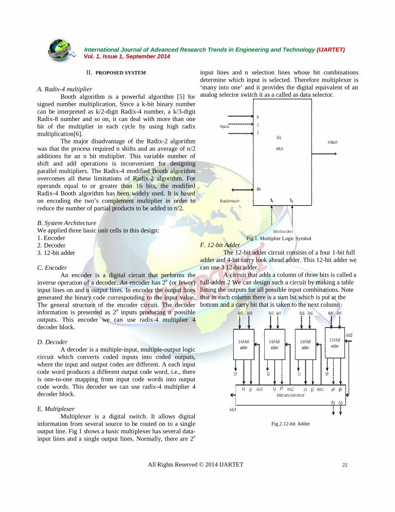
F. 12-bit Adder The 12-bit adder circuit consists of a four 1-bit full adder and 4-bit carry look ahead adder. This 12-bit adder we can use 3 12-bit adder. A circuit that adds a column of three bits is called a full-adder.2 We can design such a circuit by making a table listing the outputs for all possible input combinations. Note that in each column there is a sum bit which is put at the bottom and a carry bit that is taken to the next column
Fig.2.12-bit Adder

International Journal of Advanced Research Trends in Engineering and Technology (IJARTET) Vol. 1, Issue 1, September 2014
All Rights Reserved © 2014 IJARTET 23
G. Carry look ahead Adder Carry look-ahead logic uses the concepts of
generating and propagating carries. This allows the circuit to "pre-process" the two numbers being added to determine the carry ahead of time. Then, when the actual addition is performed, there is no delay from waiting for the ripple carry effect (or time it takes for the carry from the first Full Adder to be passed down to the last Full Adder). Below is a simple 4-bit generalized Carry Look Ahead circuit that combines with the 4-bit Ripple Carry Adder we used above with some slight adjustments:
For the example provided, the logic for the generate (g) and propagate (p) values are given below.
C1 = G0 + P0.C0 C2 = G1 + P1.C1 C3 = G2 + P2.C2 C4 = G3 + P3.C3
H. Radix-8 Multiplier: Radix-8 Booth Encoding multiplier uses 4-bit encoding scheme [9] to produce one third the number of partial products. Radix-8 Booth recoding applies the same algorithm as that of Radix-4, but now we take quartets of bits instead of triplets. Each quartet is codified as a signed digit. Radix-8 algorithm reduces the number of partial products to n/3, where n is the number of multiplier bits. Thus it allows a time gain in the partial products summation. I. System Architecture:
We applied three basic unit cells in this design: 1. Encoder 2. Decoder 3. 12-bit adder J. Encoder
An encoder is a digital circuit that performs the inverse operation of a decoder. An encoder has 4(or fewer) input lines on and n output lines. In encoder the output lines generated the binary code corresponding to the input value. As shown in the fig the decoder information is presented as 2n inputs producing n possible outputs. This radix-8 encoder we can use only 3 encoder blocks compare to the radix-4 encoder block.
K. Decoder
A decoder is a multiple-input, multiple-output logic circuit which converts coded inputs into coded outputs, where the input and output codes are different. The input code generally has fewer bits than the output code. Each
input code word produces a different output code word, i.e., there is one-to-one mapping from input code words into output code words. This decoder we can use only 3 9-bit decoder block compare to the radix-4 decoder block.
L. 12-bit adder
The 12-bit adder circuit consists of a four 1-bit full adder and 4-bit carry look ahead adder. This 12-bit adder we can use only 2 12-bit adder block compare to the radix-4 12-bit adder block.
III. RESULT AND DISCUSSION The results of radix 4 decoder and radix 4 encoder of proposed system is given in fig.3.
Fig.3. Output of 3:1 Encoder of the Proposed System
Fig.3 shows the Xilink simulation output of the radix-4 encoder proposed system. We give 3input and take the one output.

International Journal of Advanced Research Trends in Engineering and Technology (IJARTET) Vol. 1, Issue 1, September 2014
All Rights Reserved © 2014 IJARTET 24
Fig.4. Output of 9-bit Decoder of Proposed System
Fig.4 shows the xilie simulation output of the radix-4 decoder prosposed system.we give one input and take the output
Fig.5. Output of 3x1 Multiplexer of the Proposed System
Fig.5. shows xilink simulation output of the radix-4 multiplexer 3x1 Proposed system.
Fig.6. Output of 12-bit adder of the proposed system. Fig.6. shows the xilink simulation output of the
radix-4 12-bit added of the proposed system.
Fig.7. Output of the carry lookahead adder of the proposed system.
Fig.7. shows the xilink simulation output of the
ardix-4 carry look ahead adder of proposed system.

International Journal of Advanced Research Trends in Engineering and Technology (IJARTET) Vol. 1, Issue 1, September 2014
All Rights Reserved © 2014 IJARTET 25
Fig.8.Output of the radix-4 multiplier of the proposed system
Fig.8. shows the xilink simulation output of the radix-4 multiplier of the proposed system using verilog HDL.It is simulated by using the combination of the encoder,decoder,multiplexer,12-bit adder,carry lookahead adder.
Fig.9. output of the 3:1 encoder
Fig.9. shows the xilink simulation output of the radix-8 encoder of purposed system.
Fig.10 output of the 9-bit decoder
Fig.10. shows the xilink simulation output of the radix-8 decoder of purposed system.
Fig.11. outpupt of the carry lookahead adder
Fig.11 showsthe xilink simulation output of the radix-8 carry lookaheaad adder of purposed system.
International Journal of Advanced Research Trends in Engineering and Technology (IJARTET) Vol. 1, Issue 1, September 2014
All Rights Reserved © 2014 IJARTET 26
Fig.12. Output of the 3x1 multitplexer of proposed System
Fig.12 shows the xilink simulation output of the radix-8 3x1 multiplexer of purposed system.
Fig.13 Output of the 12-bit adder of proposed system Fig 13 shows the xilink simulation output of
the radix-8 12-bit adder of purposed system.
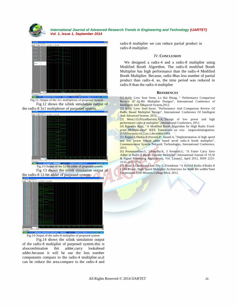
Fig.14 Output of the radix-8 multiplier of proposed system
Fig.14 shows the xilink simulation output of the radix-8 multiplier of purposed system.this is alsocombination ibit adder,carry lookahead adder.because it will be use the less number components compare to the radix-4 multiplier.so,it can be reduce the area.compare to the radix-4 and
radix-8 multiplier we can reduce partial product in radix-8 multiplier.
IV. CONCLUSION
We designed a radix-4 and a radix-8 multiplier using Modified Booth Algorithm. The radix-8 modified Booth Multiplier has high performance than the radix-4 Modified Booth Multiplier. Because, radix-8has less number of partial product than radix-4. so, the time period was reduced in radix-8 than the radix-4 multiplier
REFERENCES [1] Kelly Liew Suet Swee, Lo Hai Hiung, “ Performance Comparison Review of 32-Bit Multiplier Designs”, International Conference of Intelligent And Advanced System,2012. [2] Kelly Liew Suet Swee, ”Performance And Comparison Review Of Radix Based Multiplier Design”, International Conference Of Intelligent And Advanced System, 2012. [3] Moni,J.D,Priyadharisini,A.K,"Design of low power and high performance radix-4 multiplier”,International Conference, 2012. [4] Rajendra Katti, “A Modified Booth Algorithm for High Radix Fixed-point Multiplication” IEEE Transaction on very largescaleintegration. (VLSI)system,vol.2,no.1,december1994. [5] Rajput.S,Shukla.R,Praveen.P, Anand.A, “Implementation of high speed and low power hybrid adder based novel radix-4 booth multiplier”, Communication System Network Technologies, International Conference, 2013. [6] Premananthan.G, 2Amudha.K, 3 Sreenath.G, “A Faster Carry Save Adder in Radix-8 Booth Encoder Multiplier”,International Journal of VLSI & Signal Processing Applications, Vol. 2,Issue2, April 2012, ISSN 2231-3133, (171-175). [7] Brian S.Cherkauerl and Eby G.Friendrnan “A Hybrid Radix-4/Radix-8 LOW Power, High Speed Multiplier Architecture for Wide Bit widths”Intel Corporation 2200 Mission College Blvd, 2012.