Using Verilog-A and Verilog-AMS in Advanced Design System
57
Using Verilog-A and Verilog-AMS in Advanced Design System 1 Advanced Design System 2011 July 2011 Using Verilog-A and Verilog-AMS in Advanced Design System
-
Upload
khangminh22 -
Category
Documents
-
view
4 -
download
0
Transcript of Using Verilog-A and Verilog-AMS in Advanced Design System

Using Verilog-A and Verilog-AMS in Advanced Design System
1
Advanced Design System 2011
July 2011Using Verilog-A and Verilog-AMS in Advanced Design System

Using Verilog-A and Verilog-AMS in Advanced Design System
2
© Agilent Technologies, Inc. 2000-20115301 Stevens Creek Blvd., Santa Clara, CA 95052 USANo part of this documentation may be reproduced in any form or by any means (includingelectronic storage and retrieval or translation into a foreign language) without prioragreement and written consent from Agilent Technologies, Inc. as governed by UnitedStates and international copyright laws.
AcknowledgmentsMentor Graphics is a trademark of Mentor Graphics Corporation in the U.S. and othercountries. Mentor products and processes are registered trademarks of Mentor GraphicsCorporation. * Calibre is a trademark of Mentor Graphics Corporation in the US and othercountries. "Microsoft®, Windows®, MS Windows®, Windows NT®, Windows 2000® andWindows Internet Explorer® are U.S. registered trademarks of Microsoft Corporation.Pentium® is a U.S. registered trademark of Intel Corporation. PostScript® and Acrobat®are trademarks of Adobe Systems Incorporated. UNIX® is a registered trademark of theOpen Group. Oracle and Java and registered trademarks of Oracle and/or its affiliates.Other names may be trademarks of their respective owners. SystemC® is a registeredtrademark of Open SystemC Initiative, Inc. in the United States and other countries and isused with permission. MATLAB® is a U.S. registered trademark of The Math Works, Inc..HiSIM2 source code, and all copyrights, trade secrets or other intellectual property rightsin and to the source code in its entirety, is owned by Hiroshima University and STARC.FLEXlm is a trademark of Globetrotter Software, Incorporated. Layout Boolean Engine byKlaas Holwerda, v1.7 http://www.xs4all.nl/~kholwerd/bool.html . FreeType Project,Copyright (c) 1996-1999 by David Turner, Robert Wilhelm, and Werner Lemberg.QuestAgent search engine (c) 2000-2002, JObjects. Motif is a trademark of the OpenSoftware Foundation. Netscape is a trademark of Netscape Communications Corporation.Netscape Portable Runtime (NSPR), Copyright (c) 1998-2003 The Mozilla Organization. Acopy of the Mozilla Public License is at http://www.mozilla.org/MPL/ . FFTW, The FastestFourier Transform in the West, Copyright (c) 1997-1999 Massachusetts Institute ofTechnology. All rights reserved.
The following third-party libraries are used by the NlogN Momentum solver:
"This program includes Metis 4.0, Copyright © 1998, Regents of the University ofMinnesota", http://www.cs.umn.edu/~metis , METIS was written by George Karypis([email protected]).
Intel@ Math Kernel Library, http://www.intel.com/software/products/mkl
SuperLU_MT version 2.0 - Copyright © 2003, The Regents of the University of California,through Lawrence Berkeley National Laboratory (subject to receipt of any requiredapprovals from U.S. Dept. of Energy). All rights reserved. SuperLU Disclaimer: THISSOFTWARE IS PROVIDED BY THE COPYRIGHT HOLDERS AND CONTRIBUTORS "AS IS"AND ANY EXPRESS OR IMPLIED WARRANTIES, INCLUDING, BUT NOT LIMITED TO, THEIMPLIED WARRANTIES OF MERCHANTABILITY AND FITNESS FOR A PARTICULAR PURPOSEARE DISCLAIMED. IN NO EVENT SHALL THE COPYRIGHT OWNER OR CONTRIBUTORS BELIABLE FOR ANY DIRECT, INDIRECT, INCIDENTAL, SPECIAL, EXEMPLARY, ORCONSEQUENTIAL DAMAGES (INCLUDING, BUT NOT LIMITED TO, PROCUREMENT OF

Using Verilog-A and Verilog-AMS in Advanced Design System
3
SUBSTITUTE GOODS OR SERVICES; LOSS OF USE, DATA, OR PROFITS; OR BUSINESSINTERRUPTION) HOWEVER CAUSED AND ON ANY THEORY OF LIABILITY, WHETHER INCONTRACT, STRICT LIABILITY, OR TORT (INCLUDING NEGLIGENCE OR OTHERWISE)ARISING IN ANY WAY OUT OF THE USE OF THIS SOFTWARE, EVEN IF ADVISED OF THEPOSSIBILITY OF SUCH DAMAGE.
7-zip - 7-Zip Copyright: Copyright (C) 1999-2009 Igor Pavlov. Licenses for files are:7z.dll: GNU LGPL + unRAR restriction, All other files: GNU LGPL. 7-zip License: This libraryis free software; you can redistribute it and/or modify it under the terms of the GNULesser General Public License as published by the Free Software Foundation; eitherversion 2.1 of the License, or (at your option) any later version. This library is distributedin the hope that it will be useful,but WITHOUT ANY WARRANTY; without even the impliedwarranty of MERCHANTABILITY or FITNESS FOR A PARTICULAR PURPOSE. See the GNULesser General Public License for more details. You should have received a copy of theGNU Lesser General Public License along with this library; if not, write to the FreeSoftware Foundation, Inc., 59 Temple Place, Suite 330, Boston, MA 02111-1307 USA.unRAR copyright: The decompression engine for RAR archives was developed using sourcecode of unRAR program.All copyrights to original unRAR code are owned by AlexanderRoshal. unRAR License: The unRAR sources cannot be used to re-create the RARcompression algorithm, which is proprietary. Distribution of modified unRAR sources inseparate form or as a part of other software is permitted, provided that it is clearly statedin the documentation and source comments that the code may not be used to develop aRAR (WinRAR) compatible archiver. 7-zip Availability: http://www.7-zip.org/
AMD Version 2.2 - AMD Notice: The AMD code was modified. Used by permission. AMDcopyright: AMD Version 2.2, Copyright © 2007 by Timothy A. Davis, Patrick R. Amestoy,and Iain S. Duff. All Rights Reserved. AMD License: Your use or distribution of AMD or anymodified version of AMD implies that you agree to this License. This library is freesoftware; you can redistribute it and/or modify it under the terms of the GNU LesserGeneral Public License as published by the Free Software Foundation; either version 2.1 ofthe License, or (at your option) any later version. This library is distributed in the hopethat it will be useful, but WITHOUT ANY WARRANTY; without even the implied warranty ofMERCHANTABILITY or FITNESS FOR A PARTICULAR PURPOSE. See the GNU LesserGeneral Public License for more details. You should have received a copy of the GNULesser General Public License along with this library; if not, write to the Free SoftwareFoundation, Inc., 51 Franklin St, Fifth Floor, Boston, MA 02110-1301 USA Permission ishereby granted to use or copy this program under the terms of the GNU LGPL, providedthat the Copyright, this License, and the Availability of the original version is retained onall copies.User documentation of any code that uses this code or any modified version ofthis code must cite the Copyright, this License, the Availability note, and "Used bypermission." Permission to modify the code and to distribute modified code is granted,provided the Copyright, this License, and the Availability note are retained, and a noticethat the code was modified is included. AMD Availability:http://www.cise.ufl.edu/research/sparse/amd
UMFPACK 5.0.2 - UMFPACK Notice: The UMFPACK code was modified. Used by permission.UMFPACK Copyright: UMFPACK Copyright © 1995-2006 by Timothy A. Davis. All RightsReserved. UMFPACK License: Your use or distribution of UMFPACK or any modified versionof UMFPACK implies that you agree to this License. This library is free software; you canredistribute it and/or modify it under the terms of the GNU Lesser General Public License

Using Verilog-A and Verilog-AMS in Advanced Design System
4
as published by the Free Software Foundation; either version 2.1 of the License, or (atyour option) any later version. This library is distributed in the hope that it will be useful,but WITHOUT ANY WARRANTY; without even the implied warranty of MERCHANTABILITYor FITNESS FOR A PARTICULAR PURPOSE. See the GNU Lesser General Public License formore details. You should have received a copy of the GNU Lesser General Public Licensealong with this library; if not, write to the Free Software Foundation, Inc., 51 Franklin St,Fifth Floor, Boston, MA 02110-1301 USA Permission is hereby granted to use or copy thisprogram under the terms of the GNU LGPL, provided that the Copyright, this License, andthe Availability of the original version is retained on all copies. User documentation of anycode that uses this code or any modified version of this code must cite the Copyright, thisLicense, the Availability note, and "Used by permission." Permission to modify the codeand to distribute modified code is granted, provided the Copyright, this License, and theAvailability note are retained, and a notice that the code was modified is included.UMFPACK Availability: http://www.cise.ufl.edu/research/sparse/umfpack UMFPACK(including versions 2.2.1 and earlier, in FORTRAN) is available athttp://www.cise.ufl.edu/research/sparse . MA38 is available in the Harwell SubroutineLibrary. This version of UMFPACK includes a modified form of COLAMD Version 2.0,originally released on Jan. 31, 2000, also available athttp://www.cise.ufl.edu/research/sparse . COLAMD V2.0 is also incorporated as a built-infunction in MATLAB version 6.1, by The MathWorks, Inc. http://www.mathworks.com .COLAMD V1.0 appears as a column-preordering in SuperLU (SuperLU is available athttp://www.netlib.org ). UMFPACK v4.0 is a built-in routine in MATLAB 6.5. UMFPACK v4.3is a built-in routine in MATLAB 7.1.
Qt Version 4.6.3 - Qt Notice: The Qt code was modified. Used by permission. Qt copyright:Qt Version 4.6.3, Copyright (c) 2010 by Nokia Corporation. All Rights Reserved. QtLicense: Your use or distribution of Qt or any modified version of Qt implies that you agreeto this License. This library is free software; you can redistribute it and/or modify it undertheterms of the GNU Lesser General Public License as published by the Free SoftwareFoundation; either version 2.1 of the License, or (at your option) any later version. Thislibrary is distributed in the hope that it will be useful,but WITHOUT ANY WARRANTY; without even the implied warranty of MERCHANTABILITYor FITNESS FOR A PARTICULAR PURPOSE. See the GNU Lesser General Public License formore details. You should have received a copy of the GNU Lesser General Public Licensealong with this library; if not, write to the Free Software Foundation, Inc., 51 Franklin St,Fifth Floor, Boston, MA 02110-1301 USA Permission is hereby granted to use or copy thisprogram under the terms of the GNU LGPL, provided that the Copyright, this License, andthe Availability of the original version is retained on all copies.Userdocumentation of any code that uses this code or any modified version of this code mustcite the Copyright, this License, the Availability note, and "Used by permission."Permission to modify the code and to distribute modified code is granted, provided theCopyright, this License, and the Availability note are retained, and a notice that the codewas modified is included. Qt Availability: http://www.qtsoftware.com/downloads PatchesApplied to Qt can be found in the installation at:$HPEESOF_DIR/prod/licenses/thirdparty/qt/patches. You may also contact BrianBuchanan at Agilent Inc. at [email protected] for more information.
The HiSIM_HV source code, and all copyrights, trade secrets or other intellectual propertyrights in and to the source code, is owned by Hiroshima University and/or STARC.

Using Verilog-A and Verilog-AMS in Advanced Design System
5
Errata The ADS product may contain references to "HP" or "HPEESOF" such as in filenames and directory names. The business entity formerly known as "HP EEsof" is now partof Agilent Technologies and is known as "Agilent EEsof". To avoid broken functionality andto maintain backward compatibility for our customers, we did not change all the namesand labels that contain "HP" or "HPEESOF" references.
Warranty The material contained in this document is provided "as is", and is subject tobeing changed, without notice, in future editions. Further, to the maximum extentpermitted by applicable law, Agilent disclaims all warranties, either express or implied,with regard to this documentation and any information contained herein, including but notlimited to the implied warranties of merchantability and fitness for a particular purpose.Agilent shall not be liable for errors or for incidental or consequential damages inconnection with the furnishing, use, or performance of this document or of anyinformation contained herein. Should Agilent and the user have a separate writtenagreement with warranty terms covering the material in this document that conflict withthese terms, the warranty terms in the separate agreement shall control.
Technology Licenses The hardware and/or software described in this document arefurnished under a license and may be used or copied only in accordance with the terms ofsuch license. Portions of this product include the SystemC software licensed under OpenSource terms, which are available for download at http://systemc.org/ . This software isredistributed by Agilent. The Contributors of the SystemC software provide this software"as is" and offer no warranty of any kind, express or implied, including without limitationwarranties or conditions or title and non-infringement, and implied warranties orconditions merchantability and fitness for a particular purpose. Contributors shall not beliable for any damages of any kind including without limitation direct, indirect, special,incidental and consequential damages, such as lost profits. Any provisions that differ fromthis disclaimer are offered by Agilent only.
Restricted Rights Legend U.S. Government Restricted Rights. Software and technicaldata rights granted to the federal government include only those rights customarilyprovided to end user customers. Agilent provides this customary commercial license inSoftware and technical data pursuant to FAR 12.211 (Technical Data) and 12.212(Computer Software) and, for the Department of Defense, DFARS 252.227-7015(Technical Data - Commercial Items) and DFARS 227.7202-3 (Rights in CommercialComputer Software or Computer Software Documentation).

Using Verilog-A and Verilog-AMS in Advanced Design System
6
Getting Started with Verilog-A and Verilog-AMS in Advanced Design System . . . . . . . . . . . . . . . 7 Using a Verilog-A/AMS Device in a Simulation . . . . . . . . . . . . . . . . . . . . . . . . . . . . . . . . . . . 7 Modifying a Verilog-A/AMS Device . . . . . . . . . . . . . . . . . . . . . . . . . . . . . . . . . . . . . . . . . . . 11 Installing Verilog-A/AMS Devices Provided in a Design Kit . . . . . . . . . . . . . . . . . . . . . . . . . . 12 Licensing . . . . . . . . . . . . . . . . . . . . . . . . . . . . . . . . . . . . . . . . . . . . . . . . . . . . . . . . . . . . 15
About Model Development in Verilog-A . . . . . . . . . . . . . . . . . . . . . . . . . . . . . . . . . . . . . . . . . 16 Creating a Linear Resistor in Verilog-A . . . . . . . . . . . . . . . . . . . . . . . . . . . . . . . . . . . . . . . . 16 Creating a Linear Capacitor and Inductor in Verilog-A . . . . . . . . . . . . . . . . . . . . . . . . . . . . . 17 Creating a Nonlinear Diode in Verilog-A . . . . . . . . . . . . . . . . . . . . . . . . . . . . . . . . . . . . . . . 18 Using Parameter Ranges to Restrict Verilog-A Parameter Values . . . . . . . . . . . . . . . . . . . . . . 21 Creating Sources in Verilog-A . . . . . . . . . . . . . . . . . . . . . . . . . . . . . . . . . . . . . . . . . . . . . . 22 Creating Behavioral Models in Verilog-A . . . . . . . . . . . . . . . . . . . . . . . . . . . . . . . . . . . . . . . 22 Using Hierarchy to Manage Model Complexity . . . . . . . . . . . . . . . . . . . . . . . . . . . . . . . . . . . 25 Trapping Floating Point Exception Errors in Verilog-A . . . . . . . . . . . . . . . . . . . . . . . . . . . . . . 26
Using Verilog-A and Verilog-AMS with the ADS Analog RF Simulator (ADSsim) . . . . . . . . . . . . . 27 Loading Verilog-A/AMS modules . . . . . . . . . . . . . . . . . . . . . . . . . . . . . . . . . . . . . . . . . . . . 27 Overriding Built-in Devices with Verilog-A Devices . . . . . . . . . . . . . . . . . . . . . . . . . . . . . . . . 29 Using Models with Verilog-A/AMS Devices . . . . . . . . . . . . . . . . . . . . . . . . . . . . . . . . . . . . . 29 The Verilog-A/AMS Compiled Model Library Cache . . . . . . . . . . . . . . . . . . . . . . . . . . . . . . . . 31 Controlling the Auto Compilation Process . . . . . . . . . . . . . . . . . . . . . . . . . . . . . . . . . . . . . . 32 Verilog-A Operator Limitations in Harmonic Balance and Circuit Envelope . . . . . . . . . . . . . . . 32 Module and Parameter Naming . . . . . . . . . . . . . . . . . . . . . . . . . . . . . . . . . . . . . . . . . . . . . 33 Parameters . . . . . . . . . . . . . . . . . . . . . . . . . . . . . . . . . . . . . . . . . . . . . . . . . . . . . . . . . . . 33 Hierarchy and Module Resolution . . . . . . . . . . . . . . . . . . . . . . . . . . . . . . . . . . . . . . . . . . . . 34 Modifying the Simulator's Model Search Path . . . . . . . . . . . . . . . . . . . . . . . . . . . . . . . . . . . 34 The Compiler Include Search Path . . . . . . . . . . . . . . . . . . . . . . . . . . . . . . . . . . . . . . . . . . . 34 Interaction with the Loading of Dynamically Linked UCMs . . . . . . . . . . . . . . . . . . . . . . . . . . 35 Verilog-AMS Configuration Files and Setup . . . . . . . . . . . . . . . . . . . . . . . . . . . . . . . . . . . . . 35
About Model Development in Verilog-AMS . . . . . . . . . . . . . . . . . . . . . . . . . . . . . . . . . . . . . . . 38 Creating a Mixed-Signal PLL Model . . . . . . . . . . . . . . . . . . . . . . . . . . . . . . . . . . . . . . . . . . 38 Cosimulating a Model with ADS Transient and a Digital Simulator . . . . . . . . . . . . . . . . . . . . . 41 Viewing the Results . . . . . . . . . . . . . . . . . . . . . . . . . . . . . . . . . . . . . . . . . . . . . . . . . . . . . 42 Debugging AMS Models . . . . . . . . . . . . . . . . . . . . . . . . . . . . . . . . . . . . . . . . . . . . . . . . . . 44
Migrating from the SDD and UCM . . . . . . . . . . . . . . . . . . . . . . . . . . . . . . . . . . . . . . . . . . . . . 45 Symbolically Defined Devices . . . . . . . . . . . . . . . . . . . . . . . . . . . . . . . . . . . . . . . . . . . . . . 45 User-Compiled Models . . . . . . . . . . . . . . . . . . . . . . . . . . . . . . . . . . . . . . . . . . . . . . . . . . . 51
Verilog-A and Verilog-AMS in ADS Design Kits . . . . . . . . . . . . . . . . . . . . . . . . . . . . . . . . . . . . 55 Compilation Tools . . . . . . . . . . . . . . . . . . . . . . . . . . . . . . . . . . . . . . . . . . . . . . . . . . . . . . . . 57

Using Verilog-A and Verilog-AMS in Advanced Design System
7
Getting Started with Verilog-A andVerilog-AMS in Advanced Design SystemVerilog-A devices provide all of the capabilities as well as the look and feel of traditional, built-in components, with the added benefit that the end-user can choose to modify theunderlying equations. A number of new devices and models are supplied with AdvancedDesign System to provide both new model capability as well as to provide Verilog-Aversions of models that already exist as built-in models.
When used with a digital simulator, ADS can simulate the analog and digital constructs ofan AMS module. ADS will automatically detect the use of Verilog-AMS code and willtransparently manage the digital cosimulation process via configuration settings. The usemodel is identical to that of Verilog-A modules; however, it does require the installation ofa supported digital simulator. See Using Verilog-A and Verilog-AMS with the ADS AnalogRF Simulator (ADSsim) (veriloga).
This documentation provides an overview of the steps necessary to use Verilog-A devices.Many Verilog-A devices are provided as examples via a Design kit. For information oninstalling and using the Verilog-A devices supplied in the Verilog-A Design Kit, refer toInstalling Verilog-A/AMS Devices Provided in a Design Kit.
Using a Verilog-A/AMS Device in a SimulationTo illustrate how Verilog-A components are used and can be modified, a popular GaAsFET model that is also supplied in the Verilog-A Design Kit (see Installing Verilog-A/AMSDevices Provided in a Design Kit) is used in a tutorial workspace to show how a model canbe simulated and modified. You can copy the Verilog-A Tutorial example workspace toyour home directory or another preferred location using the Operating System.To simulate a model, begin in the ADS Main window:
Choose File > Open > Example, to open the Example directory.1.Browse to locate Tutorial_wrk example in Examples/Verilog-A directory.2.Select the example and click Open.3.Specify the directory in which you want to install the example and click Choose.4.After unarchiving the example, it'll ask to Open the workspace. Click Yes to open the5.example.After the workspace opens, a ReadMe schematic window will appear as shown in thefollowing figure.
The Verilog-A Tutorial_wrk ReadMe

Using Verilog-A and Verilog-AMS in Advanced Design System
8
The tutorial contains six different examples to illustrate Verilog-A components. Click6.the PSFETV example button on the left and then push down into the design.
The example consists of a simple DC_FET curve tracer to sweep the device.7.
Simple Schematic Design using a Verilog-A Component

Using Verilog-A and Verilog-AMS in Advanced Design System
9
Run a simulation.8.Note that the first time the design is simulated, the compiler will compile any un-compiled Verilog-A files found in the workspace veriloga directory.
NoteThe compiled files, by default, reside in a cache directory in your $HOME/hpeesof directory.
Status / Summary
AGILENT-VACOMP (*) 2003C.day Dec 3 2003 (built: 12/04/03 01:42:48)
Tiburon Design Automation (R) Verilog-A Compiler Version 0.97.120103.
Copyright (C) Tiburon Design Automation, Inc. 2002-2003. All rights reserved.
Compiling Verilog-A file
'/users/bobl/Tutorial_wrk/veriloga/psfetv.va'
Loading Verilog-A module 'R' from
'/users/bobl/hpeesof/agilent-model-
cache/cml/veriloga_21561_20031204_135236_007390/lib.hpux11/resv.cml'.
This module overrides the builtin 'R' (Linear Two Terminal Resistor).
HPEESOFSIM (*) 2003C.day Dec 3 2003 (built: 12/03/03 21:27:46)
Copyright Agilent Technologies, 1989-2003.
Loading Verilog-A module 'psfetv' from
'/users/bobl/hpeesof/agilent-model-
cache/cml/veriloga_21561_20031204_135236_007390/lib.hpux11/psfetv.cml'.
CT DC_FET1.S1[1] <(GEMX netlist)> DC_FET1.VGS=(-2->0)
DC DC_FET1.S1[1].DC_FET1.DC1[1/5] <(GEMX netlist)> DC_FET1.VGS=-2 DC_FET1.VDS=(0->5)
..
........................................
DC DC_FET1.S1[1].DC_FET1.DC1[2/5] <(GEMX netlist)> DC_FET1.VGS=-1.5 DC_FET1.VDS=(0->5)
..
........................................
DC DC_FET1.S1[1].DC_FET1.DC1[3/5] <(GEMX netlist)> DC_FET1.VGS=-1 DC_FET1.VDS=(0->5)
..
........................................
DC DC_FET1.S1[1].DC_FET1.DC1[4/5] <(GEMX netlist)> DC_FET1.VGS=-500e-03 DC_FET1.VDS=(0->5)
..
........................................
DC DC_FET1.S1[1].DC_FET1.DC1[5/5] <(GEMX netlist)> DC_FET1.VGS=0 DC_FET1.VDS=(0->5)

Using Verilog-A and Verilog-AMS in Advanced Design System
10
..
........................................
Resource usage:
Total stopwatch time: 35.54 seconds.
-------------------------------------------------------------------------------
Simulation finished: dataset `tutorial_PSFETV' written in:
`/users/bobl/Tutorial_wrk/data'
----------------------------------------------------------------------------
If there had been a compile error, the status window would display the error and theassociated line number. In this case, there were no errors and the simulationcontinued.
NoteThe status window provides information about the files that were compiled and the modules thatwere used. This is useful when files exist in multiple directories.
After the simulation is complete, open the Data Display TestBench.dds window ifnecessary. The display consists of a rectangular plot with a trace of the IDS.i data. Yourresults should look similar to the following figure.
PSFET DCIV Results
The PSFETV (and any Verilog-A based device) can be used in all analyses that atraditional built-in device could be used. The PSFETV is defined in the file psfetv.valocated in a directory called veriloga in the workspace directory. You can open and editthe file using any text editor. You can see from this file that the code is relatively easy tounderstand. The next section will show how to modify an equation and see the effect.
Other designs in the Tutorial workspace illustrate other key aspects of the Verilog-Alanguage.

Using Verilog-A and Verilog-AMS in Advanced Design System
11
Modifying a Verilog-A/AMS DeviceOne powerful feature of Verilog-A is that a user can make modifications to the equationsthat describe the behavior of the device. These changes can be available in the simulatorautomatically, with no loss of analysis functionality. Many models will be distributed withtheir source code with the expectation that end-users will modify the equations for anynumber of reasons. For example, the user may want the equations to better reflect someaspect of their device behavior, or they may want to delete code that is not necessary todescribe their device behavior, thereby improving simulation performance.
In this example, the PSFETV model will be modified slightly. During simulation, theprogram searches for the source code based on pre-defined search paths (discussed indetail later), in the workspace directory veriloga, or as specifically defined using a VerilogA_Load component.
If necessary, copy the workspace Tutorial_wrk from the Examples/Verilog-A directory1.to a local directory. This tutorial contains a directory called veriloga that includes afile called psfetv.va . This file is a copy of the parker_skellern.va file distributed inthe Verilog-A Design Kit, with the module name changed to psfetv to preventunintended overwriting of the other model.Open the design file tutorial_PSFETV and run a simulation to verify that the results2.are the same as the previous example.Using any text editor, open the psfetv.va file.3.Find the equation that describes the drain current,4.Id: Id = Area * Beta_T * (1 + lambda * Vdst) * (pow(Vgt, q) - pow(Vgt -
Vdt, q));
Purely for demonstration purposes, change the power law relation from "q" to "q/2"in the first power term (this has no physical meaning):Id = Area * Beta_T * (1 + lambda * Vdst) * (pow(Vgt, q/2 ) - pow(Vgt - Vdt,
q));
Save the file and start a simulation.5.
NoteThe program will detect that the file has not been compiled and will compile the source file. It willalso compile other Verilog-A files found in the workspace veriloga directory if they have yet to becompiled, or if they are out of date.
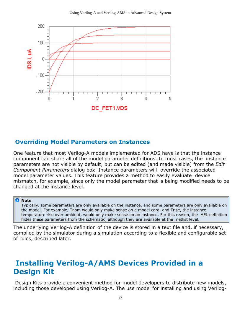
The Data Display window now shows very different results (see the following figure)compared to the figure PSFET DCIV Results, demonstrating that the modification tothe equation did indeed take effect.
PSFETV_DCIV Results using Power Law Relation of q/2
Using Verilog-A and Verilog-AMS in Advanced Design System
12
Overriding Model Parameters on Instances
One feature that most Verilog-A models implemented for ADS have is that the instancecomponent can share all of the model parameter definitions. In most cases, the instanceparameters are not visible by default, but can be edited (and made visible) from the EditComponent Parameters dialog box. Instance parameters will override the associatedmodel parameter values. This feature provides a method to easily evaluate devicemismatch, for example, since only the model parameter that is being modified needs to bechanged at the instance level.
NoteTypically, some parameters are only available on the instance, and some parameters are only available onthe model. For example, Tnom would only make sense on a model card, and Trise, the instance temperature rise over ambient, would only make sense on an instance. For this reason, the AEL definitionhides these parameters from the schematic, although they are available at the netlist level.
The underlying Verilog-A definition of the device is stored in a text file and, if necessary,compiled by the simulator during a simulation according to a flexible and configurable setof rules, described later.
Installing Verilog-A/AMS Devices Provided in aDesign Kit Design Kits provide a convenient method for model developers to distribute new models,including those developed using Verilog-A. The use model for installing and using Verilog-

Using Verilog-A and Verilog-AMS in Advanced Design System
13
A models distributed in Design Kits is the same as any other models distributed as ADSDesign Kits, except that the Verilog-A files (.va), are placed in 'veriloga' folder in the maindirectory of the design kit.
After properly installing the Design Kit, the components are made available on theassociated palettes. The ADS release includes a Design Kit called TIBURONDA_VERILOGA_DESIGN_KIT delivered as an unzipped file in the followinglocation:
$HPEESOF_DIR/tiburon-da/ads/designkits/tiburon-da_veriloga
This design kit includes the nonlinear models listed in the following two tables. Modelsshown in the first table below are new to, or later versions of, existing models in ADS.
NoteAll of these models are proof-of-concept models only and have not undergone the exhaustive qualificationthat built-ins do.
Model Name Description
aTFT Shur-RPI amorphous silicon thin film transistor MOSFET model
BSIMSOI Version 3.1 of the BSIMSOI model family
EKV Version 2.6 of the EKV MOSFET model
HICUM_L0 Level 0 version of the HICUM BJT model, a simplified version of the full HICUMmodel.
HiSIM STARC/Hiroshima University surface potential based MOSFET model
Parker_Skellern The Parker-Skellern MESFET model for medium power applications.
pTFT Shur-RPI polysilicon thin film transistor MOSFET model
The models listed in the following table are Verilog-A examples of models that alreadyexist as built-in devices.

Using Verilog-A and Verilog-AMS in Advanced Design System
14
Model Name Description
Angelov Angelov GaAs FET model
BJT SPICE Gummel-Poon BJT model
BSIM3 UC Berkeley BSIM3 (version 3.22)
BSIM4 UC Berkeley BSIM4 (version 4.3)
Curtice Curtice Quadratic GaAs FET model
Diode SPICE diode
JFET SPICE silicon junction FET
JunCap Philips JunCap diode
MESFET SPICE Metal Semiconductor FET model
MEXTRAM Philips Most Exquisite Transistor model for BJT devices
MOS9 Philips MOS Model 9
MOS11 Philips MOS Model 11
TOM1 Triquint's Own Model 1
TOM3 Triquint's Own Model 3
VBIC Vertical Bipolar InterCompany BJT model, as released.
Use the following procedure to install the TIBURONDA_VERILOGA_DESIGN_KIT.
From the ADS Main window,
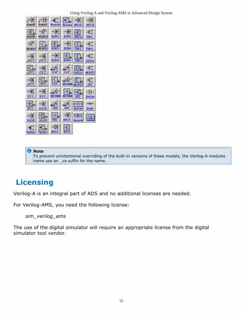
Choose DesignKit > Manage Favorite Design Kits to display the Manage1.Favorite Design Kits dialog box.Since the Design Kit is delivered as an unzipped file, simply click the Add Library2.Definition File and browse to$HPEESOF_DIR/tiburon-da/ads/designkits/tiburon-da_veriloga.Select the lib.defs file and click Open.3.The Add Design Kit dialog box appears to add the design kit to current workspace.4.Click OK.If a design is open, a warning "All designs must be closed to Add a Design Kit"5.appears.Close all the designs and click OK to add the design kit to your current workspace.6.Close the Manage Favorite Design Kits dialog box and open a schematic window.7.The Devices-Verilog-A palette should now be available in the Component Palette List.The following figure shows the icons for each of the devices and models available inthe Devices-Verilog-A palette.
Devices-Verilog-A Component Palette
Using Verilog-A and Verilog-AMS in Advanced Design System
15
NoteTo prevent unintentional overriding of the built-in versions of these models, the Verilog-A modulesname use an _va suffix for the name.
LicensingVerilog-A is an integral part of ADS and no additional licenses are needed.
For Verilog-AMS, you need the following license:
sim_verilog_ams
The use of the digital simulator will require an appropriate license from the digitalsimulator tool vendor.

Using Verilog-A and Verilog-AMS in Advanced Design System
16
About Model Development in Verilog-AThis topic provides a brief introduction to the Verilog-A language by means of examples.A more complete description of the language is available in the Verilog-A and Verilog-AMSReference Manual (verilogaref). A simple resistor is first defined, then enhanced with noise. Models for capacitors and inductors are then developed. These models use the ddt() operator to automatically generate the time-dependent functionality of the devices.Finally, a nonlinear diode is created demonstrating modeling of more complex behavior.
Creating a Linear Resistor in Verilog-AThe linear resistor in the example code below was introduced in the previous section. Thisprovides a simple example of the anatomy of a Verilog-A model. Line numbers are usedhere to help explain the code, but should not be included in the actual source code.
`include "disciplines.vams"
1.
module R(p,n);
2.
electrical p,n;3.
parameter real R=50.0;4.
analog V(p,n) <+ R * I(p,n);5.
endmodule
6.
Line 1 instructs the compiler to insert the contents of the file disciplines.vams into thetext. This file contains the definitions that make the Verilog-A specific for electricalmodeling.
Line 2 and line 6 declares the module block, within which the model behavior will bedefined. The model is named R and has two ports, named "p" and "n". Ports provideconnections to other modules.
Line 3 declares that the ports p and n have the nature of those declared in the electricaldiscipline, as defined in the disciplines.vams header file. Natures and disciplines provide away to map the general flows and potentials to particular domains, like electrical, thermal,or mechanical.
Line 4 declares one parameter, called R, and assigns it a default value of 50.0. The defaultvalue is set if the simulator is not passed an assignment in the netlist. In this case, theparameter is explicitly declared as real. However, if this attribute (which could also beinteger ) is not provided, the language infers the type from the default value. In this case,50.0 would indicate a real type, whereas 50 would indicate an integer. The parameterdeclaration also includes a simple method to restrict the range values. This is described inUsing Parameter Ranges to Restrict Verilog-A Parameter Values Parameter values cannotbe modified by the Verilog-A code. If the value needs to be modified, it should be assignedto an intermediate variable.
The keyword analog in line 5 declares the analog block. In this case, it is a single

Using Verilog-A and Verilog-AMS in Advanced Design System
17
statement. However, statements can be grouped together using begin/end keywords todenote blocks which, in turn, can be named to allow local declarations. The simple, singlestatement includes several key aspects of the language. On the right hand side, theaccess function I(p,n) returns the current flowing from node p to n. This is multiplied bythe value of the parameter R . The "<+" in line 5 is called the contribution operator and inthis example contributes the value of the evaluated right hand side expression as thevoltage from p to n.
Adding Noise to the Verilog-A Resistor
Verilog-A provides several ways to add noise, including frequency-independent,frequency-dependent, and piecewise linear frequency-dependent noise. In the case of aresistor, the thermal noise is 4*K*T/R . The value of Boltzmann's constant is available inanother header file, constants.vams , as a macro definition. Verilog-A supportspreprocessor commands similar to other languages like C. The details of macros arediscussed in the Verilog-A and Verilog-AMS Reference Manual (verilogaref), but in generalmacros can be thought of as simple text substitutions, typically used to help make thecode more readable and to gather all the constant definitions into one place. In the headerfile, the definition is
`define P_K 1.3806226e-23
whereas in the Verilog-A code, the value is used as `P_K . The temperature of the circuitis a value that can be changed outside of the model and so must be dynamically accessed.Verilog-A models use system functions to retrieve information that the simulator canchange. The temperature environment parameter function is $temperature and returnsthe circuit's ambient temperature in Kelvin.
The actual contribution of the noise is made with the white_noise() operator, which takesthe noise contribution as an argument. Noise functions also allow for an optional string tolabel the noise contribution. Some simulators can sort the noise according to the labels.
`include "disciplines.vams"
1.
`include "constants.vams"
2.
module R(p,n);
3.
electrical p,n;4.
parameter real R=50.0;5.
analog V(p,n) <+ R * I(p,n) + white_noise(4 * `P_K * $temperature / R,6.
"thermal");
endmodule
7.
Note that line 6 of the example code above shows the added noise.
Creating a Linear Capacitor and Inductor in Verilog-A

Using Verilog-A and Verilog-AMS in Advanced Design System
18
Capacitors and inductors are implemented in a similar way to resistors. However, thesedevices have dependencies on time. In the case of a capacitor, the relationship is,
I = C * dV / dt
In this case, the contribution is a current through the branch. The right hand side includesa derivative with respect to time. This is implemented with the ddt() operator. The modelthen becomes,
`include "disciplines.vams"
module C(p,n);
inout p,n;
electrical p,n;
parameter real C=0 from [0:inf);
analog I(p,n) <+ C * ddt(V(p,n));
endmodule
This example also illustrates one use of the range functions in the parameter declaration.The " from [0:inf) " addition restricts the value of C from 0 up to, but not including,infinity.Similarly, the inductor relationship is,
V = L * dI/dt
and the source code is:
`include "disciplines.vams"
module L(p,n);
inout p,n;
electrical p,n;
parameter real L=0 from [0:inf);
analog V(p,n) <+ L * ddt(I(p,n));
endmodule
Creating a Nonlinear Diode in Verilog-AVerilog-A is well-suited for describing nonlinear behavior. The basic PN junction diodebehavior will be used as an example. The I-V relation is,
I = Is * (exp(V/Vth - Rs * I) - 1)
The implementation is shown below.
`include "disciplines.vams"
`include "constants.vams"
module diode(anode,cathode);
electrical anode, cathode;

Using Verilog-A and Verilog-AMS in Advanced Design System
19
parameter real Area = 1.0 from (0:inf]; //Area scaling factor
parameter real Is = 1e-14 from [0:inf]; //Saturation current [A]
parameter real Rs = 0.0 from [0:inf); // Series resistance [Ohm]
parameter real N = 1.0 from (0:inf); //Ideality
parameter real Tt = 0.0 from [0:inf]; //Transit time [s]
parameter real Cjo = 0.0 from [0:inf]; //Junction capacitance [F]
parameter real Vj = 1.0 exclude 0; //Junction potential [v]
parameter real M = 0.5 from [0:inf]; //Grading coef
parameter real Fc = 0.5 from [0:1]; //Forward bias junct parm
parameter real Kf = 0.0; //Flicker noise coef
parameter real Af = 1.0 from (0:inf); //Flicker noise exponent
real Vd, Id, Qd;
real f1, f2, f3, Fcp;
analog begin
f1 = (Vj/(1 - M))*(1 - pow((1 - Fc), 1 - M));
f2 = pow((1 - Fc), (1 + M));
f3 = 1 - Fc * (1 + M);
Fcp = Fc * Vj;
Vd = V(anode, cathode);
// Intrinsic diode
Id = Area * Is * (exp(Vd / (N * $vt - Rs * I(anode, cathode)) / $vt)))- 1);
// Capacitance (junction and diffusion)
if (Vd <= Fcp)
Qd = Tt * Id + Area * Cjo * Vj * (1 - pow((1 - Vd / Vj), (1 - M)))/(1 - M);
else
Qd = Tt * Id + Area * Cjo * (f1 + (1 / f2) * (f3 * (Vd - Fcp) + (0.5* M / Vj) *
(Vd * Vd - Fcp * Fcp)));
I(anode, cathode) <+ Id + ddt(Qd);
end
endmodule
The more complicated behavior requires more complicated code. Comments are added tohelp clarify the source. Verilog-A supports two types of comment characters. Text to theright of // and text between /* and */ blocks will be ignored.
The analog block is extended from a single line to multiple lines using the begin and endkeywords to indicate a compound expression. Intermediate variables are declared to makethe code more readable. These variables are declared in the module but outside theanalog block.
A new system function, $vt , is used. This function returns the thermal voltage calculatedat an optional temperature. If no arguments are passed, the ambient circuit temperatureis used. The mathematical operators exp() and pow() are also used. Verilog-A includes awide range of mathematical functions.
Adding an Internal Node to the Diode
Note that the transcendental diode relationship includes the drop in the junction voltagedue to the series resistance. An alternate method of implementing the series resistancewould be to add an internal node. An internal node (also called a net) is added by simplydeclaring the node as electrical, without adding the node to the port list on the moduledeclaration line. The diode code changes as shown:

Using Verilog-A and Verilog-AMS in Advanced Design System
20
`include "constants.vams"
`include "disciplines.vams"
module diode_va(anode,cathode);
electrical anode, cathode, internal;
parameter real Area = 1.0 from (0:inf]; //Area scaling factor
parameter real Is = 1e-14 from [0:inf]; //Saturation current [A]
parameter real Rs = 0.0 from [0:inf]; //Ohmic res [Ohm]
parameter real N = 1.0 from [0:inf]; //Emission coef
parameter real Tt = 0.0 from [0:inf]; //Transit time [s]
parameter real Cjo = 0.0 from [0:inf]; //Junction capacitance [F]
parameter real Vj = 1.0 exclude 0; //Junction potential [v]
parameter real M = 0.5 from [0:inf]; //Grading coef
parameter real Kf = 0.0; //Flicker noise coef
parameter real Af = 1.0 from (0:inf); //Flicker noise exponent
parameter real Fc = 0.5 from [0:1]; //Forward bias junct parm
real Vd, Id, Qd;
real f1, f2, f3, Fcp;
analog begin
f1 = (Vj/(1 - M))*(1 - pow((1 - Fc), 1 - M));
f2 = pow((1 - Fc), (1 + M));
f3 = 1 - Fc * (1 + M);
Fcp = Fc * Vj;
Vd = V(anode, internal);
// Intrinsic diode
Id = Area * Is * ((Vd / (N * $vt)) - 1);
// Capacitance (junction and diffusion)
if (Vd <= Fcp)
Qd = Tt * Id + Area * Cjo * Vj * (1 - pow((1 - Vd / Vj), (1 - M)))/(1 - M);
else
Qd = Tt * Id + Area * Cjo * (f1 + (1 / f2) * (f3 * (Vd - Fcp) + (0.5 * M / Vj) *
(Vd * Vd - Fcp * Fcp)));
I(anode, internal) <+ Id + ddt(Qd);;
V(internal, cathode) <+ I(internal, cathode) * (Rs / Area);
end
endmodule
Adding Noise to the Diode
Noise is contributed in the same way as it was for the basic resistor. In this case, the shotnoise equation shows the dependence on the diode current. The 1/f noise is added usingthe flicker_noise() operator, which takes as arguments the value of the noisecontribution as well as the exponent to apply to the 1/f term.
// Noise
I(anode, cathode) <+ white_noise(2 * `P_Q * Id, "shot");
I(anode, cathode) <+ flicker_noise(Kf * pow(Id, Af), 1.0, "flicker");
The thermal noise from the series resistor is added in the same fashion as was done forthe resistor. Note that the label is modified to indicate which resistor the noise isgenerated from. This is useful when the analysis supports Sort Noise by Name.

Using Verilog-A and Verilog-AMS in Advanced Design System
21
// Series resistor
V(internal, cathode) <+ white_noise(4 * `P_K * T * (Rs / Area), "Rs");
Adding Limiting to the Diode for Better Convergence
The exponential function used in the diode code can result in large swings in currents forsmall changes in voltage during the simulator's attempts to solve the circuit equations. Aspecial operator, limexp() can be used instead of exp() to allow the simulator algorithmsto limit the exponential in simulator-specific ways. The specific algorithm used is simulatordependent.
Using Parameter Ranges to Restrict Verilog-AParameter ValuesThe parameter declaration allows the range of the parameter to be convenientlyrestricted. At run time, the parameter value is checked to be sure it is acceptable. If it isnot, the simulator issues an error and stops.
By default, parameters can range from -infinity to infinity. To restrict a range either theexclusive from ( : ) can be used, or the inclusive from [ : ] or a combination of the two.For example,
from (0 : 10]
will restrict the parameter from 0 to 10, excluding the value of 0 but including the value of10.
Exceptions to ranges are indicated by the except attribute. For example,
except 5
will not allow the value of 5 to be passed.
Ranges and exceptions can be repeated and combined. For example,
parameter real X = 20.0 from (-inf: -10] from [10:inf);
can also be written as,
parameter real X = 20.0 exclude (-10:10);
If a simulator supports sweeping of parameters, the model developer will have to beaware of issues related to sweeping through ranges.

Using Verilog-A and Verilog-AMS in Advanced Design System
22
Creating Sources in Verilog-AAnalog sources can also be described with Verilog-A using the same concepts. Sourcestypically have some relation to the specific time during the simulation. The time isavailable from the $abstime function, which simply returns the real time (in seconds) ofthe simulation.
A simple sine wave source would have the form:
`include "disciplines.vams"
`include "constants.vams"
module sine_wave(n1,n2);
electrical n1,n2;
parameter real gain = 1.0, freq = 1.0;
analog V(n1,n2) <+ gain * sin(2 * `M_PI * freq* $abstime);
$bound_step(0.05/freq);
endmodule
The mathematical constant for PI is available as M_PI from the constants.vams headerfile. Note that the multiple parameter declarations were combined on one line as analternative to declaring each on its own line.
The system function $bound_step() restricts the simulator's transient steps to the size0.05/freq . This allows the model to define the resolution of the signal to be controlled.
An additional use of defining sources in Verilog-A is to create test bench circuits as part ofthe model source file. This test module would provide sources with appropriate values andsweep ranges to allow the validation of the model to be contained within the codedefinition. This is a useful method of providing portable tests when distributing modelsamong different simulators.
Creating Behavioral Models in Verilog-AVerilog-A enables the user to trade off between various levels of abstraction. Certaincircuit blocks lend themselves to simple analog descriptions, resulting in improvements insimulator execution time compared to transistor level descriptions. Since Verilog-Asupports all of the analysis functionality, the user is typically only trading off simulationaccuracy when using a behavioral description of a circuit.
The Phase-Locked Loop (PLL) is a good example of a circuit that can be represented inbehavioral blocks.
The Verilog-A source code below demonstrates a PLL circuit. The PLL consists of a phasedetector, an amplifier, and a voltage controlled oscillator. In this example, a swept sine

Using Verilog-A and Verilog-AMS in Advanced Design System
23
source is used to test the circuit.
The VCO and phase detector are defined as:
// Voltage Controlled Oscillator
module vco(in, out);
inout in, out;
electrical in, out;
parameter real gain = 1, fc = 1;
analog V(out) <+ sin(2*`M_PI*(fc*$abstime() + idt(gain*V(in))));
endmodule
// Phase Detector
module phaseDetector(lo, rf, if_);
inout lo, rf, if_;
electrical lo, rf, if_;
parameter real gain=1;
analog function real chopper;
input sw, in;
real sw, in;
chopper = sw > 0 ? in : -in;
endfunction // chopper
analog V(if_) <+ gain*chopper(V(lo),V(rf));
endmodule
The modules use the keyword inout to declare that the ports are both input and output.Some simulators will check consistency of connection of ports (useful when ports aredeclared input or output only). ADS will not.
The phaseDetector makes use of an analog function definition of chopper to simplify thecode. Analog functions can be thought of a sub-routines that can take many values butreturn one value. This is in contrast to macros, which should be thought of as in-line textsubstitutions.
The PLL module uses hierarchy to instantiate these components:
// Phase Locked Loop
module pll(rf, out, ref, if_);
inout rf, out, ref, if_;
electrical rf, out, ref, if_;
parameter real tau = 1m from (0:inf);
parameter real loopGain = 1 from (0:inf);
parameter real fc = 2.0k from (0:inf);
real cap, res ;
electrical lo;
phaseDetector #(.gain(2)) pd1(lo, rf, if_);
vco #(.gain(loopGain/2), .fc(fc) ) vco1(out, lo);
analog begin
cap = 150e-9;
res = tau / cap;
V(out, if_) <+ I(out, if_)*res;
I(out, ref) <+ ddt(cap*V(out,ref));
end
Using Verilog-A and Verilog-AMS in Advanced Design System
24
endmodule
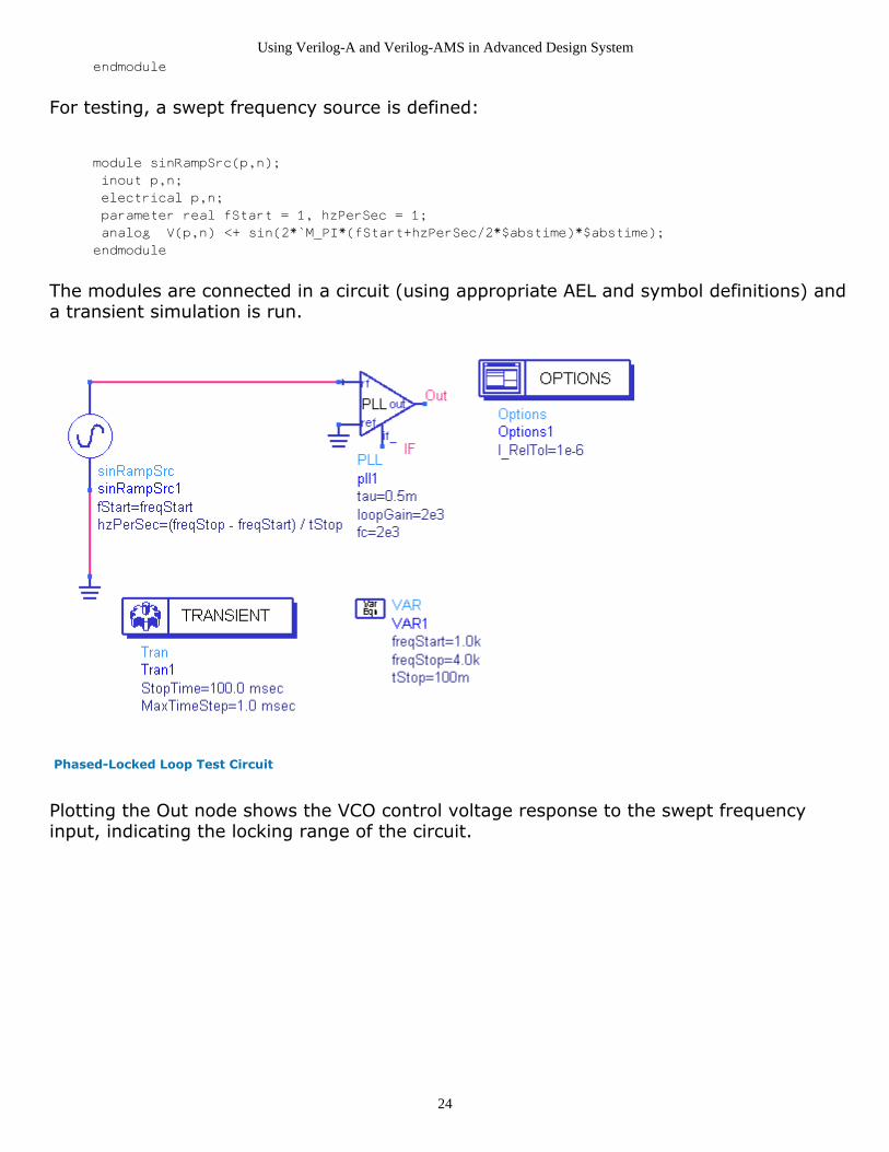
For testing, a swept frequency source is defined:
module sinRampSrc(p,n);
inout p,n;
electrical p,n;
parameter real fStart = 1, hzPerSec = 1;
analog V(p,n) <+ sin(2*`M_PI*(fStart+hzPerSec/2*$abstime)*$abstime);
endmodule
The modules are connected in a circuit (using appropriate AEL and symbol definitions) anda transient simulation is run.
Phased-Locked Loop Test Circuit
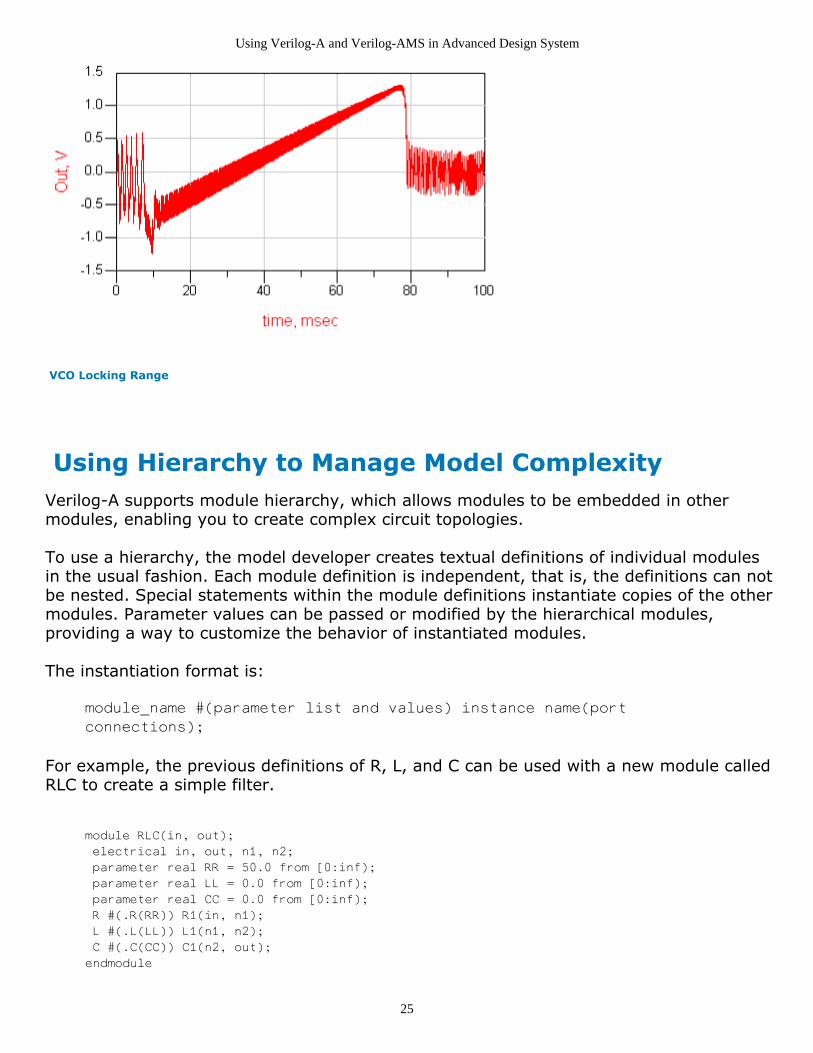
Plotting the Out node shows the VCO control voltage response to the swept frequencyinput, indicating the locking range of the circuit.
Using Verilog-A and Verilog-AMS in Advanced Design System
25
VCO Locking Range
Using Hierarchy to Manage Model ComplexityVerilog-A supports module hierarchy, which allows modules to be embedded in othermodules, enabling you to create complex circuit topologies.
To use a hierarchy, the model developer creates textual definitions of individual modulesin the usual fashion. Each module definition is independent, that is, the definitions can notbe nested. Special statements within the module definitions instantiate copies of the othermodules. Parameter values can be passed or modified by the hierarchical modules,providing a way to customize the behavior of instantiated modules.
The instantiation format is:
module_name #(parameter list and values) instance name(port
connections);
For example, the previous definitions of R, L, and C can be used with a new module calledRLC to create a simple filter.
module RLC(in, out);
electrical in, out, n1, n2;
parameter real RR = 50.0 from [0:inf);
parameter real LL = 0.0 from [0:inf);
parameter real CC = 0.0 from [0:inf);
R #(.R(RR)) R1(in, n1);
L #(.L(LL)) L1(n1, n2);
C #(.C(CC)) C1(n2, out);
endmodule

Using Verilog-A and Verilog-AMS in Advanced Design System
26
The RLC module creates a series R-L-C from the input port in to the output port out ,using two internal nodes, n1 and n2. The RLC module's parameter values of RR, LL, andCC are passed to the modules R, L, and C's parameters R, L, and C via #(.R(RR)),#(.L(LL)), and #(.C(CC)).
A unique advantage of the Compiled Model Library file is that the Verilog-A source iseffectively hidden from end users. This, coupled with Verilog-A's hierarchical structure,gives model developers a simple way to distribute intellectual property without exposingproprietary information.
Trapping Floating Point Exception Errors in Verilog-ADuring simulation, if the Verilog-A module expressions generate floating point exceptions(FPEs), the simulator will try to continue. In many cases, the bias conditions that caused aFPE may change during the simulator’s iterative solving procedure and so the simulationcan continue and eventually converge. However, if there are convergence problems, it ispossible the model is generating FPEs. To trap this condition, pass the –f flag to thecompiler. To do this, add or modify this line in the workspace hpeesofsim.cfg file (notethat you may need to Stop and Release the simulator after modifying the file):
VAMS_COMPILER_OPTIONS=-f
and then run a simulation. If a FPE is encountered, the simulation will stop, and the typeof exception and the line in the Verilog-A source code where the exception occurred will bedisplayed in the status window.

Using Verilog-A and Verilog-AMS in Advanced Design System
27
Using Verilog-A and Verilog-AMS withthe ADS Analog RF Simulator (ADSsim)Once Verilog-A modules are loaded into the simulation environment, they may be usedjust like any other device in the system. A module loaded into the system takes the lookand feel of a built-in ADS Analog RF Simulator (ADSsim) device. The module namebecomes the device definition name, the module parameters become device parameters,and, uniquely to Verilog-A, the module may have an optional model card.
Loading Verilog-A/AMS modules ADSsim has a Verilog-A model search path . Any Verilog-A module in the search path isavailable to be instantiated in the netlist or used on the schematic. This Verilog-A moduleloading mechanism is called auto loading as the search path is only traversed andmodules are only loaded when the simulator encounters an unknown device definition.The alternative loading mechanism is called explicit loading . In this case, the systemalways loads a particular Verilog-A module whether the simulator needs it or not. Theseloading mechanisms complement each other and are explained below in detail.
During the loading process, a Verilog-A file is compiled into a shared library. Theselibraries are referred to as Compiled Model Libraries (CML). In general, you do not needto be concerned about the compilation process. The process has been designed to allowusers to focus on writing and using Verilog-A modules rather than on the mechanics ofcompilation and CML file management. The system uses a CML cache. Verilog-A files arecompiled once and stored for later use in the CML cache. The system manages the CMLfiles, updating them only when necessary. As a user, you will see Verilog-A files beingcompiled the first time you use the files and subsequently only when you modify the files.
The Auto Loading Mechanism
Verilog-A files (files with a .va or .vams extension) that reside in the simulator's Verilog-A model search path are automatically compiled and loaded by the simulator, on demand,when an unknown device is encountered in the netlist. The Verilog-A model search pathhas four components,
Wrk_DIR/veriloga
$HOME/hpeesof/veriloga
$HPEESOF_DIR/custom/veriloga
$HPEESOF_DIR/veriloga
When searching for an unknown device, the system will sequentially look for a matchingVerilog-A module name in each of the above directories. The first module found is loadedand a status message issued informing you that a Verilog-A module has been loadedfrom a particular file in the model search path.

Using Verilog-A and Verilog-AMS in Advanced Design System
28
If you want the Verilog-A module to only have visibility within the current workspace, thencreate a Verilog-A directory under the current workspace ( Wrk_DIR/ veriloga ) and copythe Verilog-A file to that location. Putting a Verilog-A module in the local user directory ($HOME/hpeesof/veriloga ) will make it visible to simulations in all workspaces for this useraccount. The site custom directory ( $HPEESOF_DIR/custom/veriloga ) should be used tomake Verilog-A modules available to all users of a particular ADS installation. Finally, the site directory ( $HPEESOF_DIR/veriloga ) should not be used by you as an end user, thisdirectory is used by Agilent Technologies to deliver new Verilog-A modules as part of theADS system. Note that Verilog-A files placed in the site directory will not be compiled.
Each file in any directory in the path must have a unique set of module names. Inaddition the module namespace across all files in a given directory must be unique.Having duplicate Verilog-A module names across multiple files in a directory is flagged asan error. The system cannot determine which module to use. To correct the error, modifythe module names so that they are unique and re-run the simulation.
Explicit Loading of Verilog-A modules
Explicit loading refers to explicitly loading all modules in a named Verilog-A file using theload component. The load component is available with the Verilog-A Design Kit (seeInstalling Verilog-A/AMS Devices Provided in a Design Kit (veriloga)).
To load a file:
Insert a VerilogA_Load component from the Devices-Verilog-A palette.1.Use the Edit Parameters dialog box to add the name of the file to the Module File2.Name parameter. Note that this parameter is repeatable to enable multiple files tobe loaded. The component should look similar to the following figure.
The VerilogA_Load Component
When the file name specified is an absolute name, the system loads the file directly. Whenthe file name is relative, the system searches each directory in the Verilog-A model search path and loads the first file found with that name. Note that all modules in a file

Using Verilog-A and Verilog-AMS in Advanced Design System
29
are loaded (unlike auto loading where only the required module is loaded into thesystem.)
The load component netlists the #load ADS preprocessor command which has the syntax:
#load "veriloga", "filename"
#load is processed early in the simulation boot phase. #load commands may be placedanywhere in the netlist, but since they are preprocessor commands, there is no regard fornetwork hierarchy. #load processing occurs before auto loading; when a device isexplicitly loaded, the auto loading mechanisms are never invoked even if the device is inthe search path.
Overriding Built-in Devices with Verilog-A DevicesWhen a device has the same name as a built-in device and that Verilog-A device is in theVerilog-A model search path or is explicitly loaded, the Verilog-A device overrides thebuilt-in device. For example, if we place a file containing a module called R in a Verilog-Afile in the model search path, then the module R will override the built-in R (the simplelinear resistor). When a built-in device is overridden, the system issues a status messagewarning of the override as shown below.
Loading Verilog-A module 'R' from
'/users/bobl/hpeesof/agilent-model-cache/cml
/veriloga_21561_20031204_135236_007390
/lib.hpux11/my_resistor.cml'.
This module overrides the built-in 'R' \(Linear Two Terminal Resistor\).
NoteOverriding built-ins is a powerful and convenient way to use Verilog-A based devices in place of anexisting device, but should be used with care. The system does not check that the device being loaded hasthe same parameter list as the built-in device that it is overriding. Without careful attention to detail, youcan easily cause netlist syntax errors relating to unmatched parameters.
Using Models with Verilog-A/AMS DevicesThe model card is a simulator convenience that enables you to share device parametersamong multiple device instances. Each Verilog-A module loaded into the systemintroduces a new device and a new model - both of the same name.
All parameters on a Verilog-A device may either be specified on the model, on theinstance, or in both places. When a Verilog-A device references a model, it first reads allof the model parameters. Parameters specified directly on the instance then override themodel settings. This behavior is particularly convenient when two devices share almost

Using Verilog-A and Verilog-AMS in Advanced Design System
30
the same model. In this situation, they may reference a single model and override theparameters that are particular to the instances themselves.
For example, let us take the diode module ( PNDIODE ) from the tutorial workspace. Themodule may be instantiated directly as,
PNDIODE:d1 1 0 Is=3e-14 Rs=1 N=1.1 CJ0=1e-12 TT=0
or it may be used more conventionally with a model card as,
Model PNDIODE Dmod1 IS=3e-14 RS=1 N=1.1 CJ0=1e-12 TT=0
Dmod1:d1
Dmod1:d2
Dmod1:d3
The decision to use a model or not is your choice. Generally models are convenient whenthere are two or more instances that have the same parameter sets, as above where d1 ,d2 , and d3 all share the same model. We can go one step further in Verilog-A whenalmost all model parameters are the same. For the PNDIODE let us assume that RS i s theonly parameter that varies from instance to instance. We use Dmod1 again but simplyoverride RS on each instance that requires an RS different from the model
Dmod1:d1 RS=2
Dmod1:d2 RS=3
Dmod1:d3 RS=4
Dmod1:d4
In this example, d1 through d3 override RS while d4 inherits its value from the model,Dmod1 . This model parameter inheritance with instance parameter override is ideallysuited to mismatch modeling where two devices share almost the same model except forone or two parameters.
While this behavior is powerful, it leads to some complications in any analysis thatinvolves an operation that modifies a parameter. Operations that modify parameters areused in sweeping, tuning, optimization, and statistical analyses. We will use sweeping inthis explanation, but the rules outlined here apply to the other analyses in exactly thesame way.
Device instance parameter sweeping operates in the usual way. To sweep a Verilog-Ainstance parameter, simply reference the parameter in the normal way in the sweepdialog box. To sweep a model parameter, reference the model parameter, again in thesame way as is done for any model.
When a model parameter is swept, only those instances that inherit the parameter areaffected. Instances that reference the model but override the swept model parameter arenot affected. When all instances override the model parameter, you will see no change inresults as a function of the sweep variable. In the above example, if RS on DMod1 wasbeing swept, then the only instance affected by the sweep would be d4.

Using Verilog-A and Verilog-AMS in Advanced Design System
31
NoteOnly those model parameters that are actually specified on the model card may be swept. This is a modelonly limitation.
The Verilog-A/AMS Compiled Model Library CacheWhen Verilog-A modules are compiled, they are stored in a directory cache, which bydefault is created at,
$HOME/hpeesof/agilent-model-cache/
This cache is created the first time a Verilog-A file is compiled and entries are added orupdated as Verilog-A files are compiled. An existing cache may be moved to a newlocation, but cache contents may not be modified in any way.
A cache is user, platform, and release-version specific. However, no cache lockingmechanisms are used, so you should not run two copies of ADS on the same platform andattempt to share the same model cache. This will result in cache corruption. No cacherecovery tools are provided in this release. If two sessions do interfere with the cache thenyou must delete the cache and restart the simulation. The cache will then progressivelyrebuild itself as simulations involving Verilog-A modules are performed.
If two copies of ADS must be run concurrently (perhaps one from the ADS user-interfaceand another in batch mode), then use a separate cache. The cache location may bemodified by using the environment variable,
AGILENT_MODEL_CACHE_DIR
or a hpeesofsim.cfg configuration variable of the same name. The cache directory iscreated when the first Verilog-A file is compiled and you will see the following statusmessage,
HPEESOFSIM (*) 2003C.day Dec 13 2003 (built: 12/13/03 21:28:34)
Copyright Agilent Technologies, 1989-2003.
A Verilog-A compiled model library (CML) cache has been created at
'/users/bobl/hpeesof/agilent-model-cache/cml/0.99/hpux11'
Compiling Verilog-A file
'/users/bobl/QA_Test/Tutorial_wrk/veriloga/deadband.va'
AGILENT-VACOMP (*) 2003C.day Dec 13 2003 (built: 12/14/03 01:50:07)
Tiburon Design Automation (R) Verilog-A Compiler Version 0.99.121203.
Copyright (C) Tiburon Design Automation, Inc. 2002-2003. All rights reserved.
Compiling Verilog-A file
'/users/bobl/QA_Test/Tutorial_wrk/veriloga/gumpoonv.va'
AGILENT-VACOMP (*) 2003C.day Dec 13 2003 (built: 12/14/03 01:50:07)
Tiburon Design Automation (R) Verilog-A Compiler Version 0.99.121203.
Copyright (C) Tiburon Design Automation, Inc. 2002-2003. All rights reserved.

Using Verilog-A and Verilog-AMS in Advanced Design System
32
CML files vary in size depending on the size of the Verilog-A file and the platform used. Itis recommended that you locate the cache on a local disk with at least 200Mbytes of freespace. A local cache will improve compilation and load times. You may delete the cache atany time, though you should never need to do so, unless the size of the cache has becomeunreasonable or when it contains many old CML files that are no longer used. Deleting thecache leads only to recompiles and its clean reconstruction. Do this only when there areno simulations running.
Controlling the Auto Compilation ProcessWhen a Verilog-A module is compiled, the CML file is placed in the model cache to beretrieved later. If you do not want to use the cache, you have the option of storing theCML files in platform specific directories under the Verilog-A source directory. This andother auto compilation features are controlled by a file called vamake.spec ( Verilog-Amake specifications file .) If a file with this name is in the Verilog-A source directory, thenthe system uses it. The file may contain two options,
USE_CACHE=
PREPARE_DIR=
The USE_CACHE variable may be set to YES or NO. It defaults to YES. When you set it to NO,the cache is not used and CML files are written to the platform specific directories:
lib.linux_x86
lib.sun57
lib.win32
In some cases, you may want to compile the libraries and subsequently have the filesloaded without any dependency checks. To do this, set the PREPARE_DIR variable to NO.
Verilog-A Operator Limitations in Harmonic Balanceand Circuit EnvelopeThe Verilog-A language was first designed with time domain simulation algorithms in mindand, as such, has a set of features that are not easily supported in Harmonic Balance,Circuit Envelope analysis and their derivatives (LSSP, XDB, etc.). In these cases we eitherapproximate the behavior and/or issue an appropriate warning or error message.
Event-driven constructs such as cross and timer will not be triggered in Harmonic Balanceanalysis or in Circuit Envelope analysis. Since the cross event does not trigger in theseanalyses, it follows that the last_crossing() function is likewise not triggered. Whenthese events are present in a Verilog-A module the system issues a warning messagesaying they will not be triggered.

Using Verilog-A and Verilog-AMS in Advanced Design System
33
The $abstime() function will return zero (0) in Harmonic Balance analysis. In this release,users should use built-in ADS source components to generate time-varying waveforms.
The idtmod() operator and Z-transform filters are not supported for Harmonic Balance orCircuit Envelope in this release. The transition and slew filters act as simple allpasselements. This latter behavior is consistent with the language reference specification forfrequency domain analysis.
Modules which contain memory states are not compatible with Harmonic Balance. Amodule contains a memory state if it has local variables which retain values that are usedat subsequent time steps.
Module and Parameter NamingADS and Verilog-A are case sensitive. Verilog-A also supports a set of special charactersthrough an escaping mechanism. These special characters are not supported in thisrelease and so all module names (and therefore ADS Verilog-A based device names) arealpha numeric with underscores and no leading number. The same is true of Verilog-Amodule parameters.
ParametersVerilog-A supports reals, integers, arrays of reals, and arrays of integers. When an integervalue is passed to a real parameter, it is converted to a real. When a real value is passedto an integer parameter, the real value is rounded to the nearest integer value and thesystem issues a warning indicating loss of precision in a parameter assignment. Ties arerounded away from zero.
The ADS functions list() and makearray() are two of several functions that may be usedto generate arrays to be passed to Verilog-A array type module parameters. Verilog-Aarrays have a single dimension; ADS arrays can be multi-dimensional. If amultidimensional array is passed, then an incorrect dimension error is issued.
As with scalar integer parameters, if a real array is assigned to an integer parameter arraythen a loss of precision warning message is issued and the system rounds each real in thearray to the nearest integer value.
If either string or complex scalar or array values are passed to Verilog-A devices then anunsupported type message is issued. No roundings or conversions are attempted.
Verilog-A parameters also optionally have a range specification. If a parameter value isspecified that is outside the allowed range, then an out of range error message is issuedand the system exits. Parameters can go out of range during a sweep, a tune, anoptimization, or a statistical analysis. In each case, an out of range error is issued and the

Using Verilog-A and Verilog-AMS in Advanced Design System
34
system exits. To avoid the problem, you must ensure that during parameterized analysessuch as sweeps, Verilog-A parameter values are only varied across their allowed ranges.
Hierarchy and Module ResolutionVerilog-A enables you to describe components in terms of their structure or their behavioror a mixture of both. Often, Verilog-A modules in a module hierarchy are all contained inthe same Verilog-A file. However, this is not a requirement. The fact that the modules arein the same file has no special importance. That is, in terms of what modules actually getinstantiated when a hierarchical module is itself instantiated in the ADS netlist is set bythe search paths and not by what modules are contained in what file.
When a Verilog-A module is instantiated, the system works recursively down its hierarchyinstantiating all of its children. When instantiating a child, the system uses the Verilog-Amodel search path. This means that the first child definition found in the path isinstantiated, and that is not necessarily the child module defined in the same file as theparent.
Modifying the Simulator's Model Search PathThe simulator defines its model search path in the simulator configuration file,hpeesofsim.cfg. To extend the search path, add the line,
USER_VERILOGA_PATH=myDir1:myDir2:...
to your local configuration file. This directory or set of directories are pre-pended to theVerilog-A model search path and the system will then compile all Verilog-A modules andmake them available to the Verilog-A auto loading mechanism.
In addition to the configuration parameter, an environment variable of the same nameand the same syntax may be used. Use of the configuration file is preferred as its locationdetermines the visibility of the additions.
The Compiler Include Search PathWhen including files with a relative path via the Verilog-A `include directive the systemfirst looks in the same directory as the Verilog-A file being compiled. If the file is not foundin that directory, then the system looks in the Verilog-A system include directory givenby:
$HPEESOF_DIR/tiburon-da/veriloga/include

Using Verilog-A and Verilog-AMS in Advanced Design System
35
These are the only directories in the Verilog-A `include search path in this release.
Interaction with the Loading of Dynamically LinkedUCMsThe Verilog-A models and User-Compiled Models (UCM) using the dynamic linkingmechanism share the same search path. When the system encounters an unknowndevice, it looks in each directory in the model search path for that device.
In each directory, it first looks to see if there is a Verilog-A module with a matching namein this directory. If there is, then this Verilog-A device is used and loaded. If no Verilog-Adevice is found, then the system looks to see if there is a UCM device in this directory. If aUCM is found, it is loaded. If no UCM is found, then the system moves on to the nextdirectory in the model search path and does the same query until it finds the device orreaches the end of the path.
This means that in any given directory, a Verilog-A device takes precedence over a UCMdevice. But since Verilog-A and UCM devices are searched for in each directory, theVerilog-A modules later in the path do not hide UCM devices earlier in the path and vice -versa. When a Verilog-A device and a UCM device of the same name exist in the samedirectory, the Verilog-A device is loaded and no error or warning message is issued.
In normal usage, Verilog-A files reside in veriloga directories (described earlier) andUCM devices reside in other directories. When customizing the Verilog-A model path, youshould avoid mixing Verilog-A and UCM devices in the same directory.
Verilog-AMS Configuration Files and SetupCo-simulating with ADS and a digital simulator requires that the digital simulator beinstalled and operational as specified by the digital simulator tool vendor's procedures.
ADS will use the configuration file hpeesofsim.cfg, which enables the user to changesettings from their default values. The default version of the file can be found in thedirectory $HPEESOF_DIR/config. It can be modified and placed at the top level of theworkspace directory, at the user's local configuration (~/hpeesof/config), or site directory($HPEESOF_DIR/custom/config).
Verilog-AMS Options
The digital simulator may be set to either modelsim or ncsim.
DIGITAL_ENGINE=modelsim
The Cadence NCSim installation directory should be set by the variable NC_ROOT. It

Using Verilog-A and Verilog-AMS in Advanced Design System
36
defaults to the tools/bin directory under the directory set by $CDS_INST_DIR. The path tothe Cadence NC tools directory must be in your PATH and match the NC_ROOT setting inyour simulation configuration file, hpeesofsim.cfg.
NC_ROOT=$CDS_INST_DIR/tools/bin
The Cadence Verilog compiler option values are set by the variable NCVLOG_OPTIONS.
NCVLOG_OPTIONS=-work worklib -view v
The Cadence elaborator options are set by NCELAB_OPTIONS. See the NCSimdocumentation for acceptable values. The default values are:
NCELAB_OPTIONS=-access rw worklib.%%s:v
To enable interactive use, set the NCSIM_OPTIONS variable to (or copy and uncomment theversion in $HPEESOF_DIR/config/hpeesofsim.cfg):
NCSIM_OPTIONS=-gui -input $HPEESOF_DIR/tiburon-
da/verilogams/misc/interactive.tcl worklib.%%s:v
Otherwise the default values to NCSim are:
NCSIM_OPTIONS=-input $HPEESOF_DIR/tiburon-da/verilogams/misc/batch.tcl
worklib.%%s:v
For ModelSim, the environment variable MODELSIM_ROOT must be set to the installationdirectory. By default, this is set to the $LMS_HOME_OS value:
MODELSIM_ROOT=$LMS_HOME_OS
The Verilog Compiler options can be set using VLOG_OPTIONS (by default, no options arepassed):
VLOG_OPTIONS=
The simulator options are set by VSIM_OPTIONS. See the ModelSim documentation forallowable options.
VSIM_OPTIONS=-c -do "vsim -pli libvpi.so work.%%s; run -all"
The VLOG_OUTPUT_FILE environment variable determines where the output log will go. Bydefault this is file is called msvlog.log and will be found in the ams_files directory in theworkspace directory.
VLOG_OUTPUT_FILE = msvlog.log
The path where modified Verilog files are stored us set by VERILOG_PATH. It defaults to the

Using Verilog-A and Verilog-AMS in Advanced Design System
37
current working directory. This path must also be in the Verilog compiler path.
VERILOG_PATH=.
Connect modules are found in the CONNECT_MODULE_PATH variable. By default, it will pick upany connectmodules in the tiburon-da/connectmodules directory in the installationdirectory.
CONNECT_MODULE_PATH=$HPEESOF_DIR/tiburon-da/connectmodules
The default discipline for digital nets can be changed by setting the DEFAULT_DISCIPLINEvariable to an appropriate discipline value.
DEFAULT_DISCIPLINE=logic
To enable the detailed discipline resolution mode, set the variableDETAILED_DISCIPLINE_RESOLUTION to 1.
DETAILED_DISCIPLINE_RESOLUTION=0;
The file name and module name of the top level design created by the digital simulatorare set by the variables TOP_VERILOG_FILE and TOP_MODULE and default to __mytop.v and__mytop, respectively.
TOP_VERILOG_FILE=__mytop.v
TOP_MODULE=__mytop
The basic time resolution for the analog-digital interfaces is set by TOP_TIMESCALE. Thisdefines the timescale for the auto-generated top level module.
TOP_TIMESCALE=`timescale 1fs/1fs
The maximum number of iterations between the digital and analog simulator to achieve asteady-state initial operating point is controlled by OP_MAX_ITER and defaults to 10.
OP_MAX_ITER=10
Compile Search Path
The Verilog-AMS compiler uses the same search path as the Verilog-A compiler. Files withextensions of .va and .vams found in directories named veriloga in the workspace,$HOME/hpeesof, and $HPEESOF_DIR/custom directories will all be compiled and the modulesin the files will be available for loading by the simulator.

Using Verilog-A and Verilog-AMS in Advanced Design System
38
About Model Development in Verilog-AMSThis information explains how to co-simulate Verilog-AMS modules with ADS and a digitalsimulator. A supported digital simulator must be installed and set up appropriately. Thesteps necessary to setup and configure the ADS and digital simulator environments arediscussed in section Verilog-AMS Configuration Files and Setup (veriloga).
Before using this information, you should be familiar with the topics discussed in AboutModel Development in Verilog-A (veriloga). It uses features of the language described inmore detail in the Verilog-A and Verilog-AMS Reference Manual (verilogaref). Thefollowing sections provide an overview of creating and using an AMS model using a PLL asan example:
Creating a Mixed-Signal PLL Model explains how to create an AMS model.Cosimulating a Model with ADS Transient and a Digital Simulator shows how tosimulate the model with ModelSim.Viewing the Results shows how to view the results.Debugging AMS Models discusses how to debug the model.
Creating a Mixed-Signal PLL ModelAMS co-simulation will automatically be used whenever mixed signal syntax is detected ina model definition. The AMS model will be partitioned into digital and analog-mixed-signalcomponents and the appropriate simulator will be used to simulate the model.
The model development is essentially the same as that necessary to develop andimplement Verilog-A models. This section will review the procedure used to create themodels in the VAMS_Example_wrk workspace located in the Examples directory.
Create a new workspace, such as MyVAMS_Example, and copy the veriloga directory1.and its contents from the $HPEESOF_DIR/examples/Verilog-AMS/VAMS_Example_wrk toMyVAMS_Example_wrk.The directory veriloga contains digital, analog, and mixed signal model files. Sourcefiles with only digital content use the .v extension. Source files with only Verilog-Acontent use the .va extension, and files with AMS content use .vams. The followingtable lists the files, their type, and the modules contained in the files.Type File Name Modules
Digital DivBy8.v, DivByN.v div_by_8, div_by_N
Analog pulse_src.va pulse_src
Mixed signal ConnectA2D.vams, ConnectD2A.vams basic_A2D, basic_D2A
Each module must also have the associated AEL and symbol files available to thesimulation environment. The files can be created manually following the instructionsin the AEL (ael) documentation or they can be created using dialog boxes from theschematic window. It is necessary to know the name of the module, the port namesand order, and the parameter names and types.

Using Verilog-A and Verilog-AMS in Advanced Design System
39
In the case of the ConnectA2D.vams, the module definition of basic_A2D has twoexternal ports:
module basic_A2D(in,out);
The Verilog-AMS module definition uses the names in and out to refer to the portnames. The names on the external symbol do not have to match, but the numberand type must correspond.The module has just one parameter, thresh, with a default value of 0.5 (because ofits default value, the parameter is of type real).
parameter thresh = 0.5;
The following steps use the dialog boxes to generate the necessary files. The processactually follows the steps to create a sub-circuit definition, but takes advantage ofthe way the netlist is generated to use the module instead of the sub-circuit (whichwill be an empty circuit).Create a new schematic design using the name of the component. The design name2.must be different from the module name. For example, if the module name isbasic_A2D, the schematic design name can be basicA2D, myA2D, _basic_A2D, etc. Wewill use BasicA2D.
NoteIf the design name is the same as the module name, ADS will use the empty sub-circuit definition inthe simulation rather than the expected Verilog-AMS module.
Add the correct number of pins to the schematic, naming and numbering them3.appropriately.In this case, Pin number 1 will be called A and will correspond to the module port inwhile Pin number 2 will be named D and will correspond to the module port out.
Switch to the symbol view (Window > Symbol).4.Either use the Symbol Generator dialog box to copy an existing symbol, or use the

Using Verilog-A and Verilog-AMS in Advanced Design System
40
Auto-Generate tab to create a basic symbol and use the symbol palette to add text,rectangles, etc. Rearrange the pin positions, text, and graphics, and then save thedesign.
Return to the schematic view (Window > Schematic). Open the Design Parameters5.dialog box (File > Design Parameters).From the General dialog box tab, add to or modify the Description field as necessary.6.In the Simulation section, change the Model pull-down field to Built-in Component.In the Simulate As field, type the name of the module, in this case, basic_A2D.The Component Instance Name should be X.
Select the Parameters tab and enter the information for the parameter thresh.7.

Using Verilog-A and Verilog-AMS in Advanced Design System
41
Click OK and save the design.8.The component can now be added to a schematic design by typing the componentname (not the module name) into the history field.Repeat these steps for each module definition.9.
Cosimulating a Model with ADS Transient and aDigital Simulator
Open the schematic cell Test_Divider (shown in the following figure).1.

Using Verilog-A and Verilog-AMS in Advanced Design System
42
Select Simulate > Simulate from the menu to run the simulation. The analog2.simulation will start which will launch the digital simulator.If it does not already exist, the simulator will create a new directory, ams_files, inthe workspace's directory. The digital simulator is launched from this directory and sorelative path names for files used in modules should be referenced from thisdirectory. This directory will hold the output of the digital simulator, including log-files, intermediate files, and any files with relative path names created by Verilog-AMS modules. After the simulation is completed, you may choose to delete thedirectory.The simulation status will appear in the Status Window. Output from the digitalsimulation will also appear in status log files, whose names follow the convention ofthe particular digital simulator.
Viewing the ResultsThe analog results can be viewed in the Data Display window in the usual manner.
Open a new Data Display window and insert a rectangular plot.1.Select the Clk and DivOut nodes to be plotted as shown in the following figure.2.

Using Verilog-A and Verilog-AMS in Advanced Design System
43
The data output is displayed in the usual fashion, similar to plots shown in the3.following figure.

Using Verilog-A and Verilog-AMS in Advanced Design System
44
Debugging AMS ModelsYou can choose to bring up the associated digital tool's control UI to allow control anddebugging of the simulation. For example, for the NCSim tool suite, create or edit thehpeesofsim.cfg file in the workspace's directory to include the following line:
NCSIM_OPTIONS=-gui -input $HPEESOF_DIR/tiburon-
da/verilogams/misc/interactive.tcl worklib.%%s:v
When the simulation is run, the AMS Designer debugging window is launched. You canpause the simulation inside the digital engine so you can view intermediate values.
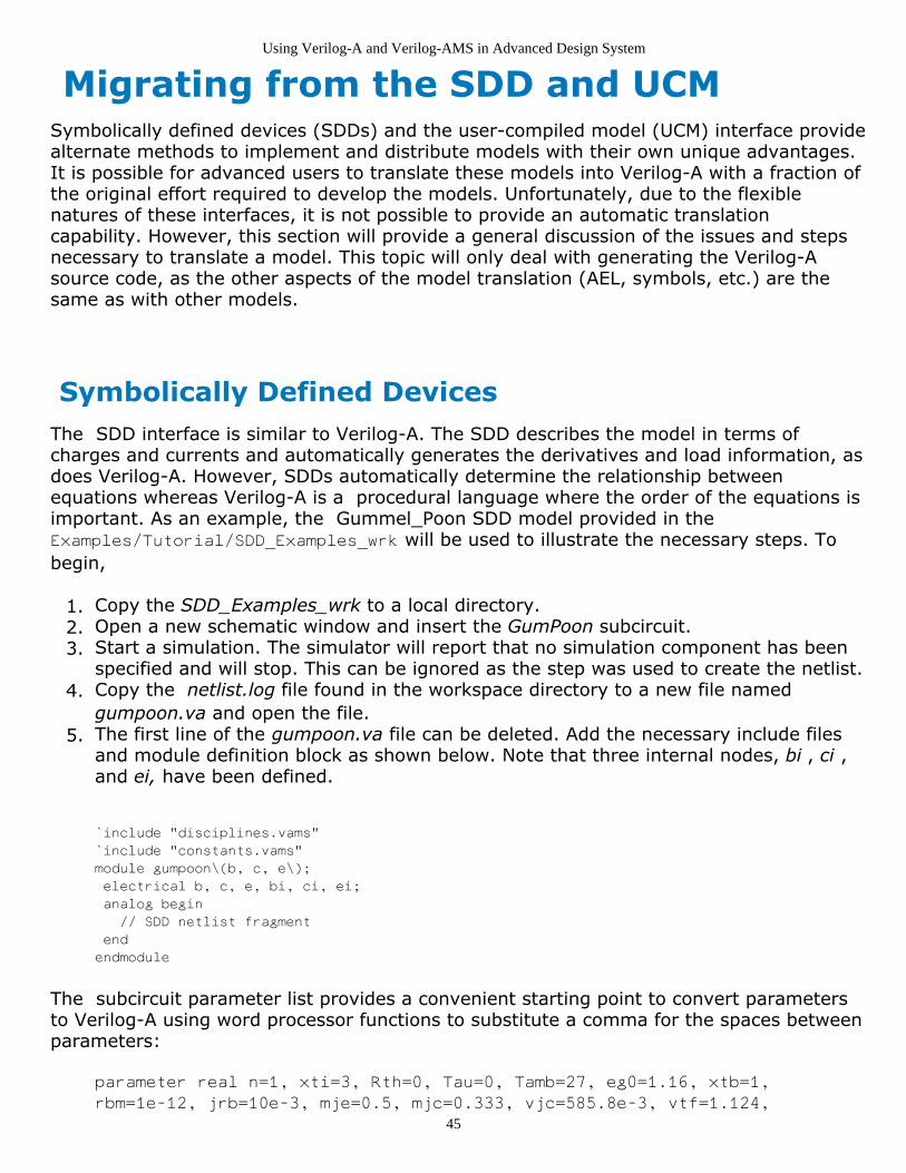
Using Verilog-A and Verilog-AMS in Advanced Design System
45
Migrating from the SDD and UCMSymbolically defined devices (SDDs) and the user-compiled model (UCM) interface providealternate methods to implement and distribute models with their own unique advantages.It is possible for advanced users to translate these models into Verilog-A with a fraction ofthe original effort required to develop the models. Unfortunately, due to the flexiblenatures of these interfaces, it is not possible to provide an automatic translationcapability. However, this section will provide a general discussion of the issues and stepsnecessary to translate a model. This topic will only deal with generating the Verilog-Asource code, as the other aspects of the model translation (AEL, symbols, etc.) are thesame as with other models.
Symbolically Defined DevicesThe SDD interface is similar to Verilog-A. The SDD describes the model in terms ofcharges and currents and automatically generates the derivatives and load information, asdoes Verilog-A. However, SDDs automatically determine the relationship betweenequations whereas Verilog-A is a procedural language where the order of the equations isimportant. As an example, the Gummel_Poon SDD model provided in theExamples/Tutorial/SDD_Examples_wrk will be used to illustrate the necessary steps. Tobegin,
Copy the SDD_Examples_wrk to a local directory.1.Open a new schematic window and insert the GumPoon subcircuit.2.Start a simulation. The simulator will report that no simulation component has been3.specified and will stop. This can be ignored as the step was used to create the netlist.Copy the netlist.log file found in the workspace directory to a new file named 4.gumpoon.va and open the file.The first line of the gumpoon.va file can be deleted. Add the necessary include files5.and module definition block as shown below. Note that three internal nodes, bi , ci ,and ei, have been defined.
`include "disciplines.vams"
`include "constants.vams"
module gumpoon\(b, c, e\);
electrical b, c, e, bi, ci, ei;
analog begin
// SDD netlist fragment
end
endmodule
The subcircuit parameter list provides a convenient starting point to convert parametersto Verilog-A using word processor functions to substitute a comma for the spaces betweenparameters:
parameter real n=1, xti=3, Rth=0, Tau=0, Tamb=27, eg0=1.16, xtb=1,
rbm=1e-12, jrb=10e-3, mje=0.5, mjc=0.333, vjc=585.8e-3, vtf=1.124,
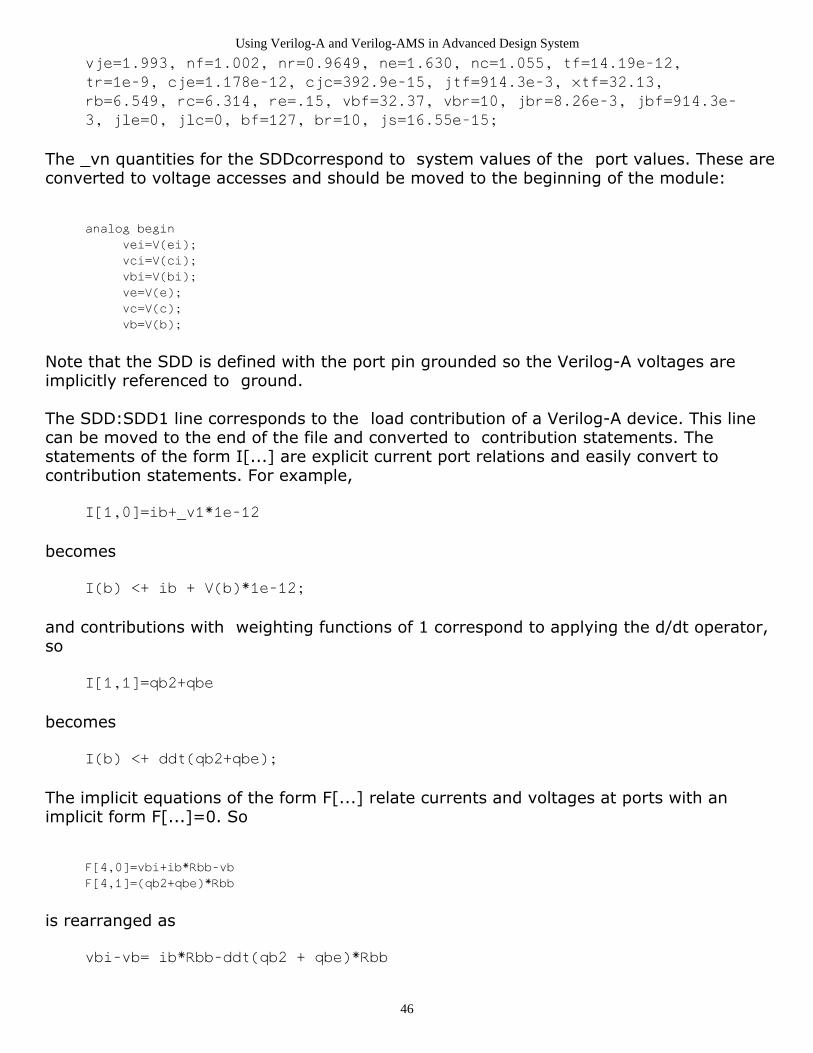
Using Verilog-A and Verilog-AMS in Advanced Design System
46
vje=1.993, nf=1.002, nr=0.9649, ne=1.630, nc=1.055, tf=14.19e-12,
tr=1e-9, cje=1.178e-12, cjc=392.9e-15, jtf=914.3e-3, xtf=32.13,
rb=6.549, rc=6.314, re=.15, vbf=32.37, vbr=10, jbr=8.26e-3, jbf=914.3e-
3, jle=0, jlc=0, bf=127, br=10, js=16.55e-15;
The _vn quantities for the SDDcorrespond to system values of the port values. These areconverted to voltage accesses and should be moved to the beginning of the module:
analog begin
vei=V(ei);
vci=V(ci);
vbi=V(bi);
ve=V(e);
vc=V(c);
vb=V(b);
Note that the SDD is defined with the port pin grounded so the Verilog-A voltages areimplicitly referenced to ground.
The SDD:SDD1 line corresponds to the load contribution of a Verilog-A device. This linecan be moved to the end of the file and converted to contribution statements. Thestatements of the form I[...] are explicit current port relations and easily convert tocontribution statements. For example,
I[1,0]=ib+_v1*1e-12
becomes
I(b) <+ ib + V(b)*1e-12;
and contributions with weighting functions of 1 correspond to applying the d/dt operator,so
I[1,1]=qb2+qbe
becomes
I(b) <+ ddt(qb2+qbe);
The implicit equations of the form F[...] relate currents and voltages at ports with animplicit form F[...]=0. So
F[4,0]=vbi+ib*Rbb-vb
F[4,1]=(qb2+qbe)*Rbb
is rearranged as
vbi-vb= ib*Rbb-ddt(qb2 + qbe)*Rbb

Using Verilog-A and Verilog-AMS in Advanced Design System
47
and is implemented as
V(bi,b) <+ Rbb*(ib + ddt(qb2 + qbe)) ;
This process is repeated for the other contributions.
The SDD uses a function named diode to implement the diode junction relation. Thisfunction, and the exponential function exp_soft , can easily be converted to analogfunctions. For example,
diode(v,is,n)=is*(exp_soft(v/(n*vt)) - 1)
becomes
analog function real diode;
input v, is, n, vt;
real v, is, n, vt;
begin
diode = is * (exp_soft(v / (n * vt)) - 1);
end
endfunction
while
exp_soft(x)=if (x < exp_max) then exp(x) else (x+1-
exp_max)*exp(exp_max) endif
becomes
analog function real exp_soft;
input x;
real x;
`define max_arg ln(1e16)
begin
if (x < `max_arg)
exp_soft = exp(x);
else
exp_soft = (x + 1 - `max_arg) * exp(`max_arg);
end
endfunction
Note that Verilog-A requires that the analog function exp_soft be defined prior to its usein the analog function diode . Also, the variable max_arg is converted to a macrodefinition.
At this point, the source code is as shown below:
`include "disciplines.vams"
`include "constants.vams"
`define max_arg ln(1e16)
module gumpoon(b, c, e);

Using Verilog-A and Verilog-AMS in Advanced Design System
48
electrical b, c, e, bi, ci, ei;
parameter real n=1, xti=3, Rth=0, Tau=0, Tamb=27, eg0=1.16, xtb=1,
rbm=1e-12, jrb=10e-3, mje=0.5, mjc=0.333, vjc=585.8e-3, vtf=1.124,
vje=1.993, nf=1.002, nr=0.9649, ne=1.630, nc=1.055, tf=14.19e-12,
tr=1e-9, cje=1.178e-12, cjc=392.9e-15, jtf=914.3e-3, xtf=32.13,
rb=6.549, rc=6.314, re=.15, vbf=32.37, vbr=10, jbr=8.26e-3,
jbf=914.3e-3, jle=0, jlc=0, bf=127, br=10, js=16.55e-15;
analog function real exp_soft;
input x;
real x;
begin
if (x < `max_arg)
exp_soft = exp(x);
else
exp_soft = (x + 1 - `max_arg) * exp(`max_arg);
end
endfunction
analog function real diode;
input v, is, n, vt;
real v, is, n, vt;
begin
diode = is * (exp_soft(v / (n * vt)) - 1);
end
endfunction
real vei, vci, vbi, ve, vc, vb;
analog begin
vei=V(ei);
vci=V(ci);
vbi=V(bi);
ve=V(e);
vc=V(c);
vb=V(b);
vjc_T=vjc
vje_T=vje
Br_T=br
Eg(t)=eg0-7.02e-4*(t+TzeroC)^2/(1108+(t+TzeroC))
Bf_T=bf
Js_T=js*TempRatio^xti *
exp_soft(Eg(Tamb)*((Tj-Tamb)/((Tamb+TzeroC)*vt)))
TempRatio=(Tj+TzeroC)/(Tamb+TzeroC)
TzeroC=273.15
Tj=Tamb
ibb=if (ib < 1pA ) then 1pA else ib endif
Rbb=3*(rb - rbm)*(tan(Z) - Z)/(Z*tan(Z)^2) + rbm
Z=(-1 + sqrt(144*ibb/(pi^2*jrb) + 1))/((24/pi^2)*sqrt(ibb/jrb))
qbc=tr*diode(vbci, Js_T, nr) -
cjc*vjc_T*((1-vbci/vjc_T)^(1-mjc))/(1-mjc)
qb2=qbc
iff=diode(vbei, Js_T, nf)
TFF=tf*(1+xtf*(exp(vbci/(1.44*vtf)*(iff/(iff+jtf))^2)))
qbe=diode(vbei, TFF*js/QB, nf) -
cje*vje_T*((1-vbei/vje_T)^(1-mje))/(1-mje)
ib2=diode(vbei, jle, ne) + diode(vbci, jlc, nc)
ib1=diode(vbei, Js_T/Bf_T, nf) + diode(vbci, Js_T/Br_T, nr)
ic2=-diode(vbci, Js_T/Br_T, nr) - diode(vbci, jlc, nc)
ic1=diode(vbei, Js_T/QB, nf) - diode(vbci, js/QB, nr)
QB=(Q1/2)*(1 + sqrt(1+4*Q2))

Using Verilog-A and Verilog-AMS in Advanced Design System
49
vt=boltzmann*(Tamb+TzeroC)/qelectron
Q2=diode(vbei, Js_T/jbf, nf) + diode(vbci, Js_T/jbr, nr)
Q1=1/(1 - vbci/vbf - vbei/vbr)
vbei=vbi-vei
vbe=vb-ve
vbc=vb-vc
vbci=vbi-vci
ib=ib1+ib2
ic=ic1+ic2
ie=-(ib+ic)
X=1.0 Hz
endmodule
The remaining equations can easily be converted to valid Verilog-A equations byappending semi-colons and declaring the variables. Certain equations, such as theequations for Tamp , vt , and TzeroC can be updated to system parameter function calls or macro constants. Other equations, such as X=1.0Hz, are superfluous and can be deleted.The final step is to rearrange the order of the equations. The compiler will issue amessage indicating a memory state exists. This is a valid outcome but is also indicative ofan un-initialized variable, which, in turn, indicates that the equation declaring the variableshould be moved before that equation. The final code is shown below.
`include "disciplines.vams"
`include "constants.vams"
`define max_arg ln(1e16)
`define TzeroC `P_CELSIUS0
module gumpoon(b, c, e);
electrical b, c, e, bi, ci, ei;
parameter real n=1, xti=3, Rth=0, Tau=0, Tamb=27, eg0=1.16, xtb=1,
rbm=1e-12, jrb=10e-3, mje=0.5, mjc=0.333, vjc=585.8e-3, vtf=1.124,
vje=1.993, nf=1.002, nr=0.9649, ne=1.630, nc=1.055, tf=14.19e-12,
tr=1e-9, cje=1.178e-12, cjc=392.9e-15, jtf=914.3e-3, xtf=32.13,
rb=6.549, rc=6.314, re=.15, vbf=32.37, vbr=10, jbr=8.26e-3,
jbf=914.3e-3, jle=0, jlc=0, bf=127, br=10, js=16.55e-15;
analog function real exp_soft;
input x;
real x;
begin
if (x < `max_arg)
exp_soft = exp(x);
else
exp_soft = (x + 1 - `max_arg) * exp(`max_arg);
end
endfunction
analog function real diode;
input v, is, n, vt;
real v, is, n, vt;
begin
diode = is * (exp_soft(v / (n * vt)) - 1);
end
endfunction
analog function real Eg;
input t, eg0;
real t, eg0;
begin

Using Verilog-A and Verilog-AMS in Advanced Design System
50
Eg=eg0-7.02e-4*(t+`TzeroC)*(t+`TzeroC)/(1108+(t+`TzeroC));
end
endfunction
real vei, vbe, vbei, vbci, vbc, vci, vbi, ve, vc, vb;
real Tj, vjc_T, vje_T, Br_T, Bf_T, Js_T, TempRatio, vth;
real ic, ie, ib, ibb, Z, vt, pi2, Rbb, Q1, Q2;
real qbc, qb2, iff, TFF, qbe, ib2, ib1, ic1, ic2, QB;
analog begin
vei=V(ei);
vci=V(ci);
vbi=V(bi);
ve=V(e);
vc=V(c);
vb=V(b);
vbei=vbi-vei;
vbe=vb-ve;
vbc=vb-vc;
vbci=vbi-vci;
Tj=$temperature;
vth = $vt;
vjc_T=vjc;
vje_T=vje;
Br_T=br;
Bf_T=bf;
TempRatio=(Tj+`TzeroC)/(Tamb+`TzeroC);
Js_T=js*pow(TempRatio,xti) *
exp_soft(Eg(Tamb,eg0)*((Tj-Tamb)/((Tamb+`TzeroC)*vth)));
qbc=tr*diode(vbci, Js_T, nr, vth) -
cjc*vjc_T*(pow(1-vbci/vjc_T,1-mjc))/(1-mjc);
qb2=qbc;
iff=diode(vbei, Js_T, nf, vth);
TFF=tf*(1+xtf*(exp(vbci/(1.44*vtf)*pow(iff/(iff+jtf),2))));
ib2=diode(vbei, jle, ne, vth) + diode(vbci, jlc, nc, vth);
ib1=diode(vbei, Js_T/Bf_T, vth) + diode(vbci, Js_T/Br_T, nr, vth);
ic2=-diode(vbci, Js_T/Br_T, nr, vth) - diode(vbci, jlc, nc, vth);
Q1=1/(1 - vbci/vbf - vbei/vbr);
Q2=diode(vbei, Js_T/jbf, nf, vth) + diode(vbci, Js_T/jbr, nr, vth);
QB=(Q1/2)*(1 + sqrt(1+4*Q2));
qbe=diode(vbei, TFF*js/QB, nf, vth) -
cje*vje_T*(pow(1-vbei/vje_T,1-mje))/(1-mje);
ic1=diode(vbei, Js_T/QB, nf, vth) - diode(vbci, js/QB, nr, vth);
ib=ib1+ib2;
if (ib < 1e-12 )
ibb = 1e-12;
else
ibb = ib;
pi2 = `M_PI * `M_PI;
Z=(-1 + sqrt(144*ibb/(pi2*jrb) + 1))/((24/pi2)*sqrt(ibb/jrb));
Rbb=3*(rb - rbm)*(tan(Z) - Z)/(Z*pow(tan(Z),2)) + rbm;
ic=ic1+ic2;
ie=-(ib+ic);
V(bi,b) <+ Rbb * (ib + ddt(qb2+qbe));
V(e,ei) <+ re * (ie - ddt(qbe));
V(c,ci) <+ rc * (ic - ddt(qb2));
I(c) <+ -ddt(qb2) + ic+vc*1e-12;
I(b) <+ ddt(qb2+qbe) + ib+vb*1e-12;
I(e) <+ -ddt(qbe) + ie+ve*1e-12;
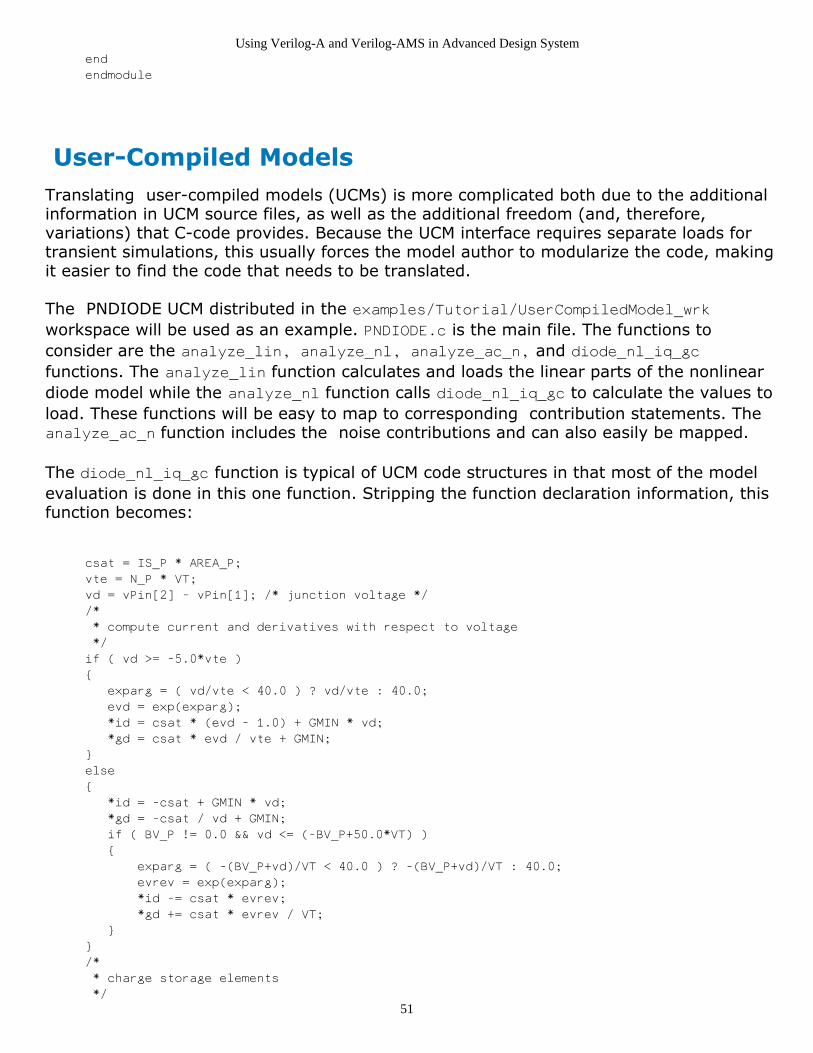
Using Verilog-A and Verilog-AMS in Advanced Design System
51
end
endmodule
User-Compiled ModelsTranslating user-compiled models (UCMs) is more complicated both due to the additionalinformation in UCM source files, as well as the additional freedom (and, therefore,variations) that C-code provides. Because the UCM interface requires separate loads for transient simulations, this usually forces the model author to modularize the code, makingit easier to find the code that needs to be translated.
The PNDIODE UCM distributed in the examples/Tutorial/UserCompiledModel_wrkworkspace will be used as an example. PNDIODE.c is the main file. The functions toconsider are the analyze_lin, analyze_nl, analyze_ac_n, and diode_nl_iq_gcfunctions. The analyze_lin function calculates and loads the linear parts of the nonlineardiode model while the analyze_nl function calls diode_nl_iq_gc to calculate the values toload. These functions will be easy to map to corresponding contribution statements. Theanalyze_ac_n function includes the noise contributions and can also easily be mapped.
The diode_nl_iq_gc function is typical of UCM code structures in that most of the modelevaluation is done in this one function. Stripping the function declaration information, thisfunction becomes:
csat = IS_P * AREA_P;
vte = N_P * VT;
vd = vPin[2] - vPin[1]; /* junction voltage */
/*
* compute current and derivatives with respect to voltage
*/
if ( vd >= -5.0*vte )
{
exparg = ( vd/vte < 40.0 ) ? vd/vte : 40.0;
evd = exp(exparg);
*id = csat * (evd - 1.0) + GMIN * vd;
*gd = csat * evd / vte + GMIN;
}
else
{
*id = -csat + GMIN * vd;
*gd = -csat / vd + GMIN;
if ( BV_P != 0.0 && vd <= (-BV_P+50.0*VT) )
{
exparg = ( -(BV_P+vd)/VT < 40.0 ) ? -(BV_P+vd)/VT : 40.0;
evrev = exp(exparg);
*id -= csat * evrev;
*gd += csat * evrev / VT;
}
}
/*
* charge storage elements
*/

Using Verilog-A and Verilog-AMS in Advanced Design System
52
fcpb = FC_P * VJ_P;
czero = CJO_P * AREA_P;
if (vd < fcpb)
{
arg = 1.0 - vd / VJ_P;
sarg = exp(-M_P * log(arg));
*qd = TT_P * (*id) + VJ_P * czero * (1.0 - arg * sarg) / (1.0 - M_P);
*capd = TT_P * (*gd) + czero * sarg;
}
else
{
xfc = log(1.0 - FC_P);
f1 = VJ_P * (1.0-exp((1.0-M_P)*xfc)) / (1.0-M_P);
f2 = exp((1.0+M_P)*xfc);
f3 = 1.0 - FC_P * (1.0+M_P);
czof2 = czero / f2;
*qd = TT_P * (*id) + czero * f1 + czof2 * (f3 * (vd - fcpb) + (M_P / (VJ_P + VJ_P))
* (vd * vd - fcpb * fcpb));
*capd = TT_P * (*gd) + czof2 * (f3 + M_P * vd / VJ_P);
}
The first step is to remove any capacitance and conductance equations that were used toload the off diagonal elements in the Jacobian. Next, convert { / } blocks to begin / endblocks and convert any math functions and operators to their Verilog-A equivalent.
NoteIn Verilog-A log is log base 10 whereas in the C language it is natural log.
The diode terminals will be called anode, cathode, and internal. Access to the vPin arraywill be converted to voltage access functions and the parameter macros will have their _Psuffix stripped.
The parameter declarations can be generated by using the PNDIODE.ael create_item'sdeclaration. Temperature dependent variables, such as VT , can be mapped to $vt , GMINto a macro definition, and the double declaration of variables in the C-code can bemapped to real declarations in Verilog-A. The final code then becomes:
`include "constants.vams"
`include "disciplines.vams"
`define GMIN 1.0e-12
module PNDIODE(anode,cathode);
inout anode, cathode;
electrical anode, cathode, internal;
parameter real AREA = 1.0 from (0:inf]; //Area scaling factor
parameter real IS = 1e-14 from [0:inf]; //Saturation current [A]
parameter real RS = 0.0 from [0:inf]; //Ohmic res [Ohm]
parameter real N = 1.0 from [0:inf]; //Emission coef
parameter real TT = 0.0 from [0:inf]; //Transit time [s]
parameter real CJO = 0.0 from [0:inf]; //Junction capacitance [F]
parameter real VJ = 1.0 exclude 0; //Junction potential [v]
parameter real M = 0.5 from [0:inf]; //Grading coef
parameter real EG = 0 from (0:inf]; //Activation energy [eV]
parameter real XTI = 3.0 from [0:inf]; //IS temp exp.
parameter real KF = 0.0; //Flicker noise coef
parameter real AF = 0.0 from (0:inf); //Flicker noise exponent

Using Verilog-A and Verilog-AMS in Advanced Design System
53
parameter real FC = 0.0 from [0:1]; //Forward bias junct parm
parameter real BV = 0.0 from [0:inf]; //Reverse breakdown voltage [v]
parameter real IBV = 0.0 from [0:inf]; //Current at BV [A]
real vd, csat, vte, evd, evrev;
real id, qd, exparg, vth, T;
real fcpb, xfc, f1, f2, f3;
real czero, arg, sarg, czof2;
analog begin
csat = IS * AREA;
vth = $vt;
vte = N * vth;
vd = V(anode, internal); /* junction voltage */
/*
* * compute current and derivatives with respect to voltage
* */
if ( vd >= -5.0*vte ) begin
exparg = ( vd/vte < 40.0 ) ? vd/vte : 40.0;
evd = exp(exparg);
id = csat * (evd - 1.0) + `GMIN * vd;
end
else begin
id = -csat + `GMIN * vd;
if ( BV != 0.0 && vd <= (-BV+50.0*vth) ) begin
exparg = ( -(BV+vd)/vth < 40.0 ) ? -(BV+vd)/vth : 40.0;
evrev = exp(exparg);
id = id - csat * evrev;
end
end
/*
* * charge storage elements
* */
fcpb = FC * VJ;
czero = CJO * AREA;
if (vd < fcpb) begin
arg = 1.0 - vd / VJ;
sarg = exp(-M * ln(arg));
qd = TT * id + VJ * czero * (1.0 - arg * sarg) / (1.0 - M);
end
else begin
xfc = ln(1.0 - FC);
f1 = VJ * (1.0-exp((1.0-M)*xfc)) / (1.0-M);
f2 = exp((1.0+M)*xfc);
f3 = 1.0 - FC * (1.0+M);
czof2 = czero / f2;
qd = TT * id + czero * f1 + czof2 * (f3 * (vd - fcpb) + (M / (VJ + VJ)) * (vd * vd
- fcpb * fcpb));
end
I(anode, internal) <+ id;
V(internal, cathode) <+ I(internal, cathode) * (RS / AREA);
I(anode, internal) <+ ddt(qd);
// Noise
T = $temperature;
V(internal, cathode) <+ white_noise(4 * `P_K * T * (RS / AREA), "thermal");
I(anode, internal) <+ white_noise(2 * `P_Q * id, "thermal");
if (id > 0)
I(anode, internal) <+ flicker_noise(KF * pow(id, AF), 1.0, "flicker");
else
I(anode, internal) <+ flicker_noise(KF * -pow(-id, AF), 1.0, "flicker");
end

Using Verilog-A and Verilog-AMS in Advanced Design System
54
endmodule
Although it is not possible to predict what code style a UCM author might use, it ispossible to convert a model to Verilog-A.

Using Verilog-A and Verilog-AMS in Advanced Design System
55
Verilog-A and Verilog-AMS in ADSDesign KitsThis topic describes the steps necessary to distribute Verilog-A models in an ADS DesignKit. Design Kits provide a convenient way to distribute Verilog-A models and the steps arevery similar to the steps to create conventional Design Kits.
For an overview of the process and the specific steps involved in creating an ADS DesignKit, refer to the Design Kit Development (dkarch) documentation.
Verilog-A models require a similar infrastructure as User-Compiled Models (UCM).Because the Verilog-A interface includes the appropriate tools to recompile on the enduser's platform, Verilog-A models can be distributed as source code, compiled form ( Compiled Model Library, or CML), or both. As with the UCM, the compiled object librarymust be provided for each platform supported by Advanced Design System.
Verilog-A modules in a Design Kit are automatically made available to workspaces usingthat design kit. Beginning with ADS 2008 Update 2, the Verilog-A files must be placed inthe design kit veriloga directory :
design_kit/veriloga
If you want to distribute the Verilog-A source, then that is all that needs to be done. Thefiles will be compiled on the user's operating system after the design kit is installed andthe first simulation is run.
If you want to ship CML files then further steps are required. You may want to ship onlyCML if you want to protect your intellectual property. Alternatively, you may want to shipboth Verilog-A source and CML files. This will avoid having all Design Kit users go throughthe compilation step the first time they simulate with your kit, and it will provide theability to view and edit Verilog-A source code.
Let's assume you have a number of Verilog-A files in the Design Kit as,
dk_wrk/veriloga/resistor.va
dk_wrk/veriloga/varactor.va
By default, the CML files associated with these Verilog-A sources are stored in the CMLcache (see The Verilog-A/AMS Compiled Model Library Cache (veriloga)). You can havethe CML files written locally by adding a vamake.spec file to the Verilog-A sourcedirectory. Add a single line to vamake.spec as,
USE_CACHE=NO
From now on, all CML files will be written locally and assuming you have simulated on a32-bit Windows platform, your directory structure will look like this,

Using Verilog-A and Verilog-AMS in Advanced Design System
56
dk_wrk/veriloga/vamake.spec
dk_wrk/veriloga/resistor.va
dk_wrk/veriloga/varactor.va
dk_wrk/veriloga/lib.win32/1.xx/cml-table.idx
dk_wrk/veriloga/lib.win32/1.xx/resistor.cml
dk_wrk/veriloga/lib.win32/1.xx/varactor.cml
Prior to shipping your Design Kit, you can seal the directory by adding another line to thevamake.spec file as,
USE_CACHE=NO
PREPARE_DIR=NO
Now when the simulator boots it will no longer check that the CML files are up to dateagainst the Verilog-A source. If you wish to protect your intellectual property, you cannow remove the Verilog-A source files from the Design Kit.
To complete your Design Kit, ensure that the necessary directories and files are available.These required directories and files are described in the following table.
Directory/File Description
circuit/ael AEL descriptions of each component
circuit/symbols Symbol information for each component (it is possible to reference existing componentsymbols instead)
circuit/bitmaps/pccircuit/bitmaps/unix
Bitmaps for each component
veriloga/ arch Compiled model libraries.
de/ael/boot.ael An AEL file with the load commands for each of the circuit/ael component files.
de/ael/palette.ael Palette and library loads for each of the components.
design_kit/ads.lib Information file for the Design Kit loading mechanism to describe the Design Kit.
examples Place example workspaces here.
doc Optional documentation files.
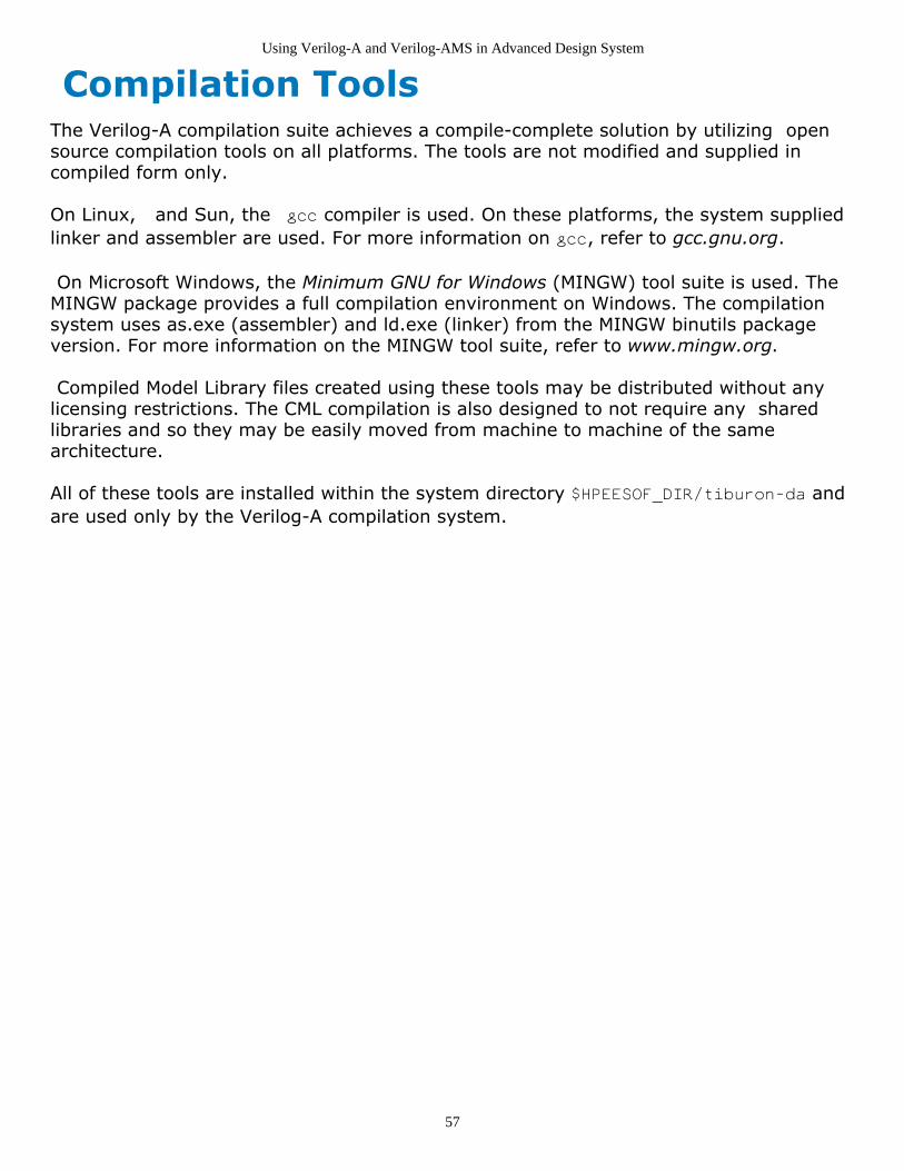
Using Verilog-A and Verilog-AMS in Advanced Design System
57
Compilation ToolsThe Verilog-A compilation suite achieves a compile-complete solution by utilizing opensource compilation tools on all platforms. The tools are not modified and supplied incompiled form only.
On Linux, and Sun, the gcc compiler is used. On these platforms, the system suppliedlinker and assembler are used. For more information on gcc, refer to gcc.gnu.org.
On Microsoft Windows, the Minimum GNU for Windows (MINGW) tool suite is used. TheMINGW package provides a full compilation environment on Windows. The compilationsystem uses as.exe (assembler) and ld.exe (linker) from the MINGW binutils packageversion. For more information on the MINGW tool suite, refer to www.mingw.org.
Compiled Model Library files created using these tools may be distributed without anylicensing restrictions. The CML compilation is also designed to not require any sharedlibraries and so they may be easily moved from machine to machine of the samearchitecture.
All of these tools are installed within the system directory $HPEESOF_DIR/tiburon-da andare used only by the Verilog-A compilation system.