MONORAIL and AMS - SCHNEEBERGER
235
MONORAIL and AMS Profiled linear guideways and integrated measuring systems Application catalog 2017
-
Upload
khangminh22 -
Category
Documents
-
view
1 -
download
0
Transcript of MONORAIL and AMS - SCHNEEBERGER
www.schneeberger.com
Ap
plic
atio
n c
atal
og
201
7 M
ON
OR
AIL
an
d A
MS
P
rofil
ed li
nea
r g
uid
eway
s an
d in
teg
rate
d m
easu
rin
g s
yste
ms
50.5
018/01
/071
7/e
PROSPECTUSES
SCHNEEBERGER COMPANIES
SWITZERLAND GERMANY ITALY USA
SCHNEEBERGER AGLineartechnikSt. Urbanstrasse 124914 Roggwil/BE
SCHNEEBERGER GmbHGräfenau75339 Höfen/Enz
SCHNEEBERGER S.r.l.Via Soldani 1021021 Angera (VA)
SCHNEEBERGER Inc.44 Sixth Road,Woburn, MA 01801-1759
PhoneFax
+41 62 918 41 11+41 62 918 41 00
PhoneFax
+49 7081 782 0+49 7081 782 124
PhoneFax
+39 0331 93 2010+39 0331 93 1655
PhoneFax
+1 781 271 0140+1 781 932 4127
E-Mail:[email protected]
E-Mail:[email protected]
E-Mail:[email protected]
E-Mail:[email protected]
JAPAN CHINA KOREA SINGAPORE
Nippon SCHNEEBERGER K.K.Crane Toranomon Bldg 7F 3-20-5 Toranomon, Minato-kuTokyo 105-0001
SCHNEEBERGER (Shanghai) Co., Ltd.Rm 606, Shang Gao International BuildingNo. 137 XianXia Road200051 Shanghai
SCHNEEBERGER Korea Ltd.Garden5 Tool10, Chungmin-ro, Songpa-gu, Seoul, Korea 05840
SCHNEEBERGER Linear Technology Pte. Ltd. 38 Ang Mo Kio Industrial Park 2#01-04, Singapore 569511
PhoneFax
+81 3 6435 7474+81 3 6435 7475
PhoneFax
+86 21 6209 0027+86 21 6209 0102
PhoneFax
+82 2 554 2971 +82 2 554 3971
PhoneFax
+ 65 6841 2385+ 65 6841 3408
E-Mail:[email protected]
E-Mail:[email protected]
E-Mail: [email protected]
E-Mail: [email protected]
JAPAN CHINA KOREA
日本シュネーベルガー株式会社〒105-0001東京都港区虎ノ門3-20-5クレイン虎ノ門ビル7F
施耐博格(上海)传动技术有限公司上海市长宁区仙霞路137号盛高国际大厦606室,上海 200051
슈니베거코리아 유한회사05840 서울시 송파구 충민로 10가든파이브 툴관 10층
電話ファクス
03 6435 747403 6435 7475
电话传真
+86 21 6209 0027 +86 21 6209 0102
전화 팩스
+82 2 554 2971 +82 2 554 3971
Eメール:[email protected]
INDIA
SCHNEEBERGER India Pvt. Ltd. 406, Satra Plaza,Palm Beach Road, Sector 19D Vashi,400 703 New Mumbai
PhoneFax
+91 22 6461 0646+91 22 6461 1756
E-Mail:[email protected]
SCHNEEBERGER MINERAL CASTING
CZECH REPUBLIC CHINA CHINA
SCHNEEBERGER Mineralgusstechnik s.r.oPrumyslový park 32/20350 02 Cheb – Dolní Dvory
SCHNEEBERGER Changzhou Precision Systems Co. Ltd. 137 Hanjiang Road Changzhou New district 213000 Changzhou, Jiangsu
施耐博格(常州)测试系统有限公司汉江路137,常州新区,常州213022
PhoneFax
+420 354 400 941+420 354 400 940
PhoneFax
+86 519 8988 3938+86 519 8988 5115
电话传真
+86 519 8988 3938+86 519 8988 5115
E-Mail:[email protected]
E-Mail: [email protected]
SCHNEEBERGER SALES DEPARTMENTS
AUSTRIA AND SOUTH EAST EUROPE
BENELUX DENMARK, SWEDEN FRANCE GREAT BRITAIN
Mobile +43 676 935 1035 Mobile +31 6 5326 3929 Mobile +31 6 5326 3929 Mobile +33 6 0941 6269 Mobile +44 77 8814 5645
E-Mail:[email protected]
E-Mail:[email protected]
E-Mail:[email protected]
E-Mail:[email protected]
E-Mail:[email protected]
ISRAEL POLAND, SLOVAKIA,CZECH REPUBLIC
RUSSIA, BELARUS, UKRAINE
SPAIN, PORTUGAL,ANDORRA
TURKEY
Mobile +972 5 0551 7920 Mobile +420 6 0278 4077 MobileMobileMobile
+7 985 960 85 53+38 050 407 6789+37 529 860 0410
Mobile +34 69 559 05 99 Mobile + 90 545 320 83 55
E-Mail:[email protected]
E-Mail:[email protected]
E-Mail:[email protected]
E-Mail:[email protected]
E-Mail:[email protected]
• COMPANY BROCHURE
• CUSTOMIZED BEARINGS
• GEAR RACKS
• LINEAR BEARINGS and RECIRCULATING UNITS
• MINERAL CASTING SCHNEEBERGER
• MINISLIDE MSQscale
• MINI-X MINIRAIL / MINISCALE PLUS / MINISLIDE
• MONORAIL and AMS profiled linear guideways with integrated measuring system
• MONORAIL and AMS application catalog
• POSITIONING SYSTEMS
• SLIDES
50.5
018/
01/0
717/
e/0.
375/
SR
O/W
D/P
rinte
d in
Ger
man
y. S
ubje
ct to
tech
nica
l cha
nges
. MONORAIL and AMS
Profiled linear guideways and integrated measuring systems
Application catalog 2017

Latest version of the catalogsYou can always find the latest version of our catalogs in the Download area of our website.
DisclaimerThis publication has been compiled with great care and all information has been checked for accuracy. However, we can assume no liability for incorrect or incomplete information. We reserve the right to make changes to the information and technical data as a result of enhancements to our products. Reprinting or reproducing, even in part, is not permitted without our written consent.
SCHNEEBERGER AGENCIES
EUROPE
AUSTRIAHaberkorn GmbH6961 WolfurtPhone: +43 5574 695-0Fax: +43 5574 695-99 [email protected]
BULGARIA / MACEDONIAAtlas Technik EOODHippodroma, Bl. 139B, Eing. A, App. 61612 Sofia, PB 51BulgarienPhone +359 2 859 76 81Fax +359 2 859 76 81Mobil +359 8 852 32 595E-Mail: [email protected]
CROATIAHaberkorn CRO d.o.o.10431 Sveta NedeljaPhone +385 1 333 5870Fax. +385 1 337 3902E-Mail: [email protected]
CZECH REPUBLICINOMECH s.r.o. .Martina Koláře 2118390 02 TáborPhone +420 381 252 223E-Mail: [email protected]
DENMARKHERSTAD + PIPER A/SJernholmen 48c2650 HvidovrePhone +45 367 740 00Fax +45 367 777 40E-Mail: [email protected]
FINLANDEIE Maskin OYPL, 80 Asematie 110601 TammisaariPhone +358 192 239 100Fax +358 192 239 199E-Mail: [email protected]
FRANCERegion Rhône-AlpesGroupe BARET6 avenue du 11 novembre 191869200 VenissieuxPhone +33 4 78 77 32 32Fax +33 4 78 00 90 00E-Mail: [email protected]
Regions Ile de France, Normandie, BretagneGroupe LECHEVALIER56 rue Jean MermozParc d›activités de la Bretèque76230 Bois-Guillaume CedexPhone +33 2 35 12 65 65Fax +33 2 35 59 89 97E-Mail: [email protected]
Region Nord Pas de CalaisLEFRANC LTL «Le Panetier»35, rue Pierre MartinParc d›Activités de l›Inquétrie62280 Saint Martin BoulognePhone +33 3 21 99 51 51Fax +33 3 21 99 51 50E-Mail: [email protected]
GERMANYBGP-Blazevic Geradlinige PräzisionstechnikStipo BlazevicAuerbacher Straße 893057 RegensburgPhone +49 941 463 704 0 Fax +49 941 463 704 50Mobil +49 151 401 126 25E-Mail: [email protected]
EUROPE HUNGARYHaberkorn Kft.Asztalos Sándor u.12Budapest, 1087Phone +36 13030325 Fax +36 1/3030262E-Mail: [email protected]
ITALYNadella S.r.I.Via Melette, 1620128 MilanoPhone +39 022 709 329 7Fax +39 022 551 768E-Mail: [email protected]
NORWAYEIE Maskin ASTvetenveien 1640671 OsloPhone +47 675 722 70Fax +47 675 722 80E-Mail: [email protected]
POLANDTECHNIKA LINIOWARollico Rolling ComponentsUI. Cegielniana 2142-700 LubliniecPhone +48 343 510 430 Fax +48 343 510 431E-Mail: [email protected]
ROMANIAMeximpex SRL4, Burebista Blvd., bl. D13 sc. A et 2 ap. 9-10031108 BucharestPhone +40 213 166 843 /44Fax +40 213 166 846E-Mail: [email protected]
RUSSIABearing Alliance, TD 121069 MoscowPhone +7495 987 32 92 add 114, 8 800 100 42 92Fax. +7495 987 32 92E-Mail: [email protected]
SERBIA/MONTENEGROHaberkorn d.o.o.Kralja Petra I, 5921203 Veternik,Phone +381 21 3 101 555Fax +381 21 3 101 554E-Mail: [email protected]
SLOVAKIAKBM, s.r.o.Juraj HajovskyZitná 13010 04 ZilinaPhone +421 417 070 324Fax +421 417 070 333Mobile +421 090 585 1465E-Mail: [email protected]
SLOVENIA / BOSNIA HERZEGOVINAHaberkorn d.o.o.Vodovodna ul. 72000 MariborPhone +386 2 320 67 10Fax +386 2 320 67 30E-Mail: [email protected]
SPAIN / PORTUGALTECNOMECA-KIDELAN-DEXIS Pol lndustrial ltziar 20829 DEBA (Gipuzkoa) Phone +34 943 199 201Phone +34 943 199 273E-Mail: [email protected]
EUROPE
SWEDENEIE Maskin ABBox 712421 BandhagenPhone +46 87 278 800Fax +46 87 278 899E-Mail: [email protected]
TURKEYBirlik Rulman (Paz.ltd.sti.)Mumhane Cad. No: 1680030 Karakoy-IstanbulPhone +90 212 249 54 95Fax +90 212 244 21 40E-Mail: [email protected]
Mustafa Kozanlı Mühendislik Ltd. Şti.Çalı Kavşağı Alaaddinbey Cad. No: 7 16130 Nilüfer / BURSAPhone +90 224 443 26 40Fax +90 224 443 26 39 E-Mail: [email protected]
ASIA
TAIWAN / REPUBLIC OF CHINAEver Bright Precisiton Ltd.1 F,nr.52 Lane 10 Chi-hu Road114 Taipei Phone +886 226 595 586Fax +886 226 595 587E-Mail: [email protected]
INDIAJagat Enterprise83, Narayan dhuru street, 3rd floor, Mazjid BunderMumbai - 400 003Phone. +91 2223421941Fax. +91 2223413405E-Mail: [email protected]
M.R. Bearing CompanyMR Complex, 224 Linghi Chetty Street Parrys,Chennai - 600001Phone +91 4425232847Fax +91 4425264497E-Mail: [email protected]
AUSTRALIA / NEW ZEALAND Benson Machines118 Carnarvon StreetNSW 2128 SilverwaterAustraliaPhone +61 1800 68 78 98Fax +61 (02) 9737 9707E-Mail: [email protected]
SOUTH AFRICA
Fischli & Fuhrmann Ltd.P.O Box 2531600 Isando GautengPhone +27 119 745 571Fax +27 119 745 574 E-Mail: [email protected]
SOUTH AMERICA
Ibatech Tecnologia Ltda.Av. Amazonas, 97690240 542 Porto Alegre RSBrazilPhone +55 513 337 14 81Fax +55 513 337 52 65 E-Mail: [email protected]

1
Foreword
The present MONORAIL and AMS application catalogue is intended for general design purposes. It supplements the general catalogues:
MONORAIL and AMS product catalogueMONORAIL and AMS installation instructions
with extensive information and know-how for sales and application recommendations. The ap-plication catalogue is available in a printed version or electronically in the “Download section” accessible from the SCHNEEBERGER home page at www.schneeberger.com.
All geometric dimensions and performance data such as load capacities and speeds should be taken from the MONORAIL and AMS product catalogue. The standard products can also be viewed there.
The application catalogue essentially describes the MR and BM product series as well as the AMS measuring systems under the name of “SCHNEEBERGER MONORAIL guideways”. The content is structured in the following sections: Technical principles, development and design, storage and transport, commissioning and operation, maintenance and servicing of products. The areas of expertise of guiding, driving and measuring are described separately within these sections.
SCHNEEBERGER GmbH 75339 Höfen/Enz

2

3
Notes
User guidelinesThis publication has been produced with great care and all information has been checked for its accuracy. No liability can, however, be accepted for erroneous or incomplete details. We reserve the right to make changes to the information and technical data for the purposes of the con-tinuous development of our products. Reprinting or copying, including extracts, is not permitted without our written approval.
Symbols used
NotesNote
¨ Notes and recommendations are set out here
Warning noteKeyword
Nature and source of the danger
¨ Consequences in the event of a failure to observe the warning. ¨ Measures to prevent damage.
Warning notes are categorised as follows using the keyword: � Warning
Means that there is a danger of serious injury or serious damage to property if the stipulated precautionary measures are not taken.
� Caution Means that there is a danger of minor injury or damage to property if the stipulated precau-tionary measures are not taken.
Additional literature � MONORAIL and AMS product catalogue � Interpolation and digitizing electronics SMEa operating instructions � AMSA-3L installation instructions/software instructions � Installation instructions for the BAC cover strip for MONORAIL BM � Installation instructions for the MAC cover strip for MONORAIL MR � Installation instructions for MRS/BRS brass plugs for MONORAIL MR/BM � MONORAIL and AMS installation instructions � Installation instructions for SPL lubrication plate for MONORAIL � Installation instructions for the MRZ steel plugs for MONORAIL MR � Installation notes for ASM metal wipers � Installation notes for MONORAIL MR and BM carriages � Installation notes for MONORAIL MR 100 carriages � Installation notes for MONORAIL BM2G � Installation notes for MONORAIL BZ
Product catalogues and installation instructions can be obtained from a SCHNEEBERGER agent or downloaded from www.schneeberger.com.

4
5
Contents
1 Technical Data: Guiding ........................................................................7
1.1. SCHNEEBERGERprofilerailguideways ............................................................................10
1.2. Constructionofaprofilerailguideway ..............................................................................15
1.3. Loadcarryingcapacity .........................................................................................................23
1.4. Preload ...................................................................................................................................28
1.5. Rigidity ...................................................................................................................................30
1.6. Accuracy ................................................................................................................................31
1.7. Servicelifecalculationprinciples .......................................................................................36
1.8. Sealingsystem ......................................................................................................................37
1.9. Build-upofnoise ...................................................................................................................40
1.10. Lubrication ............................................................................................................................42
2 Technical Data: Driving .......................................................................47
2.1. Integral rack drive BZ ...........................................................................................................50
2.2. Lubrication ............................................................................................................................53
3 Technical Data: Measuring .................................................................55
3.1. Distancemeasuringsystems ..............................................................................................58
3.2. Interfaces ...............................................................................................................................73
4 Developmentanddesign:Guiding .....................................................81
4.1. Factorsinfluencingthechoiceofproduct ........................................................................85
4.2. BalltoRollercomparison ....................................................................................................86
4.3. Guiderailtypes .....................................................................................................................88
4.4. Carriagetypes .......................................................................................................................93
4.5. Preload ...................................................................................................................................97
4.6. Accuracy ..............................................................................................................................100
4.7. Installationmethodsforguidesystems ...........................................................................106
4.8. Calculationandsizing ........................................................................................................109
4.9. Attaching the guide rail ......................................................................................................119
4.10. Multi-partguiderails ..........................................................................................................125
4.11. Fasteningcarriages ............................................................................................................126
4.12. Configurationoftheconnectingstructure .......................................................................130
4.13. Lubrication ..........................................................................................................................137
4.14. Seal ......................................................................................................................................152
6
Contents
4.15. Corrosionprotection ..........................................................................................................161
4.16. Additionalfunctionalityofclampsandbrakes.................................................................165
4.17. SCHNEEBERGERDownloadandOn-lineCADcatalogue ..............................................167
5 Developmentanddesign:Driving ....................................................169
5.1. Productoverview ................................................................................................................172
5.2. Calculationandsizing ........................................................................................................175
5.3. Attaching the guide rail ......................................................................................................180
5.4. Multi-partguiderails ..........................................................................................................183
5.5. Configurationoftheconnectingstructure .......................................................................184
5.6. Lubrication ..........................................................................................................................187
6 Developmentanddesign:Measuring ..............................................189
6.1. Integration ..........................................................................................................................192
6.2. Productoverview ................................................................................................................193
6.3. Factorsinfluencingthechoiceofproduct .......................................................................197
6.4. Arrangementofthemeasuringsystems ..........................................................................200
6.5. Operatingconditions ..........................................................................................................205
6.6. Shielding ..............................................................................................................................206
7 Storageandtransport .......................................................................209
7.1. Delivered condition .............................................................................................................212
7.2. Storage ................................................................................................................................213
7.3. Transport .............................................................................................................................214
8 Commissioning ..................................................................................217
8.1. Guidewaychecklist............................................................................................................220
8.2. Measuringsystemchecklist .............................................................................................222
9 Operating,maintenanceandservice ...............................................223
9.1. Wipers ..................................................................................................................................226
9.2. Influencingfactorsonoperatingconditions ....................................................................230
9.3. Precautionarymeasures ....................................................................................................231
9.4. 24hourdeliveryservice .....................................................................................................232

7
1 Technical Data: Guiding

8
9
1
Contents
1
1 Technical Data: Guiding ........................................................................7
1.1. SCHNEEBERGER profile rail guideways ............................................................................101.1.1 Types of linear guideway ...................................................................................................101.1.2 Characteristics and advantages of SCHNEEBERGER MONORAIL guideways. ..................12
1.2. Construction of a profile rail guideway ..............................................................................151.2.1 Carriage and guide rail ......................................................................................................151.2.2 Individual components and accessories ...........................................................................161.2.3 Types and design principles ..............................................................................................181.2.4 Materials ............................................................................................................................211.2.5 Hardening process ............................................................................................................21
1.3. Load carrying capacity .........................................................................................................231.3.1 Load carrying capacity ......................................................................................................231.3.2 Dynamic loading capacity C .............................................................................................231.3.3 Static loading capacity C0 ................................................................................................241.3.4 Static and dynamic moments ...........................................................................................251.3.5 Load directions .................................................................................................................26
1.4. Preload ...................................................................................................................................281.4.1 Definition ...........................................................................................................................281.4.2 Generating ........................................................................................................................291.4.3 SCHNEEBERGER MONORAIL guideways ........................................................................29
1.5. Rigidity ...................................................................................................................................301.5.1 Definition ...........................................................................................................................30
1.6. Accuracy ................................................................................................................................311.6.1 Accuracy ...........................................................................................................................311.6.2 Accuracy classes of SCHNEEBERGER MONORAIL guideways ......................................311.6.3 Running accuracy .............................................................................................................311.6.4 Influencesonrunningaccuracy ........................................................................................331.6.5 Measures to improve accuracy .........................................................................................35
1.7. Service life calculation principles .......................................................................................361.7.1 Definitionofterms .............................................................................................................361.7.2 Applicable standards ........................................................................................................36
1.8. Sealing system ......................................................................................................................371.8.1 Function of seals ...............................................................................................................371.8.2 Types of seals....................................................................................................................371.8.3 Friction of different seals ...................................................................................................39
1.9. Build-up of noise ...................................................................................................................401.9.1 Definition ...........................................................................................................................401.9.2 Causes ..............................................................................................................................401.9.3 Measures to reduce noise .................................................................................................41
1.10. Lubrication ............................................................................................................................421.10.1 Function of the lubrication ................................................................................................421.10.2 Types of lubricant ..............................................................................................................421.10.3 Characteristics of the lubricants ......................................................................................431.10.4 Recommended lubricants .................................................................................................441.10.5 Indicators and additives for lubricants ..............................................................................441.10.6 Brief description of the lubricants in accordance with DIN 51502 ...................................451.10.7 Deciding factors in your choice of lubricant .....................................................................46
10
1 Technical Data: Guiding1.1.SCHNEEBERGERprofilerailguideways1.1.1 Types of linear guideway
1.1. SCHNEEBERGER profile rail guideways
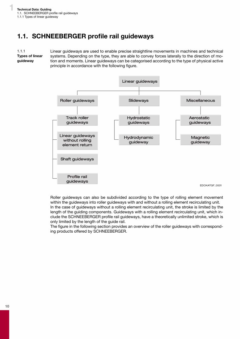
Linear guideways are used to enable precise straightline movements in machines and technical systems. Depending on the type, they are able to convey forces laterally to the direction of mo-tion and moments. Linear guideways can be categorised according to the type of physical active principleinaccordancewiththefollowingfigure.
Roller guideways can also be subdivided according to the type of rolling element movement within the guideways into roller guideways with and without a rolling element recirculating unit.In the case of guideways without a rolling element recirculating unit, the stroke is limited by the length of the guiding components. Guideways with a rolling element recirculating unit, which in-cludetheSCHNEEBERGERprofilerailguideways,haveatheoreticallyunlimitedstroke,whichisonly limited by the length of the guide rail.Thefigureinthefollowingsectionprovidesanoverviewoftherollerguidewayswithcorrespond-ing products offered by SCHNEEBERGER.
1.1.1 Types of linear guideway
11
1 Technical Data: Guiding1.1.SCHNEEBERGERprofilerailguideways1.1.1 Types of linear guideway
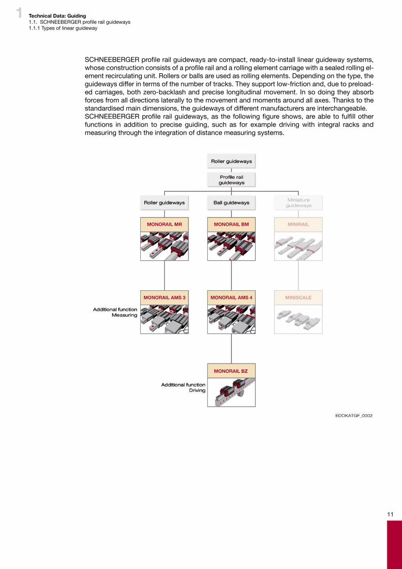
SCHNEEBERGERprofilerailguidewaysarecompact,ready-to-installlinearguidewaysystems,whoseconstructionconsistsofaprofilerailandarollingelementcarriagewithasealedrollingel-ement recirculating unit. Rollers or balls are used as rolling elements. Depending on the type, the guideways differ in terms of the number of tracks. They support low-friction and, due to preload-ed carriages, both zero-backlash and precise longitudinal movement. In so doing they absorb forces from all directions laterally to the movement and moments around all axes. Thanks to the standardised main dimensions, the guideways of different manufacturers are interchangeable.SCHNEEBERGERprofilerailguideways,asthefollowingfigureshows,areabletofulfillotherfunctions in addition to precise guiding, such as for example driving with integral racks and measuring through the integration of distance measuring systems.
12
1 Technical Data: Guiding1.1.SCHNEEBERGERprofilerailguideways1.1.2. Characteristics and advantages of SCHNEEBERGER MONORAIL guideways.
1.1.2 Characteristics and advantages of SCHNEEBERGER MONORAIL guideways.
Due to increasing competition, products need to be manufactured at ever more cost-effective prices and to even higher quality standards. This imposes stringent requirements in respect of production facilities and their guiding components, which are largely responsible alongside driv-ing and control systems for the quality produced.Included amongst these requirements in respect of modern linear guideways are: � High load carrying capacity and rigidity � Consistent precision � Zero-backlash � Positive dynamic characteristics � Ease of movement � Cost-effectiveness
• Low procurement costs• Simple installation and adjustment• Minimal maintenance overhead• Simple storage and spare parts procurement• Standardisation• Interchangeability• Extended service life• Added value through the integration of additional functions
� Environmental sustainability
SCHNEEBERGER MONORAIL guideways meet these requirements to a high level and thus offer definiteadvantagescomparedtohydrodynamicslideways.
Load carrying capacity and rigidityDue to the design principle, in spite of their compact construction SCHNEEBERGER MONORAIL guideways are able to absorb high forces and moments from all directions. For this, load carrying capacity and rigidity essentially depend on the number of load-bearing rolling elements and their structural form. Thanks to the larger contact surface between the rolling element and the track compared to ball guideways, roller guideways have a higher load carrying capacity and rigidity and are therefore able to absorb higher forces for a given size.
Consistent precisionWith SCHNEEBERGER MONORAIL guideways, the rolling elements roll on the tracks without virtually any slippage. As a result, they are only subject to minimal wear, which is also aided by the fully standard sealing of the carriages. With proper use, the SCHNEEBERGER MONORAIL guideways retain their precision throughout their entire service life without the need to be re-adjustedorre-finishedinanykindofway.This of course presupposes that the following conditions are met: � adequate lubrication � protecting the guideways from abrasive particles using appropriate measures � ensuring they are not overloaded � protection from chemicals
Zero-backlashTheSCHNEEBERGERMONORAILguidewaysarepreloadedensuringthattheprofilerailguide-ways are also free of backlash when subjected to forces. This means that the rolling elements do not lift off the tracks. Otherwise, as a result of the preload the rigidity of the system is affected, which in turn also affects the push force FV and service life.The level of preload and thus the rigidity can be ordered on a per-application basis as a result of being able to select the preload class. The preload is generated during production by selecting the appropriate rolling element and does not need to be set during installation. The customer receives systems that are fully ready-for-use, which retain their preload throughout the entire operational period under the appropriate environmental conditions.
13
1 Technical Data: Guiding1.1.SCHNEEBERGERprofilerailguideways1.1.2. Characteristics and advantages of SCHNEEBERGER MONORAIL guideways.
Dynamic characteristicsModern SCHNEEBERGER MONORAIL guideways are ideally suited for highly dynamic applica-tions and are decidedly superior to slideways in this respect. As a matter of principle, higher speeds and accelerations can be achieved with ball guideways than with roller guideways. This is related to the lower masses moved in the rolling element and to the simpler mechanism of guid-ing the balls on their cycle, as their orientation is not relevant for this.
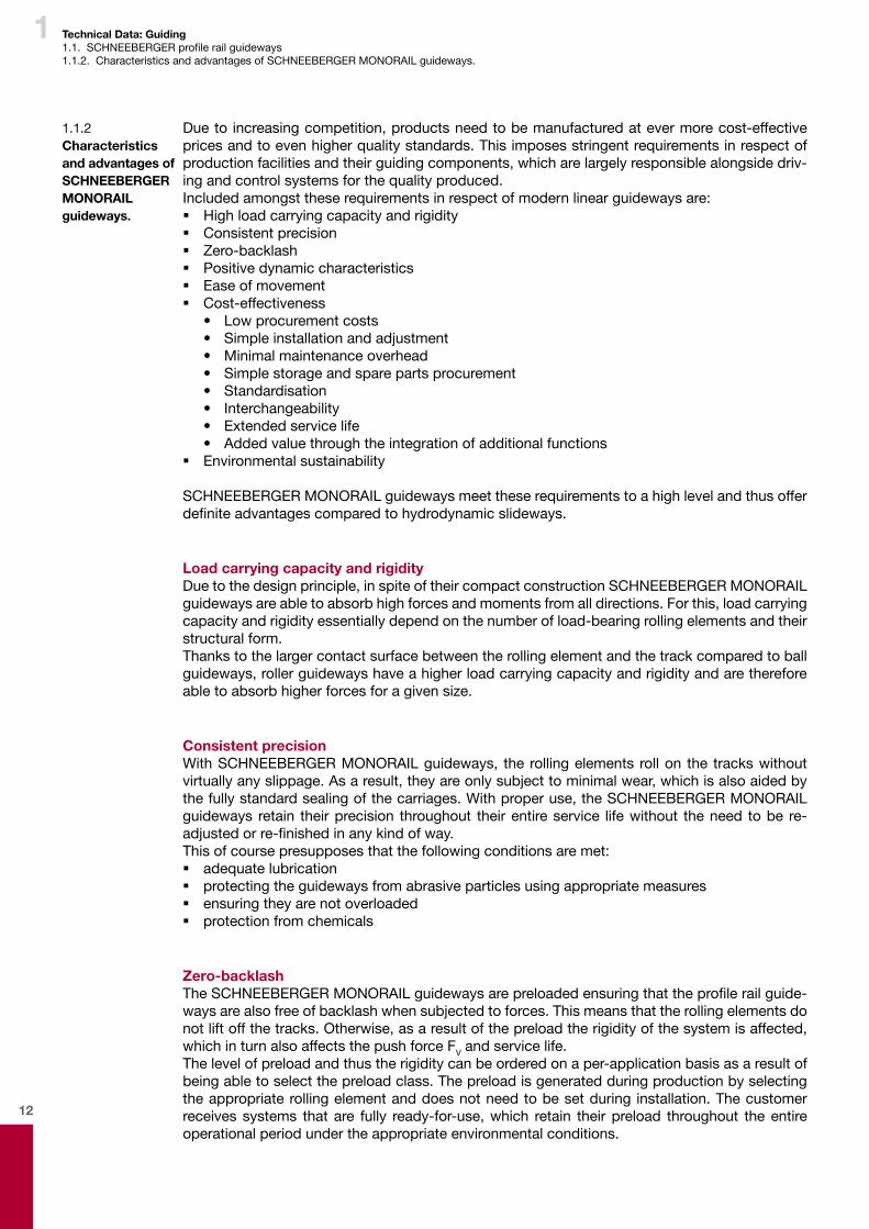
Ease of movementIn addition to the sealing friction, SCHNEEBERGER MONORAIL guideways need to overcome to therollingfrictionoftherollingelement.Comparedtoslidewaystheydemonstrateasignificantlylower push force, which also only increases a lilttle as the speed increases, as indicated in the figurebelow.Otherwisethereisnopronouncedstartingfrictioninvolvingthestick-slipeffectaswith hydrodynamic slideways. As a result, high levels of positioning accuracy can be achieved and smaller drives can be used.
1 Roller guideway
2 Magnetic guideway
3 Aerostatic guideway
4 Hydrostatic guideway
5 Hydrodynamic guideway
FR Friction force
v Speed
Speed vapplied against the friction force FR.
Cost-effectivenessSCHNEEBERGER MONORAIL guideways are standard machine components whose structural form, main dimensions and sizes are standardised. This guarantees the interchangeability of the systems of different manufacturers and saves purchasing and storage costs.As the guideways are bolted on to the machine bed as complete units, the overheads for installa-tionandadjustmentareminimal.Theconfigurationofthemachinebedisalsolesscomplexthanwith slideways. Generally, all that is required is to mill the locating surfaces to achieve a high level of accuracy. Tracks do not necessarily need to be ground.Integrating additional functions into the guideways offers another area of potential for increasing cost-effectiveness, as for example the SCHNEEBERGER products allow with BZ integral rack drive or AMS distance measuring system.SCHNEEBERGER MONORAIL guideways are virtually maintenance-free with adequate lubrica-tion and achieve a long service life. They retain their accuracy throughout their entire operating lifetime. Lubrication and replacement of parts subject to wear represent a minimal overhead.This ensures that with SCHNEEBERGER MONORAIL guideways a high level of cost-effective-ness can be achieved compared with other types of guiding.

14
1 Technical Data: Guiding1.1.SCHNEEBERGERprofilerailguideways1.1.2. Characteristics and advantages of SCHNEEBERGER MONORAIL guideways.
Environmental sustainabilityThe carriages for the SCHNEEBERGER MONORAIL guideways are compleately sealed wipers and in the rolling element recirculating units incorporate cavities, which act as lubricant reposito-ries. As a result, particularly with grease lubrication, the loss of lubricant and thus the consump-tion of lubricant is minimal. In the case of roller guideways, unlike slideways, only an extremely thin film of lubricant is needed to separate themetal rolling contacts And as a result only asmall amount of lubricant is needed for safe functioning, which means that the SCHNEEBERGER MONORAIL guideways demonstrate a high level of environmental sustainability.The positive environmental sustainability of SCHNEEBERGER MONORAIL guideways is also ex-hibited in the disposal of the products. Simple separation of the different materials is thus guar-anteed, and so steel and plastic can be recycled.
15
1 Technical Data: Guiding1.2.Constructionofaprofilerailguideway1.2.1 Carriage and guide rail
1.2. Construction of a profile rail guideway
1.2.1 Carriage and guide rail
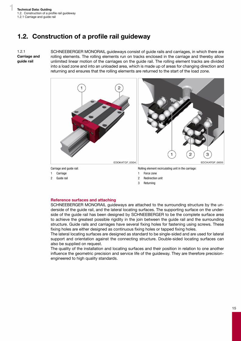
SCHNEEBERGER MONORAIL guideways consist of guide rails and carriages, in which there are rolling elements. The rolling elements run on tracks enclosed in the carriage and thereby allow unlimited linear motion of the carriages on the guide rail. The rolling element tracks are divided into a load zone and into an unloaded area, which is made up of areas for changing direction and returning and ensures that the rolling elements are returned to the start of the load zone.
Carriage and guide rail:
1 Carriage
2 Guide rail
Rolling element recirculating unit in the carriage:
1 Force zone
2 Redirection unit
3 Returning
Reference surfaces and attachingSCHNEEBERGER MONORAIL guideways are attached to the surrounding structure by the un-derside of the guide rail, and the lateral locating surfaces. The supporting surface on the under-side of the guide rail has been designed by SCHNEEBERGER to be the complete surface area to achieve the greatest possible rigidity in the join between the guide rail and the surrounding structure.Guiderailsandcarriageshaveseveralfixingholesforfasteningusingscrews.Thesefixingholesareeitherdesignedascontinuousfixingholesortappedfixingholes.The lateral locating surfaces are designed as standard to be single-sided and are used for lateral support and orientation against the connecting structure. Double-sided locating surfaces can also be supplied on request.The quality of the installation and locating surfaces and their position in relation to one another influencethegeometricprecisionandservicelifeoftheguideway.Theyarethereforeprecision-engineered to high quality standards.

16
1 Technical Data: Guiding1.2Constructionofaprofilerailguideway1.2.1 Carriage and guide rail1.2.2 Individual components and accessories
Use of the tapped fixing holes Use of the carriage fixing hole as continuous fixing hole
Guide rail with continuous fixing hole Guide rail with tapped fixing hole from below
1.2.2 Individual com-ponents and accessories
The carriages for SCHNEEBERGER MONORAIL guideways are made up of several components. Thecoreistheload-bearingbodymadeofhigh-graderollerbearingsteelwiththefixingholesaswellasthetracksandreturnfixingholesfortherollingelements.Rollers or balls are used as rolling elements. These are also made of hardened roller bearing steel. Another component of the carriage body are the synthetic guide elements with their integral lon-gitudinal wipers.The redirection unit of the rolling element is also a component of the carriage body. The front plates have integral cross wipers for sealing the front of the carriage and are responsible for dis-tributing lubricant within the carriage. Lube nipples or adapter pieces can be screwed in using connecting thread, by means of which the lubricant gets into the inside of the front plate and from there is distributed via c channels and directed to the rolling elements. The carriages can be upgraded with accessories, such as additional wipers, metal wipers or lubrication plates, which are installed at the front in front of the front plates and support optional adaptation of the system to the application in question.The guide rails like the carriages are made of roller bearing steel and are either hardened in the trackzoneorthroughhardened.Closuresfortheguiderailfixingholes intheformofcapsorcoverstripsfinishtheguiderails.
17
1 Technical Data: Guiding1.2Constructionofaprofilerailguideway1.2.2 Individual components and accessories
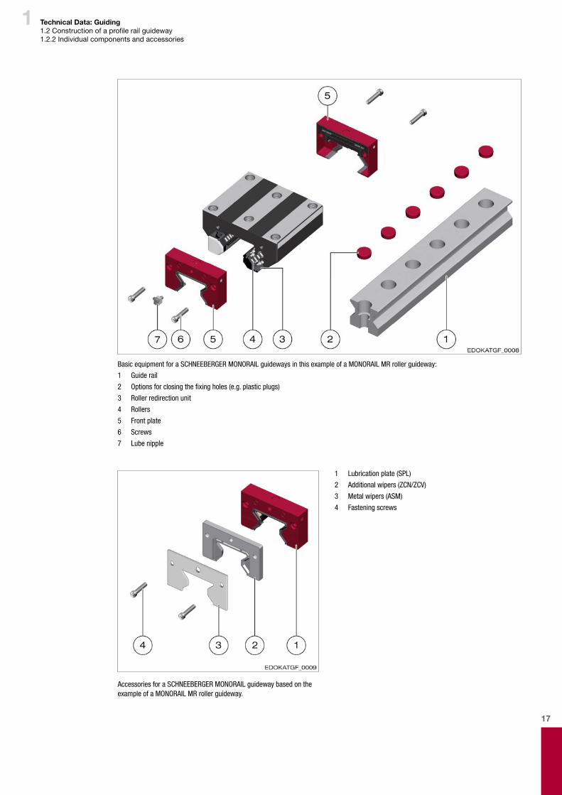
Basic equipment for a SCHNEEBERGER MONORAIL guideways in this example of a MONORAIL MR roller guideway:
1 Guide rail
2 Options for closing the fixing holes (e.g. plastic plugs)
3 Roller redirection unit
4 Rollers
5 Front plate
6 Screws
7 Lube nipple
1 Lubrication plate (SPL)
2 Additional wipers (ZCN/ZCV)
3 Metal wipers (ASM)
4 Fastening screws
Accessories for a SCHNEEBERGER MONORAIL guideway based on the example of a MONORAIL MR roller guideway.

18
1 Technical Data: Guiding1.2Constructionofaprofilerailguideway1.2.3 Types and design principles
Applicable standardsSCHNEEBERGER MONORAIL guideways are available in a wide range of sizes and types. To create a consistent standard for these machine components, the most important design ele-ments have been compiled in the industry standard DIN 645 Part 1. In addition to the types, the standarddefinesthemaindimensionsandtheaccuracyclassesforguiderailsandcarriages.TheSCHNEEBERGER MONORAIL MR and BM products comply with this standard and are therefore interchangeable.In addition to the standardised designs, SCHNEEBERGER also offers a wide range of other vari-ants for special applications, such as for example special guide rail cross sections, guide rails with gear rack, short carriages or heavy load designs.
Important product standards
DIN 637
Technicalsafetyspecificationsfordimensioningandoperatingprofilerailguidewayscompletewith rolling element recirculating unit
DIN 645 - Part 1:
Profilerails-rollerguideways-Part1:DimensionsforSeries1to3
DIN 645 - Part 2:
Profilerails-rollerguideways-Part2:DimensionsforSeries4
DIN ISO 14728 - Part 1:
Linear roller-contact bearings - Part 1: Dynamic loading capacities and nominal service life
DIN ISO 14728 - Part 2:
Linear roller-contact bearings - Part 2: Static loading capacities
ISO 12090 - Part 1:
Linear bearing with ball and roller recirculating unit - linear guideway - Part 1 Dimensions and tolerances for series 1, 2 and 3
ISO 12090 - Part 2:
Linear bearing with ball and roller recirculating unit - linear guideway - Part 2 Dimensions and tolerances for series 4 and 5
Individual components
DIN 5401:
Balls for roller-contact bearings and general industrial requirements
DIN 5402 - Part 1:
Roller-contact bearing components - Part 1: Cylindrical rollers
DIN 631:
Testconditionsforexperimentalverificationofthedynamicloadingcapacityoflinearrollerguide-wayswithprofiledrailsandrollingelementrecirculatingunit
1.2.3 Types and de-sign principles
19
1 Technical Data: Guiding1.2Constructionofaprofilerailguideway1.2.3 Types and design principles
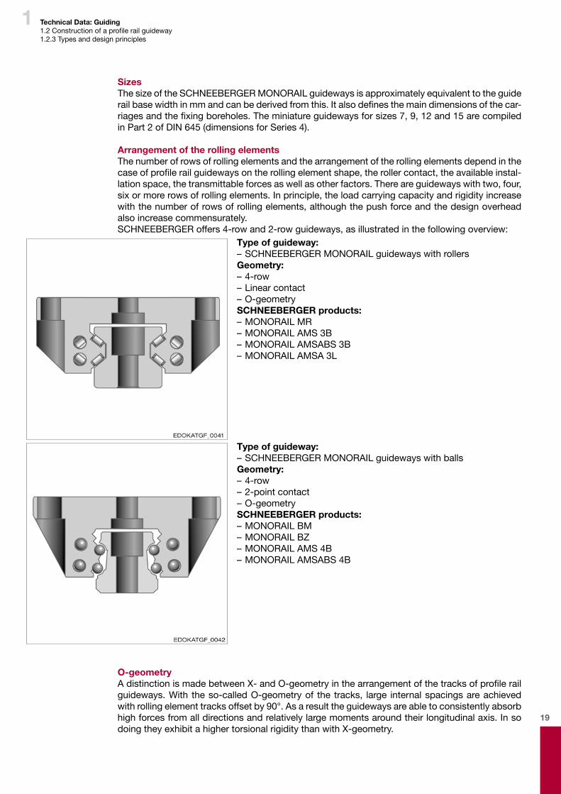
SizesThe size of the SCHNEEBERGER MONORAIL guideways is approximately equivalent to the guide railbasewidthinmmandcanbederivedfromthis.Italsodefinesthemaindimensionsofthecar-riagesandthefixingboreholes.Theminiatureguidewaysforsizes7,9,12and15arecompiledin Part 2 of DIN 645 (dimensions for Series 4). Arrangement of the rolling elementsThe number of rows of rolling elements and the arrangement of the rolling elements depend in the caseofprofilerailguidewaysontherollingelementshape,therollercontact,theavailableinstal-lation space, the transmittable forces as well as other factors. There are guideways with two, four, six or more rows of rolling elements. In principle, the load carrying capacity and rigidity increase with the number of rows of rolling elements, although the push force and the design overhead also increase commensurately.SCHNEEBERGER offers 4-row and 2-row guideways, as illustrated in the following overview:
O-geometryAdistinctionismadebetweenX-andO-geometryinthearrangementofthetracksofprofilerailguideways. With the so-called O-geometry of the tracks, large internal spacings are achieved with rolling element tracks offset by 90°. As a result the guideways are able to consistently absorb high forces from all directions and relatively large moments around their longitudinal axis. In so doing they exhibit a higher torsional rigidity than with X-geometry.
Type of guideway:– SCHNEEBERGER MONORAIL guideways with rollersGeometry:– 4-row– Linear contact– O-geometrySCHNEEBERGER products:– MONORAIL MR– MONORAIL AMS 3B– MONORAIL AMSABS 3B– MONORAIL AMSA 3L
Type of guideway:– SCHNEEBERGER MONORAIL guideways with ballsGeometry:– 4-row– 2-point contact– O-geometrySCHNEEBERGER products:– MONORAIL BM– MONORAIL BZ– MONORAIL AMS 4B– MONORAIL AMSABS 4B
20
1 Technical Data: Guiding1.2Constructionofaprofilerailguideway1.2.3 Types and design principles
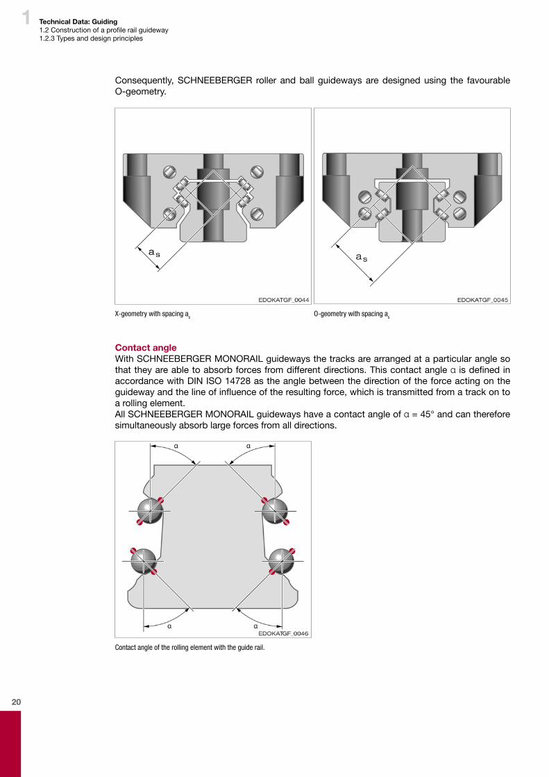
Consequently, SCHNEEBERGER roller and ball guideways are designed using the favourable O-geometry.
X-geometry with spacing as O-geometry with spacing as
Contact angleWith SCHNEEBERGER MONORAIL guideways the tracks are arranged at a particular angle so that they are able to absorb forces from different directions. This contact angle α isdefinedinaccordance with DIN ISO 14728 as the angle between the direction of the force acting on the guidewayandthelineofinfluenceoftheresultingforce,whichistransmittedfromatrackontoa rolling element.All SCHNEEBERGER MONORAIL guideways have a contact angle of α = 45° and can therefore simultaneously absorb large forces from all directions.
Contact angle of the rolling element with the guide rail.
21
1 Technical Data: Guiding1.2Constructionofaprofilerailguideway1.2.4 Materials1.2.5 Hardening process
1.2.4 Materials
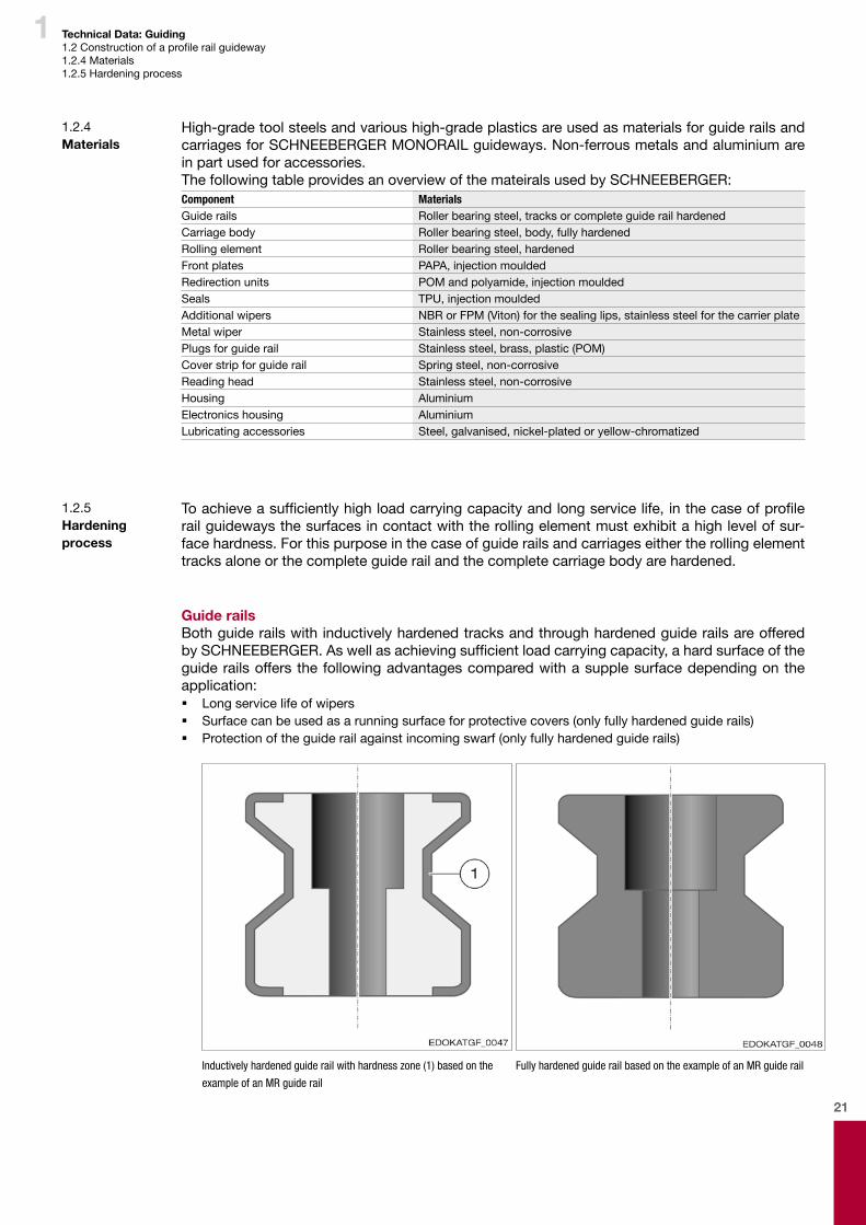
High-grade tool steels and various high-grade plastics are used as materials for guide rails and carriages for SCHNEEBERGER MONORAIL guideways. Non-ferrous metals and aluminium are in part used for accessories.The following table provides an overview of the mateirals used by SCHNEEBERGER:Component MaterialsGuide rails Roller bearing steel, tracks or complete guide rail hardenedCarriage body Roller bearing steel, body, fully hardenedRolling element Roller bearing steel, hardenedFront plates PAPA, injection mouldedRedirection units POM and polyamide, injection mouldedSeals TPU, injection mouldedAdditional wipers NBR or FPM (Viton) for the sealing lips, stainless steel for the carrier plateMetal wiper Stainless steel, non-corrosivePlugs for guide rail Stainless steel, brass, plastic (POM)Cover strip for guide rail Spring steel, non-corrosiveReading head Stainless steel, non-corrosiveHousing AluminiumElectronics housing AluminiumLubricating accessories Steel, galvanised, nickel-plated or yellow-chromatized
1.2.5 Hardening process
Toachieveasufficientlyhighloadcarryingcapacityandlongservicelife,inthecaseofprofilerail guideways the surfaces in contact with the rolling element must exhibit a high level of sur-face hardness. For this purpose in the case of guide rails and carriages either the rolling element tracks alone or the complete guide rail and the complete carriage body are hardened.
Guide railsBoth guide rails with inductively hardened tracks and through hardened guide rails are offered bySCHNEEBERGER.Aswellasachievingsufficientloadcarryingcapacity,ahardsurfaceoftheguide rails offers the following advantages compared with a supple surface depending on the application: � Long service life of wipers � Surface can be used as a running surface for protective covers (only fully hardened guide rails) � Protection of the guide rail against incoming swarf (only fully hardened guide rails)
Inductively hardened guide rail with hardness zone (1) based on the
example of an MR guide rail
Fully hardened guide rail based on the example of an MR guide rail

22
1 Technical Data: Guiding1.2Constructionofaprofilerailguideway1.2.5 Hardening process
CarriageThe steel bodies of the carriages are the critical element in achieving a long service life with a constant level of precision throughout the entire service life. To maintain these demanding requirements throughout the entire period of operation, even under extreme loads without plas-tic deformation of the carriage, SCHNEEBERGER uses high-grade roller bearing steel for all of its products. Not only the running surfaces but the complete cross-section of the carriage is hardened with this. Even when subjected to loads exceeding their recommended levels, SCHNEEBERGER carriages retain their factory-set characteristics as in principle no plastic de-formation can occur.Advantages of through hardened carriages: � A high level of dimensional stability of the carriage body throughout its entire period of op-
eration � No plastic deformation of the carriage in case of overloading or a crash � Noundefinedgeometryerrorsandpreloadlosses � High level of force absorption up to breaking point � Ground locating surfaces in the carriage cannot be damaged or scratched during transpor-
tation, storage, installation and commissioning.
1 Loaded
2 Unloaded
red = fully hardened
grey = inductively hardened
Force F is applied against deformation dx up to breaking point. In case of excessive loading an inductively hardened carriage is subject to plastic deformation; deformation x continues to occur.
23
1 Technical Data: Guiding1.3 Load carrying capacity1.3.1 Load carrying capacity1.3.2 Dynamic loading capacity C
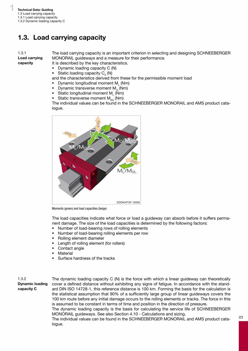
The load carrying capacity is an important criterion in selecting and designing SCHNEEBERGER MONORAIL guideways and a measure for their performance. It is described by the key characteristics. � Dynamic loading capacity C (N) � Static loading capacity C0 (N)
and the characteristics derived from these for the permissible moment load � Dynamic longitudinal moment ML (Nm) � Dynamic transverse moment MQ (Nm) � Static longitudinal moment ML (Nm) � Static transverse moment M0Q (Nm)
The individual values can be found in the SCHNEEBERGER MONORAIL and AMS product cata-logue.
Moments (green) and load capacities (beige)
The load capacities indicate what force or load a guideway can absorb before it suffers perma-nent damage. The size of the load capacities is determined by the following factors: � Number of load-bearing rows of rolling elements � Number of load-bearing rolling elements per row � Rolling element diameter � Length of rolling element (for rollers) � Contact angle � Material � Surface hardness of the tracks
1.3. Load carrying capacity
1.3.1 Load carrying capacity
The dynamic loading capacity C (N) is the force with which a linear guideway can theoretically coveradefineddistancewithoutexhibitinganysignsoffatigue.Inaccordancewiththestand-ardDIN ISO14728-1,thisreferencedistanceis100km.Formingthebasisforthecalculationisthestatisticalassumptionthat90%ofasufficientlylargegroupoflinearguidewayscoversthe100 kmroutebeforeanyinitialdamageoccurstotherollingelementsortracks.Theforceinthisis assumed to be constant in terms of time and position in the direction of pressure.The dynamic loading capacity is the basis for calculating the service life of SCHNEEBERGER MONORAIL guideways. See also Section 4.10 - Calculations and sizing.The individual values can be found in the SCHNEEBERGER MONORAIL and AMS product cata-logue.
1.3.2 Dynamic loading capacity C
24
1 Technical Data: Guiding1.3 Load carrying capacity1.3.2 Dynamic loading capacity C1.3.3 Static loading capacity C0
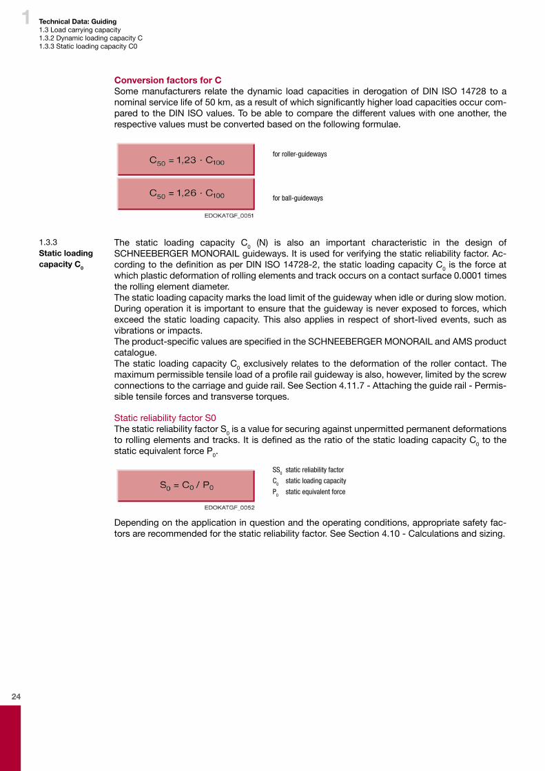
Conversion factors for CSome manufacturers relate the dynamic load capacities in derogation of DIN ISO 14728 to a nominalservicelifeof50km,asaresultofwhichsignificantlyhigherloadcapacitiesoccurcom-pared to the DIN ISO values. To be able to compare the different values with one another, the respective values must be converted based on the following formulae.
for roller-guideways
for ball-guideways
1.3.3 Static loading capacity C0
The static loading capacity C0 (N) is also an important characteristic in the design of SCHNEEBERGER MONORAIL guideways. It is used for verifying the static reliability factor. Ac-cordingtothedefinitionasperDINISO14728-2,thestaticloadingcapacityC0 is the force at which plastic deformation of rolling elements and track occurs on a contact surface 0.0001 times the rolling element diameter.The static loading capacity marks the load limit of the guideway when idle or during slow motion. During operation it is important to ensure that the guideway is never exposed to forces, which exceed the static loading capacity. This also applies in respect of short-lived events, such as vibrations or impacts.Theproduct-specificvaluesarespecifiedintheSCHNEEBERGERMONORAILandAMSproductcatalogue.The static loading capacity C0 exclusively relates to the deformation of the roller contact. The maximumpermissibletensileloadofaprofilerailguidewayisalso,however,limitedbythescrewconnections to the carriage and guide rail. See Section 4.11.7 - Attaching the guide rail - Permis-sible tensile forces and transverse torques.
Static reliability factor S0The static reliability factor S0 is a value for securing against unpermitted permanent deformations torollingelementsandtracks.ItisdefinedastheratioofthestaticloadingcapacityC0 to the static equivalent force P0.
SS0 static reliability factor
C0 static loading capacity
P0 static equivalent force
Depending on the application in question and the operating conditions, appropriate safety fac-tors are recommended for the static reliability factor. See Section 4.10 - Calculations and sizing.

25
1 Technical Data: Guiding1.3 Load carrying capacity1.3.4 Static and dynamic moments
1.3.4 Static and dynamic moments
The permissible static moment M0 is a moment, which causes a load on the carriage, which cor-responds to the static loading capacity C0. The same applies correspondingly for the permissible dynamic moment M and the dynamic loading capacity C. The permissible dynamic moments are critical for the design of the guideway, in terms of the loading of the carriages with transverse moments MQ and longitudinal moments ML. Transverse and longitudinal moments increase the overall loading of the guideway and are to be taken into account accordingly in calculating the service life and static reliability factor S0. See Section 4.10 - Calculations and sizing.The height of the permissible longitudinal moments ML essentially depends on the number of roll-ing elements per row and thus on the length of the carriage. Long carriages can therefore absorb higher moments than short ones. The loading of the individual bodies takes place in this from the outside towards the carriage centre. As well as the carriage length, the track spacing is critical for the height of the permissible transverse moments MQ. The track spacing is higher in the case of the so-called O-geometry than in guideways with X-geometry. See Section 1.2 - Construction ofaprofilerailguidewayThe static transverse moment M0Q exclusively relates to the deformation of the roller contact. The maximumpermissibletransversemomentofaprofilerailguidewayisalso,however,limitedbythe screw connection to the carriage and guide rail. See Section 4.11.7 - Attaching guide rails - Permissible tensile forces and transverse torques.
Moments, which act on the carriages.
In the SCHNEEBERGER MONORAIL guideways the four tracks are arranged at a 90° angle to one another. This results in producing for longitudinal moments an equally high loading capacity for moments around the transverse axis (ML) and vertical axis (ML).Thanks to the O-geometry of the guideways, a large track spacing and therefore high loading capacity is achieved for moments around the longitudinal axis (MQ).The individual values can be found in the SCHNEEBERGER MONORAIL and AMS product cata-logue.
26
1 Technical Data: Guiding1.3 Load carrying capacity1.3.5 Load directions
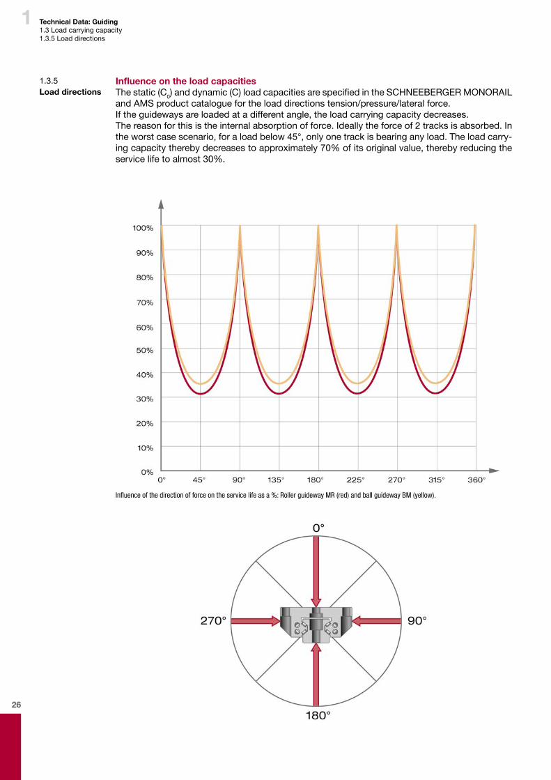
Influence on the load capacitiesThe static (C0)anddynamic(C)loadcapacitiesarespecifiedintheSCHNEEBERGERMONORAILand AMS product catalogue for the load directions tension/pressure/lateral force.If the guideways are loaded at a different angle, the load carrying capacity decreases.The reason for this is the internal absorption of force. Ideally the force of 2 tracks is absorbed. In the worst case scenario, for a load below 45°, only one track is bearing any load. The load carry-ing capacity thereby decreases to approximately 70% of its original value, thereby reducing the service life to almost 30%.
Influence of the direction of force on the service life as a %: Roller guideway MR (red) and ball guideway BM (yellow).
1.3.5 Load directions
27
1 Technical Data: Guiding1.3 Load carrying capacity1.3.5 Load directions
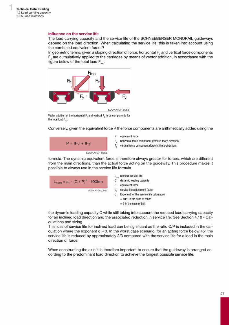
Influence on the service lifeThe load carrying capacity and the service life of the SCHNEEBERGER MONORAIL guideways depend on the load direction. When calculating the service life, this is taken into account using the combined equivalent force P.In geometric terms, given a sloping direction of force, horizontal FY and vertical force components FZ are cumulatively applied to the carriages by means of vector addition, in accordance with the figurebelowofthetotalloadFres.
Vector addition of the horizontal FY and vertical FZ force components for the total load Fres.
Conversely, given the equivalent force P the force components are arithmetically added using the
P equivalent force
FY horizontal force component (force in the y-direction)
FZ vertical force component (force in the z-direction)
formula. The dynamic equivalent force is therefore always greater for forces, which are different from the main directions, than the actual force acting on the guideway. This procedure makes it possible to always use in the service life formula
Lnom nominal service life
C dynamic loading capacity
P equivalent force
a1 service life adjustment factor
q Exponent for the service life calculation
= 10/3 in the case of roller
= 3 in the case of ball
the dynamic loading capacity C while still taking into account the reduced load carrying capacity for an inclined load direction and the associated reduction in service life. See Section 4.10 - Cal-culations and sizing.ThislossofservicelifeforinclinedloadcanbesignificantastheratioC/Pisincludedinthecal-culationwheretheexponentq≈3.Intheworstcasescenario,foranactingforcebelow45°theservice life is reduced by approximately 2/3 compared with the service life for a load in the main direction of force.
When constructing the axle it is therefore important to ensure that the guideway is arranged ac-cording to the predominant load direction to achieve the longest possible service life.
28
1 Technical Data: Guiding1.4 Preload1.4.1Definition
SCHNEEBERGERMONORAILguidewaysexhibitanelasticdeflectionbehaviour,which isnotlinear but degressive. That means that the rolling elements are relatively supple under minimal force and become more rigid with increasing force. The guideways are preloaded by the preload and so part of the elastic deformation has already been removed. Consequently, the rigidity of the overall system is increased.The followingfigureshowsthe influenceofpreloadonthedeflectionbehaviourbasedontheexample of a ball.
The preload � Changes the rigidity and thus also the natural frequency of a guide system. � Influencesthetravelpulsationofthecarriage � Increases the displacement resistance of the carriage � Increases the load acting on the carriage and thus reduces the nominal service life. When
calculating the service life the preload therefore needs to be taken into account as an ad-ditional force.
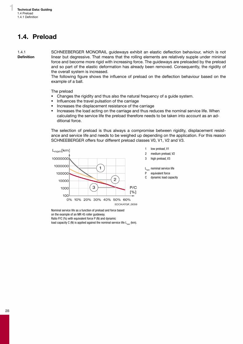
The selection of preload is thus always a compromise between rigidity, displacement resist-ance and service life and needs to be weighed up depending on the application. For this reason SCHNEEBERGER offers four different preload classes V0, V1, V2 and V3.
1 low preload, V1
2 medium preload, V2
3 high preload, V3
Lnom nominal service life
P equivalent force C dynamic load capacity
Nominal service life as a function of preload and force based on the example of an MR 45 roller guideway.Ratio P/C (%) with equivalent force P (N) and dynamic load capacity C (N) is applied against the nominal service life Lnom (km).
1.4. Preload
1.4.1 Definition
29
1 Technical Data: Guiding1.4 Preload1.4.2 Generating1.4.3 SCHNEEBERGER MONORAIL guideways
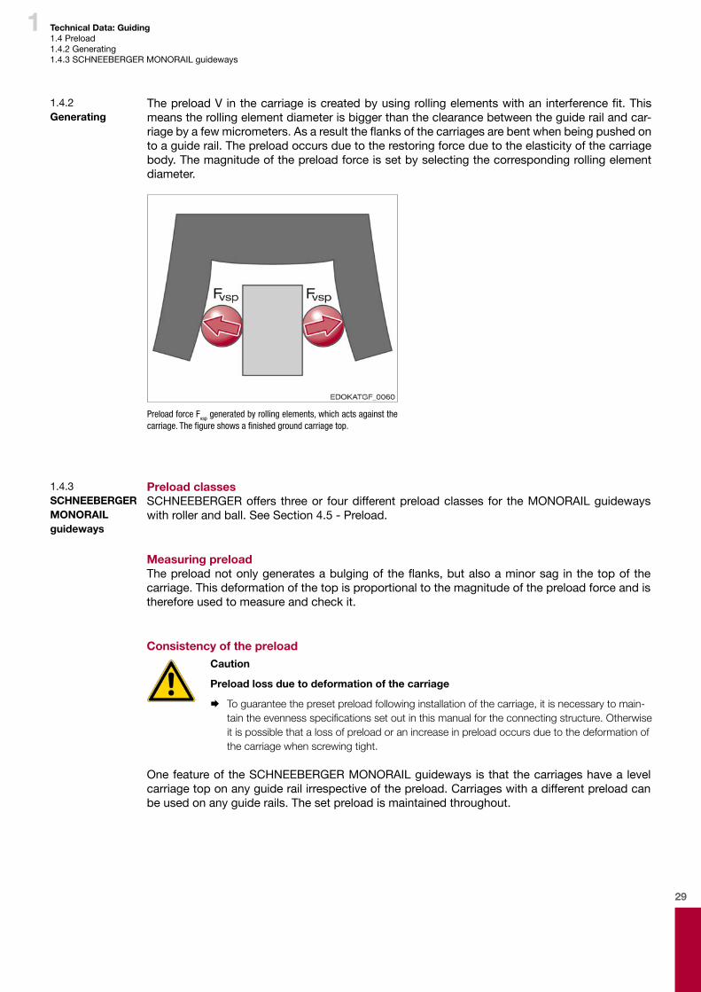
ThepreloadVinthecarriageiscreatedbyusingrollingelementswithaninterferencefit.Thismeans the rolling element diameter is bigger than the clearance between the guide rail and car-riagebyafewmicrometers.Asaresulttheflanksofthecarriagesarebentwhenbeingpushedonto a guide rail. The preload occurs due to the restoring force due to the elasticity of the carriage body. The magnitude of the preload force is set by selecting the corresponding rolling element diameter.
Preload force Fvsp generated by rolling elements, which acts against the carriage. The figure shows a finished ground carriage top.
Preload classesSCHNEEBERGER offers three or four different preload classes for the MONORAIL guideways with roller and ball. See Section 4.5 - Preload.
Measuring preloadThepreloadnotonlygeneratesabulgingoftheflanks,butalsoaminorsaginthetopofthecarriage. This deformation of the top is proportional to the magnitude of the preload force and is therefore used to measure and check it.
Consistency of the preload Caution
Preload loss due to deformation of the carriage
¨ To guarantee the preset preload following installation of the carriage, it is necessary to main-tain the evenness specifications set out in this manual for the connecting structure. Otherwise it is possible that a loss of preload or an increase in preload occurs due to the deformation of the carriage when screwing tight.
One feature of the SCHNEEBERGER MONORAIL guideways is that the carriages have a level carriage top on any guide rail irrespective of the preload. Carriages with a different preload can be used on any guide rails. The set preload is maintained throughout.
1.4.2 Generating
1.4.3 SCHNEEBERGER MONORAIL guideways
30
1 Technical Data: Guiding1.5 Rigidity1.5.1Definition
1.5. Rigidity
1.5.1 Definition
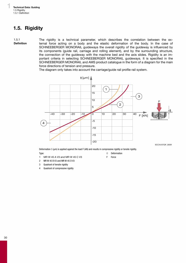
The rigidity is a technical parameter, which describes the correlation between the ex-ternal force acting on a body and the elastic deformation of the body. In the case of SCHNEEBERGERMONORAILguideways theoverall rigidityof theguideway is influencedbyits components (guide rail, carriage and rolling element), and by the surrounding structure, the connection of the guideway with the machine bed and the axis slides. Rigidity is an im-portant criteria in selecting SCHNEEBERGER MONORAIL guideways. It is specified in the SCHNEEBERGER MONORAIL and AMS product catalogue in the form of a diagram for the main force directions of tension and pressure.Thediagramonlytakesintoaccountthecarriage/guiderailprofilerailsystem.
Deformation δ (μm) is applied against the load F (kN) and results in compressive rigidity or tensile rigidity.
Type:
1 MR W 45 A V3 and MR W 45 C V3
2 MR W 45 B V3 and MR W 45 D V3
3 Quadrant of tensile rigidity
4 Quadrant of compressive rigidity
δ Deformation
F Force
31
1
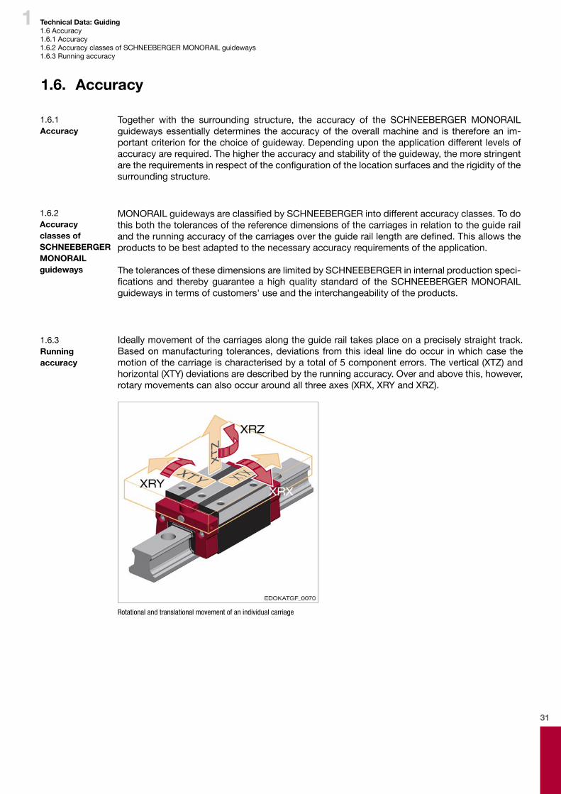
Ideally movement of the carriages along the guide rail takes place on a precisely straight track. Based on manufacturing tolerances, deviations from this ideal line do occur in which case the motion of the carriage is characterised by a total of 5 component errors. The vertical (XTZ) and horizontal (XTY) deviations are described by the running accuracy. Over and above this, however, rotary movements can also occur around all three axes (XRX, XRY and XRZ).
Rotational and translational movement of an individual carriage
1.6. Accuracy
Together with the surrounding structure, the accuracy of the SCHNEEBERGER MONORAIL guideways essentially determines the accuracy of the overall machine and is therefore an im-portant criterion for the choice of guideway. Depending upon the application different levels of accuracy are required. The higher the accuracy and stability of the guideway, the more stringent aretherequirementsinrespectoftheconfigurationofthelocationsurfacesandtherigidityofthesurrounding structure.
MONORAILguidewaysareclassifiedbySCHNEEBERGERintodifferentaccuracyclasses.Todothis both the tolerances of the reference dimensions of the carriages in relation to the guide rail andtherunningaccuracyofthecarriagesovertheguideraillengtharedefined.Thisallowstheproducts to be best adapted to the necessary accuracy requirements of the application.
The tolerances of these dimensions are limited by SCHNEEBERGER in internal production speci-ficationsand therebyguaranteeahighquality standardof theSCHNEEBERGERMONORAILguideways in terms of customers' use and the interchangeability of the products.
Technical Data: Guiding1.6 Accuracy 1.6.1 Accuracy1.6.2 Accuracy classes of SCHNEEBERGER MONORAIL guideways1.6.3 Running accuracy
1.6.1 Accuracy
1.6.2 Accuracy classes of SCHNEEBERGER MONORAIL guideways
1.6.3 Running accuracy
32
1
Short description:
XRX Rotational deviation around the x-axisXRY Rotational deviation around the y-axisXRZ Rotational deviation around the z-axisXTX Translational deviation in the x-direction (direction of motion)XTY Translational deviation in the y-directionXTZ Translational deviation in the z-direction
Definition of the short description for rotation: X R X
Axis
Component type (R = rotation)
Rotating axis of rotation (rotation variation)
Definition of the short description for translation: X T X
Axis
Component type (T = translation)
Direction of deviation (translation variation)
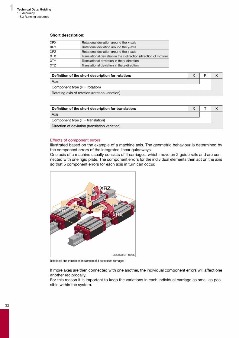
Effects of component errorsIllustrated based on the example of a machine axis. The geometric behaviour is determined by the component errors of the integrated linear guideways. One axis of a machine usually consists of 4 carriages, which move on 2 guide rails and are con-nected with one rigid plate. The component errors for the individual elements then act on the axis so that 5 component errors for each axis in turn can occur.
Rotational and translation movement of 4 connected carriages
If more axes are then connected with one another, the individual component errors will affect one another reciprocally. For this reason it is important to keep the variations in each individual carriage as small as pos-sible within the system.
Technical Data: Guiding1.6 Accuracy 1.6.3 Running accuracy
33
1
TherunningaccuracyofSCHNEEBERGERMONORAILguidewaysisnotonlyinfluencedbytheproduction accuracy of the rolling element tracks in the guide rail, but by a variety of other factors. The variations, which result from this, can be categorised according to their pattern as follows.
Long-range variation: � Geometry error in the guide rail tracks � Geometry error in the location surfaces in the machine bed
Medium-range variation: � Deformation of the guide rail due to screw forces � Positional tolerances of the guide rail boreholes
Short-range variations: � Travel pulsation of the carriages � Butt transition joint with multi-component guide rails
Geometry error in the connecting structureFor a high level of accuracy in guiding it is critical that the location surfaces in the connecting structure also exhibit a high level of accuracy. The maximum vertical, lateral and parallel devia-tionsintheguiderailrequirementscanbefoundinSection4.14-Configurationoftheconnectingstructure. Additional geometry errors are the result of the accuracy and rigidity of the machine bed, and/or of the general surrounding structure. Always adhere to the recommended installation tolerances here,andchecktheconnectionconfigurationinrelationtorigidity.
Screw forcesThe screw forces when installing the guide rail can lead to local instances of compression, the characteristicsofwhichwilldependonthetighteningtorquesandonthegeometricconfigura-tion of the guide rail. Compressions in the guide rail lead to a very small vertical rippling when runningthecarriageandthusinthespacingofthefixingboreholes.Howgreattheeffectofthesecompressions are on running accuracy, depends both on their size and also on the length of the carriageandthespacingofthefixingboreholes.Longcarriagesandsmallboreholespacingsaremore favourable than short carriages with large borehole spacings.The screw tightening torque, and lubricating the screw heads are essential for reducing head friction as well as observing a consistent tightening torque. The tightening torque should only be set as high as is necessary for this.
1.6.4 Influences on running accuracy
Technical Data: Guiding1.6 Accuracy 1.6.4Influencesonrunningaccuracy
34
1 Technical Data: Guiding1.6 Accuracy1.6.4Influencesonrunningaccuracy
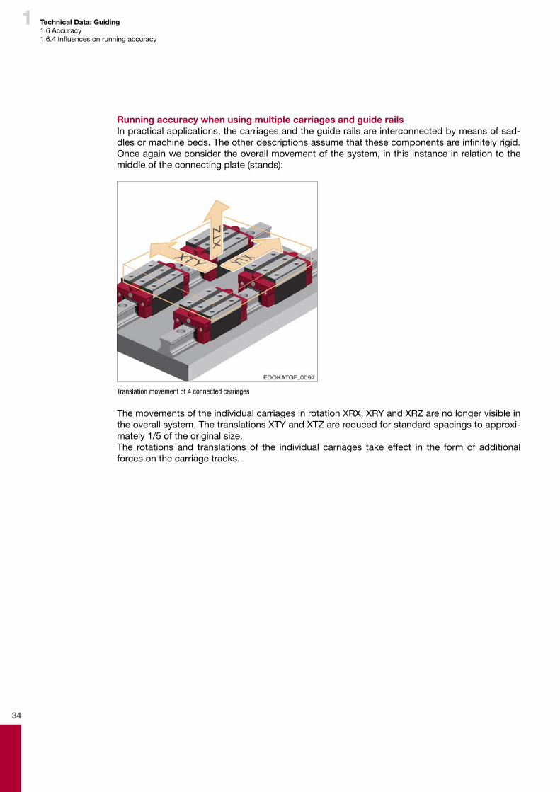
Running accuracy when using multiple carriages and guide railsIn practical applications, the carriages and the guide rails are interconnected by means of sad-dlesormachinebeds.Theotherdescriptionsassumethatthesecomponentsareinfinitelyrigid.Once again we consider the overall movement of the system, in this instance in relation to the middle of the connecting plate (stands):
Translation movement of 4 connected carriages
The movements of the individual carriages in rotation XRX, XRY and XRZ are no longer visible in the overall system. The translations XTY and XTZ are reduced for standard spacings to approxi-mately 1/5 of the original size. The rotations and translations of the individual carriages take effect in the form of additional forces on the carriage tracks.
35
1 Technical Data: Guiding1.6 Accuracy1.6.4Influencesonrunningaccuracy1.6.5 Measures to improve accuracy
1.6.5 Measures to improve accuracy
The following list provides an overview of measures which can be used to promote a high level of running accuracy. � The most rigid machine bed possible with precisely manufactured guide rail supporting
surfaces � Installation of the guideway with single-sided lateral reference � Selecting a high accuracy class for the guideway � Selecting guide rails with similar running behaviour (seematchedsystemsinSection 4.6 -Accuracy)
� Selecting smaller borehole spacings in the guide rails � Reducingthescrewtighteningtorques(insodoingensuresufficientloadcarryingcapacity) � Use of long carriages � Axleconfigurationwithtwoguiderailsandineachcaseatleasttwocarriages � Large guideway spacings (track gauge) and carriage spacings
Travel pulsationTravel pulsation is understood to mean movements of the carriage in the XTY and XTZ direction, which occur as a result of the periodic entry and exit of the rolling elements into the load-bearing zone. For this the number and location of the load-bearing rolling elements varies per track, which leads to pulsating oscillating forces in the carriage body.TravelpulsationcanbeinfluencedbythecarriagelengthLandthepreloadVofthecarriage.The following applies in this: A long carriage and a small preload V reduce travel pulsation.
With SCHNEEBERGER particular attention is paid to the rolling element recirculating units and therun-inareas inthesteelbody.Theseareasaregeometricallyconfiguredtoachieveaverysmooth run with minimal travel pulsation and variation in push force and minimal generation of noise.
36
1 Technical Data: Guiding1.7 Service life calculation principles1.7.1Definitionofterms1.7.2 Applicable standards
1.7. Service life calculation principles
1.7.1 Definition of terms
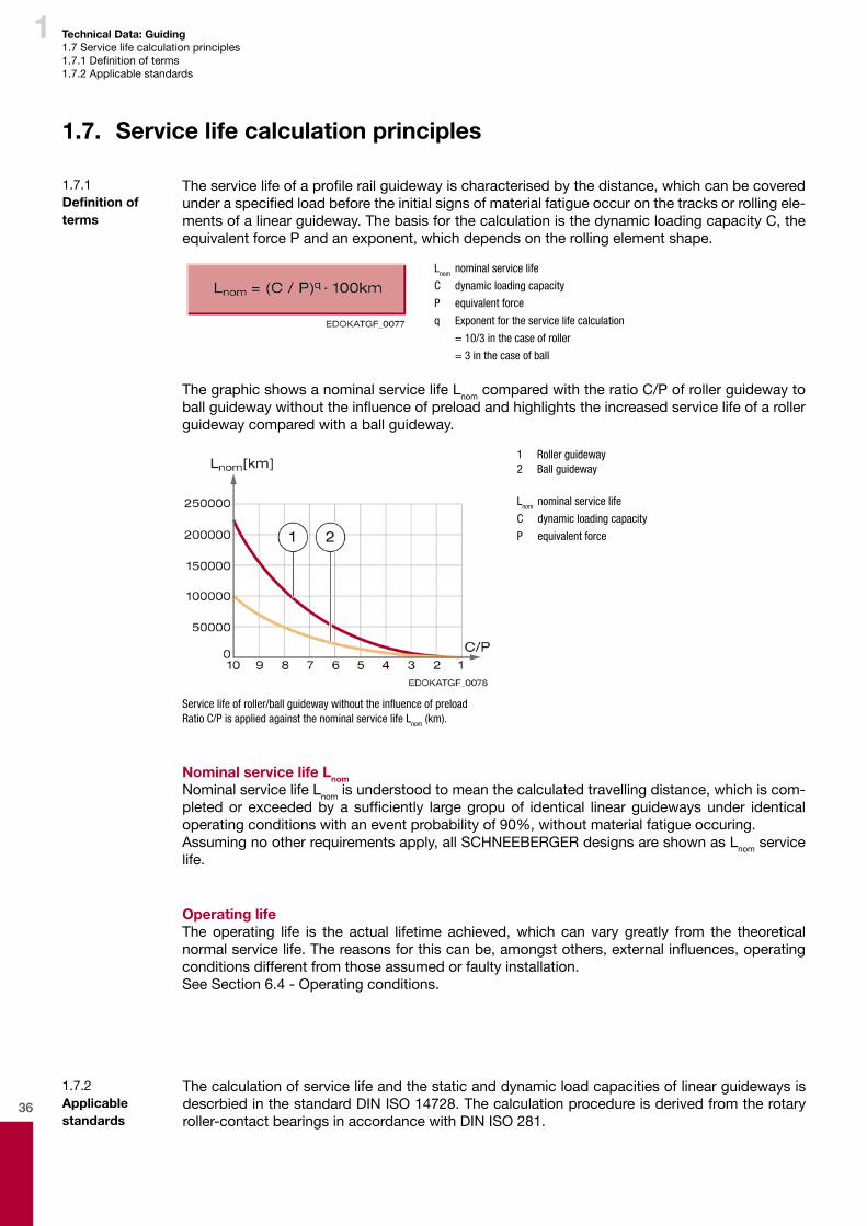
Theservicelifeofaprofilerailguidewayischaracterisedbythedistance,whichcanbecoveredunderaspecifiedloadbeforetheinitialsignsofmaterialfatigueoccuronthetracksorrollingele-ments of a linear guideway. The basis for the calculation is the dynamic loading capacity C, the equivalent force P and an exponent, which depends on the rolling element shape.
Lnom nominal service life
C dynamic loading capacity
P equivalent force
q Exponent for the service life calculation
= 10/3 in the case of roller
= 3 in the case of ball
The graphic shows a nominal service life Lnom compared with the ratio C/P of roller guideway to ballguidewaywithouttheinfluenceofpreloadandhighlightstheincreasedservicelifeofarollerguideway compared with a ball guideway.
1 Roller guideway 2 Ball guideway
Lnom nominal service life
C dynamic loading capacity
P equivalent force
Service life of roller/ball guideway without the influence of preloadRatio C/P is applied against the nominal service life Lnom (km).
Nominal service life LnomNominal service life Lnom is understood to mean the calculated travelling distance, which is com-pletedor exceededbya sufficiently largegropuof identical linearguidewaysunder identicaloperating conditions with an event probability of 90%, without material fatigue occuring. Assuming no other requirements apply, all SCHNEEBERGER designs are shown as Lnom service life.
Operating lifeThe operating life is the actual lifetime achieved, which can vary greatly from the theoretical normalservicelife.Thereasonsforthiscanbe,amongstothers,externalinfluences,operatingconditions different from those assumed or faulty installation. See Section 6.4 - Operating conditions.
1.7.2 Applicable standards
The calculation of service life and the static and dynamic load capacities of linear guideways is descrbied in the standard DIN ISO 14728. The calculation procedure is derived from the rotary roller-contact bearings in accordance with DIN ISO 281.
37
1 Technical Data: Guiding1.8 Sealing system1.8.1 Function of seals1.8.2 Types of seals
1.8. Sealing system
1.8.1 Function of seals
Seals on SCHNEEBERGER MONORAIL guideways protect the carriages and rolling elements from penetration of foreign bodies in the form of solids or liquids and prevent the lubricant from discharging. Inadequate lubrication and contamination with dirt, swarf and cooling lubricants are by far the most common causes of premature wear and failure of SCHNEEBERGER MONORAIL guideways. To maintain the operability of the guideway over its calculated service life, other measures are required other than adequate lubrication. These include all-round sealing of the carriages, which is supported as required by additional protective devices such as telescopic covers and bellows. Using these the guideway should be protected from direct contact with for-eign objects so that only small quantities of material can get on to the tracks.For optimal functionality of the guideway seals, several factors are critical: � Fullyfunctionalconfigurationandinstallationofthewipers � Supply of lubricant to the sealing lips, to prevent stick-slip effects, turning over of the sealing
lips and wear. � The smoothest possible wiping surface without projecting edges, e.g. using ground surfaces andusingguiderailswithfixingsfrombeloworusingaMACcoverstrip
1.8.2 Types of seals
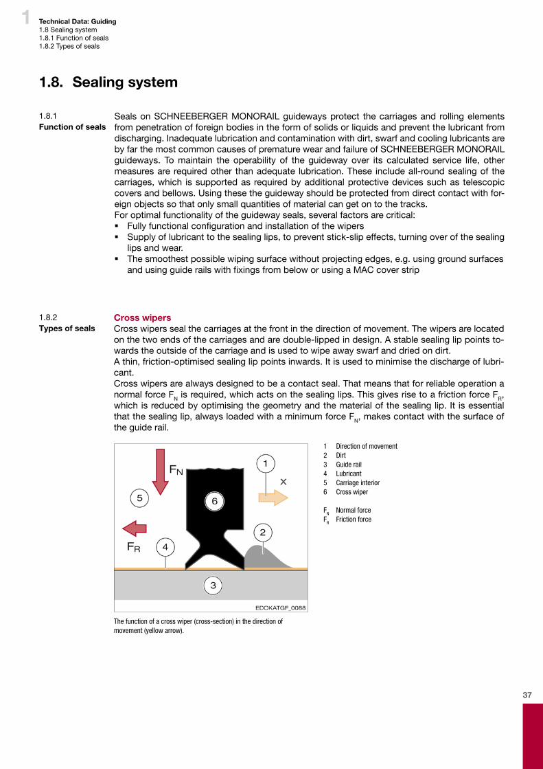
Cross wipersCross wipers seal the carriages at the front in the direction of movement. The wipers are located on the two ends of the carriages and are double-lipped in design. A stable sealing lip points to-wards the outside of the carriage and is used to wipe away swarf and dried on dirt.A thin, friction-optimised sealing lip points inwards. It is used to minimise the discharge of lubri-cant.Cross wipers are always designed to be a contact seal. That means that for reliable operation a normal force FN is required, which acts on the sealing lips. This gives rise to a friction force FR, which is reduced by optimising the geometry and the material of the sealing lip. It is essential that the sealing lip, always loaded with a minimum force FN, makes contact with the surface of the guide rail.
1 Direction of movement 2 Dirt 3 Guide rail 4 Lubricant 5 Carriage interior 6 Cross wiper
FN Normal force FR Friction force
The function of a cross wiper (cross-section) in the direction ofmovement (yellow arrow).
38
1 Technical Data: Guiding1.8 Sealing system1.8.2 Types of seals
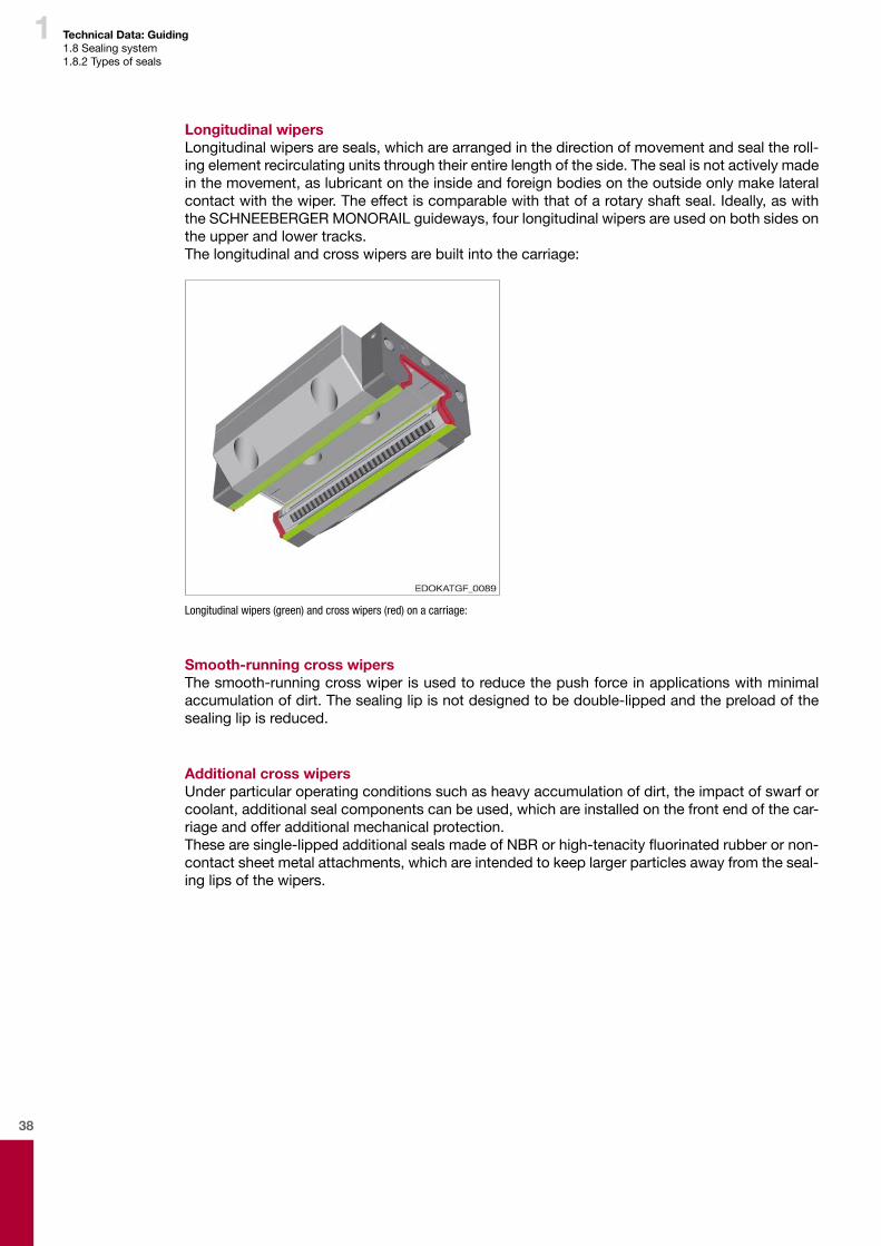
Longitudinal wipersLongitudinal wipers are seals, which are arranged in the direction of movement and seal the roll-ing element recirculating units through their entire length of the side. The seal is not actively made in the movement, as lubricant on the inside and foreign bodies on the outside only make lateral contact with the wiper. The effect is comparable with that of a rotary shaft seal. Ideally, as with the SCHNEEBERGER MONORAIL guideways, four longitudinal wipers are used on both sides on the upper and lower tracks. The longitudinal and cross wipers are built into the carriage:
Longitudinal wipers (green) and cross wipers (red) on a carriage:
Smooth-running cross wipersThe smooth-running cross wiper is used to reduce the push force in applications with minimal accumulation of dirt. The sealing lip is not designed to be double-lipped and the preload of the sealing lip is reduced.
Additional cross wipersUnder particular operating conditions such as heavy accumulation of dirt, the impact of swarf or coolant, additional seal components can be used, which are installed on the front end of the car-riage and offer additional mechanical protection.Thesearesingle-lippedadditionalsealsmadeofNBRorhigh-tenacityfluorinatedrubberornon-contact sheet metal attachments, which are intended to keep larger particles away from the seal-ing lips of the wipers.
39
1 Technical Data: Guiding1.8 Sealing system1.8.3 Friction of different seals
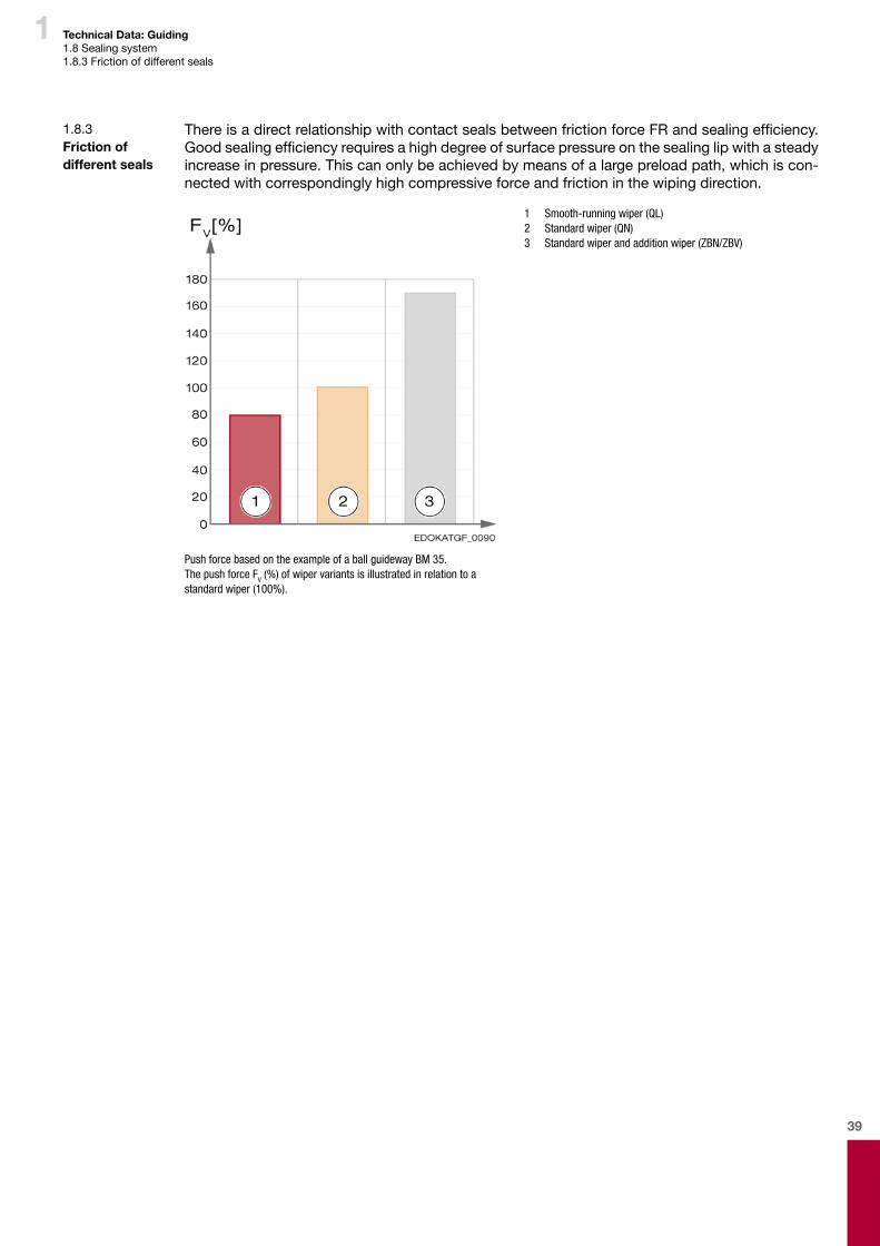
ThereisadirectrelationshipwithcontactsealsbetweenfrictionforceFRandsealingefficiency.Goodsealingefficiencyrequiresahighdegreeofsurfacepressureonthesealinglipwithasteadyincrease in pressure. This can only be achieved by means of a large preload path, which is con-nected with correspondingly high compressive force and friction in the wiping direction.
1 Smooth-running wiper (QL) 2 Standard wiper (QN) 3 Standard wiper and addition wiper (ZBN/ZBV)
Push force based on the example of a ball guideway BM 35.The push force FV (%) of wiper variants is illustrated in relation to a standard wiper (100%).
1.8.3 Friction of different seals
40
1 Technical Data: Guiding1.9 Build-up of noise1.9.1Definition1.9.2 Causes
1.9. Build-up of noise
1.9.1 Definition
Roller bearing-fitted guideways generate airborne noise and body noise. The airborne noisecaused directly by the bearing is secondary in this. The main component is the generation of body noise, which essentially depends on the type of connection and the consistency of the sur-rounding structure.
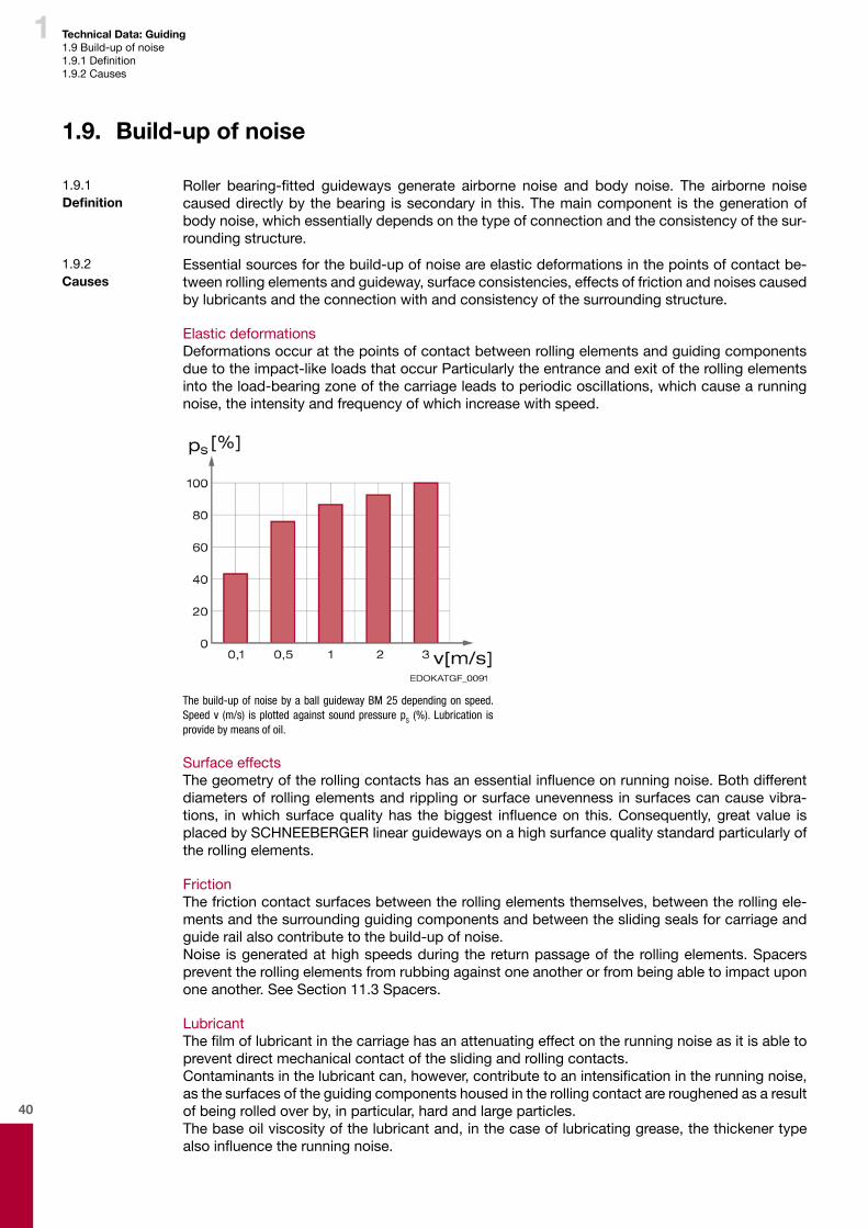
1.9.2 Causes
Essential sources for the build-up of noise are elastic deformations in the points of contact be-tween rolling elements and guideway, surface consistencies, effects of friction and noises caused by lubricants and the connection with and consistency of the surrounding structure.
Elastic deformationsDeformations occur at the points of contact between rolling elements and guiding components due to the impact-like loads that occur Particularly the entrance and exit of the rolling elements into the load-bearing zone of the carriage leads to periodic oscillations, which cause a running noise, the intensity and frequency of which increase with speed.
The build-up of noise by a ball guideway BM 25 depending on speed. Speed v (m/s) is plotted against sound pressure pS (%). Lubrication is provide by means of oil.
Surface effectsThegeometryoftherollingcontactshasanessentialinfluenceonrunningnoise.Bothdifferentdiameters of rolling elements and rippling or surface unevenness in surfaces can cause vibra-tions, inwhichsurfacequalityhas thebiggest influenceon this.Consequently,greatvalue isplaced by SCHNEEBERGER linear guideways on a high surfance quality standard particularly of the rolling elements.
FrictionThe friction contact surfaces between the rolling elements themselves, between the rolling ele-ments and the surrounding guiding components and between the sliding seals for carriage and guide rail also contribute to the build-up of noise.Noise is generated at high speeds during the return passage of the rolling elements. Spacers prevent the rolling elements from rubbing against one another or from being able to impact upon one another. See Section 11.3 Spacers.
LubricantThefilmoflubricantinthecarriagehasanattenuatingeffectontherunningnoiseasitisabletoprevent direct mechanical contact of the sliding and rolling contacts. Contaminantsinthelubricantcan,however,contributetoanintensificationintherunningnoise,as the surfaces of the guiding components housed in the rolling contact are roughened as a result of being rolled over by, in particular, hard and large particles. The base oil viscosity of the lubricant and, in the case of lubricating grease, the thickener type alsoinfluencetherunningnoise.
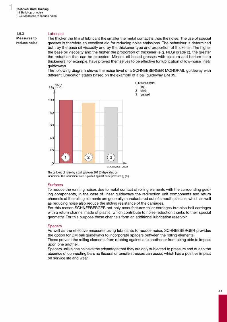
41
1 Technical Data: Guiding1.9 Build-up of noise1.9.3 Measures to reduce noise
1.9.3 Measures to reduce noise
LubricantThethickerthefilmoflubricantthesmallerthemetalcontactisthusthenoise.Theuseofspecialgreases is therefore an excellent aid for reducing noise emissions. The behaviour is determined both by the base oil viscosity and by the thickener type and proportion of thickener. The higher the base oil viscosity and the higher the proportion of thickener (e.g. NLGI grade 2), the greater the reduction that can be expected. Mineral-oil-based greases with calcium and barium soap thickeners, for example, have proved themselves to be effective for lubrication of low-noise linear guideways. The following diagram shows the noise level of a SCHNEEBERGER MONORAIL guideway with different lubrication states based on the example of a ball guideway BM 35.
Lubrication state: 1 dry 2 oiled 3 greased
The build-up of noise by a ball guideway BM 35 depending on lubrication. The lubrication state is plotted against noise pressure pS (%).
SurfacesTo reduce the running noises due to metal contact of rolling elements with the surrounding guid-ing components, in the case of linear guideways the redirection unit components and return channels of the rolling elements are generally manufactured out of smooth plastics, which as well as reducing noise also reduce the sliding resistance of the carriages.For this reason SCHNEEBERGER not only manufactures roller carriages but also ball carriages with a return channel made of plastic, which contribute to noise reduction thanks to their special geometry. For this purpose these channels form an additional lubrication reservoir.
SpacersAs well as the effective measures using lubricants to reduce noise, SCHNEEBERGER provides the option for BM ball guideways to incorporate spacers between the rolling elements.These prevent the rolling elements from rubbing against one another or from being able to impact upon one another.Spacers unlike chains have the advantage that they are only subjected to pressure and due to the absenceofconnectingbarsnoflexuralortensilestressescanoccur,whichhasapositiveimpacton service life and wear.

42
1 Technical Data: Guiding1.10 Lubrication1.10.1 Function of the lubrication1.10.2 Types of lubricant
1.10. Lubrication
1.10.1 Function of the lubrication
Adequate lubrication and subsequent lubrication using a lubricant adapted to the operat-ingandenvironmentalconditionsisrequiredtomaintainthefunctionalityofSCHNEEBERGER MONORAIL guideways.The lubrication performs the following functions: � Separatethemetalrollingcontactsthankstotheformationofafilmofstablelubricant � Minimise wear � Reduce friction between rolling elements and track and between the rolling elements with
one another. � Reduce sliding friction of the seals � Protect against corrosion � Reduce running noises
Inaddition,lubricationcanfulfilotherfunctionstoo,suchas: � Dissipate heat or rinse dirt (in the case of oil lubrication) � Together with the sealing system, prevent penetration of liquid or solid foreign bodies (with
grease lubrication).
Thelubricationthereforehasanessentialinfluenceonthefunctionandservicelifeofthelinearguideway.Theprerequisiteforoptimalefficiencyofthelubricationsystemis,however,selectingalubricant,which is suitable for the operating and environmental conditions as well as a properly functioning sealing system. The job of the seals in this is to keep the lubricant in the carriage and to prevent the penetration of liquid or solid foreign particles into the carriages. The seals should thus prevent the lubricant from getting contaminated or discharged.
Caution
Personal injury and damage to components due to breakage
¨ A deficiency of lubricant or choosing an unsuitable lubricant are the most common causes of failure of linear guideways alongside contamination and overload.
¨ Make sure you employ the correct operating conditions and lubricate regularly.
1.10.2 Types of lubricant
BothgreaseandfluidgreaseoroilcanbeusedasalubricantforSCHNEEBERGERMONORAILguideways.Lubricants with solid lubricant additives such as, for example, graphite, MoS2 or PTFE are not suitable for use in SCHNEEBERGER MONORAIL guideways as they can form harmful deposits on the rolling element tracks.The lubricant can either be applied manually, e.g. using a grease gun, or automatically using a centralised lubricating system or an additional lubricant dispenser on the carriage, see Section 4.15.9 - Lubrication plate SPL. The use of a centralised lubricating system generally guarantees a consistent and reliable supply of lubricant. In special cases an oil airborne lubricant is also used, which is a type of minimum-volume lubrication. See Section 4.15.8 - Application expertise on lubrication requirements in respect of lubrication under certain operating conditions.Critical for the selection of lubrication type and its implementation are: � Type of application � Operating conditions � Configurationofthemachineandofthesurroundingstructure � Accessibility of the guideways
43
1 Technical Data: Guiding1.10 Lubrication1.10.3 Characteristics of the lubricants
1.10.3 Characteristics of the lubricants
Lubricating oilsEither mineral oils or synthetically manufactured synthetic oils with additives to protect against ageing, corrosion, foaming and to increase compressive strength are used as lubricating oils. LubricatingoilsareclassifiedintodifferentgradesaccordingtotheirviscosityinaccordancewithDIN 51519.
Lubricating oils � penetrate more easily into the carriages and disperse more effectively than grease � effectively dissipate heat � escape more easily from the carriage than grease � are subject to the force of gravity and thus require a higher design overhead depending on
the installation orientation than is the case with grease lubrication � Provide a rinsing effect.
Lubricating greasesLubricating greases consist of a base oil (usually mineral oil), a thickener (metal soaps, simple soaps, complex soaps (calcium, lithium, sodium, other)) and various additives (e.g. to protect against oxidation, corrosion and to increase compressive strength). Lubricating greases are clas-sifiedaccordingtotheirconsistencyand/orstrengthintovariousNLGIgrades(NationalLubricat-ing Grease Institute) in accordance with DIN 51818. See Section - Characteristics of lubricants in accordance with DIN.
Lubricating greases � prevent running noises � support the effect of the wipers thanks to their solid consistency � counteract the penetration of dirt into the carriage � remaindefinedatthelubricatingpoint � thanks to their share of thickener have a sustained release / deposit effect � have a permanent effect and support extended subsequent lubricating intervals � the thickener in the lubricating greases also offer certain emergency running characteristics
Fluid greasesFluid greases are low-viscosity greases and thus � are suitable for use in centralised lubricating systems � haveasoft,fluid-likeconsistency
MiscibilityMineral-oil-basedlubricatingoilscanbemixedwhentheyhavethesameclassificationandtheirviscosity does not differ by more than one ISO-VG grade.Ask the lubricant manufacturer for synthetic oils.
Changing lubricantSubsequently changing oil lubrication to grease lubrication can be completed without danger assuming compatibility of the different lubricants.Changing grease lubrication to oil lubrication is not possible, as grease will remain in the narrow lubricationchannelsfollowinginitiallubricationandthisobstructstheflowofoilwhichmeansthatan adequate supply of oil lubricant cannot be guaranteed.

44
1 Technical Data: Guiding1.10 Lubrication1.10.4 Recommended lubricants1.10.5 Indicators and additives for lubricants
1.10.4 Recommended lubricants
Lubricants recommended by SCHNEEBERGER:
Lubrication with oil � Mineral oil CLP in accordance with DIN 51517 or HLP in accordance with DIN 51524 in the
viscosity range ISO VG 32 to ISO VG 100 in accordance with DIN 51519 � Bed track oils CGLP in accordance with DIN 51517 up to viscosity grade ISO VG 220
Lubrication with grease � Lubricating grease KP2K in accordance with DIN 51825
Lubricationwithfluidgrease � Fluid greases GP00N or GP000N in accordance with DIN 51826
1.10.5 Indicators and additives for lubricants
Viscosity Viscosityisunderstoodtomeanthemeasurementforresistancetoflowbasedontheinternalfriction of a liquid.LubricatingoilsareclassifiedintodifferentgradesaccordingtotheirviscosityinaccordancewithDIN51519.Alowviscositymeansthin-flowing,highviscositymeansthatthelubricantisviscous.Water, for example, has the ISO-VG grade 1.
ISO viscosity grades in accordance with DIN 51519
Viscosity grade ISO Mid-point viscosity at 40°C (mm²/s)
min. limits of the kinematic viscosity at 40 °C (mm²/s)
max. limits of the kinematic viscosity at 40 °C (mm²/s)
ISO VG 32 32 28.8 35.2ISO VG 46 46 41.4 50.6ISO VG 68 68 61.2 74.8
ISO VG 100 100 90 110ISO VG 150 150 135 165ISO VG 220 220 198 242
ConsistencyTheresistanceofagreasetodeformationisdefinedasitsconsistency.Thisindicatorisusedtoclassifylubricatinggreases.ForthispurposeinDIN51818thelubricatinggreasesareclassifiedinto 9 different NLGI grades. Worked penetration is used as an evaluation parameter for the clas-sification,whichstateshowdeeplyastandardconepenetratesintothelubricantunderweight.For SCHNEEBERGER MONORAIL guideways, greases in NLGI grades 000 to 3 are used.
NLGI grades in accordance with DIN 51818:
NLGI grade Type of grease Consistency Worked penetration (0.1 mm)
Application
000
Fluid greases
fluid 445 - 475Use in centralised lubricat-
ing system, gear lubrication,
SCHNEEBERGER MONORAIL guideways
00 viscous 400 - 430
0 semi-fluid 355 - 385
1
soft greases
very soft 310 - 340
2 soft 265 - 295 SCHNEEBERGER MONORAIL guideways3 smooth 220 - 250
4 almost solid 175 - 205
Sealing greases5hard greases
solid 130 - 160
6 very solid 85 - 115

45
1 Technical Data: Guiding1.10 Lubrication1.10.5 Indicators and additives for lubricants1.10.6 Brief description of the lubricants in accordance with DIN 51502
AdditivesLubricants used industrially are generally mixed with various additives. These are admixtures, which provide the lubricant with certain characteristics or improve it.Additives Intended purposeAntioxidants Prevention of changes in lubricantVI-improver Reduction in the dependency of viscosity on temperature
EP additives Improvement in compressive rigidity (is needed for high forces; EP = extreme pressure)Corrosion inhibitors Corrosion and rust preventionFoam inhibitors Prevent the formation of foam (improves force transmissibility)
1.10.6 Brief description of the lubricants in accordance with DIN 51502
Structure of the brief description for lubricating oilsSample brief description of lubricating oils: C L P PG -68
Lubricating oil type
Identificationletterforadditives(corrosion,ageing)
Identificationletterforadditives(wear,friction,loadingcapacity)
Additionalidentificationletterforsyntheticlubricants
Viscosity, ISO-VG grade
Lubricating oils C, CL, CLP in accordance with DIN 51517Lubricating oil CLP Mineral oil (C) with additives to increase corrosion protection and resistance to ageing
(L) and to reduce wear in the mixed friction area (P)Lubricating oil CGLP Sliding and bed track oil (CG) with particularly good sliding behaviour and adhesion (G)
and with additives to increase corrosion protection and resistance to ageing (L) and to reduce wear in the mixed friction area (P)
Hydraulic oils HL, HLP, HVLP in accordance with DIN 51524Hydraulic oils HLP Hydraulic oil (H) with additives to increase corrosion protection and resistance to ageing
(L) and to reduce wear in the mixed friction area (P)
Structure of the brief description for lubricating greasesSample brief description of lubricating greases: K P 2 K -30
Type of lubricating grease
Additional letter for base oil type and additives
Consistency, NLGI grade
Performance indicator for maximum operating temperature and behaviour in relation to water
Minimum operating temperature in °C
Lubricating greases K in accordance with DIN 51825Lubricating grease KP 2 K Lubricating grease for roller-contact bearings, slide bearings and sliding surfaces (K)
with additives to reduce friction and wear in the mixed friction area and/or to increase loading capacity (P), consistency grade NLGI 2, maximum operating temperature 120°C (K)
Lubricating greases OG in accordance with DIN 51825Lubricating grease OGP 2 K Lubricating grease for open gears (OG) with additives to reduce friction and wear in the
mixed friction area and/or to increase loading capacity (P), consistency grade NLGI 2, maximum operating temperature 120°C (K)
Lubricating greases G in accordance with DIN 51826Lubricating grease GP 00/000 N
Lubricating grease for closed gears (G) with additives to reduce friction and wear in the mixed friction area and/or to increase loading capacity (P), consistency grade NLGI 00/000(fluidgrease),maximumoperatingtemperature140°C(N)

46
1 Technical Data: Guiding1.10 Lubrication1.10.7 Deciding factors in your choice of lubricant
1.10.7 Deciding factors in your choice of lubricant
The choice of a suitable lubricant should be made in collaboration with a lubricant manufacturer. The following factors are critical in your choice of lubricant, quantities of lubricant and application method: � Type of use, e.g. tool machinery, handling, cleanroom � Operating conditions, e.g. speed, stroke, forces, vibrations � Environmentalinfluences,e.g.temperature,coolinglubricant,dirt � Linear guideway, e.g. ball/roller, size, installation orientation, accessibility � Lubricant feed, e.g. manual, centralised lubricating system, lubrication intervals, compatibil-
ity with other lubricants � Miscellaneous,e.g.operatinglifeofthelubricant,approvals/specifications,materials,envi-
ronmental factors, cost-effectiveness
47
2 Technical Data: Driving

48

49
2
Contents
2 Technical Data: Driving .......................................................................47
2.1. Integral rack drive BZ ...........................................................................................................502.1.1 Construction .....................................................................................................................502.1.2 Integration .........................................................................................................................512.1.3 Comparison with other drive designs ...............................................................................512.1.4 Tooth quality .....................................................................................................................52
2.2. Lubrication ............................................................................................................................532.2.1 Function of the lubrication ...............................................................................................532.2.2 Types of lubricant .............................................................................................................532.2.3 Characteristics of lubricants .............................................................................................532.2.4 Recommended lubricants .................................................................................................53
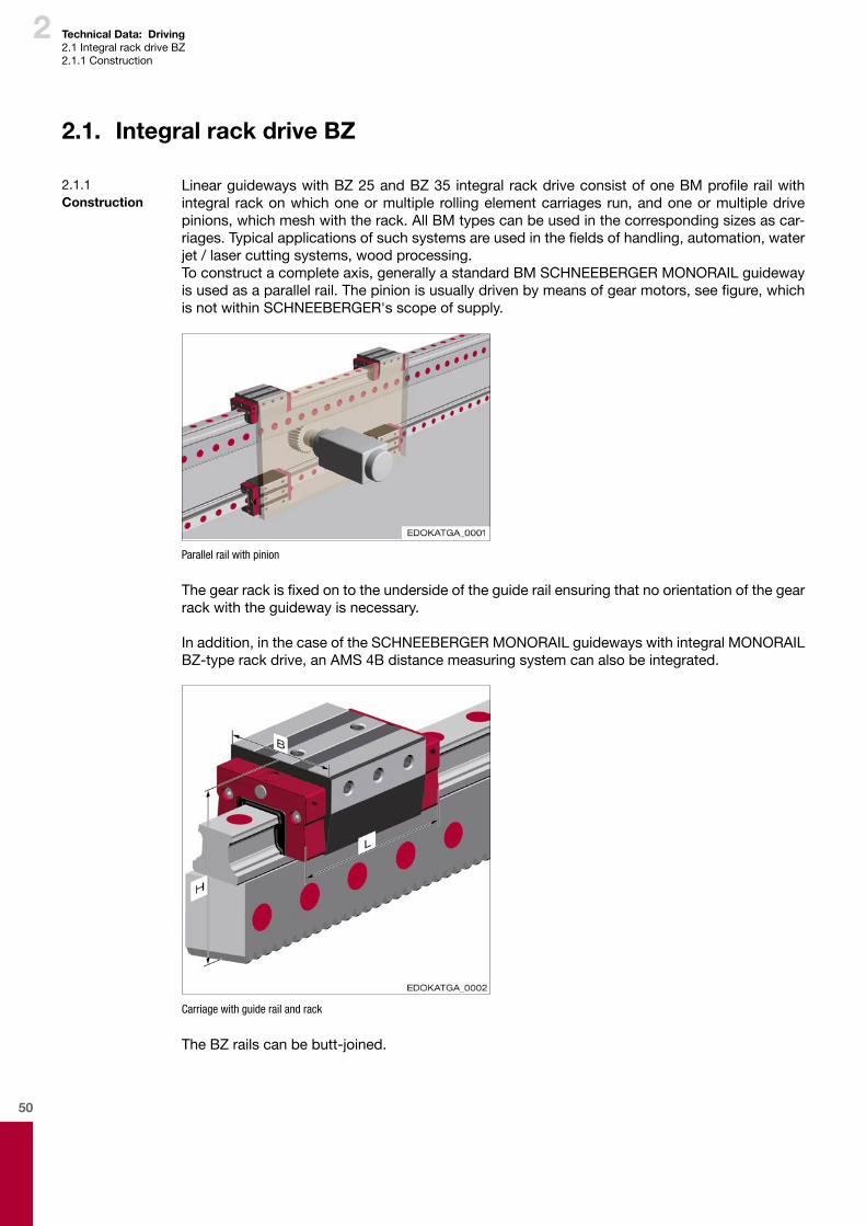
50
2
2.1. Integral rack drive BZ
Linear guideways with BZ 25 and BZ 35 integral rack drive consist of one BM profile rail with integral rack on which one or multiple rolling element carriages run, and one or multiple drive pinions, which mesh with the rack. All BM types can be used in the corresponding sizes as car-riages. Typical applications of such systems are used in the fields of handling, automation, water jet / laser cutting systems, wood processing.To construct a complete axis, generally a standard BM SCHNEEBERGER MONORAIL guideway is used as a parallel rail. The pinion is usually driven by means of gear motors, see figure, which is not within SCHNEEBERGER's scope of supply.
Parallel rail with pinion
The gear rack is fixed on to the underside of the guide rail ensuring that no orientation of the gear rack with the guideway is necessary.
In addition, in the case of the SCHNEEBERGER MONORAIL guideways with integral MONORAIL BZ-type rack drive, an AMS 4B distance measuring system can also be integrated.
Carriage with guide rail and rack
The BZ rails can be butt-joined.
2.1.1 Construction
Technical Data: Driving2.1 Integral rack drive BZ2.1.1 Construction
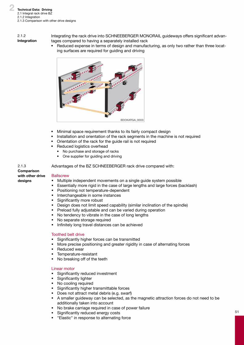
51
2
Advantages of the BZ SCHNEEBERGER rack drive compared with:
Ballscrew � Multiple independent movements on a single guide system possible � Essentially more rigid in the case of large lengths and large forces (backlash) � Positioning not temperature-dependent � Interchangeable in some instances � Significantly more robust � Design does not limit speed capability (similar inclination of the spindle) � Preload fully adjustable and can be varied during operation � No tendency to vibrate in the case of long lengths � No separate storage required � Infinitely long travel distances can be achieved
Toothed belt drive � Significantly higher forces can be transmitted � More precise positioning and greater rigidity in case of alternating forces � Reduced wear � Temperature-resistant � No breaking off of the teeth
Linear motor � Significantly reduced investment � Significantly lighter � No cooling required � Significantly higher transmittable forces � Does not attract metal debris (e.g. swarf) � A smaller guideway can be selected, as the magnetic attraction forces do not need to be
additionally taken into account � No brake carriage required in case of power failure � Significantly reduced energy costs � "Elastic" in response to alternating force
2.1.3 Comparison with other drive designs
Integrating the rack drive into SCHNEEBERGER MONORAIL guideways offers significant advan-tages compared to having a separately installed rack � Reduced expense in terms of design and manufacturing, as only two rather than three locat-
ing surfaces are required for guiding and driving
� Minimal space requirement thanks to its fairly compact design � Installation and orientation of the rack segments in the machine is not required � Orientation of the rack for the guide rail is not required � Reduced logistics overhead
• No purchase and storage of racks• One supplier for guiding and driving
2.1.2 Integration
Technical Data: Driving2.1 Integral rack drive BZ2.1.2 Integration2.1.3 Comparison with other drive designs
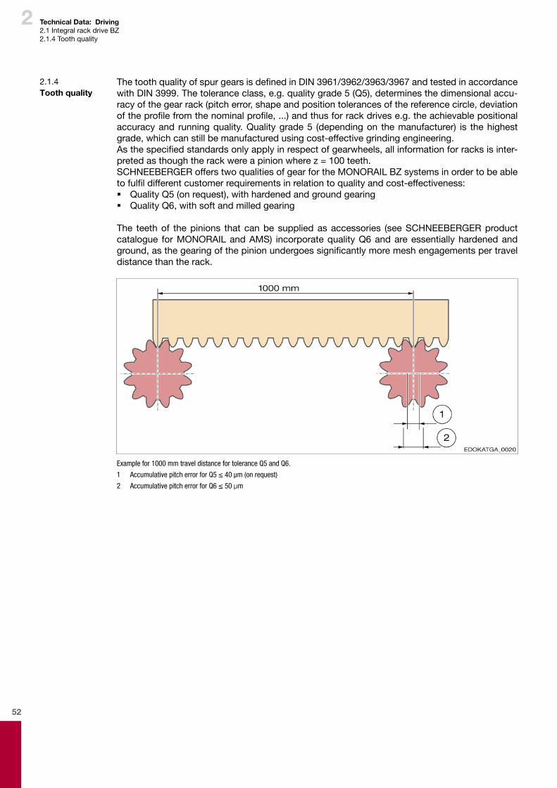
52
2
2.1.4 Tooth quality
Technical Data: Driving2.1 Integral rack drive BZ2.1.4 Tooth quality
The tooth quality of spur gears is defined in DIN 3961/3962/3963/3967 and tested in accordance with DIN 3999. The tolerance class, e.g. quality grade 5 (Q5), determines the dimensional accu-racy of the gear rack (pitch error, shape and position tolerances of the reference circle, deviation of the profile from the nominal profile, ...) and thus for rack drives e.g. the achievable positional accuracy and running quality. Quality grade 5 (depending on the manufacturer) is the highest grade, which can still be manufactured using cost-effective grinding engineering.As the specified standards only apply in respect of gearwheels, all information for racks is inter-preted as though the rack were a pinion where z = 100 teeth.SCHNEEBERGER offers two qualities of gear for the MONORAIL BZ systems in order to be able to fulfil different customer requirements in relation to quality and cost-effectiveness: � Quality Q5 (on request), with hardened and ground gearing � Quality Q6, with soft and milled gearing
The teeth of the pinions that can be supplied as accessories (see SCHNEEBERGER product catalogue for MONORAIL and AMS) incorporate quality Q6 and are essentially hardened and ground, as the gearing of the pinion undergoes significantly more mesh engagements per travel distance than the rack.
Example for 1000 mm travel distance for tolerance Q5 and Q6.
1 Accumulative pitch error for Q5 ≤ 40 µm (on request)
2 Accumulative pitch error for Q6 ≤ 50 µm
53
2 Technical Data: Driving2.2 Lubrication2.2.1 Function of the lubrication2.2.2 Types of lubricant2.2.3 Characteristics of lubricants2.2.4 Recommended lubricants
2.2. Lubrication
2.2.1 Function of the lubrication
Adequate lubrication using a lubricant adapted to the operating conditions is required to maintain the functionality of the rack drive. This also includes regular subsequent lubrication.Lubrication performs the following functions: � Separate metal rolling contacts due to the formation of a film of stable lubricant � Minimise wear � Reduce friction between the rolling contact surfaces on the gearwheel and rack � Protect against corrosion � Reduce running noises
The lubrication therefore has an essential influence on the function and service life of the gear rack.
Both grease or liquid grease or oil can be used as a lubricant for the rack drive. Mineral-oil-based lubricants or synthetic lubricants can be used, which also in part contain a proportion of solid lubricants such as graphite or MoS2.
2.2.2 Types of lubricant
2.2.3 Characteristics of lubricants
It is important to ensure in the case of lubricants for open gears and gear racks that they provide high viscosity and adhesion so that they cannot be spun off by the rotating gearwheels.Other characteristics that the lubricant must fulfil include: � High shear stability � Good wear protection � Good corrosion protection � Oxidation stability � High compressive stability
Lubricants recommended by SCHNEEBERGER:
Lubrication with oilMineral oil CLP in accordance with DIN 51517 in viscosity grade ISO VG 460 in accordance with DIN 51519
Lubrication with greaseLubricating grease OGP2K in accordance with DIN 51825
For characteristics of lubricants, see Section 1.12 - Lubrication.
2.2.4 Recommended lubricants

54

55
3 Technical Data: Measuring

56

57
3
Contents
3
3 Technical Data: Measuring .................................................................57
3.1. Distance measuring systems ..............................................................................................603.1.1. Classificationofmeasuringsystems.................................................................................603.1.2. Overviewofdifferentdistancemeasuringprinciples ........................................................623.1.3. Magneto-resistivemeasuringtechnologybySCHNEEBERGER ........................................623.1.4. Distancemeasuringsystem ..............................................................................................66
3.2. Interfaces ...............................................................................................................................753.2.1. Incrementalinterfaces .......................................................................................................753.2.2. Absoluteinterfaces ...........................................................................................................78
58
3 Technical Data: Measuring3.1Distancemeasuringsystems3.1.1Classificationofmeasuringsystems
3.1. Distance measuring systems
Different types of measuring principleDifferenttypesofhigh-precisiondistancemeasuringsystemsareusedforlineardistancemeas-uringinindustrialapplications.Thesecanbecategorisedintodifferentgroupsdependingonthephysicalmeasuringprinciple.Thebasicprincipleofaperiodicgraduation,whichisscannedwithasensor,iswidelyused. � Magneto-resistivesystemsrecordperiodicchangesinmagnetizationofthescaleusingMRsensors(MR=magneto-resistive)orHall-effectsensors.Unlikeopticalsystems,magneticsystemsarenotsensitivetodirt,andtypicalgraduationperiodsarebetween0.4and10mm.
� Opticalsystemsarewidespread.Usingthemagraduationisscannedwithappropriatesen-sors,whichrecordaperiodicchangeinbrightnessorinthephaseofthereflectedortrans-mittedlight.Bymeansofetchingorvapourdeposition,veryfinegraduationswithperiodslessthan10µmcanbeachieved,whichiswhyopticalsystemsgenerallydeliverthehighestresolutions.
� Inductivesystemsworkwithamechanicallystructured,metalscale,whichcanbedesignedtobeextremelyrobust.Thebandsonthisscaleworkinasimilarwaytotheyokeofatrans-former.Asaresultoftheshift,theamplitudeandphaseofanelectricoscillationismodu-lated.Graduationperiodsbelow1mmaredifficulttoachievewiththesesystems.
� Magnetostrictionandotherprocesseshaveonlyfoundlimitedappeal.
Depending on the type of arrangement of componentsWhathoweverhasprovedtobefarmoreimportantishowthedrivecomponentsandmeasuringsystemcomponentsworktogether.Dependingontheactiveprinciple,wetalkaboutanindirectordirectmeasurementwithmachineaxes.In thecaseof the indirectdistancemeasurement the linear shift is converted into adifferentmeasuredvalue.Oneexamplethatweoftenencounterisalinearaxiswithballscrewdrive.Theballscrewconvertsrotationintolinearmotion,andtheangleofrotationisusuallymeasureddi-rectlybytheservomotor.Theadvantageofthisisbeingabletodeterminedthepositionoftheaxiswithaninexpensiveandcompact rotaryencoder.Thedisadvantage is that theconversionofonemeasuredvalueintoanothercanneverbecompletedwithouterror.Inthecaseofthespindle,pitcherrors,clear-ance,vibrationsandthermalexpansiondistortthemeasurementofposition.Inthecaseofdirectmeasurementaso-calledlinearmeasuringscaleisused,whichisscanneddirectlybyasensor.Betterresultsareattainedasaresultofthetargetedeliminationofintermediatevaluesandmini-maldistancebetweenthemeasurementobjectandthemeasuringsensor.Ingeneral,thedirectdistancemeasurementshouldthereforebefavouredasitdeliversmoreac-curatereadingsandoneslessinfluencedbyenvironmentalfactors,provideditcanbeachievedwith a justifiable amount of effort in achieving the technical measurement. For this reason SCHNEEBERGERpositioningsystemsintegratesAMSintoitslinearguidewaytocombinetheadvantagesofapreciselinearguidewaywiththebenefitsofdirectdistancemeasurement.
3.1.1. Classification of measuring systems
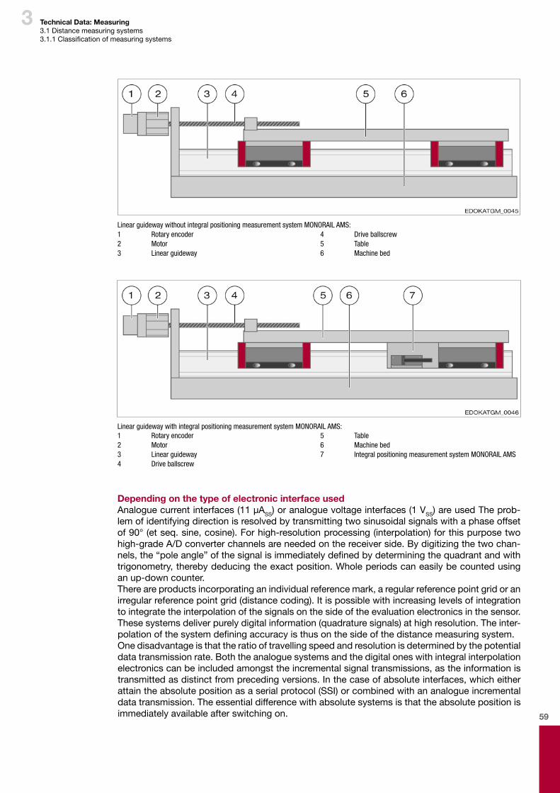
59
3 Technical Data: Measuring3.1Distancemeasuringsystems3.1.1Classificationofmeasuringsystems
Linear guideway without integral positioning measurement system MONORAIL AMS:1 Rotary encoder2 Motor3 Linear guideway
4 Drive ballscrew5 Table6 Machine bed
Linear guideway with integral positioning measurement system MONORAIL AMS:1 Rotary encoder2 Motor3 Linear guideway4 Drive ballscrew
5 Table6 Machine bed7 Integral positioning measurement system MONORAIL AMS
Depending on the type of electronic interface usedAnaloguecurrentinterfaces(11µASS)oranaloguevoltageinterfaces(1VSS)areusedTheprob-lemofidentifyingdirectionisresolvedbytransmittingtwosinusoidalsignalswithaphaseoffsetof90°(etseq.sine,cosine).Forhigh-resolutionprocessing(interpolation)forthispurposetwohigh-gradeA/Dconverterchannelsareneededonthereceiverside.Bydigitizingthetwochan-nels,the“poleangle”ofthesignalisimmediatelydefinedbydeterminingthequadrantandwithtrigonometry,therebydeducingtheexactposition.Wholeperiodscaneasilybecountedusinganup-downcounter.Thereareproductsincorporatinganindividualreferencemark,aregularreferencepointgridoranirregularreferencepointgrid(distancecoding).Itispossiblewithincreasinglevelsofintegrationtointegratetheinterpolationofthesignalsonthesideoftheevaluationelectronicsinthesensor.Thesesystemsdeliverpurelydigitalinformation(quadraturesignals)athighresolution.Theinter-polationofthesystemdefiningaccuracyisthusonthesideofthedistancemeasuringsystem.Onedisadvantageisthattheratiooftravellingspeedandresolutionisdeterminedbythepotentialdatatransmissionrate.Boththeanaloguesystemsandthedigitaloneswithintegralinterpolationelectronicscanbeincludedamongsttheincrementalsignaltransmissions,astheinformationistransmittedasdistinctfromprecedingversions.Inthecaseofabsoluteinterfaces,whicheitherattaintheabsolutepositionasaserialprotocol(SSI)orcombinedwithananalogueincrementaldatatransmission.Theessentialdifferencewithabsolutesystemsisthattheabsolutepositionisimmediatelyavailableafterswitchingon.
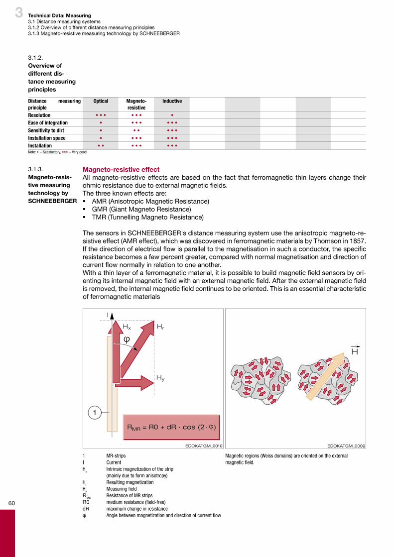
60
3
3.1.2. Overview of different dis-tance measuring principles
Technical Data: Measuring3.1Distancemeasuringsystems3.1.2Overviewofdifferentdistancemeasuringprinciples3.1.3Magneto-resistivemeasuringtechnologybySCHNEEBERGER
Magneto-resistive effectAllmagneto-resistiveeffectsarebasedonthefact that ferromagneticthin layerschangetheirohmicresistanceduetoexternalmagneticfields.Thethreeknowneffectsare: � AMR(AnisotropicMagneticResistance) � GMR(GiantMagnetoResistance) � TMR(TunnellingMagnetoResistance)
ThesensorsinSCHNEEBERGER'sdistancemeasuringsystemusetheanisotropicmagneto-re-sistiveeffect(AMReffect),whichwasdiscoveredinferromagneticmaterialsbyThomsonin1857.Ifthedirectionofelectricalflowisparalleltothemagnetisationinsuchaconductor,thespecificresistancebecomesafewpercentgreater,comparedwithnormalmagnetisationanddirectionofcurrentflownormallyinrelationtooneanother.Withathinlayerofaferromagneticmaterial,itispossibletobuildmagneticfieldsensorsbyori-entingitsinternalmagneticfieldwithanexternalmagneticfield.Aftertheexternalmagneticfieldisremoved,theinternalmagneticfieldcontinuestobeoriented.Thisisanessentialcharacteristicofferromagneticmaterials
1 MR-stripsI Current Hx Intrinsic magnetization of the strip (mainly due to form anisotropy) Hr Resulting magnetizationHy MeasuringfieldRMR Resistance of MR stripsR0 mediumresistance(field-free)dR maximum change in resistanceφ Anglebetweenmagnetizationanddirectionofcurrentflow
Magnetic regions (Weiss domains) are oriented on the external magneticfield.
3.1.3. Magneto-resis-tive measuring technology by SCHNEEBERGER
Distance measuring principle
Optical Magneto- resistive
Inductive
Resolution • • • • • • •Ease of integration • • • • • • •
Sensitivity to dirt • • • • • •Installation space • • • • • • •Installation • • • • • • • •Note: • = Satisfactory, ••• = Very good
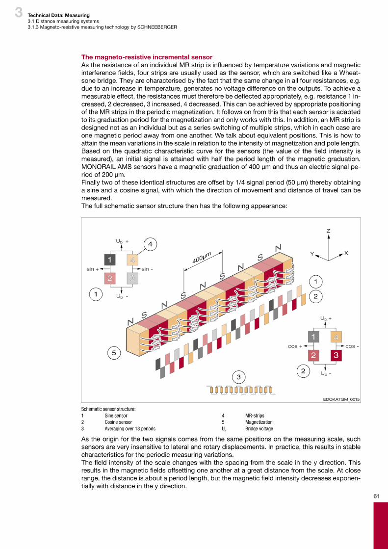
61
3 Technical Data: Measuring3.1Distancemeasuringsystems3.1.3Magneto-resistivemeasuringtechnologybySCHNEEBERGER
The magneto-resistive incremental sensorAstheresistanceofanindividualMRstripisinfluencedbytemperaturevariationsandmagneticinterferencefields,fourstripsareusuallyusedasthesensor,whichareswitchedlikeaWheat-sonebridge.Theyarecharacterisedbythefactthatthesamechangeinallfourresistances,e.g.duetoanincreaseintemperature,generatesnovoltagedifferenceontheoutputs.Toachieveameasurableeffect,theresistancesmustthereforebedeflectedappropriately,e.g.resistance1 in-creased,2decreased,3increased,4decreased.ThiscanbeachievedbyappropriatepositioningoftheMRstripsintheperiodicmagnetization.Itfollowsonfromthisthateachsensorisadaptedtoitsgraduationperiodforthemagnetizationandonlyworkswiththis.Inaddition,anMRstripisdesignednotasanindividualbutasaseriesswitchingofmultiplestrips,whichineachcaseareonemagneticperiodawayfromoneanother.Wetalkaboutequivalentpositions.Thisishowtoattainthemeanvariationsinthescaleinrelationtotheintensityofmagnetizationandpolelength.Basedon thequadraticcharacteristiccurve for thesensors (thevalueof thefield intensity ismeasured),an initialsignal isattainedwithhalf theperiod lengthof themagneticgraduation. MONORAILAMSsensorshaveamagneticgraduationof400µmandthusanelectricsignalpe-riodof200µm.Finallytwooftheseidenticalstructuresareoffsetby1/4signalperiod(50µm)therebyobtainingasineandacosinesignal,withwhichthedirectionofmovementanddistanceoftravelcanbemeasured.Thefullschematicsensorstructurethenhasthefollowingappearance:
Schematic sensor structure:1 Sine sensor2 Cosine sensor3 Averaging over 13 periods
4 MR-strips5 MagnetizationUb Bridge voltage
Astheoriginforthetwosignalscomesfromthesamepositionsonthemeasuringscale,suchsensorsareveryinsensitivetolateralandrotarydisplacements.Inpractice,thisresultsinstablecharacteristicsfortheperiodicmeasuringvariations.Thefieldintensityofthescalechangeswiththespacingfromthescaleintheydirection.Thisresultsinthemagneticfieldsoffsettingoneanotheratagreatdistancefromthescale.Atcloserange,thedistanceisaboutaperiodlength,butthemagneticfieldintensitydecreasesexponen-tiallywithdistanceintheydirection.
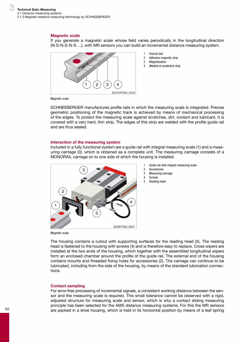
62
3
Magnetic scaleIf you generate amagnetic scale whose field varies periodically in the longitudinal direction (N-S-N-S-N-S….),withMRsensorsyoucanbuildanincrementaldistancemeasuringsystem.
1 Ground slot 2 Adhesive magnetic strip 3 Magnetization 4 Welded on protective strip
Magnetic scale
SCHNEEBERGERmanufacturesprofilerailsinwhichthemeasuringscaleisintegrated.Precisegeometric positioningof themagnetic track is achievedbymeansofmechanical processingoftheedges.Toprotectthemeasuringscaleagainstscratches,dirt,coolantandlubricant,itiscoveredwithaveryhard,thinstrip.Theedgesofthisstripareweldedwiththeprofileguiderailandarethussealed.
Interaction of the measuring systemIncludedinafullyfunctionalsystemareaguiderailwithintegralmeasuringscale(1)andameas-uringcarriage(3),which isobtainedasacompleteunit.ThemeasuringcarriageconsistsofaMONORAILcarriageontoonesideofwhichthehousingisinstalled.
1 Guide rail with integral measuring scale 2 Accessories 3 Measuring carriage 4 Screws 5 Reading head
Magnetic scale
Thehousingcontainsacutoutwithsupportingsurfaces for the readinghead (5).The readingheadisfastenedtothehousingwithscrews(4)andisthereforeeasytoreplace.Crosswipersareinstalledatthetwoendsofthehousing,whichtogetherwiththeassembledlongitudinalwipersformanenclosedchamberaroundtheprofileoftheguiderail.Theexternalendofthehousingcontainsmountsandthreadedfixingholesforaccessories(2).Thecarriagecancontinuetobelubricated,includingfromthesideofthehousing,bymeansofthestandardlubricationconnec-tions.
Contact samplingForerror-freeprocessingofincrementalsignals,aconsistentworkingdistancebetweenthesen-sorandthemeasuringscaleisrequired.Thissmalltolerancecannotbeobservedwitharigid,adjustedstructure formeasuringscaleandsensor,which iswhyacontact slidingmeasuringprinciplehasbeenselectedfortheAMSdistancemeasuringsystems.ForthistheMRsensorsarepackedinashoehousing,whichisheldinitshorizontalpositionbymeansofaleafspring
Technical Data: Measuring3.1Distancemeasuringsystems3.1.3Magneto-resistivemeasuringtechnologybySCHNEEBERGER
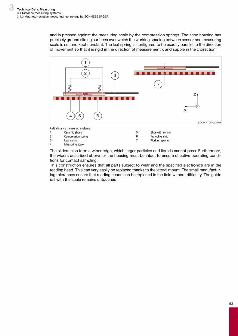
63
3
andispressedagainstthemeasuringscalebythecompressionsprings.Theshoehousinghaspreciselygroundslidingsurfacesoverwhichtheworkingspacingbetweensensorandmeasuringscaleissetandkeptconstant.Theleafspringisconfiguredtobeexactlyparalleltothedirectionofmovementsothatitisrigidinthedirectionofmeasurementxandsuppleinthezdirection.
AMS distance measuring systems:1 Ceramic shoes2 Compression spring3 Leaf spring4 Measuring scale
5 Shoe with sensor6 Protective strip7 Working spacing
Theslidersalsoformawiperedge,whichlargerparticlesandliquidscannotpass.Furthermore,thewipersdescribedaboveforthehousingmustbeintacttoensureeffectiveoperatingcondi-tionsforcontactsampling.Thisconstructionensuresthatallpartssubjecttowearandthespecifiedelectronicsareinthereadinghead.Thiscanveryeasilybereplacedthankstothelateralmount.Thesmallmanufactur-ingtolerancesensurethatreadingheadscanbereplacedinthefieldwithoutdifficulty.Theguiderailwiththescaleremainsuntouched.
Technical Data: Measuring3.1Distancemeasuringsystems3.1.3Magneto-resistivemeasuringtechnologybySCHNEEBERGER

64
3
InterpolationForapplicationsindistancemeasuring, interpolationmeansthesignalconversionofanalogueinputsignalsintodigitaloutputsignalswithasmallersignalperiod.Thisisnecessaryascounterreadingsand/orpositionreadingscannotbegenerateddirectlyfromanaloguesignals.
Theanalogueinputsignals(sin,cos,Ref)areinterpolated(redarrow)withthedigitaloutputsignals(+A,+B,+Z).Invertedsignalsarenotrepre-sented:
1 Analogue input signal: sin, cos, REF2 Digital output signal: +A, +B, +Z3 Downstream electronics4 Interpolation5 Signal transmission6 Analogue input signal (cos)
7 Analogue input signal (sin)8 Analogue input signal (REF)9 Digital output signal (+A)10 Digital output signal (+B)11 Digital output signal (+Z)12 Measuringcounter,PC,controllerformachineetc.
Forthistheinterpolationfactordefinestheratioofsignalperiodsfromtheanalogueinputsignaltothedigitaloutputsignal.
3.1.4. Distance measuring system
Technical Data: Measuring3.1Distancemeasuringsystems3.1.4Distancemeasuringsystem
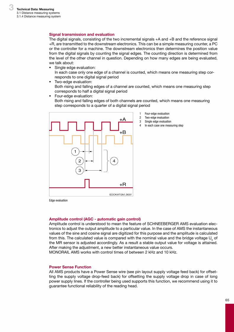
65
3
Signal transmission and evaluationThedigitalsignals,consistingofthetwoincrementalsignals+Aand+Bandthereferencesignal+R,aretransmittedtothedownstreamelectronics.Thiscanbeasimplemeasuringcounter,aPCorthecontrollerforamachine.Thedownstreamelectronicsthendeterminesthepositionvaluefromthedigitalsignalsbycountingthesignaledges.Thecountingdirectionisdeterminedfromtheleveloftheotherchannelinquestion.Dependingonhowmanyedgesarebeingevaluated,wetalkabout: � Singleedgeevaluation: Ineachcaseonlyoneedgeofachanneliscounted,whichmeansonemeasuringstepcor-respondstoonedigitalsignalperiod
� Two-edgeevaluation: Bothrisingandfallingedgesofachannelarecounted,whichmeansonemeasuringstepcorrespondstohalfadigitalsignalperiod
� Four-edgeevaluation: Bothrisingandfallingedgesofbothchannelsarecounted,whichmeansonemeasuringstepcorrespondstoaquarterofadigitalsignalperiod
1 Four-edge evaluation 2 Two-edge evaluation 3 Single edge evaluation 4 In each case one measuring step
Edge evaluation
Amplitude control (AGC - automatic gain control)AmplitudecontrolisunderstoodtomeanthefeatureofSCHNEEBERGERAMSevaluationelec-tronicstoadjusttheoutputamplitudetoaparticularvalue.InthecaseofAMStheinstantaneousvaluesofthesineandcosinesignalaredigitizedforthispurposeandtheamplitudeiscalculatedfromthis.ThecalculatedvalueiscomparedwiththenominalvalueandthebridgevoltageUboftheMRsensorisadjustedaccordingly.Asaresultastableoutputvalueforvoltageisattained.Aftermakingtheadjustment,anewbetterinstantaneousvalueoccurs.MONORAILAMSworkswithcontroltimesofbetween2kHzand10kHz.
Power Sense FunctionAllAMSproductshaveaPowerSensewire(seepinlayoutsupplyvoltagefeedback)foroffset-ting thesupplyvoltagedrop-feedback) foroffsetting thesupplyvoltagedrop incaseof longpowersupplylines.Ifthecontrollerbeingusedsupportsthisfunction,werecommendusingittoguaranteefunctionalreliabilityofthereadinghead.
Technical Data: Measuring3.1Distancemeasuringsystems3.1.4Distancemeasuringsystem
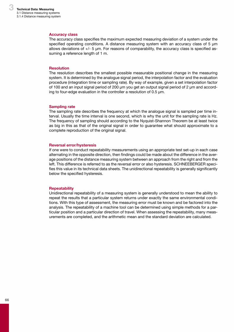
66
3 Technical Data: Measuring3.1Distancemeasuringsystems3.1.4Distancemeasuringsystem
Accuracy classTheaccuracyclassspecifiesthemaximumexpectedmeasuringdeviationofasystemunderthespecifiedoperatingconditions.Adistancemeasuringsystemwithanaccuracyclassof5µmallowsdeviationsof+/-5µm.Forreasonsofcomparability,theaccuracyclassisspecifiedas-sumingareferencelengthof1m.
ResolutionTheresolutiondescribesthesmallestpossiblemeasurablepositionalchangeinthemeasuringsystem.Itisdeterminedbytheanaloguesignalperiod,theinterpolationfactorandtheevaluationprocedure(integrationtimeorsamplingrate).Bywayofexample,givenasetinterpolationfactorof100andaninputsignalperiodof200µmyougetanoutputsignalperiodof2µmandaccord-ingtofour-edgeevaluationinthecontrolleraresolutionof0.5µm.
Sampling rateThesamplingratedescribesthefrequencyatwhichtheanaloguesignalissampledpertimein-terval.Usuallythetimeintervalisonesecond,whichiswhytheunitforthesamplingrateisHz.ThefrequencyofsamplingshouldaccordingtotheNyquist-ShannonTheorembeatleasttwiceasbiginthisasthatoftheoriginalsignalinordertoguaranteewhatshouldapproximatetoacompletereproductionoftheoriginalsignal.
Reversal error/hysteresisIfoneweretoconductrepeatabilitymeasurementsusinganappropriatetestset-upineachcasealternatingintheoppositedirection,thenfindingscouldbemadeaboutthedifferenceintheaver-agepositionsofthedistancemeasuringsystembetweenanapproachfromtherightandfromtheleft.Thisdifferenceisreferredtoasthereversalerrororalsohysteresis.SCHNEEBERGERspeci-fiesthisvalueinitstechnicaldatasheets.Theunidirectionalrepeatabilityisgenerallysignificantlybelowthespecifiedhysteresis.
RepeatabilityUnidirectionalrepeatabilityofameasuringsystemisgenerallyunderstoodtomeantheabilitytorepeattheresultsthataparticularsystemreturnsunderexactlythesameenvironmentalcondi-tions.Withthistypeofassessment,themeasuringerrormustbeknownandbefactoredintotheanalysis.Therepeatabilityofamachinetoolcanbedeterminedusingsimplemethodsforapar-ticularpositionandaparticulardirectionoftravel.Whenassessingtherepeatability,manymeas-urementsarecompleted,andthearithmeticmeanandthestandarddeviationarecalculated.
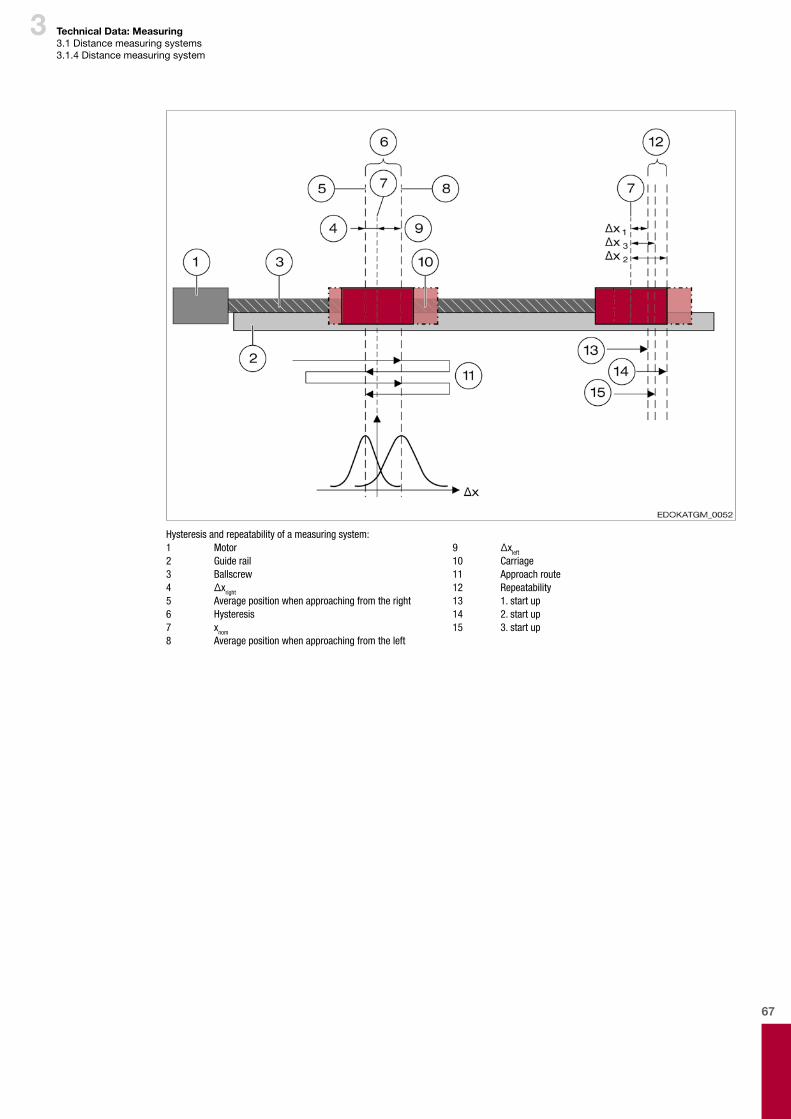
67
3
Hysteresis and repeatability of a measuring system:1 Motor2 Guide rail3 Ballscrew4 Δxright
5 Average position when approaching from the right6 Hysteresis7 xnom
8 Average position when approaching from the left
9 Δxleft
10 Carriage11 Approach route12 Repeatability13 1.startup14 2.startup15 3.startup
Technical Data: Measuring3.1Distancemeasuringsystems3.1.4Distancemeasuringsystem
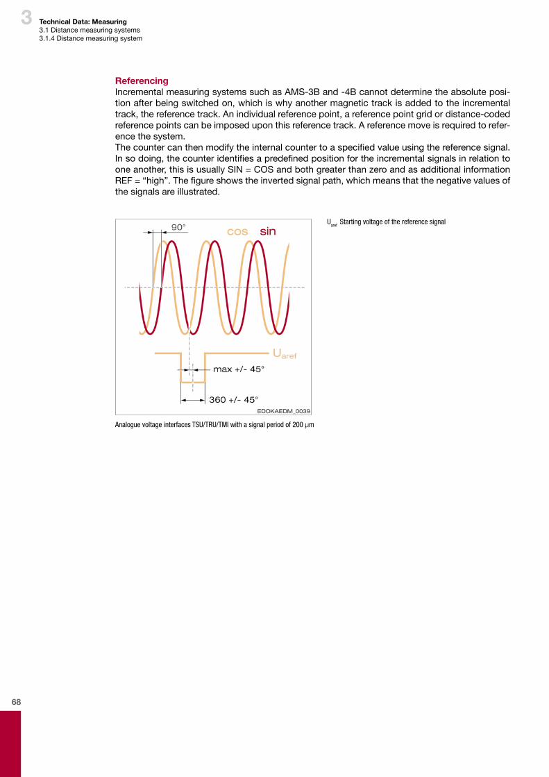
68
3 Technical Data: Measuring3.1Distancemeasuringsystems3.1.4Distancemeasuringsystem
ReferencingIncrementalmeasuringsystemssuchasAMS-3Band-4Bcannotdeterminetheabsoluteposi-tionafterbeingswitchedon,whichiswhyanothermagnetictrackisaddedtotheincrementaltrack,thereferencetrack.Anindividualreferencepoint,areferencepointgridordistance-codedreferencepointscanbeimposeduponthisreferencetrack.Areferencemoveisrequiredtorefer-encethesystem.Thecountercanthenmodifytheinternalcountertoaspecifiedvalueusingthereferencesignal.Insodoing,thecounteridentifiesapredefinedpositionfortheincrementalsignalsinrelationtooneanother,thisisusuallySIN=COSandbothgreaterthanzeroandasadditionalinformationREF=“high”.Thefigureshowstheinvertedsignalpath,whichmeansthatthenegativevaluesofthesignalsareillustrated.
Uaref Starting voltage of the reference signal
Analogue voltage interfaces TSU/TRU/TMI with a signal period of 200 µm
69
3
Individual reference pointAnindividualreferencepointrepresentsthesimplestfeatureofareferencetrack,itcanbeim-posedatanypointalongthescale.WithSCHNEEBERGERareferencepointconsistsofthreemagneticreferencemarks,whicharesampledwithoneindividualMRbridgewithoutaveraging.Onepieceofreferencedatarepresentstherisingedge,anotheronethefallingedgeoftherefer-encepulse.Thethirdpieceofreferencedataisredundantandisusedtoincreasetheoperationalreliabilityofthereferencepointidentificationsystem.
1 Rout= Reference track 2 Threshold
RI1 Reference information 1 RI2 Reference information 2 RI3 Reference information 3
Referencepointidentificationsystem
Reference point gridInthecaseofareferencepointgrid,multiplereferencepointsareimposedatequaldistancesalongthescale.Thecustomerselectsfromthesereferencepointsone,whichitwillbeusingforreferencingtheaxis.Theadvantagesofagridcomparedtoanindividualreferencepointarefirstlyashortenedrefer-ence journey, thanks to targeted application of external additional elements (cams, proximityswitches,amongstotherthings),butalsotheabilitytobeabletooperatemultiplemeasuringcar-riagesononerail.Forthis,variousreferencepointsalongthescaleareallocatedtothedifferentmeasuringcarriagesforthereferencinginquestion.
Technical Data: Measuring3.1Distancemeasuringsystems3.1.4Distancemeasuringsystem
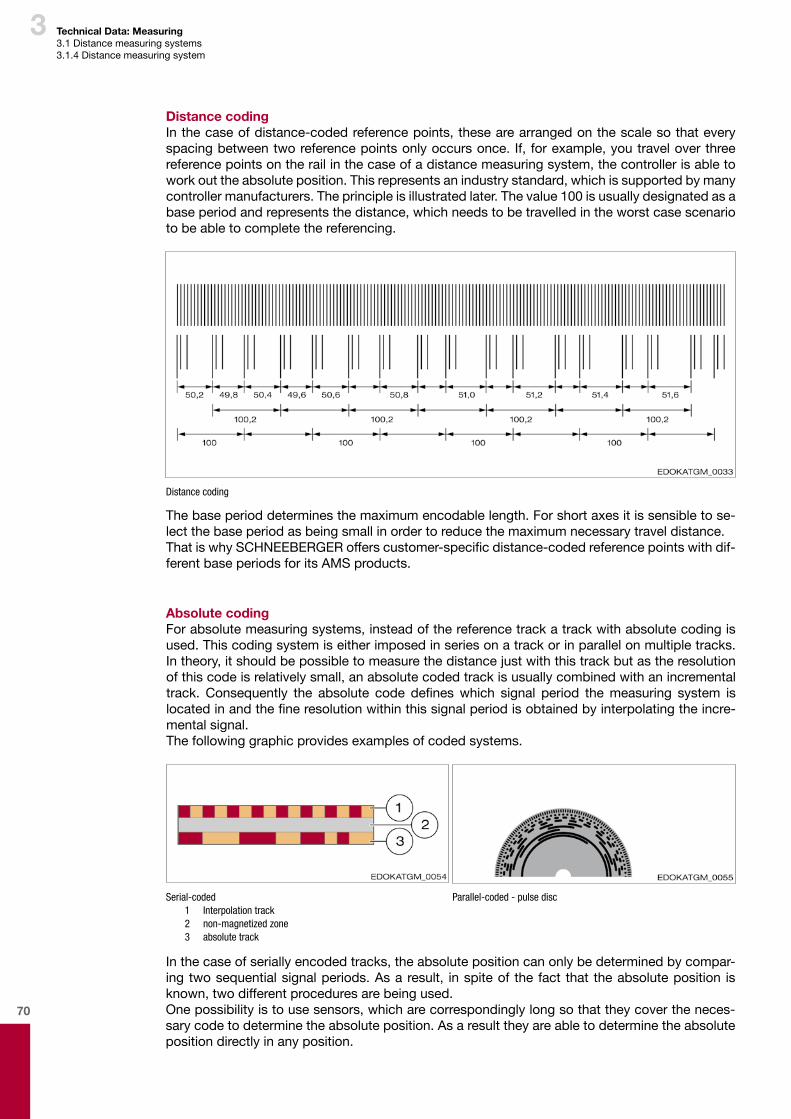
70
3 Technical Data: Measuring3.1Distancemeasuringsystems3.1.4Distancemeasuringsystem
Distance codingInthecaseofdistance-codedreferencepoints,thesearearrangedonthescalesothateveryspacingbetweentworeferencepointsonlyoccursonce.If, forexample,youtraveloverthreereferencepointsontherailinthecaseofadistancemeasuringsystem,thecontrollerisabletoworkouttheabsoluteposition.Thisrepresentsanindustrystandard,whichissupportedbymanycontrollermanufacturers.Theprincipleisillustratedlater.Thevalue100isusuallydesignatedasabaseperiodandrepresentsthedistance,whichneedstobetravelledintheworstcasescenariotobeabletocompletethereferencing.
Distance coding
Thebaseperioddeterminesthemaximumencodablelength.Forshortaxesitissensibletose-lectthebaseperiodasbeingsmallinordertoreducethemaximumnecessarytraveldistance.ThatiswhySCHNEEBERGERofferscustomer-specificdistance-codedreferencepointswithdif-ferentbaseperiodsforitsAMSproducts.
Absolute codingForabsolutemeasuringsystems,insteadofthereferencetrackatrackwithabsolutecodingisused.Thiscodingsystemiseitherimposedinseriesonatrackorinparallelonmultipletracks.Intheory,itshouldbepossibletomeasurethedistancejustwiththistrackbutastheresolutionofthiscodeisrelativelysmall,anabsolutecodedtrackisusuallycombinedwithanincrementaltrack. Consequently the absolute code defineswhich signal period themeasuring system islocatedinandthefineresolutionwithinthissignalperiodisobtainedbyinterpolatingtheincre-mentalsignal.Thefollowinggraphicprovidesexamplesofcodedsystems.
Serial-coded 1 Interpolation track 2 non-magnetized zone 3 absolute track
Parallel-coded - pulse disc
Inthecaseofseriallyencodedtracks,theabsolutepositioncanonlybedeterminedbycompar-ingtwosequentialsignalperiods.Asaresult, inspiteof thefact that theabsoluteposition isknown,twodifferentproceduresarebeingused.Onepossibilityistousesensors,whicharecorrespondinglylongsothattheycovertheneces-sarycodetodeterminetheabsoluteposition.Asaresulttheyareabletodeterminetheabsolutepositiondirectlyinanyposition.
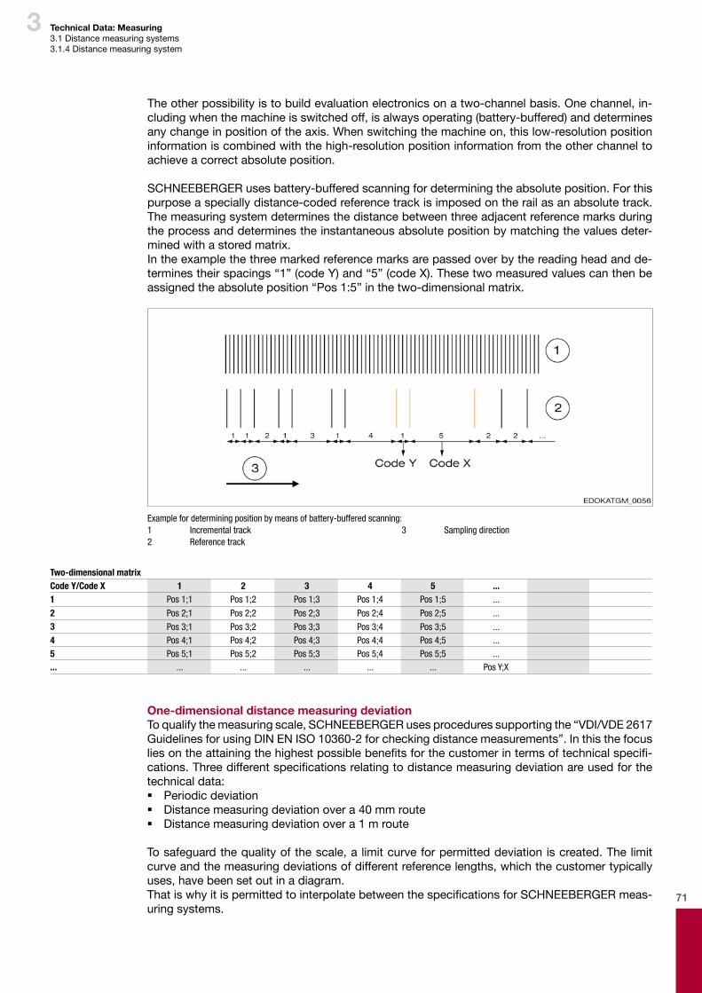
71
3 Technical Data: Measuring3.1Distancemeasuringsystems3.1.4Distancemeasuringsystem
One-dimensional distance measuring deviationToqualifythemeasuringscale,SCHNEEBERGERusesproceduressupportingthe“VDI/VDE 2617GuidelinesforusingDINENISO10360-2forcheckingdistancemeasurements”.Inthisthefocusliesontheattainingthehighestpossiblebenefitsforthecustomerintermsoftechnicalspecifi-cations.Threedifferentspecificationsrelatingtodistancemeasuringdeviationareusedforthetechnicaldata: � Periodicdeviation � Distancemeasuringdeviationovera40mmroute � Distancemeasuringdeviationovera1mroute
Tosafeguardthequalityofthescale,alimitcurveforpermitteddeviationiscreated.Thelimitcurveandthemeasuringdeviationsofdifferentreferencelengths,whichthecustomertypicallyuses,havebeensetoutinadiagram.ThatiswhyitispermittedtointerpolatebetweenthespecificationsforSCHNEEBERGERmeas-uringsystems.
Two-dimensional matrixCode Y/Code X 1 2 3 4 5 ... 1 Pos 1;1 Pos 1;2 Pos 1;3 Pos 1;4 Pos 1;5 ...
2 Pos 2;1 Pos 2;2 Pos 2;3 Pos 2;4 Pos 2;5 ...3 Pos 3;1 Pos 3;2 Pos 3;3 Pos 3;4 Pos 3;5 ...4 Pos 4;1 Pos 4;2 Pos 4;3 Pos 4;4 Pos 4;5 ...5 Pos 5;1 Pos 5;2 Pos 5;3 Pos 5;4 Pos 5;5 ...... ... ... ... ... ... Pos Y;X
Theotherpossibilityistobuildevaluationelectronicsonatwo-channelbasis.Onechannel,in-cludingwhenthemachineisswitchedoff,isalwaysoperating(battery-buffered)anddeterminesanychangeinpositionoftheaxis.Whenswitchingthemachineon,thislow-resolutionpositioninformationiscombinedwiththehigh-resolutionpositioninformationfromtheotherchanneltoachieveacorrectabsoluteposition.
SCHNEEBERGERusesbattery-bufferedscanningfordeterminingtheabsoluteposition.Forthispurposeaspeciallydistance-codedreferencetrackisimposedontherailasanabsolutetrack.Themeasuringsystemdeterminesthedistancebetweenthreeadjacentreferencemarksduringtheprocessanddeterminestheinstantaneousabsolutepositionbymatchingthevaluesdeter-minedwithastoredmatrix.Intheexamplethethreemarkedreferencemarksarepassedoverbythereadingheadandde-terminestheirspacings“1”(codeY)and“5”(codeX).Thesetwomeasuredvaluescanthenbeassignedtheabsoluteposition“Pos1:5”inthetwo-dimensionalmatrix.
Example for determining position by means of battery-buffered scanning:1 Incremental track2 Reference track
3 Sampling direction
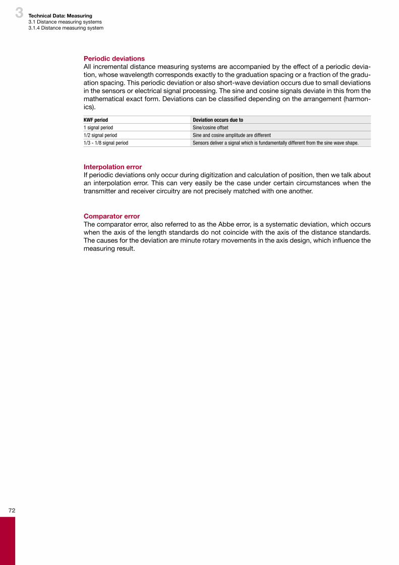
72
3 Technical Data: Measuring3.1Distancemeasuringsystems3.1.4Distancemeasuringsystem
Periodic deviationsAllincrementaldistancemeasuringsystemsareaccompaniedbytheeffectofaperiodicdevia-tion,whosewavelengthcorrespondsexactlytothegraduationspacingorafractionofthegradu-ationspacing.Thisperiodicdeviationoralsoshort-wavedeviationoccursduetosmalldeviationsinthesensorsorelectricalsignalprocessing.Thesineandcosinesignalsdeviateinthisfromthemathematicalexactform.Deviationscanbeclassifieddependingonthearrangement(harmon-ics).
KWF period Deviation occurs due to 1 signal period Sine/cosine offset1/2 signal period Sine and cosine amplitude are different1/3 - 1/8 signal period Sensorsdeliverasignalwhichisfundamentallydifferentfromthesinewaveshape.
Interpolation errorIfperiodicdeviationsonlyoccurduringdigitizationandcalculationofposition,thenwetalkaboutan interpolationerror.Thiscanveryeasilybe thecaseundercertaincircumstanceswhenthetransmitterandreceivercircuitryarenotpreciselymatchedwithoneanother.
Comparator errorThecomparatorerror,alsoreferredtoastheAbbeerror,isasystematicdeviation,whichoccurswhentheaxisofthelengthstandardsdonotcoincidewiththeaxisofthedistancestandards.Thecausesforthedeviationareminuterotarymovementsintheaxisdesign,whichinfluencethemeasuringresult.
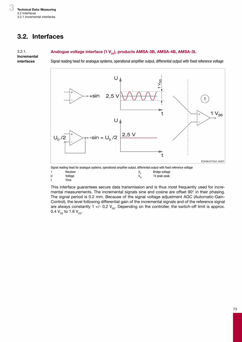
73
3 Technical Data: Measuring3.2Interfaces3.2.1Incrementalinterfaces
3.2. Interfaces
Analogue voltage interface (1 VSS), products AMSA-3B, AMSA-4B, AMSA-3L
Signalreadingheadforanaloguesystems,operationalamplifieroutput,differentialoutputwithfixedreferencevoltage
Signalreadingheadforanaloguesystems,operationalamplifieroutput,differentialoutputwithfixedreferencevoltage1 ReceiverU Voltaget Time
Ub Bridge voltageVSS 1V peak-peak
Thisinterfaceguaranteessecuredatatransmissionandisthusmostfrequentlyusedforincre-mentalmeasurements.Theincrementalsignalssineandcosineareoffset90°intheirphasing.Thesignalperiodis0.2mm.BecauseofthesignalvoltageadjustmentAGC(Automatic-Gain-Control),thelevelfollowingdifferentialgainoftheincrementalsignalsandofthereferencesignalarealwaysconstantly1+/-0,2VSS.Dependingonthecontroller,theswitch-offlimitisapprox.0.4VSSto1.6VSS.
3.2.1. Incremental interfaces
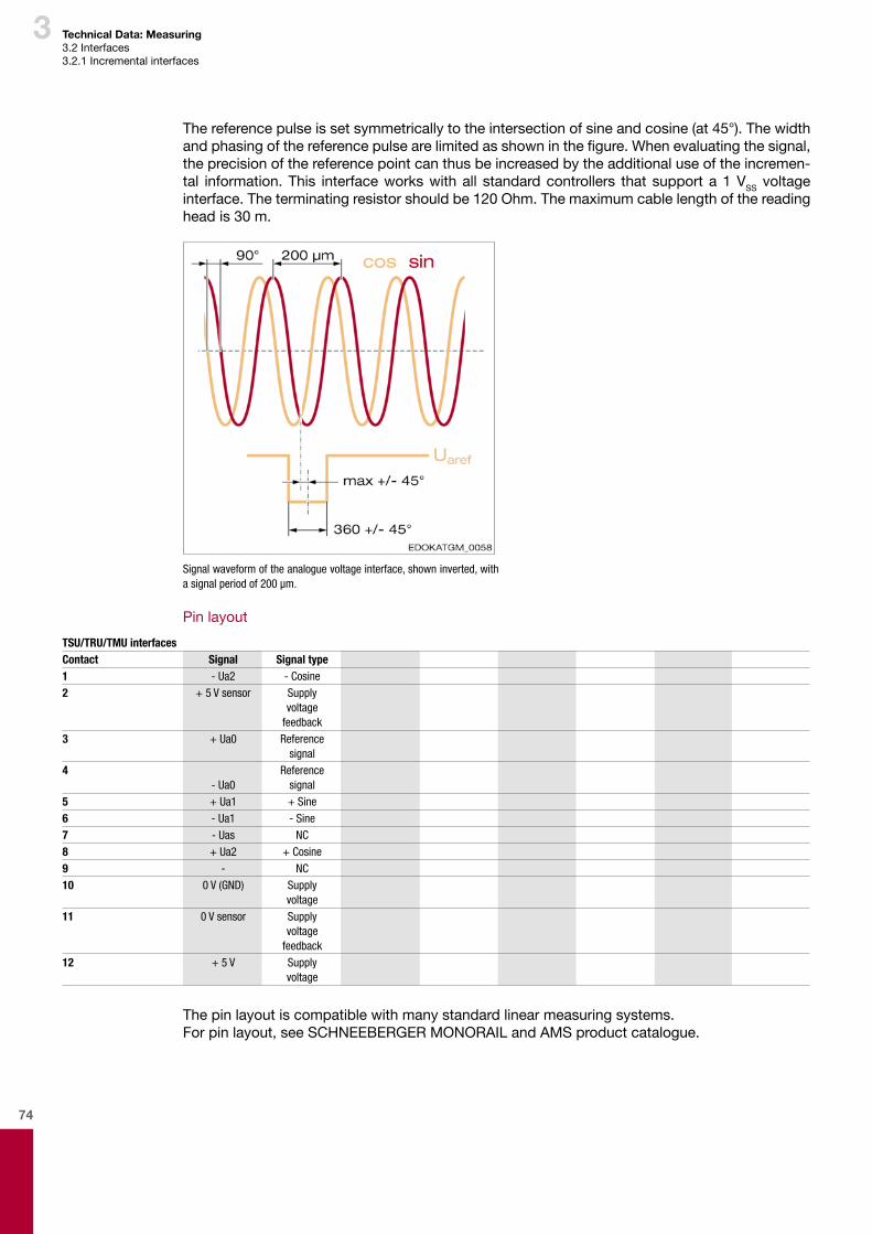
74
3 Technical Data: Measuring3.2Interfaces3.2.1Incrementalinterfaces
Thereferencepulseissetsymmetricallytotheintersectionofsineandcosine(at45°).Thewidthandphasingofthereferencepulsearelimitedasshowninthefigure.Whenevaluatingthesignal,theprecisionofthereferencepointcanthusbeincreasedbytheadditionaluseoftheincremen-tal information.This interfaceworkswithall standardcontrollers thatsupporta1VSS voltageinterface.Theterminatingresistorshouldbe120Ohm.Themaximumcablelengthofthereadingheadis30m.
Signal waveform of the analogue voltage interface, shown inverted, with asignalperiodof200μm.
Pinlayout
TSU/TRU/TMU interfacesContact Signal Signal type1 - Ua2 - Cosine2 + 5 V sensor Supply
voltage feedback
3 + Ua0 Reference signal
4- Ua0
Reference signal
5 + Ua1 + Sine6 - Ua1 - Sine7 - Uas NC8 + Ua2 + Cosine9 - NC10 0 V (GND) Supply
voltage11 0 V sensor Supply
voltage feedback
12 + 5 V Supplyvoltage
Thepinlayoutiscompatiblewithmanystandardlinearmeasuringsystems.Forpinlayout,seeSCHNEEBERGERMONORAILandAMSproductcatalogue.
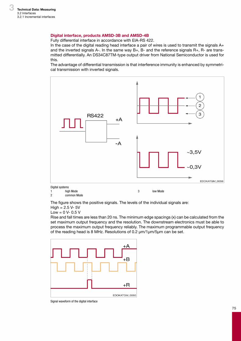
75
3 Technical Data: Measuring3.2Interfaces3.2.1Incrementalinterfaces
Digital interface, products AMSD-3B and AMSD-4BFullydifferentialinterfaceinaccordancewithEIA-RS422.InthecaseofthedigitalreadingheadinterfaceapairofwiresisusedtotransmitthesignalsA+andtheinvertedsignalsA-.InthesamewayB+,B-andthereferencesignalsR+,R-aretrans-mitteddifferentially.AnDS34C87TM-typeoutputdriverfromNationalSemiconductorisusedforthis.Theadvantageofdifferentialtransmissionisthatinterferenceimmunityisenhancedbysymmetri-caltransmissionwithinvertedsignals.
Digital systems1 high Mode2 common Mode
3 low Mode
Thefigureshowsthepositivesignals.Thelevelsoftheindividualsignalsare:High=2.5V-5VLow=0V-0.5VRiseandfalltimesarelessthan20ns.Theminimumedgespacings(x)canbecalculatedfromthesetmaximumoutputfrequencyandtheresolution.Thedownstreamelectronicsmustbeabletoprocessthemaximumoutputfrequencyreliably.Themaximumprogrammableoutputfrequencyofthereadingheadis8MHz.Resolutionsof0.2µm/1µm/5µmcanbeset.
Signal waveform of the digital interface
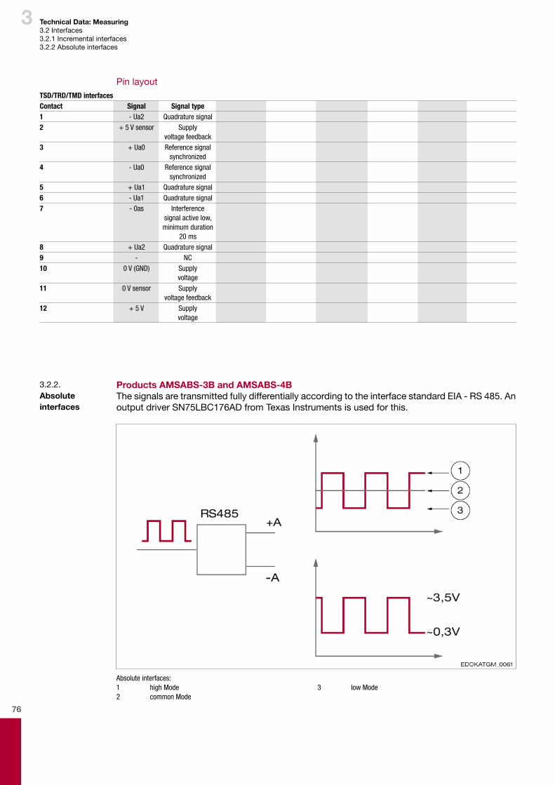
76
3 Technical Data: Measuring3.2Interfaces3.2.1Incrementalinterfaces3.2.2Absoluteinterfaces
TSD/TRD/TMD interfacesContact Signal Signal type1 - Ua2 Quadrature signal2 + 5 V sensor Supply
voltage feedback3 + Ua0 Reference signal
synchronized4 - Ua0 Reference signal
synchronized5 + Ua1 Quadrature signal6 - Ua1 Quadrature signal7 - 0as Interference
signal active low, minimum duration
20 ms8 + Ua2 Quadrature signal9 - NC10 0 V (GND) Supply
voltage11 0 V sensor Supply
voltage feedback12 + 5 V Supply
voltage
3.2.2. Absolute interfaces
Products AMSABS-3B and AMSABS-4BThesignalsaretransmittedfullydifferentiallyaccordingtotheinterfacestandardEIA-RS485.AnoutputdriverSN75LBC176ADfromTexasInstrumentsisusedforthis.
Absolute interfaces:1 high Mode2 common Mode
3 low Mode
Pinlayout
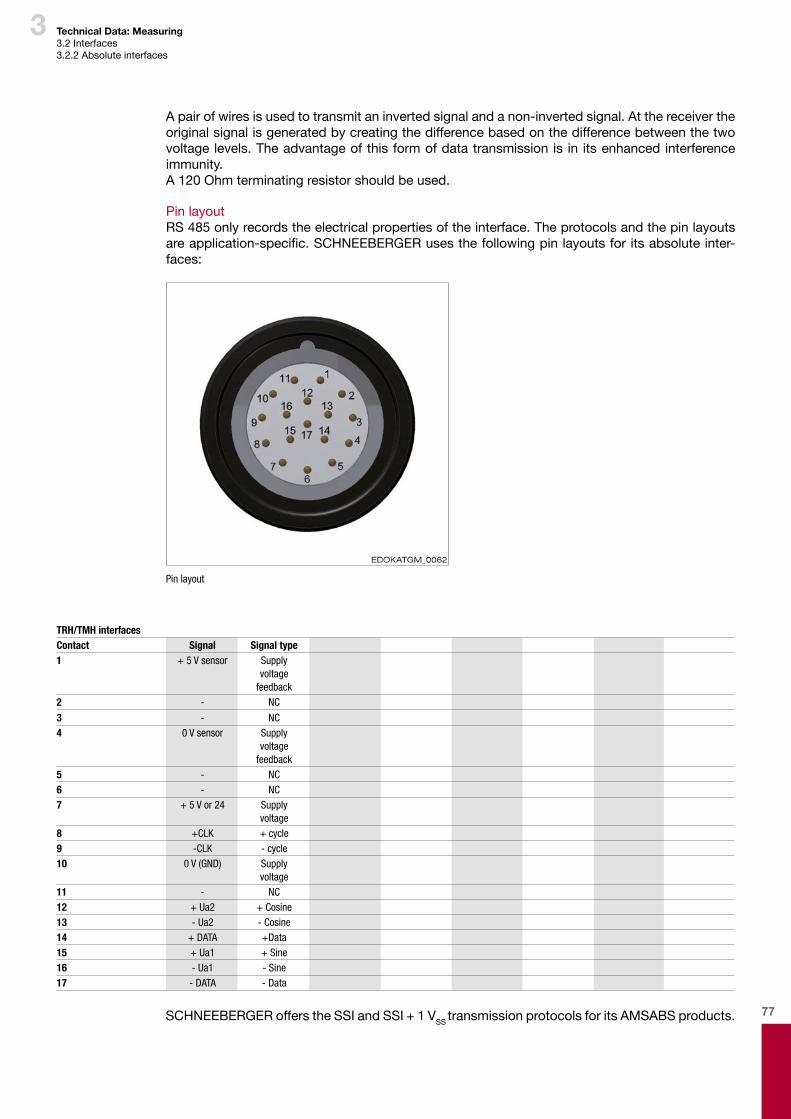
77
3 Technical Data: Measuring3.2Interfaces3.2.2Absoluteinterfaces
Apairofwiresisusedtotransmitaninvertedsignalandanon-invertedsignal.Atthereceivertheoriginalsignalisgeneratedbycreatingthedifferencebasedonthedifferencebetweenthetwovoltagelevels.Theadvantageofthisformofdatatransmissionis in itsenhancedinterferenceimmunity.A120Ohmterminatingresistorshouldbeused.
PinlayoutRS485onlyrecordstheelectricalpropertiesoftheinterface.Theprotocolsandthepinlayoutsareapplication-specific.SCHNEEBERGERusesthefollowingpinlayoutsforitsabsoluteinter-faces:
Pin layout
TRH/TMH interfacesContact Signal Signal type1 + 5 V sensor Supply
voltage feedback
2 - NC
3 - NC4 0 V sensor Supply
voltage feedback
5 - NC6 - NC7 + 5 V or 24 Supply
voltage8 +CLK + cycle9 -CLK - cycle10 0 V (GND) Supply
voltage11 - NC12 + Ua2 + Cosine13 - Ua2 - Cosine14 + DATA +Data15 + Ua1 + Sine16 - Ua1 - Sine17 - DATA - Data
SCHNEEBERGERofferstheSSIandSSI+1VSS transmissionprotocolsforitsAMSABSproducts.
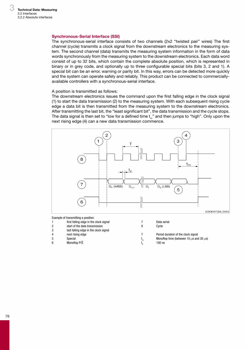
78
3 Technical Data: Measuring3.2Interfaces3.2.2Absoluteinterfaces
Synchronous-Serial Interface (SSI)Thesynchronous-serial interfaceconsistsof twochannels (2x2 “twistedpair”wires) Thefirstchannel(cycle)transmitsaclocksignalfromthedownstreamelectronicstothemeasuringsys-tem.Thesecondchannel(data)transmitsthemeasuringsysteminformationintheformofdatawordssynchronouslyfromthemeasuringsystemtothedownstreamelectronics.Eachdatawordconsistofupto32bits,whichcontainthecompleteabsoluteposition,whichisrepresentedinbinaryor ingreycode,andoptionallyuptothreeconfigurablespecialbits(bits3,2and1).Aspecialbitcanbeanerror,warningorparitybit.Inthisway,errorscanbedetectedmorequicklyandthesystemcanoperatesafelyandreliably.Thisproductcanbeconnectedtocommercially-availablecontrollerswithasynchronous-serialinterface.
Apositionistransmittedasfollows:Thedownstreamelectronicsissuesthecommanduponthefirstfallingedgeintheclocksignal(1)tostartthedatatransmission(2)tothemeasuringsystem.Witheachsubsequentrisingcycleedgeadatabitisthentransmittedfromthemeasuringsystemtothedownstreamelectronics.Aftertransmittingthelastbit,the“leastsignificantbit”,thedatatransmissionandthecyclestops.Thedatasignalisthensetto“lowforadefinedtimetm”andthenjumpsto“high”.Onlyuponthenextrisingedge(4)cananewdatatransmissioncommence.
Example of transmitting a position:1 firstfallingedgeintheclocksignal2 start of the data transmission3 last falling edge in the clock signal4 next rising edge5 Special6 MonoflopP/S
7 Data serial8 Cycle
T Period duration of the clock signaltm Monofloptime(between10µs and 30 µs)tV 100 ns
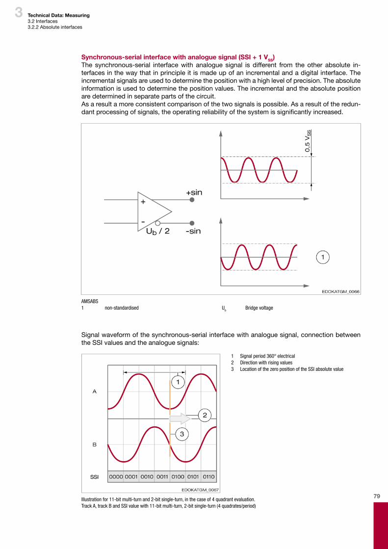
79
3 Technical Data: Measuring3.2Interfaces3.2.2Absoluteinterfaces
Synchronous-serial interface with analogue signal (SSI + 1 VSS)The synchronous-serial interfacewith analogue signal is different from the other absolute in-terfacesinthewaythatinprincipleitismadeupofanincrementalandadigitalinterface.Theincrementalsignalsareusedtodeterminethepositionwithahighlevelofprecision.Theabsoluteinformationisusedtodeterminethepositionvalues.Theincrementalandtheabsolutepositionaredeterminedinseparatepartsofthecircuit.Asaresultamoreconsistentcomparisonofthetwosignalsispossible.Asaresultoftheredun-dantprocessingofsignals,theoperatingreliabilityofthesystemissignificantlyincreased.
AMSABS1 non-standardised Ub Bridge voltage
Signalwaveformofthesynchronous-serialinterfacewithanaloguesignal,connectionbetweentheSSIvaluesandtheanaloguesignals:
1 Signal period 360° electrical 2 Direction with rising values 3 Location of the zero position of the SSI absolute value
Illustrationfor11-bitmulti-turnand2-bitsingle-turn,inthecaseof4quadrantevaluation.Track A, track B and SSI value with 11-bit multi-turn, 2-bit single-turn (4 quadrates/period)

80
3
Sineandcosineoccurinthesameperiod,thesingleturnvalueisthenalways0.Inthecontrollerthelasttwobitsarecutoff,andonlythemulti-turniscountedandthehigh-resolutionsingle-turncomponentisinserted.Parameterlistsforusewithspecificcontrollersareavailableonrequest.
Technical Data: Measuring3.2Interfaces3.2.2Absoluteinterfaces

81
4 Development and design: Guiding

82

83
4
Contents
4
4 Development and design: Guiding .....................................................81
4.1. Factors influencing the choice of product ........................................................................854.1.1. Choice of product .............................................................................................................854.1.2. Influencingfactors .............................................................................................................85
4.2. Ball to Roller comparison ....................................................................................................864.2.1. Characteristics ..................................................................................................................864.2.2. Fieldsofapplication ..........................................................................................................87
4.3. Guide rail types .....................................................................................................................884.3.1. Guiderailtypes-overview ...............................................................................................884.3.2. Characteristicsandselectioncriteria ................................................................................90
4.4. Carriage types .......................................................................................................................934.4.1. Carriagetypes-overview .................................................................................................934.4.2. Characteristicsandselectioncriteria ................................................................................95
4.5. Preload ...................................................................................................................................974.5.1. Definitionandpurpose ......................................................................................................974.5.2. Preloadclasses .................................................................................................................984.5.3. Areasofapplication ..........................................................................................................98
4.6. Accuracy ..............................................................................................................................1004.6.1. Accuracyclasses ............................................................................................................1004.6.2. Dimensionaltolerances ...................................................................................................1014.6.3. Runningaccuracy ...........................................................................................................105
4.7. Installation methods for guide systems ...........................................................................1064.7.1. Selectioncriteria .............................................................................................................1064.7.2. Installationvariants .........................................................................................................106
4.8. Calculation and sizing ........................................................................................................1094.8.1. Principles ........................................................................................................................1094.8.2. Calculatingservicelife ....................................................................................................1114.8.3. CalculatingthestaticreliabilityfactorS0 ........................................................................1144.8.4. CalculationprogramforthedimensioningMONORAIL ..................................................1144.8.5. Sampledatasheetforanx-/y-table ...............................................................................1164.8.6. Samplemachinedrawingforanx-/y-table .....................................................................117
4.9. Attaching the guide rail ......................................................................................................1194.9.1. Methodsofattachment ...................................................................................................1194.9.2. Railoptions .....................................................................................................................1194.9.3. Closuresforfixingholes ..................................................................................................1204.9.4. Tolerancesforguideraillengthandguiderailfixingholesfor N-,ND-,NU-,NUD-,C-undCD-typeguiderails ...........................................................1224.9.5. Permissiblescrewtighteningtorques .............................................................................1224.9.6. Permissiblelateralforcewithoutlocatingsurface ..........................................................1234.9.7. Permissibletensileforcesandtransversetorques .........................................................1244.9.8. Accuracy-influencingfactors ........................................................................................124
4.10. Multi-part guide rails ..........................................................................................................1254.10.1. Combinedguiderailsandbuttjoints ..............................................................................1254.10.2. Installationandmarkings ................................................................................................125
4.11. Fastening carriages ............................................................................................................1264.11.1. Methodsofattachment ...................................................................................................1264.11.2. Laterallocatingsurfaces .................................................................................................127

84
4
Contents
4
4.11.3. Permissiblelateralforcewithoutlocatingsurface ..........................................................1274.11.4. Influenceofthenumberfasteningscrewsonrigidity .....................................................1284.11.5. Permissiblescrewtighteningtorques .............................................................................1284.11.6. Minimumscrewdepth ....................................................................................................129
4.12. Configuration of the connecting structure .......................................................................1304.12.1. Laterallocatingsurfaces .................................................................................................1304.12.2. Methodsoforientationfortherail ...................................................................................1314.12.3. Laterallocatingsurfaces .................................................................................................1314.12.4. Installationmethods ........................................................................................................1324.12.5. Geometricalandpositionaccuracyofthesupportsurfaces ..........................................134
4.13. Lubrication ..........................................................................................................................1374.13.1. Lubricationinitsdeliveredcondition ..............................................................................1374.13.2. Initiallubricationandsubsequentlubrication .................................................................1374.13.3. Lifetimelubrication ..........................................................................................................1384.13.4. Precautionarymeasures .................................................................................................1384.13.5. Lubeconnections ...........................................................................................................1394.13.6. Lubricationwithgrease ...................................................................................................1424.13.7. Lubricationwithoil ..........................................................................................................1434.13.8. Applicationknow-howonlubrication-requirementsinrespect oflubricationinspecialoperatingconditions. ................................................................1444.13.9. LubricationplateSPL ......................................................................................................150
4.14. Seal ......................................................................................................................................1524.14.1. Standard-seals ..............................................................................................................1524.14.2. Additionalwipers.............................................................................................................1544.14.3. Bellows ............................................................................................................................1564.14.4. Applicationofsealingsystems .......................................................................................160
4.15. Corrosion protection ..........................................................................................................1614.15.1. Coatings ..........................................................................................................................1614.15.2. MONORAILBMinitsstainlesssteelmodel(WR,SR) ....................................................162
4.16. Additional functionality of clamps and brakes.................................................................1654.16.1. Clampingandbrakingcomponents-constructionandareasofuse.............................1654.16.2. Typesofclampingandbrakingcomponents ..................................................................1654.16.3. Overviewoftypes ...........................................................................................................166
4.17. SCHNEEBERGER Download and On-line CAD catalogue ..............................................1674.17.1. SCHNEEBERGERDownloads .........................................................................................1674.17.2. On-lineCADcatalogue ...................................................................................................167

85
4 Development and design: Guiding4.1Factorsinfluencingthechoiceofproduct4.1.1 Choice of product4.1.2Influencingfactors
4.1. Factors influencing the choice of product
ASCHNEEBERGERMONORAILguidewayshouldbeselectedinseveralstages.Thefollowingparametersshouldbedeterminedaspartofthisprocess. � Typeofguideway:roller-ball � Additionalfunctions:measuring,driving � Sizeandnumberofcarriagesorguiderails � Typeofguiderailsandcarriages � Accuracyclass � Preloadclass � Lubricationtypeandconnections � Guiderailandcarriageaccessories
• Protectiveelements(wipers,bellows)• Closuresfortheguiderail(plugs,coverstrip)• Lubricatingaccessories• Clamping/brakeelements
4.1.1. Choice of product
Selectinganappropriateguidewaydependsontherequirementsoftheapplication,theoperat-ingconditionsandonexternalinfluences.Thesefactorsmustbedeterminedatthestartoftheprocessofselectingaproduct.
Application � Typeofapplication � Additionalfunctions:measuring,driving,braking � Requiredaccuracyandrigidity � Typeofdrive � Installationorientationandinstallationspace � Lengthoftravel � Massesmoved
Operatingconditions � Forces � Speedandacceleration � Distancestravelled,shorttravel � Periodofuseandcycles � Coolants,swarf � Maintenance
Environmentalconditions � Dirt � Temperature � Humidity � Cleanroomorvacuum
4.1.2. Influencing factors
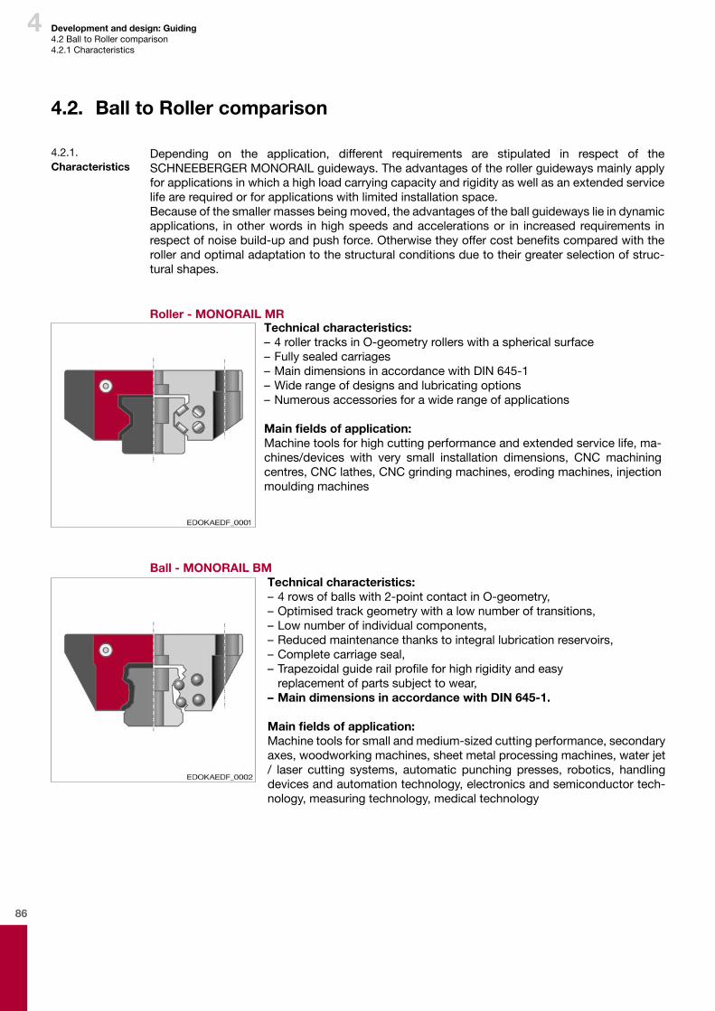
86
4 Development and design: Guiding4.2BalltoRollercomparison4.2.1Characteristics
4.2. Ball to Roller comparison
Depending on the application, different requirements are stipulated in respect of the SCHNEEBERGERMONORAILguideways.Theadvantagesoftherollerguidewaysmainlyapplyforapplicationsinwhichahighloadcarryingcapacityandrigidityaswellasanextendedservicelifearerequiredorforapplicationswithlimitedinstallationspace.Becauseofthesmallermassesbeingmoved,theadvantagesoftheballguidewayslieindynamicapplications, inotherwords inhighspeedsandaccelerationsor in increasedrequirements inrespectofnoisebuild-upandpushforce.Otherwisetheyoffercostbenefitscomparedwiththerollerandoptimaladaptationtothestructuralconditionsduetotheirgreaterselectionofstruc-turalshapes.
Roller - MONORAIL MR
4.2.1. Characteristics
Ball - MONORAIL BMTechnical characteristics:–4rowsofballswith2-pointcontactinO-geometry,–Optimisedtrackgeometrywithalownumberoftransitions,–Lownumberofindividualcomponents,–Reducedmaintenancethankstointegrallubricationreservoirs,–Completecarriageseal,–Trapezoidalguiderailprofileforhighrigidityandeasy replacementofpartssubjecttowear,– Main dimensions in accordance with DIN 645-1.
Main fields of application:Machinetoolsforsmallandmedium-sizedcuttingperformance,secondaryaxes,woodworkingmachines,sheetmetalprocessingmachines,waterjet/ laser cutting systems, automatic punching presses, robotics, handlingdevicesandautomationtechnology,electronicsandsemiconductortech-nology,measuringtechnology,medicaltechnology
Technical characteristics:–4rollertracksinO-geometryrollerswithasphericalsurface–Fullysealedcarriages–MaindimensionsinaccordancewithDIN645-1–Widerangeofdesignsandlubricatingoptions–Numerousaccessoriesforawiderangeofapplications
Main fields of application:Machinetoolsforhighcuttingperformanceandextendedservicelife,ma-chines/devices with very small installation dimensions, CNC machiningcentres,CNClathes,CNCgrindingmachines,erodingmachines,injectionmouldingmachines
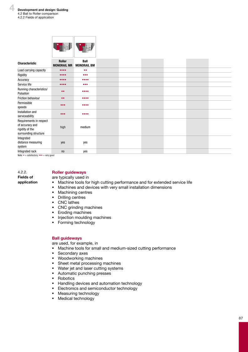
87
4 Development and design: Guiding4.2BalltoRollercomparison4.2.2Fieldsofapplication
Roller guidewaysaretypicallyusedin � Machinetoolsforhighcuttingperformanceandforextendedservicelife � Machinesanddeviceswithverysmallinstallationdimensions � Machiningcentres � Drillingcentres � CNClathes � CNCgrindingmachines � Erodingmachines � Injectionmouldingmachines � Formingtechnology
Ball guidewaysareused,forexample,in � Machinetoolsforsmallandmedium-sizedcuttingperformance � Secondaryaxes � Woodworkingmachines � Sheetmetalprocessingmachines � Waterjetandlasercuttingsystems � Automaticpunchingpresses � Robotics � Handlingdevicesandautomationtechnology � Electronicsandsemiconductortechnology � Measuringtechnology � Medicaltechnology
4.2.2. Fields of application
CharacteristicRoller
MONORAIL MRBall
MONORAIL BMLoad carrying capacity •••• ••Rigidity •••• •••Accuracy •••• ••••Service life •••• ••• Running characteristics/ Pulsation
•• ••••
Friction behaviour •• ••••Permissible speeds
••• ••••
Installation and serviceability
••• ••••
Requirements in respect of accuracy and rigidity of the surrounding structure
high medium
Integrated distance measuring system
yes yes
Integrated rack no yesNote: • = satisfactory, ••• = very good
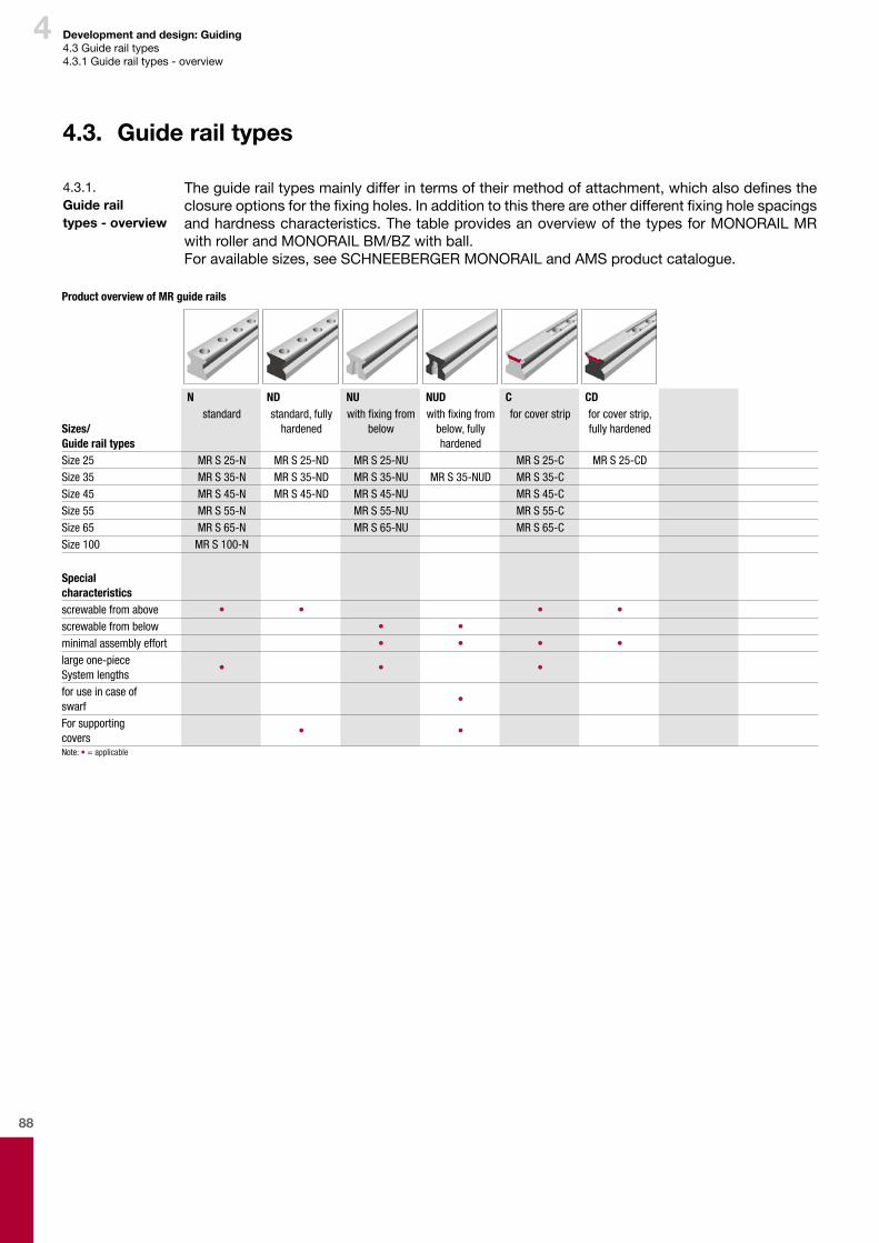
88
4 Development and design: Guiding4.3Guiderailtypes4.3.1Guiderailtypes-overview
4.3. Guide rail types
Theguiderailtypesmainlydifferintermsoftheirmethodofattachment,whichalsodefinestheclosureoptionsforthefixingholes.Inadditiontothisthereareotherdifferentfixingholespacingsandhardnesscharacteristics.ThetableprovidesanoverviewofthetypesforMONORAILMRwithrollerandMONORAILBM/BZwithball.Foravailablesizes,seeSCHNEEBERGERMONORAILandAMSproductcatalogue.
4.3.1. Guide rail types - overview
Product overview of MR guide rails
N ND NU NUD C CD
Sizes/Guide rail types
standard standard, fully hardened
with fixing from below
with fixing from below, fully hardened
for cover strip for cover strip, fully hardened
Size 25 MR S 25-N MR S 25-ND MR S 25-NU MR S 25-C MR S 25-CDSize 35 MR S 35-N MR S 35-ND MR S 35-NU MR S 35-NUD MR S 35-CSize 45 MR S 45-N MR S 45-ND MR S 45-NU MR S 45-CSize 55 MR S 55-N MR S 55-NU MR S 55-CSize 65 MR S 65-N MR S 65-NU MR S 65-CSize 100 MR S 100-N
Special characteristicsscrewable from above • • • •screwable from below • •minimal assembly effort • • • •large one-piece System lengths
• • •
for use in case of swarf
•
For supporting covers
• •
Note: • = applicable
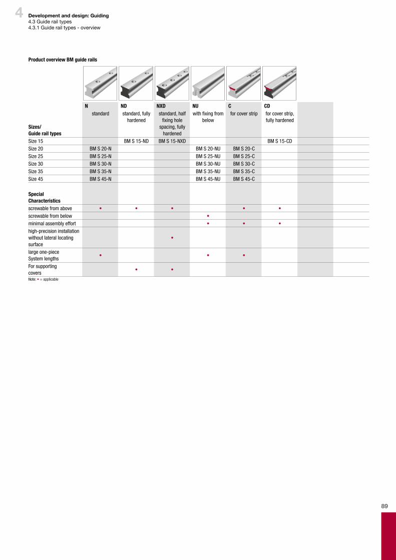
89
4 Development and design: Guiding4.3Guiderailtypes4.3.1Guiderailtypes-overview
Product overview BM guide rails
N ND NXD NU C CD
Sizes/Guide rail types
standard standard, fully hardened
standard, half fixing hole
spacing, fully hardened
with fixing from below
for cover strip for cover strip, fully hardened
Size 15 BM S 15-ND BM S 15-NXD BM S 15-CDSize 20 BM S 20-N BM S 20-NU BM S 20-CSize 25 BM S 25-N BM S 25-NU BM S 25-CSize 30 BM S 30-N BM S 30-NU BM S 30-CSize 35 BM S 35-N BM S 35-NU BM S 35-CSize 45 BM S 45-N BM S 45-NU BM S 45-C
Special Characteristicsscrewable from above • • • • •screwable from below •minimal assembly effort • • •high-precision installation without lateral locating surface
•
large one-piece System lengths
• • •
For supporting covers
• •
Note: • = applicable
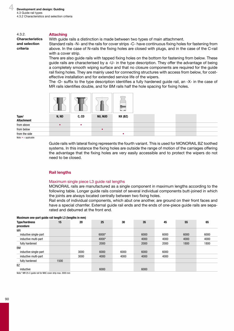
90
4 Development and design: Guiding4.3Guiderailtypes4.3.2Characteristicsandselectioncriteria
AttachingWithguiderailsadistinctionismadebetweentwotypesofmainattachment.Standardrails-N-andtherailsforcoverstrips-C-havecontinuousfixingholesforfasteningfromabove.InthecaseofN-railsthefixingholesareclosedwithplugs,andinthecaseoftheC-railwithacoverstrip.Therearealsoguiderailswithtappedfixingholesonthebottomforfasteningfrombelow.Theseguiderailsarecharacterisedbya-U-inthetypedescription.Theyoffertheadvantageofbeingacompletelysmoothwipingsurfaceandthatnoclosurecomponentsarerequiredfortheguiderailfixingholes.Theyaremainlyusedforconnectingstructureswithaccessfrombelow,forcost-effectiveinstallationandforextendedservicelifeofthewipers.The-D-suffixtothetypedescriptionidentifiesafullyhardenedguiderail,an-X-inthecaseofMRrailsidentifiesdouble,andforBMrailshalftheholespacingforfixingholes.
Guiderailswithlateralfixingrepresentsthefourthvariant.ThisisusedforMONORAILBZtoothedsystems.Inthisinstancethefixingholesareoutsidetherangeofmotionofthecarriagesofferingtheadvantagethatthefixingholesareveryeasilyaccessibleandtoprotectthewipersdonotneedtobeclosed.
Rail lengths
MaximumsinglepieceL3guideraillengthsMONORAILrailsaremanufacturedasasinglecomponentinmaximumlengthsaccordingtothefollowingtable.Longerguiderailsconsistofseveralindividualcomponentsbutt-joinedinwhichthejointsarealwayslocatedcentrallybetweentwofixingholes.Railendsofindividualcomponents,whichabutoneanother,aregroundontheirfrontfacesandhaveaspecialchamfer.Externalguiderailendsandtheendsofone-pieceguiderailsaresepa-ratedanddeburredatthefrontend.
4.3.2. Characteristics and selection criteria
Type/Attachment
N, ND C, CD NU, NUD NX (BZ)
from above • •from below •from the side •Note: • = applicable
Maximum one-part guide rail length L3 (lengths in mm)Type/hardness procedure
15 20 25 30 35 45 55 65
MRinductive single-part 6000* 6000 6000 6000 6000inductive multi-part 4000* 4000 4000 4000 4000fully hardened 2000 2000 2000 1800 1800
BMinductive single-part 3000 6000 6000 6000 6000inductive multi-part 3000 4000 4000 4000 4000fully hardened 1500
BZinductive 6000 6000
Note:* MR 25-C guide rail for MAC cover strip max. 3000 mm
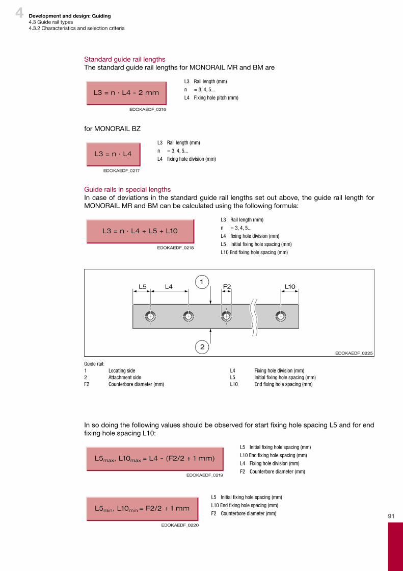
91
4 Development and design: Guiding4.3Guiderailtypes4.3.2Characteristicsandselectioncriteria
StandardguideraillengthsThestandardguideraillengthsforMONORAILMRandBMare
L3 Rail length (mm)
n = 3, 4, 5...
L4 Fixing hole pitch (mm)
forMONORAILBZ
L3 Rail length (mm)
n = 3, 4, 5...
L4 fixing hole division (mm)
GuiderailsinspeciallengthsIncaseofdeviationsinthestandardguiderail lengthssetoutabove,theguiderail lengthforMONORAILMRandBMcanbecalculatedusingthefollowingformula:
L3 Rail length (mm)
n = 3, 4, 5...
L4 fixing hole division (mm)
L5 Initial fixing hole spacing (mm)
L10 End fixing hole spacing (mm)
Guide rail:1 Locating side2 Attachment sideF2 Counterbore diameter (mm)
L4 Fixing hole division (mm)L5 Initial fixing hole spacing (mm)L10 End fixing hole spacing (mm)
InsodoingthefollowingvaluesshouldbeobservedforstartfixingholespacingL5andforendfixingholespacingL10:
L5 Initial fixing hole spacing (mm)
L10 End fixing hole spacing (mm)
L4 Fixing hole division (mm)
F2 Counterbore diameter (mm)
L5 Initial fixing hole spacing (mm)
L10 End fixing hole spacing (mm)
F2 Counterbore diameter (mm)
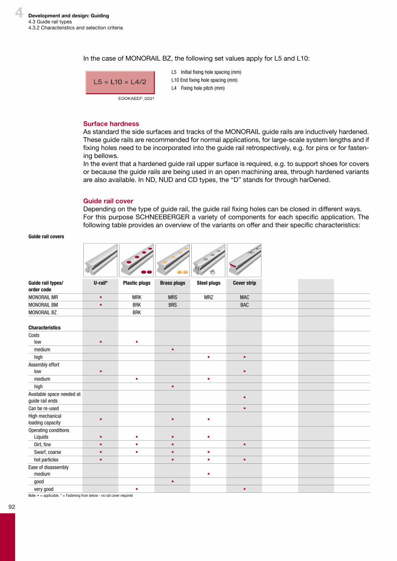
92
4 Development and design: Guiding4.3Guiderailtypes4.3.2Characteristicsandselectioncriteria
Guide rail covers
Guide rail types/ order code
U-rail* Plastic plugs Brass plugs Steel plugs Cover strip
MONORAIL MR • MRK MRS MRZ MACMONORAIL BM • BRK BRS BACMONORAIL BZ BRK
CharacteristicsCosts
low • •medium •high • •
Assembly effortlow • •medium • •high •
Available space needed at guide rail ends
•
Can be re-used •High mechanical loading capacity
• • •
Operating conditionsLiquids • • • •Dirt, fine • • • •Swarf, coarse • • • •hot particles • • • •
Ease of disassemblymedium •good •very good • •
Note: • = applicable, * = Fastening from below - no rail cover required
InthecaseofMONORAILBZ,thefollowingsetvaluesapplyforL5andL10:
L5 Initial fixing hole spacing (mm)
L10 End fixing hole spacing (mm)
L4 Fixing hole pitch (mm)
Surface hardnessAsstandardthesidesurfacesandtracksoftheMONORAILguiderailsareinductivelyhardened.Theseguiderailsarerecommendedfornormalapplications,forlarge-scalesystemlengthsandiffixingholesneedtobeincorporatedintotheguiderailretrospectively,e.g.forpinsorforfasten-ingbellows.Intheeventthatahardenedguiderailuppersurfaceisrequired,e.g.tosupportshoesforcoversorbecausetheguiderailsarebeingusedinanopenmachiningarea,throughhardenedvariantsarealsoavailable.InND,NUDandCDtypes,the“D”standsforthroughharDened.
Guide rail coverDependingonthetypeofguiderail,theguiderailfixingholescanbeclosedindifferentways.ForthispurposeSCHNEEBERGERavarietyofcomponentsforeachspecificapplication.Thefollowingtableprovidesanoverviewofthevariantsonofferandtheirspecificcharacteristics:

93
4 Development and design: Guiding4.4Carriagetypes4.4.1Carriagetypes-overview
4.4. Carriage types
Whenselectingthecarriagetypeinadditiontotheloadcarryingcapacityofparticularimportancearefasteningtypeandavailableinstallationspace.ThetableprovidesanoverviewofthetypesforMONORAILMRwithrollerandMONORAILBMwithball.Foravailablesizes,seeSCHNEEBERGERMONORAILandAMSproductcatalogue.AllcarriagetypesmatchDIN645intermsofexternaldimensionsandpositionofthelubricationfixingholesandarethereforeinterchangeable.
4.4.1. Carriage types - overview
Product overview BM carriages
A B C D E F GSizes/ carriage types
standard standard, long compact, high compact, high, long
compact, high, for lateral fixing
compact compact, long
Size 15 BM W 15-A BM W 15-C BM W 15-FSize 20 BM W 20-A BM W 20-B BM W 20-C BM W 20-DSize 25 BM W 25-A BM W 25-B BM W 25-C BM W 25-D BM W 25-E BM W 25-F BM W 25-GSize 30 BM W 30-A BM W 30-B BM W 30-C BM W 30-D BM W 30-E BM W 30-F BM W 30-GSize 35 BM W 35-A BM W 35-B BM W 35-C BM W 35-D BM W 35-E BM W 35-F BM W 35-GSize 45 BM W 45-A BM W 45-B BM W 45-C BM W 45-D BM W 45-F BM W 45-G
Special characteristicsscrewable from above • • • • • •screwable from below • •screwable from the side
•
for high forces and moments
• • •
for medium forces and moments
• • • •
for limited-space installation conditions
• •
Note: • = applicable
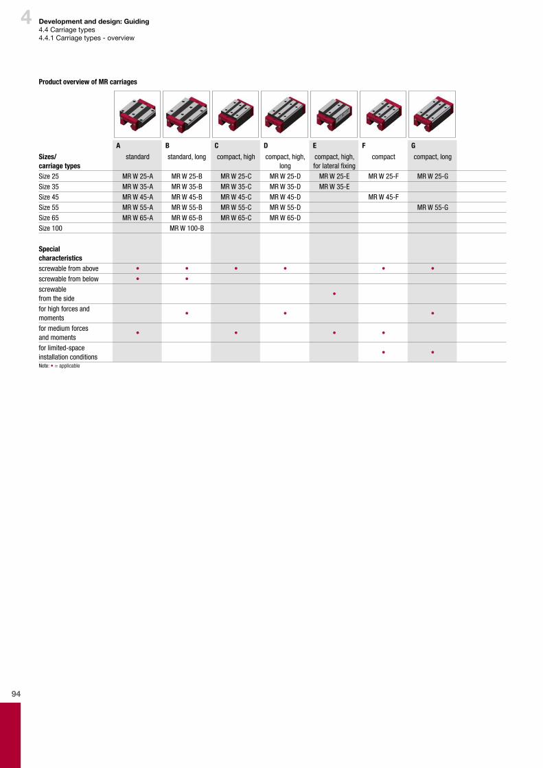
94
4 Development and design: Guiding4.4Carriagetypes4.4.1Carriagetypes-overview
Product overview of MR carriages
A B C D E F G
Sizes/ carriage types
standard standard, long compact, high compact, high, long
compact, high, for lateral fixing
compact compact, long
Size 25 MR W 25-A MR W 25-B MR W 25-C MR W 25-D MR W 25-E MR W 25-F MR W 25-GSize 35 MR W 35-A MR W 35-B MR W 35-C MR W 35-D MR W 35-ESize 45 MR W 45-A MR W 45-B MR W 45-C MR W 45-D MR W 45-FSize 55 MR W 55-A MR W 55-B MR W 55-C MR W 55-D MR W 55-GSize 65 MR W 65-A MR W 65-B MR W 65-C MR W 65-DSize 100 MR W 100-B
Special characteristicsscrewable from above • • • • • •screwable from below • •screwable from the side
•
for high forces and moments
• • •
for medium forces and moments
• • • •
for limited-space installation conditions
• •
Note: • = applicable
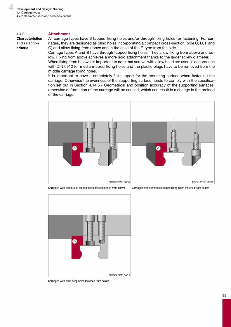
95
4 Development and design: Guiding4.4Carriagetypes4.4.2Characteristicsandselectioncriteria
4.4.2. Characteristics and selection criteria
AttachmentAllcarriagetypeshave6tappedfixingholesand/orthroughfixingholesforfastening.Forcar-riages,theyaredesignedasblindholesincorporatingacompactcross-section(typeC,D,FandG)andallowfixingfromaboveandinthecaseoftheE-typefromtheside.CarriagetypesAandBhavethroughtappedfixingholes.Theyallowfixingfromaboveandbe-low.Fixingfromaboveachievesamorerigidattachmentthankstothelargerscrewdiameter.WhenfixingfrombelowitisimportanttonotethatscrewswithalowheadareusedinaccordancewithDIN6912formedium-sizedfixingholesandtheplasticplugshavetoberemovedfromthemiddlecarriagefixingholes.It is important tohaveacompletelyflatsupport for themountingsurfacewhen fastening thecarriage.Otherwisetheevennessofthesupportingsurfaceneedstocomplywiththespecifica-tionsetout inSection4.14.5-Geometricalandpositionaccuracyofthesupportingsurfaces,otherwisedeformationofthecarriagewillbecaused,whichcanresultinachangeinthepreloadofthecarriage.
Carriages with continuous tapped fixing holes fastened from above Carriages with continuous tapped fixing holes fastened from below
Carriages with blind fxing holes fastened from below
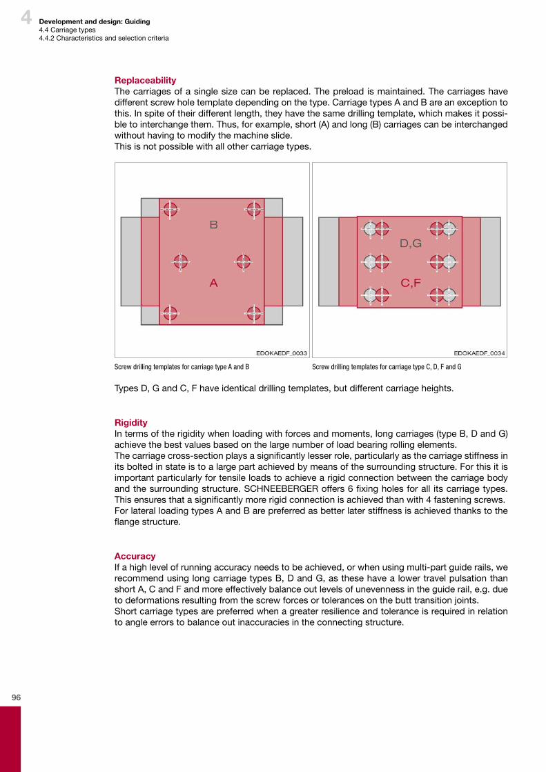
96
4 Development and design: Guiding4.4Carriagetypes4.4.2Characteristicsandselectioncriteria
ReplaceabilityThecarriagesofasinglesizecanbereplaced.Thepreloadismaintained.Thecarriageshavedifferentscrewholetemplatedependingonthetype.CarriagetypesAandBareanexceptiontothis.Inspiteoftheirdifferentlength,theyhavethesamedrillingtemplate,whichmakesitpossi-bletointerchangethem.Thus,forexample,short(A)andlong(B)carriagescanbeinterchangedwithouthavingtomodifythemachineslide.Thisisnotpossiblewithallothercarriagetypes.
Screw drilling templates for carriage type A and B Screw drilling templates for carriage type C, D, F and G
TypesD,GandC,Fhaveidenticaldrillingtemplates,butdifferentcarriageheights.
RigidityIntermsoftherigiditywhenloadingwithforcesandmoments,longcarriages(typeB,DandG)achievethebestvaluesbasedonthelargenumberofloadbearingrollingelements.Thecarriagecross-sectionplaysasignificantlylesserrole,particularlyasthecarriagestiffnessinitsboltedinstateistoalargepartachievedbymeansofthesurroundingstructure.Forthisitisimportantparticularlyfortensileloadstoachievearigidconnectionbetweenthecarriagebodyandthesurroundingstructure.SCHNEEBERGERoffers6fixingholesforall itscarriagetypes.Thisensuresthatasignificantlymorerigidconnectionisachievedthanwith4fasteningscrews.ForlateralloadingtypesAandBarepreferredasbetterlaterstiffnessisachievedthankstotheflangestructure.
AccuracyIfahighlevelofrunningaccuracyneedstobeachieved,orwhenusingmulti-partguiderails,werecommendusinglongcarriagetypesB,DandG,asthesehavealowertravelpulsationthanshortA,CandFandmoreeffectivelybalanceoutlevelsofunevennessintheguiderail,e.g.duetodeformationsresultingfromthescrewforcesortolerancesonthebutttransitionjoints.Shortcarriagetypesarepreferredwhenagreaterresilienceandtoleranceisrequiredinrelationtoangleerrorstobalanceoutinaccuraciesintheconnectingstructure.
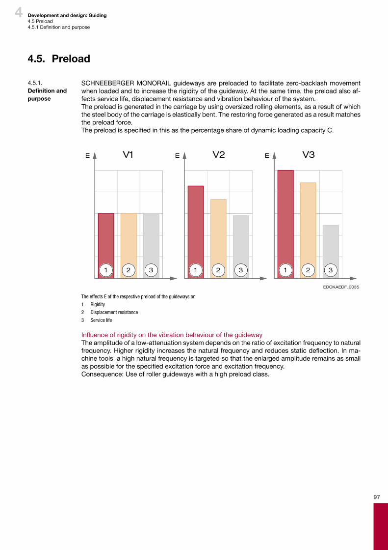
97
4 Development and design: Guiding4.5Preload4.5.1Definitionandpurpose
4.5. Preload
SCHNEEBERGERMONORAILguidewaysarepreloaded to facilitatezero-backlashmovementwhenloadedandtoincreasetherigidityoftheguideway.Atthesametime,thepreloadalsoaf-fectsservicelife,displacementresistanceandvibrationbehaviourofthesystem.Thepreloadisgeneratedinthecarriagebyusingoversizedrollingelements,asaresultofwhichthesteelbodyofthecarriageiselasticallybent.Therestoringforcegeneratedasaresultmatchesthepreloadforce.ThepreloadisspecifiedinthisasthepercentageshareofdynamicloadingcapacityC.
The effects E of the respective preload of the guideways on
1 Rigidity
2 Displacement resistance
3 Service life
InfluenceofrigidityonthevibrationbehaviouroftheguidewayTheamplitudeofalow-attenuationsystemdependsontheratioofexcitationfrequencytonaturalfrequency.Higherrigidityincreasesthenaturalfrequencyandreducesstaticdeflection.Inma-chinetoolsahighnaturalfrequencyistargetedsothattheenlargedamplituderemainsassmallaspossibleforthespecifiedexcitationforceandexcitationfrequency.Consequence:Useofrollerguidewayswithahighpreloadclass.
4.5.1. Definition and purpose
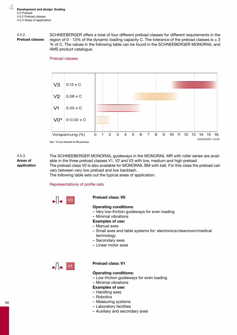
98
4 Development and design: Guiding4.5Preload4.5.2Preloadclasses4.5.3Areasofapplication
SCHNEEBERGERoffersatotaloffourdifferentpreloadclassesfordifferentrequirementsintheregionof0-13%ofthedynamicloadingcapacityC.Thetoleranceofthepreloadclassesis±3%ofC.ThevaluesinthefollowingtablecanbefoundintheSCHNEEBERGERMONORAILandAMSproductcatalogue.
Preloadclasses
Note: * V0 only obtainable for BM guideways.
4.5.2. Preload classes
TheSCHNEEBERGERMONORAILguidewaysintheMONORAILMRwithrollerseriesareavail-ableinthethreepreloadclassesV1,V2andV3withlow,mediumandhighpreload.ThepreloadclassV0isalsoavailableforMONORAILBMwithball.Forthisclassthepreloadcanvarybetweenverylowpreloadandlowbacklash.Thefollowingtablesetsoutthetypicalareasofapplication:
Representationsofprofilerails
Preload class: V0
Operating conditions:–Verylow-frictionguidewaysforevenloading–MinimalvibrationsExamples of use:–Manualaxes–Smallaxesandtablesystemsfor:electronics/cleanroom/medical technology–Secondaryaxes–Linearmotoraxes
Preload class: V1
Operating conditions:–Low-frictionguidewaysforevenloading–MinimalvibrationsExamples of use:–Handlingaxes–Robotics–Measuringsystems–Laboratoryfacilities–Auxiliaryandsecondaryaxes
4.5.3. Areas of application

99
4 Development and design: Guiding4.5Preload4.5.3Areasofapplication
Preload class: V2
Operating conditions:–Highrigidity–MediumalternatingloadsandvibrationsExamples of use:–Machinetoolswithlightcuttingforces–Grindingmachines–Machinesforwoodworking–Waterjetsystems–Lasercuttingsystems–Erodingmachines
Preload class: V3
Operating conditions:–Maximumrigidity–Highshockloadsandvibrations–Greatlychanging,highloadsandmomentsExamples of use:–Machinetoolswithhighcuttingforces–Pressmachines–Millingcentres–Lathes–Drillingmachines
EffectivenessofthepreloadWithexternalloads,whicharesmallerthan3timesthepreloadforce,thepreloadisretainedun-derload.Thismeansthesystemhasahighlevelofrigidity.Iftheexternalforceexceedsthevalueofthepreload,therigiditydecreases.Thatiswhyitisimportanttoensureinthedesignthatyouremaininthefieldofeffectivepreloadforceifthereisarequirementforhigherrigidity.
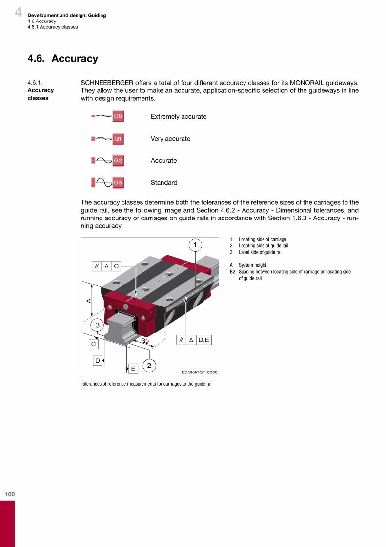
100
4 Development and design: Guiding4.6Accuracy4.6.1Accuracyclasses
4.6. Accuracy
SCHNEEBERGERoffersatotaloffourdifferentaccuracyclassesforitsMONORAILguideways.Theyallowtheusertomakeanaccurate,application-specificselectionoftheguidewaysinlinewithdesignrequirements.
Extremelyaccurate
Veryaccurate
Accurate
Standard
Theaccuracyclassesdetermineboththetolerancesofthereferencesizesofthecarriagestotheguiderail,seethefollowingimageandSection4.6.2-Accuracy-Dimensionaltolerances,andrunningaccuracyofcarriagesonguiderailsinaccordancewithSection1.6.3-Accuracy-run-ningaccuracy.
1 Locating side of carriage 2 Locating side of guide rail 3 Label side of guide rail
A System height B2 Spacing between locating side of carriage an locating side
of guide rail
Tolerances of reference measurements for carriages to the guide rail
4.6.1. Accuracy classes
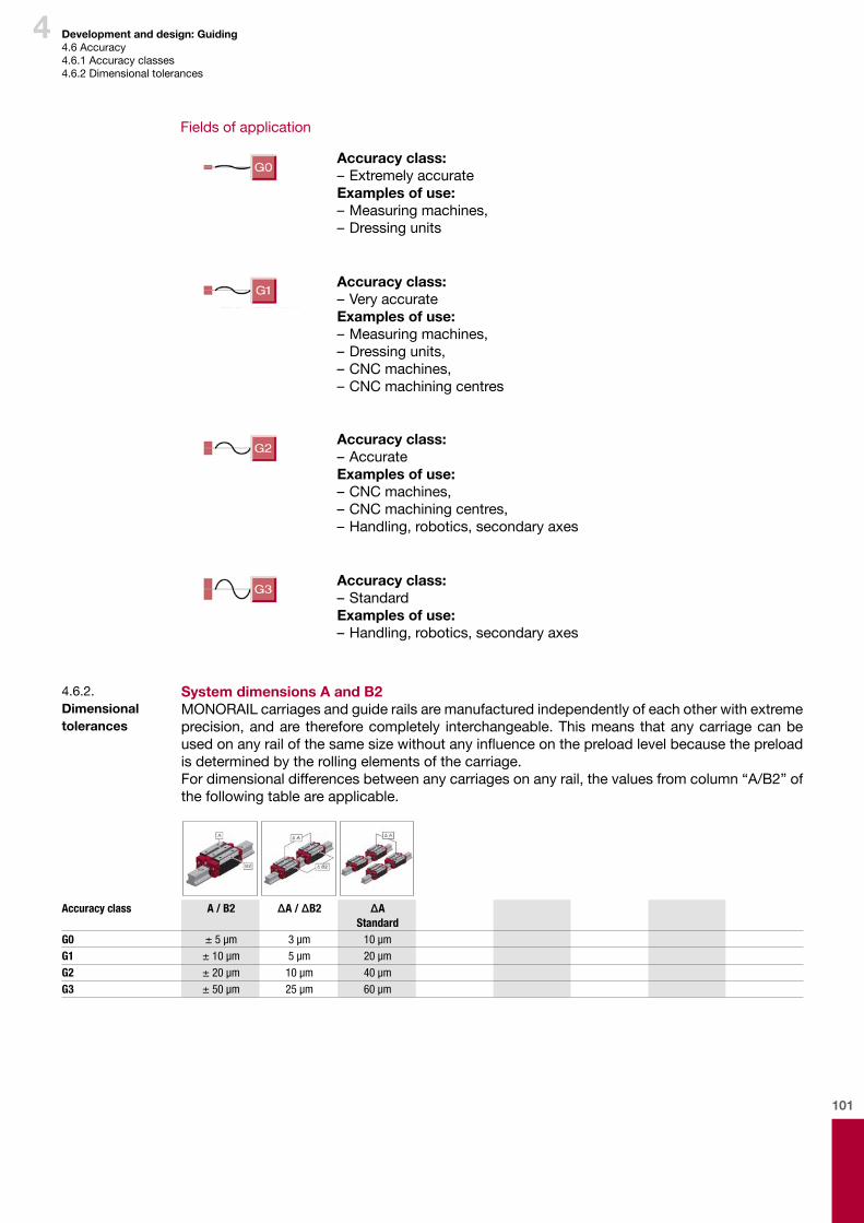
101
4 Development and design: Guiding4.6Accuracy4.6.1Accuracyclasses4.6.2Dimensionaltolerances
Fieldsofapplication
Accuracy class:–ExtremelyaccurateExamples of use:–Measuringmachines,–Dressingunits
Accuracy class:–VeryaccurateExamples of use:–Measuringmachines,–Dressingunits,–CNCmachines,–CNCmachiningcentres
Accuracy class:–AccurateExamples of use:–CNCmachines,–CNCmachiningcentres,–Handling,robotics,secondaryaxes
Accuracy class:–StandardExamples of use:–Handling,robotics,secondaryaxes
System dimensions A and B2 MONORAILcarriagesandguiderailsaremanufacturedindependentlyofeachotherwithextremeprecision,andare thereforecompletely interchangeable.Thismeansthatanycarriagecanbeusedonanyrailofthesamesizewithoutanyinfluenceonthepreloadlevelbecausethepreloadisdeterminedbytherollingelementsofthecarriage.Fordimensionaldifferencesbetweenanycarriagesonanyrail,thevaluesfromcolumn“A/B2”ofthefollowingtableareapplicable.
4.6.2. Dimensional tolerances
Accuracy class A / B2 ΔA / ΔB2 ΔA Standard
G0 ± 5 μm 3 μm 10 μmG1 ± 10 μm 5 μm 20 μmG2 ± 20 μm 10 μm 40 μmG3 ± 50 μm 25 μm 60 μm
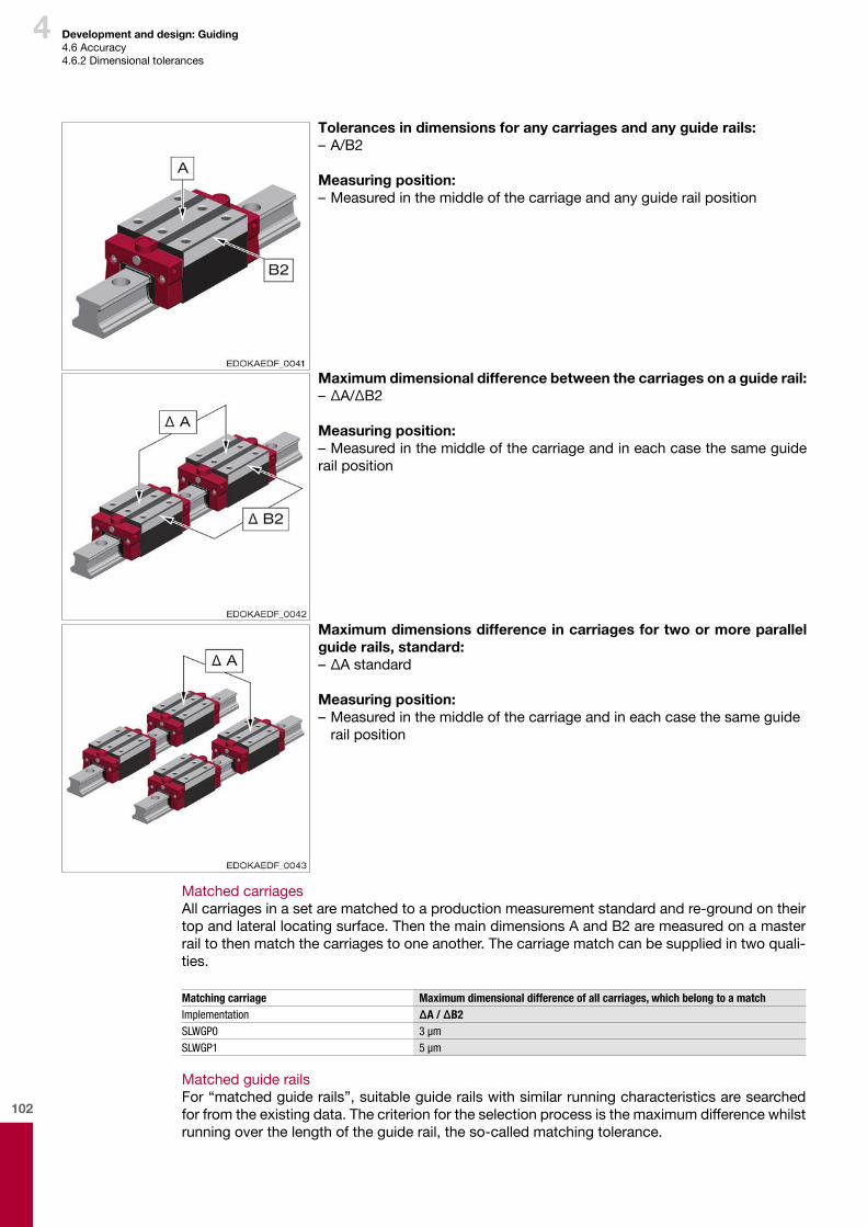
102
4 Development and design: Guiding4.6Accuracy4.6.2Dimensionaltolerances
Maximum dimensions difference in carriages for two or more parallel guide rails, standard:–ΔAstandard
Measuring position:–Measuredinthemiddleofthecarriageandineachcasethesameguide railposition
Maximum dimensional difference between the carriages on a guide rail:–ΔA/ΔB2
Measuring position:–Measuredinthemiddleofthecarriageandineachcasethesameguiderailposition
MatchedcarriagesAllcarriagesinasetarematchedtoaproductionmeasurementstandardandre-groundontheirtopandlaterallocatingsurface.ThenthemaindimensionsAandB2aremeasuredonamasterrailtothenmatchthecarriagestooneanother.Thecarriagematchcanbesuppliedintwoquali-ties.
Matching carriage Maximum dimensional difference of all carriages, which belong to a matchImplementation ΔA / ΔB2SLWGP0 3 µmSLWGP1 5 µm
MatchedguiderailsFor“matchedguiderails”,suitableguiderailswithsimilarrunningcharacteristicsaresearchedforfromtheexistingdata.Thecriterionfortheselectionprocessisthemaximumdifferencewhilstrunningoverthelengthoftheguiderail,theso-calledmatchingtolerance.
Tolerances in dimensions for any carriages and any guide rails:–A/B2
Measuring position:–Measuredinthemiddleofthecarriageandanyguiderailposition
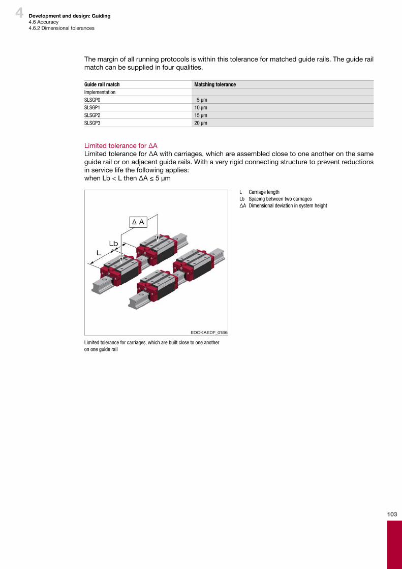
103
4 Development and design: Guiding4.6Accuracy4.6.2Dimensionaltolerances
Themarginofallrunningprotocolsiswithinthistoleranceformatchedguiderails.Theguiderailmatchcanbesuppliedinfourqualities.
Guide rail match Matching toleranceImplementationSLSGP0 5 µmSLSGP1 10 µmSLSGP2 15 µmSLSGP3 20 µm
Limitedtolerancefor∆ALimitedtolerancefor∆Awithcarriages,whichareassembledclosetooneanotheronthesameguiderailoronadjacentguiderails.Withaveryrigidconnectingstructuretopreventreductionsinservicelifethefollowingapplies:whenLb<Lthen∆A≤5µm
L Carriage length Lb Spacing between two carriages ∆A Dimensional deviation in system height
Limited tolerance for carriages, which are built close to one another on one guide rail
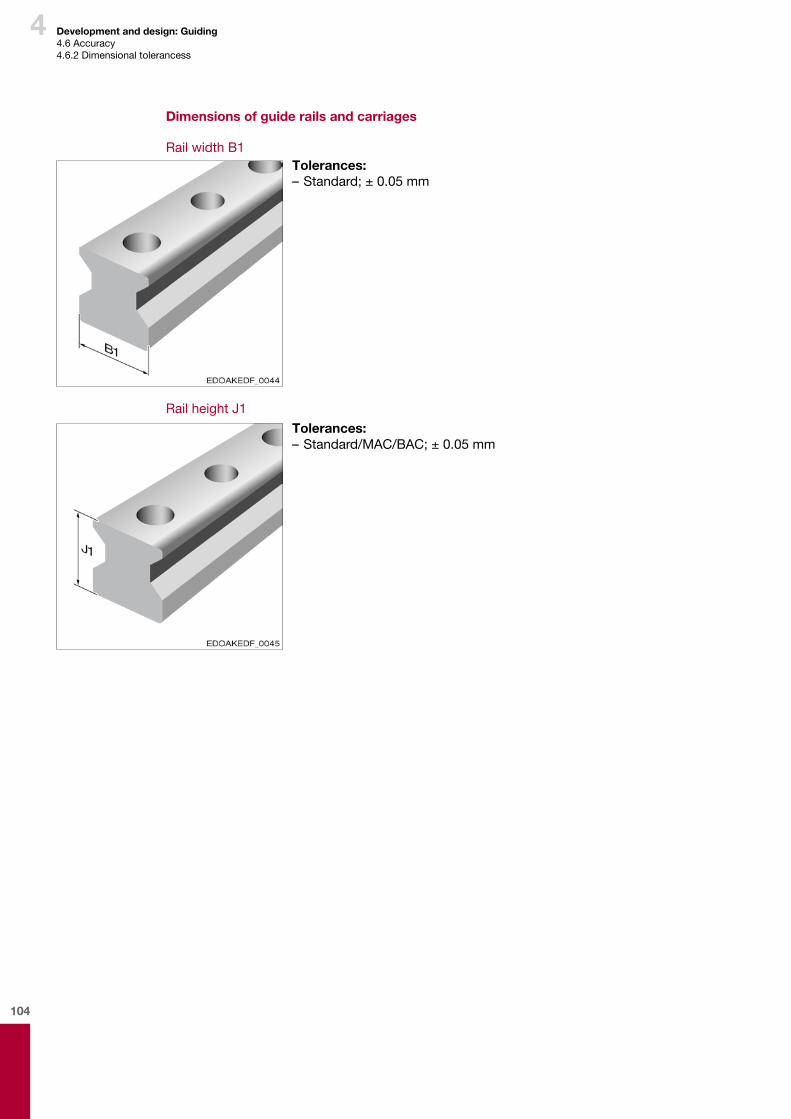
104
4
Tolerances:–Standard/MAC/BAC;±0.05mm
Development and design: Guiding4.6Accuracy4.6.2Dimensionaltolerancess
Dimensions of guide rails and carriages
RailwidthB1Tolerances:–Standard;±0.05mm
RailheightJ1
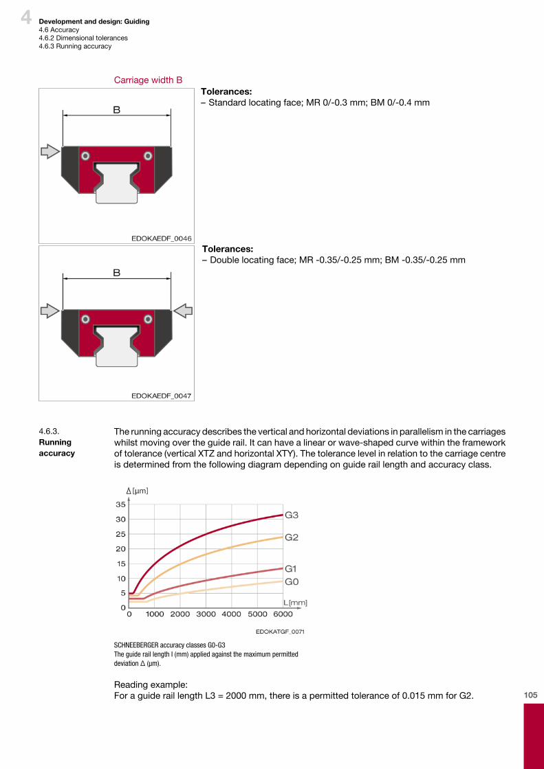
105
4 Development and design: Guiding4.6Accuracy4.6.2Dimensionaltolerances4.6.3Runningaccuracy
Therunningaccuracydescribestheverticalandhorizontaldeviationsinparallelisminthecarriageswhilstmovingovertheguiderail.Itcanhavealinearorwave-shapedcurvewithintheframeworkoftolerance(verticalXTZandhorizontalXTY).Thetolerancelevelinrelationtothecarriagecentreisdeterminedfromthefollowingdiagramdependingonguideraillengthandaccuracyclass.
SCHNEEBERGER accuracy classes G0-G3The guide rail length I (mm) applied against the maximum permitted deviation Δ (μm).
Readingexample:ForaguideraillengthL3=2000mm,thereisapermittedtoleranceof0.015mmforG2.
4.6.3. Running accuracy
CarriagewidthBTolerances:–Standardlocatingface;MR0/-0.3mm;BM0/-0.4mm
Tolerances:–Doublelocatingface;MR-0.35/-0.25mm;BM-0.35/-0.25mm
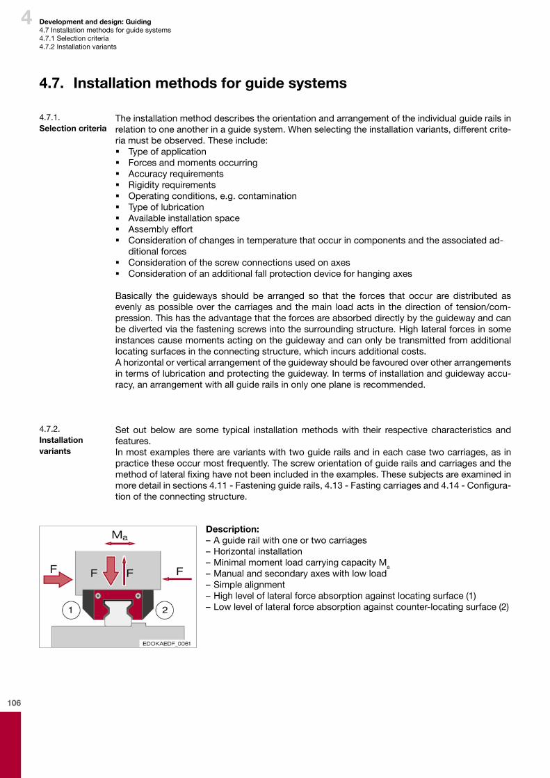
106
4 Development and design: Guiding4.7Installationmethodsforguidesystems4.7.1Selectioncriteria4.7.2Installationvariants
4.7. Installation methods for guide systems
Theinstallationmethoddescribestheorientationandarrangementoftheindividualguiderailsinrelationtooneanotherinaguidesystem.Whenselectingtheinstallationvariants,differentcrite-riamustbeobserved.Theseinclude: � Typeofapplication � Forcesandmomentsoccurring � Accuracyrequirements � Rigidityrequirements � Operatingconditions,e.g.contamination � Typeoflubrication � Availableinstallationspace � Assemblyeffort � Considerationofchangesintemperaturethatoccurincomponentsandtheassociatedad-ditionalforces
� Considerationofthescrewconnectionsusedonaxes � Considerationofanadditionalfallprotectiondeviceforhangingaxes
Basically the guideways should be arranged so that the forces that occur are distributed asevenlyaspossibleover thecarriagesandthemain loadacts in thedirectionof tension/com-pression.Thishastheadvantagethattheforcesareabsorbeddirectlybytheguidewayandcanbedivertedviathefasteningscrewsintothesurroundingstructure.Highlateralforcesinsomeinstancescausemomentsactingontheguidewayandcanonlybetransmittedfromadditionallocatingsurfacesintheconnectingstructure,whichincursadditionalcosts.Ahorizontalorverticalarrangementoftheguidewayshouldbefavouredoverotherarrangementsintermsoflubricationandprotectingtheguideway.Intermsofinstallationandguidewayaccu-racy,anarrangementwithallguiderailsinonlyoneplaneisrecommended.
4.7.1. Selection criteria
Set out beloware some typical installationmethodswith their respective characteristics andfeatures.Inmostexamplestherearevariantswithtwoguiderailsandineachcasetwocarriages,asinpracticetheseoccurmostfrequently.Thescreworientationofguiderailsandcarriagesandthemethodoflateralfixinghavenotbeenincludedintheexamples.Thesesubjectsareexaminedinmoredetailinsections4.11-Fasteningguiderails,4.13-Fastingcarriagesand4.14-Configura-tionoftheconnectingstructure.
4.7.2. Installation variants
Description:–Aguiderailwithoneortwocarriages–Horizontalinstallation–MinimalmomentloadcarryingcapacityMa
–Manualandsecondaryaxeswithlowload–Simplealignment–Highleveloflateralforceabsorptionagainstlocatingsurface(1)–Lowleveloflateralforceabsorptionagainstcounter-locatingsurface(2)
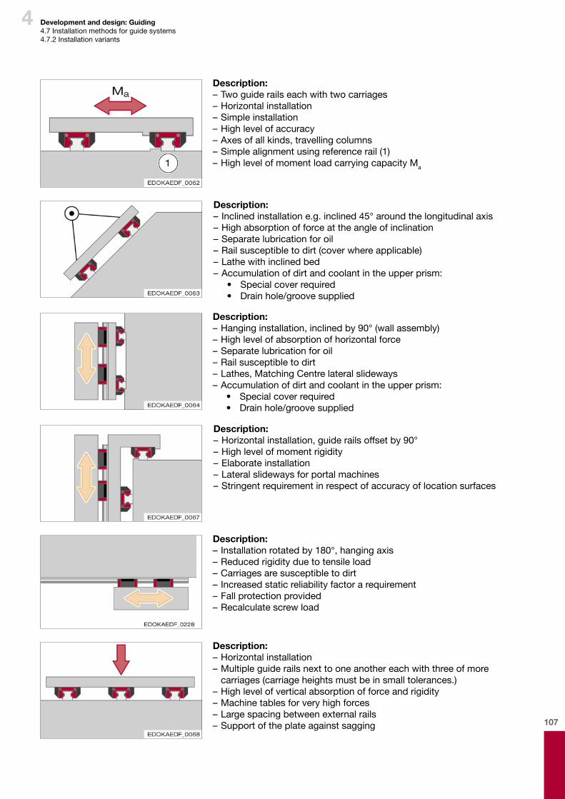
107
4 Development and design: Guiding4.7Installationmethodsforguidesystems4.7.2Installationvariants
Description:–Hanginginstallation,inclinedby90°(wallassembly)–Highlevelofabsorptionofhorizontalforce–Separatelubricationforoil–Railsusceptibletodirt–Lathes,MatchingCentrelateralslideways–Accumulationofdirtandcoolantintheupperprism:
• Specialcoverrequired• Drainhole/groovesupplied
Description:–Horizontalinstallation,guiderailsoffsetby90°–Highlevelofmomentrigidity–Elaborateinstallation–Lateralslidewaysforportalmachines–Stringentrequirementinrespectofaccuracyoflocationsurfaces
Description:–Horizontalinstallation–Multipleguiderailsnexttooneanothereachwiththreeofmorecarriages(carriageheightsmustbeinsmalltolerances.)
–Highlevelofverticalabsorptionofforceandrigidity–Machinetablesforveryhighforces–Largespacingbetweenexternalrails–Supportoftheplateagainstsagging
Description:–Inclinedinstallatione.g.inclined45°aroundthelongitudinalaxis–Highabsorptionofforceattheangleofinclination–Separatelubricationforoil–Railsusceptibletodirt(coverwhereapplicable)–Lathewithinclinedbed–Accumulationofdirtandcoolantintheupperprism:
• Specialcoverrequired• Drainhole/groovesupplied
Description:–Installationrotatedby180°,hangingaxis–Reducedrigidityduetotensileload–Carriagesaresusceptibletodirt–Increasedstaticreliabilityfactorarequirement–Fallprotectionprovided–Recalculatescrewload
Description:–Twoguiderailseachwithtwocarriages–Horizontalinstallation–Simpleinstallation–Highlevelofaccuracy–Axesofallkinds,travellingcolumns–Simplealignmentusingreferencerail(1)–HighlevelofmomentloadcarryingcapacityMa
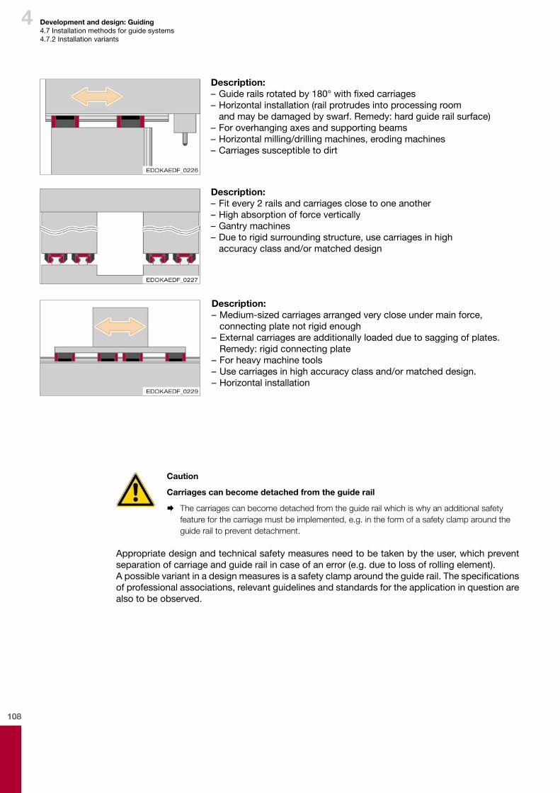
108
4 Development and design: Guiding4.7Installationmethodsforguidesystems4.7.2Installationvariants
Description:–Fitevery2railsandcarriagesclosetooneanother–Highabsorptionofforcevertically–Gantrymachines–Duetorigidsurroundingstructure,usecarriagesinhigh accuracyclassand/ormatcheddesign
Description:–Medium-sizedcarriagesarrangedverycloseundermainforce, connectingplatenotrigidenough–Externalcarriagesareadditionallyloadedduetosaggingofplates.Remedy:rigidconnectingplate
–Forheavymachinetools–Usecarriagesinhighaccuracyclassand/ormatcheddesign.–Horizontalinstallation
Description:–Guiderailsrotatedby180°withfixedcarriages–Horizontalinstallation(railprotrudesintoprocessingroom andmaybedamagedbyswarf.Remedy:hardguiderailsurface)
–Foroverhangingaxesandsupportingbeams–Horizontalmilling/drillingmachines,erodingmachines–Carriagessusceptibletodirt
Caution
Carriages can become detached from the guide rail
¨ The carriages can become detached from the guide rail which is why an additional safety feature for the carriage must be implemented, e.g. in the form of a safety clamp around the guide rail to prevent detachment.
Appropriatedesignandtechnicalsafetymeasuresneedtobetakenbytheuser,whichpreventseparationofcarriageandguiderailincaseofanerror(e.g.duetolossofrollingelement).Apossiblevariantinadesignmeasuresisasafetyclamparoundtheguiderail.Thespecificationsofprofessionalassociations,relevantguidelinesandstandardsfortheapplicationinquestionarealsotobeobserved.

109
4 Development and design: Guiding4.8Calculationandsizing4.8.1Principles
4.8. Calculation and sizing
Theclaimsrelatingtoaccuracylevels,surfacequalityandshortprocessingtimesarecontinu-ouslyincreasing.Thatiswhylinearguidewaysinthemodernmachineryconstructionareincreas-inglydeterminedbythepermissibleelasticdeformation.Thefollowingstageshavebeenestablishedasaresultfordimensioningrollerguideways: � Determiningtheexternalforcesandmoments � Distributingforcesandmomentsontheindividualcarriages � Determiningthepreloadanddeformation � Calculatingservicelife � Calculatingstaticreliabilityfactor
Theservicelifecanbelimitedbymaterialfatigueandalsobydamagetorunningsurfacesduetoenvironmentalinfluences.Surfacesbeingrolledoverleadstomaterialfatigueandthustodamageofthetrackandtheroll-ingelement(pitting).Iftheforceontherollingcontactsurfacesisknown,thefatigueservicelifecanbecalculatedinaccordancewithDINIS281orDIN636.Weartorunningsurfacesisdeterminedinparticularbythelubrication,dirt,surfacepressureandthesizeofrelativemovementsoftheloadedsurfaces.Thecalculatedservicelifecanbereducedbyadditionalrisksoffailureorotheraspects,whichvoidthewarranty.
4.8.1. Principles
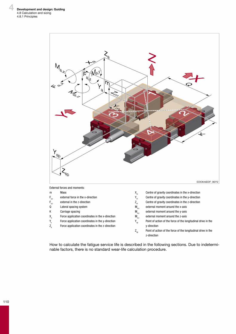
110
4 Development and design: Guiding4.8Calculationandsizing4.8.1Principles
External forces and moments:
m Mass
Fa,x external force in the x-direction
Fa,z external in the z-direction
Q Lateral spacing system
K Carriage spacing
Xa Force application coordinates in the x-direction
Ya Force application coordinates in the y-direction
Za Force application coordinates in the z-direction
Xm Centre of gravity coordinates in the x-direction
Ym Centre of gravity coordinates in the y-direction
Zm Centre of gravity coordinates in the z-direction
Ma,x external moment around the x-axis
Ma,y external moment around the y-axis
Ma,z external moment around the z-axis
Ysp Point of action of the force of the longitudinal drive in the
y-direction
Zsp Point of action of the force of the longitudinal drive in the
z-direction
Howtocalculatethefatigueservicelifeisdescribedinthefollowingsections.Duetoindetermi-nablefactors,thereisnostandardwear-lifecalculationprocedure.
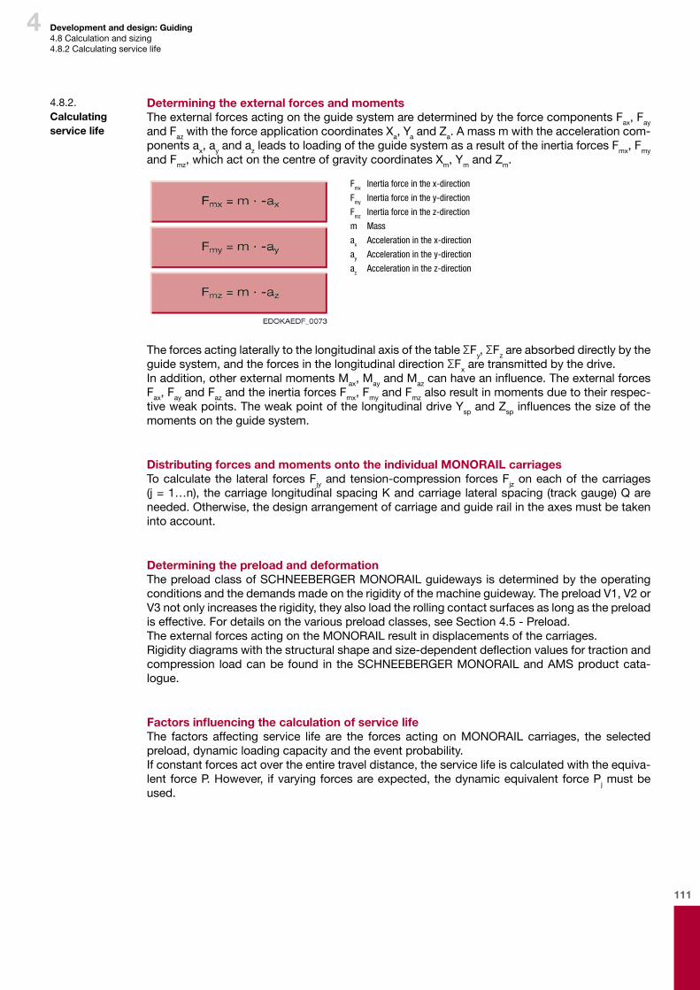
111
4 Development and design: Guiding4.8Calculationandsizing4.8.2Calculatingservicelife
Determining the external forces and momentsTheexternalforcesactingontheguidesystemaredeterminedbytheforcecomponentsFax,Fay andFazwiththeforceapplicationcoordinatesXa,YaandZa.Amassmwiththeaccelerationcom-ponentsax,ayandazleadstoloadingoftheguidesystemasaresultoftheinertiaforcesFmx,Fmy andFmz,whichactonthecentreofgravitycoordinatesXm,YmandZm.
Fmx Inertia force in the x-direction
Fmy Inertia force in the y-direction
Fmz Inertia force in the z-direction
m Mass
ax Acceleration in the x-direction
ay Acceleration in the y-direction
az Acceleration in the z-direction
TheforcesactinglaterallytothelongitudinalaxisofthetableΣFy,ΣFzareabsorbeddirectlybytheguidesystem,andtheforcesinthelongitudinaldirectionΣFxaretransmittedbythedrive.Inaddition,otherexternalmomentsMax,MayandMazcanhaveaninfluence.TheexternalforcesFax,FayandFazandtheinertiaforcesFmx,FmyandFmzalsoresultinmomentsduetotheirrespec-tiveweakpoints.TheweakpointofthelongitudinaldriveYspandZspinfluencesthesizeofthemomentsontheguidesystem.
Distributing forces and moments onto the individual MONORAIL carriagesTocalculate the lateral forcesFjyandtension-compression forcesFjzoneachof thecarriages (j=1…n),thecarriagelongitudinalspacingKandcarriagelateralspacing(trackgauge)Qareneeded.Otherwise,thedesignarrangementofcarriageandguiderailintheaxesmustbetakenintoaccount.
Determining the preload and deformationThepreloadclassofSCHNEEBERGERMONORAILguidewaysisdeterminedbytheoperatingconditionsandthedemandsmadeontherigidityofthemachineguideway.ThepreloadV1,V2orV3notonlyincreasestherigidity,theyalsoloadtherollingcontactsurfacesaslongasthepreloadiseffective.Fordetailsonthevariouspreloadclasses,seeSection4.5-Preload.TheexternalforcesactingontheMONORAILresultindisplacementsofthecarriages.Rigiditydiagramswiththestructuralshapeandsize-dependentdeflectionvaluesfortractionandcompression loadcanbe found in theSCHNEEBERGERMONORAILandAMSproductcata-logue.
Factors influencing the calculation of service lifeThe factors affecting service life are the forces actingonMONORAIL carriages, the selectedpreload,dynamicloadingcapacityandtheeventprobability.Ifconstantforcesactovertheentiretraveldistance,theservicelifeiscalculatedwiththeequiva-lentforceP.However, ifvaryingforcesareexpected,thedynamicequivalentforcePjmustbeused.
4.8.2. Calculating service life
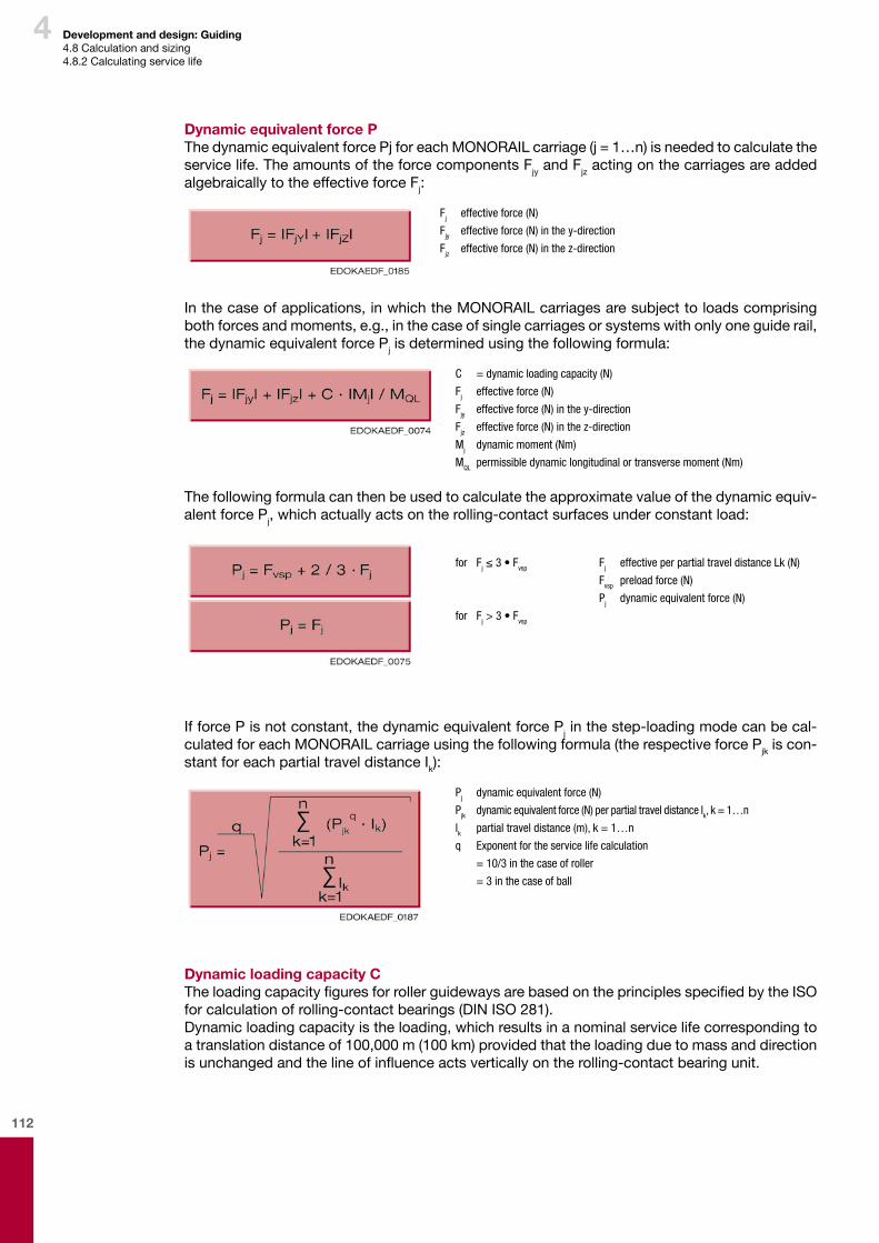
112
4
Dynamic equivalent force PThedynamicequivalentforcePjforeachMONORAILcarriage(j=1…n)isneededtocalculatetheservicelife.TheamountsoftheforcecomponentsFjyandFjzactingonthecarriagesareaddedalgebraicallytotheeffectiveforceFj:
Fj effective force (N)
Fjy effective force (N) in the y-direction
Fjz effective force (N) in the z-direction
Inthecaseofapplications,inwhichtheMONORAILcarriagesaresubjecttoloadscomprisingbothforcesandmoments,e.g.,inthecaseofsinglecarriagesorsystemswithonlyoneguiderail,thedynamicequivalentforcePjisdeterminedusingthefollowingformula:
C = dynamic loading capacity (N)
Fj effective force (N)
Fjy effective force (N) in the y-direction
Fjz effective force (N) in the z-direction
Mj dynamic moment (Nm)
MQL permissible dynamic longitudinal or transverse moment (Nm)
Thefollowingformulacanthenbeusedtocalculatetheapproximatevalueofthedynamicequiv-alentforcePj,whichactuallyactsontherolling-contactsurfacesunderconstantload:
for Fj ≤ 3 • Fvsp
for Fj > 3 • Fvsp
Fj effective per partial travel distance Lk (N)
Fvsp preload force (N)
Pj dynamic equivalent force (N)
IfforcePisnotconstant,thedynamicequivalentforcePjinthestep-loadingmodecanbecal-culatedforeachMONORAILcarriageusingthefollowingformula(therespectiveforcePjkiscon-stantforeachpartialtraveldistanceIk):
Pj dynamic equivalent force (N)
Pjk dynamic equivalent force (N) per partial travel distance lk, k = 1…n
lk partial travel distance (m), k = 1…n
q Exponent for the service life calculation
= 10/3 in the case of roller
= 3 in the case of ball
Dynamic loading capacity CTheloadingcapacityfiguresforrollerguidewaysarebasedontheprinciplesspecifiedbytheISOforcalculationofrolling-contactbearings(DINISO281).Dynamicloadingcapacityistheloading,whichresultsinanominalservicelifecorrespondingtoatranslationdistanceof100,000m(100km)providedthattheloadingduetomassanddirectionisunchangedandthelineofinfluenceactsverticallyontherolling-contactbearingunit.
Development and design: Guiding4.8Calculationandsizing4.8.2Calculatingservicelife
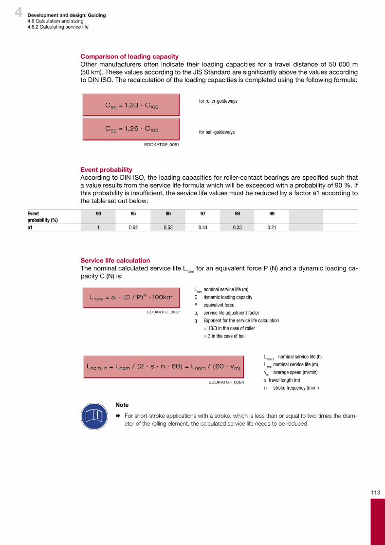
113
4
Comparison of loading capacityOthermanufacturers often indicate their loading capacities for a travel distanceof 50000 m(50 km).ThesevaluesaccordingtotheJISStandardaresignificantlyabovethevaluesaccordingtoDINISO.Therecalculationoftheloadingcapacitiesiscompletedusingthefollowingformula:
for roller-guideways
for ball-guideways
Event probabilityAccordingtoDINISO,theloadingcapacitiesforroller-contactbearingsarespecifiedsuchthatavalueresultsfromtheservicelifeformulawhichwillbeexceededwithaprobabilityof90%.Ifthisprobabilityisinsufficient,theservicelifevaluesmustbereducedbyafactora1accordingtothetablesetoutbelow:
Eventprobability (%)
90 95 96 97 98 99
a1 1 0.62 0.53 0.44 0.33 0.21
Development and design: Guiding4.8Calculationandsizing4.8.2Calculatingservicelife
Service life calculationThenominalcalculatedservicelifeLnomforanequivalentforceP(N)andadynamicloadingca-pacityC(N)is:
Lnom nominal service life (m)
C dynamic loading capacity
P equivalent force
a1 service life adjustment factor
q Exponent for the service life calculation
= 10/3 in the case of roller
= 3 in the case of ball
Lnom, h nominal service life (h)
Lnom nominal service life (m)
vm average speed (m/min)
s travel length (m)
n stroke frequency (min-1)
Note
¨ For short-stroke applications with a stroke, which is less than or equal to two times the diam-eter of the rolling element, the calculated service life needs to be reduced.
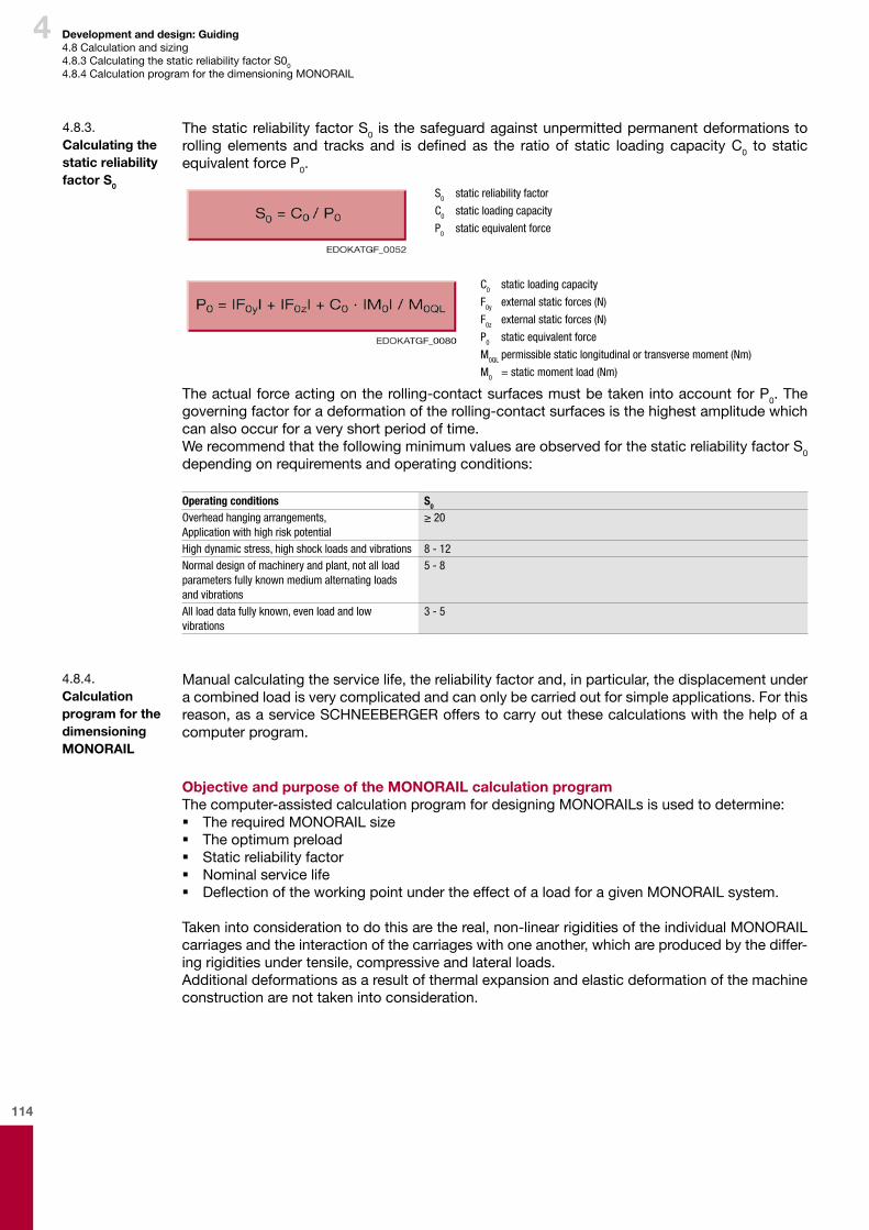
114
4 Development and design: Guiding4.8Calculationandsizing4.8.3CalculatingthestaticreliabilityfactorS00
4.8.4CalculationprogramforthedimensioningMONORAIL
ThestaticreliabilityfactorS0 isthesafeguardagainstunpermittedpermanentdeformationstorolling elements and tracks and is defined as the ratio of static loading capacityC0 to staticequivalentforceP0.
S0 static reliability factor
C0 static loading capacity
P0 static equivalent force
C0 static loading capacity
F0y external static forces (N)
F0z external static forces (N)
P0 static equivalent force
M0QL permissible static longitudinal or transverse moment (Nm)
M0 = static moment load (Nm)
Theactualforceactingontherolling-contactsurfacesmustbetakenintoaccountforP0. The governingfactorforadeformationoftherolling-contactsurfacesisthehighestamplitudewhichcanalsooccurforaveryshortperiodoftime.WerecommendthatthefollowingminimumvaluesareobservedforthestaticreliabilityfactorS0 dependingonrequirementsandoperatingconditions:
Operating conditions S0
Overhead hanging arrangements,Application with high risk potential
≥ 20
High dynamic stress, high shock loads and vibrations 8 - 12Normal design of machinery and plant, not all load parameters fully known medium alternating loads and vibrations
5 - 8
All load data fully known, even load and low vibrations
3 - 5
4.8.3. Calculating the static reliability factor S0
Manualcalculatingtheservicelife,thereliabilityfactorand,inparticular,thedisplacementunderacombinedloadisverycomplicatedandcanonlybecarriedoutforsimpleapplications.Forthisreason,asaserviceSCHNEEBERGERofferstocarryoutthesecalculationswiththehelpofacomputerprogram.
Objective and purpose of the MONORAIL calculation programThecomputer-assistedcalculationprogramfordesigningMONORAILsisusedtodetermine: � TherequiredMONORAILsize � Theoptimumpreload � Staticreliabilityfactor � Nominalservicelife � DeflectionoftheworkingpointundertheeffectofaloadforagivenMONORAILsystem.
Takenintoconsiderationtodothisarethereal,non-linearrigiditiesoftheindividualMONORAILcarriagesandtheinteractionofthecarriageswithoneanother,whichareproducedbythediffer-ingrigiditiesundertensile,compressiveandlateralloads.Additionaldeformationsasaresultofthermalexpansionandelasticdeformationofthemachineconstructionarenottakenintoconsideration.
4.8.4. Calculation program for the dimensioning MONORAIL

115
4 Development and design: Guiding4.8Calculationandsizing4.8.4CalculationprogramforthedimensioningMONORAIL
Required dataBywayofexampleforthedesign,full informationisrequired,asrepresentedonthefollowingmachinedrawingcompletewithdatasheet: � Guidewaygeometrywiththenumberofcarriagesandguiderails,carriagespacingslongitu-dinallyandlaterally
� Positionoftheaxesinspaceanddistancesbetweenthem(distancesbetweenthereferencepointsofadjacentaxes)
� Massesofallmachineaxesandworkpiecesbeingcalculated � Locationofthemasscentresofgravity � Locationofthedriveelementsinrelationtothecorrespondingaxisreferencepoint � Locationoftheloadpoint(pointofattackofforceandmoment) � Maximumtraveldistances(stroke)ofallaxesbeingcalculated � Maximumspeedandaccelerationoftheaxes
Additionally,inthecaseofdifferingloadscenarios: � Collectiveloadwithspeed,acceleration,traveldistanceandpercentageproportionoftimeaswellasmagnitudeanddirectionoftheforcesandmomentsappliedattheworkingpointaccordingtothecorrespondingloadscenario.
Allgeometricaldimensionsarerelatedtothecorrespondingaxiscentre(refertodrawing).ThedesignationoftheaxesintheCartesiancoordinates’systemcanbeselectedasrequired.Fora largenumberof typicalmachinesanddesigns,SCHNEEBERGERcanprovidemachinesketchesanddatasheets.Forfurtherinformation,pleasecontactyourSCHNEEBERGERrepre-sentative.
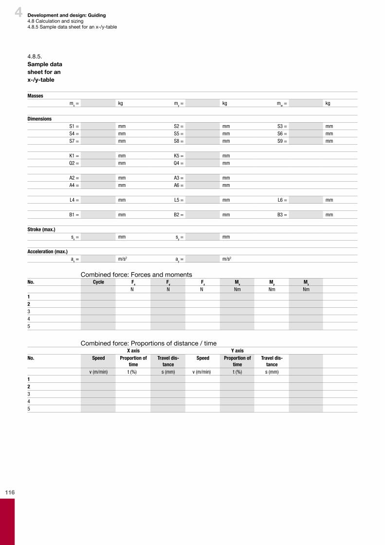
116
4 Development and design: Guiding4.8Calculationandsizing4.8.5Sampledatasheetforanx-/y-table
4.8.5. Sample data sheet for an x-/y-table
Massesmx = kg my = kg mw = kg
DimensionsS1 = mm S2 = mm S3 = mmS4 = mm S5 = mm S6 = mmS7 = mm S8 = mm S9 = mm
K1 = mm K5 = mmQ2 = mm Q4 = mm
A2 = mm A3 = mmA4 = mm A6 = mm
L4 = mm L5 = mm L6 = mm
B1 = mm B2 = mm B3 = mm
Stroke (max.)sx = mm sy = mm
Acceleration (max.)ax = m/s2 ay = m/s2
No. Cycle Fx Fy Fz Mx My Mz
N N N Nm Nm Nm12345
Combinedforce:Forcesandmoments
Combinedforce:Proportionsofdistance/timeX axis Y axis
No. Speed Proportion of time
Travel dis-tance
Speed Proportion of time
Travel dis-tance
v (m/min) t (%) s (mm) v (m/min) t (%) s (mm)12345
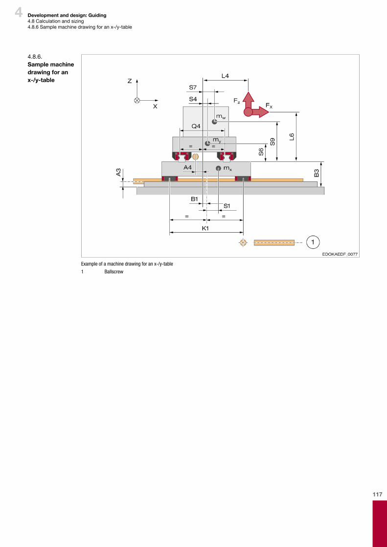
117
4 Development and design: Guiding4.8Calculationandsizing4.8.6Samplemachinedrawingforanx-/y-table
Example of a machine drawing for an x-/y-table
1 Ballscrew
4.8.6. Sample machine drawing for an x-/y-table
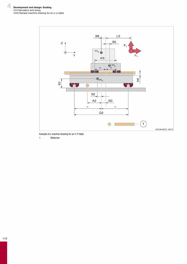
118
4 Development and design: Guiding4.8Calculationandsizing4.8.6Samplemachinedrawingforanx-/y-table
Example of a machine drawing for an X-/Y-table
1 Ballscrew
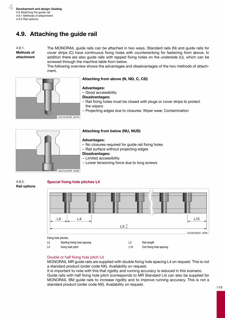
119
4 Development and design: Guiding4.9Attachingtheguiderail4.9.1Methodsofattachment4.9.2Railoptions
4.9. Attaching the guide rail
TheMONORAILguiderailscanbeattachedintwoways.Standardrails(N)andguiderailsforcoverstrips (C)havecontinuousfixingholeswithcountersinking for fastening fromabove. Inadditiontherearealsoguiderailswithtappedfixingholesontheunderside(U),whichcanbescrewedthroughthemachinetablefrombelow.Thefollowingoverviewshowstheadvantagesanddisadvantagesofthetwomethodsofattach-ment.
4.9.1. Methods of attachment
Attaching from above (N, ND, C, CD)
Advantages:–GoodaccessibilityDisadvantages:–Railfixingholesmustbeclosedwithplugsorcoverstripstoprotect thewipers
–Projectingedgesduetoclosures:Wiperwear,Contamination
Attaching from below (NU, NUD)
Advantages:–Noclosuresrequiredforguiderailfixingholes–RailsurfacewithoutprojectingedgesDisadvantages:–Limitedaccessibility–Lowertensioningforceduetolongscrews
Special fixing hole pitches L4
Fixing hole pitches:
L5 Starting fixing hole spacing
L4 fixing hole pitch
L3 Rail length
L10 End fixing hole spacing
DoubleorhalffixingholepitchL4MONORAILMRguiderailsaresuppliedwithdoublefixingholespacingL4onrequest.Thisisnotastandardproduct(ordercodeNX).Availabilityonrequest.Itisimportanttonotewiththisthatrigidityandrunningaccuracyisreducedinthisscenario.Guiderailswithhalffixingholepitch(correspondstoMRStandardL4)canalsobesuppliedforMONORAILBMguiderails to increaserigidityandto improverunningaccuracy.This isnotastandardproduct(ordercodeNX).Availabilityonrequest.
4.9.2. Rail options
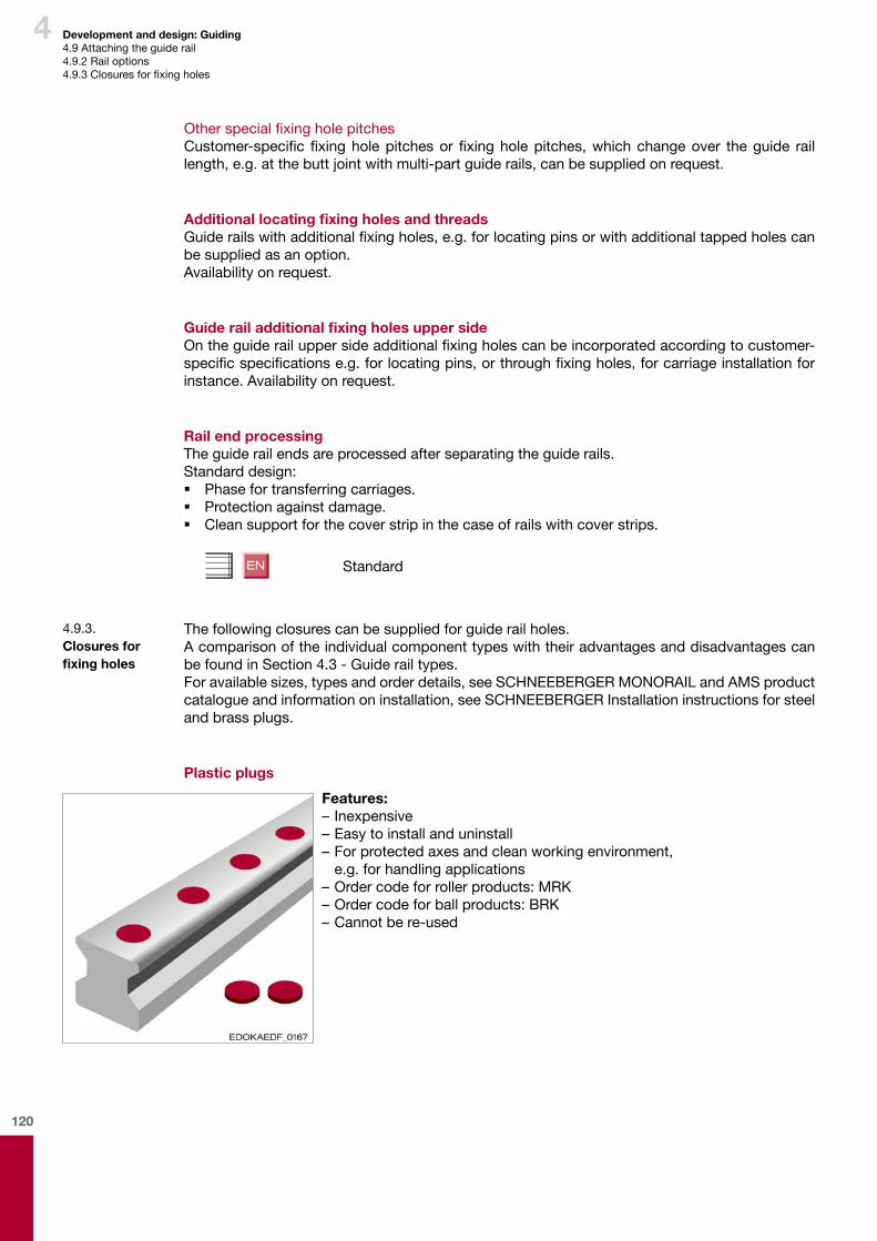
120
4 Development and design: Guiding4.9Attachingtheguiderail4.9.2Railoptions4.9.3Closuresforfixingholes
OtherspecialfixingholepitchesCustomer-specificfixingholepitchesorfixingholepitches,whichchangeover theguide raillength,e.g.atthebuttjointwithmulti-partguiderails,canbesuppliedonrequest.
Additional locating fixing holes and threadsGuiderailswithadditionalfixingholes,e.g.forlocatingpinsorwithadditionaltappedholescanbesuppliedasanoption.Availabilityonrequest.
Guide rail additional fixing holes upper sideOntheguiderailuppersideadditionalfixingholescanbeincorporatedaccordingtocustomer-specificspecificationse.g.forlocatingpins,orthroughfixingholes,forcarriageinstallationforinstance.Availabilityonrequest.
Rail end processingTheguiderailendsareprocessedafterseparatingtheguiderails.Standarddesign: � Phasefortransferringcarriages. � Protectionagainstdamage. � Cleansupportforthecoverstripinthecaseofrailswithcoverstrips.
Standard
Thefollowingclosurescanbesuppliedforguiderailholes.AcomparisonoftheindividualcomponenttypeswiththeiradvantagesanddisadvantagescanbefoundinSection4.3-Guiderailtypes.Foravailablesizes,typesandorderdetails,seeSCHNEEBERGERMONORAILandAMSproductcatalogueandinformationoninstallation,seeSCHNEEBERGERInstallationinstructionsforsteelandbrassplugs.
Plastic plugs
4.9.3. Closures for fixing holes
Features:–Inexpensive–Easytoinstallanduninstall–Forprotectedaxesandcleanworkingenvironment, e.g.forhandlingapplications–Ordercodeforrollerproducts:MRK–Ordercodeforballproducts:BRK–Cannotbere-used
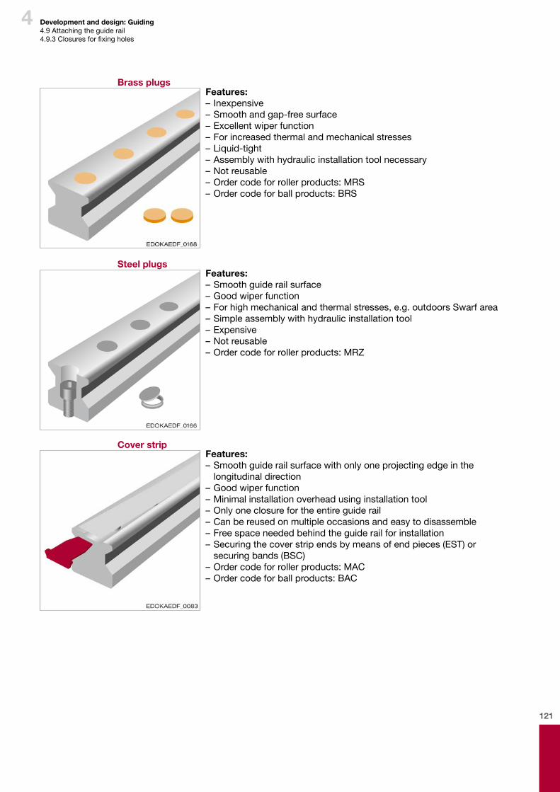
121
4 Development and design: Guiding4.9Attachingtheguiderail4.9.3Closuresforfixingholes
Features:–Inexpensive–Smoothandgap-freesurface–Excellentwiperfunction–Forincreasedthermalandmechanicalstresses–Liquid-tight–Assemblywithhydraulicinstallationtoolnecessary–Notreusable–Ordercodeforrollerproducts:MRS–Ordercodeforballproducts:BRS
Brass plugs
Steel plugsFeatures:–Smoothguiderailsurface–Goodwiperfunction–Forhighmechanicalandthermalstresses,e.g.outdoorsSwarfarea–Simpleassemblywithhydraulicinstallationtool–Expensive–Notreusable–Ordercodeforrollerproducts:MRZ
Cover stripFeatures:–Smoothguiderailsurfacewithonlyoneprojectingedgeinthe longitudinaldirection
–Goodwiperfunction–Minimalinstallationoverheadusinginstallationtool–Onlyoneclosurefortheentireguiderail–Canbereusedonmultipleoccasionsandeasytodisassemble–Freespaceneededbehindtheguiderailforinstallation–Securingthecoverstripendsbymeansofendpieces(EST)or securingbands(BSC)
–Ordercodeforrollerproducts:MAC–Ordercodeforballproducts:BAC
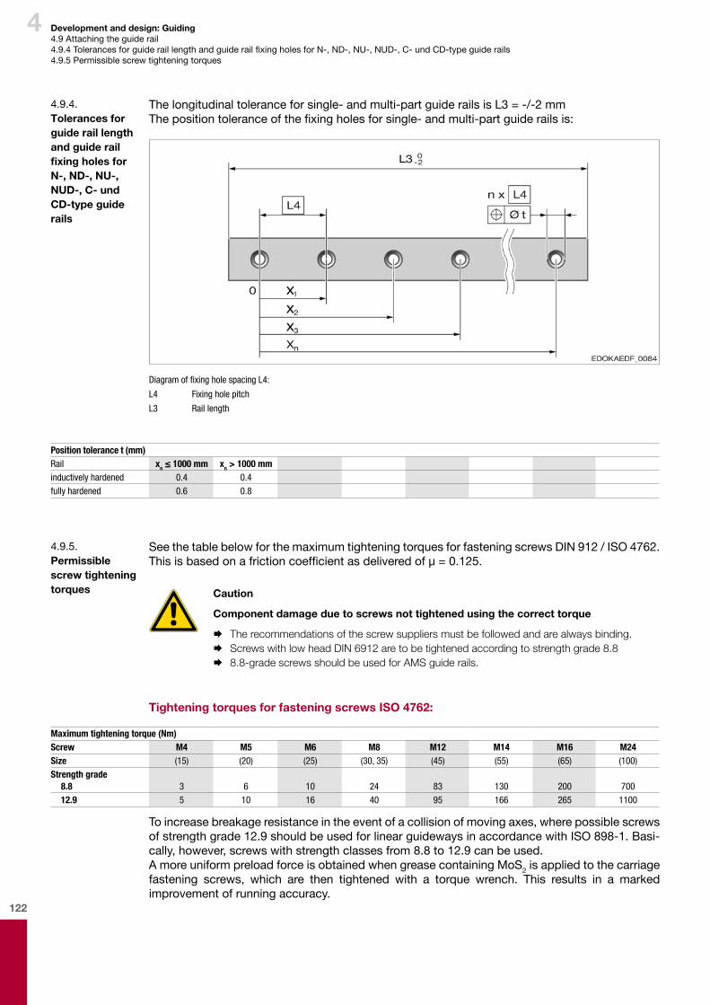
122
4 Development and design: Guiding4.9Attachingtheguiderail4.9.4TolerancesforguideraillengthandguiderailfixingholesforN-,ND-,NU-,NUD-,C-undCD-typeguiderails4.9.5Permissiblescrewtighteningtorques
Thelongitudinaltoleranceforsingle-andmulti-partguiderailsisL3=-/-2mmThepositiontoleranceofthefixingholesforsingle-andmulti-partguiderailsis:
Diagram of fixing hole spacing L4:
L4 Fixing hole pitch
L3 Rail length
4.9.4. Tolerances for guide rail length and guide rail fixing holes for N-, ND-, NU-, NUD-, C- und CD-type guide rails
Position tolerance t (mm)Rail xn ≤ 1000 mm xn > 1000 mminductively hardened 0.4 0.4fully hardened 0.6 0.8
SeethetablebelowforthemaximumtighteningtorquesforfasteningscrewsDIN912/ISO4762.Thisisbasedonafrictioncoefficientasdeliveredofμ=0.125.
Caution
Component damage due to screws not tightened using the correct torque
¨ The recommendations of the screw suppliers must be followed and are always binding. ¨ Screws with low head DIN 6912 are to be tightened according to strength grade 8.8 ¨ 8.8-grade screws should be used for AMS guide rails.
Tightening torques for fastening screws ISO 4762:
4.9.5. Permissible screw tightening torques
Maximum tightening torque (Nm)Screw M4 M5 M6 M8 M12 M14 M16 M24Size (15) (20) (25) (30, 35) (45) (55) (65) (100)Strength grade
8.8 3 6 10 24 83 130 200 70012.9 5 10 16 40 95 166 265 1100
Toincreasebreakageresistanceintheeventofacollisionofmovingaxes,wherepossiblescrewsofstrengthgrade12.9shouldbeusedforlinearguidewaysinaccordancewithISO898-1.Basi-cally,however,screwswithstrengthclassesfrom8.8to12.9canbeused.AmoreuniformpreloadforceisobtainedwhengreasecontainingMoS2isappliedtothecarriagefastening screws, which are then tightened with a torque wrench. This results in a markedimprovementofrunningaccuracy.
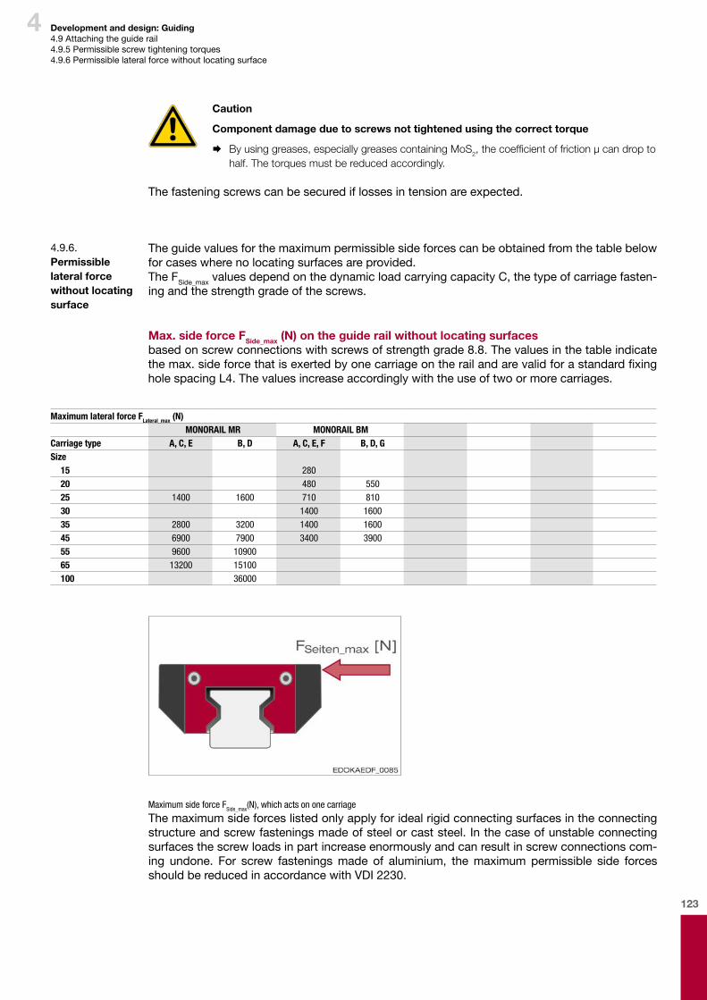
123
4 Development and design: Guiding4.9Attachingtheguiderail4.9.5Permissiblescrewtighteningtorques4.9.6Permissiblelateralforcewithoutlocatingsurface
Theguidevaluesforthemaximumpermissiblesideforcescanbeobtainedfromthetablebelowforcaseswherenolocatingsurfacesareprovided.The FSide_maxvaluesdependonthedynamicloadcarryingcapacityC,thetypeofcarriagefasten-ingandthestrengthgradeofthescrews.
Max. side force FSide_max (N) on the guide rail without locating surfacesbasedonscrewconnectionswithscrewsofstrengthgrade8.8.Thevaluesinthetableindicatethemax.sideforcethatisexertedbyonecarriageontherailandarevalidforastandardfixingholespacingL4.Thevaluesincreaseaccordinglywiththeuseoftwoormorecarriages.
4.9.6. Permissible lateral force without locating surface
Maximum lateral force FLateral_max (N)MONORAIL MR MONORAIL BM
Carriage type A, C, E B, D A, C, E, F B, D, GSize
15 28020 480 55025 1400 1600 710 81030 1400 160035 2800 3200 1400 160045 6900 7900 3400 390055 9600 1090065 13200 15100100 36000
Maximum side force FSide_max(N), which acts on one carriage
Caution
Component damage due to screws not tightened using the correct torque
¨ By using greases, especially greases containing MoS2, the coefficient of friction µ can drop to half. The torques must be reduced accordingly.
Thefasteningscrewscanbesecurediflossesintensionareexpected.
Themaximumsideforceslistedonlyapplyforidealrigidconnectingsurfacesintheconnectingstructureandscrewfasteningsmadeofsteelorcaststeel.Inthecaseofunstableconnectingsurfacesthescrewloadsinpartincreaseenormouslyandcanresultinscrewconnectionscom-ing undone. For screw fasteningsmade of aluminium, themaximum permissible side forcesshouldbereducedinaccordancewithVDI2230.
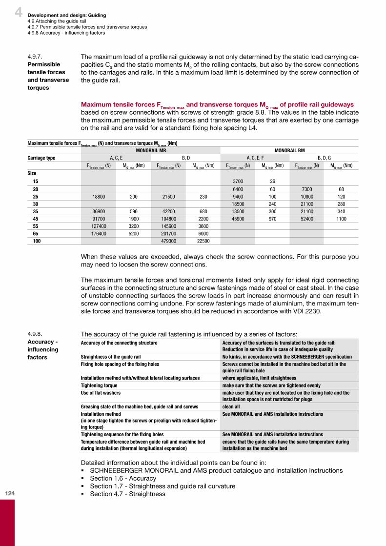
124
4 Development and design: Guiding4.9Attachingtheguiderail4.9.7Permissibletensileforcesandtransversetorques4.9.8Accuracy-influencingfactors
Theaccuracyoftheguiderailfasteningisinfluencedbyaseriesoffactors:Accuracy of the connecting structure Accuracy of the surfaces is translated to the guide rail:
Reduction in service life in case of inadequate qualityStraightness of the guide rail No kinks, in accordance with the SCHNEEBERGER specificationFixing hole spacing of the fixing holes Screws cannot be installed in the machine bed but sit in the
guide rail fixing holeInstallation method with/without lateral locating surfaces where applicable, limit straightnessTightening torque make sure that the screws are tightened evenlyUse of flat washers make user that they are not located on the fixing hole and the
installation space is not restricted for plugsGreasing state of the machine bed, guide rail and screws clean allInstallation method (in one stage tighten the screws or prealign with reduced tighten-ing torque)
See MONORAIL and AMS installation instructions
Tightening sequence for the fixing holes See MONORAIL and AMS installation instructionsTemperature difference between guide rail and machine bed during installation (thermal longitudinal expansion)
ensure that the guide rails have the same temperature during installation as the machine bed
Detailedinformationabouttheindividualpointscanbefoundin: � SCHNEEBERGERMONORAILandAMSproductcatalogueandinstallationinstructions � Section1.6-Accuracy � Section1.7-Straightnessandguiderailcurvature � Section4.7-Straightness
4.9.7. Permissible tensile forces and transverse torques
4.9.8. Accuracy - influencing factors
Themaximumloadofaprofilerailguidewayisnotonlydeterminedbythestaticloadcarryingca-pacitiesC0andthestaticmomentsM0oftherollingcontacts,butalsobythescrewconnectionstothecarriagesandrails.Inthisamaximumloadlimitisdeterminedbythescrewconnectionoftheguiderail.
Maximum tensile forces FTension_max and transverse torques MQ_max of profile rail guidewaysbasedonscrewconnectionswithscrewsofstrengthgrade8.8.ThevaluesinthetableindicatethemaximumpermissibletensileforcesandtransversetorquesthatareexertedbyonecarriageontherailandarevalidforastandardfixingholespacingL4.
Maximum tensile forces FTension_max (N) and transverse torques MQ_max (Nm)MONORAIL MR MONORAIL BM
Carriage type A, C, E B, D A, C, E, F B, D, GFTension_max (N) MQ_max (Nm) FTension_max (N) MQ_max (Nm) FTension_max (N) MQ_max (Nm) FTension_max (N) MQ_max (Nm)
Size
15 3700 26
20 6400 60 7300 6825 18800 200 21500 230 9400 100 10800 12030 18500 240 21100 28035 36900 590 42200 680 18500 300 21100 34045 91700 1900 104800 2200 45900 970 52400 110055 127400 3200 145600 360065 176400 5200 201700 6000100 479300 22500
Whenthesevaluesareexceeded,alwayscheckthescrewconnections.For thispurposeyoumayneedtoloosenthescrewconnections.
Themaximumtensileforcesandtorsionalmomentslistedonlyapplyforidealrigidconnectingsurfacesintheconnectingstructureandscrewfasteningsmadeofsteelorcaststeel.Inthecaseofunstableconnectingsurfacesthescrewloadsinpartincreaseenormouslyandcanresultinscrewconnectionscomingundone.Forscrewfasteningsmadeofaluminium,themaximumten-sileforcesandtransversetorquesshouldbereducedinaccordancewithVDI2230.
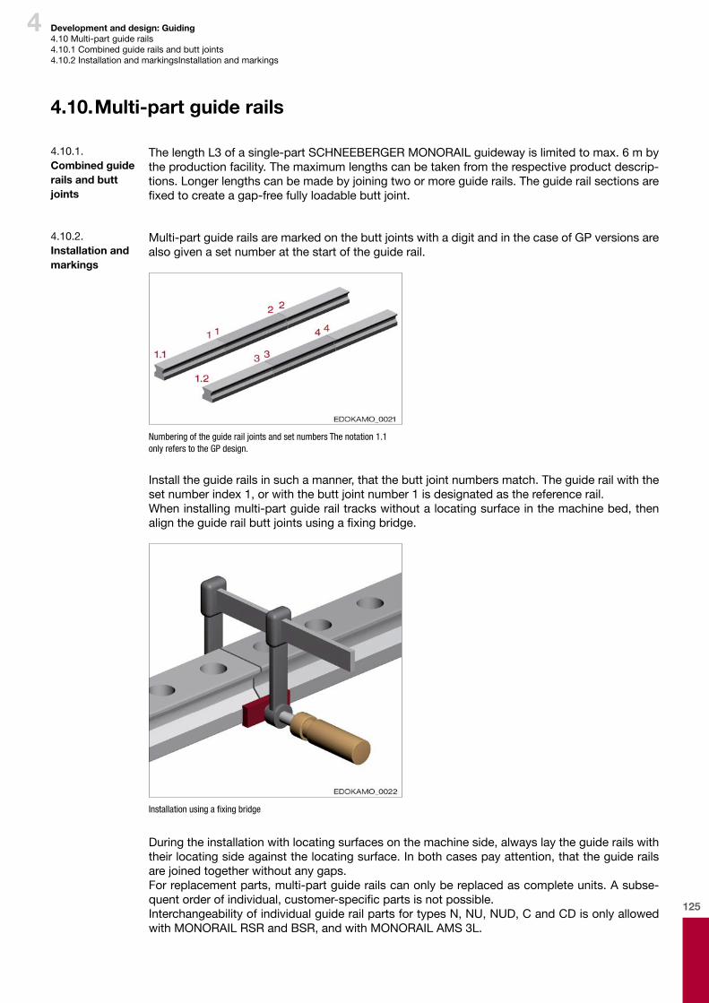
125
4 Development and design: Guiding4.10Multi-partguiderails4.10.1Combinedguiderailsandbuttjoints4.10.2InstallationandmarkingsInstallationandmarkings
4.10. Multi-part guide rails
ThelengthL3ofasingle-partSCHNEEBERGERMONORAILguidewayislimitedtomax.6mbytheproductionfacility.Themaximumlengthscanbetakenfromtherespectiveproductdescrip-tions.Longerlengthscanbemadebyjoiningtwoormoreguiderails.Theguiderailsectionsarefixedtocreateagap-freefullyloadablebuttjoint.
4.10.1. Combined guide rails and butt joints
Multi-partguiderailsaremarkedonthebuttjointswithadigitandinthecaseofGPversionsarealsogivenasetnumberatthestartoftheguiderail.
Numbering of the guide rail joints and set numbers The notation 1.1 only refers to the GP design.
Installtheguiderailsinsuchamanner,thatthebuttjointnumbersmatch.Theguiderailwiththesetnumberindex1,orwiththebuttjointnumber1isdesignatedasthereferencerail.Wheninstallingmulti-partguiderailtrackswithoutalocatingsurfaceinthemachinebed,thenaligntheguiderailbuttjointsusingafixingbridge.
Installation using a fixing bridge
Duringtheinstallationwithlocatingsurfacesonthemachineside,alwayslaytheguiderailswiththeirlocatingsideagainstthelocatingsurface.Inbothcasespayattention,thattheguiderailsarejoinedtogetherwithoutanygaps.Forreplacementparts,multi-partguiderailscanonlybereplacedascompleteunits.Asubse-quentorderofindividual,customer-specificpartsisnotpossible.InterchangeabilityofindividualguiderailpartsfortypesN,NU,NUD,CandCDisonlyallowedwithMONORAILRSRandBSR,andwithMONORAILAMS3L.
4.10.2. Installation and markings
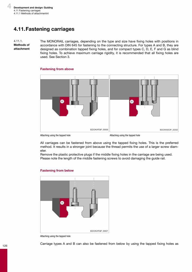
126
4 Development and design: Guiding4.11Fasteningcarriages4.11.1Methodsofattachmentnt
4.11. Fastening carriages
TheMONORAILcarriages,dependingonthetypeandsizehavefixingholeswithpositions inaccordancewithDIN645forfasteningtotheconnectingstructure.FortypesAandB,theyaredesignedascombinationtappedfixingholes,andforcompacttypesC,D,E,FandGasblindfixingholes.Toachievemaximumcarriage rigidity, it is recommended thatallfixingholesareused.SeeSection3.
Fastening from above
Attaching using the tapped hole Attaching using the tapped hole
All carriagescanbe fastened fromaboveusing the tappedfixingholes.This is thepreferredmethod.Itresultsinastrongerjointbecausethethreadpermitstheuseofalargerscrewdiam-eter.Removetheplasticprotectiveplugsifthemiddlefixingholesinthecarriagearebeingused.Pleasenotethelengthofthemiddlefasteningscrewstoavoiddamagingtheguiderail.
Fastening from below
Attaching using the tapped hole
CarriagetypesAandBcanalsobefastenedfrombelowbyusingthetappedfixingholesas
4.11.1. Methods of attachment
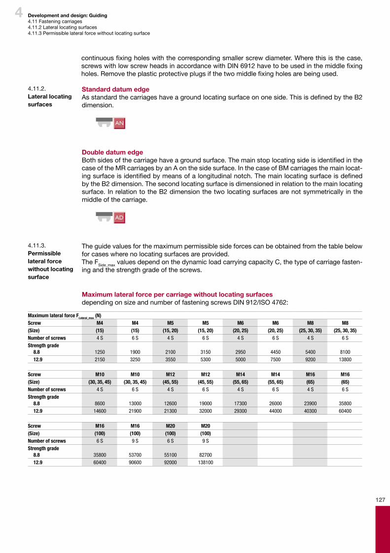
127
4 Development and design: Guiding4.11Fasteningcarriages4.11.2Laterallocatingsurfaces4.11.3Permissiblelateralforcewithoutlocatingsurface
Standard datum edgeAsstandardthecarriageshaveagroundlocatingsurfaceononeside.ThisisdefinedbytheB2dimension.
Double datum edgeBothsidesofthecarriagehaveagroundsurface.ThemainstoplocatingsideisidentifiedinthecaseoftheMRcarriagesbyanAonthesidesurface.InthecaseofBMcarriagesthemainlocat-ingsurfaceisidentifiedbymeansofalongitudinalnotch.ThemainlocatingsurfaceisdefinedbytheB2dimension.Thesecondlocatingsurfaceisdimensionedinrelationtothemainlocatingsurface.InrelationtotheB2dimensionthetwolocatingsurfacesarenotsymmetrically inthemiddleofthecarriage.
4.11.2. Lateral locating surfaces
Theguidevaluesforthemaximumpermissiblesideforcescanbeobtainedfromthetablebelowforcaseswherenolocatingsurfacesareprovided.The FSide_maxvaluesdependonthedynamicloadcarryingcapacityC,thetypeofcarriagefasten-ingandthestrengthgradeofthescrews.
Maximum lateral force per carriage without locating surfacesdependingonsizeandnumberoffasteningscrewsDIN912/ISO4762:
4.11.3. Permissible lateral force without locating surface
Maximum lateral force FLateral_max (N)Screw M4 M4 M5 M5 M6 M6 M8 M8 (Size) (15) (15) (15, 20) (15, 20) (20, 25) (20, 25) (25, 30, 35) (25, 30, 35)Number of screws 4 S 6 S 4 S 6 S 4 S 6 S 4 S 6 SStrength grade
8.8 1250 1900 2100 3150 2950 4450 5400 810012.9 2150 3250 3550 5300 5000 7500 9200 13800
Screw M10 M10 M12 M12 M14 M14 M16 M16(Size) (30, 35, 45) (30, 35, 45) (45, 55) (45, 55) (55, 65) (55, 65) (65) (65)Number of screws 4 S 6 S 4 S 6 S 4 S 6 S 4 S 6 SStrength grade
8.8 8600 13000 12600 19000 17300 26000 23900 3580012.9 14600 21900 21300 32000 29300 44000 40300 60400
Screw M16 M16 M20 M20 (Size) (100) (100) (100) (100)Number of screws 6 S 9 S 6 S 9 SStrength grade
8.8 35800 53700 55100 8270012.9 60400 90600 92000 138100
continuousfixingholeswiththecorrespondingsmallerscrewdiameter.Wherethisisthecase,screwswithlowscrewheadsinaccordancewithDIN6912havetobeusedinthemiddlefixingholes.Removetheplasticprotectiveplugsifthetwomiddlefixingholesarebeingused.

128
4 Development and design: Guiding4.11Fasteningcarriages4.11.4Influenceofthenumberfasteningscrewsonrigidity4.11.5Permissiblescrewtighteningtorques
Thediagram illustrates thecorrelationbetweenguideway rigidityand thenumberandqualityofthefasteningscrewspercarriage.Particularlyundertensileload,theelasticdeformationin-creasessignificantlywhenreducingthenumberofscrewsfrom6to4screws.
1 4 screws, quality grade 8.8 2 4 screws, quality grade 12.9 3 6 screws, quality grade 8.8
δ Deformation under force F
F Force
Influence of carriage fastening on rigidity based on the example of a 4-row ball guideway with O-geometry. The force F (kN) under tension and pressure is applied against the deformation δ (μm).
4.11.4. Influence of the number fastening screws on rigidity
SeethetablebelowforthemaximumtighteningtorquesforfasteningscrewsinaccordancewithISO4762.Thisisbasedonafrictioncoefficientasdeliveredofμ=0.125.
Caution
Component damage due to screws not tightened using the correct torque
¨ The recommendations of the screw suppliers must be followed and are always binding. ¨ Screws with low head DIN 6912 are to be tightened according to strength grade 8.8
Tightening torques for fastening screws ISO 4762:Toincreasebreakageresistanceintheeventofacollisionofmovingaxes,wherepossiblescrewsofstrengthgrade12.9shouldbeusedforlinearguidewaysinaccordancewithISO898-1.Basi-cally,however,screwswithstrengthclassesfrom8.8to12.9canbeused.
4.11.5. Permissible screw tightening torques
Maximum tightening torque (Nm)Screw M4 M5 M6 M8 M10 M12 M14 M16(Size) (15) (15, 20) (20, 25) (25-35) (30-45) (45, 55) (55) (65)Strength grade
8.8 3 6 10 25 49 83 130 20012.9 5 10 16 40 81 95 166 265
Screw M20(Size) (100)Strength grade
8.8 41012.9 680
Amoreuniformpreloadforce isobtainedwhengreasecontainingMoS2 isappliedtothecar-riagefasteningscrews,whicharethentightenedwithatorquewrench.Thisresultsinamarkedimprovementofrunningaccuracy.

129
4 Development and design: Guiding4.11Fasteningcarriages4.11.5Permissiblescrewtighteningtorques4.11.6Minimumscrewdepth
Therequiredscrewlengthforthecarriagefasteningcanbedeterminedbasedonthethicknessofthecarriageorofthemachineslideandtheminimumscrewdepthe.g. inaccordancewithguidelineVDI2230.Forcarriagedimensions,seeSCHNEEBERGERMONORAILandAMSprod-uctcatalogue.
4.11.6. Minimum screw depth
Caution
Component damage due to screws not tightened using the incorrect torque
¨ By using greases, especially greases containing MoS2, the coefficient of friction µ can drop to half. The torques must be reduced accordingly.
Securethescrewsifanylossoftensionisexpected.
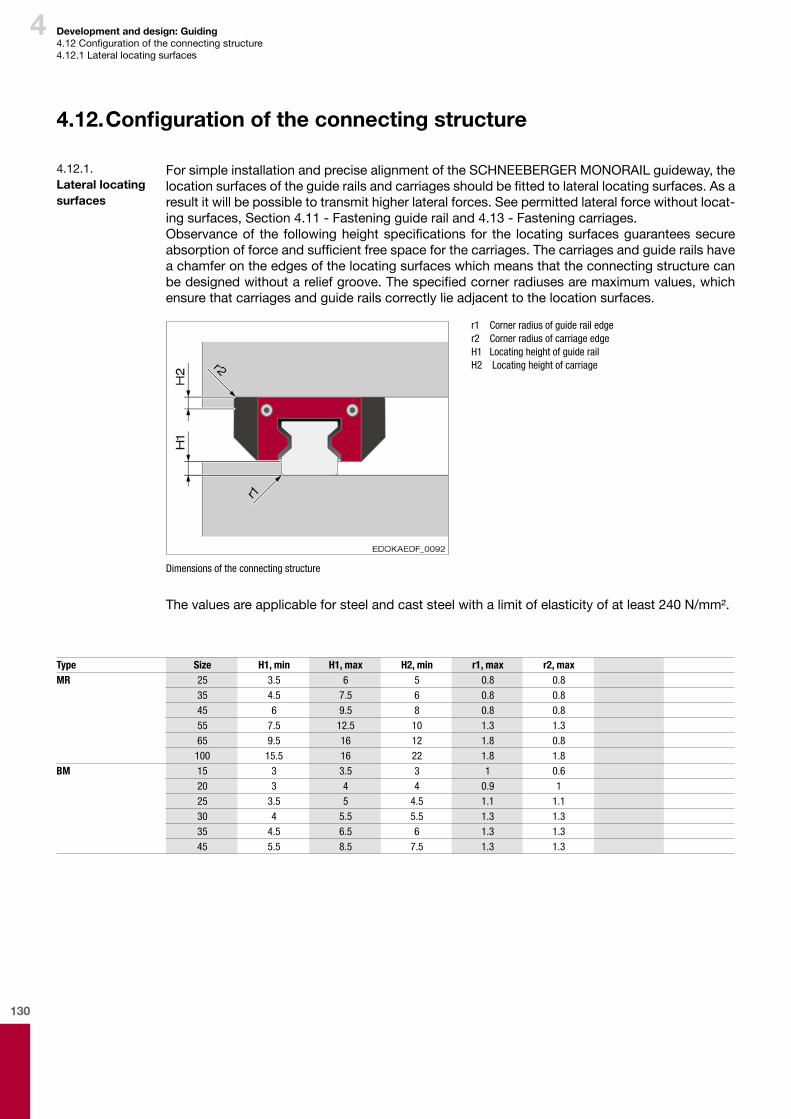
130
4 Development and design: Guiding4.12Configurationoftheconnectingstructure4.12.1Laterallocatingsurfaces
4.12. Configuration of the connecting structure
ForsimpleinstallationandprecisealignmentoftheSCHNEEBERGERMONORAILguideway,thelocationsurfacesoftheguiderailsandcarriagesshouldbefittedtolaterallocatingsurfaces.Asaresultitwillbepossibletotransmithigherlateralforces.Seepermittedlateralforcewithoutlocat-ingsurfaces,Section4.11-Fasteningguiderailand4.13-Fasteningcarriages.Observanceof the followingheightspecifications for the locatingsurfacesguaranteessecureabsorptionofforceandsufficientfreespaceforthecarriages.Thecarriagesandguiderailshaveachamferontheedgesofthelocatingsurfaceswhichmeansthattheconnectingstructurecanbedesignedwithoutareliefgroove.Thespecifiedcornerradiusesaremaximumvalues,whichensurethatcarriagesandguiderailscorrectlylieadjacenttothelocationsurfaces.
r1 Corner radius of guide rail edge r2 Corner radius of carriage edge H1 Locating height of guide rail H2 Locating height of carriage
Dimensions of the connecting structure
Thevaluesareapplicableforsteelandcaststeelwithalimitofelasticityofatleast240N/mm².
4.12.1. Lateral locating surfaces
Type Size H1, min H1, max H2, min r1, max r2, maxMR 25 3.5 6 5 0.8 0.8
35 4.5 7.5 6 0.8 0.845 6 9.5 8 0.8 0.855 7.5 12.5 10 1.3 1.365 9.5 16 12 1.8 0.8
100 15.5 16 22 1.8 1.8BM 15 3 3.5 3 1 0.6
20 3 4 4 0.9 125 3.5 5 4.5 1.1 1.130 4 5.5 5.5 1.3 1.335 4.5 6.5 6 1.3 1.345 5.5 8.5 7.5 1.3 1.3

131
4
4.12.2. Methods of orientation for the rail
Thealignmentoftheguiderailsdependsontherequiredlevelofaccuracyandmustbecarefullydevisedrightatthedesignphaseasthenumberandpositionofthelocatingsurfacesaresetatthispoint.SeeSection4.14-Configurationoftheconnectingstructure.Adistinctionismadebetweenthefollowingtypesofalignment:
Features:–Noreferenceedgeavailable–Manualalignmentwithouttools–Notrecommended–Verylowlevelofaccuracy
Features:–Noreferenceedgeavailable–Manualalignmentwithtools,e.g.aligninggauge,guidestrip, dialgauge,installationcarriage
–Dependingonthecomplexity,averagetohighlevelofaccuracy
Features:–Lateraldatuminthemachinebed–Alignmentbypressingagainstlocatingsurface–Highlevelofaccuracy,dependingontheaccuracyofthereferenceedge–Minimaltimerequired
Features:–Laterallocatingsurfacesandadditionallateralclamping–Alignmentbypressingagainstlocatingsurfacesusinglateralfixing components
–Veryhighlevelofaccuracy,dependingontheaccuracyofthe referenceedge
–Minimaltimerequired
WhenusinglaterallocatingsurfacesforinstallingtheSCHNEEBERGERMONORAILguidewaysitisrecommendedthattheoppositesideoftheguiderailandcarriagearealsofixedwithpress-oncomponents.Thismakesiteasiertoaligntheguidewayandsupportshighlateralforceabsorp-tioninbothdirections.Differentpress-oncomponentscanbeusedforlateralclamping.Theheightofthetransmittablelateral forcesdependsontherespectivedesignandneedstobecheckedonacasebycasebasis.
Adjustingscrews andclampingstrips
Singleordouble wedgestrips
Shaftwithcounter- sunkheadscrew
Eccentricscrew
Development and design: Guiding4.12Configurationoftheconnectingstructure4.12.2Methodsoforientationfortherail4.12.3Laterallocatingsurfaces
4.12.3. Lateral locating surfaces
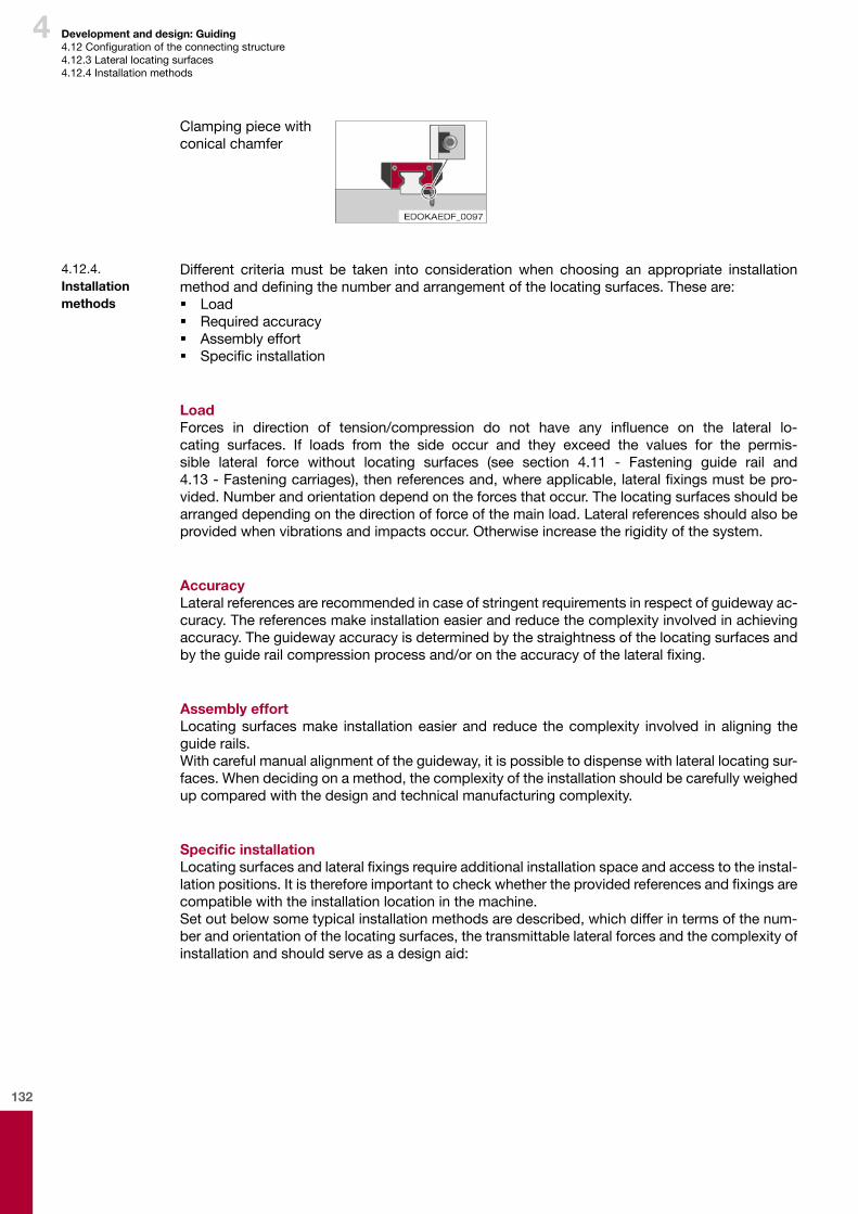
132
4 Development and design: Guiding4.12Configurationoftheconnectingstructure4.12.3Laterallocatingsurfaces4.12.4Installationmethods
Clampingpiecewithconicalchamfer
Different criteriamust be taken into consideration when choosing an appropriate installationmethodanddefiningthenumberandarrangementofthelocatingsurfaces.Theseare: � Load � Requiredaccuracy � Assemblyeffort � Specificinstallation
LoadForces in direction of tension/compression do not have any influence on the lateral lo-cating surfaces. If loads from the side occur and they exceed the values for the permis-sible lateral force without locating surfaces (see section 4.11 - Fastening guide rail and 4.13-Fasteningcarriages),thenreferencesand,whereapplicable,lateralfixingsmustbepro-vided.Numberandorientationdependontheforcesthatoccur.Thelocatingsurfacesshouldbearrangeddependingonthedirectionofforceofthemainload.Lateralreferencesshouldalsobeprovidedwhenvibrationsandimpactsoccur.Otherwiseincreasetherigidityofthesystem.
AccuracyLateralreferencesarerecommendedincaseofstringentrequirementsinrespectofguidewayac-curacy.Thereferencesmakeinstallationeasierandreducethecomplexityinvolvedinachievingaccuracy.Theguidewayaccuracyisdeterminedbythestraightnessofthelocatingsurfacesandbytheguiderailcompressionprocessand/orontheaccuracyofthelateralfixing.
Assembly effortLocatingsurfacesmake installationeasierand reduce thecomplexity involved inaligning theguiderails.Withcarefulmanualalignmentoftheguideway,itispossibletodispensewithlaterallocatingsur-faces.Whendecidingonamethod,thecomplexityoftheinstallationshouldbecarefullyweighedupcomparedwiththedesignandtechnicalmanufacturingcomplexity.
Specific installationLocatingsurfacesandlateralfixingsrequireadditionalinstallationspaceandaccesstotheinstal-lationpositions.Itisthereforeimportanttocheckwhethertheprovidedreferencesandfixingsarecompatiblewiththeinstallationlocationinthemachine.Setoutbelowsometypicalinstallationmethodsaredescribed,whichdifferintermsofthenum-berandorientationofthelocatingsurfaces,thetransmittablelateralforcesandthecomplexityofinstallationandshouldserveasadesignaid:
4.12.4. Installation methods
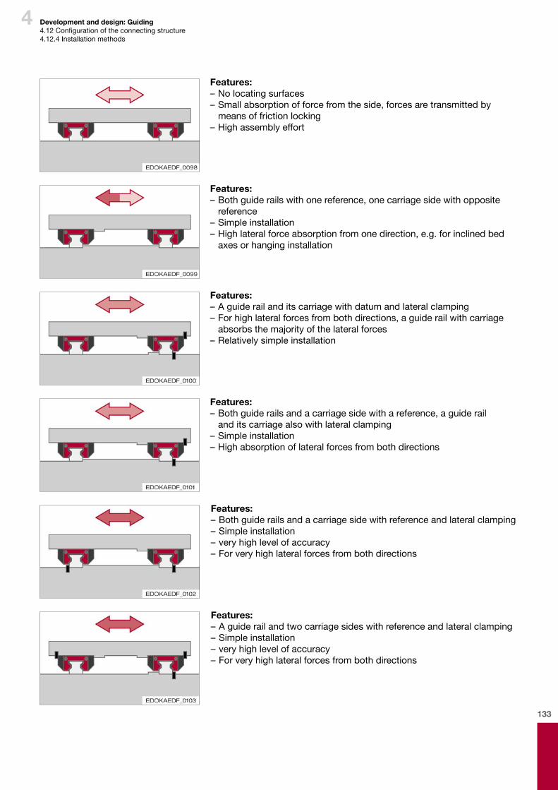
133
4
Features:–Nolocatingsurfaces–Smallabsorptionofforcefromtheside,forcesaretransmittedbymeansoffrictionlocking
–Highassemblyeffort
Features:–Bothguiderailswithonereference,onecarriagesidewithopposite
reference–Simpleinstallation–Highlateralforceabsorptionfromonedirection,e.g.forinclinedbedaxesorhanginginstallation
Features:–Aguiderailanditscarriagewithdatumandlateralclamping–Forhighlateralforcesfrombothdirections,aguiderailwithcarriageabsorbsthemajorityofthelateralforces
–Relativelysimpleinstallation
Features:–Bothguiderailsandacarriagesidewithareference,aguiderail anditscarriagealsowithlateralclamping
–Simpleinstallation–Highabsorptionoflateralforcesfrombothdirections
Features:–Bothguiderailsandacarriagesidewithreferenceandlateralclamping–Simpleinstallation–veryhighlevelofaccuracy–Forveryhighlateralforcesfrombothdirections
Features:–Aguiderailandtwocarriagesideswithreferenceandlateralclamping–Simpleinstallation–veryhighlevelofaccuracy–Forveryhighlateralforcesfrombothdirections
Development and design: Guiding4.12Configurationoftheconnectingstructure4.12.4Installationmethods

134
4
The capabilities of theSCHNEEBERGERMONORAIL guideways can only be achievedwhenmountedtoarigidstructurewithahighlevelofgeometricaccuracy.Inaccuraciesintheattach-mentsurfacesarepartiallycompensatedforbytheelasticdeformationoftheMONORAILguide-ways,however,theymayaffectoverallaccuracy,runningbehaviour,pushforceandservicelife.Unstableconnectingsurfacesincreasetheinternalconstrainingforcesoftheguideways,whichcanalsoadverselyaffectservicelife.Whenthetolerancessetoutbelowareobservedforheightdeviationandparallelism,theinflu-enceonservicelifeisnegligibleinpractice.
Surface quality of the connecting surfacesThesurfacequalityofthesupportingsurfacedoesnothaveadirectinfluenceonthefunctionandrunningbehaviouroftheguideway,butitdoestothestaticaccuracy.Carriagesandguiderailsarecompressedagainstthelocationsurfacesbythescrewconnectionswithahighlevelofforce.Topreventsettlingbehaviouroftheconnection,ahighsurfacecontactratioisrequired.Thisisachievedbymeansofhighlevelofsurfacequality.AnaveragesurfaceroughnessofRa0.4to1.6 μmisrecommendedforthesupportingandlocatingsurfaces.
Permissible deviations in transverse directionUsevaluesinmmforthecalculation.
Permissible deviations in transverse direction:B Carriage width (mm)B1 Guide rail width (mm) E1 height deviation laterallyE3 Parallelism of guide rail supporting surface laterally
E4 Parallelism of carriage supporting surface laterallyE6 Evenness of the guide rail supporting surfaceE7 Evenness of the carriage supporting surfaceQ Guide rail spacing system (mm)
HeightdeviationlaterallyE1=E1.1+E1.2.Thisalsoincludesthetoleranceforthedimension A=MONORAILheight
E1 height deviation laterally
Q Guide rail spacing system (mm)
vvsp Preload factor
ParallelismofguiderailsupportingsurfacelaterallyE3:
B1 Guide rail width(mm)
E3 Parallelism of the guide rail supporting surface laterally
vvsp Preload factor
4.12.5. Geometrical and position accuracy of the support surfaces
Development and design: Guiding4.12Configurationoftheconnectingstructure4.12.5Geometricalandpositionaccuracyofthesupportsurfaces

135
4
ParallelismofcarriagesupportingsurfacelaterallyE4:
B Carriage width (mm)
E4 Parallelism of the carriage supporting surface laterally
vvsp Preload factor
PreloadfactorThepreloadfactordescribestheinfluenceofpreloadontherequirementsinrespectofaccuracyofthesupportingsurfacesofcarriageandguiderail.Ahigherpreloadmeanshigherrigidityandthusgreaterinternalforcesincaseofdeviationsintheconnectingsurfaces.
Preload factor vvsp
Preload V0 / V1 V2 V3vvsp 3.0 2.0 1.0
Permissible deviations in longitudinal direction
Permissible deviations in longitudinal direction:L Total carriage lengthE2 Height difference between carriage 1 and carriage 2
E5 Parallelism of carriage support longitudinallyK Carriage spacing longitudinally
HeightdeviationlongitudinallyE2alsoincludesthemaximumdimensionaldifferenceΔAinthecarriagesbetweenthecarriagesonaguiderail:
E2 Height difference between carriage 1 and carriage 2
K Carriage spacing longitudinally
t carriage factor:
= 5 for MRA/C and BMA/C/F
= 4 for MRB/D and BMB/D/G
ParallelismofthecarriagesupportingsurfacelongitudinallyE5:
E5 Parallelism of carriage support longitudinally
L Total carriage length
Development and design: Guiding4.12Configurationoftheconnectingstructure4.12.5Geometricalandpositionaccuracyofthesupportsurfaces
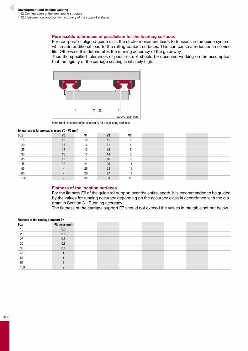
136
4
Permissible tolerances of parallelism for the locating surfacesFornon-parallelalignedguiderails,thestrokemovementleadstotensionsintheguidesystem,whichaddadditionalloadtotherollingcontactsurfaces.Thiscancauseareductioninservicelife.Otherwisethisdeterioratestherunningaccuracyoftheguideway.ThusthespecifiedtolerancesofparallelismΔshouldbeobservedworkingontheassumptionthattherigidityofthecarriageseatingisinfinitelyhigh.
Permissible tolerance of parallelism Δ for the locating surfaces
Tolerances Δ for preload classes V0 - V3 (μm)Size V0 V1 V2 V3
15 13 12 11 620 13 12 11 625 14 13 12 730 16 15 14 835 18 17 16 945 22 21 20 1155 - 25 23 1365 - 29 27 17100 - 35 33 20
Flatness of the location surfacesFortheflatnessE6oftheguiderailsupportovertheentirelength,itisrecommendedtobeguidedbythevaluesforrunningaccuracydependingontheaccuracyclassinaccordancewiththedia-graminSection3-Runningaccuracy.TheflatnessofthecarriagesupportE7shouldnotexceedthevaluesinthetablesetoutbelow.
Flatness of the carriage support E7Size Flatness (µm)
15 0.520 0.525 0.530 0.835 0.845 155 165 2100 2
Development and design: Guiding4.12Configurationoftheconnectingstructure4.12.5Geometricalandpositionaccuracyofthesupportsurfaces

137
4 Development and design: Guiding4.13Lubrication4.13.1Lubricationinitsdeliveredcondition4.13.2Initiallubricationandsubsequentlubrication
4.13. Lubrication
ThecarriagesintheSCHNEEBERGERMONORAILguidewaysaredeliveredasstandardwithaprotectiveleveloilorgreaseontheguideways.Thisissufficientasaprotectionfortheassemblyoftheguideway.Achoicecanbemadebetweendifferentoptionsdependingonthedemandsoftheapplication,therequiredstorageperiodandthelubricationtypeduringoperation.Fororderdetails,seeSCHNEEBERGERMONORAILandAMSproductcatalogue:
Oilprotection(ordercode:LN)
Greaseprotection(ordercode:LG)
Fullgreasing(ordercode:LV)
Lubricantsused
Lubricating oil for oil protection
Mineral-basedlubricatingoilwithadditivestoprotectagainstcorrosionandfoaming,withexcel-lentVIanddemulsifyingbehaviour,goodsealingcompatibility,highoxidationstability,viscositygradeISOVG32.SeeSection1.12-Lubrication.
Lubricating grease for grease protection
Mineraloil-basedlithiumcomplexsaponifiedgrease,withadditivestoprotectagainstwearandcorrosion,suitableforhighloads,suppleconsistency,NLGIgrade2
ThelubricantsusedbySCHNEEBERGERaremineral-oil-basedgreaseoroil.Theyarecompat-iblewithothermineral-oil-basedlubricants.However,theircompatibilitymustbecheckedwiththelubricantbeingused.TodothiscontactaSCHNEEBERGERrepresentative.
ConservationmethodOilprotection issufficient forapplications,whichguaranteecontinuous lubricationduring theinstallationandoperationphase(ordercode:LN)orgreaseprotection(ordercode:LG).
Caution
Component damage due to lack of lubricant
¨ Initial lubrication using the quantity of lubricant required for operation must be carried out by the customer prior to commissioning for oil or grease protection. For quantities of lubricant see Lubrication with grease and Lubrication with oil.
Note
¨ Full greasing is recommended for applications with manual re-lubrication (order code: LV). I.e. the carriage is fully replenished with grease around the rolling element recirculating units. Where this is the case initial lubrication is not required by the customer prior to commission-ing.
4.13.1. Lubrication in its delivered condition
Carriagesshouldneverbecommissionedwithoutaninitiallubrication.Compatibilitywithfactorypreservativesshouldbecheckedinrespectofthelubricantsbeingused.LubricatinggreaseswithsolidlubricatingcomponentssuchasgraphiteorMoS2shouldnotbeused. The required quantities of lubricant can be found in sections 4.15.6 - Lubricationwithgreaseor4.15.7-Lubricationwithoil.Aninitiallubricationcanbedispensedwithifthecarriagesarepre-lubricatedatthefactory.
4.13.2. Initial lubrication and subsequent lubrication
138
4 Development and design: Guiding4.13Lubrication4.13.2Initiallubricationandsubsequentlubrication4.13.3Lifetimelubrication4.13.4Precautionarymeasures
TomaintainoperationofSCHNEEBERGERMONORAILguidewaysinadditiontoaninitiallubrica-tionregularsubsequentlubricationisgenerallyalsoarequirement.SeeSection4.15.3-Lifetimelubrication.Usethesamelubricantastheoneusedfortheinitiallubricationandcheckcompatibilityforsub-sequentlubrication.Therequiredquantitiesoflubricantandsubsequentlubricationperiodscanbefoundinsections4.15.6-Lubricationwithgreaseor4.15.7-Lubricationwithoil.Thespecificationsapply fornormaloperatingconditionsandacleanworkingenvironment. Inpracticetheconsumptionoflubricant,however,dependsonmanyfactorsandcanvarygreatlydependingonindividualuse.Morefrequentsubsequentlubricationmayberequiredtocounterunwantedinfluencessuchas,depositsofcoolant,highspeeds,veryshortorlongstrokes,in-creasedtemperatures,highforcesandvibrations.
GreaselubricationalsowhencombinedwithadditionallubricantdispenserssuchastheLubri-cationplateSPLisavalidformofminimum-volumeandisoftenreferredtoaslifetimelubrica-tion.WhenoperatingSCHNEEBERGERMONORAILguideways,asamatterofprinciplelubricantescapesfromthecarriageasaresultofthelinearmotionandisdistributedovertheguiderails.Undertheinfluenceofdirtorcoolants,thislubricantcanbindtogetherorbewashedawayandwillthereforehavetobereplaced.Otherwise,thegreasechangesitsconsistencybecauseofthediffusionofoiloutofthecarriersubstance.Thesecircumstancescallforsubsequentlubrication.Thisisalsoapplicablewhenusingthelu-bricationplateSPL,withwhichtheavailablequantityoflubricantisincreasedthankstotheaddi-tionaloilreservoirandasaresultthesubsequentlubricationintervalsaresignificantlyprolonged.Subsequentlubricationvolumesandintervalsmustbedeterminedunderactualoperatingcondi-tions.Dependingontheindividualapplication,i.e.accordingtotheC/Pratio,thestrokeofthecarriageandenvironmentalinfluences,theusefulservicelifeofthegreasecanbebetweenafewhundredhoursandseveralyears.Asarule,themaximumstorageandoperatingperiodforthelubricants isthreetofouryears,becausetheyaresubjecttoanageingprocessandafterthistimeperiodtheybecomeunusableasaresultofchemicalchanges.Itisrecommendedthatthelubricantmanufacturers'instructionsareobserved!SCHNEEBERGERcannotguarantee,thatwithasinglelubrication,thecalculatedservicelifeoftheSCHNEEBERGERMONORAILguidewayswillbeachieved!Withoutanysubsequentlubrication,theservicelifeoftheSCHNEEBERGERMONORAILguide-waywilldependontheusefulservicelifeofthegrease!
4.13.3. Lifetime lubrication
TheSCHNEEBERGERMONORAILguidewaysshouldbesuppliedwithsufficientlubricantadapt-edtotheapplicationandtheenvironmentalconditions.Inselectingalubricant,werecommendthatyoucontactalubricantmanufacturerdirectly.Beforeusinglubricantsifyouhavenoexperienceorclaimsmadebythelubricantmanufacturer,youshouldalwayscheckforcompatibilitywith: � Otherlubricantsused � Anti-corrosiveagents � Coolants � Syntheticmaterials(elastomersandduroplastics),e.g.seals,frontplates � Non-ferrousandlightmetals.
UseofcoolantsIfthelinearguidewaysarebeingaffectedbycoolants,asaresultoftheemulsifyingeffectthelubricantcanbewashedoutofthecanandthushaveadetrimentaleffectontheoperationallifeoftheguideways.Consequently,whenusingcoolantstheguidewaysshouldalwaysbeprotectedfromdirectcontactwiththeliquidmediabymeansofcovers.Thecompatibilityofthecoolantwiththelubricantneedstobechecked.Otherwise,thesubsequentlubricationintervalsneedtobeshortenedaccordingly.
4.13.4. Precautionary measures
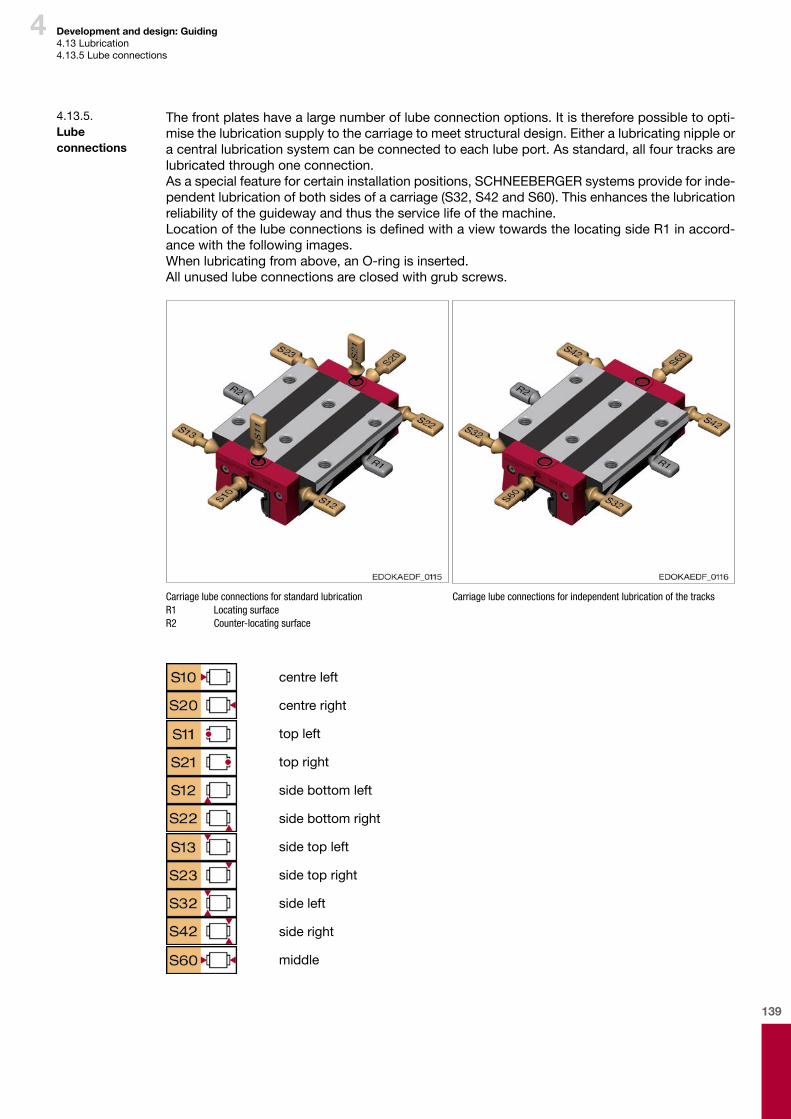
139
4 Development and design: Guiding4.13Lubrication4.13.5Lubeconnections
Thefrontplateshavealargenumberoflubeconnectionoptions.Itisthereforepossibletoopti-misethelubricationsupplytothecarriagetomeetstructuraldesign.Eitheralubricatingnippleoracentrallubricationsystemcanbeconnectedtoeachlubeport.Asstandard,allfourtracksarelubricatedthroughoneconnection.Asaspecialfeatureforcertaininstallationpositions,SCHNEEBERGERsystemsprovideforinde-pendentlubricationofbothsidesofacarriage(S32,S42andS60).Thisenhancesthelubricationreliabilityoftheguidewayandthustheservicelifeofthemachine.LocationofthelubeconnectionsisdefinedwithaviewtowardsthelocatingsideR1inaccord-ancewiththefollowingimages.Whenlubricatingfromabove,anO-ringisinserted.Allunusedlubeconnectionsareclosedwithgrubscrews.
Carriage lube connections for standard lubricationR1 Locating surfaceR2 Counter-locating surface
Carriage lube connections for independent lubrication of the tracks
centre left
centreright
top left
topright
sidebottomleft
sidebottomright
sidetopleft
sidetopright
sideleft
sideright
middle
4.13.5. Lube connections

140
4 Development and design: Guiding4.13Lubrication4.13.5Lubeconnectionss
Connecting thread in the front plate front and side
Connecting thread in the front plate front and side:D1 Connecting thread diameter frontD2 Connecting thread diameter sideM1 Spacing dimension lubrication front plate front* Connection for optional lubricating facility
M2* Spacing dimension lubrication front plate frontM3 Spacing dimension lubrication front plate sideM4 Spacing dimension lubrication front plate side
Type Dimensions (mm)M1 M2 M3 M4 D1 D2
MRA/B/F/G 25 5.5 - - - M6 -MRC/D/E 25 9.5 - - - M6 -MRA/B 35 7 32 7 6.5 M6 M6MRC/D/E 35 14 32 14 6.5 M6 M6MRA/B/F 45 8 40 8 7.5 M6 M6MRC/D 45 18 40 18 7.5 M6 M6MRA/B/G 55 9 50 9 8.5 M6 M6MRC/D 55 19 50 19 8.5 M6 M6MRA/C 65 13 64 13 12.5 M6 M6MRB/D 65 13 64 13 12.5 M6 M6MRB 100 12.5 124.5 12.5 33 M6 M6
Type Dimensions (mm)M1 M2 M3 M4 D1 D2
BMA/F 15 4 - 4 4 M3 M3BMC 15 8 - 8 4 M3 M3BMA/B 20 5.2 - 5.2 5 M6 M3BMC/D 20 5.2 - 5.2 5 M6 M3BMA/B/F/G 25 5.5 - 5.5 6 M6 M6BMC/D/E 25 9.5 - 9.5 6 M6 M6BMA/B/F/G 30 7 - 7 6 M6 M6BMC/D/E 30 10 - 10 6 M6 M6BMA/B/F/G 35 7 - 7 6.5 M6 M6BMC/D/E 35 14 - 14 6.5 M6 M6BMA/B/F/G 45 8 - 8 7.5 M6 M6BMC/D 45 18 - 18 7.5 M6 M6

141
4
Lubrication connection from aboveItisalsopossibletolubricatefromabove.Thedesiredlocationshouldalsobespecifiedforthisintheorder.TherequiredreworkiscarriedoutbySCHNEEBERGER.Orderdetails: topleft -S11 topright: -S21
Lube connections from above: 1 for MRA/MRB, BMA/BMB, BMC/BMD, BME, BMF/BMG 2 for MRC/MRD, MRE
D3 Counterbore diameter D4 Maximum diameter of the lubrication fixing hole C7 Spacing from fixing hole to the lubrication fixing hole
C7 (mm) MR 25 MR 35 MR 45 MR 55 MR 65 MR 100MRA 12 14 17 21.5 27.75 -MRB 23.2 27.5 34.5 42.5 54 67MRC 17 20 27 31.5 47.75 -MRD 20.7 22.5 34.5 42.5 49 -MRE 17 20 - - - -MRF 17 - 27 - - -MRG 20.7 - - 42.5 - -D4 6 6 6 6 6 8D3 10 10 10 10 10 12.4
C7 (mm) BM 15 BM 20 BM 25 BM 30 BM 35 BM 45BMA 9.05 10.25 13.5 15.7 15.8 17.05BMB - 18.25 23 26.7 28.55 32.8BMC 11.05 12.25 18.5 21.7 21.8 27.05BMD - 13.25 20.5 22.7 23.55 32.8BME - - 18.5 21.7 21.8 -BMF 11.05 - 18.5 21.7 21.8 27.05BMG - - 20.5 22.7 23.55 32.8D4 4 6 8 8 8 8D3 8 10 12 12 12 12
Type D5 x D6BM 15 4.48 x 1.78BM 20, MR 25-55 6.75 x 1.78BM 25-45, MR 100 8.73 x 1.78MR 65 6.5 x 2
Development and design: Guiding4.13Lubrication4.13.5Lubeconnections
Forstandardlubricationoptionsthatcanbedeliveredandorderdetails,seeSCHNEEBERGERMONORAILandAMSproductcatalogue.ThedesignationSxxisrequiredinthecarriageordercode.Otherlubricationconnectionoptionsforspecialindividualcircumstancesareavailableonrequest.
O-ringsarerequiredforsealingthelubeconnection.ThefollowingtableshowsthesizeoftheO-ringfortherespectivecarriagetype.WhereD5designatestheO-ringinternaldiameterandD6theO-ringthickness.
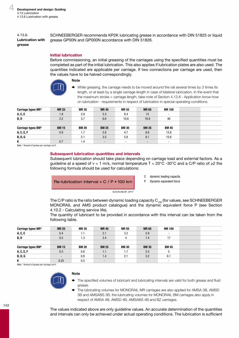
142
4 Development and design: Guiding4.13Lubrication4.13.6Lubricationwithgrease
SCHNEEBERGERrecommendsKP2KlubricatinggreaseinaccordancewithDIN51825orliquidgreaseGP00NandGP000NaccordancewithDIN51826.
Initial lubricationBeforecommissioning,aninitialgreasingofthecarriagesusingthespecifiedquantitiesmustbecompletedaspartoftheinitiallubrication.Thisalsoappliesiflubricationplatesarealsoused.Thequantitiesindicatedareapplicablepercarriage.Iftwoconnectionspercarriageareused,thenthevalueshavetobehalvedcorrespondingly.
Note
¨ While greasing, the carriage needs to be moved around the rail several times by 3 times its length, or at least by a single carriage length in case of bilateral lubrication. In the event that the maximum stroke < carriage length, take note of Section 4.13.8 - Application know-how on lubrication - requirements in respect of lubrication in special operating conditions.
4.13.6. Lubrication with grease
Carriage types MR* MR 25 MR 35 MR 45 MR 55 MR 65 MR 100A, C, E 1.9 2.9 5.3 8.4 15 -B, D 2.2 3.7 6.6 10.6 18.9 40
Carriage types BM* BM 15 BM 20 BM 25 BM 30 BM 35 BM 45A, C, E, F 0.9 1.7 2.8 4.7 6.6 12.6B, D, G - 2.1 3.5 5.8 8.1 15.6K 0.7 1.4 - - - -Note: * Amount of grease per carriage (cm³)
Subsequent lubrication quantities and intervalsSubsequentlubricationshouldtakeplacedependingoncarriageloadandexternalfactors.Asaguidelineataspeedofv=1m/s,normaltemperatureT=20°C-30°CandaC/Pratioof≥2thefollowingformulashouldbeusedforcalculations:
C dynamic loading capacity
P Dynamic equivalent force
TheC/PratioistheratiobetweendynamicloadingcapacityC100(forvalues,seeSCHNEEBERGERMONORAIL and AMS product catalogue) and the dynamic equivalent force P (see Section4.10.2 -Calculatingservicelife).Thequantityoflubricanttobeprovidedinaccordancewiththisintervalcanbetakenfromthefollowingtable.
Carriage types MR* MR 25 MR 35 MR 45 MR 55 MR 65 MR 100A, C, E 0.4 1.1 2.1 3.2 5.9 -B, D 0.5 1.3 2.4 4 7.4 17
Carriage types BM* BM 15 BM 20 BM 25 BM 30 BM 35 BM 45A, C, E, F 0.3 0.6 1.1 1.7 2.5 5B, D, G - 0.8 1.4 2.1 3.2 6.1K 0.25 0.5 - - - -Note: * Amount of grease per carriage (cm³)
Note
¨ The specified volumes of lubricant and lubricating intervals are valid for both grease and fluid grease.
¨ The lubricating volumes for MONORAIL MR carriages are also applied for AMSA 3B, AMSD 3B and AMSABS 3B, the lubricating volumes for MONORAIL BM carriages also apply in respect of AMSA 4B, AMSD 4B, AMSABS 4B and BZ carriages.
Thevaluesindicatedaboveareonlyguidelinevalues.Anaccuratedeterminationofthequantitiesandintervalscanonlybeachievedunderactualoperatingconditions.Thelubricationissufficient
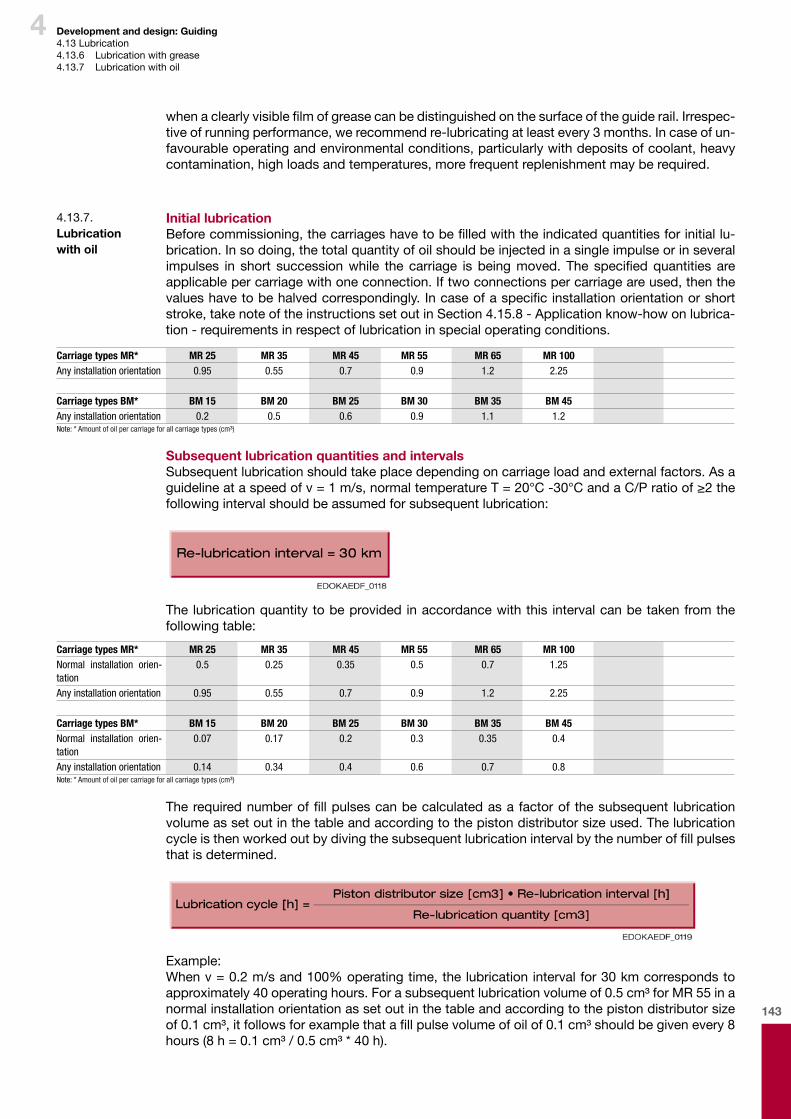
143
4
whenaclearlyvisiblefilmofgreasecanbedistinguishedonthesurfaceoftheguiderail.Irrespec-tiveofrunningperformance,werecommendre-lubricatingatleastevery3months.Incaseofun-favourableoperatingandenvironmentalconditions,particularlywithdepositsofcoolant,heavycontamination,highloadsandtemperatures,morefrequentreplenishmentmayberequired.
Initial lubricationBeforecommissioning,thecarriageshavetobefilledwiththeindicatedquantitiesforinitiallu-brication.Insodoing,thetotalquantityofoilshouldbeinjectedinasingleimpulseorinseveralimpulses in short successionwhile the carriage is beingmoved. The specifiedquantities areapplicablepercarriagewithoneconnection.Iftwoconnectionspercarriageareused,thenthevalueshavetobehalvedcorrespondingly.Incaseofaspecificinstallationorientationorshortstroke,takenoteoftheinstructionssetoutinSection4.15.8-Applicationknow-howonlubrica-tion-requirementsinrespectoflubricationinspecialoperatingconditions.
4.13.7. Lubrication with oil
Carriage types MR* MR 25 MR 35 MR 45 MR 55 MR 65 MR 100Any installation orientation 0.95 0.55 0.7 0.9 1.2 2.25
Carriage types BM* BM 15 BM 20 BM 25 BM 30 BM 35 BM 45Any installation orientation 0.2 0.5 0.6 0.9 1.1 1.2Note: * Amount of oil per carriage for all carriage types (cm³)
Subsequent lubrication quantities and intervalsSubsequentlubricationshouldtakeplacedependingoncarriageloadandexternalfactors.Asaguidelineataspeedofv=1m/s,normaltemperatureT=20°C-30°CandaC/Pratioof≥2thefollowingintervalshouldbeassumedforsubsequentlubrication:
Thelubricationquantitytobeprovidedinaccordancewiththis intervalcanbetakenfromthefollowingtable:
Carriage types MR* MR 25 MR 35 MR 45 MR 55 MR 65 MR 100Normal installation orien-tation
0.5 0.25 0.35 0.5 0.7 1.25
Any installation orientation 0.95 0.55 0.7 0.9 1.2 2.25
Carriage types BM* BM 15 BM 20 BM 25 BM 30 BM 35 BM 45Normal installation orien-tation
0.07 0.17 0.2 0.3 0.35 0.4
Any installation orientation 0.14 0.34 0.4 0.6 0.7 0.8Note: * Amount of oil per carriage for all carriage types (cm³)
Therequirednumberoffillpulsescanbecalculatedasafactorofthesubsequent lubricationvolumeassetoutinthetableandaccordingtothepistondistributorsizeused.Thelubricationcycleisthenworkedoutbydivingthesubsequentlubricationintervalbythenumberoffillpulsesthatisdetermined.
Example:Whenv=0.2m/sand100%operatingtime,thelubricationintervalfor30kmcorrespondstoapproximately40operatinghours.Forasubsequentlubricationvolumeof0.5cm³forMR55inanormalinstallationorientationassetoutinthetableandaccordingtothepistondistributorsizeof0.1cm³,itfollowsforexamplethatafillpulsevolumeofoilof0.1cm³shouldbegivenevery8hours(8h=0.1cm³/0.5cm³*40h).
Development and design: Guiding4.13Lubrication4.13.6 Lubricationwithgrease4.13.7 Lubricationwithoil
144
4 Development and design: Guiding4.13Lubrication4.13.7 Lubricationwithoil4.13.8Applicationknow-howonlubrication-requirementsinrespectoflubricationinspecialoperatingconditions.
Note
¨ In case of a specific installation orientation or short stroke, take note of the lubrication in-structions set out in Section 4.15.8 - Application know-how on lubrication - requirements in respect of lubrication in special operating conditions.
¨ The lubricating volumes for MONORAIL MR carriages are also applied for AMSA 3B and AMSD 3B, the lubrication volumes for MONORAIL BM carriages also apply in respect of AMSA 4B, AMSD 4B and BZ carriages.
Thevaluesindicatedaboveareonlyguidelinevalues.Anaccuratedeterminationofthequantitiesand intervalscanonlybeachievedunderactualoperatingconditions.Lubrication issufficientwhenanaccumulationoflubricantformswhenpushingthecarriageinfrontofthewiper,oranaccumulationoflubricantformsattheturn-aroundpointsofthecarriageontheguiderail.Itisrecommendedtore-lubricateduringoperationatleastoncepermonthandafteraalengthyma-chineshut-downpriortorecommissioning.Incaseofunfavourableoperatingandenvironmentalconditions,particularlywithdepositsofcoolant,heavycontamination,highloadsandtempera-tures,morefrequentreplenishmentmayberequired.
Thechoiceof lubricationsystemfora linearguidewaysystemisessentially influencedbythetypeofapplicationandoperatingconditions.Specificapplicationsimposespecificrequirements � Lubricanttypeandlubricantproperties � Methodofapplication � Locationofthelubeconnections � Lubricationvolumeandlubricatingcycles
Furthermore,differentfactorsaffectthefrequencyoflubrication: � Coolanteffect:Washouteffectsbycoolant � Lengthandstrokeratioofthemovementofthecarriage � Machine-basedcovers � MethodofcarriagesealingSmooth-runningwipers,additionalwipers
Whenusingacentralisedlubricatingsystem,aswellasthechoiceoflubeconnectionandofanappropriatelubricantitisimportanttonotethatthelubricantlinesaredimensionedtobeasshortandsufficientaspossible.Pistondistributorsshouldbefittedwherepossibleclosetothelubrica-tionpoints.Thelubricatingsystemmanufacturer'sinstructionsshouldbeobserved.
Typicalexamplesofuseandtheirrequirementsaresetoutbelow:
Installation orientationInthecaseofgreaselubricationitisensuredineveryinstallationorientationthatallfourtracksofthecarriagearesuppliedwithlubricantwithonelubeconnection.Inthecaseofoillubricationandahorizontalorverticalinstallation,noparticularprecautionsneedtobetakeneither.Becauseoftheadaptedlubricationchannelcrosssectionalareasinthefrontplates,thisisalsoapplicableforaninstallationwiththeguidewaysrotatedby180°aroundthelongitudinalaxisoftheguiderails.
4.13.8. Application know-how on lubrication - requirements in respect of lubrication in special operat-ing conditions.

145
4
Oil lubrication for vertical installation and installation inclined around the transverse axis–LubeconnectionsS10toS23canbeused.
Development and design: Guiding4.13Lubrication4.13.8Applicationknow-howonlubrication-requirementsinrespectoflubricationinspecialoperatingconditions.
Foraverticalinstallationoroneinclinedaroundthetransverseaxis,thelubeconnectionshouldbeprovidedintheupperfrontplate.
Oil lubrication in a horizontal installation–LubeconnectionsS10toS23canbeused.
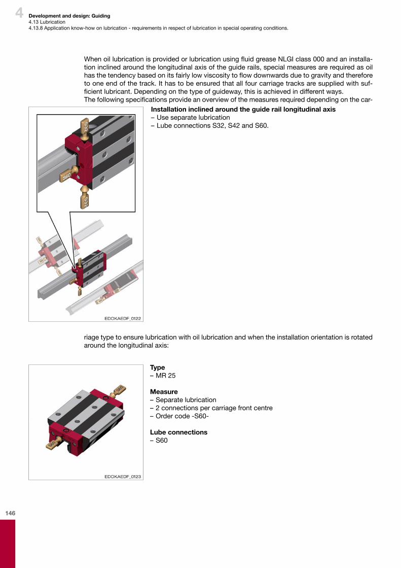
146
4
Installation inclined around the guide rail longitudinal axis–Useseparatelubrication–LubeconnectionsS32,S42andS60.
Development and design: Guiding4.13Lubrication4.13.8Applicationknow-howonlubrication-requirementsinrespectoflubricationinspecialoperatingconditions.
WhenoillubricationisprovidedorlubricationusingfluidgreaseNLGIclass000andaninstalla-tioninclinedaroundthelongitudinalaxisoftheguiderails,specialmeasuresarerequiredasoilhasthetendencybasedonitsfairlylowviscositytoflowdownwardsduetogravityandthereforetooneendofthetrack.Ithastobeensuredthatallfourcarriagetracksaresuppliedwithsuf-ficientlubricant.Dependingonthetypeofguideway,thisisachievedindifferentways.Thefollowingspecificationsprovideanoverviewofthemeasuresrequireddependingonthecar-
riagetypetoensurelubricationwithoillubricationandwhentheinstallationorientationisrotatedaroundthelongitudinalaxis:
Type –MR25
Measure–Separatelubrication–2connectionspercarriagefrontcentre–Ordercode-S60-
Lube connections– S60

147
4
Type –MR35-MR100–BM15-BM45
Measure–Separatelubrication–2connectionspercarriage–Ordercode-S32-or-S42-–dependingontheinstallationorientation
Lube connections– S32– S42
Note
¨ In the case of special installation orientations, the customer should include an installation drawing with the inquiry when obtaining a recommendation from SCHNEEBERGER.
Inthecaseofasinglelubricationconnectionpercarriage,grease,orliquidgrease,ispreferredoveroil.SeeSection4.15-Lubrication.ThespecificationforMONORAILBMalsoapplyinrespectofcarriagesforMONORAILBZ.ForsystemswithMONORAILAMSandaparticularinstallationorientation,thecustomershouldseekarecommendationaboutlubricationfromSCHNEEBERGER.
CoolantsInthecaseofdirectcontactbythelinearguidewayswithwatersolublecoolants,thereisariskduetotheiremulsifyingbehaviourthattheymixwiththelubricantandwashitoff,whichcanasaresultleadtoinadequatelubricationandcorrosionofthemetalsurfaces.Consequently,onlylubricantsmaybeused,whichhavehighcorrosionresistanceandgoodde-mulsifyingbehaviour.Otherwiseitisnecessarytore-lubricateinlargerquantitiesandatshorterintervals.
Use of aqueous media, alkalis and acidsWithapplications inwhich the linearguidewaysareexposed toaggressive liquidmediasuchas,forexample,condensationorsplashes,saltsolutionsordilutedacidsandalkalis,lubricatinggreaseswithcorrosion-inhibitingpropertiesshouldbeused.Theyshouldotherwisehaveexcel-lentdemulsifyingbehaviouraswellashighadhesivenessandexcellentsealingeffecttopreventthelubricantfrombeingwashedofforfrombeingmixedwiththeaggressivemedia.Lubricatingoilsarenotgenerallysuitableforsuchapplications.
High forcesWithhighdynamicforcesthereisariskthatduetothehighsurfacepressureonthepointsofcontactthelubricatingfilmispulledoffresultinginincreasedwearduetoinadequatelubrication.Suchapplicationsrequirelubricantswithso-calledEPadditives(EP=“ExtremePressure”)andhighshearstrength.These,forexample,includelubricatinggreaseswiththeKPorGPdesigna-tion,whicharebettersuitedtohigh-forceapplicationssuchaslubricatingoils.ItisimportanttonotewithlubricatingoilsthattheyatleasthavetheCLPclassificationandhighviscosity.Toincreasetheabsorptionofpressureandtoavoidwear,solidlubricantssuchasmolybdenumsulphideandgraphiteareoftenused.Solidlubricantsminimisewearduringthestart-upphaseorinemergencyrunningsituations.Molybdenumsulphideandgraphitecanactuallyformunevendepositsonroller-contactbearingsandprofilerailguideways.Suchsurfaceunevennesscanleadtolocalisedconcentrationsofstressesandthustoprematurefailureonrollingelements.
Development and design: Guiding4.13Lubrication4.13.8Applicationknow-howonlubrication-requirementsinrespectoflubricationinspecialoperatingconditions.

148
4
High speedsForhighspeedslubricantswithlowviscosity,thatiswithlowinternalfrictionandgoodheatdis-sipationarerequired.Lubricatingoilsaremoresuitablethanlubricatinggreasesforthis.
Short stroke and vibrationsShortstrokeisdefinedaslessthantwocarriagelengths,asforthistherollingelementsinthecarriagenolongerrevolvecompletelyandsothelubricantinthecarriageisnolongerabletobeoptimallydistributed.Insuchinstances,twolubeconnectionspercarriagearerecommended,thatisonelubricationpointonbothsides.Thelubricationquantitiespercarriage,however,remainthesame,thatisthetablevaluesshownintherelevantsectionarehalvedperconnection.Forveryshortstrokes(lessthanthediameterofasingleballorroller)orincaseofvibrations,oscillatingslidingandrollingmovementsoccurontherollingelementpointsofcontact,whichcandestroythefilmoflubricantwithariskoffrettingcorrosionandprematureguidewayfailure.Thisrequireslubricantswithexcellentpressureabsorptioncapacity,goodwettingbehaviourandcorrosionprotectionproperties.Greaselubricationshouldbefavouredaboveoillubricationforwhichmorefrequentsubsequentlubricationisnecessarythanundernormalcircumstancesduetotheshortergreaseservicelife.Foroillubrication,useoilwithhighviscosityVG220.Itisalsorecommendedthataso-calledlubricatingstroke(distancetravelled>2xcarriagelength)iscarriedoutoccasionally.
Long strokeWithlongstrokesmorelubricantisdeliveredfromthecarriagesandisdistributedoveralargersurfacearea.Thisrequireslargerquantitiesoflubricantandshorterlubricationintervalsthanwithanormalstroke.Beforecommissioningtheentireguiderailsurfaceshouldberubbedwiththelu-bricantsothatfromthestartthereisaclosedfilmoflubricantonthetracksandunderthewipers.
TemperatureTheability to formastablefilmof lubricantunder specificoperatingconditions isessentiallydeterminedby theviscosityof the lubricant.Lubricatingoilsand lubricatinggreaseshave thepropertythattheirviscositydependsonthetemperature.Itdecreasesasthetemperaturerisesandincreasesasthetemperaturefalls.Thismeansthatthelubricantismoreviscousatlowtemperaturesthanathightemperatures.Forthis reasonevery lubricanthasaspecific temperatureoperatingrange inwhich its lubricatingpropertiescanbeguaranteed.Thistemperaturerangeisgenerallygreaterinsyntheticlubricantsthan inmineral-basedonesas theviscosity-temperature ratio isnotasgreatlypronounced inthem.Tomaintainthereliabilityoflubricationinanyoperatingconditionitisimportanttoensurethatalubricantisselectedwhosepermissibletemperaturerangecoversalltemperaturesoccurringduringoperation.Asmostapplicationsoflinearguidewaystakeplaceatnormaltemperaturesfromabout0°Cto+40°C,generallystandardlubricatinggreasesandstandardoilsaresufficientforthis.Atverylowtemperatures,however,aspeciallubricantwithlowviscosityisrequiredandatveryhightemperaturesalubricantwithhighviscosity.Inaddition,howeverthepermissibletemperatureoperatingrangeofthelinearguidewaysalsoneedstobenoted.
Development and design: Guiding4.13Lubrication4.13.8Applicationknow-howonlubrication-requirementsinrespectoflubricationinspecialoperatingconditions.

149
4
Dirt, grinding dust Iflinearguidewaysareexposedduringoperationtodirtsuchas,dustorfineswarffromthema-chiningprocess,itisimportanttopreventthisdirtfromgettingintothecarriages.Inadditiontothelubrication,effectiveprotectionofthecarriagesbyappropriatecoversandadditionalwipersisalsoveryimportant.Inprinciple,bothlubricatingoilscanbeusedduetotheirrinsingeffectandlubricatinggreasesduetotheirsealingproperties.Comparedwithnormalconditions,subsequentlubricationmusttakeplaceusingmorelubricantandatshorterintervals.Withdustofallkinds,commerciallyavail-ableoil-airlubricantscanbeused,whichcreateasealingaireffectduetoexcesspressureinthecarriagetherebypreventingdustfromgettingin.MONORAILcarriagesareideallysuitedtothisduetotheirexcellentsealingproperties.Otherwisecleaningstrokesshouldbecompletedregularlytofreetheguiderailsurfaceofanystuckondirt.Similarlyacleaningstrokeshouldbecompletedprior toanyextendedmachineshut-down,e.g.atweekends.
Machine toolsItcangenerallybeassumedthatforapplicationsinmachinetoolshighstaticanddynamicforcesoccur,thatoftenliquidmedia,e.g.coolantsactontheguidewaysandthatthelinearguidewaysareusedoveralongperiodoftimeoroverlongrunningdistances.Thiscallsforthefollowingcharacteristicsinlubricants: � Effectiveforcetransmissibility � High-pressureresistance � Resistancetoageing � Corrosionresistance � Transportincentralisedlubricatingsystem
CleanroomWhenusedundercleanroomconditionsabsolutelynoparticleemissionscanescapefromthelinearguideway,e.g.fromthesealandthelubricants.Otherrequirementsincludeminimalandconsistentpushforceofthecarriagesandextendedmaintenance-freeoperatingtime.Wipersareoftendispensedwithonthecarriages.Duetotheirsealingeffect,lubricatinggreasesareusuallyused.Theyshouldbesuitableforlong-termlubrication,demonstratelowerevaporationratesandexcellentadhesionandhavesmoothrunningproperties.
High vacuum.Forapplicationsinavacuumitisimportantthatthelubricantdoesnotescapeathightempera-tureseitherandemitparticlesintotheatmosphere.Consequently,speciallubricatinggreasesareusedhere,whichdemonstrateverylowvapourpressures.
Rack drivesBothoilandgreaselubricationareusedtolubricateracksandpinions.Lubricatinggreaseisusedformanualbrushlubrication.WiththeintegralrackdriveontheMON-ORAILBZlinearguideway,thesupplyoflubricanttothegearracksisusuallymadecontinuouslyusingalubricatingpinionmadeoffelt,whichisfedbyalubricantdispenser.Eitherahigh-viscos-itylubricatingoil,e.g.ISOVG460oranNLGIclass0fluidgreaseisusedforthis.Generallythelubricantsshoulddemonstrategoodforcetransmissibilityandhighshearstrengthaswell asadequateadhesivestrengthandhighviscosity toprevent the lubricant frombeingshakenoffthepinions.
Development and design: Guiding4.13Lubrication4.13.8Applicationknow-howonlubrication-requirementsinrespectoflubricationinspecialoperatingconditions.
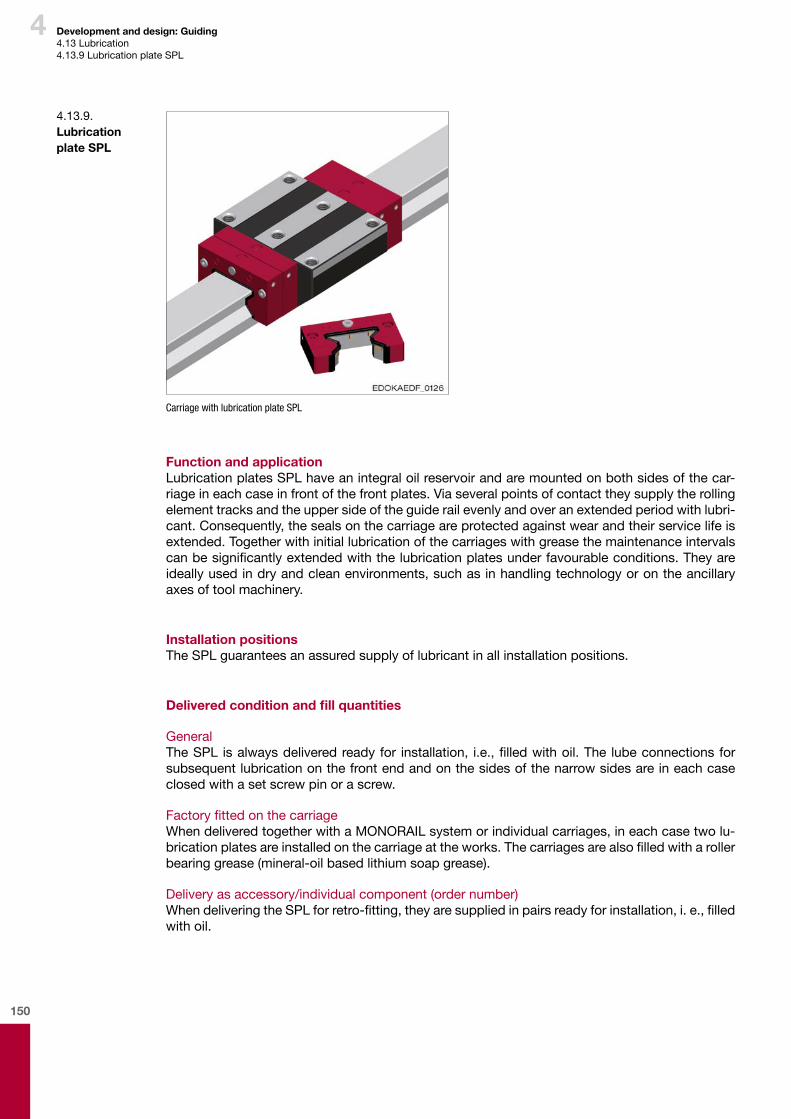
150
4 Development and design: Guiding4.13Lubrication4.13.9LubricationplateSPL
Carriage with lubrication plate SPL
Function and applicationLubricationplatesSPLhaveanintegraloilreservoirandaremountedonbothsidesofthecar-riageineachcaseinfrontofthefrontplates.Viaseveralpointsofcontacttheysupplytherollingelementtracksandtheuppersideoftheguiderailevenlyandoveranextendedperiodwithlubri-cant.Consequently,thesealsonthecarriageareprotectedagainstwearandtheirservicelifeisextended.Togetherwithinitiallubricationofthecarriageswithgreasethemaintenanceintervalscanbesignificantlyextendedwiththelubricationplatesunderfavourableconditions.Theyareideallyusedindryandcleanenvironments,suchasinhandlingtechnologyorontheancillaryaxesoftoolmachinery.
Installation positionsTheSPLguaranteesanassuredsupplyoflubricantinallinstallationpositions.
Delivered condition and fill quantities
GeneralTheSPL isalwaysdeliveredreadyfor installation, i.e.,filledwithoil.The lubeconnectionsforsubsequentlubricationonthefrontendandonthesidesofthenarrowsidesareineachcaseclosedwithasetscrewpinorascrew.
FactoryfittedonthecarriageWhendeliveredtogetherwithaMONORAILsystemorindividualcarriages,ineachcasetwolu-bricationplatesareinstalledonthecarriageattheworks.Thecarriagesarealsofilledwitharollerbearinggrease(mineral-oilbasedlithiumsoapgrease).
Deliveryasaccessory/individualcomponent(ordernumber)WhendeliveringtheSPLforretro-fitting,theyaresuppliedinpairsreadyforinstallation,i.e.,filledwithoil.
4.13.9. Lubrication plate SPL

151
4
SPL xx-MR* MR 25 MR 35 MR 45 MR 55 MR 65 -3.1 9.4 15.6 26.8 61 -
SPL xx-BM* BM 15 BM 20 BM 25 BM 30 BM 35 BM 450.7 2 3.4 4.1 8.3 15.6
Note: * Amount of oil for each 1x SPL (cm³)
InitialoilfillinthefactoryTheSPLisfilledwithoilinthefactoryusingKLÜBERLamoraD220typeandisthereforeimme-diatelyreadyforuse.
SubsequentlubricationquantitiesandintervalsRefillingofthelubricationplatesshouldtakeplacedependingontheloadandotheroperatingconditionsfortheguideways.Asaguideline,thefollowingrefillingintervalscanbeassumed:
Thequantityofoiltobesuppliedaccordingtotheserefillingintervalscanbetakenfromthefol-lowingtable:
SPL - MR* MR 25 MR 35 MR 45 MR 55 MR 65 -2500 km 2500 km 5000 km 5000 km 5000 km -
SPL - BM* BM 15 BM 20 BM 25 BM 30 BM 35 BM 452500 km 2500 km 2500 km 2500 km 2500 km 5000 km
SPL xx-MR* MR 25 MR 35 MR 45 MR 55 MR 65 -2.2 7 11 19 43 -
SPL xx-BM* BM 15 BM 20 BM 25 BM 30 BM 35 BM 450.5 1.4 2.4 2.9 5.8 10.9
Note: * Amount of oil for each 1x SPL (cm³)
Note
¨ When refilling of the lubrication plates, KLÜBER Lamora D 220-type oil should be used. Spe-cial bottles of oil can be obtained as an accessory. When refilling with other lubricants, SCH-NEEBERGER will not assume any liability. More details on this can be found in the Operation, Maintenance and Service Section.
TheSPLisrefilledusinglubricatingfixingholesatthefront,middleandside.Adetaileddescrip-tionisincludedintheSPLinstallationinstructions,whichcanbedownloadedfromwww.schnee-berger.comandDownloads.Thevaluesindicatedaboveareonlyguidelinevalues.Thequantitiesandintervalscanonlybeaccurately determinedunder actual operating conditions. The lubrication is sufficientwhen aclearlyvisiblefilmofoilcanbeseenonthesurfaceoftheguiderail.Irrespectiveofthedistancetravelled,refillingisnecessaryafteramaximumof12monthsoperation.Incaseofunfavourableoperatingandenvironmentalconditions,particularlyincaseofdirt,highloadsandtemperatures,morefrequentreplenishmentmayberequired.Whenlubricationplatesareretro-fitted,thecarriagesalsoneedtobefilledwithgrease.TherecommendedquantitiesoflubricantcanbefoundintheSectionLubricationwithgrease.Whenretro-fittingBMcarriagesmakesurethatthefrontplateneedstobeheldsecurelywhenlooseningthefasteningscrewsasotherwisetheballswillfallout.
Use of coolantsForapplicationsincorporatingcoolantsitisimportanttoensurethatthelinearguidewaysarepro-tectedwithappropriatecoversandadditionalwipersonthecarriagesbeforeanydirectcontactwiththefluidmedia.Whencoolantsaredepositeddirectlyontotheguideways,duetotheriskofthelubricatingoilbeingwashedoutoftheSPLtheiruseisnotrecommended.
Development and design: Guiding4.13Lubrication4.13.9LubricationplateSPL
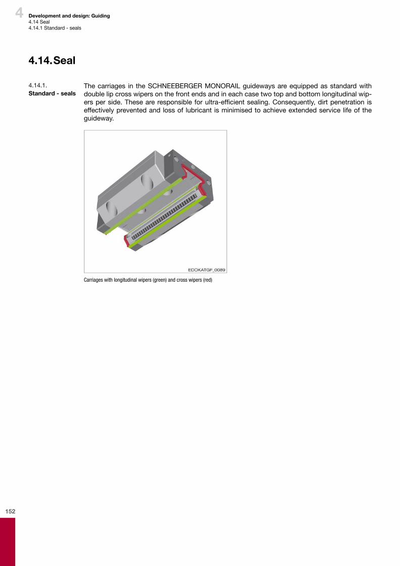
152
4 Development and design: Guiding4.14Seal4.14.1Standard-seals
4.14. Seal
Thecarriages in theSCHNEEBERGERMONORAILguidewaysareequippedasstandardwithdoublelipcrosswipersonthefrontendsandineachcasetwotopandbottomlongitudinalwip-ersperside.Theseareresponsibleforultra-efficientsealing.Consequently,dirtpenetration iseffectivelypreventedandlossof lubricant isminimisedtoachieveextendedservicelifeoftheguideway.
Carriages with longitudinal wipers (green) and cross wipers (red)
4.14.1. Standard - seals
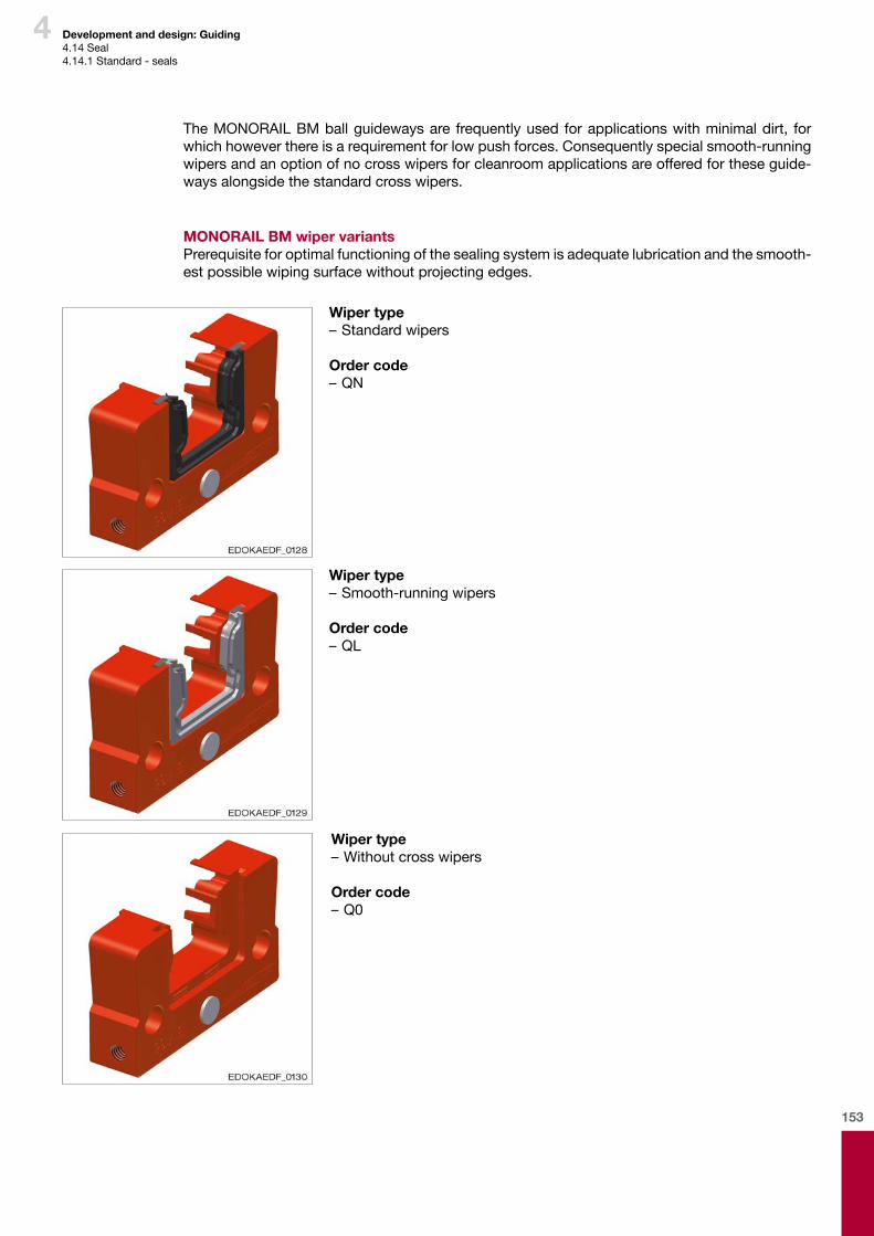
153
4
Wiper type –Standardwipers
Order code–QN
Wiper type –Smooth-runningwipers
Order code–QL
Wiper type –Withoutcrosswipers
Order code–Q0
Development and design: Guiding4.14Seal4.14.1Standard-seals
TheMONORAILBMballguidewaysare frequentlyused forapplicationswithminimaldirt, forwhichhoweverthereisarequirementforlowpushforces.Consequentlyspecialsmooth-runningwipersandanoptionofnocrosswipersforcleanroomapplicationsareofferedfortheseguide-waysalongsidethestandardcrosswipers.
MONORAIL BM wiper variantsPrerequisiteforoptimalfunctioningofthesealingsystemisadequatelubricationandthesmooth-estpossiblewipingsurfacewithoutprojectingedges.
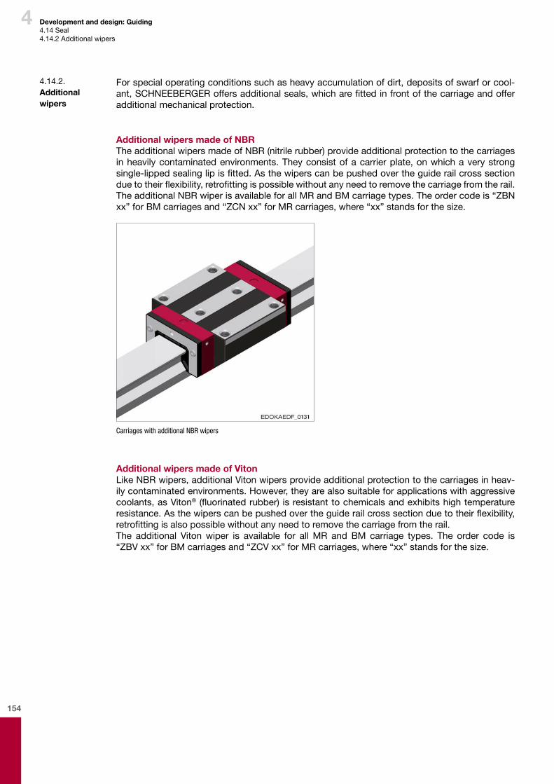
154
4 Development and design: Guiding4.14Seal4.14.2Additionalwipers
Forspecialoperatingconditionssuchasheavyaccumulationofdirt,depositsofswarforcool-ant,SCHNEEBERGERoffersadditionalseals,whicharefittedinfrontofthecarriageandofferadditionalmechanicalprotection.
Additional wipers made of NBRTheadditionalwipersmadeofNBR(nitrilerubber)provideadditionalprotectiontothecarriagesinheavilycontaminatedenvironments.Theyconsistofacarrierplate,onwhichaverystrongsingle-lippedsealinglipisfitted.Asthewiperscanbepushedovertheguiderailcrosssectionduetotheirflexibility,retrofittingispossiblewithoutanyneedtoremovethecarriagefromtherail.TheadditionalNBRwiperisavailableforallMRandBMcarriagetypes.Theordercodeis“ZBNxx”forBMcarriagesand“ZCNxx”forMRcarriages,where“xx”standsforthesize.
Carriages with additional NBR wipers
Additional wipers made of VitonLikeNBRwipers,additionalVitonwipersprovideadditionalprotectiontothecarriagesinheav-ilycontaminatedenvironments.However,theyarealsosuitableforapplicationswithaggressivecoolants,asViton® (fluorinatedrubber) isresistanttochemicalsandexhibitshightemperatureresistance.Asthewiperscanbepushedovertheguiderailcrosssectionduetotheirflexibility,retrofittingisalsopossiblewithoutanyneedtoremovethecarriagefromtherail.The additional Vitonwiper is available for allMR and BM carriage types. The order code is“ZBV xx”forBMcarriagesand“ZCVxx”forMRcarriages,where“xx”standsforthesize.
4.14.2. Additional wipers
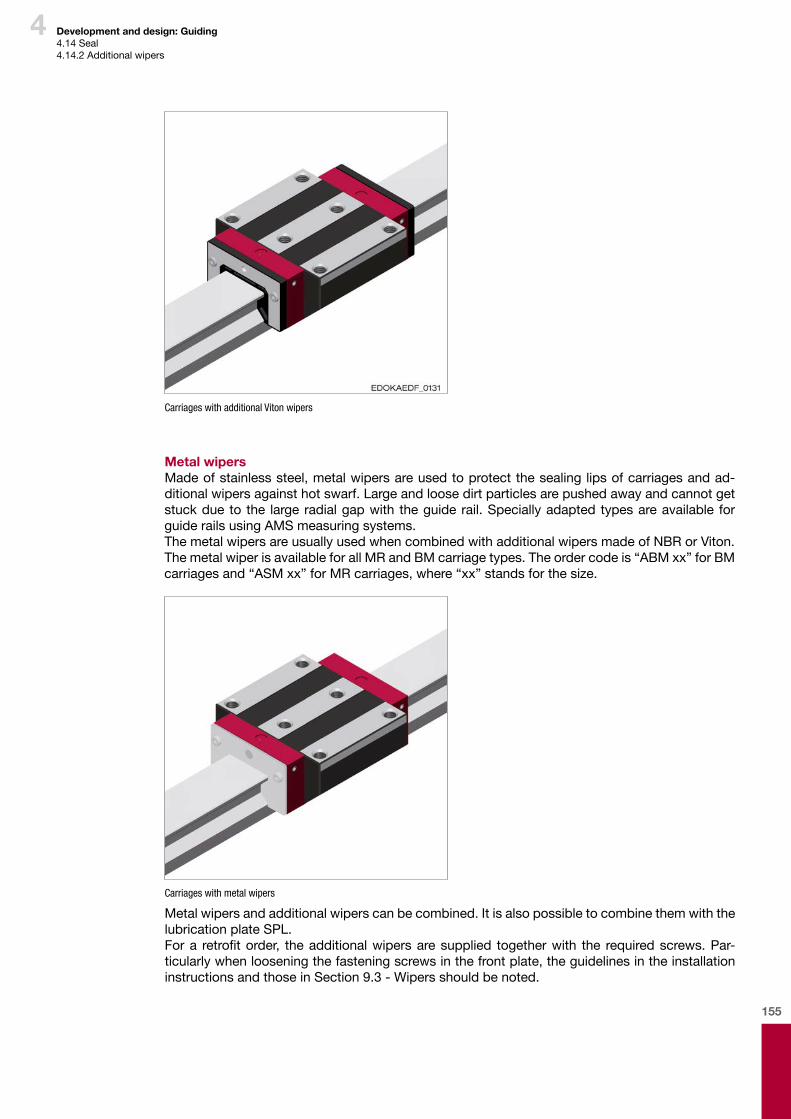
155
4
Carriages with additional Viton wipers
Metal wipersMadeofstainlesssteel,metalwipersareusedtoprotectthesealinglipsofcarriagesandad-ditionalwipersagainsthotswarf.Largeandloosedirtparticlesarepushedawayandcannotgetstuckdueto the largeradialgapwith theguiderail.Speciallyadaptedtypesareavailable forguiderailsusingAMSmeasuringsystems.ThemetalwipersareusuallyusedwhencombinedwithadditionalwipersmadeofNBRorViton.ThemetalwiperisavailableforallMRandBMcarriagetypes.Theordercodeis“ABMxx”forBMcarriagesand“ASMxx”forMRcarriages,where“xx”standsforthesize.
Carriages with metal wipers
Metalwipersandadditionalwiperscanbecombined.ItisalsopossibletocombinethemwiththelubricationplateSPL.Fora retrofitorder, theadditionalwipersaresupplied togetherwith the requiredscrews.Par-ticularlywhenlooseningthefasteningscrewsinthefrontplate,theguidelinesintheinstallationinstructionsandthoseinSection9.3-Wipersshouldbenoted.
Development and design: Guiding4.14Seal4.14.2Additionalwipers

156
4 Development and design: Guiding4.14Seal4.14.3Bellows
Bellowsaremainlyusedasanadditionalformofprotectionforcarriagesagainstdustandsplash-esofwater.TheyareofferedfortheMONORAILMRrollerguidewaysandfortheMONORAILBMballguide-wayinonestandarddesign.Thebellowsaremadeofsyntheticfabriccoatedonbothsideswithplastic.Itisextendedoverthefulllengthoftheguiderail,itscross-sectionmatchestherespec-tivefrontplateonthecarriage.Forspecialapplications,e.g. inlasercuttingorweldingsystemsonrequestaversioninheat-resistantmaterialisalsoavailable.Itisfastenedsimplyusingspecialplates,whicharescrewedontotheguiderailendsortothecarriagefrontplate.Thebellowsarefastenedbytworivetstoboththeadapterplateandtheendplate.Retro-fittingisonlyrecommendedforinductivelyhardenedguiderailsasholesneedtobedrilledintotheendoftheguiderailforattachingtheendplate.Theordercodeis“FBB”forallBMcarriagesofsize20-45and“FBM”forallMRcarriagesofsize 25-65.
Carriages with bellows
Caution
Component damage due to improper construction
¨ When using bellows it is important to ensure that no dirt can be sucked under the bellows due to any vacuum that may occur when in motion.
4.14.3. Bellows
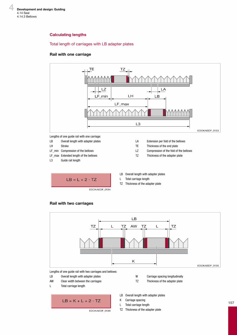
157
4
Calculating lengths
TotallengthofcarriageswithLBadapterplates
Rail with one carriage
Lengths of one guide rail with one carriage:
LB Overall length with adapter plates
LH Stroke
LF_min Compression of the bellows
LF_max Extended length of the bellows
L3 Guide rail length
LA Extension per fold of the bellows
TE Thickness of the end plate
LZ Compression of the fold of the bellows
TZ Thickness of the adapter plate
LB Overall length with adapter plates
L Total carriage length
TZ Thickness of the adapter plate
Rail with two carriages
Lengths of one guide rail with two carriages and bellows:
LB Overall length with adapter plates
AW Clear width between the carriages
L Total carriage length
W Carriage spacing longitudinally
TZ Thickness of the adapter plate
LB Overall length with adapter plates
K Carriage spacing
L Total carriage length
TZ Thickness of the adapter plate
Development and design: Guiding4.14Seal4.14.3Bellows
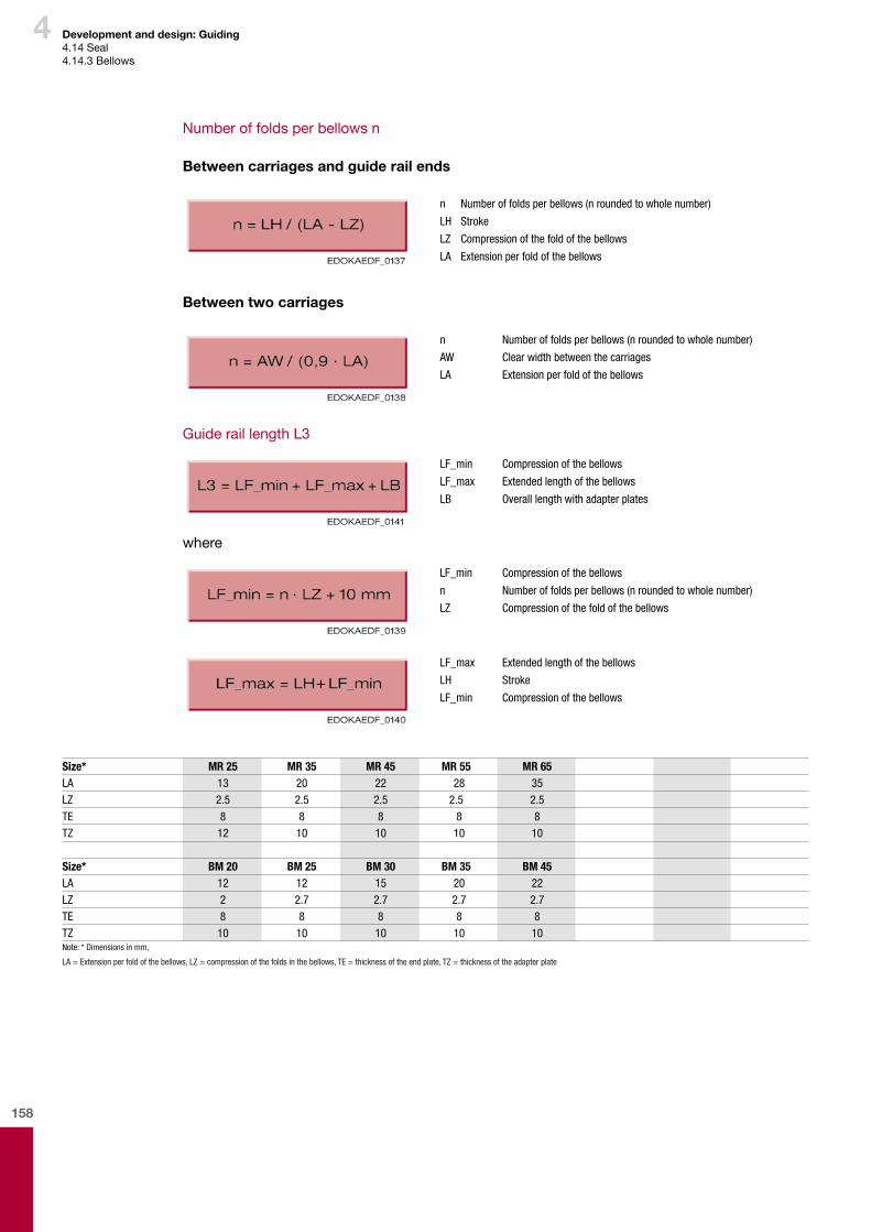
158
4
Numberoffoldsperbellowsn
Between carriages and guide rail ends
n Number of folds per bellows (n rounded to whole number)
LH Stroke
LZ Compression of the fold of the bellows
LA Extension per fold of the bellows
Between two carriages
n Number of folds per bellows (n rounded to whole number)
AW Clear width between the carriages
LA Extension per fold of the bellows
GuideraillengthL3
LF_min Compression of the bellows
LF_max Extended length of the bellows
LB Overall length with adapter plates
where
LF_min Compression of the bellows
n Number of folds per bellows (n rounded to whole number)
LZ Compression of the fold of the bellows
LF_max Extended length of the bellows
LH Stroke
LF_min Compression of the bellows
Development and design: Guiding4.14Seal4.14.3Bellows
Size* MR 25 MR 35 MR 45 MR 55 MR 65LA 13 20 22 28 35LZ 2.5 2.5 2.5 2.5 2.5TE 8 8 8 8 8TZ 12 10 10 10 10
Size* BM 20 BM 25 BM 30 BM 35 BM 45LA 12 12 15 20 22LZ 2 2.7 2.7 2.7 2.7TE 8 8 8 8 8TZ 10 10 10 10 10Note: * Dimensions in mm,
LA = Extension per fold of the bellows, LZ = compression of the folds in the bellows, TE = thickness of the end plate, TZ = thickness of the adapter plate
+
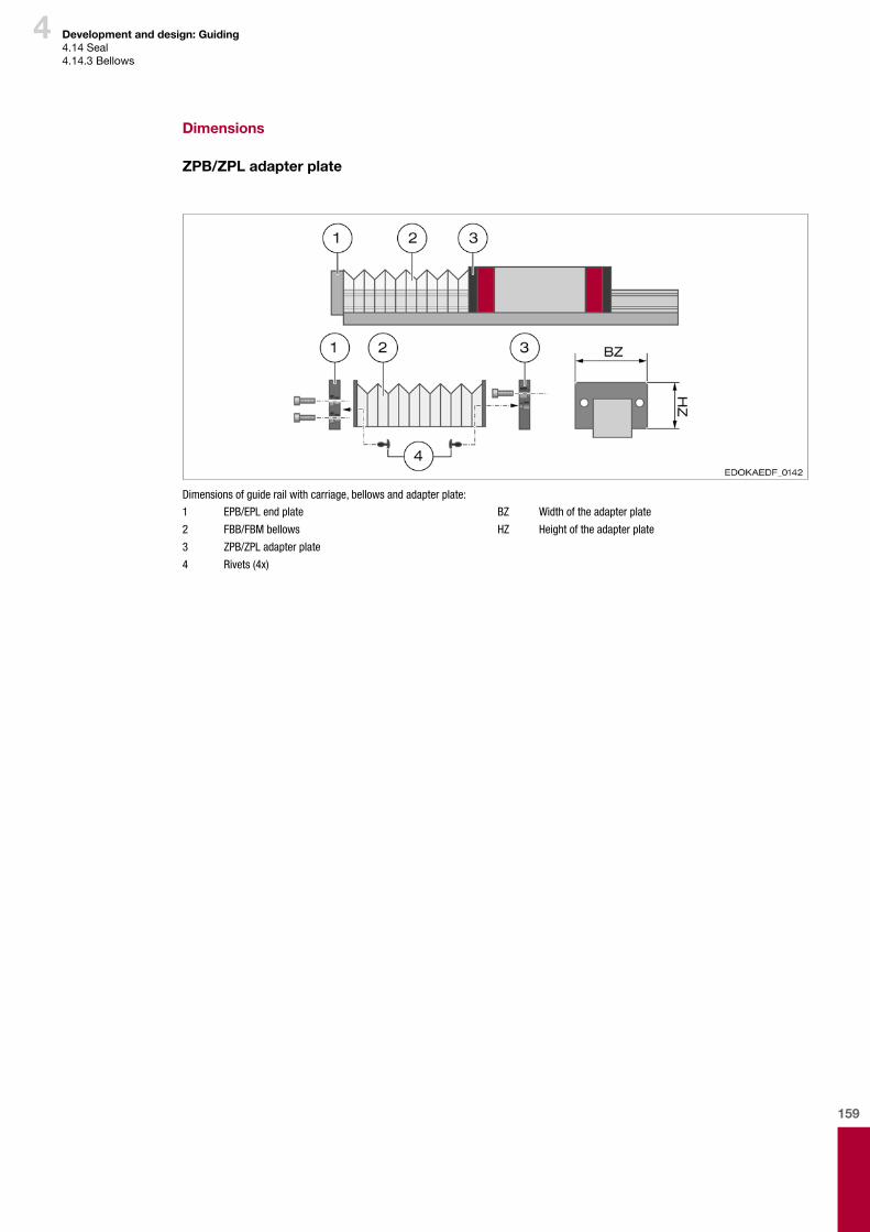
159
4
Dimensions
ZPB/ZPL adapter plate
Dimensions of guide rail with carriage, bellows and adapter plate:
1 EPB/EPL end plate
2 FBB/FBM bellows
3 ZPB/ZPL adapter plate
4 Rivets (4x)
BZ Width of the adapter plate
HZ Height of the adapter plate
Development and design: Guiding4.14Seal4.14.3Bellows
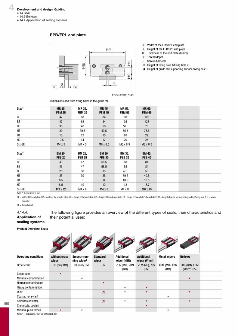
160
4
EPB/EPL end plate
BE Width of the EPB/EPL end plate HE Height of the EPB/EPL end plate TE Thickness of the end plate (8 mm) GE Thread depth S Screw diameter H3 Height of fixing hole 1/fixing hole 2 H4 Height of guide rail supporting surface/fixing hole 1
Dimensions and front fixing holes in the guide rail
Size* MR 25,FBM 25
MR 35,FBM 35
MR 45,FBM 45
MR 55,FBM 55
MR 65,FBM 65
BE 47 68 84 98 123BZ 47 68 84 98 123HE 30 40 50 57 76HZ 29 39.5 49.5 56.5 75.5H1 10 12 15 20 22H2 10.5 14 17 20 25S x GE M4 x 5 M4 x 5 M6 x 8.5 M6 x 8.5 M6 x 8.5
Size* BM 20,FBB 20
BM 25,FBB 25
BM 30,FBB 30
BM 35,FBB 35
BM 45,FBB 45
BE 43 47 58.5 68 84BZ 43 47 58.5 68 84HE 25 30 35 40 50HZ 25 30 35 39.5 49.5H1 6.5 8 8 10.5 13.5H2 8.5 10 12 13 16.7S x GE M3 x 12 M4 x 8 M4 x 8 M4 x 8 M6 x 10Note: * Dimensions in mm,
BE = width of the end plate, BZ = width of the adapter plate, HE = height of the end plate, HZ = height of the adapter plate, H1 - height of fixing hole 1/fixing hole 2, H2 = height of guide rail supporting surface/fixing hole 1, S = screw
diameter,
GE = thread depth
Thefollowingfigureprovidesanoverviewofthedifferenttypesofseals,theircharacteristicsandtheirpotentialuses:
4.14.4. Application of sealing systems
Product Overview: Seals
Operating conditions without cross wiper
Smooth-run-ning wiper1
Standard wiper
Additional wiper (NBR)
Additional wiper (Viton)
Metal wipers Bellows
Order code Q0 (only BM) QL (only BM) QN ZCN (MR), ZBN (BM)
ZCV (MR), ZBV (BM)
ASM (MR), ABM (BM)
FBB (BM), FBM (MR 25-65)
Cleanroom •Minimal contamination • •Normal contamination •Heavy contamination • •Dust (•) • • •Coarse, hot swarf •Splashes of water (•) • • •Chemicals, coolant •Minimal push forces • • •Note: • = applicable, 1 not for MONORAIL MR
Development and design: Guiding4.14Seal4.14.3Bellows4.14.4Applicationofsealingsystems
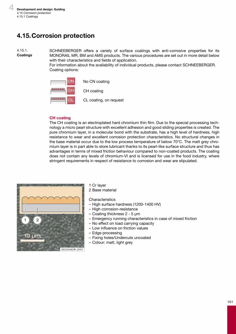
161
4 Development and design: Guiding4.15Corrosionprotection4.15.1Coatings
4.15. Corrosion protection
SCHNEEBERGER offers a variety of surface coatings with anti-corrosive properties for its MONORAILMR,BMandAMSproducts.Thevariousproceduresaresetoutinmoredetailbelowwiththeircharacteristicsandfieldsofapplication.Forinformationabouttheavailabilityofindividualproducts,pleasecontactSCHNEEBERGER.Coatingoptions:
NoCNcoating
CHcoating
CLcoating,onrequest
CH coatingTheCHcoatingisanelectroplatedhardchromiumthinfilm.Duetothespecialprocessingtech-nologyamicropearlstructurewithexcellentadhesionandgoodslidingpropertiesiscreated.Thepurechromiumlayer,inamolecularbondwiththesubstrate,hasahighlevelofhardness,highresistancetowearandexcellentcorrosionprotectioncharacteristics.Nostructuralchangesinthebasematerialoccurduetothelowprocesstemperatureofbelow70°C.Themattgreychro-miumlayerisinpartabletostorelubricantthankstoitspearl-likesurfacestructureandthushasadvantagesintermsofmixedfrictionbehaviourcomparedtonon-coatedproducts.Thecoatingdoesnotcontainanylevelsofchromium-VIandislicensedforuseinthefoodindustry,wherestringentrequirementsinrespectofresistancetocorrosionandweararestipulated.
4.15.1. Coatings
1Crlayer2Basematerial
Characteristics–Highsurfacehardness(1200-1400HV)–Highcorrosion-resistance–Coatingthickness2-5μm–Emergencyrunningcharacteristicsincaseofmixedfriction–Noeffectonloadcarryingcapacity–Lowinfluenceonfrictionvalues–Edgeprocessing–Fixingholes/Undercutsuncoated–Colour:matt,lightgrey
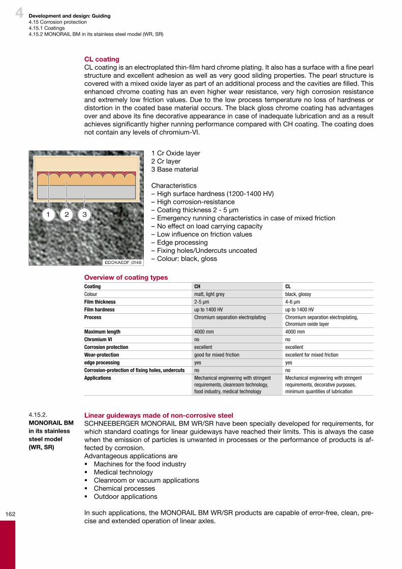
162
4 Development and design: Guiding4.15Corrosionprotection4.15.1Coatings4.15.2MONORAILBMinitsstainlesssteelmodel(WR,SR)
1CrOxidelayer2Crlayer3Basematerial
Characteristics–Highsurfacehardness(1200-1400HV)–Highcorrosion-resistance–Coatingthickness2-5μm–Emergencyrunningcharacteristicsincaseofmixedfriction–Noeffectonloadcarryingcapacity–Lowinfluenceonfrictionvalues–Edgeprocessing–Fixingholes/Undercutsuncoated–Colour:black,gloss
Linear guideways made of non-corrosive steelSCHNEEBERGERMONORAILBMWR/SRhavebeenspeciallydevelopedforrequirements,forwhichstandardcoatingsforlinearguidewayshavereachedtheirlimits.Thisisalwaysthecasewhentheemissionofparticlesisunwantedinprocessesortheperformanceofproductsisaf-fectedbycorrosion.Advantageousapplicationsare � Machinesforthefoodindustry � Medicaltechnology � Cleanroomorvacuumapplications � Chemicalprocesses � Outdoorapplications
Insuchapplications,theMONORAILBMWR/SRproductsarecapableoferror-free,clean,pre-ciseandextendedoperationoflinearaxles.
4.15.2. MONORAIL BM in its stainless steel model (WR, SR)
CL coatingCLcoatingisanelectroplatedthin-filmhardchromeplating.Italsohasasurfacewithafinepearlstructureandexcellentadhesionaswellasverygoodslidingproperties.Thepearlstructureiscoveredwithamixedoxidelayeraspartofanadditionalprocessandthecavitiesarefilled.Thisenhancedchromecoatinghasanevenhigherwear resistance,veryhighcorrosionresistanceandextremely lowfrictionvalues.Duetothe lowprocesstemperatureno lossofhardnessordistortioninthecoatedbasematerialoccurs.TheblackglosschromecoatinghasadvantagesoverandaboveitsfinedecorativeappearanceincaseofinadequatelubricationandasaresultachievessignificantlyhigherrunningperformancecomparedwithCHcoating.Thecoatingdoesnotcontainanylevelsofchromium-VI.
Overview of coating typesCoating CH CLColour matt, light grey black, glossyFilm thickness 2-5 μm 4-6 μmFilm hardness up to 1400 HV up to 1400 HVProcess Chromium separation electroplating Chromium separation electroplating,
Chromium oxide layerMaximum length 4000 mm 4000 mmChromium VI no noCorrosion protection excellent excellentWear-protection good for mixed friction excellent for mixed frictionedge processing yes yesCorrosion-protection of fixing holes, undercuts no noApplications Mechanical engineering with stringent
requirements, cleanroom technology, food industry, medical technology
Mechanical engineering with stringent requirements, decorative purposes, minimum quantities of lubrication
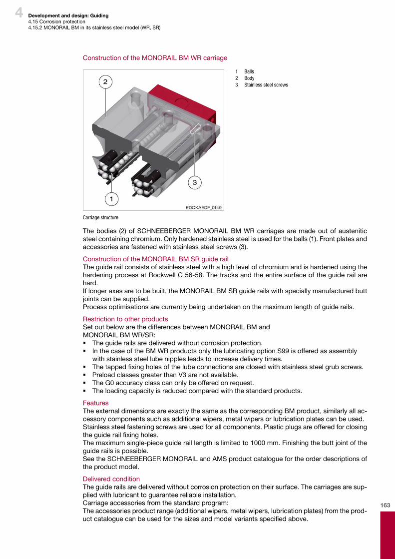
163
4 Development and design: Guiding4.15Corrosionprotection4.15.2MONORAILBMinitsstainlesssteelmodel(WR,SR)
ConstructionoftheMONORAILBMWRcarriage
1 Balls 2 Body 3 Stainless steel screws
Carriage structure
Thebodies (2)ofSCHNEEBERGERMONORAILBMWRcarriagesaremadeoutofausteniticsteelcontainingchromium.Onlyhardenedstainlesssteelisusedfortheballs(1).Frontplatesandaccessoriesarefastenedwithstainlesssteelscrews(3).
ConstructionoftheMONORAILBMSRguiderailTheguiderailconsistsofstainlesssteelwithahighlevelofchromiumandishardenedusingthehardeningprocessatRockwellC56-58.Thetracksandtheentiresurfaceoftheguiderailarehard.Iflongeraxesaretobebuilt,theMONORAILBMSRguiderailswithspeciallymanufacturedbuttjointscanbesupplied.Processoptimisationsarecurrentlybeingundertakenonthemaximumlengthofguiderails.
RestrictiontootherproductsSetoutbelowarethedifferencesbetweenMONORAILBMand MONORAILBMWR/SR: � Theguiderailsaredeliveredwithoutcorrosionprotection. � InthecaseoftheBMWRproductsonlythelubricatingoptionS99isofferedasassemblywithstainlesssteellubenipplesleadstoincreasedeliverytimes.
� Thetappedfixingholesofthelubeconnectionsareclosedwithstainlesssteelgrubscrews. � PreloadclassesgreaterthanV3arenotavailable. � TheG0accuracyclasscanonlybeofferedonrequest. � Theloadingcapacityisreducedcomparedwiththestandardproducts.
FeaturesTheexternaldimensionsareexactlythesameasthecorrespondingBMproduct,similarlyallac-cessorycomponentssuchasadditionalwipers,metalwipersorlubricationplatescanbeused.Stainlesssteelfasteningscrewsareusedforallcomponents.Plasticplugsareofferedforclosingtheguiderailfixingholes.Themaximumsingle-pieceguideraillengthislimitedto1000mm.Finishingthebuttjointoftheguiderailsispossible.SeetheSCHNEEBERGERMONORAILandAMSproductcataloguefortheorderdescriptionsofthe product model.
DeliveredconditionTheguiderailsaredeliveredwithoutcorrosionprotectionontheirsurface.Thecarriagesaresup-pliedwithlubricanttoguaranteereliableinstallation.Carriageaccessoriesfromthestandardprogram:Theaccessoriesproductrange(additionalwipers,metalwipers,lubricationplates)fromtheprod-uctcataloguecanbeusedforthesizesandmodelvariantsspecifiedabove.
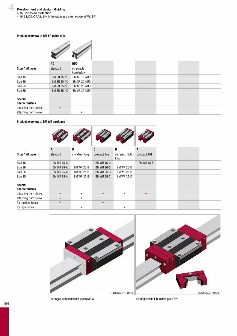
164
4 Development and design: Guiding4.15Corrosionprotection4.15.2MONORAILBMinitsstainlesssteelmodel(WR,SR)
Product overview of BM SR guide rails
ND NUD
Sizes/rail types standard screwable from below
Size 15 BM SR 15-ND BM SR 15-NUDSize 20 BM SR 20-ND BM SR 20-NUDSize 25 BM SR 25-ND BM SR 25-NUDSize 35 BM SR 35-ND BM SR 35-NUD
Special characteristicsattaching from above •attaching from below •
Product overview of BM WR carriages
A B C D F
Sizes/rail types standard standard, long compact, high compact, high, long
compact, flat
Size 15 BM WR 15-A BM WR 15-C BM WR 15-FSize 20 BM WR 20-A BM WR 20-B BM WR 20-C BM WR 20-DSize 25 BM WR 25-A BM WR 25-B BM WR 25-C BM WR 25-DSize 35 BM WR 35-A BM WR 35-B BM WR 35-C BM WR 35-D
Special characteristicsattaching from above • • • • •attaching from below • •for medium forces • •for high forces • •
Carriages with additional wipers ABM Carriages with lubrication plate SPL
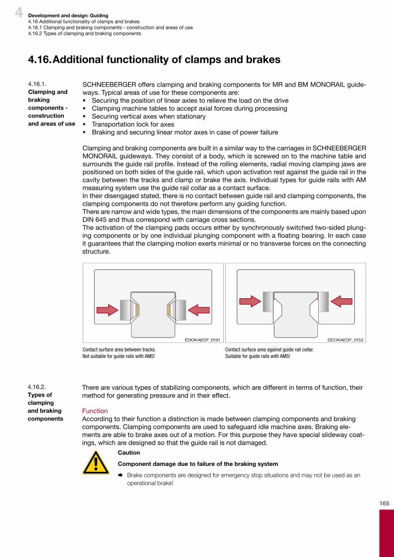
165
4 Development and design: Guiding4.16Additionalfunctionalityofclampsandbrakes4.16.1Clampingandbrakingcomponents-constructionandareasofuse4.16.2Typesofclampingandbrakingcomponents
4.16. Additional functionality of clamps and brakes
SCHNEEBERGERoffersclampingandbrakingcomponentsforMRandBMMONORAILguide-ways.Typicalareasofuseforthesecomponentsare: � Securingthepositionoflinearaxlestorelievetheloadonthedrive � Clampingmachinetablestoacceptaxialforcesduringprocessing � Securingverticalaxeswhenstationary � Transportationlockforaxes � Brakingandsecuringlinearmotoraxesincaseofpowerfailure
ClampingandbrakingcomponentsarebuiltinasimilarwaytothecarriagesinSCHNEEBERGERMONORAILguideways.Theyconsistofabody,whichisscrewedontothemachinetableandsurroundstheguiderailprofile.Insteadoftherollingelements,radialmovingclampingjawsarepositionedonbothsidesoftheguiderail,whichuponactivationrestagainsttheguiderailinthecavitybetweenthetracksandclamporbraketheaxis.IndividualtypesforguiderailswithAMmeasuringsystemusetheguiderailcollarasacontactsurface.Intheirdisengagedstated,thereisnocontactbetweenguiderailandclampingcomponents,theclampingcomponentsdonotthereforeperformanyguidingfunction.Therearenarrowandwidetypes,themaindimensionsofthecomponentsaremainlybaseduponDIN645andthuscorrespondwithcarriagecrosssections.Theactivationoftheclampingpadsoccurseitherbysynchronouslyswitchedtwo-sidedplung-ingcomponentsorbyoneindividualplungingcomponentwithafloatingbearing.Ineachcaseitguaranteesthattheclampingmotionexertsminimalornotransverseforcesontheconnectingstructure.
Contact surface area between tracks.Not suitable for guide rails with AMS!
Contact surface area against guide rail collar.Suitable for guide rails with AMS!
4.16.1. Clamping and braking components - construction and areas of use
Therearevarioustypesofstabilizingcomponents,whicharedifferentintermsoffunction,theirmethodforgeneratingpressureandintheireffect.
FunctionAccordingtotheirfunctionadistinctionismadebetweenclampingcomponentsandbrakingcomponents.Clampingcomponentsareusedtosafeguardidlemachineaxes.Brakingele-mentsareabletobrakeaxesoutofamotion.Forthispurposetheyhavespecialslidewaycoat-ings,whicharedesignedsothattheguiderailisnotdamaged.
Caution
Component damage due to failure of the braking system
¨ Brake components are designed for emergency stop situations and may not be used as an operational brake!
4.16.2. Types of clamping and braking components
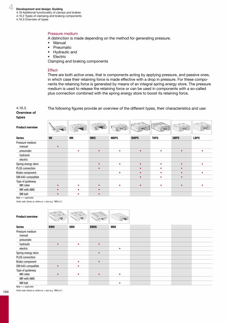
166
4 Development and design: Guiding4.16Additionalfunctionalityofclampsandbrakes4.16.2Typesofclampingandbrakingcomponents4.16.3Overviewoftypes
PressuremediumAdistinctionismadedependingonthemethodforgeneratingpressure. � Manual � Pneumatic � Hydraulicand � ElectricClampingandbrakingcomponents
EffectTherearebothactiveones,thatiscomponentsactingbyapplyingpressure,andpassiveones,inwhichcasetheirretainingforceismadeeffectivewithadropinpressure.Forthesecompo-nentstheretainingforceisgeneratedbymeansofanintegralspringenergystore.Thepressuremediumisusedtoreleasetheretainingforceorcanbeusedincomponentswithaso-calledplusconnectioncombinedwiththespringenergystoretoboostitsretainingforce.
Thefollowingfiguresprovideanoverviewofthedifferenttypes,theircharacteristicsanduse:4.16.3. Overview of types
Product overview
Series HK MK MKS MBPS BWPS TKPS UBPS LBPS
Pressure mediummanual •pneumatic • • • • • • •hydraulicelectric
Spring energy store • • • • • •PLUS connection • • • •Brake component • • • • •DIN 645-compatible • • •Type of guideway
MR roller • • • • • • • •MR with AMS • • •BM ball • • •
Note: • = applicable
Order code: Series xx, where xx = size (e.g. “MKS xx”)
Product overview
Series KWH KBH KBHS MKE
Pressure mediummanualpneumatichydraulic • • •electric •
Spring energy store •PLUS connectionBrake component • •DIN 645-compatible • •Type of guideway
MR roller • • • •MR with AMSBM ball •
Note: • = applicable
Order code: Series xx, where xx = size (e.g. “MKS xx”)
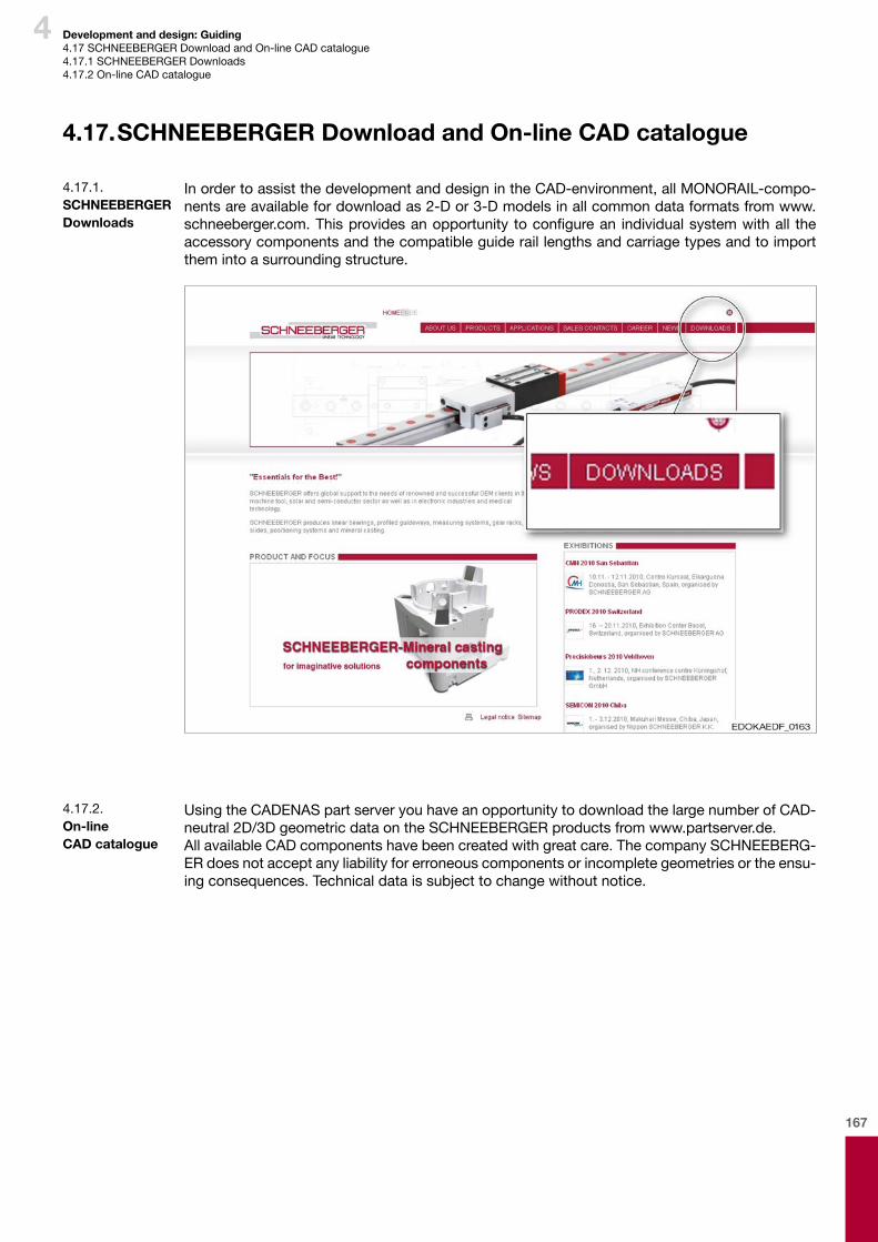
167
4 Development and design: Guiding4.17SCHNEEBERGERDownloadandOn-lineCADcatalogue4.17.1SCHNEEBERGERDownloads4.17.2On-lineCADcatalogue
4.17. SCHNEEBERGER Download and On-line CAD catalogue
InordertoassistthedevelopmentanddesignintheCAD-environment,allMONORAIL-compo-nentsareavailablefordownloadas2-Dor3-Dmodelsinallcommondataformatsfromwww.schneeberger.com.Thisprovidesanopportunity toconfigurean individualsystemwithall theaccessorycomponentsandthecompatibleguideraillengthsandcarriagetypesandtoimportthemintoasurroundingstructure.
4.17.1. SCHNEEBERGER Downloads
UsingtheCADENASpartserveryouhaveanopportunitytodownloadthelargenumberofCAD-neutral2D/3DgeometricdataontheSCHNEEBERGERproductsfromwww.partserver.de.AllavailableCADcomponentshavebeencreatedwithgreatcare.ThecompanySCHNEEBERG-ERdoesnotacceptanyliabilityforerroneouscomponentsorincompletegeometriesortheensu-ingconsequences.Technicaldataissubjecttochangewithoutnotice.
4.17.2. On-line CAD catalogue

168
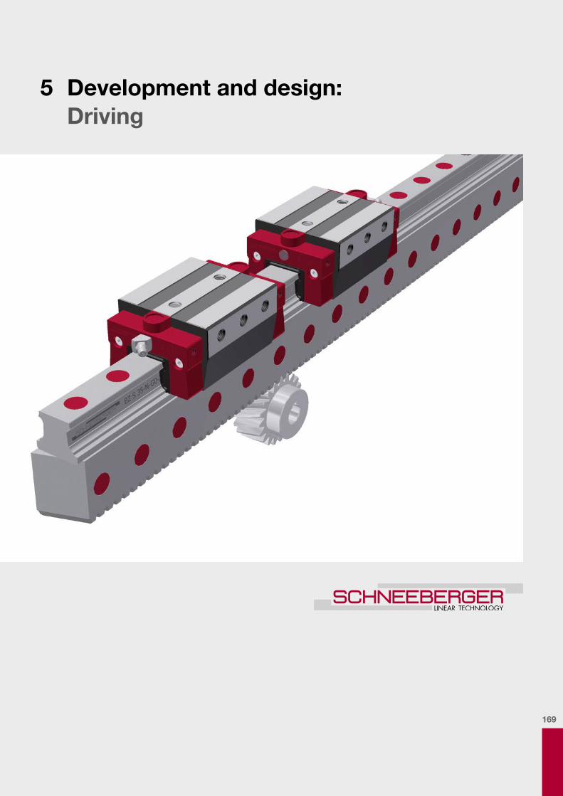
169
5 Development and design: Driving

170

171
5
Contents
5
5 Development and design: Driving ....................................................169
5.1. Product overview ................................................................................................................1725.1.1. Characteristics and advantages .....................................................................................1725.1.2. Installation orientation .....................................................................................................174
5.2. Calculation and sizing ........................................................................................................1755.2.1. Carriage and guide rail ....................................................................................................1755.2.2. Gear rack ........................................................................................................................177
5.3. Attaching the guide rail ......................................................................................................1805.3.1. Fastening method ...........................................................................................................1805.3.2. Closuresforfixingholes ..................................................................................................1805.3.3. Permissible screw tightening torques .............................................................................1815.3.4. Transportprotectionincludingassemblyfixture .............................................................181
5.4. Multi-part guide rails ..........................................................................................................1835.4.1. Butt transition joint ..........................................................................................................1835.4.2. Design .............................................................................................................................1835.4.3. Alignment ........................................................................................................................1835.4.4. Replaceability ..................................................................................................................183
5.5. Configuration of the connecting structure .......................................................................1845.5.1. Lateral locating surfaces .................................................................................................1845.5.2. Installation methods ........................................................................................................1855.5.3. Geometrical and position accuracy of the supporting surfaces, connection dimensions ...................................................................................................186
5.6. Lubrication ..........................................................................................................................1875.6.1. Delivered condition in terms of protection ......................................................................1875.6.2. Initial lubrication and subsequent lubrication .................................................................1875.6.3. Coatings ..........................................................................................................................188
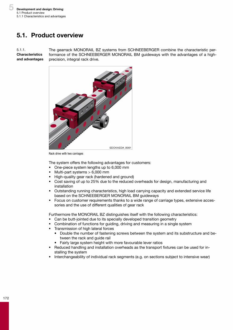
172
5 Development and design: Driving: 5.1 Product overview5.1.1 Characteristics and advantages
5.1. Product overview
The gearrack MONORAIL BZ systems from SCHNEEBERGER combine the characteristic per-formance of the SCHNEEBERGER MONORAIL BM guideways with the advantages of a high-precision, integral rack drive.
Rack drive with two carriages
The system offers the following advantages for customers: � One-piece system lengths up to 6,000 mm � Multi-part systems > 6,000 mm � High-quality gear rack (hardened and ground) � Cost saving of up to 25% due to the reduced overheads for design, manufacturing and
installation � Outstandingrunningcharacteristics,highloadcarryingcapacityandextendedservicelife
based on the SCHNEEBERGER MONORAIL BM guideways � Focusoncustomerrequirementsthankstoawiderangeofcarriagetypes,extensiveacces-
sories and the use of different qualities of gear rack
Furthermore the MONORAIL BZ distinguishes itself with the following characteristics: � Can be butt-jointed due to its specially developed transition geometry � Combination of functions for guiding, driving and measuring in a single system � Transmission of high lateral forces
• Double the number of fastening screws between the system and its substructure and be-tween the rack and guide rail
• Fairly large system height with more favourable lever ratios � Reducedhandlingandinstallationoverheadsasthetransportfixturescanbeusedforin-
stalling the system � Interchangeability of individual rack segments (e.g. on sections subject to intensive wear)
5.1.1. Characteristics and advantages
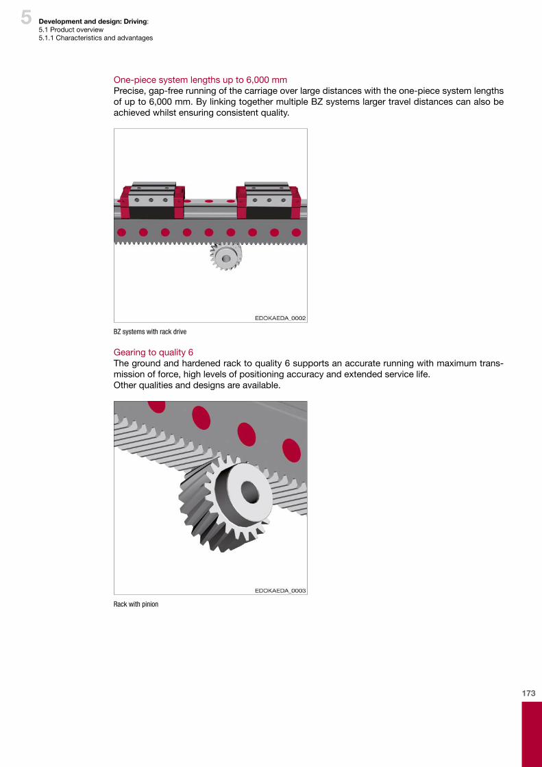
173
5 Development and design: Driving: 5.1 Product overview5.1.1 Characteristics and advantages
One-piece system lengths up to 6,000 mmPrecise, gap-free running of the carriage over large distances with the one-piece system lengths of up to 6,000 mm. By linking together multiple BZ systems larger travel distances can also be achieved whilst ensuring consistent quality.
BZ systems with rack drive
Gearing to quality 6Thegroundandhardenedracktoquality6supportsanaccuraterunningwithmaximumtrans-missionofforce,highlevelsofpositioningaccuracyandextendedservicelife.Other qualities and designs are available.
Rack with pinion

174
5 Development and design: Driving: 5.1 Product overview5.1.2 Installation orientation
Features:–Horizontalaxis– BZ guide rail horizontal, rotated by 90°– BZ guide rail with carriage type E with side attachment– Rail with carriage type C/D, which means that in each case
Location surfaces for the guide rails and carriages they are on the same level
Note: * M = Motor with gears and pinion
The installation orientation of the guideways is based on the application, that is on the functional-ityofthemachine,itsconstructionandthedirectionoftraveloftheaxis.Itaffectsthemethodofsupplying lubricant and the susceptibility to contamination of the guideway.This machine con-cept,asillustratedbywayofexampleinthefollowingfigure:
Features:– hanging installation– horizontal movement– BZ guide rail vertical, which means that the gear rack it properly
protected against dirt– BZ guide rail with carriage type E with side attachment– Parallel rail with carriage type C/D, which means that in each case
Location surfaces for the two guide rails and carriages they are on the same level
Note: * M = Motor with gears and pinion
Features:–Horizontalaxis– BZ guide rail vertical, which means that the gear rack it properly
protected against dirt– Parallel standard rail with cross section such as BZ, but without
gear rack– BZ and standard rail with the same cross-section, consequently
good accessibility, simple installation–Motorattachmentfromtheside,whichmeansmaximumfree
room on the upper side of the carriageNote: * M = Motor with gears and pinion
Features:– Hanging installation– Horizontal movement– Carriage type C/D with attachment from above and 6 screws for a high
level of rigidity–Motorattachmentfromtheside,whichmeansmaximumfreeroomon
the upper side of the carriage
Note: * M = Motor with gears and pinion
5.1.2. Installation orientation
Variant 1*
Variant 2*
Variant 3*
Variant 4*
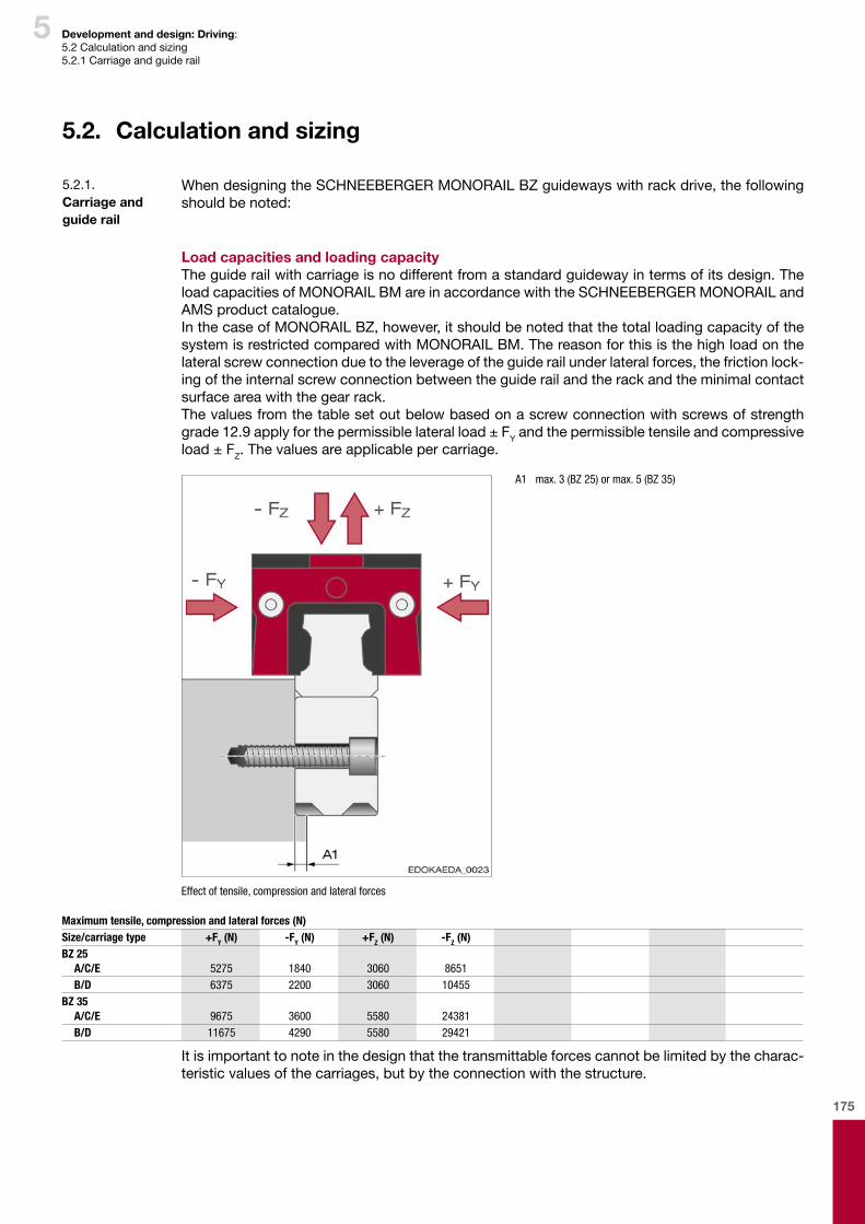
175
5 Development and design: Driving: 5.2 Calculation and sizing5.2.1 Carriage and guide rail
When designing the SCHNEEBERGER MONORAIL BZ guideways with rack drive, the following should be noted:
Load capacities and loading capacityThe guide rail with carriage is no different from a standard guideway in terms of its design. The load capacities of MONORAIL BM are in accordance with the SCHNEEBERGER MONORAIL and AMS product catalogue.In the case of MONORAIL BZ, however, it should be noted that the total loading capacity of the system is restricted compared with MONORAIL BM. The reason for this is the high load on the lateral screw connection due to the leverage of the guide rail under lateral forces, the friction lock-ing of the internal screw connection between the guide rail and the rack and the minimal contact surface area with the gear rack.The values from the table set out below based on a screw connection with screws of strength grade 12.9 apply for the permissible lateral load ± FY and the permissible tensile and compressive load ± FZ. The values are applicable per carriage.
A1 max. 3 (BZ 25) or max. 5 (BZ 35)
Effect of tensile, compression and lateral forces
5.2. Calculation and sizing
5.2.1. Carriage and guide rail
Maximum tensile, compression and lateral forces (N)Size/carriage type +FY (N) -FY (N) +FZ (N) -FZ (N)BZ 25
A/C/E 5275 1840 3060 8651B/D 6375 2200 3060 10455
BZ 35A/C/E 9675 3600 5580 24381B/D 11675 4290 5580 29421
It is important to note in the design that the transmittable forces cannot be limited by the charac-teristic values of the carriages, but by the connection with the structure.
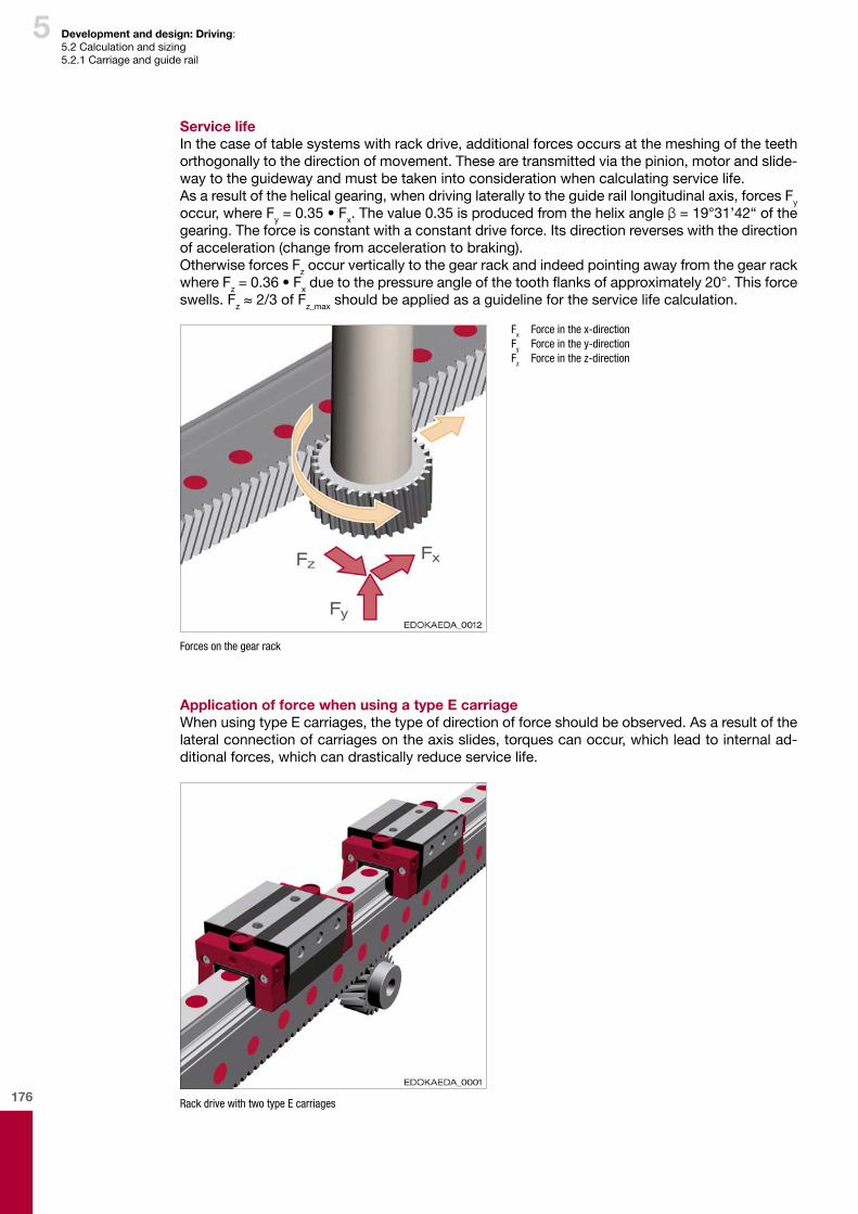
176
5 Development and design: Driving: 5.2 Calculation and sizing5.2.1 Carriage and guide rail
Service lifeIn the case of table systems with rack drive, additional forces occurs at the meshing of the teeth orthogonally to the direction of movement. These are transmitted via the pinion, motor and slide-way to the guideway and must be taken into consideration when calculating service life.Asaresultofthehelicalgearing,whendrivinglaterallytotheguideraillongitudinalaxis,forcesFy occur, where Fy = 0.35 • Fx.Thevalue0.35isproducedfromthehelixangleβ = 19°31’42“ of the gearing. The force is constant with a constant drive force. Its direction reverses with the direction of acceleration (change from acceleration to braking).Otherwise forces Fz occur vertically to the gear rack and indeed pointing away from the gear rack where Fz = 0.36 • Fxduetothepressureangleofthetoothflanksofapproximately20°.Thisforceswells. Fz≈2/3ofFz_max should be applied as a guideline for the service life calculation.
Fx Force in the x-direction Fy Force in the y-direction Fz Force in the z-direction
Forces on the gear rack
Application of force when using a type E carriageWhen using type E carriages, the type of direction of force should be observed. As a result of the lateralconnectionofcarriagesontheaxisslides,torquescanoccur,whichleadtointernalad-ditional forces, which can drastically reduce service life.
Rack drive with two type E carriages
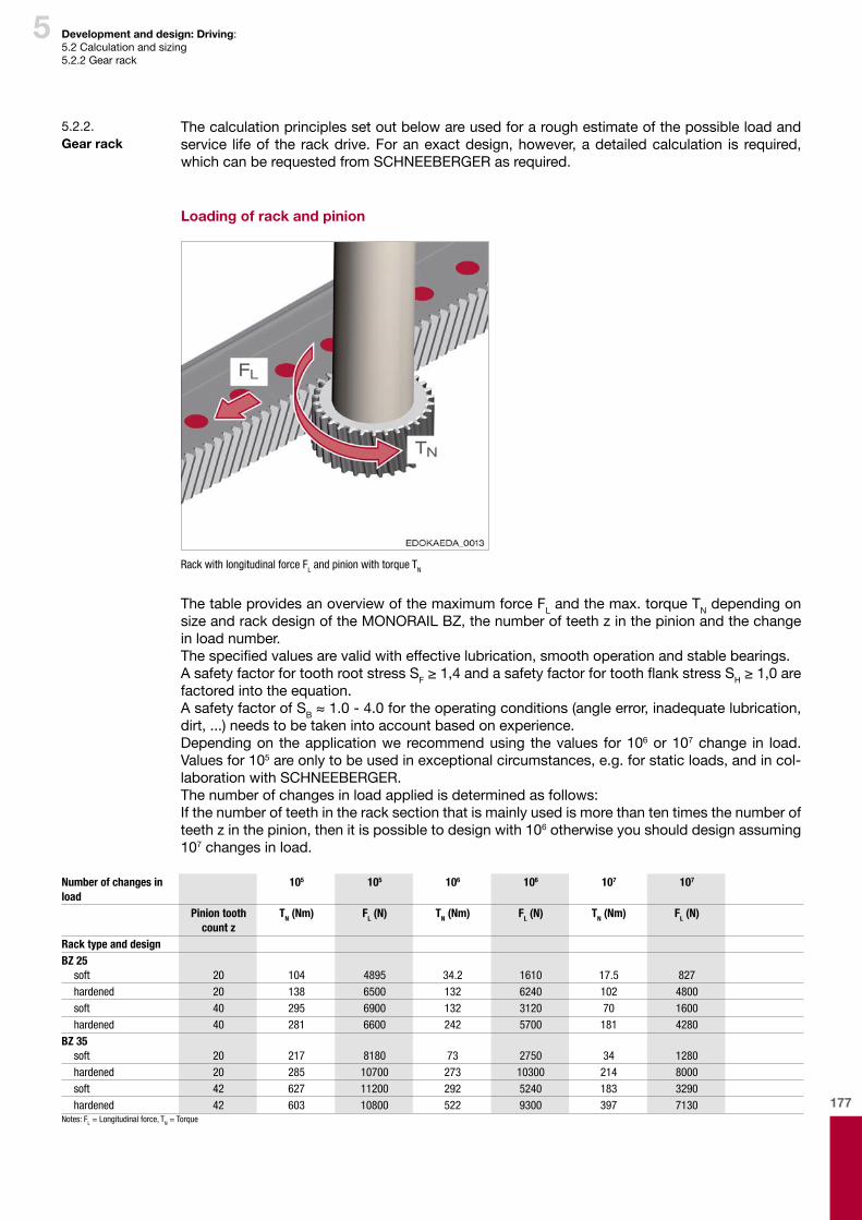
177
5
The calculation principles set out below are used for a rough estimate of the possible load and service lifeof the rackdrive.Foranexactdesign,however,adetailedcalculation is required,which can be requested from SCHNEEBERGER as required.
Loading of rack and pinion
Rack with longitudinal force FL and pinion with torque TN
ThetableprovidesanoverviewofthemaximumforceFLandthemax.torqueTN depending on size and rack design of the MONORAIL BZ, the number of teeth z in the pinion and the change in load number.Thespecifiedvaluesarevalidwitheffectivelubrication,smoothoperationandstablebearings.A safety factor for tooth root stress SF≥1,4andasafetyfactorfortoothflankstressSH≥1,0arefactored into the equation.A safety factor of SB≈1.0-4.0fortheoperatingconditions(angleerror,inadequatelubrication,dirt,...)needstobetakenintoaccountbasedonexperience.Depending on the application we recommend using the values for 106 or 107 change in load. Values for 105areonlytobeusedinexceptionalcircumstances,e.g.forstaticloads,andincol-laboration with SCHNEEBERGER.The number of changes in load applied is determined as follows:If the number of teeth in the rack section that is mainly used is more than ten times the number of teeth z in the pinion, then it is possible to design with 106 otherwise you should design assuming 107 changes in load.
Development and design: Driving: 5.2 Calculation and sizing5.2.2 Gear rack
5.2.2. Gear rack
Number of changes in load
105 105 106 106 107 107
Pinion tooth count z
TN (Nm) FL (N) TN (Nm) FL (N) TN (Nm) FL (N)
Rack type and designBZ 25
soft 20 104 4895 34.2 1610 17.5 827hardened 20 138 6500 132 6240 102 4800soft 40 295 6900 132 3120 70 1600hardened 40 281 6600 242 5700 181 4280
BZ 35soft 20 217 8180 73 2750 34 1280hardened 20 285 10700 273 10300 214 8000soft 42 627 11200 292 5240 183 3290hardened 42 603 10800 522 9300 397 7130
Notes: FL = Longitudinal force, TN = Torque

178
5 Development and design: Driving: 5.2 Calculation and sizing5.2.2 Gear rack
Calculating forces and moments
for vertical stroke axis
Fvs Push force (N)
m Mass moved (kg)
g Gravity = 9,81 m/s²
a Acceleration (m/s²)
FR Frictional resistance (N)
for a horizontal travel axis
Fvs Push force (N)
m Mass moved (kg)
a Acceleration (m/s²)
FR Frictional resistance (N)
a Acceleration (m/s²)
v Speed (m/s)
tb Acceleration time (s)
FR Frictional resistance (N)
µ Coefficientoffriction
m Mass moved (kg)
g Gravity = 9,81 m/s²
Merf required torque
Fvs Push force (N)
d Reference diameter (mm)
Merf Permissible torque
TN Torque (from table, previous page)
SB Safety factor for operating conditions
The safety factor for the operating conditions (angle error, inadequate lubrication, dirt,....)shouldbetakenintoconsiderationbasedonexperience(SB≈1.0–4.0).
The following condition must be met:
Mzul Permissible torque
Merf Required torque

179
5
SCHNEEBERGER calculation serviceWhenrequired,SCHNEEBERGERwillcompleteanexactdesignoftherackdrive.Thefollowingdetails are required for this: � Application
• Description of application � Requirements in respect of the drive
• Small dimensions with high transmittable moments• Position accuracy• Smooth running• Number of changes in load per hour
� Operating data• Permanent operation or intermittent operation (start-ups/h)• Iddle time• Drive rotational speed• Type of drive rotational speed (variable, continuous)• Desired output rotational speed• Mass being moved• Desired speed of the mass being moved• Acceleration time• Type of rack drive installation
� Working environment• Environmental temperature• Humidity
� Configuration• Accessories• Motor attachment geometry• Type of output• Specialmodifications,dimensionsorcharacteristics
Development and design: Driving: 5.2 Calculation and sizing5.2.2 Gear rack
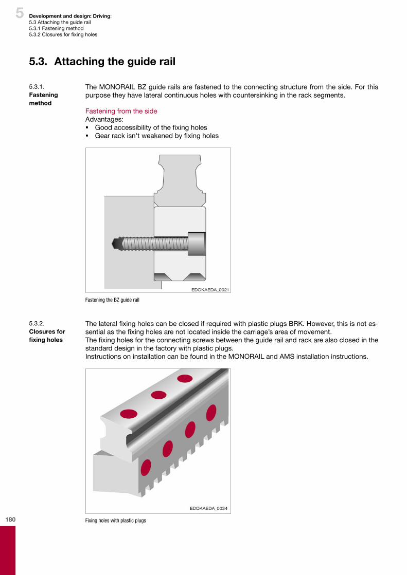
180
5 Development and design: Driving: 5.3 Attaching the guide rail5.3.1 Fastening method5.3.2Closuresforfixingholes
The MONORAIL BZ guide rails are fastened to the connecting structure from the side. For this purpose they have lateral continuous holes with countersinking in the rack segments.
Fastening from the sideAdvantages: � Goodaccessibilityofthefixingholes � Gearrackisn'tweakenedbyfixingholes
Fastening the BZ guide rail
5.3. Attaching the guide rail
5.3.1. Fastening method
ThelateralfixingholescanbeclosedifrequiredwithplasticplugsBRK.However,thisisnotes-sentialasthefixingholesarenotlocatedinsidethecarriage’sareaofmovement.Thefixingholesfortheconnectingscrewsbetweentheguiderailandrackarealsoclosedinthestandard design in the factory with plastic plugs.Instructions on installation can be found in the MONORAIL and AMS installation instructions.
Fixing holes with plastic plugs
5.3.2. Closures for fixing holes

181
5 Development and design: Driving: 5.3 Attaching the guide rail5.3.3 Permissible screw tightening torques5.3.4Transportprotectionincludingassemblyfixture
MONORAILBZguiderails,withalength>1200mmaredeliveredwithatransportfixture.ThisconsistsofanaluminiumL-profilesection,whichisconnectedviaseveralclampswiththeBZguiderail.TheL-profilesectionstabilisesandprotectstheBZsystemagainstbucklingduringstorage, transportationand installation.Thetopof theprofilesectionhasseveral tapped fix-ing holes into which eyelets can be screwed for lifting with hoisting devices. BZ systems should always be transported in an upright position, that is with the gear rack pointing downwards, becausetheguiderailsandthetransportfixturesaremorerigidinthisorientation.ThetransportfixtureshouldonlyberemovedaftertheBZguiderailhasbeenfixedtothemachine.Additionalinformation can be found in the MONORAIL BZ installation instructions.
5.3.3. Permissible screw tightening torques
Tightening torques for DIN 912 / ISO 4762 fastening screws, µ = 0.125Maximum tightening torque (Nm)Screw M6 M8Size BZ 25 35Strength grade
8.8 10 2412.9 16 40
A more uniform preload force is obtained when grease containing MoS2 is applied to the guide rail fastening screws, which are then tightened with a torque wrench. This results in a marked improvement of running accuracy.
Caution
Component damage due to screws not tightened using the correct torque
¨ By using greases, especially greases containing MoS2, the coefficient of friction µ can drop to half. The torques must be reduced accordingly.
Thefasteningscrewscanbesecurediflossesintensionareexpected.SCHNEEBERGER recommends using fastening screws of strength grade 12.9.
5.3.4. Transport protection including assembly fixture
SeethetablebelowforthemaximumtighteningtorquesforfasteningscrewsDIN912/ISO4762.Thisisbasedonafrictioncoefficientasdeliveredofμ=0.125.
Caution
Component damage due to screws not tightened using the correct torque
¨ The recommendations of the screw suppliers must be followed and are always binding. ¨ Screws with low head DIN 6912 are to be tightened according to strength grade 8.8
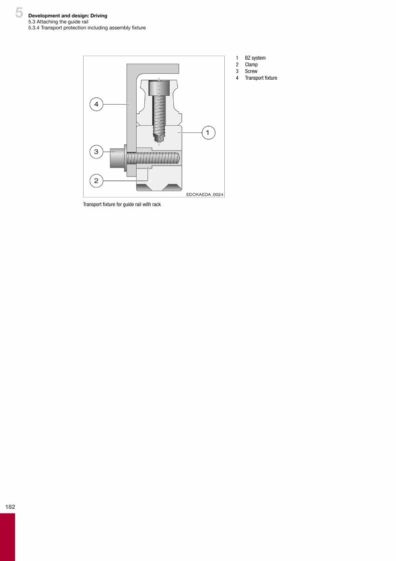
182
5 Development and design: Driving5.3 Attaching the guide rail5.3.4Transportprotectionincludingassemblyfixture
1 BZ system 2 Clamp 3 Screw 4 Transportfixture
Transportfixtureforguiderailwithrack
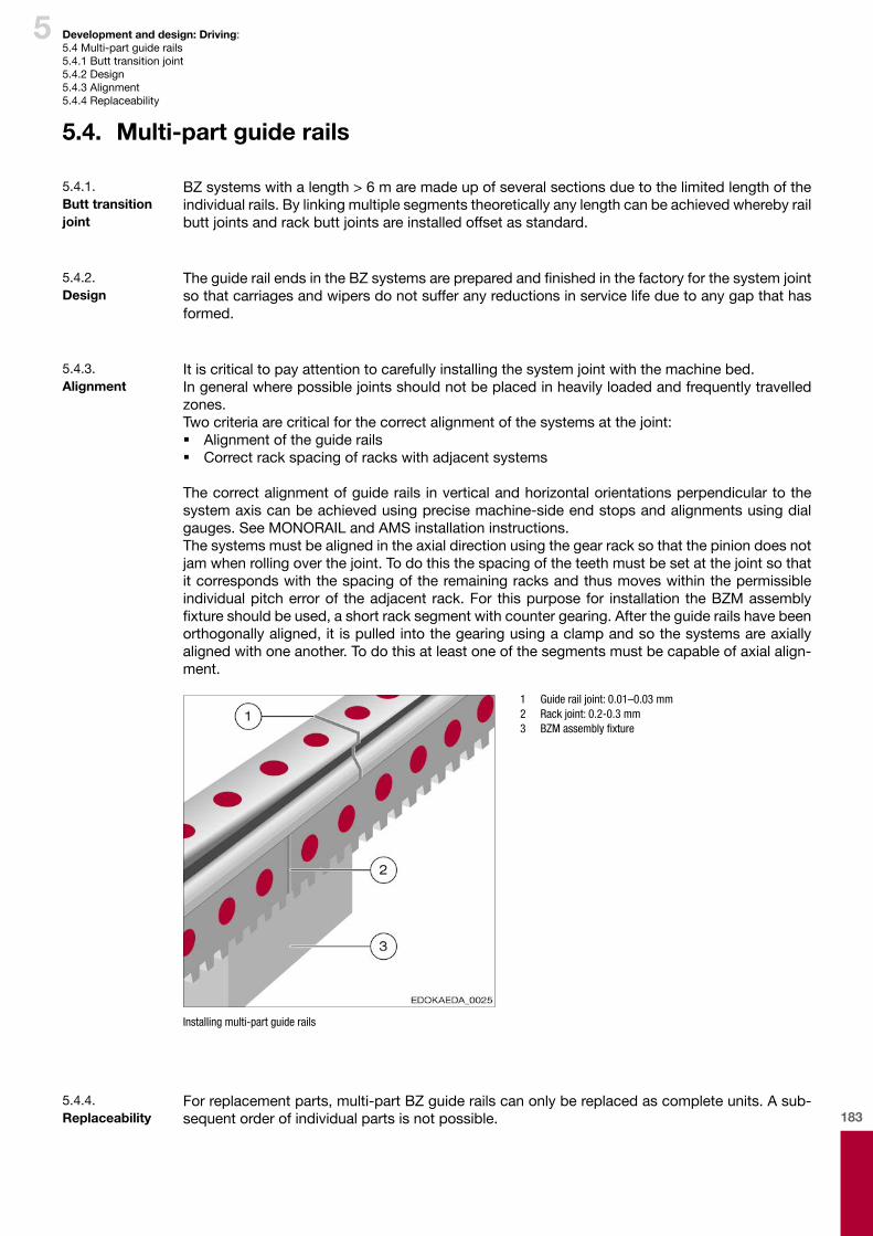
183
5 Development and design: Driving: 5.4 Multi-part guide rails5.4.1 Butt transition joint5.4.2 Design5.4.3 Alignment5.4.4 Replaceability
BZ systems with a length > 6 m are made up of several sections due to the limited length of the individual rails. By linking multiple segments theoretically any length can be achieved whereby rail butt joints and rack butt joints are installed offset as standard.
5.4. Multi-part guide rails
5.4.1. Butt transition joint
TheguiderailendsintheBZsystemsarepreparedandfinishedinthefactoryforthesystemjointso that carriages and wipers do not suffer any reductions in service life due to any gap that has formed.
5.4.2. Design
It is critical to pay attention to carefully installing the system joint with the machine bed.In general where possible joints should not be placed in heavily loaded and frequently travelled zones.Two criteria are critical for the correct alignment of the systems at the joint: � Alignment of the guide rails � Correct rack spacing of racks with adjacent systems
The correct alignment of guide rails in vertical and horizontal orientations perpendicular to the systemaxiscanbeachievedusingprecisemachine-sideendstopsandalignmentsusingdialgauges. See MONORAIL and AMS installation instructions.Thesystemsmustbealignedintheaxialdirectionusingthegearracksothatthepiniondoesnotjam when rolling over the joint. To do this the spacing of the teeth must be set at the joint so that it corresponds with the spacing of the remaining racks and thus moves within the permissible individual pitch error of the adjacent rack. For this purpose for installation the BZM assembly fixtureshouldbeused,ashortracksegmentwithcountergearing.Aftertheguiderailshavebeenorthogonallyaligned,itispulledintothegearingusingaclampandsothesystemsareaxiallyalignedwithoneanother.Todothisatleastoneofthesegmentsmustbecapableofaxialalign-ment.
1 Guide rail joint: 0.01–0.03 mm 2 Rack joint: 0.2-0.3 mm 3 BZMassemblyfixture
Installing multi-part guide rails
5.4.3. Alignment
For replacement parts, multi-part BZ guide rails can only be replaced as complete units. A sub-sequent order of individual parts is not possible.
5.4.4. Replaceability
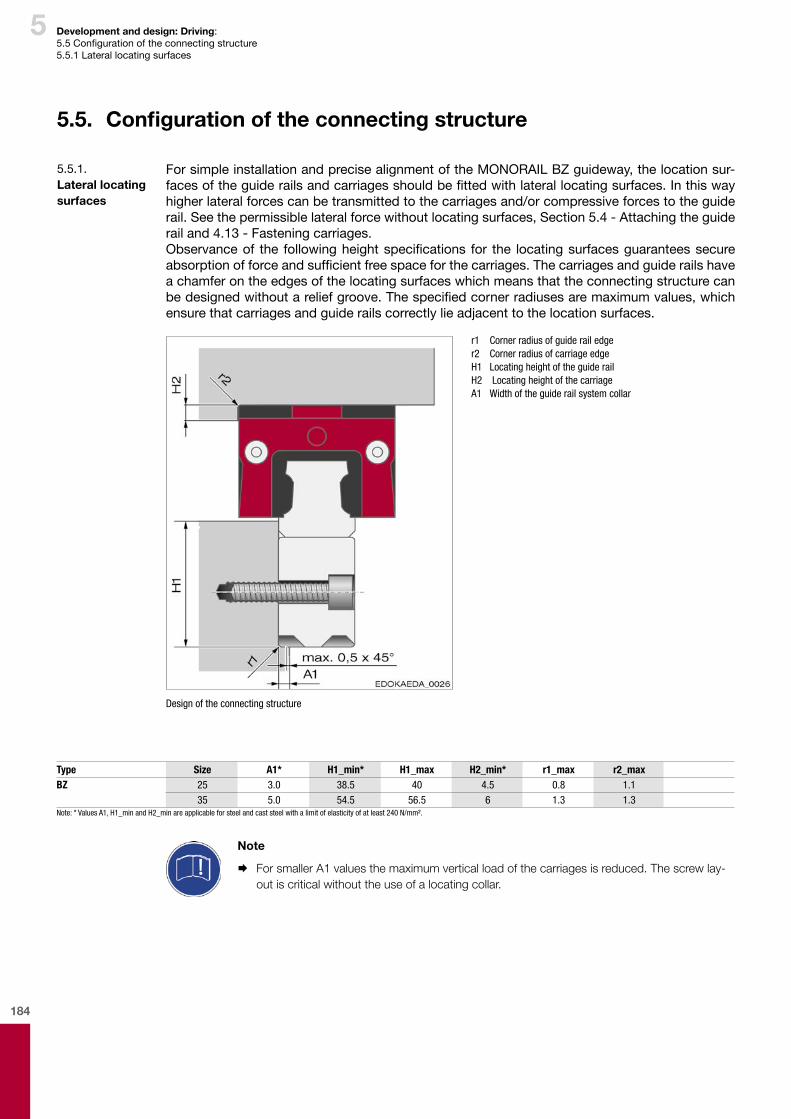
184
5 Development and design: Driving: 5.5Configurationoftheconnectingstructure5.5.1 Lateral locating surfaces
For simple installation and precise alignment of the MONORAIL BZ guideway, the location sur-facesoftheguiderailsandcarriagesshouldbefittedwithlaterallocatingsurfaces.Inthiswayhigher lateral forces can be transmitted to the carriages and/or compressive forces to the guide rail. See the permissible lateral force without locating surfaces, Section 5.4 - Attaching the guide rail and 4.13 - Fastening carriages.Observanceof the followingheightspecifications for the locatingsurfacesguaranteessecureabsorptionofforceandsufficientfreespaceforthecarriages.Thecarriagesandguiderailshavea chamfer on the edges of the locating surfaces which means that the connecting structure can bedesignedwithoutareliefgroove.Thespecifiedcornerradiusesaremaximumvalues,whichensure that carriages and guide rails correctly lie adjacent to the location surfaces.
r1 Corner radius of guide rail edge r2 Corner radius of carriage edge H1 Locating height of the guide rail H2 Locating height of the carriage A1 Width of the guide rail system collar
Design of the connecting structure
5.5. Configuration of the connecting structure
5.5.1. Lateral locating surfaces
Type Size A1* H1_min* H1_max H2_min* r1_max r2_maxBZ 25 3.0 38.5 40 4.5 0.8 1.1
35 5.0 54.5 56.5 6 1.3 1.3Note: * Values A1, H1_min and H2_min are applicable for steel and cast steel with a limit of elasticity of at least 240 N/mm².
Note
¨ For smaller A1 values the maximum vertical load of the carriages is reduced. The screw lay-out is critical without the use of a locating collar.
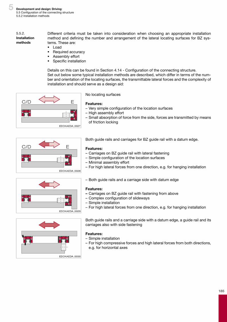
185
5 Development and design: Driving: 5.5Configurationoftheconnectingstructure5.5.2 Installation methods
No locating surfaces
Features:–Verysimpleconfigurationofthelocationsurfaces– High assembly effort– Small absorption of force from the side, forces are transmitted by means
of friction locking
Both guide rails and carriages for BZ guide rail with a datum edge.
Features:– Carriages on BZ guide rail with lateral fastening–Simpleconfigurationofthelocationsurfaces– Minimal assembly effort– For high lateral forces from one direction, e.g. for hanging installation
– Both guide rails and a carriage side with datum edge
Features:– Carriages on BZ guide rail with fastening from above–Complexconfigurationofslideways– Simple installation– For high lateral forces from one direction, e.g. for hanging installation
Both guide rails and a carriage side with a datum edge, a guide rail and its carriages also with side fastening
Features:– Simple installation– For high compressive forces and high lateral forces from both directions, e.g.forhorizontalaxes
Different criteria must be taken into consideration when choosing an appropriate installation methodanddefiningthenumberandarrangementofthe lateral locatingsurfacesforBZsys-tems. These are: � Load � Required accuracy � Assembly effort � Specificinstallation
DetailsonthiscanbefoundinSection4.14-Configurationoftheconnectingstructure.Set out below some typical installation methods are described, which differ in terms of the num-berandorientationofthelocatingsurfaces,thetransmittablelateralforcesandthecomplexityofinstallation and should serve as a design aid:
5.5.2. Installation methods

186
5 Development and design: Driving: 5.5Configurationoftheconnectingstructure5.5.3 Geometrical and position accuracy of the supporting surfaces, connection dimensions
Advantages of the SCHNEEBERGER MONORAIL BZ guideways can best be achieved when mounted to a rigid structure with a high level of geometric accuracy. Inaccuracies in the attach-ment surfaces are partially compensated for by the elastic deformation of the guideway, however, they may have a detrimental effect on overall accuracy, running behaviour, push force and service life as a result.ForMONORAILBZthesamespecificationsapplyasforMONORAIL.InSection4.14-Configura-tion of the connecting structure, the permissible values for � height deviation laterally � height deviation longitudinally � tolerances of parallelism of the locating surfaces and � evenness of the location surfaces
aredefined.Thesurfacequalityofthesupportingsurfacedoesnothaveadirect influenceonthe function and running behaviour of the guideway, but it does on the static accuracy. Carriages and guide rails are compressed against the location surfaces by the screw connections with a high level of force. To prevent settling behaviour of the connection, a high surface contact ratio is required. This is achieved by means of high level of surface quality. An average surface roughness ofRa0.4to1.6μmisrecommendedforthesupportingandlocatingsurfaces.
Connection dimensions of a BZ rail:L3 Rail lengthL4 Fixing hole pitchL10 Endfixingholespacing
L12 Rack projectionB4 Rack projection (half rail width)
β Helix angle
The values for the connection dimensions can be found in the MONORAIL and AMS product catalogue
5.5.3. Geometrical and position accuracy of the supporting surfaces, connection dimensions
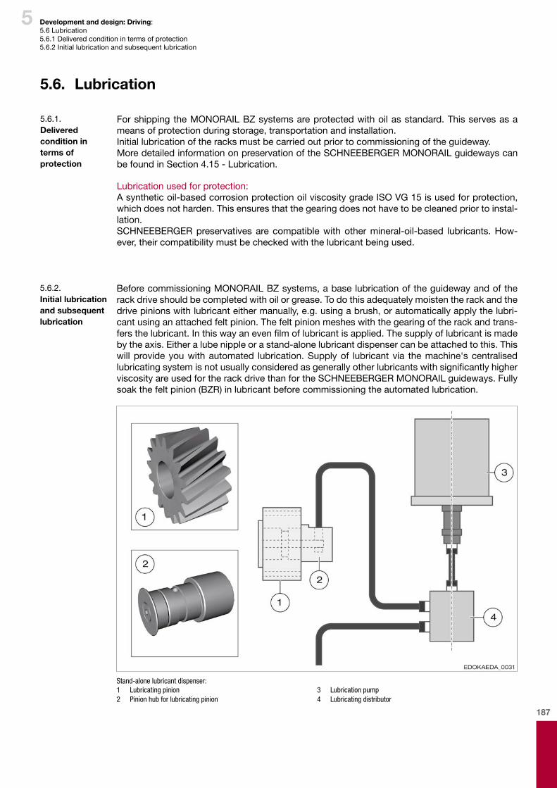
187
5 Development and design: Driving: 5.6 Lubrication5.6.1 Delivered condition in terms of protection5.6.2 Initial lubrication and subsequent lubrication
For shipping the MONORAIL BZ systems are protected with oil as standard. This serves as a means of protection during storage, transportation and installation.Initial lubrication of the racks must be carried out prior to commissioning of the guideway.More detailed information on preservation of the SCHNEEBERGER MONORAIL guideways can be found in Section 4.15 - Lubrication.
Lubrication used for protection:A synthetic oil-based corrosion protection oil viscosity grade ISO VG 15 is used for protection, which does not harden. This ensures that the gearing does not have to be cleaned prior to instal-lation.SCHNEEBERGER preservatives are compatible with other mineral-oil-based lubricants. How-ever, their compatibility must be checked with the lubricant being used.
5.6. Lubrication
5.6.1. Delivered condition in terms of protection
Before commissioning MONORAIL BZ systems, a base lubrication of the guideway and of the rack drive should be completed with oil or grease. To do this adequately moisten the rack and the drive pinions with lubricant either manually, e.g. using a brush, or automatically apply the lubri-cant using an attached felt pinion. The felt pinion meshes with the gearing of the rack and trans-fersthelubricant.Inthiswayanevenfilmoflubricantisapplied.Thesupplyoflubricantismadebytheaxis.Eitheralubenippleorastand-alonelubricantdispensercanbeattachedtothis.Thiswill provide you with automated lubrication. Supply of lubricant via the machine's centralised lubricatingsystemisnotusuallyconsideredasgenerallyotherlubricantswithsignificantlyhigherviscosity are used for the rack drive than for the SCHNEEBERGER MONORAIL guideways. Fully soak the felt pinion (BZR) in lubricant before commissioning the automated lubrication.
Stand-alone lubricant dispenser:1 Lubricating pinion2 Pinion hub for lubricating pinion
3 Lubrication pump4 Lubricating distributor
5.6.2. Initial lubrication and subsequent lubrication

188
5
To maintain operability of the rack drive in addition to an initial basic lubrication regular subse-quent lubrication is generally also a requirement. Use the same lubricant as the one used for the initial lubrication and check compatibility with the base lubricant for subsequent lubrication.The lubricating intervals can vary greatly depending on the application and must be determined during operation. The felt pinions are subject to wear and harden with time. They therefore need to be regularly checked and where applicable replaced. Their average operating life is about one year.Information about lubricating the guideway can be found in Section 4.15 - Lubrication.For lubricating accessories for MONORAIL BZ, see SCHNEEBERGER MONORAIL and AMS product catalogue.
Development and design: Driving: 5.6 Lubrication5.6.2 Initial lubrication and subsequent lubrication5.6.3 Coatings
The MONORAIL BZ systems with surface coatings to protect against corrosion are available on demand.It is important to note that only the carriages and guide rails are coated. The racks and pinions available as an accessory should remain uncoated.
5.6.3. Coatings

189
6 Development and design: Measuring

190

191
6
Contents
6
6 Development and design: Measuring ..............................................189
6.1. Integration ..........................................................................................................................1926.1.1. Characteristics ................................................................................................................192
6.2. Product overview ................................................................................................................1936.2.1. Measuring systems .........................................................................................................1936.2.2. Guide rail types ...............................................................................................................1946.2.3. Carriage types .................................................................................................................1946.2.4. System comparison – technical data ..............................................................................1956.2.5. Accessories .....................................................................................................................196
6.3. Factorsinfluencingthechoiceofproduct .......................................................................1976.3.1. Choice of product ...........................................................................................................1976.3.2. Examples of use ..............................................................................................................199
6.4. Arrangementofthemeasuringsystems ..........................................................................2006.4.1. Arrangement of the measuring system and reading head ..............................................2006.4.2. Cabling and connection to the controller ........................................................................202
6.5. Operating conditions ..........................................................................................................2056.5.1. Lubrication ......................................................................................................................2056.5.2. Wear and service life .......................................................................................................205
6.6. Shielding ..............................................................................................................................2066.6.1. Definition .........................................................................................................................2066.6.2. Types of shielding ...........................................................................................................2066.6.3. Shielding for the SCHNEEBERGER distance measuring system ...................................206
192
6 Development and design: Measuring6.1 Integration6.1.1 Characteristics
6.1. Integration
With AMS, SCHNEEBERGER provides a distance measuring system fully integrated into the pro-filerailguideway,whichcanbeinstalleddirectlywithoutalignmentandadjustment.Withaneasilyinterchangeable reading head and the system's imperviousness to all kinds of dirt, the necessary servicingandmaintenanceworkarealsoreduced.Consequently, cost savings in terms of design, manufacturing and maintenance of products are achieved thanks to its integrated design, and the combination of its high-precision scale and the MONORAIL guide rail.
Accuracy � Coefficientofexpansionlikesteel � Goodthermalconnectionwiththemachinebase � Measurement close to the machining process � Optimal alignment of the scale � Vibration-resistant technology � Themeasuringscaleisproducedasaready-to-fitcomponent
Installationandadjustment � Ready-to-fitsolution(noadditionaloverheads) � No alignment of the measuring scale � No additional mounting brackets needs � Extremelystraightforwardcommissioning(noadjustment) � Phase-lockedinterchangeablesolution(AMSA-3L) � No sealing air required
Service and maintenance � Partssubjecttowearareinterchangeable � One reading head for all sizes � Simple reading head replacement in case of a fault � Protection class IP68 � Resistant to oil, coolant, solvent � Non-corrosive cover for the scale � Impervious to all kinds of foreign particles � Interchangeableguiderailsegments(AMSA-3L)
Design and production process � Reading head and electronics are a single part � Short construction times, compact solutions � Multiple reading heads can be operated on one guide rail � Standard accessories for MONORAIL can be deployed � Single-piece up to 6m. Standardised segment lengths for longer lengths � Specialguiderailendsandreadingheadsforlongertravelswithbuttjointedrails(AMSA-3L)
6.1.1. Characteristics

193
6 Development and design: Measuring6.2Productoverview6.2.1 Measuring systems
6.2. Product overview
SCHNEEBERGER offers integrated measuring systems for both BM and MR types.
For most systems the measuring length is limited to 6 m.ForlargermeasuringlengthsthereisAMSA-3LbasedontheMRrollerguidewayandtheincre-mental analogue interface.
AMSA 3L is possible as a result of the highly accurate construction of the rails in terms of both mechanics andmetrology. The special designof theguide rail butt joints combinedwith the AMSA-3Lreadingheadmakesitpossibletotraveloverjointsandtobuildmeasuringaxesofanylength.
1 AMSA 3L measuring rail 2 AMSA 3L joint 3 AMSA 3L carriage 4 AMSA 3L reading head
AMSA 3L measuring system
TheAMSA3Lproductsetsitselfapartduetothefollowingspecialfeatures: � Large measuring length � High level of accuracy for large measuring lengths � Travelsoverjointswithoutlossofaccuracy � Integrated electronics in the reading head
No additional electronics � Individual rail segments interchangeable � One reading head for all sizes
6.2.1. Measuring systems
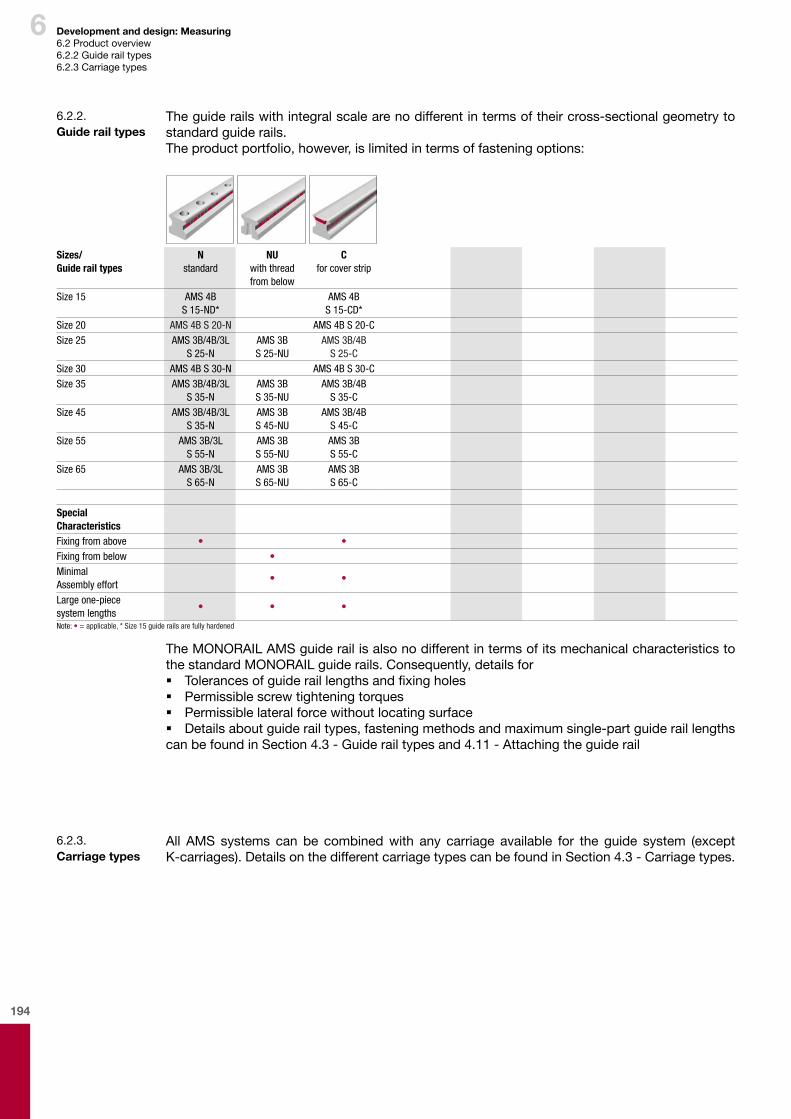
194
6 Development and design: Measuring6.2Productoverview6.2.2 Guide rail types6.2.3 Carriage types
Theguiderailswithintegralscalearenodifferentintermsoftheircross-sectionalgeometrytostandard guide rails.Theproductportfolio,however,islimitedintermsoffasteningoptions:
6.2.2. Guiderailtypes
Sizes/Guide rail types
Nstandard
NUwith thread from below
Cfor cover strip
Size 15 AMS 4BS 15-ND*
AMS 4BS 15-CD*
Size 20 AMS 4B S 20-N AMS 4B S 20-CSize 25 AMS 3B/4B/3L
S 25-NAMS 3B S 25-NU
AMS 3B/4BS 25-C
Size 30 AMS 4B S 30-N AMS 4B S 30-CSize 35 AMS 3B/4B/3L
S 35-NAMS 3B S 35-NU
AMS 3B/4BS 35-C
Size 45 AMS 3B/4B/3LS 35-N
AMS 3B S 45-NU
AMS 3B/4BS 45-C
Size 55 AMS 3B/3LS 55-N
AMS 3B S 55-NU
AMS 3B S 55-C
Size 65 AMS 3B/3LS 65-N
AMS 3B S 65-NU
AMS 3BS 65-C
Special CharacteristicsFixing from above • •Fixing from below •Minimal Assembly effort
• •
Large one-piece system lengths
• • •
Note: • = applicable, * Size 15 guide rails are fully hardened
The MONORAIL AMS guide rail is also no different in terms of its mechanical characteristics to the standard MONORAIL guide rails. Consequently, details for � Tolerancesofguideraillengthsandfixingholes � Permissiblescrewtighteningtorques � Permissiblelateralforcewithoutlocatingsurface � Details about guide rail types, fastening methods and maximum single-part guide rail lengths
can be found in Section 4.3 - Guide rail types and 4.11 - Attaching the guide rail
All AMS systems can be combinedwith any carriage available for the guide system (except K-carriages).DetailsonthedifferentcarriagetypescanbefoundinSection4.3-Carriagetypes.
6.2.3. Carriagetypes
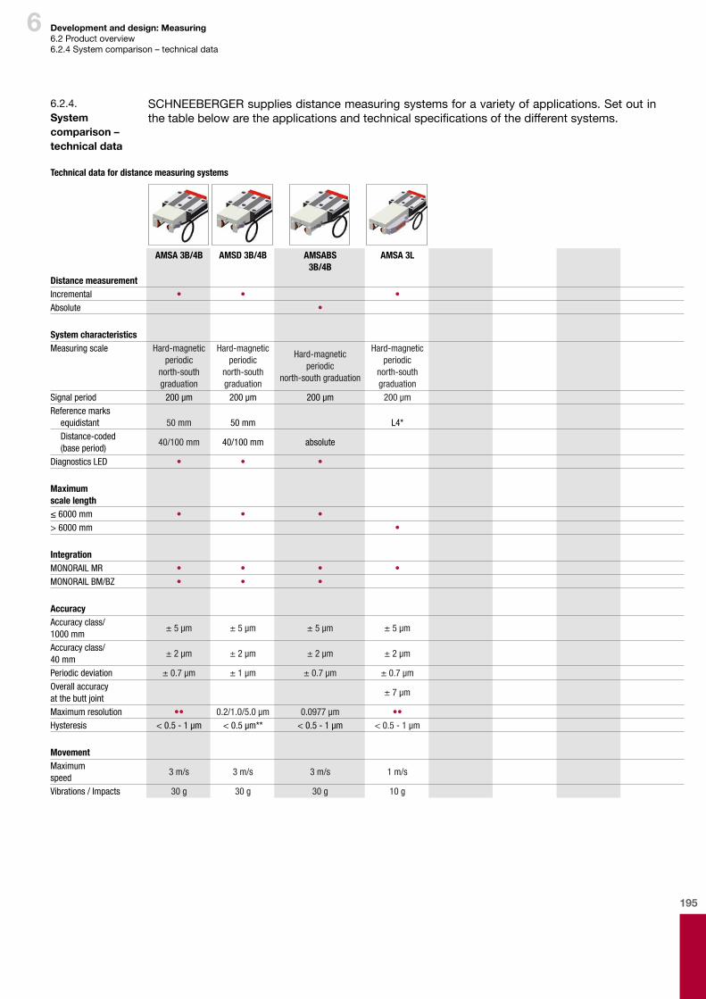
195
6 Development and design: Measuring6.2Productoverview6.2.4 System comparison – technical data
SCHNEEBERGER supplies distance measuring systems for a variety of applications. Set out in thetablebelowaretheapplicationsandtechnicalspecificationsofthedifferentsystems.
6.2.4. System comparison – technicaldata
Technical data for distance measuring systems
AMSA 3B/4B AMSD 3B/4B AMSABS 3B/4B
AMSA 3L
Distance measurementIncremental • • •Absolute •
System characteristicsMeasuring scale Hard-magnetic
periodic north-south graduation
Hard-magnetic periodic
north-south graduation
Hard-magnetic periodic
north-south graduation
Hard-magnetic periodic
north-south graduation
Signal period 200 µm 200 µm 200 µm 200 µmReference marks
equidistant 50 mm 50 mm L4*Distance-coded (base period)
40/100 mm 40/100 mm absolute
Diagnostics LED • • •
Maximum scale length≤ 6000 mm • • •> 6000 mm •
IntegrationMONORAIL MR • • • •MONORAIL BM/BZ • • •
AccuracyAccuracy class/1000 mm
± 5 µm ± 5 µm ± 5 µm ± 5 µm
Accuracy class/40 mm
± 2 µm ± 2 µm ± 2 µm ± 2 µm
Periodic deviation ± 0.7 µm ± 1 µm ± 0.7 µm ± 0.7 µmOverall accuracy at the butt joint
± 7 µm
Maximum resolution •• 0.2/1.0/5.0 µm 0.0977 µm ••Hysteresis < 0.5 - 1 µm < 0.5 µm** < 0.5 - 1 µm < 0.5 - 1 µm
MovementMaximum speed
3 m/s 3 m/s 3 m/s 1 m/s
Vibrations / Impacts 30 g 30 g 30 g 10 g

196
6 Development and design: Measuring6.2Productoverview6.2.4 System comparison – technical data6.2.5 Accessories
AMSA 3B/4B AMSD 3B/4B AMSABS 3B/4B AMSA 3LInterfaces electricanalogue 1 VSS 1 VSS
digital Quad. signal RS422 (TTL)
digital absolute SSI,SSI + 1 VSS
Supply voltage 5 ± 0.25 V 5 ± 0.25 V
5 V ± 10 %24 V ± 10 %
5 ± 0.25 V
Current consumption (unloaded)
40 mA 110 mA < 200 mA 50 mA
Interfaces mechanicalconnector type S • • •connector type R • • •connector type M • • • •
EnvironmentProtection category IP 68
(up to 0.3 bar)IP 68
(up to 0.3 bar)IP 68
(up to 0.3 bar)IP 67
Working temperature 0°C - +70°C 0°C - +70°C 0°C - +70°C 0°C - +70°CStorage temperature -20°C - +70°C -20°C - +70°C -20°C - +70°C -20°C - +70°CVibrations / Impacts 30 g 30 g 30 g 10 gNote: • = applicable, •• limited by controller, in connection with SMEA up to 0.0625µm, * except MR45, here 105 mm (at the guide rail butt joint 52.5 mm), ** or digitally adjustable
A large part of the accessories for the corresponding MONORAIL guide systems are used for the MONORAILAMSsystems.Theseinclude: � Plugsfortheguiderails(MRK/BRK,MRS/BRS,MRZ) � Coverstrips(MAC/BAC) � Installationtoolsforplugs(MWH) � Additionalwipers(ZCN/ZBN,ZCV/ZBV) � Bellows(FBM/FBB) � Lubricationplates(SPL) � Lube nipples and lubrication adapter
Inaddition,SCHNEEBERGERoffersspecialaccessoriesforMONORAILAMS: � Cable � MetalwipersforAMS(ASM/ABM-xxA) � AssemblyfixtureforAMSA3L(MWM3L) � EndpieceforAMSA3Lguiderails(EST3L) � AssemblyrailforAMSA3L(MRM3L) � ConfigurationsoftwareforAMSDandAMSABS
AfulloverviewoftheavailableaccessoriescanbefoundintheSCHNEEBERGERMONORAILand AMS product catalogue.
6.2.5. Accessories
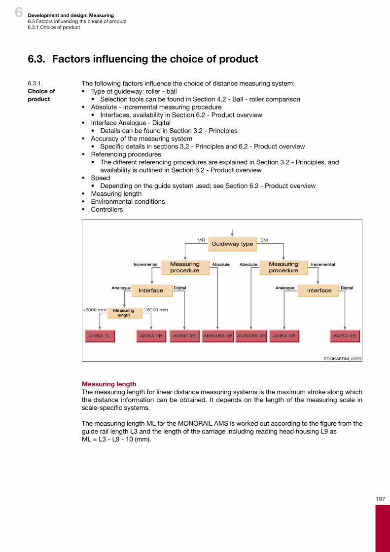
197
6 Development and design: Measuring6.3Factorsinfluencingthechoiceofproduct6.3.1 Choice of product
Thefollowingfactorsinfluencethechoiceofdistancemeasuringsystem: � Typeofguideway:roller-ball
• Selection tools can be found in Section 4.2 - Ball - roller comparison � Absolute - Incremental measuring procedure
• Interfaces,availabilityinSection6.2-Productoverview � Interface Analogue - Digital
• Details can be found in Section 3.2 - Principles � Accuracy of the measuring system
• Specificdetailsinsections3.2-Principlesand6.2-Productoverview � Referencing procedures
• The different referencing procedures are explained in Section 3.2 - Principles, and availabilityisoutlinedinSection6.2-Productoverview
� Speed• Dependingontheguidesystemused;seeSection6.2-Productoverview
� Measuring length � Environmental conditions � Controllers
MeasuringlengthThemeasuringlengthforlineardistancemeasuringsystemsisthemaximumstrokealongwhichthe distance information can be obtained. It depends on the length of the measuring scale in scale-specificsystems.
ThemeasuringlengthMLfortheMONORAILAMSisworkedoutaccordingtothefigurefromtheguide rail length L3 and the length of the carriage including reading head housing L9 as ML=L3-L9-10(mm).
6.3. Factorsinfluencingthechoiceofproduct
6.3.1. Choiceof product
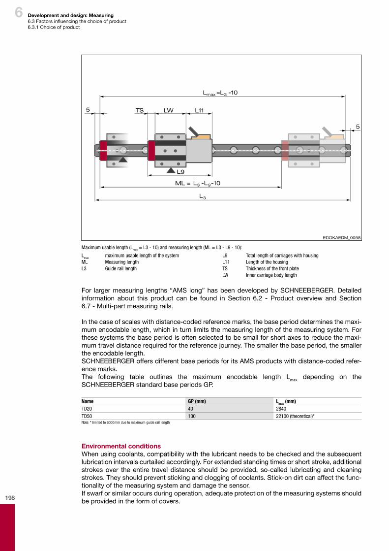
198
6 Development and design: Measuring6.3Factorsinfluencingthechoiceofproduct6.3.1 Choice of product
Maximum usable length (Lmax = L3 - 10) and measuring length (ML = L3 - L9 - 10):
Lmax maximum usable length of the systemML Measuring lengthL3 Guide rail length
L9 Total length of carriages with housingL11 Length of the housingTS Thickness of the front plateLW Inner carriage body length
For larger measuring lengths “AMS long” has been developed by SCHNEEBERGER. Detailed information about this product can be found in Section 6.2 - Product overview and Section 6.7 - Multi-part measuring rails.
Inthecaseofscaleswithdistance-codedreferencemarks,thebaseperioddeterminesthemaxi-mumencodablelength,whichinturnlimitsthemeasuringlengthofthemeasuringsystem.Forthese systems the base period is often selected to be small for short axes to reduce the maxi-mumtraveldistancerequiredforthereferencejourney.Thesmallerthebaseperiod,thesmallerthe encodable length.SCHNEEBERGERoffersdifferentbaseperiodsforitsAMSproductswithdistance-codedrefer-ence marks.The following table outlines the maximum encodable length Lmax depending on the SCHNEEBERGER standard base periods GP.
Name GP (mm) Lmax (mm)TD20 40 2840TD50 100 22100 (theoretical)*Note: * limited to 6000mm due to maximum guide rail length
Environmental conditionsWhenusingcoolants,compatibilitywiththelubricantneedstobecheckedandthesubsequentlubrication intervals curtailed accordingly. For extended standing times or short stroke, additional strokes over the entire travel distance should be provided, so-called lubricating and cleaning strokes. They should prevent sticking and clogging of coolants. Stick-on dirt can affect the func-tionality of the measuring system and damage the sensor.Ifswarforsimilaroccursduringoperation,adequateprotectionofthemeasuringsystemsshouldbe provided in the form of covers.

199
6 Development and design: Measuring6.3Factorsinfluencingthechoiceofproduct6.3.1 Choice of product6.3.2 Examples of use
Product Features Examples of useAMSABS 3B, 4B • Integrated absolute measuring system
for MONORAIL MR and BM• Use typical in CNC machines for
scale length ≤ 6 m
Turning, grinding, milling and general machining equipment
AMSA 3B, 4BAMSD 3B, 4B
• Integrated incremental measuring system for MONORAIL MR and BM
• Use typical in CNC machines with axle lengths ≤ 6 m
Turning, grinding, milling and general machining equipment
AMSA 3L • Integrated incremental measuring system for MONORAIL MR
• Use in all CNC large-scale machinery with stroke > 6 m
Large-scale milling machines and lathes, drilling machinery, automated lines, systems for aircraft production
6.3.2. Examplesofuse
ControllersTheSCHNEEBERGERdistancemeasuringsystemscanbeusedwithmostindustrialCNCcon-trollers, such as for example the Siemens SINUMERIC CNC controllers and the FANUC CNC controllers.
Moredetailedinformationoncontrollersthatcanbeusedandtheirspecificsettingscanbeob-tained from the controller manufacturer or via the competent SCHNEEBERGER agent.
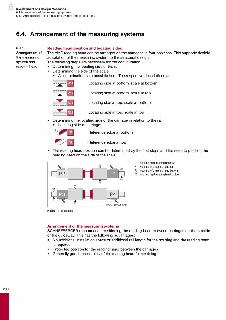
200
6 Development and design: Measuring6.4 Arrangement of the measuring systems6.4.1 Arrangement of the measuring system and reading head
6.4. Arrangementofthemeasuringsystems
6.4.1. Arrangementofthemeasuringsystemand readinghead
ReadingheadpositionandlocatingsidesTheAMSreadingheadcanbearrangedonthecarriagesinfourpositions.Thissupportsflexibleadaptation of the measuring system to the structural design.Thefollowingstepsarenecessaryfortheconfiguration: � Determining the locating side of the rail � Determining the side of the scale
• Allcombinationsarepossiblehere.Therespectivedescriptionsare:
Locating side at bottom, scale at bottom
Locating side at bottom, scale at top
Locating side at top, scale at bottom
Locating side at top, scale at top
� Determining the locating side of the carriage in relation to the rail• Locatingsideofcarriage:
Reference edge at bottom
Reference edge at top
� Thereadingheadpositioncanbedeterminedbythefirststepsandtheneedtopositionthereading head on the side of the scale.
P1 Housing right, reading head top P1 Housing left, reading head top P3 Housing left, reading head bottom P3 Housing right, reading head bottom
Position of the housing
ArrangementofthemeasuringsystemsSCHNEEBERGERrecommendspositioningthereadingheadbetweencarriagesontheoutsideoftheguideway.Thishasthefollowingadvantages: � No additional installation space or additional rail length for the housing and the reading head
is required � Protectedpositionforthereadingheadbetweenthecarriages � Generally good accessibility of the reading head for servicing
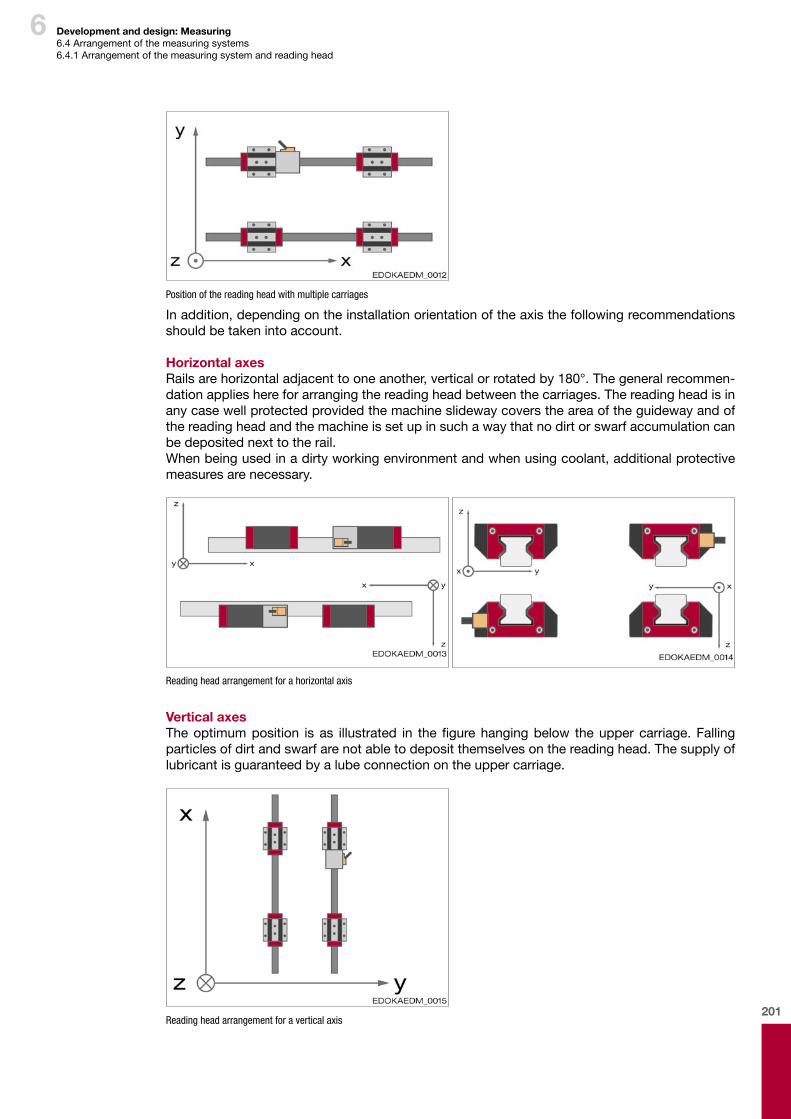
201
6 Development and design: Measuring6.4 Arrangement of the measuring systems6.4.1 Arrangement of the measuring system and reading head
Position of the reading head with multiple carriages
Inaddition,dependingontheinstallationorientationoftheaxisthefollowingrecommendationsshould be taken into account. Horizontal axesRailsarehorizontaladjacenttooneanother,verticalorrotatedby180°.Thegeneralrecommen-dationapplieshereforarrangingthereadingheadbetweenthecarriages.Thereadingheadisinanycasewellprotectedprovidedthemachineslidewaycoverstheareaoftheguidewayandofthereadingheadandthemachineissetupinsuchawaythatnodirtorswarfaccumulationcanbe deposited next to the rail.Whenbeingusedinadirtyworkingenvironmentandwhenusingcoolant,additionalprotectivemeasures are necessary.
Reading head arrangement for a horizontal axis
Vertical axesTheoptimumposition is as illustrated in thefigurehangingbelow theuppercarriage.Fallingparticlesofdirtandswarfarenotabletodepositthemselvesonthereadinghead.Thesupplyoflubricant is guaranteed by a lube connection on the upper carriage.
Reading head arrangement for a vertical axis
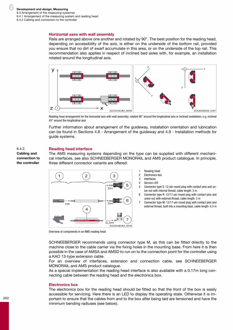
202
6 Development and design: Measuring6.4 Arrangement of the measuring systemss6.4.1 Arrangement of the measuring system and reading head6.4.2 Cabling and connection to the controller
HorizontalaxeswithwallassemblyRailsarearrangedaboveoneanotherandrotatedby90°.Thebestpositionforthereadinghead,depending on accessibility of the axis, is either on the underside of the bottom rail, provided youensurethatnodirtofswarfaccumulateinthisarea,orontheundersideofthetoprail.Thisrecommendationalsoappliesinrespectofinclinedbedaxleswith,forexample,aninstallationrotated around the longitudinal axis.
Reading head arrangement for the horizontal axis with wall assembly; rotated 90° around the longitudinal axis or inclined installation, e.g. inclined 45° around the longitudinal axis
Further informationaboutarrangementoftheguideway, installationorientationandlubricationcanbefoundinSections4.8-Arrangementoftheguidewayand4.9-Installationmethodsforguide systems.
ReadingheadinterfaceTheAMSmeasuringsystemsdependingon the typecanbesuppliedwithdifferentmechani-cal interfaces, see also SCHNEEBERGER MONORAIL and AMS product catalogue. In principle, threedifferentconnectorvariantsareoffered:
1 Reading head 2 Electronics box 3 Interfaces 4 Service LED 5 Connector type S: 12-pin round plug with contact pins and un-
ion nut with internal thread, cable length: 3 m 6 Connector type R: 12/17-pin round plug with contact pins and
union nut with external thread, cable length: 3 m 7 Connector type M: 12/17-pin round plug with contact pins and
external thread, built into a mounting base, cable length: 0.3 m
Overview of components in an AMS reading head
SCHNEEBERGER recommends using connector typeM, as this can be fitted directly to themachineclosetothecablecarrierviathefixingholesinthemountingbase.Fromhereitisthenpossible in the case of AMSA and AMSD to run on to the connection point for the controller using a KAO 13-type extension cable.For an overview of interfaces, extension and connection cable, see SCHNEEBERGER MONORAIL and AMS product catalogue.Asaspecialimplementationthereadingheadinterfaceisalsoavailablewitha0.17mlongcon-nectingcablebetweenthereadingheadandtheelectronicsbox. ElectronicsboxTheelectronicsboxforthereadingheadshouldbefittedsothatthefrontoftheboxiseasilyaccessibleforservicing.HerethereisanLEDtodisplaytheoperatingstate.Otherwiseitisim-portant to ensure that the cables from and to the box after being laid are tensioned and have the minimumbendingradiuses(seebelow).
6.4.2. Cablingand connection to thecontroller
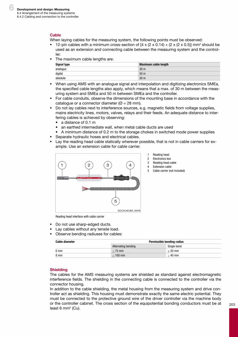
203
6
CableWhenlayingcablesforthemeasuringsystem,thefollowingpointsmustbeobserved: � 12-pincableswithaminimumcross-sectionof[4x(2x0.14)+(2x(2x0.5)]mm2 should be usedasanextensionandconnectingcablebetweenthemeasuringsystemandthecontrol-ler.
� Themaximumcablelengthsare:Signal type Maximum cable lengthanalogue 30 mdigital 50 mabsolute 30 m
� WhenusingAMSwithananaloguesignalandinterpolationanddigitizingelectronicsSMEa,thespecifiedcablelengthsalsoapply,whichmeansthatamax.of30mbetweenthemeas-uringsystemandSMEaand50mbetweenSMEaandthecontroller.
� Forcableconduits,observethedimensionsofthemountingbaseinaccordancewiththecatalogueoraconnectordiameter(Ø=28mm).
� Donotlaycablesnexttointerferencesources,e.g.magneticfieldsfromvoltagesupplies,mains electricity lines, motors, valves, relays and their feeds. An adequate distance to inter-feringcablesisachievedbyobserving:• a distance of 0.1 m• anearthedintermediatewall,whenmetalcableductsareused• Aminimumdistanceof0.2mtothestoragechokesinswitchedmodepowersupplies
� Separate hydraulic hoses and electrical cables. � Laythereadingheadcablestaticallywhereverpossible,thatisnotincablecarriersforex-
ample. Use an extension cable for cable carrier.
1 Reading head 2 Electronics box 3 Reading head cable 4 Extension cable 5 Cable carrier (not included)
Reading head interface with cable carrier
� Do not use sharp-edged ducts. � Laycableswithoutanytensileload. � Observebendingradiusesforcables:
Cable diameter Permissible bending radius
Alternating bending Single bend6 mm > 75 mm > 20 mm8 mm > 100 mm > 40 mm
ShieldingThe cables for the AMS measuring systems are shielded as standard against electromagnetic interferencefields.Theshieldingintheconnectingcableisconnectedtothecontrollerviatheconnector housing.In addition to the cable shielding, the metal housing from the measuring system and drive con-troller act as shielding. This housing must demonstrate exactly the same electric potential. They mustbeconnectedtotheprotectivegroundwireofthedrivercontrollerviathemachinebodyor the controller cabinet. The cross section of the equipotential bonding conductors must be at least 6 mm2(Cu).
Development and design: Measuring6.4 Arrangement of the measuring systems6.4.2 Cabling and connection to the controller

204
6 Development and design: Measuring6.4 Arrangement of the measuring systems6.4.2 Cabling and connection to the controller
� Connect the housing of the measuring system and drive controller via the machine body and/orthecontrollercabinettotheearthofthedrivecontroller.
� Connectthecableshieldingoftheconnectingcabletothedrivecontrollerdirectlywiththeconnectorhousingcoveringalargesurfaceareaandwiththelowestinductionpossible.
Note
¨ Whenconnectorsarepresentinacablingrun,avoidelectricalcontactsbetweenthe connectors(plugs)andothermetalcomponents.
¨ Sothatnogroundingoccursviathemetalhousing,onlyusetransmissionlineswith plastic coated metal connectors.
AccessibilityofthemeasuringsystemwheninstalledIn case of inaccessible axes it is recommended to create a service hatch in the machine so that serviceworkcaneasilybecarriedoutonthemeasuringsystem.Inthiswaythereadingheadandthe connection from the reading head cable and extension cable should be easy to reach.

205
6 Development and design: Measuring6.5 Operating conditions6.5.1 Lubrication6.5.2 Wear and service life
The lubrication for the measuring the system is indirect via the carriages in the MONORAIL guide-way.ForthisthecarriagesarelubricatedasperthespecificationsinSections1.12-Lubricationand 4.15 - Lubrication; additional lubrication is not necessary.Thelubricationfulfilsthefollowingtasksforthemeasuringsystem: � Toreduceslidingfrictionandwearoftheseals � Togetherwiththesealingsystem,topreventpenetrationofliquidorsolidforeignbodiesintothehousing(withgreaselubrication).
� Dissipateheatorrinsedirt(inthecaseofoillubrication) � Protect against corrosion � Separatethemetalandceramicslidingcomponentswiththeformationofafilmofstable
lubricant � Minimisewearonthesensorslider
Thefunctionofthesensorisnotaffectedwhenlubricationaccordingtospecifications.
6.5. Operating conditions
6.5.1. Lubrication
Lubricationof themeasuringsystemcounteractswearon thewipersandwearon theslidingcomponents.Withadequatelubrication,nonotablewearoccurstotheslidingcomponentswhichmeansthattheservicelifeoftheguidewayiscriticalfortheservicelifeofthemeasuringsystem.Inaddition,theSCHNEEBERGERAMSsystemhasbeendevelopedsothatwithinadequatesup-plyoflubricantthemechanicalwearontheAMScoverstrip(guiderail)isnegligiblecomparedtothatoftheshoe(readinghead).Consequently,wearwouldoccuroneasily interchangeablesystem components.
6.5.2. Wear and servicelife
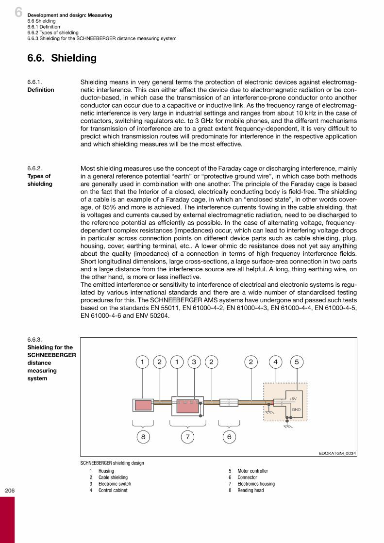
206
6 Development and design: Measuring6.6 Shielding6.6.1Definition6.6.2 Types of shielding6.6.3 Shielding for the SCHNEEBERGER distance measuring system
Shielding means in very general terms the protection of electronic devices against electromag-netic interference. This can either affect the device due to electromagnetic radiation or be con-ductor-based,inwhichcasethetransmissionofaninterference-proneconductorontoanotherconductor can occur due to a capacitive or inductive link. As the frequency range of electromag-netic interference is very large in industrial settings and ranges from about 10 kHz in the case of contactors,switchingregulatorsetc.to3GHzformobilephones,andthedifferentmechanismsfortransmissionofinterferencearetoagreatextentfrequency-dependent,itisverydifficulttopredictwhichtransmissionrouteswillpredominateforinterferenceintherespectiveapplicationandwhichshieldingmeasureswillbethemosteffective.
6.6. Shielding
6.6.1. Definition
Most shielding measures use the concept of the Faraday cage or discharging interference, mainly inageneralreferencepotential“earth”or“protectivegroundwire”,inwhichcasebothmethodsaregenerallyusedincombinationwithoneanother.TheprincipleoftheFaradaycageisbasedonthefactthattheInteriorofaclosed,electricallyconductingbodyisfield-free.TheshieldingofacableisanexampleofaFaradaycage,inwhichan“enclosedstate”,inotherwordscover-age,of85%andmoreisachieved.Theinterferencecurrentsflowinginthecableshielding,thatis voltages and currents caused by external electromagnetic radiation, need to be discharged to thereferencepotentialasefficientlyaspossible. Inthecaseofalternatingvoltage,frequency-dependentcomplexresistances(impedances)occur,whichcanleadtointerferingvoltagedropsin particular across connection points on different device parts such as cable shielding, plug, housing,cover,earthingterminal,etc..Alowerohmicdcresistancedoesnotyetsayanythingabout the quality (impedance) of a connection in terms of high-frequency interference fields.Shortlongitudinaldimensions,largecross-sections,alargesurface-areaconnectionintwopartsandalargedistancefromtheinterferencesourceareallhelpful.Along,thingearthingwire,onthe other hand, is more or less ineffective.The emitted interference or sensitivity to interference of electrical and electronic systems is regu-latedbyvarious international standardsand thereareawidenumberof standardised testingprocedures for this. The SCHNEEBERGER AMS systems have undergone and passed such tests based on the standards EN 55011, EN 61000-4-2, EN 61000-4-3, EN 61000-4-4, EN 61000-4-5, EN 61000-4-6 and ENV 50204.
6.6.2. Typesof shielding
SCHNEEBERGER shielding design
1 Housing 2 Cable shielding 3 Electronic switch 4 Control cabinet
5 Motor controller 6 Connector 7 Electronics housing 8 Reading head
6.6.3. ShieldingfortheSCHNEEBERGER distance measuring system

207
6 Development and design: Measuring6.6 Shielding6.6.3 Shielding for the SCHNEEBERGER distance measuring system
Thehousingswith thecableshielding formanenclosedFaradaycage.Thecableshielding isconnected to the connector housing. To earth the measuring system, the cable's outer shielding mustbeconnectedwiththeearthintheswitchingcabinet,andsotheinterferencecurrentscanbedischargedinthisway.Intheswitchingcabinetorcontroller0V=GNDisconnectedwithearth(protectivegroundwire).By using EMC-compliant cable glands, the transition from cable shield to housing can also be achievedatlowimpedance.Otherwiseintheelectronicshousing0Visconnectedwiththeshield-ingwhichmeansthatinterferencecanalsobeeffectivelydivertedawaytothesupplycables.

208

209
7 Storage and transport

210

211
7
Contents
7
7 Storage and transport .......................................................................209
7.1. Delivered condition .............................................................................................................212
7.2. Storage ................................................................................................................................213
7.3. Transport .............................................................................................................................214

212
7 Storage and transport7.1 Delivered condition
7.1. Delivered condition
The delivered condition of SCHNEEBERGER MONORAIL guideways is described here.As standard all guideway components are delivered individually packaged.
Individual packagingAll guideway components are supplied individually, that is unassembled, in appropriate packag-ing. Accessories are included in a separate package.If not specified by the customer, the lube connections are prepared at the front in the middle of the front plate (S10, S20) and covered with plastic plugs. Lubrication connections that are not required for use are closed.Individual carriages are supplied on a TPS transport rail to protect the rolling elements.AMS systems are installed ready to plug-in, electrical accessories and cables are packaged with the mechanics. In its delivered condition the reading head can be installed into the housing or be supplied as an individual component in separate packaging.
System deliveryA system delivery means that the carriages are assembled with all their accessories and installed onto the guide rail. Lube connections on the carriages are prepared according to the customer's specifications. Lubricating accessories are installed as specified or supplied in separate packag-ing.
Corrosion protectionThe external surfaces of the carriages and of the rails are treated with a hardening corrosion protection. The rolling elements are given a mineral-oil-based corrosion protection. Grease pro-tection can also be provided, on request. Carriages and guide rails are wrapped with a corro-sion protection film. Additional precautions are taken for special requirements such as overseas transport.
Packaging materialCardboard packaging is used for individual guide rail deliveries and system deliveries. Wooden crates are possible for certain countries or special requirements for an additional fee. Individual carriage packaging is made up using cardboard boxes. The lubricating accessories are enclosed.
Accompanying product literatureProduct-related mounting notes and operating instructions as well as customer-specific proto-cols are delivered with the products. Comprehensive installation instructions are obtainable on request from SCHNEEBERGER. See notes Additional literature.

213
7 Storage and transport7.2 Storage
7.2. Storage
SCHNEEBERGER MONORAIL guideways and the AMS distance measuring system are highly precise components, which have to be treated with care. To protect against damage, the follow-ing instructions should be followed: � Storage in original packaging is only possible for a limited period. Check the condition of
products at regular intervals. � Guide rails must be supported over their entire length. For guide rails longer than 1.5 m, sup-
port in at least 3 places. � Store rolled up cover strips in their original packaging, support straight cover strips over
their entire length and do not bend. � Store carriages on the guide rail or on a transport or assembly rail in order to protect the roll-
ing elements. � Do not store products exposed to the elements and protect against moisture / humidity. � Observe the following storage temperatures
• -40°C to +80°C for MONORAIL guideways and accessories• -20°C to +70°C for AMS measuring system
� For guideways with full greasing ex works please note that the operating life of the lubricant can be shortened by very long storage periods (several years).
� Protect the SCHNEEBERGER MONORAIL guideways with AMS distance measuring system from magnetic fields and from mechanical damage. Magnetic fields can destroy the mag-netization of the scale.
� In the case of the AMS measuring system, absolutely never remove the activation strips on the electronics box for the power supply. Only activate the battery when installing.
� Only remove the products from their original packaging at their installation location and im-mediately prior to assembly.
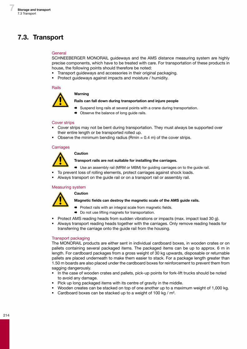
214
7 Storage and transport7.3 Transport
7.3. Transport
GeneralSCHNEEBERGER MONORAIL guideways and the AMS distance measuring system are highly precise components, which have to be treated with care. For transportation of these products in house, the following points should therefore be noted: � Transport guideways and accessories in their original packaging. � Protect guideways against impacts and moisture / humidity.
RailsWarning
Rails can fall down during transportation and injure people
¨ Suspend long rails at several points with a crane during transportation. ¨ Observe the balance of long guide rails.
Cover strips � Cover strips may not be bent during transportation. They must always be supported over
their entire length or be transported rolled up. � Observe the minimum bending radius (Rmin = 0.4 m) of the cover strips.
CarriagesCaution
Transport rails are not suitable for installing the carriages.
¨ Use an assembly rail (MRM or MBM) for guiding carriages on to the guide rail. � To prevent loss of rolling elements, protect carriages against shock loads. � Always transport on the guide rail or on a transport rail or assembly rail.
Measuring systemCaution
Magnetic fields can destroy the magnetic scale of the AMS guide rails.
¨ Protect rails with an integral scale from magnetic fields. ¨ Do not use lifting magnets for transportation.
� Protect AMS reading heads from sudden vibrations or impacts (max. impact load 30 g). � Always transport reading heads together with the carriages. Only remove reading heads for
transferring the carriage onto the guide rail from the housing.
Transport packagingThe MONORAIL products are either sent in individual cardboard boxes, in wooden crates or on pallets containing several packaged items. The packaged items can be up to approx. 6 m in length. For cardboard packages from a gross weight of 30 kg upwards, disposable or returnable pallets are placed underneath to make them easier to stack. For a package length greater than 1.50 m boards are also placed under the cardboard boxes for reinforcement to prevent them from sagging dangerously. � In the case of wooden crates and pallets, pick-up points for fork-lift trucks should be noted
to avoid any damage. � Pick up long packaged items with its centre of gravity in the middle. � Wooden creates can be stacked on top of one another up to a maximum weight of 1,000 kg. � Cardboard boxes can be stacked up to a weight of 100 kg / m².
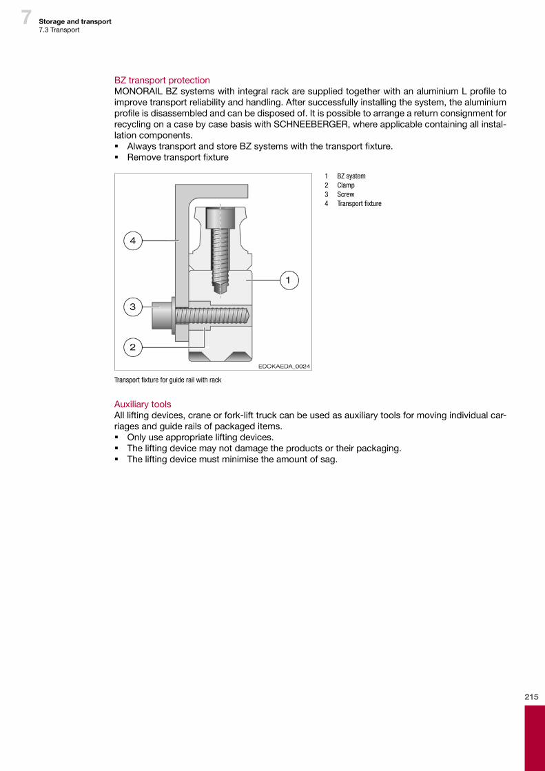
215
7
BZ transport protectionMONORAIL BZ systems with integral rack are supplied together with an aluminium L profile to improve transport reliability and handling. After successfully installing the system, the aluminium profile is disassembled and can be disposed of. It is possible to arrange a return consignment for recycling on a case by case basis with SCHNEEBERGER, where applicable containing all instal-lation components. � Always transport and store BZ systems with the transport fixture. � Remove transport fixture
1 BZ system 2 Clamp 3 Screw 4 Transportfixture
Transportfixtureforguiderailwithrack
Auxiliary toolsAll lifting devices, crane or fork-lift truck can be used as auxiliary tools for moving individual car-riages and guide rails of packaged items. � Only use appropriate lifting devices. � The lifting device may not damage the products or their packaging. � The lifting device must minimise the amount of sag.
Storage and transport 7.3 Transport
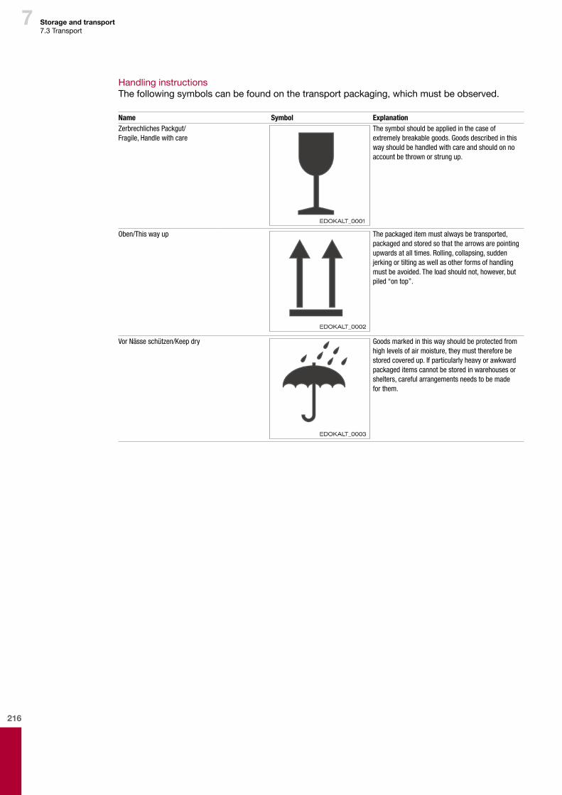
216
7 Storage and transport7.3 Transport
Handling instructionsThe following symbols can be found on the transport packaging, which must be observed.
Name Symbol ExplanationZerbrechlichesPackgut/ Fragile,Handlewithcare
Thesymbolshouldbeappliedinthecaseofextremelybreakablegoods.Goodsdescribedinthiswayshouldbehandledwithcareandshouldonnoaccountbethrownorstrungup.
Oben/Thiswayup Thepackageditemmustalwaysbetransported,packagedandstoredsothatthearrowsarepointingupwardsatalltimes.Rolling,collapsing,suddenjerkingortiltingaswellasotherformsofhandlingmustbeavoided.Theloadshouldnot,however,butpiled“ontop”.
VorNässeschützen/Keepdry Goodsmarkedinthiswayshouldbeprotectedfromhighlevelsofairmoisture,theymustthereforebestoredcoveredup.Ifparticularlyheavyorawkwardpackageditemscannotbestoredinwarehousesorshelters,carefularrangementsneedstobemadeforthem.
217
8 Commissioning

218

219
8
Contents
8
8 Commissioning ..................................................................................217
8.1. Guideway check list............................................................................................................2208.1.1. Installation and checking system accuracy ....................................................................2208.1.2. Supply of lubricant ..........................................................................................................2208.1.3. Corrosion protection .......................................................................................................2208.1.4. Initial lubrication ..............................................................................................................2208.1.5. Lubrication plate SPL ......................................................................................................221
8.2. Measuring system check list .............................................................................................222
220
8 Commissioning8.1 Guideway check list8.1.1 Installation and checking system accuracy8.1.2 Supply of lubricant8.1.3 Corrosion protection8.1.4 Initial lubrication
8.1. Guideway check list
Before commissioning the guideway, it is important to ensure that the performance of the guide-way is optimised by checking the following points: � Guideway properly installed � System accuracy and push force verified � Supply of lubricant guaranteed � Anti-corrosive protective device removed and guide rail oiled � Initial lubrication completed � Rail covers fitted and their seating has been checked � Functionality of the wipers checked � Functionality and correct seating of the bellows checked
After fitting the guideway in accordance with the “MONORAIL and AMS installation instructions”, system accuracy must be verified by measuring guide rail parallelism and running accuracy of the guideway or of the axis slide.
8.1.1. Installation and checking system accuracy
It is important to ensure that the supply of lubricant works properly. When the carriage is moving at the same time as the centralised lubricating system is working, a thin film of lubricant must be present on the guide rail and no leaks should occur within the lubrication system.
8.1.2. Supply of lubricant
When commissioning the guideway it is important to ensure that the factory-fitted anti-corrosive protective device on the guide rails is fully removed, see MONORAIL and AMS installation in-structions, and that the guide rails are lightly moistened with the lubricant. A thin film of lubricant reduces the consumption of lubricant at the start of operation as any surface unevenness of the guide rail will be pre-filled with lubricant.
8.1.3. Corrosion protection
Before commissioning the machine, initial lubrication of the carriages (other than in cases of car-riages with full greasing in the factory) should be completed with oil, grease or fluid grease.Check the lubricants used for compatibility with factory preserving agents, coolants and other working materials.Initial lubrication can be dispensed with in case of factory-based full greasing of the carriages.When a centralised lubricating system is used ensure that the lubricating lines are properly con-nected and vented. Observe the system manufacturer's instructions.After initial lubrication check that the lubricant has reached the lubrication points in the carriage. When the carriage moves a significant film of lubricant must be visible on the tracks of the guide rail.
Lubrication with greaseWith grease or fluid grease make sure that when greasing the carriages they are moved along the rail, ideally several times by 3 times the carriage length, or at least by the length of a single car-riage. In the event that the maximum stroke is less than the carriage length, take note of Section 4.15.8 - Application know-how on lubrication - requirements in respect of lubrication in special operating conditions.
Lubrication with oilWhen lubricating with oil, the total quantity of oil should be injected in a single impulse or in sev-eral impulses in short succession while the carriage is actually being moved.In case of a specific installation orientation or short stroke, take note of the instructions set out in Section 4.15.8 - Application know-how on lubrication - requirements in respect of lubrication in special operating conditions.
8.1.4. Initial lubrication

221
8 Commissioning8.1 Guideway check list8.1.5 Lubrication plate SPL
Lubrication plates are always delivered ready for installation, i.e., filled with oil. When delivering together with a MONORAIL system or individual carriages, the carriages are also pre-filled with grease.When lubrication plates are retro-fitted, full greasing (LV) of the carriages is also necessary. For the recommended quantities of lubricant, see Section 4.15.6 - Lubrication with grease.For additional information about the lubrication plate SPL, see Section 4.15 - Lubrication.
Rail coversThe guide rail fixing holes must be fully closed with a cover strip or plugs and the closures must be fitted so that no dirt build up is able to form neither can the carriage wipers be damaged as a result.Cover strips must be placed on a clean guide rail surface without gaps and the ends must be secured with a fixing bracket or end pieces.Plugs must be fitted flush and parallel with the guide rail surface and there should not be any residual swarf or burrs.
WipersThe wipers on the carriages and on the accessory components must be checked to ensure they are properly seated and work correctly: Standard wipers and additional wipersThe function of the cross wipers is guaranteed when lubricant applied to the guide rail is cleanly wiped off and when the carriage reverses no streaking occurs on the guide rail surface that has been travelled over.Metal wipersThe wipers must form an even gap around the guide rail profile and should not make any contact with the guide rail.
BellowsWhen using bellows correct installation on to the adapter plate and end plate must be ensured, as well as its freedom of movement.
8.1.5. Lubrication plate SPL

222
8
8.2. Measuring system check list
Commissioning8.2 Measuring system check list
Make sure that the performance of the measuring system is optimised by checking the following points: � Carriage with housing is conveyed on the guide rail so that the recess for the reading head is
located on the guide rail side with the scale. The scale side can be identified by the refer-ence mark.
� Battery for AMSABS should be activated by removing the magnet on the electronics box. See Section 9.4.2 - Measuring system - AMSABS
� Reading head correctly installed in the housing, see additional documents. � Cable and electronics box properly laid, see additional documents. � Connection with the controller made. See Additional documents Section. � LED for the operating state display (optional) is illuminated green after switching on the con-
troller.
223
9 Operating, maintenance and service

224

225
9
Contents
9
9 Operating, maintenance and service ...............................................223
9.1. Wipers ..................................................................................................................................2269.1.1 Testing .............................................................................................................................2269.1.2 Replacement ...................................................................................................................226
9.2. Influencingfactorsonoperatingconditions ....................................................................2309.2.1 Environmental conditions ................................................................................................2309.2.2 Operating conditions .......................................................................................................2309.2.3 Installation of the guideway ............................................................................................230
9.3. Precautionarymeasures ....................................................................................................231
9.4. 24hourdeliveryservice .....................................................................................................2329.4.1 Objectives and sequence................................................................................................2329.4.2 Products ..........................................................................................................................232
226
9
9.1. Wipers
Seals on SCHNEEBERGER MONORAIL guideways protect the carriages and the integral dis-tance measuring system from penetration of foreign bodies in the form of solids or liquids and prevent the lubricant from discharging. Their functionality therefore influences the service life of the guideway significantly. In general, the seals are designed so that they are maintenance-free with sufficient lubrication and in a clean environment.Often, however, the guideways are used under conditions in which dust and swarf can get on to the guideway. This also inevitably leads to wear of the sealing lips, as with inadequate lubrication.The wipers on the front plates and additional wipers thus need to be checked for wear at regular intervals (maximum 6 monthly) and where applicable be replaced.
Standard wipers and additional wipersThe function check on cross wipers is carried out most simply using lubricant, which is applied to the guide rail. When propelling the machine slideway, the lubricant must be wiped off cleanly and when reversing over the guide rail surface that has already been passed over should not form any streaks. Otherwise the front plate (MR) and/or cross wipers (BM) or the additional wipers need to be replaced.
Metal wipersMetal wipers like additional wipers and front plates need to be replaced in case of any visible mechanical damage.
9.1.1 Testing
Operating, maintenance and service 9.1 Wipers9.1.1 Testing9.1.2 Replacement
Note
¨ In the case of MONORAIL BM, the front plate is part of the rolling element recirculating unit. Pulling off the front plate will lead to the loss of balls. Only the cross wipers QAS and not the complete front plate are replaced in this instance.
¨ With MONORAIL BM it is important to note that when replacing or retrofitting additional wipers or lubrication plates the front plate is secured to prevent it from coming away. Do-ing otherwise can lead to a loss of balls.
Front plates and additional wipers can be individually re-ordered as spare parts. See Section 9.6 - Spare parts and the SCHNEEBERGER MONORAIL and AMS product catalogue. In case of damage to longitudinal wipers, which are mainly permanently connected with the carriage or housing (with integral distance measuring systems), the entire carriage will need to be replaced. Damage to longitudinal wipers can only usually be detected after complete uninstallation of car-riage or housing components.
� When replacing front plates and additional wipers (ZCN/V and ZBN/V) the fastening screws of the front plates must be removed. In the case of MONORAIL MR, front plates should only be removed from the carriage for a replacement and the carriage should not be moved after removing the front plate.
9.1.2 Replacement
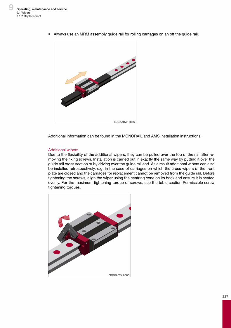
227
9
� Always use an MRM assembly guide rail for rolling carriages on an off the guide rail.
Additional information can be found in the MONORAIL and AMS installation instructions.
Additional wipersDue to the flexibility of the additional wipers, they can be pulled over the top of the rail after re-moving the fixing screws. Installation is carried out in exactly the same way by putting it over the guide rail cross section or by driving over the guide rail end. As a result additional wipers can also be installed retrospectively, e.g. in the case of carriages on which the cross wipers of the front plate are closed and the carriages for replacement cannot be removed from the guide rail. Before tightening the screws, align the wiper using the centring cone on its back and ensure it is seated evenly. For the maximum tightening torque of screws, see the table section Permissible screw tightening torques.
Operating, maintenance and service9.1 Wipers9.1.2 Replacement
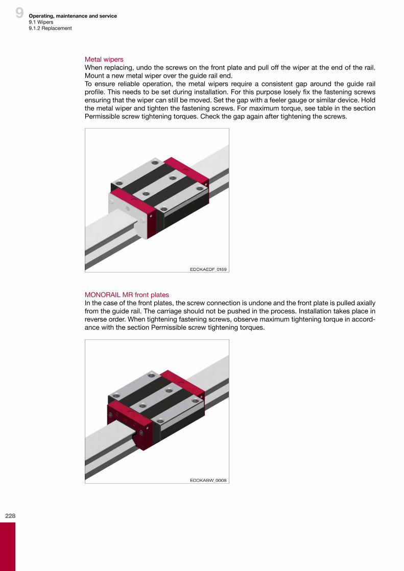
228
9
Metal wipersWhen replacing, undo the screws on the front plate and pull off the wiper at the end of the rail. Mount a new metal wiper over the guide rail end.To ensure reliable operation, the metal wipers require a consistent gap around the guide rail profile. This needs to be set during installation. For this purpose losely fix the fastening screws ensuring that the wiper can still be moved. Set the gap with a feeler gauge or similar device. Hold the metal wiper and tighten the fastening screws. For maximum torque, see table in the section Permissible screw tightening torques. Check the gap again after tightening the screws.
MONORAIL MR front platesIn the case of the front plates, the screw connection is undone and the front plate is pulled axially from the guide rail. The carriage should not be pushed in the process. Installation takes place in reverse order. When tightening fastening screws, observe maximum tightening torque in accord-ance with the section Permissible screw tightening torques.
Operating, maintenance and service9.1 Wipers9.1.2 Replacement
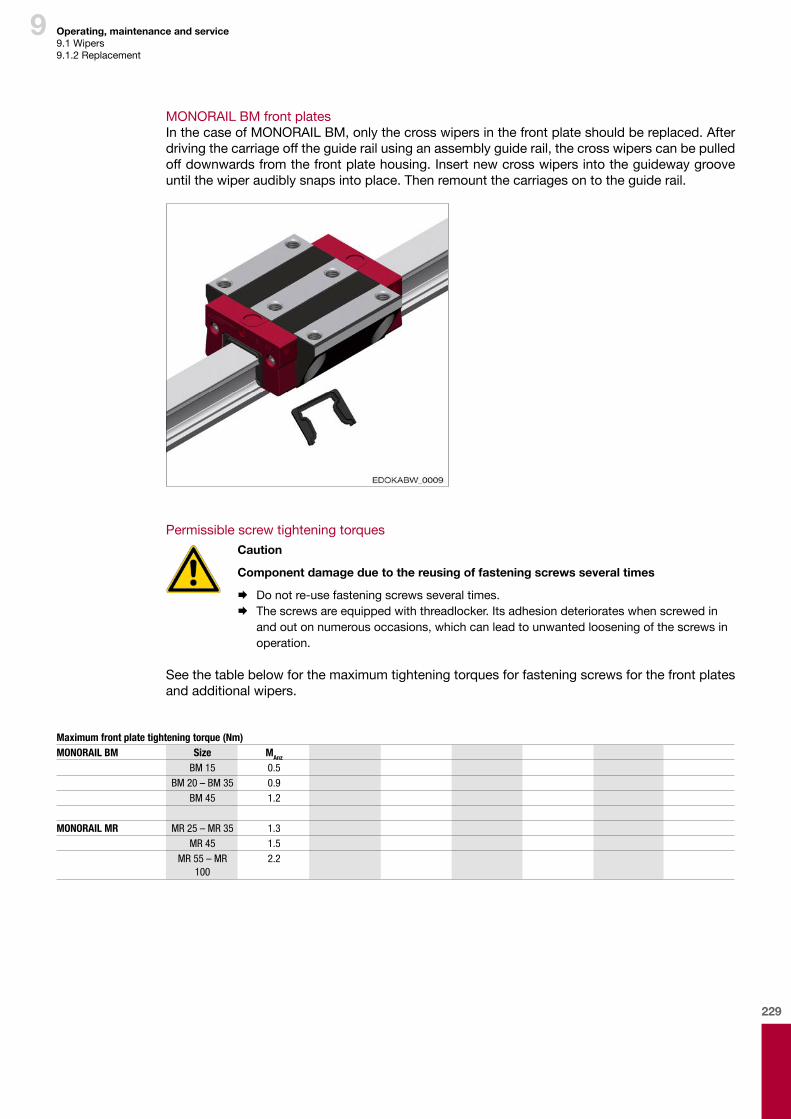
229
9
MONORAIL BM front platesIn the case of MONORAIL BM, only the cross wipers in the front plate should be replaced. After driving the carriage off the guide rail using an assembly guide rail, the cross wipers can be pulled off downwards from the front plate housing. Insert new cross wipers into the guideway groove until the wiper audibly snaps into place. Then remount the carriages on to the guide rail.
Permissible screw tightening torquesCaution
Componentdamageduetothereusingoffasteningscrewsseveraltimes
¨ Do not re-use fastening screws several times. ¨ The screws are equipped with threadlocker. Its adhesion deteriorates when screwed in
and out on numerous occasions, which can lead to unwanted loosening of the screws in operation.
See the table below for the maximum tightening torques for fastening screws for the front plates and additional wipers.
Maximum front plate tightening torque (Nm)MONORAIL BM Size MAnz
BM 15 0.5BM 20 – BM 35 0.9
BM 45 1.2
MONORAIL MR MR 25 – MR 35 1.3MR 45 1.5
MR 55 – MR 100
2.2
Operating, maintenance and service9.1 Wipers9.1.2 Replacement
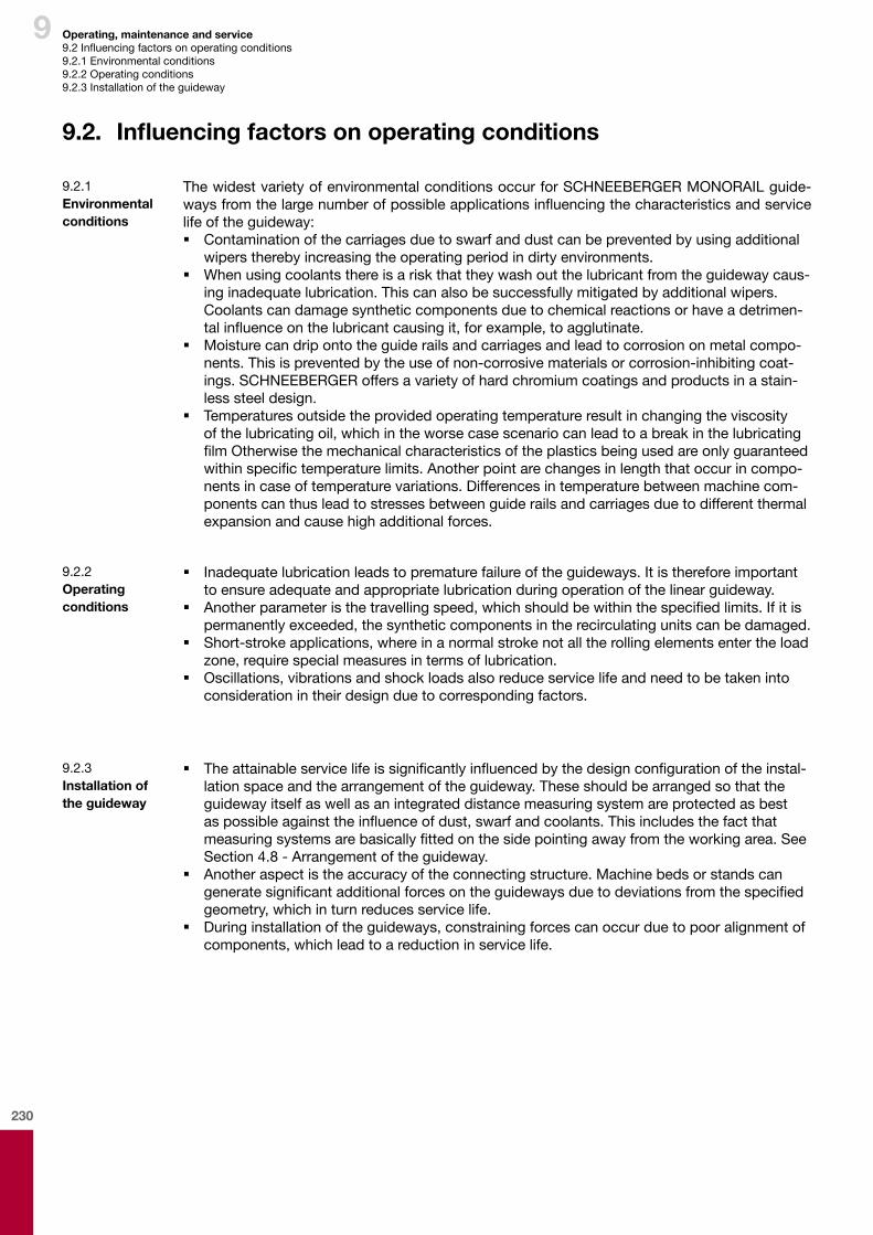
230
9 Operating, maintenance and service9.2 Influencing factors on operating conditions9.2.1 Environmental conditions9.2.2 Operating conditions9.2.3 Installation of the guideway
9.2. Influencingfactorsonoperatingconditions
The widest variety of environmental conditions occur for SCHNEEBERGER MONORAIL guide-ways from the large number of possible applications influencing the characteristics and service life of the guideway: � Contamination of the carriages due to swarf and dust can be prevented by using additional
wipers thereby increasing the operating period in dirty environments. � When using coolants there is a risk that they wash out the lubricant from the guideway caus-
ing inadequate lubrication. This can also be successfully mitigated by additional wipers. Coolants can damage synthetic components due to chemical reactions or have a detrimen-tal influence on the lubricant causing it, for example, to agglutinate.
� Moisture can drip onto the guide rails and carriages and lead to corrosion on metal compo-nents. This is prevented by the use of non-corrosive materials or corrosion-inhibiting coat-ings. SCHNEEBERGER offers a variety of hard chromium coatings and products in a stain-less steel design.
� Temperatures outside the provided operating temperature result in changing the viscosity of the lubricating oil, which in the worse case scenario can lead to a break in the lubricating film Otherwise the mechanical characteristics of the plastics being used are only guaranteed within specific temperature limits. Another point are changes in length that occur in compo-nents in case of temperature variations. Differences in temperature between machine com-ponents can thus lead to stresses between guide rails and carriages due to different thermal expansion and cause high additional forces.
9.2.1 Environmentalconditions
� Inadequate lubrication leads to premature failure of the guideways. It is therefore important to ensure adequate and appropriate lubrication during operation of the linear guideway.
� Another parameter is the travelling speed, which should be within the specified limits. If it is permanently exceeded, the synthetic components in the recirculating units can be damaged.
� Short-stroke applications, where in a normal stroke not all the rolling elements enter the load zone, require special measures in terms of lubrication.
� Oscillations, vibrations and shock loads also reduce service life and need to be taken into consideration in their design due to corresponding factors.
9.2.2 Operating conditions
� The attainable service life is significantly influenced by the design configuration of the instal-lation space and the arrangement of the guideway. These should be arranged so that the guideway itself as well as an integrated distance measuring system are protected as best as possible against the influence of dust, swarf and coolants. This includes the fact that measuring systems are basically fitted on the side pointing away from the working area. See Section 4.8 - Arrangement of the guideway.
� Another aspect is the accuracy of the connecting structure. Machine beds or stands can generate significant additional forces on the guideways due to deviations from the specified geometry, which in turn reduces service life.
� During installation of the guideways, constraining forces can occur due to poor alignment of components, which lead to a reduction in service life.
9.2.3 Installationoftheguideway
231
9
9.3. Precautionarymeasures
To maintain optimum operation of SCHNEEBERGER MONORAIL guideways over their entire service life, the following points need to be taken into account: � Precision components are used in all SCHNEEBERGER guideways, which are preserved and
packaged in the factory to optimal specifications. The systems need to be protected against impacts and humidity during transportation and storage.
� Instructions for transportation and installation are included with the measuring systems ,which need to be observed.
� Installation of the guideways and the covering of the holes in the rails must be carried out by qualified staff. Instruction on installation are available from the Download area at www.schneeberger.com.
� The guideways should be adequately supplied with a lubricant adapted to a movement and load profile as well as the environmental conditions. In selecting a lubricant, we recommend that you contact a lubricant manufacturer directly. Lubrication recommendations can other-wise be obtained from www.schneebergers.com.
� The compatibility of coolants and lubricants needs to be checked by the user prior to com-missioning to exclude the possibility of causing any negative influence on the guideway.
� The guideways should be protected from contamination, hot swarf and direct contact with coolants through covers or a suitable installation position.
� If the incidence of dirt or contact with coolant is expected during the operating phase of products, additional wipers should always be used. The functionality of these components over time is guaranteed by appropriate inspection intervals. Information on these products can be found at www.schneeberger.com.
� If the guideways come into contact with hot swarf, the use of metal wipers is also recom-mended. Information on these products can be found at www.schneeberger.com.
� The front wipers and the additional wipers for the MONORAIL carriages must be analysed at regular intervals for wear and replaced, where necessary.
� DIN 637 should always be observed when operating and dimensioning MONORAIL guide-ways. Furthermore DIN 637 is always valid even if contradictory statements are encountered within the DIN 637 document.
Operating, maintenance and service9.3 Precautionary measures
232
9
9.4. 24hourdeliveryservice
With its 24-hr delivery service, SCHNEEBERGER offers the option of ordering MONORAIL guide-ways and AMS distance measuring systems as spare parts, e.g during a machine shut-down, at very short notice. To achieve this SCHNEEBERGER maintains its own semi-finished product warehouse of carriages, reading heads, guide rails and guide rails with integral scale.Enquiries and orders can be addressed directly to SCHNEEBERGER when required: � Telephone No. +49 7081 782 0 for enquiries to the 24-hr Service Department, working days
from 7.30am to 5pm. � Fax-No. +49 7081 782 124 for orders � Orders by post to the Service Department quoting “Priority order for 24-hr Service Depart-
ment”.
Orders for goods available from stock received before 10am can generally be dispatched on the same day. Orders received later are delivered within 24 hours.
9.4.1 Objectives and sequence
Operating, maintenance and service9.4 24 hour delivery service9.4.1 Objectives and sequence9.4.2 ProductsProducts
SCHNEEBERGER offers a limited range of standard products for delivery as part of its 24-hr service. This includes: � MONORAIL MR
• Guide rail type: N, Standard; C, Cover strip• Carriage type: A, B, C and D• Size: 25-65• Accuracy class: G0• Preload: Average between V2 and V3
� MONORAIL BM• Guide rail type: N (ND), Standard; C, Cover strip• Carriage type: A, B, C, D, E, F and G• Size: 15-45• Accuracy class: G0• Preload: Average between V2 and V3
� MONORAIL AMS• Guide rails with integral distance measuring system, accuracy class G0• Reading heads type AMS30, AMSA 3B, AMSD 3B, AMSA 4B and AMSD 4B
Reading heads for older products and special guide rails on request.Detailed information on the products that can be supplied and prices can be obtained on request.
9.4.2 Products

Pro
du
ct c
atal
og
201
7 M
ON
OR
AIL
an
d A
MS
P
rofil
ed li
nea
r g
uid
eway
s an
d in
teg
rate
d m
easu
rin
g s
yste
ms
10.1
061/
04/0
717/
e
PROSPECTUSES
• COMPANY BROCHURE
• CUSTOMIZED BEARINGS
• GEAR RACKS
• LINEAR BEARINGS and RECIRCULATING UNITS
• MINERAL CASTING SCHNEEBERGER
• MINISLIDE MSQscale
• MINI-X MINIRAIL / MINISCALE PLUS / MINISLIDE
• MONORAIL and AMS profiled linear guideways with integrated measuring system
• MONORAIL and AMS application catalog
• POSITIONING SYSTEMS
• SLIDES
MONORAIL and AMS
Profiled linear guideways and integrated measuring systems
Product catalog 2017
www.schneeberger.com
www.schneeberger.com/contact