Cadence® NC-Verilog® Simulator Help - CiteSeerX
1746
Cadence® NC-Verilog® Simulator Help Product Version 8.2 November 2008
-
Upload
khangminh22 -
Category
Documents
-
view
1 -
download
0
Transcript of Cadence® NC-Verilog® Simulator Help - CiteSeerX

Cadence® NC-Verilog® Simulator Help
Product Version 8.2November 2008

1995-2009 Cadence Design Systems, Inc. All rights reserved.Portions © Free Software Foundation, Regents of the University of California, Sun Microsystems, Inc., ScripticsCorporation. Used by permission.
Printed in the United States of America.
Cadence Design Systems, Inc. (Cadence), 2655 Seely Ave., San Jose, CA 95134, USA.
Product NC-SIM contains technology licensed from, and copyrighted by: Free Software Foundation, Inc., 59Temple Place, Suite 330, Boston, MA 02111-1307 USA, and is © 1989, 1991. All rights reserved. Regents ofthe University of California, Sun Microsystems, Inc., Scriptics Corporation, and other parties and is © 1989-1994Regents of the University of California, 1984, the Australian National University, 1990-1999 ScripticsCorporation, and other parties. All rights reserved.
Open SystemC, Open SystemC Initiative, OSCI, SystemC, and SystemC Initiative are trademarks or registeredtrademarks of Open SystemC Initiative, Inc. in the United States and other countries and are used withpermission.
Trademarks: Trademarks and service marks of Cadence Design Systems, Inc. contained in this document areattributed to Cadence with the appropriate symbol. For queries regarding Cadence’s trademarks, contact thecorporate legal department at the address shown above or call 800.862.4522. All other trademarks are theproperty of their respective holders.
Restricted Permission: This publication is protected by copyright law and international treaties and containstrade secrets and proprietary information owned by Cadence. Unauthorized reproduction or distribution of thispublication, or any portion of it, may result in civil and criminal penalties. Except as specified in this permissionstatement, this publication may not be copied, reproduced, modified, published, uploaded, posted, transmitted,or distributed in any way, without prior written permission from Cadence. Unless otherwise agreed to byCadence in writing, this statement grants Cadence customers permission to print one (1) hard copy of thispublication subject to the following conditions:
1. The publication may be used only in accordance with a written agreement between Cadence and itscustomer.
2. The publication may not be modified in any way.3. Any authorized copy of the publication or portion thereof must include all original copyright, trademark,
and other proprietary notices and this permission statement.4. The information contained in this document cannot be used in the development of like products or
software, whether for internal or external use, and shall not be used for the benefit of any other party,whether or not for consideration.
Patents: Cadence products described in this document, are protected by U.S. Patents 5,095,454; 5,418,931;5,606,698; 6,487,704; 7,039,887; 7,055,116; 5,838,949; 6,263,301; 6,163,763; and 6,301,578.
Disclaimer: Information in this publication is subject to change without notice and does not represent acommitment on the part of Cadence. Except as may be explicitly set forth in such agreement, Cadence doesnot make, and expressly disclaims, any representations or warranties as to the completeness, accuracy orusefulness of the information contained in this document. Cadence does not warrant that use of suchinformation will not infringe any third party rights, nor does Cadence assume any liability for damages or costsof any kind that may result from use of such information.
Restricted Rights: Use, duplication, or disclosure by the Government is subject to restrictions as set forth inFAR52.227-14 and DFAR252.227-7013 et seq. or its successor.

NC-Verilog Simulator Help
Contents
1
Overview of the NC-Verilog Simulator . . . . . . . . . . . . . . . . . . . . . . . . . . . . . . . . . . . . 29
Native Compiled Code . . . . . . . . . . . . . . . . . . . . . . . . . . . . . . . . . . . . . . . . . . . . . . . . . . . 29The Interleaved Native Compiled Code (INCA) Architecture . . . . . . . . . . . . . . . . . . . . . . 30Language Support . . . . . . . . . . . . . . . . . . . . . . . . . . . . . . . . . . . . . . . . . . . . . . . . . . . . . . 31Memory Requirements . . . . . . . . . . . . . . . . . . . . . . . . . . . . . . . . . . . . . . . . . . . . . . . . . . 32Setting Up Your Design Environment . . . . . . . . . . . . . . . . . . . . . . . . . . . . . . . . . . . . . . . . 32
Environment Setup Files . . . . . . . . . . . . . . . . . . . . . . . . . . . . . . . . . . . . . . . . . . . . . . 33PATH and Library Path Environment Variables . . . . . . . . . . . . . . . . . . . . . . . . . . . . . . 34
Running the Simulator . . . . . . . . . . . . . . . . . . . . . . . . . . . . . . . . . . . . . . . . . . . . . . . . . . . 3464-Bit NC-Verilog . . . . . . . . . . . . . . . . . . . . . . . . . . . . . . . . . . . . . . . . . . . . . . . . . . . . . . . 39
Platform Support . . . . . . . . . . . . . . . . . . . . . . . . . . . . . . . . . . . . . . . . . . . . . . . . . . . . 40Licensing . . . . . . . . . . . . . . . . . . . . . . . . . . . . . . . . . . . . . . . . . . . . . . . . . . . . . . . . . . 40Running the Simulator in 64-Bit Mode . . . . . . . . . . . . . . . . . . . . . . . . . . . . . . . . . . . . 40Using the CDS_AUTO_64BIT Variable . . . . . . . . . . . . . . . . . . . . . . . . . . . . . . . . . . . 43Libraries and Snapshots . . . . . . . . . . . . . . . . . . . . . . . . . . . . . . . . . . . . . . . . . . . . . . . 44PLI Applications . . . . . . . . . . . . . . . . . . . . . . . . . . . . . . . . . . . . . . . . . . . . . . . . . . . . . 44Functional Differences between 32-Bit and 64-Bit . . . . . . . . . . . . . . . . . . . . . . . . . . . 45
Simulator Library Databases . . . . . . . . . . . . . . . . . . . . . . . . . . . . . . . . . . . . . . . . . . . . . . 45Simulating Large Designs . . . . . . . . . . . . . . . . . . . . . . . . . . . . . . . . . . . . . . . . . . . . . . . . 46
2
Getting Help . . . . . . . . . . . . . . . . . . . . . . . . . . . . . . . . . . . . . . . . . . . . . . . . . . . . . . . . . . . 48
About Online Help . . . . . . . . . . . . . . . . . . . . . . . . . . . . . . . . . . . . . . . . . . . . . . . . . . . . . . 48Launching Cadence Help . . . . . . . . . . . . . . . . . . . . . . . . . . . . . . . . . . . . . . . . . . . . . . 49Getting Help for Cadence Help . . . . . . . . . . . . . . . . . . . . . . . . . . . . . . . . . . . . . . . . . . 49
Getting Help on Commands to Run Tools . . . . . . . . . . . . . . . . . . . . . . . . . . . . . . . . . . . . 49Getting Help on Simulator Commands . . . . . . . . . . . . . . . . . . . . . . . . . . . . . . . . . . . . . . 49Getting Help on Tool Messages . . . . . . . . . . . . . . . . . . . . . . . . . . . . . . . . . . . . . . . . . . . . 50Return Codes for Error Conditions . . . . . . . . . . . . . . . . . . . . . . . . . . . . . . . . . . . . . . . . . 50Related Manuals . . . . . . . . . . . . . . . . . . . . . . . . . . . . . . . . . . . . . . . . . . . . . . . . . . . . . . . 52
November 2008 3 Product Version 8.2

NC-Verilog Simulator Help
Other Documentation . . . . . . . . . . . . . . . . . . . . . . . . . . . . . . . . . . . . . . . . . . . . . . . . . 53
3
Using NCLaunch . . . . . . . . . . . . . . . . . . . . . . . . . . . . . . . . . . . . . . . . . . . . . . . . . . . . . . . 54
4
Modeling Your Hardware . . . . . . . . . . . . . . . . . . . . . . . . . . . . . . . . . . . . . . . . . . . . . . . . 56
Arrays of Instances . . . . . . . . . . . . . . . . . . . . . . . . . . . . . . . . . . . . . . . . . . . . . . . . . . . . . 58Instance Array Names . . . . . . . . . . . . . . . . . . . . . . . . . . . . . . . . . . . . . . . . . . . . . . . . 58Array Range Expressions . . . . . . . . . . . . . . . . . . . . . . . . . . . . . . . . . . . . . . . . . . . . . . 58Port Connections . . . . . . . . . . . . . . . . . . . . . . . . . . . . . . . . . . . . . . . . . . . . . . . . . . . . 59Ports of Instance Arrays . . . . . . . . . . . . . . . . . . . . . . . . . . . . . . . . . . . . . . . . . . . . . . . 60Differing Instances in an Array . . . . . . . . . . . . . . . . . . . . . . . . . . . . . . . . . . . . . . . . . . 61Hierarchical References . . . . . . . . . . . . . . . . . . . . . . . . . . . . . . . . . . . . . . . . . . . . . . . 61Restrictions to the IEEE Standard . . . . . . . . . . . . . . . . . . . . . . . . . . . . . . . . . . . . . . . 61Arrays of Instances and Tcl Commands . . . . . . . . . . . . . . . . . . . . . . . . . . . . . . . . . . . 65
Sparse Arrays . . . . . . . . . . . . . . . . . . . . . . . . . . . . . . . . . . . . . . . . . . . . . . . . . . . . . . . . . 66Verilog IEEE Std 1364-2001 Enhancements . . . . . . . . . . . . . . . . . . . . . . . . . . . . . . . . . . 67
Comma-Separated Sensitivity List . . . . . . . . . . . . . . . . . . . . . . . . . . . . . . . . . . . . . . . 68Combinational Logic Sensitivity Token . . . . . . . . . . . . . . . . . . . . . . . . . . . . . . . . . . . . 68Variable Declaration with Initial Value Assignment . . . . . . . . . . . . . . . . . . . . . . . . . . . 70Combined Port and Data Type Declarations . . . . . . . . . . . . . . . . . . . . . . . . . . . . . . . 70Input and Output Declarations . . . . . . . . . . . . . . . . . . . . . . . . . . . . . . . . . . . . . . . . . . 71Signed Arithmetic Extensions . . . . . . . . . . . . . . . . . . . . . . . . . . . . . . . . . . . . . . . . . . . 72Re-Entrant Tasks and Recursive Functions . . . . . . . . . . . . . . . . . . . . . . . . . . . . . . . . 74File I/O Enhancements . . . . . . . . . . . . . . . . . . . . . . . . . . . . . . . . . . . . . . . . . . . . . . . . 76PLA System Task Extensions . . . . . . . . . . . . . . . . . . . . . . . . . . . . . . . . . . . . . . . . . . . 84‘ifndef and ‘elsif Conditional Compilation Compiler Directives . . . . . . . . . . . . . . . . . . 85Parameter Value Assignment by Name . . . . . . . . . . . . . . . . . . . . . . . . . . . . . . . . . . . 86$value$plusargs System Function . . . . . . . . . . . . . . . . . . . . . . . . . . . . . . . . . . . . . . . 86Disabling Implicit Net Declarations . . . . . . . . . . . . . . . . . . . . . . . . . . . . . . . . . . . . . . . 87Indexed Vector Part-Selects . . . . . . . . . . . . . . . . . . . . . . . . . . . . . . . . . . . . . . . . . . . . 88Power Operator . . . . . . . . . . . . . . . . . . . . . . . . . . . . . . . . . . . . . . . . . . . . . . . . . . . . . 90Local Parameters . . . . . . . . . . . . . . . . . . . . . . . . . . . . . . . . . . . . . . . . . . . . . . . . . . . . 91Implicit Nets with Continuous Assignments . . . . . . . . . . . . . . . . . . . . . . . . . . . . . . . . 92
November 2008 4 Product Version 8.2

NC-Verilog Simulator Help
Automatic Width Extension of X and Z Constants beyond 32 Bits . . . . . . . . . . . . . . . 93Line and File Compiler Directive . . . . . . . . . . . . . . . . . . . . . . . . . . . . . . . . . . . . . . . . . 94Attributes . . . . . . . . . . . . . . . . . . . . . . . . . . . . . . . . . . . . . . . . . . . . . . . . . . . . . . . . . . 97Generate Constructs . . . . . . . . . . . . . . . . . . . . . . . . . . . . . . . . . . . . . . . . . . . . . . . . . 99Multi-Dimensional Arrays and Arrays of Net Data Types . . . . . . . . . . . . . . . . . . . . . 110Bit-Selects and Part-Selects within Arrays . . . . . . . . . . . . . . . . . . . . . . . . . . . . . . . . 112Verilog Configurations . . . . . . . . . . . . . . . . . . . . . . . . . . . . . . . . . . . . . . . . . . . . . . . 112Sized and Typed Parameters . . . . . . . . . . . . . . . . . . . . . . . . . . . . . . . . . . . . . . . . . . 117
SystemVerilog Enhancements . . . . . . . . . . . . . . . . . . . . . . . . . . . . . . . . . . . . . . . . . . . . 118Loading Stimulus from an ASCII File . . . . . . . . . . . . . . . . . . . . . . . . . . . . . . . . . . . . . . . 118
Syntax . . . . . . . . . . . . . . . . . . . . . . . . . . . . . . . . . . . . . . . . . . . . . . . . . . . . . . . . . . . 119Arguments . . . . . . . . . . . . . . . . . . . . . . . . . . . . . . . . . . . . . . . . . . . . . . . . . . . . . . . . 119Data File Format . . . . . . . . . . . . . . . . . . . . . . . . . . . . . . . . . . . . . . . . . . . . . . . . . . . . 121$loadStimFileX Example . . . . . . . . . . . . . . . . . . . . . . . . . . . . . . . . . . . . . . . . . . . . . 122$loadStrobeFileX/$strobeStimX Example . . . . . . . . . . . . . . . . . . . . . . . . . . . . . . . . 124
Loading Scan Chain Elements . . . . . . . . . . . . . . . . . . . . . . . . . . . . . . . . . . . . . . . . . . . 126repeat Loop Expression Value . . . . . . . . . . . . . . . . . . . . . . . . . . . . . . . . . . . . . . . . . . . . 128$sformatf System Function . . . . . . . . . . . . . . . . . . . . . . . . . . . . . . . . . . . . . . . . . . . . . . 128$stacktrace System Task . . . . . . . . . . . . . . . . . . . . . . . . . . . . . . . . . . . . . . . . . . . . . . . . 130
5
Setting Up Your Environment . . . . . . . . . . . . . . . . . . . . . . . . . . . . . . . . . . . . . . . . . . . 131
The Library.Cell:View Approach . . . . . . . . . . . . . . . . . . . . . . . . . . . . . . . . . . . . . . . . . . . 132The cds.lib File . . . . . . . . . . . . . . . . . . . . . . . . . . . . . . . . . . . . . . . . . . . . . . . . . . . . . . . . 133
The Work Library . . . . . . . . . . . . . . . . . . . . . . . . . . . . . . . . . . . . . . . . . . . . . . . . . . . 134cds.lib Statements . . . . . . . . . . . . . . . . . . . . . . . . . . . . . . . . . . . . . . . . . . . . . . . . . . 135cds.lib Syntax Rules . . . . . . . . . . . . . . . . . . . . . . . . . . . . . . . . . . . . . . . . . . . . . . . . . 136Example cds.lib File . . . . . . . . . . . . . . . . . . . . . . . . . . . . . . . . . . . . . . . . . . . . . . . . . 137Binding One Library to Multiple Directories . . . . . . . . . . . . . . . . . . . . . . . . . . . . . . . 138Debugging cds.lib Files . . . . . . . . . . . . . . . . . . . . . . . . . . . . . . . . . . . . . . . . . . . . . . 139
The hdl.var File . . . . . . . . . . . . . . . . . . . . . . . . . . . . . . . . . . . . . . . . . . . . . . . . . . . . . . . 142hdl.var Statements . . . . . . . . . . . . . . . . . . . . . . . . . . . . . . . . . . . . . . . . . . . . . . . . . . 144hdl.var Variables . . . . . . . . . . . . . . . . . . . . . . . . . . . . . . . . . . . . . . . . . . . . . . . . . . . . 145hdl.var Syntax Rules . . . . . . . . . . . . . . . . . . . . . . . . . . . . . . . . . . . . . . . . . . . . . . . . . 152Example hdl.var File . . . . . . . . . . . . . . . . . . . . . . . . . . . . . . . . . . . . . . . . . . . . . . . . . 154
November 2008 5 Product Version 8.2

NC-Verilog Simulator Help
Debugging hdl.var Files . . . . . . . . . . . . . . . . . . . . . . . . . . . . . . . . . . . . . . . . . . . . . . 155The setup.loc File . . . . . . . . . . . . . . . . . . . . . . . . . . . . . . . . . . . . . . . . . . . . . . . . . . . . . . 156
setup.loc Syntax Rules . . . . . . . . . . . . . . . . . . . . . . . . . . . . . . . . . . . . . . . . . . . . . . . 157Directory Structure Example . . . . . . . . . . . . . . . . . . . . . . . . . . . . . . . . . . . . . . . . . . . . . 158
6
Compiling Verilog Source Files with ncvlog . . . . . . . . . . . . . . . . . . . . . . . . . . . . . . 162
ncvlog Command Syntax . . . . . . . . . . . . . . . . . . . . . . . . . . . . . . . . . . . . . . . . . . . . . . . . 167ncvlog Command Options . . . . . . . . . . . . . . . . . . . . . . . . . . . . . . . . . . . . . . . . . . . . . . . 169Example ncvlog Command Lines . . . . . . . . . . . . . . . . . . . . . . . . . . . . . . . . . . . . . . . . . 198hdl.var Variables . . . . . . . . . . . . . . . . . . . . . . . . . . . . . . . . . . . . . . . . . . . . . . . . . . . . . . 202Compiling Source Files by Specifying the Top-Level of the Design . . . . . . . . . . . . . . . . 206
Writing a Compilation Command File . . . . . . . . . . . . . . . . . . . . . . . . . . . . . . . . . . . . 207Writing a Naming Rules File . . . . . . . . . . . . . . . . . . . . . . . . . . . . . . . . . . . . . . . . . . . 209Specifying the Library Mapping . . . . . . . . . . . . . . . . . . . . . . . . . . . . . . . . . . . . . . . . 215Updating the Design . . . . . . . . . . . . . . . . . . . . . . . . . . . . . . . . . . . . . . . . . . . . . . . . . 215
Conditionally Compiling Source Code . . . . . . . . . . . . . . . . . . . . . . . . . . . . . . . . . . . . . . 218Controlling the Compilation of Design Units into Library.Cell:View . . . . . . . . . . . . . . . . 221
Compiling without Setup Files . . . . . . . . . . . . . . . . . . . . . . . . . . . . . . . . . . . . . . . . . 222The LIB_MAP and VIEW_MAP Variables . . . . . . . . . . . . . . . . . . . . . . . . . . . . . . . . 223The -libmap Command-Line Option . . . . . . . . . . . . . . . . . . . . . . . . . . . . . . . . . . . . . 225The WORK and VIEW Variables . . . . . . . . . . . . . . . . . . . . . . . . . . . . . . . . . . . . . . . 227The -work and -view Command-Line Options . . . . . . . . . . . . . . . . . . . . . . . . . . . . . 228The -specificunit Command-Line Option . . . . . . . . . . . . . . . . . . . . . . . . . . . . . . . . . 229The `worklib and `view Compiler Directives . . . . . . . . . . . . . . . . . . . . . . . . . . . . . . . 230Mapping of Modules Defined within `include Files . . . . . . . . . . . . . . . . . . . . . . . . . . 232cds.lib Files that Map Multiple Logical Names to the Same Physical Directory . . . . 234
Defining Macros on the Command Line . . . . . . . . . . . . . . . . . . . . . . . . . . . . . . . . . . . . 238
7
Elaborating the Design with ncelab . . . . . . . . . . . . . . . . . . . . . . . . . . . . . . . . . . . . . 240
ncelab Command Syntax . . . . . . . . . . . . . . . . . . . . . . . . . . . . . . . . . . . . . . . . . . . . . . . . 245General Options . . . . . . . . . . . . . . . . . . . . . . . . . . . . . . . . . . . . . . . . . . . . . . . . . . . . 246VHDL Only Options . . . . . . . . . . . . . . . . . . . . . . . . . . . . . . . . . . . . . . . . . . . . . . . . . 247Verilog Only Options . . . . . . . . . . . . . . . . . . . . . . . . . . . . . . . . . . . . . . . . . . . . . . . . . 248
November 2008 6 Product Version 8.2

NC-Verilog Simulator Help
AMS Options . . . . . . . . . . . . . . . . . . . . . . . . . . . . . . . . . . . . . . . . . . . . . . . . . . . . . . 249NC-SC Options . . . . . . . . . . . . . . . . . . . . . . . . . . . . . . . . . . . . . . . . . . . . . . . . . . . . . 250Low-Power Simulation Options . . . . . . . . . . . . . . . . . . . . . . . . . . . . . . . . . . . . . . . . . 250
ncelab Command Options . . . . . . . . . . . . . . . . . . . . . . . . . . . . . . . . . . . . . . . . . . . . . . . 251Example ncelab Command Lines . . . . . . . . . . . . . . . . . . . . . . . . . . . . . . . . . . . . . . . . . 342hdl.var Variables . . . . . . . . . . . . . . . . . . . . . . . . . . . . . . . . . . . . . . . . . . . . . . . . . . . . . . 343How Modules and UDPs Are Resolved during Elaboration . . . . . . . . . . . . . . . . . . . . . . 345
The Default Binding Mechanism . . . . . . . . . . . . . . . . . . . . . . . . . . . . . . . . . . . . . . . . 346Default Configuration Using a Library Map File . . . . . . . . . . . . . . . . . . . . . . . . . . . . 351The `uselib Compiler Directive . . . . . . . . . . . . . . . . . . . . . . . . . . . . . . . . . . . . . . . . . 354The -binding Option . . . . . . . . . . . . . . . . . . . . . . . . . . . . . . . . . . . . . . . . . . . . . . . . . 359Using a Verilog Configuration . . . . . . . . . . . . . . . . . . . . . . . . . . . . . . . . . . . . . . . . . . 362
Enabling Read, Write, or Connectivity Access to Simulation Objects . . . . . . . . . . . . . . 371Simulating a Snapshot with Default Access to Objects . . . . . . . . . . . . . . . . . . . . . . 372Using an Access File . . . . . . . . . . . . . . . . . . . . . . . . . . . . . . . . . . . . . . . . . . . . . . . . 375Using -genafile to Generate an Access File . . . . . . . . . . . . . . . . . . . . . . . . . . . . . . . 383Specifying Global Read/Write/Connectivity Access with -access . . . . . . . . . . . . . . 384Using -linedebug to Enable Line Breakpoints and Single-Stepping through Code . 385Using -anno_simtime to Modify Delays at Simulation Time . . . . . . . . . . . . . . . . . . . 386Guidelines for Access Control . . . . . . . . . . . . . . . . . . . . . . . . . . . . . . . . . . . . . . . . . 386
Extending a Snapshot to Include Additional Source Files . . . . . . . . . . . . . . . . . . . . . . . 391Using -extendsnap with irun . . . . . . . . . . . . . . . . . . . . . . . . . . . . . . . . . . . . . . . . . . . 391Using -extendsnap in Multi-Step Mode . . . . . . . . . . . . . . . . . . . . . . . . . . . . . . . . . . . 392Command-Line Options . . . . . . . . . . . . . . . . . . . . . . . . . . . . . . . . . . . . . . . . . . . . . . 392
Disabling Timing in Selected Portions of a Design . . . . . . . . . . . . . . . . . . . . . . . . . . . . 393Selecting a Delay Mode . . . . . . . . . . . . . . . . . . . . . . . . . . . . . . . . . . . . . . . . . . . . . . . . . 396
Delay Modes . . . . . . . . . . . . . . . . . . . . . . . . . . . . . . . . . . . . . . . . . . . . . . . . . . . . . . . 396Reasons to Select a Delay Mode . . . . . . . . . . . . . . . . . . . . . . . . . . . . . . . . . . . . . . . 398Setting a Delay Mode . . . . . . . . . . . . . . . . . . . . . . . . . . . . . . . . . . . . . . . . . . . . . . . . 398Timescales and Simulation Time Units . . . . . . . . . . . . . . . . . . . . . . . . . . . . . . . . . . 399Overriding Delay Values . . . . . . . . . . . . . . . . . . . . . . . . . . . . . . . . . . . . . . . . . . . . . . 401Delay Mode Example . . . . . . . . . . . . . . . . . . . . . . . . . . . . . . . . . . . . . . . . . . . . . . . . 403Decompiling with Delay Modes . . . . . . . . . . . . . . . . . . . . . . . . . . . . . . . . . . . . . . . . 404Macro Module Expansion and Delay Modes . . . . . . . . . . . . . . . . . . . . . . . . . . . . . . 404Summary of Delay Mode Rules . . . . . . . . . . . . . . . . . . . . . . . . . . . . . . . . . . . . . . . . 404
November 2008 7 Product Version 8.2

NC-Verilog Simulator Help
Setting Pulse Controls . . . . . . . . . . . . . . . . . . . . . . . . . . . . . . . . . . . . . . . . . . . . . . . . . . 405Global Pulse Control . . . . . . . . . . . . . . . . . . . . . . . . . . . . . . . . . . . . . . . . . . . . . . . . 405Pulse Control for Specific Modules and Module Paths . . . . . . . . . . . . . . . . . . . . . . . 408Pulse Filtering Style . . . . . . . . . . . . . . . . . . . . . . . . . . . . . . . . . . . . . . . . . . . . . . . . . 409
8
Simulating Your Design with ncsim . . . . . . . . . . . . . . . . . . . . . . . . . . . . . . . . . . . . . 420
ncsim Command Syntax . . . . . . . . . . . . . . . . . . . . . . . . . . . . . . . . . . . . . . . . . . . . . . . . 422General Options . . . . . . . . . . . . . . . . . . . . . . . . . . . . . . . . . . . . . . . . . . . . . . . . . . . . 422Verilog Only Options . . . . . . . . . . . . . . . . . . . . . . . . . . . . . . . . . . . . . . . . . . . . . . . . . 424VHDL Only Options . . . . . . . . . . . . . . . . . . . . . . . . . . . . . . . . . . . . . . . . . . . . . . . . . 424AMS Options . . . . . . . . . . . . . . . . . . . . . . . . . . . . . . . . . . . . . . . . . . . . . . . . . . . . . . 424NC-SC Options . . . . . . . . . . . . . . . . . . . . . . . . . . . . . . . . . . . . . . . . . . . . . . . . . . . . . 425Low-Power Simulation Options . . . . . . . . . . . . . . . . . . . . . . . . . . . . . . . . . . . . . . . . . 425
ncsim Command Options . . . . . . . . . . . . . . . . . . . . . . . . . . . . . . . . . . . . . . . . . . . . . . . 426Example ncsim Command Lines . . . . . . . . . . . . . . . . . . . . . . . . . . . . . . . . . . . . . . . . . . 480hdl.var Variables . . . . . . . . . . . . . . . . . . . . . . . . . . . . . . . . . . . . . . . . . . . . . . . . . . . . . . 481Invoking the Simulator . . . . . . . . . . . . . . . . . . . . . . . . . . . . . . . . . . . . . . . . . . . . . . . . . . 482
Invoking the Simulator in Noninteractive Mode . . . . . . . . . . . . . . . . . . . . . . . . . . . . 483Invoking the Simulator in Interactive Mode . . . . . . . . . . . . . . . . . . . . . . . . . . . . . . . . 484
Starting a Simulation . . . . . . . . . . . . . . . . . . . . . . . . . . . . . . . . . . . . . . . . . . . . . . . . . . . 485Saving, Restarting, Resetting, and Reinvoking a Simulation . . . . . . . . . . . . . . . . . . . . . 486
Saving and Restarting the Simulation . . . . . . . . . . . . . . . . . . . . . . . . . . . . . . . . . . . 486Resetting the Simulation . . . . . . . . . . . . . . . . . . . . . . . . . . . . . . . . . . . . . . . . . . . . . 488Reinvoking a Simulation . . . . . . . . . . . . . . . . . . . . . . . . . . . . . . . . . . . . . . . . . . . . . . 489
Updating Design Changes When You Invoke the Simulator . . . . . . . . . . . . . . . . . . . . . 491Providing Interactive Commands from a File . . . . . . . . . . . . . . . . . . . . . . . . . . . . . . . . . 494
-input Command Syntax . . . . . . . . . . . . . . . . . . . . . . . . . . . . . . . . . . . . . . . . . . . . . . 495Exiting the Simulation . . . . . . . . . . . . . . . . . . . . . . . . . . . . . . . . . . . . . . . . . . . . . . . . . . 497
9
Mixed Verilog/VHDL Simulation . . . . . . . . . . . . . . . . . . . . . . . . . . . . . . . . . . . . . . . . . 498
Mapping of Data Types . . . . . . . . . . . . . . . . . . . . . . . . . . . . . . . . . . . . . . . . . . . . . . . . . 499Restrictions and Limitations on Mixed-Language Simulation . . . . . . . . . . . . . . . . . . . . 511
November 2008 8 Product Version 8.2

NC-Verilog Simulator Help
Importing Verilog into VHDL . . . . . . . . . . . . . . . . . . . . . . . . . . . . . . . . . . . . . . . . . . . . . 521Using Default Binding . . . . . . . . . . . . . . . . . . . . . . . . . . . . . . . . . . . . . . . . . . . . . . . . 523Using a Configuration Specification or Configuration Declaration . . . . . . . . . . . . . . 529Using Direct Instantiation . . . . . . . . . . . . . . . . . . . . . . . . . . . . . . . . . . . . . . . . . . . . . 537Using a Shell . . . . . . . . . . . . . . . . . . . . . . . . . . . . . . . . . . . . . . . . . . . . . . . . . . . . . . 541
Importing VHDL into Verilog . . . . . . . . . . . . . . . . . . . . . . . . . . . . . . . . . . . . . . . . . . . . . 546Importing VHDL into Verilog without a Shell . . . . . . . . . . . . . . . . . . . . . . . . . . . . . . . 549Importing VHDL into Verilog with a Shell . . . . . . . . . . . . . . . . . . . . . . . . . . . . . . . . . 552
A Verilog-VHDL-Verilog Example . . . . . . . . . . . . . . . . . . . . . . . . . . . . . . . . . . . . . . . . . . 556Generating a Shell with ncshell . . . . . . . . . . . . . . . . . . . . . . . . . . . . . . . . . . . . . . . . . . . 561
ncshell Command Syntax . . . . . . . . . . . . . . . . . . . . . . . . . . . . . . . . . . . . . . . . . . . . . 561ncshell Command Options . . . . . . . . . . . . . . . . . . . . . . . . . . . . . . . . . . . . . . . . . . . . 563
Configuring a Mixed-Language Design with a VHDL Configuration Declaration . . . . . . 570Search Order for Binding Design Units . . . . . . . . . . . . . . . . . . . . . . . . . . . . . . . . . . 573Example 1: Verilog Instantiating VHDL . . . . . . . . . . . . . . . . . . . . . . . . . . . . . . . . . . 575Example 2: VHDL Instantiating Verilog . . . . . . . . . . . . . . . . . . . . . . . . . . . . . . . . . . 577Example 3: VHDL Instantiating Verilog that Instantiates VHDL . . . . . . . . . . . . . . . . 580Example 4: VHDL Instantiating Verilog that Instantiates Verilog (Using a VerilogConfiguration) . . . . . . . . . . . . . . . . . . . . . . . . . . . . . . . . . . . . . . . . . . . . . . . . . . . . . . 582
Mixed-Language Networks and Signal Resolution . . . . . . . . . . . . . . . . . . . . . . . . . . . . 584Mixed-Driver Networks . . . . . . . . . . . . . . . . . . . . . . . . . . . . . . . . . . . . . . . . . . . . . . . 585Pass-Through Networks . . . . . . . . . . . . . . . . . . . . . . . . . . . . . . . . . . . . . . . . . . . . . . 588Mixed-Language Network Initialization . . . . . . . . . . . . . . . . . . . . . . . . . . . . . . . . . . . 593
Mixed-Language Out-of-Module References . . . . . . . . . . . . . . . . . . . . . . . . . . . . . . . . . 594Path Names and Mixed-Language Designs . . . . . . . . . . . . . . . . . . . . . . . . . . . . . . . . . 597SDF Annotation for Mixed-Language Designs . . . . . . . . . . . . . . . . . . . . . . . . . . . . . . . . 599Generating a Value Change Dump (VCD) File for a Mixed-Language Design . . . . . . . 599Generating an Extended Value Change Dump (EVCD) File for a Mixed-Language Design607
Opening an EVCD Database . . . . . . . . . . . . . . . . . . . . . . . . . . . . . . . . . . . . . . . . . . 608Probing Ports to the Database . . . . . . . . . . . . . . . . . . . . . . . . . . . . . . . . . . . . . . . . . 609Examples . . . . . . . . . . . . . . . . . . . . . . . . . . . . . . . . . . . . . . . . . . . . . . . . . . . . . . . . . 611Port Value Character Mapping . . . . . . . . . . . . . . . . . . . . . . . . . . . . . . . . . . . . . . . . . 621Strength Mapping . . . . . . . . . . . . . . . . . . . . . . . . . . . . . . . . . . . . . . . . . . . . . . . . . . . 623
November 2008 9 Product Version 8.2

NC-Verilog Simulator Help
10
Debugging Your Design . . . . . . . . . . . . . . . . . . . . . . . . . . . . . . . . . . . . . . . . . . . . . . . . 625
Managing Databases . . . . . . . . . . . . . . . . . . . . . . . . . . . . . . . . . . . . . . . . . . . . . . . . . . . 627Creating a Database . . . . . . . . . . . . . . . . . . . . . . . . . . . . . . . . . . . . . . . . . . . . . . . . 627Setting a Database As the Default . . . . . . . . . . . . . . . . . . . . . . . . . . . . . . . . . . . . . . 628Displaying Information About Databases . . . . . . . . . . . . . . . . . . . . . . . . . . . . . . . . . 628Disabling a Database . . . . . . . . . . . . . . . . . . . . . . . . . . . . . . . . . . . . . . . . . . . . . . . . 629Enabling a Database . . . . . . . . . . . . . . . . . . . . . . . . . . . . . . . . . . . . . . . . . . . . . . . . 629Creating Incremental SHM Database Files . . . . . . . . . . . . . . . . . . . . . . . . . . . . . . . 629Closing a Database . . . . . . . . . . . . . . . . . . . . . . . . . . . . . . . . . . . . . . . . . . . . . . . . . 630
Setting and Deleting Probes . . . . . . . . . . . . . . . . . . . . . . . . . . . . . . . . . . . . . . . . . . . . . 631Setting a Probe . . . . . . . . . . . . . . . . . . . . . . . . . . . . . . . . . . . . . . . . . . . . . . . . . . . . . 631Displaying Information About Probes . . . . . . . . . . . . . . . . . . . . . . . . . . . . . . . . . . . . 633Disabling a Probe . . . . . . . . . . . . . . . . . . . . . . . . . . . . . . . . . . . . . . . . . . . . . . . . . . . 633Enabling a Probe . . . . . . . . . . . . . . . . . . . . . . . . . . . . . . . . . . . . . . . . . . . . . . . . . . . 633Deleting a Probe . . . . . . . . . . . . . . . . . . . . . . . . . . . . . . . . . . . . . . . . . . . . . . . . . . . . 634
Traversing the Model Hierarchy . . . . . . . . . . . . . . . . . . . . . . . . . . . . . . . . . . . . . . . . . . . 635Path Names . . . . . . . . . . . . . . . . . . . . . . . . . . . . . . . . . . . . . . . . . . . . . . . . . . . . . . . 635Setting the Debug Scope . . . . . . . . . . . . . . . . . . . . . . . . . . . . . . . . . . . . . . . . . . . . . 635
Setting Breakpoints . . . . . . . . . . . . . . . . . . . . . . . . . . . . . . . . . . . . . . . . . . . . . . . . . . . . 637Setting a Condition Breakpoint . . . . . . . . . . . . . . . . . . . . . . . . . . . . . . . . . . . . . . . . . 638Setting a Source Code Line Breakpoint . . . . . . . . . . . . . . . . . . . . . . . . . . . . . . . . . . 639Setting an Object Breakpoint . . . . . . . . . . . . . . . . . . . . . . . . . . . . . . . . . . . . . . . . . . 640Setting a Time Breakpoint . . . . . . . . . . . . . . . . . . . . . . . . . . . . . . . . . . . . . . . . . . . . 641Setting a Delta Breakpoint . . . . . . . . . . . . . . . . . . . . . . . . . . . . . . . . . . . . . . . . . . . . 642Setting a Process Breakpoint . . . . . . . . . . . . . . . . . . . . . . . . . . . . . . . . . . . . . . . . . . 642Setting a Subprogram Breakpoint . . . . . . . . . . . . . . . . . . . . . . . . . . . . . . . . . . . . . . 643
Disabling, Enabling, Deleting, and Displaying Breakpoints . . . . . . . . . . . . . . . . . . . . . . 644Stepping Through Lines of Code . . . . . . . . . . . . . . . . . . . . . . . . . . . . . . . . . . . . . . . . . . 645Forcing and Releasing Signal Values . . . . . . . . . . . . . . . . . . . . . . . . . . . . . . . . . . . . . . 646Depositing Values to Signals . . . . . . . . . . . . . . . . . . . . . . . . . . . . . . . . . . . . . . . . . . . . . 647Displaying Information About Simulation Objects . . . . . . . . . . . . . . . . . . . . . . . . . . . . . 648Displaying the Drivers of Signals . . . . . . . . . . . . . . . . . . . . . . . . . . . . . . . . . . . . . . . . . . 648
November 2008 10 Product Version 8.2

NC-Verilog Simulator Help
Checking for Bus Contention and Bus Float Conditions . . . . . . . . . . . . . . . . . . . . . . . . 649Detecting Infinite Loops . . . . . . . . . . . . . . . . . . . . . . . . . . . . . . . . . . . . . . . . . . . . . . . . . 651Displaying Waveforms with the SimVision Waveform Viewer . . . . . . . . . . . . . . . . . . . . 653
Creating an SHM Database and Probing Signals . . . . . . . . . . . . . . . . . . . . . . . . . . 653Opening a Database with $shm_open . . . . . . . . . . . . . . . . . . . . . . . . . . . . . . . . . . . 654Probing Signals with $shm_probe . . . . . . . . . . . . . . . . . . . . . . . . . . . . . . . . . . . . . . 657Invoking SimVision . . . . . . . . . . . . . . . . . . . . . . . . . . . . . . . . . . . . . . . . . . . . . . . . . . 659Using $recordvars and Related Tasks . . . . . . . . . . . . . . . . . . . . . . . . . . . . . . . . . . . 660
Generating a Value Change Dump (VCD) File . . . . . . . . . . . . . . . . . . . . . . . . . . . . . . . 673Generating a VCD File with Tcl Commands . . . . . . . . . . . . . . . . . . . . . . . . . . . . . . . 674Generating a VCD File with VCD System Tasks . . . . . . . . . . . . . . . . . . . . . . . . . . . 675Syntax and Format of the VCD File . . . . . . . . . . . . . . . . . . . . . . . . . . . . . . . . . . . . . 678
Generating an Extended Value Change Dump (EVCD) File . . . . . . . . . . . . . . . . . . . . . 679Generating an EVCD File with Tcl Commands . . . . . . . . . . . . . . . . . . . . . . . . . . . . 681Examples . . . . . . . . . . . . . . . . . . . . . . . . . . . . . . . . . . . . . . . . . . . . . . . . . . . . . . . . . 687Generating an EVCD File with the $dumpports System Task . . . . . . . . . . . . . . . . . 692Using the $dumpports_close System Task . . . . . . . . . . . . . . . . . . . . . . . . . . . . . . . 695Using the format_flag Argument to Control $dumpports Output . . . . . . . . . . . . . . . 695$dumpports Restrictions . . . . . . . . . . . . . . . . . . . . . . . . . . . . . . . . . . . . . . . . . . . . . 697Syntax and Format of the EVCD File . . . . . . . . . . . . . . . . . . . . . . . . . . . . . . . . . . . . 698
Comparing Databases with Comparescan . . . . . . . . . . . . . . . . . . . . . . . . . . . . . . . . . . 706Code Coverage with Incisive Comprehensive Coverage . . . . . . . . . . . . . . . . . . . . . . . . 707Regression Analysis with Desktop Manager . . . . . . . . . . . . . . . . . . . . . . . . . . . . . . . . . 708
Limitations . . . . . . . . . . . . . . . . . . . . . . . . . . . . . . . . . . . . . . . . . . . . . . . . . . . . . . . . 710Displaying Debug Settings . . . . . . . . . . . . . . . . . . . . . . . . . . . . . . . . . . . . . . . . . . . . . . . 711Setting a Default Radix . . . . . . . . . . . . . . . . . . . . . . . . . . . . . . . . . . . . . . . . . . . . . . . . . 711Setting Variables . . . . . . . . . . . . . . . . . . . . . . . . . . . . . . . . . . . . . . . . . . . . . . . . . . . . . . 712Suppressing Assert Messages in IEEE or User-Defined Packages . . . . . . . . . . . . . . . 730Editing a Source File . . . . . . . . . . . . . . . . . . . . . . . . . . . . . . . . . . . . . . . . . . . . . . . . . . . 733Searching for a Line Number in the Source Code . . . . . . . . . . . . . . . . . . . . . . . . . . . . . 734Searching for a Text String in the Source Code . . . . . . . . . . . . . . . . . . . . . . . . . . . . . . . 734Configuring Your Simulation Environment . . . . . . . . . . . . . . . . . . . . . . . . . . . . . . . . . . . 734
November 2008 11 Product Version 8.2

NC-Verilog Simulator Help
Saving and Restoring Your Simulation Environment . . . . . . . . . . . . . . . . . . . . . . . . . . . 735Creating or Deleting an Alias . . . . . . . . . . . . . . . . . . . . . . . . . . . . . . . . . . . . . . . . . . . . . 736
11
Using the Tcl Command-Line Interface . . . . . . . . . . . . . . . . . . . . . . . . . . . . . . . . . . 737
Executing UNIX Commands . . . . . . . . . . . . . . . . . . . . . . . . . . . . . . . . . . . . . . . . . . . 738Using Wildcards Characters in Tcl Commands . . . . . . . . . . . . . . . . . . . . . . . . . . . . 739Command Description Conventions . . . . . . . . . . . . . . . . . . . . . . . . . . . . . . . . . . . . . 740
alias . . . . . . . . . . . . . . . . . . . . . . . . . . . . . . . . . . . . . . . . . . . . . . . . . . . . . . . . . . . . . . . . 742alias Command Syntax . . . . . . . . . . . . . . . . . . . . . . . . . . . . . . . . . . . . . . . . . . . . . . 742alias Command Options . . . . . . . . . . . . . . . . . . . . . . . . . . . . . . . . . . . . . . . . . . . . . . 742alias Command Examples . . . . . . . . . . . . . . . . . . . . . . . . . . . . . . . . . . . . . . . . . . . . 743
analog . . . . . . . . . . . . . . . . . . . . . . . . . . . . . . . . . . . . . . . . . . . . . . . . . . . . . . . . . . . . . . 744assertion . . . . . . . . . . . . . . . . . . . . . . . . . . . . . . . . . . . . . . . . . . . . . . . . . . . . . . . . . . . . 745
assertion Command Syntax . . . . . . . . . . . . . . . . . . . . . . . . . . . . . . . . . . . . . . . . . . . 745assertion Command Options . . . . . . . . . . . . . . . . . . . . . . . . . . . . . . . . . . . . . . . . . . 747assertion Command Examples . . . . . . . . . . . . . . . . . . . . . . . . . . . . . . . . . . . . . . . . 756
attribute . . . . . . . . . . . . . . . . . . . . . . . . . . . . . . . . . . . . . . . . . . . . . . . . . . . . . . . . . . . . . 759attribute Command Syntax . . . . . . . . . . . . . . . . . . . . . . . . . . . . . . . . . . . . . . . . . . . . 760attribute Command Options . . . . . . . . . . . . . . . . . . . . . . . . . . . . . . . . . . . . . . . . . . . 760attribute Command Examples . . . . . . . . . . . . . . . . . . . . . . . . . . . . . . . . . . . . . . . . . 760
call . . . . . . . . . . . . . . . . . . . . . . . . . . . . . . . . . . . . . . . . . . . . . . . . . . . . . . . . . . . . . . . . . 763call Command Syntax . . . . . . . . . . . . . . . . . . . . . . . . . . . . . . . . . . . . . . . . . . . . . . . 763call Command Options . . . . . . . . . . . . . . . . . . . . . . . . . . . . . . . . . . . . . . . . . . . . . . . 765call Command Examples . . . . . . . . . . . . . . . . . . . . . . . . . . . . . . . . . . . . . . . . . . . . . 766
check . . . . . . . . . . . . . . . . . . . . . . . . . . . . . . . . . . . . . . . . . . . . . . . . . . . . . . . . . . . . . . . 767check Command Syntax . . . . . . . . . . . . . . . . . . . . . . . . . . . . . . . . . . . . . . . . . . . . . . 767check Command Options . . . . . . . . . . . . . . . . . . . . . . . . . . . . . . . . . . . . . . . . . . . . . 768check Command Examples . . . . . . . . . . . . . . . . . . . . . . . . . . . . . . . . . . . . . . . . . . . 771
constraint . . . . . . . . . . . . . . . . . . . . . . . . . . . . . . . . . . . . . . . . . . . . . . . . . . . . . . . . . . . . 772constraint Command Syntax . . . . . . . . . . . . . . . . . . . . . . . . . . . . . . . . . . . . . . . . . . 772constraint Command Options . . . . . . . . . . . . . . . . . . . . . . . . . . . . . . . . . . . . . . . . . . 773
coverage . . . . . . . . . . . . . . . . . . . . . . . . . . . . . . . . . . . . . . . . . . . . . . . . . . . . . . . . . . . . 774database . . . . . . . . . . . . . . . . . . . . . . . . . . . . . . . . . . . . . . . . . . . . . . . . . . . . . . . . . . . . 775
database Command Syntax . . . . . . . . . . . . . . . . . . . . . . . . . . . . . . . . . . . . . . . . . . . 777
November 2008 12 Product Version 8.2

NC-Verilog Simulator Help
database Command Options . . . . . . . . . . . . . . . . . . . . . . . . . . . . . . . . . . . . . . . . . . 779Opening a Database . . . . . . . . . . . . . . . . . . . . . . . . . . . . . . . . . . . . . . . . . . . . . . . . 779Setting a Database As the Default . . . . . . . . . . . . . . . . . . . . . . . . . . . . . . . . . . . . . . 788Displaying Information about Databases . . . . . . . . . . . . . . . . . . . . . . . . . . . . . . . . . 788Disabling a Database . . . . . . . . . . . . . . . . . . . . . . . . . . . . . . . . . . . . . . . . . . . . . . . . 788Enabling a Database . . . . . . . . . . . . . . . . . . . . . . . . . . . . . . . . . . . . . . . . . . . . . . . . 789Starting a New Incremental SHM Database File . . . . . . . . . . . . . . . . . . . . . . . . . . . 789Closing a Database . . . . . . . . . . . . . . . . . . . . . . . . . . . . . . . . . . . . . . . . . . . . . . . . . 789database Command Examples . . . . . . . . . . . . . . . . . . . . . . . . . . . . . . . . . . . . . . . . 789
deposit . . . . . . . . . . . . . . . . . . . . . . . . . . . . . . . . . . . . . . . . . . . . . . . . . . . . . . . . . . . . . . 793Depositing Values to Vectors . . . . . . . . . . . . . . . . . . . . . . . . . . . . . . . . . . . . . . . . . . 794deposit Command Syntax . . . . . . . . . . . . . . . . . . . . . . . . . . . . . . . . . . . . . . . . . . . . 795deposit Command Options . . . . . . . . . . . . . . . . . . . . . . . . . . . . . . . . . . . . . . . . . . . . 796deposit Command Examples . . . . . . . . . . . . . . . . . . . . . . . . . . . . . . . . . . . . . . . . . . 800
describe . . . . . . . . . . . . . . . . . . . . . . . . . . . . . . . . . . . . . . . . . . . . . . . . . . . . . . . . . . . . . 802describe Command Syntax . . . . . . . . . . . . . . . . . . . . . . . . . . . . . . . . . . . . . . . . . . . 802describe Command Options . . . . . . . . . . . . . . . . . . . . . . . . . . . . . . . . . . . . . . . . . . . 802describe Command Examples . . . . . . . . . . . . . . . . . . . . . . . . . . . . . . . . . . . . . . . . . 803
drivers . . . . . . . . . . . . . . . . . . . . . . . . . . . . . . . . . . . . . . . . . . . . . . . . . . . . . . . . . . . . . . 813drivers Command Syntax . . . . . . . . . . . . . . . . . . . . . . . . . . . . . . . . . . . . . . . . . . . . . 813drivers Command Options . . . . . . . . . . . . . . . . . . . . . . . . . . . . . . . . . . . . . . . . . . . . 814drivers Command Report Format . . . . . . . . . . . . . . . . . . . . . . . . . . . . . . . . . . . . . . . 816drivers Command Examples . . . . . . . . . . . . . . . . . . . . . . . . . . . . . . . . . . . . . . . . . . 819
dumpsaif . . . . . . . . . . . . . . . . . . . . . . . . . . . . . . . . . . . . . . . . . . . . . . . . . . . . . . . . . . . . 828dumpsaif Command Syntax . . . . . . . . . . . . . . . . . . . . . . . . . . . . . . . . . . . . . . . . . . . 829dumpsaif Command Options . . . . . . . . . . . . . . . . . . . . . . . . . . . . . . . . . . . . . . . . . . 830Limitations . . . . . . . . . . . . . . . . . . . . . . . . . . . . . . . . . . . . . . . . . . . . . . . . . . . . . . . . 831dumpsaif Command Examples . . . . . . . . . . . . . . . . . . . . . . . . . . . . . . . . . . . . . . . . 832
dumptcf . . . . . . . . . . . . . . . . . . . . . . . . . . . . . . . . . . . . . . . . . . . . . . . . . . . . . . . . . . . . . 834dumptcf Command Syntax . . . . . . . . . . . . . . . . . . . . . . . . . . . . . . . . . . . . . . . . . . . . 834dumptcf Command Options . . . . . . . . . . . . . . . . . . . . . . . . . . . . . . . . . . . . . . . . . . . 835dumptcf Command Examples . . . . . . . . . . . . . . . . . . . . . . . . . . . . . . . . . . . . . . . . . 837
exit . . . . . . . . . . . . . . . . . . . . . . . . . . . . . . . . . . . . . . . . . . . . . . . . . . . . . . . . . . . . . . . . . 838exit Command Syntax . . . . . . . . . . . . . . . . . . . . . . . . . . . . . . . . . . . . . . . . . . . . . . . 838exit Command Options . . . . . . . . . . . . . . . . . . . . . . . . . . . . . . . . . . . . . . . . . . . . . . . 838exit Command Examples . . . . . . . . . . . . . . . . . . . . . . . . . . . . . . . . . . . . . . . . . . . . . 838
November 2008 13 Product Version 8.2

NC-Verilog Simulator Help
find . . . . . . . . . . . . . . . . . . . . . . . . . . . . . . . . . . . . . . . . . . . . . . . . . . . . . . . . . . . . . . . . . 839find Command Syntax . . . . . . . . . . . . . . . . . . . . . . . . . . . . . . . . . . . . . . . . . . . . . . . 840find Command Options . . . . . . . . . . . . . . . . . . . . . . . . . . . . . . . . . . . . . . . . . . . . . . . 840find Command Examples . . . . . . . . . . . . . . . . . . . . . . . . . . . . . . . . . . . . . . . . . . . . . 843
finish . . . . . . . . . . . . . . . . . . . . . . . . . . . . . . . . . . . . . . . . . . . . . . . . . . . . . . . . . . . . . . . 847finish Command Syntax . . . . . . . . . . . . . . . . . . . . . . . . . . . . . . . . . . . . . . . . . . . . . . 847finish Command Options . . . . . . . . . . . . . . . . . . . . . . . . . . . . . . . . . . . . . . . . . . . . . 847finish Command Examples . . . . . . . . . . . . . . . . . . . . . . . . . . . . . . . . . . . . . . . . . . . . 847
fmibkpt . . . . . . . . . . . . . . . . . . . . . . . . . . . . . . . . . . . . . . . . . . . . . . . . . . . . . . . . . . . . . . 848fmibkpt Command Syntax . . . . . . . . . . . . . . . . . . . . . . . . . . . . . . . . . . . . . . . . . . . . 848fmibkpt Command Options . . . . . . . . . . . . . . . . . . . . . . . . . . . . . . . . . . . . . . . . . . . . 848
force . . . . . . . . . . . . . . . . . . . . . . . . . . . . . . . . . . . . . . . . . . . . . . . . . . . . . . . . . . . . . . . . 849Forcing Values to Vectors . . . . . . . . . . . . . . . . . . . . . . . . . . . . . . . . . . . . . . . . . . . . . 850force Command Syntax . . . . . . . . . . . . . . . . . . . . . . . . . . . . . . . . . . . . . . . . . . . . . . 851force Command Options . . . . . . . . . . . . . . . . . . . . . . . . . . . . . . . . . . . . . . . . . . . . . . 852force Command Examples . . . . . . . . . . . . . . . . . . . . . . . . . . . . . . . . . . . . . . . . . . . . 853
heap . . . . . . . . . . . . . . . . . . . . . . . . . . . . . . . . . . . . . . . . . . . . . . . . . . . . . . . . . . . . . . . . 858heap Command Syntax . . . . . . . . . . . . . . . . . . . . . . . . . . . . . . . . . . . . . . . . . . . . . . 858heap Command Options . . . . . . . . . . . . . . . . . . . . . . . . . . . . . . . . . . . . . . . . . . . . . 858heap Command Examples . . . . . . . . . . . . . . . . . . . . . . . . . . . . . . . . . . . . . . . . . . . . 860
help . . . . . . . . . . . . . . . . . . . . . . . . . . . . . . . . . . . . . . . . . . . . . . . . . . . . . . . . . . . . . . . . 864help Command Syntax . . . . . . . . . . . . . . . . . . . . . . . . . . . . . . . . . . . . . . . . . . . . . . . 864help Command Options . . . . . . . . . . . . . . . . . . . . . . . . . . . . . . . . . . . . . . . . . . . . . . 865help Command Examples . . . . . . . . . . . . . . . . . . . . . . . . . . . . . . . . . . . . . . . . . . . . 865
history . . . . . . . . . . . . . . . . . . . . . . . . . . . . . . . . . . . . . . . . . . . . . . . . . . . . . . . . . . . . . . 867history Command Syntax . . . . . . . . . . . . . . . . . . . . . . . . . . . . . . . . . . . . . . . . . . . . . 867history Command Options . . . . . . . . . . . . . . . . . . . . . . . . . . . . . . . . . . . . . . . . . . . . 867history Command Examples . . . . . . . . . . . . . . . . . . . . . . . . . . . . . . . . . . . . . . . . . . 868
input . . . . . . . . . . . . . . . . . . . . . . . . . . . . . . . . . . . . . . . . . . . . . . . . . . . . . . . . . . . . . . . . 870input Command Syntax . . . . . . . . . . . . . . . . . . . . . . . . . . . . . . . . . . . . . . . . . . . . . . 871input Command Options . . . . . . . . . . . . . . . . . . . . . . . . . . . . . . . . . . . . . . . . . . . . . . 871input Command Examples . . . . . . . . . . . . . . . . . . . . . . . . . . . . . . . . . . . . . . . . . . . . 871
loopvar . . . . . . . . . . . . . . . . . . . . . . . . . . . . . . . . . . . . . . . . . . . . . . . . . . . . . . . . . . . . . . 873loopvar Command Syntax . . . . . . . . . . . . . . . . . . . . . . . . . . . . . . . . . . . . . . . . . . . . 874loopvar Command Options . . . . . . . . . . . . . . . . . . . . . . . . . . . . . . . . . . . . . . . . . . . . 874loopvar Command Examples . . . . . . . . . . . . . . . . . . . . . . . . . . . . . . . . . . . . . . . . . . 875
November 2008 14 Product Version 8.2

NC-Verilog Simulator Help
memory . . . . . . . . . . . . . . . . . . . . . . . . . . . . . . . . . . . . . . . . . . . . . . . . . . . . . . . . . . . . . 880VHDL Array Object . . . . . . . . . . . . . . . . . . . . . . . . . . . . . . . . . . . . . . . . . . . . . . . . . . 880Memory Image File . . . . . . . . . . . . . . . . . . . . . . . . . . . . . . . . . . . . . . . . . . . . . . . . . . 881memory Command Syntax . . . . . . . . . . . . . . . . . . . . . . . . . . . . . . . . . . . . . . . . . . . . 883memory Command Options . . . . . . . . . . . . . . . . . . . . . . . . . . . . . . . . . . . . . . . . . . . 884Loading VHDL Memory . . . . . . . . . . . . . . . . . . . . . . . . . . . . . . . . . . . . . . . . . . . . . . 885Dumping VHDL Memory . . . . . . . . . . . . . . . . . . . . . . . . . . . . . . . . . . . . . . . . . . . . . 889memory Command Examples . . . . . . . . . . . . . . . . . . . . . . . . . . . . . . . . . . . . . . . . . 890
omi . . . . . . . . . . . . . . . . . . . . . . . . . . . . . . . . . . . . . . . . . . . . . . . . . . . . . . . . . . . . . . . . . 892omi Command Syntax . . . . . . . . . . . . . . . . . . . . . . . . . . . . . . . . . . . . . . . . . . . . . . . 892omi Command Options . . . . . . . . . . . . . . . . . . . . . . . . . . . . . . . . . . . . . . . . . . . . . . . 893Displaying Information . . . . . . . . . . . . . . . . . . . . . . . . . . . . . . . . . . . . . . . . . . . . . . . 893Issuing Commands . . . . . . . . . . . . . . . . . . . . . . . . . . . . . . . . . . . . . . . . . . . . . . . . . . 893omi Command Examples . . . . . . . . . . . . . . . . . . . . . . . . . . . . . . . . . . . . . . . . . . . . . 894
pause . . . . . . . . . . . . . . . . . . . . . . . . . . . . . . . . . . . . . . . . . . . . . . . . . . . . . . . . . . . . . . . 895pause Command Syntax . . . . . . . . . . . . . . . . . . . . . . . . . . . . . . . . . . . . . . . . . . . . . 896pause Command Options . . . . . . . . . . . . . . . . . . . . . . . . . . . . . . . . . . . . . . . . . . . . . 896pause Command Examples . . . . . . . . . . . . . . . . . . . . . . . . . . . . . . . . . . . . . . . . . . . 897
power . . . . . . . . . . . . . . . . . . . . . . . . . . . . . . . . . . . . . . . . . . . . . . . . . . . . . . . . . . . . . . . 900power Command Syntax . . . . . . . . . . . . . . . . . . . . . . . . . . . . . . . . . . . . . . . . . . . . . 900power Command Options . . . . . . . . . . . . . . . . . . . . . . . . . . . . . . . . . . . . . . . . . . . . . 900power Command Examples . . . . . . . . . . . . . . . . . . . . . . . . . . . . . . . . . . . . . . . . . . . 901
probe . . . . . . . . . . . . . . . . . . . . . . . . . . . . . . . . . . . . . . . . . . . . . . . . . . . . . . . . . . . . . . . 905probe Command Syntax . . . . . . . . . . . . . . . . . . . . . . . . . . . . . . . . . . . . . . . . . . . . . . 908probe Command Options . . . . . . . . . . . . . . . . . . . . . . . . . . . . . . . . . . . . . . . . . . . . . 909Creating a Probe . . . . . . . . . . . . . . . . . . . . . . . . . . . . . . . . . . . . . . . . . . . . . . . . . . . 909Deleting a Probe . . . . . . . . . . . . . . . . . . . . . . . . . . . . . . . . . . . . . . . . . . . . . . . . . . . . 924Disabling a Probe . . . . . . . . . . . . . . . . . . . . . . . . . . . . . . . . . . . . . . . . . . . . . . . . . . . 925Enabling a Probe . . . . . . . . . . . . . . . . . . . . . . . . . . . . . . . . . . . . . . . . . . . . . . . . . . . 926Saving a Script to Re-Create Probes . . . . . . . . . . . . . . . . . . . . . . . . . . . . . . . . . . . . 926Displaying Information about Probes . . . . . . . . . . . . . . . . . . . . . . . . . . . . . . . . . . . . 926probe Command Examples . . . . . . . . . . . . . . . . . . . . . . . . . . . . . . . . . . . . . . . . . . . 927
process . . . . . . . . . . . . . . . . . . . . . . . . . . . . . . . . . . . . . . . . . . . . . . . . . . . . . . . . . . . . . 936process Command Syntax . . . . . . . . . . . . . . . . . . . . . . . . . . . . . . . . . . . . . . . . . . . . 936process Command Options . . . . . . . . . . . . . . . . . . . . . . . . . . . . . . . . . . . . . . . . . . . 937process Command Examples . . . . . . . . . . . . . . . . . . . . . . . . . . . . . . . . . . . . . . . . . 938
November 2008 15 Product Version 8.2

NC-Verilog Simulator Help
profile . . . . . . . . . . . . . . . . . . . . . . . . . . . . . . . . . . . . . . . . . . . . . . . . . . . . . . . . . . . . . . . 941profile Command Syntax . . . . . . . . . . . . . . . . . . . . . . . . . . . . . . . . . . . . . . . . . . . . . 941profile Command Options . . . . . . . . . . . . . . . . . . . . . . . . . . . . . . . . . . . . . . . . . . . . . 942profile Command Examples . . . . . . . . . . . . . . . . . . . . . . . . . . . . . . . . . . . . . . . . . . . 942
release . . . . . . . . . . . . . . . . . . . . . . . . . . . . . . . . . . . . . . . . . . . . . . . . . . . . . . . . . . . . . . 944release Command Syntax . . . . . . . . . . . . . . . . . . . . . . . . . . . . . . . . . . . . . . . . . . . . 944release Command Options . . . . . . . . . . . . . . . . . . . . . . . . . . . . . . . . . . . . . . . . . . . . 945
release Command Examples . . . . . . . . . . . . . . . . . . . . . . . . . . . . . . . . . . . . . . . . . . 945reset . . . . . . . . . . . . . . . . . . . . . . . . . . . . . . . . . . . . . . . . . . . . . . . . . . . . . . . . . . . . . . . . 946
reset Command Syntax . . . . . . . . . . . . . . . . . . . . . . . . . . . . . . . . . . . . . . . . . . . . . . 946reset Command Options . . . . . . . . . . . . . . . . . . . . . . . . . . . . . . . . . . . . . . . . . . . . . 946reset Command Examples . . . . . . . . . . . . . . . . . . . . . . . . . . . . . . . . . . . . . . . . . . . . 946
restart . . . . . . . . . . . . . . . . . . . . . . . . . . . . . . . . . . . . . . . . . . . . . . . . . . . . . . . . . . . . . . 947restart Command Syntax . . . . . . . . . . . . . . . . . . . . . . . . . . . . . . . . . . . . . . . . . . . . . 948restart Command Options . . . . . . . . . . . . . . . . . . . . . . . . . . . . . . . . . . . . . . . . . . . . 948restart Command Examples . . . . . . . . . . . . . . . . . . . . . . . . . . . . . . . . . . . . . . . . . . . 948
run . . . . . . . . . . . . . . . . . . . . . . . . . . . . . . . . . . . . . . . . . . . . . . . . . . . . . . . . . . . . . . . . . 950run Command Syntax . . . . . . . . . . . . . . . . . . . . . . . . . . . . . . . . . . . . . . . . . . . . . . . . 950run Command Options . . . . . . . . . . . . . . . . . . . . . . . . . . . . . . . . . . . . . . . . . . . . . . . 951run Command Examples . . . . . . . . . . . . . . . . . . . . . . . . . . . . . . . . . . . . . . . . . . . . . 954
save . . . . . . . . . . . . . . . . . . . . . . . . . . . . . . . . . . . . . . . . . . . . . . . . . . . . . . . . . . . . . . . . 960save Command Syntax . . . . . . . . . . . . . . . . . . . . . . . . . . . . . . . . . . . . . . . . . . . . . . 962save Command Options . . . . . . . . . . . . . . . . . . . . . . . . . . . . . . . . . . . . . . . . . . . . . . 962save Command Examples . . . . . . . . . . . . . . . . . . . . . . . . . . . . . . . . . . . . . . . . . . . . 962
scope . . . . . . . . . . . . . . . . . . . . . . . . . . . . . . . . . . . . . . . . . . . . . . . . . . . . . . . . . . . . . . . 966scope Command Syntax . . . . . . . . . . . . . . . . . . . . . . . . . . . . . . . . . . . . . . . . . . . . . 966scope Command Options . . . . . . . . . . . . . . . . . . . . . . . . . . . . . . . . . . . . . . . . . . . . . 967scope Command Examples . . . . . . . . . . . . . . . . . . . . . . . . . . . . . . . . . . . . . . . . . . . 972
simvision . . . . . . . . . . . . . . . . . . . . . . . . . . . . . . . . . . . . . . . . . . . . . . . . . . . . . . . . . . . . 980simvision Command Syntax . . . . . . . . . . . . . . . . . . . . . . . . . . . . . . . . . . . . . . . . . . . 980simvision Command Options . . . . . . . . . . . . . . . . . . . . . . . . . . . . . . . . . . . . . . . . . . 980simvision Command Examples . . . . . . . . . . . . . . . . . . . . . . . . . . . . . . . . . . . . . . . . 981
sn . . . . . . . . . . . . . . . . . . . . . . . . . . . . . . . . . . . . . . . . . . . . . . . . . . . . . . . . . . . . . . . . . . 982sn Command Syntax . . . . . . . . . . . . . . . . . . . . . . . . . . . . . . . . . . . . . . . . . . . . . . . . 982
November 2008 16 Product Version 8.2

NC-Verilog Simulator Help
source . . . . . . . . . . . . . . . . . . . . . . . . . . . . . . . . . . . . . . . . . . . . . . . . . . . . . . . . . . . . . . 983source Command Syntax . . . . . . . . . . . . . . . . . . . . . . . . . . . . . . . . . . . . . . . . . . . . . 983source Command Options . . . . . . . . . . . . . . . . . . . . . . . . . . . . . . . . . . . . . . . . . . . . 983source Command Examples . . . . . . . . . . . . . . . . . . . . . . . . . . . . . . . . . . . . . . . . . . 984
stack . . . . . . . . . . . . . . . . . . . . . . . . . . . . . . . . . . . . . . . . . . . . . . . . . . . . . . . . . . . . . . . 985stack Command Syntax . . . . . . . . . . . . . . . . . . . . . . . . . . . . . . . . . . . . . . . . . . . . . . 985stack Command Options . . . . . . . . . . . . . . . . . . . . . . . . . . . . . . . . . . . . . . . . . . . . . 985stack Command Examples . . . . . . . . . . . . . . . . . . . . . . . . . . . . . . . . . . . . . . . . . . . . 986
status . . . . . . . . . . . . . . . . . . . . . . . . . . . . . . . . . . . . . . . . . . . . . . . . . . . . . . . . . . . . . . . 993status Command Syntax . . . . . . . . . . . . . . . . . . . . . . . . . . . . . . . . . . . . . . . . . . . . . 993status Command Options . . . . . . . . . . . . . . . . . . . . . . . . . . . . . . . . . . . . . . . . . . . . . 993status Command Examples . . . . . . . . . . . . . . . . . . . . . . . . . . . . . . . . . . . . . . . . . . . 993
stop . . . . . . . . . . . . . . . . . . . . . . . . . . . . . . . . . . . . . . . . . . . . . . . . . . . . . . . . . . . . . . . . 994stop Command Syntax . . . . . . . . . . . . . . . . . . . . . . . . . . . . . . . . . . . . . . . . . . . . . . . 994stop Command Options . . . . . . . . . . . . . . . . . . . . . . . . . . . . . . . . . . . . . . . . . . . . . . 996Creating a Breakpoint . . . . . . . . . . . . . . . . . . . . . . . . . . . . . . . . . . . . . . . . . . . . . . . . 996Deleting a Breakpoint . . . . . . . . . . . . . . . . . . . . . . . . . . . . . . . . . . . . . . . . . . . . . . . 1007Disabling a Breakpoint . . . . . . . . . . . . . . . . . . . . . . . . . . . . . . . . . . . . . . . . . . . . . . 1007Enabling a Breakpoint . . . . . . . . . . . . . . . . . . . . . . . . . . . . . . . . . . . . . . . . . . . . . . 1007Displaying Information about Breakpoints . . . . . . . . . . . . . . . . . . . . . . . . . . . . . . . 1007stop Command Examples . . . . . . . . . . . . . . . . . . . . . . . . . . . . . . . . . . . . . . . . . . . 1008Tcl Expressions as Arguments . . . . . . . . . . . . . . . . . . . . . . . . . . . . . . . . . . . . . . . . 1026
strobe . . . . . . . . . . . . . . . . . . . . . . . . . . . . . . . . . . . . . . . . . . . . . . . . . . . . . . . . . . . . . . 1029strobe Command Syntax . . . . . . . . . . . . . . . . . . . . . . . . . . . . . . . . . . . . . . . . . . . . 1030strobe Command Options . . . . . . . . . . . . . . . . . . . . . . . . . . . . . . . . . . . . . . . . . . . 1031strobe Command Examples . . . . . . . . . . . . . . . . . . . . . . . . . . . . . . . . . . . . . . . . . . 1032
task . . . . . . . . . . . . . . . . . . . . . . . . . . . . . . . . . . . . . . . . . . . . . . . . . . . . . . . . . . . . . . . 1037task Command Syntax . . . . . . . . . . . . . . . . . . . . . . . . . . . . . . . . . . . . . . . . . . . . . . 1037task Command Options . . . . . . . . . . . . . . . . . . . . . . . . . . . . . . . . . . . . . . . . . . . . . 1038task Command Examples . . . . . . . . . . . . . . . . . . . . . . . . . . . . . . . . . . . . . . . . . . . 1038
tcheck . . . . . . . . . . . . . . . . . . . . . . . . . . . . . . . . . . . . . . . . . . . . . . . . . . . . . . . . . . . . . 1041tcheck Command Syntax . . . . . . . . . . . . . . . . . . . . . . . . . . . . . . . . . . . . . . . . . . . . 1041tcheck Command Options . . . . . . . . . . . . . . . . . . . . . . . . . . . . . . . . . . . . . . . . . . . 1041tcheck Command Examples . . . . . . . . . . . . . . . . . . . . . . . . . . . . . . . . . . . . . . . . . . 1041
time . . . . . . . . . . . . . . . . . . . . . . . . . . . . . . . . . . . . . . . . . . . . . . . . . . . . . . . . . . . . . . . 1042time Command Syntax . . . . . . . . . . . . . . . . . . . . . . . . . . . . . . . . . . . . . . . . . . . . . . 1042
November 2008 17 Product Version 8.2

NC-Verilog Simulator Help
time Command Options . . . . . . . . . . . . . . . . . . . . . . . . . . . . . . . . . . . . . . . . . . . . . 1043time Command Examples . . . . . . . . . . . . . . . . . . . . . . . . . . . . . . . . . . . . . . . . . . . 1045
value . . . . . . . . . . . . . . . . . . . . . . . . . . . . . . . . . . . . . . . . . . . . . . . . . . . . . . . . . . . . . . 1047value Command Syntax . . . . . . . . . . . . . . . . . . . . . . . . . . . . . . . . . . . . . . . . . . . . . 1047value Command Options . . . . . . . . . . . . . . . . . . . . . . . . . . . . . . . . . . . . . . . . . . . . 1049value Command Examples . . . . . . . . . . . . . . . . . . . . . . . . . . . . . . . . . . . . . . . . . . . 1051
version . . . . . . . . . . . . . . . . . . . . . . . . . . . . . . . . . . . . . . . . . . . . . . . . . . . . . . . . . . . . . 1058version Command Syntax . . . . . . . . . . . . . . . . . . . . . . . . . . . . . . . . . . . . . . . . . . . 1058version Command Options . . . . . . . . . . . . . . . . . . . . . . . . . . . . . . . . . . . . . . . . . . . 1058version Command Examples . . . . . . . . . . . . . . . . . . . . . . . . . . . . . . . . . . . . . . . . . 1058
where . . . . . . . . . . . . . . . . . . . . . . . . . . . . . . . . . . . . . . . . . . . . . . . . . . . . . . . . . . . . . . 1059where Command Syntax . . . . . . . . . . . . . . . . . . . . . . . . . . . . . . . . . . . . . . . . . . . . 1059where Command Options . . . . . . . . . . . . . . . . . . . . . . . . . . . . . . . . . . . . . . . . . . . . 1059where Command Examples . . . . . . . . . . . . . . . . . . . . . . . . . . . . . . . . . . . . . . . . . . 1059
Verilog-XL and NC-Verilog Simulator Interactive Debug Commands . . . . . . . . . . . . . 1061
12
Maximizing Simulation Performance. . . . . . . . . . . . . . . . . . . . . . . . . . . . . . . . . . . . 1067
Coding Style Guidelines . . . . . . . . . . . . . . . . . . . . . . . . . . . . . . . . . . . . . . . . . . . . . . . 1068General Guidelines . . . . . . . . . . . . . . . . . . . . . . . . . . . . . . . . . . . . . . . . . . . . . . . . . 1068Recommended Verilog Coding Practices . . . . . . . . . . . . . . . . . . . . . . . . . . . . . . . . 1069Coding Styles to Avoid . . . . . . . . . . . . . . . . . . . . . . . . . . . . . . . . . . . . . . . . . . . . . . 1076
Refining the Testbench Strategy . . . . . . . . . . . . . . . . . . . . . . . . . . . . . . . . . . . . . . . . . 1083Use C and Tcl . . . . . . . . . . . . . . . . . . . . . . . . . . . . . . . . . . . . . . . . . . . . . . . . . . . . . 1083Use $readmemb or $readmemh for Vectors . . . . . . . . . . . . . . . . . . . . . . . . . . . . . 1083Use $test$plusargs for Conditional Code . . . . . . . . . . . . . . . . . . . . . . . . . . . . . . . . 1086Create Self-Checking Tests . . . . . . . . . . . . . . . . . . . . . . . . . . . . . . . . . . . . . . . . . . 1087
Avoiding Unnecessary Recompilation . . . . . . . . . . . . . . . . . . . . . . . . . . . . . . . . . . . . . 1088Run the Parser in Update Mode (ncvlog -update) . . . . . . . . . . . . . . . . . . . . . . . . . 1088Eliminate Cross-File Inheritance . . . . . . . . . . . . . . . . . . . . . . . . . . . . . . . . . . . . . . 1089Use One Module per File . . . . . . . . . . . . . . . . . . . . . . . . . . . . . . . . . . . . . . . . . . . . 1090Avoid Modules in `include Files . . . . . . . . . . . . . . . . . . . . . . . . . . . . . . . . . . . . . 1090Avoid Compile-Time Conditional Code . . . . . . . . . . . . . . . . . . . . . . . . . . . . . . . . . . 1090
Using Command-Line Options . . . . . . . . . . . . . . . . . . . . . . . . . . . . . . . . . . . . . . . . . . . 1091Options That Improve Performance . . . . . . . . . . . . . . . . . . . . . . . . . . . . . . . . . . . . 1091
November 2008 18 Product Version 8.2

NC-Verilog Simulator Help
Options That Degrade Performance . . . . . . . . . . . . . . . . . . . . . . . . . . . . . . . . . . . . 1093Using the Profiler to Identify and Eliminate Simulation Bottlenecks . . . . . . . . . . . . . . . 1096
Stream Counts . . . . . . . . . . . . . . . . . . . . . . . . . . . . . . . . . . . . . . . . . . . . . . . . . . . . 1098Most Active Modules . . . . . . . . . . . . . . . . . . . . . . . . . . . . . . . . . . . . . . . . . . . . . . . 1100Stream Type Summary Counts . . . . . . . . . . . . . . . . . . . . . . . . . . . . . . . . . . . . . . . 1101
Using the VHDL Source Profiler . . . . . . . . . . . . . . . . . . . . . . . . . . . . . . . . . . . . . . . . . 1102Limitations . . . . . . . . . . . . . . . . . . . . . . . . . . . . . . . . . . . . . . . . . . . . . . . . . . . . . . . 1103Example Output . . . . . . . . . . . . . . . . . . . . . . . . . . . . . . . . . . . . . . . . . . . . . . . . . . . 1103
13
Timing Checks . . . . . . . . . . . . . . . . . . . . . . . . . . . . . . . . . . . . . . . . . . . . . . . . . . . . . . . 1106
Overview of Timing Checks . . . . . . . . . . . . . . . . . . . . . . . . . . . . . . . . . . . . . . . . . . . . . 1107Timing Checks . . . . . . . . . . . . . . . . . . . . . . . . . . . . . . . . . . . . . . . . . . . . . . . . . . . . . . . 1108
$setup . . . . . . . . . . . . . . . . . . . . . . . . . . . . . . . . . . . . . . . . . . . . . . . . . . . . . . . . . . . 1108$hold . . . . . . . . . . . . . . . . . . . . . . . . . . . . . . . . . . . . . . . . . . . . . . . . . . . . . . . . . . . . 1110$setuphold . . . . . . . . . . . . . . . . . . . . . . . . . . . . . . . . . . . . . . . . . . . . . . . . . . . . . . . 1111$width . . . . . . . . . . . . . . . . . . . . . . . . . . . . . . . . . . . . . . . . . . . . . . . . . . . . . . . . . . . 1114$period . . . . . . . . . . . . . . . . . . . . . . . . . . . . . . . . . . . . . . . . . . . . . . . . . . . . . . . . . . 1116$skew . . . . . . . . . . . . . . . . . . . . . . . . . . . . . . . . . . . . . . . . . . . . . . . . . . . . . . . . . . . 1117$timeskew . . . . . . . . . . . . . . . . . . . . . . . . . . . . . . . . . . . . . . . . . . . . . . . . . . . . . . . . 1119$fullskew . . . . . . . . . . . . . . . . . . . . . . . . . . . . . . . . . . . . . . . . . . . . . . . . . . . . . . . . . 1122$recovery . . . . . . . . . . . . . . . . . . . . . . . . . . . . . . . . . . . . . . . . . . . . . . . . . . . . . . . . 1126$removal . . . . . . . . . . . . . . . . . . . . . . . . . . . . . . . . . . . . . . . . . . . . . . . . . . . . . . . . . 1128$recrem . . . . . . . . . . . . . . . . . . . . . . . . . . . . . . . . . . . . . . . . . . . . . . . . . . . . . . . . . 1129$nochange . . . . . . . . . . . . . . . . . . . . . . . . . . . . . . . . . . . . . . . . . . . . . . . . . . . . . . . 1133
Using Edge-Control Specifiers . . . . . . . . . . . . . . . . . . . . . . . . . . . . . . . . . . . . . . . . . . . 1137Using Notifiers . . . . . . . . . . . . . . . . . . . . . . . . . . . . . . . . . . . . . . . . . . . . . . . . . . . . . . . 1138Enabling Timing Checks with Conditioned Events . . . . . . . . . . . . . . . . . . . . . . . . . . . . 1141Negative Timing Check Limits in $setuphold and $recrem . . . . . . . . . . . . . . . . . . . . . 1142
Effects of Delayed Signals on Timing Checks . . . . . . . . . . . . . . . . . . . . . . . . . . . . 1143Explicitly Defining Delayed Signals . . . . . . . . . . . . . . . . . . . . . . . . . . . . . . . . . . . . 1151Calculation of Delayed Signals and Limit Modification . . . . . . . . . . . . . . . . . . . . . . 1152Glitch Suppression . . . . . . . . . . . . . . . . . . . . . . . . . . . . . . . . . . . . . . . . . . . . . . . . . 1161Filtering Out Negative Timing Checks or Warning Messages . . . . . . . . . . . . . . . . 1163Adjusting Timing Limits for Invalid Timing Check Timing Windows . . . . . . . . . . . . 1164
November 2008 19 Product Version 8.2

NC-Verilog Simulator Help
Effects of Delayed Signals on Path Delays . . . . . . . . . . . . . . . . . . . . . . . . . . . . . . . 1165Restrictions . . . . . . . . . . . . . . . . . . . . . . . . . . . . . . . . . . . . . . . . . . . . . . . . . . . . . . . 1166Exception Handling . . . . . . . . . . . . . . . . . . . . . . . . . . . . . . . . . . . . . . . . . . . . . . . . 1167
Timing Violation Messages . . . . . . . . . . . . . . . . . . . . . . . . . . . . . . . . . . . . . . . . . . . . . 1168SDF Annotation of Timing Checks . . . . . . . . . . . . . . . . . . . . . . . . . . . . . . . . . . . . . . . . 1169
Referencing Verilog HDL Source Constructs . . . . . . . . . . . . . . . . . . . . . . . . . . . . . 1170$setuphold Timing Checks . . . . . . . . . . . . . . . . . . . . . . . . . . . . . . . . . . . . . . . . . . . 1170
14
Interconnect and Module Path Delays . . . . . . . . . . . . . . . . . . . . . . . . . . . . . . . . . . 1172
Interconnect Delays . . . . . . . . . . . . . . . . . . . . . . . . . . . . . . . . . . . . . . . . . . . . . . . . . . . 1173Default Interconnect Delays . . . . . . . . . . . . . . . . . . . . . . . . . . . . . . . . . . . . . . . . . . 1174Interconnect Delays and -intermod_path . . . . . . . . . . . . . . . . . . . . . . . . . . . . . . . . 1178Pulse Handling . . . . . . . . . . . . . . . . . . . . . . . . . . . . . . . . . . . . . . . . . . . . . . . . . . . . 1179SDF Annotation of Interconnect Delays . . . . . . . . . . . . . . . . . . . . . . . . . . . . . . . . . 1179PLI Annotation of Interconnect Delays . . . . . . . . . . . . . . . . . . . . . . . . . . . . . . . . . . 1179
Module Path Delays . . . . . . . . . . . . . . . . . . . . . . . . . . . . . . . . . . . . . . . . . . . . . . . . . . . 1180Specify Blocks . . . . . . . . . . . . . . . . . . . . . . . . . . . . . . . . . . . . . . . . . . . . . . . . . . . . 1182Describing Module Paths . . . . . . . . . . . . . . . . . . . . . . . . . . . . . . . . . . . . . . . . . . . . 1183Establishing Full or Parallel Connection Paths . . . . . . . . . . . . . . . . . . . . . . . . . . . . 1193Assigning Delays to Module Paths . . . . . . . . . . . . . . . . . . . . . . . . . . . . . . . . . . . . . 1196Selecting a Delay When Multiple Delays Are Specified for a Path . . . . . . . . . . . . . 1200Specify Properties for Module Path Delays . . . . . . . . . . . . . . . . . . . . . . . . . . . . . . 1201Mixing Module Path Delays and Distributed Delays . . . . . . . . . . . . . . . . . . . . . . . . 1209Strength Changes on Path Inputs . . . . . . . . . . . . . . . . . . . . . . . . . . . . . . . . . . . . . 1210Driving Wired Logic Outputs . . . . . . . . . . . . . . . . . . . . . . . . . . . . . . . . . . . . . . . . . . 1210Simulating Path Outputs That Drive Other Path Outputs . . . . . . . . . . . . . . . . . . . . 1211Enhancing Path Delay Accuracy . . . . . . . . . . . . . . . . . . . . . . . . . . . . . . . . . . . . . . 1212Restrictions . . . . . . . . . . . . . . . . . . . . . . . . . . . . . . . . . . . . . . . . . . . . . . . . . . . . . . . 1215Examples . . . . . . . . . . . . . . . . . . . . . . . . . . . . . . . . . . . . . . . . . . . . . . . . . . . . . . . . 1215SDF Annotation of Module Path Delays . . . . . . . . . . . . . . . . . . . . . . . . . . . . . . . . . 1221
November 2008 20 Product Version 8.2

NC-Verilog Simulator Help
15
SDF Timing Annotation . . . . . . . . . . . . . . . . . . . . . . . . . . . . . . . . . . . . . . . . . . . . . . . 1223
VITAL SDF Annotation . . . . . . . . . . . . . . . . . . . . . . . . . . . . . . . . . . . . . . . . . . . . . . . . . 1224Compiling the SDF File . . . . . . . . . . . . . . . . . . . . . . . . . . . . . . . . . . . . . . . . . . . . . 1224Writing an SDF Command File . . . . . . . . . . . . . . . . . . . . . . . . . . . . . . . . . . . . . . . . 1225Specifying an SDF Command File . . . . . . . . . . . . . . . . . . . . . . . . . . . . . . . . . . . . . 1229Controlling SDF Annotator Output . . . . . . . . . . . . . . . . . . . . . . . . . . . . . . . . . . . . . 1229Multi-Source Interconnect Delays During VITAL SDF Annotation . . . . . . . . . . . . . 1229Command-Line Options that Affect SDF Annotation . . . . . . . . . . . . . . . . . . . . . . . 1232
Verilog SDF Annotation . . . . . . . . . . . . . . . . . . . . . . . . . . . . . . . . . . . . . . . . . . . . . . . . 1235Overview of Verilog SDF Annotation . . . . . . . . . . . . . . . . . . . . . . . . . . . . . . . . . . . 1235Annotating with $sdf_annotate . . . . . . . . . . . . . . . . . . . . . . . . . . . . . . . . . . . . . . . . 1236Using an SDF Command File . . . . . . . . . . . . . . . . . . . . . . . . . . . . . . . . . . . . . . . . . 1244Using a Configuration File . . . . . . . . . . . . . . . . . . . . . . . . . . . . . . . . . . . . . . . . . . . 1246Controlling SDF Annotator Output . . . . . . . . . . . . . . . . . . . . . . . . . . . . . . . . . . . . . 1257Command-Line Options that Affect SDF Annotation . . . . . . . . . . . . . . . . . . . . . . . 1258
SDF Annotation for Mixed-Language Designs . . . . . . . . . . . . . . . . . . . . . . . . . . . . . . . 1262
16
IP Protection . . . . . . . . . . . . . . . . . . . . . . . . . . . . . . . . . . . . . . . . . . . . . . . . . . . . . . . . 1264
Restrictions . . . . . . . . . . . . . . . . . . . . . . . . . . . . . . . . . . . . . . . . . . . . . . . . . . . . . . . . . 1265ncprotect Command Syntax . . . . . . . . . . . . . . . . . . . . . . . . . . . . . . . . . . . . . . . . . . . . 1266ncprotect Command Options . . . . . . . . . . . . . . . . . . . . . . . . . . . . . . . . . . . . . . . . . . . . 1267Example ncprotect Command Lines . . . . . . . . . . . . . . . . . . . . . . . . . . . . . . . . . . . . . . 1282IP Protection Using the Cadence Proprietary Mechanism . . . . . . . . . . . . . . . . . . . . . 1283
Compatibility between ncprotect Versions and IUS Releases . . . . . . . . . . . . . . . . 1283Protecting IP Using Default Parameters . . . . . . . . . . . . . . . . . . . . . . . . . . . . . . . . . 1285Protecting IP with User-Defined Algorithms and Keys . . . . . . . . . . . . . . . . . . . . . . 1292Protecting IP with Multiple User-Defined Algorithms and Keys . . . . . . . . . . . . . . . 1296Converting Encrypted IP to Clear Text Using an Encryption Information File . . . . 1302Licensing Decryption and Simulation of IP Models . . . . . . . . . . . . . . . . . . . . . . . . 1304Granting Privileges to the IP Consumer . . . . . . . . . . . . . . . . . . . . . . . . . . . . . . . . . 1308Protection of Verilog and Verilog AMS Designs . . . . . . . . . . . . . . . . . . . . . . . . . . . 1311Protection of VHDL and VHDL AMS Designs . . . . . . . . . . . . . . . . . . . . . . . . . . . . 1318
November 2008 21 Product Version 8.2

NC-Verilog Simulator Help
IP Protection Using the IEEE Verilog and VHDL Standard Mechanism . . . . . . . . . . . 1323Unsupported Pragma Expressions . . . . . . . . . . . . . . . . . . . . . . . . . . . . . . . . . . . . . 1324Other Support Information . . . . . . . . . . . . . . . . . . . . . . . . . . . . . . . . . . . . . . . . . . . 1324
17
Utilities . . . . . . . . . . . . . . . . . . . . . . . . . . . . . . . . . . . . . . . . . . . . . . . . . . . . . . . . . . . . . 1328
VHDL Configuration File Generator . . . . . . . . . . . . . . . . . . . . . . . . . . . . . . . . . . . . . . . 1331Configuration Generator Command Syntax . . . . . . . . . . . . . . . . . . . . . . . . . . . . . . 1332Configuration File Generator Options . . . . . . . . . . . . . . . . . . . . . . . . . . . . . . . . . . . 1333Search Order for Selecting Bindings . . . . . . . . . . . . . . . . . . . . . . . . . . . . . . . . . . . 1341Limitations . . . . . . . . . . . . . . . . . . . . . . . . . . . . . . . . . . . . . . . . . . . . . . . . . . . . . . . 1344Example Command Lines . . . . . . . . . . . . . . . . . . . . . . . . . . . . . . . . . . . . . . . . . . . 1345
ncdc . . . . . . . . . . . . . . . . . . . . . . . . . . . . . . . . . . . . . . . . . . . . . . . . . . . . . . . . . . . . . . . 1349ncdc Command Syntax . . . . . . . . . . . . . . . . . . . . . . . . . . . . . . . . . . . . . . . . . . . . . 1353ncdc Command Options . . . . . . . . . . . . . . . . . . . . . . . . . . . . . . . . . . . . . . . . . . . . . 1354Limitations . . . . . . . . . . . . . . . . . . . . . . . . . . . . . . . . . . . . . . . . . . . . . . . . . . . . . . . 1361Example ncdc Command Lines . . . . . . . . . . . . . . . . . . . . . . . . . . . . . . . . . . . . . . . 1366
ncexport . . . . . . . . . . . . . . . . . . . . . . . . . . . . . . . . . . . . . . . . . . . . . . . . . . . . . . . . . . . . 1376ncexport Command Syntax . . . . . . . . . . . . . . . . . . . . . . . . . . . . . . . . . . . . . . . . . . 1377ncexport Command Options . . . . . . . . . . . . . . . . . . . . . . . . . . . . . . . . . . . . . . . . . . 1378Example ncexport Command Lines . . . . . . . . . . . . . . . . . . . . . . . . . . . . . . . . . . . . 1382Example . . . . . . . . . . . . . . . . . . . . . . . . . . . . . . . . . . . . . . . . . . . . . . . . . . . . . . . . . 1382
ncgentb . . . . . . . . . . . . . . . . . . . . . . . . . . . . . . . . . . . . . . . . . . . . . . . . . . . . . . . . . . . . 1387ncgentb Command Syntax . . . . . . . . . . . . . . . . . . . . . . . . . . . . . . . . . . . . . . . . . . . 1388ncgentb Command Options . . . . . . . . . . . . . . . . . . . . . . . . . . . . . . . . . . . . . . . . . . 1389Example ncgentb Command Lines . . . . . . . . . . . . . . . . . . . . . . . . . . . . . . . . . . . . 1394Example . . . . . . . . . . . . . . . . . . . . . . . . . . . . . . . . . . . . . . . . . . . . . . . . . . . . . . . . . 1395Issues and Limitations . . . . . . . . . . . . . . . . . . . . . . . . . . . . . . . . . . . . . . . . . . . . . . 1403
nchelp . . . . . . . . . . . . . . . . . . . . . . . . . . . . . . . . . . . . . . . . . . . . . . . . . . . . . . . . . . . . . 1405nchelp Command Syntax . . . . . . . . . . . . . . . . . . . . . . . . . . . . . . . . . . . . . . . . . . . . 1406nchelp Command Options . . . . . . . . . . . . . . . . . . . . . . . . . . . . . . . . . . . . . . . . . . . 1406Example nchelp Command Lines . . . . . . . . . . . . . . . . . . . . . . . . . . . . . . . . . . . . . . 1409
ncls . . . . . . . . . . . . . . . . . . . . . . . . . . . . . . . . . . . . . . . . . . . . . . . . . . . . . . . . . . . . . . . 1411Listing Objects . . . . . . . . . . . . . . . . . . . . . . . . . . . . . . . . . . . . . . . . . . . . . . . . . . . . 1411ncls Command Syntax . . . . . . . . . . . . . . . . . . . . . . . . . . . . . . . . . . . . . . . . . . . . . . 1414
November 2008 22 Product Version 8.2

NC-Verilog Simulator Help
ncls Command Options . . . . . . . . . . . . . . . . . . . . . . . . . . . . . . . . . . . . . . . . . . . . . 1416Example ncls Command Lines . . . . . . . . . . . . . . . . . . . . . . . . . . . . . . . . . . . . . . . . 1426Object Types Listed by ncls . . . . . . . . . . . . . . . . . . . . . . . . . . . . . . . . . . . . . . . . . . 1428
ncpack . . . . . . . . . . . . . . . . . . . . . . . . . . . . . . . . . . . . . . . . . . . . . . . . . . . . . . . . . . . . . 1430ncpack Command Syntax . . . . . . . . . . . . . . . . . . . . . . . . . . . . . . . . . . . . . . . . . . . . 1430ncpack Command Options . . . . . . . . . . . . . . . . . . . . . . . . . . . . . . . . . . . . . . . . . . . 1431Example ncpack Command Lines . . . . . . . . . . . . . . . . . . . . . . . . . . . . . . . . . . . . . 1436
ncparse . . . . . . . . . . . . . . . . . . . . . . . . . . . . . . . . . . . . . . . . . . . . . . . . . . . . . . . . . . . . 1438ncparse Command Syntax . . . . . . . . . . . . . . . . . . . . . . . . . . . . . . . . . . . . . . . . . . . 1438ncparse Command Options . . . . . . . . . . . . . . . . . . . . . . . . . . . . . . . . . . . . . . . . . . 1439Example ncparse Command Lines . . . . . . . . . . . . . . . . . . . . . . . . . . . . . . . . . . . . 1443
ncprep . . . . . . . . . . . . . . . . . . . . . . . . . . . . . . . . . . . . . . . . . . . . . . . . . . . . . . . . . . . . . 1444ncprep Command Syntax . . . . . . . . . . . . . . . . . . . . . . . . . . . . . . . . . . . . . . . . . . . . 1446ncprep Command Options . . . . . . . . . . . . . . . . . . . . . . . . . . . . . . . . . . . . . . . . . . . 1446Example ncprep Run . . . . . . . . . . . . . . . . . . . . . . . . . . . . . . . . . . . . . . . . . . . . . . . 1450Example ncprep Output Files . . . . . . . . . . . . . . . . . . . . . . . . . . . . . . . . . . . . . . . . . 1451Verilog-XL Command-Line Options Translation . . . . . . . . . . . . . . . . . . . . . . . . . . . 1457Using Interactive Debugging Commands . . . . . . . . . . . . . . . . . . . . . . . . . . . . . . . . 1460PLI Tasks . . . . . . . . . . . . . . . . . . . . . . . . . . . . . . . . . . . . . . . . . . . . . . . . . . . . . . . . 1462SDF Annotation . . . . . . . . . . . . . . . . . . . . . . . . . . . . . . . . . . . . . . . . . . . . . . . . . . . 1462Troubleshooting . . . . . . . . . . . . . . . . . . . . . . . . . . . . . . . . . . . . . . . . . . . . . . . . . . . 1463
ncrm . . . . . . . . . . . . . . . . . . . . . . . . . . . . . . . . . . . . . . . . . . . . . . . . . . . . . . . . . . . . . . . 1477ncrm Command Syntax . . . . . . . . . . . . . . . . . . . . . . . . . . . . . . . . . . . . . . . . . . . . . 1477ncrm Command Options . . . . . . . . . . . . . . . . . . . . . . . . . . . . . . . . . . . . . . . . . . . . 1478Example ncrm Command Lines . . . . . . . . . . . . . . . . . . . . . . . . . . . . . . . . . . . . . . . 1482
ncsdfc . . . . . . . . . . . . . . . . . . . . . . . . . . . . . . . . . . . . . . . . . . . . . . . . . . . . . . . . . . . . . 1484ncsdfc Command Syntax . . . . . . . . . . . . . . . . . . . . . . . . . . . . . . . . . . . . . . . . . . . . 1485ncsdfc Command Options . . . . . . . . . . . . . . . . . . . . . . . . . . . . . . . . . . . . . . . . . . . 1486Example ncsdfc Command Lines . . . . . . . . . . . . . . . . . . . . . . . . . . . . . . . . . . . . . . 1490
ncshell . . . . . . . . . . . . . . . . . . . . . . . . . . . . . . . . . . . . . . . . . . . . . . . . . . . . . . . . . . . . . 1491ncshell Command Syntax . . . . . . . . . . . . . . . . . . . . . . . . . . . . . . . . . . . . . . . . . . . . 1492ncshell Command Options . . . . . . . . . . . . . . . . . . . . . . . . . . . . . . . . . . . . . . . . . . . 1493The Foreign Attribute . . . . . . . . . . . . . . . . . . . . . . . . . . . . . . . . . . . . . . . . . . . . . . . 1500Importing SWIFT Models into VHDL . . . . . . . . . . . . . . . . . . . . . . . . . . . . . . . . . . . 1500Importing FMI Models into VHDL . . . . . . . . . . . . . . . . . . . . . . . . . . . . . . . . . . . . . . 1503
November 2008 23 Product Version 8.2

NC-Verilog Simulator Help
ncsuffix . . . . . . . . . . . . . . . . . . . . . . . . . . . . . . . . . . . . . . . . . . . . . . . . . . . . . . . . . . . . . 1504ncsuffix Command Syntax . . . . . . . . . . . . . . . . . . . . . . . . . . . . . . . . . . . . . . . . . . . 1504ncsuffix Command Options . . . . . . . . . . . . . . . . . . . . . . . . . . . . . . . . . . . . . . . . . . 1505Example ncsuffix Command Lines . . . . . . . . . . . . . . . . . . . . . . . . . . . . . . . . . . . . . 1508
ncupdate . . . . . . . . . . . . . . . . . . . . . . . . . . . . . . . . . . . . . . . . . . . . . . . . . . . . . . . . . . . 1509ncupdate Command Syntax . . . . . . . . . . . . . . . . . . . . . . . . . . . . . . . . . . . . . . . . . . 1509ncupdate Command Options . . . . . . . . . . . . . . . . . . . . . . . . . . . . . . . . . . . . . . . . . 1510Example ncupdate Command Lines . . . . . . . . . . . . . . . . . . . . . . . . . . . . . . . . . . . 1516
shellgen . . . . . . . . . . . . . . . . . . . . . . . . . . . . . . . . . . . . . . . . . . . . . . . . . . . . . . . . . . . . 1517shellgen Command Syntax . . . . . . . . . . . . . . . . . . . . . . . . . . . . . . . . . . . . . . . . . . 1518shellgen Command Options . . . . . . . . . . . . . . . . . . . . . . . . . . . . . . . . . . . . . . . . . . 1518
simvisdbutil . . . . . . . . . . . . . . . . . . . . . . . . . . . . . . . . . . . . . . . . . . . . . . . . . . . . . . . . . 1522
18
Applications . . . . . . . . . . . . . . . . . . . . . . . . . . . . . . . . . . . . . . . . . . . . . . . . . . . . . . . . . 1523
ncutils . . . . . . . . . . . . . . . . . . . . . . . . . . . . . . . . . . . . . . . . . . . . . . . . . . . . . . . . . . . . . . 1524Supported Data Types . . . . . . . . . . . . . . . . . . . . . . . . . . . . . . . . . . . . . . . . . . . . . . 1525nc_mirror . . . . . . . . . . . . . . . . . . . . . . . . . . . . . . . . . . . . . . . . . . . . . . . . . . . . . . . . 1526nc_deposit . . . . . . . . . . . . . . . . . . . . . . . . . . . . . . . . . . . . . . . . . . . . . . . . . . . . . . . 1534nc_force . . . . . . . . . . . . . . . . . . . . . . . . . . . . . . . . . . . . . . . . . . . . . . . . . . . . . . . . . 1537nc_release . . . . . . . . . . . . . . . . . . . . . . . . . . . . . . . . . . . . . . . . . . . . . . . . . . . . . . . 1541Example . . . . . . . . . . . . . . . . . . . . . . . . . . . . . . . . . . . . . . . . . . . . . . . . . . . . . . . . . 1542Limitations . . . . . . . . . . . . . . . . . . . . . . . . . . . . . . . . . . . . . . . . . . . . . . . . . . . . . . . 1548
NCMemory . . . . . . . . . . . . . . . . . . . . . . . . . . . . . . . . . . . . . . . . . . . . . . . . . . . . . . . . . . 1550Configuring Generics/Parameters . . . . . . . . . . . . . . . . . . . . . . . . . . . . . . . . . . . . . 1551Connecting Ports . . . . . . . . . . . . . . . . . . . . . . . . . . . . . . . . . . . . . . . . . . . . . . . . . . 1553Load File Format . . . . . . . . . . . . . . . . . . . . . . . . . . . . . . . . . . . . . . . . . . . . . . . . . . 1554Examples . . . . . . . . . . . . . . . . . . . . . . . . . . . . . . . . . . . . . . . . . . . . . . . . . . . . . . . . 1555Types of Memory . . . . . . . . . . . . . . . . . . . . . . . . . . . . . . . . . . . . . . . . . . . . . . . . . . 1560Modes of Write Operation . . . . . . . . . . . . . . . . . . . . . . . . . . . . . . . . . . . . . . . . . . . 1562
ncreadmem . . . . . . . . . . . . . . . . . . . . . . . . . . . . . . . . . . . . . . . . . . . . . . . . . . . . . . . . . 1565ncreadmem Procedure . . . . . . . . . . . . . . . . . . . . . . . . . . . . . . . . . . . . . . . . . . . . . . 1565Loading of NCMemory . . . . . . . . . . . . . . . . . . . . . . . . . . . . . . . . . . . . . . . . . . . . . . 1566Loading of User-Defined Memory . . . . . . . . . . . . . . . . . . . . . . . . . . . . . . . . . . . . . 1570Load File Format . . . . . . . . . . . . . . . . . . . . . . . . . . . . . . . . . . . . . . . . . . . . . . . . . . 1571
November 2008 24 Product Version 8.2

NC-Verilog Simulator Help
Error/Warning Messages . . . . . . . . . . . . . . . . . . . . . . . . . . . . . . . . . . . . . . . . . . . . 1572
19
The Programming Language Interface (PLI) . . . . . . . . . . . . . . . . . . . . . . . . . . . . . 1573
Using a PLI Map File . . . . . . . . . . . . . . . . . . . . . . . . . . . . . . . . . . . . . . . . . . . . . . . . . . 1574Debugging PLI . . . . . . . . . . . . . . . . . . . . . . . . . . . . . . . . . . . . . . . . . . . . . . . . . . . . . . . 1575
Multi-Step Mode . . . . . . . . . . . . . . . . . . . . . . . . . . . . . . . . . . . . . . . . . . . . . . . . . . . 1575Single-Step Mode Using irun . . . . . . . . . . . . . . . . . . . . . . . . . . . . . . . . . . . . . . . . . 1576Single-Step Mode Using irun . . . . . . . . . . . . . . . . . . . . . . . . . . . . . . . . . . . . . . . . . 1577Debugging with C++ Dynamic Libraries . . . . . . . . . . . . . . . . . . . . . . . . . . . . . . . . . 1577
20
Importing Foreign Models . . . . . . . . . . . . . . . . . . . . . . . . . . . . . . . . . . . . . . . . . . . . . 1579
The SmartModel SWIFT Interface . . . . . . . . . . . . . . . . . . . . . . . . . . . . . . . . . . . . . . . . 1580Using the SmartModel SWIFT Interface with the Simulator . . . . . . . . . . . . . . . . . . 1580Integrating SmartModel Library Models with the Simulator on UNIX . . . . . . . . . . . 1580Running SmartModel Library Models with NC-Verilog . . . . . . . . . . . . . . . . . . . . . . 1582
The Open Model Interface (OMI) . . . . . . . . . . . . . . . . . . . . . . . . . . . . . . . . . . . . . . . . . 1583Integrating OMI Models . . . . . . . . . . . . . . . . . . . . . . . . . . . . . . . . . . . . . . . . . . . . . 1584Generating a Model Shell . . . . . . . . . . . . . . . . . . . . . . . . . . . . . . . . . . . . . . . . . . . . 1585Integrating an OMI Model into a Verilog Design . . . . . . . . . . . . . . . . . . . . . . . . . . . 1586Integrating an OMI Model into a VHDL Design . . . . . . . . . . . . . . . . . . . . . . . . . . . 1590Modifying a Model Shell . . . . . . . . . . . . . . . . . . . . . . . . . . . . . . . . . . . . . . . . . . . . . 1593Simulating a Design With Imported OMI Models . . . . . . . . . . . . . . . . . . . . . . . . . . 1593Simulating OMI Models Controlled by C++ Model Managers . . . . . . . . . . . . . . . . . 1596
A
Basics of Tcl . . . . . . . . . . . . . . . . . . . . . . . . . . . . . . . . . . . . . . . . . . . . . . . . . . . . . . . . 1598
Tcl Basics . . . . . . . . . . . . . . . . . . . . . . . . . . . . . . . . . . . . . . . . . . . . . . . . . . . . . . . . . . 1599Comments . . . . . . . . . . . . . . . . . . . . . . . . . . . . . . . . . . . . . . . . . . . . . . . . . . . . . . . 1599Tcl Variables . . . . . . . . . . . . . . . . . . . . . . . . . . . . . . . . . . . . . . . . . . . . . . . . . . . . . . 1599Variable Substitution . . . . . . . . . . . . . . . . . . . . . . . . . . . . . . . . . . . . . . . . . . . . . . . . 1599Tcl Commands . . . . . . . . . . . . . . . . . . . . . . . . . . . . . . . . . . . . . . . . . . . . . . . . . . . . 1600Command Substitution . . . . . . . . . . . . . . . . . . . . . . . . . . . . . . . . . . . . . . . . . . . . . . 1601
November 2008 25 Product Version 8.2

NC-Verilog Simulator Help
Backslash Substitution . . . . . . . . . . . . . . . . . . . . . . . . . . . . . . . . . . . . . . . . . . . . . . 1601Quoting Words in a Command . . . . . . . . . . . . . . . . . . . . . . . . . . . . . . . . . . . . . . . . 1602
Extensions to Tcl . . . . . . . . . . . . . . . . . . . . . . . . . . . . . . . . . . . . . . . . . . . . . . . . . . . . . 1603Value Substitution . . . . . . . . . . . . . . . . . . . . . . . . . . . . . . . . . . . . . . . . . . . . . . . . . . 1603The @ Character and Escaped Names . . . . . . . . . . . . . . . . . . . . . . . . . . . . . . . . . 1604Expression Evaluation . . . . . . . . . . . . . . . . . . . . . . . . . . . . . . . . . . . . . . . . . . . . . . 1606Verilog Expressions . . . . . . . . . . . . . . . . . . . . . . . . . . . . . . . . . . . . . . . . . . . . . . . . 1606VHDL Expressions . . . . . . . . . . . . . . . . . . . . . . . . . . . . . . . . . . . . . . . . . . . . . . . . . 1610Tcl Functions for Type Conversion . . . . . . . . . . . . . . . . . . . . . . . . . . . . . . . . . . . . . 1615
Enabling Tk in the Simulator . . . . . . . . . . . . . . . . . . . . . . . . . . . . . . . . . . . . . . . . . . . . 1617
B
SDF File Syntax . . . . . . . . . . . . . . . . . . . . . . . . . . . . . . . . . . . . . . . . . . . . . . . . . . . . . . 1618
Overview of the SDF File . . . . . . . . . . . . . . . . . . . . . . . . . . . . . . . . . . . . . . . . . . . . . . . 1619SDF File Conventions . . . . . . . . . . . . . . . . . . . . . . . . . . . . . . . . . . . . . . . . . . . . . . . . . 1620
Identifiers . . . . . . . . . . . . . . . . . . . . . . . . . . . . . . . . . . . . . . . . . . . . . . . . . . . . . . . . 1620Operator Precedence . . . . . . . . . . . . . . . . . . . . . . . . . . . . . . . . . . . . . . . . . . . . . . . 1623
OVI Standard 3.0 SDF Keywords . . . . . . . . . . . . . . . . . . . . . . . . . . . . . . . . . . . . . . . . 1623SDF File Keyword Constructs . . . . . . . . . . . . . . . . . . . . . . . . . . . . . . . . . . . . . . . . . . . 1625
DELAYFILE Keyword . . . . . . . . . . . . . . . . . . . . . . . . . . . . . . . . . . . . . . . . . . . . . . . 1625CELL Keyword and Constructs . . . . . . . . . . . . . . . . . . . . . . . . . . . . . . . . . . . . . . . 1627CELLTYPE Keyword . . . . . . . . . . . . . . . . . . . . . . . . . . . . . . . . . . . . . . . . . . . . . . . . 1628INSTANCE Keyword . . . . . . . . . . . . . . . . . . . . . . . . . . . . . . . . . . . . . . . . . . . . . . . . 1628INCLUDE Keyword . . . . . . . . . . . . . . . . . . . . . . . . . . . . . . . . . . . . . . . . . . . . . . . . . 1629DELAY Keyword and Constructs . . . . . . . . . . . . . . . . . . . . . . . . . . . . . . . . . . . . . . 1630ABSOLUTE Keyword . . . . . . . . . . . . . . . . . . . . . . . . . . . . . . . . . . . . . . . . . . . . . . . 1631INCREMENT Keyword . . . . . . . . . . . . . . . . . . . . . . . . . . . . . . . . . . . . . . . . . . . . . . 1632IOPATH Keyword . . . . . . . . . . . . . . . . . . . . . . . . . . . . . . . . . . . . . . . . . . . . . . . . . . 1633COND Keyword . . . . . . . . . . . . . . . . . . . . . . . . . . . . . . . . . . . . . . . . . . . . . . . . . . . 1636CONDELSE Keyword . . . . . . . . . . . . . . . . . . . . . . . . . . . . . . . . . . . . . . . . . . . . . . . 1637RETAIN Keyword . . . . . . . . . . . . . . . . . . . . . . . . . . . . . . . . . . . . . . . . . . . . . . . . . . 1637PORT Keyword . . . . . . . . . . . . . . . . . . . . . . . . . . . . . . . . . . . . . . . . . . . . . . . . . . . . 1638INTERCONNECT Keyword . . . . . . . . . . . . . . . . . . . . . . . . . . . . . . . . . . . . . . . . . . 1640NETDELAY Keyword . . . . . . . . . . . . . . . . . . . . . . . . . . . . . . . . . . . . . . . . . . . . . . . 1642DEVICE Keyword . . . . . . . . . . . . . . . . . . . . . . . . . . . . . . . . . . . . . . . . . . . . . . . . . . 1645
November 2008 26 Product Version 8.2

NC-Verilog Simulator Help
PATHPULSE Keyword . . . . . . . . . . . . . . . . . . . . . . . . . . . . . . . . . . . . . . . . . . . . . . 1647PATHPULSEPERCENT Keyword . . . . . . . . . . . . . . . . . . . . . . . . . . . . . . . . . . . . . . 1648TIMINGCHECK Keyword and Constructs . . . . . . . . . . . . . . . . . . . . . . . . . . . . . . . 1649COND Keyword . . . . . . . . . . . . . . . . . . . . . . . . . . . . . . . . . . . . . . . . . . . . . . . . . . . 1650SETUP Keyword . . . . . . . . . . . . . . . . . . . . . . . . . . . . . . . . . . . . . . . . . . . . . . . . . . . 1651HOLD Keyword . . . . . . . . . . . . . . . . . . . . . . . . . . . . . . . . . . . . . . . . . . . . . . . . . . . . 1652SETUPHOLD Keyword . . . . . . . . . . . . . . . . . . . . . . . . . . . . . . . . . . . . . . . . . . . . . . 1653RECOVERY Keyword . . . . . . . . . . . . . . . . . . . . . . . . . . . . . . . . . . . . . . . . . . . . . . . 1654REMOVAL Keyword . . . . . . . . . . . . . . . . . . . . . . . . . . . . . . . . . . . . . . . . . . . . . . . . 1656RECREM Keyword . . . . . . . . . . . . . . . . . . . . . . . . . . . . . . . . . . . . . . . . . . . . . . . . . 1657SKEW Keyword . . . . . . . . . . . . . . . . . . . . . . . . . . . . . . . . . . . . . . . . . . . . . . . . . . . 1658WIDTH Keyword . . . . . . . . . . . . . . . . . . . . . . . . . . . . . . . . . . . . . . . . . . . . . . . . . . . 1659PERIOD Keyword . . . . . . . . . . . . . . . . . . . . . . . . . . . . . . . . . . . . . . . . . . . . . . . . . . 1660NOCHANGE Keyword . . . . . . . . . . . . . . . . . . . . . . . . . . . . . . . . . . . . . . . . . . . . . . 1661TIMINGENV Keyword and Constructs . . . . . . . . . . . . . . . . . . . . . . . . . . . . . . . . . . 1662PATHCONSTRAINT Keyword . . . . . . . . . . . . . . . . . . . . . . . . . . . . . . . . . . . . . . . . . 1663PERIODCONSTRAINT Keyword . . . . . . . . . . . . . . . . . . . . . . . . . . . . . . . . . . . . . . 1665SKEWCONSTRAINT Keyword . . . . . . . . . . . . . . . . . . . . . . . . . . . . . . . . . . . . . . . . 1666SUM Keyword . . . . . . . . . . . . . . . . . . . . . . . . . . . . . . . . . . . . . . . . . . . . . . . . . . . . . 1667DIFF Keyword . . . . . . . . . . . . . . . . . . . . . . . . . . . . . . . . . . . . . . . . . . . . . . . . . . . . . 1668ARRIVAL Keyword . . . . . . . . . . . . . . . . . . . . . . . . . . . . . . . . . . . . . . . . . . . . . . . . . 1669DEPARTURE Keyword . . . . . . . . . . . . . . . . . . . . . . . . . . . . . . . . . . . . . . . . . . . . . . 1670SLACK Keyword . . . . . . . . . . . . . . . . . . . . . . . . . . . . . . . . . . . . . . . . . . . . . . . . . . . 1671WAVEFORM Keyword . . . . . . . . . . . . . . . . . . . . . . . . . . . . . . . . . . . . . . . . . . . . . . 1672
OVI SDF Specification Version Differences . . . . . . . . . . . . . . . . . . . . . . . . . . . . . . . . . 1674SDF Version 1.* Constructs . . . . . . . . . . . . . . . . . . . . . . . . . . . . . . . . . . . . . . . . . . 1674SDF Version 2.* Constructs . . . . . . . . . . . . . . . . . . . . . . . . . . . . . . . . . . . . . . . . . . 1674SDF Version 3.* Constructs . . . . . . . . . . . . . . . . . . . . . . . . . . . . . . . . . . . . . . . . . . 1674
SDF File Examples . . . . . . . . . . . . . . . . . . . . . . . . . . . . . . . . . . . . . . . . . . . . . . . . . . . 1675Example 1 . . . . . . . . . . . . . . . . . . . . . . . . . . . . . . . . . . . . . . . . . . . . . . . . . . . . . . . 1675Example 2 . . . . . . . . . . . . . . . . . . . . . . . . . . . . . . . . . . . . . . . . . . . . . . . . . . . . . . . 1677Example 3 . . . . . . . . . . . . . . . . . . . . . . . . . . . . . . . . . . . . . . . . . . . . . . . . . . . . . . . 1678
November 2008 27 Product Version 8.2

NC-Verilog Simulator Help
C
System Task Support in the NC-Verilog Simulator . . . . . . . . . . . . . . . . . . . . . . . 1679
Example Tcl Scripts . . . . . . . . . . . . . . . . . . . . . . . . . . . . . . . . . . . . . . . . . . . . . . . . . . . 1688The $readmemb and $readmemh System Tasks . . . . . . . . . . . . . . . . . . . . . . . . . . . . 1689Example PLI Routine for $test$plusargs . . . . . . . . . . . . . . . . . . . . . . . . . . . . . . . . . . . 1689
Glossary ........................................................................................................................ 1691
Index ............................................................................................................................... 1697
November 2008 28 Product Version 8.2

NC-Verilog Simulator Help
1Overview of the NC-Verilog Simulator
The Cadence® NC-Verilog® simulator is a Verilog digital logic simulator that combines thehigh-performance of native compiled code simulation with the accuracy, flexibility, anddebugging capabilities of event-driven simulation. The NC-Verilog simulator is based onCadence’s Interleaved Native Compiled Code Architecture (INCA).
Native Compiled Code
Native compiled code (NCC) is a software execution technique that provides ahigh-performance solution to the simulation performance bottleneck. In an NCC simulator, aparser produces an intermediate representation of the input source text. This intermediaterepresentation is then processed by a code generator that produces relocatable machinecode that runs directly on the host processor.
The NCC approach to simulation has several benefits over interpreted and compiled codetechniques:
■ Improved throughput, because the intermediate translation steps required by interpretedand compiled code simulators are bypassed.
■ Significantly reduced time in setting up the simulation run because the use of the Ccompiler is avoided.
■ More efficient use of memory.
NCC is the only technique that is optimal for use throughout the entire design cycle. It offersboth fast design change turnaround, which is critical early in the design cycle, and acombination of fast simulation run time with the accuracy of full functional simulation, whichis essential later in the process.
November 2008 29 Product Version 8.2

NC-Verilog Simulator HelpOverview of the NC-Verilog Simulator
The Interleaved Native Compiled Code (INCA)Architecture
The Interleaved Native Compiled Code Architecture (INCA) is an extension of the NativeCompiled Code (NCC) approach to software execution.
The NCC approach to simulation addresses the performance challenge of a single-simulationstrategy. However, many new factors are rapidly making single-language, event-driven,HDL-based simulation ineffective. These include:
■ Increased design sizes that require a mixture of behavioral, rtl, and gate-level simulationfor verification
■ Intellectual property block usage and/or embedded block reuse that necessitatemultilanguage environments
■ Asynchronous, critical-path timing accuracy requirements that increase the emphasis onmixed-signal simulation
■ Synchronous design simulation performance requirements that increase the emphasison cycle simulation
INCA provides the performance of a single-engine NCC simulator with the flexibility toimplement a multisimulation strategy. With INCA, a variety of verification disciplines can besupported, including:
■ Multiple language (Verilog, VHDL, proprietary)
■ Multiple levels (behavioral, rtl, gate)
■ Multiple paradigms (event-driven, cycle-based)
■ Mixed signal (digital, analog)
With INCA, all the supported simulation styles leverage a single high-performance engine.Optimizing compilers for each input language or format create a sequence of instructions thatare interleaved to create a single, contiguous code stream. This code stream is effectively acustom-built engine for the specific blend of simulation languages or techniques representedby a particular design.
For example, in a Verilog/VHDL configuration, both the Verilog and VHDL compilers are usedto generate code for the Verilog and VHDL portions of the design, respectively. During anelaboration process similar to the linking used in computer programming, the Verilog andVHDL code segments are combined into a single code stream. This single executable is thendirectly executed by the host processor.
November 2008 30 Product Version 8.2

NC-Verilog Simulator HelpOverview of the NC-Verilog Simulator
This approach allows completely transparent mixed language, mixed-level, and mixedcycle-event simulations. It also lays the foundation for mixed signal simulations.
The following figure illustrates the INCA mixed-language simulation flow:
Language Support
The NC-Verilog simulator is compliant with:
■ The IEEE 1364 standard described in IEEE Standard Verilog Hardware DescriptionLanguage, published by the IEEE (IEEE Std 1364-2001). This includes support for
November 2008 31 Product Version 8.2

NC-Verilog Simulator HelpOverview of the NC-Verilog Simulator
virtually all of the features introduced in the IEEE Std 1364-2001 revision of the1364-1995 standard. See “Verilog IEEE Std 1364-2001 Enhancements” on page 67 fora list of Verilog-2001 features supported in the current release.
■ The OVI 2.0 description of the language described in the OVI Verilog HardwareDescription Language Reference Manual, Version 2.0, published by OVI.
■ The Verilog-XL implementation of the Verilog language described in the Verilog-XLReference Manual.
You can use the -ieee1364 command-line option when you invoke the ncvlog compiler andthe ncelab elaborator to check your code for compatibility with the IEEE standard.
Cadence is also implementing SystemVerilog extensions to the Verilog language asdescribed in the IEEE P1800 standard. See the SystemVerilog Reference for details on theextensions supported in the current release.
Memory Requirements
As with any simulator, memory requirements for the simulator are highly dependent on thesize of the design. In order to achieve the highest performance possible, you must haveenough memory to compile and elaborate the design efficiently, and, during the actualsimulation phase, you should have enough memory so that the design resides in physicalmemory.
For RTL designs, a minimum of 64 Mb is required for both building and simulating the design.
For a gate-level design of about 150K gates, 128 Mb is recommended for optimal build time.For simulation, 64 Mb should be sufficient.
Setting Up Your Design Environment
Compiled objects (Verilog modules, macromodules, and UDPs) and other derived data arestored in libraries. The library structure is organized around a Library.Cell:View approach,where:
■ A library relates to a specific design or to a reference library.
■ Cells relate to specific modules or building blocks of the design.
■ Views relate to different representations of the building blocks.
See “The Library.Cell:View Approach” on page 132 for details on the library system.
November 2008 32 Product Version 8.2

NC-Verilog Simulator HelpOverview of the NC-Verilog Simulator
Each library has a logical name and is represented by a unique directory. When you compileand elaborate a design, all of the internal representations of cells and views that are requiredby the simulator are contained in a single file stored in the library directory.
Environment Setup Files
No environment setup files are required to run the simulator. You can simply invoke thecompiler to compile your Verilog source files, and the compiler will automatically create adefault work library called worklib in a directory called INCA_libs, which is under thecurrent directory. All design units are compiled into this library. See “Example ncvlogCommand Lines” on page 198 for an example.
Invoking the compiler and letting the tool compile the design units into a default work librarythat it creates automatically is a convenient feature that lets you start using the simulatorquickly. However, this methodology does not provide you with any control over the work libraryand where it is located. If you want more control over the libraries into which design units arecompiled, you must:
■ Create a cds.lib file. This file contains statements that define your libraries and thatmap logical library names to physical directory paths. See “The cds.lib File” on page 133for details on the cds.lib file.
■ Specify which library is the work library. You can do this by:
❑ Defining variables in an hdl.var file.
Besides defining which library is the work library, the hdl.var file also can containdefinitions of other variables that determine how your design environment isconfigured, control the operation of the simulator tools, and specify the locations ofsupport files and invocation scripts. See “The hdl.var File” on page 142 for detailson the hdl.var file.
❑ Using command-line options (-work or -specificunit).
❑ Using the `worklib compiler directive.
See “Controlling the Compilation of Design Units into Library.Cell:View” on page 221 fordetails.
If you create a cds.lib and hdl.var file, all tools and utilities that use these files use thesame search mechanism to find the files. The first file that is found is used.
You can write a setup.loc file to change the directories to search or to change the order ofprecedence to use when searching for the cds.lib and hdl.var files. See “The setup.locFile” on page 156 for details on the setup.loc file.
November 2008 33 Product Version 8.2

NC-Verilog Simulator HelpOverview of the NC-Verilog Simulator
Each tool and utility also includes command-line options (-cdslib and -hdlvar) that letyou specify which setup files to use directly on the command line.
PATH and Library Path Environment Variables
The current release includes both 32-bit and 64-bit versions of the simulator. For bothversions, you must set the PATH variable and the library path environment variable. See thefollowing sections in the IUS 8.2 Configuration Guide for details on how to set thesevariables.
■ Configuring Your Environment for the 32-Bit Version
■ Configuring Your Environment for the 64-Bit Version
Running the Simulator
There are two ways to run the simulator:
■ Multi-step invocation
In this way of running the simulator, you first invoke a compiler to compile your sourcefiles. Different types of source files must be compiled with different compilers. You theninvoke the elaborator (ncelab) to elaborate the design and generate a simulationsnapshot. You then invoke the simulator (ncsim) to simulate the snapshot. For example:
% ncvhdl [options] vhdl_source_files
% ncvlog [options] verilog_source_files
% ncelab [options] top_level_design_unit
% ncsim [options] snapshot_name
See the following chapters for information on the syntax and command-line options forthe compiler, elaborator, and simulator:
Chapter 6, “Compiling Verilog Source Files with ncvlog”
Chapter 7, “Elaborating the Design with ncelab”
Chapter 8, “Simulating Your Design with ncsim”
■ Single-step invocation using irun
The irun utility lets you run the simulator by specifying all input files and all command-lineoptions on a single command line. irun takes files from different simulation languages,such as Verilog, SystemVerilog, VHDL, Verilog AMS, VHDL AMS, Specman e, and fileswritten in general programming languages like C and C++, and compiles them using theappropriate compilers. After the input files have been compiled, irun automatically
November 2008 34 Product Version 8.2

NC-Verilog Simulator HelpOverview of the NC-Verilog Simulator
invokes ncelab to elaborate the design and then invokes the ncsim simulator. Forexample:
% irun -ieee1364 -v93 -access +r -gui verify.e top.v middle.vhd sub.v
In this example:
❑ The files top.v and sub.v are recognized as Verilog files and are compiled by theVerilog parser ncvlog. The -ieee1364 option is passed to the ncvlog compiler.
❑ The file middle.vhd is recognized as a VHDL file and is compiled by the VHDLparser ncvhdl. The -v93 option is passed to the ncvhdl compiler.
❑ The file verify.e is recognized as a Specman e file and is compiled usingsn_compile.sh.
After compiling the files, irun then calls ncelab to elaborate the design. In the examplecommand line, the -access option is passed to the elaborator to provide read accessto simulation objects.
After the elaborator has generated a simulation snapshot, ncsim is invoked with both theSimVision and Specview graphical user interfaces (-gui option).
See the irun User Guide for details on simulating with irun.
Note: The ncverilog executable has been replaced by irun. You can run the simulator insingle-step invocation mode with the ncverilog command and use the ncverilogcommand-line plus options, but using the ncverilog command will invoke irun.
Note: The following ncverilog options are not supported in irun:
■ +cellview
■ +redirect
■ -d
In all invocation models, the build and simulation steps are essentially the same and servethe same purpose. The following provides general information on a pure-Verilog flow.
■ ncvlog analyzes and compiles your Verilog source. This tool performs syntacticchecking on the HDL design unit(s) (modules, macromodules, or UDPs) in the inputsource file(s) and generates an intermediate representation for each HDL design unit.These intermediate representations are stored in a single file contained in the librarydirectory. This library database file is called:
inca.architecture.lib_version.pak
For example, on Solaris, the name of the library database file is similar to the following:
inca.sun4v.132.pak
November 2008 35 Product Version 8.2

NC-Verilog Simulator HelpOverview of the NC-Verilog Simulator
See “Simulator Library Databases” on page 45 for more information on librarydatabases.
The following figure shows the inputs and outputs of ncvlog.
See Chapter 6, “Compiling Verilog Source Files with ncvlog,” for more information oncompiling with ncvlog.
■ ncelab elaborates the design hierarchy that defines the model. The elaborator takes asinput the Library.Cell:View name of the top-level HDL design unit(s) or the name of aconfiguration. It then constructs a design hierarchy based on the instantiation andconfiguration information in the design, establishes connectivity, and computes the initialvalues for all of the objects in the design.
The code generator, which produces the machine code, runs as a subprocess ofelaboration.
If ncelab does not find any errors, it produces a simulation snapshot. The snapshotcontains the simulation data at simulation time 0, and is the input to the ncsim simulator.
The machine code and the snapshot are both stored in the library database file, alongwith the intermediate objects that are the result of compilation.
By default, the elaborator generates a snapshot in which simulation constructs aremarked as having no read, write, or connectivity access. By limiting access to simulation
November 2008 36 Product Version 8.2

NC-Verilog Simulator HelpOverview of the NC-Verilog Simulator
objects, the elaborator can perform several optimizations that greatly increaseperformance.
When you are running simulations in “regression” mode, the default access level is theobvious choice. However, if you run the simulator in this mode, you will not be able toaccess objects from a point outside the HDL code. For example, you cannot probeobjects that do not have read access, and waveforms cannot be generated for theseobjects.
If you want to run the simulation in debug mode, with access to simulation objects, usethe -access option to enable the different kinds of access to simulation objects. You canalso specify the access capability for particular instances and for parts of a design byincluding an access file with the elaborator -afile option.
See “Enabling Read, Write, or Connectivity Access to Simulation Objects” on page 371for more information on running the simulator in regression mode versus running thesimulator in debug mode.
The following figure shows the inputs and outputs of ncelab.
In multi-step invocation, the elaborator makes all binding decisions. In single-stepinvocation, the elaborator uses the binding list that ncvlog generates.
November 2008 37 Product Version 8.2

NC-Verilog Simulator HelpOverview of the NC-Verilog Simulator
See Chapter 7, “Elaborating the Design with ncelab,” for more information on elaboratingwith ncelab.
■ ncsim simulates Verilog using the native instruction streams to execute the dynamicbehavior of the design.
The simulator loads the snapshot generated by the elaborator, as well as other objectsthat the compiler and elaborator generate that are referenced by the snapshot. Thesimulator may also load HDL source files, script files, and other data files as needed (via$read* tasks or textio). ncsim can generate a log file, an SHM, VCD, or EVCDdatabase, and other results files.
The following figure shows the inputs and outputs of ncsim.
See Chapter 8, “Simulating Your Design with ncsim,” for details on simulating with ncsim.
You can invoke the ncsim simulator:
❑ In noninteractive mode, so that simulation runs after initialization without waiting foryour command input.
❑ In interactive mode, so that the simulator stops at time 0.
November 2008 38 Product Version 8.2

NC-Verilog Simulator HelpOverview of the NC-Verilog Simulator
You can also invoke the simulator with the SimVision analysis environment. SimVision isa comprehensive debug environment that includes a design browser, a waveform viewer,a source code browser, a signal flow browser, and a variety of other tools to help youdebug your design.
The SimVision debug environment can also be invoked in post processing mode. ThePost Processing Environment (PPE) lets you analyze simulation results stored in anSHM database and debug your design without using a simulator license. The PPE givesyou access to all SimVision tools available in interactive mode. All tools work together asthey do in interactive mode, and the features of each tool are virtually identical in bothmodes.
See the SimVision User Guide for details on using the SimVision analysisenvironment.
Because the simulator is a compiled code simulator that does not contain an interpreter,and because ncsim must be able to display and manipulate mixed-language constructs,you cannot enter Verilog commands at the command-line prompt. The simulatorsupports a set of Tool Command Language (Tcl) commands for interactive debugging.See Chapter 11, “Using the Tcl Command-Line Interface,” for a list of interactivecommands.
Note: Remember that if you run ncelab in the default (regression) mode to elaboratethe design, simulation objects are tagged as having no read, write, or connectivityaccess. A warning or error message is displayed if you execute a Tcl command thatrequires read or write access.
You can use Tk with the simulator. Tk is a toolkit for the X Windows System that extendsthe Tcl facilities with commands that you can use to build user interfaces, so that you candevelop Motif-like user interfaces by writing Tcl scripts instead of writing C code. Tk isnot shipped with the simulator. However, the required shared library and the library of Tclscript files is available on the internet. See “Enabling Tk in the Simulator” on page 1617for instructions on enabling Tk in the simulator.
64-Bit NC-Verilog
The current release includes both 32-bit and 64-bit versions of the simulator.
32-bit applications have an upper memory limit of 4 Gb. Many of today’s larger gate-leveldesigns are beginning to exceed this limit. The 64-bit version of the Cadence NC simulatorsprovides the capacity for the next generation of IC development by extending the effectiveupper memory limit to 18 x 10e18 bytes (18,446,744 TeraBytes).
November 2008 39 Product Version 8.2

NC-Verilog Simulator HelpOverview of the NC-Verilog Simulator
In the current release, 32-bit mode is the default. When you run an executable in this mode,no special information is displayed saying that you are running in 32-bit mode. For example:
% ncvlog -messages ff.v
ncvlog: 06.10-p001: (c) Copyright 1995-2007 Cadence Design Systems, Inc.
file: ff.v
module worklib.dEdgeFF
errors: 0, warnings: 0
64-bit applications should be used only when the 4 Gb memory limit is exceeded. There areno additional features or benefits to using the 64-bit version to simulate a design that can besimulated using the 32-bit version. By using the 64-bit version, your physical memory may bedoubled and you may see a run-time performance degradation. When smaller designs areused with the 64-bit version of the NC tools, you might experience a significant increase inthe amount of memory required during compilation.
For Solaris, you can verify that your machine is 64-bit enabled with the following command:
% isainfo -k -v
Platform Support
See What’s New in This Release for information on platform support in the current release.
Licensing
The 64-bit version does not require any additional license over the existingNC-Verilog/NC-VHDL license. However, the version in the license file must be 4.0 or greater.
Running the Simulator in 64-Bit Mode
All NC tools must be run in either 32-bit mode or in 64-bit mode. For example, you cannot runthe ncvlog compiler in 64-bit mode and then invoke the elaborator in 32-bit mode.
There are three ways to run the 64-bit version:
■ Set up your PATH variable and library path environment variable to point to the 64-bitversion.
This is recommended if you have decided that you will be running the 64-bit version, andwill not be switching between 32-bit and 64-bit.
Note: This method of running 64-bit is required if you are linking in 64-bit applications(PLI, VPI, VHPI, or C interface applications) either statically or dynamically.
November 2008 40 Product Version 8.2

NC-Verilog Simulator HelpOverview of the NC-Verilog Simulator
❑ PATH variable
The 64-bit executables are in install_dir/tools/bin/64bit. Set the PATHvariable so that the path to the 64-bit version precedes the path to the 32-bit version.For example:
set path = (install_dir/tools/bin/64bit install_dir/tools/bin $path)
❑ Library path variable
Set the library path variable as follows:
For Solaris and Linux:
Set the LD_LIBRARY_PATH variable as follows:
setenv LD_LIBRARY_PATH install_directory/tools/lib/64bit:install_dir/tools/lib:${LD_LIBRARY_PATH}
For AIX:
Set the LIBPATH variable as follows:
setenv LIBPATHinstall_dir/tools/lib/64bit:install_dir/tools/lib:${LIBPATH}
■ Include the -64bit option on the command line when you run each simulatorexecutable. For example:
% ncvlog -64bit [other_options] source_files
% ncelab -64bit [other_options] top_level_design_unit
% ncsim -64bit [other_options] snapshot_name
Or:
% irun -64bit [other_options] input_files
If you use the -64bit option, the PATH variable is automatically set up to run the 64-bitversion. The library path environment variable is automatically set up so that the correct64-bit Cadence libraries are used. The executable is then restarted.
The -64bit option must be specified on the command line. You cannot include thisoption in an hdl.var file.
You cannot use this option in flows with tools that do not support 64-bit.
Note: Do not use the -64bit option if you are linking in 64-bit applications (PLI, VPI,VHPI, or C interface applications) either statically or dynamically. If you are linking inapplications, you must set up your PATH and library variables correctly, as shown above.
■ Set the INCA_64BIT or CDS_AUTO_64BIT environment variable.
❑ The INCA_64BIT variable is treated as boolean. You can set this variable to anyvalue or to a null string.
November 2008 41 Product Version 8.2

NC-Verilog Simulator HelpOverview of the NC-Verilog Simulator
setenv INCA_64BIT
November 2008 42 Product Version 8.2

NC-Verilog Simulator HelpOverview of the NC-Verilog Simulator
❑ The CDS_AUTO_64BIT variable is set to INCLUDE:INCA.
setenv CDS_AUTO_64BIT INCLUDE:INCA
Note: The string INCA must be in uppercase. Because all NC executables must berun in either 32-bit mode or in 64-bit mode, do not set the variable to include oneexecutable, as in the following:
setenv CDS_AUTO_64BIT INCLUDE:ncelab
Setting either of these environment variables does the same thing as using the -64bitcommand-line option when you invoke each executable. The advantage is that you donot have to include the option on the command line whenever you invoke a tool.
Note: Do not set the INCA_64bit environment variable if you are linking in 64-bitapplications (PLI, VPI, VHPI, or C interface applications) either statically or dynamically.If you are linking in applications, you must set up your PATH and library variablescorrectly, as shown above.
To confirm which version you are currently set up to run, use the ncbits command. Thiscommand returns either 32 or 64. For example:
% ncbits
64
When you invoke a tool in 64-bit mode, the number 64 is shown on the copyright banner. Forexample, the following shows the banner if you run 64-bit ncelab:
ncelab(64): 06.20-p001: (c) Copyright 1995-2007 Cadence Design Systems, Inc.
If you use the -nocopyright option to suppress the display of the banner, you can use the-version option. For example,
% ncelab -version
TOOL: ncelab(64) 06.20-p001
Using the CDS_AUTO_64BIT Variable
Other Cadence tools, such as IC tools, also use the CDS_AUTO_64BIT environment variableto control the selection of 32-bit or 64-bit executables.
The following table shows how you can set the CDS_AUTO_64BIT variable to run the NCtools and IC tools in all modes.
November 2008 43 Product Version 8.2

NC-Verilog Simulator HelpOverview of the NC-Verilog Simulator
Because all NC tools must be run in either 32-bit mode or in 64-bit mode, do not use EXCLUDEto exclude a specific executable, as in the following:
setenv CDS_AUTO_64BIT EXCLUDE:ncelab
Note: If you set the CDS_AUTO_64BIT variable to exclude the NC tools (setenvCDS_AUTO_64BIT EXCLUDE:INCA), all NC tools are run in 32-bit mode. However, the-64bit command-line option overrides the environment variable.
Note: You can also run the 64-bit NC tools by setting the INCA_64BIT environment variable.This variable does not affect other Cadence tools, such as IC tools. However, for NC tools,the INCA_64BIT variable overrides the setting for the CDS_AUTO_64BIT environmentvariable. If the INCA_64BIT environment variable is set, all NC tools will be run in 64-bitmode.
Libraries and Snapshots
32-bit and 64-bit libraries and snapshots are not compatible. To simulate with 64 bits, thedesign must be compiled and elaborated with the 64-bit compiler and elaborator. If you buildwith the 32-bit versions and then try to simulate with 64 bits, the simulator generates an errortelling you that the snapshot could not be found.
32-bit and 64-bit libraries and snapshots can coexist in the same physical directory. 64-bitlibraries have the number 64 appended to their name. For example, a work library mightcontain the following two library files:
inca.sun4v.135.pak
inca.sun4v64.135.pak
PLI Applications
PLI applications that have been written for 32-bit operating systems may not be compatiblewith a 64-bit operating system, and some coding changes will have to be made. In addition,
CDS_AUTO_64BIT Variable NC Tools IC Tools
setenv CDS_AUTO_64BIT ALL 64-bit 64-bit
setenv CDS_AUTO_64BIT NONE 32-bit 32-bit
setenv CDS_AUTO_64BIT EXCLUDE:ic_binary 64-bit 32-bit
setenv CDS_AUTO_64BIT EXCLUDE:INCA 32-bit 64-bit
November 2008 44 Product Version 8.2

NC-Verilog Simulator HelpOverview of the NC-Verilog Simulator
interface applications must be built with the compiler flags specified for the version of thesimulator to be used. This means that, if both simulator versions are to be used, your interfacecode must be built twice, once for 32-bit and again for 64-bit.
For details on porting PLI models and applications, see the application note called “PortingPLI Models and Applications for 64-bit NC-Sim” on SourceLink at:
http://sourcelink.cadence.com/docs/files/Application_Notes/2005/Porting_PLI_Models.pdf
You must verify that your library path variable contains the correct path to the shared library.If you compile on 64-bit and point to the 32-bit shared library, errors will occur.
Functional Differences between 32-Bit and 64-Bit
The primary functional difference between the 32-bit and 64-bit versions of the simulator isthat the 64-bit version extends the effective upper memory limit so that designs that exceedthe 32-bit memory limit of 4 Gb can be simulated.
Functional limits, however, have not changed. For example, the range of an integer value hasnot changed.
The SWIFT interface with SmartModels will not work in 64-bit.
The addressing space for Verilog memories has not been expanded from the 32-bit limit of 4Gb. An error will be generated if you attempt to address locations beyond this limit. This is tomaintain compatibility with legacy installations.
Simulator Library Databases
When you compile and elaborate a design, all intermediate objects are stored in a single filein the design library. A library database file created by compiling and elaborating with 32-bitexecutables is called inca.architecture.lib_version.pak. For example, onSolaris, the name of the library database file looks like the following:
inca.sun4v.135.pak
64-bit libraries have the number 64 appended to the architecture part of the name. Forexample,
inca.sun4v64.135.pak
32-bit and 64-bit libraries and snapshots can coexist in the same physical directory.
32-bit and 64-bit libraries and snapshots are not compatible with each other. To simulate with64 bits, the design must be compiled and elaborated with the 64-bit compiler and elaborator.
November 2008 45 Product Version 8.2

NC-Verilog Simulator HelpOverview of the NC-Verilog Simulator
If you build with the 32-bit versions and then try to simulate with 64 bits, an error is generatedtelling you that the snapshot could not be found.
Library database files are read/write by default. You can use the ncpack utility to change theproperties of a database to make it read-only or add-only.
In virtually all cases, you can treat the contents of a library system as a black box. If, however,you need to list the objects contained in the library system, the ncls utility provides thisvisibility.
A file locking mechanism is used to manage multiple processes that might need to read ormodify the contents of a library at one time. If a process cannot get a required lock, a warningis issued, and the process tries again a short time later. If a process cannot get a lock afterapproximately one hour, the process times out and exits.
The following two messages are examples of the warning messages that are generated bythe file locking mechanism.
ncvlog: *W,DLWTLK: Waiting for a read lock on library ’alt_max2’.
ncvhdl_cg: *W,DLWTLK: Waiting for a write lock on library ’worklib’.
In rare cases, file locking can result in a real deadlock situation in which neither process canproceed because it is waiting for the other process to release a lock. For example, someprocesses suspended with a CTRL/Z retain their locks when suspended (an ncelab process,for example). In these cases, you must terminate a process manually. You can use thencpack -unlock command to do this.
A signal handling mechanism ensures that any unexpected event, such as a Ctrl/C, flushesthe database to the disk to avoid corruption of the library. However, conditions such asterminating a process with kill -9 or a power failure can corrupt a library database. Inthese cases, delete the library database file and rebuild.
The following example shows the message that is generated when the library has beencorrupted.
ncvlog: *F,DLPAKC: Packed library for alt_max2 is corrupt, please remove./alt_max2/inca.sun4v.091.pak.
Simulating Large Designs
In the current release, the Linux and Windows operating systems have a maximum file sizeof 2GB. This is an operating system limit.
For Solaris, an application that has been compiled to create a 32-bit process has a virtualaddress space of 4GB. However, by default, only about 1.9GB of this address space is
November 2008 46 Product Version 8.2

NC-Verilog Simulator HelpOverview of the NC-Verilog Simulator
available to the process for allocation of private data. To simulate designs that exceed thislimit on Solaris, you can try increasing the amount of memory that can be allocated for data.You can force your system to allocate additional data space (up to about 3.7GB). See thesection called “Simulating Large Designs” in the IUS 8.2 Configuration Guide for details.
If the design exceeds the upper memory limit for 32-bit applications, simulate with the 64-bitversion of the simulator.
November 2008 47 Product Version 8.2

NC-Verilog Simulator Help
2Getting Help
This chapter contains the following sections:
■ About Online Help
■ Getting Help on Commands to Run Tools
■ Getting Help on Simulator Commands
■ Getting Help on Tool Messages
■ Return Codes for Error Conditions
■ Related Manuals
About Online Help
Documentation for the simulator is provided in HTML and in PDF format.
The online documentation system consists of:
■ The Cadence documentation window.
This window lets you find and open any of the books shipped with the products that youordered.
■ Manuals in HTML format.
■ A PDF (Portable Document Format) file for each document so that you can print theentire document or sections of a document.
■ A powerful search tool that lets you search for information in documents for a productfamily or for specific products. You can also seach individual documents.
November 2008 48 Product Version 8.2

NC-Verilog Simulator HelpGetting Help
Launching Cadence Help
■ From the <installation_dir>/tools/bin directory, type cdnshelp at thecommand prompt.
■ From any Cadence product, click the Help button on forms and dialog boxes.
■ From any Cadence product GUI select the main Help menu.
Getting Help for Cadence Help
After launching Cadence Help, press F1 or choose Help - Contents to display the help pagefor Cadence Help.
Getting Help on Commands to Run Tools
You can display a list of options for any of the simulator tools and utilities by typing the tool orutility name followed by the -help option.
The -help option displays a list of the command options for the specified tool with a briefdescription of each option.
Syntax:
% tool_name -help
Examples:
% ncvlog -help
% ncvhdl -help
% ncelab -help
% ncsim -help
% ncupdate -help
Getting Help on Simulator Commands
To get help on simulator (ncsim) commands:
■ Use the help command.
ncsim> help [help_options] [command | all [command_options]]
November 2008 49 Product Version 8.2

NC-Verilog Simulator HelpGetting Help
Examples:
ncsim> help database
ncsim> help database -statement
In addition to the set of interactive commands implemented for the simulator, the helpcommand also displays help on standard Tcl commands. Only basic information isprovided for these commands. See the following Web sites for information on Tclcommands and for other information related to Tcl/Tk:
http://www.tcl.tk/
http://www.elf.org
http://dev.scriptics.com/
■ Use the command reference section in this online help. See Chapter 11, “Using the TclCommand-Line Interface,”
■ If you are using the SimVision analysis environment, some commands pop up forms thatyou have to fill in. Click on the Help button on the form to get more information about thatform.
Getting Help on Tool Messages
Use the nchelp utility to display extended help on the brief messages generated by thecompiler, elaborator, and simulator.
Syntax:
% nchelp [options] tool_name message_code
You can enter the message_code argument in lowercase or in uppercase.
Examples:
% nchelp ncvlog BADCLP
% nchelp ncvlog badclp
% nchelp ncelab cuvwsp
% nchelp ncsim NOSNAP
Return Codes for Error Conditions
The NC binaries (ncvlog, ncvhdl, ncelab, ncsim) and the ncshell, ncls, ncupdate, andncrelocate utilities return detailed exit codes by default.
November 2008 50 Product Version 8.2

NC-Verilog Simulator HelpGetting Help
The following table shows the exit code returned for the various error conditions.
The return codes are stored in the $status variable. You can access this variable with aecho $status (or echo $?) command. For example:
% ncvlog -nocopyright -bogus_option source.v
ncvlog: *F,BADOPT: unknown or ambiguous options (-bogus_option).
% echo $status
2
Accessing the return value of an executable can be useful in a script. For example, thefollowing code checks the return value of ncelab to decide if ncsim should be executed:
Exit Code Condition
0 Success or *W (warning) condition
1 *E (error) condition
2 *F (fatal) condition
3 *W (warning) with -warnstatus option
-1 *internal* error condition
-2 SIGILL signal condition
-3 SIGABRT signal condition
-4 SIGFPE signal condition
-5 SIGBUS signal condition
-6 SIGSEGV signal condition
-7 SIGXCPU signal condition
-8 SIGXFSZ signal condition
-9 SIGHUP signal condition
-10 SIGQUIT signal condition
-11 SIGINT signal condition
-12 SIGTERM signal condition
-16 exec failed
-17 exec failed and core file was dumped
-18 exec failed and there was a system error
November 2008 51 Product Version 8.2

NC-Verilog Simulator HelpGetting Help
ncelab ....
if ($status == 0) then
execute ncsim ....
else
exit;
end if;
Related Manuals
This section lists the names of other Cadence manuals for products that are related to thesimulator.
■ AMS simulator is the Cadence analog/mixed-signal simulator. AMS simulator extendsand modifies SimVision to support analog debugging. See the Virtuoso AMS DesignerSimulator User Guide for information about the AMS-specific features of SimVision.
■ The Cadence IP Model Packager is a model export tool that creates a protected model.You can simulate a packaged model in standard HDL simulation environments with themodel manager software that is included in the packaged model. See IP ModelPackager Guide for Model Creators and IP Model Packager Guide for ModelUsers.
■ NC-SC extends SimVision to support debugging of non-HDL portions of a SystemC®design. The NC-SC User Guide describes these SystemC extensions to SimVision.
■ The SimVision waveform viewer lets you display and analyze waveforms stored in anSHM or a VCD database. See the SimVision User Guide for details on using this tool.
■ Comparescan lets you compare simulation histories stored in SHM or VCD databases.Comparescan compares simulation results for pairs of signals. Using thesecomparisons, you can verify that different simulation runs produce functionally equivalentresults. See the Comparescan User Guide for details on using Comparescan.
■ See the NCLaunch User Guide for details on using NCLaunch.
■ See the ICC User Guide for details on code coverage.
■ PLI 1.0 User Guide and Reference
■ VPI User Guide and Reference
November 2008 52 Product Version 8.2

NC-Verilog Simulator HelpGetting Help
Other Documentation
A wealth of other documentation related to Cadence simulation products is available onSourceLink, a technical support service for Cadence software users. The service is availableto all customers who have a software support services agreement. SourceLink containproduct information, datasheets, information on what’s new in the latest release, applicationnotes, white papers, information about Cadence services, such as training, customersupport, and methodology services, and so on.
http://sourcelink.cadence.com
November 2008 53 Product Version 8.2

NC-Verilog Simulator Help
3Using NCLaunch
NCLaunch is a graphical user interface that is integrated into the Cadence Interleaved NativeCompiled Architecture (INCA). NCLaunch helps you to manage large design projects bypresenting you with a unified view of the files and libraries in your design and by providing youwith an easy and consistent way to configure and launch your Cadence simulation tools.NCLaunch provides easy access to all of the tools that you need to run a simulation.
You can use NCLaunch with any NC simulator.
On UNIX, invoke NCLaunch by typing the nclaunch command in a command window.
% nclaunch &
The NCLaunch tool consists of a single main window with two browsers that are integratedwith the suite of NC tools. Both browsers simply display the information stored in yourdirectories in a way that makes the information easy to interact with. The integrated tools arethe compilers (ncvhdl and ncvlog), the elaborator (ncelab), and the simulator (ncsim).NCLaunch also integrates other debug tools, such as the SimVision waveform viewer,Comparescan, and NCBrowse, and utilities, such as the SDF compiler (ncsdfc), andncupdate.
NCLaunch consists of the following components:
■ The File Browser
This browser, which appears on the left-hand side of the NCLaunch window, displays thefiles that make up your design. You can select files and then execute commands byselecting a command from a pulldown menu or popup menu, or by clicking on a buttonon the Toolbar.
For example, you can select Verilog source files in the File Browser and then compile thefiles by selecting Tools—Verilog Compiler, by selecting NCVlog from the popup menu,or by simply clicking the Launch Verilog Compiler button on the Toolbar. All tooloptions are available through the Tools pulldown menu. When you change the tooloptions, those options remain in effect until you change the options again. All optionsettings are saved when you exit NCLaunch and are reused the next time that you invokethe tool. This lets you save options and associate them with a specific design.
November 2008 54 Product Version 8.2

NC-Verilog Simulator HelpUsing NCLaunch
■ The Library Browser
This browser, which appears on the right-hand side of the NCLaunch window, reads anddisplays the contents of a cds.lib file and its corresponding libraries. The cds.lib fileand its libraries are displayed as a tree so that you can expand the libraries that you wantto view and manipulate the cells and design units that make up the library. The LibraryBrowser can display the libraries in either the packed library or 5.X format.
As with the File Browser, you can select objects in the Library Browser and then executecommands on these objects. For example, you can select a top-level design unit andthen elaborate the design by selecting Tools—Elaborator, by selecting NCElab fromthe popup menu, or by clicking on the Launch Elaborator button on the Toolbar.
■ I/O Region
This area of the NCLaunch window, which appears beneath the browsers, lets yousubmit Tcl commands and view the output of running processes.
■ The Status Bar
This is a small window that runs across the bottom of the NCLaunch window. A singleline of text is displayed to inform you about various UI activities. When you move themouse over a Toolbar button or a menu item, the status bar area displays a message thatdescribes the function of that item. This area also displays the number of selected itemsin the NCLaunch window.
See the NCLaunch User Guide for details on using NCLaunch.
November 2008 55 Product Version 8.2

NC-Verilog Simulator Help
4Modeling Your Hardware
The NC-Verilog simulator is compliant with:
■ The IEEE 1364 standard described in IEEE Standard Verilog Hardware DescriptionLanguage, published by the IEEE (IEEE Std 1364-2001). See Verilog IEEE Std1364-2001 Enhancements for a list of supported Verilog-2001 features.
■ The OVI 2.0 description of the language described in the OVI Verilog HardwareDescription Language Reference Manual, Version 2.0, published by OVI.
■ The Verilog-XL implementation of the Verilog language described in the Verilog -XLReference Manual.
You can use the -ieee1364 command-line option when you compile the design with ncvlogand elaborate the design with ncelab to check your code for compatibility with the IEEEstandard.
Coding style has a great impact on the performance of an event-driven simulator. There areusually several ways to model a specific piece of hardware, and some of these ways are moreefficient than others during simulation because they create fewer events. In addition, somecoding styles are more efficient than others because they allow the simulator to applyalgorithms that help it to accelerate the simulation. See Chapter 12, “Maximizing SimulationPerformance,” for guidelines on writing models that simulate faster.
This chapter includes the following sections:
■ Arrays of Instances
This section clarifies and emphasizes some points in the standard specification anddetails the restrictions on arrays of instances imposed by the simulator.
■ Sparse Arrays
This section describes how to declare a large array as a sparse array.
■ Verilog IEEE Std 1364-2001 Enhancements
This section lists the enhancements to the Verilog language added in the 1364-2001specification that are supported in the simulator.
November 2008 56 Product Version 8.2

NC-Verilog Simulator HelpModeling Your Hardware
■ SystemVerilog Enhancements
This section introduces the Verilog language enhancements proposed in the IEEEP1800 standard that Cadence has implemented in the current release.
■ Loading Stimulus from an ASCII File
This section discusses built-in system tasks that you can use to load data in a stimulusfile. The built-in system tasks are:
❑ $loadStimFileX
This system task reads and applies stimulus from a file in one call. When thesimulator executes this task, it opens the data file and assigns its contents to acontrol register until there is no data left in the file.
❑ $loadStrobeFileX and $strobeStimX
These two system tasks let you read stimulus from a file, but apply the data usingthe circuit timing. The $loadStrobeFileX task reads stimulus from a file. Thedata is applied by repeatedly calling $strobeStimX, which is executed every timedata is to be loaded.
■ Loading Scan Chain Elements
This section discusses the $broadside built-in system task, which lets you broadsideload UDPs or register data types that are part of single or multiple scan chains. You canassign each scan chain element its corresponding stimulus value and then capture theresponse, all in one cycle.
■ repeat Loop Expression Value
■ $sformatf System Function
■ $stacktrace System Task
November 2008 57 Product Version 8.2

NC-Verilog Simulator HelpModeling Your Hardware
Arrays of Instances
The ability to specify an array of instances is supported in the simulator. Arrays of instancesare described in the IEEE 1364 - 1995 Verilog HDL Language Reference Manual (Section7.1). This section clarifies and emphasizes some points in the standard specification anddetails the restrictions imposed by the simulator.
To specify an array of instances, you specify the instance name followed by a rangespecification, which is followed by the port or terminal list. For example, the followingdeclaration specifies an array of four instances:
bufif0 ar[3:0] (out, in, en); // array of tri-state buffers
Instance Array Names
An array of instances must be named. This applies to instances of gates and UDPs, as wellas to modules.
You can associate one instance identifier with only one range when you declare an array ofinstances. For example, the following specification is illegal because the same instance nameis used for two ranges:
nand t_nand[0:3] (...), t_nand[4:7] (...);
You can declare this array correctly as one array of eight instances, or as two arrays withunique names of four instances each.
nand t_nand[0:7] (...);
or:
nand x_nand[0:3] (...), y_nand[4:7] (...);
Array Range Expressions
You specify the range of an array of instances by using two constant expressions separatedby a colon and enclosed within a pair of square brackets. Neither of the two constantexpressions is required to be zero, and the left-hand index is not required to be larger thanthe right-hand index. However, an array of instances must have a continuous range.
The expressions in the range of an instance array declaration have the same restrictions asrange expressions in all other declarations. They must be constant expressions with nohierarchical references.
November 2008 58 Product Version 8.2

NC-Verilog Simulator HelpModeling Your Hardware
Port Connections
The IEEE specification includes rules for the terminal connections for an array of instances.The specification states that the bit length of each port expression in the declared instancearray is to be compared with the bit length of each port or terminal in the instantiated moduleor primitive.
■ For each port or terminal where the bit length of the instance array port expression is thesame as the bit length of the port, the instance array port expression is connected toeach port.
■ If the bit lengths are different, each instance gets a part-select of the port expression asspecified in the range, starting with the right-hand index.
■ If there are too many or too few bits to connect to all the instances, an error is generated.
For example, if the bit length of a port expression in an instance array declaration is greaterthan the bit length of the corresponding port of the instanced module or UDP, the right-mostbits of the port expression are associated with the port of the instance that corresponds to theright-most index of the instance array, and so on across to the left-most bits, which areassociated with the left-most instance.
In the following example, the bit length of the port expression in the instance array declarationis 4 bits, while the bit length of the corresponding port of the instanced module is 2 bits. Eachinstance gets a part-select of the port expression as specified in the range. The right-mostbits of the port expression ( {c, d} ) are associated with the port of bar_array[0]. Theleft-most bits ( {a, b} ) are associated with the port of bar_array[1].
November 2008 59 Product Version 8.2

NC-Verilog Simulator HelpModeling Your Hardware
Ports of Instance Arrays
The port or terminal list describes how the gate, module, or UDP connects to the rest of themodel. The list is enclosed in parentheses and the ports are separated by commas.
Complex Expressions on Ports of Instance Arrays
Unlike Verilog-XL, the NC-Verilog simulator allows expressions that involve mathematical orlogical operators (for example, a+b) in port expressions on instance arrays. Every expressionhas a size, whether explicit or inferred. The bits of the expression are associated with instancearray ports as described in “Port Connections” on page 59.
Constants on Ports of Instance Arrays
As in complex expressions, the bits of constant expressions are associated with thecorresponding ports of each array instance, as described in “Port Connections” on page 59.
November 2008 60 Product Version 8.2

NC-Verilog Simulator HelpModeling Your Hardware
As in Verilog-XL, explicit bit size specifications make a big difference in determining theassociation. For example, consider the following instances of a module that has one input portwhose size is two bits:
twobit u1 [1:4] (1);
twobit u2 [1:4] (8’b1);
twobit u3 [1:4] (2’b1);
The port expression on the first instance, u1, is an error. An integer is a 32-bit expression,and there are only eight bits of instance array ports to associate them with.
The second instance is legal. The eight bits of the port expression are divided amongst thefour two-bit ports so that the ports of instances 1 through 3 get 2’b00 and the port of instance4 gets 2’b01.
The third instance is also legal. The port expression size matches the size of each port, so2’b01 is associated with all four of them.
Differing Instances in an Array
The IEEE standard implies that instances in an instance array differ from each other only inthat their ports are connected to different nets. This is not a restriction in the simulator (or inVerilog-XL). You can set the values of parameters individually to different values usingdefparam statements, and this can result in different sizes for objects in different instanceswithin an instance array. The only restriction is that the sizes of the ports cannot differ (see“Port Sizes of Each Instance Must Be Equal” on page 64.
The elaborator generates an error when the port sizes of instance array elements differ.
Hierarchical References
References to instance arrays (in a hierarchical name, for example) must include an index. Itis not legal to refer to the entire array or to a sub-range of it. For example, the followingdeclaration of ar declares four instances that can be referenced by ar[3], ar[2], ar[1],and ar[0].
bufif0 ar[3:0] (out, in, en); // array of tri-state buffers
Restrictions to the IEEE Standard
This section lists the restrictions on using arrays of instances imposed by the simulator in thecurrent release.
November 2008 61 Product Version 8.2

NC-Verilog Simulator HelpModeling Your Hardware
Indices in References Must be Integers
When you reference an individual instance of an array of instances within the Verilog sourcecode, the instance index must be an integer or an expression that can be reduced to aninteger by the parser. You cannot use declared names (registers, wires, parameters, and soon).
Note: Verilog-XL allows any constant expression, including parameter references, butdisallows non-constant expressions.
defparam Statements Cannot Alter the Value of Parameters in Some Modules
A defparam statement cannot alter the value of a parameter in a module that is at a lesserinstance array level than the module that contains the defparam statement. The instancearray level of a module is the number of instance arrays in the full hierarchical name of themodule instance.
The following figure clarifies what is meant by a lesser or greater instance array level.
November 2008 62 Product Version 8.2

NC-Verilog Simulator HelpModeling Your Hardware
In this figure:
■ Module top, at instance array level 0, instantiates modules m1, m2, and m3. Modules m1and m2 are declared as arrays of instances and are at instance array level 1.
■ Module m2 instantiates module m4, which is declared as an array of instances. Modulem4 is at instance array level 2.
November 2008 63 Product Version 8.2

NC-Verilog Simulator HelpModeling Your Hardware
■ Module m3, at instance array level 0, instantiates module m5 (instance array level 0),which instantiates module m6, which is declared as an array of instances. Module m6 isat instance array level 1.
■ All modules contain parameter declarations in order to illustrate which defparamstatements in module m1 are legal and which are not legal.
Module m1 contains the following defparam statements:
// Module m1 is at instance array level 1
module m1;
parameter p = 2;
defparam top.p = 3; // Error. Trying to change a parameter in module top,// which is at a lesser instance array level.
defparam top.i1[0].p = 3; // Legal. Changing a parameter in this module.
defparam top.i2[0].p = 4; // Legal. Changing a parameter in a module// at the same instance array level.
defparam top.i2[0].i4[0].p = 5; // Legal. Changing a parameter in a module// at a greater instance array level.
defparam top.i3.i5.p = 6; // Error. Trying to change a parameter in a module// at a lesser instance array level.
endmodule
This restriction eliminates circular dependencies in which defparam statements within aninstance array affect the bounds of the array, and helps to implement a well-defined methodfor resolving parameter values in the presence of instance arrays.
Note: In Verilog-XL, a defparam statement is illegal only if it affects the range of an instancearray that contains it.
Port Sizes of Each Instance Must Be Equal
You can use defparam statements to give differing values to corresponding parameterswithin an instance array. However, it is an error if this causes the sizes of corresponding portsin each instance of an array to differ. For example:
November 2008 64 Product Version 8.2

NC-Verilog Simulator HelpModeling Your Hardware
module top;
sub u1 [1:2] (4’b1010);
defparam u1[1].p = 1;
defparam u1[2].p = 3;
endmodule
module sub (x);
parameter p = 2;
output [1:p] x;
endmodule
In this example, the two defparam statements would cause the port of instance u1[1] to be1 bit and the port of instance u1[2] to be 3 bits. This difference in the port sizes of the twoinstances is not allowed, and the elaborator generates an error.
Note: Verilog-XL generates a warning if the port sizes of the instances are different.Verilog-XL divides the port expression bits into equal chunks and associates them with thecorresponding ports without regard to the differing sizes of each port.
Arrays of Instances and Tcl Commands
Path names in Tcl commands, like hierarchical references in the Verilog source code, caninclude an index expression after instances that are arrays. The index can be enclosed insquare brackets or in parentheses. An instance array name with an index can be usedanywhere that a normal instance name can be used. For example:
ncsim> value top.foo_array[0].r
ncsim> deposit foo_array[1].in 1
ncsim>describe foo_array[2].out
A path element that is an instance array must include an index unless it is the last pathelement in the name. In this case, the name refers to the entire array. Such a reference is legalonly in the describe and probe commands.
The following command displays information about the instance array foo_array:
ncsim> describe foo_array
The following command probes all signals in all instances in the array foo_array:
ncsim> probe top.u1.foo_array
November 2008 65 Product Version 8.2

NC-Verilog Simulator HelpModeling Your Hardware
Sparse Arrays
If your design contains a very large array, but the simulation writes to only a small number ofelements in the array, the amount of memory required to simulate the large array can bereduced by declaring the array as sparse. Instead of allocating space for all elements of thearray, the simulator allocates space for only the elements that have non-default values.
Declaring large arrays as sparse tells the simulator that you do not intend to use the entirearray. This allows the simulator to perform memory optimizations. It does not affect thebehavior of arrays. The behavior of a sparse array is identical to a “normal” non-sparse array.
Note: This feature applies only to one-dimensional arrays of bit vectors, integers, times, andpacked structs.
To declare a sparse array, insert the /*sparse*/ pragma anywhere within the declarationof the array or after the semicolon that ends the array declaration. For example:
reg [31:0] /*sparse*/ mem [0:3000000];
reg [31:0] mem /*sparse*/ [0:3000000];
reg [31:0] mem [0:3000000]; /*sparse*/
You can also specify that all arrays over a specified size are to be treated as sparse arrays byusing the -sparsearray option when you elaborate the design (ncelab -sparsearray).The argument is a positive number that indicates the number of array elements. For example:
% ncelab -sparsearray 1000 worklib.top
This feature is intended to be used when modeling large memories that are not used to theirfull extent by any one simulation run.
The number of elements in the array that your design writes to also affects the amount ofmemory that is allocated. In general, the fewer elements in the array that are accessed, themore memory you will save by using sparse arrays. The amount of memory that is saveddecreases as the percentage of elements that are written increases.
There is a small run-time performance impact when using sparse arrays.
November 2008 66 Product Version 8.2

NC-Verilog Simulator HelpModeling Your Hardware
Verilog IEEE Std 1364-2001 Enhancements
Major enhancements were added to the Verilog HDL in the IEEE Std 1364-2001 specification.This section lists the enhancements that are supported in the simulator.
In the current release, the following Verilog-2001 features are supported.
■ “Comma-Separated Sensitivity List” on page 68
■ “Combinational Logic Sensitivity Token” on page 68
■ “Variable Declaration with Initial Value Assignment” on page 70
■ “Combined Port and Data Type Declarations” on page 70
■ “Input and Output Declarations” on page 71
■ “Signed Arithmetic Extensions” on page 72
■ “Re-Entrant Tasks and Recursive Functions” on page 74
■ “File I/O Enhancements” on page 76
■ “PLA System Task Extensions” on page 84
■ “‘ifndef and ‘elsif Conditional Compilation Compiler Directives” on page 85
■ “Parameter Value Assignment by Name” on page 86
■ “$value$plusargs System Function” on page 86
■ “Disabling Implicit Net Declarations” on page 87
■ “Indexed Vector Part-Selects” on page 88
■ “Power Operator” on page 90
■ “Local Parameters” on page 91
■ “Implicit Nets with Continuous Assignments” on page 92
■ “Automatic Width Extension of X and Z Constants beyond 32 Bits” on page 93
■ “Line and File Compiler Directive” on page 94
■ “Attributes” on page 97
■ “Generate Constructs” on page 99
■ “Multi-Dimensional Arrays and Arrays of Net Data Types” on page 110
November 2008 67 Product Version 8.2

NC-Verilog Simulator HelpModeling Your Hardware
■ “Bit-Selects and Part-Selects within Arrays” on page 112
■ “Verilog Configurations” on page 112
■ “Sized and Typed Parameters” on page 117
Comma-Separated Sensitivity List
The 1364-1995 standard specified that the event or operator must be used to separatesignals listed in a sensitivity list. For example,
@(trig or enable) rega = regb;
The 1364-2001 standard specifies that signals in a sensitivity list can also be separated witha comma. For example,
@(trig, enable) rega = regb;
See Section 9.7.4 of the IEEE 1364-2001 standard for more information.
Combinational Logic Sensitivity Token
The 1364-2001 standard adds a new wildcard token, @*, which represents a combinationallogic sensitivity list. The @* construct is a convenient shortcut that adds to the sensitivity listall nets and variables that are read by the statement of a procedural timing control statement.
In the following example, the @* token will cause the procedure to be sensitive to changes ona, b, c, d, tmp1, or tmp2.
always @* begin // same as @(a or b or c or d or tmp1 or tmp2)
tmp1 = a & b;
tmp2 = c & d;
y = tmp1 | tmp2;
end
According to Section 9.7.5 of the IEEE 1364-2001 standard, the following are excluded fromthe sensitivity list:
■ References in wait or event expressions
■ References that involve variables that are assigned to (that is, not read)
The IUS 8.1 release adds another exception. References to a simple variable used as afor-loop index are ignored if they appear in the for-loop condition, increment or body. Forexample:
November 2008 68 Product Version 8.2

NC-Verilog Simulator HelpModeling Your Hardware
always @*
begin
for ( i = 0; i < 4; i = i+1)
a[i] = b[i];
end
In this example, i is not added to the sensitivity list.
If the @* is on a statement that contains a memory reference, the memory identifier will,according to Section 9.7.5 of the IEEE 1364-2001 standard, be added to the implicit eventlist. However, a memory identifier without an index is not legal in an event control. In thesecases, the simulator adds all elements of the memory to the sensitivity list, and generates awarning. For example:
module test;
...
reg [255:0] address;
reg [15:0] mem [255:0];
...
...
always @*
begin
address = mem[i];
end
...
endmodule
% ncvlog -messages -nocopyright test.v
file: test.v
address = mem[i];
|
ncvlog: *W,MRSTAR (test.v,25|16): array reference in @* implies sensitivity to allelements.
module worklib.register_declarations
errors: 0, warnings: 1
Adding all memory elements to the sensitivity list should result in correct behavior if theconstruct is used in combinational logic. However, be aware that this situation is not coveredby the IEEE standard. This behavior may not be portable to other tools, or to future versionsof the simulator if the IEEE standardizes different behavior.
November 2008 69 Product Version 8.2

NC-Verilog Simulator HelpModeling Your Hardware
Variable Declaration with Initial Value Assignment
Note: In the Verilog 2001 standard, the term variable is used to encompass reg, integer,time, real, and realtime types. This replaces the term register, which was used inprevious versions of the standard.
The 1364-2001 standard adds a variable declaration assignment, which allows you to placean initial value in a variable in the same statement that declares the variable. The initial valueassigned to the variable takes effect at simulation time zero, just as if the value had beenassigned within an initial block.
For example, the following statement declares a 4-bit reg and assigns it the value 2:
reg[3:0] abc = 4’h2;
This is the same as:
reg[3:0] abc;
initial
abc = 4’h2;
In the following example, two integers (i and j) are declared. The value 0 is assigned to thevariable i.
integer i = 0, j;
See Sections 3.2.2 and 6.2.1 of the IEEE 1364-2001 standard for more information.
Combined Port and Data Type Declarations
For signals connected to the inputs or outputs of a module, you must declare the direction ofthe port and the data type of the signal. The 1364-1995 standard specified that these twodeclarations must be in two separate statements. The 1364-2001 standard adds a simplersyntax, by which the two declarations can be combined into one statement. For example:
module mux8 (x, a, b, enable);
output reg [7:0] x;
input wire [7:0] a, b;
input wire enable;
...
...
See Section 12.3.3 of the IEEE 1364-2001 standard for more information.
Combined port and data type declarations are also supported for tasks and functions. Forexample:
November 2008 70 Product Version 8.2

NC-Verilog Simulator HelpModeling Your Hardware
task my_task;
input a;
input reg b;
input integer c;
output reg signed [31:0] d;
begin
...
...
...
end
endtask;
See Section 10.2.1 of the IEEE 1364-2001 standard for details on task declarations. SeeSection 10.3.1 for details on function declarations.
Input and Output Declarations
When declaring module ports, the Verilog 1364-1995 standard specified that the order of theports is defined within parentheses, and the declarations of the ports are listed after theparentheses. For UDPs, the UDP identifier is followed by a list of ports enclosed inparentheses, which is followed by port declarations. For tasks and functions, the parentheseslist is omitted, and the order of the input and output declarations is used to define theinput/output order.
The 1364-2001 standard updates this syntax so that it is more like the ANSI C language.When declaring inputs and outputs of modules, UDPs, tasks, and functions, the declarationscan be contained in the parentheses that show the order of inputs and outputs.
For example, when declaring the inputs and outputs of a module, the following syntax issupported:
module mux8 (output reg [7:0] x,
input wire [7:0] a,
input wire [7:0] b,
input wire enable);
...
...
endmodule
In the following example, parameter declarations have been added to the code shown above.
module mux8 #(parameter MSB = 7, LSB = 0)
(output reg [MSB:LSB] x,
input wire [MSB:LSB] a,
November 2008 71 Product Version 8.2

NC-Verilog Simulator HelpModeling Your Hardware
input wire [7:0] b,
input wire enable);
...
...
endmodule
The following syntax is supported for UDPs:
primitive multiplexer (output mux, input control, dataA, dataB);
table
...
...
endtable
endprimitive
For a task declaration, the following syntax is now supported:
task my_task (input a, b, inout c, output d,e);
begin
...
...
...
end
endtask;
When declaring the inputs and outputs of a function, the following syntax is supported:
function [7:0] getbyte (input [15:0] address);
begin
...
...
...
end
endfunction
See the following sections of the IEEE 1364-2001 standard for more information: 8.1 and8.1.1 (UDPs), 10.2.1 and 10.3.1 (tasks and functions), and 12.3.4 (modules).
Signed Arithmetic Extensions
In Verilog, the data types of the operands are used to determine if signed or unsignedarithmetic should be performed when doing integer math operations. Both operands must besigned to perform signed arithmetic. If either operand is unsigned, unsigned operations areperformed.
November 2008 72 Product Version 8.2

NC-Verilog Simulator HelpModeling Your Hardware
In the Verilog 1995 standard, the integer data type is signed, and the reg and net data typesare unsigned.
The Verilog 2001 standard adds several enhancements to provide greater signed arithmeticcapability. These features were implemented in the simulator before they were added to thestandard, and are documented here because the features have been adopted as part of theIEEE standard.
The signed arithmetic extensions include the following:
■ Declaring reg and net data types as signed
The Verilog 2001 standard uses the signed keyword to declare net data types, reg datatypes, ports, and functions as signed types. For example:
wire signed [7:0] vector;
reg signed [3:0] signed_reg;
input signed [7:0] a;
function signed [128:0] my_function;
See the following sections in the IEEE 1364-2001 standard for more information:
Section 3.2.1 Net declarations
Section 3.2.2 Variable declarations
Section 12.3.3 Port declarations
Section 10.3.1 Function declarations
■ Declaring integer numbers in any radix as signed
In the Verilog 1995 LRM, a literal integer number with no radix specified is a signed value,but a literal integer with a radix specified is an unsigned value. The Verilog 2001 standardadds an additional specifier, the letter S or s. This specifier can be combined with theradix specifier to indicate that the literal number is a signed value. For example:
4'hf // Unsigned 4-bit hex value
4'shf // Signed 4-bit hex value
See Section 2.5.1 of the IEEE 1364-2001 standard for more information:
■ Converting operands from unsigned to signed, or vice-versa
The Verilog 2001 standard adds two new system functions: $signed() and$unsigned(). These system functions evaluate the input expression and return a valuewith the same size and value of the input expression and the type defined by the function.For example:
November 2008 73 Product Version 8.2

NC-Verilog Simulator HelpModeling Your Hardware
reg signed [7:0] signed_reg;
...
signed_reg = $signed(4’b1100); // Function returns -4
See Section 4.5 of the IEEE 1364-2001 standard for more information on the $signedand $unsigned system functions.
■ New arithmetic shift operators
The Verilog 2001 standard adds arithmetic right shift and left shift operators, representedby >>> and <<< tokens.
The left shift arithmetic operator, like the logical left shift operator (<<), shifts the leftoperand to the left by the number of bit positions given by the right operand. The vacatedbit positions are filled with zeroes.
The right shift arithmetic operator, like the logical right shift operator (>>), shifts the leftoperand to the right by the number of bit positions given by the right operand. Thevacated bit positions are filled with zeroes if the result type is unsigned. If the result typeis signed, the vacated bit positions are filled with the value of the most-significant bit ofthe left operand.
For example, assume that a 4-bit signed variable called result contains the value4’b1000. The following arithmetic right shift assigns the value 1110 to result.
result = (result >>> 2); // Shift 1000 two positions to the right and// fill with value of most-significant bit.
See Section 4.1.12 of the IEEE 1364-2001 standard for more information on shiftoperators.
Re-Entrant Tasks and Recursive Functions
In the Verilog 1364-1995 standard, tasks and functions are static. All declared items in a statictask or function are statically allocated, and are shared by all calls to the task or function.
The Verilog 1364-2001 standard adds a new keyword, automatic, which declares anautomatic task that is re-entrant. All task declarations within an automatic task are allocateddynamically for each concurrent task entry.
A function can also be declared as automatic with the automatic keyword, which allows thefunction to be called recursively. Declarations within an automatic function are allocateddynamically for each recursive call.
Declarations within an automatic task or function cannot be accessed by hierarchicalreferences. Automatic tasks and functions can be invoked by using their hierarchical name.
November 2008 74 Product Version 8.2

NC-Verilog Simulator HelpModeling Your Hardware
The following example shows a function declaration with the automatic keyword.
function automatic integer factorial;
input [31:0] operand;
integer result;
...
...
...
endfunction
See Sections 10.2.1 and 10.2.3 of the IEEE 1364-2001 standard for more information onautomatic tasks. See Section 10.3.1 for more information on automatic functions.
In addition to the restrictions on automatic tasks and functions specified in the IEEE standard,the simulator also imposes the following restrictions:
■ Fork/join blocks are not allowed in automatic tasks and functions.
■ Automatic variables are not allowed in event controls and waits. In the following example,the variable operand is not allowed in the wait:
function automatic integer factorial;
input [31:0] operand;
if (operand >= 2)
wait(operand) factorial = factorial (operand -1) * operand;
else
...
endfunction
These variables would not be useful because no other process could write to the variableto wake up the event control or wait.
■ The simulator does not support full access to stack frames from VPI or from the userinterface. However, the methods used to access static variables can be used onautomatic variables. The value of a variable in the active frame (that is, a variable in thetask or function that is currently executing) is accessible from the normal VPI interface,and from the Tcl command line and SimVision. For stack frames that are not active, acopy of the most recent value from the most recently active frame for that task or functionis accessible.
Note: For backward compatibility, you can compile modules with the -v1995 command-lineoption. This option lets you compile a legacy Verilog-1995 design that contains identifierscalled automatic. If you use the -v1995 option, the name of the variable will not be treatedas a keyword.
November 2008 75 Product Version 8.2

NC-Verilog Simulator HelpModeling Your Hardware
File I/O Enhancements
The 1364-1995 standard specifies a limited set of built-in file I/O system tasks and functions.A maximum of 31 files can be opened for writing, and only ASCII characters can be writtento files. The 1364-2001 standard extends the $fopen system task so that, in addition toopening files with multi-channel descriptors, you can open a much larger number of files forread, write, or append by using file descriptors. The file output system tasks have beenextended so that the first argument to these tasks can be either a multi-channel descriptor ora file descriptor. The 1364-2001 standard also adds several new built-in file I/O tasks.
Changes to System Tasks and Functions in the 1364-1995 Standard
This section summarizes the extensions to system tasks and functions specified in the1364-1995 standard.
Tasks for Opening and Closing Files
The system tasks and functions for opening and closing files have been extended. The$fopen function has been extended so that the function can now open a file with a specifiedname, and return either a 32-bit multi-channel descriptor or a 32-bit file descriptor, based onthe absence or presence of a type argument. The syntax for $fopen is as follows:
integer multi_channel_descriptor = $fopen (“filename”);
| integer file_descriptor = $fopen (“filename”, type);
The type argument is a character string, or a reg that contains a character string, whichindicates how the file is to be opened. If the type argument is present, the file is opened asspecified by the value of type, and a file descriptor is returned. If a file cannot be opened, azero is returned for the file descriptor.
The type argument can be one of the values shown in the following table, where the “b” formdistinguishes a binary file from a text file:
Argument Description
“r” or “rb” Open for reading
“w” or “wb” Truncate to zero length or create for writing
“a” or “ab” Append (open for writing at end of file)
“r+”, “r+b”, or “rb+” Open for update (reading and writing)
“w+”, “w+b”, or “wb+” Truncate or create for update
“a+”, “a+b”, or “ab+” Append; Open or create for update at end-of-file
November 2008 76 Product Version 8.2

NC-Verilog Simulator HelpModeling Your Hardware
Example:
module test;
integer fptr;
..
initial
begin
fptr = $fopen("datafile", "r");
if( !fptr ) $stop;
...
...
$display("Opened file datafile for reading");
end
...
endmodule
File descriptors, unlike multi-channel descriptors, cannot be combined using a bit-wise oroperation to direct output to multiple files.
The $fclose task closes the file specified by the multi-channel descriptor or file descriptorargument. For example,
$fclose(fptr);
See Section 17.2.1 of the IEEE 1364-2001 standard for details on the $fopen function andthe $fclose system task.
File Output System Tasks
The file output system tasks ($fdisplay, $fwrite, $fstrobe, $fmonitor, and theirvariants) have also been extended so that the first argument to these tasks can be either amulti-channel descriptor or a file descriptor. The new syntax is as follows:
file_output_task_name (multi_channel_descriptor, list_of_arguments);
| file_output_task_name (file_descriptor, list_of_arguments);
Examples:
module test;
reg [255:0] v;
integer fptr;
...
initial
begin
fptr = $fopen("output_data", "w");
November 2008 77 Product Version 8.2

NC-Verilog Simulator HelpModeling Your Hardware
...
...
$fwrite(fptr, "Value of v is: %b", v);
$fwrite(fptr, "Some string.");
end
endmodule
See Section 17.2.2 of the IEEE 1364-2001 standard for details on the file output systemtasks.
New Built-In File I/O System Tasks and Functions
Several new system tasks and functions have been added to the Verilog HDL.
■ Formatting data to a string
There are two new string output system tasks: $swrite and $sformat.
The $swrite tasks ($swrite, $swriteb, $swriteh, $swriteo) are similar to the$fwrite family of tasks. They accept the same arguments, except that the firstparameter is a reg variable to which the string is to be written, instead of a variable thatspecifies the file to which the string is to be written. The syntax is as follows:
$swrite (output_reg, list_of_arguments);
For example:
$swrite(str, rega);
$swriteh(str, mem[0], mem[5], mem[11], mem[15]);
The $sformat task is similar to $swrite, except that it always interprets its secondargument as a format string. The format argument can be a reg variable or a static string,such as “data is %d”.
The syntax for $sformat is as follows:
$sformat (output_reg, format_string, list_of_arguments);
This task supports all of the format specifiers that are supported by $display.
For example:
$sformat (str, "%b", rega);
$sformat (str, " data = %h %o ", mem[15], mem[5], mem[11], mem[0]);
See Section 17.2.3 of the IEEE 1364-2001 standard for details on the $swrite and$sformat system tasks.
November 2008 78 Product Version 8.2

NC-Verilog Simulator HelpModeling Your Hardware
Note: In addition to the Verilog-2001 $sformat system task, Cadence hasimplemented two similar system functions: $sformatf and $psprintf, which return astring. The behavior of these two system functions is identical. See “$sformatf SystemFunction” on page 128 for details.
■ Reading data from a file
There are several new system tasks that let you read data from a file that was openedusing a file descriptor of type r.
Note: For the system tasks described below ($fgetc, $ungetc, $fgets, $fscanf,$fread), the pre-opened file descriptors for STDIN, STDOUT and STDERR, described inSection 17.2.1 of the Verilog-2001 LRM, are supported in batch mode, but not in GUImode.
❑ Reading a character at a time
The $fgetc function reads a byte from the file specified by the file descriptor. Thesyntax is as follows:
c = $fgetc (fd);
For example:
module top();
reg [8:0] output_reg;
integer fptr;
...
initial
begin
fptr = $fopen ("Mem1r.inp", "r");
....
....
output_reg = $fgetc (fptr);
end
endmodule
The $ungetc function inserts a specified character into a buffer specified by the filedescriptor. The character will be returned by the next $fgetc call on that filedescriptor. The syntax is:
code = $ungetc (c, fd);
November 2008 79 Product Version 8.2
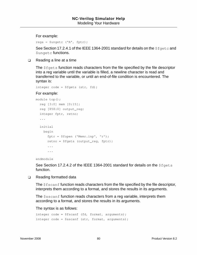
NC-Verilog Simulator HelpModeling Your Hardware
For example:
rega = $ungetc (“A”, fptr);
See Section 17.2.4.1 of the IEEE 1364-2001 standard for details on the $fgetc and$ungetc functions.
❑ Reading a line at a time
The $fgets function reads characters from the file specified by the file descriptorinto a reg variable until the variable is filled, a newline character is read andtransferred to the variable, or until an end-of-file condition is encountered. Thesyntax is:
integer code = $fgets (str, fd);
For example:
module top();
reg [3:0] mem [0:15];
reg [858:0] output_reg;
integer fptr, retno;
...
initial
begin
fptr = $fopen ("Memr.inp", "r");
retno = $fgets (output_reg, fptr);
...
...
endmodule
See Section 17.2.4.2 of the IEEE 1364-2001 standard for details on the $fgetsfunction.
❑ Reading formatted data
The $fscanf function reads characters from the file specified by the file descriptor,interprets them according to a format, and stores the results in its arguments.
The $sscanf function reads characters from a reg variable, interprets themaccording to a format, and stores the results in its arguments.
The syntax is as follows:
integer code = $fscanf (fd, format, arguments);
integer code = $sscanf (str, format, arguments);
November 2008 80 Product Version 8.2

NC-Verilog Simulator HelpModeling Your Hardware
For example:
module top();
reg [3:0] mem [0:15];
reg [299:0] output_reg;
integer fptr, retno;
initial
begin
fptr = $fopen ("Mem1r.inp", "r");
retno = $fscanf (fptr, "%b %h %o", mem[0], mem[1], mem[2]);
output_reg = "0 1 11111 a b c d e";
retno = $sscanf (output_reg, "%b %h %o", mem[3], mem[4], mem[5]);
...
...
endmodule
See Section 17.2.4.3 of the IEEE 1364-2001 standard for details on the $fscanfand $sscanf functions.
❑ Reading binary data
The $fread function reads binary data from the file specified by the file descriptorinto a register or into a memory. The syntax is as follows:
integer code = $fread (reg, fd);
integer code = $fread (mem, fd);
integer code = $fread (mem, fd, start);
integer code = $fread (mem, fd, start, count);
integer code = $fread (mem, fd, , count);
When $fread is being used to load data into a memory, the data is stored startingwith the lowest numbered location, continuing up to the higher location. Forexample, for a memory declared as memUp[3:15], the first location loaded ismemUp[3], followed by memUp[4], up to memUp[15]. For a memory declared asmemDown[15:3], the first location loaded is memDown[3], then memDown[4],down to memDown[15].
Start is an optional argument. If present, start is used as the starting location inmemory. For example, the following function will begin loading at address 4.
$fread (memUp, fptr, 4);
Count is an optional argument. If present, count is the maximum number oflocations in the memory that will be loaded. For example, for a memory declared as
November 2008 81 Product Version 8.2

NC-Verilog Simulator HelpModeling Your Hardware
memUp[3:15], the following task loads 4 memory locations, beginning withmemUp[3].
$fread (memUp, fptr, , 4);
See Section 17.2.4.4 of the IEEE 1364-2001 standard for details on the $freadfunction.
■ File positioning
The $ftell function returns the offset from the beginning of the file of the current byteof the file specified by the file descriptor. This offset will be read or written by asubsequent operation of that file descriptor. The syntax is:
integer pos = $ftell (fd);
For example, assume that the file Mem1r.inp contains the string ABCDEF:
module top();
reg [3:0] mem [0:15];
reg [8:0] output_reg;
integer fptr, posno;
initial
begin
fptr = $fopen ("Mem1r.inp", "r");
posno = $ftell (fptr); // Returns 0
output_reg = $fgetc (fptr); // Read first character “A” into 0
posno = $ftell (fptr); // Returns 1
$display( "Output of fgetc 1-> %c\n", output_reg);
output_reg = $fgetc(fd); // Read second character “B” into 1
posno = $ftell(fd); // Returns 2
$display("Output of fgetc 2-> %c\n",output_reg);
...
...
endmodule
See Section 17.2.5 of the IEEE 1364-2001 standard for details on the $ftell function.
The $fseek function sets the position of the next input or output operation on the filespecified by the file descriptor. The syntax for $fseek is:
code = $fseek (fd, offset, operation);
The offset argument is the number of offset bytes. The operation argument can be0, 1, or 2.
November 2008 82 Product Version 8.2

NC-Verilog Simulator HelpModeling Your Hardware
For example:
module top();
reg [3:0] mem [0:15];
reg [8:0] output_reg;
integer fptr, retno, posno;
initial
begin
fptr = $fopen ("Mem1r.inp", "r");
posno = $ftell (fptr);
$display ("Position = %d", posno); // Displays 0
// Offset 2 positions from beginning (i.e., C)
retno = $fseek (fptr, 2, 0);
output_reg = $fgetc (fptr);
posno = $ftell (fptr);
$display ("Position = %d", posno); // Displays 3
$display("Output of fgetc OP1-> %c\n", output_reg); // Displays “C”
// Offset 2 positions from 3 (i.e., F)
retno = $fseek (fptr, 2, 1);
output_reg = $fgetc (fptr);
posno = $ftell (fptr);
$display ("Position = %d", posno);
$display ("Output of fgetc OP2-> %c\n", output_reg);
// Offset 4 positions from EOF (i.e., I)
retno = $fseek (fptr, -4, 2);
output_reg = $fgetc (fptr);
posno = $ftell (fptr);
$display ("Position = %d", posno);
$display ("Output of fgetc OP3-> %c\n", output_reg);
// Go to begining of the file
0 Set position to offset bytes from the beginning.
1 Set position to current location plus offset.
2 Set position to EOF plus offset.
November 2008 83 Product Version 8.2

NC-Verilog Simulator HelpModeling Your Hardware
retno = $fseek (fptr, 0, 0);
output_reg = $fgetc (fptr);
posno = $ftell (fptr);
$display ("Position = %d", posno);
$display ("Output of fgetc OP4-> %c\n", output_reg);
end
endmodule
See Section 17.2.5 of the IEEE 1364-2001 standard for details on the $fseek function.
The $rewind function is the same as $fseek (0, 0);
■ Flushing Output
The $fflush function writes any buffered output to the file(s) specified by themulti-channel descriptor or to the file specified by the file descriptor. The syntax of$fflush is as follows:
$fflush (multi_channel_descriptor);
$fflush (file_descriptor);
$fflush ();
If the function is invoked with no arguments, the buffered output is written to all open files.
See Section 17.2.6 of the IEEE 1364-2001 standard for details on the $fflush function.
■ I/O Error Status
The $ferror function can be used to obtain more information about an error. Thesyntax is:
integer errno = $ferror (fd, str);
A string description of the type of error encountered by the most recent file I/O operationis written into str. The integral value of the error code is returned in errno.
See Section 17.2.7 of the IEEE 1364-2001 standard for details on the $ferror function.
PLA System Task Extensions
In the Verilog 1995 standard, the input and output terms of the PLA system tasks must berepresented as concatenations of scalar variables. For example:
module pla;
`define rows 4;
`define cols 3;
reg [1:`cols] a, mem[1:`rows];
November 2008 84 Product Version 8.2

NC-Verilog Simulator HelpModeling Your Hardware
reg [1:`rows] b;
initial
begin
$async$and$plane(mem, {a[1], a[2], a[3]}, {b[1], b[2], b[3], b[4]});
...
...
end
endmodule
The Verilog 2001 standard allows arbitrary expressions for the input terms and arbitraryassignable expressions for the output terms. For example:
$async$and$plane(mem, a[1:3], b[1:4]);
See Section 17.5 of the IEEE 1364-2001 standard for details on the PLA modeling systemtasks.
‘ifndef and ‘elsif Conditional Compilation Compiler Directives
The 1364-2001 standard includes the `ifndef and `elsif compiler directives.
■ `ifndef
This compiler directive checks for the definition of a text macro name. If the macro nameis not defined, the code after the `ifndef directive is included. If the macro name isdefined, and a `else directive exists, the code following the `else directive is included.
■ `elsif
This compiler directive must be preceded by an `ifdef or `ifndef directive, and canbe used instead of an `else directive. If `elsif exists (instead of `else), the compilerchecks for the definition of a text macro name. If the macro name has been defined, thelines after the `elsif directive are included.
The `elsif directive is the same as the sequence:
`else
`ifdef ...
`endif
See Section 19.4 of the IEEE 1364-2001 standard for more information on conditionalcompilation compiler directives.
November 2008 85 Product Version 8.2

NC-Verilog Simulator HelpModeling Your Hardware
Parameter Value Assignment by Name
The IEEE 1364-1995 standard, Section 12.2, states that the values of parameters declaredwithin an instantiated module can be altered by using:
■ A defparam statement, which allows assignment to parameters using their hierarchicalnames.
■ Module instance parameter value assignment, which allows values to be assigned inlineduring module instantiation.
In the 1364-1995 standard, only one form of module instance parameter value assignmentwas specified: assignment by ordered list. The 1364-2001 standard adds module instanceparameter value assignment by name. Parameter assignment by name consists of explicitlylinking the parameter name and its new value. For example:
module ram (...);
parameter WIDTH = 8;
parameter SIZE = 256;
endmodule
module my_chip (...);
...
ram #(8, 1023) ram1 (...); // Parameter redefinition by position
ram #(.SIZE(1023)) ram2 (...); // Parameter redefinition by name
...
endmodule
See Section 12.2 of the IEEE 1364-2001 standard for more information on overridingparameter values.
$value$plusargs System Function
The 1364-2001 LRM specifies two new system functions that provide access to informationto be used in the simulation. This information is provided in the form of plusargs on thecommand line.
The first of these system functions is $test$plusargs(user_string), which wasimplemented in Verilog-XL and which has been implemented in NC-Verilog since it was firstreleased.
See Section 17.10.1 of the IEEE 1364-2001 standard for details on $test$plusargs. Alsosee “Use $test$plusargs for Conditional Code” on page 1086.
November 2008 86 Product Version 8.2

NC-Verilog Simulator HelpModeling Your Hardware
The second system function is $value$plusargs. This system function has beenimplemented in NC-Verilog only.
The syntax for this system function is as follows:
$value$plusargs(user_string, variable)
Like $test$plusargs, this system function searches the list of plusargs on the commandline for a specified string. The string is specified as the first argument to the system function.If the string is found, the remainder of the string (that is, the part of the string after the portionthat matches the user_string) is converted into the specified format, and the resultingvalue is stored in the specified variable. For example:
reg [8*32:1] testname
...
if ($value$plusargs(“TESTNAME=%s”, testname))
begin
$display(“Running test %0s.”, testname);
startTest();
end
If you invoke the simulator with the following command line, the variable testname gets thevalue good_test.
% ncsim +TESTNAME=good_test [other_options] snapshot_name
See Section 17.10.2 of the IEEE 1364-2001 standard for details on $value$plusargs.
Disabling Implicit Net Declarations
Verilog net data types can be explicitly declared. However, if an identifier has not beenexplicitly declared, and if it is used in a port expression declaration or in the terminal list of aprimitive instance or module instance, the identifier is implicitly declared to be a net of typewire. For example, in the following module, net x9 is implicitly declared to be a scalar net oftype wire.
module fulladder(cout, sum, ain, bin, cin);
output cout, sum;
input ain, bin, cin;
wire x2;
nand (x2, ain, bin),
(cout, x2, x8);
xnor (x9, x5, x6);
or (...);
November 2008 87 Product Version 8.2

NC-Verilog Simulator HelpModeling Your Hardware
...
endmodule
While implicit nets can be convenient, in that not every signal used within a module has to beexplicitly declared, they can also lead to unintentional bugs in a design. For example, if asignal name is spelled incorrectly, a new signal is created.
The IEEE 1364-2001 LRM adds a way to disable implicit net declarations, so that all signalsmust be explicitly declared. To disable implicit nets, use the `default_nettype compilerdirective with the new argument none.
`default_nettype none
An error is generated if you disable implicit net declarations and do not explicitly declare allnets.
See Section 19.2 of the IEEE 1364-2001 standard for details on the `default_nettypecompiler directive.
Indexed Vector Part-Selects
In the Verilog-1995 standard, variable bit selects of a vector are permitted, but part-selectsmust be constant. You could not, for example, use a variable to select a specific byte out of aword.
The Verilog-2001 standard adds a second type of part-select, called indexed part selects.According to the standard, an indexed part select of a vector net, vector reg, integer variable,or time variable is specified by providing a base expression, a width expression, and an offsetdirection, using the following syntax:
[base_expression +: width_expression] //positive offset
[base_expression -: width_expression] //negative offset
The base expression can be a constant or it can vary during simulation run time. The widthexpression must be constant. The offset direction indicates if the width expression is addedto or subtracted from the base expression.
Example 1reg [1:0] dword;
reg [7:0] big_vector;
...
...
dword = big_vector [3 +: 2]
November 2008 88 Product Version 8.2

NC-Verilog Simulator HelpModeling Your Hardware
If big_vector has the value 1 0 1 0 1 1 1 0, then the value of big_vector[4:3] isassigned to dword. Bit 3 of the part-select is derived from the base expression (3). Bit 4 isderived from the positive offset and width expression (2). Therefore:
dword = 01
If a negative offset is specified, as shown in the following example, the value ofbig_vector[3:2] is assigned to dword.
dword = big_vector [3 -: 2]
Bit 3 is derived from the base expression (3). Bit 2 is derived from the negative offset and thewidth expression (2). Therefore, if big_vector has the value 1 0 1 0 1 1 1 0, then:
dword = 11
Example 2reg [63:0] word;
reg [3:0] byte_num;
wire [7:0] byteN = word[byte_num*8 +: 8];
If byte_num has a value of 4, then the value of word[39:32] is assigned to byteN. Bit 32of the part-select is derived from the base expression (4 x 8). Bit 39 is derived from thepositive offset and width expression (8).
Example 3reg [31:0] big_vect;
reg [63:0] dword;
integer sel;
...
...
if (sel > 0 && sel < 8)
dword[8 * sel +: 8] = big_vect[7:0];
...
...
If sel has the value 2, the value of big_vect[7:0] is assigned to dword[23:16].
dword[23:16] = big_vect[7:0];
Bit 16 is derived from the base expression (8 x 2). Bit 23 is derived from the positive offsetand the width expression (8).
If a negative offset is specified, as shown in the following example, the value ofbig_vect[7:0] is assigned to dword[16:9].
November 2008 89 Product Version 8.2

NC-Verilog Simulator HelpModeling Your Hardware
if (sel >0 && sel < 8)
dword[8 * sel -: 8] = big_vect[7:0];
Bit 16 is derived from the base expression (8 x 2). Bit 9 is derived from the negative offset andthe width expression (8).
Note: The LRM states that indexed part-selects “that are partially out of range shall whenread return x for the bits that are out of range, and when written shall only affect the bits thatare in range.” In the simulator, indexed part-selects that are partially out of range are treatedlike part-selects that are totally out of range. When read, x is returned for all bits, not just forthe bits that are out of range. When written, they are also treated the same way. They haveno effect on the data stored when written.
See Section 4.2.1 of the IEEE 1364-2001 standard for details on indexed part-selects.
Power Operator
The Verilog-2001 standard adds a power operator, which is represented by the token **. Thisoperator performs exponentiation.
Note: The power operator is currently described in Section 4.1.5 of the IEEE 1364-2001standard. The following text describes the result of the power operator in the simulator. Thistext has been submitted to the IEEE, and is expected to be adopted and incorporated into thestandard.
In the simulator, the result of the power operator is as follows:
If either operand of the power operator is real, the result type is real. The result value isundefined if the first operand is zero and the second operand is non-positive, or if the firstoperand is negative and the second operand is not an integral value.
If neither operand of the power operator is real, the result type is determined as outlined inSections 4.4.1 and 4.5.1 of the standard, with the second operand treated as self-determined.In this case, the power operator always interprets the second operand as an unsigned value,and the result value is 1 if both operands are zero.
The following table shows examples of the power operator.
Expression Result Comments
3**2 9 3*3
2**3 8 2*2*2, same result as 1<<3
2**0 1 By definition, and same result as 1<<0
November 2008 90 Product Version 8.2

NC-Verilog Simulator HelpModeling Your Hardware
Local Parameters
The Verilog-2001 standard adds a new type of module parameter called local parameters.These parameters are declared with the localparam keyword. For example:
localparam width = 8;
A local parameter is a constant that is similar to a parameter, but which cannot be modifiedwith a defparam statement, or by the ordered or named parameter value assignment in amodule instance statement.
Local parameters can be assigned to a constant expression containing a parameter that canbe modified with the defparam statement or by the ordered or named parameter valueassignment. The following example is from Section 12.2 of the LRM:
module generic_fifo
#(parameter MSB = 3, LSB = 0, DEPTH = 4) // These parameters can be overridden
(
input [MSB:LSB] in,
input clk, read, write, reset,
output [MSB:LSB] out,
output full, empty
);
// The following parameters are local and cannot be overridden.
// They can be affected by altering the public parameters above.
localparam FIFO_MSB = DEPTH*MSB;
localparam FIFO_LSB = LSB;
2**-3’sb1 128 -3’sb1 treated as unsigned 7, same as1<<-3’sb1
2.0**-3’sb1 0.5 -3’sb1 coerced to -1.0, giving real reciprocal
0.0**-1 Undefined Division by 0 is undefined
9**0.5 3.0 Real square root
9.0**(1/2) 1.0 Integer division truncates exponent to 0
-9.0**0.5 Undefined Square root of negative number is undefined
-3.0**2.0 9.0 Defined, because real 2.0 is still integral value
2**(-3’so4/3’so2) 64 Exponent is -3’so2, but is interpreted as 3’o6
Expression Result Comments
November 2008 91 Product Version 8.2

NC-Verilog Simulator HelpModeling Your Hardware
...
...
endmodule
The elaborator generates an error (CULPARM) if you try to override a local parameter with adefparam statement or by using named parameter value assignment in a module instancestatement.
If a module instance statement includes an ordered parameter value assignment to overridepublic parameters, any local parameters are skipped as the new values are assigned. Forexample, suppose that you have a module called mod with 3 public parameters and one localparameter, as follows:
module mod (list_of_ports);
parameter A = 5, B = 1;
localparam C = 3;
parameter D = 2;
...
...
endmodule
A module called top then instantiates module mod with the following instantiation statement:
module top;
...
...
mod #(6, 2, 3) u1 (list_of_ports);
In this example, the parameter A is assigned the value 6, the parameter B is assigned thevalue 2, and the parameter D is assigned the value 3. The local parameter C is not modified.No warning message is generated.
Note: For backward compatibility, you can compile modules with the -v1995 command-lineoption. This option lets you compile a legacy Verilog-1995 design that contains identifierscalled localparam. If you use the -v1995 option, the name of the variable will not betreated as a keyword.
See Sections 3.11.1 of the IEEE 1364-2001 standard for details on the syntax for declaringlocal parameters. See also Section 3.11.2 for more information on local parameters. SeeSection 12.2 for details on overriding parameter values.
Implicit Nets with Continuous Assignments
According to the Verilog-1995 standard, an undeclared signal that appears on the left-handside of a continuous assignment is implicitly declared as a net data type only if the signal
November 2008 92 Product Version 8.2

NC-Verilog Simulator HelpModeling Your Hardware
name is also connected to a port of that module. If the signal is not connected to a port, thesignal is considered undeclared.
The Verilog-2001 standard extends this implicit net declaration to include any signal on theleft-hand side of a continuous assignment, regardless of whether or not the signal isconnected to a module port.
If a net has not been explicitly declared, an implicit net of default net type is assumed in thefollowing cases:
■ If an identifier is used in a port expression declaration, an implicit net of default net typeis assumed, with the vector width of the port expression declaration.
■ If an identifier is used in the terminal list of a primitive instance or a module instance, andthe identifier has not been explicitly declared in one of the declaration statements of theinstantiating module, an implicit scalar net of default net type is assumed.
■ If an identifier appears on the left-hand side of a continuous assignment statement, andthe identifier has not been explicitly declared, an implicit scalar net of default net type isassumed.
Note: Use the ncvlog -v1995 command-line option to turn off this Verilog-2001feature.
See Section 3.5 of the IEEE 1364-2001 standard for details on implicit declarations, andSection 6.1 for details on continuous assignments.
Automatic Width Extension of X and Z Constants beyond 32 Bits
According to the Verilog-1995 standard, if you assigned an unsized high-impedance value oran unsized unknown value (for example, ’bz or ’bx) to a bus that is greater than 32 bits, onlythe lower 32 bits are set to z or x. The upper bits are set to 0. For example:
parameter WIDTH = 64;
reg [WIDTH-1:0] data;
data = 'bz; //Fills with 'h00000000zzzzzzzz
To set the entire bus to z or x, you must explicitly specify the number of high impedance orunknown bits. For example:
parameter WIDTH = 64;
reg [WIDTH-1:0] data;
data = 64'bz; //Fills with 'hzzzzzzzzzzzzzzzz
November 2008 93 Product Version 8.2

NC-Verilog Simulator HelpModeling Your Hardware
The Verilog-2001 standard changes this rule for assignment expansion. An unsized value ofZ or X will automatically expand to fill the full width of the vector on the left-hand side of theassignment. For example,
parameter WIDTH = 64;
reg [WIDTH-1:0] data;
data = 'bz; //Fills with 'hzzzzzzzzzzzzzzzz
This change in the standard can result in simulation differences if existing models with vectorsgreater than 32 bits do not explicitly specify the number of high impedance or unknown bits.If you experience backward compatibility problems, you can compile your modules with the-v1995 command-line option. This option turns off the automatic width extension featureintroduced in the Verilog-2001 standard.
See Section 2.5.1 of the IEEE 1364-2001 standard for details.
Line and File Compiler Directive
It is important for Verilog tools to keep track of the filenames of your Verilog source files andthe line numbers in the files. This information can be used for error messages or source codedebugging, and can be accessed by the Verilog PLI.
In many cases, however, the Verilog source is preprocessed by some other tool, and the lineand file information of the original source code can be lost because the preprocessor mightadd additional lines to the source code file, combine multiple source code lines into one line,concatenate multiple source files, and so on.
The 1364-2001 standard adds a new `line compiler directive, which can be used to specifythe original source code line number and filename. This allows the location in an original fileto be maintained if another process modifies the source. After specifying the new line numberor filename, the compiler can correctly refer to the original source file location.
The `line compiler directive can be specified anywhere within the Verilog HDL sourcedescription. The syntax for the directive is as follows:
`line number “filename” level
For example:
`line 13 “file.v” 0
All parameters in the `line directive are required.
■ The number parameter is the new line number of the next line.
■ The filename parameter is the new name of the file. The filename can be a full or relativepathname.
November 2008 94 Product Version 8.2

NC-Verilog Simulator HelpModeling Your Hardware
■ The level parameter indicates whether an include file has been entered (value is 1), aninclude file is exited (value is 2), or neither has been done (value is 0).
Note: The simulator checks that the level parameter is a legal value, but does notprocess the field. A preprocessor may insert a value of 0, 1, or 2, but the simulator treatsall values as 0.
Example:
In the following example, the original source file orig.v contains the following statement toinclude the file called inc.v.
`include “inc.v”
Suppose that some tool generates errors at line 13 in file orig.v and at line 1 in file inc.v.
Now the tool passes the files through a preprocessor, which generates a single file callednew.v by including the code in the `include file.
Original source files Output of preprocessor
// Original file inc.v // File: new.v
1 in1, 1 module simulation(
2 in2, 2 in1,
3 in2,
4 in3,
// Original file orig.v 5 out1
1 module simulation( 6 );
2 `include "inc.v" 7 input in1;
3 in3, 8 input in2;
4 out1 9 input in3;
5 ); 10 output out1;
6 input in1; 11 assign out1 = in1 & in2;
7 input in2; 12 always
8 input in3; 13 begin
9 output out1; 14 $VPI_myfunc();
10 assign out1 = in1 & in2; 15 $finish;
11 always 16 end
12 begin 17 endmodule
13 $VPI_myfunc();
14 $finish;
15 end
16 endmodule
November 2008 95 Product Version 8.2

NC-Verilog Simulator HelpModeling Your Hardware
The error message that was generated at line 13 in file orig.v will now be generated at line14 in file new.v. The line 1 error message in inc.v will be lost, and the error will now begenerated at line number 2 in file new.v.
If the preprocessor could generate code with `line directives, it might generate thefollowing:
1 module simulation(
2 `line 1 “inc.v” 1 // Next line is line 1, file inc.v, enter include file
3 in1,
4 in2,
5 `line 3 “orig.v” 2 // Next line is line 3, file orig.v, exit include file
6 in3,
7 out1
8 );
9 input in1;
10 input in2;
11 input in3;
12 output out1;
13 assign out1 = in1 & in2;
14 always
15 begin
16 $VPI_myfunc();
17 $finish;
18 end
19 endmodule
The first directive resets line 3 in the current file to line 1 of file inc.v. The level parameterindicates that an include file has been entered (Note: The simulator will ignore this levelparameter.). The error message will again show that the error was generated at line 1 ofinc.v.
The second directive resets line 6 in the current file to line 3 of file orig.v. The levelparameter indicates that an include file has been exited (Note: The simulator will ignore thislevel parameter.). The error message that was generated at line 14 in file new.v will nowshow that the error was generated at line 13 of orig.v because the compiler internallyrepresents the line numbers beginning with line 6 as line numbers beginning with line 3.
See Section 19.7 of the IEEE 1364-2001 standard for more information on the `linecompiler directive.
November 2008 96 Product Version 8.2

NC-Verilog Simulator HelpModeling Your Hardware
Attributes
Because many EDA tools besides digital simulators have adopted the Verilog language as asource input, a mechanism for specifying tool-specific information to the Verilog language isrequired. The Verilog 1364-2001 standard adds a mechanism for specifying properties aboutobjects, statements, and groups of statements in the HDL source that can be used to controlthe operation or behavior of the tools. These properties are called attributes.
The syntax for specifying attributes on Verilog language constructs is specified in thestandard as follows:
attribute_instance ::=
(* attr_spec {, attr_spec} *)
attr_spec ::=
attr_name = constant_expression
| attr_name
attr_name ::=
identifier
The attribute is specified as:
■ A prefix to a declaration, a module, a statement, or a port connection.
■ A suffix to an operator or a function name in an expression.
Multiple attributes for a language construct can be specified as a list using either of thefollowing formats:
(* A = 1 *) (* B = 2 *) (* C = 3 *) module ...
(* A = 1, B = 2, C = 3 *) module ...
Attributes can be assigned values, including strings. If a value is not specifically assigned toan attribute, the value 1 is assigned. If the same attribute name is defined more than once forthe same language element, the last attribute value is used. Attribute values can be redefinedfor each instance of an object.
If the attribute value expression contains an attribute for operators used in that expression, awarning is generated and the corresponding attribute specification is ignored. In the followingexample, the attribute (* B = 1 *), specified on the plus operator, will be ignored.
(* A = 1 + (* B = 1 *) 2 *) module A...
Examples:
November 2008 97 Product Version 8.2

NC-Verilog Simulator HelpModeling Your Hardware
Note: The LRM does not specify a standard set of attributes and their values. These aredefined by tool vendors, and the documentation for those tools will contain details on whatattributes you can define. The following examples are for illustration purposes only.
// Attach an attribute to a module definition
(* optimize_power *) // Same as (* optimize_power = 1 *)
module mod1 (port_list);
// Attach an attribute to a module instantiation
(* optimize_power = 0 *)
mod1 U1 (port_list);
// Attach attributes to a case statement. Both attributes have value 1.
(* full_case, parallel_case = 1 *)
case (foo)
state[0]: ...
state[1]: ...
state[2]: ...
endcase
// Attach an attribute to an operator. Attribute specified as a suffix.
a = b ? (* no_glitch *) c : d;
// Attach an attribute to a function call. Attribute specified as a suffix.
a = add (* mode = “cla” *) (b, c);
Note: In addition to support for the Verilog-2001 attribute formats, the Verilog parser (ncvlog)also supports the OVI attribute format currently used by AMS. In the OVI format used by AMS,attributes are always specified as suffixes to language constructs.
The values of attributes can be accessed through the VPI.
Limitations
In the current release, the following restrictions apply to attributes:
■ Parameter names cannot be used in the attribute value expression. For example, thefollowing attribute generates an error.
(* a = param1 *)
■ Constant functions cannot be used in the attribute value.
November 2008 98 Product Version 8.2

NC-Verilog Simulator HelpModeling Your Hardware
■ If both OVI and Verilog-2001 attributes are specified for a language construct, theattributes are combined into a single list. The OVI list is treated as an extension of theVerilog-2001 attribute list. In the following example, a warning message is generatedtelling you that attribute A has been defined twice and that the value 3 will be used.
(* A=1, B=1 *) module A (...) (* const integer A = 3; *)
■ Attribute access through the GUI is not supported in the current release.
See Section 2.8 and Annex A of the IEEE 1364-2001 standard for more information.
See Section 26.6.42 of the IEEE 1364-2001 standard for information on the VPI interface forthe attribute specification.
Generate Constructs
The Verilog 1364-2001 standard introduces new language constructs that allow multiple andconditional instantiations of blocks that can contain modules, UDPs, and Verilog gateprimitives, as well as multiple occurrences of variables, nets, tasks, localparams, functions,continuous assignments, initial procedures, and always procedures.
Generate block instantiations can be created in three ways:
■ generate-loop
A generate-loop, also called a for-generate, permits the module items to be instantiatedmultiple times using a for-loop construct.
See Section 12.1.3.2 (“generate-loop”) of the IEEE 1364-2001 standard for details ongenerate-loops.
■ generate-if
A generate-if, also called an if-generate, permits the module items to be conditionallyinstantiated based on the evaluation of an if-else condition.
See Section 12.1.3.3 (“generate-conditional”) of the IEEE 1364-2001 standard for detailson if-generates.
■ generate-case
A generate-case, also called a case-generate, permits the module items to beconditionally instantiated based on a select one-of-many case construct.
See Section 12.1.3.4 (“generate-case”) of the IEEE 1364-2001 standard for details oncase-generates.
November 2008 99 Product Version 8.2

NC-Verilog Simulator HelpModeling Your Hardware
Three new keywords for generates are added in the 2001 standard:
■ generate - endgenerate
All generate instantiations are coded within a module scope. The LRM states that allsyntax related to generates in a module must be enclosed by the keywords generateand endgenerate. However, defining a region with these keywords does not have anysemantic significance (for example, it does not create a new scope), and using thekeywords is optional in the simulator.
■ genvar
A genvar declaration must be used to declare the variable that will be used as theiteration variable in the for-loop of a generate-loop. This variable is called a genvar.
Note: Because the simulator supports the IEEE 1364-2001 standard by default, any legacycode that uses these new keywords must either be changed or compiled with the ncvlog-v1995 option.
See “for-generate” on page 100 for more details on for-generates. See “ConditionalGenerates” on page 105 for more details on if-generates and case-generates.
for-generate
The LRM states that a “generate-loop permits one or more variable declarations, modules,user-defined primitives, gate primitives, continuous assignments, initial blocks, and alwaysblocks to be instantiated multiple times using a for-loop.”
The following is a simple example of a generate-loop. This code generates ten initial blocks,each of which has a $display statement.
module top;
generate
genvar i;
for (i = 0; i < 10; i = i + 1)
begin : gen
initial $display("%d", i);
end
endgenerate
endmodule
In this example:
■ The keywords generate and endgenerate surround all syntax related to generates inthe module. Using these keywords is optional.
November 2008 100 Product Version 8.2

NC-Verilog Simulator HelpModeling Your Hardware
■ A genvar declaration is used to declare the variable that will be used as the iterationvariable in the for-loop. This variable is called a genvar.
The syntax of the genvar declaration is as follows:
genvar genvar_identifier [, genvar_identifier];
For example:
genvar i;
genvar i, j;
The genvar must be declared within the module where the genvar is used. If you use thegenerate - endgenerate keywords, the genvar can be declared either inside oroutside of the region. Two generate loops can use the same genvar for the iterationvariable, but these two loops cannot be nested.
A genvar can be used only as the iteration variable of a for-generate statement. It is bestto think of references to the genvar inside the for-generate not as references to the itemdeclared in the genvar declaration, but as references to an implicitly declared generateparameter declared inside the body of the for-generate.
For example, in the simple design shown above, you cannot refer to the item declared inthe genvar declaration (top.i). There are ten implicitly declared generate parameters.Hierarchical names for the generate parameters have the following form:
generate_block_identifier[index_value].genvar
In the example shown above, these hierarchical names are top.gen[0].i,top.gen[1].i, and so on. The values of each of the ten generate parameters isdisplayed by each of the display statements inside the ten generate instances.
The value of a generate parameter cannot be changed with a defparam statement orby any other means.
■ A for-generate statement defines how many instances of the for-generate there will be,and what the value of the generate parameter in each instance will be.
A for-generate statement has the same form as a for-loop, with the same three elements:an initializer, a condition, and an iteration statement. For example:
for (i = 0; i < 10; i = i + 1)
The following restrictions are imposed on the three elements of the for-generatestatement:
❑ The initializer must be an assignment of a constant expression to a genvar.
❑ The iteration statement must be an assignment of a constant expression to thesame genvar used in the initializer.
November 2008 101 Product Version 8.2

NC-Verilog Simulator HelpModeling Your Hardware
❑ Together, the three elements must define a loop that executes zero or more timesand terminates.
■ A generate block describes the contents of the for-generate.
The syntax of a generate block is similar to a named begin block, except that a generateblock contains module items (initial blocks, always blocks, primitives, continuousassignments, and so on), while named begin blocks contain sequential statements.
The code in this example generates ten initial blocks, each of which has a $displaystatement. Note that this example prints the numbers 0 through 9, but this is totallydependent on the fact that the simulator will execute the initial blocks in order, startingwith gen[0] and ending with gen[9]. This order was chosen for sanity, but it is notguaranteed by the language. Specifically, it has nothing to do with the fact thatfor-generates look like a looping construct that starts at 0 and ends with 9. All initialblocks, including the 10 created by the for-generate in this example, run at time zero inno particular order.
Note: The LRM states that the generate block for a for-generate must be named. Thesimulator does not require a name. If you do not supply a name for the generate block,an implicit name is assigned to the generate construct. However, these implicitly-creatednames cannot be used in hierarchical names to objects in the Verilog source. See“Named and Unnamed Generate Blocks” on page 109 for more information.
Example 1
This example, taken from the IEEE standard, illustrates a multi-bit wide adder that uses agenerate-loop to instantiate both the primitive instances and the internal nets connecting theprimitives. A redefinable parameter constant is used to set the width of the multi-bit adder andthe number of instances generated.
module addergen1 (co, sum, a, b, ci);
parameter SIZE = 4;
output [SIZE-1:0] sum;
output co;
input [SIZE-1:0] a, b;
input ci;
wire [SIZE:0] c;
genvar i;
assign c[0] = ci;
generate
for(i = 0; i < SIZE; i = i + 1)
November 2008 102 Product Version 8.2

NC-Verilog Simulator HelpModeling Your Hardware
begin : bit
wire t1, t2, t3; //internal nets
xor g1 (t1, a[i], b[i]);
xor g2 (sum[i], t1, c[i]);
and g3 (t2, a[i], b[i]);
and g4 (t3, t1, c[i]);
or g5 (c[i+1], t2, t3);
end
endgenerate
assign co = c[SIZE];
endmodule
Each generate instance is a scope. The name of the scope is the name of the generate block(bit, in this example), plus an instance-select, which is the value of the generate parameter.
In this example, the hierarchical names for the generated primitive instances are:
xor gates:
bit[0].g1, bit[1].g1, bit[2].g1, bit[3].g1
bit[0].g2, bit[1].g2, bit[2].g2, bit[3].g2
and gates:
bit[0].g3, bit[1].g3, bit[2].g3, bit[3].g3
bit[0].g4, bit[1].g4, bit[2].g4, bit[3].g4
or gate:
bit[0].g5, bit[1].g5, bit[2].g5, bit[3].g5
The hierarchical names for the generated nets are:
bit[0].t1, bit[1].t1, bit[2].t1, bit[3].t1
bit[0].t2, bit[1].t2, bit[2].t2, bit[3].t2
bit[0].t3, bit[1].t3, bit[2].t3, bit[3].t3
Example 2
This example shows nested for-generates where the starting value of the inner one dependson the generate parameter of the outer one. The outer generate parameter is also used tosize a register and to set its value.
November 2008 103 Product Version 8.2

NC-Verilog Simulator HelpModeling Your Hardware
module top;
generate
genvar i;
for (i = 5; i < 9; i = i + 1) begin : g1
genvar j;
for (j = i; j >= 1; j = j - 1) begin : g2
reg [0:i] r;
initial begin
r = i;
$display("%m", r);
end
end
end
endgenerate
endmodule
Example 3
The LRM specifies that index values (instance-selects) in hierarchical names must be integerliterals. This restriction has been lifted in the simulator. Index values can be constantexpressions that include parameters. It is useful inside a for-generate instance to be able torefer to an object in the “next” for-generate instance. To do this, use a hierarchical name witha path element such as gen[i+1], where i is your generate parameter.
The following example shows how to refer to an object inside a for-generate from outside itusing an instance-select that contains a parameter.
module top;
parameter p = 5;
generate
genvar i;
for (i = 1; i < p; i = i + 1) begin : g1
integer r;
initial r = i;
end
endgenerate
initial #1 $display("%d", g1[p-1].r);
endmodule
November 2008 104 Product Version 8.2

NC-Verilog Simulator HelpModeling Your Hardware
Example 4
This example shows that you can recursively instantiate a module as long as the recursionterminates. This would be more natural with if-generates. Here, a conditional expression inthe for-generate scheme is used to achieve the same effect.
module gen3;
sub #(5) u1 ();
endmodule
module sub;
parameter p = 305;
generate
genvar i;
for (i = 1; i < (p ? 2 : 1); i = i + 1) begin : g1
sub #(p-1) u1 ();
initial $display(p,,i);
end
endgenerate
endmodule
Conditional Generates
Conditional generate statements are comprised of control expressions and branches. Thebranches contain module items, and the control expressions determine which branch, if any,will be elaborated.
■ An if-generate permits module items to be conditionally instantiated into anothermodule based on the evaluation of an if-else condition that is deterministic at the time thedesign is elaborated. If-generates have one or two branches, the if branch and theoptional else branch.
■ A case-generate permits module items to be conditionally instantiated into anothermodule based on the evaluation of a select one-of-many case construct. Case-generateshave one branch for each case expression and an optional default branch.
Each branch of a conditional generate contains one module item. That module item can be agenerate block which can contain multiple module items.
Each branch defines a new scope. An object declared in one branch is distinct from anotherobject with the same name declared outside the branch or in another branch.
The scope defined by a branch can be:
November 2008 105 Product Version 8.2

NC-Verilog Simulator HelpModeling Your Hardware
■ Named by explicitly enclosing the branch in a named generate block.
Each branch of a conditional generate statement is exclusive. That is, only one branchwill be elaborated. The generate blocks for each set of exclusive branches in aconditional generate construct can have the same name. However, they cannot have thesame name as any branch of any other conditional generate statement, even in caseswhere the two branches would never both be elaborated.
■ Unnamed by either leaving out the name or by leaving out the begin and end keywordsentirely.
Objects declared in a branch that is not comprised of a named generate block belong toan unnamed scope, and are not accessible via hierarchical names in the Verilog source.However, an implicit name is assigned to the generate construct so that the unnamedelaborated scope can be referred to by VPI, Tcl, and other external interfaces. Objectsdeclared inside unnamed branches are accessible to external interfaces by using theimplicit name of the generate construct. See “Named and Unnamed Generate Blocks”on page 109 for more information.
Example 1
In the following example, if the value of the parameter param is 0, a wire called a is created,and the module mod1 is instantiated. If the value of param is any other value, the modulemod2 is instantiated.
Each branch creates a new scope. In this example, the scopes are named by explicitlyenclosing the branches in named generate blocks. The scope name can be used in ahierarchical name in the Verilog source to access objects declared in the named scope. Whenthis example is compiled and elaborated, a scope called g1 is created, and this name is usedin the $display statement.
The wire called a declared in the conditional generate block g1 is distinct from the output ofthe module, which is also called a. The uses of a in the other generate block refers to themodule output.
module top (a, b, c);
input b, c;
output a;
parameter param = 0;
generate
if (param == 0)
begin : g1
wire a;
mod1 u1 (a, b, c);
November 2008 106 Product Version 8.2

NC-Verilog Simulator HelpModeling Your Hardware
end
else
begin : g2
mod2 u1 (a, b, c);
end
endgenerate
initial
$display("Value of top.g1.u1.a is: %d", top.g1.u1.a);
endmodule
Example 2
This example is the same as the first example, except that no identifiers are supplied for thegenerate blocks. This creates unnamed scopes. Objects declared in the branches are notaccessible using hierarchical names in the Verilog source.
An implicit name is assigned to the if-generate so that objects declared in the scope that iselaborated can be referred to by VPI, Tcl, and other external interfaces. In this example, theassigned name is genblk1. You can use this name as an element in the hierarchicalpathname to an object.
module top (a, b, c);
input b, c;
output a;
parameter param = 0;
generate
if (param == 0)
begin
wire a;
mod1 u1 (a, b, c);
end
else
mod2 u1 (a, b, c);
endgenerate
// The following code would generate an error because the implicit name of the// generate block cannot be used in a hierarchical name in the Verilog source.
// initial
// $display("Value of top.genblk1.u1.a is: %d", top.genblk.u1.a);
endmodule
November 2008 107 Product Version 8.2

NC-Verilog Simulator HelpModeling Your Hardware
The implicit name assigned to the conditional generate in this example can be used as anelement in the hierarchical pathname to an object in Tcl commands. For example:
ncsim> scope -describe top.genblk1
a..........wire (wire/tri) = StX
u1.........instance of module and_gate
u2.........instance of module not_gate
ncsim>
ncsim> probe -shm top.genblk1.u1
Created default SHM database ncsim.shm
Created probe 1
Example 3
The following example shows a generate-case construct with named generate blocks.
module top (a, b, c);
input b, c;
output a;
parameter param = 0;
generate
case (param)
0: begin : g1
wire a;
mod1 u1 (a, b, c);
mod2 u2 (top.a, a);
end
1: begin : g1
mod3 u1 (a, b, c);
end
default: begin : g1
mod4 u1 (a, b, c);
end
endcase
endgenerate
endmodule
November 2008 108 Product Version 8.2

NC-Verilog Simulator HelpModeling Your Hardware
Example 4
If a branch is not surrounded explicitly by begin and end keywords, and the one module itemin the branch is another conditional generate, that conditional generate is directly nested.The branches of the directly nested conditional generate are considered to be branches ofthe outer conditional generate. These branches just happen to have some additional controlexpressions for selecting them.
In the following example, there is one conditional generate construct with three branches.each of which comprises a subscope of the module.
module top(a, b, c);
input b, c;
output a;
parameter x = 0;
parameter y = 0;
generate
if (x)
mod1 u1 (a, b, c);
else if (y)
mod2 u1 (a, b, c);
else
mod3 u1 (a, b, c);
endgenerate
endmodule
Named and Unnamed Generate Blocks
The LRM states that the generate block for a for-generate must be named, while for anif-generate or case-generate, the generate block identifier is optional.
The simulator does not require an identifier for any generate block.
If you specify a name, that name is used in creating unique names for the generatedinstances. These names can appear in a hierarchical name outside of the generate block inthe Verilog source, and they can be used in hierarchical names in external interfaces such asVPI and Tcl.
In the following example, the generate block is named gen:
genvar i;
generate
for(i = 0; i < 4; i = i + 1)
November 2008 109 Product Version 8.2

NC-Verilog Simulator HelpModeling Your Hardware
begin : gen
...
...
end
endgenerate
In this example, the names of the generated scopes would be gen[0], gen[1], gen[2],and gen[3]. These generated identifiers can be used in hierarchical names. For example:
gen[0].u1 // Hierarchical path of generated module instance
gen[2].i // Hierarchical path of generate parameter
gen[3].sig // Hierarchical path of generated net
If you do not supply a name for the generate block, an implicit name is created. Each generateconstruct (for-generate, if-generate, or case-generate) that appears in a given scope isassigned a number. The construct that appears first in the scope is assigned the namegenblk1, the construct that appears second is assigned the name genblk2, and so on. Ifan implicit name conflicts with an explicitly declared name, leading zeroes are prepended tothe number until the name does not conflict.
Unnamed scopes are assigned an implicit name so that they can be referred to usinghierarchical names by VPI, Tcl, and other external interfaces. However, theseimplicitly-created names cannot be used in hierarchical names to objects in the Verilogsource.
Defparam Restrictions
For-generates and conditional generates are treated exactly the same as arrays of instanceswhen it comes to restrictions on defparams that appear inside them or in modules instancedinside them. It is not legal to defparam the value of a parameter that might change theiteration scheme of a for-generate statement, or the elaboration of a conditional generatestatement, that is already elaborated. The wording of this restriction for arrays of instancesuses the term “AOI level,” which is the number of instance arrays above you in the hierarchy.A defparam may not change the value of a parameter that has a smaller AOI level than thescope where the defparam appears.
Multi-Dimensional Arrays and Arrays of Net Data Types
The Verilog-1995 standard allows one-dimensional arrays of variable data types reg,integer, and time. For example:
reg [7:0] mem [0:255]; // Declares a memory mem of 256 8-bit registers
integer a [1:64]; // Array of 64 integer values
time chng_hist [1:1000]; // Array of 1000 time values
November 2008 110 Product Version 8.2

NC-Verilog Simulator HelpModeling Your Hardware
The Verilog 1364-2001 standard extends this by permitting:
■ Arrays of any variable data type (reg, integer, time, real, realtime) or net datatype
■ Multi-dimensional arrays of these data types
To declare a multi-dimensional array, specify the address range for each dimension after theidentifier. For example:
reg array1 [7:0] [0:255]; // 2-dimensional array of 1-bit registers
reg [7:0] array2 [7:0] [0:255]; // 2-dimensional array of 8-bit registers
reg [3:0] array3 [0:255][0:255][0:15]; // 3-dimensional array of 4-bit registers
integer a [7:0] [1:64]; // 2-dimensional array of integer values
real data_2d [0:7] [0:3];
realtime data_3d [0:7] [0:3] [0:15];
wire [7:0] data [15:0]; // 1-dimensional array of 7-bit wires
wire w_array [7:0] [5:0]; // 2-dimensional array of wires
To assign a value to an element of an array, an index must be specified for every dimension.For example:
reg [7:0] mem [0:255];
mem[1] = 0; // Assigns 0 to second element of mem
reg [7:0] array2D [7:0] [0:255];
array2D [1][0] = 0; // Assigns 0 to element referenced by indexes [1][0]
reg [7:0] array1 [0:255];
wire [7:0] out1 = array1[1]; // Assigns value of second element of array1// to wire out1
reg [7:0] array3D [0:255] [0:255] [0:15];
wire [7:0] out2 = array3D [3][2][1]; // Assigns element of a 3-dimensional array// to wire out2
See Section 3.10 (Arrays) of the IEEE 1364-2001 standard for more information.
November 2008 111 Product Version 8.2

NC-Verilog Simulator HelpModeling Your Hardware
Bit-Selects and Part-Selects within Arrays
The Verilog-1995 standard did not allow you to access a bit-select or part-select of an arrayword directly. A full array word had to be copied to a temporary variable, and the bit or partselected from the temporary variable.
The Verilog 1364-2001 standard removes this restriction, and allows bit-selects andpart-selects of array words to be accessed directly.
To express bit-selects or part-selects of array elements, select the word by supplying anaddress for each dimension, and then address the bit- or part-select.
For example:
// Declare an array of 256 by 256 8-bit elements
reg [7:0] twod_array [0:255][0:255];
// Declare a three-dimensional array of 4-bit wires
wire [3:0] threed_array [255:0][255:0][7:0];
...
...
...
wire out = twod_array[14][1][6] // Select bit 6 of the specified word.
wire [3:0] = twod_array[14][1][3:0]; // Select lower 4 bits of the word.
wire [3:0] out2 = twod_array[14][1][3 -:4]; // Indexed part-select. Select 4 bits// of the word beginning with bit 3
// (same as [3:0]).
threed_array [5][7][2][2] = 0; // Select bit 6 of the specified word.
threed_array [5][7][2][1:0] = 0; // Select lower 2 bits of the word.
See Sections 4.2.1 and 4.2.2 of the IEEE 1364-2001 standard for more information.
Verilog Configurations
The Verilog-2001 standard adds configuration blocks, which allow the exact version andsource location of each Verilog module to be specified as part of the Verilog language. Aconfiguration is an explicit set of rules to specify the exact source description to be used torepresent each instance in a design.
In the 2001 standard, a file called a library map file is introduced. This file can contain:
November 2008 112 Product Version 8.2

NC-Verilog Simulator HelpModeling Your Hardware
■ Library declarations
A library declaration associates a logical library name with a source file or set of sourcefiles. The specified source files are compiled into the associated library. For example:
library rtlLib “*.v”;
library gateLib “adder.vg”;
In this example, all design units in files with a .v extension will be compiled into thelibrary called rtlLib, and design units in the file called adder.vg will be compiled intothe library called gateLib.
Because the simulator has always provided several ways to control the compilation ofdesign units into libraries, these library declarations are optional. If used, they provide anadditional way to control which libraries design units are compiled into.
All libraries in a library mapping file must be declared in the cds.lib file.
See “Controlling the Compilation of Design Units into Library.Cell:View” on page 221 formore information.
■ References to other library map files
An include statement can be used to include the contents of a library map file inanother library map file.
■ Configuration declarations
These are the configuration blocks that control the binding of instances. Because theconfiguration is specified in a separate file, the Verilog model source code does not needto be modified to reconfigure a design.
See Section 13 of the IEEE 1364-2001 standard for details on configurations.
See “How Modules and UDPs Are Resolved during Elaboration” on page 345 for details andexamples on using Verilog configurations in the simulator.
Example:
The following example illustrates how a simple Verilog design configuration might be used.The Verilog source code consists of a testbench module, which contains an instance of thetop level of the design hierarchy. The top level of the design includes instances of othermodules.
module testbench;
...
...
Chip dut (...); // Top-level of design hierarchy
...
November 2008 113 Product Version 8.2

NC-Verilog Simulator HelpModeling Your Hardware
...
endmodule
module Chip(...);
...
...
adder u1 (...);
adder u2 (...);
...
...
endmodule
A library mapping file for this example is shown below. This file contains:
■ Library declarations.
■ A configuration block. In this configuration example, instance a1 of the adder will beselected from the RTL library called rtlLib, and instance a2 from a specific gate-levellibrary called gateLib.
/* Location of RTL models (current directory) */
library rtlLib “./*.v”;
/* Location of synthesized models */
library gateLib “./synth_out/*.vg”;
/* The config keyword begins the config block.Define a name for this configuration. */
config cfg;
/* The following design statement specifies where to find the top-level module(s)*/
design rtlLib.testbench;
/* The following default liblist statement sets the default search order forfinding instantiated modules */
default liblist rtlLib gateLib;
/* The following instance ... liblist statement explicitly specifies whichlibrary to use for instance a2 */
instance testbench.dut.a2 liblist gateLib;
endconfig
November 2008 114 Product Version 8.2

NC-Verilog Simulator HelpModeling Your Hardware
Issues Related to Configurations
This section lists several issues related to Verilog configurations. Many of these issues stemfrom ambiguities in the LRM, and Cadence has filed errata reports with the IEEE forresolution.
■ Configurations in Verilog source code
According to the 2001 standard, configurations can appear in either a library map file orin a Verilog source file. Using configurations in Verilog source files is not supported.
■ Configuring instance arrays and generated instantiations
The LRM does not discuss the configuration of instance arrays and generatedinstantiations. Moreover, as shown in the BNF syntax (Syntax 13-6), it is illegal toconfigure an individual element of an instance array or generate block because theinst_name can contain only an instance_identifier.
Given the undefined behavior in the LRM regarding arrays of instances and generates,configurations for both of these items are not supported. The elaborator issues warningmessages, and Verilog default binding rules are used to bind each element.
■ Binding instances to primitives
In the LRM, Syntax 13-1, a library cell is specified as:
[library_identifier.]cell_identifier[:config]
Therefore, binding an instance to a primitive is not supported. For example, the followingis illegal because buf is a Verilog keyword, not a cell_identifier.
instance top.i1 use buf;
■ Priority between instance clause and cell clause
The LRM is ambiguous about the order of preference when a cell clause configures acell, and an instance clause configures an instance of the cell. For example:
instance top.f1 use rtlLib.foo;
cell rtlLib.foo use gateLib.foo;
The LRM, Syntax 13-7, shows the syntax of the cell clause as follows:
cell [library_identifier.]cell_identifier
The LRM then states that “If the optional library name is specified then the selection ruleapplies to any instance which is bound or is under consideration for being bound to theselected library and cell.”
Given the undefined behavior in the LRM, the current implementation uses theconfiguration specified in the cell clause. In the above example, the instance top.f1will be bound to gateLib.foo, not rtlLib.foo, as specified in the instance clause.
November 2008 115 Product Version 8.2

NC-Verilog Simulator HelpModeling Your Hardware
■ Error message if a cell specified in use clause is not found
The LRM does not define what happens if an instance clause specifies an instance (ora cell clause specifies a cell) and if the corresponding cell, specified by a use clause,is not found in the library. For example, consider the following instance clause:
instance top.f1 use gateLib.foo
The LRM does not specify if an error or a warning should be generated, or some otheraction taken, if cell foo does not exist in the library gateLib.
In the current implementation, the elaborator issues error messages similar to thefollowing:
ncelab: *E,BILCNF: Cell ’foo’ not found for instance ’f1’ through configuration’cfg1’.
ncelab: *E,CUVMUR: instance of module/UDP ’foo’ is unresolved in’rtlLib.top:v’.
■ VPI support for configuring UDPs
The LRM defines the vpiLibrary, vpiCell, and vpiConfig properties for objects oftype vpiModule only. According to Section 13 of the LRM, it is possible to bind aninstance to a UDP. However, these VPI properties cannot be applied to objects of typevpiUdp. The properties also cannot be applied to objects of type vpiModuleArray orvpiUdpArray.
■ String returned by vpiConfig
The LRM is not clear about the behavior of vpiConfig with respect to hierarchicalconfigurations. For example, given the following hierarchical configuration, should thevpiConfig property for vpiModule object top.bot return the string top or bot?
config bot;
design lib2.bot2;
endconfig
config top;
design rtlLib.top;
instance top.bot use lib1.bot:config;
endconfig
In the current implementation, vpiConfig returns top because instance top.bot isconfigured by the instance statement in config top.
The vpiLibrary and vpiCell properties for top.bot return lib2 and bot2,respectively.
November 2008 116 Product Version 8.2

NC-Verilog Simulator HelpModeling Your Hardware
Sized and Typed Parameters
The Verilog-1995 standard does not require or specify a syntax for sized parameterdefinitions. The size of parameters is not specified, and a parameter defaults to the size ofthe final value assigned to the parameter, after any value overrides have been applied.
In addition, the 1995 standard does not specify a syntax for declaring the parameter type.
In Verilog-2001, module parameters (declared with the parameter or localparamkeyword) can have a type specification and a range specification. The new syntax lets youspecify in bits the size that a parameter can have, and the type of value a parameter can have.
See Section 3.11.1 of the IEEE 1364-2001 standard for details on the syntax for declaring therange and type of module parameters, and on the rules that are followed when a type and/orrange is specified.
See Section 12.2 for details on the effect of parameter overrides on a parameter’s type andrange.
Note: The Verilog-2001 LRM also adds a syntax for specifying a range for specifyparameters (Section 3.11.3). The current release does not support sized specify parameters.
Examples:
parameter [3:0] f = 0; // Parameter f is 4 bits, unsigned
parameter signed [3:0] mux_sel = 0; // Parameter mux_sel is 4 bits, signed
parameter [31:0] dec_const = 1’b1; // Value of dec_const converted to 32 bits
parameter real r1 = 3.5e17; // Declares parameter r as a real parameter
The type and range can also be specified when declaring parameters in amodule_parameter_port_list. For example:
module foo
#(parameter [3:0] f = 0, signed [3:0] mux_sel = 0, [31:0] dec_const = 1’b1, realr1 = 3.5e17)
(port_declarations);
...
...
endmodule
The following examples illustrate the effects of specifying a range for a string parameter. SeeSection 4.2.3 "Strings" of the IEEE 1364-2001 standard for details on how strings are treated.
parameter A = "hello"; // Parameter A implicitly declared as 40 bits.// Referencing or printing A results in "hello".
November 2008 117 Product Version 8.2

NC-Verilog Simulator HelpModeling Your Hardware
parameter [31:0] B = "hello"; // Parameter B declared as 32 bits.// Referencing or printing B results in "ello".
parameter [64:1] C = "hello"; // Parameter C declared as 64 bits. Referencing// or printing C results in "\0\0\0hello".
parameter [1:0] D = "A"; // Parameter D declared as 2 bits. Referencing// or printing D results in least significant// two bits of A.
SystemVerilog Enhancements
SystemVerilog provides new capabilities for modeling hardware at the RTL and system level,along with a powerful set of new features for verifying model functionality. The SystemVerilogextensions are detailed in the IEEE P1800 standard.
See the SystemVerilog Reference for details on the SystemVerilog constructs supportedin the current release.
To enable the SystemVerilog constructs implemented in this release, use the -svcommand-line option (ncvlog -sv) when you compile the source code. If you are runningthe simulator in single-step invocation mode with irun, the -sv option is not required.
Loading Stimulus from an ASCII File
Including large amounts of stimulus in a Verilog HDL file can be a cumbersome process, andcan result in unacceptable memory consumption during simulation. The simulator providesthree built-in system tasks that let you drive or control a Verilog simulation from an externalASCII file.
The built-in system tasks are:
■ $loadStimFileX
This system task reads and applies stimulus from a file in one call. When the simulatorexecutes this task, it opens the data file and assigns its contents to a control register untilthere is no data left in the file.
Use the $loadStimFileX task if you know when all events are going to occur.
November 2008 118 Product Version 8.2

NC-Verilog Simulator HelpModeling Your Hardware
■ $loadStrobeFileX and $strobeStimX
These two system tasks let you read stimulus from a file, but apply the data using thecircuit timing. The $loadStrobeFileX task reads stimulus from a file. The data isapplied by repeatedly calling $strobeStimX, which is executed every time data is to beloaded. For example, the $strobeStimX task can be synchronized to a clock.
Use $loadStrobeFileX/$strobeStimX if the exact time of stimulus application isconditional on events known only at simulation time.
Syntax
The syntax for the three system tasks is as follows:
$loadStimFileX ( register, ["filename"], [status], [delay] );
$loadStrobeFileX ( register, "filename", [status], [delay] );
$strobeStimX ( register );
The X in the task name must be replaced with one of the following letters to define the datatype:
■ B (Binary)
■ O (Octal)
■ H (Hexadecimal)
■ D (Integer)
■ R (Real)
■ S (String)
For example:
$loadStimFileB(stim_vector, "test.dat");
$loadStimFileS(stim_vector, "string.dat", moreData, 0);
$loadStrobeFileH(stim_vector, "test.dat", moreData, 1);
$strobeStimH(stim_vector);
Arguments
The arguments to the system tasks are:
November 2008 119 Product Version 8.2

NC-Verilog Simulator HelpModeling Your Hardware
register
Control register that will be assigned data from a stimulus file. The control register can be:
■ A scalar or vector reg
■ An integer or time variable
■ A bit-select or part-select of a vector reg, integer, or time variable
■ A concatenation of any of the above
■ A real variable
The control register cannot be any type of array or net.
For a $loadStimFileX task, the register is continuously assigned data from the stimulusfile until it is exhausted.
For a $loadStrobeFileX task the register is associated with a file, and stimulus isassigned to the register only when a $strobeStimX task that references this register iscalled and data remains in the stimulus file.
“filename”
Quoted character string that specifies the path name of the file that contains the stimulusdata.
This argument is optional for the $loadStimFileX system task. If the argument is omitted,the stimulus file currently associated with the control register is closed and no further data isloaded.
status
Status flag to indicate that data has been read or that there is no more data to read.
This argument is optional. If present, it must be a scalar reg. The status flag is set to 1 afterthe first line of data has been read successfully, and is set to 0 when there is no more dataleft in the file.
delay
Flag that specifies how to interpret delay values in the data file.
November 2008 120 Product Version 8.2

NC-Verilog Simulator HelpModeling Your Hardware
The delay argument can be 0 or 1. If omitted, the default is 0.
The interpretation of this flag is different for the $loadStimFileX task and the$loadStrobeFileX task.
■ $loadStimFileX
❑ 0–Relative delay from current time. This is the default if the delay argument isomitted.
In relative mode, $loadStimFileX assigns the data to the register at the timevalue found in the data file plus the simulation time when it read in the data.
❑ 1–Absolute time.
In absolute mode, $loadStimFileX assigns the data to the register at the timevalue found in the data file. The next delay in the data file must be greater than theprevious delay.
■ $loadStrobeFileX
❑ 0–Delay the assignment to the register when $strobeStimX is called by the valueof the delay. This is the default if the delay argument is omitted.
❑ 1–Ignore delay information in the stimulus file.
You can call $loadStimFileX or $loadStrobeFileX multiple times with different controlregisters. For each call with a unique register, the task will open the associated data file andassign its contents to that register.
If a $loadStimFileX task is called with only the register argument, it closes the data filecurrently associated with the register and stops assigning data to it.
If a $loadStimFileX or $loadStrobeFileX task is called with both a register and a pathto a data file, the previous file associated with the register is closed and the new file opened.Data will now be loaded from the new file and assigned to the specified register.
For all three system tasks, you can execute a Tcl reset command to reload the snapshotand resimulate. However, an error is generated if you use the restart command to load asnapshot saved with the save command.
Data File Format
The format of each line in the stimulus file is:
delay value
November 2008 121 Product Version 8.2

NC-Verilog Simulator HelpModeling Your Hardware
where delay is a real or integer constant that specifies the amount of the delay, and valueis a constant in one of the following formats:
■ Binary (0, 1, z, x)
■ Hex (a-f or A-F, 0-9)
■ Octal (0-7)
■ Decimal (0-9)
■ Real (+/-)(0-9)(.)(0-9)(e or E)(+/-)(0-9)
■ String ("any ASCII character")
The following example delay/value pairs are legal lines in a stimulus file:
10.23 0011x0z
11.1 ff00a
11.2 177
11.3 1234567890
11.4 1.34
11.5 "The rain in Spain"
20 3.0e-6
Note: For the $loadStrobeFileX task, the delay information is not required in the stimulusfile. That is, the stimulus file can contain data only. However, the delay argument for the taskmust be 1.
Blank line in the stimulus file are ignored.
The stimulus file can include comments, which begin with ! or #. For example:
# This is a comment.
! This is another comment.
$loadStimFileX Example
The following example uses the $loadStimFileB system task. In this example, a 6-bit regcalled a is used as the control register. Another reg, moreData, is used as the statusargument in the system task.
The delay argument is 1, which specifies absolute time. Data is assigned to the register atthe time value found in the stimulus file.
The stimulus file, test.dat, is as follows:
November 2008 122 Product Version 8.2

NC-Verilog Simulator HelpModeling Your Hardware
100 110000
200 111111
300 101001
400 001110
500 010101
600 000010
700 100000
800 011010
1000 000100
2000 100111
/*---------------------- testload.v ----------------------------*/
‘timescale 1ns/1ns
module top;
reg [5:0] a; // A 6-bit register will be used to drive the simulation
reg moreData; // A 1-bit register status flag:
// 1 when there is data
// 0 when no more data or an error opening the data file
reg clk;
always
#50 clk = ~clk;
initial
clk = 0;
// Stop the simulation at the next posedge of a clock after// the last data point has been loaded from the file.
always wait(moreData == 1’b0)
@(posedge clk)
begin
$display("\n\n --- Out of stimulus ---\n\n");
$stop;
end
// A monitor to show the data being loaded in.
initial
begin
$monitor("%t %b", $realtime, a);
end
November 2008 123 Product Version 8.2

NC-Verilog Simulator HelpModeling Your Hardware
// Call $loadStimFileB and make sure that there were no problems opening// the data file.
initial
begin
$loadStimFileB(a, "test.dat", moreData, 1);
if (moreData != 1’b1) // If moreData does not equal 1, there is a problem.
begin
$display("\n\n Error in data \n");
$stop;
end
end
endmodule
$loadStrobeFileX/$strobeStimX Example
The following example uses the $loadStrobeFileB and $strobeStimB system tasks. Inthis example, three regs (a, a1, a2) are declared. A `define defines concat as aconcatenation of a[5:2], a1, and a2. In the $loadStrobeFileB task, this macro isspecified as the control register.
The delay argument is 0, which specifies that the assignment to the register when$strobeStimX is called should be delayed by the value of the delay in the stimulus file.
The stimulus file, test.dat, is as follows:
10 000000
20 111111
30 000111
40 111000
/*---------------------- test.v--------------------------*/
‘timescale 1ns/1ns
‘define concat {a[5:2], a1, a2}
module top;
reg a1, a2;
reg [5:0] a;
reg moreData; // A 1 bit register status flag:
// 1 when there is data
// 0 when no more data or an error opening the data file
reg clk;
November 2008 124 Product Version 8.2

NC-Verilog Simulator HelpModeling Your Hardware
always
#50 clk = ~clk;
initial
clk = 0;
// A monitor statement to show the data being loaded
initial
begin
$monitor("%t %b", $realtime, ‘concat);
end
// Call $loadStrobeFileB and make sure there were no problems opening data file.
initial
begin
$loadStrobeFileB(‘concat, "./datadir/test.dat", more Data, 0);
if (moreData != 1’b1)
begin
$display("\n\n Error in data \n");
$stop;
end
end
always @(posedge clk) // Strobe the data at every posedge of the clock.
begin
if (moreData == 1’b1) // See if there is more data in the file.
begin
// Read in next line of stimulus data.
$strobeStimB(‘concat);
if (moreData == 0)
begin
// No more data. Stop simulation at next posedge of clock.
@(posedge clk)
begin
$display("\n\n --- Out of stimulus ---\n\n");
$finish;
end
end
end
end
endmodule
November 2008 125 Product Version 8.2

NC-Verilog Simulator HelpModeling Your Hardware
The output from the simulation is as follows:
ncsim> run
0 xxxxxx
60 000000
170 111111
280 000111
390 111000
--- Out of stimulus ---
Simulation complete via $finish(1) at time 550 NS + 0
./test.v:48 $finish;
ncsim> exit
Loading Scan Chain Elements
Designs with scan chains inherently generate a large number of simulation events associatedwith the serial application of stimulus in scan mode, and the impact of scan mode events onsimulation performance is often significant.
The built-in $broadside system task provides a way to load and unload serial scan chainswithout simulating extraneous scan mode cycles. This system task lets you broadside loadUDPs or register data types that are part of single or multiple scan chains. You can assigneach scan chain element its corresponding stimulus value and then capture the response, allin one cycle.
Syntax$broadside ( vectorReg, regElementN, ..., regElement0 );
The arguments to $broadside are as follows:
■ vectorReg
Specifies the register containing the stimulus vector to be transferred to thecorresponding scan chain elements.
The register bit width declaration must be equal to the number of scan chain elements,and cannot be a part-select of a larger register. Bitwise, unary, and logical operations onregister contents are not supported.
■ regElementN
Specifies the first UDP instance or register data type in the scan chain.
November 2008 126 Product Version 8.2

NC-Verilog Simulator HelpModeling Your Hardware
For UDPs, the hierarchical instance name is all that is required, as references to inputand output terminals are not necessary. A register data type must be referenced by itshierarchical pathname.
■ regElement0
Specifies the last UDP instance or register data type in the scan chain.
Example
In the following example, vector is declared in the module load as a 4-bit reg that will holdthe input stimulus vector. Every one hundred nanoseconds, $broadside assigns the scanregister elements of top.dut their corresponding bit value of the stimulus vector register.The initial one cycle offset allows the control lines of the UDPs to initialize, and allows vectorto receive the first stimulus vector prior to the first broadside load. Simulation terminates afterseven complete cycles.
‘timescale 1ns / 1ns
module load;
reg [3:0] vector;
parameter CYCLE = 100;
initial
begin
top.CLK = 1’b1;
top.RST = 1’b1;
#CYCLE;
forever
begin
$broadside(vector,
top.dut.U1.S1, top.dut.U2.S1,
top.dut.U5.S1, top.dut.U6.S1);
#CYCLE;
end
end
endmodule
module stimulus;
initial
begin
#(load.CYCLE - 1);
load.vector = 4b1000; #(load.CYCLE);
November 2008 127 Product Version 8.2

NC-Verilog Simulator HelpModeling Your Hardware
load.vector = 4b1110; #(load.CYCLE);
load.vector = 4b0x10; #(load.CYCLE);
load.vector = 4b1010; #(load.CYCLE);
load.vector = 4b0000; #(load.CYCLE);
load.vector = 4b1101; #(load.CYCLE);
#1 $finish;
end
endmodule
repeat Loop Expression Value
The expression argument for a repeat loop is limited to a 32-bit signed integer.32’h7fff_ffff is the largest positive value that an integer can be set to.
The following code simulates correctly. However, setting the argument to a value of32’h8000_0000 would make it negative. A zero or negative repeat count results in zeroexecutions.
initial
begin
repeat (32’h7fffffff)
// In the following repeat statement, the counter is negative.
// This results in zero executions.
// repeat (32’h80000000)
#10 $finish;
end
$sformatf System Function
Cadence has implemented the $sformatf system function, which is similar to the$sformat system task. The $sformatf system function behaves like the $sformat task,but eliminates the first (output_reg) parameter and returns a string, which can be morethan 1024 characters. For example:
module top;
string s;
task t (string s);
$display(s);
endtask
initial begin
November 2008 128 Product Version 8.2

NC-Verilog Simulator HelpModeling Your Hardware
// The following will display: assignment
s = $sformatf("%s","assignment");
$display(s);
// The following will display: stf_arg
$sformat(s,"%s",$sformatf("%s","stf_arg"));
$display(s);
// The following will display: task_arg
t($sformatf("%s","task_arg"));
// The following will display: correct
if ($sformatf("%s","eq") == $sformatf("%s","eq"))
$display("correct");
// The following will display: correct
if ($sformatf("%s","eq") == $sformatf("%s","eq1"))
$display("incorrect");
else
$display("correct");
// The following will display: concat:operator
s = {"concat:",$sformatf("%s","operator")};
$display(s);
// The following will display: correct
case ($sformatf("%s","testcase"))
$sformatf("%s","false") : $display("incorrect");
$sformatf("%s","testcase") : $display("correct");
default : $display("incorrect");
endcase
// The following will display: display
$display($sformatf("%s","display"));
end
endmodule
Note: Cadence has also implemented a $psprintf system function. The behavior of$psprintf is identical to $sformatf.
November 2008 129 Product Version 8.2

NC-Verilog Simulator HelpModeling Your Hardware
$stacktrace System Task
The $stacktrace system task prints the call stack for calls to Verilog and SystemVerilogtasks and functions, including class methods. The task prints the same stack traceinformation that the Tcl stack command would print if the command were executed from thepoint of the system task in the Verilog code.
See the Verilog Example in the description of the Tcl stack command for an example.
November 2008 130 Product Version 8.2

NC-Verilog Simulator Help
5Setting Up Your Environment
The ncvlog and ncvhdl compilers, which parse and analyze your Verilog and VHDL sourcefiles, store compiled objects (Verilog modules, macromodules, and UDPs or VHDL entities,architectures, packages, package bodies, and configurations) and other derived data inlibraries that are organized according to a Library.Cell:View (L.C:V) approach. See “TheLibrary.Cell:View Approach” on page 132.
No environment configuration files are required to run the simulator. You can simply invokethe compiler to compile your Verilog source files, and the compiler will automatically create adefault work library called worklib in a directory called INCA_libs, which is under thecurrent directory.
However, three files can help you manage your data and control the operation of the varioustools and utilities:
■ cds.lib
Defines your design libraries and associates logical library names with physical librarylocations. See “The cds.lib File” on page 133.
■ hdl.var
Defines variables that affect the behavior of tools and utilities. See “The hdl.var File” onpage 142.
■ setup.loc
Specifies the search order that tools and utilities use when searching for the cds.liband hdl.var files. See “The setup.loc File” on page 156.
For detailed information on the library infrastructure, refer to the Cadence ApplicationInfrastructure User Guide.
November 2008 131 Product Version 8.2

NC-Verilog Simulator HelpSetting Up Your Environment
The Library.Cell:View Approach
Compiled objects and other derived data are stored in libraries. The library structure isorganized according to a Library.Cell:View (L.C:V) approach.
■ Library
A collection of related cells that describe components of a single design (a designlibrary) or common components used in many designs (a reference library).
Each library is referenced by a logical name and has a unique physical directoryassociated with it. You define library names and map them to physical directories in thecds.lib file.
The library used for your current design work is called the working or work library. Youdefine your current work library either by defining the WORK variable in the hdl.var fileor by using the -work command-line option.
■ Cell
A cell is an object with a unique name stored in a library. Each Verilog module,macromodule, or UDP, or each VHDL entity, architecture, package, package body, orconfiguration is a unique cell.
The internal intermediate objects necessary to represent a cell are contained in thelibrary database file (.pak file) stored in the library directory.
■ View
A view is a version of a cell. Views can be used to delineate between representations(schematic, VHDL, Verilog), abstraction levels (behavior, RTL, postsynthesis), status(experimental, released, golden), and so on. For example, you might have one view thatis the RTL representation of a particular Verilog module and another view that is thebehavioral representation, or you might have two different versions of a cell - one withtiming and one without timing.
The internal intermediate objects necessary to represent a view are contained in thelibrary database file (.pak file) stored in the library directory.
See “Directory Structure Example” on page 158 for an example directory structure.
November 2008 132 Product Version 8.2

NC-Verilog Simulator HelpSetting Up Your Environment
The cds.lib File
The cds.lib file is an ASCII text file that defines which libraries are accessible and wherethey are located. The file contains statements that map library logical names to their physicaldirectory paths. During initialization, all tools that need to understand library names read thecds.lib file and compute the logical to physical mapping.
You can create a cds.lib file with any text editor. The following examples show how librarybindings are specified in the cds.lib file with the DEFINE statement.
The cds.lib file cannot map the same library logical name to multiple physical paths. Thetools issue a warning message and use the last specified path. In the following example,lib1 will be mapped to ./otherlib.
DEFINE lib1 ./lib
DEFINE lib1 ./otherlib
Multiple logical names can be mapped to the same physical location, as in the followingexample.
DEFINE lib1 ./pci_lib
DEFINE lib2 ./pci_lib
DEFINE lib3 ./pci_lib
While this is not a recommended practice, it can be useful in designs that contain legacycode. It is also useful in situations where multiple users are using the same library, but havedefined different logical names in their respective cds.lib files, and have references to thelibrary in their code.
See “cds.lib Files that Map Multiple Logical Names to the Same Physical Directory” onpage 234 for more information.
You can have more than one cds.lib file. For example, you can have a project-widecds.lib file that contains library settings specific to a project (like technology or celllibraries) and a user cds.lib file. Use the INCLUDE or SOFTINCLUDE statements toinclude a cds.lib file within a cds.lib file.
keyword logical library name physical location
DEFINE lib_std /usr1/libs/std_lib
DEFINE worklib ../worklib
November 2008 133 Product Version 8.2

NC-Verilog Simulator HelpSetting Up Your Environment
Note: If you are doing a pure VHDL or a mixed-language simulation, you must use theINCLUDE or SOFTINCLUDE statement in the cds.lib file to include the default cds.lib filelocated in:
your_install_directory/tools/inca/files/cds.lib
On Windows, the path to an included cds.lib file must be enclosed in quotation marksbecause there are spaces in the name.
This cds.lib file contains a SOFTINCLUDE statement to include a file called cdsvhdl.lib,which defines the Synopsys IEEE libraries included in the release. If you want to use the IEEElibraries that were shipped with Version 2.1 of the NC-VHDL simulator or the mixed-languagesimulator instead of the Synopsys libraries, you must include the cds.lib file located in:
your_install_directory/tools/inca/files/IEEE_pure/cds.lib
Remember that a cds.lib file is not required in order to run the simulator. If you do notcreate a cds.lib file, the Synopsys libraries will be used.
All tools and utilities that require a cds.lib file use the same search mechanism to find thecds.lib file. See “The setup.loc File” on page 156 for information on this searchmechanism.
Each tool that reads a cds.lib file also has a -cdslib option that you can use on thecommand line to specify a cds.lib file. This option overrides the default search mechanism.
The Work Library
The library used for your current design work is called the work or working library. The worklibrary is the library into which design units are compiled. Like other libraries, the directorypath of the work library is defined in the cds.lib file.
There are several ways to specify which library is the work library. For Verilog, you can usecompiler directives in the source file, the -work command line option, or variables defined inthe hdl.var file. See “Controlling the Compilation of Design Units into Library.Cell:View” onpage 221 for details. For VHDL, define the WORK variable in the hdl.var file or use the-work option on the command line.
November 2008 134 Product Version 8.2

NC-Verilog Simulator HelpSetting Up Your Environment
cds.lib Statements
The following list shows the statements you can use in a cds.lib file.
DEFINE lib_name path
Associates the logical library name specified with the lib_name argument with the physicaldirectory path specified with the path argument.
You cannot specify the same directory in multiple library definitions.
Examples:
DEFINE ttl_lib /usr1/libraries/ttl_lib
DEFINE ttl ./libraries/ttl
UNDEFINE lib_name
Undefines the specified library. This command is useful for removing any libraries that weredefined in other files. No error is generated if lib_name was not previously defined.
Example:
UNDEFINE ttl
INCLUDE file
Reads the specified file as a cds.lib file. Use INCLUDE to include the library definitionscontained in the specified file. An error message is printed if file is not found or if recursionis detected.
Note: On Windows, the path to an included cds.lib file must be enclosed in quotationmarks because there are spaces in the name.
The file to be included does not have to be named cds.lib.
The following example includes the cds.lib file in /users/$USER:
INCLUDE /users/$USER/cds.lib
SOFTINCLUDE file
SOFTINCLUDE is the same as the INCLUDE statement, except that no error messages areprinted if the file does not exist.
November 2008 135 Product Version 8.2

NC-Verilog Simulator HelpSetting Up Your Environment
The following example includes the cds.lib file in the $GOLDEN directory:
SOFTINCLUDE $GOLDEN/cds.lib
ASSIGN lib attribute path
Assigns an attribute to the library.
Note: TMP is the only attribute that is supported.
The following example defines the iclib library and assigns the attribute TMP to the librarydefined as iclib. The value of TMP is ./ic_tmp_lib.
DEFINE iclib ./ic_lib
ASSIGN iclib TMP ./ic_tmp_lib
See “Binding One Library to Multiple Directories” on page 138 for more details on TMPlibraries.
UNASSIGN lib attribute
Removes an assigned attribute from the library.
No error is generated if the attribute has not been assigned to the library. If the library has notbeen defined, an error is generated.
Note: TMP is the only attribute that is supported.
Example:
UNASSIGN iclib TMP
cds.lib Syntax Rules
The following rules apply to the cds.lib file:
■ Only one statement per line is allowed.
■ Blank lines are allowed.
■ Use the pound sign (#) or the double hyphen ( -- ) to begin a comment. You mustprecede and follow the comment character with white space, a tab, or a new line.
Examples:
# this is a comment
-- this is another comment.
November 2008 136 Product Version 8.2

NC-Verilog Simulator HelpSetting Up Your Environment
■ Keywords are identified as the first non-whitespace string on a line.
■ Keywords and attributes are case insensitive.
■ You can include symbolic variables (UNIX environment variables like $HOME and CSHextensions such as ~ and ~user).
■ Symbolic variables and library path names are in the file system domain and are casesensitive.
■ You can enter absolute or relative file paths. Relative paths are relative to the location ofthe file in which they occur, not to the directory where the tool was invoked.
■ Library names and path names reside within the file system name-space. For Verilog,nonescaped library names are the same as the Verilog name; for VHDL, nonescapedlibrary names are resolved to lower-case.
You cannot directly use escaped library names in a cds.lib file. To use an escapedname, run the nmp program in the install_directory/tools/bin directory tosee how escaped library names are mapped to file system names. Then use the mappedname in the cds.lib file.
The syntax for the nmp program is as follows. Note the trailing space.
% nmp mapName {Verilog | NVerilog | Vhdl} Filesys ‘\illegal_name ’
For example, to use the library named Lib*, you must use the library’s escaped nameformat (\Lib*), since “*” is an illegal character. To determine the mapped file systemname for \Lib*, type:
% nmp mapName Verilog Filesys ’\Lib* ’
The nmp program returns Lib#2a.
Use the mapped name (Lib#2a) in the cds.lib file.
Example cds.lib File
The following example contains most of the statements you can use in a cds.lib file.Comments begin with the pound sign ( # ). See “cds.lib Statements” on page 135 for adescription of the cds.lib statements.
# Assign /usr1/libraries/ic_library to the logical library name ic_lib
DEFINE ic_lib /usr1/libraries/ic_library
# Specify a relative path to library aludesign. The path is relative to this# cds.lib file
DEFINE aludesign ./design
# Read cds.lib from the /users/$USERS directory.
INCLUDE /users/${USER}/cds.lib
November 2008 137 Product Version 8.2

NC-Verilog Simulator HelpSetting Up Your Environment
# Read cds.lib from the $CADLIBS directory.
SOFTINCLUDE ${CADLIBS}/cds.lib
# Define a temporary directory and assign the TMP attribute to it. The directory# ./temp must exist and templib must be set to WORK in the hdl.var file in order# to compile data into it.
DEFINE templib ./temp_lib
ASSIGN templib TMP ./temp
Binding One Library to Multiple Directories
You can bind a library that you have defined in the cds.lib file to a temporary storagedirectory by using the ASSIGN statement to assign the TMP attribute to the library. This allowsmultiple designers to reference a shared library, but store intermediate objects generated bythe compiler or by the elaborator in separate design directories. When intermediate objectsare read, the tools read whatever intermediate objects they need from the original library, and,if the objects are not in the original library, from the TMP library.
In the following example, a library called asic_lib is defined as ${PROJECT}/asic_lib.A temporary storage directory called work/design_lib is created, and the TMP attributeis then assigned to asic_lib to bind this library to the temporary storage directory.
# Define the shared library
DEFINE asic_lib ${PROJECT}/asic_lib
# Assign a temp storage directory
ASSIGN asic_lib TMP ./work/design_lib
When you compile and elaborate a design that includes design units from the shared library,all new intermediate objects are stored in the TMP library instead of in the asic_lib library.
Only one directory can be bound to a master library using the TMP attribute.
In the cds.lib file, you must define the library before you reference it with the ASSIGNstatement. If the referenced library has not been defined before the ASSIGN statement isprocessed, the statement is ignored with a warning.
Use the UNASSIGN statement to remove the TMP attribute before compiling your design unitsinto the master library.
Many design environments include a set of shared design libraries that have had their filesystem permissions set to read-only so that only an authorized user can add additionaldesign units to, or delete or move, a shared library.
When elaborating designs that include units from these read-only libraries, the elaboratormay need to produce new intermediate files for a design unit that is in a read-only library.Using an explicit TMP library (that is, one created by assigning the TMP attribute to a library)
November 2008 138 Product Version 8.2

NC-Verilog Simulator HelpSetting Up Your Environment
could solve this problem. However, using explicit TMP libraries not only requires you to addextra lines to the cds.lib file, but also opens up the possibility that design units could beaccidentally recompiled into the TMP library, perhaps masking the contents of the shareddesign library.
To solve this problem, the elaborator can automatically create implicit TMP libraries. If theelaborator needs to produce new intermediate files for a design unit that is in a read-onlylibrary that has no explicit TMP library assigned, it will automatically create a TMP library andwrite the intermediate files into this TMP library. If you have used the -messages option, theelaborator generates a message for each implicit TMP library that it creates.
These implicit TMP libraries are co-located with the design library that contains the snapshotproduced by the elaborator. Each directory for an implicit TMP library is namedinca.library_name (for example, inca.std, inca.ieee, inca.userlib).
When a snapshot is loaded, any required intermediate files are searched for in the followingorder:
■ The original read-only shared library
■ An explicit TMP library associated with the shared library, if this exists
■ An implicit TMP library
Debugging cds.lib Files
You can use the nchelp -cdslib command to display information about the contents ofcds.lib files. This can help you identify errors and any incorrect settings contained withinyour cds.lib files.
Syntax:
% nchelp -cdslib [cds.lib_file]
Examples:
% nchelp -cdslib
% nchelp -cdslib ~/cds.lib
% nchelp -cdslib ~/design/cds.lib
The following example shows how to display information about the contents of cds.libfiles. In the example, the nchelp -cdslib command displays the contents of thecds.lib file that would be used. In this example, the cds.lib file is in the current workingdirectory.
November 2008 139 Product Version 8.2

NC-Verilog Simulator HelpSetting Up Your Environment
% nchelp -nocopyright -cdslib
Parsing -CDSLIB file ./cds.lib.
cds.lib files: // The cds.lib file in the working directory includes// the cds.lib file in tools/inca/files under the// installation directory. That cds.lib file includes// two other files.
1: ./cds.lib
2: /usr1/larrybird/nccoex/tools/inca/files/cds.lib
included on line 2 of ./cds.lib
3: /usr1/larrybird/nccoex/tools/inca/files/cdsvhdl.lib
included on line 2 of /usr1/larrybird/nccoex/tools/inca/files/cds.lib
4: /usr1/larrybird/nccoex/tools/inca/files/cdsvlog.lib
included on line 3 of /usr1/larrybird/nccoex/tools/inca/files/cds.lib
Libraries defined:
Defined in ./cds.lib:
Line # Filesys Verilog VHDL Path
------ ------- ------- ---- ----
1 worklib worklib WORKLIB ./INCA_libs/worklib
Defined in /usr1/larrybird/nccoex/tools/inca/files/cdsvhdl.lib:
Line # Filesys Verilog VHDL Path
------ ------- ------- ---- ----
1 std std STD /usr1/larrybird/nccoex/tools/inca/files/STD
2 synopsys synopsys SYNOPSYS/usr1/larrybird/nccoex/tools/inca/files/SYNOPSYS
3 ieee ieee IEEE /usr1/larrybird/nccoex/tools/inca/files/IEEE
4 ambit ambit AMBIT /usr1/larrybird/nccoex/tools/inca/files/AMBIT
5 vital_memory vital_memory VITAL_MEMORY/usr1/larrybird/nccoex/tools/inca/files/VITAL_MEMORY
Here are some common error and warning messages caused by problems with the cds.libfile:
■ If you have a cds.lib file, the following warning message is generated when thedirectory path specified in the cds.lib file does not exist or is inaccessible. Forexample, you may have the following line in your cds.lib file, but you haven’t createda ./worklib physical directory.
DEFINE worklib ./worklib
November 2008 140 Product Version 8.2

NC-Verilog Simulator HelpSetting Up Your Environment
% ncvlog board.v
ncvlog: *W,DLCPTH (./cds.lib,2): cds.lib Invalid path
’/hm/belanger/inca/board/worklib’ (cds.lib command ignored).
■ If you have an hdl.var file, but no cds.lib file, the following messages are generated:
% ncvlog board.v
ncvlog: *W,DLNOCL: Unable to find a ’cds.lib’ file to load in.
ncvlog: *F,WRKBAD: logical library name WORK is bound to a bad library name’worklib’.
The DLNOCL warning occurs when the tool could not find a cds.lib file using thesearch order specified in the setup.loc file.
The WRKBAD error occurs when the work library is defined in the hdl.var file (forexample, DEFINE WORK worklib), but the cds.lib file does not define thecorresponding library (for example, DEFINE worklib ./worklib).
November 2008 141 Product Version 8.2

NC-Verilog Simulator HelpSetting Up Your Environment
The hdl.var File
The hdl.var file is an optional configuration file. This ASCII text file can contain:
■ Configuration variables, which determine how your design environment is configured.These include:
❑ Variables that you can use to specify the work library where the compiler storescompiled objects and other derived data.
❑ For Verilog, variables (LIB_MAP, VIEW_MAP, WORK) that you can use to specify thelibraries and views to search when the elaborator resolves instances.
■ Variables that allow you to define compiler, elaborator, and simulator command-lineoptions and arguments.
■ Variables that specify the locations of support files and invocation scripts.
The hdl.var file is optional because all of the variables that can be defined in the file areoptional. However, if you do not have an hdl.var file, the simulator tools generate a warningmessage telling you that an hdl.var file could not be found. For example, if you do not havean hdl.var file, and you define the work library by using the -work option on the commandline, the parser will generate the warning message and then compile the source files.
Note: Some variables that you can set in the hdl.var file, such as the NCVLOGOPTS,NCVHDLOPTS, NCELABOPTS, and NCSIMOPTS variables described in “hdl.var Variables” onpage 145, can also be set as environment variables from the operating system. Variables thatare set this way affect tool behavior, are overridden by variables set in the hdl.var file and,in some cases, can interact in undesirable ways with makefiles. No messages are generatedtelling you that a tool’s behavior has been modified because a variable was set from theoperating system.
All tools and utilities that use an hdl.var file use the same search mechanism to find thefile. See “The setup.loc File” on page 156 for information on this search mechanism.
Each tool that reads an hdl.var file also has a -hdlvar option that you can use on thecommand line to specify an hdl.var file. This option overrides the default searchmechanism.
You can have more than one hdl.var file. For example, you can have a project hdl.varfile that contains variable settings used to support all your projects and you can have localhdl.var files located in specific design directories that contain variable settings specific toeach project, such as the setting for the WORK variable.
November 2008 142 Product Version 8.2

NC-Verilog Simulator HelpSetting Up Your Environment
If you define the same variable in more than one file, the last variable read is used. Forexample, suppose that you have the following hdl.var file in your current working directory.The VERILOG_SUFFIX variable defines recognized file extensions for Verilog source files.
INCLUDE ~/hdl.var
DEFINE VERILOG_SUFFIX (.ver)
DEFINE WORK ./worklib
The hdl.var file in your home directory is as follows:
DEFINE VERILOG_SUFFIX (.vg)
The first line in the hdl.var file includes the hdl.var file in your home directory. This filesets the VERILOG_SUFFIX variable to .vg. The next line then sets the same variable to.ver. Only this suffix (.ver) will be recognized as a valid suffix.
Now, suppose that the hdl.var file was written as follows:
DEFINE VERILOG_SUFFIX (.ver)
INCLUDE ~/hdl.var
DEFINE WORK ./worklib
In this case, the VERILOG_SUFFIX variable is first set to .ver, and then redefined to be .vg.Only the .vg suffix will be recognized.
If you want both suffixes to be recognized, you could, for example, do the following:
# ./hdl.var
INCLUDE ~/hdl.var
DEFINE VERILOG_SUFFIX $VERILOG_SUFFIX (.ver)
DEFINE WORK worklib
# ~/hdl.var
DEFINE VERILOG_SUFFIX (.vg)
In this case, VERILOG_SUFFIX is first set to .vg. Then the .ver suffix is appended to thisdefinition so that the compiler will recognize both suffixes.
November 2008 143 Product Version 8.2

NC-Verilog Simulator HelpSetting Up Your Environment
hdl.var Statements
The following list shows the statements you can use in an hdl.var file. Variable is analphanumeric variable name. Value is optional; if provided, it is either scalar or a list. See“hdl.var Variables” on page 145 for a list of hdl.var variables.
DEFINE variable value
Defines a variable and assigns a value to the variable.
The following example defines the variable WORK to be worklib.
DEFINE WORK worklib
The following example defines VERILOG_SUFFIX as the list .v, .vg, and .vb.
DEFINE VERILOG_SUFFIX (.v, .vg, .vb)
The following example defines the variable NCVLOGOPTS, which is used to specifycommand-line options for the ncvlog compiler.
DEFINE NCVLOGOPTS -messages -errormax 10 -update
UNDEFINE variable
Causes variable to become undefined. This statement is useful for removing definitionsthat were defined in other files. If variable was not previously defined, you will not get anerror message.
UNDEFINE NCUSE5X
INCLUDE filename
Reads filename as an hdl.var file.
Use INCLUDE to include the variable definitions contained in the specified file. The pathnamecan be absolute or relative. If it is relative, it is relative to the hdl.var file in which it isdefined.
Examples:
INCLUDE ~/my_hdl.var
INCLUDE /users/${USER}/hdl.var
If the file is not found, a warning message is printed.
November 2008 144 Product Version 8.2

NC-Verilog Simulator HelpSetting Up Your Environment
SOFTINCLUDE filename
SOFTINCLUDE is the same as the INCLUDE statement, except that no warning message isprinted if the specified file cannot be found.
Examples:
SOFTINCLUDE ~/hdl.var
SOFTINCLUDE ${GOLDEN}/hdl.var
hdl.var Variables
The following list shows the variables you can use in an hdl.var file. Variable names can beentered in lowercase or in uppercase.
Note: The variable definitions in the hdl.var file are treated as literal strings. Do not usequotation marks in the definitions unless you explicitly want them as part of the input. Forexample, use:
DEFINE NCVLOGOPTS -define foo=16’h03
instead of
DEFINE NCVLOGOPTS -define foo=“16’h03”
which is the same as typing:
% ncvlog -define foo=\”16’h03\”
HALOPTS
Defines HAL (Incisive HDL analysis) command-line options. For example, the following linedefines the HALOPTS variable to use the -check All option.
DEFINE HALOPTS -check All
LIB_MAP
The LIB_MAP variable is used by the ncvlog and ncvhdl parsers and by ncelab.
■ For ncvlog and ncvhdl, the LIB_MAP variable maps files and directories to librarynames. The definition of the variable specifies that source files are to be compiled into aparticular library. Use the plus sign (+) to create a default for files or directories that arenot explicitly stated.
November 2008 145 Product Version 8.2

NC-Verilog Simulator HelpSetting Up Your Environment
Example:
DEFINE LIB_MAP ( ./design => designlib, \
./source/lib1/... => lib1, \
myfile.v => mylib, \
+ => worklib )
This definition of the LIB_MAP variable specifies that:
❑ All files in the directory ./design are to be compiled into designlib.
❑ All files in ./source/lib1 and in directories below ./source/lib1 are to becompiled into lib1.
❑ The file myfile.v is to be compiled into mylib.
❑ Any other file is to be compiled into worklib.
See “Controlling the Compilation of Design Units into Library.Cell:View” on page 221 formore details.
Note: Using the LIB_MAP variable, you cannot map the same name to multiple libraries.For example, if you have Verilog and VHDL source files in the same directory, you cannotuse + to map the Verilog files to one default library and map the VHDL files to a differentdefault library. The default library would be the same for both Verilog and VHDL.
■ For ncelab, LIB_MAP specifies the list of libraries to search when resolving Veriloginstances. See “How Modules and UDPs Are Resolved during Elaboration” on page 345.
NCELABOPTS
Sets elaborator command-line options. Top-level design unit name(s) can also be included.
You cannot include the -logfile, -append_log, -cdslib, or -hdlvar options in thedefinition of this variable.
Example:
DEFINE NCELABOPTS -messages -errormax 10
NCHELP_DIR
Specifies the path to the directory where the help text files are located. These files are usedby nchelp to print more detailed information on the messages printed by other tools.See“nchelp” on page 1405.
November 2008 146 Product Version 8.2

NC-Verilog Simulator HelpSetting Up Your Environment
The help files are usually located in:
install_directory/tools/inca/files/help
Use the NCHELP_DIR variable if the help files are located in another directory.
DEFINE NCHELP_DIR path_to_help_files
NCLOCK_INFO
Specifies that NC tools are to create a file containing lock information for shared librarieswhen reading or writing to the library.
Design and verification engineers often work in a shared library environment using thesimulator and other NC tools installed in a central location. The NC tools use a lockingmechanism to prevent conflicts when multiple users attempt to read or write to a sharedlibrary. In such an environment, you can encounter a situation in which your process is waitingto execute because another process being run by another user holds a shared or exclusivelock on a library. You will then see a warning message similar to the following:
ncsim: *W,DLWTLK: Waiting for an exclusive lock on library LIB.
or:
ncsim: *W,DLWTLK: Waiting for a shared lock on library LIB.
In such situations, you may want to display information that tells you which user and processholds the lock on a library so that you can determine if the lock is valid or if the process ishung.
To view lock information for a library, you must:
1. Enable the creation of files containing the lock information by setting the NCLOCK_INFOvariable in the hdl.var file.
DEFINE NCLOCK_INFO
Because all users must have this variable set, the variable should be defined in a projecthdl.var file that users include in their own hdl.var files with an INCLUDE statement.
If the NCLOCK_INFO variable is defined, NC tools create a directory called .lock_infowithin the library that is being accessed. A file that contains the library lock informationis then created in this directory.
Lock information files are deleted when the lock on the library is released, or when theNC tool is exited. The files are also deleted if the library is unlocked with the ncpack-unlock command.
% ncpack -unlock library_name
November 2008 147 Product Version 8.2

NC-Verilog Simulator HelpSetting Up Your Environment
2. Invoke the ncls utility with the -lockinfo option to display the lock information.
% ncls -lockinfo library_name [library_name...]
See ncls -lockinfo for details on displaying library lock information with ncls.
If the NCLOCK_INFO variable has not been set, lock information files are not created. ncls-lockinfo generates a NOINFO warning and displays only the last process that has put alock on the library.
If the NCLOCK_INFO variable has been set, but a library is read-only, lock information files forthat library cannot be created. A warning message (DLWRLI) is generated telling you that theinformation file could not be written. In this case, ncls -lockinfo generates a warning(NOINFO) and displays only the last process that has put a lock on the library.
Note: Setting the NCLOCK_INFO variable affects performance. The severity of the impactdepends on the design and on the environment.
NCPROTECTOPTS
Sets command-line options for ncprotect. See Chapter 16, “IP Protection” for details onncprotect.
NCSDFCOPTS
Sets command-line options for ncsdfc. See “ncsdfc” on page 1484 for details on ncsdfc.
Example:
DEFINE NCSDFCOPTS -messages
NCSHELLOPTS
Sets command-line options for ncshell. See “Generating a Shell with ncshell” on page 561for details on ncshell.
NCSIMOPTS
Sets simulator command-line options. A snapshot name can also be included.
You cannot include the -logfile, -append_log, -cdslib, or -hdlvar options in thedefinition of this variable.
November 2008 148 Product Version 8.2

NC-Verilog Simulator HelpSetting Up Your Environment
Example:
DEFINE NCSIMOPTS -messages -errormax 10
NCSIMRC
Executes a command file when ncsim is invoked. This command file can contain commands,such as aliases, that you use with every simulation run.
Example:
DEFINE NCSIMRC /usr/design/rcfile
NCUPDATEOPTS
Sets command-line options for ncupdate. For example, if you have compiled a newelaborator with PLI routines statically linked, ncupdateopts -ncelab specifies the pathto the new elaborator. See “ncupdate” on page 1509 for details on ncupdate.
Example:
DEFINE NCUPDATEOPTS -ncelab ./pli/my_elab
NCUSE5X
Generates the packed library database file, but also creates the full Cadence 5.x librarystructure, in which the intermediate objects for each design unit are stored in their ownsubdirectories under the work library. It also creates three other files for each design unit:master.tag, verilog.v, and pc.db.
The full 5.x library structure and the additional files make it possible for tools that do notunderstand the default packed library structure to access the intermediate objects that arerequired by the tool. For example, you must compile the source files with this variable defined(or by using the -use5x option on the ncvhdl or ncvlog command line) if you want to usea 5.x configuration file to control the binding of instances during elaboration.
Example:
DEFINE NCUSE5X
November 2008 149 Product Version 8.2

NC-Verilog Simulator HelpSetting Up Your Environment
NCVERILOGOPTS
(Verilog only)
Note: The ncverilog executable has been replaced with irun. Invoking simulation with thencverilog command will invoke irun. If you use the ncverilog command, you cancontinue to set this variable.
Sets command-line options for ncverilog and for ncprep. Both ncverilog and ncprep createhdl.var files automatically if one does not exist. However, if you want to set frequently-usedoptions, or if you want to set defaults to be used by all users, you can create an hdl.var filebefore running the tools, and the tools will read this hdl.var file. Use the NCVERILOGOPTSvariable to set ncverilog or ncprep command-line options.
NCVHDLOPTS
(VHDL only)
Sets command-line options for the ncvhdl compiler. VHDL source file names can also beincluded.
You cannot include the -logfile, -append_log, -cdslib, or -hdlvar options in thedefinition of this variable.
Example:
DEFINE NCVHDLOPTS -messages -errormax 10 -file ./proj_file
NCVLOGOPTS
(Verilog only)
Sets command-line options for the ncvlog compiler. Verilog source file names can also beincluded.
You cannot include the -logfile, -append_log, -cdslib, or -hdlvar options in thedefinition of this variable.
Example:
DEFINE NCVLOGOPTS -messages -errormax 10 -file ./proj_file
November 2008 150 Product Version 8.2

NC-Verilog Simulator HelpSetting Up Your Environment
SRC_ROOT
Defines an ordered list of paths to search for source files when you are updating a designeither by running ncsim -update or by rerunning irun. The paths listed in the definition ofthis variable tell the NC tools where to look for source files if design units are out-of-date.
See “SRC_ROOT” on page 203 for more information.
Example:
DEFINE SRC_ROOT (~larrybird/source, $PROJECT)
VERILOG_SUFFIX
(Verilog only)
Defines valid file extensions for Verilog source files.
Example:
DEFINE VERILOG_SUFFIX (.v, .vr, .vb, .vg)
VHDL_SUFFIX
(VHDL only)
Defines valid file extensions for VHDL source files.
Example:
DEFINE VHDL_SUFFIX (.vhd, .vhdl)
VIEW
(Verilog only)
Sets the view name. See “Controlling the Compilation of Design Units into Library.Cell:View”on page 221 for details on this variable.
Example:
DEFINE VIEW behavior
November 2008 151 Product Version 8.2

NC-Verilog Simulator HelpSetting Up Your Environment
VIEW_MAP
(Verilog only)
The VIEW_MAP variable is used by both ncvlog and by ncelab.
■ For ncvlog, VIEW_MAP maps files and file extensions to view names. The definition ofthe variable specifies that files or files with a particular extension are compiled with aspecific view name. See “Controlling the Compilation of Design Units intoLibrary.Cell:View” on page 221.
■ For ncelab, VIEW_MAP is used to establish the list of views to search when resolvinginstances. See “How Modules and UDPs Are Resolved during Elaboration” on page 345
Example:
DEFINE VIEW_MAP ( .v => behav, \
rtl => rtl, \
gate => gate, \
myfile.v => gate)
WORK
Defines the current work library into which HDL design units are compiled.
Example:
DEFINE WORK worklib
You can also specify the work library with the -work command-line option. Thecommand-line option overrides the definition in the hdl.var file.
hdl.var Syntax Rules
The following rules apply to the hdl.var file:
■ Only one statement per line is allowed.
■ Keywords and variable names are case insensitive.
■ Variable values, file names, and path names are case sensitive.
■ Begin comments with either the pound sign ( # ) or a double hyphen (--). The commentcharacter must be either the first character in a line or preceded by white space.
November 2008 152 Product Version 8.2

NC-Verilog Simulator HelpSetting Up Your Environment
■ You can extend a statement over more than one line by using the escape character ( \ )as the last character of the line. For example:
DEFINE ALPHA (a,\
b,\
c)
is the same as:
DEFINE ALPHA (a, b, c)
■ Left and right parentheses indicate the beginning and end of a list of values.
■ Use a comma to separate values in a list.
■ You can have a list containing zero elements.
DEFINE EMPTY_LIST ( )
■ Any character can be escaped using the backslash ( \ ) escape character. Charactersshould be escaped if the meaning of the character is its ASCII value. For example, thefollowing line defines the variable JUNK as \dump\.
DEFINE JUNK \\dump\\
The following example defines LIST as a, b and c.
DEFINE LIST (a\,b,c)
■ You can use tilde ( ~ ) in filename or value to specify:
❑ ~ (or $HOME)
❑ ~user (home of <user>)
The “~” must be the first non-whitespace character in filename or value. Forexample:
DEFINE DIR_RELATION ~/bin != ~larrybird/bin
expands to:
/usr/bin != /usr/larrybird/bin
■ The white space preceding and following a scalar value is ignored. In the following twolines, the variable TEST has the same value (this is a test):
DEFINE TEST this is a test
DEFINE TEST this is a test
■ You can use the dollar sign ( $ ) in filename or value to indicate variable substitution.The syntax can be either $variable or ${variable}, where the left and rightbraces ( { } ) are real characters that mark the beginning and end of the variable name.Variable substitution first searches the hdl.var definitions and, if none are found, thensearches for environment variables.
November 2008 153 Product Version 8.2

NC-Verilog Simulator HelpSetting Up Your Environment
The following example uses the environment variable $SHELL to define an hdl.varvariable:
DEFINE MY_SHELL $SHELL
In the following example, LIB_MAP is defined as:
(./source/lib1/... => lib1)
Then the variable is redefined as
(./source/lib1/... => lib1, ./design => lib2)
DEFINE LIB_MAP (./source/lib1/... => lib1)
DEFINE LIB_MAP ($LIB_MAP, ./design => lib2)
In the following example, ALPHA is defined as first. Then BETA is defined as first== one.
DEFINE ALPHA first
DEFINE BETA ${alpha} == one
■ When a scalar value or file name is specified as a relative path, the path is relative to thelocation of the hdl.var file in which it is defined.
Example hdl.var File
In the following example hdl.var file, the WORK variable is used to define the work libraryinto which design units are compiled. This library must be defined in the cds.lib file. Othervariables are defined to list valid file extensions for Verilog and VHDL source files and tospecify command-line options for various tools.
# Define the work library
DEFINE WORK worklib
# Define valid Verilog file extensions
DEFINE VERILOG_SUFFIX (.v, .vr, .vb, .vg)
# Define valid VHDL file extensions
DEFINE VHDL_SUFFIX (.vhd, .vhdl)
# Specify command-line options for the ncvhdl compiler
DEFINE NCVHDLOPTS -messages -errormax 10
# Specify command-line options for the ncvlog compiler
DEFINE NCVLOGOPTS -messages -errormax 10 -ieee1364
# Specify command-line options for the elaborator
DEFINE NCELABOPTS -messages -errormax 10 -ieee1364 -plinooptwarn
# Specify the simulation startup command file
DEFINE NCSIMRC /usr/design/simrc.cmd
November 2008 154 Product Version 8.2

NC-Verilog Simulator HelpSetting Up Your Environment
Debugging hdl.var Files
You can use the nchelp -hdlvar command to display information about the contents ofhdl.var files. This can help you identify incorrect settings that may be contained within yourhdl.var files.
Syntax:
% nchelp -hdlvar [hdl.var_file]
Examples:
% nchelp -hdlvar
% nchelp -hdlvar ~/hdl.var
The following example shows how to display information about the contents of an hdl.varfile. In the example, the nchelp -hdlvar command displays the contents of the firsthdl.var file found using the search order in the setup.loc file. In this example thehdl.var file is in the current working directory.
% nchelp -nocopyright -hdlvar
Parsing -HDLVAR file ./hdl.var.
hdl.var files:
1: ./hdl.var
Variables defined:
Defined in ./hdl.var:
Line # Name Value
------ ---- -----
5 LIB_MAP ( /net/foghorn/usr1/belanger/chip1 => chip1 , \
/net/foghorn/usr1/belanger/libs/misc.v => misc )
1 NCVLOGOPTS -messages
2 NCELABOPTS -messages
3 NCSIMOPTS -messages
4 VERILOG_SUFFIX ( .v , .vlog )
6 VIEW_MAP ( .g => gates , .b => behav , .rtl => rtl )
7 WORK worklib
November 2008 155 Product Version 8.2

NC-Verilog Simulator HelpSetting Up Your Environment
The setup.loc File
You can run the NC tools without a cds.lib or hdl.var file. If you have not created thesefiles, the compiler will automatically create a default work library called worklib in adirectory called INCA_libs, which is under the current directory.
If you use a cds.lib and hdl.var file, you can write a setup.loc file to specify thedirectories that you want the tools and utilities to search for these files.
Tools and utilities that need to read library definition files (cds.lib) and configuration files(hdl.var) search for these files in the following way:
1. Search (in order) the following directories for a setup.loc file:
❑ The current work directory
❑ $CDS_WORKAREA (user work area, if defined)
❑ $CDS_SEARCHDIR (if defined)
❑ $HOME
❑ $CDS_PROJECT (project area, if defined)
❑ $CDS_SITE (site-specific location, if defined)
❑ your_install_directory/share
2. If a setup.loc file is found, use the search list in the setup.loc file to find the setupfiles.
3. If a setup.loc file is not found, search (in order) the following directories for the setupfiles:
❑ The current work directory
❑ $CDS_WORKAREA (user work area, if defined)
❑ $CDS_SEARCHDIR (if defined)
❑ $HOME
❑ $CDS_PROJECT (project area, if defined)
❑ $CDS_SITE (site-specific location, if defined)
❑ your_install_directory/share
4. If the setup files are not found, create a directory called INCA_libs, and then create adefault work library called worklib in that directory.
November 2008 156 Product Version 8.2

NC-Verilog Simulator HelpSetting Up Your Environment
To write a setup.loc file, you can copy the example ininstall_directory/share/cdssetup/setup.loc and edit the file to list thedirectories in the order that you want them to be searched. You must put the setup.loc filein one of the locations listed above so that the tools can find it.
setup.loc Syntax Rules
The following rules apply to the setup.loc file:
■ Only one entry per line is allowed.
■ Use a semicolon ( ; ), the pound sign ( # ), or a double hyphen ( -- ) to begin a comment.
■ The file can include:
❑ ~
❑ ~user
❑ $environment_variable
❑ ${environment_variable}
By convention, environment variables are given uppercase names. See thedocumentation for your implementation of UNIX for complete details on settingenvironment variables.
If a directory specified in setup.loc references an environment variable that isnot set, the location referenced by the variable is not searched and no warning orerror message is issued.
■ Relative paths in setup.loc files are relative to the current directory; they are notrelative to the location of the file in which they occur or to the directory where the tool wasinvoked.
If a directory specified in setup.loc cannot be found or is not accessible, the searchadvances to succeeding locations without printing warning or error messages.
November 2008 157 Product Version 8.2

NC-Verilog Simulator HelpSetting Up Your Environment
Directory Structure Example
In the following example, a Verilog design is used to illustrate the concepts introduced in thischapter. In the example design, a module mychip instantiates two other modules, m1 andm2.
A single Verilog description of mychip is contained in the file mychip.v, but you havegenerated multiple descriptions of m1 and m2.
■ For m1, there is both a behavioral and an RTL description, described in m1.vb andm1.vr, respectively.
■ For m2, there is both an RTL and a synthesized gate-level representation, described inm2.vr and m2.vg, respectively.
Cell Files View
mychip mychip.v Structural
m1 m1.vbm1.vr
BehavioralRTL
m2 m2.vrm2.vg
RTLGates
November 2008 158 Product Version 8.2

NC-Verilog Simulator HelpSetting Up Your Environment
All of these source files reside in the src/ subdirectory, from which all tools are invoked. Youhave created a subdirectory at the same level as src/, which you want to use as the worklibrary.
The cds.lib file is located in the current directory (src/), and includes the followingstatement, which defines a library called worklib:
# cds.lib file
DEFINE worklib ../worklib
The hdl.var file, shown below, is also located in the src/ directory. This file includesdefinitions of the LIB_MAP and VIEW_MAP variables, which can be used to specify the libraryand view mapping for Verilog design units.
Note: The LIB_MAP and VIEW_MAP variables do not apply to VHDL.
# Define library mapping.
# Compile all files in src/ into worklib
DEFINE LIB_MAP (./ => worklib)
# Define view mapping.
# Files with .vb extension are compiled into view beh
# Files with .vr extension are compiled into view rtl
# Files with .vg extension are compiled into view gates
# Files with .v extension are compiled into view module
DEFINE VIEW_MAP (.vb => beh, \
.vr => rtl, \
.vg => gates, \
.v => module)
November 2008 159 Product Version 8.2

NC-Verilog Simulator HelpSetting Up Your Environment
Use ncvlog to compile the design units in the source files.
% ncvlog mychip.v m1.vb m1.vr m2.vg m2.vr
When the design is compiled, a cell and a view is created for each module.
The file mychip.v gets compiled into the default module view. The design unit inLib.Cell:View notation is worklib.mychip:module.
Each of the RTL representations, m1.vr and m2.vr, is compiled into its respective rtl view:worklib.m1:rtl and worklib.m2:rtl.
The behavioral representation of m1, described in the file m1.vb, is compiled intoworklib.m1:beh.
The gate-level representation of m2, described in the file m2.vg, is compiled intoworklib.m2:gates.
The library directory (worklib) contains one .pak file that contains all of the intermediateobjects created by the compiler.
In this example, the top-level module is called mychip. To elaborate the design, specify thisdesign unit on the ncelab command line using the Lib.Cell:View notation, as follows:
% ncelab worklib.mychip:module
Because there is only one view of module mychip in the library, the library and the viewspecification could be omitted, as follows:
% ncelab mychip
November 2008 160 Product Version 8.2

NC-Verilog Simulator HelpSetting Up Your Environment
The elaborator generates a simulation snapshot for the design. Intermediate objects createdduring the elaboration phase are stored in the .pak file. The snapshot is also a Lib.Cell:View.In this example, the snapshot is called worklib.mychip:module. See Chapter 7,“Elaborating the Design with ncelab,” for details on how the elaborator names snapshots.
You can now invoke the ncsim simulator by specifying the name of the snapshot on thecommand line, as follows:
% ncsim worklib.mychip:module
Because there is only one snapshot in the library, the library and the view specification couldbe omitted, as follows:
% ncsim mychip
November 2008 161 Product Version 8.2

NC-Verilog Simulator Help
6Compiling Verilog Source Files withncvlog
After writing or editing your Verilog source files, you have to compile them. The program thatyou use to analyze and compile your Verilog source is called ncvlog.
Note: In general, it is not necessary to recompile the design and libraries with hotfix releases(ISR releases), which contain bug fixes, or with update releases (USR releases), whichcontain new functionality. For example, if you compiled the design with the IUS8.2 baserelease, you do not need to recompile the design after installing an 8.2 hotfix or updaterelease, unless you are explicitly notified in the What’s New that you must recompile.Re-elaborating the design with ncelab is required.
ncvlog performs syntactic and static semantic checking on the Verilog HDL design unit(s)(modules, macromodules, or UDPs). If no errors are found, compilation produces an internalrepresentation for each HDL design unit in the source files. By default, these intermediateobjects are stored in a single packed library database file in the work library directory.
In some cases, particularly if you are using a 5.x configuration file to control the binding ofinstances during elaboration, you must use the -use5x option (or the NCUSE5X variable inthe hdl.var file) when you compile the Verilog source files. This option generates thepacked library database file, but also creates the full Cadence 5.x library system, in which theintermediate objects for each design unit are stored in their own subdirectories under thework library, and three other files: master.tag, verilog.v, and pc.db. The full 5.x librarystructure and the additional files make it possible for tools that do not understand the defaultpacked library structure to access the intermediate objects that are required by the tool.
There are several ways to compile the design units in Verilog source files with ncvlog:
■ Specify a list of source files on the command line. For example:
% ncvlog -messages src1.v src2.v src3.v
If you are running the simulator using irun, and only want to compile your source files,use the -compile option. This option stops the simulator after compilation.
November 2008 162 Product Version 8.2

NC-Verilog Simulator HelpCompiling Verilog Source Files with ncvlog
■ Compile the files using design-top compilation.
Use the ncparse utility for design-top compilation.
With design-top compilation, you specify the top-level of the design instead of specifyingall source files on the command line. The top-level is specified by defining theDESIGN_TOP variable in a file called a compilation command file, which is passed asan argument to the ncparse -cmdfile option.
The compilation command file also contains variables that define the list of directories tobe searched for locating the design files, and the path to a naming rules file thatdescribes how design unit names map to the names of the source files containing theirdefinitions.
% ncparse -messages -cmdfile comp_file.txt
For a pure Verilog design, you can also compile source files using design-top compilationby specifying the compilation command file on the ncvlog command line with the-cmdfile option. For example:
% ncvlog -messages -cmdfile comp_file.txt
See “Compiling Source Files by Specifying the Top-Level of the Design” on page 206 fordetails.
■ Specify a design unit name with the -unit option. For example:
% ncvlog -unit worklib.mymod
Use the -unit option to recompile a specific design unit that has been compiledpreviously and that you have subsequently edited. The argument to the -unit option isthe name of the design unit. You cannot specify a source file name.
■ Specify a design unit with the -specificunit option and a source file name. Forexample:
% ncvlog -specificunit worklib.arith alu.v
Use the -specificunit option to compile one design unit in a source file thatcontains multiple design units.
The arguments to the ncvlog command can occur in any order except that parameters tooptions must immediately follow the option that they modify.
ncvlog treats each command-line argument that is not an option or a parameter to an optionas a filename. For each filename, ncvlog first tries to open the file as specified. If this fails,each file extension that is specified with the VERILOG_SUFFIX variable is appended to thename, and ncvlog tries to open the file. The default file extension is .v. If no match is found,ncvlog tries the list of possible suffixes in the hdl.var variable VIEW_MAP. If all suffixes areexhausted, ncvlog generates an error.
November 2008 163 Product Version 8.2

NC-Verilog Simulator HelpCompiling Verilog Source Files with ncvlog
For details on the VERILOG_SUFFIX and VIEW_MAP variables, see “hdl.var Variables” onpage 202.
Design units are compiled into a Library.Cell:View. See “The Library.Cell:View Approach” onpage 132 for information on the simulator library system.
■ The library name is the logical name of the work library into which the design units havebeen compiled.
If you have not created cds.lib and hdl.var setup files, the compiler automaticallycreates a default work library called worklib. This library is created in a directory calledINCA_libs, which is under the current directory (that is, the physical location of thedefault work library is ./INCA_libs/worklib).
To control the compilation of design units into specific libraries, you must create acds.lib file to define the libraries. You can then use the -work command-line optionto specify the work library, or you can create an hdl.var file and define the WORKvariable or the LIB_MAP variable to map the compilation of files and directories to librarynames.
■ The cell name is always set to the name of the design unit (that is, the Verilog module,macromodule, or UDP).
■ The view is module or udp by default. You can control this by setting variables in anhdl.var file, by using the -view command-line option, or by using the `view compilerdirective.
See “Controlling the Compilation of Design Units into Library.Cell:View” on page 221 for moreinformation on controlling where the compiler stores compiled objects and the view namesthat are assigned to them.
The following figure illustrates the ncvlog process flow:
November 2008 164 Product Version 8.2

NC-Verilog Simulator HelpCompiling Verilog Source Files with ncvlog
When you change any of the design units in the hierarchy, you must recompile the designunits that you have changed and re-elaborate the design hierarchy. You can automaticallyrecompile all out-of-date design units in the hierarchy and re-elaborate the design by:
■ Running ncupdate. This utility runs ncvlog to recompile any changed modules (andncvhdl to recompile any changed VHDL units) and then runs ncelab to re-elaborate thedesign. ncelab also automatically invokes the ncsdfc utility to recompile the SDF sourcefile if it detects a change in the file. The elaborator then generates a new snapshot. Usencupdate when you want to update the snapshot, but do not want to simulate. See“ncupdate” on page 1509 for information on ncupdate.
■ Including the -update option on the ncsim command. This option calls ncupdate,which recompiles any changed design units, recompiles the SDF file if necessary,re-elaborates the design, generates a new snapshot, and then invokes the simulator.
November 2008 165 Product Version 8.2

NC-Verilog Simulator HelpCompiling Verilog Source Files with ncvlog
Use ncsim -update if you want to update and simulate. See “Updating DesignChanges When You Invoke the Simulator” on page 491 for more information.
November 2008 166 Product Version 8.2

NC-Verilog Simulator HelpCompiling Verilog Source Files with ncvlog
ncvlog Command Syntax
Command-line options can be entered in uppercase or lowercase, and can be abbreviated tothe shortest unique string, indicated here with capital letters.
ncvlog [options] filename [filename ...]
ncvlog [options] -cmdfile compilation_command_file
ncvlog [options] -specificunit [lib.]cell[:view] filename
ncvlog [options] -unit [lib.]cell[:view]
[-64bit]
[-AMs]
[-APpend_log]
[-ASsert]
[-CDS_IMPLICIT_TMPDir implicitTmpDir]
[-CDS_IMPLICIT_TMPOnly]
[-CD_Lexpragma]
[-CDSLib cdslib_pathname]
[-CHecktasks]
[-CMdfile compilation_command_file]
[-COntrolassert filename]
[-DEFine identifier[=value]]
[-DESign_top design_top_name]
[-ERrormax integer]
[-EScapedname]
[-File arguments_filename]
[-Genassert_synth_pragma]
[-HDlvar hdlvar_pathname]
[-HElp]
[-IEee1364]
[-INcdir directory]
[-LExpragma]
[-LIBCell]
[-LIBMap library_map_file [library_map_file ...]]
[-LINedebug]
[-LOgfile filename]
[-MEssages]
[-MODELIncdir pathname {: pathname}]
November 2008 167 Product Version 8.2

NC-Verilog Simulator HelpCompiling Verilog Source Files with ncvlog
[-MODELPath "pathname [(section)] {: pathname [(section)}"]
[-NCError warning_code[:warning_code ...]]
[-NCFatal {warning_code | error_code}[:{warning_code | error_code} ...]]
[-NEverwarn]
[-NOAssert_synth_pragma]
[-NOCopyright]
[-NOLIne]
[-NOLOg]
[-NOMempack]
[-NOPragmawarn]
[-NOStdout]
[-NOWarn warning_code[:warning_code ...]]
[-PRAgma]
[-PROPDir propfile_directory]
[-PROPExt propfile_extension]
[-PROPFile assertions_filename]
[-Quiet]
[-Rmkeyword keyword]
[-SPECIficunit [lib.]cell[:view] filename]
[-SPECTre_e]
[-SPECTre_spp]
[-STatus]
[-SV]
[-UNit [lib.]cell[:view]]
[-UPCase]
[-UPDate]
[-UPTodate_messages]
[-USe5x]
[-v1995]
[-v95]
[-VErsion]
[-VIew view_name]
[-Work library]
[-Zlib compression_level]
November 2008 168 Product Version 8.2

NC-Verilog Simulator HelpCompiling Verilog Source Files with ncvlog
ncvlog Command Options
This section describes the options that you can use with the ncvlog command. Options canbe entered in upper or lowercase. Capital letters indicate the shortest possible abbreviationfor an option.
-64bit
Invoke the 64-bit version of the ncvlog executable.
Besides including the -64bit command-line option when you run the executables, you canalso run the 64-bit version by:
■ Setting the INCA_64BIT environment variable.
■ Setting up your PATH and library path environment variables so that you are pointing tothe 64-bit version.
See “64-Bit NC-Verilog” on page 39 for more information.
The -64bit command-line option is ignored if you have already specified that you want torun in 64-bit mode by setting environment variables.
You cannot use the -64bit option in flows with tools that do not support 64-bit.
This option is ignored if you include it with the NCVLOGOPTS variable in an hdl.var file.
-AMs
Enable parsing of Verilog-AMS design units.
See the description of the -ams option in the chapter “Compiling” in the Virtuoso AMSDesigner Simulator User Guide for additional information on this option.
-APpend_log
Append log information from multiple runs of ncvlog to one log file. Use this option if you aregoing to run ncvlog multiple times to compile source files and you want all log informationappended to one log file. If you do not use this option, the log file is overwritten each time yourun ncvlog. For example, all log information for the following two runs of ncvlog is sent to thedefault log file (ncvlog.log):
% ncvlog -messages flop.v
% ncvlog -messages -append_log reg.v
November 2008 169 Product Version 8.2

NC-Verilog Simulator HelpCompiling Verilog Source Files with ncvlog
If you use both -append_log and -nolog on the command line, -nolog overrides-append_log.
Because the log file is opened before variables in the hdl.var file are read, the-append_log option is ignored with a warning if you define it with the NCVLOGOPTSvariable in an hdl.var file.
-ASsert
Enable PSL language parsing for simulation-based assertion checking.
Note: An Incisive license is required at simulation time for simulation-based assertionchecking.
Use the -noassert_synth_pragma option to disable the generation of assertions fromsynthesis pragmas.
See Assertion Checking in Simulation, Chapter 2, "Compiling and Elaborating a Designwith Assertions" for details.
-CDS_IMPLICIT_TMPDir implicitTmpDir
Write the compiled design data to implicitTmpDir, which is established as the implicitTMP directory for all libraries in the design.
This option is used in the Analog Design Environment. See the description of the-cds_implicit_tmpdir option in the chapter “Compiling” in the Virtuoso AMS DesignerSimulator User Guide for details.
-CDS_IMPLICIT_TMPOnly
When used with the -update option, forces the update operation to look at only design datawithin the implicitTmpDir specified by the -cds_implicit_tmpdir option. When the-cds_implicit_tmponly option is not used, updates also consider design data found inthe libraries defined by cds.lib files.
The -cds_implicit_tmponly option can be used only when the-cds_implicit_tmpdir option is also used.
See the description of the -cds_implicit_tmponly option in the chapter “Compiling” inthe Virtuoso AMS Designer Simulator User Guide for more information.
November 2008 170 Product Version 8.2

NC-Verilog Simulator HelpCompiling Verilog Source Files with ncvlog
-CD_Lexpragma
Process Verilog compiler directives before processing lexical pragmas.
You use the -lexpragma option to enable processing of lexical pragmas. Lexical pragmasare pragmas that can be associated with any Verilog or VHDL construct to indicate thattranslation/synthesis is turned off.
If you compile with the -lexpragma option, any HDL constructs between atranslate_off/synthesis_off pragma and a translate_on/synthesis_on pragma are treated ascomments.
For Verilog, if both compiler directives, such as `define and `include, and lexicalpragmas are present, the compiler processes both the compiler directives and the pragmas.The compiler directives are not processed before the lexical pragmas.
Include the -cd_lexpragma option with the -lexpragma option to specify that the Verilogcompiler directives are to be processed before the lexical pragmas are processed.
Example
module top;
‘ifdef MAX
//synopsys translate_off
parameter VALUE = 2;
reg that;
‘else
parameter VALUE = 3;
‘endif
reg this;
//synopsys translate_on
initial
$printtimescale;
endmodule
If you compile this code with the following command, all constructs between the synopsystranslate_off and the synopsys translate_on pragma are treated as comments,and the compiler generates an error because the `ifdef statement does not have an`endif.
% ncvlog -nocopyright -lexpragma test.v
(% irun -lexpragma test.v)
November 2008 171 Product Version 8.2

NC-Verilog Simulator HelpCompiling Verilog Source Files with ncvlog
If you include the -cd_lexpragma option, the compiler directive is processed before thepragmas are processed.
■ If MAX is defined, as in the following command:
% ncvlog -nocopyright -define MAX -lexpragma -cd_lexpragma test.v
(% irun -define MAX -lexpragma -cd_lexpragma test.v)
❑ The compiler directive is processed first. Parameter VALUE (=2), reg that, and regthis are visible.
❑ The pragmas are then processed. Because MAX is defined, the translate_off isprocessed and parameter VALUE (=2), reg that, and reg this are not visible.
■ If MAX is not defined, as in the following command:
% ncvlog -nocopyright -lexpragma -cd_lexpragma test.v
(% irun -lexpragma -cd_lexpragma test.v)
❑ The compiler directive is processed first. Parameter VALUE (=3) and reg this arevisible.
❑ The pragmas are then processed. Because MAX is not defined, the translate_off isnot encountered. Parameter VALUE (=3) and reg this are visible.
-CDSLib cdslib_pathname
Use the specified cds.lib file. See “The cds.lib File” on page 133 for details on thecds.lib file.
All tools and utilities that read a cds.lib file use a default search mechanism to find thecds.lib file. See “The setup.loc File” on page 156for information on this search mechanism.Use the -cdslib option to override the default search order and force the compiler to usethe specified cds.lib file.
Example:
% ncvlog -cdslib ~/design_lib/cds.lib test.v
The compiler reads the cds.lib file before it processes any variables defined in thehdl.var file. You cannot, therefore, include the -cdslib option with the NCVLOGOPTSvariable in an hdl.var file.
-CHecktasks
Check for standard system tasks.
November 2008 172 Product Version 8.2

NC-Verilog Simulator HelpCompiling Verilog Source Files with ncvlog
Use the -checktasks option to check for the presence of any non-predefined system tasksor functions in your source code. This includes checking for the presence of user-defined PLItasks and functions. A warning message is generated for each task that is not a predefinedtask.
Example:
% ncvlog -checktasks top_mod.v
-CMdfile compilation_command_file
Use the specified compilation command file for design-top compilation.
You can compile a Verilog design by specifying the top-level of the design when you invokencvlog instead of specifying all Verilog source files. The top-level module is specified in a filecalled a compilation command file, which is passed as an argument to the -cmdfileoption. The compilation command file also specifies the path to a file that contains a set ofrules that describe how design unit names map to the names of the source files and a list ofpaths to search for design files.
Example:
% ncvlog -cmdfile cmdfile.cmd [other_options]
Note: If the -cmdfile option is used, design file names cannot be specified on thecommand line. If you use the -cmdfile option and also include design file names on thecommand line, the parser generates a warning and uses the command file options.
See “Compiling Source Files by Specifying the Top-Level of the Design” on page 206 for moreinformation.
-COntrolassert filename
Use the specified assertion control file, which contains statements that enable/disablespecified assertions.
The assertion control file specifies which assertions to include in, or exclude from, thecompilation. The syntax for the commands in the file is as follows:
assertion {-off | -on}
[-directive directive_type]
[module_name.]assert_name
where:
November 2008 173 Product Version 8.2

NC-Verilog Simulator HelpCompiling Verilog Source Files with ncvlog
■ directive_type is assert, assume, cover, or restrict.
■ assert_name is the name of an assertion or a wildcard specification (* and ?wildcards are supported). The names cannot be hierarchical—the specified names andwildcards are matched during parsing, when the hierarchy and instance names are notknown.
However, names of the forms assert_name and module_name.assert_nameare allowed. For example, either in1 or top.in1, or a wildcard pattern for either kind ofname, is allowed. Ordinary names, such as in1, are treated as assertion names, notmodule names.
You can use more than one -controlassert option to specify multiple assertion controlfiles.
Line comments are supported.
Examples:
# Disable all assertions, except for assertions in module1
assertion -off *
assertion -on module1.*
# Disable prop1 wherever it occurs
assertion -off prop1
# Disable all cover directives in module1
assertion -off -directive cover module1.*
If both an enable and a disable apply to the same assertion, the specification in the lastcommand is used. If no control commands are specified, all assertions are enabled bydefault.
See the chapter “Compliling and Elaborating a Design with Assertions” in AssertionChecking in Simulation for more information.
-DEFine identifier[=value]
Define a variable name as:
■ An empty text macro to be used for conditional compilation. For example,
-define structural
See “Conditionally Compiling Source Code” on page 218.
November 2008 174 Product Version 8.2

NC-Verilog Simulator HelpCompiling Verilog Source Files with ncvlog
■ A string. For example,
-define foo=2
See “Defining Macros on the Command Line” on page 238.
-DESign_top design_top_name
Specify the top-level design unit for design-top compilation.
You can compile a Verilog design by specifying the top-level of the design when you invokencvlog instead of specifying all Verilog source files. The top-level module can be specified bydefining the DESIGN_TOP variable in a file called a compilation command file, which ispassed as an argument to the -cmdfile option. The compilation command file alsospecifies the path to a file that contains a set of rules that describe how design unit namesmap to the names of the source files and a list of paths to search for design files.
Use the -design_top option to specify the top-level design unit on the command line. Theargument to the -design_top option overrides the definition of the DESIGN_TOP variablein the compilation command file.
See “Compiling Source Files by Specifying the Top-Level of the Design” on page 206 fordetails on design-top compilation.
-ERrormax integer
Abort after reaching the specified number of errors. By default, there is no limit on the numberof error messages.
By using -errormax, you can limit the number of errors that are generated, fix those errors,and then rerun to check for other errors. This option is useful when you are compiling a largedesign that might contain numerous errors.
Example:
% ncvlog -errormax 10 source.v
-EScapedname
Print the escaped name of a compiled design unit.
If a design unit has an escaped name in the Verilog source description, the compiler does notprint the escaped name to the screen or to the log file by default. For example:
November 2008 175 Product Version 8.2

NC-Verilog Simulator HelpCompiling Verilog Source Files with ncvlog
// File test.v
module \esc_modname^1- (\o1), i1, i2, sel);
input i1, i2, sel;
output \o1);
endmodule
% ncvlog -mess -nocopyright test.v
file: test.v
module worklib.esc_modname^1-
errors: 0, warnings: 0
% more ncvlog.log
ncvlog
-mess
-nocopyright
test.v
file: test.v
module worklib.esc_modname^1-
errors: 0, warnings: 0
If you use the -escapedname option, the escaped name is printed.
% ncvlog -mess -nocopyright -escapedname test.v
...
% more ncvlog.log
...
file: test.v
module worklib.\esc_modname^1-
errors: 0, warnings: 0
-File arguments_filename
Use the command-line arguments contained in the specified arguments file.
You can store frequently used or lengthy command lines by putting command-line arguments(command options and source file names) in a text file. When you invoke the compiler withthe -file option, the arguments in the arguments file are incorporated with your commandas if they had been entered on the command line.
The arguments file can contain command options, including other -file options, andsource file names. The individual arguments within the arguments file must be separated bywhite space or comments. Both types of Verilog HDL comments are allowed.
November 2008 176 Product Version 8.2

NC-Verilog Simulator HelpCompiling Verilog Source Files with ncvlog
Example:
% ncvlog -file ncvlog.args source.v
If you use the same command-line option with different arguments in different argument files,a fatal message is generated and compilation fails. For example, you cannot do the following:
Quotation marks around arguments to a command option in an arguments file are strippedout. For example, if you include the -define option in an arguments file to define a macro,
-define foo=”8’h03”
is the same as:
-define foo=8’h03
The arguments file can include environment variables. For example, if you set theenvironment variable SRC to point to a directory that contains source files, the arguments filecan contain the variable $SRC, as in the following example:
// File args.file
$SRC/source1.v
$SRC/source2.v
You can also use the NCVLOGOPTS variable in an hdl.var file to include command-lineoptions and source file names. For example, including -file args.vc, where the fileargs.vc contains the following text:
-messages
adder.v
adder_test.v
is the same as including the following in the hdl.var file:
DEFINE NCVLOGOPTS -messages adder.v adder_test.v
Note: The following options cannot be used in an hdl.var file: -cdslib, -hdlvar,-logfile. The following options are ignored if they are included in an hdl.var file:-help, -version, -nocopyright.
Example:
% ncvlog -file user.vc design.v
November 2008 177 Product Version 8.2

NC-Verilog Simulator HelpCompiling Verilog Source Files with ncvlog
This command line uses the -file option to include a file that contains command-linearguments. The file user.vc is specific to the user and contains the following text:
/* This file contains my usual options */
-file project1.vc # Use the project-wide conventions contained in project1.vc
-nocopyright # Suppress printing of the copyright banner
-messages # Display informational and warning messages as well as error# messages
-logfile design.log # Send compiler output to design.log
-errormax 10 # Abort after 10 error messages
-file cpu.vc # Include the arguments in cpu.vc
The file project1.vc is a central file of conventions for the project. It contains the followingtext:
/* Conventions for simulating project1 hardware */
/* Larry Bird Widget Corp., Feb. 2004 */
-ieee1364 # Check for compatibility with the IEEE 1364 standard
-incdir ../rtl_models # NC-Verilog will search this directory for include files
-noline # Increase performance by not locating source lines on errors
The file cpu.vc in user.vc contains the following text:
cpu_netlist.v -file lib.vc # Include the arguments in lib.vc and compile# the cpu design
The file lib.vc contains the following text:
array_lib_version2.v # Gate array cell library
joe_alu.v # Use Joe’s alu description
-Genassert_synth_pragma
Enable the generation of assertions from synthesis pragmas.
Synthesis pragmas are comments that make claims about some aspects of the functionalityof an HDL design. Synthesis tools assume that these pragmas are correct and optimize thesynthesized implementation accordingly.
To ensure that synthesis pragmas are correct, you can specify that the parser convertsynthesis pragmas to implicit PSL assertions by using the -genassert_synth_pragmaoption.
Note: The -noassert_synth_pragma option is supported for backwards compatibility, butit is no longer needed—by default, synthesis pragmas are not converted to assertions.
November 2008 178 Product Version 8.2

NC-Verilog Simulator HelpCompiling Verilog Source Files with ncvlog
See Assertion Checking in Simulation, Chapter 2, "Compiling and Elaborating a Designwith Assertions" for more information.
-HDlvar hdlvar_pathname
Use the specified hdl.var file. See “The hdl.var File” on page 142 for details on thehdl.var file.
All tools and utilities that read an hdl.var file use a default search mechanism to find thehdl.var file. See “The setup.loc File” on page 156 for information on this searchmechanism. Use the -hdlvar option to override the default search order and force thecompiler to use the specified hdl.var file.
Example:
% ncvlog -hdlvar ~/hdl.var test.v
You cannot include the -hdlvar option with the NCVLOGOPTS variable in an hdl.var file.
-HElp
Display a list of the ncvlog command options with a brief description of each option.
% ncvlog -help
This option is ignored if you include it with the NCVLOGOPTS variable in an hdl.var file.
-IEee1364
Check the source code for compatibility with the IEEE standard described in IEEE-1364Verilog Hardware Description Language Reference Manual. For example, if yourVerilog code contains attributes that are not part of the IEEE-1364 standard and you compilewith the -ieee1364 option to check for compatibility with the standard, a compliancewarning message is generated.
Messages generated by the compiler contain references to relevant sections of theIEEE-1364 LRM.
Using this option is important if you are going to use other tools, such as a second simulatoror a synthesis tool, that are compatible only with a particular standard or specification.
There are some compatibility checks that are performed during elaboration. The-ieee1364 option can also be used when you invoke ncelab.
November 2008 179 Product Version 8.2

NC-Verilog Simulator HelpCompiling Verilog Source Files with ncvlog
Example:
% ncvlog -ieee1364 source.v
-INcdir directory
Search the specified directory for include files.
Use the `include compiler directive to insert the contents of a source file into anothersource file. See the Verilog Language Reference Manuals for details on this compilerdirective.
Use the -incdir command-line option to specify the directories to search for files specifiedwith the `include compiler directive.
Example:
% ncvlog -incdir /design/tests top_mod.v
There is no limit to the number of -incdir options you can specify.
The `include compiler directive works in the following way:
1. The compiler searches for the include file relative to the current working directory.
2. If the file is not found, the compiler searches the directories you specified with the-incdir option. Directories are searched in the order you listed them on the commandline, and the compiler uses the first file that it finds in the directory list.
3. If the compiler does not find the file in any of the directories you specified with the-incdir option, an error is generated and compilation stops.
Note: Syntax errors in a `include file generate messages that usually display the correct filename and line number. However, wrong file names and line numbers may be displayed whensome constructs are split across different file boundaries. These constructs include object orgate declarations, initial blocks, fork/join blocks, specify blocks, tasks, and functions.
The following example shows a source file that contains `include compiler directives.
November 2008 180 Product Version 8.2

NC-Verilog Simulator HelpCompiling Verilog Source Files with ncvlog
In the example, the file test.v includes three `include compiler directives:
■ The file sys_defs contains system definitions and is located in ../test_config
■ The file gates.rtl contains the gate-level description and is located in ../gates
■ The file pseudo.rtl contains the behavioral description and is located in../pseudo
The `ifdef statement in test.v is included for conditional compilation. It specifies that ifthe macro gates is defined, the file gates.rtl is to be included; otherwise, the filepseudo.rtl is to be included. Macro gates is defined in the file sys_defs with the`define compiler directive. For this simulation, the compiler must be able to find filessys_defs and gates.rtl. Use the -incdir option to specify the directories to searchfor these files.
You would compile the model with the following command:
% ncvlog -incdir ../test_config -incdir ../gates test.v
-LExpragma
Enable processing of lexical pragmas.
November 2008 181 Product Version 8.2

NC-Verilog Simulator HelpCompiling Verilog Source Files with ncvlog
Lexical pragmas are pragmas that can be associated with any Verilog or VHDL construct toindicate that translation/synthesis is turned off. The following are classified as lexicalpragmas:
■ cadence translate_off and cadence translate_on
synopsys translate_off and synopsys translate_on
pragma translate_off and pragma translate_on
■ cadence synthesis_off and cadence synthesis_on
synopsys synthesis_off and synopsys synthesis_on
pragma synthesis_off and pragma synthesis_on
■ rtl_synthesis off and rtl_synthesis on
If you compile with the -lexpragma option, any HDL constructs between atranslate_off/synthesis_off pragma and a translate_on/synthesis_on pragma are treated ascomments. For example, if the source code contains the following pragmas, `defineCI2CLKP 10 is treated as a comment.
`define CI2CLKP 512
// cadence translate_off
`define CI2CLKP 10
// cadence translate_on
If you use both -pragma and -lexpragma, lexical pragmas are processed with-lexpragma.
For Verilog, if both compiler directives, such as `define and `include, and lexicalpragmas are present, the compiler processes both the compiler directives and the pragmas.The compiler directives are not processed before the lexical pragmas are processed. Forexample, consider the following code:
module top;
‘ifdef MAX
//synopsys translate_off
parameter VALUE = 2;
reg that;
‘else
parameter VALUE = 3;
‘endif
reg this;
November 2008 182 Product Version 8.2

NC-Verilog Simulator HelpCompiling Verilog Source Files with ncvlog
//synopsys translate_on
initial
$printtimescale;
endmodule
If you compile this code with the -lexpragma option using the following command, thecompiler generates an error because the `ifdef statement does not have an `endif. Allcode between the synopsys translate_off and the synopsys translate_onpragma, including the `endif statement, is treated as comments.
% ncvlog -messages -nocopyright -lexpragma test.v
(% irun -lexpragma test.v)
You can use the -cd_lexpragma option to specify that the Verilog compiler directives are tobe processed before the lexical pragmas.
-LIBCell
Insert `celldefine and `endcelldefine compiler directives to tag module instances ascell instances. Cells are used by certain PLI and VPI routines for applications such as delaycalculation.
Use this option if you want to precompile a library and mark all cells with `celldefine.
Note: If you are running the simulator in multi-step invocation mode, you must use the-libcell option to tag module instances as cell instances. However, if you are running thesimulator in single-step invocation mode using irun, the -libcell option is turned on bydefault to tag modules extracted from libraries (from -y, -v, or `uselib) as cells, as if thesource code contained a `celldefine directive. You can use the -nolibcell option tooverride this behavior.
-LIBMap library_map_file [library_map_file ...]
Use the specified Verilog library mapping file(s).
The simulator supports Verilog-2001 configurations. Configuration information is specified inconfiguration blocks in a library map file. In addition to the configuration blocks, this file cancontain library declarations, which can be used to control the compilation of design units intospecified libraries. If the library map file contains library declarations, configuration blocks, orboth, you must specify the library map file with the -libmap option.
See “The -libmap Command-Line Option” on page 225 for more information.
November 2008 183 Product Version 8.2

NC-Verilog Simulator HelpCompiling Verilog Source Files with ncvlog
-LINedebug
Enable support for setting line breakpoints and for single-stepping through code.
By default, models are compiled with performance optimizations turned on. Some of theseoptimizations disable the ability to set line breakpoints and to single-step though code. Use-linedebug to override this behavior. Running the simulator with the SimVision debugenvironment (ncsim -gui), will then let you look at the source code and see where thesimulator has stopped for a line breakpoint or when you are stepping through the code.
Using this option sets the default access to simulation objects to read/write/connectivity whenthe design is elaborated. Do not use this option if you want to run in regression mode. See“Enabling Read, Write, or Connectivity Access to Simulation Objects” on page 371 for moreinformation.
-LOgfile filename
Use the specified name for the log file instead of the default name ncvlog.log.
Example:
% ncvlog -logfile counter.log counter.v
Use -nolog if you do not want a log file. If you use both -logfile and -nolog on thecommand line, -logfile overrides -nolog.
Use -append_log if you are going to run ncvlog multiple times to compile source files andyou want all log information appended to one log file. If you do not use this option, the log fileis overwritten each time you run ncvlog.
Because the log file is opened before variables in the hdl.var file are read, the logfileoption is ignored with a warning if you define it with the NCVLOGOPTS variable in an hdl.varfile.
-MEssages
Print informative messages during execution.
Example:
% ncvlog -messages source.v
By default, compiler messages are printed to a log file called ncvlog.log. Use -logfileto rename the log file. Use -nolog if you do not want a log file.
November 2008 184 Product Version 8.2

NC-Verilog Simulator HelpCompiling Verilog Source Files with ncvlog
Messages are also printed to the screen by default. Use -nostdout if you want to suppressprinting to the screen.
-MODELIncdir pathname {: pathname}
Specifies a list of paths to be searched for model files, included files, or files that are passedas instance parameter values.
-MOdelpath "pathname [(section)] {: pathname [(section)}"
Specifies SPICE or Spectre source files used in the design, or directories containing SPICEor Spectre source files. You must ensure that corresponding primitive table files exist in thesame locations. See “-modelpath option” in the Virtuoso AMS Designer Simulator UserGuide for details on the -modelpath option.
-NCError warning_code[:warning_code ...]
Increase the severity level of the specified warning message from warning to error. Thewarning_code argument is the message code (mnemonic) that appears in the warningmessage following the severity code.
Example:
% ncvlog -ncerror CUVWSP source.v
You can increase the severity level of multiple warning messages either by using multiple-ncerror options or by using one -ncerror option and separating the warning_codearguments with a colon. For example,
% ncvlog -ncerror INTOVF -ncerror CUVWSP source.v
% ncvlog -ncerror INTOVF:CUVWSP source.v
Using this option can change the behavior of the tool because functions that return errorsinstead of warnings may behave differently. Warnings that are changed to errors are countedin the error count limit that you specify with the -errormax option.
-NCFatal {warning_code | error_code}[:{warning_code | error_code} ...]
Increase the severity level of the specified warning message or error message from warningor error to fatal. The warning_code or error_code argument is the message code(mnemonic) that appears in the message following the severity code.
November 2008 185 Product Version 8.2

NC-Verilog Simulator HelpCompiling Verilog Source Files with ncvlog
Example:
% ncvlog -ncfatal DLCPTH source.v
You can increase the severity level of multiple warning messages or error messages to fataleither by using multiple -ncfatal options or by using one -ncfatal option and separatingthe warning_code or error_code arguments with a colon. For example,
% ncvlog -ncfatal DLCPTH -ncfatal CUVWSP source.v
% ncvlog -ncfatal DLCPTH:CUVWSP source.v
-NEverwarn
Disable printing of all warning messages.
Example:
% ncvlog -neverwarn source.v
To turn off one or more specific warning messages, use -nowarn.
-NOAssert_synth_pragma
Disable generation of assertions from synthesis pragmas.
Note: This option has been retained for backwards compatibility, but it is no longerneeded—by default, synthesis pragmas are not converted to assertions. You must use the-genassert_synth_pragma option to enable the generation of assertions from synthesispragmas.
See Assertion Checking in Simulation, Chapter 2, "Compiling and Elaborating a Designwith Assertions" for details.
-NOCopyright
Suppress printing of the copyright banner.
Because the copyright banner is displayed before any variables in the hdl.var file areprocessed, this option is ignored if you include it with the NCVLOGOPTS variable in anhdl.var file.
-NOLIne
Do not locate source line on errors.
November 2008 186 Product Version 8.2

NC-Verilog Simulator HelpCompiling Verilog Source Files with ncvlog
Use the -noline option to stop the compiler from scanning source files when it finds errors.
The compiler uses a small buffer to store and keep track of the most recently read sourcelines. Occasionally, ncvlog refers back to this buffer to print error messages. If an error occursand the source line is not contained in the buffer, ncvlog reopens the source file and scansfor the line it needs. Using the -noline option can improve performance by eliminating thissource file scanning.
Example:
% ncvlog -noline source.v
-NOLOg
Do not generate a log file. By default, ncvlog generates a log file called ncvlog.log.
If you use both -nolog and -logfile on the command line, -logfile overrides-nolog.
If you include the -nolog option in the hdl.var file, a log file will be created because thefile is opened before any variables in the hdl.var file are processed. However, once theoption is processed in the hdl.var file, output to the log file is discontinued, and the log filewill contain only header information.
-NOMempack
Design units must be compiled with this option to access memory array values using the PLIroutine tf_nodeinfo(). If you do not compile with this option and call tf_nodeinfo() toaccess memory array values, the following error message is generated, and theexpr_value_p field of the s_tfexprinfo structure will be NULL.
tf_nodeinfo() called on a memory which was compiled without the ncvlog -NOMEMPACKoption. No access to value.
In situations where tf_nodeinfo() is called but the value is not accessed, the applicationcontinues running despite the error message.
-NOPragmawarn
Do not display warning messages related to pragmas.
November 2008 187 Product Version 8.2

NC-Verilog Simulator HelpCompiling Verilog Source Files with ncvlog
-NOStdout
Suppress printing of output to the screen.
The -nostdout option does not change what is written to the log file.
-NOWarn warning_code[:warning_code ...]
Disable printing of the warning with the specified code. The warning_code argument isthe message code (mnemonic) that appears in the warning message following the errorseverity code.
Example:
% ncvlog -nowarn INTIVF source.v
You can disable the printing of multiple warning messages either by using multiple -nowarnoptions or by using one -nowarn option and separating the warning_code argumentswith a colon. For example,
% ncvlog -nowarn INTOVF -nowarn CUVWSP source.v
% ncvlog -nowarn INTOVF:CUVWSP source.v
-PRAgma
Parse synthesis pragmas contained in the HDL source files.
Some pragmas related to translation or synthesis control, such as cadencesynthesis_off and cadence translation_off, are classified as lexical pragmas.These pragmas can be associated with any Verilog or VHDL construct to indicate thattranslation/synthesis is turned off. There are restrictions on the use of these pragmas if youcompile with the -pragma option. Specifically, these pragmas do not get applied if they areused in the following ways:
■ Around `define, `include, or `ifdef constructs
■ On the branches of if or case constructs
You can include the -lexpragma option to enable the processing of these lexical pragmas.
If you use both -pragma and -lexpragma, lexical pragmas are processed with-lexpragma.
November 2008 188 Product Version 8.2

NC-Verilog Simulator HelpCompiling Verilog Source Files with ncvlog
-PROPDir propfile_directory
Search the specified directory for property files.
This option (and the -propext option) makes specifying specific property files easier if youare working with a design that uses a large number of property files.
The propfile_directory argument can be a relative or absolute path. You can usemultiple -propdir options to specify multiple directories. For example:
% ncvlog -propdir propfile_dir1 -propdir propfile_dir2 source_files
(% irun -propdir propfile_dir1 -propdir propfile_dir2 source_files)
-PROPExt propfile_extension
Use property files with the specified file extension.
This option (and the -propdir option) makes specifying specific property files easier if youare working with a design that uses a large number of property files.
The following command specifies that the compiler is to search the directory ./prop_filesfor property files that have a file extension of .prop:
% ncvlog -propdir ./prop_files -propext .prop source_files
If a file extension is not specified with the -propext option, the default is .psl.
You can use multiple -propext options. The compiler will search for all of the specifiedextensions, in all of the directories specified with -propdir.
-PROPFile assertions_filename
Use the specified file containing PSL language statements for assertion simulation.
See Assertion Checking in Simulation, Chapter 2, "Compiling and Elaborating a Designwith Assertions" for details.
-Quiet
In the log file, print the ncvlog tool banner and the command-line arguments used when thetool was invoked, but suppress the display of the summary messages from the parser.
November 2008 189 Product Version 8.2

NC-Verilog Simulator HelpCompiling Verilog Source Files with ncvlog
Using this option can enhance the readability of the log file when there are a large number ofVerilog source files because it suppresses the output of verbose informational messages. Itis also useful because the tool banner and the command-line arguments that were used arestored in the log file.
This option suppresses the “summary” output from the parser. It does not suppress toolwarning or error messages.
Note: If you also include the -messages option on the command line, or if you have createdan hdl.var file that contains a definition of the NCVLOGOPTS variable that includes the-messages option (DEFINE NCVLOGOPTS -messages), the -messages option overridesthe -quiet option, and the summary messages are printed to the log file.
-Rmkeyword keyword
Remove the specified Verilog keyword from the list of keywords so that it will always betreated as an identifier in all parts of the design.
The -rmkeyword option was added primarily to help users transitioning to SystemVerilogwho are having difficulty with a limited number of keywords in the new language that conflictwith identifiers commonly used in their Verilog code. However, the option will remove thespecified keyword from the list of keywords in any version of the Verilog LRM. That is, its useis not restricted to removing a keyword from the list of keywords specified in theSystemVerilog LRM.
Example:
-rmkeyword logic
Only one keyword can be specified with -rmkeyword. Use the option multiple times toremove multiple keywords. For example:
% ncvlog -rmkeyword logic -rmkeyword do test.v
You can also remove specific keywords by using the `remove_keyword compiler directive.The removed keyword can be restored to the set of keywords with the `restore_keyworddirective. These compiler directives, although not part of the IEEE SystemVerilog standard,are documented in the SystemVerilog Reference along with the SystemVerilog`begin_keywords and `end_keywords directives. See the chapter called “CompilerDirectives” in the SystemVerilog Reference for details.
-SPECIficunit [lib.]cell[:view] filename
Compile only the specified design unit in the source file.
November 2008 190 Product Version 8.2

NC-Verilog Simulator HelpCompiling Verilog Source Files with ncvlog
Use the -specificunit option to compile one design unit from a source file that containsmultiple design units.
Examples:
% ncvlog -specificunit arith alu.v
% ncvlog -specificunit worklib.arith alu.v
If you specify the library, the design unit is compiled into that library, unless a library isspecified with the `worklib compiler directive. If you specify the view, that view name isused, unless a view is specified with the `view compiler directive. See “Controlling theCompilation of Design Units into Library.Cell:View” on page 221 for more information.
Macros and compiler directives that are defined in the specific unit that you are compiling arenot inherited by other units in the source file.
-SPECTre_e
Run the Spectre parser with -e option (cpp on) when parsing files specified by the-modelpath option.
-SPECTre_spp
Run the Spectre parser with the -spp option (spp on) when parsing files specified by the-modelpath option.
-STatus
Print statistics on memory and CPU usage after compilation.
The following example shows the output of the -status option:
ncvlog: Memory Usage - 2.8M program + 0.8M data = 3.6M total
ncvlog: CPU Usage - 0.5s system + 0.2s user = 0.7s total (0.6s, 100.0% cpu)
-SV
Enable the SystemVerilog language constructs implemented in this release.
If you are running the simulator in single-step invocation mode with irun, the -sv option isnot required.
See the SystemVerilog Reference for details.
November 2008 191 Product Version 8.2

NC-Verilog Simulator HelpCompiling Verilog Source Files with ncvlog
-UNit [lib.]cell[:view]
Recompile the source file that contains the specified design unit.
Use the -unit option to recompile a specific design unit that has been compiled previouslyand that you have subsequently edited.
The argument to the -unit option is the name of the design unit. You cannot specify a sourcefile name. The compiler automatically finds and uses the correct files.
Examples:
% ncvlog -unit arith
% ncvlog -unit worklib.arith
-UPCase
Convert all lowercase letters in identifiers to uppercase, except for text within strings, so thata Verilog source description becomes case insensitive.
This option provides backward compatibility with the Verilog-XL -u option, and is intended tosolve problems that can potentially arise when part of a design description may refer to anobject using lowercase letters (for example, sum) while another part of the description,typically the output of a converter or netlister, may refer to the same object in uppercase ormixed case letters (SUM, for example).
Identifiers are case sensitive in Verilog. For example, if you have a signal called Sum and youcompile with -upcase, you must use SUM when you refer to the signal.
Example:
% ncvlog -upcase source.v
Note: Using this option may cause problems with name mapping in a mixed-languagesimulation.
-UPDate
Do not write a new intermediate representation for a module if the module is up-to-date.
Use this option to recompile the design after adding a design unit, a source file, or compilerdirectives to the design, or if you change a design unit in a way that introduces a new cross-filedependency. In these cases, the ncupdate utility or ncsim -update will not updatecorrectly.
November 2008 192 Product Version 8.2

NC-Verilog Simulator HelpCompiling Verilog Source Files with ncvlog
If you are running the simulator using irun, this option is on by default. Use the -noupdateoption to override it.
Note: If the location of a source file has changed (for example, if a source file has beenmoved to a new directory), you can include the -cmdfile option to perform incrementalcompilation. This option specifies a compilation command file in which the SEARCH_PATHvariable has been defined. The parser uses the search paths specified with this variable tolocate the file whose location has changed. See “Writing a Compilation Command File” onpage 207 for details on the compilation command file.
When recompiling source files with the -update option, the compiler, by default, displaysinformation only for the modules that are actually recompiled. Use the-uptodate_messages option if you want to display information about all modules, includingmodules that are not being recompiled because they are up-to-date.
Note: ncvlog -update does not update the VHDL portions of a mixed-language design.Use the VHDL compiler -update option (ncvhdl -update) to update the Verilog part ofthe design.
-UPTodate_messages
Display compilation information for all modules, including modules that are not beingrecompiled because they are up-to-date, when recompiling source files with the -updateoption.
By default, when recompiling source files with the -update command-line option, the ncvlogcompiler does not display information about modules that are up-to-date. Information isdisplayed only for modules that are recompiled. Use the -uptodate_messages option if youwant to display information about all modules.
The -uptodate_messages option can be used only in conjunction with the -updateoption.
-USe5x
Create the full Cadence 5.x library structure when compiling the Verilog source files.
By default, the compiler stores all intermediate objects for all design units in one packedlibrary database file in the work library directory. The -use5x option (or the NCUSE5X variablein the hdl.var file) generates the packed library database file, but also creates the fullCadence 5.x library structure, in which a separate directory is created under the work libraryfor each design unit. Each of these directories contains three files that are created for eachdesign unit: master.tag, verilog.v, and pc.db.
November 2008 193 Product Version 8.2

NC-Verilog Simulator HelpCompiling Verilog Source Files with ncvlog
The full 5.x library structure and the additional files make it possible for tools that do notunderstand the default packed library structure to access the intermediate objects that arerequired by the tool. For example, you must compile the source files with the -use5x optionif you want to use a 5.x configuration file to control the binding of instances during elaboration.
-v1995
Note: The -v1995 option is a Verilog-1995 backward-compatibility option. It turns off certainspecific Verilog-2001 features so that the simulator will accept legacy code that might fail orchange behavior under Verilog-2001. This option does not turn off all Verilog-2001 features.
Turn off certain Verilog-2001 features for backward compatibility.
The -v1995 option is provided for backward compatibility. This option currently turns off thefollowing:
■ New Verilog-2001 keywords
The -v1995 option turns off new keywords introduced in the IEEE 1364-2001 Verilogstandard. The option currently turns off the following keywords:
❑ automatic, which is used to declare re-entrant tasks and recursive functions (see“Re-Entrant Tasks and Recursive Functions” on page 74).
❑ localparam, which is used to declare a local parameter (see “Local Parameters”on page 91).
❑ generate, endgenerate, and genvar, which are used in generatedinstantiations (see “Generate Constructs” on page 99).
Note: The generate and genvar keywords are also used by Verilog-AMS. Thesekeywords are not turned off by the -v1995 option when compiling in AMS mode(ncvlog -ams).
For example, if you have a Verilog module that contains a variable called automatic,you can compile the module with the -v1995 option, and the name of the variable willnot be treated as a keyword.
Note: Because signed arithmetic features have been supported in the simulator formany releases, the signed keyword, which is now part of the Verilog 2001 standard, isnot turned off by this option.
■ Automatic width extension of X and Z constants beyond 32 bits
See “Automatic Width Extension of X and Z Constants beyond 32 Bits” on page 93 fordetails on this Verilog-2001 feature.
November 2008 194 Product Version 8.2

NC-Verilog Simulator HelpCompiling Verilog Source Files with ncvlog
■ Implicit nets with continuous assignments.
See “Implicit Nets with Continuous Assignments” on page 92 for details on thisVerilog-2001 feature.
-V95
This option is the same as the -v1995 option.
-VErsion
Print the version of ncvlog and exit.
This option is ignored if you include it with the NCVLOGOPTS variable in an hdl.var file.
-VIew view_name
Use the specified name as the view name for the compiled design unit. This option is used tocreate different view names for different representations of a design unit with the same name.
Using this option overrides any setting for the VIEW_MAP or VIEW variables in the hdl.varfile.
Examples:
% ncvlog -view rtl source.v
% ncvlog -view gates source.v
The -view option is used only for specifying a view name for the compiled design unit. Torecompile a specific view, use -unit lib.cell:view.
The name specified with the -view option can be:
■ Any name consisting solely of alphanumeric characters and the underscore character.For example:
-view schematic
-view SCHEMATIC
-view schematic9
-view schematic_9
■ Any name that returns "legal" when used in the following commands:
% nmp isLegalName Verilog string
% nmp isLegalName NVerilog string
November 2008 195 Product Version 8.2

NC-Verilog Simulator HelpCompiling Verilog Source Files with ncvlog
For example:
% nmp isLegalName Verilog schematic.mos
illegal
% nmp isLegalName NVerilog schematic.mos
legal
% ncvlog -messages -nocopyright -view schematic.mos ff.v
file: ff.v
module worklib.dEdgeFF:schematic.mos
errors: 0, warnings: 0
% nmp isLegalName NVerilog schematic+mos
legal
% nmp isLegalName Verilog ’\schematic.mos ’
legal
% nmp isLegalName Verilog ’\schematic mos ’
illegal
See “Controlling the Compilation of Design Units into Library.Cell:View” on page 221 for moreinformation on specifying a view name.
-Work library
Use the specified library as the work library.
The work library is the library that the compiler uses to store compiled objects (Verilogmodules, macromodules, and UDPs) and other derived data. Your work library is usuallydefined in the hdl.var file with the LIB_MAP or WORK variable. Use the -work option tooverride the current hdl.var setting.
Example:
% ncvlog -work designlib source.v
Note: The library logical name must be defined in the cds.lib file. See “The cds.lib File” onpage 133 for details on the cds.lib file.
See “Controlling the Compilation of Design Units into Library.Cell:View” on page 221 for moredetails on how to control where the compiler stores compiled design objects.
-Zlib compression_level
Compress the .pak file.
November 2008 196 Product Version 8.2

NC-Verilog Simulator HelpCompiling Verilog Source Files with ncvlog
When you compile, elaborate, and simulate a design, the tools create or modify intermediateobjects. All intermediate objects that are required by the NC tools are stored in a singledatabase file in a library directory. This library database file is calledinca.architecture.lib_version.pak. For example, the name of the librarydatabase file is similar to the following:
inca.sun4v.132.pak
For a large design, the .pak file can consume a significant amount of disk space. Use the-zlib option to compress the .pak file before it is written to disk.
The -zlib option is supported for the following tools:
■ Verilog and VHDL parsers (ncvlog and ncvhdl)
■ The SystemC ncsc utility
■ The elaborator (ncelab)
■ The simulator (ncsim)
If you are simulating in single-step mode with irun, the -zlib option is automatically passedto all appropriate tools.
The level of compression can be set from 1 to 9. For example:
% ncvlog -zlib 1 ....
% ncelab -zlib 7 ....
% irun -zlib 5 ....
A higher number results in a more highly compressed file, but performance can decreasebecause the tools must uncompress the file before reading it.
If no compression level is specified, a warning is issued and level 1 is used.
November 2008 197 Product Version 8.2
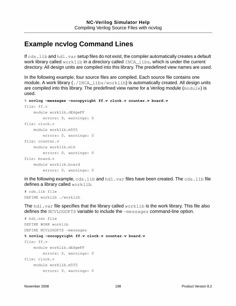
NC-Verilog Simulator HelpCompiling Verilog Source Files with ncvlog
Example ncvlog Command Lines
If cds.lib and hdl.var setup files do not exist, the compiler automatically creates a defaultwork library called worklib in a directory called INCA_libs, which is under the currentdirectory. All design units are compiled into this library. The predefined view names are used.
In the following example, four source files are compiled. Each source file contains onemodule. A work library (./INCA_libs/worklib) is automatically created. All design unitsare compiled into this library. The predefined view name for a Verilog module (module) isused.
% ncvlog -messages -nocopyright ff.v clock.v counter.v board.v
file: ff.v
module worklib.dEdgeFF
errors: 0, warnings: 0
file: clock.v
module worklib.m555
errors: 0, warnings: 0
file: counter.v
module worklib.m16
errors: 0, warnings: 0
file: board.v
module worklib.board
errors: 0, warnings: 0
In the following example, cds.lib and hdl.var files have been created. The cds.lib filedefines a library called worklib.
# cds.lib file
DEFINE worklib ./worklib
The hdl.var file specifies that the library called worklib is the work library. This file alsodefines the NCVLOGOPTS variable to include the -messages command-line option.
# hdl.var file
DEFINE WORK worklib
DEFINE NCVLOGOPTS -messages
% ncvlog -nocopyright ff.v clock.v counter.v board.v
file: ff.v
module worklib.dEdgeFF
errors: 0, warnings: 0
file: clock.v
module worklib.m555
errors: 0, warnings: 0
November 2008 198 Product Version 8.2

NC-Verilog Simulator HelpCompiling Verilog Source Files with ncvlog
file: counter.v
module worklib.m16
errors: 0, warnings: 0
file: board.v
module worklib.board
errors: 0, warnings: 0
In the following example, the cds.lib file defines two libraries: worklib and aludesign.
# cds.lib file
DEFINE worklib ./worklib
DEFINE aludesign ./aludesign
The hdl.var file specifies that the library called worklib is the work library.
# hdl.var file
DEFINE WORK worklib
DEFINE NCVLOGOPTS -messages
The -work option is included on the command line to define the current working library asaludesign. This overrides the definition of the WORK variable in the hdl.var file.
% ncvlog -work aludesign ff.v clock.v counter.v board.v
file: ff.v
module aludesign.dEdgeFF
errors: 0, warnings: 0
file: clock.v
module aludesign.m555
errors: 0, warnings: 0
file: counter.v
module aludesign.m16
errors: 0, warnings: 0
file: board.v
module aludesign.board
errors: 0, warnings: 0
The following example includes the -logfile option to send output to a log file calledboard.log instead of to the default log file ncvlog.log.
% ncvlog -messages -logfile board.log ff.v clock.v counter.v board.v
In the following example, the -ieee1364 option checks for compatibility with the IEEEspecification. Error messages reference the IEEE Language Reference Manual.
% ncvlog -ieee1364 ff.v clock.v counter.v board.v
November 2008 199 Product Version 8.2

NC-Verilog Simulator HelpCompiling Verilog Source Files with ncvlog
In the following example, -errormax 10 tells the compiler to abort after 10 errors. The-noline option suppresses the reporting of source lines when errors are encountered.Using this option can improve performance when compiling very large source files thatcontain errors.
% ncvlog -errormax 10 -noline ff.v clock.v counter.v board.v
The following example includes the -incdir option to specify a directory to search forinclude files.
% ncvlog -incdir ~larrybird/bigdesign ff.v clock.v counter.v board.v
The following example uses the -file option to include a file called ncvlog.args, whichincludes a set of command-line options, such as -messages, -nocopyright, -errormax,and -incdir. The file ncvlog.args also includes the names of the source files.
% ncvlog -file ncvlog.args
The following example illustrates how to use -nowarn to suppress the printing of a specificwarning message.
% ncvlog -nocopyright *.v
ncvlog: *W,HVLOGF: the -LOGFILE option can not be specified in an hdl.var file.
file: board.v
module worklib.board
errors: 0, warnings: 0
file: clock.v
module worklib.m555
errors: 0, warnings: 0
...
...
Total errors/warnings found outside modules and primitives:
errors: 0, warnings: 1
% ncvlog -nocopyright -nowarn hvlogf *.v
file: board.v
module worklib.board
errors: 0, warnings: 0
file: clock.v
module worklib.m555
errors: 0, warnings: 0
...
...
Total errors/warnings found outside modules and primitives:
errors: 0, warnings: 1
November 2008 200 Product Version 8.2

NC-Verilog Simulator HelpCompiling Verilog Source Files with ncvlog
The following example includes the -linedebug option, which disables the optimizationsthat prevent line debug capabilities.
% ncvlog -linedebug 2bit_adder.v
November 2008 201 Product Version 8.2

NC-Verilog Simulator HelpCompiling Verilog Source Files with ncvlog
hdl.var Variables
The following hdl.var variables are used by ncvlog.
Note: See “The hdl.var File” on page 142 for information about the hdl.var file.
■ LIB_MAP
This variable maps files and directories to the names of libraries where you want themto be compiled. Use the plus sign ( + ) to create a default for files or directories that arenot explicitly specified.
Example:
DEFINE LIB_MAP ( \
./design/lib1/... => lib1, \
./source => lib2, \
top.v => lib3, \
+ => worklib )
In this example:
❑ All files in ./design/lib1 and in directories below ./design/lib1 are mappedto library lib1.
❑ All files in the ./source directory are mapped to library lib2.
❑ The file top.v is mapped to library lib3.
❑ Everything else is mapped to library worklib.
■ NCUSE5X
This variable generates the packed library database file, but also creates the fullCadence 5.x library system, in which the intermediate objects for each design unit arestored in their own subdirectories under the work library. It also creates three other filesfor each design unit: master.tag, verilog.v, and pc.db.
The full 5.x library structure and the additional files make it possible for tools that do notunderstand the default packed library structure to access the intermediate objects thatare required by the tool. For example, you must compile the source files with this variabledefined (or by using the -use5x option on the ncvlog command line) if you want to usea 5.x configuration file to control the binding of instances during elaboration.
■ NCVLOGOPTS
This variable lets you specify ncvlog command-line options. For example:
DEFINE NCVLOGOPTS -messages -errormax 10
November 2008 202 Product Version 8.2

NC-Verilog Simulator HelpCompiling Verilog Source Files with ncvlog
The command-line options that you specify with the NCVLOGOPTS variable are appendedto the ncvlog command. For example, if you have defined the NCVLOGOPTS variable asshown above, and then enter the following command:
% ncvlog -update source.v
the actual command line is as follows:
% ncvlog -update source.v -messages -errormax 10
If an option is specified in the hdl.var file and is also included on the command line,the option specified in the hdl.var file overrides the option entered directly on thecommand line because the last option on the command line is used. For example,suppose that the hdl.var file includes the following:
DEFINE NCVLOGOPTS -errormax 10
You then enter the following ncvlog command:
% ncvlog -errormax 5 source.v
The -errormax 10 option in the hdl.var file is appended to this command line, andthis overrides the -errormax 5 option.
% ncvlog -errormax 5 source.v -errormax 10
Note: Not all ncvlog command-line options can be included in the definition of theNCVLOGOPTS variable. The description of the option in this chapter notes any suchrestrictions.
■ SRC_ROOT
This variable lets you define an ordered list of paths to search for source files when youare updating a design, either by running ncsim -update or by rerunning irun. Thepaths listed in the definition of this variable tell the NC tools where to look for source filesif design units are out-of-date.
Note: The paths listed in the SRC_ROOT variable do not tell the parser where to find thesource files that you specify on the command line. This variable is used to help the NCtools to find source files after initial compilation. You must define the SRC_ROOT variablebefore the initial compilation.
Example:
Suppose that your project has a centralized release area for source files named/project/source, and that you have a local “check out” area called~johndoe/source. In your hdl.var file, you can define the SRC_ROOT variable asfollows:
DEFINE SRC_ROOT (~johndoe/source, /project/source)
This definition of SRC_ROOT tells the tools to look first in ~johndoe/source for thesource files that contain the out-of-date units when you update the design.
November 2008 203 Product Version 8.2

NC-Verilog Simulator HelpCompiling Verilog Source Files with ncvlog
For example, suppose that the /project/source area contains a source file calledsourcefile.v. While simulating in your own local area, ~johndoe/source, younotice a bug in /project/source/sourcefile.v. Using your CM system, you checkout sourcefile.v. This copies the file into ~johndoe/source. You then editsourcefile.v. You now have to update the snapshot because of this change.
When you update the design with ncsim -update or rerun irun, the program detectsthat some design units are out-of-date. The definition of SRC_ROOT tells the tools to lookfirst in ~johndoe/source for the source files that contain the out-of-date units. In thisexample, the simulator uses sourcefile.v in ~johndoe/source to recompile theout-of-date design units. When you are satisfied with the simulation results, you cancheck the source file back into the central release area.
Given the same definition of the SRC_ROOT variable shown above, any subsequentupdate that you do that includes sourcefile.v (for example, another designer mayhave edited the file) will use the sourcefile.v in your local area. Delete or rename thefile in your local area after checking it back in to the central release area.
■ VERILOG_SUFFIX
This variable specifies valid file extensions for Verilog source files. ncvlog treats eachcommand-line argument that is not an option or a parameter to an option as a filename.It first tries to open the file as specified. If this fails, each file extension specified with theVERILOG_SUFFIX variable is appended to the name, and ncvlog tries to open the file.If no match is found, ncvlog tries the list of possible suffixes in the hdl.var variableVIEW_MAP. If all suffixes are exhausted, an error is generated.
You can specify a single value or a list of values. For example:
DEFINE VERILOG_SUFFIX .vlog
DEFINE VERILOG_SUFFIX (.vlog, .vsyn, .vrtl, .vgate)
■ VIEW
This variable determines the view name. If you invoke ncvlog without the-view option, the parser searches for this variable. If the -view option is set, ncvloguses the value as the view name.
DEFINE VIEW rtl
■ WORK
This variable defines the work library into which the HDL design units are compiled.
DEFINE WORK worklib
November 2008 204 Product Version 8.2

NC-Verilog Simulator HelpCompiling Verilog Source Files with ncvlog
■ VIEW_MAP
This variable maps file extensions to view names.
In the following example, files with a .rtl extension are given a view name of rtl.
DEFINE VIEW_MAP ( .v => behav, \
.rtl => rtl, \
.gate => gate \
.vs => module )
November 2008 205 Product Version 8.2

NC-Verilog Simulator HelpCompiling Verilog Source Files with ncvlog
Compiling Source Files by Specifying the Top-Level of theDesign
This section describes a way to compile a design by specifying the top-level of the designwhen you invoke the compiler instead of specifying all source files on the command line.
The top-level is specified in a file called a compilation command file, which is passed asan argument to the ncparse -cmdfile option. The compilation command file also specifiesthe path to a file that contains the rules that describe the mapping of design unit names tosource file names, and the list of directories to be searched for locating the design files.
You can use design-top compilation for compiling a Verilog, VHDL, or mixed Verilog-VHDLdesign.
To compile your design files using design-top compilation, you must:
1. Write a compilation command file.
A compilation command file is required. The path to this file must be specified as theargument to the -cmdfile option.
See “Writing a Compilation Command File” on page 207.
2. Write a naming rules file.
The naming rules file contains the naming rules that describe how design unit namesmap to the names of the source files containing their definitions.
See “Writing a Naming Rules File” on page 209.
If a rules file is not used, a default set of naming rules is used. The default naming rulesare shown in “Default Naming Rules” on page 215.
3. Specify the library/libraries into which you want to compile the design units.
You can specify the library mapping by using the -work command-line option, bydefining the WORK variable in the hdl.var file, or by defining the LIB_MAP variable inthe hdl.var file.
See “Specifying the Library Mapping” on page 215.
4. Use the -cmdfile compilation_command_file option.
This ncparse command-line option specifies that design-top based compilation is to beused, and the argument provides the path to the compilation command file. The syntaxis:
% ncparse -cmdfile compilation_command_file [other_ncparse_options]
November 2008 206 Product Version 8.2

NC-Verilog Simulator HelpCompiling Verilog Source Files with ncvlog
See “ncparse” on page 1438 for details on the ncparse utility.
Note: Using the -cmdfile option specifies that design-top compilation is to be used. Youcannot specify design file names on the command line. If you use the -cmdfile option andalso include design file names on the command line, the parser uses the compilationcommand file.
For a pure Verilog design, you can compile files using design-top compilation by using the-cmdfile option on the ncvlog command line. For a pure VHDL design, you can use the-cmdfile option on the ncvhdl command line.
% ncvlog -cmdfile compilation_command_file [other_options] ....
% ncvhdl -cmdfile compilation_command_file [other_options] ....
Writing a Compilation Command File
A compilation command file contains the following definitions:
■ The design top
You specify the design top by defining the DESIGN_TOP variable. The definition can beone of the following:
❑ For VHDL:
❍ The top-level entity:architecture pair
DEFINE DESIGN_TOP (top:arch)
❍ The top-level entity
DEFINE DESIGN_TOP (top:)
❍ A configuration
DEFINE DESIGN_TOP (conf1)
❍ The name of the design file that contains the top-level design unit
DEFINE DESIGN_TOP (design.vhd)
❑ For Verilog:
❍ The name of the top-level module for the design
DEFINE DESIGN_TOP topmodule
❍ The name of the design file that contains the top-level design unit
DEFINE DESIGN_TOP (design.v)
Note: You can use the -design_top option on the ncparse command line to specifythe design top. The argument to the -design_top option overrides the definition of the
November 2008 207 Product Version 8.2

NC-Verilog Simulator HelpCompiling Verilog Source Files with ncvlog
DESIGN_TOP variable in the compilation command file.
■ The path to a naming rules file
By default, the parser uses a set of default naming rules to describe how design unitnames map to the names of the source files containing their definitions. The defaultnaming rules are shown in “Default Naming Rules” on page 215.
You can write your own naming rules file to describe your naming conventions. See“Writing a Naming Rules File” on page 209 for details on writing a naming rules file.
If you use a naming rules file, you must specify the path to the naming rules file bydefining the RULES_FILE variable in the compilation command file.
DEFINE RULES_FILE (rules_file_path)
The rules file path can be absolute or relative.
■ The list of directories to be searched for locating the design files
You specify the directories to search for design files by defining the SEARCH_PATHvariable. The syntax is as follows:
DEFINE SEARCH_PATH ( directory_path[, directory_path ...] )
The paths can be absolute paths or relative paths. Environment variables can be usedin the paths.
The parser searches each directory in the list, in the order that they appear, for the filename until a match is found. The search stops as soon as a match is found. If a path isnot found, or if a path does not have executable rights, the path is skipped with a warningmessage.
Example:
DEFINE SEARCH_PATH ( /usr/user1/project/dir1, \
/usr/user1/project/dir2, \
/usr/user1/project/dir3 )
■ The REDUMP_ON_UPDATE variable
This value of this variable (ON or OFF) controls whether a source file whose contents havenot changed is recompiled when updating with the ncupdate utility or an ncvlog-update, ncvhdl -update, ncelab -update, or ncsim -update command.
The default value of the REDUMP_ON_UPDATE variable is ON.
See “Updating the Design” on page 215 for more information.
November 2008 208 Product Version 8.2

NC-Verilog Simulator HelpCompiling Verilog Source Files with ncvlog
■ The VLOG_ARGS and VHDL_ARGS variables
These variables define the command-line options for the ncvlog and ncvhdl parsers.For example:
DEFINE VLOG_ARGS (-messages -ieee1364)
DEFINE VHDL_ARGS (-messages -v93)
You cannot include parser options on the ncparse command line.
Example Compilation Command File
The following is an example compilation command file.
DEFINE DESIGN_TOP conftop
DEFINE SEARCH_PATH (./src1, ./src2, ./src3, ./top)
DEFINE RULES_FILE (./rules/name_rules.rules)
DEFINE REDUMP_ON_UPDATE (off)
DEFINE VLOG_ARGS (-messages -ieee1364)
DEFINE VHDL_ARGS (-messages -v93)
Writing a Naming Rules File
A naming rules file contains the naming rules that describe how design unit names map tothe names of the source files containing their definitions. You can specify one or more namingrules for each design unit type.
The format for a name rule is:
(DESIGN_UNIT_TYPE (NAMING_RULE) [(NAMING_RULE) ...])
DESIGN_UNIT_TYPE is one of the following:
■ ENTITY
■ ARCH
■ PACKAGE
■ PACKAGEBODY
■ CONFIG
■ MODULE
■ UDP
November 2008 209 Product Version 8.2

NC-Verilog Simulator HelpCompiling Verilog Source Files with ncvlog
A NAMING_RULE takes the following form:
([str]<DESIGN_UNIT_VARIABLE>[str])
where [str] can be any string that acts as prefix or suffix, and<DESIGN_UNIT_VARIABLE> is the name of the current design unit. The<DESIGN_UNIT_VARIABLE> can be:
■ <ENTITY>
This variable can be used in naming rules for design unit types ENTITY, ARCH, andCONFIG.
■ <ARCH>
This variable can be used in naming rules for design unit type ARCH.
■ <PACKAGE>
This variable can be used in naming rules for design unit type PACKAGE andPACKAGEBODY.
■ <CONFIG>
This variable can be used in naming rules for design unit type CONFIG.
■ <MODULE>
This variable can be used in naming rules for design unit type MODULE.
■ <UDP>
This variable can be used in naming rules for design unit type MODULE and UDP.
The following is an example naming rules file:
(ENTITY (e_<ENTITY>))
(ARCH (A_<ENTITY>_<ARCH>) (a_<ARCH>))
(PACKAGE (p_<PACKAGE>)
(PACKAGEBODY (p_<PACKAGE>_body)(<PACKAGE>body))
(CONFIG (c_<CONFIG>))
(MODULE (m_<MODULE>))
(UDP (u_<UDP>))
The following table shows example naming rules for each design unit type.
Note: In the examples shown in the following table, it is assumed that all source file namesare in lowercase, and that the file extension for all source files is .v for Verilog and .vhd forVHDL. See “Source File Names and File Extensions” on page 214 for more information.
November 2008 210 Product Version 8.2

NC-Verilog Simulator HelpCompiling Verilog Source Files with ncvlog
Design Unit Type Examples
ENTITY
Note: Naming rule for design unit typeENTITY can take only variable<ENTITY>.
An entity called foo is in file foo.vhd.
(ENTITY (<ENTITY>))
Entity foo is in file e_foo.vhd.
(ENTITY (e_<ENTITY>))
Entity foo is in file e_foo_ver1.vhd.
(ENTITY(e_<ENTITY>_ver1))
Entity foo is in file foo.entity.vhd.
(ENTITY(<ENTITY>.entity))
ARCH
Note: Naming rule for design unit typeARCH can take variables <ENTITY>and/or <ARCH>.
An architecture called rtl is in file a_rtl.vhd.
(ARCH(a_<ARCH>))
Architecture rtl of entity foo is in filea_foo.vhd.
(ARCH(a_<ENTITY>))
Architecture rtl of entity foo is in filee_foo_rtl_arch.vhd.
(ARCH(e_<ENTITY>_<ARCH>_arch))
Architecture rtl of entity foo is in filertl.foo.arch.vhd.
(ARCH(<ARCH>.<ENTITY>.arch))
Note: If a top-level configuration is not specified,and the rules file contains the following rule:
(ARCH(<ENTITY>.<ARCH>))
the ARCH name (<ARCH>) is not known ahead oftime. ncparse will search for an architecture in afile ENTITY.*. This is a wildcard search, and thewrong files could be selected.
November 2008 211 Product Version 8.2

NC-Verilog Simulator HelpCompiling Verilog Source Files with ncvlog
PACKAGE
Note: Naming rule for design unit typePACKAGE can take only variable<PACKAGE>.
A package called pack is in file pack.vhd.
(PACKAGE(<PACKAGE>))
Package pack is in file p_pack.vhd.
(PACKAGE(p_<PACKAGE>))
PACKAGEBODY
Note: Naming rule for design unit typePACKAGEBODY can take only variable<PACKAGE>.
A package body for a package called pack is in filep_pack_body.vhd.
(PACKAGEBODY(p_<PACKAGE>_body))
Package body is in file pack.body.vhd.
(PACKAGEBODY(<PACKAGE>.body))
CONFIG
Note: Naming rule for design unit typeCONFIG can take variables <CONFIG>and/or <ENTITY>.
A configuration called conftop of entity top is infile conftop.vhd.
(CONFIG(<CONFIG>))
Configuration conftop of entity top is in filec_conftop_top.vhd.
(CONFIG(c_<CONFIG>_<ENTITY>))
MODULE
Note: Naming rule for design unit typeMODULE can take variables <MODULE>and/or <UDP>.
A module called foo is in file foo.v.
(MODULE (<MODULE>))
Module foo is in file m_foo.v.
(MODULE (m_<MODULE>))
Module foo is in m_foo_ver1.v.
(MODULE(m_<MODULE>_ver1))
Design Unit Type Examples
November 2008 212 Product Version 8.2

NC-Verilog Simulator HelpCompiling Verilog Source Files with ncvlog
Multiple rules are allowed for a design unit type. For example:
(CONFIG(<CONFIG>)(c_<CONFIG>_<ENTITY>))
(MODULE (<MODULE>) (m_<MODULE>))
Note: For VHDL secondary units (architecture and package body), the parser first checks tosee if the unit is defined in the source file that defines the corresponding primary unit (entityor package) before proceeding to search according to the naming rules. For example,suppose that source files contain the following design units:
When determining the source file for architecture ha_beh_a, the parser first checks if thissecondary design unit is defined in the same file as the corresponding entity (ha_beh).Because it is, the parser associates the filename e_ha_beh.vhd with both design units.However, after determining that architecture fa_beh_a is not described in the same file asthe corresponding entity (fa_beh), the parser must use a naming rule to determine thesource file name. Therefore, in this example, the following two naming rules would berequired:
(ENTITY(e_<ENTITY>))
(ARCH(a_<ENTITY>))
UDP
Note: Naming rule for design unit typeUDP can take only variable <UDP>.
A UDP called latch is in file latch.v.
(UDP(<UDP>))
UDP latch is in file u_latch.v.
(UDP(u_<UDP>))
UDP latch is in file latch_udp.v.
(UDP(<UDP>_udp))
UDP latch is in file u_latch_ver1.v.
(UDP(u_<UDP>_ver1))
Source File Contains ...
e_fa_beh.vhd entity fa_beh
a_fa_beh.vhd architecture fa_beh_a of entity fa_beh
e_ha_beh.vhd entity ha_beh
architecture ha_beh_a of entity ha_beh
Design Unit Type Examples
November 2008 213 Product Version 8.2

NC-Verilog Simulator HelpCompiling Verilog Source Files with ncvlog
Source File Names and File Extensions
All source filenames in the design are assumed to be lowercase, except for cases where anescaped name has been used for the design unit. For example, if the design contains twoentities called ent1 and ENT2, and the naming rule for entities is:
(ENTITY (e_<ENTITY>))
the parser searches for source files called e_ent1.vhd and e_ent2.vhd.
However, for an entity called \Ent3\, the parser performs a case-sensitive search for asource file called e_Ent3.vhd.
For Verilog, the parser recognizes source files with a .v extension by default. If other fileextensions are used, you must define the VERILOG_SUFFIX variable in the hdl.var file. Forexample:
DEFINE VERILOG_SUFFIX (.v, .vlog, .vext)
For VHDL, the parser recognizes source files with .vhd and .vhdl file extensions by default.If other file extensions are used, you must define the VHDL_SUFFIX variable in the hdl.varfile. For example:
DEFINE VHDL_SUFFIX (.vhd, .vhdl, .vhext)
The ncvlog and ncvhdl parsers use the list of file extension specified with theVERILOG_SUFFIX and VHDL_SUFFIX variable to determine the file extension to beappended to the filename. For example, using the VERILOG_SUFFIX definition shown above,if you have a module called fa_beh, and the following naming rule
(MODULE(m_<MODULE>))
the parser will search for a file in the following order: m_fa_beh.v, m_fa_beh.vlog,m_fa_beh.vext.
Note: For VHDL, you can specify the name of the design file that contains the top-leveldesign unit when you define the DESIGN_TOP variable in the compilation command file. Theextension of this file has the highest priority. If a file is not found, the parser then looks for afile using the extensions specified with VHDL_SUFFIX. For example, if the design top wasspecified as:
DEFINE DESIGN_TOP (entity1.vhext)
and the VHDL_SUFFIX variable was defined as:
DEFINE VHDL_SUFFIX (.vhdl, .vhd)
then the file for a design unit ent1dep will be searched in the following order:
November 2008 214 Product Version 8.2

NC-Verilog Simulator HelpCompiling Verilog Source Files with ncvlog
ent1dep.vhext
ent1dep.vhdl
ent1dep.vhd
Default Naming Rules
If a naming rule for a particular design unit type is not specified, the default rule(s) shownbelow for that design unit type is used. If the path to a naming rules file is not specified in thecompilation command file, all defaults apply.
(ENTITY(<ENTITY>)(<ENTITY>.entity))
(ARCH(<ENTITY>.<ARCH>))
(PACKAGE(<PACKAGE>)(<PACKAGE>.pkg))
(PACKAGEBODY(<PACKAGE>.body))
(CONFIG(<CONFIG>))
(MODULE (<MODULE>))
(UDP (<UDP>))
Specifying the Library Mapping
There are several ways to specify which library, or libraries, design units should be compiledinto. When compiling files using design top compilation, it is recommended that you explicitlydefine the library mapping by defining the LIB_MAP variable in the hdl.var file. Forexample:
DEFINE LIB_MAP ( ./src/vhdl/design/ => designlib, \
/hm/xyz/abc/fpfile.vhd => lib1, \
/root/designs/main/src/verilog/... => lib2, \
/root/designs/main/src/vhdl/... => lib3, \
myfile.v => mylib \
+ => commonlib )
See “The LIB_MAP and VIEW_MAP Variables” on page 223 for details.
Updating the Design
When updating the design with the ncupdate utility or with the ncvlog -update, ncvhdl-update, ncelab -update, or ncsim -update command, you must include the-cmdfile option on the command line to specify the compilation command file if the locationof a source file has changed. This is required to pass the search path (defined with theSEARCH_PATH variable) to the parser because the location of design files may have changed.
November 2008 215 Product Version 8.2

NC-Verilog Simulator HelpCompiling Verilog Source Files with ncvlog
Note: ncupdate requires only the search path to be present in the command file. Otherspecifications in the file are ignored.
% ncvlog -update -cmdfile cmdfile.cmd
% ncvhdl -update -cmdfile cmdfile.cmd
% ncelab -update -cmdfile cmdfile.cmd top_level_unit
% ncupdate -cmdfile cmdfile.cmd snapshot_name
Note: When updating the design, you can also use the -cmdfile option if the source fileswere originally compiled by specifying a list of source files on the command line, and if thelocation of a source file has subsequently changed. The parser will use the search pathsspecified with the SEARCH_PATH variable to locate the file whose location has changed.
You can define the REDUMP_ON_UPDATE variable in the compilation command file to controlwhether or not a file is recompiled if the content of the file has not changed. This variable canhave the following value:
■ DEFINE REDUMP_ON_UPDATE ON
Recompile the file if the content has not changed. This is the default.
■ DEFINE REDUMP_ON_UPDATE OFF
Do not recompile the file unless the content has changed.
The following table summarizes the update functionality.
File... Action
Is in original location If contents have changed, recompile.
If contents have not changed, recompile ifREDUMP_ON_UPDATE ON, but do not recompile ifREDUMP_ON_UPDATE OFF.
Has been copied higher up in thesearch path order (and also existsat the old location)
If contents have changed, recompile from higherlocation.
If contents have not changed, recompile ifREDUMP_ON_UPDATE ON, but do not recompile ifREDUMP_ON_UPDATE OFF.
November 2008 216 Product Version 8.2

NC-Verilog Simulator HelpCompiling Verilog Source Files with ncvlog
Has been copied lower down inthe search path order (and alsoexists at the old location)
New path ignored, and the file from the old path isused.
If contents have changed, recompile.
If contents have not changed, recompile ifREDUMP_ON_UPDATE ON, but do not recompile ifREDUMP_ON_UPDATE OFF.
Has been moved higher up orlower down in the search pathorder (file does not exist at the oldlocation)
Recompile from new location.
File... Action
November 2008 217 Product Version 8.2

NC-Verilog Simulator HelpCompiling Verilog Source Files with ncvlog
Conditionally Compiling Source Code
Use the conditional compilation compiler directives (`ifdef, `else, and `endif) toconditionally include lines of a Verilog HDL source description during compilation. The`ifdef compiler directive checks whether a variable name is defined either in the sourcecode or on the command line. If the variable name is defined, the compiler includes the linesin the source description.
There are two ways to define `ifdef variables:
■ Use the `define compiler directive. For example:
`define debug
See the Verilog Language Reference Manuals for details on this compiler directive.
■ Use the -define command-line option.
To control conditional compilation, define a variable name as an empty text macro. Thesyntax is:
-define text_macro_name
For example,
-define debug
-define sun3
You can have multiple -define arguments on a command line. For example:
-define sun4 -define structural
If you define the same macro name differently using a `define compiler directive and a-define command-line option, the command-line option overrides the compiler directive.
The compiler does not check the syntax for any ignored group of lines. However, even thoughncvlog does not check the syntax of this text, it must conform to the lexical conventions forwhite space, comments, numbers, strings, identifiers, keywords, and operators.
The following example shows you how to define a macro on the command line with the-define option. The source code is as follows:
module test;
initial
begin
`ifdef debug // If debug is defined, execute the following line.
$display(“debug is defined.”);
`else // If debug is not defined, execute the following line.
$display(“debug is not defined.”);
`endif
November 2008 218 Product Version 8.2

NC-Verilog Simulator HelpCompiling Verilog Source Files with ncvlog
end
endmodule
Multi-Step Invocation Mode% ncvlog -nocopyright test.v ;# Compile with ncvlog. Macro debug is not
;# defined in the model or on the command line.
% ncelab -nocopyright worklib.test ;# Elaborate with ncelab.
% ncsim -nocopyright test ;# Invoke the simulator.
ncsim> run ;# Model displays “debug is not defined.”
debug is not defined
ncsim: *W,RNQUIE: Simulation is complete.
ncsim> exit
% ncvlog -nocopyright -define debug test.v ;# Compile with ncvlog.;# Macro debug is defined on the command line.
% ncelab -nocopyright worklib.test
% ncsim -nocopyright test
ncsim> run ;# Run the simulation. Model displays “debug is defined.”
debug is defined
ncsim: *W,RNQUIE: Simulation is complete.
ncsim> exit
Single-Step Invocation Mode
% irun -nocopyright -q -define debug test.v ;# Macro debug is defined on the;# command line.
Top level design units:
test
ncsim> run
debug is defined.
ncsim: *W,RNQUIE: Simulation is complete.
ncsim> exit
%
Built-In Conditional Compilation Text Macros
There are two conditional compilation text macros that, if used in your source HDL, are alwaysdefined. The text macros are:
■ INCA
The NC Verilog parser (ncvlog) will parse any code enclosed within `ifdef INCA and`endif, and the code will run in the simulator.
November 2008 219 Product Version 8.2

NC-Verilog Simulator HelpCompiling Verilog Source Files with ncvlog
■ CDS_TOOL_DEFINE
The NC Verilog parser (ncvlog) will parse any code enclosed within `ifdefCDS_TOOL_DEFINE and `endif, and the code will run in any Cadence tool that usesthe NC Verilog parser.
Note: Some Cadence tools may not have implemented this text macro yet.
For example:
module test();
...
...
‘ifdef CDS_TOOL_DEFINE
// This code will be used by all Cadence tools that use the// NC Verilog parser, and ignored by all other tools.// It is not necessary to use -define CDS_TOOL_DEFINE on the command line.
...
...
‘endif
// Other HDL code
...
...
endmodule
November 2008 220 Product Version 8.2

NC-Verilog Simulator HelpCompiling Verilog Source Files with ncvlog
Controlling the Compilation of Design Units intoLibrary.Cell:View
When you run the ncvlog compiler, your Verilog HDL design units (modules, macromodules,and UDPs) are compiled into a Library.Cell:View. For example, a Verilog module calledcounter might be compiled into:
worklib.counter:module
■ Library (worklib in the example above) is the logical name of the library into whichthe design unit is compiled. This library is called the work library. You can:
❑ Invoke the compiler and let the tool compile the design units into a default worklibrary that it creates automatically. This convenient feature lets you start using thesimulator quickly without having to create any setup files.
❑ Explicitly specify the work library. In this case, you must define all libraries in acds.lib file. This file maps logical library names to physical library locations. Thenyou specify which library is the work library by defining variables in an hdl.var file,by using command-line options, or by using the `worklib compiler directive.
■ Cell is the name of the design unit. For Verilog, a design unit can be a module,macromodule, or UDP, and the Cell is always set to the name of the design unit.
■ View is the name associated with a version of a cell. Views can be used to delineatebetween representations (schematic, VHDL, Verilog), abstraction levels (behavior, RTL,post-synthesis), status (experimental, released, golden), and so on. For example, youmight have one view that is the RTL representation of a particular unit, and another viewthat is the behavioral representation, or you might have two different versions of a cell,one with timing and one without timing.
You can:
❑ Let the compiler compile the design units using predefined default view names.
For Verilog, the predefined view names are module (for a module or macromodule)and udp (for a UDP).
❑ Explicitly specify the view name by defining variables in an hdl.var file, by usingcommand-line options, or by using the `view compiler directive.
This section begins by describing the default behavior where no setup files (cds.lib orhdl.var) have been created. See “Compiling without Setup Files” on page 222.
The subsequent sections describe how you can create a cds.lib file and then use variablesdefined in an hdl.var file, command-line options, or compiler directives to control where the
November 2008 221 Product Version 8.2

NC-Verilog Simulator HelpCompiling Verilog Source Files with ncvlog
compiler stores compiled objects and the view names that are assigned to them. The orderof precedence (from lowest to highest) is as follows:
■ The definitions of the LIB_MAP and VIEW_MAP variables in the hdl.var file. See “TheLIB_MAP and VIEW_MAP Variables” on page 223.
■ The -libmap command-line option. See “The -libmap Command-Line Option” onpage 225.
■ The definitions of the WORK and VIEW variables in the hdl.var file. See “The WORKand VIEW Variables” on page 227.
■ The -work or -view command-line options. See “The -work and -view Command-LineOptions” on page 228.
■ The -specificunit command-line option with a library and/or view specification. See“The -specificunit Command-Line Option” on page 229.
■ The `worklib and `view compiler directives. See “The `worklib and `view CompilerDirectives” on page 230.
See “Mapping of Modules Defined within `include Files” on page 232 for information on thelibrary and view mapping of modules defined within `include files.
In a cds.lib file, multiple library logical names can be mapped to the same physicallocation. In these cases, design units are compiled into the library into which the first unit iscompiled. See “cds.lib Files that Map Multiple Logical Names to the Same Physical Directory”on page 234 for an example.
Compiling without Setup Files
No environment setup files are required to run the simulator. You can simply invoke thecompiler to compile your Verilog source files, and the compiler will automatically create adefault work library. All design units are compiled into this library.
The work library is called worklib. This library is in a directory called INCA_libs, which isunder the current directory. In other words, if you have not created cds.lib or hdl.varfiles, all design units will be compiled intocurrent_working_directory/INCA_libs/worklib. For an example, see the firstexample in “Example ncvlog Command Lines” on page 198.
Invoking the compiler and letting the tool compile the design units into a default work librarythat it creates automatically is a convenient feature that lets you start using the simulatorquickly. However, this method does not provide you with any control over the work library and
November 2008 222 Product Version 8.2

NC-Verilog Simulator HelpCompiling Verilog Source Files with ncvlog
where it is located. If you want more control over the libraries into which design units arecompiled, you must:
■ Create a cds.lib file. This file contains statements that define your libraries and thatmap logical library names to physical directory paths. See “The cds.lib File” on page 133for details on the cds.lib file.
■ Specify which library is the work library. You can do this by defining variables in anhdl.var file, by using command-line options, or by using compiler directives. Thefollowing sections describe these variables, options and directives.
The LIB_MAP and VIEW_MAP Variables
The hdl.var file is the first place that the compiler searches to find information on whichlibrary to compile source files into and what view names to use. It first looks for definitions ofthe LIB_MAP and VIEW_MAP variables.
LIB_MAP maps files and directories to library names. There are four mapping types that youcan specify:
DEFINE LIB_MAP ( directory => library, \
directory/... => library, \
file => library, \
+ => library )
Use the plus sign (+) to specify files or directories that are not explicitly stated.
For example, a LIB_MAP definition of:
DEFINE LIB_MAP ( ./design => designlib, \
./source/lib1/... => lib1, \
myfile.v => mylib, \
+ => worklib )
causes:
■ Any file in the directory ./design to be compiled into designlib.
■ All files and directories below ./source/lib1 to be compiled into lib1.
■ The file myfile.v to be compiled into mylib.
■ Any other file to be compiled into worklib.
November 2008 223 Product Version 8.2

NC-Verilog Simulator HelpCompiling Verilog Source Files with ncvlog
VIEW_MAP maps file extensions to view names. The syntax is:
DEFINE VIEW_MAP (file_extension => view_name, ...)
Use the plus sign (+) to specify a default view mapping.
For example, a VIEW_MAP definition of:
DEFINE VIEW_MAP (.v => behav, .r => rtl, .g => gate, + => module)
causes files with a .v file extension to create views with the name behav, files with a .r fileextension to create views with the name rtl, and files with a .g file extension to create viewswith the name gate. Any other file extensions map to a view called module.
The LIB_MAP and VIEW_MAP variables are also used by the elaborator to resolve instances.See “How Modules and UDPs Are Resolved during Elaboration” on page 345 for moreinformation.
Example:
In the following example, the LIB_MAP and VIEW_MAP variables are defined in the hdl.varfile to determine which library the design units are compiled into and which view names theyare given. All libraries referred to in the hdl.var file are defined in the cds.lib file.
The hdl.var file for this example is as follows:
DEFINE NCVLOGOPTS -messages
DEFINE NCELABOPTS -messages
DEFINE NCSIMOPTS -messages
DEFINE LIB_MAP (/hm/belanger/inca/board => designlib, \+ => worklib)
DEFINE VIEW_MAP (.v => behav, \.rtl => rtl, \.gate => gate, \+ => module)
The definition of the LIB_MAP variable specifies that source files in the board/ directory willbe compiled into the library called designlib. All other source files are to be compiled intoworklib.
The definition of the VIEW_MAP variable specifies that files with a .v extension will get a viewname of behav. Files with a .rtl extension will get a view name of rtl.
All source files are in the /board directory.
November 2008 224 Product Version 8.2

NC-Verilog Simulator HelpCompiling Verilog Source Files with ncvlog
;# Compile all .v source files.;# Modules are compiled into designlib.module_name:behav. For example, module board;# is compiled into designlib.board:behav.
% ncvlog -nocopyright *.v
file: board.v
module designlib.board:behav
errors: 0, warnings: 0
file: clock.v
module designlib.m555:behav
errors: 0, warnings: 0
file: ff.v
module designlib.dEdgeFF:behav
errors: 0, warnings: 0
;# Compile all .rtl source files. Modules are compiled into;# designlib.module_name:rtl.
% ncvlog -nocopyright *.rtl
file: counter.rtl
module designlib.m16:rtl
errors: 0, warnings: 0
The -libmap Command-Line Option
The -libmap command-line option specifies a library map file, which can contain:
■ Library declarations
A library declaration associates a logical library name with a source file or set of sourcefiles. The design units in specified source files are compiled into the associated library.For example:
library rtlLib *.v;
library gateLib *.vg;
All libraries in a library mapping file must be declared in the cds.lib file.
■ References to other library map files
An include statement can be used to include the contents of a library map file inanother library map file.
■ Configuration declarations
These declarations (in config - endconfig blocks) are an explicit set of rules tospecify the exact source description to be used to represent each instance in a design.Configuration blocks control the binding of instances during elaboration.
November 2008 225 Product Version 8.2

NC-Verilog Simulator HelpCompiling Verilog Source Files with ncvlog
The ncvlog -libmap option can be used to specify a library map file that contains librarydeclarations.
Example:
In the following example, a library map file called lib.map contains the following librarydeclarations and a configuration block:
library rtlLib “top.v”;
library aLib “adder.v”;
library gateLib “adder.vg”;
config cfg;
design rtlLib.top;
default liblist aLib rtlLib;
endconfig
When you compile the source files with the -libmap option, the library declarations areparsed and analyzed, and the declarations are used to determine the compilation of designunits into libraries. Configurations specified in the file, if any, are checked for syntax only.
In this example:
■ Design units in file top.v are compiled into the library called rtlLib.
■ Design units in file adder.v are compiled into the library called aLib.
■ Design units in file adder.vg are compiled into the library called gateLib.
% ncvlog -nocopyright -messages -libmap lib.map top.v adder.v adder.vg
file: top.v
module rtlLib.top
errors: 0, warnings: 0
module rtlLib.foo
errors: 0, warnings: 0
file: adder.v
module aLib.adder
errors: 0, warnings: 0
module aLib.foo
errors: 0, warnings: 0
file: adder.vg
module gateLib.adder
errors: 0, warnings: 0
module gateLib.foo
errors: 0, warnings: 0
November 2008 226 Product Version 8.2

NC-Verilog Simulator HelpCompiling Verilog Source Files with ncvlog
The WORK and VIEW Variables
If the compiler does not find definitions of the LIB_MAP and VIEW_MAP variables, it looks fordefinitions of the WORK and VIEW variables.
The WORK variable defines the work library. All design units are compiled into the specifiedlibrary. For example, if you have the following definition in your hdl.var file, design units arecompiled into the library called worklib.
DEFINE WORK worklib
The VIEW variable defines the view name. All design units receive the same view name. Forexample, if you have the following definition in your hdl.var file, design units are given aview name of behav.
DEFINE VIEW behav
If both LIB_MAP/VIEW_MAP variables and WORK/VIEW variables are defined, the definition ofWORK overrides LIB_MAP, and the definition of VIEW overrides VIEW_MAP.
Note: If the WORK variable and the LIB_MAP variable are both defined, the definition of theWORK variable overrides the definition of the LIB_MAP variable. This is important to rememberif you are doing a mixed-language simulation, in which you might define the LIB_MAP variableto control where the Verilog design units get compiled and then set the WORK variable todefine the work library for VHDL. In this case, all design units would be compiled into thelibrary specified with the WORK variable. To avoid this, you can either remove the definition ofthe WORK variable and then use the -work command-line option when compiling VHDL, oryou can remove the definition of the LIB_MAP variable and then use the -work option whencompiling Verilog.
Example:
In the following example, the WORK and VIEW variables are defined in the hdl.var file. Thehdl.var file is as follows:
DEFINE NCVLOGOPTS -messages
DEFINE NCELABOPTS -messages
DEFINE NCSIMOPTS -messages
DEFINE WORK worklib
DEFINE VIEW gates
All design units will be compiled into the library called worklib, and all design units will geta view name of gates.
November 2008 227 Product Version 8.2

NC-Verilog Simulator HelpCompiling Verilog Source Files with ncvlog
;# Compile all .vg source files.;# Modules are compiled into worklib. All modules get a view name of gates.
% ncvlog -nocopyright *.vg
file: board.vg
module worklib.board:gates
errors: 0, warnings: 0
file: clock.vg
module worklib.m555:gates
errors: 0, warnings: 0
file: counter.vg
module worklib.m16:gates
errors: 0, warnings: 0
file: ff.vg
module worklib.dEdgeFF:gates
errors: 0, warnings: 0
The -work and -view Command-Line Options
If the compiler does not find definitions of the LIB_MAP and VIEW_MAP variables ordefinitions of the WORK and VIEW variables, it looks for the -work and -view command-lineoptions.
The argument to -work is a library name.
The argument to -view is a view name.
Using the command-line options overrides any variable definitions in the hdl.var file.
Example:
In the following example, the -work and -view command-line options are used to overridethe variable definitions in the hdl.var file. The hdl.var file is as follows:
DEFINE NCVLOGOPTS -messages
DEFINE NCELABOPTS -messages
DEFINE NCSIMOPTS -messages
DEFINE LIB_MAP (/hm/belanger/inca/board => designlib, \+ => worklib)
DEFINE VIEW_MAP (.v => behav, \.rtl => rtl, \+ => module)
November 2008 228 Product Version 8.2

NC-Verilog Simulator HelpCompiling Verilog Source Files with ncvlog
All source files have a .v extension, and are in the board/ directory.
;# Compile all .v source files.;# Use -work to compile the design units into the library called worklib.;# Use -view to specify a view name of gate for all design units.
% ncvlog -nocopyright -work worklib -view gate *.v
file: board.v
module worklib.board:gate
errors: 0, warnings: 0
file: clock.v
module worklib.m555:gate
errors: 0, warnings: 0
file: counter.v
module worklib.m16:gate
errors: 0, warnings: 0
file: ff.v
module worklib.dEdgeFF:gate
errors: 0, warnings: 0
The -specificunit Command-Line Option
If the compiler does not find definitions of the LIB_MAP and VIEW_MAP variables, definitionsof the WORK and VIEW variables, or the -work and -view command-line options, it looks forthe -specificunit command-line option. This option is used to compile one design unitfrom a source file that contains multiple design units, and takes [library.]cell[:view] asan argument.
■ If you include a library name, the design unit is compiled into the specified library.
■ If you include a view, the design unit is given the specified view name.
Example:
The following example uses the -specificunit option to compile one design unit in a filethat contains multiple units. The hdl.var file is as follows:
DEFINE NCVLOGOPTS -messages
DEFINE NCELABOPTS -messages
DEFINE NCSIMOPTS -messages
DEFINE LIB_MAP (/usr1/belanger/inca/alu => worklib, \
+ => designlib)
DEFINE VIEW_MAP (.v => behav, .rtl => rtl, .g => gate, + => module)
November 2008 229 Product Version 8.2

NC-Verilog Simulator HelpCompiling Verilog Source Files with ncvlog
Using the definitions in this file, source files with a .v extension in the alu/ directory will becompiled into worklib with a view name of behav.
;# Use -specificunit to compile only the design unit called arith.;# Module arith is compiled into worklib.arith:behav
% ncvlog -nocopyright -specificunit arith /hm/belanger/inca/alu/16bit_alu.v
file: /hm/belanger/inca/alu/16bit_alu.v
module worklib.arith:behav
errors: 0, warnings: 0
;# Compile only the design unit called arith. Specify the library in the;# argument to -specificunit and a view name of rtl.;# Module arith is compiled into designlib.arith:rtl.
% ncvlog -nocopyright -specificunit designlib.arith:rtl 16bit_alu.v
file: 16bit_alu.v
module designlib.arith:rtl
errors: 0, warnings: 0
The `worklib and `view Compiler Directives
Using the `worklib or `view compiler directives in your source code overrides any othermethod of specifying which library you want to compile your design units into or which viewname you want them to have.
Syntax:
`worklib library_name
`view view_name
Examples:
`worklib design_lib
`view rtl
These compiler directives must be used outside of the module.
Both compiler directives remain in effect for the rest of the compilation until the compilerencounters another `worklib or `view directive, which redefines the library or view, oruntil it encounters a `noworklib or `noview directive, which cancels any previousdirectives.
Example:
In the following example, compiler directives are used to override the library and viewmappings specified in the hdl.var file.
November 2008 230 Product Version 8.2

NC-Verilog Simulator HelpCompiling Verilog Source Files with ncvlog
# hdl.var file
# By default, compile the design units in the file 16bit_alu.v into worklib# with a view name of behav.
DEFINE WORK worklib
DEFINE VIEW_MAP (.v => behav,\
.rtl => rtl)
module alu_16 (<port_list>);
...
...
...
endmodule
//Compile module logic into designlib with a view name of behav.
`worklib designlib
module logic (<port_list>);
...
...
...
endmodule
//Compile module arith into worklib with a view name of rtl.
`worklib worklib
`view rtl.
module arith (<port_list>);
...
...
...
endmodule
// Cancel previous `worklib and `view compiler directives. Compile module// test_alu into worklib with a view name of behav.
`noworklib
`noview
module test_alu;
...
...
...
endmodule
November 2008 231 Product Version 8.2

NC-Verilog Simulator HelpCompiling Verilog Source Files with ncvlog
;# Compile the design units in 16bit_alu.v.
% ncvlog -nocopyright -messages 16bit_alu.v
file: 16bit_alu.v
module worklib.alu_16:behav
errors: 0, warnings: 0
module designlib.logic:behav
errors: 0, warnings: 0
module worklib.arith:rtl
errors: 0, warnings: 0
module worklib.test_alu:behav
errors: 0, warnings: 0
Mapping of Modules Defined within `include Files
If a module is defined within a file that was included by another file, the compiler searches foran explicit library and view mapping for the included file. The `worklib/`view compilerdirectives, the -work/-view command-line options, and the WORK/VIEW variables all provideexplicit mappings. Your definition of the LIB_MAP variable, however, may or may not specifyan explicit mapping for the `include file(s).
With the LIB_MAP variable, if no explicit library mapping is found for a module defined in a`include file, the compiler searches for an explicit mapping for the file that includes the`include file. This search continues recursively until an explicit mapping is found. If nomapping is found, the default case (specified by + => library) is used.
The file that is used to select the library mapping is also used to select the view mapping.
The following example illustrates the mapping of modules defined within `include files.
// File top.v
`include “sub1.i”
// File sub1.i
`include “sub2.h”
// File sub2.h
module sub2 ();
...
...
endmodule
November 2008 232 Product Version 8.2

NC-Verilog Simulator HelpCompiling Verilog Source Files with ncvlog
The hdl.var file for this example is as follows:
DEFINE LIB_MAP ( top.v => toplib, \
+ => worklib )
DEFINE VIEW_MAP ( .v => verilog, \
.i => include, \
.h => header )
In this hdl.var file, there is no explicit mapping for file sub2.h or for file sub1.i. Theexplicit mapping for file top.v will be used.
The file that was used to select the library mapping (top.v) is used to select the viewmapping. Module sub2 will be compiled into toplib.sub2:verilog.
% ncvlog -messages -nocopyright top.v
file: top.v
module toplib.sub2:verilog
errors: 0, warnings: 0
In the following hdl.var file, there is no explicit mapping for file sub2.h. The explicitmapping for file sub1.i will be used.
The file used to select the library mapping (sub1.i) is used to select the view mapping.Module sub2 will be compiled into sub1lib.sub2:include.
DEFINE LIB_MAP ( top.v => toplib, \
sub1.i => sub1lib, \
+ => worklib )
DEFINE VIEW_MAP ( .v => verilog, \
.i => include, \
.h => header )
% ncvlog -messages -nocopyright top.v
file: top.v
module sub1lib.sub2:include
errors: 0, warnings: 0
The following hdl.var file includes an explicit mapping for file sub2.h. This explicit mappingwill be used.
The file that was used to select the library mapping (sub2.h) is used to select the viewmapping. Module sub2 will be compiled into sub2lib.sub2:header.
November 2008 233 Product Version 8.2

NC-Verilog Simulator HelpCompiling Verilog Source Files with ncvlog
DEFINE LIB_MAP ( top.v => toplib, \
sub1.i => sub1lib, \
sub2.h => sub2lib, \
+ => worklib )
DEFINE VIEW_MAP ( .v => verilog, \
.i => include, \
.h => header )
% ncvlog -messages -nocopyright top.v
file: top.v
module sub2lib.sub2:header
errors: 0, warnings: 0
cds.lib Files that Map Multiple Logical Names to the Same PhysicalDirectory
In a cds.lib file, multiple logical names can be mapped to the same physical location, as inthe following example.
DEFINE lib1 ./pci_lib
DEFINE lib2 ./pci_lib
DEFINE lib3 ./pci_lib
The compiled design units are compiled into a Lib.Cell:View in which the library is the libraryinto which the first unit is compiled. However, after compilation, a design unit can bereferenced using the other library logical names.
Example 1:
In this example, the cds.lib file is as follows:
DEFINE lib_1 ./worklib
DEFINE lib_2 ./worklib
DEFINE lib_3 ./worklib
The work library is specified in the hdl.var file as follows:
DEFINE WORK lib_1
DEFINE NCVLOGOPTS -messages
The source files are compiled with the following command. The -nowarn option is includedto suppress a warning message telling you that there are multiple logical names mapped tothe same directory in the cds.lib file.
November 2008 234 Product Version 8.2

NC-Verilog Simulator HelpCompiling Verilog Source Files with ncvlog
% ncvlog -nocopyright -nowarn DLNCML board.v counter.v clock.v ff.v
file: board.v
module lib_1.board
errors: 0, warnings: 0
file: counter.v
module lib_1.m16
errors: 0, warnings: 0
file: clock.v
module lib_1.m555
errors: 0, warnings: 0
file: ff.v
module lib_1.dEdgeFF
errors: 0, warnings: 0
In this example, all modules are compiled with a library specification of lib_1. When usingthe units, however, you can refer to them using any of the three library logical names definedin the cds.lib file. For example, you can refer to lib_1.board, lib_2.board, orlib_3.board.
Example 2:
In this example, the cds.lib and hdl.var files are the same as in the first example.
The ncvlog command line includes the -work command-line option. This option overridesthe work library specification in the hdl.var file, and the library specification for the compileddesign units is lib_2.
% ncvlog -nocopyright -work lib_2 -nowarn DLNCML board.v counter.v clock.v ff.v
file: board.v
module lib_2.board
errors: 0, warnings: 0
file: counter.v
module lib_2.m16
errors: 0, warnings: 0
file: clock.v
module lib_2.m555
errors: 0, warnings: 0
file: ff.v
module lib_2.dEdgeFF
errors: 0, warnings: 0
November 2008 235 Product Version 8.2

NC-Verilog Simulator HelpCompiling Verilog Source Files with ncvlog
In this example, all modules are compiled with a library specification of lib_2. When usingthe units, however, you can refer to them using any of the three library logical names definedin the cds.lib file. For example, you can refer to lib_1.board, lib_2.board, orlib_3.board.
Example 3:
In this example, the cds.lib and hdl.var files are the same as in the previous twoexamples.
Each file is compiled separately, and each ncvlog command line includes the -work option.
% ncvlog -nocopyright -work lib_3 -nowarn DLNCML board.v
file: board.v
module lib_3.board
errors: 0, warnings: 0
% ncvlog -nocopyright -work lib_2 -nowarn DLNCML counter.v
file: counter.v
module lib_3.m16
errors: 0, warnings: 0
% ncvlog -nocopyright -work lib_1 -nowarn DLNCML clock.v
file: clock.v
module lib_3.m555
errors: 0, warnings: 0
% ncvlog -nocopyright -work lib_1 -nowarn DLNCML ff.v
file: ff.v
module lib_3.dEdgeFF
errors: 0, warnings: 0
Notice that the library specification for all compiled modules is the library specification usedfor the first module that is compiled (the module board). Even though lib_2 was specifiedas the work library on the second ncvlog command line, and lib_1 was specified as thework library on the last two ncvlog command lines, all compiled modules have lib_3 as thelibrary name. Any error or warning messages that are displayed during compilation willdisplay the library name as LIB_3.
However, even in this case, the library names lib_1, lib_2, and lib_3 can be usedinterchangeably. For example, if you want to elaborate board:module, you can use any ofthe following commands:
November 2008 236 Product Version 8.2

NC-Verilog Simulator HelpCompiling Verilog Source Files with ncvlog
% ncelab lib_1.board:module
% ncelab lib_2.board:module
% ncelab lib_3.board:module
November 2008 237 Product Version 8.2

NC-Verilog Simulator HelpCompiling Verilog Source Files with ncvlog
Defining Macros on the Command Line
Use the -define option to define a macro on the command line. You can:
■ Define a variable name as an empty text macro. For example:
-define structural
Empty text macros are used to define variable names to control conditional compilation.See “Conditionally Compiling Source Code” on page 218.
■ Define a macro name as a string. The -define option has the following syntax when itdefines a macro name as a string:
-define macro_name=macro_string
For example, the following option defines the macro name gate as the string or:
-define gate=or
Enclose the macro_string in quotation marks if it includes characters that youexplicitly want as part of the input. For example:
-define foo “16’h03”
You can define only one macro with each -define on the command line, but the number of-define options on the command is unlimited. The option cannot define macros of morethan one line.
If you define the same macro name differently with a `define compiler directive and acommand line -define option, the command-line option overrides the compiler directive.
When you compile the code in the following example, the `define compiler directivedefines macro gate as an AND gate. You then elaborate the model with ncelab. When yousimulate with ncsim, the value of c changes from x to 0 to 1.
% more def.v
module def();
`define gate and
reg a, b;
`gate (c, a, b);
initialbegin
#1;
a = 0;
b = 1;
$display("a=", a, " b=", b, " c=", c);
#5;
$display("a=", a, " b=", b, " c=", c);
November 2008 238 Product Version 8.2

NC-Verilog Simulator HelpCompiling Verilog Source Files with ncvlog
a = 1;
#5;
$display("a=", a, " b=", b, " c=", c);
$finish;
end
endmodule
% ncvlog -nocopyright def.v
% ncelab -nocopyright def
% ncsim -nocopyright def
ncsim> run
a=x b=x c=xa=0 b=1 c=0a=1 b=1 c=1
Simulation complete via $finish(1) at time 11 NS + 0./def.v:17 $finish;
ncsim> exit
:# The gate is simulated using the command-line definition.
% ncvlog -nocopyright -define gate=or def.v
`define gate and
|ncvlog: *W,MACNDF (def.v,2|16): text macro ‘gate’ not redefined
using command line definition.
% ncelab -nocopyright def
% ncsim -nocopyright def
ncsim> run
a=x b=x c=x
a=0 b=1 c=1
a=1 b=1 c=1
Simulation complete via $finish(1) at time 11 NS + 0
./test.v:16 $finish;
ncsim> exit
November 2008 239 Product Version 8.2
NC-Verilog Simulator Help
7Elaborating the Design with ncelab
Before you can simulate your model, the design hierarchy defining the model must beelaborated. The tool you use for elaborating the design is called ncelab.
ncelab is a language-independent elaborator. It constructs a design hierarchy based on theinstantiation and configuration information in the design, establishes signal connectivity, andcomputes initial values for all objects in the design. The elaborated design hierarchy is storedin a simulation snapshot, which is the representation of your design that the simulator usesto run the simulation. The snapshot is stored in the library database file along with the otherintermediate objects generated by the compiler and elaborator.
Invoke ncelab with command-line options and arguments. You can specify the options andarguments in any order, but parameters to options must immediately follow the options theymodify.
The argument to the ncelab command can be:
■ The Library.Cell:View name(s) of the top-level HDL design unit(s). Design units specifiedon the command line cannot be instantiated in the design.
The top-level unit(s) specified on the command line can be:
❑ One VHDL top-level unit.
❑ One or more Verilog top-level units.
❑ One VHDL unit and one or more Verilog units.
Syntax:
% ncelab [options] [Lib.]Cell[:View] ...
You must specify the cell (top-level unit name).
You must specify the library if a top-level unit with the same name exists in more than onelibrary.
If there are multiple views (Verilog views or VHDL architectures) of the top-level unit(s),the easiest, and recommended, thing to do is to specify the view on the command line.
November 2008 240 Product Version 8.2

NC-Verilog Simulator HelpElaborating the Design with ncelab
If you do not specify the library and the view, ncelab uses the following rules to resolvethe reference to the top-level design unit:
a. Search the library defined with the WORK variable in the hdl.var file.
If the cell exists in the work library, search for the views of the cell.
If one view is found, use that view.
If more than one view exists in the work library:
For Verilog, generate an error message.
For VHDL, use the most-recently analyzed architecture.
If no views for the cell are found, generate an error message.
b. If the WORK variable is not defined in the hdl.var file, or if the cell does not exist inthe work library, search the libraries defined in the cds.lib file.
If the cell exists in more than one library, or if the cell does not exist in any library,generate an error.
If the cell exists in one library, search for the views in that library.
If one view is found, use that view.
If more than one view exists in the library:
For Verilog, generate an error message.
For VHDL, use the most-recently analyzed architecture.
If no views for the cell are found, generate an error message.
■ The name of a Verilog configuration.
Syntax:
% ncelab [options] -libmap library_map_file configuration_name
If you are running the simulator using irun, use the following command:
% irun [options] -libmap library_map_file -top top_level_unitsource_files
■ The name of a 5.x configuration.
Syntax:
% ncelab [options] [Lib.]Cell[:View]
November 2008 241 Product Version 8.2

NC-Verilog Simulator HelpElaborating the Design with ncelab
If you are running the simulator using irun, and want to compile your source files andelaborate the design, use the -elaborate option. This option stops the simulator afterelaboration.
Elaboration produces a simulation snapshot. The snapshot is also a Lib.Cell:View. Assumingthat the -snapshot option was not used to explicitly name the snapshot, the snapshot isnamed:
■ Library—the name of the library where the top-level unit on the ncelab command linewas found. If more than one Verilog top-level module is specified on the command line,the Library is the name of the library where the first top-level module listed on thecommand line was found.
■ Cell—the name of the top-level unit on the ncelab command line. If more than oneVerilog top-level module is specified on the command line, the Cell is the name of thefirst top-level module listed on the command line.
■ View—the view name that was specified for the first top-level design unit on the ncelabcommand line or (if a view was not specified) the name of the view that was used as aresult of the rules that ncelab uses to resolve references to top-level units given on thencelab command line.
Note: If you are running the simulator in single-step invocation mode with irun, the toolautomatically figures out what the top-level modules are, and the snapshot name uses thelibrary and cell of the first top-level module that is processed (if all modules are in one file, thiswill be the first top-level module in the file).
The following figure illustrates the ncelab process.
November 2008 242 Product Version 8.2

NC-Verilog Simulator HelpElaborating the Design with ncelab
By default, the elaborator marks all simulation objects in the design as having no read, write,or connectivity (load and driver) access. Turning off these three forms of access allows theelaborator to perform a set of optimizations that can dramatically improve simulationperformance. However, turning off access to the HDL data structures means that you will notbe able to access these objects from a point outside the HDL code through Tcl commands orthrough PLI, VPI/VHPI. You can set the global visibility access to simulation objects with the-access option when you invoke ncelab or irun. You can also use the -afile option toinclude an access file, which lets you set the visibility access for particular instances orportions of a design.
When you change any of the design units in the hierarchy, you must recompile the designunits that you have changed and re-elaborate the design hierarchy. You can automaticallyrecompile all out-of-date design units and re-elaborate the design by:
■ Running ncupdate. This utility runs ncvlog to recompile any changed Verilog designunits and ncvhdl to recompile any changed VHDL units, and then runs ncelab to
November 2008 243 Product Version 8.2

NC-Verilog Simulator HelpElaborating the Design with ncelab
re-elaborate the design. ncelab also automatically invokes the ncsdfc utility torecompile the SDF source file if it detects a change in the file. The elaborator thengenerates a new snapshot. Use ncupdate when you want to update the snapshot, butdo not want to simulate. See “ncupdate” on page 1509 for information on ncupdate.
■ Including the -update option on the ncsim command. This option calls ncupdate,which recompiles any changed design units, recompiles the SDF file if necessary,re-elaborates the design, generates a new snapshot, and then invokes the simulator.Use ncsim -update if you want to update and simulate. See “Updating DesignChanges When You Invoke the Simulator” on page 491.
You must elaborate the entire design at least once before you can use either feature toautomatically update the design.
You can also run ncelab to automatically generate a VHDL configuration file by including the-conffile option. The syntax for the ncelab command is as follows:
ncelab [options] -conffile configuration_filename [lib.]cell[:view]
See the description of the -conffile option for details on generating a configuration file.
November 2008 244 Product Version 8.2

NC-Verilog Simulator HelpElaborating the Design with ncelab
ncelab Command Syntax
The syntax of the ncelab command is as follows:
■ Top-level design unit(s) specified on command line.
% ncelab [options] [Lib.]Cell[:View] ...
For example:
% ncelab -messages worklib.top:module
% ncelab -messages worklib.s85:module worklib.pc:module
■ Verilog configuration specified on command line.
ncelab [options] -libmap library_map_file Verilog_config_name[:config]
For example:
% ncelab -messages -libmap lib.map cfg1
Including :config after the name of the configuration is required only if theconfiguration name is the same as the cell name of a top-level design unit.
If you specify a Verilog configuration on the command line, the top-level design unit istaken from the design statement in the configuration.
You can specify a Verilog configuration and a top-level design unit on the command line.
■ Lib.Cell:View of 5.x configuration specified on command line.
ncelab [options] Lib.Cell:View
The ncelab command-line options can be entered in uppercase or lowercase, and can beabbreviated to the shortest unique string, indicated in this section with capital letters. Theoptions listed in this section are divided into groups:
■ General options, which apply to both languages
■ VHDL-only options, which apply only to the VHDL portions of a design
■ Verilog-only options, which apply only to the Verilog portions of a design
■ AMS options
■ NC-SC options
■ Low-Power Simulation Options
November 2008 245 Product Version 8.2

NC-Verilog Simulator HelpElaborating the Design with ncelab
General Options[-64bit]
[-ACcess [+] [-] access_specification]
[-AFile access_file]
[-APpend_log]
[-Binding [lib.]cell[:view]]
[-CDSLib cdslib_pathname]
[-CMdfile compilation_command_file]
[-CONFFIle configuration_filename]
[-COVDut dut_module]
[-COVErage coverage_type[:coverage_type]]
[-COVFile coverage_configuration_file]
[-ERrormax integer]
[-EXPand]
[-EXTBind bind_file]
[-EXTENDSnap snapshot_name]
[-File arguments_filename]
[-GENAfile access_filename]
[-GNoforce]
[-GPg argument]
[-GVerbose]
[-HDlvar hdlvar_pathname]
[-HElp]
[-INItbiopz]
[-INTermod_path]
[-LIBVerbose]
[-LOGfile filename]
[-MAxdelays]
[-MEssages]
[-MINdelays]
[-MIXesc]
[-NAmemap_mixgen]
[-NCError warning_code[:warning_code ...]]
[-NCFatal {warning_code | error_code}[:{warning_code | error_code} ...]]
[-NEVerwarn]
[-NOASsert]
[-NOBinding design_unit_name]
[-NOCopyright]
[-NOLog]
[-NOMxindr]
November 2008 246 Product Version 8.2

NC-Verilog Simulator HelpElaborating the Design with ncelab
[-NO_Sdfa_header]
[-NOSOurce]
[-NOSTdout]
[-NO_TCHK_Msg]
[-NOTImingchecks]
[-NOWarn warning_code[:warning_code ...]]
[-NTC_Warn ]
[-OMicheckinglevel checking_level]
[-PARtialdesign]
[-Quiet]
[-SDF_Cmd_file sdf_command_file]
[-SDF_NO_Warnings]
[-SDF_Precision precision]
[-SDF_Verbose]
[-SNapshot snapshot_name]
[-STatus]
[-TYpdelays]
[-UPDate]
[-UPTodate_messages]
[-VErsion]
[-Work work_library]
[-Zlib compression_level]
VHDL Only Options[-CMdfile compilation_command_file]
[-DYnvhpi]
[-GENEric generic_name => value]
[-LIB_Binding]
[-NOIpd]
[-NOVitalaccl]
[-NOXilinxaccl]
[-NO_TCHK_Xgen]
[-NO_VPD_Msg]
[-NO_VPD_Xgen]
[-PREserve]
[-Relax]
[-V93]
[-VHdl_time_precision time_precision]
[-VIPDMAx]
[-VIPDMIn]
November 2008 247 Product Version 8.2

NC-Verilog Simulator HelpElaborating the Design with ncelab
Verilog Only Options[-ANno_simtime]
[-ARr_access]
[-CAint]
[-DEFparam parameter_pathname=value]
[-DELay_mode {zero | unit | path | distributed}]
[-DISAble_enht]
[-DPI_Void_task]
[-DPIHeader filename]
[-EPULSE_NEg]
[-EPULSE_NOneg]
[-EPULSE_ONDetect]
[-EPULSE_ONEvent]
[-EXTEND_TCHECK_Data_limit percent_relaxation]
[-EXTEND_TCHECK_Reference_limit percent_relaxation]
[-GAteloopwarn]
[-IEEe1364]
[-LIBMap library_map_file [library_map_file ...]]
[-LIBName library_name]
[-LOADPli1 shared_lib_name:boot_func_name[:export][,boot_func_name ...]]
[-LOADVpi shared_lib_name:boot_func_name[:export][,boot_func_name ...]]
[-NCInitialize]
[-NOAUtosdf]
[-NOEsp]
[-NONEg_tchk]
[-NONOtifier]
[-NORtis]
[-NOSPecify]
[-NTC_Level ntc_level]
[-NTC_NEglim]
[-NTCNOtchks]
[-NTC_Poslim]
[-NTC_Tolerance tolerance_value]
[-NTC_Verbose]
[-OVERRIDE_Precision]
[-OVERRIDE_Timescale]
[-PAThpulse]
[-PLI_Export]
[-PLINOOptwarn]
[-PLINOWarn]
November 2008 248 Product Version 8.2

NC-Verilog Simulator HelpElaborating the Design with ncelab
[-PLIVerbose]
[-PULSE_E error_percent]
[-PULSE_INT_E error_percent]
[-PULSE_INT_R reject_percent]
[-PULSE_R reject_percent]
[-SDF_File sdf_filename]
[-SDF_NOCheck_celltype]
[-SDF_NOPulse]
[-SDF_SImtime]
[-SDF_SPecpp]
[-SDF_Worstcase_rounding]
[SEQ_udp_delay delay_specification]
[-SHow_forces]
[-SPArsearray number_of_array_elements]
[-SVPerf {+ | -} checking_specification]
[-TFile timing_file]
[-TImescale ‘time_unit / time_precision’]
[-VPicompat {1364v1995 | 1364v2001 | 1364v2005 | 1800v2005 | 1800v2008}
[-Xlifnone]
AMS Options[-AMSFastspice]
[-AMSPartinfo part_file]
[-CDS_IMPLICIT_TMPDir implicitTmpDir]
[-CDS_IMPLICIT_TMPOnly]
[-DISCipline discipline_name]
[-DResolution]
[-IEReport]
[-MODELIncdir pathname [:pathname]]
[-MODELPath argument
[-NOParamerr]
[-PROpspath property_file]
[-SEtdiscipline argument]
[-SPECTRE_Argfile_spp arg_file]
[-SPECTRE_E]
[-SPECTRE_Spp]
[-USE5X4VHdl]
[-USE5X4VLog]
November 2008 249 Product Version 8.2

NC-Verilog Simulator HelpElaborating the Design with ncelab
NC-SC Options[-LOADSc library_name]
[-SCCreateviewables]
[-SCOnly]
[-SCParameter param_name=value]
[-SCTop name]
[-SCUpdate]
Low-Power Simulation Options[-LPS_Assign_ft_buf]
[-LPS_Cpf cpf_filename]
[-LPS_Dtrn_min]
[-LPS_ISO_Off]
[-LPS_ISO_Verbose]
[-LPS_Logfile filename]
[-LPS_MTrn_min]
[-LPS_MVs]
[-LPS_PMCheck_only]
[-LPS_PMOde]
[-LPS_RTN_Lock]
[-LPS_RTN_Off]
[-LPS_SImctrl_on]
[-LPS_STDby_nowarn]
[-LPS_STIme time]
[-LPS_STL_off]
[-LPS_VERBose {1 | 2 | 3}]
[-LPS_VERIfy]
November 2008 250 Product Version 8.2

NC-Verilog Simulator HelpElaborating the Design with ncelab
ncelab Command Options
This section describes the options that you can use with the ncelab command. Options canbe entered in upper or lowercase. Capital letters indicate the shortest possible abbreviationfor an option.
The options listed in this section apply to both languages unless specifically noted.
-64bit
Invoke the 64-bit version of the ncelab executable.
Besides including the -64bit command-line option when you run the executables, you canalso run the 64-bit version by:
■ Setting the INCA_64BIT environment variable.
■ Setting up your PATH and library path environment variables so that you are pointing tothe 64-bit version.
See “64-Bit NC-Verilog” on page 39 for more information.
The -64bit command-line option is ignored if you have already specified that you want torun in 64-bit mode by setting environment variables.
You cannot use the -64bit option in flows with tools that do not support 64-bit.
This option is ignored if you include it with the NCVLOGOPTS variable in an hdl.var file.
-ACcess [+] [-] access_specification
Set the visibility access for all objects in the design. The access_specificationargument can be:
■ r (read access)
■ w (write access)
■ c (connectivity access)
■ Any combination of these three access types
Use the plus sign ( + ) to turn on the specified access. Use the minus ( - ) sign to turn off thespecified access. If no plus or minus sign is used, + is the default. The + and - options applyto all subsequent r, w, or c specifications until the next + or -.
November 2008 251 Product Version 8.2

NC-Verilog Simulator HelpElaborating the Design with ncelab
By default, objects do not have read, write, or connectivity access. In other words, the defaultis -access -r-w-c.
Objects that are given write access are also given read access. Objects that are givenconnectivity access are also given write access, and, therefore, read access.
Examples:
1. Read access only
-access +r (same as -access r)
2. Write access (objects also get read access)
-access +w (same as -access w)
3. Read/Write access
-access +r+w (same as -access +rw or -access rw)
4. Read/Write/Connectivity access
-access +r+w+c (same as -access +rwc or -access rwc)
5. Connectivity access (objects also get read access)
-access +c (same as -access c)
Note: Objects that are given connectivity access are also given write and read access. Thefollowing option results in connectivity, write, and read access to all objects:
-access +c-rw
You can also use multiple -access options. For example:
-access +r -access -w
See “Enabling Read, Write, or Connectivity Access to Simulation Objects” on page 371 formore information.
-AFile access_file
Use the specified access file. An access file is a text file that lets you set the visibility accessfor particular instances or portions of a design. See “Using an Access File” on page 375 fordetails on writing and using an access file.
Use the -access option to specify global visibility access for all objects in the design.
The -afile option can also be used to include a PLI map file. A PLI map file associatesuser-defined system tasks and system functions with functions in a PLI application. The file
November 2008 252 Product Version 8.2

NC-Verilog Simulator HelpElaborating the Design with ncelab
contains a line for each user-defined system task or system function your application needs.In each line, you specify:
■ The name of the system task or system function.
■ Additional specifications for the system task or system function.
For a user-defined system function, you must specify the size of the return value.
Other, optional, specifications include the name of the call function, the name of thecheck function, the name of the misc function, and the data value passed as the firstargument to the call, check, and misc routines.
The PLI map file can be created as a separate file, which you can include at elaboration timeusing the -afile option, or at simulation time with the -plimapfile option. If passed atelaboration time, the system tasks and functions defined in the file are known to both ncelaband ncsim. If passed at simulation time, the system tasks and functions defined in the file areknown only to ncsim.
ncelab -afile plimapfile.file ....
irun -afile plimapfile.file ....
ncsim -plimapfile plimapfile.file ....
irun -plimapfile plimapfile.file ....
You can also include the PLI map information in an access file. An access file must beincluded at elaboration time, so if you include the PLI map information in an access file, usethe -afile option, as shown above.
See the section “Using a PLI/VPI Map File” in the chapter “Using VPI” in the VPI User Guideand Reference for details on the PLI map file.
-AMSFastspice
(AMS)
Use the UltraSim solver.
See the description of the -amsfastspice option in the chapter “Elaborating” in theVirtuoso AMS Designer Simulator User Guide for additional information.
November 2008 253 Product Version 8.2

NC-Verilog Simulator HelpElaborating the Design with ncelab
-AMSPartinfo part_file
(AMS)
Use the specified file, which contains mixed-signal partition and connect module insertioninformation.
See the description of the -amspartinfo option in the chapter “Elaborating” in the VirtuosoAMS Designer Simulator User Guide for additional information.
-ANno_simtime
(Verilog only)
Enable the use of PLI/VPI routines that modify delays at simulation time. These routines areacc_replace_delays, acc_append_delays, and vpi_put_delays.
If this option is not specified at elaboration time, and a PLI/VPI routine that modifies delays isexecuted at simulation time, a message is issued and the delay modification does not takeplace.
This option disables optimizations in the simulator that take delays into account, and will,therefore, have some performance impact. In addition, the option sets the default access tosimulation objects to read/write when the design is elaborated, which can have a severeperformance impact. Use this option only if you intend to modify delays at simulation time.
Note: Negative limit values in $setuphold or $recrem timing checks cannot be modifiedusing PLI/VPI routines.
-APpend_log
Append log information from multiple runs of ncelab to one log file. Use this option if you aregoing to run ncelab multiple times and you want all log information appended to one log file.If you do not use this option, the log file is overwritten each time you run ncelab.
If you use both -append_log and -nolog on the command line, -nolog overrides-append_log.
Because the log file is opened before variables in the hdl.var file are read, the-append_log option is ignored with a warning if you define it with the NCELABOPTSvariable in an hdl.var file.
November 2008 254 Product Version 8.2

NC-Verilog Simulator HelpElaborating the Design with ncelab
-ARr_access
(Verilog only)
Store all Verilog arrays in byte-aligned format, as mandated for memories by the LRM. Thisformat lets you use the PLI routine tf_nodeinfo()to access array values forsingle-dimensional arrays of registers (memories).
By default, the simulator optimizes the array layout for fast access. However, this format doesnot allow access to array data using the tf_nodeinfo interface.
Because the array layout must be homogeneous throughout a snapshot, the -arr_accessoption is turned on by default if any design unit has been compiled with the ncvlog-nomempack option.
Using the -arr_access option may decrease the amount of memory consumed forelaboration and simulation, but may have a negative effect on simulation performance.
-Binding [lib.]cell[:view]
Force an explicit binding to the specified compiled design unit. You can use the -bindingoption to force an explicit binding to:
■ A specified Verilog module or UDP.
■ A specified VHDL architecture when instantiating a VHDL design unit into Verilog.
■ A specified Verilog module or UDP, or VHDL architecture, when instantiating the Verilogor VHDL design unit into SystemC.
For example, suppose that you have different views (RTL, gate-level, and so on) for a Verilogmodule called foo, and that you have compiled these design units with different view names(foo:rtl, foo:gate, and so on) into a library called worklib. You can use the -bindingoption as follows to specify that you want to bind to the RTL view.
% ncelab -binding worklib.foo:rtl top_level_module
In this example, specifying the library is optional because all views have been compiled intothe same library. However, the different views could be compiled into different libraries, or twoviews with the same name could be compiled into different libraries. It is recommended thatthe argument be explicitly specified by using the complete lib.cell:view syntax.
The -binding option is global to the design. Once the first instance has been resolved, allinstances of the same module or UDP are resolved the same way. Use a configuration toforce different bindings for modules or UDPs with the same name.
November 2008 255 Product Version 8.2

NC-Verilog Simulator HelpElaborating the Design with ncelab
See “How Modules and UDPs Are Resolved during Elaboration” on page 345 for moreinformation.
In a mixed-language design in which a Verilog module instantiates a VHDL entity with multiplearchitectures, the elaborator will not bind the instance of the entity because there are multiplepossible bindings. For example, suppose that entity dff has three architectures calledfirst, second, and third. In the Verilog module, the entity is instantiated as follows:
dff u1 (q, en);
You can use the -binding option to specify which architecture to use.
% ncelab -binding worklib.dff:second top_level_design_unit
-CAint
(Verilog only)
Annotate an SDF PORT delay or INTERCONNECT delay even if the source port and the loadport are not hierarchically connected by a wire because they have been disconnected by aunidirectional continuous assignment statement.
The Verilog LRM (Section 16.2.4, “SDF annotation of interconnect delays”) states that, whenannotating an INTERCONNECT construct:
“If the source port is not found, or if the source port and the load port are not actually on thesame net, then a warning message is issued, but the delay to the load port is annotatedanyway. If this happens for a load port that is part of a multi-source net, then the delay istreated as if it were the delay from all source ports, which is the same as the annotationbehavior for a PORT delay.”
By default, the SDF annotator adheres to the IEEE standard. If the source port and the loadport are not actually on the same net, warning messages are issued. For a PORTinterconnect, the delay is annotated at the destination. An INTERCONNECT delay is replacedwith a PORT annotation at the destination.
In some cases, the source and destination for the requested interconnect are disconnectedbecause a synthesis tool has inserted a unidirectional continuous assignment to alias two ormore nets together. The -caint option can be used to override the default behavior of theannotator for these cases.
If you use the -caint option, the SDF annotator does not generate warning messages aboutthe source and destination being separated by a unidirectional continuous assignment. For aPORT delay, the destination port is annotated without a warning. For a multi-sourceinterconnect delay (MSID), unique delays are annotated between each source/load pair. If thedestination is to change value, the delay associated with the monitored driver will be used to
November 2008 256 Product Version 8.2

NC-Verilog Simulator HelpElaborating the Design with ncelab
schedule the MSID’s output transition. The continuous assign must change value before thedrivers of the continuous assign can be used to calculate the transition delay.
Note: The continuous assignment cannot have delays. If it does, a warning is generated, andthe interconnect is modeled as a PORT delay.
The destination of the interconnect must be driven by the unidirectional continuousassignment. Continuous assigns enclosed by an SDF interconnect request and that aredriving the source of the interconnect are ignored.
-CDS_IMPLICIT_TMPDir implicitTmpDir
Specifies an implicit TMP directory to be searched for design data and to hold new designdata.
See the description of the -cds_implicit_tmpdir option in the chapter “Elaborating” inthe Virtuoso AMS Designer Simulator User Guide for details.
-CDS_IMPLICIT_TMPOnly
Forces the elaborator to look at only design data within the implicitTmpDir specified bythe -cds_implicit_tmpdir option. When the -cds_implicit_tmponly option is notused, the elaborator also considers design data found in the libraries defined by cds.libfiles.
The -cds_implicit_tmponly option can be used only when the-cds_implicit_tmpdir option is also used.
See the description of the -cds_implicit_tmponly option in the chapter “Elaborating” inthe Virtuoso AMS Designer Simulator User Guide for details.
-CDSLib cdslib_pathname
Use the specified cds.lib file. See “The cds.lib File” on page 133 for details on thecds.lib file.
All tools and utilities that read a cds.lib file use a default search mechanism to find thecds.lib file. See “The setup.loc File” on page 156 for information on this searchmechanism. Use the -cdslib option to override the default search order and force theelaborator to use the specified cds.lib file.
Example:
November 2008 257 Product Version 8.2

NC-Verilog Simulator HelpElaborating the Design with ncelab
% ncelab -cdslib ~/design_lib/cds.lib top
The elaborator reads the cds.lib file before it processes any variables defined in thehdl.var file. You cannot, therefore, include the -cdslib option with the NCELABOPTSvariable in an hdl.var file.
-CMdfile compilation_command_file
Use the specified compilation command file when updating the design with the -updateoption.
This option can be used if the location of a source file has been changed. The compilationcommand file contains a definition of the SEARCH_PATH variable, which lists the directoriesto be searched for locating the design files.
% ncelab -update -cmdfile cmdfile.cmd top_level_unit
See “Compiling Source Files by Specifying the Top-Level of the Design” on page 206 fordetails on the compilation command file.
-CONFFIle configuration_filename
Generate a VHDL configuration file with the specified name for the design unit specified onthe command line. When you include the -conffile option to generate a configuration file,the elaborator generates the configuration file and then exits. The design is not actuallyelaborated.
You can use a VHDL configuration declaration to configure a VHDL, Verilog, or mixedVerilog/VHDL design.
You must use the -conffile option to generate a configuration. This option has severalsuboptions that you can use to control the generator.
See “VHDL Configuration File Generator” on page 1331 for details on the configurationgenerator, and for a description of all options that are specific to the generator.
-COVDut dut_module
Specify a design under test for coverage.
Use the -covdut option to limit instrumentation of selected coverage to an instance ofdut_module with its sub-hierarchy. You can use multiple -covdut options on thecommand line.
November 2008 258 Product Version 8.2

NC-Verilog Simulator HelpElaborating the Design with ncelab
See the chapter “Generating Coverage Data” in the ICC User Guide for details on thisoption.
-COVErage coverage_type[:coverage_type]
Enable coverage data generation.
The following coverage types can be specified as the argument:
■ block–Enable block coverage.
■ expr–Enable expression coverage.
■ fsm–Enable fsm coverage.
■ toggle–Enable toggle coverage.
■ Functional - Enable functional coverage
■ all–Enable all supported code coverage types.
You can specify more than one coverage type by separating the coverage types with a colon.For example:
% ncelab -messages -coverage block worklib.top
% ncelab -messages -coverage block:fsm worklib.top
See the chapter “Generating Coverage Data” in the ICC User Guide for details on thisoption.
-COVFile coverage_configuration_file
Use the specified configuration file for code coverage instrumentation.
The -covfile option is used to control instrumentation in more detail by limiting the scopeof instrumentation. This configuration file includes commands that need to be executedduring instrumentation. The commands that you include in the configuration file are based onthe type of coverage you are implementing. You can either include all the commands in oneconfiguration file or create separate configuration files for each type of coverage. If you createseparate configuration files, you must specify multiple -covfile options.
For example, the following command specifies a configuration file named cov.args.
% ncelab -covfile cov.args worklib.top:v
See the chapter “Generating Coverage Data” in the ICC User Guide for details on thecommands you can include in a configuration file.
November 2008 259 Product Version 8.2

NC-Verilog Simulator HelpElaborating the Design with ncelab
-DEFparam parameter_pathname=value
(Verilog only)
Specifies a value for a Verilog parameter.
The -defparam option is used to override the value of a parameter specified in the source.The value specified on the command line overrides the initial value, as well as any valuechanges made with a defparam statement or with an instance value parameter change.
You can pass a value to a parameter at any level of the design hierarchy. Values can bepassed across language boundaries. For example, if the design is a mixedVHDL-Verilog-VHDL design, you can assign a value to a parameter of the lower-level Verilogdesign unit.
The argument to -defparam must specify the hierarchical path of the parameter and thevalue to be assigned.
Note: Hierarchical references terminating in Verilog are allowed to pass through VHDL butmust follow Verilog language syntax. For example, suppose that you have a VHDL testbench(top-level entity is called ent1) that instantiates a Verilog unit I1, and that there is aparameter called param1 declared inside I1 that you want to override. The following syntaxmust be used:
-defparam ent1.I1.param1=50
You cannot use the following syntax:
-defparam :I1.param1=50
The value can be an integer, a real, or a string. No spaces are allowed in the argument. Forexample:
% ncelab -defparam top.dut.u1.param4=8 ....
% ncelab -defparam top.dut.u1.param4=-6 ....
% ncelab -defparam top.param2=12.0e45 ....
% ncelab -defparam top.dut.param3=0x5 ....
If the value part of the argument is a string that begins with a letter, quotation marks areoptional. However, if you enclose the string in quotation marks, you must escape thequotation marks with backslash characters. The backslash characters are a requirement ofthe shell in which the command is issued. For example:
November 2008 260 Product Version 8.2

NC-Verilog Simulator HelpElaborating the Design with ncelab
% ncelab -defparam top.param1=hello ....
% ncelab -defparam top.param1=\"hello\” ....
Backslash characters must be used for strings that do not begin with a letter. For example:
-defparam top.param1=\".good.bye\"
-defparam top.TESTPATH=\"./tests\"
If the value is a based number (for example, 2’bx), you must include a backslash character,as shown in the following example.
-defparam top.param=12\’bx
The following items are not supported:
■ Expression evaluation as part of a value
-defparam top.param1=3+4 // Illegal
-defparam top.param2=param1+1 // Illegal
■ Expression evaluation of array of instances
-defparam top.aoi[1].param="bob" // Legal
-defparam top.aoi[3-2].param="bob" // Illegal
Use multiple -defparam options to specify values for multiple parameters. For example:
% ncelab -defparam top.abc=8 -defparam top.b1.xyz=7 worklib.top
% irun -defparam top.abc=8 -defparam top.b1.xyz=7 test.v
The order in which the parameters are specified does not matter. However, if two values forthe same parameter are specified, the value specified with the last -defparam option on thecommand line is used.
Note: You can also use the -gpg option to change the value of parameter. The -gpg optionassigns a value to all VHDL generics and Verilog parameters in the design with a specifiedname.
-DELay_mode {zero | unit | path | distributed}
(Verilog only)
Use the specified delay mode for the Verilog portions of the hierarchy. The argument can be:zero, unit, path, or distributed.
See “Selecting a Delay Mode” on page 396 for more information on specifying a delay mode.
November 2008 261 Product Version 8.2

NC-Verilog Simulator HelpElaborating the Design with ncelab
-DISAble_enht
(Verilog only)
Disable enhanced timing features. These timing features are enabled by using specialproperties in a specify block. Using the properties gives you more control over the selectionof a delay when there are multiple inputs that occur either simultaneously or while a pathdelay output is already scheduled. See “Specify Properties for Module Path Delays” onpage 1201 for more information.
This option also disables the enhanced path delay selection algorithm, which is enabled byusing the pathdelay_enhanced specify block qualifier. See “Enhancing Path DelayAccuracy” on page 1212 for details on the enhanced delay selection algorithm.
-DISCipline discipline_name
(AMS)
Specifies the discipline of discrete nets for which a discipline is otherwise undefined.
See the description of the -discipline option in the chapter “Elaborating” in the VirtuosoAMS Designer Simulator User Guide for additional information.
-DPI_Void_task
(Verilog only)
Specifies that the return value of exported and imported tasks will be VOID.
Prior to the IUS 8.1 release, exported or imported tasks did not have return values, and C andSystemC functions that corresponded to an exported or imported task had to return a voidtype. Due to the addition of support for the disable construct within DPI-based designs, Cand SystemC functions that correspond to an imported or exported task are required to returnan int value. For example, the following defines a C task called imp_task, which will beimported into SystemVerilog:
int imp_task_c (int x, int y){ /* Return type is int */..int dis_ret;dis_ret = exp_task_c(x,y); /*Return type is int */return (dis_ret);
}
For backward compatibility, use the -dpi_void_task option on existing DPI designs.Designs will not be affected by this new requirement and will behave as they did prior to IUS
November 2008 262 Product Version 8.2

NC-Verilog Simulator HelpElaborating the Design with ncelab
8.1. However, you must adhere to this new style of DPI function declaration in order to usethe disable functionality with DPI-based designs.
See the chapter “Direct Programming Interface” in the SystemVerilog Reference for detailson DPI.
-DPIHeader filename
(Verilog only)
Generate a header file for SystemVerilog Direct Programming Interface (DPI) export functionsand tasks.
Export tasks and functions are tasks and functions implemented in SystemVerilog that arecalled from import tasks/functions. The header file contains definitions for all of the Cidentifiers that correspond to exported tasks and functions contained in the elaboratedsnapshot. This header file can then be included in all C files from where exported functionshave been called.
Example:
% ncelab -dpiheader myheader.h worklib.top:module
If you are running the simulator in single-step invocation mode with irun, use the followingcommand:
% irun -dpiheader myheader.h source.v -elaborate
Note: If you are running in single-step mode and want to generate a header file, include the-elaborate option. After the header file has been generated and included in the C files, anda shared object has been created, you can run irun again to simulate the design.
See the chapter “Direct Programming Interface” in the SystemVerilog Reference for detailson DPI.
-DResolution
(AMS)
Specifies that the detailed discipline resolution method is to be used to determine thediscipline of nets that do not otherwise have defined disciplines.
See the description of the -dresolution option in the chapter “Elaborating” in the VirtuosoAMS Designer Simulator User Guide for additional information.
November 2008 263 Product Version 8.2

NC-Verilog Simulator HelpElaborating the Design with ncelab
-DYnvhpi
(VHDL only)
Enable the creation of dynamic drivers.
See “Creating Dynamic Drivers” in the chapter “VHPI Operations” in the VHPI User Guidefor details on creating dynamic drivers.
-EPULSE_NEg
(Verilog only)
Filter canceled events (negative pulses) to the e state. This option makes canceled eventsvisible. Using this option overrides any showcancelled and noshowcancelled settings inspecify blocks. See “Pulse Filtering and Canceled Schedules” on page 412 for moreinformation.
-EPULSE_NOneg
(Verilog only)
Do not filter canceled events (negative pulses) to the e state. Using this option overrides anyshowcancelled and noshowcancelled settings in specify blocks. See “Pulse Filteringand Canceled Schedules” on page 412 for more information.
-EPULSE_ONDetect
(Verilog only)
Use On-Detect filtering of error pulses. This option extends the e state back to the edge ofthe event that caused the pulse to occur.
See “Pulse Filtering Style” on page 409 for details on On-Detect and On-Event pulse filteringstyles.
-EPULSE_ONEvent
(Verilog only)
Use On-Event filtering of error pulses.
November 2008 264 Product Version 8.2

NC-Verilog Simulator HelpElaborating the Design with ncelab
See “Pulse Filtering Style” on page 409 for details on On-Detect and On-Event pulse filteringstyles.
-ERrormax integer
Abort after reaching the specified number of errors. By default, there is no limit on the numberof error messages.
By using -errormax, you can limit the number of errors that are generated, fix those errors,and then rerun to check for other errors. This option is useful when you are running a largedesign that might contain numerous errors.
Example:
% ncelab -errormax 10 top
-EXPand
Expand all vector nets that have been compressed.
For performance and memory capacity reasons, vector Verilog wires and VHDL signals arecompressed by default if the model does not require operations on individual bits of thevector.
For Verilog, you cannot perform the following operations on a compressed Verilog wire unlessyou have expanded the vectors with the -expand option:
■ Force or release a value on a subelement of a compressed vector.
■ Probe a subelement of a compressed vector to an SHM database.
■ Set a breakpoint on a subelement of a compressed vector.
Note: For VHDL, you cannot probe a subelement of a compressed vector to an EVCDdatabase unless you have included the -evcd -mode lfcompat option on the probecommand line. For example:
ncsim> probe -create :top:cans(0) -evcd -mode lfcompat -database test_default
You can use the value command to display the value of the vector or the value of asubelement of the vector, and the describe command to describe the vector or asubelement of the vector.
Note: Using the -expand option can have a severe impact on performance. Try to performoperations on the entire vector, if possible. In Verilog, you can use the scalared keyword toexpand a specific vector if you must operate on a single bit. For example:
November 2008 265 Product Version 8.2

NC-Verilog Simulator HelpElaborating the Design with ncelab
wire scalared [31:0] mainbus;
The -expand option expands vector nets the same way that the -x option in Verilog-XLexpands vector nets. Using -expand will thus eliminate mismatches due to how vectorednets are expanded when you compare databases generated by the two simulators.
-EXTBind bind_file
Specify an external binding file.
The bind file contains SystemVerilog bind directives that bind properties to design units. AllVerilog and VHDL binds can be specified together in one file.
If you are simulating in multi-step invocation mode, or in single-step invocation mode withirun, use the -extbind option.
% ncelab -extbind bindfile.txt ....
% irun -extbind bindfile.txt ....
See the chapter "Using SVA" in the Assertion Writing Guide for details on bindingSystemVerilog assertions to SystemVerilog and VHDL.
-EXTENDSnap snapshot_name
Extend the specified snapshot by including the additional source files specified on thecommand line.
The -extendsnap option reads an existing snapshot and then builds a new snapshot thatincludes additional files. This option is typically used to add a test harness to an existingsnapshot for a DUT. By using the option, you can avoid rewriting complex scripts or alteringthe verification environment when adding new files.
Example:
Suppose that you have source files that constitute a DUT, and that you have compiled the filesand generated a snapshot using the following irun command:
irun -c -access +r file1.v file2.v -snapshot mydut
To extend the snapshot mydut with other files (file1.e and file3.v) to verify the DUT,invoke irun with the -extendsnap option and the filenames, as follows:
irun -access +rwc file3.v file1.e -extendsnap mydut
See “Extending a Snapshot to Include Additional Source Files” on page 391 for more detailson using the -extendsnap option.
November 2008 266 Product Version 8.2

NC-Verilog Simulator HelpElaborating the Design with ncelab
-EXTEND_TCHECK_Data_limit percent_relaxation
(Verilog only)
Extend the violation regions established by a pair of setuphold or recrem timing checks withnegative values in which the timing checks contain two different constraints for posedge andnegedge of data with respect to the same reference signal and in which the violation regionsdo not overlap.
In situations where there are two setuphold or recrem timing checks that establish twodifferent constraints for posedge and negedge of data with respect to the same referencesignal, violation regions may not overlap. Because the violation regions created by the timingchecks do not overlap, the negative timing check algorithm does not converge. This results inboth of the negative limits being set to zero, thus underestimating the actual speed of thedesign.
You can avoid this non-convergence by hand-editing the timing checks in the HDL or in theSDF file to create some overlap, or you can use the -extend_tcheck_data_limit or the-extend_tcheck_reference_limit option to automatically extend the violation regionsby the specified percentage to create the overlap.
The -extend_tcheck_data_limit option changes the hold or recovery limit in the timingchecks so that the violation regions overlap by at least two units of simulation precision. Thepercent_relaxation argument is the maximum percentage increase allowed in thetiming violation window to achieve the overlap.
Note: In Versions prior to LDV 4.1, the percent_relaxation argument is the maximumpercentage increase allowed in the timing violation window to achieve an overlap of two timeprecision units. Beginning with Version 4.1, the argument is still required, but is ignored.
You cannot use both -extend_tcheck_data_limit and-extend_tcheck_reference_limit on the command line. Using these optionsautomatically turns on the -ntc_warn option.
When you use either of these options, the elaborator issues a warning message (NTCRLX) tolet you know that a pair of signals had non-overlapping two limit constraints for differentedges, that this situation caused non-convergence, and that the limits are being relaxed tomake the constraints overlap.
Example:
% ncelab -extend_tcheck_data_limit 100 worklib.test:module
See “Negative Timing Check Limits in $setuphold and $recrem” on page 1142 for moreinformation.
November 2008 267 Product Version 8.2

NC-Verilog Simulator HelpElaborating the Design with ncelab
-EXTEND_TCHECK_Reference_limit percent_relaxation
(Verilog only)
Extend the violation regions established by a pair of setuphold or recrem timing checks withnegative values in which the timing checks contain two different constraints for posedge andnegedge of data with respect to the same reference signal and in which the violation regionsdo not overlap.
In situations where there are two setuphold or recrem timing checks that establish twodifferent constraints for posedge and negedge of data with respect to the same referencesignal, violation regions may not overlap. Because the violation regions created by the timingchecks do not overlap, the negative timing check algorithm does not converge. This results inboth of the negative limits being set to zero, thus underestimating the actual speed of thedesign.
You can avoid this non-convergence by hand-editing the timing checks in the HDL or in theSDF file to create some overlap, or you can use the -extend_tcheck_data_limit or the-extend_tcheck_reference_limit option to automatically extend the violation regionsby the specified percentage to create the overlap.
The -extend_tcheck_reference_limit option changes the setup or removal limit in thetiming checks so that the violation regions overlap by at least two units of simulation precision.The percent_relaxation argument is the maximum percentage increase allowed in thetiming violation window to achieve the overlap.
Note: In Versions prior to LDV 4.1, the percent_relaxation argument is the maximumpercentage increase allowed in the timing violation window to achieve an overlap of two timeprecision units. Beginning with Version 4.1, the argument is still required, but is ignored.
You cannot use both -extend_tcheck_data_limit and-extend_tcheck_reference_limit on the command line. Using these optionsautomatically turns on the -ntc_warn option.
When you use either of these options, the elaborator issues a warning message (NTCRLX) tolet you know that a pair of signals had non-overlapping two limit constraints for differentedges, that this situation caused non-convergence, and that the limits are being relaxed tomake the constraints overlap.
Example:
% ncelab -extend_tcheck_reference_limit 100 worklib.test:module
See “Negative Timing Check Limits in $setuphold and $recrem” on page 1142 for moreinformation.
November 2008 268 Product Version 8.2

NC-Verilog Simulator HelpElaborating the Design with ncelab
-File arguments_filename
Use the command-line arguments contained in the specified arguments file.
You can store frequently used or lengthy command lines by putting command-line arguments(command options and top-level design unit names) in a text file. When you invoke theelaborator with the -file option, the arguments in the arguments file are incorporated withyour command as if they had been entered on the command line.
The arguments file can contain command options, including other -file options, andtop-level design unit names. The individual arguments within the arguments file must beseparated by white space or comments.
Example:
In the following example, the file called ncelab.args contains ncelab command-lineoptions and the name of the top-level design unit.
-messages
-access +rwc
worklib.top:module
You can invoke the elaborator with the following command:
% ncelab -file ncelab.args
You can also use the NCELABOPTS variable in an hdl.var file to include command-lineoptions.
If you are running the simulator in single-step invocation mode with irun, you cannot includethe name of the top-level module(s) in the arguments file. In irun, the top-level modules arepassed internally from the parser to the elaborator.
-GAteloopwarn
(Verilog only)
Enable potential zero-delay gate loop warning.
This option can help to identify zero-delay gate oscillations in gate-level designs. The optionsets a counter limit on continuous zero-delay loops. When the limit is reached, simulationstops and a warning is generated stating that a possible zero-delay gate oscillation wasdetected. You can then use the Tcl drivers -active command to identify the activesignals and trace these signals to the zero-delay loop.
November 2008 269 Product Version 8.2

NC-Verilog Simulator HelpElaborating the Design with ncelab
-GENAfile access_filename
Generate an access file that has the specified filename.
This option creates an access file based on the objects that were accessed during simulationby Tcl commands or by a PLI application and on the type of access that was required. Youcan then use this access file in a subsequent run by including it with the -afile option. See“Using -genafile to Generate an Access File” on page 383 for more information.
See “Using an Access File” on page 375 for information on the access file.
-GENEric generic_name => value
(VHDL only)
Specifies a value for a VHDL generic.
This option associates a value with a generic on the command line. You can pass a value toa generic at any level of the design hierarchy. Values can be passed across languageboundaries. For example, if the design is a mixed VHDL-Verilog-VHDL design, you canassign a value to a generic of the lower-level entity.
The value is an appropriate value for the declared data type of the generic. To pass a valueto a top-level generic, the generic_name is the name of the generic as it appears in theVHDL source. For example, assume that you have a top-level generic called gen, as in thefollowing top-level entity:
entity test is
generic (gen : integer);
port (x : in bit;
sum : out bit);
end test;
To pass a value to this top-level generic, specify the name of the generic, or the hierarchicalpath of the generic, on the command line.
% ncelab -generic "gen => 4" top_level_design_unit
or:
% ncelab -generic ":gen => 4" top_level_design_unit
To pass a value to a lower-level generic, provide the full hierarchical path to the generic. Forexample:
% ncelab -generic ":inst_full_add:gen => 4" top_level_design_unit
November 2008 270 Product Version 8.2

NC-Verilog Simulator HelpElaborating the Design with ncelab
When passing a value across language boundaries, you can use either the Verilog hierarchyseparator ( . ) or the VHDL separator ( : ). For example:
% ncelab -generic "vlog_top:vhdl_inst1:gen => 4" top_level_design_unit
% ncelab -generic "vlog_top.vhdl_inst1.gen => 4" top_level_design_unit
To pass a value to a case-sensitive generic declared with the escape character, use theescaped name in the argument. For example:
% ncelab -generic "\gen\ => 4" top_level_design_unit
% ncelab -generic "\GEN\ => 8" top_level_design_unit
Use multiple -generic options to specify values for multiple generics. For example:
% ncelab -generic "GNRC_INTEGER => -99" -generic "GNRC_TIME => 1us" \
-generic ’GNRC_STRING => "abc"’ E:A
The order in which the generics are specified does not matter. However, if two values for thesame generic are specified, the value specified with the last -generic option on thecommand line overrides the former value.
The generic subtypes are limited to:
(generic G: INTEGER := ...)
(generic G: REAL := ...)
(generic G: STD_LOGIC := ...)
(generic G: STD_LOGIC_VECTOR := ...)
(generic G: BIT := ...)
(generic G: BIT_VECTOR := ...)
(generic G: TIME := ...)
(generic G: STRING := ...)
(generic G: NATURAL := ...)
(generic G: POSITIVE := ...)
(generic G: BOOLEAN := ...)
(generic G: user-defined enumerated type)
The default value expression is optional. The shown type marks must be used.
Integers must be decimal literals (not based literals). The literals can contain underscores,but the restrictions on leading, trailing, and double underscores are not enforced.
Time literals must be decimal physical literals. The abstract literal portion (number) must bepresent; the preceding comments for integers apply to TIME literals. The unit portion of thephysical literal is required and can be any time unit name from fs through hr.
Strings must be delineated by double quotes. Colons are not allowed as alternate delimiters.You can embed double quotes in the string.
November 2008 271 Product Version 8.2

NC-Verilog Simulator HelpElaborating the Design with ncelab
Values for BIT and STD_LOGIC types must be enclosed in single quotes.
The STRING, BIT_VECTOR, and STD_LOGIC_VECTOR types have constraints anddirections.
■ If the constraint and direction is specified in the HDL code, the size of the generic beingpassed with the -generic option must match the size specified in the HDL code. If thesize does not match, a warning message is generated. The elaboration continues, butthe generic association is ignored.
Note: If you include the -relax option on the ncelab command line, the warningmessage is not generated. If the length of the value specified with the -generic optionis smaller than the length specified in the HDL code, the generic value is padded with 0’sfor BIT_VECTOR or with U’s for STD_LOGIC_VECTOR. If the length of the value specifiedwith the -generic option is larger than the length specified in the HDL code, the genericvalue is truncated.
■ If the constraint and direction is not specified in the HDL code, the constraint isdetermined from the value of the generic specified on the command line and the directionis set to TO. The left constraint is 0, and the right constraint is the length of the vectorminus 1 (length - 1). The constraint for generics of type STRING is taken from theassociated value).
Example
Given the following entity and architecture declarations:
library ieee;
use ieee.std_logic_1164.all;
library std;
use std.textio.all;
entity E is
generic (GNRC_INTEGER : INTEGER := 0;
GNRC_TIME: TIME := 0 ns;
GNRC_STRING : STRING := "";
GNRC_BOOLEAN : BOOLEAN := FALSE;
GNRC_NATURAL : NATURAL := 10;
GNRC_POSITIVE : POSITIVE := 5;
GNRC_STD_LOGIC : STD_LOGIC := ’1’;
GNRC_STD_LOGIC_VEC_1 : STD_LOGIC_VECTOR (0 TO 3) := "1111";
GNRC_STD_LOGIC_VEC_2 : STD_LOGIC_VECTOR;
GNRC_BIT : BIT := ’1’;
GNRC_BIT_VEC : BIT_VECTOR := “0011”;
November 2008 272 Product Version 8.2

NC-Verilog Simulator HelpElaborating the Design with ncelab
GNRC_REAL : REAL := 2.0);
end;
architecture A of E is
begin
...
end;
The following ncelab -generic options are legal:
-generic "GNRC_INTEGER => 99"
-generic "GNRC_INTEGER => -99"
-generic "GNRC_TIME => 17 ns"
-generic ’GNRC_STRING => "abc"’
-generic ’GNRC_BOOLEAN => "TRUE"’
-generic "GNRC_NATURAL => 12"
-generic "GNRC_POSITIVE => 7"
-generic "GNRC_STD_LOGIC => ’U’"
-generic "GNRC_STD_LOGIC_VEC_1 => U100"
-generic "GNRC_STD_LOGIC_VEC_2 => UUUU"
-generic "GNRC_BIT => ’0’"
-generic "GNRC_BIT_VEC => 1100"
-generic "GNRC_REAL => 9.0"
The following -generic options are not legal:
-generic "GNRC_INTEGER => 16#FF#" -- No based literals
-generic "GNRC_TIME => 0.1 ns" -- No real literals. Use 100 ps.
-generic "GNRC_STRING => abc" -- No quotes around abc
-generic "GNRC_BOOLEAN => 0" -- Value must be “true” or “false”
-generic "GNRC_BIT => 1" -- Value must be in single quotes
-generic "GNRC_STD_LOGIC_VEC_1 => U1" -- Ignored with a warning.Value is two bits,--but GNRC_STD_LOGIC_VEC_1 declared as-- (0 TO 3).
You can include -generic command-line options in an arguments file that you include withthe -file option. However, the syntax used for assigning a string value to a generic, and forassigning a value to a boolean, is different from the syntax used on the ncelab commandline. For example, on the ncelab command-line, the following syntax is used:
-generic ’GNRC_STRING => "abcd.txt"’
-generic ’GNRC_BOOLEAN => "TRUE"’
If you put the -generic options in an arguments file, the syntax is as follows:
-generic "GNRC_STRING => \"abcd.txt\""
-generic "GNRC_BOOLEAN => \"TRUE\""
November 2008 273 Product Version 8.2

NC-Verilog Simulator HelpElaborating the Design with ncelab
Note: You can also use the -gpg option to change the value of a generic. The -gpg optionassigns a value to all VHDL generics and Verilog parameters in the design with a specifiedname.
-GNoforce
Do not assign the value specified with the -gpg option to generics with the specified name ifthere is a default value for the generic in the VHDL source code.
You can use the -gpg option to assign a value to all VHDL generics and Verilog parameterswith a specified name. For example, the following option assigns the value 10 to allgenerics/parameters called obj1:
-gpg “obj1 => 10”
If you include the -gnoforce option, only generics that do not have a default value will beassigned the value 10.
-GPg { “object_name => value”
| “instance_name.object_name => value”
| “hierarchical_object_path => value” }
Assign the specified value to all VHDL generics and Verilog parameters with the given name.
You can use the -generic option to assign values to VHDL generics from the command line.For Verilog parameters, you can use the -defparam option. For both of these options, youmust specify the complete hierarchical path of the generic/parameter. This means that, if youwant to specify a value for all objects that have the same name, you must identify allhierarchical paths and write multiple -generic and/or -defparam options.
Use the -gpg option to assign a value to all generics and parameters in the design with aspecified name.
The argument to the -gpg option is in one of the following formats:
■ -gpg “object_name => value”
Assigns the value to all generics and parameters with the specified name.
-gpg “obj1 => 2”
■ -gpg “instance_name.object_name => value”
Note: The Verilog dot ( . ) or the VHDL colon ( : ) hierarchy separator can be used.
November 2008 274 Product Version 8.2

NC-Verilog Simulator HelpElaborating the Design with ncelab
Assigns the value to all generics and parameters with the specified name in all instanceswith the specified instance name.
-gpg “u1.obj1 => 2”
■ -gpg “hierarchical_object_path => value”
Assigns the value to the generic or parameter specified by the hierarchical path.
-gpg “:i1:i2:u1:obj1 => 2”
Note: You must use the appropriate hierarchy separator when specifying a hierarchicalpath. For example, if a top-level Verilog module instantiates a VHDL design unit thatcontains a generic called gen1, the syntax for assigning a value to this generic is:
-gpg "top.m10:gen1=>35"
The value must be a simple constant value or a string. The value is interpreted as a stringif it starts with a letter or if it is enclosed in quotes. Quotes are required for strings that do notstart with a letter. Quoted strings must be escaped with backslash characters. For example:
-gpg “obj1 => 2” Correct, integer
-gpg “obj1 => abc” Correct, string
-gpg “obj1 => \“555\”” Correct. String does not start with a letter, soquotes are required. Quoted strings must be escaped.
-gpg “obj1 => “555”” Incorrect. Quoted string is not escaped.
Because multiple formats can be used, there is a priority encoding built into this functionality.The more granular the specification, the higher the precedence. For example, if you use thefollowing command line:
% ncelab -gpg “obj1 => 2” -gpg “u1.obj1 => 3” -gpg “:i1:i2:u1:obj1 => 4” ....
then:
■ :i1:i2:u1:obj1 gets a value of 4.
■ All generics/parameters named obj1 in the instance u1 get a value of 3, except for:i1:i2:u1:obj1.
■ All other generics/parameters named obj1 get a value of 2.
Values assigned with the -generic and -defparam options override the value assignedwith -gpg. For example:
-gpg "obj1=>2" (Value of 2 assigned to all generics and parameters called obj1.)
-gpg "obj1=>2" -generic ":i2:obj1=>9" (Value of 2 assigned to all generics andparameters called obj1, but value of 9assigned to generic :i2:obj1.)
November 2008 275 Product Version 8.2

NC-Verilog Simulator HelpElaborating the Design with ncelab
-gpg "obj1=>2" -defparam top.i1.obj1=9 (Value of 2 assigned to all generics andparameters called obj1, but value of 9assigned to parameter top.i1.obj1.)
Note: You cannot use the -gpg option (or the -generic or -defparam option) to changethe value of a generic/parameter within protected code.
-GVerbose
Display messages that show the value assignments to Verilog parameters and VHDLgenerics from the -gpg option.
You can use the -gpg option to assign a value to all VHDL generics and Verilog parameterswith a specified name. For example, the following option assigns the value 10 to allgenerics/parameters called p1:
-gpg “p1 => 10”
If you include the -gverbose option, messages like the following are displayed:
top.p1 assigned a value : 10 (-gpg)
top.m10:v1.p1 assigned a value : 10 (-gpg)
top.m32:v1.p1 assigned a value : 10 (-gpg)
-HDlvar hdlvar_pathname
Use the specified hdl.var file. See “The hdl.var File” on page 142 for details on thehdl.var file.
All tools and utilities that require an hdl.var file use a default search mechanism to find thehdl.var file. See “The setup.loc File” on page 156 for information on this searchmechanism. Use the -hdlvar option to override the default search order and force theelaborator to use the specified hdl.var file.
Example:
% ncelab -hdlvar ~/hdl.var alu_16
You cannot include the -hdlvar option with the NCELABOPTS variable in an hdl.var file.
-HElp
Display a list of the ncelab command options with a brief description of each option.
% ncelab -help
This option is ignored if you include it with the NCELABOPTS variable in an hdl.var file.
November 2008 276 Product Version 8.2

NC-Verilog Simulator HelpElaborating the Design with ncelab
-IEEe1364
(Verilog only)
Check for compatibility with the IEEE1364 standard.
Use the -ieee1364 option to check for compatibility with the IEEE-1364 VerilogHardware Description Language Reference Manual. Messages generated by theelaborator contain references to relevant sections of the IEEE-1364 LRM.
Using this option is important if you are going to use other tools, such as a second simulatoror a synthesis tool, that are compatible only with a particular standard or specification.
Most compatibility checks are performed during compilation. The -ieee1364 option shouldbe used when you invoke ncvlog to compile your Verilog source files.
Example:
% ncelab -ieee1364 top_mod
-IEReport
(AMS)
Generates a report on interface elements.
See the description of the -iereport option in the chapter “Elaborating” in the VirtuosoAMS Designer Simulator User Guide for additional information.
-INItbiopz
Initialize boundary inout ports to ’Z’.
A mixed Verilog-VHDL design may contain VHDL pass-through networks (a mixed-languagenetwork with only VHDL drivers). For pass-through networks, the value of a pass-through netis resolved according to the semantics of the driving language domain. Components in theother language domain read the value through an implicit type conversion.
In VHDL, when a signal is connected to an inout port of a component instantiation, theinout port becomes one of the sources of the signal. A resolution function resolves the valueof the inout port and the values of the other drivers of the signal to determine the value ofthe signal. If the inout port does not have drivers or a default expression, it is given the
November 2008 277 Product Version 8.2

NC-Verilog Simulator HelpElaborating the Design with ncelab
default value ‘U’. According to the resolution function for std_logic, any value resolved with‘U’ results in ‘U’. This means that the value of the signal will remain at ‘U’.
Use the -initbiopz option to initialize these VHDL language boundary inout ports to ‘Z’.
See “Mixed-Language Networks and Signal Resolution” on page 584 for information onsignal resolution in mixed-language designs and for an example of using the -initbiopzoption.
-INTermod_path
For Verilog, enable the ability to specify unique delays and unique pulse control limits for eachsource-load path. See “Interconnect Delays” on page 1173 for details on interconnect delays.
For VHDL, enable the ability to specify unique delays for each source-load path during VITALSDF annotation. See “VITAL SDF Annotation” on page 1224 for details on VITAL SDFannotation.
You cannot use the -intermod_path option with the -vipdmax or -vipdmin options.
-LIB_Binding
(VHDL only)
Relax the strict default binding search order.
By default, the elaborator adheres to a strict interpretation of the VHDL LRM, which statesthat you must use LIBRARY statements with corresponding USE clauses in the source codeto provide visibility to the declarative region that an unbound instance resides in. To bindcomponent instances to compiled design units in the libraries, the elaborator:
1. Uses explicit binding indications.
2. If there is no explicit binding indication, the elaborator tries to bind the component to (inorder):
a. A design unit made visible with a USE clause given to the architecture instantiatingthe component.
b. A design unit made visible with a USE clause given to the entity of the architectureinstantiating the component.
c. A design unit available in the library into which the component was compiled. Forexample, if you have the following instantiation statement:
November 2008 278 Product Version 8.2

NC-Verilog Simulator HelpElaborating the Design with ncelab
inst1 : DUT port map (......)
and the component DUT was compiled into library LIB_COMP, the elaborator willsearch for entity DUT in the library LIB_COMP.
d. A design unit in the work library.
If a binding cannot be found, the elaborator generates an error.
The -lib_binding option extends the set of binding rules followed when a component isbeing instantiated using default binding. The search order used with the -lib_bindingoption is as follows:
1. A design unit made visible with a USE clause given to the architecture instantiating thecomponent.
2. A design unit made visible with a USE clause given to the entity of the architectureinstantiating the component.
3. A design unit available in the library into which the component was compiled.
4. A design unit in the work library.
5. A design unit made visible with a LIBRARY clause given to the architecture instantiatingthe component (no corresponding USE clause).
6. A design unit made visible with a LIBRARY clause given to the entity of the architectureinstantiating the component (no corresponding USE clause).
Note: The ncelab -relax option can also be used to relax the strict default binding searchorder. The search order used with -relax is the same as that used with -lib_binding,except that -relax will also search for a design unit in a library defined in the cds.lib file.That is, if a binding has not been found, the elaborator opens the cds.lib file and searchesall of the libraries that are defined in the file that have not already been searched. The-relax option also enables a looser interpretation of other VHDL rules specified in the LRMbesides the default binding order.
-LIBMap library_map_file [library_map_file ...]
(Verilog only)
Use the specified Verilog library mapping file(s).
The simulator supports Verilog configurations, which were introduced in the IEEE 1364-2001standard. Configuration information is specified in configuration blocks in a file called alibrary map file. You must specify the library map file(s) with the -libmap option to useVerilog configurations.
November 2008 279 Product Version 8.2

NC-Verilog Simulator HelpElaborating the Design with ncelab
In the following example command line, lib.map is the name of the library map file thatcontains the configuration rules, and cfg is the name of the configuration:
% ncelab -libmap lib.map cfg
Note: If you are using irun, and want to use a configuration, you must use the -libmapoption to specify the library map file, and use the -top option to specify the top-level unit inthe design (that is, the configuration name). For example, if the configuration name is cfg,use the following command:
% irun -libmap lib.map -top cfg source_files
See “Using a Verilog Configuration” on page 362 for more information on Verilogconfigurations.
In addition to configuration blocks, a library map file can contain library declarations. If aconfiguration is not specified on the command line, these library declarations can be used tocontrol the binding of instances. Libraries will be searched in the order in which they aredeclared.
See “How Modules and UDPs Are Resolved during Elaboration” on page 345 for moreinformation and an example.
See the description of the -use5x4vlog option for information on using 5.X configurationswith library map files.
-LIBName library_name
(Verilog only)
Search the specified library first, instead of searching the libraries in the order listed in thelibrary declarations in a library map file.
A library map file can contain either or both of the following:
■ Library declarations, which associate a source file, or set of source files, with a librarylogical name. For example:
library rtlLib “top.v”;
library aLib “adder.v”;
library gateLib “adder.vg”;
■ A configuration, which contains the explicit rules to be used for binding instances.
If the library map file does not contain a configuration, and if you use the -libmap option tospecify the name of the library map file, the libraries declared in the library declarations are
November 2008 280 Product Version 8.2

NC-Verilog Simulator HelpElaborating the Design with ncelab
searched to find a binding. By default, the libraries are searched in the order in which theyare declared. Use the -libname option to override the default library search order.
For example, suppose that you have a library map file that contains the library declarationsshown above. By default the libraries are searched in the following order: rtlLib, aLib,gateLib. To override this order so that gateLib is searched first, use the followingcommand:
% ncelab -libmap library_map_file -libname gateLib top_level_unit
If you are running the simulator in single-step invocation mode with irun, use the -libnamelibrary_name option. You must also include the -top top_level_unit option tospecify the top-level unit. This can be the top-level module if you are not using a configuration,or the name of a configuration.
See “Default Configuration Using a Library Map File” on page 351 for more information andan example.
-LIBVerbose
Display messages during design unit binding.
-LOADPli1 shared_lib_name:boot_func_name[:export][,boot_func_name ...]
(Verilog only)
Dynamically load the specified PLI1.0 application.
If a PLI application has already been compiled into a dynamic shared library, you can use-loadpli1 to load the library and to register the system tasks defined in the application atrun time.
The argument to this option is the name or full path of the shared library that contains the PLIapplication followed by the name of the function that registers the new system tasks. Thisfunction, called the bootstrap function, is part of the PLI application, and is defined in theshared library.
You can load any number of applications in the same statement by separating the names ofthe bootstrap functions with a comma. No spaces are allowed in the argument.
The file extension of the shared library is optional. The elaborator appends a suffix that isconsistent with the OS that you are running. For example, if you are running on the SUN4vplatform and enter the following command, the elaborator searches for a library calledSSI.so.
November 2008 281 Product Version 8.2

NC-Verilog Simulator HelpElaborating the Design with ncelab
% ncelab -loadpli1 SSI:ssi_boot top
For PLI1.0 applications, the simulator always loads the shared library and executes anybootstrap function(s) that is passed to the elaborator.
Examples:
1. % ncelab -loadpli1 mylib:boot1
The elaborator loads the shared library and executes boot1. The simulator loads theshared library and executes boot1.
2. % ncelab -loadpli1 mylib:boot1,boot2
The elaborator loads the shared library and executes boot1 and boot2. The simulatorloads the shared library and executes boot1 and boot2.
In some cases, you may want to execute different functions in the elaborator and in thesimulator. For example, you might have a PLI application that you want to run at simulationtime only. Such an application may perform tasks such as recording how long a simulationruns or opening communication with another tool. You can do this by using a period toseparate the function that you want to execute in the elaborator from the function that youwant to execute in the simulator. For example:
3. % ncelab -loadpli1 mylib:boot1.boot2
In this example, the argument contains one boot_func_name, which is divided intotwo parts. The elaborator loads mylib and executes boot1. The simulator loads myliband executes boot2.
Note: boot2 must register the same system tasks that are registered by boot1.
4. % ncelab -loadpli1 mylib:boot1,boot2.boot3,boot4
In this example, the argument contains three boot functions. The second is divided intotwo parts. The elaborator loads mylib and executes boot1, boot2, and boot4.
The simulator loads mylib and executes boot1, boot3, and boot4.
In the IUS 5.4 and earlier releases, symbols in dynamic libraries were exported by default.Because this sometimes resulted in symbol collisions if the same symbols were defined inmultiple applications, this default export of symbols has been turned off. To enable the exportof symbols from dynamic libraries, you can add the :export qualifier to the command-lineoption. For example, suppose that a dynamic library called libddr.so has a dependencyon a dynamic library called libdigeo.so. Use the following command-line option:
% ncelab -loadpli1 libdigeo:digeo_boot:export -loadpli1 libddr:ddr_boottop_level_design_unit
November 2008 282 Product Version 8.2

NC-Verilog Simulator HelpElaborating the Design with ncelab
Note: Instead of adding the :export qualifier, you can use the -pli_export option.
-LOADSc library_name
(NC-SC only)
Dynamically load the specified SystemC® library.
See “Elaborating SystemC Designs” in the chapter called “Simulating SystemC Models” inthe NC-SC Simulator User Guide for details on elaborating designs containing SystemCmodels.
-LOADVpi shared_lib_name:boot_func_name[:export][,boot_func_name ...]
(Verilog only)
Dynamically load the specified VPI application.
If a VPI application has already been compiled into a dynamic shared library, you can use-loadvpi to load the library and to register the system tasks and VPI callbacks defined inthe application at run time.
The argument to this option is the name or full path of the shared library that contains the VPIapplication followed by the name of the function that returns a pointer to either avpi_register_systf() or a vpi_register_cb() function call that contains thedefinitions of system tasks and functions. This function, called the bootstrap function, is partof the VPI application, and is defined in the shared library.
You can load any number of applications in the same statement by separating the names ofthe bootstrap functions with a comma. No spaces are allowed in the argument.
The file extension of the shared library is optional. The elaborator appends a suffix that isconsistent with the OS that you are running. For example, if you are running on the SUN4vplatform and enter the following command, the elaborator searches for a library calledSSI.so.
% ncelab -loadvpi SSI:ssi_boot top
Examples:
1. % ncelab -loadvpi mylib:boot1
The elaborator loads the shared library and executes boot1. The simulator loads theshared library and executes boot1.
November 2008 283 Product Version 8.2

NC-Verilog Simulator HelpElaborating the Design with ncelab
2. % ncelab -loadvpi mylib:boot1,boot2
The elaborator loads the shared library and executes boot1 and boot2. The simulatorloads the shared library and executes boot1 and boot2.
In some cases, you may want to execute different functions in the elaborator and in thesimulator. For example, you might have a PLI application that you want to run at simulationtime only. Such an application may perform tasks such as recording how long a simulationruns or opening communication with another tool. You can do this by using a period toseparate the function that you want to execute in the elaborator from the function that youwant to execute in the simulator. For example:
3. % ncelab -loadvpi mylib:boot1.boot2
In this example, the argument contains one boot_func_name, which is divided intotwo parts. The elaborator loads mylib and executes boot1. The simulator loads myliband executes boot2.
Note: boot2 must register the same system tasks that are registered by boot1.
4. % ncelab -loadvpi mylib:boot1,boot2.boot3,boot4
In this example, the argument contains three boot_func_names. The second isdivided into two parts. The elaborator loads mylib and executes boot1, boot2, andboot4.
The simulator loads mylib and executes boot1, boot3, and boot4.
If your VPI application does not contain user-defined system tasks or functions and you useother VPI callbacks (that is, vpi_register_cb instead of vpi_register_systf), thecode only needs to be run at simulation time. In this case, you can use the -loadvpi optionon the ncsim command line as follows:
% ncsim -loadvpi mylib:boot1
In the IUS 5.4 and earlier releases, symbols in dynamic libraries were exported by default.Because this sometimes resulted in symbol collisions if the same symbols were defined inmultiple applications, this default export of symbols has been turned off. To enable the exportof symbols from dynamic libraries, you can add the :export qualifier to the command-lineoption. For example, suppose that a dynamic library called libddr.so has a dependencyon a dynamic library called libdigeo.so. Use the following command-line option:
% ncelab -loadvpi libdigeo:digeo_boot:export -loadvpi libddr:ddr_boottop_level_design_unit
Note: Instead of adding the :export qualifier, you can use the -pli_export option.
November 2008 284 Product Version 8.2

NC-Verilog Simulator HelpElaborating the Design with ncelab
-LOGfile filename
Use the specified name for the log file instead of the default name ncelab.log.
Example:
% ncelab -logfile mylog.log top
Use -nolog if you do not want a log file. If you use both -logfile and -nolog on thecommand line, -logfile overrides -nolog.
Use -append_log if you are going to run ncelab multiple times and you want all loginformation appended to one log file. If you do not use this option, the log file is overwritteneach time you run ncelab.
Because the log file is opened before variables in the hdl.var file are read, the logfileoption is ignored with a warning if you define it with the NCELABOPTS variable in an hdl.varfile.
Redirecting the output of an NC tool to the same log file that the tool creates can result incorrupted information. For example, with the following command, ncelab generatesncelab.log and then the output is redirected to the same file.
% ncelab -messages worklib.top:arch > ncelab.log
Instead of using redirection, use the -logfile option to specify where the output is to berecorded. If file redirection is absolutely needed, include the -nolog option to suppress thegeneration of the log file that the tool would normally create.
-LPS_Assign_ft_buf
Specify that a continuous assignment is to be treated as a buffer.
By default, a net from an always-on domain that enters and passes through a power-downdomain (a feed-through net modeled as a continuous assignment) is treated as a wire and isnot forced to X when the domain is powered down. Use the -lps_assign_ft_buf optionto specify that a continuous assignment is to be treated as a buffer. In this case, thefeed-through net will be corrupted.
See the description of -lps_assign_ft_buf in the Low-Power Simulation Guide fordetails on this option.
November 2008 285 Product Version 8.2

NC-Verilog Simulator HelpElaborating the Design with ncelab
-LPS_Cpf cpf_filename
Specify a CPF file for low-power simulation.
See the description of -lps_cpf in the Low-Power Simulation Guide for details on thisoption.
-LPS_Dtrn_min
Treat the value specified for the transition slope with an update_power_domain-transition_slope option as the minimum slope.
See the description of -lps_dtrn_min in the Low-Power Simulation Guide for details onthis option.
-LPS_ISO_Off
Turn off port isolation in low-power simulation.
See the description of -lps_iso_off in the Low-Power Simulation Guide for details onthis option.
-LPS_ISO_Verbose
Enable reporting of isolation information.
This option logs only the isolation information. By default, the isolation information is writtento the default log file (ncsim.log, ncverilog.log, or irun.log). Use the-lps_logfile option to create a log file that contains only the isolation information. Forexample:
-lps_iso_verbose (Writes isolation information to the default log file)
-lps_iso_verbose -lps_logfile iso.log (Writes isolation information to iso.log)
Use the -lps_verbose 3 option if you want to log all low-power information, not only theisolation information.
See the description of -lps_iso_verbose in the Low-Power Simulation Guide for detailson this option.
November 2008 286 Product Version 8.2

NC-Verilog Simulator HelpElaborating the Design with ncelab
-LPS_Logfile filename
Write the low-power simulation information to a log file with the specified name.
See the description of -lps_logfile in the Low-Power Simulation Guide for details onthis option.
-LPS_MTr_min
Treat the value specified for the transition time with a create_mode_transition-latency option as the minimum latency.
See the description of -lps_mtrn_min in the Low-Power Simulation Guide for details onthis option.
-LPS_MVs
Turn on voltage scaling simulation and voltage tracking.
See the description of -lps_mvs in the Low-Power Simulation Guide for details on thisoption.
-LPS_PMCheck_only
Use the domain-level controls (active state conditions specified withcreate_power_domain -active_state_conditions) to drive the power domainnominal condition transitions. Power mode/mode transition specifications are used forverification, not control.
See the description of -lps_pmcheck_only in the Low-Power Simulation Guide fordetails on this option.
-LPS_PMOde
Turn on power mode simulation, mode tracking, and built-in mode checking, in addition tovoltage tracking.
See the description of -lps_pmode in the Low-Power Simulation Guide for details on thisoption.
November 2008 287 Product Version 8.2

NC-Verilog Simulator HelpElaborating the Design with ncelab
-LPS_RTN_Lock
Lock the value of state retention elements so that the value does not change between:
■ The save operation and power down
■ Power up and state restoration
See the description of -lps_rtn_lock in the Low-Power Simulation Guide for details onthis option.
-LPS_RTN_Off
Turn off state retention in low-power simulation.
See the description of -lps_rtn_off in the Low-Power Simulation Guide for details onthis option.
-LPS_SImctrl_on
Enable simulation-time control over low-power simulation. This option lets you elaborate thedesign with power and then control the power simulation without re-elaborating the design.
See the description of -lps_simctrl_on in the Low-Power Simulation Guide for detailson this option.
-LPS_STDby_nowarn
Suppress the warning messages that are generated when a transition occurs at an input of apower domain that is in standby mode.
When a power domain is in standby mode, the inputs to the domain should not transition. Ifan input does change during standby mode, the input is corrupted, and, by default, a warningmessage is generated.
Use the -lps_stdby_nowarn option to suppress the generation of the input violationwarning messages.
See the description of -lps_stdby_nowarn in the Low-Power Simulation Guide fordetails on this option.
November 2008 288 Product Version 8.2

NC-Verilog Simulator HelpElaborating the Design with ncelab
-LPS_STIme time
Specify the time to start low-power simulation.
See the description of -lps_stime in the Low-Power Simulation Guide for details on thisoption.
-LPS_STL_off
Turn off state loss in low-power simulation.
See the description of -lps_stl_off in the Low-Power Simulation Guide for details onthis option.
-LPS_VERBose {1 | 2 | 3}
Enable reporting of power domain information and specify the level of information you wantreported.
You must use this option to log power domain information. If this option is not specified, thesimulator does not report power domain information.
The argument to the -lps_verbose option can be:
■ 1–Reports summary and statistical information.
■ 2–Reports more detailed information, such as the names of state retention registers,power domains, setup for control signals, state retention, and port isolation.
■ 3–Reports isolation information, in addition to the information reported with level 2.
By default, low-power simulation information is written to the default log file (ncsim.log,ncverilog.log, or irun.log). Use the -lps_logfile option to specify a different logfile.
See the description of -lps_verbose in the Low-Power Simulation Guide for details onthis option.
-LPS_VERIfy
Enables the following advanced low-power verification features:
November 2008 289 Product Version 8.2

NC-Verilog Simulator HelpElaborating the Design with ncelab
■ Automatic generation of assertions that check properties of control signals and theircorrect sequencing
■ Automatic generation of a SystemVerilog coverage model for low-power control signals
See the chapter “Advanced Low-Power Verification Features” in the Low-Power SimulationGuide for details on this option.
-MAxdelays
Apply the maximum delay value from a timing triplet in the form min:typ:max that appears ina specify block in the Verilog description.
This option also selects the maximum delay value if the min:typ:max value appears in theSDF file while annotating to Verilog or to VITAL unless an SDF-specific construct is used tooverride it. For example, if you use -maxdelays on the command line, but specify MINIMUMin an SDF command file (MTM_CONTROL = “MINIMUM”), in an SDF configuration file (MTM= MINIMUM;), or in the $sdf_annotate task, the maximum values in the specify block willbe used, but the minimum values in the SDF file will be used.
Example:
% ncelab -maxdelays top_mod
-MEssages
Print informative messages during execution. During elaboration, the messages also providesome statistical information about the design hierarchy.
Example:
% ncelab -messages top
By default, elaborator messages are printed to a log file called ncelab.log. Use -logfileto rename the log file. Use -nolog if you do not want a log file.
Messages are also printed to the screen by default. Use -nostdout if you want to suppressprinting to the screen.
For Verilog portions of the design, you can use the -libverbose option to display additionalmessages that provide information on the binding of instances to compiled design units.
November 2008 290 Product Version 8.2

NC-Verilog Simulator HelpElaborating the Design with ncelab
-MINdelays
Apply the minimum delay value from a timing triplet in the form min:typ:max that appears ina specify block in the Verilog description.
This option also selects the minimum delay value if the min:typ:max value appears in the SDFfile while annotating to Verilog or to VITAL, unless an SDF-specific construct is used tooverride it. For example, if you use -mindelays on the command line, but specify MAXIMUMin an SDF command file (MTM_CONTROL = “MAXIMUM”), in an SDF configuration file (MTM= MAXIMUM;), or in the $sdf_annotate task, the minimum values in the specify block willbe used, but the maximum values in the SDF file will be used.
Example:
% ncelab -mindelays top_mod
-MIXesc
Elaborate mixed-language designs in which escaped names are used for VHDL entities, portnames, or generics.
The -mixesc option is required when elaborating a mixed-language design if you have usedescaped names for VHDL entities that are instantiated in a Verilog module, or if you haveused escaped names for VHDL ports or generics.
Note: Cadence strongly recommends that you avoid using escaped names for VHDLentities, ports, or generics. See “Importing VHDL into Verilog” on page 546 for moreinformation.
-MODELIncdir pathname [:pathname]
(AMS)
Specifies a list of directories to be searched for model files, included files, or files that arepassed as instance parameter values.
See the description of the -modelincdir option in the chapter “Elaborating” in the VirtuosoAMS Designer Simulator User Guide for details on this option.
November 2008 291 Product Version 8.2

NC-Verilog Simulator HelpElaborating the Design with ncelab
-MODELPath argument
(AMS)
Specifies SPICE or Spectre source files for the models to be used in a specified scope andin scopes below the specified scope. If a source file is a library file (which begins with thelibrary keyword), you must specify a section.
See the description of the -modelpath option in the chapter “Elaborating” in the VirtuosoAMS Designer Simulator User Guide for details on this option.
-NAmemap_mixgen
Use name mapping when mapping from VHDL component generics to Verilog parameters.
By default, when a Verilog module is instantiated inside a VHDL design unit and defaultbinding is done, VHDL generics are mapped to Verilog parameters using positional mapping.For example, suppose that the Verilog module contains the following two parameters:
parameter abc = 1;
parameter xyz = 3;
The VHDL component declaration declares the following two generics:
component mymod
generic (xyz, abc : integer);
end component
The Verilog module is instantiated as follows:
i1 : mymod generic map(xyz => 5, abc =>9);
A component instantiation statement with a generic map associates actual values with thelocal generics of the component. As the component is VHDL, named association is done. Inthis example, component generic abc gets the value 9, and component generic xyz gets thevalue 5.
While binding, the local values of the component get associated with the parameters of themodule using positional mapping. Therefore, in this example, the VHDL component genericxyz (value=5) is mapped to the Verilog parameter abc. The VHDL component generic abc(value=9) is mapped to the Verilog parameter xyz.
Use the -namemap_mixgen option if you want to use name mapping instead of positionalmapping when mapping VHDL component generics to Verilog parameters. If the exampleabove is elaborated with this option, the VHDL component generic abc (value=9) is mapped
November 2008 292 Product Version 8.2

NC-Verilog Simulator HelpElaborating the Design with ncelab
to the Verilog parameter abc, and the VHDL component generic xyz (value=5) is mapped tothe Verilog parameter xyz.
-NCError warning_code[:warning_code ...]
Increase the severity level of the specified warning message from warning to error. Thewarning_code argument is the message code (mnemonic) that appears in the warningmessage following the severity code. You can enter the warning_code in uppercase or inlowercase.
Example:
By default, the elaborator issues the following warning message if you have a$sdf_annotate system task in your HDL, but the SDF file cannot be found:
ncelab: *W,CUSFNF: The SDF file "test.sdf" not found..
If you want to upgrade this warning message to an error message so that the elaborator willstop, use the following option on the command line:
% ncelab -ncerror CUSFNF worklib.top:module
You can increase the severity level of multiple warning messages either by using multiple-ncerror options or by using one -ncerror option and separating the warning_codearguments with a colon. For example,
% ncelab -ncerror INTOVF -ncerror CUVWSP worklib.top:module
% ncelab -ncerror INTOVF:CUVWSP worklib.top:module
Using this option can change the behavior of the tool because functions that return errorsinstead of warnings may behave differently. Warnings that are changed to errors are countedin the error count limit that you specify with the -errormax option.
-NCFatal {warning_code | error_code}[:{warning_code | error_code} ...]
Increase the severity level of the specified warning message or error message from warningor error to fatal. The warning_code or error_code argument is the message code(mnemonic) that appears in the message following the severity code.
Example:
% ncelab -ncfatal LMNOPQ worklib.top:module
You can increase the severity level of multiple warning messages or error messages to fataleither by using multiple -ncfatal options or by using one -ncfatal option and separatingthe warning_code or error_code arguments with a colon. For example,
November 2008 293 Product Version 8.2

NC-Verilog Simulator HelpElaborating the Design with ncelab
% ncelab -ncfatal DLCPTH -ncfatal CUVWSP worklib.top:module
% ncelab -ncfatal DLCPTH:CUVWSP worklib.top:module
-NCInitialize
(Verilog only)
Enable the initialization of all Verilog variables to a specified value at the start of simulation.
Note: A variable is an abstraction of a data storage element (see Section 3.2.2 of the IEEE1364-2001 standard). This includes reg, integer, time, real, realtime, and memories.It also includes the new variable data types introduced by SystemVerilog, such as logic,bit, byte, int, shortint, longint, structs, enums, strings, and arrays of variables (seeSection 27.14 of the IEEE 1800 SystemVerilog LRM).
This option provides a convenient way to initialize Verilog variables in the design instead ofwriting code in an initial block, using Tcl deposit commands at time zero, or writing aVPI application to do the initialization.
The ncelab -ncinitialize option enables initialization of Verilog variables. The valuethat the variables are to be initialized to is specified with the -ncinitialize option whenyou invoke the simulator. For example:
% ncvlog test.v
% ncelab -ncinitialize worklib.top // Enable initialization
% ncsim -ncinitialize 0 worklib top // Initialize all variables in the design to 0
When you invoke the simulator:
■ All variables can be initialized to 0, 1, x, or z. For example:
ncsim -ncinitialize 0
■ Different variables can be initialized to 0, 1, x, or z randomly using rand:n, where n isa 32-bit integer used as a randomization seed. For example:
ncsim -ncinitialize rand:56
■ Different variables can be initialized to 0 or 1 randomly using rand_2state:n. Forexample:
ncsim -ncinitialize rand_2state:56
See ncsim -ncinitialize for details.
Note: You can also enable initialization by specifying global write access to all simulationobjects with the -access +w option. However, this option provides both read and writeaccess to all simulation objects in the design, which can affect performance. The-ncinitialize option provides read and write access only to Verilog variables.
November 2008 294 Product Version 8.2

NC-Verilog Simulator HelpElaborating the Design with ncelab
-NEVerwarn
Disable printing of all warning messages.
% ncelab -neverwarn worklib.top
To turn off one or more specific warning messages, use -nowarn.
-NOASsert
Disable PSL assertions in the snapshot.
During development, the individual blocks that comprise a chip are probably simulated withassertion checking turned on. When the compiled blocks are integrated at the chip level,assertion checking is no longer required.
Use the -noassert option to turn off assertion checking in the elaborator. This optiondisables all assertion properties in the snapshot.
See Assertion Checking in Simulation, Chapter 2, "Compiling and Elaborating a Designwith Assertions" for details.
-NOAUtosdf
(Verilog only)
Do not perform automatic SDF annotation.
The elaborator recognizes $sdf_annotate system tasks in the design source files, and ifthe $sdf_annotate system tasks are scheduled to run at time 0 and meet otherrequirements, annotation is performed automatically. Use the -noautosdf option if you donot want to annotate the design.
See Chapter 15, “SDF Timing Annotation,” for details on SDF annotation.
-NOBinding design_unit_name
Exclude instances of the specified design unit when elaborating the design.
Note: The -nobinding option can be used only with the -partialdesign option.
If your design contains design units that are simulation-specific or that are not suitable forsynthesis and/or formal verification, you can use this option to exclude the design units from
November 2008 295 Product Version 8.2

NC-Verilog Simulator HelpElaborating the Design with ncelab
the elaboration. When elaborating the design hierarchy, instances of the specified design unitare not bound, and the elaborator generates a snapshot of the partial design. You can thenperform formal verification (connectivity checks, for example) on the parts of the design forwhich it makes sense.
For example, the following command specifies that no binding should be done for anyinstance of design unit foo.
% ncelab -partialdesign -nobinding foo worklib.top:module
Use multiple -nobinding options to exclude mutliple design units.
-NOCopyright
Suppress the printing of the copyright banner.
Because the copyright banner is displayed before any variables in the hdl.var file areprocessed, this option is ignored if you include it with the NCELABOPTS variable in anhdl.var file.
-NOEsp
(Verilog only)
Ignore edge-sensitive path delays in specify blocks.
When describing a module path in a specify block, you can specify an edge transition atthe source to model the timing of input to output delays that occur only when a specified edgeoccurs at the source signal. This is called an edge-sensitive path delay. For example:
specify
(posedge a => (z:a)) = 5;
(negedge a => (z:a)) = 10;
endspecify
In this example, when signal a transitions from 0 to 1, the signal z will be updated 5 time unitslater. When signal a transitions from 1 to 0, the signal z will be updated 10 time units later.
Beginning with the IUS 5.4 release, edge-sensitive path delays are on by default. Use the-noesp option to disable edge-sensitive path delays. You might do this for backwardcompatibility with previous versions of the simulator, or for compatibility with Verilog-XL.
If you use the -noesp option, the edge-qualifier is ignored. The specify block shown aboveis interpreted as follows:
November 2008 296 Product Version 8.2

NC-Verilog Simulator HelpElaborating the Design with ncelab
specify
(a => z) = 5;
(a => z) = 10;
endspecify
This results in all transitions from signal a to signal z getting the smallest delay of the activepath delays (5, in this example).
See “Edge-Sensitive Module Paths” on page 1185 for more information on edge-sensitivepath delays.
-NOIpd
(VHDL only)
Ignore the input path delays in a VITAL level 1 cell and read the non-delayed input signalsdirectly.
This option causes the elaborator to ignore the lumped interconnect delays that are specifiedon input ports in the WIREDELAY block. Use this option to speed up the simulation of circuitswhen the input port delays should be ignored.
For distributed delay models (VITAL primitive procedures that have delays on them), VITALlets you specify a different delay from each input to the output. You may not need this level ofaccuracy for all of your simulation runs and you may want to compromise on it to improvespeed and/or memory in your simulation.
-NOLog
Do not generate a log file. By default, ncelab generates a log file called ncelab.log.
The -nolog option is overridden by the -logfile option.
If you include the -nolog option in the hdl.var file, a log file will be created because thefile is opened before any variables in the hdl.var file are processed. However, once theoption is processed in the hdl.var file, output to the log file is discontinued, and the log filewill contain only header information.
-NOMxindr
For a mixed Verilog-VHDL design, create a network topology that silently ignores an illegalconnection of a VHDL port of mode in to a lower-level Verilog port that has a driver. Ignoring
November 2008 297 Product Version 8.2

NC-Verilog Simulator HelpElaborating the Design with ncelab
this illegal connection eliminates the MXINDR error message, which was introduced in theLDV 4.1 release.
In Verilog, a port that has drivers is treated as an output port regardless of how the port isdeclared. VHDL does not allow an input port connection to a lower-level output port.Therefore, connecting a VHDL port of mode in to a lower-level Verilog port that has a driveris illegal in VHDL.
In the LDV 4.0 release, or earlier, this illegal connection was not detected, and thecontribution of the Verilog driver to the net was silently ignored in the VHDL component. Thenet was effectively split and had completely different values on either side of the connection.
In the LDV 4.1 release, a new error message (MXINDR) was introduced to address thisparticular situation. The error message provides the path to the VHDL input port, and sourcefile information so that you can make the appropriate corrections in your design.
Use the -nomxindr command-line option if you encounter the MXINDR error and do not wantto make the required changes in your design. If you use the option, the elaborator will createthe network topology as in releases prior to LDV 4.1, and the illegal connection will beignored.
See “Port Mode Mismatch Errors” on page 515 for more information.
-NONEg_tchk
Do not allow negative values in $setuphold and $recrem timing checks in the Verilogdescription and in SETUPHOLD and RECREM timing checks in SDF annotation. If you use thisoption, any negative values in the description or in the SDF annotation are set to 0 and awarning is issued.
See “$setuphold” on page 1111 and “$recrem” on page 1129 for more information onnegative timing checks.
-NONOtifier
(Verilog only)
Ignore notifiers in timing checks.
See “Using Notifiers” on page 1138 for information on using notifiers.
November 2008 298 Product Version 8.2

NC-Verilog Simulator HelpElaborating the Design with ncelab
-NOParamerr
(AMS)
Allow undeclared parameters to be overridden. By default, the elaborator reports an error andstops when it encounters a value override for an undeclared parameter.
See the description of the -noparamerr option in the chapter “Elaborating” in the VirtuosoAMS Designer Simulator User Guide for additional information.
-NORtis
(Verilog only)
Disable the input sense feature of SDF RETAIN annotated paths.
Note: With irun, you can use the -nortis or +ncsdf_nortis option.
An SDF IOPATH construct can contain a RETAIN construct, which specifies the time forwhich an output or inout port retains its previous logic value after a change at a related inputor inout port. For example:
(IOPATH addr[13:0] dout[7:0]
(RETAIN (4:5:7) (5:6:9)) // RETAIN delays
(15:20:25) (18:22:27) // IOPATH delays
)
In response to a transition on bus addr, output dout will transition to the X state. The firstRETAIN value (4:5:7) is the rise time used for dout going from low to X. The second RETAINvalue (5:6:9) is the fall time used for dout going from high to X. Output dout will nexttransition from X to its final state. The first IOPATH value (15:20:25) is used when douttransitions from X to high. The second IOPATH value (18:22:27) is used when douttransitions from X to low.
By default, an IOPATH annotated with a RETAIN delay is sensitive to the input, even thoughthe output may not change. Use the -nortis option to disable this input sense feature.Transitions to the X state will be visible after the RETAIN delays only if the output haschanged. The X values will not be visible if the output does not change.
-NOSOurce
Ignore source file timestamps when using the -update option.
November 2008 299 Product Version 8.2

NC-Verilog Simulator HelpElaborating the Design with ncelab
-NOSPecify
(Verilog only)
Note: The -nospecify option is intended to be used for pure Verilog designs. It is notintended for VHDL. Using this option with VHDL will disable SDF annotation.
The -nospecify command-line option is a convenient way to disable several timing featuresthat are usually not required for functional verification. This option affects timing informationcontained in specify blocks and SDF annotation, as follows:
■ Timing information described in specify blocks
❑ Module paths and delays described in specify blocks are ignored.
❑ Timing checks described in specify blocks are ignored. For negative timingchecks, delayed signals are processed to establish correct logic connections, withzero delays between the connections, but the timing checks are ignored.
❑ DelayOverride$ specparams in specify blocks are ignored.
■ SDF annotation
All SDF delays and timing checks are ignored.
The -nospecify option can be used with the -delay_mode command-line option tospecify the delay mode (zero, unit, path, or distributed), or with the `delay_mode_* compilerdirectives. The order of precedence in delay mode selection from highest to lowest is asfollows:
1. Command-line option
2. Compiler directives
3. Default — no delay mode
-NOSTdout
Suppress the printing of output to the screen.
The -nostdout option does not change what is written to the log file.
-NOTImingchecks
Do not execute timing checks.
November 2008 300 Product Version 8.2

NC-Verilog Simulator HelpElaborating the Design with ncelab
This option turns off both Verilog and accelerated VITAL timing checks.
Note: The -notimingchecks option turns off all timing checks. Because the timing checkshave been turned off, any calculation of delays that would normally occur because of negativelimits specified in timing checks is disabled. If your design requires that these delays becalculated in order for the design to simulate correctly, use the -ntcnotchks option.
-NOVitalaccl
(VHDL only)
Suppress the acceleration of VITAL level 1 compliant cells. Using this option may help you todebug a problem if you are seeing unexpected simulation results. For example, elaboratingwith this command-line option will halt the simulation for all VITAL ASSERT/WARNINGstatements.
-NOWarn warning_code[:warning_code ...]
Disable the printing of the warning with the specified code. For example, when elaborating,you may know about unconnected signals in your model. While the individual design units orsource files may compile without error, the elaborator will generate port mismatch warningmessages. If you are not interested in seeing these messages, use -nowarn to turn themoff.
The warning_code argument is the message code (mnemonic) that appears in thewarning message that follows the error severity code.
Example:
% ncelab -nowarn CUVWSP top
You can disable the printing of multiple warning messages either by using multiple -nowarnoptions or by using one -nowarn option and separating the warning_code argumentswith a colon. For example,
% ncelab -nowarn INTOVF -nowarn CUVWSP worklib.top:module
% ncelab -nowarn INTOVF:CUVWSP worklib.top:module
-NOXilinxaccl
Disable the acceleration of Xilinx library functions.
November 2008 301 Product Version 8.2

NC-Verilog Simulator HelpElaborating the Design with ncelab
Some packages in the Xilinx Integrated Software Environment versions ISE4.2i and ISE5.1ihave been accelerated in NC-VHDL. In the current release, the following libraries areaccelerated:
■ UNISIM library (VPKG package)
■ SIMPRIM library (VPACKAGE package)
■ Standard Xilinx cells like RAMS and Flip-Flops in the SIMPRIM library
Acceleration of Xilinx libraries is on by default. Use the -noxilinxaccl command-lineoption to disable acceleration.
-NO_Sdfa_header
Do not print elaborator messages that display information about arguments used in a$sdf_annotate system task or in an SDF command file.
By default, the elaborator prints out messages showing these arguments. For example:
% ncelab -nocopyright -mess worklib.top
Elaborating the design hierarchy:
Caching library ’worklib’ ....... Done
Annotating SDF timing data:
Compiled SDF file: my1.sdf.X
Log file:
Backannotation scope: top.testand.insta
Configuration file:
MTM control:
Scale factors:
Scale type:
Annotation completed successfully...
Use the -no_sdfa_header option to suppress these messages.
% ncelab -nocopyright -mess -no_sdfa_header worklib.top
Elaborating the design hierarchy:
Caching library ’worklib’ ....... Done
Annotating SDF timing data.
Annotation completed successfully...
-NO_TCHK_Msg
Do not display timing check warning messages.
November 2008 302 Product Version 8.2

NC-Verilog Simulator HelpElaborating the Design with ncelab
This option turns off messages for both Verilog and accelerated VITAL timing checks.
-NO_TCHK_Xgen
(VHDL only)
Turn off X generation in accelerated VITAL timing checks.
This option has no effect if you use the -novitalaccl option.
-NO_VPD_Msg
(VHDL only)
Turn off glitch messages from accelerated VITAL pathdelay procedures.
This option has no effect if you use the -novitalaccl option.
-NO_VPD_Xgen
(VHDL only)
Turn off X generation in accelerated VITAL pathdelay procedures.
This option has no effect if you use the -novitalaccl option.
-NTC_Level ntc_level
(Verilog only)
Specify the behavior of the algorithm used for negative timing checks (NTC).
The ntc_level argument can be:
■ 1
In level 1, the NTC algorithm assumes that a given NTC topology can be made toconverge by calculating a single delay for the different nets. This is how NTC works inVerilog-XL, and this was the default in NC-Verilog prior to version 4.1. Level 1functionality is provided primarily for backward compatibility.
November 2008 303 Product Version 8.2

NC-Verilog Simulator HelpElaborating the Design with ncelab
■ 2
Level 2 is the new enhanced NTC algorithm introduced in version 4.1. This new algorithmincreases the likelihood that a given NTC topology can be made to converge. Thealgorithm is sensitive to the posedge and negedge controls of the timing check inputs.This allows the algorithm to calculate, when needed, delays that have a rise and a fallvalue, instead of calculating a single delay for the different nets.
Level 2 is the default beginning with LDV 4.1.
Examples:
% ncelab -ntc_level 2 worklib.top:module
% irun -ntc_level 2 source1.v source2.v
See “Negative Timing Check Limits in $setuphold and $recrem” on page 1142 for details onnegative timing checks.
-NTC_NEglim
(Verilog only)
Adjust the negative limit for an invalid negative timing check timing window.
In $setuphold timing checks, you can specify a negative value for the setup or hold limit. In$recrem timing checks, you can specify a negative value for the recovery or removal limit. Inboth cases, the sum of the two arguments must be 0 or greater. If the value of the negativelimit is greater than the value of the positive limit, the negative limit is set to 0 by default. Forexample, in the following $setuphold timing check, the negative hold value is set to 0 bydefault:
$setuphold (posedge clk, data, 8, -10, ntfy_reg);
Use the -ntc_neglim option to adjust the negative limit to match the positive limit. Forexample, if you include -ntc_neglim, the timing check shown above is changed to:
$setuphold (posedge clk, data, 8, -8, ntfy_reg);
Because the timing violation window size is now zero, no violations will be reported. However,the negative values in the timing checks are preserved and used in the calculation of delayedsignals.
November 2008 304 Product Version 8.2

NC-Verilog Simulator HelpElaborating the Design with ncelab
-NTCNOtchks
(Verilog only)
Generate negative timing check (NTC) delays, but do not execute timing checks.
You can use the -notimingchecks option to turn off all timing checks in your design.However, if you have negative timing checks in the design, this option also disables thegeneration of delayed internal signals, and you may get wrong simulation results if the designrequires these delayed signals to function correctly. That is, if you have negative timingchecks, simulation results may be different with -notimingchecks and without-notimingchecks.
Use the -ntcnotchks option instead of the -notimingchecks option if you want thedelayed signals to be generated but want to turn off timing checks. This option removes thetiming checks from the simulation after the NTC delays have been generated.
See “Negative Timing Check Limits in $setuphold and $recrem” on page 1142 for details onnegative timing checks.
-NTC_Poslim
(Verilog only)
Adjust the positive limit for an invalid negative timing check timing window.
In $setuphold timing checks, you can specify a negative value for the setup or hold limit. In$recrem timing checks, you can specify a negative value for the recovery or removal limit. Inboth cases, the sum of the two arguments must be 0 or greater. If the value of the negativelimit is greater than the value of the positive limit, the negative limit is set to 0 by default. Forexample, in the following $setuphold timing check, the negative hold value is set to 0 bydefault:
$setuphold (posedge clk, data, 8, -10, ntfy_reg);
Use the -ntc_poslim option to adjust the positive limit to match the negative limit. Forexample, if you include -ntc_poslim, the timing check shown above is changed to:
$setuphold (posedge clk, data, 10, -10, ntfy_reg);
Because the timing violation window size is now zero, no violations will be reported. However,the negative values in the timing checks are preserved and used in the calculation of delayedsignals.
November 2008 305 Product Version 8.2

NC-Verilog Simulator HelpElaborating the Design with ncelab
-NTC_Tolerance tolerance_value
(Verilog only)
Specify the tolerance value for a negative timing check timing window.
The tolerance_value argument is an absolute time value followed by a time unit. Validtime units are: fs, ps, ns, us, ms, and s. The default is ns.
The -ntc_tolerance option does two things:
■ Filter out $setuphold and $recrem timing checks in which the difference between thepositive limit and the negative limit is less than the value specified in thetolerance_value argument.
For example, suppose that the timescale is 1ns, and that you have the following$setuphold timing check:
$setuphold (posedge clk, data, 2.5, -2.3, ntfy_reg);
In this example, the violation region extends from 2.5ns to 2.3ns before posedge clk.The window is only .2ns. If you are not interested in timing windows this small, you canfilter out the timing checks with the -ntc_tolerance option.
In this example, specifying a tolerance_value of .3ns will deactivate the timingcheck.
% ncelab -ntc_tolerance .3ns top_level_module
Negative limits specified in the timing check are preserved and used in the calculation ofdelayed signals.
■ Suppress the warning messages that are generated for $setuphold and $recremtiming checks in which the negative value is greater than the positive value, and in whichthe difference between the two is less than the value specified in thetolerance_value argument.
In $setuphold or $recrem timing checks, the sum of the two limits must be 0 orgreater. If the sum of the two arguments is less than 0, the negative limit is set to 0 bydefault. For example, in the following timing check, the negative value for the hold limitwill be set to 0.
$setuphold (posedge clk, data, 2.5, -2.7, ntfy_reg);
In these cases, a warning message similar to the following is issued:
ncelab: *W,SBNGL2 (./test.v,25|13): The sum of both limits in $setuphold or$recrem is less than the tolerance value: the negative limit will be set tozero.
November 2008 306 Product Version 8.2

NC-Verilog Simulator HelpElaborating the Design with ncelab
In some cases, you may want to suppress this warning message for timing checks inwhich the difference between the negative limit and the positive limit is smaller than somevalue. Use the -ntc_tolerance option to specify this tolerance value.
For example, in the timing check shown above, the negative limit is greater than thepositive limit by .2ns. The following option will suppress the warning message generatedfor this timing check:
-ntc_tolerance .3ns
When the value of the negative limit is greater than the value of the positive limit, thenegative value is set to 0 by default. You can use the -ntc_poslim or -ntc_neglimto override this behavior.
-NTC_Verbose
(Verilog only)
Display the limits that have been changed by the negative timing check (NTC) algorithm inorder to make a circuit converge. This option also displays all of the non-zero delayscalculated for the different nets in an NTC topology.
See “Negative Timing Check Limits in $setuphold and $recrem” on page 1142 for details onnegative timing checks.
-NTC_Warn
Print convergence warnings for negative timing checks for both Verilog and VITAL if delayscannot be calculated given the current limit values. By default, warnings are not printed.
See “Negative Timing Check Limits in $setuphold and $recrem” on page 1142 for details onhow delays are calculated when negative limits are used.
-OMicheckinglevel checking_level
Specify OMI checking level. The checking_level argument can be:
■ max—Maximum checking level. Use this level for early integration testing and to debugproblems.
■ std—Standard checking level. This is the default.
■ min—Minimum checking level. Select this level to achieve higher performance afterproblems have been debugged.
November 2008 307 Product Version 8.2

NC-Verilog Simulator HelpElaborating the Design with ncelab
See “The Open Model Interface (OMI)” on page 1583 for details on OMI.
-OVERRIDE_Precision
(Verilog only)
Use the timescale precision specified with the -timescale option for all modules in thedesign.
The simulator uses the smallest simulation granularity specified for any module as thesimulation granularity for all modules in the design. For example, if one module in the designspecifies the following `timescale directive, the simulation granularity will be onefemtosecond.
`timescale 1ns / 1fs
If you want to improve simulation performance by simulating with a larger simulationgranularity without modifying the time unit specified with `timescale directives in allmodules, specify the global timescale with the -timescale option and include the-override_precision option. For example:
% ncelab -timescale ’1ns/1ns’ -override_precision top_level_module
The timescale unit must be greater than or equal to the timescale precision.If the overrideprecision is greater than the timescale for a module, a warning is generated, and thetimescale is increased to match the override precision. For example:
// a.v
‘timescale 1 ps / 1 fs
module A;
initial
$printtimescale;
endmodule
// b.v
‘timescale 1 ns / 1 ps
module B;
initial
$printtimescale;
endmodule
% irun -timescale 1ns/1ns -override_precision a.v b.v
...
Elaborating the design hierarchy:
ncelab: *W,CUMPTU: Timescale precision larger than timescale unit for module ‘A’.
...
November 2008 308 Product Version 8.2

NC-Verilog Simulator HelpElaborating the Design with ncelab
ncsim> run
Time scale of (A) is 1ns / 1ns
Time scale of (B) is 1ns / 1ns
...
You cannot use this option with the -override_timescale option, which overrides boththe time unit and time precision values.
-OVERRIDE_Timescale
(Verilog only)
Assign the timescale specified with the -timescale command-line option to all modules inthe design.
This option overrides the timescale and time precision values specified with `timescalecompiler directives for all modules with a single, global timescale.
Using this option can increase the performance of RTL simulations in which no timing checksare being performed, without modifying library cells. For example, suppose that you havelibrary elements from a vendor, and that all library elements contain a `timescale of1ps/1ps. If you want to run an RTL simulation with no timing checks, you can set a globaltimescale of 1ns/1ns, to improve simulation performance, decrease the size of the waveformdatabase, and yet retain the library cells as they are for future gate-level simulations. To dothis, specify the global timescale with the -timescale option and include the-override_timescale option, as shown in the following example.
% ncelab -timescale ’1ns/1ns’ -override_timescale top_level_module
-PARtialdesign
Elaborate the design and generate a simulation snapshot even if definitions for someinstances in the design are not available.
By default, elaboration fails if instances in the design cannot be bound to compiled designunits in the libraries. However in many cases, especially early in the design cycle, somedesign components may not be available because they are still under development. While asimulation snapshot of a partial design cannot be simulated, you may want to explore thepartial design using SimVision tools such as the Schematic Tracer or Design Browser, or useIncisive Formal Verifier (IFV) to formally verify design units that contain instances of units thatare not yet defined.
November 2008 309 Product Version 8.2

NC-Verilog Simulator HelpElaborating the Design with ncelab
The -partialdesign option enables elaboration of a partially specified design. This optioninstructs the elaborator to ignore certain missing definitions and continue elaborating thedesign.
For Verilog, missing definitions for modules and UDPs are ignored. For VHDL, missingdefinitions for entities or configurations are ignored.
If an instance declaration does not have a corresponding definition, the elaborator issues aninformational message telling you that an instance of a design unit could not be resolved.
A snapshot of a partially specified design cannot be simulated. If you try to simulate asnapshot of a partial design, the simulator generates an error message (SSNOTS) telling youthat the snapshot is not simulatable.
You can invoke SimVision in post-processing mode with the -ppe option to explore thepartially defined design.
% ncsim -ppe snapshot_name
You can also load the snapshot into SimVision with the following command:
% simvision -snapshot snapshot_name
Note: You cannot use the ncelab -partialdesign option to elaborate an incompletedesign if the module that instantiates the missing module or UDP contains SystemVerilogconstructs.
You cannot decompile a snapshot of a partial design with the NC decompiler (ncdc).
-PAThpulse
(Verilog only)
Enable PATHPULSE$ specparams, which are used to set module path pulse control on aspecific module or on specific paths within modules.
See “Setting Pulse Controls” on page 405 for more information.
-PLI_Export
(Verilog only)
Enable the export of symbols from dynamic libraries that are loaded with the -loadpli1 or-loadvpi command-line options.
November 2008 310 Product Version 8.2

NC-Verilog Simulator HelpElaborating the Design with ncelab
In the IUS 5.4 and earlier releases, symbols in dynamic libraries were exported by default.Because this sometimes resulted in symbol collisions if the same symbols were defined inmultiple applications, this default export of symbols has been turned off.
Use the -pli_export option to enable the export of symbols if one dynamic library has adependency on another dynamic library.
Alternatively, you can add the :export qualifier to the -loadpli1 or -loadvpi option. Forexample, suppose that a dynamic library called libddr.so has a dependency on a dynamiclibrary called libdigeo.so. Use the following command-line option:
% ncelab -loadpli1 libdigeo:digeo_boot:export -loadpli1 libddr:ddr_boottop_level_design_unit
A third alternative is to link the library that has the dependency against the library it isdependent upon when building the dependent library.
-PLINOOptwarn
(Verilog only)
Display only one warning message the first time that a PLI read, write, or connectivity accessviolation is detected.
By default, the elaborator displays all of the warning and error messages that are generatedwhen an error is detected due to a PLI access violation. Use this option to suppress thedisplay of these access violation messages. If you use this option, a warning message isdisplayed once, when the first read or write access violation is detected. The message isdisplayed again if an access violation is detected after a reset or a restart has been executed.
Example:
% ncelab -plinooptwarn top
-PLINOWarn
(Verilog only)
Suppress the display of PLI warning and error messages. These messages are displayed bydefault.
Example:
% ncelab -plinowarn alu_16
November 2008 311 Product Version 8.2

NC-Verilog Simulator HelpElaborating the Design with ncelab
-PLIVerbose
(Verilog only)
Display information about PLI1.0 and VPI task and function registration. This option providesmore detailed messages to help you debug your PLI applications.
The -pliverbose option must be used when you invoke the elaborator (ncelab-pliverbose) and when you invoke the simulator (ncsim -pliverbose).
This option displays:
■ Information on system environment variables that were used to load dynamic libraries,along with their contents
■ The full path to dynamic libraries that were loaded
■ All registered system tasks and functions
-PREserve
(VHDL only)
Preserve resolution functions on signals with only one driver.
This option allows reflexive signal calls to the resolution function; otherwise, these calls areremoved for simulation performance improvement.
A resolved signal is called reflexive when it has only one source and the value of the signalis defined to be the same as that source. This case is common. Type conversions are notrequired to resolve reflexive signals because the output is the same as the input.
The elaborator identifies reflexive signals and removes the call to the resolution function inthe simulator. Removing this function improves the performance of the signal evaluationprocess.
To always call resolution functions, use -preserve.
-PROpspath property_file
(AMS)
Use the specified property file (prop.cfg) in a non-5x config flow.
November 2008 312 Product Version 8.2

NC-Verilog Simulator HelpElaborating the Design with ncelab
The prop.cfg file is an ASCII text file listing the source file locations of analog block netlists.Each entry gives the location of the file in which that cell is defined.
See “-propspath Option” in the chapter “Elaborating” in the Virtuoso AMS DesignerSimulator User Guide for information on the -propspath option.
See “The Property File” in the chapter “Setting Up Your Environment” in the Virtuoso AMSDesigner Simulator User Guide for information on the property file.
-PULSE_E error_percent
(Verilog only)
Set the percentage of delay for the pulse error limit for both module paths and interconnect.If the -pulse_int_e option is also used, this option applies only to module paths.
See “Setting Pulse Controls” on page 405 for more information.
-PULSE_INT_E error_percent
(Verilog only)
Set the percentage of delay for the pulse error limit for interconnect only.
See “Setting Pulse Controls” on page 405 for more information.
-PULSE_INT_R reject_percent
(Verilog only)
Set the percentage of delay for the pulse reject limit for interconnect only.
See “Setting Pulse Controls” on page 405 for more information.
-PULSE_R reject_percent
(Verilog only)
Set the percentage of delay for the pulse reject limit for both module paths and interconnect.If the -pulse_int_r option is also used, this option applies only to module paths.
See “Setting Pulse Controls” on page 405 for more information.
November 2008 313 Product Version 8.2

NC-Verilog Simulator HelpElaborating the Design with ncelab
-Quiet
In the log file, print the ncelab tool banner and the command-line arguments used when thetool was invoked, but suppress the display of the summary messages from the elaborator.
Using this option can enhance the readability of the log file when there are a large number ofsource files because it suppresses the output of verbose informational messages. It is alsouseful because the tool banner and the command-line arguments that were used are storedin the log file.
This option suppresses the “summary” output from the elaborator. It does not suppress toolwarning or error messages.
Note: If you also include the -messages option on the command line, or if you have createdan hdl.var file that contains a definition of the NCELABOPTS variable that includes the-messages option (DEFINE NCELABOPTS -messages), the -messages option overridesthe -quiet option, and the summary messages are printed to the log file.
-Relax
(VHDL only)
Enable a looser interpretation of some VHDL rules specified in the LRM.
This option relaxes the interpretation of the following rules:
■ Allow design units to be visible for default binding when those design units exist in alibrary that has not been made visible with a LIBRARY declaration in the VHDL sourceand when the design units do not exist in the library that has been defined as the worklibrary.
By default, the simulator adheres to a strict interpretation of the VHDL LRM, which statesthat you must use LIBRARY statements with corresponding USE clauses in the sourcecode to provide visibility to the declarative region that an unbound instance resides in. Tobind component instances to compiled design units in the libraries, the elaborator:
a. Uses explicit binding indications.
b. If there is no explicit binding indication, the elaborator tries to bind the component to(in order):
1. A design unit made visible with a USE clause given to the architecture instantiatingthe component.
November 2008 314 Product Version 8.2

NC-Verilog Simulator HelpElaborating the Design with ncelab
2. A design unit made visible with a USE clause given to the entity of the architectureinstantiating the component.
3. A design unit available in the library into which the component was compiled. Forexample, if you have the following instantiation statement:
inst1 : DUT port map (......)
and the component DUT was compiled into library LIB_COMP, the elaborator willsearch for entity DUT in the library LIB_COMP.
4. A design unit in the work library.
If a binding cannot be found, the elaborator generates an error.
The -relax option extends the set of binding rules followed when a component is beinginstantiated using default binding. The search order used with the -relax option is asfollows:
1. A design unit made visible with a USE clause given to the architecture instantiating thecomponent.
2. A design unit made visible with a USE clause given to the entity of the architectureinstantiating the component.
3. A design unit available in the library into which the component was compiled.
4. A design unit in the work library.
5. A design unit made visible with a LIBRARY clause given to the architectureinstantiating the component (no corresponding USE clause).
6. A design unit made visible with a LIBRARY clause given to the entity of thearchitecture instantiating the component (no corresponding USE clause).
7. A design unit in a library defined in the cds.lib file. If a binding has not been found,the elaborator opens the cds.lib file and searches all of the libraries that are definedin the file that have not already been searched. The search stops when the elaboratorfinds a component that has the same name or after all libraries have been searched andbinding has failed.
When using the cds.lib file for visibility, the elaborator searches the libraries in theorder in which they appear, and cds.lib files are searched sequentially in the order thatthey appear in the main cds.lib file. For example, given the following cds.lib file, thesearch order would be: foo3, foo1, foo2, foo4.
# File: cds.lib
INCLUDE my_cds.lib
DEFINE foo1 ./foo
DEFINE foo2 ./foo2
November 2008 315 Product Version 8.2

NC-Verilog Simulator HelpElaborating the Design with ncelab
INCLUDE my_other_cds.lib
# File: my_cds.lib
DEFINE foo3 ./foo3
# File: my_other_cds.lib
DEFINE foo4 ./foo4
If a library is redefined, the new definition supersedes the old definition. For example,given the following cds.lib file, the order of libraries to be searched is lib2, lib1,lib3.
# File: cds.lib
DEFINE lib1 lib1
DEFINE lib2 lib2
DEFINE lib1 lib1
DEFINE lib3 lib3
For a mixed-language design in which the top-level is VHDL, the elaborator will select aVHDL unit over a Verilog unit that has the same name, even if the VHDL unit is in a librarythat is listed after the library that contains the Verilog unit. If the top-level is Verilog, theelaborator will select a Verilog unit over a VHDL unit that has the same name.
Note: The ncelab -lib_binding option can also be used to relax the strict defaultbinding search order. The search order used with -lib_binding is the same as thatused with -relax, except that -lib_binding does not include searching for a designunit in a library defined in the cds.lib file (number 7 in the order shown above).
■ Array shape mismatch check.
The simulator reports an array shape mismatch error if the port width declared in acomponent instantiation or component declaration differs from the port width in the entitydeclaration when using generics in the width definition. If you use the -relax optionwhen you compile the source (ncvhdl -relax) and when you elaborate the design(ncelab -relax), the simulator relaxes the array shape checking rules so that the erroris not generated.
See the description of the ncvhdl -relax option in the chapter “Compiling VHDLSource Files with ncvhdl” in the NC-VHDL Simulator Help for details and for anexample.
November 2008 316 Product Version 8.2

NC-Verilog Simulator HelpElaborating the Design with ncelab
-SCCreateviewables
(NC-SC only)
Create ncsc_viewable objects inserted by ncsc_wizard.
See the section “Using the Transformation Wizard” in the chapter “Code TransformationWizard” in the NC-SC Simulator Reference for more information.
-SCOnly
(NC-SC only)
Specifies that the cell argument to the ncelab command is the name of the top-levelSystemC module in a SystemC-only design.
The -sconly option cannot be used with the -sctop option.
See “Elaborating SystemC Designs” in the chapter called “Simulating SystemC Models” inthe NC-SC Simulator User Guide for details on elaborating designs containing SystemCmodels.
-SCParameter param_name=value
(NC-SC only)
Associate a value with a top-level SystemC parameter.
See the section “Elaborating SystemC Designs” in the chapter “Simulating SystemC Models”in the NC-SC Simulator User Guide for details on this option.
-SCTop name
(NC-SC only)
Specify the SystemC module name to be used as the top-level of a mixed SystemC/HDLdesign.
You cannot use the -sctop option with the -sconly option.
November 2008 317 Product Version 8.2

NC-Verilog Simulator HelpElaborating the Design with ncelab
See “Elaborating SystemC Designs” in the chapter called “Simulating SystemC Models” inthe NC-SC Simulator User Guide for details on elaborating designs containing SystemCmodels.
-SCUpdate
(NC-SC only)
Update SystemC design units used in the design.
-SDF_Cmd_file sdf_command_file
Use the specified SDF command file to control SDF annotation.
For VITAL SDF annotation, you must write an SDF command file and then include thecommand file with the -sdf_cmd_file option. For Verilog, you can annotate by using$sdf_annotate or by using an SDF command file.
See Chapter 15, “SDF Timing Annotation,” for details on SDF annotation.
-SDF_File sdf_filename
(Verilog only)
Use the specified SDF file instead of the SDF file specified in the $sdf_annotate systemtask. This option lets you override the file specified as an argument to the $sdf_annotatesystem task. For example:
% ncelab -sdf_file sdf2.sdf worklib.top:module
If multiple -sdf_file options are detected on the command line, a warning is generatedtelling you that the first option on the command line will be used.
If there are multiple $sdf_annotate tasks in the design, a warning is generated telling youthat all of the SDF annotations will use the file specified by the -sdf_file option.
-SDF_NOCheck_celltype
(Verilog only)
Disable celltype validation between the SDF annotator and the Verilog description. By default,the annotator checks the type that is specified in the CELLTYPE construct against the module
November 2008 318 Product Version 8.2

NC-Verilog Simulator HelpElaborating the Design with ncelab
name in the description. If there is a mismatch, a warning is generated and no annotation tothat module instance is performed.
See Chapter 15, “SDF Timing Annotation,” for details on SDF annotation.
-SDF_NOPulse
(Verilog only)
Ignore pulse reject and error limit specifications in an SDF file.
Path pulse reject and error limits can be specified in an SDF file in IOPATH, PATHPULSE, orPATHPULSEPERCENT statements. Use the -sdf_nopulse option if you want to ignore thepath pulse information in an SDF file.
Path pulse information specified in PATHPULSE$ specparams in specify blocks will beused. You must include the -pathpulse option to enable PATHPULSE$ specparams. If pathpulse limits are not specified in a specify block, they are calculated based on the globalreject/error limits, which can be specified on the command line with the -pulse_r,-pulse_e, -pulse_int_r, and -pulse_int_e options.
Examples:
% ncelab -sdf_nopulse -pathpulse worklib.top:module
% irun -sdf_nopulse -pathpulse source_files
See “Setting Pulse Controls” on page 405 for more information.
-SDF_NO_Warnings
Do not report warning messages from the SDF annotator.
See Chapter 15, “SDF Timing Annotation,” for details on SDF annotation.
-SDF_Precision precision
Round the precision of timing values in the compiled SDF file.
The SDF compiler (ncsdfc) compiles the SDF file with a precision of 1 fs. Use the-sdf_precision option if you want to specify a coarser precision. Specifying a coarserprecision can improve simulation performance.
November 2008 319 Product Version 8.2

NC-Verilog Simulator HelpElaborating the Design with ncelab
The precision argument consists of an integer and a time unit. The integer can be 1, 10,or 100. The time unit can be fs, ps, ns, us, or s. No space is allowed between the integerand the time unit.
In the following command, the -sdf_precision option specifies a precision of 100picoseconds for timing values.
% ncelab -sdf_precision 100ps
Timing values in the compiled SDF file are rounded to the nearest 100 ps. For example, thetiming value in the following IOPATH statement is rounded to 6.1.
(IOPATH in out (6.127))
The timing values in the following IOPATH statement are rounded to 6.1 : 9.6 : 15.0.
(IOPATH in out (6.127:9.554:15.031))
-SDF_SImtime
(Verilog only)
Enable simulation-time SDF annotation.
By default, SDF annotation is performed during elaboration. The elaborator recognizes$sdf_annotate system tasks in your design source files, and if the $sdf_annotatesystem tasks are scheduled to run at time 0, annotation is performed automatically. The$sdf_annotate system tasks must be inside an initial block, cannot be preceded bydelay or event controls, and cannot be within or follow for, while, case, repeat, or waitconstructs. If a $sdf_annotate task violates these requirements, the elaborator generatesa warning message telling you that it is ignoring the system task.
Use the -sdf_simtime option to enable annotation during simulation.
This option lets you specify a delay or event control. For example:
#1000 $sdf_annotate("my.sdf", testand.insta);
#1000000 toggle = 0;
$sdf_annotate("my.sdf", testand.insta);
@(posedge toggle)
$sdf_annotate("my.sdf", testand.insta);
It also lets you backannotate different SDF files during the same run. For example, thefollowing code changes the SDF file during simulation based on a signal in the design.
November 2008 320 Product Version 8.2

NC-Verilog Simulator HelpElaborating the Design with ncelab
initial
begin
forever
begin
wait (toggle == 1’b0)
$sdf_annotate("my1.sdf", testand.insta);
wait (toggle == 1’b1)
$sdf_annotate("my2.sdf", testand.insta);
end
end
Although annotation takes places at simulation time, all SDF files are processed atelaboration time. Compiled SDF files cannot be updated after elaboration. If the file ismodified after elaboration, the design must be re-elaborated.
All warnings and errors that are detected are written to the appropriate log file duringelaboration. Warnings detected during elaboration are not repeated during simulation.
Annotation to primitives is not supported. If a request to annotate to a primitive is detected,the elaborator generates an error and no annotation is performed.
Because some performance optimizations must be turned off in order to allow annotationduring simulation time, simulation-time SDF annotation affects simulation performance. If youuse the -sdf_simtime option, any annotation request that can be determined to happen atsimulation time 0 is annotated during elaboration to allow for better simulation performance.
The -sdf_simtime option does not affect elaboration-time SDF annotation to VITAL. If anSDF file scheduled for simulation time has an annotation to a VITAL construct, an elaborationerror is generated.
See Chapter 15, “SDF Timing Annotation,” for details on SDF annotation.
-SDF_SPecpp
(Verilog only)
Use PATHPULSE$ specparams in specify blocks for calculating path pulse reject and errorlimits.
When a path delay is SDF annotated, the original path pulse limits of the path are discarded,and new path pulse limits are calculated based on the SDF path delay. If the SDF delay doesnot contain pulse information, or the path pulse information is not specified in the SDF file inPATHPULSE or PATHPULSEPERCENT statements, global reject and error limits are used. If
November 2008 321 Product Version 8.2

NC-Verilog Simulator HelpElaborating the Design with ncelab
you include the -sdf_specpp option, the path pulse reject and error limits specified inPATHPULSE$ specparams in specify blocks are used.
You must include the -pathpulse option on the command line to enable the use ofPATHPULSE$ specparams.
Note: Use the -sdf_nopulse option if you want to ignore any path pulse information in anSDF file and use the limits specified in PATHPULSE$ specparams. The -sdf_nopulseoption automatically enables -sdf_specpp.
-SDF_Verbose
Include detailed information in the SDF log file.
You specify the SDF log file with the log_file argument of the $sdf_annotate systemtask or with the LOG_FILE statement in an SDF command file.
See “$sdf_annotate System Task” on page 1238 for information on the arguments of the$sdf_annotate task. See “Writing an SDF Command File” on page 1225 for details on theSDF command file.
-SDF_Worstcase_rounding
(Verilog only)
For timing values in the SDF file, truncate the min value, round the typ value, and round upthe max value. For example, using this option changes the annotated timing values in thefollowing IOPATH statement to 0 : .1 : .1 (assuming a precision of .1).
(IOPATH in out (.05:.05:.03))
How a single timing value is treated depends on the command-line option that you use. Forexample, the timing value in the following IOPATH statement is annotated as 0 for-mindelays, and as .1 for -typdelays and -maxdelays.
(IOPATH in out (.05))
-SETdiscipline argument
(AMS)
Set discipline for a specified scope.
November 2008 322 Product Version 8.2

NC-Verilog Simulator HelpElaborating the Design with ncelab
See the section “-setdiscipline Option” in the chapter “Elaborating” in the Virtuoso AMSDesigner Simulator User Guide for details on this option.
-SEQ_udp_delay delay_specification
Apply the specified delay value to the input/output paths of all sequential UDPs in the design.
The simulation of a gate-level netlist with no timing delays is prone to race conditions. Thistypically occurs when simulating with no SDF delay annotation or when using a zero delayoption (-delay_mode_zero). Designs with test scan chain circuitry are particularlysusceptible. With no proper clock delay balancing, the clock and data signals can propagateinstantaneously, making the data from one stage available at downstream stages before theappropriate clock edge is available.
The shift register example in the following figure illustrates this problem.
Use the -seq_udp_delay option to set all of the delays to zero (as if you are using the-delay_mode_zero option) except for the sequential UDPs. The delay specified with the
When -delay_mode_zero is applied, the delays from CK to BCK and from CK to Q arezero. This causes BCK and data to transition at the same time, and potentially allowsthe changed value of data to also be seen by flop2 on the same clock edge.
flop1delay 0ns
flop2
Buf1delay 0ns
CK
CK
D
Q
QN data D QN
Qout
BCK
CK
-delay_mode_zero makes the delays 0.
CK
D
Q/data
BCK
Qout
Value from D can beclocked through flop1and flop2 on thesame clock edge.
November 2008 323 Product Version 8.2

NC-Verilog Simulator HelpElaborating the Design with ncelab
-seq_udp_delay option overrides any delay specified for the sequential UDPs in the designin specify blocks, through SDF annotation, and so on. The option also removes any timingchecks associated with the sequential UDPs.
The delay_specification argument can be a real number, or a real number followedby a time unit. The time unit can be fs, ps, ns, or us. If no time unit is specified, ns is thedefault.
Examples
The following options assign a 10 ns delay to all sequential UDP paths.
-seq_udp_delay 10
-seq_udp_delay 10ns
The following option assigns a 0.7 ns delay to all sequential UDP paths.
-seq_udp_delay 0.7ns
The following option assigns a 5 ps delay to all sequential UDP paths.
-seq_udp_delay 5ps
The following figure illustrates the effect of using -seq_udp_delay for the shift registerexample.
November 2008 324 Product Version 8.2

NC-Verilog Simulator HelpElaborating the Design with ncelab
-SHow_forces
(Verilog only)
Enable the display of objects that have been forced to a value with a Verilog proceduralforce continuous assignment.
The -show_forces option enables the display of Verilog code forces by the Tcl force-show command or in the SimVision GUI Show Forces display. See the Tcl force -showcommand for more details.
Forces that do not come from Verilog force statements do not require this option in order tobe displayed.
-seq_udp_delay 50ps
When -seq_udp_delay is applied, it adds a delay from CK to Q (50ps in this example).This causes data to transition 50ps after CK and BCK, and causes the change in data tobe seen by flop2 on the next clock edge.
flop1delay 0ns
flop2
Buf1delay 0ns
CK
CK
D
Q
QNdata D QN
Qout
BCK
CK
-seq_udp_delay 50ps adds a delayof 50ps between CK and Q.
CK
D
Q/data
BCK
Qout
Value from D isclocked through flop1on the first CK edgeand through flop2 onthe second CK edge.
November 2008 325 Product Version 8.2

NC-Verilog Simulator HelpElaborating the Design with ncelab
Note: The Tcl show_forces variable must be set to 1 at the time the forces are applied toenable the display of forces, whether from the Verilog code or from other sources. Thisvariable is automatically set to 1 when the -show_forces option is used or when thesimulator is invoked with the -gui option.
You can also enable the display of Verilog code forces by compiling the Verilog source fileswith the -linedebug option (ncvlog -linedebug). However, compiling with-linedebug does not automatically set the Tcl show_forces variable.
Note: VHDL signals and Verilog wires must have read access. Verilog regs must have readand connectivity access.
-SNapshot snapshot_name
Use the specified name for the simulation snapshot. Use this option to give differentelaborations of your design unique snapshot names.
The snapshot_name argument is a Library.Cell:View specification. The default, if the fullspecification is not given, is the cell name.
[Library.]Cell[:View]
If you do not specify the -snapshot option, the snapshot name is the name of the top-leveldesign unit that you specified on the command line. If you specify more than one Verilogtop-level module on the command line, the snapshot name is the name of the first top-levelmodule.
Example:
% ncelab alu_16 -snapshot alu16_vcd
Note: You cannot specify a snapshot name that includes a slash character ( / ) with thencelab -snapshot option. For example, the following command generates an errormessage:
% ncelab -messages -snapshot worklib.alu_16:behave/SIM alu_16:behave
-SPArsearray number_of_array_elements
(Verilog only)
Treat all arrays with the specified number of elements, or greater, as sparse arrays.
If your design contains a very large array, but the simulation writes to only a small number ofelements in the array, the amount of memory required to simulate the large array can be
November 2008 326 Product Version 8.2

NC-Verilog Simulator HelpElaborating the Design with ncelab
reduced by declaring the array as sparse. Instead of allocating space for all elements of thearray, the simulator allocates space for only the elements that have non-default values.
Declaring large arrays as sparse tells the simulator that you do not intend to use the entirearray. This allows the simulator to perform memory optimizations. It does not affect thebehavior of arrays. The behavior of a sparse array is identical to a “normal” non-sparse array.
Note: This feature applies only to one-dimensional arrays of bit vectors, integers, times, andpacked structs.
Use the -sparsearray option to specify that all arrays over a specified size are to be treatedas sparse arrays. The argument is a positive number that indicates the number of arrayelements. For example:
% ncelab -sparsearray 1000 worklib.top
This feature is intended to be used when modeling large memories that are not used to theirfull extent by any one simulation run.
The number of elements in the array that your design writes to also affects the amount ofmemory that is allocated. In general, the fewer elements in the array that are accessed, themore memory you will save by using sparse arrays. The amount of memory that is saveddecreases as the percentage of elements that are written increases.
There is a small run-time performance impact when using sparse arrays.
You can also declare an array as sparse by inserting the /*sparse*/ pragma anywherewithin the declaration of the array or after the semicolon that ends the array declaration. Forexample:
reg [31:0] /*sparse*/ mem [0:3000000];
reg [31:0] mem /*sparse*/ [0:3000000];
reg [31:0] mem [0:3000000]; /*sparse*/
-SPECTRE_Argfile_spp arg_file
(AMS)
Run the Spectre parser with the -spp option (spp on) when parsing files specified by the-modelpath option, and configure spp using options defined in the specified file.
See the chapter “Elaborating” in the Virtuoso AMS Designer Simulator User Guide forinformation on the -spectre_argfile_spp option.
November 2008 327 Product Version 8.2

NC-Verilog Simulator HelpElaborating the Design with ncelab
-SPECTRE_E
(AMS)
Run the Spectre parser with the -e option (cpp on) when parsing files specified by the-modelpath option.
See the chapter “Elaborating” in the Virtuoso AMS Designer Simulator User Guide forinformation on the -spectre_e option.
-SPECTRE_Spp
(AMS)
Run the Spectre parser with the -spp option (spp on) when parsing files specified by the-modelpath option.
See the chapter “Elaborating” in the Virtuoso AMS Designer Simulator User Guide forinformation on the -spectre_spp option.
-STatus
Print statistics on memory and CPU usage after elaboration.
The following example shows the output of the -status option:
ncelab: Memory Usage - 8.4M program + 3.9M data = 12.3M total
ncelab: CPU Usage - 1.6s system + 1.0s user = 2.6s total (2.9s, 92.2% cpu)
-SVPerf {+ | -} checking_specification
(Verilog only)
SystemVerilog adds the keywords unique and priority, which can be used before if andcase/casex/casez statements.
The SystemVerilog LRM specifies that when a case or if statement is specified as unique,the software tools will verify that all of the decision conditions are mutually exclusive, and thatthey must generate an error if more than one condition is true, or can be true. Tools are alsorequired to generate an error if the case or if statement is evaluated and no branch isexecuted.
November 2008 328 Product Version 8.2

NC-Verilog Simulator HelpElaborating the Design with ncelab
The SystemVerilog LRM also specifies that when a case or if statement is specified aspriority, there must be at least one true condition. Tools must generate a run-time error ifthe case or if statement is evaluated and no branch is executed.
By default, the simulator performs the checks that SystemVerilog requires for unique andpriority constructs. This semantic checking can have an impact on simulationperformance.
Use the ncelab -svperf command-line option to disable checking for unique and/orpriority violations.
The checking_specification argument begins with a plus sign (disable), or with aminus sign (enable). This is followed by:
■ u–Indicates unique constructs.
■ p–Indicates priority constructs.
Examples:
The following option is the default. Checking is performed for both unique and priorityconstructs, and error messages are generated for all violations.
ncelab -svperf -up // Same as -svperf -u-p
irun -svperf -up
The following option disables checking of both unique and priority constructs.
ncelab -svperf +up // Same as -svperf +u+p
irun -svperf +up
The following option disables checking of unique constructs, but enables checking ofpriority constructs.
ncelab -svperf +u // Same as +svperf+u-p
irun -svperf +u
-TFile timing_file
(Verilog only)
Use the specified timing file. A timing file is a text file that lets you turn off timing for particularinstances or portions of a design.
See “Disabling Timing in Selected Portions of a Design” on page 393 for details on writingand using a timing file.
November 2008 329 Product Version 8.2
NC-Verilog Simulator HelpElaborating the Design with ncelab
-TImescale ‘time_unit / time_precision’
(Verilog only)
Set the default timescale for Verilog modules that do not have a timescale set.
If any module in a source file specified on the command line has been compiled with a`timescale compiler directive, all other modules must have a timescale in effect whenthose modules are compiled. For example, suppose that you have three modules defined inthe following three source files:
source1.v (includes `timescale 1ns/1ps)
source2.v (no `timescale directive)
source3.v (no `timescale directive)
If you compile the source files in the order shown in the following command, the timescalespecified with the directive in source1.v remains in effect when the modules in source2.vand source3.v are compiled. All modules have a timescale set, and the design willelaborate successfully.
% ncvlog source1.v source2.v source3.v
% ncelab top_level_unit
or:
% irun source1.v source2.v source3.v
However, if you compile the source files in the order shown in the following command, themodule defined in source2.v will not have a timescale set. The module in source3.v willhave the timescale specified in source1.v. The elaborator generates an error messagebecause not all modules have a timescale set.
% ncvlog source2.v source1.v source3.v
% ncelab top_level_unit
or:
% irun source2.v source1.v source3.v
You can avoid this error by:
■ Adding a `timescale directive to each unit (perhaps after a `resetall directive).
■ Including a `timescale directive in the first unit that you list on the compile command,and then making sure that other units do not override its effect. For example, asubsequent unit that has a `resetall directive must also have a `timescaledirective.
November 2008 330 Product Version 8.2

NC-Verilog Simulator HelpElaborating the Design with ncelab
■ Using the -timescale option to specify a default timescale for modules that do nototherwise have one.
For example, the following command specifies a timescale of 1ps/1ps for modules that donot have a timescale set when the design is elaborated. In this example, the module insource2.v will have a timescale of 1ps/1ps. The module in source1.v will have thetimescale set by the directive (1ns/1ps), and this timescale remains in effect for the modulein source3.v.
% ncvlog source2.v source1.v source3.v
% ncelab -timescale ‘1ps/1ps’ top_level_unit
or:
% irun source2.v source1.v source3.v -timescale ‘1ps/1ps’
Note: The -timescale option is ignored if all modules have a timescale set aftercompilation. In the example shown above, if you compile the source files in the ordersource1.v source2.v source3.v, all modules will have a timescale set. Including the-timescale option on the command line has no effect. No warning message is issued.
Using the -timescale option is useful in situations where you do not want to, or cannot, editfiles that are generated by other tools or that are provided by library vendors. For example, asynthesis tool may generate a structural netlist that models the device as Verilog gatesconnected by wires. No timing information is needed at this level, and each subcomponentmay have a `timescale directive. You can use the -timescale option to specify atimescale for the top-level module.
The format of the argument to the -timescale option is the same as that for the`timescale directive. Enclose the argument in single quotation marks.
Example:
% ncelab -timescale ’1 ns / 1 ps’
-TYpdelays
Apply the typical delay value from a timing triplet in the form min:typ:max that appears in aspecify block in the Verilog description.
This option also selects the typical delay value if the min:typ:max value appears in the SDFfile while annotating to Verilog or to VITAL unless an SDF-specific construct is used tooverride it. For example, if you use -typdelays on the command line, but specify MAXIMUMin an SDF command file (MTM_CONTROL = “MAXIMUM”), in an SDF configuration file (MTM= MAXIMUM;), or in the $sdf_annotate task, the typical values in the specify block will beused, but the maximum values in the SDF file will be used.
November 2008 331 Product Version 8.2

NC-Verilog Simulator HelpElaborating the Design with ncelab
Example:
% ncelab -typdelays top_mod
-UPDate
Automatically recompile any out-of-date design units and then re-elaborate the design.
When re-elaborating with the ncelab -update option, the elaborator will not generate anew snapshot if all of the following conditions are true:
■ No design units have changed.
■ ncelab command-line options are the same as were used for the previous elaboration.
■ The same installation of the software is used for the re-elaboration. The hotfix releasebeing used for the re-elaboration must be the same hotfix release that was used for theprevious elaboration.
A new snapshot is generated if design units have changed, if different command-line optionsare used, or if the hotfix releases are different.
Note: Because the information contained in some files used as input to the elaborator is notpart of the simulation snapshot, a new snapshot is always generated if the command-lineoptions used to specify these files are included on the command line. For example, Verilogconfigurations (specified with the -libmap option) are not compiled configurations, and anew snapshot is always generated if the -libmap option is included on the command line.Including the -modelpath option on the command line will also cause a new snapshot to begenerated because the modelpath related information is not dumped in the snapshot. Theonly exceptions to this are the -cdslib and -hdlvar options. For these options, theelaborator will generate a new snapshot only if the argument (that is, the filename and thepath to the file) has changed. The elaborator does not generate a new snapshot if theargument is the same, even if the content of the cds.lib or hdl.var file has changed.
Note: If the location of a source file has changed (for example, if a source file has beenmoved to a new directory), you can include the -cmdfile option to perform incrementalcompilation. This option specifies a compilation command file in which the SEARCH_PATHvariable has been defined. The parser uses the search paths specified with this variable tolocate the file whose location has changed. See “Compiling Source Files by Specifying theTop-Level of the Design” on page 206 for details on the compilation command file.
% ncelab -update -cmdfile compilation_command_file top_level_unit
When using the -update option, the compiler, by default, displays information only for thedesign units that are actually recompiled. Use the -uptodate_messages option if you wantto display information about all design units, including those that are not being recompiledbecause they are up-to-date.
November 2008 332 Product Version 8.2

NC-Verilog Simulator HelpElaborating the Design with ncelab
-UPTodate_messages
Display compilation information for all design units, including those that are not beingrecompiled because they are up-to-date, when recompiling source files and re-elaboratingthe design with the -update option.
By default, when recompiling source files, the compiler does not display information aboutdesign units that are up-to-date. Information is displayed only for design units that arerecompiled. Use the -uptodate_messages option if you want to display information aboutall design units.
The -uptodate_messages option can be used only in conjunction with the -updateoption.
-USE5X4VHdl
(AMS)
Use 5.X configurations for elaborating VHDL hierarchies.
A 5.X configuration is an ASCII text file, usually written with a tool such as the HierarchyEditor, that specifies the rules that the elaborator is to use for selecting design units out ofdesign libraries for binding to instances in a design hierarchy. 5.x configurations are used byCadence® AMS simulator users.
The -use5x4vhdl option affects the set of rules that is used to resolve a VHDL instanceduring elaboration.
■ If you do not include the -use5x4vhdl option, the elaborator first uses VHDL languagerules (configuration declarations, configuration specifications, entity aspectspecifications) and then the default VHDL binding rules to determine a binding.
■ If you include the option, the elaborator first uses VHDL language rules to determine abinding. It then uses the binding rules specified in a 5.x configuration specification beforeusing the default binding rules.
-USE5X4VLog
(AMS)
Use 5.X configurations for elaborating Verilog hierarchies.
November 2008 333 Product Version 8.2

NC-Verilog Simulator HelpElaborating the Design with ncelab
A 5.X configuration is an ASCII text file, usually written with a tool such as the HierarchyEditor, that specifies the rules that the elaborator is to use for selecting design units out ofdesign libraries for binding to instances in a design hierarchy. 5.x configurations are used byCadence® AMS simulator users.
The -use5x4vlog option allows 5.X configurations to be used along with library map files.You must use this option to override default binding in the following two situations:
■ If a configuration has been specified in the library map file, and you include the-use5x4vlog option, 5.X configurations will be used for binding before the defaultbinding through the default liblist clause.
■ If a configuration has not been specified in the library map file, and you include the-use5x4vlog option, 5.X configurations will be used for binding before the defaultbinding through the default configuration in the library map file (that is, by searching thelibraries in the order in which they are declared in library declarations).
-V93
(VHDL only)
Enable VHDL-93 features. See “Features Included from the IEEE 1076-1993 Standard” in theNC-VHDL Simulator Help for a list of supported VHDL-93 features.
-VErsion
Print the version of the elaborator and exit.
This option is ignored if you include it with the NCELABOPTS variable in an hdl.var file.
-VHdl_time_precision time_precision
(VHDL only)
Specifies the timescale precision for VHDL portions of a design.
Note: This option affects VHDL portions of a design only. The time precision for Verilogmodules can be set with the ncelab -timescale option or with the `timescale compilerdirective in the Verilog source code. This option does not affect analog portions of a design.
According to the IEEE 1076-1993 VHDL Language Reference Manual (Section 3.1.3.1), theprimary unit of type TIME (1 femtosecond) is, by default, the resolution limit for type TIME. All
November 2008 334 Product Version 8.2

NC-Verilog Simulator HelpElaborating the Design with ncelab
simulations run in femtoseconds by default. Use the -vhdl_time_precision option tospecify a secondary unit of type TIME as the resolution limit.
The time_precision argument is specified as a value (1, 10, or 100) followed by a timeunit. The time unit can be: s, ms, us, ns, ps, or fs.
You must enclose the argument in single or double quotes if you have a space between thevalue and the time unit. For example:
-vhdl_time_precision 1ns
-vhdl_time_precision ’1 ps’
-vhdl_time_precision "1 us"
If you use this option to specify a time precision, all delays specified in the VHDL design arerounded off to the nearest precision specified with the option. For example, if you compile thefollowing source file and then elaborate the design with -vhdl_time_precision 1ps, thedelays are rounded off as shown in the table following the source file.
library ieee;
use ieee.std_logic_1164.all;
entity test is
end test;
architecture vhdl of test is
signal sig : std_logic := ’0’;
begin
sig <= ’1’ after 0.4 ps, ’0’ after 0.5 ps, ’1’ after 1.5 ps, ’0’ after 2.9 ps;
end vhdl;
Setting the timing resolution to a coarser value may increase simulation performance, as thesimulator will not default to femtoseconds. However, in some cases, the rounding off mayresult in more time bins, which increases the event density and slows performance. Forexample, consider the following statement:
clk <= not clk after 1.2 ns;
Delay in Design Delay After Rounding Off
0.4 ps 0 ps
0.5 ps 1 ps
1.5 ps 2 ps
2.9 ps 3 ps
November 2008 335 Product Version 8.2

NC-Verilog Simulator HelpElaborating the Design with ncelab
If you simulate for 6 ns, without using the -vhdl_time_precision option, clk changes at1.2, 2.4, 3.6, 4.8, 6.0 ns (total five time bins).
If you set the time precision to 1ns (-vhdl_time_precision 1ns), the 1.2 ns delay isrounded off to 1 ns, and clk changes at 1, 2, 3, 4, 5, 6 ns (total six time bins).
While delays specified in the VHDL are rounded off, the -vhdl_time_precision optiondoes not change the values of time signals. For example, suppose that you have the followingcode:
constant DEL : time := 6 ns;
clk <= not clk after DEL;
If you elaborate with a precision of 10 ns, clk cycles at 10 ns intervals, but the value of DELdoes not change.
10 NS + 0 (stop 1: :clk = ’1’)
20 NS + 0 (stop 1: :clk = ’0’)
30 NS + 0 (stop 1: :clk = ’1’)
40 NS + 0 (stop 1: :clk = ’0’)
ncsim> value :DEL
6000000 fs
The time precision specified with -vhdl_time_precision affects the Tcl depositcommand. Simulation times specified in a deposit command, such as the following, arerounded off.
ncsim> deposit object = value -after time_spec value -after time_spec
Delays are also rounded off by the nc_deposit() procedure. See “nc_deposit” onpage 1534 for details on the nc_deposit() procedure.
The Tcl time and run commands are not affected by this option. The time command showsthe current simulation time, and the run command advances the simulation by the specifiedtime with no precision being applied.
Using the -vhdl_time_precision option also affects the display of time units in theSimVision analysis environment. Tools such as the SimVision Waveform viewer will show theprecision time unit specified with the option instead of femtoseconds.
In a mixed-language design, the -vhdl_time_precision option does not control inputsignals coming from across the language boundary from Verilog. For example, consider thefollowing mixed-language design:
November 2008 336 Product Version 8.2

NC-Verilog Simulator HelpElaborating the Design with ncelab
// File: top.v
module top;
reg sig1, sig2;
wire out1;
and_gate inst1 (.in1(sig1), .in2(sig2), .out1(out1));
initial
begin
sig2 = 1’b1;
end
always
#3 assign sig1 = 1’b1;
endmodule
-- File and_gate.vhd
library IEEE;
use IEEE.std_logic_1164.all;
entity and_gate is
port ( in1, in2 : std_logic;
out1 : out std_logic);
end and_gate;
architecture beh of and_gate is
begin
out1 <= in1 and in2 after 6 ps;
end beh;
Now, suppose that you elaborate this design with the following command, in which the VHDLtime precision is set to 10 ps and the Verilog timescale is set to 1 ps:
% ncelab -vhdl_time_precision 10ps -timescale ’1ps/1ps’ work.top
In this example, the -vhdl_time_precision option changes the 6 ps delay in the VHDLto 10 ps. However, the Verilog signal update at 3 ps causes the VHDL process to wake up at3 ps, and the assignment to out1 happens at 13 ps. The outputs are generated at thefollowing times:
November 2008 337 Product Version 8.2

NC-Verilog Simulator HelpElaborating the Design with ncelab
0 ps: top.sig2 = 1
3 ps: top.sig1 = 1
13 ps: top.inst1.out1 = 1
-VIPDMAx
(VHDL only)
During VITAL SDF annotation, select the maximum delay value if more than one interconnectspecification maps to the same interconnect path delay generic.
By default, the SDF annotator maps every interconnect construct that has the samedestination to one tipd generic that is associated with the destination port. When more thanone construct maps to a given generic, the annotator sets the value of the generic to the lastinterconnect delay that it encounters. Use the -vipdmax option to select the maximum delayvalue.
Use the -intermod_path option if you want to specify unique delays for each source-loadpath during VITAL SDF annotation. See “VITAL SDF Annotation” on page 1224 for details onVITAL SDF annotation.
You cannot use the -vipdmax option with the -intermod_path option.
-VIPDMIn
(VHDL only)
During VITAL SDF annotation, select the minimum delay value if more than one interconnectspecification maps to the same interconnect path delay generic.
By default, the SDF annotator maps every interconnect construct that has the samedestination to one tipd generic that is associated with the destination port. When more thanone construct maps to a given generic, the annotator sets the value of the generic to the lastinterconnect delay that it encounters. Use the -vipdmin option to select the minimum delayvalue.
Use the -intermod_path option if you want to specify unique delays for each source-loadpath during VITAL SDF annotation. See “VITAL SDF Annotation” on page 1224 for details onVITAL SDF annotation.
You cannot use the -vipdmin option with the -intermod_path option.
November 2008 338 Product Version 8.2

NC-Verilog Simulator HelpElaborating the Design with ncelab
-VPicompat {1364v1995 | 1364v2001 | 1364v2005 | 1800v2005 | 1800v2008}
(Verilog only)
Specify the default IEEE VPI compatibility mode.
There are incompatibility issues in VPI between the 1364 standards (1364-1995, 1364-2001,and 1364-2005) and between the 1364 standards and the IEEE 1800 SystemVerilogstandards (1800-2005 and 1800-2008). By default, the Incisive simulators are compatiblewith the VPI specified in the IEEE 1800-2005 standard. Because of this, existing VPIapplications that are not compliant with the 1800-2005 VPI may not run.
VPI users and application developers are strongly encouraged to update their applications tothe 1800-2005 VPI version as soon as possible. Until these upgrades are completed, you canuse the -vpicompat command-line option to specify a default VPI compatibility mode sothat you can run an existing application. The default is -vpicompat 1800v2005.
If you are running the simulator in multi-step invocation mode, include this option on thencelab command line if the -loadvpi option is also required. The -vpicompat option isrequired on the ncsim command line. For example:
% ncelab top -snapshot worklib.top
% ncsim -vpicompat 1364v2005 -loadvpi ./vpilib:myvpiapp worklib.top
or:
% ncelab -vpicompat 1364v2005 -loadvpi ./vpilib:myvpiapp top -snapshot worklib.top
% ncsim -vpicompat 1364v2005 -loadvpi ./vpilib:myvpiapp worklib.top
Using the -vpicompat option lets you run your VPI applications without modification orrecompilation. However, this option sets the compatibility mode for all VPI applications. Youcan select only one mode for a given simulation run. If different applications require differentmodes in the same simulation, you can:
■ Define a compiler symbol in your own code in such a way that it is compiled beforevpi_user.h. You can define the compiler symbol in each of your VPI source code filesor in your own header file. For example:
#define VPI_COMPATIBILITY_VERSION_1364v2001 1
#include “vpi_user.h”
■ Specify the compatibility mode using an option on the C compiler command line. Forexample:
-DVPI_COMPATIBILITY_VERSION_1364v2001
November 2008 339 Product Version 8.2

NC-Verilog Simulator HelpElaborating the Design with ncelab
See “VPI Compatibility with IEEE Standards” in the chapter “Introduction to VPI” in the VPIUser Guide and Reference for information on VPI incompatibilities between the differentVPI standards and for details on how to set the compatibility mode.
-Work work_library
Use the specified library as the work library in default binding. This option overrides thesetting for the WORK variable in the hdl.var file.
-Xlifnone
(Verilog only)
Emulate Verilog-XL’s ifnone SDF annotation implementation.
In the Incisive simulators, an unconditional SDF pathdelay annotates all matchingunconditional and conditional pathdelays in the specify block, including ifnonepathdelays. This behavior is compliant with the IEEE standard.
In Verilog-XL, an unconditional SDF pathdelay annotates all matching unconditional andconditional pathdelays in the specify block, except if there is an ifnone pathdelay. If thespecify block contains an ifnone pathdelay, only the ifnone delay is annotated.
Use the -xlifnone option to emulate the behavior of Verilog-XL.
-Zlib compression_level
Compress the .pak file.
When you compile, elaborate, and simulate a design, the tools create or modify intermediateobjects. All intermediate objects that are required by the NC tools are stored in a singledatabase file in a library directory. This library database file is calledinca.architecture.lib_version.pak. For example, the name of the librarydatabase file is similar to the following:
inca.sun4v.132.pak
For a large design, the .pak file can consume a significant amount of disk space. Use the-zlib option to compress the .pak file before it is written to disk.
The -zlib option is supported for the following tools:
■ Verilog and VHDL parsers (ncvlog and ncvhdl)
November 2008 340 Product Version 8.2

NC-Verilog Simulator HelpElaborating the Design with ncelab
■ The SystemC ncsc utility
■ The elaborator (ncelab)
■ The simulator (ncsim)
If you are simulating in single-step mode with irun, the -zlib option is automatically passedto all appropriate tools.
The level of compression can be set from 1 to 9. For example:
% ncelab -zlib 1 ....
% irun -zlib 7 ....
A higher number results in a more highly compressed file, but performance can decreasebecause the tools must uncompress the file before reading it.
If no compression level is specified, a warning is issued and level 1 is used.
November 2008 341 Product Version 8.2

NC-Verilog Simulator HelpElaborating the Design with ncelab
Example ncelab Command Lines
The following command includes the -messages option, which prints elaborator messages.
% ncelab -messages top
The following example includes the -logfile option, which renames the log file fromncelab.log to top_elab.log.
% ncelab -messages -logfile top_elab.log top
In the following example, -errormax 10 tells the elaborator to abort after 10 errors.
% ncelab -messages -errormax 10 top
The following example uses the -file option to include a file called ncelab.args, whichcontains a set of elaborator command-line options.
% ncelab -file ncelab.args top
The following example uses the -snapshot option to name the snapshot topsnap. Whenthe simulator is invoked, this name should be used with the ncsim command.
% ncelab top -snapshot topsnap
In the following example, -nowarn is used to suppress the printing of a specific errormessage. The argument to the option is the mnemonic for the message.
% ncelab top
b_2bit_adder under_test (sum, c_out, bus_a, bus_b, c_in); |ncelab: *E,CUVWLP (2bit_adder_test.v,7|22): Too many module port connections.
% ncelab -nowarn CUVWLP top
The following example uses the -sdf_cmd_file option to specify an SDF command filecalled dcache_sdf.cmd. Using this option overrides the automatic SDF annotation toVerilog portions of the design. The command file contains commands that control SDFannotation. See Chapter 15, “SDF Timing Annotation,” for details on SDF annotation.
% ncelab -messages -sdf_cmd_file dcache_sdf.cmd top
November 2008 342 Product Version 8.2

NC-Verilog Simulator HelpElaborating the Design with ncelab
hdl.var Variables
The following variables are used by ncelab.
See “The hdl.var File” on page 142 for more information on the hdl.var file.
■ NCELABOPTS
This variable lets you specify ncelab command-line options. For example:
DEFINE NCELABOPTS -messages -errormax 10
A top-level module name(s) can also be included.
The command-line options that you specify with the NCELABOPTS variable are appendedto the ncelab command. For example, if you have defined the NCELABOPTS variable asshown above, and then enter the following command:
% ncelab -mindelays worklib.top:module
the actual command line is as follows:
% ncelab -mindelays worklib.top:module -messages -errormax 10
If an option is specified in the hdl.var file and is also included on the command line,the option specified in the hdl.var file overrides the option entered directly on thecommand line because the last option on the command line is used. For example,suppose that the hdl.var file includes the following:
DEFINE NCELABOPTS -access -rwc
You then enter the following ncelab command:
% ncelab -access +rwc worklib.top:module
The -access -rwc option in the hdl.var file is appended to this command line, andthis overrides the -access +rwc option.
% ncelab -access +rwc worklib.top:module -access -rwc
Note: Not all ncvhdl command-line options can be included in the definition of theNCELABOPTS variable. The description of the option in this chapter notes any suchrestrictions.
■ LIB_MAP (Verilog)
This variable is used by the ncvlog and ncvhdl compilers and, for Verilog, by theelaborator. The compiler uses the definition of the variable to map files and directories tolibrary names. Use the plus sign ( + ) to specify other files or directories that are notexplicitly specified. The elaborator uses this variable to establish the list of libraries tosearch, and the order in which to search them, when resolving Verilog instances.
November 2008 343 Product Version 8.2

NC-Verilog Simulator HelpElaborating the Design with ncelab
Example:
DEFINE LIB_MAP ( myfile.v => mylib, \
yourfile.v => yourlib, \
./source => source, \
+ => worklib )
■ VIEW_MAP (Verilog)
This variable is used by both the ncvlog compiler and by the elaborator. The compileruses the definition of the variable to map file extensions to view names. The elaboratoruses this variable to establish the list of views to search, and the order in which to searchthem, when resolving instances.
Example:
DEFINE VIEW_MAP ( .v => behav, .rtl => rtl, .gate => gate )
■ WORK
Defines the work library. This variable is used by the elaborator only for VHDL defaultbinding. Using the -work option overrides the setting of this variable.
November 2008 344 Product Version 8.2

NC-Verilog Simulator HelpElaborating the Design with ncelab
How Modules and UDPs Are Resolved during Elaboration
One of the most important operations that occurs during elaboration is binding (or linking).Binding is the process of selecting which design units are instantiated at each node of thehierarchy. Each module or UDP that is instantiated in another, higher-level, module is boundto a particular Lib.Cell:View.
The binding of instances can be controlled in several ways. This section discusses the variousmethods of controlling binding. The order of the subsections reflects the order of precedenceused by the elaborator, from lowest to highest.
■ The default binding mechanism. See “The Default Binding Mechanism” on page 346.
■ The default configuration using library declarations in a library map file. See “DefaultConfiguration Using a Library Map File” on page 351.
■ The `uselib compiler directive. See “The `uselib Compiler Directive” on page 354.
■ The -binding option, which is used to force the binding of a cell to a particular libraryand view. The -binding option overrides the default binding mechanism and the`uselib compiler directive. See “The -binding Option” on page 359.
■ A Verilog configuration, which specifies the explicit rules to be used for binding eachinstance in the design. See “Using a Verilog Configuration” on page 362.
Note: The term binding refers to the process of selecting a particular Lib.Cell:View for eachmodule or UDP that is instantiated in another, higher-level, module. The binding rulesdescribed in this section do not apply to the top-level module(s) that you specify on thecommand line.
November 2008 345 Product Version 8.2

NC-Verilog Simulator HelpElaborating the Design with ncelab
The Default Binding Mechanism
The binding rules are as follows:
1. For a particular module, if an instance has already been bound during the currentelaboration, use the same binding. Otherwise, proceed to step 2.
2. Using the libraries that are listed with the LIB_MAP variable, and beginning with thelibrary where the parent module was found, search the view names that are listed withthe VIEW_MAP variable in order, beginning with the view that has the same view nameas the parent module. If a view that has the same name as the view of the parent moduleis found, use that binding.
3. If no binding is found, continue with the next view in the VIEW_MAP variable. Continuesearching the views in order, wrapping around to the first view, if necessary.
4. If no binding is found, move on to the next library listed in the LIB_MAP variable andrepeat the view search using the same steps.
5. If no binding is found, search the library where the parent module was found to determinea possible binding.
❑ If one binding exists, use it.
❑ If more than one binding exists, exit with an error.
6. If no binding exists, search all known libraries.
❑ If one binding exists, use it.
❑ If more than one binding exists, exit with an error.
The following example shows the error message that is generated when multiplebindings exist. Note that all possible bindings are listed as part of the error message.
ncelab: *E,MULVLG: Possible bindings for instance of module/UDP ’bot’ in’worklib.top:module’ are:
worklib.bot:v1
worklib.bot:v2
❑ If no binding exists, exit with an error.
If no binding is possible, ncelab generates an error message similar to the following example:
ncelab: *E,CUVMUR: instance of module/UDP ’bot’ is unresolved in’worklib.top:module’.
If the LIB_MAP variable has not been defined, ncelab searches the libraries listed in thecds.lib file. The libraries are searched in order, beginning with the library in which theparent module was found, and wrapping around to the first library, if necessary.
November 2008 346 Product Version 8.2

NC-Verilog Simulator HelpElaborating the Design with ncelab
If you have not defined the VIEW_MAP variable, ncelab searches only the default views(module and udp). If you define a VIEW_MAP variable, and you want the elaborator tosearch for the default views, you must have an entry in the VIEW_MAP variable for moduleand udp.
Use the -libverbose option to display binding messages. For example,
% ncelab -libverbose top
The following three examples illustrate the binding rules. The following files are used in theexamples:
# hdl.var file
DEFINE VIEW_MAP ( .v => behav, \
.rtl => rtl, \
.gate => gate )
DEFINE LIB_MAP (./designlib => designlib, \
./source => source, \
+ => worklib )
// File top.rtl // File ./designlib/foo.v
module top (); module foo ();
foo a (); ...;
foo b (); ...;
endmodule endmodule
Example 1
doc_examples/ncvlog/Verilog_binding/binding/ex1
In the first example, module top in top.rtl is compiled into worklib.top:rtl, andmodule foo in ./designlib/foo.v is compiled into designlib.foo:behav using thedefinitions of the LIB_MAP and VIEW_MAP variables.
ncelab first searches the library in which the parent module (top) was found (worklib) fora view that has the same view name as the parent module (rtl). It then searches worklibfor a gate or behav view. No binding is found, so ncelab moves to the next library that islisted with the LIB_MAP variable (designlib), where it looks first for a view called rtl andthen for a view called gate before finding view behav.
November 2008 347 Product Version 8.2

NC-Verilog Simulator HelpElaborating the Design with ncelab
;# Compile top.rtl. The VIEW_MAP variable maps files with a .rtl extension to;# a view called rtl. Compilation produces worklib.top:rtl.
% ncvlog -nocopyright -messages top.rtl
file: top.rtl
module worklib.top:rtl
errors: 0, warnings: 0
;# Compile ./designlib/foo.v. The LIB_MAP variable maps files in this directory;# to the designlib library. The VIEW_MAP variable maps files with a .v;# extension to a view called behav. Compilation produces designlib.foo:behav.
% ncvlog -nocopyright -messages ./designlib/foo.v
file: ./designlib/foo.v
module designlib.foo:behav
errors: 0, warnings: 0
;# Elaborate the top-level module, top. Use the -libverbose option to display;# messages. ncelab looks in worklib for the same view as the parent (rtl),;# then for a gate or behav view. It then does the same view search in designlib.
% ncelab -nocopyright -messages -libverbose worklib.top:rtl
Elaborating the design hierarchy:
Resolving design unit ‘foo’ at ‘top.a’.
Caching library ‘worklib’ ....... Done
library: ‘worklib’ views: ‘rtl’ ‘gate’ ‘behav’ -> not found
Caching library ‘designlib’ ....... Done
library: ‘designlib’ views: ‘rtl’ ‘gate’ ‘behav’ -> found
Resolved design unit ‘foo’ at ‘top.a’ to ‘designlib.foo:behav’.
Resolved design unit ‘foo’ at ‘top.b’ to ‘designlib.foo:behav’.
...
Writing initial simulation snapshot: worklib.top:rtl
Example 2
doc_examples/ncvlog/Verilog_binding/binding/ex2
In the next example, module top in top.rtl is compiled into worklib.top:rtl. Modulefoo in ./designlib/foo.v is compiled into designlib.foo:foo using the -viewcommand-line option.
ncelab first searches the library in which the parent module (top) was found (worklib) fora view that has the same view name as the parent module (rtl). It then searches worklibfor a gate or behav view. No binding is found, so ncelab moves to the next library that islisted with the LIB_MAP variable (designlib) and then to the third library (source).
November 2008 348 Product Version 8.2

NC-Verilog Simulator HelpElaborating the Design with ncelab
ncelab then searches for a possible binding in the library in which the parent module (top)was found (worklib) . When it does not find a possible binding, ncelab searches all knownlibraries. One view (designlib.foo:foo) is found in the library designlib.
;# Compile top.rtl. The VIEW_MAP variable maps files with a .rtl extension to;# a view called rtl. Compilation produces worklib.top:rtl.
% ncvlog -nocopyright -messages top.rtl
file: top.rtl
module worklib.top:rtl
errors: 0, warnings: 0
;# Compile ./designlib/foo.v. The LIB_MAP variable maps files in this directory;# to the designlib library. The -view option creates a view called foo.;# Compilation produces designlib.foo:foo.
% ncvlog -nocopyright -messages ./designlib/foo.v -view foo
file: ./designlib/foo.v
module designlib.foo:foo
errors: 0, warnings: 0
;# Elaborate the top-level module, top. ncelab looks in worklib for the same;# view as the parent (rtl), then for a gate or behav view. It then does the;# same view search in designlib, and then in source. ncelab then searches;# worklib for a possible binding. When ncelab does not find a possible binding,;# it searches all known libraries. One view (designlib.foo:foo) is found in;# library designlib.
% ncelab -nocopyright -messages -libverbose worklib.top:rtl
Elaborating the design hierarchy:
Resolving design unit ’foo’ at ’top.a’.
Caching library ’worklib’ ....... Done
library: ’worklib’ views: ’rtl’ ’gate’ ’behav’ -> not found
Caching library ’designlib’ ....... Done
library: ’designlib’ views: ’rtl’ ’gate’ ’behav’ -> not found
Caching library ’source’ ....... Done
library: ’source’ views: ’rtl’ ’gate’ ’behav’ -> not found
Resolved design unit ’foo’ at ’top.a’ to ’designlib.foo:foo’.
ncelab: *W,CUSRCH: Resolved design unit ’foo’ at ’top.a’ to ’designlib.foo:foo’through a global search of all libraries.
Resolved design unit ’foo’ at ’top.b’ to ’designlib.foo:foo’.
...
...
Writing initial simulation snapshot: worklib.top:rtl
November 2008 349 Product Version 8.2

NC-Verilog Simulator HelpElaborating the Design with ncelab
Example 3
doc_examples/ncvlog/Verilog_binding/binding/ex3
In the third example, module top in top.rtl is compiled into worklib.top:rtl. Modulefoo in ./designlib/foo.v is compiled twice using the -view command-line option: intodesignlib.foo:foo and into designlib.foo:bar.
Using the search mechanism described above, ncelab finds two possible bindings:designlib.foo:foo and designlib.foo:bar. ncelab generates error messagessaying that it found multiple bindings and that no binding was possible.
;# Compile top.rtl. The VIEW_MAP variable maps files with a .rtl extension to;# a view called rtl. Compilation produces worklib.top:rtl.
% ncvlog -nocopyright -messages top.rtl
file: top.rtl
module worklib.top:rtl
errors: 0, warnings: 0
;# Compile ./designlib/foo.v. The LIB_MAP variable maps files in this directory;# to the designlib library. The -view option creates a view called foo.;# Compilation produces designlib.foo:foo.
% ncvlog -nocopyright -messages ./designlib/foo.v -view foo
file: ./designlib/foo.v
module designlib.foo:foo
errors: 0, warnings: 0
;# Compile ./designlib/foo.v. The LIB_MAP variable maps files in this directory;# to the designlib library. The -view option creates a view called bar.;# Compilation produces designlib.foo:bar.
% ncvlog -nocopyright -messages ./designlib/foo.v -view bar
file: ./designlib/foo.v
module designlib.foo:bar
errors: 0, warnings: 0
% ncelab -nocopyright -messages -libverbose worklib.top:rtl
Elaborating the design hierarchy:
Resolving design unit ’foo’ at ’top.a’.
Caching library ’worklib’ ....... Done
library: ’worklib’ views: ’rtl’ ’gate’ ’behav’ -> not found
Caching library ’designlib’ ....... Done
library: ’designlib’ views: ’rtl’ ’gate’ ’behav’ -> not found
Caching library ’source’ ....... Done
library: ’source’ views: ’rtl’ ’gate’ ’behav’ -> not found
November 2008 350 Product Version 8.2

NC-Verilog Simulator HelpElaborating the Design with ncelab
ncelab: *E,MULVLG: Possible bindings for instance of design unit ’foo’ in’worklib.top:rtl’ are:
designlib.foo:foo
designlib.foo:bar
ncelab: *E,CUVMUR: instance ’top.a’ of design unit ’foo’ is unresolved in’worklib.top:rtl’.
Default Configuration Using a Library Map File
The IEEE 1364-2001 standard introduces Verilog configurations. Configuration information iscontained in config - endconfig blocks in a separate file called a library map file. Alibrary map file can also contain library declarations in addition to the config blocks, whichcontain the binding rules. These declarations map source files, or sets of source files, tolibraries. For example:
library rtlLib “top.v”;
library aLib “adder.v”;
library gateLib “adder.vg”;
In this example, the declarations specify that all design units in the file top.vwill be compiledinto the library called rtlLib. Design units in the file adder.v will be compiled into thelibrary called aLib. Design units in the file called adder.vg will be compiled into the librarycalled gateLib.
Note: Libraries listed in library declarations must be defined in the cds.lib file.
To use the library mappings in a library map file, you must compile the source files with the-libmap command-line option to specify the name of the library map file. If you specify alibrary map file, the definition of the LIB_MAP variable in the hdl.var file, if any, is ignored.
If you then elaborate the design with the -libmap option, and if the library map file does notcontain a configuration, the libraries listed in the library declarations are searched to bindinstances. Libraries are searched in the order in which they are declared.
Example 1
doc_examples/ncvlog/Verilog_binding/binding_libmap/ex1
The following files are used in the example:
# hdl.var file
DEFINE LIB_MAP (./designlib => designlib, \
./source => source, \
+ => worklib )
November 2008 351 Product Version 8.2

NC-Verilog Simulator HelpElaborating the Design with ncelab
// Library map file: lib.map
library rtlLib top.v;
library aLib adder.v;
library gateLib adder.vg;
// File top.v // File adder.v File adder.vg
module top(); module adder(...); module adder(...);
adder a1(...); // rtl // gate-level
adder a2(...); foo f1(...); foo f1(...);
endmodule foo f2(...); foo f2(...);
endmodule endmodule
module foo(...);
// rtl module foo(...); module foo(...);
endmodule // rtl // gate-level
endmodule endmodule
;# Compile the source files with the -libmap option. The LIB_MAP variable in;# the hdl.var file is ignored, and the mappings in the library map file are;# used.;# Design units in top.v are compiled into rtlLib.;# Design units in adder.v are compiled into aLib.;# Design units in adder.vg are compiled into gateLib.
% ncvlog -nocopyright -messages -libmap lib.map top.v adder.v adder.vg
file: top.v
module rtlLib.top
errors: 0, warnings: 0
module rtlLib.foo
errors: 0, warnings: 0
file: adder.v
module aLib.adder
errors: 0, warnings: 0
module aLib.foo
errors: 0, warnings: 0
file: adder.vg
module gateLib.adder
errors: 0, warnings: 0
module gateLib.foo
errors: 0, warnings: 0
;# Elaborate the top-level module, rtlLib.top:module.;# ncelab searches the libraries in the library declarations in the library map;# file. Libraries are searched in the order in which they are listed in the;# file.
November 2008 352 Product Version 8.2

NC-Verilog Simulator HelpElaborating the Design with ncelab
% ncelab -nocopyright -messages -libmap lib.map -libverbose rtlLib.top:module
Elaborating the design hierarchy:
Resolving design unit ’adder’ at ’top.a1’.
Caching library ’rtlLib’ ....... Done
library: ’rtlLib’ views: ’module’ ’udp’ -> not found
Caching library ’aLib’ ....... Done
library: ’aLib’ views: ’module’ -> found
Resolved design unit ’adder’ at ’top.a1’ to ’aLib.adder:module’.
Resolving design unit ’foo’ at ’top.a1@adder<module>.f1’.
library: ’rtlLib’ views: ’module’ -> found
Resolved design unit ’foo’ at ’top.a1@adder<module>.f1’ to ’rtlLib.foo:module’.
Resolved design unit ’foo’ at ’top.a1@adder<module>.f2’ to ’rtlLib.foo:module’.
Resolved design unit ’adder’ at ’top.a2’ to ’aLib.adder:module’.
Resolved design unit ’foo’ at ’top.a2@adder<module>.f1’ to ’rtlLib.foo:module’.
Resolved design unit ’foo’ at ’top.a2@adder<module>.f2’ to ’rtlLib.foo:module’.
Building instance overlay tables: .................... Done
...
...
Writing initial simulation snapshot: rtlLib.top:module
If you are running in single-step invocation mode with irun, the command line for this exampleis as follows:
% irun -libmap lib.map -top rtlLib.top -libverbose top.v adder.v adder.vg
Example 2
doc_examples/ncvlog/Verilog_binding/binding_libmap/ex2
In Example 1, the libraries declared in the library declarations are searched to find a binding.By default, the libraries are searched in the order in which they are declared: rtlLib, aLib,gateLib.
You can use the -libname option to override the default library search order. For example,to override the default search order so that library gateLib is searched first, use the followingoption:
-libname gateLib
For example:
% ncvlog -nocopyright -libmap lib.map top.v adder.v adder.vg
% ncelab -nocopy -mess -libmap lib.map -libname gateLib -libverbose rtlLib.top
November 2008 353 Product Version 8.2

NC-Verilog Simulator HelpElaborating the Design with ncelab
Elaborating the design hierarchy:
Resolving design unit ’adder’ at ’top.a1’.
Caching library ’gateLib’ ....... Done
library: ’gateLib’ views: ’module’ -> found
Resolved design unit ’adder’ at ’top.a1’ to ’gateLib.adder:module’.
Resolving design unit ’foo’ at ’top.a1@adder<module>.f1’.
library: ’gateLib’ views: ’module’ -> found
Resolved design unit ’foo’ at ’top.a1@adder<module>.f1’ to ’gateLib.foo:module’.
Resolved design unit ’foo’ at ’top.a1@adder<module>.f2’ to ’gateLib.foo:module’.
Resolved design unit ’adder’ at ’top.a2’ to ’gateLib.adder:module’.
Resolved design unit ’foo’ at ’top.a2@adder<module>.f1’ to ’gateLib.foo:module’.
Resolved design unit ’foo’ at ’top.a2@adder<module>.f2’ to ’gateLib.foo:module’.
Building instance overlay tables: .................... Done
...
Writing initial simulation snapshot: rtlLib.top:rtl
If you are running in single-step invocation mode with irun, the command line for this exampleis as follows:
% irun -libmap lib.map -top rtlLib.top -libname gateLib -libverbose top.vadder.v adder.vg
The `uselib Compiler Directive
The `uselib compiler directive overrides the default search mechanism.
You can use special extensions to `uselib or you can use the standard Verilog-XL syntaxfor this compiler directive.
Extensions to `uselib
Syntax:
`uselib lib = library_name
`uselib view = view_name
A library and a view can be specified with one directive, as follows:
`uselib lib = library_name view = view_name
The library and the view can be specified in any order.
Each `uselib directive explicitly defines a library and/or view search that resolves theinstances that follow it until the elaborator encounters another `uselib directive, which
November 2008 354 Product Version 8.2
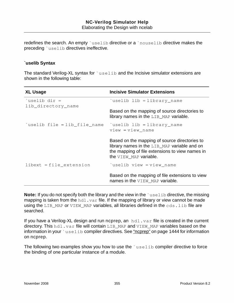
NC-Verilog Simulator HelpElaborating the Design with ncelab
redefines the search. An empty `uselib directive or a `nouselib directive makes thepreceding `uselib directives ineffective.
`uselib Syntax
The standard Verilog-XL syntax for `uselib and the Incisive simulator extensions areshown in the following table:
Note: If you do not specify both the library and the view in the `uselib directive, the missingmapping is taken from the hdl.var file. If the mapping of library or view cannot be madeusing the LIB_MAP or VIEW_MAP variables, all libraries defined in the cds.lib file aresearched.
If you have a Verilog-XL design and run ncprep, an hdl.var file is created in the currentdirectory. This hdl.var file will contain LIB_MAP and VIEW_MAP variables based on theinformation in your `uselib compiler directives. See “ncprep” on page 1444 for informationon ncprep.
The following two examples show you how to use the `uselib compiler directive to forcethe binding of one particular instance of a module.
XL Usage Incisive Simulator Extensions
`uselib dir =lib_directory_name
`uselib lib = library_name
Based on the mapping of source directories tolibrary names in the LIB_MAP variable.
`uselib file = lib_file_name `uselib lib = library_nameview = view_name
Based on the mapping of source directories tolibrary names in the LIB_MAP variable and onthe mapping of file extensions to view names inthe VIEW_MAP variable.
libext = file_extension `uselib view = view_name
Based on the mapping of file extensions to viewnames in the VIEW_MAP variable.
November 2008 355 Product Version 8.2

NC-Verilog Simulator HelpElaborating the Design with ncelab
Example 1
doc_examples/ncvlog/Verilog_binding/binding_uselib/ex1
The following files are used in the first example. Notice that the `uselib directive in the filetop.v specifies both the library and the view. The instance a of module foo will be bound tosource.foo:rtl, as specified in the `uselib compiler directive.
// hdl.var file
DEFINE VIEW_MAP ( .v => behav, \
.rtl => rtl, \
.gate => gate )
DEFINE LIB_MAP ( ./designlib => designlib, \
./source => source, \
+ => worklib )
// File source/top.v
module top ();
`uselib lib=source view=rtl
foo a(); // You want to use the rtl view in the library called source
`uselib
foo b();
bar c();
endmodule
module foo module bar
source.foo:behav compiled from foo.v source.bar:behav compiled from bar.v
source.foo:rtl compiled from foo.rtl source.bar:rtl compiled from bar.rtl
designlib.foo:rtl compiled with -work
;# Compile all .v and .rtl files. The LIB_MAP variable maps source files in the;# source directory to the library called source. The VIEW_MAP variable maps;# files with a .v extension to a view called behav and .rtl files to a view;# called rtl.
% ncvlog -nocopyright -messages source/foo.v
file: source/foo.v
module source.foo:behav
errors: 0, warnings: 0
November 2008 356 Product Version 8.2

NC-Verilog Simulator HelpElaborating the Design with ncelab
% ncvlog -nocopyright -messages source/bar.v
file: source/bar.v
module source.bar:behav
errors: 0, warnings: 0
% ncvlog -nocopyright -messages source/foo.rtl
file: source/foo.rtl
module source.foo:rtl
errors: 0, warnings: 0
% ncvlog -nocopyright -messages source/foo.rtl -work designlib
file: source/foo.rtl
module designlib.foo:rtl
errors: 0, warnings: 0
% ncvlog -nocopyright -messages source/bar.rtl
file: source/bar.rtl
module source.bar:rtl
errors: 0, warnings: 0
% ncvlog -nocopyright -messages source/top.v
file: source/top.v
module source.top:behav
errors: 0, warnings: 0
;# Elaborate the top-level module.
;# Instance foo a is bound to source.foo.rtl.
;# Instances foo b and bar c are bound to the behav views using the default;# binding mechanism.
% ncelab -nocopyright -messages -libverbose top
Elaborating the design hierarchy:
Resolving design unit ’foo’ at ’top.a’ (`uselib at ./source/top.v,3).
Caching library ’source’ ....... Done
library: ’source’ views: ’rtl’ -> found
Resolved design unit ’foo’ at ’top.a’ to ’source.foo:rtl’ (`uselib at./source/top.v,3).
Resolving design unit ’foo’ at ’top.b’.
library: ’source’ views: ’behav’ -> found
Resolved design unit ’foo’ at ’top.b’ to ’source.foo:behav’.
Resolving design unit ’bar’ at ’top.c’.
library: ’source’ views: ’behav’ -> found
Resolved design unit ’bar’ at ’top.c’ to ’source.bar:behav’.
Building instance overlay tables: .................... Done
...
...
Writing initial simulation snapshot: source.top:behav
November 2008 357 Product Version 8.2

NC-Verilog Simulator HelpElaborating the Design with ncelab
Example 2
doc_examples/ncvlog/Verilog_binding/binding_uselib/ex2
The second example is identical to the first example, except that the `uselib directivespecifies only the view. The following is the file top.v:
module top ();
`uselib view=rtl
foo a();
`uselib
foo b();
bar c();
endmodule
The view specified in the compiler directive will be used. This will override any view specifiedwith the -binding option. However, because the library is not specified, the librariesspecified in the LIB_MAP variable in the hdl.var file will be searched in order for an rtlview for module foo.
In this example, the library designlib will be searched first. Because there is a design unitcalled designlib.foo:rtl, this binding is used.
The following shows the output of the elaborator:
Elaborating the design hierarchy:
Resolving design unit ’foo’ at ’top.a’ (`uselib at ./source/top.v,3).
Caching library ’designlib’ ....... Done
library: ’designlib’ views: ’rtl’ -> found
Resolved design unit ’foo’ at ’top.a’ to ’designlib.foo:rtl’ (`uselib at./source/top.v,3).
Resolving design unit ’foo’ at ’top.b’.
Caching library ’source’ ....... Done
library: ’source’ views: ’behav’ -> found
Resolved design unit ’foo’ at ’top.b’ to ’source.foo:behav’.
Resolving design unit ’bar’ at ’top.c’.
library: ’source’ views: ’behav’ -> found
Resolved design unit ’bar’ at ’top.c’ to ’source.bar:behav’.
Building instance overlay tables: .................... Done
...
...
Writing initial simulation snapshot: source.top:behav
November 2008 358 Product Version 8.2

NC-Verilog Simulator HelpElaborating the Design with ncelab
The -binding Option
Use the -binding option to force the binding of a cell to a particular library and view. Thesyntax is:
-binding [lib.]cell[:view]
Using this option overrides the default view and library search mechanism. The specified cellis bound to the library and view that you specify.
Remember that once the first instance has been resolved, all instances of the same moduleor UDP are resolved the same way. Use a configuration to force different bindings for modulesor UDPs with the same name. See “Using a Verilog Configuration” on page 362.
The following example shows you how to use the -binding option to force the binding of acell to a particular view. The following files are used in the example:
doc_examples/ncvlog/Verilog_binding/binding_option/ex1
November 2008 359 Product Version 8.2
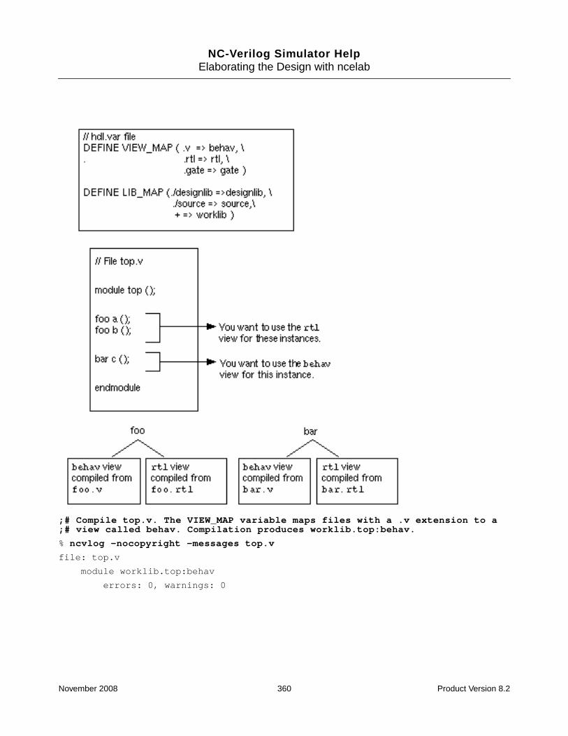
NC-Verilog Simulator HelpElaborating the Design with ncelab
;# Compile top.v. The VIEW_MAP variable maps files with a .v extension to a;# view called behav. Compilation produces worklib.top:behav.
% ncvlog -nocopyright -messages top.v
file: top.v
module worklib.top:behav
errors: 0, warnings: 0
November 2008 360 Product Version 8.2

NC-Verilog Simulator HelpElaborating the Design with ncelab
;# Compile foo.v. Compilation produces worklib.foo:behav.
;# Compile foo.rtl. The VIEW_MAP variable maps files with a .rtl extension to;# a view called rtl. Compilation produces worklib.foo:rtl.
% ncvlog -nocopyright -messages foo.v foo.rtl
file: foo.v
module worklib.foo:behav
errors: 0, warnings: 0
file: foo.rtl
module worklib.foo:rtl
errors: 0, warnings: 0
;# Compile bar.v. Compilation produces worklib.bar:behav.
;# Compile bar.rtl. The VIEW_MAP variable maps files with a .rtl extension to;# a view called rtl. Compilation produces worklib.bar:rtl.
% ncvlog -nocopyright -messages bar.v bar.rtl
file: bar.v
module worklib.bar:behav
errors: 0, warnings: 0
file: bar.rtl
module worklib.bar:rtl
errors: 0, warnings: 0
;# Elaborate top. To resolve the first instance of foo, the library where the;# parent is located (worklib) is searched for a view that matches the view of;# the parent (behav). After resolving this instance, any following instances;# of foo receive the same binding.
% ncelab -nocopyright -messages -libverbose worklib.top:behav
Elaborating the design hierarchy:
Resolving design unit ’foo’ at ’top.a’.
Caching library ’worklib’ ....... Done
library: ’worklib’ views: ’behav’ -> found
Resolved design unit ’foo’ at ’top.a’ to ’worklib.foo:behav’.
Resolved design unit ’foo’ at ’top.b’ to ’worklib.foo:behav’.
Resolving design unit ’bar’ at ’top.c’.
library: ’worklib’ views: ’behav’ -> found
Resolved design unit ’bar’ at ’top.c’ to ’worklib.bar:behav’.
Building instance overlay tables: .................... Done
...
...
Writing initial simulation snapshot: worklib.top:behav
November 2008 361 Product Version 8.2

NC-Verilog Simulator HelpElaborating the Design with ncelab
;# Elaborate top. Use -binding to force binding of instances of foo to the;# rtl view.
;# The first instance of foo is bound to the rtl view. Other instances of foo;# use the same binding.
% ncelab -nocopyright -messages -libverbose -binding foo:rtl worklib.top:behav
Elaborating the design hierarchy:
Resolved design unit ’foo’ at ’top.a’ to ’worklib.foo:rtl’ (-binding switch).
Resolved design unit ’foo’ at ’top.b’ to ’worklib.foo:rtl’ (-binding switch).
Resolving design unit ’bar’ at ’top.c’.
Caching library ’worklib’ ....... Done
library: ’worklib’ views: ’behav’ -> found
Resolved design unit ’bar’ at ’top.c’ to ’worklib.bar:behav’.
Building instance overlay tables: ........... Done
...
...
Writing initial simulation snapshot: worklib.top:behav
Using a Verilog Configuration
Verilog configurations were introduced in the IEEE 1364-2001 standard. A configuration is anexplicit set of rules that specifies the exact source code description to be used to representeach instance in a design.
To use a configuration, you:
1. Write a file, called a library map file, that contains one or more configuration blocks.
The configuration blocks contain the set of rules to be used for binding.
2. Invoke ncelab with the -libmap option to specify the name of the library map file, andspecify the name of the configuration as the argument to the command.
In addition to configurations, a library map file can also contain library declarations, which canbe used to control the compilation of design units in source files into specified libraries.
See Section 13 of the IEEE 1364-2001 standard for details on configuring the contents of adesign by using configurations.
The following examples show you how to use Verilog configurations. The hdl.var file andthe source code used for the examples is as follows:
November 2008 362 Product Version 8.2

NC-Verilog Simulator HelpElaborating the Design with ncelab
# hdl.var file
DEFINE LIB_MAP (./top.v => rtlLib, \
./adder.v => aLib, \
./adder.vg => gateLib, \
+ => worklib )
DEFINE VIEW_MAP ( .v => rtl, \
.vg => gate )
// File top.v // File adder.v File adder.vg
module top(); module adder(...); module adder(...);
adder a1(...); // rtl // gate-level
adder a2(...); foo f1(...); foo f1(...);
endmodule foo f2(...); foo f2(...);
endmodule endmodule
module foo(...);
// rtl module foo(...); module foo(...);
endmodule // rtl // gate-level
endmodule endmodule
Example 1
doc_examples/ncvlog/Verilog_binding/binding_config/ex1
In this example, the compilation of design units into libraries is determined by the LIB_MAPand VIEW_MAP variables in the hdl.var file.
% ncvlog -nocopyright top.v adder.v adder.vg
Compilation results in the following library structure:
Lib.Cell:View From ...
rtlLib.top:rtl top.v
rtlLib.foo:rtl top.v
aLib.adder:rtl RTL from adder.v
aLib.foo:rtl RTL from adder.v
gateLib.adder:gate Gate-level from adder.vg
gateLib.foo:gate Gate-level from adder.vg
November 2008 363 Product Version 8.2

NC-Verilog Simulator HelpElaborating the Design with ncelab
To always use the RTL representations of adder and foo, which are in the library aLib,create a library map file (called lib.map in this example) that contains the followingconfiguration:
config cfg;
design rtlLib.top;
default liblist aLib rtlLib gateLib;
endconfig
■ The design statement names the library and cell of the top-level module in the designhierarchy.
■ The default liblist clause defines the default library search order. In this example,library aLib will be searched before rtlLib and gateLib.
;# Elaborate the design.
;# Use the -libmap option to specify the name of the library map file.
;# Specify the name of the configuration as the argument to the ncelab command.
% ncelab -nocopyright -messages -libmap lib.map -libverbose cfg
Elaborating the design hierarchy:
Resolved design unit ’adder’ at ’top.a1’ to ’aLib.adder:rtl’ (using Verilogconfiguration).
Resolved design unit ’foo’ at ’top.a1@adder<module>.f1’ to ’aLib.foo:rtl’ (usingVerilog configuration).
Resolved design unit ’foo’ at ’top.a1@adder<module>.f2’ to ’aLib.foo:rtl’ (usingVerilog configuration).
Resolved design unit ’adder’ at ’top.a2’ to ’aLib.adder:rtl’ (using Verilogconfiguration).
Resolved design unit ’foo’ at ’top.a2@adder<module>.f1’ to ’aLib.foo:rtl’ (usingVerilog configuration).
Resolved design unit ’foo’ at ’top.a2@adder<module>.f2’ to ’aLib.foo:rtl’ (usingVerilog configuration).
Building instance overlay tables: .................... Done
...
...
Writing initial simulation snapshot: rtlLib.top:rtl
To always use the gate-level representations of adder and foo, specify the gateLib libraryfirst in the default liblist clause, as follows:
config cfg;
design rtlLib.top;
default liblist gateLib aLib rtlLib;
endconfig
If you are running in single-step invocation mode with irun, the command line for this exampleis as follows:
November 2008 364 Product Version 8.2

NC-Verilog Simulator HelpElaborating the Design with ncelab
% irun -libmap lib.map -top cfg -libverbose top.v adder.v adder.vg
Note: If the name of the configuration (cfg in this example) matches the name of a top-leveldesign unit, append :config onto the name of the configuration to specify that the argumentis a configuration. For example:
% ncelab -nocopyright -messages -libmap lib.map -libverbose cfg:config
% irun -libmap lib.map -top cfg:config -libverbose top.v adder.v adder.vg
Note: If the library map file contains multiple configurations with the same name, the lastconfiguration is used.
Example 2
doc_examples/ncvlog/Verilog_binding/binding_config/ex2
This example is similar to Example 1, except that the library map file contains librarydeclarations in addition to the configuration. The library declarations specify that:
■ Design units in top.v are to be compiled into rtlLib.
■ Design units in adder.v are to be compiled into aLib.
■ Design units in adder.vg are to be compiled into gateLib.
library rtlLib top.v;
library aLib adder.v;
library gateLib adder.vg;
config cfg;
design rtlLib.top;
default liblist aLib rtlLib gateLib;
endconfig
The source files are compiled with the -libmap option to specify the name of the library mapfile.
% ncvlog -nocopyright -messages -libmap lib.map top.v adder.v adder.vg
file: top.v
module rtlLib.top:rtl
errors: 0, warnings: 0
module rtlLib.foo:rtl
errors: 0, warnings: 0
file: adder.v
module aLib.adder:rtl
errors: 0, warnings: 0
module aLib.foo:rtl
November 2008 365 Product Version 8.2

NC-Verilog Simulator HelpElaborating the Design with ncelab
errors: 0, warnings: 0
file: adder.vg
module gateLib.adder:gate
errors: 0, warnings: 0
module gateLib.foo:gate
errors: 0, warnings: 0
% ncelab -nocopyright -messages -libmap lib.map -libverbose cfg
Elaborating the design hierarchy:
Resolved design unit ’adder’ at ’top.a1’ to ’aLib.adder:rtl’ (using Verilogconfiguration).
Resolved design unit ’foo’ at ’top.a1@adder<module>.f1’ to ’aLib.foo:rtl’ (usingVerilog configuration).
Resolved design unit ’foo’ at ’top.a1@adder<module>.f2’ to ’aLib.foo:rtl’ (usingVerilog configuration).
Resolved design unit ’adder’ at ’top.a2’ to ’aLib.adder:rtl’ (using Verilogconfiguration).
Resolved design unit ’foo’ at ’top.a2@adder<module>.f1’ to ’aLib.foo:rtl’ (usingVerilog configuration).
Resolved design unit ’foo’ at ’top.a2@adder<module>.f2’ to ’aLib.foo:rtl’ (usingVerilog configuration).
...
Writing initial simulation snapshot: rtlLib.top:rtl
If you are running in single-step invocation mode with irun, the command line for this exampleis as follows:
% irun -libmap lib.map -top cfg -libverbose top.v adder.v adder.vg
Example 3
doc_examples/ncvlog/Verilog_binding/binding_config/ex3
To use the RTL representation of the top.a1 adder (and its descendants), and the gate-levelrepresentation of the top.a2 adder, use the following configuration:
library rtlLib top.v;
library aLib adder.v;
library gateLib adder.vg;
config cfg;
design rtlLib.top;
default liblist aLib rtlLib gateLib;
instance top.a2 liblist gateLib;
endconfig
November 2008 366 Product Version 8.2

NC-Verilog Simulator HelpElaborating the Design with ncelab
In this example, the instance clause specifies the specific instance to which the followingliblist clause applies. Because the liblist is inherited, all descendants of top.a2inherit its liblist.
% ncvlog -nocopyright -libmap lib.map top.v adder.v adder.vg
% ncelab -nocopyright -messages -libmap lib.map -libverbose cfg
Elaborating the design hierarchy:
Resolved design unit ’adder’ at ’top.a1’ to ’aLib.adder:rtl’ (using Verilogconfiguration).
Resolved design unit ’foo’ at ’top.a1@adder<module>.f1’ to ’aLib.foo:rtl’ (usingVerilog configuration).
Resolved design unit ’foo’ at ’top.a1@adder<module>.f2’ to ’aLib.foo:rtl’ (usingVerilog configuration).
Resolved design unit ’adder’ at ’top.a2’ to ’gateLib.adder:gate’ (using Verilogconfiguration).
Resolved design unit ’foo’ at ’top.a2@adder<module>.f1’ to ’gateLib.foo:gate’(using Verilog configuration).
Resolved design unit ’foo’ at ’top.a2@adder<module>.f2’ to ’gateLib.foo:gate’(using Verilog configuration).
Building instance overlay tables: .................... Done
...
Writing initial simulation snapshot: rtlLib.top:rtl
If you are running in single-step invocation mode with irun, the command line for this exampleis as follows:
% irun -libmap lib.map -top cfg -libverbose top.v adder.v adder.vg
Note: The elaborator does not generate an error or a warning if the instance clausespecifies a non-existent instance. For example, in the configuration shown in this example, noerror or warning is generated for the following instance clause:
instance top.not_present liblist gateLib;
Example 4
doc_examples/ncvlog/Verilog_binding/binding_config/ex4
To use the RTL representation of adder from aLib, and the gate-level representation of foofrom gateLib, use the following configuration:
library rtlLib top.v;
library aLib adder.v;
library gateLib adder.vg;
config cfg;
design rtlLib.top;
default liblist aLib rtlLib gateLib;
November 2008 367 Product Version 8.2

NC-Verilog Simulator HelpElaborating the Design with ncelab
cell foo use gateLib.foo;
endconfig
In this example, the cell clause selects all cells named foo and binds them to the gate-levelrepresentation in gateLib.
% ncvlog -nocopyright -libmap lib.map top.v adder.v adder.vg
% ncelab -nocopyright -messages -libmap lib.map -libverbose cfg
Elaborating the design hierarchy:
Resolved design unit ’adder’ at ’top.a1’ to ’aLib.adder:rtl’ (using Verilogconfiguration).
Resolved design unit ’foo’ at ’top.a1@adder<module>.f1’ to ’gateLib.foo:gate’(using Verilog configuration).
Resolved design unit ’foo’ at ’top.a1@adder<module>.f2’ to ’gateLib.foo:gate’(using Verilog configuration).
Resolved design unit ’adder’ at ’top.a2’ to ’aLib.adder:rtl’ (using Verilogconfiguration).
Resolved design unit ’foo’ at ’top.a2@adder<module>.f1’ to ’gateLib.foo:gate’(using Verilog configuration).
Resolved design unit ’foo’ at ’top.a2@adder<module>.f2’ to ’gateLib.foo:gate’(using Verilog configuration).
Building instance overlay tables: .................... Done
...
Writing initial simulation snapshot: rtlLib.top:rtl
If you are running in single-step invocation mode with irun, the command line for this exampleis as follows:
% irun -libmap lib.map -top cfg -libverbose top.v adder.v adder.vg
If multiple cell clauses configure the same cell, a warning is issued and the first matchingcell clause is used for binding.
Note: The elaborator does not generate an error or a warning if the cell clause specifies anon-existent cell. For example, in the configuration shown in this example, no error or warningis generated for the following cell clause:
cell not_present use gateLib.foo;
Example 5
doc_examples/ncvlog/Verilog_binding/binding_config/ex5
This example illustrates the use of a hierarchical configuration.
Suppose that you have developed the adder module in this example and have written aconfiguration that will bind instances of foo as follows:
November 2008 368 Product Version 8.2

NC-Verilog Simulator HelpElaborating the Design with ncelab
// File adder.v
module adder(...);
// rtl
foo f1(...); // Use rtlLib.foo for this instance
foo f2(...); // Use gateLib.foo for this instance
endmodule
module foo(...);
// ...
endmodule
The configuration is as follows:
library rtlLib top.v;
library aLib adder.v;
library gateLib adder.vg;
config cfg2;
design aLib.adder;
default liblist gateLib aLib rtlLib;
instance adder.f1 liblist rtlLib;
endconfig
When you elaborate the top-level of the design (rtlLib.top), you can then use theconfiguration cfg2 shown above for one of the adder instances. For example:
// File top.v
module top();
adder a1(...); // Use aLib.adder for this instance
adder a2(...); // Use the rules in configuration cfg2 for this instance
endmodule
module foo(...);
// rtl
endmodule
To specify this special set of binding rules for instance a2, you can bind the instance directlyto the configuration cfg2 by using an instance clause with a use clause. In this example,the configuration is as follows:
library rtlLib “top.v”;
library aLib “adder.v”;
library gateLib “adder.vg”;
November 2008 369 Product Version 8.2
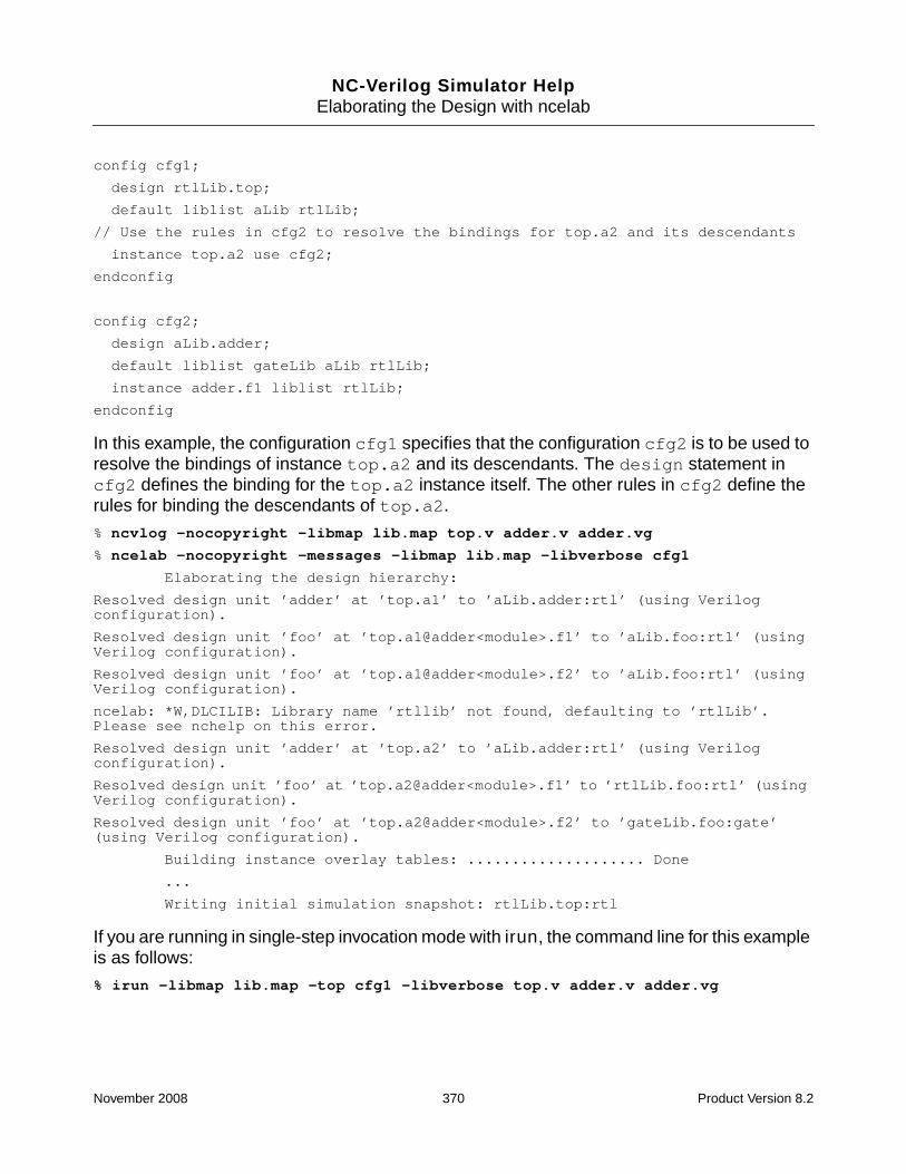
NC-Verilog Simulator HelpElaborating the Design with ncelab
config cfg1;
design rtlLib.top;
default liblist aLib rtlLib;
// Use the rules in cfg2 to resolve the bindings for top.a2 and its descendants
instance top.a2 use cfg2;
endconfig
config cfg2;
design aLib.adder;
default liblist gateLib aLib rtlLib;
instance adder.f1 liblist rtlLib;
endconfig
In this example, the configuration cfg1 specifies that the configuration cfg2 is to be used toresolve the bindings of instance top.a2 and its descendants. The design statement incfg2 defines the binding for the top.a2 instance itself. The other rules in cfg2 define therules for binding the descendants of top.a2.
% ncvlog -nocopyright -libmap lib.map top.v adder.v adder.vg
% ncelab -nocopyright -messages -libmap lib.map -libverbose cfg1
Elaborating the design hierarchy:
Resolved design unit ’adder’ at ’top.a1’ to ’aLib.adder:rtl’ (using Verilogconfiguration).
Resolved design unit ’foo’ at ’top.a1@adder<module>.f1’ to ’aLib.foo:rtl’ (usingVerilog configuration).
Resolved design unit ’foo’ at ’top.a1@adder<module>.f2’ to ’aLib.foo:rtl’ (usingVerilog configuration).
ncelab: *W,DLCILIB: Library name ’rtllib’ not found, defaulting to ’rtlLib’.Please see nchelp on this error.
Resolved design unit ’adder’ at ’top.a2’ to ’aLib.adder:rtl’ (using Verilogconfiguration).
Resolved design unit ’foo’ at ’top.a2@adder<module>.f1’ to ’rtlLib.foo:rtl’ (usingVerilog configuration).
Resolved design unit ’foo’ at ’top.a2@adder<module>.f2’ to ’gateLib.foo:gate’(using Verilog configuration).
Building instance overlay tables: .................... Done
...
Writing initial simulation snapshot: rtlLib.top:rtl
If you are running in single-step invocation mode with irun, the command line for this exampleis as follows:
% irun -libmap lib.map -top cfg1 -libverbose top.v adder.v adder.vg
November 2008 370 Product Version 8.2

NC-Verilog Simulator HelpElaborating the Design with ncelab
Enabling Read, Write, or Connectivity Access toSimulation Objects
By default, the elaborator marks all simulation objects in the design as having no read or writeaccess, and disables access to connectivity (load and driver) information. Turning off thesethree forms of access allows the elaborator to perform a set of optimizations that candramatically improve simulation performance.
The only exceptions to this default mode are objects used as arguments to user-definedsystem tasks or functions. These objects are automatically given read, write, and connectivityaccess. By default, no access is given to objects used as arguments to built-in system tasksor functions. Using a construct that does not have a value (a module instance, for example)as an argument has no effect on access capabilities.
Simulating a snapshot with limited visibility into simulation constructs has significantperformance advantages, and this is the obvious choice in some situations. For example,simulating with the default access level is recommended if you are running regressionsimulations with self-checking tests.
The disadvantage of simulating a snapshot generated with the default access levels is thatyou have minimal debugging capability. You cannot access simulation objects from a pointoutside the HDL code, through Tcl commands, or through PLI/VPI/VHPI. For example:
■ You cannot probe and generate waveforms for objects that do not have read access. Youcannot display the value of these objects with Tcl commands such as value ordescribe. PLI/VPI/VHPI applications cannot get the values of objects tagged as havingno read access.
■ You cannot modify the values of objects that do not have write access. Write access isrequired for forcing or depositing values with Tcl force and deposit commands, or fora PLI/VPI/VHPI application to put values to objects.
■ You cannot display the drivers of a particular wire or register if the object does not haveconnectivity access. Connectivity access is required for tracing signals in the TraceSignals sidebar, and for a PLI/VPI/VHPI application to scan for loads or drivers of anobject.
To access design objects during simulation, you must use debug command-line options.These options provide visibility into different parts of a design and enable debugging features,but disable optimizations performed inside the simulator. Because these options slow downperformance, you should provide the minimum amount of access possible by specifying onlythe kind of access you need for specific objects, instances, or portions of the design.
The following sections provide details on:
November 2008 371 Product Version 8.2

NC-Verilog Simulator HelpElaborating the Design with ncelab
■ The limitations imposed by simulating a snapshot generated with the default accesslevels. See “Simulating a Snapshot with Default Access to Objects” on page 372.
■ “Using an Access File” on page 375
An access file is a text file that lets you specify the type of access that you want forparticular instances and portions of the design. The access file is included with the-afile option. This option lets the simulator optimize objects that do not need to beaccessed during debugging.
■ “Using -genafile to Generate an Access File” on page 383
The -genafile option lets you automatically generate an access file, which can thenbe included in subsequent runs with the -afile option.
■ “Specifying Global Read/Write/Connectivity Access with -access” on page 384
The -access option lets you turn on read, write, or connectivity access to all simulationobjects in the design. Because this is a global option that sets access for objects in allparts of the design, including portions that you are not debugging, using -access canhave a severe performance impact.
■ “Using -linedebug to Enable Line Breakpoints and Single-Stepping through Code” onpage 385
■ “Using -anno_simtime to Modify Delays at Simulation Time” on page 386
■ General guidelines for setting access control. See “Guidelines for Access Control” onpage 386.
Note: The following sections describe how to turn access to simulation objects on or off. Ifaccess is turned on for an object, access to that object is guaranteed. However, turningaccess off for an object does not always mean that access to that object will be restricted.Turning access off is a hint to the elaborator that the object will not be referenced, but, in somecases, the elaborator will grant access to objects if there is no performance benefit to denyingaccess. For example, if signals at different levels of the hierarchy are part of the same net,and if access to the net is turned on at one level of the hierarchy, but turned off at anotherlevel of the hierarchy, access to all signals of the net will be turned on because there is noperformance benefit to turning it off at other levels of the hierarchy.
Simulating a Snapshot with Default Access to Objects
The following sections provide details on the limitations on using Tcl commands, routines inPLI/VPI/VHPI applications, and SimVision features.
November 2008 372 Product Version 8.2

NC-Verilog Simulator HelpElaborating the Design with ncelab
Default Mode and Tcl Commands
Many Tcl commands access and set values and probes on objects. Other commands provideload and driver information. With no read, write, or connectivity access to objects, thesecommands generate warning or error messages or they display output that does not includesome objects or object values. For example:
■ The force command prints an error if the object that is being forced does not have writeaccess.
■ The deposit command prints an error if the object to which a value is to be depositeddoes not have read/write access.
■ The value command prints an error if any of the objects given as arguments do not haveread access.
■ The probe command prints an error if any of the objects given as arguments do not haveread access. If the argument to this command is a scope, objects within that scope thatdo not have read access are excluded from the probe, and a warning message is printed.No waveforms are generated for these objects.
■ The drivers command cannot display the drivers of a particular wire or register if theobject does not have connectivity access.
■ The describe command output does not include the value of an object if the objectdoes not have read access.
Default Mode and PLI/VPI/VHPI Applications
If you run in the default mode, PLI/VPI/VHPI applications:
■ Cannot get the values of objects tagged as having no read access.
If the value of an object that does not have read access is requested, the PLI interfacereturns the value as a strong X in the requested format. If the requested format isdecimal, integer, or time, the value is 0. If the format is in the form of a double, the returnvalue is 0.0.
If PLI 1.0 routines are being used, the ACC flag acc_error_flag is set to non-zero.This error can be detected in the VPI interface by calling vpi_chk_error() after a callto vpi_get_value() or by registering a callback for cbPLIError.
■ Cannot put values to objects tagged as having no write access.
Trying to put a value to a non-writable object is ignored and results in an error. If an eventhandle is requested from the vpi_put_value() routine, the return value is NULL.
November 2008 373 Product Version 8.2

NC-Verilog Simulator HelpElaborating the Design with ncelab
If PLI 1.0 routines are being used, the ACC flag acc_error_flag is set to non-zero.This error can be detected in the VPI interface by calling vpi_chk_error() after a callto vpi_put_value() or by registering a callback for cbPLIError.
■ Cannot place value change callbacks on objects tagged as having no read access.
Requesting a value change callback on a non-readable object is ignored and results inan error. Calling acc_vcl_add() on the object results in the ACC flagacc_error_flag being set to non-zero. Calling vpi_register_cb() on the objectresults in a NULL being returned. This error can be detected using vpi_chk_error()immediately after the call to vpi_register_cb() or by registering a callback forcbPLIError.
■ Cannot place callbacks on objects for force and release if the objects are tagged ashaving no read access.
■ Cannot scan for loads or drivers of an object without connectivity access.
If the object does not have read connectivity access, scanning for loads results in anerror. Scanning for drivers on an object that does not have read access also generatesan error.
■ The simulated net for a net without read access is the original net.
Testing for the Visibility of an Object
The PLI 1.0, VPI, and VHPI interfaces allow an application to test for the accessibility of anobject before working on it. The following macros are defined in vxl_acc_user.h:
■ accWriteAccess
■ accReadAccess
■ accConnectivityAccess
You can use these macros with acc_object_of_type() andacc_object_in_typelist().
The following properties are included in vpi_user_cds.h:
■ vpiWriteAccess
■ vpiReadAccess
■ vpiConnectivityAccess
November 2008 374 Product Version 8.2

NC-Verilog Simulator HelpElaborating the Design with ncelab
These Boolean properties can be used with the vpi_get() routine. They return TRUE if theobject is read/write accessible and return FALSE otherwise.
These properties are accessible from any object that can have a value. In addition, the callsvpi_get(vpiWriteAccess, NULL) and vpi_get(vpiReadAccess, NULL) returnFALSE if any object in the design has limited visibility. In Verilog-XL, these properties areaccessible and always return TRUE.
The property vhpiAccessP is defined in vhpi_user.h. You can use this property to testthe visibility of VHPI objects: vhpi_get(vhpiAccessP, objHandle).
Controlling the Display of PLI Error and Warning Messages
By default, the simulator displays all warning and error messages that are generated whenan error is detected due to a PLI read, write, or connectivity access violation. You cansuppress the display of these access violation messages by using the -plinooptwarncommand-line option (ncsim -plinooptwarn or irun -plinooptwarn). If you use thisoption, a warning message is displayed only once when the first violation is detected. Themessage is displayed again if an access violation is detected after a reset or a restart.
Default Mode and the SimVision Debug Environment
The SimVision debug tools cannot display the value of objects that do not have read access.The current value for an object without read access is shown as “No Value Available”. Tryingto execute commands to show the value of an object, to set an object breakpoint, or to set aprobe on objects without read access results in an error message.
Other operations require write access. For example, objects must have write access in orderfor you to deposit or to force a value.
Connectivity access affects the Trace Signals sidebar. For signals that do not haveconnectivity access, no action is taken. In other cases, an object may have connectivityaccess, but some drivers have been removed or have been optimized. In these cases, awarning is displayed telling you that the signal has no drivers.
Using an Access File
An access file is a text file that lets you specify the type of access that you want for particularinstances and portions of the design. This section tells you how to write an access file andhow to include the access file when you invoke the elaborator.
November 2008 375 Product Version 8.2

NC-Verilog Simulator HelpElaborating the Design with ncelab
Note: An access file can also contain PLI map file information. A PLI map file associatesuser-defined system tasks and system functions with functions in a PLI application. See“Using a PLI Map File” on page 382 for more information.
Writing an Access File
An access file consists of a set of lines, each of which specifies the desired access capabilityfor instances in the design, hierarchical portions of the design, or value constructs used asarguments to user-defined system tasks or functions.
Each line in the access file begins with a keyword. You can enter keywords in uppercase orlowercase. Each line must be terminated by a carriage return.
Some keywords require a hierarchical path argument. The syntax for specifying hierarchicalpaths is language-neutral. You can use either the VHDL path element separator (a colon), orthe Verilog path element separator (a period) to separate the path elements. A path that startsat the VHDL top-level must begin with a colon.
Two wildcard extensions can be used in hierarchical path specifications:
■ An asterisk ( * ) matches any instance in the current scope.
■ Three dots ( ... ) used as a suffix matches any instance in the hierarchy below thecurrent scope.
The access specifications in the access file are similar to those used with the -accesscommand-line option. Use r, w, and c for read, write, and connectivity access, respectively.Use a plus sign to turn on the specified access, and a minus sign to turn off the specifiedaccess. Objects that are given connectivity or write access are also given read access.
However, in an access file you can also specify +d. This specification gives all drivers of a netread access if the net has connectivity access. This provides a convenient way to provideaccess so that an application can scan for all drivers and read their values.
Note: With the -access option, the plus sign is the default if you do not specify a plus orminus sign. In an access file, you must use the plus sign to turn on access.
You can also include comments in the file.
■ Begin one-line comments with two slashes ( // ).
■ Begin multiple-line comments with /* and end the comment with */.
November 2008 376 Product Version 8.2

NC-Verilog Simulator HelpElaborating the Design with ncelab
Here is a simple example access file:
// Read access for all instances in the 2nd levels of hierarchy
PATH *.* +r-wc
// Read and write access for all instances of sub that are two levels under top
PATH top.*.sub +rw-c
//Read access, but no write access, for all instances below top.sub
PATH top.sub... +r-wc
Objects derive their access from an exact match. If there is no exact match for an object, theaccess is derived from the closest matching wildcard. If an object cannot be matched with awildcard, the default access is used. For example, if you have the following two lines in anaccess file, top.u1 and all instances inside u1 have full access enabled because the firstline specifies the more complete path.
PATH top.u1.* +rwc
PATH top.*.* -rwc
Access File Syntax
The syntax of the access file is as follows:
Access_file ::= Line
Line ::=
DEFAULT Access
| BASENAME [Path] [Access]
| PATH Path Access
| CELLINST Access
| CELLLIB Cell Access
| $UDTF Stfname [<REG> | <WIRE>] Access
| INCLUDE File
| Comments
Path ::=
Name
| Path.Name NOTE: You can use the VHDL separator (:)or the Verilog separator (.).
| Path...
| Path...Key
| Path.Key
Cell ::= A name in Lib.Cell:View format
November 2008 377 Product Version 8.2

NC-Verilog Simulator HelpElaborating the Design with ncelab
Name ::= Legal Verilog or VHDL name
Stfname ::=
Name of a user-defined system task or function
| *
File::= Path to an access file to include
Key ::=
<REG>
| <WIRE>
| <INTEGER>
| <TIME>
| <REAL>
| <PRIMITIVE>
| <ASSIGN>
| <EVENT>
| <PORT>
| <PORTIN>
| <PORTOUT>
| <PORTINOUT>
| <SIGNAL>
| <VARIABLE>
Access ::= Modifier Capability
Modifier ::= + | -
Capability ::= R | W | C | D | RW | RC | WC | RWC | CD
Comments ::=
// text
| /* text */
The keywords that you can use in an access file are:
■ DEFAULT Access
Specifies the default access for all instances. This overrides any access that you specifywith the -access option.
Example:
DEFAULT +r-wc
November 2008 378 Product Version 8.2

NC-Verilog Simulator HelpElaborating the Design with ncelab
■ BASENAME [Path] [Access]
Specifies the starting point for the path in all subsequent PATH statements. The specifiedpath cannot contain any wildcard characters. If you do not specify a path, the BASENAMEis set to null.
Example:
BASENAME top.u1.foo // Start all subsequent paths with top.u1.foo
PATH bar +rwc // top.u1.foo.bar has +rwc
PATH u3 -rwc // top.u1.foo.u3 has -rwc
BASENAME // Remove previous basename specification
PATH top.u3 +rwc // top.u3 has +rwc
■ PATH Path Access
Specifies the access for all instances and constructs that match the path specification.
If a path ends with an object name, the named object gets the specified access. Thefollowing example turns on read and connectivity access for top.foo.io. The +dspecifies that all drivers of a net with connectivity access will have read access:
PATH top.foo.io +rcd-w
Objects from named blocks or HDL tasks and functions get their access from thecontaining scope if they do not have an exact match.
You can use wildcard characters in the hierarchical path argument. The two wildcardcharacters are:
❑ An asterisk ( * ) matches any instance at the current scope.
❑ Three dots ( ... ) used as a suffix matches any instance in the hierarchy below thecurrent scope.
The following example turns on read and write access for the top two levels of the design:
PATH * +rw-c // Read, write access for top level
PATH *.* +rw-c // Read, write access for second level
PATH ... -rwc // No access to objects below the second level
In addition to normal Verilog or VHDL hierarchical paths, such as top.u1.foo and:U1:foo, and hierarchical names using wildcard characters, there are several keys thatlet you specify access for particular constructs. If the path ends with a key, all objects ofa class that matches the key get the specified access. These keys are:
❑ <REG> (Matches Verilog registers not declared as integer, real, or time)
❑ <INTEGER>, <REAL>, <TIME> (Matches the corresponding type of registerdeclaration)
November 2008 379 Product Version 8.2

NC-Verilog Simulator HelpElaborating the Design with ncelab
❑ <WIRE> (Matches Verilog wires)
❑ <SIGNAL> (Matches VHDL signals and ports)
❑ <VARIABLE> (Matches VHDL variables)
❑ <PORT> (Matches all Verilog wires and registers declared as module ports, and allVHDL ports)
❑ <PORTIN>, <PORTOUT>, <PORTINOUT> (Matches only ports of the correspondingmode)
❑ <PRIMITIVE> (Matches Verilog instances of primitives)
❑ <ASSIGN> (Matches Verilog blocking assignment statements)
❑ <EVENT> (Matches Verilog named events)
Examples:
PATH top.<WIRE> +rw-c // Read, write access for wires in second level
PATH top.sub...<REG> +rw-c /* Read, write access for regs in instancesbelow top.sub */
PATH top.sub.foo.<PRIMITIVE> +rw-c // Read, write access for primitives in foo
If an object can be matched by either a <PORT*> or <WIRE> key, the <PORT*> key isused.
■ CELLINST Access
Specifies the access for all instances that are tagged as cells and their subhierarchy.Instances are tagged as cells either with the `celldefine compiler directive or byusing the -y or -v options in irun.
The access that you specify with CELLINST overrides all wildcard paths that match intoa cell instance. However, an object in a cell instance matched by an exact path isannotated using the access from the exact path.
The following example specifies that all cells in the design can be fully optimized, whilethe upper levels have full debug access:
CELLINST -rwc // No access to objects in cell instances
PATH ... +rwc // Enable full access to objects above cells
■ CELLLIB Cell Access
Specifies access using a lib.cell:view format.
Example:
CELLLIB worklib.m16:module +rw-c
November 2008 380 Product Version 8.2

NC-Verilog Simulator HelpElaborating the Design with ncelab
You can use the * wildcard character for any part of the lib.cell:view specification.
Examples:
CELLLIB worklib -rwc
CELLLIB worklib.* +rwc
CELLLIB worklib.m16:* +rwc
CELLLIB *.m16 +rwc
In the following example access file, CELLLIB is used to turn off access to all objects inthe library asic:
// Full access to all objects
PATH ... +rwc
// No access to objects in the library asic
CELLLIB asic -rwc
/* Read access to register r1 in the instance top.u1.as01, an instance of apart in the library asic */
PATH top.u1.as01.r1 +r-wc
■ $UDTF Stfname [<REG> | <WIRE>] Access
Specifies the access for value constructs used as arguments to a user-defined systemtask or function. By default, these constructs are given full access (+rwc). Use thiskeyword to turn off different kinds of access.
Example:
$UDTF $mytask +r-wc
You can use * to specify all user-defined system tasks and functions.
$UDTF * +r-wc
The following specifies write access for all registers in the module containing $mytask.
$UDTF $mytask <REG> +w
The following specifies read access for all wires in the module containing $mytask.
$UDTF $mytask <WIRE> +r
Note: The default access for constructs used as arguments to built-in system tasks andfunctions is -rwc. You cannot use $UDTF to modify this access.
■ INCLUDE File
Include the contents of the specified access file.
Warning Messages
There are several conditions that result in warning messages. These include:
November 2008 381 Product Version 8.2

NC-Verilog Simulator HelpElaborating the Design with ncelab
■ If an access mode for an object is both enabled and disabled, access is enabled, and awarning is issued. For example, in the following access file, top.u1.u3 gets readaccess.
PATH top.u1.u3 +r-wc
...
...
PATH top.u1.u3 -rwc
■ A warning is issued if an object is named in an access file, but is not used in theelaborated design. For example, a warning is generated if you have the following line inthe access file, but top.u1.u3 is not used in the design.
PATH top.u1.u3 +r-wc
No warning is generated if wildcards are used. For example, if you have the following linein the access file, no warning is issued if b is not found in the design.
PATH top.*.b +r-wc
Including the Access File
To include an access file, use the -afile access_file option when you invoke theelaborator.
% ncelab -afile access_file [lib.]cell[:view]
For example,
% ncelab -afile afile.af worklib.top
(% irun -afile afile.af source.v)
You can use more than one -afile option to include multiple access files. If you use multiple-afile options, the contents of the different files are combined before the access is actuallyset. For example,
% ncelab -afile afile1.af -afile afile2.af worklib.top
Using a PLI Map File
In addition to specifying access to simulation objects, an access file can also contain PLI mapfile information. A PLI map file associates user-defined system tasks and system functionswith functions in a PLI application. The file contains a line for each user-defined system taskor system function your application needs. In each line, you specify:
■ The name of the system task or system function.
■ Additional specifications for the system task or system function.
November 2008 382 Product Version 8.2

NC-Verilog Simulator HelpElaborating the Design with ncelab
For a user-defined system function, you must specify the size of the return value.
Other, optional, specifications include the name of the call function, the name of thecheck function, the name of the misc function, and the data value passed as the firstargument to the call, check, and misc routines.
The PLI map file information can be:
■ Included in an access file, which is specified with the ncelab -afile option.
■ Created as a separate file. You can include this file at elaboration time using the -afileoption, or at simulation time with the -plimapfile option. If passed at elaboration time,the system tasks and functions defined in the file are known to both ncelab and ncsim.If passed at simulation time, the system tasks and functions defined in the file are knownonly to ncsim.
See the section “Using a PLI/VPI Map File” in the chapter “Using VPI” in the VPI User Guideand Reference for details on the PLI map file.
Using -genafile to Generate an Access File
If you know that your simulation runs require the same types of access on the same objects,you can automatically generate an access file. To do this, include the -genafile optionwhen you invoke the elaborator. When you simulate, the objects that are accessed by Tclcommands or by a PLI application are monitored along with the types of access required foreach object. When you exit the simulation, an access file is created with the specifiedfilename.
Example:
% ncelab -genafile access.txt worklib.top:module
(% irun -genafile access.txt source_files)
You can then include this access file in subsequent runs with the -afile option.
% ncelab -afile access.txt worklib.top:module
(% irun -afile access.txt source_files)
If you use -genafile, any request for access reduction with the -access or -afilecommand-line options is ignored. The describe command does not affect the specificationsinserted into the access file.
Note: If you want to use the reinvoke simulation feature in SimVision, select Edit –Preferences and make sure that the Prompt before reinvoke option is set. When you thenselect Simulation – Reinvoke Simulator, the Reinvoke form appears and you can edit the
November 2008 383 Product Version 8.2

NC-Verilog Simulator HelpElaborating the Design with ncelab
text field that contains your original irun command-line options to change -genafile to-afile.
Specifying Global Read/Write/Connectivity Access with -access
Use the elaborator -access option (ncelab -access or irun -access) to turn on read,write, or connectivity access to all simulation objects in the design.
Note: Providing read, write, and connectivity access to all objects in the design can have asevere impact on performance. Set the minimum access necessary for your debuggingpurposes. For example, if the only reason you need access is to save waveform data, use theoption to provide only read access. If you only need to save waveform data for specificinstances or portions of the design, specify read access for those portions of the design in anaccess file, and include the access file with the -afile option.
Objects that are given write access are also given read access. Objects that are givenconnectivity access are given write and read access.
Syntax:
-access [+] [-] access_specification
The access_specification argument can be:
■ r (read access)
■ w (write access)
■ c (connectivity access)
■ Any combination of the three access types
Use the plus sign to turn on the specified access. This is the default if no plus or minus signis used with -access. Use the minus sign to turn off the specified access.
The + and - options apply to all subsequent r, w, or c specifications until the next + or -.
Examples:
■ Read access only:
-access +r (same as -access r)
■ Write access:
-access +w (same as -access w)
Objects given write access are also given read access.
November 2008 384 Product Version 8.2

NC-Verilog Simulator HelpElaborating the Design with ncelab
■ Read/Write access:
-access +rw (same as -access +r+w and -access rw)
■ Connectivity access:
-access +c (same as -access c)
Objects given connectivity access are also given write and read access.
You can also use multiple -access options. For example,
-access +r -access +c
Note: Objects that are given connectivity access are given write access, and objects that aregiven write access are given read access. With the following set of options, all objects aregiven connectivity access and, therefore, write and read access.
-access +c -access -rw
Use the following general rules when deciding what kind of access you want to specify:
■ Read access is required if you want to probe objects in the design and generate an SHM,VCD, or EVCD database. This lets you use the SimVision waveform viewer to viewwaveforms, and most Tcl commands and SimVision features. Read access is alsorequired for getting signal values with, for example, the value or describe command,or vpi_get_value().
■ Write access is required if you want to deposit values using, for example, the force ordeposit command, or vpi_put_value().
■ Connectivity access is required in order to show load or driver information. This kind ofaccess is required, for example, by the drivers command and by the Trace Signalssidebar.
Using -linedebug to Enable Line Breakpoints and Single-Stepping throughCode
The compiler -linedebug option enables support for setting line, process, and subprogrambreakpoints, and for single-stepping through code.
Using this option when you compile your source files disables many optimizations and setsthe default access to all simulation objects to read/write/connectivity when the design iselaborated. This option can have a severe impact on performance. For selective application,compile specific source files with the option. For example:
% ncvlog -linedebug options source_file
% ncvlog options other_source_files
November 2008 385 Product Version 8.2

NC-Verilog Simulator HelpElaborating the Design with ncelab
Using -anno_simtime to Modify Delays at Simulation Time
The elaborator -anno_simtime option enables the use of PLI/VPI routines that modifydelays at simulation time. These routines are acc_replace_delays,acc_append_delays, and vpi_put_delays. If this option is not specified at elaborationtime, and a PLI/VPI routine that modifies delays is executed at simulation time, a message isissued and the delay modification does not take place.
This option disables optimizations in the simulator that take delays into account. In addition,this option sets the default access of all simulation objects to read/write when the design iselaborated. Use this option only if you intend to modify delays at simulation time.
Guidelines for Access Control
You can trade off simulation performance for debugability using the access controlmechanism in the simulator. By default, the simulator runs in maximum performance mode.This means that you will have minimal debug access if you run in the default mode. If you aregoing to use Tcl interactive commands or PLI/VPI/VHPI routines to debug and/or analyze thedesign, some amount of access is required.
This section provides general guidelines for access control. There are three sections:
■ General Access Control Guidelines
■ Access Requirements for Tcl Interactive Commands
■ Access Requirements for PLI/VPI/VHPI Functions and Callbacks
General Access Control Guidelines
Except for dynamic objects, no special access is required for viewing the hierarchy or forfinding the names of objects (nets, regs, variables, scopes, and so on) in the design.
Read access (+R) is required for probing nets, regs, and variables (including setting PLIcallbacks) and getting the value of these objects.
Write access (+W) is required to interactively set the value of simulation objects (depositing orforcing variables). Write access automatically provides read access.
Note: With the exception of system tasks and functions, HDL constructs, such as a forcestatement, do not require any special access.
Connectivity access (+C) is required to get driver and load information about a specific net,reg, or other variable. Connectivity access automatically provides write and read access.
November 2008 386 Product Version 8.2

NC-Verilog Simulator HelpElaborating the Design with ncelab
Compiling with the -linedebug option (ncvlog -linedebug) is required for settingbreakpoints at source lines or for applying statement callbacks. Using this optionautomatically provides read, write, and connectivity access.
Elaborating with the -anno_simtime option (ncelab -anno_simtime) is required if youwant to use PLI/VPI routines that modify delays at simulation time. Using this optionautomatically provides read, write, and connectivity access.
These general guidelines can be summarized as follows: Specify only the type(s) of accessrequired for your debugging purposes, and try to set access controls on specific scopes, nets,regs, ports, and so on, by using an access file.
For example, if the only reason you need access is to save waveform data, use ncelab-access +R. If possible, use an access file to set read access only on the scopes orindividual variables that you want to probe. The following access file, for example, can beused to save waveform data for ports only. The DEFAULT keyword specifies the defaultaccess for all instances, and the second statement specifies read access for ports.
DEFAULT -rwc
PATH ...<PORT> +r-wc
The following access file can be used to save waveform data for all nets and regs only:
DEFAULT -rwc
PATH ...<WIRE> +r-wc
PATH ...<REG> +r-wc
The following access file can be used if you want to save waveform data for ports only andperform scan tests by writing to scanflops tagged as cells with `celldefine:
DEFAULT -rwc
PATH ...<PORT> +r-wc
CELLINST worklib.dff_scan.module +rw-c
Access Requirements for Tcl Interactive Commands
The following table lists Tcl commands and the type of access they require:
Tcl Command Access Requirement
alias None
call Depends on the C function or PLI/VPI/VHPI routine
database None
deposit +W
November 2008 387 Product Version 8.2

NC-Verilog Simulator HelpElaborating the Design with ncelab
describe None (+R to see object values)
drivers +C
finish None
force +W
help None
probe[-create]-delete-disable-enable-show
+R (for all desired objects)NoneNoneNoneNone
release None
reset None
restart None
run None
save None
scope-describe-names-sort-drivers-list[-set]-show
None (+R to see object values)NoneNone+CNoneNoneNone
status None
Tcl Command Access Requirement
November 2008 388 Product Version 8.2

NC-Verilog Simulator HelpElaborating the Design with ncelab
Access Requirements for PLI/VPI/VHPI Functions and Callbacks
stop[-create]-condition-continue-delbreak-execute-if-line-name-object-skip-time-delete-disable-enable-show
+R (if condition include simulation object values)NoneNoneNone+R (if condition must include object values)-linedebug (ncvlog option for desired file)None+RNoneNoneNoneNoneNoneNone
time None
value +R
version None
PLI 1.0 Function Access Requirement
acc_vcl_add() +R
acc_fetch_value() +R
acc_fetch_paramval() +R
acc_fetch_paramval_mtm() +R
acc_set_value() +W
acc_next_driver() +C
acc_next_load() +C
acc_append_delays() -anno_simtime
acc_fetch_delays() -anno_simtime
acc_replace_delays() -anno_simtime
Tcl Command Access Requirement
November 2008 389 Product Version 8.2

NC-Verilog Simulator HelpElaborating the Design with ncelab
acc_append_pulsere() -anno_simtime
acc_fetch_pulsere() -anno_simtime
acc_replace_pulsere() -anno_simtime
acc_set_pulsere() -anno_simtime
misc_tf reason codesreason_paramvc +R
VPI Function Access Requirement
vpi_get_value() +R
vpi_put_value() +W
vpi_get_delays -anno_simtime
vpi_iterate(vpiDriver) +C
vpi_iterate(vpiLoad) +C
vpi_put_delays -anno_simtime
vpi_register_cb()cbValueChangecbForce/cbReleasecbAssign/cbDeassigncbStmt
+R+R (on the expression)+R (on the register being assigned)-linedebug (on desired module)
VHPI Function Access Requirement
vhpi_get_value() +R
vhpi_put_value() +W
vhpi_iterator()vhpiContributorsvhpiDrivers
+C+C
vhpi_register_cb()vhpiCbValueChangecbStm
+R-linedebug
PLI 1.0 Function Access Requirement
November 2008 390 Product Version 8.2

NC-Verilog Simulator HelpElaborating the Design with ncelab
Extending a Snapshot to Include Additional Source Files
You can extend an elaborated snapshot to add additional source files by using the elaborator-extendsnap option. For example, suppose that you have compiled source files for a DUTand have generated a snapshot. You can then compile new files with code to test the DUT(HDL files or e files, for example) and re-elaborate to extend the first, or primary, snapshot.The elaborator will use the primary snapshot and the newly-compiled files to create a new,unified snapshot. By using the -extendsnap option, you can avoid rewriting complex scriptsor altering the verification environment.
All compiled libraries used to build the primary snapshot and the .pak file must be availablewhen elaborating the unified snapshot.
Using the -extendsnap option does not perform incremental elaboration. A new snapshotis built by doing a full elaboration of the design. There is no performance gain, and memoryconsumption will increase because a full snapshot is loaded in memory before elaborationstarts again.
Note: Do not use the -extendsnap option to extend a primary snapshot that has missinginstantiations and that was elaborated using the -partialdesign option. In the currentrelease, you cannot use the -extendsnap option to add files that make connections tomissing instantiations in the primary snapshot.
The argument to -extendsnap is the name of the pre-elaborated (primary) snapshot.
-extendsnap snapshot_name
Using -extendsnap with irun
With irun, you include the -extendsnap option and the new source files on the commandline to generate the unified snapshot.
For example, suppose that you have compiled VHDL files for a DUT and have generated asnapshot, as follows:
irun -c dut.vhd -top dut
Suppose that the name of the snapshot is worklib.dut:dut_a.
Now you want to add a Verilog testbench. The new file (tb.v) instantiates the DUT and isnow the new top. To extend the primary snapshot, create a unified snapshot, and simulateuse the following command:
irun -extendsnap worklib.dut:dut_a tb.v -input sim.tcl
November 2008 391 Product Version 8.2

NC-Verilog Simulator HelpElaborating the Design with ncelab
Because irun can automatically detect Verilog tops, specifying the Verilog top with the -topoption is not necessary.
Note: In this example, the new snapshot is called worklib.tb:v. The name of thesnapshot generated by the second elaboration must be different from the name of the primarysnapshot specified with -extendsnap. An error is generated if the snapshot names are thesame.
Using -extendsnap in Multi-Step Mode
In multi-step mode, the primary snapshot is generated with the following commands:
ncvhdl -messages dut.vhd
ncelab -messages dut
This generates a snapshot called worklib.dut:dut_a.
To extend the snapshot, compile the Verilog testbench file and elaborate with -extendsnap.The top-level (tb) must be specified as an argument on the command line.
ncvlog -messages tb.v
ncelab -mess -extendsnap worklib.dut:dut_a tb
ncsim worklib.tb:module -input sim.tcl
Command-Line Options
If different command-line options have been used in the first elaboration (primary snapshot)and the second elaboration (elaboration with the -extendsnap option), the secondelaboration will use the union of the options specified for both elaborations. If options conflict,a warning is issued, and the option specified in the second elaboration is used. For example,if the DUT was elaborated with -access +r and the second elaboration with -access+rwc, the latter option is used.
November 2008 392 Product Version 8.2

NC-Verilog Simulator HelpElaborating the Design with ncelab
Disabling Timing in Selected Portions of a Design
You can turn off timing in specific parts of a Verilog design by using a timing file, which youspecify on the command line with the -tfile option. For example,
% ncelab -tfile myfile.tfile worklib.top:module
% irun -tfile myfile.tfile source_files
If you are annotating with an SDF file, the design is annotated using the information in theSDF file, and then the timing constructs that you specify in the timing file are removed fromthe specified instances.
Using a timing file does not cause any new SDF warnings or remove any timing warnings thatyou would get without a timing file. There is one exception to this: The connectivity test forregister driven interconnect delays happens much later than the normal interconnect delays.Any warning that may have existed for that form of the interconnect will not be generated ifthat interconnect has been removed by a timing file.
Writing a Timing File
A timing file consists of a set of lines, each of which specifies whether or not you want timingfor specific instances in the design or for hierarchical portions of the design. Each line beginswith a keyword. You can enter the keywords in uppercase or in lowercase. Each line must beterminated by a carriage return.
Some keywords require a hierarchical path name argument. Two wildcard extensions can beused in hierarchical path specifications:
■ An asterisk ( * ) matches any instance at the current scope.
■ Three dots ( ... ) used as a suffix matches any instance in the hierarchy below thecurrent scope.
The timing specifications in the file are as follows:
■ - | + iopath—Removes module path delays.
■ - | + prim—Sets any primitive delay within the specified instance(s) to 0.
■ - | + port—Removes any port delays at the specified instance(s) or anyinterconnects whose destination is contained by the instance. Interconnect sources arenot affected by the -port construct.
■ - | + tcheck—Removes all timing checks from the instance(s).
■ - | + timing—This is an alias for the four specifications shown above.
November 2008 393 Product Version 8.2

NC-Verilog Simulator HelpElaborating the Design with ncelab
You can also include comments in the file. Begin one-line comments with two slashes ( // ).Begin multiple-line comments with /* and end the comment with */.
Here is a simple example timing file:
// Disable timing checks in top.foo
PATH top.foo -tcheck
// Disable timing checks in all scopes below top.foo
PATH top.foo... -tcheck
// Enable timing checks in top.foo.bar
PATH top.foo.bar +tcheck
// Disable timing checks for all objects in the library mylib
CELLLIB mylib -tcheck
// No module path delays for all instances in the 2nd levels of hierarchy
PATH *.* -iopath
The keywords that you can use in a timing file are:
■ DEFAULT timing_spec
Specifies the default timing behavior for all instances.
Example:
DEFAULT -timing
■ BASENAME [path] [timing_spec]
Specifies the starting point for the path in all subsequent PATH statements. The specifiedpath cannot contain any wildcard characters. If you do not specify a path, the BASENAMEis set to null.
Example:
BASENAME top.counter // Start all subsequent paths with top.counter
PATH U1 -iopath // No module path delays for top.counter.U1
PATH U2 -port // No port delays for top.counter.U2
BASENAME // Remove previous basename specification
PATH top.counter.U3 -tcheck // No timing checks for top.counter.U3
■ PATH path timing_spec
Specifies whether timing is on or off for all instances that match the path specification.You can use wildcard characters in the hierarchical path name argument. The twowildcard characters are:
❑ An asterisk ( * ) matches any instance at the current scope.
November 2008 394 Product Version 8.2

NC-Verilog Simulator HelpElaborating the Design with ncelab
❑ Three dots ( ... ) used as a suffix matches any instance in the hierarchy below thecurrent scope.
The following example turns off timing checks for the top two levels of the design andmodule path delays for instances below the second level:
PATH * -tcheck // No timing checks for top level
PATH *.* -tcheck // No timing checks for second level
PATH ... -iopath // No module path delays for instances below the second level
■ CELLINST timing_spec
Specifies whether timing is on or off for all instances that are tagged as cells and theirsubhierarchy. Instances are tagged as cells either with the `celldefine compilerdirective or by using the -y or -v options in irun.
The timing behavior that you specify with CELLINST overrides all wildcard paths thatmatch into a cell instance. However, an object in a cell instance matched by an exact pathis annotated using the access from the exact path.
In the following example, the PATH statement turns off timing for all instances. TheCELLINST statement turns on timing for all instances marked as cells.
PATH ... -timing // Turn off timing for all instances
CELLINST +timing // Turn on timing for all cell instances
■ CELLLIB lib.cell:view timing_spec
Specifies whether timing is on or off, using a lib.cell:view format.
Example:
CELLLIB worklib.m16:module -timing
You can use the * wildcard character for any part of the lib.cell:view specification.
Examples:
CELLLIB worklib -timing
CELLLIB worklib.* -timing
CELLLIB worklib.m16:* -timing
■ INCLUDE timing_file
Include the contents of the specified timing file.
November 2008 395 Product Version 8.2

NC-Verilog Simulator HelpElaborating the Design with ncelab
Selecting a Delay Mode
Delay modes let you alter the delay values specified in your models by using command-lineoptions and compiler directives. You can ignore all delays specified in your model or replaceall delays with a value of one simulation time unit. You can also replace delay values inselected portions of the model.
You can specify delay modes on a global basis or on a module basis. If you assign a specificdelay mode to a module, all instances of that module simulate in that mode. The delay modeof each module is determined at elaboration time and cannot be altered dynamically.
Note: The selected delay mode controls only structural delays (structural delays includedelays assigned to gate and switch primitives, UDPs, and nets), path delays, timing checks,and delays on continuous assignments. Other delays simulate as specified regardless ofdelay mode.
Delay Modes
The following sections describe the four delay modes that you can explicitly select and thedefault mode in effect if no delay mode is selected.
Unit Delay Mode
In unit delay mode, the simulator ignores all module path delay information and timing checksand converts all non-zero structural and continuous assignment delay expressions to a unitdelay of one simulation time unit (see “Timescales and Simulation Time Units” on page 399).
To override the effect of the unit delay mode for specific delays, you can use:
■ PLI access routines (see the PLI 1.0 User Guide and Reference and the VPI UserGuide and Reference for more information)
■ the DelayOverride$ specparam in a specify block. See “DelayOverride$ specparam”on page 401.
Zero Delay Mode
Zero delay mode is similar to unit delay mode in that all module path delay information, timingchecks, and structural and continuous assignment delays are ignored.
To override the effect of the zero delay mode for specific delays, you can use:
November 2008 396 Product Version 8.2

NC-Verilog Simulator HelpElaborating the Design with ncelab
■ PLI access routines (see the PLI 1.0 User Guide and Reference and the VPI UserGuide and Reference for more information)
■ the DelayOverride$ specparam in a specify block. See “DelayOverride$ specparam”on page 401.
Distributed Delay Mode
Distributed delays are delays on nets, primitives, or continuous assignments—in other words,delays other than those specified in procedural assignments and specify blocks. In distributeddelay mode, the simulator ignores all module path delay information and uses all distributeddelays and timing checks.
You can override specified delay values with PLI access routines (see the PLI 1.0 UserGuide and Reference and the VPI User Guide and Reference). The simulator ignoresthe DelayOverride$ specparam in the distributed delay mode.
Path Delay Mode
In this mode, the simulator derives its timing information from specify blocks. If a modulecontains a specify block with one or more module path delays, all structural and continuousassignment delays within that module (with the exception of trireg charge decay times) areset to zero. In path delay mode, trireg charge decay remains active. The module simulateswith “black box” timing—that is, with module path delays only.
You can specify distributed delays that cannot be overridden by the path delay mode by usingthe DelayOverride$ specparam or with PLI access routines (see the PLI 1.0 User Guideand Reference and the VPI User Guide and Reference). When a path delay modesimulation encounters a distributed delay that is locked in by either mechanism, module pathdelays and the distributed delay simulate concurrently. See “DelayOverride$ specparam” onpage 401.
When path delay mode is selected, modules that contain no module path delays simulate indistributed delay mode.
Default Delay Mode
If you do not specify a delay mode, the model simulates in the default mode. Delays simulateas specified in the model’s source description files. You can specify path delays anddistributed delays in the same module and they will simulate together only when simulationis in the default delay mode.
November 2008 397 Product Version 8.2

NC-Verilog Simulator HelpElaborating the Design with ncelab
Reasons to Select a Delay Mode
Replacing integer path or distributed delays with global zero or unit delays can reducesimulation time by an appreciable amount. You can use delay modes during designdebugging phases when checking circuit logic is more important than detailed timing checks.You can also speed up simulation during debugging by selectively disabling delays in sectionsof the model where timing is not currently a concern. If these are major portions of a largedesign, the time saved may be significant.
The distributed and path delay modes allow you to develop or use modules that define bothpath and distributed delays and then to choose either the path or the distributed delays atelaboration time. This feature allows you to use the same source description with multipletools and then to select the appropriate delay mode when using the sources with thesimulator. You can set the delay mode for the simulator by placing a compiler directive foreither the distributed or path mode in the module source description file or by specifying aglobal delay mode at elaboration time.
Setting a Delay Mode
There are two ways to set a delay mode:
■ Use command-line options when you invoke the elaborator to set a global delay mode.
■ Use compiler directives in the source file to set delay modes specific to particularmodules.
The order of precedence in delay mode selection from highest to lowest is as follows:
1. Command-line option
2. Compiler directives
3. Default — no delay mode
Command-Line Options
There are four command-line options you can use to set a global delay mode. If you use morethan one option, the elaborator issues a warning and selects the mode with the highestprecedence. The options are listed in the following table from highest to lowest precedence:
-delay_mode path The design simulates in path delaymode—except for modules with no module pathdelays.
November 2008 398 Product Version 8.2

NC-Verilog Simulator HelpElaborating the Design with ncelab
Compiler Directives
Use compiler directives to select a delay mode for all instances of the same module. Thecompiler directive must precede the module definition. The compiler directives are:
■ `delay_mode_path
■ `delay_mode_distributed
■ `delay_mode_unit
■ `delay_mode_zero
When the compiler encounters a delay mode directive in a source file, it applies that delaymode to all modules defined from that point on, until it encounters a directive specifying adifferent delay mode or the end of compilation. Delay modes specified with a compilerdirective remain active across file boundaries. You can use the `resetall compiler directiveat any point to return the source to the default delay mode (no mode selected). Therecommended usage is to place `resetall at the beginning of each source text file,followed immediately by the directives desired in the file. You can override all compilerdirectives by using the command-line options.
Timescales and Simulation Time Units
When working with delay modes, you should consider the way delay modes use timescalesand simulation time units. When you select the unit delay mode, each explicit delay getsconverted to a value of one, measured in simulation time units—that is, the value of thesmallest time_precision argument specified by a `timescale compiler directive in any ofyour model’s description files.
For example, you can specify an explicit delay for a gate as follows:
nand #5 g1 (qbar, q, clear);
When a model uses timescales, the delay of five units is measured in timescale units. Thatis, its simulation value is five times the unit of time specified in a controlling timescaledirective. (In the absence of any timescale directives the delay is a relative value. It is used toschedule events in the correct relative order.) For example, the gate shown above might becontrolled by the following timescale directive:
-delay_mode distributed The design simulates in distributed delay mode.
-delay_mode unit The design simulates in unit delay mode.
-delay_mode zero Modules simulate in zero delay mode.
November 2008 399 Product Version 8.2

NC-Verilog Simulator HelpElaborating the Design with ncelab
`timescale 1 us/1 ns
This directive causes the simulation delay value for the nand gate g1 to be five microseconds.Elsewhere in the model, you might have the following timescale directive, which gives thesmallest precision argument specified for the model:
`timescale 10 ns/1 ps
The previous code sets the simulation time unit as one picosecond, so the five microseconddelay on nand gate g1 is measured as 5,000,000 picoseconds. When you select the unitdelay mode, your five microsecond delay on g1 gets converted to one picosecond.
The following example shows how delay times change from the default mode when the unitdelay mode is selected.
`timescale 1 ns/1 ps
module alpha (a, b, c);
input b, c;
output a;
and #2 (a, b, c);
endmodule
`timescale 100 ns/1 ns
module beta (q, a, d, e);
input a, d, e;
output q;
wire f ;
xor #2 (f, d, e);
alpha g1 (q, f, a);
endmodule
`timescale 10 ps/1 fs
module gamma (x, y, z);
input y,z;
output x;
reg w;
initial
#200 w = 3;
...
endmodule
Delay mode selection controls the delays in the previous example with the following results:
■ zero delay mode — no delays on gates; delay on assignment to register w is 2 ns, asspecified, because delay modes do not affect behavioral delays
November 2008 400 Product Version 8.2

NC-Verilog Simulator HelpElaborating the Design with ncelab
■ unit delay mode — delays of one femtosecond on gates; delay on assignment to registerw is 2 ns, as specified, because delay modes do not affect behavioral delays
■ path delay mode — distributed delays used because no module paths are defined
■ distributed delay mode — distributed delays used
■ default delay mode — distributed delays used
Overriding Delay Values
You can use one of the following two methods to override the effect of a delay mode selection:
■ PLI access routines
■ the DelayOverride$ specparam in a specify block
PLI Access Routines and Delays
You can use a PLI access routine to override a structural delay set by a delay mode. Thismethod can provide structural delay values in a module regardless of the method used todefine the module’s delay mode. The PLI routines that set delay values are the following:
■ acc_append_delays
■ acc_replace_delays
An application can use the acc_fetch_delay_mode access routine to retrieve delay modeinformation.
Refer to the PLI 1.0 User Guide and Reference and the VPI User Guide and Referencefor more information.
Note: In a PLI access routine, the delay value is measured in the timescale units of themodule containing the gate.
DelayOverride$ specparam
Modules frequently need distributed delays on sequential elements to prevent raceconditions. Sometimes such a module also needs path delays. Use the DelayOverride$specparam to ensure that these essential delays are not overridden in path, unit, or zero delaymodes.
The DelayOverride$ specparam lets you specify a delay on a particular instance of aprimitive or UDP that takes effect during the zero, unit, or path delay modes. The delay
November 2008 401 Product Version 8.2

NC-Verilog Simulator HelpElaborating the Design with ncelab
provided by this mechanism replaces the distributed delay that the zero, unit, or path delaymode overrides. You must also provide a distributed delay to take effect during the distributedand default delay modes.
To use DelayOverride$, include it in the specify block section of the module that containsthe instance to be controlled. The specparam uses the DelayOverride$ prefix followed bythe primitive or UDP instance name, with no space between. The syntax is as follows:
specparam DelayOverride$object_name = literal_constant_value;
The object_name is a primitive or UDP instance name. If you specify no object name, thesimulator overrides all delays on gate primitives and UDPs in that module. Theliteral_constant_value is the number that provides the value for the delay. Thenumber can be any of the following:
■ a decimal integer
■ a based number (for example, 2'b10)
■ a real number
■ a min:typ:max expression composed of any one of the above three number formats
The following example shows how to use the DelayOverride$ specparam:
module
...
nand #5 g1 (q, qbar, preset) ;
...
specify
...
specparam DelayOverride$g1= 5;
...
endspecify
...
endmodule
When using DelayOverride$, the delay override value is measured in simulation timeunits—that is, the module’s timescale is ignored.
Note: In Verilog-XL, when you use +delay_mode_path with the DelayOverride$specparam, some gates are assigned zero delay and some gates are assigned the overridevalue. In the Incisive simulator, all gates are assigned the override value.
November 2008 402 Product Version 8.2

NC-Verilog Simulator HelpElaborating the Design with ncelab
Delay Mode Example
The following example illustrates the behavior of some delay mode features. The modulesimulates using the distributed delays on the gates unless you set a global delay mode byspecifying a command-line option.
`delay_mode_distributed // compiler directive controls all instances// of ffnand
module ffnand (q, qbar, preset, clear);
output q, qbar;
input preset, clear;
nand #1 g1 (q, qbar, preset); // Set to 5 in unit, zero, and path// delay modes
nand #0 g2 (qbar, q, clear); // zero in all modules
specify
(preset => q) = 10; // Path delay from preset to q.// Used only in path delay mode.
specparam DelayOverride$g1= 5; // Delay for g1 Used only in unit,// path,and zero delay modes
endspecify
endmodule
`resetall // returns delay mode to default delay mode
The following table shows the simulation delays executed when you select one of the globaldelay modes:
unit delay Gate g1 is assigned a delay value of five simulation time unitsbecause the specparam DelayOverride$g1 overrides the unitdelay mode; gate g2 keeps its zero delay because unit delay modeaffects only non-zero delays.
zero delay Gate g1 gets a delay of five simulation time units, as specified bythe specparam DelayOverride$g1.
distributed delay A global distributed delay mode has the same effect on this moduleas no global delay mode because the compiler directive selectsdistributed mode. In either case, g1 has a delay of one timescaleunit because the distributed delay is used (the specparam andmodule path specification are both ignored).
path delay The simulation uses the module path delay information and ignoresdistributed delays. The g1 delay is five simulation time units, asspecified by the DelayOverride$g1 specparam.
November 2008 403 Product Version 8.2

NC-Verilog Simulator HelpElaborating the Design with ncelab
You cannot simulate this module in the default mode because a delay mode compiler directiveprecedes it.
Decompiling with Delay Modes
When decompiling a Verilog-XL source using $list or the -d compile time option, the delayvalues displayed are the ones being simulated—not the ones in the original description. Ifdelays have been added using PLI access routines, these are not displayed in thedecompilation.
Macro Module Expansion and Delay Modes
When a delay mode is in effect, all macro module instances within the scope of that delaymode are expanded before the delay mode information is processed. This rule means that amacro module instance inherits the delay mode of the module in which it is expanded.
Summary of Delay Mode Rules
The following table summarizes the rules governing the behavior of a module for which aparticular delay mode is in effect.
Unit Zero Distributed Path** Default
module path delays ignored ignored ignored used used
timing checks ignored ignored used used used
delays specified byaccess routine
PLI access routines work in all delay modes
override byDelayOverride$
used used ignored used ignored
treatment ofdistributed delays
set to 1* set to 0 used asdefined
ignored used as defined
* non-zero values are set to one simulation time unit** path mode is ignored in modules containing no path information
November 2008 404 Product Version 8.2

NC-Verilog Simulator HelpElaborating the Design with ncelab
Setting Pulse Controls
In the Incisive simulator, both module path delays and interconnect delays are simulated astransport delays by default. There is no command-line option to enable the transport delayalgorithm. You must, however, set pulse control limits to see transport delay behavior. If youdo not set pulse control limits, the limits are set equal to the delay by default, and no pulseshaving a shorter duration than the delay will pass through. That is, if you do not set pulsecontrol limits, module path delays and interconnect delays are simulated as transport delays,but the results look as if the delays are being simulated as inertial delays.
See Chapter 14, “Interconnect and Module Path Delays,” for details on interconnect andmodule path delays.
Full pulse control is available for both types of delays. You can:
■ Set global pulse control for both module path delays and interconnect delays. See“Global Pulse Control” on page 405.
■ Set global pulse limits for module path delays and interconnect delays separately in thesame simulation.
■ Narrow the scope of module path pulse control to a specific module or to particular pathswithin modules using the PATHPULSE$ specparam. See “Pulse Control for SpecificModules and Module Paths” on page 408.
■ Specify whether you want to use On-Event or On-Detect pulse filtering. See “PulseFiltering Style” on page 409.
This section does not discuss SDF annotation. See “PATHPULSE Keyword” on page 1647and “PATHPULSEPERCENT Keyword” on page 1648 for more information on SDFannotation of pulse control limits.
Global Pulse Control
Use the -pulse_r and the -pulse_e options when you invoke the elaborator to set globalpulse control. These options set global pulse limits for both module path delays andinterconnect delays.
If you want to set pulse control for module path delays and interconnect delays separately inthe same simulation, use the following two sets of options:
■ -pulse_r and -pulse_e to set limits for path delays
■ -pulse_int_r and -pulse_int_e to set limits for interconnect delays
November 2008 405 Product Version 8.2

NC-Verilog Simulator HelpElaborating the Design with ncelab
By setting a global pulse control, you tell the simulator to take one of the following actions:
■ Reject the output pulse (the state of the output is unaffected).
■ Let the output pulse through (the state of the output reflects the pulse).
■ Filter the output pulse to the error state. This generates a warning message and thenmaps to the x state.
Note: Pulse widths are measured at the output, not at the input.
The action that the simulator takes depends on the delay value and a window of acceptance.The simulator calculates the window of acceptance from the following two values that yousupply as arguments to the options. Both arguments are percents of the delay.
■ reject_percent
■ error_percent
Syntax:
-pulse_r reject_percent -pulse_e error_percent [Lib.]Cell[:View]
Example:
% ncelab -pulse_r 50 -pulse_e 80 top_mod
The calculation of the limits is as follows:
reject_limit = (reject_percent / 100) * delay
error_limit = (error_percent / 100) * delay
For example, the command line shown above specifies a reject_percent of 50% and anerror_percent of 80%. This means that, for a module path delay of 50 time units, thereject limit is 25 time units (50% of 50 time units) and the error limit is 40 time units (80% of50 time units).
Using the reject limit and error limit calculations, the simulator acts on pulses according to thefollowing rules:
■ Reject if 0 <= pulse < (reject limit).
■ Set to error if reject limit <= pulse < (error limit).
■ Pass if pulse >= error limit.
November 2008 406 Product Version 8.2

NC-Verilog Simulator HelpElaborating the Design with ncelab
Therefore, in our example, in which the module path delay is 50 time units:
To generate an error whenever a module path pulse is less than the module path delay, usethe following values:
-pulse_r 0 -pulse_e 100
The values of reject_percent and error_percent must fall between 0 and 100, withreject_percent <= error_percent.
The default values for reject_percent and error_percent are 100. If you omit onlythe reject_percent, its default value is 100. If you omit only the error_percent, itsvalue is set to the reject_percent. If the reject_percent exceeds theerror_percent, a warning is issued and the error_percent is reset to equal thereject_percent. For example, the error_percent in the following command line isreset to 100 because the reject_percent has the default value of 100.
% ncelab top -pulse_e 80
In the following command line, the error_percent is set to the reject_percent of 50.
% ncelab top -pulse_r 50
Example:
This example shows how to use the -pulse_r and -pulse_e options to set global pathpulse control. In this example, module path delay = 50 time units.
% ncelab -pulse_r 60 -pulse_e 90 hardrive
In this example, a module path delay of 50 time units has a reject limit of 30 time units (60%of 50 time units). The error limit is 45 time units (90% of 50 time units).
■ Pulses smaller than 30 time units are rejected.
■ At 30 through 44 time units, pulses are set to the error state and then mapped to the xstate.
■ At 45 time units and above, pulses are passed through.
Output Pulse Width Result
0 - 24 Reject
25 - 39 Set to error
40+ Pass
November 2008 407 Product Version 8.2

NC-Verilog Simulator HelpElaborating the Design with ncelab
Use the -epulse_no_msg option when you invoke the simulator to suppress the display oferror messages for pulses smaller than error_percent.
% ncsim -epulse_no_msg top
Use the -epulse_onevent or -epulse_ondetect option when you invoke the simulatorto specify the type of pulse filtering that you want to use. See “Pulse Filtering Style” onpage 409 for more information.
Pulse Control for Specific Modules and Module Paths
You can override global pulse control for module paths by declaring PATHPULSE$specparams in specify blocks. The PATHPULSE$ specparam narrows the scope of modulepath pulse control to a specific module or to particular paths within modules.
Use the -pathpulse command-line option to enable the PATHPULSE$ specparams.
Note: Standard Delay Format (SDF) annotation can provide new values for pulse limits ofboth module path delays and interconnect delays. This annotation method operatesindependently of the PATHPULSE$ specparam construct, and the -pathpulse option is notneeded when pulse control values are provided by SDF annotation.
The syntax for the PATHPULSE$ specparam is:
pulse_control_specparam
::= PATHPULSE$ = (reject_limit [,error_limit]);
|| PATHPULSE$module_path_source$module_path_destination =
(reject_limit [,error_limit]);
If a module path source and a module path destination are specified, the pulse control isapplied to the specific module path. If the source and destination are not included, the pulsecontrol is applied to all paths declared within the module. If both path-specific PATHPULSE$specparams and a non-path-specific PATHPULSE$ specparam are specified in the samemodule, the path-specific specparams take precedence.
The sources and destinations in module_path_source andmodule_path_destination can be scalar nets or vector nets, but they cannot bebit-selects or part-selects. The pulse handling characteristics you specify for paths beginningin a vector and ending in a vector automatically apply to all module paths connecting the twovectors.
Values assigned to the PATHPULSE$ specparam define the pulse handling windows in timeunits (not percentages, as in the -pulse_r and -pulse_e options). The first valuerepresents the reject limit; the second value is the error limit. If you supply only one value,both limits are set to the same value.
November 2008 408 Product Version 8.2

NC-Verilog Simulator HelpElaborating the Design with ncelab
Example:
The following example illustrates how to use PATHPULSE$ specparams to set path pulsecontrols on specific paths. You must use the -pathpulse option when you elaborate thisdesign.
specify
(clk => q) = 12;
(data => q) = 10;
(clr, pre *> q) = 4;
specparam
PATHPULSE$ = 3;
PATHPULSE$clk$q = (2, 9);
PATHPULSE$clr$q = 1;
endspecify
In this example:
■ The second PATHPULSE$ specparam sets a reject limit of 2 and an error limit of 9 for thepath (clk=>q).
■ The third PATHPULSE$ specparam sets reject and error values of 1 for the path(clr*>q).
Note that a pulse control limit is specified for the first input signal clr in module path(clr, pre => q), but that no pulse control limit is specified for pre, the secondsignal in the path. Pulse limits for this path are not affected by PATHPULSE$clr$q.
Note: In Verilog-XL, you must use the +expand_specify_vectors option to obtainthis behavior. Without this option, all signals in module paths with multiple inputs oroutputs have the same delays and pulse handling. That is, without the+expand_specify_vectors option, the third PATHPULSE$ specparam sets rejectand error values of 1 for both clr=>q and pre=>q.
■ The first PATHPULSE$ specparam sets reject and error values of 3 for the path(data=>q).
Pulse Filtering Style
The simulator provides two methods of pulse filtering called On-Event and On-Detect.
On-Event filters pulses so that the transition to X occurs after the normally calculated delayfor the originally scheduled transition. The transition from X occurs after the normallycalculated delay for the new output state.
November 2008 409 Product Version 8.2

NC-Verilog Simulator HelpElaborating the Design with ncelab
On-Detect filters pulses so that the transition to the X state occurs immediately upon thedetection of the pulse error. The X state remains until the normally calculated delay for thenew output state.
The On-Detect method allows more pessimism when filtering pulses to the X state, producinga longer X region. This method more closely reflects the output caused by nearlysimultaneous inputs that result in scheduling output events at the same time.
This section includes an example that illustrates the difference between the On-Event andOn-Detect methods of pulse filtering. It also discusses anomalies associated with schedulecancellation, which occurs when narrow pulses or nearly simultaneous transitions occur atmodel inputs.
On-Event vs. On-Detect Pulse Filtering
The following figure uses a simple buffer with asymmetric rise/fall times and pulse limits equalto the delay to illustrate the difference between On-Event and On-Detect pulse filtering. Anoutput waveform is shown for both On-Event and On-Detect.
With a rise delay of 4 and a fall delay of 6, the simulator schedules the delay for times 14 and18 based on the input transitions. If pulse limits are set equal to the delay, the simulator
November 2008 410 Product Version 8.2

NC-Verilog Simulator HelpElaborating the Design with ncelab
generates an error whenever a module path pulse is less than the module path delay. If youuse the On-Event pulse filter, the X state region exists from time 14 to 18. If you use theOn-Detect pulse filter, the X state region extends from the closing edge of the violating inputtransition (time 12) to the normally calculated delay for the new output state (time 18).
You can specify the pulse filtering style by using elaborator (ncelab) command-line optionsor by using keywords in a specify block. The command-line options specify the type ofpulse filtering to use for all module path and interconnect delays. The specify blockkeywords let you specify the pulse filtering method to use for specific paths.
Command-line options override keywords in specify blocks. If you do not specify anykeywords or command-line option, On-Event is the default.
The command-line options are:
■ -epulse_onevent (default)
■ -epulse_ondetect
Example
% ncelab -epulse_ondetect top
The pulsestyle_onevent and pulsestyle_ondetect keywords can be used in aspecify block to specify the pulse filtering style for particular paths. The syntax is:
pulsestyle_onevent path_output ...;
pulsestyle_ondetect path_output ...;
The pulse filtering style keywords must be defined for an output prior to any path declarationsfor that output.
Example 1:
In this example, no keywords are specified within the specify block. If no command-lineoption is specified, the default On-Event method is used.
specify
(a => out) = (2,3);
(b => out) = (3,4);
endspecify;
Example 2:
In this example, the pulsestyle_ondetect keyword is used to apply the On-Detect pulsefiltering method to outputs out and out_b.
November 2008 411 Product Version 8.2

NC-Verilog Simulator HelpElaborating the Design with ncelab
specify
pulsestyle_ondetect out;
(a => out)=(2,3);
(b => out)=(4,5);
pulsestyle_ondetect out_b;
(a => out_b)=(5,6);
(b => out_b)=(3,4);
endspecify;
Because multiple output declarations are allowed for the same keyword, the following linecould have been used in the above example:
pulsestyle_ondetect out, out_b;
Example 3:
In the following example, the default On-Event is applied to output out prior to the (a =>out) path statement. This is then followed by the pulsestyle_ondetect keyword, whichapplies the On-Detect method to out. This generates an error because an output path cannothave both methods applied to it.
specify
(a => out)=(2,3);
pulsestyle_ondetect out;
(b => out)=(3,4);
endspecify;
Pulse Filtering and Canceled Schedules
A schedule is canceled when a delay schedules a transition to occur before a previouslyscheduled transition. By default, the presence of canceled schedules is not indicated with anX state region. You can cause specify path outputs to use the X state to indicate the presenceof canceled schedules by using the -epulse_neg command-line option when you invoke theelaborator or by using keywords in the specify block.
The -epulse_neg option turns on the X state display for all specify paths. The default is-epulse_noneg.
Example
% ncelab -epulse_ondetect -epulse_neg top
Use the showcancelled and noshowcancelled keywords in a specify block to turn onthe display for particular paths. The syntax is:
showcancelled path_output ...;
noshowcancelled path_output ...;
November 2008 412 Product Version 8.2

NC-Verilog Simulator HelpElaborating the Design with ncelab
The keywords must be defined for an output prior to any path declarations for that output.
Command-line options override keywords in specify blocks. If you do not specify anykeywords or command-line option, canceled schedules are not indicated.
For example, in the following specify block, the showcancelled keyword turns on the Xstate display for canceled schedules, and the pulsestyle_ondetect keyword specifiesOn-Detect style pulse filtering:
specify
showcancelled out;
pulsestyle_ondetect out;
(a => out)=(2,3);
(b => out)=(4,5);
showcancelled out_b;
pulsestyle_ondetect out_b;
(a => out_b)=(5,6);
(b => out_b)=(3,4);
endspecify;
Because multiple output declarations are allowed for the same keyword, the followingspecify block produces the same result as the example above:
specify
showcancelled out,out_b;
pulsestyle_ondetect out,out_b;
(a => out)=(2,3);
(b => out)=(4,5);
(a => out_b)=(5,6);
(b => out_b)=(3,4);
endspecify;
The following figure shows the X state region that occurs with a canceled schedule for eachmethod of pulse filtering. Neither On-Event nor On-Detect provides a “correct” answer. Selectthe method that you want to use based on your library characterization and best judgement.
November 2008 413 Product Version 8.2

NC-Verilog Simulator HelpElaborating the Design with ncelab
The events in this figure occur as follows:
1. At time 10, a 1->0 transition on the input causes the simulator to schedule event A at time16 (10 + 6).
2. At time 11, a 0->1 transition on the input causes the simulator to schedule event B at time15 (11 + 4).
3. Because event B is scheduled to occur before event A, the schedule for A is canceled. Ifyou include the -epulse_neg option, an X state region is produced based on the pulsefiltering method you use, as follows:
❑ On-Event pulse filtering produces an X state region on out that begins at the timeof the second schedule, B, and that ends at the time of the canceled scheduledevent, A, which is replaced with a schedule to the new logic state (in this case, 1).
❑ On-Detect pulse filtering produces an X state region on out that begins at the timethe schedule was canceled and ends at the time of the canceled schedule A, whichis replaced with a schedule to the new logic state (in this case, 1).
November 2008 414 Product Version 8.2

NC-Verilog Simulator HelpElaborating the Design with ncelab
The following two examples show what happens when two inputs arrive at nearly the sametime (closer together in time than the difference in delays) and cause a schedule cancellation.In the first example, the output events occur at different times; in the second example, theoutput events are scheduled at the same time.
Example 1: Nearly Simultaneous Switching Inputs (different event time)
The condition shown in this example is similar to the one described above in the buffer case,except that multiple signals are involved. The figure shows the waveform for a two-inputNAND gate where input A is 1 and input B is 0.
At time 10, input B makes a 0->1 transition, which schedules the output to make the 1->0transition at time 24. At time 12, input A transitions 1->0, scheduling the output to transitionfrom 0->1 at time 22.
November 2008 415 Product Version 8.2

NC-Verilog Simulator HelpElaborating the Design with ncelab
Because the second input (A) causes a schedule to be placed on the output prior to the onealready scheduled from the B transition, the output takes on an X state to reflect theuncertainty of the output state between the two schedules.
If the input events cause the output to transition in the same direction, the X state is ignoredbecause this is just a timing difference rather than an event that causes the output to createa momentary pulse.
Example 2: Nearly Simultaneous Switching Inputs (same event time)
This example shows the result of nearly simultaneous input events causing output events tobe scheduled at the same time. The transitions on inputs A and B both cause output eventsto be scheduled at time 24.
In this case, On-Event mode does not reflect that the event has occurred. This is becauseboth output events occur at the same time, so no delta with an X can be shown. TheOn-Detect mode provides a longer time period in which the uncertainty can be indicated withan X.
November 2008 416 Product Version 8.2

NC-Verilog Simulator HelpElaborating the Design with ncelab
The following is a more complex example of canceled schedules, using two inputs to out.This example also illustrates the effects of delay recalculation.
Delay recalculation takes place when a schedule is canceled, causing a change in the stateprevious to the new state. The delay must be recalculated based on the new state from whichthe signal will be transitioning. The following example shows a delay being calculated for a 0
November 2008 417 Product Version 8.2

NC-Verilog Simulator HelpElaborating the Design with ncelab
-> Z transition, but the schedule to 0 is canceled, and so a 1 -> Z transition delay must becalculated.
The waveforms in the previous figures are explained as follows:
The transport delay algorithm recalculates the 0->z delay based on a 1->z transition. Thischanges the time of the transition to z on the output to time 125. However, if that change isdone, then the 1->0 transition at time 120 no longer needs to be canceled, producing acanceled schedule dilemma.
November 2008 418 Product Version 8.2

NC-Verilog Simulator HelpElaborating the Design with ncelab
Wave a is produced because the On-Event filter causes an x to appear on the output due tothe 1->0 schedule at time 120 being canceled. The e state extends from time 115 to 125.
Wave b is produced because the On-Detect filter extends the e state to the edge of the eventthat caused the pulse to occur, which is the transition on enb at time 100.
November 2008 419 Product Version 8.2

NC-Verilog Simulator Help
8Simulating Your Design with ncsim
After you have compiled and elaborated your design, you can invoke the simulator, ncsim.This tool simulates Verilog and VHDL using the compiled-code streams to execute thedynamic behavior of the design.
ncsim loads the snapshot as its primary input. It then loads other intermediate objectsreferenced by the snapshot. In the case of interactive debugging, HDL source files and scriptfiles also may be loaded. Other data files may be loaded as demanded by the model beingsimulated (via $read* tasks or Textio).
The outputs of simulation are controlled by the model or debugger. These outputs can includeresult files generated by the model, Simulation History Manager (SHM) databases, or ValueChange Dump (VCD) files.
The following figure illustrates the ncsim process flow.
Invoke ncsim with options and a snapshot name specified in Lib.Cell:View notation. Theoptions and the snapshot argument can occur in any order except that parameters to optionsmust immediately follow the option they modify. Only one snapshot can be specified.
November 2008 420 Product Version 8.2

NC-Verilog Simulator HelpSimulating Your Design with ncsim
The syntax for invoking the simulator is:
% ncsim [options] [Lib.]Cell[:View]
■ You must specify the cell.
■ If a snapshot with the same name exists in more than one library, the easiest (andrecommended) thing to do is to specify the library on the command line.
■ If there are multiple views that contain snapshots, the easiest (and recommended) thingto do is to specify the view on the command line.
See Chapter 7, “Elaborating the Design with ncelab,” for information on how ncelab namessnapshots.
Rules for Resolving the Snapshot Reference
If you do not specify a library or a view, ncsim uses the following rules to resolve the snapshotreference on the command line (assuming that the command line is % ncsim top):
1. Is the WORK variable set in the hdl.var file?
YES => Does WORK.top exist?
YES => How many views of WORK.top have snapshots?
1 => Simulate this snapshot.
More than 1 => Error message(More than one snapshot matches “top”)
NO => Go to Step 2.
NO => Go to Step 2.
2. Search all libraries in the cds.lib file.
Does LIB*.top exist?
YES => How many views of LIB*.top have snapshots?
1 => Simulate this snapshot.
More than 1 => Error message(More than one snapshot matches “top”.)
NO => Error message(Snapshot “top” does not exist in the libraries.)
November 2008 421 Product Version 8.2

NC-Verilog Simulator HelpSimulating Your Design with ncsim
ncsim Command Syntax
The ncsim command-line options shown below are divided into the following groups:
■ General options, which apply to all languages
■ VHDL-only options, which apply only to the VHDL portions of a design
■ Verilog-only options, which apply only to the Verilog portions of a design
■ AMS options
■ NC-SC options
■ Low-Power Simulation Options
Command-line options can be entered in uppercase or lowercase, and can be abbreviated tothe shortest unique string, indicated here with capital letters.
ncsim [options] [Lib.]Cell[:View]
General Options[-64bit]
[-APPEND_Key]
[-APPEND_Log]
[-ASsert_count_traces]
[-Batch]
[-CDSLib cdslib_pathname]
[-CMdfile compilation_command_file]
[-COVDesign design_name]
[-COVOverwrite]
[-COVTest test_name]
[-COVWorkdir work_dir]
[-DUT_prof profiler_specification_file]
[-ERrormax integer]
[-EXIt]
[-File arguments_filename]
[-Gui]
[-HDlvar hdlvar_pathname]
[-HElp]
[-Input script_file]
[-Keyfile filename]
[-LIcqueue]
November 2008 422 Product Version 8.2

NC-Verilog Simulator HelpSimulating Your Design with ncsim
[-LOGfile filename]
[-MEssages]
[-NCError warning_code[:warning_code ...]]
[-NCFatal {warning_code | error_code}[:{warning_code | error_code} ...]]
[-NEverwarn]
[-NOCOpyright]
[-NOKey]
[-NOLICPromote]
[-NOLICSuspend]
[-NOLOg]
[-NOSOurce]
[-NOSTdout]
[-NOWarn warning_code[:warning_code ...]]
[-NO_SDfa_header]
[-Omicheckinglevel checking_level]
[-PAssword]
[-PPDb database_name]
[-PPE]
[-PROFIle]
[-PROFOutput filename]
[-PROFThread]
[-Quiet]
[-REdmem]
[-RUn]
[-SDF_No_warnings]
[-SDF_Verbose]
[-SIMVisargs “ argument”]
[-STACksize stack_size]
[-STATus]
[-TCl]
[-UNbuffered]
[-UPDate]
[-UPTodate_messages]
[-USE_Ieee_dumpport_ids]
[-USELicense keyword:keyword...[:DEFAULT]]
[-VCdextend]
[-VErsion]
[-Write_metrics]
[-Zlib compression_level]
November 2008 423 Product Version 8.2

NC-Verilog Simulator HelpSimulating Your Design with ncsim
Verilog Only Options[-DUMpports_format format_flag]
[-EPulse_no_msg]
[-LOADVPi shared_library_name:bootstrap_function_name[:export]]
[-NBasync]
[-NCInitialize {0 | 1 | x | z | rand:n | rand_2state:n}]
[-NONtcglitch]
[-NTc_verbose]
[-PLI_Export]
[-PLIMapfile filename]
[-PLINOOptwarn]
[-PLINOWarn]
[-PLIVerbose]
[-RAndwarn]
[-SV_Lib DPI_shared_library]
[-SV_Root directory_path]
[-SVRnc argument]
[-SVSeed {n | random}]
[-VPicompat {1364v1995 | 1364v2001 | 1364v2005 | 1800v2005 | 1800v2008}
[-XLstyle_units]
VHDL Only Options[-CMdfile compilation_command_file]
[-EXTassertmsg]
[-LOADCfc [CFC_library]:bootstrap_func_name[,bootstrap_func_name,...]]
[-LOADFmi FMI_library]
[-LOADVHpi shared_library_name:bootstrap_function_name]
[-NOCIfcheck]
[-NOTimezeroasrtmsg]
[-SProfile]
[-TImeunit_case]
AMS Options[-ANalogcontrol control_file]
[-CDS_IMPLICIT_TMPDir implicitTmpDir]
[-MOdelpath argument]
[-SIMCompatible_ams {hspice | spectre}]
November 2008 424 Product Version 8.2

NC-Verilog Simulator HelpSimulating Your Design with ncsim
NC-SC Options[-SCProcessorder arg]
[-SCSynceverydelta {on | off}]
Low-Power Simulation Options[-LPS_Alt_srr]
[-LPS_ISO_Off]
[-LPS_ISO_Verbose]
[-LPS_Logfile filename]
[-LPS_Off]
[-LPS_RTN_Lock]
[-LPS_RTN_Off]
[-LPS_STDby_nowarn]
[-LPS_STIme time]
[-LPS_STL_off]
[-LPS_Verbose {1 | 2 | 3}]
November 2008 425 Product Version 8.2

NC-Verilog Simulator HelpSimulating Your Design with ncsim
ncsim Command Options
This section describes the options that you can use with the ncsim command. Options canbe entered in upper or lowercase. Capital letters indicate the shortest possible abbreviationfor an option.
The options listed below apply to both Verilog and VHDL unless noted otherwise.
-64bit
Invoke the 64-bit version of the ncsim executable.
Besides including the -64bit command-line option when you run the executables, you canalso run the 64-bit version by:
■ Setting the INCA_64BIT environment variable.
■ Setting up your PATH and library path environment variables so that you are pointing tothe 64-bit version.
See “64-Bit NC-Verilog” on page 39 for more information.
The -64bit command-line option is ignored if you have already specified that you want torun in 64-bit mode by setting environment variables.
You cannot use the -64bit option in flows with tools that do not support 64-bit.
This option is ignored if you include it with the NCVLOGOPTS variable in an hdl.var file.
-ANalogcontrol control_file
(AMS)
Use the specified analog simulation control file. See “-Analogcontrol Option” in the chapter“Simulating” in the Virtuoso AMS Designer Simulator User Guide for more informationon this option.
November 2008 426 Product Version 8.2

NC-Verilog Simulator HelpSimulating Your Design with ncsim
-APPEND_Key
Append command input from multiple runs of ncsim to one key file. Use this option if you aregoing to run ncsim multiple times and you want all command input appended to one key file.If you do not use this option, the key file is overwritten each time you run ncsim.
By default, ncsim generates a key file called ncsim.key to capture command input. Usethe -keyfile option to rename the key file.
Use -nokey if you do not want a key file.
-APPEND_Log
Append log information from multiple runs of ncsim to one log file. Use this option if you aregoing to run ncsim multiple times and you want all log information appended to one log file.If you do not use this option, the log file is overwritten each time you run ncsim.
If you use both -append_log and -nolog on the command line, -nolog overrides-append_log.
Because the log file is opened before variables in the hdl.var file are read, the-append_log option is ignored with a warning if you define it with the NCSIMOPTS variablein an hdl.var file.
-ASsert_count_traces
Use trace-based counting for assertions.
For assertions, attempt-based counting is the default counting method for simulation.Assertion-language models will count successful assertion attempts. Use the-assert_count_traces option to change the default to trace-based counting.
You can also select trace-based counting by setting the value of the Tcl variableassert_count_attempts to 0.
set assert_count_attempts 0
-Batch
Start the simulation without waiting for command input.
November 2008 427 Product Version 8.2

NC-Verilog Simulator HelpSimulating Your Design with ncsim
Use this option if you have included the -tcl option in your NCSIMOPTS variable in thehdl.var file because you invoke the simulator in interactive mode most of the time. Using-batch allows you to override the -tcl option. See “Invoking the Simulator” on page 482for more information on invoking the simulator.
Example:
% ncsim -batch worklib.top
-CDS_IMPLICIT_TMPDir implicitTmpDir
Use the snapshot in the implicitTmpDir directory.
This option is used in the Analog Design Environment. See the description of the-cds_implicit_tmpdir option in the chapter “Simulating” in the Virtuoso AMSDesigner Simulator User Guide for details.
-CDSLib cdslib_pathname
Use the specified cds.lib file. See “The cds.lib File” on page 133 for details on thecds.lib file.
All tools and utilities that read a cds.lib file use a default search mechanism to find thecds.lib file. See “The setup.loc File” on page 156 for information on this searchmechanism. Use the -cdslib option to override the default search order and force thesimulator to use the specified cds.lib file.
Example:
% ncsim -cdslib ~/design_lib/cds.lib top
ncsim reads the cds.lib file before it processes any variables defined in the hdl.var file.You cannot, therefore, include the -cdslib option with the NCSIMOPTS variable in anhdl.var file.
-CMdfile compilation_command_file
Use the specified compilation command file when updating the design with the -updateoption.
This option can be used if the location of a source file has been changed. The compilationcommand file contains a definition of the SEARCH_PATH variable, which lists the directoriesto be searched for locating the design files.
% ncsim -update -cmdfile cmdfile.cmd snapshot_name
November 2008 428 Product Version 8.2

NC-Verilog Simulator HelpSimulating Your Design with ncsim
See “Compiling Source Files by Specifying the Top-Level of the Design” on page 206 fordetails on the compilation command file.
-COVDesign design_name
Specify the design name for coverage results databases.
By default, coverage output data is stored in cov_work/design/test. Use the-covdesign option to specify a different design name.
See the section “Simulating the Design” in the chapter “Generating Coverage Data” in theICC User Guide for more information on this option.
-COVOverwrite
Enable overwriting of coverage output files and directories.
See the section “Simulating the Design” in the chapter “Generating Coverage Data” in theICC User Guide for more information on this option.
-COVTest test_name
Specify the test name for coverage results databases.
By default, coverage output data is stored in cov_work/design/test. Use the -covtestoption to specify a different test name.
See the section “Simulating the Design” in the chapter “Generating Coverage Data” in theICC User Guide for more information on this option.
-COVWorkdir work_dir
Specify the base name for coverage results databases.
By default, coverage output data is stored in cov_work/design/test. Use the-covworkdir option to specify a different work directory.
See the section “Simulating the Design” in the chapter “Generating Coverage Data” in theICC User Guide for more information on this option.
November 2008 429 Product Version 8.2

NC-Verilog Simulator HelpSimulating Your Design with ncsim
-DUMpports_format format_flag
(Verilog only)
Generate an Extended Value Change Dump (EVCD) file in the specified format.
When using the $dumpports system task to generate an EVCD file for Verilog, you canspecify the format on the command line by using the -dumpports_format option. Theformat_flag argument can be one, or a combination, of the following values:
■ 0—Default behavior.
Report the strengths for both the zero and one components of the value if the strengthsare the same. If the strengths are different, report only the “winning” strength. That is, thetwo strength values either match (for example, pA 5 5 !) or the winning strengthis shown and the other is zero (for example, pH 0 5 !).
■ 1—Keep losing value.
Report the strengths for both the zero and one components of the value (for example,pD 6 5 !).
■ 2—Generate output according to the IEEE 1364-2001 standard.
The IEEE standard states that the values 0 (both input and output are active with value0) and 1 (both input and output are active with value 1) are conflict states. The standardthen defines two strength ranges:
❑ Strong: strengths 7, 6, and 5
❑ Weak: strengths 4, 3, 2, 1
The rules for resolving conflicts are:
❑ If the input and output are driving with the same range of strength, the resolved valueis 0 or 1, and the strength is the stronger of the two.
❑ If the input is driving a strong strength and the output is driving a weak strength, theresolved value is d or u, and the strength is the strength of the input.
❑ If the input is driving a weak strength and the output is driving a strong strength, theresolved value is l or h, and the strength is the strength of the output.
■ 4—Compress the EVCD output file in compress format (.Z file extension).
This option generates a compressed output file called file_pathname.Z.
■ 8—Dump port direction information in the node information section of the EVCD file.
November 2008 430 Product Version 8.2

NC-Verilog Simulator HelpSimulating Your Design with ncsim
■ 32—Compress the EVCD output file in gzip format (.gz file extension).
For example, suppose that you have the following $dumpports task in your Verilog code:
$dumpports(testbench.dut, “testoutput.evcd”);
If you want to dump a compressed EVCD file in compress format (with .Z file extension),include the -dumpports_format 4 option on the ncsim command line.
% ncsim -dumpports_format 4 worklib.top:module
The format_flag arguments can be combined. For example, if you want to generate acompressed EVCD file (.Z) that includes port direction information in the node informationsection of the output file, use the -dumpports_format 12 option (format 4 plus format 8).
% ncsim -dumpports_format 12 worklib.top:module
If you want to generate an EVCD file that reports the strengths for both the zero and onecomponents of the value (format_flag value 1), and that generates output according tothe IEEE 1364-2001 standard (format_flag value 2), use the -dumpports_format 3option.
Note: You cannot combine the two values that specify output file compression(format_flag value 4 and format_flag value 32).
You can also specify the format as an argument to the $dumpports system task. Theformat_flag is specified as the fourth argument to the task. For example:
$dumpports(testbench.dut, “testoutput.evcd”, , 8);
See “Generating an EVCD File with the $dumpports System Task” on page 692 for details.
If you specify the format as an argument to $dumpports and include the-dumpports_format option on the command line, the command-line option overrides the$dumpports argument.
-DUT_prof profiler_specification_file
Include a table that reports the percentage of time spent simulating a specified design undertest (DUT) in the run-time profile file.
The ncsim -profile option generates a run-time profile file. This file contains simulationrun-time information that is useful for finding performance bottlenecks and tuning a designdescription for better simulation performance.
Include the -dut_prof option if you want the profiler to report on the time spent in aspecified DUT and the amount of time spent in the rest of the design. Typically, you specify
November 2008 431 Product Version 8.2

NC-Verilog Simulator HelpSimulating Your Design with ncsim
the top-level of the DUT. Everything under the DUT hierarchy is treated as part of the DUT,and the rest of the design is the testbench.
You cannot use the -dut_prof option without the -profile option.
The argument to -dut_prof is a profiler specification file, which contains one or more linesspecifying the DUT(s) in lib.cell:view format. The syntax of the file is as follows:
# Comments start with a # character
dut: lib.cell:view
dut: lib.cell:view
other: lib.cell:view
...
The keyword other: is used to exclude design units from DUT. The specified unit is notcounted in DUT, even if it is instantiated under DUT.
The following is an example profiler specification file. This file specifies the lib.cell:view of thetop-level DUT.
# The following line specifies the lib.cell:view of the top-level of the DUT
dut: worklib.scpu_master:str
The following is an example report generated by -dut_prof. This report appears at the topof the profiler output file.
----------------------------------------
Design Unit Time Summary
----------------------------------------
%hits #hits Set
61.7 5804 Design Unit
5.3 494 Other Units
Note: The total of the %hits reported will most likely not be 100%, as some time is spent inC code, PLI applications, outside the simulation engine, and so on.
Only the following Verilog and VHDL design units are supported:
■ Verilog module and UDP
■ VHDL Entity/Architecture, Package, and Configuration blocks
VHDL extended identifiers and Verilog escaped identifiers are not supported.
If a design unit is shared (that is, instantiated both under DUT and outside DUT), the total timeis counted as part of DUT.
November 2008 432 Product Version 8.2

NC-Verilog Simulator HelpSimulating Your Design with ncsim
-EPulse_no_msg
(Verilog only)
Suppress pulse control error messages. See “Setting Pulse Controls” on page 405 for moreinformation.
-ERrormax integer
Abort after reaching the specified number of errors. By default, there is no limit on the numberof error messages.
By using -errormax, you can limit the number of errors that are generated, fix those errors,and then rerun to check for other errors. This option is useful when you are running a largedesign that might contain numerous errors.
% ncsim -errormax 10 top
Errors caused by Tcl command files or by interactive Tcl commands do not count toward theerrormax limit.
-EXIt
Exit the simulation instead of entering interactive mode. Using this option guarantees that anoninteractive simulation will exit under conditions that would normally stop the simulationand return the ncsim> prompt.
-EXTassertmsg
(VHDL only)
Print extended assert message information.
If you use this option, VHDL assert messages include additional information that tells you thelocation in your source code from which the function or procedure is being called. The deltacycle in which the assertion was triggered is also displayed.
This option displays additional information for VHDL assert statements only. The-extassertmsg option does not affect PSL assert statements.
The following example shows an assert message that was generated without the-extassertmsg option:
November 2008 433 Product Version 8.2

NC-Verilog Simulator HelpSimulating Your Design with ncsim
ASSERT/WARNING (time 902 NS) from package ieee.STD_LOGIC_ARITH, this builtinfunction called from function @ieee.std_logic_signed:"="
Built-in relational argument contains a (’U’, ’X’, ’W’, ’Z’, ’-’) in an operand.
The following example shows the same assert message generated with the-extassertmsg option:
ASSERT/WARNING (time 902 NS + 1) from package ieee.STD_LOGIC_ARITH, this builtinfunction called from function @ieee.std_logic_signed:"=", process:TOP:TDSP_CORE_INST:ALU_32_INST:GENERATE_OVERFLOW (architectureWORKLIB.alu_32:rtl)
Built-in relational argument contains a (’U’, ’X’, ’W’, ’Z’, ’-’) in an operand.
-File arguments_filename
Use the command-line arguments contained in the specified arguments file.
You can store frequently used or lengthy command lines by putting command-line arguments(command options and the snapshot name) in a text file. When you invoke ncsim with the-file option, the arguments in the arguments file are incorporated with your command asif they had been entered on the command line.
The arguments file can contain command options, including other -file options, and thesnapshot name. The individual arguments within the arguments file must be separated bywhite space or comments.
Example:
% ncsim -file ncsim.args worklib.top:module
If you use the same command-line option with different arguments in different argument files,a fatal message is generated. For example, you cannot do the following:
-Gui
Invoke the simulator with the SimVision analysis environment.
November 2008 434 Product Version 8.2

NC-Verilog Simulator HelpSimulating Your Design with ncsim
The following command invokes ncsim with SimVision and automatically stops the simulationat time 0:
% ncsim -gui snapshot_name
The following command invokes ncsim with SimVision and automatically starts thesimulation or the processing of commands from -input options without prompting you forcommand input:
% ncsim -gui -run snapshot_name
See “Invoking the Simulator” on page 482 for more information on invoking the simulator.
-HDlvar hdlvar_pathname
Use the specified hdl.var file. See “The hdl.var File” on page 142 for details on thehdl.var file.
All tools and utilities that require an hdl.var file use a default search mechanism to find thehdl.var file. See “The setup.loc File” on page 156for information on this search mechanism.Use the -hdlvar option to override the default search order and force the simulator to usethe specified hdl.var file.
Example:
% ncsim -hdlvar ~/hdl.var worklib.top:module
You cannot include this option in an hdl.var file with the NCSIMOPTS variable.
-HElp
Display a list of the ncsim command options with a brief description of each option.
% ncsim -help
This option is ignored if you include it with the NCSIMOPTS variable in an hdl.var file.
-Input script_file (or: -Input @tcl_command)
Execute the Tcl commands in the specified script file (or execute the specified Tcl command)at the beginning of the simulation session.
You can also execute a script file of Tcl commands by using the input command or thesource command. See “input” on page 870for details on the input command. See “source”on page 983for details on the source command.
November 2008 435 Product Version 8.2

NC-Verilog Simulator HelpSimulating Your Design with ncsim
See “Providing Interactive Commands from a File” on page 494 for more information ondifferent ways to execute commands in a script file.
-Keyfile filename
Use the specified name for the key file instead of the default name ncsim.key.
Example:
% ncsim -keyfile top.key worklib.top:module
Key files are useful when you want to reproduce a simulation session. To reproduce aninteractive session, specify the name of the key file with the -input option. The commandsin the key file are executed at the beginning of the simulation session. When ncsim hasprocessed all commands in the file, or if you interrupt processing with CTRL/C, input revertsback to the terminal.
Note: A key file contains all interactive commands that you have issued, including misspelledcommands and the exit command. You may have to edit the key file before you can use itas an input file.
Use -nokey if you do not want a key file.
If you use both -keyfile and -nokey on the command line, -keyfile overrides-nokey.
Use -append_key if you are going to run ncsim multiple times and you want all commandinput appended to one key file. If you do not use this option, the key file is overwritten eachtime you run ncsim.
-LIcqueue
Queue the request for a simulator (ncsim) license if one is not currently available and run thesimulation when a license becomes available.
-LOADCfc [CFC_library]:bootstrap_func_name[,bootstrap_func_name,...]
(VHDL only)
Dynamically load the specified CFC (C Function Call) library.
Use the -loadcfc option when you want to dynamically load a dynamic library containing aCFC application or multiple applications. You can use multiple -loadcfc options on the
November 2008 436 Product Version 8.2

NC-Verilog Simulator HelpSimulating Your Design with ncsim
command line. Any number of shared objects containing CFC applications can be loadedusing this option.
The arguments to the -loadcfc option are:
■ CFC_library—A simple name or a full-path-name (with or without file extensions) ofthe dynamic link library containing the CFC application. This argument is optional.
■ bootstrap_func_name—An externally visible function in the dynamically linkedCFC library which returns a pointer to the cfcTable. You must specify at least onebootstrap function. There can be multiple bootstrap functions in a single CFC library.
See CFC Functions in the NC-VHDL Simulator C Interface User Guide for informationon building dynamic libraries and appending their full-path location to the path environmentvariable.
See Loading CFC Applications from the Command Line in the NC-VHDL Simulator CInterface User Guide for detailed information on how to use the -loadcfc command-lineoption.
-LOADFmi [FMI_library]:bootstrap_func_name[,bootstrap_func_name,...]
(VHDL only)
Dynamically load the specified FMI (Foreign Model Import) library.
Use the -loadfmi option when you want to dynamically load a dynamic library containinguser FMI models. You can use multiple -loadfmi options on the command line. Any numberof libraries that contain foreign models can be loaded into the simulator using this option.
The arguments to the -loadfmi option are:
■ FMI_library—A simple name or a full-path-name (with or without file extensions) ofthe dynamically linked FMI library. This argument is optional.
■ bootstrap_func_name—An externally visible function in the dynamically linked FMIlibrary which returns a pointer to the fmiLibraryTable array. You must specify at leastone bootstrap function. There can be multiple bootstrap functions in a single FMI library.
See Foreign Model Integration in the NC-VHDL Simulator C Interface User Guide forinformation on building dynamic FMI libraries and appending their full-path location to thepath environment variable.
See Loading FMI Libraries from the Command Line in the NC-VHDL Simulator C InterfaceUser Guide for detailed information on how to use the -loadfmi command-line option.
November 2008 437 Product Version 8.2

NC-Verilog Simulator HelpSimulating Your Design with ncsim
-LOADVHpi shared_library_name:bootstrap_function_name
(VHDL only)
Dynamically load the specified VHPI application.
Use the -loadvhpi option when you have already compiled a VHPI application into a shareddynamic library.
The argument to the -loadvhpi option is the name or full path of the shared library thatcontains the VHPI application, followed by the name of the bootstrap function. This functionis part of the VHPI application, and is defined in the shared library.
The file extension of the shared library is optional and depends on the OS you are using. Forexample, if you are running on the Solaris platform, the library is called library_name.so.
For more information on the -loadvhpi option, see Cr eating a Shared Dynamic Library inthe VHPI User Guide.
-LOADVPi shared_library_name:bootstrap_function_name[:export]
(Verilog only)
Dynamically load the specified VPI application.
If a VPI application has already been compiled into a dynamic shared library, you can use-loadvpi to load the library and to register the system tasks defined in the application at runtime.
Note: You cannot dynamically load a PLI1.0 application when you invoke the simulatorbecause PLI1.0 applications require a system task or function. To dynamically load a PLI1.0application, use the -loadpli1 option when you elaborate the design (ncelab-loadpli1).
The argument to the -loadvpi option is the name or full path of the shared library thatcontains the VPI application followed by the name of the function that contains the calls tovpi_register_systf(), which register the new system tasks for the VPI application. Thisfunction, called the bootstrap function, is part of the VPI application, and is defined in theshared library.
The file extension of the shared library is optional. The elaborator appends a suffix that isconsistent with the OS that you are running. For example, if you are running on the SUN4v
November 2008 438 Product Version 8.2

NC-Verilog Simulator HelpSimulating Your Design with ncsim
platform and enter the following command, the elaborator searches for a library calledSSI.so.
% ncsim -loadvpi SSI:ssi_boot top
In the IUS 5.4 and earlier releases, symbols in dynamic libraries were exported by default.Because this sometimes resulted in symbol collisions if the same symbols were defined inmultiple applications, this default export of symbols has been turned off. To enable the exportof symbols from dynamic libraries, you can add the :export qualifier to the command-lineoption. For example, suppose that a dynamic library called libddr.so has a dependencyon a dynamic library called libdigeo.so. Use the following command-line option:
% ncsim -loadvpi libdigeo:digeo_boot:export -loadvpi libddr:ddr_boot snapshot
Note: Instead of adding the :export qualifier, you can use the -pli_export option.
See “Loading VPI Applications from the Command Line” in the VPI User Guide andReference for more information.
-LOGfile filename
Use the specified name for the log file instead of the default name ncsim.log.
Example:
% ncsim -logfile counter.log counter
Use -nolog if you do not want a log file. If you use both -logfile and -nolog on thecommand line, -logfile overrides -nolog.
Use -append_log if you are going to run ncsim multiple times and you want all loginformation appended to one log file. If you do not use this option, the log file is overwritteneach time you run ncsim.
Because the log file is opened before variables in the hdl.var file are read, the -logfileoption is ignored with a warning if you define it with the NCSIMOPTS variable in an hdl.varfile.
-LPS_Alt_srr
Overrides the default behavior for save and restore operations when modeling state retentioncells with save or restore preconditions.
See the description of -lps_alt_srr in the Low-Power Simulation Guide for details onthis option.
November 2008 439 Product Version 8.2

NC-Verilog Simulator HelpSimulating Your Design with ncsim
-LPS_ISO_Off
Turn off port isolation in low-power simulation.
You must elaborate with the -lps_simctrl_on option to enable the use of this option atsimulation-time.
See the description of -lps_iso_off in the Low-Power Simulation Guide for details onthis option.
-LPS_ISO_Verbose
Enable reporting of isolation information.
You must elaborate with the -lps_simctrl_on option to enable the use of this option atsimulation-time.
This option logs only the isolation information. By default, the isolation information is writtento the default log file (ncsim.log, ncverilog.log, or irun.log). Use the-lps_logfile option to create a log file that contains only the isolation information. Forexample:
-lps_iso_verbose (Writes isolation information to the default log file)
-lps_iso_verbose -lps_logfile iso.log (Writes isolation information to iso.log)
Use the -lps_verbose 3 option if you want to log all low-power information, not only theisolation information.
See the description of -lps_iso_verbose in the Low-Power Simulation Guide for detailson this option.
-LPS_Logfile filename
Write the low-power simulation information to a log file with the specified name.
You must elaborate with the -lps_simctrl_on option to enable the use of this option atsimulation-time.
See the description of -lps_logfile in the Low-Power Simulation Guide for details onthis option.
November 2008 440 Product Version 8.2

NC-Verilog Simulator HelpSimulating Your Design with ncsim
-LPS_Off
Turn off all low-power simulation.
You must elaborate with the -lps_simctrl_on option to enable this simulation-time controloption.
See the description of -lps_off in the Low-Power Simulation Guide for details on thisoption.
-LPS_RTN_Lock
Lock the value of state retention elements so that the value does not change between:
■ The save operation and power down
■ Power up and state restoration
You must elaborate with the -lps_simctrl_on option to enable the use of this option atsimulation-time.
See the description of -lps_rtn_lock in the Low-Power Simulation Guide for details onthis option.
-LPS_RTN_Off
Turn off state retention in low-power simulation.
You must elaborate with the -lps_simctrl_on option to enable the use of this option atsimulation-time.
See the description of -lps_rtn_off in the Low-Power Simulation Guide for details onthis option.
-LPS_STDby_nowarn
Suppress the warning messages that are generated when a transition occurs at an input of apower domain that is in standby mode.
When a power domain is in standby mode, the inputs to the domain should not transition. Ifan input does change during standby mode, the input is corrupted, and, by default, a warningmessage is generated.
November 2008 441 Product Version 8.2

NC-Verilog Simulator HelpSimulating Your Design with ncsim
Use the -lps_stdby_nowarn option to suppress the generation of the input violationwarning messages.
You must elaborate with the -lps_simctrl_on option to enable the use of this option atsimulation-time.
See the description of -lps_stdby_nowarn in the Low-Power Simulation Guide fordetails on this option.
-LPS_STIme time
Specify the time to start low-power simulation.
You must elaborate with the -lps_simctrl_on option to enable the use of this option atsimulation-time.
See the description of -lps_stime in the Low-Power Simulation Guide for details on thisoption.
-LPS_STL_off
Turn off state loss in low-power simulation.
You must elaborate with the -lps_simctrl_on option to enable the use of this option atsimulation-time.
See the description of -lps_stl_off in the Low-Power Simulation Guide for details onthis option.
-LPS_Verbose {1 | 2 | 3}
Enable reporting of power domain information and specify the level of information you wantreported.
You must use this option to log power domain information. If this option is not specified, thesimulator does not report power domain information.
You must elaborate with the -lps_simctrl_on option to enable the use of this option atsimulation-time.
The argument to the -lps_verbose option can be:
■ 1–Reports summary and statistical information.
November 2008 442 Product Version 8.2

NC-Verilog Simulator HelpSimulating Your Design with ncsim
■ 2–Reports more detailed information, such as the names of state retention registers,power domains, setup for control signals, state retention, and port isolation.
■ 3–Reports isolation information, in addition to the information reported with level 2.
By default, low-power simulation information is written to the default log file (ncsim.log,ncverilog.log, or irun.log). Use the -lps_logfile option to specify a different logfile.
See the description of -lps_verbose in the Low-Power Simulation Guide for details onthis option.
-MEssages
Print informative messages during execution.
Example:
% ncsim -messages worklib.top:module
By default, simulator messages are printed to a log file called ncsim.log. Use -logfileto rename the log file. Use -nolog if you do not want a log file.
Messages are also printed to the screen by default. Use -nostdout if you want to suppressprinting to the screen.
-MOdelpath argument
Specifies SPICE or Spectre source files for the models to be used in a specified scope andin scopes below the specified scope.
The ncsim -modelpath option is the same as ncelab -modelpath except that modelsyou specify using -modelpath on the ncsim command line override any models youspecified during elaboration with the -modelpath option, or the MODELPATH variable in yourhdl.var file, or in your prop.cfg file.
See the description of the -modelpath option in the chapter “Simulating” in the VirtuosoAMS Designer Simulator User Guide for details.
November 2008 443 Product Version 8.2

NC-Verilog Simulator HelpSimulating Your Design with ncsim
-NBasync
(Verilog only)
Places nonblocking assign events after read/write synchronization callbacks (registered bytf_synchronize and tf_isynchronize) at the end of the event queue.
By default, when you create a PLI 1.0 application that uses misctf routines and associateit with a user-defined system task or function, the tf_synchronize() andtf_isynchronize() routines schedule a callback in read-write mode to the misctfroutine. The callback occurs after all events, including nonblocking assignments, in thecurrent simulation time step have been processed.
Without the -nbasync option, tf_synchronize() and tf_isynchronize() fire at thesame time as readwrite_sync. Using the -nbasync option allows the synchronizationroutines to be triggered at the same time as the Non-Blocking-Assignments are scheduledand not at the normal readwrite_sync time. This may change possible race condition outputof the simulation.
-NCError warning_code[:warning_code ...]
Increase the severity level of the specified warning message from warning to error. Thewarning_code argument is the message code (mnemonic) that appears in the warningmessage following the severity code.
Example:
% ncsim -ncerror ABCDEF worklib.top:module
You can increase the severity level of multiple warning messages either by using multiple-ncerror options or by using one -ncerror option and separating the warning_codearguments with a colon. For example,
% ncsim -ncerror INTOVF -ncerror CUVWSP worklib.top:module
% ncsim -ncerror INTOVF:CUVWSP worklib.top:module
Using this option can change the behavior of the tool because functions that return errorsinstead of warnings may behave differently. Warnings that are changed to errors are countedin the error count limit that you specify with the -errormax option.
November 2008 444 Product Version 8.2

NC-Verilog Simulator HelpSimulating Your Design with ncsim
-NCFatal {warning_code | error_code}[:{warning_code | error_code} ...]
Increase the severity level of the specified warning message or error message from warningor error to fatal. The warning_code or error_code argument is the message code(mnemonic) that appears in the message following the severity code.
Example:
% ncsim -ncerror LMNOPQ worklib.top:module
You can increase the severity level of multiple warning messages or error messages to fataleither by using multiple -ncfatal options or by using one -ncfatal option and separatingthe warning_code or error_code arguments with a colon. For example,
% ncsim -ncfatal DLCPTH -ncfatal CUVWSP worklib.top:module
% ncsim -ncfatal DLCPTH:CUVWSP worklib.top:module
-NCInitialize {0 | 1 | x | z | rand:n | rand_2state:n}
(Verilog only)
Specify the value to which all Verilog variables in the design will be initialized.
Note: A variable is an abstraction of a data storage element (see Section 3.2.2 of the IEEE1364-2001 standard). This includes reg, integer, time, real, realtime, and memories.It also includes the new variable data types introduced by SystemVerilog, such as logic,bit, byte, int, shortint, longint, structs, enums, strings, and arrays of variables (seeSection 27.14 of the IEEE 1800 SystemVerilog LRM).
This option provides a convenient way to initialize Verilog variables in the design instead ofwriting code in an initial block, using Tcl deposit commands at time zero, or writing aVPI application to do the initialization.
You must elaborate the design with the -ncinitialize option to enable initialization.
When you invoke the simulator:
■ All variables can be initialized to 0, 1, x, or z. For example:
ncsim -ncinitialize 0
■ Different variables can be initialized to 0, 1, x, or z randomly using rand:n, where n isa 32-bit integer used as a randomization seed. For example:
ncsim -ncinitialize rand:56
■ Different variables can be initialized to 0 or 1 randomly using rand_2state:n. Forexample:
November 2008 445 Product Version 8.2

NC-Verilog Simulator HelpSimulating Your Design with ncsim
ncsim -ncinitialize rand_2state:56
Different variables in the design are initialized to different random values, but any givenvariable is always initialized to the same random value for a particular seed.
If the argument to -ncinitialize is not a legal value, the simulator generates a warningmessage and uses the default value of 0. When initializing variables to random values, thedefault seed value of 0 is used if no seed is provided (for example, -ncinitialize rand:).
Initialization using -ncinitialize happens at the start of simulation before initial andalways blocks are processed. Initialization of variables through Verilog code overwrites thevalue initialization done through the command line. That is, values set in initial blocks orduring variable declaration take precedence over command-line initialization.
Note: Dynamic variables (such as class variables, queues, and associative arrays) andvariables of type real are not initialized using this option. In addition, because packages areimported and do not constitute a subscope in the design, variables declared in packages arenot initialized.
-NEverwarn
Disable printing of all warning messages.
Example:
% ncsim -neverwarn worklib.top:module
To turn off one or more specific warning messages, use -nowarn.
-NOCIfcheck
(VHDL only)
Disable constraint checking in VHDL Design Access (VDA) functions for increasedperformance.
The VDA library is a C interface library that provides a mechanism for the interaction betweenother C interface libraries and the objects, scopes, and data types in the VHDL model. TheVDA also contains routines for examining and manipulating the values of VHDL objects, aswell as for setting up callbacks on signal events and simulation times. See Chapter 6, “TheVHDL Design Access Library,” in the Cadence NC-VHDL Simulator C Interface UserGuide for details on VDA functions.
November 2008 446 Product Version 8.2

NC-Verilog Simulator HelpSimulating Your Design with ncsim
-NOCOpyright
Suppress printing of the copyright banner.
Because the copyright banner is displayed before any variables in the hdl.var file areprocessed, this option is ignored if you include it with the NCSIMOPTS variable in anhdl.var file.
-NOKey
Do not generate a key file. By default, ncsim generates a key file called ncsim.key.
The -nokey option is overridden by the -keyfile option.
-NOLICPromote
Turn off automatic license promotion.
In the NC simulators, license promotion is enabled by default. The simulator detects whichHDL languages are in a snapshot and attempts to check out a license for the appropriatesimulation product, or products. If a license for that product(s) is not available, the simulatorattempts to check out a license for a different (and, in general, a more full-featured andexpensive) product that can simulate the design.
For example, if both Verilog and VHDL are present in the snapshot, the simulator attempts tocheck out a license for a mixed-language simulator product. If a mixed-language license isnot available, it will attempt to check out licenses for a Verilog simulation product plus a VHDLsimulation product so that the simulation can run.
The license checkout and promotion mechanism is based on a set of keywords, where eachkeyword is a mnemonic for a set of license strings. The keywords are separated by a colonto indicate the promotion order. For example, for a mixed Verilog/VHDL design that containsSystemVerilog testbench constructs, the keywords and the default order is:
NCSIM:NCVLOGVHDL:IDTS
November 2008 447 Product Version 8.2

NC-Verilog Simulator HelpSimulating Your Design with ncsim
These mnemonics map to the following license strings:
See the description of the -uselicense option for details on license promotion.
Use the -nolicpromote option to disable automatic license promotion. This option willprevent the simulator from checking out an alternative license, which might be needed for adifferent simulation.
When you use the -nolicpromote option, the simulator attempts to check out licenses forthe first product in the list that you have purchased. If a license is not available, the simulatorwill not try to check out a license for another product.
For the mixed Verilog/VHDL example used above, the simulator will attempt to check outlicenses for the first product in the list that you have purchased. Assuming that you havepurchased the NCSIM mixed-language simulation product, it will attempt to check outlicenses associated with the mnemonic NCSIM. If a license is not available, the simulator willnot try to check out licenses associated with mnemonic NCVLOGVHDL or IDTS. If you havenot purchased NCSIM, the simulator will attempt to check out licenses associated with themnemonic NCVLOGVHDL. If a license is not available, the simulator will not try to check outlicenses associated with mnemonic IDTS.
If you use the -nolicpromote option, you might consider including the -licqueuecommand-line option to queue the request for a simulator license if one is not currentlyavailable, and run the simulation when a license becomes available.
You can define your own license promotion order with the -uselicense option. Because thepurpose of this option is to specify a user-defined promotion order, you cannot use-nolicpromote to turn off the promotion mechanism.
NCSIM Affirma_NC_Simulator
VERILOG_XL (master key)
NCVLOGVHDL NC_Verilog_Simulator
NC_VHDL_Simulator
VERILOG_XL (master key)
IDTS Incisive_Design_Team_Simulator
VERILOG_XL (master key)
November 2008 448 Product Version 8.2

NC-Verilog Simulator HelpSimulating Your Design with ncsim
-NOLICSuspend
Do not release the simulator license(s) when suspending a job running under PlatformComputing’s Load Sharing Facility® (LSF) software.
Note: License suspension is not supported on Windows. Using the -nolicsuspend optionon Windows generates a message saying that this is the default.
Simulation jobs being managed by LSF can be suspended by LSF if the software determinesthat a higher priority job must be run. You can also suspend a running job by typingControl-Z. When a job suspension is requested from LSF or by a Control-Z, thesimulator, by default, releases any licenses before suspending the job so that thehigher-priority job will not be denied a license because it is being consumed by thesuspended low-priority job.
Note: In LSF, the default signal for job suspension is SIGSUSP. This signal cannot be blockedor caught by the simulator, so the simulator cannot respond and release licenses before a jobis suspended. You must configure LSF so that the notification of request for suspension is aSIGTSTP signal, the same signal that is used for Control-Z from the keyboard. You can dothis by configuring the queue on which the simulation jobs are run. Add the following entry tothe queue definition:
JOB_CONTROLS = SUSPEND[SIGTSTP]
When the suspended job is resumed by LSF (or by typing fg in a shell window), all licensesare checked out again, and license queuing is enabled so that a resumed job will not exit ifno licenses are available. Forcing queuing in this way causes the job to resume simulatingonly after all licenses become available.
The default mode (-licsuspend) only affects the simulator when running jobs controlled byLSF, and you will probably never need to turn off the default behavior. The -nolicsuspendoption is provided if you need to change the default behavior for some reason.
-NOLOg
Do not generate a log file. By default, ncsim generates a log file called ncsim.log.
The -nolog option is overridden by the -logfile option.
If you include the -nolog option in the hdl.var file, a log file will be created because thefile is opened before any variables in the hdl.var file are processed. However, once theoption is processed in the hdl.var file, output to the log file is discontinued, and the log filewill contain only header information.
November 2008 449 Product Version 8.2

NC-Verilog Simulator HelpSimulating Your Design with ncsim
-NONtcglitch
(Verilog only)
Do not display glitch suppression timing violation messages.
In a design that contains negative timing checks, the default negative timing check algorithmwill calculate, when needed, delays with two values (rise and fall) for the different nets. Whena delay with two values is calculated, there is the possibility that an event on the input net maycancel a scheduled event on the internal signal driven by the delay. This is called glitchsuppression. Because glitch suppression can hide input events from a timing check’s input,the simulator generates a glitch suppression timing violation if an event on a delayed signalis canceled.
Glitch suppression messages are displayed by default. Use the ncsim -nontcglitchoption if you want to suppress these messages.
See “Negative Timing Check Limits in $setuphold and $recrem” on page 1142 for details onnegative timing checks and glitch suppression.
-NOSOurce
Do not check source file timestamps when using the -update option. See “Updating DesignChanges When You Invoke the Simulator” on page 491 for more information.
-NOSTdout
Suppress the printing of most output to the screen.
If you are using ncsim in interactive mode, the -nostdout option turns off output generatedfrom the model via, for example, Verilog $monitor or $display commands, VHDL assertmessages, and textio writes to standard output. The ncsim> prompt, results of simulatorcommands, and a few other messages are still printed to the screen when you specify-nostdout.
The -nostdout option does not change what is written to the log file.
November 2008 450 Product Version 8.2

NC-Verilog Simulator HelpSimulating Your Design with ncsim
-NOTimezeroasrtmsg
(VHDL only)
Suppress the printing of time zero assert messages from all built-in functions.
-NOWarn warning_code[:warning_code ...]
Disable printing of the warning with the specified code. The warning_code argument isthe message code (mnemonic) that appears in the warning message following the errorseverity code.
Example:
% ncsim -nowarn HVAPKF top
You can disable the printing of multiple warning messages either by using multiple -nowarnoptions or by using one -nowarn option and separating the warning_code argumentswith a colon. For example,
% ncsim -nowarn INTOVF -nowarn CUVWSP worklib.top:module
% ncsim -nowarn INTOVF:CUVWSP worklib.top:module
-NO_SDfa_header
Do not print messages that display information about arguments used in a $sdf_annotatesystem task.
By default, the simulator prints out messages showing these arguments. For example:
% ncelab -nocopyright -sdf_simtime worklib.top
% ncsim -nocopyright -messages worklib.top
Loading snapshot worklib.top:module .................... Done
ncsim> source /dv/pv/installs/ius55/sun4v/latest/tools/inca/files/ncsimrc
ncsim> run
Annotating SDF timing data:
Compiled SDF file: my1.sdf.X
Log file:
Backannotation scope: top.testand.insta
Configuration file:
MTM control:
Scale factors:
Scale type:
November 2008 451 Product Version 8.2

NC-Verilog Simulator HelpSimulating Your Design with ncsim
Annotation completed successfully...
Use the -no_sdfa_header option to suppress these messages.
% ncsim -nocopyright -messages -no_sdfa_header worklib.top
Loading snapshot worklib.top:module .................... Done
ncsim> source /dv/pv/installs/ius55/sun4v/latest/tools/inca/files/ncsimrc
ncsim> run
Processing SDF timing data for simulation annotation.
Annotation completed successfully...
By default, the elaborator also prints these informational messages. Use the ncelab-no_sdfa_header to suppress messages from the elaborator.
-NTc_verbose
(Verilog only)
Display the limits that have been changed by the negative timing check (NTC) algorithm inorder to make a circuit converge.
-Omicheckinglevel checking_level
Specify OMI checking level. The checking_level argument can be:
■ max—Maximum checking level. Use this level for early integration testing and to debugproblems.
■ std—Standard checking level. This is the default.
■ min—Minimum checking level. Select this level to achieve higher performance afterproblems have been debugged.
See “The Open Model Interface (OMI)” on page 1583 for details on OMI.
November 2008 452 Product Version 8.2

NC-Verilog Simulator HelpSimulating Your Design with ncsim
-PAssword
Prompt for simulation password for SimVision walk-up connections.
Because users can access simulation sessions running on a network, SimVision providesfeatures to help you make those simulations more secure. You can set an environmentvariable (LDV_SIMVISION_CONNECTIONS) to control the visibility of your simulationsessions, and place passwords on your simulation processes to control who is able toconnect to a simulation.
By default, SimVision stores your passwords in a file called $HOME/.simvision/passwd.You have read-write access to the file, so that you can connect to the simulations you start onyour local machine or on any machine on the network that shares the same home directory.The simulator uses this password file for all simulator processes that you run.
Note: The passwd file contains encrypted information. You should not edit this file.
When you connect to a simulation, SimVision compares the passwords in your password fileto the password that is set on the simulation. If it finds a matching password, SimVisionconnects to the simulation. If not, it prompts you for the password. This allows other users toconnect to simulations that you start only if they know the password.
To set a password for a simulation:
1. Invoke the simulator with the -password option. For example:
ncsim -password -tcl worklib.top:module
Simulation password:
2. Enter a password and press Return.
The simulator prompts you to verify the password by entering it again:
Type it again:
3. Enter the password again.
The simulator asks if you want to make this the default password.
Do you want this to be your default password? [yes]
4. Press Return to accept the default (or type yes), and the new password replaces thedefault password, if one exists. Enter no, and the new password is added to the passwdfile along with the current default password.
See "Making Simulation Processes Secure" in the SimVision User Guide for moreinformation.
November 2008 453 Product Version 8.2

NC-Verilog Simulator HelpSimulating Your Design with ncsim
-PLI_Export
(Verilog only)
Enable the export of symbols from dynamic libraries that are loaded with the -loadvpicommand-line option.
In the IUS 5.4 and earlier releases, symbols in dynamic libraries were exported by default.Because this sometimes resulted in symbol collisions if the same symbols were defined inmultiple applications, this default export of symbols has been turned off.
Use the -pli_export option to enable the export of symbols if one dynamic library has adependency on another dynamic library.
Alternatively, you can add the :export qualifier to the -loadvpi option. For example,suppose that a dynamic library called libddr.so has a dependency on a dynamic librarycalled libdigeo.so. Use the following command-line option:
% ncsim -loadvpi libdigeo:digeo_boot:export -loadvpi libddr:ddr_boot snapshot
A third alternative is to link the library that has the dependency against the library it isdependent upon when building the dependent library.
-PLIMapfile filename
Use the specified PLI map file.
A PLI map file associates user-defined system tasks and system functions with functions ina PLI application. The file contains a line for each user-defined system task or systemfunction your application needs. In each line, you specify:
■ The name of the system task or system function.
■ Additional specifications for the system task or system function.
For a user-defined system function, you must specify the size of the return value.
Other, optional, specifications include the name of the call function, the name of thecheck function, the name of the misc function, and the data value passed as the firstargument to the call, check, and misc routines.
The syntax for each line is as follows:
$name [call=function] [size=num | r] [check=function] [misc=function][data=value]
November 2008 454 Product Version 8.2

NC-Verilog Simulator HelpSimulating Your Design with ncsim
See the section “Using a PLI/VPI Map File” in the chapter “Using VPI” in the VPI User Guideand Reference for details on the PLI map file.
-PLINOOptwarn
(Verilog only)
Display only one warning message the first time that a PLI read, write, or connectivity accessviolation is detected.
By default, the simulator displays all warning and error messages generated when an erroris detected due to a PLI access violation. Use this option to suppress the display of theseaccess violation messages. If you use this option, a warning message is displayed once,when the first access violation is detected. The message is displayed again if an accessviolation is detected after a reset or a restart has been executed.
Example:
% ncsim -plinooptwarn worklib.top:module
-PLINOWarn
(Verilog only)
Suppress the display of PLI warning and error messages. These messages are displayed bydefault.
Example:
% ncsim -plinowarn worklib.top:module
-PLIVerbose
(Verilog only)
Display information about PLI1.0 and VPI task and function registration. This option providesmore detailed messages to help you debug your PLI applications.
The -pliverbose option must be used when you invoke the elaborator (ncelab-pliverbose) and when you invoke the simulator (ncsim -pliverbose).
This option displays:
■ Information on system environment variables that were used to load dynamic libraries,along with their contents
November 2008 455 Product Version 8.2

NC-Verilog Simulator HelpSimulating Your Design with ncsim
■ The full path to dynamic libraries that were loaded
■ All registered system tasks and functions
-PPDb database_name
Invoke the Post Processing Environment (PPE) and open the specified SHM database.
The PPE lets you analyze simulation results stored in an SHM database and debug yourdesign without using a simulator license. The PPE gives you access to all of the SimVisionanalysis environment tools that are available in interactive mode. The features of each tool inthe PPE are virtually identical to those in interactive mode.
You can include the -ppe command-line option with the -ppdb option. The following twocommands are identical. They both invoke the PPE and open the database calledwaves.shm.
% ncsim -ppe -ppdb waves.shm worklib.top:module
% ncsim -ppdb waves.shm worklib.top:module
Multiple databases can be loaded into a PPE session by using multiple -ppdb options.
See “Invoking SimVision” in the SimVision User Guide for details on invoking the PPE.
-PPE
Invoke the Post Processing Environment (PPE).
The PPE lets you analyze simulation results stored in an SHM database and debug yourdesign without using a simulator license. The PPE gives you access to all of the SimVisionanalysis environment tools that are available in interactive mode. The features of each tool inthe PPE are virtually identical to those in interactive mode.
The -ppe option simply invokes the PPE. You must then use the File – Open Databasecommand to open an SHM database. Use the -ppdb database_name option if you wantto invoke the PPE and open a database in one step.
See “Invoking SimVision” in the SimVision User Guide for details on invoking the PPE.
-PROFIle
Generate a run-time profile of the design.
November 2008 456 Product Version 8.2

NC-Verilog Simulator HelpSimulating Your Design with ncsim
The -profile option generates a run-time profile file. This file contains simulation run-timeinformation that is useful for finding performance bottlenecks and for tuning a designdescription for better simulation performance.
By default, the output file is created in the current working directory and is calledncprof.out. Use the -profoutput option to give the file a different name or to write thefile to a different directory.
Include the -profthread option if you have threaded C applications.
If you start a simulation with the -profile option, profiling can be stopped only by exiting orresetting the simulation. Resetting the simulation with a reset command switches off theprofiling automatically.
You can also invoke the profiler with the Tcl profile command. The profile commandprovides more control over the profiler behavior than the -profile command-line option.For example, the profile command lets you start or stop profiling at any time and dump theprofiled data to a file at any time.
See “Using the Profiler to Identify and Eliminate Simulation Bottlenecks” on page 1096 formore information on the profiler.
-PROFOutput filename
Use the specified name for the profiler output file instead of the default name ncprof.out.
If you include the -profile option on the command line, the simulator generates a run-timeprofile of the design. By default, the output file is created in the current working directory andis called ncprof.out. Use the -profoutput option to give the file a different name or towrite the file to a different directory.
Examples:
% ncsim -profile -profoutput ncprof_run1.out snapshot
% ncsim -profile -profoutput /tmp/ncprof_run1.out snapshot
-PROFThread
Enable the profiling of threaded processes.
Use this option with the -profile option if you have C applications that are threaded.
November 2008 457 Product Version 8.2

NC-Verilog Simulator HelpSimulating Your Design with ncsim
-Quiet
In the log file, print the ncsim tool banner and the command-line arguments used when thetool was invoked, but suppress the display of the summary messages from the simulator.
Using this option can enhance the readability of the log file because it suppresses the outputof verbose informational messages. It is also useful because the tool banner and thecommand-line arguments that were used are stored in the log file.
This option suppresses the “summary” output from the simulator. It does not suppress toolwarning or error messages.
Note: If you also include the -messages option on the command line, or if you have createdan hdl.var file that contains a definition of the NCSIMOPTS variable that includes the-messages option (DEFINE NCSIMOPTS -messages), the -messages option overridesthe -quiet option, and the summary messages are printed to the log file.
-RAndwarn
(Verilog only)
Displays warning messages for all failures of all SystemVerilog randomize() function calls.
The SystemVerilog randomize() function returns 1 for success and 0 for failure. By default,the simulator displays a warning message the first time that an instance of randomize() isabout to fail. Warnings for subsequent failures of the same call are not given.
Use the -randwarn option if you want to display warning messages for all failedrandomize() calls.
-REdmem
Do not load the intermediate objects generated by the ncvlog or ncvhdl compiler when thesimulator is invoked.
By default, ncsim loads these intermediate objects to enable access to source code fordebugging the design and for providing PLI code with access to the design data. However,ncsim does not require access to this data to simulate the design. If you use this option, theintermediate objects are loaded from the library database only when information about thedesign data is requested. Depending on the amount of data in the intermediate objects, thiscan result in significantly lower memory consumption.
November 2008 458 Product Version 8.2

NC-Verilog Simulator HelpSimulating Your Design with ncsim
The performance impact of using -redmem is minimal in most cases. For a design thatincludes a significant amount of PLI code, the impact may be more severe.
Do not recompile while the simulation is running with -redmem. Recompilation causeschanges to the data in the library database, and the simulation may fail because theintermediate objects being requested no longer exist.
-RUn
Execute the simulation after initialization without waiting for user input.
Use this option if you want to invoke ncsim in noninteractive mode. This option is optional ifyou are invoking the simulator without the SimVision analysis environment. The following twocommand lines are equivalent:
% ncsim -run worklib.top:module
% ncsim worklib.top:module
The -run option must be used if you want to invoke the simulator in noninteractive mode withSimVision.
% ncsim -gui -run worklib.top:module
If you do not use the -run option, the simulator is invoked with the analysis environment andstops at time 0.
If you want to invoke ncsim in noninteractive mode, but do not want to exit the simulator whenthe simulation ends, include the -tcl option. The -tcl option tells the simulator to enterinteractive mode, while the -run option tells it to start the simulation without waiting forcommand input.
Example:
% ncsim -run -tcl worklib.top:module
See “Invoking the Simulator” on page 482 for more information on invoking the simulator.
-SCProcessorder arg
(NC-SC only)
Vary the SystemC process execution order.
According to the IEEE 1666 SystemC LRM, the order in which processes (methods andthreads) execute within the evaluation phase in a delta cycle is non-deterministic. In Incisive,separate runnable queues are maintained for method processes and thread processes, and
November 2008 459 Product Version 8.2

NC-Verilog Simulator HelpSimulating Your Design with ncsim
in the evaluation phase all method processes execute first, followed by all thread processes.Processes execute in the order in which they are pushed into the runnable queue. The queueis popped one at a time and the process executes.
Use the -scprocessorder option to change this default behavior. See the section “ProcessOrder Randomization” in the chapter “Simulating SystemC Models” in the NC-SC SimulatorUser Guide for details on this option, including the possible value of its argument.
-SCSynceverydelta {on | off}
(NC-SC only)
Turn on, or turn off, the synchronization of SystemC® delta cycles with Verilog or VHDL deltacycles, and with the simulator user interface.
NC-SC can synchronize every SystemC delta cycle with Verilog or VHDL delta cycles, andwith the simulator user interface. The default behavior of the simulator depends on if thedesign is SystemC-only or if it contains Verilog or VHDL components.
■ For SystemC-only designs, the default is to execute multiple SystemC delta cyclesbefore synchronizing with the user interface. That is, the -scsynceverydelta optionis off by default.
■ For mixed designs, the default is to synchronize every SystemC delta cycle with thecorresponding Verilog or VHDL delta cycle and with the user interface. That is, the-scsynceverydelta option is on by default.
Use the -scsynceverydelta option to override the default behavior. For example, if youwant to turn on delta synchronization, use the following option:
-scsynceverydelta on
See “Simulating Designs Containing SystemC Models” in the chapter called “SystemCModels” in the NC-SC Simulator User Guide for more information on this option and itseffects.
-SDF_No_warnings
Do not report warning messages from the SDF annotator.
See Chapter 15, “SDF Timing Annotation,” for details on SDF annotation.
November 2008 460 Product Version 8.2

NC-Verilog Simulator HelpSimulating Your Design with ncsim
-SDF_Verbose
Include detailed information in the SDF log file.
-SIMCompatible_ams {hspice | spectre}
(AMS)
Specifies whether simulation values are to be set for compatibility with the Spectre format orwith the HSPICE format.
See “-SImcompatible_ams Option” in the chapter “Simulating” in the Virtuoso AMSDesigner Simulator User Guide for more information on this option.
-SIMVisargs “ argument”
Pass SimVision command-line options to the simulator’s simvision command. SimVisionexecutes these commands at startup.
The argument is a quoted string of SimVision command-line arguments.
The argument must be quoted, and you must include a space before the option. For example:
ncsim -gui -simvisargs " -waves" worklib.top:module
The following command generates an error because there is no space.
ncsim -gui -simvisargs "-waves" worklib.top:module
The -simvisargs option accepts only one argument, but you can specify multiple-simvisargs options on the command line.
ncsim -gui -simvisargs " -waves" -simvisargs " -input simvision.sv" top
-SProfile
Invoke the VHDL source profiler.
The VHDL source profiler generates a file that contains the VHDL source and the number ofhits encountered by each statement in the design. The output file, which is created at the endof simulation, is called ncvhdl_sprofile.out.
Note: Only VHDL source can be profiled. There must be VHDL components in the design inorder for an output file to be generated.
November 2008 461 Product Version 8.2

NC-Verilog Simulator HelpSimulating Your Design with ncsim
To generate a VHDL source profile, you must:
1. Compile the source files with the -sprofile option. This option marks source filescompiled by ncvhdl for subsequent use by the VHDL source profiler.
% ncvhdl -sprofile [other_options] vhdl_source_files
2. Use the -sprofile option when you invoke the simulator.
% ncsim -sprofile [other_options] snapshot
The ncsim -sprofile command also invokes a run-time profiler that measures whereCPU time is spent during simulation. This profiler interrupts the simulation at regular intervals(currently 100 times per second) and notes what was executing at that time. It keeps track ofthe number of “hits” on different activities, which approximates the amount of CPU time spenton these activities. The output file of this profiler is a file called ncprof.out. You can invokethe run-time profiler separately with the ncsim -profile command-line option. See “Usingthe Profiler to Identify and Eliminate Simulation Bottlenecks” on page 1096 for moreinformation.
Using the -sprofile option can affect simulation performance. Use the option only to debugperformance issues. To enable the source profiler without having to update compilationscripts, you can set the following environment variables:
setenv NCVHDLOPTS -sprofile
setenv NCSIMOPTS -sprofile
The -sprofile option can also be included in the definition of the NCVHDLOPTS andNCSIMOPTS variables in the hdl.var file.
DEFINE NCVHDLOPTS -sprofile
DEFINE NCSIMOPTS -sprofile
See “Using the VHDL Source Profiler” on page 1102 for more information on the VHDLsource profiler.
-STACksize stack_size
Set the initial size of the memory used for the run-time stack in the simulator. This memory isused for C code execution, TCL processing, the GUI, some run-time routines, and for PLI orVHPI applications.
The simulator normally detects and handles stack overflow, so you do not have to use thisoption. However, if your application has a huge array allocated on a C stack, you must set thestack size so that it is large enough to hold all of the user data, plus approximately 64K or sofor the simulator.
November 2008 462 Product Version 8.2

NC-Verilog Simulator HelpSimulating Your Design with ncsim
Example:
% ncsim -tcl -stacksize 10000000 worklib.top:module
-STATus
Print statistics on memory and CPU usage after simulation.
The following example shows the output of the -status option:
ncsim: Memory Usage - 8.3M program + 1.7M data = 10.0M total
ncsim: CPU Usage - 1.0s system + 0.7s user = 1.7s total (1.3s, 100.0% cpu)
-SV_Lib DPI_shared_library
(Verilog only)
Specify the path of a shared library created for the SystemVerilog Direct ProgrammingInterface (DPI) to be loaded.
When using the DPI, you must compile your C code and link your object files into a sharedlibrary. You can:
■ Create a single shared object called libdpi.so (for Solaris, Linux, and AIX). You canthen include the path to the shared library in the library path variable(LD_LIBRARY_PATH for Solaris and Linux, LIBPATH for AIX), or just save the sharedobject in the directory from which ncsim will be invoked. When the simulator is invoked,this single shared library will be loaded. For example, the following command will loadthe libdpi.ext shared library:
% ncsim snapshot_name
■ Create a shared library that is not called libdpi.ext and use the -sv_root and-sv_lib options to specify the path and name of the shared library.
The -sv_lib DPI_shared_library argument can be the full path or a relative pathto a shared library. If it is a relative path, the directory specified with the -sv_root optionis prepended to the path.
In the following example, the full path to the shared object is specified with -sv_lib.
% ncsim -sv_lib /a/b/c/mylib snapshot
In the following example, the name of the shared library is specified with -sv_lib andthe directory path is specified with -sv_root.
% ncsim -sv_root /a/b/c -sv_lib mylib snapshot
November 2008 463 Product Version 8.2

NC-Verilog Simulator HelpSimulating Your Design with ncsim
You can specify multiple shared objects by using multiple options. For example, thefollowing command will load /x/y/mylib1 and ../mylib2.
% ncsim -sv_root /x/y -sv_lib mylib1 -sv_root ../ -sv_lib mylib2 snapshot
See the chapter “Direct Programming Interface” in the SystemVerilog Reference for detailson DPI.
-SV_Root directory_path
(Verilog only)
Prepend the specified directory to the relative path specified with the -sv_lib option.
The directory_path argument is a single directory path. This path is prepended to anyrelative path that is specified using -sv_lib.
See the description of -sv_lib for more information and for an example.
See the chapter “Direct Programming Interface” in the SystemVerilog Reference for detailson DPI.
-SVRnc argument
(Verilog only)
Set SystemVerilog randomization and constraints options.
You can control particular aspects of the SystemVerilog constraints solver using the -svrncoption. The argument can be:
■ sat_solver
Use the SAT solver instead of the BDD solver.
■ randc_max_iter=n
In SystemVerilog, randc variable values are generated before the constraints aresolved, with the randc variable values being held constant. If the solver cannot find asolution for the constraints, it generates another set of values for the randc variablesand tries the constraint again. The solver repeats this process until it:
❑ Finds a solution
❑ Reaches the maximum number of iterations, which is set using therandc_max_iter=n argument, where n is the maximum number of iterations.
November 2008 464 Product Version 8.2

NC-Verilog Simulator HelpSimulating Your Design with ncsim
❑ Has reached the maximum number of unique values for all of the randc variables(default for n).
■ fatal
Exit the simulator when a randomize() call has failed.
■ rng_old
Currently, the LRM requires you to use the same default seed for each instance of amodule, interface, program instance, and package. However, by default in the Cadenceimplementation, each initialization RNG is seeded with a value that is a function of boththe default seed and of the hierarchical path of the instance. To use the LRMimplementation, use the -svrnc rng_old option.
■ gc_mem_limit=n
Specifies the memory size at which randomization garbage collection starts. When thencsim virtual memory footprint reaches this limit, garbage collection starts. At this time,the garbage collector identifies the least-accessed randomize call site and reclaims itsallocated internal memory. If ncsim encounters a randomize call site whose memory hasbeen reclaimed, it builds new data structures as needed.
The value of n is in megabytes, and the default value is 2000.
■ gc_item_limit=n
Specifies the minimum number of Verilog randomization calls required before startinggarbage collection.
For example, when set to 5, garbage collection is not done when there are 5 or fewerrandomize call sites in the code. When set to 0, garbage collection is based on the actualncsim virtual memory footprint.
This option is used to reduce resource contention between garbage collection andsubsequent allocation of new memory.
The value of n is an integer. The default is 5.
■ gc_diff_limit=n
When the difference between the total number of randomize calls and the number oftimes a randomize call has been accessed is less than this number, garbage collectionis not done.
For example, the following sets n to 5 (10 is the default):
% irun -sv -svrnc gc_diff_limit=5 test.v
November 2008 465 Product Version 8.2

NC-Verilog Simulator HelpSimulating Your Design with ncsim
If there are 100 randomize calls in the code, the garbage collector will not reclaimmemory for randomize calls that have been accessed more than 96 times.
For example, if you do not specify n, ncsim uses the default of 10:
% irun -sv -svrnc gc_diff_limit test.v
If there are 90 randomize calls in the code, the garbage collector will not reclaim memoryfor randomize calls that have been accessed more than 81 times.
See the section “Using the -svrnc Option to Control the Solver” in the chapter “PreparingSystemVerilog Designs for Simulation” in the SystemVerilog in Simulation for details onthis option.
-SVSeed {n | random}
(Verilog only)
Set the default seed for SystemVerilog random number generators (RNG). This option:
■ Provides an easy way to seed the RNGs everywhere in the design, without having tomake explicit calls to the built-in srandom() function.
■ Lets you run simulations with new random number streams without having to recompileand re-elaborate.
The argument to -svseed can be a 32-bit unsigned integer or random. For example:
% ncsim -svseed 1234
% ncsim -svseed random
If the specified value of the seed is random, the simulator sets the value of the seed to arandom number, which is obtained from the current time of day and the current UNIX processID. This algorithm ensures that multiple simulation runs submitted simultaneously will havedifferent seeds.
Calls to srandom() override the effect of the -svseed command-line option for allsubsequent randomization within the thread or within the object. If the call to srandom() ismade at the beginning of the thread, the RNG for the thread is not affected by thecommand-line option. Similarly, if a call to an object’s built-in srandom() method is madebefore the object is randomized, the RNG for the object is not affected by the command-lineoption.
See the chapter “Random Constraints” in the SystemVerilog Reference for details onSystemVerilog randomization.
November 2008 466 Product Version 8.2

NC-Verilog Simulator HelpSimulating Your Design with ncsim
-TCl
Invoke the simulator in interactive mode. This option invokes the simulator and stops at time0 so that you can start entering interactive commands.
Example:
% ncsim -nocopyright -tcl worklib.top:module
ncsim>
If you are invoking ncsim with the SimVision analysis environment, ncsim automaticallystops at the beginning of the simulation. The -tcl option is not required.
The following two commands are equivalent.
% ncsim -gui worklib.top:module
% ncsim -gui -tcl worklib.top:module
See “Invoking the Simulator” on page 482 for more information on invoking the simulator.
-TImeunit_case
Print time units from the STD.TEXTIO WRITE procedure in uppercase.
By default, the WRITE procedure prints time units in lowercase, as specified in the VHDLLRM. Use the -timeunit_case option if you want the time units printed in uppercase.
-UNbuffered
Do not buffer output.
This option forces output to bypass the file I/O buffer. This includes commands andstatements that display information and that write information to log files, key files, and so on.
The -unbuffered option is useful when you need simulation data to be displayed as soonas it is generated. Otherwise, the simulator waits for the buffer to fill and then outputs the data.
The -unbuffered option imposes a significant performance penalty. Use -unbufferedonly when you need output information to bypass the buffer.
Example:
% ncsim -unbuffered worklib.top:module
November 2008 467 Product Version 8.2

NC-Verilog Simulator HelpSimulating Your Design with ncsim
-UPDate
Recompile any out-of-date design units if needed.
When you change design units in the hierarchy, you must recompile them and re-elaboratethe design hierarchy.
Use the -update option to automatically recompile and re-elaborate all out-of-date designunits. This option calls ncupdate to:
■ Recompile any changed design units.
■ Recompile SDF source files if they have changed.
■ Re-elaborate the design.
Note: See “NCUPDATEOPTS” on page 149 for information on specifying the path to analternate elaborator.
■ Generate a new snapshot.
The -update option then invokes the simulator and loads the new snapshot.
Note: If the location of a source file has changed (for example, if a source file has beenmoved to a new directory), you can include the the -cmdfile option to perform incrementalcompilation. This option specifies a compilation command file in which the SEARCH_PATHvariable has been defined. The parser uses the search paths specified with this variable tolocate the file whose location has changed. See “Compiling VHDL Files by Specifying theTop-Level of the Design” in the chapter “Compiling VHDL Source Files with ncvhdl” in theNC-VHDL Simulator Help for details on the compilation command file.
% ncsim -update -cmdfile compilation_command_file snapshot_name
See “ncupdate” on page 1509 for details on ncupdate.
Use the -nosource option with -update if you recompile selected parts of your designand then want to automatically re-elaborate and load the new snapshot into the simulator.
See “Updating Design Changes When You Invoke the Simulator” on page 491 for examplesof using the -update option.
-UPTodate_messages
Display information for all design units, including design units that are not being updated,when updating a snapshot with the -update option.
November 2008 468 Product Version 8.2

NC-Verilog Simulator HelpSimulating Your Design with ncsim
By default, when updating a snapshot with the -update command-line option, the ncsimsimulator does not display information about design units that are up-to-date. Use the-uptodate_messages option if you want to display information about all design units.
The -uptodate_messages option can be used only in conjunction with the -updateoption.
-USE_Ieee_dumpport_ids
Use signal identifier codes that conform to the IEEE standard when generating an extendedVCD (EVCD) file.
The signal identifier codes in an EVCD file generated by the simulator differ from what isspecified in the IEEE standard. The IEEE standard specifies that the identifier code is to bean integer preceded by <, which starts at zero and ascends in one unit increments for eachport. For example,
$scope module board.counter $end
$var port 4 <0 value $end
$var port 1 <1 clock $end
$var port 1 <2 fifteen $end
$var port 1 <3 altFifteen $end
...
Cadence simulators use space-efficient identifiers in order to minimize the size of the file. Forexample:
$scope module board.counter $end
$var port 4 ! value $end
$var port 1 " clock $end
$var port 1 # fifteen $end
$var port 1 $ altFifteen $end
...
The space-efficient identifiers can cause problems when read into some tools.
Use the -use_ieee_dumpport_ids option if you want the identifier codes to conform tothe IEEE standard.
See “Generating an Extended Value Change Dump (EVCD) File” on page 679 for informationon generating an EVCD file.
November 2008 469 Product Version 8.2

NC-Verilog Simulator HelpSimulating Your Design with ncsim
-USELicense keyword:keyword...[:DEFAULT]
Use the order specified by the keyword arguments when checking out an appropriate licensefor simulation.
The simulator detects which languages are used in the design being simulated, as well asother constructs, such as code coverage and assertions, and attempts to check out a licensefor the appropriate simulation product, or products. If a license for that product(s) is notavailable, the simulator attempts to check out a license for a different (and, in general, a morefull-featured and expensive) product that can simulate the design.
For example, if the design is Verilog only, the simulator will attempt to check out a license fora Verilog simulation product. If that fails, it will try to check out a license for a product thatincludes Verilog language simulation capability (for example, a mixed-language simulationproduct).
If both Verilog and VHDL are present in the snapshot, the simulator attempts to check out alicense for a mixed-language simulator product. If a mixed-language license is not available,it will attempt to check out licenses for a Verilog simulation product plus a VHDL simulationproduct so that the simulation can run.
The -uselicense option lets you override the default license promotion order.
The license checkout and promotion mechanism is based on a set of keywords, where eachkeyword is a mnemonic for a set of license strings. The keywords are separated by a colonto indicate the promotion order. For example, for a mixed Verilog/VHDL design that containsSystemVerilog testbench constructs, the keywords and the default order is:
NCSIM:NCVLOGVHDL:IUS:IDTS:IES
These mnemonics map to the following license strings:
NCSIM Affirma_NC_Simulator
VERILOG_XL (master key)
NCVLOGVHDL NC_Verilog_Simulator
NC_VHDL_Simulator
VERILOG_XL (master key)
IUS Incisive_Verif_Engine
Affirma_NC_Simulator (M)
VERILOG-XL (M)
November 2008 470 Product Version 8.2

NC-Verilog Simulator HelpSimulating Your Design with ncsim
To override the default promotion order, you could use the following option:
ncsim -uselicense NCVLOGVHDL:NCSIM:IUS:IDTS snapshot_name
The -uselicense option can be included in the definition of the NCSIMOPTS variable in anhdl.var file. For example:
DEFINE NCSIMOPTS -uselicense keyword:keyword:keyword [other_ncsim_options]
You can also define an NCSIMOPTS environment variable.
Table 8-1 on page 471 shows the complete set of mnemonics with their correspondinglicense strings.
Table 8-1 Mnemonics and Corresponding License Strings
IDTS Incisive_Design_Team_Simulator
VERILOG_XL (master key)
IES Incisive_Enterprise_Simulator
VERILOG-XL (M)
Mnemonic License Strings
IES Incisive_Enterprise_Simulator
VERILOG-XL (M)
IDTS Incisive_Design_Team_Simulator
VERILOG-XL (M)
IUS Incisive_Verif_Engine
Affirma_NC_Simulator (M)
VERILOG-XL (M)
NCSIM Affirma_NC_Simulator
VERILOG-XL (M)
IHS Incisive_HDL_Simulator
VERILOG-XL (M)
NCVLOGVHDL NC_Verilog_Simulator
NC_VHDL_Simulator
VERILOG-XL (M)
November 2008 471 Product Version 8.2

NC-Verilog Simulator HelpSimulating Your Design with ncsim
NCSCVLOG NC_SystemC_Simulator
NC_Verilog_Simulator
VERILOG-XL (M)
NCSCVHDL NC_SystemC_Simulator
NC_VHDL_Simulator
NCSCVLOGVHDL NC_SystemC_Simulator
NC_Verilog_Simulator
NC_VHDL_Simulator
VERILOG-XL (M)
NCVLOG NC_Verilog_Simulator
VERILOG-XL (M)
NCVHDL NC_VHDL_Simulator
NCSC NC_SystemC_Simulator
AMSD Affirma_ams_simulator
AMSDL AMS_Designer_Link
IAMSOPT Incisive_Verif_Engine
AMS_Option_to_Incisive
Affirma_NC_Simulator (M)
VERILOG-XL (M)
IDTAMSOPT Incisive_Design_Team_Simulator
AMS_Option_to_Incisive
VERILOG-XL (M)
IDTMMSIM Virtuoso_Multi_mode_Simulation [tokens: 2]
Incisive_Design_Team_Simulator
VERILOG-XL (M)
Mnemonic License Strings
November 2008 472 Product Version 8.2

NC-Verilog Simulator HelpSimulating Your Design with ncsim
(M) indicates master feature string.
Table 8-2 on page 474 shows the various design types and the mnemonics in the defaultcheckout sequence.
Note: See the section on the -uselicense option in the chapter “Simulating” in theVirtuoso AMS Designer Simulation User Guide for details on the license checkout orderfor the AMS Designer simulator.
IEAMSOPT Incisive_Enterprise_Simulator
AMS_Option_to_Incisive
VERILOG-XL (M)
IEMMSIM Incisive_Enterprise_Simulator
Virtuoso_Multi_mode_Simulation [tokens: 2]
VERILOG-XL (M)
IEMMSIML Incisive_Enterprise_Simulator
Virtuoso_Multi_mode_Simulation
or AMSDL, AMS_Designer_Link
VERILOG-XL (M)
IMMSIM Virtuoso_Multi_mode_Simulation [tokens: 2]
Incisive_Verif_Engine
Affirma_NC_Simulator (M)
VERILOG-XL (M)
MMSIM Virtuoso_Multi_mode_Simulation [tokens: 2+various]
The various number of tokens (after the first two) isaccording to the license/token checkout rules for theanalog solver you are requesting.
MMSIML Virtuoso_Multi_mode_Simulation [tokens: 2] forAMS_Designer_Link
SPECTRE Use the license/token checkout rules for Spectre
USIM Use the license/token checkout rules for UltraSim
Mnemonic License Strings
November 2008 473 Product Version 8.2

NC-Verilog Simulator HelpSimulating Your Design with ncsim
Table 8-2 Design Type and Default License Checkout Order
Note: When using the default checkout order, you can include the -nolicpromote optionto turn off the automatic license promotion mechanism. However, because the-uselicense option defines the desired promotion order, you cannot turn the specifiedorder off with -nolicpromote.
The DEFAULT Keyword
The DEFAULT mnemonic lets you specify that the simulator should switch to the defaultlicense checkout order. For example, the following option specifies that the default order is tobe used if the license strings associated with the AMSDL, MMSIML, AMSD, and MMSIMmnemonics cannot be checked out, or if the mnemonics do not provide sufficient rights toperform the simulation.
-uselicense AMSDL:MMSIML:AMSD:MMSIM:DEFAULT
The -uselicense option can be included in the definition of the NCSIMOPTS variable in anhdl.var file. For example:
DEFINE NCSIMOPTS -uselicense MMSIM:SPECTRE:DEFAULT [other_ncsim_options]
Design Type Default Order of Mnemonics
VHDL NCVHDL:IHS:NCSIM:IUS:IDTS:IES
Verilog without SystemVerilogtestbench constructs
IHS:NCVLOG:NCSIM:IUS:IDTS:IES
Verilog with SystemVerilogtestbench constructs
NCVLOG:NCSIM:IUS:IDTS:IES
Verilog without SystemVerilogtestbench constructs + VHDL
IHS:NCSIM:NCVLOGVHDL:IUS:IDTS:IES
Verilog with SystemVerilogtestbench constructs + VHDL
NCSIM:NCVLOGVHDL:IUS:IDTS:IES
SystemC NCSC:IUS:IDTS:IES
VHDL + SystemC IUS:IDTS:NCSCVHDL:IES
Verilog + SystemC IUS:IDTS:NCSCVLOG:IES
Verilog + VHDL + SystemC IUS:IDTS:NCSCVLOGVHDL:IES
Incisive features (assertions,functional coverage)
IHS: (for version 8.2-s012 or later)
IUS:IDTS:IES
November 2008 474 Product Version 8.2

NC-Verilog Simulator HelpSimulating Your Design with ncsim
-VCdextend
Left-extend all vectors in VCD files.
By default, VCD eliminates redundant bit values that result from left-extending values to fill aparticular vector size so that vector values appear in the shortest possible form. Someapplications require that vectors be left-extended. Use this option to print the whole vectorwhen any bit in the vector changes value. The rules for left-extending vector values are asfollows:
-VErsion
Print the version of ncsim and exit.
This option is ignored if you include it in an hdl.var file with the NCSIMOPTS variable.
-VPicompat {1364v1995 | 1364v2001 | 1364v2005 | 1800v2005 | 1800v2008}
(Verilog only)
Specify the default IEEE VPI compatibility mode.
There are incompatibility issues in VPI between the 1364 standards (1364-1995, 1364-2001,and 1364-2005) and between the 1364 standards and the IEEE 1800 SystemVerilogstandards (1800-2005 and 1800-2008). By default, the Incisive simulators are compatiblewith the VPI specified in the IEEE 1800-2005 standard. Because of this, existing VPIapplications that are not compliant with the 1800-2005 VPI may not run.
VPI users and application developers are strongly encouraged to update their applications tothe 1800-2005 VPI version as soon as possible. Until these upgrades are completed, you can
When thevalue is:
VCD left-extendswith:
Example (binary value extendedto fill a 4-bit register)
1 0 10 extended to 0010
0 0 01 extended to 0001
Z Z ZX0 extended to ZZX0
X X X10 extended to XX10
November 2008 475 Product Version 8.2

NC-Verilog Simulator HelpSimulating Your Design with ncsim
use the -vpicompat command-line option to specify a default VPI compatibility mode sothat you can run an existing application. The default is -vpicompat 1800v2005.
If you are running the simulator in multi-step invocation mode, include this option on thencelab command line if the -loadvpi option is also required. The -vpicompat option isrequired on the ncsim command line. For example:
% ncelab top -snapshot worklib.top
% ncsim -vpicompat 1364v2005 -loadvpi ./vpilib:myvpiapp worklib.top
or:
% ncelab -vpicompat 1364v2005 -loadvpi ./vpilib:myvpiapp top -snapshot worklib.top
% ncsim -vpicompat 1364v2005 -loadvpi ./vpilib:myvpiapp worklib.top
Using the -vpicompat option lets you run your VPI applications without modification orrecompilation. However, this option sets the compatibility mode for all VPI applications. Youcan select only one mode for a given simulation run. If different applications require differentmodes in the same simulation, you can:
■ Define a compiler symbol in your own code in such a way that it is compiled beforevpi_user.h. You can define the compiler symbol in each of your VPI source code filesor in your own header file. For example:
#define VPI_COMPATIBILITY_VERSION_1364v2001 1
#include “vpi_user.h”
■ Specify the compatibility mode using an option on the C compiler command line. Forexample:
-DVPI_COMPATIBILITY_VERSION_1364v2001
See “VPI Compatibility with IEEE Standards” in the chapter “Introduction to VPI” in the VPIUser Guide and Reference for information on VPI incompatibilities between the differentVPI standards and for details on how to set the compatibility mode.
-Write_metrics
Write run data into a verification session output file (VSOF) that can be loaded into EnterpriseManager for analysis.
In releases prior to IUS8.2-S12, you could take advantage of Enterprise Manager’sregression analysis features only if the runs were invoked using Enterprise Manager’s internalrunner. Beginning with the IUS8.2-S12 release, you can perform failure and coverageanalysis, even if the runs were invoked outside of Enterprise Manager.
November 2008 476 Product Version 8.2

NC-Verilog Simulator HelpSimulating Your Design with ncsim
Note: Regression analysis without runner integration is supported for Incisive EnterpriseSimulator XL, with or without Specman, and requires either a Desktop Manager or anEnterprise manager license.
To enable regression analysis without runner integration, you must:
1. Add the Enterprise Manager environment to the run execution environment.
2. Include the -write_metrics option when you invoke the simulator (ncsim-write_metrics or irun -write_metrics). This option enables the simulator todump information from each run into a separate, single-run VSOF.
Note: You can set the VMANAGER_WRITE_METRICS variable if you want to create asingle-run VSOF for every run.
A single-run VSOF created by the simulator contains only the results of a single run,including:
❑ General information about the run, such as the location of the log file, the start time,and the end time
❑ Coverage information, including the location of the coverage data file (UCD) and thecoverage model file (UCM)
❑ Additional properties (attributes) of the run, such as the random seed value and thesimulation time
3. Invoke Enterprise Manager to collect single-run VSOFs into a collected VSOF.
Collection allows you to:
❑ Perform analysis of multiple runs as if they had been executed as a single sessionusing Enterprise Manager’s internal runner.
❑ Assign run attribute values, such as verification scope or a user-defined scan script,to a set of runs.
Once a collected VSOF has been created, regardless of whether all the runs have completed,you can load it into Desktop Manager or Enterprise Manager and start to analyze failures andcoverage results.
Analysis of sessions created outside of Enterprise Manager together with those created byEnterprise Manager’s internal runner is supported.
See “Regression Analysis with Desktop Manager” on page 708 for details on this feature.
November 2008 477 Product Version 8.2

NC-Verilog Simulator HelpSimulating Your Design with ncsim
-Xlstyle_units
(Verilog only)
Print time values using the same formatting rules that Verilog-XL uses. XL follows any$timeformat that is in effect, and, if no $timeformat is in effect, formats values to thesmallest `timescale precision.
This option applies primarily to simulator messages that include time values, such as timingviolation, charge decay, pulse width, $finish/$stop, and Tcl messages. Using this optioncan make it easier to compare simulation results from the two simulators.
This option affects the formatting of time values only. It does not affect the format of themessages.
You can also enable XL-style time formatting by setting the predefined display_unitvariable. See “Setting Variables” on page 712 for information on predefined variables.
-Zlib compression_level
Compress the .pak file.
When you compile, elaborate, and simulate a design, the tools create or modify intermediateobjects. All intermediate objects that are required by the NC tools are stored in a singledatabase file in a library directory. This library database file is calledinca.architecture.lib_version.pak. For example, the name of the librarydatabase file is similar to the following:
inca.sun4v.132.pak
For a large design, the .pak file can consume a significant amount of disk space. Use the-zlib option to compress the .pak file before it is written to disk.
The -zlib option is supported for the following tools:
■ Verilog and VHDL parsers (ncvlog and ncvhdl)
■ The SystemC ncsc utility
■ The elaborator (ncelab)
■ The simulator (ncsim)
If you are simulating in single-step mode with irun, the -zlib option is automatically passedto all appropriate tools.
November 2008 478 Product Version 8.2

NC-Verilog Simulator HelpSimulating Your Design with ncsim
The level of compression can be set from 1 to 9. For example:
% ncsim -zlib 1 ....
% irun -zlib 7 ....
A higher number results in a more highly compressed file, but performance can decreasebecause the tools must uncompress the file before reading it.
If no compression level is specified, a warning is issued and level 1 is used.
November 2008 479 Product Version 8.2

NC-Verilog Simulator HelpSimulating Your Design with ncsim
Example ncsim Command Lines
The following command invokes the simulator in noninteractive mode. This commandautomatically starts the simulation or the processing of commands from -input optionswithout prompting you for command input.
% ncsim worklib.top:module
The following command invokes the simulator in noninteractive mode with the SimVisionanalysis environment. The -run option is required. This command automatically starts thesimulation or the processing of commands from -input options without prompting you forcommand input.
% ncsim -gui -run worklib.top:module
The following command invokes ncsim in interactive mode. The simulation stops at time 0.
% ncsim -tcl worklib.top:module
The following command invokes ncsim in interactive mode with the SimVision analysisenvironment. The simulation stops at time 0.
% ncsim -gui worklib.top:module
In the following command, the -logfile option renames the log file from the default(ncsim.log) to top.log.
% ncsim -messages -run -logfile top.log worklib.top:module
In the following example, -errormax 10 tells the simulator to abort after 10 errors.
% ncsim -errormax 10 worklib.top:module
The following example uses the -file option to include a file called top.vc, which includesa set of command line options, such as -messages, -nocopyright, -logfile, and-errormax.
% ncsim -file top.vc worklib.top:module
In the following example, the -input option sources the file top.inp at initialization. Thisfile contains a sequence of simulator (Tcl) commands.
% ncsim -input top.inp worklib.top:module
In the following example, the -keyfile option specifies that the name of the key file istop.key instead of the default ncsim.key. You could then use this file to reproduce aninteractive session by using the file name top.key as the argument to the -input option.
% ncsim -tcl -keyfile top.key worklib.top:module
November 2008 480 Product Version 8.2

NC-Verilog Simulator HelpSimulating Your Design with ncsim
hdl.var Variables
The following variables are used by ncsim:
■ NCSIMOPTS
This variable lets you specify ncsim command-line options. For example:
DEFINE NCSIMOPTS -messages -errormax 10
A snapshot name can also be included.
The command-line options that you specify with the NCSIMOPTS variable are appendedto the ncsim command. For example, if you have defined the NCSIMOPTS variable asshown above, and then enter the following command:
% ncsim -update worklib.top:module
the actual command line is as follows:
% ncsim -update worklib.top:module -messages -errormax 10
If an option is specified in the hdl.var file and is also included on the command line,the option specified in the hdl.var file overrides the option entered directly on thecommand line because the last option on the command line is used. For example,suppose that the hdl.var file includes the following:
DEFINE NCSIMOPTS -errormax 10
You then enter the following ncsim command:
% ncsim -errormax 5 worklib.top:module
The -errormax 10 option in the hdl.var file is appended to this command line, andthis overrides the -errormax 5 option.
% ncsim -errormax 5 worklib.top:module -errormax 10
Note: Not all ncsim command-line options can be included in the definition of theNCSIMOPTS variable. The description of the option in this chapter notes any suchrestrictions.
■ WORK
Specifies the default library in which to look for the snapshot. If the snapshot is not foundin this library, the rest of the libraries in the cds.lib file are searched.
See “The hdl.var File” on page 142 for more information on the hdl.var file.
November 2008 481 Product Version 8.2

NC-Verilog Simulator HelpSimulating Your Design with ncsim
Invoking the Simulator
You can invoke the simulator (ncsim) in two modes:
■ Noninteractive mode
Automatically starts the simulation or the processing of commands from -inputoptions without prompting you for command input. See “Invoking the Simulator inNoninteractive Mode” on page 483.
■ Interactive mode
Stops the simulation at time 0 and returns the ncsim> prompt. See “Invoking theSimulator in Interactive Mode” on page 484.
In either mode, you can invoke the simulator with or without the SimVision analysisenvironment.
The syntax for invoking the simulator is:
% ncsim [options] snapshot_name
The options and the snapshot argument can occur in any order except that parameters tooptions must immediately follow the option they modify.
The snapshot_name argument is a Lib.Cell:View specification. You must specify the cell.
■ If a snapshot with the same name exists in more than one library, the easiest (andrecommended) thing to do is to specify the library on the command line.
■ If there are multiple views that contain snapshots, the easiest (and recommended) thingto do is to specify the view on the command line.
If you do not specify a library or a view, ncsim uses a set of rules to resolve the snapshotreference on the command line. See “Rules for Resolving the Snapshot Reference” onpage 421.
Only one snapshot can be specified.
November 2008 482 Product Version 8.2

NC-Verilog Simulator HelpSimulating Your Design with ncsim
Invoking the Simulator in Noninteractive Mode
Invoking ncsim in noninteractive mode automatically starts the simulation or processing ofcommands from -input options without prompting you for input.
■ To invoke ncsim in noninteractive mode without the SimVision analysis environment,type:
% ncsim [-run] [other_options] snapshot_name
Examples:
% ncsim worklib.top:module
% ncsim -run worklib.top:module
The -run option is not required.
■ To invoke ncsim in noninteractive mode with the SimVision analysis environment, type:
% ncsim -gui -run [other_options] snapshot_name
Example:
% ncsim -gui -run worklib.top:module
The -run option is required.
Note: On Windows, you cannot invoke the simulator with the SimVision analysisenvironment by including the -gui option in the definition of the NCSIMOPTS variable inthe hdl.var file.
If you have included the -tcl option in your NCSIMOPTS variable in the hdl.var filebecause you invoke the simulator in interactive mode most of the time, use -batch tooverride -tcl and simulate in noninteractive mode.
Example:
% ncsim -batch worklib.top:module
If you want to run in noninteractive mode, but do not want the simulator to exit at the end ofthe simulation, use both the -run and -tcl options. The following combination of optionsruns ncsim in noninteractive mode, but returns the ncsim> prompt instead of exiting:
% ncsim -run -tcl snapshot_name
Include the -exit option on the command line if you want the simulator to exit underconditions that would normally stop the simulation and put it in interactive mode.
The following examples illustrate the various options for invoking the simulator innoninteractive mode. Other ncsim command options are not shown.
% ncsim [-run] top Invokes ncsim and runs the simulation.
November 2008 483 Product Version 8.2

NC-Verilog Simulator HelpSimulating Your Design with ncsim
Invoking the Simulator in Interactive Mode
You can interact with your design throughout a simulation by instructing ncsim to stop at thebeginning of the simulation so that you can enter interactive mode at simulation time 0.
If you are using the command-line interface, use the -tcl option when you invoke thesimulator.
% ncsim -tcl [other_options] snapshot_name
Example:
% ncsim -tcl worklib.top:module
If you are using the SimVision analysis environment, ncsim automatically stops at thebeginning of the simulation.
% ncsim -gui [-tcl] [other_options] snapshot_name
Examples:
% ncsim -gui worklib.top:module
% ncsim -gui -tcl worklib.top:module
Note: The -tcl option is not required.
% ncsim -gui -run top Invokes ncsim with the SimVision analysisenvironment and runs the simulation.
% ncsim -run -tcl top Invokes ncsim and runs the simulation.
When the simulation is completed or interrupted,returns the ncsim> prompt instead of exiting.
% ncsim -batch top Use -batch if you want to simulate innoninteractive mode, but have the -tcl optionincluded with the NCSIMOPTS variable in thehdl.var file.
November 2008 484 Product Version 8.2

NC-Verilog Simulator HelpSimulating Your Design with ncsim
Starting a Simulation
To start or resume a simulation:
■ If you are using the Tcl command-line interface, use the run command. This commandhas several options that let you control when the simulation is to stop:
❑ -delta—Run to the beginning of the next delta cycle or to a specified delta cycle.
❑ -next—Run one behavioral statement, stepping over any subprogram calls.
❑ -return—Run until the current subprogram (task, function, procedure) returns.
❑ -step—Run one behavioral statement, stepping into subprogram calls.
❑ -timepoint—Run for a specified number of time units.
❑ -phase—Run to the beginning of the next phase of the simulation cycle. The twophases of a simulation cycle are signal evaluation and process execution.
❑ -process—Run until the beginning of the next scheduled process or to thebeginning of the next delta cycle, whichever comes first. In VHDL, a process is aprocess statement. In Verilog, it is an always block, initial block, or one ofseveral kinds of anonymous behavior that can be scheduled to run.
See “run” on page 950 for details on the run command and for examples.
■ If you are using the SimVision analysis environment, use the commands on theSimulation menu. To simulate for a specified number of time units, set a time breakpointbefore starting the simulation. See “Setting a Time Breakpoint” on page 641.
You can also control the simulation by using the simulation buttons on the simulationtoolbar.
See “Controlling the Simulation” in the SimVision User Guide for details on controllingthe simulation using SimVision.
November 2008 485 Product Version 8.2

NC-Verilog Simulator HelpSimulating Your Design with ncsim
Saving, Restarting, Resetting, and Reinvoking aSimulation
This section tells you how to:
■ Save the current state of a simulation in a snapshot.
■ Restart a simulation with a saved snapshot.
■ Reset a simulation to its original state at time 0.
■ Reinvoke a simulation.
Note: On Windows platforms, restart callbacks in VPI or VHPI applications do not getregistered if the DLL has not been linked with the /DEBUG linker option. If you are usingrestart callbacks in your application, create your DLL using the /DEBUG linker option.
Saving and Restarting the Simulation
You can save and restart the simulation state at any time. Creating simulation checkpoints isespecially useful for large simulations where you might want to save the simulation state atregular intervals. Another common use is to save the simulation state after the circuit hasbeen initialized so that future simulations can begin at that point rather than from time 0.
When you save the simulation state, the simulator creates a new snapshot. To restart thesimulation at a later time, you must load the saved snapshot.
The current simulation state that is saved in the snapshot includes the simulation time and allobject values, scheduled events, annotated delays, the contents of the memory allocated foraccess type values, and file pointers. It does not include aspects of the debuggingenvironment such as breakpoints, probes, Tcl variables, and GUI configuration. PLI/VPIcallbacks and handles are saved under certain circumstances. Please refer to the PLI/VPImanuals for details.
You cannot save a snapshot if the simulator is in the process of executing sequential HDLcode. If the simulation is in a state that cannot be saved, you must use the run -cleancommand to run the simulation until the currently running sequential behavior (if any)suspends itself at a delay or event control or a VHDL wait statement.
■ If you are using the Tcl command-line interface, use the save command to save thesimulation state and the restart command to load a saved snapshot.
See “save” on page 960 and “restart” on page 947 for details on these commands. Thedocumentation for the save command includes an example of saving and restarting.
November 2008 486 Product Version 8.2

NC-Verilog Simulator HelpSimulating Your Design with ncsim
■ If you are using the SimVision analysis environment, select Simulation – SaveCheckpoint and fill in the Save Checkpoint form to save the simulation state.
To restart, select Simulation – Restart from Checkpoint and fill in the Restart fromCheckpoint form.
See “Saving and Restarting a Simulation” in the SimVision User Guide for moreinformation on saving and restarting a simulation.
When you restart with a saved snapshot in the same simulation session:
■ SHM databases remain open and all probes remain set.
■ Breakpoints set at the time that you execute the restart remain set.
Note: If you set a breakpoint that triggers, for example, every 10 ns (that is, at time 10,20, 30, and so on) and restart with a snapshot saved at time 15, the breakpoint triggersat 20, 30, and so on, not at time 25, 35, and so on.
■ Forces and deposits in effect at the time you issue a save command are still in effectwhen you restart.
If you exit the simulation and then invoke the simulator with a saved snapshot, databases areclosed. Any probes and breakpoints are deleted. If you want to restore the full Tcl debugenvironment when you restart, make sure that you save the environment with the save-environment command. This command creates a Tcl script that captures the currentbreakpoints, databases, probes, aliases, and predefined Tcl variable values. You can thenuse the Tcl source command after restarting or the -input option when you invoke thesimulator to execute the script.
For example:
% ncsim worklib.top:module
ncsim> (Open a database, set probes, set breakpoints, deposits, forces, etc.)
ncsim> run 100 ns
ncsim> save worklib.top:ckpt1
ncsim> save -environment ckpt1.tcl
ncsim> exit
% ncsim -tcl worklib.top:ckpt1
ncsim> source ckpt1.tcl
The Windows and Linux Red Hat operating systems impose a two gigabyte limit on the sizeof a file. If a library database exceeds this limit, you will not be able to add objects to thedatabase. If you save many snapshot checkpoints to unique views in a single library, this filesize limit could be exceeded. If you reach this limit, you can:
November 2008 487 Product Version 8.2

NC-Verilog Simulator HelpSimulating Your Design with ncsim
■ Use save -overwrite to overwrite an existing snapshot. For example,
ncsim> save -simulation -overwrite snap1
■ Save snapshots to a separate library. For example,
% mkdir INCA_libs/snaplib
% ncsim -f ncsim.args
ncsim> run 1000 ns
ncsim> save -simulation snaplib.snap1
ncsim> run 1000 ns
ncsim> save -simulation snaplib.snap2
Note: In addition to creating a directory for the library, the library must be defined in thecds.lib file.
■ Remove snapshots using the ncrm utility. For example,
% ncrm -snapshot worklib.snap1
Resetting the Simulation
You can reset the currently loaded model to its original state at time zero.
■ If you are using the Tcl command-line interface, use the reset command.
See “reset” on page 946 for details on using the reset command.
The documentation for the save command includes an example of resetting thesimulation. See “save” on page 960.
■ If you are using the SimVision analysis environment, select Simulation – Reset toStart. The time-zero snapshot, created by the elaborator, must still be available.
You can also click the Reset button on the simulation toolbar.
See “Resetting the Simulation” in the SimVision User Guide for more information onresetting the simulation.
When you reset the simulation to its state at time 0, the debug environment remains the same.
■ Tcl variables remain as they were before the reset.
■ SHM and VCD databases remain open, and probes remain set.
Note: VCD databases created with the $dumpvars call in Verilog source code areclosed when you reset.
November 2008 488 Product Version 8.2

NC-Verilog Simulator HelpSimulating Your Design with ncsim
■ Breakpoints remain set.
■ The SimVision waveform viewer window remain the same.
Forces and deposits in effect at the time you issue the reset command are removed.
If you exit the simulation instead of resetting, databases are closed, probes and breakpointsare deleted, and Tcl variables are reset to their default values.
Reinvoking a Simulation
If you are using the SimVision analysis environment, you can reinvoke the simulation sessionat any time, even after the simulation has finished. When you reinvoke, an exit command isissued and then ncsim is invoked with the -update option, which recompiles any changeddesign units, re-elaborates the design, generates a new snapshot, and loads the updatedsnapshot.
To reinvoke, select Simulation – Reinvoke Simulator.
If you have set the Prompt before reinvoke option on the Preferences form, SimVisiondisplays the Reinvoke form, which lists the command-line arguments you used when youinvoked ncsim originally. If you want to change the ncsim arguments, edit the text field. ClickYes to reinvoke the simulation. Click No to cancel the reinvoke and remain in the currentsimulation session.
If the Prompt before reinvoke option on the Preferences form is not set, the Reinvoke formdoes not appear, and ncsim is invoked with the same original command-line arguments.
Reinvoke works the same way if you are running the simulator with irun. If the Prompt beforereinvoke option on the Preferences form is set, the Reinvoke form contains the original iruncommand-line arguments. If you edit the text field to add an option that affects elaboration(-access, for example), the design is re-elaborated and a new snapshot is created.
Note: Reinvoke is a SimVision option. You can reinvoke the simulation inside the graphicalenvironment as many times as you want, but if you edit the text field on the Reinvoke form toremove the -gui option, it is not possible to reinvoke from the Tcl ncsim> prompt.
When you reinvoke, your current setup is automatically saved and restored. This includes:
■ SHM databases
■ Probes
■ Breakpoints
■ All signals that were displayed in the SimVision waveform viewer
November 2008 489 Product Version 8.2

NC-Verilog Simulator HelpSimulating Your Design with ncsim
Forces and deposits in effect at the time you reinvoke are removed.
See “Reinvoking the Simulation” in the SimVision User Guide for details on reinvoking asimulation.
November 2008 490 Product Version 8.2

NC-Verilog Simulator HelpSimulating Your Design with ncsim
Updating Design Changes When You Invoke theSimulator
When you change design units in the hierarchy, you must recompile them and re-elaboratethe design hierarchy.
If you want to update and simulate, use the -update option on the ncsim command toautomatically recompile and re-elaborate all out-of-date design units. This option callsncupdate to recompile any changed design units, re-elaborate the design, and generate anew snapshot. It then invokes the simulator and loads the new snapshot.
If you only want to update the snapshot, run the ncupdate utility. See “ncupdate” onpage 1509 for details on ncupdate.
The purpose of ncupdate is to provide quick design change turnaround when you haveedited a design unit. The modifications to design units cannot cross file boundaries to modifyother files. Do not use ncupdate (or ncsim -update) after adding a design unit, a sourcefile, or compiler directives to the design. For example, ncupdate will not update correctly ifyou edit a source file to define a new macro, or if you change a design unit in a way thatintroduces a new cross-file dependency. In these cases, recompile the design with ncvlog-update.
Use the -nosource option with -update if you recompile selected parts of your designand then want to automatically re-elaborate and load the new snapshot into the simulator. Forexample, suppose you have edited two source files, first.v and second.v, and you onlywant to include the changes in second.v. Recompile the file second.v and then usencsim -update -nosource.
% ncsim -update -nosource snapshot_name
You can also use -nosource when you have changed one design unit in a file with morethan one design unit. You can recompile only the unit you have changed and then use ncsim-update -nosource to re-elaborate the design and invoke the simulator.
1. Recompile the changed module.
% ncupdate -unit [lib.]cell[:view]
or
% ncvlog -unit [lib.]cell[:view]
2. Use ncsim -update -nosource
% ncsim -update -nosource snapshot_name
If you make a change to any SDF-related file (the SDF source file, the compiled SDF file, theSDF configuration file, or the SDF command file), and then execute an ncsim -update
November 2008 491 Product Version 8.2

NC-Verilog Simulator HelpSimulating Your Design with ncsim
command, the elaborator automatically re-annotates the design using the new, up-to-datefiles. SDF source files that have changed are automatically recompiled. See Chapter 15,“SDF Timing Annotation,” for details on SDF annotation.
The following example shows how to use ncsim -update to automatically recompile,re-elaborate, and load a new snapshot.
;# After editing a design unit, use -update to automatically recompile,;# re-elaborate, and reinvoke the simulator.
;# The -update option calls ncupdate to recompile the file counter.v, which;# contains the changed module, m16.
% ncsim -nocopyright -messages -update -tcl board
Updating snapshot worklib.board:module (SSS), reason: file ‘./counter.v’ is newerthan expected.
expected: Mon May 3 15:20:43 1999
actual: Tue Jun 1 08:52:57 1999
Updating: module worklib.m16:module (VST)
file: ./counter.v
module worklib.m16:module
errors: 0, warnings: 0
;# ncupdate re-elaborates the design hierarchy.
Updating: snapshot worklib.board:module (SSS)
Update of snapshot worklib.board:behav (SSS) successful.
;# The -update option automatically reinvokes the simulator.
Loading snapshot worklib.board:module .................... Done
ncsim>
The following example shows how to recompile one module in a file containing multiplemodules before using -update.
;# The source file 16bit_alu.v contains four modules. After editing module;# logic, use ncupdate-unit to update only that module.
% ncupdate -nocopyright -messages -unit worklib.logic:module
Updating: module worklib.logic:module (VST)
file: ./16bit_alu.v
module worklib.logic:module
errors: 0, warnings: 0
;# Then use ncsim -update -nosource to re-elaborate, generate a new snapshot,;# and reinvoke the simulator.
% ncsim -nocopyright -messages -tcl -update -nosource alu_16
Updating snapshot worklib.alu_16:module (SSS), reason: dependent moduleworklib.logic:module (VST) is newer than expected.
expected: Tue Oct 8 11:19:04 1996
actual: Tue Oct 8 11:20:31 1996
Updating: snapshot worklib.alu_16:module (SSS)
November 2008 492 Product Version 8.2

NC-Verilog Simulator HelpSimulating Your Design with ncsim
Update of snapshot worklib.alu_16:module (SSS) successful.
Loading snapshot worklib.alu_16:module .................... Done
ncsim: *W,VSCNEW: file ‘./16bit_alu.v’ is newer than expected by moduleworklib.alu_16:module (VST).
ncsim>
November 2008 493 Product Version 8.2

NC-Verilog Simulator HelpSimulating Your Design with ncsim
Providing Interactive Commands from a File
You can load a file containing simulator commands by specifying an input file. This is usefulwhen you want to load a file of Tcl commands or aliases, or when you want to reproduce aninteractive session by re-executing a file of commands saved from a previous simulation run(a key file). When ncsim has processed all of the commands in the input file, or if you interruptprocessing, input reverts back to the terminal.
There are three ways to execute the commands in an input file:
■ Specify the input file with the -input option when you invoke the simulator. When youuse the -input option, commands contained in the input file are executed at thebeginning of the simulation session.
See -input for information on the -input command-line option.
■ Specify the input file with the input command.
See “input” on page 870 for details on the input command.
■ Execute the Tcl source command.
If you are using the Tcl command-line interface, enter the command at the prompt. See“source” on page 983.
The behavior of the input command and the -input option is different from the behaviorof the source command in the following ways:
■ With the source command, execution of the commands in the script stops if a commandgenerates an error. With the input command or with the -input option, the contentsof the file are read in place of standard input at the next Tcl prompt, as if you had typedthe commands at the command-line prompt. This means that errors do not stop theexecution of commands in the script.
■ The input command and the -input option echo commands to the screen as they areexecuted, along with any command output or error messages.The source command,on the other hand, displays the output of only the last command in the file. Output fromthe model (for example, the output of $display, $monitor, or $strobe tasks, or theoutput of stop points) is printed to the screen.
See “-input Command Syntax” on page 495 for more information on the -inputcommand-line option.
If you are using the SimVision analysis environment:
1. Select File – Source Command Script.
November 2008 494 Product Version 8.2

NC-Verilog Simulator HelpSimulating Your Design with ncsim
This opens the Source Command Script form.
2. Enter the name of the file that contains your Tcl commands in the Filename field.
3. Set the Send commands to field to simulator Console (NC-Sim).
4. Click the OK button.
See “Using Command Scripts” in the SimVision User Guide for details on sourcing a file ofSimVision commands.
-input Command Syntax
The -input option allows you to specify a file name or a simulator command as anargument.
Use the -input option with a file name to specify a file of commands.
Example:
% ncsim -input setup.inp worklib.top:module
To specify a simulator command, use the @ symbol before the command, enclosingeverything in quotation marks if the command takes an argument, modifier, or option.
Syntax:
% ncsim -input @command snapshot_name
Examples:
% ncsim -input @run worklib.top:module
% ncsim -input “@stop -line 22” worklib.top:module
You can include more than one -input option of either form on the command line. The inputfiles (or commands) are processed in the order in which they appear on the command line.
The following example shows you how to use the -input option when you invoke thesimulator.
;# Create the input file using a text editor. Key files can also be used as;# input files.
;* command input file: set_break.inp
stop -create -line 27
run
value data
run 50
value data
November 2008 495 Product Version 8.2

NC-Verilog Simulator HelpSimulating Your Design with ncsim
run 50
value data
run
;# Run ncsim with the -input option to specify the input file. The simulator;# executes the commands in the file.
% ncsim -nocopyright -messages -input set_break.inp hardrive
Loading snapshot worklib.hardrive:module .................... Done
ncsim> stop -create -line 27
Created stop 1
ncsim> run
0 FS + 0 (stop 1: ./hardrive.v:27)
./hardrive.v:27 repeat (2)
ncsim> value data
4’hx
ncsim> run 50
Ran until 50 NS + 0
ncsim> value data
4’h0
ncsim> run 50
at time 50 clr =1 data= 0 q= x
Ran until 100 NS + 0
ncsim> value data
4’h0
ncsim> run
at time 150 clr =1 data= 1 q= 0
at time 250 clr =1 data= 2 q= 1
...
...
...
at time 3250 clr =0 data=15 q= 0
at time 3350 clr =0 data=15 q= 0
Simulation complete via $finish(1) at time 3400 NS + 0
;# Control reverts back to the terminal after ncsim has executed all commands;# in the file.
ncsim> exit
%
November 2008 496 Product Version 8.2

NC-Verilog Simulator HelpSimulating Your Design with ncsim
Exiting the Simulation
To exit the simulator:
■ If you are using the Tcl command-line interface, use either the exit command or thefinish command.
The exit command is a built-in Tcl command. It halts execution and returns control tothe operating system. See “exit” on page 838 for details.
The finish command also halts execution and returns control to the operating system.This command takes an optional argument that determines what type of information isdisplayed after exiting.
❑ 0—Prints nothing (same as executing finish without an argument).
❑ 1—Prints the simulation time.
❑ 2—Prints simulation time and statistics on memory and CPU usage.
See “finish” on page 847 for details on the finish command.
■ If you are using the SimVision analysis environment, there are two ways that you canstop simulating with SimVision:
❑ Disconnect from the simulation. This leaves the simulation running but makes itunavailable from the SimVision user interface.
To disconnect from a simulation, click the Disconnect button in the simulator tab ofthe Console window.
You can reconnect to the simulation by choosing File – Open Simulation andselecting the simulation from the Connect to Simulation Session form.
❑ Terminate the simulation. This stops the simulator. You cannot reconnect to thesimulation after you have terminated it.
To terminate a simulation, click the Terminate button in the simulator tab of theConsole window.
You can also select File – Exit SimVision.
See “Disconnecting and Terminating a Simulation” in the SimVision User Guide for moreinformation.
November 2008 497 Product Version 8.2

NC-Verilog Simulator Help
9Mixed Verilog/VHDL Simulation
The mixed-language simulator available with the Incisive Verification Platform contains all ofthe capabilities of the Verilog simulator and the VHDL simulator within a single tool so thatyou can simulate Verilog, VHDL, or mixed-language designs.
This chapter describes how data types in one language are mapped to those in the otherlanguage, current restrictions and limitations on mixed-language simulation, and how toimport a design unit in one language into a design unit in the other language.
This chapter contains the following sections:
■ Mapping of Data Types
■ Restrictions and Limitations on Mixed-Language Simulation
■ Importing Verilog into VHDL
❑ Using Default Binding
❑ Using a Configuration Specification or Configuration Declaration
❑ Using Direct Instantiation
❑ Using a Shell
■ Importing VHDL into Verilog
❑ Importing VHDL into Verilog without a Shell
❑ Importing VHDL into Verilog with a Shell
■ A Verilog-VHDL-Verilog Example
■ Generating a Shell with ncshell
■ Configuring a Mixed-Language Design with a VHDL Configuration Declaration
■ Mixed-Language Networks and Signal Resolution
■ Mixed-Language Out-of-Module References
November 2008 498 Product Version 8.2

NC-Verilog Simulator HelpMixed Verilog/VHDL Simulation
■ Path Names and Mixed-Language Designs
■ SDF Annotation for Mixed-Language Designs
■ Generating a Value Change Dump (VCD) File for a Mixed-Language Design
■ Generating an Extended Value Change Dump (EVCD) File for a Mixed-LanguageDesign
Mapping of Data Types
In a mixed-language design, VHDL signals and generics/generic values may be associatedwith Verilog ports and parameters, and Verilog nets and parameters/parameter values maybe associated with VHDL ports and generics. This section explains the data type conversionsthat are performed.
VHDL Generics
The following table shows how VHDL generic types are mapped to Verilog parameters:
When passing a Verilog parameter to a VHDL generic, the type that is passed must matchthe type of the generic, except for VHDL generics of type time, BOOLEAN, and enumeratedtypes. Failure to match the type results in an error at elaboration (for default binding) or atcompilation. VHDL generic types cannot override Verilog parameter types. However, if thetypes match, exact values will be passed. For example, suppose you have a Verilogparameter x that is initialized to 3, as follows:
parameter x = 3;
This parameter can be overridden by a VHDL generic of type integer. If the generic has avalue of 5, then x will take on the value 5.
VHDL Type Verilog Parameter
integer integer
real real
string string
time integer
BOOLEAN integer
User-defined enumerated types integer
November 2008 499 Product Version 8.2

NC-Verilog Simulator HelpMixed Verilog/VHDL Simulation
Note: Verilog parameters cannot be initialized by an expression. For example, in the followingcase, VHDL generics of type integer can be mapped only to parameter y and not to x.
parameter y = 0;
parameter x = 1*y;
VHDL generics of type time are mapped to Verilog type integer. The time unit specified inVHDL is converted to the equivalent in femtoseconds, and then the value is passed to theVerilog parameter. For example, suppose that a Verilog parameter of type integer is beingoverridden by a VHDL generic G of type time. If the value of G is 5 ns, the value passed tothe parameter is 5000000. If the value of G is 5 ps, the value passed to the parameter is 5000.
When a Verilog integer parameter is converted to a time generic of an instantiated VHDLinstance, the value is converted using the timescale applicable to the Verilog module (1 ns isthe default).
Of the predefined enumerated types, only BOOLEAN is supported. A generic of type BOOLEANis mapped to a Verilog parameter of type integer.
Note: The mapping of generics of type BOOLEAN, as well as of generics of user-definedenumerated types, is supported only when mixed-language instantiations are done directlywithout using a shell.
A Verilog parameter of type integer that is being overridden by a VHDL generic of typeBOOLEAN is assigned the value 1 if the generic is TRUE, or 0 if the value of the generic isFALSE. This is illustrated in the following example. In the output of the $display statement,P1 will have the value 1.
-- VHDL design unit
...
...
entity TB is ...
generic G1 : boolean := TRUE;
...
architecture TB_arch ...
i1 : mod ... -- Instantiating Verilog module mod
generic map ( P1 => G1);
end TB_arch;
November 2008 500 Product Version 8.2

NC-Verilog Simulator HelpMixed Verilog/VHDL Simulation
// Verilog module
module mod(...);
...
parameter P1 = 7;
...
$display(...., P1); // Output will be 1
...
endmodule;
Similarly, a VHDL generic of type BOOLEAN that is being overridden by a Verilog parameterwith a value of 1 will be assigned the value TRUE. If the parameter has a value of 0, the valueof the generic will be FALSE.
VHDL user-defined enumerated types are also mapped to Verilog parameters of typeinteger. The Verilog parameter will contain the index of the enumerated literal. For example,suppose that you have an enumerated type called MULTI_LEVEL_LOGIC, which is definedas follows:
type MULTI_LEVEL_LOGIC is (LOW, HIGH, RISING, FALLING, AMBIGUOUS);
The following figure shows the above definition and the index numbers for the enumerationliterals:
type MULTI_LEVEL_LOGIC is (LOW, HIGH, RISING, FALLING, AMBIGUOUS);
INDEX: 0 1 2 3 4
Note: In order for the mapping to work, the value of the Verilog parameter cannot be negativeand that it cannot be greater than the index of the last enumeration literal of the enumeratedtype. In this example, the value of the Verilog parameter can be 0, 1, 2, 3, or 4. Using anyother value will cause an error.
In the following example, the value of P1 in the $display statement will be 3, the index forFALLING.
-- VHDL design unit
...
...
entity TB is ...
generic G1 : MULTI_LEVEL_LOGIC := FALLING; -- enumerated type
...
architecture TB_arch ...
...
i1 : mod -- Instantiating Verilog module mod
generic map ( P1 => G1);
...
November 2008 501 Product Version 8.2

NC-Verilog Simulator HelpMixed Verilog/VHDL Simulation
...
// Verilog module
module mod(...);
...
parameter P1 = 0;
...
$display(...., P1); // Output will be 3
...
endmodule;
Similarly, the value of a Verilog parameter of type integer can be mapped to a VHDLgeneric of a user-defined enumerated type. The value of the parameter is the index for findingthe value of the generic. In the following example, the value of the parameter x is 2, so thevalue of the generic will be RISING.
// Verilog module
module top;
...
parameter x = 2;
...
mynand2 #x n1(in1, in2, out);
...
endmodule;
-- VHDL design unit
...
...
entity MYNAND2 is
generic( G : multi_level_logic := HIGH );
...
END mynand2;
architecture ... of MYNAND2 is
...
end ...;
Note: When VHDL is instantiated inside a Verilog module, you cannot use a defparamstatement to assign values to generics defined in the VHDL because a hierarchical pathcannot end with a name that refers to a VHDL object or scope. In the previous example, thefollowing defparam statement is not allowed because the out-of-module referenceterminates in a VHDL object:
defparam top.n1.g = 3;
November 2008 502 Product Version 8.2

NC-Verilog Simulator HelpMixed Verilog/VHDL Simulation
See “Mixed-Language Out-of-Module References” on page 594 for more information.
In the example shown above, the Verilog parameter x is propagated to the VHDL generic Gusing the #x construct in the instantiation statement. Verilog out-of-module references arealso supported. The target of the Verilog out-of-module reference must be a Verilogparameter that is connected to either another Verilog parameter or directly to a VHDL generic.The value of the resolved Verilog out-of-module reference is propagated to the VHDL genericand to any hierarchy below the VHDL.
In the following example, a Verilog out-of-module reference, whose target is the Verilogparameter p1, is connected directly to the VHDL generic g1. After elaboration, the value ofthe generic is 20.
// Verilog
module top;
e #(top1.p1) i1();
endmodule
module top1;
parameter p1 = 20;
endmodule
-- VHDL
entity e is
generic (g1 : integer := 1);
end e;
architecture a of e is
begin
end a;
The following example is a Verilog-Verilog-VHDL design in which the Verilog out-of-modulereference, whose target is the Verilog parameter p1, is connected to the VHDL genericg1through another Verilog parameter, p. After elaboration, the value of the generic is 20.
// Verilog
module dut_m;
parameter p = 10;
e #(p) i3();
endmodule
module top;
dut_m #(top1.p1) i1();
endmodule
November 2008 503 Product Version 8.2

NC-Verilog Simulator HelpMixed Verilog/VHDL Simulation
module top1;
parameter p1 = 20;
endmodule
-- VHDL
entity e is
generic (g1 : integer := 1);
end e;
architecture a of e is
begin
end a;
VHDL generics can have a default value specified in the generic declaration or in thecomponent declaration. You can also specify a value for a generic by mapping a value in thearchitecture (in the component instantiation), or by mapping a value in the configuration forthe component.
If a value is mapped to the generic with a generic map, the default value of the generic isoverridden.
■ A value passed to a generic with a generic map in a configuration overrides all otherdefault values specified in either the lower level, the component instantiation, or in thecomponent declaration.
■ A value passed to a generic with a generic map in a component instantiation overridesa default value specified in the component declaration or in the generic declaration.
This priority order of generic passing is illustrated in the following example. In this example,a VHDL top-level instantiates a VHDL component and Verilog module. A generic of typeBOOLEAN called G1 is declared in the entity vhdl_m. No default value is assigned to thegeneric.
In the architecture TB_arch, a default value (FALSE) is specified for G1 in the componentdeclarations for component verilog_m and for component vhdl_m.
In the component instantiations, generic maps are used to override the default values thatwere specified in the component declarations. For both instances, the value of G1 is set toTRUE.
In the configuration cfg_TB_ARCH, the configuration for the Verilog component contains ageneric map that specifies a value of FALSE for the generic. This overrides the value specifiedin the lower-level Verilog, in the component instantiation, and in the component declaration.
November 2008 504 Product Version 8.2

NC-Verilog Simulator HelpMixed Verilog/VHDL Simulation
------------------------
-- Entity declarations
------------------------
LIBRARY ieee;
USE ieee.std_logic_1164.all;
USE ieee.std_logic_arith.all;
entity TB is
end TB;
LIBRARY ieee;
USE ieee.std_logic_1164.all;
USE ieee.std_logic_arith.all;
entity vhdl_m is
-- Generic declaration. No default value specified.
generic (G1 : in boolean);
port (a : in std_logic);
end vhdl_m;
---------------------------------
-- Architecture declaration rtl
---------------------------------
architecture rtl of vhdl_m is
signal G1_local :boolean;
begin
-- Assign the generic to a local signal so the value can be observed.
assign: G1_local <= G1;
end rtl;
------------------------------------
-- Architecture declaration TB_arch
------------------------------------
architecture TB_arch of TB is
-- Verilog module
component verilog_m
-- Default value of FALSE specified for generic.
-- This value can be overriden in the instantiation or in the configuration.
generic (G1 : boolean := false);
port (a : in std_logic);
November 2008 505 Product Version 8.2

NC-Verilog Simulator HelpMixed Verilog/VHDL Simulation
end component;
component vhdl_m
-- Default value of FALSE specified for generic.
-- This value can be overriden in the instantiation or in the configuration.
generic (G1 : boolean := false);
port (a : in std_logic);
end component;
signal a_sig : std_logic;
begin
-- Verilog module instantiated
i1 : verilog_m
-- Default value TRUE specified for the generic.
-- This overrides the value specified in the component declaration.
generic map ( G1 => true )
port map (a => a_sig);
-- VHDL component instantiated
i2 : vhdl_m
-- Default value TRUE specified for the generic.
-- This overrides the value specified in the component declaration.
generic map ( G1 => true)
port map (a => a_sig);
end TB_arch;
----------------
-- Configuration
----------------
configuration cfg_TB_ARCH of TB is
for TB_ARCH
----------------------------------
-- Configure the VHDL lower level
----------------------------------
for i2: vhdl_m use entity WORK.VHDL_M(RTL);
for RTL
end for;
end for;
November 2008 506 Product Version 8.2

NC-Verilog Simulator HelpMixed Verilog/VHDL Simulation
-------------------------------------
-- Configure the Verilog lower level
-------------------------------------
for i1: verilog_m use entity work.verilog_m
-- Default value FALSE passed to the generic.
-- This overrides all other default values specified in either the lower level,-- component instantion, or component declaration.
generic map ( G1 => false);
end for;
end for;
end cfg_TB_ARCH;
// File: verilog_f1.v
// Lower-level Verilog module
`timescale 10ps/10ps
module verilog_m(a);
// Lowest priority. Can be overridden by generics from higher level.
parameter G1 = 0;
input a;
initial
begin : Version_Message
$display("Value of Verilog parameter G1 is:" ,G1);
end
endmodule
To simulate this model with irun, use the following command:
% irun -access +r -top CFG_TB_ARCH \
verilog_f1.v \
-v93 vhdl_f1.vhd
ncsim> run 1 ns
Value of Verilog parameter G1 is: 0
Ran until 1 NS + 0
ncsim> value :i2:g1_local
TRUE
To simulate in multi-step mode:
1. Compile the Verilog source file.
% ncvlog verilog_f1.v
November 2008 507 Product Version 8.2

NC-Verilog Simulator HelpMixed Verilog/VHDL Simulation
2. Compile the VHDL source file. You must use the -v93 command-line option.
% ncvhdl -v93 vhdl_f1.vhd
3. Elaborate the design.
% ncelab work.cfg_tb_arch -access +r
4. Invoke the simulator.
% ncsim -tcl work.cfg_tb_arch
ncsim> run 1 ns
Value of Verilog parameter G1 is: 0
Ran until 1 NS + 0
ncsim> value :i2:g1_local
TRUE
Verilog Parameters
The assigned values of Verilog parameters are carried over as default values for VHDLgenerics. The following Verilog parameter types are supported:
VHDL and Verilog Ports
The following table shows the port modes that are supported in each language and how theyare mapped.
VHDL ports of mode linkage are not supported.
VHDL Type Verilog Type
integer integer
real real
string string
VHDL Verilog
in input
out output
inout inout
buffer output
November 2008 508 Product Version 8.2

NC-Verilog Simulator HelpMixed Verilog/VHDL Simulation
All the Verilog port types are supported.
The following table shows the VHDL port types that are supported, and the correspondingVerilog types.
Verilog States
Verilog strengths are mapped to std_logic and bit as follows:
VHDL Port Type Verilog Data Type
std_logic bit
std_ulogic bit
std_logic_vector bit vector
std_ulogic_vector bit vector
signed bit vector
unsigned bit vector
Verilog std_logic
HiZ ‘Z’
Sm0 ‘L’
Sm1 ‘H’
SmX ‘W’
Me0 ‘L’
Me1 ‘H’
MeX ‘W’
We0 ‘L’
We1 ‘H’
WeX ‘W’
La0 ‘L’
La1 ‘H’
LaX ‘W’
November 2008 509 Product Version 8.2

NC-Verilog Simulator HelpMixed Verilog/VHDL Simulation
For Verilog states with ambiguous strength:
■ std_logic receives ‘X’ if either the 0 or 1 strength components are greater than or equalto strong strength.
■ std_logic receives ‘W’ if both the 0 and 1 strength components are less than strongstrength.
VHDL type std_logic is mapped to Verilog states as follows:
Pu0 ‘L’
Pu1 ‘H’
PuX ‘W’
St0 ‘0’
St1 ‘1’
StX ‘X’
Su0 ‘0’
Su1 ‘1’
SuX ‘X’
std_logic Verilog
‘U’ StX
‘X’ StX
‘0’ St0
‘1’ St1
‘Z’ HiZ
‘W’ WeX
‘L’ We0
‘H’ We1
‘_’ StX
Verilog std_logic
November 2008 510 Product Version 8.2

NC-Verilog Simulator HelpMixed Verilog/VHDL Simulation
Restrictions and Limitations on Mixed-LanguageSimulation
This section contains details on what is not supported in the current release. It also containsdetails on things that you should be aware of when doing mixed-language simulation.
■ You can import a Verilog design unit into VHDL if the Verilog block is a module. Youcannot import a UDP or a macromodule.
■ You can import a VHDL block into a Verilog module if:
❑ The VHDL design unit is an entity/architecture pair or a configuration declaration.
❑ The entity ports are of type std_logic, std_ulogic, std_logic_vector,std_ulogic_vector, signed, or unsigned.
❑ The generics are of type integer, real, string, time, BOOLEAN, or auser-defined enumerated type.
■ VHDL linkage ports cannot be connected to Verilog ports.
■ A VHDL buffer port can have only one source.
A VHDL buffer port connection effectively creates a one-driver network because abuffer cannot have multiple sources, cannot be connected to an out or inout port, andcannot be connected to a signal with multiple sources.
A VHDL buffer port can be connected to a Verilog port in a mixed-language design.However, the one-source rule is enforced throughout the network, including the Verilogpart. A Verilog driver is treated as a source for the buffer port. Hence, the driver can bein the VHDL part or the Verilog part, but only one driver is allowed.
■ A VHDL guarded signal (declared with the keyword bus or register) cannot beconnected to a mixed-language network that has drivers in both languages becausethere is no consistent semantic for handling disconnections and null drivers across thetwo languages.
■ VHDL and Verilog treat the port direction in a port declaration differently. VHDL enforcesthe semantics implied by the mode in a port declaration. Conversely, Verilog treats theport as it is used rather than as it is declared. Because a VHDL implementation can makeassumptions about a VHDL port’s behavior based on its declaration, it is important toensure that those assumptions are not violated by the Verilog portion of the design.Therefore, the following restrictions are enforced:
❑ If a Verilog block is both instantiated in VHDL and instantiates VHDL, the port modesof the VHDL ports on either side of the Verilog connections must match as thoughthe VHDL ports were connected directly rather than through Verilog.
November 2008 511 Product Version 8.2

NC-Verilog Simulator HelpMixed Verilog/VHDL Simulation
level 1: VHDL
|
level 2: Verilog
|
level 3: VHDL
❑ If a VHDL port of mode in is connected to a lower-level Verilog port, the lower-levelVerilog port cannot have drivers because an input port cannot be driven from below.The fact that a Verilog port is declared as an input does not prevent the Verilog portfrom having drivers. The compatibility rules are as follows:
Error messages are generated in cases of a port mode mismatch. See “Port ModeMismatch Errors” on page 515 for an example.
❑ In VHDL, if a formal port is associated with an actual that is itself a port, certainrestrictions apply depending on the mode of the formal port. These restrictions arecontained in Section 1.1.1.2 of the VHDL LRM. The same restrictions apply if theVHDL block instantiates a Verilog module. The restrictions are summarized in thefollowing table:
VHDL Mode Verilog Drivers
in 0 drivers in Verilog
out, inout 0 or more drivers in Verilog
buffer 0 or 1 driver in Verilog
Formal Port Mode(mode of the port in theinstantiated VHDL or Verilog)
Port Mode of Associated VHDL Actual
VHDL inorVerilog input
in, inout, or buffer
VHDL outorVerilog output
out or inout
VHDL or Verilog inout inout
November 2008 512 Product Version 8.2

NC-Verilog Simulator HelpMixed Verilog/VHDL Simulation
■ When you instantiate a design unit in one language into a design unit in the otherlanguage, you can map the ports using positional association or named association.
❑ You can use a mixture of positional and named association when importing Veriloginto VHDL.
❑ You cannot use a mixture of positional and named association when importingVHDL into Verilog. The Verilog LRM states that the two types of module portconnections cannot be mixed.
■ You can associate a Verilog component formal port with a type converted VHDL actual(signal) in a port map clause. In the current release, only the following type conversionsare supported in the port map association when the formal is a foreign Verilog port:
❑ std_ulogic(_vector) <-> std_logic(_vector)
❑ signed <-> std_logic(_vector)
❑ signed <-> std_ulogic(_vector)
❑ unsigned <-> std_logic(_vector)
❑ unsigned <-> std_ulogic(_vector)
Example:
-- The following is allowed
i1: foobar port map (p => STD_LOGIC_VECTOR(std_ulogic_sig));
--
-- The following is not allowed. The foreign component formal port “p”-- cannot be associated with the type converted actual “bit_vector_sig”
i2: foobar port map (p => To_StdLogicVector(bit_vector_sig));
■ If you are importing a Verilog module into VHDL using direct instantiation, a formal in aport or generic map aspect can only be a simple identifier. Named connections, bitselects, and part selects are not allowed. For example, the following port map will resultin an error if you are importing the Verilog module using direct instantiation.
U1: entity worklib.bar(module)
port map (c(4) => cx, c(2 to 3) => dx);
VHDL bufferorVerilog output
buffer
Formal Port Mode(mode of the port in theinstantiated VHDL or Verilog)
Port Mode of Associated VHDL Actual
November 2008 513 Product Version 8.2

NC-Verilog Simulator HelpMixed Verilog/VHDL Simulation
See “Using Direct Instantiation” on page 537 for details on direct instantiation.
■ Out-of-module references (OOMR) from Verilog modules must terminate in a Verilogmodule. The OOMR can go through VHDL hierarchies, but cannot reference a VHDLsignal. In other words, a hierarchical path in a Verilog model must end with a name thatrefers to a Verilog object or scope.
VHDL hierarchical references (external names) cannot terminate in Verilog. VHDLhierarchical references terminating in VHDL but passing through Verilog are notsupported.
See “Mixed-Language Out-of-Module References” on page 594 for more information.
■ A Verilog wor or wand port cannot be connected to a mixed-driver network (amixed-language network that has drivers in both languages). These Verilog constructsare hardware logic shorthands that do not exist in VHDL, and the wired-logic resolutionalgorithm will not correctly handle the drivers from the VHDL domain, which does nothave an equivalent construct. A Verilog wor or wand port can, however, be connected toa Verilog pass-through network (a mixed-language network that consists solely ofVerilog drivers).
See “Mixed-Language Networks and Signal Resolution” on page 584 for details on hownets are resolved in mixed-driver and pass-through networks.
■ The VHDL ’DRIVING_VALUE attribute cannot be placed on a VHDL port that is part ofa mixed-driver network if there are multiple sources in the design hierarchy below thatVHDL port. Mixed-driver networks are computed as a single flattened network, and theattribute will not yield the expected result.
■ For SDF annotation, interconnect delays, including multi-source interconnect delays, aresupported across the language boundary except if the language boundary is a bidirect.
See Chapter 15, “SDF Timing Annotation” for details on SDF annotation.
■ The elaborator, by default, marks all simulation objects in the design as having no read,write, or connectivity access. Turning off these three forms of access allows theelaborator to perform a set of optimizations that can dramatically improve simulationperformance. However, this means that, by default, you will not be able to accesssimulation objects from a point outside the HDL code, through Tcl commands, or throughPLI/VPI/VHPI. Access to simulation objects must be explicitly turned on by usingelaborator command-line options. See “Enabling Read, Write, or Connectivity Access toSimulation Objects” on page 371 for details.
November 2008 514 Product Version 8.2

NC-Verilog Simulator HelpMixed Verilog/VHDL Simulation
Port Mode Mismatch Errors
One area in which VHDL and Verilog differ is in their handling of port mode (the designationthat describes the direction of information flow across the port). VHDL has very strict rulesabout how port modes must match in port connections relative to their position in the designhierarchy, and exceptions are not permitted. Verilog, on the other hand, requires a tool tocoerce the port to the appropriate mode based on how the net is used, not on how the portis declared.
This difference in approach leads to problems when connecting ports at a mixed-languageboundary. Even though the port modes may appear to match, they in fact may not matchbecause Verilog treats the port as it is used, not as it is declared. Thus, the generated codefor the VHDL side of the connection is relying on a semantic that is not enforced.
For example, if you connect a VHDL port of mode in to a lower-level Verilog port that has adriver, you have created a situation that is erroneous in VHDL. The Verilog port is, in effect,an output port, and VHDL does not allow an input port connection to a lower-level output port.The generated code for the VHDL component does not expect or handle lower-level driversin this case.
The elaborator generates an error message (MXINDR) for this particular situation. The errormessage provides the path to the VHDL input port and source file information so that you canmake the appropriate corrections in your design. Possible corrective actions are explained inan example below.
A more subtle port connection mismatch can occur in a VHDL-Verilog-VHDL sandwich. In thiscase, there is a VHDL input port connected to a lower-level Verilog input port, which is in turnconnected to a lower-level VHDL output port. Through Verilog, you have erroneouslyconnected a VHDL input port to a lower-level VHDL output port. In this case, the elaboratorgenerates an error message (CFVHPM). This message provides pathname and HDL sourceinformation for each VHDL port so that you can take corrective action.
The following example illustrates this behavior. In this example, the top-level VHDLcomponent, top, has a signal called net with two VHDL drivers. The driver LDRIVER isconnected indirectly through Verilog, and RDRIVER is connected directly through a VHDLcomponent with the correct port mode. The arrows show the direction of information flowacross the ports Lport and Rport.
November 2008 515 Product Version 8.2

NC-Verilog Simulator HelpMixed Verilog/VHDL Simulation
The net is broken between the L2 and L3 components, even though the port connection is asimple one. In L2 and above, net has the value of RDRIVER. In L3 and and below, net hasthe resolved value of RDRIVER and LDRIVER.
The HDL source for this design is as follows:
doc_examples/ncvlog/mixed_lang/st_example/ex1-- File: top.vhd
library IEEE;
use IEEE.std_logic_1164.all;
use STD.textio.all;
use IEEE.std_logic_textio.all;
entity top is end;
architecture a of top is
signal net : std_logic;
begin
November 2008 516 Product Version 8.2

NC-Verilog Simulator HelpMixed Verilog/VHDL Simulation
L1: entity work.left1 port map (net);
R1: entity work.right_driver port map (net);
postponed process (net)
variable vline: line;
begin
write(vline, now, justified => right, field => 13);
write(vline, string’(" (top) : net = "));
write(vline, net);
writeline(OUTPUT, vline);
end process;
end;
-- File: right_driver.vhd
library IEEE;
use IEEE.std_logic_1164.all;
entity right_driver is
port ( Rport : out std_logic );
end;
architecture a of right_driver is
begin
RDRIVER:
Rport <= ’Z’ after 5 ns,
’0’ after 10 ns,
’1’ after 15 ns;
end;
-- File: left1.vhd
library IEEE; use IEEE.std_logic_1164.all;
entity left1 is
port ( Lport : in std_logic );
end;
architecture a of left1 is
begin
L2: entity work.left2 port map (Lport);
end;
November 2008 517 Product Version 8.2

NC-Verilog Simulator HelpMixed Verilog/VHDL Simulation
// File: left2.v
`timescale 1 ns/1 ns
module left2 ( Lport );
input Lport;
left_driver L3 (Lport);
initial $monitor ($stime, " NS (left2) : Lport = %b", Lport);
endmodule
-- File: left_driver.vhd
library IEEE;
use IEEE.std_logic_1164.all;
entity left_driver is
port ( Lport : out std_logic );
end;
architecture a of left_driver is
begin
LDRIVER:
Lport <= ’1’ after 5 ns,
’Z’ after 10 ns,
’1’ after 15 ns;
end;
The elaborator generates the following CFVHPM error when this port mode mismatch situationis detected.
ncelab: *E,CFVHPM: VHDL port mode mismatch for ports: :top:L1:L2.L3:Lport(/hm/user/example/left_driver.vhd: line 3) and:top:L1:L2:Lport(/hm/user/example/left1.vhd: line 3).
There are two kinds of corrective action that you can take:
■ You did not intend to break the net, and you want both driving contributions resolved inL2 and above. In this case you must change the port modes in L1 and L2 to either outor inout as follows:
doc_exa,ples/ncvlog/mixed_lang/st_example/ex2library IEEE; use IEEE.std_logic_1164.all;
entity left1 is
port ( Lport : out std_logic ); -- Change port mode from in to out or inout
November 2008 518 Product Version 8.2

NC-Verilog Simulator HelpMixed Verilog/VHDL Simulation
end;
architecture a of left1 is
begin
L2: entity work.left2 port map (Lport);
end;
`timescale 1 ns/1 ns
module left2 ( Lport );
output Lport; // Change from input to output
left_driver L3 (Lport);
initial $monitor ($stime, " NS (left2) : Lport = %b", Lport);
endmodule
You will then have a single, unbroken net, and you will get the following simulation results:
ncsim> run
0 NS (top) : net = U
0 NS (left2) : Lport = x
5 NS (top) : net = 1
5 NS (left2) : Lport = 1
10 NS (top) : net = 0
10 NS (left2) : Lport = 0
15 NS (top) : net = 1
15 NS (left2) : Lport = 1
ncsim: *W,RNQUIE: Simulation is complete.
ncsim> exit
■ You did intend to break the net. In this case, you must explicitly insert a new signal anddriver in the port connection to L2 as follows:
doc_examples/ncvlog/mixed_lang/st_example/ex3architecture a of left1 is
signal new_device : std_logic;
begin
new_device <= Lport;
L2: entity work.left2 port map (new_device);
November 2008 519 Product Version 8.2

NC-Verilog Simulator HelpMixed Verilog/VHDL Simulation
end;
You will then get the following simulation results:
ncsim> run
0 NS (top) : net = U
0 NS (left2) : Lport = x
5 NS (top) : net = Z
5 NS (left2) : Lport = 1
10 NS (top) : net = 0
10 NS (left2) : Lport = 0
15 NS (top) : net = 1
15 NS (left2) : Lport = 1
ncsim: *W,RNQUIE: Simulation is complete.
ncsim> exit
November 2008 520 Product Version 8.2

NC-Verilog Simulator HelpMixed Verilog/VHDL Simulation
Importing Verilog into VHDL
You can import a Verilog module into VHDL by:
■ Using default binding.
In default binding, you write a component declaration for the module and then instantiatethe component with a component instantiation statement in which the instantiated unitconsists of the name of the component. For example,
architecture A of processor is
component vlog_alu -- Component is a Verilog module
port( ...);
end component;
begin
U1 : vlog_alu port map(...); -- Component instantiation statement
end A;
See “Using Default Binding” on page 523 for more information on importing a Verilogmodule using default binding.
■ Using a configuration specification or configuration declaration.
If the component that you are importing is a Verilog module, you can use a configurationspecification to explicitly bind the Verilog module to a VHDL component instance. Insteadof specifying the entity and (optionally) the architecture, you specify the Verilog modulename and (optionally) the view. For example:
architecture A of processor is
component vlog_alu
port( ...) ;
end component;
for all : vlog_alu use entity work.vlog_alu(rtl) [port_map_aspect];
begin
U1: vlog_alu port map(...);
end A;
You can also specify the binding in a configuration declaration.
See “Using a Configuration Specification or Configuration Declaration” on page 529 formore information on importing a Verilog module using a configuration.
November 2008 521 Product Version 8.2

NC-Verilog Simulator HelpMixed Verilog/VHDL Simulation
■ Using direct instantiation.
You can directly instantiate a Verilog module by using the same type of instantiationstatement that you use to directly instantiate a VHDL entity.
For example, if you are instantiating a VHDL design entity, the instantiation statementmight look like the following:
U1 : entity work.ent(arch) port map (...);
If you are importing a Verilog design unit, you would specify the module name followedby (optionally) the view name.
U1 : entity work.vlog_alu(rtl) port map (...);
This instantiation statement specifies that the instantiation of U1 binds to the Verilogdesign unit vlog_alu:rtl present in the library work.
Direct instantiation is a VHDL-93 feature. You must compile the VHDL source files withthe -v93 option.
See “Using Direct Instantiation” on page 537 for more information on importing a Verilogmodule using direct instantiation.
■ Using a shell
You can import Verilog into VHDL by using the ncshell utility to generate a model importshell for the block that you want to import. A VHDL shell contains an entity/architecturepair in which the architecture consists of a foreign attribute that points to the compiledVerilog module.
Note: The ncshell utility cannot generate a shell for protected Verilog or VHDL models.For example, if you use ncprotect to protect a Verilog module, you cannot run ncshellto generate a VHDL shell because protected units cannot be accessed.
See “Using a Shell” on page 541 for more information on importing a Verilog moduleusing a VHDL shell.
November 2008 522 Product Version 8.2

NC-Verilog Simulator HelpMixed Verilog/VHDL Simulation
Using Default Binding
One way to import a Verilog module into a VHDL design is to write a component declarationfor the module and then instantiate the component with a component instantiation statementin which the instantiated unit is the name of the component. For example,
component vlog_alu -- Component is a Verilog module
generic (....);
port (....);
end component;
U1: vlog_alu port map (...) generic map (...);
You can write the component declaration yourself, or you can use the ncshell utility togenerate it automatically. See “Using ncshell to Generate the Component Declaration” onpage 536 for information on using ncshell to generate the component declaration.
Because the Verilog module is bound to the VHDL component instance implicitly when youuse default binding, the VHDL component name used in the component declaration mustmatch the name of the Verilog module. The case of the component name in the componentdeclaration does not have to match the case of the Verilog module name.
The case of the component specified in the instantiation statement does not have to matchthe case of the Verilog module name.
The names of the ports in the VHDL component declaration must match the names of theports in the Verilog module declaration. The order of the ports in the component declarationcan be different from the order of the ports defined in the Verilog module.
When you instantiate the Verilog component, you can map the ports using positionalassociation or named association. For example, suppose that the component foo is a Verilogmodule, defined as follows:
module foo (clk, d, q);
The VHDL component is defined as follows:
component foo is
port (CLOCK : in std_logic;
INPUT : in std_logic;
OUTPUT : out std_logic);
end component;
When you instantiate module foo in your VHDL source, both of the following instantiationstatements are valid:
November 2008 523 Product Version 8.2
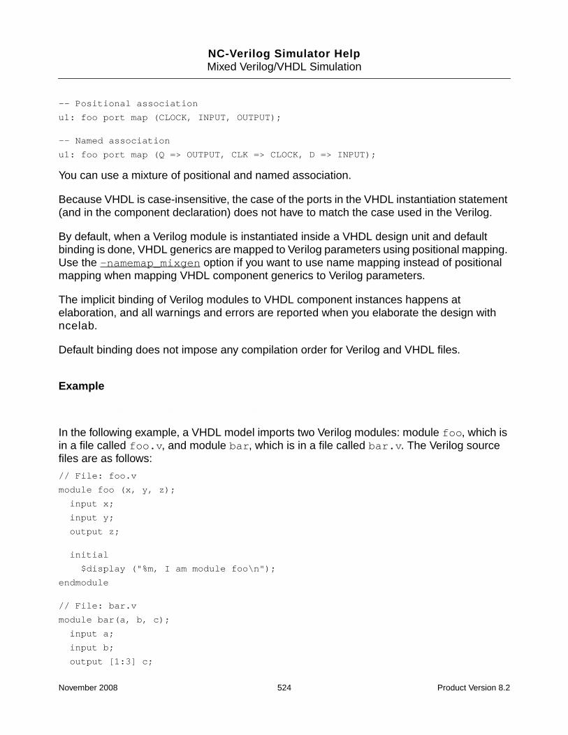
NC-Verilog Simulator HelpMixed Verilog/VHDL Simulation
-- Positional association
u1: foo port map (CLOCK, INPUT, OUTPUT);
-- Named association
u1: foo port map (Q => OUTPUT, CLK => CLOCK, D => INPUT);
You can use a mixture of positional and named association.
Because VHDL is case-insensitive, the case of the ports in the VHDL instantiation statement(and in the component declaration) does not have to match the case used in the Verilog.
By default, when a Verilog module is instantiated inside a VHDL design unit and defaultbinding is done, VHDL generics are mapped to Verilog parameters using positional mapping.Use the -namemap_mixgen option if you want to use name mapping instead of positionalmapping when mapping VHDL component generics to Verilog parameters.
The implicit binding of Verilog modules to VHDL component instances happens atelaboration, and all warnings and errors are reported when you elaborate the design withncelab.
Default binding does not impose any compilation order for Verilog and VHDL files.
Example
doc_examples/ncvlog/mixed_lang/vhdltop_noshell/ex1
In the following example, a VHDL model imports two Verilog modules: module foo, which isin a file called foo.v, and module bar, which is in a file called bar.v. The Verilog sourcefiles are as follows:
// File: foo.v
module foo (x, y, z);
input x;
input y;
output z;
initial
$display ("%m, I am module foo\n");
endmodule
// File: bar.v
module bar(a, b, c);
input a;
input b;
output [1:3] c;
November 2008 524 Product Version 8.2

NC-Verilog Simulator HelpMixed Verilog/VHDL Simulation
initial
$display("%m, I am module bar\n");
assign c = 3’b110;
endmodule
To import the Verilog modules into VHDL:
1. Write component declarations in the VHDL code for the Verilog modules, and theninstantiate the components.
You can write the component declarations manually, or you can use the ncshell utility togenerate it automatically. See “Using ncshell to Generate the Component Declaration”on page 536 for information on using ncshell to generate the component declaration.
In the instantiation statements, you can use either positional association or namedassociation to map the ports. In the following VHDL model, module foo is instantiatedthree times and module bar is instantiated two times. Named association is used to mapthe ports.
-- File: top.vhd
library ieee;
use ieee.std_logic_1164.all;
entity top is
end top;
architecture A of top is
component foo
port (x: in std_logic;
y: in std_logic;
z: out std_logic
);
end component;
component bar
port (a: in std_logic;
b: in std_logic;
c: out std_logic_vector(2 to 4)
);
end component;
signal ax: std_logic;
signal bx: std_logic_vector(1 to 5);
signal cx: std_logic;
signal dx: std_logic_vector(1 to 2);
November 2008 525 Product Version 8.2

NC-Verilog Simulator HelpMixed Verilog/VHDL Simulation
signal ex: std_logic;
begin
-- The following instantiation associates component-- ports with signals of the same width.
U1: foo port map (z => cx, y => ex, x => ax);
-- The following instantiation associates a component-- port (z) with a slice of an actual signal.
U2: foo port map (z => bx(4), x => ax, y => ex);
-- The following instantiation associates a slice of a-- component port (c(2 to 3)) with an actual signal.-- Note that you can associate mutually exclusive slices of-- a Verilog port to different signals.
U3: bar port map (c(4) => cx, c(2 to 3) => dx, a => ax, b => ex);
-- The following instantiation associates a component-- port (c) with a slice of an actual signal.
U4: bar port map (c => bx(1 to 3), b => ex, a => ax);
-- The following instantiation associates a component port (y)-- with an enumeration literal. Bit_string literals can also-- be associated with a port. You must compile with the -v93 option.
U5: foo port map (z => bx(4), y => ’1’, x => cx);
ax <= ’Z’;
tst_process: process
begin
ax <= ’1’ after 5 ns;
wait;
end process;
end;
Simulating the Design with irun
Use the following command to simulate the example in single-step invocation mode. The-libverbose option has been included on the command line to get more detailed bindingmessages.
% irun -nocopyright -q -libverbose foo.v bar.v top.vhd -v93 -top top
ncelab: *W,ARCMRA: Elaborating the WORKLIB.TOP:A, MRA (most recently analyzed)architecture.
Resolved design unit ’foo’ at ’:top:U1’ to ’worklib.foo:v ’
Resolved design unit ’foo’ at ’:top:U2’ to ’worklib.foo:v ’
November 2008 526 Product Version 8.2

NC-Verilog Simulator HelpMixed Verilog/VHDL Simulation
Resolved design unit ’bar’ at ’:top:U3’ to ’worklib.bar:v ’
Resolved design unit ’bar’ at ’:top:U4’ to ’worklib.bar:v ’
Resolved design unit ’foo’ at ’:top:U5’ to ’worklib.foo:v ’
Top level design units:
:top:
ncsim> run
:top:U1, I am module foo
:top:U2, I am module foo
:top:U3, I am module bar
:top:U4, I am module bar
:top:U5, I am module foo
ncsim: *W,RNQUIE: Simulation is complete.
ncsim> exit
Simulating the Design in Multi-Step Mode
1. Compile the Verilog source files using the Verilog compiler (ncvlog) and the VHDLsource files using the VHDL compiler (ncvhdl). You do not have to compile the Verilogfiles before the VHDL files.
% ncvlog foo.v // Compiles module foo into worklib.foo:module
% ncvlog bar.v // Compiles module bar into worklib.bar:module
% ncvhdl -v93 top.vhd // Compiles architecture A into WORKLIB.TOP:A
2. Elaborate the design using the ncelab elaborator. The -libverbose option has beenincluded on the command line to get more detailed binding messages.
% ncelab -nocopyright -messages -libverbose worklib.top:a
...
Elaborating the design hierarchy:
ncelab: *W,CUDEFB: default binding occurred for component instance (:top(A):U1)with verilog module (worklib.foo:module).
Resolved design unit ’foo’ at ’:top(A):U1’ to ’worklib.foo:module ’
ncelab: *W,CUDEFB: default binding occurred for component instance (:top(A):U2)with verilog module (worklib.foo:module).
Resolved design unit ’foo’ at ’:top(A):U2’ to ’worklib.foo:module ’
ncelab: *W,CUDEFB: default binding occurred for component instance (:top(A):U3)with verilog module (worklib.bar:module).
Resolved design unit ’bar’ at ’:top(A):U3’ to ’worklib.bar:module ’
ncelab: *W,CUDEFB: default binding occurred for component instance (:top(A):U4)with verilog module (worklib.bar:module).
November 2008 527 Product Version 8.2

NC-Verilog Simulator HelpMixed Verilog/VHDL Simulation
Resolved design unit ’bar’ at ’:top(A):U4’ to ’worklib.bar:module ’
ncelab: *W,CUDEFB: default binding occurred for component instance (:top(A):U5)with verilog module (worklib.foo:module).
Resolved design unit ’foo’ at ’:top(A):U5’ to ’worklib.foo:module ’
...
Writing initial simulation snapshot: WORKLIB.TOP:A
3. Invoke the simulator (ncsim) on the simulation snapshot.
% ncsim worklib.top:a // Loads the snapshot into the simulator
In this example, the elaborator applies default binding rules to bind the Verilog modules fooand bar to the component instances.
The elaborator first searches for a binding for foo and bar in the parent language (VHDL).
When searching for a VHDL binding, the elaborator adheres to a strict interpretation of theVHDL LRM, which states that you must use LIBRARY statements with corresponding USEclauses in the source code to provide visibility to the declarative region that an unboundinstance resides in. The search order is as follows:
1. A design unit made visible with a USE clause given to the architecture instantiating thecomponent.
2. A design unit made visible with a USE clause given to the entity of the architectureinstantiating the component.
3. A design unit available in the library into which the component was compiled. Forexample, if you have the following instantiation statement:
inst1 : DUT port map (......)
and the component DUT was compiled into library LIB_COMP, the elaborator will searchfor entity DUT in the library LIB_COMP.
4. A design unit in the work library.
Note: There are two elaborator command-line options that you can use to extend the set ofVHDL binding rules. These options (ncelab -lib_binding and ncelab -relax) bothenable a looser interpretation of the binding rules described in the LRM.
If the elaborator is not able to find a binding in the VHDL domain, it searches the entire librarystructure for an analyzed Verilog module that it can use for this binding, using the followingrules:
1. Look for a Verilog module whose name and case matches that used in the componentdeclaration.
2. Look for a Verilog module with a matching name, but that is all lowercase.
November 2008 528 Product Version 8.2

NC-Verilog Simulator HelpMixed Verilog/VHDL Simulation
3. Look for a Verilog module with a matching name in any case.
If a unique binding is found, and if the case matches, it is used. If a unique binding is found,but the case does not match, it is used with a warning. If multiple bindings are found, theelaborator generates an error message.
In this example, the component names used in the component declarations are foo and bar,and the Verilog module names are foo and bar, so the elaborator finds an exact match anduses these modules.
Using a Configuration Specification or Configuration Declaration
When you are instantiating a VHDL component, the component declaration can be explicitlybound to a specific entity in the library by using a configuration specification or a configurationdeclaration. The binding indication specifies exactly which design unit gets bound to thecomponent instance.
For example, in the following architecture a configuration specification is used to specify thatall instances of component alu are to be bound to the VHDL entity ent and architecturearch, which are present in the library WORK.
architecture A of processor is
component alu
port( ...) ;
end component;
-- Configuration specification
for all : alu use entity WORK.ent(arch) [port_map_aspect];
begin
U1: alu port map(...); -- Component instantiation statement
end A;
If the component that you are importing is a Verilog module, you can use a configurationspecification to explicitly bind the Verilog module to a VHDL component instance. Instead ofspecifying the entity and (optionally) the architecture, you specify the Verilog module nameand (optionally) the view.
For example, suppose that the component alu in the example above is a Verilog modulecalled alu. The following configuration specification specifies that all instances of thecomponent alu are to be bound to the Verilog design unit worklib.alu:module.
for all : alu use entity worklib.alu(module) [port_map_aspect];
November 2008 529 Product Version 8.2

NC-Verilog Simulator HelpMixed Verilog/VHDL Simulation
Unlike the case with default binding, when using a configuration specification, the name ofthe VHDL component in the component declaration, and the names of the component ports,can be different from the Verilog module name and port names.
To ensure that you are binding to exactly the Verilog module/view to which you want to bind,the case used in the module(view) pair in the configuration should match the case of thecompiled Verilog design unit. For example, if the compiled Verilog unit is worklib.ALU:rtl,the configuration specification should be:
for all : alu use entity worklib.ALU(rtl) [port_map_aspect];
In the instantiation statements, you can use either positional association or namedassociation to map the ports and generics.
Component/port/generic binding to Verilog happens during parsing, and so all warnings anderrors are reported when you compile the source files.
Because the Verilog modules are being configured from within a VHDL source file, the VHDLsource file is dependent on the Verilog source files. Therefore, you must compile the Verilogfiles before you compile the VHDL instantiating unit.
The following two examples illustrate how to import a Verilog module into VHDL using aconfiguration specification or a configuration declaration. Example 1 uses a configurationspecification. Example 2 uses a configuration declaration.
Example 1
doc_examples/ncvlog/mixed_lang/vhdltop_noshell/ex2
In this example, a VHDL model imports three Verilog modules: foo_rtl, foo_gate, andBAR. Module foo_rtl is an RTL view, which is described in the file foo.rtl. Modulefoo_gate is a gate-level view, which is described in the file foo.vg. Module BAR isdescribed in a file called bar.v. The architecture includes configuration specifications tocontrol the binding.
Write a component declaration in the VHDL code for the Verilog modules, and then instantiatethe components. You can write the component declaration manually, or you can use thencshell utility to generate it automatically. See “Using ncshell to Generate the ComponentDeclaration” on page 536 for information on using ncshell to generate the componentdeclaration.
In this example, there are two components called vlog_foo and vlog_bar. Notice that thename of the components can be different from the name of the Verilog modules.
Now write the configuration specifications to specify the binding explicitly.
November 2008 530 Product Version 8.2

NC-Verilog Simulator HelpMixed Verilog/VHDL Simulation
-- File: top.vhd
library ieee;
use ieee.std_logic_1164.all;
library worklib;
entity top is
end top;
architecture A of top is
component vlog_foo
port (x: in std_logic;
y: in std_logic;
z: out std_logic
);
end component;
component vlog_bar
port (a: in std_logic;
b: in std_logic;
c: out std_logic_vector(2 to 4)
);
end component;
signal ax: std_logic;
signal bx: std_logic_vector(1 to 5);
signal cx: std_logic;
signal dx: std_logic_vector(1 to 2);
signal ex: std_logic;
-- Configuration specifications
for U1 : vlog_foo use entity worklib.foo_gate(vg);
for others : vlog_foo use entity worklib.foo_rtl(rtl);
for all : vlog_bar use entity worklib.bar(v);
begin
-- Component instantiation statements
U1: vlog_foo port map (z => cx, y => ex, x => ax);
U2: vlog_foo port map (z => bx(4), x => ax, y => ex);
U3: vlog_bar port map (c(4) => cx, c(2 to 3) => dx, a => ax, b => ex);
U4: vlog_bar port map (c => bx(1 to 3), b => ex, a => ax);
U5: vlog_foo port map (z => bx(4), y => ’1’, x => cx);
ax <= ’Z’;
November 2008 531 Product Version 8.2

NC-Verilog Simulator HelpMixed Verilog/VHDL Simulation
tst_process: process
begin
ax <= ’1’ after 5 ns;
wait;
end process;
end;
Simulating the Design with irun
Use the following command to simulate the example in single-step invocation mode. The-libverbose option has been included on the command line to get more detailed bindingmessages.
Note: The file extensions .rtl and .vg are not predefined, recognized file extensions forirun. In the following command, the -vlog_ext option is used to add these two extensionsto the list of recognized extensions for Verilog files:
-vlog_ext +.rtl+.vg
% irun -nocopyright -libverbose -vlog_ext +.rtl+.vg \
foo.v foo.vg bar.v \
top.vhd -v93 -top top
file: foo.rtl
module worklib.foo_rtl:rtl
errors: 0, warnings: 0
file: foo.vg
module worklib.foo_gate:vg
errors: 0, warnings: 0
file: bar.v
module worklib.BAR:v
errors: 0, warnings: 0
top.vhd:
for all : vlog_bar use entity worklib.bar(v);
|
ncvhdl_p: *W,VLCINM (top.vhd,31|45): Verilog Unit Bound: (worklib.BAR:v) does notmatch Exact CASE.
errors: 0, warnings: 1
WORKLIB.TOP (entity):
...
Elaborating the design hierarchy:
Resolved design unit ’vlog_foo’ at ’:top(A):U1’ to ’worklib.foo_gate:vg ’
Resolved design unit ’vlog_foo’ at ’:top(A):U2’ to ’worklib.foo_rtl:rtl ’
November 2008 532 Product Version 8.2

NC-Verilog Simulator HelpMixed Verilog/VHDL Simulation
Resolved design unit ’vlog_bar’ at ’:top(A):U3’ to ’worklib.BAR:v ’
Resolved design unit ’vlog_bar’ at ’:top(A):U4’ to ’worklib.BAR:v ’
Resolved design unit ’vlog_foo’ at ’:top(A):U5’ to ’worklib.foo_rtl:rtl ’
Top level design units:
:top(a):
...
Writing initial simulation snapshot: WORKLIB.TOP:A
Loading snapshot worklib.top:a .................... Done
ncsim> run
:top:U1, I am module foo_gate
:top:U2, I am module foo_rtl
:top:U3, I am module BAR
:top:U4, I am module BAR
:top:U5, I am module foo_rtl
ncsim: *W,RNQUIE: Simulation is complete.
ncsim> exit
Simulating the Design in Multi-Step Mode
To simulate this example in multi-step mode:
1. Compile the Verilog source code for the Verilog block that you want to import.
Note: Because the Verilog modules are being configured from within a VHDL source file,the VHDL source file is dependent on the Verilog source files. Therefore, you mustcompile the Verilog files before you compile the VHDL instantiating unit.
% ncvlog foo.rtl -view rtl // Compiles module foo_rtl into// worklib.foo_rtl:rtl
% ncvlog foo.vg -view vg // Compiles module foo_gate into worklib.foo_gate:vg
% ncvlog bar.v -view v // Compiles module BAR into worklib.BAR:v
2. Compile the VHDL source code.
% ncvhdl -v93 top.vhd // Compiles architecture A into WORKLIB.TOP:A
3. Elaborate the design. The -libverbose option has been included on the command lineto get more detailed binding messages.
% ncelab -nocopyright -messages -libverbose worklib.top:a
4. Invoke the simulator (ncsim) on the simulation snapshot.
% ncsim worklib.top:a // Loads the snapshot into the simulator
November 2008 533 Product Version 8.2

NC-Verilog Simulator HelpMixed Verilog/VHDL Simulation
The parser first searches for a VHDL binding for foo_rtl, foo_gate, and BAR. If it does notfind a VHDL binding, the parser searches the entire library structure for an analyzed Verilogmodule that it can use as a binding, using the following rules:
1. Look for a Verilog module whose name and case matches that used in the bindingindication of the configuration specification.
2. Look for a Verilog module with a matching name, but that is all lowercase.
3. Look for a Verilog module with a matching name in any case.
If a unique binding is found, and if the case matches, it is used. If a unique binding is found,but the case does not match, it is used with a warning. If multiple possible bindings are found,the parser generates an error message.
In this example, the parser finds exact matches for foo_rtl:rtl and for foo_gate:vg.However, the parser generates a VLCINM warning message because the Verilog modulename is BAR, but the configuration specification uses lowercase.
Specifying a view name in the configuration specification is optional. If you do not specify aview name, and if there are multiple views in the library for a module, the parser generates anerror.
Example 2
doc_examples/ncvlog/mixed_lang/vhdltop_noshell/ex3
In the previous example, configuration specifications contained in the same architecture asthe component declarations were used to specify binding. You can also use a configurationdeclaration to specify the binding. For example, instead of using the configurationspecifications shown in the example above, you could write the following configuration file:
-- File vhdl_conf.vhd
configuration CONF of TOP is
for A
for U1 : vlog_foo
use entity worklib.foo_rtl(rtl);
end for;
for others : vlog_foo
use entity worklib.foo_gate(vg);
end for;
for all : vlog_bar
use entity worklib.bar(v);
end for;
November 2008 534 Product Version 8.2

NC-Verilog Simulator HelpMixed Verilog/VHDL Simulation
end for;
end configuration CONF;
Simulating the Design with irun
Use the following command to simulate the example in single-step invocation mode. The-top option specifies the top-level VHDL unit, the configuration called CONF. The-libverbose option has been included on the command line to get more detailed bindingmessages.
% irun -nocopyright -libverbose -vlog_ext +.rtl+.vg \
foo.rtl foo.vg bar.v \
-v93 top.vhd vhdl_conf.vhd -top CONF
file: foo.rtl
module worklib.foo_rtl:rtl
errors: 0, warnings: 0
file: foo.vg
module worklib.foo_gate:vg
errors: 0, warnings: 0
file: bar.v
module worklib.BAR:v
errors: 0, warnings: 0
top.vhd:
errors: 0, warnings: 0
vhdl_conf.vhd:
use entity worklib.bar(v);
|
ncvhdl_p: *W,VLCINM (vhdl_conf.vhd,10|25): Verilog Unit Bound: (worklib.BAR:v)does not match Exact CASE.
errors: 0, warnings: 1
WORKLIB.TOP (entity):
streams: 1, words: 9
WORKLIB.TOP:A (architecture):
streams: 1, words: 119
WORKLIB.CONF (configuration):
streams: 4, words: 30
Elaborating the design hierarchy:
Resolved design unit ’vlog_foo’ at ’:top(A):U1’ to ’worklib.foo_rtl:rtl ’
Resolved design unit ’vlog_foo’ at ’:top(A):U2’ to ’worklib.foo_gate:vg ’
Resolved design unit ’vlog_bar’ at ’:top(A):U3’ to ’worklib.BAR:v ’
Resolved design unit ’vlog_bar’ at ’:top(A):U4’ to ’worklib.BAR:v ’
Resolved design unit ’vlog_foo’ at ’:top(A):U5’ to ’worklib.foo_gate:vg ’
November 2008 535 Product Version 8.2

NC-Verilog Simulator HelpMixed Verilog/VHDL Simulation
...
...
Writing initial simulation snapshot: WORKLIB.CONF
Loading snapshot worklib.conf:configuration .................... Done
...
...
Simulating the Design in Multi-Step Mode
To simulate this example in multi-step mode:
1. Compile the Verilog source code for the Verilog block that you want to import.
Note: Because the Verilog modules are being configured from within a VHDL source file,the VHDL source file is dependent on the Verilog source files. Therefore, you mustcompile the Verilog files before you compile the VHDL instantiating unit.
% ncvlog foo.rtl -view rtl // Compiles module foo_rtl into// worklib.foo_rtl:rtl
% ncvlog foo.vg -view vg // Compiles module foo_gate into worklib.foo_gate:vg
% ncvlog bar.v -view v // Compiles module BAR into worklib.BAR:v
2. Compile the VHDL source code.
% ncvhdl -v93 top.vhd // Compiles architecture A into WORKLIB.TOP:A
% ncvhdl -v93 vhdl_conf.vhd // Compiles configuration CONF into// WORKLIB.CONF:CONFIGURATION
3. Elaborate the design.
% ncelab -nocopyright -messages -libverbose worklib.conf
4. Invoke the simulator (ncsim) on the simulation snapshot.
% ncsim worklib.conf // Loads the snapshot into the simulator
Note: You can automatically generate a configuration file with the ncelab -conffileoption. See the description of the -conffile option for more information on generating aconfiguration file.
Using ncshell to Generate the Component Declaration
You can run the ncshell utility to automatically generate the component declaration.
First, compile the Verilog source and then run ncshell. The argument to the ncshellcommand is the lib.cell:view specification for the compiled module.
November 2008 536 Product Version 8.2
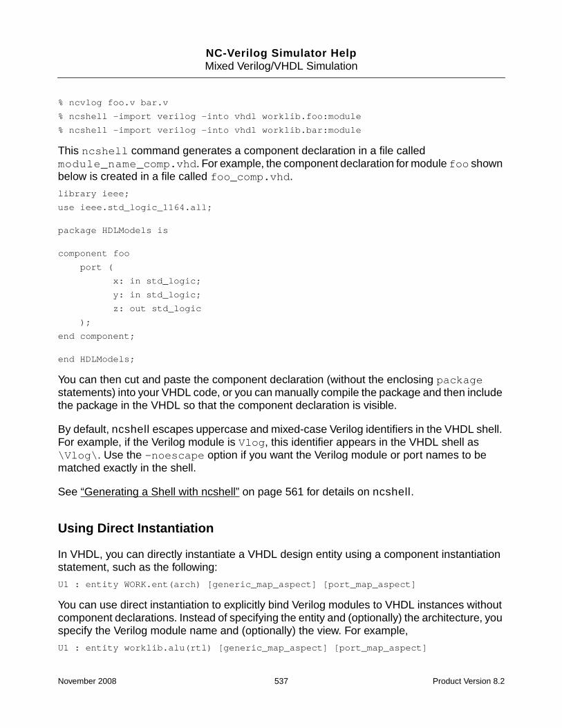
NC-Verilog Simulator HelpMixed Verilog/VHDL Simulation
% ncvlog foo.v bar.v
% ncshell -import verilog -into vhdl worklib.foo:module
% ncshell -import verilog -into vhdl worklib.bar:module
This ncshell command generates a component declaration in a file calledmodule_name_comp.vhd. For example, the component declaration for module foo shownbelow is created in a file called foo_comp.vhd.
library ieee;
use ieee.std_logic_1164.all;
package HDLModels is
component foo
port (
x: in std_logic;
y: in std_logic;
z: out std_logic
);
end component;
end HDLModels;
You can then cut and paste the component declaration (without the enclosing packagestatements) into your VHDL code, or you can manually compile the package and then includethe package in the VHDL so that the component declaration is visible.
By default, ncshell escapes uppercase and mixed-case Verilog identifiers in the VHDL shell.For example, if the Verilog module is Vlog, this identifier appears in the VHDL shell as\Vlog\. Use the -noescape option if you want the Verilog module or port names to bematched exactly in the shell.
See “Generating a Shell with ncshell” on page 561 for details on ncshell.
Using Direct Instantiation
In VHDL, you can directly instantiate a VHDL design entity using a component instantiationstatement, such as the following:
U1 : entity WORK.ent(arch) [generic_map_aspect] [port_map_aspect]
You can use direct instantiation to explicitly bind Verilog modules to VHDL instances withoutcomponent declarations. Instead of specifying the entity and (optionally) the architecture, youspecify the Verilog module name and (optionally) the view. For example,
U1 : entity worklib.alu(rtl) [generic_map_aspect] [port_map_aspect]
November 2008 537 Product Version 8.2

NC-Verilog Simulator HelpMixed Verilog/VHDL Simulation
Note: Direct instantiation of a design entity is a VHDL-93 feature. You must compile theVHDL source files with the -v93 command-line option.
In the instantiation statements, you can use either positional association or namedassociation to map the ports and generics.
If you are importing a Verilog module into VHDL using direct instantiation, a formal in a portor generic map aspect can only be a simple identifier. Named connections, bit selects, andpart selects are not allowed. For example, the following port map will result in an error.
U1: entity worklib.bar(module)
port map (c(4) => cx, c(2 to 3) => dx);
Component/port/generic binding to Verilog happens during parsing, and so all warnings anderrors are reported when you compile the source files.
Because the Verilog modules are being directly instantiated from within a VHDL source file,the VHDL source file is dependent on the Verilog source files. Therefore, you must compilethe Verilog files before you compile the VHDL instantiating unit.
Example
doc_examples/ncvlog/mixed_lang/vhdltop_noshell/ex4
In this example, instance U1 is bound to the Verilog design unit worklib.foo_rtl:rtl.Instances U2 and U5 are bound to worklib.foo_gate:vg. Both instances of module barare bound to worklib.bar:v.
library ieee;
use ieee.std_logic_1164.all;
library worklib;
entity top is
end top;
architecture A of top is
signal ax: std_logic;
signal bx: std_logic_vector(1 to 5);
signal cx: std_logic;
signal dx: std_logic_vector(1 to 2);
signal ex: std_logic;
begin
U1 : entity worklib.foo_rtl(rtl)
port map (z => cx, y => ex, x => ax);
November 2008 538 Product Version 8.2

NC-Verilog Simulator HelpMixed Verilog/VHDL Simulation
U2 : entity worklib.foo_gate(vg)
port map (z => bx(4), x => ax, y => ex);
U3 : entity worklib.bar(v)
port map (a => ax, b => ex);
U4 : entity worklib.bar(v)
port map (c => bx(1 to 3), b => ex, a => ax);
U5 : entity worklib.foo_gate(vg)
port map (z => bx(4), y => ’1’, x => cx); --allowed with -v93 option only.
ax <= ’Z’;
tst_process: process
begin
ax <= ’1’ after 5 ns;
wait;
end process;
end;
Simulating the Design with irun
Use the following command to simulate the example in single-step invocation mode. The -qoption suppresses informational messages. The -vlog_ext option adds .rtl and .vg tothe list of recognized file extensions for Verilog files. The -top option specifies the top-levelVHDL unit, TOP.
% irun -nocopyright -q -libverbose -vlog_ext +.rtl+.vg \
foo.rtl foo.vg bar.v \
-v93 top.vhd -top top
ncelab: *W,ARCMRA: Elaborating the WORKLIB.TOP:A, MRA (most recently analyzed)architecture.
Resolved design unit ’foo_rtl’ at ’:top:U1’ to ’worklib.foo_rtl:rtl ’
Resolved design unit ’foo_gate’ at ’:top:U2’ to ’worklib.foo_gate:vg ’
Resolved design unit ’bar’ at ’:top:U3’ to ’worklib.bar:v ’
Resolved design unit ’bar’ at ’:top:U4’ to ’worklib.bar:v ’
Resolved design unit ’foo_gate’ at ’:top:U5’ to ’worklib.foo_gate:vg ’
Top level design units:
:top:
ncsim> run
:top:U1, I am module foo_rtl
November 2008 539 Product Version 8.2

NC-Verilog Simulator HelpMixed Verilog/VHDL Simulation
:top:U2, I am module foo_gate
:top:U3, I am module bar
:top:U4, I am module bar
:top:U5, I am module foo_gate
ncsim: *W,RNQUIE: Simulation is complete.
ncsim> exit
Simulating the Design in Multi-Step Mode
To simulate this example in multi-step mode:
1. Compile the Verilog source code.
Note: Because the Verilog modules are being configured from within a VHDL source file,the VHDL source file is dependent on the Verilog source files. Therefore, you mustcompile the Verilog files before you compile the VHDL instantiating unit.
% ncvlog foo.rtl -view rtl // Compiles module foo_rtl into// worklib.foo_rtl:rtl
% ncvlog foo.vg -view vg // Compiles module foo_gate into worklib.foo_gate:vg
% ncvlog bar.v -view v // Compiles module bar into worklib.bar:v
2. Compile the VHDL source code.
% ncvhdl -v93 top.vhd // Compiles architecture A into WORKLIB.TOP:A
3. Elaborate the design.
% ncelab -messages -libverbose worklib.top:a // Generates snapshot// WORKLIB.TOP:A
4. Invoke the simulator (ncsim) on the simulation snapshot.
% ncsim worklib.top:a // Loads the snapshot into the simulator
When the design is elaborated, the elaborator first searches for a VHDL binding for foo_rtl,foo_gate and bar. If it does not find a VHDL binding, the elaborator searches the entirelibrary structure for an analyzed Verilog module that it can use as a binding, using thefollowing rules:
1. Look for a Verilog module whose name and case matches that used in the instantiationstatement.
2. Look for a Verilog module with a matching name, but that is all lowercase.
3. Look for a Verilog module with a matching name in any case.
November 2008 540 Product Version 8.2

NC-Verilog Simulator HelpMixed Verilog/VHDL Simulation
If a unique binding is found, and if the case matches, it is used. If a unique binding is found,but the case does not match, it is used with a warning. If multiple possible bindings are found,the elaborator generates an error message.
Specifying a view name in the instantiation statement is optional. If you do not specify a viewname, and if there are multiple views in the library for a module, the elaborator generates anerror.
Using a Shell
doc_examples/ncvlog/mixed_lang/vhdltop_shell
You can generate and use a model shell to import a Verilog module into VHDL.
The example used in this section is the same example used in “Using Default Binding” onpage 523, in which two Verilog modules (module foo and module bar) are imported into atop-level VHDL model.
Simulating the Design with irun
To simulate with irun:
1. Run irun with the -compile option to compile the design units in foo.v and bar.v.
% irun -nocopyright -compile foo.v bar.v
The modules are compiled into worklib.foo:v and worklib.bar:v.
2. Generate a model import shell for the block that you want to import using the ncshellutility. The argument to the ncshell command is the lib.cell:view specification for thecompiled module.
% ncshell -nocopyright -import verilog -into vhdl worklib.foo:v
% ncshell -nocopyright -import verilog -into vhdl worklib.bar:v
The ncshell command generates a VHDL shell in a file called module_name.vhdand then compiles the file. The two shell files for this example (foo.vhd and bar.vhd)are as follows:
-- File foo.vhd
library ieee;
use ieee.std_logic_1164.all;
entity foo is
port (
x: in std_logic;
November 2008 541 Product Version 8.2

NC-Verilog Simulator HelpMixed Verilog/VHDL Simulation
y: in std_logic;
z: out std_logic
);
end foo;
architecture verilog of foo is
attribute foreign of verilog:architecture is "VERILOG(event)worklib.foo:v";
begin
end;
-- File bar.vhd
library ieee;
use ieee.std_logic_1164.all;
entity bar is
port (
a: in std_logic;
b: in std_logic;
c: out std_logic_vector(1 to 3)
);
end bar;
architecture verilog of bar is
attribute foreign of verilog:architecture is "VERILOG(event)worklib.bar:v";
begin
end;
Notice that the name of the architecture in the shell defaults to verilog.
Note: In Verilog, identifiers are case-sensitive. By default, mixed-case and uppercaseidentifiers in Verilog are escaped in VHDL shells. For example, if the Verilog module isVlog, this identifier appears in the VHDL shell as \Vlog\. Use the -noescape optionif you want the Verilog module name to be matched exactly in the shell. Do not set theCDS_ALT_NMP environment variable. This variable is not supported.
3. In the VHDL file, specify that architecture verilog is to be used for entity foo and forentity bar. The VHDL file instantiating the Verilog modules in this example is as follows:
-- File: top.vhd
library ieee;
use ieee.std_logic_1164.all;
library worklib;
November 2008 542 Product Version 8.2

NC-Verilog Simulator HelpMixed Verilog/VHDL Simulation
entity top is
end top;
architecture A of top is
component foo
port (x: in std_logic;
y: in std_logic;
z: out std_logic
);
end component;
component bar
port (a: in std_logic;
b: in std_logic;
c: out std_logic_vector(2 to 4)
);
end component;
for all: foo use entity worklib.foo(verilog);
for all: bar use entity worklib.bar(verilog);
signal ax: std_logic;
signal bx: std_logic_vector(1 to 5);
signal cx: std_logic;
signal dx: std_logic_vector(1 to 2);
signal ex: std_logic;
begin
i1: foo port map (z => cx, y => ex, x => ax);
i2: foo port map (z => bx(4), x => ax, y => ex);
i3: bar port map (c(4) => cx, c(2 to 3) => dx, a => ax, b => ex);
i4: bar port map (c => bx(1 to 3), b => ex, a => ax);
i5: foo port map (z => bx(4), y => ’1’, x => cx);
ax <= ’Z’;
tst_process: process
begin
ax <= ’1’ after 5 ns;
November 2008 543 Product Version 8.2

NC-Verilog Simulator HelpMixed Verilog/VHDL Simulation
wait;
end process;
end;
4. Run irun again, specifying the top-level VHDL file.
% irun -nocopyright -q -libverbose -v93 top.vhd -top top
ncelab: *W,ARCMRA: Elaborating the WORKLIB.TOP:A, MRA (most recently analyzed)architecture.
Resolved design unit ’foo’ at ’:top:i1’ to ’WORKLIB.foo:verilog’
Module ’worklib.foo:v’ is instanced under VHDL at ’:top:i1’
Resolved design unit ’foo’ at ’:top:i2’ to ’WORKLIB.foo:verilog’
Module ’worklib.foo:v’ is instanced under VHDL at ’:top:i2’
Resolved design unit ’bar’ at ’:top:i3’ to ’WORKLIB.bar:verilog’
Module ’worklib.bar:v’ is instanced under VHDL at ’:top:i3’
Resolved design unit ’bar’ at ’:top:i4’ to ’WORKLIB.bar:verilog’
Module ’worklib.bar:v’ is instanced under VHDL at ’:top:i4’
Resolved design unit ’foo’ at ’:top:i5’ to ’WORKLIB.foo:verilog’
Module ’worklib.foo:v’ is instanced under VHDL at ’:top:i5’
Top level design units:
:top:
ncsim> run
:top:i1, I am module foo
:top:i2, I am module foo
:top:i3, I am module bar
:top:i4, I am module bar
:top:i5, I am module foo
ncsim: *W,RNQUIE: Simulation is complete.
ncsim> exit
Simulating the Design in Multi-Step Mode
To simulate this example in multi-step mode:
1. Compile the Verilog source code for the Verilog blocks that you want to import using theVerilog compiler (ncvlog).
% ncvlog -nocopyright foo.v // Compiles module foo into worklib.foo:module
% ncvlog -nocopyright bar.v // Compiles module bar into worklib.bar:module
November 2008 544 Product Version 8.2

NC-Verilog Simulator HelpMixed Verilog/VHDL Simulation
Note: The ncvlog compiler generates a view name of module by default (for example,worklib.foo:module). irun generates a view name that matches the extension of thefile being compiled (for example, worklib.foo:v).
2. Generate a model import shell for the block that you want to import using the ncshellutility. The argument to the ncshell command is the lib.cell:view specification for thecompiled module.
% ncshell -nocopyright -import verilog -into vhdl worklib.foo:module
% ncshell -nocopyright -import verilog -into vhdl worklib.bar:module
3. In the VHDL file, specify that architecture verilog is to be used for entity foo and forentity bar.
4. Compile the top-level VHDL file (top.vhd).
% ncvhdl -v93 top.vhd // Compiles architecture A into WORKLIB.TOP:A
5. Elaborate the design.
% ncelab worklib.top:a // Generates snapshot WORKLIB.TOP:A
6. Invoke the simulator (ncsim) on the simulation snapshot.
% ncsim worklib.top:a
November 2008 545 Product Version 8.2

NC-Verilog Simulator HelpMixed Verilog/VHDL Simulation
Importing VHDL into Verilog
You can import a VHDL block into a Verilog module if the VHDL design unit meets thefollowing criteria:
■ The design unit is an entity/architecture pair or a configuration declaration.
■ The entity ports are of type std_logic, std_ulogic, std_logic_vector,std_ulogic_vector, signed, or unsigned. A vector port must be constrained.
■ VHDL ports cannot be bidirects that connect to Verilog tran gates.
■ The generics are of type integer, real, string, time, BOOLEAN, or a user-definedenumerated type.
To reference a VHDL entity or configuration from a Verilog module, you instantiate the VHDLdesign unit in your Verilog code using the same Verilog language mechanism that you use forinstantiating another Verilog module.
Because VHDL is case-insensitive, there can never be multiple entities with names like vhdl,Vhdl, or VHDL. You can, therefore, use lowercase, uppercase, or mixed-case for the VHDLentity name in the Verilog instantiation.
You can also import a VHDL block into a Verilog module by generating a model import shellfor the VHDL block. The shell is a Verilog module that contains a foreign attribute thatpoints to the compiled VHDL architecture.
Using a Verilog shell to import a VHDL block is required if component names are differentfrom the actual design unit names. For example, suppose that you have a component calledfoo in your Verilog code, but the actual name of the VHDL design unit is myfoo. After yougenerate the model shell, you can specify the correct binding in Verilog for the VHDL designunit by modifying the foreign attribute in the shell so that it uses the correct design unit.
(*const integer foreign="VHDL(event) library.myfoo:structural";*);
Note: The ncshell utility cannot generate a shell for protected Verilog or VHDL models. Forexample, if you use ncprotect to protect a VHDL architecture, you cannot run ncshell togenerate a Verilog shell because protected units cannot be accessed.
The following two examples, “Importing VHDL into Verilog without a Shell” on page 549 and“Importing VHDL into Verilog with a Shell” on page 552, illustrate how to import VHDL intoVerilog.
November 2008 546 Product Version 8.2

NC-Verilog Simulator HelpMixed Verilog/VHDL Simulation
Using Escaped Names in VHDL Portions of the Design
Important
Cadence strongly recommends that you avoid using escaped names for VHDLentities imported into Verilog modules, and for VHDL ports or generics, because thiscan cause name mapping problems.
However, if you must import VHDL entities that have escaped names, or if escaped namesare used for VHDL ports or generics, you must elaborate the design with the -mixesc option.
You must also use the correct name-mapped name for the VHDL entity when you instantiatethe VHDL entity in the Verilog module.
For example, suppose that you have a VHDL entity in which the name of the entity is escaped.In this case, you must:
1. Use the correct, name-mapped name in the Verilog module when you instantiate theentity. This name can be determined by running the nmp utility. For example, if theescaped entity name is \FOO\, you can determine the name to use in the Veriloginstantiation with the following command:
% nmp mapName VHDL Verilog “\FOO\”
FOO
The following table summarizes the name mapping:
Example:
-- File and.vhd
library ieee;
use ieee.std_logic_1164.all;
entity \Ent\ is
port(in1 : in std_logic;
ou : out std_logic);
end;
VHDL Entity Name Name Used in Verilog Instantiation
Lowercase (\entityname\) ESC_entityname
Uppercase (\ENTITYNAME\) ENTITYNAME
Mixed-case (\ENTITYname\) ENTITYname
November 2008 547 Product Version 8.2

NC-Verilog Simulator HelpMixed Verilog/VHDL Simulation
architecture a of \Ent\ is
begin
ou <= in1;
end architecture a;
// File test.v
module test (i1, o1);
input i1;
output o1;
Ent inst1(i1,o1);
endmodule
2. Use the -mixesc command-line option when you elaborate the design.
doc_examples/ncvlog/mixed_lang/mixesc/ex1% ncelab -mixesc top_level_module
Escaping the VHDL names preserves the case of the design unit, but VHDL design unitswith escaped names are compiled with a cell name that includes backslash characters.For example, the entity and architecture shown in the example above are compiled asfollows:
% ncvhdl -nocopyright -v93 and.vhd
and.vhd:
errors: 0, warnings: 0
WORKLIB.\Ent\ (entity):
streams: 3, words: 15
WORKLIB.\Ent\:A (architecture):
streams: 1, words: 23
doc_examples/ncvlog/mixed_lang/mixesc/ex2
If you do not use the -mixesc option, the elaborator will generate a CUVMUR error whenit tries to resolve the instance called Ent because a compiled unit with a cell name ofEnt does not exist.
November 2008 548 Product Version 8.2

NC-Verilog Simulator HelpMixed Verilog/VHDL Simulation
Importing VHDL into Verilog without a Shell
In the example shown in this section, a Verilog module imports the following VHDL model.
doc_examples/ncvlog/mixed_lang/vlogtop_noshell-- File foo.vhd
library ieee;
use ieee.std_logic_1164.all;
entity foo is
port (a: in std_logic_vector(1 to 3);
b: out std_logic_vector(1 to 3)
);
end foo;
architecture foo_arch of foo is
begin
b <= "010";
end;
This VHDL model is imported into the Verilog code using the normal Verilog languagemechanism for instantiating components.
In the instantiation statements, you can use either positional association or namedassociation to map the ports. In the following Verilog module, the VHDL design unit foo isinstantiated two times using named association.
// File top.v
module top;
reg [1:3] a1x, a2x;
wire [1:3] a1x_w = a1x;
wire [1:4] b1x;
wire b2x;
initial
begin
a1x = 3’b1Z0;
a2x = 3’bX11;
end
// The following instantiation associates a formal VHDL port (a) with// the Verilog signal a1x_w.// The VHDL formal port b is associated with a complicated actual expression,// in this case, a concatenation. The various subparts of the// concatenation expression can be entire signals or slices of a signal.
November 2008 549 Product Version 8.2

NC-Verilog Simulator HelpMixed Verilog/VHDL Simulation
foo i1 (.b({b1x[2:3], b2x}), .a(a1x_w));
// The following instantiation associates a constant expression (3’b101)// with a VHDL port (a).
foo i2 (.b({b1x[2:3], b2x}), .a(3’b101));
endmodule
The elaborator searches for a Verilog binding for instances i1 and i2. If it does not find aVerilog binding, the elaborator searches the entire library structure for a successful VHDLbinding (an analyzed VHDL architecture for entity foo or a VHDL configuration for entityfoo). If a unique binding is found, it is used. If multiple bindings are found, the elaboratorgenerates an error message.
Simulating the Design with irun
To simulate with irun, use the following command. Include the -libverbose option to getdetailed binding messages.
% irun -nocopyright -libverbose foo.vhd top.v
file: top.v
module worklib.top:v
errors: 0, warnings: 0
foo.vhd:
errors: 0, warnings: 0
WORKLIB.FOO (entity):
streams: 5, words: 77
WORKLIB.FOO:FOO_ARCH (architecture):
streams: 1, words: 23
Caching library ’worklib’ ....... Done
Elaborating the design hierarchy:
Resolving design unit ’foo’ at ’top.i1’.
Caching library ’worklib’ ....... Done
library: ’worklib’ views: ’v’ ’vp’ ’vs’ ’V’ ’VP’ ’VS’ ’sv’ ’svp’ ’SV’ ’SVP’’svi’ ’svh’ ’vlib’ ’VLIB’ ’vams’ ’VAMS’ -> not found
Resolving design unit ’foo’ at ’top.i1’.
library: ’worklib’ views: ’v’ ’vp’ ’vs’ ’V’ ’VP’ ’VS’ ’sv’ ’svp’ ’SV’ ’SVP’’svi’ ’svh’ ’vlib’ ’VLIB’ ’vams’ ’VAMS’ -> not found
ncelab: *W,CUDEFB: default binding occurred for component instance (top.i1) withdesign unit (WORKLIB.FOO:FOO_ARCH).
instance of module ’foo’ in ’worklib.top:v’ is resolved to the VHDL architectureWORKLIB.FOO:FOO_ARCH
instance of module ’foo’ in ’worklib.top:v’ is resolved to the VHDL architectureWORKLIB.FOO:FOO_ARCH
Top level design units:
November 2008 550 Product Version 8.2

NC-Verilog Simulator HelpMixed Verilog/VHDL Simulation
top
...
Writing initial simulation snapshot: worklib.top:v
Loading snapshot worklib.top:v .................... Done
ncsim> run
ncsim: *W,RNQUIE: Simulation is complete.
ncsim> exit
Simulating the Design in Multi-Step Mode
To simulate this example in multi-step mode:
1. Compile the VHDL source code.
% ncvhdl -nocopyright foo.vhd // Compiles architecture foo_arch into// WORKLIB.FOO:FOO_ARCH
2. Compile your Verilog source files.
% ncvlog -nocopyright top.v // Compiles module top into worklib.top:module
3. Elaborate the design.
% ncelab -nocopyright -messages -libverbose worklib.top:module
Elaborating the design hierarchy:
Resolving design unit ’foo’ at ’top.i1’.
Caching library ’worklib’ ....... Done
library: ’worklib’ views: ’module’ ’udp’ -> not found
Caching library ’std’ ....... Done
library: ’std’ views: ’module’ ’udp’ -> not found
Caching library ’synopsys’ ....... Done
library: ’synopsys’ views: ’module’ ’udp’ -> not found
Caching library ’ieee’ ....... Done
library: ’ieee’ views: ’module’ ’udp’ -> not found
Caching library ’ambit’ ....... Done
library: ’ambit’ views: ’module’ ’udp’ -> not found
Caching library ’vital_memory’ ....... Done
library: ’vital_memory’ views: ’module’ ’udp’ -> not found
Caching library ’ncutils’ ....... Done
library: ’ncutils’ views: ’module’ ’udp’ -> not found
Caching library ’ncinternal’ ....... Done
library: ’ncinternal’ views: ’module’ ’udp’ -> not found
Caching library ’ncmodels’ ....... Done
library: ’ncmodels’ views: ’module’ ’udp’ -> not found
Caching library ’cds_assertions’ ....... Done
November 2008 551 Product Version 8.2

NC-Verilog Simulator HelpMixed Verilog/VHDL Simulation
library: ’cds_assertions’ views: ’module’ ’udp’ -> not found
ncelab: *W,CUDEFB: default binding occurred for component instance (top.i1)with design unit (WORKLIB.FOO:FOO_ARCH).
instance of module ’foo’ in ’worklib.top:module’ is resolved to the VHDLarchitecture WORKLIB.FOO:FOO_ARCH
instance of module ’foo’ in ’worklib.top:module’ is resolved to the VHDLarchitecture WORKLIB.FOO:FOO_ARCH
...
...
Writing initial simulation snapshot: worklib.top:module
4. Invoke the simulator (ncsim) on the simulation snapshot.
% ncsim -nocopyright worklib.top:module // Load and simulate the snapshot
Importing VHDL into Verilog with a Shell
You can import a VHDL component into a Verilog module using a shell. Because you cangenerate a shell that names a specific lib.cell:view, using a shell provides a way to configurethe design. This is useful if you want to bind VHDL units with the same name from differentlibraries, or to select a specific architecture when there are multiple architectures.
In the following example, entity DFF has three architectures called first, second, andthird. The example shows you how to specify which architecture to use by generating ashell.
doc_examples/ncvlog/mixed_lang/vlogtop_with_multiple_architectureslibrary IEEE;
use IEEE.STD_LOGIC_1164.all;
entity DFF is
generic(inta : integer := 1; intb : integer := 1);
port(inp, outp : std_logic);
end DFF;
library IEEE;
use IEEE.STD_LOGIC_1164.all;
architecture FIRST of DFF is
begin
assert FALSE report "Arch - 1";
end FIRST;
library IEEE;
use IEEE.STD_LOGIC_1164.all;
November 2008 552 Product Version 8.2

NC-Verilog Simulator HelpMixed Verilog/VHDL Simulation
architecture SECOND of DFF is
begin
assert FALSE report "Arch - 2";
end SECOND;
library IEEE;
use IEEE.STD_LOGIC_1164.all;
architecture THIRD of DFF is
begin
assert FALSE report "Arch - 3";
end THIRD;
The VHDL entity DFF is instantiated in a Verilog module as follows:
dff dff_i (q, en);
You can specify which architecture to use by using a shell to import the VHDL design unit.
One shell cannot point to two architectures. To force different bindings for different instances,you can generate one shell per architecture, specifically naming the shells, and theninstantiate the shells.
1. Compile the VHDL source code for the VHDL block that you want to import.
% irun -compile dff.vhd
or:
% ncvhdl dff.vhd
2. Generate the shells. Include the -nocompile option so that ncshell does not compilethe shell.
% ncshell -import vhdl -into verilog work.dff:first -shell dff_first.vs-nocompile
% ncshell -import vhdl -into verilog work.dff:second -shell dff_second.vs-nocompile
% ncshell -import vhdl -into verilog work.dff:third -shell dff_third.vs-nocompile
3. Edit each shell so that the module name matches the name of the shell.
In this example, change the module names from dff to dff_first, dff_second, anddff_third, respectively.
4. Compile the shell files.
% irun -compile dff_first.vs dff_second.vs dff_third.vs
or:
% ncvlog dff_first.vs dff_second.vs dff_third.vs
November 2008 553 Product Version 8.2

NC-Verilog Simulator HelpMixed Verilog/VHDL Simulation
5. Instantiate the shell modules in the Verilog file. For example:
dff_first D1 (ports...);
dff_second D2 (ports...);
dff_third D3 (ports...);
6. Run irun on the top Verilog file (or compile the Verilog HDL file and then elaborate thedesign).
Note: In the current release, irun does not add DEFINE statements in the cds.lib filethat it generates to define libraries such as std and ieee. In the following iruncommand, the -cdslib option is used to specify the cds.lib file in the installation thatdefines these libraries.
% irun -cdslib $CDS_INST_DIR/tools/inca/files/cds.lib -libverbose top.v
or:
% ncvlog top.v
% ncelab -libverbose worklib.top
Verilog Shell Filenames and View Names
When you import a VHDL model into Verilog using a model import shell, you can specify thefile extension for the shell with the -suffix option. If you do not use the -suffix optionncshell gives the shell a .vs file extension.
ncshell invokes ncvlog to analyze the Verilog shell in the library where the original VHDLmodel was analyzed. The following rules determine the view name under which the Verilogshell is analyzed:
1. If the hdl.var file has a VIEW_MAP variable specified, then that view name mapping isused.
2. If the hdl.var file does not have a VIEW_MAP defined, then a VIEW_MAP variable isadded to the hdl.var file with the following syntax:
define VIEW_MAP ($VIEW_MAP, file_extension_in_use => view_name)
❑ If view_name is provided through the -view option, then it is used.
❑ In all other cases, the default view_name of shell is used.
Using the -binding Option
You can use the -binding option when you elaborate the design to specify bindings. Theargument is the lib.cell:view of the compiled architecture. For example:
doc_examples/ncvlog/mixed_lang/binding_option
November 2008 554 Product Version 8.2

NC-Verilog Simulator HelpMixed Verilog/VHDL Simulation
With irun:
% irun -libverbose -binding worklib.dff:second \
dff.vhd top.v
Multi-step mode:
% ncvhdl -nocopyright dff.vhd
% ncvlog -nocopyright top.v
% ncelab -nocopyright -libverbose -binding worklib.dff:second worklib.top
The -binding option is global to the design. Once the first instance has been resolved, allinstances of the same design unit are resolved the same way.
Using a VHDL Configuration
You can use a VHDL configuration declaration to configure a mixed-language design. Forexample, a VHDL configuration can be used to force the binding of different VHDLarchitectures to Verilog instances. See “Configuring a Mixed-Language Design with a VHDLConfiguration Declaration” on page 570 for details.
November 2008 555 Product Version 8.2

NC-Verilog Simulator HelpMixed Verilog/VHDL Simulation
A Verilog-VHDL-Verilog Example
In the example shown in this section, a Verilog top-level module, described in the file top.v,contains two instantiations of a VHDL block, which is described in the file middle.vhd. EachVHDL instantiation has a Verilog child, which is described in the file sub.v.
You can import the Verilog module into VHDL and then import the VHDL into Verilog with orwithout a shell.
Source Code
The source code for the example is as follows:
doc_examples/ncvlog/mixed_lang/sandwich// File: sub.v
module vlog(io, c0);
inout io;
input c0;
reg r_io;
wire io = r_io;
November 2008 556 Product Version 8.2

NC-Verilog Simulator HelpMixed Verilog/VHDL Simulation
always @(io or c0)
$display("%t %m ctrl=%v io=%v", $time, c0, io);
always @(c0)
begin
if (c0 == 1’b1)
begin
$display("drive X\n"); r_io = 1’bx;
#10 $display("drive 0\n"); r_io = 1’b0;
#10 $display("drive 1\n"); r_io = 1’b1;
#10 $display("drive Z\n"); r_io = 1’bz;
end
else
r_io = 1’bz;
end
endmodule
The following version of the file middle.vhd contains a component declaration for importingthe Verilog module vlog, described in sub.v. You can write the component declarationmanually, or you can use the ncshell utility to generate it automatically. See “Using ncshellto Generate the Component Declaration” on page 536 for information on using ncshell togenerate the component declaration.
When you instantiate the component in the VHDL code, you can use either positional or namemapping syntax for the ports.
-- File: middle.vhd
library ieee;
use ieee.std_logic_1164.all;
library worklib;
entity middle is
port (io :inout std_logic;
vctrl : in std_logic_vector(1 downto 0));
end middle;
architecture A of middle is
component vlog
port (
io : inout std_logic;
c0 : in std_logic
);
November 2008 557 Product Version 8.2

NC-Verilog Simulator HelpMixed Verilog/VHDL Simulation
end component;
signal ctrl : std_ulogic;
begin
v1: vlog
port map(
io,
vctrl(1)
);
ctrl <= vctrl(0);
process
begin
wait on ctrl;
if (ctrl = ’1’) then
for val in STD_ULOGIC’LEFT to STD_ULOGIC’RIGHT loop
io <= val;
wait for 10 ns;
end loop;
end if;
io <= ’Z’;
end process;
process (io)
begin
assert FALSE
report "ctrl = " & STD_ULOGIC’IMAGE(ctrl) & ":middle:io = " &STD_LOGIC’IMAGE(io)
severity NOTE;
end process;
end A;
The following file contains the top-level Verilog module. Instantiate the VHDL design unit inyour Verilog code using the normal Verilog language mechanism for instantiatingcomponents. You can use either positional or name mapping for the ports.
// File: top.v
module top;
reg [4:0] vctrl;
reg r_io;
wire c0 = vctrl[4];
wire io = r_io;
November 2008 558 Product Version 8.2

NC-Verilog Simulator HelpMixed Verilog/VHDL Simulation
middle m10 (io, vctrl[1:0]);
middle m32 (io, vctrl[3:2]);
always @(io or c0)
$display("%t %m ctrl=%v io=%v", $time, c0, io);
always @(c0)
begin
if (c0 == 1’b1)
begin
$display("drive X\n"); r_io = 1’bx;
#10 $display("drive 0\n"); r_io = 1’b0;
#10 $display("drive 1\n"); r_io = 1’b1;
#10 $display("drive Z\n"); r_io = 1’bz;
end
else
r_io = 1’bz;
end
initial
begin
vctrl = 5’b0000;
#200 vctrl = 5’b00001;
#200 vctrl = 5’b00010;
#200 vctrl = 5’b00100;
#200 vctrl = 5’b01000;
#200 vctrl = 5’b10000;
end
endmodule
Simulating the Design with irun
Use the following command to simulate the design with irun:
% irun -libverbose sub.v top.v \
-v93 middle.vhd
Simulating the Design in Multi-Step Mode
1. Compile the Verilog source sub.v.
% ncvlog -nocopyright sub.v // Generates worklib.vlog:module
November 2008 559 Product Version 8.2

NC-Verilog Simulator HelpMixed Verilog/VHDL Simulation
2. Compile the VHDL source code.
% ncvhdl -nocopyright -v93 middle.vhd
3. Compile the Verilog code contained in top.v.
% ncvlog -nocopyright top.v // Generates worklib.top:module
4. Elaborate the design.
% ncelab -nocopyright -libverbose worklib.top:module
This command generates a simulation snapshot called worklib.top:module.
5. Simulate the snapshot.
% ncsim -nocopyright worklib.top:module
November 2008 560 Product Version 8.2

NC-Verilog Simulator HelpMixed Verilog/VHDL Simulation
Generating a Shell with ncshell
The ncshell utility generates a shell file that lets you import Verilog models into VHDLsimulations and VHDL models into Verilog simulations.
Note: The ncshell utility cannot generate a shell for protected Verilog or VHDL models. Forexample, if you use ncprotect to protect a VHDL architecture, you cannot run ncshell togenerate a Verilog shell because protected units cannot be accessed.
ncshell Command Syntax
Invoke ncshell with options and arguments. Options can occur in any order. Parameters tooptions must immediately follow the option they modify. Command-line options can beabbreviated to the shortest unique string, indicated by capital letters.
ncshell -import {vhdl | verilog} -into {vhdl | verilog} [other_options]lib.cell:view
The -import option, which specifies the kind of model (that is, the language of the model)being imported, and the -into option, which specifies the kind of model into which import isbeing done, are required.
The argument is the library.cell:view specification of the compiled design unit that you wantto import.
The ncshell command-line options listed in this section are divided into the following threegroups:
■ General options
■ Options that you can use when you are importing VHDL into Verilog
■ Options that you can use when you are importing Verilog into VHDL
You can use the NCSHELLOPTS variable in the hdl.var file to specify ncshell command-lineoptions.
General Options
You can use the following options if you are importing Verilog into VHDL or if you are importingVHDL into Verilog.
[-64bit]
[-ANALYze filename]
[-ANALOpts “compiler_options”]
November 2008 561 Product Version 8.2

NC-Verilog Simulator HelpMixed Verilog/VHDL Simulation
[-APpend_log]
[-CDslib filename]
[-Errormax integer]
[-FIle filename]
[-HDlvar filename]
[-HElp]
[-IMport {vhdl | verilog}]
[-INto {vhdl | verilog}]
[-LOgfile logfile_name]
[-Messages]
[-NCError warning_code[:warning_code ...]]
[-NCFatal {warning_code | error_code}[:{warning_code | error_code} ...]]
[-NEverwarn]
[-NOCOPyright]
[-NOCOMpile]
[-NOLog]
[-NOStdout]
[-NOWarn warning_code[:warning_code ...]]
[-SHell shell_output_filename]
[-VErsion]
[-Work work_library]
VHDL Models Imported into Verilog
You can use the following options with -import vhdl -into verilog.
[-Backward]
[-Generic]
[-LIst]
[-SUffix]
[-VIew viewname]
Verilog Models Imported into VHDL
You can use the following options with -import verilog -into vhdl.
[-Backward]
[-Comp component_output_file]
[-Generic]
[-LIst]
[-NOEscape]
[-Ulogic]
November 2008 562 Product Version 8.2

NC-Verilog Simulator HelpMixed Verilog/VHDL Simulation
ncshell Command Options
-64bit
Invokes the 64-bit version of the ncshell executable.
Besides including the -64bit command-line option when you run the NC executables, youcan also run the 64-bit version by:
■ Setting the INCA_64BIT environment variable.
■ Setting up your PATH and library path environment variables so that you are pointing tothe 64-bit version.
The -64bit command-line option is ignored if you have already specified that you want torun in 64-bit mode by setting environment variables.
You cannot use the -64bit option in flows with tools that do not support 64-bit.
-ANALOpts “compiler_options”
Specifies one or more ncvhdl or ncvlog command-line options. ncshell passes theseoptions to the compiler when it invokes the compiler to compile the HDL source file that youspecify with the -analyze option.
If you specify more than one option, you must enclose the list in quotation marks. Forexample:
% ncshell -messages -analyze sub.vhd -import vhdl -into verilog
worklib.sub:A -analopts "-messages -neverwarn -v93"
See Chapter 6, “Compiling Verilog Source Files with ncvlog,” for information on ncvlogcompiler options. See “Compiling VHDL Source Files with ncvhdl” in the NC-VHDLSimulator Help for information on ncvhdl compiler options.
-ANALYze filename
Specifies the HDL source file that you want to analyze. This option specifies that you wantncshell to invoke the compiler on the source file before generating a shell. For example, thefollowing command invokes ncvhdl to compile the file sub.vhd before invoking ncshell togenerate the shell.
% ncshell -messages -analyze sub.vhd -import vhdl -into verilog worklib.sub:A
You do not need to specify this option if the source file has already been analyzed.
November 2008 563 Product Version 8.2

NC-Verilog Simulator HelpMixed Verilog/VHDL Simulation
Use the -list option to analyze multiple files. Use the -analopts option to specifycommand-line options that you want passed to the ncvlog or ncvhdl compiler.
-APpend_log
Appends log information from multiple runs of ncshell to one log file. If you do not use thisoption, the log file is overwritten each time you run ncshell. The -nolog option overridesthis option.
-Backward
Provides compatibility with Leapfrog VHDL and Verilog-XL shells. NC model shells use adifferent syntax than that supported by Leapfrog and Verilog-XL.
Use this option when you want the Leapfrog or Verilog-XL shells to be used in themixed-language simulation flow instead of the syntax used in NC shells.
-CDslib filename
Specifies the name of the cds.lib file to load. See “The cds.lib File” on page 133 for moreinformation.
-COmp output_filename
(Verilog into VHDL)
Specifies the filename for the VHDL component declaration.
When you run ncshell to generate a VHDL shell to import a Verilog module, ncshell alsogenerates a component declaration corresponding to the shell. The default filename ismodel_name_comp.vhd (the model name with _comp.vhd appended). Use the -compoption to specify a different filename.
-Errormax integer
Aborts after reaching the specified number of errors.
November 2008 564 Product Version 8.2

NC-Verilog Simulator HelpMixed Verilog/VHDL Simulation
-FIle filename
Uses the command-line arguments contained in the specified file.
You can store frequently-used or lengthy command lines by putting command options andarguments in a text file. When you invoke ncshell with the -file option, the arguments inthe specified file are used with the command as if they had been entered on the commandline.
You must specify each option and its arguments on a separate line.
-Generic
(Verilog or VHDL model import)
Converts the VHDL generic data types to Verilog parameter declarations, or convertVerilog parameter declarations to VHDL generic data types.
By default, ncshell creates only the port interface in the shell. The VHDL genericdeclarations and Verilog parameter declarations are not included. Use the -generic optionwhen you want VHDL generic data types converted to Verilog parameter declarations orwhen you want Verilog parameter declarations converted to VHDL generics.
Verilog requires parameters to have default values. The ncshell utility assigns the defaultvalue 1’bx to any VHDL generic data type that does not have a default value.
-HDlvar filename
Specifies the hdl.var file to load. See “The hdl.var File” on page 142 for information on thehdl.var file.
-HElp
Displays a list of the ncshell command options.
-IMport {verilog | vhdl}
Specifies the type of model that you are importing. This option is required for every modelimport.
November 2008 565 Product Version 8.2

NC-Verilog Simulator HelpMixed Verilog/VHDL Simulation
-INto {vhdl | verilog}
Specifies the language into which you are importing a design unit. Use the vhdl argumentwhen you want to import a Verilog module into VHDL. Use the verilog argument when youwant to import a VHDL design unit into Verilog. This option is required for every model import.
-LIst list_filename
Specifies a file containing a work library name and a list of files that you want to analyze. Usethis option to analyze multiple files at one time.
A line in the file list_filename has the following syntax:
<work_library_name> file_name file_name ...
Enclose the work library within angle brackets, and separate file names with spaces.
For example, the following line analyzes the files named alu, shift and control andplaces the generated views into the library named worklib.
<worklib> alu shift control
You do not need to analyze a file if it has been analyzed once before. Use the -analyzeoption to analyze a single source file.
-LOgfile logfile_name
Uses the specified name for the log file instead of the default name ncshell.log.
Use -nolog if you do not want a log file. If you use both -logfile and -nolog on thecommand line, -logfile overrides -nolog.
-Messages
Displays informational messages during the creation of the shell.
Note: Information is written to the log file only when you use the -messages option.
-NCError warning_code[:warning_code ...]
Increases the severity level of the specified warning message from warning to error. Thewarning_code argument is the message code (mnemonic) that appears in the warningmessage following the severity code.
November 2008 566 Product Version 8.2

NC-Verilog Simulator HelpMixed Verilog/VHDL Simulation
You can increase the severity level of multiple warning messages either by using multiple-ncerror options or by using one -ncerror option and separating the warning_codearguments with a colon. For example,
-ncerror ABCDEF -ncerror HIJKLM
-ncerror ABCDEF:HIJKLM
Using this option can change the behavior of the tool because functions that return errorsinstead of warnings may behave differently. Warnings that are changed to errors are countedin the error count limit that you specify with the -errormax option.
-NCFatal {warning_code | error_code}[:{warning_code | error_code} ...]
Increase the severity level of the specified warning message or error message from warningor error to fatal. The warning_code or error_code argument is the message code(mnemonic) that appears in the message following the severity code.
You can increase the severity level of multiple warning messages or error messages to fataleither by using multiple -ncfatal options or by using one -ncfatal option and separatingthe warning_code or error_code arguments with a colon. For example,
-ncfatal ABCDEF -ncfatal HIJKLM
-ncfatal ABCDEF:HIJKLM
-NEverwarn
Disables printing of all warning messages.
-NOCOPyright
Suppresses the display of the copyright banner.
Because the copyright banner is printed before any variables in the hdl.var file areprocessed, this option is ignored if you include it with the NCVHDLOPTS variable in anhdl.var file.
-NOCOMpile
Does not compile the shell.
By default, ncshell automatically compiles the shell that it generates. Use this option if youdo not want ncshell to compile the shell.
November 2008 567 Product Version 8.2

NC-Verilog Simulator HelpMixed Verilog/VHDL Simulation
-NOEscape
(Verilog into VHDL)
Do not escape names in the VHDL shell.
By default, ncshell escapes mixed-case and uppercase identifiers in the VHDL shell. Forexample, if the Verilog module is Vlog, this identifier appears in the VHDL shell as \Vlog\.Use the -noescape option if you want the Verilog module name to be matched exactly in theshell.
Do not set the CDS_ALT_NMP environment variable. This variable is not supported.
-NOLog
Do not generate a log file. By default, ncshell generates a log file called ncshell.log.
If you include the -nolog option in the hdl.var file, a log file will be created because thefile is opened before any variables in the hdl.var file are processed. However, once theoption is processed in the hdl.var file, output to the log file is discontinued, and the log filewill contain only header information.
-NOStdout
Suppress printing of output to the screen.
-NOWarn warning_code[:warning_code ...]
Disables printing of the warning with the specified code. The warning_code argument isthe message code (mnemonic) that appears in the warning message following the errorseverity code.
You can disable the printing of multiple warning messages either by using multiple -nowarnoptions or by using one -nowarn option and separating the warning_code argumentswith a colon. For example,
-nowarn ABCDEF -nowarn HIJKLM
-nowarn ABCDEF:HIJKLM
November 2008 568 Product Version 8.2

NC-Verilog Simulator HelpMixed Verilog/VHDL Simulation
-SHell shellname
Uses the specified name for the shell.
By default, the shell name is the same as the primary design unit or module name with a .vhd(for VHDL) or .vs (for Verilog) extension. Use the -shell option to give the generated shella name other than the default name.
-SUffix file_extension
(VHDL into Verilog)
Specifies a filename extension for a Verilog shell. This option is ignored if you also specify the-shell option.
-Ulogic
(Verilog into VHDL)
Generates a shell with std_ulogic ports.
By default, ncshell generates a VHDL shell in which the port type is std_logic. Use thisoption if you want ncshell to generate a shell in which all ports are of type std_ulogic.
This option can only be used with -import verilog -into vhdl.
-VIew viewname
(VHDL into Verilog)
Specifies the name of the view that you want the generated shell analyzed into. The defaultview name is shell.
-VErsion
Displays the version of ncshell and exit.
-Work work_library
Uses the specified library as the work library. The ncshell utility stores analyzed models in
November 2008 569 Product Version 8.2

NC-Verilog Simulator HelpMixed Verilog/VHDL Simulation
the default work library, which is defined by the WORK variable in your hdl.var file. Use thisoption to store analyzed models in a library other than the default.
Configuring a Mixed-Language Design with a VHDLConfiguration Declaration
In a pure VHDL design, you can use a configuration declaration to specify the binding ofcomponent instances to entity declarations. Cadence has extended the syntax and semanticsof the VHDL configuration declaration so that a configuration declaration can be used tospecify binding information for a mixed Verilog-VHDL design hierarchy.
Note: You can also use a VHDL configuration to configure a pure Verilog design. In this case,ncsim checks out only an NC-Verilog license.
You can write a VHDL configuration declaration by hand, or you can generate one by runningthe configuration file generator. To run the generator, you invoke the elaborator (ncelab) withthe -conffile option. The elaborator generates the configuration declaration and thenexits. This section includes four examples, and the configuration declarations shown for thefirst three examples were generated using the configuration file generator. See “VHDLConfiguration File Generator” on page 1331 for details on the configuration generator.
Figure 9-1 on page 571 shows the simplified syntax for a VHDL configuration declaration.The comments indicate the ways in which the configuration declaration has been enhancedfor mixed-language designs.
November 2008 570 Product Version 8.2

NC-Verilog Simulator HelpMixed Verilog/VHDL Simulation
Figure 9-1 Extensions to VHDL Configuration Declarations
The following limitations and other issues pertain to the use of VHDL configurations:
■ VHDL configurations have been extended only to Verilog modules. Other foreign designunits (for example, SystemC® or analog) are not supported.
■ In a pure Verilog design, you can instantiate modules, macromodules, and user-definedprimitives (UDP) within a Verilog design unit. When using VHDL configurations, bindingto a UDP is not supported.
■ When specifying Verilog names in the VHDL configuration, only properly mapped namesfrom Verilog to VHDL are allowed. Use the nmp utility to determine the correct namemapping.
% nmp mapName Verilog VHDL verilog_name
configuration identifier of entity_name is
for architecture_name
for instantiation_label [,...] : component_name
| for others : component_name
| for all : component_name
use entity [lib.]cell[(architecture)];
| use configuration configuration_name;
[generic map ( generic_association_list )];
[port map ( port_association_list )];
end for;
end for;
end [configuration] [identifier];
VHDL entity name or Verilog module name
VHDL architecture name or Verilog view
VHDL or Verilog label
VHDL component name or Verilog module name
VHDL architecture name or Verilog view
VHDL or Verilog configuration name.If Verilog configuration, must include:config.
November 2008 571 Product Version 8.2

NC-Verilog Simulator HelpMixed Verilog/VHDL Simulation
For example, suppose that you have two Verilog modules/views: mymodule:moduleand MYMODULE:module.
% nmp mapName Verilog VHDL mymodule
mymodule
% nmp mapName Verilog VHDL MYMODULE
\MYMODULE\
The following configuration specifies the binding for module mymodule:
configuration cfg1 of mymodule is
for module
<binding-information>
end for;
end cfg1;
The following configuration specifies the binding for module MYMODULE:
configuration cfg2 of \MYMODULE\ is
for module
<binding-information>
end for;
end cfg2;
■ In the use clause, specifying the cell name is required. The library name and the VHDLarchitecture name (or Verilog view name) are optional. For example:
configuration cfg of M is
for module
for dut1: E
use entity E -- E is a VHDL entity. No architecture specified.
end for;
end for;
end cfg;
In this case, the elaborator will search for an architecture of entity E. Binding is successfulif one architecture is found. If multiple architectures are present, the elaborator binds theinstance with the most-recently analyzed architecture.
■ All design units referred to in the VHDL configuration must be compiled before theconfiguration declaration is compiled. If the configuration refers to Verilog design units,you must compile the Verilog source files before the configuration is compiled.
■ The VHDL LRM specifies that both the configuration declaration and the top-level entitymust reside in the same library. When using a VHDL configuration declaration toconfigure a mixed-language design, the top-level VHDL or Verilog design unit must becompiled into the library in which the configuration declaration is compiled.
November 2008 572 Product Version 8.2

NC-Verilog Simulator HelpMixed Verilog/VHDL Simulation
■ When compiling Verilog design units, the default view name is module (if the design unitis compiled using ncvlog) or the view name matches the file extension (if the design unitis compiled using irun). If you compile Verilog design units with these default viewnames, use module (or the view name generated by irun) wherearchitecture_name appears in the VHDL configuration syntax.
■ For Verilog instances, port and generic maps are ignored with a warning. In the followingconfiguration, M1 is a Verilog module. The port map will be ignored with a warning.
configuration cfg of M is
for module
for dut1: M1
use entity Lib.M1(module)
port map(a1=>a,b1=>b,z1=>z);
end for;
end for;
end cfg;
Search Order for Binding Design Units
When a VHDL configuration declaration is used to configure a mixed Verilog/VHDL designhierarchy, the search order in which design units are identified for binding is as follows:
1. For the design unit name for which you have declared your configuration, search theparent language first. In this case, the parent language is VHDL. If the design unit is notfound in VHDL, search for a Verilog design unit.
For example, suppose that you have the following configuration declaration:
configuration cfg of alu is
for rtl
use entity ...;
end for;
end cfg;
The parser first searches for a VHDL entity called alu with an architecture called rtl. Ifno VHDL design unit is found, the search is extended to Verilog.
2. For the design unit name that occurs in the use clause, search the parent language first.If the design unit is not found in parent language, search for a design unit in the otherlanguage.
The search order for Verilog names used in a VHDL configuration is as follows:
November 2008 573 Product Version 8.2

NC-Verilog Simulator HelpMixed Verilog/VHDL Simulation
Search Order for Non-Escaped Names
1. Look for a Verilog design unit (cell:view) whose case matches that used in theconfiguration declaration.
2. Look for a Verilog design unit with a matching name, but that is all lowercase.
3. Look for a Verilog design unit with a matching name in any case.
For example, suppose that the configuration contains the following use clause:
use entity worklib.Alu(Module);
The elaborator will search for (in order):
■ Alu:Module
■ alu:module. If this design unit is found, it will be used, but with a warning that the casedoes not match exactly.
■ A matching name in any case (ALU, aLU, alU, and so on). If a unique binding is found,it is used with a warning. If multiple possible bindings are found, the elaborator generatesan error message.
Search Order for Escaped Names
For escaped Verilog names, the backslash characters are first stripped, and then the searchorder is the same as that shown above for non-escaped names.
For example, suppose that the configuration contains the following use clause:
use entity worklib.\Alu(\Module);
The backslash characters are stripped and then the elaborator will search for (in order):
■ Alu:Module
■ alu:module. If this design unit is found, it will be used, but with a warning that the casedoes not match exactly.
■ A matching name in any case (ALU, aLU, alU, and so on). If a unique binding is found,it is used with a warning. If multiple possible bindings are found, the elaborator generatesan error message.
November 2008 574 Product Version 8.2

NC-Verilog Simulator HelpMixed Verilog/VHDL Simulation
Example 1: Verilog Instantiating VHDL
doc_examples/ncvlog/mixed_lang/vlogtop_with_vhdl_config
This example illustrates using a VHDL configuration declaration to specify the binding ofVHDL design units instantiated inside Verilog to specific architectures.
The example design is shown in the following figure.
// File top.v
module vlog_top;
...
vhdl_bottom i1 (port_connection_list);
vhdl_bottom i2 (port_connection_list);
vhdl_bottom i3 (port_connection_list);
endmodule
-- File vhdl_bottom.vhd
library ieee;
use ieee.std_logic_1164.all;
entity vhdl_bottom is
...
end vhdl_bottom;
vlog_top (Verilog)
vhdl_bottom i3 (VHDL)
Entity vhdl_bottom has three architectures:worklib.vhdl_bottom(arch1)worklib.vhdl_bottom(arch2)worklib.vhdl_bottom(arch3)
Module vlog_top compiled into library worklib.vlog_top:module.
vhdl_bottom i1 (VHDL) vhdl_bottom i2 (VHDL)
November 2008 575 Product Version 8.2

NC-Verilog Simulator HelpMixed Verilog/VHDL Simulation
architecture arch1 of vhdl_bottom is
...
end;
architecture arch2 of vhdl_bottom is
...
end;
architecture arch3 of vhdl_bottom is
...
end;
The following VHDL configuration file specifies that:
■ Instance i1 of vhdl_bottom is to be bound to arch1.
■ Instance i2 of vhdl_bottom is to be bound to arch2.
■ Instance i3 of vhdl_bottom is to be bound to arch3.
-- File: conf.vhd
library worklib;
configuration cfg_vlog_top_module of vlog_top is
for module
for i1: vhdl_bottom use entity WORKLIB.vhdl_bottom(ARCH1);
for ARCH1
end for;
end for;
for i2: vhdl_bottom use entity WORKLIB.vhdl_bottom(ARCH2);
for ARCH2
end for;
end for;
for i3: vhdl_bottom use entity WORKLIB.vhdl_bottom(ARCH3);
for ARCH3
end for;
end for;
end for;
end cfg_vlog_top_module;
Note: When you compile Verilog files with ncvlog, the design units are compiled with adefault view name of module (or udp). If you use irun, however, the design units arecompiled with a view name that matches the file extension. For example, the view name is :vfor design units in a Verilog .v file. This means that, if you are using irun, the line formodule in the configuration shown above must be changed to for v.
November 2008 576 Product Version 8.2

NC-Verilog Simulator HelpMixed Verilog/VHDL Simulation
Simulating the Design with irun
Use the following command to simulate the design with irun. The -top option is requiredbecause the top-level of this design is the VHDL configuration.
% irun -v93 -libverbose -top worklib.CFG_VLOG_TOP_MODULE \
top.v vhdl_bottom.vhd conf.vhd
Simulating the Design in Multi-Step Mode% ncvlog top.v
% ncvhdl -v93 vhdl_bottom.vhd
% ncvhdl -v93 conf.vhd
% ncelab -libverbose worklib.CFG_VLOG_TOP_MODULE
% ncsim worklib.CFG_VLOG_TOP_MODULE
Example 2: VHDL Instantiating Verilog
doc_examples/ncvlog/mixed_lang/vhdltop_with_vhdl_config
This example illustrates using a VHDL configuration declaration to specify the binding ofVerilog modules instantiated inside VHDL to specific design units.
The example design is shown in the following figure.
November 2008 577 Product Version 8.2

NC-Verilog Simulator HelpMixed Verilog/VHDL Simulation
The following is the top-level VHDL file:
-- File: top.vhd
library ieee;
use ieee.std_logic_1164.all;
library worklib;
entity vhdl_top is
end vhdl_top;
architecture vhdl_top_arch of vhdl_top is
component vlog_foo
port (...);
end component;
component vlog_bar
port (...);
end component;
begin
vhdl_top (VHDL)
U3: vlog_bar (Verilog)
One view of module vlog_bar:worklib.vlog_bar:module
Two views of module vlog_foo:worklib.vlog_foo:rtlworklib.vlog_foo:gate
Entity and architecture compiled into library worklib.
U1: vlog_foo (Verilog) U2: vlog_foo (Verilog)
U4: vlog_bar (Verilog) U5: vlog_foo (Verilog)
November 2008 578 Product Version 8.2

NC-Verilog Simulator HelpMixed Verilog/VHDL Simulation
-- Component instantiation statements
U1: vlog_foo port map (...);
U2: vlog_foo port map (...);
U3: vlog_bar port map (...);
U4: vlog_bar port map (...);
U5: vlog_foo port map (...);
...
end;
The following VHDL configuration file specifies that:
■ Instance U1 of vlog_foo is to be bound to vlog_foo:gate.
■ All other instances of vlog_foo are to be bound to vlog_foo:rtl.
■ All instances of vlog_bar are to be bound to vlog_bar:module.
-- File: conf.vhd
library WORKLIB;
configuration cfg_VHDL_TOP_VHDL_TOP_ARCH of VHDL_TOP is
for VHDL_TOP_ARCH
for U1: VLOG_FOO use entity worklib.vlog_foo(gate);
for gate
end for;
end for;
for U2: VLOG_FOO use entity worklib.vlog_foo(rtl);
for rtl
end for;
end for;
for U3: VLOG_BAR use entity worklib.vlog_bar(module);
for module
end for;
end for;
for U4: VLOG_BAR use entity worklib.vlog_bar(module);
for module
end for;
end for;
for U5: VLOG_FOO use entity worklib.vlog_foo(rtl);
for rtl
end for;
end for;
end for;
end cfg_VHDL_TOP_VHDL_TOP_ARCH;
November 2008 579 Product Version 8.2

NC-Verilog Simulator HelpMixed Verilog/VHDL Simulation
Example 3: VHDL Instantiating Verilog that Instantiates VHDL
doc_examples/ncvlog/mixed_lang/vhdl_vlog_vhdl_with_vhdl_config
This example shows how a VHDL configuration can be used to configure aVHDL-Verilog-VHDL design.
The example design is shown in the following figure.
-- File: vhdl_top.vhd
LIBRARY IEEE;
use IEEE.STD_LOGIC_1164.all;
library worklib;
ENTITY vhdl_top IS
END vhdl_top;
ARCHITECTURE testbench OF vhdl_top IS
component mid_vlog
end component;
vhdl_top (VHDL)
dut1: mid_vlog (Verilog)
low_vhdl (VHDL)
Entity low_vhdl has two architectures:worklib.low_vhdl:behaviorworklib.low_vhdl:rtl
Two views of module mid_vlog:worklib.mid_vlog:behaviorworklib.mid_vlog:rtl
Entity and architecture compiled into library worklib.
November 2008 580 Product Version 8.2

NC-Verilog Simulator HelpMixed Verilog/VHDL Simulation
BEGIN
dut1: mid_vlog;
END testbench;
// File: mid_vlog.v
module mid_vlog();
...
low_vhdl low_vhdl1();
endmodule
-- File: low_vhdl.vhd
use std.textio.all;
ENTITY low_vhdl IS
END low_vhdl;
ARCHITECTURE behavior OF low_vhdl IS
...
END behavior;
ARCHITECTURE rtl OF low_vhdl IS
...
END rtl;
The following configuration declaration specifies that:
■ Instance dut1 of mid_vlog is to be bound to mid_vlog:behavior.
■ Instance low_vhdl1 of low_vhdl instantiated in mid_vlog:behavior is to be boundto low_vhdl:rtl.
-- File: conf.vhd
library WORKLIB;
configuration cfg_VHDL_TOP_TESTBENCH of VHDL_TOP is
for TESTBENCH
for DUT1: MID_VLOG use entity worklib.mid_vlog(behavior);
for behavior
for low_vhdl1: low_vhdl use entity WORKLIB.LOW_VHDL(RTL);
for RTL
end for;
end for;
end for;
November 2008 581 Product Version 8.2

NC-Verilog Simulator HelpMixed Verilog/VHDL Simulation
end for;
end for;
end cfg_VHDL_TOP_TESTBENCH;
In this example, the use clause:
use entity WORKLIB.LOW_VHDL(RTL);
specifies the cell name in uppercase. In the Verilog, however, the instance is specified inlowercase (low_vhdl). Because the case does not match exactly, binding is done with awarning. For example:
ncvhdl_p: *W,VICINM (conf.vhd,,7|30): Verilog name specified: (LOW_VHDL) does notmatch exact CASE.
Example 4: VHDL Instantiating Verilog that Instantiates Verilog (Using aVerilog Configuration)
doc_examples/ncvlog/mixed_lang/vhdl_vlog_vlog_with_vhdl_config
This example illustrates how the syntax of the VHDL configuration declaration has beenenhanced so that you can specify the binding of Verilog instances through a Verilogconfiguration.
The example design is shown in the following figure.
November 2008 582 Product Version 8.2

NC-Verilog Simulator HelpMixed Verilog/VHDL Simulation
The following is the top-level VHDL file.
-- File: top_vhdl.vhd
library ieee;
use ieee.std_logic_1164.all;
library rtllib;
use rtllib.all;
entity top_vhdl is
port(in1, in2 : in std_logic; out1 : out std_logic);
end top_vhdl;
architecture top_vhdl_arch of top_vhdl is
component foo
port(a:in std_logic; b:out std_logic);
end component;
signal s1, s2 : std_logic;
begin
out1 <= in1 and in2;
top_vhdl (VHDL)
foo (Verilog)
other (Verilog)
Two views of module other:rtllib.other:rtlgatelib.other:gate
Two views of module foo:rtllib.foo:rtlgatelib.foo:gate
Entity and architecture compiled into library worklib.
November 2008 583 Product Version 8.2

NC-Verilog Simulator HelpMixed Verilog/VHDL Simulation
f1 : foo port map(s1, s2);
end top_vhdl_arch;
The following VHDL configuration declaration specifies that the binding rules in the Verilogconfiguration called vlog_config are to be used for binding instance f1 of module foo.
configuration cfg of top_vhdl is
for top_vhdl_arch
for f1: foo
use configuration worklib.vlog_config(:config);
end for;
end for;
end cfg;
Note: VHDL requires that all dependent units must exist at compilation time. However,because Verilog configurations are not compiled configurations, you must specify thekeyword :config so that the VHDL parser knows that the lib.cell:view format in theuse clause refers to a Verilog configuration instead of a design unit compiled into a library.The library name must be the library into which the top-level design unit has been compiled.
The following is the Verilog configuration file (lib.map). The binding rules in this file specifythat:
■ Instances of module foo are to be bound to the view compiled in rtllib.
■ Instance i1 of module other is to be bound to the view in rtllib.
// The following two lines control the library into which the modules are compiled.
library rtllib "vlog_rtl.v";
library gatelib "vlog_gate.vg";
config vlog_config;
design rtllib.foo;
default liblist rtllib;
cell foo use rtllib.foo;
instance top_vhdl.foo.i1 use rtllib.other;
endconfig
Mixed-Language Networks and Signal Resolution
This section describes how the simulator resolves signal values across the languageboundary.
The instantiation of a component written in one language in a design unit written in the otherlanguage creates a mixed-language network for each port connection. A network is a
November 2008 584 Product Version 8.2

NC-Verilog Simulator HelpMixed Verilog/VHDL Simulation
design-wide collection of the drivers and primitive outputs that must be considered whencomputing the value of a given net. A net is a wire or signal that connects the primitives andprocesses that can read or update its value.
The simulator treats a mixed-language network as either a mixed-driver network or as apass-through network, based on its drivers. In Verilog, the drivers can be continuousassignments, primitive outputs, and timing outputs. In VHDL, drivers are processes orconcurrent assign statements that update the net.
■ A mixed-driver network is a mixed-language network with drivers in both Verilog andVHDL.
Networks with drivers in both languages are flattened rather than hierarchical. Thenetwork is resolved in the Verilog domain. Implicit type conversions are applied to theVHDL drivers and the resulting resolved value for VHDL. Because the Verilog resolutionsemantics are a superset of the VHDL standard logic semantics, this approach ensuresthat Verilog strength information is not lost, and allows VHDL to participate in Verilog trannetwork resolution in a reliable way.
■ A pass-through network is a mixed-language network with drivers in a single language.
The value of a pass-through net is resolved according to the semantics of the drivinglanguage domain. Components in the other language domain read the value through animplicit type conversion. This preserves the semantics from the driving language,including strength information.
Mixed-Driver Networks
doc_examples/ncvlog/mixed_lang/mixed_driver_networks
A mixed-driver network has drivers in both languages. For example, the signal net in thefollowing example has a mixed-driver network because there is a VHDL driver in the implicitprocess vhdl_driver and a Verilog driver in the continuous assignment of vlog_driver.
-- VHDL top-level
entity top is end;
library IEEE; use IEEE.std_logic_1164.all;
use STD.textio.all;
use IEEE.std_logic_textio.all;
architecture a of top is
signal net : std_logic;
begin
November 2008 585 Product Version 8.2

NC-Verilog Simulator HelpMixed Verilog/VHDL Simulation
b1: entity work.bottom port map (net);
postponed process (net)
variable vline: line;
begin
write(vline, now);
write(vline, string’(" : net = "));
write(vline, net);
writeline(OUTPUT, vline);
end process;
vhdl_driver:
net <= ’1’ after 5 ns,
’Z’ after 10 ns,
’1’ after 15 ns,
’Z’ after 20 ns,
’1’ after 25 ns;
end;
// Verilog bottom
`timescale 1 ns/1 ns
module bottom (outp);
output outp;
reg vlog_driver;
initial
begin
#5 vlog_driver = 1’bz;
#5 vlog_driver = 1’b0;
#5 vlog_driver = 1’b1;
#5 vlog_driver = 1’bz;
#5 vlog_driver = 1’b0;
end
assign outp = vlog_driver;
endmodule
The simulator flattens mixed-driver networks. The drivers are resolved in the Verilog domain.VHDL driving values are converted to the equivalent Verilog values prior to resolution, and
November 2008 586 Product Version 8.2

NC-Verilog Simulator HelpMixed Verilog/VHDL Simulation
the result of the resolution is implicitly converted back to VHDL for reading in the VHDLdomain. Since the Verilog resolution semantics are a superset of the VHDL standard logicsemantics, this approach ensures that Verilog strength information is not lost, and allowsVHDL to participate in Verilog tran network resolution in a reliable way.
The following shows the output of the Tcl drivers command:
% irun bottom.v -v93 top.vhdl -access +rwc -top top -tcl
Or:
% ncvlog -nocopyright bottom.v
% ncvhdl -nocopyright -v93 top.vhdl
% ncelab -nocopyright -access +rwc worklib.top:a
% ncsim -nocopyright -tcl worklib.top:a
ncsim> run
0 ns : net = U
5 ns : net = 1
10 ns : net = 0
15 ns : net = 1
20 ns : net = Z
25 ns : net = X
ncsim: *W,RNQUIE: Simulation is complete.
ncsim> drivers -verbose :net
:net.......signal : std_logic = ’X’
St0 <- (:b1) assign outp = vlog_driver
St1 <- (:) vhdl_driver: [File: top.vhdl, Line: 24]
ncsim> drivers -verbose :b1:outp
:b1.outp...output net (wire/tri) logic = StX
St0 <- (:b1) assign outp = vlog_driver
St1 <- (:) vhdl_driver: [File: top.vhdl, Line: 24]
ncsim>
As noted in “Restrictions and Limitations on Mixed-Language Simulation” on page 511, thereare restrictions on mixed-driver networks. The VHDL ’DRIVING_VALUE attribute cannot beused because the network is flattened, and the attribute will not yield the expected result.Similarly, a Verilog wired-logic net cannot be connected to a mixed-driver network becausethe wired-logic resolution will not correctly handle the drivers from the VHDL domain, whichdoes not have an equivalent construct.
November 2008 587 Product Version 8.2

NC-Verilog Simulator HelpMixed Verilog/VHDL Simulation
Pass-Through Networks
A pass-through network consists of drivers from a single language domain. Components inthe other language observe the net’s behavior without modifying its value.
A Verilog pass-through network contains only Verilog drivers, even though the net passesthrough VHDL. A VHDL pass-through network contains only VHDL drivers, even though thenet passes through Verilog.
The following example shows a mixed-language VHDL pass-through network. In thisexample, the Verilog $monitor in module bottom is sensitive to the signal net through theinput port inp, but the only driver is in the VHDL component top.
doc_examples/ncvlog/mixed_lang/pass_through_networks/ex1-- VHDL top-level
entity top is end;
library IEEE; use IEEE.std_logic_1164.all;
use STD.textio.all;
use IEEE.std_logic_textio.all;
architecture a of top is
signal net : std_logic;
begin
b1: entity work.bottom port map (net);
vhdl_driver:
net <= ’0’ after 5 ns,
’1’ after 10 ns;
end;
// Verilog bottom
`timescale 1 ns/1 ns
module bottom (inp);
input inp;
initial
$monitor($stime,, "inp = %b", inp);
endmodule
November 2008 588 Product Version 8.2

NC-Verilog Simulator HelpMixed Verilog/VHDL Simulation
The value of a pass-through net is resolved according to the semantics of the drivinglanguage domain. Components in the other language domain read the value through animplicit type conversion.
% irun bottom.v -v93 top.vhdl -access +rwc -top top -tcl
Or:
% ncvlog -nocopyright bottom.v
% ncvhdl -nocopyright -v93 top.vhdl
% ncelab -nocopyright -access +rwc worklib.top:a
% ncsim -nocopyright -tcl worklib.top:a
ncsim> run
0 inp = x
5 inp = 0
10 inp = 1
ncsim: *W,RNQUIE: Simulation is complete.
ncsim> drivers -verbose :net
:net.......signal : std_logic = ’1’
’1’ <- (:) vhdl_driver: [File: top.vhd, Line: 15]
ncsim> drivers -verbose :b1:inp
:b1.inp....input net (wire/tri) logic = St1
St1 <- (:) vhdl_driver: [File: top.vhd, Line: 15]
ncsim>
There are no restrictions imposed on a pass-through net. For example, Verilog wired-logicnets can pass through VHDL. Similarly, the VHDL ’DRIVING_VALUE attribute can be appliedto a VHDL net that passes through Verilog.
It is possible to have a VHDL-only network in which there are multiple VHDL islands underVerilog.
level 1: Verilog
/ \
level 2: VHDL VHDL
| |
level 3: VHDL driver VHDL driver
This creates a pass-through network in which there are multiple sources in VHDL that mustbe resolved in VHDL, but there is no single top-level VHDL signal to resolve the net’s value.Since the types of the highest-level VHDL ports must be an IEEE 1164 standard logic type inorder to be connected to Verilog, the simulator invokes the standard logic resolution functionto resolve the multiple VHDL sources, and the result is passed through the Verilogcomponent.
November 2008 589 Product Version 8.2

NC-Verilog Simulator HelpMixed Verilog/VHDL Simulation
In VHDL, when a signal is connected to an inout port of a component instantiation, theinout port becomes one of the sources of the signal. A resolution function resolves the valueof the inout port and the values of the other drivers of the signal to determine the value ofthe signal. If the inout port does not have drivers or a default expression, it is given thedefault value ‘U’. According to the resolution function for std_logic, any value resolved with‘U’ results in ‘U’. This means that the value of the signal will remain at ‘U’.
In the following example, the signal :xrtc1 is connected to an inout port (xrtc1) in thecomponent ip1. This inout port becomes one of the sources of :xrtc1. Because the port:Iip1:xrtc1 is an inout port that has no drivers or default expression, it is given the value‘U’.
doc_examples/ncvlog/mixed_lang/pass_through_networks/ex2-- File top.vhd
library ieee;
use ieee.std_logic_1164.all;
use ieee.std_logic_arith.all;
entity top is
end top;
architecture structural of top is
component ip1
port (xrtc1 : inout std_logic);
end component;
component ip2
port (xrtc1 : out std_logic);
end component;
signal xrtc1 :std_logic;
begin
Iip1 : ip1
port map (xrtc1 => xrtc1); -- Signal :xrtc1 connected to xrtc1 in ip1
Iip2 : ip2
port map (xrtc1 => xrtc1);
process
begin
wait for 5 ns;
wait;
November 2008 590 Product Version 8.2

NC-Verilog Simulator HelpMixed Verilog/VHDL Simulation
end process;
end structural;
-- File: ip1.vhd
library ieee;
use ieee.std_logic_1164.all;
use ieee.std_logic_arith.all;
entity ip1 is
port (xrtc1 : inout std_logic); -- xrtc1 is an inout port with no drivers and-- no default expression. Value is ‘U’.
end ip1;
architecture rtl of ip1 is
component bot_vlog
port(A : inout STD_LOGIC);
end component;
begin
inst : bot_vlog port map (A => xrtc1);
end rtl;
-- File: ip2.vhd
library ieee;
use ieee.std_logic_1164.all;
use ieee.std_logic_arith.all;
entity ip2 is
port (xrtc1 : out std_logic);
end ip2;
architecture rtl of ip2 is
begin
xrtc1 <= ’0’;
end rtl;
// File: bot.v
module bot_vlog (A);
inout A;
endmodule
The simulation results for this example are as follows:
November 2008 591 Product Version 8.2

NC-Verilog Simulator HelpMixed Verilog/VHDL Simulation
% irun bot.v -v93 top.vhd ip1.vhd ip2.vhd -access +rwc -top top -tcl
Or:
% ncvlog -nocopyright bot.v
% ncvhdl -nocopyright ip1.vhd ip2.vhd top.vhd
% ncelab -nocopyright -access rwc WORK.TOP:STRUCTURAL
% ncsim -nocopyright -tcl top
ncsim> run
ncsim: *W,RNQUIE: Simulation is complete.
ncsim> value :Iip1:xrtc1
’U’
ncsim> value :Iip2:xrtc1
’0’
ncsim> value :xrtc1
’U’
ncsim> drivers -verbose :xrtc1
:xrtc1.....signal : std_logic = ’U’
’U’ <-[resolution function @ieee.std_logic_1164:resolved()]
<src 1>
’0’ <- (:Iip2) xrtc1 <= ’0’ [File: ip2.vhd, Line: 12]
<src 2>
No drivers for port ’xrtc1’ in architecture ’rtl’ of entity ’ip1’
ncsim> value :Iip1:inst:A
1’hx
You can disable inout default ‘U’ drivers in two ways:
■ Add a default expression to initialize the inout ports to ‘Z’. For example:
entity ip1 is
port (xrtc1 : inout std_logic := ’Z’);
end ip1;
■ Elaborate the design with the -initbiopz option (ncelab -initbiopz). This optioninitializes boundary inout ports to ’Z’.
The following shows the simulation results for the example after the design has beenelaborated with the -initbiopz option:
doc_examples/ncvlog/mixed_lang/pass_through_networks/ex3ncsim> value :Iip1:xrtc1
’0’
November 2008 592 Product Version 8.2

NC-Verilog Simulator HelpMixed Verilog/VHDL Simulation
ncsim> value :Iip2:xrtc1
’0’
ncsim> value :xrtc1
’0’
ncsim> drivers -verbose :xrtc1
:xrtc1.....signal : std_logic = ’0’
’0’ <-[resolution function @ieee.std_logic_1164:resolved()]
<src 1>
’0’ <- (:Iip2) xrtc1 <= ’0’ [File: ip2.vhd, Line: 11]
<src 2>
No drivers for port ’xrtc1’ in architecture ’rtl’ of entity ’ip1’
ncsim> value :Iip1:inst:A
1’h0
Mixed-Language Network Initialization
Each net that crosses language boundaries has both a VHDL view and a Verilog view. Aninitial value takes effect in a particular language domain in the manner prescribed by thenative language semantics. That is:
■ Verilog nets start at X and may transition to an initial value (possibly from VHDL) at timezero.
■ VHDL nets start at an initial value derived from initial value expressions or theappropriate default values (possibly from Verilog).
As a result, you may see different starting values on the VHDL and Verilog sides of the samenet. However, the initial values after the first cycle should be the same based on thetranslation described below.
Certain values receive special treatment during initialization. This approach is based onsemantic intent rather than language constructs. The Verilog starting value X translates to aVHDL U. The VHDL initial value U translates to a Verilog X for a net with drivers, and to aVerilog Z for a net with no drivers. Other values have their normal run-time mapping atinitialization.
Example 1: A mixed-language net with a single constant driver in Verilog
wire net = 1’b1;
VHDL view starting value ..... U
Verilog view starting value ... X
November 2008 593 Product Version 8.2

NC-Verilog Simulator HelpMixed Verilog/VHDL Simulation
VHDL view after time zero .... 1
Verilog view after time zero .. 1
Example 2: A mixed-language net with a single constant driver in VHDL
signal net : std_ulogic;
net <= ’1’;
VHDL view starting value ..... U
Verilog view starting value ... X
VHDL view after time zero .... 1
Verilog view after time zero ...1
Each view of a mixed-driver net (with drivers in each language) has the normal starting valuefor that language, and will transition to a new value when one of the drivers changes andcauses network resolution to take place.
Initialization of a driverless net depends on the language that defines the top net. Each viewhas the normal starting value for that language, but may transition to another value based onthe nature of the network. An explicit initialization of a top VHDL net is treated as a constantdriver of that value. Each view of a truly driverless net has the value that is normal for adriverless net in that language.
Mixed-Language Out-of-Module References
This section describes how to write hierarchical path references in your Verilog models thatrefer to objects in other Verilog islands that go through VHDL hierarchies. These referencesare called out-of-module references (OOMR).
The first component in an OOMR can be either VHDL or Verilog. This can be followed by anysequence of VHDL and Verilog components. The path must end with a name that refers to aVerilog object or scope.
vhdl_entity_name.......any_sequence_of_components.....verilog_object/scope
verilog_module_name....any_sequence_of_components.....verilog_object/scope
Note: No hierarchical path can end with a name that refers to a VHDL object or scope. Inother words, out-of-architecture references are not allowed from within a Verilog module.
If the VHDL name is in lowercase, non-escaped, and is not a Verilog keyword, you can usethe same name in the OOMR. For example, if the VHDL name is first_inst, you can usefirst_inst in the OOMR.
November 2008 594 Product Version 8.2

NC-Verilog Simulator HelpMixed Verilog/VHDL Simulation
If the VHDL name is in uppercase, mixed-case, escaped, or a Verilog keyword, use the nmputility to determine the correct VHDL to Verilog name mapping for a VHDL instance or scopename that forms part of the hierarchical path to the Verilog object. Then use thename-mapped Verilog object name as part of the hierarchical path in the OOMR references.For example, if the VHDL name is First_Inst, you must use the nmp utility to determinethe name to use in the OOMR.
Invoke the nmp utility as follows:
% nmp mapName VHDL Verilog vhdl_name
For example,
% nmp mapName VHDL Verilog First_Inst
Only integers are allowed as part of index specifications along with for-generate labels.That is, if my_instances is a for-generate label that runs from 1 to 5, only references ofthe form my_instances(3)or my_instances(5)are valid VHDL names that can be namemapped and used in the OOMR references. The name mapping of array instances, such asiter(1) is straightforward: Change the parentheses to square brackets (iter[1], forexample).
Example
doc_examples/ncvlog/mixed_lang/oomr
Consider the following Verilog module:
module bot(i, o);
input i;
output o;
reg o;
initial
begin
assign o = ~i;
end
initial
$monitor("in1: %b, out1: %b, in2: %b, out2: %b",top.iter[1].first_inst.inst1.i,top.iter[1].first_inst.inst1.o,top.iter[2].second_inst.inst2.i,top.iter[2].second_inst.inst2.o);
endmodule
A VHDL design that instantiates the Verilog model bot and that also applies stimulus, isshown below:
November 2008 595 Product Version 8.2

NC-Verilog Simulator HelpMixed Verilog/VHDL Simulation
library ieee;
use ieee.std_logic_1164.all;
entity top is
end top;
architecture a of top is
signal s_in1, s_in2, s_out1, s_out2: std_logic;
component bot is
port (i: in std_logic;
o: out std_logic);
end component bot;
begin
iter: for i in 1 to 2 generate
begin
First_Inst: if i = 1 generate
begin
INST1: bot
port map (s_in1, s_out1);
end generate First_Inst;
Second_Inst: if i /= 1 generate
begin
INST2: bot
port map (s_in2, s_out2);
end generate Second_Inst;
end generate iter;
test_process: process
begin
s_in1 <= ’1’;
s_in2 <= ’0’;
wait for 10 ns;
s_in1 <= ’0’;
s_in2 <= ’1’;
wait;
end process;
end;
November 2008 596 Product Version 8.2

NC-Verilog Simulator HelpMixed Verilog/VHDL Simulation
To determine how to write the hierarchical OOMR references used in the $monitorstatement in the Verilog module, run the nmp utility. For example, one of the OOMRreferences used in the $monitor statement is:
top.iter[1].first_inst.inst1.i
Run the nmp utility as follows to determine the OOMR hierarchical path to be written in theVerilog source.
% nmp mapName VHDL Verilog top
top
(The VHDL iter(1) becomes iter[1]
% nmp mapName VHDL Verilog First_Inst
first_inst
% nmp mapName VHDL Verilog INST1
inst1
The final object referred to in the path (object i) is an object in a Verilog scope, so it is notnecessary to map this name.
Path Names and Mixed-Language Designs
In Verilog, you use a period to separate path elements, and paths never begin with a pathelement separator. If the first element of the path is an item in the debug scope, the simulatorassumes that the name is relative. If not, it is assumed to be full, and the first element mustbe the name of a top-level module.
The following is an example of a Verilog path:
board.counter.a
In VHDL, you use a colon to separate path elements. A full path begins with a colon, whichrepresents the top-level design unit. The first path element is an item in the top-level scope.The following are examples of fully specified paths:
:vending
:vending:drinks
:vending:drinks:sig2
Relative paths do not begin with a colon. For example, if the current debug scope is:vending, the path name drinks refers to a scope within the scope vending, which iswithin the top-level design unit.
November 2008 597 Product Version 8.2

NC-Verilog Simulator HelpMixed Verilog/VHDL Simulation
In a mixed-language simulation, you can use a period or a colon as the path elementseparator. The simulator uses the following rules:
■ If the path begins with a colon, the path is a full path name starting at the VHDL top-levelscope. A colon by itself refers to this scope. You cannot use any other special characterat the start of a path.
■ If the path does not start with a colon, and the first path element is in the current debugscope, the path is relative to the debug scope. If the first path element is not in the currentdebug scope, the simulator assumes that the path is a full path name whose first pathelement is the name of one of the top-level Verilog modules.
For example, suppose that you have a mixed Verilog-VHDL design, where the top-leveldesign unit is VHDL. With Tcl commands, you can use both path element separatorsinterchangeably (except at the beginning of a path, as specified above), as shown in thefollowing examples:
Because VHDL is case insensitive (except for escaped names) and Verilog is case sensitive,each element of a mixed-language path is either case sensitive or case insensitive,depending on its language context. When the parser looks for a name in a Verilog scope, it iscase sensitive; when it looks for a name in a VHDL scope, it is case insensitive.
The syntax that you use for name expressions is also interchangeable. Name expressions arebit-selects, part-selects, and array element specifiers in Verilog, and array element and recordfield specifiers in VHDL. Index specifiers are also used in VHDL scope names when thescope is created by a for-generate statement.
Verilog index specifiers use square brackets, and a colon separates the left and right boundsof the range (for example [7:0]). VHDL index specifiers use parentheses, and the keywordTO or DOWNTO separates the left and right bounds of the range (for example, (7 downto 0)).
You can use either style with VHDL index ranges. Using a colon in a VHDL index range is thesame as using the direction with which that index range was declared.
Record field specifiers apply only to VHDL objects. Use a period to separate the object namefrom the record field.
November 2008 598 Product Version 8.2

NC-Verilog Simulator HelpMixed Verilog/VHDL Simulation
The following pairs of Tcl commands are identical.
ncsim> scope foo_array(2)
ncsim> scope foo_array[2]
ncsim> value sig[7:0]
ncsim> value sig(7:0)
ncsim> value sig[7]
ncsim> value sig(7)
ncsim> describe sig[7 downto 0]
ncsim> describe “sig(7 downto 0)”
You can use either Verilog or VHDL escaped name syntax in path names. For Verilog,escaped names begin with a backslash and are terminated with white space. For example,notice the white space after \some_name in the following example:
abc.xyz.\some_name .signal
For VHDL, escaped names begin and end with a backslash (for example, \w3.OUT\).
The following two value commands are identical:
ncsim> value top.vending.@{\w3.OUT }
ncsim> value top.vending.@{\w3.OUT\}
SDF Annotation for Mixed-Language Designs
You can annotate the timing check and delay data in an SDF file to Verilog and to VHDLVITAL. See Chapter 15, “SDF Timing Annotation,” for information on SDF annotation.
Generating a Value Change Dump (VCD) File for aMixed-Language Design
A value change dump (VCD) file is an ASCII file that contains information about valuechanges on selected variables in the design. The file contains header information, variabledefinitions, and the value changes for all specified variables.
See the IEEE Standard Hardware Description Language Based on the VerilogHardware Description Language (IEEE Std 1364-1995 or 1364-2001) for details on thesyntax and format of the VCD file.
November 2008 599 Product Version 8.2

NC-Verilog Simulator HelpMixed Verilog/VHDL Simulation
Note: You can dump only objects that have read access. If you specify a scope as anargument to the probe command, objects within that scope that do not have read access areexcluded from the dump, and the simulator prints a warning message. If you specify anindividual variable and that object does not have read access, the simulator prints an errormessage. See “Enabling Read, Write, or Connectivity Access to Simulation Objects” onpage 371 for details on specifying access to simulation objects.
For Verilog, you cannot probe arrays of variable data types to a VCD database. This includesVerilog memories, which are one-dimensional arrays of type reg. You cannot probe variablesdeclared as multi-dimensional arrays.
For VHDL, you can dump all signals, ports, and variables, including those declared asmulti-dimensional arrays, to a VCD database, with the following limitations:
■ The signal, port, or variable must be of type std_ulogic, bit, integer, real, or anyuser-defined type that is a subset of std_ulogic.
■ Objects that are declared inside a subprogram cannot be probed.
■ Signals and variables that correspond to records are not dumped to the VCD file.
■ The type of the object cannot be:
❑ A non-standard integer type whose bounds requires more than 32 bits to represent
❑ Access and file types
❑ Any composite type that contains one of the above types
To generate a VCD file for a mixed Verilog/VHDL design:
1. Open a VCD database with the Tcl database -open -vcd command. The syntax isas follows:
database [-open] dbase_name -vcd [-timescale timescale_value][-vcdmap vcd_mapping]
Use the -timescale option to set the $timescale value in the VCD file to thespecified timescale. This option lets you output a different timescale in the VCD file thanthe timescale being used during simulation. In the output file, the times that are shownfor the signal changes reflect the simulation times at the precision that you specify withthe -timescale option.
The timescale_value argument can be:
❑ fs, 10fs, 100fs
❑ ps, 10ps, 100ps
❑ ns, 10ns, 100ns
November 2008 600 Product Version 8.2

NC-Verilog Simulator HelpMixed Verilog/VHDL Simulation
❑ us, 10us, 100us
❑ ms, 10ms, 100ms
For example:
ncsim> database -open test_mp -vcd -timescale 10ps
Use the -vcdmap option to specify a user-defined mapping of VHDL std_logic valuesto the four states for VCD (1, 0, X, Z). By default, the nine values of STD_LOGIC (U, X,0, 1, Z, W, L, H, -) are mapped to (X, X, 0, 1, Z, X, 0, 1, X).
The vcd_mapping argument is a string of nine valid VCD values. For example:
ncsim> database -open myvcd.vcd -vcd -vcdmap XXXXZ1111
You can also specify the mapping by setting the Tcl vhdl_vcdmap variable. Forexample:
ncsim> set vhdl_vcdmap XXXXZ1111
This set command can be included in an input Tcl file that is executed when you invokencsim with the -input option.
The vhdl_vcdmap variable can also be set in the SimVision GUI. SelectSimulation–Show–Variables, select the vhdl_vcdmap variable, and then set thevalue to your mapping.
The mapping specified by setting the Tcl variable sets the mapping to be used for all VCDdatabases that you open. If a VCD mapping is defined by setting the Tcl variable and byspecifying the database -vcd -vcdmap option, the mapping defined by thedatabase command is used.
See “database” on page 775 for details on the database command and command-lineoptions.
The following command opens a default VCD database named vcddb. The filename issim.dump. The -timescale option sets the $timescale value in the VCD file to 1 ns.Value changes in the VCD file are scaled to 1 ns.
ncsim> database -open vcddb -vcd -default -into sim.dump -timescale ns
Created default VCD database vcddb
2. Probe signals to the database with the probe -create -vcd command. The syntaxis as follows:
probe [-create] [{object | scope_name}...] {-vcd | -database dbase_name}
[-all]
[-depth {n | all | to_cells}]
[-inputs]
[-name probe_name]
November 2008 601 Product Version 8.2

NC-Verilog Simulator HelpMixed Verilog/VHDL Simulation
[-outputs]
[-ports]
[-screen [-format format_string] [-redirect filename] objects]
[-variables]
The optional -create modifier can be followed by an argument that specifies:
❑ The object(s) to be traced
❑ The scope(s) to be traced
❑ A combination of object(s) and scope(s) to be traced
If you do not specify an argument, the current debug scope is assumed, but you mustinclude an option that specifies which objects to include in the trace (-all, -inputs,-outputs, or -ports).
If more than one database is open, you must include an option to specify the databaseinto which you want to dump values. You can do this either by specifying a databasename with the -database option or by using the -vcd option to send the probe to thedefault VCD database. If no default database is open, the simulator opens a defaultdatabase called ncsim.vcd.
The following probe command creates a probe on all ports in the scope top.counter.Data is sent to the default VCD database.
ncsim> probe -create -vcd top.counter -ports
Created probe 1
See “probe” on page 905 for details on the probe command.
Example
doc_examples/ncvlog/mixed_lang/gen_VCD
In the following example, the design shown in “A Verilog-VHDL-Verilog Example” onpage 556 is used to illustrate how to generate a VCD file for a mixed-language design.
1. Build the simulation snapshot and load the snapshot into the simulator.
% irun sub.v top.v \
-v93 middle.vhd \
-access +r -tcl
Or:
% ncvlog sub.v
% ncvhdl -v93 middle.vhd
% ncvlog top.v
November 2008 602 Product Version 8.2

NC-Verilog Simulator HelpMixed Verilog/VHDL Simulation
% ncelab -access +r worklib.top:module
% ncsim -tcl worklib.top:module
2. Open a VCD database. The following command opens a default VCD database namedvcddb. The filename is dump.vcd.
ncsim> database -open vcddb -vcd -default -into dump.vcd
Created VCD database vcddb
3. Probe signals to the database. The following command probes all signals in the designto the default VCD database.
ncsim> probe -create -vcd -all -depth all
Created probe 1
4. Run the simulation.
The following shows the output file, dump.vcd. (The output file has been edited due to spaceconsiderations.)
$date
Jan 16, 2008 16:28:17
$end
$version
TOOL: ncsim 06.20-s003
$end
$timescale
1 fs
$end
$scope module top $end
$var reg 5 ! vctrl [4:0] $end
$var reg 1 " r_io $end
$var wire 1 # c0 $end
$var wire 1 $ io $end
$scope module m10 $end
$var wire 1 % ctrl $end
$var wire 1 & io $end
$var wire 1 ’ vctrl [1] $end
$var wire 1 ( vctrl [0] $end
$scope module v1 $end
$var wire 1 $ io $end
$var wire 1 ) c0 $end
$var reg 1 * r_io $end
$upscope $end
November 2008 603 Product Version 8.2

NC-Verilog Simulator HelpMixed Verilog/VHDL Simulation
$upscope $end
$scope module m32 $end
$var wire 1 + ctrl $end
$var wire 1 & io $end
$var wire 1 , vctrl [1] $end
$var wire 1 - vctrl [0] $end
$scope module v1 $end
$var wire 1 $ io $end
$var wire 1 . c0 $end
$var reg 1 / r_io $end
$upscope $end
$upscope $end
$upscope $end
$enddefinitions $end
$dumpvars
b0 !
z"
0#
z$
0%
Z&
0’
0(
0)
z*
0+
0,
0-
0.
z/
$end
#200000000
b1 !
1(
1%
x$
November 2008 604 Product Version 8.2

NC-Verilog Simulator HelpMixed Verilog/VHDL Simulation
X&
#220000000
0$
0&
#230000000
1$
1&
#240000000
z$
Z&
#250000000
x$
X&
#260000000
0$
0&
#270000000
1$
1&
#280000000
x$
X&
#290000000
z$
Z&
#400000000
b10 !
1)
1’
0(
x*
0%
x$
X&
#410000000
0*
0$
0&
#420000000
1*
1$
November 2008 605 Product Version 8.2

NC-Verilog Simulator HelpMixed Verilog/VHDL Simulation
1&
...
...
...
#1840000000
x/
x$
X&
#1850000000
0/
0$
0&
#1860000000
1/
1$
1&
#1870000000
z/
1$
1&
#1880000000
x$
X&
#1890000000
z$
Z&
#1890000000
November 2008 606 Product Version 8.2

NC-Verilog Simulator HelpMixed Verilog/VHDL Simulation
Generating an Extended Value Change Dump (EVCD) Filefor a Mixed-Language Design
In the mixed-language simulator, you can generate an Extended Value Change Dump(EVCD) file. To create an EVCD file, the simulator scans the primary ports of a specifiedVHDL component instance or Verilog module instance and monitors the ports for both valueand drive level. It generates an output file that contains the value, direction, and strength ofthe primary ports of the specified instance.
This section describes how to generate an EVCD file for a mixed-language design.
Note: For Verilog, you cannot probe arrays of variable data types to a VCD database. Thisincludes Verilog memories, which are one-dimensional arrays of type reg.
An EVCD file contains three sections: header information, node information, and valuechanges. The format of these sections is described in “Syntax and Format of the EVCD File”on page 698.
The port value character mappings and the strength mappings for mixed-language aredescribed in this section. See “Port Value Character Mapping” on page 621 and “StrengthMapping” on page 623.
Note: To generate an EVCD file, you must provide full access to simulation objects byincluding the -access +rwc option when you elaborate the design with ncelab.
To generate an EVCD file for a mixed Verilog/VHDL design, you must open a database andthen probe the primary ports of a specified component instance, or specific primary ports, toan EVCD database. The following steps show you how to open a database with thedatabase command and then probe the ports with the probe command. You can also probeobjects to a database simply by using the probe command. In this case, the probecommand opens a default EVCD database called ncsim.evcd and probes the ports for thespecified scope. See “Example probe Command Lines” on page 610 for an example.
By default, the signal identifier codes in an EVCD file differ from what is specified in the IEEEstandard. The IEEE standard specifies that the identifier code is to be an integer precededby <, which starts at zero and ascends in one unit increments for each port. For example,
$scope module board.counter $end
$var port 4 <0 value $end
$var port 1 <1 clock $end
$var port 1 <2 fifteen $end
$var port 1 <3 altFifteen $end
...
November 2008 607 Product Version 8.2

NC-Verilog Simulator HelpMixed Verilog/VHDL Simulation
Cadence simulators use space-efficient identifiers in order to minimize the size of the file. Forexample,
$scope module board.counter $end
$var port 4 ! value $end
$var port 1 " clock $end
$var port 1 # fifteen $end
$var port 1 $ altFifteen $end
...
Use the -use_ieee_dumpport_ids command-line option when you invoke the simulatorif you want the identifier codes to conform to the IEEE standard.
Opening an EVCD Database
Open an EVCD database with the Tcl database -open -evcd command. The syntax isas follows:
database [-open] [direction] dbase_name -evcd
[-compress | gzip]
[-default]
[-into filename]
[-maxsize max_byte_size]
[-timescale timescale_value]
[-vcdmap vcd_mapping]
See “database” on page 775 for details on the database command.
Example database Command Lines
The following command opens an EVCD database called testoutput. By default, theassociated file is called db_name.evcd. In this example, the file will be calledtestoutput.evcd. The file is placed in the current working directory.
ncsim> database -open testoutput -evcd
Created EVCD database testoutput
The following command opens an EVCD database called evcd. The -default optionspecifies that this is the default database for all EVCD signal tracing. The -into optionspecifies that the associated file is called testoutput.evcd. The output file is placed in thecurrent working directory.
ncsim> database evcd -evcd -default -into testoutput.evcd
Created default EVCD database evcd
November 2008 608 Product Version 8.2
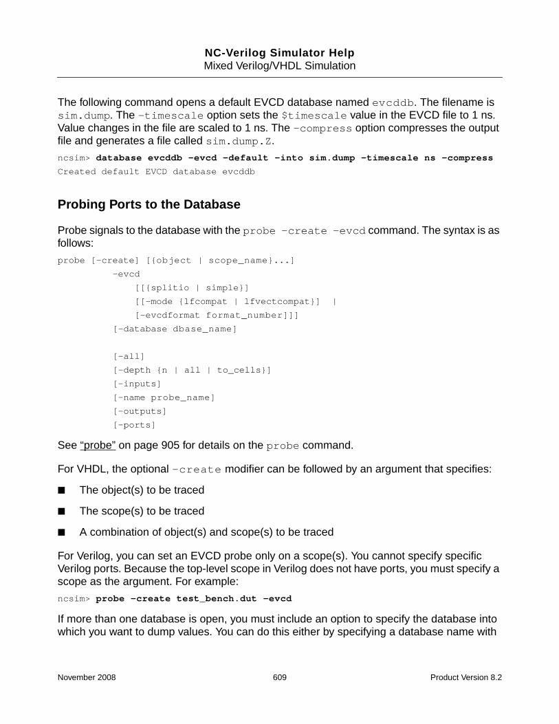
NC-Verilog Simulator HelpMixed Verilog/VHDL Simulation
The following command opens a default EVCD database named evcddb. The filename issim.dump. The -timescale option sets the $timescale value in the EVCD file to 1 ns.Value changes in the file are scaled to 1 ns. The -compress option compresses the outputfile and generates a file called sim.dump.Z.
ncsim> database evcddb -evcd -default -into sim.dump -timescale ns -compress
Created default EVCD database evcddb
Probing Ports to the Database
Probe signals to the database with the probe -create -evcd command. The syntax is asfollows:
probe [-create] [{object | scope_name}...]
-evcd
[[{splitio | simple}]
[[-mode {lfcompat | lfvectcompat}] |
[-evcdformat format_number]]]
[-database dbase_name]
[-all]
[-depth {n | all | to_cells}]
[-inputs]
[-name probe_name]
[-outputs]
[-ports]
See “probe” on page 905 for details on the probe command.
For VHDL, the optional -create modifier can be followed by an argument that specifies:
■ The object(s) to be traced
■ The scope(s) to be traced
■ A combination of object(s) and scope(s) to be traced
For Verilog, you can set an EVCD probe only on a scope(s). You cannot specify specificVerilog ports. Because the top-level scope in Verilog does not have ports, you must specify ascope as the argument. For example:
ncsim> probe -create test_bench.dut -evcd
If more than one database is open, you must include an option to specify the database intowhich you want to dump values. You can do this either by specifying a database name with
November 2008 609 Product Version 8.2

NC-Verilog Simulator HelpMixed Verilog/VHDL Simulation
the -database option or by using the -evcd option to send the probe to the default EVCDdatabase.
Example probe Command Lines
In the design used for the following examples, the top-level design unit is a Verilog modulecalled test. This Verilog module instantiates a Verilog module called vlog_inst and aVHDL entity called vhdl_inst.
The following command probes all primary ports of the Verilog scope test.vlog_inst tothe EVCD database called sim_evcd.
ncsim> probe -create test.vlog_inst -evcd -database sim_evcd
Created probe 1
The following command probes all primary ports of the Verilog scope test.vlog_inst andthe VHDL scope test.vhdl_inst to the EVCD database called sim_evcd.
ncsim> probe test.vlog_inst test.vhdl_inst -evcd -database sim_evcd
Created probe 1
The following command probes the signal common in the VHDL scope test.vhdl_inst.
ncsim> probe test.vhdl_inst.common -evcd -database sim_evcd
Created probe 1
The following command generates an error because you cannot probe specific ports of aVerilog instance.
ncsim> probe -create test.vlog_inst.common -evcd -database sim_evcd
ncsim: *E,DBOBBD: cannot create EVCD probe for test.vlog_inst.common.
The following command probes all primary ports of the scope test.vhdl_inst and itssubscopes (that is, two levels of depth) to the EVCD database.
ncsim> probe test.vhdl_inst -evcd -depth 2 -database sim_evcd
In the following example, the probe command includes the -evcd splitio option. Thisoption dumps the value of the input port if any driver into the scope test.vhdl_instchanges value, and dumps the value of the output port if any driver within the scope changesvalue. For inout ports, two values are dumped: one corresponding to value changes of driversinto the scope test.vhdl_inst, and the other corresponding to value changes of driverswithin the scope.
ncsim> probe -create test.vhdl_inst -evcd splitio -database sim_evcd
Created probe 1
In the following example, the probe command includes the -evcd -mode option. Theargument to the -mode option is lfcompat. This option dumps the EVCD data as it was
November 2008 610 Product Version 8.2

NC-Verilog Simulator HelpMixed Verilog/VHDL Simulation
dumped in the LDV 4.1 and earlier releases. Vectors are dumped as individual bits, and theLDV 4.1 strength mappings are used.
ncsim> probe -create test.vhdl_inst -evcd -mode lfcompat -database sim_evcd
Created probe 1
You must use the -evcd -mode lfcompat option if you want to dump a subelement of acompressed VHDL signal to an EVCD database. For example:
ncsim> probe -create :top:cans(0) -evcd -mode lfcompat -database test_evcd
Note: The -evcd -mode option applies to VHDL only. If a Verilog scope is specified, an errormessage is generated saying that the Verilog ports will not be probed. For example:
ncsim> probe test.vhdl_inst test.vlog_inst -evcd -mode lfcompat -databasesim_evcd
ncsim: *E,PRNONE: no new objects to probe in scope test.vlog_inst.
Created probe 1
In the following example, the probe command includes the -evcd -evcdformat option.The argument to the -evcdformat option is 1, which specifies that both the zero and onecomponent of the value is to be dumped (for example, pD 6 5 <0).
ncsim> probe test.vhdl_inst test.vlog_inst -evcd -evcdformat 1 -databasesim_evcd
Created probe 1
You do not have to open a database with the database command before probing objects.You can probe objects to a database simply by using the probe command. In this case, theprobe command opens a default EVCD database called ncsim.evcd and probes the portsfor the specified scope. For example:
ncsim> probe -create test.vhdl_inst test.vlog_inst -evcd
Created default EVCD database ncsim.evcd
Created probe 1
ncsim>
Examples
This section contains four example EVCD files. All of the examples use the following sourcecode. In the example, a top-level Verilog module called test instantiates a Verilog modulecalled dff and a VHDL entity called dff_e.
// File: dff.v
module dff(out_out, in_in, common, clk);
output [2:0] out_out;
input [1:0] in_in;
inout [2:0]common;
November 2008 611 Product Version 8.2

NC-Verilog Simulator HelpMixed Verilog/VHDL Simulation
inout clk;
wire [2:0] full_in;
wire [2:0] common;
wire clk;
nor n1[2:0] (out_out, full_in, common);
assign #50 common = 0;
assign full_in = {in_in, in_in[0]};
assign clk = 1’bz;
endmodule
-- File: dff.vhd
library ieee;
use ieee.std_logic_1164.all;
entity dff_e is
port (signal output : out std_logic_vector(2 downto 0);
signal input : in std_logic_vector(2 downto 0);
signal common : in std_logic_vector(2 downto 0);
signal clk : inout std_logic);
end dff_e;
architecture dff_a of dff_e is
begin
output <= input nor common;
clk <= ’X’ after 5 ns, ’0’ after 10 ns,’1’ after 15 ns,’Z’ after 20 ns,’W’ after25 ns, ’L’ after 30 ns, ’H’ after 35 ns,’-’ after 40 ns;
end dff_a;
//File: top.v
module test;
wire [3:0] ina, inb;
wire [2:0] outa, outb;
wire clk;
parameter b = 4’b1111;
function func;
November 2008 612 Product Version 8.2

NC-Verilog Simulator HelpMixed Verilog/VHDL Simulation
input s;
begin
func = s;
end
endfunction
dff vlog_inst (outa, ina[1:0], outb, clk);
dff_e vhdl_inst (outb, inb[2:0], outa, clk);
assign inb = b;
assign #50 ina = 4’b0000;
endmodule
Example 1
doc_examples/ncvlog/mixed_lang/evcd/ex1
In this example, the database command is used to open an EVCD database calledtest_default. The -into option specifies that the associated filename isdefault.evcd.
The probe command creates an EVCD probe on the ports for the Verilog scope vlog_instand the VHDL scope vhdl_inst.The -database option specifies that the database istest_default.
ncsim> database -open test_default -evcd -into default.evcd
Created EVCD database test_default
ncsim> probe -create vlog_inst vhdl_inst -evcd -database test_default
Created probe 1
ncsim> run 50 ns
Ran until 50 NS + 0
ncsim> exit
In this example, the simulator dumps data using the default mode. Final value changes aredumped in extended format for both vector and scalar ports. For vector ports, the simulatordumps value changes for the entire vector, not for individual bits of the vector.
% more default.evcd
$date
May 23, 2008 11:36:35
$end
$version
TOOL: ncsim 08.10-p001
$end
November 2008 613 Product Version 8.2

NC-Verilog Simulator HelpMixed Verilog/VHDL Simulation
$timescale
1 fs
$end
$scope module test $end
$scope module vhdl_inst $end
$var port [2:0] ! output $end
$var port [2:0] " input $end
$var port [2:0] # common $end
$var port 1 $ clk $end
$upscope $end
$scope module vlog_inst $end
$var port [2:0] % out_out $end
$var port [1:0] & in_in $end
$var port [2:0] ’ common $end
$var port 1 ( clk $end
$upscope $end
$upscope $end
$enddefinitions $end
#0
$dumpports
pCCC 666 666 !
pUUU 000 666 "
pNNN 666 666 #
pX 6 6 $
pXXX 666 666 %
pNN 66 66 &
paaa 666 666 ’
pN 6 6 (
$end
#10000000
pL 6 0 $
pD 6 0 (
#15000000
pH 0 6 $
pU 0 6 (
#20000000
pf 0 0 $
November 2008 614 Product Version 8.2

NC-Verilog Simulator HelpMixed Verilog/VHDL Simulation
pf 0 0 (
#25000000
pX 5 5 $
pN 5 5 (
#30000000
pL 5 0 $
pD 5 0 (
#35000000
pH 0 5 $
pU 0 5 (
#40000000
pX 6 6 $
pN 6 6 (
#50000000
Example 2
doc_examples/ncvlog/mixed_lang/evcd/ex2
In this example, the database command opens an EVCD database called test_splitio.The -into option specifies that the associated filename is splitio.evcd.
In this example, the probe command probes the ports of the Verilog scope vlog_inst andthe signal called common in the VHDL component instance vhdl_inst.
The probe command includes the -evcd splitio argument. This argument causes thesimulator to dump the value of the input port if any driver into the entity changes value, andto dump the value of the output port if any driver within the entity changes value. For inoutports, two values are dumped: one corresponding to value changes of drivers into the designentity, and the other corresponding to value changes of drivers within the design entity.
ncsim> database -open test_splitio -evcd -into splitio.evcd
Created EVCD database test_splitio
ncsim> probe -create vlog_inst vhdl_inst.common -evcd splitio -databasetest_splitio
Created probe 1
ncsim> run 50 ns
Ran until 50 NS + 0
ncsim> exit
The EVCD file generated using this sequence of commands is as follows:
November 2008 615 Product Version 8.2

NC-Verilog Simulator HelpMixed Verilog/VHDL Simulation
% more splitio.evcd
$date
May 23, 2008 11:37:28
$end
$version
TOOL: ncsim 08.10-p001
$end
$timescale
1 fs
$end
$scope module test $end
$scope module vhdl_inst $end
$var port [2:0] ! common $end
$upscope $end
$scope module vlog_inst $end
$var port [2:0] " out_out $end
$var port [1:0] # in_in $end
$var port [2:0] $ common $end
$var port [2:0] % common_O $end
$var port 1 & clk $end
$var port 1 ’ clk_O $end
$upscope $end
$upscope $end
$enddefinitions $end
#0
$dumpports
pNNN 666 666 !
pXXX 666 666 "
pNN 66 66 #
pDDD 666 000 $
pXXX 666 666 %
pN 6 6 &
pT 0 0 ’
$end
#10000000
pD 6 0 &
#15000000
November 2008 616 Product Version 8.2

NC-Verilog Simulator HelpMixed Verilog/VHDL Simulation
pU 0 6 &
#20000000
pZ 0 0 &
#25000000
pN 5 5 &
#30000000
pD 5 0 &
#35000000
pU 0 5 &
#40000000
pN 6 6 &
#50000000
Example 3
doc_examples/ncvlog/mixed_lang/evcs/ex3
In this example, the database command opens an EVCD database calledtest_lfcompat. The -into option specifies that the associated filename islfcompat.evcd.
The probe command creates an EVCD probe on the ports for the VHDL scope vhdl_inst.The -evcd -mode lfcompat option is included on the probe command. This optiondumps the EVCD data as it was dumped in the LDV 4.1 and earlier releases. Vectors aredumped as individual bits, and the LDV 4.1 strength mappings are used.
Note: The -evcd -mode {lfcompat | lfvectcompat} option applies only to VHDL.If a Verilog scope is specified on the command line, an error message is generated sayingthat the Verilog ports will not be probed.
ncsim> database -open test_lfcompat -evcd -into lfcompat.evcd
Created EVCD database test_lfcompat
ncsim> probe -create vhdl_inst -evcd -mode lfcompat -database test_lfcompat
Created probe 1
ncsim> run 50 ns
Ran until 50 NS + 0
ncsim> exit
% more lfcompat.evcd
$date
May 23, 2008 11:39:06
$end
$version
TOOL: ncsim 08.10-p001
November 2008 617 Product Version 8.2

NC-Verilog Simulator HelpMixed Verilog/VHDL Simulation
$end
$timescale
1 fs
$end
$scope module test $end
$scope module vhdl_inst $end
$var port 1 <0 output [2] $end
$var port 1 <1 output [1] $end
$var port 1 <2 output [0] $end
$var port 1 <3 input [2] $end
$var port 1 <4 input [1] $end
$var port 1 <5 input [0] $end
$var port 1 <6 common [2] $end
$var port 1 <7 common [1] $end
$var port 1 <8 common [0] $end
$var port 1 <9 clk $end
$upscope $end
$upscope $end
$enddefinitions $end
#0
$dumpports
pC 7 7 <0
pC 7 7 <1
pC 7 7 <2
pU 0 7 <3
pU 0 7 <4
pU 0 7 <5
pN 7 7 <6
pN 7 7 <7
pN 7 7 <8
pX 7 7 <9
$end
#10000000
pL 7 0 <9
#15000000
pH 0 7 <9
#20000000
November 2008 618 Product Version 8.2

NC-Verilog Simulator HelpMixed Verilog/VHDL Simulation
pf 0 0 <9
#25000000
pX 3 3 <9
#30000000
pL 5 0 <9
#35000000
pH 0 5 <9
#40000000
pX 7 7 <9
#50000000
Example 4
doc_examples/ncvlog/mixed_lang/evcd/ex4
In this example, the database command opens an EVCD database called test_format1.The -into option specifies that the associated filename is format1.evcd. The -evcdoption includes the direction argument, which outputs port direction information. Thecommand also includes the -timescale option to set the timescale in the output file to 1 ns.
The probe command creates an EVCD probe on the ports for the Verilog scope vlog_instand for the VHDL scope vhdl_inst. The -evcd -evcdformat option is included on theprobe command. The argument to the -evcdformat option is 1, which specifies that boththe zero and one component of the value is to be dumped (for example, pD 6 5 <0).
ncsim> database test_format1 -evcd direction -timescale ns -into format1.evcd
Created EVCD database test_format1
ncsim> probe vlog_inst vhdl_inst -evcd -evcdformat 1 -database test_format1
Created probe 1
ncsim> run 50 ns
Ran until 50 NS + 0
ncsim> exit
% more format1.evcd
$date
May 23, 2008 11:41:55
$end
$version
TOOL: ncsim 08.10-p001
$end
$timescale
1 ns
$end
November 2008 619 Product Version 8.2

NC-Verilog Simulator HelpMixed Verilog/VHDL Simulation
$scope module test $end
$scope module vhdl_inst $end
$var output [2:0] ! output $end
$var input [2:0] " input $end
$var input [2:0] # common $end
$var inout 1 $ clk $end
$upscope $end
$scope module vlog_inst $end
$var output [2:0] % out_out $end
$var input [1:0] & in_in $end
$var inout [2:0] ’ common $end
$var inout 1 ( clk $end
$upscope $end
$upscope $end
$enddefinitions $end
#0
$dumpports
pCCC 666 666 !
pUUU 000 666 "
pNNN 666 666 #
pX 6 6 $
pXXX 666 666 %
pNN 66 66 &
paaa 666 666 ’
pN 6 6 (
$end
#10
pL 6 0 $
pD 6 0 (
#15
pH 0 6 $
pU 0 6 (
#20
pf 0 0 $
pf 0 0 (
#25
pX 5 5 $
November 2008 620 Product Version 8.2

NC-Verilog Simulator HelpMixed Verilog/VHDL Simulation
pN 5 5 (
#30
pL 5 0 $
pD 5 0 (
#35
pH 0 5 $
pU 0 5 (
#40
pX 6 6 $
pN 6 6 (
#50
Port Value Character Mapping
The state information shown in this section is described in terms of input values from a testfixture, the output values of the device under test, and the states that represent unknowndirection.
Direction INPUT
Given a device under test (DUT) and a test fixture, the driving direction is INPUT if the driversfrom the test fixture are driving some non-tristated value and the drivers inside the DUT aretristated. The resolved value is mapped as shown in the following table. In the table, the termactive means that the drivers are in a non-tristated condition.
Table 9-1 Driving Direction INPUT Mapping
D (0) low
d (0) low (2 or more drivers active)
U (1) high
u (1) high (2 or more drivers active)
N (X) unknown
n (X) unknown because of a 1-0 collision
Z (Z) tristate
November 2008 621 Product Version 8.2

NC-Verilog Simulator HelpMixed Verilog/VHDL Simulation
Direction OUTPUT
If the driving value from drivers inside the DUT is non-tristated, but the value driven by thedrivers in the test fixture is tristated, the direction is OUTPUT. The resolved value is mappedas shown in the following table:
Direction UNKNOWN
If both the drivers in the test fixture and drivers inside the DUT are driving some non-tristatedvalue, the direction is UNKNOWN. The resolved value is mapped as shown in the followingtable:
Table 9-2 Driving Direction OUTPUT Mapping
L (0) low
l (0) low (more than 2 drivers active)
H (1) high
h (1) high (more than 2 drivers active)
X (X) unknown (don’t care)
T (Z) tristate
Table 9-3 Driving Direction UNKNOWN Mapping
0 (0) low (both input and output are active with 0 value)
1 (1) high (both input and output are active with 1 value)
? (X) unknown (input X and output X)
F tristate (input and output unconnected)
A (0-1) unknown (input 0 and output 1)
a (0-X) unknown (input 0 and output X)
B (1-0) unknown (input 1 and output 0)
b (1-X) unknown (input 1 and output X)
C (X-0) unknown (input X and output 0)
c (X-1) unknown (input X and output 1)
f (Z) unknown (input and output tristated)
November 2008 622 Product Version 8.2

NC-Verilog Simulator HelpMixed Verilog/VHDL Simulation
If a net is forced, a comment is placed into the output file stating that the net connected to theport is being forced, and giving the scope of the force. Forces are treated differently becausethe existence of a force is not permanent, even though a force is a driver.
While a force is active, driver collisions are ignored and the level part of the output isdetermined by the scope of the force definition. If the EVCD was generated using Tcl, the portdriving direction is treated as direction input. When the force is released, a note is againplaced into the output file.
Strength Mapping
Strength values in the EVCD output for the LDV 5.0 release are shown in Table 10-4.
The strength mapping for VHDL in LDV 4.1 and earlier releases is shown in Table 10-5.
To dump an EVCD file with the LDV 4.1 or earlier strength mappings, use the -modelfcompat or -mode lfvectcompat option when you create the probe. For example:
ncsim> probe -create :dut -evcd -mode lfcompat -database test_output
Both lfcompat and lfvectcompat preserve the older strength mappings.
The -mode lfcompat option dumps individual bits for vector ports, as was done by defaultin LDV 4.1 or earlier releases.
Table 9-4 Strength Mapping in LDV 5.0
Strength Verilog VHDL std_ulogicCharacter
0 highz (HiZ) Z
1 small (Sm)
2 medium (Me)
3 weak (We)
4 large (La)
5 pull (Pu) W, H, L
6 strong (St) U, X, 0, 1, -
7 supply (Su)
November 2008 623 Product Version 8.2

NC-Verilog Simulator HelpMixed Verilog/VHDL Simulation
The -mode lfvectcompat option dumps whole vectors. This argument replaces thedatabase -evcd vector option, which is no longer supported.
Table 9-5 Strength Mapping in LDV 4.1 and Earlier Releases
std_ulogic character 0’s strength 1’s strength
0 7 0
1 0 7
X 7 7
Z 0 0
U 7 7
W 3 3
- 7 7
L 5 0
H 0 5
November 2008 624 Product Version 8.2

NC-Verilog Simulator Help
10Debugging Your Design
This chapter contains the following sections:
■ Managing Databases
■ Setting and Deleting Probes
■ Traversing the Model Hierarchy
■ Setting Breakpoints
■ Disabling, Enabling, Deleting, and Displaying Breakpoints
■ Stepping Through Lines of Code
■ Forcing and Releasing Signal Values
■ Depositing Values to Signals
■ Displaying Information About Simulation Objects
■ Displaying the Drivers of Signals
■ Checking for Bus Contention and Bus Float Conditions
■ Detecting Infinite Loops
■ Displaying Waveforms with the SimVision Waveform Viewer
■ Generating a Value Change Dump (VCD) File
■ Generating an Extended Value Change Dump (EVCD) File
■ Comparing Databases with Comparescan
■ Code Coverage with Incisive Comprehensive Coverage
■ Regression Analysis with Desktop Manager
■ Displaying Debug Settings
■ Setting a Default Radix
November 2008 625 Product Version 8.2

NC-Verilog Simulator HelpDebugging Your Design
■ Setting Variables
■ Suppressing Assert Messages in IEEE or User-Defined Packages
■ Editing a Source File
■ Searching for a Line Number in the Source Code
■ Searching for a Text String in the Source Code
■ Configuring Your Simulation Environment
■ Saving and Restoring Your Simulation Environment
■ Creating or Deleting an Alias
November 2008 626 Product Version 8.2

NC-Verilog Simulator HelpDebugging Your Design
Managing Databases
The database command includes several modifiers that let you:
■ Create a database (database -open).
■ Set a database as the default database (database -setdefault).
■ Display information about databases (database -show).
■ Disable databases (database -disable).
■ Enable databases (database -enable).
■ Force the creation of a new incremental SHM database file (database -change).
■ Close a database (database -close).
Creating a Database
You can open three types of databases for writing simulation data:
■ SHM for Verilog, VHDL, or mixed-language
■ Value Change Dump (VCD) for Verilog, VHDL, or mixed-language
■ Extended Value Change Dump (EVCD) for Verilog, VHDL, or mixed-language
If you are using the Tcl command-line interface, use the database command with theoptional -open modifier to open a database. You must specify a database name. There arethree command-line options that you can use to specify the type of database that you wantto open: -shm, -vcd, and -evcd. By default, ncsim opens an SHM database.
The basic syntax of the database command is as follows:
database [-open] dbase_name [ {-shm | -vcd | -evcd} ]
See “Opening a Database” on page 779 for details on using the database command tocreate a database.
If you are using the SimVision analysis environment, select File – Create Database fromany SimVision window and fill in the New Database form to create an SHM database. Tocreate a VCD database or an EVCD database, you must use the database text command.Enter the database command at the prompt in the SimVision Console window.
To open an existing database, select File – Open Database from a SimVision window, andfill in the Open Database form.
November 2008 627 Product Version 8.2

NC-Verilog Simulator HelpDebugging Your Design
See “Managing Simulation Databases” in the SimVision User Guide for details on creatingand opening a database.
For Verilog, you can also open an SHM database with the $shm_open system task in yourVerilog code. The name of the database that is created is preceded by an underscorecharacter. For example, the following system task opens a database called _waves.shm.
$shm_open(“waves.shm”);
This lets you interact with databases opened with $shm_open in the same way that youinteract with databases that you open with the database command.
For VHDL, you can also open a VCD database and probe objects to the database by usingthe call command to call predefined CFC routines, which are part of the NC-VHDLsimulator C interface. This feature has been retained for backwards compatibility. Therecommended method of generating a VCD file is to open a database with the database-open -vcd command and to probe objects to the database with the probe -vcdcommand. See the appendix called “Generating a VCD File Using CFC Routines” in the NCVHDL Simulator Help for more information. See “call” on page 763 for details on the callcommand.
See “Generating an Extended Value Change Dump (EVCD) File” on page 679 for moreinformation on EVCD databases.
Setting a Database As the Default
If you have opened a database and want to specify that this previously opened database isnow to be used as the default database for probes and other operations, use the database-setdefault command. The syntax is:
database -setdefault dbase_name
For example, the following command makes the database waves.shm the default SHMdatabase.
ncsim> database -setdefault waves.shm
See “Setting a Database As the Default” on page 788 for details.
Displaying Information About Databases
■ If you are using the Tcl command-line interface, use the database command with the-show modifier to display information about databases.
Syntax:
database -show [{dbase_name | pattern} ...]
November 2008 628 Product Version 8.2

NC-Verilog Simulator HelpDebugging Your Design
■ If you are using the SimVision analysis environment, select Windows – Tools –Databases. The Databases tab in the Properties window displays information about allopen databases.
Disabling a Database
■ If you are using the command-line interface, use the database command with the-disable modifier to temporarily disable a database.
Syntax:
database -disable {dbase_name | pattern} ...
■ If you are using the SimVision analysis environment, enter the database -disablecommand at the prompt in the I/O region of the Console window.
Enabling a Database
■ If you are using the command-line interface, use the database command with the-enable modifier to enable a previously disabled database.
Syntax:
database -enable {dbase_name | pattern} ...
■ If you are using the SimVision analysis environment, enter the database -enablecommand at the prompt in the I/O region of the Console window.
Creating Incremental SHM Database Files
By default, there is no limit on the size of an SHM database. Because a database for a largesimulation can be very big, you may want to break up the signal transition information (the.trn file) and, if you are tracing statement data, the statement trace information (the .stcfile) into multiple files. These files correspond to a range of simulation time, and are calledincremental files.
You can create incremental files by using the database -incsize option when you open theSHM database. This option specifies the incremental file size for the SHM database. Forexample, the following command specifies a size limit of 1GB for the SHM database file.When the current SHM database file size reaches 1GB, a new incremental file is startedautomatically.
ncsim> database -open -shm shmdb -incsize 1G
November 2008 629 Product Version 8.2

NC-Verilog Simulator HelpDebugging Your Design
The initial database file and all incremental files are stored in the database directory. Theincremental files have a number included in the filename. For example, the followingcommand opens a database called ncsim.
ncsim> database -open -shm ncsim -incsize 2M
The initial database file is called ncsim.trn. The incremental files will be calledncsim-1.trn, ncsim-2.trn, and so on.
You can include the -incfiles option to set a limit on the number of incremental files thatwill be kept for the database.
Incremental files can also be created at any time with a database -change command. Forexample:
ncsim> database -change shmdb
A database -change command forces a new incremental SHM database file to be started.You can use this command at significant points during the simulation, instead of, or in additionto, automatic incremental file creation using -incsize, so that incremental files containspecific time ranges of interest. See “Starting a New Incremental SHM Database File” onpage 789 for more information.
Closing a Database
■ If you are using the Tcl command-line interface, use the database command with the-close modifier to close a database.
Syntax:
database -close {dbase_name | pattern} ...
■ If you are using the SimVision analysis environment, select File – CloseDatabase/Simulation. SimVision opens the Close Database/Simulator form. Select thedatabase that you want to close and click the OK button.
To close a VCD or an EVCD database, enter the database -close command at theprompt in the I/O region of the Console window.
See “Managing Simulation Databases” in the SimVision User Guide for details onmanaging databases.
November 2008 630 Product Version 8.2

NC-Verilog Simulator HelpDebugging Your Design
Setting and Deleting Probes
You can save the values of objects to a database by probing them. The values contained inthe database can be viewed using a waveform viewing tool.
Setting a Probe
You can probe objects to the following kinds of databases:
■ SHM (for Verilog, VHDL, or mixed-language)
■ VCD (for Verilog, VHDL, or mixed-language)
■ EVCD (for Verilog or VHDL)
If you are using the Tcl command-line interface, use the probe command with the optional-create modifier to create probes.
The basic syntax of the probe command is as follows:
probe [-create] [ {object | scope_name} ... ]{ -shm | -vcd | -evcd | -database dbase_name }
The -create modifier can be followed by an argument that specifies:
■ The object(s) to be traced
■ The scope(s) to be traced
■ A combination of object(s) and scope(s) to be traced
If you do not specify an argument, the current debug scope is assumed, but you must includean option that specifies the objects you want to include in the trace (-all, -inputs,-outputs, or -ports).
You must include an option to specify the database into which values are dumped. Use oneof the following options:
■ -database dbase_name
Send the probe to the specified database. The database must already exist.
November 2008 631 Product Version 8.2

NC-Verilog Simulator HelpDebugging Your Design
■ -shm
Send the probe to the default SHM database. If no default database is open, ncsimopens a default database called ncsim.shm.
■ -vcd
Send the probe to the default VCD database. If no default database is open, ncsimopens a default database called ncsim.vcd.
■ -evcd
Send the probe to the default EVCD database. If no default database is open, ncsimopens a default database called ncsim.evcd.
See “probe” on page 905 for details on the probe command and for information onprobing Verilog and VHDL objects to different kinds of databases.
If you are using the SimVision analysis environment, there are two ways to probe objects toan SHM database:
1. Select a signal or scope and then click the Waveform button.
SimVision performs the following operations:
❑ Opens a database, if you have not opened one already.
❑ Sets a probe on the selected object.
❑ Sends the object to the Waveform window. If a Waveform window is not opened, itopens one for you.
2. Select Simulation – Create Probe and use the Set Probe form.
You can preselect the signals or scopes that you want to probe.
The Set Probe form lets you probe one or more levels of subscope, and you can choosethe types of signals that you want to probe within those scopes.
If you are probing objects to a VCD or EVCD database, enter the probe command in the I/Oregion of the Console window.
See “Creating and Managing Probes” in the SimVision User Guide for details on creatingprobes.
Note: Only objects that have read access are probed. See “Enabling Read, Write, orConnectivity Access to Simulation Objects” on page 371 for details on specifying access tosimulation objects.
November 2008 632 Product Version 8.2

NC-Verilog Simulator HelpDebugging Your Design
Displaying Information About Probes
■ If you are using the Tcl command-line interface, use the probe command with the-show modifier to display information about the probes that you have set.
Syntax:
probe -show [probe_name ...] [-database db_name]
■ If you are using the SimVision analysis environment, you can select Windows – Tools– Show All Properties. This opens the Properties window. The Probes tab displaysinformation about the probes that you have defined.
Disabling a Probe
■ If you are using the Tcl command-line interface, use the probe command with the-disable modifier to temporarily disable an SHM probe.
Syntax:
probe -disable probe_name [probe_name ...]
■ If you are using the SimVision analysis environment, the Probes tab on the Propertieswindow contains a check box next to each probe to indicate whether the probe is enabledor disabled. When the box is checked, the probe is enabled. Click on the check box nextto the probe that you want to disable.
You can disable SHM probes individually at any time.
You cannot disable VCD and EVCD probes individually. Use database -disable todisable all VCD or EVCD probes. (See “database” on page 775.)
Enabling a Probe
■ If you are using the Tcl command-line interface, use the probe command with the-enable modifier to enable an SHM probe that was previously disabled.
Syntax:
probe -enable probe_name [probe_name ...]
■ If you are using the SimVision analysis environment, open the Properties window andclick on the check box next to the probe that you want to enable.
You cannot enable VCD and EVCD probes individually. Use database -enable to enableall VCD or EVCD probes. (See “database” on page 775.)
November 2008 633 Product Version 8.2

NC-Verilog Simulator HelpDebugging Your Design
Deleting a Probe
■ If you are using the Tcl command-line interface, use the probe command with the-delete modifier to delete a probe.
Syntax:
probe -delete probe_name [probe_name ...]
■ If you are using the SimVision analysis environment, open the Properties window, selectthe probe that you want to delete and then click the Delete button.
You can delete SHM probes at any time.
VCD and EVCD probes can only be deleted at the time the VCD or EVCD database iscreated. Once the simulation is advanced, ncsim writes the VCD or EVCD header to the fileand no modifications to the probes are possible.
See “Creating and Managing Probes” in the SimVision User Guide for details on managingprobes using the SimVision environment.
November 2008 634 Product Version 8.2

NC-Verilog Simulator HelpDebugging Your Design
Traversing the Model Hierarchy
The simulator supports hierarchical designs by allowing models to be embedded within othermodels. Levels of hierarchy in a design are called scopes. To create a scope, you nestobjects within design units by instantiating them. Instantiation allows one design unit toincorporate a copy of another into itself.
Path Names
Each scope in a design hierarchy has a unique hierarchical path name. For Verilog, elementsin the path name are separated by a period ( . ). Path names can be:
■ Fully specified from the top level of the hierarchy. Full path names begin with the nameof a Verilog top-level module. For example:
top.board.counter
top.vending.drinks.count_cans.in1
■ Relative to the current debug scope. For example, if the current debug scope istop.board, the path name counter refers to a scope within the scope board, whichis within the top-level module top.
See “Path Names and Mixed-Language Designs” on page 597 for information on how tospecify path names for mixed Verilog/VHDL designs.
Setting the Debug Scope
You traverse the model hierarchy by setting the scope to an instantiated object. If you areusing the Tcl command-line interface, use the scope -set command. For example, if thecurrent debug scope is the top level, and you want to scope down one level to a scope calledboard, use the following command:
ncsim> scope -set board
If you are at the top level and want to scope down to a scope within board called counter,use the following command:
ncsim> scope -set board.counter
You can specify a full path name from any debug scope. For example, if the current scope isboard:counter, you can scope up to the top level (module top) with the followingcommand:
ncsim> scope -set top
See “scope” on page 966 for details on using the scope command.
November 2008 635 Product Version 8.2

NC-Verilog Simulator HelpDebugging Your Design
If you are using the SimVision analysis environment, there are several ways to traverse thedesign hierarchy using the Source Browser or the Design Browser. See “Accessing theDesign Source Code” in the SimVision User Guide for details on traversing the hierarchyusing the Source Browser. See “Accessing the Design Hierarchy” for details on using theDesign Browser.
November 2008 636 Product Version 8.2

NC-Verilog Simulator HelpDebugging Your Design
Setting Breakpoints
You can interrupt the simulation by setting breakpoints.
For Verilog and VHDL, you can set the following kinds of breakpoints:
■ Condition breakpoints. See “Setting a Condition Breakpoint” on page 638.
■ Line breakpoints. See “Setting a Source Code Line Breakpoint” on page 639.
■ Object breakpoints. See “Setting an Object Breakpoint” on page 640.
■ Time breakpoints. See “Setting a Time Breakpoint” on page 641.
■ Delta breakpoints. See “Setting a Delta Breakpoint” on page 642.
■ Subprogram breakpoints. See “Setting a Subprogram Breakpoint” on page 643.
For VHDL, you can also set:
■ Process breakpoints. See “Setting a Process Breakpoint” on page 642.
The state of breakpoints is not affected by restarting or resetting the simulation. To restorethe current state of the Tcl environment, including breakpoints, use the save -commandscommand to create a Tcl script that you can use after the reset or restart to restore the stateof breakpoints. See “Saving and Restoring Your Simulation Environment” on page 735 formore information.
November 2008 637 Product Version 8.2

NC-Verilog Simulator HelpDebugging Your Design
Setting a Condition Breakpoint
You can stop the simulation when a specified condition is true by setting a conditionbreakpoint. This type of breakpoint is particularly useful when you want to stop the simulationat the instant when a signal has been set to an incorrect value.
A condition breakpoint triggers when any object referenced in the conditional expressionchanges value (wires, signals, registers, and variables) or is written to (memories) and theexpression evaluates to true (nonzero).
■ If you are using the Tcl command-line interface, use the stop command with the-condition option to set a condition breakpoint.
See “stop” on page 994 for details on using the stop command and for examples ofsetting condition breakpoints.
■ If you are using the SimVision analysis environment, select Simulation – SetBreakpoint – Condition to set a condition breakpoint.
See “Setting a Condition Breakpoint” in the SimVision User Guide for details on settinga condition breakpoint.
A condition breakpoint takes a Tcl expression as an argument. See “Tcl Expressions asArguments” on page 1026 for details on the syntax of these expressions.
The simulator does not support breakpoints on individual bits of registers. If a bit-select of aregister appears in the expression, the simulator stops and evaluates the expression whenany bit of that register changes value. The same holds true for compressed wires.
Objects included in a conditional expression must have read access. An error is printed if theobject does not have read access. See “Enabling Read, Write, or Connectivity Access toSimulation Objects” on page 371 for details on specifying access to simulation objects.
See “Disabling, Enabling, Deleting, and Displaying Breakpoints” on page 644 for moreinformation on breakpoints.
November 2008 638 Product Version 8.2

NC-Verilog Simulator HelpDebugging Your Design
Setting a Source Code Line Breakpoint
You can stop the simulation at a specified line in the source code by setting a source codeline breakpoint. This type of breakpoint is usually set when you want to simulate to a certainpoint and then single-step through lines of code.
You cannot set a line breakpoint unless you have compiled with the -linedebug option.(See -linedebug for details on using this option.)
To set a line breakpoint:
■ If you are using the Tcl command-line interface, use the stop command with the -lineoption.
See “stop” on page 994 for details on using the stop command and for examples ofsetting line breakpoints.
■ If you are using the SimVision analysis environment, select Simulation – SetBreakpoint – Line to set a line breakpoint.
You can also set a line breakpoint from the Source Browser. Double-click on the linenumber where you want to set the breakpoint. SimVision adds a breakpoint icon in theleft column of the window next to the line you selected.
See “Setting a Line Breakpoint” in the SimVision User Guide for details on setting aline breakpoint.
See “Disabling, Enabling, Deleting, and Displaying Breakpoints” on page 644 for moreinformation on breakpoints.
November 2008 639 Product Version 8.2

NC-Verilog Simulator HelpDebugging Your Design
Setting an Object Breakpoint
You can stop the simulation when a specified object changes value (wires and signals) orwhen it is written to (registers, memories, variables) by setting an object breakpoint. This typeof breakpoint is usually set when you want the simulation to stop every time the signalchanges value or when you want to see the value of signals when some condition is true (forexample, on every positive edge of the clock).
To set an object breakpoint:
■ If you are using the Tcl command-line interface, use the stop command with the-object option.
See “stop” on page 994 for details on using the stop command and for examples ofsetting object breakpoints.
■ If you are using the SimVision analysis environment, select Simulation – SetBreakpoint – Object to set an object breakpoint. If you preselect an object, the SetBreakpoint form is seeded with the name of the selected object.
You can also set an object breakpoint by selecting an object and then clicking theBreakpoint button.
See “Setting an Object Breakpoint” in the SimVision User Guide for details on settingan object breakpoint.
The object specified as the argument must have read access for the breakpoint to be created.An error is printed if the object does not have read access. See “Enabling Read, Write, orConnectivity Access to Simulation Objects” on page 371 for details on specifying access tosimulation objects.
By default, vector Verilog wires and VHDL signals are compressed if the model does notrequire operations on individual bits of the vector. For VHDL, you can set an object breakpointon a subelement of a compressed vector signal. For Verilog, however, you must elaborate thedesign with the -expand option (ncelab -expand) in order to set a breakpoint on asubelement of a compressed vector wire.
You cannot set a breakpoint on an object in a VHDL subprogram.
November 2008 640 Product Version 8.2

NC-Verilog Simulator HelpDebugging Your Design
Setting a Time Breakpoint
You can stop the simulation at a specified time by setting a time breakpoint. The time can beabsolute or relative (the default). Absolute time breakpoints are automatically deleted afterthey trigger. Relative time breakpoints are periodic, stopping, for example, every 10 ns.
This type of breakpoint is usually set when you want to advance the simulation to a certaintime point before beginning to debug or when you want to stop the simulation at regularintervals to examine signal values.
To set a time breakpoint:
■ If you are using the Tcl command-line interface, use the stop command with the -timeoption.
See “stop” on page 994 for details on using the stop command and for examples ofsetting breakpoints.
■ If you are using the SimVision analysis environment, select Simulation – SetBreakpoint – Time to set a time breakpoint.
See “Setting a Time Breakpoint” in the SimVision User Guide for details on setting atime breakpoint.
See “Disabling, Enabling, Deleting, and Displaying Breakpoints” on page 644 for moreinformation on breakpoints.
November 2008 641 Product Version 8.2

NC-Verilog Simulator HelpDebugging Your Design
Setting a Delta Breakpoint
You can stop the simulation when the simulation delta cycle count reaches a specified deltacycle. To set a delta breakpoint:
■ If you are using the Tcl command-line interface, use the stop command with the-delta option.
See “stop” on page 994 for details on using the stop command and for examples ofsetting breakpoints.
■ If you are using the SimVision analysis environment, select Simulation – SetBreakpoint – Time to set a delta breakpoint. On the Set Breakpoint form, set the Stopat regular intervals of field to the number of delta cycles you want, and then selectdelta from the pulldown.
See “Setting a Time Breakpoint” in the SimVision User Guide for details on setting adelta breakpoint.
See “Disabling, Enabling, Deleting, and Displaying Breakpoints” on page 644 for moreinformation on breakpoints.
Setting a Process Breakpoint
For VHDL, you can stop the simulation when a named process starts executing or resumesexecuting after a wait statement.
Note: You must compile with the -linedebug option to enable the setting of source line andprocess breakpoints.
To set a process breakpoint:
■ If you are using the Tcl command-line interface, use the stop command with the-process option.
See “stop” on page 994 for details on using the stop command and for examples ofsetting breakpoints.
■ If you are using the SimVision analysis environment, select Simulation – SetBreakpoint – Process to set a process breakpoint.
See “Setting a Process Breakpoint” in the SimVision User Guide for details on settinga process breakpoint.
See “Disabling, Enabling, Deleting, and Displaying Breakpoints” on page 644 for moreinformation on breakpoints.
November 2008 642 Product Version 8.2

NC-Verilog Simulator HelpDebugging Your Design
Setting a Subprogram Breakpoint
You can stop the simulation when a named subprogram (procedure or function, Verilog taskor function) starts executing.
Note: You must compile with the -linedebug option to enable the setting of source line,process, and subprogram breakpoints.
To set a subprogram breakpoint:
■ If you are using the Tcl command-line interface, use the stop command with the-subprogram option.
See “stop” on page 994 for details on using the stop command and for examples ofsetting breakpoints.
■ If you are using the SimVision analysis environment, select Simulation – SetBreakpoint – Subprogram to set a subprogram breakpoint.
See “Setting a Subprogram Breakpoint” in the SimVision User Guide for details onsetting a subprogram breakpoint.
See “Disabling, Enabling, Deleting, and Displaying Breakpoints” on page 644 for moreinformation on breakpoints.
November 2008 643 Product Version 8.2

NC-Verilog Simulator HelpDebugging Your Design
Disabling, Enabling, Deleting, and DisplayingBreakpoints
After setting breakpoints, you can display information on breakpoints, disable breakpoints,enable previously disabled breakpoints, and delete breakpoints.
■ If you are using the command-line interface, use the stop command with the -show,-disable, -enable, or -delete modifier. The argument to these modifiers can be:
❑ a break name or a list of break names
❑ a pattern
The asterisk ( * ) matches any number of characters
The question mark ( ? ) matches any one character
[characters] matches any one of the characters
❑ Any combination of literal break names and patterns
See “stop” on page 994 for details on using the stop command.
■ If you are using the SimVision analysis environment:
a. Select Windows – Tools – simulator from the menu bar of any SimVision window.This opens the simulation tab of the Property window.
b. Select Breakpoints.
You can also select Simulation – Show – Breakpoints.
SimVision displays the list of breakpoints that you have defined. A check box appearsnext to each breakpoint to indicate whether it is enabled or disabled. When the box ischecked, the breakpoint is enabled.
To disable a breakpoint, click on the check box next to the breakpoint.
To enable a previously disabled breakpoint, click the check box.
To delete a breakpoint, select the breakpoint and click the Delete button.
See “Setting and Managing Breakpoints” in the SimVision User Guide for details onsetting and managing breakpoints using SimVision.
November 2008 644 Product Version 8.2

NC-Verilog Simulator HelpDebugging Your Design
Stepping Through Lines of Code
You can examine the order in which the simulator executes the statements in your model bystepping through the simulation line by line. Single-stepping through lines of code is anespecially useful technique for debugging problems such as infinite loops. You can set abreakpoint so that the simulator stops where the problem occurs, and then step through thecode line by line to see what is happening.
Note: You cannot single step one line at a time or set line breakpoints in a particular designunit unless you have compiled that unit with the -linedebug option. If you have compiledthe unit without this option, the run -step or run -next commands will run the simulationuntil the next point where it can stop. If execution is passed to a unit that was compiled with-linedebug, full single stepping is resumed.
■ If you are using the Tcl command-line interface:
❑ Use run -step to simulate to the next executable line of code in any scope. Thiscommand runs one statement, stepping into subprogram calls.
❑ Use run -next to run one statement, stepping over any subprogram calls.
See “run” on page 950 for details on using the run command.
■ If you are using the SimVision analysis environment, select Simulation – Step orSimulation – Next.
You can also click on the Single Step or Step Over buttons on the Tool Bar.
See “Controlling the Simulation” in the SimVision User Guide for details.
November 2008 645 Product Version 8.2

NC-Verilog Simulator HelpDebugging Your Design
Forcing and Releasing Signal Values
You can ask “What if” questions about your model by interactively forcing objects to desiredvalues and seeing if the patch fixes the problem. If it does, you can then edit your source fileto incorporate the change.
The object that is being forced must have write access. An error is printed if it does not. Tospecify write access, use the -access or -afile option when you elaborate the design withncelab. See “Enabling Read, Write, or Connectivity Access to Simulation Objects” onpage 371 for details on specifying access to simulation objects.
■ If you are using the Tcl command-line interface, use the force command to set aspecified object to a given value and force it to retain that value until it is released (witha release command, a force -release command, a deposit -releasecommand, or until another force is placed on it).
See “deposit” on page 793, “force” on page 849, and “release” on page 944 for detailson using these commands.
■ If you are using the SimVision analysis environment:
a. Select an object.
b. Select Simulation – Create Force.
This opens the Force Value form.
c. Specify the new value for the object and click the OK button.
If you do not select an object before opening the form, you can select the object in anySimVision window and click the Add button to add it to the form.
To release a force, select the object and then select Release Force from the pop-upmenu.
See “Changing the Value of an Object During Simulation” in the SimVision User Guidefor more information.
November 2008 646 Product Version 8.2

NC-Verilog Simulator HelpDebugging Your Design
Depositing Values to Signals
Besides forcing an object to a desired value using the force command (Simulation –Create Force in SimVision), another way to ask “What if” questions about your model as youdebug is to interactively deposit a value to a specified object.
When you deposit a value to an object, behaviors that are sensitive to value changes on theobject run when the simulation resumes, just as if the value change was caused by the Verilogor VHDL code.
You can deposit a value to an object immediately, at a specified time in the future, or after aspecified delay. You can also specify that you want to deposit the value after an inertial delayor after a transport delay. A deposit without a delay is similar to a force in that the specifiedvalue takes effect and propagates immediately. However, it differs from a force in that futuretransactions on the signal are not blocked.
For VHDL, you can deposit to ports, signals, and variables if no delay is specified. If a delayis specified, you can deposit to signals with multiple sources, but you cannot deposit tovariables.
For Verilog, you can deposit to ports, signals (wires and registers), and variables.
The object that you want to deposit a value to must have write access. An error is printed if itdoes not. To specify write access, use the -access or -afile option when you elaboratethe design with ncelab. See “Enabling Read, Write, or Connectivity Access to SimulationObjects” on page 371 for details on specifying access to simulation objects.
To deposit a value to an object:
■ If you are using the Tcl command-line interface, use the deposit command to set aspecified object to a given value.
See “deposit” on page 793 for details on using the deposit command.
■ If you are using the SimVision analysis environment:
a. Select an object.
b. Select Simulation – Deposit Value and complete the Deposit Value form.
See “Changing the Value of an Object During Simulation” in the SimVision User Guidefor details on depositing a value to a signal.
November 2008 647 Product Version 8.2

NC-Verilog Simulator HelpDebugging Your Design
Displaying Information About Simulation Objects
You can display information about a simulation object, including its declaration.
■ If you are using the Tcl command-line interface, use the describe command. You canspecify one or more objects as the argument to the describe command. For example:
ncsim> describe dut dut.sig1
See “describe” on page 802 for details on using this command.
■ If you are using the SimVision analysis environment, you can select an object, or multipleobjects, in the Design Browser or Source Browser, and then select Describe from thepop-up menu.
Displaying the Drivers of Signals
You can display a list of all of the contributors to the value of a specified signal(s).
■ If you are using the Tcl command-line interface, use the drivers command. Forexample:
ncsim> drivers board.count
See “drivers” on page 813 for details on using this command and for examples of thereport format for Verilog signals and for VHDL signals.
You can use the scope -drivers [scope_name] command to display the drivers ofeach object that is declared within a specified scope. See “scope” on page 966 for detailson the scope command.
■ If you are using the SimVision analysis environment, use the Signal Flow Browser to viewand get information on drivers.
See “The Signal Flow Browser” in the SimVision User Guide for details on using theSignal Flow Browser.
The drivers command cannot find the drivers of a wire or register unless the object hasconnectivity access. However, even if you have specified access to the object, its drivers mayhave been collapsed, combined, or optimized away. In this case, the output of the drivers(or Show—Drivers) command might indicate that the object has no drivers. See “EnablingRead, Write, or Connectivity Access to Simulation Objects” on page 371 for details onspecifying access to simulation objects.
November 2008 648 Product Version 8.2

NC-Verilog Simulator HelpDebugging Your Design
Checking for Bus Contention and Bus Float Conditions
The NC-VHDL simulator lets you check for bus contention and bus float conditions in yourdesign. You can perform these two design checks only on VHDL std_logic bus signals (asignal that has multiple drivers). Checks cannot be applied on signals that are declared in aVITAL Level0 scope.
■ Bus contention detection
Bus contention checking detects bus fights on nodes that have multiple drivers. If morethan one driver of a std_logic bus signal drives a non-Z value for more than a specifiedtime limit, the condition is reported as a bus contention.
If the simulator detects a bus contention, it issues an error message. The messageincludes the name of the bus signal on which the contention was detected, the names ofthe drivers and their current values, the time at which the contention started, and the timeat which the time window was exceeded.
■ Bus float detection
Bus float checking detects nodes that are in the high impedance state for a time thatexceeds a specified time limit. If no driver of a std_logic bus signal is driving a non-Zvalue for more than a specified time limit, the condition is reported as a bus float.
If the simulator detects a bus float, it issues an error message. The message includesthe bus signal name, the time at which the float started, and the time at which the timewindow was exceeded.
Use the Tcl check command to check for bus contention/bus float conditions on a specifiedVHDL bus signal(s). Use the -contention option to create a bus contention check, or usethe -float option to create a bus float check.
The following example shows how to use the check command to create a bus contentioncheck. If more than one driver of bus signal sig1 is driving a non-Z value and if sig1 is activefor more than 10 ns, the simulator reports a bus contention message. If the duration of thebus contention is 10 ns or less, the condition is not reported.
ncsim> check -contention sig1 -delay 10 ns
The following example shows how to use the check command to create a bus float check. Ifno driver is driving bus signal sig1 for more than 10 ns, the simulator reports a bus floatmessage. If the duration of the bus float is 10 ns or less, the condition is not reported.
ncsim> check -float sig1 -delay 10 ns
November 2008 649 Product Version 8.2

NC-Verilog Simulator HelpDebugging Your Design
You can set the time limit for bus contention or bus float checks in two ways:
■ By including the -delay option on a check -contention or a check -floatcommand, as shown in the previous examples.
■ By issuing a check -delay command. This sets a default time limit for subsequentchecks. In the following example, the check -delay command sets a default time limitof 10 ns for the subsequent bus contention check.
ncsim> check -delay 10 ns
ncsim> check -contention sig1
If you do not specify a time limit using a check -delay command or in the check-condition or check -float command, the default time limit value is 1 fs.
Changing the default time limit using a check -delay command does not affect existingchecks.
The bus contention or bus float time limit cannot be smaller than, or more precise than, theunit of simulation.
The check command checks for bus contention and bus float conditions at the followingtimes:
■ If any of the drivers of the bus signal change.
■ At the end of the simulation.This is to take care of a situation when a contention or floatoccurs on a bus signal sometime during the simulation, and after that, none of the driversof this bus signal change. If the check was done only on a driver change, a buscontention or bus float on such a bus signal would go undetected.
See “check” on page 767 for details on the check command.
November 2008 650 Product Version 8.2
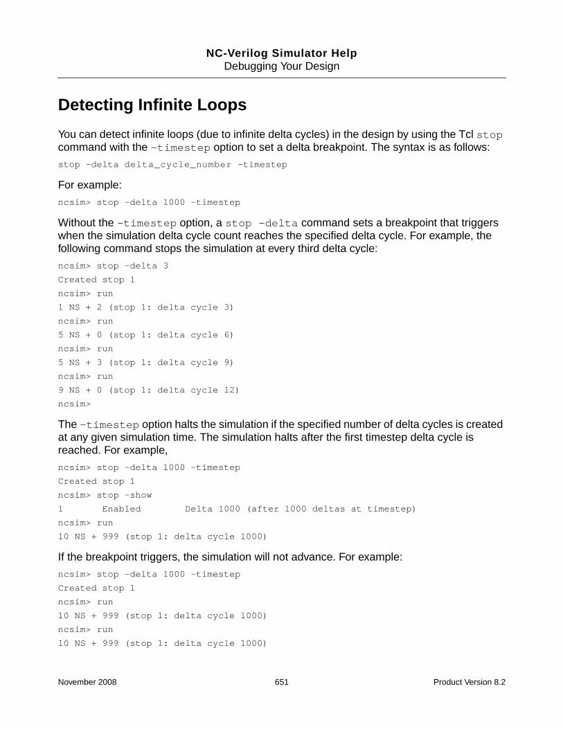
NC-Verilog Simulator HelpDebugging Your Design
Detecting Infinite Loops
You can detect infinite loops (due to infinite delta cycles) in the design by using the Tcl stopcommand with the -timestep option to set a delta breakpoint. The syntax is as follows:
stop -delta delta_cycle_number -timestep
For example:
ncsim> stop -delta 1000 -timestep
Without the -timestep option, a stop -delta command sets a breakpoint that triggerswhen the simulation delta cycle count reaches the specified delta cycle. For example, thefollowing command stops the simulation at every third delta cycle:
ncsim> stop -delta 3
Created stop 1
ncsim> run
1 NS + 2 (stop 1: delta cycle 3)
ncsim> run
5 NS + 0 (stop 1: delta cycle 6)
ncsim> run
5 NS + 3 (stop 1: delta cycle 9)
ncsim> run
9 NS + 0 (stop 1: delta cycle 12)
ncsim>
The -timestep option halts the simulation if the specified number of delta cycles is createdat any given simulation time. The simulation halts after the first timestep delta cycle isreached. For example,
ncsim> stop -delta 1000 -timestep
Created stop 1
ncsim> stop -show
1 Enabled Delta 1000 (after 1000 deltas at timestep)
ncsim> run
10 NS + 999 (stop 1: delta cycle 1000)
If the breakpoint triggers, the simulation will not advance. For example:
ncsim> stop -delta 1000 -timestep
Created stop 1
ncsim> run
10 NS + 999 (stop 1: delta cycle 1000)
ncsim> run
10 NS + 999 (stop 1: delta cycle 1000)
November 2008 651 Product Version 8.2

NC-Verilog Simulator HelpDebugging Your Design
If you want to proceed with the simulation to debug further, you can:
■ Add the -delbreak 1 option to the command.
ncsim> stop -delta 1000 -timestep -delbreak 1
■ Execute a stop -delete command.
ncsim> stop -delete breakpoint_name
If you want to exit the simulation once you have hit the delta limit, include the -executeoption to exit the simulation. For example,
ncsim> stop -delta 1000 -timestep -execute exit
See “stop” on page 994 for details on the Tcl stop command.
November 2008 652 Product Version 8.2

NC-Verilog Simulator HelpDebugging Your Design
Displaying Waveforms with the SimVision WaveformViewer
Use the SimVision waveform viewer to display and analyze waveforms that are stored in anSHM (SST2) or a VCD database.
Only SHM (SST2) databases are supported for interactive waveform display.
This section tells you how to open a database, how to probe signals, and how to invoke thewaveform viewer. See the SimVision User Guide for details on using the waveform viewer.
Note: The objects that you want to probe to an SHM or VCD database must have readaccess. By default, objects in the design are not given read access. Use the -access +roption or the -afile access_file option when you elaborate the design to provide readaccess.
Creating an SHM Database and Probing Signals
You can open a database, probe signals, and save the results in the database by entering Tclcommands at the prompt or by using the graphical user interface.
See “Managing Databases” on page 627 for details on opening a database. That section alsocontains information on displaying information about databases and on disabling, enabling,and closing a database.
See “Setting and Deleting Probes” on page 631 for details on probing signals.
You also can use a set of system tasks to open an SHM database, probe signals, and savethe results in the waveform database. You must enter the system tasks into the Verilogdescription prior to simulation. The system tasks are:
System task Description
$shm_open(); Opens a simulation database.
$shm_probe(); Specifies the signals whose simulation value changesare entered into the simulation database.
$shm_close; Closes a simulation database.
November 2008 653 Product Version 8.2

NC-Verilog Simulator HelpDebugging Your Design
Example:
initial
begin
$shm_open("waves.shm");
$shm_probe();
#1 $stop; // stop simulation at time 1
end
Note: For backward compatibility with Verilog code that contains calls to the Signalscan tasksfor recording data during a Verilog simulation ($recordvars, $recordfile,$recordsetup, and so on), Cadence has implemented these tasks as system tasks nativeto the simulator. You can keep these calls in your Verilog code, and they will function asintended. See “Using $recordvars and Related Tasks” on page 660 for details.
Note: In addition to the implementation in which the RecordVars system tasks are built intothe NC-Verilog simulator, Cadence also provides two other implementations of RecordVarssystem tasks, each with support for different simulators, platforms, and some differences inbehavior. See the RecordVars User Guide for details on these implementations.
Opening a Database with $shm_open
Use the $shm_open system task to open an SHM database.
The syntax of the $shm_open system task is as follows:
$shm_open ("db_name", is_sequence_time, db_size, is_compression, incsize,incfiles);
All arguments are optional. The arguments are:
"db_name"
Specifies the filename of the simulation database. If you do not specify the database name,a database called waves.shm is opened in the current directory.
is_sequence_time
Dumps all value changes to the database.
By default, when probing to an SHM database, the simulator discards multiple value changesfor an object during one simulation time and dumps only the final value at the end of thatsimulation time. Specify 1 for the is_sequence_time argument if you want to dump allvalue changes to the SHM database. You can then use the SimVision Waveform Viewer to
November 2008 654 Product Version 8.2

NC-Verilog Simulator HelpDebugging Your Design
expand a single moment of simulation time to show the sequence of value changes thatoccurred at that time. For example:
$shm_open(“mywaves.shm”, 1, , );
db_size
Specifies the maximum size (in bytes) of the transition file (.trn file).
The simulator maintains the size limit of the transition file by discarding the earliest recordedvalues as new values are dumped, such that the database always contains the most recentvalues for each probed object.
When the size limit is exceeded, the waveform window displays an "unknown" value for eachobject from the beginning of the simulation to the time of the first non-discarded value.
The SHM database uses approximately 2.5 MB of disk space, even if you specify a lower limit.However, the database size will not exceed the limit if the limit is greater than 2.5 MB. Forexample:
$shm_open(“mywaves.shm”, 1, 250000, );
is_compression
Compresses the SHM database to reduce its size. The default setting is 0. Specify 1 tocompress the database file. For example:
$shm_open(“mywaves.shm”, 1, , 1);
If you open an SHM database with the $shm_open system task in your Verilog code, thename of the database that is created is preceded by an underscore character. For example,the following system task opens a database called _waves.shm.
$shm_open(“waves.shm”);
incsize
Specifies the incremental file size for the SHM database.
By default, there is no limit on the size of an SHM database. Because a database for a largesimulation can be very big, you might want to break up the signal transition information (the.trn file) into multiple files. These files are called incremental files, and each filecorresponds to a range of simulation time.
Breaking up a large database file into incremental files can make the simulation results moremanageable. You can open just one incremental file, or any subset of the files, in SimVision
November 2008 655 Product Version 8.2

NC-Verilog Simulator HelpDebugging Your Design
so that you can view the waveforms for the time range(s) corresponding to that file or set offiles. This can improve viewer performance and memory usage. Incremental files can also beused to ensure that database files are kept under some specified size (for example, 2 GB),and files corresponding to uninteresting time ranges can be deleted to save disk space.
Use the incsize argument to specify a size limit for the SHM database file. The incsizeargument is an integer that is interpreted as megabytes. The default is 0, which meansunlimited size. When the current SHM database file size reaches approximately the sizespecified with incsize, a new incremental file is started automatically. The incremental filesare numbered (for example, waves-1.trn, waves-2.trn, and so on).
Use the incfiles argument to set a limit on the number of incremental files that can bestored on disk.
See the description of the incfiles argument below for examples of using the incsizeand incfiles arguments.
incfiles
Sets a limit on the number of incremental files that can be stored on disk.
This argument is an integer. The default is 0, which means that the simulator can create andstore as many incremental files as needed.
Examples:
The following $shm_open task opens a database called waves.shm. Default values areused for the is_sequence_time, db_size, and is_compress arguments. Theincremental file size is set at 1 MB. No value is specified for the incfiles argument, whichmeans that the simulator will create as many incremental files as necessary. Eachincremental file will contain approximately 1 MB of data.
$shm_open(“waves.shm”, , , , 1, );
In the following $shm_open task, the incremental file size is set at 2 MB. The incfilesargument specifies that four incremental files can be stored on disk. Each incremental file willcontain approximately 2 MB of data. If the simulation generates more than 8 MB of data, thefirst incremental file (waves-1.trn) is deleted, and a waves-5.trn is created.
$shm_open(“waves.shm”, , , , 2, 4);
In the following $shm_open task, the incremental file size is set at 2 GB. The incfilesargument specifies that three incremental files can be stored on disk.
$shm_open(“waves.shm”, , , , 2048, 3);
November 2008 656 Product Version 8.2

NC-Verilog Simulator HelpDebugging Your Design
Probing Signals with $shm_probe
The $shm_probe system task lets you specify the signals whose value changes you want torecord in your SHM database, and lets you specify the nodes at which value changes arerecorded.
The syntax for the $shm_probe system task is as follows:
$shm_probe[( scope1, "node_specifier1", scope2, "node_specifier2", ... )];
The arguments to $shm_probe are optional. If you do not specify any arguments,$shm_probe writes the value changes that occur at all inputs, outputs, and inouts in thecurrent scope to your SHM database.
The arguments to this task are as follows:
■ scope1, scope2, ...
Specifies the scope or scopes whose signals you want to probe. If you do not specify ascope, $shm_probe records the signal changes that occur in the current scope.
■ "node_specifier1", "node_specifier2", ...
Specifies a code, called a node specifier, to indicate the nodes at which you want torecord value changes for the specified signals.
Node specifiers apply to the specified scopes in order of appearance. That is,node_specifier1 applies to scope1, node_specifier2 applies to scope2,and so on. If a node specifier does not have a corresponding scope, it applies to thecurrent scope. If a scope does not have a corresponding node specifier, $shm_proberecords value changes at all inputs, outputs, and inouts in that scope.
The node specifiers are shown in the following table. The specifiers are shown in uppercase,but they are case-insensitive. The characters in a node specifier can be entered in any order.
Node Specifier Character Signals That Enter the Database
“A” All nodes (including inputs, outputs, and inouts) in thespecified scope, excluding memories.
“S” Inputs, outputs, and inouts in the specified scope, and inall instantiations below the specified scope, except nodesinside library cells.
“C” Inputs, outputs, and inouts in the specified scope, and inall instantiations below the specified scope, includingnodes inside library cells.
November 2008 657 Product Version 8.2

NC-Verilog Simulator HelpDebugging Your Design
Examples
The following examples show you how to use $shm_probe to choose the signals and nodeswhose value changes you want to record in your SHM database:
■ $shm_probe( );
Record value changes at all inputs, outputs, and inouts in the current scope.
■ $shm_probe(alu);
Record value changes at all inputs, outputs, and inouts in the scope alu.
■ $shm_probe(top.dut1, top.dut2);
Record value changes at all inputs, outputs, and inouts in the scopes top.dut1 andtop.dut2.
■ $shm_probe("A");
Record value changes at all nodes in the current scope, excluding memories.
■ $shm_probe("AM");
Record value changes at all nodes in the current scope, including memories.
■ $shm_probe("AMC");
Record value changes at all nodes (including inputs, outputs, inouts, and memories) inthe current scope, and in all instantiations below it, including nodes inside library cells.
“M” Inputs, outputs, inouts, and memories in the specifiedscope.
“T” Objects declared in task scopes. By default, task scopesare not included unless the specified scope is a taskscope.
“F” Objects declared in function scopes. By default, functionscopes are not included unless the specified scope is afunction scope.
Node Specifier Character Signals That Enter the Database
November 2008 658 Product Version 8.2

NC-Verilog Simulator HelpDebugging Your Design
■ $shm_probe("ACMTF");
Record value changes at all nodes (including inputs, outputs, inouts, memories, andobjects declared in task and function scopes) in the current scope, and in allinstantiations below it, including nodes inside library cells.
■ $shm_probe(top.dut1, "S", top.dut2, "AC");
Record value changes at:
❑ All inputs, outputs, and inouts in the scope top.dut1 and in all scopes belowtop.dut1, excluding nodes in library cells.
❑ All nodes in the scope top.dut2 and in all scopes below top.dut2, includingnodes in library cells.
■ $shm_probe("S", top.dut1, "ACMT");
Record value changes at:
❑ All inputs, outputs, and inouts in the current scope and below, excluding nodes inlibrary cells.
❑ All nodes in the scope top.dut1 and in all scopes below top.dut1, includingnodes in library cells, and including memories and objects declared in task scopes.
Invoking SimVision
When working with waveforms, there are two basic use models:
■ Invoke the simulator with the SimVision analysis environment so that you can simulateand view the waveforms as the simulation progresses. You can also invoke SimVisionseparately, and then connect to a running simulation either on the same system or overa network.
■ Simulate and generate a database. Then invoke the SimVision analysis environment inpost-processing mode (PPE).
Invoking the Simulator with SimVision for Interactive Waveform Display
If you want to interactively debug your design using the waveform tool and other SimVisiondebug features:
1. Invoke the simulator (ncsim) with the -gui option.
November 2008 659 Product Version 8.2

NC-Verilog Simulator HelpDebugging Your Design
% ncsim -gui snapshot_name
2. Create a database with the File – Create Database command.
3. Probe signals or scopes using the Simulation – Create Probe command.
On the Set Probe form, make sure that the button next to Add to waveform display isenabled.
4. Click the OK button.
This displays the selected signals or scopes in the waveform window with no values.
5. Simulate.
See the SimVision User Guide for details on other ways to create a database, createprobes, and add signals to the waveform viewer window.
You can also invoke SimVision with the simvision command and then connect to a runningsimulation with the File – Open Simulation command. See “Invoking SimVision” in theSimVision User Guide for details.
Invoking SimVision to View a Post-Simulation Database
If you have already simulated your design and saved the simulation results to a database, youcan run SimVision in post-processing environment (PPE) mode. In PPE mode, you haveaccess to the same tools as you would have during an interactive session, except forsimulation controls.
To invoke SimVision in PPE mode, use the ncsim -ppe option.
% ncsim -ppe snapshot_name
You can also use the -ppdb option to invoke SimVision in PPE mode and load a specifieddatabase. For example:
% ncsim -ppdb waves.shm worklib.top:module
You can also switch to PPE mode during simulation. To do this, first probe the signals whosevalues you want to save, and run the simulation to the point that you are interested indebugging. You can then terminate the simulator session to enter PPE mode.
Using $recordvars and Related Tasks
If you have Verilog code that contains calls to the Signalscan $recordvars and relatedtasks ($recordfile, $recordsetup, and so on), you can use these calls to record data inan SHM (SST2) database. The PLI tasks that were used for recording data during a Verilog
November 2008 660 Product Version 8.2

NC-Verilog Simulator HelpDebugging Your Design
simulation have been implemented as system tasks native to the simulator. That is, it is notnecessary to write PLI code and to link this into the simulator.
The following Signalscan PLI tasks have been implemented as system tasks native to thesimulator:
■ $recordvars
■ $recordfile
■ $recordsetup
■ $recordon/$recordoff
■ $recordclose
■ $recordabort
■ $signalscan
Only the tasks that are used for recording data have been implemented as system tasks. Thefollowing Signalscan tasks for interfacing with Signalscan from your Verilog code are notsupported, and using them will generate warning messages: $signalscanconnect,$signalscancommand, $signalscankill, $signalscanabort.
In addition, some options to the $record* tasks have not been implemented. These are theoptions that have to do with writing incremental files (incsize, inctime, inccpu,incfiles, summary, and nosummary). Using these options will generate warningmessages.
If you must use the $signalscan* tasks listed above or the incremental file options, you canrevert to using the PLI interface support. There are two easy ways to do this:
■ Add the following path to your definition of the LD_LIBRARY_PATH (Solaris) orSHLIB_PATH (HP) variable:
your_install_dir/tools/simvisdai/lib
■ Create a link to the PLI interface library with the following command:
ln -s your_install_dir/tools/simvisdai/lib/record-scb.soyour_install_dir/tools/lib/.
There are a few differences between the database that is dumped using the new built-insystem tasks and the database that is dumped using the PLI interface support. Thesedifferences include the following:
■ The database dumped using the PLI interface support includes the highconns for ports.These are not always included in the database that is dumped using the new built-insystem tasks.
November 2008 661 Product Version 8.2

NC-Verilog Simulator HelpDebugging Your Design
■ The database dumped using the PLI interface support includes continuous assignmentsthat are not always included in the database that is dumped using the new built-in systemtasks.
■ For primitive terminals, the database that is dumped using the new built-in system tasksalways dumps the signal to which the terminal is connected.
$recordvars
The only system task required to record data to an SHM (SST2) database is $recordvars.
Syntax:
$recordvars[(“options”)];
If you do not specify any options, value changes on all signals in the design hierarchy (withno driver or primitive information) are recorded.
Only one database may be written at a time, but you can add variables to be recorded to thedatabase at any time by using another $recordvars task.
The following table lists the options that you can use with $recordvars. Options apply to allfollowing variables and scopes in the call, or to the default scopes if none are specified.
Option Effect Default
“depth=n” Limit the depth if a scope is specified. If“depth=1”, no child scopes are included.
“depth=0”
“drivers” Record drivers (an output terminal of a primitive).Drivers are recorded for all recorded variables thathave more than one driver.
“nodrivers”
“primitives” Record primitives. For all scopes that are recorded,record their primitives in addition to their variables.
“noprimitives”
“nocells” Do not record variables within a cell, or within anyscopes below the cell.
By default, modules defined in a library are cells andother modules are not cells. A non-library modulecan be defined as a cell using the Verilog‘celldefine directive.
“cells”
November 2008 662 Product Version 8.2

NC-Verilog Simulator HelpDebugging Your Design
If you open an SHM database with the $record* system task in your Verilog code, the nameof the database that is created is preceded by an underscore character. For example,assuming that the top-level module is called top, the following system task opens a databasecalled _top.
$recordvars;
The following system tasks open a database called _results.
$recordfile("results");
“noports” Do not record port connectivity information.
This option is used primarily to work around asimulator defect that affects some designs. If thisoption is used, SimVision waveform viewer does notdisplay ports in different colors, the SchematicTracer does not display port connectivity, and theAdd Trace and Add Module Inputs commands donot display ports.
“ports”
“trace” Record statement trace information.
If you use this option, you must also use the“sequence” option on either the $recordfileor $recordsetup task.
Recording statement trace information isindependent of what variables you are recording.You must record variables in separate$recordvars task statements. Do not specifyother options in the same $recordvarsstatement where you specify the “trace” option.
Any variable Record a variable. A variable can be a net, register,integer, time, real, or named event. For example,top.u1.u32.a.
Any scope Record a scope. By default, all variables within thescope and all variables in all child scopes arerecorded in the database. Use “depth=n” to limitthe depth.
A scope can be a module, task, function, or namedblock. For example, top.control.
All top-levelmodules and allsubscopes.
Option Effect Default
November 2008 663 Product Version 8.2

NC-Verilog Simulator HelpDebugging Your Design
$recordvars;
This lets you interact with databases opened with $record* in the same way that youinteract with databases that you open with the database command or with $shm_open.That is, you can use the database command to disable, enable, or display information aboutthe databases.
The $recordvars task generates two output files:
■ A design file (.dsn), which contains information about the design.
By default, the name of this file is design_name-version_name.dsn. For example,top-1.dsn.
■ A transition file (.trn), which contains the transition information.
By default, the name of this file is design_name-version_name-run_name.trn.For example, top-1-1.trn.
Use the $recordsetup task to override the default design_name, version_name, andrun_name.
Note: If you revert to using the PLI interface support, the file naming convention is the sameas that described above if you do not include a $recordfile task to specify the name of thedatabase. If you use $recordfile to specify a database name, the files are calleddatabase_name.dsn and database_name.trn. These files are overwritten every timethe simulator is run. For example the following code generates results.dsn andresults.trn:
$recordfile("results");
$recordvars;
Example 1:
In the following example, no options, variables, or scopes are specified in the $recordvarscall. All top-level modules are used by default, and all variables in the design are recorded.
November 2008 664 Product Version 8.2

NC-Verilog Simulator HelpDebugging Your Design
module record;
initial $recordvars;
endmodule
Example 2:
In the following example:
■ The first $recordvars records all variables within scope top.mod1 and all of itsdescendants, but records only the variables three levels deep for scope top.mod2.
■ The second $recordvars illustrates how options apply to all variables specified later inthat $recordvars task unless overridden. This task records driver information forvariables in mod1 and driver and primitive information for variables in mod2.
■ The third $recordvars records two explicitly named variables.
module record;
initial
begin
$recordvars(top.mod1, “depth = 3”, top.mod2);
$recordvars(“drivers”, mod1, “primitives”, mod2);
$recordvars(top.io.mux1.q0, top.io.mux2.q0);
end
endmodule
Example 3:
In the following example:
■ The first $recordvars records three levels of variables within scope top.mod1.Drivers are also recorded if the variables have more than one driver. Scope top.mod2is not depth restricted and no driver information is recorded for variables in this scope.
■ The second $recordvars records driver information for variables in mod1 and driverand primitive information for variables in mod2.
■ The third $recordvars records top.middle.clock and all variables in module2and its subscopes.
■ The fourth $recordvars records statement trace information. Recording statementtrace information is independent of what variables you are recording. You must recordvariables in $recordvars task statements, and specify the trace option in a separate$recordvars statement.
■ The $recordsetup task in this example specifies the recording of sequenceinformation. Sequence information is needed to correlate statements and transitions. If
November 2008 665 Product Version 8.2

NC-Verilog Simulator HelpDebugging Your Design
you collect trace information but do not collect sequence information, you will receive awarning message during simulation.
The recording of statement trace information is either on or off for the entire simulation.The $recordon and $recordoff statements have no effect on recording statementtrace information. Other $recordvars options, such as specifying depth or scopes,have no effect on how much statement trace information is recorded.
module record;
initial
begin
$recordsetup(“design = mydesign”, “sequence”);
$recordvars(“depth = 3”, “drivers”, top.mod1,“depth = 0”, “nodrivers”, top.mod2);
$recordvars(“drivers”, mod1, “primitives”, mod2);
$recordvars(top.middle.clock, module2);
$recordvars(“trace”); // Must be alone
end
endmodule
$recordfile
The $recordfile task records basic design information and sets up the recording optionsfor variables recorded with $recordvars. This task is optional. If you use it, the task shouldbe placed before the first $recordvars task.
Syntax:
$recordfile( filename [,“options”] );
filename
The name of the database. This can be a string enclosed in double quotes, or the name of avariable that contains the file name. Although not required, the extension .trn isrecommended to identify the transition database. A .dsn file is also created with the samebase name as the .trn file.
The following table lists the options that you can use with the $recordfile task.
Note: The following $recordfile options, all of which have to do with writing incrementalfiles, are not supported. Using them will generate a warning message.
■ “incsize = size”
■ “inctime = simtime”
■ “inccpu = cputime”
November 2008 666 Product Version 8.2

NC-Verilog Simulator HelpDebugging Your Design
■ “incfiles = count”
■ “summary[=file]” and “nosummary”
Example:
In the following example, a design file named adder-1.dsn and a transition file namedadder-1-1.trn is created. The transition file is compressed. Sequence time is recorded inthe database. You can record sequence information with either the $recordfile or the$recordsetup task.
You can use the “compress” and “sequence” options together, but only transitioninformation is compressed; sequence information is not compressed.
$recordfile(“adder”, “compress”, “sequence”);
$recordvars;
Option Effect Default
“wrapsize=size” Limit the size of the .trn file before data iswrapped into another file.
The size argument is a number followed by B(bytes), K (kilobytes), M (megabytes), or G(gigabytes). The default is M.
When the transition data exceeds the specifiedsize, the oldest transitions are overwritten bynewer transitions. However, transitions arewritten to the file, and discarded from the file, inblocks of about 4-5 Mb. This means that theactual size of the database can be considerablylarger than, or smaller than, the specified size.
It is recommended that the maximum size be atleast 10 Mb, if specified.
“sequence” Save sequence information (the sequence inwhich events occurred). This is necessary fortracing.
“nosequence”
“compress” Compress the database. Sequence informationis not compressed.
“nocompress”
November 2008 667 Product Version 8.2

NC-Verilog Simulator HelpDebugging Your Design
$recordsetup
The $recordsetup task records basic design and hierarchy information and sets up therecording options for variables recorded with $recordvars. This task is optional. If you useit, the task should be placed before the first $recordvars task.
When $recordsetup is called, the scope hierarchy is recorded in the design fileimmediately. However, primitives and variables are not recorded until $recordvars iscalled.
Syntax:
$recordsetup( [“options”] );
The following table lists the options that you can use with the $recordsetup task.
Note: The following $recordsetup options, all of which have to do with writing incrementalfiles, are not supported. Using them will generate a warning message.
■ “incsize = size”
■ “inctime = simtime”
■ “inccpu = cputime”
■ “incfiles = count”
■ “summary[=file]” and “nosummary”
Option Effect Default
“design=name” Create a name for the design. Name of the firsttop scope found.
“version=name” Name this version of the design. Next number(based on thefiles in thecurrent directoryor the directoryspecified with the“directory”option).
November 2008 668 Product Version 8.2
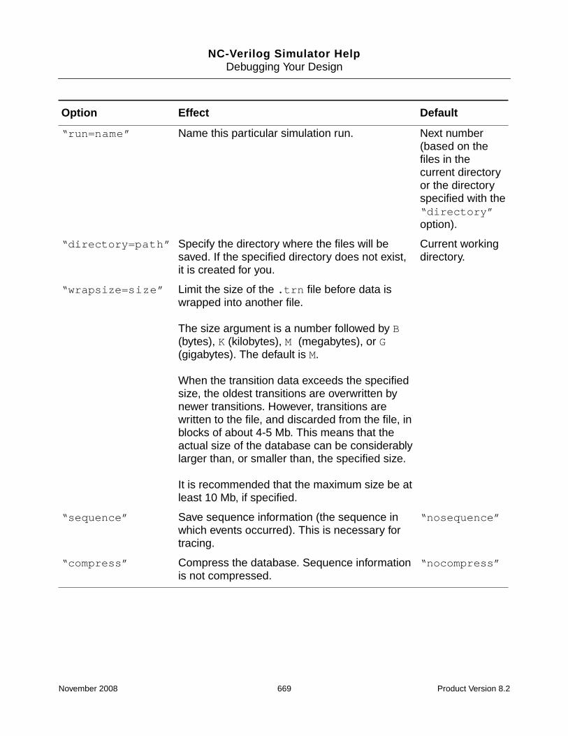
NC-Verilog Simulator HelpDebugging Your Design
“run=name” Name this particular simulation run. Next number(based on thefiles in thecurrent directoryor the directoryspecified with the“directory”option).
“directory=path” Specify the directory where the files will besaved. If the specified directory does not exist,it is created for you.
Current workingdirectory.
“wrapsize=size” Limit the size of the .trn file before data iswrapped into another file.
The size argument is a number followed by B(bytes), K (kilobytes), M (megabytes), or G(gigabytes). The default is M.
When the transition data exceeds the specifiedsize, the oldest transitions are overwritten bynewer transitions. However, transitions arewritten to the file, and discarded from the file, inblocks of about 4-5 Mb. This means that theactual size of the database can be considerablylarger than, or smaller than, the specified size.
It is recommended that the maximum size be atleast 10 Mb, if specified.
“sequence” Save sequence information (the sequence inwhich events occurred). This is necessary fortracing.
“nosequence”
“compress” Compress the database. Sequence informationis not compressed.
“nocompress”
Option Effect Default
November 2008 669 Product Version 8.2

NC-Verilog Simulator HelpDebugging Your Design
Example 1:
In the following example, a design file named data/adder-1.dsn is created. Ifadder-1.dsn already exists in the data directory, adder-2.dsn is created. A transition filenamed data/adder-1-1.trn is created. If this file already exists, a file calledadder-2-1.trn is created.
module record;
initial
begin
$recordsetup(“directory = data”, “design = adder”);
$recordvars;
end
endmodule
Example 2:
In the following example, a design file named data/adder-algo1.dsn is created, orreplaced if it exists. The database is compressed.
module record;
initial
begin
$recordsetup(“directory = data”, “design = adder”, “version = algo1”,“compress”);
$recordvars;
end
endmodule
$recordon/$recordoff
Use the $recordon and $recordoff tasks to turn recording on or off, respectively.Recording can be turned on or off at selected times or based on conditions in Verilog.
The $recordoff task does not close the database file. Variable transitions are not recordedduring the period where recording is off. All recorded variables are updated to their currentvalues when recording is turned back on.
Example:
In the following example, the $recordon and $recordoff tasks are used to recordvariables for a portion of the total simulation time.
November 2008 670 Product Version 8.2

NC-Verilog Simulator HelpDebugging Your Design
module record;
initial
begin
$recordvars;
$recordoff;
end
endmodule
module top;
reg clock;
initial
begin
#0 clock=0;
#100 clock=1;
#100 clock=1;
#100 clock=0; $recordon;
#100 clock=1;
#100 clock=0;
#100 clock=1; $recordoff;
#100 clock=0;
#100 clock=1;
end
endmodule
$recordclose
Use the $recordclose task to close an open database. This task stops the recording ofdata, flushes buffered data to the database, and closes the database.
Example:
$recordclose;
$recordabort
Use the $recordabort task to abort recording to a database that is no longer wanted. Anybuffered information not yet written to the database is discarded, and the database is deleted.Any current interactive connection to Signalscan is also aborted.
Example:
$recordabort;
November 2008 671 Product Version 8.2

NC-Verilog Simulator HelpDebugging Your Design
$signalscan
You can launch Signalscan from your Verilog code with the $signalscan task. This task isused to interactively view simulation results in Signalscan while the simulation is running. Allvariables being recorded to the database are available for viewing. Conversely, a variablemust be recorded in the database in order to view it with Signalscan. This means that theremust be at least one call to $recordvars in order for $signalscan to be useful.
Syntax:
$signalscan( ["path = path_to_signalscan_executable"] [, "arguments"] );
The path to the Signalscan executable is optional. If you do not specify a path, the PATHenvironment variable is used to find the executable, which must be named signalscan.
You can also pass Signalscan arguments as parameters to the $signalscan task. Theparameter is a string enclosed in double quotes.
There can be only one interactive Signalscan connection at a time for each simulation. If youexit Signalscan or the simulator, or use the $recordclose or $recordabort tasks, theinteractive connection is closed. You can then call the $signalscan task again to start anew interactive connection.
Example:
In the following example, the $sign Z¿an task specifies an absolute path to the Signalscanexecutable. It also includes an argument to load a Do-File.
module record;
initial
begin
$recordvars;
$signalscan("path=/usr/tools/signalscan-6.2/signalscan", "-do my.do");
end
endmodule
November 2008 672 Product Version 8.2

NC-Verilog Simulator HelpDebugging Your Design
Generating a Value Change Dump (VCD) File
A value change dump (VCD) file is an ASCII file that contains information about valuechanges on selected variables in the design. The file contains header information, variabledefinitions, and the value changes for all specified variables.
The Verilog LRM describes two types of VCD files:
■ Four-state—Represents variable changes in 0, 1, x, and z with no strength information.
■ Extended—Represents variable changes in all states and with strength information.
This section tells you how to generate a four-state VCD file for a Verilog design. See“Generating an Extended Value Change Dump (EVCD) File” on page 679 for information ongenerating an extended VCD file.
See “Generating a Value Change Dump (VCD) File for a Mixed-Language Design” onpage 599 for details on how to generate a VCD file for a mixed Verilog-VHDL design.
In NC-Verilog, there are two ways to generate a four-state VCD file:
■ Open a VCD database with the Tcl database -open -vcd command, and then probesignals to the database with the probe -create -vcd command.
■ Use the VCD system tasks in your Verilog code.
Note: You can dump only objects that have read access. If you specify a scope as anargument to the probe command, or as an argument to the $dumpvars system task, objectswithin that scope that do not have read access are excluded from the dump, and the simulatorprints a warning message. If you specify an individual variable and that object does not haveread access, the simulator prints an error message. See “Enabling Read, Write, orConnectivity Access to Simulation Objects” on page 371 for details on specifying access tosimulation objects.
Note: For Verilog, you cannot probe arrays of variable data types to a VCD database. Thisincludes Verilog memories, which are one-dimensional arrays of type reg. You cannot probevariables declared as multi-dimensional arrays.
November 2008 673 Product Version 8.2

NC-Verilog Simulator HelpDebugging Your Design
Generating a VCD File with Tcl Commands
To generate a VCD file by using Tcl commands:
1. Open a VCD database with the database command. The syntax is as follows:
database [-open] dbase_name -vcd
[-compress | -gzip]
[-default]
[-into filename]
[-maxsize max_size]
[-timescale timescale_value]
[-vcdmap vcd_mapping]
The following command opens a VCD database named vcddb. The filename isverilog.dump. The -timescale option sets the $timescale value in the VCD fileto 1 ns. Value changes in the VCD file are scaled to 1 ns.
ncsim> database -open -vcd vcddb -into verilog.dump -default -timescale ns
Created default VCD database vcddb
See “database” on page 775 for details on the database command.
2. Probe objects to the database with the probe command. The syntax is as follows:
probe [-create] [{object | scope_name}...] {-vcd | -database dbase_name}
[-all]
[-depth {n | all | to_cells}]
[-functions]
[-inputs]
[-name probe_name]
[-outputs]
[-ports]
[-screen [-format format_string] [-redirect filename] objects]
[-tasks]
The optional -create modifier can be followed by an argument that specifies:
❑ The object(s) to be traced
❑ The scope(s) to be traced
❑ A combination of object(s) and scope(s) to be traced
If you do not specify an argument, the current debug scope is assumed, but you mustinclude an option that specifies which objects to include in the trace (-all, -inputs,-outputs, or -ports).
November 2008 674 Product Version 8.2

NC-Verilog Simulator HelpDebugging Your Design
If more than one database is open, you must include an option to specify the databaseinto which you want to dump values. You can do this either by specifying a databasename with the -database option or by using the -vcd option to send the probe to thedefault VCD database. If no default database is open, the simulator opens a defaultdatabase called ncsim.vcd.
The following probe command creates a probe on all ports in the scope top.counter.Data is sent to the default VCD database.
ncsim> probe -create -vcd top.counter -ports
Created probe 1
See “probe” on page 905 for details on the probe command.
You can use the Tcl database and probe commands to generate a VCD file for amixed-language design. See “Generating a Value Change Dump (VCD) File for aMixed-Language Design” on page 599 for an example.
Generating a VCD File with VCD System Tasks
Several system tasks can be inserted in the source description to create a four-state VCD file.NC-Verilog supports all of the value change dump system tasks specified in the IEEE VerilogLanguage Reference Manual. This section summarizes the system tasks.
See the IEEE Standard Hardware Description Language Based on the VerilogHardware Description Language (IEEE Std 1364-1995 or 1364-2001) for details on theseVCD system tasks, and for information on the syntax and format of the VCD file.
VCD System Tasks
NC-Verilog supports all of the value change dump system tasks specified in the IEEE VerilogLanguage Reference Manual. These system tasks are:
■ $dumpfile (“filename”);
Specifies the name of the VCD file. If you do not use this system task to specify a filename, the simulator creates a file called verilog.dump by default. (The defaultfilename is different from that specified in the Verilog LRM, which is dump.vcd.)
■ $dumpvars;
Specifies which variables to dump into the VCD file. When invoked with no arguments,$dumpvars dumps all variables in the design, except those in source-protected regions.
■ $dumpvars (levels [, list_of_modules_or_variables]);
November 2008 675 Product Version 8.2
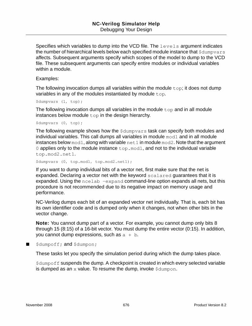
NC-Verilog Simulator HelpDebugging Your Design
Specifies which variables to dump into the VCD file. The levels argument indicatesthe number of hierarchical levels below each specified module instance that $dumpvarsaffects. Subsequent arguments specify which scopes of the model to dump to the VCDfile. These subsequent arguments can specify entire modules or individual variableswithin a module.
Examples:
The following invocation dumps all variables within the module top; it does not dumpvariables in any of the modules instantiated by module top.
$dumpvars (1, top);
The following invocation dumps all variables in the module top and in all moduleinstances below module top in the design hierarchy.
$dumpvars (0, top);
The following example shows how the $dumpvars task can specify both modules andindividual variables. This call dumps all variables in module mod1 and in all moduleinstances below mod1, along with variable net1 in module mod2. Note that the argument0 applies only to the module instance top.mod1, and not to the individual variabletop.mod2.net1.
$dumpvars (0, top.mod1, top.mod2.net1);
If you want to dump individual bits of a vector net, first make sure that the net isexpanded. Declaring a vector net with the keyword scalared guarantees that it isexpanded. Using the ncelab -expand command-line option expands all nets, but thisprocedure is not recommended due to its negative impact on memory usage andperformance.
NC-Verilog dumps each bit of an expanded vector net individually. That is, each bit hasits own identifier code and is dumped only when it changes, not when other bits in thevector change.
Note: You cannot dump part of a vector. For example, you cannot dump only bits 8through 15 (8:15) of a 16-bit vector. You must dump the entire vector (0:15). In addition,you cannot dump expressions, such as a + b.
■ $dumpoff; and $dumpon;
These tasks let you specify the simulation period during which the dump takes place.
$dumpoff suspends the dump. A checkpoint is created in which every selected variableis dumped as an x value. To resume the dump, invoke $dumpon.
November 2008 676 Product Version 8.2
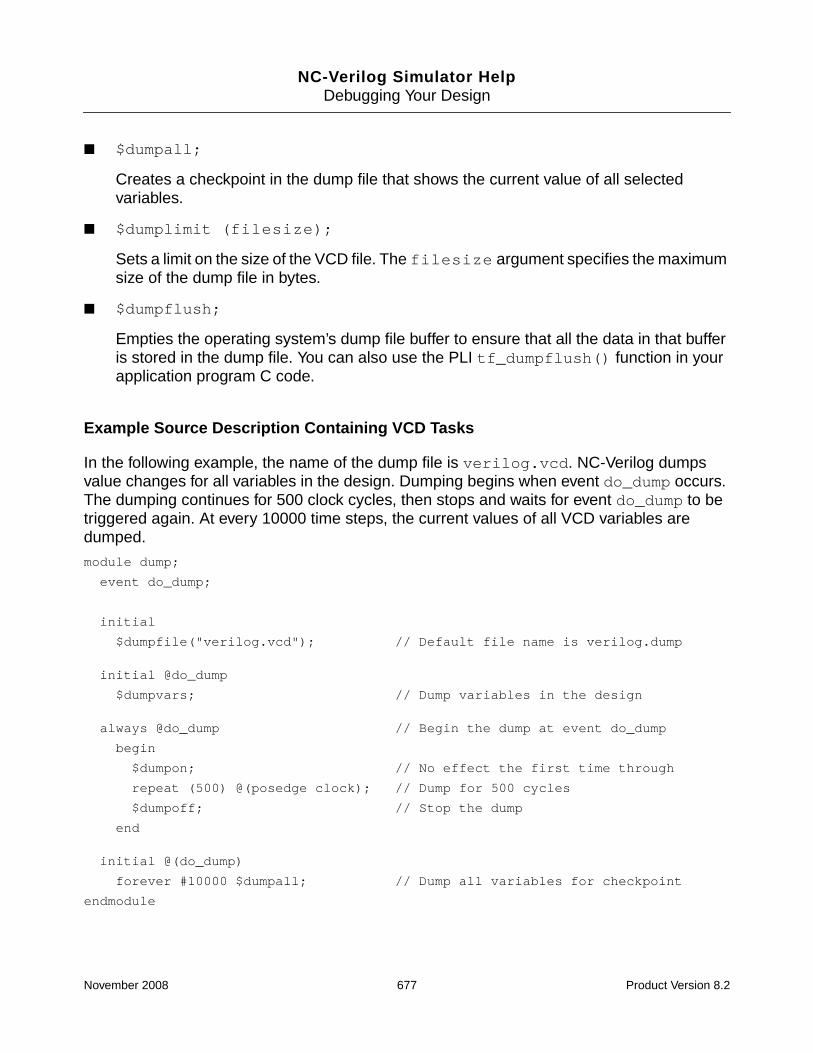
NC-Verilog Simulator HelpDebugging Your Design
■ $dumpall;
Creates a checkpoint in the dump file that shows the current value of all selectedvariables.
■ $dumplimit (filesize);
Sets a limit on the size of the VCD file. The filesize argument specifies the maximumsize of the dump file in bytes.
■ $dumpflush;
Empties the operating system’s dump file buffer to ensure that all the data in that bufferis stored in the dump file. You can also use the PLI tf_dumpflush() function in yourapplication program C code.
Example Source Description Containing VCD Tasks
In the following example, the name of the dump file is verilog.vcd. NC-Verilog dumpsvalue changes for all variables in the design. Dumping begins when event do_dump occurs.The dumping continues for 500 clock cycles, then stops and waits for event do_dump to betriggered again. At every 10000 time steps, the current values of all VCD variables aredumped.
module dump;
event do_dump;
initial
$dumpfile("verilog.vcd"); // Default file name is verilog.dump
initial @do_dump
$dumpvars; // Dump variables in the design
always @do_dump // Begin the dump at event do_dump
begin
$dumpon; // No effect the first time through
repeat (500) @(posedge clock); // Dump for 500 cycles
$dumpoff; // Stop the dump
end
initial @(do_dump)
forever #10000 $dumpall; // Dump all variables for checkpoint
endmodule
November 2008 677 Product Version 8.2

NC-Verilog Simulator HelpDebugging Your Design
Syntax and Format of the VCD File
A four-state VCD file contains three sections:
■ Header information section—Shows the date, the version number of the simulator, andthe timescale used in the simulation.
■ Node information section—Contains definitions of the scope and type of variablesdumped.
■ Value changes section—Shows the actual value changes at each simulation timeincrement. Only variables that change value during a time increment are listed.
See the IEEE Standard Hardware Description Language Based on the VerilogHardware Description Language (IEEE Std 1364-1995 or 1364-2001) for details on thesyntax and format of the VCD file.
November 2008 678 Product Version 8.2

NC-Verilog Simulator HelpDebugging Your Design
Generating an Extended Value Change Dump (EVCD) File
A value change dump (VCD) file is an ASCII file that contains information about valuechanges on selected variables in the design. The file contains header information, variabledefinitions, and the value changes for all specified variables.
The Verilog LRM describes two types of VCD files:
■ Four-state—Represents variable changes in 0, 1, x, and z with no strength information.
■ Extended—Represents variable changes in all states and strength information.
This section tells you how to generate an extended VCD file. See “Generating a ValueChange Dump (VCD) File” on page 673 for information on generating a four-state VCD file.
In NC-Verilog, you can generate an EVCD file by:
■ Using Tcl commands. See “Generating an EVCD File with Tcl Commands” on page 681.
■ Using the $dumpports system task in your Verilog source description. See “Generatingan EVCD File with the $dumpports System Task” on page 692.
The implementation of the $dumpports task in NC-Verilog differs in some ways from thedescription of the task in the IEEE Std 1364-2001 standard.
NC-Verilog also supports a $dumpports_close system task. It does not support theother extended VCD system tasks described in the IEEE 1364-2001 standard($dumpportsoff, $dumpportson, $dumpportslimit, and so on).
Note: Access to simulation objects is required to dump an EVCD file. If you are generatingthe file using Tcl commands, you must provide full access to simulation objects by includingthe -access +rwc option when you elaborate the design with ncelab. If you are runningNC-Verilog in single-step invocation mode with the ncverilog command, use the+ncaccess+rwc option. If you are generating the file by using the $dumpports systemtask, the elaborator automatically sets the required access.
Note: For Verilog, you cannot probe arrays of variable data types to a VCD database. Thisincludes Verilog memories, which are one-dimensional arrays of type reg.
By default, the signal identifier codes in an EVCD file differ from what is specified in the IEEEstandard. The IEEE standard specifies that the identifier code is to be an integer precededby <, which starts at zero and ascends in one unit increments for each port. For example,
November 2008 679 Product Version 8.2

NC-Verilog Simulator HelpDebugging Your Design
$scope module board.counter $end
$var port 4 <0 value $end
$var port 1 <1 clock $end
$var port 1 <2 fifteen $end
$var port 1 <3 altFifteen $end
...
Cadence simulators use space-efficient identifiers in order to minimize the size of the file. Forexample,
$scope module board.counter $end
$var port 4 ! value $end
$var port 1 " clock $end
$var port 1 # fifteen $end
$var port 1 $ altFifteen $end
...
Use the -use_ieee_dumpport_ids command-line option when you invoke the simulatorif you want the identifier codes to conform to the IEEE standard. If you are running thesimulator in single-step invocation mode with the ncverilog command, use the+use_ieee_dumpport_ids option.
After generating an EVCD file, you can use the ncgentb utility to generate a testbench. See“ncgentb” on page 1387 for details.
November 2008 680 Product Version 8.2

NC-Verilog Simulator HelpDebugging Your Design
Generating an EVCD File with Tcl Commands
To generate an EVCD file, you must open an EVCD database and then probe the primaryports of a specified module instance to the database. The following steps show you how toopen a database with the database command and then probe the ports with the probecommand. You can also probe objects to a database simply by using the probe command.In this case, the probe command opens a default EVCD database called ncsim.evcd andprobes the ports for the specified scope. See “Example probe Command Lines” on page 686for an example.
Opening an EVCD Database
Open an EVCD database with the database command. The syntax is as follows:
database [-open] [direction] dbase_name -evcd
[-compress | gzip]
[-default]
[-into filename]
[-maxsize max_byte_size]
[-timescale timescale_value]
See “database” on page 775 for a complete description of the database command and itsmodifiers and options. The following is a summary of the command-line options.
■ -open
Creates a new database. This modifier is optional.
■ -evcd [direction] [-timescale timescale_value]
Specifies that this is an EVCD database.
Include the direction argument if you want to dump port direction in the nodeinformation section of the output file.
Use the -timescale timescale_value option to set the $timescale value in theEVCD file to the specified timescale. This option lets you output a different timescale inthe EVCD file than the timescale being used during simulation. In the output file, thetimes that are shown for the signal changes reflect the simulation times at the precisionspecified with the -timescale option.
The timescale_value argument can be:
fs, 10fs, 100fs
ps, 10ps, 100ps
November 2008 681 Product Version 8.2

NC-Verilog Simulator HelpDebugging Your Design
ns, 10ns, 100ns
us, 10us, 100us
ms, 10ms, 100ms
■ -compress or -gzip
Both options compress the output file. The -compress option generates a compresseddatabase file in compress format (with a .Z file extension). The -gzip option generatesa compressed database file in gzip format (with a .gz file extension).
Use the uncompress or gzip -d command to uncompress the file.
■ -default
Specifies that this is the default database for all EVCD signal tracing.
■ -into filename
Specifies the physical filename for the database. By default, the filename for an EVCDdatabase is dbase_name.evcd. Use the -into option to override this default.
■ -maxsize max_byte_size
Specifies a limit on the number of bytes that the simulator can dump to the EVCD file. Ifthe size of the EVCD file reaches the specified limit, the simulator inserts a comment(dump limit reached) into the file, and dumping stops. The output file size will be nomore than a few hundred bytes over the specified limit.
Example database Command Lines
The following command opens an EVCD database called testoutput. By default, theassociated file is called db_name.evcd. In this example, the file will be calledtestoutput.evcd. The file is placed in the current working directory.
ncsim> database -open testoutput -evcd
The following command opens an EVCD database called evcd. The -default optionspecifies that this is the default database for all EVCD signal tracing. The -into optionspecifies that the output file is called testoutput.evcd. This file is placed in the currentworking directory.
ncsim> database evcd -evcd -default -into testoutput.evcd
The following command opens a default EVCD database named evcddb. The filename issim.dump. The -timescale option sets the $timescale value in the EVCD file to 1 ns.Value changes in the file are scaled to 1 ns. The -compress option compresses the outputfile and generates a file called sim.dump.Z.
November 2008 682 Product Version 8.2

NC-Verilog Simulator HelpDebugging Your Design
ncsim> database evcddb -evcd -default -into sim.dump -timescale ns -compress
Created default EVCD database evcddb
Probing Objects to the Database
Probe objects to the database with the probe command. The syntax is as follows:
probe [-create] scope_name [...]
-evcd
[[{splitio | simple}]
[-evcdformat format_number]]
[-database dbase_name]
[-all]
[-depth {n | all | to_cells}]
[-functions]
[-inputs]
[-name probe_name]
[-outputs]
[-ports]
[-tasks]
See “probe” on page 905 for a complete description of the probe command and its modifiersand options. The following is a summary of the command-line options.
■ -create
Places values of the primary ports in a database.
For Verilog, you can set an EVCD probe only on a scope(s). You cannot probe specificVerilog ports. Because the top-level scope in Verilog does not have ports, you mustspecify a scope as the argument. For example:
ncsim> probe -create test_bench.dut -evcd
The -create modifier is optional.
■ -evcd [[{splitio | simple}] [-evcdformat format_number]]
Creates an EVCD probe.
By default, the simulator dumps final value changes in extended format for both vectorand scalar ports. For vector ports, the simulator dumps value changes for the entirevector, not for individual bits of the vector.
November 2008 683 Product Version 8.2
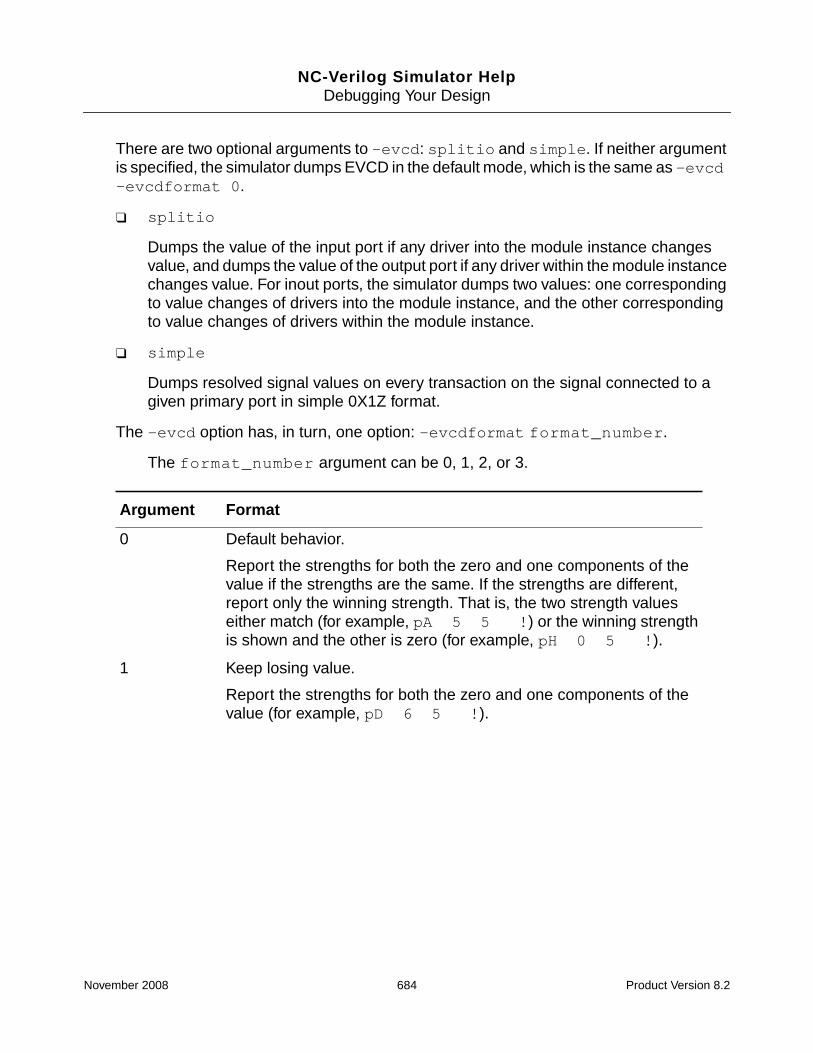
NC-Verilog Simulator HelpDebugging Your Design
There are two optional arguments to -evcd: splitio and simple. If neither argumentis specified, the simulator dumps EVCD in the default mode, which is the same as -evcd-evcdformat 0.
❑ splitio
Dumps the value of the input port if any driver into the module instance changesvalue, and dumps the value of the output port if any driver within the module instancechanges value. For inout ports, the simulator dumps two values: one correspondingto value changes of drivers into the module instance, and the other correspondingto value changes of drivers within the module instance.
❑ simple
Dumps resolved signal values on every transaction on the signal connected to agiven primary port in simple 0X1Z format.
The -evcd option has, in turn, one option: -evcdformat format_number.
The format_number argument can be 0, 1, 2, or 3.
Argument Format
0 Default behavior.
Report the strengths for both the zero and one components of thevalue if the strengths are the same. If the strengths are different,report only the winning strength. That is, the two strength valueseither match (for example, pA 5 5 !) or the winning strengthis shown and the other is zero (for example, pH 0 5 !).
1 Keep losing value.
Report the strengths for both the zero and one components of thevalue (for example, pD 6 5 !).
November 2008 684 Product Version 8.2

NC-Verilog Simulator HelpDebugging Your Design
■ [-database dbase_name]
Saves the probe into the specified database.
■ -all (or -ports), -inputs, -outputs
Use one of these three options to specify that all of the declared primary ports, inputports, or output ports, respectively, within a scope are to be included in the probe. Thisapplies to:
❑ The scope(s) named in the argument.
❑ The subscopes that you specify with the -depth option.
■ -depth {n | all | to_cells} [-tasks] [-functions]
Specifies the number of scope levels to descend when searching for objects to probe.You must specify one of the following arguments:
2 Generate output according to the IEEE 1364-2001 standard.
The IEEE standard states that the values 0 (both input and outputare active with value 0) and 1 (both input and output are active withvalue 1) are conflict states. The standard then defines two strengthranges:
Strong: strengths 7, 6, and 5Weak: strengths 4, 3, 2, 1
The rules for resolving conflicts are:
■ If the input and output are driving with the same range ofstrength, the resolved value is 0 or 1, and the strength is thestronger of the two.
■ If the input is driving a strong strength and the output is drivinga weak strength, the resolved value is d or u, and the strengthis the strength of the input.
■ If the input is driving a weak strength and the output is driving astrong strength, the resolved value is l or h, and the strength isthe strength of the output.
3 Do both 1 and 2. Generate output according to the IEEE 1364-2001standard, and also keep the losing strength.
Argument Format
November 2008 685 Product Version 8.2

NC-Verilog Simulator HelpDebugging Your Design
n–Descend the specified number of scopes. For example, -depth 1 meansinclude only the given scope, -depth 2 means include the given scope and itssubscopes, and so on. The default is 1.
all–Include all scopes in the hierarchy below the specified scope(s).
to_cells–Include all scopes in the hierarchy below the specified scope(s), butstop at cells (Verilog modules with ‘celldefine or VITAL entities with VITALLevel0 attribute).
■ -name probe_name
Specifies a user-defined name for the probe. If you do not use -name to name yourprobes, every probe that you create is given a sequential number.
Example probe Command Lines
The following command probes all primary ports of the scope test_bench.dut to thedefault EVCD database opened with a database -open -evcd -default command.
ncsim> probe -create test_bench.dut -evcd
Created probe 1
The following command probes all primary ports of the scope test_bench.dut and itssubscopes (that is, two levels of depth) to the EVCD database.
ncsim> probe test_bench.dut -evcd -depth 2
The following command probes all primary ports of the scope test_bench.dut to theEVCD database called testoutput.
ncsim> probe test_bench.dut -evcd -database testoutput
You do not have to open a database with the database command before probing objects.You can probe objects to a database simply by using the probe command. In this case, theprobe command opens a default EVCD database called ncsim.evcd and probes the portsfor the specified scope. For example:
ncsim> probe -create test_bench.dut -evcd
Created default EVCD database ncsim.evcd
Created probe 1
November 2008 686 Product Version 8.2

NC-Verilog Simulator HelpDebugging Your Design
Examples
This section contains three example EVCD files. All of the examples use the following sourcecode:
‘timescale 1 ns / 1 ns
module test_bench;
reg AS_3, AS_2, AS_1;
tri TF;
// The following 3 continuous assignments are the drivers from the test fixture
assign (strong1, strong0) TF = AS_1; // Will make TF have strength 6
assign (pull1, pull0) TF = AS_2; // Will make TF have strength 5
assign (weak1, weak0) TF = AS_3; // Will make TF have strength 3
initial
begin
assign AS_3 = 1’bz;
assign AS_1 = 1’bz;
assign AS_2 = 1’bz;
#10;
assign AS_3 = 1’bz;
assign AS_2 = 1’bz;
assign AS_1 = 0;
#10;
assign AS_3 = 0;
assign AS_1 = 1’bz;
assign AS_2 = 1’bz;
#10;
end
buf_w_strength dut(TF);
endmodule
module buf_w_strength (IO);
inout IO;
wire IO_wire;
pullup (pull1, pull0) (IO_wire); // This is the driver within the DUT
// Assignment will make IO have a strength of 5
assign (pull1, pull0) IO = IO_wire;
endmodule
November 2008 687 Product Version 8.2

NC-Verilog Simulator HelpDebugging Your Design
Example 1
In this example, the database command is used to open an EVCD database calledtest_default. The -into option specifies that the associated filename isdefault.evcd.
The probe command creates an EVCD probe on the ports for the scope test_bench.dut.The -database option specifies that the database is test_default.
ncsim> database -open test_default -evcd -into default.evcd
Created EVCD database test_default
ncsim> probe -create test_bench.dut -evcd -database test_default
Created probe 1
ncsim> run
In this example, the simulator dumps data using the default mode. Final value changes aredumped in extended format for both vector and scalar ports. For vector ports, the simulatordumps value changes for the entire vector, not for individual bits of the vector.
% more default.evcd
$date
Feb 25, 2003 14:46:21
$end
$version
TOOL: ncsim 05.00-p001
$end
$timescale
1 ns
$end
$scope module test_bench $end
$scope module dut $end
$var port 1 ! IO $end
$upscope $end
$upscope $end
$enddefinitions $end
#0
$dumpports
pH 0 5 !
$end
#10
November 2008 688 Product Version 8.2

NC-Verilog Simulator HelpDebugging Your Design
pD 6 0 !
#20
pH 0 5 !
#30
Example 2
In this example, the database command is used to open an EVCD database calledtest_splitio. The -into option specifies that the associated filename issplitio.evcd.
The probe command creates an EVCD probe on the ports for the scope test_bench.dut.
The splitio argument is included as an argument to the -evcd option. This argumentcauses the simulator to dump the value of the input port if any driver into the module instancechanges value, and to dump the value of the output port if any driver within the moduleinstance changes value. For inout ports, the simulator dumps two values: one correspondingto value changes of drivers into the module instance, and the other corresponding to valuechanges of drivers within the module instance.
The -database option specifies that the database is test_splitio.
ncsim> database -open test_splitio -evcd -into splitio.evcd
Created EVCD database test_splitio
ncsim> probe -create test_bench.dut -evcd splitio -database test_splitio
Created probe 1
ncsim> run
% more splitio.evcd
$date
Feb 25, 2003 14:46:21
$end
$version
TOOL: ncsim 05.00-p001
$end
$timescale
1 ns
$end
$scope module test_bench $end
$scope module dut $end
$var port 1 ! IO $end
$upscope $end
November 2008 689 Product Version 8.2

NC-Verilog Simulator HelpDebugging Your Design
$upscope $end
$enddefinitions $end
#0
$dumpports
pZ 0 0 !
pH 0 5 !
$end
#10
pD 6 0 !
#20
pD 3 0 !
#30
Example 3
In this example, the probe command creates a default EVCD database called ncsim.evcd,and then creates a probe on the ports for the scope test_bench.dut.
The probe command includes the -evcd -evcdformat option. The argument to-evcdformat is 1, which reports the strengths for both the zero and one components of thevalue.
See Table 10-1 on page 691 for a summary of the output using all -evcdformat arguments.
ncsim> probe -create test_bench.dut -evcd -evcdformat 1
Created default EVCD database ncsim.evcd
Created probe 1
ncsim> run
% more ncsim.evcd
$date
Feb 25, 2003 14:52:59
$end
$version
TOOL: ncsim 05.00-p001
$end
$timescale
1 ns
$end
$scope module test_bench $end
November 2008 690 Product Version 8.2

NC-Verilog Simulator HelpDebugging Your Design
$scope module dut $end
$var port 1 ! IO $end
$upscope $end
$upscope $end
$enddefinitions $end
#0
$dumpports
pH 0 5 !
$end
#10
pD 6 5 !
#20
pH 3 5 !
#30
The following table shows the output for the example using the various -evcdformatarguments:
Table 10-1 Effect of -evcdformat Argument
-evcdformat Argument
0 1 2 3
#0
pH 0 5 <0
#10
pD 6 0 <0
#20
pH 0 5 <0
#0
pH 0 5 <0
#10
pD 6 5 <0
#20
pH 3 5 <0
#0
pH 0 5 <0
#10
pA 6 5 <0
#20
pH 0 5 <0
#0
pH 0 5 <0
#10
pA 6 5 <0
#20
pH 3 5 <0
November 2008 691 Product Version 8.2

NC-Verilog Simulator HelpDebugging Your Design
Generating an EVCD File with the $dumpports System Task
The $dumpports system task scans the primary ports of a specified module instance andmonitors the ports for both value and drive level. The task generates an output file thatcontains the value, direction, and strength information for all the ports of a device.
Syntax:
$dumpports [([scope_list], ["file_pathname"], [ID], [format_flag])];
All arguments are optional. If you do not specify any arguments, both of the following areallowed:
$dumpports;
$dumpports();
If an argument is null, you must use a comma before specifying the following argument. Forexample:
$dumpports( , “output.evcd”);
The following table describes the arguments of $dumpports.
■ scope_list
One or more module identifiers. If more than one module is specified, separate themodule identifiers with a comma.
You cannot specify a top-level module.
This argument is optional if $dumpports is called from a module instance. If you do notspecify a module, the scope is the module from which $dumpports has been called.However, if $dumpports is called from the top-level module, you must specify ascope_list argument because a top-level module is not a valid argument to$dumpports.
Paths to modules are allowed, using the period hierarchy separator.
■ “file_pathname”
A string containing the name of the output file.
This argument is optional. If you do not include this argument, the simulator creates a filecalled verilog.evcd in the current working directory.
■ ID
An integer data type that identifies a running $dumpports task with the$dumpports_close system task. For example,
module ...;
November 2008 692 Product Version 8.2

NC-Verilog Simulator HelpDebugging Your Design
...
integer evcd_id;
...
initial
begin
$dumpports(dut1, “dut1.evcd”, evcd_id);
...
#4000 $dumpports_close(evcd_id);
end
...
This argument is optional.
See “Using the $dumpports_close System Task” on page 695 for more information.
■ format_flag
An integer value that determines the value/strength format.
The format_flag argument is optional. It can be one of the following values, or a sumof any of the following values.
Note: There are two values that can be used to specify output file compression(format_flag value 4 and format_flag value 32). You cannot combine these twovalues.
❑ 0—Default behavior.
❑ 1—Keep losing value.
❑ 2—Generate output according to the IEEE 1364-2001 standard.
❑ 4—Compress the EVCD output file in compress format (.Z file extension).
❑ 8—Dump port direction information in the node information section of the output file.See “Node Information Section” on page 699 for an example.
❑ 32—Compress the EVCD output file in gzip format (.gz file extension).
The format_flag arguments can be combined. For example, if you want to generatean EVCD file that reports the strengths for both the zero and one components of thevalue (value 1), and that generates output according to the IEEE 1364-2001 standard(value 2), specify the format_flag argument as 3. To generate output according tothe IEEE 1364-2001 standard (value 2) and compress the output file (value 4), specify avalue of 6 for the format_flag.
See “Using the format_flag Argument to Control $dumpports Output” on page 695 fordetails on the format_flag argument.
November 2008 693 Product Version 8.2

NC-Verilog Simulator HelpDebugging Your Design
Note: You can also specify the format by using the -dumpports_format option whenyou invoke the simulator.
Examples
The following example generates an output file that contains the value, direction, and strengthinformation for all the ports of testbench.dut. The output file is called verilog.evcd.
$dumpports(testbench.dut);
The following example generates an output file called testoutput.evcd in the currentworking directory.
$dumpports(testbench.dut, “testoutput.evcd”);
The following example generates an output file that contains the value, direction, and strengthinformation for all the ports of testbench.dut1 and testbench.dut2. The output file iscalled verilog.evcd.
$dumpports(testbench.dut1, testbench.dut2);
The following example generates an output file called testoutput.evcd in the currentworking directory. This file contains output data for the two specified modules.
$dumpports(testbench.dut1, testbench.dut2, “testoutput.evcd”);
The following example generates an output file called testoutput.evcd in the ./worklibdirectory.
$dumpports(testbench.dut, “./worklib/testoutput.evcd”);
The following example generates an EVCD file called testoutput.evcd. This$dumpports call includes the format_flag argument 1, which specifies that thecalculated strengths for both the one and zero components of the value are to be reported.
$dumpports(testbench.dut, “testoutput.evcd”, , 1);
The following example generates a compressed EVCD file called testoutput.evcd.Z inthe current working directory.
Note: Compression of EVCD files is not supported on Windows platforms.
$dumpports(testbench.dut, “testoutput.evcd”, , 4);
The following example generates an EVCD file called testoutput.evcd. This$dumpports call includes the format_flag argument 8, which specifies that informationon the direction of ports is to be included in the node information section of the output file.
$dumpports(testbench.dut, “testoutput.evcd”, , 8);
November 2008 694 Product Version 8.2

NC-Verilog Simulator HelpDebugging Your Design
Using the $dumpports_close System Task
The $dumpports_close system task stops a running $dumpports task. The syntax is asfollows:
$dumpports_close(ID);
The ID argument is an integer data type that identifies a particular $dumpports system task.If only one $dumpports system task is running, the ID argument can be omitted.
Example
In the following example, two EVCD files are generated: dut1.evcd and dut2.evcd. Thedump identified with the ID called id1 is closed after 4000 time units.
module top;
reg A;
integer id1;
integer id2;
...
...
initial
begin
$dumpports(dut1, “dut1.evcd”, id1);
$dumpports(dut2, “dut2.evcd”, id2);
#4000 $dumpports_close(id1);
end
....
....
endmodule
Using the format_flag Argument to Control $dumpports Output
You can control the output of $dumpports with the format_flag argument. Thisargument can be one of the following values:
■ 0—Default behavior.
Report the strengths for both the zero and one components of the value if the strengthsare the same. If the strengths are different, report only the “winning” strength. That is, thetwo strength values either match (for example, pA 5 5 !) or the winning strengthis shown and the other is zero (for example, pH 0 5 !)
■ 1—Keep losing value.
November 2008 695 Product Version 8.2

NC-Verilog Simulator HelpDebugging Your Design
Report the strengths for both the zero and one components of the value (for example,pD 6 5 !).
■ 2—Generate output according to the IEEE 1364-2001 standard.
The IEEE standard states that the values 0 (both input and output are active with value0) and 1 (both input and output are active with value 1) are conflict states. The standardthen defines two strength ranges:
❑ Strong: strengths 7, 6, and 5
❑ Weak: strengths 4, 3, 2, 1
The rules for resolving conflicts are:
❑ If the input and output are driving with the same range of strength, the resolved valueis 0 or 1, and the strength is the stronger of the two.
❑ If the input is driving a strong strength and the output is driving a weak strength, theresolved value is d or u, and the strength is the strength of the input.
❑ If the input is driving a weak strength and the output is driving a strong strength, theresolved value is l or h, and the strength is the strength of the output.
■ 4—Compress the EVCD output file.
This option generates a compressed output file called file_pathname.Z.
Compression of EVCD files is not supported on Windows platforms. On Windows, using4 as the value for the format_flag argument generates a warning message.
■ 8—Dump port direction information in the node information section of the EVCD file. See“Node Information Section” on page 699 for an example.
Example
The source code for this example is the same as that used for the examples shown in thesection that describes how to generate an EVCD file using Tcl commands. See “Examples”on page 687. The only difference is that a $dumpports system task has been inserted intothe initial block, as shown below:
‘timescale 1 ns / 1 ns
module test_bench;
reg AS_3, AS_2, AS_1;
tri TF;
...
...
November 2008 696 Product Version 8.2

NC-Verilog Simulator HelpDebugging Your Design
initial
begin
$dumpports(test_bench.dut, "test_format0.evcd", , 0);
assign AS_3 = 1’bz;
assign AS_1 = 1’bz;
...
...
end
...
endmodule
In this example, the format_flag argument to the $dumpports call was set to 0, 1, 2,and 3 to generate four EVCD files. The following table shows the value change section for thefour output files. Notice that, if the format_flag argument is set to 1 or to 3, strengths forboth the zero and one components of the value are reported.
$dumpports Restrictions
The following restrictions apply to the $dumpports system task:
■ The $dumpports system task does not work with save and restart.
■ Continuous assignments cannot have delays.
■ The following wire types are the only ones permitted to be connected to the ports:
Table 10-2 Effect of format_flag Argument
format_flag Argument
0 1 2 3
#0
pH 0 5 !
#10
pD 6 0 !
#20
pH 0 5 !
#0
pH 0 5 !
#10
pD 6 5 !
#20
pH 3 5 !
#0
pH 0 5 !
#10
pA 6 5 !
#20
pH 0 5 !
#0
pH 0 5 !
#10
pA 6 5 !
#20
pH 3 5 !
November 2008 697 Product Version 8.2

NC-Verilog Simulator HelpDebugging Your Design
wire, tri, tri0, tri1, reg, trireg, supply0, supply1
■ Directional information can be lost when a port is driven by one or more drivers of thedifferent tran elements (tran, rtran, rtranif0, ...).
In the following example, the direction of the port out cannot be determined because thevalue that the tran gate is transporting from its other terminal is unknown.
bufif1 u1(out, 1’b1, 1’b1);
DUT udut(out);
...
module DUT(out)
tran t1(out, int);
Syntax and Format of the EVCD File
The format of the extended VCD file is similar to that of the four-state VCD file, which isdescribed in the IEEE Verilog LRM. The file contains three sections: header information, nodeinformation, and value changes.
Header Information Section
The EVCD file begins with a header in the following format:
$date
<date and time file was generated>
$end
$version
<version of ncsim>
$end
$timescale
<timescale used for the simulation>
$end
The following is an example header section from an EVCD file that was generated using Tclcommands:
$date
Dec 11, 2002 15:42:26
$end
$version
TOOL: ncsim 05.00-p001
$end
$timescale
November 2008 698 Product Version 8.2

NC-Verilog Simulator HelpDebugging Your Design
1 ns
$end
Node Information Section
This section of the EVCD file begins with the $scope keyword command, which defines thescope of the primary ports being dumped, and ends with $enddefinitions $end, whichmarks the end of the header and node information sections.
This section has the following syntax:
$scope module <module_instance_name> $end
$var <var_type> <port_size> <port_identifier_code> <port_reference> $end
...
...
$upscope $end
$enddefinitions $end
The constructs in the lines that begin with the $var keyword command are defined as follows:
■ var_type—The type of variable. For EVCD, this is always the keyword port, unlessyou have specified that you want port direction information in the output file. You can dothis by using the -evcd direction option when you open the database with the Tcldatabase command, or by setting the format_flag argument to 8 if you are usingthe $dumpports task. See the examples below.
■ port_size—The port size is a decimal number indicating the number of bits in theport.
■ port_identifier_code—The identifier for the port. This identifier is used insubsequent message dumping.
Note: The port identifier codes in an EVCD file differ from what is specified in the IEEEstandard. The IEEE standard specifies that the identifier code is to be an integerpreceded by <, which starts at zero and ascends in one unit increments for each port.For example <0, <1, and so on. In an EVCD file generated by NC-Verilog, space-efficientidentifiers are used in order to minimize the size of the file. See the example below.
Use the ncsim -use_ieee_dumpport_ids option if you want the identifier codes toconform to the IEEE standard. If you are running the simulator in single-step invocationmode with the ncverilog command, use the +ncuse_ieee_dumpport_ids option.
■ port_reference—An identifier that indicates the port name.
Examples:
November 2008 699 Product Version 8.2

NC-Verilog Simulator HelpDebugging Your Design
The following is an example of the node information section in an EVCD file:
$scope module board.counter $end
$var port 4 ! value $end
$var port 1 " clock $end
$var port 1 # fifteen $end
$var port 1 $ altFifteen $end
$upscope $end
$enddefinitions $end
The following example shows the node information section if the format_flag has beenset to 8, as in the following $dumpports task:
$dumpports(board.counter, "test.evcd", , 8);
Notice that port direction information is included in the output.
$scope module board.counter $end
$var output 4 ! value $end
$var input 1 " clock $end
$var output 1 # fifteen $end
$var output 1 $ altFifteen $end
$upscope $end
$enddefinitions $end
Value Change Section
The value change section shows the actual value changes at each simulation time increment.Only variables that change value during a time increment are listed. The format of themessage is as follows:
#<simulation_time>
p<port_value> <0_strength_component> <1_strength_component> <identifier_code>
The constructs in the message are defined as follows:
■ #simulation_time—The simulation time.
■ p—Key character that indicates a port.
■ port_value—State character that indicates the driving direction and state. The statecharacters are described in “Port Value Character Mapping” on page 702.
■ 0_strength_component—One of the eight Verilog strengths. This indicates thestrength0 component of the value. See “Strength Mapping” on page 705 forinformation on strength mapping.
November 2008 700 Product Version 8.2

NC-Verilog Simulator HelpDebugging Your Design
■ 1_strength_component—One of the eight Verilog strengths. This indicates thestrength1 component of the value.
■ identifier_code—The identifier code for the port, which was defined in the $varconstruct for the port.
The following example shows the node information section and part of the value changesection of an EVCD file:
$scope module board $end
$scope module counter $end
$var port [3:0] ! value $end
$var port 1 “ clock $end
$var port 1 # fifteen $end
$var port 1 $ altFifteen $end
$upscope $end
$upscope $end
$enddefinitions $end
#0
$dumpports
pXXXX 6666 6666 !
pN 6 6 "
pX 6 6 #
pX 6 6 $
$end
#5
pU 0 6 "
#10
pLLLL 6666 0000 !
pL 6 0 #
pL 6 0 $
#50
pD 6 0 "
...
...
Port Names
Port names are recorded in the output file as follows:
November 2008 701 Product Version 8.2

NC-Verilog Simulator HelpDebugging Your Design
■ A port that is explicitly named is recorded in the output file.
■ If a port is not explicitly named, the name of the object used in the port definition isrecorded.
■ If the name of a port cannot be determined from the object used in the port definition, theport index number is used (the first port being 0).
Drivers
A driver is anything that can drive a value onto a net, including the following:
■ Primitives
■ Continuous assigns
■ Forces
■ Ports with objects of type other than net, such as the following:
module foo(out, ...)
output out;
reg out;
If a net is forced, a comment is placed into the output file stating that the net connected to theport is being forced, and giving the scope of the force. Forces are treated differently becausethe existence of a force is not permanent, even though a force is a driver.
While a force is active, driver collisions are ignored and the level part of the output isdetermined by the scope of the force definition. If the EVCD was generated using Tcl, the portdriving direction is treated as direction input (see Port Value Character Mapping). When theforce is released, a note is again placed into the output file.
Port Value Character Mapping
The state information shown in this section is described in terms of input values from a testfixture, the output values of the device under test, and the states that represent unknowndirection.
Direction INPUT
Given a device under test (DUT) and a test fixture, the driving direction is INPUT if the driversfrom the test fixture are driving some non-tristated value and the drivers inside the DUT are
November 2008 702 Product Version 8.2

NC-Verilog Simulator HelpDebugging Your Design
tristated. The resolved value is mapped as shown in the following table. In the table, the termactive implies that the drivers are in a non-tristated condition.
Direction OUTPUT
If the driving value from drivers inside the DUT is non-tristated, but the value driven by thedrivers in the test fixture is tristated, the direction is OUTPUT. The resolved value is mappedas shown in the following table:
Direction UNKNOWN
If both the drivers in the test fixture and drivers inside the DUT are driving some non-tristatedvalue, the direction is UNKNOWN. The resolved value is mapped as shown in the followingtable:
Table 10-3 Driving Direction INPUT Mapping
D (0) low
d (0) low (2 or more drivers active)
U (1) high
u (1) high (2 or more drivers active)
N (X) unknown
n (X) unknown because of a 1-0 collision
Z (Z) tristate
Table 10-4 Driving Direction OUTPUT Mapping
L (0) low
l (0) low (more than 2 drivers active)
H (1) high
h (1) high (more than 2 drivers active)
X (X) unknown (don’t care)
T (Z) tristate
Table 10-5 Driving Direction UNKNOWN Mapping
0 (0) low (both input and output are active with 0 value)
November 2008 703 Product Version 8.2

NC-Verilog Simulator HelpDebugging Your Design
The level of a driver is determined by the scope of the driver’s placement on a net. Port typehas no influence on the level of a signal. Any driver whose definition is outside of the scopeof the DUT is at the test fixture level.
In the following example, because the driver is outside the scope of a DUT, the continuousassignment is at the test fixture level:
module top;
reg regA;
assign dut1.out = regA;
dut dut1(out, ....);
initial
$dumpports(dut1, "testVec.file");
...
..
endmodule
module dut(out, ...
output out;
wire out;
...
endmodule
1 (1) high (both input and output are active with 1 value)
? (X) unknown (input X and output X)
F tri-state (input and output unconnected)
A (0-1) unknown (input 0 and output 1)
a (0-X) unknown (input 0 and output X)
B (1-0) unknown (input 1 and output 0)
b (1-X) unknown (input 1 and output X)
C (X-0) unknown (input X and output 0)
c (X-1) unknown (input X and output 1)
f (Z) unknown (input and output tristated)
Table 10-5 Driving Direction UNKNOWN Mapping
November 2008 704 Product Version 8.2

NC-Verilog Simulator HelpDebugging Your Design
Strength Mapping
Strength values in the EVCD output are shown in the following table. Append 0 or 1 to thekeyword as appropriate for the strength component.
0 highz (HiZ)
1 small (Sm)
2 medium (Me)
3 weak (We)
4 large (La)
5 pull (Pu)
6 strong (St)
7 supply (Su)
November 2008 705 Product Version 8.2

NC-Verilog Simulator HelpDebugging Your Design
Comparing Databases with Comparescan
Use Comparescan to compare simulation histories stored in SHM (SST2) or VCD databases.
Comparescan is a comprehensive comparison tool that can compare single signals orcomplete simulations. Using these comparisons, you can verify that different simulation runsproduce functionally equivalent results.
Note: Comparescan is not available on Windows platforms. However, the SST2 database isplatform independent, so you can use Comparescan on UNIX to compare databases createdon Windows.
You can use Comparescan to compare simulations performed:
■ At the same or at different levels (RTL to RTL, gate to gate, RTL to gate, behavioral togate, and so on).
■ After design optimizations (for speed or area).
■ After technology changes (shrink or vendor).
■ Using different clock rates.
■ For regression testing.
For test vector applications, you can use Comparescan to perform comparisons:
■ Of best and worst case timing simulations.
■ Of simulations before and after backannotation.
■ After clock tree insertions.
You can also use Comparescan to compare simulations performed on different simulators.For example, you can compare simulation results from Verilog-XL and results from theNC-Verilog simulator.
You cannot compare a VCD database with an SHM database.
See the Comparescan User Guide for details on using Comparescan.
November 2008 706 Product Version 8.2

NC-Verilog Simulator HelpDebugging Your Design
Code Coverage with Incisive Comprehensive Coverage
Incisive Comprehensive Coverage is a verification tool that can increase your design andverification productivity by identifying and quantifying the parts of your design that have andhave not been exercised during simulation. By providing detailed coverage information,Incisive Comprehensive Coverage quickly identifies the untested areas of your design andany weaknesses in your test suite. You can then create additional tests to target those areasof the design. You can also use code coverage to identify redundant tests that you can removefrom a regression suite or set of production test vectors. This helps you to reduce your testgeneration time without sacrificing design quality.
Incisive Comprehensive Coverage provides a fast, accurate measure of the quality andeffectiveness of simulation tests applied to an HDL design. The tool quickly takes you fromintuition to quantifiable verification metrics with its robust coverage model.
Incisive Comprehensive Coverage is fully integrated with the Incisive Unified Simulator,NC-Verilog, and NC-VHDL.
See the ICC Code Coverage User Guide for details on code coverage. For information onIncisive Comprehensive Coverage Solution, refer to the ICC Overview.
November 2008 707 Product Version 8.2

NC-Verilog Simulator HelpDebugging Your Design
Regression Analysis with Desktop Manager
You can take advantage of Enterprise Manager’s regression analysis features for:
■ Runs that were invoked using Enterprise Manager’s internal runner. Enterprise Managercreates a verification session output file (VSOF) that contains information about a set ofruns that are launched serially or in parallel using a Distributed Resource Manager.
■ Runs that were invoked outside of Enterprise Manager. In this case, the simulatorcreates a VSOF for each run (a “single-run” VSOF). You then collect the single-runVSOFs into a “collected” VSOF that can be loaded into Enterprise Manager or DesktopManager for failure and coverage analysis.
Note: Regression analysis without runner integration is supported for Incisive EnterpriseSimulator XL, with or without Specman, and requires either a Desktop Manager or anEnterprise Manager license.
To perform regression analysis without runner integration:
1. Install the EMGR release.
This step may already have been performed as part of an IES install. If the EMGRrelease was installed as part of an IES install, you will see an EMGR82 directory underthe IES82 directory.
2. Add the Enterprise Manager environment to the run execution environment by doing oneof the following:
❑ Set the VRST_HOME variable and source $VRST_HOME/env.[c]sh. For example:
setenv VRST_HOME /cad/tools/IES82/EMGR82
source $VRST_HOME/env.csh
❑ Set the VMANAGER_HOME variable. For example:
setenv VMANAGER_HOME /cad/tools/IES82/EMGR82/components/vm
Note: No Enterprise Manager license is checked out during run execution, so licensingsetup is not required.
3. Execute one or more runs while enabling the simulator to dump information from eachrun into a single-run VSOF. To trigger VSOF creation, do one of the following:
❑ Include the -write_metrics option when you invoke the simulator (ncsim-write_metrics or irun -write_metrics).
❑ Set the VMANAGER_WRITE_METRICS variable. Setting this variable will trigger thecreation of a single-run VSOF for every run.
November 2008 708 Product Version 8.2

NC-Verilog Simulator HelpDebugging Your Design
Note: In the current release, ALL is the only legal value for this variable.
setenv VMANAGER_WRITE_METRICS ALL
A single-run VSOF created by the simulator contains only the results of a single run,including:
❑ General information about the run, such as the location of the log file, the start time,and the end time
❑ Coverage information, including the location of the coverage data file (UCD) and thecoverage model file (UCM)
❑ Additional properties (attributes) of the run, such as the random seed value and thesimulation time
You can also set the VMANAGER_RUNS_DATA_DIR variable to specify the path to adirectory where all single-run VSOFs are to be written. Setting this variable reduces thetime spent searching a directory hierarchy for single-run VSOFs.
4. Collect the single-run VSOFs into a collected VSOF.
Collection allows you to:
❑ Perform analysis of multiple runs as if they had been executed as a single sessionusing Enterprise Manager’s internal runner.
❑ Assign run attribute values, such as verification scope or a user-defined scan script,to a set of runs.
To create a collected VSOF, invoke Enterprise Manager with the collect_runscommand.
emanager -c "collect_runs options"
For example, the following command creates a collected VSOF called s1.vsof in thecurrent working directory and adds any single-run VSOFs that it finds in the/results/project1/regs directory hierarchy. The single-run VSOFs are removedafter they are added to the collected VSOF.
% emanager -c "collect_runs -vsof s1.vsof -dir /results/project1/regs -remove"
You can invoke Enterprise Manager to collect the results either while the runs areexecuting or after they have completed.
Note: To perform failure analysis, you must collect single-run VSOFs into a collectedVSOF. However, you can load single-run VSOFs directly into Enterprise Manager inorder to perform coverage analysis.
For details on the collect_runs command, see Appendix A, “Invocation andCommand-Line Interface” in Managing Regressions in the EMGR online help library.
November 2008 709 Product Version 8.2

NC-Verilog Simulator HelpDebugging Your Design
5. Perform failure and coverage analysis.
Once a collected VSOF has been created, regardless of whether all the runs havecompleted, you can load it into Desktop Manager or Enterprise Manager and start toanalyze failures and coverage results.
The following command invokes Enterprise Manager and loads the VSOF:
emanager -desktop -p “analyze_runs -vsof ncsim.vsof”
See Enterprise Manager Getting Started in the EMGR online help library for detailson Enterprise Manager’s analysis features.
Note: Analysis of sessions created outside of Enterprise Manager together with thosecreated by Enterprise Manager’s internal runner is supported.
Limitations
The following limitations apply to the current release:
■ The failures information is not contained in the single-run VSOF. Instead, failures areextracted by scanning the log files during collection. The run’s status in the single-runVSOF is set to Waiting to indicate that it has not yet been scanned for failures. Thisstatus does not prevent you from loading the single-run VSOF (without collection) toperform coverage analysis.
■ A single-run VSOF is not created if simulation fails to start or to complete normally dueto initialization problems, license checkout failures, compilation or elaboration problems,environment failures, and so on.
■ When you do not use irun, but invoke the HDL compiler and elaborator as separate stepsin a multi-step process, warnings and informational messages are not collected and soare not visible during regression analysis. Errors prevent the creation of a single-runVSOF, as noted above.
■ Assigning a value to a failure attribute using the -attribute option of thecollect_runs command is not supported. Assigning values is supported only forsession and run attributes.
■ No GUI is provided for VSOF collection.
November 2008 710 Product Version 8.2

NC-Verilog Simulator HelpDebugging Your Design
Displaying Debug Settings
While debugging, you may open databases, set probes, set breakpoints, set aliases, and soon. To display your current debug settings:
■ If you are using the Tcl command-line interface, use the appropriate modifier to displayinformation. For most commands, this is the -show modifier. For example:
ncsim> database -show
ncsim> probe -show
ncsim> stop -show
Use the alias command without a modifier to display information about aliases youhave set, as shown in the following example:
ncsim> alias
f2 finish 2
h history
ncsim>
■ If you are using the SimVision analysis environment, select Simulation – Show. Forexample, to view information on the breakpoints you have set, select Simulation –Show – Breakpoints.
Setting a Default Radix
If you are using the SimVision analysis environment, you can specify a radix for the simulatorto use in displaying signal values. By default, the Source Browser displays values in the radixin which they were recorded.
From the Source Browser window, select Format – Radix to select a radix.
You can also select Edit – Preferences to open the Preferences form.
1. Click on Source Browser from the list on the left side of the window.
This displays the Source Browser preferences.
2. Select a radix from the Value Popup Radix drop-down list.
The radix you choose is used to display values when you position your cursor over an objectin the Source Browser or right click on an object and select Show Value from the pop up.
November 2008 711 Product Version 8.2

NC-Verilog Simulator HelpDebugging Your Design
Setting Variables
You can set Tcl variables to help you debug your design. In addition to user-defined variables,the simulator includes several predefined Tcl variables that you can use to control varioussimulator features.
You can:
■ Set a variable or change the value of a variable with the built-in Tcl set command.
ncsim> set abc 10
ncsim> set vlog_format %b
ncsim> set pack_assert_off {std_logic_arith}
■ Delete a variable, with the unset command.
ncsim> unset abc
■ Display a list of predefined simulation variables and their current values, with the help-variables command.
ncsim> help -variables
■ Display a list of all currently set variables, with the info vars command. Thiscommand does not display variable values.
ncsim> info vars
You can put variable definitions in an input file and then execute the commands in this file byusing the -input option when you invoke the simulator. You can also execute thesecommands by using the source or input command or the File – Source CommandScript command after invoking the simulator.
If you are using the SimVision analysis environment, you can see a list of variables byselecting Simulation – Show – Variables.
To create a variable, or change the value of a variable, select Simulation – Create DebugVariable.
See “Setting Variables in the NC Simulators” in the SimVision User Guide for moreinformation.
The predefined Tcl variables are:
November 2008 712 Product Version 8.2

NC-Verilog Simulator HelpDebugging Your Design
assert_1164_warnings = value
Controls the display of warnings from built-in functions from the std_logic_1164 package. Thevalue can be yes or no. If you set it to no, the simulator suppresses the warnings. Thisvariable is initially set to yes.
assert_count_attempts = value
Enables trace-based counting for assertions.
For assertions, attempt-based counting is the default counting method for simulation. Theinitial value of this variable is 1. Assertion-language models will count successful assertionattempts.
You can select trace-based counting by setting the value of this variable to 0.Assertion-language models will count successful traces.
set assert_count_attempts 0
You can also override the default attempt-based counting with the ncsim (or irun)-assert_count_traces option.
Note: The assert_count_attempts variable has no effect on SystemC PSL assertions.You must use the -assert_count_traces option to enable trace-based counting.
assert_output_stop_level = value
Specifies the assertion state(s) that will stop the simulation.
The value can be set to inactive, finished, failed, none, or all. This variable isinitially set to failed.
If you do not want to break at any assertion transitions, use the none keyword. Use the allkeyword for all states.
See Assertion Checking in Simulation, Chapter 3, "Simulating a Design with Assertions"for more information.
assert_report_incompletes = value
The value of this variable can be set to 1 or 0. The value is initially set to 1.
November 2008 713 Product Version 8.2

NC-Verilog Simulator HelpDebugging Your Design
By default, SystemVerilog assertions (SVA) use "strong" semantics for assertion reporting. Ifthe enabling condition of a sequential assertion has been satisfied, but it is incomplete at theend of simulation, the simulator reports it as a failure.
if you set this variable to 0, strong semantics are turned off. However, this turns it off for bothSVA and PSL.
assert_report_level = value
Sets the global minimum severity level at which VHDL and PSL assertion messages will bereported. The value can be note, warning, error, failure, or never.
If the severity level specified in the assertion statement is at or above the severity levelspecified by this variable, the report message is written to standard output, along with thetime, severity, and the name of the design unit in which the assertion occurred.
This variable is initially set to note.
You can override the global report level set with the assert_report_level variable byusing the assertion -logging command. For example, the following command logsoutput for VHDL assertions in scope :drivers1 that have severity level error (or higher).The reporting behavior of VHDL assertions in scope :driver1will be controlled by the valueof the command-line option. This localized value overrides the global report level set with theassert_report_level variable.
ncsim> assertion -logging -vhdl :driver1 -severity error -redirect assert.log
assert_stop_level = value
Specifies the minimum severity level for which VHDL assertions cause the simulation to stop.
The value can be note, warning, error, failure, or never.
This variable is initially set to error.
If the severity level specified in the assertion statement is at or above the severity levelspecified by this variable, the simulator stops and returns the Tcl prompt.
Note: By default, when you invoke the simulator with the -input option, all of the commandsin the Tcl script are executed sequentially, just as if each command had been entered at thesimulator prompt. The simulator exits after the last command in the input file has beenexecuted. In other words, the simulator will stop if an assertion that is at, or above, the severitylevel specified with the assert_stop_level variable, but the simulator, by default, will exit
November 2008 714 Product Version 8.2

NC-Verilog Simulator HelpDebugging Your Design
at that point only if there are no other commands in the input file. You can change this defaultbehavior by setting the tcl_runerror_exit variable.
You can override the global stop level set with the assert_stop_level variable by usingthe assertion -simstop command. For example, the following command sets theminimum severity level for which VHDL assertions in scope :driver1 cause simulation tostop. The -simstop -severity warning option sets a localized stop level for the scope.This overrides the global stop level set with the assert_stop_level variable.
ncsim> assertion -vhdl -simstop -severity warning :driver1 -depth all
assert_stop_reason
Identifies which assertion caused a breakpoint in simulation.
The assert_stop_reason Tcl variable is intended for use in scripts, to make it easy todetermine the reason for an assertion stop. It returns a list containing:
■ The stop number assigned by the stop command
■ The hierarchical assertion name
■ The directive: assume, assert, cover, or restrict
Note: An expect statement is listed as an assert.
■ The severity, if specified:
❑ SVA—The fail action block severity task: $error, $warning, or $info
❑ PSL—The severity value: error, warn, or note
❑ When there is no specified severity, the word default
■ The report value:
❑ PSL—The report message argument specified for the assertion.
❑ {}—For SVA, or when there is no PSL report message.
For example, the following PSL assertion definition:
assert Clr_Mem_Write_N report "Memory failure" severity warning;
will return:
{stop_1 top.Clr_Mem_Write_N assert warning{Memory failure}}
November 2008 715 Product Version 8.2

NC-Verilog Simulator HelpDebugging Your Design
There are several ways to use this variable in a script. For example, you might set abreakpoint on specific assertions of interest, and print the value of the variable when one ofthe specified assertions fails.
stop -assert {assertion_names} -execute {echo "$assert_stop_reason"}
See “Interrogating Assertions” in the chapter “Running an Assertion Simulation” in AssertionChecking in Simulation for more information about the assert_stop_reason variableand how it can be used.
autoscope = value
The value of this variable can be yes or no.
■ yes—Set the debug scope to the scope of the current execution point (if any) when thesimulator stops.
■ no—Do not automatically set the debug scope to the scope of the current execution point(if any) when the simulator stops.
This variable is initially set to yes.
clean = value
The value of this variable can alternate between 1 and 0 as the simulation runs:
■ 1—The simulation is in a clean state, and you can use the save -simulationcommand to create a snapshot of the current simulation state.
■ 0—The simulation is not in a clean state. If you want to save the simulation state, use therun -clean command to run the simulation to the next point at which the savecommand will work.
display_unit = value
The value of this variable is the time unit used to display time values throughout the userinterface.
■ auto—Use the largest time unit in which the time can be expressed as an integer.
■ module—Use the timescale of the module that is the current debug scope.
■ FS, 10FS, 100FS, ...
■ xlstyle—Print time values using the same formatting rules that Verilog-XL uses. XLfollows any $timeformat that is in effect, and, if there is none, formats time values to
November 2008 716 Product Version 8.2

NC-Verilog Simulator HelpDebugging Your Design
the smallest `timescale precision. Setting display_unit to xlstyle can make iteasier to compare simulation results from the two simulators.
Setting the value to xlstyle affects the formatting of time values only. It does not affectthe format of messages.
The default value is auto unless you have invoked the simulator (ncsim) with the-xlstyle_units command-line option, in which case the default value is xlstyle.
heap_garbage_check value
Specifies which simulation events trigger garbage collection. You can specify the followingevents:
■ SVH_CHK_NEW—On any new operation.
■ SVH_CHK_ASSIGNALL—On any assignment to a handle.
■ SVH_CHK_ASSIGN—On any assignment to a handle that decrements a reference count.
■ SVH_CHK_DEREF—On any dereference operation.
For example:
ncsim> set heap_garbage_check SVH_CHK_NEW
The default value is SVH_CHK_ASSIGN. A value of 0 disables these checks.
heap_garbage_size value
Triggers garbage collection when the size of the heap has increased since the last garbagecollection.
A positive value specifies an increase in bytes. For example, the following command triggersgarbage collection when the heap has increased by five bytes:
ncsim> set heap_garbage_size 5
A negative value specifies an increase in percentage. For example, the following commandtriggers garbage collection when the heap has increased by 5%.
ncsim> set heap_garbage_size -5
The value of this variable is initially set to -200. Setting this variable to 0 will disable thecheck.
To see the current value for the heap_garbage_size variable, display the heap systemparameters using the heap -show command.
November 2008 717 Product Version 8.2

NC-Verilog Simulator HelpDebugging Your Design
heap_garbage_time value
Specifies the number of seconds to wait before triggering the next garbage collection. Forexample, the following triggers garbage collection every seven seconds.
ncsim> set heap_garbage_time 7
The default value is 0. A value that is less than or equal to 0 will disable the check.
To see the current value for the heap_garbage_time variable, display the heap systemparameters using the heap -show command.
intovf_severity_level = value
The value of this variable determines whether an integer overflow violation is reported as anerror, which stops the simulation, as a warning, or if the violation is ignored.
The value of the variable can be set to error, warning, or ignore. By default, the value isset to error.
ncsim> set intovf_severity_level ignore
pack_assert_off = value
The value of this variable specifies the package name(s) from which you want to suppressthe display of VHDL assert messages. The value is:
{ [library.]package [[library.]package ...] }
If you specify more than one package, use a space (not a comma) to separate the packagenames. For example,
ncsim> set pack_assert_off {std_logic_arith numeric_std}
You can specify a library name if there are packages with the same name in different librariesand you want to turn off messages only in a package in a particular library. If you do notspecify a library name, assert messages are turned off in all packages with the specifiedname.
Set the severity_pack_assert_off variable to specify the severity level(s) of themessages that you want to suppress.
November 2008 718 Product Version 8.2

NC-Verilog Simulator HelpDebugging Your Design
probe_screen_format
You can use a Tcl probe -screen command to monitor the value changes on the specifiedobject(s) and display the values on the screen. When using this command with multiplesignals, a discrete line of output is generated for each signal by default.
Set the value of the probe_screen_format variable to 1 if you want to generate multiplesignal events on the same line.
ncsim> set probe_screen_format 1
In the following example, two signals are probed.
ncsim> scope top.u1
ncsim> probe -screen a4 a32
ncsim> run 35 ns
The following shows the output format of the probe -screen command when theprobe_screen_format variable is set to 0:
Time: 0 FS: top.u1.a4 = 4’h0
Time: 0 FS: top.u1.a32 = 32’h00000000
Time: 10 NS: top.u1.a4 = 4’hf
Time: 10 NS: top.u1.a32 = 32’hffffffff
Time: 20 NS: top.u1.a4 = 4’ha
Time: 20 NS: top.u1.a32 = 32’haaaaaaaa
Time: 30 NS: top.u1.a4 = 4’h5
Time: 30 NS: top.u1.a32 = 32’h55555555
The following shows the output format of the command with the probe_screen_formatvariable set to 1:
Time: 0 FS: top.u1.a4 = 4’h0; top.u1.a32 = 32’h00000000;
Time: 10 NS: top.u1.a4 = 4’hf; top.u1.a32 = 32’hffffffff;
Time: 20 NS: top.u1.a4 = 4’ha; top.u1.a32 = 32’haaaaaaaa;
Time: 30 NS: top.u1.a4 = 4’h5; top.u1.a32 = 32’h55555555;
rangecnst_severity_level = value
By default, a VHDL simulation generates an error, which stops simulation, if a rangeconstraint violation is detected. You can use this variable to specify that simulation shouldcontinue.
The rangecnst_severity_level variable can have one of three values:
■ error – Generate an error and stop the simulation if a range constraint error is detected.This is the default.
November 2008 719 Product Version 8.2

NC-Verilog Simulator HelpDebugging Your Design
■ warning – Generate a warning and continue the simulation.
■ ignore – Do not generate a warning and continue the simulation.
Example:
ncsim> set rangecnst_severity_level warning
real_precision = value
The value of this variable determines the number of digits to the right of the decimal point toinclude when formatting values of type REAL. The value of this variable is initially set to 6.
relax_path_name = value
The value of this variable determines the string that is returned when the VHDL ‘PATH_NAMEattribute is used.
The VHDL LRM states that the result of the ‘PATH_NAME attribute is “A string describing thehierarchical path starting at the root of the design hierarchy and descending to the namedentity, excluding the name of the instantiated design entities.”
The value of this variable is initially set to 0. This prints the name of the VHDL top-level entity.That is, the root of the design hierarchy is reported as :entity_name. In addition, for amixed-language design, the result includes the module name and the instance identifier foreach Verilog unit. For example, the hierarchical path returned by the ‘PATH_NAME attributemight look as follows:
:vhdl_top_test:top:u1:subtractor:u1:vlog_test
where:
■ :vhdl_top_test is the top-level entity name.
■ subtractor is the Verilog module name for top:u1.
If you set the value of the relax_path_name variable to 1, the VHDL top-level is reportedas :, instead of :entity_name, and Verilog module names do not appear in the outputrepresenting the hierarchy anywhere below the top level. The Verilog module name is printedonly if the top-level of the hierarchical path is Verilog. In addition, the language-specifichierarchy separators are used (. for Verilog, and : for VHDL), and case is preserved forVerilog instance indentifiers. For example, if you set the value of the variable to 1, the pathshown above is reported as follows:
:top:u1.U1:vlog_test
November 2008 720 Product Version 8.2

NC-Verilog Simulator HelpDebugging Your Design
Setting the value of this variable to 1 prints hierarchical path strings that match the formatrequired by, or returned by, Tcl commands (for example, the strings match the output of theTcl describe command) and that are more useful with other NC tools.
severity_pack_assert_off = value
The value of this variable specifies the severity level of the VHDL assert messages thatoriginate from IEEE or user-defined packages that you want to suppress in the simulation run.The value can be one or more of the following:
■ failure
■ error
■ warning
■ note
The value of this variable is initially set to {warning note}.
If you specify more than one severity level, separate the levels with a space. For example,
ncsim> set severity_pack_assert_off {error warning note}
After you have specified the severity level of the assert messages that you want to suppress,you must specify the package names by setting the pack_assert_off variable.
show_forces = value
Enables the display of objects that have been forced to a value.
The value of this variable must be set to 1 at the time that the forces are applied to enable thedisplay of forces with a subsequent Tcl force -show command or in the SimVision GUI.Normally, this variable is initialized to 0. However, the variable is automatically set to 1 if youhave:
■ Elaborated the design with the -show_forces option (ncelab -show_forces)
■ Invoked the simulator with the -gui option
It is recommended that you set this variable to 1 at the beginning of simulation if you intendto use force -show commands.
November 2008 721 Product Version 8.2

NC-Verilog Simulator HelpDebugging Your Design
simvision_attached = value
The value of this variable indicates whether SimVision is being used to control the simulator,either because the simulator was run in GUI mode or because SimVision was attachedsubsequently with a walk-up connection. A value of 1 indicates that SimVision is being usedto control the simulator; a value of 0 indicates that it is not.
This variable is read-only. You cannot change its value.
snapshot = value
The value of this variable is the name of the currently loaded simulation snapshot. Thisvariable is read-only.
strobeFmt = format
The value of this variable specifies the format in which to print the value of objects when usingthe Tcl strobe command.
By default, the simulator prints the values of the specified objects using the default format ofthe value command. You can specify a format for individual objects by enclosing theobject-format pair in curly braces. For example, the following command prints the value ofdata in binary.
ncsim> strobe -time 100 clk {data %b}
You can also set the strobeFmt variable to specify a global format. For example:
ncsim> set strobeFmt %b
If a strobe is already set, you must reset the strobe in order for the change to take effect.
See “strobe Command Examples” on page 1032 for an example.
strobeHeader = value
The value of this variable determines if the header information is printed in the tabular outputof the Tcl strobe command.
The value is initially set to 0. If you interrupt or stop the simulation (with CTRL-C, an assertstatement, or by running the simulation for a specified period of time, for example), and thencontinue the simulation, the simulator does not print the header in the tabular output. This isdone so that if you send the output to a file with the -redirect option, the header does notappear in the output file every time you continue the simulation.
November 2008 722 Product Version 8.2

NC-Verilog Simulator HelpDebugging Your Design
However, if you are sending output to the screen, you might want to redisplay the header. Todisplay the header again, set the strobeHeader variable to 1, as follows:
ncsim> set strobeHeader 1
See “strobe Command Examples” on page 1032 for an example.
strobeTimeWidth = value
The value of this variable controls how much space is used to print the simulation time in theoutput of a Tcl strobe command. The value is initially set to 15. To change this, set thestrobeTimeWidth variable before creating the strobe. For example:
ncsim> set strobeTimeWidth 25
If a strobe is already set, you must reset the strobe in order for this change to take effect.
ncsim> strobe -time 100 clk clr data q
Setting up strobe time - ’100’
ncsim> run 200 ns
Time |clk |clr |data |q |
-----------------------------------------
100 NS |1’h1 |1’h1 |4’h0 |4’hx |
200 NS |1’h1 |1’h1 |4’h1 |4’h0 |
Ran until 200 NS + 0
ncsim>
ncsim> set strobeTimeWidth 25
25
ncsim> strobe -time 100 clk clr data q
Setting up strobe time - ’100’
ncsim> run 200 ns
Time |clk |clr |data |q |
---------------------------------------------------
300 NS |1’h1 |1’h1 |4’h2 |4’h1 |
400 NS |1’h1 |1’h1 |4’h3 |4’h2 |
Ran until 400 NS + 0
ncsim>
tcl_debug_level = value
Indicates whether to display Tcl output when sourcing scripts with the source command.The value of this variable is initially set to 0 (no display when sourcing a script). Setting thevalue to 1, as shown in the following command, displays output for the Tcl run, stop-create and stop -show commands.
November 2008 723 Product Version 8.2

NC-Verilog Simulator HelpDebugging Your Design
ncsim> set tcl_debug_level 1
tcl_prompt1 = value
The value of this variable is the command that generates the main Tcl prompt. The default is:
puts -nonewline “ncsim> “
The following command changes the prompt to ncverilog>:
ncsim> set tcl_prompt1 {puts -nonewline “ncverilog> “}
tcl_prompt2 = value
The value of this variable is the command that generates the prompt you get if you press theReturn key before completing a Tcl command. The default is:
puts -nonewline “> “
The following command changes the prompt to Give me more>:
ncsim> set tcl_prompt2 {puts -nonewline “Give me more> “}
tcl_runerror_exit = value
Specifies whether the simulator, when invoked with a Tcl script (using the -input option),should exit after encountering a condition that would stop a simulation, or whether thesimulator should continue to execute commands in the input file after encountering thecondition.
By default, when you invoke the simulator with the -input option, all of the commands in theTcl script are executed sequentially, as if each command had been entered at the simulatorprompt. If an error or some other condition that would stop the simulation is encountered, theappropriate message is issued, and subsequent commands in the file are executed. If thereare no other commands, the simulator exits.
For example, suppose that you have set the assert_stop_level variable to failure tospecify the severity level of assertions that will cause the simulator to stop. The Tcl input fileis as follows:
set assert_stop_level failure
run
When you invoke the simulator, both commands are executed. The simulator stops when itencounters the assertion failure (at time 3 ns in this example). The simulator then exitsbecause there are no other commands to execute.
November 2008 724 Product Version 8.2

NC-Verilog Simulator HelpDebugging Your Design
% ncsim -input input.tcl worklib.testb
ncsim> set assert_stop_level failure
failure
ncsim> run
ASSERT/FAILURE (time 3 PS) from process :inst:$PROCESS_000 (architectureworklib.test:behave)
FIFO blah blah
Assertion at 3 PS + 0
./assert.vhd:27 assert (dummy >= tDS)
ncsim> exit
%
If there are subsequent commands in the input file, those commands will be executed. Thesimulator does not exit until the last command has been executed. For example:
set assert_stop_level failure
run
run 10 ps
run 10 ps
% ncsim -input input.tcl worklib.testb
ncsim> set assert_stop_level failure
failure
ncsim> run
ASSERT/FAILURE (time 3 PS) from process :inst:$PROCESS_000 (architectureworklib.test:behave)
FIFO blah blah
Assertion at 3 PS + 0
./assert.vhd:27 assert (dummy >= tDS)
ncsim> run 10 ps
Ran until 13 PS + 0
ncsim> run 10 ps
ASSERT/FAILURE (time 15 PS) from process :inst:$PROCESS_000 (architectureworklib.test:behave)
FIFO blah blah
Assertion at 15 PS + 0
./assert.vhd:27 assert (dummy >= tDS)
ncsim> exit
%
The tcl_runerror_exit variable is initially set to false. Set the variable to true to forcethe simulator to exit when it encounters a condition that stops the simulation, ignoringsubsequent commands in the Tcl input file.
November 2008 725 Product Version 8.2

NC-Verilog Simulator HelpDebugging Your Design
tcl_simcmderror = value
This variable is read-only. The initial value at the start of simulation is 0, and the value isupdated after the execution of every simulation command (for example, run, value, scope,and so on). The variable is set to 1 when there is a simulation error.
This predefined variable can be used in scripts to check if commands executed successfully,or if some appropriate error handling is required.
Only simulation commands change the value of the variable. Standard Tcl commands andTcl errors do not change the value. For example:
ncsim> scope -show
Directory of scopes at current scope level:
module (m16), instance (counter)
module (m555), instance (clockGen)
Current scope is (board)
Highest level modules:
board
ncsim> puts $tcl_simcmderror
0
ncsim> sceop -set dwe
ncsim: *E,TCLERR: invalid command name "sceop".
ncsim> puts $tcl_simcmderror
0
ncsim> scope -set dwe
ncsim: *E,PNOOBJ: Path element could not be found: dwe.
ncsim> puts $tcl_simcmderror
1
textio_severity_level = value
By default, a VHDL simulation generates an error, which stops simulation, if a TEXTIO erroris detected. You can use this variable to specify that simulation should continue.
The textio_severity_level variable can have one of three values:
■ error – Generate an error and stop the simulation if a textio error is detected. Thisis the default.
■ warning – Generate a warning and continue the simulation.
■ ignore – Do not generate a warning and continue the simulation.
November 2008 726 Product Version 8.2

NC-Verilog Simulator HelpDebugging Your Design
Example:
ncsim> set textio_severity_level warning
time_unit = value
The value of this variable is the unit to be used in time or cycle specifications that do notcontain an explicit unit. The value can be: FS, 10FS, 100FS, ... , SEC, MIN, HR, DELTA, ormodule. For example, if time_unit = NS, the following command runs the simulation for100 ns.
ncsim> run 100
This variable is initially set to module, which uses the timescale of the module that is thecurrent debug scope.
time_scale = value
The value of this variable is the timescale of the current debug scope. This variable isread-only.
vhdl_format = value
The value of this variable is the format for the output of VHDL values in describe output, stoppoint messages, and expression results. The value can be set to %h, %x, %d, %o, or %b, or %v.This variable is initially set to %v.
vhdl_vcdmap value
The value of this variable is a user-defined mapping of VHDL std_logic values to the fourstates for VCD (1, 0, X, Z). By default, the nine values of STD_LOGIC (U, X, 0, 1, Z, W, L, H,-) are mapped to (X, X, 0, 1, Z, X, 0, 1, X).
You can set the vhdl_vcdmap variable to define your own mapping. The value is a string ofnine valid VCD values. For example:
ncsim> set vhdl_vcdmap XXXXZ1111
The specified mapping will be used for all VCD databases that you open.
You can also specify a user-defined mapping by using the -vcd -vcdmap option when youopen a VCD database. For example:
ncsim> database -open myvcd.vcd -vcd -vcdmap XXXXZ1111
November 2008 727 Product Version 8.2

NC-Verilog Simulator HelpDebugging Your Design
If a VCD mapping is defined by setting the Tcl variable and by specifying the database-vcd -vcdmap option, the mapping defined by the database command is used.
vital_timing_checks_on value
The value of this variable controls whether or not VITAL timing checks are executed.
You can use the vital_timing_checks_on variable to turn VITAL timing checks on or offat any point during the simulation.
The value of the vital_timing_checks_on variable can be:
■ 1–Execute VITAL timing checks. The variable is initially set to 1, which means that VITALtiming checks are on.
ncsim> set vital_timing_checks_on 1
■ 0–Do not execute VITAL timing checks.
ncsim> set vital_timing_checks_on 0
The vital_timing_checks_on variable affects both accelerated and unacceleratedVITAL cells.
Note: If you have elaborated the design with the -notimingchecks option (ncelab-notimingchecks), all timing checks are disabled. You cannot use thevital_timing_checks_on variable to re-enable the VITAL timing checks. The simulatorgenerates an error if you elaborate with -notimingchecks and then try to enable VITALtiming checks with:
ncsim> set vital_timing_checks_on 1
vlog_code_show_force = value
In previous releases, the value of the vlog_code_show_force variable had to be set to 1if you wanted the output of a Tcl force -show command to include objects that had beenforced by a Verilog procedural force continuous assignment. In the current release, the Tclshow_forces variable must be set to 1 at the time the forces are applied to enable thedisplay of forces, whether from the Verilog code or from other sources. Thevlog_code_show_force variable has been deprecated, and is maintained for backwardscompatibility.
vlog_format = value
The value of this variable is the format for the output of Verilog values in describe output,stop point messages, and expression results. The value can be set to %h, %x, %d, %o, or %b.
November 2008 728 Product Version 8.2

NC-Verilog Simulator HelpDebugging Your Design
This variable is initially set to %h.
November 2008 729 Product Version 8.2

NC-Verilog Simulator HelpDebugging Your Design
Suppressing Assert Messages in IEEE or User-DefinedPackages
When simulating a VHDL design, you may want to turn off assert messages that come fromIEEE or user-defined packages, especially assert messages with a severity level of warningand note, and assert warning messages from built-in operators. You can do this by using theTcl set command to set two variables: severity_pack_assert_off andpack_assert_off.
1. Specify the severity level of the messages that you want to suppress by setting theseverity_pack_assert_off variable. The syntax is as follows:
set severity_pack_assert_off {severity_level}
The severity_level value can be one or more of the following:
❑ failure
❑ error
❑ warning
❑ note
If you specify more than one severity level, separate the levels with a space.
Examples
ncsim> set severity_pack_assert_off {note}
ncsim> set severity_pack_assert_off {warning}
ncsim> set severity_pack_assert_off {error warning note}
The value of severity_pack_assert_off is initially set to {warning note}.
Note: You cannot turn off different types of messages for different packages.
2. Specify the package name(s) from which you want to suppress the display of VHDLassert messages by setting the pack_assert_off variable. The syntax is as follows:
set pack_assert_off {package_specification}
November 2008 730 Product Version 8.2

NC-Verilog Simulator HelpDebugging Your Design
The package_specification value is:
[library.]package [[library.]package ...]
If you specify more than one package, use a space (not a comma) to separate thepackage names.
You can specify a library name if there are packages with the same name in differentlibraries and you want to turn off messages only in a package in a particular library. If youdon’t specify a library name, assert messages are turned off in all packages with thespecified name.
Examples
ncsim> set pack_assert_off {numeric_std}
ncsim> set pack_assert_off {std_logic_arith numeric_std}
To set these variables if you are using the SimVision analysis environment:
1. Select Simulation – Create Debug Variable.
This opens the Debug Variable form.
2. Select the variable from the Variable Name pull-down.
3. Enter a value in the Value field.
The NC VHDL simulator also has a predefined Tcl variable calledassert_1164_warnings. This variable controls the display of warnings from built-infunctions from the std_logic_1164 package. This value of this variable is initially set toyes, which tells the simulator not to suppress these warnings. If you set the value to no, thesimulator suppresses the warnings from this particular package.
Some packages include other packages. To turn off assertions that come from functions inan included package, you must specify the included package. To determine what package(s)the messages that you want to suppress come from, look at the actual assert messagesgenerated in the ncsim.log file.
The following UNIX command is useful for determining which packages to filter:
% grep ieee ncsim.log | cut -d’@’ -f2 | cut -d’,’ -f1 | sort | uniq
Examples:
The following commands turn off assert warning messages from package numeric_std.The first command is optional if the severity_pack_assert_off variable is already setto warning.
ncsim> set severity_pack_assert_off {warning}
ncsim> set pack_assert_off {numeric_std}
November 2008 731 Product Version 8.2

NC-Verilog Simulator HelpDebugging Your Design
The following commands turn off assert warning messages from packages numeric_stdand std_logic_arith.
ncsim> set severity_pack_assert_off {warning}
ncsim> set pack_assert_off {numeric_std std_logic_arith}
The following commands turn off assert warning messages from packages numeric_std,std_logic_arith, and mytypes, which is in the library mypack.
ncsim> set severity_pack_assert_off {warning}
ncsim> set pack_assert_off {numeric_std std_logic_arith mypack.mytypes}
November 2008 732 Product Version 8.2

NC-Verilog Simulator HelpDebugging Your Design
Editing a Source File
If you are using the SimVision analysis environment, you can open a source file for editing inyour editor from any SimVision window.
To specify an editor:
1. Select Edit – Preferences from any SimVision window.
This opens the Preferences form.
2. Choose Source Browser from the list on the left side of the window.
This displays the Source Browser preferences.
3. Enter the command to invoke the editor in the Editor Command field.
See “Source Browser Preferences” in the SimVision User Guide for more information.
To open a source file for editing, select a scope or object in any SimVision window and clickthe Source Browser button.
If nothing is selected when you click the Source Browser button, an empty Source Browserwindow opens. You can then open any source file.
1. Click the Open Source button or select File – Open Source File from any SimVisionwindow.
SimVision opens the Open Source File form.
2. Select a file and click the Open button.
See “Opening a Source File” in the SimVision User Guide for more information.
November 2008 733 Product Version 8.2

NC-Verilog Simulator HelpDebugging Your Design
Searching for a Line Number in the Source Code
If you are using the SimVision analysis environment, the Edit – Go To Line command onthe Source Browser window lets you quickly find a line of text in the source code displayed inthe Source Browser.
See “Searching the Source File” in the SimVision User Guide for more information onsearching a source file.
Searching for a Text String in the Source Code
If you are using the SimVision analysis environment, the Edit – Text Search command onthe Source Browser window lets you quickly locate a text string in the source code displayedin the Source Browser.
See “Searching the Source File” in the SimVision User Guide for more information onsearching a source file.
Configuring Your Simulation Environment
When you use the SimVision analysis environment, you can configure your simulationenvironment to reflect your preferences. The preferences you can set include the following:
■ General options to set the style of the toolbars in all SimVision windows, the behavior ofSimVision when it exits, and the general look and feel of the Waveform window.
■ Waveform options to define how much space is allocated by default for waveforms,including the height for viewing analog and transaction data, and the default time unitsthat are used.
■ Signal display options to determine the icons and colors used for displaying signals inthe Waveform window.
■ Keyboard shortcuts to define the hotkey sequences you can use for the Waveformwindow and the operations that are common in all windows.
■ Other options related to specific SimVision windows. These include Source Browser,Measurement window, and Signal Flow Browser options.
See “Setting Preferences” in the SimVision User Guide for details on setting these andother preferences.
November 2008 734 Product Version 8.2

NC-Verilog Simulator HelpDebugging Your Design
Saving and Restoring Your Simulation Environment
You can save the current state of the debug environment at any time.
■ If you are using the Tcl command-line interface, use the save -environmentcommand.
ncsim> save -commands [filename]
This command generates a script containing Tcl commands to recreate breakpoints,databases, probes, and the values of Tcl variables. The filename argument isoptional. If not specified, the script is written to standard output.
See “save” on page 960 for more information on the save -commands command andfor an example.
To restore the environment, execute the script with the Tcl source command or use the-input option when you invoke the simulator.
■ If you are using the SimVision analysis environment, you open databases, createwindows, cursors and markers, groups, and other objects that make debugging yourdesign easier. SimVision can save these settings automatically on exit and restore themthe next time you start another session. SimVision also lets you save these settings in acommand script, which you can then execute at startup or after startup.
See “Saving and Restoring Your Debugging Environment” in the SimVision User Guidefor details on how to automatically save the debug environment and on how to save yourdebug settings in a command script.
When you source a script containing commands to restore a saved debug environment, thedebug settings in the script are merged with your current debug settings.
Note: These scripts are meant to be sourced into a “clean” environment. That is, typically yousource the script after you have invoked the simulator, but before you set any breakpoints orprobes or open a database.
If you invoke the simulator, set some breakpoints and probes, and then source a script thatcontains commands to set breakpoints and probes, the simulator will probably generateerrors telling you that some commands in the script could not be executed. These errors aredue to name conflicts. For example, you may have set a breakpoint that received the defaultname “1”, and the command in the script is trying to create a breakpoint with the same name.You can, of course, give your breakpoints unique names to avoid this problem. You can alsoedit the scripts to make them work the way you would like them to work.
November 2008 735 Product Version 8.2

NC-Verilog Simulator HelpDebugging Your Design
Creating or Deleting an Alias
You can create your own shorthand for a command or series of commands by setting an alias.
■ If you are using the Tcl command-line interface, use the alias command to create anew alias.
See “alias” on page 742 for details on using the alias command and for an example.
■ If you are using the SimVision analysis environment, select Simulation – CreateCommand Alias from any SimVision window, and then fill in the Command Alias formwith the name and definition of the alias.
To display the aliases that are currently set, select Simulation – Show – Aliases.
See “Creating and Deleting an Alias in the NC Simulators” in the SimVision User Guidefor more information.
You cannot create an alias with the same name as a predefined Tcl command. For example,
ncsim> alias gets value
ncsim: *E,ALNORP: cannot create an alias for Tcl command gets.I
November 2008 736 Product Version 8.2

NC-Verilog Simulator Help
11Using the Tcl Command-Line Interface
The following simulator commands are available to help you debug your design:
The simulator command language is based on Tcl. The language is object-oriented, whichmeans that the action to be performed on the object is supplied as a modifier to the command.For example, in the following command, database is the object, and -open is a modifier.
ncsim> database -open
The command format is:
ncsim> command [-modifier] [-options] [arguments]
■ Commands consist of a command name, which may be followed by either argumentsor -modifiers. The command name is always the first or left-most word in thecommand. -modifiers may have -options.
alias dumpsaif memory simvision
analog dumptcf omi sn
assertion exit pause source
attribute find power stack
call finish probe status
check fmibkpt process stop
constraint force profile strobe
coverage heap release task
database help reset tcheck
deposit history restart time
describe input run value
drivers loopvar save version
scope where
November 2008 737 Product Version 8.2

NC-Verilog Simulator HelpUsing the Tcl Command-Line Interface
■ Commands must be entered in lowercase. For example:
ncsim> scope
board
ncsim> SCOPE
ncsim: *E,TCLERR: invalid command name "SCOPE".
■ Command options can be entered in upper or lowercase.
ncsim> scope -history
ncsim> scope -HISTORY
■ Command options can be abbreviated to the shortest unique string.
ncsim> scope -history
ncsim> scope -hi
Here are some example Tcl commands:
ncsim> alias (command)
ncsim> alias myalias (command, argument)
ncsim> probe -show (command, modifier)
ncsim> probe -show myprobe (command, modifier, argument)
ncsim> probe -create -all (command, modifier, option)
ncsim> probe -create -all -name myprobe
(command, modifier, option, option, argument)
You can enter more than one command on the command line. Use a semicolon to separatethe commands.
Because of the way that Tcl works, only the output from the last command in a script or onthe command line is printed to the screen or to the logfile. In the following example, only theoutput of the help command is printed.
ncsim> status; help
The last section in this chapter, “Verilog-XL and NC-Verilog Simulator Interactive DebugCommands” on page 1061, contains tables listing Verilog-XL commands and their Tclequivalents.
In addition to the simulator commands listed above, you can also use any Tcl built-incommand. See Appendix A, “Basics of Tcl,” for information on Tcl syntax and on theextensions that have been added to the Tcl interpreter.
Executing UNIX Commands
You can also execute UNIX commands from within the simulator by entering them at thencsim> prompt. You can do this whether you are using the command-line interface or the
November 2008 738 Product Version 8.2

NC-Verilog Simulator HelpUsing the Tcl Command-Line Interface
SimVision analysis environment. Command output goes to the log file. If you are using theanalysis environment, output goes to the I/O region of the Console window. For example:
ncsim> ls
ncsim> pwd
ncsim> which ncelab
You can run UNIX commands in the background by including the ampersand character.
ncsim> xterm &
You also can use the Tcl exec command to run UNIX commands.
ncsim> exec xterm &
You cannot invoke a program that takes control of the window (such as the vi editor) from thencsim> prompt.
Using Wildcards Characters in Tcl Commands
You can use wildcard characters in arguments to some Tcl commands. The wildcardcharacters are:
■ The asterisk (*)
This character stands for any combination of zero or more characters. For example, thepattern s*n matches any object name, regardless of length, that starts with the letter sand that ends with the letter n. Possible matches include sn, sun, son, and sudden.
■ The question mark (?)
This character stands for any single character. For example, the pattern p?n matchesany three character object name that starts with the letter p and that ends with the lettern. Possible matches include pun, pan, and pin.
You can use wildcard characters in two types of arguments:
■ In the names of objects that you create with commands such as probe -create orstop -create.
When you create a probe or set a breakpoint, the simulator gives the probe or breakpointeither a default name or a name that you specify with the -name option. You can usewildcard characters to delete, disable, or enable these probes or breakpoints. Forexample:
ncsim> stop -delete * ;# Deletes all breakpoints
ncsim> stop -disable br* ;# Disables all breakpoints that have names thatbegin with br.
November 2008 739 Product Version 8.2

NC-Verilog Simulator HelpUsing the Tcl Command-Line Interface
ncsim> stop -enable break? ;# Enables all breakpoints that have names thatbegin with break and that have one additionalcharacter.
■ In the names of Verilog and VHDL objects in Tcl commands that can take multiple objectnames as their arguments. When used by itself, * matches every object name in thespecified scope. If the scope is not specified, it matches every object in the currentscope. For example:
ncsim> stop -create -object * ;# Creates a breakpoint on all objects in thecurrent scope.
ncsim> describe mypin*z ;# Describes all objects in the current scopethat have names that start with mypin andthat end with z.
ncsim> probe -create -shm top.dut.tes* ;# Creates a probe on all objects inscope dut that have names thatbegin with tes.
ncsim> value :process1:pin?z ;# Displays the values of objects that havenames that have five characters and thatbegin with pin and end with z in the scope:process1.
You cannot use wildcard characters:
■ In scope specifiers. Wildcards are allowed only in the final path element.
ncsim> probe -create -shm top.u*.sig1
ncsim: *E,PWFLEL: Illegal use of wildcards - u*.
■ Inside escaped names.
ncsim> stop -create -object :\_sig*\ ;# The wildcard character will beconsidered to be part of theescaped name.
■ To specify array elements, array slice, signal attributes, and record elements. Forexample, the following commands are not valid:
ncsim> value ab*c’delayed
ncsim> value ab*c[4]
ncsim> deposit :data_rec_out1.dout1.my* = ’0’
ncsim> deposit :data_rec_in(0).d?n1 = ’0’ -after 10ns, ’1’ -after 20ns
Command Description Conventions
The following conventions are used in the command reference section:
November 2008 740 Product Version 8.2

NC-Verilog Simulator HelpUsing the Tcl Command-Line Interface
■ literal
Nonitalic words indicate keywords that you must enter literally. These keywordsrepresent command, modifier, or option names.
In the following examples, run and -step are command and modifier names,respectively.
ncsim> run
ncsim> run -step
■ argument
Words in italics indicate user-defined arguments for which you must substitute a nameor a value. Arguments are case sensitive if used in directory paths or if they refer toVerilog objects.
In the following command, you must enter the name of an object for the object_nameargument.
ncsim> value object_name
■ [ ]
Square brackets denote optional arguments.
In the following example, the probe_name argument is optional.
ncsim> probe -show [probe_name]
■ |
Vertical bars (OR-bars) separate possible choices for a single argument.
■ { }
Curly braces are used with OR-bars and enclose a list of choices from which you mustchoose one.
For example, the following syntax indicates that one of the three keywords (name, kind,or declaration) must be specified:
ncsim> scope -describe -sort {name | kind | declaration}
■ ...
Three dots ( ... ) indicate that you can repeat the previous argument. If they are used withbrackets, you can specify zero or more arguments. If they are used without brackets, youneed to specify at least one argument, but you can specify more. For example:
argument ... (Specify at least one, but more are possible)
[argument ...] (You can specify zero or more)
November 2008 741 Product Version 8.2

NC-Verilog Simulator HelpUsing the Tcl Command-Line Interface
alias
The alias command lets you define aliases that you use as command short-cuts. You can:
■ Define an alias (using the optional -set modifier).
■ Display the definition of a specific alias using the alias name as an argument. If theargument is omitted, all aliases and their definitions are displayed.
■ Remove an alias definition (-unset).
You cannot create an alias with the same name as a predefined Tcl command. For example,the puts command is a Tcl command, so you cannot do the following:
ncsim> alias puts value
ncsim: *E,ALNORP: cannot create an alias for Tcl command puts.
alias Command Syntaxalias [-set] alias_name alias_definition
-unset alias_name
[alias_name]
alias Command Options
The alias command has two modifiers: -set, which creates an alias, and -unset, whichdeletes an alias definition.
The alias command, with no modifiers or arguments, prints all alias definitions. If you wantto print the definition of a particular alias, include the alias name on the command line.
-set alias_name alias_definition
Creates a command alias. The -set modifier is optional.
-unset alias_name
Removes an alias definition. You must include the alias_name argument to specify thename of the alias that you want to remove.This is equivalent to the UNIX unaliascommand.
November 2008 742 Product Version 8.2

NC-Verilog Simulator HelpUsing the Tcl Command-Line Interface
alias Command Examples
The following command creates an alias called h, which is defined as the historycommand. The -set modifier is optional.
ncsim> alias -set h history
The following command creates an alias called bp and defines it as the stop -showcommand.
ncsim> alias bp stop -show
The following command creates an alias called go and defines it as {run 10;valuecount}.
ncsim> alias go {run 10;value count}
The following command prints all alias definitions.
ncsim> alias
bp stop -show
go run 10;value count
h history
The following command prints the definition of the alias bp.
ncsim> alias bp
bp stop -show
The following command deletes the alias bp.
ncsim> alias -unset bp
In the following command, the go alias is used to advance the simulation and show the valueof count.
ncsim> go
5 count= x
4’hx
In the following command, the h alias is used as a shortcut for the history command.
ncsim> h
1 alias h history
2 alias bp stop -show
3 alias go {run 10;value count}
4 alias
5 alias bp
6 go
7 h
November 2008 743 Product Version 8.2

NC-Verilog Simulator HelpUsing the Tcl Command-Line Interface
analog
Controls the analog solver during a mixed-signal simulation.
For details on the analog command, see the description of this command in Appendix B ofthe Virtuoso AMS Designer Simulator User Guide.
November 2008 744 Product Version 8.2

NC-Verilog Simulator HelpUsing the Tcl Command-Line Interface
assertion
The assertion command lets you control various PSL and SystemVerilog assertion-basedverification features and VHDL assert messages.
You can:
■ Disable PSL/SVA and VHDL assertions (assertion -off).
■ Enable PSL/SVA and VHDL assertions (assertion -on).
■ Control logging of PSL/SVA and VHDL assertion output (assertion -logging).
■ Specify style preferences for PSL/SVA assertion log messages (assertion -style).
■ Print a summary report of PSL/SVA assertion statistics (assertion -summary).
■ Print the number of times an assertion has been in a specified state as of the currentsimulation time (-counter).
■ Control the severity level for which VHDL assertions cause the simulation to stop(assertion -simstop).
See Assertion Checking in Simulation, Chapter "Running an Assertion Simulation” formore details on the assertion command.
assertion Command Syntax
Disable Assertionsassertion -off [-psl | -vhdl] [scope_name]
[-all]
[-cellname vhdl_cell_name]
[-depth {levels | all | to_cells}]
[-directive {directive | {directive_list} | none | all}]
[-onfailure [fail_limit]]
Enable Assertionsassertion -on [-psl | -vhdl] [scope_name]
[-all]
[-cellname vhdl_cell_name]
[-depth {levels | all | to_cells}]
[-directive {directive | {directive_list} | none | all}]
November 2008 745 Product Version 8.2

NC-Verilog Simulator HelpUsing the Tcl Command-Line Interface
Control Logging of Assertion Outputassertion -logging [-psl | -vhdl] [scope_name]
[-all]
[-append]
[-cellname vhdl_cell_name]
[-depth {levels | all | to_cells}]
[-error {on | off}]
[-redirect filename]
[-severity [-only] {note | warning | error | failure | never | global}
[-state {state | {state_list} | none | all}]
Specify Style Preferences for Log Messagesassertion -style
[-multiline | -oneline]
[-statement | -unit]
Control Stop Level of VHDL Assertionsassertion -simstop -severity [-only] {note | warning | error | failure
| never | global}
[-all]
[-cellname vhdl_cell_name]
[-depth {levels | all | to_cells}]
Print Summary Report of Assertion Statisticsassertion -summary [instance_name]
[-byfailure | -byname]
[-final]
[-redirect filename]
[-show {counter | {counter_list} | none | all}]
Control SystemVerilog Assertionsassertion -strict {on | off}
November 2008 746 Product Version 8.2

NC-Verilog Simulator HelpUsing the Tcl Command-Line Interface
assertion Command Options
This section describes the options you can use with the assertion command.
-all
Applies the assertion command to all assertions in the design.
The -all option can be used when you disable assertions (-off), enable assertions (-on),log assertions (-logging), or control the stop level of VHDL assertions (-simstop).
-cellname vhdl_cell_name
This option applies to VHDL assertions only.
Applies the assertion command to all VHDL assertions in the complete hierarchy of thespecified VHDL cell.
The -cellname option can be used when you disable assertions (-off), enable assertions(-on), log assertions (-logging), or control the stop level of VHDL assertions (-simstop).For example:
ncsim> assertion -off -cellname test.e1.arch1
ncsim> assertion -logging -cellname test.e1.arch1 -severity error
ncsim> assertion -simstop -cellname test.e1.arch1 -severity warning
-counter {counter | {counter_list}} assertion_name
Prints the value of the given statistics counters, as of the current simulation time, for thespecified assertion.
Valid counters are finished, failed, checked, and disabled. If you are using the-strict option, you can also display the pass, vacuous, and attempts counters.
For example:
ncsim> assertion -counter failed memtest2.mctl.CLEAR_MEM_WRITE_N
ncsim> assertion -counter {failed finished} memtest2.mctl.CLEAR_MEM_WRITE_N
-depth {levels | all | to_cells}
Specifies how many scope levels in the instance hierarchy to descend when searching forassertions. The -depth option applies to a specified scope. This option has no effect if ascope is not specified.
November 2008 747 Product Version 8.2

NC-Verilog Simulator HelpUsing the Tcl Command-Line Interface
You must specify one of the following arguments:
■ levels
Descend the specified number of scopes. For example, -depth 1 means include onlythe given scope, -depth 2 means include the given scope and its subscopes, and soon. The default is 1.
■ all
Include all scopes in the hierarchy below the specified scope.
■ to_cells
Include all scopes in the hierarchy below the specified scope, but stop at cells (Verilogmodules with `celldefine or VITAL entities with VITAL Level0 attribute).
-directive {directive | {directive_list} | none | all}
This option applies to PSL/SVA assertions only.
Restricts the effect of the assertion command to the specified assertion directive(s).
The directive can be assert, assume, cover, or restrict. To specify more than onedirective, you can use the option multiple times or specify a list of directives. For example:
ncsim> assertion -off -directive cover
ncsim> assertion -off -directive {assert assume}
ncsim> assertion -on -directive assert
ncsim> assertion -summary -directive assert
You can use all for all directives. To turn off applying the command to all directives, you canuse an empty list or none.
-off
Disables assertions.
Use the assertion command with the -off option to disable a specified assertiondirective, all assertions within a scope or VHDL cell, or all assertions in the design. This optiondisables assertion reporting, breakpoints, failures in the probe waveform, and incrementingthe failure count for the specified property.
You can use the following options with assertion -off:
November 2008 748 Product Version 8.2

NC-Verilog Simulator HelpUsing the Tcl Command-Line Interface
■ -psl | -vhdl
■ -all
■ -cellname vhdl_cell_name
■ -depth {levels | all | to_cells}
■ -directive {directive | {directive_list} | none | all}
■ -onfailure [fail_limit]
-on
Enables previously disabled assertions.
Use the assertion command with the -on option to enable a specified assertion directive,all assertions within a scope or VHDL cell, or all assertions in the design. This option enablesassertion reporting, breakpoints, failures in the probe waveform, and incrementing the failurecount for the specified property.
You can use the following options with assertion -on:
■ -psl | -vhdl
■ -all
■ -cellname vhdl_cell_name
■ -depth {levels | all | to_cells}
■ -directive {directive | {directive_list} | none | all}
Note: You cannot use this command to re-enable assertions that were globally disabled atelaboration time with ncelab -noassert.
-error {on | off}
Controls whether assertion failures contribute to the error total when logging assertions with-logging. The default is on, which means that the global simulation error count is updatedwhen an assertion fails. If you specify -error off, assertion failures do not contribute tothe global error count.
Note: The -error option is not available for SVA immediate assertions.
November 2008 749 Product Version 8.2

NC-Verilog Simulator HelpUsing the Tcl Command-Line Interface
-logging
Controls the logging of assertion output.
Use the assertion command with the -logging option to specify which state transitionsare reported, how to redirect the output, and whether assertions contribute to the total errorcount of a running simulation.
You can use the following options with assertion -logging:
■ -psl | -vhdl
■ -all
■ -cellname vhdl_cell_name
■ -depth {levels | all | to_cells}
■ -error {on | off}
■ -redirect filename [-append]
■ -severity [-only] {note | warning | error | failure | never | global}
■ -state {assertion_state | {state_list} | none | all}
-onfailure [fail_limit]
This option applies to PSL/SVA assertions only.
Specifies the number of times that a PSL/SVA assertion can fail before it is disabled.
The -onfailure option can be used only with -off. The option disables a PSL or SVAassertion after the specified number of failures. The default is to disable the properties aftertheir next failures.
This option applies to each instance of an assertion separately, so an assertion in one placein the design could be disabled, while the same assertion in a different place in the designcould still be enabled.
A reset command resets the assertion failure count to zero.
If you save the simulation, the failure count is saved. After a restart, the number of times anassertion is allowed to fail before being disabled depends on how many times the assertionfailed before the save, in addition to the -onfailure limit.
November 2008 750 Product Version 8.2

NC-Verilog Simulator HelpUsing the Tcl Command-Line Interface
-psl
Applies the assertion command to PSL/SVA assertions only.
By default, an assertion command applies to both PSL/SVA assertions and to VHDLassertions when you disable assertions (-off), enable assertions (-on), or log assertions(-logging). Use the -psl option to apply the assertion command to PSL/SVA assertionsonly.
Use the -vhdl option to apply the assertion command to VHDL assertions only.
-redirect filename [-append]
Redirects assertion output to a file with the specified name. This option is used with the-logging option. It disables the default logging to the standard output device and thesimulation log file. For example:
ncsim> assertion -logging -all -redirect run26.log
To reinstate the default logging, use an empty string as the filename.
ncsim> assertion -logging -all -redirect ""
Note: The -redirect option is not available for SVA immediate assertions.
Include the -append option if you want to append the results of another assertion-logging command to the file specified with -redirect. You can accumulate assertionoutput from multiple simulations by using this option.
Note: The log file is not locked, so using -append for parallel simulations might result inoverwritten output.
-severity [-only] {note | warning | error | failure | never | global}
This option applies to VHDL assertions only.
The -severity option can be used with -logging or with -simstop.
■ With -logging, the -severity option sets the minimum severity level for which VHDLassertion report messages will be output. Assertions are logged when the severity of theassertion is at or above the severity level specified by this option.
The value specified with the -severity option overrides locally the global reportseverity level set with the assert_report_level variable. For example, you can set
November 2008 751 Product Version 8.2

NC-Verilog Simulator HelpUsing the Tcl Command-Line Interface
the global report level to warning by setting the assert_report_level variable asfollows:
ncsim> set assert_report_level warning
and then use the following command to set the severity level to error for instance s1and all subscopes:
ncsim> assertion -logging :s1 -depth all -severity error
To turn off logging, you can use -severity never.
To remove the localized control set with the option, use -severity global. Assertionreporting will then be controlled by the value of the assert_report_level variable.
If you include the -only option, only assertions at the specified level will be logged. Forexample:
ncsim> assertion -logging :s1 -depth all -severity -only error
■ With -simstop, the -severity option is required. This option sets the minimumseverity level for which VHDL assertion report messages cause the simulation to stopand return to the Tcl prompt (or exit if not in interactive mode).
The value specified with the -severity option overrides locally the global stop severitylevel set with the assert_stop_level variable. For example, you can set the globalstop level to warning by setting the assert_stop_level variable as follows:
ncsim> set assert_stop_level warning
and then use the following command to set the severity level to error for instance s1and all subscopes:
ncsim> assertion -simstop :s1 -depth all -severity error
To turn off logging any assertion, you can use -severity never.
To remove the localized control set with the option, use -severity global. Theassertion stop level will then be controlled by the value of the assert_stop_levelvariable.
If you include the -only option, only assertions at the specified level will stop thesimulation. For example:
ncsim> assertion -simstop :s1 -depth all -severity -only error
-show {counter | {counter_list} | none | all}
Specifies which assertion statistics counters to include in the summary report. This option letsyou control which counters get displayed with the assertion -summary command.
November 2008 752 Product Version 8.2

NC-Verilog Simulator HelpUsing the Tcl Command-Line Interface
Valid statistics counters are finished, failed, checked, and disabled. If you use-strict mode, you can specify the pass, vacuous, and attempts counters.
To specify more than one counter, use the option multiple times, or specify a list of the counternames. For example:
ncsim> assertion -summary -show failed
ncsim> assertion -summary -show failed -show disabled
ncsim> assertion -summary -show {failed disabled}
Use all to print all counters. To omit all counters, you can use an empty list or none.
-simstop -severity [-only] {note | warning | error | failure | never | global}
This option applies to VHDL assertions only.
Specifies the minimum severity level for which VHDL assert statements cause the simulationto stop and return to the Tcl prompt (or exit if not in interactive mode). The severity level isspecified with the -severity option.
You can use the following options with assertion -simstop:
■ -all
■ -cellname vhdl_cell_name
■ -depth {levels | all | to_cells}
The value specified with the -severity option overrides locally the global stop severity levelset with the assert_stop_level variable. For example, you can set the global stop levelto warning by setting the assert_stop_level variable as follows:
ncsim> set assert_stop_level warning
and then use the following command to set the severity level to error for instance s1 and allsubscopes:
ncsim> assertion -simstop :s1 -depth all -severity error
To remove the localized control set with the option, use -severity global. The assertionstop level will then be controlled by the value of the assert_stop_level variable.
You can include the -only option to stop the simulation only for assertions at a specifiedseverity level. For example, the following command will stop the simulation only for assertionswith the severity level warning.
ncsim> assertion -simstop :s1 -depth all -severity -only warning
November 2008 753 Product Version 8.2

NC-Verilog Simulator HelpUsing the Tcl Command-Line Interface
-state {assertion_state | {state_list} | none | all}
This option applies to PSL/SVA assertions only.
Specifies which assertion state transition(s) to log. Assertions can be logged when theytransition to one of the following states: inactive, active, failed, or finished. Tospecify more than one state transition, you can use the option multiple times or specify a listof state transition values. For example:
ncsim> assertion -logging -all -state {finished failed}
Use -state all to log all state transitions.
To turn off logging for any transition, you can use an empty list or none.
-strict {on | off}
Controls the simulation of SystemVerilog assertions.
The Incisive simulator runs the pass statement of an SVA action block only when the statusis finished, not when a vacuous pass occurs. You can override this behavior by using theassertion command with the -strict option to control simulation checking ofSystemVerilog assertions. The default is off.
Note: You must use this command before starting the simulation.
When this option is on, the simulation:
■ Executes both the pass and fail action blocks when a concurrent assertion passes andfails at the same time, which overlapping assertions can do. The property is consideredto have failed.
■ Counts vacuous pass conditions (the left operand of an implication is not met).
■ Runs action blocks on vacuous pass conditions.
■ Counts simultaneous finish and fail conditions.
-style
The -style option applies to PSL/SVA assertions only.
Use the assertion command with the -style option to modify the style of your assertionlog messages.
November 2008 754 Product Version 8.2

NC-Verilog Simulator HelpUsing the Tcl Command-Line Interface
You can use the following options with assertion -style:
■ -oneline
Print log messages on a single line. This is the default.
■ -multiline
Print log messages on multiple lines.
■ -statement
Print source information for the assertion statement directly. This is the default.
■ -unit
Print source information for the parent unit of the assertion, rather than for the assertionstatement itself.
-summary [instance_name]
The -summary option applies to PSL/SVA assertions only.
Use the assertion command with the -summary option to print a summary report ofassertion statistics. The summary report is a plain text listing of the information displayed inthe Assertion Browser: the assertions in your design and their checked, finished, and failedcounts.
You can specify that the summary is to start at a specified instance name so that onlyassertions in that module and below are included in the summary report.
You can use the following options with -summary:
■ -byname
Sort assertions by hierarchical name. This is the default.
■ -byfailure
Sort assertions by the number of failures.
■ -final
Defer the summary report until the end of simulation.
■ -redirect filename
Print the summary output to the specified file.
November 2008 755 Product Version 8.2

NC-Verilog Simulator HelpUsing the Tcl Command-Line Interface
■ -show {counter | {counter_list} | none | all}
Print the summary output for the specified counter(s).
-vhdl
Applies the assertion command to VHDL assertions only.
By default, an assertion command applies to both PSL/SVA assertions and to VHDLassertions when you disable assertions (-off), enable assertions (-on), or log assertions(-logging). Use the -vhdl option to apply the assertion command to VHDL assertionsonly.
Use the -psl option to apply the assertion command to PSL/SVA assertions only.
assertion Command Examples
The following command disables all PSL/SVA and VHDL assertions in the design.
ncsim> assertion -off -all
The following command includes the -vhdl option. This command disables VHDLassertions only.
ncsim> assertion -off -vhdl -all
The following command disables the assertion directive assert.
ncsim> assertion -off -directive assert
The following command disables the assertion directives assert and assume.
ncsim> assertion -off -directive {assert assume}
The following command disables assertions in scope :driver1 and all subscopes.
ncsim> assertion -off :driver1 -depth all
The following command disables VHDL assertions in the VHDL cellCELLS.X_TRI:X_TRI_V.
ncsim> assertion -off -cellname CELLS.X_TRI:X_TRI_V
The following command enables VHDL assertions in the VHDL cellCELLS.X_TRI:X_TRI_V.
ncsim> assertion -on -cellname CELLS.X_TRI:X_TRI_V
The following command enables assertions in scope :driver1 and its subscopes.
ncsim> assertion -on :driver1 -depth 2
November 2008 756 Product Version 8.2

NC-Verilog Simulator HelpUsing the Tcl Command-Line Interface
The following command specifies that all assertions should be logged in the fileassert.log.
ncsim> assertion -logging -all -redirect assert.log
The following command logs output for PSL/SVA assertions when they transition to thefinished or failed state.
ncsim> assertion -logging -all -state {finished failed}
The following command logs output of VHDL assertions in the VHDL cellCELLS.X_TRI:X_TRI_V.
ncsim> assertion -logging -cellname CELLS.X_TRI:X_TRI_V
The following command logs output for VHDL assertions in scope :drivers1 that haveseverity level error (or higher). The reporting behavior of VHDL assertions in scope:driver1 will be controlled by the value of the command-line option. This localized valueoverrides the global report level set with the assert_report_level variable.
ncsim> assertion -logging -vhdl :driver1 -severity error -redirect assert.log
In the following command, -severity global returns control of the report level to theassert_report_level variable. The reporting behavior of VHDL assertions in scope:drivers1 will be controlled by the value of the assert_report_level variable, ratherthan by the severity level set with the -severity option in the previous command.
ncsim> assertion -logging -vhdl :driver1 -severity global
The following command includes the -style -multiline options. This prints logmessages using multiple lines, instead of a single line.
ncsim> assertion -logging -all -style -multiline -redirect assert.log
The following command prints a summary report of assertion statistics. In the report,assertions will be sorted by the number of failures. The -final option specifies that thereport will be generated at the end of simulation.
ncsim> assertion -summary -byfailure -final -redirect assert.log
The following command sets the minimum severity level for which VHDL assertions in scope:driver1 cause simulation to stop. The -simstop -severity warning option sets alocalized stop level for the scope. This overrides the global stop level set with theassert_stop_level variable.
ncsim> assertion -vhdl -simstop -severity warning :driver1 -depth all
In the following command, -severity global returns control of the stop level to theassert_stop_level variable. The stop level for VHDL assertions in scope :drivers1willbe controlled by the value of the assert_stop_level variable, rather than by the severitylevel set with the -severity option in the previous command.
ncsim> assertion -vhdl -simstop -severity global :driver1 -depth all
November 2008 757 Product Version 8.2

NC-Verilog Simulator HelpUsing the Tcl Command-Line Interface
You can use the describe -verbose command to display the assertion status for a scope.For example, in the following sequence of commands, a describe command is issued afterthe snapshot is loaded. The report level for VHDL assertions is controlled by theassert_report_level variable, which is initially set to note. The stop level is controlledby the assert_stop_level variable, which is initially set to error.
An assertion -logging -severity command is then issued to set the report level forscope :driver1 to error, and an assertion -simstop -severity command isissued to set the stop level for scope :driver1 to warning. A describe -verbosecommand is then used to display the assertion status for the scope :driver1.
% ncsim -nocopyright -mess -tcl test:bench
Loading snapshot worklib.test:bench .................... Done
ncsim> describe -verbose :driver1
:driver1...direct instantiation of entity X_TRI(X_TRI_V)
VHDL assertion properties
-------------------------
Local settings:
status................enable
Logging...............default
Global settings:
assert_report_level...note
assert_stop_level.....error
ncsim>
ncsim> assertion -logging -vhdl :driver1 -severity error
ncsim> assertion -vhdl -simstop -severity warning :driver1
ncsim> describe -verbose :driver1
:driver1...direct instantiation of entity X_TRI(X_TRI_V)
VHDL assertion properties
-------------------------
Local settings:
status................enable
report_level..........error (Overrides assert_report_level value)
stop_level............warning (Overrides assert_stop_level value)
Logging...............default
Global settings:
assert_report_level...note
assert_stop_level.....error
ncsim>
November 2008 758 Product Version 8.2

NC-Verilog Simulator HelpUsing the Tcl Command-Line Interface
attribute
The attribute command enables VHDL function signal attributes for specified signals sothat they can then be accessed from the Tcl interface with the value command.
The function signal attributes that are supported are:
■ ‘EVENT
■ ‘LAST_EVENT
■ ‘ACTIVE
■ ‘LAST_ACTIVE
■ ‘LAST_VALUE
See the VHDL LRM for a complete description of these attributes.
If you use the attribute command to enable attributes on a signal, all five function signalattributes are automatically enabled on the specified signal.
Function signal attributes that you use in the design are automatically enabled on the prefixsignal. All five attributes are automatically enabled on the prefix signal. For example, if youuse clk’EVENT in the design, all function signal attributes are enabled for clk.
Because of an internal optimization for vector signals, attributes are enabled for allsubelements of the vector. For example, suppose that you have the following signal declaredin your VHDL code:
signal x1 : std_logic_vector (0 to 1);
The following attribute command enables the attributes for both bits of the vector, eventhough one subelement is specified.
ncsim> attribute :x1(0)
If you must enable the attributes only for specific subelements of the vector, elaborate thedesign with the -expand command-line option. The simulator will generate an error if youthen use the value command on a subelement for which you have not enabled the attributes.For example:
ncsim> attribute :x1(0)
ncsim> value :x1(0)’event
FALSE
ncsim> value :x1(1)’event
ncsim: *E,NONFVA: function valued attributes are not enabled for this prefix.
November 2008 759 Product Version 8.2

NC-Verilog Simulator HelpUsing the Tcl Command-Line Interface
If you issue the attribute command after simulation has begun, the attributes assume thedefault values that they would have had at the start of the simulation. The attribute values willbe accurate only after the values have been updated during the simulation.
Once you have enabled function signal attributes for a signal, you cannot disable them.
You cannot use the attribute command to enable signal kind attributes (‘DELAYED,‘STABLE, ‘QUIET, ‘TRANSACTION). These signal attributes are enabled only if they are usedin the design.
See “Accessing Signal Attributes Using Tcl Commands” in the NC-Verilog Simulator Helpfor more information.
attribute Command Syntaxattribute signal_name [signal_name ...]
attribute Command Options
None.
attribute Command Examples
The following VHDL source code is used for the examples in this section.
library ieee;
use ieee.std_logic_1164.all;
entity d_flop is
generic (setup_time, hold_time : time );
port (d, clk : in std_logic;
q : out std_logic);
begin
setup_check : process (clk)
begin
if (clk = ’1’) and (clk’event) then
assert (d’last_event <= setup_time)
report "setup violation"
severity error;
end if;
end process setup_check;
November 2008 760 Product Version 8.2

NC-Verilog Simulator HelpUsing the Tcl Command-Line Interface
hold_check : process (clk’delayed(hold_time))
begin
if (clk’delayed(hold_time) = ’1’) and
(clk’delayed(hold_time)’event) then
assert (d’last_event = 0 ns) or
(d’last_event < hold_time)
report "hold violation"
severity error;
end if;
end process hold_check;
end d_flop;
architecture d_flop_behave of d_flop is
begin
dff_process : process (clk)
begin
if (clk = ’1’) and (clk’event) then
q <= d;
end if;
end process dff_process;
end d_flop_behave;
% ncvhdl -nocopyright d_flop.vhd
% ncelab -nocopyright -access +rwc -generic "setup_time => 10 fs"-generic "hold_time => 10 fs" WORKLIB.D_FLOP:D_FLOP_BEHAVE
% ncsim -nocopyright -tcl WORKLIB.D_FLOP:D_FLOP_BEHAVE
Loading snapshot worklib.d_flop:d_flop_behave .................... Done
ncsim> run 400
Ran until 400 FS + 0
In the code example shown above, clk’event and d’last_event are used in the design.Therefore, all function signal attributes are automatically enabled for the signals clk and d.
ncsim> value clk’event
FALSE
ncsim> value clk’last_event
400 FS
ncsim> value clk’last_value
’U’
November 2008 761 Product Version 8.2

NC-Verilog Simulator HelpUsing the Tcl Command-Line Interface
ncsim> value d’last_event
400 FS
ncsim> value d’last_value
’U’
In the code example, no attributes are used on the q signal. Use the attribute commandto enable function signal attributes for this signal. The attributes assume the default value thatthey would have had at the start of the simulation. The accurate value of the attributes is onlyavailable after the simulation has been advanced and the values have been updated.
ncsim> attribute q
ncsim> run 400
Ran until 800 FS + 0
ncsim> value q’event
FALSE
ncsim> value q’last_active
800 FS
Signal-valued attributes (‘DELAYED, ‘STABLE, ‘QUIET, ‘TRANSACTION) are enabled only ifyou have used them in the design. You cannot enable these attributes by using theattribute command.
ncsim> attribute q
ncsim> value q’quiet
ncsim: *E,BASGAT: Attribute not enabled for this signal.
November 2008 762 Product Version 8.2

NC-Verilog Simulator HelpUsing the Tcl Command-Line Interface
call
The call command lets you call a user-defined C-interface function or a Verilog user-definedPLI system task or function from the command line.
call Command Syntaxcall [-systf | -predefined] task_or_function_name [arg1 [arg2 ...]]
If you use the -systf or -predefined command option, the option must appear before thetask or function name or the simulator interprets it as an argument to the task or function. See“call Command Options” on page 765 for details on these options.
The task_or_function_name argument is the name of the system task or function withor without the beginning dollar sign. The dollar sign character has a special meaning in Tcl.If the name of the task or function contains any dollar signs, you must enclose the argumentin curly braces or precede each dollar sign by a backslash. For example, you can invoke asystem task or function called $mytask with:
ncsim> call mytask
ncsim> call \$mytask
ncsim> call {$mytask}
ncsim> call {mytask}
You can invoke a system task or function called $my$task with any of the following:
ncsim> call my\$task
ncsim> call \$my\$task
ncsim> call {$my$task}
ncsim> call {my$task}
Arguments to the system task or function can be either literals or names.
Literals can be:
■ Integers
ncsim> call mytask 5
ncsim> call mytask 5 7
■ Reals
ncsim> call mytask 3.4
ncsim> call mytask 22.928E+10
November 2008 763 Product Version 8.2

NC-Verilog Simulator HelpUsing the Tcl Command-Line Interface
■ Strings
Strings must be enclosed in double quotes. Enclose strings in curly braces or use thebackslash character to escape quotes, spaces, and other characters that have specialmeaning to Tcl. For example:
ncsim> call mytask {“hello world”}
ncsim> call mytask \”hello\ world\”
■ Verilog literals, such as 8’h1f
Names can be full or relative path names of instances or objects. Relative path names arerelative to the current debug scope (set by the scope command). Object names can includea bit select or part select. For example:
ncsim> call mytask top.u1
ncsim> call mytask top.u1.reg[3:5]
Expressions that include operators or function calls are not allowed. For example, thefollowing two commands result in an error:
ncsim> call \$mytask a+b
ncsim> call \$mytask {func a}
However, literals can be created using Tcl’s expr command. For example, if the desiredargument is the expression (a+b), use the following:
ncsim> call \$mytask [expr #a + #b]
The result of the expression (a+b) is substituted on the command line and then treated bythe call command as a literal.
Note: The expr command cannot evaluate calls to Verilog functions.
If you are calling a user-defined system function, the result of the call command is the returnvalue from the system function. Therefore, user-defined system functions can be used togenerate literals for other commands. For example:
ncsim> call task [call func arg1 ...]
ncsim> force a = [call func arg1 ...]
November 2008 764 Product Version 8.2

NC-Verilog Simulator HelpUsing the Tcl Command-Line Interface
call Command Options
The call command has two options: -systf and -predefined.
-systf [task_or_function_name]
Look for the specified task or function name only in the table of user-defined PLI system tasksand functions.
This option is available because the call command is also used to invoke functions from theVHDL C-interface, and there may be a user-defined C-interface function with the same nameas a PLI system task or function. The -systf option causes the lookup in the C-interfacetask list to be skipped.
This option must appear before the task or function name on the command line.
You cannot use this option with the -predefined option.
The command call -systf with no task or function name argument displays a list of allregistered user-defined system tasks and functions.
-predefined [function_name]
Look for the specified task or function name only in the table of predefined CFC libraryfunctions.
You cannot use the -predefined option when calling a user-defined system task orfunction.
This option must appear before the CFC function name on the command line.
You cannot use this option with the -systf option.
The command call -predefined with no function name argument displays a list of allpredefined C function names.
November 2008 765 Product Version 8.2

NC-Verilog Simulator HelpUsing the Tcl Command-Line Interface
call Command Examples
The following Verilog module contains a call to a user-defined system task and to a systemfunction. The task and function can also be invoked from the command line.
module test();
initial
begin
$hello_task();
$hello_task($hello_func());
end
endmodule
The following command invokes the $hello_task system task:
ncsim> call \$hello_task
This task can also be invoked with any of the following:
ncsim> call hello_task
ncsim> call {$hello_task}
ncsim> call {hello_task}
The $hello_func function can be invoked with any of the following commands:
ncsim> call \$hello_func
ncsim> call hello_func
ncsim> call {$hello_func}
ncsim> call {hello_func}
In the following command, the call command calls the $hello_task system task with acall to the system function $hello_func as an argument.
ncsim> call hello_task [call hello_func]
The following command displays a list of all registered user-defined system tasks andfunctions.
ncsim> call -systf
November 2008 766 Product Version 8.2

NC-Verilog Simulator HelpUsing the Tcl Command-Line Interface
check
The check command checks for bus contention and bus float conditions for specified VHDLbus signals (a signal that has multiple drivers). You can use this command only on std_logicbus signals. Checks cannot be applied on signals that are declared in a VITAL Level0 scope.
Checks can be applied only on VHDL objects. The simulator issues a warning message if youattempt to use the check command on Verilog objects.
The check command performs the bus contention and bus float checks at the followingtimes:
■ If any of the drivers of the bus signal change.
■ At the end of the simulation.
If the simulator detects a bus contention or bus float, it issues an error message. For a buscontention, the message includes the name of the bus signal on which the contention wasdetected, the names of the drivers and their current values, the time at which the contentionstarted, and the time at which the time window was exceeded. For a bus float detection, themessage includes the bus signal name, the time at which the float started, and the time atwhich the time window was exceeded.
See “Checking for Bus Contention and Bus Float Conditions” on page 649 for moreinformation on bus contention and bus float checks.
check Command Syntax
check
-delay time_limit |
{-contention | -float} signal_specifier [-name check_name][-delay time_limit]
-delete check_name [check_name ...]
-disable check_name [check_name ...]
-enable check_name [check_name ...]
-show [check_name ...]
November 2008 767 Product Version 8.2

NC-Verilog Simulator HelpUsing the Tcl Command-Line Interface
check Command Options
This section describes the options that you can use with the check command.
-contention signal_specifier
Specifies bus contention detection.
The signal_specifier argument can be:
■ -all
Specifies bus contention checking on all bus signals in the current scope.
■ A signal name or a list of signal names separated by spaces.
■ -depth all | n scope_name
❑ -depth all specifies bus contention checking on all bus signals in the specifiedscope and in all scopes in the hierarchy below the specified scope.
❑ -depth n specifies bus contention checking on all bus signals in the specifiedscope and in the specified number of subscopes. For example, -depth 1 meansonly the specified scope, -depth 2 means the specified scope and its subscopes,and so on. The default is 1.
Use the -name option to specify a name for the check. By default, checks are numberedsequentially.
Include the -delay option to specify the bus contention time limit. If you do not specify a timelimit in the check -contention command, the time value is the value set with a previouscheck -delay command. If you have not specified a time limit using a check -delaycommand, the default value is 1 fs.
-delay time_limit
Specifies the time limit for bus contention or bus float checks.
You can set the time limit for bus contention or bus float checks in two ways:
■ Set a default time limit with a check -delay command. For example:
ncsim> check -delay 10 ns
■ Set a time limit for a specific check by including the -delay option on a check-contention or a check -float command. For example:
ncsim> check -float pin1 -delay 10 ns
November 2008 768 Product Version 8.2

NC-Verilog Simulator HelpUsing the Tcl Command-Line Interface
If you do not specify a time limit in the check -contention or check -float command,the time value is the value set with a previous check -delay command. If you have notspecified a time limit using a check -delay command, the default value is 1 fs.
Changing the default time limit using a check -delay command does not affect existingchecks.
The bus contention or bus float time limit cannot be smaller than, or more precise than, theunit of simulation.
-delete check_name [check_name ...]
Deletes the check that has the specified name. If you specify more than one check, separatethe names with a space.
You can use wildcard characters (* or ?) in a check -delete command.
-disable check_name [check_name ...]
Disables the check that has the specified name. If you specify more than one check, separatethe names with a space.
You can use wildcard characters (* or ?) in a check -disable command.
To resume checking, use the -enable modifier.
-enable check_name [check_name ...]
Enables a previously disabled check so that checking is resumed. If you specify more thanone check, separate the names with a space.
You can use wildcard characters (* or ?) in a check -enable command.
-float signal_specifier
Specifies bus float detection.
The signal_specifier argument can be:
■ -all
Specifies bus float checking on all bus signals in the current scope.
November 2008 769 Product Version 8.2

NC-Verilog Simulator HelpUsing the Tcl Command-Line Interface
■ A signal name or a list of signal names separated by spaces.
■ -depth all | n scope_name
❑ -depth all specifies bus float checking on all bus signals in the specified scopeand in all scopes in the hierarchy below the specified scope.
❑ -depth n specifies bus float checking on all bus signals in the specified scope andin the specified number of subscopes. For example, -depth 1 means only thespecified scope, -depth 2 means the specified scope and its subscopes, and soon. The default is 1.
Use the -name option to specify a name for the check. By default, checks are numberedsequentially.
Include the -delay option to specify the bus float time limit. If you do not specify a time limitin the check -float command, the time value is the value set with a previous check-delay command. If you have not specified a time limit using a check -delay command,the default value is 1 fs.
The bus contention or bus float time limit cannot be smaller than, or more precise than, theunit of simulation.
-name check_name
Specifies a user-defined name for the check. You can then use the name that you assign tothe check with the -disable, -enable, -delete, and -show modifiers.
Because the check -delay command does not create a check, no check name is created.The following command results in an error:
ncsim> check -delay 10 ns -name my_check
-show [check_name ...]
Displays information about the check that has the specified name. If you specify more thanone check, separate the names with a space.
If you do not include a check_name argument, the check -show command displaysinformation on all checks.
November 2008 770 Product Version 8.2

NC-Verilog Simulator HelpUsing the Tcl Command-Line Interface
check Command Examples
See the description of the check command in the NC-VHDL Simulator Help for examplesof using the check command.
November 2008 771 Product Version 8.2

NC-Verilog Simulator HelpUsing the Tcl Command-Line Interface
constraint
The constraint command lets you add a new SystemVerilog randomization constraint tothe class randomize call that you are debugging.
The SystemVerilog built-in randomize() function returns the value 1 for success or 0 forfailure. A failure occurs because there are conflicts in the collection of constraints to solve orbecause a variable is over-constrained.
There are several commands you can use to help you debug these failures:
■ stop -randomize – Sets a breakpoint in randomize() method calls.
■ deposit -constraint_mode – Enables/disables a specific constraint.
■ deposit -rand_mode – Enables/disables a specific random variable.
■ run -rand_solve – Executes the current randomize() call again.
Use the constraint command to add a new constraint to the class randomize call you aredebugging. The constraint is added to the current set of constraints of the class.
Note: A constraint can be added only to class randomize calls. You cannot add a constraintto a scope randomize call.
This command creates a persistent constraint. That is, the constraint remains in effect evenafter you complete the debugging session by continuing the simulation with the runcommand. However, you can clear all of the new constraints that you have added with theconstraint command by using the constraint -clear command.
constraint Command Syntaxconstraint “constraint_expression”
constraint -clear
The “constraint_expression” argument must be in the following form:
operand_1 operator operand_2
where:
■ operand_1 and operand_2 are either unsigned integers or variables. If they arevariables, they must be random variables that are declared in the class of the currentrandomize() call, and they cannot be hierarchical references.
■ The operator must be one of the following: ==, !=, >, >=, <, or <=.
November 2008 772 Product Version 8.2

NC-Verilog Simulator HelpUsing the Tcl Command-Line Interface
The constraint_expression must be enclosed in double quotes if there are spacesbetween the operands and the operator. For example:
constraint intl==200
constraint “intl == 200”
constraint Command Options
-clear
Deletes all constraints that you have added with the constraint command.
The constraint command creates a persistent constraint that remains in effect after youfinish the randomization/constraint debugging session by executing a run command. Use theconstraint -clear command to remove these constraints.
November 2008 773 Product Version 8.2

NC-Verilog Simulator HelpUsing the Tcl Command-Line Interface
coverage
The coverage command lets you set up and generate coverage data for a simulation run.The NC simulators support code coverage analysis at all levels of design abstraction forVerilog, VHDL, and mixed-language.
The coverage command options that you use to generate coverage data differs for differentcoverage types. The coverage type must be specified with an option. For example:
■ coverage -code generates coverage data for block and expression coverage.
■ coverage -fsm generates coverage data for FSM coverage.
■ coverage -toggle generates coverage data for toggle coverage.
Each option for specifying the coverage type has its own set of suboptions.
See Appendix A “Coverage Commands and Limitations” in the ICC User Guide for thesyntax and options of the coverage command.
See the chapter “Generating Coverage Data” in the ICC User Guide for detaileddescriptions of the coverage command options and for examples.
Note: You must elaborate the design with the ncelab -coverage option to enablecoverage.
November 2008 774 Product Version 8.2

NC-Verilog Simulator HelpUsing the Tcl Command-Line Interface
database
The database command lets you control an SHM, Value Change Dump (VCD), orExtended Value Change Dump (EVCD) database. You can:
■ Open a database by using the optional -open modifier. You can open the following kindsof databases for Verilog, VHDL, or mixed-language:
❑ SHM
❑ VCD
❑ EVCD
See “Opening a Database” on page 779.
■ Set a database as the default database (database -setdefault).
See “Setting a Database As the Default” on page 788.
■ Display information about databases (database -show).
See “Displaying Information about Databases” on page 788.
■ Disable databases (database -disable).
See “Disabling a Database” on page 788.
■ Enable databases (database -enable).
See “Enabling a Database” on page 789.
■ Force the creation of a new incremental SHM database file (database -change).
See “Starting a New Incremental SHM Database File” on page 789.
■ Close a database (database -close).
See “Closing a Database” on page 789.
See “Managing Databases” on page 627 for more information.
After opening an SHM, VCD, or EVCD database, you can then probe the items that you wantto dump to the database by using the probe command. See “probe” on page 905 forinformation on probing objects to a database with the probe command.
For Verilog, in addition to creating an SHM, VCD, or EVCD database with the Tcl databaseand probe commands, you can:
November 2008 775 Product Version 8.2

NC-Verilog Simulator HelpUsing the Tcl Command-Line Interface
■ Create an SHM database by using the $shm_open and $shm_probe system tasks inyour Verilog source code. See “Creating an SHM Database and Probing Signals” onpage 653 for details.
For backward compatibility with Verilog code that contains calls to the Signalscan tasksfor recording data ($recordvars, $recordfile, $recordsetup, and so on),Cadence has implemented these tasks as system tasks native to the simulator. See“Using $recordvars and Related Tasks” on page 660 for details.
■ Create a VCD database by using value change dump system tasks ($dumpfile,$dumpvars, $dumpall, and so on) in your Verilog source code. See “Generating aValue Change Dump (VCD) File” on page 673 for more information.
■ Create an EVCD database by using the $dumpports system task. See “Generating anExtended Value Change Dump (EVCD) File” on page 679.
For VHDL, in addition to creating a VCD database with the database and probecommands, you can also open a VCD database and probe objects to the database by usingthe call command to call predefined CFC routines, which are part of the NC-VHDLsimulator C interface. This feature has been retained for backwards compatibility. Therecommended method of generating a VCD file is to open a database with the database-open -vcd command and to probe objects to the database with the probe -vcdcommand. See the appendix called “Generating a VCD File Using CFC Routines” in theNC-VHDL Simulator Help for more information. See “call” on page 763 for details on thecall command.
For information on generating an EVCD database for VHDL, see the section called“Generating an Extended Value Change Dump (EVCD) File” in the chapter called “DebuggingYour Design” in the NC-VHDL Simulator Help.
November 2008 776 Product Version 8.2

NC-Verilog Simulator HelpUsing the Tcl Command-Line Interface
database Command Syntax
Open an SHM Databasedatabase [-open] dbase_name [-shm]
[-compress]
[-default]
[-event]
[-incfiles number_of_incremental_files]
[-incsize incremental_file_size]
[-into filename]
[-maxsize max_size]
[-statement]
Open a VCD Databasedatabase [-open] dbase_name -vcd
[-compress | -gzip]
[-default]
[-into filename]
[-maxsize max_size]
[-mti]
[-timescale timescale_value]
[-vcdmap vcd_mapping]
Open an EVCD Databasedatabase [-open] [direction] dbase_name -evcd
[-compress | -gzip]
[-default]
[-into filename]
[-maxsize max_size]
[-mti]
[-timescale timescale_value]
Set a Database as the Defaultdatabase -setdefault dbase_name [dbase_name ...]
Display Information about Databasesdatabase -show [{dbase_name | pattern} ...]
November 2008 777 Product Version 8.2

NC-Verilog Simulator HelpUsing the Tcl Command-Line Interface
Disable a Databasedatabase -disable {dbase_name | pattern} ...
Enable a Databasedatabase -enable {dbase_name | pattern} ...
Start a New Incremental SHM Database Filedatabase -change shm_database_name [shm_database_name ...]
Close a Databasedatabase -close {dbase_name | pattern} ...
The argument to -open is a database name.
The argument to -close, -disable, -enable, or -show can be:
■ A database name
■ A list of database names
■ A pattern
❑ The asterisk ( * ) matches any number of characters.
❑ The question mark ( ? ) matches any one character.
❑ [characters] matches any one of the characters.
■ Any combination of literal database names and patterns
November 2008 778 Product Version 8.2

NC-Verilog Simulator HelpUsing the Tcl Command-Line Interface
database Command Options
Opening a Database
[-open] dbase_name
Creates a new database with the name specified by the dbase_name argument. The-open modifier is optional.
By default, the database command opens an SHM database. Use the -vcd option to opena VCD database or the -evcd option to open an EVCD database.
-compress
Compresses a database to reduce its size.
For VCD or EVCD databases, this option generates a compressed database file with a .Z fileextension. Use the uncompress or gzip -d command to uncompress the file.
Note: You can also compress a VCD or EVCD database with the -gzip option.
For SHM databases, data is stored in the database by signal, and the data for each signal iscompressed independently. This allows data for arbitrary signals to be loaded and viewedwithout uncompressing an entire file. Only the data that is being loaded is uncompressed, andthis is done automatically as it is read.
Signal transition data is always compressed. The default level of compression requires noadditional memory, and the compression time is minimal. The time spent in compression is,in almost all cases, made up by decreased I/O time, since less data is written to disk.
The -compress option enables maximum compression. This requires additional memoryand takes more compression time, but results in a smaller database.
The amount of time spent in compression, and the resulting size of the database, is highlydependent on the characteristics of the data. For example, with the -compress option, datathat is essentially random may take extra time to write as the program unsuccessfullysearches for patterns in the data, and the database may not use significantly less disk space.Without the -compress option, random data does not require any additional time other thanthe time to write that data to disk.
The -compress option may also not decrease the database size significantly if all of the dataconsists of very simple patterns that are found using the fast compression enabled by default.Most of the time, however, the data consists of a mixture of simple patterns, more complex
November 2008 779 Product Version 8.2

NC-Verilog Simulator HelpUsing the Tcl Command-Line Interface
patterns, and uncompressible data, and -compress will produce a smaller database at thecost of some additional time and memory.
There is no penalty when reading the database if -compress was used to write the data. Infact, reading will be faster if the compression was effective because there is less data thatmust be read from disk.
Because the size of the tradeoff is highly dependent on the data, you might want to try bothlevels of compression. In general, however, if you want the highest writing speed or lowestmemory use, use the default level of compression. If you want minimum database size, use-compress.
-default
Specifies that this is the default database for all signal tracing of the same kind (SHM, VCD,or EVCD).
-evcd [direction] [-mti] [-timescale timescale_value]
Specifies that this is an EVCD database.
By default, the simulator does not dump port direction information. The keyword port isdumped for all ports. For example:
$scope module top $end
$scope module m10 $end
$var port 1 <0 io $end
$var port [1:0] <1 vctrl $end
$upscope $end
$upscope $end
$enddefinitions $end
Include the direction argument if you want to dump port direction in the node informationsection of the output file. For example:
$scope module top $end
$scope module m10 $end
$var inout 1 <0 io $end
$var input [1:0] <1 vctrl $end
$upscope $end
November 2008 780 Product Version 8.2

NC-Verilog Simulator HelpUsing the Tcl Command-Line Interface
$upscope $end
$enddefinitions $end
Use the -timescale option to set the $timescale value in the EVCD file to the specifiedtimescale. This option lets you output a different timescale in the EVCD file than the timescalebeing used during simulation. In the output file, the times that are shown for the signalchanges reflect the simulation times at the precision that you specify with the -timescaleoption.
The timescale_value argument can be:
■ fs, 10fs, 100fs
■ ps, 10ps, 100ps
■ ns, 10ns, 100ns
■ us, 10us, 100us
■ ms, 10ms, 100ms
For example:
ncsim> database -open test_mp -evcd -timescale 10ps
The -mti option is a compatibility switch that changes the default format for VHDLfor-generate or if-generate constructs in the header of the EVCD file. By default, the index isin parentheses. For example:
$scope begin ADDR_GEN(5) $end
If you use the -mti option, the format is:
$scope begin ADDR_GEN_5 $end
By default, vector ports are dumped as vectors, not as individual elements. For VHDL, youcan dump individual elements of vector ports by including the -evcd -mode lfcompatoption on the probe command. See “probe” on page 905 for details.
To generate a compressed EVCD output file, include the -compress option on thedatabase command line.
-event
Dumps all value changes to the database.
November 2008 781 Product Version 8.2

NC-Verilog Simulator HelpUsing the Tcl Command-Line Interface
By default, when probing to an SHM database, the simulator discards multiple value changesfor an object during one simulation time and dumps only the final value at the end of thatsimulation time. Use -event if you want to dump all value changes to the SHM database.You can then use the SimVision waveform viewer to expand a single moment of simulationtime to show the sequence of value changes that occurred at that time.
This option is not turned on for a database when a probe command causes the automaticcreation of a default database.
This option has no effect on VCD or EVCD databases. The simulator always dumps all valuechanges to a VCD or EVCD database.
If you are doing transaction-based verification, you must use the -event option to enabletransaction recording. See the SimVision User Guide for information on transactionrecording and viewing.
-gzip
Compresses a VCD or EVCD database to reduce its size.
For VCD or EVCD databases, this option generates a compressed database file with a .gzfile extension. Use the gzip -d command to uncompress the file.
Note: You can also compress a VCD or EVCD (or SHM) database with the -compressoption.
-incfiles number_of_incremental_files
Specifies the maximum number of incremental files that will be kept for an SHM database.
Note: The -incfiles option can be used only when opening an SHM database. This optionis not supported for VCD or EVCD databases.
Incremental files are created:
■ Through the -incsize option
■ By a database -change command
■ By save, restart, or reset commands
By default, all incremental files are preserved. Use the -incfiles option to set a limit on thenumber of incremental files that will be kept for the database.
November 2008 782 Product Version 8.2

NC-Verilog Simulator HelpUsing the Tcl Command-Line Interface
The number_of_incremental_files argument is an integer that specifies thenumber of incremental files to keep. When more than the specified number of incrementalfiles have been written, the oldest files are deleted automatically.
Examples:
The following command specifies that no more than four incremental files are to be kept forthe database.
ncsim> database -open -shm shmdb -incfiles 4
The following command specifies that the size of the incremental files is 1 MB, and that nomore than four incremental files are to be kept for the database.
ncsim> database -open -shm shmdb -incsize 1M -incfiles 4
-incsize incremental_file_size
Specifies the incremental file size for the SHM database.
Note: The -incsize option can be used only when opening an SHM database. This optionis not supported for VCD or EVCD databases.
By default, there is no limit on the size of an SHM database. Because a database for a largesimulation can be very big, you may want to break up the signal transition information (the.trn file) and, if you are tracing statement data, the statement trace information (the .stcfile) into multiple files. These files correspond to a range of simulation time, and are calledincremental files.
Breaking up a large database file into incremental files can make the simulation results moremanageable. You can open just one incremental file, or any subset of the files, in SimVisionso that you can view the waveforms for the time range(s) corresponding to that file or set offiles. This can improve viewer performance and memory usage. Incremental files can also beused to ensure that database files are kept under some specified size (for example, 2 GB),and files corresponding to uninteresting time ranges can be deleted to save disk space.
Use the -incsize option to specify a size limit for the SHM database file. When the currentSHM database file size reaches approximately the size specified, a new incremental file isstarted automatically.
The incremental_file_size argument is an integer, which can be followed by aqualifier to indicate that the value is in MB or GB. The qualifier can be:
■ M or m (Size value is in MB. This is the default.)
■ G or g (Size value is in GB.)
November 2008 783 Product Version 8.2

NC-Verilog Simulator HelpUsing the Tcl Command-Line Interface
The qualifier can be separated from the value with a blank space.
For example:
ncsim> database -open -shm shmdb -incsize 4 (Default is MB)
ncsim> database -open -shm shmdb -incsize 4M
ncsim> database -open -shm shmdb -incsize 4 M
ncsim> database -open -shm shmdb -incsize 1G
ncsim> database -open -shm shmdb -incsize 1 g
Note: Because the file size is checked on simulation time changes, and because buffereddata is subjected to further compression, the actual size of the incremental files can vary fromthe specified size.
The initial database file and all incremental files are stored in the database directory. Theincremental files have a number included in the filename. For example, the followingcommand opens a database called ncsim.
ncsim> database -open -shm ncsim -incsize 2M
The initial database file is called ncsim.trn. The incremental files will be calledncsim-1.trn, ncsim-2.trn, and so on.
The same incremental file number is used for both .trn and .stc files, and if both are beingwritten, both files are changed at the same time.
You can include the -incfiles option to set a limit on the number of incremental files thatwill be kept for the database.
If you specify both the -incsize and -maxsize options when opening an SHM database,the -maxsize option is ignored.
-into filename
Specifies the physical filename for the database. By default, the filename for an SHMdatabase is dbase_name.shm, the filename for a VCD database is dbase_name.vcd,and the filename for an EVCD database is dbase_name.evcd. Use the -into option tooverride these defaults.
-maxsize max_size
Sets a limit on the size of the database. By default, there is no size limit.
The max_size argument is a positive integer, which can be followed by a qualifier to indicatethat the value is in bytes, KB, MB, or GB. The qualifier can be:
November 2008 784 Product Version 8.2

NC-Verilog Simulator HelpUsing the Tcl Command-Line Interface
■ B or b (Size value is in bytes. This is the default.)
■ K or k (Size value is in KB.)
■ M or m (Size value is in MB.)
■ G or g (Size value is in GB.)
The qualifier can be separated from the value with a blank space.
For example:
ncsim> database -open -shm -maxsize 4000000 shmdb (Default is bytes)
ncsim> database -open -vcd -maxsize 400K vcddb
ncsim> database -open -evcd -maxsize 4 m evcddb
For VCD and EVCD databases, this option specifies a limit on the number of bytes that thesimulator can dump to the VCD or EVCD file. This option has the same effect as the Verilog$dumplimit system task for VCD. If the size of the VCD or EVCD file reaches the specifiedlimit, the simulator inserts a comment (dump limit reached) into the file, and dumpingstops.
In most cases, the VCD or EVCD output file size will be no more than a few hundred bytesover the specified limit. However, because the header and initial values are always dumpedregardless of the limit, and because the limit is not checked until after the header and initialvalues are written, the size of the database could far exceed the limit specified using the-maxsize option if you have a large design in which the number of objects that you areprobing is very high.
SHM (SST2) databases exist as chunks that vary in size from about 2 MB to about 4 MB.Thus, the minimum possible size of the database is somewhere between 2 MB and 4 MB. Ifyou set the maximum size to less than this approximate range of sizes, the resulting databasesize can still be up to about 4 MB.
When the maximum size that you specified with the -maxsize option is about to beexceeded, the simulator maintains the size limit by discarding an entire chunk (2-4 MB) of theearliest recorded values. This means that if the maximum size that you specify is greater than4 MB, the database size will be below the limit, but it can be up to 4 MB below the limit.
When the size limit is exceeded, the waveform window displays no value for objects, from thebeginning of the simulation to the time of the first undiscarded value.
If a probe command automatically creates a default database, the -maxsize option has noeffect.
November 2008 785 Product Version 8.2

NC-Verilog Simulator HelpUsing the Tcl Command-Line Interface
-shm
Specifies that this is an SHM database. This is the default.
-statement
Specifies that statement trace data should be written to the SHM database. After writingstatement trace data to the SHM database, you can use the Explore – Go To – Causecommand in SimVision to help you track down the cause of a signal transition with either theSource Code Browser or the Trace Signals sidebar. See “Finding the Cause of a SignalTransition” in the SimVision User Guide for more information.
Note: You can also use the $recordvars system task to dump statement trace informationfor Verilog designs.
You must compile design units with the -linedebug option to record statement trace data.
You can only write statement trace data into an SHM database. The simulator generates anerror if you use the -vcd or -evcd option with the -statement option.
Using the -statement option creates an SHM database with the -event option. All valuechanges are dumped to the database.
You can probe specific objects, inputs, outputs, or ports to a database opened with-statement. However, no statement trace data will be recorded unless you specify one ormore scopes as the argument to the probe command. All statements within the specifiedscope(s) will be traced. Statements are not traced if you specify an object or use the-inputs, -outputs, or -ports options.
Note: Recording statement trace information can have a severe performance impact, and thesimulator issues a warning message (DBSPER) to this effect when you open a database withthe -statement option.
-vcd [-mti] [-timescale timescale_value] [-vcdmap vcd_mapping]
Specifies that this is a VCD database.
Use the -timescale option to set the $timescale value in the VCD file to the specifiedtimescale. This option lets you output a different timescale in the VCD file than the timescalebeing used during simulation. In the output file, the times that are shown for the signalchanges reflect the simulation times at the precision that you specify with the -timescaleoption.
November 2008 786 Product Version 8.2

NC-Verilog Simulator HelpUsing the Tcl Command-Line Interface
The timescale_value argument can be:
■ fs, 10fs, 100fs
■ ps, 10ps, 100ps
■ ns, 10ns, 100ns
■ us, 10us, 100us
■ ms, 10ms, 100ms
For example:
ncsim> database -open test_mp -vcd -timescale 10ps
Use the -vcdmap option to specify a user-defined mapping of VHDL std_logic values tothe four states for VCD (1, 0, X, Z). By default, the nine values of STD_LOGIC (U, X, 0, 1, Z,W, L, H, -) are mapped to (X, X, 0, 1, Z, X, 0, 1, X).
The vcd_mapping argument is a string of nine valid VCD values. For example:
ncsim> database -open myvcd.vcd -vcd -vcdmap XXXXZ1111
You can also specify the mapping by setting the Tcl vhdl_vcdmap variable. For example:
ncsim> set vhdl_vcdmap XXXXZ1111
The mapping specified by setting the Tcl variable sets the mapping to be used for all VCDdatabases that you open. If a VCD mapping is defined by setting the Tcl variable and byspecifying the database -vcd -vcdmap option, the mapping defined by the databasecommand is used.
The -mti option is a compatibility switch that changes the default format for VHDLfor-generate or if-generate constructs in the header of the VCD file. By default, the index is inparentheses. For example:
$scope begin ADDR_GEN(5) $end
If you use the -mti option, the format is:
$scope begin ADDR_GEN_5 $end
To generate a compressed VCD output file, include the -compress option on the databasecommand line.
November 2008 787 Product Version 8.2
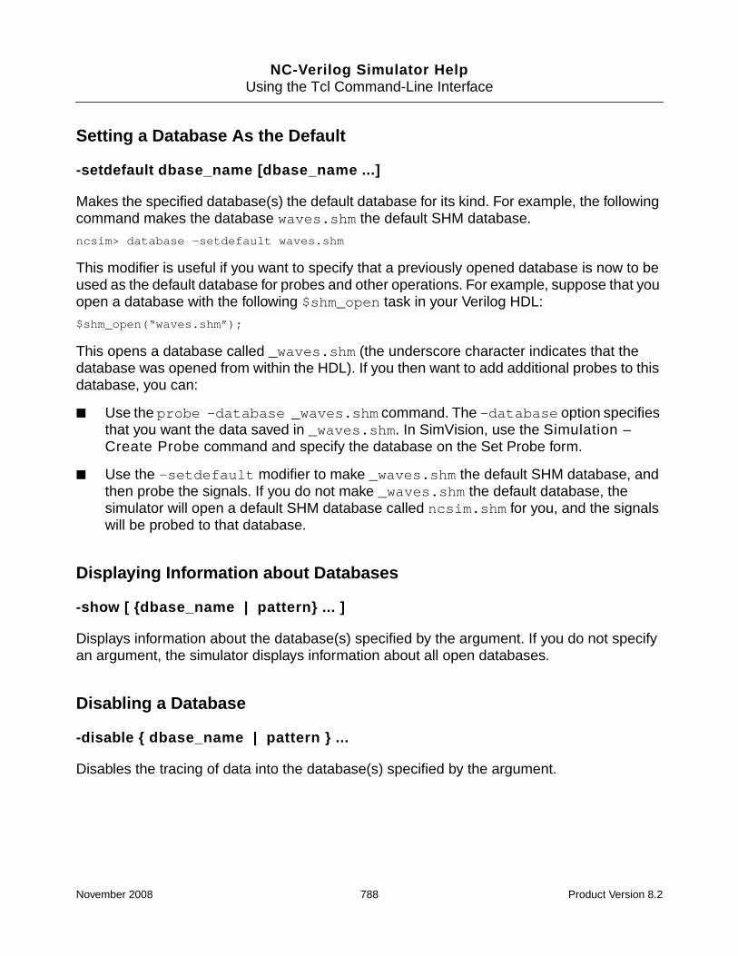
NC-Verilog Simulator HelpUsing the Tcl Command-Line Interface
Setting a Database As the Default
-setdefault dbase_name [dbase_name ...]
Makes the specified database(s) the default database for its kind. For example, the followingcommand makes the database waves.shm the default SHM database.
ncsim> database -setdefault waves.shm
This modifier is useful if you want to specify that a previously opened database is now to beused as the default database for probes and other operations. For example, suppose that youopen a database with the following $shm_open task in your Verilog HDL:
$shm_open(“waves.shm”);
This opens a database called _waves.shm (the underscore character indicates that thedatabase was opened from within the HDL). If you then want to add additional probes to thisdatabase, you can:
■ Use the probe -database _waves.shm command. The -database option specifiesthat you want the data saved in _waves.shm. In SimVision, use the Simulation –Create Probe command and specify the database on the Set Probe form.
■ Use the -setdefault modifier to make _waves.shm the default SHM database, andthen probe the signals. If you do not make _waves.shm the default database, thesimulator will open a default SHM database called ncsim.shm for you, and the signalswill be probed to that database.
Displaying Information about Databases
-show [ {dbase_name | pattern} ... ]
Displays information about the database(s) specified by the argument. If you do not specifyan argument, the simulator displays information about all open databases.
Disabling a Database
-disable { dbase_name | pattern } ...
Disables the tracing of data into the database(s) specified by the argument.
November 2008 788 Product Version 8.2

NC-Verilog Simulator HelpUsing the Tcl Command-Line Interface
Enabling a Database
-enable { dbase_name | pattern } ...
Resumes the tracing of data into the database(s) specified by the argument.
Starting a New Incremental SHM Database File
-change shm_database_name [shm_database_name ...]
Immediately starts a new incremental SHM database file. A new incremental file is createdwithout saving the simulation snapshot.
Note: database -change is not supported for VCD or EVCD databases.
A database -change command forces a new incremental SHM database file to be started.You can use this command at significant points during the simulation, instead of, or in additionto, automatic incremental file creation using -incsize, so that incremental files containspecific time ranges of interest.
The incremental files have the same name as the initial database file, but with a numberfollowing the name of the database. For example, if the database is called ncsim, the initial.trn file is ncsim.trn. The incremental files will be called ncsim-1.trn, ncsim-2.trn,and so on.
Closing a Database
-close { dbase_name | pattern } ...
Closes the database(s) specified by the argument.
database Command Examples
The following command opens an SHM database named waves and places the data into thefile waves.shm. The -open modifier is optional. The -shm option is the default.
ncsim> database -open -shm waves
Created SHM database waves
The following command opens an SHM database named waves and places the data into thefile mywaves.shm.
ncsim> database waves -into mywaves.shm
Created SHM database waves
November 2008 789 Product Version 8.2

NC-Verilog Simulator HelpUsing the Tcl Command-Line Interface
The following command opens an SHM database named waves and places the data into thefile waves.shm. The -default option specifies that waves is the default database.
ncsim> database waves -default
Created default SHM database waves
The following command includes the -compress option, which compresses the SHMdatabase.
ncsim> database -open waves -compress -default
Created default SHM database waves
The following command includes the -maxsize option to limit the size of the database to 4MB.
ncsim> database -open -shm shmdb -maxsize 4M
The following command includes the -incsize option, which specifies a size limit of 1 GBfor the SHM database file. When the current SHM database file size reaches 1 GB, a newincremental file is started automatically.
ncsim> database -open -shm shmdb -incsize 1G
The following command includes the -incsize option, which specifies a size limit of 1 GBfor the SHM database file, and the -incfiles option, which specifies that a maximum of 5incremental files are to be kept.
ncsim> database -open -shm shmdb -incsize 1G -incfiles 5
The following command opens an SHM database named waves. The -statement optionspecifies that statement trace information is to be recorded in the database.
ncsim> database -open waves -statement
ncsim: *W,DBSPER: The database -statement option will have an adverse performanceimpact. The -LINEDEBUG option must be used during compilation to probe statements.
Created SHM database waves
ncsim>
The following command opens a VCD database named vcddb and places the data into thefile vcddb.vcd.
ncsim> database -open -vcd vcddb
Created VCD database vcddb
The following command opens a VCD database named vcddb. The filename of thedatabase is verilog.dump. The -timescale option sets the $timescale value in theVCD file to 1 ns. Value changes in the VCD file are scaled to 1 ns. The -compress optioncompresses the file. The output file will be called verilog.dump.Z.
ncsim> database -open -vcd vcddb -into verilog.dump -timescale ns -compress
Created VCD database vcddb
November 2008 790 Product Version 8.2

NC-Verilog Simulator HelpUsing the Tcl Command-Line Interface
The following command opens an EVCD database named evcddb and places the data intothe file evcddb.evcd.
ncsim> database evcddb -evcd
Created EVCD database evcddb
The following command opens an EVCD database named evcddb. The database iscompressed, and the output file is called evcddb.evcd.Z.
ncsim> database evcddb -evcd -compress
Created EVCD database evcddb
The following command displays information about the status of all databases.
ncsim> database -show
The following command displays information about the status of all databases that havenames that start with db.
ncsim> database -show db*
The following command displays information about the status of all databases that havenames that start with db and end with 1.
ncsim> database -show db*1
The following command displays information about the status of all databases that havenames that start with v or w.
ncsim> database -show v* w*
The following command is identical to the previous command. It displays information aboutthe status of all databases that have names that start with v or w. The curly braces suppresscommand substitution with square brackets.
ncsim> database -show {[vw]*}
The following command displays information about the status of all databases that havenames that have three characters, starting with db.
ncsim> database -show db?
The following command displays information about the status of the database called wavesand of all databases with names that start with db.
ncsim> database -show waves db*
The following command disables the databases named db1 and db2.
ncsim> database -disable db1 db2
The following command enables the database named db1.
ncsim> database -enable db1
November 2008 791 Product Version 8.2

NC-Verilog Simulator HelpUsing the Tcl Command-Line Interface
The following sequence of commands includes two database -change commands. Thesecommands are used to create new incremental SHM database files, which contain data forspecific time ranges. The incremental files are called ncsim-1.trn and ncsim -2.trn.
ncsim> database -open -shm ncsim
Created SHM database ncsim
ncsim> probe -create -database ncsim -all -depth all
Created probe 1
ncsim> run 1000 ns
Ran until 1 US + 0
ncsim> database -change ncsim
New incremental file started for SHM database: ncsim
ncsim> run 1000 ns
Ran until 2 US + 0
ncsim> database -change ncsim
New incremental file started for SHM database: ncsim
ncsim> run 1000 ns
Ran until 3 US + 0
The following command closes the database called ncsim.
ncsim> database -close ncsim
The following command closes all databases that have names that start with db.
ncsim> database -close db*
November 2008 792 Product Version 8.2

NC-Verilog Simulator HelpUsing the Tcl Command-Line Interface
deposit
The deposit command lets you set the value of an object. Behaviors that are sensitive tovalue changes on the object run when the simulation resumes, just as if the value change wascaused by the Verilog or VHDL code.
The deposit command without a delay is similar to a force in that the specified value takeseffect and propagates immediately. However, it differs from a force in that future transactionson the signal are not blocked.
You can specify that the deposit is to take effect at a time in the future (-after -absolute)or after some amount of time has passed (-after -relative). In VHDL, a deposit with adelay is different from Verilog in that it creates a transaction on a driver, much the same as aVHDL signal assignment statement. Use the -inertial or -transport option to depositthe value after an inertial delay or after a transport delay, respectively.
For VHDL, you can deposit to ports, signals, and variables if no delay is specified. If a delayis specified, you cannot deposit to variables or to signals with multiple sources. You candeposit to a subelement of a compressed VHDL vector.
For Verilog, you can deposit to ports, signals (wires and registers), and variables. You candeposit to a subelement of a compressed Verilog vector.
If the object is a memory or a range of memory elements, the specified value is deposited intoeach element of the memory or into each element in the specified range.
If the object is currently forced, you can release the force and then apply a deposit with onedeposit command by using the deposit -release option. If you do not include the-release option, the specified value appears on the object after the force is released,unless the release value is overwritten by another assignment in the meantime.
If the object is a register that is currently forced or assigned, the deposit command has noeffect.
The value assigned to the object must be a literal. The literal can be generated with Tcl valuesubstitution or command substitution. (See “Value Substitution” on page 1603 and“Command Substitution” on page 1601 for details on Tcl substitution.)
For VHDL, the value specified with the deposit command must match the type and subtypeconstraints of the VHDL object. Integers, reals, physical types, enumeration types, andstrings (including std_logic_vector and bit_vector) are supported. Records andnon-character array values are not supported, but objects of these types can be assigned toby issuing commands for each subelement individually.
November 2008 793 Product Version 8.2

NC-Verilog Simulator HelpUsing the Tcl Command-Line Interface
The object to which the value is to be deposited must have write access. An error is generatedif the object does not have this access. See “Enabling Read, Write, or Connectivity Access toSimulation Objects” on page 371 for details on specifying access to simulation objects.
Depositing Values to Vectors
For Verilog, you can deposit values to vectors in hexadecimal, octal, decimal, or binaryformats using the standard Verilog notation. For example:
wire [15:0] sig;
ncsim> deposit sig = 16’hffff
ncsim> deposit sig = 16’b0000000000000000
ncsim> deposit sig = 16’d10
For VHDL, you can deposit values to vectors by specifying the value for each bit, as follows:
signal sig : std_logic_vector(15 downto 0 );
ncsim> deposit :sig = {"1111111111111111"}
However, an easier, more intuitive way to deposit to a VHDL vector is with the followingsyntax:
base"value"
where:
■ base specifies the base. This can be binary (b or B), octal (o or O), or hex (x or X). If nobase is specified, the value is assumed to be binary.
■ value specifies the bit-string literal in the appropriate base. Underscore characters canbe included to improve readability.
Examples:
signal sig : std_logic_vector(15 downto 0);
ncsim> deposit :sig {B"1111111111111111"}
ncsim> deposit :sig {b"00000000_11111111"} Can include underscore characters.
ncsim> deposit :sig {"11111111_11111111"} No base specified. Value is binary.
ncsim> deposit :sig {O"76543"}
ncsim> deposit :sig {X"ffff"}
ncsim> deposit :sig {x"FF_FF"}
For 9-state logic values (-, U, 1, 0, Z, X, L, H, W), each value is expanded to four binary bitsif the base is hex, and to three binary bits if the base is octal. For example:
ncsim> deposit :sig {X"FZHA"}
ncsim> value :sig
"1111ZZZZHHHH1010"
November 2008 794 Product Version 8.2

NC-Verilog Simulator HelpUsing the Tcl Command-Line Interface
If the value being deposited is less than the declared width, a vector size mismatch warningis issued, and the right-most bits (LSB) of the value are applied to the right-most (LSB) bitsof the vector, and the MSB bits of the object are unchanged. For example:
ncsim> value :sig
"UUUUUUUUUUUUUUUU"
ncsim> deposit :sig {X"FF"}
ncsim: *W,SEBNDP: Vector size mismatch: "11111111", MSB bits of object unchanged.
ncsim> value :sig
"UUUUUUUU11111111"
If the value being deposited is wider than the declared width, a vector size mismatch warningis issued, and the MSB bits of the value are truncated. For example:
ncsim> value :sig
"UUUUUUUUUUUUUUUU"
ncsim> deposit :sig {X"F0000"}
ncsim: *W,SEBNDT: Vector size mismatch: "11110000000000000000", MSB bits of valuetruncated.
ncsim> value :sig
"00000000"
deposit Command Syntaxdeposit object_name [=] value
[-after time_spec [value -after time_spec ...]]
[{-relative | -absolute}]
[-cancel 0]
[-constraint_mode constraint_name [=] {0 | 1}]
[-generic]
[-inertial]
[-rand_mode object_name [=] {0 | 1}]
[-release]
[-repeat period [-cancel period]]
[-transport]
November 2008 795 Product Version 8.2

NC-Verilog Simulator HelpUsing the Tcl Command-Line Interface
deposit Command Options
-absolute
Causes the deposit to occur at the simulation time specified in the time_spec argument.
By default, the deposit command causes the assignment to occur after the amount of timespecified in the time_spec argument has passed. That is, -relative is the default.
If you specify multiple value -after time_spec pairs, and use -absolute to specify anabsolute time, the option applies to all pairs. For example, in the following command, thedeposits will occur at absolute time 10 ns and at time 40 ns.
ncsim> deposit x 1 -after 10 ns 0 -after 40 ns -absolute
However, you cannot use -absolute if you set up a repeating deposit cycle using the-repeat option. The following command is not valid.
ncsim> deposit x 1 -after 10 ns 0 -after 40 ns -absolute -repeat 100 ns
-after time_spec [value -after time_spec ...]
Causes the assignment to occur at a time in the future, rather than immediately. The timespecified in the time_spec argument can be relative (the default) or absolute.
If you do not specify a time, the assignment happens immediately, before simulation resumes.If the specified time is the current simulation time, the assignment occurs after simulationresumes, but before time advances.
-cancel period
-cancel 0
The -cancel option has two uses:
■ Cancel a repeating deposit after the specified number of time units (-cancel period).
In this case, the -cancel option is used in conjunction with the -repeat option.
The period argument is a relative time duration. For example, in the following depositcommand, the value of sig1 is set to 1 at 10 ns after the current simulation time, andthen to 0 at 20 ns after the current simulation time. These deposits start repeating at 100ns after the current simulation time, so that the next deposits are at 110 ns and at 120 nsafter the current simulation time. The deposit command is canceled 1000 ns after thecurrent simulation time.
November 2008 796 Product Version 8.2

NC-Verilog Simulator HelpUsing the Tcl Command-Line Interface
ncsim> deposit sig1 1 -after 10ns 0 -after 20ns -repeat 100ns -cancel 1000 ns
■ Cancel a repeating deposit immediately (-cancel 0).
For example, suppose that you have created a repeating waveform with a commandsuch as the following:
ncsim> deposit sig1 1 -after 10ns 0 -after 20ns -repeat 100ns
You can cancel the deposit on the object sig1 at any time with the following command.The deposit is canceled immediately.
ncsim> deposit sig1 -cancel 0
-constraint_mode constraint_name [=] {0 | 1}
Enables or disables the specified SystemVerilog randomization constraint.
By default, all constraints are enabled. When a constraint is enabled, it is included in the setof constraints that are solved. In some cases, a randomize() method call may fail becausethe collection of constraints to solve conflict with each other or because they over-constraina variable. In this case, the simulator generates a warning telling you that the randomize()call failed.
The deposit -constraint_mode command can help you debug these constraint solverfailures. After setting a breakpoint in randomize() calls with the stop -randomizecommand, you can then disable specific constraints by setting the constraint mode to 0.Disabled constraints are ignored by the constraint solver. To re-enable the constraint, set theconstraint mode to 1. After you have enabled/disabled constraints, you can execute thecurrent randomize() call again with the run -rand_solve command.
See the section “run Command Examples” in the description of the run command for anexample of using these commands.
No other deposit command options can be included on the command line when using the-constraint_mode option.
Note: The deposit -constraint_mode command is supported only for class randomizecalls. The command is not supported for scope randomize calls.
A deposit -constraint_mode command sets a value that persists for the class instanceof the current randomize() call. That is, when you continue the simulation using the runcommand, the value remains set and will affect other randomize() calls of the same classinstance. New values will also affect static rand and randc variables for all instances of theclass.
November 2008 797 Product Version 8.2

NC-Verilog Simulator HelpUsing the Tcl Command-Line Interface
-generic
Deposits the specified value to a VHDL generic. You must use this option if you want todeposit a value to a generic.
Changing the value of a generic may lead to a violation of globally static bounds.
-inertial
Deposits the value after an inertial delay.
-rand_mode object_name [=] {0 | 1}
Enables or disables the specified SystemVerilog randomization (rand or randc) variable.
By default, all variables are enabled, and the randomize() method generates randomvalues for all active random variables within an object, subject to the active constraints withinthe object. In some cases, a randomize() call may fail because the collection of constraintsto solve conflict with each other or because they over-constrain a variable. In this case, thesimulator generates a warning telling you that the randomize() call failed.
The deposit -rand_mode command can help you debug these failures. After setting abreakpoint in randomize() calls with the stop -randomize command, you can thendisable a specific rand or randc variable by setting the variable mode to 0. When a variableis disabled, it is treated as a state variable and is not randomized by the randomize()method. To re-enable the variable, set the mode to 1. After you have enabled/disabledvariables, you can execute the current randomize() call again with the run -rand_solvecommand. See the section “run Command Examples” in the description of the run commandfor an example of using these commands.
The object_name argument must be a simple name that denotes a rand or randc variablein the class of the current randomize() call. It cannot be a handle, struct, or array.
No other deposit command options can be included on the command line when using the-rand_mode option.
Note: The deposit -rand_mode command is supported only for class randomize calls.The command is not supported for scope randomize calls.
A deposit -rand_mode command sets a value that persists for the class instance of thecurrent randomize() call. That is, when you continue the simulation using the runcommand, the value remains set and will affect other randomize() calls of the same class
November 2008 798 Product Version 8.2

NC-Verilog Simulator HelpUsing the Tcl Command-Line Interface
instance. New values will also affect static rand and randc variables for all instances of theclass.
-relative
Causes the deposit to occur after the amount of time specified in the time_spec argumenthas passed. This is the default.
-release
Releases a force if a force is active on the object.
The -release option lets you release a force and then apply a deposit with one depositcommand.
-repeat period
Repeats the deposit command.
The period argument is the relative time duration at which to start repeating the cycle ofdeposits. For example, the following deposit command sets the value of sig1 to 1 at 10time units after the current simulation time, and then to 0 at 20 time units after the currentsimulation time. This cycle repeats at 100 time units after the current simulation time, so thatthe next deposits are at 110, 120, 210, 220 (and so on) time units after the current simulationtime.
ncsim> deposit sig1 1 -after 10 0 -after 20 -repeat 100
You can include the -cancel option to specify the period at which to stop the deposit cycle.
If there is a repeating deposit on an object, and a second repeating deposit command onthe same object is issued, the first command is cancelled, and the new one comes into effect.
-transport
Deposits the value after a transport delay.
November 2008 799 Product Version 8.2

NC-Verilog Simulator HelpUsing the Tcl Command-Line Interface
deposit Command Examples
The examples shown in this section are Verilog examples. See the NC-VHDL SimulatorHelp for VHDL examples.
The following command assigns the value 8’h1F to test_drink.nickels. No time for thisassignment is specified, so the assignment occurs immediately. The equal sign is optional.
ncsim> deposit test_drink.nickels = 8’h1F
The following command assigns 25 to nickels[7:0] after simulation resumes and 1 timeunit has elapsed.
ncsim> deposit test_drink.nickels[7:0] = 25 -after 1
The following command deposits the value 1 to nickels[2].
ncsim> deposit nickels[2] 1
The following command assigns 25 to r[8:15] at simulation time 1 ns.
ncsim> deposit r[8:15] = 25 -after 1 ns -absolute
The following command sets the value of x to the current value of w. The assignment occursat simulation time 10 ns.
ncsim> deposit x = #w -after 10 ns -absolute
The following command uses both command and value substitution. The object y is set to thevalue returned by the Tcl expr command, which evaluates the expression #r[0] & ~#r[1]using the current value of r.
ncsim> deposit y = [expr #r[0] & ~#r[1]]
The following command deposits the value 1 to object my_bit 10 ns after the currentsimulation time, and then deposits the value 0 20 ns after the current simulation time.
ncsim> deposit my_bit 1 -after 10 ns 0 -after 20 ns
The following command deposits the value 4’b0000 to object bit_vec 5 ns after the currentsimulation time, and then deposits the value 4’b1111 15 ns after the current simulation time.This cycle repeats starting at 100 ns after the current simulation time. In other words,4’b0000 will be deposited at time 105, 4’b1111 at time 115, and so on.
ncsim> deposit bit_vec 4’b0000 -after 5 ns 4’b1111 -after 15 ns -repeat 100 ns
The following command deposits the value 1 to object my_bit 10 ns after the currentsimulation time, and then deposits the value 0 to my_bit 20 ns after the current simulationtime. The cycle repeats starting at 100 ns after the current simulation time. The deposit iscanceled at time 1000 ns.
ncsim> deposit my_bit = 1 -after 10 ns 0 -after 20 ns -repeat 100 ns -cancel 1000 ns
November 2008 800 Product Version 8.2

NC-Verilog Simulator HelpUsing the Tcl Command-Line Interface
The following command removes an existing force on object top.myint, and then depositsthe value 1.
ncsim> deposit top.myint 1 -release
The following command shows the error message that is displayed if you run in regressionmode and then try to deposit a value to an object that does not have write access.
ncsim> deposit count 4’b0000
ncsim: *E,OBJACC: Object must have write access: board.count.
November 2008 801 Product Version 8.2

NC-Verilog Simulator HelpUsing the Tcl Command-Line Interface
describe
The describe command displays information about the specified simulation object,including its declaration. You can also use the describe command to display low-powersimulation information.
The kind of access that has been enabled for simulation objects is shown in the output. Forexample, the string (-WC) is included in the output for objects that have read access but nowrite or connectivity access. See “Enabling Read, Write, or Connectivity Access to SimulationObjects” on page 371 for details on specifying access to simulation objects.
For objects without read access, the output of the describe command does not include theobject’s value.
Use the scope -describe command to describe all objects declared within a scope.
describe Command Syntaxdescribe object [object ...] [-verbose]
describe -power [-verbose]
You can use wildcard characters in the argument to a describe command.
■ The asterisk ( * ) matches any number of characters.
■ The question mark ( ? ) matches any one character.
You cannot use wildcard characters inside escaped names.
See “Using Wildcards Characters in Tcl Commands” on page 739 for more information onusing wildcards.
describe Command Options
-power [-verbose]
Display low-power simulation information.
This option displays information such as the name of the CPF file(s), the names of controlsignals for power shutoff, state retention, and port isolation, and information for each definedpower domain. The information displayed with a describe -power command is the sameas that printed to the log file if you use the -lps_verbose 1 option when you invoke theelaborator or simulator.
November 2008 802 Product Version 8.2

NC-Verilog Simulator HelpUsing the Tcl Command-Line Interface
Include the -verbose option to display more detailed information about the power domains.The information displayed with a describe -power -verbose command is the same asthat printed to the log file if you use the -lps_verbose 2 option when you invoke theelaborator or simulator.
See the Low-Power Simulation Guide for details on low-power simulation.
-verbose
Display additional properties of the specified object(s) or additional low-power simulationinformation.
describe Command Examples
Verilog Examples:
The following module contains the declarations of objects used in the describe commandexamples. This module contains SystemVerilog constructs and must be compiled with the-sv option (ncvlog -sv). The -sv option is not required if you are running in single-stepmode with irun.
module top;
reg regScalar;
reg [1:2] regVector;
reg regMemory [3:4];
reg [1:2] reg2dMem [3:4];
reg [1:2] reg3dMem [3:4] [5:6];
bit bitScalar;
bit [1:2] bitVector;
bit [1:2] bit2dMem [3:4];
logic [1:2] logicVector;
logic logicMemory [3:4];
logic [1:2] logic3dMem [3:4] [5:6];
integer integerScalar;
integer integerVector [3:4];
integer integer2dMem [3:4] [5:6];
int int_Vector [3:4];
November 2008 803 Product Version 8.2

NC-Verilog Simulator HelpUsing the Tcl Command-Line Interface
int int_2dMem [3:4] [5:6];
real realScalar;
time timeVector [3:4];
time time2dMem [3:4] [5:6];
enum { aScalar, bScalar } enumScalar;
enum [1:2] { aVector, bVector } enumVector;
enum { aMemory, bMemory } enumMemory [3:4];
enum [1:2] { a3dMem, b3dMem } enum3dMem [3:4] [5:6];
typedef enum [1:2] { a, b, c, d } eType;
eType eTypeScalar;
eType eTypeMemory [3:4];
// **************************
// Parameters
// **************************
parameter bit [1:2] bitVectorP = 0;
parameter logic logicScalarP = 0;
parameter integer integerScalarP = 0;
parameter int int_ScalarP = 0;
parameter real realScalarP = 0;
parameter time timeScalarP = 0;
parameter enum [1:2] { aVectorP, bVectorP } enumVectorP = 0;
// *************************
// Nets
// *************************
wire wireScalar;
wire [1:2] wireVector;
wire wireMemory [3:4];
wire [1:2] wire2dMem [3:4];
wire [1:2] wire3dMem [3:4][5:6];
wire enum logic { aScalarW, bScalarW } enumScalarW = 0;
wire enum [1:2] { aVectorW, bVectorW } enumVectorW = 0;
wire scalared [1:2] trdrvVector;
wire scalared [1:2] trdrvMemory [3:4];
endmodule
The following command displays information about the object top.
November 2008 804 Product Version 8.2

NC-Verilog Simulator HelpUsing the Tcl Command-Line Interface
ncsim> describe top
top........top-level module
The following command displays information about the Verilog object regVector.
ncsim> describe regVector
regVector...variable reg [1:2] = 2’hx
The following command displays information about regVector[1].
ncsim> describe regVector[1]
regVector[1]...variable reg = 1’hx
The following command displays information about two objects: regMemory andwireVector.
ncsim> describe regMemory wireVector
regMemory....variable reg array [3:4] = (1’hx,1’hx)
wireVector...net (wire/tri) logic [1:2] = 2’hz
The following command displays information about all objects in the current scope that havenames that start with real.
ncsim> describe real*
realScalar....variable real = 0
realScalarP...parameter real = 0
The following command displays information about all objects in the current scope that havenames with eight characters and that start with reg and end with dMem.
ncsim> describe reg?dMem
reg2dMem...variable reg [1:2] array [3:4] = (2’hx,2’hx)
reg3dMem...variable reg [1:2] array [3:4] [5:6] = ((2’hx,2’hx), (2’hx,2’hx))
The following command shows the output of the describe command for an object that doesnot have read, write, or connectivity access. The output of the command includes the string(-RWC) instead of the object’s value.
ncsim> describe trdrvVector
trdrvVector...net logic [1:2]
trdrvVector[1] (-RWC)
trdrvVector[2] (-RWC)
The following commands show you the output format of the describe command when usedto describe different types of objects.
ncsim> describe reg*
regScalar...variable reg = 1’hx
regVector...variable reg [1:2] = 2’hx
regMemory...variable reg array [3:4] = (1’hx,1’hx)
November 2008 805 Product Version 8.2

NC-Verilog Simulator HelpUsing the Tcl Command-Line Interface
reg2dMem....variable reg [1:2] array [3:4] = (2’hx,2’hx)
reg3dMem....variable reg [1:2] array [3:4] [5:6] = ((2’hx,2’hx), (2’hx,2’hx))
ncsim>
ncsim> describe bit*
bitScalar....variable bit = 1’h0
bitVector....variable bit [1:2] = 2’h0
bit2dMem.....variable bit [1:2] array [3:4] = (2’h0,2’h0)
bitVectorP...parameter bit [1:2] = 2’h0
ncsim>
ncsim> describe logic*
logicVector....variable logic [1:2] = 2’hx
logicMemory....variable logic array [3:4] = (1’hx,1’hx)
logic3dMem.....variable logic [1:2] array [3:4] [5:6] = ((2’hx,2’hx), (2’hx,2’hx))
logicScalarP...parameter logic = 1’h0
ncsim>
ncsim> describe integer*
integerScalar....variable integer = x
integerVector....variable integer array [3:4] = (x,x)
integer2dMem.....variable integer array [3:4] [5:6] = ((x,x), (x,x))
integerScalarP...parameter integer = 0
ncsim>
ncsim> describe int_*
int_Vector....variable int array [3:4] = (0,0)
int_2dMem.....variable int array [3:4] [5:6] = ((0,0), (0,0))
int_ScalarP...parameter int = 0
ncsim>
ncsim> describe time*
timeVector....variable time array [3:4] = (x,x)
time2dMem.....variable time array [3:4] [5:6] = ((x,x), (x,x))
timeScalarP...parameter time = 0
ncsim>
ncsim> describe enum*
enumScalar....variable enum { aScalar, bScalar } = aScalar
enumVector....variable enum logic [1:2] { aVector, bVector } = 2’hx
enumMemory....variable enum { aMemory, bMemory } array [3:4] = (aMemory,aMemory)
enum3dMem.....variable enum logic [1:2] { a3dMem, b3dMem } array [3:4] [5:6] =((2’hx,2’hx), (2’hx,2’hx))
enumVectorP...parameter enum logic [1:2] { aVectorP, bVectorP } = aVectorP
enumScalarW...net (wire/tri) enum logic [0:0] { aScalarW, bScalarW }
enumScalarW[2] (wire/tri) = St0
enumVectorW...net (wire/tri) enum logic [1:2] { aVectorW, bVectorW } = aVectorW
November 2008 806 Product Version 8.2

NC-Verilog Simulator HelpUsing the Tcl Command-Line Interface
ncsim>
ncsim> describe eType
eType......typedef enum logic [1:2] { a, b, c, d }
ncsim>
ncsim> describe eType*
eType.........typedef enum logic [1:2] { a, b, c, d }
eTypeScalar...variable eType = 2’hx
eTypeMemory...variable eType array [3:4] = (2’hx,2’hx)
ncsim>
ncsim> describe a b c d
a..........enum constant = 2’h0 (-RWC)
b..........enum constant = 2’h1 (-RWC)
c..........enum constant = 2’h2 (-RWC)
d..........enum constant = 2’h3 (-RWC)
ncsim>
ncsim> describe wire*
wireScalar...net (wire/tri) logic = HiZ
wireVector...net (wire/tri) logic [1:2] = 2’hz
wireMemory...net (wire/tri) logic array [3:4] = (HiZ,HiZ)
wire2dMem....net (wire/tri) logic [1:2] array [3:4] = (2’hz,2’hz)
wire3dMem....net (wire/tri) logic [1:2] array [3:4] [5:6] = ((2’hz,2’hz),(2’hz,2’hz))
ncsim>
ncsim> describe trdrv*
trdrvVector...net logic [1:2]
trdrvVector[1] (wire/tri) = HiZ
trdrvVector[2] (wire/tri) = HiZ
trdrvMemory...net logic [1:2] array [3:4]
trdrvMemory[3][1] (wire/tri) = HiZ
trdrvMemory[3][2] (wire/tri) = HiZ
trdrvMemory[4][1] (wire/tri) = HiZ
trdrvMemory[4][2] (wire/tri) = HiZ
ncsim>
The following examples show the output of the describe command when used on classesand class objects. These examples use the following source code:
November 2008 807 Product Version 8.2

NC-Verilog Simulator HelpUsing the Tcl Command-Line Interface
module test_top;
class Base;
integer p1;
task Base_task(integer i);
p1 = i;
endtask
function Base_function;
Base_function = p1;
endfunction
constraint foo {p1 < 100;}
endclass
Base b1 = new;
class Base2 extends Base;
integer p2;
task Base2_task(integer i);
p1 = 2 * i;
p2 = 4 * i;
endtask
virtual function integer Base2_function();
Base2_function = this.p1 + 1;
endfunction
endclass
Base2 b2;
initial begin
b1.p1 = 2;
end
endmodule
The following command describes the class Base.
ncsim> describe Base
Base.......class {
integer p1
}
November 2008 808 Product Version 8.2

NC-Verilog Simulator HelpUsing the Tcl Command-Line Interface
The following command includes the -verbose option, which provides more informationabout the class Base.
ncsim> describe -verbose Base
Base.......class {
integer p1
task Base_task
function Base_function
constraint foo
}
The following command describes the class Base2.
ncsim> describe Base2
Base2......class extends test_top.Base {
integer p2
integer p1 (from class Base)
}
The following command includes the -verbose option, which provides more informationabout the class Base2.
ncsim> describe -verbose Base2
Base2......class extends test_top.Base {
integer p2
task Base2_task
function Base2_function
integer p1 (from class Base)
task Base_task (from class Base)
function Base_function (from class Base)
constraint foo (from class Base)
}
The following command describes a class member in the class Base2.
ncsim> describe Base2::p2
Base2::p2...variable integer
When used on a class object handle, the describe command displays the handle’s classand value. An object handle’s value is the heap data index for the class.
ncsim> describe b1
b1.........handle class test_top.Base = @1_1
ncsim> describe b2
b2.........handle class test_top.Base2 = null
November 2008 809 Product Version 8.2

NC-Verilog Simulator HelpUsing the Tcl Command-Line Interface
The following command includes the -verbose option to display a detailed description of anobject handle.
ncsim> describe -verbose b1
b1.........handle class test_top.Base {
integer p1 = 2
task Base_task
function Base_function
constraint foo
}
The following command describes a class handle using the value of the object handle.
ncsim> describe [value b1]
test_top.Base@1_1...handle class test_top.Base {
integer p1 = 2
}
VHDL Examples:
The following command displays information about the VHDL object :t_NICKEL_IN.
ncsim> describe :t_NICKEL_IN
t_NICKEL_IN...signal : std_logic = ’0’
The following command displays information about two VHDL objects: :t_NICKEL_IN and:t_CANS.
ncsim> describe :t_NICKEL_IN :t_CANS
t_NICKEL_IN...signal : std_logic = ’0’
t_CANS........signal : std_logic_vector(7 downto 0) = "11111111"
The following command displays information about :t_CANS(4).
ncsim> describe :t_CANS(4)
:t_CANS(4)...signal : std_logic = ’1’
The following command displays information about the object :top.
ncsim> describe :top
top........component instantiation
The following command displays information about all objects in the current scope that havenames that start with t_DI.
ncsim> describe t_DI*
:t_dime_out...signal : std_logic = ’0’
:t_dispense...signal : std_logic = ’0’
:t_dimes......signal : std_logic_vector(7 downto 0) = "11111111"
November 2008 810 Product Version 8.2

NC-Verilog Simulator HelpUsing the Tcl Command-Line Interface
:t_dime_in....signal : std_logic = ’0’
In the following example, the stack -show command displays the current call stack. Theprocess (process1) is displayed as nest-level 0, the base of the stack. The subprogramfunction1 is :process1[1], and the subprogram function2 is :process1[2].
■ The first describe command describes the object tmp5_local, which is in the currentdebug scope.
■ The second describe command describes the object tmp4 in :process1[1].
■ A scope command is then executed to set the scope to :process1[1]. Because thecurrent debug scope is now function1, you can refer to object tmp4 by simply usingits name.
■ The last describe command describes var4 in :process1.
ncsim> stop -subprogram function1
Created stop 1
ncsim> run
0 FS + 0 (stop 1: Subprogram :function1)
./test.vhd:36 tmp4_local := function2 (tmp4);
ncsim> run -step
./test.vhd:29 tmp5_local := tmp5 + 1;
ncsim> stack -show ;# Display the current call stack
2: Scope: :process1[2] Subprogram:@work.e(a):function2
File: /usr1/belanger/inca/vhdl/subprogram_debug/scope_test/test.vhd
Line: 29
1: Scope: :process1[1] Subprogram:@work.e(a):function1
File: /usr1/belanger/inca/vhdl/subprogram_debug/scope_test/test.vhd
Line: 36
0: Scope: :process1
File: /usr1/belanger/inca/vhdl/subprogram_debug/scope_test/test.vhd
Line: 52
ncsim> scope -show ;# Display the current debug scope
Directory of scopes at current scope level:
Current scope is (:process1[2])
Highest level modules:
Top level VHDL design unit:
entity (e:a)
November 2008 811 Product Version 8.2

NC-Verilog Simulator HelpUsing the Tcl Command-Line Interface
VHDL Package:
STANDARD
ATTRIBUTES
std_logic_1164
TEXTIO
ncsim> describe tmp5_local ;# Describe tmp5_local in the current debug scope
tmp5_local...variable : INTEGER
ncsim>
ncsim> describe :process1[1]:tmp4 ;# Describe tmp4 in :process1[1];# i.e., function1
:process1[1]:tmp4...constant parameter : INTEGER
ncsim>
ncsim> scope -set :process1[1] ;# Set scope to function1 (:process1[1])
ncsim> describe tmp4 ;# Describe tmp4 in function1
tmp4.......constant parameter : INTEGER
ncsim>
ncsim> describe :process1:var4
:process1:var4....variable : INTEGER = 0
November 2008 812 Product Version 8.2

NC-Verilog Simulator HelpUsing the Tcl Command-Line Interface
drivers
The drivers command lets you:
■ Display a list of all contributors to the value of the specified object(s) (-show).
You can use the scope -drivers [scope_name] command to display the drivers ofeach object that is declared within a specified scope. See “scope” on page 966 for detailson the scope command.
The drivers command cannot find the drivers of a wire or register unless the objecthas read and connectivity access. However, even if you have specified access to anobject, its drivers may have been collapsed, combined, or optimized away. In this case,the output of the command may indicate that the object has no drivers. See “EnablingRead, Write, or Connectivity Access to Simulation Objects” on page 371 for details onspecifying access to simulation objects.
■ List all of the currently active drivers (-active).
■ Create a run-time driver for a VHDL object and drive a specified value (-add).
■ Replace an existing run-time driver for a VHDL object and drive a new value(-replace).
■ Remove a run-time driver for a VHDL object (-delete).
In a low-power simulation, the drivers command shows the power drivers, with thecorresponding CPF file and line number of the associated CPF command.
drivers Command Syntaxdrivers
[-show] object_name [object_name ...]
[-effective]
[-future]
[-novalue]
[-verbose]
-active
-add object_name [=] value
-replace object_name [=] value
-delete object_name [object_name ...]
November 2008 813 Product Version 8.2

NC-Verilog Simulator HelpUsing the Tcl Command-Line Interface
drivers Command Options
-active
Lists all of the currently active drivers
-add object_name [=] value
Creates a driver for the object and drives the specified value.
The following restrictions apply to the object for which a run-time driver is created:
■ The object must be a resolved VHDL object (that is, it should have a resolution functionassociated with it).
■ The object must be driven by multiple sources in the design.
■ The object must not have a previously created run-time driver associated with it.
■ If the object is a VHDL port, it must be of type IN, OUT, or INOUT.
■ The object must not be a guarded signal.
■ Objects with composite resolution functions are not supported.
■ The object must have read, write, and connectivity access.
■ The value specified with the drivers command must match the type and subtypeconstraints of the VHDL object. Integers, reals, physical types, enumeration types, andstrings (including std_logic_vector and bit_vector) are supported. Records andnon-character array values are not supported, but drivers for objects of these types canbe created by issuing commands for each subelement individually.
The simulator generates error messages if the above conditions are not met, and the driveris not created.
Run-time drivers created with drivers -add are not visible in the Trace Signals sidebar.
-delete object_name [object_name ...]
Removes the run-time driver (created with a drivers -add command) for the specifiedobject(s).
November 2008 814 Product Version 8.2

NC-Verilog Simulator HelpUsing the Tcl Command-Line Interface
The simulator generates an error if an object specified with the -delete option is an objectthat does not satisfy the conditions for driver creation (see the description of the -add optionabove).
-effective
Displays contributions to the effective value of the signal. By default, the drivers commanddisplays contributions to the driving value.
Only VHDL inout and linkage ports can have different driving and effective values.
-future
Displays the transactions that are scheduled on each driver.
-novalue
Suppresses the display of the current value of each driver.
-replace object_name [=] value
Replaces the run-time driver (created with a drivers -add command) for the specifiedobject and drives the new value.
The simulator generates an error if a run-time driver was not previously created for thespecified object.
-show object_name [object_name ...]
Displays a list of all contributors to the value of the specified object(s). You must specify atleast one object.
The -show modifier is optional. The following two commands are equivalent:
ncsim> drivers -show f af
ncsim> drivers f af
November 2008 815 Product Version 8.2

NC-Verilog Simulator HelpUsing the Tcl Command-Line Interface
-verbose
Note: This option affects VHDL signals only.
Displays all of the processes (signal assignment statements), resolution functions, and typeconversion functions that contribute to the value of the specified signal.
If you do not include the -verbose option, resolution and type conversion functioninformation is omitted from the output.
drivers Command Report Format
Verilog Signals
The drivers report for Verilog signals is as follows:
value <- (scope) verilog_source_line_of_the_driver
For example:
ncsim> drivers af
af.........net (wire/tri) logic = St0
St0 <- (board.counter) assign altFifteen = &value
Instead of the verilog_source_line_of_the_driver, the following is output whenthe actual driver is from a VHDL model:
port ’port_name’ in module_name [File:
path_to_file_containing_module], driven by a VHDL model.
This report indicates that the signal is ultimately driven by a port (connected to port_nameof the specified module) on a module whose body is an imported VHDL model. Themodule_name corresponds to the module name of the shell being used to import the VHDLmodel.
VHDL Signals
The drivers report for VHDL signals is as follows:
description_of_signal = value
value_contributed_by_driver <- (scope_name) source_description
The source_description for the various kinds of drivers are shown below:
November 2008 816 Product Version 8.2

NC-Verilog Simulator HelpUsing the Tcl Command-Line Interface
A Process
Nothing is generated for the source_description. This implies that a sequential signalassignment statement within a process is the driver. The scope_name is the scope nameof the process.
Concurrent Signal Assignment/Concurrent Procedure Call
The source_description is the VHDL source text of the concurrent signal assignmentstatement or concurrent procedure call that results in a driving value. This concurrentstatement is within the scope scope_name.
No Drivers
If the signal has no drivers, the text No drivers appears verbatim.
A Verilog Driver
If the driver is from a Verilog model, the report has the following form:
port ’port_name’ in entity(arch) [File:
path_to_file_containing_entity], driven by a Verilog model.
This report indicates that the signal is ultimately driven by a port (connected to port_nameof the specified entity-architecture pair) on an entity whose body is an imported Verilogmodel.
Driver from a C Model
If the driver is from an imported C model, the report has the following form:
port ’port_name’ in entity(arch) [File:
path_to_file_containing_entity], driven by a C model.
Driver from an OMI Model
If the driver is from an imported OMI model, the report has the following form:
port ’port_name’ in entity(arch) [File:
path_to_shell_file], driven by a OMI model.
November 2008 817 Product Version 8.2

NC-Verilog Simulator HelpUsing the Tcl Command-Line Interface
Resolution / Type Conversion Function in Non-Verbose Mode
If you do not use the -verbose option, the text [verbose report available ....]may appear. This indicates that the signal gets its value from a resolution function or a typeconversion function. Use -verbose to display more information on the derivation of thesignal’s value.
On the next line of output (indented), a nonverbose driver report is displayed for each signalwhose driver contributes to the value of the signal in question.
Resolution Function
The following text is generated only when the -verbose option is used:
[resolution function function_name()]
This means that the signal is resolved with the named resolution function. A verbose driversreport is displayed (indented) for all inputs to the resolution function.
Type Conversion on Formal of Port Association
The following text is generated only when the -verbose option is used:
[type conversion function function_name(formal)]
This means that the signal’s driving value comes from a type conversion function on a formalin a port association. A verbose drivers report is displayed (indented) for the formal port thatis the input to the function.
Type Conversion on Actual of Port Association
The following text is generated only when the -verbose option is used:
[type conversion function function_name(actual)]
This means that the signal’s effective value comes from a type conversion function on anactual in a port association. A verbose drivers report is displayed (indented) for the actual thatis the input to the function.
Implicit Guard Signal
The following text is displayed in response to a query on a signal whose value is computedfrom a GUARD expression:
[implicit guard signal]
November 2008 818 Product Version 8.2

NC-Verilog Simulator HelpUsing the Tcl Command-Line Interface
Signal Attribute
The following is displayed in response to a query on an IN port that ultimately is associatedwith a signal valued attribute:
[attribute of signal full_path_of_the_signal]
The full_path_of_the_signal corresponds to the complete hierarchical path of thesignal whose attribute is the driver.
Constant Expression on a Port Association
The following is displayed when the value of the signal in question is from a constantexpression in a port map association:
[constant expression associated with port port_name]
Composite Signals
For a composite signal, a separate report is displayed for each group of subelements that canbe uniquely named and that have the same set of drivers.
drivers Command Examples
This section includes examples of using the drivers command with Verilog and with VHDLsignals.
Example Output for Verilog Signals
The following command lists the drivers of a signal called f.
ncsim> drivers f
f..........net (wire/tri) logic = St0
St0 <- (board.counter) assign fifteen = value[0] & value[1] & value[2] & value[3]
November 2008 819 Product Version 8.2

NC-Verilog Simulator HelpUsing the Tcl Command-Line Interface
The following command lists the drivers of two signals called f and af.
ncsim> drivers f af
f..........net (wire/tri) logic = St0
St0 <- (board.counter) assign fifteen = value[0] & value[1] & value[2] & value[3]
af.........net (wire/tri) logic = St0
St0 <- (board.counter) assign altFifteen = &value
The following command lists the drivers of a signal called top.under_test.sum.
ncsim> drivers top.under_test.sum
top.under_test.sum...output net (wire/tri) logic [1:0] = 2’h0
2’h0 <- (top.under_test) assign {c_out, sum} = a + b + c_in
The following command lists the drivers of a signal called board.count.
ncsim> drivers board.count
board.count...net logic [3:0]
count[3] (wire/tri) = St0
St0 <- (board.counter.d) output port 1, bit 0 (./counter.v:19)
count[2] (wire/tri) = St0
St0 <- (board.counter.c) output port 1, bit 0 (./counter.v:18)
count[1] (wire/tri) = St1
St1 <- (board.counter.b) output port 1, bit 0 (./counter.v:17)
count[0] (wire/tri) = St0
St0 <- (board.counter.a) output port 1, bit 0 (./counter.v:16)
The following command lists the drivers of board.count[2].
ncsim> drivers board.count[2]
board.count......net logic [3:0]
count[2] (wire/tri) = St0
St0 <- (board.counter.c) output port 1, bit 0 (./counter.v:18)
The following command shows the error message that the simulator displays if you run in thedefault “regression” mode (no read, write, or connectivity access to simulation objects) andthen use the drivers command to find the drivers of an object that does not have read andconnectivity access.
ncsim> drivers count
ncsim: *E,OBJACC: Object must have read and connectivity access: board.count.
The following examples illustrate the output of the drivers command when the actual driveris from a VHDL model:
ncsim> drivers :u1.a
:u1.a......input net (wire/tri) logic = St1
St1 <- (:u1) driven by a VHDL model
November 2008 820 Product Version 8.2

NC-Verilog Simulator HelpUsing the Tcl Command-Line Interface
ncsim> drivers :u1.v.d
:u1.v.d....input net (wire/tri) logic = St1
St1 <- (:u1) port ’a’ in module ’and2’ [File: ./verilog.v],driven by a VHDL model
ncsim>
This report indicates that the signal :u1.v.d is ultimately driven by a port (connected to porta of the module and2) on a module whose body is an imported VHDL model.
Example Output for VHDL Signals
The following examples use the VHDL model shown below. A run command has been issuedafter invoking the simulator.
library ieee;
use ieee.std_logic_1164.all;
entity e is
end e;
architecture a of e is
signal s: std_logic;
function bit_to_std (x: bit) return std_logic is
begin
return ’0’;
end bit_to_std;
function std_to_bit (x: std_logic) return bit is
begin
return ’1’;
end std_to_bit;
begin
s <= ’0’ after 1 ns;
GATE: block
port (q: inout bit);
port map (bit_to_std (q) => std_to_bit (s));
begin
p: process (q)
begin
q <= not q;
end process;
end block;
end;
November 2008 821 Product Version 8.2

NC-Verilog Simulator HelpUsing the Tcl Command-Line Interface
The following command shows the drivers of signal s. The -show modifier is optional. Thestring [verbose report available .....] indicates that type conversion functions orresolution functions are part of the hierarchy of drivers. Use the -verbose option to displaythis additional information.
% ncsim -tcl -nocopyright e:a
ncsim> run 100 ns
Ran until 100 NS + 0
ncsim> drivers -show s
s..........signal : std_logic = ’0’
[verbose report available.....]
’0’ <- (:GATE:p) [File: test.vhd]
’0’ <- (:) s <= ’0’ after 1 ns [File: test.vhd, Line: 20]
The following command includes the -novalue option, which suppresses the display of thecurrent value of each driver.
ncsim> drivers s -novalue
s..........signal : std_logic
[verbose report available.....]
(:GATE:p) [File: test.vhd]
(:) s <= ’0’ after 1 ns [File: test.vhd, Line: 20]
The following command includes the -verbose option, which causes the output to includeresolution function and type conversion function information. This report shows that the port:GATE:q is one of the contributing drivers, and that there is a type conversion functionbit_to_std through which the value of the port is routed before being assigned to the signal:s. The report also shows that there is a concurrent signal assignment statement contributingas one of the sources to the resolution function.
ncsim> drivers s -verbose
s..........signal : std_logic = ’0’
’0’ <-[resolution function @ieee.std_logic_1164:resolved()]
<src 1>
’0’ <- (:GATE) [type conversion function
bit_to_std(<formal>)]
<formal> connected to port q
:GATE:q....port : inout BIT = ’1’
’0’ <- (:GATE:p) [File: test.vhd]
<src 2>
’0’ <- (:) s <= ’0’ after 1 ns [File: test.vhd, Line: 20]
November 2008 822 Product Version 8.2

NC-Verilog Simulator HelpUsing the Tcl Command-Line Interface
The following command shows the drivers :gate:q.
ncsim> drivers :gate:q
GATE:q.....port : inout BIT = ’1’
’0’ <- (:GATE:p) [File: test.vhd]
The following command includes the -effective option, which displays contributions to theeffective value of the signal instead of to the driving value.
ncsim> drivers :GATE:q -effective
GATE:q.....port : inout BIT = ’1’
[verbose report available.....]
’0’ <- (:GATE:p) [File: test.vhd]
’0’ <- (:) s <= ’0’ after 1 ns [File: test.vhd, Line: 20]
The following command includes the -verbose option, which helps you to understand wherethe effective value of 1 in the previous example comes from.
ncsim> drivers :GATE:q -effective -verbose
GATE:q.....port : inout BIT = ’1’
’1’ <- (:GATE) [type conversion function std_to_bit(<actual>)]
<actual> connected to signal s
:s.........signal : std_logic = ’0’
’0’ <-[resolution function @ieee.std_logic_1164:resolved()]
<src 1>
’0’ <- (:GATE) [type conversion function
bit_to_std(<formal>)]
<formal> connected to port q
:GATE:q....port : inout BIT = ’1’
’0’ <- (:GATE:p) [File: test.vhd]
<src 2>
’0’ <- (:) s <= ’0’ after 1 ns [File: test.vhd, Line: 20]
The following command includes the -future option, which lists the currently scheduledtransactions on each driver.
% ncsim -tcl -nocopyright e:a
ncsim> run .5 ns
Ran until 500 PS + 0
November 2008 823 Product Version 8.2

NC-Verilog Simulator HelpUsing the Tcl Command-Line Interface
ncsim> drivers s -future
s..........signal : std_logic = ’U’
[verbose report available.....]
’0’ <- (:GATE:p) [File: test.vhd]
Future Transactions
None Scheduled
’U’ <- (:) s <= ’0’ after 1 ns [File: test.vhd, Line: 20]
Future Transactions
’0’ after 1000000.00 fs
The following command creates a driver for the object :s and drives the value 1.
ncsim> drivers -add :s = ’1’
ncsim> drivers :s
:s.........signal : std_logic = ’U’
[verbose report available.....]
’1’ <- runtime driver from Tcl
’0’ <- (:GATE:p) [File: test.vhd]
’U’ <- (:) s <= ’0’ after 1 ns [File: test.vhd, Line: 20]
The following command replaces the existing run-time driver for the object :s and drives thenew value 0.
ncsim> drivers -replace :s = ’0’
ncsim> drivers :s
:s.........signal : std_logic = ’U’
[verbose report available.....]
’0’ <- runtime driver from Tcl
’0’ <- (:GATE:p) [File: test.vhd]
’U’ <- (:) s <= ’0’ after 1 ns [File: test.vhd, Line: 20]
The following command removes the drivers for the object :s.
ncsim> drivers -delete :s
The following command creates a driver for an object :d and drives the value00000000000000000000000000000000 with immediate effect.
ncsim> drivers -add :d {“00000000000000000000000000000000”}
The following command shows the output of the drivers command when the driver is froma Verilog model.
ncsim> drivers -effective i1:a
i1:a.......port : in std_logic = ’1’
St1 <- (and2_top.i1) input port 1, bit 0 (./and2.v:9)
November 2008 824 Product Version 8.2

NC-Verilog Simulator HelpUsing the Tcl Command-Line Interface
ncsim> drivers -effective i1:i1:port1
i1:i1:port1...port : in std_logic = ’1’
St1 <- (and2_top.i1) input port 1, bit 0 (./and2.v:9)
Example Output for a Low-Power Simulation
In a low-power simulation, the drivers command shows the power drivers, with thecorresponding CPF file and line number of the associated CPF command.
In the example, there are two power domains defined as follows:
create_power_domain -name PDau \
-instances alu_inst/aui \
-shutoff_condition {pcu_inst/pau[2]}
create_power_domain -name PDrf \
-instances rf_inst \
-shutoff_condition {pcu_inst/prf[2]}
The following create_isolation_rule command is used to illustrate the output of thedrivers command:
create_isolation_rule -name PDau_iso \
-to PDrf \
-isolation_condition {pcu_inst/pau[0]} \
-isolation_output low
ncsim> ;# Run until isolation is enabled and power is on
ncsim> stop -object inst.pcu_inst.pau[0]
Created stop 1
ncsim> run
100 PS + 3 (stop 1: TESTBENCH.inst.pcu_inst.pau[0] = 0)
ncsim> run
13400 NS + 4 (stop 1: TESTBENCH.inst.pcu_inst.pau[0] = 1) ;# Isolation enabled
ncsim> run 1 ps
Ran until 13400001 PS + 0
ncsim> value inst.alu_inst.aui.a ;# Display value of input a
32’h00000dfe
ncsim> drivers inst.alu_inst.aui.a ;# Display drivers of input a
inst.alu_inst.aui.a...input net logic [31:0]
a[31] (wire/tri) = St0
St0 <- low power driver, power domain rule (power domain is on)[File:./nano.cpf, Line:16]
November 2008 825 Product Version 8.2

NC-Verilog Simulator HelpUsing the Tcl Command-Line Interface
St0 <- (TESTBENCH.inst.rf_inst) assign a = rf[ra]
...
...
a[0] (wire/tri) = St0
St0 <- low power driver, power domain rule (power domain is on)[File:./nano.cpf, Line:16]
St0 <- (TESTBENCH.inst.rf_inst) assign a = rf[ra]
ncsim> value inst.rf_inst.result ;# Display value of input result of rf_inst
32’h00000000 ;# Value is 0 because of isolation rule.
ncsim> drivers inst.rf_inst.result ;# Display drivers of input result
inst.rf_inst.result...input net logic [31:0]
result[31] (wire/tri) = St0
St0 <- low power driver, isolation rule (is enabled) [File:./nano.cpf,Line:60]
St0 <- (TESTBENCH.inst) assign result = (opcode == ‘LOAD) ? dinr : alu
...
...
result[0] (wire/tri) = St0
St0 <- low power driver, isolation rule (is enabled) [File:./nano.cpf,Line:60]
St0 <- (TESTBENCH.inst) assign result = (opcode == ‘LOAD) ? dinr : alu
ncsim> ;# Run until PDau powers down
ncsim> stop -object inst.pcu_inst.pau[2]
Created stop 2
ncsim> run
15800 NS + 4 (stop 2: TESTBENCH.inst.pcu_inst.pau[2] = 1)
ncsim> run 1 ps
Ran until 15800001 PS + 0
ncsim> ;# Power domain is powered down. Values are unknown.
ncsim> value inst.alu_inst.aui.a
32’hxxxxxxxx
ncsim> drivers inst.alu_inst.aui.a
inst.alu_inst.aui.a...input net logic [31:0]
a[31] (wire/tri) = StX
StX <- low power driver, power domain rule (power domain is off)[File:./nano.cpf, Line:16]
St0 <- (TESTBENCH.inst.rf_inst) assign a = rf[ra]
...
...
a[0] (wire/tri) = StX
StX <- low power driver, power domain rule (power domain is off)[File:./nano.cpf, Line:16]
November 2008 826 Product Version 8.2

NC-Verilog Simulator HelpUsing the Tcl Command-Line Interface
St0 <- (TESTBENCH.inst.rf_inst) assign a = rf[ra]
ncsim> value inst.rf_inst.result
32’h00000000 ;# Value of result is 0 because it is isolated low
ncsim> drivers inst.rf_inst.result
inst.rf_inst.result...input net logic [31:0]
result[31] (wire/tri) = St0
St0 <- low power driver, isolation rule (is enabled) [File:./nano.cpf,Line:60]
StX <- (TESTBENCH.inst) assign result = (opcode == ‘LOAD) ? dinr : alu
...
...
result[0] (wire/tri) = St0
St0 <- low power driver, isolation rule (is enabled) [File:./nano.cpf,Line:60]
StX <- (TESTBENCH.inst) assign result = (opcode == ‘LOAD) ? dinr : alu
ncsim>
November 2008 827 Product Version 8.2

NC-Verilog Simulator HelpUsing the Tcl Command-Line Interface
dumpsaif
The dumpsaif command lets you generate a Switching Activity Interchange Format (SAIF)file during simulation.
SAIF is an ASCII format developed at Synopsys® designed to help extract toggle rate andstate probability data based on switching activity during simulation. The switching activity inthis file can then be backannotated into power analysis and optimization tools.
An SAIF file containing switching activity information generated by the simulator is called abackward SAIF file. You can use the dumpsaif command to generate a backward SAIF filefor a Verilog, VHDL, or mixed Verilog/VHDL design.
The backward SAIF file generation process also supports the use of SAIF files that providedirectives to the simulator about which design elements to trace during simulation and whichswitching activity to monitor. These files containing directives to the simulator are usuallygenerated by the power/optimization tool, and are called forward SAIF files.
Forward and backward SAIF files can be generated for both RTL and gate-level analysis andoptimization. To provide the simulator with the necessary directives, there are two types offorward SAIF files:
■ RTL forward SAIF file
Contains directives that determine which design elements to trace during simulation.These directives list the synthesis-invariant objects in the RTL description (objects thatare mapped directly to equivalent design objects in the synthesized gate-leveldescription). An RTL forward SAIF file also provides a mapping from the RTL identifiersof these design objects to their synthesized gate-level identifiers.
■ Library forward SAIF file
Contains directives for generating state-dependent and path-dependent switchingactivity during simulation of a gate-level netlist. The directives specify state-dependentand/or path-dependent information that must be gathered for all instances of the celltypes.
The following figure shows the flow between the simulator and the power analysis andoptimization tools using a forward SAIF file.
November 2008 828 Product Version 8.2

NC-Verilog Simulator HelpUsing the Tcl Command-Line Interface
If you reset the simulation with the reset command, the SAIF database remains open, andthe probe is still active. However, because the simulation will start again from time 0, thecomplete dump will happen again.
The state of the SAIF database is saved if you use the save command to create a snapshotof the current simulation state. If you then use the restart command to load the savedsnapshot, the database remains open and the probe is still active.
dumpsaif Command Syntaxdumpsaif
[-hierarchy]
[-input forward_saif_pathname]
[-output backward_saif_pathname]
[-overwrite]
[-scope scope_identifier]
[-verbose]
dumpsaif -end
Verilog, VHDL,mixed-languagedesign description
Power analysis/optimization tool
BackwardSAIF file
Simulator
ForwardSAIF file
November 2008 829 Product Version 8.2

NC-Verilog Simulator HelpUsing the Tcl Command-Line Interface
dumpsaif Command Options
-end
Ends all SAIF probing activity.
When a dumpsaif -end command is issued, the SAIF database is closed. Any simulationactivity after a dumpsaif -end command is not reflected in the backward SAIF database.
You cannot restart the SAIF dumping to the same database.
-hierarchy
Enables a hierarchical dump of the backward SAIF file.
-input forward_saif_pathname
Specifies the path to the forward SAIF file.
You cannot use the -scope and -input options on the same command line. If both optionsare used, a warning is issued and the forward SAIF file specified with the -input option isused for generating the backward SAIF file.
-output backward_saif_pathname
Specifies the path to the backward SAIF file.
By default, the backward SAIF file is generated in the current working directory and is calledncsim_backward.saif. Use the -output option to override the default. For example:
ncsim> dumpsaif -input rtlfwd.saif -output rtlbkwd.saif
ncsim> dumpsaif -scope : -output ./saifout/ncsim_backward.saif
If a file with the specified name already exists, a warning is generated telling you that theexisting file will not be overwritten unless the -overwrite option is used.
If you do not include an argument to the -output option, a warning is generated and abackward SAIF file with the default name (ncsim_backward.saif) is generated in thecurrent working directory.
November 2008 830 Product Version 8.2

NC-Verilog Simulator HelpUsing the Tcl Command-Line Interface
-overwrite
Enables overwriting of the generated backward SAIF file. By default, the dumpsaifcommand will not overwrite an existing backward SAIF file.
-scope scope_identifier
Specifies the scope of the hierarchy for which the backward SAIF needs to be dumped.
The scope_identifier argument is a Verilog or VHDL hierarchical path. The specifiedpath determines the domain of the probing activity. All instances and cells below thishierarchy are probed for the SAIF information.
If you do not include an argument to the -scope option, a warning is generated and thetop-level design unit is used as the scope.
You cannot use the -scope and -input options on the same command line. If both optionsare used, a warning is issued and the forward SAIF file specified with the -input option isused for generating the backward SAIF file.
-verbose
Displays informational messages during the generation of the backward SAIF file. Thesemessages include information on:
■ The scope being probed, or the forward SAIF file being used.
■ The name of the output file.
■ The instances being probed (if -scope or an RTL forward SAIF file is used), or librarycells (if a Library forward SAIF file is used).
■ When the information collected by the data structures is written to the output backwardfile.
Limitations
The following limitations exist on the dumping of SAIF databases:
■ Multiple SAIF files cannot be dumped at the same time. Only one dumpsaif commandis active during a given simulation timeframe. Another dumpsaif command can beissued only if the first has been terminated with dumpsaif -end.
November 2008 831 Product Version 8.2

NC-Verilog Simulator HelpUsing the Tcl Command-Line Interface
■ When the -scope option is used to specify the hierarchy of objects to be probed, onlyports from the respective entities are probed.
■ All generated backward SAIF files have a default timescale of 1 fs.
■ Vectors and complex data types, such as records and access types, are not supported.Only scalars of type std_logic, std_ulogic, and bit are supported. Individual bitsof vectors can be specified in the forward file.
■ Internal signals can be probed for SAIF activity. However, variables within a process aredropped from the list of elements being probed.
■ Any state-dependent expression with a component value X or Z is treated asCOND_DEFAULT.
dumpsaif Command Examples
On the dumpsaif command, you must use either the -scope option to specify the scope ofthe hierarchy for which the backward SAIF needs to be dumped, or the -input option tospecify a forward SAIF file.
The following command uses the -scope option. No argument is provided, and the top-leveldesign unit is used as the scope. A backward SAIF file called ncsim_backward.saif isgenerated in the current working directory.
ncsim> dumpsaif -scope
In the following command, the -scope option specifies the Verilog scope top.dut. Allinstances and cells below this hierarchy are probed for the SAIF information.
ncsim> dumpsaif -scope top.dut
In the following command, the -scope option specifies the VHDL scope :dut.
ncsim> dumpsaif -scope :dut
The following command includes the -input option, which specifies a forward SAIF filecalled fwd.saif.
ncsim> dumpsaif -input fwd.saif
The following command includes the -output option. A backward SAIF file calledbkwd.saif is generated in the current working directory.
ncsim> dumpsaif -input fwd.saif -output bkwd.saif
November 2008 832 Product Version 8.2

NC-Verilog Simulator HelpUsing the Tcl Command-Line Interface
In the following sequence of commands, the simulation is run for 3000 ns. A dumpsaif -endcommand is then issued to close the SAIF database and end the SAIF dumping.
ncsim> dumpsaif -input fwd.saif -output bkwd.saif
ncsim> run 3000 ns
ncsim> dumpsaif -end
ncsim> run
November 2008 833 Product Version 8.2

NC-Verilog Simulator HelpUsing the Tcl Command-Line Interface
dumptcf
The dumptcf command lets you generate a Toggle Count Format (TCF) file duringsimulation. The TCF is the Cadence standard to describe the switching activity information inthe design. The switching activity information contained in the file is required for accuratepower analysis or power optimization of a design.
The switching activity includes:
■ The toggle count, which indicates how often the pin or net switches between the logic 1and logic 0 states for the duration of the TCF dump.
■ The probability of the pin or net to be in the logic 1 state (total time in logic state 1 / totaltime of TCF dump).
For VHDL, state L is considered as 0, while H is considered as 1.
This information is collected for pins (ports in VHDL or interface elements in Verilog) and fornets (signals in VHDL or wires in Verilog).
Note: By default, only transitions from 0 to 1 and 1 to 0 are included in the toggle count. Usethe -inctoggle option to dump TCF data for X and Z transitions.
The format of the TCF output generated by the dumptcf command is identical to the formatof TCF files generated by the RTL Compiler write_tcf command.
See the Toggle Count Format Reference, which is part of the RTL Compilerdocumentation set, for details on the TCF file.
By default, a TCF file called ncsim.tcf is written to the directory from which the simulatorwas invoked. Use the -output option to specify a different name or location for the outputfile.
dumptcf Command Syntaxdumptcf
[-flatformat]
[-inctoggle]
[-internal]
[-optimized]
[-output filename]
[-overwrite]
November 2008 834 Product Version 8.2

NC-Verilog Simulator HelpUsing the Tcl Command-Line Interface
[-scope scope_identifier]
[-verbose]
dumptcf -end
dumptcf Command Options
-end
Ends all TCF probing activity.
By default, the TCF file is written at the end of simulation. Use the dumptcf -end commandat any point during the simulation to close the TCF database and write the TCF file. Anysimulation activity after a dumptcf -end command is not reflected in the output file.
You cannot restart the TCF dumping to the same TCF file.
-flatformat
Specifies that the TCF output should be in flat format.
A TCF file can contain the switching activity information in a flat or hierarchical representation.
■ In the flat representation, all net and pin names are specified by a full path with respectto the top-level design.
■ In a hierarchical representation, the net and pin names are specified with respect to theinstance scope.
By default, the dumptcf command dumps a TCF file in hierarchical format. Use the-flatformat option if you want a flat representation.
-inctoggle
Dumps TCF data for X and Z transitions.
By default, only transitions from 0 to 1 and 1 to 0 are included in the toggle count. Use the-inctoggle option to include data for X and Z transitions. The additional information in theTCF file includes:
■ The toggle counts for X and Z states.
❑ How often the pin or net switches from 1/0/X to X, and vice-versa
❑ How often the pin or net switches from 1/0/X/Z to Z, and vice-versa
November 2008 835 Product Version 8.2

NC-Verilog Simulator HelpUsing the Tcl Command-Line Interface
■ The probability of the pin or net to be in the X state, and the probability of the pin or netto be in the Z state.
-internal
Enables probing of internal wires/signals to the TCF file.
By default, only ports are probed. Use the -internal option to include internal nets/signalsin the probe.
-optimized
Turns on performance optimizations when dumping TCF.
Note: In the current release, these performance optimizations are turned on by default, andusing the -optimized option is not required.
-output filename
Specifies the path to the output TCF file.
By default, the TCF file is generated in the directory from which the simulator was invoked,and the file is called ncsim.tcf. Use the -output option to override the default. Forexample:
ncsim> dumptcf -output tcf.dump
ncsim> dumptcf -scope :dut -output ./tcfout/tcfdump.file
If a file with the specified name already exists, an error is generated telling you that theexisting file will not be overwritten unless the -overwrite option is used.
-overwrite
Enables overwriting of an existing TCF file.
By default, the dumptcf command will not overwrite an existing TCF file with the same name(ncsim.tcf or the name specified with the -output option).
-scope scope_identifier
Specifies the scope of the hierarchy for which the TCF needs to be dumped.
November 2008 836 Product Version 8.2
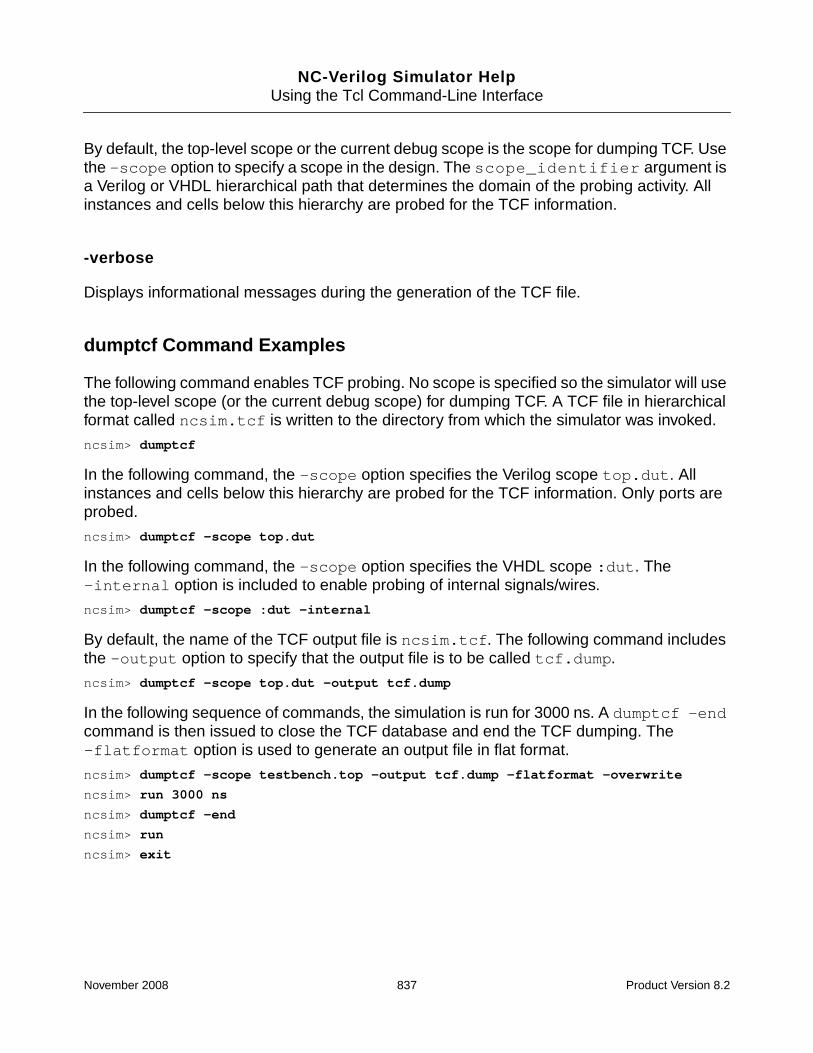
NC-Verilog Simulator HelpUsing the Tcl Command-Line Interface
By default, the top-level scope or the current debug scope is the scope for dumping TCF. Usethe -scope option to specify a scope in the design. The scope_identifier argument isa Verilog or VHDL hierarchical path that determines the domain of the probing activity. Allinstances and cells below this hierarchy are probed for the TCF information.
-verbose
Displays informational messages during the generation of the TCF file.
dumptcf Command Examples
The following command enables TCF probing. No scope is specified so the simulator will usethe top-level scope (or the current debug scope) for dumping TCF. A TCF file in hierarchicalformat called ncsim.tcf is written to the directory from which the simulator was invoked.
ncsim> dumptcf
In the following command, the -scope option specifies the Verilog scope top.dut. Allinstances and cells below this hierarchy are probed for the TCF information. Only ports areprobed.
ncsim> dumptcf -scope top.dut
In the following command, the -scope option specifies the VHDL scope :dut. The-internal option is included to enable probing of internal signals/wires.
ncsim> dumptcf -scope :dut -internal
By default, the name of the TCF output file is ncsim.tcf. The following command includesthe -output option to specify that the output file is to be called tcf.dump.
ncsim> dumptcf -scope top.dut -output tcf.dump
In the following sequence of commands, the simulation is run for 3000 ns. A dumptcf -endcommand is then issued to close the TCF database and end the TCF dumping. The-flatformat option is used to generate an output file in flat format.
ncsim> dumptcf -scope testbench.top -output tcf.dump -flatformat -overwrite
ncsim> run 3000 ns
ncsim> dumptcf -end
ncsim> run
ncsim> exit
November 2008 837 Product Version 8.2

NC-Verilog Simulator HelpUsing the Tcl Command-Line Interface
exit
The exit command terminates simulation and returns control to the operating system.
You also can use the finish command to exit a simulation. (See “finish” on page 847.)
See “Exiting the Simulation” on page 497 for more information.
exit Command Syntaxexit
exit Command Options
None.
exit Command Examples
The following command ends the simulation session.
ncsim> exit
November 2008 838 Product Version 8.2

NC-Verilog Simulator HelpUsing the Tcl Command-Line Interface
find
The find command lets you search for objects in the design hierarchy.
The argument to the find command is the name of the object that you want to search for.Multiple object names can be specified, and wildcard characters (* and ?) can be used. Forexample:
ncsim> find carry
ncsim> find carry out
ncsim> find ca*
ncsim> find *
By default, the find command displays a list of HDL objects in the current debug scopewhose name matches the name specified in the argument. The objects are displayed on asingle line so that the output can be used as the argument to other commands that accept alist of objects, such as the force, deposit, value, stop, and probe commands.
The find command includes a variety of options that let you:
■ Search for objects in a specified scope.
■ Search for objects in all scopes in the design, or in a specified number of subscopes.
■ Restrict the search to certain kinds of objects, such as ports, VHDL signals andvariables, Verilog wires and registers, instances, and so on.
■ Modify the default output format. For example, you can specify that objects should belisted on separate lines instead of on one line, or that absolute paths should be displayedinstead of relative paths.
Note: The find command applies to Verilog and VHDL design objects only. SystemC,analog, and assertion objects are not supported. SystemVerilog constructs are not currentlysupported.
November 2008 839 Product Version 8.2

NC-Verilog Simulator HelpUsing the Tcl Command-Line Interface
find Command Syntaxfind [-options] object_name [object_name ...]
[-absolute]
[-blocks]
[-instances]
[-internals]
[-registers]
[-signals]
[-variables]
[-wires]
[-newline]
[-nocase]
[-packages] [-exclude package_name]
[-ports]
[-inputs]
[-outputs]
[-inouts]
[-recursive] [{levels | all}]
[-scope scope]
[-subprograms]
[-verbose]
find Command Options
-absolute
Display absolute paths for each object. By default, the find command displays relative paths(relative to the current debug scope).
-blocks
Search for named or unnamed scopes matching the object name, other than instances in thedesign.
The blocks can be Verilog named blocks, specify blocks, VHDL processes, VHDL blocks,for-generate, or if-generate blocks.
You can use the -blocks option with the -instances option to display all scoped objectsin the design, blocks as well as instantiations.
November 2008 840 Product Version 8.2

NC-Verilog Simulator HelpUsing the Tcl Command-Line Interface
-instances
Search only for module, UDP, and component instances with the specified name.
-internals [-signals] [-variables] [-wires] [-registers]
Search for internal objects only and not ports.
Include the -ports option to search for both ports and internal objects.
You can use one of the following options with the -internals option to further filter theinternal objects:
■ -signals (VHDL only)
Search for VHDL internal signals only.
■ -variables (VHDL only)
Search for VHDL internal variables only.
■ -wires (Verilog only)
Search for Verilog internal wires only.
■ -registers (Verilog only)
Search for Verilog internal registers only.
-newline
Display objects on separate lines. By default, objects are displayed on a single line.
The -newline option also generates a warning message if unsupported constructs orprotected code is encountered.
-nocase
Perform a case-insensitive search. By default, the search is case-sensitive.
This option is useful when searching for Verilog objects because Verilog, unlike VHDL, iscase-sensitive.
November 2008 841 Product Version 8.2

NC-Verilog Simulator HelpUsing the Tcl Command-Line Interface
-packages [-exclude package_name]
Include packages when searching for objects.
This option extends the search to include packages. By default, the specified object issearched in the design hierarchy.
Use the -exclude option to exclude a specified package from the search. Multiple-exclude options can be specified, and the wildcard characters * and ? can be used in thepackage_name argument.
-ports [-inputs] [-outputs] [-inouts]
Search for ports only.
You can use one of the following options to search for ports of type input, output, or inout.These options can be used with or without the -ports option. For example, the following twocommands are equivalent:
ncsim> find -ports -inouts a*
ncsim> find -inouts a*
■ -inputs–Search for input ports only.
■ -outputs–Search for output ports only.
■ -inouts–Search for inout ports only.
-recursive [ {levels | all} ]
Specifies the scope levels to descend when searching for objects.
By default, the search is limited to the scope specified with -scope, or to the current debugscope if no scope is specified. Use the -recursive option to specify that the search is todescend recursively into subscopes.
The default argument to -recursive is all, which means that all scopes in the hierarchybelow the given scope are included in the search. To limit the number of scopes, specify thenumber of scopes, where 0 means include only the given scope, 1 means the given scopeand its subscopes, and so on. For example:
#; Find all objects that begin with “ad” in the current debug scope.
ncsim> find ad*
November 2008 842 Product Version 8.2

NC-Verilog Simulator HelpUsing the Tcl Command-Line Interface
#; Find all objects that begin with “ad” in the whole design.
ncsim> find -recursive ad*
#; Find all objects that begin with “ad” in the current debug scope and its#; subscopes.
ncsim> find -recursive 1 ad*
-scope scope
Search for the objects in the specified scope. By default, the find command searches for thespecified objects in the current debug scope.
The specified scope can be relative to the current debug scope or absolute. For example:
ncsim> find -scope r0 ad*
ncsim> find -scope top.r0 ad*
You can use multiple -scope options to specify more than one scope to search.
-subprograms
Search for subprograms used in the design. This includes VHDL functions and procedures,and Verilog tasks and functions.
ncsim> find -scope r0 -subprograms *
-verbose
Display additional information about the objects, such as the compiled design unit name, thesource file name, the line number of the declaration, and the current value, if applicable.
The -verbose option also generates a warning message if unsupported constructs orprotected code is encountered.
find Command Examples
The syntax of the find command is the same for Verilog and VHDL. In the output, the Veriloghierarchy separator ( . ) is displayed for Verilog, and the VHDL separator ( : ) is displayed forVHDL. A Verilog example was used to generate the following example find commands.
The following command displays all objects in the current debug scope.
ncsim> find *
clockGen counter af f clock count
November 2008 843 Product Version 8.2

NC-Verilog Simulator HelpUsing the Tcl Command-Line Interface
The following command includes the -instances option to limit the search to instances inthe current debug scope.
ncsim> find -instances *
clockGen counter
The following command includes the -scope option to specify that the search is limited tothe scope called counter.
ncsim> find -scope counter *
counter.d counter.c counter.b counter.a counter.clock counter.altFifteencounter.fifteen counter.value
The following command includes the -recursive option. No argument to the option isspecified. The find command searches for all objects called q in the entire design.
ncsim> find -recursive q
counter.a.q counter.b.q counter.c.q counter.d.q
The following command searches for objects called value in the current debug scope andits subscopes.
ncsim> find -recursive 1 value
counter.value
The following command searches for output ports in the scope counter.
ncsim> find -scope counter -ports -outputs *
counter.clock counter.altFifteen counter.fifteen counter.value
The following command includes the -absolute option. The output displays the output portsusing absolute paths.
ncsim> find -scope counter -ports -outputs -absolute *
board.counter.altFifteen board.counter.fifteen board.counter.value
The following command includes the -internals and -wires options to limit the search tointernal Verilog wires.
ncsim> find -internals -wires *
af f clock count
The following command includes the -newline option to display objects on separate lines.
ncsim> find -internals -wires -newline *
af
f
clock
count
November 2008 844 Product Version 8.2

NC-Verilog Simulator HelpUsing the Tcl Command-Line Interface
The following command illustrates the additional information about objects displayed with the-verbose option.
ncsim> find -recursive -verbose value
board.counter.value...output net logic [3:0]
value[3] (wire/tri) = St0
value[2] (wire/tri) = St0
value[1] (wire/tri) = St1
value[0] (wire/tri) = St0
Design Unit: @worklib.m16
File: ./counter.v
Line number: 13
The following example uses the ouput of the find command as input to a probe command.
ncsim> probe -create -shm [find -ports -scope counter *]
Created default SHM database ncsim.shm
Created probe 1
ncsim> probe -show
1 Enabled board.counter.clock (database: ncsim.shm) -shm
board.counter.altFifteen
board.counter.fifteen
board.counter.value
Number of objects probed : 4
ncsim>
Commands, like the one in the previous example, work even if objects have Verilog escapednames. For example, the following command uses the ouput of the find command as inputto a describe command.
ncsim> describe [find -recursive all -internals -absolute *]
or:
ncsim> set foo [find -recursive all -internals -absolute *]
ncsim> describe $foo
top.\myBuf[0] .\int[0] ...net (wire/tri) logic = StX
top.\myBuf[0] .\int[1] ...net (wire/tri) logic = StX
top.\myBuf[0] .\int[2] ...net (wire/tri) logic = StX
top.\myBuf[0] .\int[3] ...net (wire/tri) logic = StX
However, if you have a Tcl script that repeats an operation based on the output of the findcommand, the path name parser interprets spaces in the output as word separators. Forexample:
November 2008 845 Product Version 8.2

NC-Verilog Simulator HelpUsing the Tcl Command-Line Interface
ncsim> set foo [find -recursive all -internals -absolute *]
top.\myBuf[0] .\int[0] top.\myBuf[0] .\int[1] top.\myBuf[0] .\int[2]top.\myBuf[0] .\int[3]
ncsim>
ncsim> foreach f $foo {
> puts $f
> }
top.myBuf[0]
.int[0]
top.myBuf[0]
.int[1]
top.myBuf[0]
.int[2]
top.myBuf[0]
.int[3]
A workaround for this issue is to include the -newline option on the find command, andthen split the list using \n. For example:
ncsim> set foo [find -recursive all -internals -absolute -newline *]
top.\myBuf[0] .\int[0]
top.\myBuf[0] .\int[1]
top.\myBuf[0] .\int[2]
top.\myBuf[0] .\int[3]
ncsim> set foo [split $foo \n]
{top.\myBuf[0] .\int[0] } {top.\myBuf[0] .\int[1] } {top.\myBuf[0] .\int[2] }{top.\myBuf[0] .\int[3] } {}
ncsim> foreach f $foo {
> puts $f
> }
top.\myBuf[0] .\int[0]
top.\myBuf[0] .\int[1]
top.\myBuf[0] .\int[2]
top.\myBuf[0] .\int[3]
November 2008 846 Product Version 8.2

NC-Verilog Simulator HelpUsing the Tcl Command-Line Interface
finish
The finish command causes the simulator to exit and returns control to the operatingsystem.
This command takes an optional argument that determines what type of information isdisplayed.
■ 0—Prints nothing (same as executing finish without an argument).
■ 1—Prints the simulation time.
■ 2—Prints simulation time and statistics on memory and CPU usage.
See “Exiting the Simulation” on page 497 for more information.
finish Command Syntaxfinish [0 | 1 | 2]
finish Command Options
None.
finish Command Examples
The following command ends the simulation session.
ncsim> finish
The following command ends the simulation session and prints the simulation time.
ncsim> finish 1
Simulation complete via $finish(1) at time 0 FS + 0
%
The following command ends the simulation session, prints the simulation time, and displaysmemory and CPU usage statistics.
ncsim> finish 2
Memory Usage - 7.6M program + 2.1M data = 9.8M total
CPU Usage - 0.9s system + 2.5s user = 3.4s total (28.5% cpu)
Simulation complete via $finish(2) at time 500 NS + 0
%
November 2008 847 Product Version 8.2

NC-Verilog Simulator HelpUsing the Tcl Command-Line Interface
fmibkpt
The fmibkpt command performs operations on breakpoints that are coded into C modelsusing the fmiBreakpoint call. This command is only available when using the C interfaceto integrate C models into a VHDL design.
You can:
■ Enable FMI breakpoints (-enable). FMI breakpoints are all initially disabled.
■ Disable FMI breakpoints (-disable)
■ Display information about FMI breakpoints (-show)
fmibkpt Command Syntaxfmibkpt {-enable bkpt_number | -disable bkpt_number | -show}
fmibkpt Command Options
-enable bkpt_number
Enables the FMI breakpoint with the specified number.
-disable bkpt_number
Disables the FMI breakpoint with the specified number.
-show
Displays information about FMI breakpoints.
November 2008 848 Product Version 8.2

NC-Verilog Simulator HelpUsing the Tcl Command-Line Interface
force
The force command sets a specified object to a given value and forces it to retain that valueuntil it is released with a release command, a force -release command, a deposit-release command, or until another force is placed on it.
See “release” on page 944 for details on the release command. See “deposit” on page 793for details on the deposit command.
By default, the new value takes effect immediately. You can use the -after option to delaythe assignment for a specified period of time. For Verilog wires and VHDL signals and ports,the new value propagates throughout the hierarchy before the command returns.
By default, releasing a force causes the value to immediately return to the value that wouldhave been there if the force had not been blocking transactions. If the -keepvalue option isincluded (force -release -keepvalue time_spec), the forced value remains on theobject until a driver modifies it.
The object that is being forced must have write access. The simulator generates an error ifthe object does not have write access. See “Enabling Read, Write, or Connectivity Access toSimulation Objects” on page 371 for details on specifying access to simulation objects.
The object cannot be a:
■ A Verilog memory
■ A Verilog memory element
■ A bit-select or part-select of a Verilog register
■ A bit-select or part-select of an unexpanded Verilog wire
■ A VHDL variable
By default, vector Verilog wires and VHDL signals are compressed if the model does notrequire operations on individual bits of the vector. For VHDL, you can force a subelement ofa compressed vector signal. For Verilog, however, you must elaborate the design with the-expand option (ncelab -expand) in order to force a subelement of a compressed vectorwire.
For Verilog, a force created by the force command is identical in behavior to a force createdby a Verilog force procedural statement. The force can be released by a Verilog releasestatement or replaced by a Verilog force statement during subsequent simulation.
The value specified with the force command must be a literal, and the literal is treated as aconstant. Even if the literal is generated using value substitution or Tcl’s expr command, the
November 2008 849 Product Version 8.2

NC-Verilog Simulator HelpUsing the Tcl Command-Line Interface
value is considered to be a constant. The forced value will not change if objects used togenerate the literal change value during subsequent simulation.
For VHDL, the value specified with the force command must match the type and subtypeconstraints of the VHDL object. Integers, reals, physical types, enumeration types, andstrings (including std_logic_vector and bit_vector) are supported. Records andnon-character array values are not supported, but objects of these types can be assigned toby issuing commands for each subelement individually.
Forces created by the force command and those created by a Verilog force proceduralstatements are saved if the simulation is saved.
See “Forcing and Releasing Signal Values” on page 646 for more information.
Forcing Values to Vectors
For Verilog, you can force values to vectors in hexadecimal, octal, decimal, or binary formatsusing the standard Verilog notation. For example:
wire [15:0] sig;
ncsim> force sig = 16’hffff
ncsim> force sig = 16’b0000000000000000
ncsim> force sig = 16’d10
For VHDL, you can force values to vectors by specifying the value for each bit, as follows:
signal sig : std_logic_vector(15 downto 0);
ncsim> force :sig = {"1111111111111111"}
However, an easier, more intuitive way to force a VHDL vector is with the following syntax:
base"value"
where:
■ base specifies the base. This can be binary (b or B), octal (o or O), or hex (x or X). If nobase is specified, the value is assumed to be binary.
■ value specifies the bit-string literal in the appropriate base. Underscore characters canbe included to improve readability.
Examples:
signal sig : std_logic_vector(15 downto 0);
ncsim> force :sig {B"1111111111111111"}
ncsim> force :sig {b"00000000_11111111"} Can include underscore characters.
ncsim> force :sig {"11111111_11111111"} No base specified. Value is binary.
November 2008 850 Product Version 8.2

NC-Verilog Simulator HelpUsing the Tcl Command-Line Interface
ncsim> force :sig {O"76543"}
ncsim> force :sig {X"ffff"}
ncsim> force :sig {x"FF_FF"}
For 9-state logic values (-, U, 1, 0, Z, X, L, H, W), each value is expanded to four binary bitsif the base is hex, and to three binary bits if the base is octal. For example:
ncsim> force :sig {X"FZHA"}
ncsim> value :sig
"1111ZZZZHHHH1010"
If the value being deposited is less than the declared width, a vector size mismatch warningis issued, and the right-most bits (LSB) of the value are applied to the right-most (LSB) bitsof the vector, and the MSB bits of the object are unchanged. For example:
ncsim> value :sig
"UUUUUUUUUUUUUUUU"
ncsim> force :sig {X"FF"}
ncsim: *W,SEBNDP: Vector size mismatch: "11111111", MSB bits of object unchanged.
ncsim> value :sig
"UUUUUUUU11111111"
If the value being deposited is wider than the declared width, a vector size mismatch warningis issued, and the MSB bits of the value are truncated. For example:
ncsim> value :sig
"UUUUUUUUUUUUUUUU"
ncsim> force :sig {X"F0000"}
ncsim: *W,SEBNDT: Vector size mismatch: "11110000000000000000", MSB bits of valuetruncated.
ncsim> value :sig
"00000000"
force Command Syntaxforce object_name [=] value
[-after time_spec [value -after time_spec ...]]
[-release [-keepvalue] time_spec]
[-repeat time_spec [-cancel time_spec]]
force -show [-quiet]
November 2008 851 Product Version 8.2

NC-Verilog Simulator HelpUsing the Tcl Command-Line Interface
force Command Options
-after time_spec [value -after time_spec ...]
Delays the assignment of the new value by the time specified with the time_specargument.
The time specified in the time_spec argument is relative to the current simulation time. Forexample, if the current simulation time is 100 ns, and you specify -after 50 ns, theassignment takes place at time 150 ns.
You can specify multiple values/time_specs using the following syntax:
force object value -after time_spec value -after time_spec ...
For example:
force mysig 1 -after 10 ns 0 -after 20 ns
-release [-keepvalue] time_spec
Releases a force on the object after the delay specified by the time_spec argument.
By default (without the -keepvalue option), the force on the object is released and theinternal value takes effect immediately.
If the -keepvalue option is included, the forced value remains on the object until a drivermodifies it.
-repeat time_spec [-cancel time_spec]
Repeats the force command after the specified time.
The time_spec argument is the relative time duration at which to start repeating the cycleof forces. For example, the following force command sets the value of sig to 1 at 10 timeunits after the current simulation time, and then to 0 at 20 time units after the currentsimulation time. This cycle repeats at 100 time units after the current simulation time, so thatthe next forces are at 110, 120, 210, 220 (and so on) time units after the current simulationtime.
ncsim> force sig 1 -after 10 0 -after 20 -repeat 100
You can include the -cancel option to specify the period at which to stop the cycle. Forexample:
ncsim> force sig 1 -after 10 0 -after 20 -repeat 100 -cancel 1000
November 2008 852 Product Version 8.2

NC-Verilog Simulator HelpUsing the Tcl Command-Line Interface
-show [-quiet]
Lists objects in the design hierarchy that have been explicitly forced to a value.
A force -show command displays a list of objects that are forced, the value to which thesignals are forced, and the source, or origination, of the force. The origination can be:
■ A Tcl force command
■ A VPI force (vpi_put_value() with a vpiForceFLAG flag)
■ A VHPI force (vhpi_put_value with an update mode of vhpiForce orvhpiForcePropagate)
■ An nc_force call
■ A Verilog procedural force continuous assignment
Note: By default, objects that have been forced to a value by a Verilog procedural forcecontinuous assignment are not displayed. If you want to include these forced objects, you can:
■ Compile the Verilog source code with the -linedebug option (ncvlog -linedebug)
■ Elaborate the design with the -show_forces option (ncelab -show_forces). If youcompile with -linedebug, it is not necessary to elaborate with -show_forces.
The value of the Tcl show_forces variable must be set to 1 at the time that the forces areapplied in order to enable the display of forces with a force -show command. Normally, thisvariable is initialized to 0. However, the variable is automatically set to 1 if you have:
■ Elaborated the design with the -show_forces option (ncelab -show_forces)
■ Invoked the simulator with the -gui option
It is recommended that you set the Tcl show_forces variable to 1 at the beginning ofsimulation if you intend to use force -show commands.
If you include the -quiet option, the forced object names only are listed on a single line. Youcan use the output of a force -show -quiet command as input for other Tcl commands.
force Command Examples
The examples shown in this section are Verilog examples. See the NC-VHDL SimulatorHelp for VHDL examples.
November 2008 853 Product Version 8.2

NC-Verilog Simulator HelpUsing the Tcl Command-Line Interface
The following command forces object r to the value `bx. The equal sign is optional.
ncsim> force r = ’bx
The following command sets the value of sig to 0. The new value takes effect immediately.
ncsim> force sig 0
The following command delays the assignment of the value 0 to sig by 10 ns.
ncsim> force sig 0 -after 10 ns
The following command forces the value of sig to 0 at the current simulation time and thento 1 at 50 ns after the current simulation time. For example, if the current simulation time is20 ns, sig is forced to 0 at time 20 ns, and then to 1 at time 70 ns.
ncsim> force sig 0 -after 0 ns 1 -after 50 ns
The following force command sets the value of sig to 0 at the current simulation time, andthen to 1 at 50 ns after the current simulation time. This cycle repeats at 100 ns after thecurrent simulation time.
ncsim> force sig 0 -after 0 ns 1 -after 50 ns -repeat 100 ns
Assuming that the current simulation time is 0 ns, the value of sig changes as follows:
0 NS: sig = 0
50 NS: sig = 1
100 NS: sig = 0
150 NS: sig = 1
200 NS: sig = 0
250 NS: sig = 1
...
The following command includes the -cancel option to cancel the repeating force 300 nsafter the current simulation time.
ncsim> force sig 0 -after 0 ns 1 -after 50 ns -repeat 100 ns -cancel 300 ns
Assuming that the current simulation time is 0 ns, the value of sig changes as follows:
0 NS: sig = 0
50 NS: sig = 1
100 NS: sig = 0
150 NS: sig = 1
200 NS: sig = 0
250 NS: sig = 1
300 NS: sig = 0 <- Repeat scheduled for 400 ns is cancelled.
350 NS: sig = 1
November 2008 854 Product Version 8.2

NC-Verilog Simulator HelpUsing the Tcl Command-Line Interface
The following command releases the force on sig 300 ns after the current simulation time.
ncsim> force sig 0 -after 0 ns 1 -after 50 ns -release 300 ns
0 NS: sig = 0
50 NS: sig = 1
300 NS: sig = 0 <- The value on sig at 300 ns, had the force not been applied.
The following command specifies that the force on sig is to be released 300 ns after thecurrent simulation time. The -keepvalue option specifies that the forced value is to remainin effect until a driver modifies it.
ncsim> force sig 0 -after 0 ns 1 -after 50 ns -release -keepvalue 300 ns
0 NS: sig = 0
50 NS: sig = 1
300 NS: sig = 1 <- Force on sig is released, but forced value still in effect.
320 NS: sig = 0 <- Driver changes value of sig.
The following command specifies that the force on sig is to be released 100 ns after thecurrent simulation time. The cycle of forces and release is repeated 500 ns after the currentsimulation time.
ncsim> force sig 0 -after 0 ns 1 -after 50 ns -release 100 ns -repeat 500 ns
0 NS: sig = 0
50 NS: sig = 1
100 NS: sig = 0 <- Force released.
...
... <- Value of sig changes in response to its drivers.
...
500 NS: sig = 0 <- sig forced to 0.
550 NS: sig = 1
600 NS: sig = 0 <- Force released.
...
... <- Value of sig changes in response to its drivers.
...
1000 NS: sig = 0 <- sig forced to 0.
1050 NS: sig = 1
1100 NS: sig = 0 <- Force released.
...
The following command forces the signal nickels (declared as an 8-bit Verilog wire) to thevalue 2.
ncsim> force test_drink.nickels 2
In the above example, test_drink.nickels is a compressed Verilog wire. You cannotforce a subelement of a compressed Verilog wire unless you have elaborated the design with
November 2008 855 Product Version 8.2

NC-Verilog Simulator HelpUsing the Tcl Command-Line Interface
the -expand command-line option. The following example shows the error message that isgenerated if the design has not been elaborated with -expand.
ncsim> force test_drink.nickels[2] 0
ncsim: *E,FOCMSB: cannot force a bit-select of a compressed wire:test_drink.nickels[2].
The following command uses value substitution. Object x is forced to the current value of w.
ncsim> force x = #w
The following command uses command substitution and value substitution. Object y is forcedto the result of the Tcl expr command, which evaluates the expression #r[0] & ~#r[1]using the current value of r.
ncsim> force y [expr #r[0] & ~#r[1]]
The following command shows the error message that is displayed if you run in regressionmode and then use the force command on an object that does not have write access.
ncsim> force clrb 1
ncsim: *E,OBJACC: Object must have write access: clrb.
The following command illustrates the output displayed by a force -show command. Thecommand displays a list of objects that are forced, the value to which the signals are forced,and the source, or origination, of the force.
Note: By default, objects that have been forced to a value by a Verilog procedural forcecontinuous assignment are not displayed. If you want to include these forced objects, youmust compile the source code with the -linedebug option (ncvlog -linedebug) orelaborate the design with the -show_forces option (ncelab -show_forces). You mustalso set the value of the show_forces variable to 1.
ncsim> force -show
:s_my_record.rec_int <- 111 ... from nc_force() [ File: ./testbench.vhd,Line: 78 ]
:I2.wout <- 4’hf ... from nc_force() [ File: ./testbench.vhd, Line:78 ]
:I1:s_stdlogic1 <- ’1’ ... from TCL
:I1:s_character <- ’b’ ... from nc_force() [ File: ./testbench.vhd, Line:78 ]
:I1:s_stdlogica2 <- "1111" ... from TCL
ncsim>
The following force -show command includes the -quiet option. The forced objectnames only are listed on a single line.
ncsim> force -show -quiet
:s_my_record.rec_int :I2.wout :I1:s_stdlogic1 :I2.in1[3:2] :I1:s_character:I2.reg1 :I1:s_stdlogica2 :I2.bus1[7:2]
November 2008 856 Product Version 8.2

NC-Verilog Simulator HelpUsing the Tcl Command-Line Interface
The following command shows how you can use the output of a force -show -quietcommand as input for another Tcl command. In this example, all forced objects will bereleased by the release command.
ncsim> release [force -show -quiet]
November 2008 857 Product Version 8.2

NC-Verilog Simulator HelpUsing the Tcl Command-Line Interface
heap
The heap command provides information on objects allocated on the heap. Objects areallocated onto the heap when the SystemVerilog new function is used to allocate storage fora dynamic object, such as a class object.
heap Command Syntaxheap
-gc
-report
[-redirect file | -append file]
[-recurse class_instance]
[-distribution | -reference class_object | -type object_type]
-show [-verbose]
-size
heap Command Options
-gc
Start heap garbage collection.
The heap -gc command lets you run garbage collection on the heap at any time.
You can also control when garbage collection is initiated by setting the following predefinedTcl variables:
■ heap_garbage_size
■ heap_garbage_time
■ heap_garbage_check
-report [-redirect file | -append file] [-recurse class_instance][-distribution | -reference class_object | -type object_type]
Report information about heap usage during simulation.
The heap -report command has several suboptions that let you generate different kindsof report:
November 2008 858 Product Version 8.2

NC-Verilog Simulator HelpUsing the Tcl Command-Line Interface
■ -distribution
Generates an object distribution report that shows how many classes, queues, andstrings are currently allocated on the heap. This is the default.
■ -reference class_object
Reports references to and from the specified class object. You can specify multiple classobjects.
■ -type object_type
Reports the names, sizes, and reference counts of all objects of a given type. Theobject_type argument specifies the type of heap object about which you want toproduce a report. This option reports the definitions used, the number of instances ofeach definition, and the memory footprint of each instance. The object_typeargument can be one or more of the following characters:
s String
e Event
g Covergroup
a Associative array
q Queue
d Dynamic array
c Class
V Virtual interface
m Mailbox
4 Semaphore
The -recurse option descends into the design hierarchy and gathers the overall memoryfootprint. This option is useful for exposing design objects that consume a disproportionateamount of memory.
The -redirect option specifies the path to the file where the report is written. If the file doesnot exist, it is created; if the file does exist, it is overwritten. If you do not specify this option,the report is written to the standard output device. The report data is timestamped with thecurrent simulation time.
November 2008 859 Product Version 8.2

NC-Verilog Simulator HelpUsing the Tcl Command-Line Interface
The -append option is similar to the -redirect option, but appends the data to the reportfile, if it exists. If a report file does not exist, it creates one. The appended report data istimestamped with the current simulation time.
-size
Display the number of objects in the heap, and the total size in bytes of the allocated data.
-show [-verbose]
Display the current heap content.
The heap -show command displays information about objects in the heap, including thenumber of objects in the heap, their allocated handles, and heap system parameters(garbage collection size policy and time policy).
The -verbose option displays additional information, such as where the object wasallocated, the size and type of the object, and its current value.
heap Command Examples
The examples in this section use the following HDL code:
module top;
int myq[$];
int queueSize;
class c1;
real r;
byte u;
byte u1;
real r1;
integer p1;
endclass
class c2;
real r;
integer foo;
integer p1;
integer p2;
endclass
November 2008 860 Product Version 8.2

NC-Verilog Simulator HelpUsing the Tcl Command-Line Interface
reg [63:0] addr[];
c1 pc1, pc12, pc13;
c2 pc2;
integer i1;
initial
begin
#100;
pc1 = new;
pc2 = new;
pc12 = pc1;
pc13 = pc12;
queueSize = 10;
end
task queueInit(input int qsiz);
for (int j = 0; j <= qsiz; j++)
begin
myq.push_back( j );
end
endtask
endmodule
ncsim> heap -size
No object allocated on heap ;# Does not return any information because objects;# not allocated on the heap at start of simulation.
ncsim>
ncsim> run 120 ns
ncsim> heap -size
2 objects allocated on heap ;# Number of objects on the heap
112 total storage bytes ;# Size in bytes of allocated data
ncsim> heap -show
2 objects allocated on heap
User Allocated Handles: 3, 4 ;# Returns handles 3 and 4, because the first two;# handles were internally allocated.
Heap System Parameters:
Garbage collection size policy (%)= -200
Garbage collection time policy (sec) = (default)
ncsim> heap -show -verbose
2 objects allocated on heap
User Allocated Handles: 3, 4
November 2008 861 Product Version 8.2

NC-Verilog Simulator HelpUsing the Tcl Command-Line Interface
3..........handle class c1{
real r = 0
byte u = 8’h00
byte u1 = 8’h00
real r1 = 0
integer p1 = x
}
Object size = 64 bytes
Handle has 3 references
4..........handle class top.c2 {
real r = 0
integer foo = x
integer p1 = x
integer p2 = x
}
Object size = 48 Bytes
Handle has 1 reference
Heap System Parameters:
Garbage collection size policy (%)= -200
Garbage collection time policy (sec) = (default)
ncsim>
ncsim> ;# Generate an object distribution report that shows how many
ncsim> ;# classes, queues, and strings are currently allocated on the heap.
ncsim> heap -report -distribution
Queue: 1 [ 48 bytes ]
Q or AA Value: 1 [ 32 bytes ]
Class: 2 [ 112 bytes ]
ncsim> ;# Report names, sizes, and reference counts of all objects of type class.
ncsim> heap -report -type c
2 objects of type : Class [ 112 bytes ]
Index - Datatype - Hierarchical Pathname
3:handle class top.c1 top.pc1 [ 64 bytes ]
handle class top.c1 top.pc12 [ 64 bytes ]
handle class top.c1 top.pc13 [ 64 bytes ]
4:handle class top.c2 top.pc2 [ 48 bytes ]
ncsim> heap -report -type cq ;# Specify more than one report type.
2 objects of type : Class [ 112 bytes ]
Index - Datatype - Hierarchical Pathname
3:handle class top.c1 top.pc1 [ 64 bytes ]
November 2008 862 Product Version 8.2

NC-Verilog Simulator HelpUsing the Tcl Command-Line Interface
handle class top.c1 top.pc12 [ 64 bytes ]
handle class top.c1 top.pc13 [ 64 bytes ]
4:handle class top.c2 top.pc2 [ 48 bytes ]
1 object of type : Queue [ 48 bytes ]
Index - Datatype - Hierarchical Pathname
1: int queue top.myq [ 48 bytes ]
ncsim> ;# Report references for a particular class object.
ncsim> heap -report -reference pc1
References to pc1:
top.pc1
top.pc12
top.pc13
ncsim> heap -report -reference pc1 pc2 ;# Can specify multiple class objects.
References to pc1:
top.pc1
top.pc12
top.pc13
References to pc2:
top.pc2
ncsim> ;# To generate a report about references for all class objects
ncsim> ;# on the heap, use the value -classlist command as an argument to -reference
ncsim> heap -report -reference [value -classlist]
References to top.c1@3_1:
top.pc1
top.pc12
top.pc13
References to top.c2@4_1:
top.pc2
ncsim> heap -gc ;# Garbage collection
Performing heap garbage collection
ncsim>
November 2008 863 Product Version 8.2

NC-Verilog Simulator HelpUsing the Tcl Command-Line Interface
help
The help command displays information about simulator (ncsim) commands and optionsand predefined variable names and values. You can:
■ Get help on all commands.
■ Get detailed help on a specific command.
■ Get help on a command option.
■ Display help on all commands that take a specific option.
■ Display help for predefined simulation variable names and values.
■ Display help for Tcl functions that can be used in expressions.
You also can use the help command to display help on standard Tcl commands. Only basicinformation is provided for these commands. Man pages for Tcl commands, as well as asummary of the Tcl language syntax, can be found on the Web at:
http://www.elf.org/tcltk-man-html.html
See “Getting Help on Simulator Commands” on page 49 for more information.
help Command Syntaxhelp [help_options] [command | all [command_options]]
-brief
-functions [function_name ...]
-variables [variable_name ...]
The special keyword all can be used instead of a specific command name. For example,the following command shows full help for all commands:
ncsim> help all
The following command shows full help for all commands that have the -enable option:
ncsim> help all -enable
November 2008 864 Product Version 8.2

NC-Verilog Simulator HelpUsing the Tcl Command-Line Interface
help Command Options
-brief
Displays a list of commands with no description of the commands or options.
-functions [function_name ...]
Displays help for Tcl functions that can be used in expressions. This includes help onmathematical functions that are predefined in Tcl, as well as special functions that have beenadded to deal with Verilog values. If no function name is specified, help is displayed for allfunctions.
-variables [variable_name...]
Displays a description of the specified predefined simulation variable name(s) and its currentvalue. If no variable name is specified, help is displayed for all predefined variables.
help Command Examples
The following command displays a list of all ncsim commands and Tcl standard commands.
ncsim> help
The following command displays help for the probe command and all its options.
ncsim> help probe
The following command displays a list of all options to the probe command. No descriptionof the command or options is displayed.
ncsim> help -brief probe
The following command displays a list and description of options that can be used with theprobe command used with the -create modifier.
ncsim> help probe -create
The following command displays the options that can be used with the probe commandused with the -create modifier. No description of the options is displayed.
ncsim> help -brief probe -create
The following command displays full help for all ncsim commands and basic help for Tclstandard commands.
ncsim> help all
November 2008 865 Product Version 8.2

NC-Verilog Simulator HelpUsing the Tcl Command-Line Interface
The following command displays a simple list of all ncsim and Tcl standard commands. Nodescription of the commands or options is displayed.
ncsim> help -brief all
The following command displays brief help for all commands that have the -enable option.
ncsim> help -brief all -enable
The following command displays help for the describe command and for the -nounitoption of the time command.
ncsim> help describe time -nounit
The following command displays help for the describe command, the -nounit option ofthe time command, and all commands with the -enable option.
ncsim> help describe time -nounit all -enable
The following command displays help for all predefined simulation variables.
ncsim> help -variables
The following command displays a description of the predefined simulation variabletime_scale.
ncsim> help -variables time_scale
time_scale = NS..........Timescale of the current debug scope (read only)
The following command displays help for all Tcl functions that can be used in expressions.
ncsim> help -functions
November 2008 866 Product Version 8.2

NC-Verilog Simulator HelpUsing the Tcl Command-Line Interface
history
The history command is a built-in Tcl command that lets you reexecute commandswithout having to retype them. You also can use the history command to modify oldcommands—for example, to fix typographical errors.
The history command is similar to the UNIX history command, but with different syntaxin some cases. You can:
■ Modify the number of commands retained by the history mechanism (keep). By default,the history mechanism keeps track of the last twenty commands.
■ Reexecute commands by giving their event number (redo).
■ Modify parts of a previous command before reexecuting it (substitute).
You can also use the ! command to reexecute commands.
See the Tcl documentation for complete details on the history command.
history Command Syntaxhistory
keep n
redo event_number
substitute old new event_number
Note: This list of options for the history command is partial. See the Tcl documentationfor details on all options.
history Command Options
redo [event_number]
Reexecutes the command specified by the event_number argument. The argument canbe:
■ A positive number
Reexecutes the command with that number.
November 2008 867 Product Version 8.2

NC-Verilog Simulator HelpUsing the Tcl Command-Line Interface
■ A negative number
Reexecutes a command relative to the current command. For example, -1 reexecutesthe last command, -2 reexecutes the one before that, and so on.
■ A string
Reexecutes the command that matches the string. The string matches the command ifit is the same as the first characters of the command or it meets Tcl’s rules for stringmatching.
If no argument is specified, redo reexecutes the most recent command.
keep n
Changes the number of commands retained by the history mechanism. The default is the 20most recent commands.
substitute old new event_number
Modifies the old command before executing it.
history Command Examples
The history command is a built-in Tcl command with many features and options. Theexamples here illustrate only the most commonly used options.
Assume you have entered the following seven commands:
ncsim> database -open waves -into waves1.shm
ncsim> database -show
ncsim> stop -create -line 10
ncsim> stop -show
ncsim> run
ncsim> run 100 ns
ncsim> value data
The following sequence of commands illustrates some of the most useful features of thehistory command:
November 2008 868 Product Version 8.2

NC-Verilog Simulator HelpUsing the Tcl Command-Line Interface
;# Get a list of interactive commands.
ncsim> history
1 database -open waves -into waves1.shm
2 database -show
3 stop -create -line 10
4 stop -show
5 run
6 run 100 ns
7 value data
8 history
;# Reexecute the second from the last command (value data). Same as !-2.
ncsim> history redo -2
4’b0000
;# Reexecute command number 6 (run 100 ns). Same as !6.
ncsim> history redo 6
Ran until 200 NS + 0
;# Reexecute the last command matching the string dat. Same as !dat.
ncsim> history redo dat
waves Enabled (file: waves1.shm) (SHM)
;# Reexecute command number 3, changing 10 to 11.
ncsim> history substitute 10 11 3
Created stop 2
November 2008 869 Product Version 8.2

NC-Verilog Simulator HelpUsing the Tcl Command-Line Interface
input
The input command pushes the Tcl commands in the specified script file(s) onto thestandard input queue so that ncsim reads and executes them at the next ncsim> Tcl prompt.The simulator executes the commands that are contained in the script file(s) as if you hadtyped them at the prompt.
You can also execute commands in a script file by using the -input option when you invokethe simulator. Like the input command, the -input option takes a script file as an argumentand queues the commands in the file so that the simulator executes them when it issues itsfirst prompt.
You can specify more than one script file with the input command. If you specify more thanone file, the files are executed in the order that they appear on the command line.
A script file that you specify with the input command can contain other input commands.When ncsim executes an embedded input command, it pushes the contents of theembedded input command file to the front of the input queue so that the commands areexecuted before the remaining commands from the original script file. That is, the simulatorexecutes the commands in an embedded script file as if you included those commands in theoriginal script file.
You can also execute Tcl commands in a script file by using the source command. However,because the commands that are pushed onto the input queue by the input command arenot read until a prompt is issued, input commands that are embedded in a script file that isexecuted with the source command do not take effect until after the source commandfinishes and another prompt is issued. ncsim pushes the scripts from all of the inputcommands that it encounters when executing the source command so that they areexecuted in the order that they were encountered.
The input command also differs from the source command in the following ways:
■ With the source command, execution of the commands in the script stops if a commandgenerates an error. With the input command, the contents of the file are read in placeof standard input at the next Tcl prompt, as if you had typed the commands at thecommand-line prompt. This means that errors do not stop the execution of commands inthe script.
■ The source command displays the output of only the last command in the file. Theinput command, on the other hand, echoes commands to the screen as they areexecuted, along with any command output or error messages.
November 2008 870 Product Version 8.2

NC-Verilog Simulator HelpUsing the Tcl Command-Line Interface
input Command Syntaxinput [-quiet] script_file [script_file ...]
input Command Options
-quiet
Suppresses all output during the running of the specified script.
input Command Examples
In the following example, the snapshot is loaded into ncsim and then an input command isissued to execute the commands in the file tcl.inp1. This is the same as using the -inputoption on the ncsim command line when you invoke the simulator. The file tcl.inp1contains the following Tcl commands:
stop -create -line 27
run
value data
run 100 ns
value data
run 100 ns
value data
You can include the -quiet option on the input command line to suppress output when thescript is running.
% ncsim -nocopyright -tcl worklib.hardrive
Loading snapshot worklib.hardrive:module .................... Done
ncsim> input tcl.inp1
ncsim> stop -create -line 27
Created stop 1
ncsim> run
0 FS + 0 (stop 1: ./hardrive.v:27)
./hardrive.v:27 repeat (2)
ncsim> value data
4’hx
ncsim> run 100 ns
Ran until 100 NS + 0
ncsim> value data
4’h0
ncsim> run 100 ns
November 2008 871 Product Version 8.2

NC-Verilog Simulator HelpUsing the Tcl Command-Line Interface
Ran until 200 NS + 0
ncsim> value data
4’h1
ncsim>
In the following example, an input command is issued to execute the commands in the filetcl.inp2. Notice that, unlike the source command, errors do not stop the execution ofcommands in the script. The simulator generates an error message for the second probecommand, and then the following command is executed.
The file tcl.inp2 contains the following Tcl commands:
database -open -shm waves -default
probe -create -database waves clk
probe -create -database waves nonexistent_signal
probe -create -database waves data
% ncsim -nocopyright -tcl worklib.hardrive
Loading snapshot worklib.hardrive:module .................... Done
ncsim> run 50 ns
Ran until 50 NS + 0
ncsim> input tcl.inp2
ncsim> database -open -shm waves -default
Created default SHM database waves
ncsim> probe -create -database waves clk
Created probe 1
ncsim> probe -create -database waves nonexistent_signal
ncsim: *E,PNOOBJ: Path element could not be found: non_existent_signal.
ncsim> probe -create -database waves data
Created probe 2
ncsim>
November 2008 872 Product Version 8.2

NC-Verilog Simulator HelpUsing the Tcl Command-Line Interface
loopvar
The loopvar command lets you:
■ Display the value of VHDL for-loop variables (-value).
■ Deposit a value into a VHDL for-loop variable (-deposit).
■ Describe VHDL for-loop variables (-describe).
Note: You must compile the source code with the ncvhdl -linedebug command-lineoption to use the loopvar command. The simulator generates an error if you try to accessa loop variable in a design unit that has not been compiled with the -linedebug option. Thisoption is the default with the VHDL Desktop simulator.
The current release does not include GUI support for accessing loop variables. If you areusing the SimVision analysis environment, you must enter the loopvar command in the I/Oregion of the Console window.
Loop variables are “alive” only while the associated loop is executing. Therefore, you canquery the value of a loop variable or deposit into a loop variable only while the loop isexecuting. You can, however, describe the loop variables even when the loop is not executing.
The text in the following sections refers to variables whose loops are currently executing asbeing active.
Note that, if a for-loop has a wait statement, and the loop is currently executing the waitstatement, the loop and the loop variable are both active.
Loop labels can be used in the loop variable name. For example:
ncsim> loopvar L1.i
Each loopvar command option has a -scope option that you can use to specify the scope.In a mixed-language design, you can access a loop variable from a Verilog scope byspecifying the VHDL scope with this option.
Setting object breakpoints on loop variables is not supported. However, you can set aconditional line breakpoint (-line line_number -if tcl_expression).
You cannot use the standard VHDL path naming conventions to access a loop variable. Forexample, you cannot access a loop variable with the following full path:
:P1:L1:i
November 2008 873 Product Version 8.2

NC-Verilog Simulator HelpUsing the Tcl Command-Line Interface
loopvar Command Syntaxloopvar
[-value] [loopvar_id ...] [-scope scope_name]
-describe [loopvar_id ...] [-scope scope_name]
-deposit loopvar_id [=] value [-scope scope_name]
If you include the -scope option to specify a scope, the scope_name argument must be aprocess or a process stack frame. Stack frames are named using the following form:
process_path_name[call_frame_level]
For example:
-scope :P1[1]
If you do not specify a scope, the current debug scope is assumed. The simulator generatesan error if the current debug scope is not a process or a subprogram scope.
loopvar Command Options
-deposit loopvar_id [=] value [-scope scope_name]
Deposits the specified value to the loop variable.
Example:
ncsim> loopvar -deposit i 3
You can only deposit a value to an active loop variable.
Only valid values as defined by the range specified in the for-loop statement are allowed withthe -deposit option. For example, the following for-loop statement defines a variable iwitha range of 1 to 10. You cannot deposit a value greater than 10 or less than 1 to this variable.
L1: for i in 1 to 10
-describe [loopvar_id ...] [-scope scope_name]
Describes the specified loop variable(s).
Example:
ncsim> loopvar -describe i
$LOOP_000.i......loop variable : INTEGER = 3 ( Line 16 )
November 2008 874 Product Version 8.2

NC-Verilog Simulator HelpUsing the Tcl Command-Line Interface
The -describe option can be used for both active and inactive loop variables. The value isprinted only if the loop is active.
If you do not specify a loopvar_id argument, all loop variables in the current scope aredescribed.
-value [loopvar_id ...] [-scope scope_name]
Displays the value of the specified loop variable(s).
The -value option is the default for the loopvar command. For example, the following twocommands are identical.
ncsim> loopvar -value i
ncsim> loopvar i
If you do not specify a loopvar_id argument, the value of all active loop variables in thecurrent scope is displayed.
loopvar Command Examples
Example 1:
The following VHDL source file is used for this example. The source file has been compiledwith the -linedebug command-line option.
library IEEE;
use IEEE.Std_Logic_1164.all;
use IEEE.Std_Logic_arith.all;
use IEEE.Std_Logic_unsigned.all;
entity entity_object is
end entity_object;
architecture arch_object of entity_object is
signal counter_sig : integer:=0;
begin
P : process
variable counter_var : integer:=0;
begin
for i in 0 to 9
loop
counter_sig <= counter_sig + 1; -- This is line 18
November 2008 875 Product Version 8.2

NC-Verilog Simulator HelpUsing the Tcl Command-Line Interface
counter_var := counter_var + 1;
end loop;
wait;
end process;
end arch_object;
The following scope command sets the scope to :P. Because the loop in this process is notcurrently executing, you cannot use the loopvar -value command to see the value of theloop variable i, or loopvar -deposit to deposit a value to the loop variable. You can,however, describe the loop variable with loopvar -describe.
ncsim> scope -set :P
ncsim> loopvar -value
ncsim: *W,LVNOA: No active loop variables found in scope ’:P’.
ncsim> loopvar -deposit i 4
ncsim: *W,LVINA: Loop variable i is currently not active.
ncsim> loopvar -describe
$LOOP_000.i......loop variable : INTEGER ( inactive ) ( Line 16 )
The following commands set a line breakpoint on line 18 and then run the simulation. Thescope is now an active process with an active for loop.
ncsim> stop -create -line 18
Created stop 1
ncsim> run
0 FS + 0 (stop 1: ./test_design.vhd:18)
./test_design.vhd:18 counter_sig <= counter_sig + 1;
The following two commands are identical. They display the value of all active loop variablesin the current debug scope.
ncsim> loopvar -value
$LOOP_000.i = 0 ( Line 16 )
ncsim> loopvar
$LOOP_000.i = 0 ( Line 16 )
The following command displays the value of loop variable i in the current debug scope.
ncsim> loopvar i
0
The following command displays the value of all loop variables in scope :P.
ncsim> loopvar -scope :P
$LOOP_000.i = 0 ( Line 16 )
November 2008 876 Product Version 8.2

NC-Verilog Simulator HelpUsing the Tcl Command-Line Interface
The following two commands are identical. They display the value of loop variable i in scope:P.
ncsim> loopvar -value i -scope :P
0
ncsim> loopvar i -scope :P
0
In this example the loop is not labelled. The simulator generates a name for the loop variable($LOOP_000.i). You can use this name with the loopvar command as follows:
ncsim> loopvar \$loop_000.i
0
The following command describes all loop variables in scope :P.
ncsim> loopvar -describe -scope :P
$LOOP_000.i......loop variable : INTEGER = 0 ( Line 16 )
The following command sets loop variable i in scope :P to 3.
ncsim> loopvar -deposit i 3 -scope :P
ncsim> loopvar i -scope :P
3
The following command describes loop variable i in the current debug scope.
ncsim> loopvar -describe i
$LOOP_000.i......loop variable : INTEGER = 3 ( Line 16 )
Example 2:
The VHDL source file used for the following examples contains a nested for loop. The loopsare labelled L1 and L2.
library IEEE;
use IEEE.Std_Logic_1164.all;
use IEEE.Std_Logic_arith.all;
use IEEE.Std_Logic_unsigned.all;
entity entity_object is
end entity_object;
architecture arch_object of entity_object is
signal counter_sig : integer:=0;
November 2008 877 Product Version 8.2

NC-Verilog Simulator HelpUsing the Tcl Command-Line Interface
begin
P : process
variable counter_var : integer:=0;
begin
L1:for i in 0 to 9
loop
L2:for i in 0 to 9
loop
counter_sig <= counter_sig + 1; -- This is line 20
counter_var := counter_var + 1;
end loop L2;
end loop L1;
wait;
end process;
end arch_object;
The following commands set a line breakpoint on line 20 and then run the simulation. Thecurrent debug scope is now :P, and the current execution point is in loop L2.
ncsim> stop -create -line 20
Created stop 1
ncsim> run
0 FS + 0 (stop 1: ./test_design.vhd:20)
./test_design.vhd:20 counter_sig <= counter_sig + 1;
The following command displays the values of all active loop variables in the current debugscope.
ncsim> loopvar
L1.i = 0
L2.i = 0
If there are multiple active loop variables with the same name, the loopvar commanddisplays the value of the variable in the innermost loop. The following command displays thevalue of i of loop L2.
ncsim> loopvar i
0
A loop variable name can include the loop label. The following command displays the valueof variable i of loop L1.
ncsim> loopvar L1.i
0
November 2008 878 Product Version 8.2

NC-Verilog Simulator HelpUsing the Tcl Command-Line Interface
The following command displays the value of variable i of loop L1 and i of loop L2.
ncsim> loopvar L1.i L2.i
L1.i = 0
L2.i = 0
The following command deposits the value 3 into variable i of loop L2.
ncsim> loopvar -deposit i 3
The following command deposits the value 4 into variable i of loop L1.
ncsim> loopvar -deposit L1.i 4
The following command describes all active loop variables in the current debug scope.
ncsim> loopvar -describe
L1.i.............loop variable : INTEGER = 4
L2.i.............loop variable : INTEGER = 3
Setting an object breakpoint on a loop variable is not supported. However, you can set aconditional line breakpoint as shown in the following command.
ncsim> stop -line 20 -if {[loopvar -value i] = 1}
Created stop 2
November 2008 879 Product Version 8.2

NC-Verilog Simulator HelpUsing the Tcl Command-Line Interface
memory
The memory command loads VHDL memory from a memory file or dumps VHDL memory toa memory file. The command has two modifiers: -load and -dump.
■ Use the -load modifier to load VHDL memory from a memory file. The memory -loadcommand reads the contents of a memory image file into a VHDL array object.
■ Use the -dump modifier to dump VHDL memory to a memory file. The memory -dumpcommand writes out the contents of a VHDL array object into a specified memory imagefile.
The description of the memory command contains the following sections:
■ “VHDL Array Object” on page 880.
■ “Memory Image File” on page 881.
■ “memory Command Syntax” on page 883.
■ “memory Command Options” on page 884.
■ “Loading VHDL Memory” on page 885.
■ “Dumping VHDL Memory” on page 889.
■ “memory Command Examples” on page 890.
VHDL Array Object
The VHDL array object must be a one-dimensional array, and its index subtype must be aninteger type. The element type of the variable must also be a one-dimensional array. The typeof the array elements must be an enumeration type that contains the literals 0 and 1, and thatcan contain any of the enumeration literals in std_logic. Here is an example of a VHDLarray that satisfies these conditions:
type MVL4 is (X, 0, 1, Z);
type MVL4_VECTOR is array (NATURAL range <>) of MVL4;
type MEMTYPE is array (NATURAL range <>) of MVL4_VECTOR (31 downto 0);
variable MEM: MEMTYPE (0 to 1023);
The VHDL array object must have write access. Use the ncelab -access +w option whenyou elaborate the design.
November 2008 880 Product Version 8.2

NC-Verilog Simulator HelpUsing the Tcl Command-Line Interface
Memory Image File
A memory image file contains:
■ Directives for specifying the address format and the data format.
❑ $ADDRESSFMT address_format
The address_format can be H (Hex), B (Binary), or O (Octal).
The memory image file must have a $ADDRESSFMT directive as the firstnon-comment line.
❑ $DATAFMT data_format
The data_format can be H (Hex), B (Binary), or O (Octal).
■ An optional directive for specifying a default value for unspecified addresses.
$DEFAULTVALUE default_value
The default_value can be 0, 1, X (unknown), or any enumeration literal instd_logic.
■ One or more lines that specify:
❑ The address(es) to be filled and the data to be loaded. You can specify the addressand data in hexadecimal, octal, or binary format. See “Address/Data Format” onpage 881.
❑ The data to be loaded. You can specify the data in hexadecimal, octal, or binaryformat. See “Data-Only Format” on page 882.
The memory image file can also contain comments, which begin with a pound (#) sign.
Address/Data Format
A memory image file in address/data format contains lines that specify both the addresses tobe filled and data to be loaded.
The format is:
start_address[:end_address]/data[;data ...]
As shown by the syntax, three cases are supported:
■ Single address/single data
3/X
November 2008 881 Product Version 8.2

NC-Verilog Simulator HelpUsing the Tcl Command-Line Interface
■ Single address/multiple data
3/X;1;0
■ Multiple address/single data
3:5/X
Example
The following is an example memory image file in address/data format.
# Address format
$ADDRESSFMT H
# Data format
$DATAFMT H
# Default value for unspecified addresses.
# If default value is omitted, only the memory addresses that are# specified are filled. Other addresses remain unchanged.
$DEFAULTVALUE X
# The following line loads value 0 at address 0.
0/0
# The following line loads values a, b, c, d, and e at addresses 1 to 5.
1/a;b;c;d;e
# The following line loads value f at addresses a to 1f.
a:1f/f
# Values for address 6 to 9 are not specified, and will be set to X, the# default value.
Data-Only Format
In this format, the lines in the memory file specify only the data. The format is:
data[;data ...]
Example
The following is an example memory image file in data-only format.
# Address format
$ADDRESSFMT B
# Data format
$DATAFMT B
November 2008 882 Product Version 8.2

NC-Verilog Simulator HelpUsing the Tcl Command-Line Interface
# Default value for unspecified addresses.
# If default value is omitted, only the memory addresses that are# specified are filled. Other addresses remain unchanged.
$DEFAULTVALUE XXXX
# The following line loads value 0000 at the address specified with -start.
0000
# The following line loads values XXXX, 1111, and 0000 at the next three addresses.
XXXX;1111;0000
# Values for other addresses are not specified, and will be set to XXXX, the# default value.
memory Command Syntax
The memory command has two modifiers: -load and -dump.
memory -load Command Syntax
If the memory image file is in data-only format, you must include the -start and -endoptions to specify the start and end addresses.
memory -load vhdl_array_object -file mem_filename
-start start_address -end end_address
If the memory image file is in address/data format, -start and -end are optional. If youinclude them, the addresses specified in the file are ignored.
memory -load vhdl_array_object -file mem_filename
[-start start_address -end end_address]
memory -dump Command Syntaxmemory -dump [output_format] [-start start_address] [-end end_address]
vhdl_array_object -file mem_filename
November 2008 883 Product Version 8.2

NC-Verilog Simulator HelpUsing the Tcl Command-Line Interface
memory Command Options
-dump
Dump the contents of the specified VHDL array object to the specified memory file. See“Dumping VHDL Memory” on page 889 for details.
-end end_address
■ For memory -load, this option specifies the address where the load should end.
You must also include the -start start_address option to specify the addresswhere the load should start.
You must include the -start and -end options if the memory image file is in data-onlyformat. If the memory image file is in address/data format, and you include the -startand -end options, the addresses specified with the options are used.
■ For memory -dump, this option specifies the address where the dump should end.
You can also include the -start start_address option to specify the addresswhere the dump should start.
-file mem_filename
Specifies the name of the memory image file.
If you are using the memory -load command, this option specifies the name of the memoryimage file that contains the data to be loaded.
If you are using the memory -dump command, this option specifies the name of the outputfile.
-load
Load the specified VHDL array object with the contents of the specified memory file. See“Loading VHDL Memory” on page 885 for details.
-start start_address
■ For memory -load, this option specifies the address where the load should start.
November 2008 884 Product Version 8.2

NC-Verilog Simulator HelpUsing the Tcl Command-Line Interface
You must also include the -end end_address option to specify the address where theload should end.
You must include the -start and -end options if the memory image file is in data-onlyformat. If the memory image file is in address/data format, and you include the -startand -end options, the addresses specified with the options are used.
■ For memory -dump, this option specifies the address where the dump should start.
You can also include the -end end_address option to specify the address where thedump should end.
Loading VHDL Memory
This section shows you how to load a VHDL memory with the contents of a memory imagefile.
If the memory image file has fewer elements than the VHDL array, the correspondingelements (addresses) of the VHDL array are changed. The rest of the VHDL array elementsare either set to the default value that you specify with the $DEFAULTVALUE directive or theyremain unchanged (if no $DEFAULTVALUE directive is specified).
If the memory image file has an address that does not exist in the VHDL array, the simulatorissues a warning message and ignores such elements in the memory image file.
The memory -load command fills each element of the VHDL array from LSB to MSB. If thewidth of the VHDL array element is smaller than the width of the memory image file element,the most significant (left-most) bits of the memory image file element are lost. If the memoryimage file has fewer elements than the VHDL array, the corresponding bits of the element arechanged. The rest of the VHDL bits are either set to the default value specified with the$DEFAULTVALUE directive or remain unchanged (if no $DEFAULTVALUE directive isspecified).
Loading VHDL Memory with a File in Address/Data Format
To load the contents of a memory file in address/data format:
memory -load vhdl_array_object -file mem_filename
[-start start_address -end end_address]
For example:
ncsim> memory -load :mem_obj -file ram.mem
ncsim> memory -load :mem_obj -file ram.mem -start 0 -end 10
November 2008 885 Product Version 8.2

NC-Verilog Simulator HelpUsing the Tcl Command-Line Interface
■ If you do not include the -start and -end options, the addresses specified in the fileare used.
For lines with a single address and multiple data (for example 3/X;1:0), the direction ofthe load is determined by the direction of the signal definition. If the object definition inthe VHDL file is as follows, the load direction is ascending.
type MEMTYPE is array (NATURAL range <>) of std_logic_vector (15 downto 0);
signal MEM_load: MEMTYPE (0 to 7);
If the object definition is as follows, the load direction is descending.
type MEMTYPE is array (NATURAL range <>) of std_logic_vector (15 downto 0);
signal MEM_load: MEMTYPE (7 downto 0);
■ If you include the -start and -end options, the addresses specified in the file areignored, and the start and end addresses specified with the options are used. Thedirection of the load (ascending or descending) is determined from the -start and-end options. For example:
-start 0 -end 7 (ascending)
-start 7 -end 0 (descending)
Example
In the VHDL file, the signal MEM_OBJ is defined as follows:
type MEMTYPE is array (NATURAL range <>) of std_logic_vector (15 downto 0);
signal MEM_OBJ: MEMTYPE (0 to 20);
The memory image file, called mem.dmp, is as follows:
$ADDRESSFMT H
$DATAFMT H
0/U
1/X;0
3/1
4:6/Z
7/W
8/L
9/H
If you execute a memory -load command without the -start and -end options, as follows,the addresses specified in the file are used.
ncsim> memory -load :MEM_OBJ -file mem.dmp
November 2008 886 Product Version 8.2

NC-Verilog Simulator HelpUsing the Tcl Command-Line Interface
The following values are loaded:
MEM_OBJ[0] -> U
MEM_OBJ[1] -> X
MEM_OBJ[2] -> 0
MEM_OBJ[3] -> 1
MEM_OBJ[4] -> Z
MEM_OBJ[5] -> Z
MEM_OBJ[6] -> Z
MEM_OBJ[7] -> W
MEM_OBJ[8] -> L
MEM_OBJ[9] -> H
For lines with a single address and multiple data, such as line 2 in the memory image fileshown above, the direction of the load is determined by the direction of the signal definition(ascending, in this example).
If you include the -start and -end options on the command line, the addresses in thememory file are ignored, and the start and end addresses specified with the options are used.The direction is also determined by the options. For example, the following commandspecifies that the load is to start with array element 11 and end with array element 4.
ncsim> memory -load :MEM_OBJ -file mem.dmp -start 11 -end 4
In this case, the memory file for this example (shown below on the left) is read as follows:
$ADDRESSFMT H $ADDRESSFMT H
$DATAFMT H $DATAFMT H
0/U U
1/X;0 X;0
3/1 => 1
4:6/Z Z
7/W W
8/L L
9/H H
The following values are loaded:
MEM_OBJ[11] -> U
MEM_OBJ[10] -> X
MEM_OBJ[9] -> 0
MEM_OBJ[8] -> 1
MEM_OBJ[7] -> Z
MEM_OBJ[6] -> W
MEM_OBJ[5] -> L
MEM_OBJ[4] -> H
November 2008 887 Product Version 8.2

NC-Verilog Simulator HelpUsing the Tcl Command-Line Interface
Because the memory image file does not contain a $DEFAULTVALUE directive, the rest of theVHDL array elements remain unchanged.
Loading VHDL Memory with a File in Data-Only Format
To load the contents of a memory file in data-only format, you must specify the start and endaddress with the -start and -end options.
memory -load vhdl_array_object -file mem_filename
-start start_address -end end_address
The direction of the load (ascending or descending) is determined from the -start and-end options. For example:
-start 0 -end 7 (ascending)
-start 7 -end 0 (descending)
Example
In the VHDL file, the signal MEM_OBJ is defined as follows:
type MEMTYPE is array (NATURAL range <>) of std_logic_vector (15 downto 0);
signal MEM_OBJ: MEMTYPE (0 to 20);
The memory image file, called mem.dmp, is as follows:
$ADDRESSFMT H
$DATAFMT H
U
X
0
1
Z;Z;Z
W
L
H
To load this memory image file, you must include the -start and -end options. For example,the following command specifies that the load is to start with array element 2 and end witharray element 11.
ncsim> memory -load :MEM_OBJ -file mem.dmp -start 2 -end 11
The following values are loaded:
November 2008 888 Product Version 8.2

NC-Verilog Simulator HelpUsing the Tcl Command-Line Interface
MEM_OBJ[2] -> U
MEM_OBJ[3] -> X
MEM_OBJ[4] -> 0
MEM_OBJ[5] -> 1
MEM_OBJ[6] -> Z
MEM_OBJ[7] -> Z
MEM_OBJ[8] -> Z
MEM_OBJ[9] -> W
MEM_OBJ[10] -> L
MEM_OBJ[11] -> H
Because the memory image file does not contain a $DEFAULTVALUE directive, the rest of theVHDL array elements remain unchanged.
Dumping VHDL Memory
Use the -dump modifier to dump VHDL memory to a specified memory file. The restrictionson the array object are the same as those described in “VHDL Array Object” on page 880.
The syntax is as follows:
memory -dump [output_format] [-start start_address] [-end end_address]vhdl_array_object -file mem_filename
You must specify the VHDL array object and use the -file option to specify the memory file.
You can specify:
■ An output format. The output format options are:
❑ %h—hexadecimal (default)
❑ %o—octal
❑ %b—binary
■ The start address where the dump should start (-start start_address), and theend address where the dump should end (-end end_address). The arguments tothese options are integers, which you can specify in decimal, hexadecimal, or octalnotation.
You can read back the memory image file produced with memory -dump to load VHDLmemory. This file does not contain a $DEFAULTVALUE directive. The simulator dumps onlythe addresses that you specify, so that a load in the same simulation session cannot destroyother memory locations.
November 2008 889 Product Version 8.2

NC-Verilog Simulator HelpUsing the Tcl Command-Line Interface
memory Command Examples
An example of a VHDL design with a memory component is shown below. DLATRAM isdefined in the package IEEE.std_logic_components.
library IEEE;
use IEEE.std_logic_1164.all;
use IEEE.std_logic_components.all;
entity ram_top is
port (
DATAin : in STD_LOGIC_VECTOR(3 downto 0);
DATAout : out STD_LOGIC_VECTOR(3 downto 0);
ADDR : in STD_LOGIC_VECTOR(4 downto 0);
WE : in STD_LOGIC;
RE : in STD_LOGIC
);
end ram_top;
architecture A of ram_top is
begin
C_RAM: DLATRAM
generic map (4, 5, 6 ns, 9 ns)
port map (DATAin, DATAout, ADDR, WE, RE);
end A;
The memory image file to be loaded in this example (c_ram.mem) is as follows:
$ADDRESSFMT H
$DATAFMT H
$DEFAULTVALUE X
0:0/0
1/a;b;c;d;e
a:1f/f
The following command loads the contents of the memory file (c_ram.mem) into the VHDLmemory.
ncsim> memory -load :C_RAM:p:m -file c_ram.mem
ncsim> value %h :C_RAM:p:m
(0, A, B, C, D, E, X, X, X, X, F, F, F, F, F, F, F, F, F, F, F, F, F, F, F, F, F,F, F, F, F, F)
The following command dumps the contents of :C_RAM:p:m into a file called memfile.mem.
ncsim> memory -dump :C_RAM:p:m -file memfile.mem
November 2008 890 Product Version 8.2

NC-Verilog Simulator HelpUsing the Tcl Command-Line Interface
The following command loads the contents of the memory file (c_ram.mem) into the VHDLmemory starting at address 0 and ending at address 5.
ncsim> memory -load :C_RAM:p:m -file c_ram.mem -start 0 -end 5
ncsim> value %h :C_RAM:p:m
(0, A, B, C, D, E, X, X, X, X, X, X, X, X, X, X, X, X, X, X, X, X, X, X, X, X, X,X, X, X, X, X)
The following command dumps the contents of addresses 0 to 5 of the VHDL memory arrayto a memory file called memfile.mem.
ncsim> memory -dump :C_RAM:p:m -start 0 -end 5 -file memfile.mem
ncsim> exit
% more memfile.mem
# Memory Dump.
# Version - TOOL: ncsim 05.10-s011
# Memory Object - :C_RAM:P:m
$ADDRESSFMT H
$DATAFMT h
0/0
1/A
2/B
3/C
4/D
5/E
# End of Memory Dump
November 2008 891 Product Version 8.2

NC-Verilog Simulator HelpUsing the Tcl Command-Line Interface
omi
The omi command lets you display information about model managers and instancescontrolled by model managers. It also lets you pass OMI model manager run-time commandsto model managers that support this capability. Some model managers provide specialcapabilities that enhance the usability of the models under its control. For example, a modelmanager might let you load the contents of a memory viewport from a file or let youdynamically control the collection of simulation data.
Use the omi command to:
■ Display information on the model managers and model instances for the currentsimulation session (-list).
■ Send commands to model managers and model instances (-send).
See “The Open Model Interface (OMI)” on page 1583 for details on importing OMI models.
omi Command Syntaxomi
-list
[-all]
[-manager]
[-instance [model_manager]]
-send
[-all] command
[-manager model_manager command]
[-instance instance_name command]
November 2008 892 Product Version 8.2

NC-Verilog Simulator HelpUsing the Tcl Command-Line Interface
omi Command Options
The omi command has two modifiers: -list, which is used to display information, and-send, which is used to issue commands.
Displaying Information
-list -all
Displays a list of all model managers and the instances managed by each model manager.The model manager aliases are also listed.
-list -manager
Displays a list of the model managers. The list includes the model manager aliases and thecorresponding names given by the model managers.
-list -instance [model_manager]
Displays a list of all OMI instances. If you include a model manager alias, only the instancescontrolled by that model manager are listed.
Issuing Commands
-send [-all] command
Sends the command to all model managers.
-send -manager model_manager command
Sends the command to the specified model manager.
-send -instance instance_name command
Sends the command to the specified model instance.
November 2008 893 Product Version 8.2

NC-Verilog Simulator HelpUsing the Tcl Command-Line Interface
omi Command Examples
The following command displays a list of the OMI model managers and instances informationfor the current simulation session.
ncsim> omi -list -all
The following command displays a list of the model managers. The list includes modelmanager aliases and the corresponding names given by the model managers.
ncsim> omi -list -manager
The following command displays a list of all OMI instances.
ncsim> omi -list -instance
The following command displays a list of all OMI instances controlled by the model managermm:1.
ncsim> omi -list -instance mm:1
The following command sends the specified command to all model managers for all modelinstances.
ncsim> omi -send -all “dump mem”
The following command sends the command to model instances controlled by the specifiedmodel manager.
ncsim> omi -send -manager mm:1 “dump mem”
The following command sends the command to the specified model instance only.
ncsim> omi -send -instance top.p1 “loadmem mem ./mem_file”
November 2008 894 Product Version 8.2

NC-Verilog Simulator HelpUsing the Tcl Command-Line Interface
pause
The pause command interrupts the execution of a Tcl command script and returns control tothe Tcl interpreter prompt.
The pause command, without command-line options, can be used only in a Tcl commandscript. The command is ignored if it is entered at the command-line prompt.
The Tcl script that contains the pause command must be invoked with the input command,or with the ncsim -input option when you invoke the simulator. For example:
ncsim> input script.tcl
% ncsim -input script.tcl snapshot_name
If the script is executed with the source command, the pause command in the script isignored. No error or warning is generated.
The pause command is also ignored if it is the last command in the script.
When a script has been interrupted by a pause command, control is returned to the Tclinterpreter. The command-line prompt includes a reminder that a script has been interrupted.The prompt looks like the following:
ncsim(pause 1)>
You can then enter Tcl commands, set or unset environment variables, invoke another script,and so on. If you invoke another script, that script may also be paused and another scriptinvoked, up to a nesting level of 50 scripts. The prompt includes a number that indicates thelevel of nesting. For example:
ncsim(pause 4)>
At the command-line prompt, you can also:
■ Resume the execution of the last interrupted script (pause -resume).
■ Abort the execution of a script (pause -abort).
■ Display which scripts have been interrupted, and at which line number (pause-status).
Limitations
You cannot use a pause command in a foreach Tcl construct. The following message isdisplayed when pause is used inside a foreach construct:
ncsim: *N,NOPAUS: Pause-resume functionality is not supported for ’foreach’construct.
November 2008 895 Product Version 8.2

NC-Verilog Simulator HelpUsing the Tcl Command-Line Interface
You cannot use a pause command in a Tcl proc. For example, the following is not supported:
proc sum {arg1 arg2} {
puts "calling sum procedure \n";
pause
set x [expr $arg1 + $arg2];
return $x }
The following message is displayed when pause is used inside a Tcl proc:
ncsim: *N,NOPAUS: Pause-resume functionality is not supported for ’proc’ construct.
pause Command Syntax
Note: The pause command, with no options, can be used only in a Tcl script. You cannotexecute this command from the command-line prompt.
pause
pause -abort [number_levels | all]
-resume
-status
pause Command Options
-abort [number_levels | all]
Stop the execution of a Tcl script that has been interrupted with a pause command.
If the Tcl scripts are nested, you can:
■ Abort the last script only (pause -abort).
■ Abort a specified number of nesting levels (pause -abort number_levels).
The number_levels argument is an integer that specifies the number of nested scriptlevels to abort. The default is -abort 1.
■ Abort all scripts (pause -abort all).
The abort option has no effect if there are no scripts to abort.
-resume
Resume execution of the last Tcl script that was paused.
The -resume option has no effect if there are no scripts that are paused.
November 2008 896 Product Version 8.2

NC-Verilog Simulator HelpUsing the Tcl Command-Line Interface
-status
List all currently paused Tcl scripts. The listing shows the name of the interrupted script(s),and the line number at which the script was interrupted.
pause Command Examples
Example 1
The following Tcl script (script.tcl) contains a pause command to interrupt the executionof the script.
script.tcl
----------
puts "HELLO WORLD"
pause
puts "HELLO UNIVERSE"
Executing the script with the input command generates the following output:
ncsim> input script.tcl
ncsim> puts "HELLO WORLD"
HELLO WORLD
ncsim> pause
ncsim(pause 1)>
Use pause -resume to continue the script.
ncsim(pause 1)> pause -resume
ncsim> puts "HELLO UNIVERSE"
HELLO UNIVERSE
ncsim>
Example 2
The following example illustrates a nested pause. In this example, the simulator is invokedwith the -input option to invoke the script start.tcl.
The start.tcl script invokes another script, called script1.tcl, which contains apause command. At the command-line prompt, an input command is executed to invoke athird script, script2.tcl. This script is also interrupted with a pause command. A pause-abort command stops the execution of script2.tcl, and then a pause -resumecommand resumes the execution of script1.tcl.
November 2008 897 Product Version 8.2

NC-Verilog Simulator HelpUsing the Tcl Command-Line Interface
start.tcl
---------
puts "START Script"
input script1.tcl
puts "END Script"
script1.tcl script2.tcl
----------- -----------
puts "First command in script1" puts "First command in script2"
pause pause
puts "Last command in script1" puts "Last command in script2"
% ncsim -nocopyright -input start.tcl worklib.top
ncsim> puts "START Script"
START Script
ncsim> input script1.tcl
ncsim> puts "First command in script1"
First command in script1
ncsim> pause
ncsim(pause 1)> input script2.tcl
ncsim (pause 1)> puts "First command in script2"
First command in script2
ncsim (pause 1)> pause
ncsim(pause 2)> pause -status
Macro ’script2.tcl’ paused at line ’2’ (Current Macro)
Macro ’script1.tcl’ paused at line ’2’
ncsim(pause 2)> pause -abort
ncsim(pause 1)> pause -status
Macro ’script1.tcl’ paused at line ’2’ (Current Macro)
ncsim(pause 1)> pause -resume
ncsim> puts "Last command in script1"
Last command in script1
ncsim> puts "END Script"
END Script
ncsim>
November 2008 898 Product Version 8.2

NC-Verilog Simulator HelpUsing the Tcl Command-Line Interface
Example 3
In this example, the Tcl script runs the simulation for 1000 ns and then pauses. Various Tclcommands are entered at the prompt before resuming the script with a pause -resumecommand.
% ncsim -nocopyright -input test.script worklib.top
Loading snapshot worklib.top:module .................... Done
ncsim> run 1000 ns
Ran until 1 US + 0
ncsim> pause
ncsim (pause 1)> value count
4’ha
ncsim (pause 1)> drivers count
count......wire [3:0]
count[3] (wire/tri) = St1
St1 <- (top.counter.d) output port 1, bit 0 (./counter.v:19)
count[2] (wire/tri) = St0
St0 <- (top.counter.c) output port 1, bit 0 (./counter.v:18)
count[1] (wire/tri) = St1
St1 <- (top.counter.b) output port 1, bit 0 (./counter.v:17)
count[0] (wire/tri) = St0
St0 <- (top.counter.a) output port 1, bit 0 (./counter.v:16)
ncsim (pause 1)> stop -object count
Created stop 1
ncsim (pause 1)> pause -resume
ncsim> run
1060 NS + 1 (stop 1: top.count = b)
ncsim>
November 2008 899 Product Version 8.2

NC-Verilog Simulator HelpUsing the Tcl Command-Line Interface
power
The power command can be used to display:
■ Information about a specified power domain (-pdname)
■ Information about the power domain that contains a specified HDL object (-object)
■ A list of power domains within a specified power mode, along with their correspondingnominal condition names and voltage values (-pwr_mode)
The power command has one modifier: -show. This is the default action, and specifying-show is not required.
You must specify either a power domain name with the -pdname option, an HDL object withthe -object option, or a power mode name with the -pwr_mode option.
power Command Syntaxpower [-show] {-object hdl_object [hdl_object ...]
| -pdname power_domain_name [power_domain_name ...]}
[-instances]
[-isolation_ports]
[-sr_variables]
[-state]
power [-show] -pwr_mode power_mode_name [power_mode_name ...]
power Command Options
-instances
Displays the name of the power domain and the top instances in the power domain. This isthe default if no other option is specified.
-isolation_ports
Displays the name of the power domain, the isolation ports in the power domain, the isolationstatus (not enabled or enabled), and the line number of the correspondingcreate_isolation_rule command in the CPF file.
November 2008 900 Product Version 8.2

NC-Verilog Simulator HelpUsing the Tcl Command-Line Interface
-object hdl_object
Specifies the name of an HDL object in the design. If you specify -object, information forthe parent power domain containing the object is displayed.
-pdname power_domain_name
Specifies the name of the power domain.
-pwr_mode power_mode_name
Displays a list of power domains within the specified power mode, along with theircorresponding nominal condition names and voltage values.
-sr_variables
Displays the name of the power domain, the state retention registers and variables in thepower domain, their retention status (not retained or retained), and the line number ofthe corresponding create_state_retention_rule command in the CPF file.
-state
Displays the current state information of the power domain. This includes the current state ofthe power domain, the saved values of any retained variables of associated state retentionrules, and the current active state (nominal condition) and voltage of the power domain.
power Command Examples
The following command displays the top instances for power domain PDau.
ncsim> power -pdname PDau
Power Domain TESTBENCH.inst.PDau
Top instances:
TESTBENCH.inst.alu_inst.aui
November 2008 901 Product Version 8.2

NC-Verilog Simulator HelpUsing the Tcl Command-Line Interface
The following command displays the top instances for power domains PDau and PDrf.
ncsim> power -pdname PDau PDrf
Power Domain TESTBENCH.inst.PDau
Top instances:
TESTBENCH.inst.alu_inst.aui
Power Domain TESTBENCH.inst.PDrf
Top instances:
TESTBENCH.inst.rf_inst
The following command displays the top instances, the isolation ports, and the state retentionregisters and variables in the power domain PDau.
The output of this command shows that the status of the state retention variables andregisters is retained. The value of the master register in the state retention cell has beensaved in the slave register. Even after this value is restored into the master register, the slaveregister still contains the retained value. That is, once the save operation has been performed,the status will always be retained.
The -state option is included to display the current state information of the power domain.
ncsim> stop -pdname PDau
Created stop 1
ncsim> run
ncsim> power -pdname PDau -instances -isolation_ports -sr_variables -state
Power Domain TESTBENCH.inst.PDau is OFF
Top instances:
TESTBENCH.inst.alu_inst.aui
Isolation ports:
TESTBENCH.inst.alu_inst.aui.z
Status is: enabled
Isolation rule: file ./nano.cpf line 54
State Retention variables and registers:
TESTBENCH.inst.alu_inst.aui.z (saved value = 32’h0000124e)
State Retention rule: file ./nano.cpf line 44
Status is: retained
ncsim>
The following command displays the power domain that contains the objectTESTBENCH.inst.alu_inst.aui.br and the top instances in the power domain. The-instances option is the default if no other option is specified. This command is the sameas power -object TESTBENCH.inst.alu_inst.aui.br.
November 2008 902 Product Version 8.2

NC-Verilog Simulator HelpUsing the Tcl Command-Line Interface
ncsim> power -object -instances TESTBENCH.inst.alu_inst.aui.br
Power Domain TESTBENCH.inst.PDau
Top instances:
TESTBENCH.inst.alu_inst.aui
The following command displays the power domain that contains the objectsinst.alu_inst.aui.br and inst.alu_inst.aui.z.
ncsim> power -object inst.alu_inst.aui.br inst.alu_inst.aui.z
Power Domain TESTBENCH.inst.PDau
Top instances:
TESTBENCH.inst.alu_inst.aui
The following command displays the power domain that contains the object and the isolationports for that power domain. The isolation status and the line number of the correspondingcreate_isolation_rule command in the CPF file is displayed.
ncsim> power -object TESTBENCH.inst.alu_inst.aui.br -isolation_ports
Power Domain TESTBENCH.inst.PDau
Isolation ports:
TESTBENCH.inst.alu_inst.aui.z
Status is: not enabled
Isolation rule: file nano.cpf line 54
The following command includes the -sr_variables option, which displays the stateretention registers and variables in the power domain, their retention status, and the linenumber of the corresponding create_state_retention_rule command in the CPF file.
ncsim> power -object TESTBENCH.inst.alu_inst.aui.br -sr_variables
Power Domain TESTBENCH.inst.PDau
State Retention variables and registers:
TESTBENCH.inst.alu_inst.aui.z
State Retention rule: file nano.cpf line 44
Status is: not retained
In the following example, the CPF file includes a create_power_mode command thatdefines a power mode called M3. This power mode consists of power domain pdT at nominalcondition NC_12 (1.2 V), power domain pdA at nominal condition NC_12 (1.2 V), and powerdomain pdB at nominal condition NC_08 (.8 V).
create_power_mode -name M3 \
-default \
-domain_conditions {pdT@NC_12 pdA@NC_12 pdB@NC_08}
November 2008 903 Product Version 8.2

NC-Verilog Simulator HelpUsing the Tcl Command-Line Interface
ncsim> power -pwr_mode M3
Power mode top.M3
Domains:
pdT
Nominal condition is (NC_12): voltage = 1.200000
pdA
Nominal condition is (NC_12): voltage = 1.200000
pdB
Nominal condition is (NC_08): voltage = 0.800000
November 2008 904 Product Version 8.2

NC-Verilog Simulator HelpUsing the Tcl Command-Line Interface
probe
The probe command lets you control the values that you save to an SHM, Value ChangeDump (VCD), or Extended Value Change Dump (EVCD) database. You can:
■ Create probes by using the optional -create modifier. You can probe objects to thefollowing kinds of databases for Verilog, VHDL, or mixed-language:
❑ SHM
❑ VCD
❑ EVCD
You can also use probe -create to record statement trace data into an SHM databasethat was opened with a database -statement command. All statements within aspecified scope are traced. After writing statement trace data to the SHM database, youcan use the Explore – Go To – Cause command in the SimVision waveform viewer tohelp you track down the cause of a signal transition with either the Source Code Browseror the Trace Signals sidebar. See “Finding the Cause of a Signal Transition” in theSimVision User Guide for more information.
See “Creating a Probe” on page 909 for details.
■ Delete probes (probe -delete).
See “Deleting a Probe” on page 924.
■ Disable probes (probe -disable).
See “Disabling a Probe” on page 925.
■ Enable previously disabled probes (probe -enable).
See “Enabling a Probe” on page 926.
■ Display information about probes (probe -show).
See “Displaying Information about Probes” on page 926.
You can probe only objects that have read access. If you specify an object as an argument tothe probe command, and that object does not have read access, the simulator prints an errormessage. If you specify a scope as an argument to the probe command, objects within thatscope that do not have read access are excluded from the probe, and the simulator prints awarning message. See “Enabling Read, Write, or Connectivity Access to Simulation Objects”on page 371 for details on specifying access to simulation objects.
November 2008 905 Product Version 8.2

NC-Verilog Simulator HelpUsing the Tcl Command-Line Interface
Probing Verilog Objects
For Verilog, you can create an SHM, VCD, or EVCD database by opening a database withthe database command and then probing signals or scopes with the probe command. Youcan also:
■ Create an SHM database by using the $shm_open and $shm_probe system tasks inyour Verilog source code. See “Creating an SHM Database and Probing Signals” onpage 653 for details.
For backward compatibility with Verilog code that contains calls to the Signalscan tasksfor recording data ($recordvars, $recordfile, $recordsetup, and so on),Cadence has implemented these tasks as system tasks native to the simulator. See“Using $recordvars and Related Tasks” on page 660 for details.
■ Create a VCD database by using value change dump system tasks ($dumpfile,$dumpvars, $dumpall, and so on) in your Verilog source code. See “Generating aValue Change Dump (VCD) File” on page 673 for more information.
■ Create an EVCD database by using the $dumpports system task. See “Generating anExtended Value Change Dump (EVCD) File” on page 679.
For Verilog, you can only specify a scope(s) when probing to an EVCD database. Youcannot probe specific signals.
Note: For Verilog, you cannot probe arrays of variable data types to a VCD database. Thisincludes Verilog memories, which are one-dimensional arrays of type reg. You cannot probevariables declared as multi-dimensional arrays.
Probing VHDL Objects
For VHDL, you cannot probe objects that are declared inside a subprogram. You can probeall VHDL signals, ports, and variables that are not declared inside subprograms to an SHMdatabase unless their type falls into one of the following categories:
■ Non-standard integer types whose bounds require more than 32 bits to represent
■ Access and file types
■ Any composite type that contains one of the above types
For VHDL, the syntax and format of the VCD file is identical to Verilog. You can dump allsignals, ports, and variables, including those declared as multi-dimensional arrays, to a VCDdatabase, with the following limitations:
■ The signal, port, or variable must be of type std_ulogic, bit, integer, real, or anyuser-defined type that is a subset of std_ulogic.
November 2008 906 Product Version 8.2

NC-Verilog Simulator HelpUsing the Tcl Command-Line Interface
■ Objects that are declared inside a subprogram cannot be probed.
■ Signals and variables that correspond to records are not dumped to the VCD file.
■ The type of the object cannot be:
❑ A non-standard integer type whose bounds requires more than 32 bits to represent
❑ Access and file types
❑ Any composite type that contains one of the above types
Signals and ports in VHDL map to wires in Verilog, and variables map to registers.
The values that can be dumped to a VCD file are 0, 1, Z, and X. Other values are mapped asfollows:
■ U -> X
■ W -> X
■ L -> 0
■ H -> 1
■ - -> X
You can also create a VCD database and probe VHDL objects to the database by using thecall command to call predefined CFC routines, which are part of the simulator C interface.This feature has been retained for backwards compatibility. The recommended method ofgenerating a VCD file is to open a database with the database -open -vcd command andto probe objects to the database with the probe -vcd command. See “call” on page 763 fordetails on the call command. See the appendix called “Generating a VCD File Using CFCRoutines” in the NC-VHDL Simulator Help for details on this alternate method of generatinga VCD file.
For an EVCD database, you can probe only the primary ports of a component instance(s).The simulator monitors the ports for both value and drive level, and generates an output filethat contains the value, direction, and strength of the primary ports of the componentinstance(s). See the section called “Generating an Extended Value Change Dump (EVCD)File” in the chapter called “Debugging Your Design” in the NC-VHDL Simulator Help formore information on EVCD databases.
November 2008 907 Product Version 8.2

NC-Verilog Simulator HelpUsing the Tcl Command-Line Interface
probe Command Syntax
probe
[-create] [{object | scope_name}...]
[{ -shm |
-vcd |
-evcd
[[{splitio | simple}]
[[-mode {lfcompat | lfvectcompat}] |
[-evcdformat format_number]]] |
-database dbase_name }]
[-activations [-depth {n | all}] [-future_processes]
[-all [-memories] [-variables] [-sc_processes]]
[-assertions {-failure | -state} [-signals]]
[-depth {n | all | to_cells}]
[-domain {analog | digital}]
[-emptyok]
[-exclude {object_name | scope_name}]
[-flow]
[-functions]
[-inhconn_signal global_signal]
[-inputs]
[-name probe_name]
[-outputs]
[-ports]
[-power]
[-pwr_mode]
[-screen [-format format_string] [-redirect file] [-append] objects]
[-tasks]
[-transaction]
[-waveform]
-delete probe_name [probe_name ...]
-disable probe_name [probe_name ...]
If you do not specify an object or scope_name argument, you must use one of thefollowing options: -inputs, -outputs, -ports, -all.
You must specify the database type (-shm, -vcd, -evcd) or the database name, ifmore than one database is open.
November 2008 908 Product Version 8.2

NC-Verilog Simulator HelpUsing the Tcl Command-Line Interface
-enable probe_name [probe_name ...]
-save [filename]
-show [probe_name ...] [-database dbase_name]
You can use wildcard characters in the argument to a probe -create command if theargument is a Verilog or VHDL object name.
■ The asterisk ( * ) matches any number of characters.
■ The question mark ( ? ) matches any one character.
You cannot use wildcard characters in scope specifiers or inside escaped names.
The argument to -delete, -disable, -enable, or -show is a probe name or a list ofprobe names. You can use the two wildcard characters (* and ?) in the probe nameargument.
See “Using Wildcards Characters in Tcl Commands” on page 739 for more information onusing wildcards.
probe Command Options
Creating a Probe
-create [ {object | scope_name} ... ] [options]
Places the values of the specified objects in a database. The -create modifier is optional.
Simulation objects must have read access in order to be probed.
If you are probing to an SHM or VCD database, or if you are probing VHDL objects to anEVCD database, the -create modifier can be followed by an argument that specifies:
■ The object(s) to be traced
■ The scope(s) to be traced
■ A combination of object(s) and scope(s) to be traced
If you do not specify an argument, the current debug scope is assumed, but you must includean option that specifies which objects to include in the trace (-all, -inputs, -outputs,or -ports).
November 2008 909 Product Version 8.2
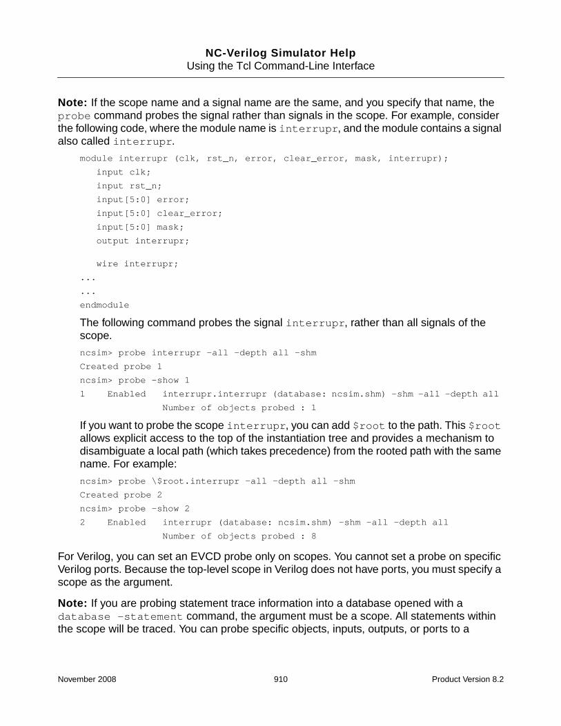
NC-Verilog Simulator HelpUsing the Tcl Command-Line Interface
Note: If the scope name and a signal name are the same, and you specify that name, theprobe command probes the signal rather than signals in the scope. For example, considerthe following code, where the module name is interrupr, and the module contains a signalalso called interrupr.
module interrupr (clk, rst_n, error, clear_error, mask, interrupr);
input clk;
input rst_n;
input[5:0] error;
input[5:0] clear_error;
input[5:0] mask;
output interrupr;
wire interrupr;
...
...
endmodule
The following command probes the signal interrupr, rather than all signals of thescope.
ncsim> probe interrupr -all -depth all -shm
Created probe 1
ncsim> probe -show 1
1 Enabled interrupr.interrupr (database: ncsim.shm) -shm -all -depth all
Number of objects probed : 1
If you want to probe the scope interrupr, you can add $root to the path. This $rootallows explicit access to the top of the instantiation tree and provides a mechanism todisambiguate a local path (which takes precedence) from the rooted path with the samename. For example:
ncsim> probe \$root.interrupr -all -depth all -shm
Created probe 2
ncsim> probe -show 2
2 Enabled interrupr (database: ncsim.shm) -shm -all -depth all
Number of objects probed : 8
For Verilog, you can set an EVCD probe only on scopes. You cannot set a probe on specificVerilog ports. Because the top-level scope in Verilog does not have ports, you must specify ascope as the argument.
Note: If you are probing statement trace information into a database opened with adatabase -statement command, the argument must be a scope. All statements withinthe scope will be traced. You can probe specific objects, inputs, outputs, or ports to a
November 2008 910 Product Version 8.2

NC-Verilog Simulator HelpUsing the Tcl Command-Line Interface
database opened with -statement. However, statements are not traced if you specify anobject or use the -inputs, -outputs, or -ports options.
If more than one database is open, you must include an option to specify the database intowhich you want to dump values. Use one of the following options:
■ -database dbase_name
Send the probe to the specified database. The database must already exist.
■ -shm
Send the probe to the default SHM database. If no default database is open, thesimulator opens a default database called ncsim.shm.
■ -vcd
Send the probe to the default VCD database. If no default database is open, thesimulator opens a default database called ncsim.vcd.
■ -evcd
Send the probe to the default EVCD database. If no default database is open, thesimulator opens a default database called ncsim.evcd.
The -evcd option can be followed by arguments (splitio or simple) and by othercommand-line options. See the description of the -evcd option below.
-activations [-depth {n | all}] [-future_processes]
Creates a summary probe of the SystemC processes in the specified scope(s), or in thecurrent debug scope if no scope is specified. This option records the names of the SystemCprocesses into an SHM database in the order of their activations. The probe values are storedin sequence time.
Use the -depth option to specify the levels of hierarchies to traverse to collect the SystemCprocesses. The default value of depth is 1.
Use the -future_processes option to include new SystemC processes created in thescope(s) after the probe is created.
See the section “Thread Manager in Tcl Command Mode” in the chapter “DebuggingSystemC Models” in the NC-SC Simulator User Guide for more information.
November 2008 911 Product Version 8.2

NC-Verilog Simulator HelpUsing the Tcl Command-Line Interface
-all [-memories] [-variables] [-sc_processes]
Specifies that all of the declared objects within a scope, except for Verilog memories, VHDLvariables, and SystemC processes are to be included in the probe. This applies to:
■ The scope(s) named in the argument
■ The current debug scope, if no scope or object is named in an argument
■ The subscopes that you specify with the -depth option
For EVCD, the -all option (or the -ports option) probes all of the declared primary portswithin a scope.
When you probe all objects in a scope to an SHM database, Verilog memories, VHDLvariables, and SystemC processes are not included by default.
■ To include Verilog memories in the probe, use -all -memories.
You can also probe a memory by:
❑ Including the name of the memory as an argument to the probe command. Probingof individual memory elements or ranges of memory elements is supported.
❑ Using the $shm_probe system task in your Verilog code. See “Creating an SHMDatabase and Probing Signals” on page 653 for details.
Verilog memories cannot be dumped to VCD or EVCD databases.The simulatorgenerates an error message if you use the -memories option when creating a probe toa VCD or EVCD database.
■ To include VHDL variables in the probe, use -all -variables.
These options probe all objects, including variables, in the specified scope and in allsub-processes of the probed scope. For example, the following command probes allobjects, including variables, in scope : and in all sub-processes of scope :.
ncsim> probe -create : -all -variables -database waves
When probing a VHDL process, the -variables option is not required because all youcan probe is variables. The behavior of the following two commands is identical:
ncsim> probe -create {:$PROCESS_000} -all -variables -database waves
ncsim> probe -create {:$PROCESS_000} -all -database waves
Because you can probe only the primary ports of a component instance(s) to an EVCDdatabase, you cannot use the -all -variables option if you are probing to an EVCDdatabase.
November 2008 912 Product Version 8.2

NC-Verilog Simulator HelpUsing the Tcl Command-Line Interface
■ To include SystemC processes in the probe, use -all -sc_processes.
-assertions {-failure | -state} [-signals]
Creates probes on assertions.
If you have PSL assertions in your design and have compiled with the -assert option, orSystemVerilog assertions and have compiled with the -sv option, you can use the probecommand with the -assertions option to create three kinds of assertion probes:
■ -assertions -failure
Records assertion failures.
■ -assertions -transaction
Records the assertions as transactions.
■ -assertions -state
Creates a state probe, which records changes in the assertion state for the probedassertions. This is the default if -failure or -transaction is not used.
The following command lets you record all assertions in a hierarchy as state probeswithout having to name each assertion:
ncsim> probe -create -shm -assertions -state -depth all
You can specify only one type of assertion probe. The -failure, -state, and-transaction options are mutually exclusive.
Use the -signals option to probe the signals that are referenced by the assertions. If theassertion signals are not probed, the waveform window will not show any data for thesesignals during simulation.
Note: If there are multiple probe -assertions -transaction commands, all of thetransaction records for assertion objects are written to the database used in the first probecommand, even if the subsequent probe commands explicitly specify a database with the-database option.
Examples:
The following command creates a single waveform trace on the triggerRW assertion withinthe ctr module.
ncsim> probe -create -shm -assertions -state top.ctr.triggerRW
November 2008 913 Product Version 8.2

NC-Verilog Simulator HelpUsing the Tcl Command-Line Interface
The following command records all assertion objects in the scope top.ctr as transactions.
ncsim> probe -create -shm -assertions -transaction top.ctr
The following command sets a failure probe on an assertion calledASSERT_WIDTH_MAX_CHECK in the scope top.soc.duv0.core.mii_inport0. Thetrace will be called Inport0_Mii_Clk_High_Max in the Waveform window.
ncsim> probe -create -assertions -failure -name Inport0_Mii_Clk_High_Max \-shm top.soc.duv0.core.mii_inport0.mii_clk_high.ASSERT_WIDTH_MAX_CHECK
See Assertion Checking in Simulation, Chapter 3, "Simulating a Design with Assertions"for more details on probing assertions and on the differences between failure, transaction,and state probes.
-database dbase_name
Saves the probe into the specified database.
If more than one database is open, you must specify the database into which you want todump values. You can do this by specifying a database name with the -database option.The dbase_name argument is the logical name of the database in which you want to savethe probe. This database must be open. The -database option does not create a databasefor you.
You can also specify the database into which you want to dump values with the -shm, -vcd,or -evcd option. These options specify that you want to save the probe to the default SHM,VCD, or EVCD database, respectively.
If only one database is open, you do not need to specify a database.
-depth { n | all | to_cells }
Specifies how many scope levels to descend when searching for objects to probe if you havespecified a scope. You must specify one of the following arguments:
■ n
Descend the specified number of scopes. For example, -depth 1 means include onlythe given scope, -depth 2 means include the given scope and its subscopes, and soon. The default is 1.
■ all
Include all scopes in the hierarchy below the specified scope(s).
November 2008 914 Product Version 8.2

NC-Verilog Simulator HelpUsing the Tcl Command-Line Interface
■ to_cells
Include all scopes in the hierarchy below the specified scope(s), but stop at cells (Verilogmodules with `celldefine or VITAL entities with VITAL Level0 attribute).
Note: If you are running the simulator in multi-step invocation mode, you must use the-libcell option to tag module instances as cell instances. However, if you are runningthe simulator in single-step invocation mode using the irun command, the -libcelloption is turned on by default to tag modules extracted from libraries (from -y, -v, or`uselib) as cells, as if the source code contained a `celldefine directive. You canuse the -nolibcell option to override this behavior.
-domain {analog | digital}
Specifies whether probes should be set up on analog or digital signals. By default, bothanalog and digital signals are probed.
■ -domain analog–Probe analog signals only.
■ -domain digital–Probe digital signals only.
-emptyok
Turns off the PRNONE error message issued when there is nothing for a probe -createcommand to probe in the specified scope.
-evcd[[{ splitio | simple }][[-mode { lfcompat | lfvectcompat }] |[-evcdformat format_number]]]
Sends the probe to the default EVCD database opened with a database -evcd -defaultcommand. If a default EVCD database does not exist, the simulator opens a default databasenamed ncsim.evcd. The associated file is ncsim.evcd. The file is placed in the currentworking directory.
If you want to send the probe to a database that is not the default, you must specify thedatabase with the -database option.
If you have opened an EVCD database with the database command, and if this is the onlydatabase of any kind that is open, a probe command will automatically use that database. Itis not necessary to use the -evcd option or the -database option to specify the database.
November 2008 915 Product Version 8.2

NC-Verilog Simulator HelpUsing the Tcl Command-Line Interface
Note: For Verilog, you cannot probe arrays of variable data types to an EVCD database. Thisincludes Verilog memories, which are one-dimensional arrays of type reg.
By default, the simulator dumps final value changes in extended format for both vector andscalar ports. For vector ports, the simulator dumps value changes for the entire vector, not forindividual bits of the vector.
There are two arguments and two command-line options that you can use with the -evcdoption to control the EVCD dump.
The arguments are splitio and simple.
■ splitio
Dump the value of the input port if any driver into the design under test changes value,and dump the value of the output port if any driver within the design under test changesvalue. If both inside and outside drivers change, dump two values: one corresponding tothe input, and one corresponding to the output.
■ simple
Dump resolved signal values on every transaction on the signal connected to a givenprimary port in simple 0X1Z format.
The command-line options to control output are -mode and -evcdformat.
■ -mode {lfcompat | lfvectcompat}
The -mode option applies to VHDL only.
In the LDV 5.0 release, there are two significant changes to VHDL EVCD.
❑ In releases prior to LDV 5.0, the default was to dump individual bits of a vector port.If you wanted to dump a single entry for a vector, it was necessary to open thedatabase with database -evcd vector. Beginning with LDV 5.0, a single entryis dumped for a vector. The database -evcd vector option is no longersupported.
❑ Some strength mapping changes have been introduced in LDV 5.0.
For backward compatibility, you can use the -mode option. This option has two possiblearguments:
November 2008 916 Product Version 8.2

NC-Verilog Simulator HelpUsing the Tcl Command-Line Interface
❑ lfcompat
Vector ports are dumped as individual elements, and the strength mapping is thesame as it was in LDV 4.1 or earlier releases.
You must use the -mode lfcompat option if you want to dump a subelement of acompressed VHDL signal.
❑ lfvectcompat
Vector ports are dumped as complete vectors, and the strength mapping is the sameas it was in LDV 4.1 or earlier releases.
See “Generating an Extended Value Change Dump (EVCD) File” in the chaptercalled “Debugging Your Design” in the NC-VHDL Simulator Help for moreinformation on generating an EVCD file for VHDL and for details on VHDL strengthmapping.
If the -mode option and the -evcdformat option are both included on the commandline, a warning message is issued. The VHDL scope(s) is dumped in the format specifiedwith the -mode option. The Verilog scope(s) is dumped in the format specified with-evcdformat.
■ -evcdformat format_number
The format_number argument can be 0, 1, 2, or 3.
❑ 0—Default behavior. Report the strengths for both the zero and one components ofthe value if the strengths are the same. If the strengths are different, report only thewinning strength. That is, the two strength values either match (for example,pA 5 5 !) or the winning strength is shown and the other is zero (forexample, pH 0 5 !).
❑ 1—Keep losing value. Report the strengths for both the zero and one componentsof the value (for example, pD 6 5 !).
❑ 2—Generate output according to the IEEE 1364-2001 standard.
The IEEE standard states that the values 0 (both input and output are active withvalue 0) and 1 (both input and output are active with value 1) are conflict states. Thestandard then defines two strength ranges:
❍ Strong: strengths 7, 6, and 5
❍ Weak: strengths 4, 3, 2, 1
The rules for resolving conflicts are:
November 2008 917 Product Version 8.2

NC-Verilog Simulator HelpUsing the Tcl Command-Line Interface
❍ If the input and output are driving with the same range of strength, the resolvedvalue is 0 or 1, and the strength is the stronger of the two.
❍ If the input is driving a strong strength and the output is driving a weak strength,the resolved value is d or u, and the strength is the strength of the input.
❍ If the input is driving a weak strength and the output is driving a strong strength,the resolved value is l or h, and the strength is the strength of the output.
❑ 3—Do both 1 and 2. Generate output according to the IEEE 1364-2001 standard,and also keep the losing strength.
See “Generating an Extended Value Change Dump (EVCD) File” on page 679 for moreinformation on generating an EVCD file and for an example of using the -evcdformatoption.
-exclude {object_name | scope_name}
Exclude the specified object or the specified scope from the probe.
In some cases, writing a probe command to probe all of the objects that you want to probe(without probing unwanted objects) can be difficult. The -exclude option provides aconvenient way to exclude certain objects or scopes when creating a probe. Instead ofspecifying all of the objects or scopes that you want to probe, you can specify which objectsor scopes not to probe. For example, you might probe all objects in the design except objectsin certain instances, or probe all levels of a certain instance, but not certain instances withinthose levels.
The argument to the -exclude option is either an object name or a scope name. You canuse multiple -exclude options to exclude multiple objects or scopes. For example:
ncsim> probe -vcd muxdff -depth all -exclude dff_g1 -exclude mux_m1:d*
You can also exclude multiple objects or scopes by enclosing the arguments in curly braces.For example:
ncsim> probe -vcd muxdff -depth all -exclude {dff_g1 mux_m1:d*}
When a scope is excluded, all objects inside the specified scope and in all of its subscopesare excluded.
The wildcard characters * and ? are allowed. However, wildcards are applicable only forobject names, not scope names. In order to exclude a scope from the probe, you must specifythe complete path of the scope. For example, the following command probes everythingexcept objects inside scope muxdff.
ncsim> probe -evcd -depth all -all : -exclude :tb:muxdff
November 2008 918 Product Version 8.2

NC-Verilog Simulator HelpUsing the Tcl Command-Line Interface
The following command probes everything except objects whose name start with tb.However any scope name starting with tb will be probed.
ncsim> probe -vcd -depth all -all : -exclude tb*
The -exclude option can be used for SHM, VCD, EVCD or screen (probe -screen)probes.
See “probe Command Examples” on page 927 for examples of using the -exclude option.
-flow
Specifies that the probe is for currents, rather than voltage.
Specifying -flow -all saves port currents and all other values and quantities covered bythe -all option (but not including probing of currents though inherited connections).Specifying -flow with -ports, -inputs, or -outputs probes currents in the specifiedobjects of the scope.
See the Virtuoso AMS Designer Simulator User Guide, Appendix B (“Tcl-BasedDebugging”) for details on the -flow option.
-functions
By default, objects declared within Verilog function scopes are not included in the probe. Usethe -functions option to include function scopes.
Note: Including the -functions option is not necessary if a Verilog function scope isspecified as the argument to the probe command (either explicitly or implicitly as the currentdebug scope).
-inhconn_signal global_signal
The -flow option must be specified along with the -inhconn_signal option. These twooptions together specify that the probe is to return the total current drawn fromglobal_signal through inherited connections by the specified instance.
See the Virtuoso AMS Designer Simulator User Guide, Appendix B (“Tcl-BasedDebugging”) for details on the -inhconn_signal option.
-inputs
Specifies that all inputs within a scope are to be included in the probe. This applies to:
November 2008 919 Product Version 8.2

NC-Verilog Simulator HelpUsing the Tcl Command-Line Interface
■ The current debug scope (if no scope(s) or object(s) is named in an argument)
■ The scope(s) named in the argument
■ Subscopes that you specify with the -depth option
-name probe_name
Specifies a user-defined name for the probe. You can then use the name that you assign toa probe with the -disable, -enable, -delete, and -show modifiers.
If you do not use -name to name your probes, the simulator gives every probe that you createa sequential number.
-outputs
Specifies that all outputs within a scope are to be included in the probe. This applies to:
■ The current debug scope (if no scope(s) or object(s) is named in an argument)
■ The scope(s) named in the argument
■ Subscopes that you specify with the -depth option
-ports
Specifies that all ports within a scope are to be included in the probe. This applies to:
■ The current debug scope (if no scope(s) or object(s) is named in an argument)
■ The scope(s) named in the argument
■ Subscopes that you specify with the -depth option
For EVCD, you can use -ports or -all to include all of the declared ports within a scopein the probe.
-power
Probes all low-power simulation control expressions to the SHM database.
The -power option probes all control expressions used in Common Power Format (CPF)commands for the design.
November 2008 920 Product Version 8.2

NC-Verilog Simulator HelpUsing the Tcl Command-Line Interface
Only SHM probes are supported. VCD, EVCD, and screen probes (using -screen) are notsupported. Including the -shm option is not required.
Example:
ncsim> probe -power -database waves inst.rst inst.clk inst.opcode
-pwr_mode
Probes power mode information for all power domains.
Only SHM probes are supported. VCD, EVCD, and screen probes (using -screen) are notsupported. Including the -shm option is not required.
Note: The only other probe command option that can be used with -pwr_mode is the-name option. You cannot specify other objects with the probe -pwr_mode command.
The following information is saved in the SHM database for each power domain:
■ The power domain name
■ The name of the power mode the domain is currently in
■ The state of the power domain (on, off, or transitional)
■ The nominal condition name and current voltage of the power domain
-screen [-format format_string] [-redirect filename] [-append] objects
Monitors the value changes on the specified object(s) and displays the values on the screen.
You cannot specify a scope as the argument to the -screen option. The argument must beone or more objects. This can include Verilog memories, memory ranges, and single memoryelements.
You cannot use this option with any other probe command-line option.
Use the -format option to specify the output format. The format_string argument cancontain both text and format specifiers. Variables and objects are paired sequentially withspecifiers.
Valid formats are:
■ %b—Binary format. The argument must be an object name that is either a scalar objector a logic vector.
November 2008 921 Product Version 8.2

NC-Verilog Simulator HelpUsing the Tcl Command-Line Interface
■ %d—Decimal format. The argument must be an object name whose type is integer,physical, or enumeration.
■ %f—Real number in floating-point notation. The argument must be an object whosebase type is real.
■ %o—Unsigned octal object. The argument must be a scalar object or a logic vector.
■ %s—Substitute. The argument is substituted on an as-is basis.
■ %x—Unsigned hex object. The argument is an object name that is either a scalar objector a logic vector.
■ %v—Default value format. The argument must be a signal or a variable name. The valueof the object is formatted appropriately, according to its type.
■ \t—Inserts a horizontal tab.
■ \n—Inserts a carriage return.
■ \c—Used as the last character, this suppresses the default line feed.
■ %C—Prints the cycle count.
■ %D—Prints the current delta cycle count.
■ %T—Prints the current simulation time.
Include the -redirect option to redirect the output to a file. For example:
ncsim> probe -screen -redirect myprobe.txt sum
Include the -append option if you want to append the results of another probe -screencommand to the file specified with -redirect. For example:
ncsim> probe -screen -redirect myprobe.txt board.count
Created probe 1
ncsim> run 500 ns
Ran until 500 NS + 0
ncsim> probe -screen -redirect myprobe.txt -append board.clock
Created probe 2
ncsim> run 500 ns
When using the probe -screen command with multiple signals, a discrete line of output isgenerated for each signal by default. For example:
Time: 10 NS: top.u1.a4 = 4’hf
Time: 10 NS: top.u1.a32 = 32’hffffffff
November 2008 922 Product Version 8.2

NC-Verilog Simulator HelpUsing the Tcl Command-Line Interface
Set the value of the probe_screen_format variable to 1 if you want to generate multiplesignal events on the same line. For example:
Time: 10 NS: top.u1.a4 = 4’hf; top.u1.a32 = 32’hffffffff;
See “probe_screen_format” on page 719 for more information.
-shm
Sends the probe to the default SHM database. The simulator opens a default databasenamed ncsim.shm if one does not already exist. The associated file is ncsim.shm. Thesimulator places the file in the current working directory.
If you have opened an SHM database with the database command, and if this is the onlydatabase of any kind that is open, a probe command will automatically use that database. Itis not necessary to use the -shm option or the -database option to specify the database.
-tasks
By default, objects declared within Verilog task scopes are not included in the probe. Use the-tasks option to include task scopes.
Note: Including the -tasks option is not necessary if a Verilog task scope is specified as theargument to the probe command (either explicitly or implicitly as the current debug scope).
-transaction
Records the value change trace as a transaction.
Transaction probes are created for only those objects whose value change can be recordedas a transaction. If you specify a scope(s), a transaction probe is created for the objects thatsupport transactions, and other objects in the scope(s) are ignored. If you specify an object,a transaction probe is created if the object supports transactions. If the object does notsupport transactions, the object is ignored with a warning.
You can use the -transaction option with -assertions to probe assertions astransactions. Using -assertions -transaction probes only assertion objects astransactions. If the -signals option is also included, the signals contributing to theassertions are also included as probed signals. Other objects that can be recorded astransactions are not included in the probe.
SystemC transaction probes can write transaction records to multiple databases. Eachprobe -transaction command uses the database specified for the probe command.
November 2008 923 Product Version 8.2

NC-Verilog Simulator HelpUsing the Tcl Command-Line Interface
If there are multiple probe -assertions -transaction commands, all of thetransaction records for assertions are written to the database used in the first probecommand, even if the subsequent probe commands explicitly specify a database with the-database option.
-vcd
Sends the probe to the default VCD database opened with a database -vcd -defaultcommand. If a default VCD database does not exist, the simulator opens a default databasenamed ncsim.vcd. The associated file is ncsim.vcd. The file is placed in the currentworking directory.
If you want to send the probe to a database that is not the default, you must specify thedatabase with the -database option.
If you have opened a VCD database with the database command, and if this is the onlydatabase of any kind that is open, a probe command will automatically use that database. Itis not necessary to use the -vcd option or the -database option to specify the database.
-waveform
Causes the objects in the probe to be added to the SimVision waveform display if thesimulator is running in GUI mode. If the waveform viewer is not running, it is invoked and theobjects are then added to the display.
This option has no effect if the simulator is not in GUI mode.
Deleting a Probe
-delete probe_name [probe_name ...]
Deletes the probe(s) specified by the argument.
The argument to -delete is a probe name or a list of probe names. You can use the twowildcard characters (* and ?) in the probe name argument.
■ The asterisk ( * ) matches any number of characters
■ The question mark ( ? ) matches any one character
You can delete SHM probes at any time.
November 2008 924 Product Version 8.2

NC-Verilog Simulator HelpUsing the Tcl Command-Line Interface
You can delete VCD or EVCD probes only at the time the VCD or EVCD database is created.Once the simulation is advanced, the VCD or EVCD header is written to the file and nomodifications to the probes are possible.
You cannot delete probes that record statement trace data into a database opened with adatabase -statement command.
Disabling a Probe
-disable probe_name [probe_name ...]
Disables the probe(s) specified by the argument. While the probe is disabled, values for theobjects in that probe are not written to the database. To resume probing, use the -enablemodifier.
The argument to -disable is a probe name or a list of probe names. You can use the twowildcard characters (* and ?) in the probe name argument.
■ The asterisk ( * ) matches any number of characters
■ The question mark ( ? ) matches any one character
You can disable SHM probes individually at any time.
You cannot disable VCD or EVCD probes individually. Use database -disable to disableall VCD or EVCD probes. See “database” on page 775.
You cannot disable probes that record statement trace data into a database opened with adatabase -statement command.
November 2008 925 Product Version 8.2

NC-Verilog Simulator HelpUsing the Tcl Command-Line Interface
Enabling a Probe
-enable probe_name [probe_name ...]
Causes a previously disabled probe(s) to be resumed. As soon as the probe resumes, allobjects in the probe have their values written to the database.
The argument to -enable is a probe name or a list of probe names. You can use the twowildcard characters (* and ?) in the probe name argument.
■ The asterisk ( * ) matches any number of characters
■ The question mark ( ? ) matches any one character
Saving a Script to Re-Create Probes
-save [filename]
Creates a Tcl script that you can execute to re-create the current databases and probes. Ifyou do not specify a filename argument, the script is printed to the screen.
Displaying Information about Probes
-show [probe_name ...] [-database dbase_name]
Provides information about the probe(s) specified in the argument. The argument to -showis a probe name or a list of probe names. You can use the two wildcard characters (* and ?)in the probe name argument.
■ The asterisk ( * ) matches any number of characters.
■ The question mark ( ? ) matches any one character.
If you do not include an argument, the simulator displays information on all probes.
Use the -database option to print information on probes in a specified database.
The information displayed by the probe -show command includes the number of objectsincluded in the probe. For example:
ncsim> probe -show
1 Enabled board (database: waves) -shm -depth all
Number of objects probed : 21
2 Enabled board (database: ncsim.vcd) -vcd
Number of objects probed : 4
November 2008 926 Product Version 8.2

NC-Verilog Simulator HelpUsing the Tcl Command-Line Interface
Each probe command has its own count, even if the output goes to the same database. Forexample:
ncsim> probe count[1:0] -database waves
ncsim> probe count[2] count[3] -database waves
ncsim> probe -show
1 Enabled board.count[1:0] (database: waves) -shm
Number of objects probed : 1
2 Enabled board.count[2] (database: waves) -shm
board.count[3]
Number of objects probed : 2
For VCD and EVCD, the number of objects displayed is the number of objects that appear inthe header of the generated VCD or EVCD file.
For SHM, the probe count is the number of objects displayed when the SHM database isopened with the SimVision waveform viewer. This also applies to probes opened with probe-screen.
probe Command Examples
In the following example, the database command opens a default SHM database calledwaves. The probe command creates a probe on all objects in the current debug scope. Datais sent to the default SHM database. The -create modifier is not required. The -all option(or -inputs, -outputs, or -ports) is required because no object or scope_nameargument is specified.
In this example, only one database, a default SHM database, is opened. The -shm option onthe probe command is, therefore, optional.
ncsim> database -open -shm waves -default
Created default SHM database waves
ncsim> probe -create -shm -all
Created probe 1
The following command creates a probe on all objects in the current debug scope. In thisexample, no default SHM database exists, so the simulator creates a default database calledncsim.shm.
ncsim> probe -create -shm -all
Created default SHM database ncsim.shm
Created probe 1
November 2008 927 Product Version 8.2

NC-Verilog Simulator HelpUsing the Tcl Command-Line Interface
The following command creates a probe on all signals in top. Data is sent to the databasewaves2. This database must already exist.
ncsim> probe -database waves2 top
The following command creates a probe on all objects in scope top.u1 and sends data tothe default SHM database (creating one called ncsim.shm, if a default database does notexist).
ncsim> probe -shm top.u1
The following command creates probes on all objects in the current scope that have namesbeginning with rst and ending with p5.
ncsim> probe -shm rst*p5
The following command creates probes on all objects in the scope top that have two lettersand that have names that start with the letter c.
ncsim> probe -shm top.c?
The following command creates a probe on all objects in scopes top.u1 and top.u2.
ncsim> probe -shm top.u1 top.u2
The following command creates a probe on the signal sum in the current debug scope andsends data to the default SHM database.
ncsim> probe -shm sum
The following command creates a probe on sum and c_out in the current debug scope andsends data to the default SHM database.
ncsim> probe -shm sum c_out
The following command creates a probe on sum in scope u1, sending data to the defaultSHM database.
ncsim> probe -shm u1.sum
The following command creates a probe on all ports in scope u1.
ncsim> probe -shm u1 -ports
The following command creates a probe on all ports in scope u1 and its subscopes.
ncsim> probe -shm u1 -ports -depth 2
The following command creates a probe on all ports in scope u1 and all scopes below u1.
ncsim> probe -shm u1 -ports -depth all
The following command creates a probe on all ports in scope u1 and all scopes below u1,stopping at modules with a `celldefine directive.
ncsim> probe -shm u1 -ports -depth to_cells
November 2008 928 Product Version 8.2

NC-Verilog Simulator HelpUsing the Tcl Command-Line Interface
By default, Verilog memories are not included when you probe objects in a scope. To probeVerilog memories in a scope, use -all -memories, as shown in the following example.
ncsim> probe -shm -all -memories u1
The following command creates a probe on the Verilog memory called mem in the currentscope.
ncsim> probe -shm mem
You can also probe individual memory elements or memory ranges, as shown in the followingtwo commands.
ncsim> probe -shm mem[255]
ncsim> probe -shm mem[255:128]
The following command creates a probe called peek.
ncsim> probe -shm sum -name peek
The following probe command includes the -power option to probe all low-power simulationcontrol expressions to the SHM database. Only SHM probes are supported. VCD, EVCD, andscreen probes (using -screen) are not supported. Including the -shm option is not required.
ncsim> database -open -shm -into waves.shm waves -default
Created default SHM database waves
ncsim> probe -power -database waves
Created probe 1
ncsim> probe -show 1
1 Enabled TESTBENCH.inst.pcu_inst.pau[2] (database: waves) -shm
TESTBENCH.inst.pcu_inst.plu[2]
TESTBENCH.inst.pcu_inst.palu[2]
TESTBENCH.inst.pcu_inst.prf[2]
TESTBENCH.inst.pcu_inst.prf[1]
TESTBENCH.inst.pcu_inst.pau[1]
TESTBENCH.inst.pcu_inst.pau[0]
TESTBENCH.inst.pcu_inst.plu[0]
TESTBENCH.inst.pcu_inst.palu[0]
TESTBENCH.inst.pcu_inst.prf[0]
Number of objects probed : 10
ncsim>
In the following example, the probe -pwr_mode command probes power mode informationfor the three power domains in the design.
ncsim> database -open -shm -into waves.shm waves -default
Created default SHM database waves
ncsim> probe -create -pwr_mode -database waves
November 2008 929 Product Version 8.2

NC-Verilog Simulator HelpUsing the Tcl Command-Line Interface
Created probe 1
ncsim> probe -show
1 Enabled LPS (database: waves) -shm
Number of objects probed : 3
ncsim>
The following example shows a Verilog module that contains a generate-loop. Eachfor-generate instance is a scope. The name of the scope is the name of the generate block(bit, in this example), plus an instance-select, which is the value of the generate parameter.In this example, the scopes are bit[0], bit[1], bit[2], and bit[3]. See “GenerateConstructs” on page 99 for details on generated instantiations.
module addergen1 (co, sum, a, b, ci);
parameter SIZE = 4;
output [SIZE-1:0] sum;
output co;
input [SIZE-1:0] a, b;
input ci;
wire [SIZE:0] c;
genvar i;
assign c[0] = ci;
generate
for(i = 0; i < SIZE; i = i + 1)
begin : bit
wire t1, t2, t3; //internal nets
xor g1 (t1, a[i], b[i]);
xor g2 (sum[i], t1, c[i]);
and g3 (t2, a[i], b[i]);
and g4 (t3, t1, c[i]);
or g5 (c[i+1], t2, t3);
end
endgenerate
assign co = c[SIZE];
endmodule
The name of a for-generate, without an index, is treated as a reference to each of thegenerate scopes. The following two commands are equivalent.
ncsim> probe -shm bit
ncsim> probe -shm bit[0] bit[1] bit[2] bit[3]
November 2008 930 Product Version 8.2

NC-Verilog Simulator HelpUsing the Tcl Command-Line Interface
In the following example, the database command opens a default VCD database calledtest_vcd. The probe command creates a probe on all ports in the scope counter. Datais sent to the default VCD database.
ncsim> database -open -vcd test_vcd -default
Created default VCD database test_vcd
ncsim> probe -create -vcd top.counter -ports
Created probe 1
The following probe -vcd command creates a probe on all objects in the current debugscope. In this example, no default VCD database exists, so the simulator creates a defaultdatabase called ncsim.vcd.
ncsim> probe -create -vcd -all
Created default VCD database ncsim.vcd
Created probe 1
When generating an EVCD database for Verilog, you must specify a scope(s) as theargument to the probe command. You cannot specify specific ports. In the followingexample, the database command opens a default database called test_evcd. Theassociated filename is test_evcd.evcd. The probe command creates a probe on allprimary ports in the scope test_bench.dut.
ncsim> database -open test_evcd -evcd -default
Created default EVCD database test_evcd
ncsim> probe -create test_bench.dut -evcd
In the following example, the database command opens an EVCD database calledtest_evcd. The -into option specifies that the filename of the output file is test.evcd.The probe command creates a probe on all primary ports in the scope test_bench.dut.Data is sent to the EVCD database called test_evcd.
ncsim> database -open test_evcd -evcd -into test.evcd
ncsim> probe -create test_bench.dut -evcd -database test_evcd
In the following example, the probe command includes the -evcd splitio option. Thisoption dumps the value of the input port if any driver into the scope test_bench.dutchanges value, and dumps the value of the output port if any driver within the scope changesvalue. If both inside and outside drivers change, two messages are dumped: onecorresponding to the input, and one corresponding to the output.
ncsim> database -open -evcd test_evcd -into test.evcd
ncsim> probe -create test_bench.dut -evcd splitio -database test_evcd
The probe command in the following example includes the -evcd -evcdformat option.The argument to the -evcdformat option is 1, which specifies that both the zero and onecomponent of the value is to be dumped (for example, pD 6 5 <0).
ncsim> database -open -evcd test_evcd -into test.evcd
November 2008 931 Product Version 8.2

NC-Verilog Simulator HelpUsing the Tcl Command-Line Interface
ncsim> probe -create test_bench.dut -evcd -evcdformat 1 -database test_evcd
In the following example, the database command opens a default EVCD database calledtest_evcd. The probe command creates a probe on all primary ports in the VHDL scope:u1. Data is sent to the default EVCD database.
ncsim> database -open -evcd test_evcd -default
Created default EVCD database test_evcd
ncsim> probe -create -evcd -all :u1
Created probe 1
In the following example, the probe command includes the -evcd -mode lfcompatoption. This option applies only to VHDL, and is provided for backward compatibility. Itspecifies that vector ports are to be dumped as individual elements, and that the strengthmapping will be that used in LDV 4.1 or earlier releases.
ncsim> database -open test_evcd -evcd -into test.evcd -timescale ns
ncsim> probe -create :i1:i1:d -evcd -mode lfcompat -database test_evcd
The following probe command also includes the -evcd -mode lfcompat option. Thisoption is required if you want to dump a subelement of a compressed VHDL signal to anEVCD database.
ncsim> probe -create :top:cans(0) -evcd -mode lfcompat -database test_evcd
The following probe -evcd command creates a probe on all primary ports in the currentdebug scope. In this example, no default EVCD database exists, so the simulator creates adefault database called ncsim.evcd.
ncsim> probe -create -evcd -all
Created default EVCD database ncsim.evcd
Created probe 1
The following command monitors value changes on signals clock and count. When eitherof these signals changes value, the simulator displays output on the screen.
ncsim> probe -screen clock count
Created probe 1
ncsim> run 10 ns
Time: 5 NS: board.clock = 1’h1 : board.count = 4’hx
Ran until 10 NS + 0
In the following command, the -format option is included to format the output of probe-screen.
ncsim> probe -screen -format "clock = %d \ncount = %b" clock count
Created probe 1
ncsim> run 10 ns
clock = 1’d1
November 2008 932 Product Version 8.2

NC-Verilog Simulator HelpUsing the Tcl Command-Line Interface
count = 4’bxxxx
Ran until 10 NS + 0
The following example illustrates the simulator output when you use probe -screen tomonitor signal value changes, and then disable the probe at some later time.
ncsim> probe -screen clock count
Created probe 1
ncsim> run 10 ns
Time: 5 NS: board.clock = 1’h1: board.count = 4’hx
Ran until 10 NS + 0
ncsim> probe -disable 1
ncsim> run 10 ns
Time: 10 NS: board.clock = <disabled> : board.count = <disabled>
Ran until 20 NS + 0
The following command probes all objects in the current debug scope, except clk.
ncsim> probe -shm * -exclude clk
The following command probes all objects in the current debug scope, except clk and rst.
ncsim> probe -shm * -exclude clk -exclude rst
or:
ncsim> probe -shm * -exclude {clk rst}
The following command probes all objects in the current debug scope, except objects whosename starts with d.
ncsim> probe -shm * -exclude d*
The following command probes all objects, except objects inside scope mux_m1 and itssubscopes.
ncsim> probe -vcd muxdff -depth all -exclude mux_m1
The -exclude option supports wildcards, but the wildcards are applicable only to objectnames, not scope names. For example, the following command probes all objects in thedesign except those objects inside scope mux_m1 whose name starts with d.
ncsim> probe -vcd muxdff -depth all -exclude mux_m1:d*
The following command probes all objects in scope muxdff and its subscopes, except for:
■ Objects in instance dff_g1
■ Objects in scope mux_m1 whose name starts with d
November 2008 933 Product Version 8.2

NC-Verilog Simulator HelpUsing the Tcl Command-Line Interface
ncsim> probe -vcd muxdff -depth all -exclude dff_g1 -exclude mux_m1:d*
Created default VCD database ncsim.vcd
Created probe 1
ncsim> probe -show
1 Enabled muxdff (database: ncsim.vcd) -vcd -depth all -exclude{mux_m1:d*} -exclude dff_g1
Number of objects probed : 10
The following command displays the state of all probes.
ncsim> probe -show
The following command displays the state of the probe called peek.
ncsim> probe -show peek
The following command disables the probe called peek.
ncsim> probe -disable peek
The following command enables the probe called peek, which was disabled in the previouscommand.
ncsim> probe -enable peek
The following sequence of commands illustrates the use of wildcard characters in probename arguments. Two probes called peek1 and peek2 are created. Both probes are thendisabled using the * wildcard character. Both probes are then deleted using the ? wildcardcharacter.
ncsim> probe -database waves clock -name peek1
Created probe peek1
ncsim> probe -database waves count -name peek2
Created probe peek2
ncsim> probe -show
peek1 Enabled board.clock (database: waves) -shm
Number of objects probed : 1
peek2 Enabled board.count (database: waves) -shm
Number of objects probed : 1
ncsim> probe -disable pe*
ncsim> probe -show
peek1 Disabled board.clock (database: waves) -shm
Number of objects probed : 1
peek2 Disabled board.count (database: waves) -shm
Number of objects probed : 1
ncsim> probe -delete peek?
November 2008 934 Product Version 8.2

NC-Verilog Simulator HelpUsing the Tcl Command-Line Interface
ncsim> probe -show
No probes set
ncsim>
The following command shows the error message that is displayed if you run in the default“regression” mode (no read, write, or connectivity access to simulation objects) and thenprobe an object that does not have read access.
ncsim> probe -shm d
ncsim: *E,RDACRQ: Object does not have read access: hardrive.h1.d.
November 2008 935 Product Version 8.2

NC-Verilog Simulator HelpUsing the Tcl Command-Line Interface
process
The process command displays information about the processes that are currentlyexecuting or that are scheduled to execute at the current simulation time. You can use thiscommand to display the processes in VHDL, in Verilog, or in mixed VHDL/Verilog designs.
For VHDL, the following constructs qualify as processes:
■ VHDL process statements
■ Postponed processes
■ Concurrent statements (implicit process)
■ Foreign processes (FMI)
For Verilog, the following constructs qualify as processes:
■ initial and always statement blocks
■ Continuous assignments
■ Implicit continuous assignments (port connections)
■ Non-blocking assignments
■ $monitor statements
Note: You must compile the source code with the -linedebug option (non-optimizationmode) in order for the process command to display correct information.
process Command Syntaxprocess
[-all] [count]
[-current] (Default if no option is specified)
[-eot] [count]
[-next] [count]
November 2008 936 Product Version 8.2

NC-Verilog Simulator HelpUsing the Tcl Command-Line Interface
process Command Options
-all [count]
If you do not specify a count argument, process -all lists all of the processes that arescheduled to execute at the current simulation time. This option shows the process that iscurrently executing (-current), all scheduled processes (-next), and all processes that arescheduled to execute at the end of the current simulation time (-eot).
If you specify a count argument, the number of processes in each of these categories islimited to the specified number. For example:
ncsim> process -all 2
-current
Displays the process that is currently executing.
This option is the default if no option is specified.
-eot [count]
Lists all of the processes that are scheduled to execute at the end of the current simulationtime.
The -eot option shows the processes that are scheduled to execute after normal activity forthe current time has stabilized. These processes include postponed processes, non-blockingassignments, and $monitor statements. Postponed processes and $monitor statementsare guaranteed to be the last processes run in the current time, but other end-of-time processactivity may cause further delta cycles.
Include a count argument to limit the number of processes that are displayed. For example:
ncsim> process -eot 5
-next [count]
Lists all of the processes that are scheduled to execute at the current simulation time.
Include a count argument to limit the number of processes that are displayed. For example:
ncsim> process -next 2
November 2008 937 Product Version 8.2

NC-Verilog Simulator HelpUsing the Tcl Command-Line Interface
process Command Examples
The Verilog source code used in the examples in this section is shown below. This sourcecode was compiled with the -linedebug option.
module top_module;
reg[1:0]x, y, z;
wire [1:0]sum, co;
initial
$monitor($time,,"x=%b y=%b z=%b sum=%b co=%b", x, y, z, sum, co);
initial
begin
x=2’b00;
y=2’b00;
z=2’b00;
end
always
x=#10 x+1;
always
y=#40 y+1;
always
z=#160 z+1;
endmodule
The process command with no command-line option is the same as process -current.This command displays the full pathname of the executing process, as well as the file nameand the source code line number.
% ncsim worklib.top_module
ncsim> process
Executing Process:
[./test.v, 6, top_module] initial
In the following command, the -all option shows the currently executing process and allscheduled processes, including those that are scheduled at the end of the current simulationtime.
ncsim> run -process
./test.v:11 x=2’b00;
ncsim> process -all
Executing Process:
[./test.v, 9, top_module] initial
November 2008 938 Product Version 8.2

NC-Verilog Simulator HelpUsing the Tcl Command-Line Interface
Scheduled Process(es):
[./test.v, 16, top_module] always
[./test.v, 19, top_module] always
[./test.v, 22, top_module] always
End-of-time Process(es):
[./test.v, 7, top_module] $monitor($time,,"x=%b y=%b z=%b sum=%b co=%b",x, y, z, sum, co)
The following command line includes a count argument to limit the number of processesthat are displayed.
ncsim> process -all 1
Executing Process:
[./test.v, 9, top_module] initial
Scheduled Process(es):
[./test.v, 16, top_module] always
End-of-time Process(es):
[./test.v, 7, top_module] $monitor($time,,"x=%b y=%b z=%b sum=%b co=%b", x, y,z, sum, co)
The following command shows the next two processes that are scheduled to execute.
ncsim> process -next 2
Scheduled Process(es):
[./test.v, 16, top_module] always
[./test.v, 19, top_module] always
The following command shows the processes that are scheduled to execute at the end of thecurrent simulation time.
ncsim> process -eot
End-of-time Process(es):
[./test.v, 7, top_module] $monitor($time,,"x=%b y=%b z=%b sum=%b co=%b", x, y,z, sum, co)
November 2008 939 Product Version 8.2

NC-Verilog Simulator HelpUsing the Tcl Command-Line Interface
The following example illustrates the output of the process -all command for amixed-language design.
ncsim> process -all
ncsim> process -all
Executing Process:
[File: tb.vhd, Line: 153] :$PROCESS_001
Scheduled Process(es):
[File: tb.vhd, Line: 152] :$PROCESS_000
[File: tb.vhd, Line: 134] :gen_quarters
[File: tb.vhd, Line: 122] :gen_dimes
[File: tb.vhd, Line: 114] :gen_nickels
...
...
...
[File: DRINK.vhd, Line: 356] :top:$PROCESS_002
[File: DRINK.vhd, Line: 355] :top:$PROCESS_001
[File: DRINK.vhd, Line: 354] :top:$PROCESS_000
module DRINK_MACHINE:
[File: ./SOURCES/drink_machine.v, Line: 54] initial $sdf_annotate("SDFFILE")
End-of-time Process(es):
No Processes Scheduled
November 2008 940 Product Version 8.2

NC-Verilog Simulator HelpUsing the Tcl Command-Line Interface
profile
The profile command lets you invoke the profiler and control its behavior.
The profiler is a tool that measures where CPU time is spent during simulation. The profilergenerates a run-time profile file that contains simulation run-time information that is useful forfinding performance bottlenecks and for tuning a design description for better simulationperformance. See “Using the Profiler to Identify and Eliminate Simulation Bottlenecks” onpage 1096 for details on the profiler.
You can invoke the profiler in two ways:
■ Use the -profile command-line option when you invoke the simulator (ncsim) or runin single-step invocation mode with irun.
If you start a simulation with the -profile option, profiling can be stopped only byexiting or resetting the simulation. Resetting the simulation with a reset commandswitches off the profiling automatically.
■ Use the Tcl profile command.
The profile command provides more control over the profiler behavior than the-profile command-line option. With the profile command, you can:
❑ Start or stop profiling at any time (-on and -off)
❑ Dump the profiled data to a file at any time (-dump)
❑ Clear the currently collected profiled data (-clear)
If profiling is turned on with the profile command, it remains on after a reset. A resetcommand clears the currently collected profile data, but does not disable profiling.
profile Command Syntaxprofile
-clear
-dump [-overwrite] [filename]
-off
-on
You must specify at least one option. You can specify more than one option on the sameprofile command. For example:
ncsim> profile -dump myprof.out -clear
November 2008 941 Product Version 8.2

NC-Verilog Simulator HelpUsing the Tcl Command-Line Interface
profile Command Options
-clear
Clears the profile information collected so far. A profile -clear command clears theinternal profile information buffer. It does not disable profiling.
You can use this option only when the profiler is on.
-dump [-overwrite] [filename]
Writes the profile information to a file.
This option lets you write the profile data to a file at any time during the simulation.
You can use this option only when the profiler is on.
You can specify the output file name as an argument to -dump. If you do not specify the nameof the output file, the profiler writes to a file called ncprof.out.
If the output file already exists, you must include the -overwrite option. The profiler will notoverwrite an existing file.
-off
Turns off the profiler.
-on
Turns on the profiler.
profile Command Examples
In the following example, separate profiles are created for different simulation times.
ncsim> profile -on ;# Turn profiling on.
ncsim> run 1000 ns
ncsim> profile -dump profdata1.out ;# Write profile data to profdata1.out.
ncsim> set vital_timing_checks_on 1 ;# Set variables, execute Tcl commands, etc.
ncsim> run 1000 ns
ncsim> profile -dump profdata2.out ;# Write profile data to profdata2.out.;# File contains profile data for 2000 ns.
November 2008 942 Product Version 8.2

NC-Verilog Simulator HelpUsing the Tcl Command-Line Interface
ncsim> set vital_timing_checks_on 0
ncsim> run 1000 ns
ncsim> profile -dump -overwrite profdata1.out ;# Write profile data to;# profdata1.out.
ncsim> ;# File contains profile data for;# 3000 ns.
ncsim> exit
In the following example, profile results are generated for a simulation run. The simulation isthen reset. The value of a Tcl variable is changed, a Tcl command is executed, and thesimulation is run again with the profile results dumped to a separate file.
ncsim> profile -on ;# Turn profiling on.
ncsim> run
ncsim> profile -dump file1.prof ;# Write profile results to file1.prof.
ncsim>
ncsim> reset ;# Reset simulation to time 0 ns.;# This clears the profile data, but profiling is still on.
ncsim> set real_precision 5 ;# Set variables, execute Tcl commands, etc.
ncsim> tcheck -off top.y1.u2
ncsim> run
ncsim> profile -dump file2.prof ;# Write profile results of second simulation run.
ncsim> profile -off ;# Turn profiling off.
ncsim> exit
November 2008 943 Product Version 8.2

NC-Verilog Simulator HelpUsing the Tcl Command-Line Interface
release
The release command releases any force set on the specified object(s). Releasing a forcecauses the value to immediately return to the value that would have been there if the forcehadn’t been blocking transactions. Use the -keepvalue option if you want to release theforced object, but retain the forced value.
This command will release any force, whether it was created by a force command or by aVerilog force procedural statement during simulation. The behavior is the same as that of aVerilog release statement.
Objects specified as arguments to the release command must have write access. See“Enabling Read, Write, or Connectivity Access to Simulation Objects” on page 371 for detailson specifying access to simulation objects.
The following objects cannot be forced to a value with the force command and, therefore,cannot be specified as the object in a release command.
■ memory
■ memory element
■ bit-select or part-select of a register
■ bit-select or part-select of a unexpanded wire
■ VHDL variable
See “Forcing and Releasing Signal Values” on page 646 for more information.
release Command Syntaxrelease [-keepvalue] object_name ...
You can use wildcard characters in the argument to a release command.
■ The asterisk ( * ) matches any number of characters.
■ The question mark ( ? ) matches any one character.
You cannot use wildcard characters inside escaped names.
See “Using Wildcards Characters in Tcl Commands” on page 739 for more information onusing wildcards.
November 2008 944 Product Version 8.2

NC-Verilog Simulator HelpUsing the Tcl Command-Line Interface
release Command Options
-keepvalue
Release the forced object, but retain the forced value.
release Command Examples
The following command removes a force set on object x.
ncsim> release x
The following command removes a force set on object :top:DISPENSE_tempsig.
ncsim> release :top:DISPENSE_tempsig
The following command releases two objects: w[0] and r.
ncsim> release w[0] r
The following command releases all forces applied on objects in the current scope that havenames that end in td.
ncsim> release *td
November 2008 945 Product Version 8.2

NC-Verilog Simulator HelpUsing the Tcl Command-Line Interface
reset
The reset command resets the currently loaded model to its original state at time zero. Thetime-zero snapshot, created by the elaborator, must still be available.
The Tcl debug environment remains the same as much as possible after a reset.
■ Tcl variables remain as they were before the reset.
■ SHM and VCD databases remain open, and probes remain set.
Note: VCD databases created with the $dumpvars call in Verilog source code areclosed when you reset.
■ Breakpoints remain set.
■ The SimVision waveform viewer window remain the same.
Forces and deposits in effect at the time you issue the reset command are removed.
See “Saving, Restarting, Resetting, and Reinvoking a Simulation” on page 486 for moreinformation.
When you run the simulation after a reset, the order in which commands are executed to setprobes, set breakpoints, and so on, may be different from the order in which they wereexecuted before the reset. However, the commands are still executed at the correct simulationtime cycle.
reset Command Syntaxreset
reset Command Options
None.
reset Command Examples
The following command resets the currently loaded model to its original state at time zero.
ncsim> reset
November 2008 946 Product Version 8.2

NC-Verilog Simulator HelpUsing the Tcl Command-Line Interface
restart
The restart command replaces the currently simulating snapshot with another snapshot ofthe same elaborated design.
You must specify a snapshot name with the restart command, and the specified snapshotmust be a snapshot created by the save command. (See “save” on page 960 for details onthis command.)
The snapshot name is interpreted the same way as the snapshot name on the ncsimcommand line, with the addition that you can give only the view name preceded by a colon ifyou want to load a snapshot that is a view of the currently loaded cell. For example:
An error message is issued if the snapshot specified on the command line is not a snapshotof the design hierarchy that is currently loaded. That is, you cannot use the restartcommand to load a snapshot of a different elaborated design or one that comes from adifferent elaborated design. To load a different model, exit ncsim and then invoke it with thenew snapshot.
When you restart with a saved snapshot in the same simulation session:
■ SHM databases remain open and all probes remain set.
■ Breakpoints set at the time that you execute the restart remain set.
Note: If you set a breakpoint that triggers, for example, every 10 ns (that is, at time 10,20, 30, and so on) and restart with a snapshot saved at time 15, the breakpoint triggersat 20, 30, and so on, not at time 25, 35, and so on.
■ Forces and deposits in effect at the time you issue a save command are still in effectwhen you restart.
If you exit the simulation and then invoke the simulator with a saved snapshot, databases areclosed. Any probes and breakpoints are deleted. If you want to restore the full Tcl debug
restart top Restarts [lib.]top[:view]
If the view name is omitted, there must be only onesnapshot of the given cell, otherwise the snapshot nameis ambiguous. In this case, an error message is issued,and a list of available snapshots is printed.
restart top:ckpt Restarts [lib.]top:ckpt
restart :ckpt Restarts [lib.][cell]:ckpt
November 2008 947 Product Version 8.2

NC-Verilog Simulator HelpUsing the Tcl Command-Line Interface
environment when you restart, make sure that you save the environment with the save-environment command. This command creates a Tcl script that captures the currentbreakpoints, databases, probes, aliases, and predefined Tcl variable values. You can thenuse the Tcl source command after restarting or the -input option when you invoke thesimulator to execute the script. For example,
% ncsim top
ncsim> (Open a database, set probes, set breakpoints, deposits,
forces, etc.)
ncsim> run 100 ns
ncsim> save worklib.top:ckpt1
ncsim> save -environment ckpt1.tcl
ncsim> exit
% ncsim -tcl worklib.top:ckpt1
ncsim> source ckpt1.tcl
restart Command Syntaxrestart snapshot_name
restart -show
restart Command Options
-show
List the names of all snapshots that can currently be used as the argument to the restartcommand.
restart Command Examples
In the following example, a save command is issued to save the simulation state as a viewof the currently loaded cell, top. This snapshot can be loaded using either of the followingtwo restart commands.
ncsim> save top:ckpt1
ncsim> restart top:ckpt1
ncsim> restart :ckpt1
November 2008 948 Product Version 8.2

NC-Verilog Simulator HelpUsing the Tcl Command-Line Interface
In the following example, a save command is issued to save the simulation state as a viewof the currently loaded cell, top. A second save command is issued to save the Tcl debugenvironment. If you exit the simulator, you can restart with the saved snapshot and thenrestore the debug settings by sourcing the script created with the save -environmentcommand.
ncsim> save top:ckpt1
ncsim> save -environment top_ckpt1.env
ncsim> exit
% ncsim -tcl :ckpt1
ncsim> source top_ckpt1.env
The following command reloads the snapshot of the given cell, top. Because the view nameis not specified, the snapshot name is ambiguous if there is more than one view, and an errormessage is issued.
ncsim> restart top
The following restart command results in an error because you are trying to replace thecurrently simulating snapshot (asic1:ckpt1) with another snapshot of a differentelaborated design (asic2:ckpt1). You can only restart snapshots of the same elaborateddesign.
% ncsim -tcl asic1:ckpt1
ncsim> restart asic2:ckpt1
The following command lists all of the snapshots you can currently load with the restartcommand.
ncsim> restart -show
otherlib.board:module
worklib.board:ckpt1
worklib.board:ckpt2
November 2008 949 Product Version 8.2

NC-Verilog Simulator HelpUsing the Tcl Command-Line Interface
run
The run command starts simulation or resumes a previously halted simulation. You can:
■ Run until an interrupt, such as a breakpoint or error, occurs or until simulation completes(the run command with no modifiers or arguments).
■ Run one behavioral statement, stepping over subprogram calls (-next).
■ Run one behavioral statement, stepping into subprogram calls (-step).
■ Run until the current subprogram ends (-return).
■ Run to a specified timepoint or for a specified length of time (-timepoint).
■ Run to the beginning of the next delta cycle or to a specified delta cycle (-delta).
■ Run to the beginning of the next phase of the simulation cycle (-phase).
■ Run until the beginning of the next scheduled process or to the beginning of the nextdelta cycle, whichever comes first (-process).
See “Starting a Simulation” on page 485 for more information.
run Command Syntaxrun
-adjacent
-clean
-delta [cycle_spec]
-next
-phase
-process
-rand_solve
-return
-step
-sync
[-timepoint] [time_spec] [-absolute | -relative]
November 2008 950 Product Version 8.2

NC-Verilog Simulator HelpUsing the Tcl Command-Line Interface
run Command Options
-adjacent
Run one behavioral statement, remaining in the current process.
Note: The run -adjacent command is supported for Verilog processes only.
A run -next or run -step command stops at the next executable line of code to beprocessed by the simulator. This next line of code could be anywhere in the design hierarchy.
A run -adjacent command also steps to the next line of executable code, but remainswithin the currently executing process or thread. This is useful when debugging a complexalgorithm with many conditional flows through the code because it lets you retain focus on aspecific area of the code, rather than on the next scheduled event in the simulation.
-clean
Run the simulation to the next point at which it is possible to create a checkpoint snapshotwith the save -simulation command. (See “save” on page 960 for details.)
-delta [cycle_spec]
Run the simulation for the specified number of delta cycles. If no cycle_spec argument isspecified, run the simulation to the beginning of the next delta cycle. A run -deltacommand is the same as run -delta 1.
-next
Run one behavioral statement, stepping over any subprogram calls.
In some cases, a run -next command produces results that are similar to a run -stepcommand when the current execution point is a VHDL non-zero WAIT statement. Forexample, if the current execution point is a statement such as wait for 10 ns;, anotherprocess may be scheduled to run at the current simulation time while the current process issuspended because of the WAIT statement. A run -next command executes the nextbehavioral statement, and the simulation stops in the scheduled process. If you want to runto the next executable line in the source code after the WAIT statement, you can set a linebreakpoint on that line and enter a run command.
November 2008 951 Product Version 8.2

NC-Verilog Simulator HelpUsing the Tcl Command-Line Interface
-phase
Run to the beginning of the next phase of the simulation cycle. A simulation cycle consists oftwo phases: signal evaluation and process execution.
-process
Run until the beginning of the next scheduled process or to the beginning of the next deltacycle, whichever comes first.
In VHDL, a process is a process statement. In Verilog it is an always block, an initialblock, or some other behavior that can be scheduled to run.
-rand_solve
Execute the current SystemVerilog randomize() call and display the status (1 for successor 0 for failure).
The SystemVerilog built-in randomize() function returns the value 1 for success or 0 forfailure. A failure occurs because there are conflicts in the collection of constraints to solve orbecause a variable is over-constrained. In this case, the simulator generates a warning tellingyou that the randomize() call failed.
To help you debug these randomization failures, you can set a breakpoint in randomize()method calls using the stop -randomize command. Then, when the simulator is stoppedin a randomize() call, you can use other commands to debug the failures. For example, youcan:
■ Enable/disable specific constraints with a deposit -constraint_mode command.
■ Enable/disable specific random variables with a deposit -rand_mode command.
■ Add a new constraint to the class randomize call you are debugging with theconstraint command.
After executing these, or other, Tcl commands, use the run -rand_solve command toexecute the current randomization call again, using the currently enabled/disabled constraintsand variables and the current state variable values.
No other run command options can be included on the command line when using the-rand_solve option.
November 2008 952 Product Version 8.2

NC-Verilog Simulator HelpUsing the Tcl Command-Line Interface
New random values are generated for each run -rand_solve command. Afterre-executing the randomize() call, the simulator stops and returns the Tcl prompt. If thesolver succeeds, it copies the newly generated random values to the rand and randcvariables. If the solver fails, the copy is not done.
Use the run command to continue out of the randomize() call.
See the “run Command Examples” section for an example.
-return
Run until the current subprogram (task, function, procedure) returns.
-step
Run one behavioral statement, stepping into subprogram calls.
-sync
Run to the next point at which the digital engine will synchronize with the analog engine.
[-timepoint] [time_spec] [-absolute | -relative]
Run until the specified time is reached. The time specification can be absolute or relative.Relative is the default.
In addition to time units such as fs, ps, ns, us, and so on, you can use deltas as the unit.For example,
ncsim> run 10 deltas
This is the same as run -delta 10.
If you include a time specification and a breakpoint or interrupt stops simulation before thespecified time is reached, the time specification is thrown away. For example, in the followingsequence of commands, the last run command will not stop the simulation at 500 ns.
ncsim> stop -object x
Created stop 1
ncsim> run 500 ns
Stop 1 {x = 0} at 10 ns
ncsim> run
November 2008 953 Product Version 8.2

NC-Verilog Simulator HelpUsing the Tcl Command-Line Interface
run -timepoint without a time_spec argument runs the simulation until the nextscheduled event.
run Command Examples
The following command runs the simulation until an interrupt occurs or until simulationcompletes.
ncsim> run
The following command advances the simulation to 500 ns absolute time. The -timepointoption is not required.
ncsim> run -timepoint 500 ns -absolute
The following command advances the simulation 500 ns relative time. With a timespecification, -relative is the default.
ncsim> run 500 ns
The following two commands are equivalent. They both run the simulation for 5 delta cycles.
ncsim> run -delta 5
ncsim> run 5 deltas
The following command runs one behavioral statement, stepping into any subprogram calls.
ncsim> run -step
The following command runs until the current subprogram returns. The subprogram can be atask, function, or procedure.
ncsim> run -return
The following command runs one behavioral statement, stepping over any subprogram calls.
ncsim> run -next
The following example illustrates the difference between run -next and run -adjacent.The Verilog code used for this example is as follows:
module top;
int i;
initial begin
// Wait for event on i
@i; // Line 6
$display($stime, " spot 1"); // 7
// Wait 5 time units // 8
#5; // 9
November 2008 954 Product Version 8.2

NC-Verilog Simulator HelpUsing the Tcl Command-Line Interface
$display($stime, " spot 2"); // 10
// Wait for another event on i // 11
@i; // 12
$display($stime, " spot 3"); // 13
end // 14
// 15
initial begin // 16
#10 i = i + 1; // 17
#10 i = i + 1; // 18
end
endmodule
A run -next command stops at the next executable line of code to be processed by thesimulator. This line of code could be anywhere in the design hierarchy. On the other hand, arun -adjacent command stops at the next line of executable code within the currentprocess or thread.
In this example, a sequence of run -next commands is issued. With each command, thesimulator executes the next line of executable code, which could be in the first or the secondinitial block. The simulation is then reset and a sequence of run -adjacent commandsis issued. The simulator executes the next line of executable code, but remains in the sameprocess, the first initial block, until the process is exited.
ncsim> stop -line 6
Created stop 1
ncsim> run
0 FS + 0 (stop 1: ./test.sv:6)
./test.sv:6 @i; // Line 6
ncsim> run -next
./test.sv:17 #10 i = i + 1; // 17
ncsim> run -next
Stepped to 10 NS + 0
ncsim> run -next
./test.sv:17 #10 i = i + 1; // 17
ncsim> run -next
./test.sv:18 #10 i = i + 1; // 18
ncsim> run -next
10 NS + 0 (stop 1: ./test.sv:6)
./test.sv:6 @i; // Line 6
ncsim> run -next
./test.sv:7 $display($stime, " spot 1"); // 7
November 2008 955 Product Version 8.2

NC-Verilog Simulator HelpUsing the Tcl Command-Line Interface
ncsim> run -next
10 spot 1
./test.sv:9 #5; // 9
ncsim> run -next
Stepped to 15 NS + 0
ncsim> run -next
./test.sv:9 #5; // 9
ncsim> run -next
./test.sv:10 $display($stime, " spot 2"); // 10
ncsim> run -next
15 spot 2
./test.sv:12 @i; // 12
ncsim> run -next
Stepped to 20 NS + 0
ncsim> run -next
./test.sv:18 #10 i = i + 1; // 18
ncsim> run -next
./test.sv:12 @i; // 12
ncsim> run -next
./test.sv:13 $display($stime, " spot 3"); // 13
ncsim> run -next
20 spot 3
ncsim: *W,RNQUIE: Simulation is complete.
ncsim> ;#
ncsim> ;# Reset the simulation. Line breakpoint at line 6 remains set.
ncsim> reset
Loaded snapshot worklib.top:sv
ncsim> run
0 FS + 0 (stop 1: ./test.sv:6)
./test.sv:6 @i; // Line 6
ncsim> run -adjacent
10 NS + 0 (stop 1: ./test.sv:6)
Simulation time has advanced to 10 NS + 0
./test.sv:6 @i; // Line 6
ncsim> run -adjacent
./test.sv:7 $display($stime, " spot 1"); // 7
ncsim> run -adjacent
10 spot 1
./test.sv:9 #5; // 9
November 2008 956 Product Version 8.2

NC-Verilog Simulator HelpUsing the Tcl Command-Line Interface
ncsim> run -adjacent
Simulation time has advanced to 15 NS + 0
./test.sv:9 #5; // 9
ncsim> run -adjacent
./test.sv:10 $display($stime, " spot 2"); // 10
ncsim> run -adjacent
15 spot 2
./test.sv:12 @i; // 12
ncsim> run -adjacent
Simulation time has advanced to 20 NS + 0
./test.sv:12 @i; // 12
ncsim> run -adjacent
./test.sv:13 $display($stime, " spot 3"); // 13
ncsim> run -adjacent
20 spot 3
ncsim: *N,ADJTHE: Thread exited under ’run -adjacent’; continuing as ’run -next’.
ncsim: *W,RNQUIE: Simulation is complete.
ncsim>
Debugging SystemVerilog Randomization Constraint Failures
This example shows you how to set a breakpoint in randomize() calls and then use othercommands, including the run -rand_solve command, to debug randomization failures.
The source code for the example is as follows:
// File: test.v
module top;
integer i4, i5;
class c1;
rand integer r1;
rand integer r2;
rand integer r3;
/* Conflicting constraints */
constraint con1 { r1 == 111; }
constraint con2 { r1 == 222; }
constraint con3 { r2 == 888; }
endclass
c1 ch1 = new;
integer res;
November 2008 957 Product Version 8.2

NC-Verilog Simulator HelpUsing the Tcl Command-Line Interface
initial begin
ch1.r1 = 111;
ch1.r2 = 777;
ch1.r3 = 666;
i4 = 444;
i5 = 555;
res = ch1.randomize();
$display("ch1.r1 = %d", ch1.r1);
$display("ch1.r2 = %d", ch1.r2);
res = randomize(i4) with { i4 == i5; };
$display("i4 = %d", i4);
end
endmodule
% ncvlog -nocopyright -sv test.v
% ncelab -nocopyright -access +rwc top
% ncsim -nocopyright -tcl top
#; Set a breakpoint for all randomize() calls
ncsim> stop -create -randomize -always
Created stop 1
ncsim> run
./test.v:26 res = ch1.randomize();
#; Disable the constraint named con1
ncsim> deposit -constraint_mode con1 = 0
#; Execute the current randomize() call again
ncsim> run -rand_solve
ncsim: *N,DBGSLV: The randomization solver returned this status: 1 (success).
#; Display the values of variables r1 and r2
ncsim> value ch1.r1
222
ncsim> value ch1.r2
888
#; Enable the constraint named con1. Disable the constraint named con2.
ncsim> deposit -constraint_mode con1 = 1
ncsim> deposit -constraint_mode con2 = 0
November 2008 958 Product Version 8.2

NC-Verilog Simulator HelpUsing the Tcl Command-Line Interface
ncsim> run -rand_solve
ncsim: *N,DBGSLV: The randomization solver returned this status: 1 (success).
ncsim> value ch1.r1
111
ncsim> value ch1.r2
888
#; Disable r1, con1, and con2
ncsim> deposit -rand_mode r1 = 0
ncsim> deposit -constraint_mode con1 = 0
ncsim> deposit -constraint_mode con2 = 0
ncsim> run -rand_solve
ncsim: *N,DBGSLV: The randomization solver returned this status: 1 (success).
ncsim> value ch1.r1
111
ncsim> value ch1.r2
888
ncsim> run
ch1.r1 = 111
ch1.r2 = 888
./test.v:30 res = randomize(i4) with { i4 == i5; };
ncsim> value i4
555
ncsim> deposit i5 = 999
ncsim> run -rand_solve
ncsim: *N,DBGSLV: The randomization solver returned this status: 1 (success).
ncsim> value i4
999
ncsim> run
i4 = 999
ncsim: *W,RNQUIE: Simulation is complete.
ncsim> exit
November 2008 959 Product Version 8.2
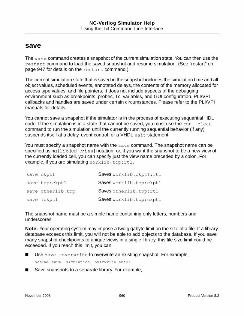
NC-Verilog Simulator HelpUsing the Tcl Command-Line Interface
save
The save command creates a snapshot of the current simulation state. You can then use therestart command to load the saved snapshot and resume simulation. (See “restart” onpage 947 for details on the restart command.)
The current simulation state that is saved in the snapshot includes the simulation time and allobject values, scheduled events, annotated delays, the contents of the memory allocated foraccess type values, and file pointers. It does not include aspects of the debuggingenvironment such as breakpoints, probes, Tcl variables, and GUI configuration. PLI/VPIcallbacks and handles are saved under certain circumstances. Please refer to the PLI/VPImanuals for details.
You cannot save a snapshot if the simulator is in the process of executing sequential HDLcode. If the simulation is in a state that cannot be saved, you must use the run -cleancommand to run the simulation until the currently running sequential behavior (if any)suspends itself at a delay, event control, or a VHDL wait statement.
You must specify a snapshot name with the save command. The snapshot name can bespecified using [lib.]cell[:view] notation, or, if you want the snapshot to be a new view ofthe currently loaded cell, you can specify just the view name preceded by a colon. Forexample, if you are simulating worklib.top:rtl,
The snapshot name must be a simple name containing only letters, numbers andunderscores.
Note: Your operating system may impose a two gigabyte limit on the size of a file. If a librarydatabase exceeds this limit, you will not be able to add objects to the database. If you savemany snapshot checkpoints to unique views in a single library, this file size limit could beexceeded. If you reach this limit, you can:
■ Use save -overwrite to overwrite an existing snapshot. For example,
ncsim> save -simulation -overwrite snap1
■ Save snapshots to a separate library. For example,
save ckpt1 Saves worklib.ckpt1:rtl
save top:ckpt1 Saves worklib.top:ckpt1
save otherlib.top Saves otherlib.top:rtl
save :ckpt1 Saves worklib.top:ckpt1
November 2008 960 Product Version 8.2

NC-Verilog Simulator HelpUsing the Tcl Command-Line Interface
% mkdir INCA_libs/snaplib
% ncsim -f ncsim.args
ncsim> run 1000 ns
ncsim> save -simulation snaplib.snap1
ncsim> run 1000 ns
ncsim> save -simulation snaplib.snap2
■ Remove snapshots using the ncrm utility. For example,
% ncrm -snapshot worklib.snap1
The state of the Tcl debug environment is not part of the simulation that is saved in asnapshot. To save the debug environment, you must issue a separate save -environmentcommand. This command creates a Tcl script that captures the current breakpoints,databases, probes, aliases, and predefined Tcl variable values. You can then restore theenvironment by executing this script with the Tcl source command, or you can use the-input option when you invoke the simulator.
The save -commands command is the same as save -environment.
For example:
ncsim> save :ckpt1
ncsim> save -environment ckpt1.tcl
ncsim> restart :ckpt1
ncsim> source ckpt1.tcl
(or: % ncsim -tcl cell:ckpt1 -input ckpt1.tcl)
These scripts are meant to be sourced into an empty environment (that is, an environmentwith no breakpoints, no probes, no databases). If you invoke the simulator, set somebreakpoints and probes, and then source a script that contains commands to set breakpointsand probes, the simulator will probably generate errors telling you that some commands inthe script could not be executed. These errors are due to name conflicts. For example, youmay have set a breakpoint that received the default name “1”, and the command in the scriptis trying to create a breakpoint with the same name. You can, of course, give your breakpointsunique names to avoid this problem. You can also edit the scripts to make them work the wayyou would like them to work.
See “Saving, Restarting, Resetting, and Reinvoking a Simulation” on page 486 for moreinformation.
November 2008 961 Product Version 8.2
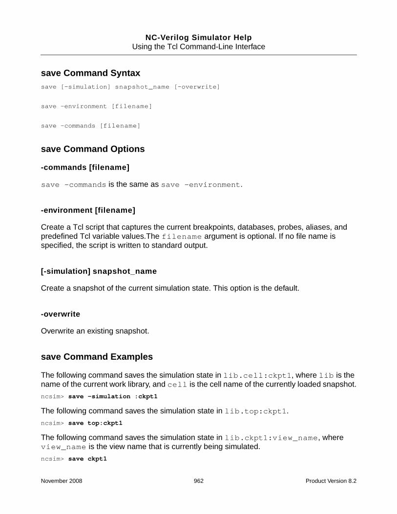
NC-Verilog Simulator HelpUsing the Tcl Command-Line Interface
save Command Syntaxsave [-simulation] snapshot_name [-overwrite]
save -environment [filename]
save -commands [filename]
save Command Options
-commands [filename]
save -commands is the same as save -environment.
-environment [filename]
Create a Tcl script that captures the current breakpoints, databases, probes, aliases, andpredefined Tcl variable values.The filename argument is optional. If no file name isspecified, the script is written to standard output.
[-simulation] snapshot_name
Create a snapshot of the current simulation state. This option is the default.
-overwrite
Overwrite an existing snapshot.
save Command Examples
The following command saves the simulation state in lib.cell:ckpt1, where lib is thename of the current work library, and cell is the cell name of the currently loaded snapshot.
ncsim> save -simulation :ckpt1
The following command saves the simulation state in lib.top:ckpt1.
ncsim> save top:ckpt1
The following command saves the simulation state in lib.ckpt1:view_name, whereview_name is the view name that is currently being simulated.
ncsim> save ckpt1
November 2008 962 Product Version 8.2

NC-Verilog Simulator HelpUsing the Tcl Command-Line Interface
The following example illustrates how to use the save, restart, and reset commands.
% ncsim -nocopyright -input run.vc hardrive
Loading snapshot worklib.hardrive:module .................... Done
ncsim> database -open waves -default -shm ;# Open default SHM;# dbase called waves.
Created default SHM database waves
ncsim> probe -create -all -database waves ;# Probe all signals;# in current scope.
Created probe 1
ncsim> stop -create -object clr ;# Create an object breakpoint and a time;# breakpoint at absolute time 200.
Created stop 1
ncsim> stop -create -time -absolute 200 ns
Created stop 2
ncsim> run
0 FS + 0 (stop 1: hardrive.clr = 1)
./hardrive.v:12 clr = 1;
ncsim> run
at time 50 clr =1 data= 0 q= x
at time 150 clr =1 data= 1 q= 0
200 NS + 0 (stop 2)
ncsim> save :ckpt1 ;# Save the simulation state at 200 ns.
Saved snapshot worklib.hardrive:ckpt1
ncsim> stop -create -time -relative 300 ns ;# Create a breakpoint to stop;# every 300 ns.
Created stop 3
ncsim> run
at time 250 clr =1 data= 2 q= 1
at time 350 clr =1 data= 3 q= 2
at time 450 clr =1 data= 4 q= 3
500 NS + 0 (stop 3)
ncsim> save :ckpt2 ;# Save another snapshot at time 500 ns.
Saved snapshot worklib.hardrive:ckpt2
ncsim> run
at time 550 clr =1 data= 5 q= 4
at time 650 clr =1 data= 6 q= 5
at time 750 clr =1 data= 7 q= 6
800 NS + 0 (stop 3)
November 2008 963 Product Version 8.2

NC-Verilog Simulator HelpUsing the Tcl Command-Line Interface
ncsim> restart :ckpt1 ;# Use the restart command to load;# worklib.hardrive.ckpt1.
Loaded snapshot worklib.hardrive:ckpt1
ncsim> time
200 NS ;# Simulation is at 200 ns. Two breakpoints are still set;# (the breakpoint set for absolute time 200 was deleted;# automatically when it triggered). The SHM database has;# been closed and all probes deleted.
ncsim> stop -show
1 Enabled Object hardrive.clr
3 Enabled Time 500 NS (every 300 NS)
ncsim> database -show
No databases are open
ncsim> run
at time 250 clr =1 data= 2 q= 1
at time 350 clr =1 data= 3 q= 2
at time 450 clr =1 data= 4 q= 3
500 NS + 0 (stop 3)
ncsim> reset ;# Use the reset command to reset the model;# to its original state at time zero.;# Notice that both breakpoints are still set.
Loaded snapshot worklib.hardrive:module
ncsim> time
0 FS
ncsim> stop -show
1 Enabled Object hardrive.clr
3 Enabled Time 200 NS (every 300 NS)
ncsim>
The following example illustrates how to use the save -environment command.
% ncsim -nocopyright -tcl hardrive
Loading snapshot worklib.hardrive:module .................... Done
;# Set a line breakpoint, an object breakpoint, and create a probe.;# The probe command creates a default SHM database.
ncsim> stop -create -line 32
Created stop 1
ncsim> stop -create -object hardrive.clk
Created stop 2
ncsim> probe -create -shm hardrive.data
Created default SHM database ncsim.shm
Created probe 1
ncsim> run
November 2008 964 Product Version 8.2

NC-Verilog Simulator HelpUsing the Tcl Command-Line Interface
0 FS + 0 (stop 2: hardrive.clk = 0)
./hardrive.v:13 clk = 0;
ncsim> run
50 NS + 0 (stop 2: hardrive.clk = 1)
./hardrive.v:16 always #50 clk = ~clk;
ncsim> save -environment env1.env ;# Save debug settings in a file;# called env1.env.
ncsim> more env1.env ;# The file env1.env contains;# commands to recreate debug settings.
set assert_report_level {note}
set assert_stop_level {error}
set autoscope {yes}
set display_unit {auto}
set tcl_prompt1 {puts -nonewline "ncsim> "}
set tcl_prompt2 {puts -nonewline "> "}
set time_unit {module}
set vlog_format {%h}
set assert_1164_warnings {yes}
stop -create -name 1 -line 32 hardrive
stop -create -name 2 -object hardrive.clk
database -open -shm -into ncsim.shm ncsim.shm -default
probe -create -name 1 -database ncsim.shm hardrive.data
scope -set hardrive
ncsim> exit ;# Exit and then reinvoke the simulator.
% ncsim -nocopyright -tcl hardrive
Loading snapshot worklib.hardrive:module .................... Done
ncsim> stop -show
No stops set
ncsim> source env1.env ;# Source the script env1.env.
ncsim>
;# Show the status of breakpoints, probes, and databases.
ncsim> stop -show
1 Enabled Line: ./hardrive.v:32 (scope: hardrive)
2 Enabled Object hardrive.clk
ncsim> probe -show
1 Enabled hardrive.data (database: ncsim.shm) -shm
ncsim> database -show
ncsim.shm Enabled (file: ncsim.shm) (SHM) (default)
November 2008 965 Product Version 8.2

NC-Verilog Simulator HelpUsing the Tcl Command-Line Interface
scope
The scope command lets you:
■ Set the current debug scope (-set)
■ Describe items declared within a scope (-describe)
■ Display the drivers of objects declared within a scope (-drivers)
■ Print the source code, or part of the source code, for a scope (-list)
■ Display scope information (-show)
See “Traversing the Model Hierarchy” on page 635 for more information on setting the debugscope.
scope Command Syntaxscope [-set] [-fullpath] [scope_name]
scope [-set]
-back
-derived
-forward
-running
-super
-up
scope
-aicms [-all] [-recurse] [scope_name]
-describe [-names] [-sort {name | kind | declaration}] [scope_name]
-disciplines [-all] [-recurse] [-sort {name | kind | declaration}] [scope]
-drivers [scope_name]
-history
-list [line | start_line end_line] [scope_name]
-sc_processes [-all] [-recurse] [-verbose] [scope_name]
-show
-tops
November 2008 966 Product Version 8.2

NC-Verilog Simulator HelpUsing the Tcl Command-Line Interface
scope Command Options
-aicms [-all] [-recurse] [scope_name]
Lists auto-inserted connect modules (AICMs) inserted within the specified scope, or withinthe current debug scope if no scope is specified.
The -recurse option descends recursively through the design hierarchy, starting with thespecified scope (or the current debug scope if no scope is specified), listing all AICMinstances.
The -all option lists the AICM instances in all top-level scopes. If used with -recurse, the-all option recursively lists all AICM instances in the entire design.
See the description of the scope command in Appendix B, “Tcl-Based Debugging” in theVirtuoso AMS Designer Simulator User Guide for more information.
-back
Changes the debug scope back to the previous debug scope.
You can use the scope -history command to get a list of scopes in the order in which theywere entered. In the scope history list, the current debug scope is marked with an asterisk(*). A scope -back command will set the current debug scope to the scope that is shownimmediately before the current debug scope.
Use the scope -forward command to change the debug scope to the scope recorded onthe history list just after the current scope.
A scope -back command does not add a new entry to the scope history list.
During the course of a simulation run, dynamic scopes (class instances and methods) maybecome invalid because the dynamic object no longer exists. Invalid scopes are removedfrom the history list, and a scope -back command will set the scope to the first valid scopeprior to the invalid scope.
-derived
Sets the debug scope to be the derived class of the current class instance scope.
SystemVerilog allows classes to extend classes. In a complex design using extensiveobject-oriented techniques, this class inheritance can sometimes make it difficult to interpretdata when debugging class objects.
November 2008 967 Product Version 8.2

NC-Verilog Simulator HelpUsing the Tcl Command-Line Interface
Use the scope -derived command to set the current debug scope to the derived class ofthe current class instance scope. The scope -super command lets you set the currentdebug scope to the super or base class of the current class instance scope.
-describe [-names] [-sort {name | kind | declaration}] [scope_name]
Describes all objects declared within the specified scope. If no scope is specified, objects inthe current debug scope are described.
The kind of access that has been enabled for simulation objects is shown in the output. Forexample, the string (-WC) is included in the output for objects that have read access but nowrite or connectivity access. See “Enabling Read, Write, or Connectivity Access to SimulationObjects” on page 371 for details on specifying access to simulation objects.
For objects without read access, the output of scope -describe does not include theobject’s value.
Use the -names option if you want to display only the names of each declared item in thescope.
Use the -sort option if you want to specify a sort order. There are three possible argumentsto the -sort option:
■ name—Sort alphabetically by name.
■ kind—Sort by declaration type (reg, wire, instance, process, and so on).
■ declaration—Sort by the order in which objects are declared in the source code.
-disciplines [-all] [-recurse] [-sort {name | kind | declaration}] [scope_name]
Lists all resolved net disciplines within the given scope, or within the current debug scope ifno scope is given.
The -recurse option descends recursively through the design hierarchy, starting with thespecified scope (or the current debug scope if no scope is specified), listing all resolved netdisciplines.
The -all option lists all resolved net disciplines in all top-level scopes. If used with-recurse, it recursively lists all resolved net disciplines in the entire design.
The -sort option can be used to sort the nets alphabetically by net name, by discipline(electrical, logic, and so on), or by the order they are declared in the source code. The defaultis to sort by discipline.
November 2008 968 Product Version 8.2

NC-Verilog Simulator HelpUsing the Tcl Command-Line Interface
See the section “Thread Manager in Tcl Command Mode” in the chapter “DebuggingSystemC Models” in the NC-SC Simulator User Guide for more information.
-drivers [scope_name]
Shows the drivers of each object declared within the specified scope. If no scope is specified,the drivers of objects in the current debug scope are displayed.
The output of scope -drivers includes only the objects that have read access. However,even if an object has read access, its drivers may have been collapsed, combined, oroptimized away, and the output of the command might indicate that the object has no drivers.See “Enabling Read, Write, or Connectivity Access to Simulation Objects” on page 371 fordetails on specifying access to simulation objects.
-forward
Changes the debug scope to the scope recorded on the scope history list just after the currentscope.
You can use the scope -history command to get a list of scopes in the order in which theywere entered. In the scope history list, the current debug scope is marked with an asterisk(*). A scope -forward command will set the current debug scope to the scope that isshown immediately after the current debug scope.
Use the scope -back command to change the debug scope back to the previous debugscope.
A scope -forward command does not add a new entry to the scope history list.
During the course of a simulation run, dynamic scopes (class instances and methods) maybecome invalid because the dynamic object no longer exists. Invalid scopes are removedfrom the history list, and a scope -forward command will set the scope to the first validscope after the invalid scope.
-fullpath
Treats the specified path as the full hierarchical path to the scope.
-history
Lists all scopes in the order in which they were visited.
November 2008 969 Product Version 8.2

NC-Verilog Simulator HelpUsing the Tcl Command-Line Interface
As you change scopes during a debug session, each scope that you visit is captured in a list.Use the scope -history command to display this list.
In the scope history list, the current debug scope is marked with an asterisk ( * ). You can usethe scope -back command to change the debug scope to the scope that is shownimmediately before the current debug scope. Use the scope -forward command tochange the debug scope to the scope that is shown immediately after the current debugscope.
During the course of a simulation run, dynamic scopes (class instances and methods) maybecome invalid because the dynamic object no longer exists. Scopes that are no longer validare removed from the scope history list.
-list [line | start_line end_line] [scope_name]
Prints lines of source code for the specified scope, or for the current debug scope if no scopeis specified.
You can follow the -list modifier with:
■ No range of lines to print all lines for the scope.
■ One line number to display that line of source text.
■ Two line numbers to display the text between those two line numbers. You can use a dash( - ) for either the start_line or the end_line.
-running
Sets the debug scope to the currently running process.
-set [scope_name]
Sets the current debug scope to the specified scope. If no scope or other option is given, thename of the current scope is printed.
The -set modifier is optional.
-sc_processes [-all] [-recurse] [-verbose] [scope_name]
Lists SystemC processes in the specified scope, or in the current debug scope if no scope isspecified.
November 2008 970 Product Version 8.2

NC-Verilog Simulator HelpUsing the Tcl Command-Line Interface
The -verbose option reports all properties of the processes.
The -recurse option descends recursively through the design hierarchy, starting with thespecified scope (or the current debug scope if no scope is specified), and listing all of theprocesses.
The -all option lists the processes in all top-level scopes. If used with -recurse, itrecursively lists all SystemC processes in the entire design.
See the section “Thread Manager in Tcl Command Mode” in the chapter “DebuggingSystemC Models” in the NC-SC Simulator User Guide for more information.
-show
Shows scope information, including the current debug scope, instances within the debugscope, and top-level modules in the currently loaded model.
If the current debug scope is a subprogram on a VHDL call stack, the output of the scope-show command or of the scope command (with no options or arguments) shows thecurrent scope as :process_scope[nest_level]. For example, if the current scope is asubprogram called function1, which is at nest-level 1, the output of these commandsshows the current scope as:
:process1[1]
-super
Sets the debug scope to be the super or base class of the current class instance scope.
SystemVerilog allows classes to extend classes. In a complex design using extensiveobject-oriented techniques, this class inheritance can sometimes make it difficult to interpretdata when debugging class objects.
Use the scope -super command to set the current debug scope to the super or base classof the current class instance scope. The scope -derived command lets you set the currentdebug scope to the derived class of the current class instance scope.
-tops
Displays a list of the names of the top-level modules in the design, including VHDL packages.For example, the following command shows the output for a VHDL model with two packagesand the one top-level scope (:):
ncsim> scope -tops
November 2008 971 Product Version 8.2

NC-Verilog Simulator HelpUsing the Tcl Command-Line Interface
@std.STANDARD @ieee.std_logic_1164 :
The following command shows the output for a Verilog model with two top-level modules:
ncsim> scope -tops
top initialize
The -tops modifier is useful when you want to execute a Tcl command that takes a list ofscopes as arguments, and you want to execute the command on all top-level scopes. Forexample, you can use the following command to probe all objects in the entire design:
ncsim> probe -shm -all [scope -tops] -depth all
-up
Sets the debug scope to one level up the hierarchy from the current scope.
scope Command Examples
The following example prints the name of the current scope.
ncsim> scope
The following example sets the debug scope to scope u1. The -set modifier is not required.
ncsim> scope -set u1
The following example moves the debug scope up one level in the hierarchy.
ncsim> scope -up
In the following VHDL example, the stack -show command displays the current call stack.The process (process1) is displayed as nest-level 0, the base of the stack. The subprogramfunction1 is :process1[1], and the subprogram function2 is :process1[2].
■ The first scope command displays the current debug scope.
■ The second scope command sets the debug scope to :process1.
■ The third scope command sets the debug scope to the subprogram :process1[2](that is, to function2).
ncsim> stop -subprogram function1
Created stop 1
ncsim> run
0 FS + 0 (stop 1: Subprogram :function1)
./test.vhd:36 tmp4_local := function2 (tmp4);
November 2008 972 Product Version 8.2

NC-Verilog Simulator HelpUsing the Tcl Command-Line Interface
ncsim> run -step
./test.vhd:29 tmp5_local := tmp5 + 1;
ncsim> stack -show ;# Display the current call stack
2: Scope: :process1[2] Subprogram:@work.e(a):function2
File: /usr1/belanger/inca/vhdl/subprogram_debug/scope_test/test.vhd
Line: 29
1: Scope: :process1[1] Subprogram:@work.e(a):function1
File: /usr1/belanger/inca/vhdl/subprogram_debug/scope_test/test.vhd
Line: 36
0: Scope: :process1
File: /usr1/belanger/inca/vhdl/subprogram_debug/scope_test/test.vhd
Line: 52
ncsim> scope -show ;# Display the current debug scope
Directory of scopes at current scope level:
Current scope is (:process1[2])
Highest level modules:
Top level VHDL design unit:
entity (e:a)
VHDL Package:
STANDARD
ATTRIBUTES
std_logic_1164
TEXTIO
ncsim> scope -set :process1 ;# Set scope to :process1
ncsim> scope -set :process1[2] ;# Set scope to :process1[2];# i.e., function2
In the previous example, you can also use the stack command to set the debug scope to:process1[2] (that is, function2).
ncsim> scope -set :process1
ncsim> stack -set 2
The following SystemVerilog example is used to illustrate the scope -super and scope-derived commands. This example also illustrates the -back, -forward, and -historyoptions, which are language-independent.
package pack;
class A;
int aVal;
endclass
November 2008 973 Product Version 8.2

NC-Verilog Simulator HelpUsing the Tcl Command-Line Interface
endpackage
module top;
class B extends pack::A;
task bTask();
int value;
$display( value );
endtask
endclass
B b = new;
endmodule
ncsim> run 1 ns
Ran until 1 NS + 0
ncsim> scope
top
ncsim> ;# Scope into class object
ncsim> scope top.b
ncsim> ;# Scope into the task
ncsim> scope bTask
ncsim> scope
top.B@1_1.bTask
ncsim> ;# Attempt to scope to base class
ncsim> scope -super
ncsim: *E,SCPSP2: Current debug scope is not a class instance : top.B::bTask.
ncsim> ;# scope one level up
ncsim> scope -up
ncsim> scope
top.B@1_1
ncsim> ;# Scope to base class
ncsim> scope -super
ncsim> scope
pack::A@1_1
ncsim> ;# Scope back to the derived class
ncsim> scope -derived
ncsim> scope
top.B@1_1
November 2008 974 Product Version 8.2

NC-Verilog Simulator HelpUsing the Tcl Command-Line Interface
ncsim> ;# View list of scopes in order in which they were visited
ncsim> scope -history
1) top
2) top.B@1_1
3) bTask
4) top.B@1_1
5) pack::A@1_1
* 6) top.B@1_1
Where: * => current debug scope
ncsim> ;# Scope back to previous scope in the list
ncsim> scope -back
ncsim> scope
pack::A@1_1
ncsim> scope -back
ncsim> scope
top.B@1_1
ncsim> ;# Scope forward
ncsim> scope -forward
ncsim> scope
pack::A@1_1
ncsim>
The following command displays a list and a description of all objects declared in the currentdebug scope (a Verilog module).
ncsim> scope -describe
clr..............variable logic = 1’hx
clk..............variable logic = 1’hx
data.............variable logic [3:0] = 4’hx
q................net logic [3:0]
q[3] (wire/tri) = StX
q[2] (wire/tri) = StX
q[1] (wire/tri) = StX
q[0] (wire/tri) = StX
end_first_pass...named event
h1...............instance of module hardreg
The following command displays a list and a description of all objects declared in the currentdebug scope (a VHDL architecture).
ncsim> scope -describe
top..............component instantiation
load_nickels.....process statement
November 2008 975 Product Version 8.2

NC-Verilog Simulator HelpUsing the Tcl Command-Line Interface
load_dimes.......process statement
load_cans........process statement
load_action......process statement
gen_clk..........process statement
gen_reset........process statement
gen_nickels......process statement
gen_dimes........process statement
gen_quarters.....process statement
$PROCESS_000.....process statement
$PROCESS_001.....process statement
stoppit..........signal : BOOLEAN = TRUE
t_NICKEL_OUT.....signal : std_logic = ’0’
t_EMPTY..........signal : std_logic = ’1’
t_EXACT_CHANGE...signal : std_logic = ’0’
t_TWO_DIME_OUT...signal : std_logic = ’Z’
...
...
t_NICKELS........signal : std_logic_vector(7 downto 0) = "11111111"
t_RESET..........signal : std_logic = ’0’
The following command lists the names of all objects declared in the current debug scope.No description is included.
ncsim> scope -describe -names
clr clk data q end_first_pass h1
The following example displays a list and a description of all objects declared in the currentdebug scope. Objects are listed in alphabetical order.
ncsim> scope -describe -sort name
The following command displays a list and a description of all objects declared in the currentdebug scope. Objects are sorted by type of declaration.
ncsim> scope -describe -sort kind
The following command displays a list and a description of all objects declared in scope u1.Objects are listed in the order in which they were declared in the source code.
ncsim> scope -describe -sort declaration u1
The following example shows a Verilog module that contains nested generate-loops. Eachfor-generate instance is a scope. You can set the debug scope to a for-generate instance ordescribe a for-generate instance with scope -describe. See “Generate Constructs” onpage 99 for details on generated instantiations.
module top;
November 2008 976 Product Version 8.2

NC-Verilog Simulator HelpUsing the Tcl Command-Line Interface
generate
genvar i;
for (i = 5; i < 9; i = i + 1) begin : g1
genvar j;
for (j = i; j >= 1; j = j - 1) begin : g2
reg [0:i] r;
initial begin
r = i;
$display("%b", r);
end
end
end
endgenerate
endmodule
ncsim> scope -describe top
i..........genvar
g1.........for-generate statement [5 to 8]
ncsim> scope g1[6]
ncsim> scope -describe
i..........generate parameter = 6
j..........genvar
g2.........for-generate statement [6 to 1, step -1]
ncsim> scope -describe g2[5]
j..........generate parameter = 5
r..........variable logic [0:6] = 7’hxx
The following command shows the drivers for all objects declared in scope h1.
ncsim> scope -drivers h1
clk........input net (wire/tri) logic = St1
St1 <- (hardrive.h1) input port 2, bit 0 (./hardrive.v:8)
clrb.......input net (wire/tri) logic = St1
St1 <- (hardrive.h1) input port 3, bit 0 (./hardrive.v:8)
d..........input net logic [3:0]
d[3] (wire/tri) = St1
St1 <- (hardrive.h1) input port 1, bit 3 (./hardrive.v:8)
d[2] (wire/tri) = St0
St0 <- (hardrive.h1) input port 1, bit 2 (./hardrive.v:8)
d[1] (wire/tri) = St0
St0 <- (hardrive.h1) input port 1, bit 1 (./hardrive.v:8)
d[0] (wire/tri) = St1
November 2008 977 Product Version 8.2

NC-Verilog Simulator HelpUsing the Tcl Command-Line Interface
St1 <- (hardrive.h1) input port 1, bit 0 (./hardrive.v:8)
q..........output net logic [3:0]
q[3] (wire/tri) = St1
St1 <- (hardrive.h1.f4) nd7 (q, e, qb)
q[2] (wire/tri) = St0
St0 <- (hardrive.h1.f3) nd7 (q, e, qb)
q[1] (wire/tri) = St0
St0 <- (hardrive.h1.f2) nd7 (q, e, qb)
q[0] (wire/tri) = St0
St0 <- (hardrive.h1.f1) nd7 (q, e, qb)
The following example lists the source for the current debug scope.
ncsim> scope -list
The following example lists the source for scope u1.
ncsim> scope -list u1
The following example displays line 12 of the source for the current debug scope.
ncsim> scope -list 12
The following example lists lines 10 through 15 of the source for the current debug scope.
ncsim> scope -list 10 15
The following command lists lines from the top of the module through line 10 of the source forthe current debug scope.
ncsim> scope -list - 10
The following command lists lines of source for the current debug scope, beginning with line30.
ncsim> scope -list 30 -
The following command shows the output of the scope -describe command when you runin regression mode (no read, write, or connectivity access to simulation objects) and someobjects do not have read or write access.
ncsim> scope -describe h1
clk........input net logic (-RWC)
clrb.......input net logic (-RWC)
d..........input net logic [3:0]
d[3] (-RWC)
d[2] (-RWC)
d[1] (-RWC)
d[0] (-RWC)
q..........output net logic [3:0]
November 2008 978 Product Version 8.2

NC-Verilog Simulator HelpUsing the Tcl Command-Line Interface
q[3] (-RWC)
q[2] (-RWC)
q[1] (-RWC)
q[0] (-RWC)
f1.........instance of module flop
f2.........instance of module flop
f3.........instance of module flop
f4.........instance of module flop
November 2008 979 Product Version 8.2

NC-Verilog Simulator HelpUsing the Tcl Command-Line Interface
simvision
The simvision command lets you:
■ Invoke SimVision and connect to the current simulation (simvision command with nooptions).
■ Send a script containing SimVision commands to SimVision (simvision -input). Ifyou are not currently in SimVision, this command will invoke the GUI and execute thecommands in the script.
■ Send a SimVision command (or multiple commands) to SimVision (simvision-submit). If you are not currently in SimVision, this command will invoke the GUI andexecute the command(s).
See the SimVision Command Language Reference for details on SimVision commands.
simvision Command Syntaxsimvision
-input script_file
[-submit] simvision_command
simvision Command Options
-input script_file
Execute the SimVision commands in the specified script.
If you are not currently in the SimVision environment, a simvision -input commandinvokes SimVision and then executes the commands in the script.
If you are in the SimVision environment, entering a simvision -input command at thencsim> prompt in the Console window is the same as using the File – Source CommandScript command to source a script.
[-submit] simvision_command
Execute the specified SimVision command.
If you are not currently in the SimVision environment, a simvision -submit commandinvokes SimVision and then executes the command.
November 2008 980 Product Version 8.2

NC-Verilog Simulator HelpUsing the Tcl Command-Line Interface
You can specify multiple commands by enclosing the commands in curly braces.
The -submit option is not required.
simvision Command Examples
The following command invokes SimVision and connects to the current simulation.
ncsim> simvision
The following command executes the SimVision commands in the file called simvision.sv.
ncsim> simvision -input simvision.sv
The following command executes a SimVision command to create a new waveform window.The -submit option can be omitted.
ncsim> simvision -submit waveform new
The following command executes two SimVision waveform commands. The first commandcreates a new waveform window called MyWaves. The second command adds the signalsboard.count and board.af to the new waveform window.
ncsim> simvision {
> waveform new -name “MyWaves”
> waveform add -signals {board.count board.af}
> }
November 2008 981 Product Version 8.2

NC-Verilog Simulator HelpUsing the Tcl Command-Line Interface
sn
The sn command is used to pass commands from the simulator to Specman.
sn Command Syntaxsn [specman_command[\; specman_command ...]]
The sn command passes control from ncsim to Specman.
ncsim> sn
You can pass a command to Specman by including the Specman command. For example:
ncsim> sn load test_1
You can issue multiple sn commands on the same command line by separating thecommands with a semicolon. For example:
ncsim> sn load test_1; sn test
is the same as:
ncsim> sn load test_1
ncsim> sn test
You can also issue multiple commands to Specman with one sn command. In this case, theSpecman commands are separated with a semicolon, and the semicolon must be escaped.For example:
ncsim> sn config gen -seed=125645\; test
See “Simulator Related Commands” in the Specman Command Reference for details onother commands used when running Specman with the simulator.
November 2008 982 Product Version 8.2

NC-Verilog Simulator HelpUsing the Tcl Command-Line Interface
source
The source command lets you execute Tcl commands contained in a script file.
When ncsim has processed all the commands in the source file, or if you interrupt processingwith CTRL/C, input reverts back to the terminal.
See “Providing Interactive Commands from a File” on page 494 for more information.
You can also execute Tcl commands in a script file by using the input command or by usingthe -input command-line option when you invoke the simulator. However, the behavior ofthe source command differs from the behavior of the input command or the -input optionin the following ways:
■ With the source command, execution of the commands in the script stops if a commandgenerates an error. With the input command, the contents of the file are read in placeof standard input at the next Tcl prompt, as if you had typed the commands at thecommand-line prompt. This means that errors do not stop the execution of commands inthe script.
■ The input command echoes commands to the screen as they are executed, along withany command output or error messages.The source command, on the other hand,displays the output of only the last command in the file. Output from the model (forexample, the output of $display, $monitor, or $strobe tasks, or the output of stoppoints) is printed to the screen.
See “input” on page 870 for details on the input command. See -input for details on the-input option.
source Command Syntaxsource script_file
Note: You can specify only one script_file.
source Command Options
None.
November 2008 983 Product Version 8.2

NC-Verilog Simulator HelpUsing the Tcl Command-Line Interface
source Command Examples
The following example uses the command file named set_break.inp to show how thesource command displays output from only the last command in the file. Theset_break.inp file contains the following commands:
stop -create -line 27
run
value data
run 50
value data
run 50
value data
run
%> ncsim -nocopyright -tcl hardrive
ncsim>
ncsim> source set_break.inp
0 FS + 0 (stop 1) 27: repeat (2) ;# Output of the stop command
at time 50 clr =1 data= 0 q= x ;# Output of $strobe task in model
at time 150 clr =1 data= 1 q= 0
at time 250 clr =1 data= 2 q= 1
...
at time 3150 clr =0 data=14 q= 0
at time 3250 clr =0 data=15 q= 0
at time 3350 clr =0 data=15 q= 0
Simulation complete via $finish(1) at time 3400 NS + 0 ;# Output of last command;# (run)
ncsim> ;# Control reverts to the terminal after the simulator;# executes the last command.
November 2008 984 Product Version 8.2

NC-Verilog Simulator HelpUsing the Tcl Command-Line Interface
stack
The stack command helps you to debug Verilog descriptions that involve multiple task andfunction calls, and VHDL descriptions that involve multiple subprogram calls. Using thiscommand, you can:
■ View the current call stack (-show).
■ For VHDL, set the current stack frame (-set) so that you can describe objects that arelocal to a subprogram, view object values, and set object values.
Note: The stack -set command is not supported for Verilog call stacks.
stack Command Syntaxstack
[-set] [{stack_level_spec | -down | -up}]
[-show] [-levels stack_level_count]
stack Command Options
-set [ { stack_level_spec | -down | -up } ]
The stack -set command with no argument displays the call stack for the current debugscope. This is the same as stack -show.
If you specify an argument, the argument can be:
■ stack_level_spec
Sets the current debug stack to the specified stack level. This applies only to the currentdebug scope, which must be a process scope.
The stack_level_spec argument specifies the call stack depth. This can be:
❑ An absolute value, which sets the context to the specified stack frame. For example:
stack -set 2
❑ A relative value, which moves the stack context up or down relative to the currentstack frame. For example:
stack -set +2
stack -set -1
November 2008 985 Product Version 8.2

NC-Verilog Simulator HelpUsing the Tcl Command-Line Interface
■ -down
Sets the debug stack one level down from the current level.
stack -set -down is the same as stack -set -1.
■ -up
Sets the debug stack one level up from the current level.
stack -set -up is the same as stack -set +1.
-show [-levels stack_level_count]
Displays the call stack for the current debug scope.
By default, a stack -show command displays the call stack used by the process to reachthe current execution point. It stops at the construct that started the process (for example, aVerilog initial block or fork process, or a VHDL process). Include the -levels optionto limit the depth of the call stack that is displayed.
Note: For Verilog, the stack -show command works only for the currently executingprocess, and only if the debug scope is set to the scope (usually a task or function) in whichit is executing.
stack Command Examples
VHDL Example
The following VHDL source code is used for the example in this section:
LIBRARY IEEE;
USE IEEE.Std_logic_1164.all;
USE STD.TEXTIO.ALL;
entity e is
end;
architecture a of e is
procedure procedure1 (tmp1 : INOUT bit) is
begin
tmp1 := not tmp1;
return;
end procedure1;
November 2008 986 Product Version 8.2

NC-Verilog Simulator HelpUsing the Tcl Command-Line Interface
procedure procedure2 (tmp2 : INOUT bit) is
begin
if (tmp2 = ’0’)
then
tmp2 := not tmp2;
return;
else
procedure1(tmp2);
end if;
end procedure2;
function function2 (tmp5 : IN integer) return integer is
variable tmp5_local : integer := tmp5;
begin
tmp5_local := tmp5 + 1;
return tmp5_local;
end function2;
function function1 (tmp4 : IN integer) return integer is
variable tmp4_local : integer := tmp4;
begin
tmp4_local := function2 (tmp4);
return tmp4_local;
end function1;
begin
process1 : process
variable var1, var2, var3 : bit := ’0’;
variable var4, var5, var6, var7, var8 : integer := 0;
begin
var1 := ’1’;
procedure1 (var1);
var2 := ’1’;
procedure2 (var2);
procedure2 (var3);
var5 := 1;
var6 := function1 (var5);
var7 := function2 (var6);
wait;
end process;
end;
November 2008 987 Product Version 8.2

NC-Verilog Simulator HelpUsing the Tcl Command-Line Interface
In the following example, the stack -show command displays the current call stack. Theprocess (process1) is displayed as nest-level 0, the base of the stack.
After setting the scope to process1, a stack -set command sets the current debug scopeto nest-level 1 (function1). The stack -set -up command sets the debug scope tonest-level 2 (function2).
ncsim> stop -subprogram function1
Created stop 1
ncsim> run
0 FS + 0 (stop 1: Subprogram :function1)
./test.vhd:36 tmp4_local := function2 (tmp4);
ncsim> run -step
./test.vhd:29 tmp5_local := tmp5 + 1;
ncsim>
ncsim> stack -show ;# Display the current call stack
2: Scope: :process1[2] Subprogram:@work.e(a):function2
File: ./test.vhd
Line: 29
1: Scope: :process1[1] Subprogram:@work.e(a):function1
File: ./test.vhd
Line: 36
0: Scope: :process1
File: ./test.vhd
Line: 52
ncsim> stack -show -levels 2 ;# Display only two levels
2: Scope: :process1[2] Subprogram:@work.e(a):function2
File: ./test.vhd
Line: 29
1: Scope: :process1[1] Subprogram:@work.e(a):function1
File: ./test.vhd
Line: 36
ncsim>
ncsim> scope -show ;# Display the current scope
Directory of scopes at current scope level:
Current scope is (:process1[2])
Highest level modules:
Top level VHDL design unit:
November 2008 988 Product Version 8.2

NC-Verilog Simulator HelpUsing the Tcl Command-Line Interface
entity (e:a)
VHDL Package:
STANDARD
ATTRIBUTES
std_logic_1164
TEXTIO
ncsim> scope -set :process1 ;# Set scope to process1
ncsim> stack -set 1 ;# Set scope to :process1[1];#(i.e., function1)
ncsim> scope -show
Directory of scopes at current scope level:
Current scope is (:process1[1])
...
...
ncsim> stack -show ;# Show stack for function1
1: Scope: :process1[1] Subprogram:@worklib.e(a):function1
File: ./test.vhd
Line: 36
0: Scope: :process1
File: ./test.vhd
Line: 52
ncsim> stack -set -up ;# Set scope up one level, to :process1[2];# This is the same as stack -set +1
ncsim> scope -show
Directory of scopes at current scope level:
Current scope is (:process1[2])
...
...
ncsim> value tmp5 ;# Display the value of :process1[2]:tmp5
1
ncsim> value :process1[1]:tmp4 ;# Display the value of :process1[1]:tmp4
1
November 2008 989 Product Version 8.2

NC-Verilog Simulator HelpUsing the Tcl Command-Line Interface
Verilog Example
The following Verilog source code is used for the example in this section:
module top;
task error;
begin
$display("Error at");
$stop;
end
endtask
task t;
input integer i;
if (i == 0)
error;
endtask
initial
begin
t(1);
t(0);
end
endmodule
In the following example, the stack -show command displays the current call stack. Theinitial block, the base of the stack, is displayed as nest-level 2.
ncsim> run
Error at
Simulation stopped via $stop(1) at time 0 FS + 0
./test.v:7 $stop;
ncsim> stack -show
0: task top.error at ./test.v:7
1: task top.t at ./test.v:14
2: initial block in top at ./test.v:20
ncsim>
ncsim> stack -show -levels 2
0: task top.error at ./test.v:7
1: task top.t at ./test.v:14
ncsim>
November 2008 990 Product Version 8.2

NC-Verilog Simulator HelpUsing the Tcl Command-Line Interface
ncsim> scope -show
Directory of scopes at current scope level:
Current scope is (top.error)
Highest level modules:
top
ncsim> scope top.t ;# Set scope to top.t
ncsim> stack -show ;# stack -show will not work. Works only for the;# currently executing process.
ncsim: *E,STKRVL: Command works only in the running scope in verilog.
ncsim> scope -set top
ncsim> stack -set 1 ;# The stack -set command is not implemented for Verilog
ncsim: *E,NSTKVL: Command works only for vhdl subprogram.
Cadence has also implemented a $stacktrace system task. You can use this task to printthe call stack as part of your own error message output from Verilog.
The $stacktrace task prints the same stack trace information that the Tcl stack commandwould print if the command were executed from the point of the system task in the Verilogcode. For example:
module top;
task error;
begin
$display("Error at");
$stacktrace;
end
endtask
task t;
input integer i;
if (i == 0)
error;
endtask
initial
begin
t(1);
t(0);
end
endmodule
November 2008 991 Product Version 8.2

NC-Verilog Simulator HelpUsing the Tcl Command-Line Interface
% ncvlog -nocopyright test.v
% ncelab -nocopyright worklib.top
% ncsim -nocopyright worklib.top
ncsim> run
Error at
Verilog Stack Trace:
0: task top.error at ./test.v:6
1: task top.t at ./test.v:13
2: initial block in top at ./test.v:19
ncsim: *W,RNQUIE: Simulation is complete.
ncsim>
November 2008 992 Product Version 8.2

NC-Verilog Simulator HelpUsing the Tcl Command-Line Interface
status
The status command displays memory and CPU usage statistics and shows the currentsimulation time.
status Command Syntaxstatus
status Command Options
None.
status Command Examples
The following example shows the type of statistics displayed by the status command.
ncsim> status
Memory Usage - text: 3656824, static: 561600, dynamic: 835136, total: 5053560
CPU Usage - 12.21 seconds (user = 8)
Simulation Time - 19721 US + 0
November 2008 993 Product Version 8.2

NC-Verilog Simulator HelpUsing the Tcl Command-Line Interface
stop
The stop command creates or operates on a breakpoint. You can:
■ Create various kinds of breakpoints by using the -create modifier followed by anoption that specifies the breakpoint type. See “Creating a Breakpoint” on page 996.
■ Delete a breakpoint using the -delete modifier. See “Deleting a Breakpoint” onpage 1007.
■ Disable a breakpoint using the -disable modifier. See “Disabling a Breakpoint” onpage 1007.
■ Enable a previously disabled breakpoint using the -enable modifier. See “Enabling aBreakpoint” on page 1007.
■ Display information on breakpoints using the -show modifier. See “DisplayingInformation about Breakpoints” on page 1007.
stop Command Syntaxstop
-create
-assert
[{-all | -depth {levels | all | to_cells}}] [scope_name]
-condition {tcl_expression}
-delta delta_cycle_number [-relative | -absolute]
[-start delta_cycle_number]
[-modulo delta_cycle_number]
[-timestep]
-iso_rule rule_name [rule_name ...] [-iso_enable | -iso_disable]
-line line_number [scope_name]
[-all]
[-file filename]
[-unit unit_name]
-object object_names
November 2008 994 Product Version 8.2

NC-Verilog Simulator HelpUsing the Tcl Command-Line Interface
-pdname power_domain_name[power_domain_name ...]
[-isolation [-iso_disable | -iso_enable]]
[-pd_off]
[-pd_on]
[-pd_trans]
[-retention [-sr_restore | -sr_save]]
-process process_name
-pwr_mode_transition mode_transition_name [mode_transition_name ...]
-randomize [-always] [object_name]
-sr_rule rule_name [rule_name ...] [-sr_save | -sr_restore]
-subprogram subprogram_name
-time time_spec [-relative | -absolute [-delbreak 0]]
[-start time_spec]
[-modulo time_spec]
[-continue]
[-delbreak count]
[-execute command [-noexecout]]
[-if {tcl_expression}]
[-name break_name]
[-silent]
[-skip count]
-delete {break_name | pattern} ...
-disable {break_name | pattern} ...
-enable {break_name | pattern} ...
-show [{break_name | pattern} ...]
The argument to -delete, -disable, -enable, or -show can be:
■ A break name
■ A list of break names
November 2008 995 Product Version 8.2

NC-Verilog Simulator HelpUsing the Tcl Command-Line Interface
■ A pattern
❑ The asterisk ( * ) matches any number of characters
❑ The question mark ( ? ) matches any one character
❑ [characters] matches any one of the characters
■ Any combination of literal break names and patterns
stop Command Options
The stop command has five modifiers:
■ -create—Lets you create various types of breakpoints
■ -delete—Lets you delete a breakpoint
■ -disable—Lets you disable a breakpoint
■ -enable—Lets you enable a previously disabled breakpoint
■ -show—Lets you display information on breakpoints
Creating a Breakpoint
-create
Creates a breakpoint. This modifier must be followed by an option that specifies thebreakpoint type:
■ -assert
■ -condition
■ -delta
■ -iso_rule
■ -line
■ -object
■ -pdname
■ -process
■ -pwr_mode_transition
November 2008 996 Product Version 8.2

NC-Verilog Simulator HelpUsing the Tcl Command-Line Interface
■ -randomize
■ -sr_rule
■ -subprogram
■ -time
-assert [ {-all | -depth {levels | all | to_cells} } ] [scope_name]
Stop at failures for assertions.
The -assert option lets you define a single breakpoint that is shared by multiple assertionsin the design. You can:
■ Stop at failures for all assertions in the design hierarchy by using the -all option.
ncsim> stop -assert -all
■ Stop at failures for all assertions in a specified scope (or the current debug scope if noscope is specified).
ncsim> stop -assert
ncsim> stop -assert top
ncsim> stop -assert top.u1
■ Specify how many scope levels to descend when searching for assertions to stop byusing the -depth option. The argument to -depth can be:
❑ levels
Descend the specified number of scopes. For example, -depth 1 means includeonly the given scope, -depth 2 means include the given scope and its subscopes,and so on. The default is 1.
ncsim> stop -assert -depth 3
ncsim> stop -assert top.u1 -depth 2
❑ all
Include all scopes in the hierarchy below the given scope.
ncsim> stop -assert top.u1 -depth all
❑ to_cells
Include all scopes in the hierarchy below the specified scope(s), but stop at cells(Verilog modules with `celldefine or VITAL entities with VITAL Level0 attribute).
By using the -assert option, you can avoid having to define a whole set of breakpoints onthe assertions using separate stop -object commands. The -assert option can also be
November 2008 997 Product Version 8.2

NC-Verilog Simulator HelpUsing the Tcl Command-Line Interface
used with other stop command options, such as -execute and -continue. For example,the following command sets one breakpoint on all assertions in the design hierarchy with acommon script to execute when the breakpoint triggers.
ncsim> stop -assert -all -execute stopscript.tcl
-condition {tcl_expression}
Sets a breakpoint that triggers when any object referenced in the tcl_expressionchanges value (wires, signals, registers, and variables) or is written to (memories) AND theexpression evaluates to true (non-zero, non-x, non-z).
The simulator does not support stop points on individual bits of registers. If a bit-select of aregister appears in the expression, the simulator stops and evaluates the expression whenany bit of that register changes value. The same holds true for compressed wires.
See “Tcl Expressions as Arguments” on page 1026 for details on the format of conditionalexpressions.
Objects included in a -condition expression must have read access. An error is printed ifthe object does not have read access. See “Enabling Read, Write, or Connectivity Access toSimulation Objects” on page 371.
See “Condition Breakpoints” on page 1017 for examples of setting condition breakpoints.
-continue
Resumes the simulation after executing the breakpoint. The simulator will not go intointeractive mode.
-delbreak count
Deletes the breakpoint after it has triggered count number of times.
By default, an absolute time breakpoint is deleted after it triggers. Set the count argumentto 0 to prevent the absolute time breakpoint from being deleted. For example:
ncsim> stop -time -absolute 2ns -delbreak 0
November 2008 998 Product Version 8.2

NC-Verilog Simulator HelpUsing the Tcl Command-Line Interface
-delta delta_cycle_num [-absolute] [-relative][-start delta_cycle_num] [-modulo delta_cycle_num] [-timestep]
Sets a breakpoint that triggers when the simulation delta cycle count reaches the specifieddelta cycle.
The delta cycle specification can be absolute or relative (the default). If absolute, thebreakpoint is automatically deleted after the delta cycle is reached and the breakpointtriggers. If relative, the delta cycle specification is an interval, and the breakpoint stops thesimulation every nth delta cycle.
Use -start to specify the absolute delta cycle at which a repetitive breakpoint is to beginfiring. If this cycle is before the current cycle, the first stop occurs at the next cycle at which itwould have occurred had the stop been set at the cycle specified with -start.
The -modulo option is similar to -start. Use -modulo to specify the absolute delta cycleof the first stop cycle for a repeating delta cycle stop. This differs from -start only when thegiven cycle is more than one repeat interval in the future. In this case, the first stop occurs ata delta cycle less than or equal to one interval in the future, such that a stop will eventuallyoccur at the given cycle. For example, if you set a delta breakpoint to stop the simulation every10 delta cycles, and specify -modulo 15, the simulation stops at delta cycle 5, 15, 25, andso on.
The -timestep option provides a way to detect infinite loops (due to infinite delta cycles) inthe design. This option halts the simulation if the specified number of delta cycles is createdat any given simulation time. The simulation halts after the first timestep delta cycle isreached, and the simulation cannot be advanced. For example:
ncsim> stop -delta 1000 -timestep
Created stop 1
ncsim> stop -show
1 Enabled Delta 1000 (after 1000 deltas at timestep)
ncsim> run
10 NS + 999 (stop 1: delta cycle 1000)
ncsim> run
10 NS + 999 (stop 1: delta cycle 1000)
If you want to proceed with the simulation to debug further, you can add the -delbreak 1option to the command, as follows:
ncsim> stop -delta 1000 -timestep -delbreak 1
You can also execute a stop -delete command.
ncsim> stop -delete breakpoint_name
November 2008 999 Product Version 8.2

NC-Verilog Simulator HelpUsing the Tcl Command-Line Interface
If you want to exit the simulation once you have hit the delta limit, include the -executeoption to exit the simulation. For example,
ncsim> stop -delta 1000 -timestep -execute exit
Because the -start and -modulo options apply only to repetitive (-relative) time stops,you cannot use -start or -modulo with the -timestep option.
When you execute a save -environment command to save your debug environment, thisoption is written to the script to restore your delta breakpoint pattern.
-execute command [-noexecout]
Executes the specified Tcl command when the breakpoint is triggered.
If the command that you want to execute requires an argument, enclose the command andits argument in curly braces.
You also can specify that you want to execute a list of commands. Separate the commandswith a semicolon. Tcl, however, displays only the output of the last command.
Use the -noexecout option to suppress output from the Tcl command.
-if {tcl_expression}
Sets a condition on the breakpoint. The breakpoint will trigger only if the given Tcl booleanexpression evaluates to true (non-zero, non-x, non-z). This option can be used with anybreakpoint type. See “Tcl Expressions as Arguments” on page 1026 for more information onthe format of the tcl_expression argument.
Objects included in an -if expression must have read access. An error is printed if the objectdoes not have read access. See “Enabling Read, Write, or Connectivity Access to SimulationObjects” on page 371 for details on specifying access to simulation objects.
-iso_rule rule_name [rule_name ...] [-iso_enable | -iso_disable]
Stop when the specified isolation rule becomes enabled or disabled.
You can specify multiple isolation rule names.
The -iso_rule option has two suboptions:
November 2008 1000 Product Version 8.2

NC-Verilog Simulator HelpUsing the Tcl Command-Line Interface
■ -iso_disable–Stop only when the isolation rule becomes disabled.
■ -iso_enable–Stop only when the isolation rule becomes enabled.
-line line_number [scope_name] [-all] [-file filename [-unit unit_name]
Note: You must compile with the -linedebug option to enable the setting of linebreakpoints.
Sets a breakpoint that triggers when the specified line number is about to execute.
You can use the stop -line command to stop at a specified line in one or all instances(module instances or class instances within a given class method).
■ Instance-specific breakpoints
By default, the breakpoint is set on the specified line in the current debug scope.
ncsim> stop -line 8
To set the breakpoint on a line in a different scope, include the scope_name on thecommand line.
ncsim> stop -line 8 counter
ncsim> stop -line 13 myClassInstance
To set a breakpoint on a line in a class method for a specific class instance, the followingsyntax can be used:
❑ stop -line line_number class_handle
ncsim> stop -line 13 cl1
❑ stop -line line_number class_instance
ncsim> stop -line 13 @1
❑ stop -line line_number instance_handle
ncsim> stop -line 13 @1_1
❑ stop -line line_number [value class_variable]
ncsim> stop -line 13 [value cl1]
■ Non-instance-specific breakpoints
To create a breakpoint that is not instance-specific, use the -all option. The break willoccur on all scopes that are instances of the same module or class.
The -unit unit_name option specifies a design unit name for non-instance-specificbreakpoints. The stop will occur whenever the line number in the specified design unit isabout to execute, no matter where in the design hierarchy that unit appears.
November 2008 1001 Product Version 8.2

NC-Verilog Simulator HelpUsing the Tcl Command-Line Interface
The -file option specifies which of the source files that make up the given scope (or thecurrent debug scope if none is given) contains the specified line. This is necessary if thescope has multiple source files.
See “Line Breakpoints” on page 1013 for examples of setting line breakpoints.
-name break_name
Specifies a name for the breakpoint. This name can then be used to delete, disable, or enablethe breakpoint. If you do not use -name, breakpoints are numbered sequentially.
-object object_name
Sets a breakpoint that triggers when the specified object changes value (wires, signals,registers, and variables) or is written to (memories). You can also set a breakpoint on anassertion.
By default, vector Verilog wires and VHDL signals are compressed if the model does notrequire operations on individual bits of the vector. For VHDL, you can set an object breakpointon a subelement of a compressed vector signal. For Verilog, however, you must elaborate thedesign with the -expand option (ncelab -expand) in order to set a breakpoint on asubelement of a compressed vector wire.
You cannot set a breakpoint on a VHDL subprogram object.
The stop -object command can be used to monitor changes to SystemVerilog dynamicobjects such as class instances, queues, dynamic arrays, associative arrays, and strings.
■ For class instances, you can set a breakpoint that triggers when a class instance iscreated or deleted or when data members are written to. The stop -object commandtakes the following syntax:
stop -object classObject
where classObject takes the following forms:
❑ Class handle
stop -object cl1
❑ Instance handle
stop -object @5_1stop -object [value cl1]
❑ Class instance
ncsim> stop -object @5
November 2008 1002 Product Version 8.2

NC-Verilog Simulator HelpUsing the Tcl Command-Line Interface
❑ Class property
stop -object C::staticVarstop -object @1_1.dynamicVar
Note: Breakpoints set using the class instance handle (for example, stop -object@1_1 or stop -object @1_1.member) do not live beyond the life of the specifiedclass object; in other words, breakpoints are garbage collected once a class object is nolonger valid. When the instance is no longer valid, the simulator stops and produces amessage noting that the stop is no longer valid.
■ For queues, dynamic arrays, associative arrays, and strings, you can set a breakpointthat triggers when the object is created, deleted, or resized, or when data elements arewritten to.
You can use wildcard characters in the argument to a stop -object command.
■ The asterisk ( * ) matches any number of characters.
■ The question mark ( ? ) matches any one character.
You cannot use wildcard characters inside escaped names.
See “Using Wildcards Characters in Tcl Commands” on page 739 for more information onusing wildcards.
The object specified as the argument must have read access for the breakpoint to be created.An error is printed if the object does not have read access. See “Enabling Read, Write, orConnectivity Access to Simulation Objects” on page 371 for details on specifying access tosimulation objects.
See “Object Breakpoints” on page 1008 for examples of setting object breakpoints.
-pdname power_domain_name [power_domain_name ...]
[-isolation [-iso_disable | -iso_enable]]
[-pd_off]
[-pd_on]
[-pd_trans]
[-retention [-sr_restore | -sr_save]]
Sets a breakpoint that triggers when the specified power domain changes status. If no optionsare specified, simulation stops when the power domain is powered down or powered up. Thebreakpoint triggers when the power switch enable signal, specified with the
November 2008 1003 Product Version 8.2

NC-Verilog Simulator HelpUsing the Tcl Command-Line Interface
-shutoff_condition option of the CPF create_power_domain command, is assertedor deasserted.
You can specify multiple power domain names.
The -pdname option has several suboptions that let you create power domain breakpointsthat trigger under specific conditions:
■ -pd_off–Stop when the power domain turns off.
■ -pd_on–Stop when the power domain turns on.
■ -pd_trans–Stop when the power domain transitions. The breakpoint triggers when thespecified power domain starts transitioning from one nominal condition to a differentnominal condition.
■ -isolation–Stop when any isolation rule associated with the power domain is enabledor disabled.
❑ -iso_disable–Stop when any isolation rule associated with the power domain isdisabled.
❑ -iso_enable–Stop when any isolation rule associated with the power domain isenabled.
■ -retention–Stop when any state retention rule associated with the power domainsaves or restores its variables.
❑ -sr_restore–Stop when any state retention rule associated with the powerdomain restores its variables.
❑ -sr_save–Stop when any state retention rule associated with the power domainsaves its variables.
-process process_name
Sets a breakpoint that triggers when the specified VHDL named process starts executing orwhen it resumes executing after a wait statement.
Note: You must compile with the -linedebug option to enable the setting of processbreakpoints.
-pwr_mode_transition mode_transition_name [mode_transition_name ...]
Stop when the specified power mode transition starts and ends.
November 2008 1004 Product Version 8.2

NC-Verilog Simulator HelpUsing the Tcl Command-Line Interface
-randomize [-always] [object_name]
Sets a breakpoint in SystemVerilog randomize() method calls.
The SystemVerilog built-in randomize() function returns the value 1 for success or 0 forfailure. A failure occurs because there are conflicts in the collection of constraints to solve orbecause a variable is over-constrained.
The stop -create -randomize command lets you set a breakpoint in randomize()method calls. You can then use other Tcl commands, such as deposit-constraint_mode, deposit -rand_mode, constraint, and run -rand_solve, todebug the randomization failures. See “run Command Examples” on page 954 for anexample of using these commands.
By default, simulation stops at the end of randomize() calls when the call is about to return0, or failure. If you include the -always option, simulation stops for all randomize() calls,regardless of the return status of the call.
You can include an object_name argument to stop the simulation in specificrandomize() calls. The argument can be a class name or a module name. The simulatorwill stop on a failure in any call of the randomize() method in the specified module or withthe specified class name. If -always is specified, the simulator stops in all calls to therandomize() method.
stop -randomize commands are supported for calls to class and scope randomizemethods.
-silent
Suppresses the display of the message that is printed when a breakpoint triggers.
-skip count
Tells the simulator to ignore the breakpoint for the first count times that it triggers.
You can use -skip to set a breakpoint on the nth occurrence of an event; in particular, youcan use it to get inside for loops.
-sr_rule rule_name [rule_name ...] [-sr_save | -sr_restore]
Stop when the specified state retention rule saves or restores its variables.
November 2008 1005 Product Version 8.2

NC-Verilog Simulator HelpUsing the Tcl Command-Line Interface
You can specify multiple state retention rule names.
The -sr_rule option has two suboptions:
■ -sr_restore–Stop only when the state retention rule restores its variables.
■ -sr_save–Stop only when the state retention rule saves its variables.
-subprogram subprogram_name
Sets a breakpoint that triggers when the specified VHDL subprogram or Verilog task orfunction is called.
Note: You must compile with the -linedebug option to enable the setting of subprogrambreakpoints.
See “Subprogram Breakpoints” on page 1019 for examples of setting subprogrambreakpoints.
-time time_spec [-absolute] [-relative] [-start time_spec] [-modulo time_spec]
Sets a breakpoint that triggers at the specified time. The time can be absolute or relative (thedefault). Relative time breakpoints are periodic, stopping, for example, every 10 ns. Absolutetime breakpoints are, by default, automatically deleted after they trigger. Use the -delbreak0 option to prevent an absolute time breakpoint from being deleted after it triggers.
Use -start to specify the absolute simulation time at which a relative time breakpoint is tobegin firing. If this time is before the current simulation time, the first stop occurs at the nextfuture time at which it would have occurred had the stop been set at the time specified with-start.
The -modulo option is similar to -start. Use -modulo to specify the absolute simulationtime of the first stop time for a repeating stop. This differs from -start only when the giventime is more than one repeat interval in the future. In this case, the first stop occurs at a timeless than or equal to one interval in the future such that a stop will eventually occur at thegiven time. For example, if you set a time breakpoint to stop the simulation every 100 ns, andspecify -modulo 250, the simulation stops at time 50, 150, 250, and so on.
When you execute a save -environment command to save your debug environment, thisoption is written to the script to restore your time breakpoint pattern.
See “Time Breakpoints” on page 1016 for examples of setting time breakpoints.
November 2008 1006 Product Version 8.2

NC-Verilog Simulator HelpUsing the Tcl Command-Line Interface
Deleting a Breakpoint
-delete {break_name | pattern} ...
Deletes the breakpoint(s) specified by the argument. See “Disabling, Enabling, Deleting, andDisplaying Breakpoints” on page 644 for more information.
Disabling a Breakpoint
-disable {break_name | pattern} ...
Disables the breakpoint(s) specified by the argument without deleting it. See “Disabling,Enabling, Deleting, and Displaying Breakpoints” on page 644 for more information.
Enabling a Breakpoint
-enable {break_name | pattern} ...
Enables the previously disabled breakpoint(s) specified by the argument. See “Disabling,Enabling, Deleting, and Displaying Breakpoints” on page 644 for more information.
Displaying Information about Breakpoints
-show [{break_name | pattern} ...]
Shows the status of the breakpoint(s) specified by the argument. If no breakpoint is specified,all breakpoints are shown. See “Disabling, Enabling, Deleting, and Displaying Breakpoints”on page 644 for more information.
November 2008 1007 Product Version 8.2

NC-Verilog Simulator HelpUsing the Tcl Command-Line Interface
stop Command Examples
Object Breakpoints
The following command creates a breakpoint that stops simulation when sum changes value.The -create modifier is not required. Because the -name option is not included to specifya breakpoint name, ncsim assigns a sequential number as the name. This breakpoint iscalled 1.
ncsim> stop -create -object sum
Created stop 1
The following command creates a breakpoint that stops simulation when sum or cinchanges value.
ncsim> stop -object sum cin
Created stop 1
The following command creates a breakpoint named mybreak that stops simulation whensum changes value.
ncsim> stop -object sum -name mybreak
Created stop mybreak
The following command creates a breakpoint that triggers when sum changes value. Thebreakpoint is ignored the first three times it triggers.
ncsim> stop -object sum -skip 3
The following command creates a breakpoint on a Verilog vector wire called dimes.
ncsim> stop -object test_drink.dimes
The Verilog vector wire dimes is a compressed vector. You cannot set an object breakpointon a subelement of a compressed Verilog vector unless you have elaborated the design withthe -expand command-line option. The following example shows the error message that isgenerated if the design has not been elaborated with -expand.
ncsim> stop -object test_drink.dimes[2]
ncsim: *E,STWSUB: Cannot set stop point on subelement of a compressed wire orsignal.
You can set an object breakpoint on a subelement of a compressed VHDL vector withoutusing the -expand option when you elaborate the design. The following command creates abreakpoint that stops simulation when :vec1(29) changes value.
ncsim> stop -object :vec1(29)
November 2008 1008 Product Version 8.2

NC-Verilog Simulator HelpUsing the Tcl Command-Line Interface
The following command creates breakpoints on all objects in the current scope.
ncsim> stop -object *
Created stop 1
The following command creates breakpoints on all objects in the current scope that have aname that starts with bus.
ncsim> stop -object bus*
The following command creates breakpoints on all objects in the scope top that have twoletters and that have names that start with the letter c.
ncsim> stop -object top.c?
The following command creates a breakpoint that stops simulation when clr changes value.The value data command is executed when the breakpoint triggers. Because the valuecommand requires an argument, it must be enclosed in curly braces.
ncsim> stop -object clr -execute {value data}
The following command creates a breakpoint that triggers when clr changes value. Thevalue data command is executed when the breakpoint triggers. The -continue optionprevents the simulator from entering interactive mode every time the stop triggers.
ncsim> stop -object clr -execute {value data} -continue
The following command creates an object breakpoint that triggers when data changesvalue. The -delbreak option specifies that the breakpoint is deleted after it triggers threetimes.
ncsim> stop -object data -continue -delbreak 3
The following command creates a breakpoint that triggers when clk changes value, but onlyif clk is high. See “Tcl Expressions as Arguments” on page 1026 for details on the syntax ofthe argument to the -if option.
ncsim> stop -object clk -if {#clk == 1} -continue
The following command creates a breakpoint that triggers when data[1] has the value 1and the time becomes greater than 3 ns.
ncsim> stop -object data -if {#data[1] == 1 && [time ns -nounit] > 3}
The following command shows the error message that is displayed if you run in regressionmode (no read, write, or connectivity access to simulation objects) and then try to set anobject breakpoint on an object that does not have read access.
ncsim> stop -object clk
ncsim: *E,RDACRQ: Object does not have read access: hardrive.clk.
November 2008 1009 Product Version 8.2

NC-Verilog Simulator HelpUsing the Tcl Command-Line Interface
Monitoring Changes to Class Objects
The following example shows how you can use stop -object to monitor changes to classobjects.
module top;
class C;
static int staticVar;
int dynamicVar;
// Writes to a static variable
task setStatic(int v);
staticVar = v;
endtask
// Writes to a dynamic variable
task setDynamic(int v);
dynamicVar = v;
endtask
// Writes to a local variable (within a task scope)
task setLocal(int v);
int localVar;
localVar = v;
endtask
endclass:C
C cl1, cl2;
initial begin
cl1 = new;
cl2 = new;
#1 cl1.setStatic(417);
#1 cl1.setDynamic(93);
#1 cl1.setLocal(54);
// Writes to static variable thru cl2
#1 cl2.setStatic( -14 );
end
endmodule
;# Set breakpoint on a class handle
ncsim> stop -object cl1
Created stop 1
November 2008 1010 Product Version 8.2

NC-Verilog Simulator HelpUsing the Tcl Command-Line Interface
ncsim> ;# The following command generates an error because the object hasncsim> ;# not been allocated yet
ncsim> stop -object @1_1
ncsim: *E,HPIINV: Heap Index Invalid: there is no object allocated at this index:@1_1.
ncsim> ;# Run until we stop due to cl1 change
ncsim> run
0 FS + 0 (stop 1: top.cl1 = @1_1)
./test.sv:27 cl1 = new;
ncsim> ;# Set breakpoint on the class instance handle after the object is allocated.
ncsim> stop -object @1_1
Created stop 2
ncsim> ;# Set breakpoints on individual class properties
ncsim> stop -object C::staticVar
Created stop 3
ncsim> stop -object @1_1.dynamicVar
Created stop 4
ncsim> run
1 NS + 0 (stop 2: top.C@1_1)
1 NS + 0 (stop 3: top.C::staticVar = 417)
./test.sv:9 staticVar = v;
ncsim> run
2 NS + 0 (stop 2: top.C@1_1)
2 NS + 0 (stop 4: top.C@1_1.dynamicVar = 93)
./test.sv:14 dynamicVar = v;
ncsim> run
4 NS + 0 (stop 2: top.C@1_1)
4 NS + 0 (stop 3: top.C::staticVar = -14)
./test.sv:9 staticVar = v;
ncsim> run
ncsim: *W,RNQUIE: Simulation is complete.
Monitoring Changes to Queues, Dynamic Arrays, Associative Arrays, and Strings
The following example shows how you can monitor changes to queues, dynamic arrays,associative arrays, and strings. A stop -object command monitors the object creation ordeletion, array resize operations, and data element modifications.
module top;
class C;
int i;
endclass
November 2008 1011 Product Version 8.2

NC-Verilog Simulator HelpUsing the Tcl Command-Line Interface
int q[$];
int aa[int];
int da[];
string s;
C c1 = new;
initial begin
#1 s = "foo";
#1 da = new[4];
#1 aa[15] = 4;
#1 aa[4] = 10;
#1 q[0] = 1;
#1 da.delete;
end
endmodule
ncsim> ;# Set a breakpoint on the queue, assoc. array, dynamic array, string
ncsim> stop -object s
Created stop 1
ncsim> stop -object da
Created stop 2
ncsim> stop -object aa
Created stop 3
ncsim> stop -object q
Created stop 4
ncsim> run ;# Write to string.
1 NS + 0 (stop 1: top.s = foo)
./test.sv:15 #1 s = "foo";
ncsim> run ;# Run. Stop when dynamic array is created.
2 NS + 0 (stop 2: top.da = (0,0,0,0))
./test.sv:16 #1 da = new[4];
ncsim> run ;# Write to location [15] of the associative array.
3 NS + 0 (stop 3: top.aa = 1)
./test.sv:17 #1 aa[15] = 4;
ncsim> run ;# Write to location [4] of the associative array.
4 NS + 0 (stop 3: top.aa = 2)
./test.sv:18 #1 aa[4] = 10;
ncsim> value -keys aa ;# Get a list of indices (keys) for the associative array.
4 15
November 2008 1012 Product Version 8.2

NC-Verilog Simulator HelpUsing the Tcl Command-Line Interface
ncsim> run ;# Write to location [0] of the queue.
5 NS + 0 (stop 4: top.q = 1)
./test.sv:19 #1 q[0] = 1;
ncsim> run ;# Delete the dynamic array. Stop when it is deleted.
6 NS + 0 (stop 2: top.da)
./test.sv:20 #1 da.delete;
ncsim> run
ncsim: *W,RNQUIE: Simulation is complete.
ncsim> exit
Line Breakpoints
The following command creates a breakpoint that stops simulation when line number 10 inthe current debug scope is about to execute.
ncsim> stop -line 10
The following command creates a breakpoint that stops simulation when line number 13 inscope counter is about to execute.
ncsim> stop -line 13 counter
In the following command, the -all option specifies that the stop is non-instance-specific.The breakpoint will occur on all scopes that are instances of the same module. For example,if there are two instances of module m16, as follows, the breakpoint will trigger when line 13in either counter1 or counter2 is about to execute.
module board;
<declarations>
m16 counter1 (...);
m16 counter2 (...);
<code>
endmodule
ncsim> stop -line 13 counter1 -all
The following command is equivalent to the command shown in the previous example. Bothcommands create non-instance-specific breakpoints.
ncsim> stop -line 13 -unit m16
In the following example, the -file option specifies which of the source files that make upthe given scope (or the debug scope if none is given) contains the specified line. This isnecessary if the scope has multiple source files.
ncsim> stop -line 13 counter -file foo.v
November 2008 1013 Product Version 8.2

NC-Verilog Simulator HelpUsing the Tcl Command-Line Interface
Setting Line Breakpoints on Class Instances
The following example illustrates how you can set a breakpoint on a line of source code in aclass method. The example uses the following Verilog code:
module top;
class C;
int value;
task show;
$display("class data follows"); // Line 6
$display("value=%d", value); // Line 7
$display("complement=%d", ~value); // Line 8
$display("That’s all"); // Line 9
endtask
function new (int v);
value = v;
endfunction
endclass
C cl1, cl2;
initial begin
cl1 = new(10);
cl2 = new(20);
$stop;
// Stop 1 applies to all instances at line 9
// Stop 2 is specific to cl1 at line 7
// Stop 3 is specific to cl2 at line 8
// This call will stop for breaks 1 and 2
cl1.show();
// This call will stop for breaks 1 and 3
cl2.show();
end
endmodule
The example is run in single-step invocation mode with irun using the following command:
% irun -q -linedebug -access +rw -tcl test.sv
irun: *W,BADPRF: The -linedebug option may have an adverse performance impact.
Top level design units:
November 2008 1014 Product Version 8.2

NC-Verilog Simulator HelpUsing the Tcl Command-Line Interface
top
ncsim> source /proj/install/tools/inca/files/ncsimrc
ncsim> run
Simulation stopped via $stop(1) at time 0 FS + 0
./test.sv:22 $stop;
ncsim> stop -line 9 -all ;# This stop applies to all instances
Created stop 1
ncsim> stop -line 7 cl1 ;# This stop applies only to cl1
Created stop 2 ;# Can also use:
;# stop -line 7 @1
;# stop -line 7 [value cl1]
ncsim> stop -line 8 cl2 ;# This stop applies only to cl2
Created stop 3
ncsim> run
class data follows
0 FS + 0 (stop 2: ./test.sv:7)
./test.sv:7 $display("value=%d", value); // Line 7
ncsim> run
value= 10
complement= -11
0 FS + 0 (stop 1: ./test.sv:9)
./test.sv:9 $display("That’s all"); // Line 9
ncsim> run
That’s all
class data follows
value= 20
0 FS + 0 (stop 3: ./test.sv:8)
./test.sv:8 $display("complement=%d", ~value); // Line 8
ncsim> run
complement= -21
0 FS + 0 (stop 1: ./test.sv:9)
./test.sv:9 $display("That’s all"); // Line 9
ncsim> run
That’s all
ncsim: *W,RNQUIE: Simulation is complete.
ncsim> exit
November 2008 1015 Product Version 8.2

NC-Verilog Simulator HelpUsing the Tcl Command-Line Interface
Time Breakpoints
The following command creates a breakpoint that stops simulation at absolute time 200 ns.The breakpoint is automatically deleted after it triggers. If you want to prevent the breakpointfrom being deleted after it triggers, include the -delbreak 0 option.
ncsim> stop -time 200 ns -absolute
The following command creates a repetitive breakpoint that stops the simulation every 200ns and then executes the value command. The -relative option is the default for timebreakpoints.
ncsim> stop -time 200 ns -relative -execute {value data}
The following command creates a repetitive breakpoint that stops the simulation every 200ns. The -start option specifies the absolute time at which the breakpoint will start. Forexample, if the current simulation time is 300 ns, the breakpoint will stop the simulation at time600, 800, 1000, and so on.
ncsim> stop -time 200 ns -start 600 ns
In the following example, assume that the current simulation time is 300 ns. The absolute timespecified with -start is before the current simulation time. The first stop will occur at the nextfuture time at which it would have occurred had the stop been set at the time specified with-start. In this example, the first stop will occur at time 450 ns.
ncsim> stop -time 200 ns -start 250 ns
The following example shows how the -modulo option is used to save a breakpoint pattern.Suppose that you simulate to time 300 ns and then set a repetitive breakpoint with thefollowing command:
ncsim> stop -time 200 ns -start 350 ns
This command stops the simulation at time 350, 550, 750, and so on. If you then execute asave -environment command to save your debug environment, the following line iswritten to the script:
stop -create -name 1 -time 200 NS -relative -modulo 950 NS
If you then exit and re-enter the simulation and source the script containing this command,the breakpoint pattern is re-established. In this example, if you reinvoke the simulation andstart at time 0, the breakpoint will trigger the first time at time 150. It will then trigger at 350,550, 750, and so on.
The following command includes the -if option to set a breakpoint at time 100 ns (relative)if data[1] has the value 1.
ncsim> stop -time 100 ns -if {#data[1] == 1}
November 2008 1016 Product Version 8.2

NC-Verilog Simulator HelpUsing the Tcl Command-Line Interface
Delta Breakpoints
The following command creates a breakpoint that stops the simulation when it reaches 20delta cycles. The breakpoint is automatically deleted after it triggers.
ncsim> stop -delta 20 -absolute
The following command creates a repetitive breakpoint that stops the simulation every 10delta cycles. The -start option specifies the absolute delta cycle at which the breakpointwill start. For example, if the current delta cycle count is 0, the breakpoint will stop thesimulation when the delta cycle count is 30, 40, 50, and so on.
ncsim> stop -delta 10 -start 30
Condition Breakpoints
In a condition breakpoint, the argument to the -condition option is a Tcl expression. See“Tcl Expressions as Arguments” on page 1026 for more information on writing theseexpressions.
The following command sets a condition breakpoint that stops the simulation when count,the output of a 32-bit counter, has the value 100, decimal. The signal count is available fromthe top level of the hierarchy.
Verilog:
ncsim> stop -condition {[value %d top.count] = 100}
VHDL:
ncsim> stop -condition {[value %d :count] = 100}
If you are currently at the top level, you can omit the hierarchical path specification to count,and the two commands shown in the previous example could be written as follows:
ncsim> stop -condition {[value %d count] = 100}
The value command uses the value of the vlog_format (or vhdl_format) variable. Ifyou set the value of this variable to %d, the command shown in the previous example couldbe written as follows:
ncsim> stop -condition {[value count] = 100}
Instead of using the value command to get the value of count into the expression evaluator,you can use #count. Include the format specifier after the # sign.
ncsim> stop -condition {#%dcount = 100}
November 2008 1017 Product Version 8.2

NC-Verilog Simulator HelpUsing the Tcl Command-Line Interface
For Verilog, you can use the standard notation (for example 4’b0011). For example, you canset the breakpoint on count as follows:
ncsim> stop -condition {#count = 32’d100}
ncsim> stop -condition {#count = 32’b00000000000000000000000001100100}
VHDL does not have the same type of notation. Vectors must be enclosed in quotation marks,as shown in the next example.
ncsim> stop -condition {#count = ”00000000000000000000000001100100”}
The following command sets a condition breakpoint that stops the simulation when bit 0 ofcount is 1. The expression is evaluated when any bit of count changes value. For VHDL,single-bit entities must be enclosed in single quotation marks.
Verilog:
ncsim> stop -condition {#count[0] == 1}
VHDL:
ncsim> stop -condition {#count(0) == ‘1’}
The following command is identical to the previous command. An explicit value commandis used to get the value of count(bit 0) into the expression parser.
Verilog:
ncsim> stop -condition {[value %b count[0]] == 1’b1}
VHDL:
ncsim> stop -condition {[value %e count(0)] == ‘1’}
Note the use of %e in the VHDL example. The Tcl expression evaluator must know whatenumeration type to use in the comparison expression, so at least one of the enumerationliterals in the expression must be in the fully qualified format, which includes a path to the typedeclaration that defines the literal. The value command used with the %e format specifierreturns the current value of a VHDL object in the fully qualified format. This value issubstituted into the command line before the expression is passed to the Tcl expressionevaluator.
The following command will stop the simulation when clk or enable is 1.
Verilog:
ncsim> stop -condition {#clk || #enable}
VHDL:
ncsim> stop -condition {#clk == ’1’ || #enable == ’1’}
November 2008 1018 Product Version 8.2

NC-Verilog Simulator HelpUsing the Tcl Command-Line Interface
In the following command, the -if option is used to conditionalize the condition breakpoint.This breakpoint will stop the simulation at the next positive edge of the clock if en1 or en2 is 1.
Verilog:
ncsim> stop -condition {#clock == 1} -if {#en1 || #en2}
VHDL:
ncsim> stop -condition {#clock == ’1’} -if {#en1==’1’|| #en2==’1’}
The following command stops the simulation at 5 ns (absolute time). After that, clockchanges depending on the condition in the if expression, and this happens repeatedly every5 ns. The -continue option is used to prevent the simulation from stopping every time thebreakpoint triggers. VHDL requires use of the single quotation marks.
ncsim> stop -time 5 ns -start 5 ns -execute {if {#clk == ’0’} {force clk ’1’}else {force clk ’0’}} -continue
The following command stops the simulation when the value of the specified signal has thevalue x. Notice that in the Tcl expression, the case-equality operator ( === ) is used. For thisoperator, bits that are unknown are included in the comparison, and the result of theexpression is always 1 (true) or 0 (false).
ncsim> stop -create -condition {#top.load === 1’bx}
In the following command, the logical comparison operator ( = or ==) is used. These operatorsreturn the unknown value (x) if either operand is unknown. In a conditional expression, anunknown result is treated as false. Therefore, the following command will not stop thesimulation when the signal has the value x.
ncsim> stop -create -condition {#top.load == 1’bx}
Process Breakpoints
The following command sets a breakpoint that stops the simulation whenever the processcalled :load_action is executed.
ncsim> stop -process :load_action
Subprogram Breakpoints
The following command sets a breakpoint that stops the simulation when the VHDLsubprogram procedure1 is called. You can also set a subprogram breakpoint on a Verilogtask or function.
ncsim> stop -subprogram procedure1
Created stop 1
November 2008 1019 Product Version 8.2

NC-Verilog Simulator HelpUsing the Tcl Command-Line Interface
ncsim> run
0 FS + 0 (stop 1: Subprogram :procedure1)
./scope_test.vhd:11 tmp1 := not tmp1;
The following command sets a breakpoint that stops the simulation when the VHDLsubprogram function2 is called.
ncsim> stop -subprogram function2
Created stop 1
ncsim> run
0 FS + 0 (stop 1: Subprogram :function2)
./scope_test.vhd:29 tmp5_local := tmp5 + 1;
Power Domain Breakpoints
The following partial CPF file is used for the examples in this section. The CPF file defines:
■ Power domain PDau, which has an associated state retention rule (PDau_sr) and anassociated isolation rule (PDau_iso)
■ Power domain PDrf, which has an associated state retention rule (PDrf_sr) and anassociated isolation rule (PDrf_iso)
set_design core
create_power_domain -name PDau \
-instances alu_inst/aui \
-shutoff_condition {pcu_inst/pau[2]}
create_power_domain -name PDrf \
-instances rf_inst \
-shutoff_condition {pcu_inst/prf[2]}
create_state_retention_rule -name PDrf_sr \
-instances {rf_inst/rf[0] rf_inst/rf[1] rf_inst/rf[2]
rf_inst/rf[3] rf_inst/rf[4] rf_inst/rf[5]
rf_inst/rf[6] rf_inst/rf[7]} \
-restore_edge {!pcu_inst/prf[1]}
create_state_retention_rule -name PDau_sr \
-instances {alu_inst/aui/z* } \
-restore_edge {!pcu_inst/pau[1]}
November 2008 1020 Product Version 8.2

NC-Verilog Simulator HelpUsing the Tcl Command-Line Interface
create_isolation_rule -name PDau_iso \
-from PDau \
-pins alu_inst/aui/z* \
-isolation_condition {pcu_inst/pau[0]} \
-isolation_output high
create_isolation_rule -name PDrf_iso \
-from PDrf \
-pins rf_inst/z* \
-isolation_condition {pcu_inst/prf[0]} \
-isolation_output high
The following command sets a breakpoint on power domain PDau. Simulation stops when thepower switch enable signal is asserted and the power domain is powered down, or when it isdeasserted and power is restored to the domain.
ncsim> scope TESTBENCH.inst
ncsim> stop -pdname PDau
Created stop 1
ncsim> stop -show
1 Enabled Power Domain TESTBENCH.inst.PDau
ncsim> run
15800 NS + 6 (stop 1: Power Domain TESTBENCH.inst.PDau is OFF)
TESTBENCH.inst.PDau ./nano.cpf line 16
ncsim> value pcu_inst.pau[2]
1’h1
ncsim> run
23800 NS + 6 (stop 1: Power Domain TESTBENCH.inst.PDau is ON)
TESTBENCH.inst.PDau ./nano.cpf line 16
ncsim> value pcu_inst.pau[2]
1’h0
ncsim>
The following command sets a breakpoint on power domains PDau and PDrf.
ncsim> stop -pdname PDau PDrf
The following command creates a breakpoint on power domain PDau. The -pd_off optionspecifies that simulation will stop when the domain powers down.
ncsim> stop -pdname -pd_off PDau
Created stop 1
ncsim> run
15800 NS + 6 (stop 1: Power Domain TESTBENCH.inst.PDau is OFF)
TESTBENCH.inst.PDau ./nano.cpf line 16
November 2008 1021 Product Version 8.2

NC-Verilog Simulator HelpUsing the Tcl Command-Line Interface
ncsim> run
60600 NS + 6 (stop 1: Power Domain TESTBENCH.inst.PDau is OFF)
TESTBENCH.inst.PDau ./nano.cpf line 16
The following command creates a breakpoint on power domain PDrf. The -isolation-iso_enable option specifies that simulation will stop when the isolation rule associatedwith the domain PDrf (PDrf_iso) is enabled.
ncsim> stop -pdname PDrf -isolation -iso_enable
Created stop 1
ncsim> stop -show
1 Enabled Power Domain Isolation TESTBENCH.inst.PDrf_iso (enable)
ncsim> run
99800 NS + 6 (stop 1: Isolation Rule TESTBENCH.inst.PDrf_iso: is ENABLED)
TESTBENCH.inst.PDrf_iso ./nano.cpf line 72
The following stop command creates a breakpoint on power domain PDau. The-retention option specifies that simulation will stop when the state retention ruleassociated with the domain PDau (PDau_sr) either saves or restores its variables. Asubsequent stop command includes the -retention -sr_save option to specify thatsimulation will stop only when the state retention rule saves its variables.
ncsim> scope inst
ncsim> stop -name PDau_ret -pdname PDau -retention
Created stop PDau_ret
ncsim> run
14200 NS + 6 (stop PDau_ret: State Retention Rule TESTBENCH.inst.PDau_sr)
TESTBENCH.inst.PDau_sr ./nano.cpf line 44
ncsim> value pcu_inst.pau[1]
1’h1
ncsim> run
26200 NS + 6 (stop PDau_ret: State Retention Rule TESTBENCH.inst.PDau_sr)
TESTBENCH.inst.PDau_sr ./nano.cpf line 44
ncsim> value pcu_inst.pau[1]
1’h0
ncsim> stop -disable PDau_ret
ncsim> stop -name PDau_ret_save -pdname PDau -retention -sr_save
Created stop PDau_ret_save
ncsim> run
59 US + 6 (stop PDau_ret_save: State Retention Rule TESTBENCH.inst.PDau_sr)
TESTBENCH.inst.PDau_sr ./nano.cpf line 44
ncsim> value pcu_inst.pau[1]
1’h1
November 2008 1022 Product Version 8.2

NC-Verilog Simulator HelpUsing the Tcl Command-Line Interface
The following command creates a breakpoint on the isolation rule called PDau_iso.Simulation stops when isolation is either enabled or disabled.
ncsim> stop -iso_rule PDau_iso
Created stop 1
ncsim> stop -show
1 Enabled Isolation Rule TESTBENCH.inst.PDau_iso
ncsim> run
13400 NS + 6 (stop 1: Isolation Rule TESTBENCH.inst.PDau_iso is ENABLED)
TESTBENCH.inst.PDau_iso ./nano.cpf line 54
ncsim> run
28600 NS + 6 (stop 1: Isolation Rule TESTBENCH.inst.PDau_iso is DISABLED)
TESTBENCH.inst.PDau_iso ./nano.cpf line 54
The following command creates a breakpoint on two state retention rules: PDrf_sr andPDau_sr. The -sr_save option is included to specify that simulation should stop when therule saves its variables.
ncsim> stop -sr_rule PDrf_sr PDau_sr -sr_save
Created stop 1
ncsim> stop -show
1 Enabled State Retention Rule TESTBENCH.inst.PDrf_srTESTBENCH.inst.PDau_sr (save)
ncsim> run
100600 NS + 6 (stop 1: State Retention Rule TESTBENCH.inst.PDrf_sr,TESTBENCH.inst.PDau_sr)
TESTBENCH.inst.PDrf_sr (saved) ./nano.cpf line 38
Power Mode Transition Breakpoints
In this example, the CPF file defines a power mode transition called mt1 with the followingcreate_mode_transition command:
create_mode_transition -name mt1 \
-from M3 -to M1 \
-start_condition pmc.mte[1]
Power modes M3 and M1 are defined with the following two create_power_modecommands:
create_power_mode -name M3 \
-default \
-domain_conditions {pdT@NC_12 pdA@NC_12 pdB@NC_12}
create_power_mode -name M1 \
-domain_conditions {pdT@NC_08 pdA@NC_08}
November 2008 1023 Product Version 8.2

NC-Verilog Simulator HelpUsing the Tcl Command-Line Interface
The following stop command creates a breakpoint that stops the simulation when powermode transition mt1 starts and ends.
ncsim> stop -pwr_mode_transition mt1
Created stop 1
ncsim> stop -show
1 Enabled Power Mode Transition top.mt1
ncsim> run
0 clk=0 data=000000 ndata=111111
5 clk=1 data=000001 ndata=111110
...
...
95 clk=1 data=001010 ndata=110101
At simulation time 99 NS: Mode transition mt1 [M3->M1] has started.
99 NS + 1 (stop 1: Power Mode Transition top.mt1)
top.mt1 ./dut.cpf line 57
Examples of Other stop Command Modifiers
The following command sequence illustrates the -show modifier. The first command createsa source line breakpoint called break1; the second creates an object breakpoint calledbreak2. The third command shows the status of the two breakpoints.
ncsim> stop -line 12 -name break1
Created stop break1
ncsim> stop -object data -name break2
Created stop break2
ncsim> stop -show
break1 Enabled Line: ./shortdrive.v:12 (scope: top)
break2 Enabled Object top.data
In the following command sequence, breakpoint break1 is first disabled with the-disable modifier and then enabled with the -enable modifier.
ncsim> stop -show
break1 Enabled Line: ./shortdrive.v:12 (scope: top)
break2 Enabled Object top.data
ncsim> stop -disable break1
ncsim> stop -show
break1 Disabled Line: ./shortdrive.v:12 (scope: top)
break2 Enabled Object top.data
ncsim> stop -enable break1
November 2008 1024 Product Version 8.2

NC-Verilog Simulator HelpUsing the Tcl Command-Line Interface
The following command deletes breakpoint break1.
ncsim> stop -delete break1
To disable, enable, or delete the two breakpoints break1 and break2, any of the followingcommands could be used.
ncsim> stop -delete *1 *2
ncsim> stop -delete break?
ncsim> stop -delete br*
The following command displays information on any breakpoint beginning with v or b.
ncsim> stop -show {[vb]*}
November 2008 1025 Product Version 8.2

NC-Verilog Simulator HelpUsing the Tcl Command-Line Interface
Tcl Expressions as Arguments
The stop command has two options that let you specify conditions. Both options require aTcl expression argument.
■ -condition
This option specifies that you are creating a condition breakpoint, as opposed to someother kind of breakpoint, such as a time or object breakpoint. A condition breakpointtriggers when any object named in the Tcl expression has an event that would trigger anobject breakpoint and the expression evaluates to non-zero, non-x, or non-z.
■ -if
This option can be used with any breakpoint type, including condition breakpoints. TheTcl expression argument is evaluated, and the stop triggers if the expression evaluatesto non-zero, non-x, or non-z.
There are two general rules to keep in mind when writing the Tcl expression:
■ Enclose the expression in braces to suppress immediate substitution of values.
{tcl_expression}
Note: If you are using the SimVision analysis environment, these braces are includedon the Set Breakpoint form.
In the following example, the value of w[1] would be substituted with its current value(1’bx, for example) if there were no braces. No object would be named in theexpression by the time the stop command routine sees it, resulting in an error.
ncsim> stop -condition #w[1] == 1
ncsim> stop -condition {#w[1] == 1}
■ You must use either an explicit value command or the # character to get the object’svalue into the expression parser because the parser does not understand names. Forexample, the following command generates an error message.
ncsim> stop -time 100 ns -if {r[1] == 1}
Use the following commands:
Verilog:
ncsim> stop -time 100 ns -if {[value r[1]] == 1’b1}
ncsim> stop -time 100 ns -if {#r[1] == 1}
VHDL:
ncsim> stop -time 100 ns -if {[value r(1)] == ‘1’}
ncsim> stop -time 100 ns -if {#r(1) == ‘1’}
November 2008 1026 Product Version 8.2

NC-Verilog Simulator HelpUsing the Tcl Command-Line Interface
Format specifiers can be used with either the value command or the # sign. If you use the# sign, place the format specifier after the # sign. For example,
Verilog:
ncsim> stop -condition {[value %d out] = 12}
ncsim> stop -condition {#%dout = 12}
VHDL:
ncsim> stop -condition {[value %d out] = 12}
ncsim> stop -condition {#%dout = 1}
For VHDL, you must enclose vectors in quotation marks and single-bit entities in singlequotation marks.
For example:
Verilog:
ncsim> stop -condition {#clock == 1}
VHDL:
ncsim> stop -condition {#clock == ‘1’}
Verilog:
ncsim> stop -condition {#count = 4’b0101}
VHDL:
ncsim> stop -condition {#clock = “0101”}
In a Tcl expression, the single-equality operator ( = ), which is used for assignment in Verilog,is a logical comparison operator. In a Tcl expression, = is the same as the Verilog logicalcomparison operator ( == ). The following two expressions are the same:
{ #top.load = 1’b1 }
{ #top.load == 1’b1 }
These operators return the unknown value (x) if either operand is unknown. In a conditionalexpression, an unknown result is treated as false. For example, in the following stopcommand, the expression returns an unknown result, and is, therefore, false. This conditionalbreakpoint will not trigger when the signal top.load has the value x.
ncsim> stop -create -condition {#top.load == 1’bx}
To set a breakpoint that will stop when the value is x, use the case equality operator ( === ).The result of the expression is always 1 (true) or 0 (false). For example:
ncsim> stop -create -condition {#top.load === 1’bx}
November 2008 1027 Product Version 8.2

NC-Verilog Simulator HelpUsing the Tcl Command-Line Interface
See Appendix A, “Basics of Tcl,” for more details on basic Tcl syntax and on the extensionsto Tcl that have been added to handle types and operators of the Verilog and VHDL hardwaredescription languages.
November 2008 1028 Product Version 8.2

NC-Verilog Simulator HelpUsing the Tcl Command-Line Interface
strobe
The strobe command prints the values of specified VHDL or Verilog objects based on oneof the following specifications:
■ When a specified condition is true.
■ When a specified signal changes value.
■ At a specified time interval.
The strobe command is a Tcl procedure that uses the stop command to set a condition,object, or time breakpoint and then, when the breakpoint triggers, executes a valuecommand to print out the values of the specified objects in tabular format.
Simulation objects in the design must have read access. See “Enabling Read, Write, orConnectivity Access to Simulation Objects” on page 371 for details on specifying access tosimulation objects.
You can set only one strobe at a time. Setting a new strobe automatically deletes the previousstrobe.
By default, the simulator prints the values of the specified objects using the default format ofthe value command. You can specify a format for individual objects by enclosing theobject-format pair in curly braces. For example:
ncsim> strobe -time 100 clk {data %b}
You can also set the strobeFmt variable to specify a global format. For example:
ncsim> set strobeFmt %b
Note: If a strobe is already set, you must reset the strobe in order for the change to takeeffect.
If you interrupt or stop the simulation (with CTRL/C, an assert statement, or by running thesimulation for a specified period of time, for example), and then continue the simulation, thesimulator does not print the header in the tabular output. This is done so that if you send theoutput to a file with the -redirect option, the header does not appear in the output file everytime you continue the simulation. However, if you are sending output to the screen, you mightwant to redisplay the header. To display the header again, set the strobeHeader variableto 1, as follows:
ncsim> set strobeHeader 1
November 2008 1029 Product Version 8.2

NC-Verilog Simulator HelpUsing the Tcl Command-Line Interface
The variable strobeTimeWidth can be used to control how much space is used to print thesimulation time in the strobe output. By default, the value is15. To change this, set thestrobeTimeWidth variable before creating the strobe. For example:
ncsim> set strobeTimeWidth 25
Note: If a strobe is already set, you must reset the strobe in order for this change to takeeffect.
The strobe command defines other Tcl variables that are internal to the operation of thecommand. The following variables should not be changed:
■ strobeObjects
■ strobeObjectList
■ strobeStream
■ headerList
■ widthList
■ valueList
strobe Command Syntaxstrobe strobe_specification object_list [output_file_specification]
❑ strobe_specification can be:
❍ -condition condition_specification
❍ -object object_specification
❍ -time time_specification
❑ object_list can be:
object | {object format} [object | {object format} ...]
❑ output_file_specification can be:
-redirect filename [-append]
strobe -delete
strobe -help
November 2008 1030 Product Version 8.2

NC-Verilog Simulator HelpUsing the Tcl Command-Line Interface
strobe Command Options
You must specify if you want to display signal values when a specified condition is true(-condition), when a specified signal changes value (-object), or at a specified timeinterval (-time).
-condition condition_specification object | {object format} [object |{object format} ...]
Display the values of the specified object(s) when the condition_specification istrue.
The condition_specification argument is the same as in the stop command.
For example, the following command displays the values of the specified signals when datahas the value 3, decimal.
ncsim> strobe -condition {[value %d top.data] = 3} clk clr data q
-object object_specification object | {object format} [object |{object format} ...]
Display the values of the specified object(s) when the object specified by theobject_specification argument changes value.
With -object, you can specify only one object to monitor for a change in value. For example,the following command displays the values of y and z when x changes value.
ncsim> strobe -object x y z
The following command displays the value of y in the default format and the value of z inbinary when x changes value.
ncsim> strobe -object x y {z %b}
-time time_specification object | {object format} [object |{object format} ...]
Display the values of the object(s) at the time interval specified by thetime_specification argument.
ncsim> strobe -time 100ns x y z
ncsim> strobe -time 100ns x {y %b} z
November 2008 1031 Product Version 8.2

NC-Verilog Simulator HelpUsing the Tcl Command-Line Interface
-redirect filename [-append]
Redirect output to the specified file. By default, the simulator prints the output of the strobecommand to the screen.
Include the -append option to append output to the file specified with the -redirect option.
-delete
Deletes the strobe.
-help
Display help on the strobe command.
You can also get help on the strobe command by using the help command.
ncsim> help strobe
strobe Command Examples
The following command prints the values of signals clk, clr, data, and q every 100 ns.
ncsim> strobe -time 100 clk clr data q
Setting up strobe time - ’100’
ncsim> run
Time |clk |clr |data |q |
-----------------------------------------
100 NS |1’h1 |1’h1 |4’h0 |4’hx |
200 NS |1’h1 |1’h1 |4’h1 |4’h0 |
300 NS |1’h1 |1’h1 |4’h2 |4’h1 |
400 NS |1’h1 |1’h1 |4’h3 |4’h2 |
...
The following command prints the values of signals clk, clr, data (in binary), and q every100 ns.
ncsim> strobe -time 100ns clk clr {data %b} q
Setting up strobe time - ’100ns’
November 2008 1032 Product Version 8.2

NC-Verilog Simulator HelpUsing the Tcl Command-Line Interface
ncsim> run 300 ns
Time |clk |clr |data |q |
--------------------------------------------
100 NS |1’h1 |1’h1 |4’b0000 |4’hx |
200 NS |1’h1 |1’h1 |4’b0001 |4’h0 |
300 NS |1’h1 |1’h1 |4’b0010 |4’h1 |
Ran until 300 NS + 0
In the following command sequence, the simulation is run for 300 ns. When the simulation isresumed, the strobe header is not displayed. The strobeHeader variable is then set todisplay the header when the simulation is resumed.
ncsim> strobe -time 100 clk clr data q
Setting up strobe time - ’100’
ncsim> run 300
Time |clk |clr |data |q |
-----------------------------------------
100 NS |1’h1 |1’h1 |4’h0 |4’hx |
200 NS |1’h1 |1’h1 |4’h1 |4’h0 |
300 NS |1’h1 |1’h1 |4’h2 |4’h1 |
Ran until 300 NS + 0
ncsim> run 300
400 NS |1’h1 |1’h1 |4’h3 |4’h2 |
500 NS |1’h1 |1’h1 |4’h4 |4’h3 |
600 NS |1’h1 |1’h1 |4’h5 |4’h4 |
Ran until 600 NS + 0
ncsim> set strobeHeader 1
1
ncsim> run 300
Time |clk |clr |data |q |
-----------------------------------------
700 NS |1’h1 |1’h1 |4’h6 |4’h5 |
800 NS |1’h1 |1’h1 |4’h7 |4’h6 |
900 NS |1’h1 |1’h1 |4’h8 |4’h7 |
Ran until 900 NS + 0
To change the format globally, you can set the strobeFmt variable, as shown in the followingexample. You must reset the strobe after setting the strobeFmt variable.
ncsim> strobe -time 100 clk clr data q
Setting up strobe time - ’100’
November 2008 1033 Product Version 8.2

NC-Verilog Simulator HelpUsing the Tcl Command-Line Interface
ncsim> run 300
Time |clk |clr |data |q |
-----------------------------------------
100 NS |1’h1 |1’h1 |4’h0 |4’hx |
200 NS |1’h1 |1’h1 |4’h1 |4’h0 |
300 NS |1’h1 |1’h1 |4’h2 |4’h1 |
Ran until 300 NS + 0
ncsim> set strobeFmt %b
%b
ncsim> strobe -time 100 clk clr data q
Setting up strobe time - ’100’
ncsim> run 300
Time |clk |clr |data |q |
-----------------------------------------------
400 NS |1’b1 |1’b1 |4’b0011 |4’b0010 |
500 NS |1’b1 |1’b1 |4’b0100 |4’b0011 |
600 NS |1’b1 |1’b1 |4’b0101 |4’b0100 |
Ran until 600 NS + 0
The following command displays the values of clk, clr, and q when data changes value.
ncsim> strobe -object data clk clr q
Setting up strobe object - ’data’
ncsim> run 300 ns
Time |clk |clr |q |
-----------------------------------
0 NS |1’h0 |1’h1 |4’hx |
100 NS |1’h1 |1’h1 |4’hx |
200 NS |1’h1 |1’h1 |4’h0 |
Ran until 300 NS + 0
The following command displays the values of data, clk, clr, and q when data changesvalue.
ncsim> strobe -object data data clk clr q
Setting up strobe object - ’data’
ncsim> run 300 ns
Time |data |clk |clr |q |
-----------------------------------------
0 NS |4’h0 |1’h0 |1’h1 |4’hx |
100 NS |4’h1 |1’h1 |1’h1 |4’hx |
200 NS |4’h2 |1’h1 |1’h1 |4’h0 |
Ran until 300 NS + 0
November 2008 1034 Product Version 8.2

NC-Verilog Simulator HelpUsing the Tcl Command-Line Interface
The following command displays the values of data (in binary), clk, clr, and q (in hex)when data changes value. Notice that the object-format pair is enclosed in curly braces.
ncsim> strobe -object data {data %b} clk clr q
Setting up strobe object - ’data’
ncsim> run 300 ns
Time |data |clk |clr |q |
--------------------------------------------
0 NS |4’b0000 |1’h0 |1’h1 |4’hx |
100 NS |4’b0001 |1’h1 |1’h1 |4’hx |
200 NS |4’b0010 |1’h1 |1’h1 |4’h0 |
Ran until 300 NS + 0
The following command displays the values of the specified signals when data has the value3, decimal. The signal data is available from the top level of the hierarchy.
Verilog:
ncsim> strobe -condition {[value %d top.data] = 3} clk clr data q
VHDL:
ncsim> strobe -condition {[value %d :data] = 3} clk clr data q
If you are currently at the top level, you can omit the hierarchical path specification to data,and write the two commands shown in the previous example as follows:
ncsim> strobe -condition {[value %d data] = 3} clk clr data q
Instead of using the value command to get the value of data into the expression evaluator,you can use #data. Include the format specifier after the # sign.
ncsim> strobe -condition {#%ddata = 3} clk clr data q
The following command displays the values of the specified signals when data has the value0010 (binary). For VHDL, you must enclose vectors in quotation marks.
Verilog:
ncsim> strobe -condition {#data = 4’b0010} clk clr data q
VHDL:
ncsim> strobe -condition {#data =”0010”} clk clr data q
The following command displays the values of the specified signals when bit 0 of data is 1.The expression is evaluated when any bit of data changes value. For VHDL, you mustenclose single-bit entities in single quotation marks.
November 2008 1035 Product Version 8.2

NC-Verilog Simulator HelpUsing the Tcl Command-Line Interface
Verilog:
ncsim> strobe -condition {#data[0] == 1} clk clr data q
VHDL:
ncsim> strobe -condition {#data(0) == ‘1’} clk clr data q
The following command is identical to the previous command except that it uses an explicitvalue command to get the value of data (bit 0) into the expression parser.
Verilog:
ncsim> strobe -condition {[value %b data[0]] == 1’b1} clk clr data q
VHDL:
ncsim> strobe -condition {[value %b data(0)] == ‘1’} clk clr data q
The following command displays the values of the specified signals if the value of top.loadhas the value x. Notice that in the Tcl expression, the case-equality operator ( === ) is used.For this operator, bits that are unknown are included in the comparison, and the result of theexpression is always 1 (true) or 0 (false).
ncsim> strobe -condition {#top.load === 1’bx} clk clr data q
In the following command, the logical comparison operator ( = or ==) is used. Theseoperators return the unknown value (x) if either operand is unknown. In a conditionalexpression, an unknown result is treated as false. Therefore, the following command does notstop the simulation when the signal has the value x.
ncsim> strobe -condition {#top.load == 1’bx} clk clr data q
November 2008 1036 Product Version 8.2

NC-Verilog Simulator HelpUsing the Tcl Command-Line Interface
task
The task command lets you schedule Verilog tasks for execution. Verilog tasks are thosetasks that are implemented in the Verilog source code with a task declaration. You cannotuse the task command to schedule the execution of built-in or user-defined Verilog systemtasks, Verilog functions, VHDL functions, or VHDL procedures.
The task command schedules the specified task(s) to execute at the current simulation time.However, the task is not executed immediately (as is the case in Verilog-XL). The task beginsexecuting after you resume the simulation, and is executed at some point during the currentsimulation time. The simulator may execute other behaviors that are already scheduled forthe current simulation time before executing the scheduled task.
When scheduling tasks that may be called elsewhere (from within the Verilog code, from VPI,or from Tcl), you must remember that, because tasks in Verilog are static, multiple concurrentcalls to tasks can interfere with each other, stomping on the values of parameters andregisters within the task.
Parameters to tasks are static registers. You must set the input and inout parameters beforethe scheduled task runs by using a deposit command. You can schedule the task before orafter you deposit values to the input and inout parameters. Remember that intervening callsto the same task in the model can interfere with and overwrite the values that you depositedto the task parameters before the scheduled task actually runs.
You can read the value of output parameters after the task has completed by using the valuecommand.
Note: To deposit values to parameters and to read output parameters, the parameters musthave read/write access. See “Enabling Read, Write, or Connectivity Access to SimulationObjects” on page 371 for details on specifying access to simulation objects.
Disable statements in the Verilog code affect active tasks that you scheduled with the taskcommand in the same way that they affect tasks that are scheduled by the code in the model.
Once a task is scheduled, it becomes part of the model’s state. If you save a snapshot with atask that is scheduled or that is in progress, the task will still be scheduled or in progress whenyou restart that snapshot. Tasks that are scheduled or that are in progress at the time of thesave will be the only tasks that are scheduled or in progress after the restart.
task Command Syntaxtask [-schedule] task_name [task_name ...]
November 2008 1037 Product Version 8.2

NC-Verilog Simulator HelpUsing the Tcl Command-Line Interface
task Command Options
[-schedule] task_name [task_name ...]
Schedule the specified task(s) for execution at the current simulation time.
The task begins executing after the simulation is resumed, and at some point during thecurrent simulation time. Other behaviors that are already scheduled for the current simulationtime may execute before the scheduled task starts.
The -schedule modifier is optional.
task Command Examples
The following source code is used in the examples in this section:
module top;
reg out;
reg i1,i2,i3;
reg clock;
initial
#10000 $display("DONE");
always
@(posedge clock) print_task1(out,i1,i2,i3);
task print_task1;
output [31:0] out;
input [31:0] i1;
input [31:0] i2;
input [31:0] i3;
begin
out = i1 + i2 + i3;
$display("%t %0d %0d %0d %0d", $time,out,i1,i2,i3);
end
endtask
task print_task2;
output [31:0] out;
input [31:0] i1;
input [31:0] i2;
input [31:0] i3;
begin
November 2008 1038 Product Version 8.2

NC-Verilog Simulator HelpUsing the Tcl Command-Line Interface
out = i1 * i2 * i3;
$display("%t %0d %0d %0d %0d",$time,out,i1,i2,i3);
end
endtask
endmodule
The following sequence of commands schedules the task called print_task1 for executionand sets the input parameter values that will be in effect when the task runs. The runcommand then continues the simulation so that the task is executed.
ncsim> run 50
ncsim> task -schedule print_task1
ncsim> deposit print_task1.i1 1
ncsim> deposit print_task1.i2 1
ncsim> deposit print_task1.i3 1
ncsim> run 1
50 3 1 1 1
Ran until 51 NS + 0
The following command specifies the full path to the task. The -schedule modifier is notrequired.
ncsim> task top.print_task1
To schedule more than one task, specify the task names on the command line and thendeposit values to the input and inout parameters.
ncsim> task print_task1 print_task2
ncsim> deposit print_task1.i1 1
ncsim> deposit print_task1.i2 1
ncsim> deposit print_task1.i3 1
ncsim> deposit print_task2.i1 1
ncsim> deposit print_task2.i2 1
ncsim> deposit print_task2.i3 1
ncsim> run 1
0 3 1 1 1
0 1 1 1 1
Ran until 1 NS + 0
November 2008 1039 Product Version 8.2

NC-Verilog Simulator HelpUsing the Tcl Command-Line Interface
If you want to schedule a task at a specific time, set a time breakpoint, advance the simulationto that time, and then schedule the task.
ncsim> stop -time 50 -absolute
ncsim> run
ncsim> task print_task2
ncsim> (deposit values to parameters)
ncsim> run
In the following sequence of commands, a line breakpoint is set on the first statement in thetask so that the simulation stops when the task is about to execute. Parameter values are thendeposited immediately before the execution of the task.
ncsim> stop -line 18
ncsim> run
ncsim> deposit i1 0
ncsim> deposit i2 1
ncsim> deposit i3 1
ncsim> run 1
100 2 0 1 1
Ran until 101 NS + 0
In the following sequence of commands, a line breakpoint is set on the first statement in thetask. After depositing values to the input parameters, a run -return command is issued.This stops the simulation when the task returns so that you can read output parameters assoon as they are available.
ncsim> stop -line 18
Created stop 1
ncsim> run
100 NS + 0 (stop 1: ./test2.v:18)
./test2.v:18 begin
ncsim> deposit i1 1
ncsim> deposit i2 0
ncsim> deposit i3 0
ncsim> run -return
100 1 1 0 0
./test2.v:10 @(posedge clock) print_task1(out,i1,i2,i3);
November 2008 1040 Product Version 8.2

NC-Verilog Simulator HelpUsing the Tcl Command-Line Interface
tcheck
The tcheck command turns timing check messages and notifier updates on or off for aspecified Verilog instance. The specified Verilog instance can be an instance of a Verilogmodule instantiated in VHDL.
This command affects only the specified instance. It does not apply to instances below thespecified instance.
tcheck Command Syntaxtcheck instance_path
-off
-on
tcheck Command Options
-off
Turn off timing check messages and notifier updates.
This is the default.
-on
Turn on timing check messages and notifier updates.
tcheck Command Examples
The following sequence of commands turns off all timing check messages and notifierupdates for instance top.y1.u2, runs the simulation for 1000 ns, and then turns the timingcheck messages and notifier updates back on.
ncsim> tcheck -off top.y1.u2
ncsim> run 1000 ns
ncsim> tcheck -on top.y1.u2
The following command turns off all timing check messages and notifier updates for instance:U_DFF, an instance of a Verilog module instantiated in VHDL.
ncsim> tcheck -off :U_DFF
November 2008 1041 Product Version 8.2

NC-Verilog Simulator HelpUsing the Tcl Command-Line Interface
time
The time command displays the current simulation time scaled to the specified unit. The unitcan be:
■ a time unit that you specify
■ auto—use the largest base unit that makes the numeric part of the time an integer
■ module—use the timescale of the current debug scope
The simulation time can be displayed in the following time units:
■ fs—femtoseconds
■ ps—picoseconds
■ ns—nanoseconds
■ us—microseconds
■ ms—milliseconds
■ sec—seconds
If no unit is given, the value of the $display_unit variable is used. This variable is set toauto by default.
You also can display the time in 10 or 100 times the base unit. For example,
ncsim> time fs
ncsim> time 10fs
ncsim> time 100fs
The time command also includes a -operation option that lets you perform conversion,comparison, and arithmetic operations on objects of type time.
time Command Syntaxtime [[10 | 100]time_unit | auto | module]
-delta
-nounit
-operation
-addtime time time
-divtime time time
-eqtime time time
-gtetime time time
November 2008 1042 Product Version 8.2

NC-Verilog Simulator HelpUsing the Tcl Command-Line Interface
-gttime time time
-int2time intHi32 intLo32
-ltetime time time
-lttime time time
-multime time time
-neqtime time time
-real2time real
-scaletime time scale_factor
-subtime time time
-time2real time
time Command Options
-delta
Includes the delta cycle count.
At any given simulation time, values of nets are first updated and then behaviors that aresensitive to those nets are executed. This two step process may be repeated any number oftimes because of zero-delays. The delta cycle count represents the number of times theprocess is repeated for the given simulation time.
-nounit
Does not include the time unit.
-operation operation_option arguments
Performs an operation on objects of type time.
The -operation option lets you perform conversion, comparison, and arithmetic operationson objects of type time. You specify the operation that you want to perform with a suboptionand arguments. The operations and their corresponding suboptions are as follows:
■ Conversion operations
❑ Convert two 32-bit pieces to one 64-bit integer.
time -operation -int2time intHi32 intLo32
❑ Convert a real number to time using the current time scale.
time -operation -real2time real
November 2008 1043 Product Version 8.2

NC-Verilog Simulator HelpUsing the Tcl Command-Line Interface
❑ Convert time to a real number using the current time scale.
time -operation -time2real time
❑ Return the value of time multiplied by a scale factor.
time -operation -scaletime time scale_factor
■ Comparison operations
❑ Evaluate for equal.
time -operation -eqtime time time
❑ Evaluate for not equal.
time -operation -neqtime time time
❑ Evaluate for greater than.
time -operation -gttime time time
❑ Evaluate for greater than or equal.
time -operation -gtetime time time
❑ Evaluate for less than.
time -operation -lttime time time
❑ Evaluate for less than or equal.
time -operation -ltetime time time
■ Arithmetic operations
❑ Add two time values.
time -operation -addtime time time
❑ Subtract two time values.
time -operation -subtime time time
❑ Divide two time values.
time -operation -divtime time time
❑ Multiply two time values.
time -operation -multime time time
November 2008 1044 Product Version 8.2

NC-Verilog Simulator HelpUsing the Tcl Command-Line Interface
If a time unit is specified with the time command, the output is displayed in that time unit. Ifno unit is specified, the value of the $display_unit variable is used. If you include the-nounit option, the output will not include the time unit.
time Command Examples% ncsim -nocopyright -tcl board
Loading snapshot worklib.board:module .................... Done
ncsim> run 100 ns
5 count= X, f=x, af=x
Ran until 100 NS + 0
The following command displays the current simulation time in ns.
ncsim> time ns
100 NS
The following command displays the current simulation time in fs.
ncsim> time fs
100000000 FS
The following command displays the current simulation time in 100 times the base unit of fs.
ncsim> time 100fs
1000000 100FS
The following commands illustrate the auto keyword, which displays the time using thelargest base unit that makes the numeric part of the time an integer.
ncsim> time fs
100000000 FS
ncsim> time auto
100 NS
The following command displays the current simulation time using the timescale of the currentdebug scope.
ncsim> time module
100 NS
The following command displays the current simulation time using the timescale of the currentdebug scope and including the delta cycle count.
ncsim> time module -delta
100 NS + 0
November 2008 1045 Product Version 8.2

NC-Verilog Simulator HelpUsing the Tcl Command-Line Interface
The following command displays the current simulation time with no time unit.
ncsim> time -nounit
100
The following shows the output of various time -operation commands.
ncsim> time -operation -addtime 50 ns 30 ns ;# Add two time values
80 NS
ncsim> time -operation -multime 30 ns 30 ns ;# Multiply two time values
900 MS
ncsim> time fs -operation -multime 30 ns 30 ns ;# Show output in FS
900000000000000 FS
ncsim> time -operation -divtime 300 ns 30 ns ;# Divide two time values
10 FS
ncsim> time -operation -subtime 100 ns 200 ns ;# Subtract two time values
-100 NS
ncsim>
ncsim> ;# Convert two 32-bit pieces to one 64-bit integer
ncsim> time -operation -int2time 100 200
429496729800 FS
ncsim> ;# Convert real number to time using current time scale
ncsim> time -operation -real2time 34.00
34 FS
ncsim> ;# Convert time to real number using current time scale
ncsim> time -operation -time2real 300
300.00
ncsim> ;# Return value of time multiplied by scale factor
ncsim> time -operation -scaletime 300 ns 2
600 NS
ncsim>
ncsim> time -operation -eqtime 1 ns 1 ps ;# Evaluate for equal
0
ncsim> time -operation -neqtime 1 ns 1 ps ;# Evaluate for not equal
1
ncsim> time -operation -lttime 1 ns 1 ps ;# Evaluate for less than
0
ncsim> time -operation -ltetime 1 ns 1 ps ;# Evaluate for less than or equal
0
ncsim> time -operation -gttime 1 ns 1 ps ;# Evaluate for greater than
1
ncsim> time -operation -gtetime 1 ns 1 ps ;# Evaluate for greater than or equal
1
November 2008 1046 Product Version 8.2

NC-Verilog Simulator HelpUsing the Tcl Command-Line Interface
value
The value command prints the current value of the specified objects using the last formatspecifier preceding the object name argument. If no format is specified, a default format isused.
If the object is an analog branch, you can specify whether you want to display the flow of thebranch by including the -flow option, or its potential by including the -potential option. Ifneither option is specified, the potential is displayed.
Objects specified as arguments to the value command must have read access. An error isprinted if an object does not have read access.
value Command Syntaxvalue [format_specifier] [pot_flow_specifier] object_name [object_name ...]
-classlist [class_definition]
-flow
-keys associative_array
-potential
-saved
-signed
-verbose
The valid formats are:
Format Specifier Format
%c character
%s string
%b binary
%d unsigned decimal
Use the -signed option to print the value of asa signed decimal value.
%o octal
%x hexadecimal
%h same as %x
%f floating-point number
November 2008 1047 Product Version 8.2

NC-Verilog Simulator HelpUsing the Tcl Command-Line Interface
To revert to the default format, use %.
If no format is specified, the default format depends on the object type. The following defaultsare used:
■ time—%d
■ integer—%d
■ real—%g
■ reg—$vlog_format
■ wire—$vlog_format
where $vlog_format is a predefined Tcl variable that defaults to %h. You can set thisvariable to %b, %o, or %d.
For VHDL, values are returned in a format that resembles the appropriate VHDL syntax forthe object type. If one of the radix format specifiers (%b, %o, %d, or %x) is given, the formataffects the format of integer values and of bit and std_logic values. The value is shownwithout any added VHDL syntax, such as double or single quotes. Otherwise, the formatspecifier is ignored for VHDL values. The VHDL literal format (%v) is the default format. Forexample:
ncsim> value :vector
"101010111100"
ncsim> value %b :vector
101010111100
ncsim> value %h :vector
ABC
ncsim> value :enum
’1’
ncsim> value %d :enum
1
%e real number in mantissa-exponent form
%g use %e or %f, whichever is shorter
%t decimal time scaled from the timescale of theobject’s module to the simulation’s timescale
%v strength value—wires only
Format Specifier Format
November 2008 1048 Product Version 8.2

NC-Verilog Simulator HelpUsing the Tcl Command-Line Interface
ncsim> value %b :enum
1
You can use wildcard characters in the argument to a value command.
■ The asterisk ( * ) matches any number of characters.
■ The question mark ( ? ) matches any one character.
You cannot use wildcard characters inside escaped names.
See “Using Wildcards Characters in Tcl Commands” on page 739 for more information onusing wildcards.
value Command Options
-classlist [class_definition]
Print a list of class instances in instance handle format (for example, @1_1).
By default, the -classlist option produces a list of all class instance handles regardlessof the current debug scope. Only class instances that exist at the time the command is issuedare listed.
Include the class_definition argument if you want to list the class instances with acommon definition.
See “value Command Examples” on page 1051 for an example.
-flow
Return the flow value of analog branches that are specified on the command line immediatelyfollowing the -flow option. Returns the flow value of analog objects that have existing Tclcurrent probes. This option is ignored for any other kind of object.
-keys associative_array
Print a list of the keys associated with the specified SystemVerilog associative array object.
When an associative array object is provided as the argument, the value command returnsthe size of the array (number of elements). For example, the following command tells you thatthere are two elements in the array.
November 2008 1049 Product Version 8.2

NC-Verilog Simulator HelpUsing the Tcl Command-Line Interface
ncsim> value aa
2
The value -keys command lets you obtain a list of indices or keys for an associative array.
ncsim> value -keys aa
4 15
The format of the generated list is compatible with the Tcl list command, which lets youmanipulate the result through the Tcl programming language. See “value CommandExamples” on page 1051 for an example.
-potential
Returns the potential of analog branches that are specified on the command line immediatelyfollowing the -potential option. This option is ignored for any other kind of object.
-saved
Display the saved value of a state retention variable.
In a low-power simulation, the state of sequential elements (registers, latches, flip-flops) in aswitchable power domain must be saved and retained for the entire shutoff period. When thepower domain is powered back up, the saved states must be written back into the registers.
To ensure that a powered-down block resumes normal operation after power up, thesesequential elements can be replaced by special state retention cells. The design registers orinstances that must be replaced with state retention cells, the control signals, and theconditions that control the save and restore operation of the retention registers is specified bya create_state_retention_rule command in the Common Power Format (CPF) file.
Use the -saved option to print the saved value of a state retention variable. For example, ifSR1 is a state retention register in the current scope, the following command prints the currentvalue of the variable, which will be x if the domain is powered down:
ncsim> value SR1
The following command returns the saved value.
ncsim> value -saved SR1
Using the -saved option on non-state retention variable generates an error.
See the Low-Power Simulation Guide for information on low-power simulation.
November 2008 1050 Product Version 8.2

NC-Verilog Simulator HelpUsing the Tcl Command-Line Interface
-signed
Print the current value of each specified object as a signed decimal value, according to itswidth and MSB. This option overrides any format specified with the command.
The -signed option is ignored if the value cannot be converted to signed decimal.
-verbose
Print the name of the object and its current value in name=value format.
This option is useful if you are displaying the values of several signals or if you are usingwildcard characters. For example,
ncsim> value *
4’ha 1’h0 1’h0 1’h0
ncsim> value -verbose *
count=4’ha clock=1’h0 f=1’h0 af=1’h0
ncsim> value %d -verbose *f
f=1’d0 af=1’d0
The -verbose option must precede the object name(s) on the command line.
value Command Examples
The following command displays the value of the signal data.
ncsim> value top.u1.data
4’h2
If the current debug scope has been set to instance u1, you can display the value of data withthe following command.
ncsim> value data
4’h2
The following command displays the value of all objects in the current scope that have namesthat start with the letter c.
ncsim> value c*
4’ha 1’h0
The following command displays the value of all objects in the current scope that have namesthat are six characters long and that start with rst and end with p5. The -verbose optionis included so that the signal names are included in the output.
November 2008 1051 Product Version 8.2

NC-Verilog Simulator HelpUsing the Tcl Command-Line Interface
ncsim> value -verbose rst?p5
rst1p5=1’h0 rst2p5=1’h0 rst3p5=1’h0
The following sequence of value commands displays the current value of data in a varietyof formats.
ncsim> value data
4’h2
ncsim> value %o data
4’o02
ncsim> value %b data
4’b0010
ncsim> value %d data
4’d2
ncsim> value %g data
2
ncsim> value %f data
2.000000
ncsim> value %e data
2.000000e+00
ncsim> value %b data %d q
4’b0010 4’d1
ncsim> value % data %d data %b data
4’h2 4’d2 4’b0010
The following example illustrates the -saved option. In this example, the CPFcreate_power_domain command creates a power domain called PDau, which containsinstance alu_inst/aui. The create_state_retention_rule command specifies thatregister alu_inst.aui.z is to be replaced with a state retention cell. The current value ofthe register is saved when the save_edge expression changes from false to true. Thesaved value is restored when the restore_edge condition changes from false to true.
create_power_domain -name PDau \
-instances alu_inst/aui \
-shutoff_condition {pcu_inst/pau[2]}
create_state_retention_rule -name PDau_sr \
-instances {alu_inst/aui/z* } \
-save_edge {pcu_inst/pau[1]}
-restore_edge {!pcu_inst/pau[1]}
ncsim>
;# Set break on state retention save enable
ncsim> stop -object inst.pcu_inst.pau[1]
November 2008 1052 Product Version 8.2

NC-Verilog Simulator HelpUsing the Tcl Command-Line Interface
Created stop 1
ncsim> stop -pdname PDau ;# Set break on power domain PDau
Created stop 2
ncsim> run ;# Run until save enable is active
100 PS + 3 (stop 1: TESTBENCH.inst.pcu_inst.pau[1] = 0)
ncsim> run
14200 NS + 4 (stop 1: TESTBENCH.inst.pcu_inst.pau[1] = 1)
ncsim> run 1 ps
Ran until 14200001 PS + 0
ncsim> power -pdname PDau -sr_variables ;# See if variable is retained
Power domain is (PDau)
State Retention variables and registers:
TESTBENCH.inst.alu_inst.aui.z
State Retention rule: file ./nano.cpf line 44
Status is: retained
ncsim> value inst.alu_inst.aui.z ;# Display current value
32’h0000124e
ncsim> run ;# Run until power domain is shut off
15800 NS + 6 (stop 2: Power Domain PDau)
ncsim> value inst.alu_inst.aui.z ;# Display current value
32’hxxxxxxxx
ncsim> value -saved inst.alu_inst.aui.z ;# Display saved value
32’h0000124e
ncsim>
The following example illustrates the -signed option.
wire [3:0] count;
ncsim> deposit count 4’b0110
ncsim> value count
4’h6
ncsim> value -signed count
6
ncsim> deposit count 4’b1010
ncsim> value count
4’ha
ncsim> value -signed count
-2
ncsim> value -signed -verbose count
count=-2
November 2008 1053 Product Version 8.2

NC-Verilog Simulator HelpUsing the Tcl Command-Line Interface
The following example uses the -keys option to get a list of keys for a SystemVerilogassociative array, and illustrates how you can manipulate the output of the command usingthe Tcl programming language.
module top;
int i;
int aa [ int ];
// Load address .eq. content
initial
for (i=0; i<10; i++) begin
aa[ i ] = i;
end
endmodule
ncsim> value -keys aa
0 1 2 3 4 5 6 7 8 9
ncsim> foreach idx [ value -keys aa ] {
> puts -nonewline "AA( $idx ) = "
> puts [ value aa[$idx] ]
> }
AA( 0 ) = 0
AA( 1 ) = 1
AA( 2 ) = 2
AA( 3 ) = 3
AA( 4 ) = 4
AA( 5 ) = 5
AA( 6 ) = 6
AA( 7 ) = 7
AA( 8 ) = 8
AA( 9 ) = 9
ncsim>
The following command includes the -classlist option, which generates a list of classinstances handles.
module top;
class A; int value; endclass
class B; int neg; endclass
int i;
A cla [];
B clb [];
November 2008 1054 Product Version 8.2

NC-Verilog Simulator HelpUsing the Tcl Command-Line Interface
initial begin
cla = new[3];
clb = new[3];
for (i=0; i<3; i++) begin
cla[i] = new;
clb[i] = new;
end
end
endmodule
ncsim> run 1 ns
Ran until 1 NS + 0
ncsim> ;# List all instance handles
ncsim> value -classlist
@3_1 @4_1 @5_1 @6_1 @7_1 @8_1
ncsim> ;# List instance handles for class B
ncsim> value -classlist B
@4_1 @6_1 @8_1
ncsim> ;# Use the instance handle list with the describe command
ncsim> describe [value -classlist top.A]
top.A@3_1...handle class top.A {
int value = 0
}
top.A@5_1...handle class top.A {
int value = 0
}
top.A@7_1...handle class top.A {
int value = 0
}
ncsim>
The following command shows the error message that is displayed when you run inregression mode (no read, write, or connectivity access to simulation objects) and then usethe value command on an object that does not have read access.
ncsim> value clk
ncsim: *E,OBJACC: Object must have read access: clk.
In the following VHDL example, the stack -show command displays the current subprogramcall stack. The process (process1) is displayed as nest-level 0, the base of the stack. The
November 2008 1055 Product Version 8.2

NC-Verilog Simulator HelpUsing the Tcl Command-Line Interface
subprogram function1 is :process1[1], and the subprogram function2 is:process1[2].
■ The first value command displays the value of the variable tmp5 in the current debugscope.
■ The second value command displays the value of the variable var1 in :process1.
■ The third value command displays the value of the signal tmp4 in :process1[1] (thatis, in function1).
■ A scope command is then executed to set the scope to function1. The last valuecommand displays the value of tmp4.
ncsim> stop -subprogram function1
Created stop 1
ncsim> run
0 FS + 0 (stop 1: Subprogram :function1)
./test.vhd:36 tmp4_local := function2 (tmp4);
ncsim> run -step
./test.vhd:29 tmp5_local := tmp5 + 1;
ncsim> stack -show ;# Display the current call stack
2: Scope: :process1[2] Subprogram:@work.e(a):function2
File: /usr1/belanger/inca/vhdl/subprogram_debug/scope_test/test.vhd
Line: 29
1: Scope: :process1[1] Subprogram:@work.e(a):function1
File: /usr1/belanger/inca/vhdl/subprogram_debug/scope_test/test.vhd
Line: 36
0: Scope: :process1
File: /usr1/belanger/inca/vhdl/subprogram_debug/scope_test/test.vhd
Line: 52
ncsim> scope -show ;# Display the current debug scope
Directory of scopes at current scope level:
Current scope is (:process1[2])
Highest level modules:
Top level VHDL design unit:
entity (e:a)
VHDL Package:
STANDARD
ATTRIBUTES
std_logic_1164
November 2008 1056 Product Version 8.2

NC-Verilog Simulator HelpUsing the Tcl Command-Line Interface
TEXTIO
ncsim> value tmp5 ;# Display the value of tmp5 in :process1[2];# i.e., function2
1
ncsim> value :process1:var1 ;# Display the value of var1 in :process1
’0’
ncsim> value :process1[1]:tmp4 ;# Display the value of tmp4 in :process1[1];# i.e., function1
1
ncsim> scope -set :process1[1] ;# Set scope to function1 (:process1[1])
ncsim> value tmp4 ;# Display the value of tmp4
1
November 2008 1057 Product Version 8.2

NC-Verilog Simulator HelpUsing the Tcl Command-Line Interface
version
The version command displays the version number of ncsim.
You can also print the version number by invoking the simulator with the -version option.
% ncsim -version
version Command Syntaxversion
version Command Options
None.
version Command Examplesncsim> version
TOOL: ncsim 08.20-p001
November 2008 1058 Product Version 8.2

NC-Verilog Simulator HelpUsing the Tcl Command-Line Interface
where
The where command displays the current location of the simulation.
where Command Syntaxwhere
where Command Options
None.
where Command Examples
The output of the where command depends on the phase of a delta cycle in which thesimulator is stopped. The two phases are called Behavior Execution and Wire Resolution (forVerilog) and Process Execution and Signal Resolution (for VHDL). You can use the CycleView window in the SimVision analysis environment to see which phase the simulator iscurrently in.
For example, suppose that line 13 of scope :dff_inst in your VHDL model is as follows:
q <= d;
If you set a line breakpoint on line 13 and then simulate, the simulator stops when it reachesline 13. The simulator is in the Process Execution phase, and this time is different from thetime at which the object q on line 13 actually gets its value. A where command executed atthis point will show the line number, file, and the scope for the line.
If you also set an object breakpoint on q, and advance the simulation, the simulator stopswhen q changes value. The simulator is now in the Signal Resolution phase, where q actuallygets its value. In this case, a where command displays the current simulation time.
ncsim> stop -create -line 13 :dff_inst ;# Set line breakpoint
Created stop 1
ncsim> stop -object :dff_inst:q ;# Set object breakpoint
Created stop 2
ncsim> run
0 FS + 0 (stop 1: ./test.vhd:13)
ncsim> where ;# Stopped at line 13 in Process Execution phase
Line 13, file "./test.vhd", scope (:dff_inst.dff)
Scope is (:dff_inst.dff)
November 2008 1059 Product Version 8.2

NC-Verilog Simulator HelpUsing the Tcl Command-Line Interface
ncsim> run
0 FS + 1 (stop 1: ./test.vhd:13)
ncsim> where
Line 13, file "./test.vhd", scope (:dff_inst.dff)
Scope is (:dff_inst.dff)
ncsim> run
0 FS + 2 (stop 2: :dff_inst:q = ’0’)
ncsim> where ;# Stopped when q gets its value in Signal Resolution phase
TIME: 0 FS + 2
Scope is (:dff_inst.dff)
November 2008 1060 Product Version 8.2

NC-Verilog Simulator HelpUsing the Tcl Command-Line Interface
Verilog-XL and NC-Verilog Simulator Interactive DebugCommands
Simulation Control Commands
Description XL Command Tcl Command
Run . run
Run 100 ns #100 $stop; run 100 ns
Run 1 event ; run -step
Exit simulator $finish; exit or finish
Save simulation $save(“fname”); save cellname
Restore simulation $restart(“fname”); restore cellname
Reset to time 0 $reset; reset
Breakpoint Commands
Description XL Command Tcl Command
Relative time breakpoint #100 $stop; stop -time 100 ns-delbreak 1
Absolute time breakpoint $db_breakbeforetime(100); stop -time 100 ns-absolute
Object breakpoint @(clk) $stop;
or
$db_breakoncewhen (clk);
stop -object clk-delbreak 1
Condition breakpoint wait (A&B) $stop; stop -condition {#A& #B} -delbreak 1
Source Line breakpoint $db_breakonceatline(23); stop -line 23-delbreak 1
November 2008 1061 Product Version 8.2

NC-Verilog Simulator HelpUsing the Tcl Command-Line Interface
Show active breakpoint $history;
(* denotes active commands)
To display $db breakpoints:
$db_showbreak;
stop -show
Disable or deletebreakpoints
-interactive_cmd_num
or if a $db breakpoint:
$db_disablebreak(break_num);
$db_deletebreak(break_num);
stop -deletebreak_num
stop -disablebreak_num
Enabling breakpoint $db_enablebreak(break_num);
stop -enablebreak_num
Breakpoint Commands
Description XL Command Tcl Command
November 2008 1062 Product Version 8.2

NC-Verilog Simulator HelpUsing the Tcl Command-Line Interface
Simulation Debug Commands
Description XL Command Tcl Command
Force identifier to a value force clk = 1; force clk = 1
Release forced identifier release clk; release clk
Deposit value on identifier $deposit(clk, 1); deposit clk = 1
Display current simulation time $display($time); time or time -ns
Display drivers of net or reg $showvars(clk); drivers clk
Display value of object $display(clk); value clk
Display value of objectformatted
$display(“clk = %b”,clk);
puts “clk = [value%b clk]”
Display value of objectw/o carriage return
$write(“clk = %b”, clk); puts-nonewline “clk =[value %b clk]”
Display value of all variables incurrent scope
$showvariables; scope -drivers
Display instances in currentscope
$showscopes; scope -show
Display current debug scope : scope
Set debug scope $scope(A.B.C); scope A.B.C
Set debug scope up one level scope -up
VCD Waveform Commands
Description XL Command Tcl Command
Open VCD file $dumpfile(“fname.vcd”);
database -default-vcd fname -intofname.vcd
Add signal to VCD file $dumpvars(0,signame);
probe signame -vcd
November 2008 1063 Product Version 8.2

NC-Verilog Simulator HelpUsing the Tcl Command-Line Interface
Add all signals in an instanceto VCD file
$dumpvars(1,instname);
probe instname -all-vcd
Add all signals in an instanceand all subinstances to VCDfile
$dumpvars(0,instname);
probe instname -all-depth all -vcd
Add all ports in an instance toVCD file
probe instname -ports-vcd
Add all ports in an instanceand all subinstances to VCDfile
probe instname -ports-depth all -vcd
Show probes probe -show
Delete probe probe -deleteprobename
Show open databases database -show
Disable waveform capture $dumpoff; database -disablefname
Enable waveform capture $dumpon; database -enablefname
VCD Waveform Commands
Description XL Command Tcl Command
November 2008 1064 Product Version 8.2

NC-Verilog Simulator HelpUsing the Tcl Command-Line Interface
SHM Waveform Commands
Description XL Command Tcl Command
Open SHM database $shm_open (“fname.shm”); database -default-shm fname -intofname.shm
Add signal to SHMdatabase
$shm_probe(signame); probe signame -shm
Add all signals in aninstance to SHM database
$shm_probe(“A”,instname);
probe instname -all-shm
Add all signals in aninstance and allsubinstances to SHMdatabase
$shm_probe(“AC”,instname);
probe instname -all-depth all -shm
Add all ports in aninstance to SHM database
$shm_probe(instname); probe instname-ports -shm
Add all ports in aninstance and allsubinstances to SHMdatabase
$shm_probe(“C”,instname);
probe instname-ports -depth all-shm
Show probes probe -show
Disable probe probe -disableprobename
Enable probe probe -enableprobename
Delete probe probe -deleteprobename
Show open databases database -show
Disable waveform capture database -disablefname
Enable waveform capture database -enablefname
Close SHM database $shm_close; database -closefname
November 2008 1065 Product Version 8.2

NC-Verilog Simulator HelpUsing the Tcl Command-Line Interface
Other Commands
Description XL Command Tcl Command
Command alias `define h $history; alias h history
Command history $history; history
Replay previouscommand
cmd_number !cmd_number
Save tcl enviornment save -environment fname
Load file of interactivecommands
$input(“fname”); source fname
Decompile Verilog source $list(instname); scope -list instname
Display message to logfile
$display(“HelloWorld”);
puts “Hello World”
Create additional log file set fileid [ open“logfilename” w]
Display message toalternate log file
puts $fileid “clk =[value clk]”
Help help
Help on a specificcommand
help command
November 2008 1066 Product Version 8.2

NC-Verilog Simulator Help
12Maximizing Simulation Performance
This chapter discusses ways to maximize simulation performance.
Cadence recommends that you always use the latest available release of the software. SinceNC-Verilog was first released in 1996, simulator performance has been our highest priority inevery release, and the development team continues to add enhancements that optimize thesimulator for specific design styles.
This chapter contains the following sections:
■ Coding Style Guidelines
❑ General Guidelines
❑ Recommended Verilog Coding Practices
❑ Coding Styles to Avoid
■ Refining the Testbench Strategy
■ Avoiding Unnecessary Recompilation
■ Using Command-Line Options
■ Using the Profiler to Identify and Eliminate Simulation Bottlenecks
■ Using the VHDL Source Profiler
November 2008 1067 Product Version 8.2

NC-Verilog Simulator HelpMaximizing Simulation Performance
Coding Style Guidelines
Perhaps the most important factor in simulation performance is the code that is beingsimulated and how it is written. There are usually many ways to model specific pieces ofhardware, to write a PLI application, and to write and apply stimulus. For an event-drivensimulator, some coding styles are more efficient in simulation than others, due to differencesin how many events they create. For example, adding unnecessary assignments or gates willcause any event-driven simulator to simulate more events, and thus do more work thannecessary. In addition, some coding styles are more efficient than others because they allowthe simulator to apply algorithms that help it to accelerate the simulation.
This section is divided into three subsections:
■ General Guidelines
Presents some general, high-level strategies for achieving optimal simulationperformance.
■ Recommended Verilog Coding Practices
Presents Verilog coding styles that will simulate with the best performance.
■ Coding Styles to Avoid
Shows you examples of Verilog code that will slow down simulation.
General Guidelines
This section presents some high-level strategies for achieving optimal simulationperformance.
Simulate with Code Written at Higher Levels of Abstraction
Like most simulators, NC-Verilog simulates behavioral/RTL code faster than it simulatesgate-level or switch-level designs.
For regression testing, it is best to stay away from gates and switches if possible, and simulatewith code written at higher levels of abstraction, such as RTL or behavioral. In particular,designs coded with RTL representations of flip-flops tend to simulate much faster than thosewith gate-level or switch-level representations.
November 2008 1068 Product Version 8.2

NC-Verilog Simulator HelpMaximizing Simulation Performance
Waveform Dumping
Dumping waveforms has a high impact on simulator performance. Avoid dumping waveformsfor all tests in a regression run. Most regression tests pass and you will not need thewaveforms dumped for these tests. Run all of the tests with no waveform dumping and then,if necessary, simulate the failed tests a second time, dumping waveforms. In other words, donot dump waveforms just because you think that you might need them later.
Avoid Unnecessary File I/O
One of the biggest bottlenecks in designs and testbenches is excessive file I/O. While writingto files, displaying messages, dumping waveforms, and so on, are all useful techniques fordebugging, these operations are expensive and may be unnecessarily excessive. Forexample, displaying status messages to the screen or log file will create a bottleneck for thesimulation.
The goal of regression testing is to run as many tests as possible to find the few bugs that areleft. True regression runs are self-checking and should require only minimal screen and fileI/O. Should one of the tests find a bug and cause that test to fail, that particular test can bererun with waveforms and informative messages.
Improve Inefficient PLI
Another common bottleneck in designs is PLI. In some cases, the culprit is a third-party toolthat you have no control over. However, if you do have control over the PLI code, you shouldreview this code and try to streamline it. Common inefficiencies in PLI are too much file I/O,too many unnecessary accesses to the simulation’s data structure, and inefficient algorithmsin the code.
Recommended Verilog Coding Practices
This section presents some coding guidelines that can increase the performance of thesimulator. It tells you how to write Verilog code that will simulate with the best performance.Because designers have the most coding flexibility and the most opportunities for tuning thecode for simulation speed when writing procedural RTL, most of the focus in the followingsections is on procedural RTL, particularly some of the most commonly-used pieces of code,such as flip-flops and stimulus.
Most synchronous designs spend much of their time simulating simple flip-flops, which arethe baseline of synchronous design. The simulator includes algorithms that optimize theperformance of simple, properly-coded flip-flops. There are rules to which the flip-flop must
November 2008 1069 Product Version 8.2

NC-Verilog Simulator HelpMaximizing Simulation Performance
conform in order for these optimizations to be performed, and the next few pages outline howto properly code flops that will be optimized by the simulator.
Simple DFF
The base element of most synchronous design is the D flip-flop (DFF). The following figureillustrates how to code a simple one-bit wide RTL DFF:
Good: Bad:module DFF (q, d, clk); module DFF (q, d, clk);
output q; output q;
input d, clk; input d, clk;
reg q; reg q;
always @(posedge clk) always @(posedge clk)
q <= d; begin
if (clk !== 1’bX)
endmodule $display (“ERROR”);
else q = #1 d;
end
endmodule
Guidelines:
■ Use non-blocking procedural assignments ( <= ). This type of assignment is just as fastas a blocking assignment ( = ), and is generally preferred to avoid race-conditions, orevent-ordering dependencies within a time slice.
■ Avoid blocking assignments with a delay, such as the following:
q = #1 d;
This type of assignment disables optimizations.
■ Make sure that the action is independent of the clk value.
■ Do not use system tasks in an always block. This disables optimizations.
N-Bit Wide DFF
To design registers that are wider than one bit, it is more efficient to create an n-bitrepresentation of the DFF shown in the previous section than it is to string n number of theseflops together, because performance is more dependent on the number of operations than onthe size of the operations. For example, a single 32-bit operation is much faster than 32single-bit operations.
November 2008 1070 Product Version 8.2

NC-Verilog Simulator HelpMaximizing Simulation Performance
For flexibility purposes, you can create a DFF model with a parameterized width. When usingthis model, the width parameter can be overridden at the instantiation with the appropriatevalue. For example:
module DFF (q, d, clk);
parameter WIDTH = 8;
output [WIDTH - 1 : 0] q;
input [WIDTH - 1 : 0] d;
input clk;
reg [WIDTH - 1 : 0] q;
always @(posedge clk)
q <= d;
endmodule
Instantiations of this flop might look like the following, which represent a two-bit data bus anda 32-bit data bus.
DFF #(2) DFF_inst_0 (out0, in0, clk);
DFF #(32) DFF_inst_1 (out1, in1, clk);
This style not only allows the n-bit wide register to simulate faster, but also allows thesimulator to keep the input and output vectors as one unit, rather than having to expand themto individual bits.
Guidelines:
■ Create an n-bit representation of the DFF rather than stringing together n number ofone-bit DFFs.
■ Leave buses intact. Avoid bit-selects (foo[3]) or part-selects (foo[5:3]).
■ Do not force expansion by using the ncelab -expand option.
Note: To avoid vector expansion, it is important to remember that a vector will beexpanded to individual bits if there is any point along its path where it must be expanded.For more on vector expansion, see “Avoid Unnecessary Vector Expansion” onpage 1081.
DFF With Asynchronous Reset
You can add an asynchronous active-low reset signal to this DFF model in two ways, both ofwhich allow the DFF to be optimized. Note, however, that in order for a DFF to qualify foroptimization, all assignments to its regs must be of the same type. In other words, if q is
November 2008 1071 Product Version 8.2

NC-Verilog Simulator HelpMaximizing Simulation Performance
assigned in one place with a non-blocking procedural assignment, it must be assignedeverywhere with one.
The first example uses multiple always blocks.
module DFF (q, d, clk, rst);
parameter WIDTH = 8;
output [WIDTH - 1 : 0] q;
input [WIDTH - 1 : 0] d;
input clk, rst;
reg [WIDTH - 1 : 0] q;
always @(posedge clk)
if (rst)
q <= d;
always @(negedge rst)
q <= 0;
endmodule
This reset modeling style is cycle-simulatable. However, some synthesis tools prefer that theclock and reset be contained in one always block, as shown in the following example:
module DFF (q, d, clk, rst);
parameter WIDTH = 8;
output [WIDTH - 1 : 0] q;
input [WIDTH - 1 : 0] d;
input clk, rst;
reg [WIDTH - 1 : 0] q;
always @(posedge clk or negedge rst)
if (!rst)
q <= 0;
else
q <= d;
endmodule
This second model will simulate as fast as the previous example as long as every flop that isdriven by the clock signal is also dependent on the same reset signal. This can be hard tokeep track of in a real design if there is one clock signal with a large amount of fanout thatgoes to all kinds of blocks, which may or may not have the same reset line, if they have a resetat all. In this case, it can be worthwhile to have separate simulation and synthesis versions ofthis module. You can accomplish this either with an `ifdef conditional compile, or by havingseparate files, either in different directories or with different filename extensions.
November 2008 1072 Product Version 8.2

NC-Verilog Simulator HelpMaximizing Simulation Performance
Guidelines:
■ All assignments to regs of the DFF must be of the same type. Do not mix blocking andnon-blocking assignments.
■ The second example, with a single always block, may be preferred by the synthesis tool.However, every flop that is driven by the clock signal must also be dependent on thesame reset signal.
Delays in RTL Code
Adding delays to RTL code is a common practice that is used either to add some timing tothe RTL simulation, or to just offset the output transition from the clock for readability in awaveform display.
To model delays with non-blocking assignments in the DFF, the delay values can be added tothe assigning statements themselves. Every assignment to the reg must be delayed by thesame amount in order to take advantage of the optimizations.
This method takes away the ability to specify different rise and fall delays. However, thismethod is the simplest, and is more generally accepted by synthesis tools, which wouldprobably eliminate the delay anyway.
Here is an example using the synthesizable DFF presented in the preceding section:
module DFF (q, d, clk, rst);
parameter WIDTH = 8;
parameter DELAY = 1;
output [WIDTH - 1 : 0] q;
reg [WIDTH - 1 : 0] q;
input [WIDTH - 1 : 0] d;
input clk, rst;
always @(posedge clk or negedge rst)
if (!rst)
q <= #(DELAY) 0;
else
q <= #(DELAY) d;
endmodule
You could also model the DFF using a continuous assignment with some delay to the outputport, as shown in the following example. In this example, the use of non-blocking assignmentsis not necessary, since the delayed continuous assignment will prevent any possible raceconditions.
November 2008 1073 Product Version 8.2

NC-Verilog Simulator HelpMaximizing Simulation Performance
module DFF (q, d, clk, rst);
parameter WIDTH = 8;
parameter DELAY = 1;
output [WIDTH - 1 : 0] q;
input [WIDTH - 1 : 0] d;
input clk, rst;
reg [WIDTH - 1 : 0] q_reg;
assign #(DELAY) q = q_reg;
always @(posedge clk)
if (rst)
q_reg = d;
always @(negedge rst)
q_reg = 0;
endmodule
Guidelines:
■ For both styles shown above, all assignments must use the same delay.
■ Do not mix blocking and non-blocking assignments.
DFF Modeled with a User-Defined Primitive
Various constraints may require that you use user-defined primitives (UDP’s) rather than RTLflip-flops. The simulator can optimize UDP’s so that they simulate very fast. In fact, for aone-bit-wide flop, a UDP can actually be faster than its one-bit-wide always block RTLcounterpart.
This difference in speed is an example of the effect of dealing with a construct more than onceduring an evaluation. When the clock input to the UDP changes, it is evaluated immediately,so it is dealt with only once. On the other hand, when the clock input to the always blockchanges, it is scheduled to be evaluated later, so it is dealt with twice. If the always blockuses a non-blocking assignment to set its output, it must be dealt with again to finish theassignment at the end of the time slice.
There are two restrictions on modeling UDPs so that they qualify for optimization:
■ State transitions based on non-clock signals must be independent of the clock value. Forthese lines, use the question mark symbol ( ? ) for the clock.
November 2008 1074 Product Version 8.2

NC-Verilog Simulator HelpMaximizing Simulation Performance
■ No state transitions are permitted on the non-active edge of the clock. For these lines,use a dash ( - ).
The following example illustrates the restrictions:
primitive DFF (q, d, clk, rst);
output q;
input d, clk, rst;
reg q;
table
// d clk rst : q : next_q
0 r 1 : ? : 0 ;
1 r 1 : ? : 1 ;
? ? 0 : ? : 0 ; // Transition on non-clock signal. Use ? for clock.
? f ? : ? : - ; // No state transitions on inactive clock edge.
endtable
endprimitive
Because transitions to and from unknown values, as well as stable unknown values, must beaccounted for, the table can grow quite large, and modeling a UDP that qualifies foroptimization can be a daunting task. It is recommended that RTL flops be used for RTLregression simulation.
Transparent Latches
In order to qualify for optimization, latches must be coded with the following restrictions:
■ There can be three, or fewer, scalar wires in the sensitivity list.
■ The always block must have a single if with no else.
■ You must use non-blocking assignments with zero or a constant delay.
■ The left-hand side of the assignments must be a scalar reg.
Example:
module DL (q, d, en, rst);
output q;
input d, en, rst;
reg q;
always @(en or rst or d)
if (~en & rst)
q <= #2 d;
November 2008 1075 Product Version 8.2

NC-Verilog Simulator HelpMaximizing Simulation Performance
always @ (rst)
if (~rst)
q <= #2 0;
endmodule
Coding Styles to Avoid
Various coding styles detract from the overall simulation performance of any simulator. Manyinefficiencies can be avoided by using common sense. For instance, if a DFF module has twooutputs and one is the inverse of the other (q and qn), it is more efficient to have qn drivenby the inverse of q than it is to have two separate flip-flop functions to drive each outputindividually.
This section focuses on coding styles that have a negative impact on the performance of thesimulator in less obvious ways.
Avoid Using Blocking Procedural Assignments
Although blocking assignments ( = ) are slightly faster than non-blocking assignments ( <= ),only a small part of simulation time is spent performing assignments, and the disadvantagesof using blocking assignments outweigh the small performance gain.
All of the examples shown in the section on recommended coding practices use non-blockingassignments for two reasons:
■ Using regular blocking procedural assignments can cause event-ordering differenceswithin a time slice, which can cause race conditions. Non-blocking assignments help toprevent race conditions.
■ The rules for optimization when adding delays to modules with blocking assignments aremuch more complex than the rules for adding delays to modules with non-blockingassignments. For blocking assignments to be optimized by the simulator:
❑ All of the assignments to the output reg must have the same delay, and the delaymust be specified on the right-hand side of the assignment (even when assigningconstants to the reg).
❑ All paths through the module must be of the same delay, even if the path does noteventually drive the reg.
❑ If there is a conditional assignment to an output with a delay, and there is noassignment done for the non-active condition (an if with no else), there still mustbe a null statement with the same delay. The reasoning behind this is that the delay
November 2008 1076 Product Version 8.2

NC-Verilog Simulator HelpMaximizing Simulation Performance
in getting back to wait on the clock must be the same for all paths through themodule.
For these two reasons, it is recommended that you use non-blocking assignments as muchas possible.
Use Regs Instead of Nets Wherever Possible
Verilog nets use more memory than regs. It also takes much longer to update nets than ittakes to update regs.
Avoid complex continuous assignments.
Bad: Good:wire q = (en) ? d : q; always @(posedge en or d)
if (en) q <= d;
Avoid always Blocks That Wait at Different Points
Procedural blocks that wait on different signals at different points in the block have a negativeimpact on performance. For example, a common coding style is to model a DFF to trigger onlywhen the input changes, and then to assign the output at the next active edge of the clock,as shown in the following example:
module BAD_DFF (q, d, clk);
output q;
input d, clk;
reg q;
always @(d)
@(posedge clk)
q <= d;
endmodule
This is inefficient because it is dynamically changing the block’s trigger, which adds overheadto the process of updating the effective fanout of the signal every time it changes. In addition,because of the multiple separate sensitivities in the block, a more complex data structureneeds to be used in order to trigger it.
Because the optimization algorithms avoid execution of always blocks when the non-clockinputs have not changed, the always block can be coded more efficiently as follows:
always @(posedge clk)
November 2008 1077 Product Version 8.2

NC-Verilog Simulator HelpMaximizing Simulation Performance
q <= d;
It should also be noted that many synthesis tools do not accept code styles like that used inthe BAD_DFF module shown above. In addition, this piece of code will not be optimized verywell by a cycle simulator, if the cycle simulator even accepts it. So using the recommendedcoding style will enhance both NC-Verilog and cycle simulator performance, and will makethe code more synthesizable.
Avoid Code That Causes Zero-Delay Glitches
The following coding style is often used to ensure a default and to prevent inferred latches.
always @ (a or b or c)
begin
{h, j, k} = 3’b0;
case {a, b, c}
3’b001 : k = 1’b1;
3’b010 : j = 1’b1;
3’b011 : k = 1’b1;
3’b111 : h = 1’b1;
endcase
end
The following style is more readable, prevents inferred latches, and has no unintendedglitches.
always @ (a or b or c)
case {a, b, c}
3’b001 : {h, j, k} <= 3’b001;
3’b010 : {h, j, k} <= 3’b010;
3’b011 : {h, j, k} <= 3’b001;
3’b111 : {h, j, k} <= 3’b100;
default : {h, j, k} <= 3’b000;
endcase
Avoid Clocks with Skew
Some designs contain clock signals that transition from 0->X->1, and then from 1->X->0.Often, this all happens within the same time slice, with each transition representing a differentdelta cycle. Sometimes this behavior is intentional, such as to simulate clock skew, but mostof the time it is not intentional.
This behavior on clock signals can cause problems because the designer is typically unawareof it, and thus the design may not be coded to handle it properly. Problems may arise in
November 2008 1078 Product Version 8.2

NC-Verilog Simulator HelpMaximizing Simulation Performance
simulation if blocking procedural assignments are used (remember, non-blockingassignments do not assign the new value until the end of the time slice). Also, most UDP’sare not constructed to handle this properly.
Clocks with skew also generate many unnecessary events. For example, an always@(posedge clk) block will run on the 0->X transition as well as on the X->1 transition. Thismeans that every time the clock goes from 0->1, the always block executes twice. Thisobviously has a detrimental effect on simulation performance.
The most obvious way to detect this behavior is to insert a $display statement with a $timecall into an always block that is triggered by the clock to see if it executes more than once ina particular time slice. You can also set an object breakpoint on the clock signal, and thencontinue the simulation a couple of times to see if it stops at the same simulation time morethan once.
In general, intentionally modeling a clock to perform this behavior has more drawbacks thanit is worth, for both performance and accuracy reasons. It’s also good practice to make surethat clock signals in a design do not do this unintentionally.
Avoid Assigning an Output reg to Itself
Assigning an output reg back to itself as part of a “hold state” disables the optimizationalgorithm. The algorithm requires that a constant or a wire (not a reg) be assigned to the reg.In the following example, the assignment q <= q; is not only unnecessary, but it alsodisables the optimization for this flop.
module BAD_DFF (q, d, clk, rst);
output q;
input d, clk, rst;
reg q;
always @(negedge rst)
q <= 0;
always @(posedge clk)
if (rst)
q <= d;
else
q <= q;
endmodule
Modeling this flop in one of the recommended ways of modeling asynchronous reset will allowthe algorithm to optimize this DFF, and it will still be synthesizable.
November 2008 1079 Product Version 8.2

NC-Verilog Simulator HelpMaximizing Simulation Performance
module DFF (q, d, clk, rst);
output q;
input d, clk, rst;
reg q;
always @(negedge rst)
q <= 0;
always @(posedge clk)
if (rst)
q <= d;
endmodule
Avoid Unnecessarily Wide Buses
Many designs require signals to be greater than 64 bits wide. Frequently, though, a designwill have signals that are wider than necessary. Common examples of this are addressregisters and indices such as a for-loop counter. This is usually a result of the designer tryingto be safe and not overflow the register.
These unnecessarily wide buses can cause severe performance slowdowns because theassembly code that gets generated can only operate using 32-bit registers, and thus must usemore instructions for operations on signals larger than this.
A specific example of this is multiplication. If the left-hand side (the result) of a multiplicationoperation is wider than 64 bits, the simulator cannot use an inline multiply. In this case, thesimulator must use a function called vm_mult, and this will generate many more assemblyinstructions. To help detect this kind of problem, you can run the profiler. If the functionvm_mult is showing up significantly in the profile, there might be multiplication operationswriting to excessively large signals. See “Using the Profiler to Identify and EliminateSimulation Bottlenecks” on page 1096 for details on using the profiler.
A full understanding of the design specifications can help to avoid this problem. An indexvariable needs to be only wide enough to be able to handle the largest index accessible. Fora for-loop counter, using the variable type integer (an integer is basically a 32-bit reg)should be more than enough. In the case of the address register, workstations that use 32-bitaddresses cannot address enough memory to represent a Verilog memory that requires a64-bit address. The simulator produces a warning that it truncates the address register to 32bits, but the point is that a lot of Verilog code contains unnecessarily wide buses which, inturn, cause an unnecessary reduction in simulation throughput.
November 2008 1080 Product Version 8.2

NC-Verilog Simulator HelpMaximizing Simulation Performance
Avoid Unnecessary Vector Expansion
The simulator can simulate a change on one big object faster than it can simulate manychanges on many small objects. A practical example would be a 32-bit bus. The simulator canmore easily update one 32-bit value than it can update 32 individual one-bit values. It istherefore more efficient to leave buses intact and not break them out into bits or parts, ifpossible. This will greatly reduce the number of values that the simulator must update andtrack.
There will, of course, be many design requirements where a bus has to be split out, but manydesigns do this unnecessarily. Netlisters are a common culprit when they netlist out all of theindividual bits of an entire bus when they could just use the bus as a whole entity. Anotherexample is declaring a bus with the scalared keyword, when it is never split out.
It is also important to note that driving a bit-select or a part-select of a wire forces the wire tobe expanded. In addition, connecting a bit-select or part-select of a wire to a port will alsoforce it to be expanded. Simply reading a bit or part from a wire will not force it to be expanded.
The following example illustrates this behavior. In this example, test.a will be expandedbecause a part-select of it is connected to a port. This wire will be expanded into 64 one-bitsignals. On the other hand, test.b will be expanded into individual bits because one bit isbroken out and driven individually.
module test();
wire [63:0] a;
wire [31:0] b;
submod U1 (a[31:0], b);
endmodule
module submod (in, out);
input [31:0] in;
output [31:0] out;
wire [31:0] out;
assign out[31] = ~in[31];
assign out[30:0] = in[30:0];
endmodule
The two assign statements in submod can be replaced by the following assignment to avoidvector expansion of test.b:
assign out = in ^ 32’h8000;
November 2008 1081 Product Version 8.2

NC-Verilog Simulator HelpMaximizing Simulation Performance
A common example of code that causes vector expansion is the following code fragment,which performs a sign extension operation:
wire [30:0] in;
wire [31:0] out;
assign out[31] = in[30];
assign out[30:0] = in;
This can be rewritten in the following way to prevent out from being expanded:
assign out = {in[30], in};
The following code fragment represents a more general-purpose method for sign extension,also without causing out to be expanded:
wire [Win:0] in;
wire [Wout:0] out;
assign out = { {(Wout-Win){in[Win]}, in};
The simulator recognizes this last piece of code as sign-extension and thus simulates it moreefficiently.
Avoid Excessive Hierarchy and Hierarchical References
Avoid excessive layering of library cells. This causes unnecessary extra connectivity, andadds to design size and complexity.
Also avoid the use of hierarchical paths to refer to objects (for example, top.core.a)wherever possible. Referencing an object from outside of its module causes widespreaddisabling of optimizations. Performing writes to an object from outside of a module has a morenegative impact than reading its value from outside the module, but both will impact theperformance of that module.
Besides having a negative impact on simulation performance, hierarchical references shouldbe avoided for other reasons. They not only make the code more difficult to debug, but theyalso make it less flexible, in that you cannot as easily pull pieces out and plug in others, orreuse the testbench code somewhere else.
With the performance impact coupled with the effect they have on code reuse and readability,hierarchical references should be avoided as much as possible in both designs andtestbenches.
November 2008 1082 Product Version 8.2

NC-Verilog Simulator HelpMaximizing Simulation Performance
Refining the Testbench Strategy
This section discusses testbench strategies that can improve simulation performance.
Use C and Tcl
Writing testbenches in Verilog can be inefficient because if you change the HDL you mustrecompile and then re-elaborate the entire design to generate a new snapshot. Consideralternatives to writing your testbenches in HDL, such as using C or C++.
Cadence recommends that you also look into its free open-source TestBuilder product. Forinformation on TestBuilder go to:
http://www.testbuilder.net/
Note: Using Tcl force commands to drive static values instead of coding this directly in theHDL can prevent some performance optimizations from being applied, which can result insignificant performance degradation. For example, VCC and VSS should be coded as HDLsupplies, rather than being set with Tcl forces.
supply1 VCC;
supply0 VSS;
Use $readmemb or $readmemh for Vectors
Testbench stimulus is often applied in one large initial block that executes for the lengthof the simulation, constantly delaying and doing more assignments to regs. There can be tensof thousands of these vectors in the initial block. This causes a compiled-code simulatorto generate a single, huge chunk of compiled code. Not only does this not simulate as well,but it can cause the code generator itself to take up enormous amounts of memory which, inturn, can cause swapping and thus severe slowdown.
In most cases, this stimulus code is machine-generated by a third-party tool over which youhave no control. The simulator contains some performance enhancements that speed uplarge stimulus initial blocks and that reduce memory overhead for both elaboration andsimulation. However, if you create your own stimulus with this style, or if you develop a tool tocreate stimulus, it is better to create a stimulus file and to read this in with a $readmemb or$readmemh system task.
This methodology has several advantages over applying the stimulus in an initial block:
■ It avoids the performance and memory capacity problems associated with hugeinitial blocks.
November 2008 1083 Product Version 8.2

NC-Verilog Simulator HelpMaximizing Simulation Performance
■ It keeps the stimulus separate from the Verilog HDL code. Because of the simulator’sincremental compilation, it is more efficient to leave intact as much Verilog code aspossible to minimize the amount of time spent compiling. Reading in a stimulus filecontaining vectors with a $readmemb or $readmemh lets you change the data filewithout rebuilding the design. This can provide tremendous efficiency gains, especiallyif the stimulus changes often and is large.
■ It lets you separate the clock that drives the test from the clock that drives the design,which eliminates race conditions. For example:
reg[127:0] stim_mem[0:20000];
assign my_inputs = stim_mem[i];
initial
begin
$readmemh(“stim0.dat”, stim_mem);
i = 0;
clk = 1’b0;
testclk = 1’b0;
end
always @(testclk)
begin
i <= i + 1;
#1;
clk <= !clk;
testclk <= #9 !testclk;
end
always @(i) if (i >= 20000) $finish(2);
The following example shows how you can apply stimulus at irregular time intervals with$readmemh.
module top;
// input buses
reg [15:0] in1;
reg [15:0] in2;
reg [7:0] in3;
// delay value
reg [15:0] delay;
// counter of vector number
integer vecnum;
// table of input vectors
// width = sum of input widths + delay width
November 2008 1084 Product Version 8.2

NC-Verilog Simulator HelpMaximizing Simulation Performance
// depth = maximum number of vectors expected
reg [71:0] stimtable[1023:0];
// top level design module
my_design DUT(in1, in2, in3, out);
initial
begin
// read in vectors from file
$readmemh("vectors.dat", stimtable);
// start with first vector
vecnum = 0;
// loop through vectors
forever
begin
// assign input values and delay before next vector
{in1, in2, in3, delay} = stimtable[vecnum];
if (delay == 0)// use 0 delay to indicate end of vectors
$finish(2);
else // else wait for delay time
#(delay);
// next vector
vecnum = vecnum + 1;
end
end
endmodule
Here is the example stimulus file, vectors.dat. The extra spaces, underscores, andcomments in this file will slow down $readmem initialization slightly. They are added here tomake the example clearer.
// in1_in2_in3_delay// time 0
0000_0000_00_0014// time 20
0001_0001_ff_000a// time 30
0002_0002_ff_000a// time 40
0004_0003_ff_000a// time 50
0008_0004_ff_000a// time 60
0010_0005_00_000a// time 70
0020_0006_ff_000a// time 80
0040_0007_ff_000a// time 90
0080_0008_ff_000a// time 100
November 2008 1085 Product Version 8.2

NC-Verilog Simulator HelpMaximizing Simulation Performance
0100_0009_ff_0014// time 120
0200_000a_ff_000a// time 130
0400_000b_ff_000a// time 140
0800_000c_ff_000a// time 150
0000_000d_ff_000b// time 161
0000_0000_00_0000// end of vectors
Note: If no addressing information is specified in the system task, and if no addressspecification appears in the data file, the default start address for loading the memory is thelowest address given in the declaration of the memory. Data is read into the memory from thelowest address to the upper address. This matches the behavior of Verilog-XL, but differsfrom the IEEE standard, which specifies that the default start address for loading the memoryis the left-hand address given in the declaration.
For example, given the following memory declaration, the simulator will load the memory,starting with the lowest address (in this case, the address on the right).
reg[7:0] mem{256:1];
To match the behavior specified in the standard, you can declare the memory with the lowestaddress on the left, or you can specify both the starting and ending address to $readmembor $readmemh.
Use $test$plusargs for Conditional Code
A common coding style is to use `ifdef compiler directives in a Verilog module to controlthe execution of certain statements when the `define compiler directive appears in thesource code, or when the -define compile-time option appears on the command line. Forexample, you could control the dumping of values to a VCD file with the following code:
initial
begin
`ifdef dumpon
$dumpfile(“results.vcd”);
$dumpvars;
`endif
end
You can then dump values to a VCD file by compiling with the following command:
% ncvlog -define dumpon test.v
This method of coding conditional code requires recompilation every time that thecompile-time option changes.
November 2008 1086 Product Version 8.2

NC-Verilog Simulator HelpMaximizing Simulation Performance
A more efficient method is to use the $test$plusargs system function to check for thepresence of a plusarg run-time option. For example, the code shown above can be written asfollows:
initial
if ($test$plusargs(“dumpon”))
begin
$dumpfile(“results.vcd”);
$dumpvars;
end
In this example, you can enable dumping by including the +dumpon option on the ncsimcommand line. No recompilation is necessary.
% ncsim +dumpon snapshot_name
The following example illustrates how to use $test$plusargs to control which stimulus fileis used for a particular simulation.
initial
if ($test$plusargs(“test01”))
$readmemh(“test01.dat”, stim_mem);
if ($test$plusargs(“test02”))
$readmemh(“test02.dat”, stim_mem);
if ($test$plusargs(“test03”))
$readmemh(“test03.dat”, stim_mem);
if ($test$plusargs(“test04”))
$readmemh(“test04.dat”, stim_mem);
By using the $test$plusargs system function, you can change the stimulus withoutrebuilding the design. This method is also an easy way to run multiple simulations in parallel.For example:
% ncsim snapshot_name +test01 &
% ncsim snapshot_name +test02 &
% ncsim snapshot_name +test03 &
% ncsim snapshot_name +test04 &
Create Self-Checking Tests
As mentioned in a previous section, one of the biggest bottlenecks in designs andtestbenches is excessive I/O: too much file writing, too much message displaying, or toomuch waveform dumping. True regression runs are self-checking and should require only
November 2008 1087 Product Version 8.2

NC-Verilog Simulator HelpMaximizing Simulation Performance
minimal screen and file I/O. Create tests that print information only if an error is encounteredor upon successful completion of the test. Should one of the tests find a bug and cause aparticular test to fail, that test can be rerun with waveforms and informative messages. Youshould also turn off unnecessary warning messages, and include code to exit the simulator ifthe error count is high.
In the following code fragment, messages are printed only if there is an error, and thesimulation stops if there are more than 20 errors.
always @(i)
begin
#(`HCYCLE - 1);
if (response !== resp_mem(i))
begin
$display(“Error at vector %d”, i);
err_cnt = err_cnt + 1;
end
end
always @(err_cnt)
if (err_cnt >= 20)
begin
$display(“Too many errors. Exiting”);
$finish(2);
end
Avoiding Unnecessary Recompilation
This section contains information on a few simple steps that you can take to minimize theamount of recompilation that is necessary when changes are made to modules.
Run the Parser in Update Mode (ncvlog -update)
If you are running the simulator using single-step invocation (irun), this is the default.
If you are running the simulator in multi-step invocation, there are three ways to update amodel:
■ Running ncsim with the -update option.
■ Running the ncupdate utility, followed by ncsim.
■ Running ncvlog with the -update option, followed by ncelab and ncsim.
November 2008 1088 Product Version 8.2
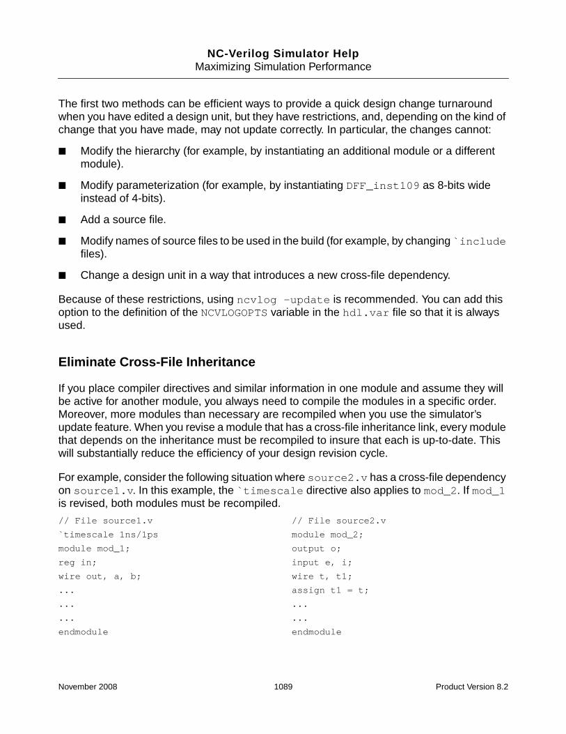
NC-Verilog Simulator HelpMaximizing Simulation Performance
The first two methods can be efficient ways to provide a quick design change turnaroundwhen you have edited a design unit, but they have restrictions, and, depending on the kind ofchange that you have made, may not update correctly. In particular, the changes cannot:
■ Modify the hierarchy (for example, by instantiating an additional module or a differentmodule).
■ Modify parameterization (for example, by instantiating DFF_inst109 as 8-bits wideinstead of 4-bits).
■ Add a source file.
■ Modify names of source files to be used in the build (for example, by changing `includefiles).
■ Change a design unit in a way that introduces a new cross-file dependency.
Because of these restrictions, using ncvlog -update is recommended. You can add thisoption to the definition of the NCVLOGOPTS variable in the hdl.var file so that it is alwaysused.
Eliminate Cross-File Inheritance
If you place compiler directives and similar information in one module and assume they willbe active for another module, you always need to compile the modules in a specific order.Moreover, more modules than necessary are recompiled when you use the simulator’supdate feature. When you revise a module that has a cross-file inheritance link, every modulethat depends on the inheritance must be recompiled to insure that each is up-to-date. Thiswill substantially reduce the efficiency of your design revision cycle.
For example, consider the following situation where source2.v has a cross-file dependencyon source1.v. In this example, the `timescale directive also applies to mod_2. If mod_1is revised, both modules must be recompiled.
// File source1.v // File source2.v
`timescale 1ns/1ps module mod_2;
module mod_1; output o;
reg in; input e, i;
wire out, a, b; wire t, t1;
... assign t1 = t;
... ...
... ...
endmodule endmodule
November 2008 1089 Product Version 8.2

NC-Verilog Simulator HelpMaximizing Simulation Performance
In addition, cross-file inheritance may spawn across the logical libraries. As a result, the waysource code is compiled in one library can affect another logical library.
To avoid this situation, put all global information (such as `timescale, `define, and so on)in a file that can be included by the source files. If you use this approach, no information isinherited by one module from another.
As in Verilog-XL, the `resetall compiler directive does not reset macros that have beenset with `define. You can use the `undefineall compiler directive before `resetall toreset macros.
Note: The `undefineall directive is not currently supported by Verilog-XL, so you mustsurround it with `ifdef INCA. Cells that started with `resetall should begin with:
`ifdef INCA
`undefineall
`endif
`resetall
Use One Module per File
If you have multiple modules in a design file, you may recompile modules that do not have tobe recompiled during incremental compile. Using one module per file is more efficient,especially for source files that are changing frequently.
However, putting multiple modules in a static or infrequently changed library file is desirableand even preferable.
Avoid Modules in `include Files
If you put modules in a `include file, every module that references it is dependent on thatmodule file. Whenever a module changes, the module that includes it must also berecompiled. The best use of `include files is for shared control information, such as`define, `timescale, and so on.
Avoid Compile-Time Conditional Code
If possible, use the $test$plusargs system function to check for the presence of asimulation-time plusarg option instead of using `ifdef compiler directives and thecompile-time -define command-line option.
See “Use $test$plusargs for Conditional Code” on page 1086 for more information.
November 2008 1090 Product Version 8.2

NC-Verilog Simulator HelpMaximizing Simulation Performance
Using Command-Line Options
This section provides information on some command-line options that can significantly affectsimulator performance.
Options That Improve Performance
The command-line options shown in this section can significantly improve simulationperformance.
Disabling Timing Features
If timing constructs exist in a design, the simulator will run with full timing standard delayformat (SDF) annotation and timing checks by default. If you do not need full timing forfunctional verification, you can improve performance significantly and decrease the designsize by disabling a variety of timing features.
The following is a general command-line string to use for maximum performance when timingis not required.
% ncelab -delay_mode distributed -notimingchecks -noneg_tchk
The following table shows the relevant global timing options:
Option Function
ncelab -nonotifier Disable notifier register.
ncelab -notimingchecks Disable timing checks.
ncelab -noneg_tchk Set negative values in timing checks tozero. See the Note below.
ncelab -no_tchk_msg Do not display timing check violationmessages.
ncelab -delay_mode unit Set all non-zero delays to 1.
November 2008 1091 Product Version 8.2

NC-Verilog Simulator HelpMaximizing Simulation Performance
The ncelab -nospecify option provides a convenient way to disable several timingfeatures with one command-line option. See -nospecify for details on this command-lineoption.
Note: In versions prior to 3.3, negative timing checks were used only if they were explicitlyenabled with the ncelab -neg_tchk option. In version 3.3 or later, if negative timing checksexist, they are used by default, and you must use the ncelab -noneg_tchk option todisable the use of negative values in these timing checks.
You can apply timing options to specific modules in a design using a timing control file. Youcan enable or disable timing checks, I/O path delays, port delays, primitive delays, and fulltiming on a module-by-module basis. The timing file lists instances in the design and whetheror not you want timing for those instances. The command-line syntax is as follows:
% ncelab -tfile timing_file other_options top_level_module
See “Disabling Timing in Selected Portions of a Design” on page 393 for details on the syntaxof the timing control file.
Changing the SDF Precision
In versions of the simulator prior to the 3.1 release, timing values in an SDF file weretruncated to 10 ps. Beginning with the LDV 3.1 release, all timing values (including those lessthan 10 ps) are used by default. This results in more accurate timing, but slower simulation.
In most cases, 10 ps is sufficient, and you may want to control the precision during simulation.You can do this with the ncelab -sdf_precision option. The syntax is as follows:
% ncelab -sdf_precision 10ps other_options top_level_module
Suppressing Printing of Output to the Screen
By default, simulator output is printed to the screen. If the design prints a lot of messages,use the ncsim -nostdout option to suppress the printing of output to the screen. Theoutput is still printed to the log file.
ncelab -delay_mode zero Zero delay.
ncelab -delay_mode distributed Ignore specify block delays.
Option Function
November 2008 1092 Product Version 8.2

NC-Verilog Simulator HelpMaximizing Simulation Performance
Options That Degrade Performance
By default, the simulator runs in a fast mode with minimal debugging capability. To accessdesign objects and lines of code during simulation, you must use debug options. Theseoptions provide visibility into different parts of a design, but disable several optimizationsperformed inside the simulator.
For example, the NC simulators include an optimization that prevents code that does notcontribute in any way to the output of the model from running. Because this “dead” code doesnot run, any run-time errors, such as constraint errors or null access dereferences, that wouldbe generated by the code are not generated. Other simulation differences (for example, withdelta cycle counts and active time points) can also occur. This dead code optimization isturned off if you use the ncvlog -linedebug option, or if read access is turned on with thencelab -access +r option.
The following table lists the debug command-line options that give additional information andaccess but reduce speed. Because these options slow down performance, you should try toapply them selectively rather than globally.
November 2008 1093 Product Version 8.2

NC-Verilog Simulator HelpMaximizing Simulation Performance
Option Function
ncelab -access +[r][w][c] Provide read access (r) to objects, write access (w) toobjects, and enable access to connectivity (load anddriver) information (c).
To apply global access to the design, the followingcommand can be used for read, write, and connectivityaccess:
% ncelab -access +rwc options top_level_module
Try to specify only the type(s) of access required foryour debugging purposes. In general,
■ Read access is required for waveform dumping andfor code coverage.
■ Write access is required for modifying valuesthrough PLI or Tcl.
■ Connectivity access is required for querying driversand loads in C or Tcl. support for features liketracing signals in the Trace Signals sidebar.
For example, if the only reason you need access is tosave waveform data, use ncelab -access +r.
To maximize performance, consider using an accessfile with the ncelab -afile option instead ofspecifying global access using the -access option.
See “Enabling Read, Write, or Connectivity Access toSimulation Objects” on page 371 for details onspecifying access to simulation objects and forguidelines on specifying access.
November 2008 1094 Product Version 8.2

NC-Verilog Simulator HelpMaximizing Simulation Performance
Expanding Vectors
The ncelab -expand command-line option forces expansion of vector signals. Using thisoption can severely impact performance.
All vectors are compressed by default. Use this option only when you need to modify or setcallbacks on parts of vector signals through Tcl or PLI.
ncelab -afile access_file Use the specified access file, which specifies accesspermissions for specific instances and portions of thedesign.
This option lets the simulator optimize objects that donot need to be accessed. Using this option is moreefficient than specifying global access using the-access option.
See “Using an Access File” on page 375 for details onhow to write and include an access file.
You can use the ncelab -genafile option toautomatically generate an access file. See“Using -genafile to Generate an Access File” onpage 383 for details.
ncvlog -linedebug Enable support for setting line breakpoints and forsingle-stepping through code.
Using this option when you compile your source filesdisables many optimizations and sets the defaultaccess to simulation objects to read/write/connectivitywhen the design is elaborated. This option has asevere impact on performance.
You can apply this option globally by including it in thedefinition of the NCVLOGOPTS variable in the hdl.varfile.
DEFINE NCVLOGOPTS -linedebug
For selective application, compile specific source fileswith the option. For example:
% ncvlog -linedebug options source_file
Option Function
November 2008 1095 Product Version 8.2

NC-Verilog Simulator HelpMaximizing Simulation Performance
Using the Profiler to Identify and Eliminate SimulationBottlenecks
The profiler is a tool that measures where CPU time is spent during simulation. Although itwas developed primarily to help Cadence R&D diagnose performance bottlenecks in thesimulator, some of the information in the output file can help you to identify inefficient HDLcoding practices. Once you have determined what code the simulator is spending most of itstime running, improving the efficiency of this code will have the greatest effect on simulationperformance.
The profiler works by interrupting the simulation at regular intervals (currently 100 times persecond) and noting what was executing at that time. It keeps track of the number of “hits” ondifferent activities, which approximates the amount of CPU time spent in these activities.
The profiler is easy to run and has minimal impact on simulation performance and memoryusage. You can invoke the profiler in two ways:
■ Use the -profile command-line option when you invoke the simulator (ncsim) or runin single-step invocation mode with irun.
% ncsim -profile snapshot_name
% irun -profile other_options source_files
If you start a simulation with the -profile option, profiling can be stopped only byexiting or resetting the simulation. Resetting the simulation with a reset commandswitches off the profiling automatically.
When the simulator exits, the profiler creates an output file. By default, the file is createdin the current working directory and is called ncprof.out. You can use the-profoutput option to give the file a different name or to write the file in a differentdirectory. For example:
% ncsim -profile -profoutput ncprof_run1.out snapshot
% ncsim -profile -profoutput /tmp/ncprof_run1.out snapshot
You can also include the -dut_prof option on the command line. This option generatesa run-time profile file that includes a table reporting the percentage of time spentsimulating a specified design under test (DUT) and the amount of time spent in the restof the design.
■ Use the Tcl profile command.
The profile command provides more control over the profiler behavior than the-profile command-line option. With the profile command, you can:
❑ Start or stop profiling at any time (-on and -off)
November 2008 1096 Product Version 8.2

NC-Verilog Simulator HelpMaximizing Simulation Performance
❑ Dump the profiled data to a file at any time (-dump)
❑ Clear the currently collected profiled data (-clear)
If profiling is turned on with the profile command, it remains on after a reset. A resetcommand clears the profile data, but does not disable profiling.
Each profile begins with a header that provides general information. This includes the versionof ncsim, the operating system and version, and a description of the computer hardware onwhich the simulation was executed. The header also includes the number of interrupts persecond, and the same total memory and CPU usage information that the ncsim -statusoption provides.
The information contained in the header can reveal performance problems such asinsufficient physical memory for the size of the simulation, or low CPU utilization due to a busymachine or waiting for I/O.
The following is an example of the header section in a profile.
ncsim: 06.20-p001: (c) Copyright 1995-2007 Cadence Design Systems, Inc.
SunOS foghorn 5.9 Generic_118558-09 sun4u sparc Sun_Microsystems
SUNW,Ultra-5_10, 1 CPU, 440 MHz, 512 Meg RAM, 100 hits/sec, (belanger)
ncelab options:
-MESSAGES
-ACCESS
+RWC
WORKLIB.TB:ARCH
Memory Usage - 33.1M program + 6.4M data + 1.0M profile = 40.5M total
CPU Usage - 0.4s system + 92.0s user = 92.4s total (94.3% cpu)
After the header, the profile is divided into three sections: Stream Counts, Most ActiveModules, and Stream Type Summary Counts. These sections summarize the profileinformation in different ways, but have the same basic structure. There are four columns ofinformation:
■ The first column shows the percentage of the total hits that were detected in a givenactivity.
■ The second column displays the raw number of hits that were detected in a given activity.
The percentage shown in the first column is simply the raw number of hits as apercentage of the total given at the top of the section.
November 2008 1097 Product Version 8.2

NC-Verilog Simulator HelpMaximizing Simulation Performance
Dividing the raw number of hits by the interrupt rate indicated in the header, gives theapproximate CPU time spent on that particular activity.
■ The third column shows the number of instances, when applicable.
■ The fourth column gives the name or description of the activity.
Within each section, the activities are sorted in descending order of number of hits. Thatis, the most time-consuming activities appear at the top of the list.
The following sections describe the three sections of the profile in more detail.
Stream Counts
The section titled Stream Counts provides detailed information about time spent inindividual generated code streams. These code streams correspond to specific HDL sourceconstructs. They include:
■ always blocks
■ initial blocks
■ continuous assignments
■ tasks and functions
■ non-blocking assignments
■ quasi-continuous assignments
■ parallel block sub-processes (statements inside fork/join)
■ Logic primitives for gates and UDPs (Because logic primitives share the same codebetween different instances, the profiler cannot indicate which gate instances are takingup the most time.)
There are also separate streams for certain kinds of complex statements that have to operateasynchronously from the blocks containing them. Anonymous (or implicit) continuousassignments are inserted when regs or expressions are attached to module ports. Timingoutput delay elements are inserted to implement path delays.
There are other activities that are not clearly related to any particular source construct or thatdo not use generated code. For example, there are run-time library functions that implementsystem tasks or complex arithmetic operations. These can often be recognized by theirnames. The run-time library function rtl_readmem, for example, implements the$readmemb/$readmemh system tasks. There are categories for VPI/PLI and tracing support.There are also streams called “methods”, which perform internal simulator operations,
November 2008 1098 Product Version 8.2
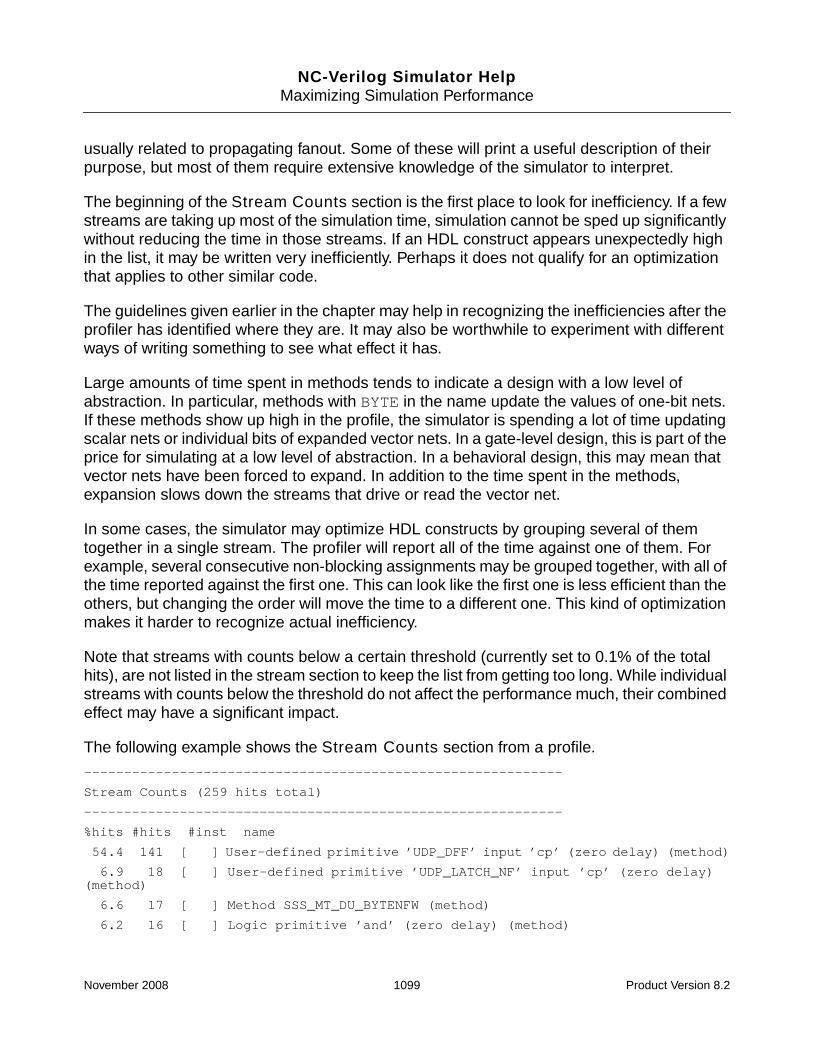
NC-Verilog Simulator HelpMaximizing Simulation Performance
usually related to propagating fanout. Some of these will print a useful description of theirpurpose, but most of them require extensive knowledge of the simulator to interpret.
The beginning of the Stream Counts section is the first place to look for inefficiency. If a fewstreams are taking up most of the simulation time, simulation cannot be sped up significantlywithout reducing the time in those streams. If an HDL construct appears unexpectedly highin the list, it may be written very inefficiently. Perhaps it does not qualify for an optimizationthat applies to other similar code.
The guidelines given earlier in the chapter may help in recognizing the inefficiencies after theprofiler has identified where they are. It may also be worthwhile to experiment with differentways of writing something to see what effect it has.
Large amounts of time spent in methods tends to indicate a design with a low level ofabstraction. In particular, methods with BYTE in the name update the values of one-bit nets.If these methods show up high in the profile, the simulator is spending a lot of time updatingscalar nets or individual bits of expanded vector nets. In a gate-level design, this is part of theprice for simulating at a low level of abstraction. In a behavioral design, this may mean thatvector nets have been forced to expand. In addition to the time spent in the methods,expansion slows down the streams that drive or read the vector net.
In some cases, the simulator may optimize HDL constructs by grouping several of themtogether in a single stream. The profiler will report all of the time against one of them. Forexample, several consecutive non-blocking assignments may be grouped together, with all ofthe time reported against the first one. This can look like the first one is less efficient than theothers, but changing the order will move the time to a different one. This kind of optimizationmakes it harder to recognize actual inefficiency.
Note that streams with counts below a certain threshold (currently set to 0.1% of the totalhits), are not listed in the stream section to keep the list from getting too long. While individualstreams with counts below the threshold do not affect the performance much, their combinedeffect may have a significant impact.
The following example shows the Stream Counts section from a profile.
------------------------------------------------------------
Stream Counts (259 hits total)
------------------------------------------------------------
%hits #hits #inst name
54.4 141 [ ] User-defined primitive ’UDP_DFF’ input ’cp’ (zero delay) (method)
6.9 18 [ ] User-defined primitive ’UDP_LATCH_NF’ input ’cp’ (zero delay)(method)
6.6 17 [ ] Method SSS_MT_DU_BYTENFW (method)
6.2 16 [ ] Logic primitive ’and’ (zero delay) (method)
November 2008 1099 Product Version 8.2

NC-Verilog Simulator HelpMaximizing Simulation Performance
6.2 16 [ ] User-defined primitive ’UDP_LATCH’ input ’cp’ (zero delay)(method)
3.9 10 [ ] User-defined primitive ’UDP_DFF’ input ’cp’ (zero delay) (method)
3.1 8 [ ] User-defined primitive ’UDP_DFF’ input ’cp’ (zero delay) (method)
2.7 7 [ ] User-defined primitive ’UDP_DFF’ input ’cp’ (zero delay) (method)
2.7 7 [ ] Logic primitive ’not’ (1 outputs) (zero delay) (method)
1.2 3 [ ] User-defined primitive ’UDP_DFF’ input ’cp’ (zero delay) (method)
1.2 3 [ ] User-defined primitive ’UDP_DFF’ input ’cp’ (zero delay) (method)
0.8 2 [ 1] Always stmt (file: ./addsub_top.v, line: 187 in worklib.top[module])
0.8 2 [ ] outside engine
0.4 1 [ ] Method SSS_MT_POSEDGEN (method)
0.4 1 [ ] Logic primitive ’or’ (zero delay) (method)
0.4 1 [ ] Logic primitive ’nor’ (zero delay) (method)
0.4 1 [ ] Method SSS_MT_RETURN_BYTE (method)
0.4 1 [ ] Method SSS_KM_FINDRFT (method)
0.4 1 [ 1] Always stmt (file: ./addsub_top.v, line: 259 in worklib.top[module])
0.4 1 [ 1] Always stmt (file: ./prog_ram_syn.v, line: 41 inworklib.prog_ram_syn [module])
0.4 1 [ 1] Always stmt (file: ./prog_ram_syn.v, line: 43 inworklib.prog_ram_syn [module])
0.4 1 [ 4] Continuous Assignment (file: ./addsub_top.v, line: 410 inworklib.clk_gate_ran_r [module])
The example Stream Counts section shown above contains a category called “Outsideengine.” This category, and one other called “Engine support”, are catch-all categories foractivities that cannot be otherwise categorized. These categories can also appear in theStream Type Summary Counts section.
■ “Outside engine” is a catch-all description for external processing. This refers to C codethat is executed outside of the main simulation engine. This could be caused by the GUIor by intensive TCL processing. A high number for “Outside engine” could also be theresult of having a complex simulation environment in which foreign models and otherproducts are being used in conjunction with the simulator.
■ “Engine support” refers to time spent in support functions that are called from within thesimulation engine and for time spent while the model is running that is not otherwisecategorized. This could be user PLI code or some other uncategorized function.
Most Active Modules
The second section of the profile, Most Active Modules, summarizes the stream counts bymodule. For each module listed, the sum of the counts in all of the streams in that module is
November 2008 1100 Product Version 8.2

NC-Verilog Simulator HelpMaximizing Simulation Performance
given. This can be useful when a module is taking a lot of time due to the combined time in alot of streams that are below the threshold for being listed in the Stream Counts section. Itmay also provide useful information to someone who is familiar with the design at the modulelevel.
Counts that are not clearly associated with a particular module are omitted from this section.
The following is an example of the Most Active Modules section.
------------------------------------------------------------
Most Active Modules (behavioral)
------------------------------------------------------------
%hits #hits #inst name
27.3 75 [ 8] worklib.SDRAM:v (file: ../lib/sdram.v line: 215)
10.9 30 [ 1] worklib.ddr_ctrl:v (file: ../rtl/ddr_ctrl.v line: 43)
6.5 18 [ 1] worklib.page_table:v (file: ../rtl/page_table.v line: 59)
4.4 12 [ 1] worklib.ddr_dxfr:v (file: ../rtl/ddr_dxfr.v line: 56)
4.4 12 [ 1] worklib.system:v (file: ./system.v line: 53)
4.0 11 [ 4] worklib.BusMaster:v (file: ../lib/bm.v line: 169)
4.0 11 [ 1] worklib.gg_test:v (file: ./gg_test.v line: 49)
3.3 9 [ 1] worklib.arbiter:v (file: ../rtl/arbiter.v line: 51)
2.5 7 [ 3] worklib.sync_fifo:v (file: ../rtl/sync_fifo.v line: 30)
1.8 5 [ 1] worklib.agp_test:v (file: ./agp_test.v line: 26)
1.8 5 [ 1] worklib.data_cyc:v (file: ../rtl/data_cyc.v line: 46)
1.5 4 [ 1] worklib.add_fifo:v (file: ../rtl/add_fifo.v line: 51)
1.5 4 [ 1] worklib.req_fifo:v (file: ../rtl/req_fifo.v line: 27)
0.7 2 [ 3] worklib.bank_sel:v (file: ../rtl/bank_sel.v line: 35)
0.4 1 [ 1] worklib.ddr_top:v (file: ../rtl/ddr_top.v line: 63)
0.4 1 [ 1] worklib.max_test:v (file: ./max_test.v line: 23)
0.4 1 [ 8] worklib.mem_bank:v (file: ../lib/mem_bank.v line: 1)
0.4 1 [ 1] worklib.mem_req:v (file: ../rtl/mem_req.v line: 56)
Stream Type Summary Counts
The Stream Type Summary Counts section summarizes the stream counts by the type ofstream or other activity. For example, there might be a total for logic primitives, timing checks,always or initial statements, non-blocking assignments, continuous assignments, andso on. As with the Most Active Modules section, this section includes streams with countstoo low to appear separately in the first section. This section gives a general idea of wheresimulation time is being spent.
November 2008 1101 Product Version 8.2

NC-Verilog Simulator HelpMaximizing Simulation Performance
The summary makes it easier to identify widespread inefficiencies in the simulation. Forexample, large amounts of time spent on probing, file I/O, and PLI will show up most clearlyin this section. Time spent directly on timing features is also summed up here. If they aretaking a lot of time and are not actually needed, these timing features can be turned off withcommand-line options. A design that is supposedly behavioral may actually be spending mostof its time simulating gate-level portions. Replacing those portions with equivalenthigher-level models could improve performance dramatically.
Here is an example Stream Type Summary Counts section:
------------------------------------------------------------
Stream Type Summary Counts (275 hits total)
------------------------------------------------------------
%hits #hits #inst name
30.2 83 [ 1456] Timing checks
25.5 70 [ 229] Always statements
17.5 48 [ ] Standard methods (mostly fanout propagation)
11.3 31 [ 759] Non-blocking assignments
8.4 23 [ 324] Continuous assignments
4.7 13 [ 88] Initial statements
3.6 10 [ 41] Anonymous continuous assignments
2.9 8 [ 193] Verilog tasks
2.5 7 [ 26] Verilog functions
2.5 7 [ ] Wire evaluation
2.2 6 [ ] System tasks/functions or library functions
1.5 4 [ ] Outside engine
0.7 2 [ 80] Parallel block sub-processes
Using the VHDL Source Profiler
The VHDL source profiler generates a file that contains the VHDL source and the number ofhits encountered by each statement in the design. The output file, which is created at the endof simulation, is called ncvhdl_sprofile.out.
To generate a VHDL source profile, you must:
1. Compile the source files with the -sprofile option. This option marks source filescompiled by ncvhdl for subsequent use by the VHDL source profiler.
% ncvhdl -sprofile [other_options] vhdl_source_files
2. Use the -sprofile option when you invoke the simulator.
% ncsim -sprofile [other_options] snapshot
November 2008 1102 Product Version 8.2

NC-Verilog Simulator HelpMaximizing Simulation Performance
The ncsim -sprofile command also invokes the run-time profiler described in theprevious section (see “Using the Profiler to Identify and Eliminate Simulation Bottlenecks” onpage 1096). The output file of this profiler is a file called ncprof.out. You can invoke therun-time profiler separately with the ncsim -profile command-line option.
Using the -sprofile option can affect simulation performance. Use the option only to debugperformance issues. To enable the source profiler without having to update compilationscripts, you can set the following environment variables:
setenv NCVHDLOPTS -sprofile
setenv NCSIMOPTS -sprofile
The -sprofile option can also be included in the definition of the NCVHDLOPTS andNCSIMOPTS variables in the hdl.var file.
DEFINE NCVHDLOPTS -sprofile
DEFINE NCSIMOPTS -sprofile
Limitations
The source profiler has the following limitations:
■ Only VHDL source can be profiled with the -sprofile option.
■ If there are no VHDL components in the design, an ncvhdl_sprofile.out file is notgenerated. The run-time profiler, however, will generate an ncprof.out output file.
■ Subprograms or processes that encounter fewer than 0.1% hits are not included in theoutput.
■ A file must be compiled with the -sprofile option to be profiled. A warning messageis displayed in the output file for processes or subprograms that have not been compiledwith the -sprofile option.
■ If the VHDL source file does not have read permissions, only the filename, line number,and number of hits are displayed in the output.
■ If the file has been modified after it was compiled, the source profiler may not be able tocorrectly print its output.
Example Output
An example of the VHDL source profiler output is shown below.
November 2008 1103 Product Version 8.2

NC-Verilog Simulator HelpMaximizing Simulation Performance
Profile generated on: Tue Apr 20 11:02:24 2004
*********************
NCVHDL SOURCE PROFILE
*********************
---------------------------------------------------------------
Source Code Profile For: Process statement: $PROCESS_000 (line: 547, in designunit WORKLIB.SHIFTREG64:SHIFTREG64RTL) ( 24.7% hits)
---------------------------------------------------------------
%hits
0.0 PROCESS
0.0 VARIABLE SHIFTREG: TSHIFTREG;
0.0 BEGIN
1.3 WAIT UNTIL CLK = ’1’;
0.9 IF SHIFTENABLE = ’1’ THEN
2.9 DATAOUT <= SHIFTREG(62);
0.1 FOR I IN 62 DOWNTO 1 LOOP
92.2 SHIFTREG(I) := SHIFTREG(I-1);
0.0 END LOOP;
2.0 SHIFTREG(0) := DATAIN;
0.0 END IF;
0.3 IF RSTN = ’0’ THEN
0.3 SHIFTREG(0) := TDATA’(OTHERS => ’0’);
0.0 END IF;
0.0 END PROCESS;
---------------------------------------------------------------
Source Code Profile For: Process statement: DATAPATHCOMB (line: 665, in designunit WORKLIB.VERFIL:VERFILRTL) ( 11.6% hits)
---------------------------------------------------------------
%hits
0.0 DATAPATHCOMB: PROCESS (DATA, COEF)
0.0 VARIABLE DATATMP: UNSIGNED(7 DOWNTO 0);
0.0 VARIABLE COEFTMP: SIGNED(7 DOWNTO 0);
0.0 VARIABLE MPYOUTTMP: SIGNED(16 DOWNTO 0);
0.0 BEGIN
0.2 FOR I IN TINDEX LOOP
5.4 DATATMP := DATA(I);
15.4 COEFTMP := COEF(I);
12.5 MPYOUTTMP := DATATMP * COEFTMP;
51.3 MPYOUTTMP := MPYOUTTMP + ROUNDINGOFFSET;
13.7 MPYOUT(I) <= MPYOUTTMP(15 DOWNTO 6);
November 2008 1104 Product Version 8.2

NC-Verilog Simulator HelpMaximizing Simulation Performance
0.0 END LOOP;
0.0 END PROCESS DATAPATHCOMB;
1.4 IMPLICIT VHDL WAIT;
---------------------------------------------------------------
Source Code Profile For: Process statement: DATAPATHSEQ (line: 679, in designunit WORKLIB.VERFIL:VERFILRTL) ( 8.3% hits)
---------------------------------------------------------------
%hits
0.0 DATAPATHSEQ: PROCESS
0.0 BEGIN
2.3 WAIT UNTIL CLK = ’1’;
0.0 FOR I IN TINDEX LOOP
20.8 PRODUCT(I) <= MPYOUT(I);
0.0 END LOOP;
34.4 SUMA <= (PRODUCT(-2)(9) & PRODUCT(-2)) + PRODUCT(2);
11.5 SUMB <= (PRODUCT(-1)(9) & PRODUCT(-1)) + PRODUCT(1);
3.5 SUMC <= PRODUCT(0);
10.5 SUMD <= (SUMA(10) & SUMA) + SUMB;
1.7 SUME <= SUMC;
13.0 SUM <= (SUMD(11) & SUMD) + SUME;
2.3 DATAOUT <= LIMITOUT;
0.0 END PROCESS DATAPATHSEQ;
November 2008 1105 Product Version 8.2

NC-Verilog Simulator Help
13Timing Checks
This chapter contains the following sections:
■ Overview of Timing Checks
■ Timing Checks
■ Using Edge-Control Specifiers
■ Using Notifiers
■ Enabling Timing Checks with Conditioned Events
■ Negative Timing Check Limits in $setuphold and $recrem
■ Timing Violation Messages
■ SDF Annotation of Timing Checks
November 2008 1106 Product Version 8.2

NC-Verilog Simulator HelpTiming Checks
Overview of Timing Checks
A timing check verifies the timing performance of a design by making sure that critical eventsoccur within given time limits. A timing check performs the following steps:
1. Determines the elapsed time between two events.
2. Compares the elapsed time to a specified minimum or maximum time limit.
3. Reports a timing violation if the elapsed time occurs outside the specified time window.
Timing check information can be included by using the timing check tasks available in theVerilog HDL or by using SDF annotation. This topic deals primarily with using the timing checktasks. See “SDF Annotation of Timing Checks” on page 1169 for details on SDF annotation.
Timing checks are invoked in specify blocks. They can contain:
■ Edge-control specifiers, which control events in timing checks based on specific edgetransitions between 0, 1, and x. (See “Using Edge-Control Specifiers” on page 1137 fordetails.)
■ Notifiers, which specify user-defined responses to timing violations. (See“UsingNotifiers” on page 1138 for details.)
■ Conditioned events, which tie the occurrence of timing checks to the value of aconditioning signal. (See “Enabling Timing Checks with Conditioned Events” onpage 1141 for details.)
(See “Specify Blocks” on page 1182 for details on using these statements.)
You can invoke the following timing checks:
■ $setup
■ $hold
■ $setuphold
■ $width
■ $period
■ $skew
■ $timeskew
■ $fullskew
■ $recovery
November 2008 1107 Product Version 8.2

NC-Verilog Simulator HelpTiming Checks
■ $removal
■ $recrem
■ $nochange
Note: If you do not want to execute timing checks, you can improve processing performanceby disabling timing checks by elaborating with the -notimingchecks option. For example,
% ncelab -notimingchecks worklib.top
The -notimingchecks option turns off all timing checks. Because the timing checks havebeen turned off, any calculation of delays that would normally occur because of negativelimits specified in timing checks is disabled. If your design requires that these delays becalculated in order for the design to simulate correctly, you can use the following two options,which disable timing check notifiers and suppress the display of timing check messages,while allowing delays to be calculated from the negative limits.
-nonotifier -no_tchk_msg
Timing Checks
$setup
The $setup timing check determines whether a data signal remains stable long enoughbefore a transition in a control signal, such as a clock signal that latches data in memory. Aviolation occurs when a change to the data signal occurs within a specified time limit beforethe transition at the control signal. The following figure illustrates the violation region specifiedby the $setup timing check.
The $setup timing check has the following format:
$setup(data_event, reference_event, setup_limit [,notifier]);
November 2008 1108 Product Version 8.2

NC-Verilog Simulator HelpTiming Checks
The $setup timing check arguments are as follows:
Note: If the reference event and the data event occur simultaneously, $setup performs thetiming check before it records the new data event value. Therefore, no violation is reported.
Example:
In the following example, the $setup timing check sets up a time window 10 time units beforea positive transition on clock. A timing violation is reported if data transitions within thisinterval.
specify
specparam setup_param=10;
$setup( data, posedge clock, setup_param );
endspecify
$setup Arguments Description
data_event Transition at a data signal that initiates the timing check. This is amodule input or inout that is a scalar or vector net.
reference_event Transition at a control signal that establishes the reference timefor tracking timing violations on the data event. This is a moduleinput or inout that is a scalar or vector net.
setup_limit Positive constant expression or specparam that specifies theminimum interval between the data event and the referenceevent. Any change to the data signal within this interval results ina timing violation.
notifier (optional) Register whose value is updated whenever a timing violationoccurs. You can use notifiers to define responses to timingviolations. (See “Using Notifiers” on page 1138 for details.)
November 2008 1109 Product Version 8.2

NC-Verilog Simulator HelpTiming Checks
$hold
The $hold timing check determines whether a data signal remains stable long enough aftera transition in a control signal, such as a clock signal that latches data in a memory. Thefollowing figure illustrates the violation region specified by the $hold timing check.
The $hold timing check has the following format:
$hold(reference_event, data_event, hold_limit [,notifier]);
The $hold timing check arguments are as follows:
Note: If the reference event and the data event occur at the same time, the $hold timingcheck records the new reference event time before it performs the timing check and aviolation is reported.
Example:
In the following example, $hold reports a violation if the time that elapses from the referenceevent (posedge clk) to a change in data is smaller than hold_param (11). The notifier,flag, detects the timing violation behaviorally and performs some user-defined action.
$hold Arguments Description
reference_event Module input or inout transition at a control signal that establishesthe reference time.
data_event Module input or inout transition at a data signal that initiates atiming check against the value in hold_limit.
hold_limit Positive constant expression or specparam that specifies theinterval between the reference event and data event. Any changeto the data signal within this interval results in a timing violation. Ifhold_limit is 0, a timing check does not occur.
notifier (optional) Register whose value is updated whenever a timing violationoccurs. You can use notifiers to define responses to timingviolations. (See “Using Notifiers” on page 1138 for details.)
November 2008 1110 Product Version 8.2

NC-Verilog Simulator HelpTiming Checks
specify
specparam hold_param=11;
$hold( posedge clk, data, hold_param, flag ) ;
endspecify
$setuphold
The $setuphold task combines the functionality of $setup and $hold into one timingcheck. It also offers additional functionality in that you can specify a negative timespecification for the setup limit or for the hold limit.
The $setuphold timing check has the following format:
$setuphold( reference_event, data_event, setup_limit, hold_limit
[,notifier] [,tstamp_cond] [,tcheck_cond]
[,delayed_reference] [,delayed_data] );
The $setuphold timing check arguments are as follows:
$setupholdArguments Description
reference_event Transition at a control signal that establishes the reference time fortracking timing violations on the data event. This is a module inputor inout that is a scalar or vector net. The reference_eventargument represents the lower bound event for $hold and theupper bound event for $setup.
data_event Transition at a data signal that initiates the timing check. This is amodule input or inout that is a scalar or vector net. Thedata_event argument represents the upper bound event for$hold and the lower bound event for $setup.
setup_limit Constant expression or specparam that specifies the minimuminterval between the data event and the reference event. Anychange to the data signal within this interval results in a timingviolation.
You can specify negative times for either the setup_limit orhold_limit arguments. The sum of the two arguments mustbe 0 or greater.
November 2008 1111 Product Version 8.2

NC-Verilog Simulator HelpTiming Checks
Absent optional parameters must be indicated as null parameters by using commas. Do notadd one or more commas after the last argument. For example, the following $setupholdtask includes a tcheck_cond argument:
$setuphold(posedge clk, data, 2, 3, , , tcheck_cond);
Note: You cannot condition a $setuphold timing check by using the tstamp_cond ortcheck_cond arguments and a conditioned event. If you attempt to use both methods, onlythe parameters in the tstamp_cond and tcheck_cond arguments are effective, and awarning message is generated.
hold_limit Constant expression or specparam that specifies the intervalbetween the reference event and data event. Any change to thedata signal within this interval results in a timing violation.
You can specify negative times for either the setup_limit orhold_limit arguments. The sum of the two arguments mustbe 0 or greater.
notifier (optional) Register whose value is updated whenever a timing violationoccurs. You can use notifiers to define responses to timingviolations. (See “Using Notifiers” on page 1138 for details.)
tstamp_cond(optional)
Places a condition on the stamp event. For the setup check of$setuphold, this argument places a condition on the transition ofthe data signal. For the hold check of $setuphold, this argumentplaces a condition on the transition of the reference signal.
tcheck_cond(optional)
Places a condition on the check event. For the setup check of$setuphold, this argument places a condition on the transition ofthe reference signal. For the hold check of $setuphold, thisargument places a condition on the transition of the data signal.
delayed_reference(optional)
A delayed version of the reference signal generated by a negativetiming check. See “Negative Timing Check Limits in $setupholdand $recrem” on page 1142 for more information.
delayed_data(optional)
A delayed version of the data signal generated by a negativetiming check. See “Negative Timing Check Limits in $setupholdand $recrem” on page 1142 for more information.
$setupholdArguments Description
November 2008 1112 Product Version 8.2

NC-Verilog Simulator HelpTiming Checks
Example 1:
The following example shows how the $setuphold timing check combines the functionalityof $setup and $hold. The following invocation:
$setuphold(posedge clk, data, 3, 2);
is equivalent to the following two timing checks:
$setup( data, posedge clk, 3 );
$hold( posedge clk, data, 2 );
Example 2:
The following example illustrates $setuphold with positive time specifications for bothsetup_limit and hold_limit arguments.
specify
specparam tSU=16, tHLD=17;
$setuphold( posedge clk, data, tSU, tHLD );
endspecify
In this example, $setuphold reports a violation if the interval from a transition on the datasignal to the positive edge of clk is less than tSU (16), enacting its $setup component. Italso reports a violation if the interval from the positive edge of clk to a transition on the datasignal is less than tHLD (17), enacting its $hold component.
The following figure shows the violation region:
Example 3:
You can specify negative times for either the setup_limit or hold_limit arguments.The sum of the two arguments must be 0 or greater.
■ A negative setup_limit value specifies a period following a change in the referencesignal.
November 2008 1113 Product Version 8.2

NC-Verilog Simulator HelpTiming Checks
■ A negative hold_limit value specifies a period preceding a change in the referencesignal.
The following figure illustrates the violation region for the following $setuphold, whichspecifies a negative setup limit:
$setuphold( posedge clk, data, -2, 4);
The following figure illustrates the violation region when you specify a negative hold limit.
$setuphold( posedge clk, data, 4, -2 );
See “Negative Timing Check Limits in $setuphold and $recrem” on page 1142 for moreinformation on negative timing checks.
$width
The $width timing check specifies the duration of signal levels from one edge transition tothe opposite edge transition. A violation occurs when the pulse width is smaller than thespecified limit. The following figure illustrates how a violation occurs with the $width timingcheck.
November 2008 1114 Product Version 8.2

NC-Verilog Simulator HelpTiming Checks
The syntax for the $width timing check is as follows:
$width(reference_event, limit [,threshold, notifier]);
Notice that no data_event argument is passed to $width. The data event for $width isderived from the reference event and is the reference event signal with the opposite edge.
The $width timing check arguments are as follows:
If you specify more than one edge control specifier, the edges must be either all rising (anyof 01, 0X, X1) or all falling (any of 10,1X, X0).
Example 1:
The following $width timing check reports a violation if the interval from the reference event(negedge clr) to the implicit data event (posedge clr) is less than the limit specified bywidth_param (12). Note that the data event and the reference event never occursimultaneously because they are triggered by opposite transitions.
specify
specparam width_param=12;
$width( negedge clr, width_param );
endspecify
$width Arguments Description
reference_event Transition at a control signal that establishes the reference timefor tracking timing violations on the data event. This argumentmust be an edge-triggered event. A compilation error occurs if thereference event is not an edge specification.
limit Positive constant expression or specparam that specifies theminimum interval between the time of the reference event and thetime of the implicit data event.
threshold (optional) Positive constant expression or specparam that specifies thelargest ignored pulse width. This argument is used for timinganalysis by Veritime. The simulator ignores threshold, butcompiles system calls to $width that contain this argument.
notifier (optional) Register whose value is updated whenever a timing violationoccurs. You can use notifiers to define responses to timingviolations. (See “Using Notifiers” on page 1138 for details.)
November 2008 1115 Product Version 8.2

NC-Verilog Simulator HelpTiming Checks
Example 2:
You cannot use null arguments for $width. If you pass a notifier argument, you mustalso supply the threshold argument. However, you do not have to specify either of thesearguments. The following example shows legal and illegal calls.
// Legal calls
$width( negedge clr, lim );
$width( negedge clr, lim, thresh, notif );
$width( negedge clr, lim, 0, notif );
// Illegal calls
$width( negedge clr, lim, , notif );
$width( negedge clr, lim, notif );
$period
The $period timing check specifies the duration of signal levels from one edge transition tothe same edge transition. A violation occurs when the pulse width is smaller than thespecified limit. The following figure illustrates how a violation occurs with the $period timingcheck.
The $period timing check has the following format:
$period(reference_event, limit [,notifier]);
Notice that no data_event argument is passed to $period. The data event for $periodis derived from the reference event and is the reference event signal with the same edge.
November 2008 1116 Product Version 8.2

NC-Verilog Simulator HelpTiming Checks
The $period timing check arguments are as follows:
If you specify more than one edge control specifier, the edges must be either all positive (01,0X, X1) or all negative (10, 1X, X0).
Example:
In the following example, the $period timing check reports a violation if the time betweenthe reference event (negedge clk) and the implicit data event (the next negedge clk) isless than period_param (13).
specify
specparam period_param=13;
$period( negedge clk, period_param ) ;
endspecify
$skew
The $skew timing check specifies the maximum delay allowable between two signals. Aviolation occurs when signals are too far apart. The following figure shows how a violationoccurs with the $skew timing check.
$period Arguments Description
reference_event Transition at a control signal that establishes the reference timefor tracking timing violations on the data event. This argumentmust be an edge-triggered event. A compilation error will occur ifthe reference_event is not an edge specification.
limit Positive constant expression or specparam that specifies theminimum interval between the time of the reference event and thetime of the implicit data event.
notifier (optional) Register whose value is updated whenever a timing violationoccurs. You can use notifiers to define responses to timingviolations. (See “Using Notifiers” on page 1138 for details.)
November 2008 1117 Product Version 8.2

NC-Verilog Simulator HelpTiming Checks
The $skew timing check has the following format:
$skew(reference_event, data_event, limit [,[notifier]]);
The $skew timing check arguments are as follows:
The $skew timing check is event-based; it is evaluated only after a data event. Once it hasdetected a reference event, $skew continuously checks data events for a timing violation, andreports a violation for all data events that occur beyond the limit after a reference event. Ifthere is never a data event, the timing check is never evaluated, and no timing violation is everreported.
If the reference event and the data event occur at the same time, $skew does not report atiming violation.
A second consecutive reference event cancels the old wait for a data event and begins a newone.
$skew Arguments Description
reference_event Module input or inout transition at a control signal thatestablishes the reference time for tracking violations on the dataevent.
data_event Module input or inout transition at a signal that initiates thetiming check against the value in limit.
limit Non-negative constant expression or specparam that specifiesthe delay allowed between the transitions of the two signals.
notifier (optional) Register whose value is updated whenever a timing violationoccurs. You can use notifiers to define responses to timingviolations. (See “Using Notifiers” on page 1138 for details.)
November 2008 1118 Product Version 8.2

NC-Verilog Simulator HelpTiming Checks
Example:
In the following example, the $skew timing check reports a violation if the interval from thereference event (posedge clk1) to the data event (negedge clk2) exceeds skew_param(14).
specify
specparam skew_param=14;
$skew(posedge clk1, negedge clk2, skew_param);
endspecify
$timeskew
The $timeskew timing check, like the $skew timing check, specifies the maximum delayallowable between two signals. A violation occurs when signals are too far apart. However,the default behavior of $timeskew is timer-based, while $skew is event-based. In otherwords:
■ $skew reports a violation for all data events that occur beyond the limit after a referenceevent.
■ $timeskew reports one violation upon an elapse of time after the reference event equalto the limit. The timing check then becomes dormant until after the next reference event.
The following figure shows the default timer-based behavior of the $timeskew timing check.
November 2008 1119 Product Version 8.2

NC-Verilog Simulator HelpTiming Checks
The $timeskew timing check has the following format:
$timeskew(reference_event, data_event, limit
[,[notifier] [,[event_based_flag] [,[remain_active_flag]]]]);
The $timeskew timing check arguments are as follows:
If the reference event and the data event occur at the same time, $timeskew does not reporta timing violation.
A second consecutive reference event cancels the old wait for a data event and begins a newone.
The default timer-based behavior can be changed to event-based behavior by using theevent_based_flag argument. In this case, it behaves like $skew except that the timingcheck becomes dormant after reporting the first violation.
If you also include the remain_active_flag argument, the behavior of $timeskew isidentical to $skew. Timing violations are reported for all data events occurring beyond thelimit after a reference event.
$timeskew Arguments Description
reference_event Module input or inout transition at a control signal thatestablishes the reference time for tracking violations on thedata event.
data_event Module input or inout transition at a signal that initiates thetiming check against the value in limit.
limit Non-negative constant expression or specparam thatspecifies the delay allowed between the transitions of thetwo signals.
notifier (optional) Register whose value is updated whenever a timing violationoccurs. You can use notifiers to define responses to timingviolations. (See “Using Notifiers” on page 1138 for details.)
event_based_flag(optional)
Constant expression. Changes the default behavior fromtimer-based to event-based.
remain_active_flag(optional)
Constant expression. This argument can be used only if youuse the event_based_flag argument. Specifies thattiming violations are reported for all data events that occurbeyond the limit after a reference event.
November 2008 1120 Product Version 8.2

NC-Verilog Simulator HelpTiming Checks
The following diagram, adapted from the diagram in the LRM, is used for the followingexamples.
Example 1$timeskew (posedge CP &&& MODE, negedge CPN, 50);
In this example, the skew limit is 50 time units. The first reference event on CP occurs at time100. The negative transition on CPN occurs at time 200, which is beyond the limit. A violationis reported as soon as 50 time units have elapsed after the reference event (that is, at time150), and no further violations are reported.
Example 2$timeskew (posedge CP &&& MODE, negedge CPN, 50, 1);
In this example, the event_based_flag argument is set. The negative transition on CPNat time 200 causes a timing violation because the transition is beyond the specified limit. Theviolation is reported at time 200. Only one violation is reported. The subsequent negativetransitions at time 300 and 400 do not cause violations. The second reference event on CP attime 400 occurs while the condition is false, which causes the timing check to becomedormant.
November 2008 1121 Product Version 8.2

NC-Verilog Simulator HelpTiming Checks
Example 3specify
specparam ebf = 1, raf = 1;
$timeskew (posedge CP &&& MODE, negedge CPN, 50, ntfy_reg, ebf, raf);
endspecify
In this example, the event_based_flag and remain_active_flag arguments areboth set. The behavior of $timeskew is identical to $skew. The three negative transitions onCPN are reported as timing violations at time 200, 300, and 400, respectively.
$fullskew
The $fullskew timing check is similar to the $timeskew timing check, except that two limitsare specified.
■ The first limit specifies the maximum time by which the data event can follow thereference event.
For this limit, the reference event is the timestamp event, and the data event is thetimecheck event.
■ The second limit specifies the maximum time by which the reference event can follow thedata event.
For this limit, the data event is the timestamp event, and the reference event is thetimecheck event.
The default behavior of $fullskew is timer-based. $fullskew reports one violation uponan elapse of time after the timestamp event equal to the limit. The timing check then becomesdormant until after the next timestamp event.
The syntax for $fullskew is as follows:
$fullskew(reference_event, data_event, limit1, limit2
[,[notifier] [,[event_based_flag] [,[remain_active_flag]]]]);
The $fullskew timing check arguments are as follows:
$fullskew Arguments Description
reference_event The timestamp event when the reference event precedesthe data event. The timecheck event when the data eventprecedes the reference event.
November 2008 1122 Product Version 8.2

NC-Verilog Simulator HelpTiming Checks
If the timestamp event and the timecheck event occur at the same time, $fullskew does notreport a timing violation.
A second consecutive timestamp event cancels the old wait for a timecheck event and beginsa new one.
The default timer-based behavior can be changed to event-based behavior by using theevent_based_flag argument. In this case, the timing check becomes dormant afterreporting the first violation, as with the default timer-based behavior, but the violation isreported at the time of the timecheck event, not upon an elapse of time after the timestampevent equal to the limit.
If you also include the remain_active_flag argument, the timing check does notbecome dormant after the first violation. Timing violations are reported for all timecheckevents occurring beyond the limit after a timestamp event until the next timestamp event.
data_event The timestamp event when the data event precedes thereference event. The timecheck event when the referenceevent precedes the data event.
limit1 Non-negative constant expression or specparam thatspecifies the delay allowed between the transition at thereference event signal and the transition at the data eventsignal.
limit2 Non-negative constant expression or specparam thatspecifies the delay allowed between the transition at thedata event signal and the transition at the reference eventsignal.
notifier (optional) Register whose value is updated whenever a timing violationoccurs. You can use notifiers to define responses to timingviolations. (See “Using Notifiers” on page 1138 for details.)
event_based_flag(optional)
Constant expression. Changes the default behavior fromtimer-based to event-based.
remain_active_flag(optional)
Constant expression. This argument can be used only if youuse the event_based_flag argument. Specifies thattiming violations are reported for all data events that occurbeyond the limit after a reference event, and for all referenceevents that occur beyond the limit after a data event.
$fullskew Arguments Description
November 2008 1123 Product Version 8.2

NC-Verilog Simulator HelpTiming Checks
The following diagram is used for the following examples.
Example 1$fullskew (posedge CP, negedge CPN, 50, 70);
In this example, the $fullskew timing check reports a violation if:
■ The timecheck event, which is the data event (negedge CPN), occurs more than 50 timeunits after the timestamp event, which is the reference event (posedge CP).
❑ The reference event occurs at time 100. The negative transition on CPN happens attime 160, which is greater than the 50 time unit limit. A timing violation is reportedas soon as the specified limit has elapsed (that is, at time 150). This check thenbecomes dormant until the next reference event.
❑ The next reference event is at time 300. The negative transition on CPN happens attime 400, which is greater than the 50 time unit limit. A timing violation is reported attime 350.
❑ The next reference event is at time 480. The negative transition on CPN happens attime 500, which is not greater than the 50 time unit limit, so there is no timingviolation.
❑ The next reference event is at time 550. A negative transition on CPN does nothappen within 50 time units, so a violation is reported at time 600.
■ The timecheck event, which is the reference event (posedge CP), occurs more than 70time units after the timestamp event, which is the data event (negedge CPN).
❑ The negative transition on CPN at time 160 begins a wait for a positive transition onCP. However, a second consecutive reference event (at time 180) cancels this waitand begins a new one. The positive transition on CP occurs at time 300, which isbeyond the 70 time unit limit. A timing violation is reported as soon as the specified
November 2008 1124 Product Version 8.2

NC-Verilog Simulator HelpTiming Checks
limit has elapsed (that is, at time 250). This check then becomes dormant until thenext negative transition on CPN.
❑ The next negative transitions on CPN occurs at time 400, and a positive transition onCP occurs at time 480. This is greater than the 70 time unit limit. A violation isreported at time 470.
❑ The next negative transition on CPN occurs at time 500. A positive transition on CPoccurs at time 550, which is not greater than the 70 time unit limit, so there is notiming violation.
Example 2$fullskew (posedge CP, negedge CPN, 50, 70, 1);
In this example, the event_based_flag argument is set. The same violations reported inExample 1 are also reported in this example, but the violations are reported at the time thatthe timecheck event occurs.
■ For the first check, in which the reference event (posedge CP) is the timestamp event,and the data event (negedge CPN) is the timecheck event:
❑ The reference event occurs at time 100, and the negative transition on CPN happensat time 160, which is greater than the 50 time unit limit. The timing violation isreported at time 160. The check then becomes dormant until the next referenceevent.
❑ The next reference event is at time 300. The negative transition on CPN happens attime 400, which is greater than the 50 time unit limit. A timing violation is reported attime 400.
❑ The next reference event is at time 480. The negative transition on CPN happens attime 500, which is not greater than the 50 time unit limit, so there is no timingviolation.
❑ The next reference event is at time 550. A negative transition on CPN does nothappen within 50 time units. This timing violation will be reported at the time whenthe negative transition on CPN occurs.
■ For the second check, in which the data event (negedge CPN) is the timestamp event,and the reference event (posedge CP &&& MODE) is the timecheck event:
❑ The negative transition on CPN at time 160 begins a wait for a positive transition onCP. However, a second consecutive reference event (at time 180) cancels this waitand begins a new one. The positive transition on CP occurs at time 300, which isbeyond the 70 time unit limit. A timing violation is reported at time 300. This checkthen becomes dormant until the next negative transition on CPN.
November 2008 1125 Product Version 8.2
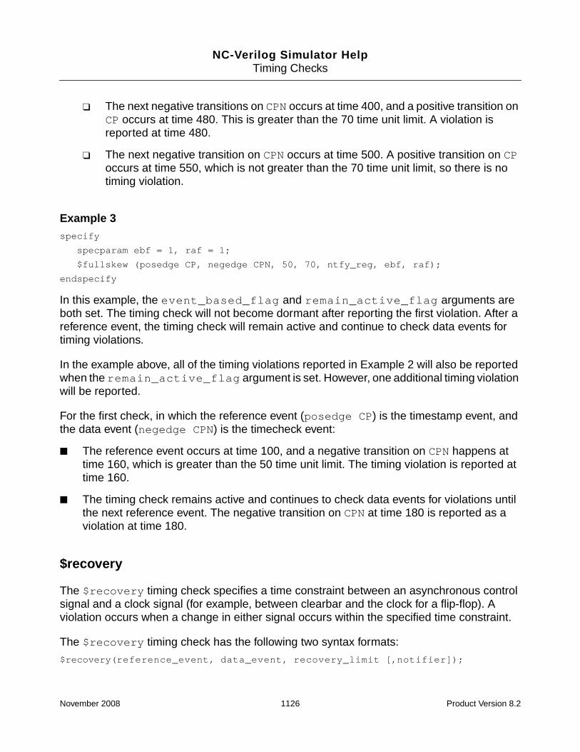
NC-Verilog Simulator HelpTiming Checks
❑ The next negative transitions on CPN occurs at time 400, and a positive transition onCP occurs at time 480. This is greater than the 70 time unit limit. A violation isreported at time 480.
❑ The next negative transition on CPN occurs at time 500. A positive transition on CPoccurs at time 550, which is not greater than the 70 time unit limit, so there is notiming violation.
Example 3specify
specparam ebf = 1, raf = 1;
$fullskew (posedge CP, negedge CPN, 50, 70, ntfy_reg, ebf, raf);
endspecify
In this example, the event_based_flag and remain_active_flag arguments areboth set. The timing check will not become dormant after reporting the first violation. After areference event, the timing check will remain active and continue to check data events fortiming violations.
In the example above, all of the timing violations reported in Example 2 will also be reportedwhen the remain_active_flag argument is set. However, one additional timing violationwill be reported.
For the first check, in which the reference event (posedge CP) is the timestamp event, andthe data event (negedge CPN) is the timecheck event:
■ The reference event occurs at time 100, and a negative transition on CPN happens attime 160, which is greater than the 50 time unit limit. The timing violation is reported attime 160.
■ The timing check remains active and continues to check data events for violations untilthe next reference event. The negative transition on CPN at time 180 is reported as aviolation at time 180.
$recovery
The $recovery timing check specifies a time constraint between an asynchronous controlsignal and a clock signal (for example, between clearbar and the clock for a flip-flop). Aviolation occurs when a change in either signal occurs within the specified time constraint.
The $recovery timing check has the following two syntax formats:
$recovery(reference_event, data_event, recovery_limit [,notifier]);
November 2008 1126 Product Version 8.2

NC-Verilog Simulator HelpTiming Checks
or:
$recovery(reference_event, data_event,
removal_limit, recovery_limit,
[notifier], [tstamp_cond], [tcheck_cond],
[delayed_clk], [delayed_data]);
The following $recovery timing check reports a timing violation if the data event (posedgeclk) occurs within the interval specified by recovery_param (3).
specify
specparam recovery_param=3;
$recovery( posedge set, posedge clk, recovery_param );
endspecify
The following figure shows the violation region:
The $recovery timing check arguments are as follows:
$recovery Arguments Description
reference_event Asynchronous control signal, which normally has an edgeidentifier associated with it to indicate which transitioncorresponds to the release from the active state.
data_event Clock (flip-flops) or gate (latches) signal, which normally hasan edge identifier to indicate the active edge of the clock orthe closing edge of the gate.
removal_limit Minimum interval between the active edge of the clock eventand the release of the asynchronous control signal. Anychange to a signal within this interval results in a timingviolation.
recovery_limit A positive minimum interval between the release of theasynchronous control signal and the next active edge of theclock.
November 2008 1127 Product Version 8.2

NC-Verilog Simulator HelpTiming Checks
$recovery records the new reference event time before performing the timing check, so ifa data event and a reference event occur at the same simulation time, a violation occurs.
$removal
The $removal timing check specifies a time constraint between an asynchronous controlsignal and a clock signal (for example, between clearbar and the clock for a flip-flop). Aviolation occurs when a change to either signal occurs within the specified time constraint.
The $removal timing check has the following format:
$removal(reference_event, data_event, removal_limit [,notifier]);
The following $removal timing check reports a timing violation if the data event (posedgeclk) occurs within the interval specified by removal_param (3).
specify
specparam removal_param=3;
$removal( posedge set, posedge clk, removal_param );
endspecify
notifier (optional) Register whose value is updated whenever a timing violationoccurs. You can use notifiers to define responses to timingviolations. (See “Using Notifiers” on page 1138 for details.)
tstamp_cond (optional) Places a condition on the reference_event and thedata_event, if both removal_limit andrecovery_limit are positive values. Places a conditiononly on the reference_event if the removal_limit isnegative. Places a condition only on the data_event if therecovery_limit is negative.
tcheck_cond (optional) Places a condition on the reference_event and thedata_event if both removal_limit andrecovery_limit are positive values. Places a conditiononly on the data_event if the removal_limit isnegative. Places a condition only on thereference_event if the recovery_limit is negative.
delayed_clk (optional) Delayed signal value for reference_event when one ofthe limits is negative.
delayed_data(optional)
Delayed signal value for data_event when one of the limitsis negative.
$recovery Arguments Description
November 2008 1128 Product Version 8.2

NC-Verilog Simulator HelpTiming Checks
The following figure shows the violation region:
The $removal timing check arguments are as follows:
If the data_event and the reference_event occur simultaneously, $removalperforms the timing check before it records the new reference_event time. Therefore,no violation is reported.
$recrem
The $recrem timing check combines the functionality of $recovery and $removal intoone timing check. It defines a time period relative to an asynchronous control signal duringwhich another control signal (often a clock) must be stable. A violation occurs when a changein one of the signals causes a violation of the specified constraint.
$removalArguments Description
reference_event Asynchronous control signal, which normally has an edgeidentifier associated with it to indicate which transitioncorresponds to the release from the active state.
data_event Clock (flip-flops) or gate (latches) signal, which normally has anedge identifier to indicate the active edge of the clock or theclosing edge of the gate.
removal_limit A positive minimum interval between the release of theasynchronous control signal and the next active edge of theclock.
notifier (optional) Register whose value is updated whenever a timing violationoccurs. You can use notifiers to define responses to timingviolations. (See “Using Notifiers” on page 1138 for details.)
November 2008 1129 Product Version 8.2

NC-Verilog Simulator HelpTiming Checks
Two limits, corresponding to the removal and the recovery time constraints, must be specified.One of these limits can be negative, but the sum of the two limits must be 0 or greater.
The $recrem timing check has the following format:
$recrem(control_event, data_event, recovery_limit, removal_limit,
[notifier], [tstamp_cond], [tcheck_cond],
[delayed_clk], [delayed_data]);
Note: Absent optional parameters must be indicated as null parameters by using commas.Do not add one or more commas after the last argument because the syntax can be truncatedafter any argument.
The following $recrem timing check contains two positive time limits. In this example,$recrem reports a violation if the interval between posedge ctrl and clk is less than thevalue of tREC (which is 3), enacting its $recovery component. It also reports a violation ifthe interval between posedge ctrl and clk is less than the value of tREM (which is 2),enacting its $removal component.
specify
specparam tREC=3, tREM=2;
$recrem( posedge ctrl, clk, tREC, tREM );
endspecify
The following figure shows the violation region:
The $recrem timing check arguments are as follows:
$recremArguments Description
reference_event Asynchronous control signal, which normally has an edgeidentifier to indicate which transition corresponds to the releasefrom the active state.
November 2008 1130 Product Version 8.2

NC-Verilog Simulator HelpTiming Checks
Note: You cannot condition a $recrem timing check with both the &&& conditioned eventsymbol and the inclusion of the tstamp_cond or tcheck_cond in the syntax. If youattempt to use both methods, only the parameters in the tstamp_cond andtcheck_cond positions in the syntax are effective, and the attempt generates a warningsimilar to that shown in the following example.
Warning! Conditions for timecheck input specified both on argument and as explicitcondition, argument condition ignored [Verilog-SPAMCN]
data_event Clock (flip-flops) or gate (latches) signal, which normally has anedge identifier to indicate the active edge of the clock or theclosing edge of the gate.
recovery_limit Minimum interval between the release of the asynchronouscontrol signal and the active edge of the clock event. Any changeto a signal within this interval results in a timing violation.
removal_limit Minimum interval between the active edge of the clock event andthe release of the asynchronous control signal. Any change to asignal within this interval results in a timing violation.
notifier (optional) Register whose value is updated whenever a timing violationoccurs. You can use notifiers to define responses to timingviolations. (See “Using Notifiers” on page 1138 for details.)
tstamp_cond(optional)
Places a condition on the stamp_event. For the removal checkof $recrem, this argument places a condition on the transition ofthe data signal. For the recovery check of $recrem, thisargument places a condition on the transition of the referencesignal.
tcheck_cond(optional)
Places a condition on the check_event. For the removal checkof $recrem, this argument places a condition on the transition ofthe reference signal. For the recovery check of $recrem, thisargument places a condition on the transition of the data signal.
delayed_clk
(optional)
Delayed signal value for reference_event when one of thelimits is negative. See “Negative Timing Check Limits in$setuphold and $recrem” on page 1142 for more information.
delayed_data
(optional)
Delayed signal value for data_event when one of the limits isnegative. See “Negative Timing Check Limits in $setuphold and$recrem” on page 1142 for more information.
$recremArguments Description
November 2008 1131 Product Version 8.2

NC-Verilog Simulator HelpTiming Checks
“/net/machine/home/willy/1.8/code/cond8.18.525”, 31: $recrem(ckin &&& cond2in,datin, su, hl, flag, , cond1in);
You can specify negative times for either the recovery_limit or the removal_limitargument. The sum of the two arguments must be 0 or greater. The following examples showthe effects of negative values.
Negative recovery_limit
A negative recovery_limit value specifies a time period preceding a change in thecontrol signal. The following example shows a $recrem timing check with a recovery limit of-2 and a removal limit of 4.
$recrem( posedge ctrl, clk,-2, 4, notifier );
Negative removal_limit
A negative removal_limit value specifies a time period following a change in the controlevent signal. The following example shows the $recrem timing check with a a recovery limitof 4 and a removal limit of -2.
$recrem( posedge ctrl, clk, 4, -2, notifier );
A violation of $recrem in signals passing from a vector port to a vector port generates anidentical message for each bit that experiences a violation.
See “Negative Timing Check Limits in $setuphold and $recrem” on page 1142 for moreinformation on negative timing checks.
November 2008 1132 Product Version 8.2

NC-Verilog Simulator HelpTiming Checks
$nochange
The $nochange timing check reports a timing violation if the data event occurs during thespecified level of the control signal (the reference event).
The $nochange timing check has the following syntax:
$nochange(reference_event, data_event, start_edge_offset, end_edge_offset[,notifier]);
See Section 15.3.6 of the IEEE 1364-2001 standard for details on the syntax of $nochange.
The reference event can be specified with the posedge or negedge keyword. You cannotuse edge control specifiers, which are described in Section 15.4 of the LRM. The timingviolation region is defined by the duration of the reference event signal after the edge. Forexample, if the reference event is a posedge, the duration is the period during which thereference signal is high.
The start_edge_offset and end_edge_offset arguments can be used to expandor shrink the timing violation region.
■ A positive value for start_edge_offset extends the region by starting the timingviolation region earlier. A negative value shrinks the region by starting it later.
■ A positive value for end_edge_offset extends the timing violation region by endingit later. A negative value shrinks the region by ending it earlier.
If both offsets are zero, the size of the timing violation region does not change.
The following examples illustrate the $nochange timing check, and show the times at whichviolations are reported. For these examples, the stimulus is as follows:
fork
clk=0; data=0;
#10 data = 1;
#30 data = 0;
#45 data = 1;
// At time 50, clk goes high
#50 clk = 1;
#60 data = 0;
#90 data = 1;
// At time 100, clk and data go low
#100 clk = 0; data = 0;
join
#300 $finish;
November 2008 1133 Product Version 8.2

NC-Verilog Simulator HelpTiming Checks
Example 1
The following $nochange timing check reports a violation if the data signal changes whileclk is high. If posedge clk and data transition simultaneously, no violation is reported.
$nochange(posedge clk, data, 0, 0);
In this example, timing violations will be reported at time 60 and at time 90. The LRM specifiesthat the endpoints of the time window are not included. Therefore, the transition on data attime 100 is not reported as a violation.
Example 2
The following $nochange timing check specifies a positive offset of 10 for the start edgeoffset. This extends the timing violation region by starting it earlier.
$nochange(posedge clk, data, 10, 0);
clk
10 20 30 40 50 60 70
data
80 90 100
reference event
violation region
clk
10 20 30 40 50 60 70
data
80 90 100
violation region
November 2008 1134 Product Version 8.2

NC-Verilog Simulator HelpTiming Checks
In this example, the timing violations at time 60 and at time 90 will be reported, as in the firstexample. However, the transition to 1 at time 45 will be reported as a violation at time 50because the timecheck event is the transition on the reference signal. The timing violationmessages are shown below.
Warning! Timing violation
$nochange( posedge clk:50 NS, data:45 NS, 10 : 10 NS, 0 : 0 FS );
File: ./test.v, line = 17
Scope: top.d_1
Time: 50 NS
Warning! Timing violation
$nochange( posedge clk:50 NS, data:60 NS, 10 : 10 NS, 0 : 0 FS );
File: ./test.v, line = 17
Scope: top.d_1
Time: 60 NS
Warning! Timing violation
$nochange( posedge clk:50 NS, data:90 NS, 10 : 10 NS, 0 : 0 FS );
File: ./test.v, line = 17
Scope: top.d_1
Time: 90 NS
If there are multiple transitions in the extended region, only the last violation will be reported.
If you include a notifier argument, the value of the notifier changes at the time that theviolation is reported. In this example, the value of the notifier would change at time 50 for thefirst timing violation.
Example 3
The following $nochange timing check specifies a negative offset of 10 for the start edge.This shrinks the timing violation region by starting the region later.
November 2008 1135 Product Version 8.2

NC-Verilog Simulator HelpTiming Checks
$nochange(posedge clk, data, -10, 0);
In this example, the transition of the data signal to 0 at time 60 is not reported as a violation.The transition to 1 at time 90 is reported as a violation at time 90.
Example 4
The following $nochange timing check specifies a negative offset of 10 for the end edge.This shrinks the timing violation region by ending the region earlier.
$nochange(posedge clk, data, 0, -10);
If a negative value is specified for the end_edge_offset, timing violations are reportedafter the actual violation. In this example, the transition of the data signal to 0 at time 60 isreported as a timing violation at time 70 (60 + the value of the offset), as shown in thefollowing violation message.
clk
10 20 30 40 50 60 70
data
80 90 100
violation region
clk
10 20 30 40 50 60 70
data
80 90 100
violation region
November 2008 1136 Product Version 8.2

NC-Verilog Simulator HelpTiming Checks
Warning! Timing violation
$nochange( posedge clk:50 NS, data:60 NS, 0 : 0 FS, -10 : -10 NS );
File: ./test.v, line = 17
Scope: top.d_1
Time: 70 NS
Using Edge-Control Specifiers
You can control timing check events using specific edge transitions between 0, 1, and x.Edge-control specifiers begin with the keyword edge followed by a list of from one to six pairsof the following edge transitions:
The edge transitions are separated by commas, and the list is enclosed in square brackets.For example,
edge[01, 0x]
Edge transitions involving z are treated the same way as edge transitions involving x.
You can also use the posedge and negedge keywords for edge transitions, as follows:
■ The posedge keyword is equivalent to edge[01,0x,x1].
■ The negedge keyword is equivalent to edge[10,x0,1x].
Example:
The following example shows how to use edge control specifiers using the $setup, $hold,and $width timing checks. Timing checks for the $setup and $hold checks occur onlywhen clk transitions 0->1 or x->1. Timing checks for $width occur when clk transitions1->0, x->0, or 1->x.
01 From 0 to 1
0x From 0 to x
10 From 1 to 0
1x From 1 to x
x0 From x to 0
x1 From x to 1
November 2008 1137 Product Version 8.2

NC-Verilog Simulator HelpTiming Checks
module DFF2(clk, d, q, qb);
input clk, d;
output q,b;
...
specify
specparam tSetup = 60:70:75, tHold = 45:50:55;
specparam tWpos = 180:600:1050,tWneg = 150:500:880;
$setup(d, edge[01, x1]clk, tSetup);
$hold(edge[01, x1]clk,d, tHold);
$width(negedge clk, tWneg);
endspecify
endmodule
Using Notifiers
Timing check notifiers let you detect timing check violations behaviorally, and take an actionas soon as they occur. For example, you may print an informative error message describingthe violation, or you may propagate an x value at the output of the device that reported theviolation.
A notifier is a register that you pass as the last argument to a system timing check. Theregister must be declared in the module where the timing check tasks are invoked. Thenotifier is an optional argument that can be omitted from the timing check call without affectingits operation.
If a notifier is included as the last argument, a timing violation will toggle the notifier’s valueas shown in the following table:
Note: Do not initialize notifier registers because this could affect the behavior of the circuit.For example, initializing a notifier could cause a sequential UDP to go to the X statedepending on the order that the UDP received its inputs at time 0.
Before timing violation After timing violation
x 0
0 1
1 0
z z
November 2008 1138 Product Version 8.2

NC-Verilog Simulator HelpTiming Checks
To specify that you want to ignore notifiers when performing timing checks, use the-nonotifier option when you elaborate the design.
% ncelab -nonotifier top_mod
The following examples show timing checks with notifier arguments.
Example 1:
$setup( data, posedge clk, 10, notify_reg );
$width( posedge clk, 16, flag );
Example 2:
The following is an example of how to use notifiers in a behavioral model. In this example, anotifier is used to set the D flip-flop output to x when a timing violation occurs in anedge-sensitive user-defined primitive (UDP). This model applies to edge-sensitive UDPsonly; for level-sensitive models, you must generate an additional UDP for x propagation.
primitive posdff_udp(q, clock, data, preset, clear, notifier);
output q; reg q;
input clock, data, preset, clear, notifier;
table
// clock data p c notifier state q
//-----------------------------------------
r 0 1 1 ? : ? : 0 ;
r 1 1 1 ? : ? : 1 ;
p 1 ? 1 ? : 1 : 1 ;
p 0 1 ? ? : 0 : 0 ;
n ? ? ? ? : ? : - ;
? * ? ? ? : ? : - ;
? ? 0 1 ? : ? : 1 ;
? ? * 1 ? : 1 : 1 ;
? ? 1 0 ? : ? : 0 ;
? ? 1 * ? : 0 : 0 ;
? ? ? ? * : ? : x ; // At any notifier//event, output to x
endtable
endprimitive
November 2008 1139 Product Version 8.2

NC-Verilog Simulator HelpTiming Checks
module dff(q, qbar, clock, data, preset, clear);
output q, qbar;
input clock, data, preset, clear;
reg notifier;
and (enable, preset,clear);
not (qbar, ffout);
buf (q, ffout);
posdff_udp (ffout, clock, data, preset, clear, notifier);
specify
// Define timing check specparam values
specparam tSU = 10, tHD = 1, tPW = 25, tWPC = 10, tREC = 5;
// Define module path delay rise and fall specparam
// min:typ:max values
specparam tPLHc = 4:6:9 , tPHLc = 5:8:11;
specparam tPLHpc = 3:5:6 , tPHLpc = 4:7:9;
// Specify module path delays
(clock *> q,qbar) = (tPLHc, tPHLc);
(preset,clear *> q,qbar) = (tPLHpc, tPHLpc);
// Setup time : data to clock, only when
// preset and clear are 1
$setup(data, posedge clock &&& enable, tSU, notifier);
// Hold time : clock to data, only when preset and clear are 1
$hold(posedge clock, data &&& enable, tHD,notifier);
// Clock period check
$period(posedge clock, tPW, notifier);
// Pulse width : preset, clear
$width(negedge preset, tWPC, 0, notifier);
$width(negedge clear, tWPC, 0, notifier);
// Recovery time: clear or preset to clock
$recovery(posedge preset, posedge clock, tREC, notifier);
$recovery(posedge clear, posedge clock,tREC, notifier);
endspecify
endmodule
November 2008 1140 Product Version 8.2

NC-Verilog Simulator HelpTiming Checks
Enabling Timing Checks with Conditioned Events
A conditioned event allows a timing check to occur only when a signal with a specific valueexists.
A conditioned event is a scalar expression of one of the following forms:
controlled_timing_check_event
::= timing_check_event_control specify_terminal_descriptor
[&&& timing_check_condition]
timing_check_condition
::= scalar_expression
||= ~scalar_expression
||= scalar_expression == scalar_constant
||= scalar_expression === scalar_constant
||= scalar_expression != scalar_constant
||= scalar_expression !== scalar_constant
The comparisons used in the condition can be deterministic, as in ===, !==, ~, or nooperation; or non-deterministic as in ==, or !=.
When comparisons are deterministic, an x value on the conditioning signal will not enable thetiming check. For non-deterministic comparisons, an x on the conditioning signal will enablethe timing check.
A scalar_expression evaluating to 1`bz is always true.
A scalar_constant evaluating to 1`bz is interpreted as 1`b1.
For compatibility with Verilog-XL, the scalar_expression should be a scalar net. Thesimulator, however, accepts a general expression that can be a single-bit or multi-bit quantity.When the scalar_expression evaluates to a multi-bit quantity, the least significant bit isused.
A scalar_constant should be a single-bit constant value or expression, but if a multi-bitconstant expression is used, only the least significant bit is considered. For example, thefollowing expression is legal:
wire[3:0] A;
&&&(A == 4`b1010)
In this case, the least significant bit of A and 4`b1010 are considered with thenon-deterministic == operator.
November 2008 1141 Product Version 8.2

NC-Verilog Simulator HelpTiming Checks
Example 1:
The following example $setup timing check is unconditioned. The timing check will occurwhenever there is a positive edge on clk.
$setup( data, posedge clk, 10 );
To trigger this timing check on the positive edge of clk, but only when clr is high, rewritethe command as follows:
$setup( data, posedge clk &&& clr, 10 );
To trigger this timing check on the positive edge of clk, but only when clr is low, use one ofthe following commands:
$setup( data, posedge clk &&& (~clr), 10 );
$setup( data, posedge clk &&& (clr===0), 10 );
Example 2:
If you want to condition a timing check using multiple conditioning signals, you can add astatement outside the specify block to create a gate whose output is then used as theconditioning signal. For example, to invoke $setup on the positive clk edge only when clrand set are high, perform the following steps:
1. Add the following declaration outside the specify block:
and( clr_and_set, clr, set );
2. Add the condition to the timing check, using the signal clr_and_set as follows:
$setup( data, posedge clk &&& clr_and_set, 10 );
Negative Timing Check Limits in $setuphold and $recrem
The use of negative time specifications in $setuphold or $recrem timing checks is enabledby default. Use the -noneg_tchk option when you invoke the elaborator to disallow the useof negative values. If you use this option, negative limits are set to 0 in the description orannotation, and a warning is issued.
Using negative limits in these timing checks can affect the evaluation of timing checks. Foreach timing check with a negative limit, the reference and/or data event may be delayed,thereby delaying the execution of the timing check. When either the reference or data signalof a check is delayed, the limits of the check are appropriately modified to verify the sameconstraint using the delayed signals.
The delayed version of a signal generated by a $setuphold or $recrem timing check witha negative limit does not only apply to that specific $setuphold or $recrem check. Once a
November 2008 1142 Product Version 8.2

NC-Verilog Simulator HelpTiming Checks
delayed version of a signal is calculated, it is also used when evaluating $setup, $hold,$setuphold, $recovery, $removal, $recrem, $width, and $period checks. The$nochange and $skew timing checks are exceptions. All timing checks are consideredtogether. For example, if multiple timing checks are driven with the signal CLK, then one delayis calculated for CLK, and each timing check is evaluated using this single delayed version ofCLK. See “Calculation of Delayed Signals and Limit Modification” on page 1152 for details onhow delay values are calculated and on how limits are adjusted.
In most cases, you will want to drive your functional model using the delayed version ofsignals to ensure correct function of your circuit. To do this, you can explicitly name thedelayed versions of signals in the $setuphold and $recrem timing checks using thedelayed_reference and delayed_data arguments. See “Explicitly Defining DelayedSignals” on page 1151 for details.
Effects of Delayed Signals on Timing Checks
When a negative limit value is specified in a $setuphold or $recrem timing check, theviolation region is offset from the reference signal. For example, the following figure illustratesthe violation region for a $setuphold task with a negative setup limit.
Example 1: Negative Setup Limit$setuphold(posedge clk, d, -2, 4);
The following figure illustrates the violation region for a $setuphold task with a negativehold limit.
November 2008 1143 Product Version 8.2

NC-Verilog Simulator HelpTiming Checks
Example 2: Negative Hold Limit$setuphold(posedge clk, d, 4, -2);
Because the violation region no longer extends from the reference signal, the constraintscannot be verified when the check events occur in the same way that they can be withoutnegative limits, and downstream devices may not function correctly.
For example, consider the following module, which contains the timing check in Example 2above:
`timescale 1ns/1ns
module myflop (q, d, clk);
input d, clk;
output q;
flop flop_inst (q, d, clk);
specify
$setuphold(posedge clk, d, 4, -2);
endspecify
endmodule
November 2008 1144 Product Version 8.2

NC-Verilog Simulator HelpTiming Checks
In this example, at the posedge of clk, d = 0. However, the negative hold timing check meansthat we are supposed to get the old value of d (1).
To solve this problem, delayed copies of the data and reference signals are generated in thetiming checks, and these delayed signals are used internally for timing check evaluation atrun time. The setup and hold times used internally are adjusted to shift the violation windowso that it overlaps the reference signal. The check can then be evaluated as if only positivelimits were encountered.
In the example above, you can name the delayed nets for the tool to create in the timingcheck, and then drive your functional model using the delayed version of the signals, asshown in the following code:
November 2008 1145 Product Version 8.2

NC-Verilog Simulator HelpTiming Checks
`timescale 1ns/1ns
module myflop (q, d, clk);
input d, clk;
output q;
wire delayed_clk, delayed_d;
flop flop_inst (q, delayed_d, delayed_clk);
specify
$setuphold(posedge clk, d, 4, -2,,,, delayed_clk, delayed_d);
endspecify
endmodule
In our example, the violation window can be shifted so that it overlaps the reference signal bydelaying signal d by 3 precision time units.
In effect, the setup and hold times in the timing check are now as follows:
Reference Data Setup Hold Width
delayed_clk delayed_d 1 1 2
November 2008 1146 Product Version 8.2

NC-Verilog Simulator HelpTiming Checks
The following figure shows the adjusted constraints:
When the timing check is performed on the delayed signals, the input to the flop is still 1 whenthe clock goes high, which is the correct behavior.
The $setuphold task shown above in Example 1 is as follows:
$setuphold(posedge clk, d, -2, 4);
The following figure shows the violation region for this $setuphold timing check. Theviolation window can be shifted so that it overlaps the reference signal by delaying clk by 3precision time units. The “equivalent constraint,” shown at the bottom of the figure, is verified.
November 2008 1147 Product Version 8.2

NC-Verilog Simulator HelpTiming Checks
In this example, clk is delayed 3 time units, producing delayed_clk, which is used to verifythe same constraint with a setup limit of 1 and a hold limit of 1. This constraint is equivalentto the original one.
Notice that delayed_clk was produced by delaying clk by 3 time units, and not by 2 timeunits, the value of the negative setup limit. The reason for this is best illustrated by thefollowing diagram:
November 2008 1148 Product Version 8.2

NC-Verilog Simulator HelpTiming Checks
The above modified constraint implies that a data change at t(delayed_clk) is not aviolation. This implies that a change on the data signal at t(delayed_clk) should beclocked in by a storage element in the model. However, if the data signal can change at thesame time as delayed_clk, then it is not certain which value will be clocked in. Therefore,delayed_clk has been delayed by an additional time unit. The simulator uses the localsimulation precision to determine this additional increment.
Example 3: Timing Checks with Edge Specifiers
In the following example, the specify block contains two $setuphold timing checks withdifferent edges specified for the data event signal.
`timescale 1ns/1ns
module myflop (q, d, clk);
input d, clk;
output q;
wire delayed_clk, delayed_d;
flop flop_inst (q, delayed_d, delayed_clk);
November 2008 1149 Product Version 8.2

NC-Verilog Simulator HelpTiming Checks
specify
$setuphold(posedge clk, negedge d, 8, -2,,,, delayed_clk, delayed_d);
$setuphold(posedge clk, posedge d, 8, 0,,,, delayed_clk, delayed_d);
endspecify
endmodule
The following figure illustrates the violation regions for these timing checks:
As in Example 2 above, the timing check with the negative hold value can be adjusted so thatthe violation region overlaps the reference signal by delaying signal d by three time units ofprecision. This delayed version of d is also used in the second timing check. In effect, thesetup and hold times in the timing check are now as follows:
Reference Data Setup Hold Width
delayed_clk negedge delayed_d 5 1 6
delayed_clk posedge delayed_d 5 3 8
November 2008 1150 Product Version 8.2

NC-Verilog Simulator HelpTiming Checks
The following figure shows the adjusted constraints:
Explicitly Defining Delayed Signals
The delayed versions of signals can be explicitly defined in the $setuphold and $recremtiming checks using the delayed_reference and delayed_data arguments, which arethe delayed version of the reference and data signals, respectively. You should explicitlydefine the delayed signals in order to drive the functional model using the delayed version ofthese signals. The following example illustrates this. The negative timing check value causesthe simulator to generate a delayed signal to use as input to the functional part of the UDPcircuit. This ensures that the correct value for the data signal is present at the UDP input whenthe clock edge occurs.
module dff (q, d, clk);
output q;
input d, clk;
dff_prim p1(q, dd, dclk, notfy);
specify
$setuphold(posedge clk, d, 12, -5, notfy, , , dclk, dd);
endspecify
endmodule
If the delayed signals dclk and dd, were not explicitly defined, delayed versions of clkand/or dwould still be used to evaluate the timing check. However, the functional model wouldutilize the undelayed signals.
November 2008 1151 Product Version 8.2

NC-Verilog Simulator HelpTiming Checks
The following is a slightly more complex example, which uses several delayed signals.
module device(q, d, clk, set, clr);
output q;
input d, clk, set, clr;
prim p1(q, dd, dclk, dset, dclr);
specify
$setuphold(posedge clk, d, 12, -3, , , , dclk, dd);
$recrem(posedge clr, posedge clk, 10, -7, , , , dclr, dclk);
$recrem(posedge set, posedge clk, 13, -4, , , , dset, dclk);
endspecify
endmodule
The simulator iteratively analyzes the entire set of timing checks to generate a correct set ofdelay values for a device. The generated delay values for the model in the previous exampleare as follows:
clk 7
set 0
clr 0
d 10
The simulator takes the limits from the entire set of timing checks into account when creatingand then using the delayed versions of the signals to evaluate the timing checks. You mustexplicitly define the delayed signals in the timing checks to drive the functional model usingthe delayed signals.
Calculation of Delayed Signals and Limit Modification
When $setuphold or $recrem timing checks contain negative values, an implicit delayedvalue is generated for each signal so that the timing check can be performed on the delayedsignal, and the limits adjusted so that no negative values remain. Because multiple timingchecks may involve any individual signal, a whole topology of delayed signals must beresolved so that it will converge to individual delayed values for each signal.
In LDV releases prior to version 4.1, the negative timing check (NTC) algorithm assumed that,for a given NTC topology, correct simulation results could be obtained by calculating a singledelay for each net. For a large number of cells in deep sub-micron technology libraries,however, this algorithm does not converge successfully on single delay values. Thisconvergence failure generally occurs during SDF annotation, when final values are applied tothe cells. When the algorithm fails, negative limits are set to zero, one at a time, until the toolhas no more negative numbers in the adjusted timing checks. This setting to zero is overlypessimistic in many situations, producing false timing check violations.
November 2008 1152 Product Version 8.2

NC-Verilog Simulator HelpTiming Checks
The LDV 4.1 release includes a new enhanced NTC algorithm. This new algorithm increasesthe likelihood that a given NTC topology can be made to converge. The algorithm treats theposedge and negedge controls of the timing check inputs separately. This allows thealgorithm to calculate, when needed, delays that have a rise and a fall value, instead ofcalculating a single delay for a net, as was done in the older algorithm. To producemeaningful, accurate delay values that reflect the user’s intent without introducingunnecessary pessimism, the calculated values are the smallest values possible, and thedifference between the larger and the smaller part of the two-value delay is kept to aminimum.
You can control which NTC algorithm the simulator uses with the elaborator -ntc_levelcommand-line option. The two possible values are:
■ ncelab -ntc_level 2
Level 2 is the new enhanced NTC algorithm introduced in version 4.1. This is the default.
■ ncelab -ntc_level 1
Level 1 specifies the older NTC implementation. This is how NTC works in Verilog-XL,and this was the default in NC-Verilog prior to version 4.1.
Level 1 functionality is provided primarily for backward compatibility. For example, youcan use level 1 for a legacy design that you want to run but do not want to re-verifybecause the output changed. You can also revert to level 1 in situations where you haverun with level 2 and the output has changed because the timing values now converge orlimits do not have to be modified, and you want to verify that the difference is caused bythe new and improved algorithm.
Example
The following example illustrates a situation that is fairly common in deep submicron designs.In this example, different timing checks specify different constraints for posedge and negedgeof data with respect to the reference signal, and the constraints do not overlap. A timescaleof 1ns/1ns is used for simplicity.
If this example is compiled and then elaborated using the older algorithm (ncelab-ntc_level 1), the calculated timing values do not converge. The elaborator then sets oneof the negative values to 0 and then recalculates the delays. In this example, both negativevalues get set to 0, thus underestimating the actual speed of the design.
If the example is compiled and then elaborated using the enhanced algorithm (that is, usingthe default ncelab -ntc_level 2), the calculated values converge because a delay withtwo values is calculated.
`timescale 1ns/1ns
November 2008 1153 Product Version 8.2

NC-Verilog Simulator HelpTiming Checks
module top();
reg a, b;
check inst(a, b);
initial
begin
fork
a = 1’b0; b = 1’b0;
#10 b = 1’b1;
#13 a = 1’b1;
#30 a = 1’b0;
#36 b = 1’b0;
#41 a = 1’b1;
join
#100 $finish;
end
endmodule
module check(clk, data);
input clk, data;
wire del_clk, del_data;
specify
$setuphold (posedge clk, posedge data, 12, -9,,,, del_clk, del_data);
$setuphold (posedge clk, negedge data, 5, -4,,,, del_clk, del_data);
endspecify
endmodule
The first timing check establishes a violation region from 9 to 12 before the reference event(posedge clock). The second check establishes a violation region from 4 to 5 before thereference event. These violation regions do not overlap, as shown in the following figure:
November 2008 1154 Product Version 8.2

NC-Verilog Simulator HelpTiming Checks
NTC Level 1
If you run the example shown above using the older NTC algorithm (ncelab -ntc_level1), the negative values specified in the timing checks are both set to 0, as shown in the outputbelow.
If you were annotating using an SDF SETUPHOLD construct, the SDF values are notannotated correctly. The SDF log file indicates that correct values are annotated, but negativevalues have actually been set to 0.
In cases like this, where multiple timing checks use the same signals and where the timingviolation regions do not overlap, the negative timing check algorithm tries to forceconvergence by setting one negative value in the timing checks to zero and then checking tosee if the timing converged. The process is repeated until the timing converges or until all ofthe negative values are set to zero.
In the following output, the ncelab -ntc_verbose option is used to display the results ofthe NTC calculations.
November 2008 1155 Product Version 8.2

NC-Verilog Simulator HelpTiming Checks
% ncvlog -nocopyright test.v
% ncelab -messages -nocopyright -ntc_verbose -ntc_level 1 top
Elaborating the design hierarchy:
Caching library ’worklib’ ....... Done
NEGTC working on scope: top.inst
ntc is modifying the second limit from -4000000 to 0 at location: 40 :./test.v
ntc is modifying the second limit from -9000000 to 0 at location: 39 :./test.v
Building instance overlay tables: .................... Done
...
...
Writing initial simulation snapshot: worklib.top:module
In effect, the setup and hold times in the timing checks are now as follows:
The width of the violation region has been increased from 3 to 12 for the first timing check,and from 1 to 5 for the second. This often results in unexpected timing violation reports.
In the example, the data input is changed to 1 at time 10, 3 ns before the positive edge ofclk, and then to 0 at time 36, 5 ns before the next positive edge of clk. Therefore, thefollowing unexpected setup violation is reported:
% ncsim -nocopyright worklib.top:module
Loading snapshot worklib.top:module .................... Done
ncsim> run
Warning! Timing violation
$setuphold<setup>( posedge clk:13 NS, posedge data:10 NS, 12 : 12 NS, 0: 0 FS );
File: ./test.v, line = 39
Scope: top.inst
Time: 13 NS
Simulation complete via $finish(1) at time 141 NS + 0
./test.v:29 #100 $finish;
ncsim> exit
Reference Data Setup Hold Width
del_clk del_data 12 0 12
del_clk del_data 5 0 5
November 2008 1156 Product Version 8.2

NC-Verilog Simulator HelpTiming Checks
You can avoid this non-convergence problem in two ways:
■ By hand-editing the values in the timing checks (or in the SDF file) so that the violationregions overlap by more than one base simulation time unit.
For example, you could edit the timing checks in the example to change the -9 hold timeon the positive edge to -4. This makes the violation regions overlap by two simulationtime units (the timescale is 1 ns/1 ns).
You could also create some overlap in the violation regions by changing the setup timein the second timing check from 5 to 11.
■ By using the ncelab -extend_tcheck_data_limit or-extend_tcheck_reference_limit command-line options.
These options automatically extend the violation regions so that they overlap by twosimulation precision units.
Syntax:
-extend_tcheck_data_limit percent_relaxation
-extend_tcheck_reference_limit percent_relaxation
Note: In Versions prior to LDV 4.1, the percent_relaxation argument is themaximum percentage increase allowed in the timing violation window to achieve anoverlap of two time precision units. Beginning with Version 4.1, the argument is stillrequired, but is ignored.
The -extend_tcheck_data_limit option changes the hold or recovery limit in thetiming checks so that the violation regions overlap by at least two units of simulationprecision. The -extend_tcheck_reference_limit option changes the setup orremoval limit in the timing checks so that the violation regions overlap by at least twounits of simulation precision.
Example:
In the example used in the previous section, the timing checks are:
$setuphold( posedge clock, posedge data, 12, -9);
$setuphold( posedge clock, negedge data, 5, -4);
The following output shows how the hold limits are adjusted so that the violation regionsoverlap by two simulation precision units.
November 2008 1157 Product Version 8.2

NC-Verilog Simulator HelpTiming Checks
% ncelab -nocopyright -ntc_warn -ntc_verbose -ntc_level 1 -access +rwc-extend_tcheck_data_limit 100 top
NEGTC working on scope: top.inst
ntc "min window" is modifying the first limit from 5 NS to 6 NS atlocation: 34 : ./test.v
relax2 is modifying the $hold limit from -9 NS to -3 NS at location: 33: ./test.v
relax2 is modifying the $hold limit from -4 NS to -3 NS at location: 34: ./test.v
The following delays have been derived for the NTC topology
net rise fall
data 4 NS 4 NS
The following figure shows the adjusted constraints.
NTC Level 2
If you run the same example using the enhanced NTC algorithm (that is, with the defaultncelab -ntc_level 2), both edges of the data signal are treated individually, and a delaywith two values is calculated. The timing checks in the example are as follows:
Reference Data Setup Hold Width
posedge clk posedge data 8 1 9
posedge clk negedge data 2 1 3
November 2008 1158 Product Version 8.2

NC-Verilog Simulator HelpTiming Checks
$setuphold (posedge clk, posedge data, 12, -9,,,, del_clk, del_data);
$setuphold (posedge clk, negedge data, 5, -4,,,, del_clk, del_data);
The enhanced algorithm first adjusts the width of the violation windows so that no window issmaller than 2 precision units. In this example, the setup of the second check is changed to6 to create a window that is 2 precision units wide.
In this example, posedge data is delayed by 10, and negedge data is delayed by 5. Thisis illustrated in the following figure.
Reference Data Setup Hold Width
posedge clk posedge data 12 -9 3
posedge clk negedge data 5 -4 1
Reference Data Setup Hold Width
posedge clk posedge data 12 -9 3
posedge clk negedge data 6 -4 2
November 2008 1159 Product Version 8.2

NC-Verilog Simulator HelpTiming Checks
By delaying posedge data by 10 and negedge data by 5, the adjusted constraints usedinternally to verify the checks are as follows:
% ncvlog -nocopyright test.v
% ncelab -nocopyright -messages -ntc_verbose top
Elaborating the design hierarchy:
Caching library ’worklib’ ....... Done
NEGTC working on scope: top.inst
ntc "min window" is modifying the first limit from 5 NS to 6 NS at location:40 : ./test.v
The following delays have been derived for the NTC topology
net rise fall
data 10 NS 5 NS
Building instance overlay tables: .................... Done
...
...
Writing initial simulation snapshot: worklib.top:module
In the example, data transitions to 1 at 10 ns, and posedge clk is at 13 ns. The delayedversion of the data signal (del_data) transitions to 1 at 20. Therefore, the timing violationreported above where the level 1 algorithm was used disappears.
The next transition of data is a transition to 0 at 36 ns. the delayed version transitions to 0 at41 ns, when positive edge of clock occurs. Therefore, the hold violation shown below isreported.
% ncsim -nocopyright top
Loading snapshot worklib.top:module .................... Done
ncsim> run
Warning! Timing violation
$setuphold<hold>( posedge clk:41 NS, negedge data:36 NS, 6 : 6 NS, -4: -4 NS );
File: ./test.v, line = 40
Scope: top.inst
Time: 41 NS
Reference Data Setup Hold Width
del_clk del_data 2 1 3
del_clk del_data 1 1 2
November 2008 1160 Product Version 8.2

NC-Verilog Simulator HelpTiming Checks
Simulation complete via $finish(1) at time 141 NS + 0
./test.v:29 #100 $finish;
ncsim> exit
Glitch Suppression
When a delay with two values is calculated, there is the possibility that an event on the inputnet may cancel a scheduled event on the internal signal driven by the delay. This is calledglitch suppression. Because glitch suppression can hide input events from a timing check’sinput, the simulator generates a glitch suppression timing violation if an event on a delayedsignal is canceled.
In the example used the previous sections, the timing checks are as follows:
$setuphold (posedge clk, posedge data, 12, -9,,,, del_clk, del_data);
$setuphold (posedge clk, negedge data, 5, -4,,,, del_clk, del_data);
posedge data is delayed by 10 and negedge data is delayed by 5.
The initial block has been modified as follows:
initial
begin
fork
a = 1’b0; b = 1’b0;
#10 b = 1’b1;
#13 a = 1’b1;
#30 a = 1’b0;
#36 b = 1’b0;
#41 a = 1’b1;
#100 a = 0;
#200 b = 1;
#202 b = 0;
join
#300 $finish;
end
At time 200, data transitions to 1. The expected 0 -> 1 transition of del_data is at time 210.
At time 202, data transitions to 0. The expected 1-> 0 transition of del_data is at time 207.
November 2008 1161 Product Version 8.2

NC-Verilog Simulator HelpTiming Checks
The 1-> 0 transition of del_data at time 207 happens before the 0 -> 1 transition, so the 0-> 1 transition is canceled, and del_data remains low. This is shown in the followingwaveforms.
When you run the simulator, the following glitch suppression timing violations are reported:
Warning! Timing violation
Scheduled event for delayed signal of net "data" at time 210 NS wascanceled!
File: ./test.v, line = 38
Scope: top.inst
Time: 202 NS
Warning! Timing violation
November 2008 1162 Product Version 8.2

NC-Verilog Simulator HelpTiming Checks
Scheduled event for delayed signal of net "del_data" at time 210 NS wascanceled!
File: ./test.v, line = 39
Scope: top.inst
Time: 202 NS
Any sequential element driven by the delayed signal does not see this glitch. If there is atiming check relative to data after the glitch suppression and if there is a timing violation, noviolation message will be reported.
Glitch suppression timing violation messages are displayed by default. Use the ncsim-nontcglitch option if you want to suppress these messages.
Filtering Out Negative Timing Checks or Warning Messages
You can filter out negative timing checks that have a small timing violation window, or filter outcertain warning messages by using the ncelab -ntc_tolerance option. This option isused to specify a tolerance value for a negative timing check timing window.
The tolerance_value argument is an absolute time value followed by a time unit. Validtime units are: fs, ps, ns, us, ms, and s. The default is ns. For example:
% ncelab -ntc_tolerance .3ns top_level_module
The -ntc_tolerance option does two things:
■ Filter out $setuphold and $recrem timing checks in which the difference between thepositive limit and the negative limit is less than the value specified in thetolerance_value argument.
For example, suppose that the timescale is 1 ns, and that you have the following$setuphold timing check:
$setuphold (posedge clk, data, 2.5, -2.3, ntfy_reg);
In this example, the violation region extends from 2.5 ns to 2.3 ns before posedge clk.The window is only .2 ns. If you are not interested in timing windows this small, you canfilter out the timing checks with the -ntc_tolerance option.
In this example, specifying a tolerance_value of .3 ns will deactivate the timingcheck.
% ncelab -ntc_tolerance .3ns top_level_module
Negative limits specified in the timing check are preserved and used in the calculation ofdelayed signals.
November 2008 1163 Product Version 8.2

NC-Verilog Simulator HelpTiming Checks
■ Suppress the warning messages that are generated for $setuphold and $recremtiming checks in which the negative value is greater than the positive value, and in whichthe difference between the two is less than the value specified in thetolerance_value argument.
In $setuphold or $recrem timing checks, the sum of the two limits must be 0 orgreater. If the sum of the two arguments is less than 0, the negative limit is set to 0 bydefault. For example, in the following timing check, the negative value for the hold limitwill be set to 0.
$setuphold (posedge clk, data, 2.5, -2.7, ntfy_reg);
In these cases, a warning message similar to the following is issued:
ncelab: *W,SBNGL2 (./test.v,25|13): The sum of both limits in $setuphold or$recrem is less than the tolerance value: the negative limit will be set tozero.
In some cases, you may want to suppress this warning message for timing checks inwhich the difference between the negative limit and the positive limit is smaller than aspecified value. Use the -ntc_tolerance option to specify this tolerance value.
For example, in the timing check shown above, the negative limit is greater than thepositive limit by .2 ns. The following option will suppress the warning message generatedfor this timing check:
-ntc_tolerance .3ns
When the value of the negative limit is greater than the value of the positive limit, thenegative value is set to 0 by default. You can use the -ntc_poslim or -ntc_neglimoption to override this behavior.
Adjusting Timing Limits for Invalid Timing Check Timing Windows
You can adjust the positive limit or the negative limit for an invalid negative timing check timingwindow.
In $setuphold or $recrem timing checks with negative timing values, the sum of the twoarguments must be 0 or greater. If the value of the negative limit is greater than the value ofthe positive limit, the negative limit is set to 0 by default. For example, in the following$setuphold timing check, the negative hold value is set to 0 by default:
$setuphold (posedge clk, data, 8, -10, ntfy_reg);
You can use one of the following options to override the default behavior:
■ -ntc_poslim
Use the -ntc_poslim option to adjust the positive limit to match the negative limit. Forexample, if you include -ntc_poslim, the timing check shown above is changed to:
November 2008 1164 Product Version 8.2

NC-Verilog Simulator HelpTiming Checks
$setuphold (posedge clk, data, 10, -10, ntfy_reg);
■ -ntc_neglim
Use the -ntc_neglim option to adjust the negative limit to match the positive limit. Forexample, if you include -ntc_neglim, the timing check shown above is changed to:
$setuphold (posedge clk, data, 8, -8, ntfy_reg);
Because the timing violation window size is now zero, no violations will be reported. However,the negative values in the timing checks are preserved and used in the calculation of delayedsignals.
Effects of Delayed Signals on Path Delays
Delayed signals may affect path delays. When you specify a negative timing check, thesimulator chooses a path delay that may be different from the path delay that is chosenwithout negative timing checks.
To illustrate this, consider the following set of timing checks and path delays and the inputwaveforms (with delayed signals) in the following figure.
If only undelayed signals are used, the output transition is scheduled at 2.2 ns because thefunctional part of the circuit immediately detects the clk transition at 1 ns and schedules theoutput at q 1.2 ns later.
November 2008 1165 Product Version 8.2

NC-Verilog Simulator HelpTiming Checks
If the delayed signals are used, the functional part of the circuit does not detect a transition(and a corresponding output change) until 1.23 ns. Because the path delay algorithmdetermines the path delay from the input with the most recent transition, it picks the path delayfrom clr, and the output transition is scheduled at time 1.43 ns (1.1 + 0.33).
To restore the original behavior, the delayed signals would need to be used as the input to thepath delay algorithm in addition to the functional part of the circuit. However, the originalbehavior does not exactly represent the silicon because the actual device probably followsthe shorter clr delay.
The simulator uses the undelayed signals as the inputs to the path delays because the outputresults depend on whether the delayed or undelayed signals are used, and the path delaymay not be any less accurate than when using the delayed signals.
The delay calculated for a delayed signal should not be longer than a path delay with thatsignal as a source. After the delays for the delayed signals are calculated, all path delays ina module are scanned, and if any are longer than the delayed signal for their source, awarning is issued if the -ntc_warn option is provided to the elaborator. Furthermore, whenthis condition is detected (regardless of the presence of -ntc_warn), the entire process ofcalculating delays is started again, just as when a convergence error is detected, asdescribed in “Calculation of Delayed Signals and Limit Modification” on page 1152.
Restrictions
The delayed signal algorithm for negative timing check values cannot resolve the followingsituations for nonconverging timing check limits or signal delays that are bigger than the pathdelay for any signal:
■ A signal that has a relationship to other signals where the other signals have norelationship to each other. For example, see the following figure where MC between Q1and SLC, where there is no relationship between Q1 and SLC.
■ Multiple timing checks that are based on relations that have no correlation with eachother. For example, see the following figure where the relationship between MC and D hasno correlation with the relationship between MC and SLC.
November 2008 1166 Product Version 8.2

NC-Verilog Simulator HelpTiming Checks
You cannot use a single delayed signal to simultaneously model two different relationships.In the previous figure, the $setuphold timing check shows that the MC signal needs to bedelayed by 9.4 to maintain the functional relationship between the SLC and MC signals.However, because you can create only one delayed version of MC, the effect of MC on Q1 isalso delayed by 9.4, but this delay is longer than the needed path delay between MC and Q1.
A similar situation can arise between sets of timing checks. Consider the following set oftiming checks, using the model in the previous figure.
$setuphold(negedge MC, D, 0.18, 0.03, ...);
$setuphold(negedge SLC, D, 1.28, -0.69, ...);
$setuphold(posedge MC, negedge SLC, -0.13, 0.21, ...);
Even though all timing check limits are valid by themselves, you cannot have a single delayvalue to satisfy all of the timing checks because the functional relationship between sets ofsignals (MC and D, and MC and SLC) are independent of each other. The timing check valuebetween MC and SLC has no effect on the timing check value between MC and D, and viceversa. Therefore the two cannot be modeled simultaneously.
Exception Handling
When delayed signals cannot be resolved exactly, or when a signal delay is longer than a pathdelay, the simulator approximates the set of delay values by setting the setup limit with the
November 2008 1167 Product Version 8.2

NC-Verilog Simulator HelpTiming Checks
smallest magnitude to 0 then reapplying the algorithm. If the signals do not converge, theprocess is repeated on successive setup limits from smallest to largest. If delayed signals stilldo not converge, the process begins with hold limits. This method is guaranteed to eventuallysucceed because eventually all negative limits are set to 0.
You can display a warning message when the simulator uses this approximation algorithm byspecifying the -ntc_warn option on the command line. By default, a warning is not printed.
Timing Violation Messages
When a system timing check encounters a timing violation, the simulator reports the followinginformation:
■ Time of the second event (the violation)
■ Time of the first event
■ Value of the timing check limit
■ File and line number
■ Instance name of the module in which the violation occurred
■ Time of the violation
Timing check violation messages have one of two different formats depending on whether`timescale compiler directives control the modules containing them. In both of theexamples shown below, a timing violation occurred on line 13 of the Verilog sourcedescription file ff.v in board.counter.a.
The following message shows that without the `timescale directive the $setup timingcheck reported the violation that occurred at time 60 NS with a clock time of 100 and atiming check limit of 50.
Warning! Timing violation
$setup( data: 60 NS, posedge clock: 100 NS, 50 : 50 NS);
File: ./ff.v, line = 13
Scope: board.counter.a
Time: 100 NS + 1
The following example shows that with the `timescale directive the $setup timing checkreported the violation that occurred at time 60 US with a clock time of 100 US and a timingcheck limit of 50. The 50 in the violation message is the unscaled value that appears in thetiming check code; the 50 US is the scaled value that the timing check tests.
Warning! Timing violation
November 2008 1168 Product Version 8.2

NC-Verilog Simulator HelpTiming Checks
$setup( data: 60 US, posedge clock: 100 US, 50 : 50 US);
File: ./ff.v, line = 13
Scope: board.counter.a
Time: 100 US + 1
The values of time limits in timing violation messages are always current, reflecting anychanges made by PLI and SDF annotation.
When a timing violation occurs due to a vector, system timing checks report one violation foreach bit that changed.
Violation messages for $setuphold are similar to other violation messages, but they alsoinclude information on which component of the timing check was violated. The followingexample shows a typical $setuphold violation message:
Warning! Timing violation
$setuphold <setup> (posedge clock: 100 NS, data: 60 NS, 50
50 NS, 50 : 50 NS);
File: ./ff.v, line = 13
Scope: board.counter.a
Time: 100 NS + 1
A violation of $setuphold in signals passing from a vector port to a vector port generatesan identical message for each bit that experiences a violation.
If you want the time values in the violation messages to be printed using the same formattingrules that Verilog-XL uses, use the -xlstyle_units option when you invoke ncsim orchange the value of the display_unit predefined variable to xlstyle after you haveinvoked the simulator (See “Setting Variables” on page 712).
SDF Annotation of Timing Checks
You can annotate timing check information using an SDF file. Use the SDF file TIMINGCHECKkeyword and associated timing check constructs. (See “TIMINGCHECK Keyword andConstructs” on page 1649 for details.)
Timing checks in the SDF file are mapped to corresponding HDL constructs as follows:
■ A timing check with no edges or no conditions in the SDF file, matches any timing checkwith the same arguments.
■ A timing check with an edge in the SDF file must have the same edge in the HDL.
■ A timing check with a condition in the SDF file must have the same condition in the HDL.
November 2008 1169 Product Version 8.2

NC-Verilog Simulator HelpTiming Checks
Referencing Verilog HDL Source Constructs
The simulator lets you annotate objects at the source level or select “sub-paths” in the SDFfile. For example, if you have the following Verilog description:
wire [3:0] A, Y;
specify
$setuphold( A, Y, 3, 2);
endspecify
An SDF file can contain the following constructs:
(SETUPHOLD A Y (10) (11))
(SETUPHOLD A[3] Y[3] (8) (9))
The first statement references the Verilog HDL source constructs at the source level, and thesecond statement references the constructs at the bit level. There is no restriction that allreferences must be made at the source or bit-level. In addition, source and bit-levelreferences can be made to the same statement.
This is different from Verilog-XL, which requires that you specify whether timing checks inspecify blocks are to be expanded or unexpanded using the +expand_specify_vectorscommand line option or the `expand_specify_vectors and`noexpand_specify_vectors compiler directives.
$setuphold Timing Checks
A SETUP in the SDF file modifies the setup limit in a matching $setuphold, and a HOLDmodifies the hold limit. A SETUPHOLD in the SDF file can be used to modify both limits in a$setuphold, or it can be used to annotate separate $setup and $hold checks.
The following are all valid annotations:
Example1
Verilog:
$setup( D, posedge clk, 10 );
$hold( posedge clk, D, 10 );
SDF:
( SETUP D (posedge clk) (5) )
( HOLD D (posedge clk) (5) )
November 2008 1170 Product Version 8.2

NC-Verilog Simulator HelpTiming Checks
Example 2
Verilog:
$setup( D, posedge clk, 10 );
$hold( posedge clk, D, 10 );
SDF:
( SETUPHOLD D (posedge clk) (5) (6) )
Note: You cannot annotate a negative value to a one-limit timing check, such as $setup or$hold, as in the previous two examples. Negative values are only allowed in $setuphold,$recrem, and the non-standard two-limit version of $recovery.
Example 3
Verilog:
$setuphold( posedge clk, D, 10, 10);
SDF:
( SETUPHOLD D (posedge clk) (5) (6) )
Example 4
Verilog:
$setuphold( posedge clk, D, 10, 10);
SDF:
( SETUP D (posedge clk) (5) )
( HOLD D (posedge clk) (6) )
See Chapter 15, “SDF Timing Annotation,” for more information on SDF annotation.
November 2008 1171 Product Version 8.2

NC-Verilog Simulator Help
14Interconnect and Module Path Delays
This chapter contains the following sections:
■ Interconnect Delays on page 1173
❑ Default Interconnect Delays
❑ Interconnect Delays and -intermod_path
❑ Pulse Handling
❑ SDF Annotation of Interconnect Delays
❑ PLI Annotation of Interconnect Delays
■ Module Path Delays on page 1180
❑ Specify Blocks
❑ Describing Module Paths
❑ Establishing Full or Parallel Connection Paths
❑ Assigning Delays to Module Paths
❑ Selecting a Delay When Multiple Delays Are Specified for a Path
❑ Specify Properties for Module Path Delays
❑ Mixing Module Path Delays and Distributed Delays
❑ Strength Changes on Path Inputs
❑ Driving Wired Logic Outputs
❑ Simulating Path Outputs That Drive Other Path Outputs
❑ Enhancing Path Delay Accuracy
❑ SDF Annotation of Module Path Delays
November 2008 1172 Product Version 8.2

NC-Verilog Simulator HelpInterconnect and Module Path Delays
Interconnect Delays
The wire connecting source ports to load ports is responsible for interconnect delays. A fullinterconnect delay specification describes the delay from the output of one module to theinput of another module, while a port interconnect delay specification describes the delay tothat port from all source ports connected to it.
Annotation of interconnect delays in the simulator is similar to annotation in Verilog-XL. Youcan annotate interconnect delays using SDF or PLI routines.
In Verilog-XL, delays are inertial by default. You use two command-line plus options together,+transport_int_delays and +multisource_int_delays, to enable transport delaybehavior with pulse control and the ability to specify unique delays for each source-load path.
In the NC-Verilog simulator, interconnect delays and module path delays are simulated astransport delays by default, so no command-line option is needed to enable transport delay.However, you must set pulse control limits to see transport delay behavior. If you do not setpulse control limits, the limits are set equal to the delay by default, and no pulses having ashorter duration than the delay will pass through. That is, if you do not set pulse control limits,module path delays and interconnect delays are simulated as transport delays, but the resultslook as if the delays are being simulated as inertial delays.
Use the -intermod_path command-line option when you invoke the elaborator (ncelab)to enable the ability to specify unique delays and unique pulse limits for each source-loadpath.
The following table summarizes the default type of interconnect delay and interconnect delayswith the -intermod_path option:
Aspect Default Interconnect With -intermod_path
Ports subject to delay One set of delays specified toeach port. No unique source-loaddelays.
Unique source-load delays canbe specified.
Transitions affected Twelve transitions.
Verilog-XL allows three: to 1, to 0,to Z
Twelve transitions.
Verilog-XL allows six: 0->1, 1->0,0->Z, Z->0, 1->Z, Z->1
min:typ:max triplets Available for each of the twelvedelays.
Available for each of the twelvedelays.
Delay handling Transport delay. Transport delay.
November 2008 1173 Product Version 8.2

NC-Verilog Simulator HelpInterconnect and Module Path Delays
Default Interconnect Delays
This section describes the default type of interconnect delay in more detail.
■ Interconnect delays are specified only on input and inout ports. In the following figure,the valid ports for interconnect delays are m1ia, m1ib, m2io, m2ia, and m2ib. Theinterconnect delays have been explicitly represented as delay lines for purposes ofillustration.
■ Delays affect all levels of the hierarchy. Delays are distributed to each load in a port’sfanout. They require no specific hierarchical relationship between drivers and loads orbetween ports and loads. Delays are distributed to loads within the port’s module anddown to lower hierarchical levels. The propagation of transitions is delayed betweendrivers and loads on the same or different hierarchical levels.
Pulse control Global pulse control only. Global and uniqueper-annotation pulse controlavailable.
Observability ofsignal values bysystem tasks
Post-interconnect delaymonitoring available. Delayedsignal value is visible at annotatedload port.
In Verilog-XL, the delayed signalvalue is visible only after it passesthrough a primitive.
Post-interconnect delaymonitoring available. Delayedsignal value is visible atannotated load port.
Aspect Default Interconnect With -intermod_path
November 2008 1174 Product Version 8.2

NC-Verilog Simulator HelpInterconnect and Module Path Delays
The following figure shows the loads and drivers on different levels of a hierarchy that areaffected by an interconnect delay:
In this figure, an interconnect delay placed on input port m2a of module mod2 provides adelay between port m1a of module mod1 and port m2a of module mod2. All loads of portm2a inside module mod2 also see this delay.
Notice that the net has two sources: the buf1 in mod1 and the not1 in mod2. You canalso specify an interconnect delay from not1 to or1 and and1, assuming that these aremodules that have named ports.
■ Delays are directional. You can specify a full source-load delay in either direction throughan inout port. A port delay is always interpreted as a delay into a port from sourcesoutside the module. Port delays cannot be annotated to outputs.
In the following figure, the delay to port m3a of mod3 specifies a delay from driver xor1to the load and1, whether this port is declared as an input or as an inout. It does notspecify a delay to nor1 in module mod2.
November 2008 1175 Product Version 8.2

NC-Verilog Simulator HelpInterconnect and Module Path Delays
■ For paths with multiple sources, you can fully specify source-load interconnect delays byusing the -intermod_path option when you invoke the elaborator.
The following figure shows modules with single-bit ports and their valid interconnectdelays.
November 2008 1176 Product Version 8.2

NC-Verilog Simulator HelpInterconnect and Module Path Delays
In this figure, port m3a of module mod3 and port m4a of module mod4 can each have theirown unique delay from each source. In the figure, the dotted line to the interconnect delayon port m4a indicates that the sources for it are actually nor1 and nand1, not port m3a.If you specify a delay only to port m3a, the delay to port m4awill be the same as the delayto m3a.
■ Each bit in a port can have only one delay. If a port comprises more than one bit, you canassign a different delay for each bit.
The following figure shows the valid delays for multiple-bit and single-bit ports. In thisfigure, port m3a was declared to be 2 bits wide. One bit connects buf1 to and1, and theother bit connects or1 to xnor1. You must specify a delay for each bit of the portindividually. The simulator does not permit the annotation of more than one bit at a time.
■ The default interconnect delays are inertial delays just like the delays on primitives. Aninertial delay filters out pulse widths shorter than the specified delay. If a pulse width isexactly as long as a delay, you cannot predict if the simulator will schedule or filter outthe pulse width.
■ Interconnect delays affect timing checks. If a timing check’s data or reference eventpropagates through a port with a delay, the event is delayed by the amount of the delay.
November 2008 1177 Product Version 8.2

NC-Verilog Simulator HelpInterconnect and Module Path Delays
If this delay means the event is no longer within the time limit of the timing check, thetiming check does not report a timing violation.
■ Strength changes are propagated through interconnect delays, but are not affected bythem.
■ If you annotate an interconnect from a source to a load, monitoring the source or any net“before” the load yields undelayed signal values. Monitoring the net at or “after” the loadyields the delayed signal value. For example, in the following figure, nets top1 and inp1are connected by port m1ia, and an interconnect delay has been annotated to portm1ia. Monitoring the port or inp1 displays delayed signal values.
In Verilog-XL, the delay element is associated with the primitive it drives, and anymonitoring of the net yields undelayed signal values. For this example, Verilog-XLdisplays the same values and transition times for top1 and inp1.
The same distinction applies to behavioral statements. If inp1 is used in a behavioralstatement in NC-Verilog, the delayed value is used. In Verilog-XL, the undelayed valueis used.
Interconnect Delays and -intermod_path
Use the -intermod_path option when you invoke the elaborator (ncelab) to enable theability to specify unique delays for source-load paths. By using this option, you can imposedelays from the same source to different loads, and you can specify different delays and pulselimits on paths from different sources to the same load.
Remember that, in the NC-Verilog simulator, interconnect delays and module path delays arealways simulated as transport delays, but that pulse control limits are set to the delay bydefault, and no pulses having a shorter duration than the delay will pass through. That is, ifyou do not set pulse control limits, module path delays and interconnect delays are simulatedas transport delays, but the results look as if the delays are being simulated as inertial delays.
November 2008 1178 Product Version 8.2

NC-Verilog Simulator HelpInterconnect and Module Path Delays
Pulse Handling
By default, pulse control limits are set to the delay to yield inertial delay behavior. To seetransport delay behavior, you must set pulse control limits:
■ Use the -pulse_r and the -pulse_e options when you invoke the elaborator. Theseoptions set global pulse limits for both module path delays and interconnect delays.
■ Use the -pulse_int_r and -pulse_int_e options to set limits for interconnectdelays only. For interconnect delays, these options take precedence over settings for-pulse_r and -pulse_e.
■ Specify reject and error limits in the SDF file constructs.
SDF Annotation of Interconnect Delays
Use the SDF PORT, INTERCONNECT, or NETDELAY constructs to annotate interconnectdelays. See “PORT Keyword” on page 1638, “INTERCONNECT Keyword” on page 1640,and “NETDELAY Keyword” on page 1642 for details on these SDF file constructs.
See Chapter 15, “SDF Timing Annotation,” for details on SDF annotation.
PLI Annotation of Interconnect Delays
Use the PLI/VPI acc_replace_delays, acc_append_delays, and vpi_put_delaysroutines to modify delays at simulation time.
You must use the -anno_simtime option when you elaborate the design to enable the useof these routines. If you do not specify this option at elaboration time, and a PLI/VPI routinethat modifies delays is executed at simulation time, the simulator issues a message and thedelay modification does not take place.
November 2008 1179 Product Version 8.2

NC-Verilog Simulator HelpInterconnect and Module Path Delays
Module Path Delays
The Verilog HDL can describe two types of delays:
■ distributed delays, which specify the time it takes events to propagate through gatesand nets inside the module.
■ module path delays, which specify the time it takes an event at a source (input port orinout port) to propagate to a destination (output port or inout port).
This section tells you how to describe module paths and how to assign delays to those paths.
Module paths pair a signal source with a signal destination. The module source signal can beunidirectional (an input port) or bidirectional (an inout port). The module destination signalcan be unidirectional (an output port) or bidirectional (an inout port). The following figureillustrates a circuit with module path delays:
Module path delays are described inside specify blocks (see “Specify Blocks” on page 1182for details).
There are three aspects to defining module path delays in a specify block:
1. Describe the module paths (see “Describing Module Paths” on page 1183 for details).
Module paths can be described as:
❑ Simple paths
❑ Edge-sensitive paths
❑ State-dependent paths
November 2008 1180 Product Version 8.2

NC-Verilog Simulator HelpInterconnect and Module Path Delays
2. Decide if the connection between the source and destination is to be a full or a parallelconnection path (see “Establishing Full or Parallel Connection Paths” on page 1193 fordetails).
3. Assign delays to the paths (see“Assigning Delays to Module Paths” on page 1196 fordetails). Delays must be positive.
Module path delays (and interconnect delays) are simulated as transport delays by default.No command-line option is necessary to enable the transport delay algorithm. You must,however, set pulse control limits in order for pulses that have a shorter duration than the delayto pass through to the output. If you do not set pulse control limits, the limits are set equal tothe delay by default. This means that, even though module path delays and interconnectdelays are simulated as transport delays, with no pulse control the results look as if they arebeing simulated as inertial delays. (See “Setting Pulse Controls” on page 405 for details.)
In addition to pulses being lost or filtered due to pulse control, pulses can also be filtered dueto event cancellation. The following figure shows why an event cancellation policy that canlose transitions is necessary. The module path delay has different delays specified for twotypes of output transitions: a delay of 4 for rising transitions, and a delay of 7 for fallingtransitions. The waveform named path_input represents the signal at the path input, andpath_output is the signal propagating from the end of the module path. The two versionsof the path_output signal show the signal propagating from the module with and withoutevent cancellation.
November 2008 1181 Product Version 8.2

NC-Verilog Simulator HelpInterconnect and Module Path Delays
As this figure shows, passing all transitions in transport delay would make the output transmitan incorrect signal. NC-Verilog, like Verilog-XL, deletes scheduled events that would lead tosuch a result.
Specify Blocks
A specify block is a block statement in which you describe paths across a module and assigndelays to those paths. In addition to describing module path delays, the specify block can alsoused for:
■ Performing timing checks to ensure that events occurring at the module inputs satisfy thetiming constraints of the device described by the module. (See Chapter 13, “TimingChecks,” for details.)
■ Defining pulse filtering limits for a specific module or for particular paths within a module.(See “Setting Pulse Controls” on page 405 for details.)
The syntax for a specify block is as follows:
specify_block ::= specify [specify_item] endspecify
specify_item ::=
specparam_declaration
|= path_declaration
|= system_timing_check
Example:
specify
// Two specparam declarations
specparam tRise_clk_q = 150, tFall_clk_q = 200;
specparam tSetup = 70;
// Module path delay
(clk => q) = (tRise_clk_q, tFall_clk_q);
// System timing check
$setup(d, posedge clk, tSetup);
endspecify
Specparam Declarations
The keyword specparam declares parameters within specify blocks—called specifyparameters or specparams, to distinguish them from module parameters. Unlike specifyparameters, module parameters are declared outside the specify block with the keywordparameter. You cannot use module parameters in specify blocks.
November 2008 1182 Product Version 8.2

NC-Verilog Simulator HelpInterconnect and Module Path Delays
The syntax for declaring specify parameters is as follows.
specparam_declaration ::= specparam list_of_specparam_assignments;
list_of_specparam_assignments ::=specparam_assignment {,specparam_assignment}
specparam_assignment ::=
identifier = constant_expression
| pulse_control_specparam
The value assigned to a specify parameter can be any constant expression, and a specifyparameter declared in the specify block can be used to construct a constant expression for asubsequent specify parameter declaration.
Example:
specify
specparam tRise_clk_q=150, tFall_clk_q=200;
specparam tRise_control=40, tFall_control=50;
endspecify
Specify parameters and module parameters are not interchangeable. The following tablesummarizes the differences between the two types of parameter declarations.
Specify blocks cannot appear in macro modules.
Describing Module Paths
A module path is described inside a specify block as a connection between a source signaland a destination signal. The following restrictions apply to the source and the destination:
■ The module path source must be a net that is connected to a module input or inout port.
■ The module path destination must be a net that is connected to a module output or inoutport. (Note: This is different from the Verilog LRM, which states that the destination canbe a net or a register.)
Module paths can connect any combination of vectors and scalars.
Specparams Parameters
Use keyword specparam Use keyword parameter
Declared inside specify blocks Declared outside specify blocks
Used only inside specify blocks Not used in specify blocks
Cannot use defparam to override values Use defparam to override values
November 2008 1183 Product Version 8.2

NC-Verilog Simulator HelpInterconnect and Module Path Delays
More than one source can have a module path to the same output, and different delays canbe specified for each input to output path.
The IEEE 1364 standard (IEEE Standard Hardware Description Language Based onthe Verilog Hardware Description Language) states that a module path can be describedas:
■ A simple path
■ An edge-sensitive path
■ A state-dependent path
The syntax of the module path declaration is described in the IEEE standard as follows.
path_declaration ::=
simple_path_declaration;
| edge_sensitive_path_declaration;
| state_dependent_path_declaration;
Cadence has extended this syntax to include four specify properties that enhance the pathdelay selection algorithm. These properties give you more control over the selection of adelay when there are multiple inputs that occur either simultaneously or while a path delayoutput is already scheduled. These extensions are discussed in “Specify Properties forModule Path Delays” on page 1201.
Simple Module Paths
A simple module path is a path with no edge-sensitive or state-dependent conditions. Thesyntax of a simple module path declaration is as follows:
simple_path_declaration ::=
parallel_path_description = path_delay_value;
| full_path_description = path_delay_value;
parallel_path_description ::=
(specify_input_terminal_descriptor [polarity_operator] =>
specify_output_terminal_descriptor);
full_path_description ::=
(list_of_path_inputs [polarity_operator] *> list_of_path_outputs);
list_of_path_inputs ::= specify_input_terminal_descriptor {,specify_input_terminal_descriptor}
list_of_path_outputs ::= specify_output_terminal_descriptor {,specify_output_terminal_descriptor}
November 2008 1184 Product Version 8.2

NC-Verilog Simulator HelpInterconnect and Module Path Delays
specify_input_terminal_descriptor ::=
input_identifier
| input_identifier [constant_expression]
| input_identifier [msb_constant_expression:lsb_constant_expression]
specify_output_terminal_descriptor ::=
output_identifier
| output_identifier [constant_expression]
| output_identifier [msb_constant_expression:lsb_constant_expression]
input_identifier ::= input_port_identifier | inout_port_identifier
output_identifier ::= output_port_identifier | inout_port_identifier
The syntax shows the two operators you can use in a path declaration:
■ *> establishes a full connection between the source and the destination (see “FullConnections” on page 1193 for details).
■ => establishes a parallel connection between the source and the destination (see“Parallel Connections” on page 1194 for details).
Examples:
(A => Q) = 10;
(B => Q) = (12);
(C, D *> Q) = 18;
Edge-Sensitive Module Paths
The IEEE 1364 standard describes an edge-sensitive module path delay as a module paththat is described using an edge transition at the source. The syntax of an edge-sensitivemodule path declaration is shown in the IEEE specification as follows:
edge_sensitive_path_declaration ::=
parallel_edge_sensitive_path_description = path_delay_value;
| full_edge_sensitive_path_description = path_delay_value;
parallel_edge_sensitive_path_description ::=
([edge_identifier] specify_input_terminal_descriptor =>
specify_output_terminal_descriptor
[polarity_operator] : data_source_expression)
November 2008 1185 Product Version 8.2

NC-Verilog Simulator HelpInterconnect and Module Path Delays
full_edge_sensitive_path_description ::=
([edge_identifier] list_of_path_inputs *>
list_of_path_outputs
[polarity_operator]: data_source_expression)
data_source_expression ::= expression
edge_identifier ::= posedge | negedge
The edge identifier can be the keyword posedge or negedge. The optional polarity operatordescribes whether the data path is inverting or non-inverting. The data source expressiondescribes the flow of data to the path destination.
The simulator compiles source code containing this syntax, but ignores the polarity operatorsand the data source expression. The edge keywords are recognized and used by default.
Example:
The following specify block describes an edge-sensitive path. The module path is describedusing an edge transition at the source.
specify
(posedge a => (z:a)) = 5;
(negedge a => (z:a)) = 10;
endspecify
If the signal a transitions from 0 to 1, the signal z is updated 5 units of time later. When signala transitions from 1 to 0, the signal z is updated 10 units of time later.
Note: In releases of the simulator prior to IUS 5.4, edge-sensitive path delays were enabledby the ncelab -esp command-line option. Beginning with the IUS 5.4 release,edge-sensitive path delays are enabled by default. No command-line option is required.
Use the -noesp option to disable edge-sensitive path delays. You might do this for backwardcompatibility with previous versions of the simulator, or for compatibility with Verilog-XL.
If you use the -noesp option, the edge-qualifier is ignored. The specify block shown aboveis interpreted as follows:
specify
(a => z) = 5;
(a => z) = 10;
endspecify
This results in all transitions from signal a to signal z getting the smallest delay of the activepath delays (5, in this example).
November 2008 1186 Product Version 8.2

NC-Verilog Simulator HelpInterconnect and Module Path Delays
State-Dependent Module Paths
A state-dependent module path delay (SDPD) is a conditional module path delay. It assignsa delay to a module path when specific conditions are true. The syntax of an SDPD is asfollows:
state_dependent_path_declaration ::=
if (module_path_expression) simple_path_declaration
| if (module_path_expression) edge_sensitive_path_declaration
| ifnone simple_path_declaration
The conditional expression must evaluate to true for the path to be assigned a delay value.Expressions that evaluate to 1, X, or Z are treated as true. If the result is multi-bit, the lsbrepresents the result.
Note: The evaluation of SDPD conditional expressions is unlike the evaluation of otherVerilog HDL constructs. For example, in the behavioral language, if statements that evaluateto X or Z are treated as false.
If multiple SDPDs are specified for a path, the simulator looks at the delays for all statementswhose condition is true and whose source had the most recent transition, and then selectsthe smallest delay. This behavior is the same as Verilog-XL.
The operands in an SDPD conditional expression must be one of the following:
■ Scalar or vector module input or inout port in its entirety or in bit-select or part-selectform.
■ Compile time constant (constant numbers or specify parameters).
■ Parameter (an expression that can be changed after compile time). The updated valueis not used. The parameter value used is the compile time value.
■ Net or register declared within the module containing the SDPD description.
The SDPD conditional expression can have any number of operators, and all operators arevalid.
You can use edge keywords (posedge and negedge) in state-dependent module pathdescriptions. Polarity operators and data source expressions are ignored. For example, in thefollowing path description, the polarity operator (+:) and data source expression (in) areignored:
if (!reset && !clear) (posedge clock => (out +: in)) = (10, 8);
See “Edge-Sensitive Module Paths” on page 1185 for more information.
November 2008 1187 Product Version 8.2

NC-Verilog Simulator HelpInterconnect and Module Path Delays
Use the ifnone keyword to specify a default path delay for cases where all of the SDPDconditional expressions are false. You cannot specify an ifnone condition for a path and anunconditional simple path for the same module path.
Note: The Cadence implementation of ifnone differs from the IEEE LRM in two ways:
■ The standard states that only simple module paths can be described with an ifnonecondition. For example:
if (C1) (IN => OUT) = (1,1);
ifnone (IN => OUT) = (2,2);
The Cadence implementation allows edge-sensitive path declarations in an ifnonecondition. For example:
if (...) (posedge clk *> (out +: foo)) = (10, 5);
ifnone (posedge clk *> (out +: foo)) = (15, 8);
■ In the Cadence implementation, the path specified in the ifnone condition mustcorrespond exactly to the state-dependent path declaration. If the state-dependent pathis a simple path, the path in the ifnone statement must be simple. If thestate-dependent path is edge-sensitive, the path in the ifnone statement must beedge-sensitive. For example:
if (...) (in *> out) = y1;
ifnone (in *> out) = x1;
OR:
if (...) (posedge clk *> (out +: foo) = y2;
ifnone (posedge clk *> (out +: foo) = x2;
If the paths do not correspond, they are regarded as different paths. For example:
if (...) (posedge i => (o +: i)) = 3;
ifnone (i => o) = 5;
In this example, the ifnone statement is always active. However, if the condition in thestate-dependent path description is true and if i transitions to 1, the smaller delay (3) willbe used.
Example 1
In the following example, the first two SDPDs describe a pair of output rise and fall delay timeswhen the XOR gate (x1) inverts a changing input. When the XOR buffers a changing input,SDPDs allow you to describe another pair of output rise and fall delay times.
module sdpdexample (a,b,out);
input a,b:
output out;
xor x1 (out,a,b);
November 2008 1188 Product Version 8.2

NC-Verilog Simulator HelpInterconnect and Module Path Delays
specify
specparam noninvrise = 1, noninvfall = 2
specparam invertrise = 3, invertfall = 4;
if(a) (b=>out)=(invertrise,invertfall);
if(b) (a=>out)=(invertrise,invertfall);
if(~a)(b=>out)=(noninvrise,noninvfall);
if(~b)(a=>out)=(noninvrise,noninvfall);
endspecify
endmodule
Example 2
In the following example, SDPDs specify different sets of path delays for different ALUoperations. The first three path declarations declare paths extending from operand inputs i1and i2 to the o1 output. The delays on these paths are assigned to operations on the basisof the operation specified by the inputs on opcode. The last path declaration declares a pathfrom the opcode input to the o1 output.
module ALU(o1,i1,i2,opcode);
input [7:0] i1,i2;
input [2:1] opcode;
output [7:0] o1;
...
...
specify
// add operation
if (opcode == 2’b00)
(i1,i2 *> o1) = (25.0, 25.0);
// pass-through i1 operation
if (opcode == 2’b01)
(i1 => o1) = (5.6, 8.0);
// pass-through i2 operation
if (opcode == 2’b10)
(i2 => o1) = (5.6, 8.0);
// delays on opcode changes
(opcode => o1) = (6.1, 6.5);
endspecify
endmodule
November 2008 1189 Product Version 8.2

NC-Verilog Simulator HelpInterconnect and Module Path Delays
Example 3
The following example includes an ifnone condition, which specifies a default path delay forcases where all of the SDPD conditional expressions are false:
if (c1) (in => out) = 10;
if (c2) (in => out) = 9;
ifnone (in => out) = 8;
Example 4
The following is another example of using the ifnone keyword to specify a default path delayfor cases where all of the SDPD conditional expressions are false:
// add operation
if (opcode == 2’b00)
(i1,i2 *> o1) = (25.0, 25.0);
// pass-through i1 operation
if (opcode == 2’b01)
(i1 => o1) = (5.6, 8.0);
// pass-through i2 operation
if (opcode == 2’b10)
(i2 => o1) = (5.6, 8.0);
// all other operations
ifnone (i2 => o1) = (15.0, 15.0);
Example 5
The following example is illegal because it combines an SDPD using an ifnone conditionand an unconditional path for the same module path:
November 2008 1190 Product Version 8.2

NC-Verilog Simulator HelpInterconnect and Module Path Delays
if (a) (b => out) = (2, 2);
if (b) (a => out) = (2, 2);
ifnone (a => out) = (1, 1);
(a => out) = (1, 1);
Unknowns on Level-Sensitive Delays
With the typical implementation of level-sensitive qualifiers, the simulator handles unknownsproperly. The following example shows a level-sensitive path delay.
if (flag == 1)( in => out ) = 7,9;
if (flag == 0)( in => out ) = 10,5;
When flag is 1, the out signal rises 7 time units and falls 9 time units after the in signalchanges. When flag is 0, the out signal rises 10 time units or falls 5 time units after the insignal changes. But when flag is unknown, both conditional expressions evaluate as true,and the output rises in min(7,10) time units and falls in min(9,5) time units.
When an SDPD expression has an unknown value as an operand, the simulator treats thecondition as true. The following table shows all possible conditional expressions, using flag,for a path from in to out. The table also shows the delays that Verilog-XL selects when flagis 1, 0, X, or Z.
The condition (flag == X) has no effect because this path delay will always be selected.If you do not care about the value of flag, specify an unconditioned path. If you do care aboutthe value of flag, specify a complete set of conditional path delays (a and b).
The minimum delays are used because the only time when multiple paths should be selectedis when unknowns are introduced into the conditional expressions. When unknowns areinvolved as part of the conditional expression, then it is likely that the output value will becorrupted by the unknown signal. This will result in the output signal going to an unknownvalue after the minimal delay.
SDPD expression: path selected when... flag is 1
flag is 0
flag isX or Z
if (flag == 1)(in => out) = a; Yes No Yes
if (flag == 0)(in => out) = b; No Yes Yes
if (flag == X)(in => out) = c; Yes Yes Yes
(in => out) = d; Yes Yes Yes
Delay selected for path from in to out min (a,c,d) min (b,c,d) min (a,b,c,d)
November 2008 1191 Product Version 8.2

NC-Verilog Simulator HelpInterconnect and Module Path Delays
The case equality operator (===) and the case inequality operator (!==) have different effectsthan the logical equality operator. The condition if (flag === 1) is true if flag is 1, butfalse if flag is X.
Possible Effects of Internal Logic
When the same output terminates multiple paths, some combinations of module pathdeclarations that include that output can cause unexpected modeling results. The followingfigure shows this with a module that has one output port designated out and two input portsdesignated A and B. The module contains zero delay logic. Input A has a delay of 5 to theoutput. Input B has a delay of 30 to the output.
At simulation time 10, the simulator evaluates the gate and determines a change in out to 0.It schedules the change to appear at time 40, based on the path delay from B to out. Wheninput A changes to 0 at time 15, the simulator does not reschedule out’s change to time 20,because the simulator schedules output changes when edges transmit to module outputs. A’schange to 0 at time 15 does not transmit an edge to out because the net named out whichis internal to the module already has the value 0, due to B’s change at time 10. The 25 timeunit difference between the two path delays is significant for the following reasons:
November 2008 1192 Product Version 8.2

NC-Verilog Simulator HelpInterconnect and Module Path Delays
■ It is the length of the period that follows the change on the input of the longer delay pathduring which a change on the input of the shorter delay path can introduce theunexpected behavior.
■ It is the maximum possible deviation from the expected timing for the change in themodule output signal.
Establishing Full or Parallel Connection Paths
Two types of connections can be established between the source and the destination whendescribing a module path: full or parallel.
Full Connections
The *> operator establishes a full connection between source and destination. A fullconnection establishes a connection between every bit in the source and every bit in thedestination. The module path source does not need to have the same number of bits as themodule path destination.
The full connection will handle most types of module paths, since it does not restrict the sizeor number of source signals and destination signals. However, you must establish a fullconnection in the following situations:
■ Describing a module path between one vector and one scalar.
■ Describing a module path between vectors of different sizes.
■ Describing a module path with multiple sources or multiple destinations in a singlestatement.
When describing multiple module paths in one statement, the lists of sources anddestinations can contain a mix of scalars and vectors of any size. For example, the followingstatement:
(a, b, c *> q1, q2) = 10;
Is equivalent to the following six individual module path assignments:
(a *> q1) = 10;
(a *> q2) = 10;
(b *> q1) = 10;
(b *> q2) = 10;
(c *> q1) = 10;
(c *> q2) = 10;
November 2008 1193 Product Version 8.2

NC-Verilog Simulator HelpInterconnect and Module Path Delays
Parallel Connections
The => operator establishes a parallel connection between source and destination. Aparallel connection establishes a connection between each bit in the source to eachcorresponding bit in the destination.
Parallel module paths can be created only between one source and one destination whereeach signal contains the same number of bits. That is, a parallel connection is used todescribe a path between two vectors of the same size. Since scalars are one bit wide, either*> or => can be used to set up bit-to-bit connections between two scalars.
Example 1:
The following figure illustrates how a parallel connection differs from a full connectionbetween two 4-bit vectors.
Example 2:
In the following example, the module path from s to q uses a full connection (*>) because itconnects a scalar source (the 1-bit select line) to a vector destination (the 8-bit output bus).The module paths from both input lines in1 and in2 to q use a parallel connection (=>)because they set up parallel connections between two 8-bit busses.
module MUX8 (in1, in2, s, q);
input [7:0] in1, in2;
input s;
output [7:0] q;
November 2008 1194 Product Version 8.2

NC-Verilog Simulator HelpInterconnect and Module Path Delays
...
...
specify
(in1 => q) = (3, 4); // parallel connection
(in2 => q) = (2, 3); // parallel connection
(s *> q) = 1; // full connection
endspecify
endmodule
Module Path Polarity
In the Verilog HDL, you can specify the polarity of a module path. The polarity indicateswhether or not the direction of a signal transition is inverted as it propagates from the input tothe output.
A module path can have:
■ Unknown polarity
❑ A rise at the source causes either a rise or a fall at the destination.
❑ A fall at the source causes either a rise or a fall at the destination.
■ Positive polarity
❑ A rise at the source always causes a rise at the destination.
❑ A fall at the source always causes a fall at the destination.
■ Negative polarity
❑ A rise at the source always causes a fall at the destination.
❑ A fall at the source always causes a rise at the destination.
To set up module paths with positive polarity, add the plus sign (+) prefix to the connectionoperators *> and =>. For negative polarity, add the minus sign (-) prefix. For unknownpolarity, add no prefix. The following example shows each type of path polarity.
(In1 +=> q) = In_to_q; // Positive Polarity
(s +*> q) = s_to_q; // Positive Polarity
(In1 -=> q) = In_to_q; // Negative Polarity
(s -*> q) = s_to_q; // Negative Polarity
(In1 => q) = In_to_q; // Unknown Polarity
(s *> q) = s_to_q; // Unknown Polarity
November 2008 1195 Product Version 8.2

NC-Verilog Simulator HelpInterconnect and Module Path Delays
Polarity has no effect on the scheduling of simulation events, but is used by some timinganalyzers to calculate module path delays. The simulator, like Verilog-XL, ignores all polarityoperators.
Assigning Delays to Module Paths
To specify the delays that occur at the module outputs where paths terminate, you assigndelay values to the module path descriptions. Delay values can be constant expressions thatcontain literals or specparams.
You specify delays as a list of one, two, three, six, or twelve path delay expressions separatedby commas. You can specify a single delay value representing the typical delay, or acolon-separated list of three delay values for minimum, typical, and maximum delay. See“Calculating Delay Values for X Transitions” on page 1199 for information on how delay valuesfor x transitions are calculated when they are not explicitly specified.
Number of path delayexpressions Description
1 Specifies one delay for the following six transitions:0->11->00->ZZ->11->ZZ->0
2 Specifies a rise delay for:0->1, 0->Z, Z->1
Specifies a fall delay for:1->0, 1->Z, Z->0
3 Specifies delays for:rising (0->1, Z->1)falling (1->0, Z->0)Z transitions (0->Z, 1->Z)
November 2008 1196 Product Version 8.2

NC-Verilog Simulator HelpInterconnect and Module Path Delays
Examples:
The following examples show you how to specify delays using one delay value and threedelay values in min:typ:max form:
// One delay expression
// Assign a delay of 20 for all transitions from C to Q
(C => Q) = 20;
// Assign min:typ:max delays to all transitions from C to Q
(C => Q) = 10:14:20;
// Two delay expressions
// Assign rise and fall delays
specparam tPLH = 12, tPHL = 25;
(C => Q) = (tPLH, tPHL);
specparam tPLH = 12:16:22, tPHL = 16:22:25;
(C => Q) = (tPLH, tPHL);
6 Specifies six different transition delays for thefollowing six transitions:
0->11->00->ZZ->11->ZZ->0
12 Specifies delays for the six transitions shownabove, plus delays for transitions to and from X.
0->XX->11->XX->0X->ZZ->X
Number of path delayexpressions Description
November 2008 1197 Product Version 8.2

NC-Verilog Simulator HelpInterconnect and Module Path Delays
// Three delay expressions
// Assign delays for rise, fall, and z transitions
specparam tPLH = 12, tPHL = 22, tPz = 34;
(C => Q) = (tPLH, tPHL, tPz);
specparam tPLH = 12:14:30, tPHL = 16:22:40, tPz = 22:30:34;
(C => Q) = (tPLH, tPHL, tPz);
// Six delay expressions
// Assign delays for transitions to and from 0, 1, and z
specparam t01 = 12, t10 = 16, t0z = 13,
tz1 = 10, t1z = 14, tz0 = 34;
(C => Q) = ( t01, t10, t0z, tz1, t1z, tz0);
specparam t01=12:14:24, t10=16:18:20, t0z=13:16:30;
specparam tz1=10:12:16, t1z=14:23:36, tz0=15:19:34;
(C => Q) = (t01, t10, t0z, tz1, t1z, tz0);
// Twelve delay expressions
// Specify all transition delays explicitly
specparam t01 = 12, t10 = 16, t0z = 13,
tz1 = 10, t1z = 14, tz0 = 34,
t0x = 14, tx1 = 15, t1x = 15,
tx0 = 14, txz = 20, tzx = 30;
(C => Q) = (t01, t10, t0z, tz1, t1z, tz0, t0x, tx1, t1x, tx0, txz, tzx);
In the following example, each specparam keyword specifies one set of delays for the risingtransitions and another set of delays for the falling transitions. Each delay triplet specifies theminimum, typical, and maximum delay values.
specify
specparam tRise_clk_q=45:150:270, tFall_clk_q=60:200:350;
specparam tRise_control=35:40:45, tFall_control=40:50:65;
(clk=>q)=(tRise_clk_q,tFall_clk_q);
(clr,pre*>q)=(tRise_control,tFall_control);
endspecify
To specify that you want to use the minimum delays, use the -mindelays option on thecommand line when you elaborate the design.
% ncelab -mindelays top_module
Use the -maxdelays option for maximum delays and -typical (the default) for typicaldelays.
November 2008 1198 Product Version 8.2

NC-Verilog Simulator HelpInterconnect and Module Path Delays
Calculating Delay Values for X Transitions
If you do not explicitly specify X transition delays, the calculation of delay values for Xtransitions is based on the following two pessimistic rules:
■ Transitions from a known state (s) to X (s->X) should occur as quickly as possible—thatis, they receive the shortest possible delay.
■ Transitions from X to a known state (s) (X->s) should take as long as possible—that is,they receive the longest possible delay.
The following table presents the general algorithm for calculating delay values for Xtransitions, along with specific examples.
X Transition Delay Value
General Algorithm
s -> X Minimum of (s -> s)
X -> s Maximum of (s -> s)
Specific Transitions
0 -> X Minimum of (0 -> z delay, 0 -> 1 delay)
1 -> X Minimum of (1 -> z delay, 1 -> 0 delay)
Z -> X Minimum of (z -> 1 delay, z -> 0 delay)
X -> 0 Maximum of (Z -> 0 delay, 1 -> 0 delay)
X -> 1 Maximum of (Z -> 1 delay, 0 -> 1 delay)
X -> Z Maximum of (1 -> Z delay, 0 -> Z delay)
Usage: (C=>Q) = (5, 12, 17, 10, 6, 22)
0 -> X Minimum of (17, 5) = 5
1 -> X Minimum of (6, 12) = 6
Z -> X Minimum of (10, 22) = 10
X -> 0 Maximum of (22, 12) = 22
X -> 1 Maximum of (10, 5) = 10
X -> Z Maximum of (6, 17) =17
November 2008 1199 Product Version 8.2

NC-Verilog Simulator HelpInterconnect and Module Path Delays
Selecting a Delay When Multiple Delays Are Specified for a Path
The following table summarizes how the simulator selects a delay from multiple path delayspecifications. Verilog-XL selects delays in the same way.
Delay Types and Examples NC-Verilog Delay Choice
Multiple unconditional path delays
(in => out) = 10;
(in => out) = 9;
Error
Multiple unconditional path delays, one ofwhich redefines an input or output as a bit-or part-select
(in => out) = 10;
(in[1] => out[1]) = 9;
Error
Two edge-sensitive delays with differentedges
(posedge in => (out:d1)) = 10;
(negedge in => (out:d2)) = 9;
Ignore edge keywords and select min delay.
delay = min(9, 10)
Unconditional edge-sensitive delay andunconditional level-sensitive delay
(posedge in => (out:d)) = 10;
(in => out) = 9;
Error
Multiple SDPDs
if (c1) (in => out) = 10;
if (c2) (in => out) = 9;
Select min of all true conditions.
if (c1 && c2) delay = min(10, 9)
else if (c1) delay=10
else if (c2) delay=9
else delay=0;
Multiple SDPDs and an unconditional pathdelay
if (c1) (in => out) = 10;
if (c2) (in => out) = 9;
(in => out) = 8;
Unconditional path delay is always true.
Select min of all true conditions.
if (c1 && c2) delay = min(10,9,8)
else if (c1 && !c2) delay=min(10,8)
else if (!c1 && c2) delay=min(9,8)
else delay=8;
November 2008 1200 Product Version 8.2

NC-Verilog Simulator HelpInterconnect and Module Path Delays
Specify Properties for Module Path Delays
The default delay selection algorithm for module path delays can, under certain glitchconditions during simulation, result in the wrong delay or an undesired delay being selected.These problems tend to arise when modeling basic primitives such as NANDs and NORs.Cadence has extended the syntax of the specify block with four specify properties thatprovide more flexibility so that you can better control which delays are selected. Theseproperties let you choose how a set of path delays operate when there are multiple inputstransitioning simultaneously or when a path delay output has already been scheduled.
The four specify properties are:
■ pathdelay_sense
■ pathdelay_max0
■ pathdelay_max1
■ pathdelay_controlsignal
You can disable the enhanced timing features provided by these specify properties by usingthe ncelab -disable_enht command-line option.
pathdelay_sense
The pathdelay_sense specify property forces the transition time of a given path delay tobe recalculated when one of its sensitive inputs changes value and an output is alreadyscheduled.
Without pathdelay_sense, the transition time is recalculated only if a new output value isto be scheduled on the timing output. With pathdelay_sense, the output transition time isrecalculated even if the same output value is to be used. This may allow a previouslyscheduled output to be rescheduled to a shorter transition time.
Multiple SDPDs and ifnone delay
if (c1) (in => out) = 10;
if (c2) (in => out) = 9;
ifnone (in => out) = 8;
Select min of all true conditions.
Select ifnone delay if no true conditions.
if (c1 && c2) delay=min(10,9)
else if (c1 && !c2) delay=10
else if (!c1 && C2) delay=9)
else delay = 8;
Delay Types and Examples NC-Verilog Delay Choice
November 2008 1201 Product Version 8.2

NC-Verilog Simulator HelpInterconnect and Module Path Delays
The syntax is as follows:
pathdelay_sense output [, input ...]
Specifying one or more inputs is optional. If you specify inputs, only those inputs areconsidered in the calculation. If you do not specify any inputs, the default is to use all of theinputs included in the module path delay specifications in the specify block to the specifiedoutput.
Example:
Suppose that you model the rise and fall delays of a NAND gate as follows:
nand (out, in1, in2);
specify
(in1 *> out) = (30, 29);
(in2 *> out) = (10, 9);
endspecify
Given the following input stimulus, the results are as follows:
Stimulus: Results:
#0 in1 = 1; in2 = 1; At time 0: out = X
#100 in1 = 0; At time 9: out -> 0
#1 in2 = 0; At time 130: out -> 1
■ At time 9, out transitions to 0. This delay is selected because both in1 and in2transitioned to 0 at time 0, and the algorithm selects the smallest fall delay (9).
■ At time 100, in1 transitions to 0. This schedules a transition on out to 1 at time 130.
■ At time 101, in2 transitions to 0. However, the transition time to 1 at 130 is notrecalculated because, by default, the transition time is calculated only if a new outputvalue is to be scheduled on the output.
Using the pathdelay_sense specify property, the output transition time is recalculatedeven if the same output value is to be used.
specify
pathdelay_sense out, in1, in2;
(in1 *> out) = (30, 29);
(in2 *> out) = (10, 9);
endspecify
In this example, the pathdelay_sense property forces the recalculation of the outputtransition time when in2 transitions to 0 at time 101. The transition time is rescheduled after
November 2008 1202 Product Version 8.2

NC-Verilog Simulator HelpInterconnect and Module Path Delays
a delay of 10 (that is, at time 111). The following figure illustrates the effect of using thepathdelay_sense property.
pathdelay_max0 and pathdelay_max1
By default, the delay selection algorithm selects a delay by looking at the most recenttransition(s), and if more than one input has occurred, selecting the smallest delay.
The pathdelay_max0 property specifies that the longest transition time is to be selectedwhen the output transitions to 0. The pathdelay_max1 property specifies that the longesttransition time is to be selected when the output transitions to 1. You can use both propertieson the same output.
The syntax is as follows:
pathdelay_max0 output [, output ...]
pathdelay_max1 output [, output ...]
Example 1
Suppose that you model the rise and fall delays of a NAND gate as follows:
November 2008 1203 Product Version 8.2

NC-Verilog Simulator HelpInterconnect and Module Path Delays
nand (out, in1, in2);
specify
(in1 *> out) = (30, 29);
(in2 *> out) = (10, 9);
endspecify
Given the following input stimulus, the results are as follows:
Stimulus: Results:
#0 in1 = 0; in2 = 0; At time 0: out = X
#100 in1 = 1; in2 = 1; At time 10: out -> 1 (Shortest rise delay)
At time 109: out -> 0 (Shortest fall delay)
Using the pathdelay_max0 specify property, as shown in the following specify block, wouldpush the output transition to 0 to time 129 because the longest transition (29) would beselected.
specify
pathdelay_max0 out;
(in1 *> out) = (30, 29);
(in2 *> out) = (10, 9);
endspecify
The following figure illustrates the effect of using the pathdelay_max0 property.
November 2008 1204 Product Version 8.2

NC-Verilog Simulator HelpInterconnect and Module Path Delays
Example 2
Using the same NAND gate with the same rise and fall delays, suppose that the input stimulusis as follows:
Stimulus: Results:
#0 in1 = 0; in2 = 0; At time 0: out = X
At time 10: out -> 1 (Shortest rise delay)
#100 in1 = 1; This change does not affect the output, sonothing happens.
#5 in2 = 1; At time 105, out is scheduled to transitionto 0 at time 114 (105 + 9)
At time 114, out -> 0
By default, the transition of in2 to 1 at time 105 schedules the output transition to 0 at time114 (105 + the fall delay for in2).
November 2008 1205 Product Version 8.2

NC-Verilog Simulator HelpInterconnect and Module Path Delays
If you use the pathdelay_max0 property, the longest transition time (the fall delay for in1,which is 29) is selected, and out transitions to 0 at 129.
Example 3
When pathdelay_max0 or pathdelay_max1 is used, an already scheduled output willnever be rescheduled for a longer transition time. The calculation is done only at the timewhen the need to change the output is detected.
The following example uses the same NAND gate and the same rise and fall delays. However,the pathdelay_max1 directive is used in the specify block.
specify
pathdelay_max1 out;
(in1 *> out) = (30, 29);
(in2 *> out) = (10, 9);
endspecify
November 2008 1206 Product Version 8.2

NC-Verilog Simulator HelpInterconnect and Module Path Delays
Now suppose that the input stimulus is as follows:
Stimulus: Results:
#0 in1 = 1; in2 = 1; At time 0: out = X
At time 9: out -> 0 (Shortest fall delay)
#100 in2 = 0; Schedule output transition to 1 at time 110(rise delay for in2).
#5 in1 = 0; This change does not affect the output, sonothing happens.
At time 110, out -> 1
pathdelay_controlsignal
The pathdelay_controlsignal property specifies that, when an event caused by acontrol signal is scheduled, all other path delays are to be ignored. The output transition timecan be recalculated according to the existing rules being applied to the active path delay(s).This behavior may be desired when modeling something like the enable of a BUFIF gate.
The syntax is as follows:
pathdelay_controlsignal output, input [, input ...]
Example:
Suppose that you model the rise and fall delays of a BUFIF1 gate as follows:
bufif1 (out, in, en);
specify
(in *> out) = (5, 6);
(en *> out) = (10, 11, 12);
endspecify
Given the following input stimulus, the results are as follows:
Stimulus: Results:
#0 in = 0; en = 0; At time 0: out = X
#100 en = 1; At time 6: out -> Z
#1 in = 1; At time 106: out -> 1
■ At time 6, out transitions to Z. This delay is selected because both in and entransitioned to 0 at time 0, and the algorithm selects the minimum of 1->Z (6) and 0->Z(12).
■ At time 100, en transitions to 1. This schedules a transition on out to 0 at time 111.
November 2008 1207 Product Version 8.2

NC-Verilog Simulator HelpInterconnect and Module Path Delays
■ At time 101, in transitions to 1. Because this transition schedules a new output value onthe output, the transition time on out is recalculated. The output transitions from Z to 1at time 106 (101 + 5).
Using the pathdelay_controlsignal specify property, as shown in the following specifyblock, would push the output transition to 1 to time 111 because the transition on en from 0to 1 at time 100 causes the other path delay to be ignored. When in transitions to 1 at time101, the rise delay of the enable signal (10) is used to schedule the output transition.
bufif1 (out, in, en);
specify
pathdelay_controlsignal out, en;
(in *> out) = (5, 6);
(en *> out) = (10, 11, 12);
endspecify
The following figure illustrates the effect of using the pathdelay_controlsignalproperty:
November 2008 1208 Product Version 8.2

NC-Verilog Simulator HelpInterconnect and Module Path Delays
Mixing Module Path Delays and Distributed Delays
When a module contains both module path delays and distributed delays, the larger of thetwo delays is used.
Example 1:
In the following example, the delay on the module path from input D to output Q is 22, whilethe sum of the distributed delays is 1 (0+1=1). Therefore, it takes 22 time units for an eventon D to cause an event on Q.
Example 2:
In the following example, the delay on the module path from D to Q is 22, but the distributeddelays along that module path now add up to 30 (10+20=30). Therefore, it takes 30 time unitsfor an event on D to cause an event on Q.
November 2008 1209 Product Version 8.2

NC-Verilog Simulator HelpInterconnect and Module Path Delays
Strength Changes on Path Inputs
The strength is an implementation function of the internal module. When scheduling modulepath output events, the simulator does not consider the time of the strength change at theinput. Strength changes always propagate through a circuit using the gate and net delays, notthe module path delays.
Driving Wired Logic Outputs
The IEEE 1364 standard (IEEE Standard Hardware Description Language Based onthe Verilog Hardware Description Language) states that “Module path output nets shallnot have more than one driver within the module. Therefore, wired logic is not allowed atmodule path outputs”. The specification shows the following two figures as examples of illegalmodule paths:
The NC-Verilog simulator, unlike Verilog-XL, does not impose this restriction. You shouldremember, however, that this is a restriction in the language, and that if you use wired logicat module path outputs, you will not be able to simulate the module path delays withVerilog-XL.
November 2008 1210 Product Version 8.2

NC-Verilog Simulator HelpInterconnect and Module Path Delays
Simulating Path Outputs That Drive Other Path Outputs
If one module path output drives another module path output, the delay on the driving pathmust be less than the delay on the driven path. Otherwise, the simulator will schedule anevent on the driven path output later than expected—at the time when the driving path outputoccurs.
Consider the example in the following figure that shows module path outputs driving othermodule path outputs.
In this figure, the output of module path (in => q) drives the output of module path (in=> qbar). Assuming the last in input occurred at time 0, the simulator would schedule a qoutput event at time 12 and a qbar output event at time 12—even though the desired resultis to schedule the qbar output at time 10.
To avoid this situation, place a buffer on the driving output, as shown in the following figure.This creates an internal net to drive qbar so that any event on qbar caused by an event onin will occur after 10 time units.
November 2008 1211 Product Version 8.2

NC-Verilog Simulator HelpInterconnect and Module Path Delays
Enhancing Path Delay Accuracy
Using a specify block, you can provide delays for the various paths from inputs to outputs.The behavior associated with these delays is well-defined when the outputs change due to achange in a single input. However, when more than one input changes before the outputshave settled, the correct choice of delay and pulse behavior becomes more complicated.
In general, the default delay selection algorithm in NC provides accurate results. It works wellwhen the input edges are not near each other in time. However, there are cases whenenhanced accuracy might be needed, such as in parts of the design where timing affectsfunctionality and when glitch detection is important. The enhanced timing algorithm providesa more accurate selection algorithm that takes into account the logic relationships betweenthe inputs and outputs.
For example, consider the following code, which describes an AND gate:
`timescale 1ps/1ps
module top;
reg A, B;
test_and i1 (OUT, A, B);
initial begin
$monitor($time, , "A=%b B=%b OUT=%b", A, B, OUT);
A = 0;
B = 0;
#10 A = 1; B = 1;
#1000 $finish;
end
endmodule
`timescale 1ps/1ps
module test_and(OUT, A, B);
output OUT;
input A, B;
and i1 (OUT, A, B);
specify
(A => OUT) = 5;
(B => OUT) = 10;
endspecify
endmodule
November 2008 1212 Product Version 8.2

NC-Verilog Simulator HelpInterconnect and Module Path Delays
In this example, the inputs A and B transition to 1 at time 10. The default path delay selectionalgorithm schedules the transition at OUT by selecting the shorter delay of 5, specified for thepath from A to OUT. However, the output cannot transition until both inputs are at 1, and themaximum delay should be selected. In this example, the transition on OUT is scheduled earlierthan it should be.
% ncvlog -nocopyright test.v
% ncelab -nocopyright worklib.top:module
% ncsim -nocopyright worklib.top:module
ncsim> run
0 A=0 B=0 OUT=x
5 A=0 B=0 OUT=0
10 A=1 B=1 OUT=0
15 A=1 B=1 OUT=1
Simulation complete via $finish(1) at time 1010 PS + 0
./test.v:14 #1000 $finish;
ncsim> exit
You can use an alternative, more accurate, algorithm for delay selection by including thepathdelay_enhanced specify block qualifier. Using the example shown above, theenhanced algorithm can be invoked by including the pathdelay_enhanced qualifier, asfollows:
specify
pathdelay_enhanced;
(A => OUT) = 5;
(B => OUT) = 10;
endspecify
In contrast to the default algorithm, which selected the shorter delay when it scheduled thetransition at OUT, the enhanced algorithm correctly selects the longer delay.
% ncvlog -nocopyright test.v
% ncelab -nocopyright worklib.top:module
% ncsim -nocopyright worklib.top:module
ncsim> run
0 A=0 B=0 OUT=x
5 A=0 B=0 OUT=0
10 A=1 B=1 OUT=0
20 A=1 B=1 OUT=1
Simulation complete via $finish(1) at time 1010 PS + 0
./test.v:14 #1000 $finish;
November 2008 1213 Product Version 8.2

NC-Verilog Simulator HelpInterconnect and Module Path Delays
ncsim> exit
The enhanced path delay selection algorithm that is enabled in NC with thepathdelay_enhanced specify block qualifier implements an algorithm that is similar to theVerilog-XL accu_path delay algorithm, which is invoked with the +accu_path_delay plusoption or the $eventcond system task in a specify block. For most cases, the two algorithmswill result in the same delay selection. However, there are conditions that result in differentresults, such as in selecting delays for the transition to the unknown (X) state.
See the chapter “Using Specify Blocks and Path Delays” in the Verilog-XL ReferenceManual for details on the accu_path algorithm.
The enhanced path delay selection algorithm can be disabled from the command line byusing the ncelab -disable_enht option. For example:
% ncelab -disable_enht worklib.top:module
0 5 10 15 20 25 30 35 40
OUTA
B
5
10
The default algorithmschedules the transition onOUT earlier than it shouldappear, because it selectsthe shorter of the two delayson paths with simultaneousinput events.
The enhanced algorithm correctlyselects the time at which bothinputs can affect OUT.
A
B
OUT
November 2008 1214 Product Version 8.2

NC-Verilog Simulator HelpInterconnect and Module Path Delays
Restrictions
The following restrictions apply to the use of the pathdelay_enhanced specify blockqualifier:
■ The pathdelay_enhanced specify block qualifier applies the enhanced algorithm to allpaths in the module. You cannot apply the enhanced algorithm to selected paths.
■ All IO paths in the module must have a path delay specified. If you do not specify a pathdelay for a path, the elaborator generates an error.
■ The use of the pathdelay_enhanced qualifier restricts access to the module internals,limiting visibility to internal signals.
■ The qualifier can be applied only to non-hierarchical modules containing only gate-levelprimitives and/or combinational UDPs. Sequential UDPs are not allowed.
■ The module cannot contain other timing constructs, timing behavioral code, or adistributed delay on a net or gate on the path between the path input and the path output.
■ To use the enhanced path delay selection algorithm, the simulator must determine howthe logic of the circuit affects the choice of delay paths. The following conditions preventthe simulator from making this determination, and the default algorithm will be used:
❑ A circuit loop between the path input and the path output
❑ Bidirectional switches on the path between the path input and the path output
❑ An expression driving a net on the path between the path input and the path output
❑ A register driving a net on the path between the path input and the path output
❑ A net on the path between the path input and the path output that has no driver inthe module
Examples
This section contains examples that compare the default delay selection algorithm with theenhanced algorithm.
Example 1
This example shows how the default algorithm does not correctly evaluate a path when anearlier input event should control the output event delay.
November 2008 1215 Product Version 8.2

NC-Verilog Simulator HelpInterconnect and Module Path Delays
In this example, input B transitions to 1 at time 8. Input A transitions to 1 at time 10. The defaultalgorithm schedules the transition on OUT by evaluating only the path with the latest inputevent (A => OUT). Simulation produces the following results:
ncsim> run
0 A=0 B=0 OUT=x
5 A=0 B=0 OUT=0
8 A=0 B=1 OUT=0
10 A=1 B=1 OUT=0
15 A=1 B=1 OUT=1
Simulation complete via $finish(1) at time 1010 PS + 0
./test.v:15 #1000 $finish;
By contrast, the enhanced algorithm schedules the event on OUT at the earliest time that OUTcan change, which is 10 units after the transition on B. Simulation results are as follows:
ncsim> run
0 A=0 B=0 OUT=x
5 A=0 B=0 OUT=0
8 A=0 B=1 OUT=0
0 5 10 15 20 25 30 35 40
OUTA
B
A
B
OUT
5
10
The default algorithm schedules thetransition on OUT too early because itdoes not evaluate the delay on the pathfrom B to OUT.
It evaluates only the delay on the path fromA to OUT because that path has had themost recent input event.
The enhanced algorithm correctlyselects the time at which bothinputs can affect OUT.
time 8
time 18
specifypathdelay_enhanced(A => OUT) = 5;(B => OUT) = 10;endspecify
November 2008 1216 Product Version 8.2

NC-Verilog Simulator HelpInterconnect and Module Path Delays
10 A=1 B=1 OUT=0
18 A=1 B=1 OUT=1
Simulation complete via $finish(1) at time 1010 PS + 0
./test.v:15 #1000 $finish;
Example 2
The following example shows how the enhanced algorithm can reschedule an output event ifa later input event indicates that the output is to occur earlier than previously scheduled. Thesource code for this example is as follows:
`timescale 1ps/1ps
module top;
reg A, B, C;
or_nand i1 (OUT, A, B, C);
initial begin
$monitor($time, , "A=%b B=%b C=%b OUT=%b", A, B, C, OUT);
A = 0; B = 0; C = 0;
#10 C = 1;
#5 A = 1;
#5 B = 1;
#1000 $finish;
end
endmodule
`timescale 1ps/1ps
module or_nand(OUT, A, B, C);
output OUT;
input A, B, C;
or i1 (N1, A, B);
nand i2(OUT, N1, C);
specify
pathdelay_enhanced;
(A => OUT) = (30, 29);
(B => OUT) = (20, 19);
(C => OUT) = (10, 9);
endspecify
endmodule
November 2008 1217 Product Version 8.2

NC-Verilog Simulator HelpInterconnect and Module Path Delays
In this example, the delay from A to the output OUT of the module is longer than the delay fromB to OUT. To schedule the transition at OUT when all of the inputs are 1 (at time 20), the defaultalgorithm chooses the delay from A, and the transition at OUT occurs at time 44 (15 + 29).
ncsim> run
0 A=0 B=0 C=0 OUT=x
10 A=0 B=0 C=1 OUT=1
15 A=1 B=0 C=1 OUT=1
20 A=1 B=1 C=1 OUT=1
44 A=1 B=1 C=1 OUT=0
Simulation complete via $finish(1) at time 1020 PS + 0
./test.v:15 #1000 $finish;
This delay is incorrect because A and B drive an OR gate. The delay at the internal node N1should be the minimum delay from A or B, resulting in a faster transition at the output.
OUT
OUT
A
A
B
B
C
N1specifypathdelay_enhanced(A => OUT) = (30, 29);(B => OUT) = (20, 19);(C => OUT) = (10, 9);endspecify
The enhanced algorithm reschedulesthe output event to an earlier time,correctly reflecting its origin in a laterinput event on a path that has ashorter delay.
The default algorithm cannot reschedulean output event to an earlier time.
C
0 5 10 15 20 25 30 35 40 45
xxxxxxxx
November 2008 1218 Product Version 8.2

NC-Verilog Simulator HelpInterconnect and Module Path Delays
Running the same example with the pathdelay_enhanced qualifier produces the resultsshown below. Notice that the enhanced algorithm chooses the delay from B, and the transitionat OUT occurs at time 39 (20 + 19).
ncsim> run
0 A=0 B=0 C=0 OUT=x
10 A=0 B=0 C=1 OUT=1
15 A=1 B=0 C=1 OUT=1
20 A=1 B=1 C=1 OUT=1
39 A=1 B=1 C=1 OUT=0
Simulation complete via $finish(1) at time 1020 PS + 0
./test.v:15 #1000 $finish;
Example 3
The following example shows how the default delay selection algorithm causes the selectionof the non-logical shorter path when a multiplexer’s inputs experience simultaneoustransitions. In this example, the default algorithm groups all inputs connected to the output byunconditional paths, and the path in that group with the shortest delay (B => OUT) cannotlogically control any transition at OUT. By contrast, the enhanced algorithm evaluates only theinput that can affect OUT.
November 2008 1219 Product Version 8.2

NC-Verilog Simulator HelpInterconnect and Module Path Delays
The following shows the output using the default delay selection algorithm:
ncsim> run
0 A=0 B=0 SEL=0 OUT=x
2 A=0 B=0 SEL=0 OUT=0
15 A=1 B=1 SEL=0 OUT=0
20 A=1 B=1 SEL=0 OUT=1
Simulation complete via $finish(1) at time 1015 PS + 0
./test.v:15 #1000 $finish;
The following shows the output when the pathdelay_enhanced qualifier is used to invokethe enhanced algorithm:
ncsim> run
0 A=0 B=0 SEL=0 OUT=x
10 A=0 B=0 SEL=0 OUT=0
15 A=1 B=1 SEL=0 OUT=0
OUT
OUT
A
A
B
B
SEL = 0
0 5 10 15 20 25 30 35 40
The multiplexer is set to respond to input A, and should use the delay of 10.
specifypathdelay_enhanced;(A => OUT) = 10;(B => OUT) = 5;(SEL => OUT) = 2;endspecify
With the default algorithm,the shorter delay of 5 controlsthe output.
The enhanced algorithm perceivesthat the transition must originate atinput A and chooses the delay of 10.
November 2008 1220 Product Version 8.2

NC-Verilog Simulator HelpInterconnect and Module Path Delays
25 A=1 B=1 SEL=0 OUT=1
Simulation complete via $finish(1) at time 1015 PS + 0
./test.v:15 #1000 $finish;
SDF Annotation of Module Path Delays
You can annotate module paths using an SDF file. Use one of the following SDF file keywords:
■ IOPATH (see “IOPATH Keyword” on page 1633 for details)
■ DEVICE (see “DEVICE Keyword” on page 1645 for details)
IOPATH statements in the SDF file are mapped to corresponding HDL constructs as follows:
■ A path with no edges or no conditions in the SDF file, matches any path with the sameinputs and outputs.
■ A path with an edge in the SDF file must have the same edge in the HDL.
■ A path with a condition in the SDF file must have the same condition in the HDL.
IOPATH delays in the SDF file must be positive. If the path delay expression results in anegative value, a delay of zero is used.
The simulator lets you annotate objects entire module paths or selected sub-paths using theSDF file. For example, assume that you have the following Verilog description:
wire [3:0] A, Y;
specify
(A => Y) = (1, 1);
endspecify
An SDF file can contain the following constructs:
(IOPATH A Y (3) (4))
(IOPATH A[3] Y[3] (5) (6))
The first statement annotates path A[3] -> Y[3], path A[2] -> Y[2], and so on. Thesecond statement annotates only A[3] -> Y[3]. Both entire module path and sub-pathannotations can be made to the same module path statement.
Note: This is different from Verilog-XL, which requires that you specify whether specify pathsare to be expanded or unexpanded using the +expand_specify_vectors command lineoption or the`expand_specify_vectors and`noexpand_specify_vectors compilerdirectives.
November 2008 1221 Product Version 8.2

NC-Verilog Simulator HelpInterconnect and Module Path Delays
In the NC-Verilog simulator, only the path specified with the IOPATH statement is annotated.For example, assume that you have a module path in a specify block that contains a list ofinputs and outputs, such as:
(A, B *> Y, Z) = delay
In Verilog-XL, the following IOPATH statement in the SDF file annotates all the paths thesource construct represents, while in NC-Verilog, only the sub-path from A to Y is annotated.
(IOPATH A Y (8) (9))
The simulator supports up to 12 delays including pulse limits in the SDF file. Verilog-XLannotation will only annotate up to six delays including pulse limits.
See Chapter 15, “SDF Timing Annotation,” for more information on SDF annotation.
November 2008 1222 Product Version 8.2

NC-Verilog Simulator Help
15SDF Timing Annotation
You can annotate the timing check and delay data in an SDF file to Verilog and to VHDLVITAL. SDF annotation is performed during elaboration.
This chapter discusses the following topics:
■ VITAL SDF Annotation
■ Verilog SDF Annotation
■ SDF Annotation for Mixed-Language Designs
November 2008 1223 Product Version 8.2

NC-Verilog Simulator HelpSDF Timing Annotation
VITAL SDF Annotation
In VHDL, you can annotate timing data to VITAL cells only. During annotation, the annotatorlocates a specified scope and then updates VHDL generics in the cells with the delay andtiming constraint data in the SDF file.
VITAL95 supports SDF version 2.1. VITAL2000 supports SDF version 4.0. However, theactual SDF constructs supported by the VITAL standard is only a subset of SDF 2.1 or SDF4.0. See the chapter on backannotation in the VITAL LRM for details on the constructs thatVITAL supports.
Note: SDF data containing negative interconnect delays cannot be annotated onto VHDLVITAL delay models. The simulator generates an error if the SDF contains negativeINTERCONNECTdelays.
To annotate timing data to VITAL cells, you must:
■ Compile the SDF file with ncsdfc. See “Compiling the SDF File” on page 1224.
■ Write an SDF command file. See “Writing an SDF Command File” on page 1225.
■ Use the ncelab -sdf_cmd_file filename option to include the SDF commandfile. See “Specifying an SDF Command File” on page 1229.
Compiling the SDF File
Use the ncsdfc utility to compile SDF files. You must compile your SDF files with ncsdfc toannotate the timing information that is contained in an SDF file.
This section summarizes how to use ncsdfc to compile an SDF file. See “ncsdfc” onpage 1484 for full details on using ncsdfc.
Note: SDF files compiled with ncsdfc are platform-independent.
To compile an SDF file, specify the name of the SDF source file as an argument to thencsdfc command. The syntax is as follows:
% ncsdfc [-options] sdf_filename
For example, the following command compiles the SDF file called ibox.sdf.
% ncsdfc -messages ibox.sdf
The output of ncsdfc is a compiled SDF file called sdf_filename.X. For example, if thename of the SDF file is ibox.sdf, the output file is called ibox.sdf.X. The output file isplaced in the current working directory.
November 2008 1224 Product Version 8.2

NC-Verilog Simulator HelpSDF Timing Annotation
You can use the -output option to rename the output file. For example, the followingcommand compiles the SDF file called ibox.sdf. The -output option specifies that thecompiled file is to be called ibox.compiled.
% ncsdfc ibox.sdf -output ibox.compiled
You can compress an SDF file before compiling it with ncsdfc. For example:
% gzip foo.sdf
% ncsdfc foo.sdf.gz
The ncsdfc command generates foo.sdf.gz.X.
Writing an SDF Command File
An SDF command file contains one or more blocks of statements. There are sevenstatements. Only one statement is required: the COMPILED_SDF_FILE statement, whichspecifies the compiled SDF file that you want to use. A block can also contain otherstatements that specify the cell instance to annotate, the name of the log file, scale factors,and so on.
The statements in a command file can be in any order. Use commas to separate thestatements, and use a semicolon after the last statement.
SDF Command File Statements
■ COMPILED_SDF_FILE = “compiled_sdf_filename”
Specifies the full or relative path of the compiled SDF file. This statement is required. Theargument must be enclosed in quotation marks.
Examples:
COMPILED_SDF_FILE = “ipipe.sdf.X”
// SDF file compressed with compress utility and compiled with ncsdfc
COMPILED_SDF_FILE = “ipipe.sdf.Z.X”
// SDF file compressed with gzip and compiled with ncsdfc
COMPILED_SDF_FILE = “ipipe.sdf.gz.X”
Environment variables can be used in the argument specifying the path to the compiledSDF file. The syntax must be ${env_var}. For example:
COMPILED_SDF_FILE = “${AMSKITHOME}/ipipe.sdf.X”
November 2008 1225 Product Version 8.2

NC-Verilog Simulator HelpSDF Timing Annotation
■ SCOPE = instance_path
Specifies the scope in which the annotation takes place. The annotator uses thehierarchy level of the specified instance to perform the annotation.
This statement is optional. If you do not specify an instance path, the annotator sets thescope to the top level. Any additional instance path information that is contained in theINSTANCE statement in the SDF file or in other SDF file constructs, such as IOPATH, areadded to the path that you specify with SCOPE.
Examples:
SCOPE = :top
SCOPE = :top:i1
■ CONFIG_FILE = “configuration_filename”
Specifies the name of the configuration file. Enclose the name of the configuration file inquotation marks.
This statement is optional. If you do not specify a configuration file, the annotator usesdefault settings. See “Using a Configuration File” on page 1246 for details on theconfiguration file.
■ LOG_FILE = “logfile_name”
Specifies the name of the log file. Enclose the name of the log file in quotation marks.
This statement is optional, but the annotator does not generate a log file by default.
Example:
LOG_FILE = “sdf.log”
■ MTM_CONTROL = “mtm_spec”
Specifies the delay values that you want to annotate. Use one of the following keywordsfor the mtm_spec:
❑ MINIMUM—Annotates the minimum delay value.
❑ TYPICAL—Annotates the typical delay value.
❑ MAXIMUM—Annotates the maximum delay value.
❑ TOOL_CONTROL—Annotates the delay value that is specified on the ncelabcommand line using the -mindelays, -typdelays, or -maxdelays option. Thisis the default.
If no command-line option is specified, the default is -typical.
November 2008 1226 Product Version 8.2

NC-Verilog Simulator HelpSDF Timing Annotation
Examples:
MTM_CONTROL = “MAXIMUM”
MTM_CONTROL = “TOOL_CONTROL”
■ SCALE_FACTORS = “scale_factors”
Specifies a set of three positive real number multipliers(min_mult:typ_mult:max_mult) that the annotator uses to scale the minimum,typical, and maximum timing data from the SDF file before they are annotated.
This statement is optional. If you do not specify values, the default values are 1.0:1.0:1.0for minimum, typical, and maximum values.
Example:
SCALE_FACTORS = “1.6:1.4:1.2”
■ SCALE_TYPE = “scale_type”
Specifies how the annotator scales the timing specifications in the SDF file. Use one ofthe following keywords for the scale_type:
❑ FROM_MINIMUM—Scales from the minimum timing specification.
❑ FROM_TYPICAL—Scales from the typical timing specification.
❑ FROM_MAXIMUM—Scales from the maximum timing specification.
❑ FROM_MTM—Scales from the minimum, typical, and maximum timing specifications.This is the default.
Example:
SCALE_TYPE = “FROM_MINIMUM”
Example SDF Command Files
Example 1:
The following SDF command file contains only the required COMPILED_SDF_FILEstatement to indicate the name of the compiled SDF file.
// File dcache.sdf_cmd
COMPILED_SDF_FILE = “dcache.sdf.X”;
Example 2:
You can annotate a design using multiple SDF files. The following SDF command file containsthree COMPILED_SDF_FILE statements.
November 2008 1227 Product Version 8.2

NC-Verilog Simulator HelpSDF Timing Annotation
// File dcache.sdf_cmd
COMPILED_SDF_FILE = “dcache1.sdf.X”;
COMPILED_SDF_FILE = “dcache2.sdf.X”;
COMPILED_SDF_FILE = “dcache3.sdf.X”;
Example 3:
The following SDF command file contains statements that specify the cell to annotate, a logfile called sdf.log, minimum delay values to be annotated, scale factors for min, typ, andmax delay timing specifications, and a scale type that specifies how the annotator scales thetiming specifications.
// File dcache.sdf_cmd
COMPILED_SDF_FILE = “dcache.sdf.X”,
SCOPE = :dcache:i1,
LOG_FILE = “sdf.log”,
MTM_CONTROL = “MINIMUM”,
SCALE_FACTORS = “.201:1.01:3.01”,
SCALE_TYPE = “FROM_MINIMUM”;
Note: If you are using an SDF command file to annotate to Verilog, write the SCOPEstatement in this example as follows:
SCOPE = dcache.i1,
Example 4:
The following SDF command file contains separate sections that annotate distinct portions ofa design hierarchy.
// File sdf.cmd
COMPILED_SDF_FILE = “cpu.sdf.X”,
SCOPE = :m1,
LOG_FILE = “cpu_sdf.log”;
COMPILED_SDF_FILE = “fpu.sdf.X”,
SCOPE = :m2,
LOG_FILE = “fpu_sdf.log”;
COMPILED_SDF_FILE = “dma.sdf.X”,
SCOPE = :m3,
LOG_FILE = “dma_sdf.log”;
November 2008 1228 Product Version 8.2

NC-Verilog Simulator HelpSDF Timing Annotation
Specifying an SDF Command File
After you have compiled your SDF file(s) and written your SDF command file(s), you can runthe elaborator with the -sdf_cmd_file option to specify the name of the SDF commandfile(s). For example, in the following command, the -sdf_cmd_file option specifies theSDF command file called dcache.sdf_cmd.
% ncelab -sdf_cmd_file dcache.sdf_cmd top
You can repeat the option to specify more than one command file. For example:
% ncelab top -sdf_cmd_file cpu.sdf_cmd -sdf_cmd_file ebox.sdf_cmd
Controlling SDF Annotator Output
Error and warning messages that are generated by ncsdfc while compiling the SDF file arecontained in ncsdfc.log. You can suppress the printing of warning messages with the-neverwarn option.
The annotator ignores SDF constructs that are not supported by VITAL, and the elaboratorissues warning messages. For SDF constructs that are supported, the elaborator generateserror messages if it cannot find the corresponding VHDL generics in the model.
The SDF annotator does not generate a log file by default. You must specify the name of thelog file by using the LOG_FILE statement in the SDF command file. You can use elaboratoroptions such as -sdf_no_warning to control the output to the log file.
Use the -sdf_verbose option if you want to include more detailed information in the log file.
Multi-Source Interconnect Delays During VITAL SDF Annotation
During VITAL SDF annotation, the SDF annotator can annotate multi-source interconnectdelays in two ways:
■ Default mode, in which one set of delay values is mapped to the tipd generic that isassociated with the destination port.
The following figure illustrates the default implementation of multi-source interconnectdelays in a VITAL Level1 model.
November 2008 1229 Product Version 8.2

NC-Verilog Simulator HelpSDF Timing Annotation
In this figure, the delay (D) is the value of the tipd generic that is associated with thedestination port. The SDF annotator maps every interconnect construct that has thisdestination to the tipd generic. When more than one SDF construct maps to the sametipd generic, the annotator sets the value of the generic to the last interconnect delaythat it encounters.
Use the ncelab -vipdmin or -vipdmax command-line option to select the minimumor maximum of the delay values, respectively.
■ Multi-source mode, in which the annotator annotates unique delays for each source-loadpair.
Use the ncelab -intermod_path command-line option to turn on this functionality.
During elaboration, if the SDF annotator detects that more than one SDF interconnectconstruct maps to a given tipd generic in a VITAL Level1 architecture, the annotatorcreates separate locations for the delays from each source of the destination port. Eachlocation is initialized to the current value of the tipd generic, and then eachINTERCONNECT entry in the SDF file updates the location corresponding to its sourceonly. Each PORT entry updates the locations of all sources of the port.
During simulation, the delay (D in the figure shown above) is selected dynamically in thefollowing way:
In every simulation cycle in which there is an event on the destination port:
a. Select all sources of the destination port that have changed in the current simulationcycle.
November 2008 1230 Product Version 8.2

NC-Verilog Simulator HelpSDF Timing Annotation
b. Using the new and old values of the destination port, select the appropriateedge-dependent delay for each of the sources that have changed in the currentsimulation cycle.
c. Select the minimum of all the delays identified in step b and set the delay (D) to thisvalue.
You cannot use the -vipdmin or -vipdmax options to select the minimum or maximumof the delay values with the -intermod_path option.
For a pure VHDL design, programmable pulse limits, if specified, have no effect.
If the source specified in the interconnect specification is not connected directly orindirectly to the destination port in the VHDL model, the SDF annotator ignores the SDFconstruct and prints a warning message. For example, in the following figure, the twosources S0 and S1 are at different levels of hierarchy but are connected to the destination
port D0. Unique interconnect delay values can be annotated for delays from S0 and S1to D0.
November 2008 1231 Product Version 8.2

NC-Verilog Simulator HelpSDF Timing Annotation
In the following figure, S2 is not connected directly or indirectly to the destination port D0.In this case, the annotator will ignore an interconnect specification that has S2 as thesource.
Command-Line Options that Affect SDF Annotation
The following list shows the elaborator command-line options that affect VITAL SDFannotation.
-intermod_path
Enable the ability to specify unique delays for multi-source interconnect delays.
-maxdelays, -mindelays, -typdelays
Select the max, min, or typ delay value if a timing triplet in the form min:typ:max is providedin the SDF file.
-noipd
Ignore the input path delays in a VITAL level 1 cell and directly read the non-delayed inputsignals.
November 2008 1232 Product Version 8.2

NC-Verilog Simulator HelpSDF Timing Annotation
-notimingchecks
Do not execute accelerated VITAL timing checks.
-novitalaccl
Suppress the acceleration of VITAL level 1 compliant cells.
-no_sdfa_header
Do not print messages that display information that is contained in the SDF command file.
-no_tchk_msg
Do not display timing check warning messages.
-no_tchk_xgen
Turn off x-generation in accelerated VITAL timing check procedures.
-no_vpd_msg
Turn off glitch messages from accelerated VITAL path delay procedures.
-no_vpd_xgen
Turn off x-generation in accelerated VITAL path delay procedures.
-ntc_warn
Print convergence warnings for negative timing checks if delays cannot be calculated giventhe current limit values. By default, these warnings are not printed.
-sdf_cmd_file filename
Use the specified SDF command file to control SDF annotation.
November 2008 1233 Product Version 8.2

NC-Verilog Simulator HelpSDF Timing Annotation
-sdf_no_warnings
Do not report warning messages from the SDF annotator.
-sdf_precision precision
Round the precision of timing values in the compiled SDF file.
-sdf_verbose
Include detailed information in the SDF log file.
-vipdmax
Select the maximum delay value if more than one interconnect construct in the SDF file mapsto the same interconnect path delay generic.
By default, only the last interconnect delay value that the annotator encounters is used as alumped delay on the destination port. Use the -vipdmax option to select the maximum delayvalue.
Use the -intermod_path command-line option if you want to specify unique delay valuesfor multi-source interconnect delays. You cannot use the -vipdmax or -vipdmin option withthe -intermod_path option.
-vipdmin
Select the minimum delay value if more than one interconnect construct in the SDF file mapsto the same interconnect path delay generic.
By default, only the last interconnect delay value that the annotator encounters is used as alumped delay on the destination port. Use the -vipdmin option to select the minimum delayvalue.
Use the -intermod_path command-line option if you want to specify unique delay valuesfor multi-source interconnect delays. You cannot use the -vipdmax or -vipdmin option withthe -intermod_path option.
November 2008 1234 Product Version 8.2

NC-Verilog Simulator HelpSDF Timing Annotation
Verilog SDF Annotation
This section contains the following topics:
■ Overview of Verilog SDF Annotation
■ Annotating with $sdf_annotate
❑ $sdf_annotate System Task
❑ $sdf_annotate Examples
■ Using an SDF Command File
■ Using a Configuration File
■ Controlling SDF Annotator Output
■ Command-Line Options that Affect SDF Annotation
Overview of Verilog SDF Annotation
There are two ways to perform Verilog SDF annotation:
■ By using $sdf_annotate system tasks in your design source files.
By default, SDF annotation is performed during elaboration. The elaborator recognizes$sdf_annotate system tasks in your design source files, and if the $sdf_annotatesystem tasks are scheduled to run at time 0, and if they meet other requirements,annotation is performed automatically.
Simulation-time SDF annotation can be enabled with the ncelab -sdf_simtimeoption.
■ By using an SDF command file.
An SDF command file can be used if the annotation is to take place at time 0 (that is,during elaboration). This is an alternative to annotating at time 0 by using a$sdf_annotate call. A command file can also be used to force elaboration-timeannotation if the $sdf_annotate system tasks in the design do not meet therequirements for elaboration-time annotation.
November 2008 1235 Product Version 8.2

NC-Verilog Simulator HelpSDF Timing Annotation
Annotating with $sdf_annotate
By default, SDF annotation is performed during elaboration. Only $sdf_annotate tasksscheduled to run at time 0 are used for annotation. The elaborator ignores and generates awarning for any $sdf_annotate system task that does not satisfy the following rules:
■ $sdf_annotate tasks must be inside an initial block. For example,
initial
$sdf_annotate("../DataFiles/dramctrl.sdf",test.top,,,"MAXIMUM");
A $sdf_annotate task cannot be referenced in a task call contained in an initialblock. The following code results in an error because the $sdf_annotate task is notinside an initial block:
initial
begin
tasksdf;
end
...
task tasksdf;
begin
$sdf_annotate("../DataFiles/dramctrl.sdf",test.top,,,"MAXIMUM");
end
endtask
■ Delay or event control statements cannot precede $sdf_annotate calls. For example,the following calls are ignored with a warning:
initial
begin
#10 out = 56;
$sdf_annotate("../DataFiles/dramctrl.sdf");
end
initial
begin
@(posedge clk)
$sdf_annotate("../DataFiles/dramctrl.sdf");
end
■ $sdf_annotate calls cannot be within or follow for, while, case, repeat, or waitconstructs.
■ Because annotation takes place at elaboration time, and the values of variables in thedesign are determined at simulation time, a $sdf_annotate task cannot be invokedfrom an if construct with a variable expression as the condition. The expression that is
November 2008 1236 Product Version 8.2

NC-Verilog Simulator HelpSDF Timing Annotation
used in the guard expression must evaluate to a constant. For example, if count is a netor register in the design, the following call results in an error that causes the elaboratorto exit:
initial
if (count == 1)
$sdf_annotate("../DataFiles/dramctrl.sdf");
If a $sdf_annotate task violates the above requirements, the elaborator generates warningmessages telling you that it is ignoring the system task. The following example illustrates thewarning message that is generated if a $sdf_annotate task is preceded by a delaystatement.
#5 $sdf_annotate("my.sdf",testand.insta);
|
ncelab: *W,CUSDEC (./test.v,13|16): A Delay or an Event Control was found beforethe SDF System Task. $sdf_annotate being ignored.
You can override this behavior and force annotation by using an SDF command file. See“Using an SDF Command File” on page 1244 for more information.
To enable simulation-time annotation, use the ncelab -sdf_simtime option. This optionlets you specify a delay or event control. For example:
#1000 $sdf_annotate("my.sdf", testand.insta);
#1000000 toggle = 0;
$sdf_annotate("my.sdf", testand.insta);
@(posedge toggle)
$sdf_annotate("my.sdf", testand.insta);
It also lets you backannotate different SDF files during the same run. For example, duringsimulation you can change the SDF file based on the value of a signal in the design. See“Example 5” on page 1243.
For both elaboration-time and simulation-time annotation, all SDF files are processed atelaboration time. The elaborator reads only compiled SDF files. The elaborator automaticallycalls the ncsdfc utility to compile, or recompile, the SDF source file, if necessary.
Note: SDF files compiled with ncsdfc are platform-independent.
If you make a change to any SDF-related file (the SDF source file, the compiled SDF file, orthe SDF configuration file) after elaboration, the design must be re-elaborated. You canexecute an ncsim -update command to re-annotate the design using the new, up-to-datefiles. See “Updating Design Changes When You Invoke the Simulator” on page 491 for detailson ncsim -update.
November 2008 1237 Product Version 8.2

NC-Verilog Simulator HelpSDF Timing Annotation
$sdf_annotate System Task
The syntax of the $sdf_annotate system task is as follows:
$sdf_annotate ( "sdf_file", [module_instance],
["config_file"], ["log_file"], ["mtm_spec"],
["scale_factors"], ["scale_type"] );
The “sdf_file” argument is required. All other arguments are optional. All argumentsexcept module_instance must be in quotation marks.
If you omit optional arguments, the commas that would have surrounded them must remain,unless the omitted arguments are consecutive and include the last argument. For example,in the following task, the third (“config_file”) and fourth (“log_file”) arguments areomitted:
$sdf_annotate("mysdf.sdf", m1, , , "MAXIMUM", "1:2:3", "FROM_MTM");
In the following example, the last three arguments (“mtm_spec”, “scale_factors”, and“scale_type”) are omitted, so the closing parenthesis can follow the last argumentpresent:
$sdf_annotate("mysdf.sdf", m1, “mysdf.config”, “mysdf.log”);
The following list describes the $sdf_annotate arguments.
“sdf_file”
The name of the SDF file. For this argument, you can specify:
■ The name of the SDF source file. For example:
$sdf_annotate("dcache.sdf");
In this case, the elaborator determines that the $sdf_annotate argument is a text SDFfile, and looks for a corresponding compiled file (sdf_filename.X). For example, ifthe SDF file is cpu.sdf, the elaborator looks for cpu.sdf.X.
If the elaborator does not find a corresponding compiled file, the elaborator issues awarning message and then spawns the ncsdfc utility to automatically compile the SDFfile. The compiled SDF file is written to the directory from which the simulation waslaunched.
If the elaborator finds a corresponding compiled file, the elaborator spawns ncsdfc,which checks to make sure that the date of the compiled file is newer than the date of thesource SDF file and that the version of the compiled file matches the version of ncsdfc.If either check fails, ncsdfc recompiles the SDF file. Otherwise, the elaborator simplyreads the compiled file.
November 2008 1238 Product Version 8.2

NC-Verilog Simulator HelpSDF Timing Annotation
■ The name of a compressed or zipped SDF file. For example:
$sdf_annotate("dcache.sdf.Z");
$sdf_annotate("dcache.sdf.gz");
In this case, the elaborator calls ncsdfc, which uses uncompress or gzip -d to read thecompressed file and then compiles the SDF file.
See “ncsdfc” on page 1484 for details on ncsdfc.
module_instance
The name of the module instance that you want to annotate.
The instance can have an array index (for example, x.y[3].p) to indicate that the instanceis an element in an array of instances.
The SDF annotator uses the hierarchy level of the specified module instance to run theannotation. If you do not specify module_instance, the annotator uses the module thatcontains the call to the $sdf_annotate system task as the module_instance forannotation.
The names in the SDF file are either relative paths to the module_instance or full pathswith respect to the entire Verilog HDL description.
“config_file”
The name of the configuration file. The configuration file lets you control how the timing datain the SDF file is annotated.
Using a configuration file is optional. The annotator uses default settings if you do not specifya configuration file. See “Using a Configuration File” on page 1246 for a description of theconfiguration file.
“log_file”
The name of the annotation log file. This file contains status information, warnings, and errormessages from the SDF annotator. The annotator also prints warning and error messages tostandard output.
By default, the annotator does not create an SDF log file. You must include this argument ifyou want a log file with annotation-specific messages.
November 2008 1239 Product Version 8.2

NC-Verilog Simulator HelpSDF Timing Annotation
“mtm_spec”
Specifies the delay values that you want to annotate. mtm_spec is one of the followingkeywords:
■ MINIMUM—Annotates the minimum delay value.
■ TYPICAL—Annotates the typical delay value.
■ MAXIMUM—Annotates the maximum delay value.
■ TOOL_CONTROL—Annotates the delay value that is specified by the command-lineoption -mindelays, -typdelays, or -maxdelays.
The default for mtm_spec is TOOL_CONTROL. If no command-line option is specified, thedefault is TYPICAL.
Note: The mtm_spec argument overrides the mtm command in the configuration file.
“scale_factors”
Set of three positive real number multipliers that the SDF annotator uses to scale theminimum, typical, and maximum timing values in the SDF file before annotating the values.The syntax of this argument is:
min_mult:typ_mult:max_mult
For example:
“1.6:1.4:1.2”
The default for scale_factors is 1.0:1.0:1.0 for minimum, typical, and maximumvalues.
Note: The “scale_factors” argument overrides the scale command in theconfiguration file.
“scale_type”
Specifies how the SDF annotator scales the timing specifications. scale_type is one ofthe following keywords:
■ FROM_MINIMUM—Scales from the minimum timing specification.
■ FROM_TYPICAL—Scales from the typical timing specification.
■ FROM_MAXIMUM—Scales from the maximum timing specification.
November 2008 1240 Product Version 8.2

NC-Verilog Simulator HelpSDF Timing Annotation
■ FROM_MTM—Scales from the minimum, typical, and maximum timing specifications.
The default for scale_type is FROM_MTM.
Note: The scale_type argument overrides the scale command in the configuration file.
$sdf_annotate Examples
This section contains examples of annotation using $sdf_annotate.
Example 1
In the following example, timing information in a file called my.sdf is used to annotatemodule instance top.m1.
module top;
...
circuit m1(i1,i2,i3,o1,o2,o3);
initial
$sdf_annotate("my.sdf", m1, , ,"MAXIMUM", "1.6:1.4:1.2","FROM_MTM");
//stimulus and response checking
...
....
endmodule
In the $sdf_annotate system task shown in this example:
■ "my.sdf" is the name of the SDF file.
■ m1 is the module instance that the $sdf_annotate task annotates.
■ The third argument, the configuration file name, is omitted, as is the fourth argument, thename of the log file. By default, no SDF log file is generated. The commas separatingthese omitted arguments are required.
■ The “mtm_spec” argument "MAXIMUM" specifies that the maximum delays in the SDFfile are annotated to the design.
■ The fifth argument specifies scale factors of 1.6, 1.4, and 1.2. These scale factorsmultiply the members of all delay triplets in the SDF file to create new triplets, whosemembers are then annotated to the design.
■ The last argument specifies that the scale type is FROM_MTM, which specifies that scalefactor 1.6 multiplies the minimum members in the SDF file delay triplets, 1.4 multipliesthe typical members, and 1.2 multiplies the maximum members.
November 2008 1241 Product Version 8.2

NC-Verilog Simulator HelpSDF Timing Annotation
In this example, a timing triplet in the SDF file of 1.0:2.0:3.0 is changed to 1.6:2.8:3.6.This is arrived at by:
■ Multiplying the min value in the SDF file (1.0) by scale factor 1.6
■ Multiplying the typ value in the SDF file (2.0) by scale factor 1.4
■ Multiplying the max value in the SDF file (3.0) by scale factor 1.2
The delay in the maximum position in the new triplet (3.6) is then used for annotation.
Example 2
The following example is identical to Example 1, except that the “scale_type” argumenthas been changed to “FROM_MAXIMUM”.
module top;
...
circuit m1(i1,i2,i3,o1,o2,o3);
initial
$sdf_annotate("my.sdf", m1, , ,"MAXIMUM", "1.6:1.4:1.2","FROM_MAXIMUM");
//stimulus and response checking
...
...
endmodule
In this example, a timing triplet in the SDF file of 1.0:2.0:3.0 is changed to 4.8:4.2:3.6.This is arrived at by:
■ Multiplying the max value in the SDF file (3.0) by scale factor 1.6
■ Multiplying the max value in the SDF file (3.0) by scale factor 1.4
■ Multiplying the max value in the SDF file (3.0) by scale factor 1.2
The delay in the maximum position in the new triplet (3.6) is then used for annotation.
Example 3
In the following example, $test$plusargs is used to check for the presence of plus optionson the command line. If +preroute appears on the command line, the file preroute.sdfis used for annotation. If +postroute appears on the command line, the filepostroute.sdf is used.
November 2008 1242 Product Version 8.2

NC-Verilog Simulator HelpSDF Timing Annotation
module top;
...
circuit m1(i1,i2,i3,o1,o2,o3);
initial
if ($test$plusargs(“preroute”))
$sdf_annotate(“preroute.sdf”, m1);
else
if ($test$plusargs(“postroute”))
$sdf_annotate(“postroute.sdf”, m1);
else
$display(“No SDF annotation being done for this run“);
//stimulus and response checking
...
endmodule
Example 4
The following example shows separate annotations to distinct portions of a design hierarchy.When performing multiple annotations, specify a different log file for each annotation foreasier verification of the results.
module top;
...
cpu m1(i1,i2,i3,o1,o2,o3);
fpu m2(i4,o1,o3,i2,o4,o5,o6);
dma m3(o1,o4,i5,i6,i2);
// perform annotation
initial
begin
$sdf_annotate("cpu.sdf",m1, ,"cpu.log");
$sdf_annotate("fpu.sdf",m2, ,"fpu.log");
$sdf_annotate("dma.sdf",m3, ,"dma.log");
end
// stimulus and response-checking
...
endmodule
Example 5
In the following example, different SDF files are annotated during the same simulation run.The code changes the SDF file during simulation based on the value of the toggle signal.
November 2008 1243 Product Version 8.2

NC-Verilog Simulator HelpSDF Timing Annotation
You must use the -sdf_simtime option when you elaborate the design (ncelab-sdf_simtime) to enable simulation-time annotation.
‘timescale 1ps/1ps
module top;
reg in1, in2, in3;
reg toggle;
...
initial
begin
forever
begin
wait (toggle == 1’b0)
$sdf_annotate("my1.sdf",testand.insta);
wait (toggle == 1’b1)
$sdf_annotate("my2.sdf",testand.insta);
end
end
...
...
Using an SDF Command File
If you want to annotate at time 0 (elaboration-time annotation), you can use an SDF commandfile. This is an alternative to annotating at time 0 by using a $sdf_annotate call. Acommand file can also be used to force elaboration-time annotation if the $sdf_annotatesystem tasks in the design do not meet the requirements for elaboration-time annotation.
To annotate with an SDF command file:
■ Compile the SDF file with ncsdfc.
To compile an SDF file, specify the name of the SDF source file as an argument to thencsdfc command. The syntax is as follows:
% ncsdfc [-options] sdf_filename
For example, the following command compiles the SDF file called ibox.sdf.
% ncsdfc -messages ibox.sdf
The output of ncsdfc is a compiled SDF file called sdf_filename.X. For example, ifthe name of the SDF file is ibox.sdf, the output file is called ibox.sdf.X. The outputfile is placed in the current working directory.
November 2008 1244 Product Version 8.2

NC-Verilog Simulator HelpSDF Timing Annotation
Note: SDF files compiled with ncsdfc are platform-independent.
You can use the -output option to rename the output file. For example, the followingcommand compiles the SDF file called ibox.sdf. The -output option specifies thatthe compiled file is to be called ibox.compiled.
% ncsdfc ibox.sdf -output ibox.compiled
You can compress an SDF file before compiling it with ncsdfc. For example:
% gzip foo.sdf
% ncsdfc foo.sdf.gz
The ncsdfc command generates foo.sdf.gz.X.
See “ncsdfc” on page 1484 for more details on compiling an SDF file with ncsdfc.
■ Write an SDF command file.
An SDF command file contains one or more blocks of statements. There are sevenstatements, which correspond to the seven arguments of the $sdf_annotate systemtask. Only one statement is required: the COMPILED_SDF_FILE statement, whichspecifies the compiled SDF file that you want to use. For example:
COMPILED_SDF_FILE = “ipipe.sdf.X”;
Environment variables can be used in the argument specifying the path to the compiledSDF file. The syntax must be ${env_var}. For example:
COMPILED_SDF_FILE = “${AMSKITHOME}/ipipe.sdf.X”
The statements in a command file can be in any order. Use commas to separate thestatements, and use a semicolon after the last statement.
An SDF command file is required if you are annotating to VHDL VITAL cells. The syntaxof the command file is described in the section on VITAL SDF annotation. See “Writingan SDF Command File” on page 1225 for details on the SDF command file and forexamples.
■ Use the ncelab -sdf_cmd_file filename option to include the SDF commandfile.
For example, in the following command, the -sdf_cmd_file option specifies the SDFcommand file called dcache.sdf_cmd.
% ncelab -sdf_cmd_file dcache.sdf_cmd worklib.top
November 2008 1245 Product Version 8.2

NC-Verilog Simulator HelpSDF Timing Annotation
You can repeat the option to specify more than one command file. For example:
% ncelab -sdf_cmd_file cpu.sdf_cmd -sdf_cmd_file ebox.sdf_cmd worklib.top
Using a Configuration File
The configuration file lets you control how the timing data in the SDF file is annotated. Usinga configuration file is optional. The annotator uses default settings if you do not specify aconfiguration file in the $sdf_annotate task or in the SDF command file.
You can do the following by using a configuration file:
■ Ignore the timing constructs in the SDF file.
■ Select the minimum, typical, or maximum delay values.
■ Specify scaling operations
■ Determine turnoff delays
■ Map annotation data when the SDF file and the module differ
Note: The simulator annotates the design even if the annotator finds a problem in theconfiguration file.
Configuration File Syntax
This section shows the syntax of the configuration file. All keywords must be in uppercase,and no blank lines are allowed.
Note: In the following syntax description, square brackets enclosing a list of argumentsseparated by OR bars indicates that you must select one of the enclosed arguments.
sdf_construct = IGNORE;
INTERCONNECT_DELAY = [MINIMUM | MAXIMUM | AVERAGE];
INTERCONNECT_MIPD = [MINIMUM | MAXIMUM | AVERAGE];
MTM = [MINIMUM | TYPICAL | MAXIMUM | TOOL_CONTROL];
SCALE_FACTORS = min_mult:typ_mult:max_mult;
SCALE_TYPE = [FROM_MINIMUM | FROM_TYPICAL | FROM_MAXIMUM | FROM_MTM];
November 2008 1246 Product Version 8.2

NC-Verilog Simulator HelpSDF Timing Annotation
TURNOFF_DELAY = [MINIMUM | MAXIMUM | AVERAGE | FROM_FILE];
MODULE module_name
{
MTM = [MINIMUM | TYPICAL | MAXIMUM];
SCALE_FACTORS = min_mult:typ_mult:max_mult;
SCALE_TYPE = [FROM_MINIMUM | FROM_TYPICAL | FROM_MAXIMUM | FROM_MTM];
MAP_INNER = hierarchical_path;
[ (original_timing) = ADD {(new_timing); ...;}
| (original_timing) = OVERRIDE {(new_timing); ...;}
| (original_timing) = IGNORE;]
}
Example Configuration File
All of the configuration file keywords are shown in the following example. If the SDF annotatorfinds conflicting keywords, it uses the last specified keyword.
PATHPULSE = IGNORE; // Ignore all PATHPULSE constructs in SDF file.
INTERCONNECT_DELAY = MAXIMUM; // Use maximum interconnect delay.
MTM = MAXIMUM; // Use maximum delays from SDF.
SCALE_FACTORS = 0.5:1:2.0; // Scale the delays with these factors.
SCALE_TYPE = FROM_TYPICAL; // Scale from the typical delays.
TURNOFF_DELAY = FROM_FILE; // Use the turnoff delays in SDF.
MODULE AND // Applies to instances of type AND.
{
MAP_INNER = and1; // Map delays to inner module and1.
(in1 => out1) = OVERRIDE // Use delays specified between in1 and
{ // out1 in the SDF file to override the
(CP => Q); // delay paths between CP and Q specified
} // in the module instance and1.
}
IGNORE Keyword
The IGNORE keyword specifies that the annotator should ignore the timing check or delayconstruct in the SDF file. See Appendix B, “SDF File Syntax,” for details on SDF file keywords.
DEVICE = IGNORE;
HOLD = IGNORE;
INTERCONNECT = IGNORE;
IOPATH = IGNORE;
November 2008 1247 Product Version 8.2
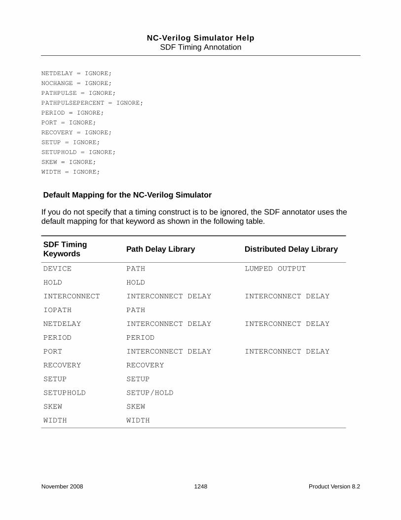
NC-Verilog Simulator HelpSDF Timing Annotation
NETDELAY = IGNORE;
NOCHANGE = IGNORE;
PATHPULSE = IGNORE;
PATHPULSEPERCENT = IGNORE;
PERIOD = IGNORE;
PORT = IGNORE;
RECOVERY = IGNORE;
SETUP = IGNORE;
SETUPHOLD = IGNORE;
SKEW = IGNORE;
WIDTH = IGNORE;
Default Mapping for the NC-Verilog Simulator
If you do not specify that a timing construct is to be ignored, the SDF annotator uses thedefault mapping for that keyword as shown in the following table.
SDF TimingKeywords Path Delay Library Distributed Delay Library
DEVICE PATH LUMPED OUTPUT
HOLD HOLD
INTERCONNECT INTERCONNECT DELAY INTERCONNECT DELAY
IOPATH PATH
NETDELAY INTERCONNECT DELAY INTERCONNECT DELAY
PERIOD PERIOD
PORT INTERCONNECT DELAY INTERCONNECT DELAY
RECOVERY RECOVERY
SETUP SETUP
SETUPHOLD SETUP/HOLD
SKEW SKEW
WIDTH WIDTH
November 2008 1248 Product Version 8.2

NC-Verilog Simulator HelpSDF Timing Annotation
INTERCONNECT_DELAY Keyword
Note: The INTERCONNECT_DELAY construct is not currently implemented in the NC-Verilogsimulator.
If multiple interconnect delays fan into the same device input port, and if the interconnectdelays have different values, the maximum delay is annotated at the common input port bydefault.
You can use the INTERCONNECT_DELAY keyword to specify which delay to use whenmultiple interconnect delays fan into the same device input port, and when the interconnectdelays have different values.
You can select one of the following arguments:
INTERCONNECT_DELAY = [MINIMUM | MAXIMUM | AVERAGE];
For example, if you want to annotate the minimum delay, use the following configuration filestatement:
INTERCONNECT_DELAY = MINIMUM;
INTERCONNECT_MIPD Keyword
Note: The INTERCONNECT_MIPD construct is not currently implemented in the NC-Verilogsimulator.
The INTERCONNECT_MIPD construct performs the same function as theINTERCONNECT_DELAY construct. It is provided for compatibility with Verilog-XL.
MTM Keyword
The MTM keyword specifies whether the SDF annotator uses the minimum, typical, ormaximum delays from the SDF file. The syntax for the MTM keyword is as follows:
Keyword Description
MINIMUM Annotates the minimum delay.
MAXIMUM Annotates the maximum delay.
AVERAGE Annotates the average of all the delays.
November 2008 1249 Product Version 8.2

NC-Verilog Simulator HelpSDF Timing Annotation
MTM = [MINIMUM | TYPICAL | MAXIMUM | TOOL_CONTROL];
Note: The MTM_CONTROL statement in the SDF command file overrides the MTM keywordin the configuration file.
SCALE_FACTORS Keyword
The SCALE_FACTORS keyword specifies the scaling operations that the SDF annotatorperforms on the timing information before it is annotated. The syntax for theSCALE_FACTORS keyword is as follows:
SCALE_FACTORS = min_mult:typ_mult:max_mult;
The argument to the SCALE_FACTORS keyword is a set of three positive real numbermultipliers. If you do not specify values, the default values are 1.0:1.0:1.0 for theminimum, typical, and maximum values.
Note: The SCALE_FACTORS statement in the SDF command file overrides theSCALE_FACTORS keyword in the configuration file.
Example:
SCALE_FACTORS = 1.6:1.4:1.2;
SCALE_TYPE Keyword
The SCALE_TYPE keyword specifies the scale type that the annotator uses when it performsscaling operations on the timing information before it is annotated. The syntax for theSCALE_TYPE keyword is as follows:
SCALE_TYPE = [FROM_MINIMUM | FROM_TYPICAL | FROM_MAXIMUM | FROM_MTM];
Keyword Description
MINIMUM Annotates the minimum delay value.
TYPICAL Annotates the typical delay value. This is the default.
MAXIMUM Annotates the maximum delay value.
TOOL_CONTROL Annotates the delay value specified by the option thatyou use when you invoke the elaborator: -mindelays,-typdelays, or -maxdelays.
November 2008 1250 Product Version 8.2

NC-Verilog Simulator HelpSDF Timing Annotation
Note: The SCALE_TYPE statement in the SDF command file overrides the SCALE_TYPEkeyword in the configuration file.
Example:
The following example shows how the SCALE_FACTORS and SCALE_TYPE keywords inthe configuration file affect the timing specifications in the SDF file. In the following CELLentry, the NETDELAY keyword is used to assign rise, fall, and turnoff delays to a net in the cellinstance x.
(CELL (CELLTYPE "adder4")
(INSTANCE x)
(DELAY
(ABSOLUTE (NETDELAY a.o2 (6:7:8) (4:6:7) (5:8:9)))
)
)
The configuration file defines the scale factors and scale type as follows:
SCALE_FACTORS = 0.5:1:1.5;
SCALE_TYPE = FROM_TYPICAL;
MTM = MINIMUM;
The typical delays in the SDF file are multiplied by the minimum scale factor to annotate thefollowing rise, fall, and turnoff delays for the net:
(3.5) (3) (4)
Keyword Description
FROM_MINIMUM Scales from the minimum timing specification in the SDF file.
FROM_TYPICAL Scales from the typical timing specification in the SDF file.
FROM_MAXIMUM Scales from the maximum timing specification in the SDF file.
FROM_MTM Scales directly from the minimum, typical, or maximum timingspecifications in the SDF file, as selected by MTM in theconfiguration file, MTM_CONTROL in the SDF command file,and command-line options. This is the default.
November 2008 1251 Product Version 8.2

NC-Verilog Simulator HelpSDF Timing Annotation
TURNOFF_DELAY Keyword
Note: The TURNOFF_DELAY construct is not currently implemented in the NC-Verilogsimulator.
The TURNOFF_DELAY keyword specifies how the SDF annotator determines the turnoffdelay that is annotated. The syntax for the TURNOFF_DELAY keyword is as follows:
TURNOFF_DELAY=[MINIMUM | MAXIMUM | AVERAGE | FROM_FILE];
Example:
The following CELL entry in the SDF file assigns rise, fall, and turnoff delays to a net in thecell instance x.
(CELL (CELLTYPE “adder4”)
(INSTANCE x)
(DELAY
(ABSOLUTE (NETDELAY a.o2 (6:7:8) (4:6:9) (5:8:10)))
If the configuration file sets the TURNOFF_DELAY keyword to MAXIMUM, then the turnoffdelay for annotation is (6:7:9), which is derived from the maximum of the rise and fallmin:typ:max values:
maximum (6, 4):maximum (7, 6):maximum (8, 9)
MODULE Keyword
The MODULE keyword maps path delays and timing checks from the SDF file to the VerilogHDL description, performs scaling operations for a specific type of module, and selectsmin:typ:max delay data.
The syntax for the MODULE keyword is as follows:
Keyword Description
MINIMUM Choose the smallest values from the rise and fall delays.This is the default.
MAXIMUM Choose the greatest values from the rise and fall delays.
AVERAGE Average the values from the rise and fall delays.
FROM_FILE Use the turnoff delays in the SDF file. If you do not specifyFROM_FILE, or if you specify FROM_FILE but the SDF filedoes not contain the turnoff delay, the turnoff delay is set toMINIMUM(rise, fall).
November 2008 1252 Product Version 8.2

NC-Verilog Simulator HelpSDF Timing Annotation
MODULE module_name
{
MTM = [MINIMUM | TYPICAL | MAXIMUM];
SCALE_FACTORS = min_mult:typ_mult:max_mult;
SCALE_TYPE = [FROM_MINIMUM | FROM_TYPICAL | FROM_MAXIMUM | FROM_MTM];
MAP_INNER = hierarchical_path;
[ (original_timing) = ADD {(new_timing); ...;}
| (original_timing) = OVERRIDE {(new_timing); ...;}
| (original_timing) = IGNORE;]
}
Note: The MTM, SCALE_FACTORS, and SCALE_TYPE arguments to the MODULE keywordaffect only the IOPATH, DEVICE, and TIMINGCHECK information that is annotated to thespecified module.
MAP_INNER Keyword
The MAP_INNER keyword specifies a submodule in the hierarchy of the module specifiedwith the MODULE keyword. You can use MAP_INNER for any number of submodulescontained within the module.
The syntax for the MAP_INNER keyword is as follows:
MAP_INNER = hierarchical_path;
[ (original_timing) = ADD {(new_timing); ...;}
| (original_timing) = OVERRIDE {(new_timing); ...;}
| (original_timing) = IGNORE;]
Argument Description
module_name Name of a specific type of module (not instance name)specified in the Verilog HDL description.
MTM See the “MTM Keyword” on page 1249 for details.
SCALE_FACTORS See the “SCALE_FACTORS Keyword” on page 1250 fordetails.
SCALE_TYPE See the “SCALE_TYPE Keyword” on page 1250 for details.
MAP_INNER See the “MAP_INNER Keyword” on page 1253 for details.
November 2008 1253 Product Version 8.2

NC-Verilog Simulator HelpSDF Timing Annotation
Note: In all cases, the hierarchical_path name is applied to all new_timingspecifications before they are annotated. In the case of ADD, the hierarchical_pathname is applied to the original timing specification.
Example 1:
This example applies module mapping to the shift module type, which contains asubmodule called m2. For this module, the minimum delays in the SDF file are to be used,and the scale factor is 2.0. For submodule m2, the delay between in1 and out1 in the SDFfile is to be mapped to the delay between i and x.
Argument Description
hierarchical_ path Verilog HDL hierarchical path of a submodule of the modulespecified with the MODULE keyword. The paths specified inthe SDF file are mapped to this instance within the module.This path applies to all path delays and timing checksspecified for this module in the SDF file and that arementioned in ADD, OVERRIDE, or IGNORE statements, upuntil the next MAP_INNER statement.
original_timing Verilog HDL syntax of the path delay or timing check fromthe SDF file.
new_timing Verilog HDL syntax of the path delay or timing check towhich to map.
ADD Annotate not only to the original timing construct in themapped instance, but also to these additional constructs.
OVERRIDE Annotate to the provided list of constructs instead of to theconstruct as specified in the SDF file.
IGNORE Ignore the matching timing specifications in the SDF file.
November 2008 1254 Product Version 8.2

NC-Verilog Simulator HelpSDF Timing Annotation
MODULE shift
{
MTM = MINIMUM;
SCALE_FACTORS = 2.0:2.0:2.0;
MAP_INNER = m2;
(in1 => out1) = OVERRIDE
{
(i => x); } }
Example 2:
In this example, two mappings are performed with the MAP_INNER keyword. Using theOVERRIDE keyword with the hierarchical design in the following figure, this example showsyou how to map and annotate the delay from the path ctrl_in1=>ctrl_out1 to the pathmoto_i=>moto_o, and clk=>moto_o.
The Verilog design has a specify block with the following path delay specification:
(moto_i => moto_o) = (3, 4);
The SDF file for the design has the following delay specification for the path:
(IOPATH ctrl_in1 ctrl_out1 (5) (6))
A module mapping for this hierarchy is specified in the SDF configuration file as follows:
MODULE ctrl_module
{ MAP_INNER = moto_ctrl;
(ctrl_in1 => ctrl_out1) = OVERRIDE
{ (moto_i => moto_o);
(clk => moto_o); }
}
November 2008 1255 Product Version 8.2

NC-Verilog Simulator HelpSDF Timing Annotation
Example 3:
Using the IGNORE keyword with the same hierarchy as shown in Example 2, the followingmapping in the configuration file ignores the specification in the SDF file and continues to usethe timing in the Verilog design.
MODULE ctrl_module
{
MAP_INNER = moto_ctrl;
(ctrl_in1 => ctrl_out1) = IGNORE;
}
Rules for Module Mapping with Conditional Delays
The rules for module mapping in the case of conditional path delays are shown in thefollowing tables. The first table shows the different ways in which Verilog design path delaysare handled in the SDF annotation process, when combined with the COND statements in theSDF file. The second table shows the rules for mapping paths between the SDF file and theconfiguration file.
Annotating Path Delays in the NC-Verilog Simulator
SDF NC-Verilog Annotate Action
no condition no condition Annotate one path
no condition conditional path delay Annotate to all conditions in the design,including an ifnone pathdelay.
Note: In Verilog-XL, all conditions areannotated except if the specify blockcontains an ifnone pathdelay. If thespecify block contains an ifnone,only the ifnone is annotated. Use theelaborator -xlifnone option to emulatethe Verilog-XL behavior.
COND no condition No annotation
COND conditional path delay Annotate one path
November 2008 1256 Product Version 8.2

NC-Verilog Simulator HelpSDF Timing Annotation
Module Mapping in SDF
Controlling SDF Annotator Output
Log and error messages generated by the elaborator and by ncsdfc while compiling the SDFfile specified in a $sdf_annotate() system task are contained in ncelab.log. If you runthe simulator using the irun command, these messages are contained in irun.log.
The SDF annotator does not generate a log file by default. You must specify the name of thelog file either by using the log_file argument of the $sdf_annotate system task or byusing the LOG_FILE statement in an SDF command file.
You can use elaborator options such as -sdf_no_warning to control the output to the logfile.
Use the -sdf_verbose option if you want more detailed information included in the log file.
SDF File Config File Map Action
no condition no condition Mapping performed
no condition COND No mapping performed
COND no condition Mapping performed
COND COND Mapping performed
November 2008 1257 Product Version 8.2

NC-Verilog Simulator HelpSDF Timing Annotation
Command-Line Options that Affect SDF Annotation
The following tables list the elaborator and simulator command-line options that have aneffect on SDF annotation. The second column shows the equivalent Verilog-XL options.
Elaborator (ncelab) Options Verilog-XL
-anno_simtime
Enable the use of PLI/VPI routines that modifydelays at simulation time.
None
-caint
Annotate an SDF PORT delay or INTERCONNECTdelay even if the source port and the load port arenot hierarchically connected by a wire because theyhave been disconnected by a unidirectionalcontinuous assignment statement.
None
-delay_mode {zero | unit | path |distributed | none}
Use the specified delay mode.
+delay_mode_*
-disable_enht
Disable enhanced timing features.
None
-epulse_neg
Filter canceled events (negative pulses) to the estate. This option makes canceled events visible.
+show_cancelled_e
-epulse_noneg
Do not filter canceled events (negative pulses) tothe e state.
+no_show_cancelled_e
-epulse_ondetect
Use On-Detect filtering of error pulses. This optionextends the e state back to the edge of the eventthat caused the pulse to occur.
+pulse_e_style_ondetect
November 2008 1258 Product Version 8.2

NC-Verilog Simulator HelpSDF Timing Annotation
-epulse_onevent
Use On-Event filtering of error pulses.
+pulse_e_style_onevent
-extend_tcheck_data_limitpercent_relaxation
-extend_tcheck_reference_limitpercent_relaxation
Extend the violation regions established by a pair ofsetuphold or recrem timing checks with negativevalues in which the timing checks contain twodifferent constraints for posedge and negedge ofdata with respect to the same reference signal andin which the violation regions do not overlap.
None
-intermod_path
Enable transport delay behavior with pulse controland the ability to specify unique delays for eachsource-load path.
Two command-line options:
+multisource_int_delays and+transport_int_delays
-maxdelays
Apply the maximum delay value if a timing triplet inthe form min:typ:max is provided in the Verilogdescription or in the SDF annotation.
+maxdelays
-mindelays
Apply the minimum delay value if a timing triplet inthe form min:typ:max is provided in the Verilogdescription or in the SDF annotation.
+mindelays
-neg_tchk
Allow negative values in $setuphold and$recovery timing checks in the Verilog descriptionand in SETUPHOLD and RECREM timing checks inSDF annotation.
+neg_tchk
Elaborator (ncelab) Options Verilog-XL
November 2008 1259 Product Version 8.2

NC-Verilog Simulator HelpSDF Timing Annotation
-noautosdf
Do not perform automatic SDF annotation.
None
-noneg_tchk
Do not allow negative values in $setuphold and$recrem timing checks in the Verilog descriptionand in SETUPHOLD and RECREM timing checks inSDF annotation.
None
-no_sdfa_header
Do not print messages displaying informationcontained in the SDF command file.
None
-notimingchecks
Do not execute timing checks.
+notimingchecks
-ntc_warn
Print convergence warnings for negative timingchecks if delays cannot be calculated given currentlimit values. By default, warnings are not printed.
+ntc_warn
-pathpulse
Enable PATHPULSE$ specparams, which are usedto set module path pulse control on a specificmodule or on specific paths within modules.
+pathpulse
-pulse_e error_percent
Set the percentage of delay for pulse error limit forboth module paths and interconnect. If the-pulse_int_e option is also used, this optionapplies only to module paths.
+pulse_e/error_percent
-pulse_int_e error_percent
Set the percentage of delay for pulse error limit forinterconnect only.
+pulse_int_e/error_ percent
Elaborator (ncelab) Options Verilog-XL
November 2008 1260 Product Version 8.2

NC-Verilog Simulator HelpSDF Timing Annotation
-pulse_int_r reject_percent
Set the percentage of delay for pulse reject limit forinterconnect only.
+pulse_int_r/reject_percent
-pulse_r reject_percent
Set the percentage of delay for pulse reject limit forboth module paths and interconnect. If the-pulse_int_r option is also used, this optionapplies only to module paths.
+pulse_r/reject_percent
-sdf_cmd_file
Use the specified SDF command file to control SDFannotation.
None
-sdf_file sdf_filename
Use the specified SDF file instead of the SDF filespecified in the $sdf_annotate system task. Thisoption lets you override the file specified as anargument to the $sdf_annotate system task.
+sdf_filesdf_filename
-sdf_nocheck_celltype
Disable celltype validation between the SDFannotator and the Verilog description. By default,the annotator checks the type specified in theCELLTYPE construct against the module name inthe description. If there is a mismatch, a warning isgenerated and no annotation to that moduleinstance is performed.
+sdf_nocheck_celltype
-sdf_no_warnings
Do not report warning messages from the SDFannotator.
+sdf_no_warnings
-sdf_precision precision
Round the precision of timing values in thecompiled SDF file.
None
Elaborator (ncelab) Options Verilog-XL
November 2008 1261 Product Version 8.2

NC-Verilog Simulator HelpSDF Timing Annotation
SDF Annotation for Mixed-Language Designs
In a mixed-language simulation, you can annotate to both the Verilog and VITAL parts of thedesign from a single SDF file. You can:
■ Annotate to both Verilog and VITAL using the SDF command file methodology describedin “VITAL SDF Annotation” on page 1224.
For the VITAL part of the design, you must use an SDF command file. You can specifymultiple SDF files in the command file, and each of these can go across languageboundaries.
In the following example SDF command file, one SDF file is used to annotate to theVHDL scope :pm7324_inst, which contains Verilog blocks.
-sdf_simtime
Enable simulation-time annotation.
None
-sdf_verbose
Include detailed information in the SDF log file.
+sdf_verbose
-sdf_worstcase_rounding
For timing values in the SDF file, truncate the minvalue, round the typ value, and round up the maxvalue.
None
-typdelays
Apply the typical delay value if a timing triplet in theform min:typ:max is provided in the Verilogdescription or in the SDF annotation.
+typdelays
Simulator (ncsim) Options Verilog-XL
-epulse_no_msg
Suppress pulse control error messages.
+no_pulse_msg
Elaborator (ncelab) Options Verilog-XL
November 2008 1262 Product Version 8.2

NC-Verilog Simulator HelpSDF Timing Annotation
COMPILED_SDF_FILE = "pm7324_flat.sdf.X",
SCOPE = :pm7324_inst,
LOG_FILE = "pm7324_flat.sdf.log",
MTM_CONTROL = "TYPICAL",
SCALE_FACTORS = "1.0:1.0:1.0",
SCALE_TYPE = "FROM_MTM";
■ Annotate to the VITAL parts of the design using an SDF command file and annotate tothe Verilog parts of the design using $sdf_annotate system tasks.
In the current version of the simulator, interconnect delays, including multi-sourceinterconnect delays, are supported across the language boundary except if the languageboundary is a bidirect.
November 2008 1263 Product Version 8.2

NC-Verilog Simulator Help
16IP Protection
The ncprotect utility lets you protect proprietary model information for both Verilog andVHDL. You can protect entire Verilog modules or UDPs and VHDL design units, or you canprotect specific language constructs, such as declarations, expressions, assignments,instantiation statements, Verilog tasks and functions and specify blocks, VHDL subprogramsand processes, and so on.
ncprotect supports two mechanisms for encrypting IP:
■ The Cadence proprietary mechanism, which lets you encrypt both Verilog and VHDLsource files. See “IP Protection Using the Cadence Proprietary Mechanism” onpage 1283.
■ The standard mechanism, which lets you protect Verilog files using the IEEE Verilogstandard, and VHDL files using the IEEE VHDL standard. See “IP Protection Using theIEEE Verilog and VHDL Standard Mechanism” on page 1323.
In both mechanisms, the information that ncprotect needs to generate an encrypted file isprovided in the form of pragmas. The pragmas that specify the portions of the file to encryptare inserted in the HDL source. Additional pragmas can be used to specify the algorithms andkeys to be used, and rights provided by the IP author to the consumer. You can insert theseadditional pragmas into the HDL source or you can put them in a separate file that is thenincluded with the -parameters command-line option.
The protected IP prevents access to internal objects of a protected model through Tcl,SimVision, and programming interfaces, including PLI/VPI, VHPI, and the NC-VHDL Cinterface. The encrypted model information also prevents derived visibility through tools suchas schematic generators or state-machine extraction. Warning and error messages fromprotected regions are either suppressed, or generic messages are issued without disclosingprotected information.
The protected IP is platform-independent. You can run ncprotect on one platform, and thencompile the protected file on any other supported platform.
The encryption process in ncprotect and the decryption process in the Verilog and VHDLparsers require licenses if the effective key length for encryption and decryption is 64 bits or
November 2008 1264 Product Version 8.2

NC-Verilog Simulator HelpIP Protection
more. If the effective key length is 64 bits or less, no license is required. The default effectivekey length for encryption and decryption is 64 bits, so no license is required.
This chapter contains the following subsections:
■ Restrictions
■ ncprotect Command Syntax
■ ncprotect Command Options
■ Example ncprotect Command Lines
■ IP Protection Using the Cadence Proprietary Mechanism
❑ Compatibility between ncprotect Versions and IUS Releases
❑ Protecting IP Using Default Parameters
❑ Protecting IP with User-Defined Algorithms and Keys
❑ Protecting IP with Multiple User-Defined Algorithms and Keys
❑ Converting Encrypted IP to Clear Text Using an Encryption Information File
❑ Licensing Decryption and Simulation of IP Models
❑ Granting Privileges to the IP Consumer
❑ Protection of Verilog and Verilog AMS Designs
❑ Protection of VHDL and VHDL AMS Designs
■ IP Protection Using the IEEE Verilog and VHDL Standard Mechanism
Restrictions
Protection of SDF files is not supported. During backannotation, if a warning or errormessage generates information about the protected code in the design, the code is reportedas protected.
For VHDL, the ncvhdl -smartorder option, which enables order-independent compilationof VHDL design files, works with files that have been protected by running the ncprotectutility. However, the script file generated by the -smartscript option may not be functionalin some situations. For example, the generated script will not work if specific units in thedesign need to be referred to on the ncvhdl command (that is, if the ncvhdl commands inthe generated script include the -specificunit unit_name option).
November 2008 1265 Product Version 8.2

NC-Verilog Simulator HelpIP Protection
The ncshell utility cannot generate a shell for protected Verilog or VHDL models. Forexample, if you use ncprotect to protect a VHDL architecture, compile the source file, andthen run ncshell as shown in the following command, an error is generated because theprotected unit cannot be accessed.
% ncshell -import vhdl -into systemc multiplier:behavioral
Strings passed to Verilog $display statements are not protected internally. However, onlyhardcoded strings are visible. Instance names, module names, and so on are not visible.
ncprotect Command Syntax
Invoke ncprotect with command-line options and the name of the HDL source file(s) thatcontains the blocks of text you want to protect.
Command-line options can occur in any order. Parameters to options must immediately followthe option they modify. Command-line options can be abbreviated to the shortest uniquestring, indicated here with capital letters.
Note: All command-line options are supported for both the Cadence proprietary and IEEEstandard protection mechanisms.
ncprotect [-options] hdl_source_file [hdl_source_file ...]
[-APpend_log]
[-AUtoprotect]
[-Decrypt_with_eif encryption_information_filename]
[-Extension output_file_extension]
[-FCreate]
[-FIle filename]
[-Generate_eif encryption_information_filename]
[-Help]
[-IFILEProtect [-IFILEInline] [-INcdir include_file_path]]
[-IP200x]
[-LAnguage {vlog | vhdl}]
[-LOgfile logfile_name]
[-Messages]
[-NOCopyright]
[-NOLog]
[-NOStdout]
[-OUTDir directory_path]
[-OUTName filename]
[-OVerwrite]
[-Parameters filename]
November 2008 1266 Product Version 8.2

NC-Verilog Simulator HelpIP Protection
[-Rsakeygenerate [-seed “string”] [-keylength length] [-keyname filename]
[-SImulation {portview | debugall | none}]
[-SYnthesis identifier:right]
[-Usekey CDS_NC]
[-Version]
If you specify that you want to use the RSA encryption algorithm, you must generate key pairsbefore running ncprotect to encrypt the files. To generate the key pairs, use the-rsakeygenerate option.
ncprotect -Rsakeygenerate [-seed “string”] [-keylength length] \
[-keyname filename]
You can define the environment variable NCPROTECTOPTS to include command-line options.For example:
setenv NCPROTECTOPTS “-messages -extension prt”
The NCPROTECTOPTS variable cannot be defined in an hdl.var file.
ncprotect Command Options
This section describes the options that you can use with the ncprotect command. Optionscan be entered in upper or lowercase. Capital letters indicate the shortest possibleabbreviation for an option.
-APpend_log
Append log information from multiple ncprotect runs into one log file.
Use -append_log if you are going to run ncprotect multiple times and you want all of thelog information appended to one log file. If you do not use this option, ncprotect overwritesthe log file each time you run ncprotect.
If you use both -append_log and -nolog on the command line, -nolog overrides-append_log.
-AUtoprotect
Encrypt the entire input file(s), ignoring any protection pragmas in the file(s).
The -autoprotect option encrypts the complete file(s) specified on the command lineusing default parameter values. If you want to encrypt the file using a user-defined algorithm
November 2008 1267 Product Version 8.2

NC-Verilog Simulator HelpIP Protection
or key, you must also use the -parameters option to include the file that contains theuser-defined parameters.
When you include the -autoprotect option on the ncprotect command line, ncprotectencrypts the files using the Cadence proprietary mechanism by default. Use the -ip200xoption to use the IEEE standard mechanism.
-Decrypt_with_eif encryption_information_filename
Use the specified encryption information file (EIF) to convert the specified encrypted filesback to clear text files.
When you run ncprotect to encrypt HDL files, you can include the -generate_eif optionon the command line to generate an EIF. The EIF contains encrypted information about thekey_block. The information in the EIF is encrypted using a special key and algorithm set thatcan be used only by ncprotect for converting the encrypted IP to clear text. In other words,the information required to decrypt the data_block resides in encrypted form in the EIF. Thisprevents anyone other than the owner of the EIF from recovering the encrypted IP.
For example, the following command encrypts the VHDL source file counter.vhd in a filecalled counter.vhdp and generates an EIF called IP2clear.eif.
% ncprotect -generate_eif IP2clear.eif -language vhdl counter.vhd
The following command can then be used to convert the encrypted IP back to clear text.
% ncprotect -decrypt_with_eif IP2clear.eif -language vhdl counter.vhdp
The file extension for the clear text file has a “c” appended to the extension of the encryptedfile. For example, if the protected file is called counter.vhdp, the clear text output file iscalled counter.vhdpc. If the protected file is test.vp, the clear text file is calledtest.vpc.
By default, the clear text file is written to the directory that contains the EIF. Use the -outdiroption to specify a different directory. For example:
% ncprotect -decrypt_with_eif IP2clear.eif -outdir ./clear -lang vhdl counter.vhdp
See “Converting Encrypted IP to Clear Text Using an Encryption Information File” onpage 1302 for more information.
-Extension output_file_extension
Use the specified file extension for the ncprotect output file.
November 2008 1268 Product Version 8.2

NC-Verilog Simulator HelpIP Protection
By default, ncprotect generates an output file that has the same filename as the input file,but with the letter p appended to the file extension. For example, if the input file is source.v,the output file is called source.vp. If the input file is source.vhd, the output file is calledsource.vhdp.
Use the -extension option to append a specified extension. For example, the followingcommand generates an output file called source.v.prot:
% ncprotect -language vlog -extension prot source.v
-FCreate
For files that do not include protection pragmas, generate files that have the same fileextension as the protected files.
By default, if an HDL source file does not contain protection pragmas, or if the -parametersoption is not used to include a file that contains protection pragmas, no output file isgenerated. Use the -fcreate option to force the creation of an output file.
This option is convenient if you want to ship multiple design files to an IP user, but only someof the files have protection pragmas. For example, suppose that you have files file1.v,file2.v, and file3.v, and that only file2.v includes protection pragmas. Rather thanprocessing the files selectively, you can run ncprotect with the wildcard character, as shownin the following command.
% ncprotect -messages -lang vlog *.v -fcreate
This creates three files with a .vp extension: file1.vp, file2.vp, and file3.vp.
Now you can copy all .vp files to some directory and deliver this to the customer, who can,in turn, compile the files using the wildcard character.
% ncvlog *.vp
-FIle filename
Use the command-line arguments contained in the specified file.
You can store frequently used or lengthy command lines by putting command options andarguments in a text file. When you invoke ncprotect with the -file option, the arguments inthe specified file are used with the command as if they had been entered on the commandline.
November 2008 1269 Product Version 8.2

NC-Verilog Simulator HelpIP Protection
-Generate_eif encryption_information_filename
Generate an encryption information file (EIF).
Including the -generate_eif option on the command line encrypts the HDL file(s) andgenerates an EIF, which can be used by the IP provider to convert the encrypted IP back toclear text. You must save the generated file so that it can be used during decryption.
The EIF contains encrypted information about the key_block. The information in the EIF isencrypted using a special key and algorithm set. Unlike the embedded corporate keys, whichare visible to parsers for decryption of the key_block, this special set can be used only byncprotect for converting the encrypted IP to clear text. In other words, the informationrequired to decrypt the data_block resides in encrypted form in the EIF. This prevents anyoneother than the owner of the EIF from recovering the encrypted IP.
The following command encrypts the VHDL source file counter.vhd in a file calledcounter.vhdp and generates an EIF called IP2clear.eif, which contains the contentsof the key_block encrypted using a key and algorithm set that can be used only by ncprotectto convert the encrypted IP back to clear text.
% ncprotect -generate_eif IP2clear.eif -language vhdl counter.vhd
By default, the encrypted file and the EIF are written to the directory that contains the originalHDL file. Use the -outdir option to specify a different directory. For example:
% ncprotect -generate_eif IP2clear.eif -outdir ./clear -lang vhdl counter.vhd
To convert the IP to clear text using the EIF, use the -decrypt_with_eif option.
See “Converting Encrypted IP to Clear Text Using an Encryption Information File” onpage 1302 for more information.
-Help
Display a brief summary of the ncprotect command-line options.
-IFILEProtect [-IFILEInline] [-INcdir include_file_path]
Enable the processing of Verilog `include compiler directives.
The Verilog file inclusion compiler directive, `include, is used to insert the contents of aspecified source file in another file during compilation. By default, ncprotect does not encryptthese included files.
November 2008 1270 Product Version 8.2
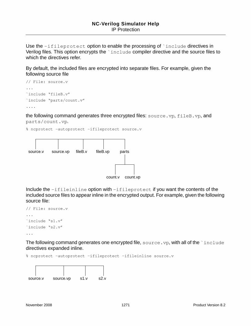
NC-Verilog Simulator HelpIP Protection
Use the -ifileprotect option to enable the processing of `include directives inVerilog files. This option encrypts the `include compiler directive and the source files towhich the directives refer.
By default, the included files are encrypted into separate files. For example, given thefollowing source file
// File: source.v
...
`include “fileB.v”
`include “parts/count.v”
....
the following command generates three encrypted files: source.vp, fileB.vp, andparts/count.vp.
% ncprotect -autoprotect -ifileprotect source.v
Include the -ifileinline option with -ifileprotect if you want the contents of theincluded source files to appear inline in the encrypted output. For example, given the followingsource file:
// File: source.v
...
`include “s1.v”
`include “s2.v”
...
The following command generates one encrypted file, source.vp, with all of the `includedirectives expanded inline.
% ncprotect -autoprotect -ifileprotect -ifileinline source.v
source.v source.vp fileB.v fileB.vp parts
count.v count.vp
source.v source.vp s1.v s2.v
November 2008 1271 Product Version 8.2

NC-Verilog Simulator HelpIP Protection
Use the -incdir option to specify the directory search path for include files. Multiple-incdir options can be included on the command line.
ncprotect searches for include files in the following order:
■ Search the current directory
■ If the file is not found, search the include directories specified with the -incdir options.
■ Generate an error if the include file is not found.
For example, given the following source file
// File: source.v
..
`include “p1.v” // Actual file path is ./include1/p1.v
`include “p2.v” // Actual file path is ./include2/p2.v
...
use the following command to protect the source file source.v and the include files:% ncprotect -autoprotect -ifileprotect source.v \
-incdir ./include1 -incdir ./include2
Using -ifileprotect with the -outname and -outdir Options
The -outname option lets you specify the name of the encrypted output file.
If you use the -outname option, the output of ncprotect is a single encrypted file. ncprotectencrypts all of the input files and concatenates the encrypted files into a single file with thespecified name. The following command generates one output file called protected.v.
% ncprotect -autoprotect source1.v source2.v source3.v -outname protected.v
However, using the -outname option with the -ifileprotect option will generate oneencrypted file for the source files listed on the command line, and generate separate files forthe include files.
For example, given the following source files
source.v source.vp p1.vp p2.vp include1 include2
p1.v p2.v
November 2008 1272 Product Version 8.2

NC-Verilog Simulator HelpIP Protection
// File: source1.v
...
`include “fileB.v”
...
// File: source2.v
...
`include “parts/count.v”
....
the following command generates out.vp, fileB.vp, and ./parts/count.vp.
% ncprotect -autoprotect -ifileprotect source1.v source2.v -outname out.vp
If you include -ifileprotect -ifileinline with the -outname option, one output fileis generated with all of the `include directives expanded inline.
% ncprotect -autoprotect -ifileprotect -ifileinline \
source1.v source2.v -outname out.vp
The -outdir option lets you write out the encrypted source to a specified directory. Usingthis option with -ifileprotect -ifileinline writes the full encrypted source to onedirectory, making it easy to distribute and compile the encrypted source.
The following command encrypts the three source files specified on the command line,encrypts any include files, concatenates the encrypted files, and generates one output filewith all of the `include directives expanded inline, and writes the output file out.vp to the./encrypted directory.
source1.v source2.v fileB.v fileB.vp parts
count.v count.vp
out.vp
source1.v source2.v fileB.v parts
count.v
out.vp
November 2008 1273 Product Version 8.2

NC-Verilog Simulator HelpIP Protection
% ncprotect -autoprotect -ifileprotect -ifileinline \
source1.v source2.v source3.v \
-outname out.vp -outdir ./encrypted
-IP200x
Encrypt the files using the IEEE standard mechanism.
When you include the -autoprotect option on the ncprotect command line, encryptionpragmas in the HDL file(s) are ignored and the entire files are encrypted. By default, whenyou use the -autoprotect option, ncprotect encrypts the files using the Cadenceproprietary mechanism. Use the -ip200x option with -autoprotect to use the IEEEstandard mechanism.
The -ip200x option is necessary only with the -autoprotect option. If -autoprotect isnot specified, ncprotect uses the appropriate encryption mechanism based on the pragmasused in the source files.
Note: With the -ip200x option, the default encryption algorithm used to encrypt data blocksis aes256-cbc, which requires an AES license.
-LAnguage {vlog | vhdl}
Specify the language of the input design files.
If this option is not specified, vlog is the default.
-LOgfile logfile_name
Use the specified name for the log file instead of the default name ncprotect.log.
-Messages
Print informative messages during execution.
Note: Information is written to the log file only when you use the -messages option.
-NOCopyright
Suppress printing of the copyright banner.
November 2008 1274 Product Version 8.2

NC-Verilog Simulator HelpIP Protection
-NOLog
Do not generate a log file. By default, ncprotect generates a log file called ncprotect.log.
-NOStdout
Suppress printing of output to the screen.
-OUTDir directory_path
Save the encrypted file in the specified directory.
By default, ncprotect saves the encrypted file in the directory from which ncprotect wasinvoked. Use the -outdir option to direct the encrypted output files to a specified directory.For example:
% ncprotect -lang vlog -outdir /hm/larrybird/protect test.v
% ncprotect -lang vlog -outdir ./protect_dir test.v
-OUTName filename
Specify the name of the encrypted output file.
By default, ncprotect output filenames have a p appended to the file extension of theunencrypted source file. For example, the following command generates an output file calledvhdl_source.vhdp.
% ncprotect -autoprotect -language vhdl vhdl_source.vhd
Use the -outname option to specify a name for the encrypted output file. For example, thefollowing command encrypts the source file source.v and generates an output file calleds1.vp.
% ncprotect -autoprotect source.v -outname s1.vp
If you use the -outname option, the output of ncprotect is a single encrypted file. ncprotectencrypts all of the input files and concatenates the encrypted files into a single file with thespecified name. The following command generates one output file called protected.v.
% ncprotect -autoprotect source1.v source2.v source3.v -outname protected.v
Note: See “Using -ifileprotect with the -outname and -outdir Options” on page 1272 forinformation on using -outname with the -ifileprotect option.
November 2008 1275 Product Version 8.2

NC-Verilog Simulator HelpIP Protection
-OVerwrite
Overwrite an existing output file.
By default, ncprotect does not overwrite an existing output file.
-Parameters filename
Include the protection parameters in the specified file.
This option is used in the following two ways:
■ When you use the -autoprotect option, ncprotect encrypts the entire source file(s)specified on the command line. Any protection pragmas in the source files are ignored,and default parameters are used.
To specify user-defined keys and algorithms, you must specify the user-definedparameters in a separate file. You can then use -autoprotect -parametersfilename to include these parameters. For example:
% ncprotect -autoprotect -parameters protparams.txt source.vhd
■ If you have a file with multiple protection blocks, you can put the user-defined parametersin a separate parameters file instead of editing the file in multiple places to insert thepragmas. If a parameter is not specified in the input HDL source file, the parameter in theparameters file will be used. Default parameter values are used for parameters that arenot specified in the source file or in the parameters file.
For example, the design file may contain only the following pragmas:
// pragma protect
// pragma protect begin
data to encrypt...
data to encrypt...
// pragma protect end
The parameters file may contain the following text:
data_keyowner=data_keyowner1
data_method=DES
data_keyname=datakey_name1
key_keyowner=key_owner1
key_method=RC2
key_keyname=key_name1
November 2008 1276 Product Version 8.2
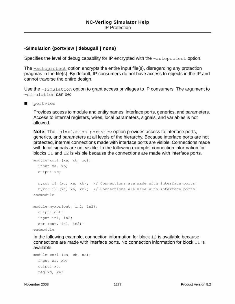
NC-Verilog Simulator HelpIP Protection
-SImulation {portview | debugall | none}
Specifies the level of debug capability for IP encrypted with the -autoprotect option.
The -autoprotect option encrypts the entire input file(s), disregarding any protectionpragmas in the file(s). By default, IP consumers do not have access to objects in the IP andcannot traverse the entire design.
Use the -simulation option to grant access privileges to IP consumers. The argument to-simulation can be:
■ portview
Provides access to module and entity names, interface ports, generics, and parameters.Access to internal registers, wires, local parameters, signals, and variables is notallowed.
Note: The -simulation portview option provides access to interface ports,generics, and parameters at all levels of the hierarchy. Because interface ports are notprotected, internal connections made with interface ports are visible. Connections madewith local signals are not visible. In the following example, connection information forblocks i1 and i2 is visible because the connections are made with interface ports.
module xor1 (xa, xb, xc);
input xa, xb;
output xc;
myxor i1 (xc, xa, xb); // Connections are made with interface ports
myxor i2 (xc, xa, xb); // Connections are made with interface ports
endmodule
module myxor(out, in1, in2);
output out;
input in1, in2;
xor (out, in1, in2);
endmodule
In the following example, connection information for block i2 is available becauseconnections are made with interface ports. No connection information for block i1 isavailable.
module xor1 (xa, xb, xc);
input xa, xb;
output xc;
reg xd, xe;
November 2008 1277 Product Version 8.2

NC-Verilog Simulator HelpIP Protection
wire xf;
myxor i1 (xf, xd, xe); // Connections are made with local signals
myxor i2 (xc, xa, xb); // Connections are made with interface ports
initial
begin
xd = xa;
xe = xb;
end
assign xf = xc;
endmodule
module myxor(out, in1, in2);
output out;
input in1, in2;
xor (out, in1, in2);
endmodule
■ debugall
Provides access to complete information about the design at all levels of the hierarchyusing any interface (Tcl commands, VPI, VHPI, SimVision, and so on).
■ none
Denies debug capability.
The debug capability specified with the -simulation option overrides the rights specifiedin the HDL source file with the rights pragma. See “Granting Privileges to the IP Consumer”on page 1308 for information on the rights pragma.
Example
% ncprotect -lang vlog -autoprotect -simulation portview source.v
November 2008 1278 Product Version 8.2

NC-Verilog Simulator HelpIP Protection
-SYnthesis identifier:right
Specifies the level of protection information required during synthesis by RTL compiler (RC)for IP encrypted with the -autoprotect option.
By default, if IP is encrypted with ncprotect, RC generates an encrypted netlist aftersynthesis. Use the -synthesis option to change the default rights for synthesis activities.
The argument to -synthesis takes the form identifier:right, where:
■ identifier is a keyword defined for a specific synthesis activity.
■ right is a keyword that describes the right being granted.
The following table shows the identifiers defined for synthesis activity and the rights definedfor each identifier.
Synthesis ActivityIdentifier Rights Description
output_netlist Specifies the format of the netlist generated by RC. This canbe:
■ cleartext–Generate a cleartext netlist.
■ data_key–Encrypt netlist using keys and method usedfor encrypting the original IP.
■ none–Encrypt the netlist with the default Cadence key.
output_annotation Specifies the format of backannotation data generated fromthe protected IP. This can be:
■ cleartext–Generate a cleartext netlist.
■ data_key–Encrypt netlist using keys and method usedfor encrypting the original IP.
■ none–Encrypt the netlist with the default Cadence key.
November 2008 1279 Product Version 8.2

NC-Verilog Simulator HelpIP Protection
The rights specified with the -synthesis option override the rights specified in the HDLsource file with the rights pragma. See “Granting Privileges to the IP Consumer” onpage 1308 for information on the rights pragma.
Examples
% ncprotect -lang vlog -autoprotect -synthesis output_netlist:cleartext source.v
% ncprotect -lang vhdl -autoprotect -synthesis viewers:portview source.vhd
-Rsakeygenerate [-seed “string”] [-keylength length] [-keyname filename]
Generate a key pair for the RSA algorithm.
The RSA algorithm, unlike the other algorithms that you can select to encrypt your IP files, isan asymmetric key algorithm. This algorithm uses a pair of different, but compatible, keyscalled public and private keys. Data encrypted with one key can be decrypted only with thecorresponding key.
Use the -rsakeygenerate option to generate the key pair required by the RSA algorithm.If this option is set, ncprotect generates the keys and exits.
There are three options that you can use with -rsakeygenerate:
■ -seed “string”
Specifies a random string that is used as a seed to generate the random numbersrequired in generation of the key pair. If you do not include this flag, an internal seed isused.
ncprotect -rsakeygenerate -seed “random string”
viewers Specifies the permitted viewing modes for the protected IP.This can be:
■ portview–Provide access to ports, generics, andparameters and to module and entity names. Access tointernal registers, wires, local parameters, signals, andvariables is not allowed.
■ debugall–Provide the ability to traverse the completedesign.
■ none–Deny debug capability.
Synthesis ActivityIdentifier Rights Description
November 2008 1280 Product Version 8.2

NC-Verilog Simulator HelpIP Protection
■ -keylength length
Specifies the length in bits of the generated keys. Keys can be from 256 to 4096 bits. Thedefault length is 512 bits.
■ -keyname filename
Specifies the name of the output files in which the key data is written. The generated keysare written to filename.pub and filename.prv. For example, the followingcommand generates foo.pub and foo.prv.
ncprotect -rsakeygenerate -keyname foo
By default, ncprotect generates files called key.pub and key.prv.
-Usekey CDS_NC
Encrypt the input file(s) with the CDS_NC_KEY key, which restricts use of the protected IP totools in the Incisive platform.
If you encrypt IP using the Cadence corporate key or a user-defined key, other tools, such asRTL Compiler or Conformal, can consume the encrypted IP. Use the -usekey CDS_NCoption to encrypt the IP with a key that can be consumed only by Incisive tools. The argumentcan be entered in uppercase or lowercase.
The -usekey CDS_NC option overrides any user-defined keys that may have been specified.ncprotect will skip the user-defined keys, and the key block will be encrypted with theCDS_NC_KEY key.
For example:
% ncprotect -autoprotect -usekey CDS_NC -language vlog *.v
% ncprotect -usekey CDS_NC -language vhdl *.vhd
-Version
Display the version of ncprotect and exit.
November 2008 1281 Product Version 8.2

NC-Verilog Simulator HelpIP Protection
Example ncprotect Command Lines
The following command encrypts the blocks of text marked as protected in the Verilog filesource.v. The -language option is not required because the default is -language vlog.The ncprotect output file is called source.vp. The output file is located in the directory fromwhich ncprotect was invoked.
% ncprotect -nocopyright -messages -language vlog source.v
The following command includes the -outdir option to redirect the output to a directorycalled protdir.
% ncprotect -nocopyright -messages -language vlog -outdir ./protdir source.v
The following command encrypts the blocks of text marked as protected in the VHDL filesource.vhd. The output file is called source.vhdp.
% ncprotect -nocopyright -messages -language vhdl source.vhd
The following command includes the -extension option to specify a file extension for theoutput file. ncprotect generates an output file called source.v.prot:
% ncprotect -nocopyright -messages -language vlog -extension prot source.v
The following command includes the -logfile option. By default, ncprotect generates alog file called ncprotect.log. In this example, the log file will be called prot.log.
% ncprotect -nocopyright -language vhdl -logfile prot.log source.vhd
The following command includes the -autoprotect option, which encrypts the entire inputfile(s), disregarding any protection pragmas in the file(s). The source file is encrypted with theCadence proprietary mechanism.
% ncprotect -nocopyright -language vhdl -autoprotect source.v
The following command includes the -autoprotect option and the -ip200x option, whichencrypts the file with the IEEE standard mechanism.
% ncprotect -nocopyright -lang vlog -autoprotect -ip200x source.v
The following command includes the -autoprotect option and the -parameters option,which is used to specify a file containing user-defined keys and algorithms. See “ProtectingIP with User-Defined Algorithms and Keys” on page 1292 for more information.
% ncprotect -nocopyright -lang vlog -autoprotect -parameters params.txt source.v
Two VHDL source files are specified as arguments on the following command line. ncprotectgenerates two output files: source1.vhdp and source2.vhdp.
% ncprotect -nocopyright -language vhdl source1.vhd source2.vhd
November 2008 1282 Product Version 8.2

NC-Verilog Simulator HelpIP Protection
The following ncprotect command generates key files for the RSA algorithm and then exits.Two 512-bit key files are generated: key.pub and key.prv.
% ncprotect -nocopyright -rsakeygenerate
The following ncprotect command generates key files for the RSA algorithm and then exits.Two 4096-bit key files are generated: rsa4096.pub and rsa4096.prv.
% ncprotect -nocopyright -rsakeygenerate -keylength 4096 -keyname rsa4096
IP Protection Using the Cadence Proprietary Mechanism
If the protection pragmas in the HDL source files conform to the Cadence proprietary style,ncprotect automatically encrypts the files using the Cadence proprietary mechanism.
Note: When you include the -autoprotect option on the ncprotect command line,encryption pragmas in the HDL file(s) are ignored and the entire files are encrypted. Bydefault, when you use the -autoprotect option, ncprotect encrypts the files using theCadence proprietary mechanism. Use the -ip200x option with -autoprotect to overridethe default and use the IEEE standard mechanism.
This section describes the Cadence proprietary mechanism for protecting IP.
Compatibility between ncprotect Versions and IUS Releases
As a general rule, the version of the IUS release used to simulate a design with protectedcode must be equal to, or greater than, the version of ncprotect used to encrypt the code.Backward compatibility is not guaranteed because new features added in a release, orchanges made in a release, are not available in earlier releases. A new feature added to thecurrent release is available in all subsequent releases. For example, a new feature added toIUS 6.1 is available in all versions released after IUS 6.1, including hotfix releases, but thechanges are not available in releases prior to 6.1, such as IUS 5.83, IUS 5.7, and so on.
The following table shows the compatibility of designs protected with CDS_NC_KEY and IUSreleases.
November 2008 1283 Product Version 8.2

NC-Verilog Simulator HelpIP Protection
For other new features or changes, the following table shows which versions of ncprotect arecompatible with which IUS releases.
In this table, an asterisk ( * ) indicates any version of that release. An X in a particular cellindicates that the version of ncprotect is compatible with the IUS release. For example, if youprotect source files with ncprotect 5.83-p, you can simulate with IUS5.83-s. However, if youprotect source files with ncprotect 5.83-s1, you cannot simulate with IUS5.83-p.
IUS ReleaseDesign protected with CDS_NC_KEY
Previous to 6.2-S3 Previous to 6.1-S9
Previous to 6.1-S8 Y Y
6.1-S9 forward N N
Previous to 6.2-S3 Y Y
6.2-S4 to S12 N N
6.2-S13 forward Y Y
8.1-P1 to 8.1-S9 N N
8.1-S10 forward Y Y
ncprotect Version
5.3-s17
5.3-s18
5.4-* 5.5-* 5.6-* 5.7-* 5.83-p5.83-s1
6.1-*(and allversionsafter6.1)
IUS
5.3-s17 X
5.3-s18 X X X X X X X
5.4-* X X X X X X X
5.5-* X X X X X X X
5.6-* X X X X X X X
5.7-* X X X X X X X
November 2008 1284 Product Version 8.2

NC-Verilog Simulator HelpIP Protection
Protecting IP Using Default Parameters
By default, data is encrypted using the AES algorithm with an internal randomly-generated64-bit key. The parsers (ncvlog or ncvhdl) use an embedded key to decrypt the files. Noother key is required.
To protect the IP, the IP author:
1. Specifies the blocks of the design that must be encrypted by inserting protectionpragmas around the blocks. The pragmas, which are in the form of Verilog or VHDLcomments, are:
❑ pragma protect indicates the start of a protection block
❑ pragma protect begin indicates the start of the data to be encrypted
❑ pragma protect end indicates the end of the data to be encrypted
Each pragma should start on a new line.
2. Runs ncprotect on the input files containing the IP.
If you want to protect an entire source file, you can either surround all text in the file with thepragmas or you can just run ncprotect with the -autoprotect option.
5.83-p X X X X X X X
5.83-s1 X X X X X X X X X
6.1-*(and allreleasesafter6.1
X X X X X X X X X
ncprotect Version
5.3-s17
5.3-s18
5.4-* 5.5-* 5.6-* 5.7-* 5.83-p5.83-s1
6.1-*(and allversionsafter6.1)
November 2008 1285 Product Version 8.2

NC-Verilog Simulator HelpIP Protection
The following figure summarizes the IP author flow:
To use the protected IP in your design, you compile the encrypted file(s) and other,non-protected files, and then run the elaborator and simulator (or run the simulator insingle-step invocation mode with irun). No command-line option is required. The parserdecrypts the encrypted file(s) and compiles the design units in the file. Downstream toolsprovide restricted visibility and access to the protected units of the IP.
The IP consumer flow is illustrated in the following figure:
IP author flow
Design file(s) ncprotect -autoprotect Protected IP files
Encrypt the entire file(s)
Encrypt portions of the design
Design file(s) withblocks to be protectedsurrounded byprotection pragmas
ncprotect Protected IP files
Design file(s) with alltext surrounded byprotection pragmas
ncprotect Protected IP files
IP consumer flow
Protected IP fileand otherdesign files
Parser Compileddesign units
Elaboratorandsimulator
November 2008 1286 Product Version 8.2

NC-Verilog Simulator HelpIP Protection
Example 1: Verilog
To protect a Verilog module so that the complete module cannot be accessed, you canprotect:
■ The declaration of the module
■ The keyword module
■ The module name
■ The entire module
In the following example, the file top.v contains module fa1, which instantiates modulesxor1, and1, and or1, which are described in the file protected.v. These three modulesare marked as protected. Only the text surrounded by the pragmas is encrypted, but the entiremodule cannot be accessed by Tcl commands, SimVision, or a programming interface.
// File: top.v
module fa1 (fa, fb, fcin, fsum, fcout);
input fa, fb, fcin;
output fsum, fcout;
wire s1, s2, s3, s4;
xor1 x1(fa, fb, s1),
x2(s1, fcin, fsum);
and1 a1(fa, fb, s2),
a2(fa, fcin, s3),
a3(fb, fcin, s4);
or1 o1(s2, s3, s4, fcout);
endmodule
// File: protected.v
// pragma protect
// pragma protect begin
module xor1 (xa, xb, xc);
// pragma protect end
input xa, xb;
output xc;
assign xc = xa ^ xb;
November 2008 1287 Product Version 8.2

NC-Verilog Simulator HelpIP Protection
endmodule
// pragma protect
// pragma protect begin
module
// pragma protect end
and1(aa, ab, ac);
input aa, ab;
output ac;
assign ac = aa & ab;
endmodule
// pragma protect
// pragma protect begin
module or1(oa, ob, oc, od);
input oa, ob, od;
output oc;
assign oc = oa | ob | od;
endmodule
// pragma protect end
The following ncprotect command generates an output file called protected.vp.
% ncprotect -nocopyright -messages -language vlog protected.v
file protected.v -> protected.vp : 3 protection block(s) processed
To use this file containing protected modules, compile the file, elaborate the design, and runthe simulator.
If you are running in single-step invocation mode with irun, specify the name of the protectedIP file(s) on the irun command line.
% irun -nocopyright -access +rwc -tcl top.v protected.vp
file: top.v
module worklib.fa1:v
errors: 0, warnings: 0
file: protected.vp
errors: 0, warnings: 0
errors: 0, warnings: 0
errors: 0, warnings: 0
November 2008 1288 Product Version 8.2

NC-Verilog Simulator HelpIP Protection
Caching library ’worklib’ ....... Done
Elaborating the design hierarchy:
...
Writing initial simulation snapshot: worklib.fa1:v
Loading snapshot worklib.fa1:v .................... Done
ncsim> scope -show
Directory of scopes at current scope level:
protected unit, instance (x1)
protected unit, instance (x2)
protected unit, instance (a1)
protected unit, instance (a2)
protected unit, instance (a3)
protected unit, instance (o1)
Current scope is (fa1)
Highest level modules:
fa1
ncsim> scope -set a1
ncsim: *E,PROPTH: Path element is protected.
ncsim> value fa1.x1.fa
ncsim: *E,PROPTH: Path element is protected.
ncsim> stop -object fa1.o1.fcout
ncsim: *E,PROPTH: Path element is protected.
ncsim> probe -create -shm fa1.x1.fa
ncsim: *E,PROPTH: Path element is protected.
Use the following commands if you are running the simulator in multi-step invocation mode:
% ncvlog -nocopyright -messages top.v protected.vp
% ncelab -nocopyright -messages -access +rwc worklib.fa1:module
% ncsim -nocopyright -tcl worklib.fa1:module
See “Protection of Verilog and Verilog AMS Designs” on page 1311 for more information.
Example 2: VHDL
In the following VHDL example, the ports of the entity counter_4bit are marked asprotected. The ports cannot be accessed. The unprotected part of the entity can beaccessed, as can the corresponding architecture.
-- File: counter_4bit.vhd
-- A synchronous modulo-16 binary (4-bit) counter
November 2008 1289 Product Version 8.2

NC-Verilog Simulator HelpIP Protection
library ieee;
use ieee.std_logic_1164.all;
entity counter_4bit is
-- pragma protect
-- pragma protect begin
port(
clk_n : in std_ulogic; -- clock input (active falling-edge)
sr_n : in std_ulogic; -- synchronous reset input (active low)
le_n : in std_ulogic; -- synchronous load enable input (active low)
enable : in std_ulogic; -- count enable (active high)
countin : in std_ulogic_vector(3 downto 0);
countout : out std_ulogic_vector(3 downto 0);
carryout : out std_ulogic
);
-- pragma protect end
end counter_4bit;
architecture rtl of counter_4bit is
begin
count : process (clk_n) is
variable icount : std_ulogic_vector(3 downto 0) := "0000";
begin
if (falling_edge(clk_n)) then
if (to_X01(sr_n) = ’0’) then
icount := "0000";
countout <= icount;
carryout <= ’0’;
elsif (to_X01(le_n) = ’0’) then
icount := countin;
countout <= countin;
carryout <= ’0’;
elsif (to_X01(enable) = ’1’) then
if (icount = "1111") then
carryout <= ’1’;
else
carryout <= ’0’;
end if;
for index in countout’low to countout’high loop
if (icount(index) = ’0’) then
November 2008 1290 Product Version 8.2

NC-Verilog Simulator HelpIP Protection
icount(index) := ’1’;
exit;
else
icount(index) := ’0’;
end if;
end loop;
countout <= icount;
end if;
end if;
end process count;
end rtl;
The following ncprotect command generates an output file called counter_4bit.vhdp.
% ncprotect -nocopyright -messages -language vhdl counter_4bit.vhd
file counter_4bit.vhd -> counter_4bit.vhdp : 1 protection block(s) processed
To simulate, compile the file counter_4bit.vhdp, elaborate the design, and run thesimulator.
If you are running in single-step invocation mode with irun, specify the name of the protectedIP file(s) on the irun command line.
% irun -nocopyright -v93 -access +rwc -tcl -top counter_4bit \
counter_4bit.vhdp
counter_4bit.vhdp:
errors: 0, warnings: 0
WORKLIB.COUNTER_4BIT (entity):
streams: 10, words: 90
WORKLIB.COUNTER_4BIT:RTL (architecture):
streams: 1, words: 76
Elaborating the design hierarchy:
...
...
Writing initial simulation snapshot: WORKLIB.COUNTER_4BIT:RTL
Loading snapshot worklib.counter_4bit:rtl .................... Done
ncsim> value countin
ncsim: *E,PROPTH: Path element is protected.
ncsim> scope -show
Directory of scopes at current scope level:
process statement (count)
Current scope is (:)
November 2008 1291 Product Version 8.2

NC-Verilog Simulator HelpIP Protection
Highest level modules:
Top level VHDL design unit:
entity (counter_4bit:rtl)
VHDL Package:
STANDARD
ATTRIBUTES
std_logic_1164
ncsim> scope :count
ncsim> value icount
"0000"
Use the following commands if you are running the simulator in multi-step invocation mode:
% ncvhdl -nocopyright -messages -v93 counter_4bit.vhdp
% ncelab -nocopyright -messages -access +rwc WORKLIB.COUNTER_4BIT:RTL
% ncsim -nocopyright -tcl WORKLIB.COUNTER_4BIT:RTL
See “Protection of VHDL and VHDL AMS Designs” on page 1318 for more information.
Protecting IP with User-Defined Algorithms and Keys
When protecting your IP, you can specify the algorithm to be used for encrypting the data andthe keys, and use user-defined keys. The user-defined keys are stored in files in a keydatabase management infrastructure described in “Key Management” on page 1297.Decrypting tools must use the same key management infrastructure to access theappropriate keys.
Note: All encryption algorithms, except for the RSA algorithm, are symmetric keyalgorithms. These algorithms use the same key for encryption and decryption. The RSAalgorithm is asymmetric. It uses two different keys. Data encrypted with one of the keys canbe decrypted only with its complementary key. These keys are referred to below as a keypair, and must be generated by running ncprotect with the -rsakeygenerate option.
User-defined algorithms and keys are specified by two sets of input pragmas.
Pragmas for Specifying Algorithm and Keys for Data Encryption
Use the following pragmas for specifying the algorithm and keys to be used for encrypting anddecrypting the data:
November 2008 1292 Product Version 8.2

NC-Verilog Simulator HelpIP Protection
■ pragma protect data_method=string
Specifies the algorithm to be used to encrypt and decrypt the data. The stringargument can be: AES, DES, RSA, RC2, RC4, or RC5. You can specify the argument inuppercase or lowercase.
■ pragma protect data_keyowner=string
Specifies the owner of the key who is providing the keys used for encryption anddecryption of the data.
■ pragma protect data_keyname=string
Specifies the name of the key or key pair that should be used to encrypt and decrypt thedata.
If you have specified the RSA algorithm as the data_method, you must run ncprotect-rsakeygenerate to generate a key pair. The string argument for data_keynamemust then specify whether you want to use the public or the private key for encryption.For example, if you run ncprotect -rsakeygenerate, two keys will be generated.These keys are called key.prv and key.pub by default. Use the following syntax tospecify that you want to use the public key:
pragma protect data_keyname=pub(key)
The encrypted data is placed in the data_block portion of the output file.
Note: In the key management system, the string argument to the data_keyownerpragma maps to a directory name, and the string argument to the data_keynamepragma maps to a filename. Therefore, on UNIX, the string argument cannot containspaces. See “Key Management” on page 1297 for details on the key management system.
Pragmas for Specifying Algorithm and Keys for Encryption of Data Block EncryptionDetails
Use the following pragmas to specify the algorithm and keys to be used for encrypting anddecrypting the information about the algorithm and keys that were used to encrypt the data(that is, for encrypting the data_method, data_keyowner, and data_keyname). Thisinformation is placed in the key_block portion of the output file.
■ pragma protect key_method=string
Specifies the algorithm to be used to encrypt the data_method, data_keyowner,and data_keyname information. For decryption, the key_method indicates thealgorithm to be used to decrypt the key_block portion of the output file.
November 2008 1293 Product Version 8.2

NC-Verilog Simulator HelpIP Protection
The string argument can be: AES, DES, RSA, RC2, RC4, or RC5. You can specifythe argument in uppercase or lowercase.
■ pragma protect key_keyowner=string
Specifies the owner of the key who is providing the keys for encryption of thedata_method, data_keyowner, and data_keyname information, and fordecryption of the key_block.
■ pragma protect key_keyname=string
Specifies the name of the key or key pair that should be used to encrypt thedata_method, data_keyowner, and data_keyname.
If you have specified the RSA algorithm as the key_method, you must run ncprotect-rsakeygenerate to generate a key pair. The string argument for key_keynamemustthen specify whether you want to use the public or the private key for encryption. Forexample, if you run ncprotect -rsakeygenerate, two keys will be generated. Thesekeys are called key.prv and key.pub by default. Use the following syntax to specifythat you want to use the public key:
pragma protect key_keyname=pub(key)
Note: In the key management system, the string argument to the key_keyownerpragma maps to a directory name, and the string argument to the key_keyname pragmamaps to a filename. Therefore, on UNIX, the string argument cannot contain spaces. See“Key Management” on page 1297 for details on the key management system.
You can insert these pragmas in the HDL source, or put them in a separate parameters fileto be included with the -parameters option.
If you put the pragmas in the HDL source, they must be inserted between pragma protectand pragma protect begin, as shown in the following VHDL example.
-- pragma protect
-- pragma protect data_keyowner=data_keyowner1
-- pragma protect data_method=DES
-- pragma protect data_keyname=data_keyname1
-- pragma protect key_keyowner=key_keyowner1
-- pragma protect key_method=RC2
-- pragma protect key_keyname=key_keyname1
-- pragma protect begin
data to encrypt...
data to encrypt...
-- pragma protect end
November 2008 1294 Product Version 8.2
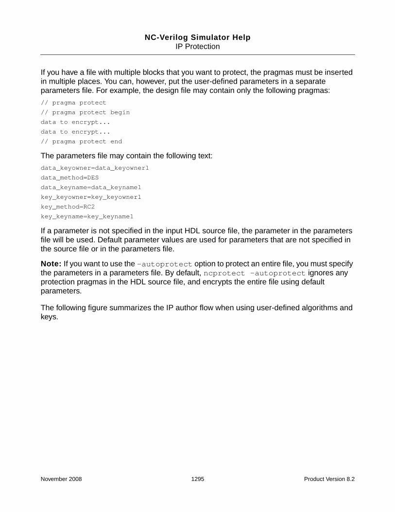
NC-Verilog Simulator HelpIP Protection
If you have a file with multiple blocks that you want to protect, the pragmas must be insertedin multiple places. You can, however, put the user-defined parameters in a separateparameters file. For example, the design file may contain only the following pragmas:
// pragma protect
// pragma protect begin
data to encrypt...
data to encrypt...
// pragma protect end
The parameters file may contain the following text:
data_keyowner=data_keyowner1
data_method=DES
data_keyname=data_keyname1
key_keyowner=key_keyowner1
key_method=RC2
key_keyname=key_keyname1
If a parameter is not specified in the input HDL source file, the parameter in the parametersfile will be used. Default parameter values are used for parameters that are not specified inthe source file or in the parameters file.
Note: If you want to use the -autoprotect option to protect an entire file, you must specifythe parameters in a parameters file. By default, ncprotect -autoprotect ignores anyprotection pragmas in the HDL source file, and encrypts the entire file using defaultparameters.
The following figure summarizes the IP author flow when using user-defined algorithms andkeys.
November 2008 1295 Product Version 8.2

NC-Verilog Simulator HelpIP Protection
Protecting IP with Multiple User-Defined Algorithms and Keys
If you want to send the same protected IP to different IP users with different user-defined keysand algorithms, you do not have to generate multiple output files, one for each user-definedkey. You can generate one output file in which the data has been encrypted with a single data
IP author flow
Design file(s) ncprotect -autoprotect -parameters Protected IP files
Encrypt the entire file(s)
Parameters file
Encrypt portions of the design
ncprotect Protected IP files
Design file(s) with all textsurrounded by basic protectionpragmas. Parameters can bespecified with pragmas in theHDL or in a parameters file.
ncprotect Protected IP files
Parameters file(if used, include the filewith -parameters option)
Design file(s) with blocks to beprotected surrounded by basicprotection pragmas. Parameterscan be specified with pragmas inthe HDL or in a parameters file.
Parameters file(if used, include the filewith -parameters option)
November 2008 1296 Product Version 8.2

NC-Verilog Simulator HelpIP Protection
key, but in which the key information has been encrypted using multiple user-defined keys andalgorithms. The output file will, in effect, contain one data block and multiple key blocks thatcorrespond to the different user-defined keys.
To encrypt a data block with a single data key while encrypting the key information withdifferent keys and algorithms, specify multiple key_keyowner, key_keyname, andkey_method pragmas.
In the following example, two sets of key block encrypting parameters are specified:
-- pragma protect
-- pragma protect data_keyowner=data_keyowner
-- pragma protect data_method=DES
-- pragma protect data_keyname=data_keyname
-- pragma protect key_keyowner=key_keyowner1
-- pragma protect key_method=RC2
-- pragma protect key_keyname=key_keyname1
-- pragma protect key_keyowner=key_keyowner2
-- pragma protect key_method=RC5
-- pragma protect key_keyname=key_keyname2
-- pragma protect begin
data to encrypt...
data to encrypt...
--pragma protect end
When the IP user compiles the protected IP, the parser scans the key blocks in order until itfinds a key block for which it has the keys that are specified. It will then decrypt the data blockfrom the information obtained by decrypting the key block. An error is generated if the keysare not found.
Key Management
In order to use user-defined keys, a key identification, storage, and access mechanism isrequired. This section describes the key management system by first describing what the IPauthor must do, and then what the IP consumer must do.
IP Author
When using user-defined keys, the IP author must:
1. Create a directory for the key database. This directory can have any name. For example,you might create a directory called ip_keys.
November 2008 1297 Product Version 8.2

NC-Verilog Simulator HelpIP Protection
2. In the key database directory, create directories that have the same names as thekeyowners. For example, if you specify the data_keyowner and the key_keyownerwith the following pragmas:
// pragma protect data_keyowner=ip_author
// pragma protect key_keyowner=key_keyowner1
you would create two directories, called ip_author and key_keyowner1.
The key database directory can contain multiple keyowner directories.
3. In the keyowner directory:
❑ If you are using the RSA algorithm, run ncprotect -rsakeygenerate togenerate the public/private key pair.
❑ If you are using any algorithm besides RSA, create a file that has the same nameas the keyname. For example, if you specify the key_keyname with the followingpragma, you would create a file called key_keyname1.
// pragma protect key_keyname=key_keyname1
Enter random data into the file. This data will be used as the key for encryption anddecryption.
If a key owner has multiple keys, the keys must be stored in the same keyowner directory.
4. Set the NCPROTECT_KEYDB environment variable to point to the location of the keydatabase directory. For example:
setenv NCPROTECT_KEYDB /var/ip_keys
If there are multiple key databases, define the NCPROTECT_KEYDB variable to point tomultiple locations. For example:
setenv NCPROTECT_KEYDB ~/local_keydb:/var/ip_keys
ncprotect will look for keys in the order specified in the NCPROTECT_KEYDB variable.
Note: On UNIX platforms, the delimiter used for delimiting multiple entries inenvironment variables such as NCPROTECT_KEYDB is a colon ( : ).
5. Run ncprotect.
6. Deliver the encrypted files and the key database to the IP consumer.
IP User
To use IP files that have been protected with user-defined keys, the IP user must:
1. Create a directory for the key database. This directory can have any name.
November 2008 1298 Product Version 8.2

NC-Verilog Simulator HelpIP Protection
2. In the key database directory, copy the keyowner directories that have been delivered toyou by the IP author. The names of the directories and the names of the key files in thedirectories must exactly match the names of the directories and files that you received.
3. Set the NCPROTECT_KEYDB environment variable to point to the location of the keydatabase directory. If there are multiple key databases, define the NCPROTECT_KEYDBvariable to point to multiple locations. For example:
setenv NCPROTECT_KEYDB /directory/first_keydb:/directory/second_keydb
4. Run the parser on the protected files, and other source files, to compile the design units.
5. Elaborate and simulate.
Example
The following Verilog example will illustrate the IP author and IP user flows when creating andusing IP that has been protected using user-defined keys.
In the file protected.v, the three modules xor1, and1, and or1, are marked as protected.
// File: protected.v
// pragma protect
// pragma protect begin
module xor1 (xa, xb, xc);
// pragma protect end
input xa, xb;
output xc;
assign xc = xa ^ xb;
endmodule
// pragma protect
// pragma protect begin
module
// pragma protect end
and1(aa, ab, ac);
input aa, ab;
output ac;
assign ac = aa & ab;
endmodule
November 2008 1299 Product Version 8.2

NC-Verilog Simulator HelpIP Protection
// pragma protect
// pragma protect begin
module or1(oa, ob, oc, od);
input oa, ob, od;
output oc;
assign oc = oa | ob | od;
endmodule
// pragma protect end
Now suppose that you want to protect the modules in this file using the following parameters:
data_method=DES
data_keyowner=data_keyowner1
data_keyname=data_keyname1
key_keyowner=key_keyowner1
key_method=RSA
key_keyname=prv(key)
key_keyowner=key_keyowner2
key_method=RC5
key_keyname=key_keyname2
You can do this by inserting the pragmas into the HDL source. But this means that you haveto insert the pragmas in three places in the file. In this example, the parameters are placed ina file called params.txt.
The following shows the IP author flow:
1. Create a key database directory, keyowner directories, and key files. The directorystructure might look as follows:
November 2008 1300 Product Version 8.2

NC-Verilog Simulator HelpIP Protection
In this example, the key database directory is called ip_keys. Three directories arecreated in the key database directory: data_keyowner1, key_keyowner1, andkey_keyowner2. The names of these directories match the names of the keyowners.
The names of the key files in the data_keyowner1 and key_keyowner2 directoriesmatch the corresponding keynames. However, for key_keyowner1, the RSA algorithmhas been specified as the key method. To generate keys for RSA, run the followingcommand in the key_keyowner1 directory:
% ncprotect -rsakeygenerate
This command generates key files for the RSA algorithm and then exits. Two 512-bit keyfiles are generated: key.pub and key.prv.
2. Set NCPROTECT_KEYDB to point to the key database directory.
setenv NCPROTECT_KEYDB /some_directory/ip_keys
3. Run ncprotect (with -parameters to include the parameters file).
ncprotect -messages -language vlog -parameters params.txt protected.v
In this example, the output file will contain one data block and multiple key blocks to thedifferent user-defined keys.
4. Deliver the IP and the appropriate directories in the key database to the IP user.
In this example, the IP author delivers the protected IP and the two directoriesdata_keyowner1 (which contains the key file data_keyname1) and key_keyowner1(which contains the RSA keys key.prv and key.pub).
After receiving the IP and the keys from the IP vendor, the user must:
ip_keys (directory)
data_keyowner1(directory)
data_keyname1(file)
key.prv and key.pub(RSA keys generated byrunning ncprotect-rsakeygenerate in thekey_keyowner1 directory)
key_keyowner1(directory)
key_keyowner2(directory)
key_keyname2(file)
November 2008 1301 Product Version 8.2

NC-Verilog Simulator HelpIP Protection
1. Create a key database directory and keyowner directories. The name of the keydatabase directory can be any name (for example, my_keys), but the keyowner directorynames must be the same, and the key file names must be the same. For example:
2. Set NCPROTECT_KEYDB to point to the key database directory.
setenv NCPROTECT_KEYDB /some_directory/my_keys
3. Run the parser to decrypt the files.
ncvlog -messages protected.vp other_source_files
4. Elaborate and simulate.
Converting Encrypted IP to Clear Text Using an Encryption InformationFile
In some situations during the design process, it is necessary to convert encrypted IP to cleartext because some tools do not support encrypted data as input. For example, consider thefollowing scenario:
1. An IP provider creates IP (RTL-level), encrypts it with ncprotect, and ships it to the IPconsumer.
2. The IP consumer instantiates the IP into the design and uses RTL Compiler forsynthesis. RTL Compiler decrypts the HDL, synthesizes the design, and encrypts thenetlist. The synthesized netlist is readable, except for the synthesized IP, which isencrypted.
3. Place and Route tools do not support an encrypted netlist as input.
In this scenario, the IP consumer ships the protected netlist back to the IP provider, whoconverts the netlist to clear text. The IP provider then performs the place and route andmanufactures the chip.
my_keys (directory)
data_keyowner1(directory name is same asthat created by IP author)
data_keyname1(filename is same as thatcreated by IP author)
key_keyowner1(directory name is same asthat created by IP author)
key.prv and key.pub
November 2008 1302 Product Version 8.2

NC-Verilog Simulator HelpIP Protection
This “round trip” sharing of IP is possible with an encryption information file (EIF). The IPprovider must do two things:
1. Generate an EIF when running ncprotect to encrypt the HDL file(s).
The EIF contains encrypted information about the key_block. The information in the EIFis encrypted using a special key and algorithm set. Unlike the embedded corporate keys,which are visible to parsers for decryption of the key_block, this special set can be usedonly by ncprotect for converting the encrypted IP to clear text. In other words, theinformation required to decrypt the data_block resides in encrypted form in the EIF. Thisprevents anyone other than the owner of the EIF from recovering the encrypted IP.
To generate an EIF, use the -generate_eif option. For example:
% ncprotect -generate_eif IP2clear.eif -language vlog IP.v
By default, the encrypted file and the EIF are written to the directory that contains theoriginal HDL file. Use the -outdir option to specify a different directory. For example:
% ncprotect -generate_eif IP2clear.eif -outdir ./clear -lang vhdl counter.vhd
2. Convert the IP consumer’s encrypted netlist to clear text using the EIF.
To decrypt the netlist, use the decrypt_with_eif option. For example:
% ncprotect -decrypt_with_eif IP2clear.eif -language vlog netlist.vp
By default, the clear text file is written to the directory that contains the EIF. Use the-outdir option to specify a different directory.
This process is illustrated in “Round-Trip Encryption” on page 1304.
November 2008 1303 Product Version 8.2

NC-Verilog Simulator HelpIP Protection
Figure 16-1 Round-Trip Encryption
Licensing Decryption and Simulation of IP Models
IP vendors can license their IPs to control simulation usage of the IP. You can licensedecryption of your encrypted IP and/or execution of the protected IP. To do this, the IP author:
1. Writes an entry function to which is passed a feature string, and which returns a value.You can also write an exit function to release the license when decryption or executionhas completed.
2. Creates a shared library.
3. Adds the decrypt_license and/or the runtime_license pragma to the HDLsource code.
These pragmas specify the shared library to be loaded, the name of the entry functionto be called when the library is loaded, the feature string to be passed to the entryfunction, and a match value to be compared with the return value of the entry function.
IP owner
ncprotect-generate_eif ...
ncprotect
ncprotect-decrypt_with_eif
ncprotect
IP consumerrunning RCDecrypt HDL
Synthesize
Encrypt netlist
Originaldesign
ProtectedHDL
ProtectednetlistEncryption
InformationFile
Clear textnetlist
P&R
November 2008 1304 Product Version 8.2
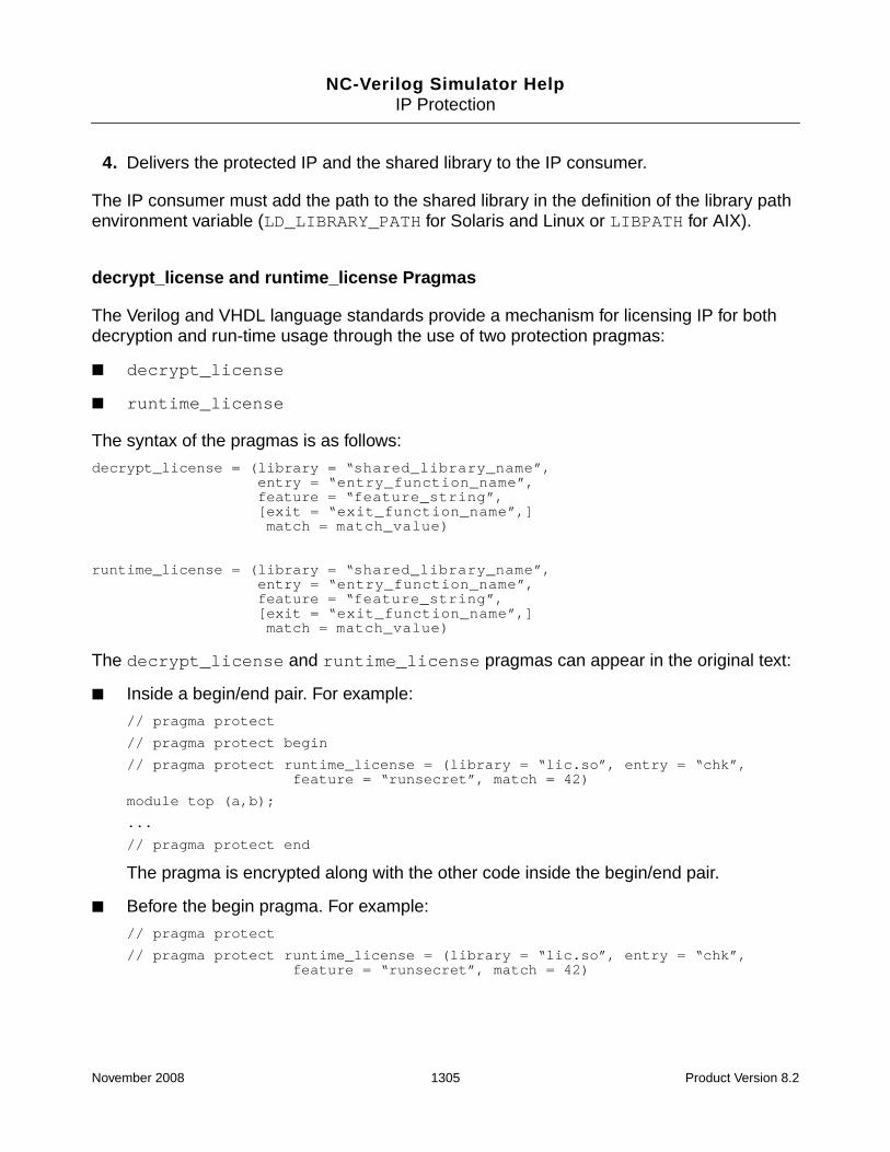
NC-Verilog Simulator HelpIP Protection
4. Delivers the protected IP and the shared library to the IP consumer.
The IP consumer must add the path to the shared library in the definition of the library pathenvironment variable (LD_LIBRARY_PATH for Solaris and Linux or LIBPATH for AIX).
decrypt_license and runtime_license Pragmas
The Verilog and VHDL language standards provide a mechanism for licensing IP for bothdecryption and run-time usage through the use of two protection pragmas:
■ decrypt_license
■ runtime_license
The syntax of the pragmas is as follows:
decrypt_license = (library = “shared_library_name”,entry = “entry_function_name”,feature = “feature_string”,[exit = “exit_function_name”,]match = match_value)
runtime_license = (library = “shared_library_name”,entry = “entry_function_name”,feature = “feature_string”,[exit = “exit_function_name”,]match = match_value)
The decrypt_license and runtime_license pragmas can appear in the original text:
■ Inside a begin/end pair. For example:
// pragma protect
// pragma protect begin
// pragma protect runtime_license = (library = “lic.so”, entry = “chk”,feature = “runsecret”, match = 42)
module top (a,b);
...
// pragma protect end
The pragma is encrypted along with the other code inside the begin/end pair.
■ Before the begin pragma. For example:
// pragma protect
// pragma protect runtime_license = (library = “lic.so”, entry = “chk”,feature = “runsecret”, match = 42)
November 2008 1305 Product Version 8.2

NC-Verilog Simulator HelpIP Protection
// pragma protect begin
module top (a,b);
...
// pragma protect end
The pragma is output as clear text in the output file.
If there are multiple decrypt_license or runtime_license pragmas, the first one willbe used.
The sequence of actions that takes place when the decrypting tool encounters adecrypt_license pragma, or when the run-time application encounters aruntime_license pragma is similar:
1. The tool loads the specified shared library, calls the entry function, and passes thespecified feature string to the entry function.
2. The return value of the entry function is compared to the match value.
3. If the return value of the entry function matches the match value, the IP is decrypted orexecuted.
If the application is not licensed to decrypt the model, no decryption is performed. If theapplication is not licensed to execute the model, execution does not begin. The toolgenerates an error message that includes the return value of the entry function.
Note: Execution can mean any evaluation of the model, including simulation, synthesis,or layout. Only simulation run-time licensing is supported.
If an exit function is specified, the function is called prior to exiting the decrypting application,or the run-time application, so that the license can be released.
This process is illustrated in “Licensing IP” on page 1307.
November 2008 1306 Product Version 8.2

NC-Verilog Simulator HelpIP Protection
Figure 16-2 Licensing IP
Verilog/VHDL ncprotect Protected HDL
Parserdecrypt_license pragma?
Found
IP type?Cadence IP Third-party IP
Simulate the IP
Check outlicenses directly
Load library, transfercontrol to entry function,passing feature stringas argument
Return valuematches matchvalue?
Matched
Simulatorruntime_license pragma?
Found
IP type?Cadence IP Third-party IP
Elaborator
Check outlicenses directly
Load library, transfercontrol to entry function,passing feature stringas argument
Return valuematches matchvalue?
Matched
Notfound
Notfound
Notmatched
Errormessage
Notmatched
November 2008 1307 Product Version 8.2

NC-Verilog Simulator HelpIP Protection
Granting Privileges to the IP Consumer
The IP author can grant privileges to the IP consumer in two ways:
■ If you run ncprotect with the -autoprotect option to protect the entire source file(s),you can include one or both of the following options on the command line:
❑ -simulation {portview | debugall | none}
This option specifies the level of debug capability for the IP. For example, the IP authorcan specify that the consumer can access ports, generics, parameters, and module andentity names of the IP with the following command:
% ncprotect -lang vlog -autoprotect -simulation portview source.v
❑ -synthesis identifier:right
Specifies the level of protection required for synthesis by RTL compiler (RC). Forexample, the IP author can specify that the consumer can synthesize the IP with RC andgenerate a cleartext netlist with the following command:
% ncprotect -lang vlog -autoprotect -synthesis output_netlist:cleartext \source.v
■ Use the rights pragma in the HDL code.
The rights pragma describes the rights granted for objects within the current protectedenvelope. The pragma consists of an expression that identifies a default set of rights, andexpressions that modify the default rights for specified activities.
The rights pragma is inserted inside a begin/end pair in the HDL source. For example:
//pragma protect
//pragma protect begin
//pragma protect rights=....
// other protection pragmas
...
...
// pragma protect end
The rights Pragma
The syntax for the rights pragma is as follows:
pragma protect rights = (scheme=“string” [, default=”string”],activity=definition)
November 2008 1308 Product Version 8.2

NC-Verilog Simulator HelpIP Protection
■ scheme=“string”
The specified scheme defines the interpretation of pragma keywords contained withinthe rights pragma expression. If the value of scheme is simple, the remainingsub-pragma expressions identify the default set of rights, and activities for which thedefault rights are modified.
If the value of scheme is not simple, the interpretation of the rights pragmaexpression is implementation-specified.
■ default=“string”
The value of the default pragma expression is either allow or deny. The defaultpragma expression is optional. If it is not specified, the value is deny.
■ activity=definition
These pragma expressions describe the activities whose rights differ from the default.
The activity is a keyword identifier. The following activities are supported in thecurrent release, and apply to the specified uses of the design data.
For each activity, the value of the activity keyword is a list of pragma sub-expressions thatmodify the default rights. The following table shows the keyword identifiers, the activitiesto which they apply, and a description of the rights.
Keyword Identifier Activity
simulate Execution of the design using simulation semantics asdescribed by the standard
synthesis Translation of the design to another form with equivalentbehavior under simulation
November 2008 1309 Product Version 8.2

NC-Verilog Simulator HelpIP Protection
Keyword Identifier Activities Rights Description
output_annotation synthesis Specifies rights for backannotation datagenerated from a protected envelope.Themethod keyword of this pragma specifies howthe data will be represented upon output fromthe tool. The supported methods are:
■ cleartext
■ data_key
■ none
Example:
synthesis=(output_annotation=(method="cleartext"))
output_netlist synthesis Specifies rights for netlist data generated froma protected envelope.The method keyword ofthis pragma specifies how the data will berepresented upon output from the tool. Thesupported methods are:
■ cleartext
■ data_key
■ none
Example:
synthesis=(output_netlist=(method="cleartext"))
viewers all Specifies the permitted viewing modes for theprotected envelope.
The supported viewers are:
■ portview
■ debugall
■ none
Example:
simulate=(viewers="portview")
November 2008 1310 Product Version 8.2

NC-Verilog Simulator HelpIP Protection
Examples:
// pragma protect rights=(scheme="simple", default="deny",simulate=(viewers="portview"))
// pragma protect rights=(scheme="simple", default="deny",simulate=(viewers="portview"), synthesis=(output_netlist=(method="cleartext")))
// pragma protect rights=(scheme="simple", default="deny",simulate=(viewers="portview"),synthesis=(output_netlist=(method="cleartext"),output_annotation=(method="cleartext"))
If no activity is specified, default values are used. The default values depend upon the valueof the default expression, as shown in the following table.
Protection of Verilog and Verilog AMS Designs
The text in the source file that you enclose within the protection pragmas is always encrypted.However, which language constructs are enclosed in the pragmas affects visibility and accessto objects.
This section provides information on the functionality of a protected Verilog design.
Module and Ports
To protect a module so that the complete module cannot be accessed, you can protect:
■ The declaration of the module
■ The keyword module
■ The module name
For example:
Activity default="deny" default="allow"
simulate viewers="none" viewers="debugall"
synthesis output_netlist=(method="data_key")
output_annotation=(method="data_key")
viewers="none"
output_netlist=(method="cleartext")
output_annotation=(method="cleartext")
viewers="debugall"
November 2008 1311 Product Version 8.2

NC-Verilog Simulator HelpIP Protection
// pragma protect // pragma protect
// pragma protect begin // pragma protect begin
module top; module
// pragma protect end // pragma protect end
reg a,c; top;
wire b,d; reg a,c;
endmodule wire b,d;
endmodule
Only the text between the pragmas will be encrypted.
If only one or more ports of a module is protected, the unprotected blocks of the module canbe accessed. If this module is instantiated, only the ports are encrypted, and the completemodule can be accessed. For example:
module top (a,
// pragma protect
// pragma protect begin
b, c
// pragma protect end);
input a,b;
output c;
reg c;
wire b,d;
endmodule
Declarations
If the complete declaration of a net, variable, or other object is protected, the object cannotbe accessed. For example:
// pragma protect
// pragma protect begin
reg a;
// pragma protect end
If only the type or range, or both, is protected, only the text between the pragmas is encrypted.For example:
November 2008 1312 Product Version 8.2

NC-Verilog Simulator HelpIP Protection
// pragma protect reg
// pragma protect begin // pragma protect
wire // pragma protect begin
// pragma protect end [4:0]
b,d; // b and d can be accessed // pragma protect end
e; // e can be accessed
If a function or task declaration is completely protected, the function or task cannot beaccessed. For example:
// pragma protect
// pragma protect begin
task do_display;
input w1, w2, w3, w4, w5, w6, w7;
begin
$display ("display: ", $time,,w1,w2,w3,,w4,w5,w6,,w7);
end
endtask
// pragma protect end
If only the function or task declaration statement is protected, the function or task cannot beaccessed, but only the text between the pragmas is encrypted. For example:
// pragma protect
// pragma protect begin
task do_display;
// pragma protect end
input w1, w2, w3, w4, w5, w6, w7;
begin
$display ("display: ", $time,,w1,w2,w3,,w4,w5,w6,,w7);
end
endtask
In the current release, if only the function or task declaration arguments are protected, thecomplete process is protected. For example:
task do_display;
// pragma protect
// pragma protect begin
input w1, w2, w3, w4, w5, w6, w7;
// pragma protect end
begin
$display ("display: ", $time,,w1,w2,w3,,w4,w5,w6,,w7);
end
endtask
November 2008 1313 Product Version 8.2
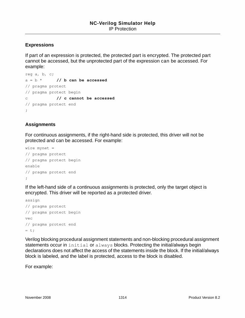
NC-Verilog Simulator HelpIP Protection
Expressions
If part of an expression is protected, the protected part is encrypted. The protected partcannot be accessed, but the unprotected part of the expression can be accessed. Forexample:
reg a, b, c;
a = b * // b can be accessed
// pragma protect
// pragma protect begin
c // c cannot be accessed
// pragma protect end
;
Assignments
For continuous assignments, if the right-hand side is protected, this driver will not beprotected and can be accessed. For example:
wire mynet =
// pragma protect
// pragma protect begin
enable
// pragma protect end
;
If the left-hand side of a continuous assignments is protected, only the target object isencrypted. This driver will be reported as a protected driver.
assign
// pragma protect
// pragma protect begin
vec
// pragma protect end
= t;
Verilog blocking procedural assignment statements and non-blocking procedural assignmentstatements occur in initial or always blocks. Protecting the initial/always begindeclarations does not affect the access of the statements inside the block. If the initial/alwaysblock is labeled, and the label is protected, access to the block is disabled.
For example:
November 2008 1314 Product Version 8.2

NC-Verilog Simulator HelpIP Protection
// pragma protect
// pragma protect begin
initial
begin
// pragma protect end
cycle_count = 0;
end
initial
// pragma protect
// pragma protect begin
begin
#4 D2 = 1’b1;
// pragma protect end
#7 D2 = 1’b0;
end
initial
begin
#100 s1 = 1’bz;
// pragma protect
// pragma protect begin
#100 s1 = 1’b1;
// pragma protect end
end
If a function or task call in an initial or always block is protected, but the declaration ofthe function or task is not protected, the function or task can be accessed. Tasks andfunctions are scopes, and the declaration of the scope must be protected to prevent access.
If only the arguments of the function or task are protected, the function or task can beaccessed.
For force and release statements, protecting the keyword force or release does notaffect the protection of the statement.
Hierarchical Structures and Gates and UDPs
If the complete instantiation statement or the instantiation name is protected, the instantiatedmodule cannot be accessed.
If only the module name in the instantiation statement is protected, the instantiated modulecan be accessed.
November 2008 1315 Product Version 8.2

NC-Verilog Simulator HelpIP Protection
If only some of the ports of the instantiated module are protected, the instantiated module canbe accessed.
For example:
module top;
integer cycle_count;
reg CLK, RST, D0, D1, D2, s1;
wire clk = CLK;
trireg (large) #(3,8,20) la_t;
and and0(and0y, D0, D1);
// Complete statement protected
// pragma protect
// pragma protect begin
D100S dff100fs(.QB(QB0), .Q(Q0), .RB(RST), .CK(clk), .D(and0y));
// pragma protect end
// Instance name protected
D11PS
// pragma protect
// pragma protect begin
dff11ps
// pragma protect end
(.QB(QB0), .Q(Q0), .RB(RST), .CK(clk), .D(and0y));
// Portmap information protected
D10PS dff10ps(
// pragma protect
// pragma protect begin
.QB(QB0), .Q(Q0), .RB(RST), .CK(clk), .D(and0y)
// pragma protect end
);
endmodule
If the declaration of a UDP, only the UDP name, or the keyword primitive is protected, thecomplete UDP cannot be accessed. Only the text between the pragmas is encrypted. Forexample:
primitive
// pragma protect
// pragma protect begin
d_edge_ff
November 2008 1316 Product Version 8.2

NC-Verilog Simulator HelpIP Protection
// pragma protect end
( q, clk, data);
output q;
reg q;
input data, clk;
...
...
endprimitive
Specify Blocks and Timing Checks
If a specify item in a specify block is partially or fully protected, it will be encrypted. If only thespecify keyword is protected, interfaces will have complete visibility to the timing checksection.
If a timing check function is protected, the path of the function is not displayed. All otherinformation is displayed. For example:
// pragma protect
// pragma protect begin
$setup (D, posedge CK &&& RB, 10, notify_reg);
// pragma protect end
$removal (posedge CK &&& RB, D, 10, notify_reg);
$hold (posedge CK &&& RB, D, 10, notify_reg);
Standard Delay Format (SDF)
Protection of SDF files is not supported.
If a warning or error message during backannotation generates information about theprotected code in the design, it will be reported as protected.
System Tasks and Functions
Messages from a system task about the protected parts of the design hierarchy is reported.
For VCD, the $dumpports system task will protect object names if the scope being dumpedis protected. The dumping of values is not affected.
November 2008 1317 Product Version 8.2

NC-Verilog Simulator HelpIP Protection
Compiler Directives
Compiler directives cannot be used to report protected information about the design.
If the `include directive is protected, the compiler directive is not encrypted, and thecorresponding code is not protected.
Verilog Configurations
If the configuration is partially or completely protected, the protected part is encrypted. Thisprotection has no impact on design access.
Protection of VHDL and VHDL AMS Designs
This section provides information on the functionality of a protected VHDL design.
Design Unit
If the entity declaration is partially (starting from the beginning) or completely protected, thecomplete entity cannot be accessed. Only the text between the pragmas is encrypted. Thecorresponding bound architecture cannot be accessed, even if it is not protected.
Note: In the current release, the unprotected declaration inside a partially protected entitycan be accessed. Also, the corresponding architecture can be accessed.
For example:
-- complete entity ROM is protected
-- pragma protect
-- pragma protect begin
entity ROM is
-- pragma protect end
port ( Addr: in Word);
end ROM;
If only the entity’s declarative item or the entity’s declarative statement is protected, theunprotected part of the entity can be accessed. In this case, the corresponding boundarchitecture can be accessed if the architecture declaration is not protected. For example:
November 2008 1318 Product Version 8.2
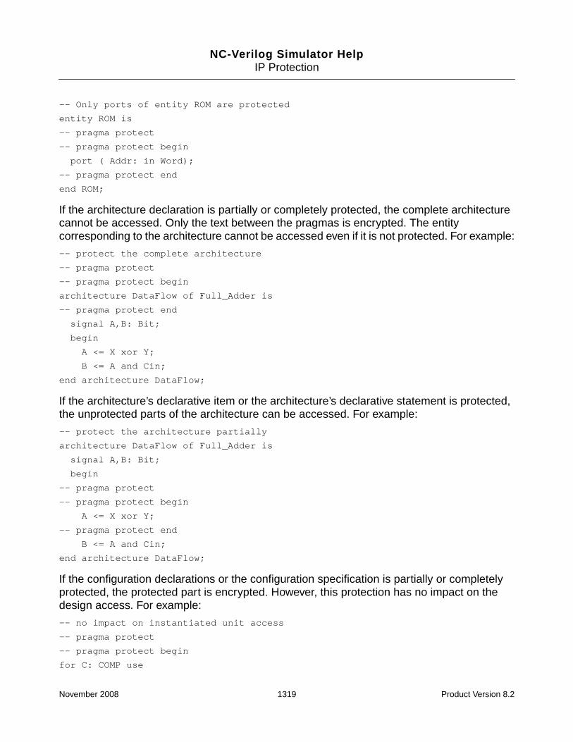
NC-Verilog Simulator HelpIP Protection
-- Only ports of entity ROM are protected
entity ROM is
-- pragma protect
-- pragma protect begin
port ( Addr: in Word);
-- pragma protect end
end ROM;
If the architecture declaration is partially or completely protected, the complete architecturecannot be accessed. Only the text between the pragmas is encrypted. The entitycorresponding to the architecture cannot be accessed even if it is not protected. For example:
-- protect the complete architecture
-- pragma protect
-- pragma protect begin
architecture DataFlow of Full_Adder is
-- pragma protect end
signal A,B: Bit;
begin
A <= X xor Y;
B <= A and Cin;
end architecture DataFlow;
If the architecture’s declarative item or the architecture’s declarative statement is protected,the unprotected parts of the architecture can be accessed. For example:
-- protect the architecture partially
architecture DataFlow of Full_Adder is
signal A,B: Bit;
begin
-- pragma protect
-- pragma protect begin
A <= X xor Y;
-- pragma protect end
B <= A and Cin;
end architecture DataFlow;
If the configuration declarations or the configuration specification is partially or completelyprotected, the protected part is encrypted. However, this protection has no impact on thedesign access. For example:
-- no impact on instantiated unit access
-- pragma protect
-- pragma protect begin
for C: COMP use
November 2008 1319 Product Version 8.2

NC-Verilog Simulator HelpIP Protection
entity X(Y)
port map (P1 => A, P2 => B);
-- pragma protect end
-- no impact on instantiated unit access
-- pragma protect
-- pragma protect begin
library TTL, Work;
configuration V4_27_87 of Processor is
use Work.all;
for Structure_View
for A1: ALU
use configuration TTL.SN74LS181;
end for;
end configuration V4_27_87;
-- pragma protect end
Declarations
If the complete declaration of a signal, variable, or any object is protected, it cannot beaccessed.
If only the type or range, or both, is protected, only the text between the pragmas is encrypted.
If the type declaration is protected, only the type is protected.
Instantiation Statements
If the complete instantiation statement or the instantiation label is protected, the instantiatedunit cannot be accessed. For example:
-- the instantiated unit cannot be accessed
-- pragma protect
-- pragma protect begin
C:
-- pragma protect end
COMP port map (A => S1, B => S2);
However, if only the portmaps and generic maps are protected, the instantiated unit can beaccessed. For example:
November 2008 1320 Product Version 8.2

NC-Verilog Simulator HelpIP Protection
-- the instantiated unit can be accessed
C: COMP port map (
-- pragma protect
-- pragma protect begin
A => S1, B => S2
-- pragma protect end
);
If the component declaration corresponding to a component instantiation statement isprotected, the instantiated unit can be accessed.
-- no impact on instantiated unit access
-- pragma protect
-- pragma protect begin
component
COMP port (A,B : inout BIT);
end component;
-- pragma protect end
Subprograms
If the subprogram declaration is partially or completely protected, the complete subprogramcannot be accessed. Only the text between the pragmas is encrypted. For example:
-- Complete procedure is protected
-- pragma protect
-- pragma protect begin
procedure Dump
-- pragma protect end
(F: inout Text; Value: Integer);
If only the parameters of the subprogram declaration are protected, the unprotected parts ofthe subprogram can be accessed. For example:
-- procedure can be accessed
procedure Dump(
-- pragma protect
-- pragma protect begin
F: inout Text; Value: Integer
-- pragma protect end
);
If the subprogram declaration is not protected but the definition of the subprogram body isprotected, the subprogram can be accessed.
November 2008 1321 Product Version 8.2

NC-Verilog Simulator HelpIP Protection
Processes
If the process label is protected, the process scope cannot be descended into. Only the textbetween the pragmas is encrypted. For example:
-- Complete process is protected
-- pragma protect
-- pragma protect begin
process
begin
CheckTiming (tPLH, tPHL, Clk, D, Q);
wait on Clk, D, Q;
end process;
-- pragma protect end
-- Access to the process is allowed
process (
-- pragma protect
-- pragma protect begin
clk
-- pragma protect end
)
begin
if (clk = ‘0’) then
end if;
end process;
Expressions
If part of an expression is protected, the protected part is encrypted. The protected partcannot be accessed, but the unprotected part of the expression can be accessed.
Assignments
For sequential assignments, if the left-hand side or the right-hand side is protected, theprotected area is encrypted. The protected area of the statement does not impact theunprotected area.
For concurrent signal assignments, if the left-hand side is protected, the corresponding driveris reported as protected. If only the right-hand side is protected, the corresponding drivers arenot protected.
November 2008 1322 Product Version 8.2

NC-Verilog Simulator HelpIP Protection
Assertion statements will not report about the protected parts of the design hierarchy.
Attributes
Any user-defined attribute will not return the protected information of the design. Predefinedattributes return complete information regardless of protection.
Packages
If the use clause of the package is protected, the corresponding package and package bodyare not protected. Access of the package by the interfaces is not affected.
IP Protection Using the IEEE Verilog and VHDL StandardMechanism
ncprotect supports both the Verilog and VHDL protection mechanisms described in the IEEEstandards.
■ For Verilog, the IEEE Standard for Verilog Hardware Description Language (IEEEStd 1364-2005), Clause 28 “Protected Envelopes”, defines the standard for encryptionand decryption of Verilog files.
■ For VHDL, the IEEE Standard VHDL Language Reference Manual (Draft IEEEP1076/D2.11, May 20, 2006), Clause 22 “Standard tool directives”, defines the standardfor encryption and decryption of VHDL files.
Protect pragmas, or directives, in the source file are used to specify the regions of the file tobe protected, and the processing specifications (cryptographic method, key to be used, andso on) for each region.
For Verilog, all protect pragmas begin with `pragma protect. For VHDL, all protectpragmas begin with `protect. Besides that minor difference, the protect pragmassupported by ncprotect are syntactically identical.
ncprotect detects whether the protection pragmas used in the source files conform to theCadence proprietary format or to the IEEE standard, and encrypts the files using theappropriate mechanism.
Note: If you include the -autoprotect option on the ncprotect command line, theprotection pragmas in the files are ignored and the entire content of the source files isencrypted. By default, ncprotect used with the -autoprotect option encrypts the files
November 2008 1323 Product Version 8.2

NC-Verilog Simulator HelpIP Protection
using the Cadence proprietary mechanism. Use the -ip200x option with -autoprotect tospecify the IEEE standard mechanism.
Unsupported Pragma Expressions
The following pragma expressions are not supported in the current release:
■ data_public_key (Section 28.4.13 of the Verilog standard)
■ data_decrypt_key (Section 28.4.14 of the Verilog standard)
■ digest_decrypt_key (Section 28.4.20 of the Verilog standard)
■ comment (Section 28.4.30 of the Verilog standard and 22.1.1.25 of the VHDL standard)
■ reset (Section 28.4.31 of the Verilog standard)
■ viewport (Section 28.4.32 of the Verilog standard and 22.1.1.23 of the VHDL standard)
Other Support Information
■ encoding pragma expression
Section 28.4.9 (Verilog) and Section 22.1.2.1 (VHDL) specify the identifiers that can beused for the enctype sub-keyword. The base64 identifier is supported.
■ digest_method pragma expression
Section 28.4.21 (Verilog) and Section 22.1.2.3 (VHDL) specify the string values for thedigest method. The following identifiers are supported:
❑ sha1 (this is the default value)
❑ md5
❑ md2
■ data_method and key_method pragma expressions
The data_method pragma expression, described in Section 28.4.11 (Verilog) andSection 22.1.1.15 (VHDL), identifies the encryption algorithm to be used to encryptsubsequent begin - end blocks.
The key_method pragma expression, described in Section 28.4.24 (Verilog) andSection 22.1.1.11 (VHDL), identifies the encryption algorithm to be used to encrypt thekeys used to encrypt the data_block.
November 2008 1324 Product Version 8.2

NC-Verilog Simulator HelpIP Protection
For both pragma expressions, the encryption method is an identifier associated with aspecific encryption algorithm. The supported identifiers are the same for both pragmaexpressions. The value can be:
❑ des-cbc (this is the default value for key_method)
❑ aes128-cbc
❑ aes192-cbc
❑ aes256-cbc (this is the default value for data_method)
Note: With the -autoprotect -ip200x option, the default encryption algorithmis aes256-cbc, which requires an AES license.
❑ rsa
■ data_keyname pragma expression
Section 28.4.12 (Verilog) and Section 22.1.1.14 (VHDL) define the data_keynamepragma expression. The default value is CDS_DATA_KEY.
■ key_keyname pragma expression
Section 28.4.25 (Verilog) and Section 22.1.1.10 (VHDL) define the key_keynamepragma expression. The default value is CDS_KEY.
■ With the IEEE standards, if an encrypt key specification, or an encrypt digestspecification, occurs in an encryption envelope, ncprotect forms a digital envelope in thecorresponding decryption envelope.
With the Cadence proprietary mechanism, ncprotect forms a digest block and a digitalenvelope in the corresponding decryption envelope, whether the encrypt key/digestspecification occurs or not.
Encrypt key specification:
encrypt_key_specification :=
{encrypt_key_directive}
key_block_directive
encrypt_key_directive :=
key_keyowner directive
| key_keyname directive
| key_method directive
Encrypt digest specification:
encrypt_digest_specification :=
{encrypt_digest_directive}
November 2008 1325 Product Version 8.2

NC-Verilog Simulator HelpIP Protection
digest_block_directive
encrypt_digest_directive
digest_keyowner directive
| digest_keyname directive
| digest_key_method directive
| digest_method directive
■ To encrypt IP with more than 64-bit encryption, the IP author must have an AES license.The IP user also needs an AES license to consume the IP.
November 2008 1326 Product Version 8.2

NC-Verilog Simulator HelpIP Protection
November 2008 1327 Product Version 8.2

NC-Verilog Simulator Help
17Utilities
There are several utilities that are provided with the simulator:
■ Configuration declaration generator
Generates a VHDL configuration declaration for a specified design unit. See “VHDLConfiguration File Generator” on page 1331 for details on the configuration generator.
■ ncdc
Decompiles a Verilog, VHDL, or mixed Verilog/VHDL design that is represented in asnapshot created by the elaborator or by a Tcl save command. See “ncdc” onpage 1349 for details on ncdc.
■ ncexport
Exports an entire VHDL design hierarchy or just sections of it into a directory structure.See “ncexport” on page 1376 for details on ncexport.
■ ncgentb
Reads an Extended Value Change Dump (EVCD) file that has been generated for adesign under test and generates a Verilog or VHDL testbench. See “ncgentb” onpage 1387 for details on ncgentb.
■ nchelp
Provides help on compiler, elaborator, and simulator messages. Used with the -hdlvaror -cdslib option, nchelp prints the contents of the default or of a specified hdl.varor cds.lib file. See “nchelp” on page 1405 for details on nchelp.
■ ncls
Lists compiled objects stored in the library system and displays various attributes andinformation about those objects. See “ncls” on page 1411 for details on ncls.
■ ncpack
Lets you change the properties of a packed library database. For example, you can makethe database read-only or add-only. See “ncpack” on page 1430 for details on ncpack.
November 2008 1328 Product Version 8.2

NC-Verilog Simulator HelpUtilities
■ ncparse
Lets you compile a Verilog, VHDL, or mixed Verilog-VHDL design using design-topcompilation, in which you specify the top-level of the design instead of specifying allsource files on the command line.
See “ncparse” on page 1438 for details on ncparse.
■ ncprep
Provides a quick transition from simulating a design with Verilog-XL to simulating withNC-Verilog in multi-step invocation mode (ncvlog/ncelab/ncsim). See “ncprep” onpage 1444 for details on ncprep.
■ ncprotect
Lets you protect proprietary model information for both Verilog and VHDL. SeeChapter 16, “IP Protection” for details on ncprotect.
■ ncrm
Deletes design units from a library. See “ncrm” on page 1477 for details on ncrm.
■ ncsdfc
Compiles and decompiles SDF files. See “ncsdfc” on page 1484 for details on ncsdfc.
■ ncshell
Generates a shell file to facilitate model import. See “ncshell” on page 1491 for detailson ncshell.
■ ncsuffix
Displays the machine architecture and the revision number of the library system. See“ncsuffix” on page 1504 for details on ncsuffix.
■ ncupdate
Automatically recompiles and re-elaborates all out-of-date design units in the hierarchy.See “ncupdate” on page 1509 for details on ncupdate.
■ shellgen
Generates a Verilog or VHDL model shell that you can then instantiate in a design toimport OMI-compliant models. See “shellgen” on page 1517 for details on shellgen.
November 2008 1329 Product Version 8.2

NC-Verilog Simulator HelpUtilities
■ simvisdbutil
Translates databases through a command-line interface rather than the SimVisiongraphical user interface. See “simvisdbutil” on page 1522 for information onsimvisdbutil.
November 2008 1330 Product Version 8.2

NC-Verilog Simulator HelpUtilities
VHDL Configuration File Generator
The configuration file generator creates a VHDL configuration file for the design unit specifiedon the command line.
You can generate a VHDL configuration declaration to configure a pure VHDL design, a pureVerilog design, or a mixed Verilog/VHDL design. See “Configuring a Mixed-Language Designwith a VHDL Configuration Declaration” on page 570 for details on using a VHDLconfiguration in a mixed-language design.
For a pure Verilog design that has been configured using a VHDL configuration, ncsimchecks out only an NC-Verilog license.
To generate a configuration file, compile the source files and then include the -conffileoption on the ncelab command line.
% ncelab -conffile configuration_filename [other_options] [lib.]cell[:view]
When you include the -conffile option to generate a configuration file, the elaboratorgenerates the configuration file and then exits. The design is not actually elaborated, and nosimulation snapshot is generated.
The configuration file generator binds instances that have not been explicitly or directlybound. It only works for default binding cases. In addition, if the binding of an entity/modulehappens with an existing configuration declaration, then no configuration happens forinstances below that entity/module.
The rules that the configuration file generator uses when searching for a suitable binding fora VHDL component or Verilog module instance differ slightly depending on whether theinstance is instantiated in a VHDL architecture or in a Verilog module. See “Search Order forSelecting Bindings” on page 1341 for details.
Note: You can use the ncprotect utility to protect proprietary model information for bothVerilog and VHDL. You can protect entire Verilog modules or UDPs and VHDL design units,or you can protect specific language constructs. See Chapter 16, “IP Protection” for detailson using ncprotect.
The configuration file generator will not generate configuration specifications in the output fileif any of the following is protected:
■ VHDL component instance or Verilog module instance
■ Component declaration (for VHDL instance)
■ Bound VHDL entity/architecture or a bound Verilog module
November 2008 1331 Product Version 8.2

NC-Verilog Simulator HelpUtilities
Configuration Generator Command Syntax
To generate a configuration, you must use the ncelab -conffile option.
ncelab -conffile configuration_filename [other_options] [lib.]cell[:view]
The following options can be used to control the configuration generation. These options canbe used only with the -conffile option.
-conffile configuration_filename
[-compile]
[-confflat]
[-confhier]
[-confname configuration_name]
[-insert string_to_insert -matchinst match_string]
[-overwrite]
[-prompt]
[-multview]
[-savechoice savechoice_filename]
[-usechoice usechoice_filename]
[-usearch priority_list_of_architectures]
[-useconf priority_list_of_configuration_declarations]
[-useview priority_list_of_verilog_views]
Most elaborator options do not apply when you are generating a configuration declarationwith the -conffile option because no elaboration of the design actually takes place. Youcan use the following elaborator command-line options when you are using ncelab togenerate a configuration file:
[-append_log]
[-cdslib cdslib_pathname]
[-errormax integer]
[-file arguments_filename]
[-hdlvar hdl_pathname]
[-libverbose]
[-logfile filename]
[-messages]
[-neverwarn]
[-nocopyright]
[-nolog]
[-nostdout]
[-v93]
[-work work_library]
November 2008 1332 Product Version 8.2

NC-Verilog Simulator HelpUtilities
Configuration File Generator Options
-append_log
Append log information from multiple runs of the generator to one log file. This option isoverridden by the -nolog option.
-cdslib cdslib_pathname
Use the specified cds.lib file. See “The cds.lib File” on page 133.
-compile
Compile the generated configuration file after creating it.
This option automatically invokes ncvhdl to compile the generated configuration.
-conffile configuration_filename
Generate a VHDL configuration file for the design unit specified on the command line.
When you include the -conffile option to generate a configuration file, the elaboratorgenerates the configuration file and then exits. The design is not actually elaborated, and nosimulation snapshot is generated.
To generate a configuration file, use the following command:
% ncelab -conffile configuration_filename [other_options] [lib.]cell[:view]
The [lib.]cell[:view] argument is the name of a compiled VHDL design unit orVerilog module.
By default, the elaborator generates a single flat configuration declaration for the entiredesign (that is, the -confflat option is the default). The name of the output configurationfile is the name that you specify on the command line with the -conffile option. Forexample, the following command generates a flat configuration in a file called abc.vhd.
% ncelab -conffile abc.vhd worklib.vhdl_top:testbench
Use the -confhier option if you want to generate a hierarchical configuration file thatcontains a separate configuration specification for each entity or Verilog module. In this case,the name of the output configuration file is LIBRARY_filename. For example, the followingcommand generates a configuration in a file called WORKLIB_abc.vhd.
% ncelab -conffile abc.vhd -confhier worklib.vhdl_top:testbench
November 2008 1333 Product Version 8.2

NC-Verilog Simulator HelpUtilities
-confflat
Generate a flat configuration declaration.
This option generates a single configuration declaration for the entire design. This is thedefault.
The name of the configuration file is the name that you specify with the -conffile option.For example, the following command generates a flat configuration in a file called abc.vhd.
% ncelab -conffile abc.vhd worklib.vhdl_top:testbench
Use the -confhier option if you want to generate a hierarchical configuration file thatcontains a separate configuration for each instance.
An error is generated if you use both -confflat and -confhier on the command line.
-confhier
Generate a hierarchical configuration declaration.
By default, a single, flat configuration declaration for the entire design is generated. Use the-confhier option if you want to generate a hierarchical configuration that contains aseparate configuration for each instance.
The name of the output configuration file is LIBRARY_filename. For example, thefollowing command generates a configuration in a file called WORKLIB_abc.vhd.
% ncelab -conffile abc.vhd -confhier worklib.vhdl_top:testbench
Note: If your design has VHDL entities/Verilog modules that are compiled into differentlibraries, the elaborator generates multiple configuration files in the current directory for thehierarchical format so that the configuration can be compiled in the design unit’s library.These configuration files are called LIBRARYNAME_filename (for example,LIB1_cfg.vhd, LIB2_cfg.vhd, and LIB3_cfg.vhd). For the flat configuration fileformat, the elaborator always generates a single file.
An error is generated if you use both -confflat and -confhier on the command line.
-confname configuration_name
Use the specified name for the configuration instead of the default name.
For VHDL, the default name of the configuration is cfg_entity_architecture.
November 2008 1334 Product Version 8.2

NC-Verilog Simulator HelpUtilities
For Verilog, the default name is cfg_modulename_view.
For a hierarchical configuration, in which a separate configuration specification is generatedfor each entity/module, the configuration name that you specify with the -confname optionis used for the top-level unit.
-errormax integer
Abort the generator after reaching the specified number of errors.
-file arguments_filename
Use the command-line arguments contained in the specified file.
You can store frequently used or lengthy command lines by putting command options andarguments in a text file. When you invoke the generator with the -file option, thearguments in the specified file are used with the command as if you had entered them on thecommand line.
-hdlvar hdl_pathname
Use the specified hdl.var file. See “The hdl.var File” on page 142.
-insert “string_to_insert” -matchinst match_string
Note: The -insert and -matchinst options apply only to instances that have beeninstantiated in VHDL.
Insert the specified string for instances whose name matches (completely or partially) thestring specified with the -matchinst option. Use these options to insert a generic map orport map string for instances.
The -insert option must be used with a corresponding -matchinst option. The stringspecified as the argument to the -matchinst option is used to select the instance(s) forwhich the -insert string is to be added.
For example, the following options can be used to insert the generic map string specified with-insert for instances that match, or that contain, the string other.
-matchinst other -insert "GENERIC MAP (Xon => false, TimingChecksOn => false)"
In the configuration file, the string is inserted for instance whose names contain other. Forexample:
November 2008 1335 Product Version 8.2

NC-Verilog Simulator HelpUtilities
...
for OTHER3: OTHER use entity WORKLIB.OTHER(OTHER_B)
GENERIC MAP (Xon => false, TimingChecksOn => false);
for OTHER_B
end for;
end for;
The string is inserted only when an instance is being bound to an architecture. That is, thestring is inserted only for for ... use entity ... statements. The string is not insertedwhen the binding is with a configuration declaration (for ... use configuration ...statements).
You can use multiple -insert/-matchinst pairs on the command line. This allows you toinsert multiple strings for the same instance(s). For example:
-insert "some string" -matchinst other -insert "another string” -matchinst other
The number of -matchinst options must be the same as the number of -insert options.If there is a mismatch, as in the following example, the configuration file generator prints awarning and ignores the options.
-matchinst other -insert "some string" -insert "another string”
Note: In the hierarchical format of the generated configuration file (-confhier), all bindingsare done with configuration declarations. The -matchinst and -insert options will notinsert any strings for the specified instances in the hierarchical format.
Note: If the string to be inserted is incorrect, and if you include the -compile option toautomatically compile the generated configuration, ncvhdl may not be able to compile the file.
-libverbose
Display verbose messages about resolving instances.
-logfile filename
Use the specified name for the log file instead of the default name ncelab.log.
-messages
Print informative messages during execution.
November 2008 1336 Product Version 8.2

NC-Verilog Simulator HelpUtilities
-multview
Prompt for a binding choice for each instance.
When you have included the -prompt option on the command line, and are prompted for abinding choice, the binding you select is used for all instances of that entity or module. Includethe -multview option if you want to be prompted for each instance so that you can selectdifferent bindings for different instances of the same entity/module.
The -multview option can be used only with the -prompt option.
-neverwarn
Disable printing of all warnings.
-nocopyright
Suppress printing of the copyright banner.
-nolog
Do not generate a log file. By default, a log file called ncelab.log is generated.
This option is overridden by the -logfile option.
-nostdout
Suppress printing of output to the screen.
-overwrite
Overwrite an existing configuration file that has the same name.
By default, the configuration generator does not overwrite an existing configuration file thathas the same name as the configuration file that you are generating. Use the -overwriteoption if you want to generate a configuration file that has the same name as an existingconfiguration file.
November 2008 1337 Product Version 8.2

NC-Verilog Simulator HelpUtilities
-prompt
Prompt the user with binding choices.
If you include the -prompt option on the command line, and if a binding cannot be foundusing a priority list of configurations (-useconf), a priority list of architectures (-usearch),or a priority list of Verilog views (-useview), the configuration generator prompts you with alist of all possible bindings and asks you to choose one from the list.
The prompt list contains all configuration declarations for any component instances, all of itsarchitectures, all views of all Verilog modules in all libraries (case insensitive match), and allof their configuration declarations written in VHDL.
The prompts are similar to the following:
ncelab> Enter the number of the architecture/configuration/view to be bound toentity WORKLIB.LOW_VHDL (Last architecture is the MRA)
0: BEHAVIOR (arch.)
1: RTL (arch.)
In this example, you would enter 0 to select the architecture called BEHAVIOR, or 1 to selectthe architecture called RTL.
The selected binding is used for all instances of that entity or module. Include the -multviewoption if you want to be prompted for each instance so that you can select different bindingsfor different instances of the same entity/module.
-savechoice savechoice_filename
Save user-selected bindings in a file with the specified filename.
When you run the configuration generator with the -prompt option, the bindings you selectare saved in a text file. By default, the name of this file is choices.dat. Use the-savechoice option if you want to give the file a different name. For example:
% ncelab -conffile abc.vhd -prompt -savechoice selections.txt work.vhdl_top:tb
A save bindings file is created only if you use the -prompt option. The file contains only thosebindings that you have selected in response to a prompt. Bindings selected through the-useconf, -usearch, or -useview options are not saved to the file.
After a save file has been created, a subsequent run of the generator can use the-usechoice option to read the file. This can save you time when responding to promptsbecause the generator will not prompt you for those instances recorded in the save file.
November 2008 1338 Product Version 8.2

NC-Verilog Simulator HelpUtilities
The format of the save file is as follows:
work.mid_vlog|VERILOG|VIEW|work.mid_vlog:rtl
WORK.LOW_VHDL|VHDL|ARCHITECTURE|WORK.LOW_VHDL:BEH
where:
■ Column 1: library_name.entity_name or library_name.module_name
■ Column 2: Design unit language (Verilog or VHDL)
■ Column 3: Binding type (ARCHITECTURE, VIEW, or CONFIGURATION)
■ Column 4: Design unit in lib.cell:view format orlibrary_name.configuration_name
If the command line included the -multview option, the format includes a fifth columnshowing the instance name. For example:
work.mid_vlog|VERILOG|VIEW|work.mid_vlog:rtl|WORK.VHDL_TOP.TESTBENCH.DUT1
WORK.LOW_VHDL|VHDL|ARCHITECTURE|WORK.LOW_VHDL:BEH|work.mid_vlog.rtl.low_vhdl1
-usearch priority_list_of_architectures
Use the specified priority list of VHDL architectures when selecting an architecture forbinding.
The priority_list_of_architectures argument can be a single architecture or alist of architectures. If you specify a list of architectures, separate the items on the list with acomma. No spaces are allowed in the list.
Example:
% ncelab -conffile conf.vhd -usearch arch1,arch2,arch3 lib.cell:view
The -usearch option is useful for quickly generating a configuration file with differentbindings. For example, suppose that you specify the following option on the command line:
-usearch rtl,behav
In this case, the configuration generator selects the architecture called rtl for all entities thathave an architecture called rtl. For all other entities, the generator selects the architecturecalled behav.
-usechoice usechoice_filename
Search the specified file for a user-specified binding, and, if one is found, use that bindinginstead of prompting for one. Prompt for a binding only if a binding is not found in the file.
November 2008 1339 Product Version 8.2

NC-Verilog Simulator HelpUtilities
The usechoice_filename is a save file that was created by a previous run of theconfiguration generator in which the -prompt option was included on the command line. Thefile records information about any bindings selected in response to prompts. By default, thename of this save file is choices.dat. You can give the file a different name with the-savechoice option.
See the description of the -savechoice option for more information.
For example, suppose that you have generated a configuration file with the followingcommand:
% ncelab -conffile abc.vhd -prompt work.vhdl_top:tb
The selections you have made in response to the prompts are recorded in a file calledchoices.dat. In a subsequent run of the generator, you can use the -usechoice optionto read the file. This can save you time when responding to prompts because the generatorwill not prompt you for those instances recorded in the save file. You will be prompted only fornew components or modules that have been added to the design. The save file generated bythis subsequent run will record the previous bindings and the new user-selected bindinginformation.
Note: If you included the -multview option on the command line along with -promptwhenthe save file was created, you must include the -multview option when you run thegenerator with the -usechoice option to read the save file. If you did not use the-multview option, do not use -multview with -usechoice.
-useconf priority_list_of_configuration_declarations
Use the specified priority list of compiled VHDL configuration declarations.
The priority_list_of_configuration_declarations argument can be asingle configuration name or a list of configuration names. If you specify a list, separate theitems on the list with a comma. No spaces are allowed in the list.
Example:
% ncelab -conffile conf.vhd -useconf config1,config2,config3 lib.cell:view
-useview priority_list_of_verilog_views
Use the specified priority list of Verilog views when selecting a view for binding.
The priority_list_of_verilog_views argument can be a single view or a list ofviews. If you specify a list of views, separate the items on the list with a comma. No spacesare allowed in the list.
November 2008 1340 Product Version 8.2

NC-Verilog Simulator HelpUtilities
Example:
% ncelab -conffile conf.vhd -useview rtl,gate lib.cell:view
The -useview option is useful for quickly generating a configuration file with differentbindings. For example, suppose that you specify the following option on the command line:
-useview rtl,behav
In this case, the configuration generator selects the view called rtl for all modules that havea view called rtl. For all other modules, the generator selects the view called behav.
-v93
Enable VHDL-93 features. See “VHDL-93 Features” in the chapter “Modeling Your Hardware”in the NC-VHDL Simulator Help for a list of supported VHDL-93 features.
-work work_library
Specifies the work library.
Search Order for Selecting Bindings
The rules that the configuration file generator uses when searching for a suitable binding fora VHDL component or Verilog module instance differ slightly depending on whether theinstance is instantiated in a VHDL architecture or in a Verilog module.
Instance Is Instantiated in a VHDL Architecture
If the instance is instantiated in a VHDL architecture, as shown in the following example, thebinding search rules in “Binding Selection Rules for an Instance Instantiated in VHDL” onpage 1342 are used.
architecture a of e is
component comp is
end component;
begin
comp_inst: comp;
end a;
November 2008 1341 Product Version 8.2

NC-Verilog Simulator HelpUtilities
Figure 17-1 Binding Selection Rules for an Instance Instantiated in VHDL
Instance Is Instantiated in a Verilog Module
If the instance is instantiated in a Verilog module, as shown in the following example, thebinding search rules in “Binding Selection Rules for an Instance Instantiated in Verilog” onpage 1343 are used.
If -useconf option:Search in the priority list of configurations for a compiled configuration declaration.
If no compiled configuration found ...
If -usearch option:Search in the priority list of architectures.
If no architecture found ...
If -useview option:Search in the priority list of Verilog views for a matching Verilog view.
If no view found ...
If -prompt option:Prompt with a list of all possible bindings. Bind instance with selected binding.
If no -prompt option ...
1. Search for a VHDL configuration of a VHDL entity whose name matches the name of thecomponent (comp in the example). If multiple matches, select the first one found (the first onecompiled).
2. If no configuration is found, search for a VHDL configuration for a Verilog module whose namematches the name of the component (case insensitive match). If more than one module is found,select the first one found and then select the first found matching configuration declaration for thatmodule.
3. If no configuration is found, search for VHDL architectures for the entity whose name matches thename of the component. Bind with the most-recently analyzed architecture.
4. If no architectures are found, bind with the first found view of the first found module whose namematches the name of the component.
November 2008 1342 Product Version 8.2

NC-Verilog Simulator HelpUtilities
module m()
...
comp module_inst();
...
end module;
Figure 17-2 Binding Selection Rules for an Instance Instantiated in Verilog
If -useconf option:Search in the priority list of configurations for a compiled configuration declaration.
If no compiled configuration found ...
If -usearch option:Search in the priority list of architectures.
If no architecture found ...
If -useview option:Search in the priority list of Verilog views for a matching Verilog view.
If no view found ...
If -prompt option:Prompt with a list of all possible bindings. Bind instance with selected binding.
If no -prompt option ...
1. Search for a VHDL configuration of a Verilog module whose name matches the name of thecomponent (comp in the example). Search first for a name with an exact case match, then a namethat is all lowercase, and then a name in any case. If multiple matches, select the first one found.
2. If no configuration is found, search for a VHDL configuration for a VHDL entity whose namematches the name of the component (case insensitive match). If more than one entity is found, selectthe first one found and then select the first found matching configuration declaration for that module.
3. If no configuration is found, search for Verilog views for the module whose name matches the nameof the component. Bind with the first view found.
4. If no views are found, bind with the most-recently analyzed architecture of the first found entitywhose name matches the name of the component.
November 2008 1343 Product Version 8.2

NC-Verilog Simulator HelpUtilities
Limitations
The configuration file generator has the following limitations:
■ Verilog modules are supported. Verilog UDP’s and primitives are not supported.
■ Verilog configurations are not supported. If the -conffile and -libmap options haveboth been specified, the -conffile option is ignored. That is, the following twocommands are the same:
ncelab -conffile conf.vhd -libmap vlog_conf.txt lib.cell:view
ncelab -libmap vlog_conf.txt lib.cell:view
■ If the -binding option has also been specified, the -conffile option is ignored. Thefollowing two commands are the same:
ncelab -conffile conf.vhd -binding behavior lib.cell:view
ncelab -binding behavior lib.cell:view
■ If you try to generate a configuration file for an existing configuration declaration, thegenerator uses the top-level design unit from the specified configuration declaration andproceeds for that design unit.
For example, suppose that you have compiled a configuration declaration calledconf_top_arch.
configuration conf_top_arch of top is
for arch
...
end for;
end conf_top_arch;
On the ncelab command line, you specify the configuration, as follows:
ncelab -conffile conf.vhd work.conf_top_arch
The configuration file generator will use the top-level design unit from conf_top_arch(which is work.top:arch) and proceed as if you had specified:
ncelab -conffile conf.vhd work.top:arch
November 2008 1344 Product Version 8.2

NC-Verilog Simulator HelpUtilities
Example Command Lines
The example used in this section is a VHDL-Verilog-VHDL design. The example design isshown in the following figure:
vhdl_top (VHDL)
dut1: mid_vlog (Verilog)
low_vhdl (VHDL)
Entity low_vhdl has two architectures:worklib.low_vhdl:behaviorworklib.low_vhdl:rtl
Two views of module mid_vlog:worklib.mid_vlog:behaviorworklib.mid_vlog:rtl
Entity and architecture compiled into library worklib.
dut2: mid_vlog (Verilog)
low_vhdl (VHDL)
November 2008 1345 Product Version 8.2

NC-Verilog Simulator HelpUtilities
-- File: vhdl_top.vhd
LIBRARY IEEE;
use IEEE.STD_LOGIC_1164.all;
library worklib;
ENTITY vhdl_top IS
END vhdl_top;
ARCHITECTURE testbench OF vhdl_top IS
component mid_vlog
end component;
BEGIN
dut1: mid_vlog;
dut2: mid_vlog;
END testbench;
// File: mid_vlog.v
module mid_vlog();
...
low_vhdl low_vhdl1();
endmodule
-- File: low_vhdl.vhd
use std.textio.all;
ENTITY low_vhdl IS
END low_vhdl;
ARCHITECTURE behavior OF low_vhdl IS
...
END behavior;
ARCHITECTURE rtl OF low_vhdl IS
...
END rtl;
The following commands are used to compile the source files. All design units are compiledinto a library called worklib.
% ncvlog -nocopyright mid_vlog.v -view rtl
% ncvlog -nocopyright mid_vlog.bv -view behavior
November 2008 1346 Product Version 8.2

NC-Verilog Simulator HelpUtilities
% ncvhdl -nocopyright -v93 low_vhdl.vhd
% ncvhdl -nocopyright -v93 vhdl_top.vhd
The following command generates a flat configuration declaration in a file called conf.vhd.The ncvhdl parser is then invoked to compile conf.vhd. The name of the configuration iscfg_VHDL_TOP_TESTBENCH.
% ncelab -nocopyright -conffile conf.vhd -compile worklib.vhdl_top:testbench
The following command includes the -confname option, which is used to override the defaultname for the configuration. The -overwrite option specifies that the configurationgenerator can overwrite an existing file called conf.vhd.
% ncelab -nocopy -conffile conf.vhd -confname cfg_mydesign -overwriteworklib.vhdl_top:testbench
The following command includes the -usearch and -useview options.
■ The -usearch option specifies that the generator is to bind VHDL component instancesto architecture behavior, if it exists. If architecture behavior does not exist, thegenerator will then search for an architecture called rtl.
■ The -useview option specifies that the generator is to bind Verilog module instances toview rtl, if it exists. If view rtl does not exist, the generator will then search for a viewcalled behavior.
% ncelab -nocopy -conffile conf.vhd -usearch behavior,rtl -useview rtl,behavior-overwrite worklib.vhdl_top:testbench
The following command includes the -prompt option. If no suitable binding can be foundusing a priority list of configurations (-useconf), a priority list of architectures (-usearch),or a priority list or Verilog views (-useview), you will be prompted for a selection.
In this example, you will be asked to select a view for module mid_vlog. Then you will beasked to select an architecture for the VHDL instance low_vhdl.
The bindings you select will be used for all instances of that entity or module.
% ncelab -nocopy -conffile conf.vhd -prompt -overwrite worklib.vhdl_top:testbench
The following command includes -prompt and -multview. The -multview optionspecifies that you want to be prompted for each instance so that you can select differentbindings for different instances of the same entity/module.
% ncelab -nocopy -conffile conf.vhd -prompt -multview -overwriteworklib.vhdl_top:testbench
Any binding selections that you make in response to prompts are saved in a file. This file iscalled choices.dat by default. The following command includes the -savechoice optionto override this default name.
November 2008 1347 Product Version 8.2

NC-Verilog Simulator HelpUtilities
% ncelab -nocopy -conffile conf.vhd -prompt -multview -overwrite -savechoicemychoices.txt worklib.vhdl_top:testbench
The following command includes the -usechoice option, which is used to read the save filemychoices.txt generated by the previous command. The configuration generatorsearches this file for a user-specified binding, and, if one is found, uses that binding insteadof prompting you for one. The generator will not prompt you for those instances recorded inthe save file. You will be prompted only for new instances that have been added to the design.
Because the -multview option was included on the command line along with -promptwhen the save file was created, you must include the -multview option when you run thegenerator with the -usechoice option.
% ncelab -nocopy -conffile conf.vhd -multview -prompt -overwrite -usechoicemychoices.dat worklib.vhdl_top:testbench
November 2008 1348 Product Version 8.2

NC-Verilog Simulator HelpUtilities
ncdc
The ncdc utility decompiles a Verilog, VHDL, or mixed Verilog-VHDL design represented ina simulation snapshot.
The ncdc decompiler is useful in many situations, including:
■ System testing
■ Generating test cases that will be useful in fixing bugs
■ Providing test cases to be used in measuring performance
■ Decompiling a snapshot to see what the file contains
■ Recovering the original source text
Decompiling requires a simulation snapshot and its associated libraries. The snapshot canbe one generated by the elaborator or a snapshot that has been saved with a savecommand.
Key features of the ncdc decompiler include the following:
■ The Verilog and VHDL code generated by the decompiler is functionally identical to theoriginal source code, although it may not be syntactically identical. You can compile,elaborate, and simulate the decompiled code, and get the same results.
■ Names of identifiers in the original code can be replaced with automatically generatednames in the output (with the -mangle option). The names of identifiers in SDF filesreferenced in the design are also name-mangled.
■ Source code that has been protected is not decompiled. This includes code surroundedby protection pragmas that has been protected by the ncprotect utility, code that hasbeen packaged with the Model Packager, and Verilog code wrapped in the `protectand `endprotect compiler directives. A commented warning message is inserted intothe output file where the protected IP would go.
■ Comments in the original source code do not appear in the output.
■ Compiler directives, such as `ifdef, `include, and `macro, are resolved.
■ Synthesis pragmas are decompiled (with the -pragma option).
■ PSL is decompiled.
Note: For VHDL, PSL statements in a vunit are decompiled in pragma form, and thepragmas are placed before the end of the architecture to which the vunit is bound.
November 2008 1349 Product Version 8.2

NC-Verilog Simulator HelpUtilities
■ Standard packages are not decompiled. Any package that is a part of any library listedin the file install_directory/tools/inca/files/cds.lib is considered tobe a standard package and is not decompiled.
There are two modes for decompilation: single file decompilation, and original filesdecompilation.
Single File Decompilation
By default, ncdc generates a single output file containing the decompiled Verilog, VHDL, orVerilog/VHDL source code. The output is redirected to stdout. The following commanddecompiles the design represented in the snapshot and sends the output to stdout.
% ncdc snapshot
There are two command-line options that you can use to get an output file:
■ -nostdout. This option suppresses the printing of output to the screen and generatesan output file called ncdc.v (for Verilog) or ncdc.vhd (for VHDL). For a mixed-languagedesign, both files are generated.
■ -output output_filename. This option suppresses the printing of output to thescreen and generates one output file with the specified filename. For example, thefollowing command generates an output file called decomp.out.
% ncdc -output decomp.out snapshot
For a mixed-language design, you can include the -split option to create two separatefiles, one for the Verilog portion of the design (.v), and one for the VHDL portion (.vhd).The name that you specify with the -output option is used in creating the filenames.For example, the following command will create two files: ncdc.out.v andncdc.out.vhd.
% ncdc -output ncdc.out -split snapshot
Single file decompilation mode has the following limitations:
■ If one output file is generated for a mixed-language design, you cannot compile the file.
■ If the original source files were compiled with different command-line options, thedecompiled file may not compile successfully.
■ If two or more design units have the same name and were originally compiled intodifferent libraries, the decompiled file may not compile successfully.
In these cases, you must use the -origfiles option to enable the original filesdecompilation mode.
November 2008 1350 Product Version 8.2

NC-Verilog Simulator HelpUtilities
Original Files Decompilation
If you use the -origfiles command-line option, ncdc generates decompiled output filesthat correspond to the original files. The -origfiles option:
■ Creates a directory called ncdc in the present working directory.
■ Generates separate decompiled files that correspond to the original files. Onedecompiled file is created for each original Verilog and/or VHDL file. These files have thesame name as the original files, and are located in the ncdc directory.
If two or more original files have the same name, a numerical suffix (1, 2, ...) is added tothe decompiled filename.
■ Generates a compilation script called ncdc.run in the ncdc directory. This script canbe used to compile and elaborate the generated files. The commands in the scriptinclude the options used when the original files were compiled, the -work option tospecify the work library, and, for VHDL files, the -smartorder option.
■ Generates a cds.lib file in the ncdc directory. This cds.lib is used for thecompilation of the generated files. An hdl.var file is not created.
You cannot use the -output option with -origfiles.
SDF Files
If you include the -mangle option on the command line, the decompiler replaces the namesof identifiers used in the original source code with automatically generated names. Identifiernames in SDF files required by the design are also replaced with corresponding obfuscatednames. For SDF files, the decompiler:
■ Creates all required name-mangled SDF files in the current directory. The name of thefile is the name of the original SDF file prefixed with mangle_. For example, if the designreferences an SDF file called test.sdf in a $sdf_annotate task($sdf_annotate(“test.sdf”);) , the decompiler generates mangled_test.sdf.
■ Renames the SDF file referenced in each $sdf_annotate system task to itscorresponding mangled SDF file in the generated Verilog source. For example, thedecompiled Verilog source will contain:
$sdf_annotate("mangled_test.sdf");
■ Displays in the ncdc log file a list of the original SDF file names and their mangledequivalents. For example:
SDF file "test.sdf" replaced with mangled file "mangled_test.sdf" in decompiledsource
November 2008 1351 Product Version 8.2

NC-Verilog Simulator HelpUtilities
ncdc retains the type of the original SDF file in the output. For example, if the original SDFsource file was compressed (test.sdf.Z) or gzipped (test.sdf.gz), the mangled SDFfile will also be compressed or gzipped.
Use the -nosdf option to disable the generation of name-mangled SDF files.
There are several related command-line options:
■ -sdf
The decompiler generates a warning if it cannot find an SDF file referenced in the design.Use this option to explicitly specify the path of the SDF file to be mangled together withthe name of the corresponding SDF file in the design.
■ -information
Lists in the ncdc log file all SDF files required to run the decompiled design and any otherfiles referenced by a $readmemb, $readmemh, or $fopen system task.
■ -map
Generates a name mapping file, which lists the mangled identifier names in thedecompiled file(s) and their corresponding names in the original design.
November 2008 1352 Product Version 8.2

NC-Verilog Simulator HelpUtilities
ncdc Command Syntax
Invoke ncdc with options and the name of a snapshot. Options can occur in any order.Parameters to options must immediately follow the option they modify. Command-line optionscan be abbreviated to the shortest unique string, indicated here with capital letters.
The snapshot_name argument is the name of the snapshot in [lib.]cell[:view]format. The snapshot can be generated by the elaborator or created by a Tcl save command.
ncdc [options] snapshot_name
[-64BIT]
[-Append_log]
[-Cdslib filename]
[-File filename]
[-HDlvar filename]
[-HElp]
[-Information]
[-LInelen line_length]
[-LOgfile logfile_name]
[-MANgle]
[-MAP mapfile_name]
[-MEssages]
[-NEverwarn]
[-NOCopyright]
[-NOLog]
[-NOSDf]
[-NOSTdout]
[-NOWarn warning_code[:warning_code]]
[-ORigfiles]
[-OUtput filename [-split]]
[-Pragma]
[-SDf sdf_name=pathname_of_replacement_SDF[:sdf_name=pathname_of_replacement_SDF ...]]
[-STatus]
[-Version]
November 2008 1353 Product Version 8.2
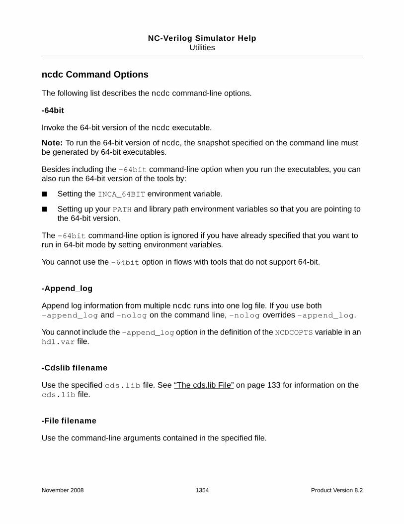
NC-Verilog Simulator HelpUtilities
ncdc Command Options
The following list describes the ncdc command-line options.
-64bit
Invoke the 64-bit version of the ncdc executable.
Note: To run the 64-bit version of ncdc, the snapshot specified on the command line mustbe generated by 64-bit executables.
Besides including the -64bit command-line option when you run the executables, you canalso run the 64-bit version of the tools by:
■ Setting the INCA_64BIT environment variable.
■ Setting up your PATH and library path environment variables so that you are pointing tothe 64-bit version.
The -64bit command-line option is ignored if you have already specified that you want torun in 64-bit mode by setting environment variables.
You cannot use the -64bit option in flows with tools that do not support 64-bit.
-Append_log
Append log information from multiple ncdc runs into one log file. If you use both-append_log and -nolog on the command line, -nolog overrides -append_log.
You cannot include the -append_log option in the definition of the NCDCOPTS variable in anhdl.var file.
-Cdslib filename
Use the specified cds.lib file. See “The cds.lib File” on page 133 for information on thecds.lib file.
-File filename
Use the command-line arguments contained in the specified file.
November 2008 1354 Product Version 8.2

NC-Verilog Simulator HelpUtilities
You can store frequently used or lengthy command lines by putting command options andarguments in a text file. When you invoke ncdc with the -file option, the arguments in thespecified file are used with the command as if you had entered them on the command line.
-HDlvar filename
Use the specified hdl.var file. See “The hdl.var File” on page 142 for information on thehdl.var file.
-HElp
Display a list of the ncdc command-line options with a brief description of each option.
-Information
List all files required to run the decompiled design.
When running the decompiled design, or shipping the decompiled source, you may not beaware of all files that are required to run the simulation. Use the -information option to geta list of these required files. This option lists in the ncdc log file all SDF files required to runthe decompiled design and any other files referenced by a $readmemb, $readmemh, or$fopen system task.
The -information option can be used only with the -mangle option.
Example:
% ncdc -nocopyright -mangle -information worklib.test:module
% cat ncdc.log
SDF file "test.sdf" replaced with mangled file "mangled_test.sdf" in decompiledsource
SDF file "mangled_test.sdf" required in decompiled source
-LInelen line_length
Change the length of a line in the decompiled output to the specified number of characters.
By default, ncdc limits the length of a line to 80 characters. Use the -linelen option toincrease this limit. The line_length argument can be any integer from 80 to 4096.
November 2008 1355 Product Version 8.2

NC-Verilog Simulator HelpUtilities
-LOgfile logfile_name
Use the specified name for the log file instead of the default name ncdc.log.
You cannot include the -logfile option in the definition of the NCDCOPTS variable in anhdl.var file.
-MANgle
Enable name-mangling.
This option enables a feature in ncdc that replaces the names of identifiers used in theoriginal source code with automatically generated names. This feature provides some IPprotection.
SDF files referenced in the design are also name-mangled if you use -mangle. Use the-nosdf option to disable the name-mangling of SDF files.
Note: Designs that contain VITAL Level0 or VITAL Level1 compliant design units cannot bedecompiled with the -mangle option. A warning message is issued if ncdc is invoked withthe -mangle option to decompile a design that contains VITAL cells, and the name-manglingfeature is turned off for the whole decompilation.
-MAP mapfile_name
Generate a name mapping file.
A name mapping file is an ASCII text file that lists the mangled identifier names in thedecompiled file(s) and their corresponding names in the original source files.
You must use the -mangle option with -map to generate a mapping file. For example:
% ncdc -output ncdc.v -mangle -map map.file worklib.top:module
The format of the name mapping file is:
mangled_name original_name
For example:
_1 top
_2 x
_3 y
_4 r
_5 mask
November 2008 1356 Product Version 8.2

NC-Verilog Simulator HelpUtilities
The file is generated in the current directory unless a full or relative path is specified, in whichcase the map file will be created in the designated directory.
-MEssages
Print informational messages to the log file during execution.
-NEverwarn
Disable printing of all warning messages.
-NOCopyright
Suppress printing of the copyright banner.
Because the copyright banner is printed before any variables in the hdl.var file areprocessed, this option is ignored if you include it with the NCDCOPTS variable in an hdl.varfile.
-NOLog
Do not generate a log file. By default, ncdc generates a log file called ncdc.log.
If you include the -nolog option in the hdl.var file, a log file will be created because thefile is opened before any variables in the hdl.var file are processed. However, once theoption is processed in the hdl.var file, output to the log file is discontinued, and the log filewill contain only header information.
-NOSDf
Do not generate SDF files with mangled names.
When you decompile a snapshot with the -mangle option, any SDF files referenced in thedesign are name-mangled by default.
Use -mangle -nosdf if you do not want to generate name-mangled SDF files. For example:
% ncdc -output ncdc.v -mangle -nosdf worklib.top:module
November 2008 1357 Product Version 8.2

NC-Verilog Simulator HelpUtilities
-NOSTdout
Suppress printing of output to the screen, and generate one output file called ncdc.v (forVerilog) or ncdc.vhd (for VHDL). For a mixed-language design, both files are generated.
Use the -output filename option to specify a different name for the output file.
-NOWarn warning_code[:warning_code]
Disable the printing of the specified warning. The warning_code is the sequence ofcharacters following the error severity code.
Example:
% ncdc -nowarn ABCDEF
You can disable the printing of multiple warning messages by using either multiple -nowarnoptions or by using one -nowarn option and separating the warning_code argumentswith a colon. For example,
% ncdc -nowarn ABCDEF -nowarn HIJKLM
% ncdc -nowarn ABCDEF:HIJKLM
-ORigfiles
Enable original files decompilation mode.
The -origfiles option:
■ Creates a directory called ncdc in the present working directory.
■ Generates separate decompiled files that correspond to the original files. Onedecompiled file is created for each original Verilog and/or VHDL file. These files have thesame name as the original files.
If two or more original files have the same name, a numerical suffix (1, 2, ...) is added tothe decompiled filename.
■ Generates a compilation script called ncdc.run in the ncdc directory. This script canbe used to compile and elaborate the generated files. The commands in the scriptinclude the options used when the original files were compiled, the -work option tospecify the work library, and, for VHDL files, the -smartorder option.
■ Generates a cds.lib file in the ncdc directory. This cds.lib is used for thecompilation of the generated files. An hdl.var file is not created.
November 2008 1358 Product Version 8.2

NC-Verilog Simulator HelpUtilities
You cannot use the -output option with -origfiles.
-OUtput filename [-split]
Generate an output file with the specified name.
By default, ncdc redirects the output of the decompiler to stdout. No output file is written.
Use the -output option to suppress the printing of output to the screen and to generate anoutput file with the specified filename. For example, the following command generates anoutput file called decompile.out.
% ncdc -output decompile.out worklib.top:module
For a mixed-language design, you can include the -split option to create two separate files,one for the Verilog portion of the design (.v), and one for the VHDL portion (.vhd). The namethat you specify with the -output option is used in creating the filenames. For example, thefollowing command will create two files: ncdc.out.v and ncdc.out.vhd.
% ncdc -output ncdc.out -split snapshot
You cannot use the -origfiles option with -output.
-Pragma
Decompile synthesis pragmas. By default, synthesis pragmas are not decompiled.
-SDf sdf_name=pathname_of_replacement_SDF[:sdf_name=pathname_of_replacement_SDF ...]
In some situations, ncdc may not be able to find the SDF file referenced by the snapshot. Forexample, if you compile and elaborate the design to generate a snapshot, the snapshotreferences the compiled version of the SDF file(s). If a compiled SDF file is then moved orremoved, ncdc will not find the referenced file, and will generate a warning.
Use the -sdf option to specify the name of the SDF file and the path of the replacement SDFfile to be decompiled and name-mangled. The argument to this option is:
-sdf sdf_name=pathname_of_replacement_SDF
The left-hand side of the argument is the SDF filename referenced in the design (for example,in a $sdf_annotate call), and the right-hand side is the path of the SDF file to be used asits replacement in the decompiled source. For example, suppose that the $sdf_annotatetask is as follows:
$sdf_annotate("test.sdf");
November 2008 1359 Product Version 8.2

NC-Verilog Simulator HelpUtilities
and that ncdc generates a warning that it cannot find the compiled SDF file (test.sdf.X)because it no longer exists. In this case, you could recompile and re-elaborate the design togenerate the compiled SDF file and then rerun ncdc, or you could use the following -sdfoption:
-sdf test.sdf=test.sdf
In this case, ncdc would call ncsdfc to compile the source SDF file, and then generate themangled SDF output file (mangled_test.sdf).
If the compiled SDF file exists, but has been moved to some other directory, you could usethe following -sdf option:
-sdf test.sdf=path_to_directory/test.sdf.X
You can also use the -sdf option to change the name of the SDF file to be used in thedecompiled output. For example, suppose that you have two SDF files called test.sdf andfile.sdf. In the Verilog source, the $sdf_annotate task specifies test.sdf. Aftercompiling and elaborating the design, the snapshot refers to test.sdf.X. If you want thedecompiled output to use file.sdf, you can use the following option:
-sdf test.sdf=file.sdf
While the original Verilog source contains:
$sdf_annotate("test.sdf");
The decompiled output would use the name-mangled version of file.sdf.
$sdf_annotate("mangled_file.sdf");
Multiple -sdf options can be included on the command line. You can also use one option andspecify multiple arguments by separating the arguments with a colon. For example:
-sdf file1.sdf=test1.sdf:file2.sdf=test2.sdf
Note: The -sdf option can be used only with the -mangle option.
-STatus
Display memory and CPU usage statistics. This information is displayed on the terminal andprinted to the log file.
-Version
Display the version of ncdc and exit.
November 2008 1360 Product Version 8.2

NC-Verilog Simulator HelpUtilities
Limitations
This section lists limitations of the ncdc utility that, in some cases, could result in a situationin which the decompiled design cannot be compiled.
■ Full names
In some cases, it is impossible for the decompiler to determine if the actual symbol or thefull name of the symbol was used in the initial design. Dumping the full name by defaultcan result in a host of issues related to name visibility. For example, consider thefollowing code:
architecture A of E .....
function f1 (....)
function f2 (...) -- f2 is a function whose scope is f1 only
end f2;
begin
f2 () ----- Call to f2 in the original code
...
end f1;
If the decompiler dumped full names by default, the call to f2 in the decompiled codewould look like:
A.f1.f2();
If any symbol named A were declared in the scope of f1, this symbol would clash withthe architecture name A. Because of the potential for these name clashes, full names arenot dumped by default.
In the following example, the decompiler dumps the actual name of the symbol x insteadof the full name using information in the library and use clauses. In this example, theclause use lib.p1.all; makes all symbols in package p1 visible inside thearchitecture. Because everything in p1 is visible, dumping the full name is not required.
Original Design Decompiled Designlibrary lib; library lib;
use lib.p1.all; use lib.p1.all;
architecture A of E is architecture A of E is
... ...
a <= p1.x; a <= x;
While dumping the actual name of a symbol is safer than dumping the full name bydefault, there are still situations in which the decompiled output may not compile. Forexample, consider the following code. In this example, the symbol x is defined in bothpackage p1 and package p2.
November 2008 1361 Product Version 8.2

NC-Verilog Simulator HelpUtilities
Original Design Decompiled Designlibrary lib; library lib;
use lib.p1.all; use lib.p1.all;
use lib.p2.all; use lib.p2.all;
architecture A of E is architecture A of E is
... ...
a <= p1.x; a <= x;
In this case, the compiler would generate an error telling you that the identifier x is notvisible because of the conflicting use clauses.
In the following example, the decompiler dumps the actual names, rather than thecomplete names, of the components in the instantiation of u1 and u2 based on the useclause. Because the symbols pcie_test and pcie belong to the package pciecomp,and the use clause specifies that all symbols in pciecomp are visible, the decompilerdumps the actual names only. However, the name of the library is pcie. Therefore, thecomponent name in the instantiation of u2 conflicts with the name of the library, and thedecompiled design will not compile.
Original Design Decompiled Designlibrary pcie; ...
use pcie.pciecomp.all; ...
library pcie;
entity test is use PCIE.pciecomp.all;
end test; ...
...
architecture a of test is architecture a of test is
begin begin
...
u1: pcie.pciecomp.pcie_test; u1: pcie_test;
u2: pcie.pciecomp.pcie; u2: pcie;
...
end a; end ; -- a
■ Null ranges in for/if generates
In some cases, a for-generate or if-generate never gets executed. For example:
for i in X’low to X’high generate
I: A ...
If i never falls in the specified range, it becomes a null range, and the for-generate blockis never elaborated. In the decompiled design, the for-generate and the instantiation I:A would not exist. Any reference to the symbol I in the decompiled design will result in aparser error because symbol I cannot be found. For example, if the original design
November 2008 1362 Product Version 8.2

NC-Verilog Simulator HelpUtilities
contained a configuration specification that configured this instance, the configurationspecification would be decompiled. Because this configuration specification referencesthe symbol I, an error would be generated.
■ Files needed by a design
If a design opens a file from some path, and you use the -origfiles option todecompile the whole design into the ncdc directory, the required file cannot be openedbecause it does not exist in the ncdc directory.
In this case, the decompiler issues a warning telling you that the file must be copied tothe ncdc directory, and that you must edit the decompiled file(s) to specify the correctpath to the file.
■ Design compiled with -relax and hidden library/use clauses
The -relax option lets you use symbols without specifying the library and useclauses. For example, you can access a symbol abc inside a package pack, withoutspecifying
use lib.pack.all;
The decompiler identifies the list of packages to be decompiled through the libraryand use clauses. Without these clauses, the package pack would not be decompiled,and you will not be able to compile the decompiled design.
■ Incremental binding
For incremental binding, there are cases where part of the binding is specified throughthe configuration declaration, and part is specified through the configurationspecification. For example, the port mappings could be specified in the configurationdeclaration, and the generic mapping could be specified through the configurationspecification.
The decompiler cannot identify what binding was done through which mechanism, anddumps all the binding at both places. When you compile the decompiled design, theparser generates an error, complaining that generics and ports have been reassociated.
■ VHDL-Verilog associated port mapping
When a Verilog module is instantiated from a VHDL design unit, the port/genericmappings can be specified in the associated form. For example:
a=>b
where a is the formal in the Verilog module, and b is the actual.
It is possible that the formal (in the Verilog namespace) starts with an underscorecharacter. However, VHDL does not support names starting with an underscore, and anerror is generated when compiling the decompiled design.
November 2008 1363 Product Version 8.2

NC-Verilog Simulator HelpUtilities
By default, the decompiler always dumps the port mappings and generic mappings in theassociated form and not in the sequential form, even if in the initial design the mappingswere specified in a sequential form.
■ Library name same as other object name in scope
The WORK variable can be defined in the hdl.var file to specify the library into whichdesign units are compiled. If the design is compiled into a different library using the-work command-line option, the decompiler dumps the name of the logical libraryname, not the variable WORK. If this logical library name clashes with the name ofanother object, the decompiled design will not compile.
For example, the following design is compiled into a library called test.
Original Designlibrary work;
entity E is
end E;
architecture A of E is
begin
end A;
entity testbench is
end testbench;
architecture testbench_A of testbench is
signal test : integer;
begin
I : entity WORK.E(A);
end testbench_A;
% ncvhdl -v93 -work test test.vhd
% ncelab TEST.TESTBENCH:TESTBENCH_A
% ncdc -origfiles TEST.TESTBENCH:TESTBENCH_A
Decompiled Designlibrary STD;
library TEST;
use STD.STANDARD.all;
...
architecture A of E is
begin
end ; -- A
November 2008 1364 Product Version 8.2

NC-Verilog Simulator HelpUtilities
...
entity E is
end ; -- E
...
entity testbench is
end ; -- testbench
...
architecture testbench_A of testbench is
signal test : INTEGER ;
begin
I:entity TEST.E ( A ); -- Logical library name TEST clashes with-- the signal named test
end ; -- testbench_A
■ Compilation script
If you use the -origfiles command-line option, ncdc generates a compilation scriptcalled ncdc.run in the ncdc directory. This script can be used to compile and elaboratethe generated files. However, in some cases, the decompiler cannot determine thecorrect order in which the files should be compiled. In these situations, the decompilergenerates a warning with the names of the files whose order might need to be changedin the compilation script.
■ Verilog configurations
In some designs, a Verilog configuration is used to define the bindings. NC reads aVerilog configuration file as a text file, and uses the information in the file to do the bindingduring elaboration. This information is not stored, which means there is no way to identifyif the binding was done through a Verilog configuration.
In scenarios where a VHDL configuration specifies that a particular binding should bedone using a Verilog configuration, the decompiled set of VHDL/Verilog files cannot becompiled because the Verilog configuration has not been decompiled.
■ The hdl.var file
The hdl.var file can contain definitions of variables such as LIB_MAP, whichdetermines the libraries into which design units are compiled, and VIEW_MAP, whichdetermines the view names for compiled design units. These definitions are used duringcompilation and elaboration, but the information is not stored anywhere. Therefore, thedecompiler cannot regenerate the hdl.var, and, in some cases, the decompiled designmay not compile.
November 2008 1365 Product Version 8.2

NC-Verilog Simulator HelpUtilities
Example ncdc Command Lines
The following command decompiles the snapshot worklib.top:snap. All Verilog andVHDL portions of the design are decompiled, and the output is sent to stdout. No output fileis generated. A log file called ncdc.log is generated.
% ncdc -nocopyright worklib.top:snap
The following command decompiles the snapshot worklib.top:snap. The -nostdoutoption is included on the command line. All Verilog and VHDL portions of the design aredecompiled, and the output of the decompiler is sent to an output file called ncdc.v (forVerilog) and ncdc.vhd (for VHDL).
% ncdc -nocopyright -nostdout worklib.top:snap
The following command decompiles the snapshot worklib.top:snap. All Verilog andVHDL portions of the design are decompiled, and one output file, called decomp.out, iscreated. The -logfile option specifies that the log file is to be called decomp.log.
% ncdc -nocopyright -output decomp.out -logfile decomp.log worklib.top:snap
The following command is the same as that shown in the previous example, except that the-split option is included. In this case, ncdc will generate two output files: decomp.out.v,containing the Verilog portions of the design, and decomp.out.vhd, containing the VHDLportions of the design.
% ncdc -nocopyright -output decomp.out -split -logfile decomp.log worklib.top:snap
The following command uses the -origfiles option. This command generates separatedecompiled files with names that correspond to the names of the original HDL files. Theoutput files are written to a directory called ncdc, which is created in the current workingdirectory. A cds.lib file and a compilation script called ncdc.run are also created in thencdc directory.
% ncdc -nocopyright -origfiles worklib.top:snap
The following command decompiles the snapshot worklib.top:snap. The -mangleoption is included to enable an ncdc feature that alters the names of identifiers used in theoriginal source code. The output of the decompiler is sent to an output file called ncdc.v. The-status option displays memory and CPU usage statistics.
% ncdc -nocopyright -mangle -output ncdc.v -status worklib.top:snap
ncdc: Memory Usage - 15.8M program + 0.6M data = 16.5M total
ncdc: CPU Usage - 0.1s system + 0.1s user = 0.2s total (0.3s, 61.0% cpu)
%
November 2008 1366 Product Version 8.2

NC-Verilog Simulator HelpUtilities
The following command includes the -file option. The file ncdc.args contains thefollowing three ncdc command-line options:
-output ncdc.v
-mangle
-status
% ncdc -nocopyright -file ncdc.args worklib.top:snap
Example 1
The following Verilog source code is used for this example. Notice that this code containscomments, a lint pragma, a synthesis pragma, a reg declaration with an initial valueassignment, and compiler directives (`ifdef, `else, `endif).
// File: test.v
module top(x,y);
input x, y;
reg [7:0] r, mask;
// reg declaration with initial assignment
reg done = 0;
// This is a comment
//lint_checking a b c d on
initial
begin
/* If debug is defined, display "debug is defined."
If not defined, display "debug not defined." */
`ifdef debug
$display("debug is defined.");
`else
$display("debug is not defined");
`endif
end
// cadence sync_set_reset_local simple "x, y"
always
begin:simple
mask = 8’bx0x0x0x0;
// cadence translate_off
casex (r ^ mask)
8’b001100xx: done = done + 1;
8’b1100xx00: done = 0;
November 2008 1367 Product Version 8.2

NC-Verilog Simulator HelpUtilities
endcase
// cadence translate_on
end
endmodule
In this example, ncdc is used to decompile the Verilog design represented in a snapshotgenerated by the elaborator. The ncdc -pragma option is included so that the pragmas aredecompiled.
% ncvlog -nocopyright -pragma test.v
% ncelab -nocopyright worklib.top:module
% ncdc -nocopyright -output ncdc.v -pragma worklib.top:module
The following shows the decompiled code that ncdc writes to the output file ncdc.v.
//
// Generated by TOOL: ncdc 08.10-p002
// the decompiler of NC Verilog
// Thu Jul 10 11:02:12 2008
//
// ./test.v : 1
module top(x, y);
input x;
input y;
reg [7:0] r;
reg [7:0] mask;
reg done = 0;
// lint_checking a b c d on
initial
begin
$display("debug is not defined");
end
/* cadence sync_set_reset_local simple "x,y" */
always
begin: simple
mask = 8’bx0x0x0x0;
/* cadence translate_off */
casex ((r ^ mask))
8’b01100xx:
done = (done + 1);
8’b1100xx00:
done = 0;
November 2008 1368 Product Version 8.2

NC-Verilog Simulator HelpUtilities
endcase
/* cadence translate_on */
end
endmodule
Example 2
This example is included to illustrate what the decompiler output can look like in somesituations in which the `uselib directive is used to specify bindings.
The directory structure for the example is as follows:
The hdl.var file for the example is as follows:
DEFINE LIB_MAP ( + => worklib , \
./lib3 => lib3 , \
./lib1 => lib1 , \
./lib2 => lib2 )
DEFINE VIEW_MAP ( + => default , \
.v => v )
The top-level module, top, instantiates module middle twice. Module middle, in turn,instantiates module bottom. The top-level module contains two `uselib directives tospecify the bindings.
module top;
`uselib libext=.v dir=./lib3 dir=./lib1
middle m1 ();
`uselib libext=.v dir=./lib3 dir=./lib2
middle m2 ();
example_dir
test.v cds.lib hdl.var lib1 lib2 lib3
middle.vbottom.v
middle.vbottom.v
middle.v
November 2008 1369 Product Version 8.2

NC-Verilog Simulator HelpUtilities
`uselib
endmodule
When you compile all source files and then elaborate the design, the first instance of modulemiddle (m1) is selected from lib3. This library does not contain a view for module bottom,so the elaborator selects the module from lib1.
The second instance of module middle (m2) is selected from lib3. This library does notcontain a view for module bottom, so the elaborator selects the module from lib2.
% ncelab -messages -nocopyright -libverbose -nowarn CUVWSI worklib.top:v
Elaborating the design hierarchy:
Resolving design unit ’middle’ at ’top.m1’ (‘uselib at ./test.v,3).
Caching library ’lib3’ ....... Done
library: ’lib3’ views: ’v’ -> found
Resolved design unit ’middle’ at ’top.m1’ to ’lib3.middle:v’ (‘uselib at./test.v,3).
Resolving design unit ’bottom’ at ’top.m1@middle<module>.b1’ (‘uselib at./test.v,3).
library: ’lib3’ views: ’v’ -> not found
Caching library ’lib1’ ....... Done
library: ’lib1’ views: ’v’ -> found
Resolved design unit ’bottom’ at ’top.m1@middle<module>.b1’ to ’lib1.bottom:v’(‘uselib at ./test.v,3).
Resolving design unit ’middle’ at ’top.m2’ (‘uselib at ./test.v,6).
library: ’lib3’ views: ’v’ -> found
Resolved design unit ’middle’ at ’top.m2’ to ’lib3.middle:v’ (‘uselib at./test.v,6).
Resolving design unit ’bottom’ at ’top.m2@middle<module>.b1’ (‘uselib at./test.v,6).
library: ’lib3’ views: ’v’ -> not found
Caching library ’lib2’ ....... Done
library: ’lib2’ views: ’v’ -> found
Resolved design unit ’bottom’ at ’top.m2@middle<module>.b1’ to ’lib2.bottom:v’(‘uselib at ./test.v,6).
Building instance overlay tables: .................... Done
...
...
Writing initial simulation snapshot: worklib.top:v
The snapshot worklib.top:v is then decompiled with ncdc.
% ncdc -nocopyright -output ncdc.v worklib.top:v
November 2008 1370 Product Version 8.2

NC-Verilog Simulator HelpUtilities
The output file (ncdc.v) is shown below.
In the output, notice that the first module is called bottom. This is the module selected fromlib1 for the first instantiation (m1) of module middle. The second module, however, is themodule bottom selected from lib2. This is called bottom_3 to differentiate it from the firstmodule.
The third module is called middle. This is the first instance of module middle (m1) in theoriginal source code. In the decompiler output, the module name for the second instance ofmiddle (m2) in the original source code has been changed to middle_4.
The top-level module then instantiates modules middle and middle_4.
//
// Generated by TOOL: ncdc 08.10-p002
// the decompiler of NC Verilog
// Thu Jul 10 11:42:01 2008
//
// ./lib1/bottom.v : 1
module bottom(I1, I2);
input I1;
input I2;
initial
$display("I’m Bottom in L1");
endmodule
// ./lib2/bottom.v : 1
module bottomv_3(I1, I2);
input I1;
input I2;
initial
$display("I’m Bottom in L2");
endmodule
// ./lib3/middle.v : 1
module middle;
wire w;
initial
$display("I’m Middle in L3");
bottom b1(.I1(w));
endmodule
November 2008 1371 Product Version 8.2

NC-Verilog Simulator HelpUtilities
// ./lib3/middle.v : 1
module middlev_4;
wire w;
initial
$display("I’m Middle in L3");
bottomv_3 b1(.I1(w));
endmodule
// ./test.v : 1
module top;
middle m1();
middlev_4 m2();
endmodule
Example 3
The example shown in this section is a simple mixed-language design. A Verilog top-levelmodule, described in the file top.v, contains two instantiations of a VHDL block, which isdescribed in the file middle.vhd. Each VHDL instantiation has a Verilog child, which isdescribed in the file sub.v.
// File top.v
module top;
reg [4:0] vctrl;
reg r_io;
wire c0 = vctrl[4];
wire io = r_io;
middle m10 (io, vctrl[1:0]);
middle m32 (io, vctrl[3:2]);
always @(io or c0)
$display("%t %m ctrl=%v io=%v", $time, c0, io);
always @(c0)
begin
if (c0 == 1’b1)
begin
$display("drive X\n"); r_io = 1’bx;
#10 $display("drive 0\n"); r_io = 1’b0;
#10 $display("drive 1\n"); r_io = 1’b1;
#10 $display("drive Z\n"); r_io = 1’bz;
November 2008 1372 Product Version 8.2

NC-Verilog Simulator HelpUtilities
#10 $display("drive X\n"); r_io = 1’bx;
end
else
r_io = 1’bz;
end
initial
begin
vctrl = 5’b0000;
#200 vctrl = 5’b00001;
#200 vctrl = 5’b00010;
#200 vctrl = 5’b00100;
#200 vctrl = 5’b01000;
end
endmodule
-- File: middle.vhd
library ieee;
use ieee.std_logic_1164.all;
library worklib;
entity middle is
port (io :inout std_logic;
vctrl : in std_logic_vector(1 downto 0));
end middle;
architecture A of middle is
component vlog
port (io : inout std_logic;
c0 : in std_logic);
end component;
signal ctrl : std_ulogic;
begin
v1: vlog
port map(io, vctrl(1));
ctrl <= vctrl(0);
process
begin
November 2008 1373 Product Version 8.2

NC-Verilog Simulator HelpUtilities
wait on ctrl;
if (ctrl = ’1’) then
for val in STD_ULOGIC’LEFT to STD_ULOGIC’RIGHT loop
io <= val;
wait for 10 ns;
end loop;
end if;
io <= ’Z’;
end process;
process (io)
begin
assert FALSE
report "ctrl = " & STD_ULOGIC’IMAGE(ctrl) & ":middle:io = " &STD_LOGIC’IMAGE(io)
severity NOTE;
end process;
end A;
// File: sub.v
module vlog(io, c0);
inout io;
input c0;
reg r_io;
wire io = r_io;
always @(io or c0)
$display("%t %m ctrl=%v io=%v", $time, c0, io);
always @(c0)
begin
if (c0 == 1’b1)
begin
$display("drive X\n"); r_io = 1’bx;
#10 $display("drive 0\n"); r_io = 1’b0;
#10 $display("drive 1\n"); r_io = 1’b1;
#10 $display("drive Z\n"); r_io = 1’bz;
#10 $display("drive X\n"); r_io = 1’bx;
end
else
r_io = 1’bz;
November 2008 1374 Product Version 8.2

NC-Verilog Simulator HelpUtilities
end
endmodule
The following commands are used to compile and elaborate the design. The elaboratorgenerates a snapshot called worklib.top:module.
% ncvlog -nocopyright -ieee1364 sub.v
% ncvhdl -nocopyright -v93 middle.vhd
% ncvlog -nocopyright -errormax 5 top.v
% ncelab -nocopyright -access +rw worklib.top:module
The following ncdc command generates one file, called ncdc.out, that contains all of thedecompiled HDL source code.
% ncdc -nocopyright -output ncdc.out worklib.top:module
The following command includes the -output and -split options. This commandgenerates two files: ncdc.out.v, which contains all of the decompiled Verilog in the design,and ncdc.out.vhd, which contains all of the decompiled VHDL in the design.
% ncdc -nocopyright -output ncdc.out -split worklib.top:module
The following command uses the -origfiles option. This command generates separatedecompiled files with names that correspond to the names of the original HDL files. Theoutput files are written to a directory called ncdc, which is created in the current workingdirectory. A cds.lib file and a compilation script called ncdc.run are also created in thencdc directory.
% ncdc -nocopyright -origfiles worklib.top:module
The ncdc.run script for this example is as follows:
# compilescript generated by tool - ncdc
ncvlog -nowarn DLNOHV -MESSAGES -IEEE1364 -WORK worklib sub.v
ncvhdl -smartorder -nowarn DLNOHV -MESSAGES -V93 -WORK worklib middle.vhd
ncvlog -nowarn DLNOHV -MESSAGES -ERRORMAX 5 -WORK worklib top.v
ncelab -MESSAGES -ACCESS +rw worklib.top:module -work worklib
November 2008 1375 Product Version 8.2

NC-Verilog Simulator HelpUtilities
ncexport
Note: ncexport does not support Verilog or mixed-language designs.
The ncexport utility copies the source code for an entire compiled or elaborated VHDLdesign hierarchy into a directory and generates a compilation script. ncexport does notautomatically execute the script.
For each library in the design to be exported, ncexport creates a subdirectory calledlibrary_name.ncxp (for example, worklib.ncxp). It then copies each design unit inthe design into the corresponding directory and gives the unit a file name. The ncexport utilityuses the following file naming convention:
<primary_name>_<secondary_name>_<type>.file_extension
where type is:
■ e for VHDL entity
■ a for VHDL architecture
■ p for VHDL package
■ b for VHDL package body
■ c for VHDL configuration
For example, suppose that there are two libraries called worklib and design_lib in thedesign to be exported. ncexport creates two subdirectories called worklib.ncxp anddesign_lib.ncxp, and then copies each design unit in the design into the correspondingdirectory and gives the unit a file name. For example, the worklib.ncxp directory mightcontains files such as the following:
test_e.vhd (VHDL entity)
test_vhdl_a.vhd (VHDL architecture)
add1_e.vhd (VHDL entity)
add1_vhdl_a.vhd (VHDL architecture)
The compilation script that ncexport generates depends on the -target command-lineoption. The argument to this option can be generic, inca, or synopsys. See thedescription of the -target option for details.
ncexport also generates cds.lib and hdl.var files. These files are used by the generatedcompilation script, and contain only the entries that are required to map the library logicalnames to the physical paths of the exported libraries and design units during compilation. Thefiles may be different from the cds.lib and hdl.var files that were originally used tocompile and elaborate the design.
November 2008 1376 Product Version 8.2
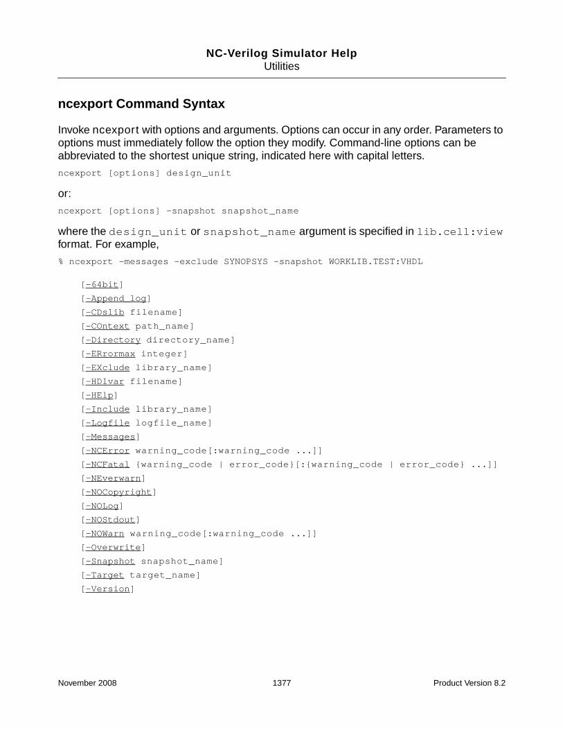
NC-Verilog Simulator HelpUtilities
ncexport Command Syntax
Invoke ncexport with options and arguments. Options can occur in any order. Parameters tooptions must immediately follow the option they modify. Command-line options can beabbreviated to the shortest unique string, indicated here with capital letters.
ncexport [options] design_unit
or:
ncexport [options] -snapshot snapshot_name
where the design_unit or snapshot_name argument is specified in lib.cell:viewformat. For example,
% ncexport -messages -exclude SYNOPSYS -snapshot WORKLIB.TEST:VHDL
[-64bit]
[-Append_log]
[-CDslib filename]
[-COntext path_name]
[-Directory directory_name]
[-ERrormax integer]
[-EXclude library_name]
[-HDlvar filename]
[-HElp]
[-Include library_name]
[-Logfile logfile_name]
[-Messages]
[-NCError warning_code[:warning_code ...]]
[-NCFatal {warning_code | error_code}[:{warning_code | error_code} ...]]
[-NEverwarn]
[-NOCopyright]
[-NOLog]
[-NOStdout]
[-NOWarn warning_code[:warning_code ...]]
[-Overwrite]
[-Snapshot snapshot_name]
[-Target target_name]
[-Version]
November 2008 1377 Product Version 8.2

NC-Verilog Simulator HelpUtilities
ncexport Command Options
The following list describes the ncexport command-line options.
-64bit
Invoke the 64-bit version of the ncexport executable.
Besides including the -64bit command-line option when you run the executables, you canalso run the 64-bit version by:
■ Setting the INCA_64BIT environment variable.
■ Setting up your PATH and library path environment variables so that you are pointing tothe 64-bit version.
The -64bit command-line option is ignored if you have already specified that you want torun in 64-bit mode by setting environment variables.
You cannot use the -64bit option in flows with tools that do not support 64-bit.
This option is ignored if you include it with the NCVHDLOPTS variable in an hdl.var file.
-Append_log
Append log information from multiple ncexport runs into one log file. If you use both-append_log and -nolog on the command line, -nolog overrides -append_log.
-CDslib filename
Use the specified cds.lib file. See “The cds.lib File” on page 133 for information on thecds.lib file.
-COntext path_name
Use the specified path in the compilation script. The default is the exported directory.
-Directory directory_name
Specifies the directory into which ncexport copies the VHDL source and writes thecompilation script. The default is the current directory. For example, the following command
November 2008 1378 Product Version 8.2

NC-Verilog Simulator HelpUtilities
writes the compilation script to the directory called ncexp. The source files are copied to./ncexp/library_name.ncxp.
% ncexport -directory ncexp -snapshot worklib.top:arch
-ERrormax integer
Abort after reaching the specified number of errors. By default, there is no limit on the numberof error messages.
-EXclude library_name
Exclude the specified library from export. The ncexport command excludes STD and IEEElibraries by default.
-HDlvar filename
Use the specified hdl.var file. See “The hdl.var File” on page 142 for information on thehdl.var file.
-HElp
Display a list of the ncexport command-line options with a brief description of each option.
-Include library_name
Include the specified library for export.
-Logfile logfile_name
Use the specified name for the log file instead of the default name ncexport.log.
You can not include this option in an hdl.var file. This option overrides the -nolog option.
-Messages
Display informational messages during the creation of the compilation script.
Note: Information is only written to the log file when you use the -messages option.
November 2008 1379 Product Version 8.2

NC-Verilog Simulator HelpUtilities
-NCError warning_code[:warning_code ...]
Increase the severity level of the specified warning message from warning to error. Thewarning_code argument is the message code (mnemonic) that appears in the warningmessage following the severity code.
Example:
% ncexport -ncerror ABCDEF -directory my_dir my_lib.top:arch
You can increase the severity level of multiple warning messages either by using multiple-ncerror options or by using one -ncerror option and separating the warning_codearguments with a colon. For example,
% ncexport -ncerror ABCDEF -ncerror HIJKLM -directory my_dir my_lib.top:arch
% ncexport -ncerror ABCDEF:HIJKLM -directory my_dir my_lib.top:arch
Using this option can change the behavior of the tool because functions that return errorsinstead of warnings may behave differently. Warnings that are changed to errors are countedin the error count limit that you specify with the -errormax option.
-NCFatal {warning_code | error_code}[:{warning_code | error_code} ...]
Increase the severity level of the specified warning message or error message from warningor error to fatal. The warning_code or error_code argument is the message code(mnemonic) that appears in the message following the severity code.
Example:
% ncexport -ncfatal LMNOPQ -directory my_dir my_lib.top:arch
You can increase the severity level of multiple warning messages or error messages to fataleither by using multiple -ncfatal options or by using one -ncfatal option and separatingthe warning_code or error_code arguments with a colon. For example,
% ncexport -ncfatal ABCDEF -ncfatal LMNOPQ -directory my_dir my_lib.top:arch
% ncexport -ncfatal ABCDEF:LMNOPQ -directory my_dir my_lib.top:arch
-NEverwarn
Disable printing of all warning messages.
To turn off one or more specific warning messages, use -nowarn.
November 2008 1380 Product Version 8.2

NC-Verilog Simulator HelpUtilities
-NOCopyright
Suppress the display of the copyright banner.
Because the copyright banner is printed before any variables in the hdl.var file areprocessed, this option is ignored if you include it with the NCEXPORTOPTS variable in anhdl.var file.
-NOLog
Do not generate a log file. By default, ncexport generates a log file called ncexport.log.
If you include the -nolog option in the hdl.var file, a log file will be created because thefile is opened before any variables in the hdl.var file are processed. However, once theoption is processed in the hdl.var file, output to the log file is discontinued, and the log filewill contain only header information.
-NOStdout
Suppress printing of output to the screen.
-NOWarn warning_code[:warning_code]
Disable the printing of the specified warning. The warning_code is the sequence ofcharacters following the error severity code.
Example:
% ncexport -nowarn ABCDEF
You can disable the printing of multiple warning messages either by using multiple -nowarnoptions or by using one -nowarn option and separating the warning_code argumentswith a colon. For example,
% ncexport -nowarn ABCDEF -nowarn HIJKLM
% ncexport -nowarn ABCDEF:HIJKLM
-Overwrite
Overwrite an existing directory with the same name.
November 2008 1381 Product Version 8.2

NC-Verilog Simulator HelpUtilities
-Snapshot snapshot_name
Specifies the simulation snapshot to export.
-Target target_name
Specifies the target for the compilation script. The target_name argument can begeneric, inca, or synopsys. The default is generic.
If the target is generic, ncexport generates a file called Generic.Dependencies. Thisfile contains the list of design hierarchy dependencies exported bottom up.
The -target inca option generates a script called Inca.Script for the Cadence NCsimulators.
The -target synopsys option generates a script called Synopsys.Script in Synopsysformat. This argument can only be specified with a pure VHDL design.
-Version
Display the version of ncexport and exit.
Example ncexport Command Lines
To export an analysed unit my_lib.top:arch into the directory my_dir:
% ncexport -directory my_dir my_lib.top:arch
To export an elaborated unit my_lib.top:arch into the directory my_dir:
% ncexport -directory my_dir -snapshot my_lib.top:arch
Example
The example used in this section is a VHDL design for an adder. The source files are asfollows:
-- File: fa1.vhd
library ieee;
use ieee.std_logic_1164.all;
use ieee.std_logic_arith.all;
November 2008 1382 Product Version 8.2

NC-Verilog Simulator HelpUtilities
entity FA1 is
PORT(ci : IN std_logic;
a : IN std_logic;
b : IN std_logic;
s : OUT std_logic;
co : OUT std_logic);
end FA1;
ARCHITECTURE beh of FA1 is
begin
s <= a xor b xor ci;
co <= (a and b) or ( b and ci ) or (a and ci);
end beh;
-- File: test_adder.vhd
library ieee;
library worklib;
use ieee.std_logic_1164.all;
use ieee.numeric_std.all;
entity test_adder is end;
architecture BEHAVIORAL of test_adder is
component fa1 -- full_adder
PORT(ci : IN std_logic;
a : IN std_logic;
b : IN std_logic;
s : OUT std_logic;
co : OUT std_logic);
end component;
signal X, Y, CIN : std_logic;
signal COUT, SUM : std_logic;
signal addend1, addend2, cyin, exsum, exco :std_logic_vector ( 0 to 7 );
signal i :integer;
BEGIN
-- full adder under test
process
November 2008 1383 Product Version 8.2

NC-Verilog Simulator HelpUtilities
begin
wait for 2 ns;
i<=0;
addend1 <= "00001111";
addend2 <= "00110011";
cyin <= "01010101";
exco <= "00010111";
exsum <= "01101001";
wait;
end process;
U1: fa1 port map (CIN, X, Y, SUM, COUT) ; -- instantiate full_adder
process begin
for i in 0 to 7 loop
-- test stimuli
wait for 10 ns;
X <= addend1 (i);
wait for 10 ns;
Y <= addend2 (i);
wait for 10 ns;
CIN <= cyin (i);
-- test response evaluation
wait for 170 ns; -- keep a 200 ns cycle
assert COUT = exco(i) report " ERROR EXPECTED COUT DIFFERS FROM ACTUAL COUT "severity note;
assert SUM = exsum (i) report "ERROR EXPECTED SUM DIFFERS FROM ACTUAL SUM "severity note;
end loop;
wait;
end process;
end behavioral;
-- File: test_adder_conf.vhd
-- Configuration for top level unit WORKLIB.TEST_ADDER:BEHAVIORAL
-- Configuration Model: HIERARCHICAL
library WORKLIB;
configuration cfg_FA1_BEH of FA1 is
for BEH
November 2008 1384 Product Version 8.2

NC-Verilog Simulator HelpUtilities
end for;
end cfg_FA1_BEH;
library WORKLIB;
configuration cfg_TEST_ADDER_BEHAVIORAL of TEST_ADDER is
for BEHAVIORAL
for OTHERS: FA1 use configuration WORKLIB.cfg_FA1_BEH;
end for;
end for;
end cfg_TEST_ADDER_BEHAVIORAL;
To export an elaborated design:
1. Compile and elaborate the design. For example,
% ncvhdl -v93 fa1.vhd test_adder.vhd test_adder_conf.vhd
% ncelab -access +rwc WORKLIB.TEST_ADDER:BEHAVIORAL
In this example, ncelab generates a snapshot calledworklib.test_adder:behavioral.
2. Run ncexport.
% ncexport -messages -nocopyright -directory ncexp -overwrite -target INCA-exclude SYNOPSYS -snapshot WORKLIB.TEST_ADDER:BEHAVIORAL
ncexport: Started on Dec 05, 2002 at 13:52:55
Export directory ’ncexp’
created for ’WORKLIB.TEST_ADDER:BEHAVIORAL’
for target ’INCA’
ncexport: Exiting on Dec 05, 2002 at 13:52:56 (total: 00:00:01)
This command creates a subdirectory called ncexp, which contains the compilation script(Inca.Script) and a directory called worklib.ncxp. The worklib.ncxp directorycontains the following files:
fa1_e.vhd (VHDL entity FA1)
fa1_beh_a.vhd (VHDL architecture beh of FA1)
test_adder_e.vhd (VHDL entity test_adder)
test_adder_behavioral_a.vhd (VHDL architecture behavioral of test_adder)
The Inca.Script file generated by ncexport is as follows:
#!/bin/csh -f
# ncexport: v04.00.(s010)
# Date : Dec 05, 2002 at 13:54:45
mkdir ./worklib
ncvhdl -MESSAGES -V93 -WORK worklib ../ncexp/worklib.ncxp/test_adder_e.vhd
November 2008 1385 Product Version 8.2

NC-Verilog Simulator HelpUtilities
ncvhdl -MESSAGES -V93 -WORK worklib../ncexp/worklib.ncxp/test_adder_behavioral_a.vhd
ncvhdl -MESSAGES -V93 -WORK worklib ../ncexp/worklib.ncxp/fa1_e.vhd
ncvhdl -MESSAGES -V93 -WORK worklib ../ncexp/worklib.ncxp/fa1_beh_a.vhd
ncelab -MESSAGES -ACCESS +rwc WORKLIB.TEST_ADDER:BEHAVIORAL
November 2008 1386 Product Version 8.2

NC-Verilog Simulator HelpUtilities
ncgentb
The ncgentb utility reads an Extended Value Change Dump (EVCD) file that has beengenerated for a design under test (DUT) and generates a Verilog or VHDL testbench. TheEVCD file can be generated by a Verilog $dumpports system task (for Verilog) or by a Tclprobe -evcd command (for Verilog or VHDL), or by another tool. The DUT can be acomplete design or an instance in the design. The testbench contains test vectors that canbe applied on the IN port and the IN part of the INOUT port of the design or the instance.
After generating the testbench, you can compile the testbench, elaborate the design, andsimulate.
If the design under test is VHDL, then the ports must be of type std_logic orstd_logic_vector.
By default, ncgentb creates a Verilog testbench. Use the -into vhdl option if you want togenerate a VHDL testbench.
The default name of the output file is ncsim_tb.v for Verilog, and ncsim_tb.vhd forVHDL. Use the -testbench option to specify a different name for the testbench output file.
See “Generating an Extended Value Change Dump (EVCD) File” on page 679 for details ongenerating an EVCD file for Verilog.
See the “Generating an Extended Value Change Dump (EVCD) File” in the chapter called“Debugging Your Design” in the NC-VHDL Simulator Help for details on generating anEVCD file for VHDL.
November 2008 1387 Product Version 8.2

NC-Verilog Simulator HelpUtilities
ncgentb Command Syntax
Invoke ncgentb with:
■ The -input option, which specifies the name of the input EVCD file.
■ The -dut option, which specifies the name of the design under test in lib.cell:viewformat.
■ An argument, which is the instance name of the design under test.
■ Other command-line options.
Command-line options can occur in any order. Parameters to options must immediately followthe option they modify. Command-line options can be abbreviated to the shortest uniquestring, indicated here with capital letters.
ncgentb -input evcd_filename -dut [lib.]cell[:view] [other_options] argument
[-64bit]
[-Append_log]
[-Errormax integer]
[-CDslib filename]
[-COncurrent]
[-Dut [lib.]cell[:view]]
[-Hdlvar filename]
[-File filename]
[-Help]
[-INTo {vhdl | verilog}]
[-INPut evcd_filename]
[-Logfile logfile_name]
[-Messages]
[-NCError warning_code[:warning_code ...]]
[-NCFatal {warning_code | error_code}[:{warning_code | error_code} ...]]
[-NEverwarn]
[-NOCopyright]
[-NOLog]
[-NOStdout]
[-NOWarn warning_code[:warning_code ...]]
[-Overwrite]
[-Script filename]
[-Testbench testbench_output_filename]
[-Version]
November 2008 1388 Product Version 8.2

NC-Verilog Simulator HelpUtilities
ncgentb Command Options
This section describes the options that you can use with the ncgentb command. Options canbe entered in upper or lowercase. Capital letters indicate the shortest possible abbreviationfor an option.
-64bit
Invoke the 64-bit version of the ncgentb executable.
Besides including the -64bit command-line option when you run the executables, you canalso run the 64-bit version by:
■ Setting the INCA_64BIT environment variable.
■ Setting up your PATH and library path environment variables so that you are pointing tothe 64-bit version.
See “64-Bit NC-Verilog” on page 39 for more information.
The -64bit command-line option is ignored if you have already specified that you want torun in 64-bit mode by setting environment variables.
You cannot use the -64bit option in flows with tools that do not support 64-bit.
This option is ignored if you include it with the NCVLOGOPTS variable in an hdl.var file.
-Append_log
Append log information from multiple ncgentb runs into one log file.
Use -append_log if you are going to run ncgentb multiple times and you want all of the loginformation appended to one log file. If you do not use this option, ncgentb overwrites the logfile each time you run ncgentb.
If you use both -append_log and -nolog on the command line, -nolog overrides-append_log.
-Errormax integer
Abort after reaching the specified number of errors. By default, there is no limit on the numberof error messages.
November 2008 1389 Product Version 8.2

NC-Verilog Simulator HelpUtilities
-CDslib filename
Use the specified cds.lib file. See “The cds.lib File” on page 133 for information on thecds.lib file.
-COncurrent
Specifies that the generated testbench will have concurrent signal assignments.
-Dut [lib.]cell[:view]
Specifies the name of the design under test (DUT) in lib.cell:view format. This option isrequired.
The library and the view name of the DUT are optional if the cell exists in one library and thereis only one view.
For VHDL, the cell is the entity name of the DUT. For Verilog, the cell is the module name ofthe DUT.
-Hdlvar filename
Use the specified hdl.var file. See “The hdl.var File” on page 142 for information on thehdl.var file.
-File filename
Use the command-line arguments contained in the specified file.
You can store frequently used or lengthy command lines by putting command options andarguments in a text file. When you invoke ncgentb with the -file option, the arguments inthe specified file are used with the command as if they had been entered on the commandline.
-Help
Display a brief summary of the ncgentb command-line options.
November 2008 1390 Product Version 8.2

NC-Verilog Simulator HelpUtilities
-INTo {vhdl | verilog}
Generate a testbench in the specified language.
By default, ncgentb generates a Verilog testbench. Use the -into vhdl option if you wantto generate a VHDL testbench.
-INPut evcd_filename
Use the specified EVCD file as the input file. This option is required.
-Logfile logfile_name
Use the specified name for the log file instead of the default name ncgentb.log.
Use -nolog if you do not want a log file. If you use both -logfile and -nolog on thecommand line, -logfile overrides -nolog.
-Messages
Display informational messages during execution.
Note: Information is written to the log file only when you use the -messages option.
-NCError warning_code[:warning_code ...]
Increase the severity level of the specified warning message from warning to error. Thewarning_code argument is the message code (mnemonic) that appears in the warningmessage following the severity code.
You can increase the severity level of multiple warning messages either by using multiple-ncerror options or by using one -ncerror option and separating the warning_codearguments with a colon. For example,
% ncgentb -input file.evcd -dut worklib.dut -ncerror ABCDEF -ncerror HIJKLM top.u1
% ncgentb -input file.evcd -dut worklib.dut -ncerror ABCDEF:HIJKLM top.u1
November 2008 1391 Product Version 8.2

NC-Verilog Simulator HelpUtilities
-NCFatal {warning_code | error_code}[:{warning_code | error_code} ...]
Increase the severity level of the specified warning message or error message from warningor error to fatal. The warning_code or error_code argument is the message code(mnemonic) that appears in the message following the severity code.
Example:
% ncgentb -input file.evcd -dut worklib.dut -ncfatal ABCDEF top:u1
You can increase the severity level of multiple warning messages or error messages to fataleither by using multiple -ncfatal options or by using one -ncfatal option and separatingthe warning_code or error_code arguments with a colon. For example,
% ncgentb -input file.evcd -dut worklib.dut -ncfatal ABCDEF -ncfatal LMNOPQ top:u1
% ncgentb -input file.evcd -dut worklib.dut -ncfatal ABCDEF:LMNOPQ top:u1
-NEverwarn
Disable printing of all warning messages.
-NOCopyright
Suppress printing of the copyright banner.
Because the copyright banner is printed before any variables in the hdl.var file areprocessed, this option is ignored if you include it with the NCGENTBOPTS variable in anhdl.var file.
-NOLog
Do not generate a log file. By default, ncgentb generates a log file called ncgentb.log.
This option is overridden by the -logfile option.
If you include the -nolog option in the hdl.var file, a log file will be created because thefile is opened before any variables in the hdl.var file are processed. However, once theoption is processed in the hdl.var file, output to the log file is discontinued, and the log filewill contain only header information.
November 2008 1392 Product Version 8.2

NC-Verilog Simulator HelpUtilities
-NOStdout
Suppress printing of output to the screen.
-NOWarn warning_code[:warning_code ...]
Disables the printing of the specified warning. The warning_code is the sequence ofcharacters following the error severity code.
Example:
% ncgentb -input file.evcd -nowarn ABCDEF -dut worklib.dut top:u1
You can disable the printing of multiple warning messages either by using multiple -nowarnoptions or by using one -nowarn option and separating the warning_code argumentswith a colon. For example,
% ncgentb -input file.evcd -nowarn ABCDEF -nowarn LMNOPQ -dut worklib.dut top:u1
% ncgentb -input file.evcd -nowarn ABCDEF:LMNOPQ -dut worklib.dut top:u1
-Overwrite
Overwrite an existing testbench with a new generated testbench.
By default, ncgentb does not overwrite an existing testbench. You can use the -overwriteoption to:
■ Overwrite an existing testbench with the default name (ncsim_tb.v for Verilog, orncsim_tb.vhd for VHDL).
■ Overwrite an existing testbench that was generated with the -testbench option tospecify a name for the output file. For example, the following command generates atestbench called my_tb.v.
% ncgentb -input input.evcd -dut worklib.dut -testbench my_tb.v top:u1
To overwrite the my_tb.v testbench, use the -testbench option to specify the nameof the testbench and the -overwrite option. For example:
% ncgentb -input input.evcd -dut worklib.dut -overwrite -testbench my_tb.vtop:u1
-Script filename
Generate a script that contains commands to compile the generated testbench, elaborate,and simulate the design under test with the generated testbench.
November 2008 1393 Product Version 8.2

NC-Verilog Simulator HelpUtilities
-Testbench testbench_output_filename
Use the specified filename for the generated testbench.
By default, ncgentb generates a Verilog testbench called ncsim_tb.v. If you use the -intovhdl option, a VHDL testbench called ncsim_tb.vhd is generated. Use the -testbenchoption to specify a different name for the testbench output file.
-Version
Print the version of ncgentb and exit.
Example ncgentb Command Lines
The following command generates a Verilog testbench for the design under test first. The-input option specifies the name of the EVCD file. The -dut option specifies the DUT (thecell is the module name of the DUT). The argument is the instance name of the design undertest. The name of the testbench file will be ncsim_tb.v.
% ncgentb -input input.evcd -dut worklib.first:module top.u1
By default, ncgentb does not overwrite an existing testbench file. The following commandincludes the -overwrite option, which overwrites an existing testbench with a newgenerated testbench. This command will overwrite the ncsim_tb.v testbench generated bythe previous command.
% ncgentb -input input.evcd -overwrite -dut worklib.first top.u1
The following command includes the -testbench option, which specifies that the name ofthe testbench file will be vlog_tb.v.
% ncgentb -input input.evcd -dut worklib.first -testbench vlog_tb.v top.u1
To overwrite the testbench called vlog_tb.v generated by the previous command, includethe -overwrite option and the -testbench option to specify the name of the testbench tooverwrite.
% ncgentb -input input.evcd -overwrite -testbench vlog_tb.v -dut worklib.firsttop.u1
The -script option is included on the following command line. This option generates a filethat contains commands to compile the generated testbench, elaborate, and simulate theDUT with the generated testbench.
% ncgentb -input input.evcd -script myscript -dut worklib.first top.u1
November 2008 1394 Product Version 8.2

NC-Verilog Simulator HelpUtilities
Example
In this example, a Verilog testbench is generated from an EVCD file, which was generated byrunning a simulation of a Verilog design that contains a $dumpports system task. TheVerilog source code used for the example is as follows:
// File: board.v
`timescale 1 ns/1 ns
module board;
wire [3:0] count;
wire clock, f, af;
m16 counter (count, clock, f, af);
m555 clockGen (clock);
initial
$dumpports(counter, "counter.evcd", , 0);
initial
#1700 $finish;
always @(posedge clock)
$display($time,,,"count=%d", count );
endmodule
// File counter.v
`timescale 1 ns/1 ns
module m16(value, clock, fifteen, altFifteen);
output [3:0] value;
output fifteen,altFifteen;
input clock;
dEdgeFF a(value[0], clock, ~value[0]),
b(value[1], clock, value[1] ^ value[0]),
c(value[2], clock, value[2] ^ &value[1:0]),
d(value[3], clock, value[3] ^ &value[2:0]);
assign fifteen = value[0] & value[1] & value[2] & value[3];
assign altFifteen = &value;
endmodule
November 2008 1395 Product Version 8.2

NC-Verilog Simulator HelpUtilities
// File: clock.v
`timescale 1 ns/1 ns
module m555(clock);
output clock;
reg clock;
initial
#5 clock = 1;
always
#50 clock = ~clock;
endmodule
// File ff.v
`timescale 1 ns/1 ns
module dEdgeFF(q, clock, data);
output q;
reg q;
input clock, data;
initial
#10 q = 0;
always
@(negedge clock)#10 q=data;
endmodule
The following sequence of commands is used to compile the source files, elaborate thedesign, and invoke and run the simulator.
% ncvlog -nocopyright board.v counter.v clock.v ff.v
% ncelab -nocopyright worklib.board:module
% ncsim -nocopyright worklib.board:module
The following shows the contents of the EVCD file, counter.evcd.
$date
Wed Mar 19 15:58:34 2003
$end
$version
ncsim 04.10-s007
$end
$timescale
1ns
$end
November 2008 1396 Product Version 8.2

NC-Verilog Simulator HelpUtilities
$scope module board.counter $end
$var port 4 ! value $end
$var port 1 " clock $end
$var port 1 # fifteen $end
$var port 1 $ altFifteen $end
$upscope $end
$enddefinitions $end
#0
pXXXX 6666 6666 !
pN 6 6 "
pX 6 6 #
pX 6 6 $
#5
pU 0 6 "
#10
pLLLL 6666 0000 !
pL 6 0 #
pL 6 0 $
#50
pD 6 0 "
#60
pLLLH 6660 0006 !
#100
pU 0 6 "
#150
pD 6 0 "
#160
pLLHL 6606 0060 !
#200
pU 0 6 "
#250
pD 6 0 "
November 2008 1397 Product Version 8.2

NC-Verilog Simulator HelpUtilities
#260
pLLHH 6600 0066 !
#300
pU 0 6 "
#350
pD 6 0 "
#360
pLHLL 6066 0600 !
#400
pU 0 6 "
#450
pD 6 0 "
#460
pLHLH 6060 0606 !
#500
pU 0 6 "
#550
pD 6 0 "
#560
pLHHL 6006 0660 !
#600
pU 0 6 "
#650
pD 6 0 "
#660
pLHHH 6000 0666 !
#700
pU 0 6 "
#750
pD 6 0 "
November 2008 1398 Product Version 8.2

NC-Verilog Simulator HelpUtilities
#760
pHLLL 0666 6000 !
#800
pU 0 6 "
#850
pD 6 0 "
#860
pHLLH 0660 6006 !
#900
pU 0 6 "
#950
pD 6 0 "
#960
pHLHL 0606 6060 !
#1000
pU 0 6 "
#1050
pD 6 0 "
#1060
pHLHH 0600 6066 !
#1100
pU 0 6 "
#1150
pD 6 0 "
#1160
pHHLL 0066 6600 !
#1200
pU 0 6 "
#1250
pD 6 0 "
November 2008 1399 Product Version 8.2

NC-Verilog Simulator HelpUtilities
#1260
pHHLH 0060 6606 !
#1300
pU 0 6 "
#1350
pD 6 0 "
#1360
pHHHL 0006 6660 !
#1400
pU 0 6 "
#1450
pD 6 0 "
#1460
pHHHH 0000 6666 !
pH 0 6 #
pH 0 6 $
#1500
pU 0 6 "
#1550
pD 6 0 "
#1560
pLLLL 6666 0000 !
pL 6 0 #
pL 6 0 $
#1600
pU 0 6 "
#1650
pD 6 0 "
#1660
pLLLH 6660 0006 !
$comment
November 2008 1400 Product Version 8.2

NC-Verilog Simulator HelpUtilities
$dumpports closed at time: 1700
$end
The following command generates a Verilog testbench called ncsim_tb.v.
% ncgentb -input counter.evcd -script myscript -dut worklib.m16:moduleboard.counter
■ The -input option specifies the name of the EVCD input file.
■ The -dut option specifies the name of the design under test in lib.cell:view format. Thecell is the module name of the design under test.
■ The -script option is included on the command line to generate a script to compile thetestbench, elaborate, and simulate the design using the generated testbench.
■ The argument board.counter is the instance name of the design under test.
This command generates the testbench (ncsim_tb.v) and a script called myscript. Thetestbench for the example is as follows:
`timescale 1 ns/1 ns
module m16_nc_v();
reg net_clock;
wire[1:4] w_net_value;
wire w_net_clock;
wire w_net_fifteen;
wire w_net_altFifteen;
m16 entity_inst(w_net_value, w_net_clock, w_net_fifteen,w_net_altFifteen);
assign w_net_clock = net_clock;
initial
begin
#0 net_clock = 1’bX;
#5 net_clock = 1’b1;
#45 net_clock = 1’b0;
#50 net_clock = 1’b1;
#50 net_clock = 1’b0;
#50 net_clock = 1’b1;
#50 net_clock = 1’b0;
#50 net_clock = 1’b1;
#50 net_clock = 1’b0;
November 2008 1401 Product Version 8.2

NC-Verilog Simulator HelpUtilities
#50 net_clock = 1’b1;
#50 net_clock = 1’b0;
#50 net_clock = 1’b1;
#50 net_clock = 1’b0;
#50 net_clock = 1’b1;
#50 net_clock = 1’b0;
#50 net_clock = 1’b1;
#50 net_clock = 1’b0;
#50 net_clock = 1’b1;
#50 net_clock = 1’b0;
#50 net_clock = 1’b1;
#50 net_clock = 1’b0;
#50 net_clock = 1’b1;
#50 net_clock = 1’b0;
#50 net_clock = 1’b1;
#50 net_clock = 1’b0;
#50 net_clock = 1’b1;
#50 net_clock = 1’b0;
#50 net_clock = 1’b1;
#50 net_clock = 1’b0;
#50 net_clock = 1’b1;
#50 net_clock = 1’b0;
#50 net_clock = 1’b1;
#50 net_clock = 1’b0;
#50 net_clock = 1’b1;
#50 net_clock = 1’b0;
end
initial
#1700 $finish;
endmodule
The script is as follows:
#!/bin/csh -f
#
# ncgentb script generated for: ncsim_tb.v
#
ncvlog -mess ncsim_tb.v
ncelab -mess -access +rwc worklib.m16_nc_v
ncsim -mess worklib.m16_nc_v
November 2008 1402 Product Version 8.2

NC-Verilog Simulator HelpUtilities
Issues and Limitations
This section lists some issues that you should be aware of when using ncgentb and somelimitations of the utility.
Timescales
ncgentb generates a Verilog testbench with a `timescale directive taken from thetimescale specified in the EVCD file. If the original Verilog testbench and the DUT do not have`timescale directives, elaboration will fail because all modules must be compiled with a`timescale directive if any module has been compiled with a `timescale directive.
To elaborate the DUT with the generated testbench, use the ncelab -timescale option toprovide a timescale for all modules that do not have one. The timescale should be thetimescale that is defined in the generated testbench. If you have generated a script by usingthe -script option, edit the ncelab command in the script to include the -timescaleoption.
Initial Values
In a Verilog testbench, registers can be initialized at the beginning of simulation or after adelta time from the start of simulation.
Value is initialized at beginning of simulationinitial
begin
din = 8’h00;
...
end
Value is initialized after a delta time from the start of simulationinitial
begin
#0 din = 8’h00;
end
Because the EVCD for both of these cases is the same, ncgentb cannot distinguish thedifference between the cases. The testbench is generated with the latter kind of initialization.
November 2008 1403 Product Version 8.2

NC-Verilog Simulator HelpUtilities
DUT Ports Being Driven Using an Interface Such as Tcl
If Tcl is used to drive a port that has drivers only in the DUT, the EVCD will show the drivingdirection of the port as OUT for all the Tcl deposits. Because ncgentb does not capture theOUT driving values in the EVCD, the generated testbench will have different simulationbehavior for these ports.
Verilog Testbench Generated from an EVCD Generated from a VHDL Testbench
If an EVCD file is generated using a VHDL testbench, the strength corresponding to logiclevels ‘U’, ‘X’, ‘0’, and ‘1’ is 7. If you use ncgentb to generate a Verilog testbench using thisEVCD, the generated testbench will behave differently, as the strength level 7 corresponds tosupply strength in Verilog.
November 2008 1404 Product Version 8.2

NC-Verilog Simulator HelpUtilities
nchelp
Use the nchelp utility to:
■ Get help on messages generated by the compiler, elaborator, and simulator, and by otherutilities.
Syntax:
% nchelp [options] tool_name message_code
Examples:
% nchelp ncvhdl BADCLP
% nchelp ncvhdl badclp
The nchelp utility displays extended help on the brief messages generated by thesimulator tools and utilities.
■ To print:
❑ the variables defined in a specific hdl.var file or the libraries defined in a specificcds.lib file.
❑ the variables defined in the default hdl.var file or the libraries defined in thedefault cds.lib file.
Syntax:
% nchelp [options] {-hdlvar | -cdslib} [filename]
Examples:
% nchelp -hdlvar
% nchelp -cdslib ./cds.lib
November 2008 1405 Product Version 8.2

NC-Verilog Simulator HelpUtilities
nchelp Command Syntax
Invoke nchelp with options and arguments. Options can occur in any order. Parameters tooptions must immediately follow the option they modify. Command line options can beabbreviated to the shortest unique string, indicated here with capital letters.
nchelp [-options] tool_name message_code
[-All message_code]
[-Cdslib [filename]]
[-HDlvar [filename]]
[-HElp]
[-Lockcheck filename]
[-NCError warning_code[:warning_code ...]]
[-NCFatal {warning_code | error_code}[:{warning_code | error_code} ...]]
[-NEverwarn]
[-NOCopyright]
[-NOWarn warning_code[:warning_code ...]]
[-Tools]
[-Version]
nchelp Command Options
The following list describes the options you can use with the nchelp command. Options canbe entered in upper or lowercase. In the table, capital letters indicate the shortest possibleabbreviation for an option.
-All message_code
Displays extended help for the message with the specified message code for all tools that cangenerate the message. For example, the following command displays the help for all tools thatcan generate the BADCLP error message.
% nchelp -all BADCLP
-Cdslib [filename]
Prints the libraries defined in the specified cds.lib file. If no filename is specified,prints the libraries defined in the default cds.lib file. See “The cds.lib File” on page 133.
November 2008 1406 Product Version 8.2

NC-Verilog Simulator HelpUtilities
-HDlvar [filename]
Prints the variables defined in the specified hdl.var file. If no filename is specified,prints the variables defined in the default hdl.var file. See “The hdl.var File” on page 142
-HElp
Prints a brief summary of the nchelp command options.
-Lockcheck filename
Tests a file system to determine if it has file locking capabilities.
The argument to this option is a pathname to a non-existent file. For example:
% nchelp -lockcheck /net/linux-box/disk1/testme.tmp
nchelp: 05.10-p001: (c) Copyright 1995-2003 Cadence Design Systems, Inc.
File locking PASSED
-NCError warning_code[:warning_code ...]
Increase the severity level of the specified warning message from warning to error. Thewarning_code argument is the message code (mnemonic) that appears in the warningmessage following the severity code.
Example:
% nchelp -hdlvar -ncerror ABCDEF
You can increase the severity level of multiple warning messages either by using multiple-ncerror options or by using one -ncerror option and separating the warning_codearguments with a colon. For example,
% nchelp -hdlvar -ncerror ABCDEF -ncerror HIJKLM
% nchelp -hdlvar -ncerror ABCDEF:HIJKLM
Using this option can change the behavior of the tool because functions that return errorsinstead of warnings may behave differently.
November 2008 1407 Product Version 8.2

NC-Verilog Simulator HelpUtilities
-NCFatal {warning_code | error_code}[:{warning_code | error_code} ...]
Increase the severity level of the specified warning message or error message from warningor error to fatal. The warning_code or error_code argument is the message code(mnemonic) that appears in the message following the severity code.
Example:
% nchelp -hdlvar -ncfatal LMNOPQ
You can increase the severity level of multiple warning messages or error messages to fataleither by using multiple -ncfatal options or by using one -ncfatal option and separatingthe warning_code or error_code arguments with a colon. For example,
% nchelp -hdlvar -ncfatal ABCDEF -ncfatal HIJKLM
% nchelp -hdlvar -ncfatal ABCDEF:HIJKLM
-NEverwarn
Disables printing of all warning messages.
-NOCopyright
Suppresses printing of the copyright banner.
-NOWarn warning_code
Disables the printing of the specified warning. The warning_code is the sequence ofcharacters following the error severity code.
Example:
% nchelp -hdlvar -nowarn ABCDEF
You can disable the printing of multiple warning messages either by using multiple -nowarnoptions or by using one -nowarn option and separating the warning_code argumentswith a colon. For example,
% nchelp -hdlvar -nowarn ABCDEF -nowarn HIJKLM
% nchelp -hdlvar -nowarn ABCDEF:HIJKLM
-Tools
Displays a list of all of the tools for which extended help is available.
November 2008 1408 Product Version 8.2

NC-Verilog Simulator HelpUtilities
-Version
Prints the version of nchelp and exits.
Example nchelp Command Lines
The following command provides help on the BADCLP message from ncvlog.
% nchelp ncvlog -nocopyright BADCLP
ncvlog/BADCLP = The path specified for the -CDSLIB argument is invalid, please checkthat the specified path exists and is readable.
%
The following command provides help on the CUVWSP message from ncelab.
% nchelp ncelab -nocopyright cuvwsp
ncelab/CUVWSP = The indicated module instance contains a connection list that doesnot connect all the module ports.
The following command provides help on the NOSNAP message from ncsim.
% nchelp ncsim NOSNAP
The following command prints the variables defined in the default hdl.var file. In thisexample, the default hdl.var file is in the user’s home directory (~larry/hdl.var) andthe file contains a SOFTINCLUDE statement to include a second hdl.var file.
% nchelp -nocopyright -hdlvar
Parsing -HDLVAR file ./hdl.var.
hdl.var files:
1: ./hdl.var
2: ./inca/adder/hdl.var
included on line 4 of ./hdl.var
Variables defined:
Defined in ./hdl.var:
Line # Name Value
------ ---- -----
1 NCVLOGOPTS -messages
2 NCELABOPTS -messages
3 NCSIMOPTS -messages -tcl
November 2008 1409 Product Version 8.2

NC-Verilog Simulator HelpUtilities
Defined in ./inca/adder/hdl.var:
Line # Name Value
------ ---- -----
1 WORK worklib
The following command prints the variables defined in ~larry/inca/adder/hdl.var.
% nchelp -nocopyright -hdlvar ~larrybird/inca/adder/hdl.var
Parsing -HDLVAR file ./inca/adder/hdl.var.
hdl.var files:
1: ./inca/adder/hdl.var
Variables defined:
Defined in ./inca/adder/hdl.var:
Line # Name Value
------ ---- -----
1 WORK worklib
November 2008 1410 Product Version 8.2

NC-Verilog Simulator HelpUtilities
ncls
The ncls utility lists the compiled objects that are stored in the library system and displaysvarious attributes and information about those objects.
When you compile and elaborate a design, all intermediate objects that are required by theNC tools are logically and physically stored in a library system. The interface to this librarysystem is through the cds.lib file, which defines the libraries by associating logical librarynames with physical library directories. Intermediate objects are stored in a single databasefile in a library directory. This library database file is calledinca.architecture.lib_version.pak. For example, the name of the librarydatabase file is similar to the following:
inca.sun4v.154.pak
inca.hppa.154.pak
In virtually all cases, you can treat the contents of a library system as a black box. If, however,you need to list the objects in the library system, the ncls utility provides this visibility.
Note: ncls only lists those objects that are generated and used by the NC core system. Theutility does not list any other objects that may be stored in the same libraries with the NC coredata.
Listing Objects
Each object in the library system has a three-part name called a lib.cell:view. In addition tothis three-part name, NC core data can be categorized into two logical subgroups by objecttype and by design unit type.
■ The elements of the object type group are Verilog Syntax Tree (VST), VHDL Syntax Tree(AST), Overlay Table (SIG), Code (COD), and Simulation Snapshot (SSS).
See “Object Types Listed by ncls” on page 1428 for description of these object types.
■ The elements of the design unit type group are Verilog module, Verilog primitive, VHDLentity, VHDL architecture, VHDL package, VHDL package body, VHDL configuration,and Simulation Snapshot.
Any object in the library system can be uniquely described by its lib.cell:view name plus itsobject type and design unit type. The ncls utility lists the NC core data objects in the followingformat:
design_unit_type lib.cell[:view] (object_type)
November 2008 1411 Product Version 8.2

NC-Verilog Simulator HelpUtilities
Examples:
module worklib.top:verilog (VST)
entity asic1.flop (AST)
snapshot worklib.main:snap (SSS)
ncls sorts the data before displaying it. For example, the utility groups together all of the datafrom the same library, all of the data from the same cell, and all of the data from the sameview. All object types that are built from other object types are displayed in build order.
The ncls command has many options that let you specify the objects that you want to list.You can select objects by name, by object type, by design unit type, or by a combination ofthese three. The following sections summarize the ncls command-line options. See “nclsCommand Options” on page 1416 for details on these command-line options.
Selecting Objects by Name
You can select objects to display by specifying one or more [lib.][cell][:view] arguments.Each of the bracketed items is optional.
This naming convention assumes that a name without any punctuation (that is, without aperiod or a semicolon) is a cell name. For example, in the following command, ncls interpretsdrink_machine as a cell name.
% ncls drink_machine
If you want to display all of the elements in a library or all of the elements with a particularview name, include the punctuation or use the -library or -view option.
■ -library—Modifies the meaning of an argument without any punctuation from all of theobjects that match this cell name to all objects that match this library name.
■ -view—Modifies the meaning of an argument without any punctuation from all of theobjects that match this cell name to all objects that match this view name.
For example, the following commands are identical. They both specify that you want to displayall objects that match the view name rtl.
% ncls :rtl
% ncls -view rtl
Use the -all option to specify a listing of all objects. For example:
% ncls -all
The [lib.][cell][:view] names can be in any of the accepted name spaces that areallowed by the INCA tools (Verilog, NVerilog, VHDL, Filesys, and Library). The ncls utility listsany objects that it finds in the library system that match the command-line argument in any
November 2008 1412 Product Version 8.2

NC-Verilog Simulator HelpUtilities
of these name spaces. See the NMP documentation for a description of the exact meaningof the name spaces.
Selecting Objects by Object Type
To display only information about a particular object type, use one or more of the followingoptions:
Selecting Objects by Design Unit Type
To display only information about a particular design unit type, use one or more of thefollowing options:
Option Object Type
-verilog Verilog Syntax Tree (VST)
-vhdl VHDL Syntax Tree (AST)
-overlay Overlay Table (SIG)
-code Code (COD)
-snapshot Simulation Snapshot (SSS)
-systemc SystemC® objects (SCD and CST)
Option Design Unit Type
-connect Verilog connectrule objects
-module Verilog modules
-primitive Verilog primitives
-interface SystemVerilog interface
-program SystemVerilog program objects
-entity VHDL entities
-architecture VHDL architectures
-package VHDL and SystemVerilog packages
-body VHDL package bodies
-configuration VHDL configurations
November 2008 1413 Product Version 8.2

NC-Verilog Simulator HelpUtilities
Display Options
There are several options that you can use on the ncls command to display additionalinformation about objects.
ncls Command Syntax
Invoke ncls with options and arguments. Options can occur in any order. Parameters tooptions must immediately follow the option that they modify. Command-line options can beabbreviated to the shortest unique string, indicated here with capital letters.
You can set the NCLSOPTS environment variable or use the NCLSOPTS variable in thehdl.var file to include ncls command-line options.
ncls [options] [lib.][cell][:view]
[-64bit]
[-ABsolute_path]
[-ALl]
[-APpend_log]
[-ARchitecture]
[-Body]
[-CDS_IMPLICIT_TMPDir implicitTmpDir]
[-CDS_IMPLICIT_TMPOnly]
[-CDSLib filename]
[-CODe]
-snapshot simulation snapshots
Option Function
-messages Controls the printing of attributes about the objects.
-command Prints the command line used to generate the specified object(applies only to AST/VST/SSS objects).
-source Prints the source files that were used in the compilation of thespecified object (only applies to AST/VST/SSS objects).
-dependents Prints the dependencies that the object has to other data objects.
-time Prints the timestamp that is associated with an object.
Option Design Unit Type
November 2008 1414 Product Version 8.2

NC-Verilog Simulator HelpUtilities
[-COMmand]
[-CONFiguration]
[-CONNect]
[-Dependents]
[-Entity]
[-File filename]
[-HDlvar filename]
[-HElp]
[-Interface]
[-LIbrary]
[-LOCkinfo library_name [library_name ...]]
[-LOGfile logfile_name]
[-MEssages]
[-MOdule]
[-NCError warning_code[:warning_code ...]]
[-NCFatal {warning_code | error_code}[:{warning_code | error_code} ...]]
[-NEverwarn]
[-NOCopyright]
[-NOLog]
[-NOStdout]
[-NO_std_ieee]
[-NOWarn warning_code[:warning_code ...]]
[-Overlay]
[-PAckage]
[-PRImitive]
[-PROgram]
[-Release]
[-SNapshot]
[-SOurce]
[-SYstemc]
[-Time]
[-VERIlog]
[-VERSion]
[-VHdl]
[-VIew]
November 2008 1415 Product Version 8.2

NC-Verilog Simulator HelpUtilities
ncls Command Options
The following list describes the options that you can use with the ncls command. You canenter options in upper or lowercase. In the table, capital letters indicate the shortest possibleabbreviation for an option.
-64bit
Invoke the 64-bit version of the ncls executable.
Besides including the -64bit command-line option when you run the executables, you canalso run the 64-bit version by:
■ Setting the INCA_64BIT environment variable.
■ Setting up your PATH and library path environment variables so that you are pointing tothe 64-bit version.
See “64-Bit NC-Verilog” on page 39 for more information.
The -64bit command-line option is ignored if you have already specified that you want torun in 64-bit mode by setting environment variables.
You cannot use the -64bit option in flows with tools that do not support 64-bit.
This option is ignored if you include it with the NCVLOGOPTS variable in an hdl.var file.
-ABsolute_path
Display the absolute path of source files when using an ncls -command or ncls -sourcecommand.
By default, these commands display the absolute path of a file if that file is not in the currentdirectory, and the relative path if that file is in the current directory. Use the -absolute_pathoption to print the absolute path of all files.
-ALl
List all objects in all libraries.
If you use -all and a [lib.][cell][:view] argument on the command line, ncls ignores the-all option.
November 2008 1416 Product Version 8.2

NC-Verilog Simulator HelpUtilities
-APpend_log
Append log information from multiple runs of ncls to one log file. This option is overridden bythe -nolog option.
-ARchitecture
List VHDL architecture objects.
-Body
List VHDL package body objects.
-CDS_IMPLICIT_TMPDir implicitTmpDir
List all design objects in the library specified with the -library option relative to the implicittmp directory specified with -cds_implicit_tmpdir and to the cds.lib specification.
-CDS_IMPLICIT_TMPOnly
Report only design objects relative to the implicit_TmpDir directory specified by the-cds_implicit_tmpdir option.
The -cds_implicit_tmponly option can be used only when the-cds_implicit_tmpdir option is also used.
-CDSLib filename
Use the specified cds.lib file. See “The cds.lib File” on page 133 for information on thecds.lib file.
-CODe
List Code (COD) objects.
-COMmand
Print the command line used to generate the specified object.
November 2008 1417 Product Version 8.2

NC-Verilog Simulator HelpUtilities
Note: For a SystemC SCD object, a ncls -command SCD command displays the .cpp filepassed to ncsc when generating the SCD. It does not print the full ncsc command line thatgenerated the SCD. To maintain compatibility with previous releases, in which SCD data wasnot reported by default, set the NCLS_NO_SCD_OUTPUT environment variable to 1.
The command line that ncls displays includes all arguments that are required to compile theobject. This command line may be different from the original command line used to compilethe object. Specifically, you may need some additional options in order to force compilationto the matching library and view and to find the correct cds.lib and hdl.var files. Becauseof this, you should use the command line for informative purposes only. You should not use itto regenerate the object. See “ncupdate” on page 1509 (especially the documentation for the-script and -force options) to find correct command lines for regeneration of an object.
-CONFiguration
List VHDL configuration objects.
-CONNect
List Verilog connectrule objects.
-Dependents
Show the dependencies that the specified object has to other core data objects. For example,the following command displays all of the Verilog and VHDL objects that were used to build asnapshot.
% ncls -snapshot -dependents snapshot_name
For SystemC SCD objects, a ncls -dependents SCD command lists all files used ingenerating the SCD, excluding .cpp files used on the command line, files in the releaseinstallation directory, and system header files. To maintain compatibility with previousreleases, in which SCD data was not reported by default, set the NCLS_NO_SCD_OUTPUTenvironment variable to 1.
-Entity
List VHDL entity objects.
November 2008 1418 Product Version 8.2

NC-Verilog Simulator HelpUtilities
-File filename
Use the command-line arguments contained in the specified file.
You can store frequently used or lengthy command lines by putting command options andarguments in a text file. When you invoke ncls with the -file option, the arguments in thespecified file are used with the command as if you had entered them on the command line.
-HDlvar filename
Use the specified hdl.var file. See “The hdl.var File” on page 142 for information on thehdl.var file.
-HElp
Display a brief summary of the ncls command-line options.
-Interface
List SystemVerilog interface objects.
See the section on interfaces in the SystemVerilog Reference for information onSystemVerilog interfaces.
-LIbrary
Indicates that the name specified on the command line is a library.
If you specify a name as an argument on the command line with no period or semicolon (forexample, % ncls worklib), ncls interprets the name as a cell name. The -library optionspecifies that the name is a library name.
-LOCkinfo library_name [library_name ...]
Display library lock information on the specified library or libraries.
Design and verification engineers often work in a shared library environment using thesimulator and other NC tools installed in a central location. The NC tools use a lockingmechanism to prevent conflicts when multiple users attempt to read or write to a sharedlibrary. In such an environment, you can encounter a situation in which your process is waiting
November 2008 1419 Product Version 8.2

NC-Verilog Simulator HelpUtilities
to execute because another process being run by another user holds a shared or exclusivelock on a library. You will then see a warning message similar to the following:
ncsim: *W,DLWTLK: Waiting for an exclusive lock on library LIB.
or:
ncsim: *W,DLWTLK: Waiting for a shared lock on library LIB.
In such situations, you may want to display information that tells you which user and processholds the lock on a library so that you can determine if the lock is valid or if the process ishung.
To view lock information for a library, you must:
1. Enable the creation of files containing the lock information by setting the NCLOCK_INFOvariable in the hdl.var file.
DEFINE NCLOCK_INFO
See “NCLOCK_INFO” on page 147 for more information on this variable.
2. Use the ncls -lockinfo command to display the information stored in lockinformation files.
% ncls -lockinfo library_name [library_name...]
ncls reports the name of the library, the ID of the process that is holding the lock, thehostname of the machine, the name of the user, the time that the lock was set, and thelock mode (shared or exclusive).
If the NCLOCK_INFO variable has not been set, lock information files are not created. ncls-lockinfo generates a NOINFO warning and displays only the last process that has put alock on the library.
If the NCLOCK_INFO variable has been set, but a library is read-only, lock information files forthat library cannot be created. A warning message (DLWRLI) is generated telling you that theinformation file could not be written. In this case, ncls -lockinfo generates a warning(NOINFO) and displays only the last process that has put a lock on the library.
Note: On Linux, ncls cannot report the ID of the process that has locked the library. An errormessage (NOINFL) is generated telling you that no lock information is available for thespecified libary.
-LOGfile logfile_name
Use the specified name for the log file instead of the default name ncls.log.
November 2008 1420 Product Version 8.2

NC-Verilog Simulator HelpUtilities
Use -nolog if you do not want a log file. If you use both -logfile and -nolog on thecommand line, -logfile overrides -nolog.
Use -append_log if you are going to run ncls multiple times and you want all of the loginformation appended to one log file. If you do not use this option, ncls overwrites the log fileeach time you run ncls.
-MEssages
Display attributes about the objects in addition to listing them. The attributes that are currentlyprinted are as follows:
■ [### bytes]
Indicates the size of the object.
■ [TMP]
Indicates that the object is physically in the TMP area for a library. See “The cds.lib File”on page 133 for information on assigning the TMP area attribute.
■ [unreadable]
Indicates that the object is unreadable by the INCA tools. This is usually due todependency recompilation or deletion. For example, this attribute is listed for a snapshotif one or more of the VST files have been recompiled or deleted.
■ [out-of-date]
Indicates that the object is not up-to-date. This is probably caused by one or more sourcefiles or INCA core data objects being newer or older than expected.
■ [saved]
Indicates that the snapshot being displayed was saved from the simulator (that is, thesnapshot is not a time zero snapshot generated by the elaborator).
■ [MRA]
Indicates that this is the most recently analyzed architecture for a given VHDL entity. Thisarchitecture will be the one selected for default VHDL binding.
-MOdule
List Verilog module objects.
November 2008 1421 Product Version 8.2

NC-Verilog Simulator HelpUtilities
-NCError warning_code[:warning_code ...
Increase the severity level of the specified warning message from warning to error. Thewarning_code argument is the message code (mnemonic) that appears in the warningmessage following the severity code.
Example:
% ncls -all -ncerror ABCDEF
You can increase the severity level of multiple warning messages either by using multiple-ncerror options or by using one -ncerror option and separating the warning_codearguments with a colon. For example,
% ncls -all -ncerror ABCDEF -ncerror HIJKLM
% ncls -all -ncerror ABCDEF:HIJKLM
Using this option can change the behavior of the tool because functions that return errorsinstead of warnings may behave differently.
-NCFatal {warning_code | error_code}[:{warning_code | error_code} ...]
Increase the severity level of the specified warning message or error message from warningor error to fatal. The warning_code or error_code argument is the message code(mnemonic) that appears in the message following the severity code.
Example:
% ncls -all -ncfatal LMNOPQ
You can increase the severity level of multiple warning messages or error messages to fataleither by using multiple -ncfatal options or by using one -ncfatal option and separatingthe warning_code or error_code arguments with a colon. For example,
% ncls -all -ncfatal ABCDEF -ncfatal LMNOPQ
% ncls -all -ncfatal ABCDEF:LMNOPQ
-NEverwarn
Disable the printing of all warning messages.
To turn off one or more specific warning messages, use -nowarn.
November 2008 1422 Product Version 8.2

NC-Verilog Simulator HelpUtilities
-NOCopyright
Suppress printing of the copyright banner.
Because the copyright banner is printed before any variables in the hdl.var file areprocessed, this option is ignored if you include it with the NCLSOPTS variable in an hdl.varfile.
-NOLog
Do not generate a log file. By default, ncls generates a log file called ncls.log.
If you use both -nolog and -logfile on the command line, -logfile overrides-nolog.
If you include the -nolog option in the hdl.var file, a log file will be created because thefile is opened before any variables in the hdl.var file are processed. However, once theoption is processed in the hdl.var file, output to the log file is discontinued, and the log filewill contain only header information.
-NOStdout
Suppress printing of output to the screen.
-NO_std_ieee
Suppress information about STD and IEEE libraries from the output.
When using ncls to display objects stored in libraries, information about STD and IEEElibraries is displayed by default. Use the -no_std_ieee option to suppress informationabout these libraries.
-NOWarn warning_code[:warning_code ...]
Disable printing of the warning that has the specified code. The warning_code argumentis the message code (mnemonic) that appears in the warning message following the errorseverity code.
Example:
% ncls -all -nowarn ABCDEF
November 2008 1423 Product Version 8.2

NC-Verilog Simulator HelpUtilities
You can disable the printing of multiple warning messages either by using multiple -nowarnoptions or by using one -nowarn option and separating the warning_code argumentswith a colon. For example,
% ncls -all -nowarn ABCDEF -nowarn HIJKLM
% ncls -all -nowarn ABCDEF:HIJKLM
-Overlay
List Overlay Table (SIG) objects.
-PAckage
List VHDL and SystemVerilog package objects.
-PRImitive
List Verilog primitive objects.
-PROgram
List SystemVerilog program objects.
See the section on program blocks in the SystemVerilog Reference for information onSystemVerilog program blocks.
-Release
Display the release version number with which COD files have been compiled. For example:
% ncls -nocopyright -release worklib.board:module
module worklib.board:module (VST)
module worklib.board:module (SIG) <0x2587d627>
module worklib.board:module (COD) <0x2587d627> @ 5.50-p001
snapshot worklib.board:module (SSS)
-SNapshot
List snapshot (SSS) objects.
November 2008 1424 Product Version 8.2
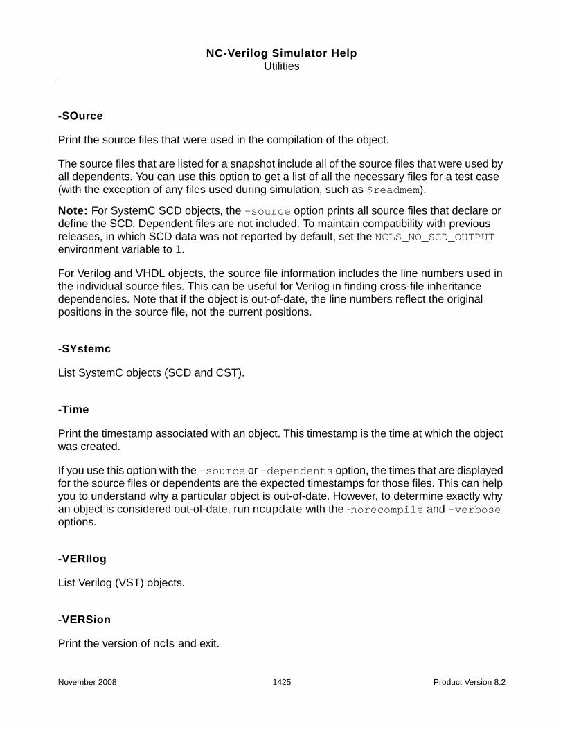
NC-Verilog Simulator HelpUtilities
-SOurce
Print the source files that were used in the compilation of the object.
The source files that are listed for a snapshot include all of the source files that were used byall dependents. You can use this option to get a list of all the necessary files for a test case(with the exception of any files used during simulation, such as $readmem).
Note: For SystemC SCD objects, the -source option prints all source files that declare ordefine the SCD. Dependent files are not included. To maintain compatibility with previousreleases, in which SCD data was not reported by default, set the NCLS_NO_SCD_OUTPUTenvironment variable to 1.
For Verilog and VHDL objects, the source file information includes the line numbers used inthe individual source files. This can be useful for Verilog in finding cross-file inheritancedependencies. Note that if the object is out-of-date, the line numbers reflect the originalpositions in the source file, not the current positions.
-SYstemc
List SystemC objects (SCD and CST).
-Time
Print the timestamp associated with an object. This timestamp is the time at which the objectwas created.
If you use this option with the -source or -dependents option, the times that are displayedfor the source files or dependents are the expected timestamps for those files. This can helpyou to understand why a particular object is out-of-date. However, to determine exactly whyan object is considered out-of-date, run ncupdate with the -norecompile and -verboseoptions.
-VERIlog
List Verilog (VST) objects.
-VERSion
Print the version of ncls and exit.
November 2008 1425 Product Version 8.2

NC-Verilog Simulator HelpUtilities
-VHdl
List VHDL (AST) objects.
-VIew
Indicates that the name specified on the command line is a view name.
If you specify a name as an argument on the command line with no period or semicolon (forexample, % ncls rtl), ncls interprets the name as a cell name. The -view option specifiesthat the name is a view name.
Example ncls Command Lines
The following command lists all objects in all libraries.
% ncls -all
The following command lists all Verilog objects named top.
% ncls -verilog top
The following command lists all VHDL architectures named ARCH_1.
% ncls -vhdl -architecture ARCH_1
The following command lists all of the objects in library asic_1.
% ncls -library asic_1
The following command displays information on all VHDL entities and all Verilog modules andprimitives.
% ncls -verilog -entity
All of the following commands can be used to list the snapshot worklib.top:snap.
% ncls -snapshot worklib.top:snap
% ncls -snapshot worklib.top
% ncls -snapshot top:snap
% ncls -snapshot top
% ncls -view -snapshot snap
% ncls -view snap
The following command includes the -source option. This prints the source files that areused by the snapshot worklib.top:snap. The source files listed for the snapshot includeall source files used by all dependents (ASTs and VSTs).
November 2008 1426 Product Version 8.2

NC-Verilog Simulator HelpUtilities
% ncls -source -snapshot worklib.top:snap
The following command lists the source files that were used in compiling worklib.dut:v.
% ncls -source -verilog worklib.dut:v
The following command lists the objects that were used in building the snapshot top:snap.
% ncls -dependents -snapshot worklib.top:snap
The following command includes the -command option. This option shows the command linethat was used to build the object my_module.
% ncls -command my_module
In the following command, the -lockinfo option is used to display the library lockinformation on library LIB. In this example, two users (user1 and user2) put a shared lockon a library LIB from machines mach1 and mach2, respectively.
Note: Library lock information is dumped only if the users are using an hdl.var file in whichthe NCLOCK_INFO variable has been defined and if the library has write permission.
The following ncls command can be used to access the library lock information:
% ncls -nocopyright -lockinfo LIB
Library : LIB
locked by process : 19629
on Machine : mach1
by User : user1
since Time : Wed Feb 11 17:32:19 2004
in shared mode
****************************************8
Library : LIB
locked by process : 12991
on Machine : mach2
by User : user2
since Time : Wed Feb 11 17:31:04 2004
in shared mode
In the following example, a user (user1) puts an exclusive lock on a 64-bit library LIB frommachine mach1. To display the library lock information, you must run ncls in 64-bit mode.Running in the default 32-bit mode will not provide any information on the 64-bit library.
The following command assumes that you have set your path variable and library pathenvironment variable so that you are pointing to the 64-bit version of the tools.
November 2008 1427 Product Version 8.2

NC-Verilog Simulator HelpUtilities
% ncls -nocopyright -lockinfo LIB
Library : LIB
locked by Process : 12991
on Machine : mach1
by User : user1
since Time : Wed Feb 11 17:31:04 2004
in exclusive mode
Object Types Listed by ncls
The ncls utility lists objects that are stored in the library system. The objects that nclsdisplays are generated and used by NC tools. Because the files are system generated, theyare generally not a user concern. This section provides information about the various objecttypes that can be displayed by the ncls utility.
Object Description
AST Abstract Syntax Tree. The file format produced by the VHDL compiler torepresent the VHDL language in an intermediate form.
COD Code file. The file format used to store platform-specific machine codegenerated by the native code compiler.
CST SystemC Syntax Tree. The file format produced by ncelab to representportions of the SystemC syntax in a design.
SAM Spectre Analog Master. The file format produced by the AMS elaborator torepresent the analog master data in a Verilog-AMS design.
SCD SystemC Data. The file format produced by the ncsc tool to representinformation about the SystemC portions of the design.
SDB SAM DataBase. The file format produced by the AMS elaborator torepresent flavors of an analog master. Flavors arise when masters containparameterized topology (for example, generate loops in Verilog-AMS) or ifthe type of an object in a master is instance-dependent. Modules that donot need flavors have no SDB files.
SIG Signature file. The file format used to represent a unique instantiation of aVerilog or VHDL design unit.
November 2008 1428 Product Version 8.2

NC-Verilog Simulator HelpUtilities
SSI Spectre Simulation Image. The file format produced by the AMS elaboratorto represent all the information needed to simulate the analog portion of anAMS design. It contains a reference to an analog description of all the AMSmasters containing analog functionality (SAMs) used in the design, as wellas descriptions of all the natures and disciplines in the design, the nodes inthe design, and the instances of AMS analog masters in the design.
SSS Simulation Snapshot file. The file format used to store the state of anelaborated design, including simulation run-time data. The snapshot isgenerated by the elaborator.
VST Verilog Syntax Tree. The file format produced by the Verilog compiler torepresent the Verilog language in an intermediate form.
Object Description
November 2008 1429 Product Version 8.2

NC-Verilog Simulator HelpUtilities
ncpack
The ncpack utility lets you change the properties of a packed library database. When youcompile source files or elaborate a design, packed library databases are generated. Thesedatabases are readable and writable by default. You can:
■ Make a library database read-only (-readonly).
■ Make a library database add-only (-addonly).
New data can be added to an add-only database, but existing data cannot be removedor modified.
■ Make a library database readable/writable (-database).
You can use ncpack with the -unpack option to unpack a packed library so that you cansee which cells and views are in the library. If you then repack the library, ncpack createsa read-only database.
ncpack Command Syntax
Invoke ncpack with options and arguments. Options can occur in any order. Parameters tooptions must immediately follow the option they modify. Command-line options can beabbreviated to the shortest unique string, indicated here with capital letters.
ncpack [-options] logical_library_name ...
[-64bit]
[-ADdonly]
[-APpend_log]
[-Cdslib filename]
[-Database]
[-Errormax integer]
[-HDlvar filename]
[-HElp]
[-Logfile filename]
[-Messages]
[-NCError warning_code[:warning_code ...]]
[-NCFatal {warning_code | error_code}[:{warning_code | error_code} ...]]
[-NEverwarn]
[-NOCopyright]
[-NOLog]
[-NOStdout]
[-NOWarn warning_code[:warning_code ...]]
November 2008 1430 Product Version 8.2

NC-Verilog Simulator HelpUtilities
[-Readonly]
[-Status]
[-Tmpdir directory]
[-UNLock]
[-UNPack]
[-Version]
Note: No cds.lib and hdl.var files are required to run the simulator. You can invoke thecompiler to compile your source files, and the compiler will automatically create a default worklibrary called worklib in a directory called INCA_libs, which is under the current directory.The logical name of this library is worklib. When you run ncpack, you must specify thisname as the argument. For example:
% ncpack -messages -readonly worklib
ncpack Command Options
The following list describes the options you can use with the ncpack command. Options canbe entered in upper or lowercase. Capital letters indicate the shortest possible abbreviationfor an option.
-64bit
Invoke the 64-bit version of the ncpack executable.
Besides including the -64bit command-line option when you run the executables, you canalso run the 64-bit version by:
■ Setting the INCA_64BIT environment variable.
■ Setting up your PATH and library path environment variables so that you are pointing tothe 64-bit version.
See “64-Bit NC-Verilog” on page 39 for more information.
The -64bit command-line option is ignored if you have already specified that you want torun in 64-bit mode by setting environment variables.
You cannot use the -64bit option in flows with tools that do not support 64-bit.
November 2008 1431 Product Version 8.2

NC-Verilog Simulator HelpUtilities
-ADdonly
Make the packed library database an add-only database. New data can be added to anadd-only database, but nothing in the database can be deleted or modified. It isrecommended that you mark shared libraries as add-only.
-APpend_log
Append log information from multiple runs of ncpack to one log file. This option is overriddenby the -nolog option.
-Cdslib filename
Use the specified cds.lib file. See “The cds.lib File” on page 133.
-Database
Generate a writeable packed library.
If you unpack a library and then repack it, ncpack creates a read-only library. Use the-database option to make the library writeable.
-Errormax integer
Abort ncpack after reaching the specified number of errors.
-HDlvar filename
Use the specified hdl.var file. See “The hdl.var File” on page 142.
-HElp
Print a brief summary of the ncpack command-line options.
-Logfile filename
Use the specified name for the log file instead of the default name ncpack.log.
November 2008 1432 Product Version 8.2

NC-Verilog Simulator HelpUtilities
-Messages
Print informative messages during execution.
-NCError warning_code[:warning_code ...]
Increase the severity level of the specified warning message from warning to error. Thewarning_code argument is the message code (mnemonic) that appears in the warningmessage following the severity code.
Example:
% ncpack -messages -database worklib -ncerror ABCDEF
You can increase the severity level of multiple warning messages either by using multiple-ncerror options or by using one -ncerror option and separating the warning_codearguments with a colon. For example,
% ncpack -database worklib -ncerror ABCDEF -ncerror HIJKLM
% ncpack -database worklib -ncerror ABCDEF:HIJKLM
Using this option can change the behavior of the tool because functions that return errorsinstead of warnings may behave differently.
-NCFatal {warning_code | error_code}[:{warning_code | error_code} ...]
Increase the severity level of the specified warning message or error message from warningor error to fatal. The warning_code or error_code argument is the message code(mnemonic) that appears in the message following the severity code.
Example:
% ncpack -messages -database worklib -ncfatal LMNOPQ
You can increase the severity level of multiple warning messages or error messages to fataleither by using multiple -ncfatal options or by using one -ncfatal option and separatingthe warning_code or error_code arguments with a colon. For example,
% ncpack -database worklib -ncfatal ABCDEF -ncfatal LMNOPQ
% ncpack -database worklib -ncfatal ABCDEF:LMNOPQ
-NEverwarn
Disable printing of all warning messages.
November 2008 1433 Product Version 8.2

NC-Verilog Simulator HelpUtilities
-NOCopyright
Suppress printing of the copyright banner.
Because the copyright banner is printed before any variables in the hdl.var file areprocessed, this option is ignored if you include it with the NCPACKOPTS variable in anhdl.var file.
-NOLog
Do not generate a log file. By default, ncpack generates a log file called ncpack.log.
If you include the -nolog option in the hdl.var file, a log file will be created because thefile is opened before any variables in the hdl.var file are processed. However, once theoption is processed in the hdl.var file, output to the log file is discontinued, and the log filewill contain only header information.
-NOStdout
Suppress printing output to the screen.
-NOWarn warning_code[:warning_code ...]
Disable the printing of the specified warning. The warning_code is the sequence ofcharacters following the error severity code.
Example:
% ncpack -database worklib -nowarn ABCDEF
You can disable the printing of multiple warning messages either by using multiple -nowarnoptions or by using one -nowarn option and separating the warning_code argumentswith a colon. For example,
% ncpack -database worklib -nowarn ABCDEF -nowarn HIJKLM
% ncpack -database worklib -nowarn ABCDEF:HIJKLM
-Readonly
Make the packed database read-only. The database generated by compiling and elaboratinga design is read/write by default. Use the -readonly option to make the database read-only.
November 2008 1434 Product Version 8.2

NC-Verilog Simulator HelpUtilities
-Status
Check whether the specified library was packed as read-only or add-only. For example:
% ncpack -nocopyright -readonly worklib
% ncpack -nocopyright -status worklib
Add only flag is unset
Read only flag is set
-Tmpdir directory
Specify the directory that ncpack uses to store temporary data while it packs the library. Thetemporary directory can be located anywhere in the local file system or on a remote machine.
When a library is being packed or unpacked it temporarily uses about two times the diskspace required by the library. If the disk on which you are operating is not large enough tohandle this much additional data, you can use the -tmpdir option to specify a differentdirectory to store the temporary data.
Note: This option is not the same as assigning the TMP attribute in cds.lib.
-UNLock
Unlock the specified library.
When you compile source files or elaborate a design, a lock is placed on the database as itis being generated. Use the -unlock option to remove the lock to make the databasewriteable immediately.
Locks are placed on databases to prevent different users from trying to write to themsimultaneously. The -unlock option should only be used in situations where a lockeddatabase must be unlocked. For example, a suspended process can keep a databaselocked, and you may want to use -unlock to unlock that database.
-UNPack
Unpack the specified library.
November 2008 1435 Product Version 8.2

NC-Verilog Simulator HelpUtilities
-Version
Print the version of ncpack and exit.
Example ncpack Command Lines
The following command makes the packed library database for library worklib read-only.
% ncpack -readonly worklib
The following command checks the status of the library worklib.
% ncpack -nocopyright -status worklib
Add only flag is unset
Read only flag is set
The following command makes the packed library database for library worklib and forlibrary alt_max2 add-only.
% ncpack -addonly worklib alt_max2
The following command unpacks the data stored in the library database file (.pak) in thelibrary named worklib. A subdirectory under the worklib directory is created for each celland for each view, and the appropriate intermediate objects are placed in the subdirectories.The packed library is then removed.
% ncpack -nocopyright -unpack -messages worklib
Unpacking library ‘worklib’ ...
Moving packed library to temporary location ...
Reading packed library index ...
Copying packed objects back into library ...
Removing packed library ...
% ls worklib
board/ dEdgeFF/ m16/ m555/
The following command packs the library named worklib. The -database option isincluded to make the database writable.
% ncpack -nocopyright -messages -database worklib
Packing library ‘worklib’ ...
Scanning library ...
Creating packed library index ...
Copying objects into packed library ...
Writing packed library index ...
Removing packed objects from library ...
Moving packed library into place ...
November 2008 1436 Product Version 8.2

NC-Verilog Simulator HelpUtilities
% ls worklib
board/ inca.sun4v.090.pak m555/
dEdgeFF/ m16/
November 2008 1437 Product Version 8.2

NC-Verilog Simulator HelpUtilities
ncparse
ncparse is the executable you use to compile design source files using design-topcompilation. Design-top compilation is a way to compile a design by specifying the top-levelof the design when you invoke the compiler instead of specifying all source files on thecommand line.
The top-level is specified in a file called a compilation command file, which is passed asan argument to the -cmdfile option. The compilation command file also specifies the pathto a file that contains the rules that describe the mapping of design unit names to source filenames, and the list of directories to be searched for locating the design files.
You can use design-top compilation for compiling a Verilog, VHDL, or mixed Verilog-VHDLdesign.
Note: Using the -cmdfile option specifies that design-top compilation is to be used. Youcannot specify design file names on the command line. If you use the -cmdfile option andalso include design file names on the command line, the parser uses the compilationcommand file.
See “Compiling Source Files by Specifying the Top-Level of the Design” on page 206 fordetails on design-top compilation and on writing a compilation command file.
ncparse Command Syntax
Invoke ncparse with options and arguments. Options can occur in any order. Parameters tooptions must immediately follow the option they modify. Command-line options can beabbreviated to the shortest unique string, indicated here with capital letters.
ncparse [other_ncparse_options] -cmdfile compilation_command_file
[-64bit]
[-Append_log]
[-CDslib filename]
[-CMdfile compilation_command_file]
[-Design_top design_top_name]
[-Errormax integer]
[-File arguments_filename]
[-HDlvar filename]
[-HElp]
[-LAng {vlog | vhdl}]
[-LOgfile filename]
[-Messages]
[-NCError warning_code[:warning_code ...]]
November 2008 1438 Product Version 8.2

NC-Verilog Simulator HelpUtilities
[-NCFatal {warning_code | error_code}[:{warning_code | error_code} ...]]
[-NEverwarn]
[-NOCopyright]
[-NOLog]
[-NOStdout]
[-NOWarn warning_code[:warning_code ...]]
[-UPDate]
[-UPTodate_messages]
[-Version]
ncparse Command Options
The following list describes the options you can use with the ncparse command. Optionscan be entered in upper or lowercase. Capital letters indicate the shortest possibleabbreviation for an option.
-64bit
Invoke the 64-bit version of the ncparse executable.
Besides including the -64bit command-line option when you run the executables, you canalso run the 64-bit version by:
■ Setting up your PATH and library path environment variables so that you are pointing tothe 64-bit version.
■ Setting the INCA_64BIT or CDS_AUTO_64BIT environment variable.
See “64-Bit NC-Verilog” on page 39 for more information.
-Append_log
Append log information from multiple runs of ncparse to one log file. This option is overriddenby the -nolog option.
-CDslib filename
Use the specified cds.lib file. See “The cds.lib File” on page 133.
November 2008 1439 Product Version 8.2

NC-Verilog Simulator HelpUtilities
-CMdfile compilation_command_file
Use the specified compilation command file for design-top compilation.
See “Writing a Compilation Command File” on page 207 for details on the compilationcommand file.
-Design_top design_top_name
Specify the top-level design unit for design-top compilation.
The top-level unit must be specified either by defining the DESIGN_TOP variable in thecompilation command file or with the -design_top option on the command line. If both arespecified, the command-line option overrides the definition of the DESIGN_TOP variable in thecompilation command file.
-Errormax integer
Abort ncparse after reaching the specified number of errors.
-File arguments_filename
Use the command-line arguments contained in the specified file.
You can store frequently used or lengthy command lines by putting command options andarguments in a text file. When you invoke ncparse with the -file option, the arguments inthe specified file are used with the command as if you had entered them on the command line.
-HDlvar filename
Use the specified hdl.var file. See “The hdl.var File” on page 142.
-HElp
Print a brief summary of the ncparse command-line options.
-LAng {vlog | vhdl}
Specify the language of the top-level design unit.
November 2008 1440 Product Version 8.2
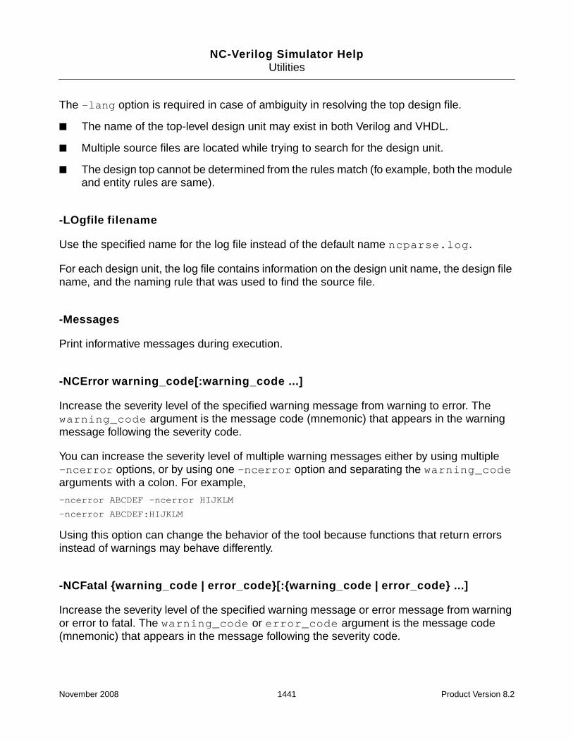
NC-Verilog Simulator HelpUtilities
The -lang option is required in case of ambiguity in resolving the top design file.
■ The name of the top-level design unit may exist in both Verilog and VHDL.
■ Multiple source files are located while trying to search for the design unit.
■ The design top cannot be determined from the rules match (fo example, both the moduleand entity rules are same).
-LOgfile filename
Use the specified name for the log file instead of the default name ncparse.log.
For each design unit, the log file contains information on the design unit name, the design filename, and the naming rule that was used to find the source file.
-Messages
Print informative messages during execution.
-NCError warning_code[:warning_code ...]
Increase the severity level of the specified warning message from warning to error. Thewarning_code argument is the message code (mnemonic) that appears in the warningmessage following the severity code.
You can increase the severity level of multiple warning messages either by using multiple-ncerror options, or by using one -ncerror option and separating the warning_codearguments with a colon. For example,
-ncerror ABCDEF -ncerror HIJKLM
-ncerror ABCDEF:HIJKLM
Using this option can change the behavior of the tool because functions that return errorsinstead of warnings may behave differently.
-NCFatal {warning_code | error_code}[:{warning_code | error_code} ...]
Increase the severity level of the specified warning message or error message from warningor error to fatal. The warning_code or error_code argument is the message code(mnemonic) that appears in the message following the severity code.
November 2008 1441 Product Version 8.2

NC-Verilog Simulator HelpUtilities
You can increase the severity level of multiple warning messages or error messages to fataleither by using multiple -ncfatal options, or by using one -ncfatal option and separatingthe warning_code or error_code arguments with a colon. For example,
-ncfatal ABCDEF -ncfatal LMNOPQ
-ncfatal ABCDEF:LMNOPQ
-NEverwarn
Disable printing of all warning messages.
-NOCopyright
Suppress printing of the copyright banner.
-NOLog
Do not generate a log file. By default, ncparse generates a log file called ncparse.log.
-NOStdout
Suppress printing output to the screen.
-NOWarn warning_code[:warning_code ...]
Disable the printing of the specified warning. The warning_code is the sequence ofcharacters following the error severity code.
You can disable the printing of multiple warning messages either by using multiple -nowarnoptions or by using one -nowarn option and separating the warning_code argumentswith a colon. For example,
-nowarn ABCDEF -nowarn HIJKLM
-nowarn ABCDEF:HIJKLM
-UPDate
Check if the design unit is up-to-date before writing a new intermediate representation.
November 2008 1442 Product Version 8.2

NC-Verilog Simulator HelpUtilities
-UPTodate_messages
Display compilation information for all design units, including those that are not beingrecompiled because they are up-to-date, when recompiling source files with the -updateoption.
By default, when recompiling source files with the -update command-line option, thecompiler does not display information about design units that are up-to-date. Information isdisplayed only for design units that are recompiled. Use the -uptodate_messages optionif you want to display information about all design units.
The -uptodate_messages option can be used only in conjunction with the -updateoption.
-Version
Print the version of ncparse and exit.
Example ncparse Command Lines
The following command specifies that the design is to be compiled using design-topcompilation. The -cmdfile option specifies the path of the compilation command file, whichdefines:
■ The DESIGN_TOP variable to specify the top-level design unit.
■ The RULES_FILE variable to specify the path of the naming rules file.
■ The SEARCH_PATH variable to list the directories to search for design files.
■ The VLOG_ARGS and VHDL_ARGS variables to specify command-line options for thencvlog and ncvhdl parsers.
% ncparse -cmdfile cmdfile.txt
The following command includes the -design_top option to specify the top-level designunit. The top-level unit must be specified either by defining the DESIGN_TOP variable in thecompilation command file or with the -design_top option on the command line.
% ncparse -cmdfile cmdfile.txt -design_top designtop
November 2008 1443 Product Version 8.2

NC-Verilog Simulator HelpUtilities
ncprep
ncprep is a utility that can help you transition from simulating a design with Verilog-XL tosimulating with NC-Verilog in multi-step invocation mode (ncvlog/ncelab/ncsim).
ncprep provides a quick transition to the NC-Verilog simulator for designs that already run inVerilog-XL. This utility is run with the same command-line options and arguments you use torun Verilog-XL. The ncprep utility evaluates the Verilog-XL command options and generatesscript and data files that contain the corresponding NC-Verilog simulator options.
ncprep can also be run with the same options and arguments that you provide to the iruncommand.
ncprep creates the following files and directories:
■ A library directory called INCA_libs
■ A work directory called INCA_libs/worklib
ncprep also creates directories under the INCA_libs directory for directories specifiedwith the -y option.
■ A cds.lib file that defines all of the libraries. See “The cds.lib File” on page 133 fordetails on the cds.lib file.
■ An hdl.var file. See “The hdl.var File” on page 142 for details on the hdl.var file.
■ ncvlog.args—A file of translated arguments that is passed to the Verilog parser,ncvlog.
■ ncelab.args—A file of translated arguments that is passed to the elaborator, ncelab.
■ ncsim.args—A file of translated arguments that is passed to the simulator, ncsim.
■ A log file (called ncprep.log by default).
■ A script file that contains commands to run ncvlog, ncelab, and ncsim using thearguments in the corresponding .args files. On UNIX, ncprep generates a csh ( Cshell) file called RUN_NC. On Windows, ncprep generates a batch file calledRUN_NC.bat.
If the files already exist, ncprep reports an error and stops. To overwrite existing files, use the+overwrite option to ncprep.
After you have run ncprep, you can execute the RUN_NC (or RUN_NC.bat) script. The scriptuses the *.args files to run ncvlog, ncelab, and ncsim to compile, elaborate, and simulateyour design.
November 2008 1444 Product Version 8.2

NC-Verilog Simulator HelpUtilities
The ncvlog.args file lists all of the HDL files required for a particular design. The ncpreputility searches library directories and only includes the files that are needed from thedirectories. However, ncprep can’t determine which modules are required in the library files,so it includes the entire file in the ncvlog.args file. Thus ncvlog compiles the completelibrary file even though only a few modules are needed.
ncprep cannot convert every Verilog-XL option to an equivalent NC-Verilog simulator option.Some designs will still require manual intervention. Also, ncprep is not designed to createan optimized simulation flow. Your coding style, library management process, and designenvironment will define the ultimate performance of the simulator.
By default, the elaborator (ncelab) creates a simulation snapshot in which simulation objectsare tagged as having no read, write, or connectivity access. This increases the performanceof the simulator for long regression test runs, but does not provide the access to objects thatyou need to debug a design. There are two ncprep command-line options you can use tospecify access to simulation objects:
■ +ncdebug. This option turns on read access to all objects in the design. Read access isrequired for probing nets, regs and variables (including setting PLI callbacks) and gettingthe value of these objects. The ncprep +ncdebug option is translated to the ncelab-access +r option.
■ +linedebug. This option enables support for setting line breakpoints and forsingle-stepping through code, and provides read, write, and connectivity access to allobjects in the design. The +linedebug option is translated to the ncvlog-linedebug option.
You can also edit the ncelab.args file to insert the -access or -afile elaboratorcommand options.
November 2008 1445 Product Version 8.2

NC-Verilog Simulator HelpUtilities
ncprep Command Syntax
Invoke ncprep with the ncprep command followed by the Verilog-XL command-linearguments and any ncprep command options.
ncprep [ncprep_options] verilog-xl_arguments
[+ncdebug]
[-h]
[-l filename]
[+linedebug]
[+ncerror+warning_code[:warning_code ...]]
[+ncfatal+{warning_code | error_code}[:{warning_code | error_code} ...]]
[+nclibdirname+directory_name]
[+nospecify]
[+nowarn+warning_code[:warning_code ...]]
[+overwrite]
[+redirect+directory_name]
ncprep Command Options
The following list describes the ncprep command-line options:
+ncdebug
Create a simulation snapshot in which all simulation objects are tagged as having readaccess. This option is translated to the ncelab -access +r option. See “Enabling Read,Write, or Connectivity Access to Simulation Objects” on page 371 for details on specifyingaccess.
-h
Display help on the ncprep command and its options.
-l filename
Use the specified name for the log file instead of the default name, ncprep.log.
ncprep ignores the Verilog-XL -l filename option and generates a log file which is calledncprep.log by default. In the ncvlog.args, ncelab.args, and ncsim.args outputfiles, ncprep inserts a -logfile option. For example, in the ncvlog.args file, ncprepinserts the following lines:
November 2008 1446 Product Version 8.2

NC-Verilog Simulator HelpUtilities
// Uncomment the following line to generate a named log file
// -LOGFILE ncvlog.log
Uncomment these lines if you want a log file when you run the RUN_NC (or RUN_NC.bat)script.
+linedebug
Enable support for setting line breakpoints and for single-stepping through code. Using thisoption automatically provides read, write, and connectivity access. This option is translatedto the ncvlog -linedebug option.
+ncerror+warning_code[:warning_code ...]
Increase the severity level of the specified warning message from warning to error. Thewarning_code argument is the message code (mnemonic) that appears in the warningmessage following the severity code.
Example:
% ncprep -f verilog.vc +ncerror+CUVWSP
You can increase the severity level of multiple warning messages either by using multiple+ncerror+ options or by using one +ncerror+ option and separating thewarning_code arguments with a colon. For example,
% ncprep -f verilog.vc +ncerror+CUVWSP +ncerror+ABCDEF
% ncprep -f verilog.vc +ncerror+CUVWSP:ABCDEF
Using this option can change the behavior of the tool because functions that return errorsinstead of warnings may behave differently. Warnings that are changed to errors are countedin the error count limit that you specify with the +max_err_count+ option.
+ncfatal+{warning_code | error_code}[:{warning_code | error_code} ...]
Increase the severity level of the specified warning message or error message from warningor error to fatal. The warning_code or error_code argument is the message code(mnemonic) that appears in the message following the severity code.
Example:
% ncprep -f verilog.vc +ncfatal+DLCPTH
November 2008 1447 Product Version 8.2

NC-Verilog Simulator HelpUtilities
You can increase the severity level of multiple warning messages or error messages to fataleither by using multiple +ncfatal+ options or by using one +ncfatal+ option andseparating the warning_code or error_code arguments with a colon. For example,
% ncprep -f verilog.vc +ncfatal+DLCPTH +ncfatal+CUVWSP
% ncprep -f verilog.vc +ncfatal+DLCPTH:CUVWSP
+nclibdirname+directory_name
Store the snapshot, packed library file, and other generated objects in a directory with thespecified name.
By default, ncprep creates a directory called INCA_libs in the current working directory tostore these objects. Use the +nclibdirname+ option to specify a different directory. ncprepautomatically creates the directory for you.
The directory_name argument can be a relative or absolute path to the directory. Forexample:
+nclibdirname+foo // Stores objects in ./foo
+nclibdirname+./foo // Stores objects in ./foo
+nclibdirname+foo/bar // Stores objects in ./foo/bar. Directory foo must// exist. ncprep will create directory bar.
+nclibdirname+./foo/bar // Stores objects in ./foo/bar
+nclibdirname+../foo // Stores objects in ../foo
+nclibdirname+../foo/bar // Stores objects in ../foo/bar
+nclibdirname+/tmp // Stores objects in /tmp
+nclibdirname+.. // Stores objects in .. (upper directory)
Use the +redirect+ option if you want all ncprep output redirected to a specific directory.
+nospecify
The -nospecify command-line option is a convenient way to disable several timing featuresthat are usually not required for functional verification. This option affects timing informationcontained in specify blocks and SDF annotation, as follows:
November 2008 1448 Product Version 8.2

NC-Verilog Simulator HelpUtilities
■ Timing information described in specify blocks
❑ Module paths and delays described in specify blocks are ignored.
❑ Timing checks described in specify blocks are ignored. For negative timingchecks, delayed signals are processed to establish correct logic connections, withzero delays between the connections, but the timing checks are ignored.
❑ DelayOverride$ specparams in specify blocks are ignored.
■ SDF annotation
All SDF delays and timing checks are ignored.
The -nospecify option can be used with the -delay_mode command-line option tospecify the delay mode (zero, unit, path, or distributed), or with the `delay_mode_* compilerdirectives. The order of precedence in delay mode selection from highest to lowest is asfollows:
1. Command-line option
2. Compiler directives
3. Default — no delay mode
+nowarn+warning_code[:warning_code ...]
Disable printing of the warning with the specified code. The warning_code argument isthe message code (mnemonic) that appears in the warning message following the errorseverity code.
Example:
% ncprep +nowarn+INTIVF source.v
You can disable the printing of multiple warning messages either by using multiple +nowarn+options or by using one +nowarn+ option and separating the warning_code argumentswith a colon. For example,
% ncprep +nowarn+INTOVF +nowarn+CUVWSP source.v
% ncprep +nowarn+INTOVF:CUVWSP source.v
+overwrite
Overwrite any script files, setup files, and directories that already exist. The default is to printan error message and not overwrite files or directories. You cannot abbreviate +overwrite.
November 2008 1449 Product Version 8.2

NC-Verilog Simulator HelpUtilities
+redirect+directory_name
Redirect the output of ncprep to the specified directory. This option creates a directory withthe specified name, and uses that directory to store the following output: the INCA_libsdirectory, the ncvlog, ncelab, and ncsim arguments files, the cds.lib and hdl.var files,and the RUN_NC (RUN_NC.bat) script.
The ncprep.log file is stored in the current working directory.
Example ncprep Run
In the following example, source files are in the directory structure shown below.
% ncprep -f verilog.vc
ncprep: 05.50-p004.(d6): (c) Copyright 1995 - 2005 Cadence Design Systems, Inc.
Translating +libverbose to ncelab option -LIBVERBOSE
Translating +gui to ncsim option -GUI
Translating +max_err_count+25 to ncvlog, ncelab, ncsim option ERRORMAX
Translating +notimingchecks to ncelab option -NOTIMINGCHECKS
November 2008 1450 Product Version 8.2

NC-Verilog Simulator HelpUtilities
Translating +maxdelays to ncelab option -MAXDELAYS
Translating +nowarnTFNPC to ncvlog, ncelab, ncsim option -NOWARN
Translating +nowarnTFMPS to ncvlog, ncelab, ncsim option -NOWARN
Adding -UPDATE option, to disable update run ncprep with the +noupdate
Translation successful.
This run of ncprep creates the following directory structure:
Example ncprep Output Files
The following sections show the output files created by running the example in “Examplencprep Run” on page 1450.
ncprep Output File—cds.lib
ncprep creates a cds.lib file in the current run directory. See “The cds.lib File” on page 133for details on the cds.lib file.
In this example, ncprep creates a cds.lib file that defines three libraries: worklib, libs,and models. The libraries libs and models are created using the names of directoriesspecified with the -y option.
November 2008 1451 Product Version 8.2

NC-Verilog Simulator HelpUtilities
# cds.lib: Defines the locations of compiled libraries.
# Created by ncprep on Mon Jun 20 15:30:12 2005
#
DEFINE worklib ./INCA_libs/worklib
DEFINE libs ./INCA_libs/libs // These libraries are specified in the// arguments file, verilog.vc, with -y.
DEFINE models ./INCA_libs/models
ncprep Output File—hdl.var
ncprep creates an hdl.var file in the current run directory. See “The hdl.var File” onpage 142 for details on the hdl.var file.
In this example, the hdl.var file contains three LIB_MAP variables. These variables specifythat:
■ Files in the ./libs directory are to be compiled into library libs.
■ Files in the ./models directory are to be compiled into library models.
■ Other files are to be compiled into library worklib.
The VIEW_MAP variable specifies that design units in files with a .v extension are to becompiled with a view name of v. For example, design units in the file top.v will be compiledinto worklib.top:v. Design units in ./libs/comb_logic.v will be compiled intolibs.comb_logic:v.
# hdl.var: Defines variables used by the INCA tools.
# Created by ncprep on Mon Jun 20 15:30:12 2005
#
softinclude $CDS_INST_DIR/tools/inca/files/hdl.var
define LIB_MAP ( $LIB_MAP, + => worklib )
define VIEW_MAP ( $VIEW_MAP, .v => v )
define LIB_MAP ( $LIB_MAP, ./libs => libs )
define LIB_MAP ( $LIB_MAP, ./models => models )
ncprep Output File—ncvlog.args
ncprep creates the ncvlog.args file. This file is the arguments file for the ncvlogcommand. See Chapter 6, “Compiling Verilog Source Files with ncvlog,” for details onncvlog.
November 2008 1452 Product Version 8.2

NC-Verilog Simulator HelpUtilities
// ncvlog.args: Arguments passed to the Verilog parser.
// Created by ncprep on Mon Jun 20 15:30:12 2005
-ERRORMAX 25
// Frequently occuring Verilog Warnings.
// Turn on informative messages.
-MESSAGES
// -NOCOPYRIGHT
// Uncomment the following line to generate a named log file
// -LOGFILE ncvlog.log
// Comment the following line to force recompilation.
-UPDATE
// Source Files
./top.v
// Library Files and Directories
./libs/comb_logic.v
./models/or2.v
./models/and2.v
ncprep Output File—ncelab.args
ncprep creates the ncelab.args file. This file is the argument file for the ncelabcommand. See Chapter 7, “Elaborating the Design with ncelab,” for details on ncelab.
// ncelab.args: Arguments passed to the elaborator.
// Created by ncprep on Mon Jun 20 15:30:12 2005
-ERRORMAX 25
// Frequently occuring Verilog Warnings.
-NOWARN CUVWSP
-NOWARN CUVWSP
// Turn on informative messages.
-MESSAGES
// -NOCOPYRIGHT
// Uncomment the following line to generate a named log file
// -LOGFILE ncelab.log
November 2008 1453 Product Version 8.2

NC-Verilog Simulator HelpUtilities
-LIBVERBOSE
-MAXDELAYS
-NOTIMINGCHECKS
// Translated Options.
+libverbose
+gui
+max_err_count+25
+notimingchecks
+maxdelays
+nowarnTFNPC
+nowarnTFMPS
// Top level module(s)
top
// Design snapshot name
-SNAPSHOT worklib.top:v
ncprep Output File—ncsim.args
ncprep creates the ncsim.args file. This file is the argument file for the ncsim command.See Chapter 8, “Simulating Your Design with ncsim,” for details on ncsim.
// ncsim.args: Arguments passed to the simulator.
// Created by ncprep on Mon Jun 20 15:30:12 2005
-ERRORMAX 25
// Frequently occuring Verilog Warnings.
// Turn on informative messages.
-MESSAGES
// -NOCOPYRIGHT
// Uncomment the following line to generate a named log file
// -LOGFILE ncsim.log
// This will bring you to an interactive TCL session.
-TCL
-GUI
// Translated Options.
+libverbose
November 2008 1454 Product Version 8.2

NC-Verilog Simulator HelpUtilities
+gui
+max_err_count+25
+notimingchecks
+maxdelays
+nowarnTFNPC
+nowarnTFMPS
// Design snapshot name
worklib.top:v
ncprep Output File—RUN_NC
After running ncprep, you can execute the RUN_NC script (or RUN_NC.bat on Windows) tocompile, elaborate, and simulate the design. The following shows the RUN_NC script:
#!/bin/csh -f
#
# RUN_NC: Script to run all of NC-Verilog (the first time).
# Created by ncprep on Mon Jun 20 15:30:12 2005
#
# Run the NC-Verilog parser (compile the source)
ncvlog -f ncvlog.args
if ($status != 0) then
exit
endif
# Run the NC-Verilog elaborator (build the design hierarchy)
ncelab -f ncelab.args
if ($status != 0) then
exit
endif
# Run the NC-Verilog simulator (simulate the design)
ncsim -f ncsim.args
When you execute the RUN_NC script (or RUN_NC.bat), log files for the three tools arecreated (ncvlog.log, ncelab.log, and ncsim.log) in the current working directory.
After you execute the RUN_NC script for this example, the INCA_libs directory contains thefollowing directories and files. The .pak files are packed library database files. Thesedatabases are readable and writable by default. Use the ncpack utility to change the
November 2008 1455 Product Version 8.2

NC-Verilog Simulator HelpUtilities
properties of the databases. For example, you can use ncpack to make the databasesread-only or add-only. See “ncpack” on page 1430 for details on ncpack.
November 2008 1456 Product Version 8.2

NC-Verilog Simulator HelpUtilities
Verilog-XL Command-Line Options Translation
ncprep translates all applicable Verilog-XL command-line options into options for ncvlog,ncelab, and ncsim. The tables in this section detail which XL options are translated intowhich NC-Verilog simulator options.
Verilog-XL Dash (-) Option Translation Table
The ncprep utility evaluates Verilog-XL command line dash options and generates theequivalent NC-Verilog simulator options. The following table lists the translations that ncprepperforms.
Table 17-1 Dash (-) Option Translation
Verilog-XL Dash (-) Option Action
-a Ignored.
-c Ignored.
-d Ignored.
-f filename Translates the Verilog-XL command line optionscontained in filename.
-i filename Ignored because NC-Verilog cannot use a file ofVerilog commands. Prints a message telling youto use the +tcl+ option to include a file of Tclcommands.
-k filename Translated to ncsim -keyfile.
-l filename Ignored.
ncprep generates a log file called ncprep.logby default. Use the ncprep -l filenameoption to give this log file a different name.
-q Comments out the -messages option and insertsthe -nocopyright option in the ncvlog, ncelab,and ncsim arguments files.
-r Ignored.
-s Translated to ncsim -tcl.
-t Ignored.
November 2008 1457 Product Version 8.2

NC-Verilog Simulator HelpUtilities
Verilog-XL Plus (+) Option Translation Table
The following table shows which Verilog-XL command-line plus options are translated byncprep. There are many other Verilog-XL plus options documented in the Verilog-XLReference Manual that have no counterparts in the NC-Verilog simulator or that are ignoredwith a warning.
-u Translated to ncvlog -upcase.
-v library Defines library in the cds.lib file and setsthe LIB_MAP variable in the hdl.var file.
-w Translated to ncvlog -neverwarn, ncelab-neverwarn, and ncsim -neverwarn.
-x Ignored. Prints a message telling you thatexpansion has a severe performance impact andis almost never necessary in NC-Verilog. Use+expand to force expansion of all vectors.
-y library Defines library in the cds.lib file and setsthe LIB_MAP variable in the hdl.var file.
Table 17-2 Plus (+) Option Translation
Verilog-XL Plus (+) Option Action
+define+arg ncvlog -define
+delay_mode_distributed ncelab -delay_mode distributed
+delay_mode_path ncelab -delay_mode path
+delay_mode_unit ncelab -delay_mode unit
+delay_mode_zero ncelab -delay_mode zero
+expand_specify_vectors ncelab -expand
+gui ncsim -gui
+incdir+arg ncvlog -incdir
Table 17-1 Dash (-) Option Translation
Verilog-XL Dash (-) Option Action
November 2008 1458 Product Version 8.2

NC-Verilog Simulator HelpUtilities
+libext+arg Sets the VIEW_MAP variable in the hdl.var file.
+libverbose ncelab -libverbose
+licq* ncsim -licqueue
+loadpli1=arg ncelab -loadpli1
+loadvpi=arg ncelab -loadvpi
+maxdelays ncelab -maxdelays
+max_err_count+argor+max_error_count+arg
ncvlog, ncelab, and ncsim -errormax
+mindelays ncelab -mindelays
+multisource_int_delays ncelab -intermod_path
+no_notifier ncelab -nonotifier
+no_pulse_msg ncsim -epulse_no_msg
+nosdfwarn ncelab -sdf_no_warnings
+no_show_cancelled_eor+noshow_cancelled_e
ncelab -epulse_noneg
+no_tchk_msgor+notchkmsg
ncelab -no_tchk_msg
+notimingchecks ncelab -notimingchecks
+nowarn+arg ncvlog, ncelab, and ncsim -nowarn
+ntc_warn ncelab -ntc_warn
+pathpulse ncelab -pathpulse
+profile ncsim -profile
+pulse_e/arg ncelab -pulse_e
Table 17-2 Plus (+) Option Translation
Verilog-XL Plus (+) Option Action
November 2008 1459 Product Version 8.2
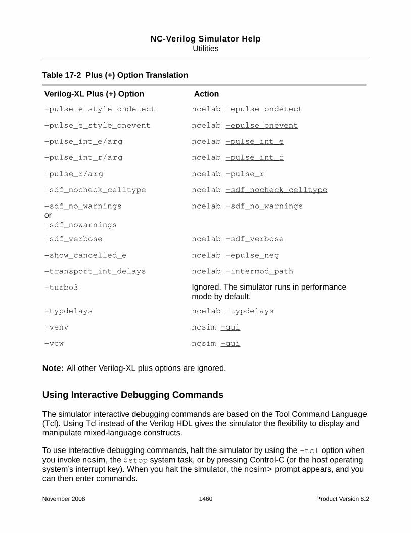
NC-Verilog Simulator HelpUtilities
Note: All other Verilog-XL plus options are ignored.
Using Interactive Debugging Commands
The simulator interactive debugging commands are based on the Tool Command Language(Tcl). Using Tcl instead of the Verilog HDL gives the simulator the flexibility to display andmanipulate mixed-language constructs.
To use interactive debugging commands, halt the simulator by using the -tcl option whenyou invoke ncsim, the $stop system task, or by pressing Control-C (or the host operatingsystem’s interrupt key). When you halt the simulator, the ncsim> prompt appears, and youcan then enter commands.
+pulse_e_style_ondetect ncelab -epulse_ondetect
+pulse_e_style_onevent ncelab -epulse_onevent
+pulse_int_e/arg ncelab -pulse_int_e
+pulse_int_r/arg ncelab -pulse_int_r
+pulse_r/arg ncelab -pulse_r
+sdf_nocheck_celltype ncelab -sdf_nocheck_celltype
+sdf_no_warningsor+sdf_nowarnings
ncelab -sdf_no_warnings
+sdf_verbose ncelab -sdf_verbose
+show_cancelled_e ncelab -epulse_neg
+transport_int_delays ncelab -intermod_path
+turbo3 Ignored. The simulator runs in performancemode by default.
+typdelays ncelab -typdelays
+venv ncsim -gui
+vcw ncsim -gui
Table 17-2 Plus (+) Option Translation
Verilog-XL Plus (+) Option Action
November 2008 1460 Product Version 8.2

NC-Verilog Simulator HelpUtilities
For more information on the interactive commands, type help at the ncsim> prompt. SeeChapter 11, “Using the Tcl Command-Line Interface,” for detailed information on eachinteractive command.
With both Verilog-XL and the NC-Verilog simulator you can use the SimVision analysisenvironment to debug your design. With Verilog-XL, you invoke the environment with the+gui option. With the NC-Verilog simulator, use the -gui option when you invoke thesimulator (ncsim). For example:
% ncsim -gui worklib.top:module
The following table lists common Verilog-XL commands and their NC-Verilog simulatorequivalents.
Verilog-XL NC-Verilog Description
`define alias Alias a command
. run Continue with the simulation
; run -step Step a single statement
, Step and trace a single statement
: Print current location
<NUMBER> !<number> Re-execute a previous command
-<NUMBER> Disable a previous command
$history history Show a history of previous commands
$showscopes; scope -show Show current scope and subscopes
$list; scope -list List source HDL of current scope
$showvars; value <object> Show value of object
time Show current simulation time
#10 $stop; . run 10<ns> Run for some amount of time then stop
$finish (0,1,2) finish<0,1,2>
exit
Finish the simulation and exit
November 2008 1461 Product Version 8.2

NC-Verilog Simulator HelpUtilities
PLI Tasks
Designs that use PLI or VPI routines (referred to as user system tasks) must be compiledand linked into a dynamic library or linked statically with the simulator tools. When ncprepdetects a user system task, it prints a message informing you that the simulator will need tobe specially set up to run with your PLI or VPI code.
See the PLI and VPI reference manuals for details on how to link system tasks to thesimulator tools.
SDF Annotation
You can annotate timing check and delay data contained in an SDF file. The simulatorsupports SDF versions 1.0, 2.0, 2.1, and 3.0. For versions 2.0 and above, use theSDFVERSION statement in the header of the SDF file to specify the version.
There are two ways to perform Verilog SDF annotation:
■ By using $sdf_annotate system tasks in your design source files.
By default, SDF annotation is performed during elaboration. The elaborator detects thepresence of $sdf_annotate system tasks in the design source files and if the$sdf_annotate system tasks are scheduled to run at time 0 and meet otherrequirements, annotation is performed automatically when you run the RUN_NC script.
Simulation-time SDF annotation can be enabled with the -sdf_simtime option. To dothis, edit the ncelab.args file and insert the option.
■ By using an SDF command file.
An SDF command file can be used if the annotation is to take place at time 0 (that is,during elaboration). This is an alternative to annotating at time 0 by using a$sdf_annotate call. A command file can also be used to force elaboration-timeannotation if the $sdf_annotate system tasks in the design do not meet therequirements for elaboration-time annotation.
To do this, edit the ncelab.args file and insert the -sdf_cmd_file filenameoption.
See “Verilog SDF Annotation” in Chapter 15, “SDF Timing Annotation” for details on SDFannotation.
November 2008 1462 Product Version 8.2

NC-Verilog Simulator HelpUtilities
Troubleshooting
This section describes common problems that you may encounter when you convert a designto NC-Verilog. In each case, manual intervention in the form of editing the scripts or modifyingthe Verilog source, will be required.
The following problem conditions are illustrated in this section:
■ Duplicate Modules
■ Scanning Multiple -v Files
■ Race Conditions
■ Renaming Modules
Duplicate Modules
Having more than one module with the same name in the set of source files may causeunpredictable differences in the behavior of the NC-Verilog simulator as compared toVerilog-XL.
A number of duplicate module scenarios and solutions are presented here:
Problem: A -v file contains multiple modules with the same name.
If a -v file contains multiple modules of the same name, Verilog-XL detects and compiles onlythe first one it encounters. Subsequent modules of the same name are never used. ncvlogdetects this and displays a warning message that a module with the same lib, cell, and viewname is being recompiled.
Solution: Remove the second module or use the compiler directive `ifdef
In order to correct this problem, you must remove the second module or use the conditionalcompiler directive `ifdef to conditionally exclude the second module during compilation.Then rerun ncvlog or the RUN_NC script.
The following example shows a file named multimod.v that contains multiple modules withthe same name. ncvlog detects the duplicate module and displays a warning message.
November 2008 1463 Product Version 8.2

NC-Verilog Simulator HelpUtilities
% more multimod.v
// First module.
module mod();
initial
$display (“I am mod #1”);
endmodule
// Second module.
module mod();
initial
$display (“I am mod #2”);
endmodule
% more top.v
module top();
mod mod_inst();
endmodule
% more argfile
top.v
-v multimod.v
// Run Verilog-XL.
% verilog -f argfile
VERILOG-XL 2.4.2 Oct 18, 1996 13:31:11
...
...
...
Highest level modules:
top
// Verilog-XL executes the $display statement from the first module.
I am mod #1
0 simulation events (use +profile or +listcounts option to count)
CPU time: 0.6 secs to compile + 0.2 secs to link + 0.0 secs in simulation
End of VERILOG-XL 2.4.2 Oct 18, 1996 13:31:14
// Run ncprep.
% ncprep -f argfile
ncprep: v1.0.(p1): (c) Copyright 1995,1996 Cadence Design Systems, Inc.
...
...
...
November 2008 1464 Product Version 8.2

NC-Verilog Simulator HelpUtilities
ncprep: v1.0.(p1) Exiting on Oct 17, 1996 10:15:58
// Run the RUN_NC script.
% RUN_NC
ncvlog: v1.0.(p1): (c) Copyright 1995,1996 Cadence Design Systems, Inc.
file: top.v
module worklib.top
errors: 0, warnings: 0
file: multimod.v
module multimod.mod
errors: 0, warnings: 0
// ncvlog detects the duplicate module.
module mod();
|
ncvlog: *W,RECOMP (multimod.v,6|9): recompiling module/udp multimod.mod.
First compiled from line 1 of multimod.v.
module multimod.mod
errors: 0, warnings: 1
ncelab: v1.0.(p1): (c) Copyright 1995,1996 Cadence Design Systems, Inc.
Elaborating the design hierarchy:
...
...
...
Writing initial simulation snapshot: worklib.top:snap
ncsim: v1.0.(p1): (c) Copyright 1995,1996 Cadence Design Systems, Inc.
Loading snapshot worklib.top:snap .................... Done
ncsim> source /usr2/cds/inca/tools/inca/files/ncsimrc
ncsim> run
// ncsim executes the $display statement from the second module.
I am mod #2
ncsim: *W,RNQUIE: Simulation is complete.
ncsim> exit
%
November 2008 1465 Product Version 8.2

NC-Verilog Simulator HelpUtilities
Duplicate Modules (continued)
Problem: A -v or -y file contains a module with the same name as one of the top levelmodules.
If a -v or -y file contains a module with the same name as one of the top level modules,ncelab displays an error message indicating an ambiguous top level module.
Solution: In the ncelab.args file, specify exactly which module to use.
To correct an ambiguous top level module, you must edit the ncelab.args file to specifyexactly which module to use. You can do this by adding the name of the library and/or thename of the view to the top level module specification of the ncelab.args file.
The following example shows a -v file containing a module with the same name as the toplevel module and the entry in the ncelab.args file that corrects the problem.
% more multimod.v
// There are two modules named top.
module top();
initial
$display (“I am named top”);
endmodule
module mod2();
initial
$display (“I am named mod2”);
endmodule
% more top.v
module top();
mod2 mod_inst();
endmodule
% more argfile
top.v
-v multimod.v
%
// Run Verilog-XL.
% verilog -f argfile
VERILOG-XL 2.4.2 Oct 18, 1996 13:48:19
...
...
...
November 2008 1466 Product Version 8.2

NC-Verilog Simulator HelpUtilities
Highest level modules:
top
// Verilog-XL prints the $display statement from the second module.
I am named mod2
0 simulation events (use +profile or +listcounts option to count)
CPU time: 0.8 secs to compile + 0.2 secs to link + 0.1 secs in simulation
End of VERILOG-XL 2.4.2 Oct 18, 1996 13:48:22
// Run ncprep.
% ncprep -f argfile
ncprep: v1.0.(p1): (c) Copyright 1995,1996 Cadence Design Systems, Inc.
...
...
...
Translation successful.
ncprep: v1.0.(p1) Exiting on Oct 17, 1996 16:40:23
// Execute the RUN_NC script.
% RUN_NC
ncvlog: v1.0.(p1): (c) Copyright 1995,1996 Cadence Design Systems, Inc.
file: top.v
...
...
...
ncelab: v1.0.(p1): (c) Copyright 1995,1996 Cadence Design Systems, Inc.
// ncelab detects the duplicate module and issues an error message.
ncelab: *E,MTOMDU: More than one unit matches ‘top’:
module multitop.top:module (VST)
module worklib.top:module (VST).
ncsim: v1.0.(p1): (c) Copyright 1995,1996 Cadence Design Systems, Inc.
ncsim: *F,NOSNAP: snapshot ‘worklib.top:snap’ does not exist in the libraries.
%
November 2008 1467 Product Version 8.2

NC-Verilog Simulator HelpUtilities
Duplicate Modules (continued)
Problem: Multiple -v and -y files contain multiple modules with the same name.
If more than one -y or -v file contains the same module name, ncelab may, in rare cases,perform the instance binding in a different order than Verilog-XL.
Solution: This case can only be detected when using the libverbose features ofVerilog-XL and the NC-Verilog simulator, or by comparing simulation results and notingdifferences.
The following example shows more than one -v file containing the same module name andthe output of ncelab with the -libverbose option.
% more top.v
module top();
a a1();
b b1();
endmodule
% more one.v
// First module named b.
module b();
initial
$display (“I am B in one.v %m”);
endmodule
% more two.v
module a();
initial
$display (“I am A in two.v %m”);
b b2();
endmodule
// Second module named b.
module b();
initial
$display (“I am B in two.v %m”);
endmodule
% more argfile
top.v
-v a.v
-v b.v
November 2008 1468 Product Version 8.2

NC-Verilog Simulator HelpUtilities
+libverbose
// Run Verilog-XL
% verilog -f argfile
VERILOG-XL 2.4.2 Oct 18, 1996 13:57:15
...
...
...
Compiling source file “top.v”
Scanning library file “one.v”
Compiling library module (b)
Scanning library file “two.v”
Compiling library module (a)
Highest level modules:
top
// Output from Verilog-XL
I am A in two.v top.a1
I am B in one.v top.a1.b2
I am B in one.v top.b1 // This output differs from NC-Verilog
0 simulation events (use +profile or +listcounts option to count)
CPU time: 0.8 secs to compile + 0.0 secs to link + 0.1 secs in simulation
End of VERILOG-XL 2.4.2 Oct 18, 1996 14:10:11
// Run ncprep
% ncprep -f argfile
ncprep: v1.0.(p1): (c) Copyright 1995,1996 Cadence Design Systems, Inc.
...
...
...
Translation successful.
ncprep: v1.0.(p1) Exiting on Oct 17, 1996 16:40:23
// Execute the RUN_NC script
% RUN_NC
ncvlog: v1.0.(p1): (c) Copyright 1995,1996 Cadence Design Systems, Inc.
...
...
...
ncelab: v1.0.(p1): (c) Copyright 1995,1996 Cadence Design Systems, Inc.
...
...
...
Writing initial simulation snapshot: worklib.top:snap
ncsim: v1.0.(p1): (c) Copyright 1995,1996 Cadence Design Systems, Inc.
November 2008 1469 Product Version 8.2
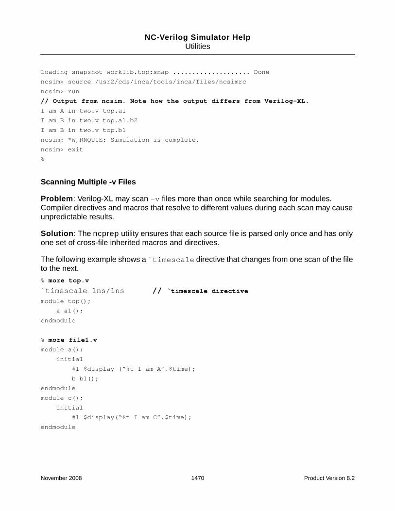
NC-Verilog Simulator HelpUtilities
Loading snapshot worklib.top:snap .................... Done
ncsim> source /usr2/cds/inca/tools/inca/files/ncsimrc
ncsim> run
// Output from ncsim. Note how the output differs from Verilog-XL.
I am A in two.v top.a1
I am B in two.v top.a1.b2
I am B in two.v top.b1
ncsim: *W,RNQUIE: Simulation is complete.
ncsim> exit
%
Scanning Multiple -v Files
Problem: Verilog-XL may scan -v files more than once while searching for modules.Compiler directives and macros that resolve to different values during each scan may causeunpredictable results.
Solution: The ncprep utility ensures that each source file is parsed only once and has onlyone set of cross-file inherited macros and directives.
The following example shows a `timescale directive that changes from one scan of the fileto the next.
% more top.v
`timescale 1ns/1ns // `timescale directive
module top();
a a1();
endmodule
% more file1.v
module a();
initial
#1 $display (“%t I am A”,$time);
b b1();
endmodule
module c();
initial
#1 $display(“%t I am C”,$time);
endmodule
November 2008 1470 Product Version 8.2

NC-Verilog Simulator HelpUtilities
% more file2.v
`timescale 1ps/1ps // `timescale directive changes from one scan of the// file to another.
module b();
initial
#1 $display(“%t I am B”, $time);
c c1();
endmodule
% more argfile
top.v
-v
file1.v
-v
file2.v
// Run Verilog-XL
% verilog -f argfile
VERILOG-XL 2.4.2 Oct 18, 1996 13:57:15
...
...
...
// The `timescale directive has changed between the first and last scan of// file1.v.
Compiling source file “top.v”
Scanning library file “file1.v”
Scanning library file “file1.v”
Scanning library file “file2.v”
Scanning library file “file2.v”
Scanning library file “file1.v”
Highest level modules:
top
1 I am B
1 I am C
1000 I am A
0 simulation events (use +profile or +listcounts option to count)
CPU time: 0.6 secs to compile + 0.1 secs to link + 0.0 secs in simulation
End of VERILOG-XL 2.4.2 Oct 18, 1996 16:25:25
// Run ncprep
% ncprep -f argfile
ncprep: v1.0.(p1): (c) Copyright 1995,1996 Cadence Design Systems, Inc.
...
...
November 2008 1471 Product Version 8.2

NC-Verilog Simulator HelpUtilities
...
Translation successful.
ncprep: v1.0.(p1) Exiting on Oct 18, 1996 16:33:18
// Execute the RUN_NC script
% RUN_NC
ncvlog: v1.0.(p1): (c) Copyright 1995,1996 Cadence Design Systems, Inc.
...
...
...
ncelab: v1.0.(p1): (c) Copyright 1995,1996 Cadence Design Systems, Inc.
...
...
...
Writing initial simulation snapshot: worklib.top:snap
ncsim: v1.0.(p1): (c) Copyright 1995,1996 Cadence Design Systems, Inc.
Loading snapshot worklib.top:snap .................... Done
ncsim> source /usr2/cds/inca/tools/inca/files/ncsimrc
ncsim> run
1 I am B // Note how the simulation times differ from Verilog-XL.
1000 I am A
1000 I am C
ncsim: *W,RNQUIE: Simulation is complete.
ncsim> exit
Race Conditions
Problem: Multiple simulation events that occur at the same time may cause a race condition.In the case of a race condition, Verilog-XL and the NC-Verilog simulator will have differentsimulation results. Detecting a race condition is a complex problem that can not be detectedby ncprep.
Solution: Race conditions can only be detected when you compare simulation results, andnoting differences, trace the cause back to multiple simultaneous events.
The following example illustrates a race condition that can only be detected when youcompare the simulation results.
November 2008 1472 Product Version 8.2

NC-Verilog Simulator HelpUtilities
% more race.v
module top();
reg r1, r2;
xor x1(o, i1, r2);
buf #1 b1(i1, r1), b2(i2, r2);
initial
begin
r1 = 1;
r2 = 0;
end
// Multiple simultaneous events may cause race conditions.
always @(r1) r1 <= #1 ~r1;
always @(r2) r2 <= #2 ~r2;
always @(o) $display (“time %t o = %b”, $time, o);
always @(o) $display (“time %t r1 = %b”, $time, r1);
always @(o) $display (“time %t r2 = %b”, $time, r2);
initial
#100 $finish;
endmodule
// Run Verilog-XL
% verilog race.v
VERILOG-XL 2.4.2 Oct 24, 1996 14:21:28
...
...
...
Compiling source file “race.v”
Highest level modules:
// Output from Verilog-XL
top
time 1 r2 = 0
time 1 r1 = 1
time 1 o = 1
L20 “file.v”: $finish at simulation time 100
0 simulation events (use +profile or +listcounts option to count) + 5 acceleratedevents
CPU time: 0.8 secs to compile + 0.3 secs to link + 0.0 secs in simulation
End of VERILOG-XL 2.4.2 Oct 24, 1996 13:14:29
November 2008 1473 Product Version 8.2

NC-Verilog Simulator HelpUtilities
// Run ncprep
% ncprep race.v
ncprep: v1.0.(p1): (c) Copyright 1995, 1996 Cadence Design Systems, Inc.
...
...
...
Translation successful.
ncprep: v1.0.(p1) Exiting on Oct 24, 1996 14:25:33
// Execute the RUN_NC script
% RUN_NC
ncvlog: v1.0.(p1): (c) Copyright 1995,1996 Cadence Design Systems, Inc.
...
...
...
ncelab: v1.0.(p1): (c) Copyright 1995,1996 Cadence Design Systems, Inc.
...
...
...
ncsim: v1.0.(p1): (c) Copyright 1995,1996 Cadence Design Systems, Inc.
Loading snapshot worklib.top:snap .................... Done
ncsim> source /usr2/cds/inca/tools/inca/files/ncsimrc
ncsim> run
// Output from NC-Verilog. Note that the event ordering of the NC-Verilog output// is reversed from the Verilog-XL output. This race condition can only be// detected by comparing the output results.
time 1 o = 1
time 1 r1 = 1
time 1 r2 = 0
Simulation complete via $finish(1) at time 100 NS + 0
./file.v:20 #100 $finish;
ncsim> exit
November 2008 1474 Product Version 8.2

NC-Verilog Simulator HelpUtilities
Renaming Modules
Problem: When more than one module of the same name is instantiated in a design,Verilog-XL may rename one of the instantiated modules. The NC-Verilog simulator uses aunique lib, cell, and view name and will not rename modules. ncvlog or ncelab will detect thenaming inconsistency and display an error message.
Solution: Rename one of the modules.
The following example shows more than one module of the same name instantiated in adesign.
% more file1.v
module top();
a a1(); // An instantiation of multiple modules with the// same name.
b b1();
endmodule
module a();
initial
$display (“I am mod a in File1.top”);
endmodule
% more b.v
module b();
endmodule
module a();
initial
$display (“I am mod a in b.v”);
endmodule
// Run Verilog-XL
% verilog file1.v -y . +libext+.v
VERILOG-XL 2.4.2 Oct 23, 1996 14:11:10
...
...
...
Highest level modules:
top
a$b$1 // The module named top has been renamed.
November 2008 1475 Product Version 8.2

NC-Verilog Simulator HelpUtilities
I am mod a in File1.top
I am mod a in b.v
0 simulation events (use +profile or +listcounts option to count)
CPU time: 0.9 secs to compile + 0.2 secs to link + 0.0 secs in simulation
// Run ncprep
% ncprep file1.v -y . +libext+.v
ncprep: v1.0.(p1): (c) Copyright 1995,1996 Cadence Design Systems, Inc.
...
...
...
Translation successful.
// Execute the RUN_NC script
% RUN_NC
ncvlog: v1.0.(p1): (c) Copyright 1995,1996 Cadence Design Systems, Inc.
file: file1.v
module local.top:v
errors: 0, warnings: 0
module local.a:v
errors: 0, warnings: 0
file: ./b.v
module local.b:v
errors: 0, warnings: 0
module a();
|
ncvlog: *W,RECOMP (./b.v,4|7): recompiling module/udp local.a:v.
First compiled from line 6 of file1.v.
module local.a:v
errors: 0, warnings: 1
ncelab: v1.0.(p1): (c) Copyright 1995,1996 Cadence Design Systems, Inc.
// Verilog-XL has renamed the duplicate module and ncelab detects the error.
ncelab: *E,NOUNIT: Unable to find a unit named ‘a$b$1’ in the libraries.
ncsim: v1.0.(p1): (c) Copyright 1995,1996 Cadence Design Systems, Inc.
ncsim: *F,NOSNAP: snapshot ‘worklib.top:snap’ does not exist in the libraries.
November 2008 1476 Product Version 8.2

NC-Verilog Simulator HelpUtilities
ncrm
The ncrm utility lets you delete the contents of a library. You can delete the entire contents ofa library or you can selectively delete specific design units: cells, views, and snapshots.
Syntax:
ncrm [-options] {[[lib.]cell[:view]] ...
[-library library_name] ...
[-snapshot snapshot] ...}
Examples:
% ncrm top
% ncrm top:module
% ncrm worklib.top:module
% ncrm -library worklib
% ncrm -snapshot top
ncrm Command Syntax
Invoke ncrm with options and arguments. Options can occur in any order. Parameters tooptions must immediately follow the option they modify.
ncrm [-options] {
[[lib.]cell[:view]] ...
[-library library_name] ...
[-snapshot snapshot] ...
}
[-64bit]
[-Append_log]
[-Cdslib filename]
[-Force]
[-HDlvar filename]
[-HElp]
[-LIbrary library_name]
[-LOgfile logfile_name]
[-Messages]
[-NCError warning_code[:warning_code ...]]
[-NCFatal {warning_code | error_code}[:{warning_code | error_code} ...]]
[-NEverwarn]
[-NOCopyright]
November 2008 1477 Product Version 8.2

NC-Verilog Simulator HelpUtilities
[-NOLog]
[-NOStdout]
[-NOWarn warning_code[:warning_code ...]]
[-Release release {-library library_name | [lib.]cell[:view]}]
[-Snapshot snapshot]
[-Version]
ncrm Command Options
The following list describes the options you can use with the ncrm command. Options canbe entered in upper or lowercase. In the list, capital letters indicate the shortest possibleabbreviation for an option.
-64bit
Invoke the 64-bit version of the ncrm executable.
Besides including the -64bit command-line option when you run the executables, you canalso run the 64-bit version by:
■ Setting the INCA_64BIT environment variable.
■ Setting up your PATH and library path environment variables so that you are pointing tothe 64-bit version.
See “64-Bit NC-Verilog” on page 39 for more information.
The -64bit command-line option is ignored if you have already specified that you want torun in 64-bit mode by setting environment variables.
You cannot use the -64bit option in flows with tools that do not support 64-bit.
This option is ignored if you include it with the NCVLOGOPTS variable in an hdl.var file.
-Append_log
Appends log information from multiple runs of ncrm to one log file. This option is overriddenby the -nolog option.
-Cdslib filename
Uses the specified cds.lib file. See “The cds.lib File” on page 133 for more information.
November 2008 1478 Product Version 8.2

NC-Verilog Simulator HelpUtilities
-Force
Disables printing of all error messages.
-HDlvar filename
Uses the specified hdl.var file. See “The hdl.var File” on page 142 for more information.
-HElp
Prints a brief summary of the ncrm command options. No other action besides printing thehelp message takes place.
-LIbrary library_name
Removes all elements in the specified library.
-LOgfile logfile_name
Uses the specified name for the log file instead of the default name ncrm.log.
Note: Information is only written to the log file when you use the -messages option.
-Messages
Prints informative messages during execution.
Note: Information is only written to the log file when you use the -messages option.
-NCError warning_code[:warning_code ...
Increase the severity level of the specified warning message from warning to error. Thewarning_code argument is the message code (mnemonic) that appears in the warningmessage following the severity code.
Example:
% ncrm -messages -library worklib -ncerror ABCDEF
November 2008 1479 Product Version 8.2

NC-Verilog Simulator HelpUtilities
You can increase the severity level of multiple warning messages either by using multiple-ncerror options or by using one -ncerror option and separating the warning_codearguments with a colon. For example,
% ncrm -library worklib -ncerror ABCDEF -ncerror HIJKLM
% ncrm -library worklib -ncerror ABCDEF:HIJKLM
Using this option can change the behavior of the tool because functions that return errorsinstead of warnings may behave differently.
-NCFatal {warning_code | error_code}[:{warning_code | error_code} ...]
Increase the severity level of the specified warning message or error message from warningor error to fatal. The warning_code or error_code argument is the message code(mnemonic) that appears in the message following the severity code.
Example:
% ncrm -messages -library worklib -ncfatal LMNOPQ
You can increase the severity level of multiple warning messages or error messages to fataleither by using multiple -ncfatal options or by using one -ncfatal option and separatingthe warning_code or error_code arguments with a colon. For example,
% ncrm -library worklib -ncfatal ABCDEF -ncfatal LMNOPQ
% ncrm -library worklib -ncfatal ABCDEF:LMNOPQ
-NEverwarn
Disables printing of all warnings.
-NOCopyright
Suppresses printing the copyright banner.
Because the copyright banner is printed before any variables in the hdl.var file areprocessed, this option is ignored if you include it with the NCRMOPTS variable in an hdl.varfile.
-NOLog
Does not generate a log file. By default, ncrm generates a log file called ncrm.log. Thisoption is overridden by the -logfile option.
November 2008 1480 Product Version 8.2

NC-Verilog Simulator HelpUtilities
If you include the -nolog option in the hdl.var file, a log file will be created because thefile is opened before any variables in the hdl.var file are processed. However, once theoption is processed in the hdl.var file, output to the log file is discontinued, and the log filewill contain only header information.
-NOStdout
Suppresses printing to the screen.
-NOWarn warning_code[:warning_code ...]
Disables the printing of the specified warning. The warning_code is the sequence ofcharacters following the error severity code.
Example:
% ncrm -library worklib -nowarn ABCDEF
You can disable the printing of multiple warning messages either by using multiple -nowarnoptions or by using one -nowarn option and separating the warning_code argumentswith a colon. For example,
% ncrm -library worklib -nowarn ABCDEF -nowarn HIJKLM
% ncrm -library worklib -nowarn ABCDEF:HIJKLM
-Release release {-library library_name | [lib.]cell[:view]}
Deletes the COD files of the specified hotfix release. Deleting COD files that are no longerneeded when you upgrade to a newer version of the tools can save disk space and decreasethe size of the packed library file (.pak).
You can delete all COD files in a specified library, or delete COD files for a specific design unit.
Use the ncsuffix utility to determine the release with which the library is compiled.
Note: ncsuffix uses the intermediate COD files, which are generated by the elaborator, todetermine the version. You must elaborate the design before you can use the ncsuffix-release command.
For example:
November 2008 1481 Product Version 8.2

NC-Verilog Simulator HelpUtilities
% ncsuffix -nocopyright -release worklib designlib
library worklib is compiled with the following versions
05.10-s001
library designlib is compiled with the following versions
05.10-s001
% ncrm -nocopyright -messages -release S1 -library worklib
Removing module worklib.board:module (COD) <0x37c5bdc6>
Removing module worklib.m16:module (COD) <0x6ba6d199>
To delete the COD file for a specific design unit, specify the unit in lib.cell:view formaton the command line. For example:
% ncrm -nocopyright -messages -release S1 m16:module
-Snapshot snapshot
Deletes the specified design unit, which is a snapshot.
-Version
Prints the version of ncrm and exits.
Example ncrm Command Lines
The following command deletes all intermediate objects for design unit top from the librarydatabase file.
% ncrm -messages top
The following command deletes all intermediate objects for design unit top:viewa.
% ncrm -messages top:viewa
The following command deletes the contents of the library named worklib.
% ncrm -messages -library worklib
The following command deletes the snapshot for design unit top.
% ncrm -messages -snapshot top
The following command deletes the snapshot top, everything in library alt_lib, and allintermediate objects for larry, moe, and curly.
% ncrm -mess -snapshot top -library alt_lib larry moe curly
November 2008 1482 Product Version 8.2

NC-Verilog Simulator HelpUtilities
The following command deletes the design unit board:behav and sends log informationto a file called del.log.
% ncrm -messages board:behav -logfile del.log
November 2008 1483 Product Version 8.2

NC-Verilog Simulator HelpUtilities
ncsdfc
The ncsdfc utility lets you compile and decompile SDF files.
SDF files must be compiled with ncsdfc in order to annotate the timing information containedin the SDF file.
For VHDL VITAL, you must compile the file yourself using ncsdfc.
For Verilog, the elaborator automatically invokes ncsdfc to compile the SDF file if you areusing the $sdf_annotate system task to perform the annotation, and if the annotatordetects that the file specified as the argument to $sdf_annotate is not a compiled SDF file.If you are using an SDF command file, you must invoke ncsdfc to compile the SDF file.
SDF files compiled with ncsdfc are platform-independent.
See Chapter 15, “SDF Timing Annotation,” for more information on using an SDF file fortiming annotation.
Invoke ncsdfc with the ncsdfc command. The syntax is as follows:
Syntax:
ncsdfc [-options] sdf_filename
The sdf_filename argument can be the filename of the source SDF file, or an SDF filethat has been compressed with the compress utility or gzip.
Note: An SDF file compressed with gzip must have a .gz suffix.
The output of ncsdfc is a compiled SDF file called sdf_filename.X. For example, if thename of the SDF file is dcache.sdf, the output file is called dcache.sdf.X. Use the-output option to rename the output file. The output file is placed in the current workingdirectory.
Examples:
% ncsdfc dcache.sdf (Generates dcache.sdf.X)
% gzip -S .gz foo.sdf (Generates foo.sdf.gz)
% ncsdfc foo.sdf.gz (Generates foo.sdf.gz.X)
% ncsdfc dcache.sdf -output mysdf.sdf.X (Generates mysdf.sdf.X)
Use the -decompile option to decompile an SDF file if you want to view or edit the file.Decompiling the file is also necessary if you have deleted the original file to save disk spaceand now want to use the SDF file with another tool. The output file is called
November 2008 1484 Product Version 8.2

NC-Verilog Simulator HelpUtilities
compiled_filename.sdfd by default, and the file is placed in the current workingdirectory.
Note: ncsdfc saves only delay and timing check values. Decompilation cannot restore, forexample, path constraint or waveform data.
ncsdfc Command Syntax
Invoke ncsdfc with options and arguments. Options can occur in any order. Parameters tooptions must immediately follow the option they modify.
You can specify ncsdfc command-line options using the NCSDFCOPTS variable in anhdl.var file.
ncsdfc [-options] sdf_filename
[-64bit]
[-Append_log]
[-CDslib filename]
[-COmpile]
[-CPutime]
[-Decompile]
[-HDlvar filename]
[-HElp]
[-Logfile filename]
[-Messages]
[-NCError warning_code[:warning_code ...]]
[-NCFatal {warning_code | error_code}[:{warning_code | error_code} ...]]
[-NEverwarn]
[-NOCopyright]
[-NOLog]
[-NOStdout]
[-Output filename]
[-STAtus]
[-STDin]
[-Update]
[-Version]
[-Worstcase_rounding]
November 2008 1485 Product Version 8.2

NC-Verilog Simulator HelpUtilities
ncsdfc Command Options
The following list describes the options you can use with the ncsdfc command. Options canbe entered in upper or lowercase. In the list, capital letters indicate the shortest possibleabbreviation for an option.
-64bit
Invoke the 64-bit version of the ncsdfc executable.
Besides including the -64bit command-line option when you run the executables, you canalso run the 64-bit version by:
■ Setting the INCA_64BIT environment variable.
■ Setting up your PATH and library path environment variables so that you are pointing tothe 64-bit version.
See “64-Bit NC-Verilog” on page 39 for more information.
The -64bit command-line option is ignored if you have already specified that you want torun in 64-bit mode by setting environment variables.
You cannot use the -64bit option in flows with tools that do not support 64-bit.
This option is ignored if you include it with the NCVLOGOPTS variable in an hdl.var file.
-Append_log
Append log information from multiple runs of ncsdfc to one log file.
-CDslib filename
Use the specified cds.lib file. See “The cds.lib File” on page 133 for information on thecds.lib file.
-COmpile
Compile the specified SDF file(s). This is the default.
November 2008 1486 Product Version 8.2

NC-Verilog Simulator HelpUtilities
-CPutime
Print CPU time after ncsdfc has completed.
-Decompile
Decompile the specified SDF file(s).
-HDlvar filename
Use the specified hdl.var file. See “The hdl.var File” on page 142 for information on thehdl.var file.
-HElp
Print a brief summary of the ncsdfc command options. No action takes place other thanprinting the help message.
-Logfile filename
Use the specified name for the log file instead of the default name ncsdfc.log. You can notinclude this option in an hdl.var file. This option overrides the -nolog option.
-Messages
Print informative messages during execution.
-NCError warning_code[:warning_code ...]
Increase the severity level of the specified warning message from warning to error. Thewarning_code argument is the message code (mnemonic) that appears in the warningmessage following the severity code.
Example:
% ncsdfc ibox.sdf -ncerror ABCDEF
November 2008 1487 Product Version 8.2

NC-Verilog Simulator HelpUtilities
You can increase the severity level of multiple warning messages either by using multiple-ncerror options or by using one -ncerror option and separating the warning_codearguments with a colon. For example,
% ncsdfc ibox.sdf -ncerror ABCDEF -ncerror HIJKLM
% ncsdfc ibox.sdf -ncerror ABCDEF:HIJKLM
Using this option can change the behavior of the tool because functions that return errorsinstead of warnings may behave differently.
-NCFatal {warning_code | error_code}[:{warning_code | error_code} ...]}
Increase the severity level of the specified warning message or error message from warningor error to fatal. The warning_code or error_code argument is the message code(mnemonic) that appears in the message following the severity code.
Example:
% ncsdfc ibox.sdf -ncfatal LMNOPQ
You can increase the severity level of multiple warning messages or error messages to fataleither by using multiple -ncfatal options or by using one -ncfatal option and separatingthe warning_code or error_code arguments with a colon. For example,
% ncsdfc ibox.sdf -ncfatal ABCDEF -ncfatal LMNOPQ
% ncsdfc ibox.sdf -ncfatal ABCDEF:LMNOPQ
-NEverwarn
Disable printing of all warnings.
-NOCopyright
Suppress printing of the copyright banner.
-NOLog
Do not generate a log file. By default, ncsdfc generates a log file called ncsdfc.log. Thisoption is overridden by the -logfile option.
If you include the -nolog option in the hdl.var file, a log file will be created because thefile is opened before any variables in the hdl.var file are processed. However, once theoption is processed in the hdl.var file, output to the log file is discontinued, and the log filewill contain only header information.
November 2008 1488 Product Version 8.2

NC-Verilog Simulator HelpUtilities
-NOStdout
Suppress printing of output to the screen.
-Output filename
Redirect output to the specified file.
-Status
Display memory and CPU usage statistics.
-STDin
Specifies that input is from stdin instead of an ASCII file.
You can use this option to compile a compressed or zipped SDF file. For example,
% cat test.sdf.Z | uncompress | ncsdfc -stdin -output test.sdf.X
% cat test.sdf.gz | gzip -d | ncsdfc -stdin -output test.sdf.gz.X
-Update
Compile the SDF file only if recompilation is necessary. The SDF file must be recompiled if:
■ The SDF source file is newer than the compiled file.
■ The SDF source file is not the same file that was used to build the compiled file.
■ The version of ncsdfc that was used to generate the compiled file is not compatible withthe current version of ncsdfc.
-Version
Print the version of ncsdfc and exit.
-Worstcase_rounding
For timing values in timing triplets, truncate the min value, round the typ value, and round upthe max value. For single values, round the value normally.
November 2008 1489 Product Version 8.2

NC-Verilog Simulator HelpUtilities
Example ncsdfc Command Lines
The following command compiles the SDF file called ibox.sdf. The output file is calledibox.sdf.X.
% ncsdfc ibox.sdf
The following command compiles the SDF file called ibox.sdf. The -output optionspecifies that the compiled file is to be called ibox.compiled.
% ncsdfc ibox.sdf -output ibox.compiled
The following command compiles a compressed SDF file called ibox.sdf.gz. The outputfile is called ibox.sdf.gz.X.
% ncsdfc ibox.sdf.gz
The following command decompiles ibox.sdf.X, a compiled SDF file. The output file iscalled ibox.sdf.X.sdfd.
% ncsdfc -decompile ibox.sdf.X
The following command decompiles ibox.sdf.X, and names the decompiled fileibox.decompiled.
% ncsdfc -decompile ibox.sdf.X -output ibox.decompiled
In the following command, the -worstcase_rounding option specifies that the min valueis to be truncated, the typ value rounded, and the max value rounded up.
% ncsdfc -worstcase_rounding ibox.sdf
For example, the timing values in the following IOPATH statement are changed to 0 : .1 : .1.
(IOPATH in out (.05:.05:.03))
A single timing value is rounded normally. For example, the timing value in the followingIOPATH statement is changed to 1.
(IOPATH in out (.05))
November 2008 1490 Product Version 8.2

NC-Verilog Simulator HelpUtilities
ncshell
ncshell is a utility that automatically generates shells to facilitate model import.
You can use ncshell to generate shells so that you can import:
■ VHDL models into Verilog
■ Verilog models into VHDL
■ SWIFT models into a VHDL simulation
■ FMI models into a VHDL simulation
■ Verilog-AMS module into a VHDL design unit
■ SystemC models into Verilog or VHDL
■ Verilog or VHDL models into SystemC
Note: All information on using the ncshell utility to import VHDL models into Verilog orVerilog models into VHDL is contained in Chapter 9, “Mixed Verilog/VHDL Simulation”.
See the section “Importing Verilog-AMS Modules into VHDL” in the chapter “Preparing theDesign: Using Mixed Languages” in the Virtuoso AMS Designer Simulator User Guidefor details on importing Verilog-AMS models into VHDL.
See the NC-SC Simulator User Guide for details on importing Verilog or VHDL intoSystemC or importing SystemC into Verilog or VHDL.
This section discusses the following topics:
■ ncshell Command Syntax
■ ncshell Command Options
■ The Foreign Attribute
■ Importing SWIFT Models into VHDL
■ Importing FMI Models into VHDL
November 2008 1491 Product Version 8.2

NC-Verilog Simulator HelpUtilities
ncshell Command Syntax
Invoke ncshell with options and arguments. Options can occur in any order. Parameters tooptions must immediately follow the option they modify. Command-line options can beabbreviated to the shortest unique string.
ncshell -import {fmi | swift | verilog -ams | verilog | vhdl | systemc}
-into {vhdl | verilog | systemc} [other_options] argument
The -import option, which specifies the kind of model that is being imported, and the -intooption, which specifies the kind of model (that is, the language of the model) into which importis being done, are always required.
The argument is one of the following:
■ A model name (for SWIFT and FMI import)
■ The library.cell:view specification of the compiled design unit that you want to import (forimporting SystemC into Verilog or VHDL or for importing Verilog or VHDL into SystemC).
The ncshell utility has command-line options that are specific to each of the model formats.The options you use depend on the type of model you are importing. The ncshellcommand-line options listed in this section are divided into the following groups:
■ General Options
■ SWIFT Models Imported into VHDL
■ FMI Models Imported into VHDL
General Options
General options apply to all of the model import formats.
[-64bit]
[-APpend_log]
[-Errormax integer]
[-FIle filename]
[-Generic]
[-Help]
[-IMport {fmi | swift | verilog -ams | systemc}]
[-INto {vhdl | verilog | systemc}]
[-LOgfile logfile_name]
[-Messages]
[-NCError warning_code[:warning_code ...]]
[-NCFatal {warning_code | error_code}[:{warning_code | error_code} ...]]
November 2008 1492 Product Version 8.2

NC-Verilog Simulator HelpUtilities
[-NEverwarn]
[-NOCOPyright]
[-NOCOMpile]
[-NOLog]
[-NOStdout]
[-NOWarn warning_code[:warning_code ...]]
[-Package package_name]
[-Shell shell_output_filename]
[-Version]
SWIFT Models Imported into VHDL
You can use the following options when the argument to -import is swift.
[-ALl]
[-Backward]
[-Comp component_output_file]
FMI Models Imported into VHDL
You can use the following options when the argument to -import is fmi.
[-Backward]
[-FMILib]
[-FMIEnt]
ncshell Command Options
This section describes the options that you can use with the ncshell command. Options canbe entered in upper or lowercase. Capital letters indicate the shortest possible abbreviationfor an option.
The options listed in this section apply to importing foreign models into both languages(Verilog and VHDL) unless noted.
-64bit
Invoke the 64-bit version of the ncshell executable.
Besides including the -64bit command-line option when you run the executables, you canalso run the 64-bit version by:
■ Setting the INCA_64BIT environment variable.
November 2008 1493 Product Version 8.2

NC-Verilog Simulator HelpUtilities
■ Setting up your PATH and library path environment variables so that you are pointing tothe 64-bit version.
See “64-Bit NC-Verilog” on page 39 for more information.
The -64bit command-line option is ignored if you have already specified that you want torun in 64-bit mode by setting environment variables.
You cannot use the -64bit option in flows with tools that do not support 64-bit.
This option is ignored if you include it with the NCVLOGOPTS variable in an hdl.var file.
-ALl
(SWIFT Models imported into VHDL)
When you import multiple SWIFT models, all the models are captured in a single shell file.You specify the name of the shell with the -shell option. Component declarations are alsopackaged into a single file. You define the name of the component declarations file with the-comp option.
Note: This option is only valid when the argument to the -import option is swift.
-APpend_log
Appends log information from multiple ncshell runs into one log file. The -nolog optionoverrides this option.
-Backward
Provides compatibility with Leapfrog VHDL and Verilog-XL shells. INCA model shells use adifferent syntax than that supported by Leapfrog and Verilog-XL. Use this option in thefollowing cases:
■ When you import a Verilog-XL shell into an NC-VHDL simulation.
■ When you import a Leapfrog VHDL shell into an NC-Verilog simulation.
November 2008 1494 Product Version 8.2

NC-Verilog Simulator HelpUtilities
-Comp output_filename
(All models imported into VHDL)
Specifies the file name in which a component declaration is written.
Whenever you import a model into VHDL, a component declaration corresponding to the shellis generated (the component declaration is not needed for FMI models and it will not begenerated). This option specifies the filename for the generated component declaration. Thedefault filename is model_name_comp.vhd (the model name with _comp.vhd appended).
Note: This option is applicable only when the argument to -into is vhdl.
-Errormax integer
Specifies the maximum number of errors processed. Aborts ncshell after reaching thespecified number of errors (expressed as an integer).
-FIle filename
Use the command-line arguments contained in the specified file.
You can store frequently used or lengthy command lines by putting command options andarguments in a text file. When you invoke ncshell with the -file option, the arguments inthe specified file are used with the command as if they had been entered on the commandline.
Each option, with its arguments must be specified on a separate line.
-FMIEnt entity_name
(FMI Model import Only)
When you import a C interface foreign model into a VHDL simulation, this option specifies theentity name of the foreign model. This option is required when you import an FMI model.
Note: This option is only valid when the argument to -import is fmi.
November 2008 1495 Product Version 8.2

NC-Verilog Simulator HelpUtilities
-FMILib library_name
(FMI Model import Only)
When you import a C interface foreign model into a VHDL simulation, this option specifies thelibrary in which the foreign model resides. This option is required when you import an FMImodel.
Note: This option is only valid when the argument to -import is fmi.
-Generic
Generate generics or parameters as part of the shell.
If the module to be imported uses generics or parameters, you must use the -genericoption to ensure that the parameters are available in the shell.
-HElp
Prints a brief summary of the ncshell command options.
-IMport {fmi | swift | verilog -ams | systemc}
Specifies the type of the foreign model you are importing. This option is required for everymodel import.
-INto {vhdl | verilog | systemc}
Specifies the generated shell’s output HDL format. This option is required for every modelimport.
Note: When you import FMI, SWIFT, or Verilog-AMS models, the argument to this optionmust be vhdl. The component declaration is not needed for FMI models and it will not begenerated.
November 2008 1496 Product Version 8.2

NC-Verilog Simulator HelpUtilities
-LOgfile logfile_name
Specifies the name for the log file. This name is used instead of the default namencshell.log. You can not include this option in an hdl.var file. This option overrides the-nolog option.
-Messages
Displays informational messages during the creation of the shell.
Note: Information is only written to the log file when you use the -messages option.
-NCError warning_code[:warning_code ...]
Increase the severity level of the specified warning message from warning to error. Thewarning_code argument is the message code (mnemonic) that appears in the warningmessage following the severity code.
Example:
% ncshell -import swift -into vhdl -all -ncerror ABCDEF
You can increase the severity level of multiple warning messages either by using multiple-ncerror options or by using one -ncerror option and separating the warning_codearguments with a colon. For example,
% ncshell -import swift -into vhdl -all -ncerror ABCDEF -ncerror HIJKLM
% ncshell -import swift -into vhdl -all -ncerror ABCDEF:HIJKLM
Using this option can change the behavior of the tool because functions that return errorsinstead of warnings may behave differently.
-NCFatal {warning_code | error_code}[:{warning_code | error_code} ...]
Increase the severity level of the specified warning message or error message from warningor error to fatal. The warning_code or error_code argument is the message code(mnemonic) that appears in the message following the severity code.
Example:
% ncshell -import swift -into vhdl -all -ncfatal LMNOPQ
November 2008 1497 Product Version 8.2

NC-Verilog Simulator HelpUtilities
You can increase the severity level of multiple warning messages or error messages to fataleither by using multiple -ncfatal options or by using one -ncfatal option and separatingthe warning_code or error_code arguments with a colon. For example,
% ncshell -import swift -into vhdl -all -ncfatal ABCDEF -ncfatal LMNOPQ
% ncshell -import swift -into vhdl -all -ncfatal ABCDEF:LMNOPQ
-NEverwarn
Disables printing of all warning messages.
-NOCOPyright
Suppresses printing of the copyright banner.
Because the copyright banner is printed before any variables in the hdl.var file areprocessed, this option is ignored if you include it with the NCSHELLOPTS variable in anhdl.var file.
-NOCOMpile
By default, ncshell automatically analyzes the shell it generates. Use this option to overridethe default analysis.
-NOLog
Suppresses creation of the default logfile.
If you include the -nolog option in the hdl.var file, a log file will be created because thefile is opened before any variables in the hdl.var file are processed. However, once theoption is processed in the hdl.var file, output to the log file is discontinued, and the log filewill contain only header information.
-NOStdout
Suppresses output display to screen.
November 2008 1498 Product Version 8.2

NC-Verilog Simulator HelpUtilities
-NOWarn warning_code[:warning_code ...]
Disables the printing of the specified warning. The warning_code is the sequence ofcharacters following the error severity code.
Example:
% ncshell -import swift -into vhdl -all -nowarn ABCDEF
You can disable the printing of multiple warning messages either by using multiple -nowarnoptions or by using one -nowarn option and separating the warning_code argumentswith a colon. For example,
% ncshell -import swift -into vhdl -all -nowarn ABCDEF -nowarn HIJKLM
% ncshell -import swift -into vhdl -all -nowarn ABCDEF:HIJKLM
-Package package_name
Specifies the package name for the VHDL package generated during Verilog-AMS modelimport into VHDL.
-SHell shellname
Specifies the name of the generated shell. This option can be used to give the generated shella name other than the default.
-SUffix file_extension
(Models imported into Verilog)
Specifies a filename extension for a Verilog shell. This option is ignored if you also specify the-shell option.
-VIew viewname
Specifies the name of the view that you want the generated shell analyzed into. The defaultview name is shell.
For Verilog-AMS model import, view name controls the domain shell view name andarchitecture name of the generated VHDL shell.
November 2008 1499 Product Version 8.2

NC-Verilog Simulator HelpUtilities
-VErsion
Prints the version of ncshell and exits.
The Foreign Attribute
The ncshell utility places a foreign attribute within the shell to indicate the source formatof the foreign model. The foreign attribute is created in the architecture of a VHDL modelshell and in the module definition of a Verilog shell.
■ When you import a SWIFT model into VHDL, the syntax of the foreign attribute is:
attribute FOREIGN of SmartModel : architecture is "SWIFT model_name";
For example:
attribute FOREIGN of SmartModel : architecture is "SWIFT tt100";
See “Importing SWIFT Models into VHDL” on page 1500 for more details.
■ When you import an FMI model into VHDL, the syntax of the foreign attribute is:
"FMI fmi_library:model_name";
For example the following line illustrates the foreign attribute for an FMI model importedinto a VHDL shell. The attribute specifies the work library and the model name:
"FMI fmi_model_lib:FMI_ALU";
See “Importing FMI Models into VHDL” on page 1503 for more details.
Importing SWIFT Models into VHDL
You need to be aware of the following when you import SWIFT models into VHDL.
■ The ncshell utility assumes that the SWIFT shared library resides at:
$(LMC_HOME)/../lib/sun4.solaris/libswift.so for SUN platforms
■ You can use the -all option to import all the models in a SWIFT shared library. Thefollowing line is an example:
ncshell -import swift -into vhdl -all
■ ncshell analyzes the generated shells in the work directory.
November 2008 1500 Product Version 8.2

NC-Verilog Simulator HelpUtilities
Example SWIFT Model Imported into VHDL
The following example shows the entity-architecture shell and the component declaration thatncshell generates from a SWIFT model. You must have the LMC_HOME environment variableset to a SWIFT shared library. The -all option generates shells for all the SWIFT models inthe directories specified by the LMC_HOME environment variable.
ncshell -import swift -into vhdl -all
The SWIFT Model Entity-Architecture Shelllibrary ieee;
use ieee.std_logic_1164.all;
entity swift_model_name is
// In an actual shell, these generic and port related labels are replaced with// actual values from the SWIFT model.
generic (
generic_name : string;
--Similar entries for all generics in the model
);
port (
port_name : port_mode std_logic := ’U’;
--Similar entries as above for all non-output ports
port_name : port_mode std_logic;
--Similar entries as above for all output ports
);
end swift_model_name ;
November 2008 1501 Product Version 8.2

NC-Verilog Simulator HelpUtilities
architecture SmartModel of swift_model_name is
attribute foreign of SmartModel : architecture is "SWIFT swift_model_name";
begin
end;
Note: If you use the -backward option to generate a shell that is compatible with Leapfrog,ncshell creates the following foreign attribute in the architecture:
attribute foreign of SmartModel : architecture is "LFSM: LFSmartModel";
The SWIFT Model Component Declarationpackage SmartModels is
component swift_model_name is
// In the component declaration, these port and generic related labels are// replaced with actual values from the SWIFT model.
generic (
generic_name : string;
--All possible options for the generic value listed as a comment
--Similar entries for all generics in the model
);
port (
port_name : port_mode std_logic := ’U’;
--Similar entries as above for all non output ports
port_name : port_mode std_logic;
--Similar entries as above for all output ports
);
end component;
end SmartModels;
November 2008 1502 Product Version 8.2

NC-Verilog Simulator HelpUtilities
Importing FMI Models into VHDL
You need to be aware of the following when you import FMI models into VHDL.
■ You must use the -fmient option to specify the entity name of the foreign model.
■ You must use the -fmilib option to specify the library in which the foreign modelresides.
■ You must specify the name of the foreign model.
■ The component declaration is not needed for FMI models and it will not be generated.
■ You must use the following command line syntax:
ncshell -import fmi -into vhdl -fmilib fmi_lib_name -fmient fmi_entity_namefmi_model_name
For example:
ncshell -import fmi -into vhdl -fmilib alu_lib -fmient alu_entity alu_model
The following shows the architecture shell that ncshell generates from the command lineshown above.
The FMI Model Architecture Shellarchitecture fmi of fmi_entity_name is
attribute foreign of fmi:architecture is "FMI alu_lib :alu_model";
begin
end;
Note: If you use the -backward option to generate a shell that is compatible with Leapfrog,ncshell creates the following foreign attribute in the architecture:
attribute foreign of fmi : architecture is "alu_lib:alu_model";
November 2008 1503 Product Version 8.2

NC-Verilog Simulator HelpUtilities
ncsuffix
The ncsuffix utility lets you display the machine architecture and the revision number of thelibrary system for the current version of the software. You can display this information for thevarious intermediate objects that are generated by the simulator tools (ncvlog, ncvhdl,ncelab, ncsim).
You can use this information when you create Makefiles or otherwise automate yourprocesses. For example, you can include a rule in a Makefile that checks to see if a libraryexists and if it is the right version. If the library is the wrong version, the rule can delete theold library.
ncsuffix Command Syntax
Invoke ncsuffix with the ncsuffix command.
ncsuffix [options] -release library_name [library_name ...]
ncsuffix [options] {-ast | -cod | -pak | -sig | -sss | -vst}
[-64bit]
[-ALl]
[-ASt]
[-Cod]
[-Help]
[-NCError warning_code[:warning_code ...]]
[-NCFatal {warning_code | error_code}[:{warning_code | error_code} ...]]
[-NOcopyright]
[-Pak]
[-Release library_name [library_name ...]]
[-SIg]
[-SSs]
[-VErsion]
[-VSt]
November 2008 1504 Product Version 8.2

NC-Verilog Simulator HelpUtilities
ncsuffix Command Options
The following list shows the options you can use with the ncsuffix command. Options canbe entered in upper or lowercase. In the list, capital letters indicate the shortest possibleabbreviation for an option.
-64bit
Invoke the 64-bit version of the ncsuffix executable.
Besides including the -64bit command-line option when you run the executables, you canalso run the 64-bit version by:
■ Setting the INCA_64BIT environment variable.
■ Setting up your PATH and library path environment variables so that you are pointing tothe 64-bit version.
See “64-Bit NC-Verilog” on page 39 for more information.
The -64bit command-line option is ignored if you have already specified that you want torun the tools in 64-bit mode by setting environment variables.
You cannot use the -64bit option in flows with tools that do not support 64-bit.
This option is ignored if you include it with the NCVLOGOPTS variable in an hdl.var file.
-ALl
Prints the AST, VST, SSS, COD, SIG, and PAK suffixes.
-ASt
Prints the AST (Abstract Syntax Tree) suffix.
-Cod
Prints the COD suffix.
-Help
Prints a brief summary of the ncsuffix command-line options.
November 2008 1505 Product Version 8.2

NC-Verilog Simulator HelpUtilities
-NCError warning_code[:warning_code ...]
Increase the severity level of the specified warning message from warning to error. Thewarning_code argument is the message code (mnemonic) that appears in the warningmessage following the severity code.
You can increase the severity level of multiple warning messages either by using multiple-ncerror options or by using one -ncerror option and separating the warning_codearguments with a colon.
Using this option can change the behavior of the tool because functions that return errorsinstead of warnings may behave differently.
-NCFatal {warning_code | error_code}
Increase the severity level of the specified warning message or error message from warningor error to fatal. The warning_code or error_code argument is the message code(mnemonic) that appears in the message following the severity code.
You can increase the severity level of multiple warning messages or error messages to fataleither by using multiple -ncfatal options or by using one -ncfatal option and separatingthe warning_code or error_code arguments with a colon.
-NOcopyright
Suppresses printing of the copyright banner.
Because the copyright banner is printed before any variables in the hdl.var file areprocessed, this option is ignored if you include it with the NCSUFFIXOPTS variable in anhdl.var file.
-Pak
Prints the PAK file suffix.
-Release library_name [library_name ...]
Displays the version of the tool that was used to compile the specified library.
November 2008 1506 Product Version 8.2

NC-Verilog Simulator HelpUtilities
Note: ncsuffix uses the intermediate COD files, which are generated by the elaborator, todetermine the version. You must elaborate the design before you can use the ncsuffix-release command.
This option is used to determine the version of the tool that was used to compile a specifiedlibrary. You can then use the ncrm -release command to delete the COD files generatedwith an older version to save disk space and decrease the size of the packed library file(.pak). For example:
% ncsuffix -nocopyright -release worklib
library worklib is compiled with the following versions
05.10-s003
% ncrm -messages -nocopyright -release S3 -library worklib
Removing module worklib.board:module (COD) <0x24b8e6da>
Removing module worklib.dEdgeFF:module (COD) <0x672bc683>
Removing module worklib.m16:module (COD) <0x361ef95f>
Removing module worklib.m555:module (COD) <0x3b9a6eca>
You can also use ncrm to delete specific units. For example:
% ncrm -release S3 m16:module
-SIg
Prints the SIG suffix.
-SSs
Prints the SSS (simulation snapshot) suffix.
-VErsion
Prints the version of ncsuffix and exits.
-VSt
Prints the VST (Verilog Syntax Tree) suffix.
November 2008 1507 Product Version 8.2

NC-Verilog Simulator HelpUtilities
Example ncsuffix Command Lines
The following command prints the simulation snapshot suffix.
% ncsuffix -nocopyright -sss
sun4v.150.sss
The following command prints the VST suffix.
% ncsuffix -nocopyright -vst
sun4v.150.vst
The following command includes the -all option, which prints all suffixes.
% ncsuffix -nocopyright -all
sun4v.151.ast
sun4v.151.vst
sun4v.151.sss
sun4v.151.cod
sun4v.151.sig
sun4v.151.pak
The following command displays the version of the software that was used to compile thelibrary worklib. The design must be elaborated before this command will work.
% ncsuffix -nocopyright -release worklib
library worklib is compiled with the following versions
5.10-p001
The following command displays the version of the software that was used to compile thelibraries worklib and designlib.
% ncsuffix -nocopyright -release worklib designlib
library worklib is compiled with the following versions
5.10-p001
library designlib is compiled with the following versions
5.10-p001
November 2008 1508 Product Version 8.2

NC-Verilog Simulator HelpUtilities
ncupdate
When you change any of the design units in the hierarchy, you must compile and elaboratethe design hierarchy again. You can automatically recompile and re-elaborate all out-of-datedesign units in the hierarchy with ncupdate. The ncupdate utility also calls the ncsdfc utilityto recompile SDF source files if it detects that the SDF source has changed.
ncupdate re-elaborates the design, and always generates a new snapshot.
The argument to ncupdate is a snapshot name. Therefore, you must elaborate the entiredesign at least once before you can use ncupdate.
The purpose of ncupdate is to provide quick design change turnaround when you haveedited a design unit. The modifications to design units cannot cross file boundaries to modifyother files. Do not use ncupdate (or ncsim -update) after adding a design unit, a sourcefile, or compiler directives to the design. For example, ncupdate will not update correctly ifyou edit a source file to define a new macro, or if you change a design unit in a way thatintroduces a new cross-file dependency. In these cases, recompile the design with ncvlog-update or ncvhdl -update.
The ncupdate utility uses the same compiler and elaborator command line options that wereused originally. If you want to use different command line options, recompile and re-elaborateby running ncvlog/ncvhdl and ncelab.
You can also automatically recompile and re-elaborate all out-of-date design units by invokingthe simulator with the -update option. See “Updating Design Changes When You Invokethe Simulator” on page 491.
ncupdate Command Syntax
Invoke ncupdate with options and arguments. Options can occur in any order. Parametersto options must immediately follow the option they modify. Command-line options can beabbreviated to the shortest unique string, indicated here with capital letters.
ncupdate [options] [lib.]cell[:view]
[-64bit]
[-Append_log]
[-CDS_IMPLICIT_TMPDir implicitTmpDir]
[-CDS_IMPLICIT_TMPOnly]
[-CDslib filename]
[-CMdfile compilation_command_file]
[-ERrormax integer]
[-EXCLFile filename]
November 2008 1509 Product Version 8.2

NC-Verilog Simulator HelpUtilities
[-EXCLUde library_name]
[-Force]
[-HDlvar filename]
[-HElp]
[-Ieee]
[-LIbrary library_name]
[-LOgfile logfile_name]
[-Messages]
[-NCError warning_code[:warning_code ...]]
[-NCFatal {warning_code | error_code}[:{warning_code | error_code} ...]]
[-NEverwarn]
[-NOCopyright]
[-NOLog]
[-NORecompile]
[-NOSOurce]
[-NOSTdout]
[-NOWarn warning_code[:warning_code ...]]
[-Overwrite]
[-SCript filename]
[-SHow]
[-Unit module_name]
[-VERBose]
[-VERSion]
ncupdate Command Options
The following list describes the options you can use with the ncupdate command. Optionscan be entered in upper or lowercase. In the table, capital letters indicate the shortestpossible abbreviation for an option.
-64bit
Invoke the 64-bit version of the ncupdate executable.
Besides including the -64bit command-line option when you run the executables, you canalso run the 64-bit version by:
■ Setting the INCA_64BIT environment variable.
■ Setting up your PATH and library path environment variables so that you are pointing tothe 64-bit version.
See “64-Bit NC-Verilog” on page 39 for more information.
November 2008 1510 Product Version 8.2

NC-Verilog Simulator HelpUtilities
The -64bit command-line option is ignored if you have already specified that you want torun in 64-bit mode by setting environment variables.
You cannot use the -64bit option in flows with tools that do not support 64-bit.
This option is ignored if you include it with the NCVLOGOPTS variable in an hdl.var file.
-Append_log
Appends log information from multiple runs of ncupdate to one log file. This option isoverridden by the -nolog option.
-CDS_IMPLICIT_TMPDir implicitTmpDir
Reads the snapshot from the implicit_TmpDir and determines from the snapshotheader whether the -cds_implicit_tmponly option was used during elaboration. It thenrecompiles design units relative to the specifications in the implicit_TmpDir as necessary.When the -cds_implicit_tmponly option is not used, also updates design objectsrelative to the specifications in the cds.lib file.
-CDS_IMPLICIT_TMPOnly
Reads design data only from the implicit_TmpDir area.
-CDslib filename
Specifies the cds.lib file to use for this update.
-CMdfile compilation_command_file
Use the specified compilation command file when updating the design.
This option can be used if the location of a source file has been changed. The compilationcommand file contains a definition of the SEARCH_PATH variable, which lists the directoriesto be searched for locating the design files.
% ncupdate -cmdfile cmdfile.cmd lib.cell:view
See “Compiling Source Files by Specifying the Top-Level of the Design” on page 206 fordetails on the compilation command file.
November 2008 1511 Product Version 8.2

NC-Verilog Simulator HelpUtilities
-ERrormax integer
Aborts ncupdate after reaching the specified number of errors.
-EXCLFile filename
Excludes the libraries listed in the specified file when updating a model.
-EXCLUde library
Excludes the specified library when updating a model. Excludes STD and IEEE libraries bydefault.
-Force
Forces an update whether or not the model is out of date.
-HDlvar filename
Specifies the hdl.var file to use for this update.
-HElp
Prints a brief summary of the ncupdate command options. No other action besides printingthe help message takes place.
-Ieee
Allows the IEEE library to be updated.
-LIbrary library
Causes the compiler to use only the specified library when updating a model. All otherlibraries listed in your cds.lib file are excluded.
November 2008 1512 Product Version 8.2

NC-Verilog Simulator HelpUtilities
-LOgfile logfile_name
Specifies the name for the log file. This name is used instead of the default namencupdate.log. You can not include this option in an hdl.var file. This option overrides the-nolog option.
-Messages
Prints informative messages during execution. Information is only written to the log file whenyou use the -messages option.
-NCError warning_code[:warning_code ...]
Increase the severity level of the specified warning message from warning to error. Thewarning_code argument is the message code (mnemonic) that appears in the warningmessage following the severity code.
Example:
% ncudpate -messages my_lib.top:snap -ncerror ABCDEF
You can increase the severity level of multiple warning messages either by using multiple-ncerror options or by using one -ncerror option and separating the warning_codearguments with a colon. For example,
% ncudpate my_lib.top:snap -ncerror ABCDEF -ncerror HIJKLM
% ncudpate my_lib.top:snap -ncerror ABCDEF:HIJKLM
Using this option can change the behavior of the tool because functions that return errorsinstead of warnings may behave differently.
-NCFatal {warning_code | error_code}[:{warning_code | error_code} ...]
Increase the severity level of the specified warning message or error message from warningor error to fatal. The warning_code or error_code argument is the message code(mnemonic) that appears in the message following the severity code.
Example:
% ncudpate -messages my_lib.top:snap -ncfatal LMNOPQ
You can increase the severity level of multiple warning messages or error messages to fataleither by using multiple -ncfatal options or by using one -ncfatal option and separatingthe warning_code or error_code arguments with a colon. For example,
November 2008 1513 Product Version 8.2

NC-Verilog Simulator HelpUtilities
% ncudpate my_lib.top:snap -ncfatal ABCDEF -ncfatal LMNOPQ
% ncudpate my_lib.top:snap -ncfatal ABCDEF:LMNOPQ
-NEverwarn
Disables printing of all ncupdate warning messages.
-NOCopyright
Suppresses printing of the copyright banner.
Because the copyright banner is printed before any variables in the hdl.var file areprocessed, this option is ignored if you include it with the NCUPDATEOPTS variable in anhdl.var file.
-NOLog
Do not generate a log file. By default, ncupdate generates a log file called ncupdate.log.This option is overridden by the -logfile option.
If you include the -nolog option in the hdl.var file, a log file will be created because thefile is opened before any variables in the hdl.var file are processed. However, once theoption is processed in the hdl.var file, output to the log file is discontinued, and the log filewill contain only header information.
-NORecompile
Used with -show to display the modules that need to be updated.
-NOSOurce
Eliminates source file time stamp checks.
-NOSTdout
Suppresses printing to the screen.
November 2008 1514 Product Version 8.2

NC-Verilog Simulator HelpUtilities
-NOWarn warning_code[:warning_code ...]
Disables the printing of the specified ncupdate warning. The warning_code is thesequence of characters following the error severity code.
Example:
% ncudpate my_lib.top:snap -nowarn ABCDEF
You can disable the printing of multiple warning messages either by using multiple -nowarnoptions or by using one -nowarn option and separating the warning_code argumentswith a colon. For example,
% ncudpate my_lib.top:snap -nowarn ABCDEF -nowarn HIJKLM
% ncudpate my_lib.top:snap -nowarn ABCDEF:HIJKLM
-Overwrite
Causes the script file that is specified with the -script option to be overwritten. The-overwrite option is used with the -script option to replace a previously generatedscript.
-SCript filename
Generates a script to recompile the model. Generates a script that forces an update of allunits when used with the -force option.
-SHow
Prints the compile commands to the screen. Use the -show option with the -norecompileoption to display modules that need to be updated.
-Unit module_name
Updates the specified module. The default argument to ncupdate is a snapshot. Use the-unit option to recompile a design unit if the source code has changed.
-VERBose
Displays compilation information for all modules, including modules that are not beingrecompiled because they are up-to-date.
November 2008 1515 Product Version 8.2

NC-Verilog Simulator HelpUtilities
By default, when recompiling source files, the compiler does not display information aboutmodules that are up-to-date. Information is displayed only for modules that are actuallyrecompiled. Use the -verbose option if you want to display information about all modules.
-VERSion
Prints the version of ncupdate and exits.
Example ncupdate Command Lines
To update the module my_lib.top:behav
% ncupdate -unit my_lib.top:behav
To create a script to force update of all units in my_lib
% ncupdate -force -script ./update.script -library my_lib
To update the snapshot my_lib.top:snap with informative messages
% ncudpate -messages my_lib.top:snap
November 2008 1516 Product Version 8.2

NC-Verilog Simulator HelpUtilities
shellgen
The shellgen utility generates a Verilog or VHDL model shell that you can instantiate in adesign to import OMI-compliant models. The shell file is a Verilog module or a VHDLentity/architecture body pair that contains:
■ A set of predefined attributes that identify the model and the corresponding modelmanager. The NC simulation tools use the attribute information to identify an importedOMI model, to locate the controlling model manager, and to initiate communication withit.
❑ foreign—Identifies the Verilog module or VHDL entity/architecture as a shell forimporting an OMI-compliant model.
❑ mm_path—Specifies the path to the model manager object file.
❑ mm_object—Specifies the name of the model manager object file.
❑ mm_bootstrap—Specifies the name of the model manager bootstrap routine tocall.
❑ model—Specifies the name of the model.
❑ library—Specifies the library name.
The OMI specification supports models delivered as either model objects orlibraries. The library attribute is necessary when models with the same name arepackaged into different libraries controlled by the same model manager.
■ Port, parameter/generic, and signal declarations that shellgen has extracted from themodel.
■ Definitions of the viewports of the model, the internal signals (if any) that the modelprovider has designated as visible for read and/or write permission.
To generate the simulation shell, invoke shellgen with the shellgen command. You mustuse the -b option to specify the full path to a file supplied with the model manager called thebootstrap file. This file contains the name of the model manager object file and the name ofthe bootstrap routine to call.
When you invoke shellgen, it:
■ Loads the appropriate model manager specified in the bootstrap file.
■ Queries the model manager for the presence of the model(s) you specified.
■ Extracts model boundary information (ports, parameters, generics, and viewports).
November 2008 1517 Product Version 8.2

NC-Verilog Simulator HelpUtilities
■ Writes the shell file.
See “The Open Model Interface (OMI)” on page 1583 for more information on importing OMImodels.
shellgen Command Syntax
Invoke shellgen with options and arguments. Options can occur in any order. The syntax ofthe shellgen command is as follows:
shellgen -b bootstrap_file [other_options]
[-f options_file]
[-help]
[-l library_name]
[-m model_name]
[-nomm_object]
[-nomm_path]
[-o output_file]
[-pli]
[-r]
[-unresolved]
[-verilog]
[-version]
[-vhdl]
[+model_manager_invocation_option[=option_value]]
shellgen Command Options
The following list describes the options that you can use with the shellgen command.
-b path_to_bootstrap_file
Use the bootstrap file in the specified location. This option is required.
The bootstrap file is a text file supplied by the model provider. It contains:
■ The name of the model manager object file.
■ The name of the bootstrap routine to call so that shellgen can initiate communicationwith the model manager.
November 2008 1518 Product Version 8.2

NC-Verilog Simulator HelpUtilities
The argument specifies the full path name to the bootstrap file. For example:
/net/machine/model_manager/bootstrap_file
-f options_file
Use the shellgen command options in the specified file.
The options file can contain only options that take a value. In the file, specify each option ona separate line. You must use the equal ( = ) sign in the options file (for example,-l=library_name).
-help
Print a brief summary of the shellgen command options.
-l library_name
Generate shells for all models in the specified library.
If you do not use the -m model_name option to specify a particular model, shellgengenerates shells for all of the models in this library.
-m model_name
Generate a shell for the specified model.
The model_name argument is the name of the model as defined by the model provider.Model names are case sensitive.
If you omit this option, shellgen generates a shell for all models controlled by the modelmanager. Use the -l library_name option to specify that shells are to be generated formodels in a particular library.
-nomm_object
Generate the mm_object attribute value without a file extension in the shell file.
November 2008 1519 Product Version 8.2

NC-Verilog Simulator HelpUtilities
-nomm_path
Generate an empty string for the mm_path attribute in the shell.
By default, the mm_path attribute value is the full path to the model manager object file. Usingthe -nomm_path option removes the dependency on a specific model manager installlocation.
If you use this option, you must include the path to the model manager dynamic library in yourlibrary path environment variable (LD_LIBRARY_PATH on Solaris and Linux, LIBPATH onAIX), so that the OMI socket can locate and load the library.
-o output_file
Generate a shell file with the specified filename.
If you do not use this option, shell files are created in the current working directory and arecalled:
■ model_name.v for Verilog
■ model_name.vhd for VHDL
■ model_name_pli.v for use with the IP Model Packager OMI adapter.
If a file already exists, the shell is written to stdout unless you include the -r option.
-pli
Create a Verilog PLI shell for use with the IP Model Packager OMI adapter.
If you do not use this option or the -vhdl or -verilog option to specify the kind of HDL shellto create, shellgen creates a Verilog shell file for the model by default.
-r
Overwrite the existing shell file.
November 2008 1520 Product Version 8.2

NC-Verilog Simulator HelpUtilities
-unresolved
Use the std_ulogic and std_ulogic_vector unresolved types for ports and viewportsof any logic type when creating a VHDL shell. The default is to use the std_logic andstd_logic_vector logic types.
-verilog
Create a Verilog shell.
If you do not use this option or the -vhdl or -pli option to specify the kind of HDL shell tocreate, shellgen creates a Verilog shell file for the model by default.
-version
Display the version of shellgen.
-vhdl
Create a VHDL shell.
If you do not use this option or the -verilog or -pli option to specify the kind of HDL shellto create, shellgen creates a Verilog shell file for the model by default.
+model_manager_invocation_option[=option_value]
Use the specified model manager invocation option.
A model manager may define its own invocation options. The shellgen utility does notrecognize these options, but can pass them to the model manager. See the model managerdocumentation for descriptions of any model manager invocation options.
Each model manager invocation option begins with a plus sign ( + ) followed by the name ofthe option. If the option takes a value, specify the value after the equal sign ( = ).
You can include model manager invocation options in an options file that you specify with the-f option. Each invocation option must be on a separate line.
November 2008 1521 Product Version 8.2

NC-Verilog Simulator HelpUtilities
simvisdbutil
simvisdbutil is a command-line database translation utility. You can place thesimvisdbutil command in a batch file, for example, to translate large databases overnight.
You can also translate databases using the SimVision graphical user interface.
The simvisdbutil utility can translate any of the following database formats into SST2 format:
■ VCD
■ EVCD
■ HSPICE list
■ HSPICE transient output
■ Nutmeg
■ Epic
■ Qsim
It can also translate an SST2 database into either VCD or CSV format.
The simvisdbutil command has the following syntax:
simvisdbutil [options] input_filename
For example, the following command converts the VCD database in the file vcddb.vcd to anSST2 database.
% simvisdbutil -sst2 vcddb.vcd
See the section called “Using the Batch Database Translation Utility” in the SimVision UserGuide for details on simvisdbutil.
November 2008 1522 Product Version 8.2

NC-Verilog Simulator Help
18Applications
This chapter contains the following sections:
■ ncutils
ncutils is a set of four VHDL procedures/Verilog built-in system tasks that you can callto access VHDL signals or Verilog wires at any level of hierarchy in the design. Theprocedures/system tasks are intended to be used primarily in a testbench so that youhave visibility to signals at a lower-level in the hierarchy. However, it is possible toreference signals at any level, higher or lower.
The four procedures are:
❑ nc_mirror
❑ nc_deposit
❑ nc_force
❑ nc_release
■ NCMemory
NCMemory is the name used for behavioral models of synchronous and asynchronousmemories. These memory models, which can be instantiated in both Verilog and VHDLdesigns, are fully configurable, with multiple input/output ports, multiple memory select,multiple clocks, and generic size and depth. All models also support write-through modefeatures.
■ ncreadmem
ncreadmem is a procedure used to load a user-defined memory or an NCMemory modelat run time.
November 2008 1523 Product Version 8.2

NC-Verilog Simulator HelpApplications
ncutils
ncutils is a set of four VHDL procedures/Verilog built-in system tasks that you can call toaccess VHDL signals or Verilog variables or wires at any level of hierarchy in the design. Theprocedures/system tasks are intended to be used primarily in a testbench so that you havevisibility to signals at a lower-level in the hierarchy. However, it is possible to reference signalsat any level, higher or lower.
The four procedures/system tasks are:
■ nc_mirror
Lets you trace the value of a VHDL signal or Verilog variable or wire lying anywhere inthe design from within a VHDL architecture or Verilog module. This procedure/systemtask can also be used to mirror the value of a source signal onto a destination signal.
■ nc_deposit
Lets you deposit a value on a VHDL signal or Verilog variable or wire lying anywhere inthe design.
■ nc_force
Lets you force a value on a VHDL signal or Verilog variable or wire lying anywhere in thedesign.
■ nc_release
Lets you release a force on a VHDL signal or Verilog variable or wire lying anywhere inthe design.
For Verilog, the system tasks are built-in. For VHDL, the ncutils procedures are contained ina utilities package that is part of the NCUTILS library. To access the utilities in the package,you must reference the package in a use clause by adding the following lines to your VHDLcode:
library NCUTILS;
use NCUTILS.ncutilities.all;
The procedures can then be called in either a concurrent procedure call or in a process.
Note: You can use the VHDL colon ( : ) or the Verilog dot ( . ) as the hierarchy separatorwhen specifying the hierarchical path to a signal.
November 2008 1524 Product Version 8.2

NC-Verilog Simulator HelpApplications
Supported Data Types
The following table shows which data types are supported for each procedure/system task.See “Limitations” on page 1548 for a list of limitations on the ncutils procedures/system tasksin the current release.
Note: The SystemVerilog logic data type and the two-state data types bit, byte, and intare supported.
Procedure/System Task Supported Data Types
nc_mirror ■ VHDL to VHDLVHDL signal/port/variable can be any data type.
■ Verilog to VerilogWire data types and variable data types reg,integer, real, and time are supported. Thesource and destination must be the same datatype.
■ Verilog to VHDL or VHDL to VerilogVHDL signal must be of type std_logic,std_logic_vector, std_ulogic, orstd_ulogic_vector.Verilog must be a wire data type or variable datatype reg.
Note: Using nc_mirror to mirror a value to an arrayor record using aggregates is not supported. You canmirror values to records only by mirroring to eachindividual element separately. Mirroring of arrays ofarrays is not allowed. You can mirror each individualelement separately.
nc_deposit,
nc_force,
nc_release
■ VHDLSignal/port/variable can be any data type.
■ VerilogAll data types are supported.
November 2008 1525 Product Version 8.2

NC-Verilog Simulator HelpApplications
nc_mirror
Use the nc_mirror() procedure or $nc_mirror() system task to trace the value of anyVHDL signal/port/variable or Verilog variable/wire lying anywhere in the design from within aVHDL architecture or Verilog module. This procedure establishes a link so that the value of aVHDL signal/port/variable or the value of a Verilog variable/wire can be read.
VHDL nc_mirror() Procedure
Parameters can be associated by position or by using named association.
-- Parameters associated by name
nc_mirror (destination => “destination”,
source => “source”,
verbose => “verbose”);
-- Parameters associated by position
nc_mirror (“destination”, “source”, “verbose”);
Verilog $nc_mirror() System Task
Parameters can be associated only by position. Named association is not supported.
$nc_mirror (“destination”, “source”, “verbose”);
Parameters
The following table shows the parameters for the nc_mirror procedure/system task.
“destination” The path of a VHDL signal/port/variable or Verilog variable/wire towhich the value of the source signal is to be mirrored.
The path can be a full hierarchical path or a relative path.
You must specify either the destination signal, or pass a null stringusing “”. If you do not specify a destination signal, the new value of thesource signal is displayed.
“source” The full hierarchical path, or a relative path, of a VHDLsignal/port/variable or Verilog variable/wire that is to be mirrored ortraced.
This parameter is required.
November 2008 1526 Product Version 8.2

NC-Verilog Simulator HelpApplications
The “destination” and “source” parameters can be:
■ A full hierarchical path. A full path starts with the name of the top-level module if thetop-level is Verilog, or with : if the top-level is VHDL. For example:
(Top-level is Verilog)
nc_mirror("tb_top:mon:in2", "tb_top:DUT:io", "verbose");
(Top-level is VHDL)
nc_mirror(":mon:in2", ":DUT:io", "verbose");
■ A relative path
Relative paths begin with an instance name. For example:
“dut.data_bus”
You can use the upscope operator ( ^ ) in a relative path to specify one level up in thehierarchy. This lets you access signals/wires lying at a higher level in the hierarchy. Forexample:
“^.^.inst2.signal1”
If the source is a VHDL signal and the destination is a Verilog wire, or vice versa, mappingtakes place according to the following tables.
Verilog values are mapped to std_logic as follows:
“verbose” The verbose parameter is used for status reporting.
This parameter is optional. If specified, a message is displayed statingthat the source object value has been mirrored onto the destinationobject.
Verilog std_logic
1 ‘1’
0 ‘0’
X ‘X’
Z ‘Z’
November 2008 1527 Product Version 8.2

NC-Verilog Simulator HelpApplications
VHDL type std_logic is mapped to Verilog states as follows:
Because the $nc_mirror system task sets up a permanent connection between the sourceand destination variables, and because dynamic objects are not permanent, the“destination” and “source” parameters cannot be a dynamic object. For example, inthe following code, the variable destination is a class object that can be newed and nulledat any time:
module tb();
...
...
class dfe_rotcal_seq;
task check_rotcal_offsets;
begin
reg destination=1’b1;
$nc_mirror("tb.dfe_rotcal_seq.check_rotcal_offsets.destination","tb.g1.instance1.source","");
$monitor("%0d mirror_test=%b ", $time,AOffset00xS);
end
endtask
endclass
...
endmodule
std_logic Verilog
‘U’ X
‘X’ X
‘0’ 0
‘1’ 1
‘Z’ Z
‘W’ X
‘L’ 0
‘H’ 1
‘_’ X
November 2008 1528 Product Version 8.2

NC-Verilog Simulator HelpApplications
The workaround is to set up mirroring between objects with a permanent lifetime. In theexample shown above, declare the reg destination outside the class, and change the$nc_mirror call as follows:
$nc_mirror("tb.destination","tb.g1.instance1.source","");
The nc_mirror procedure/system task performs syntax and error checks to ensure that thesource and destination are of a compatible type, that the number of elements match, thatspecified ranges are valid, and so on.
The $nc_mirror task can be specified in any Verilog procedural construct. It isrecommended that the task be used in an initial statement.
Examples
In the following example, a VHDL signal called dest has been declared in the top-level VHDLarchitecture. The nc_mirror routine is used to mirror the value of a signal called src, whichis in a lower-level design unit called I1, which could be VHDL or Verilog. The parameters areassociated using named association.
nc_mirror(destination => “:dest”,
source => “:I1:src”,
verbose => “verbose”);
In the following example, the optional verbose parameter is omitted.
nc_mirror(destination => “:dest”,
source => “:I1:src”);
In the following example, the parameters are associated by position.
nc_mirror(“:dest”, “:I1:src”, “verbose”);
In the following example, the destination parameter is omitted. For every change in valueof :I1:src, the value and time will be displayed.
nc_mirror(“”, “:I1:src”, “verbose”);
In this example, if the signal called dest was declared in a Verilog module, you could use the$nc_mirror system task to mirror the value of src, which is in a lower-level design unitcalled I1.
$nc_mirror(“top.dest”, “top.I1.src”, “verbose”); // Using absolute paths
$nc_mirror(“dest”, “I1.src”, “verbose”); // Using relative paths
$nc_mirror(“dest”, “I1.src”); // verbose parameter is omitted
November 2008 1529 Product Version 8.2

NC-Verilog Simulator HelpApplications
Using Relative Paths
You can use an absolute path to specify the source and destination. You can also specify arelative path.
A relative path, such as “inst2.signal1”, is relative to the scope where nc_mirror isused. Only signals/wires lying at a lower level hierarchy can be accessed.
Use the upscope operator ( ^ ) in a relative path to specify one level up in the hierarchy.
“^.^.inst2.signal1”
For example, consider the following design.
November 2008 1530 Product Version 8.2

NC-Verilog Simulator HelpApplications
In this example, the nc_mirror calls are in the file top.vhd.
-- File top.vhd
library IEEE;
library worklib;
use IEEE.STD_LOGIC_1164.all;
use worklib.all;
test (VHDL top-level)
I1_fulladder : fulladder
I2_fulladder : fulladder
I_top_vlog : top_vlog
Instantiate VHDL fulladder
Instantiate Verilog top_vlog
top_vhdl I_top_vhdl
I_bottom_vhdl : bottom_vhdl
I_bottom_vlog : bottom_vlog
Instantiate VHDL top_vhdltop_vhdl is described in top.vhd.All nc_mirror calls are in top.vhd.
Instantiate VHDL bottom_vhdl
Instantiate Verilog bottom_vlog
November 2008 1531 Product Version 8.2

NC-Verilog Simulator HelpApplications
library ncutils;
use ncutils.ncutilities.all;
entity top_vhdl is
port (a: in std_logic;
b: out std_logic_vector(3 downto 0));
end entity top_vhdl;
architecture a_top of top_vhdl is
...
-- Mirror a VHDL port called portio_stdlogic, which is at a higher level-- in the hierarchy, to a Verilog port called win, which is at a lower level-- in the hierarchy.
nc_mirror(source => ":I1_fulladder.portio_stdlogic", -- Absolute path
destination => "I_bottom_vhdl:I_bottom_vlog.win",-- Relative path
verbose => "verbose");
-- Mirror a topmost testbench local signal called s_stdlogicIS1 to a port-- called a of top_vhdl
nc_mirror(source => ":s_stdlogicIS1", -- Absolute path
destination => "a", -- Relative path
verbose=>"verbose");
-- Mirror a topmost testbench local signal called s_stdlogicIS1 to a port-- called port_a of top_vlog
nc_mirror(source => ":s_stdlogicIS1", -- Absolute path
destination => "^.port_a", -- Relative path using upscope operator
verbose=>"verbose");
...
end a_top;
Because generate and block statements define a new scope, using a relative path(without an upscope operator) in a generate or block statement means that the path isrelative to the scope of the generate or block level scope. For example:
-- File test.vhd
library IEEE;
library NCUTILS;
use IEEE.std_logic_1164.all;
use NCUTILS.ncutilities.all;
entity test is
end test;
November 2008 1532 Product Version 8.2

NC-Verilog Simulator HelpApplications
architecture testarch of test is
component fulladder
port (...
portio_stdlogic : inout std_logic;
...);
end component;
...
signal s_stdlogicIS: std_logic := ’X’;
..
begin
I1_fulladder: fulladder
port map (...);
...
...
B1 : block
signal b_stdlogicS :std_logic := ’1’;
signal b_stdlogicD :std_logic := ’0’;
begin
G1 : for i in 3 downto 0 generate
signal g_stdlogicS : std_logic := ’1’;
begin
-- Mirror signal g_stdlogicS in the generate scope to a VHDL port signal.
nc_mirror(":I1_fulladder.portio_stdlogic", "g_stdlogicS", "verbose");
end generate G1;
P1: process
begin
-- Mirror a VHDL port signal to another VHDL port signal.
nc_mirror(source => ":I1_fulladder.portio_stdlogic",
destination => ":s_stdlogicIS",
verbose => "verbose");
-- Mirror a VHDL port signal to signal b_stdlogicS in the block scope.
nc_mirror(source => ":I1_fulladder:portio_stdlogic",
destination => "b_stdlogicS",
verbose => "verbose");
wait;
November 2008 1533 Product Version 8.2

NC-Verilog Simulator HelpApplications
end process;
end block;
end testarch;
nc_deposit
Use the nc_deposit() procedure or the $nc_deposit() system task to deposit a valueon a VHDL signal/port/variable or Verilog variable/wire.
The behavior of the nc_deposit procedure/system task is the same as the behavior of theTcl deposit command. The value on the specified object is set, and behaviors that aresensitive to value changes on the object run when the simulation resumes, just as if the valuechange was caused by the Verilog or VHDL code.
If no time is specified, the new value takes effect when the next signal evaluation phaseoccurs. If this phase has already begun, the value takes effect in the next delta cycle. If a timeis specified, the new value takes effect at the given time.
VHDL nc_deposit() Procedure
Parameters can be associated by position or by using named association.
-- Parameters associated by name
nc_deposit (source => “source”,
value => “value”,
time => “time”,
delay_type => “delay_type”,
verbose => “verbose”);
-- Parameters associated by position
nc_deposit (“source”, “value”, “time”, “delay_type”, “verbose”);
Verilog $nc_deposit() System Task
Parameters can be associated only by position. Named association is not supported.
$nc_deposit (“source”, “value”, “time”, “delay_type”, “verbose”);
November 2008 1534 Product Version 8.2

NC-Verilog Simulator HelpApplications
Parameters
The following table shows the parameters for the nc_deposit procedure/system task.
“source” The full hierarchical path, or a relative path, of a VHDLsignal/port/variable or Verilog variable/wire.
You can use the upscope operator ( ^ ) in a relative path to specify onelevel up in the hierarchy. This lets you access signals/wires lying at ahigher level in the hierarchy. For example:
“^.^.inst2.signal1”
This parameter is required.
“value” The value to be deposited on the source object. The format of the valuedepends on the language of the source object. VHDL syntax must beused if the target is a VHDL object, and Verilog syntax must be used ifthe target is a Verilog object.
This parameter is required.
“time” The simulation time at which to assign the value. The time parameterindicates the absolute simulation time at which the transaction shouldoccur (unlike signal assignment statements, which take a relative time).
This parameter is optional. If a time is not specified, the value isdeposited with no time delay when the procedure is called.
If the time specified by the parameter is less than the current simulationtime, the deposit is ignored, and an error message is generated.
“delay_type” The delay mechanism to be used.
You can specify “transport” or “inertial”. These delay typescorrespond to the transport and inertial delays defined by VHDL. If adelay type is not specified, “transport” is the default.
This parameter can only be specified if the time parameter isspecified. If the time parameter is specified, you must specify thedelay type, which can be “transport”, “inertial”, or an emptystring (“ ”) to specify the default (“transport”).
“verbose” The verbose parameter is used for status reporting.
This parameter is optional. If specified, a message is displayed statingthat the deposit has been applied to the source signal.
November 2008 1535 Product Version 8.2

NC-Verilog Simulator HelpApplications
Examples
The following examples deposit the specified value on signal :I1:src at absolute time 10ns. In the VHDL nc_deposit() procedure, the parameters are associated using namedassociation. This is not supported for the Verilog $nc_deposit system task, and parameterscan be associated only by position.
nc_deposit (source => “:I1:src”,
value => “11001110”,
time => “10 ns”,
delay_type => “transport”,
verbose => “verbose”);
$nc_deposit(“top.I1.src”,
“11001110”,
“10 ns”,
“transport”,
“verbose”);
The following examples deposit the specified value on signal :I1:src at absolute time 10ns. Because the time parameter is specified, the delay type must be specified. An emptystring is passed to specify the default (“transport”). The verbose parameter is omitted.Parameters are associated by position.
nc_deposit (“:I1:src”,
“11001110”,
“10 ns”,
“”);
$nc_deposit (“top.I1.src”,
“11001110”,
“10 ns”,
“”);
In the following examples, the time, delay_type, and verbose parameters are omitted.The value is deposited with no time delay.
nc_deposit (“:I1:src”,
“11001110”);
$nc_deposit (“top.I1.src”,
“11001110”);
November 2008 1536 Product Version 8.2

NC-Verilog Simulator HelpApplications
In the following example, a single bit value is deposited to a VHDL signal of type std_logic.Notice that the value (’1’) is enclosed in double quotation marks. This syntax must be usedfor any enumerated type with single characters comprising the value set.
nc_deposit (“:I1:sig”, “’1’”, “verbose”);
To deposit a single bit on a Verilog target, Verilog syntax must be used for the value. Forexample:
nc_deposit (“:I1:sig”, “1’b1”, “verbose”);
nc_force
Use the nc_force() procedure or the $nc_force() system task to force a value on aVHDL signal/port or a Verilog signal/port/variable/wire.
The behavior of the nc_force procedure/system task is the same as the behavior of the Tclforce command. The new value takes effect immediately and the new value propagatesthroughout the hierarchy. The transaction is processed in the simulation cycle that follows thecall. The simulator schedules a new delta cycle, if necessary, to process the transaction.
The forced value can be released by calling the nc_release procedure/system task or witha Tcl release command.
VHDL nc_force() Procedure
For the VHDL nc_force() procedure, parameters can be associated by using namedassociation or by position.
-- Parameters associated by name
nc_force (source => “source”,
value => “value”,
verbose => “verbose”,
after_time => “after_time”,
rel_time => “rel_time”,
repeat_time => “repeat_time”,
cancel_time => “cancel_time”);
-- Parameters associated by position
nc_force (“source”, “value”, “verbose”, “after_time”, “rel_time”,“repeat_time”, “cancel_time”);
November 2008 1537 Product Version 8.2

NC-Verilog Simulator HelpApplications
Verilog $nc_force() System Task
For the $nc_force() system task, parameters can be associated only by position. Namedassociation is not supported.
$nc_force (“source”, “value”, “after_time”, “rel_time”, “repeat_time”,
“cancel_time”, “verbose”);
Parameters
The following table shows the parameters for the nc_force procedure/system task.
“source” For the nc_force() procedure, the source is specified as a stringliteral (enclosed in double quotes) specifying the full hierarchical path,or a relative path, of a VHDL signal/port or a Verilogsignal/port/variable/wire.
For the Verilog $nc_force() system task, this parameter can be:
■ A string literal (enclosed in double quotes) specifying the fullhierarchical path, or a relative path, of a VHDL signal/port or aVerilog signal/port/variable/wire.
■ A string variable. In this case, $ncforce() determines thewire/signal/port name from the value of the specified register.
You can use the upscope operator ( ^ ) in a relative path to specify onelevel up in the hierarchy. This lets you access signals/wires lying at ahigher level in the hierarchy. For example:
“^.^.inst2.signal1”
This parameter is required.
November 2008 1538 Product Version 8.2

NC-Verilog Simulator HelpApplications
Note: The after_time, rel_time, repeat_time, and cancel_time parameters areoptional. However, if any of these four parameters are specified, you must specify an emptystring (“ ”) for the remaining parameters.
Note: The after_time, rel_time, repeat_time, and cancel_time parametersare the same as the Tcl force command -after, -release, -repeat, and -canceloptions. The force command allows multiple -after options. However, multipleafter_time clauses are not supported for the nc_force procedure/system task.
“value” Value to be forced on the source object.
For the nc_force() procedure, the value parameter is specifieddirectly as a string literal. The format of the value depends on thelanguage of the source object. VHDL syntax must be used if the targetis a VHDL object, and Verilog syntax must be used if the target is aVerilog object
For the $nc_force() system task, the value parameter can bespecified:
■ Directly as a string literal.
■ As a register variable. The format is:
"#str_var”
This specifies that the value to be forced is the value of thespecified variable. The format depends on the language of thesource object.
This parameter is required.
“after_time” Delay the assignment of the new value by the specified time.
This parameter is optional.
“rel_time” Release any existing force on the object after the specified time.
This parameter is optional.
“repeat_time” Repeat the assignment of the value after the specified time.
This parameter is optional.
“cancel_time” Cancel the assignment of the value after the specified time.
This parameter is optional.
“verbose” The verbose parameter is used for status reporting.
This parameter is optional. If specified, a message is displayed statingthat the source signal was forced to the specified value.
November 2008 1539 Product Version 8.2

NC-Verilog Simulator HelpApplications
Examples
In the following examples, a force is set on a VHDL signal :I1:src. In the VHDLnc_force() procedure, the parameters are associated using named association. This is notsupported for the Verilog $nc_force system task, and parameters can be associated onlyby position. The format of the value parameter uses VHDL syntax because the target is aVHDL object. The verbose parameter displays a message reporting that the force has beenset.
nc_force (source => “:I1:src”,
value => “11010101”,
verbose => “verbose”);
$nc_force (“:I1.src”, “11010101”, “verbose”);
In the following example, a single bit value is forced on a VHDL signal of type std_logic.Notice that the value (’1’) is enclosed in double quotation marks. This syntax must be usedfor any enumerated type with single characters comprising the value set.
nc_force (“:I1:sig”, “’1’”);
To force a value on a Verilog target, Verilog syntax must be used for the value. For example:
nc_force (“:I1:sig”, “1’b1”);
In the following $nc_force() system task, the source parameter is specified as a stringvariable, which points to a wire, signal, or port. The system task determines the name of thewire/signal/port from the value of the r1 variable and forces the value ’1’on this target.
$nc_force (r1, "’1’", "verbose");
In the following $nc_force() system task, the value parameter is specified as a registervariable. The system task determines the name of the target wire/signal/port from the valueof the r1 variable and forces the value of the r_val variable on this target.
$nc_force(r1, "#r_val", "verbose");
In the following examples, a force is set on signal :I1:src. The force is applied 50 ns afterthe current simulation time and released 300 ns after the current simulation time. In theseexamples, the empty string for the repeat_time and cancel_time parameters is required.
nc_force (“:I1:src”, “11010101”, “50 ns”, “300 ns”, “”, “”, “verbose”);
$nc_force (“:I1:src”, “11010101”, “50 ns”, “300 ns”, “”, “”, “verbose”);
November 2008 1540 Product Version 8.2

NC-Verilog Simulator HelpApplications
nc_release
Use the nc_release() procedure or the $nc_release() system task to release a forceon an object.
The behavior of the nc_release procedure/system task is the same as the behavior of theTcl release command. The forced value is released, and the value of the object immediatelyreturns to the value that the object would have had if the force had not been blockingtransactions. The keepvalue parameter can be used to specify that the forced value is to beretained.
VHDL nc_release() Procedure
Parameters can be associated by position or by using named association.
-- Parameters associated by name
nc_release (source => “source”,
keepvalue => “keepvalue”,
verbose => “verbose”);
-- Parameters associated by position
nc_release (“source”, “keepvalue”, “verbose”);
Verilog $nc_release() System Task
Parameters can be associated only by position. Named association is not supported.
$nc_release (“source”, “keepvalue”, “verbose”);
Parameters
The following table shows the parameters for the nc_release procedure/system task.
“source” The full hierarchical path, or a relative path, of a VHDLsignal/port/variable or Verilog variable/wire.
You can use the upscope operator ( ^ ) in a relative path to specify onelevel up in the hierarchy. This lets you access signals/wires lying at ahigher level in the hierarchy. For example:
“^.^.inst2.signal1”
This parameter is required.
November 2008 1541 Product Version 8.2

NC-Verilog Simulator HelpApplications
Examples
In the following example, a previously set force on signal :I1:src is released. The verboseparameter displays a message reporting that the force has been released. In the VHDLnc_release() procedure, the parameters are associated using named association. This isnot supported for the Verilog $nc_release system task, and parameters can be associatedonly by position.
nc_release (source => “:I1:src”,
verbose => “verbose”);
$nc_release (“:I1:src”, “verbose”);
The following example releases the force, but retains the forced value. The verboseparameter is omitted.
nc_release (“:I1:src”, “keepvalue”);
$nc_release (“:I1:src”, “keepvalue”);
Example
The example used in this section is a mixed-language design. The top-level testbench iswritten in VHDL. The testbench instantiates a counter, which is written in Verilog.
In the VHDL testbench, each of the ncutils procedures is contained in its own process forreadability. Named association of parameters is used throughout, and the verboseparameter is included for each procedure.
■ The nc_mirror procedure sets up a link so that the value of the Verilog wirecounter_verilog_wire can be read.
■ At time 140, the value of counter_verilog_wire is forced to 8’b10000000.
■ The nc_release procedure is called at time 170 to release the force. The value ofcounter_verilog_wire returns to the value it would have had if the force had notbeen applied.
“keepvalue” Release the forced object, but retain the forced value.
This parameter is optional.
“verbose” The verbose parameter is used for status reporting.
This parameter is optional. If specified, a message is displayed statingthat the force on the source signal has been released.
November 2008 1542 Product Version 8.2

NC-Verilog Simulator HelpApplications
■ At time 190, the nc_deposit procedure is called to deposit a value of 8’b11001110on counter_verilog_wire.
-- VHDL testbench
-- File: vhdl_counter_tb.vhd
library ieee,std;
use ieee.std_logic_1164.all;
use ieee.std_logic_arith.all;
library ncutils;
use ncutils.ncutilities.all;
entity counter_tb is
end counter_tb;
architecture behav OF counter_tb is
component counter_verilog
port (clk, reset_n : in std_logic;
counter_out_verilog : out std_logic_vector(7 downto 0)
);
end component;
-------------------------
-- user defined signals
-------------------------
signal clk_tb : std_logic := ’0’; -- testbench clock
signal finished : boolean := FALSE; -- end testbench
signal clkSignal : std_logic;
signal clkSignal_temp : std_logic := ’U’;
signal reset_nSignal : std_logic;
signal counter_out_verilogSignal : std_logic_vector(7 downto 0);
signal temp_counter_verilog : std_logic_vector(7 downto 0);
signal counter_from_verilog_sig : std_logic_vector(7 downto 0);
begin
clkSignal <= clk_tb; -- assign testbench clock to the modules
------------------------------------------------------------------
-- This process sets up the various nc_mirror links in the design.
-- More than one nc_mirror procedure can exist in the same process.
------------------------------------------------------------------
November 2008 1543 Product Version 8.2

NC-Verilog Simulator HelpApplications
mirror_process : process
begin
-- mirror the counter in the Verilog block to the VHDL block.
nc_mirror (destination => ":counter_from_verilog_sig",
source => ":counter_verilog_inst:counter_verilog_wire",
verbose => "verbose");
wait; -- process activates only once at startup.
end process mirror_process;
------------------------------------------------------------------------
-- This process forces 10000000 to the Verilog wire counter_verilog_wire.
-- More than one nc_force procedure can exist in the same process.
------------------------------------------------------------------------
force_process : process
begin
wait for 140 ns;
nc_force (source => ":counter_verilog_inst:counter_verilog_wire",
value => "8’b10000000",
verbose => "verbose");
wait; -- process activates only once at startup.
end process force_process;
---------------------------------------------------------------------------
-- This process releases the force on the Verilog wire counter_verilog_wire.
-- The keepvalue parameter is used to specify that the forced value is to be-- retained.
-- More than one nc_release procedure can exist in the same process.
---------------------------------------------------------------------------
release_process : process
begin
wait for 170 ns;
nc_release (source => ":counter_verilog_inst:counter_verilog_wire",
keepvalue => "",
verbose => "verbose");
wait; -- process activates only once at startup.
November 2008 1544 Product Version 8.2

NC-Verilog Simulator HelpApplications
end process release_process;
---------------------------------------------------------------
-- This process deposits the value 11001110 on the Verilog wire-- counter_verilog_wire.
-- More than one nc_deposit procedure can exist in the same process.
----------------------------------------------------------------
deposit_process : process
begin
wait for 190 ns;
nc_deposit (source => ":counter_verilog_inst:counter_verilog_wire",
value => "8’b11001110",
time => "",
delay_type => "transport",
verbose => "verbose");
wait; -- process activates only once at startup.
end process deposit_process;
---------------------
-- Process: clockgen
---------------------
clockgen :process
begin
while not finished loop
clk_tb <= ’0’;
wait for 20 ns;
clk_tb <= ’1’;
wait for 20 ns;
end loop;
wait; -- stop simulation
end process clockgen;
------------------------
-- Process: stimulation
------------------------
stimulation : process
begin
November 2008 1545 Product Version 8.2

NC-Verilog Simulator HelpApplications
reset_nSignal <= ’0’;
wait UNTIL (clk_tb’EVENT AND clk_tb = ’0’);
reset_nSignal <= ’1’;
wait for 150 us;
finished <= true; -- Stop the clock
wait;
end process stimulation;
counter_verilog_inst : counter_verilog
port map (clk => clkSignal,
reset_n => reset_nSignal,
counter_out_verilog => counter_out_verilogSignal);
end behav;
// Verilog 8 bit incrementing counter.
// File verilog_counter.v
`timescale 1 ns / 1 ns
module counter_verilog ( clk, reset_n, counter_out_verilog );
input clk, reset_n;
output [7:0] counter_out_verilog;
reg[7:0] counter_verilog;
wire[7:0] counter_verilog_wire;
assign counter_out_verilog = counter_verilog;
// convert reg to wire for nc_mirror
assign counter_verilog_wire[7:0] = counter_verilog[7:0];
initial
begin
$monitor($time, "counter_verilog_wire = %b", counter_verilog_wire);
end
always @(posedge clk)
begin
if (reset_n == 0)
counter_verilog = 0;
else
November 2008 1546 Product Version 8.2

NC-Verilog Simulator HelpApplications
counter_verilog <= counter_verilog + 1;
end
endmodule
The following commands compile the source files, elaborate the design, and load thesnapshot.
% ncvlog -nocopyright -nostdout verilog_counter.v
% ncvhdl -nocopyright -nostdout vhdl_counter_tb.vhd
% ncelab -nocopyright -nostdout worklib.counter_tb:behav
% ncsim -nocopyright -tcl worklib.counter_tb:behav
Loading snapshot worklib.counter_tb:behav .................... Done
ncsim> run 300 ns
ASSERT/NOTE (time 0 FS)
The value of object :counter_verilog_inst:counter_verilog_wire has been mirroredto object :counter_from_verilog_sig
0counter_verilog_wire = xxxxxxxx
ASSERT/NOTE (time 20 NS)
The value of object :counter_verilog_inst:counter_verilog_wire has been mirroredto object :counter_from_verilog_sig
20counter_verilog_wire = 00000000
ASSERT/NOTE (time 60 NS)
The value of object :counter_verilog_inst:counter_verilog_wire has been mirroredto object :counter_from_verilog_sig
60counter_verilog_wire = 00000001
ASSERT/NOTE (time 100 NS)
The value of object :counter_verilog_inst:counter_verilog_wire has been mirroredto object :counter_from_verilog_sig
100counter_verilog_wire = 00000010
ASSERT/NOTE (time 140 NS)
The value of object :counter_verilog_inst:counter_verilog_wire has been mirroredto object :counter_from_verilog_sig
ASSERT/NOTE (time 140 NS)
The value 8’b10000000 has been forced on object:counter_verilog_inst:counter_verilog_wire
140counter_verilog_wire = 10000000
ASSERT/NOTE (time 170 NS)
The value of object :counter_verilog_inst:counter_verilog_wire has been mirroredto object :counter_from_verilog_sig
ASSERT/NOTE (time 170 NS)
The object :counter_verilog_inst:counter_verilog_wire has been released
170counter_verilog_wire = 00000011
November 2008 1547 Product Version 8.2

NC-Verilog Simulator HelpApplications
ASSERT/NOTE (time 180 NS)
The value of object :counter_verilog_inst:counter_verilog_wire has been mirroredto object :counter_from_verilog_sig
180counter_verilog_wire = 00000100
ASSERT/NOTE (time 190 NS)
The value of object :counter_verilog_inst:counter_verilog_wire has been mirroredto object :counter_from_verilog_sig
ASSERT/NOTE (time 190 NS)
The value 8’b11001110 will be deposited on object:counter_verilog_inst:counter_verilog_wire
190counter_verilog_wire = 11001110
ASSERT/NOTE (time 220 NS)
The value of object :counter_verilog_inst:counter_verilog_wire has been mirroredto object :counter_from_verilog_sig
220counter_verilog_wire = 00000101
ASSERT/NOTE (time 260 NS)
The value of object :counter_verilog_inst:counter_verilog_wire has been mirroredto object :counter_from_verilog_sig
260counter_verilog_wire = 00000110
Ran until 300 NS + 0
ncsim>
Limitations
This section lists the limitations on the ncutils procedures/system tasks in the currentrelease.
■ For specifying a slice or index of an array, only integer literals can be used. For example,abc(12) or abc(2 to 1).
■ Using nc_mirror to mirror a value to an array or record using aggregates is notsupported. You can mirror values to records only by mirroring to each individual elementseparately. Mirroring of arrays of arrays is not allowed. You can mirror each individualelement separately.
■ Depositing or forcing a value to an array or record using aggregates is not supported.You can deposit or force values to records only by depositing to each individual elementseparately. For example:
type rec is record
f1 : integer;
f2 : std_logic;
end record rec;
type arr is array (0 to 2) of std_logic;
type brr is array (0 to 2) of arr;
November 2008 1548 Product Version 8.2

NC-Verilog Simulator HelpApplications
signal r1 : rec;
signal b1 : brr;
You can call the nc_deposit procedure in the following way to deposit values to theelements of the record.
nc_deposit (source => “:r1.f1”,
value => “10”,
time => “10 ns”,
delay_type => “transport”,
verbose => “verbose”);
nc_deposit (source => “:r1.f2”,
value => "’1’",
time => “20 ns”,
delay_type => “transport”,
verbose => “verbose”);
nc_deposit (source => “:b1(1)”,
value => “10X”,
time => “20 ns”,
delay_type => “transport”,
verbose => “verbose”);
For bit string literals, the value must be specified in binary format. Octal and hexadecimalformats are not supported. For example, for a bit vector 3 downto 0, the value should bespecified as “1010”. For a Verilog bit vector [3:0], the value should be specified as 4’b1010.
■ All ncutils procedures are not allowed on an attribute of a signal.
■ All ncutils procedures are not allowed on a subprogram parameter or subprogramvariable.
November 2008 1549 Product Version 8.2

NC-Verilog Simulator HelpApplications
NCMemory
NCMemory is the name used for behavioral models of synchronous and asynchronousmemories. These memory models, which can be instantiated in both Verilog and VHDLdesigns, are fully configurable, with multiple input/output ports, multiple memory select,multiple clocks, and generic size and depth. All models also support write-through modefeatures.
See “Types of Memory” on page 1560 for more information on the memory types that areavailable.
Note: The NCMemory models are VHDL models. Instantiating a model in Verilog creates amixed-language design. Simulating the design requires a license for a product withmixed-language simulation capability.
To use the memory models, you must:
1. Instantiate the top level of the model.
2. Configure the memory by assigning values to a set of VHDL generics or Verilogparameters. See “Configuring Generics/Parameters” on page 1551 for a description ofthe generics/parameters.
3. Connect the ports. See “Connecting Ports” on page 1553 for a list of ports and thesignals to which they must be connected.
4. For VHDL, provide visibility to the NCMODELS library with the following library and useclauses:
library NCMODELS;
use NCMODELS.all;
The following example illustrates how a memory model is instantiated in Verilog. Thisexample shows you the parameters that must be used and the port connections.
top_mem // Top-level name
#(
.PRELOAD_FILE(“value”), // Path of preload file for initialization
.BINARY_INIT(value), // Preloading format: binary or hexadecimal
.WARNING_ON(value), // Enable or disable warning messages
.MEM_TYPE(value), // Memory type
.CLKEDGE(value), // Edge sensitivity of clock
.MEMSEL_ACTIVE(value), // Memory select active high or low
.RW_EN_ACTIVE(value), // Read/write enable active high or low
.WMASK_ACTIVE(value), // Write mask active high or low
.WMODE_ACTIVE(value), // Write mode active high or low
November 2008 1550 Product Version 8.2

NC-Verilog Simulator HelpApplications
.N_PORT(value), // Number of ports
.N_WIDTH(value), // Number of data bits
.N_DEPTH(value), // Number of memory locations
.N_ADDRBITS(value) // Number of address bits in the memory
)
inst_name( // Memory instance name
.clk(signal), // Connect clk to clock signal if synchronous
// Connect clk to ‘Z’ if asynchronous
.din(signal), // Connect din to input data signal
.addr(signal), // Connect addr to the address lines
.mem_sel(signal), // Connect mem_sel to memory select signal
.rw_en(signal), // Connect rw_en to read/write enable signal
.wmask(signal), // Connect wmask to write-mask signal
.wmode(signal), // Connect wmode to write-mode signal
.dout(signal) // Connect dout to output data signal
);
Configuring Generics/Parameters
Table 18-1 on page 1551 describes the generics/parameters used in the memory models.
Table 18-1 NCMemory Generics/Parameters
Generic/Parameter Description Default
PRELOAD_FILE Path of a preload file for initializing the memory at0 ns.
See “Load File Format” on page 1554 forinformation on the format of the data file.
For VHDL designs, you can also load the memoryat run time with the ncreadmem procedure. See“ncreadmem” on page 1565 for details.
“NULL”
BINARY_INIT Format of data in the preload file.
0 – binary
1 – hexadecimal
0
WARNING_ON Enable or disable warning messages.
True – Display warnings
False – Do not display warnings
False
November 2008 1551 Product Version 8.2

NC-Verilog Simulator HelpApplications
MEM_TYPE Type of memory.
0 – Asynchronous memory
1 – Read-Write synchronous memory
2 – Write synchronous memory
3 – Sparse memory
1
CLKEDGE Edge sensitivity of the clock.
True – Positive edge synchronous
False – Negative edge synchronous
Note: Asynchronous memory does not requirethis generic/parameter. Specify True as default.
True
MEMSEL_ACTIVE Memory select is active high or active low.
True – Active high
False – Active low
True
RW_EN_ACTIVE Read/write enable is active high or active low.
True – Active high
False – Active low
True
WMASK_ACTIVE Write mask is active high or active low.
True – Active high
False – Active low
True
WMODE_ACTIVE Write mode is active high or active low.
True – Active high
False – Active low
True
N_PORT Number of ports. 1
N_WIDTH Number of data bits. All ports have the samenumber of input and output bits.
Not defined
N_DEPTH Number of memory locations. All ports have thesame number of memory locations.
Not defined
N_ADDRBITS Number of address bits in the memory. All portshave the same number of address bits.
Not defined
Generic/Parameter Description Default
November 2008 1552 Product Version 8.2

NC-Verilog Simulator HelpApplications
Connecting Ports
Table 18-2 on page 1553 shows the ports of the memory models and how to connect them.
Table 18-2 Ports
Port Connection
clk If the memory is synchronous, connect this terminal to the clock signal.All of the ports have a separate clock.
Edge Type of memory
1 Positive edge synchronous
0 Negative edge synchronous
If the memory is asynchronous, connect this terminal to ‘Z’.
din Connect this terminal to the input data signal. Each port has a separate dinterminal.
addr Connect this terminal to the address lines. Each port has separate addresslines.
mem_sel Connect this terminal to the memory select signal. Each port has a separatememory select.
MEMSEL_ACTIVE MEMSEL[i] ith Port
1 0 Port disable
1 1 Port enable
0 0 Port enable
0 1 Port disable
rw_en Connect this terminal to the read/write enable signal. Each port has aseparate write-enable signal.
RW_EN_ACTIVE RD_EN[i] ith Port
1 0 Write
1 1 Read
0 0 Read
0 1 Write
Note: Asynchronous memory requires Read pulse between back-to-backwrites.
November 2008 1553 Product Version 8.2

NC-Verilog Simulator HelpApplications
Load File Format
The preload file used for initializing NCMemory at time 0 can be in binary or hexadecimalformat. Use the BINARY_INIT generic/parameter to specify the format. The default value forBINARY_INIT is 0 (binary).
Data in the load file must be separated by white space, tabs, or a carriage return. Underscorecharacters in the data are ignored.
wmask Connect this terminal to the write-mask signal. Each port has a separatewrite mask signal.
WMASK_ACTIVE WMASK[i,j] ith bit of jth Port
1 0 Write disable
1 1 Write enable
0 0 Write enable
0 1 Write disable
wmode Connect this terminal to the write-mode signal. All ports have the same writemode policy. See “Modes of Write Operation” on page 1562 for detailson write mode.
WMODE_ACTIVE WMODE Mode
1 00 Write with no Read
1 01 Write with Read first
1 10 Write with Write first
1 11 Invalid Write
0 00 Invalid Write
0 01 Write with Write first
0 10 Write with Read first
0 11 Write with no Read
Note: During Read, wmode is ignored. Invalid write (wmode = 11 andwmode_active = 1 OR wmode = 00 and wmode_active = 0) generates anerror.
dout Connect this terminal to the output data signal. Each port has a separatedout terminal.
Port Connection
November 2008 1554 Product Version 8.2

NC-Verilog Simulator HelpApplications
Data is loaded into memory from LSB to MSB. If the number of data bits exceeds the widthof the memory, the excess bits are ignored. If the number of data bits is less than the widthof the memory, the corresponding bits of the memory are loaded, and the other bits remainunchanged.
For VHDL designs, you can load the memory at run time with the ncreadmem procedure. See“ncreadmem” on page 1565 for details.
Examples
This section contains three examples of using NCMemory.
Example 1: Read-Write Synchronous Memory
In the following Verilog example, NCMemory is used as read-write synchronous memory.
■ NCMemory will behave as read-write synchronous memory (parameter MEM_TYPE isdeclared as 1).
■ Positive edge synchronous memory (parameter CLKEDGE is declared as 1 (true)).
■ All ports are active high.
■ Single port memory.
■ Memory size: 32 depth x 16 width.
module fifo_ram( clk, wr_data, mem_en, mem_addr, wr_en, wmask, wmode, rd_data );
parameter MEM_ADDR_BITS = 10;
parameter MEM_DATA_WIDTH = 16;
parameter MEM_SIZE = 32;
input clk, wr_en, mem_en;
input [MEM_DATA_WIDTH-1:0]wr_data;
input [MEM_DATA_WIDTH-1:0]wmask;
input [MEM_ADDR_BITS-1:0]mem_addr;
input [1:0]wmode;
output [MEM_DATA_WIDTH-1:0]rd_data;
top_mem // Top level name
#(
.PRELOAD_FILE("./MemInit.prg"), // Path to preload file
.BINARY_INIT(0), // Preload file format = binary
November 2008 1555 Product Version 8.2

NC-Verilog Simulator HelpApplications
.WARNING_ON(1), // Enable warning messages
// For read-write sync, set MEM_TYPE to 1.
// For Sparse memory, set MEM_TYPE to 3.
.MEM_TYPE(1), // Configure memory as read-write sync
.CLKEDGE(1), // Positive edge
.MEMSEL_ACTIVE(1), // Active high
.RW_EN_ACTIVE(1), // Active high
.WMASK_ACTIVE(1), // Active high
.WMODE_ACTIVE(1), // Active high
.N_PORT(1), // Number of ports set to 1
.N_WIDTH(MEM_DATA_WIDTH), // Data width = 16
.N_DEPTH(MEM_SIZE), // No. of locations = 32
.N_ADDRBITS(MEM_ADDR_BITS) // No. of address bits = 10
)
mem_inst_0( // Memory instance name
.clk(clk), // Clock
.din(wr_data), // Memory data in
.addr(mem_addr), // Read/Write address
.mem_sel(mem_en), // Memory enable
.rw_en(wr_en), // Read/Write enable
.wmask(wmask), // Write mask
.wmode(wmode), // Write mode
.dout(rd_data) // Memory data out
);
endmodule
In the preload file MemInit.prg, data starts with all zeros (for address=0),
0000000000000000 address 0
0000000000000001
0000000000000010
...
...
1000000000000000
0100000000000000
0010000000000000
...
...
0000000000000010
0000000000000001 address 31
November 2008 1556 Product Version 8.2

NC-Verilog Simulator HelpApplications
Example 2: Write Synchronous Memory
In the following VHDL example:
■ NCMemory will behave as write synchronous memory (generic MEM_TYPE is declaredas 2).
■ Negative edge synchronous memory (generic CLKEDGE is set to FALSE).
■ All ports are active low.
■ Dual-port memory (generic size).
library ieee;
use ieee.std_logic_1164.all;
library NCMODELS;
use NCMODELS.all;
entity fifo_ram is
GENERIC (
N_WIDTH : INTEGER := 16;
N_DEPTH : INTEGER := 1024;
N_ADDRBITS : INTEGER := 10
);
PORT (
clk : IN STD_LOGIC_VECTOR(1 DOWNTO 0);
din : IN STD_LOGIC_VECTOR(31 DOWNTO 0);
addr : IN STD_LOGIC_VECTOR(19 DOWNTO 0);
mem_sel : IN STD_LOGIC_VECTOR(1 DOWNTO 0);
rw_en : IN STD_LOGIC_VECTOR(1 DOWNTO 0);
wmask : IN STD_LOGIC_VECTOR(31 DOWNTO 0);
wmode : IN STD_LOGIC_VECTOR(1 DOWNTO 0);
dout : OUT STD_LOGIC_VECTOR(31 DOWNTO 0)
);
end fifo_ram;
ARCHITECTURE arch OF fifo_ram IS
COMPONENT top_mem
GENERIC (
PRELOAD_FILE : STRING;
BINARY_INIT : INTEGER := 0;
WARNING_ON : BOOLEAN := FALSE;
MEM_TYPE : INTEGER := 1;
November 2008 1557 Product Version 8.2

NC-Verilog Simulator HelpApplications
CLKEDGE : BOOLEAN := TRUE;
MEMSEL_ACTIVE : BOOLEAN := TRUE;
RW_EN_ACTIVE : BOOLEAN := TRUE;
WMASK_ACTIVE : BOOLEAN := TRUE;
WMODE_ACTIVE : BOOLEAN := TRUE;
N_PORT : INTEGER := 1;
N_WIDTH : INTEGER;
N_DEPTH : INTEGER;
N_ADDRBITS : INTEGER
);
PORT (
clk : IN STD_LOGIC_VECTOR(N_PORT-1 DOWNTO 0);
din : IN STD_LOGIC_VECTOR(N_PORT*N_WIDTH-1 DOWNTO 0);
addr : IN STD_LOGIC_VECTOR(N_PORT*N_ADDRBITS-1 DOWNTO 0);
mem_sel : IN STD_LOGIC_VECTOR(N_PORT-1 DOWNTO 0);
rw_en : IN STD_LOGIC_VECTOR(N_PORT-1 DOWNTO 0);
wmask : IN STD_LOGIC_VECTOR(N_PORT*N_WIDTH-1 DOWNTO 0);
wmode : IN STD_LOGIC_VECTOR(1 DOWNTO 0);
dout : OUT STD_LOGIC_VECTOR(N_PORT*N_WIDTH-1 DOWNTO 0)
);
END COMPONENT;
BEGIN
x0_mem_inst : top_mem
GENERIC MAP (
PRELOAD_FILE => "NULL", -- NULL for no preloading
BINARY_INIT => 0,
WARNING_ON => FALSE, -- Disable warning messages
MEM_TYPE => 2, -- Configure memory as write sync
CLKEDGE => FALSE, -- Negative edge synchronous
MEMSEL_ACTIVE => FALSE, -- Active low
RW_EN_ACTIVE => FALSE, -- Active low
WMASK_ACTIVE => FALSE, -- Active low
WMODE_ACTIVE => FALSE, -- Active low
N_PORT => 2, -- Number of ports is 2
N_WIDTH => N_WIDTH, -- Generic from Top
N_DEPTH => N_DEPTH, -- Generic from Top
N_ADDRBITS => N_ADDRBITS -- Generic from Top
)
November 2008 1558 Product Version 8.2

NC-Verilog Simulator HelpApplications
PORT MAP (
clk => clk,
din => din,
addr => addr,
mem_sel => mem_sel,
rw_en => rw_en,
wmask => wmask,
wmode => wmode,
dout => dout
);
END arch;
Example 3: Asynchronous Memory
In the following Verilog example:
■ NCMemory will behave as asynchronous memory (parameter MEM_TYPE is declared as0).
■ CLKEDGE parameter does not affect any operation. Parameter is set to the default (1).
■ All ports are active high.
■ Single-port memory (2K x 16).
■ clk port is tied to Z.
■ Back-to-back write needs the dummy read in between as sync pulse in asynchronousmemory. See “Asynchronous Memory” for details.
module async_fifo_ram( wr_data, mem_en, mem_addr, wr_en, wmask, wmode, rd_data );
parameter MEM_ADDR_BITS = 11;
parameter MEM_DATA_WIDTH = 16;
parameter MEM_SIZE = 2048;
input wr_en, mem_en;
input [MEM_DATA_WIDTH-1:0]wr_data;
input [MEM_DATA_WIDTH-1:0]wmask;
input [MEM_ADDR_BITS-1:0]mem_addr;
input [1:0]wmode;
output [MEM_DATA_WIDTH-1:0]rd_data;
November 2008 1559 Product Version 8.2

NC-Verilog Simulator HelpApplications
top_mem // Top-level name
#(
.PRELOAD_FILE("NULL"), // NULL for no preloading
.BINARY_INIT(0), // Preload file format = binary
.WARNING_ON(1), // Enable warning messages
.MEM_TYPE(0), // Configure memory as async
.CLKEDGE(1), // Set to 1 (default)
.MEMSEL_ACTIVE(1), // Active high
.RW_EN_ACTIVE(1), // Active high
.WMASK_ACTIVE(1), // Active high
.WMODE_ACTIVE(1), // Active high
.N_PORT(1), // Number of ports set to 1
.N_WIDTH(MEM_DATA_WIDTH), // Data width = 16
.N_DEPTH(MEM_SIZE), // No. of locations = 2048
.N_ADDRBITS(MEM_ADDR_BITS) // No. of addr bits = 11
)
mem_inst_0( // Memory instance name
.clk(1’bz), // Tie the clock to tri-state
.din(wr_data), // Memory data in
.addr(mem_addr), // Read/Write address
.mem_sel(mem_en), // Memory enable
.rw_en(wr_en), // Read/Write enable
.wmask(wmask), // Write mask
.wmode(wmode), // Write mode
.dout(rd_data) // Memory data out
);
endmodule
Types of Memory
The following memory types are available:
■ Synchronous memory
Synchronous memory responds to the input signals at specific time intervals regulatedby the system clock. Synchronous memory can be further categorized into the followingtypes:
November 2008 1560 Product Version 8.2

NC-Verilog Simulator HelpApplications
❑ Read-Write edge synchronous memory
Read-Write edge synchronous memory is the synchronous SRAM that providessynchronous read/write operations. Both read and write operations are synchronousto the positive/negative edge of the clock.
❑ Write edge synchronous memory
Write edge synchronous memory is the synchronous SRAM that providessynchronous write operations. Write operations are synchronous to thepositive/negative edge of the clock, and read operations are asynchronous.
❑ Sparse memory
In any simulation, it is unlikely that all memory locations are required. Usually, theaccess is limited to a few regions within the memory address space. To avoid theoverhead of large memory, a sparse memory is used. Sparse memory stores onlythose regions that are required during the simulation. Sparse memory isimplemented using a list of records, where each record represents a region of thememory. The list can grow dynamically by allocating each region on demand andlinking each element in the list to another using the access types.
■ Asynchronous memory
Asynchronous memory responds to the input signals whenever they occur, and arebased on a clock that operates independently of the system clock. That is, the memoryruns on its own clock and is asynchronous to the system clock. Read and write areasynchronous in this model.
For back-back writes, a dummy read or sync pulse is required on the rw_en signal.
November 2008 1561 Product Version 8.2

NC-Verilog Simulator HelpApplications
Modes of Write Operation
The DOUT buses reflect the contents of memory locations referenced by the address busduring a read operation. During a write operation of a memory, the DOUT buses reflect databased on write mode operation. NCMemory has three modes of write operation:
■ Read first or read before write mode
During the writes, data will be first read (that is, the previous data is stored and will beavailable on the dout port), and then the new data will be stored.
Note: All the waveforms/logic described in this document assume the default signal/portbehavior. For example, all the synchronous behavior is synchronous to the positive edgeof the clock.
November 2008 1562 Product Version 8.2

NC-Verilog Simulator HelpApplications
■ Write first or read after write mode
During the write of the memory, data will be first stored in the memory location, and thenthe same data will be read on the dout port.
November 2008 1563 Product Version 8.2

NC-Verilog Simulator HelpApplications
■ No read during write mode
No data will be read during the write mode.
November 2008 1564 Product Version 8.2

NC-Verilog Simulator HelpApplications
ncreadmem
ncreadmem is a procedure used to load a user-defined memory or an NCMemory model atrun time.
The ncreadmem procedure can be called only in VHDL designs.
To use ncreadmem, you must:
■ Instantiate the top level of the NCMemory or define the user-defined memory.
See “NCMemory” on page 1550 for details on NCMemory. See “Loading of User-DefinedMemory” on page 1570 for a description of user defined memory.
■ Include the following library and use clauses in the VHDL code:
library NCUTILS;
use NCUTILS.NCUTILITES.all;
■ Call the ncreadmem procedure with the relevant parameters.
ncreadmem Procedure
Syntaxncreadmem(“path_to_load_file”, “path_to_memory_element”, size, start_addr);
Arguments
“path_to_load_file”
(Required)
Complete path to file containing data to be loaded.
“path_to_memory_element”
(Required)
Complete path to memory element.
For NCMemory, this is the path from the top level tothe instance name of the NCMemory component.
For user-defined memory, this is the path from thetop level to the memory declaration.
size
(Required)
Number of address locations to be loaded.
November 2008 1565 Product Version 8.2

NC-Verilog Simulator HelpApplications
Loading of NCMemory
Note: An NCMemory model can be loaded at 0 ns by specifying the path to a preload filewith the PRELOAD_FILE generic/parameter in the instance of NCMemory. See “NCMemory”on page 1550 for details. You can also load NCMemory at run time by calling the ncreadmemprocedure.
Addressing Scheme of NCMemory
ncreadmem considers multi-port NCMemory as a single memory. For example, the followingillustration shows an example in which NCMemory has been configured with three ports,each with a depth of ten locations. ncreadmem considers NCMemory as a single memorywith an address range from 0 to 29.
If you want to load the last three addresses of port0 (that is, 7 to 9) and the first threeaddresses of port1 (that is, 0 to 2), you must specify the number of locations to be loaded(6) and the start address (7), as follows:
ncreadmem(“path_to_load_file”, ”path_to_ncmemory”, 6, 7)
start_addr
(Optional)
Start address/location for loading.
By default, ncreadmem loads data starting with thefirst location.
port0
port1
port2
NCMemory
Address seenby NCMemory
0
0
0
9
9
9
Actual addressin NCMemory
0
29
port0 addresses to be loaded
port1 addresses to be loaded
79
02
7
12
Addresses passedto ncreadmem
November 2008 1566 Product Version 8.2

NC-Verilog Simulator HelpApplications
To load the 10 addresses of port1, use the following ncreadmem call:
ncreadmem(“path_to_load_file”, ”path_to_ncmemory”, 10, 10)
To load the 10 addresses of port0, it is not necessary to specify the start address.
ncreadmem(“path_to_load_file”,”path_to_ncmemory”,10)
If you want to load non-contiguous memory (for example, port0 from 0 to 5 and port2 from5 to 7), ncreadmem must be called twice.
ncreadmem(“path_to_load_file”,”path_to_ncmemory”, 6, 0)
ncreadmem(“path_to_load_file”,”path_to_ncmemory”, 3, 25)
Example: Loading of NCMemory at 0 ns and at Run Time
In the following example, there are two instances of the NCMemory top-level componenttop_mem. For instance u1, the PRELOAD_FILE generic is set to the path of a preload file.This loads the memory at 0 ns. After 2 ns, ncreadmem is called twice to:
■ Load the five loacations of instance u1 starting from address location 4.
ncreadmem("./example/mem1load2ns.txt”, ":u1", 5, 4);
■ Load the five loacations of instance u2 starting from address location 0.
ncreadmem("./example/mem2load2ns.txt”, ":u2", 5);
library ieee;
use ieee.std_logic_1164.all;
library NCMODELS;
use NCMODELS.all;
library NCUTILS;
use NCUTILS.NCUTILITIES.all;
entity top is
end top;
architecture top_a of top is
component top_mem
GENERIC (
PRELOAD_FILE : STRING;
WARNING_ON : BOOLEAN := FALSE;
MEM_TYPE : INTEGER := 1;
CLKEDGE : BOOLEAN := TRUE;
MEMSEL_ACTIVE : BOOLEAN := TRUE;
November 2008 1567 Product Version 8.2

NC-Verilog Simulator HelpApplications
RW_EN_ACTIVE : BOOLEAN := TRUE;
WMASK_ACTIVE : BOOLEAN := TRUE;
WMODE_ACTIVE : BOOLEAN := TRUE;
N_PORT : INTEGER := 1;
N_WIDTH : INTEGER;
N_DEPTH : INTEGER;
N_ADDRBITS : INTEGER;
BINARY_INIT : INTEGER:= 0
);
PORT (
clk : IN STD_LOGIC_VECTOR(N_PORT-1 DOWNTO 0);
din : IN STD_LOGIC_VECTOR(N_PORT*N_WIDTH-1 DOWNTO 0);
addr : IN STD_LOGIC_VECTOR(N_PORT*N_ADDRBITS-1 DOWNTO 0);
mem_sel : IN STD_LOGIC_VECTOR(N_PORT-1 DOWNTO 0);
rw_en : IN STD_LOGIC_VECTOR(N_PORT-1 DOWNTO 0);
wmask : IN STD_LOGIC_VECTOR(N_PORT*N_WIDTH-1 DOWNTO 0);
wmode : IN STD_LOGIC_VECTOR(1 DOWNTO 0);
dout : OUT STD_LOGIC_VECTOR(N_PORT*N_WIDTH-1 DOWNTO 0)
);
end component;
signal clk : STD_LOGIC_VECTOR(2 DOWNTO 0);
signal din : STD_LOGIC_VECTOR(47 DOWNTO 0);
signal addr : STD_LOGIC_VECTOR(14 DOWNTO 0);
signal mem_sel : STD_LOGIC_VECTOR(2 DOWNTO 0);
signal rw_en : STD_LOGIC_VECTOR(2 DOWNTO 0);
signal wmask : STD_LOGIC_VECTOR(47 DOWNTO 0);
signal wmode : STD_LOGIC_VECTOR(1 DOWNTO 0);
signal dout : STD_LOGIC_VECTOR(47 DOWNTO 0);
begin
u1: top_mem
generic map (
PRELOAD_FILE => "./example/load.txt", -- load u1 at 0ns
WARNING_ON => TRUE,
MEM_TYPE => 1,
CLKEDGE => FALSE,
MEMSEL_ACTIVE => TRUE,
RW_EN_ACTIVE => TRUE,
WMASK_ACTIVE => TRUE,
WMODE_ACTIVE => TRUE,
November 2008 1568 Product Version 8.2

NC-Verilog Simulator HelpApplications
N_PORT => 3,
N_WIDTH => 16,
N_DEPTH => 10,
N_ADDRBITS => 5,
BINARY_INIT => 0
)
port map (
clk => clk,
din => din,
addr => addr,
mem_sel => mem_sel,
rw_en => rw_en,
wmask => wmask,
wmode => wmode,
dout => dout
);
U2: top_mem
generic map (
PRELOAD_FILE => "NULL", -- no load of u2 at 0 ns
WARNING_ON => TRUE,
MEM_TYPE => 1,
CLKEDGE => FALSE,
MEMSEL_ACTIVE => TRUE,
RW_EN_ACTIVE => TRUE,
WMASK_ACTIVE => TRUE,
WMODE_ACTIVE => TRUE,
N_PORT => 3,
N_WIDTH => 16,
N_DEPTH => 10,
N_ADDRBITS => 5,
BINARY_INIT => 0
)
port map (
clk => clk,
din => din,
addr => addr,
mem_sel => mem_sel,
rw_en => rw_en,
wmask => wmask,
wmode => wmode,
November 2008 1569 Product Version 8.2

NC-Verilog Simulator HelpApplications
dout => dout
);
process
begin
wait for 2 ns;
-- loading the five loacation of u1 instance starting
-- from address location 4
ncreadmem("./example/mem1load2ns.txt”,":u1",5,4);
-- loading the five loacation of u2 instance starting
-- from address location 0
ncreadmem("./example/mem2load2ns.txt”,":u2",5);
wait;
end process;
end top_a;
Loading of User-Defined Memory
User-defined memories can be loaded using ncreadmem. The following types ofuser-defined memory are supported:
■ array(<int> downto <int>) of std_logic_vector
■ array(<int> to <int>) of std_logic_vector
Example: Loading of User-Defined Memorylibrary ieee;
use ieee.std_logic_1164.all;
library NCUTILS;
use NCUTILS.NCUTILITIES.all;
entity top is
end top;
architecture top_a of top is
type ext_mem1 is array(0 to 12) of std_logic_vector(15 downto 0);
type ext_mem2 is array(0 to 12) of std_logic_vector(0 to 15);
type ext_mem3 is array(12 downto 0) of std_logic_vector(15 downto 0);
type ext_mem4 is array(12 downto 0) of std_logic_vector(0 to 15);
November 2008 1570 Product Version 8.2

NC-Verilog Simulator HelpApplications
signal mem1 : ext_mem1;
signal mem2 : ext_mem2;
signal mem3 : ext_mem3;
signal mem4 : ext_mem4;
begin
process
begin
wait for 2 ns;
ncreadmem("/cadence/example/user1.txt”,":mem1",15);
ncreadmem("/cadence/example/user2.txt”,":mem2",15);
ncreadmem("/cadence/example/user3.txt”,":mem3",15);
ncreadmem("/cadence/example/user4.txt”,":mem4",15);
wait;
end process;
var_mem: process
variable memv1 : ext_mem1;
variable memv2 : ext_mem2;
variable memv3 : ext_mem3;
variable memv4 : ext_mem4;
begin
wait for 2 ns;
ncreadmem("/cadence/example/user1.txt”,":var_mem:memv1",15);
ncreadmem("/cadence/example/user2.txt”,":var_mem:memv2",15);
ncreadmem("/cadence/example/user3.txt”,":var_mem:memv3",15);
ncreadmem("/cadence/example/user4.txt”,":var_mem:memv4",15);
wait;
end process;
end top_a;
Load File Format
ncreadmem supports the following load file formats:
■ Binary and hexadecimal format for NCMemory. You can configure the BINARY_INITgeneric for selecting between binary and hexadecimal formats. The default value forBINARY_INIT is 0 (binary).
■ Binary format for user-defined memory.
November 2008 1571 Product Version 8.2

NC-Verilog Simulator HelpApplications
Data in the load file must be separated by white space, tabs, or a carriage return. Underscorecharacters in the data are ignored.
Data is loaded into memory from LSB to MSB. If the number of data bits exceeds the widthof the memory, the excess bits are ignored. If the number of data bits is less than the widthof the memory, the corresponding bits of the memory are loaded, and the other bits remainunchanged.
Error/Warning Messages
ncreadmem informational, warning, and error messages are printed in the file ncmem.log.
November 2008 1572 Product Version 8.2

NC-Verilog Simulator Help
19The Programming Language Interface(PLI)
The Programming Language Interface (PLI) is a public-domain C-language proceduralinterface and interface mechanism that lets you access and modify data dynamically in thedata structure that results from compiling Verilog HDL source descriptions and elaboratingthe design hierarchy. The PLI provides a library of C-language functions that can directlyaccess data within the data structure.
Some applications of the PLI interface include:
■ Customized debugging routines
■ Applications that read data, such as test vectors, from a file and that pass the data to thesimulator
■ Simulation models written in C and dynamically linked into a Verilog simulation
■ Event-driven callback routines
■ Delay calculators
■ Backannotating routines
The PLI has been standardized by the IEEE. The standard is described in the IEEEStandard Hardware Description Language Based on the Verilog HardwareDescription Language.
The IEEE standard describes the PLI routines in terms of three generations:
■ Task/function routines (TF routines)
These routines are used primarily for operations involving user-defined system task/function arguments and for utility functions, such as setting up callback mechanisms andwriting data to output devices. The TF routines are sometimes called utility routines.
November 2008 1573 Product Version 8.2

NC-Verilog Simulator HelpThe Programming Language Interface (PLI)
■ Access routines (ACC routines)
These routines provide access into a Verilog HDL structural description. The ACCroutines are used to access and modify information, such as delay values and logicvalues on a wide variety of objects that exist in a Verilog description.
The TF and ACC routines are sometimes referred to as PLI 1.0.
In addition to the information on the PLI TF and ACC mechanism contained in the IEEEstandard, refer to the PLI 1.0 User Guide and Reference for details on these routines.
■ Verilog Procedural Interface (VPI) routines
These routines provide an object-oriented access for both Verilog HDL structural andbehavioral objects. The VPI routines are a superset of the functionality of the TF andACC routines.
Using the VPI rather than PLI 1.0 is strongly recommended because VPI is morecomplete, is easier to learn and to use, and can result in better simulation performance.
In addition to the information on the VPI contained in the IEEE standard, see the VPIUser Guide and Reference for details on the VPI routines.
To use PLI with the NC-Verilog simulator, you write a standard C language application thatcalls PLI routines. You then integrate your application either by compiling and linking theapplication and the simulator object modules into a new set of executables (static linking), orby compiling and linking the application into a shared library (dynamic linking). If a PLIapplication has been compiled into a dynamic shared library, you can use the -loadpli1 or-loadvpi command-line option to load the library and to register the system tasks definedin the application at run time.
There are two ways to integrate a PLI application with the NC-Verilog simulator:
■ Use the PLI Wizard. This is a graphical interface that presents a series of windows thatlead you through the process of linking the application. See the PLI Wizard User Guidefor information on using the PLI Wizard.
■ Manually copy and then edit the Makefile.nc file in your installation (UNIX). SeeChapter 3 in the PLI Wizard User Guide for details.
Using a PLI Map File
A PLI map file associates user-defined system tasks and system functions with functions ina PLI application. The file contains a line for each user-defined system task or systemfunction your application needs. In each line, you specify:
November 2008 1574 Product Version 8.2

NC-Verilog Simulator HelpThe Programming Language Interface (PLI)
■ The name of the system task or system function.
■ Additional specifications for the system task or system function.
For a user-defined system function, you must specify the size of the return value.
Other, optional, specifications include the name of the call function, the name of thecheck function, the name of the misc function, and the data value passed as the firstargument to the call, check, and misc routines.
The PLI map file can be created as a separate file, which you can include at elaboration timeusing the -afile option, or at simulation time with the -plimapfile option. If passed atelaboration time, the system tasks and functions defined in the file are known to both ncelaband ncsim. If passed at simulation time, the system tasks and functions defined in the file areknown only to ncsim.
ncelab -afile plimapfile.file ....
irun -afile plimapfile.file ....
ncsim -plimapfile plimapfile.file ....
irun -plimapfile plimapfile.file ....
You can also include the information in an access file. An access file is a text file that letsyou specify the type of access (read, write, connectivity) that you want for particular instancesand portions of the design. An access file must be included at elaboration time, so if youinclude the PLI map information in an access file, use the -afile option, as shown above.
See the section “Enabling Read, Write, or Connectivity Access to Simulation Objects” in thechapter “Elaborating the Design with ncelab” in the NC-Verilog Simulator Help forinformation on the access file.
See the section “Using a PLI/VPI Map File” in the chapter “Using VPI” in the VPI User Guideand Reference for details on the PLI map file.
Debugging PLI
Running the simulator with PLI applications can sometimes result in errors or in a crash. Thissection tells you how to debug these problems.
Multi-Step Mode
If the simulation was run in multi-step invocation mode, you can debug the PLI crash asfollows:
November 2008 1575 Product Version 8.2

NC-Verilog Simulator HelpThe Programming Language Interface (PLI)
1. Invoke the gdb debugger on ncsim.
% gdb ncsim
2. Set a breakpoint on the ncdbg_fatal function. This function will be called immediatelyafter a fatal error has been encountered in your application and reported, and before theexecutable calls exit().
(gdb) b ncdbg_fatal
3. Execute the following handle commands so that the debugging session can continuewithout interruption by a SIGSEGV or SIGBUS signal.
(gdb) handle SIGSEGV pass nostop noprint
(gdb) handle SIGBUS pass nostop noprint
4. Execute a run command to run ncsim. For example:
(gdb) run ncsim_options snapshot_name
or:
(gdb) run -f arguments_file
5. If you now execute a where command, you will see a stack trace leading back to the usercode where the problem occurred.
(gdb) where
Single-Step Mode Using irun
If you are running the simulator in single-step mode with the irun command, you can debugthe PLI crash as follows:
1. Invoke gdb on ncsim.
% gdb ncsim
2. Set a breakpoint on the ncdbg_fatal function, and execute the handle commands,as shown above for multi-step mode.
(gdb) b ncdbg_fatal
(gdb) handle SIGSEGV pass nostop noprint
(gdb) handle SIGBUS pass nostop noprint
3. Run the simulator using the ncsim.args file that irun generated in the INCA_libs/irun.nc directory.
(gdb) run -f INCA_libs/irun.nc/ncsim.args
4. If you now execute a where command, you will see a stack trace leading back to the usercode where the problem occurred.
(gdb) where
November 2008 1576 Product Version 8.2

NC-Verilog Simulator HelpThe Programming Language Interface (PLI)
Single-Step Mode Using irun
If you are running the simulator in single-step mode with the irun command, you must rerunthe simulator to generate an arguments file that can be used when you run the simulator inthe debugger.
1. Remove the INCA_libs directory.
% rm -rf INCA_libs
2. Rerun irun using the --X option.
% irun --X -f run.args (or whatever command line was used to invokeirun originally)
When you invoke the simulator with the --X option and with a clean INCA_libsdirectory, the INCA_libs/snap.nc/ directory is populated with a set of argumentsfiles (.args files) that can be used to run the different executables. For ncsim, thearguments file is called ncsim.args.
3. To debug the PLI crash, invoke gdb, set a breakpoint on the ncdbg_fatal function, andexecute the handle commands, as shown above. Then run the simulator using thencsim.args file.
% gdb ncsim
(gdb) b ncdbg_fatal
(gdb) handle SIGSEGV pass nostop noprint
(gdb) handle SIGBUS pass nostop noprint
(gdb) run -f INCA_libs/snap.nc/ncsim.args
4. If you now execute a where command, you will see a stack trace leading back to the usercode where the problem occurred.
(gdb) where(gdb) where
Debugging with C++ Dynamic Libraries
In some cases, when using C++ dynamic libraries, the debugger cannot properly handlesymbolic information in the dynamic library and will not provide the necessary debuginformation. A simple workaround for this issue is to build static executables.
A quick way to build static executables is to use the PLI Wizard.
November 2008 1577 Product Version 8.2

NC-Verilog Simulator HelpThe Programming Language Interface (PLI)
1. Invoke the PLI Wizard
% pliwiz
2. Enter the Config Session Name and the Config Session Directory. Click the Next button.
3. Click on NC Simulators and then select NC-Verilog. Click Next.
4. Click on PLI 1.0 Application (or VPI Application) and select static. Click Next.
5. Enter the name(s) of your C++ source file(s). Click Next.
6. On the Select Compiler window, select the G++ compiler and then click on AdvancedCompiler and Linker Options. Click Next.
7. Add the -g option to the Compiler Options. Click Next.
8. Click the Finish button.
When the make is executed, two executables are created in the local directory: ncelabCand ncsimC.
To debug the PLI crash:
1. Remove the INCA_libs directory.
% rm -rf INCA_libs
2. Rerun irun, including the following options on the command line:
% irun +ncelabexe+./ncelabC +ncsimexe+./ncsimC -f run.args
3. Invoke the debugger, but debug using ncsimC.
% gdb ./ncsimC
(gdb) b ncdbg_fatal
(gdb) handle SIGSEGV pass nostop noprint
(gdb) handle SIGBUS pass nostop noprint
(gdb) run -f INCA_libs/snap.nc/ncsim.args
Breakpoint 1, ncdbg_fatal ()
(gdb) where
November 2008 1578 Product Version 8.2

NC-Verilog Simulator Help
20Importing Foreign Models
The simulator supports three modeling interfaces that let you integrate hardware models intoyour simulation: SmartModel SWIFT Interface and the OMI interface.
These interfaces are described in the following sections:
■ The SmartModel SWIFT Interface
■ The Open Model Interface (OMI)
November 2008 1579 Product Version 8.2

NC-Verilog Simulator HelpImporting Foreign Models
The SmartModel SWIFT Interface
The SmartModel SWIFT™ Interface lets you create and simulate designs that includeSmartModel Library models provided by the Logic Modeling Group (LMG) of Synopsys.Using the interface, you can instantiate SmartModel Library models in your Verilog HDLdesign and monitor and modify their contents.
The SWIFT Interface is available on UNIX and Windows NT platforms.
The simulator supports SmartModels R41.
For more details on SmartModel Library models, see the Synopsys SmartModel LibraryReference Manual.
Using the SmartModel SWIFT Interface with the Simulator
LMG provides two description files for each model:
■ An object file (modelname.so on UNIX, or modelname.dll on NT) that contains theobject code for the model
■ A Verilog HDL shell file (modelname.v) that contains a Verilog HDL description of themodel
To use a SmartModel Library model in a Verilog HDL design that you simulate with theNC-Verilog simulator, you:
■ Install the library models and the SWIFT interface.
■ Integrate the SWIFT Interface with the simulator.
■ Instantiate library models in your design.
■ Compile the source files, including the .v files for the library models.
■ Elaborate and simulate the design.
Integrating SmartModel Library Models with the Simulator on UNIX
There are two ways to integrate the SWIFT interface with the simulator:
■ Use the PLI Wizard. This is a graphical interface that presents a series of windows thatlead you through the process of linking the interface. See the PLI Wizard User Guidefor information on using the PLI Wizard.
November 2008 1580 Product Version 8.2

NC-Verilog Simulator HelpImporting Foreign Models
■ Manually copy and then edit the Makefile.nc file in your installation (UNIX). The restof this section tells you how to do this.
On UNIX platforms, you integrate the SWIFT interface with the simulator by statically linkingthe following components with the elaborator and with the simulator to create a new set ofexecutables:
■ Available in the Cadence installation:
❑ The NC-Verilog object modules: ncelab.o, ncsim.o
■ Available in the LMC installation:
❑ The LMC shared library (lmtv.o)
❑ The SWIFT interface (sun4Solaris.lib)
To build the new executables:
1. Copy the file Makefile.nc to a Makefile in your application directory. Call the fileMakefile (not Makefile.nc).
Makefile.nc is available in the Cadence installation in the directory:
your_install_directory/tools/inca/files
2. Edit Makefile.
❑ Edit the LMC_HOME macro to point to the SWIFT installation.
❑ If you are using a version prior to R41, edit the LMC_LIB macro, changing lmtv.oto lmtv.a.
Note: The shared VPI and PLI libraries are linked in because they contain global variablesreferenced by the simulator. If you are building a PLI or VPI application in addition to using aSmartModel Library model, you must adjust the Makefile as described in the PLI 1.0 UserGuide and Reference or VPI User Guide and Reference manuals, respectively.
3. Set the LD_LIBRARY_PATH (Solaris platform) environment variable as follows:
setenv LD_LIBRARY_PATHyour_install_directory/tools/inca/lib:/usr/dt/lib:usr/lib
4. Type make swift to execute the branch of the Makefile that builds ncelab and ncsim.
November 2008 1581 Product Version 8.2

NC-Verilog Simulator HelpImporting Foreign Models
Running SmartModel Library Models with NC-Verilog
To run the simulator on a design that includes SmartModels library models, compile yoursource files, including the .v file(s) of the model(s) you used in your design, elaborate thedesign with ncelab, and run ncsim. For example, assume that you have a top-level modulecalled top in a file called my_hdl.v, and that module top includes a model called TTL260.Run the simulator as follows:
1. Run the ncvlog compiler:
% ncvlog my_hdl.v TTL260.v
The compiler takes as input your Verilog HDL design and the SmartModel library modelHDL description, and performs syntactic and semantic checking. It generates anintermediate representation for the design.
Note: If you use two or more SmartModel Library models in your design, you can listthem in a .v file (swift_mods.v, for example). When you run ncvlog to compile thesource files, you can include this file using the -f option as follows:
% ncvlog my_hdl.v -f swift_mods.v
2. Run the ncelab elaborator:
% ncelab top
The elaborator takes as input the name of the top-level design unit (in this example top)and constructs a design hierarchy based on the instantiation and configurationinformation in the design.
3. Run the ncsim simulator:
% ncsim top
November 2008 1582 Product Version 8.2
NC-Verilog Simulator HelpImporting Foreign Models
The Open Model Interface (OMI)
The Open Model Interface (OMI) is an open procedural interface that lets you use models thathave been compiled and packaged using an OMI-compliant packaging tool with anOMI-compliant simulator, such as the NC-Verilog simulator or the NC-VHDL simulator,regardless of the language in which the models have been developed.
The OMI model import capability in the NC simulators lets you import OMI models that arecompliant with Version 4.0 of the IEEE Std. 1499 Open Model Interface specification. Usingthis capability you can:
■ Reuse OMI-based simulation models in your design. Using an OMI-compliant modelpackaging solution, IC vendors can deliver models developed in an HDL modelinglanguage, such as Verilog or VHDL, or in a general-purpose programming language,such as C. You can then use the packaged models in your design. Models are deliveredin object code format to protect intellectual property.
■ Include models that simulate in conjunction with the Palladium emulation system.
■ Include models that were packaged with the IP Model Packager. These arehigh-performance protected binary representations of HDL models.
■ Reuse the same stimulus/testbench developed in SPW that was used by high-levelsystem designers to model the environment surrounding the target design. You canimport these system testbenches and use them to help you verify that the hardware youare developing in an HDL is functionally correct.
■ Reuse models that were developed by system designers to describe the algorithms orspecification used in the target design. To help you verify that your HDL design matchesthe original system design algorithm/specification, you can import the original modelsinto the design and use them as an embedded reference (shadow) component.
OMI models are integrated into a design as black-boxed models through an HDL model shell.The model shell defines the ports and design parameters of the model without defining thestructure or behavior of the model. The shell may also contain definitions of viewports, theinternal signals that the model provider has designated as visible for read and/or writepermission. These internal signals provide limited visibility into the model.
The OMI interface communicates boundary information and activities with model instancesthrough a model manager. Each OMI model is controlled by a model manager. A modelmanager can control multiple models, and the simulator can communicate with more than
November 2008 1583 Product Version 8.2

NC-Verilog Simulator HelpImporting Foreign Models
one model manager in a single simulation session. The following figure shows the majorsoftware elements in a mixed-language simulation that includes imported OMI models:
Integrating OMI Models
To integrate an OMI model into a design, you have to:
1. Install the model(s) and the model manager. See the documentation provided by themodel supplier for details on the installation procedure.
2. Use the shellgen utility to create a Verilog or VHDL model shell to represent the modelin the design.
The shell file is a Verilog module or a VHDL entity/architecture pair that serves as awrapper for integrating the OMI model into the target Verilog or VHDL design as a foreignmodel.
Note: The IP Model Packager runs shellgen to create shells for the models beingpackaged.
3. Instantiate the Verilog module or the VHDL entity/architecture pair contained in the shellin the Verilog or VHDL design.
November 2008 1584 Product Version 8.2

NC-Verilog Simulator HelpImporting Foreign Models
4. Compile the shell and the design source files, elaborate the design, and then simulatethe design.
Note: In order to simulate OMI models that are controlled by a C++ model manager, you mustcreate a new elaborator and simulator that are linked with a C++ compiler rather than with aC compiler. See “Simulating OMI Models Controlled by C++ Model Managers” on page 1596for details.
The following section provides general information about shells that is applicable to bothVerilog and VHDL. See “Integrating an OMI Model into a Verilog Design” on page 1586 fordetails on integrating an OMI model into a Verilog design and “Integrating an OMI Model intoa VHDL Design” on page 1590 for details on integrating an OMI model into a VHDL design.
Generating a Model Shell
You integrate OMI models into a design using an HDL model shell.
To generate a shell, use the shellgen utility. You can generate a shell for one model, or youcan generate shells for all models in a specified library of models. See “shellgen” onpage 1517 for details on running shellgen.
A model shell contains:
■ A set of predefined attributes that identify the model and the corresponding modelmanager. The NC simulation tools use the attribute information to identify an importedOMI model, to locate the controlling model manager, and to initiate communication withit. The predefined attributes are:
❑ foreign—Identifies the Verilog module or VHDL entity/architecture as a shell forimporting an OMI-compliant model.
❑ mm_path—Specifies the path to the model manager object file.
You can use the -nomm_path option when you run shellgen to generate an emptystring for the mm_path attribute in the shell. Using this option removes thedependency on a specific model manager install location. If you use this option, youmust include the path to the model manager shared object in your library pathenvironment variable (LD_LIBRARY_PATH on Solaris), so that the OMI socket canlocate and load the library.
❑ mm_object—Specifies the name of the model manager object file.
❑ mm_bootstrap—Specifies the name of the model manager bootstrap routine tocall.
❑ model—Specifies the name of the model.
November 2008 1585 Product Version 8.2

NC-Verilog Simulator HelpImporting Foreign Models
❑ library—Specifies the library name.
The OMI specification supports models delivered as either binary objects or assharable libraries.
Several models can be grouped together as a library. The library attribute isnecessary when models with the same name are packaged into different librariescontrolled by the same model manager.
■ Definitions of the ports and design parameters of the model.
■ Definitions of the viewports. Viewports are the internal signals (if any) that the modelprovider has designated as visible for read and/or write permission. Refer to the userdocumentation supplied by the model provider for details on viewport access.
Different restrictions apply to viewport use in VHDL and Verilog designs. Theserestrictions are covered in the following sections.
The shell may also include descriptive information in the form of comments to help you usethe model correctly. For example, comments may tell you how to interpret the vector bits.
Integrating an OMI Model into a Verilog Design
A Verilog module shell that defines the model ports and parameters is used to instantiate anOMI model in a Verilog design. The following example shows a Verilog shell for an OMI modelgenerated by the IP Model Packager. This example shell has been edited to save space.
module rpuTop (A0,A1,A2,A3,A4,A5,A6,A7,A8,A9,A10,A11,A12,A13,A14,A15,iom,rd,sdo,wr,Dout0,Dout1,Dout2,Dout3,Dout4,Dout5,Dout6,Dout7,Dout8,Dout9,Dout10,Dout11,Dout12,Dout13,Dout14,Dout15,clock,reset,sdi,se,stall)
(* integer foreign = "omi";
integer mm_path = "";
integer mm_object = "libcdsmm1.0.d4.so";
integer mm_bootstrap = "mmAffirmaBootstrap";
integer model = "rpuTop";
*);
output A0 ; // omiMVL4
output A1 ; // omiMVL4
...
...
output sdo ; // omiMVL4
output wr ; // omiMVL4
inout Dout0 ; // omiMVL4
inout Dout1 ; // omiMVL4
November 2008 1586 Product Version 8.2

NC-Verilog Simulator HelpImporting Foreign Models
...
...
inout Dout15 ; // omiMVL4
input clock ; // omiMVL4
input reset ; // omiMVL4
input sdi ; // omiMVL4
input se ; // omiMVL4
input stall ; // omiMVL4
reg [15:0] (* integer omi_viewport = "READ"; *) Din ;
reg [15:0] (* integer omi_viewport = "READ"; *) Dout ;
reg [15:0] (* integer omi_viewport = "READ"; *) PC ;
reg (* integer omi_viewport = "READ"; *) writeOk ;
endmodule
Logic viewport objects are represented as registers in the Verilog module shell. Viewports ofomi1164Logic and omi1364Logic data types are converted to MVL4 (0,1,Z,X) based on theVHDL and Verilog logic value mappings defined in the OMI specification.
Note: Time and memory viewports are not supported in the current release.
Verilog viewport access is specified in the model shell using the predefined omi_viewportattribute. The attribute value is set to “READ” for a read only viewport, and is set to “WRITE”for a viewport that has read and write access. For example:
reg [3:0] (* integer omi_viewport = "READ"; *) probe2;
reg (* integer omi_viewport = "WRITE"; *) \u1.inA ;
All model boundary objects (ports and viewports) have read access by default, even if the restof the design has read/write/connectivity access turned off.
You can display and monitor viewport values by using simulator commands, such as valueand probe, or by using Verilog system tasks such as $display and $monitor.
Use the deposit simulator command to write to viewports.
Note: The force and release commands are not supported for viewports.
Viewport assignment is not allowed in an HDL design source file regardless of the accessmode specified for the module shell.
OMI ports may be double precision floating point ports. These ports are typically marked withthe following comment in the model shell:
// omiReal
November 2008 1587 Product Version 8.2

NC-Verilog Simulator HelpImporting Foreign Models
For example:
module omitest (STROBE_,omitest_out,omitest_in)
(* integer foreign = "omi";
integer mm_path = "./ModelManager/";
integer mm_object = "libspwMM_c40.so";
integer mm_bootstrap = "bootstrap_c40";
integer model = "omitest";
*);
parameter gain = 1.000000;
input STROBE_ ; // omiMVL2
output [0:63] omitest_out ; // 64-bit real // omiReal
input [0:63] omitest_in ; // 64-bit real // omiReal
endmodule
Although the OMI socket automatically converts a logic vector to a floating point number whencommunicating with an OMI model with floating point ports, you must make sure that the bitsrepresent a valid floating point number. A common error is to forget to initialize the wire to anon-X value.
In order to manipulate floating point ports as floating point numbers rather than as 64-bitvectors, you can use the $bitstoreal and $realtobits system tasks to convert thevector representation to a floating point representation or to convert a floating pointrepresentation to a vector representation. This conversion is particularly useful in $displayand $monitor system tasks.
The following two examples illustrate floating point port connection. Each connects to themodel shell with floating point points shown above.
Example 1:
This example maintains corresponding real registers for simple floating point manipulation inbehavioral code.
`timescale 1 ns / 1 ns
module omitest_tb;
reg [1:1] STROBE;
wire [0:63] spw_model_in;
wire [0:63] spw_model_out;
omitest spw_model(.omitest_in(spw_model_in), .omitest_out(spw_model_out),.STROBE_(STROBE));
defparam spw_model.gain = 1.5;
real rspw_model_out,
rspw_model_in;
assign spw_model_in = $realtobits(rspw_model_in);
November 2008 1588 Product Version 8.2

NC-Verilog Simulator HelpImporting Foreign Models
always @(spw_model_out)
rspw_model_out = $bitstoreal(spw_model_out);
initial
begin
STROBE <= 0;
$display(" Time in out");
$monitor ($time,,,,,,,"%f %f",rspw_model_in,rspw_model_out);
# 10 rspw_model_in <= 1.0;
# 20 rspw_model_in <= 2.0;
# 70 $finish; // stop at 100 ns
end
always
# 10 STROBE = !STROBE;
endmodule
Example 2:
This example uses $bitstoreal and $realtobits directly in the behavioral code. In thiscase, an explicit initialization of the wire connected to the input port is required.
`timescale 1 ns / 1 ns
module omitest_tb;
reg [1:1] STROBE;
reg [0:63] spw_model_in;
wire [0:63] spw_model_out;
omitest spw_model(.omitest_in(spw_model_in), .omitest_out(spw_model_out),.STROBE_(STROBE));
defparam spw_model.gain = 1.5;
initial
begin
STROBE <= 0;
spw_model_in <= $realtobits(0.0);
$display(" Time in out");
$monitor ($time,,,,,,,"%f %f",$bitstoreal(spw_model_in),$(bitstoreal(spw_model_out));
# 10 spw_model_in <= $realtobits(1.0);
# 20 spw_model_in <= $realtobits(2.0);
# 70 $finish; // stop at 100 ns
end
November 2008 1589 Product Version 8.2

NC-Verilog Simulator HelpImporting Foreign Models
always
begin
# 10 STROBE = !STROBE;
end
endmodule
By default, unit delay port updates scheduled by the model manager are treated as zero delayupdates scheduled to occur in the next delta cycle. You can specify an actual delay for amodel by adding an omi_unit_delay attribute to the Verilog module shell to indicate thetime of the delay. The specified delay unit is based on the simulation timescale that appliesto the model instance. In the following example, the specified unit delay is 1 ns.
`timescale 1ns/1ns
module omi_model (...)
(* integer foreign = "OMI"; // <model manager name>
integer mm_path = "/net/machine/spw_mm/";
integer mm_object = "libspwMM_1.0";
integer mm_bootstrap = "mmSPWB_1_0";
integer model = "shiftfxp";
integer omi_unit_delay = 1;
*);
...
...
endmodule
Integrating an OMI Model into a VHDL Design
A VHDL shell that contains an entity declaration/architecture body pair with the appropriatename, generics, ports, and signal declarations is used for encapsulating an OMI model in aVHDL design.
The following example shows a VHDL shell for a model generated by the IP Model Packager.This example shell has been edited to save space.
November 2008 1590 Product Version 8.2

NC-Verilog Simulator HelpImporting Foreign Models
LIBRARY ieee;
USE ieee.std_logic_1164.all;
ENTITY rpuTop IS
PORT (
A0 : OUT std_logic;
A1 : OUT std_logic;
...
...
A15 : OUT std_logic;
iom : OUT std_logic;
rd : OUT std_logic;
sdo : OUT std_logic;
wr : OUT std_logic;
Dout0 : INOUT std_logic;
...
...
Dout15 : INOUT std_logic;
clock : IN std_logic;
reset : IN std_logic;
sdi : IN std_logic;
se : IN std_logic;
stall : IN std_logic
);
END;
ARCHITECTURE omi OF rpuTop IS
ATTRIBUTE foreign OF omi : ARCHITECTURE IS "OMI:rpuTop";
--- libcdsmm1.0.d4.so
ATTRIBUTE mm_path : string;
ATTRIBUTE model : string;
ATTRIBUTE model OF omi : ARCHITECTURE IS "rpuTop";
ATTRIBUTE mm_bootstrap : string;
ATTRIBUTE mm_object : string;
ATTRIBUTE mm_path OF omi : ARCHITECTURE IS "";
ATTRIBUTE mm_object OF omi : ARCHITECTURE IS "libcdsmm1.0.d4.so";
ATTRIBUTE mm_bootstrap OF omi : ARCHITECTURE IS "mmAffirmaBootstrap";
BEGIN
viewports : PROCESS
VARIABLE Din :std_logic_vector(15 DOWNTO 0); -- readonly
VARIABLE Dout :std_logic_vector(15 DOWNTO 0); -- readonly
VARIABLE PC :std_logic_vector(15 DOWNTO 0); -- readonly
November 2008 1591 Product Version 8.2

NC-Verilog Simulator HelpImporting Foreign Models
VARIABLE writeOk :std_logic; -- readonly
BEGIN
WAIT;
END PROCESS viewports;
END;
OMI parameters are represented as generics in the VHDL shell.
Viewport access is specified through a separate viewports process created in thearchitecture of the model shell. All the viewports of the OMI model are mapped to variableswithin this process. The process has no significance other than declaring the viewportvariables.
The mapping of OMI viewport types to VHDL is shown in the following table:
For all viewports of type omiMemoryKind, the viewports process declarative region in theshell contains a type declaration, memory_memCount, where memCount signifies everyviewport of type omiMemoryKind.
You can display and monitor viewport values by using simulator commands, such as valueand probe. Unlike Verilog, VHDL does not support a $monitor system task to monitorviewport values. To continuously monitor and display any change in probed objects, use theprobe -screen simulator command.
Use the deposit and force simulator commands to write to viewports. Viewportassignment is not allowed in an HDL design source file.
OMI Viewport Type VHDL Variable Type
omi1164LogicData
omi1364LogicData
omiMVL4LogicData
Std_logic/Std_ulogic
omiFixedArrayData Std_logic_vector
omiMVL2LogicData Bit
omiBooleanData Boolean
omiIntegerData Integer
omiRealData Real
omiTimeData Time
November 2008 1592 Product Version 8.2

NC-Verilog Simulator HelpImporting Foreign Models
By default, unit delay port updates scheduled by the model manager are treated as zero delayupdates scheduled to occur in the next delta cycle. To specify an actual delay for a model,add the time-valued attribute omi_unit_delay declaration and specification in the VHDLforeign architecture. In the following example, the specified unit delay is 1 fs.
architecture omi of <model> is
attribute foreign ...
...
attribute omi_unit_delay : time;
attribute omi_unit_delay of omi:architecture is 1 fs;
end;
Modifying a Model Shell
The interface of an exported model is defined by the model provider and is fixed. Do notmodify the model shell to change or rearrange the port definitions.
The position, name, and value type of a Verilog parameter or VHDL generic object are fixedand must not be changed.
Default values are always generated for the parameters or generic objects in the shell. Insome cases, you may have to edit the default value because an appropriate default valuecannot be delivered with the model. For example, a parameter representing the pathname toa file on the local file system might require a default value that is peculiar to your site. In thesecases, documentation explaining the meaning of the parameter and what values areappropriate should be provided by the model supplier.
If you change the default value of a Verilog parameter or VHDL generic, the value expressioncannot not be altered in a way that affects the OMI parameter or generic type to which theoriginal default value was mapped. Although Verilog does not recognize “types”, the defaultvalue expression in the shell must be consistent in representation with the default valuespecified by the model provider. For example, if the original expression is a string, the newdefault expression must also be a string. From an OMI perspective, a Verilog defaultexpression can be classified as a string, an integer, or a real number.
Simulating a Design With Imported OMI Models
After generating the shell and instantiating it in your design, compile your source files,including the shell, and then elaborate the design as usual. No special command-line optionsare required to simulate designs with imported OMI models.
November 2008 1593 Product Version 8.2

NC-Verilog Simulator HelpImporting Foreign Models
Scanning of Model Manager Invocation Options on the ncsim Command Line
You can specify model manager invocation options when you invoke the simulator with thencsim command. The simulator does not interpret these options; it merely provides amechanism to pass the invocation options to the model manager.
Specify model manager invocation options as plus options. The syntax is:
% ncsim +model_manager_option_keyword[=option_value] ...
The model_manager_option_keyword is defined by the model manager and isfollowed by a white space. The keyword matching operation is case-sensitive.
You provide the option_value (if required) as a string terminated by white space. Thevalue is passed to the model manager without modification. Use quotation marks if theoption_value contains white spaces. For example:
% ncsim +mmA_simopts=”-input control.txt -log /tmp/mm.log”
The -omicheckinglevel Option
Use the -omicheckinglevel option to specify the level of OMI checking to perform whenyou invoke the elaborator or simulator. The argument to this option can be:
■ max—maximum checking level. Use this level for early integration testing and to debugproblems, and then lower the level to increase performance.
■ std—standard checking level. This is the default.
■ min—minimum checking level. Select this level when you simulate to achieve higherperformance after problems have been debugged. This level is not recommended duringelaboration.
Examples:
% ncelab -omicheckinglevel max top
% ncsim -omicheckinglevel min worklib.top
Simulator Commands
Imported OMI models are essentially black boxes. Some models may provide limited internalvisibility through viewports. All ports and viewports have read access by default, even if therest of the design has read, write, and connectivity access turned off.
You can access port and viewport values using simulator commands, such as value andprobe, or with Verilog system tasks, such as $display and $monitor. For VHDL, theprobe -screen command lets you monitor signals as they change value. These commands
November 2008 1594 Product Version 8.2

NC-Verilog Simulator HelpImporting Foreign Models
and system tasks show the effective values of ports and viewports. Values driven by the OMImodel instance can only be accessed using the drivers command.
Some viewports may also have write access. Use the deposit or force command to assignand force values to ports and viewports. Viewport assignment is not allowed in an HDL designsource file regardless of the access mode specified for the module shell.
Most simulator commands can be executed on OMI model objects. However, some simulatorcommands are affected by OMI model import.
■ The save and restart commands are not supported in the current release. You cannotsave or restart a simulation if it includes OMI models.
A save or restart request results in a model manager warning message.
■ You can use the deposit and force commands to assign or force values to OMI modelports and viewports only if the model provider has given write access to those objects.The model shell indicates if a viewport has read or write access.
■ You can only use the reset command, which resets the currently loaded snapshot to itsoriginal state at time zero, if all model managers loaded for the current simulation sessionalso support the reset feature.
■ Inout and output ports declared within the OMI module shell are driven externally by theOMI model instances. A scope -drivers command on one of these objects shows thedriver as a port. No driver information is available for viewports.
The omi Command
Some model managers provide special capabilities that enhance the usability of the modelsunder their control. For example, a model manager may let you load the contents of a memoryviewport from a file, or it may let you dynamically control the collection of simulation data. Theomi simulator command lets you pass model manager run-time commands to modelmanagers that support this capability.
The omi command has two modifiers:
■ -list
Use this modifier to display information about the model managers and model instancesfor the current simulation session.
■ -send
November 2008 1595 Product Version 8.2

NC-Verilog Simulator HelpImporting Foreign Models
Use this modifier to send commands to model managers and model instances. Thesimulator sends the specified command string to the model manager withoutmodification.
See “omi” on page 892 for details on the omi command. See the documentation from themodel manager provider for information on the model manager commands.
The $omiCommand System Task
You can use the $omiCommand system task in your Verilog code to pass model managercommands to OMI instances. The syntax for this task is:
$omiCommand(instance_name, “command”);
The instance_name must be an OMI instance. The command can be any command stringsupported by the model instance.
Message Logging
The simulator displays a list of all model managers included for the simulation session beforethe simulation starts. Each model manager is listed with its name and an alias. The modelmanager aliases are used for sending commands to the model managers.
A model manager may create its own log file to save the simulation history. It can also returnmessages to the simulator for display. Messages received from the model managers areprefixed with the name of the model manager.
Log output of the Model Manager is incorporated directly into the ncsim log output(ncsim.log and stdout) by default. This logging output includes not only the specialmessages which ncsim normally incorporates, but also output from internal model outputstatements like $display and $monitor. You can control the log output with modelmanager options. For example, you can suppress the model manager output with the+ampnolog model manager option, or you can redirect the output to another file using the+amplogfile filename option.
Simulating OMI Models Controlled by C++ Model Managers
In order to simulate OMI models that are controlled by C++ model managers (SPW, forexample), you must create a new elaborator and simulator that is linked with a C++ compilerrather than with a C compiler. This ensures correct initialization of memory management(constructors and destructors), and file I/O. Failure to do this results in a message that lookssomething like this:
% ncelab -nocopyright omitest_tb
November 2008 1596 Product Version 8.2

NC-Verilog Simulator HelpImporting Foreign Models
ncelab: *F,OMILDD: Could not load OMI Model Manager /ModelManager/libspwMM_c40.so(ld.so.1: ncelab: fatal: relocation error: symbol not found: _pure_error_:referenced in ./ModelManager/libspwMM_c40.so).
To link the C++ versions:
1. Log into a machine that has a C++ compiler installed on it. The C++ compiler should bethe same compiler that was used to compile the model manager.
2. Create a directory to hold the new ncelab and ncsim executables.
3. Go to the directory that you just created.
4. Copy the example Makefile in the installation hierarchy into the directory. The exampleMakefile is located in:
install_directory/tools/inca/files/Makefile.nc
5. Edit the Makefile. At the top of the Makefile, set the CCC macro to the location of the C++compiler, if necessary. On Solaris, the change might look like this:
CCC=/usr1/opt/SUNWspro/SC4.2/bin/CC
6. Edit the CCC_OBJECTS macro to include the C++ object files.
7. Type make ccc_static to execute the branch of the makefile that builds theexecutables.
November 2008 1597 Product Version 8.2

NC-Verilog Simulator Help
ABasics of Tcl
The ncsim simulator uses the Tool Command Language (Tcl) to control the execution of asimulation. Cadence has extended the functionality of the Tcl command interpreter so that itunderstands a number of new commands and some new syntax.
The current release uses Tcl 8.4.13.
This appendix provides some basic information on Tcl syntax and information on Cadenceextensions to the Tcl syntax.
For a complete description of Tcl, refer to Tcl and the Tk Toolkit by John K. Ousterhout(Addison-Wesley, Reading, MA, 1994).
There are also several Web sites that provide information on Tcl. The following sites areparticularly useful:
■ http://www.tcl.tk/
■ http://dev.scriptics.com/
November 2008 1598 Product Version 8.2
NC-Verilog Simulator HelpBasics of Tcl
Tcl Basics
This section provides basic information on Tcl.
Comments
Use the # character to create a comment in Tcl. For example:
ncsim> put test1; put test2
test1
test2
ncsim> # put test1; put test2
ncsim>
Tcl Variables
A simple Tcl variable has a name and a value. Both the name and the value can be arbitrarystrings of characters. Variable names are case sensitive.
The value of a variable is always stored as a character string. Tcl variables can be used torepresent many things, such as integers, real numbers, names, lists, and Tcl scripts, but theyare always stored as strings. For example, if you use the set command to assign a value toa variable, as in
ncsim> set a 140
140
it is critical to understand that the value of a is the character string 140, not the integer 140.
Variables are created automatically when they are assigned values.
Variable Substitution
Placing an unquoted dollar sign character ($) in front of a variable name triggers variablesubstitution. All characters following the $ that are letters, digits, or underscores are treatedas a variable name. The $ and the name are replaced in the word by the value of the variable.
In the following example, $a is replaced with the value of a, the character string 140. Thisvalue is then assigned to the variable b.
ncsim> set a 140
140
November 2008 1599 Product Version 8.2

NC-Verilog Simulator HelpBasics of Tcl
ncsim> set b $a
140
Braces can be used to delineate the extent of the name. For example, the following commandsets c to the value of b with pounds appended.
ncsim> set c ${b}pounds
140pounds
Tcl Commands
A Tcl command consists of one or more words. The first word is the name of the commandand additional words are arguments to that command. Words are separated by spaces ortabs.
Most Tcl commands have a “result” that is a string. What happens with the result depends onhow the command was invoked. For commands typed at the prompt, the result is printed tothe screen.
The set Command
The set command is used to create, read, and modify variables. This command takes twoarguments, and assigns the value of the second argument to the first argument.
ncsim> set a 24
24
ncsim> set 42 b
b
In the second example, a variable named 42 is created, and is assigned the value b.
The expr Command
The expr command is used to evaluate arithmetic expressions. The argument must be anexpression.
The expr command returns the string value of the computed expression.
ncsim> expr 24/3.2
7.5
ncsim> expr (2+3) * 3
15
November 2008 1600 Product Version 8.2

NC-Verilog Simulator HelpBasics of Tcl
Command Scripts
Tcl commands can be combined into scripts by separating the commands with either anewline or a semicolon. For example, suppose that a file called myscript.tcl contains thefollowing two commands:
set a 20
set b 40
You can source this script with the source command, as follows:
ncsim> source myscript.tcl
40
The following example shows the same two commands separated with a semicolon:
set a 20; set b 40
ncsim> source myscript.tcl
40
Notice that the result string of a command script is the result of the last command in the script.
Command Substitution
In addition to variable substitution (see “Variable Substitution” on page 1599), Tcl also allowscommand substitution, which causes part or all of a word to be replaced with the result of aTcl command.
Enclose the command in brackets to invoke command substitution.
ncsim> set inches 20
20
ncsim> set cm [expr $inches*2.54]
50.8
The characters enclosed in brackets must be a valid Tcl script. The brackets and all of thecharacters between them are replaced with the result of the script.
Backslash Substitution
Backslash substitution is used in Tcl to insert special characters, such as newlines, [, #, and$, without them being treated specially by the Tcl interpreter.
In the following example, the value 24 is assigned to the variable a. In the second command,$a is replaced by the value 24, and this is assigned to b. In the third command, however, the
November 2008 1601 Product Version 8.2

NC-Verilog Simulator HelpBasics of Tcl
‘\’ prevents the $ from being treated specially (that is, triggering variable substitution), andtherefore the string value of $a is assigned to b.
ncsim> set a 24
24
ncsim> set b $a
24
ncsim> set b \$a
$a
ncsim> set b \#a
#a
Quoting Words in a Command
There are two ways to quote words in a command: with double quotes ( “ “) or with curlybraces ( { } ).
Using Double Quotes
If you enclose a word in a command in double quotes:
■ Spaces, tabs, newlines, and semicolons are treated as ordinary characters within theword.
■ Variable substitution, command substitution, and backslash substitution all occur asusual inside the double quotes.
For example, the following command sets msg to a string containing the name of a variable,and the value of a numeric expression:
ncsim> set msg “The value of \$b = [expr $a/2]”
The value of $b = 12
Using Braces
If you enclose a word in a command in braces ( { } ):
■ All characters, including spaces, tabs, newlines and semicolons, are treated as ordinarycharacters.
■ No substitutions are performed.
In the following example, the value of msg is the entire string, verbatim, that is enclosed bythe braces.
November 2008 1602 Product Version 8.2

NC-Verilog Simulator HelpBasics of Tcl
ncsim> set msg {The value of \$b = [expr $a/2]}
The value of \$b = [expr $a/2]
Braces are typically used to prevent the immediate processing of special characters by theTcl parser. This is called deferred evaluation. Special characters are passed to thecommand procedure as part of its argument. The command procedure then processes thespecial characters itself, often by passing the argument back to the Tcl interpreter forevaluation.
In the following example, the proc command is used to create a procedure that adds twonumbers:
ncsim> proc add {a1 a2} {
> set sum [expr $a1+$a2];return $sum
> }
ncsim> add 3 4
7
Because the body of the procedure is enclosed in braces, it is passed verbatim to proc. Thevalue of the variables a1 and a2 is not substituted when the proc command is parsed. Thisis necessary because a different value must be substituted for these variables each time theprocedure is invoked.
Extensions to Tcl
The functionality of the Tcl expression evaluator has been extended to handle types andoperators of the Verilog and VHDL hardware description languages.
The Tcl command interpreter has also been enhanced so that it understands some newsyntax and new commands. See Chapter 11, “Using the Tcl Command-Line Interface,” fordescriptions of the new ncsim-specific commands.
Value Substitution
Using the value of an object in a command is very common:
ncsim> set a [value w]
The Tcl interpreter includes a shorthand notation, using the pound sign (#), for this:
ncsim> set a #w
This notation is completely analogous to the $ variable substitution that is standard in Tcl (see“Variable Substitution” on page 1599), although a format specifier capability has been added.
November 2008 1603 Product Version 8.2

NC-Verilog Simulator HelpBasics of Tcl
To control the format of the value substitution, a format character preceded by a percent signcan follow the #. For example,
ncsim> value w
8’b11111111
ncsim> set a #%xw
8’hff
Because all format specifiers are one character long, no special syntax is needed to separatethe format specifier from the HDL name.
The format used when no format specifier is given will be the most verbose and specificformat for the type of the object. In some cases, this makes value substitution preferable tocommand substitution with the value command. For example, the first command shownbelow assigns 12’hXaZ to the variable a, while the second command assigns12’b000x10101z01 to the variable.
ncsim> set a [value w]
12’hXaZ
ncsim> set a #w
12’b000x10101z01
If the substituted value is to be used as part of a command-line argument, braces can be usedto delineate the extent of the HDL name in the same way that they are used by Tcl (and thec-shell) to delineate variable names. For example, the following command sets x to the valueof w with 10 appended.
ncsim> set x #%x{w}10
8’ff10
#%x{name} is syntactically equivalent to [value %x name].
The following deposit command sets the value of x to the current value of w.
ncsim> deposit x = #w
The @ Character and Escaped Names
In order to be able to specify HDL escaped names on the ncsim Tcl command line, a specialsyntax using the @ character has been added.
The backslash ( \ ) character used by both Verilog and VHDL make escaped names difficultto specify, because the backslash is a special character in the Tcl parser which suppressesthe special meaning of the character that follows it. See “Backslash Substitution” onpage 1601.
November 2008 1604 Product Version 8.2

NC-Verilog Simulator HelpBasics of Tcl
For example, consider a VHDL escaped name such as \ARR"32"\. In order to specify thisname on the command line, the backslashes and the quotes must be escaped withbackslashes, as follows:
ncsim> value \\ARR\"32\"\\
Also consider a Verilog escaped name such as \ARR"32" . Note that Verilog escapednames are terminated by a space character. This character must be explicitly specified on theTcl command line:
ncsim> value \\ARR\"32\"\ # a space character follows the final backslash
To simplify the specification of HDL escaped names on the command line, a syntax has beenadded that lets you use the “at” sign ( @ ) followed by the escaped name enclosed in curlybraces. The meaning of special characters inside the braces is suppressed as if they wereeach preceded by a backslash. For example:
ncsim> value @{\ARR"32"\} # VHDL escaped name
ncsim> value @{\ARR"32" } # Verilog escaped name
This syntax matches the opening curly brace with the next closing brace on the commandline, collecting all characters between the braces, and ignoring their special meaning. If theescaped name includes a closing curly brace, an error will be generated. For example, if youhave a VHDL escaped name such as \ARR{32}\, the following syntax will result in an errorbecause the closing brace inside the name terminates the @ sign syntax.
ncsim> value @{\ARR{32}\}
Even though it is clear in this example that the inner closing brace matches an inner openbrace, a closing brace could appear without a corresponding open brace. In order to be ableto parse such a name, the parser needs to use the cues given by the HDL’s escaped namesyntax to figure out when a curly brace is inside an escaped name and when it is theterminating curly brace. To do this, the parser has to know what language’s escaped namesyntax to expect. This can be specified with an extra character following the @ sign. Abackslash indicates VHDL syntax, and an underscore character indicates Verilog syntax.
ncsim> value @\{\ARR{32}\}
ncsim> value @_{\ARR{32} }
The @ sign syntax can surround more than onepath name element, as shown in the followingexample:
ncsim> value @_{top.u1.\ARR{32} .r}
The syntax can also surround one element in a pathname:
ncsim> value top.u1.@_{\ARR{32} }.r
November 2008 1605 Product Version 8.2

NC-Verilog Simulator HelpBasics of Tcl
Expression Evaluation
Tcl has a built-in expr command that parses and evaluates numeric expressions. Thiscommand handles the standard arithmetic and logical operators on operands that are ofinteger, real, and string types. This facility has been enhanced for both Verilog and for VHDLto handle types and operators of these languages.
Verilog Expressions
Verilog has one main data type (a four-state logic vector) and the operators on this type areclearly defined in the language. This type and its operators have been incorporated into theexpression evaluator so that just about any expression appearing in Verilog code can bemimicked in Tcl.
The new data type added to the Tcl parser to support the evaluation of Verilog expressionsis Verilog Register. The Verilog Register type is an unsigned vector type of arbitrary bit sizewhose values are Verilog literals, such as `b1001, 16’h8ff0, and 8’bxxxxxx01.
Any expression that has an operand in this form is treated as a Verilog expression, and theexpression evaluator follows the rules of Verilog literals and operators when evaluating it.
ncsim> expr `h1f + 42
32’b1001001
ncsim> value reg
8`b11111111
ncsim> expr #reg & ~32’h1f
32’b11100000
The format of the value returned from the expr command is controlled by thevlog_format variable.
Array indexes can be specified using square brackets (Verilog style) or parentheses (VHDLstyle). For example:
ncsim> value count[0]
1’h1
ncsim> value count(0)
1’h1
ncsim> value %b count[1:0]
2’b01
ncsim> value %b count(1:0)
2’b01
ncsim> value count[’b0000]
1’h1
November 2008 1606 Product Version 8.2

NC-Verilog Simulator HelpBasics of Tcl
ncsim> value count(’b0000)
1’h1
The square brackets in the the examples shown above do not invoke command substitution.The modified Tcl parser can tell when square brackets are meant to be array indexes.
Operators Added to Tcl
The Tcl expression parser already supports most of the logical and arithmetic operatorsymbols of Verilog. The following operators have been added:
Table A-1 Binary Operator Extensions
Operator Function
=== Case equality.
See “Equality Operators” on page 1609 formore information on equality operators.
!== Case inequality
~^ Bit-wise XNOR
^~ Another symbol for bit-wise XNOR
Table A-2 Unary Operator Extensions
Operator Function
& Reduction AND
~& Reduction NAND
| Reduction OR
~| Reduction NOR
^ Reduction XOR
~^ Reduction XNOR
^~ Another symbol for reduction XNOR
November 2008 1607 Product Version 8.2

NC-Verilog Simulator HelpBasics of Tcl
Concatenation Operators
Because native Tcl syntax uses braces for suppressing substitution, the Tcl interpreter isunable to support braces for use as the Verilog concatenation operator. Instead, you can usea function called vcat, which takes an arbitrary number of arguments and returns a VerilogRegister value which is the concatenation of all the bits in all the arguments.
ncsim> expr vcat(3’b101, 5’b1, #r)
16’b1010000111111111
The arguments to the vcat function can be numeric literals or strings enclosed in doublequotes. Strings are converted to Verilog’s value representation of ASCII characters beforethey are concatenated into the return value. This allows the vcat function to double as aconversion function from strings to Verilog values, as shown in the following example.
ncsim> expr vcat(“Hello”)
40’b100100001100101011011000110110001101111
You can use a function called vrep to repeat concatenation. This function takes an integerrepetition count and a Verilog value as arguments and returns a value whose bit pattern isthat of the second argument repeated the number of times specified by the first argument:
ncsim> expr vrep(3, 3’b101)
9’b101101101
Logical AND and OR Operators
Tcl defines the logical AND and OR operators to be short-circuiting. That is, if the firstoperand is sufficient to determine the result of the operator, then the second operand is notevaluated. This conflicts with Verilog in that both operands are needed to determine whetherthe Verilog version of the operator should be performed, and to determine the bit size of theresult.
Because of this, these operators will not behave exactly as they do in Verilog, but will alwaysreturn an integer, either 1 or 0. If the result of the expression contains x or z bits, these aretreated as zeroes.
ncsim> expr 2’b11 || 5’b0
1
ncsim> expr ’bx || 2’b1
1
ncsim> expr 2’b01 && 5’b10
1
ncsim> expr ’bx && 2’b1
0
November 2008 1608 Product Version 8.2

NC-Verilog Simulator HelpBasics of Tcl
Equality Operators
The single-equality operator ( = ) is used for assignment in Verilog. In Tcl, this operator is alogical comparison operator. In a Tcl expression, = is the same as the Verilog logicalcomparison operator ( == ). The following two expressions are the same:
{ #top.load = 1’b1 }
{ #top.load == 1’b1 }
These operators return the unknown value (x) if either operand is unknown. For example, thefollowing expression returns an unknown result because one of the operands is unknown:
{ #top.load == 1’bx }
For the case equality operator ( === ) and the case inequality operator ( !== ), bits that areunknown are included in the comparison, and the result of the expression is always 1 (true)or 0 (false).
In a conditional expression, an unknown result is treated as false. For example, in thefollowing stop command, the expression returns an unknown result, and is, therefore, false.This conditional breakpoint will not trigger when the signal top.load has the value x.
ncsim> stop -create -condition {#top.load == 1’bx}
To set a breakpoint that will stop when the value is x, use the case equality operator, asfollows:
ncsim> stop -create -condition {#top.load === 1’bx}
Conversion Functions
The functions vhex, voct, vdec and vbin convert a Verilog value or an integer to a Verilogliteral in the corresponding format. The result type of these functions is a string. Thesefunctions are provided simply for base conversion and output formatting.
ncsim> expr vhex(`b111100101)
32’h1e5
ncsim> expr voct(9’b111100101)
9’o745
ncsim> expr vdec(9’o745)
9’d485
ncsim> expr vbin(400 + 80 + 5)
32’b111100101
The function vstr takes a bit pattern argument and returns the equivalent string:
ncsim> expr vstr(16’b100100001101001)
Hi
November 2008 1609 Product Version 8.2

NC-Verilog Simulator HelpBasics of Tcl
VHDL Expressions
In VHDL, unlike in Verilog, there are many data types, both predefined and user-defined, andthe user can redefine the operator functions for these types. Because it is not possible to buildall possible VHDL expressions into Tcl, the most common data types and the predefinedversions of the operators for these types that are contained in standard packages have beenbuilt into the Tcl interpreter.
The types STD.INTEGER, STD.REAL, and STD.STRING are handled in basic Tcl. Theexpression evaluator has been enhanced to handle enumeration values and vectors ofenumeration values. These are critical because they are used to represent logic vectors. Theenhancements allow the expression evaluator to handle enumeration literals and vectorliterals and the predefined operators that VHDL provides for them.
Because logic vectors are the basis of most simulations, and because the predefinedoperators in VHDL for arrays of enumeration types are not sufficient to make them useful aslogic types, a package that defines a logic type and its operators is generally used. Since thisis most commonly IEEE.STD_LOGIC_1164, the operators that are defined in this packagehave also been built into the Tcl expression evaluator.
Enumeration Literals
In basic Tcl, the type of a literal can be determined directly. Integers and reals contain onlydigits, decimal points, and other well-defined characters. Strings are always enclosed indouble-quotes. Verilog literals have a specific format that includes a tick ( `) followed by aradix character. In VHDL, a word that is not followed by parentheses (as for a function call) istreated as a VHDL enumeration literal. A character that is enclosed in single quotes is alsotreated as an enumeration literal. Anything else is an invocation of a math function (such assin(1)) or a syntax error.
To be able to use an enumeration literal, the expression evaluator must also be able todetermine the type declaration to which the literal belongs. In order to tell the expressionevaluator what type a literal is, you can include the name of the type with the literal. The formatis type:literal, where type is a local unit path name to the enumeration type, andliteral is the enumeration literal.
Use the %e format specifier on the value command to generate a fully qualified enumerationliteral. Without a format specifier, an unqualified enumeration literal will result, as shown inthe following example.
ncsim> value color
green
ncsim> value %e color
@mylib.color_pkg:colors:green
November 2008 1610 Product Version 8.2

NC-Verilog Simulator HelpBasics of Tcl
This syntax assumes that the object called color is of type colors, which is declared in apackage called color_pkg in the design library mylib.
For types that are declared in architectures, the syntax is:
ncsim> value %e x
@mylib.testbench(behav):my_logic:logic_1
where testbench is the entity, behav is the architecture, and my_logic is the type.
You almost never have to type this format because:
■ If a binary operation is being performed, the expression evaluator only needs to know thetype of one operand. It assumes that the other operand is of the same type.
■ When the value of an HDL object is substituted using value substitution, the fully typedformat is used. That is, the expression evaluator understands an expression such as{#color = green}, where color is an enumeration type object, and green is a literalof that type.
The operators for enumeration types are those that are implicitly defined in VHDL for allenumeration types. These are the equality and relational operators. Addition and subtractionof two enumeration literals, or one enumeration literal and one integer is also supported. Forthese operators, operands that are enumeration literals are converted to their position value,the operation is performed as for integers, the result is taken as a position value, and thisresult is then converted back to the corresponding enumeration literal. For example:
ncsim> expr green + 1
ncsim: *E,TCLERR: cannot determine enumeration type for "green" (operator: +).
ncsim> expr @mylib.color_pkg:colors:green + 1
@mylib.color_pkg:colors:blue
Enumeration Vectors
Enumeration vectors that can appear in VHDL as strings are handled in the same way asenumeration literals. Strings can be qualified with a type name, just as enumeration literalscan. If the type of a string can be deduced from the context, it does not have to be qualified.For example:
ncsim> value my_bus
"11001100"
ncsim> value %e my_bus
@std.bit:"11001100"
ncsim> expr #my_bus = \"11001100\"
@std.standard:boolean:true
November 2008 1611 Product Version 8.2

NC-Verilog Simulator HelpBasics of Tcl
In these examples, although my_bus is of type bit_vector, the qualifying type is theelement type bit. When Tcl generates a qualified enumeration literal, it uses the name of thebase enumeration type. If you enter a qualified literal, the qualifying type can be any subtypeof an enumeration type or an array type whose element type is an enumeration. Either ofthese is equivalent to using the enumeration base type directly.
In the last command shown above, the double-quotes around the vector literal are required.The backslashes are necessary so that the quotes are not stripped by the Tcl parser.Alternatively, the expression can be enclosed in braces so that the backslashes are notnecessary. For example:
ncsim> expr {#my_bus = "11001100"}
@std.standard:boolean:true
The result of the expr command is a fully qualified literal. If the result is a VHDL enumerationor vector type, it includes the type qualification. In the example above, the result of theequality operator is of type STD.STANDARD:BOOLEAN. Because the operands areVHDL-specific types, the VHDL definition of the operator is used. The LRM defines thisoperator to return the VHDL boolean type.
Operators on enumeration vector types are those that are implicitly defined in VHDL for stringtypes. These are the equality operators, relational operators, and the concatenation operator.
The concatenation operator symbol in VHDL is an ampersand (&). This is the same as theVerilog bitwise-and operator symbol. This symbol represents both operations. Theexpression evaluator looks at the types of its operands to determine which operation toperform.
The precedence of the & operator in VHDL is higher than that of the & operator in Verilog, butthe expression evaluator cannot distinguish the two at the time it needs to know the operatorprecedence. Therefore, the VHDL & operator has the same precedence as the Verilog &operator. If you use this operator in a complex expression, use parentheses to enforce thedesired precedence.
Standard Logic Type
Additional support is provided for the logic type defined in the IEEE 1164 standard packages.The base enumeration type that this package defines is called STD_ULOGIC. It is a nine-statelogic type. The packages that define this type and its operators are STD_LOGIC_1164 andSTD_LOGIC_ARITH. There is a resolved subtype of STD_ULOGIC that is called STD_LOGIC,so you can use either name to qualify a literal of this type.
The operators that are defined for operands of type STD_ULOGIC are those that are definedin the IEEE.STD_LOGIC_1164 and IEEE.STD_LOGIC_ARITH packages. These operators
November 2008 1612 Product Version 8.2

NC-Verilog Simulator HelpBasics of Tcl
have definitions other than the standard VHDL definition for one-dimensional discrete arrays.These operations are described in the next section. Here are some examples:
ncsim> expr @ieee.std_logic_1164:std_logic:’X’
@ieee.std_logic_1164:std_ulogic:’X’
ncsim> value %e my_bus
@ieee.std_logic_1164:std_ulogic:"00001010"
ncsim> expr #my_bus + 10
@ieee.std_logic_1164:std_ulogic:"00010100"
ncsim> expr #my_bus + 0x1f
@ieee.std_logic_1164:std_ulogic:"00101001"
VHDL operators
The following table shows the operators that have been added to support VHDL. In the table,the term any VHDL type means "any enumeration literal or vector type". A specific type suchas bit or boolean refers to a literal of this type or to a vector with this as its element type. Inall cases, an operand that is an enumeration literal is treated the same as a vector of length 1.
For precise definitions of the operators, see the VHDL Language Reference Manual or thesource code for the IEEE standard logic packages.
Operation InfixSymbol
Left operandtype
Right operandtype Result type
BITWISE AND
BITWISE NAND
BITWISE OR
BITWISE NOR
BITWISE XOR
BITWISE XNOR
and
nand
or
nor
xor
xnor
Bit, boolean, orstd_ulogic,any length
same type,same length
same type,same length
BITWISE NOT not N/A bit / boolean /std_ulogic,any length
same type,same length
November 2008 1613 Product Version 8.2

NC-Verilog Simulator HelpBasics of Tcl
PLUS
MINUS
+
-
any VHDL type,length 1
same type,length 1
same type,length 1
any VHDL type,length 1
integer same VHDL type,length 1
integer any VHDL type,length 1
same VHDL type,length 1
PLUS
MINUS
MULTIPLY
DIVIDE
+
-
*
/
std_ulogic,any length
std_ulogic,any length
std_ulogic, lengthof longer operand
std_ulogic,any length
integer std_ulogic, lengthof left operand
integer std_ulogic,any length
std_ulogic, lengthof right operand
LESS THAN
LESS OR EQUAL
GREATER THAN
GREATER OREQUAL
EQUAL TO
NOT EQUAL TO
<
<=
>
>=
=, ==
/=, !=
any VHDL type,any length
same type,same length
boolean, length 1
std_ulogic,any length
integer
integer std_ulogic,any length
LOGICAL SHIFTLEFT
LOGICAL SHIFTRIGHT
ROTATE LEFT
ROTATE RIGHT
sll
srl
rol
ror
bit, boolean, orstd_ulogic,any length
integer same VHDL type,same length
ARITHMETIC SHIFTLEFT
ARITHMETIC SHIFTRIGHT
sla
sra
bit or boolean,any length
integer same VHDL type,same length
CONCATENATION & any VHDL type,any length
same type,any length
same type, sum ofoperand’s lengths
Operation InfixSymbol
Left operandtype
Right operandtype Result type
November 2008 1614 Product Version 8.2

NC-Verilog Simulator HelpBasics of Tcl
The bitwise logical operators and the logical shift operators that are shown in this table alsoexist in Verilog, but with different infix symbols. The symbols are not interchangeable. To getthe VHDL version of the operator, you must use the VHDL infix symbol.
For the equality and modulus operators, you can use the Verilog symbol and the VHDLsymbol interchangeably. The VHDL definition of these operators will be used if at least one ofthe operands is a VHDL enumeration type.
Arithmetic operations in which at least one of the operands is STD_ULOGIC are defined in thestandard logic package to be integer operations. In these cases, the STD_ULOGIC operandsare first converted to integers and the result is converted back to STD_ULOGIC. The rules forthis conversion are found in the standard logic package’s to_integer function.
Relational operations in which one operand is STD_ULOGIC and the other is an integer arealso integer operations. The STD_ULOGIC operand is first converted to an integer, and aninteger comparison is performed. Relational operations on two STD_ULOGIC vector valuesuse the standard definitions for one-dimensional VHDL arrays.
Tcl Functions for Type Conversion
Tcl has predefined functions for converting to and from integer and double (floating-point)types. These functions also work with VHDL and Verilog types.
■ int(x)
Converts its parameter to an integer.
❑ If the parameter is a floating-point value, the conversion is as defined by Tcl. Thedecimal portion is truncated.
❑ If the parameter is of STD_ULOGIC type, the conversion is that of the functionto_integer in the STD_LOGIC_ARITH package. If the parameter is of type BIT,it is converted as an unsigned binary number whose most significant bit is theleft-most bit. For both of these VHDL types, the 32nd bit is a sign bit. Values that
EXPONENTIATION ** integer or real integer integer or real
ABSOLUTE VALUE abs N/A integer or real same type
MODULUS mod, % integer integer integer
REMAINDER rem integer integer integer
Operation InfixSymbol
Left operandtype
Right operandtype Result type
November 2008 1615 Product Version 8.2

NC-Verilog Simulator HelpBasics of Tcl
have fewer than 32 bits are unsigned. If the vector length is greater than 32, only theright-most 32 bits are used.
❑ If the parameter is a Verilog vector type, the conversion is as defined by Verilog forarithmetic operations, with x and z valued bits treated as zero bits, and with valueslonger than 32 bits truncated to the right-most 32 bits.
■ double(x)
Converts its parameter to a floating-point value.
❑ For integers, the conversion is as defined in Tcl.
❑ For VHDL types BIT and STD_ULOGIC, the parameter is first converted to aninteger, as described above, and then this integer is converted to a floating-pointvalue.
❑ For Verilog values, x and z bits are changed to zero, and the resulting bit pattern isextended with zeroes or truncated to 64 bits. The bit pattern is interpreted as a 64-bitrepresentation of a floating-point number.
Two new type conversion functions have also been added:
■ vlog(x)
Converts its parameter to the Verilog logic type.
❑ If the parameter is a vector of type STD_ULOGIC or BIT, the conversion is the samethat occurs across language boundaries in a mixed-language simulation.
❑ If the parameter is an integer, the result is a Verilog vector of length 32.
❑ If the parameter is a floating-point value, it is converted to a 64-bit Verilog value thatrepresents the same floating-point value.
❑ If the parameter is a string enclosed in quotes, it is converted to a Verilog logic vectorrepresentation of the ASCII codes for the characters in the string.
■ std_logic(x, size)
Converts its first parameter to a STD_ULOGIC vector of the specified size.
❑ If the parameter is a Verilog literal, the conversion is the same that occurs acrosslanguage boundaries in a mixed-language simulation for nets without strengthinformation on the Verilog side.
❑ If the parameter is an integer, the conversion is that of the functionTo_StdUlogicVector defined in the STD_LOGIC_ARITH package.
November 2008 1616 Product Version 8.2

NC-Verilog Simulator HelpBasics of Tcl
❑ If the parameter is a VHDL value, it must either be of type BIT or of typeSTD_ULOGIC. It is an error if the first parameter is a floating-point value.
If the given size is too small to contain the converted value, excess bits are truncatedfrom the left end of the vector. If the size is larger than necessary, the resulting value ispadded on the left with zeros (0) for integer conversion and with the unknown value (U)for Verilog and VHDL value conversion. If the given size is zero, the size of the convertedvalue is the size of the value being converted (32 for integers). You cannot specify a sizeless than zero.
Enabling Tk in the Simulator
You can use Tk with the simulator. In order to use it, you need a shared library version of Tkand the library of Tcl script files that comes with it. The version of Tk currently required by thesimulator is 8.4.13. Later versions of Tk will not work.
Tk is not included as part of the simulator product, but is available on the internet. One sitefrom which you can download version 8.3.2 is:
http://tcl.activestate.com/software/tcltk/choose.html
Download the following files:
■ tcl8.4.13-src.tar.gz
■ tk8.4.13-src.tar.gz
Untar these files in the same directory, and then execute the following commands:
1. cd your_tcl_dir/tcl8.4.13/unix
2. ./configure
3. make
4. cd ../../tk8.4.13/unix
5. ./configure --enable-shared
Note: This command could change. See the README file in the tcl8.4.13/unixdirectory to verify that the command shown above is correct.
6. make
When you run ncsim, you can enable Tk with the following two commands:
ncsim> set tk_library your_tcl_dir/tk8.4.13/library
ncsim> load your_tcl_dir/tk8.4.13/unix/libtk8.4.so
November 2008 1617 Product Version 8.2

NC-Verilog Simulator Help
BSDF File Syntax
This topic describes the syntax of the SDF file. It contains the following sections:
■ Overview of the SDF File
■ SDF File Conventions
■ OVI Standard 3.0 SDF Keywords
■ SDF File Keyword Constructs
■ OVI SDF Specification Version Differences
■ SDF File Examples
November 2008 1618 Product Version 8.2

NC-Verilog Simulator HelpSDF File Syntax
Overview of the SDF File
Every SDF file contains a header section followed by one or more cell entries. For each cellentry, you can specify delays, timing checks, and other constraints using a wide variety ofkeywords.
Although the simulator can read an SDF file with all of the OVI SDF Standard keywordconstructs, only a subset of the constructs are relevant to logic simulation. Constructs thatare used by other tools (logic synthesis, layout, timing analysis, and so on) are ignored by thesimulator. No error message is generated, assuming that the constructs are syntacticallycorrect.
The SDF annotator supports multiple versions of the OVI SDF specification. Because someconstructs in one version may not available in other versions, you need to specify which
November 2008 1619 Product Version 8.2

NC-Verilog Simulator HelpSDF File Syntax
version you want to use in the SDFVERSION entry in the header section of the SDF file. If noSDFVERSION is specified, version 1.0 is used by default. In most cases, the differencebetween versions is minimal. If a construct that is not supported under the current versionsetting is encountered, you will receive a syntax error. See “OVI SDF Specification VersionDifferences” on page 1674 for details on some of the differences between versions.
“OVI Standard 3.0 SDF Keywords” on page 1623 shows all of the constructs that aresupported by the OVI SDF Specification, Version 3.0. Click on a keyword to go to the sectiondescribing the construct.
SDF File Conventions
This section describes identifiers, character use, operators, and common expressions in SDFfiles.
Identifiers
Identifiers are names for ports or nets, depending on the syntax. Identifiers can have up to1024 alphanumeric characters. Special characters are permitted if the escape character ( \ )precedes the special character. Spaces are not allowed in identifiers.
You can specify hierarchical identifiers by placing the hierarchy divider character (. or /) inthe identifier name.
Bit specifications can be placed at the end of identifiers with no spaces between the bitspecifications and the identifier. Bit specifications are specified in square braces ([ ]). If thebit spec is a range, use a colon to separate the range, as shown in the following examples:
[4] [3:31] [15:0]
Edge identifiers are specified with the following names:
posedge negedge 01 10 0z z1 lz z0
Examples of Correct Identifiers//From a language where square brackets indicate arrays
// parentheses indicate bit specs
AMUX\+BMUX
Cache_Row_\#4
mem_array\[0\:1023\]\(0\:15\)
// Unescaped square brackets is a bit spec
pipe4\-done\&enb[3]
November 2008 1620 Product Version 8.2

NC-Verilog Simulator HelpSDF File Syntax
Examples of Incorrect Identifiers// Do not use Verilog style name escaping
\AMUX+BMUX
// Spaces cannot be escaped
PHASE\ LOCK\ DONE
// Do not use carriage return
Ctl_Brk\
// Do not include bit specs within identifiers
MEM[4:16]_BRK\+IDLE
The following table describes the characters you can use in the SDF file.
Character Type Characters
Alphanumeric Characters ABCDEFGHIJKLMNOPQRSTUVWXYZabcdefghijklmnopqrstuvwxyz0123456789_ (underscore)
Arithmetic Characters + (add), - (subtract), / (divide), * (multiply)
Bit-wise binary and & (ampersand)
Bit-wise binary equivalence ^~ or ~^ (caret tilde or tilde caret)
Bit-wise binary exclusive or ^ (caret)
Bit-wise binary inclusive or |(vertical bar)
Bit-wise unary negation ~ (tilde)
Case equality operator === (triple equals signs)
Case inequality operator !== (exclamation equals equals)
Case inequality operator !== (exclamation equals equals)
Comment Characters // double slash for any single line/* begins comment text ending with */
Escape Character \ (backslash)
Hierarchy dividers . (period) or / (slash)
Left shift << (double left angle brackets)
Logical and && (double ampersand)
November 2008 1621 Product Version 8.2

NC-Verilog Simulator HelpSDF File Syntax
Note: The escape character (\) must precede a special character in a port or net identifier.If you use an escape character preceding a hierarchy divider character (. or /), thecharacters no longer divide the hierarchy.
Logical equality == (double equals signs)
Logical inequality != (exclamation equals)
Logical negation ! (exclamation)
Logical or || (double vertical bar)
Modulus % (percentage)
Relational operators > (greater than), >= (greater than or equal to),< (less than), <= (less than or equal to),
Right shift >> (double right angle brackets)
Space Space, tab, and new line.
Special Characters ~ ! " # $ % & ´ ( ) * + , -
. / : ; < = > ? @ [ \ ] ^ `
{ | }
Unary Operators + - ! ~ & ~& | ~| ^ ^~ ~^
Binary Operators + < - <= * > / >= % & == | != ^=== ^~ !== ~^ && >> || <<
Character Type Characters
November 2008 1622 Product Version 8.2

NC-Verilog Simulator HelpSDF File Syntax
Operator Precedence
The following figure shows the order of precedence for SDF operators. Operators shown onthe same row have the same precedence.
OVI Standard 3.0 SDF Keywords(DELAYFILE
(SDFVERSION “sdf_version”)
(DESIGN “design_name”)
(DATE “date”)
(VENDOR “vendor_name”)
(PROGRAM “program_name”)
(VERSION “program_version”)
(DIVIDER hierarchy_divider)
(VOLTAGE min:typ:max)
(PROCESS “process_name”)
November 2008 1623 Product Version 8.2

NC-Verilog Simulator HelpSDF File Syntax
(TEMPERATURE min:typ:max)
(TIMESCALE time_scale)
(CELL (CELLTYPE ...)
(INSTANCE ...)
(INCLUDE ...)
(DELAY
(ABSOLUTE | INCREMENT
(IOPATH ...)
(COND ... (IOPATH ... {(RETAIN ...)}...))
(CONDELSE ...(IOPATH ... {(RETAIN ...)} ...))
(PORT ...)
(INTERCONNECT ...)
(DEVICE ...)
) // end ABSOLUTE or INCREMENT
(PATHPULSE ...)
(PATHPULSEPERCENT ...)
) // end DELAY
(TIMINGCHECK {COND ...)
(SETUP ...)
(HOLD ...)
(SETUPHOLD ... {(SCOND ...)} {(CCOND ...)} )
(RECOVERY ... {(SCOND ...)} {(CCOND ...)} )
(REMOVAL ... {(SCOND ...)} {(CCOND ...)} )
(RECREM ... {(SCOND ...)} {(CCOND ...)} )
(SKEW ...)
(WIDTH ...)
(PERIOD ...)
(NOCHANGE ...)
) // end TIMINGCHECK
(TIMINGENV
(PATHCONSTRAINT ...)
(PERIODCONSTRAINT ... (EXCEPTION (INSTANCE ...)))
(SKEWCONSTRAINT ...)
(SUM ...)
(DIFF ...)
(ARRIVAL ...)
(DEPARTURE ...)
(SLACK ...)
November 2008 1624 Product Version 8.2

NC-Verilog Simulator HelpSDF File Syntax
(WAVEFORM ...)
) // end TIMINGENV
) // end CELL
) // end DELAYFILE
Note: The NETDELAY construct is not supported in version 3.0. The NC-Verilog annotator,however, supports multiple versions of the OVI specification. To use the NETDELAY construct,specify a version number that is lower than 3.0 with the SDFVERSION statement. Forexample,
(SDFVERSION “2.1”)
...
...
(NETDELAY ...)
SDF File Keyword Constructs
DELAYFILE Keyword
The DELAYFILE construct contains all header and CELL entries in an SDF file. Headerentries must precede CELL entries.
You can specify any or all header entries, but they must be in the sequence shown in thefollowing syntax:
(DELAYFILE
{ (SDFVERSION "sdf_version") }
{ (DESIGN "design_name") }
{ (DATE "date") }
{ (VENDOR "vendor_name") }
{ (PROGRAM "program_name") }
{ (VERSION "program_version") }
{ (DIVIDER hierarchy_divider) }
{ (VOLTAGE min:typ:max) }
{ (PROCESS "process_name") }
{ (TEMPERATURE min:typ:max) }
{ (TIMESCALE time_scale) }
(CELL cell_constructs)
)
Note: The simulator uses only the SDFVERSION, DIVIDER, and TIMESCALE headerkeywords.
November 2008 1625 Product Version 8.2

NC-Verilog Simulator HelpSDF File Syntax
The following table describes the SDF file header keywords and arguments.
Keyword Keyword Argument Description
SDFVERSION “sdf_version” A string specified in quotation marks thatspecifies the SDF software versionnumber.
DESIGN “design_name” A string specified in quotation marks thatspecifies the name of the design.
DATE “date” A string specified in quotation marks thatspecifies the date and time when SDFwas generated.
VENDOR “vendor_name” A string specified in quotation marks thatspecifies the name of the vendor whosetools generated the SDF file.
PROGRAM “program_name” A string specified in quotation marks thatspecifies the name of the program usedto generate the SDF file.
VERSION “program_version” A string specified in quotation marks thatspecifies the program version numberused to generate the SDF file.
DIVIDER hierarchy_divider The hierarchical path divider yourprogram is using. This can be either theperiod (.), which is the default, or theslash (/).
VOLTAGE min:typ:max Three values (min:typ:max) that specifythe operating voltage (in volts) of thedesign.
PROCESS “process_name” A string specified in quotation marks thatspecifies the process operatingenvelope.
TEMPERATURE min:typ:max Three values (min:typ:max) that specifythe operating ambient temperature(s) ofthe design in centigrade degrees.
November 2008 1626 Product Version 8.2

NC-Verilog Simulator HelpSDF File Syntax
CELL Keyword and Constructs
The cell entries identify specific design instances, paths, and nets and associate timing datawith them. Cell entries are specific to a design, instance, library, or type. Each cell entrybegins with the CELL keyword followed by the CELLTYPE, and INSTANCE keywords.These keywords, in turn, are followed by one or more timing specifications, which contain theactual timing data associated with the cell entry. The timing data is specified with theINCLUDE, DELAY, TIMINGCHECK, and TIMINGENV keywords.
The CELL keyword specifies an instance of a cell. The syntax for the CELL keyword is asfollows:
(CELL
(CELLTYPE "celltype")
(INSTANCE path)
{(INCLUDE path)}
{(DELAY delay_keywords)}
{(TIMINGCHECK tcheck_keywords)}
{(TIMINGENV tenv_keywords)}
)
Note: The TIMINGENV keyword and its constructs are ignored by the simulator, but areincluded in this syntax diagram for completeness. You do not receive error messages if youspecify TIMINGENV keywords.
TIMESCALE time_scale A value followed by a time specification,such as 100 ps for 100 picoseconds. Ifyou do not specify this keyword, thedefault is 1 ns. You can specify thefollowing time specifications:
ns (nanoseconds; default)us (microseconds)ps (picoseconds)
CELL cell_constructs See “CELL Keyword and Constructs” onpage 1627 for more information.
Keyword Keyword Argument Description
November 2008 1627 Product Version 8.2

NC-Verilog Simulator HelpSDF File Syntax
CELLTYPE Keyword
The CELLTYPE keyword specifies the type of a cell. This keyword is equivalent to the HDLmodule name. Enclose this string in quotation marks. For example,
(CELL
(CELLTYPE "DFF")
...
INSTANCE Keyword
The INSTANCE keyword specifies an instance of the specified cell type. Specify a fullhierarchical path such as a1.b1.c1 or a path relative to the scope of annotation. A fullhierarchical path can be represented in either of the following formats:
(CELL
(CELLTYPE "DFF")
(INSTANCE a1.b1.c1)
timing_specification
timing_specification
)
(CELL
(CELLTYPE "DFF")
(INSTANCE a1)
(INSTANCE b1)
(INSTANCE c1)
timing_specification
timing_specification
)
The timing data in the timing specification applies only to the specified cell instance. You canalso specify an arrayed instance for the cell instance, as shown in the following format:
(CELL (CELLTYPE "DFF")
(INSTANCE a1.b1[3].c1)
timing_specification
timing_specification
)
To associate the timing data with all instances of the specified cell type, place a wildcardcharacter (*) after the INSTANCE keyword, as shown in the following example. Onlyinstances in or below the current top level are affected.
November 2008 1628 Product Version 8.2

NC-Verilog Simulator HelpSDF File Syntax
(CELL (CELLTYPE "DFF")
(INSTANCE *)
timing_specification
timing_specification
...
)
If you do not specify a path, the default is the current top level.
INCLUDE Keyword
The INCLUDE keyword specifies the full or relative path of a file that contains timingspecifications. The file is read as if it was inserted as a continuation of the current SDF file. Ifthe specified file is in your current directory, you can specify just the file name.
The following example shows how to use the INCLUDE keyword.
(CELL (CELLTYPE "DFF")
(INSTANCE a.b.c)
(INCLUDE /cds/home/dff_celldef)
)
November 2008 1629 Product Version 8.2

NC-Verilog Simulator HelpSDF File Syntax
DELAY Keyword and Constructs
The DELAY keyword specifies the delay values associated with module paths, nets,interconnects, devices, and ports. You can specify the keyword entries listed in the followingsyntax.
(DELAY
{(ABSOLUTE | INCREMENT
(IOPATH port_spec port_path delay_list)
(COND cond_port_expr
(IOPATH port_spec port_path
{(RETAIN delay_list)} delay_list))
(CONDELSE cond_port_expr
(IOPATH port_spec port_path
{(RETAIN delay_list)} delay_list))
(PORT port_path delay_list)
(INTERCONNECT port_path1 port_path2 delay_list)
(NETDELAY name delay_list)
(DEVICE {port_path} delay_list))}
{(PATHPULSE port_path1 {port_path2} (reject) {(error)})}
{(PATHPULSEPERCENT port_path1 {port_path2} (reject) {(error)} )}
)
The delay_list variable can specify one, two, three, six, or twelve delays. A delay can bea single value or three values representing minimum, typical, and maximum delays in the formmin:typ:max.
The following table shows the transitions for which you can specify delays:
Transitions Delay Syntax
All transitions (delay)
Rise and fall (delay) (delay)
Rise, fall, and Z (delay) (delay) (delay)
01, 10, 0Z, Z1, 1Z, Z0 (delay) (delay) (delay)(delay) (delay) (delay)
01, 10, 0Z, Z1, 1Z, Z0,0X, X1, 1X, X0, XZ, ZX
(delay) (delay) (delay)(delay) (delay) (delay)(delay) (delay) (delay)(delay) (delay) (delay)
November 2008 1630 Product Version 8.2

NC-Verilog Simulator HelpSDF File Syntax
ABSOLUTE Keyword
The ABSOLUTE keyword specifies that the delay values replace the existing delay values inthe design. You can use positive or negative numbers with the ABSOLUTE keyword. Thesyntax is as follows:
(ABSOLUTE
(IOPATH port_spec port_path delay_list)
(COND cond_port_expr
(IOPATH port_spec port_path
{(RETAIN delay_list)} delay_list))
(CONDELSE cond_port_expr
(IOPATH port_spec port_path
{(RETAIN delay_list)} delay_list))
(PORT port_path delay_list)
(INTERCONNECT port_path1 port_path2 delay_list)
(NETDELAY name delay_list)
(DEVICE {port_path} delay_list)
)
In the following example, the delay values are specified as two min:typ:max triplets. Thefirst triplet is the delay for a rising edge transition and the second triplet is the delay for a fallingedge transition.
(CELL
(CELLTYPE "DFF")
(INSTANCE a.b.c)
(DELAY
(ABSOLUTE
(IOPATH (posedge clk) q (22:28:33) (25:30:37))
(PORT clr (32:39:49) (35:41:47))
)
)
)
November 2008 1631 Product Version 8.2

NC-Verilog Simulator HelpSDF File Syntax
INCREMENT Keyword
The INCREMENT keyword specifies that the delay values are added to the existing delayvalues. You can use positive or negative numbers with the INCREMENT keyword. The syntaxis as follows:
(INCREMENT
(IOPATH port_spec port_path delay_list)
(COND cond_port_expr
(IOPATH port_spec port_path
{(RETAIN delay_list)} delay_list))
(CONDELSE cond_port_expr
(IOPATH port_spec port_path
{(RETAIN delay_list)} delay_list))
(PORT port_path delay_list)
(INTERCONNECT port_path1 port_path2 delay_list)
(NETDELAY name delay_list)
(DEVICE {port_path} delay_list)
)
In the following example, the delay values are specified as two min:typ:max triplets. Thefirst triplet is the delay for a rising edge transition and the second triplet is the delay for a fallingedge transition.
(CELL (CELLTYPE "DFF")
(INSTANCE a.b.c)
(DELAY (INCREMENT
(IOPATH (posedge clk) q (-4::2) (-7::5))
(PORT clr (2:3:4) (5:6:7))
)
)
)
November 2008 1632 Product Version 8.2

NC-Verilog Simulator HelpSDF File Syntax
IOPATH Keyword
The IOPATH keyword specifies delays on a path from an input port to an output port of adevice and optional reject limits and error limits on the path. The syntax for the IOPATHkeyword is as follows:
(IOPATH port_spec port_path {(RETAIN delay_list)} delay_list)
Each delay value is associated with a unique input port/output port pair.
Use the COND keyword to specify conditional module path delays.
In the following example, the delay_list for each IOPATH is a set of threemin:typ:max triplets that specifies the delays for rise, fall, and turn-off transitions. Thisexample also includes a conditional IOPATH using the COND construct to representstate-dependent path delays.
KeywordArgument Description
port_spec Input or inout (bidirectional) port. An edge identifier can be included.
port_path Output or inout port. Where applicable, a port path can have an arrayindex (for example, x.y[3].p).
RETAINdelay_list
Time for which an output or inout port retains its previous logic valueafter a change at a related input or inout port.
delay_list IOPATH delay from port_spec to port_path. The delay canalso include optional reject and error limit specifications. You canspecify negative numbers only within the INCREMENT keywordconstruct.
November 2008 1633 Product Version 8.2

NC-Verilog Simulator HelpSDF File Syntax
(INSTANCE x.y.z)
(DELAY (ABSOLUTE
(IOPATH (posedge i1) o1 (2:3:4) (4:5:6) (3:5:6))
(IOPATH i2 o1 (2:4:5) (5:6:7) (4:6:7))
(COND i1 (IOPATH i3 o1 (2:4:5) (4:5:6) (4:5:7))
)
)
To specify optional reject and error limits, enclose the entire delay_list in parenthesesand enclose the delay, reject limit, and error limit in their own parentheses. For example, thefollowing construct specifies one delay. For all transitions, the delay is 12, the reject limit is 6,and the error limit is 10.
(IOPATH A B ((12:12:12) (6:6:6) (10:10:10)))
Note: The SDF Annotator calculates the reject and error limit values as follows to determinethe level of acceptance for a delay value on a module path.
error_limit = (error%/100) * (module_path_delay)reject_limit = (reject%/100) * (module_path_delay)
To specify that a current delay is to be maintained, use an empty set of parentheses. Forexample, the following IOPATH statement annotates a delay of 3:5:7 and an error limit of2:3:6, while keeping the current setting for the reject limit.
(IOPATH A B ((3:5:7) ( ) (2:3:6)))
The following commented examples illustrate the syntax for the IOPATH keyword construct.
(IOPATH A B (12:12:12))
// Delay=12 for all transitions.
// Reject and error limits are not specified, and are set equal to the delay.
(IOPATH A B (12:12:12)
(10:10:10))
// Delay=12 for rise transition. Delay=10 for fall transition.
// Reject and error limits are not specified, and are set equal to the delay.
November 2008 1634 Product Version 8.2

NC-Verilog Simulator HelpSDF File Syntax
(IOPATH A B ((12:12:12) (10:10:10)))
// Delay=12 and reject=10 for all transitions.
// Error limit is not included, so it is set equal to reject limit.
(IOPATH A B ((12:12:12) (6:6:6) (10:10:10)))
// Delay=12, reject=6, error=10 for all transitions.
(IOPATH A B ((12:12:12) ( ) (10:10:10)))
// Delay=12, reject=current value, error=10 for all transitions.
(IOPATH A B (12:12:12)
((10:10:10) (5:5:5) (9:9:9)))
// Delay=12, reject=12, error=12 for rise transition.
// Delay=10, reject=5, error=9 for fall transition.
(IOPATH A B ((12:12:12) (6:6:6) (8:8:8))
((10:10:10) (5:5:5) (9:9:9)))
// Delay=12, reject=6, error=8 for rise transition.
// Delay=10, reject=5, error=9 for fall transition.
(IOPATH A B ((12:12:12) (6:6:6))
((10:10:10) (5:5:5) (9:9:9)))
// Delay=12, reject=6, error=6 for rise transition.
// Delay=10, reject=5, error=9 for fall transition.
(IOPATH A B ((5:5:5) (2:2:2) (3:3:3))
((6:6:6) (3:3:3) (4:4:4))
((15:15:15) (7:7:7) (10))
((14:14:14) (6:6:6) (9:9:9))
((12:12:12) (7:7:7) (9:9:9))
((13:13:13) (5:5:5) (8:8:8)))
// Delay=5, reject=2, error=3 for 01 transition.
// Delay=6, reject=3, error=4 for 10 transition.
// Delay=15, reject=7, error=10 for 0Z transition.
// Delay=14, reject=6, error=9 for Z1 transition.
// Delay=12, reject=7, error=9 for 1Z transition.
// Delay=13, reject=5, error=8 for Z0 transition.
November 2008 1635 Product Version 8.2

NC-Verilog Simulator HelpSDF File Syntax
COND Keyword
The COND keyword specifies conditional module path delays. The syntax is as follows:
(COND cond_port_expr
(IOPATH port_spec port_path
{(RETAIN delay_list)} delay_list
)
)
The following example shows a conditional IOPATH using the COND construct to representstate-dependent path delays.
(INSTANCE x.y.z)
(DELAY (ABSOLUTE
(COND i1 (IOPATH i3 o1 (2:4:5) (4:5:6) (4:5:7))
)
)
Keyword Argument Description
cond_port_expr Boolean description of the state dependency of the delay.The delay values apply if the cond_port_expr is true(logical one) and do not apply if the cond_port_expr isfalse (logical 0).
IOPATH See “IOPATH Keyword” on page 1633 for more information.
port_spec Input or inout port that can have an edge identifier.
port_path Output or inout port. Where applicable, a port path can havearray index (for example, x.y[3].p).
RETAIN Time for which an output or inout port retains its previouslogic value after a change at a related input or inout port.
delay_list IOPATH delay from port_spec to port_path.
November 2008 1636 Product Version 8.2

NC-Verilog Simulator HelpSDF File Syntax
CONDELSE Keyword
The CONDELSE keyword specifies path delays when a signal change propagates to anoutput or inout, but none of the conditions for module paths to it are true. The syntax is asfollows:
(CONDELSE (IOPATH port_spec port_path delay_list) )
See the “COND Keyword” on page 1636 section for details.
Use the CONDELSE keyword to cover all cases that have not been specified for a path inCOND keyword constructs.
RETAIN Keyword
The RETAIN keyword specifies the time for which an output or inout port retains its previouslogic value after a change at a related input or inout port. It is specified inside an IOPATHkeyword construct. Use the RETAIN keyword on paths that proceed from the address orselect inputs to the data outputs of memory and register file circuits.
The syntax for RETAIN is as follows:
(RETAIN delay_list)
The delay_list variable specifies the delay data used for retaining the value of the outputor bidirectional port. This delay data can have up to three delays (0 -> X, 1 -> X, Z -> X).
The following example shows the retain time of the bus dout[7:0] with respect to changeson the bus addr[13:0].
(IOPATH addr[13:0] dout[7:0]
(RETAIN (4:5:7) (5:6:9)) // RETAIN delays
(15:20:25) (18:22:27) // IOPATH delays
)
In response to a transition on bus addr, output dout will transition to the X state. The firstRETAIN value (4:5:7) is the rise time used for dout going from low to X. The second RETAIN
November 2008 1637 Product Version 8.2

NC-Verilog Simulator HelpSDF File Syntax
value (5:6:9) is the fall time used for dout going from high to X. Output dout will nexttransition from X to its final state. The first IOPATH value (15:20:25) is used when douttransitions from X to high. The second IOPATH value (18:22:27) is used when douttransitions from X to low.
PORT Keyword
The PORT keyword specifies estimated or actual interconnect delay values you can place onthe input port, without having to specify a start point for the wire path. The syntax is as follows:
(PORT port_path delay_list)
If you have multiple port delays to the same port, the maximum delay is selected by default.
If you specify interconnect delays with the INTERCONNECT keyword and port delays with thePORT keyword for the same input of a module, the annotator maps the interconnect delays toport delays and then selects the maximum delay by default.
In the following example, the delay consists of one min:typ:max triplet specifying theminimum, typical, and maximum delays for all transitions. The PORT delay is specified asincremental, which means the existing delay data values are increased or decreased ratherthan replaced.
(INSTANCE x)
(DELAY
(INCREMENT (PORT a.b.i1 (-2:0:2))
)
)
KeywordArgument Description
port_path Input or inout port. Where applicable, a port path can havearray index (for example, x.y[3].p).
delay_list PORT delay of the port_path. Optional reject and errorlimits can be included.
November 2008 1638 Product Version 8.2

NC-Verilog Simulator HelpSDF File Syntax
By default, PORT delays are mapped to the default type of interconnect delay, which useinertial delays. Use the -intermod_path command-line option when you invoke theelaborator (ncelab) to enable transport delay functionality with full pulse control.
To specify optional reject and error limits, enclose the entire delay_list in parenthesesand enclose the delay, reject limit, and error limit in their own parentheses. For example, thefollowing command specifies one delay. For all transitions, the delay is 12, the reject limit is6, and the error limit is 10.
(PORT A ((12:12:12) (6:6:6) (10:10:10)))
To specify that a current delay is to be maintained, use an empty set of parentheses. Forexample, the following PORT keyword annotates a delay of 3:5:7 and an error limit of 2:3:6,while keeping the current setting for the reject limit.
(PORT A ((3:5:7) ( ) (2:3:6)))
The following commented examples show how to use the PORT keyword.
(PORT A (12:12:12))
// Delay=12 for all transitions
// Reject and error limits are not specified, and are set equal to the delay.
(PORT A (12:12:12)
(10:10:10))
// Delay=12 for rise transition. Delay=10 for fall transition.
// Reject and error limits are not specified, and are set equal to the delay.
(PORT A ((12:12:12) (6:6:6) (10:10:10)))
// Delay=12, reject=6, error=10 for all transitions.
(PORT A ((12:12:12) ( ) (10:10:10)))
// Delay=12, reject=current value, error=10 for all transitions.
November 2008 1639 Product Version 8.2

NC-Verilog Simulator HelpSDF File Syntax
(PORT A ((12:12:12) (10:10:10)))
// Delay=12 and reject=10 for all transitions.
// Error limit is not included, so it is set equal to reject limit.
(PORT A ((5:5:5) (2:2:2) (3:3:3))
((6:6:6) (3:3:3) (4:4:4))
((15:15:15) (7:7:7) (10))
((14:14:14) (6:6:6) (9:9:9))
((12:12:12) (7:7:7) (9:9:9))
((13:13:13) (5:5:5) (8:8:8)))
// Delay=5, reject=2, error=3 for 01 transition.
// Delay=6, reject=3, error=4 for 10 transition.
// Delay=15, reject=7, error=10 for 0Z transition.
// Delay=14, reject=6, error=9 for Z1 transition.
// Delay=12, reject=7, error=9 for 1Z transition.
// Delay=13, reject=5, error=8 for Z0 transition.
INTERCONNECT Keyword
The INTERCONNECT keyword specifies estimated or actual delays in the wire paths betweendevices. The syntax is as follows:
(INTERCONNECT port_path1 port_path2 delay_list)
In the following example, the delay_list consists of two min:typ:max tripletsspecifying the delays for rise and fall transitions.
KeywordArgument Description
port_path1 Output or inout port. Where applicable, a port path can havearray index (for example, x.y[3].p).
port_path2 Input or inout port. Where applicable, a port path can havearray index (for example, x.y[3].p).
delay_list Interconnect delay between the output and input ports. Uniquedelays can be specified for multi-source nets. The delay can alsoinclude optional reject and error limits.
November 2008 1640 Product Version 8.2

NC-Verilog Simulator HelpSDF File Syntax
(INSTANCE x)
(DELAY
(ABSOLUTE
(INTERCONNECT y.z.o1 w.i3 (5:6:7) (5.5:6:6.5))
)
)
If you specify interconnect delays with the INTERCONNECT keyword and port delays with thePORT keyword for the same input of a module, the annotator maps the interconnect delays toport delays and then selects the maximum delay by default.
By default, INTERCONNECT delays are mapped to the default type of interconnect delay,which use inertial delays. Use the -intermod_path command-line option when you invokethe elaborator (ncelab) to enable transport delay functionality with full pulse control.
To specify optional reject and error limits, enclose the entire delay_list in parenthesesand enclose the delay, reject limit, and error limit in their own parentheses. For example, thefollowing command specifies one delay. For all transitions, the delay is 12, the reject limit is6, and the error limit is 10.
(INTERCONNECT A B ((12:12:12) (6:6:6) (10:10:10)))
To specify that a current delay is to be maintained, use an empty set of parentheses. Forexample, the following INTERCONNECT statement annotates a delay of 3:5:7 and an errorlimit of 2:3:6, while keeping the current setting for the reject limit.
(INTERCONNECT A B ((3:5:7) ( ) (2:3:6)))
The following commented examples illustrate the syntax for INTERCONNECT.
(INTERCONNECT A B (12:12:12))
// Delay=12 for all transitions.
// Reject and error limits are not specified, and are set equal to the delay.
November 2008 1641 Product Version 8.2

NC-Verilog Simulator HelpSDF File Syntax
(INTERCONNECT A B ((12:12:12) (6:6:6) (10:10:10)))
// Delay=12, reject=6, error=10 for all transitions.
(INTERCONNECT A B ((12:12:12) ( ) (10:10:10)))
// Delay=12, reject=current value, error=10 for all transitions.
(INTERCONNECT A B ((12:12:12) (10:10:10)))
// Delay=12 and reject=10 for all transitions.
// Error limit is not included, so it is set equal to reject limit.
(INTERCONNECT A B (12:12:12)
((10:10:10) (5:5:5) (9:9:9)))
// Delay=12, reject=12, error=12 for rise transition.
// Delay=10, reject=5, error=9 for fall transition.
(INTERCONNECT A B ((5:5:5) (2:2:2) (3:3:3))
((6:6:6) (3:3:3) (4:4:4))
((15:15:15) (7:7:7) (10))
((14:14:14) (6:6:6) (9:9:9))
((12:12:12) (7:7:7) (9:9:9))
((13:13:13) (5:5:5) (8:8:8)))
// Delay=5, reject=2, error=3 for 01 transition.
// Delay=6, reject=3, error=4 for 10 transition.
// Delay=15, reject=7, error=10 for 0Z transition.
// Delay=14, reject=6, error=9 for Z1 transition.
// Delay=12, reject=7, error=9 for 1Z transition.
// Delay=13, reject=5, error=8 for Z0 transition.
(INTERCONNECT A D ((5:5:5) (2:2:2) (3:3:3)))
(INTERCONNECT B D ((6:6:6) (3:3:3) (4:4:4)))
(INTERCONNECT C D ((7:7:7) (4:4:4) (5:5:5)))
// Unique delays, reject limits, and error limits for multi-source net.
NETDELAY Keyword
Note: This construct is not supported in the OVI SDF Version 3 specification. Specify aversion number that is lower than 3.0 with the SDFVERSION statement (for example,SDFVERSION “2.1”) to use the NETDELAY construct.
The NETDELAY keyword specifies delay for a complete net, where delays from all the sourceport(s) on the net to all destination port(s) have the same value. NETDELAY is a short formof INTERCONNECT delay.
November 2008 1642 Product Version 8.2

NC-Verilog Simulator HelpSDF File Syntax
The syntax is as follows:
(NETDELAY name delay_list)
In the following example, the net is identified by name. The delay_list consists of threemin:typ:max triplets specifying the rise, fall, and turn-off delays.
(INSTANCE x)
(DELAY
(ABSOLUTE
(NETDELAY w1 (2.5:3.0:3.5) (2.9:3.4:4.2) (6.3:8:9.9)) ) )
By default, NETDELAY delays are mapped to the default type of interconnect delay, whichuse inertial delays. Use the -intermod_path command-line option when you invoke theelaborator (ncelab) to enable transport delay functionality with full pulse control.
To specify optional reject and error limits, enclose the entire delay_list in parenthesesand enclose the delay, reject limit, and error limit in their own parentheses. For example, thefollowing command specifies one delay. For all transitions, the delay is 12, the reject limit is6, and the error limit is 10.
(NETDELAY A ((12:12:12) (6:6:6) (10:10:10)))
To specify that a current delay is to be maintained, use an empty set of parentheses. Forexample, the following NETDELAY statement annotates a delay of 3:5:7 and an error limitof 2:3:6, while keeping the current setting for the reject limit.
Keyword Argument Description
name Name of the net or the output port driving the net. Whereapplicable, a port name can have array index (for example,x.y[3].p).
delay_list Delay associated with the net or port specified by name. Thevalue specifies the same delay for all source/load pairs. Thedelay can include optional reject and error limits.
November 2008 1643 Product Version 8.2

NC-Verilog Simulator HelpSDF File Syntax
(NETDELAY A ((3:5:7) ( ) (2:3:6)))
The following commented examples illustrate the syntax for NETDELAY.
(NETDELAY A (12:12:12))
// Delay=12 for all transitions.
// Reject and error limits are not specified, and are set equal to the delay.
(NETDELAY A (12:12:12)
(10:10:10))
// Delay=12 for rise transition. Delay=10 for fall transition.
// Reject and error limits are not specified, and are set equal to the delay.
(NETDELAY A ((12:12:12) (6:6:6) (10:10:10)))
// Delay=12, reject=6, error=10 for all transitions.
(NETDELAY A ((12:12:12) ( ) (10:10:10)))
// Delay=12, reject=current value, error=10 for all transitions.
(NETDELAY A ((12:12:12) (10:10:10)))
// Delay=12 and reject=10 for all transitions.
// Error limit is not included, so it is set equal to reject limit.
(NETDELAY A ((5:5:5) (2:2:2) (3:3:3))
((6:6:6) (3:3:3) (4:4:4))
((15:15:15) (7:7:7) (10))
((14:14:14) (6:6:6) (9:9:9))
((12:12:12) (7:7:7) (9:9:9))
((13:13:13) (5:5:5) (8:8:8)))
// Delay=5, reject=2, error=3 for 01 transition.
// Delay=6, reject=3, error=4 for 10 transition.
// Delay=15, reject=7, error=10 for 0Z transition.
// Delay=14, reject=6, error=9 for Z1 transition.
// Delay=12, reject=7, error=9 for 1Z transition.
// Delay=13, reject=5, error=8 for Z0 transition.
November 2008 1644 Product Version 8.2

NC-Verilog Simulator HelpSDF File Syntax
DEVICE Keyword
The DEVICE keyword specifies the intrinsic delay of a module or gate. Intrinsic delay isspecific to the type of the object and has the same value for every instance of that module orgate. Conceptually, this represents all path delays through the object, independent of loadingor input slope. At the gate level, the delay is associated with the output. If a module has morethan one output, specify the delays to each output port by using additional port_pathspecifications. If you do not specify any port, SDF assumes that all output ports have thesame delay values. The syntax is as follows:
(DEVICE {port_path} delay_list)
■ If port_path is a gate primitive, delays are annotated to the gate primitive.
■ If port_path is a module instance, delays are annotated to all paths to all outputs.
■ If port_path is an output or inout port, delays are annotated to all paths to that outputor inout.
In the following example, the delay_list consists of three min:typ:max tripletsspecifying the rise, fall, and turn-off delays.
(INSTANCE x.a.b)
(DELAY
(ABSOLUTE
(DEVICE o1 (6:7:8) (4:6:7) (5:8:9))
)
)
Keyword Argument Description
port_path Gate primitive instance, module instance, or output or inoutport. Where applicable, a port path can have an array index(for example, x.y[3].p).
delay_list Device delay (specific to a type). The delay can includeoptional reject and error limits.
November 2008 1645 Product Version 8.2

NC-Verilog Simulator HelpSDF File Syntax
To specify optional reject and error limits, enclose the entire delay_list in parenthesesand enclose the delay, reject limit, and error limit in their own parentheses. For example, thefollowing command specifies one delay. For all transitions, the delay is 12, the reject limit is6, and the error limit is 10.
(DEVICE A ((12:12:12) (6:6:6) (10:10:10)))
To specify that you want a current delay maintained, use an empty set of parentheses. Forexample, the following DEVICE statement annotates a delay of 3:5:7 and an error limit of2:3:6, while keeping the current setting for the reject limit.
(DEVICE A ((3:5:7) ( ) (2:3:6)))
The following commented examples illustrate the syntax for DEVICE.
(DEVICE A (12:12:12))
// Delay=12 for all transitions.
// Reject and error limits are not specified, and are set equal to the delay.
(DEVICE A (12:12:12)
(10:10:10))
// Delay=12 for rise transition. Delay=10 for fall transition.
// Reject and error limits are not specified, and are set equal to the delay.
(DEVICE A ((12:12:12) (10:10:10)))
// Delay=12 and reject=10 for all transitions.
// Error limit is not included, so it is set equal to reject limit.
(DEVICE A ((12:12:12) (6:6:6) (10:10:10)))
// Delay=12, reject=6, error=10 for all transitions.
(DEVICE A ((12:12:12) ( ) (10:10:10)))
// Delay=12, reject=current value, error=10 for all transitions.
(DEVICE A (12:12:12)
((10:10:10) (5:5:5) (9:9:9)))
// Delay=12, reject=12, error=12 for rise transition.
// Delay=10, reject=5, error=9 for fall transition.
(DEVICE A ((12:12:12) (6:6:6) (8:8:8))
((10:10:10) (5:5:5) (9:9:9)))
// Delay=12, reject=6, error=8 for rise transition.
// Delay=10, reject=5, error=9 for fall transition.
November 2008 1646 Product Version 8.2

NC-Verilog Simulator HelpSDF File Syntax
(DEVICE A ((5:5:5) (2:2:2) (3:3:3))
((6:6:6) (3:3:3) (4:4:4))
((15:15:15) (7:7:7) (10))
((14:14:14) (6:6:6) (9:9:9))
((12:12:12) (7:7:7) (9:9:9))
((13:13:13) (5:5:5) (8:8:8)))
// Delay=5, reject=2, error=3 for 01 transition.
// Delay=6, reject=3, error=4 for 10 transition.
// Delay=15, reject=7, error=10 for 0Z transition.
// Delay=14, reject=6, error=9 for Z1 transition.
// Delay=12, reject=7, error=9 for 1Z transition.
// Delay=13, reject=5, error=8 for Z0 transition.
PATHPULSE Keyword
The PATHPULSE keyword specifies the limits associated with a legal path between an inputport and an output port of a device. These limits determine whether a pulse at the input canpass through the device to the output.
The syntax for the PATHPULSE keyword is as follows. If you specify only one value forreject or error, both limits are set to that value.
(PATHPULSE port_path1 {port_path2} (reject) {(error)} )
KeywordArgument Description
port_path1 Input or inout port. Where applicable, a port path can havearray index (for example, x.y[3].p).
port_path2 Output or inout port. Where applicable, a port path can havearray index (for example, x.y[3].p).
reject Pulse rejection limit, in time units. This limit defines the minimumpulse width required for the pulse to pass through to the output.Anything smaller does not affect the output.
error The error limit, in time units. This limit defines the minimum pulsewidth necessary to drive the output to a known state. Anything smallercauses the output to enter the unknown (e) state or is rejected (ifsmaller than the pulse reject limit). The error limit must be equal to orgreater than the pulse reject limit.
November 2008 1647 Product Version 8.2

NC-Verilog Simulator HelpSDF File Syntax
In the following example, the first value (13) is the pulse reject limit and the second value (21)is the error limit.
(INSTANCE x)
(DELAY
(PATHPULSE y.i1 y.o1 (13) (21))
)
PATHPULSEPERCENT Keyword
The PATHPULSEPERCENT keyword is the same as the PATHPULSE keyword except thatreject and error limits are expressed in percentages (%) of the cell path delay from the inputto the output. If you specify only one value, both reject and error limits are set to that value.See the PATHPULSE keyword for a description of the syntax.
Note: The PATHPULSEPERCENT keyword supersedes the GLOBALPATHPULSE keyword.
In the following example, the first value (25) is the pulse reject limit and the second value (35)is the error limit.
(INSTANCE x)
(DELAY
(PATHPULSEPERCENT y.i1 y.o1 (25) (35))
)
The error limit must be equal to or greater than the reject limit.
If you omit both the reject limit and error limit, both specifications are set to 100. If the rejectlimit exceeds the error limit or if you omit the error limit, the error limit is set equal to the rejectlimit.
November 2008 1648 Product Version 8.2

NC-Verilog Simulator HelpSDF File Syntax
TIMINGCHECK Keyword and Constructs
The TIMINGCHECK keyword assigns timing check limits to specific cell instances and assignslayout constraints to critical paths in the design that determine how the signals can change inrelation to each other. EDA tools use this information during the design process, as follows:
■ Simulation tools are notified of signal transitions that violate timing checks.
■ Timing analysis tools identify paths that might violate timing checks and determine thetiming constraints for those paths.
■ Layout tools use the timing constraints from timing analysis tools to generate layouts thatdo not violate any timing checks.
The syntax of the TIMINGCHECK keyword is as follows:
(TIMINGCHECK
{(SETUP data_sig clk_sig setup_time)}
{(HOLD data_event clk_event hold_time)}
{(SETUPHOLD data_event clk_event setup_time hold_time
{(SCOND tstamp_cond)} {(CCOND tcheck_cond)} )}
{(RECOVERY asynch_ctl_sig clk_or_gate recovery_time
{(SCOND tstamp_cond)} {(CCOND tcheck_cond)} )}
{(REMOVAL asynch_ctl_sig clk_or_gate removal_time
{(SCOND tstamp_cond)} {(CCOND tcheck_cond)} )}
{(RECREM asynch_ctl_port clk_or_gate recovery_time removal_time
{(SCOND tstamp_cond)} {(CCOND tcheck_cond)} )}
{(SKEW lower_clk upper_clk max_skew)}
{(WIDTH edge_clk max_width)}
{(PERIOD edge_clk max_period)}
{(NOCHANGE clk_event data_event start_offset end_offset)}
)
November 2008 1649 Product Version 8.2

NC-Verilog Simulator HelpSDF File Syntax
Note: The following syntax applies to SDF standards prior to OVI Version 2.0, wheretcheck applies to the TIMINGCHECK keyword constructs.
(TIMINGCHECK
(COND tcheck_cond tcheck)
)
The following example shows a cell entry that assigns setup and hold timing checks:
(CELL (CELLTYPE "DFF")
(INSTANCE a.b.c)
(TIMINGCHECK
(SETUP din (posedge clk) (3:4:5.5))
(HOLD din (posedge clk) (4:5.5:7))
)
)
COND Keyword
The COND keyword specifies conditional timing check. The syntax is as follows for OVI SDFVersions previous to 2.0:
(COND tcheck_cond tcheck)
The COND keyword in OVI SDF Version 2.0 and higher places the condition on the signal itselfas shown in the following syntax examples:
(SETUP (COND tcheck_cond data_sig) clk_sig setup_time)
(SETUP (data_sig (COND tcheck_cond clk_sig) setup_time)
Note: In SETUPHOLD and RECOVERY timing checks, you can use the SCOND and CCONDconstructs to condition the time stamp and time check events. See “SETUPHOLD Keyword”on page 1653 and “RECOVERY Keyword” on page 1654 for more information about theseconditional keywords.
Keyword Argument Description
tcheck_cond Boolean expression.
data_sig Data signal.
November 2008 1650 Product Version 8.2

NC-Verilog Simulator HelpSDF File Syntax
SETUP Keyword
The SETUP keyword specifies the minimum interval before a clock transition. The syntax isas follows:
(SETUP data_sig clk_sig setup_time)
The following example shows a SETUP timing check:
(INSTANCE x.a)
(TIMINGCHECK
(SETUP din (posedge clk) (12) ) )
Keyword Argument Description
data_sig Data signal.
clk_sig Clock signal.
setup_time Specifies the minimum interval between the data andclock event (that is, before the clock transition). Anychange to the data signal within these intervals resultsin a timing violation.
November 2008 1651 Product Version 8.2

NC-Verilog Simulator HelpSDF File Syntax
HOLD Keyword
The HOLD keyword specifies the minimum interval after a clock transition. The syntax is asfollows:
(HOLD data_event clk_event hold_time)
The following example shows a HOLD timing check:
(INSTANCE x.a)
(TIMINGCHECK
(HOLD din (posedge clk) (9.5) ) )
Keyword Argument Description
data_event Data event.
clk_event Clock event.
hold_time Specifies the minimum interval between the clockand data events (that is, after clock transition).Any change to the data signal within these intervalsresults in a timing violation.
November 2008 1652 Product Version 8.2

NC-Verilog Simulator HelpSDF File Syntax
SETUPHOLD Keyword
The SETUPHOLD keyword specifies the same information with one keyword as both theSETUP and HOLD keywords do. The syntax is as follows:
(SETUPHOLD data_event clk_event setup_time hold_time
{(SCOND tstamp_cond)} {(CCOND tcheck_cond)} )
Note: The setup_time or the hold_time can be negative, but their sum must be 0 ormore. To perform SDF annotation to SETUPHOLD timing checks with negative values, youmust use the -neg_tchk option on the command line when you invoke the elaborator.Beginning with the LDV 3.3 release, this option is the default.
In addition to performing the SETUP and HOLD operations, the SETUPHOLD keyword can havedifferent conditions specified for the event that triggers the check and the event that causesthe check to be validated.
If SCOND or CCOND is used with the COND construct, the COND construct is overruled.
The following examples show how to use the SETUPHOLD keyword:
Keyword Argument Description
data_event Data event.
clk_event Clock event.
setup_time Minimum interval between the data and clock events (thatis, before clock transition). Any change to the data signalwithin these intervals results in a timing violation.
hold_time Minimum interval between the clock and data events (thatis, after clock transition). Any change to the data signalwithin these intervals results in a timing violation.
(SCOND tstamp_cond) Event that triggers the timing check. If thetstamp_cond is true, the timing check is accepted. Iffalse, it is ignored.
(CCOND tcheck_cond) Event that causes the timing check to be validated. If thetcheck_cond is true, the timing check is accepted. Iffalse, it is ignored.
November 2008 1653 Product Version 8.2

NC-Verilog Simulator HelpSDF File Syntax
(INSTANCE x.a)
(TIMINGCHECK
(SETUPHOLD din (posedge clk) (12) (9.5)
)
)
(INSTANCE x.a)
(TIMINGCHECK
(SETUPHOLD din (posedge clk) (12) (9.5) (SCOND !rst)
)
)
(INSTANCE x.a)
(TIMINGCHECK
(SETUPHOLD din (posedge clk) (12) (9.5) (CCOND !rst)
)
)
RECOVERY Keyword
The RECOVERY keyword limits a change in an asynchronous control signal and the next clockpulse (for example, between clearbar and the clock for a flip-flop). If the clock signal violatesthe constraint, the output value is unknown. The syntax is as follows:
(RECOVERY asynch_ctl_sig clk_or_gate recovery_time
{(SCOND tstamp_cond)} {(CCOND tcheck_cond)}
)
Keyword Argument Description
asynch_ctl_sig Asynchronous control signal, which normally has an edgeidentifier associated with it to indicate which transitioncorresponds to the release from the active state.
clk_or_gate Clock (flip-flops) or gate (latches) signal, which normallyhas an edge identifier to indicate the active edge of theclock or the closing edge of the gate.
recovery_time Minimum interval between the release of theasynchronous control signal and the next active edge ofthe clock/gate event. The simulator uses the recovery limitfor deterministic comparisons and does not admit xvalues.
(SCOND tstamp_cond) Event that triggers the timing check. If the tstamp_condis true, the timing check is accepted. If false, it is ignored.
November 2008 1654 Product Version 8.2

NC-Verilog Simulator HelpSDF File Syntax
The recovery timing check can have different conditions specified for the event that triggersthe check and the event that causes the check to be validated.
If SCOND or CCOND is used with the COND construct, the COND construct is overruled.
The following example shows how to use the RECOVERY keyword:
(INSTANCE x.b)
(TIMINGCHECK
(RECOVERY (posedge clearbar) (posedge clk) (11.5)
)
)
(INSTANCE x.a)
(TIMINGCHECK
(RECOVERY (posedge rst) (posedge clk) (12) (9.5) (SCOND !clear)
)
)
(INSTANCE x.a)
(TIMINGCHECK
(RECOVERY (posedge rst) (posedge clk) (12) (9.5) (CCOND !clear)
)
)
(CCOND tcheck_cond) Event that causes the timing check to be validated. If thetcheck_cond is true, the timing check is accepted. Iffalse, it is ignored.
Keyword Argument Description
November 2008 1655 Product Version 8.2

NC-Verilog Simulator HelpSDF File Syntax
REMOVAL Keyword
The REMOVAL keyword is similar to the HOLD keyword. It specifies the time between an activeclock edge and the release of an asynchronous control signal from the active state. Thesyntax is as follows:
(REMOVAL asynch_ctl_sig clk_or_gate removal_time
{(SCOND tstamp_cond)} {(CCOND tcheck_cond)}
)
For example, if the release of the clearbar occurs too soon after the edge of the clock, thestate of a flip-flop between the clock and the clearbar becomes uncertain. That is, it could bethe value set by the clearbar, or it could be the value clocked into the flip-flop from the datainput. The following example shows how to use the REMOVAL keyword to avoid this problem.
(INSTANCE x.b)
(TIMINGCHECK
(REMOVAL (posedge clearbar) (posedge clk) (6.3)
)
)
Keyword Argument Description
asynch_ctl_sig Asynchronous control signal, which normally has an edgeidentifier associated with it to indicate which transitioncorresponds to the release from the active state.
clk_or_gate Clock (flip-flops) or gate (latches) signal, which normallyhas an edge identifier to indicate the active edge of theclock or the closing edge of the gate.
removal_time Positive time value for which an extraordinary operation(such as a set or reset) must persist to ensure that adevice ignores any normal operation (such as, clocking innew data).
(SCOND tstamp_cond) Event that triggers the timing check. If the tstamp_condis true, the timing check is accepted. If false, it is ignored.
(CCOND tcheck_cond) Event that causes the timing check to be validated. If thetcheck_cond is true, the timing check is accepted. Iffalse, it is ignored.
November 2008 1656 Product Version 8.2

NC-Verilog Simulator HelpSDF File Syntax
RECREM Keyword
The RECREM keyword specifies both recovery and removal limits in a single keyword. Thesyntax is as follows:
(RECREM asynch_ctl_sig clk_or_gate recovery_time removal_time
{(SCOND tstamp_cond)} {(CCOND tcheck_cond)}
)
When two time limits (recovery_time and removal_time) are specified, therecovery_time can be negative, but the sum of both must be 0 or more. To perform SDFannotation to recovery timing checks with negative values, you must use the -neg_tchkoption on the command line when you invoke the elaborator. Beginning with the LDV 3.3release, this option is the default.
The following example specifies a recovery time of 1.5 before the clock transition and aremoval time of 0.8 after the clock transition. Any change to the clearbar signal within thisinterval results in a timing violation.
Keyword Argument Description
asynch_ctl_sig Asynchronous control signal, which normally has an edgeidentifier associated with it to indicate which transitioncorresponds to the release from the active state.
clk_or_gate Clock (flip-flop) or gate (latch) signal, which normally hasan edge identifier to indicate the active edge of the clock orthe closing edge of the gate.
recovery_time Minimum interval between the release of theasynchronous control signal and the next active edge ofthe clock/gate event. The simulator uses the recovery limitfor deterministic comparisons and does not admit xvalues.
removal_time Minimum interval between the clock and data events (thatis, after clock transition). Any change to the data signalwithin these intervals results in a timing violation.
(SCOND tstamp_cond) Event that triggers the timing check. If the tstamp_condis true, the timing check is accepted. If false, it is ignored.
(CCOND tcheck_cond) Event that causes the timing check to be validated. If thetcheck_cond is true, the timing check is accepted. Iffalse, it is ignored.
November 2008 1657 Product Version 8.2

NC-Verilog Simulator HelpSDF File Syntax
(INSTANCE x.b)
(TIMINGCHECK
(RECREM (posedge clearbar) (posedge clk) (1.5) (0.8)
)
)
SKEW Keyword
The SKEW keyword specifies the limits for signal skew timing checks. A signal skew limit is themaximum delay allowable between two signals. You can specify these timing checks onlybetween two signals existing at the same design hierarchy level. The syntax is as follows:
(SKEW lower_clk upper_clk max_skew)
The following example shows how to use the SKEW keyword:
(INSTANCE x)
(TIMINGCHECK
(SKEW (posedge clk1) (posedge clk2) (6) ) )
Keyword Argument Description
lower_clk Lower-bound clock event which can includean edge specification.
upper_clk Upper-bound clock event which can includean edge specification.
max_skew Maximum delay allowed between the upper-and lower-bound clock signals.
November 2008 1658 Product Version 8.2

NC-Verilog Simulator HelpSDF File Syntax
WIDTH Keyword
The WIDTH keyword specifies the duration of signal levels from one clock edge to theopposite clock edge. If a signal has unequal phases, specify a separate width check for eachphase. The syntax is as follows:
(WIDTH edge_clk max_width)
The following example shows how to use the WIDTH keyword:
(INSTANCE x.b)
(TIMINGCHECK
(WIDTH (posedge clk) (30))
(WIDTH (negedge clk) (16.5))
)
The first width check is the phase beginning with the positive clock edge, and the secondwidth check is the phase beginning with the negative clock edge. The data event is equal tothe clock event with the opposite edge.
Keyword Argument Description
edge_clk Edge-triggered clock event.
max_width Maximum time for the positive ornegative phase of each cycle.
November 2008 1659 Product Version 8.2

NC-Verilog Simulator HelpSDF File Syntax
PERIOD Keyword
The PERIOD keyword specifies limit values for a minimum period timing check. The minimumperiod timing check is the minimum allowable time for one complete cycle.
(PERIOD edge_clk max_period))
The following example shows how to use the PERIOD keyword. The period is the intervalbetween two positive clock edges. The data event is equal to the clock event with the sameedge.
(INSTANCE x.b)
(TIMINGCHECK
(PERIOD (posedge clk) (46.5))
)
Keyword Argument Description
edge_clk Edge-triggered clock event.
max_period Minimum period for complete signal cycle.
November 2008 1660 Product Version 8.2

NC-Verilog Simulator HelpSDF File Syntax
NOCHANGE Keyword
The NOCHANGE keyword specifies a signal constraint relative to the width of a clock pulse. Youcan use this construct to model the timing constraints of memory devices, for example, whenaddress lines must remain stable during a write pulse. The syntax is as follows:
(NOCHANGE clk_event data_event start_offset end_offset)
The following example defines a period beginning at 4.5 time units before the negative clkedge and ending at 4.5 time units after the subsequent positive clk edge. Both clock anddata events can be edge-triggered and conditional. During this time period, the data signalmust not change.
(INSTANCE x)
(TIMINGCHECK
(NOCHANGE (negedge clk) data (4.5) (4.5) ) )
Keyword Argument Description
clk_event Clock event.
data_event Data event.
start_offset Start edge event.
end_offset End edge event.
November 2008 1661 Product Version 8.2

NC-Verilog Simulator HelpSDF File Syntax
TIMINGENV Keyword and Constructs
Note: The TIMINGENV keyword and its constructs are ignored by the simulator. Thefollowing syntax is included for completeness. Specifying the TIMINGENV keyword constructswill not generate an error message.
The TIMINGENV keyword associates constraint values with critical paths in the design andprovides information about the timing environment in which the circuit operates. Constraintentries provide information about the timing properties that a design is required to have tomeet certain design objectives.
The syntax is as follows:
(TIMINGENV
{(PATHCONSTRAINT {"path_name"} start_path {int_path+} end_pathmax_rise max_fall)}
{(PERIODCONSTRAINT edge_clk max_period {(EXCEPTION (INSTANCE path+))} )}
{(SKEWCONSTRAINT port_path max_skew)}
{(SUM (start_path end_path) {(start_path end_path)+} (start_end_sum){(start_end_sum)+})}
{(DIFF (start_path end_path) {(start_path end_path)+} (start_end_diff){(start_end_diff)+})}
{(ARRIVAL {(edge port)} port_name early_rise late_rise early_falllate_fall)}
{(DEPARTURE {(edge port)} port_name early_rise late_rise early_falllate_fall)}
{(SLACK port rise_setup fall_setup rise_hold fall_hold {clk_period} )
{(WAVEFORM port wave_period (edge num1 {num2})+ (edge num1 {num2})+ )
)
November 2008 1662 Product Version 8.2

NC-Verilog Simulator HelpSDF File Syntax
PATHCONSTRAINT Keyword
Note: The PATHCONSTRAINT keyword and all other TIMINGENV constructs are ignored bythe simulator.
The PATHCONSTRAINT keyword specifies the maximum allowable delay for a path, which istypically identified by the two ports at each end of the path. Path constraints are the criticalpaths in a design identified during timing analysis. You can also specify intermediate ports touniquely identify path(s). Layout tools use these constraints to direct the physical design. Thesyntax is as follows:
(PATHCONSTRAINT {"path_name"} start_path {int_path+} end_path max_risemax_fall)
The following example shows how to use the PATHCONSTRAINT keyword:
(INSTANCE x)
(TIMINGENV
(PATHCONSTRAINT y.z.i3 y.z.o2 a.b.o1 (25.1) (15.6)
)
)
KeywordArgument Description
path_name Optional symbolic or actual name of the path.
start_path Start of port path. Where applicable, a port path can have arrayindex (for example, x.y[3].p).
int_path Intermediate points to describe the path. You can have multipleint_path arguments. Where applicable, a port path can havearray index (for example, x.y[3].p).
end_path End of port path. Where applicable, a port path can have arrayindex (for example, x.y[3].p).
max_rise Maximum rise delay between the start and end path points.
max_fall Maximum fall delay between the start and end path points.
November 2008 1663 Product Version 8.2

NC-Verilog Simulator HelpSDF File Syntax
The following example shows a cell entry specifying a path constraint.
(CELL (CELLTYPE “DFF”)
(INSTANCE a.b.c)
(TIMINGENV
(PATHCONSTRAINT y.z.i3 a.b.o1 (25)(15))
)
)
November 2008 1664 Product Version 8.2

NC-Verilog Simulator HelpSDF File Syntax
PERIODCONSTRAINT Keyword
Note: The PERIODCONSTRAINT keyword and all other TIMINGENV constructs are ignoredby the simulator.
The PERIODCONSTRAINT keyword specifies the maximum time allowable for one completecycle of the signal. The syntax is as follows:
(PERIODCONSTRAINT edge_clk max_period {(EXCEPTION (INSTANCE path+))} )
Note: You must specify the PERIODCONSTRAINT keyword at a code-hierarchy level thatincludes the cell instance that drives the common clock inputs of the flip-flops and any cellinstances to be placed in the exception list.
The following example shows how to use the PERIODCONSTRAINT keyword.
(INSTANCE x)
(TIMINGENV
(PERIODCONSTRAINT bufa.y (10)
(EXCEPTION (INSTANCE dff3)
)
)
)
Keyword Argument Description
edge_clk Edge-triggered clock event.
max_period Maximum period for complete signal cycle.
EXCEPTION A list of one or more cell instances to beexcluded from the group.
INSTANCE Cell instance.
November 2008 1665 Product Version 8.2

NC-Verilog Simulator HelpSDF File Syntax
SKEWCONSTRAINT Keyword
Note: The SKEWCONSTRAINT keyword and all other TIMINGENV constructs are ignored bythe simulator.
The SKEWCONSTRAINT keyword specifies the clock event signal which is constrained againstthe associated port signals. For example, in a chain of devices such as counters that areconnected to the same clock signal, the clock ideally changes at exactly the same time at allcounters. However, there is some delay between the change at one device and the changeat another. If this delay exceeds the signal skew limit, the data passed along the chain isunreliable. The syntax is as follows:
(SKEWCONSTRAINT port_path max_skew)
The following example shows how to use the SKEWCONSTRAINT keyword:
(INSTANCE z)
(TIMINGENV
(SKEWCONSTRAINT (posedge i2) (7.5)
)
)
KeywordArgument Description
port_path Port that drives the net. Where applicable, a port path can havearray index (for example, x.y[3].p).
max_skew Maximum skew between signals is identified as a design constraintby timing analysis tools. This information can be passed throughthe SDF file to layout tools to ensure that the physical design is laidout within these constraints.
November 2008 1666 Product Version 8.2

NC-Verilog Simulator HelpSDF File Syntax
SUM Keyword
Note: The SUM keyword and all other TIMINGENV constructs are ignored by the simulator.
The SUM keyword specifies the maximum sum of two or more path delays. The syntax is asfollows:
(SUM (start_path end_path) {(start_path end_path)+}
(start_end_sum) {(start_end_sum)+}
)
Note: You can specify additional paths by using additional pairs of start_path andend_path arguments with corresponding start_end_sum arguments.
Keyword Argument Description
start_path Start of port path. Where applicable, a port path can havearray index (for example, x.y[3].p).
end_path End of port path. Where applicable, a port path can havearray index (for example, x.y[3].p).
start_end_sum Sum of the individual delays associated with each start andend port pair. The sum of all port pair delays must be lessthan the value of start_end_path.
November 2008 1667 Product Version 8.2

NC-Verilog Simulator HelpSDF File Syntax
The following example shows how to use the SUM keyword:
(INSTANCE x)
(TIMINGENV
(SUM (m.n.o1 y.z.i1) (y.z.o2 a.b.i2) (67.3)
)
)
DIFF Keyword
Note: The DIFF keyword and all other TIMINGENV constructs are ignored by the simulator.
The DIFF keyword specifies the maximum allowable difference between the delays of twopaths in a design. The syntax is as follows:
(DIFF (start_path end_path) {(start_path end_path)+}
(start_end_diff) {(start_end_diff)+} )
Note: You can specify additional paths by using additional pairs of start_path andend_path arguments with corresponding start_end_diff arguments.
Keyword Argument Description
start_path Start of port path. Where applicable, a port path can havearray index (for example, x.y[3].p).
end_path End of port path. Where applicable, a port path can havearray index (for example, x.y[3].p).
start_end_diff Maximum difference between two path delays. The differenceof the individual delays in the two circuit paths must be lessthan the value of start_end_diff.
November 2008 1668 Product Version 8.2

NC-Verilog Simulator HelpSDF File Syntax
The following example shows how to use the DIFF keyword:
(INSTANCE x)
(TIMINGENV
(DIFF (m.n.o1 y.z.i1) (y.z.o2 a.b.i2) (8.3) ) )
ARRIVAL Keyword
Note: The ARRIVAL keyword and all other TIMINGENV constructs are ignored by thesimulator.
The ARRIVAL keyword specifies the time when a primary input signal is applied during theintended circuit operation. You use this keyword to analyze the timing behavior for a circuitand to compute logic constraints for logic synthesis and layout. The syntax is as follows:
(ARRIVAL {(edge port)} port_name early_rise late_rise
early_fall late_fall)
The following example shows how to use the ARRIVAL keyword. It applies rising transitionsat D[15:0] no sooner than 10 and no later than 40 time units after the rising edge of thereference time MCLK. It applies falling transitions no sooner than 12 and no later than 45 timeunits after the edge.
Keyword Argument Description
edge Either posedge or negedge.
port The input port from which the time reference is specified. Thisrequired primary input signal is a fan-out from a sequentialelement (usually an active edge of a clock signal).
port_name The input or inout port for which the arrival time is to be defined.This port must be a primary (external) input of the top-levelmodule.
early_rise Earliest rise value relative to the time reference. This value mustbe less than the late_rise value.
late_rise Latest rise value relative to the time reference. This value mustbe greater than the early_rise value.
early_fall Earliest fall value relative to the time reference. This value mustbe less than the late_fall value.
late_fall Latest fall value relative to the time reference. This value must begreater than the early_fall value.
November 2008 1669 Product Version 8.2

NC-Verilog Simulator HelpSDF File Syntax
(INSTANCE top)
(TIMINGENV
(ARRIVAL (posedge MCLK) D[15:0] (10) (40) (12) (45)
)
)
DEPARTURE Keyword
Note: The DEPARTURE keyword and all other TIMINGENV constructs are ignored by thesimulator.
The DEPARTURE keyword specifies the time when a primary output signal is applied duringthe intended circuit operation. You use this keyword to analyze the timing behavior for a circuitand to compute logic constraints for logic synthesis and layout. The syntax is as follows:
(DEPARTURE {(edge port)} port_name early_rise late_rise
early_fall late_fall)
The following example shows how to use the DEPARTURE keyword. It applies risingtransitions at A[15:0] no sooner than 8 and no later than 20 time units after the rising edgeof the reference time SCLK. It applies falling transitions no sooner than 12 and no later than34 time units after the edge.
Keyword Argument Description
edge Either posedge or negedge.
port The input port from which the time reference is specified. Thisrequired primary input signal is a fan-out from a sequentialelement (usually an active edge of a clock signal).
port_name The output or inout port for which the departure time is to bedefined. This port must be a primary (external) output of thetop-level module.
early_rise Earliest rise value relative to the time reference. This valuemust be less than the late_rise value.
late_rise Latest rise value relative to the time reference. This value mustbe greater than the early_rise value.
early_fall Earliest fall value relative to the time reference. This value mustbe less than the late_fall value.
late_fall Latest fall value relative to the time reference. This value mustbe greater than the early_fall value.
November 2008 1670 Product Version 8.2

NC-Verilog Simulator HelpSDF File Syntax
(INSTANCE top)
(TIMINGENV
(DEPARTURE (posedge SCLK) D[15:0] (8) (20) (12) (34)
)
)
SLACK Keyword
Note: The SLACK keyword and all other TIMINGENV constructs are ignored by the simulator.
The SLACK keyword compares the calculated delay over a path to the delay constraintsimposed upon the path and determines the available slack or margin in the delay path.Positive slack indicates that the constraints are met with additional time units to spare.Negative slack indicates a failure to construct a circuit according to the constraints. Thesyntax is as follows:
(SLACK port rise_setup fall_setup rise_hold fall_hold {clk_period})
Note: You can specify multiple SLACK keyword constructs for the same port. They are distinctas long as the value of clk_period is different.
The following example shows that the signal arrives at port macro.AOI6.B in time to meetthe setup time requirement of a flip-flop down the path with 3 time units to spare. Therefore,the delay of any and all paths leading to port macro.AOI6.B can be increased by anadditional 3 time units without violating a setup requirement. The example also shows that
Keyword Argument Description
port Input port that provides the slack or margin information.
rise_setup Additional rise delay that can be tolerated in all paths ending atthe port without causing the design constraint to be violated.
fall_setup Additional fall delay that can be tolerated in all paths ending atthe port without causing the design constraint to be violated.
rise_hold Reduction of rise delay that can be tolerated in all paths endingat the port without causing the design constraint to be violated.
fall_hold Reduction of fall delay that can be tolerated in all paths ending atthe port without causing the design constraint to be violated.
clk_period Optionally represents the clock period on which the slack ormargin values are based. The clock period is specified by theWAVEFORM keyword construct.
November 2008 1671 Product Version 8.2

NC-Verilog Simulator HelpSDF File Syntax
the delay of any data paths leading to port macro.AOI6.B can be decreased by 7 time unitswithout violating a hold requirement.
(CELL
(CELLTYPE "cpu")
(INSTANCE macro.AOI6)
(TIMINGENV
(SLACK B (3) (3) (7) (7)
)
)
)
WAVEFORM Keyword
Note: The WAVEFORM keyword and all other TIMINGENV constructs are ignored by thesimulator.
The WAVEFORM keyword specifies a periodic waveform that is applied to a circuit during itsintended operation. Typically, you use this to define a clock signal. You use this keyword toanalyze the timing behavior for a circuit and to compute logic constraints for logic synthesisand layout. The syntaxes are as follows:
(WAVEFORM port wave_period (posedge num1 {num2}) (negedge num1 {num2}) )
(WAVEFORM port wave_period (negedge num1 {num2}) (posedge num1 {num2}) )
Note: Specifying posedge or negedge first determines the direction of the transition.
If the port is not a primary input of the circuit (that is, if it is driven by the output of some othercircuit element in the scope of the analysis), then the signal driven in the circuit should beignored and the specified waveform should replace it in the analysis.
Keyword Argument Description
port Input or inout port where the waveform appears.
wave_period Number that specifies the waveform that repeatsindefinitely at the interval.
num1 When specified alone, defines the transition offset.
When specified with num2, defines the beginning ofthe uncertainty region in which the transition takes place.
num2 Defines the end of the uncertainty region in which thetransition takes place.
November 2008 1672 Product Version 8.2

NC-Verilog Simulator HelpSDF File Syntax
The following example shows the specification of a waveform of period 15 to be applied toport top.clka. Within each period, a rising edge occurs somewhere between 0 and 2 anda falling edge somewhere between 5 and 7.
(CELL (CELLTYPE "cpu")
(INSTANCE top)
(TIMINGENV (WAVEFORM clka 15 (posedge 0 2) (negedge 5 7))
)
)
The following example shows the specification of a waveform of period 25 to be applied toport top.clkb. Within each period, a falling edge occurs at 0, a rising edge at 5, a fallingedge at 10, and a rising edge at 15.
(CELL (CELLTYPE "cpu")
(INSTANCE top)
(TIMINGENV (WAVEFORM clkb 25 (negedge 0) (posedge 5)(negedge 10) (posedge 15))
)
)
The following example shows negative numbers in defining a waveform.
(CELL (CELLTYPE "cpu")
(INSTANCE top)
(TIMINGENV (WAVEFORM clkb 50 (negedge -10) (posedge 20))
)
)
November 2008 1673 Product Version 8.2

NC-Verilog Simulator HelpSDF File Syntax
OVI SDF Specification Version Differences
The SDF annotator supports multiple versions of the OVI SDF specifications. The followingsections summarize the major differences between the versions.
SDF Version 1.* Constructs
Specify 1.* for any version prior to 2.0. If no SDFVERSION is specified, version 1.0 is usedby default. Version 1.* specifies the conditional TIMINGCHECK construct differently thanlater versions, as follows:
(COND ... (timing_check ...))
This implies that you can supply a single condition to the timing check. By contrast, in SDFversion 2.0 or greater, you can match one or more timing check terminals, if more than oneis present.
SDF Version 2.* Constructs
The following constructs are specific to the 2.* versions of the SDF standard:
■ The GLOBALPATHPULSE construct is supported. This was changed toPATHPULSEPERCENT in Version 3.0.
■ You can optionally specify the TIMESCALE keyword in Version 2.0; in Version 2.1, theTIMESCALE keyword is required. The default for TIMESCALE is 1 nanosecond (ns).
■ The timing constraints (PATHCONSTRAINT, SUM, DIFF, SKEWCONSTRAINT) areallowed within the TIMINGCHECK construct.
SDF Version 3.* Constructs
The following constructs are specific to the 3.* versions of the SDF standard:
■ The PATHPULSEPERCENT keyword replaces the 2.* GLOBALPATHPULSE keywordbut the functionality is the same.
■ Consecutive INSTANCE constructs are not allowed. In addition, the INSTANCEconstruct is allowed only in the CELL header.
■ You can specify 12 delay values, the extra 6 delay values being X transition delays.
■ The CONDELSE construct is supported.
■ The RETAIN construct is supported in IOPATH, COND IOPATH, and CONDELSEIOPATH constructs.
November 2008 1674 Product Version 8.2

NC-Verilog Simulator HelpSDF File Syntax
■ The REMOVAL timing check is allowed.
■ The RECOVERY construct allows a single limit only, and does not allow use of theSCOND or CCOND constructs. Two-limit recoveries are annotated using the RECREMconstruct.
■ The NETDELAY construct is no longer supported.
■ The RECREM construct is supported.
■ You can specify timing constraint constructs only in the TIMINGENV construct. Inaddition the new TIMINGENV entries (ARRIVAL, DEPARTURE, SLACK, WAVEFORM)are supported.
SDF File Examples
Example 1
The SDF file example that follows is based on the following schematic.
(DELAYFILE
(SDFVERSION "2.1")
(DESIGN "system")
(DATE "Saturday December 14 08:30:33 PST 1996")
(VENDOR "Cadence")
(PROGRAM "delay_calc")
(VERSION "1.5")
November 2008 1675 Product Version 8.2

NC-Verilog Simulator HelpSDF File Syntax
(DIVIDER /)
(VOLTAGE 4.5:5.0:5.5)
(PROCESS "worst")
(TEMPERATURE 55:85:125)
(TIMESCALE 1ns)
(CELL (CELLTYPE "system") (INSTANCE block_1)
(DELAY (ABSOLUTE
(INTERCONNECT P1/z B1/C1/i (.145::.145) (.125::.125))
(INTERCONNECT P1/z B1/C2/i2 (.135::.135) (.130::.130))
(INTERCONNECT B1/C1/z B1/C2/i1 (.095::.095) (.095::.095))
(INTERCONNECT B1/C2/z B2/C1/i (.145::.145) (.125::.125))
(INTERCONNECT B2/C1/z B2/C2/i1 (.075::.075) (.075::.075))
(INTERCONNECT B2/C2/z P2/i (.055::.055) (.075::.075))
(INTERCONNECT B2/C2/z D1/i (.255::.255) (.275::.275))
(INTERCONNECT D1/z B2/C2/i2 (.155::.155) (.175::.175))
(INTERCONNECT D1/z P3/i (.155::.155) (.130::.130)))))
(CELL (CELLTYPE "INV") (INSTANCE B1/C1)
(DELAY (ABSOLUTE
(IOPATH i z (.345::.345) (.325::.325)))))
(CELL (CELLTYPE "OR2") (INSTANCE B1/C2)
(DELAY (ABSOLUTE
(IOPATH i1 z (.300::.300) (.325::.325))
(IOPATH i2 z (.300::.300) (.325::.325)))))
(CELL (CELLTYPE "INV") (INSTANCE B2/C1)
(DELAY (ABSOLUTE
(IOPATH i z (.345::.345) (.325::.325)))))
(CELL (CELLTYPE "AND2") (INSTANCE B2/C2)
(DELAY (ABSOLUTE
(IOPATH i1 z (.300::.300) (.325::.325))
(IOPATH i2 z (.300::.300) (.325::.325)))))
(CELL (CELLTYPE "INV") (INSTANCE D1)
(DELAY (ABSOLUTE
(IOPATH i z (.380::.380) (.380::.380)))))
) // end delayfile
November 2008 1676 Product Version 8.2

NC-Verilog Simulator HelpSDF File Syntax
Example 2
This example shows how you can use the COND construct with the IOPATH andTIMINGCHECK constructs.
(DELAYFILE
(SDFVERSION "2.0")
(DESIGN "top")
(DATE "Nov 12, 1996 11:30:10")
(VENDOR "Cool New Tools")
(PROGRAM "Delay Obfuscator")
(VERSION "v1.0")
(DIVIDER .)
(VOLTAGE :5:)
(PROCESS "typical")
(TEMPERATURE :25:)
(TIMESCALE 1ns)
(CELL (CELLTYPE "CDS_GEN_FD_P_SD_RB_SB_NO")
(INSTANCE top.ff1)
(DELAY
(ABSOLUTE (COND (TE == 0 && RB == 1 && SB == 1)
(IOPATH (posedge CP) Q (2:2:2) (3:3:3))))
(ABSOLUTE (COND (TE == 0 && RB == 1 && SB == 1)
(IOPATH (posedge CP) QN (4:4:4) (5:5:5))))
(ABSOLUTE (COND (TE == 1 && RB == 1 && SB == 1)
(IOPATH (posedge CP) Q (6:6:6) (7:7:7))))
(ABSOLUTE (COND (TE == 1 && RB == 1 && SB == 1)
(IOPATH (posedge CP) QN (8:8:8) (9:9:9))))
(ABSOLUTE
(IOPATH (negedge RB) Q (1:1:1) (1:1:1)))
(ABSOLUTE
(IOPATH (negedge RB) QN (1:1:1) (1:1:1)))
(ABSOLUTE
(IOPATH (negedge SB) Q (1:1:1) (1:1:1)))
(ABSOLUTE
(IOPATH (negedge SB) QN (1:1:1) (1:1:1)))
) // end delay
(DELAY
(ABSOLUTE (PORT D (0:0:0) (0:0:0) (5:5:5)))
(ABSOLUTE (PORT CP (0:0:0) (0:0:0) (0:0:0)))
(ABSOLUTE (PORT RB (0:0:0) (0:0:0) (0:0:0)))
(ABSOLUTE (PORT SB (0:0:0) (0:0:0) (0:0:0)))
November 2008 1677 Product Version 8.2

NC-Verilog Simulator HelpSDF File Syntax
(ABSOLUTE (PORT TI (0:0:0) (0:0:0) (0:0:0)))
(ABSOLUTE (PORT TE (0:0:0) (0:0:0) (0:0:0)))
) // end delay
(TIMINGCHECK
(COND D_ENABLE (SETUP D (posedge CP) (1:1:1)))
(COND D_ENABLE (HOLD D (posedge CP) (1:1:1)))
(COND TI_ENABLE (SETUPHOLD TI (posedge CP)) (1:1:1) (1:1:1))
(COND ENABLE (WIDTH (posedge CP) (1:1:1)))
(COND ENABLE (WIDTH (negedge CP) (1:1:1)))
(WIDTH (negedge SB) (1:1:1))
(WIDTH (negedge RB) (1:1:1))
(COND SB (RECOVERY (posedge RB) (negedge CP) (1:1:1)))
(COND RB (RECOVERY (posedge SB) (negedge CP) (1:1:1)))
) // end timingcheck
) // end cell
) // end delayfile
Example 3
This example shows how State Dependent Path Delays (SDPDs) can be annotated usingCOND and IOPATH constructs.
(DELAYFILE
(SDFVERSION "2.0")
(DESIGN "top")
(DATE "May 12, 1996 17:25:18")
(VENDOR "Slick Trick Systems")
(PROGRAM "Viability Tester")
(VERSION "v3.0")
(DIVIDER .)
(VOLTAGE :5:) (PROCESS "typical") (TEMPERATURE :25:)
(TIMESCALE 1ns)
(CELL (CELLTYPE "XOR2") (INSTANCE top.x1)
(DELAY
(INCREMENT (COND i1 (IOPATH i2 o1 (2:2:2) (2:2:2))))
(INCREMENT (COND i2 (IOPATH i1 o1 (2:2:2) (2:2:2))))
(INCREMENT (COND ~i1 (IOPATH i2 o1 (3:3:3) (3:3:3))))
(INCREMENT (COND ~i2 (IOPATH i1 o1 (3:3:3) (3:3:3))))
)
)
)
November 2008 1678 Product Version 8.2

NC-Verilog Simulator Help
CSystem Task Support in the NC-VerilogSimulator
The NC-Verilog simulator supports many Verilog-XL system tasks. However, some systemtasks are supported as Tcl (interactive) commands, rather than as system tasks in thelanguage, and some system tasks are not supported at all. This appendix tells you whichsystem tasks are supported in the simulator and which are not supported.
Note: In the table, a dash ( — ) means “not applicable.”
System Task LanguageSupport Tcl Command
. — run
, — run -step (But does not trace)
; — run -step
: — No
number — !number
-number — No
$async$and$array Yes —
$async$and$plane Yes —
$async$nand$array Yes —
$async$nand$plane Yes —
$async$nor$array Yes —
$async$nor$plane Yes —
$async$or$array Yes —
$async$or$plane Yes —
$bitstoreal Yes No
November 2008 1679 Product Version 8.2

NC-Verilog Simulator HelpSystem Task Support in the NC-Verilog Simulator
$cleartrace No No
$clockdef Yes No.
Can be done with a Tcl script.
$compare Yes No
$countdrivers Yes No.
An example Tcl script is included inthe installation. See“Example Tcl Scripts” on page 1688for more information.
$db_breakaftertime No run -relative time
$db_breakatline No stop -line line_number
$db_breakbeforetime No run -absolute time
$db_breakonceatline No stop -line line_number-delbreak 1
$db_breakonceonnegedge No stop -condition{#signame == 1’b0}-delbreak 1
$db_breakonceonposedge No stop -condition{#signame == 1’b1}-delbreak 1
$db_breakoncewhen No stop -object signame-delbreak 1
$db_breakonnegedge No stop -condition{#signame == 1’b0}
$db_breakonposedge No stop -condition{#signame == 1’b1}
$db_breakwhen No stop -object signame
$db_cleartrace No No
$db_deletebreak No stop -delete stop_name
$db_deletefocus No No
System Task LanguageSupport Tcl Command
November 2008 1680 Product Version 8.2

NC-Verilog Simulator HelpSystem Task Support in the NC-Verilog Simulator
$db_disablebreak No stop -disable stop_name
$db_disablefocus No No
$db_enablebreak No stop -enable stop_name
$db_enablefocus No No
$db_help No help
$db_setfocus No No
$db_settrace No No
$db_showbreak No stop -show
$db_showfocus No No
$db_steptime No run -step
$deposit Yes deposit signame = value
$disable_warnings Yes No
$display Yes puts [concat "string" [evalvalue formats objects]]
An example Tcl script is included inthe installation. See“Example Tcl Scripts” on page 1688for more information.
$displayh Yes puts [concat "string" [evalvalue %h objects]]
$displayb Yes puts [concat "string" [evalvalue %b objects]]
$displayo Yes puts [concat "string" [evalvalue %o objects]]
$dist_chi_square Yes No
$dist_erlang Yes No
$dist_exponential Yes No
$dist_normal Yes No
$dist_poisson Yes No
System Task LanguageSupport Tcl Command
November 2008 1681 Product Version 8.2

NC-Verilog Simulator HelpSystem Task Support in the NC-Verilog Simulator
$dist_t Yes No
$dist_uniform Yes No
$dumpall Yes probe -all-database dbase_name
$dumpfile Yes database -vcd dbase_name
$dumpflush Yes No
$dumplimit Yes No.
Can be done with a Tcl script.
$dumpoff Yes database-disable dbase_name
$dumpon Yes database-enable dbase_name
$dumpports Yes database-open -evcd
$dumpports_close Yes No
$dumpvars Yes probe-database dbase_name-depth level
$enable_warnings Yes No
$eventcond No —
$fclose Yes close file_id
Used with open.
$fdisplay Yes puts [file_id] [concat"string" [eval valueformats objects]]
Used with open.
$finish Yes finish
$fmonitor Yes script...
(Using opened file)
$fopen Yes open filename access_mode
System Task LanguageSupport Tcl Command
November 2008 1682 Product Version 8.2

NC-Verilog Simulator HelpSystem Task Support in the NC-Verilog Simulator
$fstrobe Yes puts [file_id] [concat"string" [eval valueformats objects]]
Used with open.
$fullskew Yes —
$fwrite Yes puts [file_id] [concat"string" [eval valueformats objects]]
Used with open.
$getpattern Yes —
$gr_regs No If you invoke ncsim with -gui,equivalent functionality is provided bythe SimVision waveform viewer.
$gr_waves No If you invoke ncsim with -gui,equivalent functionality is provided bythe SimVision waveform viewer.
$history No history
$hold Yes —
$incpattern_read Yes No
$incpattern_write No No
$incsave No No
$input No source tcl_filename
$itor Yes expr double([eval value %gsigname])
$keepcommands No Default (no way to turn off)
$key No No. Use ncsim -keyfile option.
$list No scope -list
$list_forces No No
scope -describe shows thisinformation along with a lot of otherinformation.
System Task LanguageSupport Tcl Command
November 2008 1683 Product Version 8.2

NC-Verilog Simulator HelpSystem Task Support in the NC-Verilog Simulator
$listcounts No No
This information can be obtained withthe simulator code coverage feature.
$log Yes No. Use ncsim -logfile option.
$monitor Yes probe -screen
An example Tcl script is included inthe installation. See“Example Tcl Scripts” on page 1688for more information.
$monitoroff Yes Can be done with a Tcl script.
An example Tcl script is included inthe installation. See“Example Tcl Scripts” on page 1688for more information.
$monitoron Yes Can be done with a Tcl script.
An example Tcl script is included inthe installation. See“Example Tcl Scripts” on page 1688for more information.
$noshowcancelled No —
$nochange Yes —
$noeventcond No —
$nokeepcommands No No. See $keepcommands.
$nokey No No. Use ncsim -nokey option.
$nolog Yes No. Use ncsim -nolog option.
$period Yes —
$printtimescale Yes set time_scale
$pulse_e_style_ondetect No —
$pulse_e_style_onevent No —
$q_add Yes No
System Task LanguageSupport Tcl Command
November 2008 1684 Product Version 8.2

NC-Verilog Simulator HelpSystem Task Support in the NC-Verilog Simulator
$q_exam Yes No
$q_full Yes No
$q_initialize Yes No
$q_remove Yes No
$random Yes No
$readmemb Yes. See“The$readmemband$readmemhSystemTasks” onpage 1689for moreinformation.
No. Can be done with a Tcl script.
An example Tcl script is included inthe installation. See“Example Tcl Scripts” on page 1688for more information.
$readmemh Yes. See“The$readmemband$readmemhSystemTasks” onpage 1689for moreinformation.
No.
An example Tcl script is included inthe installation. See“Example Tcl Scripts” on page 1688for more information.
$realtime Yes time auto
$realtobits Yes No
$recovery Yes —
$recrem Yes —
$removal Yes —
$reportfile No No
$reportprofile No No
$reset No reset
System Task LanguageSupport Tcl Command
November 2008 1685 Product Version 8.2

NC-Verilog Simulator HelpSystem Task Support in the NC-Verilog Simulator
$reset_count No No. Can be done with a Tcl script.
An example Tcl script is included inthe installation. See“Example Tcl Scripts” on page 1688for more information.
$reset_value No No. Can be done with a Tcl script.
An example Tcl script is included inthe installation. See“Example Tcl Scripts” on page 1688for more information.
$restart No restart snapshot_name
$rtoi Yes expr int([valuereal_sig_name])
$save No save snapshot_name
$scale Yes No
$scope Yes scope -set scope
$sdf_annotate Yes No
$settrace No No
$setup Yes —
$setuphold Yes —
$shm_open Yes database-shm dbase_name
$shm_probe Yes probe-database dbase_nameobjects
$showcancelled No —
$showallinstances No No. Can be done with a PLI routine.
$showexpandednets No No. Information is provided in theelaborator log file. Write a PLI routineto get a list of expanded nets.
$showmodes No No
System Task LanguageSupport Tcl Command
November 2008 1686 Product Version 8.2

NC-Verilog Simulator HelpSystem Task Support in the NC-Verilog Simulator
$shownonxl No —
$showportsnotcollapsed No No
$showscopes No scope -show
scope -show does not display theentire hierarchy. An example Tclscript is included in the installation.This is a recursive script that willrecurse the hierarchy if an argumentis passed. This is similar to$showscopes(1);
See “Example Tcl Scripts” onpage 1688for more information.
$showvariables No describe variable
$showvars No describe variable
$skew Yes —
$sreadmemb Yes No
$sreadmemh Yes No
$startprofile No No
$stime Yes time
$stop Yes stop -time time
or run time
$stopprofile No No
$strobe Yes No
$strobe_compare Yes No
$sync$and$array Yes —
$sync$and$plane Yes —
$sync$nand$array Yes —
$sync$nand$plane Yes —
$sync$nor$array Yes —
System Task LanguageSupport Tcl Command
November 2008 1687 Product Version 8.2

NC-Verilog Simulator HelpSystem Task Support in the NC-Verilog Simulator
Example Tcl Scripts
There are several example Tcl scripts included in the Tcl library in your installation. The Tcllibrary is in the following directory:
install_directory/tools/inca/files/tcl/library
A predefined Tcl variable, $tcl_library, is automatically set to this directory.
The script file names are:
■ countdrivers.tcl
■ display.tcl
■ readmem.tcl
■ reset_count.tcl
■ reset_value.tcl
■ showscopes.tcl
$sync$nor$plane Yes —
$sync$or$array Yes —
$sync$or$plane Yes —
$test$plusargs Yes No. Can be done with a PLI routine.
See “Example PLI Routine for$test$plusargs” on page 1689 for anexample.
$time Yes time
$timeformat Yes No
$timeskew Yes —
$width Yes —
$write Yes puts
$writememb Yes
$writememh Yes
System Task LanguageSupport Tcl Command
November 2008 1688 Product Version 8.2

NC-Verilog Simulator HelpSystem Task Support in the NC-Verilog Simulator
The example scripts are not loaded automatically when you invoke the simulator. You mustload a script from the library before you can use the procedure. For example, to load thereadmem.tcl procedure, execute the following load command:
ncsim> source $tcl_library/readmem.tcl
You can then use the procedure with a command like the following:
ncsim> readmemh mem memfile
The $readmemb and $readmemh System Tasks
The IEEE standard says that if no addressing information is specified in the system task andif no address specification appears in the data file, the default start address for loading thememory is the left-hand address given in the declaration of the memory.
For NC-Verilog, the default start address is the lowest address given in the declaration. Datais read into the memory from the lowest address to the upper address. This matches thebehavior of Verilog-XL. For example, given the following memory declaration:
reg[7:0] mem{256:1];
NC-Verilog will load the memory starting with the lowest address (in this case, the addresson the right).
To match the behavior specified in the standard, you can declare the memory with the lowestaddress on the left, or you can specify both the starting and ending address to $readmembor $readmemh.
Example PLI Routine for $test$plusargsint testplusargs () {
char testval [256];
char *retval;
if(tf_nump()!=1) {
tf_putp(0, 0);
return(-1);
}
strcpy(testval, tf_getcstringp(1));
retval = mc_scan_plusargs(testval);
if(!retval) tf_putp(0, 0);
else tf_putp(0, 1);
}
November 2008 1689 Product Version 8.2

NC-Verilog Simulator HelpSystem Task Support in the NC-Verilog Simulator
/*** for the veriuser.c file ***/
{ userfunction, 0, 0, 0, testplusargs, 0, "$testplusargs" },
To use this routine from Tcl mode, use the call command:
ncsim> call testplusargs {"string"}
November 2008 1690 Product Version 8.2

NC-Verilog Simulator Help
Glossary
A
aliasShorthand for a command or series of commands.
ASTAbstract Syntax Tree. The file format produced by the VHDL compiler to represent theVHDL language in an intermediate form. Because the files are system generated, theyare generally not a user concern.
B
bindingThe operation of locating a module or udp that is instantiated in another (higher-level)module.
breakpointA trigger that stops the simulation when a specified condition is true. You can setbreakpoints on conditions, objects, times. or lines of source code.
C
cellAn object stored in a library with a unique name. In the Cadence library structure, cellsare represented by a directory under the library directory.
cds.libA file that maps logical library names to physical directory paths.
CLACadence Library Access. A procedural interface that parses the cds.lib file and providesa procedural interface to the data contained in it.
November 2008 1691 Product Version 8.2

NC-Verilog Simulator HelpGlossary
CODCode file. The file format used to store platform-specific machine code generated by thenative code compiler.
Command FileA file containing simulator commands used as input to a simulation run.
CSTSystemC® Syntax Tree. The file format produced by the elaborator to represent portionsof the SystemC syntax in a design.
D
databaseA file containing the logic states of selected signals from a simulation run.The NC-Verilog simulator supports the Simulation History Manager (SHM) and the ValueChange Dump (VCD) database formats.
delta cycle countAt any given simulation time, values of nets are first updated and then behaviors that aresensitive to those nets are executed. This two step process may be repeated anynumber of times because of zero-delays. The delta cycle count represents the numberof times the process is repeated for the given simulation time.
design libraryA collection of cells that describe a single design.
design unitA single cell in a design library. Also refered to as a design module.
E
elaboratingThe process of constructing a design hierarchy based on the instantiation andconfiguration information in the design. The elaborator creates a simulation snapshotfrom the design hierarchy.
November 2008 1692 Product Version 8.2

NC-Verilog Simulator HelpGlossary
F
FormA dialog box that prompts you for information before a command executes. Formscontain fields and buttons that you use to set the values for a command.
H
HDL design unitAny Verilog or VHDL object compilable on its own. For Verilog HDL, this includes module,macromodule, UDP, and config design units. For VHDL, this includes entity,architecture, package, package body, and configuration design units.
hdl.varAn ASCII file that contains the setting for the WORK variable, which specifies which libraryis the working library where the simulator stores HDL design units and derived data,configuration variables, which determine how your design environment is configured,and statements that specify the locations of support files and invocation scripts.
I
I/O RegionThe region on the Console window of the grahical user interface that displays thecommands that are being executed and simulator output.
L
L.C:VShorthand notation for Library.Cell:View
LD_LIBRARY_PATHAn environment variable used to define dynamic libraries on Sun platforms.
libraryA container for cells. In the Cadence library structure, libraries are directories on the filesystem. The directories are referenced by the logical name of the library.
November 2008 1693 Product Version 8.2

NC-Verilog Simulator HelpGlossary
M
message regionThe display area at the bottom of the SimVision window that displays informativemessages from the user interface.
Mixed language simulatorCadence’s native-compiled code mixed-language simulator. This capability is availableas part of the Incisive Verification Platform, and it includes all capabilities of theNC-Verilog and NC-VHDL simulators.
N
ncelabCadence’s native code elaborator for the NC-Verilog and NC-VHDL simulators.
ncsimCadence’s native code simulator.
NC-Verilog simulatorCadence’s native-compiled code Verilog compiler and simulator.
NC-VHDL simulatorCadence’s native-compiled code VHDL compiler and simulator.
ncvhdlThe VHDL compiler.
ncvlogThe Verilog compiler.
P
PackingConverting a library stored as L.C:V data to a structure that contains the entire library ina more compact and efficient format.
November 2008 1694 Product Version 8.2

NC-Verilog Simulator HelpGlossary
R
reference libraryA collection of cells that describe components used in many designs.
S
SAMSpectre Analog Master. The file format produced by the AMS elaborator to represent theanalog master data in a Verilog-AMS design.
SCDSystemC Data. The file format produced by the ncsc tool to represent information aboutthe SystemC portions of the design.
SDBSAM DataBase. The file format produced by the AMS elaborator to represent flavors ofan analog master. Flavors arise when masters contain parameterized topology (forexample, generate loops in Verilog-AMS) or if the type of an object in a master isinstance-dependent. Modules that do not need flavors have no SDB files.
setup.locAn ASCII file that specifies the search rules used for finding library definition (cds.lib)and configuration (hdl.var) files. The setup.loc file contains a list of directories tosearch. The order of the directories determines the search order.
SIGSignature file. The file format used to represent a unique instantiation of a Verilog orVHDL design unit.
SSISpectre Simulation Image. The file format produced by the AMS elaborator to representall the information that is needed to simulate the analog portion of an AMS design. Itcontain a reference to an analog description of all the AMS masters containing analogfunctionality (SAMs) used in the design, descriptions of all the natures and disciplinesin the design, descriptions of all the nodes in the design, and descriptions of all theinstances of AMS analog masters in the design.
SSSSimulation Snapshot file. The file format used to store the state of an elaborated design,including simulation run-time data. The snapshot is generated by the elaborator.
November 2008 1695 Product Version 8.2

NC-Verilog Simulator HelpGlossary
T
TclThe Tool Command Language (Tcl) used to control the execution of a simulation.Cadence has extended the functionality of the Tcl command interpreter so that itunderstands a number of new commands and some new syntax.
V
VPIVerilog Programming Interface. A procedural interface that lets programs access thecontents of VST files. This conforms to the IEEE-1364 Verilog Standard. This interfacealso is known as PLI 2.0.
VSTVerilog Syntax Tree. The file format produced by the Verilog compiler to represent theVerilog language in an intermediate form. Because the files are system generated, theyare generally not a user concern.
W
WORKAn environment variable that defines the library where compiled design units are to besaved.
November 2008 1696 Product Version 8.2

NC-Verilog Simulator Help
Index
Symbols74
! command 867$broadside 126$dumpall 677$dumpfile 675$dumpflush 677$dumplimit 677$dumpoff 676$dumpon 676$dumpports 692$dumpports_close 695$dumpvars 675$fclose 77$fdisplay 77$ferror 84$fflush 84$fgetc 79$fgets 80$fmonitor 77$fopen 76$fread 81$fscanf 80$fseek 82$fstrobe 77$ftell 82$fullskew 1122$fwrite 77$hold 1110$loadStimFileX 118$loadStrobeFileX 118$nc_deposit 1534$nc_force 1537$nc_mirror 1526$nc_release 1541$nochange 1133$omiCommand system task 1596$period 1116$psprintf 129$readmemb 1685$readmemh 1685$recordabort 660$recordclose 660$recordfile 660$recordoff 660
$recordon 660$recordsetup 660$recordvars 660$recovery 1126$recrem 1129$removal 1128$rewind 84$sdf_annotate 1238
examples of 1241$setup 1108$setuphold 1111$sformat 78$sformatf 128$shm_close 653$shm_open 653$shm_probe 653$signalscan 660$signed 73$skew 1117$sscanf 80$stacktrace 130$strobeStimX 118$swrite 78$timeskew 1119$UDTF keyword
in access file 381$ungetc 79$unsigned 73$value$plusargs 86$width 1114** power operator 90+linedebug
for ncprep 1447+ncdebug
for ncprep 1446+ncerror+
for ncprep 1447+ncfatal+
for ncprep 1447+nclibdirname+
for ncprep 1448+nospecify
for ncprep 1448+nowarn
for ncprep 1449+overwrite
November 2008 1697 Product Version 8.2

NC-Verilog Simulator Help
for ncprep 1449+redirect+
for ncprep 1450.COD files
deleting 1481>>> shift operator 74`default_nettype 87`elsif 85`ifndef 85`line compiler directive 94‘ifdef CDS_TOOL_DEFINE 220‘ifdef INCA 219‘noview 230‘noworklib 230‘undefineall 1090‘uselib 345‘view 230‘worklib 230’define 218’ifdef-’endif 218
Numerics-64bit
for ncdc 1354for ncelab 251for ncexport 1378for ncgentb 1389for ncls 1416for ncpack 1431for ncparse 1439for ncrm 1478for ncsdfc 1486for ncshell 563, 1493for ncsim 426for ncsuffix 1505for ncupdate 1510for ncvlog 169
64-bit 39-64bit option 41
AABSOLUTE keyword 1631-absolute_path
for ncls 1416Access
to simulation objects 371-access 251
Access fileincluding 382keywords 378specifying with -afile 252writing 376
Adding values to existing delays 1632-addonly
for ncpack 1432-afile 252alias command 742
examples 743options
-set 742-unset 742
syntax 742using to set and unset aliases 736
Aliasescreating 736displaying information about 736removing 736
-allfor nchelp 1406for ncls 1416for ncshell 1494for ncsuffix 1505
all keyword 864-ams
for ncvlog 169-amsfastspice
for ncelab 253-amspartinfo
for ncelab 254-analogcontrol
for ncsim 426-analopts
for ncshell 563-analyze
for ncshell 563-anno_simtime 254Annotation
PLI/VPIat simulation time 254
SDF 1223file syntax 1618
-appendfor strobe command 1032
-append_logfor ncdc 1354for ncelab 254for ncexport 1378for ncgentb 1389
November 2008 1698 Product Version 8.2

NC-Verilog Simulator Help
for ncls 1417for ncpack 1432for ncparse 1439for ncprotect 1267for ncrm 1478for ncsdfc 1486for ncshell 1494for ncsim 427for ncupdate 1511for ncvlog 169
-architecturefor ncls 1417
-arr_accessfor ncelab 255
Arrayssparse 66
declaring with -sparsearray 326Arrays of instances 58ARRIVAL keyword 1669-assert
for ncvlog 170Assert messages
printing extended messages 433suppressing 730suppressing time zero messages 451
assert_1164_warnings variable 713assert_count_attempts variable 713-assert_count_traces
for ncsim 427assert_output_stop_level variable 713assert_report_incompletes variable 713assert_report_level variable 714assert_stop_level variable 714assert_stop_reason variable 715assertion command 745
examples 756options 747
-all 747-cellname 747-depth 747-directive 748-error 749-logging 750-off 748-on 749-onfailure 750-psl 751-redirect 751-severity 751-show 752-simstop 753
-state 754-strict 754-style 754-summary 755-vhdl 756
syntax 745Assertions
disabling and enabling with -controlassert 173
disabling assertion checking 295probing with probe command 913specifying a directory for property
files 189specifying file extension for property
files 189ASSIGN statement
in cds.lib file 136Assigning delays
to module paths 1196-ast
for ncsuffix 1505attribute command 759
examples 760syntax 760
Attributesassigning to libraries 136enabling with attribute command 759TMP 136
automatic keyword 74-autoprotect
for ncprotect 1267autoscope variable 716
B-backward
for ncshell 1494BASENAME keyword
in access file 379in timing access file 394
-batch 427Bind file
specifying with -extbind 266Binding 345
effect of -lib_binding option 278effect of -relax option 314forcing an explicit binding 345
-binding 255-body
for ncls 1417
November 2008 1699 Product Version 8.2

NC-Verilog Simulator Help
Breakpointscondition 638deleting 644delta 642disabling 644displaying 644enabling 644line 639object 640power domain 1003process 642subprogram 643time 641
Bus contentioncheck command 767
Bus contention detection 649Bus float
check command 767Bus float detection 649
C-caint
for ncelab 256call command 763
examples 766options 765
-predefined 765-systf 765
syntax 763Call stack 985
printing with $stacktrace 991printing with stack command 985
Cancelled schedulesand pulse filtering 412
-cd_lexpragmafor ncvlog 171
cds.lib file 133displaying contents of 139example 137statements 135
ASSIGN 136DEFINE 135INCLUDE 135SOFTINCLUDE 135UNDEFINE 135
syntax rules 136CDS_AUTO_64BIT environment
variable 41-cds_implicit_tmpdir
for ncelab 257for ncls 1417for ncsim 428for ncvlog 170
-cds_implicit_tmponlyfor ncelab 257for ncls 1417for ncvlog 170
-cdslibfor ncdc 1354for ncelab 257for ncexport 1378for ncgentb 1390for nchelp 1406for ncls 1417for ncpack 1432for ncparse 1439for ncrm 1478for ncsdfc 1486for ncsim 428for ncupdate 1511for ncvlog 172
Celldefinition of 132
CELL keyword 1627CELLINST keyword
in access file 380in timing access file 395
CELLLIB keywordin access file 380in timing access file 395
CELLTYPE keyword 1628CFC
loading applications with -loadcfc 436check command 767
examples 771options 768
-contention 768-delay 768-delete 769-disable 769-enable 769-float 769-name 770-show 770
syntax 767-checktasks 172clean variable 716-cmdfile
for ncelab 258for ncparse 1440
November 2008 1700 Product Version 8.2

NC-Verilog Simulator Help
for ncsim 428for ncupdate 1511for ncvlog 173
-codfor ncsuffix 1505
-codefor ncls 1417
Code coveragecoverage configuration file 259enabling with -coverage 259
Codesreturn codes 50
Coding style guidelines 1068-command
for ncls 1417Command file
SDFCOMPILED_SDF_FILE 1225CONFIG_FILE 1226examples 1227LOG_FILE 1226MTM_CONTROL 1226SCALE_FACTORS 1227SCALE_TYPE 1227SCOPE 1226specifying 1229
Command filesexecuting with -input 494executing with the source
command 494Command syntax conventions 740Commands
! 867alias 742assertion 745attribute 759call 763check 767constraint 772coverage 774database 775deposit 793describe 802drivers 813dumpsaif 828dumptcf 834exec 739executing UNIX 738exit
838find 839
finish 847fmibkpt 848force 849getting help on 49heap 858help 864history 867input 870loopvar 873memory 880omi 892pause 895power 900probe 905process 936profile 941release 944reset 946restart 947run 950save 960scope 966set 712simvision 980sn 982source 983stack 985status 993stop 994strobe 1029task 1037tcheck 1041time 1042using wildcards in Tcl 739value 1047version 1058where 1059
Commentsin Tcl 1599
-compfor ncshell 564, 1495
Comparescan 706Compilation command file
for design-top compilation 206writing 207
-compile 1486COMPILED_SDF_FILE 1225Compiler directives
‘noview 230‘nowork 230‘uselib 345
November 2008 1701 Product Version 8.2

NC-Verilog Simulator Help
‘view 230‘worklib 230and lexical pragmas 171
Compilingby specifying design top 206checking for non-standard system
tasks 172conditional compilation 218
with ‘ifdefCDS_TOOL_DEFINE 220
with ‘ifdef INCA 219controlling compilation into
Lib.Cell:View 221defining macros 238
Compiling Verilog source files 162Compressing PAK files 196, 340, 478-concurrent
for ncgentb 1390COND keyword 1636, 1650CONDELSE keyword 1637-condition
for strobe command 1031Condition breakpoints 638Conditional compilation 218Conditional compilation text macro
CDS_TOOL_DEFINE 220INCA 219
Conditioned eventsin timing checks 1141
-conffilefor ncelab 258
CONFIG_FILE 1226-configuration
for ncls 1418Configuration file 244, 1246
automatically generating withncelab 244
compiling 1333example 1247IGNORE 1247INTERCONNECT_DELAY 1249INTERCONNECT_MIPD 1249MAP_INNER 1253MODULE 1252MTM 1249SCALE_FACTORS 1250SCALE_TYPE 1250syntax 1246TURNOFF_DELAY 1252
Configuration file generator 1331examples 1345
limitations 1344options 1333
-append_log 1333-cdslib 1333-compile 1333-conffile 1333-confflat 1334-confhier 1334-confname 1334-errormax 1335-file 1335-hdlvar 1335-insert 1335-libverbose 1336-logfile 1336-matchinst 1335-messages 1336-multview 1337-neverwarn 1337-nocopyright 1337-nolog 1337-nostdout 1337-overwrite 1337-prompt 1338-savechoice 1338-usearch 1339-usechoice 1339-useconf 1340-useview 1340-v93 1341-work 1341
syntax 1332Configurations 112-connect
for ncls 1418constraint command 772
options 773-clear 773
syntax 772-constraint_mode
for deposit command 797Constraints
enabling or disabling with depositcommand 797
-contextfor ncexport 1378
Control MenuRun 485
-controlassertfor ncvlog 173
Controlling compilation into
November 2008 1702 Product Version 8.2

NC-Verilog Simulator Help
Lib.Cell:View 221Conventions for command syntax 740Converting databases with
simvisdbutil 1522Corruption
of library database 46-covdesign
for ncsim 429-covdut
for ncelab 258-coverage
for ncelab 259coverage command 774-covfile
for ncelab 259-covoverwrite
for ncsim 429-covtest
for ncsim 429-covworkdir
for ncsim 429-cputime
for ncsdfc 1487Currents
probing 919
D-database
for ncpack 1432database command 775
examples 789options 779
-change 789-close 789-compress 779-default 780-disable 788-enable 789-evcd 780-event 781-gzip 782-incfiles 782-incsize 783-into 784-maxsize 784-open 779-setdefault 788-shm 786-show 788
-statement 786-vcd 786
syntax 777Databases
changing the default 788closing 630comparing with Comparescan 706compressing an SHM 779converting with simvisdbutil 1522creating 627disabling 629displaying information about 628dumping all value changes to 781enabling 629limiting the size of 784using $recordvars 660
DATE keyword 1626Deassigning attributes from libraries 136Debug scope
setting 635Debugging
comparing databases withComparescan 706
disabling, enabling, deleting, anddisplaying breakpoints 644
displaying information aboutobjects 648
displaying waveforms with SimVisionWavefrom Viewer 653
searching for a text string 734setting a condition breakpoint 638setting a delta breakpoint 642setting a line breakpoint 639setting a process breakpoint 642setting a subprogram breakpoint 643setting a time breakpoint 641setting an object breakpoint 640stepping through lines of code 645
-decompile 1487Decompiler 1349-decrypt_with_eif
for ncprotect 1268DEFAULT keyword
in access file 378in timing access file 394
Default modeand PLI applications 373and SimVision 375and Tcl commands 373
Default radix 711-define 174
November 2008 1703 Product Version 8.2

NC-Verilog Simulator Help
DEFINE statementin cds.lib file 135in hdl.var file 144
Defining librariesin cds.lib file 133
Defining variablesin hdl.var file 144
-defparamfor ncelab 260
DELAY keyword 1630-delay_mode 261DELAYFILE keyword 1625Delays
adding values to existing delays 1632device 1645distributed 1180for a complete net 1642replacing values in existing
delays 1631state-dependent path 1187
Deleting COD files 1481Delta breakpoints 642DEPARTURE keyword 1670-dependents
for ncls 1418deposit command 793
examples 800options 796
-absolute 796-after 796-cancel 796-constraint_mode 797-generic 798-inertial 798-rand_mode 798-relative 799-release 799-repeat 799-transport 799
syntax 795Depositing values 647describe command 802
examples 803options 802
-power 802-verbose 803
syntax 802Design changes
updating 491DESIGN keyword 1626Design libraries
example structure 158mapping to multiple directories 138
Design unitsexcluding during elaboration 295
-design_topfor ncparse 1440for ncvlog 175
Design-top compilation 206Device delay 1645DEVICE keyword 1645DIFF keyword 1668Direct Programming Interface 463, 464Directories
binding multiple to one library 138-directory
for ncexport 1378-disable_enht 262-discipline
for ncelab 262display_unit variable 716Distributed delays
and module path delays 1209DIVIDER keyword 1626-domain
for probe command 915DPI 463, 464-dpi_void_task
for ncelab 262-dpiheader
for ncelab 263-dresolution
for ncelab 263Drivers
dynamicenabling creation of 264
drivers command 813examples 819options 814
-active 814-add 814-delete 814-effective 815-future 815-novalue 815-replace 815-show 815-verbose 816
report format of 816syntax 813
dumpportsSee $dumpports 692
November 2008 1704 Product Version 8.2

NC-Verilog Simulator Help
dumpports_closeSee $dumpports_close 695
-dumpports_formatfor ncsim 430
dumpsaif command 828examples 832options 830
-end 830-hierarchy 830-input 830-output 830-overwrite 831-scope 831-verbose 831
syntax 829dumptcf command 834
examples 837options 835
-end 835-flatformat 835-inctoggle 835-internal 836-optimized 836-output 836-overwrite 836-scope 836-verbose 837
syntax 834-dut
for ncgentb 1390-dut_prof
for ncsim 431Dynamic drivers 264
enabling with -dynvhpi 264Dynamic libraries
exporting symbols 310, 454-dynvhpi
for ncelab 264
EEdge-control specifiers 1137Edge-sensitive module paths 1185Edge-sensitive path delays 296Edge-to-source tracing
opening a database for 786Editing source files 733EIF 1270Elaborating
a partial design 309
overview of 240setting module path pulse controls 405
Encryption information file (EIF) 1270endgenerate keyword 100-entity
for ncls 1418Environment
customizing 734saving and restoring 735
-epulse_neg 264-epulse_no_msg 433-epulse_ondetect 264-epulse_onevent 264Equality operators 1609-error
for ncgentb 1391-errormax
for ncelab 265for ncexport 1379for ncgentb 1389for ncpack 1432for ncparse 1440for ncshell 1495for ncsim 433for ncupdate 1512for ncvlog 175
Escaped namesmapping to file system names 137
-escapednamefor ncvlog 175
EVCD databases 679closing with $dumpports_close 695compressing with -compress 779compressing with -gzip 782examples of 687generating with $dumpports 692generating with Tcl commands 681signal identifiers in 469specifying format on command line 430syntax and format of 698
-exclfilefor ncupdate 1512
-excludefor ncexport 1379for ncupdate 1512for probe command 918
Excluding design units duringelaboration 295
Excluding objects or scopes in probe 918exec command 739-exit 433
November 2008 1705 Product Version 8.2

NC-Verilog Simulator Help
Exit codes 50exit command 838
syntax 838Explicit TMP libraries 138-extassertmsg
for ncsim 433-extbind 266-extend_tcheck_data_limit 267-extend_tcheck_reference_limit 268Extended value change dump
See EVCD databases 679Extending a snapshot 391-extendsnap
for ncelab 266-extension
for ncprotect 1268
F-fcreate
for ncprotect 1269-file
for ncdc 1354for ncelab 269for ncgentb 1390for ncls 1419for ncparse 1440for ncprotect 1269for ncshell 1495for ncsim 434for ncvlog 176
File locking 46File Menu
CommandsSource 494
FindText 734
find command 839examples 843options 840
-absolute 840-blocks 840-inouts 842-inputs 842-instances 841-internals 841-newline 841-nocase 841-outputs 842-packages 842
-ports 842-recursive 842-registers 841-scope 843-signals 841-subprograms 843-variables 841-verbose 843-wires 841
syntax 840finish command 847
examples 847syntax 847
FMIloading applications with -loadfmi 437
fmibkpt command 848options 848
-disable 848-enable 848-show 848
syntax 848-fmient
for ncshell 1495-fmilib
for ncshell 1496-force
for ncrm 1479for ncupdate 1512
force command 849examples 853options 852
-after 852-cancel 852-keepvalue 852-release 852-repeat 852-show 853
syntax 851Forces
displaying Verilog code forces 325Forces on objects
displaying 853Foreign attribute 1500Formatting of time values 478Full connection
in module path delay 1193Functions
calling from the command line 763for type conversion 1615recursive 74
Function-valued attributes
November 2008 1706 Product Version 8.2

NC-Verilog Simulator Help
enabling 759
G-gateloopwarn
for ncelab 269-genafile 270-genassert_synth_pragma 178generate keyword 100-generate_eif
for ncprotect 1270-generic 270
for ncshell 565Generics
passing values to 270, 274genvar keyword 100Getting help
on NC tools 49Glitch suppression 1161
-nontcglitch 450GLOBALPATHPULSE keyword 1648-gnoforce
for ncelab 274-gpg
for ncelab 274-gui 434-gverbose
for ncelab 276-gzip
for database command 782
H-h
for ncprep 1446HALOPTS variable 145hdl.var file 142
displaying contents of 155example 154statements 144
DEFINE 144INCLUDE 144SOFTINCLUDE 145UNDEFINE 144
syntax rules 152variables
HALOPTS 145LIB_MAP 145NCELABOPTS 146
NCHELP_DIR 146NCLOCK_INFO 147NCPROTECTOPTS 148NCSDFCOPTS 148NCSIMOPTS 148NCSIMRC 149NCUPDATEOPTS 149NCUSE5X 149NCVERILOGOPTS 150NCVHDLOPTS 150NCVLOGOPTS 150SRC_ROOT 151VERILOG_SUFFIX 151VHDL_SUFFIX 151VIEW 151VIEW_MAP 152WORK 152
hdl.var variablesfor ncelab 343for ncsim 481for ncvlog 202
-hdlvarfor ncdc 1355for ncelab 276for ncexport 1379for ncgentb 1390for nchelp 1407for ncls 1419for ncpack 1432for ncparse 1440for ncrm 1479for ncsdfc 1487for ncsim 435for ncupdate 1512for ncvlog 179
Headerof SDF file 1625
heap command 858options
-gc 858-show 860-size 860
syntax 858heap Command Examples 860heap Command Options 858heap_garbage_check variable 717heap_garbage_size variable 717heap_garbage_time variable 718Help
invoking 48on ncvlog, ncelab, ncsim messages 50
November 2008 1707 Product Version 8.2
NC-Verilog Simulator Help
on simulator commands 49online 48using 48
-help 49for ncdc 1355for ncelab 276for ncexport 1379for ncgentb 1390for nchelp 1407for ncls 1419for ncpack 1432for ncparse 1440for ncprotect 1270for ncrm 1479for ncsdfc 1487for ncshell 1496for ncsim 435for ncsuffix 1505for ncupdate 1512for ncvlog 179
help command 864examples 865options 865
-brief 865-functions 865-variables 865
syntax 864Hierarchy 635
traversing with scope command 635history command 867
examples 868options 867
keep 868redo 867substitute 868
syntax 867HOLD keyword 1652
I-ieee
for ncupdate 1512IEEE Std 1364-2001
See Verilog-2001IEEE-1364
compliance with 56-ieee1364
for ncelab 277for ncvlog 179
-iereport
for ncelab 277-ifileinline
for ncprotect 1270-ifileprotect
for ncprotect 1270IGNORE 1247Implicit TMP libraries 138-import
for ncshell 1496for Verilog or VHDL import 565
INCA 30INCA_64BIT environment variable 41-incdir 180
for ncprotect 1270-incfiles 782-include
for ncexport 1379Include files
specifying a directory to search 180INCLUDE keyword 1629
in access file 381in timing access file 395
INCLUDE statementin cds.lib file 135in hdl.var file 144
Including filesin cds.lib file 135in hdl.var file 144
INCREMENT keyword 1632Incremental file size 783Incremental files 782-incsize 783Infinite loops
detecting 651-information
for ncdc 1355-initbiopz
for ncelab 277Initialization
of Verilog variables 294Inout ports
initializing with -initbiopz 277-input 435
for ncgentb 1391input command 870
examples 871options
-quiet 871syntax 871
Input filesexecuting with -input 494
November 2008 1708 Product Version 8.2

NC-Verilog Simulator Help
executing with the sourcecommand 494
sourcing 983INSTANCE keyword 1628Instances
arrays of 58integer overflow 718Interconnect delays
setting pulse controls 405INTERCONNECT keyword 1640INTERCONNECT_DELAY 1249INTERCONNECT_MIPD 1249-interface
for ncls 1419Interleaved Native Compiled Code
Architecture (INCA) 30-intermod_path 278-into
for ncgentb 1391for ncshell 1496
for Verilog or VHDL import 566intovf_severity_level variable 718IOPATH keyword 1633IP
protecting 1264-ip200x
for ncprotect 1274irun 34
K-keepvalue 945-keyfile 436Keywords
removing with -rmkeyword 190
L-l
for ncprep 1446-lang
for ncparse 1440-language
for ncprotect 1274Language rules
VHDLrelaxing 314
Launch tool (NCLaunch) 54Lexical pragmas
and compiler directives 171-lexpragma
for ncvlog 181-lib_binding
for ncelab 278LIB_MAP variable 145-libcell 183-libmap
for ncelab 279for ncvlog 183
-libnamefor ncelab 280
Librariesassigning attributes to 136defining in cds.lib file 133displaying lock information 147, 1419example structure 158undefining 135viewing contents of 1411
Librarybinding to multiple directories 138definition of 132
-libraryfor ncls 1419for ncrm 1479for ncupdate 1512
Library database 45and file locking 46corruption of 46
Library map filespecifying to ncelab with -libmap 279specifying to ncvlog with -libmap 183
Library structure 132Library.Cell:View 132
controlling compilation into 221-libverbose
for ncelab 281License promotion
controlling with -uselicense 470turning off with -nolicpromote 447
License queueingncsim 436
License suspension 449-licqueue
for ncsim 436Line breakpoints 639-linedebug 184-linelen
for ncdc 1355-list
for ncshell 566
November 2008 1709 Product Version 8.2

NC-Verilog Simulator Help
-loadcfcfor ncsim 436
-loadfmifor ncsim 437
Loading scan chains 126Loading stimulus from an ASCII file 118-loadpli1
for ncelab 281-loadsc
for ncelab 283-loadvhpi
for ncsim 438-loadvpi
for ncelab 283for ncsim 438
localparam keyword 91Lock information
displaying with ncls 1419setting NCLOCK_INFO variable 147
-lockcheckfor nchelp 1407
-lockinfofor ncls 1419
LOG_FILE 1226-logfile
for ncdc 1356for ncelab 285for ncexport 1379for ncgentb 1391for ncls 1420for ncpack 1432for ncparse 1441for ncprotect 1274for ncrm 1479for ncsdfc 1487for ncshell 1497for ncsim 439for ncupdate 1513for ncvlog 184
Loop detection 269Loop variables 873
accessing value of 873depositing to 873describing 873
Loopsinfinite
detecting 651loopvar command 873
examples 875options 874
-deposit 874
-describe 874-value 875
syntax 874Low-power simulation
displaying information about 900-lps_alt_srr 439-lps_assign_ft_buf
for ncelab 285-lps_cpf
for ncelab 286-lps_dtrn_min 286-lps_iso_off
for ncelab 286for ncsim 440
-lps_iso_verbosefor ncelab 286for ncsim 440
-lps_logfilefor ncelab 287for ncsim 440
-lps_mtrn_min 287-lps_mvs 287-lps_off
for ncsim 441-lps_pmcheck_only 287-lps_pmode 287-lps_rtn_lock
for ncelab 288for ncsim 441
-lps_rtn_offfor ncelab 288for ncsim 441
-lps_simctrl_onfor ncelab 288
-lps_stdby_nowarn 288, 441-lps_stime
for ncelab 289for ncsim 442
-lps_stl_offfor ncelab 289for ncsim 442
-lps_verbosefor ncelab 289for ncsim 442
-lps_verifyfor ncelab 289
MMacros
November 2008 1710 Product Version 8.2

NC-Verilog Simulator Help
defining 238undefining 1090
-manglefor ncdc 1356
Manualsrelated to NC-Verilog 52
-mapfor ncdc 1356
MAP_INNER 1253Mapping
escaped names to file systemnames 137
master.tag file 149, 162, 202-maxdelays 290Memories
sparse 66declaring with -sparsearray 326
Memorydumping VHDL 880loading VHDL 880tracing Verilog memories 912
memory command 880examples 890options 884
-dump 884-end 884-file 884-load 884-start 884
syntax 883Memory requirements 32Memory usage
displaying 993Menu commands
ControlRun 485
FileCommands
Source 494Find
Text 734Messages
printing extended VHDL assert 433suppressing VHDL assert 730timing check violation 1168
-messagesfor ncdc 1357for ncelab 290for ncexport 1379for ncgentb 1391for ncls 1421
for ncpack 1433for ncparse 1441for ncprotect 1274for ncrm 1479for ncsdfc 1487for ncshell 1497for ncsim 443for ncupdate 1513for ncvlog 184
-mindelays 291Mixed-language
and SDF annotation 1262-mixesc
for ncelab 291Model Manager
for OMI models 1583-modelincdir
for ncelab 291for ncvlog 185
-modelpathfor ncelab 292for ncsim 443for ncvlog 185
MODULE 1252-module
for ncls 1421Module path delays
and distributed delays 1209and strength changes 1210assigning delays 1196calculating values for x transitions 1199describing paths 1183driving wired logic outputs 1210edge-sensitive paths 1185full connection 1193multiple delays for a path 1200overview 1180parallel connection 1193PATHPULSE$ 408pulse filtering style 409setting pulse control for specific
paths 408setting pulse controls 405simple paths 1184simulating path outputs that drive other
path outputs 1211specify properties 1201
pathdelay_controlsignal 1201pathdelay_max0 1201pathdelay_max1 1201pathdelay_sense 1201
November 2008 1711 Product Version 8.2

NC-Verilog Simulator Help
state-dependent paths 1187Monitoring value changes 921MTM 1249MTM_CONTROL 1226Multi-source interconnect delays
(VITAL) 1229
N-namemap_mixgen
for ncelab 292Naming rules file
for design-top compilation 206writing 209
Native compiled code 29-nbasync
for ncsim 444NC Verilog
memory requirements 32nc_deposit procedure 1534nc_force procedure 1537nc_mirror procedure 1526nc_release procedure 1541ncdc 1349ncdc command
examples 1366options 1354
-64bit 1354-append_log 1354-cdslib 1354-file 1354-hdlvar 1355-help 1355-information 1355-linelen 1355-logfile 1356-mangle 1356-map 1356-messages 1357-neverwarn 1357-nocopyright 1357-nolog 1357-nosdf 1357-nostdout 1358-nowarn 1358-origfiles 1358-output 1359-pragma 1359-sdf 1359-status 1360
-version 1360syntax 1353
ncelab 240hdl.var variables 343
ncelab commandexamples 342options 251
-64bit 251-access 251-afile 252-amsfastspice 253-amspartinfo 254-anno_simtime 254-append_log 254-arr_access 255-binding 255-caint 256-cds_implicit_tmpdir 257-cds_implicit_tmponly 257-cdslib 257-cmdfile 258-conffile 258-covdut 258-coverage 259-covfile 259-defparam 260-delay_mode 261-disable_enht 262-discipline 262-dpi_void_task 262-dpiheader 263-dresolution 263-dynvhpi 264-epulse_neg 264-epulse_ondetect 264-epulse_onevent 264-errormax 265-extbind 266-extend_tcheck_data_limit 267-
extend_tcheck_reference_limit 268
-extendsnap 266-file 269-gateloopwarn 269-genafile 270-generic 270-gnoforce 274-gpg 274-gverbose 276-hdlvar 276
November 2008 1712 Product Version 8.2

NC-Verilog Simulator Help
-help 276-ieee1364 277-iereport 277-initbiopz 277-intermod_path 278-lib_binding 278-libmap 279-libname 280-libverbose 281-loadpli1 281-loadsc 283-loadvpi 283-logfile 285-lps_assign_ft_buf 285-lps_cpf 286-lps_dtrn_min 286-lps_iso_off 286-lps_iso_verbose 286-lps_logfile 287-lps_mtrn_min 287-lps_mvs 287-lps_pmcheck_only 287-lps_pmode 287-lps_rtn_lock 288-lps_rtn_off 288-lps_simctrl_on 288-lps_stdby_nowarn 288-lps_stime 289-lps_stl_off 289-lps_verbose 289-lps_verify 289-maxdelays 290-messages 290-mindelays 291-mixesc 291-modelincdir 291-modelpath 292-namemap_mixgen 292-ncerror 293-ncfatal 293-ncinitialize 294-neverwarn 295-no_tchk_msg 302-no_tchk_xgen 303-no_vpd_msg 303-no_vpd_xgen 303-noassert 295-noautosdf 295-nobinding 295-nocopyright 296-noesp 296
-noipd 297-nolog 297-nomxindr 297-noneg_tchk 298-nonotifier 298-noparamerr 299-nortis 299-nospecify 300-nostdout 300-notimingchecks 300-novitalaccl 301-nowarn 301-noxilinxaccl 301-ntc_level 303-ntc_neglim 304-ntc_poslim 305-ntc_tolerance 306-ntc_verbose 307-ntc_warn 307-ntcnotchks 305-override_precision 308-override_timescale 309-partialdesign 309-pathpulse 310-pli_export 310-plinowarn 311-pliverbose 312-preserve 312-propspath 312-pulse_e 313-pulse_int_e 313-pulse_int_r 313-pulse_r 313-quiet 314-relax 314-sccreateviewables 317-sconly 317-scparameter 317-sctop 317-scupdate 318-sdf_cmd_file 318-sdf_file 318-sdf_no_warnings 319-sdf_nocheck_celltype 318-sdf_nopulse 319-sdf_precision 319-sdf_simtime 320-sdf_specpp 321-sdf_verbose 322-sdf_worstcase_rounding 322-seq_udp_delay 323
November 2008 1713 Product Version 8.2

NC-Verilog Simulator Help
-setdiscipline 322-show_forces 325-snapshot 326-sparsearray 326-spectre_argfile_spp 327-spectre_e 328-spectre_spp 328-status 328-svperf 328-tfile 329-timescale 330-typdelays 331-update 332-uptodate_messages 333-use5x4vhdl 333-use5x4vlog 333-v93 334-version 334-vhdl_time_precision 334-vipdmax 338-vipdmin 338-vpicompat 339-work 340-xlifnone 340-zlib 340
syntax 245NCELABOPTS variable 146-ncerror
for ncelab 293for ncexport 1380for nchelp 1407for ncls 1422for ncpack 1433for ncparse 1441for ncrm 1479for ncsdfc 1487for ncshell 566, 1497for ncsim 444for ncsuffix 1506for ncupdate 1513for ncvlog 185
ncexport 1376ncexport command
examples 1382options 1378
-64bit 1378-append_log 1378-cdslib 1378-context 1378-directory 1378-errormax 1379
-exclude 1379-hdlvar 1379-help 1379-include 1379-logfile 1379-messages 1379-ncerror 1380-ncfatal 1380-neverwarn 1380-nocopyright 1381-nolog 1381-nostdout 1381-nowarn 1381-overwrite 1381-snapshot 1382-target 1382-version 1382
syntax 1377-ncfatal
for ncelab 293for ncexport 1380for ncgentb 1392for nchelp 1408for ncls 1422for ncpack 1433for ncparse 1441for ncrm 1480for ncsdfc 1488for ncshell 567, 1497for ncsim 445for ncsuffix 1506for ncupdate 1513for ncvlog 185
ncgentb 1387ncgentb command
examples 1394options 1389
-64bit 1389-append_log 1389-cdslib 1390-concurrent 1390-dut 1390-errormax 1389-file 1390-hdlvar 1390-help 1390-input 1391-into 1391-logfile 1391-messages 1391-ncerror 1391
November 2008 1714 Product Version 8.2

NC-Verilog Simulator Help
-ncfatal 1392-neverwarn 1392-nocopyright 1392-nolog 1392-nostdout 1393-nowarn 1393-overwrite 1393-script 1393-testbench 1394-version 1394
syntax 1388nchelp 50, 1405nchelp command
examples 1409options 1406
-all 1406-cdslib 1406-hdlvar 1407-help 1407-lockcheck 1407-ncerror 1407-ncfatal 1408-neverwarn 1408-nocopyright 1408-nowarn 1408-tools 1408-version 1409
syntax 1406NCHELP_DIR variable 146-ncinitialize
for ncelab 294for ncsim 445
NCLaunch 54NCLOCK_INFO variable 147ncls 1411ncls command
examples 1426options 1416
-64bit 1416-absolute_path 1416-all 1416-append_log 1417-architecture 1417-body 1417-cds_implicit_tmpdir 1417-cds_implicit_tmponly 1417-cdslib 1417-code 1417-command 1417-configuration 1418-connect 1418
-dependents 1418-entity 1418-file 1419-hdlvar 1419-help 1419-interface 1419-library 1419-lockinfo 1419-logfile 1420-messages 1421-module 1421-ncerror 1422-ncfatal 1422-neverwarn 1422-no_std_ieee 1423-nocopyright 1423-nolog 1423-nostdout 1423-nowarn 1423-overlay 1424-package 1424-primitive 1424-program 1424-release 1424-snapshot 1424-source 1425-systemc 1425-time 1425-verilog 1425-version 1425-vhdl 1426-view 1426
syntax 1414ncpack 1430ncpack command
examples 1436options 1431
-64bit 1431-addonly 1432-append_log 1432-cdslib 1432-database 1432-errormax 1432-hdlvar 1432-help 1432-logfile 1432-messages 1433-ncerror 1433-ncfatal 1433-neverwarn 1433-nocopyright 1434
November 2008 1715 Product Version 8.2

NC-Verilog Simulator Help
-nolog 1434-nostdout 1434-nowarn 1434-readonly 1434-status 1435-tmpdir 1435-unlock 1435-unpack 1435-version 1436
syntax 1430ncparse 1438ncparse command
examples 1443options 1439
-64bit 1439-append_log 1439-cdslib 1439-cmdfile 1440-design_top 1440-errormax 1440-file 1440-hdlvar 1440-help 1440-lang 1440-logfile 1441-messages 1441-ncerror 1441-ncfatal 1441-neverwarn 1442-nocopyright 1442-nolog 1442-nostdout 1442-nowarn 1442-update 1442-uptodate_messages 1443-version 1443
syntax 1438ncprep 1444
and PLI 1462and SDF annotation 1462and Verilog-XL Dash (-) Options 1457and Verilog-XL Plus (+) Options 1458example output 1451example run 1450troubleshooting 1463
ncprep commandoptions 1446
+linedebug 1447+ncdebug 1446+ncerror+ 1447+ncfatal+ 1447
+nclibdirname+ 1448+nospecify 1448+nowarn 1449+overwrite 1449+redirect+ 1450-h 1446-l 1446
syntax 1446ncprotect 1264ncprotect command
examples 1282options 1267
-append_log 1267-autoprotect 1267-decrypt_with_eif 1268-extension 1268-fcreate 1269-file 1269-generate_eif 1270-help 1270-ifileinline 1270-ifileprotect 1270-incdir 1270-ip200x 1274-language 1274-logfile 1274-messages 1274-nocopyright 1274-nolog 1275-nostdout 1275-outdir 1275-outname 1275-overwrite 1276-parameters 1276-rsakeygenerate 1280-simulation 1277-synthesis 1279-usekey 1281-version 1281
syntax 1266NCPROTECTOPTS variable 148ncrm 1477ncrm command
examples 1482options 1478
-64bit 1478-append_log 1478-cdslib 1478-force 1479-hdlvar 1479-help 1479
November 2008 1716 Product Version 8.2

NC-Verilog Simulator Help
-library 1479-logfile 1479-messages 1479-ncerror 1479-ncfatal 1480-neverwarn 1480-nocopyright 1480-nolog 1480-nostdout 1481-nowarn 1481-release 1481-snapshot 1482-version 1482
syntax 1477ncsdfc 1484ncsdfc command
examples 1490options 1486
-64bit 1486-append_log 1486-cdslib 1486-compile 1486-cputime 1487-decompile 1487-hdlvar 1487-help 1487-logfile 1487-messages 1487-ncerror 1487-ncfatal 1488-neverwarn 1488-nocopyright 1488-nolog 1488-nostdout 1489-output 1489-status 1489-stdin 1489-update 1489-version 1489-worstcase_rounding 1489
syntax 1485NCSDFCOPTS variable 148ncshell
for FMI or SWIFT import 1491for Verilog or VHDL import 561syntax
for Verilog and VHDL import 561ncshell command
options-64bit 563, 1493-all 1494
-analopts 563-analyze 563-append_log 1494-backward 1494-cdslib 564-comp 564, 1495-errormax 1495-file 1495-fmient 1495-fmilib 1496-generic 565-hdlvar 565-help 1496-import 1496-import verilog 565-import vhdl 565-into 1496-into verilog 566-into vhdl 566-list 566-logfile 1497-messages 1497-ncerror 566, 1497-ncfatal 567, 1497-neverwarn 1498-nocompile 1498-nocopyright 1498-noescape 568-nolog 1498-nostdout 1498-nowarn 1499-shell 569, 1499-suffix 569, 1499-ulogic 569-version 1500-view 569, 1499-work 569
syntaxfor FMI, SWIFT 1492
ncsim 420hdl.var variables 481invoking 482, 494
ncsim commandexamples 480options 426
-64bit 426-analogcontrol 426-append_log 427-assert_count_traces 427-batch 427-cds_implicit_tmpdir 428
November 2008 1717 Product Version 8.2

NC-Verilog Simulator Help
-cdslib 428-cmdfile 428-covdesign 429-covoverwrite 429-covtest 429-covworkdir 429-dumpports_format 430-dut_prof 431-epulse_no_msg 433-errormax 433-exit 433-extassertmsg 433-file 434-gui 434-hdlvar 435-help 435-input 435-keyfile 436-licqueue 436-loadcfc 436-loadfmi 437-loadvhpi 438-loadvpi 438-logfile 439-lps_alt_srr 439-lps_iso_off 440-lps_iso_verbose 440-lps_logfile 440-lps_off 441-lps_rtn_lock 441-lps_rtn_off 441-lps_stdby_nowarn 441-lps_stime 442-lps_stl_off 442-lps_verbose 442-messages 443-modelpath 443-nbasync 444-ncerror 444-ncfatal 445-ncinitialize 445-neverwarn 446-no_sdfa_header 451-nocopyright 447-nokey 447-nolicpromote 447-nolicsuspend 449-nolog 449-nontcglitch 450-nosource 450-nostdout 450
-notimezeroasrtmsg 451-nowarn 451-ntc_verbose 452-password 453-pli_export 454-plimapfile 454-plinooptwarn 455-plinowarn 455-pliverbose 455-ppdb 456-ppe 456-profile 456-profoutput 457-profthread 457-quiet 458-randwarn 458-redmem 458-run 459-scprocessorder 459-scsynceverydelta 460-sdf_no_warnings 460-sdf_verbose 461-simcompatible_ams 461-simvisargs 461-sprofile 461-stacksize 462-status 463-sv_lib 463-sv_root 464-svrnc 464-svseed 466-tcl 467-timeunit_case 467-unbuffered 467-update 468-uptodate_messages 468-use_IEEE_dumpport_ids 469-uselicense 470-vcdextend 475-version 475-vpicompat 475-write_metrics 476-xlstyle_units 478-zlib 478
syntax 422NCSIMOPTS variable 148NCSIMRC variable 149ncsuffix 1504ncsuffix command
examples 1508options 1505
November 2008 1718 Product Version 8.2

NC-Verilog Simulator Help
-64bit 1505-all 1505-ast 1505-cod 1505-help 1505-ncerror 1506-ncfatal 1506-nocopyright 1506-pak 1506-release 1506-sig 1507-sss 1507-version 1507-vst 1507
syntax 1504ncupdate 1509ncupdate command
examples 1516options 1510
-64bit 1510-append_log 1511-cds_implicit_tmpdir 1511-cds_implicit_tmponly 1511-cdslib 1511-cmdfile 1511-errormax 1512-exclfile 1512-exclude 1512-force 1512-hdlvar 1512-help 1512-ieee 1512-library 1512-logfile 1513-messages 1513-ncerror 1513-ncfatal 1513-neverwarn 1514-nocopyright 1514-nolog 1514-norecompile 1514-nosource 1514-nostdout 1514-nowarn 1515-overwrite 1515-script 1515-show 1515-unit 1515-verbose 1515-version 1516
syntax 1509
NCUPDATEOPTS variable 149NCUSE5X variable 149ncutils 1524NC-Verilog
64-bit 39overview of 29
NCVERILOGOPTS variable 150NCVHDLOPTS variable 150ncvlog 162
hdl.var variables 202ncvlog command
examples 198options 169
-64bit 169-ams 169-append_log 169-assert 170-cd_lexpragma 171-cds_implicit_tmpdir 170-cds_implicit_tmponly 170-cdslib 172-checktasks 172-cmdfile 173-controlassert 173-define 174-design_top 175-errormax 175-escapedname 175-file 176-genassert_synth_pragma 178-hdlvar 179-help 179-ieee1364 179-incdir 180-lexpragma 181-libcell 183-libmap 183-linedebug 184-logfile 184-messages 184-modelincdir 185-modelpath 185-ncerror 185-ncfatal 185-neverwarn 186-noassert_synth_pragma 186-nocopyright 186-noline 186-nolog 187-nomempack 187-nopragmawarn 187
November 2008 1719 Product Version 8.2

NC-Verilog Simulator Help
-nostdout 188-nowarn 188-pragma 188-propdir 189-propext 189-propfile 189-quiet 189-rmkeyword 190-specificunit 190-spectre_e 191-spectre_spp 191-status 191-sv 191-unit 192-upcase 192-update 192-uptodate_messages 193-use5x 193-v1995 194-v95 195-version 195-view 195-work 196-zlib 196
syntax 167NCVLOGOPTS variable 150NETDELAY keyword 1642-neverwarn
for ncdc 1357for ncelab 295for ncexport 1380for ncgentb 1392for nchelp 1408for ncls 1422for ncpack 1433for ncparse 1442for ncrm 1480for ncsdfc 1488for ncshell 1498for ncsim 446for ncupdate 1514for ncvlog 186
nmp program 137-no_sdfa_header
for ncsim 451-no_std_ieee
for ncls 1423-no_tchk_msg 302-no_tchk_xgen 303-no_vpd_msg 303-no_vpd_xgen 303
-noassertfor ncelab 295
-noassert_synth_pragmafor ncvlog 186
-noautosdffor ncelab 295
-nobindingfor ncelab 295
NOCHANGE keyword 1661-nocompile
for ncshell 1498-nocopyright
for ncdc 1357for ncelab 296for ncexport 1381for ncgentb 1392for nchelp 1408for ncls 1423for ncpack 1434for ncparse 1442for ncprotect 1274for ncrm 1480for ncsdfc 1488for ncshell 1498for ncsim 447for ncsuffix 1506for ncupdate 1514for ncvlog 186
-noescapefor ncshell 568
-noespfor ncelab 296
-noipd 297-nokey 447-nolicpromote 447-nolicsuspend
for ncsim 449-noline 186-nolog
for ncdc 1357for ncelab 297for ncexport 1381for ncgentb 1392for ncls 1423for ncpack 1434for ncparse 1442for ncprotect 1275for ncrm 1480for ncsdfc 1488for ncshell 1498for ncsim 449
November 2008 1720 Product Version 8.2

NC-Verilog Simulator Help
for ncupdate 1514for ncvlog 187
-nomempackfor ncvlog 187
-nomm_objextfor shellgen 1519
-nomxindrfor ncelab 297
-noneg_tchk 298-nonotifier 298-nontcglitch
for ncsim 450-noparamerr
for ncelab 299-nopragmawarn
for ncvlog 187-norecompile
for ncupdate 1514-nortis
for ncelab 299-nosdf
for ncdc 1357noshowcancelled keyword 412-nosource
for ncsim 450for ncupdate 1514
-nospecifyfor ncelab 300
-nostdoutfor ncdc 1358for ncelab 300for ncexport 1381for ncgentb 1393for ncls 1423for ncpack 1434for ncparse 1442for ncprotect 1275for ncrm 1481for ncsdfc 1489for ncshell 1498for ncsim 450for ncupdate 1514for ncvlog 188
Notifiers 1138-notimezeroasrtmsg
for ncsim 451-notimingchecks 300-novitalaccl 301-nowarn
for ncdc 1358for ncelab 301
for ncexport 1381for ncgentb 1393for nchelp 1408for ncls 1423for ncpack 1434for ncparse 1442for ncrm 1481for ncshell 1499for ncsim 451for ncupdate 1515for ncvlog 188
-noxilinxacclfor ncelab 301
-ntc_levelfor ncelab 303
-ntc_neglimfor ncelab 304
-ntc_poslimfor ncelab 305
-ntc_tolerancefor ncelab 306
-ntc_verbosefor ncelab 307for ncsim 452
-ntc_warnfor ncelab 307
-ntcnotchksfor ncelab 305
O-object
for strobe command 1031Object breakpoints 640Objects
displaying information about 648omi command 892
examples 894options 893
-all 893-instance 893-list 893-manager 893-send 893
syntax 892OMI models 1583
and C++ model managers 1596generating a shell for 1585integrating 1584integrating into a Verilog design 1586
November 2008 1721 Product Version 8.2

NC-Verilog Simulator Help
integrating into a VHDL design 1590simulating with 1593
On-Detect pulse filtering 409On-Event pulse filtering 409Online help 48Open Model Interface 1583Options
alias command-set 742-unset 742
assertion command-all 747-cellname 747-depth 747-directive 748-error 749-logging 750-off 748-on 749-onfailure 750-psl 751-redirect 751-show 752-simstop 753-state 754-strict 754-summary 755-vhdl 756
assertions command-severity 751
call command-predefined 765-systf 765
check command-contention 768-delay 768-delete 769-disable 769-enable 769-float 769-name 770-show 770
constraint command-clear 773
database command-change 789-close 789-compress 779-default 780-disable 788-enable 789
-evcd 780-event 781-gzip 782-incfiles 782-incsize 783-into 784-maxsize 784-open 779-setdefault 788-shm 786-show 788-statement 786-vcd 786
deposit command-absolute 796-after 796-cancel 796-constraint_mode 797-generic 798-inertial 798-rand_mode 798-relative 799-release 799-repeat 799-transport 799
describe command-power 802-verbose 803
drivers command-active 814-add 814-delete 814-effective 815-future 815-novalue 815-replace 815-show 815-verbose 816
dumpsaif command-end 830-hierarchy 830-input 830-output 830-overwrite 831-scope 831-verbose 831
dumptcf command-end 835-flatformat 835-inctoggle 835-internal 836
November 2008 1722 Product Version 8.2

NC-Verilog Simulator Help
-optimized 836-output 836-overwrite 836-scope 836-verbose 837
find command-absolute 840-blocks 840-inouts 842-inputs 842-instances 841-internals 841-newline 841-nocase 841-outputs 842-packages 842-ports 842-recursive 842-registers 841-scope 843-signals 841-subprograms 843-variables 841-verbose 843-wires 841
fmibkpt command 848-disable 848-enable 848-show 848
force command-after 852-cancel 852-keepvalue 852-release 852-repeat 852-show 853
heap command-gc 858-show 860-size 860
help command-brief 865-functions 865-variables 865
history commandkeep 868redo 867substitute 868
input command-quiet 871
loopvar command
-deposit 874-describe 874-value 875
memory command-dump 884-end 884-file 884-load 884-start 884
ncdc command-64bit 1354-append_log 1354-cdslib 1354-file 1354-hdlvar 1355-help 1355-information 1355-linelen 1355-logfile 1356-mangle 1356-map 1356-messages 1357-neverwarn 1357-nocopyright 1357-nolog 1357-nosdf 1357-nostdout 1358-nowarn 1358-origfiles 1358-output 1359-pragma 1359-sdf 1359-status 1360-version 1360
ncelab command-64bit 251-access 251-afile 252-amsfastspice 253-amspartinfo 254-anno_simtime 254-append_log 254-arr_access 255-binding 255-caint 256-cds_implicit_tmpdir 257-cds_implicit_tmponly 257-cdslib 257-cmdfile 258-conffile 258-covdut 258
November 2008 1723 Product Version 8.2

NC-Verilog Simulator Help
-coverage 259-covfile 259-defparam 260-delay_mode 261-disable_enht 262-discipline 262-dpi_void_task 262-dpiheader 263-dresolution 263-dynvhpi 264-epulse_neg 264-epulse_ondetect 264-epulse_onevent 264-errormax 265-extbind 266-extend_tcheck_data_limit 267-
extend_tcheck_reference_limit 268
-extendsnap 266-file 269-gateloopwarn 269-genafile 270-generic 270-gnoforce 274-gpg 274-gverbose 276-hdlvar 276-help 276-ieee1364 277-iereport 277-initbiopz 277-intermod_path 278-lib_binding 278-libmap 279-libname 280-libverbose 281-loadpli1 281-loadsc 283-loadvpi 283-logfile 285-lps_assign_ft_buf 285-lps_cpf 286-lps_dtrn_min 286-lps_iso_off 286-lps_iso_verbose 286-lps_logfile 287-lps_mtrn_min 287-lps_mvs 287-lps_pmcheck_only 287-lps_pmode 287
-lps_rtn_lock 288-lps_rtn_off 288-lps_simctrl_on 288-lps_stdby_nowarn 288-lps_stime 289-lps_stl_off 289-lps_verbose 289-lps_verify 289-maxdelays 290-messages 290-mindelays 291-mixesc 291-modelincdir 291-modelpath 292-namemap_mixgen 292-ncerror 293-ncfatal 293-ncinitialize 294-neverwarn 295-no_tchk_msg 302-no_tchk_xgen 303-no_vpd_msg 303-no_vpd_xgen 303-noassert 295-noautosdf 295-nobinding 295-nocopyright 296-noesp 296-noipd 297-nolog 297-nomxindr 297-noneg_tchk 298-nonotifier 298-noparamerr 299-nortis 299-nospecify 300-nostdout 300-notimingchecks 300-novitalaccl 301-nowarn 301-noxilinxaccl 301-ntc_level 303-ntc_neglim 304-ntc_poslim 305-ntc_tolerance 306-ntc_verbose 307-ntc_warn 307-ntcnotchks 305-override_precision 308-override_timescale 309-partialdesign 309
November 2008 1724 Product Version 8.2

NC-Verilog Simulator Help
-pathpulse 310-pli_export 310-plinowarn 311-pliverbose 312-preserve 312-propspath 312-pulse_e 313-pulse_int_e 313-pulse_int_r 313-pulse_r 313-quiet 314-relax 314-sccreateviewables 317-sconly 317-scparameter 317-sctop 317-scupdate 318-sdf_cmd_file 318-sdf_file 318-sdf_no_warnings 319-sdf_nocheck_celltype 318-sdf_nopulse 319-sdf_precision 319-sdf_simtime 320-sdf_specpp 321-sdf_verbose 322-sdf_worstcase_rounding 322-seq_udp_delay 323-setdiscipline 322-show_forces 325-snapshot 326-sparsearray 326-spectre_argfile_spp 327-spectre_e 328-spectre_spp 328-status 328-svperf 328-tfile 329-timescale 330-typdelays 331-update 332-uptodate_messages 333-use5x4vhdl 333-use5x4vlog 333-v93 334-version 334-vhdl_time_precision 334-vipdmax 338-vipdmin 338-vpicompat 339-work 340
-xlifnone 340-zlib 340
ncexport command-64bit 1378-append_log 1378-cdslib 1378-context 1378-directory 1378-errormax 1379-exclude 1379-hdlvar 1379-help 1379-include 1379-logfile 1379-messages 1379-ncerror 1380-ncfatal 1380-neverwarn 1380-nocopyright 1381-nolog 1381-nostdout 1381-nowarn 1381-overwrite 1381-snapshot 1382-target 1382-version 1382
ncgentb command-64bit 1389-append_log 1389-cdslib 1390-concurrent 1390-dut 1390-error 1391-errormax 1389-file 1390-hdlvar 1390-help 1390-input 1391-into 1391-logfile 1391-messages 1391-ncfatal 1392-neverwarn 1392-nocopyright 1392-nolog 1392-nostdout 1393-nowarn 1393-overwrite 1393-script 1393-testbench 1394-version 1394
November 2008 1725 Product Version 8.2

NC-Verilog Simulator Help
nchelp command-all 1406-cdslib 1406-hdlvar 1407-help 1407-lockcheck 1407-ncerror 1407-ncfatal 1408-neverwarn 1408-nocopyright 1408-nowarn 1408-tools 1408-version 1409
ncls command-64bit 1416-absolute_path 1416-all 1416-append_log 1417-architecture 1417-body 1417-cds_implicit_tmpdir 1417-cds_implicit_tmponly 1417-cdslib 1417-code 1417-command 1417-configuration 1418-connect 1418-dependents 1418-entity 1418-file 1419-hdlvar 1419-help 1419-interface 1419-library 1419-lockinfo 1419-logfile 1420-messages 1421-module 1421-ncerror 1422-ncfatal 1422-neverwarn 1422-no_std_ieee 1423-nocopyright 1423-nolog 1423-nostdout 1423-nowarn 1423-overlay 1424-package 1424-primitive 1424-program 1424-release 1424
-snapshot 1424-source 1425-systemc 1425-time 1425-verilog 1425-version 1425-vhdl 1426-view 1426
ncpack command-64bit 1431-addonly 1432-append_log 1432-cdslib 1432-database 1432-errormax 1432-hdlvar 1432-help 1432-logfile 1432-messages 1433-ncerror 1433-ncfatal 1433-neverwarn 1433-nocopyright 1434-nolog 1434-nostdout 1434-nowarn 1434-readonly 1434-status 1435-tmpdir 1435-unlock 1435-unpack 1435-version 1436
ncparse command-64bit 1439-append_log 1439-cdslib 1439-cmdfile 1440-design_top 1440-errormax 1440-file 1440-hdlvar 1440-help 1440-lang 1440-logfile 1441-messages 1441-ncerror 1441-ncfatal 1441-neverwarn 1442-nocopyright 1442-nolog 1442-nostdout 1442
November 2008 1726 Product Version 8.2

NC-Verilog Simulator Help
-nowarn 1442-update 1442-uptodate_messages 1443-version 1443
ncprep command+linedebug 1447+ncdebug 1446+ncerror+ 1447+ncfatal+ 1447+nclibdirname+ 1448+nospecify 1448+nowarn 1449+overwrite 1449+redirect+ 1450-h 1446-l 1446
ncprotect-synthesis 1279
ncprotect command-append_log 1267-autoprotect 1267-decrypt_with_eif 1268-extension 1268-fcreate 1269-file 1269-generate_eif 1270-help 1270-ifileinline 1270-ifileprotect 1270-incdir 1270-ip200x 1274-language 1274-logfile 1274-messages 1274-nocopyright 1274-nolog 1275-nostdout 1275-outdir 1275-outname 1275-overwrite 1276-parameters 1276-rsakeygenerate 1280-simulation 1277-usekey 1281-version 1281
ncrm command-64bit 1478-append_log 1478-cdslib 1478-force 1479-hdlvar 1479
-help 1479-library 1479-logfile 1479-messages 1479-ncerror 1479-ncfatal 1480-neverwarn 1480-nocopyright 1480-nolog 1480-nostdout 1481-nowarn 1481-release 1481-snapshot 1482-version 1482
ncsdfc-update 1489
ncsdfc command-64bit 1486-append_log 1486-cdslib 1486-compile 1486-cputime 1487-decompile 1487-hdlvar 1487-help 1487-logfile 1487-messages 1487-ncerror 1487-ncfatal 1488-neverwarn 1488-nocopyright 1488-nolog 1488-nostdout 1489-output 1489-status 1489-stdin 1489-version 1489-worstcase_rounding 1489
ncshell command-64bit 563, 1493-all 1494-analopts 563-analyze 563-append_log 1494-backward 1494-cdslib 564-comp 564, 1495-errormax 1495-file 1495-fmient 1495-fmilib 1496
November 2008 1727 Product Version 8.2

NC-Verilog Simulator Help
-generic 565-hdlvar 565-help 1496-import 1496-import verilog 565-import vhdl 565-into 1496-into verilog 566-into vhdl 566-list 566-logfile 1497-messages 1497-ncerror 566, 1497-ncfatal 567, 1497-neverwarn 1498-nocompile 1498-nocopyright 1498-noescape 568-nolog 1498-nostdout 1498-nowarn 1499-shell 569, 1499-suffix 569, 1499-ulogic 569-version 1500-view 569, 1499-work 569
ncsim command-64bit 426-analogcontrol 426-append_log 427-assert_count_traces 427-batch 427-cds_implicit_tmpdir 428-cdslib 428-cmdfile 428-covdesign 429-covoverwrite 429-covtest 429-covworkdir 429-dumpports_format 430-dut_prof 431-epulse_no_msg 433-errormax 433-exit 433-extassertmsg 433-file 434-gui 434-hdlvar 435-help 435-input 435
-keyfile 436-licqueue 436-loadcfc 436-loadfmi 437-loadvhpi 438-loadvpi 438-logfile 439-lps_alt_srr 439-lps_iso_off 440-lps_iso_verbose 440-lps_logfile 440-lps_off 441-lps_rtn_lock 441-lps_rtn_off 441-lps_stdby_nowarn 441-lps_stime 442-lps_stl_off 442-lps_verbose 442-messages 443-modelpath 443-nbasync 444-ncerror 444-ncfatal 445-ncinitialize 445-neverwarn 446-no_sdfa_header 451-nocopyright 447-nokey 447-nolicpromote 447-nolicsuspend 449-nolog 449-nontcglitch 450-nosource 450-nostdout 450-notimezeroasrtmsg 451-nowarn 451-ntc_verbose 452-password 453-pli_export 454-plimapfile 454-plinooptwarn 455-plinowarn 455-pliverbose 455-ppdb 456-ppe 456-profile 456-profoutput 457-profthread 457-quiet 458-randwarn 458-redmem 458
November 2008 1728 Product Version 8.2

NC-Verilog Simulator Help
-run 459-scprocessorder 459-scsynceverydelta 460-sdf_no_warnings 460-sdf_verbose 461-simcompatible_ams 461-simvisargs 461-sprofile 461-stacksize 462-status 463-sv_lib 463-sv_root 464-svrnc 464-svseed 466-tcl 467-timeunit_case 467-unbuffered 467-update 468-uptodate_messages 468-use_IEEE_dumpport_ids 469-uselicense 470-vcdextend 475-version 475-vpicompat 475-write_metrics 476-xlstyle_units 478-zlib 478
ncsuffix command-64bit 1505-all 1505-ast 1505-cod 1505-help 1505-ncerror 1506-ncfatal 1506-nocopyright 1506-pak 1506-release 1506-sig 1507-sss 1507-version 1507-vst 1507
ncupdate command-64bit 1510-append_log 1511-cds_implicit_tmpdir 1511-cds_implicit_tmponly 1511-cdslib 1511-cmdfile 1511-errormax 1512-exclfile 1512
-exclude 1512-force 1512-hdlvar 1512-help 1512-ieee 1512-library 1512-logfile 1513-messages 1513-ncerror 1513-ncfatal 1513-neverwarn 1514-nocopyright 1514-nolog 1514-norecompile 1514-nosource 1514-nostdout 1514-nowarn 1515-overwrite 1515-script 1515-show 1515-unit 1515-verbose 1515-version 1516
ncvlog command-64bit 169-ams 169-append_log 169-assert 170-cd_lexpragma 171-cds_implicit_tmpdir 170-cds_implicit_tmponly 170-cdslib 172-checktasks 172-cmdfile 173-controlassert 173-define 174-design_top 175-errormax 175-escapedname 175-file 176-genassert_synth_pragma 178-hdlvar 179-help 179-ieee1364 179-incdir 180-lexpragma 181-libcell 183-libmap 183-linedebug 184-logfile 184-messages 184
November 2008 1729 Product Version 8.2

NC-Verilog Simulator Help
-modelincdir 185-modelpath 185-ncerror 185-ncfatal 185-neverwarn 186-noassert_synth_pragma 186-nocopyright 186-noline 186-nolog 187-nomempack 187-nopragmawarn 187-nostdout 188-nowarn 188-pragma 188-propdir 189-propext 189-propfile 189-quiet 189-rmkeyword 190-specificunit 190-spectre_e 191-spectre_spp 191-status 191-sv 191-unit 192-upcase 192-update 192-uptodate_messages 193-use5x 193-v1995 194-v95 195-version 195-view 195-work 196-zlib 196
omi command-all 893-instance 893-list 893-manager 893-send 893
pause command-abort 896-resume 896-status 897
power command-instances 900-isolation_ports 900-object 901-pdname 901-pwr_mode 901
-sr_variables 901-state 901
probe command-activations 911-all 912-assertions 913-create 909-database 914, 926-delete 924-depth 914-disable 925-domain 915-emptyok 915-enable 926-evcd 915-exclude 918-flow 919-functions 919-inhconn_signal 919-inputs 919-memories 912-name 920-outputs 920-ports 920-power 920-pwr_mode 921-save 926-sc_processes 912-screen 921-shm 923-show 926-tasks 923-transaction 923-variables 912-vcd 924-waveform 924
process command-all 937-current 937-eot 937-next 937
profile command-clear 942-dump 942-off 942-on 942
release command-keepvalue 945
restart command-show 948
run command
November 2008 1730 Product Version 8.2

NC-Verilog Simulator Help
-adjacent 951-clean 951-delta 951-next 951-phase 952-process 952-rand_solve 952-return 953-step 953-sync 953-timepoint 953
save command-commands 962-environment 962-overwrite 962-simulation 962
scope command-aicms 967-back 967-derived 967-describe 968-disciplines 968-drivers 969-forward 969-fullpath 969-history 969-list 970-names 968-running 970-sc_processes 970-set 970-show 971-sort 968-super 971-tops 971-up 972
shellgen command 1518-b 1518-f 1519-help 1519including model manager invocation
options 1521-l 1519-m 1519-nomm_objext 1519-nomm_path 1520-o 1520-pli 1520-r 1520-unresolved 1521-verilog 1521
-version 1521-vhdl 1521
simvision command-input 980-submit 980
stack command-down 986-set 985-show 986-up 986
stop command-assert 997-condition 998-continue 998-create 996-delbreak 998-delete 1007-delta 999-disable 1007-enable 1007-execute 1000-if 1000-iso_rule 1000-line 1001-name 1002-object 1002-pdname 1003-process 1004-pwr_mode_transition 1004-randomize 1005-show 1007-silent 1005-skip 1005-sr_rule 1005-subprogram 1006-time 1006
strobe command-append 1032-condition 1031-delete 1032-help 1032-object 1031-redirect 1032-time 1031
task command-schedule 1038
tcheck command-off 1041-on 1041
time command-delta 1043
November 2008 1731 Product Version 8.2

NC-Verilog Simulator Help
-nounit 1043-operation 1043
value command-classlist 1049-flow 1049-keys 1049-potential 1050-saved 1050-signed 1051-verbose 1051
Options assertion command-style 754
-origfilesfor ncdc 1358
-outdirfor ncprotect 1275
-outnamefor ncprotect 1275
-outputfor ncdc 1359for ncsdfc 1489
-overlayfor ncls 1424
-override_precisionfor ncelab 308
-override_timescalefor ncelab 309
Overviewof NC-Verilog 29
-overwrite 962for ncexport 1381for ncgentb 1393for ncprotect 1276for ncupdate 1515
OVI 2.0compliance with 56
Ppack_assert_off variable 718-package
for ncls 1424Packages
suppressing assert messages from 730-pak
for ncsuffix 1506Parallel connection
in module path delay 1193Parameters
changing value on command line 260,
274-parameters
for ncprotect 1276Partial design
elaborating 309-partialdesign
for ncelab 309-password
for ncsim 453Path
delays 1633PATH keyword
in access file 379in timing access file 394
PATHCONSTRAINT keyword 1663pathdelay_controlsignal 1201pathdelay_max0 1201pathdelay_max1 1201pathdelay_sense 1201-pathpulse 310PATHPULSE keyword 1647PATHPULSE$ 408PATHPULSEPERCENT keyword 1648Paths
describing 1183pause command 895
examples 897options 896
-abort 896-resume 896-status 897
syntax 896pc.db file 149, 162, 202Performance
and coding style 1068PERIOD keyword 1660PERIODCONSTRAINT keyword 1665PLA system tasks 84PLI 1573
debugging 312, 455, 1575table file 1574
PLI map file 454PLI tasks
checking for 172-pli_export
for ncelab 310for ncsim 454
PLI1.0loading applications with -loadpli1 281
-plimapfile 454-plinooptwarn 455
November 2008 1732 Product Version 8.2

NC-Verilog Simulator Help
-plinowarnfor ncelab 311for ncsim 455
-pliverbosefor ncelab 312for ncsim 455
PORT keyword 1638Post Processing Environment
invoking 456invoking and opening a database 456
power command 900examples 901options 900
-instances 900-isolation_ports 900-object 901-pdname 901-pwr_mode 901-sr_variables 901-state 901
syntax 900Power domain
setting a breakpoint on 1003-ppdb
for ncsim 456-ppe
for ncsim 456-pragma
for ncdc 1359for ncvlog 188
Pragmasenabling processing of 188lexical 181synthesis
generation of assertions from 178turning off warning messages 187
Precisionspecifying 319
Predefined Tcl variables 712assert_1164_warnings 713assert_count_attempts 713assert_output_stop_level 713assert_report_incompletes 713assert_report_level 714assert_stop_level 714assert_stop_reason 715autoscope 716clean 716display_unit 716heap_garbage_check 717heap_garbage_size 717
heap_garbage_time 718intovf_severity_level 718pack_assert_off 718probe_screen_format 719rangecnst_severity_level 719real_precision 720relax_path_name 720severity_pack_assert_off 721show_forces 721simvision_attached 722snapshot 722strobeFmt 722strobeHeader 722strobeTimeWidth 723tcl_debug_level 723tcl_prompt1 724tcl_prompt2 724tcl_runerror_exit 724tcl_simcmderror 726textio_severity_level 726time_scale 727time_unit 727vhdl_format 727vhdl_vcdmap 727vital_timing_checks_on 728vlog_code_show_force 728vlog_format 728
Preferences form 734-preserve
for ncelab 312-primitive
for ncls 1424probe command 905
examples 927options 909
-activations 911-all 912-assertions 913-create 909-database 914, 926-delete 924-depth 914-disable 925-domain 915-emptyok 915-enable 926-evcd 915-exclude 918-flow 919-functions 919-inhconn_signal 919
November 2008 1733 Product Version 8.2

NC-Verilog Simulator Help
-inputs 919-memories 912-name 920-outputs 920-ports 920-power 920-pwr_mode 921-save 926-sc_processes 912-screen 921-shm 923-show 926-tasks 923-transaction 923-variables 912-vcd 924-waveform 924
syntax 908probe_screen_format variable 719Process breakpoints 642process command 936
examples 938options 937
-all 937-current 937-eot 937-next 937
process command syntax 936PROCESS keyword 1626Profile
generating 456generating a VHDL source profile 1102renaming output file 457
-profilefor ncsim 456
profile command 941examples 942options 942
-clear 942-dump 942-off 942-on 942
syntax 941-profoutput
for ncsim 457-profthread
for ncsim 457-program
for ncls 1424PROGRAM keyword 1626Programming Language Interface
(PLI) 1573-propdir
for ncvlog 189-propext
for ncvlog 189-propfile
for ncvlog 189-propspath
for ncelab 312Protecting IP 1264Pulse controls 405Pulse filtering
and cancelled schedules 412Pulse filtering style 409-pulse_e 313-pulse_int_e 313-pulse_int_r 313-pulse_r 313pulsestyle_ondetect keyword 411pulsestyle_onevent keyword 411
QQueueing
ncsim license 436-quiet
for ncelab 314for ncsim 458for ncvlog 189
RRadix
setting a default 711-rand_mode
for deposit command 798-rand_solve
for run command 952Randomization
failuresenabling warnings 458
Randomization variablesenabling or disabling with deposit
command 798Randomize method calls
setting a breakpoint in 1005-randwarn
for ncsim 458rangecnst_severity_level variable 719
November 2008 1734 Product Version 8.2

NC-Verilog Simulator Help
readmembSee $readmemb 1685
readmemhSee $readmemh 1685
-readonlyfor ncpack 1434
real_precision variable 720recordabort
See $recordabort 660recordclose
See $recordclose 660recordfile
See $recordfile 660recordoff
See $recordoff 660recordon
See $recordon 660recordsetup
See $recordsetup 660recordvars
See $recordvars 660RECOVERY keyword 1654RECREM keyword 1657Recursive functions 74-redirect
for strobe command 1032-redmem 458Re-entrant tasks 74Regression mode 371Reinvoking the simulation 489Related manuals 52-relax
for ncelab 314relax_path_name variable 720-release
for ncls 1424for ncrm 1481for ncsuffix 1506
release command 944examples 945syntax 944
release commandsoptions
-keepvalue 945REMOVAL keyword 1656Removing assigned attributes from
libraries 136Replacing values in existing delays 1631reset command 946
examples 946syntax 946
Resetting the simulation 488restart command 947
examples 948options
-show 948syntax 948
Restarting the simulation state 486Restoring
the simulation environment 735Restoring the simulation state 486RETAIN keyword 1637
turning off input sense with -nortis 299Return codes 50-rmkeyword
for ncvlog 190RSA encryption algorithm 1280
generating keys for 1280-rsakeygenerate
for ncprotect 1280-run 459run command 950
examples 954options 951
-adjacent 951-clean 951-delta 951-next 951-phase 952-process 952-rand_solve 952-return 953-step 953-sync 953-timepoint 953
syntax 950using to simulate to the next line 645
SSAIF 828save command 960
examples 962options 962
-commands 962-environment 962-overwrite 962-simulation 962
syntax 962Saving
the simulation environment 735
November 2008 1735 Product Version 8.2
NC-Verilog Simulator Help
Saving the simulation state 486SCALE_FACTORS 1227, 1250SCALE_TYPE 1227, 1250Scan chains
loading 126-sccreateviewables
for ncelab 317-sconly
for ncelab 317SCOPE 1226Scope 635scope command 966
examples 972options 967
-aicms 967-back 967-derived 967-describe 968-disciplines 968-drivers 969-forward 969-fullpath 969-history 969-list 970-names 968-running 970-sc_processes 970-set 970-show 971-sort 968-super 971-tops 971-up 972
syntax 966traversing hierarchy with 635
-scparameterfor ncelab 317
-scprocessorderfor ncsim 459
-scriptfor ncgentb 1393for ncupdate 1515
Script filesexecuting with input commnd 870
-scsynceverydeltafor ncsim 460
-sctopfor ncelab 317
-scupdatefor ncelab 318
SDF
and Verilog 1235annotating mixed-language 1262annotating to VITAL 1224annotating with 1223annotator output 1229cell entries in SDF file 1627command file 1225
COMPILED_SDF_FILE 1225CONFIG_FILE 1226examples 1227LOG_FILE 1226MTM_CONTROL 1226SCALE_FACTORS 1227SCALE_TYPE 1227SCOPE 1226specifying 1229
command line options 1258compiling an SDF file 1224configuration file 1246
example 1247IGNORE 1247INTERCONNECT_DELAY 1249INTERCONNECT_MIPD 1249MAP_INNER 1253MODULE 1252MTM 1249SCALE_FACTORS 1250SCALE_TYPE 1250syntax 1246TURNOFF_DELAY 1252
example SDF files 1675keywords
ABSOLUTE 1631ARRIVAL 1669CELL 1627CELLTYPE 1628COND 1636, 1650CONDELSE 1637DATE 1626DELAY 1630DELAYFILE 1625DEPARTURE 1670DESIGN 1626, 1645DIFF 1668DIVIDER 1626GLOBALPATHPULSE 1648HOLD 1652INCLUDE 1629INCREMENT 1632INSTANCE 1628INTERCONNECT 1640
November 2008 1736 Product Version 8.2

NC-Verilog Simulator Help
IOPATH 1633NETDELAY 1642NOCHANGE 1661PATHCONSTRAINT 1663PATHPULSE 1647PATHPULSEPERCENT 1648PERIOD 1660PERIODCONSTRAINT 1665PORT 1638PROCESS 1626PROGRAM 1626RECOVERY 1654RECREM 1657REMOVAL 1656RETAIN 1637SDFVERSION 1626SETUP 1651SETUPHOLD 1653SKEW 1658SKEWCONSTRAINT 1666SLACK 1671SUM 1667TEMPERATURE 1626TIMESCALE 1627TIMINGCHECK 1649TIMINGENV 1662VENDOR 1626VERSION 1626VOLTAGE 1626WAVEFORM 1672WIDTH 1659
overriding file in $sdf_annotate 318simulation time annotation 320specifying precision 319syntax of SDF file 1618
characters 1621conventions 1620header 1625identifiers 1620operators 1623overview 1619Version 3.0 keywords 1623
turning off automatic annotation 295-sdf
for ncdc 1359-sdf_cmd_file 318-sdf_file
for ncelab 318-sdf_no_warnings 319
for ncsim 460-sdf_nocheck_celltype 318
-sdf_nopulsefor ncelab 319
-sdf_precision 319-sdf_simtime 320-sdf_specpp
for ncelab 321-sdf_verbose 322
for ncsim 461-sdf_worstcase_rounding 322SDFVERSION keyword 1626Search order
for setup fileschanging 156
Seedsetting with -svseed 466
-seq_udp_delayfor ncelab 323
set command 712-setdiscipline
for ncelab 322Setup files
specifying search order for 156SETUP keyword 1651setup.loc file 156SETUPHOLD keyword 1653severity_pack_assert_off variable 721-shell
for ncshell 569, 1499shellgen 1517shellgen command
options 1518-b 1518-f 1519-help 1519including model manager invocation
options 1521-l 1519-m 1519-nomm_objext 1519-nomm_path 1520-o 1520-pli 1520-r 1520-unresolved 1521-verilog 1521-version 1521-vhdl 1521
syntax 1518SHM databases
compressing with -compress 779dumping all value changes to 781
November 2008 1737 Product Version 8.2

NC-Verilog Simulator Help
incremental file size 783incremental files 782limiting the size of 784using $recordvars 660using system tasks to open and probe
signals 653-show
for ncupdate 1515for restart command 948
-show_forcesfor ncelab 325
show_forces variable 721showcancelled keyword 412-sig
for ncsuffix 1507signed keyword 73-simcompatible_ams
for ncsim 461Simple module paths 1184Simulating
invoking the simulator 482, 494managing databases 627overview of 420providing interactive commands from a
file 494starting a simulation 485updating changes when you invoke
ncsim 491-simulation
for ncprotect 1277Simulation objects
displaying information about 648Simulation state
saving and restarting 486Simulation time SDF annotation 320Simulator commands
getting help on 49-simvisargs
for ncsim 461simvisdbutil 1522SimVision
customizing 734invoking from simulator prompt 980
simvision command 980examples 981options 980
-input 980-submit 980
syntax 980SimVision Waveform Viewer 653
invoking 659
simvision_attached variable 722Single stepping 645SKEW keyword 1658SKEWCONSTRAINT keyword 1666SLACK keyword 1671sn command 982
syntax 982Snapshot
extending with new source files 391-snapshot
for ncelab 326for ncexport 1382for ncls 1424for ncrm 1482
snapshot 240snapshot variable 722SOFTINCLUDE statement
in cds.lib file 135in hdl.var file 145
-sourcefor ncls 1425
source command 983examples 984syntax 983
Source filesediting 733
Source profilefor VHDL 1102
Sparse arrays 66declaring with -sparsearray 326
Sparse memories 66-sparsearray
for ncelab 326-specificunit 190Specify block 1182
parameters in 1182pathdelay_controlsignal 1201pathdelay_max0 1201pathdelay_max1 1201pathdelay_sense 1201syntax of 1182
Specify properties 1201pathdelay_controlsignal 1201pathdelay_max0 1201pathdelay_max1 1201pathdelay_sense 1201
Specman commandspassing with sn command 982
Specparam declaration 1182-spectre_argfile_spp
for ncelab 327
November 2008 1738 Product Version 8.2

NC-Verilog Simulator Help
-spectre_efor ncelab 328for ncvlog 191
-spectre_sppfor ncelab 328for ncvlog 191
-sprofilefor ncsim 461
SRC_ROOT variable 151-sss
for ncsuffix 1507stack command 985
examples 986options 985
-down 986-set 985-show 986-up 986
syntax 985-stacksize
for ncsim 462State-dependent path delays 1187-statement
for database command 786Statistics
memory usagedisplaying 993
-statusfor ncdc 1360for ncelab 328for ncpack 1435for ncsdfc 1489for ncsim 463for ncvlog 191
status command 993examples 993syntax 993
-stdinfor ncsdfc 1489
Stepping through code 645Stimulus
loading from an ASCII file 118stop command 994
examples 1008options 996
-assert 997-condition 998-continue 998-create 996-delbreak 998-delete 1007
-delta 999-disable 1007-enable 1007-execute 1000-if 1000-iso_rule 1000-line 1001-name 1002-object 1002-pdname 1003-process 1004-pwr_mode_transition 1004-randomize 1005-show 1007-silent 1005-skip 1005-sr_rule 1005-subprogram 1006-time 1006
syntax 994using to disable, enable, delete, or show
breakpoints 644using to set a condition breakpoint 638using to set a delta breakpoint 642using to set a line breakpoint 639using to set a process breakpoint 642using to set a subprogram
breakpoint 643using to set a time breakpoint 641using to set an object breakpoint 640
Strength changeson path inputs 1210
strobe command 1029examples 1032options 1031
-append 1032-condition 1031-delete 1032-help 1032-object 1031-redirect 1032-time 1031
syntax 1030strobeFmt variable 722strobeHeader variable 722strobeTimeWidth variable 723Subprogram breakpoints 643-suffix
for ncshell 569, 1499SUM keyword 1667-sv
November 2008 1739 Product Version 8.2

NC-Verilog Simulator Help
for ncvlog 191-sv_lib
for ncsim 463-sv_root
for ncsim 464-svperf
for ncelab 328-svrnc
for ncsim 464-svseed
for ncsim 466Switching Activity Interchange Format
(SAIF) 828Symbols
exporting in dynamic libraries 310, 454-sync
for run command 953Syntax conventions for commands 740-synthesis
for ncprotect 1279System tasks
$omiCommand 1596calling from the command line 763checking for non-standard 172for SHM databases 653loading scan chain elements 126
$broadside 126loading stimulus 118
$loadStimFileX 118$loadStrobeFileX 118$strobeStimX 118
-systemcfor ncls 1425
SystemC processesprobing 912
SystemVerilogDPI 263
generating a header file 263specifying path to shared
library 463, 464enabling with -sv 191setting randomization seed with -
svseed 466-svperf option 328
TTAB file 1574-target
for ncexport 1382
task command 1037examples 1038options 1038
-schedule 1038syntax 1037
Tasksre-entrant 74scheduling from Tcl 1037
TCF 834tcheck command 1041
examples 1041options 1041
-off 1041-on 1041
syntax 1041Tcl 1598
creating comments 1599extensions to 1603summary of basic syntax 1598
-tcl 467Tcl commands
executing a script file of 870getting help on 49using wildcards 739
Tcl variablesassert_count_attempts 713assert_output_stop_level 713heap_garbage_check 717predefined 712
assert_1164_warnings 713-assert_report_incompletes 713assert_report_level 714assert_stop_level 714assert_stop_reason 715autoscope 716clean 716display_unit 716heap_garbage_size 717heap_garbage_time 718intovf_severity_level 718pack_assert_off 718probe_screen_format 719rangecnst_severity_level 719real_precision 720relax_path_name 720severity_pack_assert_off 721show_forces 721simvision_attached 722snapshot 722strobeFmt 722strobeHeader 722
November 2008 1740 Product Version 8.2

NC-Verilog Simulator Help
strobeTimeWidth 723tcl_debug_level 723tcl_prompt1 724tcl_prompt2 724tcl_runerror_exit 724tcl_simcmderror 726textio_severity_level 726time_scale 727time_unit 727vhdl_format 727vhdl_vcdmap 727vital_timing_checks_on 728vlog_code_show_force 728vlog_format 728
tcl_debug_level variable 723tcl_prompt1 variable 724tcl_prompt2 variable 724tcl_runerror_exit variable 724tcl_simcmderror variable 726TEMPERATURE keyword 1626-testbench
for ncgentb 1394Text
searching for 734textio_severity_level variable 726-tfile
for ncelab 329-time
for ncls 1425for strobe command 1031
Time breakpoints 641time command 1042
examples 1045options 1043
-delta 1043-nounit 1043-operation 1043
syntax 1042Time objects
performing operations on 1043Time precision
setting with -vhdl_time_precision 334Time values
formatting of 478time_scale variable 727time_unit variable 727Timescale
overriding on command line 309setting on command line 330
-timescalefor ncelab 330
TIMESCALE keyword 1627-timeunit_case
for ncsim 467Timing
retaining port values 1637Timing access file 329
keywords 394writing 393
Timing checks 1106$fullskew 1122$hold 1110$nochange 1133$period 1116$recovery 1126$recrem 1129$removal 1128$setup 1108$setuphold 1111$skew 1117$timeskew 1119$width 1114conditioned events 1141negative
turning off 298nonconvergence of
extending data limit 267extending reference limit 268
overview 1107SDF 1649
conditional 1650HOLD 1652NOCHANGE 1661PERIOD 1660RECOVERY 1654RECREM 1657REMOVAL 1656SETUP 1651SETUPHOLD 1653SKEW 1658WIDTH 1659
suppressing execution of 300and generating negative delays 305
suppressing warning messages 302using edge-control specifiers 1137using notifiers for timing violations 1138violation messages 1168
TIMINGCHECK keyword 1649TIMINGENV keyword 1662Tk 39TMP attribute 136TMP libraries 138
November 2008 1741 Product Version 8.2

NC-Verilog Simulator Help
explicit 138implicit 138
-tmpdirfor ncpack 1435
Toggle Count Format (TCF) 834Tools
getting help on 49-tools
for nchelp 1408TURNOFF_DELAY 1252-typdelays 331Type conversion functions 1615
U-ulogic
for ncshell 569-unbuffered 467UNDEFINE statement
in cds.lib file 135in hdl.var file 144
Undefining libraries 135Undefining variables
in hdl.var file 144-unit
for ncupdate 1515for ncvlog 192
UNIX commandsexecuting 738
-unlockfor ncpack 1435
-unpackfor ncpack 1435
-upcase 192-update
for ncelab 332for ncparse 1442for ncsdfc 1489for ncsim 468for ncvlog 192
Updating design changes 491-uptodate_messages
for ncelab 333for ncparse 1443for ncsim 468for ncvlog 193
-use_IEEE_dumpport_idsfor ncsim 469
-use5x 193-use5x4vhdl
for ncelab 333-use5x4vlog
for ncelab 333-usekey
for ncprotect 1281-uselicense
for ncsim 470Utilities 1328
ncdc 1349ncexport 1376ncgentb 1387nchelp 50, 1405ncls 1411ncpack 1430ncparse 1438ncprep 1444ncprotect 1264ncrm 1477ncsdfc 1484ncshellfor FMI, SWIFT import 1491ncsuffix 1504ncupdate 1509shellgen 1517simvisdbutil 1522
uwire net type 58
V-v1995
for ncvlog 194-v93
for ncelab 334-v95
for ncvlog 195value command 1047
examples 1051options 1049
-classlist 1049-flow 1049-keys 1049-potential 1050-saved 1050-signed 1051-verbose 1051
syntax 1047Values
depositing 647Variables
CDS_AUTO_64BIT 41defining in hdl.var file 144
November 2008 1742 Product Version 8.2

NC-Verilog Simulator Help
INCA_64BIT 41initialization of Verilog 294probing VHDL variables 912setting 712undefining in hdl.var file 144
VCD databasescompressing with -compress 779compressing with -gzip 782extended VCD 679for mixed-language design 599generating 673
using system tasks 675using Tcl commands 674
limiting the size of 784-vcdextend 475VENDOR keyword 1626-verbose
for ncupdate 1515for value command 1051
-verilogfor ncls 1425
Verilog coding guidelines 1068Verilog configurations 112Verilog IEEE Std 1364-2001 Enhancements
See Verilog-2001Verilog Procedural Interface (VPI) 1573Verilog source files
compiling 162Verilog variables
initialization of 294verilog.v file 149, 162, 202VERILOG_SUFFIX variable 151Verilog-2001 67
supported features 67$value$plusargs system function 86`line compiler directive 94attributes 97bit-selects and part-selects within
arrays 112combinational logic sensitivity
token 68@* 68
combined port and data typedeclarations 70
comma-separated sensitivity list 68conditional compilation compiler
directives 85`elsif 85`ifndef 85
disabling implicit netdeclarations 87
`default_nettype 87file I/O enhancements 76
$fclose 77$fdisplay 77$ferror 84$fflush 84$fgetc 79$fgets 80$fmonitor 77$fopen 76$fread 81$fscanf 80$fseek 82$fstrobe 77$ftell 82$fwrite 77$rewind 84$sformat 78$sscanf 80$swrite 78$ungetc 79
generated instantiations 99case-generate 105endgenerate keyword 100for-generate 100generate keyword 100genvar keyword 100if-generate 105
implicit nets with continuousassignments 92
indexed vector part-selects 88input and output declarations 71local parameters 91
localparam keyword 91multi-dimensional arrays 110parameter value assignment by
name 86PLA system task extensions 84power operator 90
** 90re-entrant tasks and recursive
functions 74automatic keyword 74
signed arithmetic extensions 7274
$signed 73$unsigned 73>>> operator 74declaring integer numbers as
signed 73signed keyword 73
November 2008 1743 Product Version 8.2

NC-Verilog Simulator Help
sized and typed parameters 117variable declaration with initial value
assignment 70Verilog configurations 112width extension of X and Z constants
beyond 32 bits 93Verilog-XL
compliance with 56-version
for ncdc 1360for ncelab 334for ncexport 1382for ncgentb 1394for nchelp 1409for ncls 1425for ncpack 1436for ncprotect 1281for ncrm 1482for ncsdfc 1489for ncshell 1500for ncsim 475for ncsuffix 1507for ncupdate 1443, 1516for ncvlog 195
version command 1058examples 1058syntax 1058
VERSION keyword 1626-vhdl
for ncls 1426VHDL language rules
relaxing 314VHDL source profile 1102vhdl_format variable 727VHDL_SUFFIX variable 151-vhdl_time_precision
for ncelab 334vhdl_vcdmap variable 727VHPI
loading applications with -loadvhpi 438View
definition of 132-view 195
for ncls 1426for ncshell 569, 1499
VIEW variable 151VIEW_MAP variable 152Viewports 1583-vipdmax
for ncelab 338-vipdmin
for ncelab 338Visibility of simulation objects 371VITAL 1224
multi-source interconnect delays 1229SDF annotation 1224
vital_timing_checks_on variable 728vlog_code_show_force variable 728vlog_format variable 728VOLTAGE keyword 1626VPI 1573
annotation at simulation time 254compatibility mode 339, 475debugging 312, 455, 1575loading applications with -loadvpi 283,
438-vpicompat
for ncelab 339for ncsim 475
-vstfor ncsuffix 1507
WWAVEFORM keyword 1672Waveforms
displaying with SimVision WaveformViewer 653
where command 1059examples 1059syntax 1059
WIDTH keyword 1659Wildcards
in Tcl commands 739Wired logic outputs
and module paths 1210-work
for ncelab 340for ncshell 569for ncvlog 196
WORK variable 152-worstcase_rounding 1489-write_metrics 476
XXilinx libraries
acceleration of 301-xlifnone
for ncelab 340
November 2008 1744 Product Version 8.2

NC-Verilog Simulator Help
-xlstyle_units 478
Z-zlib
for ncelab 340for ncsim 478for ncvlog 196
November 2008 1745 Product Version 8.2

NC-Verilog Simulator Help
November 2008 1746 Product Version 8.2