Role of Fluid Dynamics in Particulate Formation ...
14
Role of fluid-dynamics in soot formation and microstructure in acetylene-air laminar diffusion flames Praveen Pandey a and B. P. Pundir b a Mechanical Engineering Department, The PNG University of Technology, Lae, PNG Email: [email protected] b Mechanical Engineering Department, Indian Institute of Technology, Kanpur, India Email: [email protected] (Submission date: July 11, 2013; Revised Submission date: March 30, 2014; Accepted date: May 13, 2014) ABSTRACT Residence time and thermo-chemical environment are important factors in the soot-formation process in flames. Studies have revealed that flow-dynamics plays a dominant role in soot formation process. For understanding the effect of flow dynamics on soot formation and physical structure of the soot formed in different combustion environments two types of laminar diffusion flames of Acetylene and air, a normal diffusion flame (NDF) and an inverse diffusion flame (IDF) have been investigated. The fuel and air supply in the reaction zone in two flame types were kept constant but the interchange of relative position of fuel and air altered the burner exit Reynolds and Froude numbers of gases, fuel/ air velocity ratio and flame shape. Soot samples were collected using thermophoretic sampling on transmission electron microscope (TEM) grids at different flame heights and were analyzed off-line in a Transmission Electron Microscope. Soot primary particle size, soot aggregate size and soot volume fraction were measured using an image analysis software. In NDF the maximum flame temperature was about 1525 K and 1230 K for IDF. The soot primary particles are distinctly smaller in size in IDF (between 19 - 26 nm) compared to NDF (between 29-34 nm). Both NDF and IDF show chainlike branched structure of soot agglomerate with soot particles of a nearly spherical shape. The average number of soot primary particles per aggregate in NDF was in the range of 24 to 40 and in IDF it varied between 16 to 24. Soot volume fraction was between 0.6 to 1.5 ppm in NDF where as it was less than 0.2 ppm in IDF. The change in sooting characteristics of the two flame types is attributed to changed fuel/air velocity ratio, entrainment of gas molecules and thermophoresis on soot particles. Keywords: fluid-dynamics, normal diffusion flames, inverse diffusion flame, temperature, soot microstructure, soot volume fraction. International journal of spray and combustion dynamics Volume · 7 · Number · 1 – pages 25 – 38 25 * Corresponding author email: [email protected]
-
Upload
independent -
Category
Documents
-
view
3 -
download
0
Transcript of Role of Fluid Dynamics in Particulate Formation ...
Role of fluid-dynamics in soot formationand microstructure in acetylene-air
laminar diffusion flames
Praveen Pandeya and B. P. Pundirb
aMechanical Engineering Department, The PNG University of Technology, Lae, PNG
Email: [email protected] Engineering Department, Indian Institute of Technology, Kanpur, India
Email: [email protected]
(Submission date: July 11, 2013; Revised Submission date: March 30, 2014; Accepted date: May 13, 2014)
ABSTRACTResidence time and thermo-chemical environment are important factors in the soot-formationprocess in flames. Studies have revealed that flow-dynamics plays a dominant role in sootformation process. For understanding the effect of flow dynamics on soot formation andphysical structure of the soot formed in different combustion environments two types of laminardiffusion flames of Acetylene and air, a normal diffusion flame (NDF) and an inverse diffusionflame (IDF) have been investigated. The fuel and air supply in the reaction zone in two flametypes were kept constant but the interchange of relative position of fuel and air altered theburner exit Reynolds and Froude numbers of gases, fuel/ air velocity ratio and flame shape.Soot samples were collected using thermophoretic sampling on transmission electronmicroscope (TEM) grids at different flame heights and were analyzed off-line in a TransmissionElectron Microscope. Soot primary particle size, soot aggregate size and soot volume fractionwere measured using an image analysis software. In NDF the maximum flame temperature wasabout 1525 K and 1230 K for IDF. The soot primary particles are distinctly smaller in size inIDF (between 19 - 26 nm) compared to NDF (between 29-34 nm). Both NDF and IDF showchainlike branched structure of soot agglomerate with soot particles of a nearly spherical shape.The average number of soot primary particles per aggregate in NDF was in the range of 24 to40 and in IDF it varied between 16 to 24. Soot volume fraction was between 0.6 to 1.5 ppm inNDF where as it was less than 0.2 ppm in IDF. The change in sooting characteristics of the twoflame types is attributed to changed fuel/air velocity ratio, entrainment of gas molecules andthermophoresis on soot particles.
Keywords: fluid-dynamics, normal diffusion flames, inverse diffusion flame, temperature, sootmicrostructure, soot volume fraction.
International journal of spray and combustion dynamics Volume · 7 · Number · 1 – pages 25 – 38 25
*Corresponding author email: [email protected]
1. INTRODUCTIONSoot emission from hydrocarbon diffusion flames has been extensively studied for itssignificant impact on the combustion efficiency [1], flame radiation [2], andenvironmental pollution [3]. Gaydon et al. [4] defined a critical carbon to hydrogenratio for soot formation in the reaction zone of premixed flames. In diffusion flames,this ratio is exceeded on the fuel side by the deficiency of oxygen [5]. In this case, thefuel molecules are thermally broken into hydrocarbon fragments forming a pyrolysiszone on the inner side of the flame envelope [6]. At relatively low flow rates, the sootparticles are oxidized upon crossing the flame sheet [7]. However, as fuel flow rate isincreased, there is a corresponding flame height at which there is free soot piercing theflame sheet and such height was named as the sooting height, as a measurable propertyfor each hydrocarbon fuel [5]. Calcote [8] defined three stages of soot formation,namely the nucleation, the particle surface growth, and the agglomeration. The firststage includes the transformation from a molecular system to a particulate system bythe formation of an embryonic species that grow faster than they decompose ordisappear by reaction. In the second stage, heterogeneous reactions occur on the surface of those formed nuclei and the spherical particles grow in size by furthercarbonization [9]. The agglomeration of small particles to form chains then takes placein the third stage. As reported by Pandey [10], the diffusion flame height and shapechange if the fuel and air streams were altered to form an inverse flame (with a centralair jet and a co-axial surrounding air flow), wherein the fuel molecules diffuse inwardinto the flame reaction zone and soot formed moves outward into the cooler fuel stream.Because of such substantial difference in flame shape and flow field, both flamesexhibit distinctive sooting characteristics [10].
Kaplan et al. [11] using direct numerical simulations with varying flow velocities formethane-air diffusion flames revealed that under ventilated IDFs form relatively veryless soot. The soot surface growth rate is very small along the particle path line goingthrough the maximum soot volume fraction, because the temperature and stoichiometryconditions on that path line are unfavorable. However, the surface growth continueslong after soot oxidation has ceased, and the oxidation rates are very low. In normaldiffusion flames, the stages of soot formation and oxidation almost take place in asuccessive order [12]. In normal diffusion flames, the soot is formed in the annularflame region by the fuel pyrolysis in the inner side of the high temperature reaction zone [13]. When these soot particles cross the reaction zone, they are partially orentirely oxidized depending on the sooting load [14, 15]. Wu and Essenhigh [16]studied over ventilated methane inverse diffusion flames and found that in some cases,IDFs are essentially non-luminous with no apparent soot formation, but in other casesespecially at high air-jet velocities a luminous region is formed with orange cap on topof the flame. Interestingly, these authors reported the existence of an un-oxidized poolof CO and H2 at the IDF tip [16]. The surface growth is the dominant mechanism in sootformation [17], in inverse diffusion flames surface growth is very small and thereforethese flames produce less soot [18]. Among the listed publications, little work has beendone on the inverse diffusion flame. In the present study, the role of flow-dynamics onsoot formation processes has been studied using laminar NDF and IDF configurations
26 Role of fluid-dynamics in soot formation and microstructure in acetylene-air laminar diffusion flames
of acetylene and air. The fuel and air supply ports were interchanged, but the acetyleneand air flow rate were kept constant to maintain a fixed supply concentration of carbonmoles and oxidizer moles in the reaction zone of the two flame types. This enables thestudy of the effect of altered fuel and air velocities, gas entrainment and flame shape onsoot formation in laminar diffusion flames.
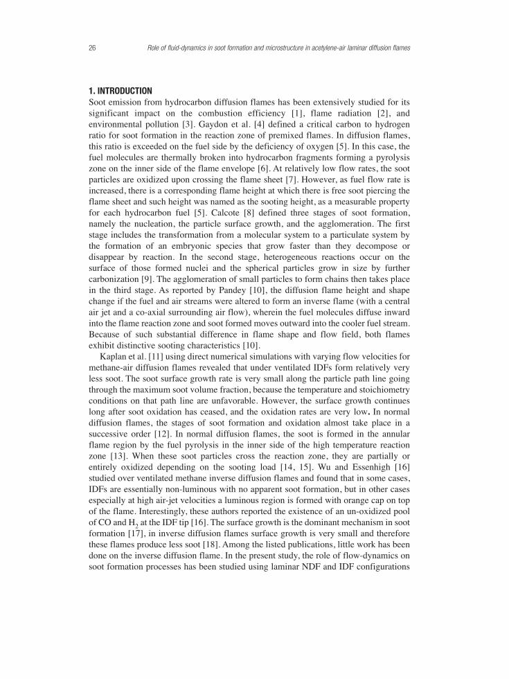
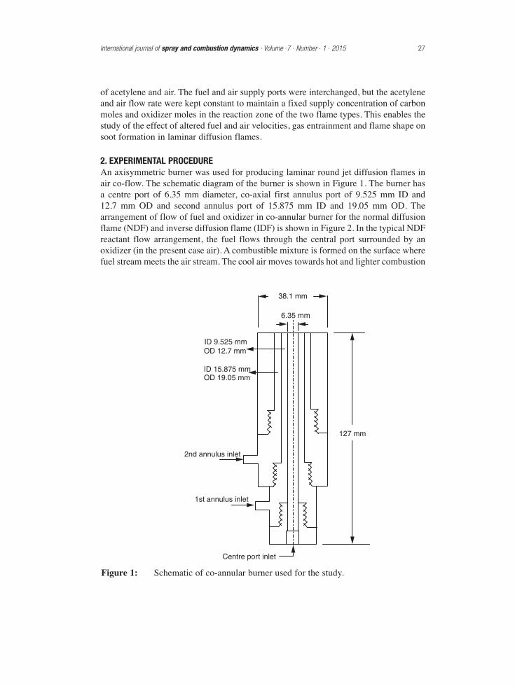
2. EXPERIMENTAL PROCEDUREAn axisymmetric burner was used for producing laminar round jet diffusion flames inair co-flow. The schematic diagram of the burner is shown in Figure 1. The burner hasa centre port of 6.35 mm diameter, co-axial first annulus port of 9.525 mm ID and12.7 mm OD and second annulus port of 15.875 mm ID and 19.05 mm OD. Thearrangement of flow of fuel and oxidizer in co-annular burner for the normal diffusionflame (NDF) and inverse diffusion flame (IDF) is shown in Figure 2. In the typical NDFreactant flow arrangement, the fuel flows through the central port surrounded by anoxidizer (in the present case air). A combustible mixture is formed on the surface wherefuel stream meets the air stream. The cool air moves towards hot and lighter combustion
International journal of spray and combustion dynamics · Volume .7 · Number . 1 . 2015 27
ID 9.525 mmOD 12.7 mm
ID 15.875 mmOD 19.05 mm
38.1 mm
6.35 mm
2nd annulus inlet
127 mm
1st annulus inlet
Centre port inlet
Figure 1: Schematic of co-annular burner used for the study.
zone. Intermediate combustion products and soot particles pass through the reactingoxidation zone along the flame length. On the other hand in the IDF, the oxidizer flowsthrough the central port and fuel surrounds the oxidizer. The outer surface of highvelocity air jet coming out of central port interacts with the inner surface of fuel jetissuing from first annular port. The momentum exchange occurs at the surface wheretwo gas streams flowing with different velocities meet and the slow moving fuelmolecules are entrained inwards and mix with air to form a combustible mixture. InIDF, fuel is on the outer side and hence, the soot is formed on the outer ring of the flame reaction zone. The thermophoretic effect drives away the soot formed from theflame into the cool fuel region at the outer flame boundaries where the reactions getquenched; however some soot gets dragged into air stream also. The soot particleswhich escape to cooler fuel region do not undergo surface growth as the temperatureconditions are not conducive for it. Also, the residence time available at hightemperatures in the flame is very small for surface growth and oxidation. Hence, theIDF provides a good separation of the pyrolysis and oxidation processes during soot formation. As the fuel and pyrolysis intermediates in IDF generally move to fuelzone and only a small portion is convected into oxidation zone, it is possible to collectlarge samples of incipient soot particles, though the soot concentration in IDF tend to be much lower than in NDF. Both the flame types were isolated from ambient air of thelab by supplying the inert nitrogen gas through the second annulus port of the burner.
Thermophoretic sampling used in this study involves physical collection of sootaggregates from the flame for subsequent off-line analysis using a JOEL (product code-JEM2000FX) transmission electron microscope (TEM). Thermophoresis is thephenomenon in which particles are driven towards colder regions in a gas environment
28 Role of fluid-dynamics in soot formation and microstructure in acetylene-air laminar diffusion flames
Soot path Soot path
Luminousflame sheet
Luminousflame sheet
NitrogenNitrogenAir
AirFuel Fuel
(a) (b)
Figure 2: Fuel and air flow arrangement in co-annular burner. (a) Normal DiffusionFlame: Soot passes through flame, undergoes heating, surface growthand oxidation. (b) Inverse Diffusion Flame: Soot is driven away from the flame into the cool fuel or air, both surface growth and oxidation very small.
with the temperature gradient. When a cold sampling surface is inserted into relativelyhot and soot containing flame gas environment, the mass transfer occurs due to netmomentum exchange between cold surface of TEM grid held at the tip of the probe andthe hot gases and the soot particles get collected on the sampling surface. A doubleacting pneumatic system operating through a solenoid valve and a digital timer wasused to insert the probe into flame for a time period ranging from 45 ms to 80 ms. Thegas flow measurements were made using standard acrylic body rotameters for each gas type.
TEM images of soot deposited near the centre of the grid were obtained atmagnifications of 8 × 10³, 15 × 103 and 80 × 103. The TEM photographs of sootparticles and aggregates were analyzed for primary particle size, aggregate size and sootvolume fraction, using NIH image analysis software ImageJ 1.33u. The flametemperatures were measured using a 0.35 mm diameter Pt/Pt-13Rh thermocouple. Thethermophoretic sampling probe and thermocouple were mounted on a traverseassembly which can be moved both horizontally and vertically with the help of leadscrews to facilitate collection of soot samples and temperature measurement at anylocation in the flame with reference to the burner exit plane. The experimental set-up,TEM image analysis and the calculation of soot characteristics procedure is describedin detail in author’s earlier work [18].
3. UNCERTAINTY ANALYSISThe flame temperatures measured by thermocouple have been corrected for radiationheat loss from the thermocouple bead and heat conduction through the thermocouplewires. The temperature of the thermocouple bead and actual temperature of the local gasare different. The steady-state energy balance for the thermocouple bead relates the twotemperatures. Heat is added to the thermocouple bead through convection from theflame. Heat is lost from the thermocouple bead by radiation and by axial heat conduction along the two-thermocouple wires. The catalytic effects have beenignored [18]. The radiation correction is in the range of 90-150 K and the temperaturecorrection for conduction ranged from 71-88 K. The measured flame temperature hasan uncertainty of about ± 23 oC.
The particle coverage area is higher near the copper bars of the TEM grid than thecentral region. Therefore, the particle images at couple of microns away from the gridboundary have been used for calculation. This leads to consistent soot images withreduced deviation from each other. TEM images at 80 × 103 magnification are used todetermine the soot primary particle size. About 30-40 primary soot particles withclearly visible boundaries are averaged at each sampling location to obtain the meanprimary particle diameter. The experimental uncertainty of soot primary particlediameter at 95% confidence interval is less than 9% of mean value. TEM images at 8 × 10³ and 15 × 103 magnifications have been used to analyze soot volume fraction andsoot aggregate size. The magnifications of 8 × 10³ for NDF and 15 × 103 for IDF werechosen as it resolves soot aggregates clearly and provides a statistically significantaggregate population. At 95% confidence interval, the uncertainty in soot volumefraction is about 10%.
International journal of spray and combustion dynamics · Volume .7 · Number . 1 . 2015 29
4. RESULTS AND DISCUSSIONThe air and fuel flow rates were selected for a global stoichiometry of 0.55 of reactantssupplied through the burner and to obtain a stable flame for the study. The carbon andair moles supply in the reaction zone was kept constant in the two flame types bymaintaining the same fuel and air flow rates. Thus the altered flow-dynamics in thecombustion zone, due to the change in burner exit velocities of gases and Reynolds (Re)and Froude (Fr) numbers, becomes the primary influence on the sooting characteristicsof the two flame types.
The Re and Fr values are based on mean burner exit velocity u0. Reynolds number,Re = u0d/v, Froude number, Fr = u0
2/gd, where d = hydraulic mean diameter (4 × cross-section area/wetted perimeter) and kinematic viscosity νg = 1.29 × 10⁻⁹ Tg
1.65 m2/s [19].u0 is the momentum-driven velocity at the burner exit, which is computed by dividinggas flow rate by the respective port area at the burner exit. The details of two flametypes are summarized in Table 1. The fuel jet Reynolds number governs the characterof the flame. The chemical kinetics and fluid mechanics both play role in combustionand there is a different transition Reynolds number for different gases. For acetylene jetdiffusing into air the transition from laminar to turbulent flame occurs betweenReynolds numbers 9,000-10,000 [20]. The flames under study are laminar flames. TheFroude number for fuel stream is much small than 1, therefore the flow is dominated bybuoyancy. The results obtained with change in flow-dynamics on flame temperature,soot microstructure, soot volume fraction and soot aggregate size are discussed below.
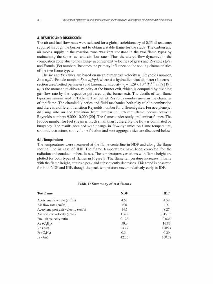
4.1. TemperatureThe temperatures were measured at the flame centerline in NDF and along the flamesooting line in case of IDF. The flame temperatures have been corrected for theradiation and conduction heat losses. The temperatures variations with flame height areplotted for both types of flames in Figure 3. The flame temperature increases initiallywith the flame height, attains a peak and subsequently decreases. This trend is observedfor both NDF and IDF, though the peak temperature occurs relatively early in IDF.
30 Role of fluid-dynamics in soot formation and microstructure in acetylene-air laminar diffusion flames
Table 1: Summary of test flames
Test flame NDF IDF
Acetylene flow rate (cm3/s) 4.58 4.58Air flow rate (cm3/s) 100 100Acetylene port exit velocity (cm/s) 14.5 8.27Air co-flow velocity (cm/s) 114.8 315.76Fuel-air velocity ratio 0.126 0.026Re (C2H2) 59.0 16.83Re (Air) 233.7 1285.4Fr (C2H2) 0.34 0.20Fr (Air) 42.36 160.22
The other significant observation is that the flame temperature in IDF is lower by anorder of magnitude of about 250 to 300 K compared to NDF. The lower flametemperatures in IDF might be due to the following three effects: (i) faster diffusion ofheat released in IDF due to 5 times higher Air/Fuel velocity ratio compared to NDF (ii) possible thermal effect of co-flowing shrouding nitrogen. In IDF the reaction zoneis closer to outer shielding nitrogen gas, which carries away a fraction of heat releasedwith it. In NDF the thermal effect of nitrogen is not present, as it is away from thereaction zone, and (iii) incomplete combustion. In IDF, the fuel is on the outer side ofthe flame and there is a tendency of fuel and products of incomplete combustion tomove away from the flame into the cooler shielding nitrogen stream where there is nopossibility of oxidation. The cumulative effect of these three factors results in lowtemperatures in IDF compared to NDF.
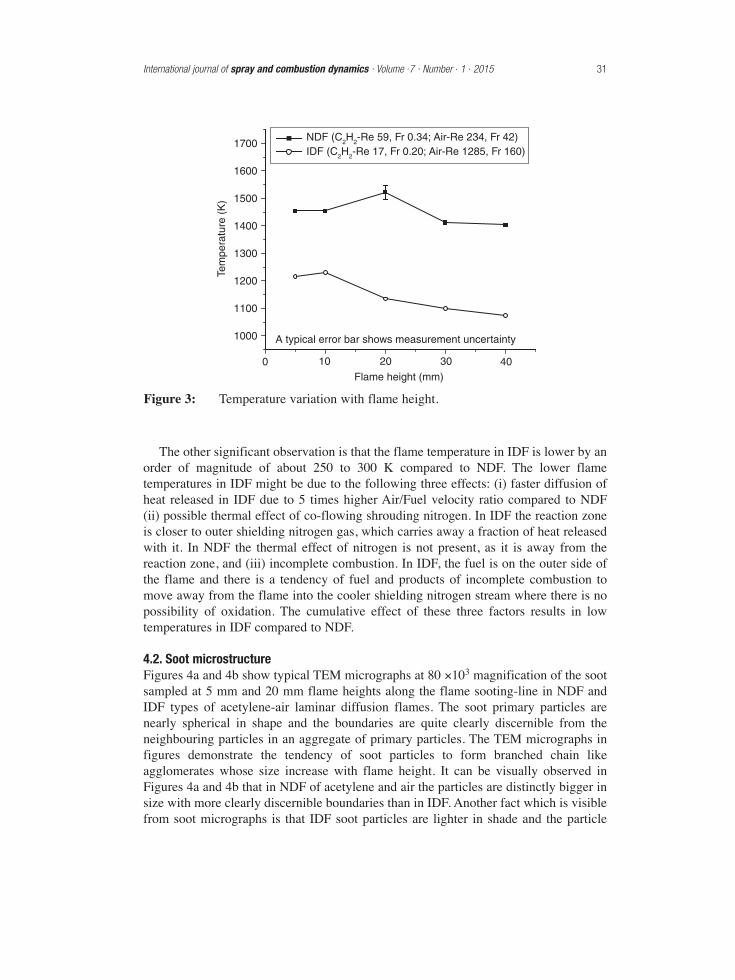
4.2. Soot microstructureFigures 4a and 4b show typical TEM micrographs at 80 ×103 magnification of the sootsampled at 5 mm and 20 mm flame heights along the flame sooting-line in NDF andIDF types of acetylene-air laminar diffusion flames. The soot primary particles arenearly spherical in shape and the boundaries are quite clearly discernible from theneighbouring particles in an aggregate of primary particles. The TEM micrographs infigures demonstrate the tendency of soot particles to form branched chain likeagglomerates whose size increase with flame height. It can be visually observed inFigures 4a and 4b that in NDF of acetylene and air the particles are distinctly bigger insize with more clearly discernible boundaries than in IDF. Another fact which is visiblefrom soot micrographs is that IDF soot particles are lighter in shade and the particle
International journal of spray and combustion dynamics · Volume .7 · Number . 1 . 2015 31
1000
1100
1200
1300
1400
1500
1600
1700NDF (C2H2-Re 59, Fr 0.34; Air-Re 234, Fr 42)IDF (C2H2-Re 17, Fr 0.20; Air-Re 1285, Fr 160)
Flame height (mm)0 10 20 30 40
Tem
pera
ture
(K
)
A typical error bar shows measurement uncertainty
Figure 3: Temperature variation with flame height.
boundaries are more intermingled with adjoining particles compared to NDF. Thissuggests that NDF soot particles are more mature and denser by surface growth whereasIDF produces incipient and young soot particles. Further these micrographs reveal thatsoot primary particles are relatively smaller in size at 20 mm flame height than at 5 mmheight in both types of the flames.
Average primary particle size variations for both the flames with the flame height areshown in Figure 5. The primary particle size varies between 29-34 nm for NDF. Theparticle sizes are observed to be smaller in IDF and vary between 19 - 26 nm. In bothtypes of the flames, the largest primary particle sizes are observed at 5 mm flameheight, which means particles mature quite close to burner exit, which is a fuel richzone. The particle size further downstream in the flame is the outcome of mutuallycompeting processes of soot surface growth and oxidation.
The smaller particle size in IDF indicates a smaller surface growth in this type offlame. There are two probable ways to explain this phenomenon. The first explanationlies in the fact that compared to NDF flame fuel stream Froude number in IDF issmaller than NDF and therefore IDF is more buoyant. Also the fuel/air velocity ratio incase of IDF is lower compared to NDF as the fuel velocity is lowered and air velocityis increased due to change in relative position of fuel and air. The combined effect of
32 Role of fluid-dynamics in soot formation and microstructure in acetylene-air laminar diffusion flames
(a) Flame Height = 5 mm
(b) Flame Height = 20 mm
NDF IDF
NDF IDF
100 nm100 nm
100 nm100 nm
Figure 4: Soot micrographs at 80 × 103 magnification; C2H2= 4.58 cm3/s, air = 100 cm3/s.
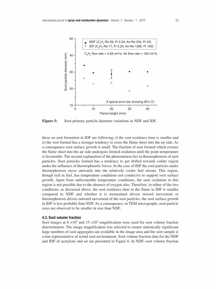
these on soot formation in IDF are following; i) the soot residence time is smaller andii) the soot formed has a stronger tendency to cross the flame sheet into the air side. Asa consequence soot surface growth is small. The fraction of soot formed which crossesthe flame sheet into the air side undergoes limited oxidation until the point temperatureis favourable. The second explanation of the phenomenon lies in thermophoresis of sootparticles. Soot particles formed has a tendency to get drifted towards colder regionunder the influence of thermophoretic forces. In the case of IDF the soot particles underthermophoresis move outwards into the relatively cooler fuel stream. This region,though rich in fuel, has temperature conditions not conducive to support soot surfacegrowth. Apart from unfavourable temperature conditions, the soot oxidation in thisregion is not possible due to the absence of oxygen also. Therefore, in either of the twoconditions, as discussed above, the soot residence time in the flame in IDF is smallercompared to NDF and whether it is momentum driven inward movement orthermophoresis driven outward movement of the soot particles, the soot surface growthin IDF is less probable than NDF. As a consequence, in TEM micrographs, soot particlesizes are observed to be smaller in size than NDF.
4.3. Soot volume fractionSoot images at 8 ×10³ and 15 ×103 magnification were used for soot volume fractiondetermination. The image magnification was selected to ensure statistically significantlarge numbers of soot aggregates are available in the image area and the soot sample isa true representative of actual soot environment. Soot volume fraction data for the NDFand IDF of acetylene and air are presented in Figure 6. In NDF, soot volume fraction
International journal of spray and combustion dynamics · Volume .7 · Number . 1 . 2015 33
10
20
30
40
50
0 10 20 30 40Flame height (mm)
A typical error bar showing 95% CI
Soo
t par
ticle
dia
met
er (
nm)
NDF (C2H2-Re 59, Fr 0.34; Air-Re 234, Fr 42)IDF (C2H2-Re 17, Fr 0.20; Air-Re 1285, Fr 160)
C2H2 flow rate = 4.58 cm3/s, Air flow rate = 100 cm3/s
Figure 5: Soot primary particle diameter variations in NDF and IDF.
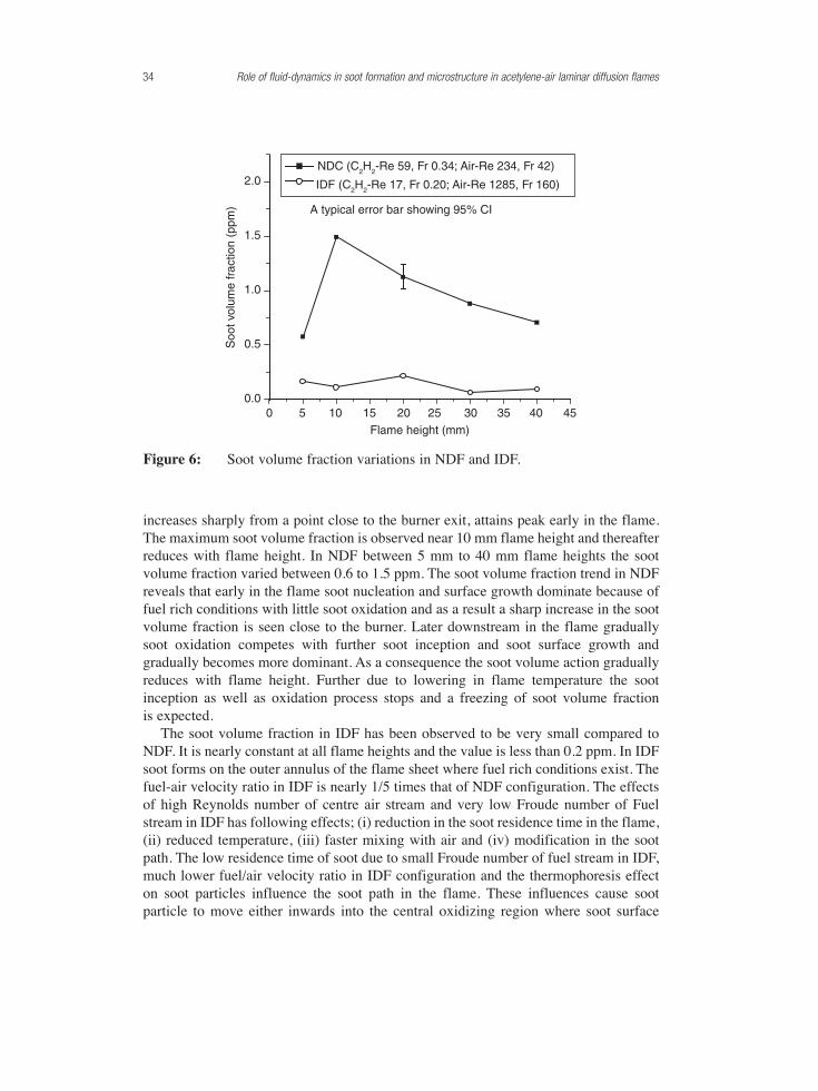
increases sharply from a point close to the burner exit, attains peak early in the flame.The maximum soot volume fraction is observed near 10 mm flame height and thereafterreduces with flame height. In NDF between 5 mm to 40 mm flame heights the sootvolume fraction varied between 0.6 to 1.5 ppm. The soot volume fraction trend in NDFreveals that early in the flame soot nucleation and surface growth dominate because offuel rich conditions with little soot oxidation and as a result a sharp increase in the sootvolume fraction is seen close to the burner. Later downstream in the flame graduallysoot oxidation competes with further soot inception and soot surface growth andgradually becomes more dominant. As a consequence the soot volume action graduallyreduces with flame height. Further due to lowering in flame temperature the sootinception as well as oxidation process stops and a freezing of soot volume fraction is expected.
The soot volume fraction in IDF has been observed to be very small compared toNDF. It is nearly constant at all flame heights and the value is less than 0.2 ppm. In IDFsoot forms on the outer annulus of the flame sheet where fuel rich conditions exist. Thefuel-air velocity ratio in IDF is nearly 1/5 times that of NDF configuration. The effectsof high Reynolds number of centre air stream and very low Froude number of Fuelstream in IDF has following effects; (i) reduction in the soot residence time in the flame,(ii) reduced temperature, (iii) faster mixing with air and (iv) modification in the sootpath. The low residence time of soot due to small Froude number of fuel stream in IDF,much lower fuel/air velocity ratio in IDF configuration and the thermophoresis effecton soot particles influence the soot path in the flame. These influences cause sootparticle to move either inwards into the central oxidizing region where soot surface
34 Role of fluid-dynamics in soot formation and microstructure in acetylene-air laminar diffusion flames
0.0
0.5
1.0
1.5
2.0
0 5 10 15 20 25 30 35 40 45
Flame height (mm)
Soo
t vol
ume
frac
tion
(ppm
)
NDC (C2H2-Re 59, Fr 0.34; Air-Re 234, Fr 42)
IDF (C2H2-Re 17, Fr 0.20; Air-Re 1285, Fr 160)
A typical error bar showing 95% CI
Figure 6: Soot volume fraction variations in NDF and IDF.
growth is prevented and soot is oxidized until the point temperature is favourable oroutwards into the fuel rich cooler region where soot formation reactions are quenched.The overall influence of change in soot path due to altered flow-dynamics in IDF is thatthe surface growth of the soot is inhibited and soot oxidation is promoted and thereforecompared to NDF an extremely low value of soot volume fraction is observed, despitethe fact that fuel and air supply rates were kept constant in the two flame types. Acomparison of Figure 3 and Figure 6 show that the peak flame temperature locationdoes not coincide with the peak soot volume fraction location. In NDF the peak sootvolume faction location is observed to occur earlier than peak temperature value. Thismay be explained by the fact that soot volume fraction gradually reduces after itsmaximum value and due to oxidation of soot additional heat is released and the flametemperature continues to increase. As a result, compared to the soot volume fractionpeak, the temperature peak occurs later in the flame. In IDF the soot volume fraction isvery low and also there is very limited soot oxidation, due to the reasons discussedearlier in this section, no pronounced effect of soot oxidation is visible on flametemperature. The temperature variation in IDF appears to be mainly dependent on heatrelease due to combustion of fuel only.
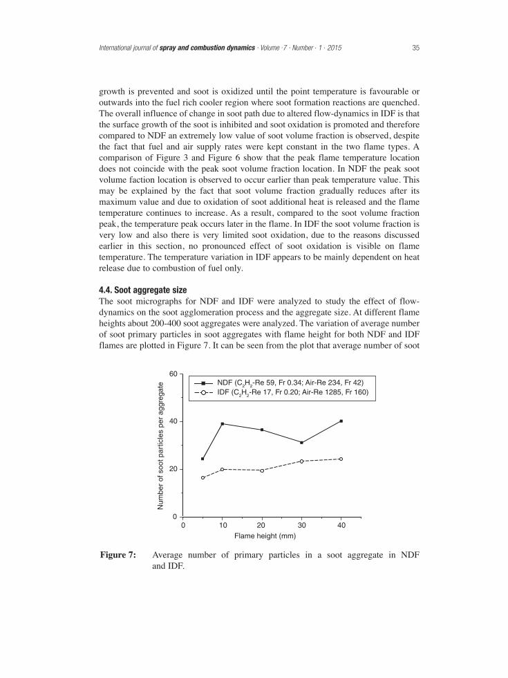
4.4. Soot aggregate sizeThe soot micrographs for NDF and IDF were analyzed to study the effect of flow-dynamics on the soot agglomeration process and the aggregate size. At different flameheights about 200-400 soot aggregates were analyzed. The variation of average numberof soot primary particles in soot aggregates with flame height for both NDF and IDFflames are plotted in Figure 7. It can be seen from the plot that average number of soot
International journal of spray and combustion dynamics · Volume .7 · Number . 1 . 2015 35
0
20
40
60
0 10 20 30 40
Flame height (mm)
Num
ber
of s
oot p
artic
les
per
aggr
egat
e NDF (C2H2-Re 59, Fr 0.34; Air-Re 234, Fr 42)IDF (C2H2-Re 17, Fr 0.20; Air-Re 1285, Fr 160)
Figure 7: Average number of primary particles in a soot aggregate in NDF and IDF.
primary particles per aggregate at different flame heights in NDF was in the range of24 to 40 and for IDF it varied between 16 to 24. This further corroborates the effect ofchanged hydro-dynamic conditions as discussed in earlier sections and its effect onflame temperature, soot microstructure and soot volume fraction.
5. CONCLUSIONSEffects of flow-dynamics on soot formation and soot microstructure were studied usinglaminar normal diffusion flame (NDF) and laminar inverse diffusion flame (IDF) ofacetylene and air in co-flow. Thermophoretic sampling technique followed bytransmission electron microscope imaging and image analysis was employed for sootdiagnostic. The carbon and air moles supply in the reaction zone in two flame types waskept constant. Significant differences in flame temperature, soot microstructure andsoot volume fraction were observed in the two flame types. The differences observedare primarily due to the changed fuel/air velocity ratio and therefore changed burnerexit Reynolds and Froude numbers, entrainment of gas molecules and thermophoresison soot particles. Following are the main findings of this study;
• In NDF the maximum temperature was about 1525 K whereas in IDF themaximum was about 1250 K. At all flame heights the IDF temperature was lowerby about 250-300 K
• The soot primary particle size varies between 29-34 nm in NDF and between 19 - 26 nm in IDF. The soot primary particles are distinctly smaller in size in IDFcompared to NDF.
• TEM images show a chainlike branched structure of soot agglomerate with sootparticles of nearly spherical shape in both NDF and IDF.
• Soot volume fraction values varied between 0.6 to 1.5 ppm in NDF against a muchsmaller value of less than 0.2 ppm in IDF.
• The average number of soot primary particles per aggregate in NDF was in therange of 24 to 40 and where as in IDF it varied between 16 to 24.
REFERENCES[1] R. A. Strehlow, Combustion Fundamentals, McGraw Hill Inc., London, 1984.
[2] I. Glassman, Combustion, Academic Press Inc., New York, 1977.
[3] C. F. Taylor, The Internal Combustion Engine in Theory and Practice, Vol. 2, MITPress, Massachusetts Institute of Technology, London, 1968.
[4] A. G. Gaydon, and H. G. Wolfhard, Flames, Their Structure, Radiation andTemperature, Chapman and Hall Ltd., London, 1960.
[5] B. S. Haynes, and H. G. Wagner, Soot formation, Progress in Energy andCombustion Science, 1981, 7 (4), 229–273.
[6] Ö, L. Gülder, Effect of oxygen on soot formation in methane. Propane, and n-butane diffusion flames, Combustion and Flame, 1995, 101, 302–310.
[7] P. B. Sunderland, and G. M. Faeth, Soot Formation in Hydrocarbon/Air LaminarJet Diffusion Flames, Combustion and Flame, 1996, 105, 132–146.
36 Role of fluid-dynamics in soot formation and microstructure in acetylene-air laminar diffusion flames
[8] H. F. Calcote, Mechanisms of Soot Nucleation in Flames-A Critical Review,Combustion and Flame, 1981, 42, 215–242.
[9] C. S. Mcenally, A. M. Schaffer, M. B. Long, L. D. Pfefferle, M. D. Smooke, M. B. Colket, and R. J. Hall, Computational and experimental study of sootformation in a co-flow, laminar ethylene diffusion flame, Proceedings of theCombustion Institute, Pittsburgh, 1998, 27, 1497–1505.
[10] P. Pandey, Studies on the effect of hydrogen addition on soot formation inacetylene-air laminar diffusion flames, Ph. D. Thesis, IIT Kanpur, 2007.
[11] C.R. Kaplan, and K. Kailasanath, Flow-field effects on soot formation in normaland inverse methane-air diffusion flames, Combustion and Flame, 2001, 124(1-2), 275–294.
[12] R. J. Santoro, T. Yeh, J. Horvath, and H. Semerjian, The transport and growth ofsoot particles in laminar diffusion flames, Combustion Science and Technology,1987, 53, 89–115.
[13] F. Xu, A. El-Leathy, C. H. Kim, and G. M. Faeth, Soot surface oxidation inhydrocarbon/air diffusion flames at atmospheric pressure, Combustion andFlame, 2003, 132, 43–57.
[14] J. B. Moss, C. D. Stewart, and K. J. Young, Modeling soot formation and burnoutin a high temperature laminar diffusion flame burning under oxygen-enrichedconditions, Combustion and Flame, 1995, 101, 491–500.
[15] K. B. Lee, M. W. Thring, and J. M. Beér, On the Rate of Combustion of Soot ina Laminar Soot Flame, Combustion and Flame,1962, 6, 137–145.
[16] K.-T. Wu, and R. H. Essenhigh, Mapping and structure of inverse diffusion flamesof methane, Proceedings of the Combustion Institute, Pittsburgh, 1984, 20,1925–32.
[17] I. Glassman, Soot formation in combustion processes, Proceedings of theCombustion Institute, Pittsburgh, 1989, 22, 295–311.
[18] P. Pandey, B. P. Pundir, and P. K. Panigrahi, Hydrogen addition to acetylene–airlaminar diffusion flames: Studies on soot formation under different flowarrangements, Combustion and Flame, 2007, 148(4), 249–262.
[19] J.P. Holman, Heat Transfer, McGraw-Hill, New York, 1997.
[20] H. C. Hottel, and W. R. Hawthorn, Diffusion in Laminar Flame Jets, Proceedingsof the Combustion Institute, Pittsburgh, 1949, 3, 254–266.
International journal of spray and combustion dynamics · Volume .7 · Number . 1 . 2015 37