Diesel particulate filter pressure drop Part 1: modelling and experimental validation
15
http://jer.sagepub.com/ International Journal of Engine Research http://jer.sagepub.com/content/5/2/149 The online version of this article can be found at: DOI: 10.1243/146808704773564550 2004 5: 149 International Journal of Engine Research O. A. Haralampous, I. P. Kandylas, G. C. Koltsakis and Z. C. Samaras Diesel particulate filter pressure drop Part 1: Modelling and experimental validation Published by: http://www.sagepublications.com On behalf of: Institution of Mechanical Engineers can be found at: International Journal of Engine Research Additional services and information for http://jer.sagepub.com/cgi/alerts Email Alerts: http://jer.sagepub.com/subscriptions Subscriptions: http://www.sagepub.com/journalsReprints.nav Reprints: http://www.sagepub.com/journalsPermissions.nav Permissions: http://jer.sagepub.com/content/5/2/149.refs.html Citations: What is This? - Apr 1, 2004 Version of Record >> by guest on September 6, 2012 jer.sagepub.com Downloaded from
-
Upload
independent -
Category
Documents
-
view
3 -
download
0
Transcript of Diesel particulate filter pressure drop Part 1: modelling and experimental validation
http://jer.sagepub.com/International Journal of Engine Research
http://jer.sagepub.com/content/5/2/149The online version of this article can be found at:
DOI: 10.1243/146808704773564550
2004 5: 149International Journal of Engine ResearchO. A. Haralampous, I. P. Kandylas, G. C. Koltsakis and Z. C. Samaras
Diesel particulate filter pressure drop Part 1: Modelling and experimental validation
Published by:
http://www.sagepublications.com
On behalf of:
Institution of Mechanical Engineers
can be found at:International Journal of Engine ResearchAdditional services and information for
http://jer.sagepub.com/cgi/alertsEmail Alerts:
http://jer.sagepub.com/subscriptionsSubscriptions:
http://www.sagepub.com/journalsReprints.navReprints:
http://www.sagepub.com/journalsPermissions.navPermissions:
http://jer.sagepub.com/content/5/2/149.refs.htmlCitations:
What is This?
- Apr 1, 2004Version of Record >>
by guest on September 6, 2012jer.sagepub.comDownloaded from

Diesel particulate filter pressure dropPart 1: modelling and experimentalvalidation
O A Haralampous, I P Kandylas, G C Koltsakis
and Z C Samaras
Laboratory of Applied Thermodynamics,
Aristotle University Thessaloniki, Greece
Accepted 29 September 2003
Abstract: Pressure drop modelling is a subject of special Due to the fuel penalty resulting from the increased
backpressure of the loaded filter, it is necessaryinterest for the design and control of diesel particulate
for the filter to be regenerated. This regenerationfilters. Based on previous experience, an improved pressure
involves oxidation of the accumulated particulate,drop model is presented. Special emphasis is given on the
which may be periodical or continuous, duringsoot permeability properties and its dependence on tem-
regular engine operation. The initiation and controlperature and pressure. With the assumption of uniform
of the regeneration process is the main issue in dieselwall flow distribution throughout the channel length, it
filter technology, as regeneration should be as safeis possible to derive an analytic expression for pressure
as possible to avoid excessive thermal stresses anddrop calculation. The main difference with previously pro-
failure of the filter material. Regeneration systemsposed analytic expressions lies in the inclusion of gas
are based on the use of catalysts (catalytic coatingsdensity dependence on local pressure, which necessitates
or fuel-borne catalysts) to lower the reaction tem-an iterative calculation procedure. The importance of this
perature and/or engine measures (e.g. post-injection)improvement is illustrated parametrically. The new model
or electrical heating to increase the exhaust gasis validated against experimental data on an engine bench,
temperature.using a double filter configuration to ensure constant filter
Understanding the flow phenomena contributingsoot loading throughout the test.to the pressure drop in particulate filters is of great
importance for the emissions engineer. On the oneKey words: diesel engine, after-treatment technology,hand, filter design should target the minimization ofexhaust emissions, mathematical modelling, pressure droppressure drop in real-world conditions by careful
selection of filter geometry (volume, cell density,
wall thickness, porosity). On the other hand, the1. Introductioninitiation and control of the regeneration process by
Particulate filtration in the exhaust system of the engine management should take into account
diesel engines is increasingly gaining in importance the mass of accumulated soot in the filter, which is
for both light-duty and heavy-duty applications. commonly assessed by interpreting the pressure drop
Passenger cars equipped with diesel particulate measurement on-board. Furthermore, pressure drop
filters (DPFs) appeared in the market as a means to measurements are expected to support the task of
achieve the low particulate emission standards on-board diagnosis of a filter structural failure [1].
required in Europe [1]. The particulate filter tech- Mathematical models have been widely employed
nology is also considered the most promising to describe the filter pressure drop as a function of
solution towards attaining the emission standards of filter geometry (volume, cell density, wall thickness),
heavy-duty vehicles [2 ± 5]. operating conditions (flowrate, temperature) and the
Diesel filters show close to 100 per cent filtration accumulated soot mass. These models are either
based on analytical functions [6, 7] or on the solutionefficiencies for the solid part of emitted particulates.
149Int. J. Engine Res. ä Vol. 5 ä No. 2JER 02202 ä © 2004 ä IMechE
by guest on September 6, 2012jer.sagepub.comDownloaded from

O A Haralampous, I P Kandylas, G C Koltsakis and Z C Samaras
of mass and momentum balances in the filter channel non-reacting conditions. Therefore, only the balance
equations for mass and momentum of the one-[8, 9]. The former approach is definitely simpler and
allows straightforward application for on-board esti- dimensional model will be employed. The con-
servation of energy and the reaction rate equationsmation of the accumulated soot. The latter approach
requires a computationally demanding solution of a will not be included.
The mass balance equation for gas flowing in thesingle-channel model. The possible advantages of
employing such a complicated model are discussed inlet and outlet channels is given as
in this paper.
Validation of pressure drop models is not an qqz
(rivi)=( 1)iA 4
DiB rwvw (1)obvious task, mainly due to the difficulty of measuring
exactly the mass of accumulated soot in the filter.
Since the diesel engine continuously emits soot, it is where the subscript i identifies regions 1 (inletnot possible to measure the pressure drop under channel) and 2 (outlet channel). The momentumdifferent flowrate and temperature conditions with balance of exhaust gas in the inlet and outleta constant soot mass. A common approach used to channels can be formulated as below, taking intoevaluate the pressure drop of particulate filters is account the mass loss/gain through the porous wallcold flow testing using air at constant temperature and the flow friction in the axial direction z:(usually room temperature) as the flowing gas
[10 ± 12]. qpi
qz+
qqz
(riv2i )=
a 1mvi
D2(2)In the present work, the problem is overcome by
using two particulate filters in series. The first is
responsible for collecting practically all soot emittedThe right-hand side of this expression is based on
during the test. The second filter is used for pressurethe assumption of laminar flow conditions for the
drop measurements under variable flowrates andchannel flow, which is actually the case in usual
temperatures. The accumulated soot mass is measuredoperating conditions.
by dismantling and weighing the second filter.To solve the velocity and pressure distribution in
the inlet and outlet channels, it is necessary to know
the pressure drop law for the flow through the soot
layer deposit and the porous filter wall. In the
original model of Bissett [13], the soot porosity was2. One-dimensional Pressure Drop Modelconsidered negligible and thus the soot layer thick-
The prediction of filter pressure drop requires ness was assumed to be negligible compared to the
a mathematical description of flow phenomena wall thickness and the channel diameter. This allowed
including flow distribution in the channels, through the use of a constant velocity through the wall.the soot layer and filter walls, as well as flow Moreover, the soot permeability was considered to
entrance and exit effects. A one-dimensional model, be constant. The pressure drop calculation was based
which could sufficiently describe the velocity and on the Darcy law, neglecting the inertial terms
pressure variations inside a single-filter channel, was and applying a correction for initial pressure drop
originally presented by Bissett [13]. The model relies build-up due to initial blocking of the open wall
on the transient solution of the mass, momentum pores.
and energy balances in a single channel, with the Since then, numerous studies have shown that soot
following major assumptions: porosity in actual conditions may be of the order of
90 per cent and therefore the soot layer thickness is
1. All filter channels behave in the same way. This large enough to cause variations in wall velocities in
presumes adiabatic conditions and uniform flow the flow direction (Fig. 1). On the other hand, the
distribution at the filter entrance. soot permeability dependence on temperature has
2. Laminar axial flow inside channels. proven to be far from being negligible in real-world
3. Pressure drop according to Darcy’s law for flow conditions [8, 10, 14]. The contribution of inertial
across the soot layer and substrate. pressure drop terms for the soot layer has also
been questionable. Taking the above into account, a
comprehensive approach to model the soot layerFor the purpose of pressure drop modelling, the
focus here will be on steady state, isothermal and pressure drop is now described.
150 Int. J. Engine Res. ä Vol. 5 ä No. 2JER 02202 ä © 2004 ä IMechE
by guest on September 6, 2012jer.sagepub.comDownloaded from
Diesel particulate filter pressure drop. Part 1
dependence. In the present study, the following
expression proposed in reference [15] is used:
kp=k0A1+C4
p0
pmS T
MgB (8)
This formula expresses the dependency of soot
permeability on local temperature and pressure.
Two parameters, namely k0 and C4 , present in this
expression have to be estimated by experimental
data on soot properties. This procedure is discussed
in the next chapter.
Equation (5) can be integrated over x to provide
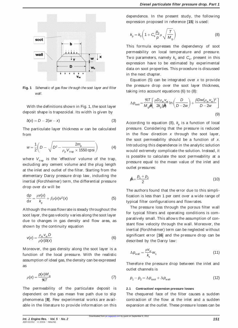
the pressure drop over the soot layer thickness,Fig. 1 Schematic of gas flow through the soot layer and filter
taking into account equations (6) to (8):wall.
Dpsoot=T
MgpÅ CmDrwvw
2kp(pÅ )lnA D
D 2wB+bDw(rwvw)2
D 2w DWith the definitions shown in Fig. 1, the soot layer
deposit shape is trapezoidal. Its width is given by(9)
b(x)=D 2(w x) (3)According to equation (8), kp is a function of local
pressure. Considering that the pressure is reducedThe particulate layer thickness w can be calculated
in the flow direction x through the soot layer,from
the soot permeability should be a function of x.
Introducing this dependence in the analytic solutionw=
1
2AD SD2 2mp
rpVtrap ×1550 cpsiB (4)would extremely complicate the solution. Instead, it
is possible to calculate the soot permeability at awhere Vtrap is the `effective’ volume of the trap,
pressure equal to the mean value of the inlet andexcluding any cement volume and the plug length
outlet pressures:at the inlet and outlet of the filter. Starting from the
elementary Darcy pressure drop law, including thepÅ =
p1+p2
2(10)
inertial (Forchheimer) term, the differential pressure
drop over dx will beThe authors found that the error due to this simpli-
fication is less than 1 per cent over a wide range ofdp
dx=
mv(x)
kp
+br(x)v2(x) (5)typical filter configurations and flowrates.
The pressure loss through the porous filter wallAlthough the mass flowrate is steady throughout the
for typical filters and operating conditions is com-soot layer, the gas velocity varies along the soot layer
paratively small. This allows the assumption of con-due to changes in gas density and flow area, as
stant flow velocity through the wall. Moreover, theshown by the continuity equation
inertial (Forchheimer) term can be neglected without
significant error [16] and the pressure drop can bev(x)=
rwvwD
r(x)b(x)(6)
described by the Darcy law:
Moreover, the gas density along the soot layer is aDpwall=
mvw
ks
ws (11)function of the local pressure. With the realistic
assumption of ideal gas, the density can be expressedTherefore the pressure drop between the inlet and
asoutlet channels is
r(x)=p(x)Mg
T(7) p1 p2=Dpsoot+Dpwall (12)
2.1 Contraction/expension pressure lossesThe permeability of the particulate deposit is
dependent on the gas mean free path due to slip The chequered face of the filter causes a sudden
contraction of the flow at the inlet and a suddenphenomena [8]. Few experimental works are avail-
able in the literature to provide information on this expansion at the outlet. These pressure losses can be
151Int. J. Engine Res. ä Vol. 5 ä No. 2JER 02202 ä © 2004 ä IMechE
by guest on September 6, 2012jer.sagepub.comDownloaded from

O A Haralampous, I P Kandylas, G C Koltsakis and Z C Samaras
assessed using the following formulae respectively able to flow. On the other hand, in the case of the
clean filter, the channel velocity profiles deviate sub-[17]:
stantially from linear, while the flow through the
wall is far from being uniform. Thus, the assumptionDpcontraction = C1.1 0.4(D 2w)2
2(D+ww)2DMg(p1v21)z=0
2 Tof uniform wall velocity is realistic for moderately
and heavily loaded filters.(13)
The pressure variation inside the inlet and outlet
channels was also studied for the same conditions.Dpexpansion =C1 D2
2(D+ww )2D2 Mg(p2v22)z=L
2 T(14)
Figure 3a depicts the absolute pressure inside the
inlet channel for several soot loadings. The pressureThe mass and momentum balance equations canin the outlet channel is shown in Fig. 3b. When uni-be solved to compute the velocity v1(z), v2(z), theform wall flow conditions prevail (moderately andpressure field p1 (z), p2(z) in the inlet and outletheavily loaded filters), the pressure field in the outletchannels, as well as the velocity through the wallchannel is almost independent of the soot loading.vw (z) with given gas flowrate and temperature. The
pressure at the exit of the outlet channel is set equal
to ambient. The axial gas velocity is set to zero for
the last node of the inlet channel and at the first node 3. One-dimensional Pressure Drop Modelof the outlet channel. An iterative solution procedure Validationis employed to calculate the velocity and pressure
field, as described in reference [18]. This solution3.1 Experimental set-up
method offers very low computational time. The experiments were carried out on a direct injectionThe model was applied for the case of an SiC filter diesel engine installed on an engine dynamometer
with a 200 cpsi cell density. More details about test bench. The engine displacement is 1.9 l andthe geometrical properties of the filter are given in the maximum power output is 66 kW. The engineTable 1. The exhaust gas flowrate selected for this is turbocharged, intercooled and uses exhaust gasanalysis is 0.1 kg/s and the temperature is 200 °C. recirculation (EGR). The original oxidation catalyst
Figures 2a and b present the computed axial velocity was removed from the exhaust system of the engineprofiles in the inlet and outlet filter channels at and two particulate filters were installed in series, asvarious soot loadings. Figure 2c presents the com- shown in Fig. 4. The geometric and thermophysicalputed velocity of the gas through the filter wall. It is properties of the two particulate filters are given inclear that for the case of a heavily loaded filter (8 g/l) Table 1.the gas velocity decreases and increases almost The first filter in series is used to filter out thelinearly in the inlet and outlet channels respectively, particulates emitted during a single test. In this way,while the wall velocity remains uniform throughout it is possible to carry out measurements in the secondthe whole length of the trap. In a moderately loaded filter at steady soot loading. The second filter, intrap (2 g/l), the channel velocity profiles are very addition to the standard canning material, was alsoclose to linear, while the wall velocity is close to uni- heavily insulated externally in order to approximateform. Near the entrance of the loaded channels, the adiabatic operating conditions. Dedicated measure-flow accelerates slightly in the beginning of the inlet ments showed that the maximum temperaturechannel during the transition from the clear region difference in the radial direction during the tests did(due to the plugs of the outlet channel) to the loaded not exceed 5 °C.region, where a smaller cross-sectional area is avail- The intake air flow was measured by a hot-wire
anemometer. This measurement along with the air±
fuel ratio measured by a wide-range sensor installedFilter material Silicon carbide in the exhaust pipe was used to calculate the exhaustCell density 200 cpsi
mass flowrate. The pressure drop was continuouslyWall thickness 0.38 mmDiameter 144 mm monitored by pressure transducers installed upstreamLength 152 mm
and downstream of the filter while 1 mm thick thermo-Plug length 5 mmWall density 1800 kg/m3
couples measured the exhaust gas temperature atWall permeability 1.2×10 12 m2
different positions in the exhaust system, as shown
in Fig. 4. All the measured data were recorded at aTable 1 Geometrical data and properties of thefilter used in this study. 1 Hz acquisition rate.
152 Int. J. Engine Res. ä Vol. 5 ä No. 2JER 02202 ä © 2004 ä IMechE
by guest on September 6, 2012jer.sagepub.comDownloaded from

Diesel particulate filter pressure drop. Part 1
Fig. 2 Computed velocity profiles for different soot loadings: (a) inlet channel, (b) outlet channel, (c) wall.
3.2 Model validation measurements After completion of the loading protocol the filter
is weighed and the first filter is installed. The engineTo load the second filter with a prescribed amount
of soot, the first filter was removed and the engine operates at various steady state operating points,
varying the engine speed and torque in such a wayoperated steady state at 4000 r/min and 40 N m
torque. The filter temperature during the loading as to ensure that the filter temperature remains con-
stant while the flowrate varies between differentexperiment was between 320 and 350 °C.
153Int. J. Engine Res. ä Vol. 5 ä No. 2JER 02202 ä © 2004 ä IMechE
by guest on September 6, 2012jer.sagepub.comDownloaded from

O A Haralampous, I P Kandylas, G C Koltsakis and Z C Samaras
Fig. 3 Computed pressure profiles for different soot loadings: (a) inlet channel, (b) outlet channel.
Fig. 4 Experimental set-up.
steady state points. Figure 5 presents the gas flow- 200 °C exhaust gas temperature and 0.024 kg/s mass
flowrate. As soon as stabilized engine and gas con-rate, the temperature and the filter pressure drop
recordings during a typical experiment with 9.2 g/l ditions are attained, the engine is set to a different
point with the same exhaust gas temperature andsoot mass. Initially an engine point is selected with
154 Int. J. Engine Res. ä Vol. 5 ä No. 2JER 02202 ä © 2004 ä IMechE
by guest on September 6, 2012jer.sagepub.comDownloaded from

Diesel particulate filter pressure drop. Part 1
Fig. 5 Temperature, flowrate and pressure drop recordings during a typical pressure drop experiment with 9.2 g/l soot mass.
different mass flowrates. The same procedure is 4. Analytical Approximationrepeated with operating points that result in filter
As mentioned in section 1, analytical solutions fortemperatures of 300 and 400 °C. The above protocolthe pressure drop in the case of an isothermal, cleanwas repeated four times using soot loadings from 0.2filter with constant gas density and a negligibleto 9.2 g/l. The soot loading in each case was esti-inertial term contribution have been derived [19].mated by dismantling and weighing the filters beforeEven with the assumption of constant gas density,and after each test.the analytical expression is particularly cumbersome.The results obtained for each soot loading are pre-Simplified analytical formulae have also been pro-sented in Fig. 6 in the form of measured pressureposed. The validity of the simplified formula wasdrop versus mass flowrate, using the filter temper-established by showing that the fit to the originalature as a parameter. The lines in these plots presentanalytical expression is generally good [19].the pressure drop for the respective conditions as
The above studies claimed that an analyticalcomputed by the one-dimensional model presentedpressure drop formula could be extended to includeabove. The computed results were obtained afterthe effect of accumulated soot by adding thefitting the following parameters: soot permeabilityrespective pressure drop term. The soot permeabilityk0 , soot slip correction factor C4 and soot inertialwas expressed as a function of the mean free pathpressure drop coefficient b, which were kept thelength and the Peclet number during the soot loadingsame for all simulations. From these results it ismode [7]. The analytical expression derived con-shown that the one-dimensional model is able tosiders uniform gas properties throughout the filter.predict the dependence of the pressure drop as aHowever, in the case of heavily soot-loaded filters,function of soot loading, mass flowrate and temper-the absolute pressure in the inlet channel couldature for the filter tested, after fitting the relatedbe substantially different compared to the outletpressure drop parameters.channel pressure. This will in turn affect the gasAn additional type of experiment was conducteddensity and the mean free path length, which willto validate the pressure drop model at room tem-also vary. In the following, an improved analyticalperature conditions. The filter was mounted in theexpression will be developed, which is able toinlet air duct of the engine. The engine was operatedaccount for the pressure-dependent gas propertiesat various steady state operating points to obtain avariation. The importance of this improvement willlarge range of intake flow rates and the pressurebe discussed with comparative results.drop was measured along the filter. The results are
presented in Fig. 7 for two soot loadings. The com-
parison with the computed pressure drop validates the 4.1 Soot layer pressure drop
accuracy of the model, even at ambient temperature With the assumption of uniform wall velocity and
using the index w for the conditions at the wall-outletconditions.
155Int. J. Engine Res. ä Vol. 5 ä No. 2JER 02202 ä © 2004 ä IMechE
by guest on September 6, 2012jer.sagepub.comDownloaded from

O A Haralampous, I P Kandylas, G C Koltsakis and Z C Samaras
Fig. 6 (continued over)
channel interface, the mass balance gives In equation (17), the mean pressure pÅ is not known
beforehand. This means that an iterative procedure
is necessary when applying this equation.rwvw=
mÇ g
Af
(15)
4.2 Wall pressure dropThe filtration area Af appearing in the above The overall contribution of the porous wall on theequations is defined as pressure drop for uniform wall velocity is given by
Af=2Vtrap D×1550 cpsi (16)Dpwall=
T
Mgp2AmwwmÇ
ksAf B (18)
The soot layer pressure drop contribution can be
calculated from equations (9) and (15):4.3 Channel flow pressure drop
With the assumption of uniform wall velocity,
Dpsoot=T
MgpÅ C mDmÇ
2kp(pÅ )Af
lnA D
D 2wB+bDwmÇ 2
A2f (D 2w)D the axial velocities in the inlet and outlet channels
are readily computed from simple mass balances.
Therefore, it is possible to compute the pressure drop(17)
156 Int. J. Engine Res. ä Vol. 5 ä No. 2JER 02202 ä © 2004 ä IMechE
by guest on September 6, 2012jer.sagepub.comDownloaded from

Diesel particulate filter pressure drop. Part 1
Fig. 6 Measured and one-dimensional model computed pressure drop versus flowrate at different temperatures. Soot loadings:
(a) 0.2g/l, (b) 5.5 g/l, (c) 8.0 g/l and (d) 9.2g/l.
Fig. 7 Measured and one-dimensional model computed pressure drop versus flowrate at room temperature. Soot loadings: 0.5
and 8.6 g/l.
157Int. J. Engine Res. ä Vol. 5 ä No. 2JER 02202 ä © 2004 ä IMechE
by guest on September 6, 2012jer.sagepub.comDownloaded from

O A Haralampous, I P Kandylas, G C Koltsakis and Z C Samaras
due to the flow friction in the channels: To assess the importance of accounting for pressure-
dependent gas properties, the same figure presents
the results of the analytical expression in the case ofDpchannel=a1m TLmÇ
3MgN C 1
p2D4+
1
p1(D 2w)4D (19)assuming uniform gas properties throughout the
filter, corresponding to ambient pressure. In this casewhere N denotes the total number of open channels the deviation compared to the one-dimensionaland can be assessed with the following formula: model can be quite significant, especially for heavily
loaded filters.
To illustrate the significance of the analyticalN=Vtrap ×1550 cpsi
2L(20)
expression improvement, Fig. 9 presents the measured
pressure drop versus flowrate compared with theAgain, this equation requires an iterative procedure
respective calculations based on the analyticalsince the unknown pressure is included in the
expression. The same calculations with the assump-expression.
tion of uniform gas properties are also included in
the same graph. Neglecting the dependence of the gas
properties on pressure, the error could be obvious,4.4 Contraction/expansion pressure losses
especially at high flowrates and temperatures.With a simple manipulation of equations (13) and
(14), the contraction and expansion losses can be
expressed using the exhaust mass flowrate as a4.6 Pressure drop contributions
parameter:It is interesting to study the relative contribution of
each of the pressure drop mechanisms describedDpcontractionabove, based on the analytical expressions derived.
Figure 10a shows the computed dependence of these=C1.1 0.4(D 2w)2
2(D+ww)2D TmÇ 2
2p1MgN2(D 2w)2 contributions on soot loading for the filter described
in Table 1. The results refer to a temperature of 300 °C(21)
and a mass flowrate of 0.05 kg/s.
In the case of a completely clean filter, the pressureDpexpansion =C1
D2
2(D+ww )2D2 TmÇ 2
2p2MgN2D2(22) drop due to friction losses in the channel axial
flow are more than 50 per cent of the total. The
wall flow pressure drop accounts for about 30 perThe total trap pressure drop is the sum of thecent. The contraction end expansion pressure lossindividual terms previously explained:contributions are of minor importance.
For soot loadings exceeding 1 g/l, the contributionDp=Dpcontraction +Dpchannel+Dpsoot+Dpwall
of the soot layer becomes dominant. The channel+Dpexpansion (23)
flow still accounts for about 10 per cent at soot load-
ings up to 20 g/l. At unusually high soot loadings
(>20 g/l) the free-flow channel diameter becomes4.5 Comparisons between the one-dimensional model and
very small and the channel flow pressure loss contri-analytic solutions
bution starts to increase significantly. The wall flowThe accuracy of the analytical expression was
pressure drop is of course independent of soot load-initially evaluated by comparing its results with the
ing; therefore, its percentile contribution steadilymore comprehensive one-dimensional model as a
decreases with soot loading. The contraction pressurefunction of soot loading. The calculation was done
losses increase with soot loading as absolutefor the filter described in Table 1, assuming a flow-
magnitude due to the open frontal area decrease.rate of 0.1 kg/s and a temperature of 200 °C. It is
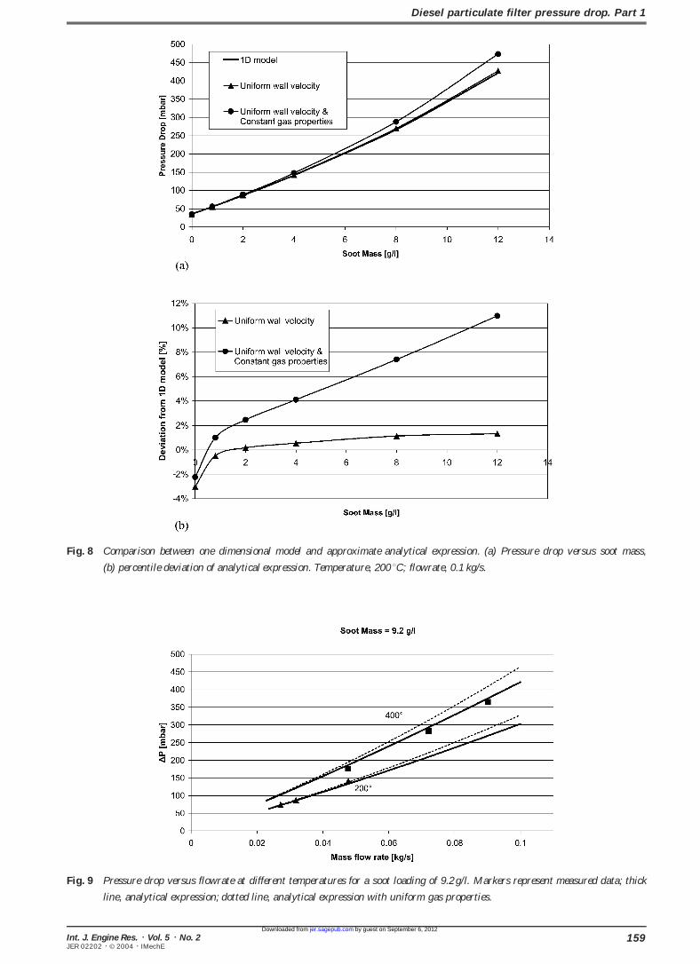
Figure 10b presents the same results obtained withapparent from Fig. 8a that the analytical approxi-
a lower cell density filter (100 cpsi/0.43mm wallmation [equation (23)] yields almost identical results
thickness), keeping all other parameters the same.with the one-dimensional model. A small deviation
Interestingly, compared to the 200 cpsi filter theof the order of 3 per cent occurs in the case of the
channel flow pressure loss is much less importantclean filter, as shown in Fig. 8b. This deviation is
in both clean and loaded filters. The wall flow isapparently due to the fact that the assumption of
responsible for more than 60 per cent of the totaluniform wall velocity is not accurate in this case, as
discussed above. pressure drop in the clean filter. However, the soot
158 Int. J. Engine Res. ä Vol. 5 ä No. 2JER 02202 ä © 2004 ä IMechE
by guest on September 6, 2012jer.sagepub.comDownloaded from
Diesel particulate filter pressure drop. Part 1
Fig. 8 Comparison between one dimensional model and approximate analytical expression. (a) Pressure drop versus soot mass,
(b) percentile deviation of analytical expression. Temperature, 200 °C; flowrate, 0.1 kg/s.
Fig. 9 Pressure drop versus flowrate at different temperatures for a soot loading of 9.2 g/l. Markers represent measured data; thick
line, analytical expression; dotted line, analytical expression with uniform gas properties.
159Int. J. Engine Res. ä Vol. 5 ä No. 2JER 02202 ä © 2004 ä IMechE
by guest on September 6, 2012jer.sagepub.comDownloaded from

O A Haralampous, I P Kandylas, G C Koltsakis and Z C Samaras
Fig. 10 Computed pressure drop contributions as a function of soot loading: (a) 200 cpsi/0.38 mm, (b) 100 cpsi/0.43 mm.
layer contribution accounts for more than 90 per cent the full range of engine operating conditions. The
innovative dual-filter configuration employed wasof the total pressure loss when the soot loading is
larger than 3 g/l. necessary to ensure constant filter soot loading
throughout the test procedure.
Finally, the possibility of deriving a more practical
analytical expression for the pressure drop was5 Conclusionsexamined. Indeed, with the assumption of uniform
In this first part of the present paper, the mass and wall velocity, it is relatively simple to derive such an
momentum balance governing the flow phenomena analytical expression, which correlates excellently
in the inlet and outlet channels of a particulate with the experimental and the one-dimensional
filter were solved. Special focus was given on the model results. It was shown that the assumption of
dependence of soot permeability on temperature and a uniform wall velocity is very close to reality for
pressure. For the first time, the effect of non-uniform moderately and heavily loaded filters. The inclusion
gas properties due to significant pressure variations of pressure-dependent gas properties in the present
in the filter was addressed. analytical expression was proven to be necessary.
The independent parameters of the improved Neglect of this effect could yield an error of the order
pressure drop model referring to the permeability of of 10 per cent in terms of pressure drop predictions.
the soot layer and wall were determined based on In the second part of this work, pressure drop
an extensive set of experimental data. The experi- modelling and the analytical expression derived
mental set-up designed especially for this validation here will be applied to solve the so-called inverse’
problem, namely that of calculating the soot mass infacilitated the pressure drop measurement under
160 Int. J. Engine Res. ä Vol. 5 ä No. 2JER 02202 ä © 2004 ä IMechE
by guest on September 6, 2012jer.sagepub.comDownloaded from

Diesel particulate filter pressure drop. Part 1
the filter based on the flowrate, temperature and s solid, ceramic substrate
w wall-outlet channel interfacepressure drop recordings. This approach could be
very valuable for a number of applications, including
regeneration control and on-board diagnostics.Acknowledgements
The authors gratefully acknowledge the financial
support and useful contributions to this work ofNotation
NGK Insulators Limited. Special thanks also go to
Dr P. Pistikopoulos and Mr A. Tzilvelis for theirAf filtration area (m2 )
valuable assistance in carrying out the experi-b particulate layer width (m)
mental work. The financial assistance of the Greekcpsi cells per square inch=cell density
Scholarship Foundation (IKY) is also acknowledged.C4 slip correction factor
[ms/(kg mole T)1/2 ]
D hydraulic diameter of the clean channel (m) Referenceskp apparent permeability of the particulate
layer (m2) 1 Salvat, O., Marez, P. and Belot, G. Passenger carserial application of a particulate filter system on aks permeability of the ceramic substrate (m2)common rail direct injection diesel engine. SAE Paperk0 permeability of the particulate layer (m2)2000-01-0473, 2000.
L filter length (m)2 Khair, M., Lemair, J. and Fischer, S. Achieving
m mass (kg) heavy-duty diesel NOx/PM levels below the EPA2002 standardsÐ an integrated solution. SAE PaperM molecular weight (kg/mole)2000-01-0187, 2000.N total number of open channels (cells)
3 Chandler, G. R., Cooper, B. J., Harris, J. P., Thoss, J. E.,p pressure (Pa) UusimaÈ ki, A., Walker, A. P. and Warren, J. P. An
integrated SCR and continuously regenerating trappÅ mean pressure of the inlet and outletsystem to meet future NOx and PM legislation. SAEchannels (Pa)Paper 2000-01-0188, 2000.
p0 reference pressure for apparent4 LuÈ ders, H., Stommel, P. and Geckler, S. Diesel exhaust
permeability calculations (103 250 Pa) treatmentÐ new approaches to ultra low emissiondiesel vehicles. SAE Paper 1999-01-0108, 1999.Dp backpressure (Pa)
5 Zelenka, P., Egert, M. and Cartellieri, W. Ways to meetuniversal gas constant (J/mole K)future emission standards with diesel engine powered
t time (s) sport utility vehicles. SAE Paper 2000-01-0181, 2000.6 Ohno, K., Shimato, K., Taoka, N., Santae, H.,T temperature (K)
Ninomiya, T. and Komori, T. Characterization ofv velocity (m/s)SiC± DPF for passenger car. SAE Paper 2000-01-0185,
Vtrap effective trap volume (m3 ) 2000.w particulate layer thickness (m) 7 Konstandopoulos, A. G., Skaperdas, E. and Masoudi, M.
Microstructural properties of soot deposits in dieselws channel wall thickness (m)particulate traps. SAE Paper 2002-01-1015, 2002.
z axial distance (m)8 Versaevel, P., Colas, H., Rigaudeau, C., Noirot, R.,
Koltsakis, G. C. and Stamatelos, A. M. Some empiricala 1 constant in channel pressure drop observations on diesel particulate filter modeling and
comparison between simulations and experiments. SAEcorrelationPaper 2000-01-0477, 2000.b Forchheimer term coefficient (m 1)
9 Opris, C. N. and Johnson, J. H. A 2-D computationall thermal conductivity (W/m K) model describing the flow and filtration characteristics
of a ceramic diesel particulate trap. SAE Paper 980545,m exhaust gas viscosity (kg/ms)1998.r exhaust gas density (kg/m3)
10 Mogaka, Z., Wong, V. and Shaded, S. Performance andregeneration characteristics of a cellular ceramic dieselparticulate trap. SAE Paper 820272, 1982.
11 Sorenson, S., Hoj, J. and Stobbe, P. Flow characteristicsSubscripts
of SiC diesel particulate filter materials. SAE Paperc carbon 940236, 1994.
12 Hashimoto, S., Miyairi, Y., Hamanaka, T., Matsubara,R.,g exhaust gasHarada, T. and Miwa, S. SiC and cordierite dieseli space node index (1= inlet channel,particulate filters designed for low pressure drop and
2=outlet channel) catalyzed, uncatalyzed systems. SAE Paper 2002-01-0322, 2002.p particulate layer
161Int. J. Engine Res. ä Vol. 5 ä No. 2JER 02202 ä © 2004 ä IMechE
by guest on September 6, 2012jer.sagepub.comDownloaded from
O A Haralampous, I P Kandylas, G C Koltsakis and Z C Samaras
13 Bissett, E. J. Mathematical model of the thermal 16 Konstandopoulos, A. G., Skaperdas, E. and Masoudi, M.Inertial contributions to the pressure drop of dieselregeneration of a wall-flow monolith diesel particulate
filter. Chem. Engng Sci., 1984, 39, 1233± 1244. particulate filters. SAE Paper 2001-01-0909, 2001.17 VDI-Waermeatlas, Vol. 6, 1992 (VDI-Verlag, Duesseldorf,14 Pattas, K. N., Stamatelos, A. M., Koltsakis, G. C.,
Kandylas, I. P. and Mustel, W. Computer aided Germany).18 Koltsakis, G. C. and Stamatelos, A. M. Modes ofengineering in the design of catalytically assisted trap
systems. SAE Paper 970472, 1997. catalytic regeneration in diesel particulate filters. Ind.Engng Chem. Res., 1997, 36, 4255± 4265.15 Pulkrabek, W. W. and Ibele, W. E. The effect
of temperature on the permeability of a porous 19 Konstandopoulos, A. G. and Johnson, H. J. Wall-flowparticulate filters Ð their pressure drop and collectionmaterial. Int. J. Heat and Mass Transfer, 1987, 30(6),
1103± 1109. efficiency. SAE Paper 890405, 1989.
162 Int. J. Engine Res. ä Vol. 5 ä No. 2JER 02202 ä © 2004 ä IMechE
by guest on September 6, 2012jer.sagepub.comDownloaded from