
Development of a nano electrospray time of flight setup
6
Development of a Nano Electrospray Time of Flight Setup T. Momin, A. Bhowmick 1 and S. C. Gadkari Technical Physics & Prototype Engineering Division, Bhabha Atomic Research Centre, Trombay, Mumbai 400085 E-mail: [email protected] Abstract. Certain complexities often encountered in the experimentation using the electrospray technique apart from the occurrence of multiply charged species. The process being essentially happening at atmospheric pressure, it is a nontrivial task to couple it with the time-of-flight mass spectrometer without affecting the dynamic range. Second, ions being created from an explosion of the charged droplet, the spatial and energy spread are rather broad that hampers the resolution of the spectrometer. Moreover, formation of large droplets often causes severe discharge with the ground interface of the inlet system causing damage to the stability of electrical conditions. In this paper, we describe a new development in that these issues are circumvented while coupling it to a time-of-flight mass spectrometer. 1. Introduction Electrospray has become one of the most efficient non-destructive soft ionization techniques for mass spectrometry of thermally labile, large and even complex molecular species [1-5]. Since discovery [1- 2] till date, the technique has been proved to be extensively useful for a wide range of applications, starting from the mass analysis of simple organic structure to large polymer and complex biological entities like peptides and proteins [4, 6]. The greatest advantage in this process of ionization is that the species under measurement remains intact in configuration except making rooms to accommodate one or more amount of protons at specific atomic sites thereby getting charged and sensitive to ion detection methods. Attachment of more than one proton making the species multiply charged adds in some degree of complexity into the spectrum for mass analysis, nevertheless computable within the limit of certain a priori information about the molecule. However, apart from this there are some difficulties in the experimentation commonly encountered those hinder a well motivated stable measurement. The most important ones might be listed as, i. The issue of coupling the electrospray source with the time-of-flight mass spectrometer, ii. Tackling the rather large spatial and kinetic energy spread of the ions, iii. Discharge between the droplet and the ground interface of the inlet system. Since this ionization happens at atmospheric pressure condition, ions are to be fed into the system from 1000mb. This is equivalent to keep a leak in the system open to atmosphere under running condition. It has two immediate consequences. One, a tremendous load onto the pumping systems which compels a judicious choice of the pumps to be employed as the performance of best ion detectors require low pressure condition and two, the dynamic range [7-9] of the mass spectrometer that is directly proportional to the base pressure at which the ions are injected, is affected. The solution 1 To whom any correspondence should be addressed. International Symposium on “Vacuum Science and Technology” (IVS 2007) IOP Publishing Journal of Physics: Conference Series 114 (2008) 012053 doi:10.1088/1742-6596/114/1/012053 c 2008 IOP Publishing Ltd 1
Transcript of Development of a nano electrospray time of flight setup
Development of a Nano Electrospray Time of Flight Setup
T. Momin, A. Bhowmick1 and S. C. Gadkari
Technical Physics & Prototype Engineering Division, Bhabha Atomic Research Centre, Trombay, Mumbai 400085 E-mail: [email protected]
Abstract. Certain complexities often encountered in the experimentation using the electrospray technique apart from the occurrence of multiply charged species. The process being essentially happening at atmospheric pressure, it is a nontrivial task to couple it with the time-of-flight mass spectrometer without affecting the dynamic range. Second, ions being created from an explosion of the charged droplet, the spatial and energy spread are rather broad that hampers the resolution of the spectrometer. Moreover, formation of large droplets often causes severe discharge with the ground interface of the inlet system causing damage to the stability of electrical conditions. In this paper, we describe a new development in that these issues are circumvented while coupling it to a time-of-flight mass spectrometer.
1. Introduction Electrospray has become one of the most efficient non-destructive soft ionization techniques for mass spectrometry of thermally labile, large and even complex molecular species [1-5]. Since discovery [1-2] till date, the technique has been proved to be extensively useful for a wide range of applications, starting from the mass analysis of simple organic structure to large polymer and complex biological entities like peptides and proteins [4, 6]. The greatest advantage in this process of ionization is that the species under measurement remains intact in configuration except making rooms to accommodate one or more amount of protons at specific atomic sites thereby getting charged and sensitive to ion detection methods. Attachment of more than one proton making the species multiply charged adds in some degree of complexity into the spectrum for mass analysis, nevertheless computable within the limit of certain a priori information about the molecule.
However, apart from this there are some difficulties in the experimentation commonly encountered those hinder a well motivated stable measurement. The most important ones might be listed as,
i. The issue of coupling the electrospray source with the time-of-flight mass spectrometer, ii. Tackling the rather large spatial and kinetic energy spread of the ions,
iii. Discharge between the droplet and the ground interface of the inlet system. Since this ionization happens at atmospheric pressure condition, ions are to be fed into the system
from 1000mb. This is equivalent to keep a leak in the system open to atmosphere under running condition. It has two immediate consequences. One, a tremendous load onto the pumping systems which compels a judicious choice of the pumps to be employed as the performance of best ion detectors require low pressure condition and two, the dynamic range [7-9] of the mass spectrometer that is directly proportional to the base pressure at which the ions are injected, is affected. The solution 1 To whom any correspondence should be addressed.
International Symposium on “Vacuum Science and Technology” (IVS 2007) IOP PublishingJournal of Physics: Conference Series 114 (2008) 012053 doi:10.1088/1742-6596/114/1/012053
c© 2008 IOP Publishing Ltd 1

to this issue is dependent on the particular system and to some extent on the measurement requirement of a particular sample. For the analysis of an unknown protein digested into its component peptides, this is a very important issue as the abundances of peptides might vary to a large extent [10-11]. There are several ways to solve this issue of which the most simple and primary ones being the use of large diffusion pumps [12]. But this might become a rather unclean practice and is coupled to standard operational difficulties for continual use. Another way is to have successive differential stages thereby reducing the pumping load in sequence. However, in the latter there is comparatively more amount of loss of ions than in the former.
The ions here are formed from the breaking apart of the charged droplet created by applying very high voltage to the needle used to inject the sample solution. This happens when the droplet accumulates excess charge to go beyond the Rayleigh stability limit [13]. A plume of tiny highly charged species are generated in the process that remains exceedingly dependent on certain experimental parameters viz. the applied voltage, diameter of the needle, position of the needle and the solvent used. D. P. H. Smith gives an empirical relation between these experimental parameters [14]. Even in an optimized situation, by virtue of the inherent nature of generation of ions in this process, the initial spatial and kinetic energy spread is comparatively much larger than in any ion producing techniques using laser, e.g. laser desorption or matrix assisted desorption [15]. Moreover the laser dependent processes can be executed all within vacuum. Interfacing of a high pressure source like electrospray with a time-of-flight mass spectrometer hence gives an additional issue of dodging this inconvenience in order to have a better resolution that depends on ∆x and ∆t [7, 9, 16-17]. For example, to address a problem connected to protein modification and find out the exact number of additives like water or any other functional groups in addition to isotopic contributions, it is mandatory to have a moderately high resolution. A better result may be achieved through perpendicular injection together with the use of a reflectron downstream in the flight path. However, for a denatured protein there remains an additional risk of the protein getting folded again while passing through the turning potential. This suggests that a linear geometry is rather favorable.
From the equation given by Smith [14] it is seen that the onset potential depends directly on the distance between the needle tip and the vacuum interface (normally at ground potential). This causes a disadvantage in conventional spray as overgrown droplets quite often discharge causing a sharp drop of the applied high voltage. The value of the applied voltage in fact imposes to have an optimum distance between the two. Even though the growth of droplets to a critical size depends on the surface tension of the solution and the flow rate in injection pump, sheath gas is often required to be flown in order to reduce the frequency of occurrence of this discharge in a given setup. But this enhances the pumping load. However, the equation indicates that a reduction in diameter of the needle might be useful to solve the issue as the onset potential then reduces provided all other parameters are kept unchanged. This obviously indicates a reduction in flow rate too. But a reduced flow rate through a large diameter needle is certainly ineffective to produce the required droplets.
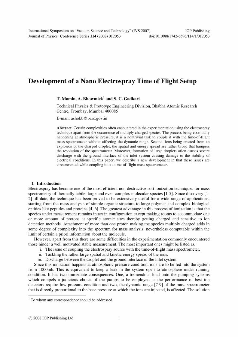
2. Description The development of the current setup described in the following is done keeping in mind to improve upon these three factors. Figure 1 shows the schematic layout of the setup. Ions are taken from atmosphere through four successive differential stages set by predetermined conductance paths C0, C1, C2 and C3 respectively [18]. C0 is the 250micron diameter inlet to the first stage coupled coaxially with C1 and C2 skimmers. The skimmers have same cone angle but with reducing diameter orifice and are constructed coaxially within a cylinder that might be grounded or floated to a potential level (figure 2). Pump S1 is connected between these skimmers. S0 and S1 are large capacity mechanical pumps whereas S2 and S3 are turbo-molecular drag stations of 250liters/sec. and 500liters/sec. respectively. C3 is the conductance path that separates the drift and detection zone from the sample injection zone and is pulsed at high voltage simultaneously with the extraction grid. The pressure levels at running condition in successive stages are as follows: Stage-1 (between C0 and C1)
International Symposium on “Vacuum Science and Technology” (IVS 2007) IOP PublishingJournal of Physics: Conference Series 114 (2008) 012053 doi:10.1088/1742-6596/114/1/012053
2
P1 ~ 10-1mb, Stage-2 (between C1 and C2) P2 ~ 10-2mb, Stage-3 (between C2 and C3) P3 ~ 10-4mb, Stage-4 (between C3 and detector) P4 ~ 10-7mb which is the safe limit for operation of the APTOF ion detector (Burle Electrooptics, USA) [19]. Even though a determination of ion intensities at successive stages is practically an involved task, skimming of the central flow definitely gives much higher central axis intensity of ions.
Figure 1 Schematic layout of the nano-electrospray time of flight setup with four successive differential stages.
Figure 2 The arrangement of the skimmers and the drift tube of the linear time of flight.
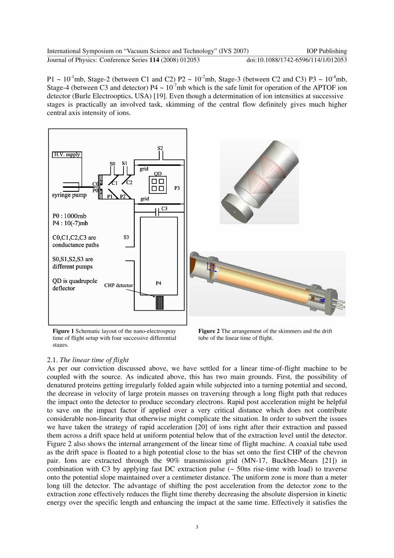
2.1. The linear time of flight As per our conviction discussed above, we have settled for a linear time-of-flight machine to be coupled with the source. As indicated above, this has two main grounds. First, the possibility of denatured proteins getting irregularly folded again while subjected into a turning potential and second, the decrease in velocity of large protein masses on traversing through a long flight path that reduces the impact onto the detector to produce secondary electrons. Rapid post acceleration might be helpful to save on the impact factor if applied over a very critical distance which does not contribute considerable non-linearity that otherwise might complicate the situation. In order to subvert the issues we have taken the strategy of rapid acceleration [20] of ions right after their extraction and passed them across a drift space held at uniform potential below that of the extraction level until the detector. Figure 2 also shows the internal arrangement of the linear time of flight machine. A coaxial tube used as the drift space is floated to a high potential close to the bias set onto the first CHP of the chevron pair. Ions are extracted through the 90% transmission grid (MN-17, Buckbee-Mears [21]) in combination with C3 by applying fast DC extraction pulse (~ 50ns rise-time with load) to traverse onto the potential slope maintained over a centimeter distance. The uniform zone is more than a meter long till the detector. The advantage of shifting the post acceleration from the detector zone to the extraction zone effectively reduces the flight time thereby decreasing the absolute dispersion in kinetic energy over the specific length and enhancing the impact at the same time. Effectively it satisfies the
International Symposium on “Vacuum Science and Technology” (IVS 2007) IOP PublishingJournal of Physics: Conference Series 114 (2008) 012053 doi:10.1088/1742-6596/114/1/012053
3
objective of introducing a reflector field within the path. Under a unique configuration the same effect might be achieved within a shorter path length compared to normal reflectron setup. This is further advantageous because a journey through shorter path also reduces the collision probability with background elements thereby contributing in enhancing the dynamic range of the spectrometer [7].
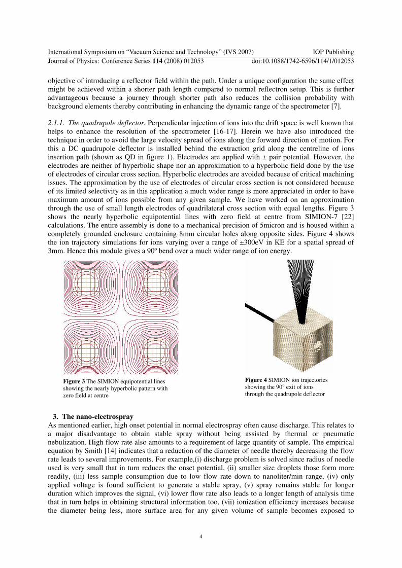
2.1.1. The quadrupole deflector. Perpendicular injection of ions into the drift space is well known that helps to enhance the resolution of the spectrometer [16-17]. Herein we have also introduced the technique in order to avoid the large velocity spread of ions along the forward direction of motion. For this a DC quadrupole deflector is installed behind the extraction grid along the centreline of ions insertion path (shown as QD in figure 1). Electrodes are applied with ± pair potential. However, the electrodes are neither of hyperbolic shape nor an approximation to a hyperbolic field done by the use of electrodes of circular cross section. Hyperbolic electrodes are avoided because of critical machining issues. The approximation by the use of electrodes of circular cross section is not considered because of its limited selectivity as in this application a much wider range is more appreciated in order to have maximum amount of ions possible from any given sample. We have worked on an approximation through the use of small length electrodes of quadrilateral cross section with equal lengths. Figure 3 shows the nearly hyperbolic equipotential lines with zero field at centre from SIMION-7 [22] calculations. The entire assembly is done to a mechanical precision of 5micron and is housed within a completely grounded enclosure containing 8mm circular holes along opposite sides. Figure 4 shows the ion trajectory simulations for ions varying over a range of ±300eV in KE for a spatial spread of 3mm. Hence this module gives a 90º bend over a much wider range of ion energy.
Figure 4 SIMION ion trajectories showing the 90° exit of ions through the quadrupole deflector
Figure 3 The SIMION equipotential lines showing the nearly hyperbolic pattern with zero field at centre
3. The nano-electrospray As mentioned earlier, high onset potential in normal electrospray often cause discharge. This relates to a major disadvantage to obtain stable spray without being assisted by thermal or pneumatic nebulization. High flow rate also amounts to a requirement of large quantity of sample. The empirical equation by Smith [14] indicates that a reduction of the diameter of needle thereby decreasing the flow rate leads to several improvements. For example,(i) discharge problem is solved since radius of needle used is very small that in turn reduces the onset potential, (ii) smaller size droplets those form more readily, (iii) less sample consumption due to low flow rate down to nanoliter/min range, (iv) only applied voltage is found sufficient to generate a stable spray, (v) spray remains stable for longer duration which improves the signal, (vi) lower flow rate also leads to a longer length of analysis time that in turn helps in obtaining structural information too, (vii) ionization efficiency increases because the diameter being less, more surface area for any given volume of sample becomes exposed to
International Symposium on “Vacuum Science and Technology” (IVS 2007) IOP PublishingJournal of Physics: Conference Series 114 (2008) 012053 doi:10.1088/1742-6596/114/1/012053
4
applied potential. Commercially available fused silica tubes ‘PicoTip’ with 30micron inner diameter from New Objective [23] has been extremely useful to serve this purpose in our measurement. Flow rates in nanoliters per minute could be achieved through the use of these needles suggesting the system to be referred as nanoelectrospray.
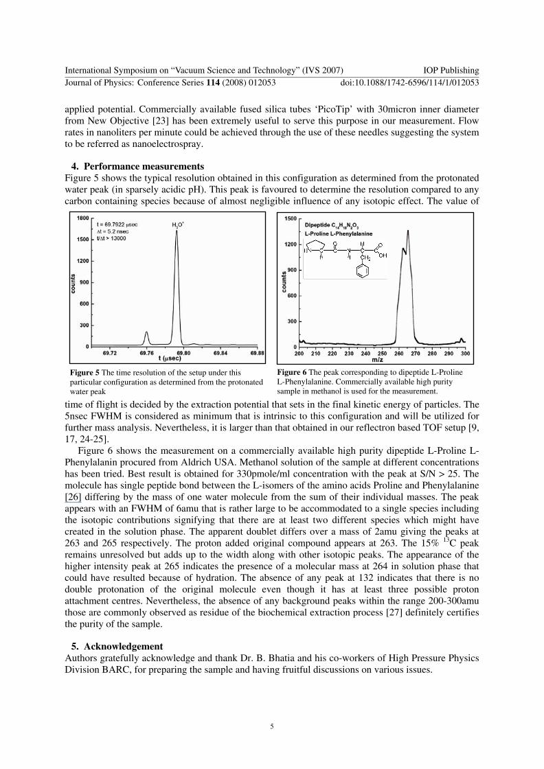
4. Performance measurements Figure 5 shows the typical resolution obtained in this configuration as determined from the protonated water peak (in sparsely acidic pH). This peak is favoured to determine the resolution compared to any carbon containing species because of almost negligible influence of any isotopic effect. The value of
time of flight is decided by the extraction potential that sets in the final kinetic energy of particles. The 5nsec FWHM is considered as minimum that is intrinsic to this configuration and will be utilized for further mass analysis. Nevertheless, it is larger than that obtained in our reflectron based TOF setup [9, 17, 24-25].
Figure 6 The peak corresponding to dipeptide L-Proline L-Phenylalanine. Commercially available high purity sample in methanol is used for the measurement.
Figure 5 The time resolution of the setup under this particular configuration as determined from the protonated water peak
Figure 6 shows the measurement on a commercially available high purity dipeptide L-Proline L-Phenylalanin procured from Aldrich USA. Methanol solution of the sample at different concentrations has been tried. Best result is obtained for 330pmole/ml concentration with the peak at S/N > 25. The molecule has single peptide bond between the L-isomers of the amino acids Proline and Phenylalanine [26] differing by the mass of one water molecule from the sum of their individual masses. The peak appears with an FWHM of 6amu that is rather large to be accommodated to a single species including the isotopic contributions signifying that there are at least two different species which might have created in the solution phase. The apparent doublet differs over a mass of 2amu giving the peaks at 263 and 265 respectively. The proton added original compound appears at 263. The 15% 13C peak remains unresolved but adds up to the width along with other isotopic peaks. The appearance of the higher intensity peak at 265 indicates the presence of a molecular mass at 264 in solution phase that could have resulted because of hydration. The absence of any peak at 132 indicates that there is no double protonation of the original molecule even though it has at least three possible proton attachment centres. Nevertheless, the absence of any background peaks within the range 200-300amu those are commonly observed as residue of the biochemical extraction process [27] definitely certifies the purity of the sample.
5. Acknowledgement Authors gratefully acknowledge and thank Dr. B. Bhatia and his co-workers of High Pressure Physics Division BARC, for preparing the sample and having fruitful discussions on various issues.
International Symposium on “Vacuum Science and Technology” (IVS 2007) IOP PublishingJournal of Physics: Conference Series 114 (2008) 012053 doi:10.1088/1742-6596/114/1/012053
5
References [1] Yamashita M and Fenn J B 1984 J. Physical Chemistry 88 p 4451; ibid 4671 [2] Fenn J B, Whitehouse C and Yamashita M 1985 US Patent No. 4542293 [3] Fenn J B, Mann M, Chin-Kai-Meng, Shek-Fu-Wong and Whitehouse C M 1989 Science
246 64-71 [4] Dole R B 1997 Electrospray ionization mass spectrometry- Fundamentals,
Instrumentation & applications (Chichester: John Willey) [5] Fenn J B 2003 Angew. Chem. Int. Ed. 42 3871-3894 [6] Pramanik B N, Ganguly A K and Gross M L (Eds.) 2002 Applied Electrospray
Mass Spectrometry, Practical Spectroscopy Series vol 32 (New York: Marcel Dekker) [7] Bergmann T and Bergmann Eva Martina 1996 US Patent No. 5496998 and 5543624 [8] Bhowmick A, Gadkari S C, Yakhmi J V and Sahni V C 2005 Bulletin of Indian Vacuum
Society 8 19-23 [9] Bhowmick A, Momin T and Gadkari S C, 2007 Asian J. Phys. 16 373-383 [10] Cotter R J 1997 Time of Flight Mass Spectrometry: Instrumentation and Applications
in Biological Research (Washington: American Chemical Society) pp 229-276 [11] Hayter J R, Robertson Duncan H L, Gaskell Simon J and Beynon Robert J 2003 Molecular
and Cellular Proteomics 2.2 85-95 [12] Bondarenko P V and Macfarlane R D 1997 Int. J. Mass Spectrometry and Ion Processes
160 241-258 [13] Lord Rayleigh 1882 Phil. Mag. 14 404 [14] Smith D P H 1986 IEEE Trans. Ind. Appl-IA 22 527 [15] Cotter R J 1997 Time of Flight Mass Spectrometry: Instrumentation and Applications
in Biological Research (Washington: American Chemical Society) pp 113-136 [16] Bergmann T, Goehlish H, Martin T P, Schaber H, 1990 Rev. Sci. Instrum. 61 2585, ibid
2592 [17] Bhowmick A, Carvalho W C J, Korgaonkar A V, Yakhmi J V and Sahni V C 2005
Int. J. Mod. Phys. B 19 2621-2626 [18] Dushman Saul 1955 Scientific Foundations of Vacuum Technique (New York: John Wiley
& Sons Inc.) [19] http://www.burle.com/advperfdet.htm[20] Payne Marvin J, Thonnard Norbert and Hurst George S 1987 US Patent No. 4694167 [21] Buckbee-Mears, A unit of BMC Industries Inc., 278 East 7th Street, St. Paul, Minnesota
55102 USA, http://www.bmcind.com[22] David A. Dhal 1999 SIMION 3D Ver. 7.00, Idaho National Engineering &
Environmental Laboratory [23] http://www.newobjective.com/products/tips_online_tips.html#silica[24] Bhowmick A, Gadkari S C, Yakhmi J V and Sahni V C 2005 BARC Newsletter,
Founders Day Special Issue No.261 61-71 [25] Bhowmick A, Korgaonkar A V, Carvalho W C J, Yakhmi J V and Sahni V C
2004 Proceedings, 11th International ISMAS Workshop on Mass Spectrometry, Eds. Aggarwal S K and Jaison P G 201-209
[26] Nelson D L and Cox M M 2007 Chapter 3, Lehninger Principles of biochemistry (New York: W.H.Freeman & Company) 75-115
[27] http://www.newobjective.com/downloads/technotes/PV-3.pdf
International Symposium on “Vacuum Science and Technology” (IVS 2007) IOP PublishingJournal of Physics: Conference Series 114 (2008) 012053 doi:10.1088/1742-6596/114/1/012053
6