Design, testing and optimization of aneutron radiography system based on aDeuterium–Deuterium...
13
1 23 Journal of Radioanalytical and Nuclear Chemistry An International Journal Dealing with All Aspects and Applications of Nuclear Chemistry ISSN 0236-5731 J Radioanal Nucl Chem DOI 10.1007/s10967-013-2729-y Design, testing and optimization of a neutron radiography system based on a Deuterium–Deuterium (D–D) neutron generator K. Bergaoui, N. Reguigui, C. K. Gary, J. T. Cremer, J. H. Vainionpaa & M. A. Piestrup
Transcript of Design, testing and optimization of aneutron radiography system based on aDeuterium–Deuterium...

1 23
Journal of Radioanalytical andNuclear ChemistryAn International Journal Dealing withAll Aspects and Applications of NuclearChemistry ISSN 0236-5731 J Radioanal Nucl ChemDOI 10.1007/s10967-013-2729-y
Design, testing and optimization of aneutron radiography system based on aDeuterium–Deuterium (D–D) neutrongenerator
K. Bergaoui, N. Reguigui, C. K. Gary,J. T. Cremer, J. H. Vainionpaa &M. A. Piestrup

1 23
Your article is protected by copyright and
all rights are held exclusively by Akadémiai
Kiadó, Budapest, Hungary. This e-offprint is
for personal use only and shall not be self-
archived in electronic repositories. If you wish
to self-archive your article, please use the
accepted manuscript version for posting on
your own website. You may further deposit
the accepted manuscript version in any
repository, provided it is only made publicly
available 12 months after official publication
or later and provided acknowledgement is
given to the original source of publication
and a link is inserted to the published article
on Springer's website. The link must be
accompanied by the following text: "The final
publication is available at link.springer.com”.
Design, testing and optimization of a neutron radiography systembased on a Deuterium–Deuterium (D–D) neutron generator
K. Bergaoui • N. Reguigui • C. K. Gary •
J. T. Cremer • J. H. Vainionpaa • M. A. Piestrup
Received: 6 March 2013
� Akademiai Kiado, Budapest, Hungary 2013
Abstract Simulations show that significant improvement
in imaging performance can be achieved through colli-
mator design for thermal and fast neutron radiography with
a laboratory neutron generator. The radiography facility
used in the measurements and simulations employs a fully
high-voltage-shielded, axial D–D neutron generator with a
radio frequency driven ion source. The maximum yield of
such generators is about 1010 fast neutrons per seconds
(E = 2.45 MeV). Both fast and thermal neutron images
were acquired with the generator and a Charge Coupled
Devices camera. To shorten the imaging time and decrease
the noise from gamma radiation, various collimator designs
were proposed and simulated using Monte Carlo N-Particle
Transport Code (MCNPX 2.7.0). Design considerations
included the choice of material, thickness, position and
aperture for the collimator. The simulation results and
optimal configurations are presented.
Keywords Thermal neutron radiography � Fast
neutron radiography � D–D Neutron generator �Monte Carlo simulation (MCNPX) � Collimator �CCD camera
Introduction
Neutron radiography (NR) is an important tool in non-
destructive examination, which has been adopted in
industrial, medical, metallurgical, nuclear and explosive
inspections [1]. From the 1990s to the present day, neutron
radiography imaging systems and the methods used to
analyse the images have continued to advance [2]. It offers
some very explicit advantages over c-ray (or X-ray)
imaging.
Neutron cross-sections, being almost independent of the
atomic number (Z) of the material, result in neutron
imaging being capable of discerning materials of similar Z
and/or low Z materials even when they are present inside
high Z surroundings. Also, hydrogen, which is a very
important element in determining the properties of mate-
rials, can be imaged even if present in minute quantities
due to its significant neutron scattering and absorption
cross sections. Neutrons also offer the advantage of being
able to differentiate between isotopes of an element. Fur-
thermore, radioactive materials which cannot be imaged
using photons due to fogging of the detector can be imaged
with neutrons using the transfer technique [3].
The neutron radiography facility discussed consists of
three major components: a neutron source, neutron colli-
mator and image processing system (Fig. 1). The neutron
collimator is a critical component in neutron radiography
because it affects directly the characteristics of the neutron
beam and the quality of the radiographic image [4, 5].
Thermal and fast neutron images were acquired using a D–D
neutron generator and image intensified Charge Coupled
Devices (CCD) camera focused on a neutron sensitive
scintillator. While these images demonstrate the ability of
laboratory based neutron radiography, they could benefit
from decreased imaging time and reduced background. The
K. Bergaoui (&) � N. Reguigui
Unite de Recherche ‘‘Maıtrise et Developpement des Techniques
Nucleaires a Caractere Pacifique’’, National Center of Nuclear
Sciences and Technologies, Technopole Sidi Thabet, BP 72,
2020 Tunis, Tunisia
e-mail: [email protected];
C. K. Gary � J. T. Cremer � J. H. Vainionpaa � M. A. Piestrup
Adelphi Technology Inc., 2003 East Bayshore Road, Redwood
City, CA 94063, USA
123
J Radioanal Nucl Chem
DOI 10.1007/s10967-013-2729-y
Author's personal copy

neutron flux, spatial collimation and neutron to gamma
ration (neutron/gamma) can be improved through collima-
tion. A range of collimator designs were considered and
modelled using Monte Carlo code Version MCNP 2.7.0 [6].
Materials and methods
Neutron generator D–D
The deuterium–deuterium 2.5 MeV neutron generator
developed by Adelphi Technology Inc. [7], uses a deuteron
beam produced with radio frequency (RF) plasma and
acceleration voltage in the range from 100 to 140 keV
(Fig. 2). The deuterium ion beam was directed at the tita-
nium-covered cathode, which adsorbs deuterons and works
as a deuterium target [8]. The neutron source operates in
continuous mode, producing up to 1010 neutrons per sec-
ond, though an intensity of 109 n/s was used in the mea-
surements presented. Due to the physics of D–D reaction,
the generated neutrons have a well-defined energy maxi-
mum close to 2.5 MeV, slightly dependent on the emission
angle. The energy and this anisotropy were included in the
MCNP simulations for the moderator design. The effective
fast neutron source size is 2–3 cm [9].
The CCD detector
A camera box allows the Stanford Photonics CCD camera
and its electronics to be placed outside the direct neutron
beam exposure. A scintillator is mounted on the inner
surface of the 3 mm wall of the box. A mirror reflects light
from the scintillator out of the neutron/gamma path to a
5 cm diameter lens with f-stop equal to 1.0. The lens
focuses the light onto the dual microchannel plate (MCP).
The dual MCP light amplifier and a coupled CCD chip are
thermoelectrically cooled to -20 �C. A tapered fiber optic
directs the amplified light to the CCD sensor. The dual
MCP amplifier produces high photon gains up to 106 at a
very low dark count levels of 1 or 2 electron counts per
frame at 15 frames per second. In our experiments the dual
MCP amplifier was set to an overall photon amplification
gain of 5 9 105. The Stanford Photonics CCD camera uses
a Sony XX285 scientific grade image sensor, which has a
full frame pixel count of 1,380 by 1,024 K, where the
pixels are 6.47 microns square. The 1.6–1 reducing fiber
optic taper creates an effective square pixel with 10.35-lm
sides at the input image plane. The dual MCP image
intensifier has a 50 line-pairs/mm resolution, which cor-
responds to the effective pixel size. An image is created by
summing multiple frames. The short 15-s frame times
reduce the dark count accumulation to 1 or 2 dark counts
per frame, and the data acquisition software further reduces
Fig. 1 The principle of a
neutron radiographic facility (D:
diameter of the aperture next the
neutron generator and D0:
diameter of the aperture next to
the image plane)
Fig. 2 The D–D-110 neutron generator
J Radioanal Nucl Chem
123
Author's personal copy
noise by filtering out cosmic ray noise and spot noise from
each of the incoming frames.
The radiography system
The design of the collimator will directly affect funda-
mental properties of the resulting neutron beam. The design
choices that are made must recognize the relationship
between all of the various components and features. The
key issues in the design of any facility for neutron imaging
include the neutron flux and L/D ratio [10].
Collimator parameters
The parameters most important to the quality of the image
data are the ratio of the collimator length to diameter of the
aperture (Collimation Ratio (L/D)) [11], Beam Divergence
[11], Gamma content [12] and the thermal neutron content
(TNC) [10].
Collimator design
Geometric Shape of the Collimator: The divergent beam
collimator is commonly used after the conclusion of Barton
in 1967 that divergent beam collimators produce highest
resolution [13]. Among them the most commonly used
physical form is a truncated cone or pyramid [11]. In this
study, we used a divergent beam collimator.
Materials of the Walls and their lining: The most
important item of each collimator is its lining. Unlike
charged particles, neutrons cannot be focused [11]. Hence
the neutron beam must be collimated by suitable lining in
the collimator. To prevent stray neutrons from reaching the
radiographed object and to reduce the scattering of neu-
trons within the collimator, the lining must be made with
neutron absorbing material. Some materials suitable for
this purpose are: boron, cadmium, dysprosium, europium,
gadolinium and indium [11]. The effectiveness of these
materials varies with the neutron energy spectrum. The use
of boron is recommended because it gets less activated,
which facilitates maintenance of the collimator [11].
Generally boron in the form of Boral (B4C) is used in the
collimator [13]. Borated Polyethylene (PE-B) (2.5 cm) and
Lead (1 cm) are chosen as our collimator wall material.
Gamma and Neutron Filters: To filter out the gamma
rays from the beam, Lead (Pb) and Bismuth (Bi) filters are
used [11]. Neutron filters are also required to filter out the
fast neutrons from the beam. Single crystal sapphire
(Al2O3), silicon, quartz and Bismuth act as fast neutron
filters [14, 15]. Sapphire (Al2O3) is an effective fast-
neutron filter because its transmission for neutrons of
wavelengths less than 0.04-nm (500 MeV) is less than 3 %
for a filter thickness of 100-mm [14]. For gamma filter we
used Lead for its effectiveness in attenuating the gamma
and its durability. Bismuth may be used as the gamma
filter; it is usually more expensive than Lead.
Experimental neutron radiography configuration
In this experimental step, a D–D neutron generator was
used to illuminate a set of objects, and a scintillator cou-
pled to a CCD camera was used to record thermal and fast
neutron images. The generator was housed in a polyeth-
ylene block 61 cm high and 61 cm deep. A 15-cm 9 10-
cm square opening extended from the wall of the generator
to the edge of the polyethylene block with a length of
20 cm. This opening served as the collimation for the
experiment.
The set of objects that were imaged is shown in Fig. 3.
The objects were chosen to provide varying contrast for
fast and thermal neutrons as well as gammas and X-rays. A
4-step lead phantom was used to provide contrast for
X-rays and gammas. Polyethylene blocks (2.5 and 1.3 cm
thick) provide contrast for fast and thermal neutrons.
Beryllium, in the form of a biconcave lens, has a cross
section that is relatively larger for fast neutrons. Electrical
tape, due to the presence of hydrogen as well as higher Z
materials has good contrast for both thermal neutrons and
gammas. The smaller 6.25 and 12.5-mm steps of the lead
were eclipsed the bottom half of roll of black electrical tape
The 2.5 cm and 5 cm thick portion of the 4-step lead
phantom covers a 1.25 cm thick polyethylene plate. On top
of the lead phantom and eclipsing the 1.25 cm thick
polyethylene is a 2.5 cm thickness of the 4-step silicon
stacked-chip phantom. Silicon has a low cross section for
all the radiation measured, but is significantly more sen-
sitive to photons than neutrons. This variety of materials,
and the use of know thicknesses provides qualitative
information similar to that from more expensive calibrated
beam purity and sensitivity indicators.
In the fast neutron radiography we placed the object at a
distance of 1.52 meter from the D–D generator. A 4-cm
thick BC-408 plastic scintillator was placed immediately
behind the objects to convert the fast neutron signal to
visible light imaged by the CCD camera. For the thermal
neutron radiography we placed 2.5 cm of polyethylene
before the object to moderate the fast neutrons and the
10 cm 9 10 cm by 5 mm thick plastic scintillator on the
inner wall of the camera box was replaced by a
10 cm 9 10 cm by 100 micron thick gadolinium-based,
thermal neutron phosphor, Gd2O2S:Tb, which produced
light upon thermal neutron capture by the gadolinium.
J Radioanal Nucl Chem
123
Author's personal copy

Simulation model
Thermal neutron radiography
Simulations of the thermal neutron radiography facility
were implemented in four stages: In the first stage (1), we
tested the best position of the divergent collimator (the
length of the collimator L = 50 cm, diameter of the
aperture D = 1 cm and the aperture next to the image
plane D0 = 12 cm), from the neutron generator with a
variable thickness of polyethylene, between the neutron
generator and the aperture of the collimator (Fig. 4).
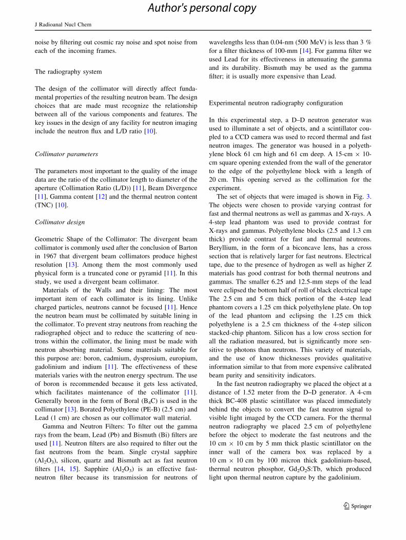
In the second stage (2), different configurations were
considered to obtain the maximum thermal neutron flux
(fth) at the image plane (Fig. 5), the first configuration was
composed of a divergent collimator (L = 50 cm,
D = 1 cm and D0 = 24 cm) and walls made of 2.5-cm
deep (PE-B) covered by 1 cm of lead. The walls started
15 cm from the neutron generator. The second configura-
tion was similar as in the first with walls starting 40.35 cm
from the neutron generator. The third configuration was
composed of a divergent collimator (L = 50 cm,
D = 1 cm and D0 = 12 cm), 2 cm of Polyethylene
between the aperture of collimator and the neutron gener-
ator and the walls made of (PE-B) with depth 2.5 cm
covered by 1 cm of Lead. The fourth configuration inclu-
ded two collimators. The first was a conic collimator with a
length of 13 and radii 4 and 0.5 cm [16]. The larger radii
was close to the source, with 2 cm of Polyethylene between
the aperture of collimator and the neutron generator. The
second was a divergent collimator (L = 50 cm, D = 1 cm
and D0 = 12 cm). The walls were made of (PE-B) with
depth 2.5 cm covered by 1 cm of Lead.
In the third stage (3), we studied the influence of gamma
and neutron filters on the parameters associated with neu-
tron radiography. In our study, we tested sapphire (Al2O3)
for fast neutron filtering and lead for gamma filtering
(Figs. 6, 7).
In the fourth stage (4), we fixed the best configuration
from the last stages and we calculated fth, TNC and (n/c)
parameter with a variable collimator length (L), diameter
of the aperture (D) and diameter of the aperture next to the
image plan (D0).
Fast neutron radiography
In the fast neutron radiography facility the quality of the
NR image is determined by the collimator ratio (L/D) in a
similar way as in the case of thermal neutron flux. The
imaging quality of a fast neutron radiography facility
would be further characterized by the beam quality profile,
described by the number of uncollided fast neutrons that
reach the detector position within the neutron beam [16].
The fast neutron radiography facility was examined in two
stages: In the first stage (1), different configurations are
considered to obtain the maximum fast neutron flux at the
image plane (Fig. 7). The configurations of the collimator
are shown in the Fig. 8. The first configuration was com-
posed by divergent collimator (L = 50 cm, D = 1 cm and
D0 = 12 cm). The second configuration was composed by
divergent collimator (L = 50 cm, D = 1 cm and
D0 = 12 cm) and the walls were made of (PE-B) with
depth of 3 cm covered by 1 cm of lead. Configuration # 3
we used divergent collimator and the walls are made of
iron with depth 3 cm covered by 1 cm of Lead. In the
second stage (2), we calculated fast neutron flux, and un-
collided fast neutrons parameters with a variable collimator
length, diameter of the aperture D and diameter with
D0 = 24 cm.
Results and discussion
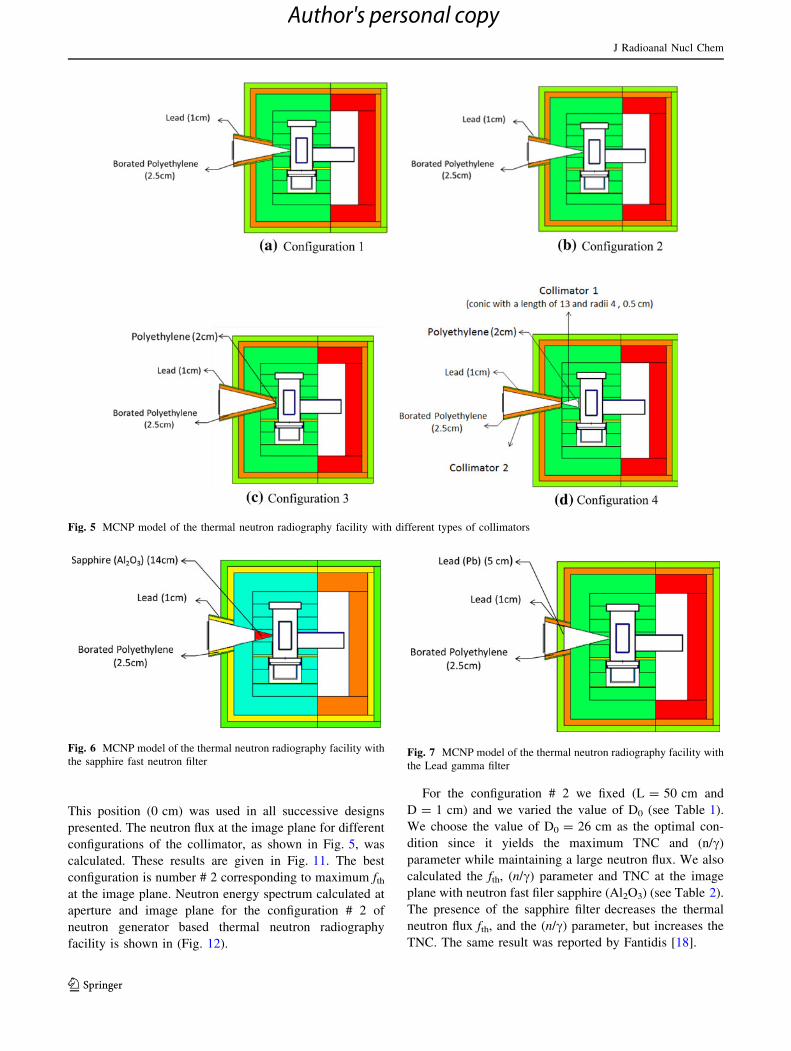
A thermal neutron image of the assorted objects was
acquired with a 17 min exposure using an intensity of 109
n/s, and is shown in Fig. 9a. The fast neutron image shown
in Fig. 9b was acquired in a longer 67 min exposure. The
relatively long image times can be shortened by using the
full output of the generator (which requires greater
shielding for personnel safety), but improvements to the
geometry can reduce exposure times without increasing
radiation dose. Importantly, significant degradation of the
image quality was observed due to gamma radiation
Fig. 3 Set of objects that are imaged by thermal and fast neutron
radiography. Assorted objects were 4-step lead and silicon-chip Rose
phantoms, beryllium biconcave neutron lens, black electrical tape,
1.25 and 2.5 cm polyethylene blocks
J Radioanal Nucl Chem
123
Author's personal copy

background [17]. The thermal neutron image shows
absorption of some of the signal by the lead, and the
contrast for the tape, which contains higher Z elements in
addition to hydrogen is equal to or greater than that for the
polyethylene, while one would expect the polyethylene to
have greater contrast for a pure thermal beam. Significant
neutron radiation is present as can be seen from the contrast
from the polyethylene and beryllium, both of which have
very small gamma absorption, especially in comparison to
the lead. Similarly, in the fast neutron image, gammas are
indicated by lead contrast, but the presence of fast neutrons
can be seen from the beryllium and especially silicon
contrast. Some of the contrast from the polyethylene and
tape could be due to thermal neutrons.
A better collimator system would reduce the background
noise and improve the Single/Noise radio (SNR) and
thereby improve resolution and contrast. Thus, the mod-
eling effort concentrated on increasing the neutron flux and
improving the n/c ratio to reduce quantum noise and
gamma background.
The goals of the computer modeling of the fast and
thermal neutron radiography system were to optimized
useful neutron flux for a given source intensity, provide a
large L/D for good resolution, and minimize the stray
neutron and gamma background, while providing sufficient
shielding for radiation protection. Polyethylene and paraf-
fin were used for neutron shielding and lead for gamma
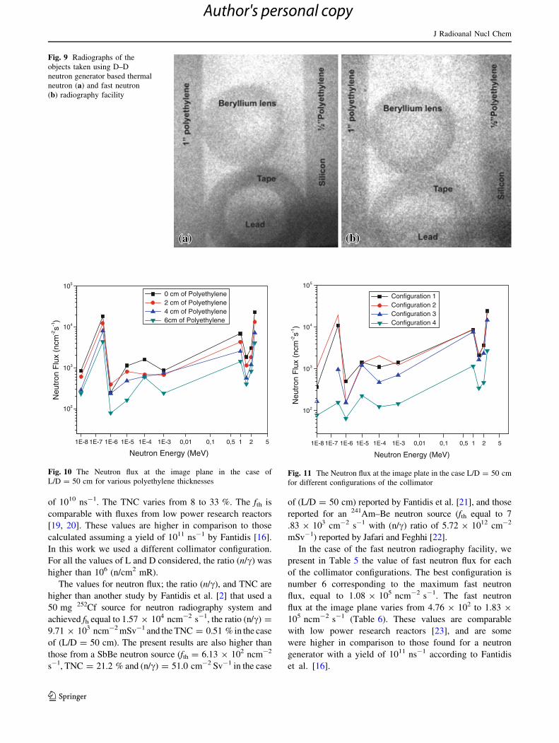
shielding. For the setup shown in Fig. 4 the neutron flux at
the image plane in the case (L = 50 cm, D = 1 cm and
D0 = 22 cm) as a function of collimator position is given
in Fig. 10. The maximum fth occurs for a (0 cm) of poly-
ethylene between the aperture and the neutron generator.
Fig. 4 MCNP model of the D–D generator with moderator, shielding and collimator for various polyethylene thicknesses between the collimator
and the generator
J Radioanal Nucl Chem
123
Author's personal copy
This position (0 cm) was used in all successive designs
presented. The neutron flux at the image plane for different
configurations of the collimator, as shown in Fig. 5, was
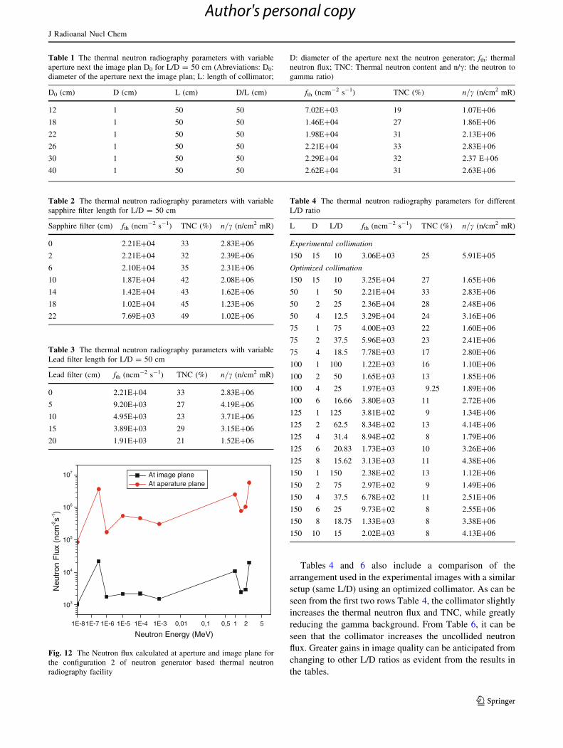
calculated. These results are given in Fig. 11. The best
configuration is number # 2 corresponding to maximum fthat the image plane. Neutron energy spectrum calculated at
aperture and image plane for the configuration # 2 of
neutron generator based thermal neutron radiography
facility is shown in (Fig. 12).
For the configuration # 2 we fixed (L = 50 cm and
D = 1 cm) and we varied the value of D0 (see Table 1).
We choose the value of D0 = 26 cm as the optimal con-
dition since it yields the maximum TNC and (n/c)
parameter while maintaining a large neutron flux. We also
calculated the fth, (n/c) parameter and TNC at the image
plane with neutron fast filer sapphire (Al2O3) (see Table 2).
The presence of the sapphire filter decreases the thermal
neutron flux fth, and the (n/c) parameter, but increases the
TNC. The same result was reported by Fantidis [18].
Fig. 5 MCNP model of the thermal neutron radiography facility with different types of collimators
Fig. 6 MCNP model of the thermal neutron radiography facility with
the sapphire fast neutron filterFig. 7 MCNP model of the thermal neutron radiography facility with
the Lead gamma filter
J Radioanal Nucl Chem
123
Author's personal copy

For the presence of lead as a gamma filter at the colli-
mator, the thermal neutron flux (fth), TNC and the (n/c)
parameter decrease (Table 3), except in the case where the
thickness of lead was equal to 5 cm, which resulted in a
slight increase in (n/c) parameter.
In the optimization process of the collimator, the colli-
mator length (L) and the inlet aperture (D) were varied in
order to attain the values for which the maximum thermal
flux is obtained in the image plane. These results are given
in Table 4. The object to detector distance was considered
to be 0.5 cm. An energy boundary of 0.01–0.3 eV was used
to define the thermal neutron flux.
The fth would vary from 2.38 9 102 up to 3.29 9 104
n cm-2 s-1 for a maximum neutron yield by the generator
3 cm B-PE + 1cm of lead 3 cm of iron+ 1cm of lead
(a) Configuration 1 (b) Configuration 2 (c) Configuration 3
6 cm of iron + 1cm of lead 8 cm of iron + 1cm of lead 8 cm of iron + 3 cm B-PE+ 1cm of lead
(d) Configuration 4 (e) Configuration 5 (f)
(g) (h) (i)
Configuration 6
8 cm of Tungsten + 3 cm B-PE 6 cm of iron + 3 cm B-PE 6 cm of iron + 3 cm B-PE+ 1cm of lead 1cm of lead + 1cm of lead
Configuration 7 Configuration 8 Configuration 9
Fig. 8 MCNP model of the fast neutron radiography facility with different types of collimators
J Radioanal Nucl Chem
123
Author's personal copy
of 1010 ns-1. The TNC varies from 8 to 33 %. The fth is
comparable with fluxes from low power research reactors
[19, 20]. These values are higher in comparison to those
calculated assuming a yield of 1011 ns-1 by Fantidis [16].
In this work we used a different collimator configuration.
For all the values of L and D considered, the ratio (n/c) was
higher than 106 (n/cm2 mR).
The values for neutron flux; the ratio (n/c), and TNC are
higher than another study by Fantidis et al. [2] that used a
50 mg 252Cf source for neutron radiography system and
achieved fh equal to 1.57 9 104 ncm-2 s-1, the ratio (n/c) =
9.71 9 103 ncm-2 mSv-1 and the TNC = 0.51 % in the case
of (L/D = 50 cm). The present results are also higher than
those from a SbBe neutron source (fth = 6.13 9 102 ncm-2
s-1, TNC = 21.2 % and (n/c) = 51.0 cm-2 Sv-1 in the case
of (L/D = 50 cm) reported by Fantidis et al. [21], and those
reported for an 241Am–Be neutron source (fth equal to 7
.83 9 103 cm-2 s-1 with (n/c) ratio of 5.72 9 1012 cm-2
mSv-1) reported by Jafari and Feghhi [22].
In the case of the fast neutron radiography facility, we
present in Table 5 the value of fast neutron flux for each
of the collimator configurations. The best configuration is
number 6 corresponding to the maximum fast neutron
flux, equal to 1.08 9 105 ncm-2 s-1. The fast neutron
flux at the image plane varies from 4.76 9 102 to 1.83 9
105 ncm-2 s-1 (Table 6). These values are comparable
with low power research reactors [23], and are some
were higher in comparison to those found for a neutron
generator with a yield of 1011 ns-1 according to Fantidis
et al. [16].
Fig. 9 Radiographs of the
objects taken using D–D
neutron generator based thermal
neutron (a) and fast neutron
(b) radiography facility
1E-8 1E-7 1E-6 1E-5 1E-4 1E-3 0,01 0,1 0,5 1 2 5
102
103
104
105
Neu
tron
Flu
x (n
cm-2s-1
)
Neutron Energy (MeV)
0 cm of Polyethylene 2 cm of Polyethylene 4 cm of Polyethylene 6cm of Polyethylene
Fig. 10 The Neutron flux at the image plane in the case of
L/D = 50 cm for various polyethylene thicknesses
1E-8 1E-7 1E-6 1E-5 1E-4 1E-3 0,01 0,1 0,5 1 2 5
102
103
104
105
Neu
tron
Flu
x (n
cm-2s-1
)
Neutron Energy (MeV)
Configuration 1 Configuration 2 Configuration 3 Configuration 4
Fig. 11 The Neutron flux at the image plate in the case L/D = 50 cm
for different configurations of the collimator
J Radioanal Nucl Chem
123
Author's personal copy
Tables 4 and 6 also include a comparison of the
arrangement used in the experimental images with a similar
setup (same L/D) using an optimized collimator. As can be
seen from the first two rows Table 4, the collimator slightly
increases the thermal neutron flux and TNC, while greatly
reducing the gamma background. From Table 6, it can be
seen that the collimator increases the uncollided neutron
flux. Greater gains in image quality can be anticipated from
changing to other L/D ratios as evident from the results in
the tables.
1E-81E-7 1E-6 1E-5 1E-4 1E-3 0,01 0,1 0,5 1 2 5
103
104
105
106
107
Neu
tron
Flu
x (n
cm-2s-1
)
Neutron Energy (MeV)
At image plane At aperature plane
Fig. 12 The Neutron flux calculated at aperture and image plane for
the configuration 2 of neutron generator based thermal neutron
radiography facility
Table 1 The thermal neutron radiography parameters with variable
aperture next the image plan D0 for L/D = 50 cm (Abreviations: D0:
diameter of the aperture next the image plan; L: length of collimator;
D: diameter of the aperture next the neutron generator; fth: thermal
neutron flux; TNC: Thermal neutron content and n/c: the neutron to
gamma ratio)
D0 (cm) D (cm) L (cm) D/L (cm) fth (ncm-2 s-1) TNC (%) n=c (n/cm2 mR)
12 1 50 50 7.02E?03 19 1.07E?06
18 1 50 50 1.46E?04 27 1.86E?06
22 1 50 50 1.98E?04 31 2.13E?06
26 1 50 50 2.21E?04 33 2.83E?06
30 1 50 50 2.29E?04 32 2.37 E?06
40 1 50 50 2.62E?04 31 2.63E?06
Table 2 The thermal neutron radiography parameters with variable
sapphire filter length for L/D = 50 cm
Sapphire filter (cm) fth (ncm-2 s-1) TNC (%) n=c (n/cm2 mR)
0 2.21E?04 33 2.83E?06
2 2.21E?04 32 2.39E?06
6 2.10E?04 35 2.31E?06
10 1.87E?04 42 2.08E?06
14 1.42E?04 43 1.62E?06
18 1.02E?04 45 1.23E?06
22 7.69E?03 49 1.02E?06
Table 3 The thermal neutron radiography parameters with variable
Lead filter length for L/D = 50 cm
Lead filter (cm) fth (ncm-2 s-1) TNC (%) n=c (n/cm2 mR)
0 2.21E?04 33 2.83E?06
5 9.20E?03 27 4.19E?06
10 4.95E?03 23 3.71E?06
15 3.89E?03 29 3.15E?06
20 1.91E?03 21 1.52E?06
Table 4 The thermal neutron radiography parameters for different
L/D ratio
L D L/D fth (ncm-2 s-1) TNC (%) n=c (n/cm2 mR)
Experimental collimation
150 15 10 3.06E?03 25 5.91E?05
Optimized collimation
150 15 10 3.25E?04 27 1.65E?06
50 1 50 2.21E?04 33 2.83E?06
50 2 25 2.36E?04 28 2.48E?06
50 4 12.5 3.29E?04 24 3.16E?06
75 1 75 4.00E?03 22 1.60E?06
75 2 37.5 5.96E?03 23 2.41E?06
75 4 18.5 7.78E?03 17 2.80E?06
100 1 100 1.22E?03 16 1.10E?06
100 2 50 1.65E?03 13 1.85E?06
100 4 25 1.97E?03 9.25 1.89E?06
100 6 16.66 3.80E?03 11 2.72E?06
125 1 125 3.81E?02 9 1.34E?06
125 2 62.5 8.34E?02 13 4.14E?06
125 4 31.4 8.94E?02 8 1.79E?06
125 6 20.83 1.73E?03 10 3.26E?06
125 8 15.62 3.13E?03 11 4.38E?06
150 1 150 2.38E?02 13 1.12E?06
150 2 75 2.97E?02 9 1.49E?06
150 4 37.5 6.78E?02 11 2.51E?06
150 6 25 9.73E?02 8 2.55E?06
150 8 18.75 1.33E?03 8 3.38E?06
150 10 15 2.02E?03 8 4.13E?06
J Radioanal Nucl Chem
123
Author's personal copy
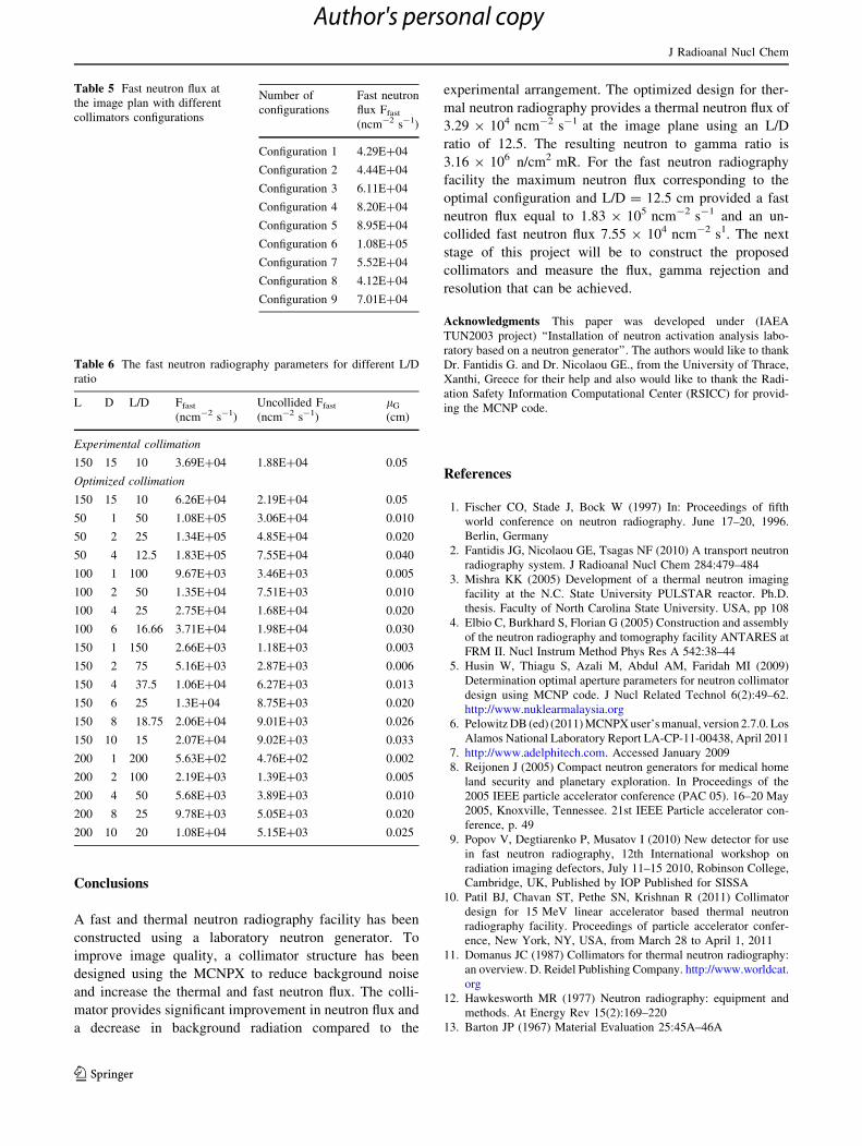
Conclusions
A fast and thermal neutron radiography facility has been
constructed using a laboratory neutron generator. To
improve image quality, a collimator structure has been
designed using the MCNPX to reduce background noise
and increase the thermal and fast neutron flux. The colli-
mator provides significant improvement in neutron flux and
a decrease in background radiation compared to the
experimental arrangement. The optimized design for ther-
mal neutron radiography provides a thermal neutron flux of
3.29 9 104 ncm-2 s-1 at the image plane using an L/D
ratio of 12.5. The resulting neutron to gamma ratio is
3.16 9 106 n/cm2 mR. For the fast neutron radiography
facility the maximum neutron flux corresponding to the
optimal configuration and L/D = 12.5 cm provided a fast
neutron flux equal to 1.83 9 105 ncm-2 s-1 and an un-
collided fast neutron flux 7.55 9 104 ncm-2 s1. The next
stage of this project will be to construct the proposed
collimators and measure the flux, gamma rejection and
resolution that can be achieved.
Acknowledgments This paper was developed under (IAEA
TUN2003 project) ‘‘Installation of neutron activation analysis labo-
ratory based on a neutron generator’’. The authors would like to thank
Dr. Fantidis G. and Dr. Nicolaou GE., from the University of Thrace,
Xanthi, Greece for their help and also would like to thank the Radi-
ation Safety Information Computational Center (RSICC) for provid-
ing the MCNP code.
References
1. Fischer CO, Stade J, Bock W (1997) In: Proceedings of fifth
world conference on neutron radiography. June 17–20, 1996.
Berlin, Germany
2. Fantidis JG, Nicolaou GE, Tsagas NF (2010) A transport neutron
radiography system. J Radioanal Nucl Chem 284:479–484
3. Mishra KK (2005) Development of a thermal neutron imaging
facility at the N.C. State University PULSTAR reactor. Ph.D.
thesis. Faculty of North Carolina State University. USA, pp 108
4. Elbio C, Burkhard S, Florian G (2005) Construction and assembly
of the neutron radiography and tomography facility ANTARES at
FRM II. Nucl Instrum Method Phys Res A 542:38–44
5. Husin W, Thiagu S, Azali M, Abdul AM, Faridah MI (2009)
Determination optimal aperture parameters for neutron collimator
design using MCNP code. J Nucl Related Technol 6(2):49–62.
http://www.nuklearmalaysia.org
6. Pelowitz DB (ed) (2011) MCNPX user’s manual, version 2.7.0. Los
Alamos National Laboratory Report LA-CP-11-00438, April 2011
7. http://www.adelphitech.com. Accessed January 2009
8. Reijonen J (2005) Compact neutron generators for medical home
land security and planetary exploration. In Proceedings of the
2005 IEEE particle accelerator conference (PAC 05). 16–20 May
2005, Knoxville, Tennessee. 21st IEEE Particle accelerator con-
ference, p. 49
9. Popov V, Degtiarenko P, Musatov I (2010) New detector for use
in fast neutron radiography, 12th International workshop on
radiation imaging defectors, July 11–15 2010, Robinson College,
Cambridge, UK, Published by IOP Published for SISSA
10. Patil BJ, Chavan ST, Pethe SN, Krishnan R (2011) Collimator
design for 15 MeV linear accelerator based thermal neutron
radiography facility. Proceedings of particle accelerator confer-
ence, New York, NY, USA, from March 28 to April 1, 2011
11. Domanus JC (1987) Collimators for thermal neutron radiography:
an overview. D. Reidel Publishing Company. http://www.worldcat.
org
12. Hawkesworth MR (1977) Neutron radiography: equipment and
methods. At Energy Rev 15(2):169–220
13. Barton JP (1967) Material Evaluation 25:45A–46A
Table 5 Fast neutron flux at
the image plan with different
collimators configurations
Number of
configurations
Fast neutron
flux Ffast
(ncm-2 s-1)
Configuration 1 4.29E?04
Configuration 2 4.44E?04
Configuration 3 6.11E?04
Configuration 4 8.20E?04
Configuration 5 8.95E?04
Configuration 6 1.08E?05
Configuration 7 5.52E?04
Configuration 8 4.12E?04
Configuration 9 7.01E?04
Table 6 The fast neutron radiography parameters for different L/D
ratio
L D L/D Ffast
(ncm-2 s-1)
Uncollided Ffast
(ncm-2 s-1)
lG
(cm)
Experimental collimation
150 15 10 3.69E?04 1.88E?04 0.05
Optimized collimation
150 15 10 6.26E?04 2.19E?04 0.05
50 1 50 1.08E?05 3.06E?04 0.010
50 2 25 1.34E?05 4.85E?04 0.020
50 4 12.5 1.83E?05 7.55E?04 0.040
100 1 100 9.67E?03 3.46E?03 0.005
100 2 50 1.35E?04 7.51E?03 0.010
100 4 25 2.75E?04 1.68E?04 0.020
100 6 16.66 3.71E?04 1.98E?04 0.030
150 1 150 2.66E?03 1.18E?03 0.003
150 2 75 5.16E?03 2.87E?03 0.006
150 4 37.5 1.06E?04 6.27E?03 0.013
150 6 25 1.3E?04 8.75E?03 0.020
150 8 18.75 2.06E?04 9.01E?03 0.026
150 10 15 2.07E?04 9.02E?03 0.033
200 1 200 5.63E?02 4.76E?02 0.002
200 2 100 2.19E?03 1.39E?03 0.005
200 4 50 5.68E?03 3.89E?03 0.010
200 8 25 9.78E?03 5.05E?03 0.020
200 10 20 1.08E?04 5.15E?03 0.025
J Radioanal Nucl Chem
123
Author's personal copy

14. Mildner DFR, Arif M, Stone CA (1993) Neutron transmission of
single crystal sapphire filters. J Appl Cryst 26:438–447
15. Adib M, Kilany M (2003) On the use of Bismuth as a neutron
filter. Radiat Phys Chem 66:81–88
16. Fantidis JG, Nicolaou GE, Tsagas NF (2010) Optimization study
of a transportable neutron radiography unit based on a compact
neutron generator. Nucl Instrum Method Phys Res A 618:331–335
17. Cremer JT, Williams DL, Gary CK, Piestrup MA, Faber DR,
Fuller MJ, Vainionpaa JH, Apodaca M, Pantell RH, Feinstein J
(2012) Large area imaging of hydrogenous materials using fast
neutrons from a DD fusion. Nucl Instrum Method Phys Res A
675:51–55
18. Fantidis JG (2012) A study of a transportable thermal neutron
radiography unit based on a compact RFI linac. J Radioanal Nucl
Chem 293:95–101
19. Zawisky M, Hameed F, Dyrnjaja E, Springer J (2008) Digitized
neutron imaging with high spatial resolution at a low power
research reactor: I. Analysis of detector performance. Nucl In-
strum Method Phys Res A 587:342–349
20. Chankow N, Punnachaiya S, Wonglee S (2010) Neutron radi-
ography using neutron imagingplate. Appl Radiat Isot 68:662
21. Fantidis JG, Nicolaou GE, Tsagas NF (2009) A transportable
neutron radiography system based on a SbBe neutron source.
Nucl Instrum Method Phy Res A 606:806–810
22. Jafari H, Feghhi SAH (2012) Design and simulation of neutron
radiography system based on 241Am–Be source. Radiat Phys
Chem 81:506–511
23. Bucherl T, Kutlar E, Von Gostomski C L, Calzada E, Pfister G,
Koch D (2004) Radiography and tomography using fission neu-
trons at FRM-II. Appl Radiat Isot 61:537
J Radioanal Nucl Chem
123
Author's personal copy