history of dental radiography: evolution of 2d and 3d imaging ...
43
MEDICAL PHYSICS INTERNATIONAL Journal 235 HISTORY OF DENTAL RADIOGRAPHY: EVOLUTION OF 2D AND 3D IMAGING MODALITIES R. Pauwels 1 1 Aarhus Institute of Advanced Studies, Aarhus University, Aarhus, Denmark Abstract— Dental radiography is one of the most frequently performed type of medical imaging. The teeth and associated structures form a unique anatomical complex, being in direct contact with an extensive intra-oral microbiome as well as outside agents. Oral pathology covers a wide array of diseases and trauma to the teeth, gums, jaw bones, and associated structures such as salivary glands and temporomandibular joint. Dentistry has evolved into a highly specialized profession, comprising general practitioners, orthodontists, periodontists, prosthodontists, endodontists, oral & maxillofacial surgeons, pediatric dentists, and others. Furthermore, in many countries, oral radiology is recognized as a specialty, acknowledging the need for adequate training and experience in the diagnosis and treatment planning of the wide array of oral diseases. Nowadays, several dental radiographic techniques are used in practice to complement the clinical examination, with the most frequent modalities being unique to this profession (i.e. intra-oral and panoramic radiography). Considering the high diagnostic efficacy of dental radiographs, it is to no surprise that they were among the first X-ray images obtained of humans, and that this occurred mere days after Röntgen’s report regarding his discovery. Whereas the first recorded dental radiograph was not considered to be of diagnostic image quality, and required an exposure time of 25 min, it took only a few weeks until images with demonstrable diagnostic benefit were produced. After the initial hype of medical X-ray application had passed, it took several years before radiography became an integral part of dental practice. When it did, however, rapid improvements were made to each aspect of the radiographic imaging chain, and new techniques were developed to address specific practical or diagnostic challenges in dentistry. This review covers the history of dental radiography, and the evolution of 2D and 3D imaging modalities used in dentistry throughout the past 125 years. Keywords— Dental imaging, intra-oral radiography, panoramic radiography, cone-beam computed tomography, imaging technology CONTENT I. A NEW KIND OF RAYS (1895) II. THE HAND(S) WITH THE RING – THE FIRST HUMAN RADIOGRAPHS III. THE FIRST DENTAL RADIOGRAPHS: THE EARLY ADOPTERS IV. THE PIONEERING WORK OF DENTISTS IN RADIOPROTECTION V. INTRA-ORAL PROJECTION TECHNIQUES VI. EVOLUTION OF DENTAL (INTRA-ORAL) X-RAY UNITS VII. EVOLUTION OF DENTAL (INTRA-ORAL) X-RAY IMAGE RECEPTORS – FROM PLATE TO PLATE VIII. HISTORY OF PANORAMIC RADIOGRAPHY IX. OTHER EXTRAORAL RADIOGRAPHIC TECHNIQUES X. DENTAL TOMOGRAPHY XI. CONE-BEAM COMPUTED TOMOGRAPHY XII. RADIOLOGICAL VIEWING/DISPLAY SYSTEMS I. A NEW KIND OF RAYS (1895) Wilhelm Röntgen’s discoveries, as well as the contributions by other contemporaries, have been extensively covered in literature and will not be reiterated in excessive detail in this paper. Nonetheless, it is pivotal to start our narrative on Friday November 8, 1895; in his laboratory in Würzburg, Germany, Röntgen was investigating fluorescent effects of cathode rays generated by a Crookes-Hittorf tube. Covering the tube with cardboard, he did a quick check to ensure the set-up was light- tight by darkening the room and passing a charge through the tube. While preparing the next step in his experiment, a flicker caught his eye. He noticed that the faint light came from a barium platinocyanide screen that he intended to use in a subsequent phase of his experiment. As this screen was nearly 3 m away from the tube at that time, he correctly deduced that this effect could not have been due to cathode rays, which travel only a few cm in air. A few weeks of further experimentation in total seclusion resulted in the submission of his seminal paper on December 28, 1895, and its publication three days later [1]. The impact of this paper cannot be overstated. The speed at which the news of his discovery spread was astounding, considering that this discovery predates the first e-mail by 75 years and the world wide web by almost 100 years.
-
Upload
khangminh22 -
Category
Documents
-
view
4 -
download
0
Transcript of history of dental radiography: evolution of 2d and 3d imaging ...

MEDICAL PHYSICS INTERNATIONAL Journal
235
HISTORY OF DENTAL RADIOGRAPHY: EVOLUTION OF 2D AND 3D
IMAGING MODALITIES
R. Pauwels1
1 Aarhus Institute of Advanced Studies, Aarhus University, Aarhus, Denmark
Abstract— Dental radiography is one of the most frequently performed type of medical imaging. The teeth and associated
structures form a unique anatomical complex, being in direct contact with an extensive intra-oral microbiome as well as outside
agents. Oral pathology covers a wide array of diseases and trauma to the teeth, gums, jaw bones, and associated structures such as
salivary glands and temporomandibular joint. Dentistry has evolved into a highly specialized profession, comprising general
practitioners, orthodontists, periodontists, prosthodontists, endodontists, oral & maxillofacial surgeons, pediatric dentists, and
others. Furthermore, in many countries, oral radiology is recognized as a specialty, acknowledging the need for adequate training
and experience in the diagnosis and treatment planning of the wide array of oral diseases. Nowadays, several dental radiographic
techniques are used in practice to complement the clinical examination, with the most frequent modalities being unique to this
profession (i.e. intra-oral and panoramic radiography).
Considering the high diagnostic efficacy of dental radiographs, it is to no surprise that they were among the first X-ray images
obtained of humans, and that this occurred mere days after Röntgen’s report regarding his discovery. Whereas the first recorded
dental radiograph was not considered to be of diagnostic image quality, and required an exposure time of 25 min, it took only a
few weeks until images with demonstrable diagnostic benefit were produced. After the initial hype of medical X-ray application
had passed, it took several years before radiography became an integral part of dental practice. When it did, however, rapid
improvements were made to each aspect of the radiographic imaging chain, and new techniques were developed to address specific
practical or diagnostic challenges in dentistry. This review covers the history of dental radiography, and the evolution of 2D and
3D imaging modalities used in dentistry throughout the past 125 years.
Keywords— Dental imaging, intra-oral radiography, panoramic radiography, cone-beam computed tomography, imaging
technology
CONTENT
I. A NEW KIND OF RAYS (1895)
II. THE HAND(S) WITH THE RING – THE FIRST HUMAN RADIOGRAPHS
III. THE FIRST DENTAL RADIOGRAPHS: THE EARLY ADOPTERS
IV. THE PIONEERING WORK OF DENTISTS IN RADIOPROTECTION
V. INTRA-ORAL PROJECTION TECHNIQUES
VI. EVOLUTION OF DENTAL (INTRA-ORAL) X-RAY UNITS
VII. EVOLUTION OF DENTAL (INTRA-ORAL) X-RAY IMAGE RECEPTORS – FROM PLATE TO PLATE
VIII. HISTORY OF PANORAMIC RADIOGRAPHY
IX. OTHER EXTRAORAL RADIOGRAPHIC TECHNIQUES
X. DENTAL TOMOGRAPHY
XI. CONE-BEAM COMPUTED TOMOGRAPHY
XII. RADIOLOGICAL VIEWING/DISPLAY SYSTEMS
I. A NEW KIND OF RAYS (1895)
Wilhelm Röntgen’s discoveries, as well as the contributions by other contemporaries, have been extensively covered in
literature and will not be reiterated in excessive detail in this paper. Nonetheless, it is pivotal to start our narrative on Friday
November 8, 1895; in his laboratory in Würzburg, Germany, Röntgen was investigating fluorescent effects of cathode rays
generated by a Crookes-Hittorf tube. Covering the tube with cardboard, he did a quick check to ensure the set-up was light-
tight by darkening the room and passing a charge through the tube. While preparing the next step in his experiment, a flicker
caught his eye. He noticed that the faint light came from a barium platinocyanide screen that he intended to use in a
subsequent phase of his experiment. As this screen was nearly 3 m away from the tube at that time, he correctly deduced that
this effect could not have been due to cathode rays, which travel only a few cm in air. A few weeks of further
experimentation in total seclusion resulted in the submission of his seminal paper on December 28, 1895, and its publication
three days later [1]. The impact of this paper cannot be overstated. The speed at which the news of his discovery spread was
astounding, considering that this discovery predates the first e-mail by 75 years and the world wide web by almost 100 years.

MEDICAL PHYSICS INTERNATIONAL Journal, Special Issue, History of Medical Physics 3, 2020
236
Not only did fellow scientists eagerly attempt to reproduce the experiments described by Röntgen mere weeks into 1896,
rapid development of tubes allowing for a more consistent and efficient generation of these new rays took place [2].
Whereas Röntgen has received most of the credit for the discovery of X-rays, the role of several predecessors should be
recognized (Fig. 1), including but not limited to:
• Sir William Morgan and Michael Faraday: believed to be among the first researchers who generated X-rays (1795 and
1800, respectively).
• Wilhelm Hittorf (1870) and William Crookes (1879): implemented modifications to vacuum tubes and generated X-rays
during their experiments. The latter even noticed the fogging of photographic film that was left in the vicinity of his
experimental set-up, but did not make the connection that Röntgen did, even complaining to the film manufacturer
regarding the poor quality of their product.
• Philip Lenard (1890s) studied cathode rays, and was the primary inspiration to Röntgen’s experiment, which was
essentially a repetition of Lenard’s work with a different type of tube (i.e. a Crookes-Hittorf tube with a thicker glass
wall). The reason why Lenard did not notice the production of X-rays has been attributed to the use of a material that,
unlike barium platinocyanide, shows no fluoresce from X-rays.
• Arthur Goodspeed and William Jennings (1890) accidentally created a radiograph, showing the outline of two coins, by
leaving a photographic plate in the vicinity of a Crookes-Hittorf tube [3].
Fig. 1 Non-exhaustive overview of pioneers in the discovery of X-rays. Public domain.

MEDICAL PHYSICS INTERNATIONAL Journal, Special Issue, History of Medical Physics 3, 2020
237
II. THE HAND(S) WITH THE RING – THE FIRST HUMAN RADIOGRAPHS
With the knowledge we have now about the dangers of exposing living tissues to X-rays, it may seem that Röntgen was a
bit too eager in finding a test subject to undergo exposure to rays with unknown properties. However, at the time of his
discovery, nothing was known regarding the nature and interactions of X-rays, let alone the dangers. In his excitement,
Röntgen convinced the person that was literally and figuratively closest to take up the role of test subject. His wife, Anna
Bertrand Röntgen, has gone down in history as the first person that underwent X-ray radiography on December 22, 1895, by
placing her left hand on a photographic plate for 15 min. However, it is more than likely that Röntgen acquired an image of
his own hand first [4]; the post-mortem burning of his records at his own request makes this hard to verify. Nonetheless, it
was Mrs. Röntgen’s radiograph that was distributed to colleagues, with her wedding ring on prominent display (Fig. 2). For a
period of time, these images produced by a type of radiation other than visible light were referred to as ‘skiagraphs’.
One can find a second radiograph showing a hand with a ring in literature, which is often incorrectly annotated as being
the one Röntgen took of his wife. While it was indeed Röntgen who acquired this image, the hand belonged to Albert von
Kölliker, a Swiss anatomist and friend of Röntgen (Fig. 2). This radiograph was made at a public lecture before the
Würzburg Physico-Medical Society on 23 January 1896. One can see drastic improvements in image quality between the
two hand radiographs, taken only one month apart. The contrast between bone and soft tissues, as well as the clear depiction
of the ‘foreign body’, immediately caught interest of the medical community. Within days, exposures were made of various
body parts, including the visualization of fractures, the localization of bullets in injured soldiers, and even early attempts at
radiotherapy [5].
Fig. 2 Left: X-ray of Anna Bertrand Röntgen’s hand (1895-12-22). Right: X-ray of Albert von Kölliker’s hand (1896-01-23).

MEDICAL PHYSICS INTERNATIONAL Journal, Special Issue, History of Medical Physics 3, 2020
238
III. THE FIRST DENTAL RADIOGRAPHS: THE EARLY ADOPTERS
Two weeks after the publication of Röntgen’s discovery, the German dentist Otto Walkhoff acquired a radiograph of his
own teeth with the help of Fritz Giesel. An exposure time of a whopping 25 min was used (Fig. 3). A lack of diagnostic
quality of Walkhoff’s blot-like ‘bitewing’ image can be perceived. Subsequent attempts by fellow pioneers showed rapid
improvement of the diagnostic image quality. In 1896, Walkhoff and Giesel established the first dental X-ray laboratory in
the world. Later-on, Walkhoff also produced extra-oral radiographs [6].
Fig. 3 Left: Otto Walkhoff. Right: Walkhoff’s dental radiographs.
Across the Channel, an English dentist named Frank Harrison experimented with dental radiography in early 1896. He
presented his findings at the Annual General Meeting of the Midland Branch of the British Dental Association 26 June 26,
1896 [7]. He mentioned in particular the potential applicability of dental radiography for artificial crowns, endodontic
treatment, and eruption issues [8]. Furthermore, he provided details regarding the acquisition procedure:
“The film is cut to the required size and enclosed in black paper and then covered with rubber dam; if in the upper jaw a
small square simply laid over the film is sufficient to protect it, but if in the lower jaw, it must be completely enclosed in
rubber. The whole is then held in position with a frame of stent which has been previously adjusted to the required area and
held in place by closing the teeth upon it much after the form of an interdental splint.” (F. Harrison, as quoted by Figures &
Smith [8])
Around the same time, the physicist Walter König performed tests on a wide variety of radiographic applications; among
the objects he exposed were different animals, paintings and Egyptian mummies [9]. In March 1896 at the Physical Society
of Frankfort, König published an overview of his work [10], containing radiographs of the anterior teeth of upper and lower
jaw (Fig. 4). König’s adaptation of the Crookes-Hittorf tube, containing an angled platinum disc, allowed the exposure time
to be reduced considerably [11]. The radiographs, in his words:
“are not only able to prove the position and the form of the fillings in the teeth but we are also able to examine parts of the
teeth which are sticking into the jaw bones ...’. (W. König, as quoted by Forrai [11]).
In the US, several forerunners in dental radiography can be mentioned. C. Edmund Kells [12], an American dentist, was
informed of Röntgen’s discovery on 6 January 1896 by attending a presentation on Röntgen’s discovery by Brown Ayres, a
physicist at Tulane University. Kells immediately took action in exploring the potential use of X-rays in dentistry, procuring
equipment for generating X-rays with the help of Ayres, and acquiring an intraoral radiograph of a living subject (i.e. his
dental assistant). He later estimated that this occurred in April/May 1896 [13], using a film holder he developed himself that
allowed the patient to swallow during the 15 min of exposure. Furthermore, to stabilize the head, a thin board was placed
between the tube and the face, which could be considered as one of the first (albeit inadvertent) uses of X-ray filtration. Kells
started demonstrating his radiography technique to eager audiences, including the first clinic in which dental radiography

MEDICAL PHYSICS INTERNATIONAL Journal, Special Issue, History of Medical Physics 3, 2020
239
performed on a patient was shown (July 1896; Southern Dental Association annual meeting). By emphasizing the need for
parallel film placement as well as minimal object-film distance he can be considered as the first pioneer of the paralleling
technique described several years later by Price [14] and McCormick [15]. He also advocated the use of holders for proper
film positioning (Fig. 5) and designed an aluminum/rubber-based film holder [16]. Furthermore, he is alleged to be the first
to propose the simultaneous use of two films for the purpose of record keeping.
Fig. 4 König’s dental radiographs
Fig. 5 Kells’ film holder
William J. Morton presented intraoral radiographs (Fig. 6, 7) acquired of a dry skull at a lecture for the New York
Odontological Society on 24 April 1896. One of his earliest quotes regarding the potential of radiography in dentistry was:
“Already painless dentistry is within your grasp by aid of electricity and simple anesthetics, and now the X ray more than
rivals your exploring mirror, your probe, your most delicate sense of touch, and your keenest powers of hypothetical
diagnosis.” (W.J. Morton, as quoted by Martinez [17])
His work was published in the journal Dental Cosmos [18], mentioning the applicability of radiography for
impacted/unerupted teeth, inflammatory jaw lesions, necrotic bone, and endodontic applications (detecting broken
instruments in root canals as well as fillings beyond the apical foramen)[19]. Kells expanded on the endodontic applications
by being the first to determine the working length of a root canal using a radiopaque wire. In 1896, Morton published “The
X-Ray or Photography of the Invisible and Its Value in Surgery” along with Edwin W. Hammer. This highly informative
textbook was seemingly aimed at researchers and medical/dental professionals, containing operational instructions as well as
an overview of clinical applications [20].

MEDICAL PHYSICS INTERNATIONAL Journal, Special Issue, History of Medical Physics 3, 2020
240
Fig. 6 Morton’s radiograph, showing an artificial crown on a molar [18].
Fig. 7 Skiagraph showing upper and lower jaw teeth.
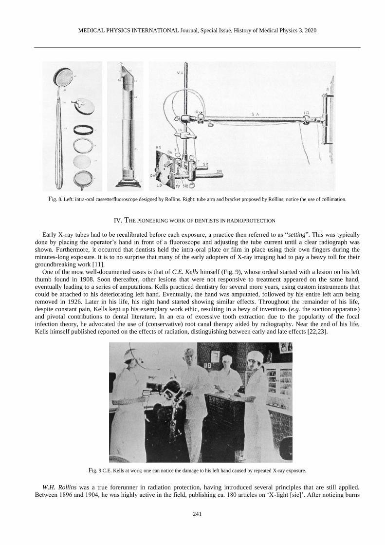
William H. Rollins, a Boston-based dentist, was another early adopter of dental radiography. In July 1896, he showed the
design of an intraoral cassette with accompanying fluoroscope, which could be used to visualize the posterior teeth (Fig. 8);
for more on dental fluoroscopy, see section V. Rollins also designed an X-ray tube arm, with a bracket for wall mounting
and the use of a (rectangular) collimator, which was never commercially manufactured (Fig. 8). Rollins’ legacy is further
expanded upon in section IV.
Weston A. Price [21] was at a forefront of radiographic record keeping by meticulously labeling the radiographs he
acquired using a thin copper wire, ensuring that the images could not be mixed up. He is also considered as the creator of the
bisecting-angle technique described further below. He was among the first to acknowledge the expertise required to interpret
dental radiographs.
MEDICAL PHYSICS INTERNATIONAL Journal, Special Issue, History of Medical Physics 3, 2020
241
Fig. 8. Left: intra-oral cassette/fluoroscope designed by Rollins. Right: tube arm and bracket proposed by Rollins; notice the use of collimation.
IV. THE PIONEERING WORK OF DENTISTS IN RADIOPROTECTION
Early X-ray tubes had to be recalibrated before each exposure, a practice then referred to as “setting”. This was typically
done by placing the operator’s hand in front of a fluoroscope and adjusting the tube current until a clear radiograph was
shown. Furthermore, it occurred that dentists held the intra-oral plate or film in place using their own fingers during the
minutes-long exposure. It is to no surprise that many of the early adopters of X-ray imaging had to pay a heavy toll for their
groundbreaking work [11].
One of the most well-documented cases is that of C.E. Kells himself (Fig. 9), whose ordeal started with a lesion on his left
thumb found in 1908. Soon thereafter, other lesions that were not responsive to treatment appeared on the same hand,
eventually leading to a series of amputations. Kells practiced dentistry for several more years, using custom instruments that
could be attached to his deteriorating left hand. Eventually, the hand was amputated, followed by his entire left arm being
removed in 1926. Later in his life, his right hand started showing similar effects. Throughout the remainder of his life,
despite constant pain, Kells kept up his exemplary work ethic, resulting in a bevy of inventions (e.g. the suction apparatus)
and pivotal contributions to dental literature. In an era of excessive tooth extraction due to the popularity of the focal
infection theory, he advocated the use of (conservative) root canal therapy aided by radiography. Near the end of his life,
Kells himself published reported on the effects of radiation, distinguishing between early and late effects [22,23].
Fig. 9 C.E. Kells at work; one can notice the damage to his left hand caused by repeated X-ray exposure.
W.H. Rollins was a true forerunner in radiation protection, having introduced several principles that are still applied.
Between 1896 and 1904, he was highly active in the field, publishing ca. 180 articles on ‘X-light [sic]’. After noticing burns
MEDICAL PHYSICS INTERNATIONAL Journal, Special Issue, History of Medical Physics 3, 2020
242
on his body in exposed regions, including his hands, he linked these effects to X-rays in a letter to the editor in the Boston
Medical and Surgical Journal [24]. In this paper, with the candid title “X-light kills”, he detailed an experiment involving
guinea pigs, concluding that “when electricity is excluded, death can be produced with x-light without burning.” Two years
later, he published his findings regarding the effects of X-rays on the eye lens [25]. He proposed the use of shielding of the
operator’s eyes (e.g. using lead-lined glasses), the tube and the patient, a principle which is still used in current
radioprotection. Furthermore, he advocated the use of proper beam collimation to avoid exposure to areas of the body
outside the region of diagnostic interest, which is one of the most efficient practical applications of the ‘optimization of
exposures’ principle. Unfortunately, Rollins was largely ignored by his colleagues; several decades later, after the atomic
bombings of Hiroshima and Nagasaki, the interest in dental radioprotection resurged. Perhaps owing to his caution regarding
the harmful effects of X-rays, Rollins did not suffer the same, excruciating fate of Kells and many other contemporaries
[26,27].
V. INTRA-ORAL PROJECTION TECHNIQUES
A. Conventional Projections
In 1904, Weston A. Price proposed an isometric X-ray projection technique, which later gained popularity under the name
‘bisecting-angle’ (Fig. 10). This technique was introduced due to practical difficulties in having the image receptor placed
parallel to the long axis of the teeth, especially in the upper jaw. Whereas this practical issue has recently reemerged with the
use of (relatively bulky) solid-state receptors, a ‘rectangular’ technique has been favored over a revisit to the bisecting-angle
technique [28]. With the rectangular technique, the focus is on ensuring perpendicularity between X-ray beam and receptor,
regardless of tooth orientation.
Franklin W. McCormack, a medical technician, focused on the application of the paralleling technique (Fig. 10) in intra-
oral dental radiography. This was facilitated through the attachment of the film to a rigid metal plate, with the added benefit
of reducing backscatter. He advocated the use of long source-skin distances (36” or ca. 91 cm) in a 1920 paper [15],
mentioning several benefits: reduced X-ray burns when making multiple exposures, improved image quality owing to beam
hardening, and avoiding overlap of the zygomatic bone with the apices of the maxillary molars [29]. Gordon M. Fitzgerald
was in close contact with McCormack throughout his career and applied his technique to actual dental practice. He also
advocated the use of high kV (80-100 kVp) X-rays. However, for several decades, dental X-ray tubes operated at a much
lower voltage; the low tube output coupled with the limited film speed at the time necessitated the use of short source-
detector distances (SDD) of 10 cm and below (i.e. ‘short cone’ units). At such short distances, the bisecting-angle technique
was preferred due to its lower distortion of the root. Subsequent technological improvements made it possible to use an SDD
of ca. 20 cm (‘long cone’), which is considered the standard today. Along with this increased SDD, the paralleling technique
became the most common projection technique. Whereas SDDs of 30-40 cm were proposed they proved to be impractical in
a confined dental environment, even with the focal spot at the back side of the unit as described in an article by AG Richards
in 1966 [30]. Neither the slight dose reduction achieved with such an ‘extra-long cone’, nor the improved projection
geometry was enough to overcome this practical limitation, resulting in little or no commercial success [31].
Fig. 10 Left: the paralleling technique, in which the X-ray beam is perpendicular to the long axis of the tooth as well as the image receptor. Right: the
bisecting-angle technique, in which the X-ray beam is perpendicular to the bisector of the tooth axis and receptor.
Out of the three types of intra-oral radiographs used today (periapical / occlusal / bitewing), the first two were employed
from the start, albeit with somewhat inconsistent positioning of the receptor. Howard R. Raper, considered among the first
dental radiology ‘specialists’, proposed the development of a bitewing film to Eastman Kodak in 1925, with the aim of

MEDICAL PHYSICS INTERNATIONAL Journal, Special Issue, History of Medical Physics 3, 2020
243
visualizing interproximal caries. He also invented an anglemeter that could be used for proper angulation of the X-ray beam
when using the bisecting-angle technique [29].
As shown in Fig. 5, film holders were used early-on; commercial film holders have been used for decades (Fig. 11 & 12),
although several dental offices still do not make use of them (Fig. 12). A UK study in 1994 involving four types of film
holders showed differences in practicality and patient comfort, with the ‘Superbite’ holder showing the highest performance
[32]. In 2009, a study in Lithuania reported that 32.7% of dental practitioners had the patient hold the receptor with their
finger, and 48.0% used film holders and the patient’s finger alternatively [33].
Fig. 11. Top: Vintage film holder. Bottom left: temporomandibular joint film holder and positioning device. Bottom right: occlusal film holder. Courtesy of
S. Anamali (University of Iowa).

MEDICAL PHYSICS INTERNATIONAL Journal, Special Issue, History of Medical Physics 3, 2020
244
Fig. 12 Left: receptor holders and positioning devices used in petiapical (top) and bitewing (bottom) radiography. Courtesy of P. Sinpitaksakul
(Chulalongkorn University). Right: Despite the large difference between beam area and receptor area, misalignment of the beam (collimator cut / beam cut)
can still occur when positioning devices are not used.
B. Parallax technique
Despite the immeasurable enthusiasm regarding the use of X-rays in medicine, the limitations of projection radiography
became apparent quickly. To visualize three-dimensional relationships, the use of complementary angles and stereoscopic
viewing (Fig. 13) was proposed by W.S. Hedley in 1898 [34]. C.A. Clark elaborated on the parallax concept in 1910 [35].
Common application in dentistry include the determination of the relative position of unerupted teeth (i.e. buccally / palatally
to, or in line with, erupted teeth), and the visualization of multi-rooted teeth. Both horizontal and vertical parallax techniques
have been employed [36], and different rules for interpreting the multiple radiographs have been defined, such as:
• Same Lingual Opposite Buccal (SLOB) [37] or Buccal Always Moves Away (BAMA): considering radiographs of two
objects acquired at different angles, the object furthest from the tube will appear to move along with the tube and vice
versa. This concept was introduced by Clark in his 1910 paper through the use of three radiographs [35]. AG Richards
revised the rule in 1952, simplifying the technique to only two radiographs [38,39].
• Mesial-Buccal-Distal (MBD) [40]: for an exposure obtained at a slight angle to the mesial surface, the buccal root is
situated distally.
Fig. 13 Ritter intra-oral ‘stereoscope and diagnostic lamp’ (ca. 1930, pre-patent [41]), used for pseudo-3D diagnosis based on multiple radiographs until at
least the 1950s. Pictures and information provided by the Oak Ridge Associated Universities (ORAU) Health Physics Historical Instrumentation Museum
Collection under a non-transferable, non-exclusive, limited license [42].
C. Dental fluoroscopy
After its invention by Thomas Edison, fluoroscopy was used in medical radiography early-on. A fluoroscope consists of a
calcium tungstate screen, allowing for real-time X-ray imaging. W.H. Rollins’ dental fluoroscope has been mentioned above
(Fig. 8); W.J. Morton also showed interest in this technique in his early work [18], predicting that it would eventually replace

MEDICAL PHYSICS INTERNATIONAL Journal, Special Issue, History of Medical Physics 3, 2020
245
the use of still images, as it could speed up the examination by avoiding exposures of several minutes as well as film
processing. The technique was abandoned rather quickly, however, due to its unjustifiable high radiation exposure as well as
the relatively poor image quality. In 1908, a medical doctor named G.E. Pfahler made a strong statement in Dental Cosmos,
claiming that the fluoroscope had no place in dentistry [43]. Later attempts to revive this technology (Fig. 14) were quelled.
Whereas fluoroscopy is commonly used in contemporary interventional radiology, its use in dentistry has waned: the closest
thing to ‘interventional’ dental radiography involves static images (i.e. periapical radiographs) acquired during different
phases of root canal treatment.
Fig. 14 Top left: the Dentoscope, an intra-oral fluoroscope produced in Switzerland (ca. 1930s). Bottom left: the Indian Head X-ray Reflector of the Union
Broach Company (US, ca. 1955). Distribution was halted by the State of New York. Pictures and information provided by the Oak Ridge Associated
Universities (ORAU) Health Physics Historical Instrumentation Museum Collection under a non-transferable, non-exclusive, limited license [44,45].
VI. EVOLUTION OF DENTAL (INTRA-ORAL) X-RAY UNITS
After the initial wave of dental radiographs produced in 1896 within weeks of Röntgen’s publication, one would expect
rapid adoption of this new technology in routine dental practice. However, commercialization and widespread clinical
implementation took quite some time. In 1905, the first dental X-ray machines were manufactured in Germany by the
company now known as Siemens. In 1910 it was reported that only a few dentists in the USA used radiography, but in 1912-
1913 dental X-ray units reached the US. In 1932, a survey by the American Dental Association showed that nearly half of
newly graduated dentists procured an X-ray unit for their office.
One of the main reasons why so many researchers started experimenting with X-rays in early 1896 was the accessibility to
the tools used by W. Röntgen and his predecessors. No new equipment or machines needed to be produced; one simply
required an induction coil coupled to a Crookes-Hittorf (or similar vacuum) tube to generate X-rays. Both tools could be
purchased or borrowed from physics labs, as they were commonly used for energy-based experiments. The reason why the
Crookes-Hittorf tube was well-suited for X-ray generation is attributed to its relatively high vacuum. The dispersion of the
remaining air molecules in the tube resulted in a constant electron stream; W.H. Rollins reported that high vacuum tubes
resulted in increased radiographic detail [46]. Early improvements to the basic Crookes-Hittorf tube were implemented by
König (see above). F. Harrison (UK) has been credited for designed a custom vacuum tube for dental radiography in January
1896 [16]. C.E. Kells also showed interested in the optimization of the technology used for generating X-rays at that time. In
an 1899 paper published in Dental Cosmos [47], he evaluated the state-of-the-art in radiographic technology. Out of different
available vacuum tubes, he found that the Crookes-Hittorf type was preferred. He also noted that the Tesla coil or the static
(friction-based) Ranney-Wimshurst-Holtz machine were adequate substitutes of the Ruhmkorff coil, although a report of the
US military showed preference for the latter due to its ease of use and lower bulk [48], both of which are relevant in a dental
clinical environment as well.
A limitation of the Crookes-Hittorf tube set-up was a lack of consistency in the quantity and quality of X-rays. George M.
Mackee and John Remer addressed this issue by proposing the use of a ‘radiochromometer’ that could measure the hardness
of the X-ray beam, and a radiometer to measure the tube output [49].

MEDICAL PHYSICS INTERNATIONAL Journal, Special Issue, History of Medical Physics 3, 2020
246
Subsequent changes to the X-ray tube design, culminating in the Coolidge-type tube, which is still used today, are
described in a prior paper [2]. In summary, in 1913, William David Coolidge (General Electric Co. New York) designed a
tube in which a heated tungsten wire (cathode) served as the source of electrons, rather than residual air molecules in the
vacuum. The new design improved safety as well as a more controlled X-ray quantity and quality. Furthermore, he
discovered the dual purpose of oil immersion for electrical insulation and cooling. An adapted Coolidge tube for dental
radiography was developed several years later. The following figures show the evolution of dental x-ray tubes throughout the
decades (Fig. 15-29).
Fig. 15 Left: 1917 brochure for X-ray tube stand and wall brackets, used to adapt medical X-ray units for dental radiography. Multi-jointed arms of current
intra-oral X-ray tubes were still years removed. Instead, the tube was stationary, and the patient was adjusted accordingly. Right: first commercial X-ray
unit in the US (1913), produced by American X-ray Equipment Co. This unit used an induction coil, and was suited for AC or DC input, with exposures
times of 10-20 s. The tube was shielded using lead glass [52].
Fig. 16 Component of a "therapeutic" X-ray unit. Ca. 1914, the use of X-rays in combination with high-frequency current was being considered e.g. for
periodontal treatment [52]. The application of this technique was short-lived.

MEDICAL PHYSICS INTERNATIONAL Journal, Special Issue, History of Medical Physics 3, 2020
247
Fig. 17 Coolidge-tube (10 mA), ca. 1922. Courtesy of D. Bednarek (University at Buffalo).
Fig. 18 Wall-mounted (left) and mobile (middle) ‘CDX’ Coolidge-type dental X-ray units (1923, Victor X-ray Corp., later General Electric X-ray Corp.).
These units were shock-proof by collecting high-tension components within a grounded housing. Their compact design was possible owing to using smaller
transformers as well as an autotransformer (vs. a rheostat) [52]. In 1933, the redesigned CDX model E (middle & right) was released, showing the typical closed ‘pointed cone’ position indicating device that would be used for several decades (i.e. the era of ‘short cone bisecting-angle’ intra-oral radiography).
The unit shown on the right was still operational in 1981 (Science Museum Group under CC BY-NC-SA 4.0) [53].
Fig. 19 Coolidge-type RD (Radiator Dental) dental x-ray tube (Victor X-Ray Corporation), manufactured ca. 1926-1932. The right-angled design was
suited for dental radiography, allowing close tube positioning. The cathode, which was closest to the patient, was grounded, and the high-potential anode was deliberately positioned away from the patient, according to the original 1919 patient [54]. Left: the spherical part of the tube shows the focusing cup
and the target (embedded in a slanted copper block). Right: close-up of the focusing cup, showing the tungsten filament. When in use, a finned metal
radiation was placed over the copper rod for heat dissipation (not shown on figure). This type of tube was self-rectifying, meaning that it could be directly attached to an induction coil or transformer. Figure and information provided by the Oak Ridge Associated Universities (ORAU) Health Physics Historical
Instrumentation Museum Collection under a non-transferable, non-exclusive, limited license [55].

MEDICAL PHYSICS INTERNATIONAL Journal, Special Issue, History of Medical Physics 3, 2020
248
Fig. 20 Left: early X-ray unit with exposed high-tension wire, which is believed to have several grave (even fatal) accidents [52]. Right: the Ritter dental X-
ray unit (1928), despite using a Coolidge tube, still had an exposed wire. Open-tube units were manufactured until the 1930s. Courtesy of D. Bednarek
(University at Buffalo) [56].
Fig. 21 Left: Ritter X-ray unit. Courtesy of P. Pittayapat (Chulalongkorn University). Middle: Weber no. 5 Raydex mobile dental X-ray unit, with a design
typical of the late 1930s and 1940s. Right: the compact design of the Philips Oralix X-ray unit (1940s-1950s) allowed it to be attached to the dental chair; it
was also produced as a wall-mounted or mobile unit [52].

MEDICAL PHYSICS INTERNATIONAL Journal, Special Issue, History of Medical Physics 3, 2020
249
Fig. 22 Top. Single focus dental XPD Coolidge tube (General Electric, ca. 1930s-1940s). Bottom: shock-proof dental x-ray tube (likely by General Electric,
ca. 1935) [57]. The housing is made of several lead layers, separated by an insulating material. Figures and information provided by the Oak Ridge
Associated Universities (ORAU) Health Physics Historical Instrumentation Museum Collection under a non-transferable, non-exclusive, limited license
[58,59].
Fig. 23 X-ray tube with static anode (low power). 1. Anode stem. 2. Electron capture hood. 3. Beryllium window over the Anode. 4. Metallization of the
glass envelope. Courtesy of S. Tabakov (King’s College London).

MEDICAL PHYSICS INTERNATIONAL Journal, Special Issue, History of Medical Physics 3, 2020
250
Fig. 24 Ritter Dual-X unit (ca. 1950). Notice the double-cone design of the tube head, combining a longer source-skin distance with a position indicating
device. Courtesy of P. Pittayapat (Chulalongkorn University).
Fig. 25 Left: Ritter Model E X-ray unit (1956), with kilovoltages from 65 to 90 kVp. Throughout the 1950s, innovation to X-ray units included electronic
timers, beam collimation and filtration [52]. Middle: Ritter Mark 75 model H (1966). This unit had preset mA and kV. Right: Heliodent X-ray machine
(1957-1962) attached to an Artiflex dental unit (Siemens, Germany) (Science Museum Group under CC BY-NC-SA 4.0) [60].

MEDICAL PHYSICS INTERNATIONAL Journal, Special Issue, History of Medical Physics 3, 2020
251
Fig. 26 MAX-GL dental X-ray unit (South Korea, ca. 1972) with built-in chair. Courtesy of P. Pittayapat (Chulalongkorn University).
Fig. 27 Oralix 50 (left; ca. 1960s-1970s) and Oralix 65 (right; ca. 1984) intra-oral X-ray units (Philips, The Netherlands). The model number seemingly
referred to the kV at stability (i.e. not the kVp) of the tube [61]; a ‘45’ model was also produced. Absorbed dose to the skin inside the primary beam ranged between 3.3 mGy and 9.7 mGy for these two units [61]. Right: Gendex GX 1000 (ca. late 1980s). Courtesy of J.K.M. Aps (University of Western
Australia).

MEDICAL PHYSICS INTERNATIONAL Journal, Special Issue, History of Medical Physics 3, 2020
252
Fig. 28 Left: the MINRAY (1982-1992, Soredex, Tuusula, Finland), a high-frequency DC intra-oral X-ray unit. Courtesy of Soredex Oy and Dr Jörg
Mudrak. Right: The MAX-F (1985, J. Morita, Kyoto, Japan), using a straight-cylindrical tube exit. Courtesy of J Morita.
Fig. 29 Intra-oral X-ray tube with circular (left, ca. 2005) and rectangular (right) collimation. The use of circular collimation is still prevalent, despite the
considerable dose reduction obtained using rectangular collimation [61-64]. Right figure courtesy of K. Horner (University of Manchester)
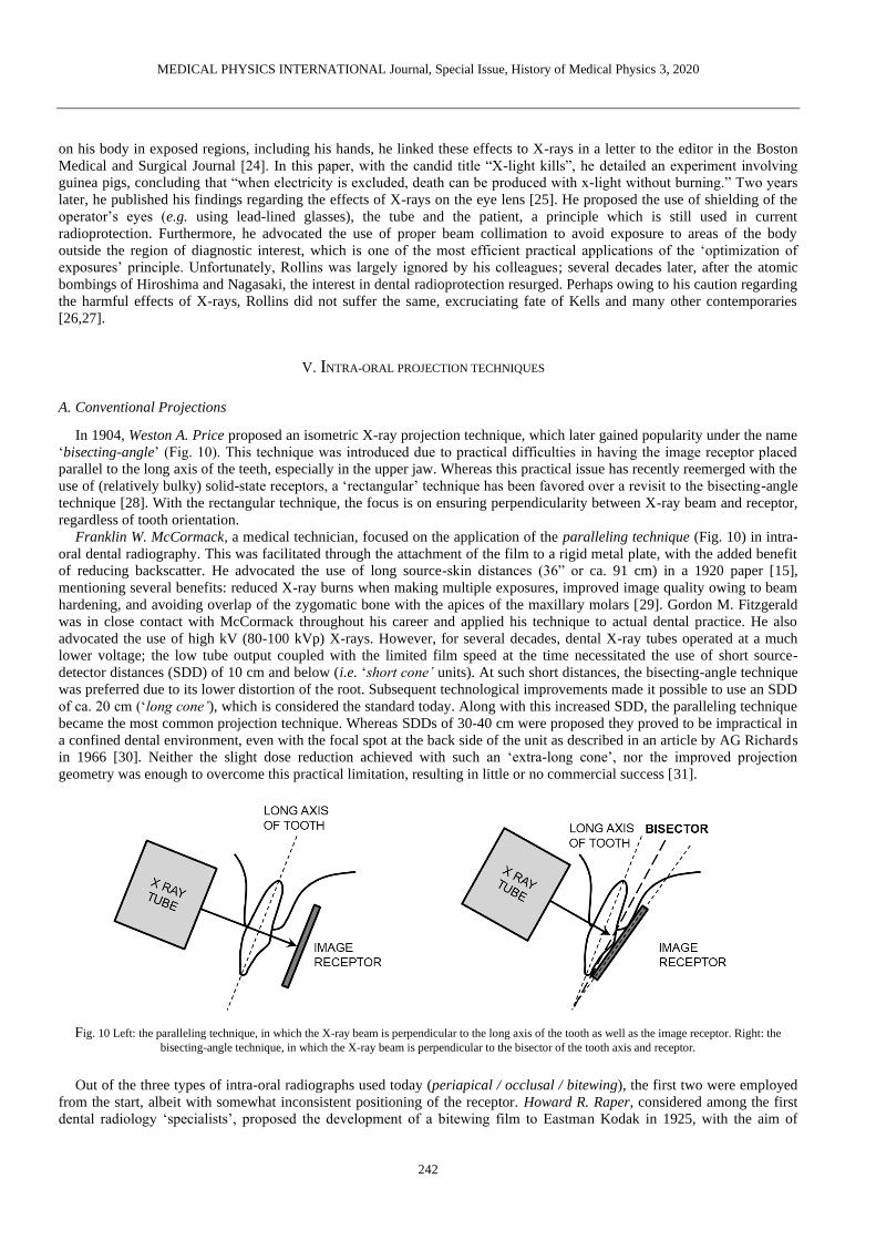
The use of hand-held (portable) X-ray units for intra-oral radiography was first described in 1993, when the commercially
developed PXS7 (Kevex X-Ray Corporation, USA) unit, with intended applications ranging from contraband/drug
inspection to quality control in manufacturing, was compared with a conventional X-ray machine. In the folowing years, the
interest in hand-held units increased in forensic [65] and clinical dentistry (Fig. 30). The main limitation of this technology is
the proximity of the operator, resulting in exposure to scatter radiation. Furthermore, it was found that several hand-held
units exhibited a low tube output, requiring a longer exposure time. Thus, it was recommended that they should only be used
in specific environments, including but not limited to remote areas and facilities with immobile or confined patients (e.g.
elderly homes and detention centers), and only if a mobile unit is not available [66,67].
MEDICAL PHYSICS INTERNATIONAL Journal, Special Issue, History of Medical Physics 3, 2020
253
Fig. 30 Portable hand-held intra-oral units. Reproduced from Pittayapat et al. 2012 [65] with the author’s permission.
VII. EVOLUTION OF DENTAL (INTRA-ORAL) X-RAY IMAGE RECEPTORS – FROM PLATE TO PLATE
A. Film
Several practical difficulties were found in the early implementation of dental radiographs. To produce dental radiographs
the photographic glass plates had to be cut in small pieces, wrapped in lightproof paper, and placed in a rubber dam [68].
Due to the extremely long exposure time as well as the weight and bulk of the plates, it was reported to be a quite
uncomfortable experience by O. Walkhoff himself:
“It was a true torture, but I felt a great joy at the sight of the results when I become aware of the importance of the
Röntgen rays for dentistry.” (O. Walkhoff, as quoted by Forrai [11])
The fragility and the cost of the plates was another issue to consider. W. Röntgen himself remarked that film can be used
instead of glass plates [69]. Initially, Eastman NC films were meticulously cut and wrapped in black paper. Early use of film
in dental radiography was challenging due to stability issues as well as the necessity to maintain the film dry. Morton
proposed the use of gutta percha receptacles to avoid that the emulsion became wet [18].
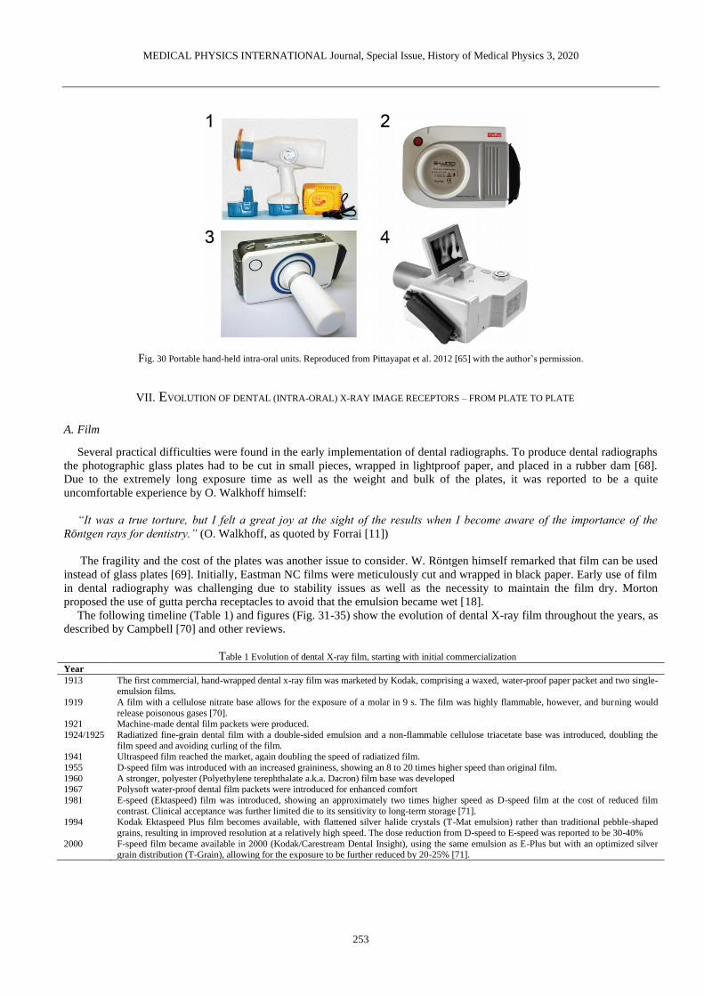
The following timeline (Table 1) and figures (Fig. 31-35) show the evolution of dental X-ray film throughout the years, as
described by Campbell [70] and other reviews.
Table 1 Evolution of dental X-ray film, starting with initial commercialization
Year
1913 The first commercial, hand-wrapped dental x-ray film was marketed by Kodak, comprising a waxed, water-proof paper packet and two single-emulsion films.
1919 A film with a cellulose nitrate base allows for the exposure of a molar in 9 s. The film was highly flammable, however, and burning would
release poisonous gases [70]. 1921 Machine-made dental film packets were produced.
1924/1925 Radiatized fine-grain dental film with a double-sided emulsion and a non-flammable cellulose triacetate base was introduced, doubling the
film speed and avoiding curling of the film. 1941 Ultraspeed film reached the market, again doubling the speed of radiatized film.
1955 D-speed film was introduced with an increased graininess, showing an 8 to 20 times higher speed than original film.
1960 A stronger, polyester (Polyethylene terephthalate a.k.a. Dacron) film base was developed 1967 Polysoft water-proof dental film packets were introduced for enhanced comfort
1981 E-speed (Ektaspeed) film was introduced, showing an approximately two times higher speed as D-speed film at the cost of reduced film
contrast. Clinical acceptance was further limited die to its sensitivity to long-term storage [71].
1994 Kodak Ektaspeed Plus film becomes available, with flattened silver halide crystals (T-Mat emulsion) rather than traditional pebble-shaped
grains, resulting in improved resolution at a relatively high speed. The dose reduction from D-speed to E-speed was reported to be 30-40%
2000 F-speed film became available in 2000 (Kodak/Carestream Dental Insight), using the same emulsion as E-Plus but with an optimized silver grain distribution (T-Grain), allowing for the exposure to be further reduced by 20-25% [71].

MEDICAL PHYSICS INTERNATIONAL Journal, Special Issue, History of Medical Physics 3, 2020
254
Fig. 31 Left: Eastman (Kodak) radiatized dental film. Right: Victor-Bolin dental film container (ca. 1930; patent by Bolin granted in 1925 [72]). Figure and
information provided by the Oak Ridge Associated Universities (ORAU) Health Physics Historical Instrumentation Museum Collection under a non-
transferable, non-exclusive, limited license [73].
Fig. 32 Wolf X-ray intra-oral cassette for occlusal radiography (ca. 6.4 x 8.3 cm). The cassette appeared in a 1955 catalog, which mentioned an exposure
time of 1.5-2 s. Figure and information provided by the Oak Ridge Associated Universities (ORAU) Health Physics Historical Instrumentation Museum
Collection under a non-transferable, non-exclusive, limited license [74].
Fig. 33 Dental film holders (ca. 1937). The text on the box reads "The wood block film holder is used to radiograph films in the mouth, especially where it
is difficult for patient to hold the film in proper position or when patient is distressed by film. Insert film, folded side against rounded part of the block, and have patient bite on adjoining flat surface. Can be used either upper or lower." One block is approx. 1.8 cm across. A box of 10 blocks sold for $0.25 [75].
Figure and information provided by the Oak Ridge Associated Universities (ORAU) Health Physics Historical Instrumentation Museum Collection under a
non-transferable, non-exclusive, limited license [76].

MEDICAL PHYSICS INTERNATIONAL Journal, Special Issue, History of Medical Physics 3, 2020
255
Fig. 34 ‘Sta-put’ bitewing tabs and Minimax bitewing film packets. Courtesy of D. Bednarek (University at Buffalo).
Fig. 35 Wall-mounted shielded X-ray film containers for storing film prior to development. Left: Eastman Dental Film Safe (1920s), with two
compartments for a total of 24 film packets. Right: more recent units by Eastman/Kodak; the rightmost is shown in a 1955 catalog. All containers seem to
be made of a lead alloy. Figure and information provided by the Oak Ridge Associated Universities (ORAU) Health Physics Historical Instrumentation
Museum Collection under a non-transferable, non-exclusive, limited license [77].
The development process of plates and film was based on previously established concepts in photography. The
importance of this aspect of radiography may have been underestimated during the early years. In a 1922 paper, C.E. Kells
reviewed the significance of proper film development, emphasizing that radiographic image quality it is as affected by the
operator’s expertise as the X-ray exposure itself [78]. He also focused on the importance of having constant environmental
factors (e.g. temperature). An automatic developer was introduced early-on, with the dual benefit of reducing operator-
dependency and saving time; regardless, manual film development is still performed to this day (Fig. 36-39).
Fig. 36 Left: A dental assistant (hygienist) developing an X-ray film (original source and year unknown). Middle and right: automatic processors for intra-
oral films and large films. Courtesy of A. Al-Ekrish (King Saud University).

MEDICAL PHYSICS INTERNATIONAL Journal, Special Issue, History of Medical Physics 3, 2020
256
Fig. 37 Left: Litton automatic dental film processor with daylight loading. Courtesy of D. Bednarek (University at Buffalo). Right: Manual development
using a lightproof glovebox.
Fig. 38 Left: Safelight filter for intra-oral films. Middle: Kodak dental film dispenser. Courtesy of S. Anamali (University of Iowa). Right: Rinn dental film
dispenser. Courtesy of D. Bednarek (University at Buffalo).
Fig. 39 Left: Digital densitometer (DD500 S&S X-Ray Products). Right: troubleshooting guide for dark and light radiographs. Courtesy of S. Anamali
(University of Iowa).

MEDICAL PHYSICS INTERNATIONAL Journal, Special Issue, History of Medical Physics 3, 2020
257
B. Digital receptors
The transition to digital dental radiography was gradual [79] and is still on-going. In 1987, a digital charge-coupled device
(CCD) intra-oral detector was introduced (RadioVisioGraphy, Trophy Radiologic, France; Fig. 40) [80]. The advantages of
reduced patient exposure and immediate availability of the image were immediately apparent, although the spatial resolution
was less than that of film [79]. Further improvements to CCD-based sensors were made in the following years.
Photostimulable phosphor (PSP) receptors were introduced in 1994 (DIGORA, Soredex, Finland; Fig. 40)) despite having
been used in medicine as early as 1983. Whereas resolution was considered somewhat inferior to CCD systems, PSPs
showed an improved dynamic range [81,82] and signal-to-noise ratio [83]. Complementary metal-oxide semiconductor
(CMOS) sensors were commercialized in 1998 (CDR-APS, Schick Technologies, USA) and have largely replaced CCD
sensors in intra-oral radiography owing to several advantages such as cost, dynamic range and the absence of
blooming/smearing effects [79]. In a 2001 survey involving Norwegian dentists, two thirds of the respondents found that
digital (solid state sensors or PSP) receptors yielded equal or better image quality than film, at a mean reduction in exposure
time of 55% [84]. Furthermore, the use of digital receptors saved an average of 36 min/day and 25 min/day for sensors and
PSPs, respectively. A dosimetric study published in 2008, using the latest tissue weighting factors from the International
Commission on Radiological Protection [85], found a 56% effective dose reduction for PSPs or F-speed film vs. D-speed
film [86]. A more detailed overview digital receptors in intra-oral radiography, including their performance vs. film, can be
found in the review by Yoshida et al [79].
Fig. 40 Left: the RadioVisioGraphy a digital charge-coupled device (CCD) intra-oral detector (1987, Trophy Radiologic, France). Courtesy of A. Wenzel,
Aarhus University. Right: The DIGORA (‘DIGitalORAl’) system intraoral imaging system using storage phosphor plates (1994, Soredex, Tuusula,
Finland). Courtesy of Soredex Oy and J. Mudrak.
C. Xeroradiography
Xeroradiography was invented by the American physicist and patent attorney F. Chester Carlson, aided by Otto Kornei,
in 1937. Ten years later, the Haloid Company (later known as Xerox) started commercial development. The technique was
used in several areas of medicine and was first used for dental radiography in 1963 [87]. It was applied for panoramic and
cephalometric radiography as well as sialography [88]. In 1978, intraoral xenoradiography was introduced and evaluated for
endodontic use; it was found to depict anatomical structures more clearly than film radiographs at a third of the dose, along
with a rapid image generation (20 s after exposure) [89]. Xeroradiography is performed using a plate containing a 150-320
µm amorphous selenium layer and a 2 mm thick aluminum substrate. Prior to X-ray exposure, a uniform positive charge is
applied to the plate surface using a ‘scorotron’ [90]. If used intra-orally, the cassette is covered by plastic to avoid contact
with saliva. When the surface is exposed with X-rays, the charge will be passed to the grounded conductive backing in
proportion with the exposure, resulting in a latent image. Development involves electrophoresis with a negatively charged
(powder or liquid) toner, which is (1) deposited on the photoconductor, (2) attaches itself to the remaining negatively
charged areas, and (3) is transferred and fixed to a paper or plastic sheet. After cleaning the plate, it can be reused.
Advantages of the technique include a low sensitivity to ambient light, high resolution, high dynamic range, low cost,
straightforward copying of radiographs, and high (development) speed. On the other hand, contradictory reports regarding
the relative dose of xeroradiography vs. film radiography can be found [91-93]. Xeroradiography gained interest for use in
endodontics, as its contrast in the soft tissue density range allowed the visualization of calcification in the pulp and its spatial
resolution allowed the depiction of fine anatomical details as well as instruments. However, several disadvantages of the
technique became apparent, such as the impracticality of using charged plates intra-orally due to the presence of saliva.
Furthermore, the ‘speed’ of the system was proportionate to its thickness, which in turn was limited by the space in the oral

MEDICAL PHYSICS INTERNATIONAL Journal, Special Issue, History of Medical Physics 3, 2020
258
cavity. The surface of the plate was also rather fragile. The technique has since faded from clinical dental use, despite calls
for its reintroduction [94].
VIII. HISTORY OF PANORAMIC RADIOGRAPHY
Panoramic radiographic is a unique imaging modality, specifically designed for dental applications. The challenge
addressed by this technology was to acquire a single radiograph that encompassed all teeth of the upper and lower jaw. The
invention of the panoramic radiography unit is largely attributed to Yrjö Paatero [95], a Finnish dentist whose work resulted
in widespread clinical practice and commercial distribution after the second World War (Fig. 41). However, the technique
itself is much older; in 1922, Zulauf (USA) proposed a narrow-beam scanning technique for upper and lower jaw, obtaining
a patent [96]. He also coined the term ‘panoramic radiography’. Numata (Japan) published clinical results of a prototype
‘parabolic radiography’ device in 1933 [97]. Heckmann (Germany) obtained a patient for narrow-beam radiography of
curved objects in 1939 [98].
Fig. 41 Yrjö Paatero and one of his early experimental set-ups. Courtesy of Instrumentarium Oy and J. Mudrak.
After the second World War, Paatero took up a position at the Institute of Dentistry of the University of Helsinki and was
seemingly pushed into taking charge (and becoming the only member) of the Department of Radiology. Despite a high
clinical workload and scarce resources, Paatero was able to make important contributions to the field. It has been speculated
that one of the driving forces behind Paatero’s dedication was the unsustainable work pressure in his one-man department;
indeed, the workflow in dental radiography could be sped up considerably by replacing several radiographic acquisitions by
a single panoramic radiograph. His work progressed quickly, despite being unaware of previous publications and patents on
this technique: in 1946, a preliminary report was published in the Proceedings of the Finnish Dental Society. Initially, he
used a long, curved film placed intra-orally, exposed with a moving narrow X-ray beam that passed along the patient’s face.
The resulting image was dubbed ‘parablograph’ in 1949. In the same year, Paatero altered this technique by placing the film
extraorally (curved around the face) and having a relative rotation of the X-ray tube posterior to the patient (Fig. 42). Paatero
referred to this technique as the orthoradial pantomograph, eventually shortened into the trade name ‘Orthopantomograph’,
which is still used as a generic term for panoramic radiography, along with its abbreviation ‘OPG’. Whereas the X-ray tube
was stationary in early iterations, eventually prototypes were constructed in which the tube rotated.
An important step towards eventual commercialization of this technique was made in the early 1950s, when Paatero
liaised with an engineer named Timo Nieminen via the Finnish company Lääkintäsähkö. The two would closely collaborate
for the next decade. Paatero also spent a few years at the University of Washington, contributing to the development of a
double eccentric rotation technique that was later patented by Hudson et al. (USA) [99]. After returning to Finland, Paatero
and Nieminen developed a panoramic radiography unit with a triple rotation center [100], followed by extensive clinical
testing [101-105] (Fig. 42).
Through collaboration with Siemens, who produced the X-ray tube and generators, the commercialization of the
Orthopantomograph commenced in 1960 (Fig. 43-44). In 1965, the company Palomex (Panoramic Layer Observing Machine
for Export) was established. In the USA, after clinical testing of the double eccentric machine of Hudson et al., production of
the ‘Panorex’ commenced by the S.S. White company (Pennwalt Corporation). In the UK, after gaining expertise with a
panoramic radiography unit produced in Helsinki, S. Blackman worked with the company Watson & Sons in the
development of a panoramic machine named the Rotograph [106]. Soon enough, other manufacturers around the world
produced panoramic radiography units (Fig. 45-55).

MEDICAL PHYSICS INTERNATIONAL Journal, Special Issue, History of Medical Physics 3, 2020
259
Fig. 42 Panoramic radiography applied in dental practice. Left: schematic (1949). Right: unit for clinical testing (1951). Courtesy of Instrumentarium Oy
and J. Mudrak.
Fig. 43 The Orthopantomograph OP1 (1961-1964, Instrumentarium, Tuusula, Finland). Courtesy of Instrumentarium Oy and J. Mudrak.
Fig. 44 Early use of panoramic radiographic for planning (left) and post-operative evaluation (right) of enossal (spiral) implants (1962). Courtesy of
Instrumentarium Oy and J. Mudrak.

MEDICAL PHYSICS INTERNATIONAL Journal, Special Issue, History of Medical Physics 3, 2020
260
Fig. 45 The Orthopantomograph OP2 (1964-1972, Instrumentarium, Tuusula, Finland) featured an improved imaging geometry and a redesigned, curved
cassette. Courtesy of Instrumentarium Oy and J. Mudrak.
Fig. 46 Left and middle: the Orthopantomograph OP3 (1972-1978, Instrumentarium, Tuusula, Finland) combined panoramic and cephalometric
radiography. Over 10 000 units were produced. Right: the Orthopantomograph OP5 (1978-1983, Instrumentarium) featured new patient positioning tools
and an improved imaging geometry. Over 20 000 units were produced. Courtesy of Instrumentarium Oy and J. Mudrak.
Fig. 47 The Orthopantomograph OP10 (1983-1984, Instrumentarium, Tuusula, Finland) implemented horizontal (Frankfort) positioning lights and
advanced imaging programs. Courtesy of Instrumentarium Oy and J. Mudrak.

MEDICAL PHYSICS INTERNATIONAL Journal, Special Issue, History of Medical Physics 3, 2020
261
Fig. 48 Left: The Panex-E by (1972, J Morita, Kyoto, Japan). Middle: The Panex-EC panoramic/cephalometric unit (1975, J Morita). Right: the Veraview
(1979, J Morita), brandishing an electronic control system. Courtesy of J Morita.
Fig. 49 Vintage calibration phantoms for panoramic radiography. Separate phantoms were used for small, medium and large jaws. Courtesy of S. Anamali
(University of Iowa).
Further development of panoramic radiography was aided by its clinical implementation: whereas AC generators used in
early models were often of the one-pulse type, the use of this modality in hospitals allowed them to be coupled to 12-pulse
generators, which in turn allowed the use of rotating anode tubes [100]. DC generators were introduced by Soredex (Finland)
in 1978.
A dosimetric study in 1979 found that the energy imparted in the head and neck from panoramic radiography was
between 0.45 mJ and 4.5 mJ; for different combinations of conventional radiographs, the same range was found (i.e. from
0.40 mJ for left and right oblique, up to 4.4 mJ for full mouth series at 65 kV) [107]. The highest local absorbed dose was 3.7
mGy for panoramic radiography, whereas an absorbed dose at the corner of the mouth of 10 mGy and 12 mGy was measured
for a full mouth series at 45 kV and 65 kV, respectively [107].
Mechanical movement was gradually replaced by step motors and electronic control systems. The ergonomics of the
device was also improved through innovation in patient position devices. Whereas mechanical movement allowed for
variations in exposure geometry for visualization of non-dental structures (e.g. optic foramina and cervical spine), further
development initially focused on image layers that followed the dental arch, until electronics allowed for the customization
and further refinement of image layers as described by Hallikainen (Fig. 50) [100].

MEDICAL PHYSICS INTERNATIONAL Journal, Special Issue, History of Medical Physics 3, 2020
262
Fig. 50 The Zonarc (Palomex Oy, Helsinki, Finland) unit allowed for the visualization of structures outside of the dental region. The patient is in a supine
position, and the movement of the X-ray tube and receptor rotate in the vertical plane. Rotation of the tube/receptor was complemented by up/down
movement of the unit to create eccentric motion paths [108]. Courtesy of J.K.M. Aps (University of Western Australia).
Fig. 51 Panoramic single-jaw radiograph with intra-oral X-ray source and extra-oral film, placed in a flexible cassette (top right), which was held by the
patient wrapped around the face. The cross marker on the cassette faced the operator and served as a guide in determining the midsagittal plane. Maxillary views (left) were made with the patient in an upright position and the cassette placed above the tube. For mandibular views, the patient's head was slightly
tilted back and they would bite on the X-ray tube. The tube was a small cylinder covered with a disposable sleeve. Courtesy of K. Sansare and F. Karjodkar
(Nair Hospital Dental College).

MEDICAL PHYSICS INTERNATIONAL Journal, Special Issue, History of Medical Physics 3, 2020
263
Fig. 52 Quality control on a film-based panoramic radiography unit (ca. 1990). The dosimeter was firmly affixed to the rotating assembly. Note the metals
slits of the X-ray tube and of the film holder (marked with arrows). Courtesy of S. Tabakov (King’s College London)
Along with the digitization of other radiographic techniques in dentistry and medicine, ‘computed’ panoramic
radiography (Fig. 53-55) was developed in the 1980s, first described by Kashima et al. in 1985 [109]. Direct digital
panoramic radiography followed in the early 1990s [110,111]. Some current-generation panoramic units have incorporated
direct-conversion (CdTe) receptors. Recent dosimetric studies involving panoramic radiography are somewhat scarce. A
2019 study found an absorbed dose of 0.62 mGy for CCD panoramic radiography vs 0.80 mGy for intra-oral radiography
[112]. One of the most recently reported effective dose values is 17.6 µSv for a full-size panoramic radiograph with a CCD
detector, with dose reductions between 4.5% and 86.9% for collimated radiographs [113]. A 2008 study involving two CCD-
type panoramic units found effective doses of 14-24 µSv [86]. A 2005 study, using now-outdated tissue weighting factors,
found effective doses between 5-15 µSv for digital (CCD or PSP) panoramic radiography [114].
Fig. 53 The Orthopantomograph OP100 (1992-2006, Instrumentarium, Tuusula, Finland) implemented automatic exposure control, computed radiology
(CR) and linear tomography (OrthoTrans). Courtesy of Instrumentarium Oy and J. Mudrak.

MEDICAL PHYSICS INTERNATIONAL Journal, Special Issue, History of Medical Physics 3, 2020
264
Fig. 54 The Orthopantomograph OP100D and two-in-one Orthoceph OC100D (1999-2006, Instrumentarium, Tuusula, Finland) had digital (charge-coupled
device, CCD) image receptors. CCD image receptors were used as well in the OP30 model (2009). In the OP300 (2010), complementary metal–oxide–
semiconductor (CMOS) digital sensors are used. Courtesy of Instrumentarium Oy and J. Mudrak.
Fig. 55 Left: Digital panoramic system ‘Veraviewepocs’ (1998, J Morita, Kyoto, Japan). Middle: Veraviewepocs 3D, a ‘3-in-1’
(panoramic/cephalometric/cone-beam CT) system (2007, J Morita). Right: Veraview X800 (2016, J Morita) 3-in-1 unit. Courtesy of J Morita.
IX. OTHER EXTRAORAL RADIOGRAPHIC TECHNIQUES
The most common type of extra-oral, non-tomographic radiographic technique in dentistry is the lateral cephalometric
radiograph. The posteroanterior cephalometric radiograph is used less frequently, e.g. for the evaluation of left-right
symmetry. Other projections (Fig. 56-57) usually require isocentric (or formerly Lysholm) skull units and are not performed
in a typical dental office; the most common techniques are shown in Fig 56.

MEDICAL PHYSICS INTERNATIONAL Journal, Special Issue, History of Medical Physics 3, 2020
265
Fig. 56 Overview of common extra-oral projection radiography techniques. Own work, from the IAEA Training Material “Radiation Protection in Dental
Radiology” [115]. Radiographs courtesy of P. Pittayapat, Chulalongkorn University, Bangkok, Thailand.
Fig. 57 Left and middle: transcranial radiograph in open and closed mouth position, indicating degenerative joint disease. Right: lateral oblique radiograph
showing temporomandibular joint ankylosis. Courtesy of K. Sansare, Nair Hospital Dental College.
A. Cephalometric radiography
The origin of head measurements can be traced back to Leonardo da Vinci and other Renaissance scientists and artists.
Facial proportions and angles were used in the next centuries for ethnic evaluation and the analysis of human remains, using
the ‘cephalic index’. In 1931, the use of cephalometric analysis in orthodontics commenced [116,117]; the use of a
cephalostat for standard head positioning allowed for the evaluation of normal/average cephalometric features [118]. After
World War II, cephalometric radiography gained acceptance (Fig. 58-59), and several cephalometric analyses were defined,
including those by Steiner (1953), Ricketts (1960) and McNamara (1983) (Fig. 60). Computerized cephalometrics, with a
much-improved workflow due to the automatic calculation of distances and angles, was introduced in the late 1960s [119].
The evolution of image receptors in cephalometric radiography was concurrent with that of panoramic radiography, with the
latest innovation being the use of direct-conversion CdTe sensors.

MEDICAL PHYSICS INTERNATIONAL Journal, Special Issue, History of Medical Physics 3, 2020
266
Fig. 58 Vintage cephalostat. Courtesy of A. Wenzel, Aarhus University
Fig. 59 Experimental cephalostat used with the Orthopantomograph OP1 panoramic radiography unit (Instrumentarium, Tuusula, Finland). Two-in-one
panoramic/cephalometric units gained popularity in the 1970s with the introduction of the Orthopantomograph OP3 (Fig. 46). Courtesy of Instrumentarium
Oy and J. Mudrak.

MEDICAL PHYSICS INTERNATIONAL Journal, Special Issue, History of Medical Physics 3, 2020
267
Fig. 60 Lateral cephalometric radiograph (left) and corresponding Ricketts cephalometric analysis (right). Courtesy of K.F. Vasconcelos (Catholic
University of Leuven).
B. Sialography
Another type of radiography used in dentistry is sialography (Fig. 61), which originated in 1925 [120]. By injecting
contrast medium (typically into a salivary gland, and acquiring an extra-oral radiograph, different types of pathosis could be
evaluated, including tumors, duct obstruction (e.g. calculus), and inflammatory disorders such as Sjögren's syndrome [121].
The main reason why sialography had difficulty getting accepted in clinical practice was the rather impractical technique,
with an excess of contrast medium (i.e. a type of iodobenzene known as Pantopaque/Myodil) resulting in both pain to the
patient and impaired diagnostic efficacy. Whereas modified sialographic techniques were proposed [122,123], including the
use of more suitable contrast media, catheters, and gland stimulation techniques, the advent of advanced imaging techniques
(CT, MRI, ultrasound) [124] has rendered sialography largely obsolete.
Fig. 61 Sialogram of the parotid gland. Cortesy of Asma'a Al-Ekrish, King Saud University, Riyadh, Saudi Arabia.
X. DENTAL TOMOGRAPHY
Panoramic radiography, discussed in the previous section, is in fact a special type of tomography in which a curved ‘slice’
is formed that follows the dental arch. Whereas panoramic radiography has remained a routine imaging technique in
dentistry, other types of tomography were used for several years in dentistry but have faded from clinical use since the
introduction of computed tomography.
The origin of tomography has been the source of debate [125], with claims of the invention coming from Netherlands,
France, Italy, USA, and Germany. The theoretical aspects were described in the late 1910s, but the first experimental units
were produced around 1930. The problem that was addressed by tomography was the same reason radiostereoscopy was
MEDICAL PHYSICS INTERNATIONAL Journal, Special Issue, History of Medical Physics 3, 2020
268
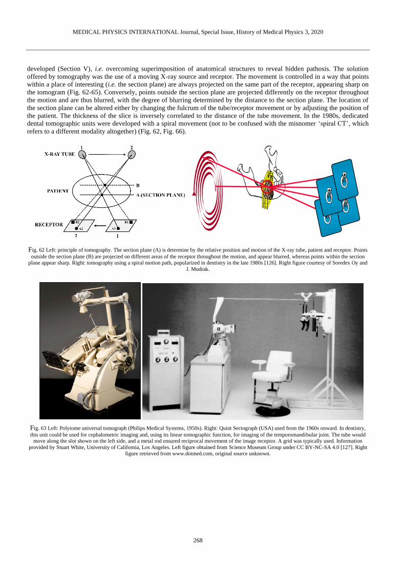
developed (Section V), i.e. overcoming superimposition of anatomical structures to reveal hidden pathosis. The solution
offered by tomography was the use of a moving X-ray source and receptor. The movement is controlled in a way that points
within a place of interesting (i.e. the section plane) are always projected on the same part of the receptor, appearing sharp on
the tomogram (Fig. 62-65). Conversely, points outside the section plane are projected differently on the receptor throughout
the motion and are thus blurred, with the degree of blurring determined by the distance to the section plane. The location of
the section plane can be altered either by changing the fulcrum of the tube/receptor movement or by adjusting the position of
the patient. The thickness of the slice is inversely correlated to the distance of the tube movement. In the 1980s, dedicated
dental tomographic units were developed with a spiral movement (not to be confused with the misnomer ‘spiral CT’, which
refers to a different modality altogether) (Fig. 62, Fig. 66).
Fig. 62 Left: principle of tomography. The section plane (A) is determine by the relative position and motion of the X-ray tube, patient and receptor. Points
outside the section plane (B) are projected on different areas of the receptor throughout the motion, and appear blurred, whereas points within the section
plane appear sharp. Right: tomography using a spiral motion path, popularized in dentistry in the late 1980s [126]. Right figure courtesy of Soredex Oy and
J. Mudrak.
Fig. 63 Left: Polytome universal tomograph (Philips Medical Systems, 1950s). Right: Quint Sectograph (USA) used from the 1960s onward. In dentistry,
this unit could be used for cephalometric imaging and, using its linear tomographic function, for imaging of the temporomandibular joint. The tube would move along the slot shown on the left side, and a metal rod ensured reciprocal movement of the image receptor. A grid was typically used. Information
provided by Stuart White, University of California, Los Angeles. Left figure obtained from Science Museum Group under CC BY-NC-SA 4.0 [127]. Right
figure retrieved from www.dotmed.com, original source unknown.
MEDICAL PHYSICS INTERNATIONAL Journal, Special Issue, History of Medical Physics 3, 2020
269
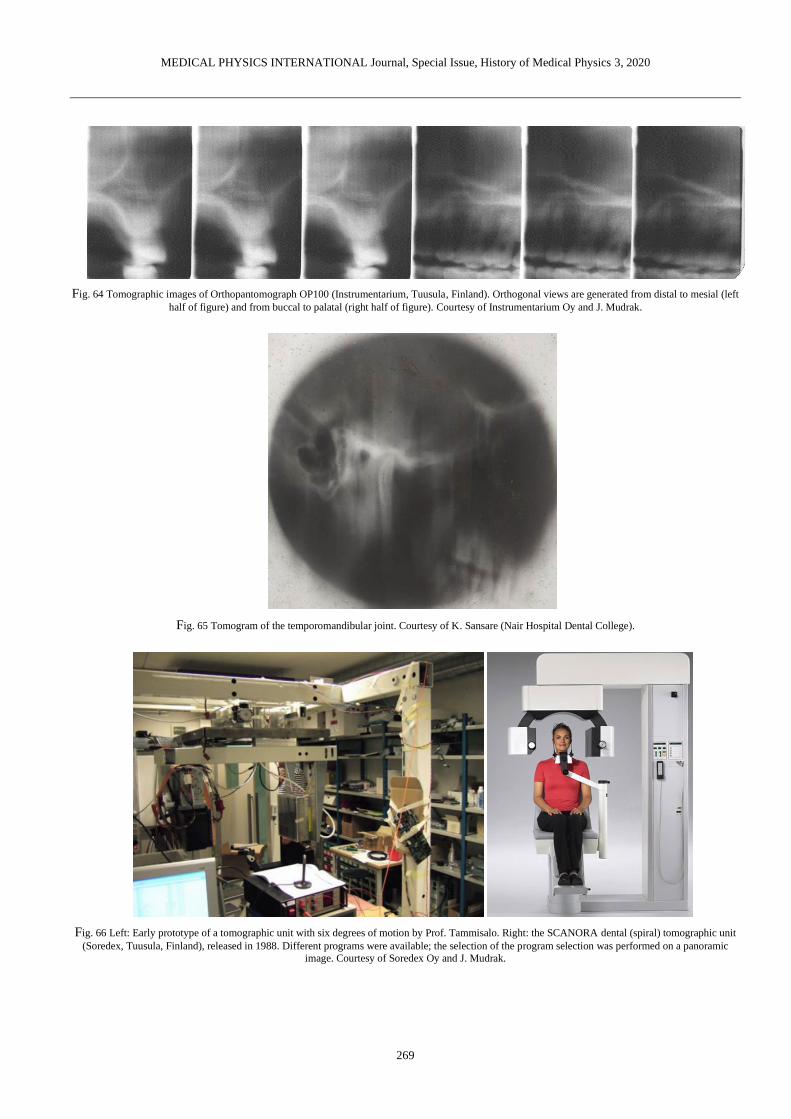
Fig. 64 Tomographic images of Orthopantomograph OP100 (Instrumentarium, Tuusula, Finland). Orthogonal views are generated from distal to mesial (left
half of figure) and from buccal to palatal (right half of figure). Courtesy of Instrumentarium Oy and J. Mudrak.
Fig. 65 Tomogram of the temporomandibular joint. Courtesy of K. Sansare (Nair Hospital Dental College).
Fig. 66 Left: Early prototype of a tomographic unit with six degrees of motion by Prof. Tammisalo. Right: the SCANORA dental (spiral) tomographic unit
(Soredex, Tuusula, Finland), released in 1988. Different programs were available; the selection of the program selection was performed on a panoramic
image. Courtesy of Soredex Oy and J. Mudrak.

MEDICAL PHYSICS INTERNATIONAL Journal, Special Issue, History of Medical Physics 3, 2020
270
XI. CONE-BEAM COMPUTED TOMOGRAPHY
The development of dedicated dental CBCT units was a logical outcome of the increased necessity for cross-sectional
imaging in dentistry, primarily due to the increasing popularity of implant placement. Whereas helical CT has been applied
in dentistry since its inception, and is still used to some extent, CBCT has become the convention in 3D dental imaging. In
the footsteps of dental tomography (section X), dental CBCT scanners were developed in the 1990s. Prior to dental CBCT,
this technology was used for applications such as angiography as early as 1982 [128]. Commercialization of dental CBCT
happened in parallel in Europe [129] and Japan [130], followed by the USA. The number of dental CBCT models on the
market has increased from 23 devices in 2008 [131], to 43 devices in 2013 [132], to 280 devices at the time of writing [133].
The technical aspects of CBCT have been described in a previous review [134], and patient dose has been measured by a
multitude of studies [135-140]. Most CBCT models have the patient in a standing or seated position; a few units use supine
patient positioning (Fig. 67). The first generation(s) dental CBCT units used image intensifier detector systems, but from the
mid-2000s the use of scintillator-type (indirect) flat panel detectors (FPD) increased and has since become the norm. FPDs
showed several benefits over image intensifier systems, including reduced bulk, improved spatial resolution at equal noise
level, and higher geometric accuracy [141]. Several of the first- and second-generation CBCT units used continuous
exposure, with an exposure time typically between 15-20 s. Due to the limited frame rate of FPD detectors and the presence
of afterglow, pulsed X-ray exposure was introduced, with total exposure time decreasing to a few seconds. Automatic
exposure control (AEC) is still largely absent in dental CBCT: a pre-scan AEC system based on the signal distribution of a
scout image (topogram) was introduced on NewTom (QR, Italy) systems several years ago (SafeBeamTM); more recently, the
same manufacturer has introduced tube current modulation during the scan based on pre-set mA curves [142], with a
relatively lower tube output for lateral projection angles due to the lower attenuation. The majority of current commercial
CBCT units, however, involve manual exposure set-up and/or the use of presets (e.g. adult male/female vs child protocols).
Reconstruction is typically based on the adapted filtered backprojection technique by Feldkamp-Davis-Kress [143].
Fig. 67 Seated (left), standing (middle) and supine (right) cone-beam computed tomography units.
Following the implementation of dual-energy scanning in medical CT, dual-energy CBCT was recently introduced
[144,145]. The main potential benefit of dual-energy CBCT in dentistry is artefact reduction; dual-energy imaging could also
allow for improved soft tissue contrast and/or density estimation, but there are few clinical indications in dentistry for which
this could be of benefit. Metal artefacts, however, are one of the most prominent artefacts in dental CBCT, often
deteriorating image quality to unacceptable levels. Whereas several CBCT units have incorporated a metal artefact reduction
(MAR) technique in their reconstruction algorithm, several studies have shown that diagnostic image quality was not
improved [146,147] or even impaired [148] when using MAR. This is likely due to the fact that currently used MAR
techniques on commercial units are fast, interpolation-based techniques; while they may lead to an esthetically improved
image, the additional diagnostic information provided by MAR can be limited. Iterative techniques that model the physics of
the system could offer a more robust solution to metal artefacts, but they are often computationally expensive and thus
impractical in a dental clinical environment. The use of artificial intelligence for real-time artefact correction could combine
the robustness of physics-based correction with the speed of backprojection, but requires further validation [149,150].
Another common artefact is due to patient motion; while this is mainly apparent in cases with severe movement, even
swallowing, breathing or reverberation of the jaw causes some degree of blurring. Motion correction based on selective
elimination of projections was introduced ca. 2007 (Iluma, IMTEC Imaging, USA) and has been implemented on a few
CBCT models; it has been shown that this approach can reduce motion artefacts and thus avoid the need for re-exposure

MEDICAL PHYSICS INTERNATIONAL Journal, Special Issue, History of Medical Physics 3, 2020
271
[151]. Recently, head tracking (X1, 3Shape, Denmark) [152] and reconstruction-based motion correction (CALMTM,
Planmeca, Helsinki, Finland) [153] were introduced.
XII. RADIOLOGICAL VIEWING/DISPLAY SYSTEMS
Along with the drastic improvement in image quality in the early years in radiographs came the necessity of appropriate
viewing systems (Fig. 68-72). Once film became ubiquitous in radiography, so did the lightbox [154]. Furthermore,
projections were used for the purpose of zooming, and specialized equipment was designed for stereoscopic (‘parallax’)
radiology as mentioned in section V.
Fig. 68 Left: Vintage lightbox (ca. 1930s). Picture formerly hosted on Hoarde Vintage; original source unknown. Right: dental X-ray projector (ca. 1940,
Spencer Lens Company). Figure and information provided by the Oak Ridge Associated Universities (ORAU) Health Physics Historical Instrumentation
Museum Collection under a non-transferable, non-exclusive, limited license [155].
Fig. 69 X-ray film illuminator; estimated manufacturing date 1950s. The level of illumination by the incandescent bulb was adjustable. Figure and
information provided by the Oak Ridge Associated Universities (ORAU) Health Physics Historical Instrumentation Museum Collection under a non-
transferable, non-exclusive, limited license [156].

MEDICAL PHYSICS INTERNATIONAL Journal, Special Issue, History of Medical Physics 3, 2020
272
Fig. 70 High intensity illuminator (Picker X-Ray, USA) with attached magnifying glass. Courtesy of S. Anamali (University of Iowa)
Fig. 71 Vintage intra-oral film mount. Courtesy of A. Wenzel (Aarhus University)

MEDICAL PHYSICS INTERNATIONAL Journal, Special Issue, History of Medical Physics 3, 2020
273
Fig. 72 Left: Radiograph copying machine. Courtesy of A. Al-Ekrish (King Saud University) Right: intra-oral film duplicator. Courtesy of S. Anamali
(University of Iowa).
For digital radiographs, although it still occurs to this day that they are printed on film (e.g. for external requests), cathode
ray tube (CRT) screens were initially used. More recently, (1) liquid-crystal display (LCD) with thin-film transistor (TFT)
technology and (2) light-emitting-diode (LED) display systems have become the norm. With recent improvements in
commercial off-the-shelf monitor technology, the benefit of costly ‘medical grade’ displays has been questioned, as the
improved technical specifications of the latter type could be overcome by proper use of software tools like display
calibration, window/level adjustment, zooming and filters. Furthermore, several recent studies have investigated the use of
tablets for displaying dental radiographs. For the diagnosis of vertical root fractures on periapical radiographs, no difference
was found between PC displays and tablets [157]. In the evaluation of caries on bitewing radiographs, increased performance
was found for DICOM-calibrated consumer-grade displays vs. uncalibrated displays [158], although diagnostic accuracy was
not assessed due to the absence of a ground truth. Tablet displays showed an almost equal performance to calibrated
consumer-grade displays, both of which performed slightly worse than medical-grade displays [158]. Another study found
that tablet displays performed equal to PACS-LCD monitors in the identification of anatomical landmarks in panoramic and
lateral cephalometric radiographs [159]. In an evaluation of anatomical structures on cone-beam CT scans, a tablet display,
PACS-LCD monitor, consumer-grade LCD monitor and laptop display all showed similar performance [160].
Recently, the use of augmented reality and virtual reality in image-guided surgery, both during pre-operative planning and
intra-operatively, has gained attention [161-163]; further validation of this technology is needed in terms of effects on
surgical time and outcome.
A NOTE ON HISTORICAL ACCURACY, COMPLETENESS AND SCOPE
During the preparation of this review, care was taken to ensure accuracy in terms of people, actions, dates and technology,
relying on primary sources when possible. However, due to the limited availability/accessibility of such courses (most
famously Röntgen’s notes, burned at his own request after his death), and conflicting information found in secondary/tertiary
sources, a fully accurate representation of the 125-year old history of dental radiography cannot be guaranteed. The
discrepancy between previously published information was mainly apparent when dealing with issues such as “In [year],
[person/company] was the first to [develop/use something] in [country/region].”
Furthermore, several role-players in dental X-ray history were omitted from this review, either due to a lack of
information regarding their exact contribution, or for conciseness. Little or no history of CT was included, as this is better
suited for a separate review. Modalities that do not make use of ionizing radiation (i.e. magnetic resonance imaging,
ultrasound) are outside of the scope of this review.
ACKNOWLEDGMENTS
R. Pauwels is supported by the European Union Horizon 2020 Research and Innovation Programme under the Marie
Skłodowska-Curie grant agreement number 754513 and by Aarhus University Research Foundation (AIAS-COFUND).
The author is heavily indebted to the extensive collection of historical information on dental radiography performed by
authors of previously published work, and would like to emphasize in particular the publications by AAOMR [29], Campbell

MEDICAL PHYSICS INTERNATIONAL Journal, Special Issue, History of Medical Physics 3, 2020
274
[70], Forrai [11], Glenner [52], Hallikainen [100], Jacobsohn & Fedran [16], Martinez [17], and Serman & Singer [19], and
to recommend each of them for further reading.
A special thanks to Asma'a Al-Ekrish (King Saud University), Sindhura Anamali (University of Iowa), Johan K.M. Aps
(University of Western Australia), Daniel Bednarek (University at Buffalo, Museum of Radiology and Medical Physics),
Pam Bonee & Paul Frame (Oak Ridge Associated Universities, Health Physics Historical Instrumentation Museum
Collection), Keith Horner (University of Manchester), Instrumentarium (Tuusula, Finland), Freny Karjodkar (Nair Hospital
Dental College), Jörg Mudrak, J Morita (Kyoto, Japan), Pisha Pittayapat (Chulalongkorn University), Kaustubh Sansare
(Nair Hospital Dental College), Steven R. Singer (Rutgers, The State University of New Jersey), Phonkit Sinpitaksakul
(Chulalongkorn University), Soredex (Tuusula, Finland), Slavik Tabakov (King’s College London), Karla de Faria
Vasconcelos (Catholic University of Leuven), Rick Waters, Ann Wenzel (Aarhus University) and Stuart White (University
of California, Los Angeles) for providing various source material.
The Author declares that there is no conflict of interest.
REFERENCES
1. Röntgen W (1895) Ueber eine neue Art von Strahlen. Vorläufige Mitteilung. Aus den Sitzungsberichten der Würzburger Physik.-medic. Gesellschaft
Würzburg: 137-147
2. Behling R (2018) X-ray tubes development - IOMP history of medical physics. Med Phys Int: 6:8-55 3. Walden TL Jr (1991) The first radiation accident in America: a centennial account of the x-ray photograph made in 1890. Radiology 181:635-639
4. Conrad C (2011) Vergleich der metrischen Genauigkeit von extraoralen Röntgenverfahren: in vitro Studie an humanen Schädelpräparaten.
Dissertation, Justus Liebig University Giessen. 5. Gianfaldoni S, Gianfaldoni R, Wollina U et al. (2017) An Overview on Radiotherapy: From Its History to Its Current Applications in Dermatology.
Open Access Maced J Med Sci 5:521-525 DOI 10.3889/oamjms.2017.122
6. Sansare K, Khanna V, Karjodkar F (2011) Early victims of X-rays: a tribute and current perception. Dentomaxillofac Radiol 40:123-125 DOI 10.1259/dmfr/73488299
7. Harrison F (1896) The New Photography and its Application to Dental Practice. J Br Dent Assoc 17:343-344
8. Figures K, Smith C (2012) A profile of Frank Harrison: a pioneering Sheffield dentist from 100 years ago. Br Dent J 213:405–408 DOI 10.1038/sj.bdj.2012.931
9. Zesch S, Panzer S, Rosendahl W, et al (2016) From first to latest imaging technology: Revisiting the first mummy investigated with X-ray in 1896 by
using dual-source computed tomography. Eur J Radiol Open 25:172-181. DOI 10.1016/j.ejro.2016.07.002 10. König W (1896) 14 Photographien mit Röntgen-Strahlen aufgenommen im Physikalischen Verein zu Frankfurt a. M. Johann Ambrosius Barth,
Leipzig.
11. Forrai J (2007) History of X-ray in dentistry. Rev Clín Pesq Odontol 3:205-211 12. Langland OE, Peter Fortier A (172) C. Edumund Kells. Oral Surg Oral Med Oral Path 34:680-689 DOI 10.1016/0030-4220(72)90353-2
13. Kells CE (1926) Three score years and nine. Self-published.
14. Price WA (1904) The technique necessary for making good dental skiagraphs. Dent Items Interest 26:161-171 15. McCormack FW (1920) A Plea for a Standardized Technique for Oral Radiography, with an Illustrated Classification of Findings and Their Verified
Interpretations. J Dent Res 2:467-509 DOI 10.1177/00220345200020030401
16. Jacobsohn PH, Fedran RJ (1995) Making Darkness Visible: The Discovery of X-ray and Its Introduction to Dentistry. J Am Dent Assoc 126:1359-1366
17. Martinez B (2013) In a New Light: Early X-Ray Technology in Dentistry, 1890-1955. Dissertation, Arizona State University.
18. Morton WJ (1896) The x-ray and its application in dentistry. Dent Cosmos 38:478-485 19. Serman N, Singer SR (1995) The history of dental radiology. N Y State Dent J 61:78-81
20. Morton WJ, Hammer EW (1896) The X-Ray or Photography of the Invisible and its Value in Surgery. American Technical Book Co., New York.
21. Price WA (1900) The Roentgen rays with associated phenomena and their applications to dentistry. Dent Cosmos 42:117-129 22. Kells CE (1926) Thirty years’ experience in the field of radiography. J Am Dent Assoc 13:693-711
23. Kells CE (1927) Roentgen-ray burns. J Am Dent Assoc 14:235
24. Rollins WH (1901) X-light kills. Boston Med Surg J 144:173 25. Rollins WH (1903) Notes on x-light: the effect of x-light on the crystalline lens. Boston Med Surg J 148:364-365.
26. Wynbrandt J (1998) The Excruciating History of Dentistry. St. Martin’s Griffin, New York
27. Kathren RL (1964) William Rollins (1852-1929): X-ray protection pioneer. J Hist Med Allied Sci 19:287-294 28. Roeder F, von Rechenberg I, d'Hoedt B, et al. (2011). Spatial relation between a rigid (digital) intraoral X-ray receptor and longitudinal axes of
maxillary teeth. Clin Oral Investig 15:715-9. DOI 10.1007/s00784-010-0430-x
29. AAOMR at https://www.aaomr.org/assets/History/early_pioneers_of_oral_and_m.pdf 30. Richards AG (1966) New concepts in dental X-ray machines. J Am Dent Assoc 73:69-76 DOI 10.14219/jada.archive.1966.0232
31. ‘Oradlist’ Oral Radiology Discussion Group contribution by R. Molteni (2013) 32. Rushton VE, Horner K (1994) The acceptability of five periapical radiographic techniques to dentists and patients. Br Dent J 177:325-331
33. Peciuliene V, Rimkuviene J, Maneliene R, et al (2009) Use of dental radiography among Lithuanian general dentists. Stomatologija 11:77-82
34. Hedley WS (1898) Radiostereoscopy. Lancet 151:639 35. Clark CA (1910) A Method of ascertaining the Relative Position of Unerupted Teeth by means of Film Radiographs. Proc R Soc Med 3:87-90
36. Armstrong C, Johnston C, Burden D, et al (2003) Localizing ectopic maxillary canines--horizontal or vertical parallax?. Eur J Orthod 25:585-589
37. Hubar JS, Caballero P (2017) Localization of Objects (SLOB Rule). In: Fundamentals of Oral and Maxillofacial Radiology. John Wiley & Sons, Hoboken DOI 10.1002/9781119411871.ch18
38. Richards AG (1952) Roentgenographic localization of the mandibular canal. J Oral Surg 10:325-329
39. Richards AG (1953) The buccal object rule. J Tennessee State Dent Assoc 33:263-268 40. Ingle JI, Bakland LK, Baumgartner JC (2008). Ingle's Endodontics 6 (6th ed.). BC Decker, Hamilton
41. Pieper AF, Kester GL (1931) Stereoscopic view box. U.S. Pat. No. 1808176.

MEDICAL PHYSICS INTERNATIONAL Journal, Special Issue, History of Medical Physics 3, 2020
275
42. Oak Ridge Associated Universities (ORAU) Health Physics Historical Instrumentation Museum Collection at https://www.orau.org/ptp/collection/Radiology/Stereo%20viewer.htm
43. Pfahler GE (1908) The use of the roentgen rays in dentistry. Dent Cosmos 50:916-919
44. Oak Ridge Associated Universities (ORAU) Health Physics Historical Instrumentation Museum Collection at https://www.orau.org/ptp/collection/Radiology/dentoscope.htm
45. Oak Ridge Associated Universities (ORAU) Health Physics Historical Instrumentation Museum Collection at
https://www.orau.org/ptp/collection/Radiology/indianheadreflector.htm 46. Rollins WH (1898) Roentgen-ray notes. Electr Rev 32:12
47. Kells CE (1899) Roentgen rays. Dent Cosmos 41:1014-1029 48. Borden WC (1898) The use of the Röntgen ray by the medical department of the United States military in the war with Spain.
49. Mackee GM, Remer J (1914) Measurement of the amount of x ray employed in making dental radiographs. Dent Cosmos 56:35-42
50. Jacobsohn PH, Fedran RJ (1995) Harnessing the x-ray: Coolidge’s contribution. J Am Dent Assoc 126:1365 DOI 10.14219/jada.archive.1995.0045 51. Coolidge WD (1919). X-ray apparatus. U.S. Patent 1408989
52. Glenner RA (1975) 80 years of dental radiography. J Am Dent Assoc 90:549-563.
53. Science Museum Group at https://collection.sciencemuseumgroup.org.uk/objects/co100154/cdx-model-e-dental-x-ray-unit-chicago-usa-1935-1936-x-ray-machine
54. Coolidge WD (1919) X-ray Apparatus. U.S. Patent 1310061.
55. Oak Ridge Associated Universities (ORAU) Health Physics Historical Instrumentation Museum Collection at https://www.orau.org/ptp/collection/xraytubescoolidge/Victordental.htm
56. UB Museum of Radiology and Medical Physics at http://ubradiologymuseum.com/
57. Gross MJ (1935) Progress in the Design of Shock Proof Roentgen Tubes for Therapy and Industrial Roentgenography. Am J Roent Radium Therapy 34:518-522
58. Oak Ridge Associated Universities (ORAU) Health Physics Historical Instrumentation Museum Collection at
https://www.orau.org/ptp/collection/xraytubescoolidge/GEXPD.htm 59. Oak Ridge Associated Universities (ORAU) Health Physics Historical Instrumentation Museum Collection at
https://www.orau.org/ptp/collection/xraytubescoolidge/grossshockproof.htm
60. Science Museum Group at https://collection.sciencemuseumgroup.org.uk/objects/co100221/artiflex-dental-unit-by-siemens-reiniger-werke-a-dental-units
61. Velders XL, van Aken J, van der Stelt PF (1991) Absorbed dose to organs in the head and neck from bitewing radiography. Dentomaxillofac Radiol
20:161-165 62. Shetty A, Almeida FT, Ganatra S, et al. (2019) Evidence on radiation dose reduction using rectangular collimation: a systematic review. Int Dent J
69:84-97. DOI 10.1111/idj.12411
63. Magill D, Ngo NJH, Felice MA, et al. (2019) Kerma area product (KAP) and scatter measurements for intraoral X-ray machines using three different types of round collimation compared with rectangular beam limiter. Dentomaxillofac Radiol 48:20180183. DOI 10.1259/dmfr.20180183.
64. Ludlow JB, Davies-Ludlow LE, White SC (2008) Patient risk related to common dental radiographic examinations: the impact of 2007 International
Commission on Radiological Protection recommendations regarding dose calculation. J Am Dent Assoc 139:1237-1243. 65. Pittayapat P, Jacobs R, De Valck E, et al. (2012) Forensic odontology in the disaster victim identification process. J Forensic Odontostomatol 30:1-12
66. Berkhout WER, Suomalainen A, Brullmann D, et al. (2015) Justification and good practice in using handheld portable dental x-ray equipment: a
position paper prepared by the European Academy of Dentomaxillofacial Radiology (EADMFR) Dentomaxillofac Radiol 44:20140343 DOI 10.1259/dmfr.20140343
67. HERCA (2014) Position statement on use of handheld portable dental x-ray equipment.
http://www.herca.org/uploaditems/documents/HERCA%20position%20statement%20on%20use%20of%20handheld%20portable%20dental%20x-ray%20equipment.pdf
68. Thunthy KH. Timeline of Oral and Maxillofacial Radiology. https://www.aaomr.org/assets/History/timeline_of_omr.pdf
69. Röntgen W (1897) Further Observations on the Properties of X-ray. Prussian Academy of Sciences, Berlin. 70. Campbell DJ (1995) A brief history of dental radiography. N Z Dent J 91:127-133
71. U.S. Food and drug administration. Nationwide Evaluation of X-Ray Trends (NEXT). Dental Radiography: Doses and Film Speed.
72. Bolin L (1925) Dental x-ray-film package. U.S. Pat. No. 1,537,925
73. Oak Ridge Associated Universities (ORAU) Health Physics Historical Instrumentation Museum Collection at
https://www.orau.org/ptp/collection/Radiology/Dental%20Film.htm
74. Oak Ridge Associated Universities (ORAU) Health Physics Historical Instrumentation Museum Collection at https://www.orau.org/ptp/collection/Radiology/Dental%20cassettes.htm
75. Geo. W. Brady & Company (1937) Paragon X-ray Supplies and Accessories.
76. Oak Ridge Associated Universities (ORAU) Health Physics Historical Instrumentation Museum Collection at https://www.orau.org/ptp/collection/Radiology/intra-oral%20film%20blocks.htm
77. Oak Ridge Associated Universities (ORAU) Health Physics Historical Instrumentation Museum Collection at
https://www.orau.org/ptp/collection/Radiology/intra-oral%20film%20blocks.htm 78. Kells CE (1922) Practical development of dental films. Dent Items Interest 44:927-937
79. Yoshida M, Yoshihara H, Honda E (2018) History of Digital Detectors in Intraoral Radiography. Dent Health Curr Res 4 DOI 10.4172/2470-0886.1000135
80. Duret F, Coste BC, Duret, B (1988) The Radio Visiography (RVG): where reality surpasses radiological fiction a hope that is becoming reality. J Dent
Pract Admin 5:138-140 81. Borg E (1999) Some characteristics of solid-state and photo-stimulable phosphor detectors for intra-oral radiography. Swed Dent J Suppl 139:1-67
82. Borg E, Grondahl HG (1996) On the dynamic range of different X-ray photon detectors in intra-oral radiography. a comparison of image quality in
film, charge-coupled device and storage phosphor systems. Dentomaxillofac Radiol 25: 82-88. 83. Attaelmanan AG, Borg E, Gröndahl HG (2001) Signal-to-noise ratios of 6 intraoral digital sensors. Oral Surg Oral Med Oral Pathol Oral Radiol Endod
91:611-615
84. Wenzel A, Møystad A (2001) Experience of Norwegian general dental practitioners with solid state and storage phosphor detectors. Dentomaxillofac Radial 30:203-208
85. ICRP (2007) The 2007 Recommendations of the International Commission on Radiological Protection. ICRP publication 103. Ann ICRP 37:1-332
86. Ludlow JB, Davies-Ludlow LE, White SC (2008) Patient risk related to common dental radiographic examinations: the impact of 2007 International Commission on Radiological Protection recommendations regarding dose calculation. J Am Dent Assoc 139:1237-1243
87. Pogorzelska-Stronczak B (1963) Attempted application of xeroradiography in stomatology. Pol Przegl Radiol Med Nukl 27:265-275

MEDICAL PHYSICS INTERNATIONAL Journal, Special Issue, History of Medical Physics 3, 2020
276
88. Ferguson MM, Davison M, Evans A, et al. (1976) Application of xeroradiography in sialography. Int J Oral Surg 5:176-179 89. Gratt BM, Sickles EA, Nguyen NT (1979) Dental xeroradiography for endodontics: a rapid X-ray system that produces highquality images. J Endod
5:266-270
90. Jeromin LS, Geddes GF, White SC, et al. (1980) Xeroradiography for intraoral dental radiology. A process description. Oral Surg Oral Med Oral Pathol 49:178-183
91. Barkhordar RA, Nicholson RJ, Nguyen NT, et al. (1987) An evaluation of xeroradiographs and radiographs in length determination in endodontics.
Oral Surg Oral Med Oral Pathol 64:747-750 92. Gratt BM, Sickles EA, Nguyen NT (1979) Dental xeroradiography for endodontics: a rapid X-ray system that produces highquality images. J Endod
5:266-270 93. Wilson NH, Grant AA (1986) A clinical trial of dental xeroradiography. Br Dent J 161:327-335
94. Udoye CI, Jafarzadeh H (2010) Xeroradiography: stagnated after a promising beginning? A historical review. Eur J Dent 4:95-99
95. Tammisalo EH (1975) Professor Yrjö v. Paatero - the pioneer of panoramic oral tomography. Dentomaxillofac Radiol 4:53-56. DOI 10.1259/dmfr.1975.0010
96. Zulauf AF (1922) Panoramic X-ray apparatus. U.S. Patent No 1408559
97. Numatha H (1933) Consideration of the parabolic radiography of the dental arch. J Shimazu Stud 10:13 98. Heckmann K (1939) Die Rontgenperspektive und ihre Umwandlung durch eine neue Aufnahmetechnik. RöFo 60:144-157
99. Dickson G, Hudson DC, Kumpula JW (1957) A panoramic x-ray dental machine. U S Armed Forces Med J 13:46-55
100. Hallikainen D (1996) History of panoramic radiography. Acta Radiol 37:441-445 101. Paatero YV (1952) Thickness of layer reproduced on pantomogram in relation to location of the object, speed of rotation, and divergence of roentgen
rays. Soumen Hammaslaiikariseuran Toimituksia 48:113-128
102. Paatero YV (1953) Radiography of the temporo-mandibular joint. A new method. Ann Chir Gynaecol Fenn 42:259-264 103. Paatero YV (1954) Geometrical study on possibilities of making double eccentric pantomograms with a single exposure. Suomen
Hammaslaiikariseuran Toimituksia 50:36-43
104. Paatero YV (1955) Die Andwendungen der Pantomographie fur klinische Untersuchungen. RöFo 82:525-528 105. Paatero YV (1957) Pantomography of spherical layers. Acta Radiol 48:181-187
106. Blackman S (1956) Mass dental radiography. Radiography 22:21-25
107. Br J Radiol. 1979 Sep;52(621):727-34. Doses to patients from pantomographic and conventional dental radiography. Wall BF, Fisher ES, Paynter R, Hudson A, Bird PD.
108. McDavid WD, Tronje G, Welander U (1989) Image layers in the Zonarc. Dentomaxillofac Radiol 18:1-10
109. Kashima I, Kanno M, Higashi T, et al. (1985) Computed panoramic tomography with scanning laser-stimulated luminescence. Oral Surg Oral Med Oral Pathol 60:448-453
110. McDavid WD, Dove SB, Welander U, et al. (1991) Electronic system for digital acquisition of rotational panoramic radiographs. Oral Surg Oral Med
Oral Pathol 71:499-502 111. Dove SB, McDavid WD, Welander U, et al. (1992) Preliminary evaluation of a digital system for rotational panoramic radiography. Oral Surg Oral
Med Oral Pathol 73:623-632
112. Qiang W, Qiang F, Lin L (2019) Estimation of effective dose of dental x-ray devices. Radiat Prot Dosimetry. 183:417-421. DOI 10.1093/rpd/ncy159 113. Benchimol D, Koivisto J, Kadesjö N, et al. (2018) Effective dose reduction using collimation function in digital panoramic radiography and possible
clinical implications in dentistry. Dentomaxillofac Radiol 47:20180007. DOI 10.1259/dmfr.20180007
114. Gijbels F, Jacobs R, Bogaerts R, et al. (2005) Dosimetry of digital panoramic imaging. Part I: Patient exposure. Dentomaxillofac Radiol 34:145-149 115. IAEA at https://www.iaea.org/resources/rpop/resources/training-material#11
116. Broadbent HB (1931) A new X-ray technique and its application to orthodontia. Angle Orthod 1:45-66
117. Hofrath H (1931) Die Bedeutung der Röntgenfern– und Abstandsaufnahme für die Diagnostik der Kieferanomalien. Fortschritte Orthod 1:232-258 118. Broadbent HB (1937) The face of the normal child. Angle Orthod 7:183-208.
119. Ricketts RM (1969) The evolution of diagnosis to computerized cephalometrics. Am J Orthod Dentofacial Orthop 55:795-803
120. Barsony T (1925) Idiopathic Dilatation of Stenson's Duct. Klin Wchnschr 4:2500-2501 121. Holt JF (1957). Sialography. Radiology 68:584–585
122. Rubin P, Blatt M (1955) Sialography, Preliminary Report. Univ Michigan M Bull 21:57-63
123. Rubin P, Blatt M, Holt JF, Maxwell JH (1955) Physiological or Secretory Sialography. Ann Oto1 Rhin Laryng 64:667-688
124. Afzelius P, Nielsen MY, Ewertsen C, et al. (2016) Imaging of the major salivary glands. Clin Physiol Funct Imaging 36:1-10. DOI 10.1111/cpf.12199
125. Littleton JT, Littleton MLD (1996) Conventional tomography. A History of the Radiological Sciences. American Roentgen Society, Leesburg.
126. Tammisalo E, Hallikainen D, Kanerva H, et al. (1992) Comprehensive oral X-ray diagnosis: Scanora multimodal radiography. A preliminary description. Dentomaxillofac Radiol 21:9-15
127. Science Museum Group at https://collection.sciencemuseumgroup.org.uk/objects/co440061/tomograph-united-kingdom-1950-1959-tomograph
128. Robb RA (1982) The dynamic spatial reconstructor: an x-ray video-fluoroscopic CT scanner for dynamic volume imaging of moving organs. IEEE Trans Med Imaging 1:22-33
129. Mozzo P, Procacci C, Tacconi A, et al. (1998) A new volumetric CT machine for dental imaging based on the cone-beam technique: preliminary
results. Eur Radiol 8:1558-1564 130. Arai Y, Tammisalo E, Iwai K, et al. (1999) Development of a compact computed tomographic apparatus for dental use. Dentomaxillofac. Radiol
28:245-248 131. Kau CH, Bozic M, English J, et al. (2009) Cone-beam computed tomography of the maxillofacial region: an update. Int J Med Robot Comput Assist
Surg 5:366-80
132. Nemtoi A, Czink C, Haba D, et al. Cone beam CT: a current overview of devices. Dentomaxillofacial Radiol 42:20120443 133. Gaêta-Araujo H, Alzoubia T, Vasconcelos KF, et al. Cone-beam computed tomography in Dentomaxillofacial radiology: a two-decade overview. Pre-
published.
134. Pauwels R, Araki K, Siewerdsen JH, et al. (2015) Technical aspects of dental CBCT: state of the art. Dentomaxillofac Radiol 44:20140224 DOI 10.1259/dmfr.20140224
135. Al-Okshi A, Lindh C, Salé H, et al. (2015) Effective dose of cone beam CT (CBCT) of the facial skeleton: a systematic review. Br J Radiol
88:20140658 DOI 10.1259/bjr.20140658 136. Ludlow JB, Timothy R, Walker C, et al. (2015) Effective dose of dental CBCT-a meta analysis of published data and additional data for nine CBCT
units. Dentomaxillofac Radiol 44:20140197 DOI 10.1259/dmfr.20140197
137. Pauwels R, Beinsberger J, Collaert B, et al. (2012) Effective dose range for dental cone beam computed tomography scanners. Eur J Radiol 81:267-271 DOI 10.1016/j.ejrad.2010.11.028

MEDICAL PHYSICS INTERNATIONAL Journal, Special Issue, History of Medical Physics 3, 2020
277
138. Bornstein MM, Scarfe WC, Vaughn VM, et al. (2014) Cone beam computed tomography in implant dentistry: a systematic review focusing on guidelines, indications, and radiation dose risks. Int J Oral Maxillofac Implants 29S:55-77 DOI 10.11607/jomi.2014suppl.g1.4
139. Rottke D, Patzelt S, Poxleitner P, et al. (2013) Effective dose span of ten different cone beam CT devices. Dentomaxillofac Radiol 42:20120417 DOI
10.1259/dmfr.20120417 140. Pauwels R (2015) Cone beam CT for dental and maxillofacial imaging: dose matters. Radiat Prot Dosimetry 165:156-161. DOI 10.1093/rpd/ncv057
141. Baba R, Konno Y, Ueda K et al. (2002) Comparison of flat-panel detector and image-intensifier detector for cone-beam CT. Comput Med Imaging
Graph 26:153-158 142. Stratis A, Zhang G, Lopez-Rendon X, et al. (2017) Two examples of indication specific radiation dose calculations in dental CBCT and Multidetector
CT scanners. Phys Med 41:71-77 DOI 10.1016/j.ejmp.2017.03.027 143. Feldkamp LA, Davis LC, Kress JW (1984) Practical cone-beam algorithm. J Opt Soc Am A 1:612-619
144. Kim HJ, Kim JE, Choo J, et al. (2019) A clinical pilot study of jawbone mineral density measured by the newly developed dual-energy cone-beam
computed tomography method compared to calibrated multislice computed tomography. Imaging Sci Dent 49:295-299 DOI 10.5624/isd.2019.49.4.295 145. Zhu L, Chen Y, Yang J, et al. (2019) Evaluation of the dental spectral cone beam CT for metal artefact reduction. Dentomaxillofac Radiol
48:20180044 DOI 10.1259/dmfr.20180044
146. Kamburoğlu K, Yılmaz F, Yeta EN, et al. (2016) Assessment of furcal perforations in the vicinity of different root canal sealers using a cone beam computed tomography system with and without the application of artifact reduction mode: an ex vivo investigation on extracted human teeth. Oral
Surg Oral Med Oral Pathol Oral Radiol 121:657-665 DOI 10.1016/j.oooo.2016.01.010
147. de-Azevedo-Vaz SL, Peyneau PD, Ramirez-Sotelo LR, et al. (2016) Efficacy of a cone beam computed tomography metal artifact reduction algorithm for the detection of peri-implant fenestrations and dehiscences. Oral Surg Oral Med Oral Pathol Oral Radiol 121:550-556 DOI
10.1016/j.oooo.2016.01.013
148. Bezerra IS, Neves FS, Vasconcelos TV, et al. (2015) Influence of the artefact reduction algorithm of Picasso Trio CBCT system on the diagnosis of vertical root fractures in teeth with metal posts. Dentomaxillofac Radiol 44:20140428 DOI 10.1259/dmfr.20140428
149. Pauwels R, Oliveira-Santos C, Oliveira ML, et al. (2019) Artefact reduction in cone beam CT through deep learning: a pilot study using neural
networks in the projection domain. The 22nd International Congress of DentoMaxilloFacial Radiology, Philadelphia, PA, USA, 2019 150. Pauwels R, Oliveira-Santos C, Watanabe P, et al. (2020) Correction of exomass artefacts in dental cone-beam CT using convolutional neural networks
poster. EPOS C-14953, European Congress of Radiology, Vienna, Austria, 2020
151. Yeung AWK, Azevedo B, Scarfe WC, et al. (2019) Patient motion image artifacts can be minimized and re-exposure avoided by selective removal of a sequence of basis images from cone beam computed tomography data sets: a case series. Oral Surg Oral Med Oral Pathol Oral Radiol. In press. DOI
10.1016/j.oooo.2019.07.003
152. 3Shape at https://www.3shape.com/en/scanners/x1-cbct 153. Planmeca at https://www.planmeca.com/imaging/3d-imaging/planmeca-calm/
154. Seeley GW, McNeill K, Dallas WJ (1987) Displays in radiology: past, present, and future. Radiographics 7:1261-1266
155. Oak Ridge Associated Universities (ORAU) Health Physics Historical Instrumentation Museum Collection at https://www.orau.org/ptp/collection/Radiology/Dental%20xray%20projector.htm
156. Oak Ridge Associated Universities (ORAU) Health Physics Historical Instrumentation Museum Collection at
https://www.orau.org/ptp/collection/Radiology/xrayviewer.htm 157. Vasconcelos TV, Santaella GM, Nascimento HA, et al. (2016) Digital radiographs displayed on different devices: effect on the detection of vertical
root fractures. Int Endod J 49:386-392 DOI 10.1111/iej.12466
158. Kallio-Pulkkinen S, Huumonen S, Haapea M, et al. (2016) Effect of display type, DICOM calibration and room illuminance in bitewing radiographs. Dentomaxillofac Radiol 45:20150129 DOI 10.1259/dmfr.20150129
159. Tadinada A, Mahdian M, Sheth S, et al. (2015) The reliability of tablet computers in depicting maxillofacial radiographic landmarks. Imaging Sci Dent
45:175-180. DOI 10.5624/isd.2015.45.3.175 160. Carrasco A, Jalali E, Dhingra A, et al. (2017) Analyzing dental implant sites from cone beam computed tomography scans on a tablet computer: a
comparative study between iPad and 3 display systems. Implant Dent 26:393-399 DOI 10.1097/ID.0000000000000595
161. Kwon HB, Park YS, Han JS (2018) Augmented reality in dentistry: a current perspective. Acta Odontol Scand 76:497-503 DOI 10.1080/00016357.2018.1441437
162. Bartella AK, Kamal M, Scholl I, et al. (2019) Virtual reality in preoperative imaging in maxillofacial surgery: implementation of "the next level"? Br J
Oral Maxillofac Surg 57:644-648 DOI 10.1016/j.bjoms.2019.02.014
163. Jiang W, Ma L, Zhang B, et al. (2018) Evaluation of the 3D augmented reality-guided intraoperative positioning of dental implants in edentulous
mandibular models. Int J Oral Maxillofac Implants 33:1219-1228 DOI 10.11607/jomi.6638
Contacts of the corresponding author:
Author: Ruben Pauwels
Institute: Aarhus Institute of Advanced Studies Street: Høegh-Guldbergs Gade 6B
City: 8000 Aarhus Country: Denmark
Email: [email protected]