Design of the GG satellite
8
Physics Letters A 318 (2003) 205–212 www.elsevier.com/locate/pla Design of the GG satellite A. Anselmi ∗ , G. Catastini Scientific Satellites Directorate, Alenia Spazio S.p.A., Turin, Italy Received 5 February 2003; accepted 28 July 2003 Communicated by V.M. Agranovich Abstract The design of the satellite for the GG experiment was addressed in phase-A level studies in 1997–2000, based on an equatorial orbit, and more recently re-addressed for sun-synchronous orbit (SSO). The mission consists of an experiment running uninterrupted with few operational modes, small telemetry rates, easily controlled by one ground station. The satellite is small, low-weight, with low power demand. The configuration, resembling a spinning top, is very compact and stiff. The main requirements are for thermal stability, drag-free control and spin rate control. The reconfiguration to SSO makes the mission suitable for a low-cost launch, and improves the thermal performance. 2003 Elsevier B.V. All rights reserved. PACS: 07.87.+v 1. Introduction GG is a small scientific satellite mission with the objective of testing the equivalence principle (EP) to 1 part in 10 17 , four orders of magnitude better than the best experiments to date. The experiment [1,2] con- sists in testing the universality of free fall by means of two concentric hollow cylinders of different composi- tion (the test masses) in orbit in the gravitational field of the Earth. Two additional cylinders, also concen- tric, made from the same materials, provide the zero- check. The cylinders spin around their common axis, perpendicular to the orbit plane, at a rate (2 Hz) much larger than the orbit rate. Weak suspensions constrain the motion to the plane perpendicular to the spin axis. * Corresponding author. E-mail address: [email protected] (A. Anselmi). Suitable sensors (capacitance plates) located between the test masses detect the relative displacements. A vi- olation of EP would manifest itself as a displacement of the order of 1 pm, constant in the orbit frame and directed toward the center of the Earth. The test bodies, their mechanical coupling and the capacitance read-out are the core of the mission. Once the experimental design has been conceived, the required features of the spacecraft and its attitude and orbit follow. The spacecraft must provide a suitable accommodation to the experiment, provide specific and stable mass properties, shield it from thermal and dynamic perturbations within specified limits. The spin axis must be nearly perpendicular to the orbit plane, gyroscopic stiffness providing stability against external attitude disturbances. The orbit must be near circular, the altitude and inclination being selected as the best compromise between experiment needs and technical and cost considerations. 0375-9601/$ – see front matter 2003 Elsevier B.V. All rights reserved. doi:10.1016/j.physleta.2003.07.023
-
Upload
thalesgroup -
Category
Documents
-
view
0 -
download
0
Transcript of Design of the GG satellite

ed on anperimentsatellitee mainmission
Physics Letters A 318 (2003) 205–212
www.elsevier.com/locate/pla
Design of the GG satellite
A. Anselmi∗, G. Catastini
Scientific Satellites Directorate, Alenia Spazio S.p.A., Turin, Italy
Received 5 February 2003; accepted 28 July 2003
Communicated by V.M. Agranovich
Abstract
The design of the satellite for the GG experiment was addressed in phase-A level studies in 1997–2000, basequatorial orbit, and more recently re-addressed for sun-synchronous orbit (SSO). The mission consists of an exrunning uninterrupted with few operational modes, small telemetry rates, easily controlled by one ground station. Theis small, low-weight, with low power demand. The configuration, resembling a spinning top, is very compact and stiff. Threquirements are for thermal stability, drag-free control and spin rate control. The reconfiguration to SSO makes thesuitable for a low-cost launch, and improves the thermal performance. 2003 Elsevier B.V. All rights reserved.
PACS: 07.87.+v
eo 1heon-ofi-
eldn-ro-
xis,ch
trainxis.
eenA vi-entnd
ndion., theand
bleific
malherbitnstearasand
1. Introduction
GG is a small scientific satellite mission with thobjective of testing the equivalence principle (EP) tpart in 1017, four orders of magnitude better than tbest experiments to date. The experiment [1,2] csists in testing the universality of free fall by meanstwo concentric hollow cylinders of different compostion (the test masses) in orbit in the gravitational fiof the Earth. Two additional cylinders, also concetric, made from the same materials, provide the zecheck. The cylinders spin around their common aperpendicular to the orbit plane, at a rate (2 Hz) mularger than the orbit rate. Weak suspensions consthe motion to the plane perpendicular to the spin a
* Corresponding author.E-mail address: [email protected] (A. Anselmi).
0375-9601/$ – see front matter 2003 Elsevier B.V. All rights reserveddoi:10.1016/j.physleta.2003.07.023
Suitable sensors (capacitance plates) located betwthe test masses detect the relative displacements.olation of EP would manifest itself as a displacemof the order of 1 pm, constant in the orbit frame adirected toward the center of the Earth.
The test bodies, their mechanical coupling athe capacitance read-out are the core of the missOnce the experimental design has been conceivedrequired features of the spacecraft and its attitudeorbit follow. The spacecraft must provide a suitaaccommodation to the experiment, provide specand stable mass properties, shield it from therand dynamic perturbations within specified limits. Tspin axis must be nearly perpendicular to the oplane, gyroscopic stiffness providing stability agaiexternal attitude disturbances. The orbit must be ncircular, the altitude and inclination being selectedthe best compromise between experiment needstechnical and cost considerations.
.

206 A. Anselmi, G. Catastini / Physics Letters A 318 (2003) 205–212
edallI).theus
toesTheiesre
dsnterasereheairtionean
. AtithµN.tors
freeitytoherhe
eof
melmeedof
uldchle.tlythethe
meinsial
itialsun
un-
inonithde.alof
ngrialted.be) bythere-
dumon
alily
ne)och
The GG mission in equatorial orbit was studiat phase A level [1] as a candidate for the SmMission Program of the Italian Space Agency (ASMore recently, a supplementary study addressedimplementation of the mission in sun-synchronoorbit. A prototype of the GG payload was builtdemonstrate the validity of the physical principlon which the proposed space experiment relies.ground experiment is operational in the laboratorof LABEN in Florence. A second-generation, mosensitive prototype is under testing [2].
2. Orbit design
Since the intensity of the putative signal depenon the inverse-square of the distance from the ceof the Earth, the orbit altitude should be as lowpossible, and the orbit should be near-circular. A lowlimit to the altitude is set by the need to limit thdisturbing effects from the residual air density. Tcriterion adopted is that of an altitude at which thedrag is of comparable magnitude to the solar radiapressure (that does not depend on height). The maltitude adopted is 520 km and the period is 95 min520 km, the magnitude of the perturbing forces (wthe given spacecraft cross section) is less than 50This value also sets the requirements of the actuadedicated to balancing the perturbations (drag-control micro-thrusters). A residual orbit eccentricwill be induced by both natural perturbations duethe non-spherical potential of the Earth and launcinjection errors. The expected upper limit of teccentricity, of some parts in 103, is tolerable by theexperiment. As is well known, the flattening of thEarth J2 induces a secular precession of the linenodes of an orbit of radiusr and inclinationi at therate
Ω ≈ −3
2
(R
r
)2
J2ncos(i),
whereR is the radius of the Earth andn the satellitemean motion. Hence for any inclination different fro0 orπ/2, the spin axis of the satellite, initially parallto the normal to the orbit plane, will move away froit up to a maximum separation 2i reached after a timπ/Ω . For this reason, GG was originally conceivfor an equatorial orbit [1]. In this orbit, the attitude
the spin axis perpendicular to the orbit plane wobe naturally maintained. However, low-cost launopportunities for equatorial orbits are not availabSun-synchronous orbit (SSO) is far more frequenvisited and currently the cheapest option. HenceGG mission was redesigned for SSO. In SSO,inclination and radius are chosen such thatΩ equalsthe apparent rotation rate of the sun in an inertial fracentered in the Earth. Thus the orbit plane maintaits relative position with respect to the sun. A speccase is the so-called dawn-dusk orbit, where the inconditions are set such that the projection of thevector on the equator makes an angle ofπ/2 to the lineof nodes, i.e., the orbit rides the terminator. The ssynchronous inclination atr = R + 520 km is 97.5.
The effect of the inertially fixed attitude of the spaxis is that the ‘node’ of the spin axis (intersectiof the plane perpendicular to the spin axis wthe equatorial plane) lags behind the orbit noThus the spin axis will move away from its nominposition, aligned with the orbit normal, at a rateabout 1/day. This misalignment leads to a growicomponent of the EP signal out of the equatoplane of the satellite where the sensors are locaHence it must be corrected. The misalignment willcorrected every 20 days (1 measurement intervala dedicated spin axis turn maneuver executed byon-board thrusters. The average amplitude of theorientation maneuvers is 18.5 and they are executeat intervals selected in such a way that the maximmisalignment with respect to the ideal orientatidoes not exceed 10 (Fig. 1). The nominal launchtime for dawn-dusk SSO is 6 a.m. or 6 p.m., locsolar time (LST) at the launch site. The typical da
Fig. 1. Evolution of longitude of ascending node (continuous liand spin axis node (step function). Dawn-dusk orbit, initial epwinter solstice.

A. Anselmi, G. Catastini / Physics Letters A 318 (2003) 205–212 207
rbitound
e ifth. In
ingm.,thetheonebit).
candge
sta-he, allria-ntd isso-odyskheanrysedt anc-ofn-um
oreer-
axi-
thetoctes.n
theiod
thess
erar,terthe
te
sta-ithSanlarp ofre-tacts9.4meser-
betanteter
a in
d
heofoutoutrial
anr,adndbe
act59
eirre-
launch window for such orbits is±1/2 hour. Thelaunch can occur at any epoch in the year. The ohas one eclipse season per year, occurring (a) arthe winter solstice ifΩ = αsun − 1/2π (ascendingnode at dawn), or (b) around the summer solsticΩ = αsun+ 1/2π (ascending node at dusk). In bocases, the peak duration of eclipse is about 23 minprinciple, condition (a) can be realized by launchdue North at 6 a.m. or launching due South at 6 p.and condition (b) the other way round. Because ofgeographical constraints of the launch site, onlySouth-bound launch is allowed. Therefore there islaunch opportunity per day, at 6 p.m. LST for the orof type (a), and at 6 a.m. LST for the orbit of type (bDepending on the launch epoch, the type of orbitbe selected so as to place the eclipse season as jumore convenient for the early orbit operations.
An important advantage of SSO is a much moreble thermal environment. In the equatorial orbit, tsatellite enters the Earth’s shadow once per orbityear round. This is a source of severe thermal vations at orbit frequency, which affect the experimeand must be damped by design. The SSO insteaeclipse free for about 265 days in a year, and thelar array can be used to protect the spacecraft bfrom direct illumination by the sun, easing the taof the thermal control. At the selected altitude, teclipse in SSO (23 min) is significantly shorter thin equatorial orbit (36 min). Thus, a smaller battecan be employed. The size of the solar array uas sun shade is determined by the solar aspecgle (SAA) of the spin axis. The maximum SAA ocurs around a solstice, winter solstice in an orbittype (a) or summer solstice in type (b). As a cosequence of the non-ideal orientation, this maximincreases slightly, from 31 to 32.5. The maximumSAA is coincident with the eclipse season. Therefthis is the worst case for thermal variations (tempature excursion due to shadow+ maximum incidenceof the sun). Outside of the eclipse season, the mmum SAA never exceeds 23.
Atmospheric drag will cause a secular decay ofsemi-major axis of the GG orbit, eventually leadingre-entry. The semi-major axis drop will have an effeon the eclipse pattern and the ground contact timHowever, for the 2-year nominal life of the missiothese effects are negligible. The next minimum ofsolar cycle occurs in mid-2007 and through the per
d
-
June 2005–June 2008 the solar activity indexF10.7remains below 100. This contributes to makingorbit decay particularly small. With an area-to-maratio of 0.005 m2/kg re-entry occurs 7.6 years aftlaunch. The mean altitude drop is 8 km after 1 ye18 km after 2 years and 29 km after 3 years. Af3 years, the eclipse season is 3 days longer andmaximum duration of eclipse per orbit is half a minulonger.
The mission design assumes a single groundtion. The data flow with ground was examined wreference to the near-equatorial ground station ofMarco (Malindi, Kenya). Contacts occur in a regupattern, on two successive orbits, after which a ga6 orbits (10 hours) follows, and then the patternpeats. Occasionally, one of the two successive conis missing. The average duration of a contact isminutes, and the sum of two successive contact tiis nearly constant, around 19 minutes. The daily avage is 35 minutes.
During the normal science mode, the data totransmitted to ground are accumulated at a consrate of about 8 kbit/s. This rate is dominated by thhousekeeping data (including the record of thrusand damper commands). The accumulated dat1 day are about 700 Mbit, and, with 35 min/dayavailable for the downlink, the minimum requiretelemetry data rate is less than 400 kbit/s, easilywithin the capability of a standard S-band station. Tmass memory is sized by the maximum durationa contact gap, about 12 hours, which leads to ab350 Mbit. Hence the required mass memory is ab1.5 times the size of that designed for the equatoorbit.
The reference launch vehicle is Dnepr. Dnepr cinject directly the satellite into the required circula520-km altitude, sun-synchronous orbit. The paylocapability is close to 1500 kg. Given the low mass asmall size of GG, a double or even triple launch canenvisaged. The typical injection errors have no impon the GG mission. The flight reliability, based on 1launches, is 97%.
3. Spacecraft configuration and thermal design
The cylindrical symmetry of test masses and thenclosure (Pico-Gravity Box, PGB), and the spin
208 A. Anselmi, G. Catastini / Physics Letters A 318 (2003) 205–212
n).
the
werhebandolanentedup
awnass.nder
onta-is.
rafttalmenec-ralTheofneentpera 2
te,
op,ed
ssrsth isd
odeingls.
ingthe
in-ever
ex-oldestIRte-te-ex-adgs.hec-testria-
er-as
per-onsw-turet
dif-
ntllitebouter-m-at
.o-ryd
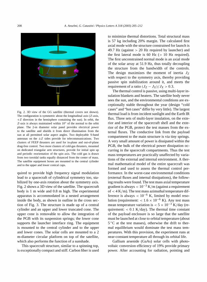
Fig. 2. 3D view of the GG satellite (thermal covers not showThe configuration is symmetric about the longitudinal axis (Z-axis,+Z direction in the hemisphere containing the sun). In orbit,Z-axis is always maintained within 10 of the normal to the orbitplane. The 2-m diameter solar panel provides electrical poto the satellite and shields it from direct illumination from tsun at all permitted solar aspect angles. Two deployable S-antennas on the±Z sides provide for telecommunications. Twclusters of FEEP thrusters are used for in-plane and out-of-pdrag-free control. Two more clusters of cold-gas thrusters, mouon dedicated triangular arm structures, provide for initial spinand periodic reorientation of the spin axis. The cold gas is drfrom two toroidal tanks equally distanced from the center of mThe satellite equipment boxes are mounted to the central cyliand to the upper and lower conical caps.
quired to provide high frequency signal modulatilead to a spacecraft of cylindrical symmetry too, sbilized by one-axis rotation about the symmetry axFig. 2 shows a 3D view of the satellite. The spacecbody is 1 m wide and 0.8 m high. The experimenapparatus is accommodated in a nested arrangeinside the body, as shown in outline in the cross stion of Fig. 3. The structure is made up of a centcylinder and an upper and lower truncated cone.upper cone is removable to allow the integrationthe PGB with its suspension springs; the lower cosupports the launcher interface ring. The equipmis mounted to the central cylinder and to the upand lower cones. The solar cells are mounted tom-diameter circular platform on top of the satelliwhich also performs the function of a sunshade.
This spacecraft structure, similar to a spinning tis exceptionally compact and stiff. Carbon fiber is us
t
to minimize thermal distortions. Total structural mais 57 kg including 20% margin. The calculated fiaxial mode with the structure constrained for launc49.7 Hz (against> 20 Hz required by launcher) anthe first lateral mode is 60 Hz (> 10 Hz required).The first unconstrained normal mode is an axial mof the solar array at 51.9 Hz, thus totally decouplthe structure from the bandwidth of the controThe design maximizes the moment of inertiaJZ
with respect to the symmetry axis, thereby providpassive spin stabilization around it, and meetsrequirement of a ratio(JZ − JX)/JX > 0.3.
The thermal control is passive, using multi-layersulation blankets and heaters. The satellite body nsees the sun, and the environmental conditions areceptionally stable throughout the year (design “ccases” and “hot cases” differ by very little). The largthermal load is from incident sunlight and the Earthflux. Three sets of multi-layer insulation, on the exrior and interior of the spacecraft shell and the exrior of the PGB, protect the test masses from theternal fluxes. The conductive link from the paylocompartment to the main structure is via tiny sprinA very small amount of power is dissipated within tPGB, the bulk of the electrical power dissipation ocurring in the spacecraft compartments. Thus themass temperatures are practically unaffected by vations of the external and internal environment. A thmal mathematical model of the entire spacecraft wformed and used to assess the thermal controlformance. In the worst-case environmental conditi(external fluxes and internal dissipations), the folloing results were found. The test mass axial temperagradient is always< 10−3 K/m (against a requiremenof < 4 K/m). The test mass azimuthal temperatureference is always< 10−6 K, limited by model reso-lution (requirement:< 1.6 × 10⁻⁶ K). Any test massmean temperature variation is< 5 × 10⁻³ K/day (re-quirement:< 0.1 K/day). The thermal time constaof the payload enclosure is so large that the satemust be launched at close to orbital temperature (a5 C at the test masses), otherwise the drift to thmal equilibrium would dominate the test mass teperatures. With this provision, the experiment runsnear-constant temperature all through its orbital life
Gallium arsenide (GaAs) solar cells with photvoltaic conversion efficiency of 19% provide primapower. After accounting for radiation, pointing an

A. Anselmi, G. Catastini / Physics Letters A 318 (2003) 205–212 209
Fig. 3. Layout of the reorientation thrusters and cross section showing the toroidal tanks for symmetric mass depletion.
rdereringum
2,sun
thetesol,sksularuterTheem
allthedesgin-
ers36of
or-lignheper-ien-eansis
rmssurelace-ghhirledter-ec-as-othce-per
oreiv-
kset-pro-oththe
thet be
packing factor losses, the specific power is on the oof 150 W/m2. A preliminary assessment of the powdemand of the spacecraft gives about 200 W, includbattery charging and margins. Therefore, the minimrequired array area is about 1.4 m2. More than 3 m2
are available for cells in the configuration of Fig.where the disk-shaped array is sized for its use asshield.
The spacecraft data management unit handlesground link (telemetry and command) and executhe software performing the platform attitude contrdata handling and fault detection and recovery tavia a 1553 data bus. Data are stored in a modsolid-state mass memory unit. A dedicated comphandles the payload control and processing tasks.total mass amounts to 276 kg (316 kg with systmargins).
4. Attitude and drag-free control
The launcher releases the satellite with a smspin rate and the spin axis roughly oriented inrequired direction. An autonomous system provifor initial correction of angular momentum depointinand damping of residual angular rates and for spup to the nominal spin rate of 120 rpm. Two (+2 re-dundant) circumferential 200 mN nitrogen thrustare provided for this purpose. The maneuver lastsminutes and uses 1.3 kg propellant. Another pair
200 mN nitrogen thrusters, at right angles to the fmer set, is used for the periodic maneuvers to reathe spin axis to the orbit normal. For this function tthrusters, located at 0.7 m from the spin axis, are oated in pulsed mode for 3.4 hours. Before each reortation maneuver, the test masses are locked by mof inch worms (use of the launch-lock mechanismnot necessary). After the maneuver, the inch woare released in a controlled way, using the pressensors associated to them for measuring the dispment from the symmetry axis until it is small enoufor the capacitive sensors/actuators to take over wcontrol. Finally, the along-track drag signal is usfor proof mass balancing and capacitive plate cening, thus restoring the nominal common-mode rejtion ratio. In the mission operations plan, one day issigned to each reorientation maneuver (including bthruster actuation and lock-unlock-rebalancing produre). The propellant mass required is 0.38 kgmaneuver, which translates into 6.8 kg/year. The to-tal propellant budget for 2-year operation is theref15 kg. The nitrogen propellant is stored at 550 bar, ging a required volume of 40 liters. Two toroidal tanwill be employed, placed as shown in Fig. 3, symmric with respect the spacecraft center of mass. Thepellant for the periodic maneuvers is drawn from btanks so as to produce negligible displacements ofcenter of mass.
Because of the position of the solar array,thrusters for the re-orientation maneuvers canno

210 A. Anselmi, G. Catastini / Physics Letters A 318 (2003) 205–212
r
Fig. 4. Perturbing accelerations in the measurement plane and perpendicular to it, when the spin axis is 10 away from the orbit normal (summesolstice 2005). The magnitude of the out-of-plane acceleration (top) is less than 1/6 of the in-plane component (bottom).es).it.
rbiteoftionelychn anver
ofhattlythering
larowsndi-rbit
ag-ancesss
dend-
cy
-ls-ft-fre-
tionGBde-the
ustcy)torbyieldrs
xiterees ofuetheingveand
balanced (they produce torques as well as forcTherefore they will produce an effect on the orbThe main component of the thrust is along the onormal. At first order, thrust in the direction of thorbit normal affects the inclination and longitudeascending node. The magnitude of the perturbais about 0.12 milliradians per maneuver, completnegligible. Moreover, the orbital positions at whithe maneuvers are executed can be selected iappropriate way so as to make the net effect zero oa number of maneuvers.
The kinetic spin energy at the nominal rate2 Hz is so high compared to all natural torques tthey would need a very long time to even slighdisplace the spin axis. Therefore, active control ofdirection of the spin axis in space is not needed dumeasurement periods.
The main perturbing accelerations are from soradiation pressure and atmospheric drag. Fig. 4 shthe pattern of the accelerations in worst-case cotions (epoch 2005, spin axis at maximum angle to onormal). The effect of a 10 offset of the spin axis withrespect to the orbit normal is an increase of the mnitude of the in-plane forces by a factor of 2, andincrease of the magnitude of the out-of-plane forby a factor of 5. The out-of-plane force remains lethan 1/6 of the in-plane component.
Drag-free control must reduce the common-modrag force acting on the satellite in a narrow ba
width (notch filter) centered at the orbital frequen(1/5700 s), by a factor 1/10 000 in theXY plane andby a factor 1/400 on theZ axis. A supplementary requirement is to reduce by a factor 1/100 the externadisturbance acting in theXY plane at the test-masdifferential frequency (1/540 s). By reducing the acceleration, the amplitude of oscillation of spacecraPGB is reduced by the same amount, at the samequency. Phase differences due to a differential rotarate between the spacecraft outer shell and the Pare mostly compensated passively. Residuals aretected by displacement sensors and corrected bydrag-free control thrusters.
The actuator system for drag-free control mproduce finely tuned (in magnitude and frequenforces, using tiny amounts of propellant in orderminimize perturbations on the test bodies from neamoving masses. The solution adopted is to use FEmission Electric Propulsion (FEEP) mini-thrustewith high specific impulse (gas velocity at nozzle e> 6 km/s) [3]. A few grams of cesium suffice for thentire 2-year duration of the mission. The drag-fcontrol thrusters are accommodated in two cluster3 each, with orientations providing sufficient torqand force authority on all axes. Fig. 5 showsperformance required of the notch filter implementthe drag-free control. Detailed time simulations hashown the adequacy of the adopted control lawsthe selected actuators [1].

A. Anselmi, G. Catastini / Physics Letters A 318 (2003) 205–212 211
ented by
Fig. 5. Relative displacement between PGB and spacecraft without (continuous line) and with (dashed line) drag-free control implemnotch filter at orbital frequency.ub-ure-
ofualtchofift
n oftheheen-ne
o-re-dueers-rs.the
veB).the
dis-xis
aft
ligi-toxisds.thesionandionsrtia
spinthisted
usivetwo
The drag-free and attitude control system is sjected to demanding requirements on the measment and control of the spin rateωS and the ori-entation of the spin axis. The standard deviationthe spin angular frequency determines the residdrag at the orbital frequency (placement of the nofilter). This translates into a control requirementω/ωS 10−4, equivalent to detecting a phase shof ϕ = 6× 10⁻⁴ rad (0.035) in one spin period. Onthe other hand, a constant error in the determinatiothe spin angular frequency is easily removed fromcontroller input. The requirement for measuring tseparation between the spin rate and the fundamtal frequency of the test mass differential mode is oorder of magnitude less demanding,ω/ωS
∼= 10−3.The satellite is made up of six co-aligned, c
rotating cylinders, coupled by springs. The spin fquency is much higher than the natural frequencyto the mechanical coupling of the springs, in ordto produce supercritical rotation, which is the cloest possible condition to that of free rotating cylindeExternal torques applied to the outermost cylinder (
‘spacecraft’) will tend to change its orientation relatito the cylinder surrounding the test masses (the PGDifferential spin rates between the spacecraft andPGB must not be allowed to produce an angularplacement in the plane perpendicular to the spin a> 10−2 rad, and a tilt of the spin axis of the spacecrwith respect to that of the PGB< 10−2 rad. The tilt ofthe spin axis during measurement periods is negble, because of the high ratio of spin kinetic energymagnitude of the perturbing torques. Hence, spin acontrol is not needed during measurement perioThe largest effect potentially producing a change inspin rate of the spacecraft is due to thermal expanand contraction of the satellite. The eclipse-sunsun-eclipse transitions induce such thermal expansand contractions, which change the spacecraft ineand hence, to conserve angular momentum, therate. With the given SSO orbit and thermal design,effect is minimized and easily managed by a dedicaspin controller (proportional-derivative controller pllow pass filter). The system for detecting the relatphase between spacecraft and PGB consists of

212 A. Anselmi, G. Catastini / Physics Letters A 318 (2003) 205–212
s.of
ther the
hee
forter.
toawllite
piculd
roll.altheon.atic
ri-97–ntly
Thed.
ard,ex-al
oned toop,g-rededSOandol-nd
an-
N-ion
symmetrically placed pairs of light-emitting diodeThe resolution is better than 10 µm at a distance30 cm (43 arcseconds). The phase coming fromaverage of the two sensor pairs is used as input fospin controller.
Both the orientation of the spin axis and tdirection of the Earth with respect to an inertial frammust be measured with an accuracy of 6× 10⁻³ rad(0.35). An Earth elevation sensor is envisagedmeasuring the inertial direction of the Earth’s cenFor a satellite with momentum bias perpendicularthe orbit plane, there is no indetermination in yangle measurement with just one sensor. The sateorientation is inertially fixed because of the gyroscostiffness, and therefore an error in the yaw angle wobe detected, after a quarter turn, as an error inThe sensor is fixed to the satellite with two opticaxes perpendicular to the spin direction, andsatellite spin provides the required scanning motiThe required Earth sensor must provide a systemerror< 0.05 and a random error< 0.01 (3σ).
5. Conclusions
The design of the satellite for the GG expement was addressed in phase-A level studies in 192000 (based on an equatorial orbit) and more rece
(2001) re-addressed for sun-synchronous orbit.satellite is small, low-weight, with low power demanThe service functions can be provided by standlow-cost equipment. The mission consists of anperiment running uninterrupted with few operationmodes, small telemetry rates, easily controlled byground station. The experiment requirements leaan ad hoc configuration, resembling a spinning tvery compact and stiff. The requirements for drafree control, spin rate control, thermal stability ademanding but manageable, as shown by extenanalysis and simulations. The reconfiguration to Smakes the mission suitable for a low-cost launch,improves the thermal performance. Enabling technogy items include the drag-free control thrusters aattitude sensors, for both of which state-of-the-art cdidates exist.
References
[1] “GALILEO GALILEI” (GG), Phase A Report, ASI (Agen-zia Spaziale Italiana), 1998 (2nd Edition, 2000),http://eotvos.dm.unipi.it/nobili/ggweb/phaseA.
[2] A.M. Nobili, et al., New Astron. 8 (2003) 371.[3] S. Marcuccio, et al., Experimental performance of 1 m
class FEEP Thrusters, 28th International Electric PropulsConference, Toulouse, March 17–21, 2003.