archaeological research using satellite
61
ARCHAEOLOGICAL RESEARCH USING SATELLITE REMOTE SENSING TECHNIQUES (CORONA) IN THE VALLEYS OF SHIRWAN AND CHARDAWAL (PUSHT-I KUH, LURISTAN), IRAN BY Mathieu DE MEYER* (Ghent University, Belgium) Introduction For the past few years scientists have been trying to find archaeological remains using Satellite Remote Sensing techniques. Some were lucky enough to find some new sites, others were not so fortunate even though they spent considerable amounts of money and time trying. The goal of our project was to look for a cheaper and more effective way to investigate archaeological remains from space, using the CORONA (keyhole) satellite imagery from the United States Geological Survey. The investigated area was the Shirwan and Chardawal valleys in Luristan, West-Iran. The purpose of this study was to investigate whether or not the sites which were already known from previous field work were also visible on the CORONA images. In addition, the aim was to locate new, similar sites and other non-natural features of interest. At the time of the study, it was not possible to know for certain which of the new ‘sites’ found, have potential archaeological value. Some clues were found, and this study can be used as a kind of key or guide for new field work, in which it will be pos- sible to confirm or disprove the provisional results of this research, after which it will be possible to improve this technique. Iranica Antiqua, vol. XXXIX, 2004 * This article is a result of my MA-thesis in Archaeology (Ancient Near East) at Ghent University, 1999. This thesis was written under supervision of Prof. Dr. Ernie Haer- inck. Prof. Dr. Rudi Goossens of the Geography Dept., equally at Ghent University was willing to provide his expertise and help. The negatives were acquired by the Dept. of Near Eastern Archaeology, on the budget of the ongoing Luristan project, while the Dept. of Geography provided the logistics to do the research. The revised and abbreviated Eng- lish version of my thesis was kindly corrected by Lisa Hill (Australia).
-
Upload
khangminh22 -
Category
Documents
-
view
5 -
download
0
Transcript of archaeological research using satellite

ARCHAEOLOGICAL RESEARCH USING SATELLITEREMOTE SENSING TECHNIQUES (CORONA)
IN THE VALLEYS OF SHIRWAN AND CHARDAWAL(PUSHT-I KUH, LURISTAN), IRAN
BY
Mathieu DE MEYER*(Ghent University, Belgium)
Introduction
For the past few years scientists have been trying to find archaeologicalremains using Satellite Remote Sensing techniques. Some were luckyenough to find some new sites, others were not so fortunate even thoughthey spent considerable amounts of money and time trying.
The goal of our project was to look for a cheaper and more effective wayto investigate archaeological remains from space, using the CORONA(keyhole) satellite imagery from the United States Geological Survey.
The investigated area was the Shirwan and Chardawal valleys in Luristan,West-Iran. The purpose of this study was to investigate whether or not thesites which were already known from previous field work were also visibleon the CORONA images. In addition, the aim was to locate new, similarsites and other non-natural features of interest. At the time of the study, itwas not possible to know for certain which of the new ‘sites’ found, havepotential archaeological value. Some clues were found, and this study canbe used as a kind of key or guide for new field work, in which it will be pos-sible to confirm or disprove the provisional results of this research, afterwhich it will be possible to improve this technique.
Iranica Antiqua, vol. XXXIX, 2004
* This article is a result of my MA-thesis in Archaeology (Ancient Near East) atGhent University, 1999. This thesis was written under supervision of Prof. Dr. Ernie Haer-inck. Prof. Dr. Rudi Goossens of the Geography Dept., equally at Ghent University waswilling to provide his expertise and help. The negatives were acquired by the Dept. ofNear Eastern Archaeology, on the budget of the ongoing Luristan project, while the Dept.of Geography provided the logistics to do the research. The revised and abbreviated Eng-lish version of my thesis was kindly corrected by Lisa Hill (Australia).

Because the investigation is based on the reflection of light it is impor-tant to know what the landscape looks like in the area. Therefore mapswere searched. First all known structures were determined on the satelliteimages and a number was given to them. Then a key was made out ofthem, and with that key new sites were searched. Other features of interestwere also identified and assigned keys. Retrospective effect was usedthroughout the entire study, changing the methodology to achieve thedesired results.
1. Previous use of Remote Sensing for Archaeological purposes
Various Remote Sensing systems have already been used for differentkinds of archaeological research. Some have been effective, others despiteconsiderable expense were less so. It is not the purpose of this article tocriticize specific research, but some examples of previous studies havebeen analyzed to establish what has already been done and which of thetechniques can also be used with the CORONA images.
In most research of this kind, satellite information is combined with otherresources such as aerial photography and/or field work. Aerial Reconnais-sance has been used extensively all over the world to find archaeologicalsites, and has also been combined with Satellite Remote Sensing (Renfrew,Bahn, 1996, 75-82). Both visual (passive) systems (satellite observation:SPOT, LANDSAT) and non-visual (active) systems (radar observation (SIR:Shuttle Imaging Radar — SAR: Synthetic Aperture Radar…) have beenused. Many countries have a scientific space program (the United States:NASA, Europe: ESA, Japan: NASDA, Russia, India, China, Brasilia, Israel,Australia and South Africa are the major ones) and most of them have estab-lished Remote Sensing Programs (Sanders, Ouwehand, 1994, 40).
Examples of archaeological purposes for which satellites are used include:
– Measuring structures which are difficult to measure on the ground orsites which take too much time to measure. An example of this tech-nique is the measurement of the Great Wall of China.
– Restoring sites requiring identification of structures needing repair.Satellites have been used to identify parts of sections for restoration,and parts of the Great Wall of China have been repaired using thistechnique (Arnold, 1989, 248-252).
44 M. DE MEYER
– Searching for areas which could contain archaeological sites bylocating specific types of landscape, such as ancient rivers whichhave been buried by sand storms. These sites were often inhabited informer times, an example of which is the old Nile in Sudan (Rehorst,Sanders, 1997, 25). Active systems are used for this because they canpenetrate through the ground with the waves they are transmitting toearth and reflected back to the satellite. This technique is particularlyuseful for flat territories because subterranean water halts the waves,making it very useful in dry areas to find lost rivers. In addition tolocating ancient rivers, vegetation and different kinds of land types inone region have also been used as keys to locate possible archaeo-logical sites. An example is the San Juan Basin in New Mexico(Fowler, 1991, 281-282).
– Discovering new archaeological sites or structures using satellites.Some examples are the Irrigation Canals in Guatemala (Fowler,1991, 281-283) and the ruins in Saffara (Van der Laan, 1992, 33).
– Discovering old fields and transport networks (Roads, irrigationcanals, fields,…) from space. One example is Yucatan in Mexico(Renfrew, Bahn, 1996, 80-81).
– Illustrating ancient structures by using satellite images. Examples arethe Pyramids of Giza in Egypt, Hadrian’s Wall in England (Fowler,1991, 281) and the Great Wall of China (Arnold, 1989, 248).
– Rebuilding the past, and research the evolution of an area by com-bining these techniques, which is of great value in archaeology.Examples are Thebes (Egypt) and the Enipaeus valley (Greece)(Fowler, 1991, 282).
Most of this research has been done with satellite images with less detailedresolution compared to the CORONA-images used in this study. Unlikenormal aerial photography with a maximum observable detail of 10 cen-timeters, the maximum with satellites is 10 meters. For huge structuressuch as the Great Wall of China, the Maya-temples in the jungle or for lostcities in the desert, the low resolution of conventional sensors can beacceptable in some applications. The resolution of the images used in thisstudy is 9 feet (about 3 meters) which is also inexpensive compared toother (commercial) satellite imagery. Unfortunately they are not digital,which has become the standard for modern systems.
SATELLITE REMOTE SENSING TECHNIQUES 45

2. What is CORONA and Keyhole?
A. General information
The CORONA satellites were part of the first generation of American Intel-ligence satellites. It was one of their code-names, together with ARGONand LANYARD. The original main purpose of the satellites images gath-ered was to investigate the military power of the former Soviet Union andAsia, and to monitor agriculture, industry, environment and populationissues. The program, which was launched by U.S. President Eisenhower in1958 in order to replace the flights of U-2’s above Soviet areas, was devel-oped by the CIA and the Air Force. The first successful CORONA missiontook place in August 1960, and on the 18th of that month the first goal, amilitary airport in Russia, was photographed. The images were not verygood at the start, but rapidly improved and satellite images grew to havegreat importance during the Cold War (Campbell, 1996, 196). 860.000 pho-tographs taken between 18/08/1960 and 31/05/1972 were declassified on the24th of February 1995 by the U.S. Geological Survey (DISP — DeclassifiedIntelligence Satellite Photographs).
The CORONA-systems were named KH-1, KH-2, KH-3, KH-4, KH-4A and KH-4B, ‘KH’ meaning ‘keyhole’. KH-5 was used by ARGONand KH-6 by LANYARD. They were launched in a low polar orbit. Thefirst missions were of only one day’s duration, which grew to sixteendays by the end of the project, requiring two film capsules on boardinstead of one. (KH-4A was the first system with two capsules on board).At the end of each mission the films were returned to earth, travellingthrough the atmosphere to a height of 18 km when a parachute openedand the capsules were caught by a specially designed plane. (The capsuleswere designed to sink to the bottom of the ocean if something went wrongto ensure that they could not be retrieved by other countries) (Campbell,1996, 191, 196).
The best resolution obtained by these satellites was 6 feet (KH-6), whilethe worst was 460 feet (KH-5). Only very recently has an American com-mercial satellite system for high resolution images (1 meter) been devel-oped. The older systems had only one panoramic camera on board (KH-1,KH-2, KH-3 and KH-6) or one frame camera (KH-5), while the morerecent systems (KH-4, KH-4A and KH-4B) had two on board panoramiccameras with an angle of 30° difference, i.e. a Forward looking (Fore
46 M. DE MEYER

Camera) and an Afterward looking (Aft Camera) cameras, which enabledstereoscopic imagery (Pl. 1).
Every mission was divided into axes of rotation, and every image takenin such an axis received an image number. The co-ordinates of the bound-aries of the photographed area are: Western border: 180W; Eastern border:180E; Southern border: 90S and Northern border: 90N. Photography wasnot continuous, sometimes by design when film was reserved for areas ofmore importance for intelligence purposes, and sometimes because of faultsin the camera’s operation. These faults sometimes result in there being onlyForward or Afterward images.
The GLIS (Global Land Information System) is an interactive systemwhere the images used in this study can easily be found. It contains about98% of the total collection of declassified images. All images were takenon black and white 70mm Panoramic film. (A very small amount ofinfrared and colour film was tested on the KH-4B missions, but the resultswere unsatisfactory).
The most commonly used KH-4 systems had two panoramic vertical ori-ented KH-3 cameras on board which were pointed to the same area. One ofthem was pointed 15° to the front (for), the other 15° to the back (aft). Asmall index camera took care of the context and orientation of the images,the astronomical cameras were directed to the stars and the horizon cameraswatched the horizon of the earth. Those were necessary to be able to steerthe satellite from the control center on earth (Campbell, 1996, 193-194).
The CORONA website contains extensive information about the projectand images can be ordered on the Internet at edcsns17.cr.usgs.gov/Earth-Explorer/. The original films are preserved by NARA (National Archivesand Records Administration).
Addresses:Customer Services National Archives and Records AdministrationU.S. Geological Survey (NARA)EROS Data Centre 8601 Adelphi Road47914 252nd Street College Park, MD 20740-6001Sioux Falls, SD 57198-0001 USAUSA Telephone: 866-272-6272Telephone: 605-594-6151 Fax: 301-837-0483Fax: 605-594-6589 E-mail: [email protected]: [email protected]
SATELLITE REMOTE SENSING TECHNIQUES 47

Internet addresses:
USGS EROS DATA CENTER, SIOUX FALLS, SDhttp://edc.usgs.gov/USGS (United States Geological Survey)http://www.usgs.gov/
Bibliography about the satellite and images:
CENTRAL INTELLIGENCE AGENCY, Press release, Langley, Virginia, February 24,1995.
DEUTCH, J., CORONA and the revolution in intelligence: [presented at] CORONA
Symposium, May 23, 1995, Washington DC, George Washington University,1995.
MCDONALD, R.A., CORONA—success for space reconnaissance, a look into theCold War, and a revolution for intelligence: Photogrammetric Engineeringand Remote Sensing, v. 61, no. 6, p. 689-720, 1995.
RUFFNER, K.C., CORONA—America’s first satellite program, History Staff, Cen-tre for the Study of Intelligence, Central Intelligence Agency, WashingtonD.C.,1995 [Direct requests for copies to National Technical Information Ser-vice (NTIS), 5285 Port Royal Road, Springfield, Virginia 22161 or telephonethe order desk at 703-487-4650].
THE WHITE HOUSE, 1995, Release of imagery acquired by space-based nationalintelligence reconnaissance systems, executive order 12951, Washington DC,February 1995.
B. The images selected
Eight negatives were selected from 306 covering the area under study onthe GLIS website. The criteria for selection were that the images be ofgood quality and
• the area shown was not obscured by cloud cover or snow in themountains,
• the images were stereoscopic,• the negatives were photographed in a single mission.
Forward images:DS1030-2103DF080, DS1030-2103DF081, DS1030-2103DF082, DS1030-2103DF083 Afterward images:DS1030-2103DA086, DS1030-2103DA087, DS1030-2103DA088, DS1030-2103DA089
48 M. DE MEYER

A single negative covers an area of 10.6 to 144 American miles, but unfor-tunately the valleys of Shirwan and Chardawal were situated on the edgeof each negative, causing greater distortion (Pl. 1). Four Forward and fourAfterward images were bought, so it was possible to do some stereoscopictests. All photographs were from KH-4A (Mission 1030-2). Here are sometechnical details about it:
– Camera: panoramic– Film: 70 mm– Estimated Frame Format (in. x in.): 2.18 x 29.8– Focal distance (inches): 24– Enlargement possibility: 16 times– Estimated best ground resolution: 9 feet– Nominal height System (in sea miles): 100– Nominal photo scale on film: 1:305000– Nominal area on one image (in miles): 10.6 x 144
All cameras worked well during the mission. The price of one negativewas US $18. All pictures were taken on the 16th of March 1966. This datecould be important for the research, because of the vegetation, whichchanges every season. The quality of the negatives purchased differedfrom image to image, which has influenced the investigation, becausesome of the pictures could not be examined as well as others. There is, forexample, a clear difference between the Forward and the Afterward pic-tures purchased because some of the negatives sent by the United StatesGeological Survey were under-exposed. For this study, most negativeswere developed on a scale of 1/35.000 to provide 82 pictures (41 Forwardand 41 Afterward images) covering the area but some were also developedat a scale of 1/19000 to do some further smaller, more specific studies.
3. The investigated area
A. Geography
The Kabir Kuh mountain range, which is a part of the Zagros range,divides Luristan in two areas, Pish-i Kuh in the east and Pusht-i Kuh in thewest, where the areas under study, the valleys Shirwan and Chardawal, arelocated. The valleys are (at least until 1979) part of the official fifth district
SATELLITE REMOTE SENSING TECHNIQUES 49

of the province (= ustan) Pusht-i Kuh Ilam. The northern boundary of thearea is the district (= farmandari) of Shahabad Garbi (now IslamabadGarbi), which is part of the province of Kirmanshah (now Bakhtaran). In theeast lies the district of Kuh-i Dasht. It is part of the province of Luristan-Khurramabad. In the south is the boundary of the district of Badrah. South-west lies the district of Mehran. The departments (= Bakhsh) of Ilam andAivan, both part of the district of Ilam, form the Western border (VandenBerghe, Tourovetz, 1992, 1-2, Fig. no 1). The capital of the area is the smalltown of Wargatch-Lumar. The most important river in Shirwan-Chardawalis the Saimareh which forms the eastern boundary. Two other rivers of sig-nificance are the Rudkhaneh-i Chardawal and Ab-i Shirwan, which gavetheir names to the two rather large fertile plains along both rivers, whichcross the area from the north-west to the south-east and discharge in theSaimarreh. The mountain Kuh-i Charmi separates both valleys, and to thenorth lies Chardawal with Shirwan to the south. In the south-west of the areais the mountain range Kuh-i Shamangar, which runs parallel with Kuh-iCharmi (Vanden Berghe, 1982, 14; Vanden Berghe, Tourovetz, 1992, 1-3)(Pl. 2).
The inhabitants of Luristan are nomads or semi-nomads wanderingaround with their herds of animals in both valleys which are, in contrast toother valleys in the Pusht-i Kuh, well irrigated, quite large and very fertile.Prior to the 1930s there were few houses built of durable materials andpeople used to live in tents (Vanden Berghe, 1982, 13-14, Vanden Berghe,Tourovetz, 1992, 3).
B. History
Several periods were distinguished in the area (Vanden Berghe, Tourovetz,1992, 3-4, 9-10, 12): the Paleolithic, the Neolithic/Chalcolithic, the BronzeAge, the Iron Age, the pre-Sassanian, the Sassanian and Islamic periods.
C. Previous Field work and results
Many archaeologists and travellers were attracted by the so called LuristanBronzes. According to M. Godard, many of them were found in the ceme-teries in Luristan (Maleki, 1964, 5; Mortensen, 1979, 3; Stein, 1969, 189,241; Zagarell, 1982, 79). However, few people have visited the valleys ofShirwan and Chardawal. The archaeologist A. Stein travelled through the
50 M. DE MEYER

Shirwan valley in 1939 and a few Arabian geographers also visited thearea. The Sassanian town Shirwan was probably visited in the 12th centuryby Benjamin de Tudèle and in the 19th century by H.C. Rawlinson. J. deMorgan investigated the area in 1907 (Gabriel, 1952, 29; Stein, 1969, 223-228; Vanden Berghe, Tourovetz, 1992, 12-13).
The most important study of the area was done by Belgian archaeologistL. Vanden Berghe of Ghent University (Belgium) between the 10th and 27th
of November 1979. His goal was to map all the archaeological sites of thearea, especially the cemeteries (Vanden Berghe, Tourovetz, 1992).
4. The sites in the area
The archaeological sites, buildings, villages and towns which will be men-tioned here, were known structures. For this purpose two major resourceshave been used: the results of the expedition of Vanden Berghe (VandenBerghe, Tourovetz, 1992) and the detailed maps from the Iranian Oil Oper-ating Companies (Geological and Exploration division Tehran) (1966: Iran1: 50.000 Series; Sheet No. 20223: KUH-E VARZARIN; based on pic-tures taken in 1961. Edition September 1966) and 1967 (Iran 1: 50.000Series; Sheet No. 20217: PALGANEH; based on pictures taken in 1961.Edition November 1967). Most buildings, towns and villages of the area aredrawn on those maps and some of them may be old structures.
The sites mentioned by Vanden Berghe are the ‘S’-sites in this study.The places mentioned by the Iranian Oil Operating Companies maps arethe ‘O’-sites. 131 Buildings, villages or towns were found on the maps.Vanden Berghe mentioned 91 sites, making a total of 222 sites. After a first selection this resulted in 206 different structures. Only 16 placeswere reported by both resources. Sites are named in the study if the nameis known, and for some sites, measurements and other structural informa-tion are also available. Pictures and extra information from other similarsites in Pusht-i Kuh have also been used as a reference (Pl. 3-7).
Modern towns or villages (62)
S1 (Chamzuyah (Cham Ritat); S2 (Dar Balut); S3 (Qazi Khan Oliah) = O10(Qazi Khan) (2 buildings); S4 (Zuhairi) = O17 (Zuheyri) + O18 (1 build-ing); S5 (Sar Khan); S6 (War Gatch) = O28 (Var Gach); S7 (Kurahvand =Kurahvand Lamar) = O32 (Kurehvand) (+2 buildings)); S8 (Imarat) = O26
SATELLITE REMOTE SENSING TECHNIQUES 51

(Shurab-e Khan Ali) (5 buildings); S9 (Shahman Suri); S10 (Larini) = O41(Baraftab-e Larini); S11 (Gurab Sufla) = O35 (Gurab-e Sufla) (1 building);S12 (Sar Kalan (Sarab Kalan)); S13 (Hassan Gavdari) = O42 (HasanGudari); S14 (Hillah Waran); S15 (Pananbar) = O45 (3 buildings); S16(Shahqalandar Oliah) = O50 (Shah Qalandar) (6 buildings); S17 (BabaShamsh) = O52 (Baba Shamshi); S18 (Sar Kalleh Safid Kani) = O54(Zangevan) (3 buildings); S19 (Darreh Surkh); S20 (Aliabat Wasat) = O60(Sar Kalleh-Ye ‘Aliabad); S21 (Kali Kali); S22 (Chasmah Pan (ChasmahRashid); S23 (Sarab Qarazan Oliah) = O65 (Tarzan-e’ Ulya (Karzan) (2 buildings); S24 (Miviyan Tang-I Hujanan); S76 (Zir Tang) = O122 (Zir-tang); S77 (Balavah Sufla) = O99 (Balaveh Khushkek); S78 (Taq — Gau-rin) = O83 (Taq-e Gavrin); S79 (Chamshmah Qulah) = O79 (ChashmQuleh); S80 (Cham Chamar Rud); O4 (‘Eyn-e Hareh); O7; O12; O23;O27 (+ 2 buildings); O29 (Qaryeh-ye Darvishan); O33 (Cham-e Chenar (+ 1 building); O34 (Hivand); O40; O47; O48; O49 (Dar Mian); O68(Khar-e Shir’ Ali); O70 (Mushekan); O71 (Tu Surkh-e Ulya); O72 (Dar-tut); O75 (Sang-e Safid); O77 (Dar Eshkaft); O81; O82 (Haleh Sam + 2 buildings); O84; O86; O87 (Keleh Qatar); O89 (Cheqa Sabz); O90(Shurabeh); O92; O97 (Balaveh Tireh); O101 (Kurak) (+ 1 building);O108; O112 (Jub Shaleh); O120 (Darreh Chapi); O121 (Talkhestan (+ 1 building); O126
Some ‘buildings’ on the Iranian Oil Operating Companies maps arementioned as a ‘village’ by Vanden Berghe (example: S18 = O54: 3buildings). The methodology used here included noting how many build-ings were drawn on the maps. Some of the places which are reported as‘villages’ on the map also contain some ‘buildings’.
Buildings (82)
O1 (3 buildings); O2 (2 buildings); O3 (1 building); O5 (Kowsheh) (2 build-ings); O6 (Cham-e Latur) (1 building); O8 (1 building); O9 (2 buildings);O11 (1 building); O13 (1 building); O14 (2 buildings); O15 (1 building);O16 (1 building); O19 (Siyah) (5 buildings); O20 (2 buildings); O21 (Sarab-e Gavar Tuti) (4 buildings); O22 (1 building); O24 (1 building); O25 (1 building); O26 (Shurab-e Khan ‘Ali) (5 buildings); O30 (2 buildings);O31 (2 buildings); O36 (1 building); O37 (1 building); O38 (2 buildings);O39 (3 buildings); O43 (2 buildings); O44 (2 buildings); O45 (3 buildings);O46 (3 buildings); O51 (2 buildings); O53 (1 building); O55 (2 buildings);
52 M. DE MEYER

O56 (3 buildings); O57 (4 buildings); O58 (3 buildings); O59 (3 build-ings); O61 (1 building); O62 (Tarzan-e Sufla (Karzan)) (1 building); O63(Tarzan-e Sufla (Karzan) (1 building); O64 (5 buildings); O66 (Shubab-e‘ulya) (9 buildings); O67 (Shubab-e Sufla) (6 buildings); O69 (1 building);O73 (2 buildings); O74 (1 building); O76 (3 buildings); O78 (2 build-ings); O80 (1 building); O85 (1 building); O88 (1 building); O91 (1 build-ing); O93 (1 building); O94 (2 buildings); O95 (1 building); O96 (2 build-ings); O98 (5 buildings); O100 (1 building); O102 (Palganeh) (1 building);O103 (2 buildings); O104 (1 building); O105 (Chalab Zarb) (2 buildings);O106 (2 buildings); O107 (2 buildings); O109 (2 buildings); O110 (Zul-mat) (4 buildings); O111 (Kulang Bur) (2 buildings); O113 (1 building);O114 (1 building); O115 (1 building); O116 (1 building); O117 (1 build-ing); O118 (1 building); O119 (2 buildings); O123 (1 building); O124(Mian Qal’eh (Pakeh)) (2 buildings); O125 (1 building); O127 (1 building);O128 (1 building); O129 (1 building); O130 (1 building); O131 (1 building);
All buildings were found on the Iranian Oil Operating Companiesmaps. On the satellite images many of them resemble villages. Given thatbetween the two resources there is a difference of 20 years, some scatteredbuildings may have developed into villages.
Pre-Sassanian ruins (4)
S44 (Kallegah); S45 (Awareh); S46 (Cham Mayah); S47 (Darreh Sarab)It is possible that S47 has existed since the 2nd millennium (Vanden
Berghe, Tourovetz, 1992, 11-12).
Sassanian and Post-Sassanian ruins (15)
S48 (Zuhairi (Ramilah)); S49 (Kalah); S50 (Ban-i Shan); S51 (DarrehMar); S52 (Kalah Wah); S53 (War Gar); S54 (Kalleh Seh Pa); S55 (DarKalleh); S56 (Qal’Ah Tur Riz); S57 (Shirwan); S58 (Kalleh Wazul); S59(Aliabat Wasat); S84 (Zir Tang); S85 (Balavah Sufla); S86 (Taq-i Gaurin)
The two most significant ruins are Shirwan (with numerous remains,below a modern village built above) and Zuhairi. Most of the other Sas-sanian (224-642 AD) and Post-Sassanian ruins were built in proximity tothese two major towns. Shirwan has been studied by different archaeolo-gists visiting the site. Some major buildings are still recognisable, butmany parts have been built over by the modern village of Sar Kalan. It was
SATELLITE REMOTE SENSING TECHNIQUES 53

an area of about 100 to 120 ha and contained a palace, bridges, and numer-ous houses (de Morgan, 1897, 361-365; Gabriel, 1952, 29; Stein, 1969,224 and Vanden Berghe, Tourovetz, 1992, 12-16).
Sassanian Chahar Taqs (3)
S60 (Pal Sakinah); S61 (Kalleh She Pa); S62 (Taq-i Bahram)This is a square religious building, constructed of four pillars with a
dome above. Only some remains, about 7 to 8 metres long are still present.There are some other ruins, probably a village, near S61 (Vanden Berghe,Tourovetz 1992, 16-20).
Islamic Imamzadehs (6)
S63 (Imamzadeh Abbas); S64 (Imamzadeh Seid Ali); S65 (ImamzadehSeid Ali (Abbas); S66 (Imamzadeh Hadjdj Hazar); S68 (ImamzadehAhmad Bagar Pandjum); S67 (Imamzadeh Shahqalandar)
Imamzadeh means ‘born from a (Shi’ite) Imam’. They were the placeswhere the properties of the 12 Shi’ite Imams were kept. Some of their suc-cessors who were exceptionally devoted (the Seids) were buried in suchbuildings. Such funeral places were also used for local saints and piouspersons, especially in Luristan. Sometimes they were built because anImam had been resting or praying at that location. Around the Imamzadehthere was a cemetery. The only exception to the practice of burying Imamsat the site is S67, which is the grave of a tribal leader. In the IslamicPeriod it became normal to put a stone on top of a grave and a stela abovethe head of the deceased. The Imamzadeh is made out of two well pre-served different rooms: the praying area and the sepulchral chamber,topped by a dome (Vanden Berghe, Tourovetz, 1992, 20-23).
Other Islamic cemeteries (3)
S69 (Mullah Taq); S87 (Zir Tang); S88 (Cham Chamar Rud)There were three cemeteries without Imamzadeh. These sites are pre-
served in reasonable condition (Vanden Berghe, Tourovetz, 1992, 20-23).
Islamic funeral pillars (3)
S70 (Mil Bardjiei (Mil Bardjigi); S71 (Imamzadeh Hadjdj Hazar) (2 pillars)
54 M. DE MEYER

Above graves of important deceased persons a tall pillar was con-structed in the shape of an obelisk. It was 3 to 4 metres high and well pre-served (Vanden Berghe, Tourovetz, 1992, 24-33).
Sites with dolmens (2)
S22a (Kufah); S22b (Shalan Qazi)There were different dolmens in the area, but few have survived. Previ-
ous studies show that there used to be a mound above them (diameter: 3to 4m), but they disappeared because of looting and erosion. Many stonesremain scattered about, and it is not possible to establish the number ofdolmens. They were probably built in the middle of the 2nd millenniumand are comparable with the West-Asian and European dolmens (VandenBerghe, Tourovetz, 1992, 5-7).
Bani Surmah cemeteries (6)
S26 (Chamshiri B); S37 (Taq-i Bahram); S38 (Millah Mehr); S39 (Kalah-nowlah); S40 (Sar Eskaft); S41 (Djana Tamaz Qulli)
These Early Bronze Age graves (3rd millennium) are approximately 7 to10 metres long, and 1.70 to 3 metres wide. They date back to the EarlyBronze Age. Characteristic are the very large stones which were laid par-allel next to each other. Most of the graves were plundered and left open(Vanden Berghe, 1968, 111-121; Vanden Berghe, Tourovetz, 1992, 9).
Dar Tanha cemeteries (2)
S25 (Chamshiri A); S28 (Ban Shekar)These date equally back to the Early Bronze Age in Luristan and are
approximately 7 to 10 metres long. They are similar to the Bani Surmahtype, but have a gabbled roof (Vanden Berghe, 1970, 358; Vanden Berghe,Tourovetz, 1992, 9).
Other kinds of 2nd Millennium cemeteries (1)
S83 (Sar Tang Ab-i Garm)Little is known about this site (Vanden Berghe, Tourovetz, 1992, 9).
SATELLITE REMOTE SENSING TECHNIQUES 55

Individual Graves from approximately 1000 BC (9)
S27 (Dar Balut); S29 (Qalalan); S30 (Halurah); S31 (Kallasiah); S32(Chamshah Millah Kavan); S33 (Qalarah); S42 (Chika Saïfur); S43 (PaKursiah); S82 (Banwarshan)
These are small structures which date back to the Iron Age (VandenBerghe, Tourovetz, 1992, 10-11).
Other Unspecified cemeteries (4)
S34 (Chasmah Sar Tang); S35 (Pananbar); S36 (Pananbar); S81 (DamanahKuh-i Tang-i Kurah)
Little is known about this site (Vanden Berghe, Tourovetz, 1992, map).
Abris-sous-roche (2)
S72 (Tang-i Shamshah); S73 (Eskaft Shamshah Dar Nam)There is no evidence of man-made structures at this site, but remains
indicate that humans of the Neolithic or Palaeolithic Periods used naturalfeatures such as over-hanging rocks for shelter (Vanden Berghe, Tourovetz,1992, 3-4).
Pre-Sassanian tells (3)
S74 (Qal’Ah Tur Riz); S75 (Chika Saïfur); S89 (Tepe Mehraban)These tepes/tells are high human built hills, developed from layers of
habitation. Some details are available for S89, which is described as‘large’, but little is known about the others, which have suffered from ero-sion but are still present (Vanden Berghe, Tourovetz, 1992, 11).
5. Identifying the known structures on the satellite images (Pl. 3-7)
All known archaeological sites and buildings, villages and towns werelocated on the Forward and Afterward images and their appearanceclosely studied. (The satellite pictures were taken on the 16th of March1966, so there should be good correlation with the maps from 1966 and1967, which were based on pictures from 1961). 200 of them could belocated, but S24, S43, O102, O103, O124 and O125 could not be localized
56 M. DE MEYER

on the pictures. Some sites were not immediately visible, but could belocated by close scrutiny of possible locations.
All the sites mentioned by Vanden Berghe were placed in categories,which form a key to finding new possible archaeological sites. The infor-mation from the Iranian Oil Operating Companies was not used, becauseit is not clear if the buildings, villages and towns they mention are recentor not, and so have been considered to be new sites. Only the sites whichwere also mentioned by Vanden Berghe have been used to form the key.Old fields and road patterns have not been investigated during this study.
The key has been based on the texture of the sites on the Forward images:
– Form and color: most structures built by human beings have an artifi-cial shape and clear boundaries, while natural features have less sharpcontours and are less regular. Care needs to be taken with this gener-alization, however, because mistakes have been made in the past.
– Composition: Are there several structures in one ‘site’ (e.g. villages,towns)? What’s the form of the area?
– Boundaries: Is the boundary of the site clear (sharp) compared to thesurrounding landscape?
– Shadows: The (shape of the) shadow could be an important key torecognize some structures on the images. An archaeological site maylook very different from a similar structure, depending on how thephotograph was taken.
– Position: Are the sites appearing in the valleys, the mountains, onthe mountain-sides or are they elsewhere?
– Associated elements: Are there any rivers or roads near the site?Roads could mean the site is still in use.
– Other features: Other remarks about the site, and eventually moredetails about the way they appear on the Afterward-images.
– Sites: The structures which belong to the type. The size of the site onthe image is noted between brackets. If visible on the image, it is alsonoted.
The normal appearance of the structures on the images (scale: 1/35000)was studied, including some stereoscopic research (see section 7). Thesites not detectable on the satellite images are not included in the key asthey are of no significance to this study.
SATELLITE REMOTE SENSING TECHNIQUES 57

S19 fore S21 fore
Modern towns or villages (28)
S1; S2; S3 = O10; S4 = O17, O18; S5; S6 = O28; S7 = O32; S8 = O26;S9; S10 = O41; S11 = O35; S12; S13 = O42; S14; S15 = O45; S16 =O50; S17 = O52; S18 = O54; S19; S20 = O60; S21; S22; S23 = O65;S76 = O122; S77 = O99; S78 = O83; S79 = O79; S80
TYPE 0: Sites which were not put in a particular type because of the badquality of the satellite image.
Sites: S14; S13=O42 (7 x 6 mm.); S8=O26 (11 x 6 mm.); S6=O28(15 x 3 mm.)
TYPE 1: Only a few roads are clearly visible. They are situated on themountain-sides. Their appearance is better on the Afterward Images (onwhich the streets have a white color).
Sites: S21 (4 x 2 mm.); S19 (6 x 3 mm.)
58 M. DE MEYER
S18 = O54 aft S7 = O32 fore S5 aft S2 aft
TYPE 2: Some lines and structures are visible, but it is not clear if theyare buildings. The traces are irregularly scattered and partially obscured byshadows. Most of them are in the valley near a river with roads nearby.There are more structures visible on the Afterward Images. Roads andbuildings are clearer and boundaries are sharper.
Sites: S18 = O54 (6 x 3 mm.) (7 x 2 mm.); S7 = O32 (6 x 3 mm.); S5(5 x 2 mm.); S2 (4 x 3 mm.)

TYPE 3: The sites look like white stains. No clear buildings can be rec-ognized, but there are some exceptions, which look more like white dis-turbance. The village or town has a very rectangular shape and all housesare constructed next to each other. Boundaries are not sharp and shadowsare visible. The position of the sites is in the valleys and on the mountain-sides. Associated elements are roads and a river. On the Afterward Imagesthere is little to see, other than some disturbance.
Sites: S17 = O52 (6 x 5 mm.); S15 = O45 (5 x 5 mm.); S78 = O83 (10 x6 mm.); S77 = O99 (20 x 6 mm.); S10 = O41 (5 x 3 mm.); S9 (6 x 5 mm.);S1 (15 x 6 mm.)
SATELLITE REMOTE SENSING TECHNIQUES 59
S17 = O52 fore S78 = O83 fore S9 fore
S77 = O99 fore
S1 aftS10 = O41 foreS15 = O45 fore
TYPE 4: Grey blocks. The shape is not strictly rectangular but roundedoff. The buildings appear to be grouped around a square. There’s an obvi-ous boundary with the surrounding landscape and shadows are present.The site is situated in the valley, with a river and roads near the site. Thereis little to see on the Afterward images, other than that the villages haveflat roofs.
Sites: S80 (3 x 2 mm.)
S80 fore

TYPE 5: Square and white structures, which appear to be much largerthan the other sites. There is also a black/grey/white disturbed area, whichcould be the Sassanian ruins. They are triangular, square buildings, lyingirregularly next to each other. The structures are clear, but the differencebetween two buildings next to each other is unclear due to shadows. Thesite is situated in the valley, with a river and roads nearby.
Sites: S4 = O17, O18 + S48 (Sassanian and Pre-Sassanian ruin, O18 is abuilding) (24 x 9 mm.); S3 = O10 + S45 (Pre-Sassanian ruin) (14 x 10 mm.)
60 M. DE MEYER
S4 = O17, O18 + S48 fore S3 = O10 + S45 aft
TYPE 6: Bright white linear structures and black spots with a regular ori-entation. Everything is orientated to the same direction. All structures areclearly visible and there are no shadows. The site is situated in the valley,with a river and roads nearby.
Sites: S23 = O65 (4 x 2 mm.); S20 = O60 (half of it looks more liketype 2, the other half has a grey/black disturbance) (6 x 3 mm.)
S23 = O65 fore S20 = O60 fore
S16 = O50 + S67 fore
TYPE 7: Clear white buildings, but also less clear areas. The town is rec-tangular, and very regular with sharp boundaries. There are shadows. Thesite is situated in the valley, with a river and roads nearby.
Sites: S16 = O50 + S67 (an Imamzadeh with cemetery) (7 x 4 mm.)

TYPE 8: Square structures which are grey/black on the inside, and brightwhite on the outside. Some grey/white disturbance is also present, spreadirregularly along the road in one group. Some structures are very clear,other less so due to shadows. The sites are situated in the valleys or on themountain-sides, with a river and roads nearby.
Sites: S22 (16 x 3 mm.); S79 = O79 (6 x 5 mm.); S76 = O122 + S84+ S87 (S84 is a Sassanian and Post-Sassanian ruin and S87 is an Islamiccemetery) (13 x 3 mm.)
SATELLITE REMOTE SENSING TECHNIQUES 61
S12 + S57 fore S11 = O35 fore
S22 fore S79 = O79 fore S76 = O122 + S84 + S87 fore
TYPE 9: Square structures and roads are visible, but they are darker thanthe other types. There is also a more disturbed dark area. The total imageis irregular and unclear but with sharp boundaries and shadows. Scatteredbetween Sassanian Ruins, these sites, houses with flat roofs, are situated inthe valleys or on the mountain-sides and are near a river. On other exam-ples there are no ruins, but those have a similar appearance on the images.
Sites: S12 + S57 (S57 is a Sassanian and Post-Sassanian ruin) (20 x9 mm.); S11 = O35 (7 x 4 mm.)
TYPE 1 is not very clear, with no visible structures. On TYPE 2 andTYPE 3 disturbance is clearly visible, but buildings are difficult to distin-guish. On TYPE 4 and TYPE 5 different shapes are clearly distinguish-able. TYPE 6 and TYPE 7 show the clearest buildings, which are also vis-ible on TYPE 8 and TYPE 9. Both types show square buildings. There areroads near all types, and usually a river or smaller water-courses. This

could be a criterion to distinguish modern villages and towns from ruins.Several modern structures, however, are built on top of older places. Newsites which will look like TYPE 9 will have the greatest potential to con-tain ruins of an ancient period. Pictures of the area show that most houseshave flat (horizontal) rooftops. Most of them are built next to each other,but some of them appear separately.
Pre-Sassanian ruins (4)
S4; S45; S46; S47
TYPE 0: Sites which were not put in a category because they are toosmall. Only modern remains are visible.
Sites: S47 (15 x 10 mm.); S3 = O10 + S45 (S3 = O10 is a modern townor village) (14 x 4 mm.)
TYPE 1: Square structures with a white border. There are also places,colored white, which are disturbed. These are scattered in the area, butclear, with no shadows. They appear on the mountain-sides, with roadsnearby. S44 was previously known to be a large area. S46 has a largesquare building.
Sites: S44 (19 x 9 mm.); S46 (1 x 1 mm.)
62 M. DE MEYER
The Pre-Sassanian ruins are recognizable because they appear as squarestructures on the images, which look like the villages and towns of TYPE9. There are roads near the ruins.
Sassanian and Post-Sassanian ruins (15)
S48; S49; S50; S51; S52; S53; S54; S55; S56; S57; S58; S59; S84;S85; S86
S44 fore S46 fore

TYPE 0: There is no difference between the modern village and the ruins,so they were not categorized as a particular type.
Sites: S4 = O17, O18 + S48 (S4 and O17 is a village or town and O18is a building)
TYPE 1: In some places disturbance is present, but clear structures are notvisible. They are situated in the valleys, with a river and roads nearby.
Sites: S58; S86; S61 + S54 (S61 is a Chahar Taq); S49; S52; S51;S55
SATELLITE REMOTE SENSING TECHNIQUES 63
TYPE 2: Situated in the valleys, there are one or more small, square struc-tures with a white border. The buildings are standing on their own or aregrouped together. The boundaries are not always clear, but there are noshadows. There are no roads near the site.
Sites: S85 (0.5 x 0.5 mm.); S76 = O122 + S84 + S87 (S76 and O122 isa modern town or village and S87 is an Islamic cemetery) (3 x 5 mm.);S50 (0.5 x 0.5 mm.); S53 (3 x 2 mm.)
S58 fore S61 + S54 aft S55 foreS52 aft
S86 fore S49 fore S51 fore
S85 fore S76 = O122 + S84 + S87 fore S50 fore S53 aft

TYPE 3: Square structures and some roads are visible. They are darkerthan the other types, with some dark disturbance. The structures are lyingirregularly next to each other, in a random pattern. The boundaries aresharp and there are shadows. The site is situated in the valley and on themountain-side, with a river nearby. Additional information about Shirwanfrom previous fieldwork includes the presence of a palace on a small hill,a large square, bridges (above the Ab-i Shirwan), large buildings, but alsoa lot of debris. There’s a modern village on top of it, with a surface of 100to 120 ha.
Sites: S12 + S57 (S12 is a modern village or town) (20 x 9 mm.)
64 M. DE MEYER
S59 fore S56 + S74 aft
S12 + S57 fore
TYPE 4: The sites are located on a grey/black mound (a tepe/tell). Build-ings in the valleys near roads, are isolated. Boundaries are sharp and shad-ows are clear.
Sites: S59 (2 x 2 mm.); S56 + S74 (S74 is a tepe/tell)
There are no roads near TYPE 2, so this type can be used as a criterion.TYPE 3 of this category has the same texture as TYPE 9 of the moderntown or villages. Eight of the fifteen ruins could not be placed in a par-ticular type. All ruins, therefore, cannot be found with the satelliteimages.

Sassanian Chahar Taqs (3)
S60; S61; S62
TYPE 1: No sites are visible.Sites: S62; S61 + S54 (S54 is a Sassanian or Post-Sassanian Ruin);
S60No sites are visible because the structures are too small to be seen on
the images.
Islamic Imamzadehs (6)
S63; S64; S65; S66; S67; S68
TYPE 1: No sites are visible. Sites: S16 = O50 + S67 (S16 and O50 is a modern town or village);
S66 (with cemetery); S64 (with cemetery)
TYPE 2: No sites are visible other than a black/white/grey disturbance. It is probably the cemetery which is visible and not the Imamzadeh itself.The sites are situated in the valleys and on the mountain-sides, with roadsnearby. A square structure is visible on site S65.
Sites: S68 (with cemetery) (7 x 8 mm.); S65 (with cemetery) (2 x 1.5 mm.);S63 (with cemetery) (10 x 4 mm.)
SATELLITE REMOTE SENSING TECHNIQUES 65
S68 fore S65 fore S63 aft
It is not possible to see any difference between an ordinary domesticbuilding and an Imamzadeh on the satellite images. This may be becausethe remains are very few. It is not possible to find the Imamzadeh and theircemeteries from the satellite pictures in any reliable way.

Other Islamic cemeteries (3)
S69; S87; S88
TYPE 1: Some disturbance is visible. There is no difference from otherkinds of disturbances, and there are also natural disturbances. The bound-aries are not very clear and there are no shadows. There are roads near thesites and they are situated in the valleys.
Sites: S76 = O122 + S84 + S87 (S76 and O122 is a modern town or vil-lage and S84 is a Sassanian or Post-Sassanian ruin. The disturbancedetectable here could also be those ruins) (4 x 2 mm.); S88 (7 x 2 mm.);S69 (11 x 7 mm.)
66 M. DE MEYER
S76 = O122 + S84 + S87 fore S88 fore S69 fore
Islamic cemeteries cannot be distinguished from other structures on theSatellite Images.
Islamic funeral pillars (2)
S70; S71
TYPE 1: No sites are visible, other than some disturbance, of no apparentsignificance.
Sites: S70; S71The feature is too small to be visible on a satellite image.
Sites with dolmens (2)
S22a; S22b
TYPE 1: No sites are visible. Sites: S22a + S22bThese features cannot be seen on the images because they are too
small, but it is possible that there are other places where the tumuli are

still preserved. Stereoscopic research could be used for further investiga-tion but it is probable those will also be too small to be distinguished fromthe landscape.
Bani Surmah cemeteries (6)
S26; S37; S38; S39; S40; S41
TYPE 1: No features are visible other than natural disturbance.Sites: S41; S40; S39; S38; S37; S25 + S26 (S25 is a Dar Tanha type
cemetery)The structures are quite large, but still too small to be seen on the
images.
Dar Tanha cemeteries (2)
S25; S28
TYPE 1: No features are visible, other than some natural disturbance.Sites: S28, S25 + S26 (S26 is a Bani Surmah type cemetery)The structures are quite large, but still too small to be seen on the images.
Other kinds of 2nd Millennium cemeteries (1)
S83
TYPE 1: No sites are visible. Sites: S83Measurements or details were not available for this site, but it is cer-
tainly not visible.
Individual graves from approximately 1000 BC (8)
S27; S29; S30; S31; S32; S33; S42; S43; S82
TYPE 1: No sites are visible.Sites: S27; S29; S30; S31; S32; S33; S42; S43; S82The sites are too small to be seen on the images.
SATELLITE REMOTE SENSING TECHNIQUES 67

Other not-specified cemeteries (4)
S34; S35; S36; S81
TYPE 1: No sites are visible.Sites: S34; S35; S36; S81No information was available for these sites. No features were detectable.
Abris-sous-roche (2)
S72; S73
TYPE 1: No sites were visible. Sites: S72; S73These shelters are a natural feature, which means they cannot be
detected on the images.
Pre-Sassanian Tepe’s/Tells (3)
(S74; S75; S89)
TYPE 1: No sites were visible. S89 is very large and high, and situated onthe confluence of the Chardawal-river and the Girini-River. There shouldbe some Sassanian ruins on the sides or on top of it, but they are notdetectable on the photos.
Sites: S89
TYPE 2: The photographs show an isolated grey/black mound (tell), withclear boundaries and a clear shadow. There are roads in the area. The siteslies in the valleys.
Sites: S75; S56 + S74 (S56 is a Sassanian or Post-Sassanian ruin; itcould be S74)
68 M. DE MEYER
S75 aft S56 + S74 aft
Although other types are visible, TYPE 1 is unexpectedly not visible in thepictures.

SATELLITE REMOTE SENSING TECHNIQUES 69
THE PROVISIONAL KEY
Types have been classified in new categories. In the next chapter structures ofthe Iranian Oil Operating Companies maps and the new sites will be placed inthese types and categories. Only the categories and types which are writtenhere in CAPITALS, will be used in the next chapter.
CATEGORY 0: NO SITES OR FEATURES VISIBLE
Sassanian Chahar Taqs Type 1Islamic Imamzadehs Type 1
Islamic funeral pillars Type 1Sites with dolmens Type 1
Other kinds of 2nd Millennium cemeteries Type 1Individual graves from approximately 1000 BC Type 1
Other Islamic cemeteries Type 1Abris-sous-roche Type 1
Pre-Sassanian tells Type 1
CATEGORY A: MODERN TOWNS OR VILLAGES
MODERN TOWNS OR VILLAGES TYPE 2MODERN TOWNS OR VILLAGES TYPE 3MODERN TOWNS OR VILLAGES TYPE 4MODERN TOWNS OR VILLAGES TYPE 5MODERN TOWNS OR VILLAGES TYPE 6MODERN TOWNS OR VILLAGES TYPE 7MODERN TOWNS OR VILLAGES TYPE 8
CATEGORY B: POSSIBLE RUINS
Modern towns or villages Type 9 Sassanian and Post-Sassanian ruins Type 3
Pre-Sassanian ruins Type 1Sassanian en Post-Sassanian ruins Type 2
Distinguishing between:
SQUARE STRUCTURES WITH ROADSSQUARE STRUCTURES WITHOUT ROADS
CATEGORY C: HILLS (TELLS)
Sassanian and Post-Sassanian ruins type 4Pre-Sassanian tells type 2

6. The Search for possible New Archaeological Sites (Pl. 3-7)
Every image was carefully studied several times in order to discover newsites, but it is, however, still possible that some structures were missed.The same categories and types described previously were used, augmentedwith some new ones, culminating with ‘The Final Key’ at the end of thischapter.
Nevertheless, this final key may not correspond with the actual situa-tion. For example, a modern village may still contain a ruin. CATEGORY0 is not visible, so it has no use, except for the structures mentioned by theIranian Oil Operating Companies. We used
• CATEGORY A with its eight different types of modern villages andtowns,
• CATEGORY B in which square structures with roads are distin-guished from square structures without roads,
• CATEGORY C (tells) (without further distinction), and • CATEGORY D (also without further distinction).
70 M. DE MEYER
CATEGORY D: PLACES WITH DISTURBANCE
Modern towns or villages Type 1Sassanian and Post-Sassanian ruins Type 1
Islamic Imamzadehs Type 2Other Islamic cemeteries Type 1Bani Surmah cemeteries Type 1Dar Tanha cemeteries Type I
CATEGORY 0 will only be used in the next chapter for sites of the IranianOil Operating Companies maps. CATEGORY A could also contain ruins,because it cannot be determined if some of the structures in CATEGORY Bare old or new remains. There is certainly no clear difference between the Pre-Sassanian, Sassanian and Post-Sassanian ruins. CATEGORY C could be tells,but there could also be other kinds of mounds in the area and some of themalso contain ruins. CATEGORY D contains sites of uncertain significancebecause it cannot be determined whether they are interesting archaeologicalsites, or perhaps just some modern disturbance.

Structures which did not fit in any of those groups were placed into newcategories. Some structures were not put into any category because of thepoor quality of some minor parts of the images.
The results of this study should be interpreted with caution, becausethey have not yet been verified with fieldwork.
A. Structures of the Iranian Oil Operating Companies maps
33 towns or villages: O4; O7; O12; O23; O27; O29; O33; O34; O40;O47; O48; O49; O68; O70; O71; O72; O75; O77; O81; O82; O84; O86;O87; O89; O90; O92; O97; O101; O108; O112; O120; O121; O12672 buildings: O1; O2; O3; O5; O6; O8; O9; O11; O13; O14; O15; O16;O19; O20; O21; O22; O24; O25; O26; O30; O31; O36; O37; O38; O39;O43; O44; O45; O46; O51; O53; O55; O56; O57; O58; O59; O61; O62;O63; O64; O66; O67; O69; O73; O74; O76; O78; O80; O85; O88; O91;O93; O94; O95; O96; O98; O100; O104; O105; O106; O107; O109;O110; O111; O113; O114; O115; O116; O117; O118; O119; O123;O127; O128; O129; O130; O131
These structures were not used to develop the Key model referred to in theprevious chapter because it could not be determined whether they wererecent or not. They are to be considered as ‘new’ sites. Only the structuresof the Iranian Oil Operating Companies maps which were determined byVanden Berghe have been used in the previous model.
Sites uncategorized because of the poor quality of the imageO70 (8 x 3 mm.); O47 (7 x 5 mm.); O57 (4 buildings) (4 x 3 mm.); O89(9 x 3 mm.); O107 (2 buildings) (1 x 2 mm.); O27 (7 x 4 mm.); O23 (5 x2 mm.); O29 (6 x 2 mm.); O7 (6 x 4 mm.); O12 (7 x 4 mm.)
CATEGORY 0: No sites or features visibleO64 (5 buildings); O62 (1 building); O73 (2 buildings); O61 (1 building);O56 (3 buildings); O92; O94 (2 buildings); O93 (1 building); O101; O44(2 buildings); O100 (1 building); O24 (1 building); O25 (1 building);O22 (1 building); O15 (1 building); O13 (1 building); O8 (1 building)
CATEGORY A: Modern towns or villagesTYPE 2: O91 (1 building) (6 x 6 mm.); O128 (1 building) (17 x 2 mm.);O38 (2 buildings) (10 x 2.5 mm.); O5 (2 buildings) (2 x 2 mm.)
SATELLITE REMOTE SENSING TECHNIQUES 71

TYPE 3: O76 (3 buildings) (6 x 3 mm.); O71 (6 x 5 mm.); O67 (6 build-ings) (2 x 2 mm.); O59 (3 buildings) (8 x 3 mm.); O48 (7 x 4 mm.); O49 (7 x 4 mm.); O53 (1 building) (3 x 2 mm.); O46 (3 buildings) (6 x 5 mm.);O87 (7 x 3 mm.); O86 (3 x 3 mm.); O90 (11 x 3 mm.); O84 + O85 (O85 is1 building) (3 x 2 mm.); O97 (7 x 3 mm.); O116 (1 building) (3 x 3 mm.);O108 (7 x 5 mm.); O112 (5 x 3 mm.); O120 (7 x 2 mm.); O118 (1 build-ing) (2 x 1 mm.); O126 (3 x 4 mm.); O31 (2 buildings) (6 x 1 mm.); O20(2 buildings) (8 x 3 mm.)
72 M. DE MEYER
O76 fore O49 fore O84 + O85 fore O120 fore
O71 fore O53 fore O97 aft O118 fore
O67 fore O46 fore O116 aft O126 fore
O59 fore O87 fore O108 fore O31 fore
O91 aft O128 fore O38 fore O5 aft

TYPE 4 O72 (6 x 3 mm.)
SATELLITE REMOTE SENSING TECHNIQUES 73
O48 fore O86 fore O112 fore
O20 foreO90 fore
TYPE 5: No examples.
TYPE 6: O95 (1 building) (2 x 3 mm.); O111 (2 buildings) (4 x 5 mm.);O33 (6 x 4 mm.) O39 (3 buildings) (7 x 4 mm.) (very regular); O36 (1 building) (2 x 2 mm.)
O72 fore
O95 fore O33 fore O36 fore
O111 fore O39 fore
TYPE 7: O82 (9 x 6 mm.); O77 (6 x 4 mm.); O110 (4 buildings) (6 x 3 mm.); O40 (17 x 4 mm.)
O82 fore O77 fore O110 fore O40 fore

TYPE 8: O88 (1 building) (3 x 4 mm.) (grey outside inside of bright white);O119 (2 buildings) (6 x 5 mm.) (grey outside inside of bright white)
74 M. DE MEYER
O88 fore O119 fore
O66 fore O119 fore O16 aft O4 aft
O74 fore O131 fore O9 aft O1 fore
O113 foreO2 aft
CATEGORY B: Possible ruinsFor this category we developed two new types: square structures withroads and those without roads. Besides those, sites with a disturbedblack/white/grey structure also seem to appear. Since there are no build-ings visible but they are identified on the maps as villages, it seems likelythat they are ruins, especially those without roads.
SQUARE STRUCTURES WITH ROADS: O66 (9 buildings) (25 x 10mm.) (also a lot of debris and boulder ruins (see further); O74 (1 building)(4 x 4 mm.); O109 (2 buildings) (7 x 3 mm.); O131 (1 building) (3 x 2mm.); O16 (1 building) (4 x 4 mm.); O9 (2 buildings) (10 x 4 mm.); O2(2 buildings) (3 x 3 mm.) O4 (6 x 6 mm.); O1 (3 buildings) (7 x 5 mm.);O113 (1 building) (6 x 2 mm.)

SQUARE STRUCTURES WITHOUT ROADS: O68 (3 x 3 mm.) (halfsquare, also debris); O58 (3 buildings) (5 x 3 mm.)
SATELLITE REMOTE SENSING TECHNIQUES 75
O75 fore O51 fore O106 fore O34 fore
O81 fore O55 fore O105 fore O21 aft
O78 fore O98 fore O19 fore
O68 aft O58 aft
DISTURBED AREAS WITH ROADS: The site has a grey/black/whitedisturbed texture. There are no clear buildings, or very few. All structuresare close to each other. Sometimes the site of the disturbed zone is next toa place where there seems to be some kind of buildings. The boundariesare not clear. They are situated in the valleys, and there are roads near thesites.
Sites: O75 (7 x 6 mm.) (irregular) (also square structures); O81 (4 x 2 mm.) (irregular); O78 (2 buildings) (3 x 1 mm.); O51 (2 buildings) (3 x3 mm.); O55 (2 buildings) (6 x 1 mm.); O98 (5 buildings) (5 x 4 mm.);O106 (2 buildings) (4 x 5 mm.); O105 (2 buildings) (7 x 3 mm.); O34 (14 x 4 mm.); O19 (5 buildings) (4 x 4 mm.); O21 (4 buildings) (2 x 2 mm.)

DISTURBED AREAS WITHOUT ROADS: The area looks very dis-turbed (white/black/grey). There are no clear buildings or very few. Allstructures are close to each other. The boundaries are not sharp, and theyare situated in the valleys. There are no roads near the sites.
Sites: O14 (2 buildings) (4 x 3 mm.) (This site also contains a part withmodern, white buildings)
76 M. DE MEYER
O69 aft O37 fore O123 fore O11 fore
O14 fore
CATEGORY C: Hills (Tells)No examples.
CATEGORY D: Places with disturbanceO69 (1 building) (2 x 2 mm.); O37 (1 building); O123 (1 building) (2.5 x3 mm.); O11 (1 building) (3 x 2 mm.)
CATEGORY E: BuildingsWe divided the buildings standing on their own into two new types.
TYPE 1: One grey or white building is visible. They stand alone or thereare a couple adjacent to one another. The boundaries are not always clear,and some shadows are visible. These sites are situated in the valleys neara river and roads.
Sites: O80 (1 building) (0.5 x 0.5 mm.); O96 (2 buildings) (2 x 1 mm.);O114 (1 building) + O115 (1 building) (3 x 3 mm.); O121 (5 x 3 mm.);O117 (1 building) (2 x 0.5 mm.); O130 (1 building) (1 x 1.5 mm.); O30(2 buildings) (2 x 1 mm.); O6 (1 building) (0.5x 0.5mm.); O3 (1 building)(0.5 x 0.5 mm.)

TYPE 2: Square structures which are grey/white on the outside and whiteinside. They are standing alone or with little buildings attached. Theboundaries are clear and there are shadows. They are situated on the val-ley, the mountainside or in the mountains, with roads and a river nearby.These sites are almost not visible on the Afterward images. The structureslook modern, but should not be dismissed because square structures likethis also appear in archaeological sites, although such sites tend to be a lit-tle darker on the image.
Sites: O63 (1 building) (2 x 1 mm); O129 (1 building) (2 x 2 mm);O43 (2 buildings) (0.5 x 0.5 mm); O104 (1 building) (3 x 1 mm); O127 (1 building) (1 x1 mm)
SATELLITE REMOTE SENSING TECHNIQUES 77
O129 aft
O43 fore
O104 fore
O63 fore
O127 fore
O80 aft
O114 + O115 fore
O121 fore
O117 aft
O130 fore
O30 fore
O6 aft
O3 aft
O96 aft

B. New sites
The new sites (‘N’-sites) found were divided into the already known cate-gories. The use of group 0 (No sites or features visible) was discontinued.In this chapter some sites are also placed in new types.
CATEGORY A: Modern towns or villagesTYPE 2: N1 (6 x 1 mm.) (in 1 line); N2 (5 x 2 mm.); N3 (7 x 4 x 8mm);N4 (4 x 1 mm.); N5 (2 x 2 mm.); N6 (2 x 2 mm.); N7 (1 x 1 mm.); N8(4 x 3 mm.); N9 (10 x 6 mm.); N10 (5 x 5 mm.); N11 (5 x 3 mm.)
78 M. DE MEYER
N1 fore N4 aft N7 fore N9 fore
N2 aft N5 aft N8 fore N10 fore
N3 aft N6 fore N11 fore
TYPE 3: N12 (30 x 10 mm.); N13 (4 x 5 mm.); N14 (9 x 7mm); N15 (5 x 3 mm.); N16 (7 x 3 mm.); N17 (7 x 4 mm.); N18 (3 x 1 mm.); N19(7 x 1 mm.); N20 (5 x 3 mm.); N21 (4 x 3 mm.); N22 (2 x 2 mm.); N23(1 x 1 mm.); N24 (3 x 2 mm.); N25 (5 x 4 mm.); N26 (5 x 6 mm.); N27(4 x 4 mm.); N28 (7 x 4 mm.); N29 (15 x 5 mm.); N30 (4 x 1,5 mm.);N31 (5 x 5 mm.)

TYPE 4: No examples.
TYPE 5: No examples.
TYPE 6: N32 (3 x 3 mm.); N33 (4 x 2 mm.); N34 (3 x 2 mm.)
SATELLITE REMOTE SENSING TECHNIQUES 79
N12 aft N13 aft N14 for N15 fore
N16 fore N20 fore N24 fore N28 fore
N17 fore N21 fore N25 fore N29 fore
N18 fore N22 fore N26 fore N30 fore
N19 fore N23 aft N27 fore N31 fore
N32 aft N33 fore N34 aft

TYPE 7: N35 (3 x 3 mm.)
80 M. DE MEYER
N36 fore N39 fore N42 fore N45 fore
N37 fore N40 fore N43 fore N46 fore
N38 fore N41 fore N44 fore
N35 fore
TYPE 8: No examples.
CATEGORY B: Possible ruinsSQUARE STRUCTURES WITH ROADS: N36 (10 x 3 mm.); N37 (4 x3 mm.); N38 (3 x 3 mm.); N39 (6 x 6 mm.); N40 (12 x 6 mm.); N41 (2 x 1 mm.); N42 (5 x 2 mm.); N43 (1 x 1 mm.); N44 (4 x5 mm.); N45(13 x 7mm); N46 (3 x 2 mm.)
SQUARE STRUCTURES WITHOUT ROADS: N47 (1 x 0.5 mm.); N48(2 x 2 mm.); N49 (1 x 0.55 mm.); N50 (17 x 10 mm.); N51 (1 x 1 mm.);N52 (1 x 1,5 mm.); N53 (6 x 3 mm.); N54 (1 x 1 mm.); N55 (12 x 7mm);N56 (1 x 1 mm.); N57 (3 x 1 mm.); N58 (3 x 1 mm.); N59 (10 x 20mm);N60 (0.50 x 0.50mm)

DISTURBED AREAS WITH ROADS: N61 (14 x 2 mm. en 3 x 4 mm.)(triangles); N62 (3 x 3 mm.); N63 (3 x 3 mm.); N64 (3 x 2 mm.); N65 (3 x 2 mm.); N66 (6 x 3 mm.); N67 (6 x 2 mm.); N68 (2 x 2 mm.); N69(3 x 4 mm.); N70 (8 x 2 mm.); N71 (12 x 6 x 10 mm.); N72 (12 x 3 mm.en 6 x 2 mm.); N73 (6 x 5 mm.2.5 mm.); N74 (10 x 7mm); N75 (9 x 4 mm.); N76 (3 x 2 mm.); N77 (3 x 2 mm.); N78 (7 x 5 mm.)
SATELLITE REMOTE SENSING TECHNIQUES 81
N61 aft N62 aft N63 aft N64 fore
N65 fore N69 fore N72 fore N75 aft
N47 fore N50 fore N53 fore N57 fore
N48 fore N51 fore
N54 fore N58 aft
N49 fore N52 aft
N55 fore N59 aft
N56 fore N60 aft

DISTURBED AREAS WITHOUT ROADS: N79 (5 x 2 mm.) (there’s aroad on the other side of the river); N80 (3 x 2 mm.); N81 (3 x 2 mm.);N82 (2 x 1 mm.); N83 (4 x 4 mm.); N84 (7 x 3 mm.); N85 (7 x 6 mm.);N86 (3 x 3 mm.); N87 (5 x 5 mm.); N88 (5 x 2 mm.); N89 (2 x 2 mm.);N90 (4 x 3 mm.); N91 (2 x 2 mm.); N92 (4 x 2 mm.); N93 (15 x 7mm);N94 (15 x 10 mm.); N95 (4 x 3 mm.); N96 (18 x 5 mm.); N97 (5 x 3 mm.); N98 (5 x 2 mm.); N99 (7 x 7mm); N100 (6 x 3 mm.); N101 (6 x 4 mm.)
82 M. DE MEYER
N79 fore N84 fore N88 aft N92 fore
N80 aft N85 fore N89 fore N93 fore
N66 fore N70 fore N73 fore N76 aft
N67 aft N71 aft N74 aft N77 fore
N68 fore N78 fore

BOULDER RUINS: This new type consists of structures which are hol-low on the inside. They are difficult to distinguish from the Sassanian andPre-Sassanian ruins. The best way to distinguish them is by identifyingtheir situation on the mountainside where they are spread out. Some ofthem are black structures in the fields, and in some cases only a few linesare visible… It is possible that some structures categorised as CATE-GORY B or CATEGORY F are also boulder ruins. The boundaries areclear and they are all situated near other large structures. Occasionallythere are roads near the sites. It is possible that Sassanian and Pre-Sassan-ian ruins are between these boulder ruins. There are many boulder ruins inLuristan, but not all of them are old settlements, some of them are modernstructures which are used to keep the cattle together, similar to the ancientones.
SATELLITE REMOTE SENSING TECHNIQUES 83
N81 fore N86 fore N90 fore N94 fore
N82 aft N87 aft N91 fore N95 fore
N83 fore
N96 aft
N97 fore N99 fore N101 aft
N98 fore N100 aft

Sites: N102 (35 x 20 mm.) (total area); N103 (3 x 2 mm.); N104 (25 x15 mm.) (total area); N105 (1 x 1 mm.); N106 (25 x 15 mm.) (total area);N107 (10 x 15 mm.) (total area); N108 (27 x 20 mm.) (total area); N109(10 x 1 mm.) (total area); N110 (10 x 8 mm.) (total area); N111 (10 x 4 mm.) (total area); N112 (25 x 10 mm.) (total area); N113 (40 x 20 mm.)(total area) (+ big white stain); N 114 (10 x 5 mm.) (total area); N115 (9 x 5 mm.) (total area); N116 (1 x 0.5 mm.); N117 (20x 10 mm.) (totalarea); N118 (33 x 13 mm.) (total area); N119 (20 x 10 mm.) (total area);N120 (23 x 10 mm.) (total area); N121 (55 x 5 mm.) (total area); N122(25 x 13 mm.) (total area); N123 (3 x 1 mm.) (total area); N124 (17 x 5 mm.) (total area); N125 (22 x 17 mm.) (total area); N126 (5 x 4 mm.);N127 (5 x 2 mm.); N128 (5 x 2 mm.); N129 (16 x 7 mm.) (total area);N130 (3 x 1 mm.) (total area)
84 M. DE MEYER
N102 aft N104 fore 106 aft
N103 fore N105 aft N107 fore
N108 aft N115 aft N122 aft

SATELLITE REMOTE SENSING TECHNIQUES 85
N109 fore N116 aft N123 fore
N110 foreN117 aft
N124 aft
N111 fore
N118 aft N125 aftN112 fore
N119 aft
N126 aft
N113 aft
N127 aft

OTHER LINEAR STRUCTURES: Besides the linear structures alreadymentioned, some which don’t seem to fit in any of the other categories canbe observed. They are bright white, black or grey, and most of them arelarger than those already mentioned. Some of these structures certainlyhave archaeological importance. They are all standing alone, situated inthe mountains and on the mountain-sides. Boundaries are very clear, andthere are no roads near them.
Sites: N131 (2 x 1.25 mm. en 3 x 1,25 mm.) (white lines in blackstains); N132 (2 x 2 mm.) (also earth traces) (white lines with a # —
86 M. DE MEYER
N114 fore N120 + N138 aft N128 aft
N129 fore N130 aft
N121 aft

shape); N133 (4 x 2 mm.) (white lines with two C-shapes turned to eachother); N134 (2 x 2 mm.) (a vague white square with rounded off cor-ners); N135 (6 x 1 mm.) (two long black lines (possibly the remains of avillage); N136 (1.5 x 1 mm.) (bright, white lines against a black back-ground); N137 (long white line in the shape of a corner, contains a rec-tangular building) (7 x 2 mm.); N138 (four small white lines next to eachother) (1.5 x 1 mm.); N139 (3 x 2 mm.) (black rectangular which is bendover hypotenuse in a field; possibly a boulder ruin); N140 (2 x 1.25 mm.)(bright white rectangular in alluvium of the mountain)
SATELLITE REMOTE SENSING TECHNIQUES 87
N131 aft N134 aft N137 fore N120 + N138 aft
N132 fore N135 fore N140 aft N136 fore
N133 fore N139 fore
CATEGORY C: Hills (Tells)N141 (10 x 6 mm.) (not circular, but some kind of artificial hill); N142 (1 x 1 mm.); N143 (13 x 2 mm.) (small hills); N144 (5 x 2 mm.) (+ ground marks) (probably not a tell); N145 (7 x 7 mm.); N146 (1 x 1 mm.); N147 (0.5 x 0.5 5 mm.) (could also be a building TYPE 1); N148(the hill on the Forward-image is a technical mistake); N149 (6 x 3 mm.)(+ ground marks); N150 (1.5 x 1.5 mm.); N154 (3 x 3 mm.)
CATEGORY D: Places with disturbanceN151 (7 x 2 mm.) (disturbed area with a lot of hills)
88 M. DE MEYER
N141 fore N144 fore N147 fore N149 fore
N142 fore O73 + N145 fore N148 fore N150 fore
N143 fore N146 fore N154 aft
N151 aft
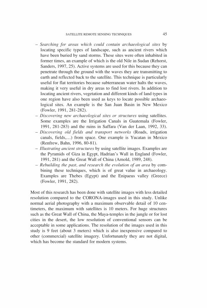
CATEGORY E: BuildingsSquare buildings without roads standing on their own were placed inCATEGORY B within SQUARE STRUCTURES WITH ROADS. It isnot clear if these are modern structures or not.
TYPE 1: N152 (2 x 1 mm.); N153 (5 x 1 mm.)

TYPE 2: No examples.
C. Conclusion
All together, the following sites were identified:
Sites uncategorized because of the poor quality of the image: 10 (O)Category 0: No sites or features visible: 17 (O)Category A: Eight types of Modern towns or villages: 37 (O) + 35 (N)Category B: Possible ruins:• Square structures with roads: 10 (O) + 11 (N) • Square structures without roads: 2 (O) + 13 (N) • Disturbed areas with roads: 11 (O) +18 (N) • Disturbed areas without roads: 1 (O) + 23 (N) • Boulder ruins: 29 (N) • Other linear structures: 10 (N) Category C: Hills (tells): 11 (N)Category D: Places with disturbance:4 (O) + 1 (N)Category E: Two types of buildings: 14 (O) + 2 (N)
Our study located many sites which could perhaps be archaeological sites.Some structures mentioned on the Iranian Oil Operating Companies mapsalso seem to be possible archaeological sites. All structures from CATE-GORY A are certainly modern, but they can of course, also contain oldstructures and sites. Possible ruins (CATEGORY B) without roads have aslightly larger chance of having archaeological importance than structureswith roads leading to them. However some known archaeological sites alsocontain roads leading to them (maybe old roads?). Boulder ruins of uncer-tain age are known all over Luristan and are not considered to be of signif-icant archaeological value, although they could contain more interestingstructures. The other linear structures certainly have an archaeologicalvalue. From CATEGORY C, it is not always clear if they are tells, and this
SATELLITE REMOTE SENSING TECHNIQUES 89
N152 fore N153 aft

needs further stereoscopic investigation. CATEGORY D is worth studying.They contain the structures which do not fit in CATEGORY C. CATE-GORY E are almost certainly all recent structures. It would also be inter-esting to do some fieldwork near the sites which were not placed in a spe-cific category.
90 M. DE MEYER
THE FINAL KEY
CATEGORY A: MODERN TOWNS OR VILLAGES
MODERN TOWNS OR VILLAGES TYPE 2MODERN TOWNS OR VILLAGES TYPE 3MODERN TOWNS OR VILLAGES TYPE 4MODERN TOWNS OR VILLAGES TYPE 5MODERN TOWNS OR VILLAGES TYPE 6MODERN TOWNS OR VILLAGES TYPE 7MODERN TOWNS OR VILLAGES TYPE 8
CATEGORY B: POSSIBLE RUINS
SQUARE STRUCTURES WITH ROADSSQUARE STRUCTURES WITHOUT ROADS
DISTURBED AREAS WITH ROADSDISTURBED AREAS WITHOUT ROADS
BOULDER RUINSOTHER LINEAR STRUCTURES
CATEGORY C: HILLS (TELLS)
CATEGORY D: PLACES WITH DISTURBANCE
CATEGORY E: BUILDINGS
BUILDINGS TYPE 1BUILDINGS TYPE 2
7. Extended investigations
Some of the images were examined using the stereoscopic technique, whichresulted in some interesting findings concerning the location of the sites inrelation to each other. Two overlapping pictures from an aerial series are

called a stereopair. In our study it is the Forward and Afterward images whichform the stereopairs. With them it is possible to get a stereoscopic, three-dimensional view. Some structures which are difficult to see while looking ata single image could be discovered in a quick and efficient way using thestereoscopic technique, but it is important to take account of the existence ofthe stereoscopic exaggeration (A hill, for example, looks stereoscopicallymuch higher than it really is). Textures could also look completely differentunder a stereoscope (Lillesand, Kiefer, 1994, 126, 159). If the entire area couldbe searched with this method, more tells and other human built hills (includ-ing possibly tumuli from dolmens) would certainly be found. This study, how-ever, only investigated three pairs of Forward and Afterward images.
The pictures were developed on a scale of 1/19.000 for this study, as faras possible in a way that both Forward and Afterward pictures would havethe same texture. This is essential in order to get a good stereoscopicresult, but is never completely possible. After that images were scannedand transferred to computer. One out of each pair had to be rectified. Thishad to be done because the images are not geometrically correct, becauseof the corner in which the pictures were taken and because the earth isround. The photographed area of one negative is 200 km. long, so there isconsiderable deformation on the sides. The investigated area is on the sideof the negative strips.
Pair 1:
Sites on the images: S12/S57 (The Sassanian town Shirwan and the mod-ern town of Sar Kalan); O40 (A modern village or town); S10 = O41 (Themodern village Larini); O39 (3 buildings); O38 (2 buildings); S66(Imamzadeh Hadjdj Hazar with cemetery); S56 + S74 (S56 is Sassanianruin Qa’lah Tur Riz and S74 is Tepe Qal’Ah Tur Riz); S71 (Islamicfuneral pillar Imamzadeh Hadjdj Hazar); S70 (Islamic funeral pillar MilBardjiei); N54 (A square structure); N43 (A square structure)
This is the first pair investigated. Three-dimensional buildings wereidentified, and the mountains and terraced country were really clear. TheSassanian town of Shirwan is visible, but not much more could be deter-mined. The most important result was Tepe Qal’Ah Tur Riz, which couldbe seen in three-dimensions with a clear elevation. A possible new tell inthe valley of Shirwan was also discovered with three dimensions visible.The Imamzadeh and the pillars are not visible.
SATELLITE REMOTE SENSING TECHNIQUES 91

Pair 2:
Sites on the images: S25 + S26 (S25 is a Dar Tanha cemetery and S26 aBani Surmah Cemetery); S1 (The modern town or village Chamzuyah(Cham Ritat)); N140 (A square linear structure); N58 (A square linearstructure); N59 (A square linear structure); N60 (A square linear struc-ture)
Some square structures were investigated on this pair, but they did notappear to be visible in three-dimensions, although one new structure wasdiscovered. However, the study did lead to the interesting discovery thatwith this technique the positions that sites have compared to each othercan be seen. Some structures seem to have a function connected to eachother, while others seem to be lookouts for another structure.
Pair 3:
Sites on the images: O82 (The modern village or town Haleh Sam and twobuildings); O81 (A modern village or town); O80 (One building); O78(Two buildings); S79 = O79 (The modern village or town ChamshmahQulah); O77 (The modern town or village Dar Eshkaft); S89 (TepeMehraban); N136 (Black stain with bright white line structure); N83 (Apossible hill and a black triangle-shaped stain)
The priority in studying pair 3 was to establish whether or not a tell(Tepe Mehraban) which was not visible with the images could be identi-fied using the stereoscopic technique. A clearly visible sharp elevationindicates that this kind of tells (TYPE 1) can also be found on the images.
The study suggests that this technique is certainly useful. It can be used tosearch for human and natural elevations, and can also be used to study therelation of the sites between each other on the pictures. With this spatialaspect, and on this scale it is possible to build up improved interpretationsabout both old and new structures.
Conclusion
This research should be followed by new field work to either confirm ordisprove its conclusions. This project will not be said to be finalized untilthe results have been compared with facts, and the method refined.
92 M. DE MEYER

At this stage, this research can only be said to consist of constructing apotentially successful method for identifying possible new sites, and otheradjacent sites of potential interest, including square structures, linear struc-tures and tells. There are of course also the boulder ruins which could besurveyed, and structures identified as modern sites which could also con-tain old features. Remote Sensing must be used here as a kind of prelimi-nary investigation, before new field work is started for more effectiveresults to be achieved. The stereoscopic investigation should also beextended, because the case studies with the three pairs of photographsappeared quite promising. It is certainly a good way to locate tells.
Some of the sites studied here were perhaps seen during the expeditionof 1979, but dismissed as of little or no interest. Vanden Berghe had littleinterest in tells and boulder ruins, and didn’t record them all. It is unfortu-nate that Vanden Berghe also did not record all modern buildings, becausesuch information would have been valuable for a study like this one.Future field trips to this area should record as much information as possi-ble, and satellite images should be used as maps to refine the method usedin this research. The technique can of course also be used outside Iran.
The quality of the images also had an influence on the study, in partbecause of the quality of the negatives purchased. As a result some areascouldn’t be studied as intensely as they should have been, and there was asignificant difference between the Forward and Afterward imagery. TheAfterward images were a lot sharper than the others, but because of thecolor contrast sites were easier to see on the Forward images.
Just one of the possibilities offered by satellite images was studied, butit is clear there is still much work to be done. The stereoscopic method hasbeen discussed, but filtering systems could also be used to find linearstructures. A more integrated use of GIS (Geographical Information Sys-tems) would also be useful.
A summary of the archaeological purposes CORONA (keyhole) can beused for includes:
– The study of the destruction of the archaeological heritage: The tech-nique facilitates investigation of buildings or sites which were stillexisting 30 years ago, and which have now disappeared. The studyclearly showed the differences between the maps of the Iranian OilOperating Companies, the information from Vanden Berghe and the
SATELLITE REMOTE SENSING TECHNIQUES 93
images from CORONA. In a period of less than two decades someplaces which were referred to as buildings became villages, possiblybecause of the fertility of both valleys.
– The verification of old archaeological reports: If a site was visitedbefore the 1960s it can be verified or a search conducted for its exactlocation.
– The study of the relationship of different sites or buildings withregard to each other and their situation in the landscape: On themaps most structures can be seen in the valleys, or on their edges,while boulder ruins are situated along the mountains. Most possibleruins seem to be situated close to the mountains. All tells are in thevalleys of Shirwan and Chardawal and not on the south eastern sideof the Saimarreh. Disturbed places are found everywhere. Moderntowns, villages and buildings are situated along the heart of the val-leys on the banks of rivers. On a smaller scale, one can study therelationship which some buildings have with each other. Stereo-scopic research enables differences between older and more recentsites to be identified because their situation in the landscape is moreclearly seen.
– The location of new archaeological sites and interesting archaeolog-ical areas (old river-beds, fields, roads, irrigation patterns,…): Onthe images old river beds can be seen, and these are potential sitesfor archaeological remains.
– The measurement and illustration of sites.
Using CORONA images is much cheaper than the other Satellite RemoteSensing applications identified in the first chapter, and the results aresuperior most of the time. While it cannot replace all the other SatelliteRemote Sensing techniques, most of research done using expensive com-mercial systems, can also be done with CORONA.
Bibliography
Articles
ARNOLD, H.J.P., 1989, The Great Wall of China From Space. The Exploration ofa Myth, Spaceflight, Vol. 31, No. 7, London, July 1989, p. 248-252.
CAMPBELL, J.B., 1996, Introduction to Remote Sensing, London, 1996.
94 M. DE MEYER

DE MORGAN, J., 1897, Mission Scientifique en Perse, Tome Quatrième (Deux-ième partie), Paris, 1897.
FOWLER, M.J.F., 1952, Satellite Archaeology, Spaceflight, Vol. 33, No 8, London,August 1991, p. 281-283.
GABRIEL, A., 1952, Die Erforschung Persiens, Wien, 1952.LILLESAND, T.M., KIEFER, R.W., 1994, Remote Sensing and Image Interpretation,
New York, Chichester, Brisbane, Toronto, Singapore, 1994.MALEKI, Y., 1964, Une fouille en Luristan, Iranica Antiqua, vol. IV, 1964, p. 1-35.MORTENSEN, P., 1979, The Hulailan Survey: A Note on the Relationship between
Aims and Method, Akten des VII. Internationalen Kongresses für IranischeKunst und Archäologie, München, 7-10. September 1976, Archäologische Mit-teilungen aus Iran, Erganzungsband 6, Berlin, 1979, p. 3-8.
RENFREW, C., BAHN, P., 1996, Archaeology: Theories, Methods and Practice,London,1996.
SANDERS, H.M., OUWEHAND, B., 1994, Ruimtevaartjournaal: Spionage opnamenop de commerciële markt, Ruimtevaart, 43e jaargang, nummer 4, Utrecht,August 1994, p. 38-40.
STEIN, A., 1969, Old Routes of Western Iran, New York, 1969 (original publica-tion: 1940)
VANDEN BERGHE, L., 1969, Belgische opgravingen en navorsingen in de Pusht-iKuh, Phoenix, vol. 14, 1968, p. 109-127.
VANDEN BERGHE, L., 1970, Belgische opgravingen in Luristan. Archeologischenavorsingen in de Pusht-i Kuh, Phoenix, vol. 16, 1970, p. 351-366.
VANDEN BERGHE, L., 1982, Catalogus Luristan, een verdwenen bronskunst uitWest-Iran, Gent, 1982.
VANDEN BERGHE, L., TOUROVETZ, A., 1992, Prospections archéologiques dans ledistrict de Shirwan-Chardawal (Pusht-i Kuh, Luristan), Iranica Antiqua, vol.XXVII, 1992, p. 1-74.
VAN DER LAAN, F., 1992, ISY; Aardobservatie heeft de toekomst, Ruimtevaart,41e jaargang, nummer 3, Utrecht, June 1992, p. 33-38.
ZAGARELL, A., 1982, The Prehistory of the Northeast Bahtiyari Mountains, Iran.The Rise of a Highland Way of Life, Beihefte zum Tübinger Atlas desVorderen Orients, Reihe B., n. 42, Wiesbaden, 1982.
Maps
IRANIAN OIL OPERATING COMPANIES, Kuh-e Varzarin, in: Iran 1:50.000 series,Tehran, 1966.
IRANIAN OIL OPERATING COMPANIES, Palganeh, in: Iran 1:50.000 series, Tehran,1967.
The map used by Vanden Berghe is a simplified version of the Iranian Oil Oper-ating Companies map.
SATELLITE REMOTE SENSING TECHNIQUES 95

Plates
CORONA Imagery: Data available from U.S. Geological Survey, EROS DataCenter, Sioux Falls, SD
Pl. 1: CORONA-system: CAMPBELL, 1996, 194 / CORONA Negatives: Dataavailable from U.S. Geological Survey, EROS Data Center, Sioux Falls, SD
Pl. 2: “Iran; Azië” Microsoft® Encarta® 2001 Encyclopedia. http://encarta.msn.com © 1993-2001 Microsoft Corporation. All rights reserved. / “Ilam;Iran” Microsoft® Encarta® 2001 Encyclopedia. http://encarta.msn.com ©1993-2001 Microsoft Corporation. All rights reserved.
Pl. 3: based on the IRANIAN OIL OPERATING COMPANIES maps.Pl. 4: based on the IRANIAN OIL OPERATING COMPANIES maps.Pl. 5: based on the IRANIAN OIL OPERATING COMPANIES maps.Pl. 6: based on the IRANIAN OIL OPERATING COMPANIES maps.Pl. 7: based on the IRANIAN OIL OPERATING COMPANIES maps.
96 M. DE MEYER

Aft image
Fore image
SATELLITE REMOTE SENSING TECHNIQUES 97
Pl. 1: The CORONA system (top) together with an example of a Forward andAfterward negative of approximately the same area (bottom).

98 M. DE MEYER
Pl. 2: General map of the location of Shirwan and Chardawal in Iran (top) and more detailed overview of the region (bottom).

SATELLITE REMOTE SENSING TECHNIQUES 99
Pl. 3
:Fi
rst
part
(m
ap A
) of
the
stu
died
are
a w
ith i
ndic
atio
n of
the
‘N
’, ‘
O’
and
‘S’
site
s.

100 M. DE MEYER
Pl. 4
:Se
cond
par
t (m
ap B
) of
the
stu
died
are
a w
ith i
ndic
atio
n of
the
‘N
’, ‘
O’
and
‘S’
site
s.

SATELLITE REMOTE SENSING TECHNIQUES 101
Pl. 5
:T
hird
par
t (m
ap C
) of
the
stu
died
are
a w
ith i
ndic
atio
n of
the
‘N
’, ‘
O’
and
‘S’
site
s.

102 M. DE MEYER
Pl. 6
:Fo
urth
par
t (m
ap D
) of
the
stu
died
are
a w
ith i
ndic
atio
n of
the
‘N
’, ‘
O’
and
‘S’
site
s.

SATELLITE REMOTE SENSING TECHNIQUES 103
Pl. 7
:Fi
fth
part
(m
ap E
) of
the
stu
died
are
a w
ith i
ndic
atio
n of
the
‘N
’, ‘
O’
and
‘S’
site
s.