Mobile Satellite Services - SatMagazine
86
SatMagazine Worldwide Satellite Magazine July / August 2008 Thousands of Antennas, Thousands of Places www.avltech.com ® Patented Roto-Lok Cable Drive only from Mobile Satellite Services - GEOSS To The Rescue - Expert insight from Chris Forrester, NSR’s Claude Rous- seau, WTA’s Robert Bell - Times Are A’ Changin’ For MSS Operators - Universal Service--Who Pays For It? - Boeing’s President of SSI In The Spotlight - In-Depth Look At GOES - ICO MSS Trials Set To Start - Part Three Satellite Imagery... - San Diego Venue Big Hit - Relay Examined - ...and more
-
Upload
khangminh22 -
Category
Documents
-
view
4 -
download
0
Transcript of Mobile Satellite Services - SatMagazine
SatMagazineWorldwide Satellite Magazine July / August 2008
Thousands of Antennas, Thousands of Places
www.avltech.com ®Patented Roto-Lok Cable Drive only from
Mobile Satellite Services
- GEOSS To The Rescue
- Expert insight from Chris Forrester, NSR’s Claude Rous-
seau, WTA’s Robert Bell
- Times Are A’ Changin’ For MSS Operators- Universal Service--Who Pays For It?
- Boeing’s President of SSI In The Spotlight- In-Depth Look At GOES
- ICO MSS Trials Set To Start- Part Three Satellite Imagery...
- San Diego Venue Big Hit- Relay Examined
- ...and more
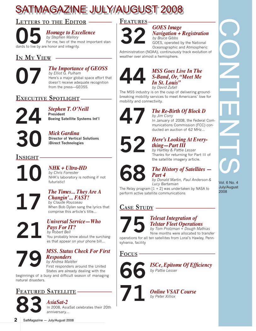
SatMagazine — July/August 2008 2
CO
NTE
NTS
Vol. 6 No. 4 July/August 2008
SATMAGAZINE JULY/AUGUST 2008Letters to the editor
Homage to Excellenceby Stephen MalloryFor me, two of the most important stan-
dards to live by are honor and integrity.
in My View
The Importance of GEOSSby Elliot G. PulhamHere’s a major global space effort that doesn’t receive adequate recognition from the press—GEOSS.
executiVe spotLight
Stephen T. O’NeillPresidentBoeing Satellite Systems Int’l
Mick GardinaDirector of Vertical SolutionsiDirect Technologies
insight
NHK + Ultra-HDby Chris ForresterNHK’s laboratory is nothing if not futuristic!
The Times... They Are A Changin’... FAST!by Claude RousseauWhen Bob Dylan sang the lyrics that comprise this article’s title...
Universal Service—Who Pays For IT?by Robert BellYou probably know about the surcharg-es that appear on your phone bill...
MSS. Status Check For First Respondersby Andrea MaléterFirst responders around the United States are already dealing with the
beginnings of a busy and difficult season of managing natural disasters.
Featured sateLLite
AsiaSat-2In 2008, AsiaSat celebrates their 20th anniversary...
FeaturesGOES Image Navigation + Registrationby Bruce GibbsGOES, operated by the National Oceanographic and Atmospheric
Administration (NOAA), continuously track evolution of weather over almost a hemisphere.
MSS Goes Live In The S-Band, Or, “Meet Me In St. Louis”by David Zufall
The MSS industry is on the cusp of delivering ground-breaking mobility services to meet Americans’ love for mobility and connectivity.
The Re-Birth Of Block Dby Jim CorryIn January of 2008, the Federal Com-munications Commission (FCC) con-ducted an auction of 62 MHz...
Here’s Looking At Every-thing—Part IIIby Hartley & Pattie LesserThanks for returning for Part III of the satellite imagery article.
The History of Satellites — Part 4by Donald Martin, Paul Anderson & Lucy Bartamian
The Relay program [1 + 2] was undertaken by NASA to perform active satellite communications
case study
Telesat Integration ofTelstar Fleet Operationsby Tom Protzman + Dough MathiasNine months were allocated to transfer
operations for all ten satellites from Loral’s Hawley, Penn-sylvania, facility
Focus
ISCe, Epitome Of Efficiencyby Pattie Lesser
Online VSAT Courseby Peter Xilliox
05
07
17
47
32
75
245230
44
68
21
10
79
83
6671
SatMagazine — July/August 2008 3
EDITORIAL + PRODUCTION
Silvano PaynePublisher
Hartley LesserEditorial Director
P.J. WaldtAssociate Editor
THIS ISSUE’S AUTHORS
Paul Anderson
Linda Bartamian
Robert Bell
Jim Corry
Chris Forrester
Bruce Gibbs
Pattie Lesser
Andrea Malateir
Stephen Mallory
Donald Martin
Doug Mathias
Tom Protzman
Elliot G. Pulham
Claude RousseauPeter XillioxDavid Zufall
SALES
Jill DurfeeAdvertising [email protected]
DESIGN + DEVELOPMENT
Simon PayneCreative Manager
SATMAGAZINEJuly/August 2008
Published monthly by Satnews Publishers800 Siesta Way, Sonoma, CA 95476 USAPhone (707) 939-9306 Fax (707) 939-9235E-mail: [email protected]: www.satmagazine.com© 2008 Satnews Publishers
EDITOR’S NOTES
Mobile Satellite Services (MSS) are a crucial component of the satcom industry. The main difference between MSS and a cell system is—mobility! MSS has proven its efficacy for providing
communication services across the globe, especially in servicing those areas that have poor or few communication options, including developing countries and the vast oceans of Earth.
With MSS, there are several positive aspects. Some include:
very high bit rates•
channels dynamically assigned to users who are located in various •areas of the world
the cost of doing business (• i.e., the transmission itself) is indepen-dent of distance
a station that’s handling the data transmission can, itself, receive its •own transmission, which is a definite plus when transmission control is needed
There are other considerations as well as various plusses and minuses for MSS providers when using either a geosynchronous or low Earth orbit satellite.
To obtain a clearer view of the MSS market, I asked one of the leading MSS providers to comment on this segment of the satcom industry.
Iridium Satellite’s Don Thoma, the company’s Executive Vice President, took up the cause. He noted the MSS market growing this year and added in those areas where he believes the growth will be experienced.
“Iridium Satellite continues to achieve double-digit growth across all verti-cal markets for MSS. At the end of the first quarter of 2008, Iridium’s sub-scriber base had grown to more than a quarter-million. That’s a 37 percent increase over the same period last year.
“Regionally, traffic in the U.S. and Canada was up almost 100 percent, largely driven by churn from faltering competitors. The Asia-Pacific region was also a very strong market, with traffic up 61 percent.”
Don then delved into the short-burst arena by stating, “In the maritime market, the number of active subscribers grew 17 percent, with airtime for voice and circuit-switched data up 28 percent, and short-burst data (SBD) traffic up 122 percent.
SatMagazine — July/August 2008 4
The dramatic increase in SBD usage is being driven by growing demand for vessel tracking and monitoring, and unmanned oceanographic/weather sensors. We continue to capture a growing market share, especially in prepaid crew calling services for ships at sea.“We are poised to make further market share gains with the introduction of our new Iridium OpenPort enhanced-bandwidth service, which will provide a cost-effective alternative to Fleet 77 and Fleet Broadband services. More than six major international Service Providers have already signed agreements to distribute Iridium OpenPort products and services, and preorders for Iridium OpenPort ship terminals have far ex-ceeded projections.”
Does the same hold true for the aeronautical market? “We have seen similar rapid growth over the past 12 months, with subscribers up 51 percent. Airtime usage for voice and circuit-switched data was up 46 percent over last year, while short-burst data (SBD) traffic rose 77 percent. Iridium’s growth encompasses all sec-tors of the market, including fixed-wing aircraft and helicopters, to meet the rising demand for reliable, secure voice and data communications with global gap-free coverage over regions not served by other MSS providers.
“While we foresee continuing growth in our traditional core market of business jets and helicopter fleets, we are projecting a major up-surge in the commercial aviation sector. This is buoyed by the ICAO approval earlier this year for Iridium to provide AMS(R)S (Aeronautical Mobile Satellite (Route) Services) for commer-cial aircraft on transoceanic routes. Iridium is the only MSS provider with complete gap-free coverage over the important polar routes.
“The M2M mobile data sector is Iridium’s fast-est growing market, driven by emerging mar-kets for asset tracking and remote monitoring. Our total number of SBD subscribers grew 169 percent over first quarter 2007.”
I inquired as to what issues Iridium will have to confront, and how will such issues be ad-dressed. Don replied, “We are laying the foun-dation now for our next-generation satellite con-stellation with our Iridium NEXT program. Ear-lier this year, we announced agreements with three companies — Lockheed Martine, Space Systems Loral and Theles Alenia Space — to develop design concepts, review critical engi-neering trades, and evaluate performance and capabilities required for NEXT, along with costs to manufacture and launch the system. We will downselect two finalists this summer and award a contract to the prime contractor in mid-2009.
We are on schedule to commence satellite launches in We expect to offset a significant portion of the estimated $2.6 billion cost for NEXT deployment by adding secondary pay-loads onto the satellites, for applications such as weather observations.”
Thanks, Don, for your opinions.
This issue of SatMagazine includes a variety of material we hope you will find intriguing and interesting, ranging from our continued look at satellite imagery with truly expert content from those in the know... to a continuation of the history of satellites, a case study and more. Enjoy!
Hartley LesserEditorial Director
EDITOR’S NOTES
SatMagazine — July/August 2008 5
LETTERS TO THE EDITOR
Dear Editor, For me, two of the most important standards to live by are honor and integrity. This has also served me well in business practices. However, as we all know, it is not uncom-mon to encounter and endure less savory entities during our journeys. I learned long ago to cultivate the honorable, not to compromise one’s principles, and to stand by those who share those lofty endeavors, personally and professionally. I took a serious risk twenty years ago when I walked away from my lifelong dream as a foreign correspondent to concentrate on my personal family responsibilities. At that time, while based in Tokyo, I hocked the farm to buy a used Ku uplink truck, hired six people to start a television news service based in the California Capitol, and began to build a transportable uplinking business that has taken our teams around the world. Over the years, we met and worked with some absolutely wonderful people… and some less so. When we found respectable companies and people to work with, we nurtured and protected those relationships. This was an important key to our continued success. We have clients and vendors we’ve been working with for more than two decades—and some we will never do business with again. One of the most outstanding people I met during this cycle of my life was semi-retired. He was tinkering around with some ideas to keep his keen mind working and was get-ting some sales, however, nothing on a grand scale. His knowledge of the satellite in-dustry was phenomenal. He was well educated, being one of the elite graduates of one of this nation’s finest universities, Georgia Tech. He completed post graduate studies at Stanford. He also earned accolades for his time at Lockheed-Martin, Scientific Atlan-ta, and he co-founded SatCom Technologies.. Several years ago, when I couldn’t locate any “traditional” antenna manufactures to build for my company a 1.8-meter clamshell antenna to fit on a small Ford Econoline van, I was told that he could handle the task. We were already sold on his Roto-Lok ca-ble drive antenna positioner, and all we had to do was convince him to take a risk. To this day, we’re still using that AVL antenna. Jim Oliver took the classic entrepreneurial leap, kick-started a new phase of his life, and developed some great products with his company, AVL Technologies.
His antennas are sold around the world in great numbers. His success is remarkable and well earned. He’s an easygoing, humble, soft-spoken techno wizard that truly knows his business. What sets Jim above so many others isn’t just his vast knowl-edge—it’s his and his staff’s dedication to reliability, quality, innovation, and sterling customer service. This is the salient stuff of dreams.
“Homage To excellence”
SatMagazine — July/August 2008 6
Not only do uplinkers like me buy his products, but there are also others who sub-contract AVL to build parts for their products. That’s a testament to one’s success, which Jim has thoroughly earned. But, you might be surprised to learn that a major manufacturer, one that has paid AVL to incorporate its’ patented Roto-Lok cable drives into some of their antenna systems, has apparently been influenced by the dark side of the force. That company is now copying and selling that technology in their systems. Some might call this patent in-fringement. Others might say Jim’s pocket is being picked. No matter how you cut it, this is a shabby way to treat a business partner. During a trade show earlier this year, I heard the dirty whispers about the pirating of AVL’s technology. Many were examining the reproductions of Jim’s handiwork. Many others and I asked Jim about it and he said he was talking to “them” and was looking for a patent savvy attorney. My approach then, and now, is take no prisoners. Go for the throat. Despite Jim’s efforts, it would seem the big bad wolf is trying to use its bazillions to out lawyer and intimidate him by engaging him in a war of attrition. This situation is as de-spicable as it is disgraceful. There is no question that what is going on is shameless. We want nothing to do with such perfidy. Jim Oliver and his team have performed admirably and now they have been bushwhacked. The offenders were not wearing masks or carrying guns. They could certainly incorporate such elements into their new logo, along with the Jolly Roger’s skull and cross bones flying over their corporate headquarters. Hang in there, Jim. Don’t give up the good fight. We’re with you! Sincerely,Steve MalloryPresidentPACSATSacramento, California
LETTERS TO THE EDITOR
IN MY VIEW
SatMagazine - July/August 2008 7
THe ImporTance of geoSSby Elliot G. PulhamPresident and Chief Executive OfficerSpace Foundation
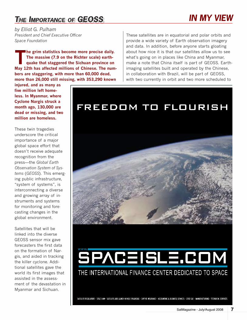
The grim statistics become more precise daily. The massive (7.9 on the Richter scale) earth-quake that staggered the Sichuan province on
May 12th has affected millions of Chinese. The num-bers are staggering, with more than 60,000 dead, more than 26,000 still missing, with 353,290 known injured, and as many as five million left home-less. In Myanmar, where Cyclone Nargis struck a month ago, 130,000 are dead or missing, and two million are homeless.
These twin tragedies underscore the critical importance of a major global space effort that doesn’t receive adequate recognition from the press—the Global Earth Observation System of Sys-tems (GEOSS). This emerg-ing public infrastructure, “system of systems”, is interconnecting a diverse and growing array of in-struments and systems for monitoring and fore-casting changes in the global environment.
Satellites that will be linked into the diverse GEOSS sensor mix gave forecasters the first data on the formation of Nar-gis, and aided in tracking the killer cyclone. Addi-tional satellites gave the world its first images that assisted in the assess-ment of the devastation in Myanmar and Sichuan.
These satellites are in equatorial and polar orbits and provide a wide variety of Earth observation imagery and data. In addition, before anyone starts gloating about how nice it is that our satellites allow us to see what’s going on in places like China and Myanmar, make a note that China itself is part of GEOSS. Earth-imaging satellites built and operated by the Chinese, in collaboration with Brazil, will be part of GEOSS, with two currently in orbit and two more scheduled to
IN MY VIEW
SatMagazine - July/August 20088
launch in the next three years. As these satellites pass overhead, they provide, free of charge, constant real-time imagery to any GEOSS member country that can downlink from them. Countries who currently are with-out a domestic downlink will soon be able to download the imagery, free, over the Internet through a GEOSS data processing center in Germany.
As Germany’s contribution suggests, there’s a lot more to GEOSS than satellites, which includes many countries. While the U.S. is taking a primary role (some 15 fed-eral agencies, with NOAA in the lead, are involved), the “G” in GEOSS really does stand for Global. At the first global Earth observation summit in 2003, GEOSS was launched. The intergovernmental Group on Earth Observa-tions (GEO) was tasked to develop the GEOSS framework. Working as a voluntary alliance, each nation, or organiza-tion, contributes whatever is within its means.
GEO, which now includes more than 70 nations, the European Commission, and 40 international organiza-tions, has framed a 10-year implementation plan for GEOSS, with aims are far more visionary than provid-ing a look at the tragedies in progress.
Linking together existing and planned observation sys-tems around the world, GEOSS will provide decision makers access to data and information and will facili-tate more predictive capabilities. GEOSS is working to address nine areas of critical importance to humanity that include:
Improvement in weather forecasting•
Reduction in loss of life and property from disasters•
Understand, assess, predict, mitigate, and •adapt to climate change
Support sustainable agriculture and forestry, •and combat land degradation
Understand environmental impacts on human health•
Develop capacity for ecological forecasting•
Protect and monitor water resources•
Monitor and manage energy resources•
Improve biodiversity conservation•
According to the U.S. Environmental Protection Agen-cy, GEOSS holds the potential to shape a future in which we can:
Forecast next winter’s weather months in advance •
Predict where and when malaria, West Nile virus, •SARS, and other diseases are likely to strike
Reduce U.S. energy costs by approximately $1 •billion annually
More effectively monitor forest fires, and predict •the effect of air quality on sensitive populations in real time
Provide farmers with immediate forecasts es-•sential to maximizing crop yields
Predict the patterns of the North American •monsoons (I didn’t even know there was such a thing as a North American monsoon, but they occur in Arizona – a state that derives two-thirds of its water from the phenomena)
GEOSS is not just a space system, although the more than 50 environmental satellites in a wide variety of orbits do provide millions of data sets for GEOSS. There are also commercial satellites that provide some of the communication backbone for GEOSS, and GPS satellites provide the precision timing signals that en-able the terrestrial GEOSS computer networks and In-ternet nodes to talk to each other.
Add to this thousands of land-based environmental stations, and thousands of moored and free-floating ocean buoys plugged in (many by satellite, of course), all provide millions of additional data sets to GEOSS.
The challenge now is to enable all the parts and pieces to talk to each other. The exercise includes having to syn-thesize the babble of all these systems, which were in-dependently and individually conceived, developed, built, owned, and operated, into a seamless system-of-systems. Through the GEO, progress on GEOSS is being made daily.When GEOSS reaches its full fruition, the plan-etary good of this space-essential system will be overwhelming.
In the U.S. alone, about $1.7 billion in weather-related aviation delays can be avoided. For every degree (Fahr-enheit) we can more accurately forecast weather, we can save a billion dollars in annual energy costs; and with accurate long-lead weather forecasts, operating efficiency can be improved for weather-sensitive indus-tries that account for one-third of the nation’s GDP, or about $3 trillion. Now, extend those benefits to every country on the planet.
satnewspublishers
Let Satnews put the world of satellites in your hand.
Visit www.satnews.com/mobile
to receive Satnews Daily on
your mobile device.
On The
Move?
IN MY VIEW
SatMagazine - July/August 2008 9
Imagine having weeks, rather than hours, to prepare for the next Cyclone Nargis or the ability to forecast the next killer earthquake before it hits.
We must not lose sight of the tremendous geopoliti-cal significance of GEOSS. Thanks to this remarkable effort, countless human beings from all around the planet, from every kind of background, culture, race, religion, national origin, socio-economic, and political system, are working together for the common good. It is precisely this type of collaborative, global effort that can help bring people together to promote understand-ing, acceptance, and eventually friendship and peace.
It should not go unnoticed that, despite all the recent tension between China and the U.S., we are collaborat-ing on GEOSS; nor should it go unnoticed that among the first flights of international aid to reach the Si-chuan province were U.S. Air Force C-17 cargo jets, tasked by Pacific Air Forces, in a fledgling U.S.-China military-to-military operation.
The view from here is that there is currently no more important effort in international space collaboration than GEOSS. GEOSS serves as a potential model for future international space ventures, and as a shin-ing beacon that reveals what we accomplish in space really can improve life for every living being on the home planet.
SatMagazine — July/August 200810
INSIGHT
by Chris Forrester
For this issue, Chris journeys to Japan to receive an update on new technology—Ultra HDTV—which some suggest is the absolute Holy Grail for the
satellite TV industry.
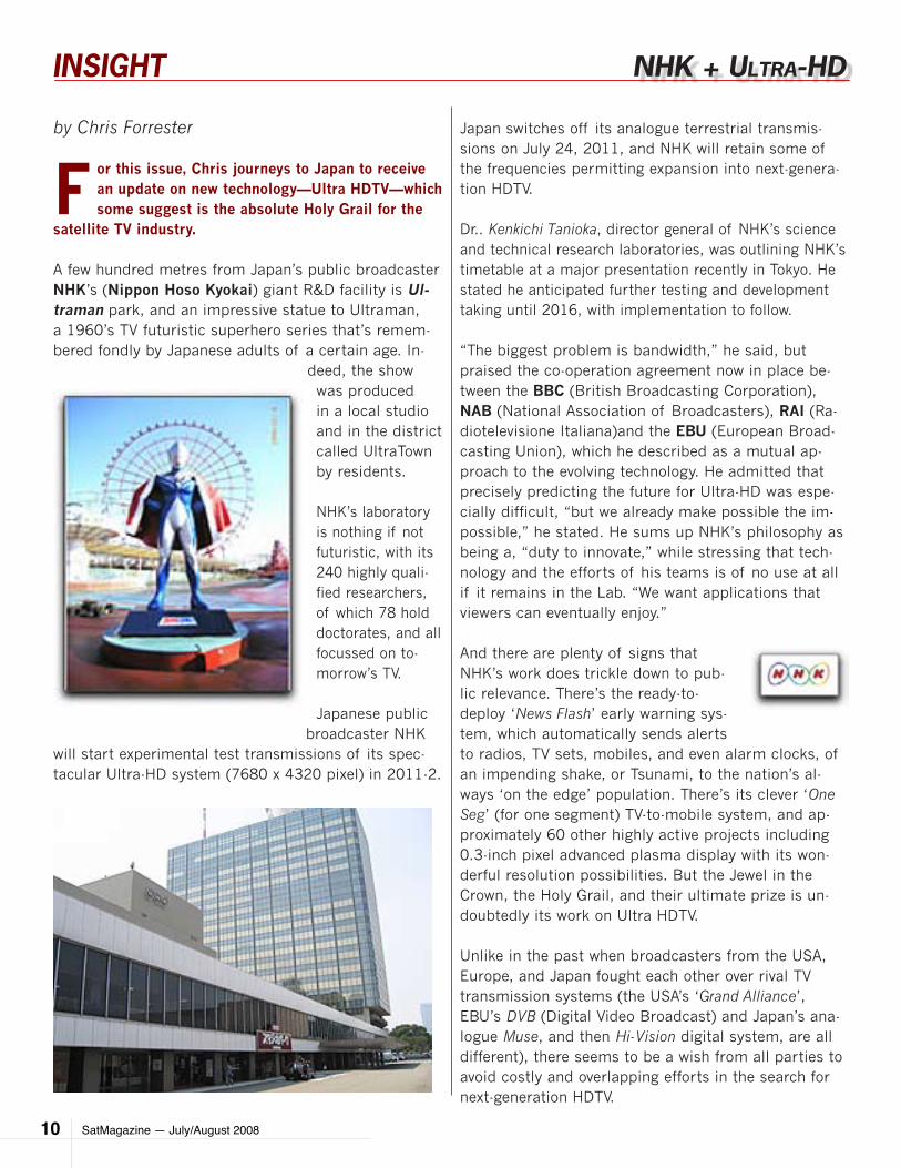
A few hundred metres from Japan’s public broadcaster NHK’s (Nippon Hoso Kyokai) giant R&D facility is Ul-traman park, and an impressive statue to Ultraman, a 1960’s TV futuristic superhero series that’s remem-bered fondly by Japanese adults of a certain age. In-
deed, the show was produced in a local studio and in the district called UltraTown by residents.
NHK’s laboratory is nothing if not futuristic, with its 240 highly quali-fied researchers, of which 78 hold doctorates, and all focussed on to-morrow’s TV.
Japanese public broadcaster NHK
will start experimental test transmissions of its spec-tacular Ultra-HD system (7680 x 4320 pixel) in 2011-2.
Japan switches off its analogue terrestrial transmis-sions on July 24, 2011, and NHK will retain some of the frequencies permitting expansion into next-genera-tion HDTV.
Dr.. Kenkichi Tanioka, director general of NHK’s science and technical research laboratories, was outlining NHK’s timetable at a major presentation recently in Tokyo. He stated he anticipated further testing and development taking until 2016, with implementation to follow.
“The biggest problem is bandwidth,” he said, but praised the co-operation agreement now in place be-tween the BBC (British Broadcasting Corporation), NAB (National Association of Broadcasters), RAI (Ra-diotelevisione Italiana)and the EBU (European Broad-casting Union), which he described as a mutual ap-proach to the evolving technology. He admitted that precisely predicting the future for Ultra-HD was espe-cially difficult, “but we already make possible the im-possible,” he stated. He sums up NHK’s philosophy as being a, “duty to innovate,” while stressing that tech-nology and the efforts of his teams is of no use at all if it remains in the Lab. “We want applications that viewers can eventually enjoy.”
And there are plenty of signs that NHK’s work does trickle down to pub-lic relevance. There’s the ready-to-deploy ‘News Flash’ early warning sys-tem, which automatically sends alerts to radios, TV sets, mobiles, and even alarm clocks, of an impending shake, or Tsunami, to the nation’s al-ways ‘on the edge’ population. There’s its clever ‘One Seg’ (for one segment) TV-to-mobile system, and ap-proximately 60 other highly active projects including 0.3-inch pixel advanced plasma display with its won-derful resolution possibilities. But the Jewel in the Crown, the Holy Grail, and their ultimate prize is un-doubtedly its work on Ultra HDTV.
Unlike in the past when broadcasters from the USA, Europe, and Japan fought each other over rival TV transmission systems (the USA’s ‘Grand Alliance’, EBU’s DVB (Digital Video Broadcast) and Japan’s ana-logue Muse, and then Hi-Vision digital system, are all different), there seems to be a wish from all parties to avoid costly and overlapping efforts in the search for next-generation HDTV.
nHK + UlTra-HD
SatMagazine — July/August 2008 11
INSIGHT
The progress made on this technology over the past 24 months is nothing short of remarkable. During this time period, they’ve mounted exhibitions at IBC (Inter-national Broadcasting Convention) and NAB, and (liter-ally), bit-by-bit, improved compression ratios (helped by the BBC’s codec DIRAC system named after British physicist Paul Dirac), made significant improvements to their 33-million pixel camera lens, complete with its high-speed, wide-band processing circuits.
They’re now ready for further size reduction and integration. They’ve developed prototype transmission circuits that significantly reduce the challenges for actual broadcast. Both the BBC and NHK are making steady progress on the compression algorithms, which have already brought the bit-rate down from a massive 28Gb/s to a far more reasonable 120Mb/s.
All that remains is to get the signal up to a satellite. NHK is contem-plating a new breed of satellite (“Kizuna” mean-ing Wind) that uses the 21Ghz Ka-band. One clever thought is to de-sign and build the new satellites with phased array antenna technol-ogy that concentrates the strongest beams to those regions of Japan, which traditionally suffer from heavy rainfall.
NHK is also experimenting with 16APSK (Amplitude and Phase-shift keying)
and 32APSK transmission schemes, in an attempt to compact this particular ‘quart through a pint pot’! NHK is also reviewing what they call ultra multi-level OFDM technology (1024QAM), and again with the intention of expanding transmission capacity. None of this work is likely to result in over-night success, but it is a sign of the commitment of NHK towards engineering excellence.
SatMagazine — July/August 200812
INSIGHT
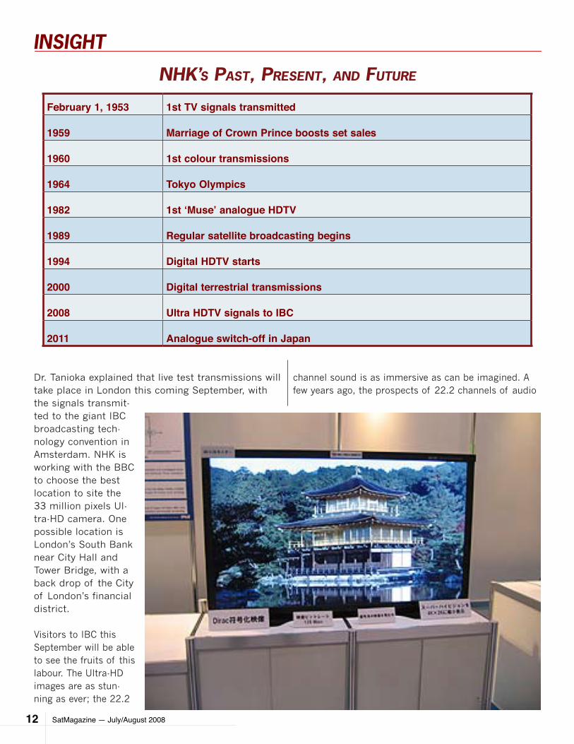
Dr. Tanioka explained that live test transmissions will take place in London this coming September, with the signals transmit-ted to the giant IBC broadcasting tech-nology convention in Amsterdam. NHK is working with the BBC to choose the best location to site the 33 million pixels Ul-tra-HD camera. One possible location is London’s South Bank near City Hall and Tower Bridge, with a back drop of the City of London’s financial district.
Visitors to IBC this September will be able to see the fruits of this labour. The Ultra-HD images are as stun-ning as ever; the 22.2
channel sound is as immersive as can be imagined. A few years ago, the prospects of 22.2 channels of audio
February 1, 1953 1st TV signals transmitted
1959 Marriage of Crown Prince boosts set sales
1960 1st colour transmissions
1964 Tokyo Olympics
1982 1st ‘Muse’ analogue HDTV
1989 Regular satellite broadcasting begins
1994 Digital HDTV starts
2000 Digital terrestrial transmissions
2008 Ultra HDTV signals to IBC
2011 Analogue switch-off in Japan
nHK’S paST, preSenT, anD fUTUre
SatMagazine — July/August 2008 13
INSIGHT
might have caused a heart attack for wiring looms and a boom in speaker sales. NHK’s engineers contemplate ‘towers’ of speakers, delivering bottom layer, mid-layer, and bottom layer audio. Eutelsat is bringing in the Ultra HDTV satellite images to Amsterdam on a pair of its satellite transponders.
Cable & Wireless will handle the cable feeds. NHK-captured content from Japan will be linked with live signals from a camera in central London (let’s hope it isn’t raining). Altogether, the IBC demonstrations promise to be spectacular.
As mentioned, the BBC is already working closely on the project with its DIRAC advanced compression sys-tem. Dr.. John Zubrzycki, the BBC’s principal research engineer at Kingswood Warren, speaking in Tokyo, said they were very pleased with the way DIRAC’s de-velopment was progressing in software form, but the moment was approaching when it would be time for silicon hardware to be employed. DIRAC is achieving
close to 1/200th compression, and a vital link in get-ting the massively fat 24 Gb/s signals down to a man-ageable 120Mb/s.
Peter Wilson, technical advisor to the BBC’s Research & Innovation division, who is also present in Tokyo, said the BBC DIRAC team had several directions to follow. “We are already standardising the technologies within SMPTE (Society of Motion Picture and Television Engi-neers), and our original intent was to focus on profes-sional applications, that is for extremely high-fidelity images within the broadcasting environment, for post-production and for transmission links and possibly storage. We also have a hardware partner called New Media Technologies with products in the market. But the other side of the coin was our wish to see DIRAC used for transmission, including streaming. Here the emphasis is on bandwidth saving for transmission, but if we can achieve both, that is bandwidth saving, but also high quality end results, then we have a very ap-pealing technology.”
SatMagazine — July/August 200814
INSIGHT
Cable & Wireless will pipe these London signals to Amsterdam. Other pre-recorded material will be played out in Turin and beamed by a Eutelsat satel-lite to the Convention Centre. One of the challenges is that currently there’s only one camera, and the sys-tem’s hard disc Dr.ive can only manage 18 minutes of recorded material.
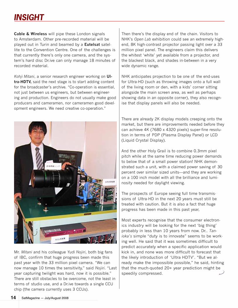
Kohji Mitani, a senior research engineer working on Ul-tra-HDTV, said the next stage is to start adding content for the broadcaster’s archive. “Co-operation is essential, not just between us engineers, but between engineer-ing and production. Engineers do not usually make good producers and cameramen, nor cameramen good devel-opment engineers. We need creative co-operation.”
Mr. Mitani and his colleague Yudi Nojiri, both big fans of IBC, confirm that huge progress been made this past year with the 33 million pixel camera. “We can now manage 10 times the sensitivity,” said Nojiri. “Last year capturing twilight was hard, now it is possible.” There are still obstacles to be overcome, not the least in terms of studio use, and a Dr.ive towards a single CCU chip (the camera currently uses 3 CCUs).
Then there’s the display end of the chain. Visitors to NHK’s Open Lab exhibition could see an extremely high-end, 8K high-contrast projector passing light over a 33 million pixel panel. The engineers claim this delivers the whitest ‘white’ yet available from a projector, and the blackest black, and shades in-between in a very wide dynamic range.
NHK anticipates projection to be one of the end-uses for Ultra-HD (such as throwing images onto a full wall of the living room or den, with a kids’ corner sitting alongside the main screen area, as well as perhaps showing data in an opposite corner), they also recogn-ise that display panels will also be needed.
There are already 2K display models creeping onto the market, but there are improvements needed before they can achieve 4K (7680 x 4320 pixels) super-fine resolu-tion in terms of PDP (Plasma Display Panel) or LCD (Liquid Crystal Display).
And the other Holy Grail is to combine 0.3mm pixel pitch while at the same time reducing power demands to below that of a small power station! NHK demon-strated such a unit, with a claimed power saving of 30 percent over similar sized units—and they are working on a 100 inch model with all the brilliance and lumi-nosity needed for daylight viewing.
The prospects of Europe seeing full time transmis-sions of Ultra-HD in the next 20 years must still be treated with caution. But it is also a fact that huge progress has been made in this past year,
Most experts recognise that the consumer electron-ics industry will be looking for the next ‘big thing’ probably in less than 10 years from now. Dr.. Tan-ioka’s simple “duty is to innovate” seems to be work-ing well. He said that it was sometimes difficult to predict accurately when a specific application would kick in, and none was more difficult to forecast that the likely introduction of ‘Ultra HDTV’. “But we al-ready make the impossible possible,” he said, hinting that the much-quoted 20+ year prediction might be speedily compressed.
SatMagazine — July/August 2008 15
INSIGHT
Towards next generation displays by Chris Forrester
There are huge strides being made in display efficiency,
and progress beyond 1080p 120 Hz (and even 240 Hz)
models, and even breathtaking 8K units, are happening
much faster than anticipated. South Korea’s Samsung in
May unveiled their massive 82 inch (4k x 2k) prototype
LCD panel, and claimed, with some justification, to be
the largest commercial LCD TV in the world.
In fact, the unit measures 3840 x 2160 pixels in size,
which is part of the problem. To fully appreciate this
monster you will need to be viewing at a safe distance,
or else definition is lost. Which is where NHK of Japan
comes in. NHK funds, what is without doubt, the most
advanced portfolio of R&D engineers in broadcasting.
They have 240 very talented engineers (of which 78 hold
doctorates) working on next-generation TV, which has
been dubbed Ultra HDTV, and the technical shape and
potential future for displays.
One area that hasn’t changed is NHK’s commitment to
programming and technological excellence. The pro-
gramming highlights are numerous, while it is worth re-
membering that NHK has been transmitting high-defini-
tion since 1989. That initial HD system was its analogue
MUSE version.
Not bad for an organisation that didn’t transmit its first
TV signals until 1953. NHK went with digital HDTV (Hi-
Vision) in 1994, while the USA, and especially Europe,
were still arguing about how to achieve the technology.
NHK’s logic assumes that 33 million pixel TV cameras
will happen, and that MPEG4 digital compression will be
superseded, and that display technology (either projec-
tion or Plasma/LCD) will also evolve to handle Ultra-HD.
Indeed, the assumption is very much that the initial mar-
ket for this technology will not be for TV, but exhibition,
museum and retail exploitation.
All the while the likes of Samsung, Sony, JVC, Toshiba
and many others are also researching numerous varia-
tions on these themesDr. Kenkichi Tanioka, NHK’s direc-
tor general of its Science & Technical Research Laborato-
ry, who is driving these elements forward calls it,“making
For more information about NHK,
please select on the logo above
About the author
London-based Chris Forrester is a well-known entertainment
and broadcasting journalist. He reports on all aspects of the
TV industry with special emphasis on
content, the business of film, television
and emerging technologies. This in-
cludes interactive multi-media and the
growing importance of web-streamed
and digitized content over all delivery
platforms including cable, satellite and
digital terrestrial TV as well as cellular
and 3G mobile. Chris has been investi-
gating, researching and reporting on the so-called ‘broadband
explosion’ for 25 years.
SatMagazine — July/August 200816
INSIGHT
it,“making the impossible, possible. NHK’s (and Sam-
sung and others) can all handle ‘true’ HD 8 megapixel
displays of 3840 x 2160 with ease. The next step is
to boost this resolution to 7860 x 4320. Indeed, NHK
has achieved it in the research lab by bundling together
four conventional 8k displays, each of 56 inches. But,
as John Wayne might say in a slow drawl, ”There’s not
enough glass in the world” to scale this up to 100 inches
across — yet. Or achieve the super-fine resolution they
are aiming for.
Currently most display screens are next-generation sets
of the X-VGA standard (through WXGA, SXGA, WXGA+,
and more) but NHK’s concept, as well as the new SMPTE
standard (2036-1-2007) takes this a major step forward.
NHK has developed ultra-fine 0.3mm pixel plasma dis-
play panels, vital to help create the longed-for 100 inch
screens to make the most of Ultra-HD images – and in
these energy-saving days, bringing the concept in with a
30 percent power reduction on today’s plasma models.
NHK’s PDP use Strontium Calcium Oxide (SrCaO) elec-
trode protection film to achieve ultra high-resolution
while at the same time without losing degradation, and a
30percent power-saving compared to today’s Magnesium
Oxide displays.
There’s also a widespread expectation that IMAX-style
projection technology will be needed in the home, and
again NHK’s engineers have done the groundwork for
a highly dynamic 33m pixel projector with a very wide
range that clearly shows the colour black.
Moreover, NHK sees us holding on to the normal 0.75
times sitting position. This means that viewers sit or ob-
serve the display at three-quarters of the screen height.
So a 60 inch screen height would have viewers sitting
just 40 inches away from the screen. Hence the drive
towards 0.3mm pixel sizes, for an invisible, ultra-fine
screen image.
Dr. Tanioka calls this work moving from “Next” to “You”,
the ‘You’ element being us, the professional user, pro-
gramme maker, and, ultimately the consumer.
Capturing Ultra HD images at studio production rates of
up to 250 Mb/s is another huge challenge, and NHK’s
technicians have developed a flexible high-speed, thin,
rotating optical disc, with a very low error rate, that
helps achieve this with stored media. The disc floats on
a bed of air, and is so light and flexible that it bends and
collapses under its own weight, hence the bed of air that
creates a sort of sandwich between the spinning disc
and the stabilisation board.
It almost has to be seen to be believed, but the impor-
tant thing is that it works, and is capable of recording
at a massive 250 Mbps. Currently, the best NHK can do
is to capture 18 minutes of stored media — but they’re
working on more.
Key to the overall concept of Ultra HDTV is 22.2channel
surround sound. There’s probably been more tangible
progress in this area than any of the developments.
Now, instead of having 20 dedicated speakers scattered
around the room (plus the sub-woofers) they have con-
solidated the units in six ‘tall boy’ speaker systems, with
each set of speakers capable of handling bottom layer,
middle and top layer audio, and delivering a truly immer-
sive sound system.
Naturally enough, they are also working on 3D, al-
though this technology is undoubtedly a little further
off. They have developed Braille displays using opti-
cal touch panels that can display forms, figures and
graphs onto a GUI display (being developed with the
University of Tokyo).
They are also working hard on flexible displays. We all
know the work being done by Sony and others on OLED
(Organic Light–Emitting Diode) units, but NHK is work-
ing hard on lightweight flexible displays in what they
describe as Organic TFT technology, designated QQVGA
O-TFT. It has 5 inch working prototypes that unroll from
a pen-sized holder.
NHK is planning to start testing Ultra HDTV in
2011-2012, and foresees the technology as becoming
mainstream by 2020. It’s an exciting future.
SatMagazine — July/August 2008 17
INSIGHT
by Claude RousseauSenior AnalystNSR (Northern Sky Research)
When Bob Dylan sang the lyrics that comprise this article’s title back in 1964, he proph-esized a future where “the slow one now, will
later be fast”, a maxim in a different context today that could apply to the MSS industry. There are plans by almost all MSS operators to go faster and have more content delivered over their satellites at broad-band speeds.
Inmarsat, the elder of MSS operators, last year launched their maritime Fleet and aeronautical Swift Broadband solutions, following quickly on the heels of a successful land-mobile BGAN release a year earlier. Inmarsat had, up to then, captured a sizeable market share with narrowband products using slower data speeds and was hoping to gain on its new product and turn its customers on to broadband.
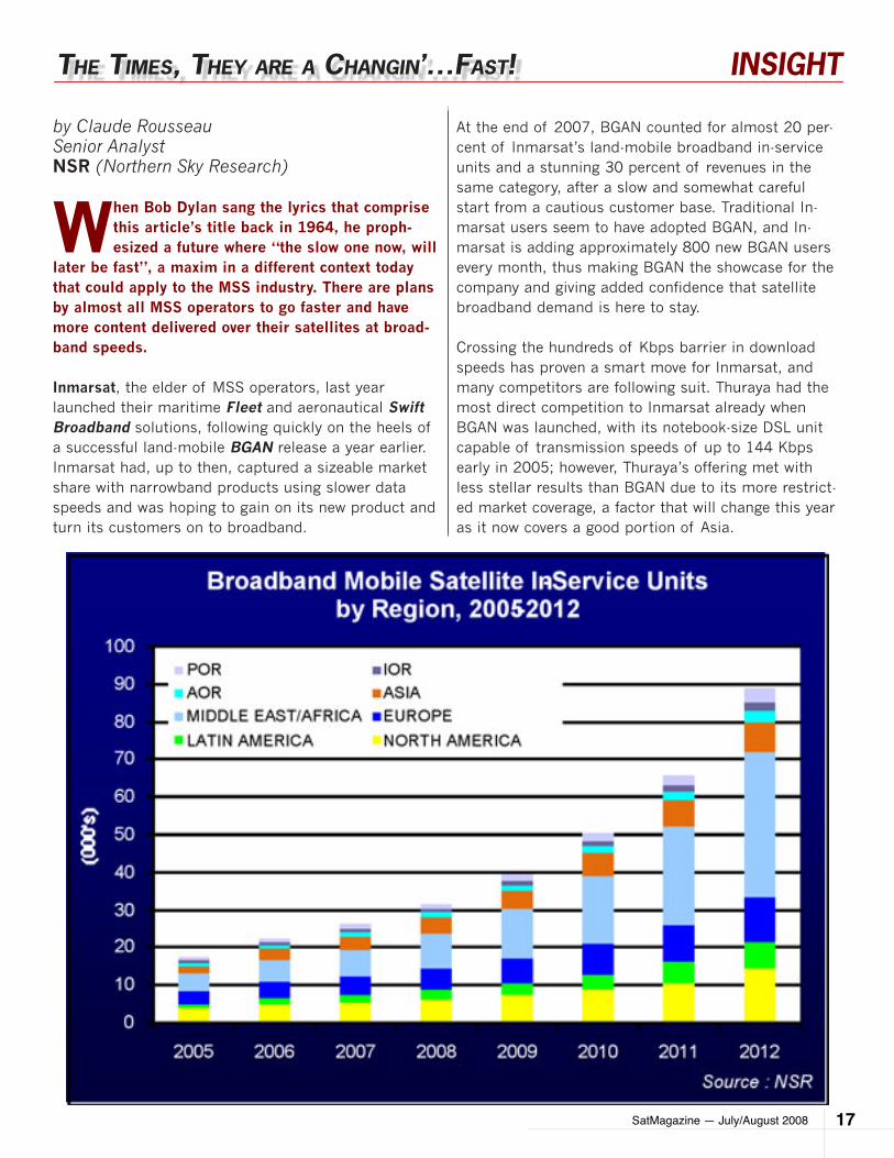
At the end of 2007, BGAN counted for almost 20 per-cent of Inmarsat’s land-mobile broadband in-service units and a stunning 30 percent of revenues in the same category, after a slow and somewhat careful start from a cautious customer base. Traditional In-marsat users seem to have adopted BGAN, and In-marsat is adding approximately 800 new BGAN users every month, thus making BGAN the showcase for the company and giving added confidence that satellite broadband demand is here to stay.
Crossing the hundreds of Kbps barrier in download speeds has proven a smart move for Inmarsat, and many competitors are following suit. Thuraya had the most direct competition to Inmarsat already when BGAN was launched, with its notebook-size DSL unit capable of transmission speeds of up to 144 Kbps early in 2005; however, Thuraya’s offering met with less stellar results than BGAN due to its more restrict-ed market coverage, a factor that will change this year as it now covers a good portion of Asia.
THe TImeS, THey are a cHangIn’…faST!
SatMagazine — July/August 200818
INSIGHT
Like many products built for mobility and using sat-ellite as the primary link, the variety of the end-user population is increasing, too, with certain markets more likely to take-up products at higher bandwidth speeds. Among the core target markets are homeland security, humanitarian aid and first responders, gov-ernment agencies, the military, satellite news gather-ing (SNG), oil and gas exploration, forestry and utility companies, many of which are targets of ‘other’ com-petitors, namely the fixed satellite services operators.
These competitors operate C- and Ku-band transpon-ders on GEO satellites and play a more prominent role in land-mobile, air, and ocean-going platforms than be-fore. With increasing revenues from managed services and transponder leases, they offer a seamless service at much higher download speeds than L-band can enable. The price model (fixed monthly fee) and their ‘natural’ broadband capabilities have helped them pick up steam and step on the traditional MSS operators’ turf.
For all players, the overarching vision to increase num-bers of units deployed is to provide users with a global mobile network, where one can roam from its base to any point on the planet, while moving. But the main difficulty with mobile satellite services for a traditional broadcast fixed satellite business is… mobility. Con-trary to fixed users, the MSS market is more oriented for, and pushed by, on-demand services due to earlier capacity constraints and pay-per-use models. Why, then, pay for something you do not use constantly?
The FSS players know well that higher speeds are re-quired for large data file transfers, video, and Internet browsing and such is the way to go in mobile mar-kets. They have entered the fray with a business model based on a monthly fee for ‘all the data you can eat’, at a set download speed, as opposed to a per-minute pric-ing structure. The FSS-based mobile services also offer lower airtime prices to offset much larger equipment price (compared to L-band systems), which can be three to four times more in the maritime sector.
SatMagazine — July/August 2008 19
INSIGHT
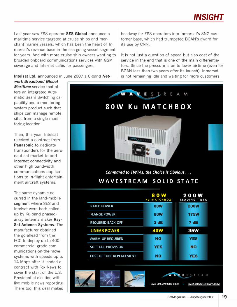
Last year saw FSS operator SES Global announce a maritime service targeted at cruise ships and mer-chant marine vessels, which has been the heart of In-marsat’s revenue base in the sea-going vessel segment for years. And with more cruise ship owners wanting to broaden onboard communications services with GSM coverage and Internet cafés for passengers,
Intelsat Ltd. announced in June 2007 a C-band Net-work Broadband Global Maritime service that of-fers an integrated Auto-matic Beam Switching ca-pability and a monitoring system product such that ships can manage remote sites from a single moni-toring location.
Then, this year, Intelsat received a contract from Panasonic to dedicate transponders for the aero-nautical market to add Internet connectivity and other high bandwidth communications applica-tions to in-flight entertain-ment aircraft systems.
The same dynamic oc-curred in the land-mobile segment where SES and Intelsat were both called up by Ku-band phased-array antenna maker Ray-Sat Antenna Systems. The manufacturer obtained the go-ahead from the FCC to deploy up to 400 commercial-grade com-munications-on-the-move systems with speeds up to 14 Mbps after it landed a contract with Fox News to cover the start of the U.S. Presidential election with live mobile news reporting. There too, this deal makes
headway for FSS operators into Inmarsat’s SNG cus-tomer base, which had trumpeted BGAN’s award for its use by CNN.
It is not just a question of speed but also cost of the service in the end that is one of the main differentia-tors. Since the pressure is on to lower airtime (even for BGAN less than two years after its launch), Inmarsat is not remaining idle and waiting for more customers
SatMagazine — July/August 200820
INSIGHT
to lower prices. One of the main BGAN distributors (Vizada) announced that it was doing just that and re-duced prices in Latin America in late May 2008.
Time is also of the essence and, for many users, hurry-ing up to a location in 24 hours, getting past customs quickly, and setting up a communications link at more than 128 Kbps with one unit in the following minutes after arrival is critical. And there, the edge goes to smaller, lower power and weight units in L-band.
The future of the MSS market holds the promise of a dynamic environment which will see more products compete to provide users a full mobility experience, enhanced from the usual voice and data services. Al-ready in preparation with Internet and video to the handheld, the plans of operators for the next ten years are taking stock of the various thrusts in media, data, voice and video convergence.
Some astounding jumps could take place in the com-ing years when narrowband operators literally skyrock-et to broadband, with perhaps the most impressive one being Iridium, which is currently offering 2.4 Kbps data but plans to enable speeds on its NEXT constella-tion of up to 2 Mbps.
Either for business purposes in land-based solutions, or for entertainment on passengers aircraft, or crews in merchant marine ships, the times for broadband satellite solutions are ‘a changin’ faster than before.
About the Author
Mr. Rousseau has more than 15 years of experience in the
space sector in various roles, including business and pro-
gram management, consulting,
research, administration and
communications. Mr. Rousseau
started his career in Ottawa,
Canada as Special Assistant for
space and science in the Office of
the Minister of Industry, Science
and Technology of Canada. He then joined the Canadian
Space Agency in 1992 in Montreal, Canada where he was
Assistant to the President, then successively Analyst for In-
dustrial and Regional Development, Administrator for the
RADARSAT program and Manager for Strategic Planning in
the Long Term Space Plan Task Force.
SatMagazine — July/August 2008 21
INSIGHT
by Robert BellExecutive DirectorWorld Teleport Association
If you live in the USA, you probably know about the surcharges that appear on your personal or busi-ness phone bill for the Universal Service Fund.
This fund subsidizes phone services in rural and oth-er locations where it is difficult to offer a profitable service at an affordable price. But did you know that your company should be reporting to the FCC about compliance, and may be obligated to collect fees and pay them to the Fund?
When Congress passed the Communications Act of 1934, the premise was to provide access to efficient, affordable communications services for all U.S. citi-zens. Funding for said “universal service” was origi-nally offered through an inter nal cross-subsidy imbed-ded in AT&T’s rela tive pricing structure for local and
long distance services. Higher long distance charges basi cally subsidized lower local telephone rates in-cluding service to low-income households and high-cost areas. The breakup of the Bell System in the early 1980s, however, meant this approach was no longer sustainable.
Plan B FundingAn alternative funding arrangement was initially ac-complished through an access charge by which long distance carriers would compensate local exchange carriers for interconnection with their networks. With the passage of the Telecommunications Act of 1996, the scope of the universal service commitment was significantly expanded. Service providers were now re-quired to provide support services for rural health care providers as well as eligible schools and libraries, and low-income households and high-cost areas. The range of companies falling within the scope of these man-dates now included all telecommunications’ carriers
UnIverSal ServIce – WHo payS for IT?
SatMagazine — July/August 200822
INSIGHT
and providers of telecommunications’ services.
This expanded legislative mandate ultimately gave way to the Universal Service Fund (USF). Today’s USF took shape in 1999 after the FCC consolidated responsibil-ity for overseeing the various universal service support mechanisms. Under the USF guidelines, all telecom-munications companies that provide service between states must pay a percentage – currently set at over 10 percent – of their interstate end-user revenues to the USF. Companies providing a mix of domestic and international services must also contribute.
The USF, however, is not the only universal service mandate in town. The Telecommunications Relay Ser-vices Fund (TRS Fund), the Local Num ber Portability Administration (LNPA), and the administration of the North American Numbering Plan (NANP) are also part of the mix.
The TRS Fund, which actually predates the USF, is an outgrowth of the “Americans With Disabilities Act of 1990”, which directed the FCC to ensure that telecom-munications relay services are available to hearing-impaired and speech-impaired individuals throughout the U.S. The other two entities trace their origins to the Telecommunications Act of 1996 and were established to ensure the impartial administration of telecommu-nications numbering.
Where The Satellite Industry Fits InIt may come as a surprise to learn that satellite com-munications is one of the services with obligations to the USF and TRS. But determining the extent to which satellite service providers are required to contribute is not easy. Part of the problem lies in the definition of “satellite service provider” as it applies to the funding mandates.
In 1997, the FCC made it clear that the satellite in-dustry had a clear obligation to contribute, stating:
“satellite providers that provide interstate telecommu-nications’ services or interstate telecommunications to others, for a fee, must contribute to universal service.”PanAmSat was one of several organizations that chal-lenged the broad statement. The FCC allowed that leasing of bare transponder capacity to others did not constitute the provision of telecommunications’ servic-es because it did not involve the transmission of infor-mation. In other words, entities that simply engage in the leasing of transponder capacity (i.e., satellite op-erators) are not subject to the USF contribution rules while those companies that are involved in the trans-mission of signals to satellites (i.e., ground segment operators engaged in uplinking activities) are, indeed, obligated to contribute.
It is simple in principle, but the complexity of today’s satellite services industry makes it complex in prac-tice. Satellite carriers now operate ground segment, and provide end-to-end services in addition to leasing bandwidth. Integration companies are also carrying voice minutes and Internet links via satellite.
It takes a green eyeshade to work out which revenues are subject to the obligations and which are exempt.
Compliance Is The Name Of The GameIt also takes paperwork. The satellite industry has a lot of experience with regulatory compliance, and it will come as no surprise that the funding mandates involve the filing of various reports with the FCC disclosing specified financial information.
The good news is that in 1999, the FCC substantially simplified the filing process weaving all four funding mandates into a single form known as the Telecommu-nications Reporting Worksheet, FCC Form 499. There are two versions of this form though: one which gets filed annually on April 1, and the other which gets filed on a quarterly basis.
SatMagazine — July/August 2008 23
INSIGHT
2008 Teleport Awards For Excellence
Since 1995, WTA has presented annual awards to companies and individuals who have dramatically demonstrated excellence in the field of teleport op-erations, development and technology. The recipi-ents of the 2008 Teleport Awards are...
Independent Teleport Operator of the YearCapRock Communications (United States). An impressive record of sustained growth, expan-sion into new geographic markets and intro-duction of new services secured the win for CapRock.
Corporate Teleport Operator of the YearEntertainment Sports Programming Network (ESPN) Broadcast Center (United States). The company’s Bristol teleport covers the equivalent of about eight American football fields contain-ing over 30 antennas and moved over 50,000 feeds for use by the network.
Teleport Executive of the YearKenneth Miller, President and Chief Operating Officer, Globecomm Systems (United States). Mr. Miller was recognized for leading his com-pany to record profitability and working with his management team to transform Globecomm into a provider of complex network solutions for a range of vertical markets.
Teleport Technology of the YearGroup QoS and Global NMS from iDirect Tech-nologies (United States). The combined capa-bilities of Group QoS and Global NMS allow teleport operators, enterprise customers and the military to achieve an unprecedented bal-ance of flexibility and control in satellite-based communications worldwide.
Nova AwardSES AMERICOM (United States). The newly created award was given to SES AMERICOM for the development and successful rollout of its IP-PRIME service.
With very few exceptions, the obligation to file Form 499 applies to any company that is an intrastate, in-terstate or international provider of telecommunica-tions in the United States. Exceptions include govern-ments, broadcasters, schools and libraries, system integrators that derive less than five percent of their system integration revenues from resale of telecom-munications, and entities that provide services only to themselves. Everyone else must file both the yearly and quarterly reports.
There are, however, two additional exemptions to note: if the amount of the company’s annual contribution to the USF would be less than $10,000; and if the company does not provide any domestic U.S. services. Such companies would still file the annual form but would be exempt from filing quarterly forms, and con-tributing to the USF.
The vast reach of the funding mandates affects a sig-nificant number of the U.S. satellite services providers, and, particularly teleport operators. The obligation to contribute should be taken seriously.
More details on the Universal Service Fund can be found in the WTA-published White Paper “Universal Service: Satellite Service Companies and the FCC”, writ-ten by Maury J. Mechanick, Counsel, White & Case LLP for the World Teleport Association. The White Paper is available on the web site at the WTA’s website or by contacting WTA at [email protected].
About the author
Robert Bell is the Executive Director of the
World Teleport Association. Robert has au-
thored articles in numerous industry publi-
cations and has appeared in segments of
ABC World News and The Discovery Chan-
nel. He is a frequent speaker and modera-
tor at industry conferences including SAT-
ELLITE, NAB and SATCON. He is also the
author of WTA’s Teleport Benchmarks and
Sizing the Teleport Market research studies; and of B2B With-
out the BS, a guide to sales and marketing in the business-to-
business sector available from Amazon.com.
SatMagazine — July/August 200824
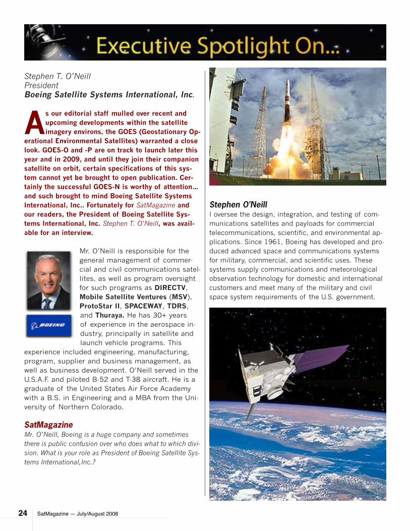
Stephen T. O’NeillPresidentBoeing Satellite Systems International, Inc.
As our editorial staff mulled over recent and upcoming developments within the satellite imagery environs, the GOES (Geostationary Op-
erational Environmental Satellites) warranted a close look. GOES-O and -P are on track to launch later this year and in 2009, and until they join their companion satellite on orbit, certain specifications of this sys-tem cannot yet be brought to open publication. Cer-tainly the successful GOES-N is worthy of attention… and such brought to mind Boeing Satellite Systems International, Inc.. Fortunately for SatMagazine and our readers, the President of Boeing Satellite Sys-tems International, Inc. Stephen T. O’Neill, was avail-able for an interview.
Mr. O’Neill is responsible for the general management of commer-cial and civil communications satel-lites, as well as program oversight for such programs as DIRECTV, Mobile Satellite Ventures (MSV), ProtoStar II, SPACEWAY, TDRS, and Thuraya. He has 30+ years of experience in the aerospace in-dustry, principally in satellite and launch vehicle programs. This
experience included engineering, manufacturing, program, supplier and business management, as well as business development. O’Neill served in the U.S.A.F. and piloted B-52 and T-38 aircraft. He is a graduate of the United States Air Force Academy with a B.S. in Engineering and a MBA from the Uni-versity of Northern Colorado.
SatMagazineMr. O’Neill, Boeing is a huge company and sometimes there is public confusion over who does what to which divi-sion. What is your role as President of Boeing Satellite Sys-tems International,Inc.?
Stephen O’NeillI oversee the design, integration, and testing of com-munications satellites and payloads for commercial telecommunications, scientific, and environmental ap-plications. Since 1961, Boeing has developed and pro-duced advanced space and communications systems for military, commercial, and scientific uses. These systems supply communications and meteorological observation technology for domestic and international customers and meet many of the military and civil space system requirements of the U.S. government.
SatMagazine — July/August 2008 25
The world’s first geosynchronous communications sat-ellite, Syncom, was built by Boeing and launched in 1963. Today, nearly half of the commercial satellites in geosynchronous orbit were built by Boeing at the Satellite Development Center in El Segundo, California, the world’s largest satellite manufacturing factory.
Boeing’s spacecraft routinely relay digital communications, telephone calls, videoconferences, television news reports, facsimiles, television programming, mobile communi-cations, navigation and location services, Internet connectivity, and direct-to-home entertainment.
SatMagazineWe are in the second month of the hur-ricane season and it is quite fitting we focus on weather satellites in addition to our commercial satellite systems coverage. What has been Boeing’s role in building weather satellites?
Stephen O’NeillStarting with the launch of the first Applications Technology Satel-lite in December 1966, Boeing has 42 years of experience in building weather satellites. In fact, more than half of all GOES satellites ever built have been manufactured by Boeing.
Boeing has also built space-based weather instruments with the abil-ity to provide timely and accurate meteorological information about ocean systems, storms, and the ef-fects of tropical and polar weather patterns on the rest of the world.
We’ve come a long way in the past four decades—from a satellite that provided the capability to photo-graph earth with a spin scan cloud
camera, boasting “new” color television transmission, and a demonstration of multiple access capability with several ground stations, simultaneously—to the GOES-N series, the next generation of Earth Observa-tion Satellites.
SatMagazine — July/August 200826
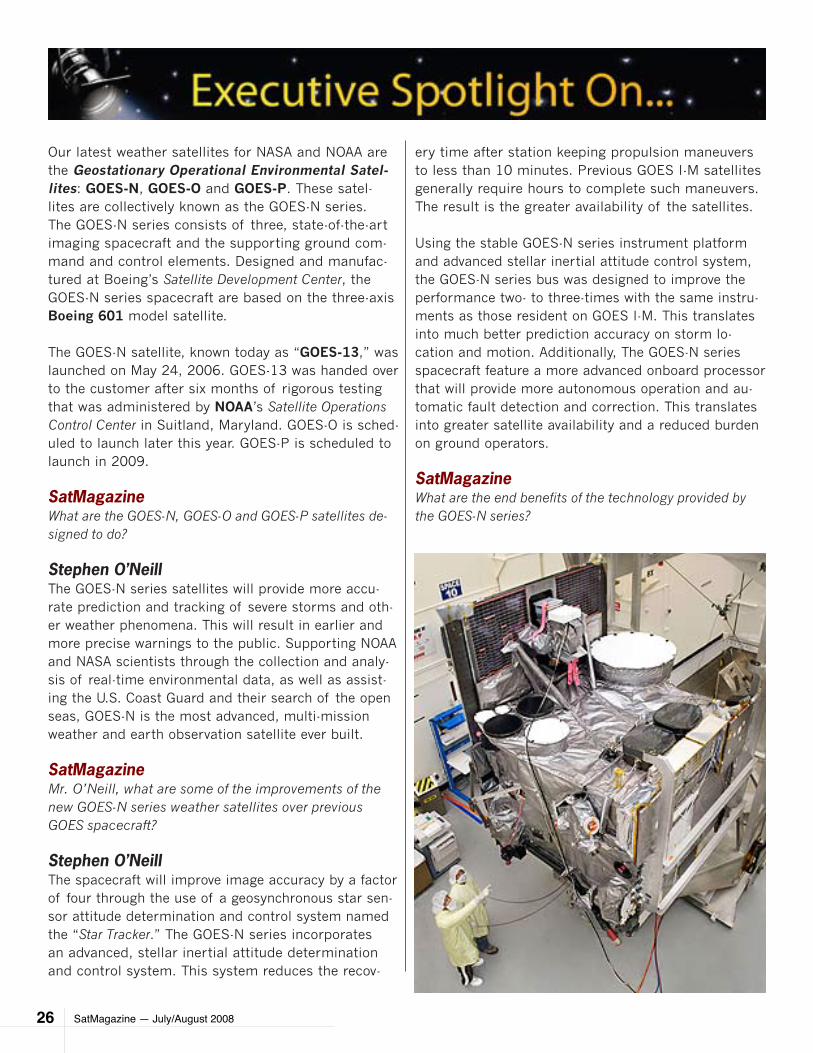
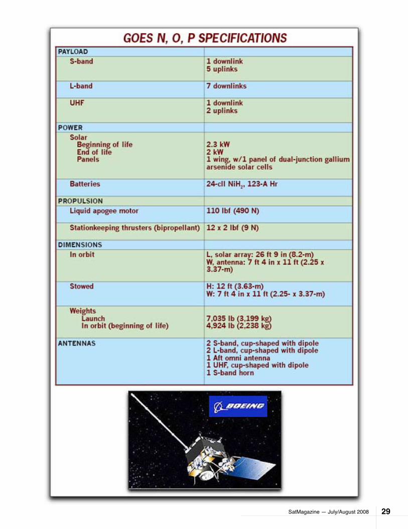
Our latest weather satellites for NASA and NOAA are the Geostationary Operational Environmental Satel-lites: GOES-N, GOES-O and GOES-P. These satel-lites are collectively known as the GOES-N series. The GOES-N series consists of three, state-of-the-art imaging spacecraft and the supporting ground com-mand and control elements. Designed and manufac-tured at Boeing’s Satellite Development Center, the GOES-N series spacecraft are based on the three-axis Boeing 601 model satellite.
The GOES-N satellite, known today as “GOES-13,” was launched on May 24, 2006. GOES-13 was handed over to the customer after six months of rigorous testing that was administered by NOAA’s Satellite Operations Control Center in Suitland, Maryland. GOES-O is sched-uled to launch later this year. GOES-P is scheduled to launch in 2009.
SatMagazineWhat are the GOES-N, GOES-O and GOES-P satellites de-signed to do?
Stephen O’NeillThe GOES-N series satellites will provide more accu-rate prediction and tracking of severe storms and oth-er weather phenomena. This will result in earlier and more precise warnings to the public. Supporting NOAA and NASA scientists through the collection and analy-sis of real-time environmental data, as well as assist-ing the U.S. Coast Guard and their search of the open seas, GOES-N is the most advanced, multi-mission weather and earth observation satellite ever built.
SatMagazineMr. O’Neill, what are some of the improvements of the new GOES-N series weather satellites over previous GOES spacecraft?
Stephen O’NeillThe spacecraft will improve image accuracy by a factor of four through the use of a geosynchronous star sen-sor attitude determination and control system named the “Star Tracker.” The GOES-N series incorporates an advanced, stellar inertial attitude determination and control system. This system reduces the recov-
ery time after station keeping propulsion maneuvers to less than 10 minutes. Previous GOES I-M satellites generally require hours to complete such maneuvers. The result is the greater availability of the satellites.
Using the stable GOES-N series instrument platform and advanced stellar inertial attitude control system, the GOES-N series bus was designed to improve the performance two- to three-times with the same instru-ments as those resident on GOES I-M. This translates into much better prediction accuracy on storm lo-cation and motion. Additionally, The GOES-N series spacecraft feature a more advanced onboard processor that will provide more autonomous operation and au-tomatic fault detection and correction. This translates into greater satellite availability and a reduced burden on ground operators.
SatMagazineWhat are the end benefits of the technology provided by the GOES-N series?
SatMagazine — July/August 2008 27
Stephen O’NeillThere are many. To boil it down, atmospheric phenom-ena can be better tracked, ensuring real-time cover-age of short-lived dynamic events, such as severe local storms and tropical hurricanes and cyclones. These are two meteorological event types that directly affect public safety, property, and, ultimately, economic health and development.
SatMagazineWhat do you feel is the im-portance of GOES?
Stephen O’NeillGOES is one of those unique programs that touch the lives of every person. When you watch the nightly news or read the daily newspaper, the weather predictions are based largely upon imag-ery provided by the GOES satellites. People depend on accurate weather infor-mation— and the depth of leadership and knowledge at NASA and NOAA will ensure the information the public receives continues to increase in terms of accuracy.Boeing recognizes the importance and critical importance of the GOES mission. Timely and ac-curate weather forecast-ing provided by the GOES system benefits people everywhere. Hundreds of lives are saved annually as a result of the Search and Rescue system enabled by the GOES satellites. Boe-ing is proud of our contri-
butions to this system over the years, which date back to the launch of ATS-1 in 1966 and continue today.
SatMagazineBy all accounts, the GOES-13 satellite is performing well. To what do you attribute to the success of GOES-13?
SatMagazine — July/August 200828
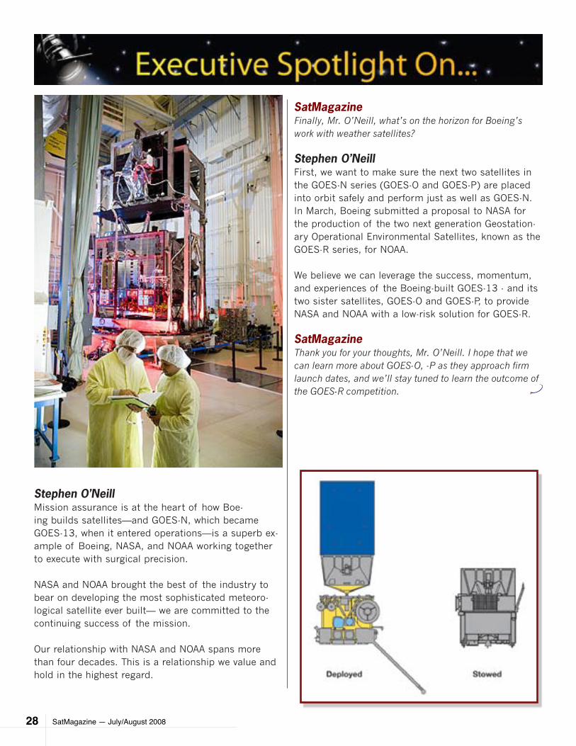
Stephen O’NeillMission assurance is at the heart of how Boe-ing builds satellites—and GOES-N, which became GOES-13, when it entered operations—is a superb ex-ample of Boeing, NASA, and NOAA working together to execute with surgical precision.
NASA and NOAA brought the best of the industry to bear on developing the most sophisticated meteoro-logical satellite ever built— we are committed to the continuing success of the mission.
Our relationship with NASA and NOAA spans more than four decades. This is a relationship we value and hold in the highest regard.
SatMagazineFinally, Mr. O’Neill, what’s on the horizon for Boeing’s work with weather satellites?
Stephen O’Neill First, we want to make sure the next two satellites in the GOES-N series (GOES-O and GOES-P) are placed into orbit safely and perform just as well as GOES-N. In March, Boeing submitted a proposal to NASA for the production of the two next generation Geostation-ary Operational Environmental Satellites, known as the GOES-R series, for NOAA.
We believe we can leverage the success, momentum, and experiences of the Boeing-built GOES-13 - and its two sister satellites, GOES-O and GOES-P, to provide NASA and NOAA with a low-risk solution for GOES-R.
SatMagazineThank you for your thoughts, Mr. O’Neill. I hope that we can learn more about GOES-O, -P as they approach firm launch dates, and we’ll stay tuned to learn the outcome of the GOES-R competition.
SatMagazine — July/August 2008 29
SatMagazine — July/August 200830
Mick GardinaDirector of Vertical SolutionsiDirect Technologies
Mick focuses on solutions in the Broadcast Media and Cellular Backhaul market-
places. We recently spoke with Mick regarding iDirect’s announcement regarding their intelligent platform having been tested and certified to be fully interoperable with Erics-son’s Abis over IP GSM satellite backhaul solution. An extremely valuable accomplishment!
SatMagazineWhy is GSM backhaul over satellite such an important issue today?
Mick GardinaThis is a technology that has the potential to dramati-cally improve quality of life for an enormous number of people. More than two billion people worldwide – al-most a third of the population – live in areas without cellular connectivity. These are predominantly rural regions where it has been cost prohibitive for cellular operators to extend service.
Unfortunately, many of these regions are in developing countries that could benefit greatly from cellular com-munications. GSM backhaul over satellite has proven to be an effective technology for extending precious cellu-lar connectivity into these hard to reach areas.
SatMagazineWhy isn’t satellite more widely adopted for GSM backhaul?
Mick GardinaCost issues have prohibited GSM backhaul over satellite from being deployed on a greater scale. Traditional sat-ellite links, such as Single Channel Per Carrier (SCPC) or other dedicated links, are inefficient and therefore ex-pensive for backhauling cellular traffic. They force oper-ators to set peak-time bandwidth requirements for every base station, at all times, in order to handle periods of activity when cellular use is high. User experience can
be compromised in this environment. Often, the ineffi-ciencies of SCPC satellite links force end-users to limit their calling patterns to certain hours.
SatMagazineHow can network operators overcome SCPC inefficiencies?
Mick GardinaOne solution is for cellular operators to pool backhaul traffic onto a common network, replacing the previous standard SCPC links with a shared IP Time Division Multiple Access (TDMA) network. TDMA allows opera-tors to allocate bandwidth according to the real-time, not busy-hour, requirements of each individual Base Tower System (BTS). The result is dramatically re-duced bandwidth usage and lower costs.
SatMagazineHow does TDMA manage the demands of real-time voice applications?
Mick GardinaIn the past, TDMA has not supported voice applica-tions adequately. This was problematic on a cellular network because, when voice calls are delayed, cus-tomers tend to hang up and try again. When this hap-pens throughout a network the results can be disas-trous. iDirect’s advanced Group QoS (Quality of Ser-vice) algorithms allow network operators to avoid these pitfalls by allocating bandwidth instantaneously, and ensuring that the integrity of the connection is main-tained while reducing overall bandwidth requirements.
SatMagazineYou’ve recently announced that your technology is fully in-teroperable with Ericsson’s Abis over IP solution. Can you elaborate on the Ericsson solution?
Mick GardinaEricsson’s Abis over IP solution integrates IP routing capabilities into its cellular networking equipment. This delivers built-in IP traffic optimization, increasing transmission speed, which is a critical requirement for voice networks. The solution represents the first time a cellular networking equipment provider has integrated IP routing capabilities into its own hardware, signaling
SatMagazine — July/August 2008 31
a growing demand for GSM satellite backhaul.
In addition, the Ericsson solution will deliver further bandwidth savings when the company introduces local switching later this year. This will allow calls on a lo-cal group of BTS to be directly connected via the BTS rather than over the satellite.
SatMagazineWhat are the combined ben-efits of the joint solution?
Mick GardinaThe combination of Erics-son’s Abis over IP solu-tion and iDirect’s satellite platform dramatically reduces backhaul trans-mission costs, clearing the way for providers to extend cellular networks across the globe.
SatMagazineIn which regions do you anticipate the most de-mand for GSM backhaul over satellite?
Mick GardinaThere is enormous po-tential for GSM backhaul over satellite in Africa and South America, where economies are developing more rapidly than commu-nications infrastructure.
We’re also seeing tre-mendous demand in Asia – especially South-east Asia – as well as in parts of the Middle East where we recently signed Nawras, our first joint customer with Ericsson.
Nawras is a major cellular operator based in Oman. The company will be extending its GSM ser-vice to the country’s entire population and plans to leverage the satellite network to provide broadband connectivity to commercial enterprises and govern-ment organizations.
SatMagazine — July/August 200832
FEATURE
by Bruce GibbsIntegral Systems, Inc.
The Geostationary Operational Environmental Satellites (GOES), operated by the National Oceanographic and Atmospheric Administration
(NOAA), continuously track evolution of weather over almost a hemisphere. GOES primary functions are to support weather forecasting, severe storm tracking, and meteorological research.
The earliest GOES satellites, numbered 1 to 7, were 100 RPM spin-stabilized satellites where Earth imag-ing was accomplished using north-to-south detector step scanning on each spin. GOES-1, launched in 1975, flew Visible Infrared Spin Scan Radiometer (VISSR) and Space Environment Monitor (SEM) instruments. The VISSR provided cloud imagery and data for determin-ing cloud and surface temperatures, and wind fields.
The next series of GOES satellites, designated GOES I-M1 and numbered 8 to 12, were first launched in 1994; GOES 10, 11 and 12 are still operational. These GOES are Earth-pointing, three-axis stabilized space-craft supporting two 2-axis scanning instruments: the 5-channel visible/Infrared (IR) Imager with 1, 4 and 8 km resolution, and the 19-channel Sounder with 8 km resolution and 10 km sampling. The Imager and Sounder scan in an east-west (EW) direction with north-south (NS) steps at the end of east-west swaths.
Other GOES I-M instruments include the Solar X-ray Imager (SXI) and SEM with magnetometer. Use of a three-axis stabilized spacecraft and 2-axis scan-ning instruments enable the sensors to “stare” at the Earth. GOES sensors image clouds, monitor Earth surface temperature and water vapor, and sound the atmosphere vertical thermal and vapor profiles. These capabilities allow tracking of dynamic atmospheric phenomena, particularly severe local storms and tropical cyclones.
GOES 13, the first in the NOP-series, was built by The Boeing Company and launched in May 2006; Integral Systems built most of the ground system. GOES NOP spacecraft2,3 retain the GOES I-M heritage instruments but the spacecraft differ in many respects.
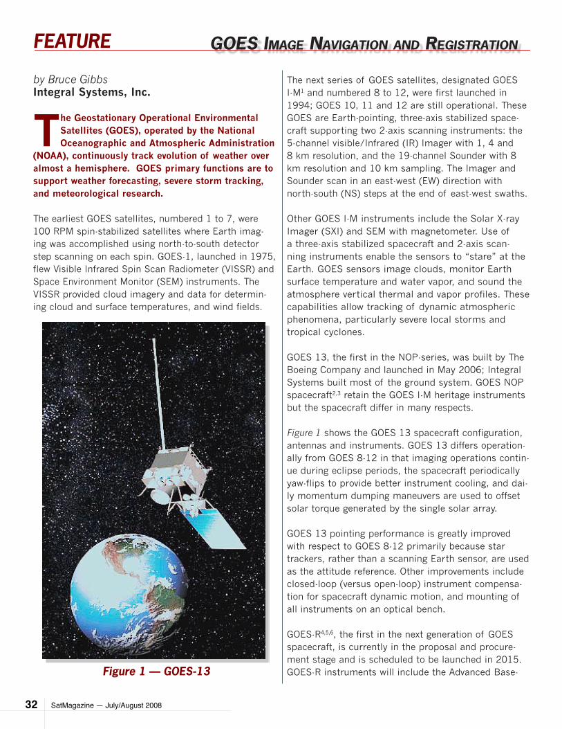
Figure 1 shows the GOES 13 spacecraft configuration, antennas and instruments. GOES 13 differs operation-ally from GOES 8-12 in that imaging operations contin-ue during eclipse periods, the spacecraft periodically yaw-flips to provide better instrument cooling, and dai-ly momentum dumping maneuvers are used to offset solar torque generated by the single solar array.
GOES 13 pointing performance is greatly improved with respect to GOES 8-12 primarily because star trackers, rather than a scanning Earth sensor, are used as the attitude reference. Other improvements include closed-loop (versus open-loop) instrument compensa-tion for spacecraft dynamic motion, and mounting of all instruments on an optical bench.
GOES-R4,5,6, the first in the next generation of GOES spacecraft, is currently in the proposal and procure-ment stage and is scheduled to be launched in 2015. GOES-R instruments will include the Advanced Base-
goeS Image navIgaTIon anD regISTraTIon
Figure 1 — GOES-13
SatMagazine — July/August 2008 33
FEATURE
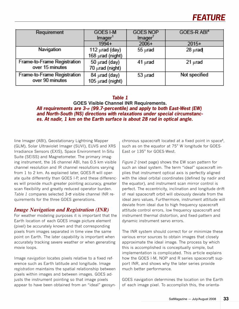
line Imager (ABI), Geostationary Lightning Mapper (GLM), Solar Ultraviolet Imager (SUVI), EUVS and XRS Irradiance Sensors (EXIS), Space Environment In-Situ Suite (SEISS) and Magnetometer. The primary imag-ing instrument, the 16 channel ABI, has 0.5 km visible channel resolution and IR channel resolutions varying from 1 to 2 km. As explained later, GOES-R will oper-ate quite differently than GOES I-P, and these differenc-es will provide much greater pointing accuracy, greater scan flexibility and greatly reduced operator burden. Table 1 compares selected 3-σ visible channel INR re-quirements for the three GOES generations.
Image Navigation and Registration (INR)For weather modeling purposes it is important that the Earth location of each GOES image picture element (pixel) be accurately known and that corresponding pixels from images separated in time view the same point on Earth. The later capability is important when accurately tracking severe weather or when generating movie loops.
Image navigation locates pixels relative to a fixed ref-erence such as Earth latitude and longitude. Image registration maintains the spatial relationship between pixels within images and between images. GOES ad-justs the instrument pointing so that image pixels appear to have been obtained from an “ideal” geosyn-
chronous spacecraft located at a fixed point in space8, such as on the equator at 75° W longitude for GOES-East or 135° for GOES-West.
Figure 2 (next page) shows the EW scan pattern for such an ideal system. The term “ideal” spacecraft im-plies that instrument optical axis is perfectly aligned with the ideal orbital coordinates (defined by nadir and the equator), and instrument scan mirror control is perfect. The eccentricity, inclination and longitude drift of real spacecraft orbit will obviously deviate from the ideal zero values. Furthermore, instrument attitude will deviate from ideal due to high frequency spacecraft attitude control errors, low frequency spacecraft and instrument thermal distortion, and fixed-pattern and dynamic instrument servo errors.
The INR system should correct for or minimize these various error sources to obtain images that closely approximate the ideal image. The process by which this is accomplished is conceptually simple, but implementation is complicated. This article explains how the GOES I-M, NOP and R series spacecraft sup-port INR, and shows why the later series provide much better performance.
GOES navigation determines the location on the Earth of each image pixel. To accomplish this, the orienta-
Table 1GOES Visible Channel INR Requirements.
All requirements are 3-σ (99.7-percentile) and apply to both East-West (EW) and North-South (NS) directions with relaxations under special circumstanc-es. At nadir, 1 km on the Earth surface is about 28 rad in optical angle.
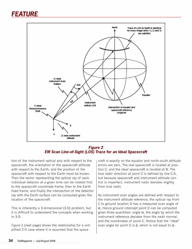
SatMagazine — July/August 200834
FEATURE
tion of the instrument optical axis with respect to the spacecraft, the orientation of the spacecraft attitude with respect to the Earth, and the position of the spacecraft with respect to the Earth must be known. Then the vector representing the optical ray of each individual detector at a given time can be rotated first to the spacecraft coordinate frame, then to the Earth fixed frame, and finally the intersection of the detector ray with the Earth surface can be computed given the location of the spacecraft.
This is inherently a 3-dimensional (3-D) problem, but it is difficult to understand the concepts when working in 3-D.
Figure 3 (next page) shows the relationship for a sim-plified 2-D case where it is assumed that the space-
craft is exactly on the equator and north-south attitude errors are zero. The real spacecraft is located at posi-tion C, and the ideal spacecraft is located at B. The true nadir direction at point C is defined by line C-A, but because spacecraft and instrument attitude con-trol is imperfect, instrument nadir deviates slightly from true nadir.
As instrument scan angles are defined with respect to the instrument attitude reference, the optical ray from C to ground location D has a measured scan angle of α. Hence ground intercept point D can be computed given three quantities: angle α, the angle by which the instrument reference deviates from the nadir normal, and the coordinates of point C. Notice that the “ideal” scan angle for point D is β, which is not equal to α.
Figure 2EW Scan Line-of-Sight (LOS) Trace for an Ideal Spacecraft
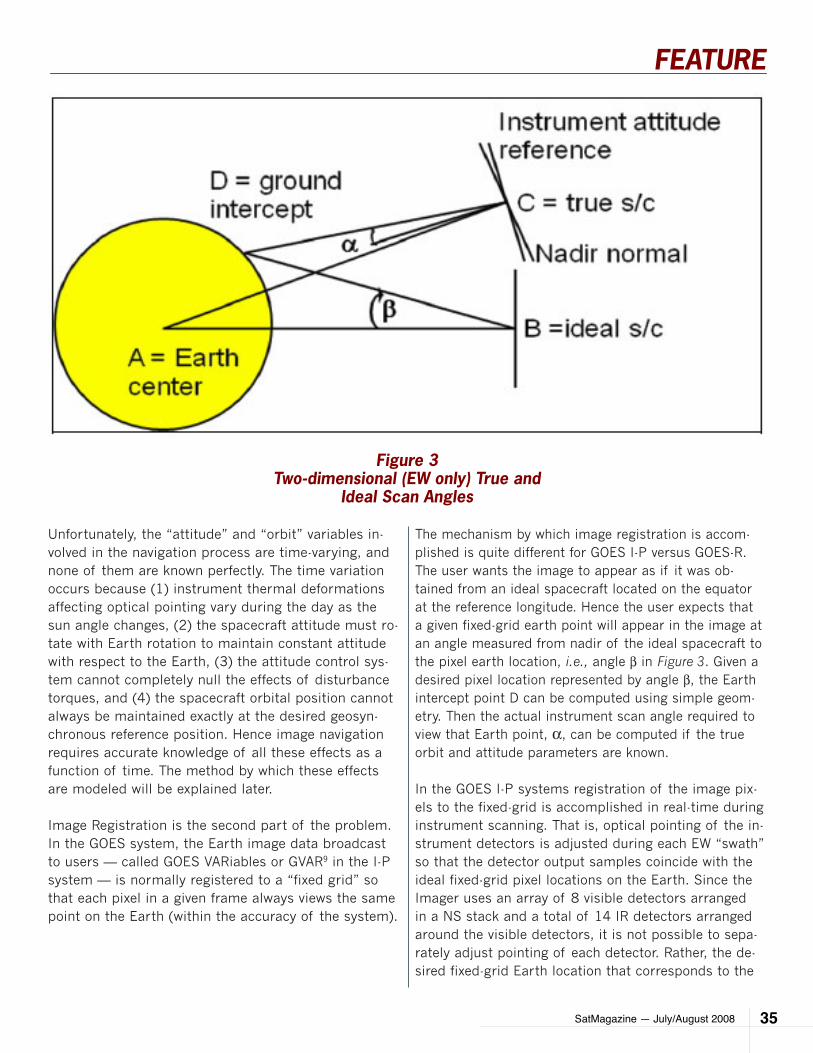
SatMagazine — July/August 2008 35
FEATURE
Unfortunately, the “attitude” and “orbit” variables in-volved in the navigation process are time-varying, and none of them are known perfectly. The time variation occurs because (1) instrument thermal deformations affecting optical pointing vary during the day as the sun angle changes, (2) the spacecraft attitude must ro-tate with Earth rotation to maintain constant attitude with respect to the Earth, (3) the attitude control sys-tem cannot completely null the effects of disturbance torques, and (4) the spacecraft orbital position cannot always be maintained exactly at the desired geosyn-chronous reference position. Hence image navigation requires accurate knowledge of all these effects as a function of time. The method by which these effects are modeled will be explained later.
Image Registration is the second part of the problem. In the GOES system, the Earth image data broadcast to users — called GOES VARiables or GVAR9 in the I-P system — is normally registered to a “fixed grid” so that each pixel in a given frame always views the same point on the Earth (within the accuracy of the system).
The mechanism by which image registration is accom-plished is quite different for GOES I-P versus GOES-R. The user wants the image to appear as if it was ob-tained from an ideal spacecraft located on the equator at the reference longitude. Hence the user expects that a given fixed-grid earth point will appear in the image at an angle measured from nadir of the ideal spacecraft to the pixel earth location, i.e., angle β in Figure 3. Given a desired pixel location represented by angle β, the Earth intercept point D can be computed using simple geom-etry. Then the actual instrument scan angle required to view that Earth point, α, can be computed if the true orbit and attitude parameters are known.
In the GOES I-P systems registration of the image pix-els to the fixed-grid is accomplished in real-time during instrument scanning. That is, optical pointing of the in-strument detectors is adjusted during each EW “swath” so that the detector output samples coincide with the ideal fixed-grid pixel locations on the Earth. Since the Imager uses an array of 8 visible detectors arranged in a NS stack and a total of 14 IR detectors arranged around the visible detectors, it is not possible to sepa-rately adjust pointing of each detector. Rather, the de-sired fixed-grid Earth location that corresponds to the
Figure 3Two-dimensional (EW only) True and
Ideal Scan Angles
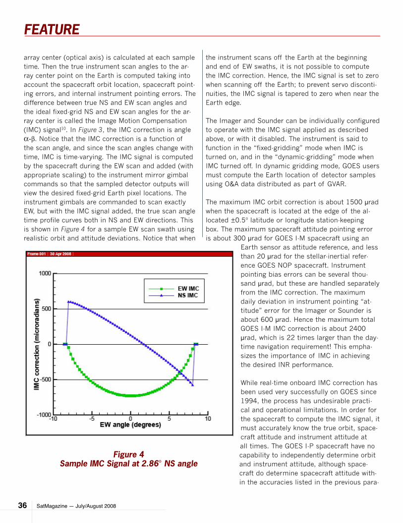
SatMagazine — July/August 200836
FEATURE
array center (optical axis) is calculated at each sample time. Then the true instrument scan angles to the ar-ray center point on the Earth is computed taking into account the spacecraft orbit location, spacecraft point-ing errors, and internal instrument pointing errors. The difference between true NS and EW scan angles and the ideal fixed-grid NS and EW scan angles for the ar-ray center is called the Image Motion Compensation (IMC) signal10. In Figure 3, the IMC correction is angle α-β. Notice that the IMC correction is a function of the scan angle, and since the scan angles change with time, IMC is time-varying. The IMC signal is computed by the spacecraft during the EW scan and added (with appropriate scaling) to the instrument mirror gimbal commands so that the sampled detector outputs will view the desired fixed-grid Earth pixel locations. The instrument gimbals are commanded to scan exactly EW, but with the IMC signal added, the true scan angle time profile curves both in NS and EW directions. This is shown in Figure 4 for a sample EW scan swath using realistic orbit and attitude deviations. Notice that when
the instrument scans off the Earth at the beginning and end of EW swaths, it is not possible to compute the IMC correction. Hence, the IMC signal is set to zero when scanning off the Earth; to prevent servo disconti-nuities, the IMC signal is tapered to zero when near the Earth edge.
The Imager and Sounder can be individually configured to operate with the IMC signal applied as described above, or with it disabled. The instrument is said to function in the “fixed-gridding” mode when IMC is turned on, and in the “dynamic-gridding” mode when IMC turned off. In dynamic gridding mode, GOES users must compute the Earth location of detector samples using O&A data distributed as part of GVAR.
The maximum IMC orbit correction is about 1500 µrad when the spacecraft is located at the edge of the al-located ±0.5º latitude or longitude station-keeping box. The maximum spacecraft attitude pointing error is about 300 µrad for GOES I-M spacecraft using an
Earth sensor as attitude reference, and less than 20 µrad for the stellar-inertial refer-ence GOES NOP spacecraft. Instrument pointing bias errors can be several thou-sand µrad, but these are handled separately from the IMC correction. The maximum daily deviation in instrument pointing “at-titude” error for the Imager or Sounder is about 600 µrad. Hence the maximum total GOES I-M IMC correction is about 2400 µrad, which is 22 times larger than the day-time navigation requirement! This empha-sizes the importance of IMC in achieving the desired INR performance.
While real-time onboard IMC correction has been used very successfully on GOES since 1994, the process has undesirable practi-cal and operational limitations. In order for the spacecraft to compute the IMC signal, it must accurately know the true orbit, space-craft attitude and instrument attitude at all times. The GOES I-P spacecraft have no capability to independently determine orbit and instrument attitude, although space-craft do determine spacecraft attitude with-in the accuracies listed in the previous para-
Figure 4Sample IMC Signal at 2.86° NS angle
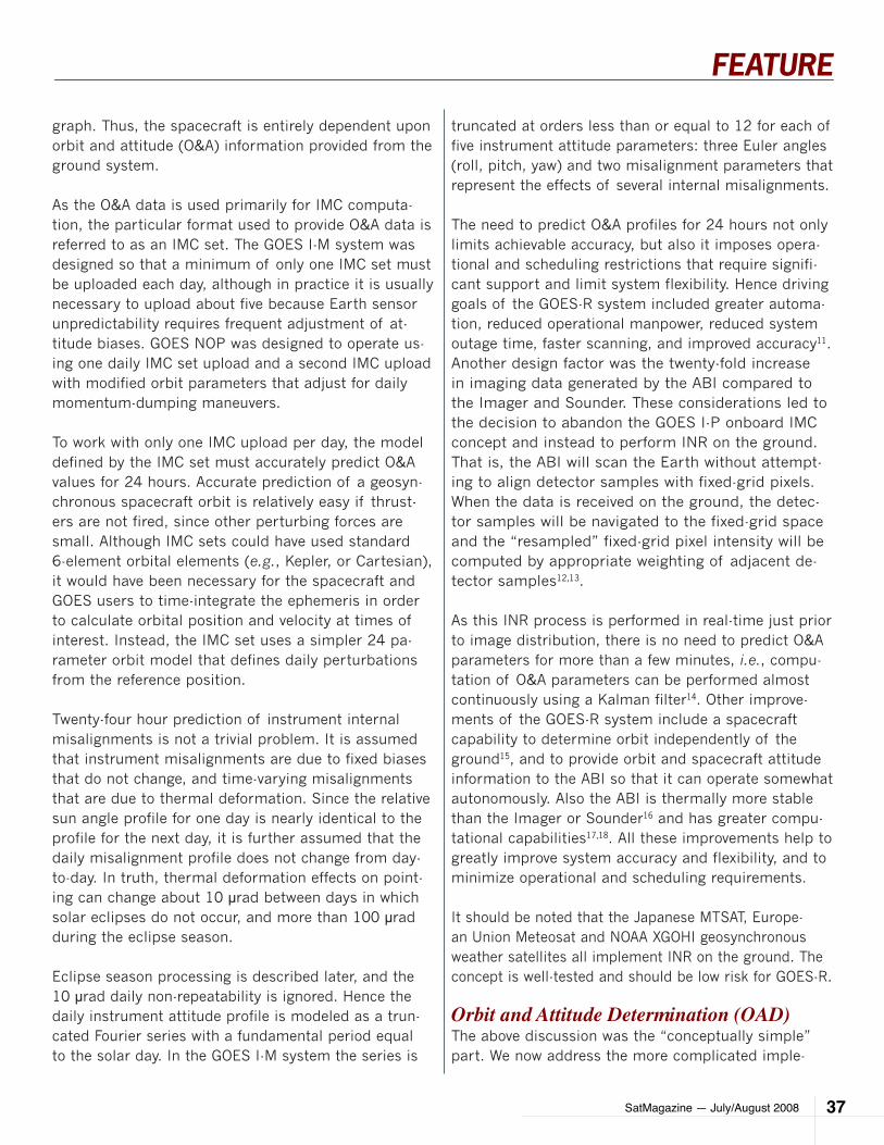
SatMagazine — July/August 2008 37
FEATURE
graph. Thus, the spacecraft is entirely dependent upon orbit and attitude (O&A) information provided from the ground system.
As the O&A data is used primarily for IMC computa-tion, the particular format used to provide O&A data is referred to as an IMC set. The GOES I-M system was designed so that a minimum of only one IMC set must be uploaded each day, although in practice it is usually necessary to upload about five because Earth sensor unpredictability requires frequent adjustment of at-titude biases. GOES NOP was designed to operate us-ing one daily IMC set upload and a second IMC upload with modified orbit parameters that adjust for daily momentum-dumping maneuvers.
To work with only one IMC upload per day, the model defined by the IMC set must accurately predict O&A values for 24 hours. Accurate prediction of a geosyn-chronous spacecraft orbit is relatively easy if thrust-ers are not fired, since other perturbing forces are small. Although IMC sets could have used standard 6-element orbital elements (e.g., Kepler, or Cartesian), it would have been necessary for the spacecraft and GOES users to time-integrate the ephemeris in order to calculate orbital position and velocity at times of interest. Instead, the IMC set uses a simpler 24 pa-rameter orbit model that defines daily perturbations from the reference position.
Twenty-four hour prediction of instrument internal misalignments is not a trivial problem. It is assumed that instrument misalignments are due to fixed biases that do not change, and time-varying misalignments that are due to thermal deformation. Since the relative sun angle profile for one day is nearly identical to the profile for the next day, it is further assumed that the daily misalignment profile does not change from day-to-day. In truth, thermal deformation effects on point-ing can change about 10 µrad between days in which solar eclipses do not occur, and more than 100 µrad during the eclipse season.
Eclipse season processing is described later, and the 10 µrad daily non-repeatability is ignored. Hence the daily instrument attitude profile is modeled as a trun-cated Fourier series with a fundamental period equal to the solar day. In the GOES I-M system the series is
truncated at orders less than or equal to 12 for each of five instrument attitude parameters: three Euler angles (roll, pitch, yaw) and two misalignment parameters that represent the effects of several internal misalignments.
The need to predict O&A profiles for 24 hours not only limits achievable accuracy, but also it imposes opera-tional and scheduling restrictions that require signifi-cant support and limit system flexibility. Hence driving goals of the GOES-R system included greater automa-tion, reduced operational manpower, reduced system outage time, faster scanning, and improved accuracy11. Another design factor was the twenty-fold increase in imaging data generated by the ABI compared to the Imager and Sounder. These considerations led to the decision to abandon the GOES I-P onboard IMC concept and instead to perform INR on the ground. That is, the ABI will scan the Earth without attempt-ing to align detector samples with fixed-grid pixels. When the data is received on the ground, the detec-tor samples will be navigated to the fixed-grid space and the “resampled” fixed-grid pixel intensity will be computed by appropriate weighting of adjacent de-tector samples12,13.
As this INR process is performed in real-time just prior to image distribution, there is no need to predict O&A parameters for more than a few minutes, i.e., compu-tation of O&A parameters can be performed almost continuously using a Kalman filter14. Other improve-ments of the GOES-R system include a spacecraft capability to determine orbit independently of the ground15, and to provide orbit and spacecraft attitude information to the ABI so that it can operate somewhat autonomously. Also the ABI is thermally more stable than the Imager or Sounder16 and has greater compu-tational capabilities17,18. All these improvements help to greatly improve system accuracy and flexibility, and to minimize operational and scheduling requirements.
It should be noted that the Japanese MTSAT, Europe-an Union Meteosat and NOAA XGOHI geosynchronous weather satellites all implement INR on the ground. The concept is well-tested and should be low risk for GOES-R.
Orbit and Attitude Determination (OAD)The above discussion was the “conceptually simple” part. We now address the more complicated imple-
SatMagazine — July/August 200838
FEATURE
mentation issues involving computation of the IMC sets. In the GOES I-P system, the Orbit and Attitude Determination (OAD) ground process computes O&A parameters by weighted least-squares fitting of range, star and landmark observation data taken over the pre-vious 24 to 48 hours19,20,21.
The OAD function is executed once per day. Range mea-surements are obtained by inserting ranging bits in the uploaded GVAR data and measuring the time delay before the same data is received back on the ground. Hence, the range measurement is the two-way transit time between the ground station and the spacecraft, multiplied by the speed of light. A measurement pre-processing function removes known range bias errors, such as equip-ment delays and atmospheric group delay effects, be-fore data are used in OAD. Notice that the range measurement is only a function of spacecraft orbital position and ve-locity, not space-craft or instrument attitude.
Landmark mea-surements22 are obtained by cor-relating maps of prominent land/water interfaces, such as islands or peninsulas, with an edge-detecting transform of the received image pix-el data. The shift in latitude and lon-gitude required to maximize correla-tion between the
shoreline map and transformed image data is added to the nominal landmark location to generate an ob-served landmark position. As with range measure-ments, a preprocessing function converts data from one form to another and applies various corrections, such as telemetry downlink time, detector offset, and IMC compensation. Because the instrument image is used to obtain the measurement, landmark obser-vations are a function of both spacecraft orbit and spacecraft/instrument attitude. Separate landmark observations are obtained for both the visible and at least one IR channel.
Figure 5GOES-13 Imager Star Residuals for 2006 days 250-255
SatMagazine — July/August 2008 39
FEATURE
Star observations are not obtained while the instru-ments are scanning the Earth. Several times per hour the instruments briefly stop scanning and dwell at fixed gimbal angles, selected by ground processing, to view given stars. As the spacecraft is always rotating (primarily in pitch) at Earth rotation rate to maintain Earth pointing, detector output will peak as the star crosses the detector field-of-view.
The detector number, gimbal angles, and star detec-tion time provide the information necessary to deter-mine the star angles in instrument coordinates and to process the observation. Star preprocessing includes corrections for downlink time, servo error, origin offset, and detector offset and rotation effects. In the stel-lar inertial GOES NOP system, star observations are only a function of spacecraft/instrument attitude, but because GOES I-M spacecraft use an Earth sensor for attitude reference, star observations are also a weak function of spacecraft orbit.
In addition to converting/correcting observations so that they can be used by OAD, GOES preprocessing also computes the residual (difference) between the corrected observations and predicted observations based on the currently enabled IMC set. These residu-als are usually interpreted as a measure of the GOES navigation errors, and landmark residuals in particu-lar are similar (but not identical) to the navigation er-ror seen by a GVAR user. Figures 5 and 6 show typical GOES-13 residuals obtained during a period of post-launch testing23 when the spacecraft experienced daily Earth eclipses at local midnight.
If the three observation types could be grouped so that two were a function of only spacecraft orbit pa-rameters, and one type was only a function of attitude parameters (or vice versa), then the OAD function could be performed separately for orbit and attitude. Since GOES landmark observations are a function of both orbit and attitude, it is necessary to simultane-
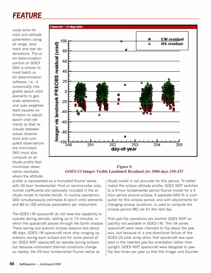
SatMagazine — July/August 200840
FEATURE
ously solve for orbit and attitude parameters using all range, land-mark and star ob-servations. The or-bit determination portion of GOES OAD is similar to most batch or-bit determination software, i.e., it numerically inte-grates epoch orbit elements to gen-erate ephemeris, and uses weighted least-squares es-timation to adjust epoch orbit ele-ments so that re-siduals between actual observa-tions and com-puted observations are minimized. OAD must also compute an at-titude profile that minimizes obser-vation residuals, where the attitude profile is represented as a truncated Fourier series with 24-hour fundamental. First or second-order poly-nomial coefficients are optionally included in the at-titude model to handle trends. In routine operations, OAD simultaneously estimates 6 epoch orbit elements and 80 to 100 attitude parameters per instrument.
The GOES I-M spacecraft do not have the capability to operate during periods, lasting up to 72 minutes, in which the spacecraft passes through the Earth shadow. These spring and autumn eclipse seasons last about 48 days. GOES I-M spacecraft must stop imaging op-erations during each eclipse and for some period af-ter. GOES NOP spacecraft do operate during eclipse, but because instrument thermal conditions change so rapidly, the 24-hour fundamental Fourier series at-
titude model is not accurate for this period. To better match the eclipse attitude profile, GOES NOP switches to a 4-hour fundamental period Fourier model for a 4 hour period around eclipse. A separate OAD fit is com-puted for this eclipse period, and with adjustments for changing eclipse durations, is used to compute the eclipse period IMC set for the next day.
Post yaw-flip operations are another GOES NOP ca-pability not available in GOES I-M. The I-M series spacecraft were never intended to flip about the yaw axis, but because of a one-directional failure of the GOES-10 solar array drive, that spacecraft was oper-ated in the inverted yaw-flip orientation rather than upright. GOES NOP spacecraft were designed to yaw-flip two times per year so that the Imager and Sounder
Figure 6GOES-13 Imager Visible Landmark Residuals for 2006 days 250-255
SatMagazine — July/August 2008 41
FEATURE
coolers will always face away from the sun. This reduc-es instrument temperatures and hence detector ther-mal noise. However a yaw-flip maneuver changes the daily instrument thermal profile and thermal deforma-tion. OAD solutions computed using the last 24 hour of observations cannot be used to predict the next 24 hours. Instead, a previous attitude profile for the same yaw orientation and time-of-year is used for the first 24 hours after a yaw-flip maneuver.
IMC Set GenerationBecause of limited computational capabilities, the GOES I-M spacecraft do not directly use the O&A set computed by OAD. Instead, ground software time-integrates the OAD epoch orbit elements to compute spacecraft ephemeris over the 24-hour IMC prediction interval and a 24-parameter orbit perturbation model is least-squares fit to the ephemeris. OAD attitude coefficients are re-epoched and re-formatted and in-cluded with the 24 orbit parameters in the IMC set24. These IMC sets are uploaded to the spacecraft to al-low on-board IMC calculations, and are also included in GVAR so that GOES users can navigate image pixels during periods when spacecraft IMC is turned off.
Whenever a maneuver is expected during the 24-hour prediction period covered by an IMC set, two IMC sets are generated: pre-maneuver and post-maneuver. The post-maneuver IMC set uses the same OAD solution as the pre-maneuver, but the post-maneuver ephemeris is computed by including the effects of the planned maneuver velocity change. This happens at least once per day for GOES NOP spacecraft because of the daily momentum-dumping maneuvers required to unload reaction wheel angular momentum generated by solar pressure on the single solar array.
IMC set generation is not the only system complexity caused by the GOES I-P need to predict O&A behavior for 24 hours. Instrument commands for image frames (scan patterns boundaries) and for star sensing must be uploaded in instrument coordinates that the instru-ments can directly convert to mirror gimbal angles. Separate star angle commands must be computed in advance and uploaded for every star sense during the 24-hour IMC prediction interval. Any change in IMC sets requires that all star sense angles after the IMC set change be re-computed. This re-computation is
also necessary for all image frame boundaries whenev-er the spacecraft is operated with IMC turned off. Nor-mally, IMC is on, so that it should only be necessary to compute frame boundaries once for each frame.
The proposed GOES-R system is much simpler in that there is little need to predict behavior for more than a few minutes into the future. Rather than performing OAD using batch least-squares estimation with a 24 to 48-hour span of observations, the effects of instru-ment thermal deformation can be computed in near real-time using a Kalman filter that processes star and optionally landmark observations as they become available25. The spacecraft will independently deter-mine its orbit and attitude rates and supply that data to the instruments and to ground processing26,27. Star sense and frame boundary angles can be computed directly by the much more capable ABI with very little input from the ground28. These changes will greatly re-duce operator workload and allow for a much more re-liable and accurate system.
SummaryTo perform the weather-monitoring functions for which GOES was designed, the spacecraft must image the Earth from a fixed-point relative to the Earth. Since real spacecraft and instruments cannot exactly main-tain the ideal orbit and attitude position desired by us-ers, the GOES system applies pointing corrections so that image pixels appear to have been obtained from an ideal fixed-grid system.
Requirements on INR accuracy have become pro-gressively tighter as the GOES system has continued to evolve. GOES I-P spacecraft implement on-board pointing corrections during scanning so that the de-tector samples are directly registered to the fixed-grid. While this approach has been used successfully since 1994, the system is complex and requires pre-dicting orbit and attitude behavior for 24 hours in the future. This has undesirable operational and per-formance limitations.
The next generation of spacecraft and instruments, starting with GOES-R, will perform INR on the ground by resampling detector samples. In this ap-proach it is only necessary to predict O&A behavior for a few minutes into the future, so the system is
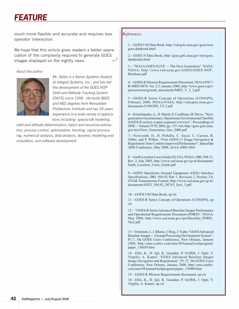
SatMagazine — July/August 200842
FEATURE
much more flexible and accurate and requires less operator interaction.
We hope that this article gives readers a better appre-ciation of the complexity required to generate GOES images displayed on the nightly news.
About the author
Mr. Gibbs is a Senior Systems Analyst
at Integral Systems, Inc., and has led
the development of the GOES NOP
Orbit and Attitude Tracking System
(OATS) since 1998. He holds BSEE
and MEE degrees from Rensselaer
Polytechnic Institute and has 39 years
experience in a wide variety of applica-
tions including spacecraft modeling,
orbit and attitude determination, batch and recursive estima-
tion, process control, optimization, tracking, signal process-
ing, numerical analysis, data analysis, dynamic modeling and
simulation, and software development.
References
1—GOES I-M Data Book, http://rsd.gsfc.nasa.gov/goes/text/goes.databook.html
2—GOES N Data Book, http://goes.gsfc.nasa.gov/text/goes.databookn.html
3—”NOAA GOES-N,O,P — The Next Generation”, NASA/NOAA, http://www.osd.noaa.gov/GOES/GOES-NOP_Brochure.pdf
4—GOES-R Mission Requirements Document, NOAA P417-R-MRD-0070, Ver. 3.2, January 2008, http://www.goes-r.gov/procurement/ground_documents/MRD_V_3_2.pdf
5—GOES-R Series Concept of Operations (CONOPS), February 2008, NOAA/NASA, http://osd.goes.noaa.gov/documents/CONOPS_V2.3.pdf
6—Krimchansky, A., D. Machi, S. Cauffman, M. Davis, “Next-generation Geostationary Operational Environmental Satellite (GOES-R series): a space segment overview”, Proceedings of SPIE -- Volume 5570, 2004, pp. 155-164, http://goes.gsfc.nasa.gov/text/Next_Generation_Geo_2006.pdf7—Newcomb, H., R. Pirhalla, C. Sayal, C. Carson, B. Gibbs, and P. Wilkin, “First GOES-13 Image Navigation & Registration Tests Confirm Improved Performance”, SpaceOps 2008 Conference, May 2008, AIAA-2008-3464
8—Earth Location Users Guide (ELUG), NOAA, DRL 504-11, Rev. 2, July 2005, http://www.osd.noaa.gov/gvar/documents/Earth_Location_Users_Guide.pdf
9—GOES Operations Ground Equipment (OGE) Interface Specifications, DRL 504-02 Part 1, Revision 2, Section 3.0, GVAR Transmission Format, http://www.osd.noaa.gov/gvar/documents/G023_504.02_DCN3_Sect_3.pdf
10—GOES I-M Data Book, op cit.11—GOES-R Series Concept of Operations (CONOPS), op cit.
12—”GOES-R Series Advanced Baseline Imager Performance and Operational Requirements Document (PORD)”, NOAA, May 2004, http://www.osd.noaa.gov/rpsi/Baseline_PORD_Ver2.pdf
13—Ormiston, J., J. Blume, J. Ring, J. Yoder, “GOES Advanced Baseline Imager— Ground Processing Development System”, P1.7, 5th GOES Users Conference, New Orleans, January 2008, http://ams.confex.com/ams/88Annual/techprogram/paper_136059.htm14—Ellis, K., D. Igli, K. Gounder, P. Griffith, J. Ogle, V. Virgilio, A. Kamel, “GOES Advanced Baseline Imager Image Navigation and Registration”, P1.27, 5th GOES Users Conference, New Orleans, January 2008, http://ams.confex.com/ams/88Annual/techprogram/paper_136060.htm15—GOES-R Mission Requirements Document, op cit. 16—Ellis, K., D. Igli, K. Gounder, P. Griffith, J. Ogle, V. Virgilio, A. Kamel, op cit
SatMagazine — July/August 2008 43
FEATURE
.17—Krimchansky, A., D. Machi, S. Cauffman, M. Davis, op cit.
18—GOES-R Mission Requirements Document, op cit.19—Ong, K. and S. Lutz, “GOES orbit and attitude determination — theory, implementation, and recent results”, Proc. SPIE, v2812, p 652-663, Oct. 1996
20—Kelly, K., J. Hudson, and N. Pinkine, “GOES 8/9 Image Navigation and Registration Operations”, GOES-8 and Beyond, 1996 International Symposium on Optical Science, Engineering, and Instrumentation, SPIE, Denver, Co., August 1996; describes measurements and preprocessing21—Gibbs, B., J. Carr, D. Uetrecht and C. Sayal, “Analysis of GOES-13 Orbit and Attitude Determination”, SpaceOps 2008 Conference, May 2008, AIAA-2008-3222.
22—Madani, H., J. Carr, and C. Schoeser, “Image Registration using AutoLandmark”, Proceedings of the 2004 IEEE International Geoscience and Remote Sensing Symposium, 20-24 September 2004
23—Carson, C., J. Carr, and C. Sayal, “GOES-13 End-to-End INR Performance Verification and Post Launch Testing”, 5th GOES Users Conference, Annual Meeting of the American Meteorological Society, 20-24 January 2008, http://ams.confex.com/ams/pdfpapers/135921.pdf24—GOES I-M Data Book, op cit; IMC set.25—Ormiston, J., J. Blume, J. Ring, J. Yoder, op cit.26—Ellis, K., D. Igli, K. Gounder, P. Griffith, J. Ogle, V. Virgilio, A. Kamel, op cit.
27—GOES-R Series Concept of Operations (CONOPS), op cit.
28—Ellis, K., K. Gounder, P. Griffith, E. Hoffman, D. Igli, J. Ogle, and V. Virgilio, “The ABI star sensing and star selection”, P1.28, 5th GOES Users Conference, New Orleans, January 2008, http://ams.confex.com/ams/88Annual/techprogram/paper_136061.htm
DISCLAIMER
This article does not reflect the perspective of NASA/GSFC
GOES-R Project— all information presented was gathered
from the public domain by the author.

SatMagazine — July/August 200844
FEATURE
by David ZufallSenior Vice President, Network TechnologyICO
Americans love movies, like that Judy Garland classic of hopes and expectations in an excit-ing new era. The MSS industry is evolving in
much the same way, and is on the cusp of delivering groundbreaking mobility services to meet Americans’ love for mobility and connectivity. The cornerstone of these next-generation systems just happens to be a prime piece of ‘real estate’ in the orbital band: 92.85 degrees West longitude, covering the U.S. from the equator, just over St. Louis, Missouri.
Just a few weeks ago, the final milestone in a process to usher in that new era of MSS was achieved when ICO’s G1 (launched April 14) was declared operational. Trials for MSS services are now set to begin, the culmi-nation of years of research, collaboration and technol-ogy development.
To get to St. Louis, MSS operators have navigated a maze of technology choices, regulatory frameworks
and a challenged business climate. Considering the required investment and competitive landscape, the primary question during this process has been to determine what suite of products, and or services, can tap the demand for mobility services ideally suited to satellite in a successful business model? Was the answer voice and data services? Broadband? Mobile Video?
The research and discovery process was driven by an understanding of the ideal attributes – and today’s drawbacks – of satellite services. The terrestrial wire-less business has always operated on two fundamental principles: coverage and capacity. The key to wide-spread adoption of MSS is no different. Satellites are ideal at overcoming the limits of terrestrial networks, in terms of delivering a signal to as broad an area as possible (coverage). Yet traditional terrestrial cellular operators are able to maximize spectral efficiency to meet the insatiable market demand for mobility ser-vices (capacity).
The technology development process has, ultimately, led to two key decisions: select an agnostic platform
mSS goeS lIve In THe S-BanD, or, “meeT me In ST. loUIS”
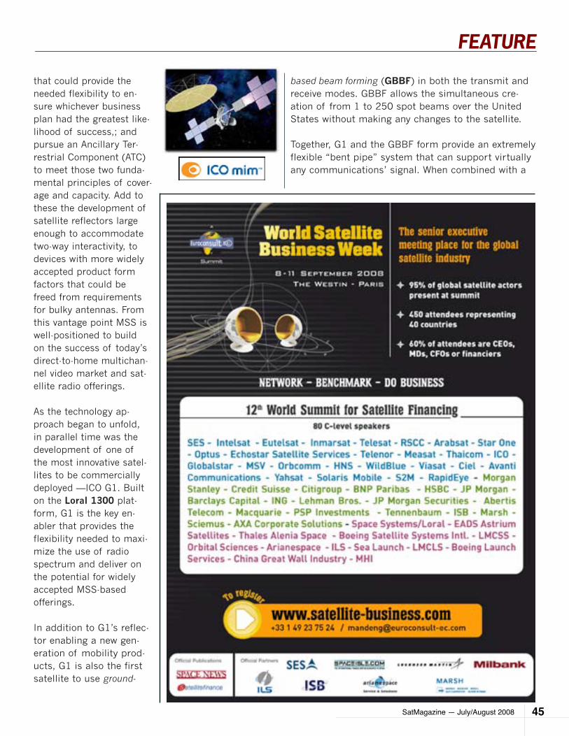
SatMagazine — July/August 2008 45
FEATURE
that could provide the needed flexibility to en-sure whichever business plan had the greatest like-lihood of success,; and pursue an Ancillary Ter-restrial Component (ATC) to meet those two funda-mental principles of cover-age and capacity. Add to these the development of satellite reflectors large enough to accommodate two-way interactivity, to devices with more widely accepted product form factors that could be freed from requirements for bulky antennas. From this vantage point MSS is well-positioned to build on the success of today’s direct-to-home multichan-nel video market and sat-ellite radio offerings.
As the technology ap-proach began to unfold, in parallel time was the development of one of the most innovative satel-lites to be commercially deployed —ICO G1. Built on the Loral 1300 plat-form, G1 is the key en-abler that provides the flexibility needed to maxi-mize the use of radio spectrum and deliver on the potential for widely accepted MSS-based offerings.
In addition to G1’s reflec-tor enabling a new gen-eration of mobility prod-ucts, G1 is also the first satellite to use ground-
based beam forming (GBBF) in both the transmit and receive modes. GBBF allows the simultaneous cre-ation of from 1 to 250 spot beams over the United States without making any changes to the satellite.
Together, G1 and the GBBF form provide an extremely flexible “bent pipe” system that can support virtually any communications’ signal. When combined with a
SatMagazine — July/August 200846
FEATURE
terrestrial component via ATC, the system laid the groundwork for offering a differentiated set of capa-bilities and services with widespread growth potential.The system’s ability to support any number of stan-dards-based technologies, ranging from GMR (Geo-Mobile Radio), GSM (Global System for Mobile com-munications), CDMA (Code Division Multiple Acess) or WiMAX (Worldwide Interoperability for Microwave Access), to the emerging worldwide standard of DVB-SH (Digital Video Broadcasting - Satellite services to Handhelds) for mobile video, not only minimizes the risks inherent with proprietary technologies, it also de-livers economies of scale that can be achieved through standards-based technology deployments.In the case of ICO, our investment in the foundation of ICO G1, GBBF and perfecting our spectrum holdings for ATC has allowed us to now concentrate on develop-ing a standards-based suite of services.
Our MSS offering, ICO mim™ (mobile interactive me-dia) will include a combination of mobile video (live TV delivered over 8-15 channels with a broad mix of programming choices), interactive navigation and an emergency communications’ capability. The service will be delivered through a combination of automotive-based and portable devices. Unlike current mobile television options, the product is focusing on larger screens more suited to a better mobile video experi-ence, which will drive greater consumer adoption.
We believe MSS enhances what is in the market today with a differentiated and improved product set that takes advantage of widespread consumer demand for enhanced mobile services. In addition, it delivers on the promise of ubiquitous service that only the combi-nation of an MSS network and nationwide radio spec-trum allow. ICO is able to leverage the flexibility of the satellite and GBBF to support these services. This is accomplished through simultaneous use of a broad-cast oriented standard, DVB-SH for mobile video and the industry proven 2-way standard, GMR, to deliver the interactive element.
Alpha trials for the service are scheduled to begin this summer in Las Vegas, Nevada, and Raleigh - Durham, North Carolina. Demonstrations this year in Las Vegas using terrestrial spectrum have already realized impor-tant results and shown the quality of satellite-based
mobile services. Initial commercial prototypes are on track for delivery by the end of this year, with a com-mercial service launch slated for late 2009.A growing standards-based ecosystem worldwide has emerged to support the DVB-SH and GMR standards. They are joined by dozens of leading names in tech-nology, service providers, automotive companies and consumer electronics’ manufacturers creating the mo-mentum for full-scale commercial offerings.
In sum, MSS has come a long way from having a great deal of promise, to having real market potential. The first operational system in the U.S. using MSS spec-trum, combined with worldwide MSS deployments, marks a bright future for next-generation services that have widespread consumer and business appeal.
With such a wide variety of technology options and ser-vice offerings worldwide, the lyrics of the title song of that old classic musical seem to sum up best the ex-citement building for a next-generation of MSS services. Especially when it comes to America’s love of all things mobile and all things video, or as the old song goes: “Meet me in St. Louis, we’ll see you at the fair.”
About the author
Mr. Zufall has been Senior Vice President,
Network Systems since January 2, 2006.
During the 12 years prior to joining the Com-
pany, Mr. Zufall served in a number of techni-
cal and operational capacities at Nextel Com-
munications, Inc., including Vice President,
Infrastructure Technology Development, and
Vice President, Network Architecture/Chief
Architect. Nextel operated a nationwide digi-
tal cellular network in the United States. Mr.
Zufall had responsibility for working with part-
ners in Nextel’s strategy and marketing divi-
sions to establish Nextel’s long-term network
and technology roadmap. Mr. Zufall holds a
Bachelor of Sciences degree in Electrical En-
gineering and an M.B.A. in Finance and Inter-
national Business, both from Columbia University.
SatMagazine — July/August 2008 47
FEATURE
by Jim CorryVice President, Government SolutionsMobile Satellite Ventures
In January of 2008, the Federal Communications Commission (FCC) conducted an auction of 62 MHz of spectrum that was to become available upon the
switch from analog to digital signal transmis-sion by TV broadcasters. The changeover occurs in February of 2009. Of the 62 MHz, 20 MHz was ap-portioned in two, 10 MHz blocks. This public-private partnership will be respon-sible for building out 10 MHz for a nationwide, in-teroperable, public safety broadband network and a 10 MHz block for commer-cial licensing, known as the Upper D Block. As the $1.3 billion reserve price for the latter portion was not met during the 700 MHz auc-tion in January, the FCC is likely to re-auction the spectrum by the end of this year, if possible.
Much discussion has taken place as to why the original auction was unsuccessful and what might occur in order to turn the venture around. Commentators have suggested that the fail-ure of the Upper D Block auction was a combina-tion of the FCC’s stringent build-out requirements, which included requiring coverage of 99.3 percent of the U.S. population within 10 years, and uncertainty regarding the terms of the public-private partnership.
For any upcoming re-auction, the FCC is looking at pro-viding more flexibility in the build-out requirements as well as more certainty regarding the relationship be-tween the commercial and public safety licensees.
Mobile Satellite Ventures (MSV) believes satellite ser-vice can play a critical role in making a public safety
THe re-BIrTH of BlocK D
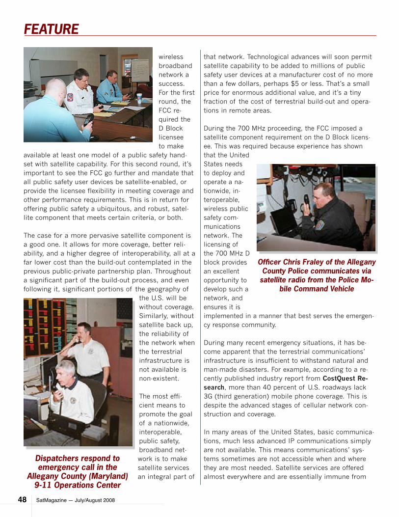
SatMagazine — July/August 200848
FEATURE
wireless broadband network a success. For the first round, the FCC re-quired the D Block licensee to make
available at least one model of a public safety hand-set with satellite capability. For this second round, it’s important to see the FCC go further and mandate that all public safety user devices be satellite-enabled, or provide the licensee flexibility in meeting coverage and other performance requirements. This is in return for offering public safety a ubiquitous, and robust, satel-lite component that meets certain criteria, or both.
The case for a more pervasive satellite component is a good one. It allows for more coverage, better reli-ability, and a higher degree of interoperability, all at a far lower cost than the build-out contemplated in the previous public-private partnership plan. Throughout a significant part of the build-out process, and even following it, significant portions of the geography of
the U.S. will be without coverage. Similarly, without satellite back up, the reliability of the network when the terrestrial infrastructure is not available is non-existent.
The most effi-cient means to promote the goal of a nationwide, interoperable, public safety, broadband net-work is to make satellite services an integral part of
that network. Technological advances will soon permit satellite capability to be added to millions of public safety user devices at a manufacturer cost of no more than a few dollars, perhaps $5 or less. That’s a small price for enormous additional value, and it’s a tiny fraction of the cost of terrestrial build-out and opera-tions in remote areas.
During the 700 MHz proceeding, the FCC imposed a satellite component requirement on the D Block licens-ee. This was required because experience has shown that the United States needs to deploy and operate a na-tionwide, in-teroperable, wireless public safety com-munications network. The licensing of the 700 MHz D block provides an excellent opportunity to develop such a network, and ensures it is implemented in a manner that best serves the emergen-cy response community. During many recent emergency situations, it has be-come apparent that the terrestrial communications’ infrastructure is insufficient to withstand natural and man-made disasters. For example, according to a re-cently published industry report from CostQuest Re-search, more than 40 percent of U.S. roadways lack 3G (third generation) mobile phone coverage. This is despite the advanced stages of cellular network con-struction and coverage.
In many areas of the United States, basic communica-tions, much less advanced IP communications simply are not available. This means communications’ sys-tems sometimes are not accessible when and where they are most needed. Satellite services are offered almost everywhere and are essentially immune from
Dispatchers respond to emergency call in the
Allegany County (Maryland) 9-11 Operations Center
Officer Chris Fraley of the Allegany County Police communicates via
satellite radio from the Police Mo-bile Command Vehicle
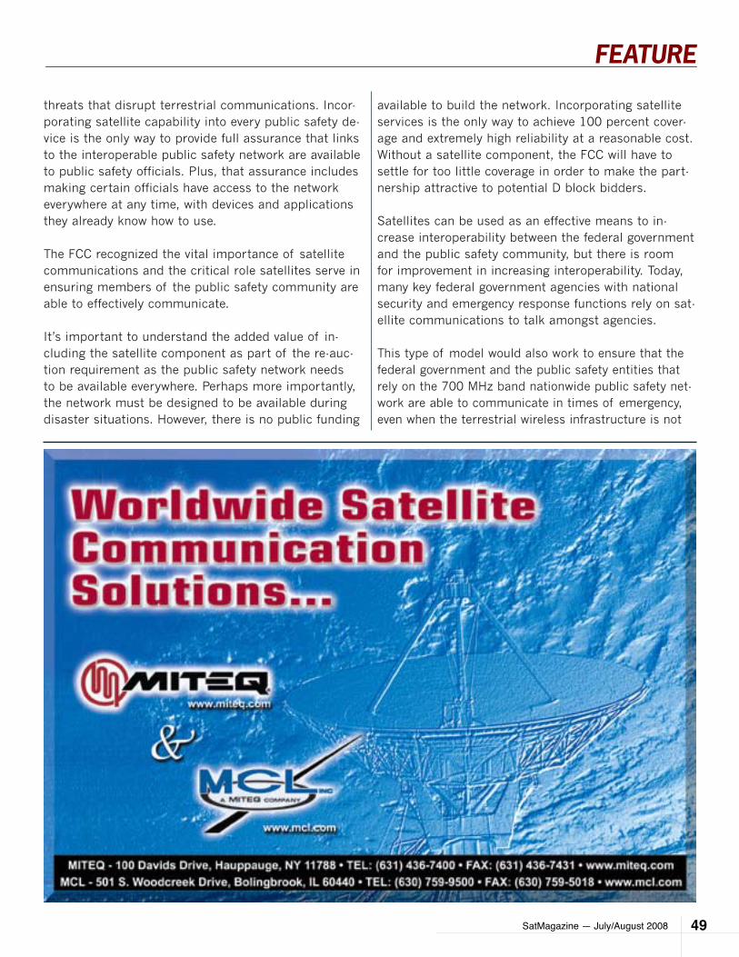
SatMagazine — July/August 2008 49
FEATURE
threats that disrupt terrestrial communications. Incor-porating satellite capability into every public safety de-vice is the only way to provide full assurance that links to the interoperable public safety network are available to public safety officials. Plus, that assurance includes making certain officials have access to the network everywhere at any time, with devices and applications they already know how to use.
The FCC recognized the vital importance of satellite communications and the critical role satellites serve in ensuring members of the public safety community are able to effectively communicate.
It’s important to understand the added value of in-cluding the satellite component as part of the re-auc-tion requirement as the public safety network needs to be available everywhere. Perhaps more importantly, the network must be designed to be available during disaster situations. However, there is no public funding
available to build the network. Incorporating satellite services is the only way to achieve 100 percent cover-age and extremely high reliability at a reasonable cost. Without a satellite component, the FCC will have to settle for too little coverage in order to make the part-nership attractive to potential D block bidders.
Satellites can be used as an effective means to in-crease interoperability between the federal government and the public safety community, but there is room for improvement in increasing interoperability. Today, many key federal government agencies with national security and emergency response functions rely on sat-ellite communications to talk amongst agencies.
This type of model would also work to ensure that the federal government and the public safety entities that rely on the 700 MHz band nationwide public safety net-work are able to communicate in times of emergency, even when the terrestrial wireless infrastructure is not

SatMagazine — July/August 200850
FEATURE
available. If satellite capability is built into every public safety device, every public safety user can be assured of getting a link to the interoperable network anywhere, anytime, using the device they use every day.
Incentives that could be considered for potential li-censee bidders begin with requirements that should in-clude extending the build-out period, and reducing the hardening requirement, particularly in rural areas, if the D Block licensee offers public safety a ubiquitous and robust satellite component that meets certain criteria. By substituting satellite service for terrestrial service in less densely populated areas, the operator’s costs will be substantially reduced—by possibly bil-lions of dollars by managing the needs for thousands of cell sites—without compromising the availability to public safety agencies of a reliable, interoperable net-work that is available nationwide.
By complying with these requirements, it would give the licensee the flexibility it needs to build out the na-tional public safety network. It would ensure the net-work’s ubiquity and interoperability, and it will give the emergency response community the communication tools it so desperately needs to efficiently respond to emergencies and protect the public.
The American public benefits from the unique availability and reliability of Mobile Satellite Ser-vices (MSS) networks that provide an effective, high value service to public safety users and con-sumers. In fact, public safety agencies, the nation-al security community, and the defense commu-nity, are the heaviest users of MSS services today.
Making MSS services available and accessible to more agencies and consumers through mandatory inclusion in terrestrial communications devices encourages improved interoperability, greater geo-graphic coverage, and communications’ reliability independent of the condition of the terrestrial in-frastructure. MSS provides pervasive, disaster-proof communications to public safety responders and consumers to essentially 100 percent of the U.S.
To further protect the public and respond to emergencies, the next generation hybrid sat-ellite-terrestrial networks will prove invaluable.
As an example, the one being constructed by Mo-bile Satellite Ventures, which means that, for the first time, the public safety community will be able to seamlessly and transparently roam between cel-lular and satellite networks on a handheld device (cell phones, PDA, laptops, GPS devices, and such) virtually anywhere throughout North America These next-generation networks will offer the public safety community the ability to allocate more capacity almost instantly to an area where terrestrial infrastructure is saturated, out of service, or destroyed altogether. Ter-restrial facilities, even when equipped with backup power, are far more limited in their ability to re-allo-cate capacity to respond to local demand and cannot reallocate capacity across large distances at all. Mobile Satellite Ventures (MSV) is involving itself in the auction process and the company has filed its of-ficial comments recommending the FCC require every public safety device be satellite-enabled, and provide the D Block licensee flexibility in meeting license re-quirements, such as build-out and hardening. This is in return for offering public safety a ubiquitous and robust satellite component that meets certain crite-ria. This requirement would ensure that emergency re-sponders truly have a reliable, interoperable, and ubiq-
Dr. Fred Conley and technician Ken Watkins, communicating via satellite push-to-talk from the
Emergency Room in the Preston County (West Virginia) Memorial Hospital
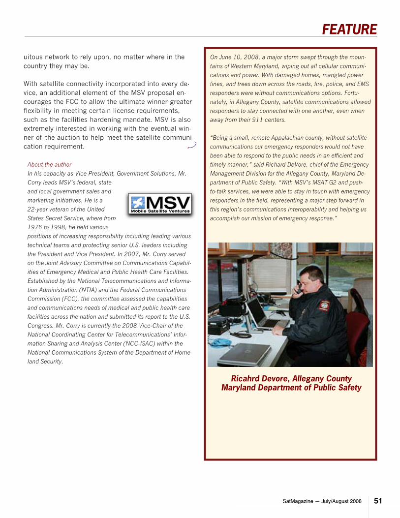
SatMagazine — July/August 2008 51
FEATURE
On June 10, 2008, a major storm swept through the moun-
tains of Western Maryland, wiping out all cellular communi-
cations and power. With damaged homes, mangled power
lines, and trees down across the roads, fire, police, and EMS
responders were without communications options. Fortu-
nately, in Allegany County, satellite communications allowed
responders to stay connected with one another, even when
away from their 911 centers.
“Being a small, remote Appalachian county, without satellite
communications our emergency responders would not have
been able to respond to the public needs in an efficient and
timely manner,” said Richard DeVore, chief of the Emergency
Management Division for the Allegany County, Maryland De-
partment of Public Safety. “With MSV’s MSAT G2 and push-
to-talk services, we were able to stay in touch with emergency
responders in the field, representing a major step forward in
this region’s communications interoperability and helping us
accomplish our mission of emergency response.”
Ricahrd Devore, Allegany CountyMaryland Department of Public Safety
uitous network to rely upon, no matter where in the country they may be.
With satellite connectivity incorporated into every de-vice, an additional element of the MSV proposal en-courages the FCC to allow the ultimate winner greater flexibility in meeting certain license requirements, such as the facilities hardening mandate. MSV is also extremely interested in working with the eventual win-ner of the auction to help meet the satellite communi-cation requirement.
About the author
In his capacity as Vice President, Government Solutions, Mr.
Corry leads MSV’s federal, state
and local government sales and
marketing initiatives. He is a
22-year veteran of the United
States Secret Service, where from
1976 to 1998, he held various
positions of increasing responsibility including leading various
technical teams and protecting senior U.S. leaders including
the President and Vice President. In 2007, Mr. Corry served
on the Joint Advisory Committee on Communications Capabil-
ities of Emergency Medical and Public Health Care Facilities.
Established by the National Telecommunications and Informa-
tion Administration (NTIA) and the Federal Communications
Commission (FCC), the committee assessed the capabilities
and communications needs of medical and public health care
facilities across the nation and submitted its report to the U.S.
Congress. Mr. Corry is currently the 2008 Vice-Chair of the
National Coordinating Center for Telecommunications’ Infor-
mation Sharing and Analysis Center (NCC-ISAC) within the
National Communications System of the Department of Home-
land Security.
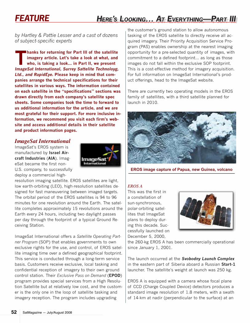
SatMagazine — July/August 200852
FEATURE
by Hartley & Pattie Lesser and a cast of dozens of subject-specific experts
Thanks for returning for Part III of the satellite imagery article. Let’s take a look at what, and who, is taking a look... in Part II, we present
ImageSat International, Surrey Sattelite Technoloyg, Ltd., and RapidEye. Please keep in mind that com-panies arrange the technical specifications for their satellites in various ways. The information contained on each satellite in the “specifications” sections was drawn directly from each company’s satellite spec sheets. Some companies took the time to forward to us additional information for the article, and we are most grateful for their support. For more inclusive in-formation, we recommend you visit each firm’s web-site and access additional details in their satellite and product information pages.
ImageSat InternationalImageSat’s EROS system is manufactured by Israel Air-craft Industries (AIA). Imag-eSat became the first non-U.S. company, to successfully deploy a commercial high-resolution imaging satellite. EROS satellites are light, low earth-orbiting (LEO), high-resolution satellites de-signed for fast maneuvering between imaged targets. The orbital period of the EROS satellites is 94 to 96 minutes for one revolution around the Earth. The satel-lite completes approximately 15 revolutions around the Earth every 24 hours, including two daylight passes per day through the footprint of a typical Ground Re-ceiving Station.
ImageSat International offers a Satellite Operating Part-ner Program (SOP) that enables governments to own exclusive rights for the use, and control, of EROS satel-lite imaging time over a defined geographical footprint. This service is conducted through a long-term service basis. Customers receive exclusive, local tasking and confidential reception of imagery to their own ground control station. Their Exclusive Pass on Demand (EPOD) program provides special services from a High Resolu-tion Satellite but at relatively low cost, and the custom-er is the only one in the loop of satellite tasking and imagery reception. The program includes upgrading
the customer’s ground station to allow autonomous tasking of the EROS satellite to directly receive all ac-quired imagery. Their Priority Acquisition Service Pro-gram (PAS) enables ownership at the nearest imaging opportunity for a pre-selected quantity of images, with commitment to a defined footprint… as long as those images do not fall within the exclusive SOP footprint. This is a cost-effective method for imagery acquisition. For full information on ImageSat International’s prod-uct offerings, head to the ImageSat website.
There are currently two operating models in the EROS family of satellites, with a third satellite planned for launch in 2010.
EROS AThis was the first in a constellation of sun-synchronous, polar-orbiting satel-lites that ImageSat plans to deploy dur-ing this decade. Suc-cessfully launched on December 5, 2000, the 260-kg EROS A has been commercially operational since January 1, 2001.
The launch occurred at the Svobodny Launch Complex in the eastern part of Siberia aboard a Russian Start-1 launcher. The satellite’s weight at launch was 250 kg.
EROS A is equipped with a camera whose focal plane of CCD (Charge Coupled Device) detectors produces a standard image resolution of 1.8 meters, with a swath of 14-km at nadir (perpendicular to the surface) at an
Here’S looKIng… aT everyTHIng—parT III
EROS image capture of Papua, new Guinea, volcano
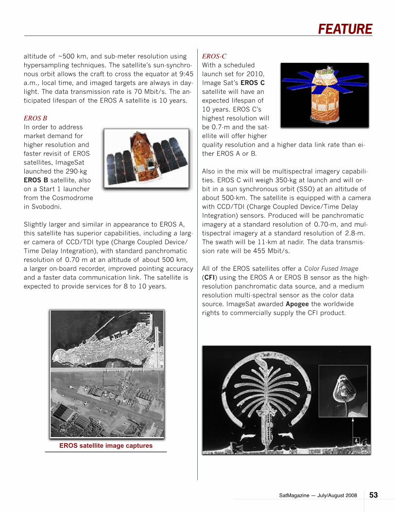
SatMagazine — July/August 2008 53
FEATURE
altitude of ~500 km, and sub-meter resolution using hypersampling techniques. The satellite’s sun-synchro-nous orbit allows the craft to cross the equator at 9:45 a.m., local time, and imaged targets are always in day-light. The data transmission rate is 70 Mbit/s. The an-ticipated lifespan of the EROS A satellite is 10 years.
EROS BIn order to address market demand for higher resolution and faster revisit of EROS satellites, ImageSat launched the 290-kg EROS B satellite, also on a Start 1 launcher from the Cosmodrome in Svobodni.
Slightly larger and similar in appearance to EROS A, this satellite has superior capabilities, including a larg-er camera of CCD/TDI type (Charge Coupled Device/Time Delay Integration), with standard panchromatic resolution of 0.70 m at an altitude of about 500 km, a larger on-board recorder, improved pointing accuracy and a faster data communication link. The satellite is expected to provide services for 8 to 10 years.
EROS-CWith a scheduled launch set for 2010, Image Sat’s EROS C satellite will have an expected lifespan of 10 years. EROS C’s highest resolution will be 0.7-m and the sat-ellite will offer higher quality resolution and a higher data link rate than ei-ther EROS A or B.
Also in the mix will be multispectral imagery capabili-ties. EROS C will weigh 350-kg at launch and will or-bit in a sun synchronous orbit (SSO) at an altitude of about 500-km. The satellite is equipped with a camera with CCD/TDI (Charge Coupled Device/Time Delay Integration) sensors. Produced will be panchromatic imagery at a standard resolution of 0.70-m, and mul-tispectral imagery at a standard resolution of 2.8-m. The swath will be 11-km at nadir. The data transmis-sion rate will be 455 Mbit/s.
All of the EROS satellites offer a Color Fused Image (CFI) using the EROS A or EROS B sensor as the high-resolution panchromatic data source, and a medium resolution multi-spectral sensor as the color data source. ImageSat awarded Apogee the worldwide rights to commercially supply the CFI product.
EROS satellite image captures
SatMagazine — July/August 200854
FEATURE
Spot ImageSPOT 1, 2, 4 + 5
Spot Image offers standard products to value-added geo-metric products, and has an archive of several million im-ages. With custom program-ming of satellites, their mul-tiresolution imagery can meet multiscale needs from 2.5 to 20 meters. They publish an online catalog through SIRIUS, where customers can locate images archived since 1986.
The company has also created a web-based service for AmericaView members in which archived SPOT imag-ery can be purchased at discounted rates. This data includes the North American Archive, USA Select, USA Na-tionwide Prime and, coming soon—One Country, One Year.
Spot Image’s satellites perform 14 + 5/26 revolutions per day. The same pattern is “phased”, meaning it is repeated over and over. Both High Visible Resolution (HRV) and High Geometric Resolution (HRG) instru-ments offer combined field-of-view that is wider than the greatest distance between two adjacent tracks.
Every point on the Earth’s surface, between 81.5° N and 81.5° S, can be collected during the satellites’ 26-day cycle. Collection above 81.5° N, or below 81.5° S, is possible, but is not conducted on a “normal” basis. The revisit frequency depends upon the latitude needed. At the equator, a target area can be imaged 11 times during the orbital cycle, or, an average of 2.4 days.
SPOT satellites transmit their image data in two ways, all depending on whether or not the bird is within range of a ground sta-tion: download-ed in real-time if within range of a Direct Re-ceiving Station (DRS); if not within range of a Spot DRS, the image data is stored onto onboard receivers on SPOT 4 + 5. If within range of a main receiving station, the satellite can be programmed to downlink image data in real-time or play back the onboard recorders and transmit the image data that was recorded earlier.
SPOT 4 + 5 satellites pack two, identical optical im-aging instruments as well as two tape recorders for image data, plus a payload telemetry package for im-ages’ transmissions to ground stations. On SPOT 2, there is HRV; SPOT 4 offers HRV-IR, and on SPOT 5, HRG is the imaging device. HRV’s offer an oblique viewing capability, with the look angle being steerable through +/- 27°, relative to the vertical. Such produces an incidence angle of +/-31°. This steering capability is handled by the programming system and provides for target capture of regions that are not directly below the satellite’s path. As you’ll note in the specifications,
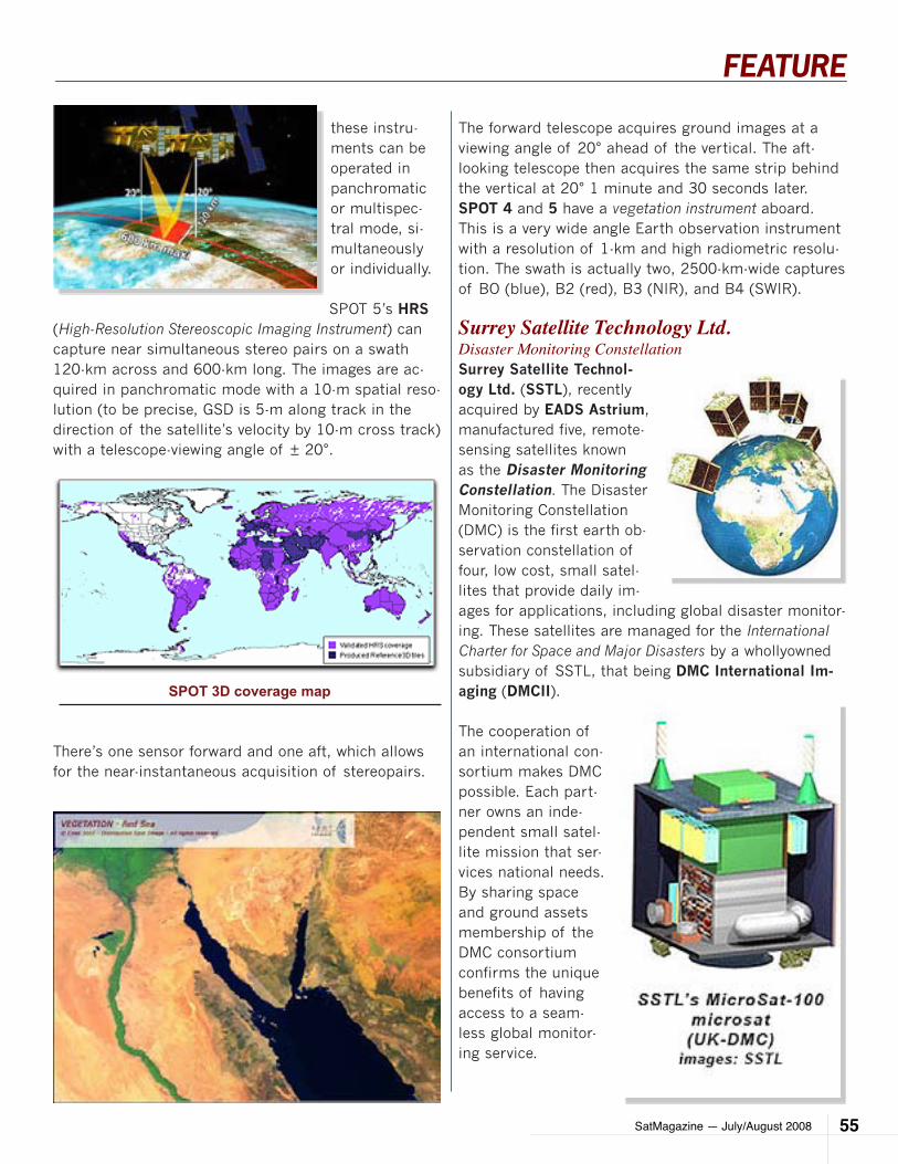
SatMagazine — July/August 2008 55
FEATURE
these instru-ments can be operated in panchromatic or multispec-tral mode, si-multaneously or individually.
SPOT 5’s HRS (High-Resolution Stereoscopic Imaging Instrument) can capture near simultaneous stereo pairs on a swath 120-km across and 600-km long. The images are ac-quired in panchromatic mode with a 10-m spatial reso-lution (to be precise, GSD is 5-m along track in the direction of the satellite’s velocity by 10-m cross track) with a telescope-viewing angle of ± 20°.
There’s one sensor forward and one aft, which allows for the near-instantaneous acquisition of stereopairs.
The forward telescope acquires ground images at a viewing angle of 20° ahead of the vertical. The aft-looking telescope then acquires the same strip behind the vertical at 20° 1 minute and 30 seconds later.SPOT 4 and 5 have a vegetation instrument aboard. This is a very wide angle Earth observation instrument with a resolution of 1-km and high radiometric resolu-tion. The swath is actually two, 2500-km-wide captures of BO (blue), B2 (red), B3 (NIR), and B4 (SWIR).
Surrey Satellite Technology Ltd.Disaster Monitoring ConstellationSurrey Satellite Technol-ogy Ltd. (SSTL), recently acquired by EADS Astrium, manufactured five, remote-sensing satellites known as the Disaster Monitoring Constellation. The Disaster Monitoring Constellation (DMC) is the first earth ob-servation constellation of four, low cost, small satel-lites that provide daily im-ages for applications, including global disaster monitor-ing. These satellites are managed for the International Charter for Space and Major Disasters by a whollyowned subsidiary of SSTL, that being DMC International Im-aging (DMCII).
The cooperation of an international con-sortium makes DMC possible. Each part-ner owns an inde-pendent small satel-lite mission that ser-vices national needs. By sharing space and ground assets membership of the DMC consortium confirms the unique benefits of having access to a seam-less global monitor-ing service.
SPOT 3D coverage map

SatMagazine — July/August 200856
FEATURE
DMC was designed as a proof of concept constella-tion. The satellites are capable of multispectral imag-ing of any part of the world every day. All satellites have been equally spaced around a sun synchronous orbit (SSO) to provide daily imaging capability.
SSTL continues to own and operate the United King-dom’s satellite in this constellation. Daily revisit is possible as they image an area of up to 600x600-km.
There’s no need for mosaics of images from different seasons. The members of DMC all agree to provide 5 percent of capacity at no charge for imaging disaster areas. Reuters’ AlertNet is the channeling agency for such work, contributing daily imaging capability to fill the existing three to five day response gap.
The DMC Imager is a 6-channel, Surrey Linear Imager (SLIM6). When operated from a near polar, SSO and circular orbit at a 686-km nominal altitude, with an or-bit inclination of 98°, the design offers a nadir viewing, three-band multispectral scanning camera that’s capa-ble of providing mid-resolution image info. The swath is 600-km wide as it passes over the target area, using
the spacecraft’s orbital motion to provide an along-track scan with the pushbroom configuration. The on-board Close Coupled Device (CCD) scan’s 6 channels are stored in a Solid State Data Recorder (SSDR) in a band-interlaced RAW format. Storing data from each bank of the three CCDs is a separate SSDR. There are 2 banks of 3 channels, with the combination of the 2 banks providing the total swath width of 600-km. The SLIM6 imager channel has a solid-state detector at the focal plane, with the spectral filters located in front of each channel lens.
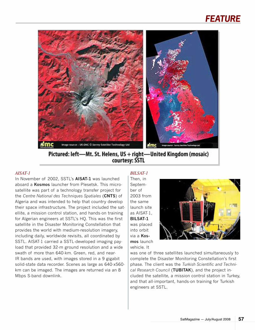
SatMagazine — July/August 2008 57
FEATURE
AISAT-1In November of 2002, SSTL’s AISAT-1 was launched aboard a Kosmos launcher from Plesetsk. This micro-satellite was part of a technology transfer project for the Centre National des Techniques Spatiales (CNTS) of Algeria and was intended to help that country develop their space infrastructure. The project included the sat-ellite, a mission control station, and hands-on training for Algerian engineers at SSTL’s HQ. This was the first satellite in the Disaster Monitoring Constellation that provides the world with medium-resolution imagery, including daily, worldwide revisits, all coordinated by SSTL. AISAT-1 carried a SSTL-developed imaging pay-load that provided 32-m ground resolution and a wide swath of more than 640-km. Green, red, and near-IR bands are used, with images stored in a 9 gigabit solid-state data recorder. Scenes as large as 640-x560-km can be imaged. The images are returned via an 8 Mbps S-band downlink.
BILSAT-1Then, in Septem-ber of 2003 from the same launch site as AISAT-1, BILSAT-1 was placed into orbit via a Kos-mos launch vehicle. It was one of three satellites launched simultaneously to complete the Disaster Monitoring Constellation’s first phase. The client was the Turkish Scientific and Techni-cal Research Council (TUBITAK), and the project in-cluded the satellite, a mission control station in Turkey, and that all-important, hands-on training for Turkish engineers at SSTL.
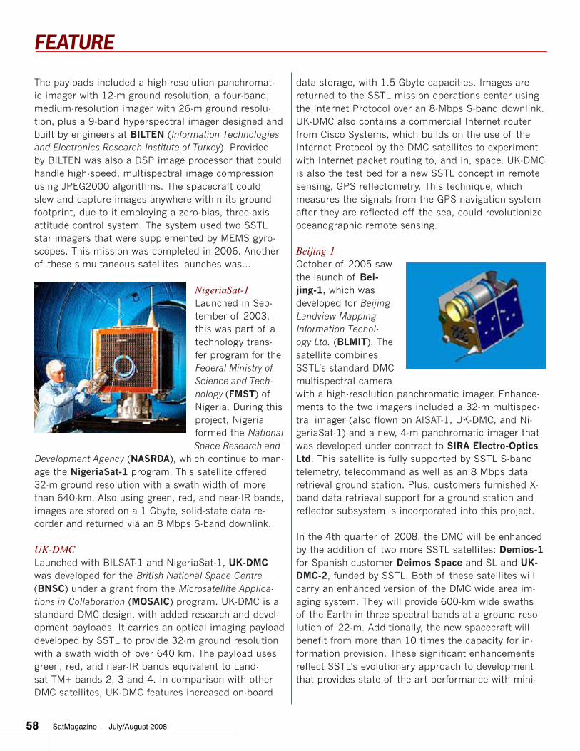
SatMagazine — July/August 200858
FEATURE
The payloads included a high-resolution panchromat-ic imager with 12-m ground resolution, a four-band, medium-resolution imager with 26-m ground resolu-tion, plus a 9-band hyperspectral imager designed and built by engineers at BILTEN (Information Technologies and Electronics Research Institute of Turkey). Provided by BILTEN was also a DSP image processor that could handle high-speed, multispectral image compression using JPEG2000 algorithms. The spacecraft could slew and capture images anywhere within its ground footprint, due to it employing a zero-bias, three-axis attitude control system. The system used two SSTL star imagers that were supplemented by MEMS gyro-scopes. This mission was completed in 2006. Another of these simultaneous satellites launches was...
NigeriaSat-1Launched in Sep-tember of 2003, this was part of a technology trans-fer program for the Federal Ministry of Science and Tech-nology (FMST) of Nigeria. During this project, Nigeria formed the National Space Research and
Development Agency (NASRDA), which continue to man-age the NigeriaSat-1 program. This satellite offered 32-m ground resolution with a swath width of more than 640-km. Also using green, red, and near-IR bands, images are stored on a 1 Gbyte, solid-state data re-corder and returned via an 8 Mbps S-band downlink.
UK-DMCLaunched with BILSAT-1 and NigeriaSat-1, UK-DMC was developed for the British National Space Centre (BNSC) under a grant from the Microsatellite Applica-tions in Collaboration (MOSAIC) program. UK-DMC is a standard DMC design, with added research and devel-opment payloads. It carries an optical imaging payload developed by SSTL to provide 32-m ground resolution with a swath width of over 640 km. The payload uses green, red, and near-IR bands equivalent to Land-sat TM+ bands 2, 3 and 4. In comparison with other DMC satellites, UK-DMC features increased on-board
data storage, with 1.5 Gbyte capacities. Images are returned to the SSTL mission operations center using the Internet Protocol over an 8-Mbps S-band downlink. UK-DMC also contains a commercial Internet router from Cisco Systems, which builds on the use of the Internet Protocol by the DMC satellites to experiment with Internet packet routing to, and in, space. UK-DMC is also the test bed for a new SSTL concept in remote sensing, GPS reflectometry. This technique, which measures the signals from the GPS navigation system after they are reflected off the sea, could revolutionize oceanographic remote sensing.
Beijing-1October of 2005 saw the launch of Bei-jing-1, which was developed for Beijing Landview Mapping Information Techol-ogy Ltd. (BLMIT). The satellite combines SSTL’s standard DMC multispectral camera with a high-resolution panchromatic imager. Enhance-ments to the two imagers included a 32-m multispec-tral imager (also flown on AISAT-1, UK-DMC, and Ni-geriaSat-1) and a new, 4-m panchromatic imager that was developed under contract to SIRA Electro-Optics Ltd. This satellite is fully supported by SSTL S-band telemetry, telecommand as well as an 8 Mbps data retrieval ground station. Plus, customers furnished X-band data retrieval support for a ground station and reflector subsystem is incorporated into this project.
In the 4th quarter of 2008, the DMC will be enhanced by the addition of two more SSTL satellites: Demios-1 for Spanish customer Deimos Space and SL and UK-DMC-2, funded by SSTL. Both of these satellites will carry an enhanced version of the DMC wide area im-aging system. They will provide 600-km wide swaths of the Earth in three spectral bands at a ground reso-lution of 22-m. Additionally, the new spacecraft will benefit from more than 10 times the capacity for in-formation provision. These significant enhancements reflect SSTL’s evolutionary approach to development that provides state of the art performance with mini-
SatMagazine — July/August 2008 59
FEATURE
imal risk. The improved resolution and capacity enable the system to better meet European Global Monitoring for Environment and Security (GMES) program needs, particularly in the areas of forestry and fire.
Nigerian customer NASRDA has contracted SSTL for a next generation DMC satellite and will launch Nige-riaSat-2 in 2009. The contract includes a training and development program for 25 Nigerian engineers, and the launch of the training satellite, NX, into the DMC alongside NigeriaSat-2.
RapidEyeRapidEye AG (Branden-burg, Germany), a public-private cooperative en-terprise, has stated that during 2008, the already delayed launch of five microsatellites will oc-cur. RapidEye controls and partially handles the satellite manufacturing. Subcontractors involved in this constellation ef-fort include MacDonald, Dettwiler and Associates (MDA) in Canada, who re-ceived a $170 million CDN contract from RapidEye in June of 2004, and is the prime contractor.
MDA, in turn, awarded a 19.2 million pound con-tract to Surrey Satellite Technology Ltd. (SSTL) in the United Kingdom to supply the spacecraft platforms, integration, and launch arrangements for the five satellites. The satellites will use SSTL’s advanced microsatellite avionics, a precision atti-tude orbit and control sys-
tem with star tracker. The latter will provide 30 degrees roll-offset for accurate image targeting and onboard propulsion for constellation sta-tion keeping. SSTL is going to provide the Spacecraft Control Center ground equipment for the mission. The camera subcontractor is Jena Optronik GmbH.
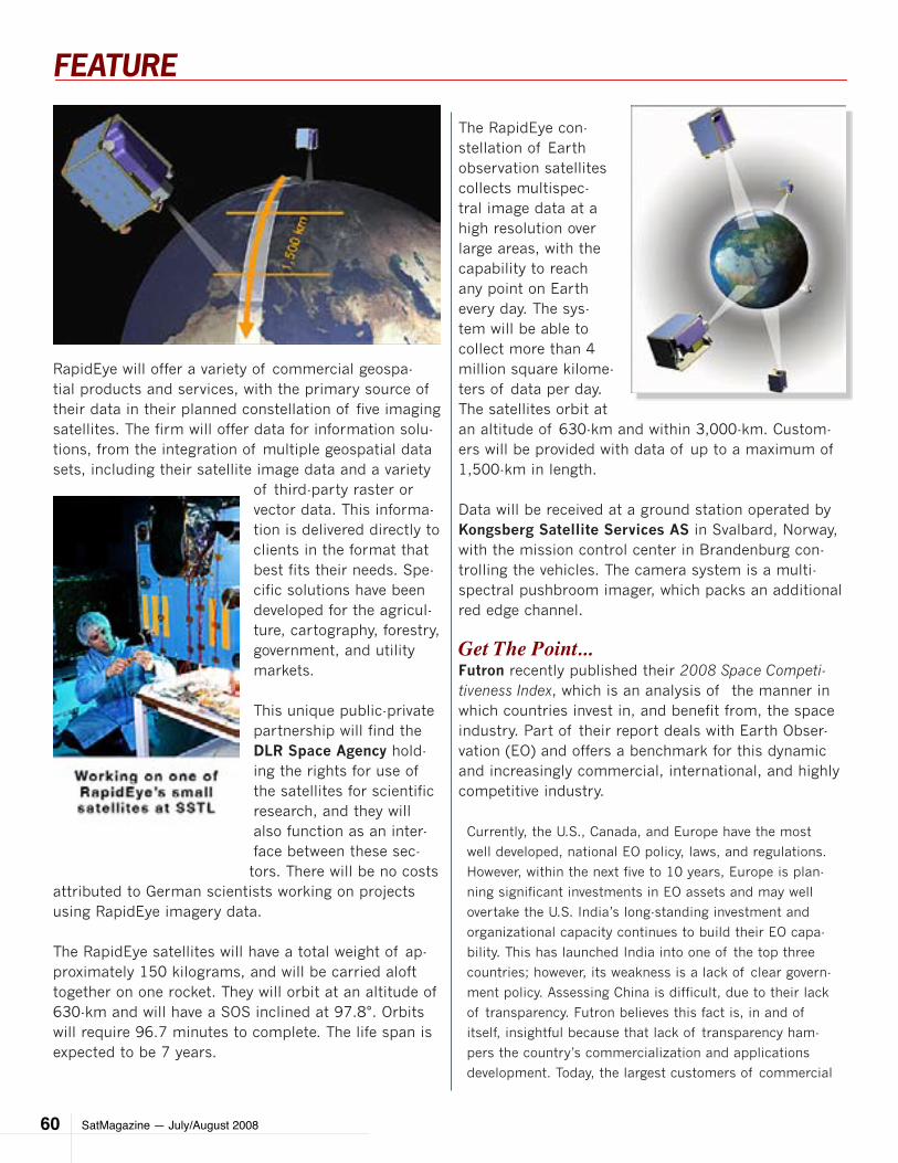
SatMagazine — July/August 200860
FEATURE
RapidEye will offer a variety of commercial geospa-tial products and services, with the primary source of their data in their planned constellation of five imaging satellites. The firm will offer data for information solu-tions, from the integration of multiple geospatial data sets, including their satellite image data and a variety
of third-party raster or vector data. This informa-tion is delivered directly to clients in the format that best fits their needs. Spe-cific solutions have been developed for the agricul-ture, cartography, forestry, government, and utility markets.
This unique public-private partnership will find the DLR Space Agency hold-ing the rights for use of the satellites for scientific research, and they will also function as an inter-face between these sec-tors. There will be no costs
attributed to German scientists working on projects using RapidEye imagery data.
The RapidEye satellites will have a total weight of ap-proximately 150 kilograms, and will be carried aloft together on one rocket. They will orbit at an altitude of 630-km and will have a SOS inclined at 97.8°. Orbits will require 96.7 minutes to complete. The life span is expected to be 7 years.
The RapidEye con-stellation of Earth observation satellites collects multispec-tral image data at a high resolution over large areas, with the capability to reach any point on Earth every day. The sys-tem will be able to collect more than 4 million square kilome-ters of data per day. The satellites orbit at an altitude of 630-km and within 3,000-km. Custom-ers will be provided with data of up to a maximum of 1,500-km in length.
Data will be received at a ground station operated by Kongsberg Satellite Services AS in Svalbard, Norway, with the mission control center in Brandenburg con-trolling the vehicles. The camera system is a multi-spectral pushbroom imager, which packs an additional red edge channel.
Get The Point...Futron recently published their 2008 Space Competi-tiveness Index, which is an analysis of the manner in which countries invest in, and benefit from, the space industry. Part of their report deals with Earth Obser-vation (EO) and offers a benchmark for this dynamic and increasingly commercial, international, and highly competitive industry.
Currently, the U.S., Canada, and Europe have the most
well developed, national EO policy, laws, and regulations.
However, within the next five to 10 years, Europe is plan-
ning significant investments in EO assets and may well
overtake the U.S. India’s long-standing investment and
organizational capacity continues to build their EO capa-
bility. This has launched India into one of the top three
countries; however, its weakness is a lack of clear govern-
ment policy. Assessing China is difficult, due to their lack
of transparency. Futron believes this fact is, in and of
itself, insightful because that lack of transparency ham-
pers the country’s commercialization and applications
development. Today, the largest customers of commercial

SatMagazine — July/August 2008 61
FEATURE
EO data are governments yet, innovative products such as
Google Earth permit public access to integrated remote
sensing data, while raising awareness, and increases prod-
uct value.
Faster, longer and crisper — improvements are a regular
occurrence in the satellite realm, making it surely one of
today’s most exciting industries.
This closes our look at satellite imagery, with a com-mercial perspective. Tables for the mentioned satel-liets follow... we hope you have found the information useful... we recommend you go directly to any of the mentioned companies’ websites to learn more about their services and the satellites on orbit. Thank you for attending this series!—Hartley & Pattie Lesser
CREDITS and THANKS…Companies supplying information for this arti-•cle, and their missions, include…
DigitalGlobe•
Earth Observation Research Center, JAXA•
Futron•
ESRI •
GeoEye•
Lockheed Martin•
Space Foundation•
National Weather Association (NWA) Remote •Sensing Committee
Satellite Imaging Corporation•
ViaSat GeoTechnologies•
1 The GIS information text and graphics in Part I of this
article were excerpted from ww.gis.com and www.esri.com
and are the intellectual property of ESRI and are used by
permission. Copyright © ESRI. All rights reserved.
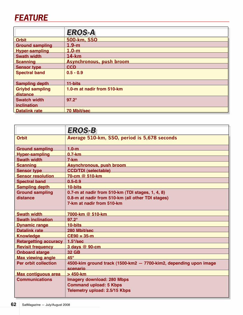
SatMagazine — July/August 200862
FEATURE
eroS-aOrbit 500-km, SSOGround sampling 1.9-mHyper-sampling 1.0-mSwath width 14-kmScanning Asynchronous, push broomSensor type CCDSpectral band 0.5 - 0.9
Sampling depth 11-bitsGriybd sampling distance
1.0-m at nadir from 510-km
Swatch width inclination
97.2°
Datalink rate 70 Mbit/sec
eroS-BOrbit Average 510-km, SSO, period is 5,678 seconds
Ground sampling 1.0-mHyper-sampling 0.7-kmSwath width 7-kmScanning Asynchronous, push broomSensor type CCD/TDI (selectable)Sensor resolution 70-cm @ 510-kmSpectral band 0.5-0.9Sampling depth 10-bitsGround sampling distance
0.7-m at nadir from 510-km (TDI stages, 1, 4, 8)0.8-m at nadir from 510-km (all other TDI stages)7-km at nadir from 510-km
Swath width 7000-km @ 510-kmSwath inclination 97.2°Dynamic range 10-bitsDatalink rate 280 Mbit/secKnowledge CE90 = 35-mRetargetting accuracy 1.5°/secRevisit frequency 3 days @ 90-cmOnboard starge 32 GBMax viewing angle 45°Per orbit collection 4500-kim ground track (1500-km2 — 7700-kim2, depending upon image
scenarioMax contiguous area > 450-kmCommunications Imagery download: 280 Mbps
Command upload: 5 KbpsTelemetry upload: 2.5/15 Kbps
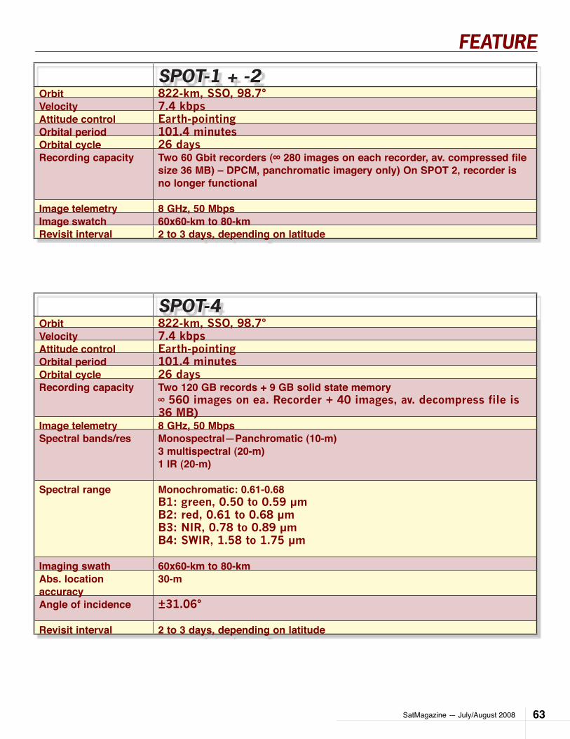
SatMagazine — July/August 2008 63
FEATURE
SpoT-4Orbit 822-km, SSO, 98.7°Velocity 7.4 kbpsAttitude control Earth-pointingOrbital period 101.4 minutesOrbital cycle 26 daysRecording capacity Two 120 GB records + 9 GB solid state memory
∞ 560 images on ea. Recorder + 40 images, av. decompress file is 36 MB)
Image telemetry 8 GHz, 50 MbpsSpectral bands/res Monospectral—Panchromatic (10-m)
3 multispectral (20-m)1 IR (20-m)
Spectral range Monochromatic: 0.61-0.68B1: green, 0.50 to 0.59 µmB2: red, 0.61 to 0.68 µmB3: NIR, 0.78 to 0.89 µmB4: SWIR, 1.58 to 1.75 µm
Imaging swath 60x60-km to 80-kmAbs. location accuracy
30-m
Angle of incidence ±31.06°
Revisit interval 2 to 3 days, depending on latitude
SpoT-1 + -2Orbit 822-km, SSO, 98.7°Velocity 7.4 kbpsAttitude control Earth-pointingOrbital period 101.4 minutesOrbital cycle 26 daysRecording capacity Two 60 Gbit recorders (∞ 280 images on each recorder, av. compressed file
size 36 MB) – DPCM, panchromatic imagery only) On SPOT 2, recorder is no longer functional
Image telemetry 8 GHz, 50 MbpsImage swatch 60x60-km to 80-kmRevisit interval 2 to 3 days, depending on latitude

SatMagazine — July/August 200864
FEATURE
SpoT-5Orbit 822-km, SSO, 98.7°
Velocity 7.4 kbps
Attitude control Earth-pointing + yaw-axis controlled, which compensate for Earth’s rotational effects
Orbital period 101.4 minutes
Orbital cycle 26 days
Recording capacity 110 GB solid state memory (∞ 210 images, av. decompressed file is 144 MB)
Image telemetry 8 GHz, 2x50 Mbps
Spectral bands/res 2 panchromatic (5-m), generating 2.5-m product3 multispectral (10-m)1 IR (20-m)
Spectral range Panchromatic, 0.48 to 0.71 µmB1: green, 0.50 to 0.59 µm B2: red, 0.61 to 0.68 µmB3: NIR, 0.78 to 0.89 µmB4: SWIR, 1.58 to 1.75 µm
Imaging swath 60x60-km to 80-km
Abs. location accuracy
30-m
Angle of incidence ±31.06°
Revisit interval 2 to 3 days, depending on latitude
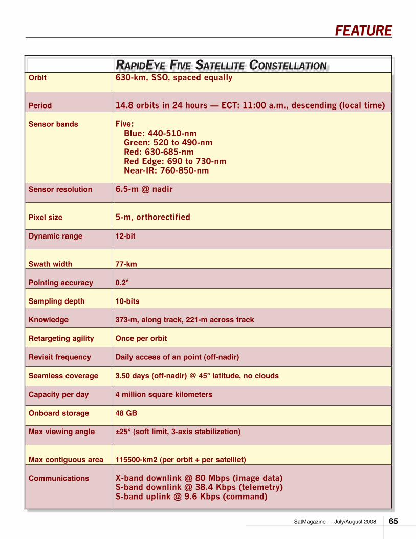
SatMagazine — July/August 2008 65
FEATURE
rapIDeye fIve SaTellITe conSTellaTIonOrbit 630-km, SSO, spaced equally
Period 14.8 orbits in 24 hours — ECT: 11:00 a.m., descending (local time)
Sensor bands Five: Blue: 440-510-nm Green: 520 to 490-nm Red: 630-685-nm Red Edge: 690 to 730-nm Near-IR: 760-850-nm
Sensor resolution 6.5-m @ nadir
Pixel size 5-m, orthorectified
Dynamic range 12-bit
Swath width 77-km
Pointing accuracy 0.2°
Sampling depth 10-bits
Knowledge 373-m, along track, 221-m across track
Retargeting agility Once per orbit
Revisit frequency Daily access of an point (off-nadir)
Seamless coverage 3.50 days (off-nadir) @ 45° latitude, no clouds
Capacity per day 4 million square kilometers
Onboard storage 48 GB
Max viewing angle ±25° (soft limit, 3-axis stabilization)
Max contiguous area 115500-km2 (per orbit + per satelliet)
Communications X-band downlink @ 80 Mbps (image data)S-band downlink @ 38.4 Kbps (telemetry)S-band uplink @ 9.6 Kbps (command)
SatMagazine — July/August 200866
FOCUS
by Pattie Lesser
A three-in-one conference must be similar to drinking a double espresso and a Red Bull, combined. Talk about getting many things ac-
complished in a little amount of time! Very smart. The ISCe 2008, ICSSC-2008 and Navy SATCOM Us-ers Workshop has proven to be a major success. An indicator of such is in sheer numbers‚ close to seven hundred satellite industry executives and military/government leaders who spent three days addressing key industry issues, policies, opportunities and chal-lenges in San Diego, at Hannover Fairs‚ seventh an-nual ISCe conference.
The conference, which ended on June 12, focused its program on Access to SATCOM for the Next Decade, and provided a unique forum for military SATCOM us-ers and planners, and commercial SATCOM products and service providers. This enabled them to examine the continuing importance of satellites in the global information and war fighting grid.
This was the first time in the seven-year history that ISCe teamed with two other leading organizations to provide a platform for collaborative discussion and net-working. Members and supporters of the 26th Annual AIAA International Satellite Systems Conference (IC-SSC-2008) and the 2nd Annual Navy SATCOM Users Workshop joined with hundreds of industry and gov-ernment/military leaders in a comprehensive program of technical, marketing, and user-themed panels.
Speaking of themes, several dominated ISCe 2008.
The critical need for commercial bandwidth •and services to support the military and its warfighters
The convergence of satellite communications •with fixed, mobile, and wireless networks
The increasingly crucial role played by integra-•tors of satellite services to deliver solutions to commercial and government customers
Plans are already underway for next year’s event-ISCe 2009, which will take place June 2nd through 4th at the San Diego Marriott Hotel and Marina, in San Diego, California.
In her annual State of the Satellite Industry report, Satel-lite Industry Association (SIA) president Patricia Cooper reported a 16 percent growth in global revenues for the commercial satellite industry. Patricia’s annual re-port was commissioned by her organization and con-ducted by Futron Corp. Worldwide industry revenues in 2007 were $123 billion, representing an average annual growth of 11.5 percent for the period from 2002-2007. Encouraging reports, indeed. Satellite ser-vices’ revenues continued to drive the overall industry, with a 60 percent total share of industry revenues.
Continuing a trend identified in previous Futron/ISCe surveys, commercial attendees also project that the Department of Defense will remain their primary tar-get for new products and services. However, some five percent are planning to increase their solutions tar-geting Department of Homeland Security and public safety/first responders. While satellite capacity sales remain the dominant new service driver for most re-spondents, more than 20 percent see an increase in their hybrid network services. Twice as many respon-dents as last year project software to be their big driv-er of new business.
Almost 70 percent of military and other government attendees anticipate that the launch of new military satellites will have no impact on their use of commer-cial communications satellites; more than 20 percent projected that commercial usage will decline by 25 percent or more. Seventy percent believe availability of appropriate space segment is the government’s greatest challenge in utilizing commercial satellites, 30 percent see avail-ability of ground terminals as the greater challenge in accessing commercial bandwidth.
ISce epITome of effIcIency, THree-In-one conference
SatMagazine — July/August 2008 67
FOCUS
Military/government attendees gave the commercial satellite industry good grades on understanding and meeting govern-ment needs. More than 85 percent reported that commer-cial vendors meet their needs in a timely manner always or most of the time, while 76 percent believe industry under-stands their service and procurement requirements.The Boeing Corporation played host to the awards din-ner in which the ISCe honored Globecomm Systems‚ Chairman and CEO, David Hershberg, with its Lifetime Achievement Award. Hershberg joins previous re-nowned recipients such as Dr. Harold Rosen (formerly of Hughes), Connie Kullman (formerly with Intelsat), Dr. Denis Curtin (XTAR) and Joseph Clayton, among others. ISCe also honored ATCi founder and CEO Gary Hatch with its Innovation Award and Boeing Satellite Sys-tems International with its 2008 Leadership Award.
At its annual Awards Luncheon, the AIAA International Communication Satellite Systems Conference presented Mark Dankberg, ViaSat CEO & Chairman, with its Aero-space Communications Award. Dankberg, founder of the company, was cited for shepherding ViaSat into a leading satellite communications company through outstanding leadership and technical expertise.
“This year’s ISCe event was the culmination of a year-long planning process involving the expertise of the ISCe Advisory Board, our partners at the AIAA and our program partners the Satellite Industry Association (SIA) and SPAWAR, said David Bross, ISCe 2008 Chair-man and Director of Business Development, HFUSA. “The new military/government focus of ISCe proved key to capitalizing on the economic trends affecting the commercial satellite industry and its military and gov-ernment customers.”
Future events include—October 14th, the third annual ISCe Satellite Investment Symposium (ISIS NYC 08) to take place at the 3 West Club in Manhattan, New York—February 4 and 5, 2009, HFUSA will launch the Multichannel Content Distribution Conference & Expo (Powered by CeBIT) at the University City Hilton Hotel, Universal Studios, California. Focusing on the commercial and entertainment sides of multichannel and mobile signal content delivery to consumers, this hybrid conference and expo will address networks and distribution, and will look behind the scenes at what the impetus is that creates the transport of content.
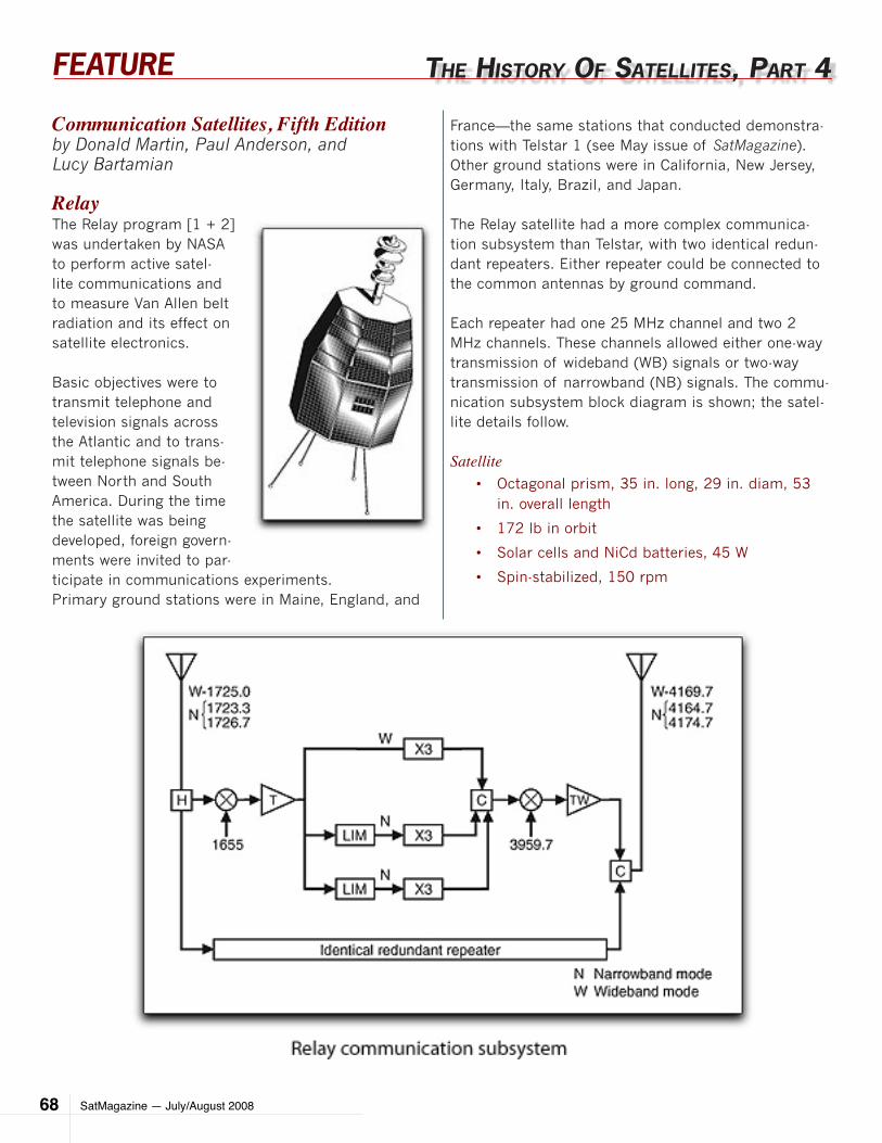
SatMagazine — July/August 200868
FEATURE
Communication Satellites, Fifth Edition by Donald Martin, Paul Anderson, and Lucy Bartamian
RelayThe Relay program [1 + 2] was undertaken by NASA to perform active satel-lite communications and to measure Van Allen belt radiation and its effect on satellite electronics.
Basic objectives were to transmit telephone and television signals across the Atlantic and to trans-mit telephone signals be-tween North and South America. During the time the satellite was being developed, foreign govern-ments were invited to par-ticipate in communications experiments.Primary ground stations were in Maine, England, and
THe HISTory of SaTellITeS, parT 4
France—the same stations that conducted demonstra-tions with Telstar 1 (see May issue of SatMagazine). Other ground stations were in California, New Jersey, Germany, Italy, Brazil, and Japan.
The Relay satellite had a more complex communica-tion subsystem than Telstar, with two identical redun-dant repeaters. Either repeater could be connected to the common antennas by ground command.
Each repeater had one 25 MHz channel and two 2 MHz channels. These channels allowed either one-way transmission of wideband (WB) signals or two-way transmission of narrowband (NB) signals. The commu-nication subsystem block diagram is shown; the satel-lite details follow.
SatelliteOctagonal prism, 35 in. long, 29 in. diam, 53 •in. overall length
172 lb in orbit•
Solar cells and NiCd batteries, 45 W•
Spin-stabilized, 150 rpm•
SatMagazine — July/August 2008 69
FEATURE
ConfigurationTwo double-conversion repeaters (one on, one •standby), each with one WB and two NB channels
CapacityWB: 300 one-way voice circuits or one TV •channel
NB: 12 two-way telephone circuits (limited by •ground equipment, not satellite bandwidth)
Transmitter4164.7, 4174.7 MHz (NB), 4169.7 MHz (WB)•
All solid state except TWT•
10 W output•
Receiver1723.3, 1726.7 MHz (NB), 1725 MHz (WB)•
All solid state•
14 dB noise figure•
AntennaTwo biconical horns (one transmit, one receive)•
Approximately 0 dB gain normal to spin axis•
Circular polarization•
LifeOne year•
OrbitRelay 1: 712 x 4012 nmi, 47.5 deg inclination•
Relay 2: 1130 x 4000 nmi, 46 deg inclination•
Orbital historyRelay 1: launched 13 December 1962, operated •until February 1965
Relay 2: launched 21 January 1964, operated •until May 1965
Delta launch vehicle•
ManagementDeveloped by RCA for NASA Goddard Space Flight Cen-ter Relay 1 was launched in December 1962. Radia-tion experiment data were obtained on the first day. That same day, difficulties with communications tran-sponder No. 1 that caused excessive power consump-tion were noticed. The problem could not be fully cor-rected, and from January 1963 transponder No. 2 was
used for almost all the communication experiments. Relay 1 operated until February 1965.
During 1963, several tests and demonstrations were conducted including telephone and television transmis-sions. Network TV broadcasts were transmitted from the United States to Europe and to Japan. Several times, both television and telephone transmissions were used for international medical consultations.
In October 1964, television coverage of the Olympic Games was relayed from Japan to the UnitedStates by Syncom 3, and then from the United States to Europe by Relay 1.
Relay 2 was modified slightly to provide increased rel ability and radiation resistance. Relay 2 was launched in January 1964 and was used in a variety of commu-nications tests similar to those done with Relay 1.
SatMagazine — July/August 200870
FEATURE
By July 1964, Relays 1 and 2 had been used for 112 public demonstrations of telephone and television transmission. Relay 2 was used until May 1965.
The Telstar and Relay programs were both considered successful. They demonstrated that the technology at that time could produce a useful,medium-altitude com-munication satellite. In addition, ground stationtechnology was proven, and routine operation of ground stations was demonstrated.
Measurements of communications parameters indicat-ed no significant deviations from theoretically expected values. Finally, it was shown that satellite communica-tion systems could share frequencies with terrestrial microwave systems without mutual interference.
Select the book graphic to order this book from The Aerospace Company
Author BiographyDonald H. Martin is a senior engineering specialist in The Aero-
space Corporation’s Architectures and Spectrum Management
Office. Martin joined the Communications
Department in the Engineering Group at Aero-
space in 1968 after receiving B.S. and M.S.
degrees in engineering from the University of
California, Los Angeles. He has been collect-
ing information on satellite communications
since 1972, when his manager offered him a
choice of assignments: of the three options, he chose to write a
description of communication satellites then in orbit. The assign-
ment grew the next year to include a report describing satellites
being built, and gradually expanded to the first edition of “Com-
munication Satellites in 1986”, with the book now in its Fifth
Edition.
1. Space Communications and Navigation 1958—1964, NASA SP-93 (1966).
2. K. W. Gatland, Telecommunication Satellites, Prentic Hall, New York (1964).
3. Final Report on the Relay 1 Program, NASA SP-76, Goddard Space Flight Center (1965).
4. L. Jaffe, “The NASA Communications Satellite Program Results and Status,” Proceedings of the 15th International Astronautical Congress (1964), Vol. 2: Satellite Systems (1965).
5. S. Metzger and R. H. Pickard, “Relay,” Astronautics and Aerospace Engineering, Vol. 1, No. 8 (September 1963).
6. Publications of Goddard Space Flight Center 1963, Vol. II:7. a. S. Metzger and R. H. Pickard, “Relay” (See Ref. 5).8. b. R. H. Pickard, “Relay 1 Spacecraft Performance.”9. c. R.Pickard, S. Roth, and J. Kiesling, “Relay, An Experimental Satellite for TV and Multichannel Telephony.”
10. “Development of the Relay Communications Satellite,” Interavia, Vol. 17 (June 1962).
11. D. R. Glover, “NASA Experimental Communications Satellites,” http//sulu.lerc.nasa.gov/dglover/satcom2.html (10 June 1999).
12. D. R. Glover, “NASA Experimental Communications Satellites, 1958—1995,” in Beyond the Ionosphere: Fifty Years of Satellite Communication, A. J. Butrica, ed., NASA History Office, Washington, D.C. (1997), ch. 2.
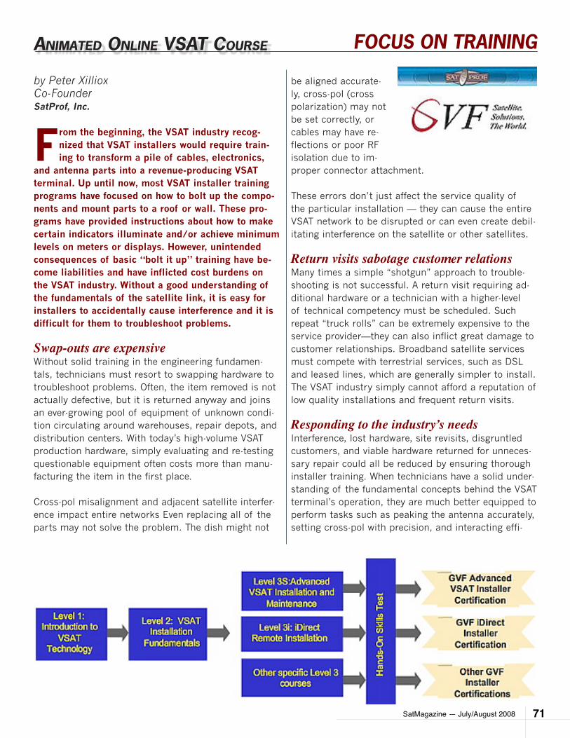
SatMagazine — July/August 2008 71
FOCUS ON TRAINING
by Peter XillioxCo-FounderSatProf, Inc.
From the beginning, the VSAT industry recog-nized that VSAT installers would require train-ing to transform a pile of cables, electronics,
and antenna parts into a revenue-producing VSAT terminal. Up until now, most VSAT installer training programs have focused on how to bolt up the compo-nents and mount parts to a roof or wall. These pro-grams have provided instructions about how to make certain indicators illuminate and/or achieve minimum levels on meters or displays. However, unintended consequences of basic “bolt it up” training have be-come liabilities and have inflicted cost burdens on the VSAT industry. Without a good understanding of the fundamentals of the satellite link, it is easy for installers to accidentally cause interference and it is difficult for them to troubleshoot problems.
Swap-outs are expensiveWithout solid training in the engineering fundamen-tals, technicians must resort to swapping hardware to troubleshoot problems. Often, the item removed is not actually defective, but it is returned anyway and joins an ever-growing pool of equipment of unknown condi-tion circulating around warehouses, repair depots, and distribution centers. With today’s high-volume VSAT production hardware, simply evaluating and re-testing questionable equipment often costs more than manu-facturing the item in the first place.
Cross-pol misalignment and adjacent satellite interfer-ence impact entire networks Even replacing all of the parts may not solve the problem. The dish might not
anImaTeD onlIne vSaT coUrSe
be aligned accurate-ly, cross-pol (cross polarization) may not be set correctly, or cables may have re-flections or poor RF isolation due to im-proper connector attachment.
These errors don’t just affect the service quality of the particular installation — they can cause the entire VSAT network to be disrupted or can even create debil-itating interference on the satellite or other satellites.
Return visits sabotage customer relationsMany times a simple “shotgun” approach to trouble-shooting is not successful. A return visit requiring ad-ditional hardware or a technician with a higher-level of technical competency must be scheduled. Such repeat “truck rolls” can be extremely expensive to the service provider—they can also inflict great damage to customer relationships. Broadband satellite services must compete with terrestrial services, such as DSL and leased lines, which are generally simpler to install. The VSAT industry simply cannot afford a reputation of low quality installations and frequent return visits.
Responding to the industry’s needsInterference, lost hardware, site revisits, disgruntled customers, and viable hardware returned for unneces-sary repair could all be reduced by ensuring thorough installer training. When technicians have a solid under-standing of the fundamental concepts behind the VSAT terminal’s operation, they are much better equipped to perform tasks such as peaking the antenna accurately, setting cross-pol with precision, and interacting effi-
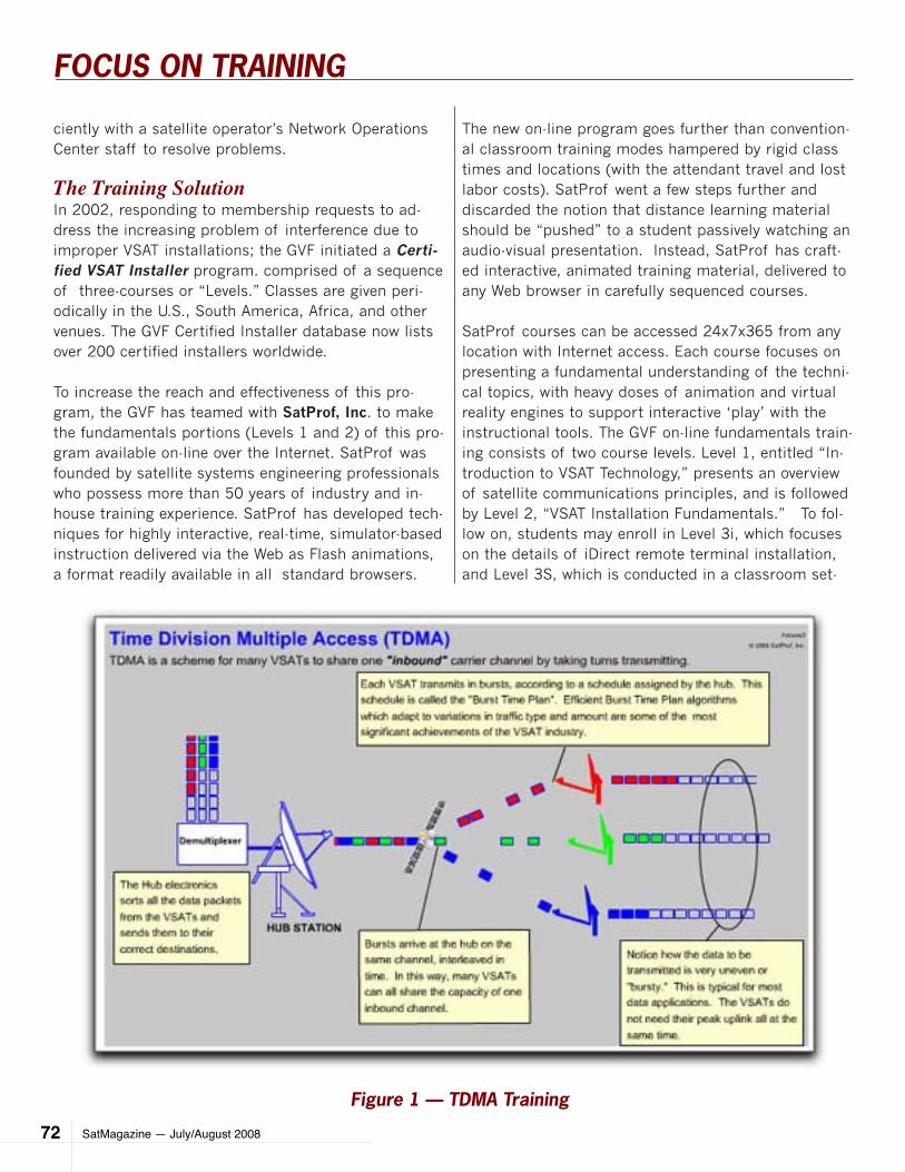
SatMagazine — July/August 200872
FOCUS ON TRAINING
ciently with a satellite operator’s Network Operations Center staff to resolve problems.
The Training SolutionIn 2002, responding to membership requests to ad-dress the increasing problem of interference due to improper VSAT installations; the GVF initiated a Certi-fied VSAT Installer program. comprised of a sequence of three-courses or “Levels.” Classes are given peri-odically in the U.S., South America, Africa, and other venues. The GVF Certified Installer database now lists over 200 certified installers worldwide.
To increase the reach and effectiveness of this pro-gram, the GVF has teamed with SatProf, Inc. to make the fundamentals portions (Levels 1 and 2) of this pro-gram available on-line over the Internet. SatProf was founded by satellite systems engineering professionals who possess more than 50 years of industry and in-house training experience. SatProf has developed tech-niques for highly interactive, real-time, simulator-based instruction delivered via the Web as Flash animations, a format readily available in all standard browsers.
The new on-line program goes further than convention-al classroom training modes hampered by rigid class times and locations (with the attendant travel and lost labor costs). SatProf went a few steps further and discarded the notion that distance learning material should be “pushed” to a student passively watching an audio-visual presentation. Instead, SatProf has craft-ed interactive, animated training material, delivered to any Web browser in carefully sequenced courses.
SatProf courses can be accessed 24x7x365 from any location with Internet access. Each course focuses on presenting a fundamental understanding of the techni-cal topics, with heavy doses of animation and virtual reality engines to support interactive ‘play’ with the instructional tools. The GVF on-line fundamentals train-ing consists of two course levels. Level 1, entitled “In-troduction to VSAT Technology,” presents an overview of satellite communications principles, and is followed by Level 2, “VSAT Installation Fundamentals.” To fol-low on, students may enroll in Level 3i, which focuses on the details of iDirect remote terminal installation, and Level 3S, which is conducted in a classroom set-
Figure 1 — TDMA Training
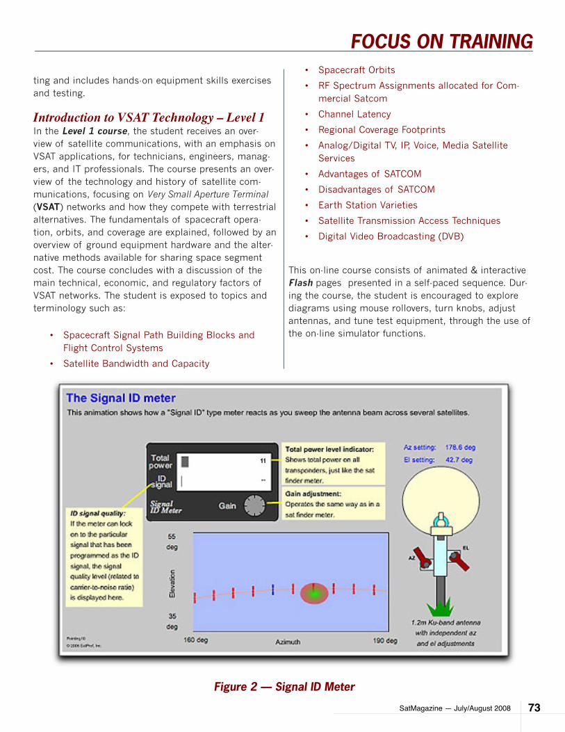
SatMagazine — July/August 2008 73
FOCUS ON TRAINING
ting and includes hands-on equipment skills exercises and testing.
Introduction to VSAT Technology – Level 1In the Level 1 course, the student receives an over-view of satellite communications, with an emphasis on VSAT applications, for technicians, engineers, manag-ers, and IT professionals. The course presents an over-view of the technology and history of satellite com-munications, focusing on Very Small Aperture Terminal (VSAT) networks and how they compete with terrestrial alternatives. The fundamentals of spacecraft opera-tion, orbits, and coverage are explained, followed by an overview of ground equipment hardware and the alter-native methods available for sharing space segment cost. The course concludes with a discussion of the main technical, economic, and regulatory factors of VSAT networks. The student is exposed to topics and terminology such as:
Spacecraft Signal Path Building Blocks and •Flight Control Systems
Satellite Bandwidth and Capacity•
Spacecraft Orbits•
RF Spectrum Assignments allocated for Com-•mercial Satcom
Channel Latency•
Regional Coverage Footprints•
Analog/Digital TV, IP, Voice, Media Satellite •Services
Advantages of SATCOM•
Disadvantages of SATCOM•
Earth Station Varieties•
Satellite Transmission Access Techniques•
Digital Video Broadcasting (DVB)•
This on-line course consists of animated & interactive Flash pages presented in a self-paced sequence. Dur-ing the course, the student is encouraged to explore diagrams using mouse rollovers, turn knobs, adjust antennas, and tune test equipment, through the use of the on-line simulator functions.
Figure 2 — Signal ID Meter
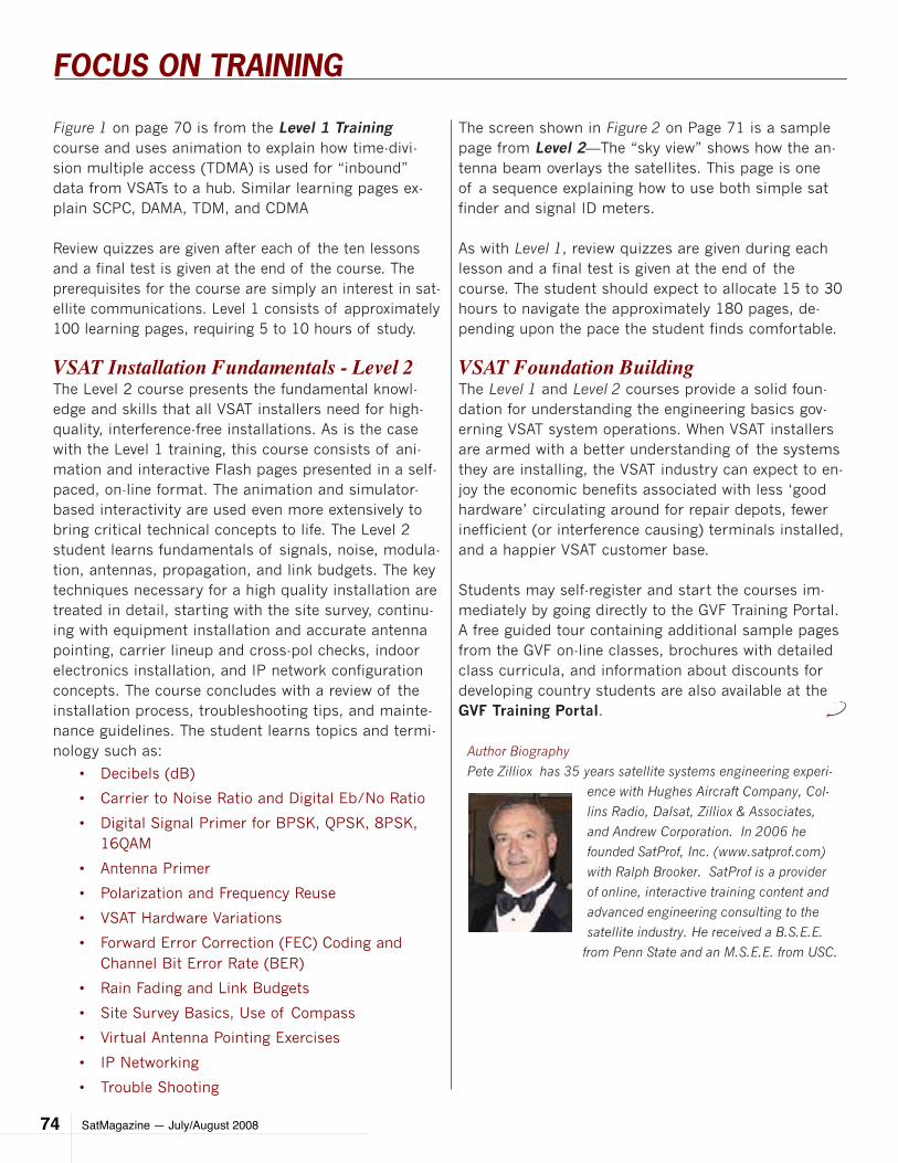
SatMagazine — July/August 200874
FOCUS ON TRAINING
Figure 1 on page 70 is from the Level 1 Training course and uses animation to explain how time-divi-sion multiple access (TDMA) is used for “inbound” data from VSATs to a hub. Similar learning pages ex-plain SCPC, DAMA, TDM, and CDMA
Review quizzes are given after each of the ten lessons and a final test is given at the end of the course. The prerequisites for the course are simply an interest in sat-ellite communications. Level 1 consists of approximately 100 learning pages, requiring 5 to 10 hours of study.
VSAT Installation Fundamentals - Level 2The Level 2 course presents the fundamental knowl-edge and skills that all VSAT installers need for high-quality, interference-free installations. As is the case with the Level 1 training, this course consists of ani-mation and interactive Flash pages presented in a self-paced, on-line format. The animation and simulator-based interactivity are used even more extensively to bring critical technical concepts to life. The Level 2 student learns fundamentals of signals, noise, modula-tion, antennas, propagation, and link budgets. The key techniques necessary for a high quality installation are treated in detail, starting with the site survey, continu-ing with equipment installation and accurate antenna pointing, carrier lineup and cross-pol checks, indoor electronics installation, and IP network configuration concepts. The course concludes with a review of the installation process, troubleshooting tips, and mainte-nance guidelines. The student learns topics and termi-nology such as:
Decibels (dB)•
Carrier to Noise Ratio and Digital Eb/No Ratio•
Digital Signal Primer for BPSK, QPSK, 8PSK, •16QAM
Antenna Primer•
Polarization and Frequency Reuse•
VSAT Hardware Variations•
Forward Error Correction (FEC) Coding and •Channel Bit Error Rate (BER)
Rain Fading and Link Budgets•
Site Survey Basics, Use of Compass•
Virtual Antenna Pointing Exercises•
IP Networking•
Trouble Shooting•
The screen shown in Figure 2 on Page 71 is a sample page from Level 2—The “sky view” shows how the an-tenna beam overlays the satellites. This page is one of a sequence explaining how to use both simple sat finder and signal ID meters.
As with Level 1, review quizzes are given during each lesson and a final test is given at the end of the course. The student should expect to allocate 15 to 30 hours to navigate the approximately 180 pages, de-pending upon the pace the student finds comfortable.
VSAT Foundation BuildingThe Level 1 and Level 2 courses provide a solid foun-dation for understanding the engineering basics gov-erning VSAT system operations. When VSAT installers are armed with a better understanding of the systems they are installing, the VSAT industry can expect to en-joy the economic benefits associated with less ‘good hardware’ circulating around for repair depots, fewer inefficient (or interference causing) terminals installed, and a happier VSAT customer base.
Students may self-register and start the courses im-mediately by going directly to the GVF Training Portal. A free guided tour containing additional sample pages from the GVF on-line classes, brochures with detailed class curricula, and information about discounts for developing country students are also available at the GVF Training Portal.
Author Biography
Pete Zilliox has 35 years satellite systems engineering experi-
ence with Hughes Aircraft Company, Col-
lins Radio, Dalsat, Zilliox & Associates,
and Andrew Corporation. In 2006 he
founded SatProf, Inc. (www.satprof.com)
with Ralph Brooker. SatProf is a provider
of online, interactive training content and
advanced engineering consulting to the
satellite industry. He received a B.S.E.E.
from Penn State and an M.S.E.E. from USC.
CASE STUDY
SatMagazine - July/August 2008 75
by Tom ProtzmanSystem Test EngineerIntegral Systems IncorporatedandDoug Mathias, M. Math Manager,Satellite Operations SystemsSpace Systems, Telesat
In December 2006, the purchase of Telesat Canada by Loral Space and Communications and
PSP Investments was an-nounced. At this time, Loral Skynet, the satel-lite services subsidiary of Loral Space and Commu-nications, was operating ten satellites. Four satel-lites were Loral-owned (Telstar), and six others were being maintained for two different customers. The ten satellites incor-porated three different bus types. All of these satellites were operated by Skynet with the Epoch command and control software provided by Inte-gral Systems, Inc (ISI).
The original business deal estimated a closing of early summer 2007. In the interim, only minimal high-level planning could be done concerning future spacecraft operations. Nine months were allocat-ed to transfer operations for all ten satellites from Loral’s Hawley, Pennsylva-nia, facility to the Telesat control center in Ottawa, Canada.
As the actual purchase did not occur until the fall of
2007, the project team only had six months to accom-plish this transfer.
Upon closing the deal, Telesat appointed Tony Grise as the project lead. Under his guidance, many people within the operations and network teams of both com-panies worked to get the entire task scoped, sched-uled, and completed.
TeleSaT InTegraTIon of TelSTar fleeT operaTIonS
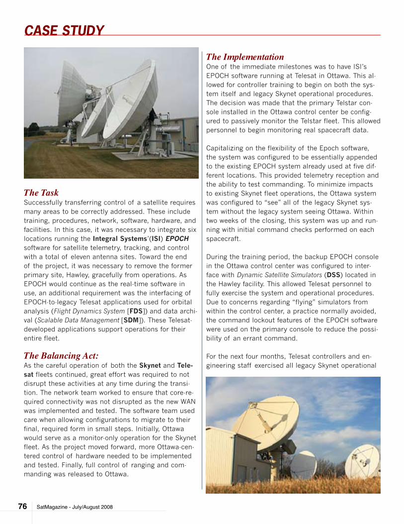
CASE STUDY
SatMagazine - July/August 200876
The TaskSuccessfully transferring control of a satellite requires many areas to be correctly addressed. These include training, procedures, network, software, hardware, and facilities. In this case, it was necessary to integrate six locations running the Integral Systems’(ISI) EPOCH software for satellite telemetry, tracking, and control with a total of eleven antenna sites. Toward the end of the project, it was necessary to remove the former primary site, Hawley, gracefully from operations. As EPOCH would continue as the real-time software in use, an additional requirement was the interfacing of EPOCH-to-legacy Telesat applications used for orbital analysis (Flight Dynamics System [FDS]) and data archi-val (Scalable Data Management [SDM]). These Telesat-developed applications support operations for their entire fleet.
The Balancing Act:As the careful operation of both the Skynet and Tele-sat fleets continued, great effort was required to not disrupt these activities at any time during the transi-tion. The network team worked to ensure that core-re-quired connectivity was not disrupted as the new WAN was implemented and tested. The software team used care when allowing configurations to migrate to their final, required form in small steps. Initially, Ottawa would serve as a monitor-only operation for the Skynet fleet. As the project moved forward, more Ottawa-cen-tered control of hardware needed to be implemented and tested. Finally, full control of ranging and com-manding was released to Ottawa.
The ImplementationOne of the immediate milestones was to have ISI’s EPOCH software running at Telesat in Ottawa. This al-lowed for controller training to begin on both the sys-tem itself and legacy Skynet operational procedures. The decision was made that the primary Telstar con-sole installed in the Ottawa control center be config-ured to passively monitor the Telstar fleet. This allowed personnel to begin monitoring real spacecraft data.
Capitalizing on the flexibility of the Epoch software, the system was configured to be essentially appended to the existing EPOCH system already used at five dif-ferent locations. This provided telemetry reception and the ability to test commanding. To minimize impacts to existing Skynet fleet operations, the Ottawa system was configured to “see” all of the legacy Skynet sys-tem without the legacy system seeing Ottawa. Within two weeks of the closing, this system was up and run-ning with initial command checks performed on each spacecraft.
During the training period, the backup EPOCH console in the Ottawa control center was configured to inter-face with Dynamic Satellite Simulators (DSS) located in the Hawley facility. This allowed Telesat personnel to fully exercise the system and operational procedures. Due to concerns regarding “flying” simulators from within the control center, a practice normally avoided, the command lockout features of the EPOCH software were used on the primary console to reduce the possi-bility of an errant command.
For the next four months, Telesat controllers and en-gineering staff exercised all legacy Skynet operational
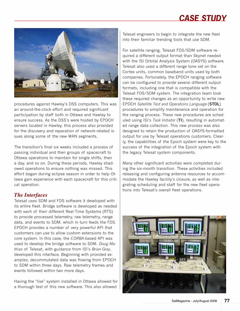
CASE STUDY
SatMagazine - July/August 2008 77
procedures against Hawley’s DSS computers. This was an around-the-clock effort and required significant participation by staff both in Ottawa and Hawley to ensure success. As the DSS’s were hosted by EPOCH servers located in Hawley, this process also provided for the discovery and reparation of network-related is-sues along some of the new WAN segments.
The transition’s final six weeks included a process of passing individual and then groups of spacecraft to Ottawa operations to maintain for single shifts, then a day, and so on. During these periods, Hawley shad-owed operations to ensure nothing was missed. This effort began during eclipse season in order to help Ot-tawa gain experience with each spacecraft for this criti-cal operation.
The InterfacesTelesat uses SDM and FDS software it developed with its entire fleet. Bridge software is developed as needed with each of their different Real-Time Systems (RTS) to provide processed telemetry, raw telemetry, range data, and events to SDM, which in turn feeds the FDS. EPOCH provides a number of very powerful API that customers can use to allow custom extensions to the core system. In this case, the CORBA-based API was used to develop the bridge software to SDM. Doug Ma-thias of Telesat, with guidance from ISI’s Brian Gray, developed this interface. Beginning with provided ex-amples, decommutated data was flowing from EPOCH to SDM within three days. Raw telemetry frames and events followed within two more days.
Having the “live” system installed in Ottawa allowed for a thorough test of this new software. This also allowed
Telesat engineers to begin to integrate the new fleet into their familiar trending tools that use SDM.
For satellite ranging, Telesat FDS/SDM software re-quired a different output format than Skynet needed with the ISI Orbital Analysis System (OASYS) software. Telesat also used a different range tone set on the Cortex units, common baseband units used by both companies. Fortunately, the EPOCH ranging software can be configured to provide several different output formats, including one that is compatible with the Telesat FDS/SDM system. The integration team took these required changes as an opportunity to write new EPOCH Satellite Test and Operations Language (STOL) procedures to simplify maintenance and operation for the ranging process. These new procedures are sched-uled using ISI’s Task Initiator (TI), resulting in automat-ed range data collection. This new process was also designed to retain the production of OASYS-formatted output for use by Telesat operations customers. Clear-ly, the capabilities of the Epoch system were key to the success of the integration of the Epoch system with the legacy Telesat system components.
Many other significant activities were completed dur-ing the six-month transition. These activities included releasing and configuring antenna resources to accom-modate the Hawley facility’s closure, as well as inte-grating scheduling and staff for the new fleet opera-tions into Telesat’s overall fleet operations.
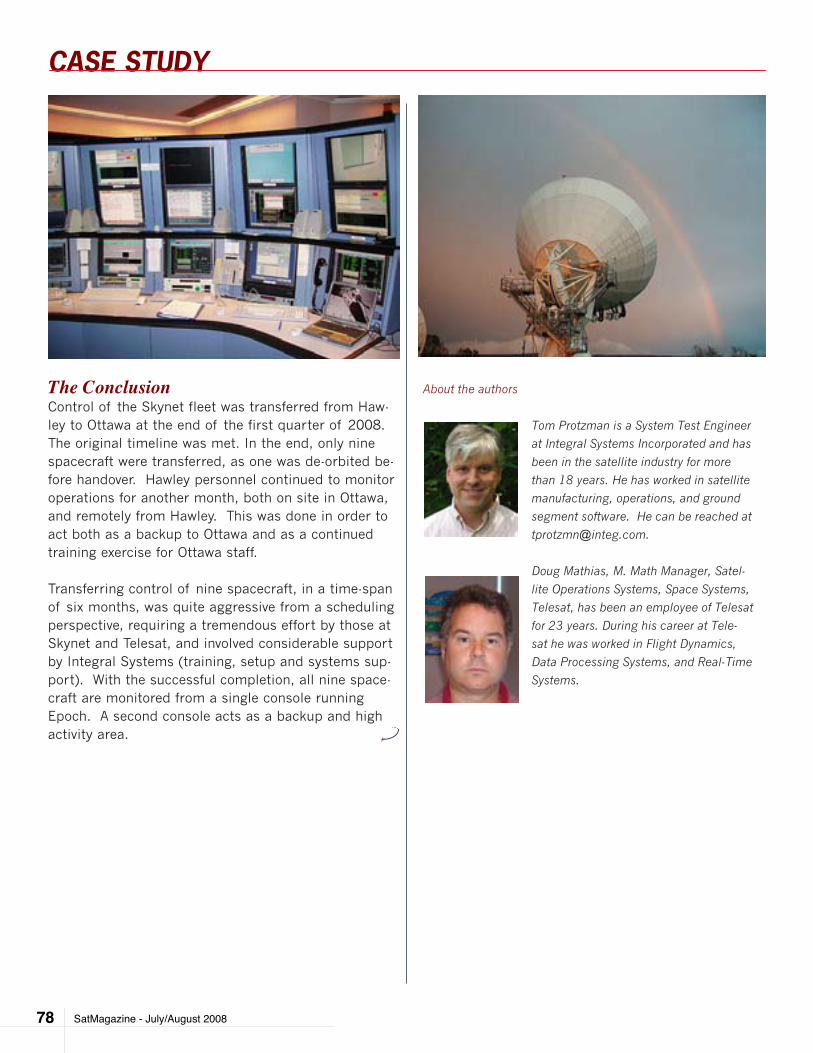
CASE STUDY
SatMagazine - July/August 200878
The ConclusionControl of the Skynet fleet was transferred from Haw-ley to Ottawa at the end of the first quarter of 2008. The original timeline was met. In the end, only nine spacecraft were transferred, as one was de-orbited be-fore handover. Hawley personnel continued to monitor operations for another month, both on site in Ottawa, and remotely from Hawley. This was done in order to act both as a backup to Ottawa and as a continued training exercise for Ottawa staff. Transferring control of nine spacecraft, in a time-span of six months, was quite aggressive from a scheduling perspective, requiring a tremendous effort by those at Skynet and Telesat, and involved considerable support by Integral Systems (training, setup and systems sup-port). With the successful completion, all nine space-craft are monitored from a single console running Epoch. A second console acts as a backup and high activity area.
About the authors
Tom Protzman is a System Test Engineer
at Integral Systems Incorporated and has
been in the satellite industry for more
than 18 years. He has worked in satellite
manufacturing, operations, and ground
segment software. He can be reached at
Doug Mathias, M. Math Manager, Satel-
lite Operations Systems, Space Systems,
Telesat, has been an employee of Telesat
for 23 years. During his career at Tele-
sat he was worked in Flight Dynamics,
Data Processing Systems, and Real-Time
Systems.
SatMagazine — July/August 2008 79
INSIGHT
by Andrea Maléter
First responders around the United States are al-ready dealing with the beginnings of a busy and difficult season of managing natural disasters.
From wildfires in the west to floods in the mid-west, the season has already started, and the National Hur-ricane Center has just forecast a bad season ahead with 9 major hurricanes predicted.
With this in mind, we have reviewed the current status of these systems to provide some insight into what users can expect, and what preparations they need to make to ensure they are able to get the communica-tions capabilities they need to meet these challenges. For emergency services users there is a need to take steps now to best ensure that they can rely on the sys-tems they currently use, including the systems capable of providing handheld satellite communications ser-
mSS: STaTUS cHecK for fIrST reSponDerS
vice. The chart, at the top of the next page, provides an overview of these alternatives, and the rest of this article discusses each system in more detail.
What Are the Promises?It has been ten years since the mobile satellite indus-try expanded dramatically beyond its traditional core with the launch of service on a series of low-earth-orbit (LEO) satellites. LEO satellites for the first time in his-tory made handheld satellite communications services available commercially. While the range of services re-quired to support recovery and reconstruction activities following natural disasters are supported by multiple satellite communications systems, handheld satellite services, which today are available in North America only from two LEO satellite systems, have proven them-selves to be indispensable during the search and res-cue phase of activities which occurs immediately fol-lowing each disaster. To provide more details of current
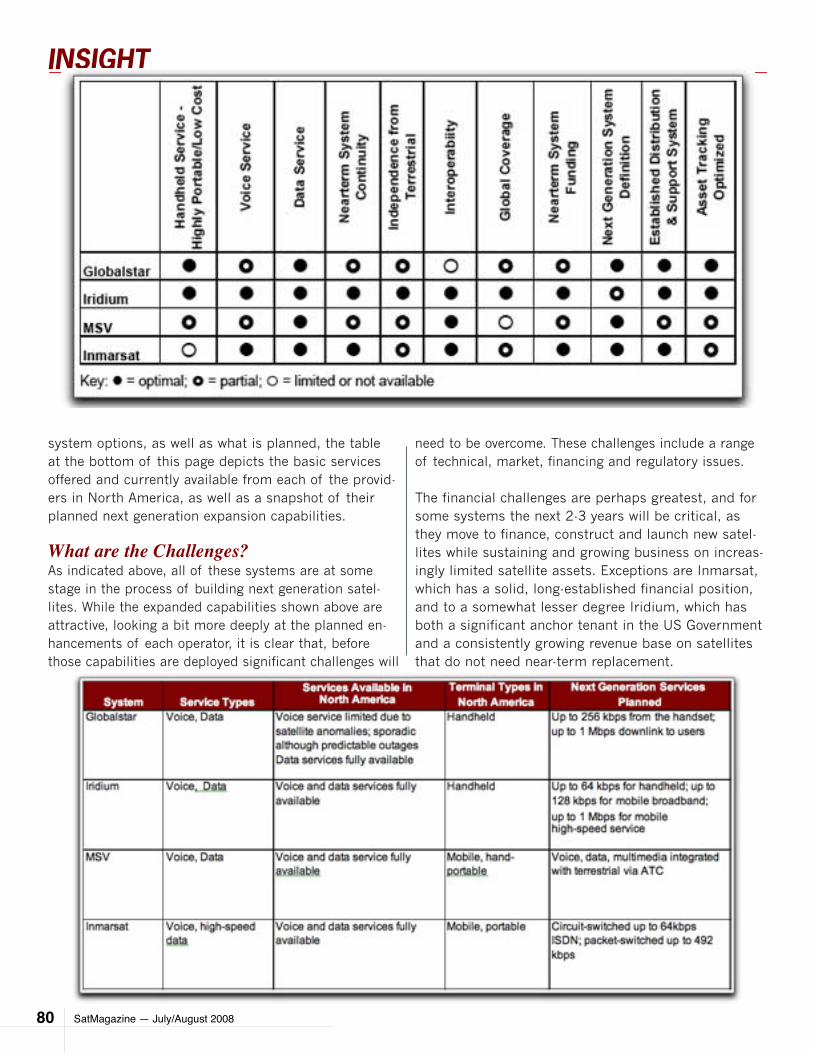
SatMagazine — July/August 200880
INSIGHT
system options, as well as what is planned, the table at the bottom of this page depicts the basic services offered and currently available from each of the provid-ers in North America, as well as a snapshot of their planned next generation expansion capabilities.
What are the Challenges?As indicated above, all of these systems are at some stage in the process of building next generation satel-lites. While the expanded capabilities shown above are attractive, looking a bit more deeply at the planned en-hancements of each operator, it is clear that, before those capabilities are deployed significant challenges will
need to be overcome. These challenges include a range of technical, market, financing and regulatory issues.
The financial challenges are perhaps greatest, and for some systems the next 2-3 years will be critical, as they move to finance, construct and launch new satel-lites while sustaining and growing business on increas-ingly limited satellite assets. Exceptions are Inmarsat, which has a solid, long-established financial position, and to a somewhat lesser degree Iridium, which has both a significant anchor tenant in the US Government and a consistently growing revenue base on satellites that do not need near-term replacement.
SatMagazine — July/August 2008 81
INSIGHT
On the distribution side partnerships are evolving to bet-ter serve customers and ensure access to equipment as well as services as and when needed. Finally, on the regulatory front, all companies are working continuously with the FCC to have a regulatory landscape which pro-vides a positive future environment for the user. Within this general framework, however, each system has its own challenges, some more immediate than others, as summarized in the table at the top of the next page, and discussed in further detail.
Globalstar one of only two companies providing handheld service in North America, is experiencing satellite anomalies which present perhaps the most visible and immediate risks, and the company has confirmed in filings with the FCC that there are times of the day when its coverage for voice ser-vices falls short of the level expected under the Commission’s rules.
What this means is that phone service on the Globalstar system is not always available. In re-porting on this situation in November 2007, in-dustry publication Satel-lite Finance stated that: “While its low cost simplex products for asset track-ing has continued to at-tract demand, subscriber numbers for its two-way voice and data services have flattened since the degradation of services began and much of the company’s plans are reli-ant on its next generation system, the first satellites of which are due to go up in mid-2009. The practical
deployment of a potential ATC network would also ob-viously rely on the second generation system being in place, which is not likely until late 2010.” Potentially as problematic as the immediate technical concerns presented by this situation are the longer-term implica-tions for the financial health of the business.Iridium, the only company other than Globalstar providing por-table handheld satellite services, operates its first gen-eration constellation which has outlasted initial design
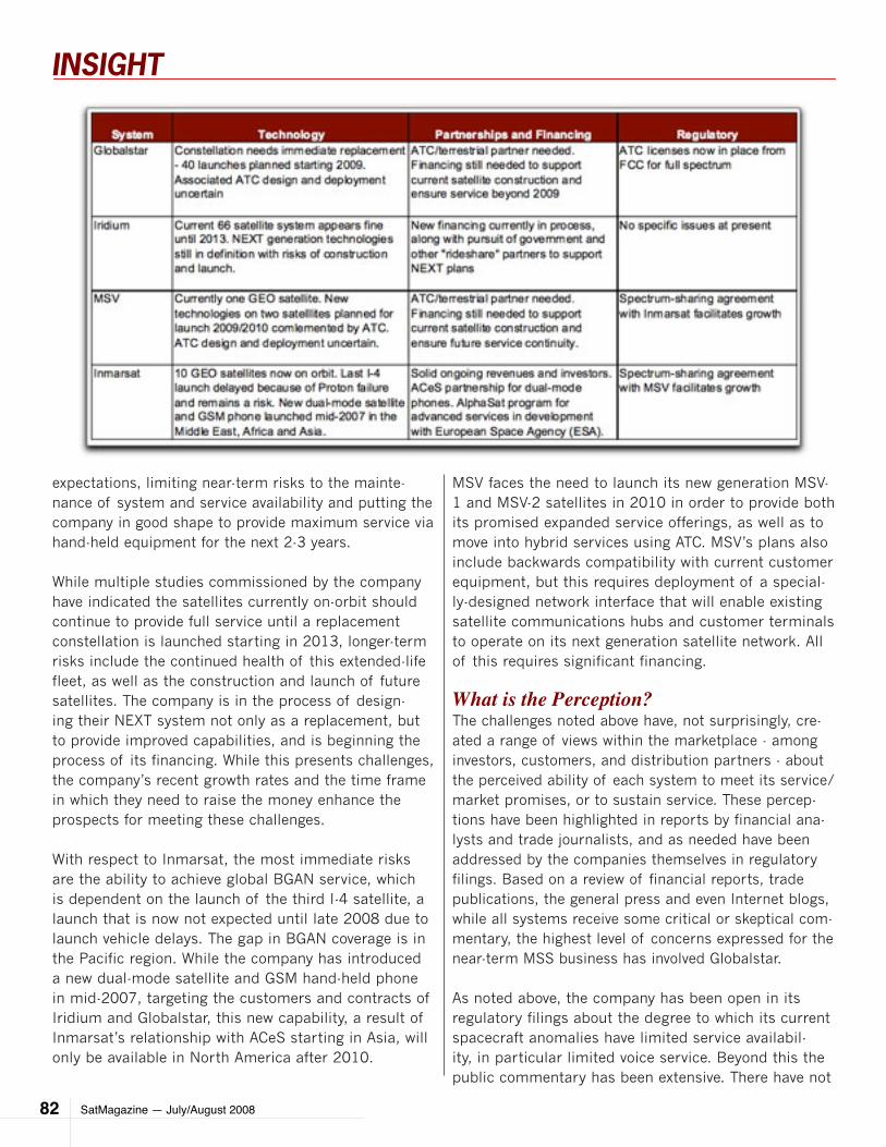
SatMagazine — July/August 200882
INSIGHT
expectations, limiting near-term risks to the mainte-nance of system and service availability and putting the company in good shape to provide maximum service via hand-held equipment for the next 2-3 years.
While multiple studies commissioned by the company have indicated the satellites currently on-orbit should continue to provide full service until a replacement constellation is launched starting in 2013, longer-term risks include the continued health of this extended-life fleet, as well as the construction and launch of future satellites. The company is in the process of design-ing their NEXT system not only as a replacement, but to provide improved capabilities, and is beginning the process of its financing. While this presents challenges, the company’s recent growth rates and the time frame in which they need to raise the money enhance the prospects for meeting these challenges.
With respect to Inmarsat, the most immediate risks are the ability to achieve global BGAN service, which is dependent on the launch of the third I-4 satellite, a launch that is now not expected until late 2008 due to launch vehicle delays. The gap in BGAN coverage is in the Pacific region. While the company has introduced a new dual-mode satellite and GSM hand-held phone in mid-2007, targeting the customers and contracts of Iridium and Globalstar, this new capability, a result of Inmarsat’s relationship with ACeS starting in Asia, will only be available in North America after 2010.
MSV faces the need to launch its new generation MSV-1 and MSV-2 satellites in 2010 in order to provide both its promised expanded service offerings, as well as to move into hybrid services using ATC. MSV’s plans also include backwards compatibility with current customer equipment, but this requires deployment of a special-ly-designed network interface that will enable existing satellite communications hubs and customer terminals to operate on its next generation satellite network. All of this requires significant financing.
What is the Perception?The challenges noted above have, not surprisingly, cre-ated a range of views within the marketplace - among investors, customers, and distribution partners - about the perceived ability of each system to meet its service/market promises, or to sustain service. These percep-tions have been highlighted in reports by financial ana-lysts and trade journalists, and as needed have been addressed by the companies themselves in regulatory filings. Based on a review of financial reports, trade publications, the general press and even Internet blogs, while all systems receive some critical or skeptical com-mentary, the highest level of concerns expressed for the near-term MSS business has involved Globalstar.
As noted above, the company has been open in its regulatory filings about the degree to which its current spacecraft anomalies have limited service availabil-ity, in particular limited voice service. Beyond this the public commentary has been extensive. There have not
SatMagazine — July/August 2008 83
INSIGHT
been any similar concerns expressed with the ability of the other operational systems - Inmarsat, Iridium, and MSV - to provide service this hurricane/wildfire season or next. Questions do continue to be raised for the lon-ger term about the ability of the latter two to finance and launch capacity needed by 2012-2014.
Next Steps?For organizations gearing up to face the challenges of disaster response and emergency communica-tions, the good news is that MSS systems of-fer a wide range of solid choices for both voice and data services this year. That being said, the op-tions are reduced from last year, and many of the promised new capabili-ties are on hold, awaiting satellites, partners and money. First responders and others with a genuine potential need for such services thus need to carefully assess whether the specific equipment they own and the associ-ated services will be avail-able when needed.
Candid, early discussions with service providers are the best way to determine whether the solutions procured over the past 2-3 years will be the best options for the next 2-3 years. Emergency man-agers need to review the equipment they have on hand, as well as the ser-vice agreements associ-ated with that equipment, and contact their service providers to verify the cur-rent system status. All of the MSS system operators
reviewed in this paper are ready and willing to have those discussions.
About the authorAndrea Maléter, the Technical Director,
Space and Communications Division, at
Futron Corporation, a leading consultant
firm to the aerospace and telecommunica-
tions industries.
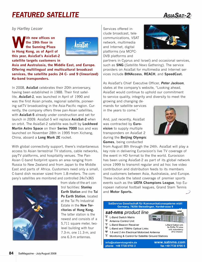
SatMagazine - July/August 200884
FEATURED SATELLITE
by Hartley Lesser
With new offices on the 19th floor in the Sunning Plaza
in Hong Kong, as of April of this year, AsiaSat’s AsiaSat-2 satellite targets customers in Asia and Australasia, the Middle East, and Europe. Offering multilingual and multicultural broadcast services, the satellite packs 24 C- and 9 (linearized) Ku-band transponders.
In 2008, AsiaSat celebrates their 20th anniversary, having been established in 1988. Their first satel-lite, AsiaSat-1, was launched in April of 1990 and was the first Asian private, regional satellite, pioneer-ing satTV broadcasting in the Asia-Pacific region. Cur-rently, the company offers three pan-Asian satellites, with AsiaSat-5 already under construction and set for launch in 2009. AsiaSat-5 will replace AsiaSat-2 when on orbit. The AsiaSat-2 satellite was built by Lockheed Martin Astro Space on their Series 7000 bus and was launched on November 28th in 1995 from Xichang, China, aboard a Long Mark 2E rocket.
With global connectivity support, there’s instantaneous access to Asian terrestrial TV stations, cable networks, payTV platforms, and hospitality venues. The Pan-Asian C-band footprint spans an area ranging from Russia to New Zealand and from Japan to the Middle East and parts of Africa. Customers need only a small, C-band dish receiver sized from 1.8-meters. The com-pany’s satellites are monitored and controlled 24x7x365
from state-of-the-art con-trol facilities: Stanley Earth Station and the Tai Po Earth Station, located at the Tai Po Industrial Estate in the New Ter-ritories of Hong Kong. The latter station is the newest and consists of a 5,711 square meter, two-level building with four 7.3-m, one 11.3-m, and one 6.3-m antennas.
aSIaSaT-2
Services offered in-clude broadcast, tele-communications, VSAT network, multimedia and Internet, digital platforms (via MCPC-DVB platforms and partners in Cyprus and Israel) and occasional services, such as SNG (Satellite News Gathering). The service providers on AsiaSat for multimedia and Internet ser-vices include BtNAccess, REACH, and SpeedCast.
As AsiaSat’s Chief Executive Officer, Peter Jackson, states at the company’s website, “Looking ahead, AsiaSat would continue to uphold our commitment to service quality, integrity and diversity to meet the growing and changing de-mands for satellite services in the years to come.”
And, just recently, AsiaSat was contracted by Euro-vision to supply multiple transponders on AsiaSat 2 during the Beijing Olympic Games, being conducted from August 8th through the 24th. AsiaSat will play a key role in delivering Eurovision’s live TV coverage of the event in HD format to the the world. Eurovision has been using AsiaSat-2 as part of its global network since 1999 to transmit regular and ad hoc live video contribution and distribution feeds to its members and customers between Asia, Australasia, and Europe. These include the latest coverage of premier sports events such as the UEFA Champions League, top Eu-ropean national football leagues, Grand Slam Tennis and Motor Sports.

SatMagazine - July/August 2008 85
FEATURED SATELLITE
C-band footprint Ku-band footprint
C-band Number of Transponders 24 (linearised) Frequency Band 6/4 GHz Transponder Bandwidth 20 at 36 MHz and 4 at 72 MHz Uplink/Downlink polarisation Horizontal and Vertical TWTA Size 55 watts TWTA Redundancy 2 Groups 16 for 12 Satellite Receiving G/T 0 dB/k max Saturated Flux Density (SFD) -97±1dBW/m2 max. Receiver Redundancy 4 for 2Ku-band Number of Transponders 9 (linearised) Frequency Band 14/12 GHz Transponder Bandwidth 65 MHz Uplink/Downlink Polarisation Horizontal and Vertical TWTA Size 115 watts TWTA Redundancy 12 for 9 Satellite Receiving G/T 6 dB/K max. Saturated Flux Density (SFD) -97±1dBW/m2 max. Receiver Redundancy 4 for 2 ULPC/Tracking Beacons Horizontal and vertical polarisationsThe Spacecraft Designed/Built by Lockheed Martin Astro Space Model Series 7000 Expected End of Life 2010 Geostationary Orbital Position 100.5° E Stationkeeping ±0.05°
commUnIcaTIonS payloaD
SatMagazine - July/August 200886
Index of Advertisers
Company Page Number
AAE Systems 67
ADVANTECH AMT 83
AEROSPACE CORPORATION, The 69
AVL 43
COMTECH EF DATA 21
E2V TECHNOLOGIES 13
EUROCONSULT 45
FOXCOM INC., A DIVISION OF ONEPATH 39
FUTRON 79
IDIRECT 31
INTEGRAL SYSTEMS (NEWPOINT) 75
MANSAT LLC 7
MICROSPACE COMMUNICATIONS 59
MITEQ INC. / MCL 49
NEWSAT LIMITED 11
NEWTEC PRODUCTIONS N.V. 25
NSR (NORTHERN SKY RESEARCH) 20
RADYNE—TIERNAN—XICOM 27
SATSERVICE GMBH 84
TSC PUBLISHING / OFFSHORE 81
W.B. WALTON ENTERPRISES 47
WAVESTREAM CORPORATION 19