Mobile Robotics Experiments with DaNI - National Instruments
Upload
independentCategory
view
0download
0
Mobile Robotics
By
ITHINYAI MOSES MUTWIRI
Department of computer science
South Eastern Kenya University
Kitui, Kenya
P15/1/1548/2011
Email: [email protected]
Abstract
As research is taking root in various branches and
interdisciplinaries of computer science robotics is one of the
field growing day by day, robotics is discipline that deals with
the design, construction, operation, and application of robots.
Many people have been thinking that robots look
like human beings, which is not true, there are various
classifications of robots, and these mainly include: Mobile
robotics, Stationary robotics, which are not only used to
explore areas or imitate human being. Most robots perform
repeating tasks without ever moving an inch. Most robots are
‘working’ in industry settings. Especially dull and repeating
tasks are suitable for robots. A robot never grows tired, it will
perform its duty day and night without ever complaining. In
case the tasks at hand are done, the robots will be reprogrammed
to perform other tasks..
Robotics also includes, Autonomous robots, which are self-
supporting or in other words self-contained. In a way they rely
on their own ‘brains’. Autonomous robots run a program that
give them the opportunity to decide on the action to perform
depending on their surroundings. At times these robots even
learn new behavior. They start out with a short routine and
adapt this routine to be more successful at the task they
perform. The most successful routine will be repeated as such
their behavior is shaped. Autonomous robots can learn to walk
or avoid obstacles they find in their way. Think about a six
legged robot, at first the legs move and random, after a little
while the robot adjust its program and performs a pattern which
enables it to move in a direction.

Remote-control Robot is An autonomous robot,
despite its autonomous not a very clever or intelligent
unit. The memory and brain capacity is usually
limited, an autonomous robot can be compared to an
insect in that respect. In case a robot needs to perform
more complicated yet undetermined tasks an
autonomous robot is not the right choice. Complicated
tasks are still best performed by human beings with
real brainpower. A person can guide a robot by
remote control. A person can perform difficult and
usually dangerous tasks without being at the spot
where the tasks are performed. To detonate a bomb it
is safer to send the robot to the danger area.
In computing there may also be virtual robots, which are
termed as they don’t exist in real life. Virtual robots are just
programs, building blocks of software inside a computer. A
virtual robot can simulate a real robot or just perform a repeating
task. A special kind of robot is a robot that searches the World
Wide Web. The internet has countless robots crawling from site
to site. These WebCrawler’s collect information on websites and
send this information to the search engines. Other popular virtual
robots are chatterbox, BEAM robots
In this research paper mobile robotics is featuring
1.0 Introduction
Working
Majority of mobile robots are required to work in un-engineered
environments. Compare the work-spaces of a welding robot in
automotive plant to one that delivers blood samples between labs
in a hospital. The former operates in a highly controlled, known,
time invariant (apart from the thing being built) scene. If
computer vision is used as a sensor then the workspace can be
lit arbitrarily well to mitigate against shadows and color
ambiguity. Many industrial robots work in such well known
engineered environments that very little external sensing is
needed they can do their job simply by controlling their own
internal joint angles. Hospitals are a different ball-park
altogether. The corridors are dynamic filling and emptying
(eventually) with people on stretchers. Even if the robot is
endowed with a map of the hospital and fitted with an upward
looking camera to navigate or markers on the ceiling it still has
to avoid fast moving obstacles (humans) while moving

purposely towards its goal destination. The more generic case
involves coping with substantial scene changes (accidental or
malicious) for example doors closing in corridors or furniture
being moved. The thing then, which makes mobile robotics so
challenging is uncertainty.
Robot should perceive its environment through sensors
and act upon it through actuators. A mobile robot might have A
robotic agent might have:
cameras and
infrared range finders for sensors and
Various motors for actuators.
Suppose an a mobile robot of taxi driver has to
be made ,its performance can be measured in terms
of safe, fast, legal, comfortable trip, maximize
profits.to make clear observation it may operate in an
environment such as: roads, other traffic, pedestrians
and customers. Actuators like steering, accelerator,
brake, signal, horn, display need to be included.
Cameras, sonar, speedometer, GPS, odometer,
accelerometer, engine sensors, and keyboard are the
sensors that might be used.
1.1. AREAS COVERED IN MOBILE ROBOTICS
Components of a Mobile Robot
A mobile robot is a combination of various physical
(hardware) and Computational (software) components.
Locomotion how the robot moves through its environment.
Sensing how the robot measures properties of itself and its
environment. Reasoning how the robot maps the
measurements into actions. Communication how the robot
communicates with an outside operator. In terms of
software components, a set of subsystems are responsible
for: Planning in its various aspects.
1.1.0. Robot locomotion, navigation and mapping
Mobile robots have the capability to move around in their
environment and are not fixed to one physical location (cited
from Wikipedia).They have the advantage of consuming less
energy and move faster than other type of locomotion
mechanisms. The application of mobile robots have been
successfully designed for both indoor and outdoor
environments. Mobile robots incorporating vision systems are
the most desirable type of mobile robots navigation which can

provide a lot of information of the real world enough for better
navigation. Furthermore, object tracking technique is utilized in
various robot vision applications such as autonomous vehicle
navigation, surveillance and many more applications. Although
a lot of research and experiments have been done in the past
few decades had been concerned and dedicated to solve the
problematic issue of tracking the desired target in a chaotic and
noisy environment.
There are several mechanisms to accomplish locomotion
mechanisms to make robot enable to move through its
environment; for example one, four, and six legged locomotion
and many configurations of wheeled locomotion. Legged robot
locomotion mechanisms are often inspired by biological
systems, which are very successful in moving through a wide
area of harsh environments. To implement locomotion
mechanisms in robotics the main problems are the mechanical
complexity of legs, stability and power consumption. The main
attributes of stability are the number and geometry of contact
points, the robots Centre of gravity, if the robot is static or
dynamic stable and the inclination of terrain. The
characteristics of ground contact depend on the type of the
contact point (in case of legged locomotion this is the
footprint), the angle of contact to the ground and the friction
between the robot and the surface. The attributes of the type of
the environment are the structure of the medium (for example
in case of hard ground, if the ground is either flat or rough) and
the medium itself (e.g. water, air, hard or soft ground).
Legged Locomotion
A legged robot is well suited for rough terrain; it is able to
climb steps, to cross gaps which are as large as its stride and to
walk on extremely rough terrain where, due to ground
irregularities, the use of wheels would not be feasible. To make
a legged robot mobile each leg must have at least two degrees
of freedom (DOF). For each DOF one joint is needed, which is
usually powered by one servo. Because of this a four legged
robot needs at least eight servos to travel around. Figure 3
shows the energy consumption of different locomotion
concepts. It strikes that the power consumption of legged
locomotion is nearly two orders of magnitude more inefficient
than of wheeled locomotion on hard, flat surface (e.g. railway
wheel on steel). One reason for this is that wheeled locomotion
requires in general fewer motors than legged locomotion.

Figure 3: Power consumption of several locomotion [1]
Mechanisms
When the surface becomes soft wheeled locomotion offers
some inefficiency, due to increasing rolling friction more motor
power is required to move. As figure 3 shows legged
locomotion is more power efficient on soft ground than
wheeled locomotion, because legged locomotion consists only
of point contacts with the ground and the leg is moved through
the air. This means that only a single set of point contacts is
required, so the quality of the ground does not matter, as long
as the robot is able to handle the ground. But exactly the single
set of point contacts offers one of the most complex problem in
legged locomotion, the stability problem.
Stability
Stability is of course a very important issue of a robot, because
it should not overturn. Stability can be divided into the static
and dynamic stability criterion.
Static stability means that the robot is stable, with no need of
motion at every moment of time. In Static stability, balance is
maintained as long as the Centre of mass is completely within
the legs. This results to a triangle called support polygon. The
support polygon is the convex hull which is set by the ground
contact points. Of course, in case of more ground contact
points, the polygon can be a quadrangle or a pentagon or a
different geometrical figure. More in general the following
must hold to support static stability: Static stability is given,
when the Centre of mass is completely within the support
polygon and the polygon’s area is greater than zero, therefore
static stability requires at least three points of ground contact.

To achieve statically stable walking a robot must have a
minimum number of four legs, because during walking at least
one leg is in the air. Statically stable walking means that all
robots’ motion can be stopped at every moment in the gait
cycle without overturning. Most robots which are able to walk
static stable have six legs, because walking static stable with
four legs means that just one leg can be lifted at the same time
(lifting more legs will reduce the support polygon to a line), so
walking becomes slowly. Most two legged walking machines
are dynamically stable for several reasons. Human like robots
have relatively small footprints, because of this the support
polygon is almost a line (in the double support phase, when
both foots are connected with the ground) which is even
reduced to a single point (in the single support phase, when just
one foot has ground contact) during walking. Therefore the
robot must actively balance itself to prevent overturning. In
face of that the robots’ Centre of mass has to be shifted actively
between the footprints. But the robots exact Centre of mass is
hard to predict due to the high dynamic of walking (for
example because of the force which is imparted to whole robot
when one leg swings forward). The realization of bipedal
dynamic stable walking machines is due to the continuous
danger of overbalance a high complex problem for engineers,
which is just solved for some special cases.
Leg configuration
To move a leg forward at least two degrees of freedom are
required, one for lifting and one for swinging. Most legs have
three degrees of freedom; this makes the robot able to travel in
rougher terrain and to do more complex manoeuvres. Figure 5
shows the leg of the Titan VIII robot from the Tokyo Institute
of Technology. This leg has three degrees of freedom. In
general, adding degrees of freedom to a robots leg means
increasing the manoeuvrability of the robot, the range of terrain
on which it can travel and the ability to travel in a variety of
gaits.
But adding degrees of freedom causes also some
disadvantages, because for moving additional joints and more
servos are required, this increases the power consumption and
the weight of the robot. Furthermore controlling the robot
becomes more complex, because more motors have to be
controlled and actuated at the same time.

If the robot has more than one leg there is the issue of leg
coordination for locomotion. The total number of possible gaits
in which a robot can travel depends on the number on legs it
has. The gait is a periodic sequence of lift and release events
for each leg. If a robot has k legs the number of possible events
N is, accordant to,
N=(2k-1)!
In case of a bipedal walking machine (k=2) the number of
possible events is
N=(2k-1)! = (2*2-1)! = 3! = 6
So there are six possible different events, these are
1. Lift left leg
2. Release left leg
3. Lift right leg
4. Release right leg
5. Lift both legs together
6. Release both legs together
In case of k=6 legs there are already 39916800 possible events,
in face of that, controlling a six legged robot is because of the
large number of possible events more complex than controlling
a two legged robot. But robots with fewer legs have some other
problems; one of the most complex problems is stability as
mentioned before. In the following different leg configurations,
advantages/disadvantages of these and examples of robots are
shown.
One leg
One leg is of course the minimum number of legs which a
legged robot can have. A smaller number of legs reduces body
mass of the robot and no leg coordination is needed. One-
legged locomotion requires just a single point of ground
contact; this makes the robot amenable to travel the roughest
terrain. As an example the robot is able to overcome an

obstacle like a gap that is larger than its stride by talking a
running start. A multi legged robot that cannot run is just able
to cross gaps that are as large as its reach. But the single point
of ground contact offers the main problem for single legged
robots – stability. Static stability is impossible even when the
robot is stationary, because the support polygon is reduced to a
single point. So singled legged robots must be dynamically
stable, that means that the robot has to actively balance itself
either by changing its Centre of gravity or by imparting
corrective forces. One of the first successful one-legged robots
was the one leg hopper form MIT, developed by Marc Raibert
in 1983.
Raibert’s hopper is not able to be stable when it is stationary,
so it has to hop all the time. To support locomotion and
stability there is of course the need of controlling the robot.
Raiberts’ hopper uses a simple controller, which divides the
control problem into three independent parts. These parts are
hopping height, velocity and attitude. [4]
• Hopping height: The control system controls hopping
height by manipulating hopping energy. The leg is
springy, so hopping is a bouncing motion that is
generated by an actuator (an external air-pressure
pump) that excites the leg. Hopping height is
determined by the energy recovered from the previous
hop, the losses in the hopping cycle and thrust
developed in the actuator. Height is regulated by
adjusting the amount of thrust on each cycle to just
make up for losses.
• Velocity: The control system manipulates forward
velocity by placing the foot with respect to the Centre
of the CG-print on each step. The CG-print is the locus
of points on the ground over which the Centre of
gravity of the system will pass during stance.
Displacing the foot from the Centre of the CG-print
causes the system to run either faster or slower. The
control system calculates the length of the CG-print
from the measured forward velocity and an estimate of
the duration of stance. The error in forward velocity
determines a foot position that will maintain the correct
speed of forward travel.
• Attitude: The control system maintains an erect body
posture during running, by generating hip torques
during stance that servo the body angle. During stance
friction between the foot and ground permits large

torques to be applied to the body without causing large
accelerations of the leg. These torques are used to
implement a simple proportional servo that moves the
body toward an erect posture once each step.
Two legs
Bipedal walking robots have become very popular in the last
ten years; two of the most well-known examples are QRIO
from Sony (Figure 7) [5] and Asimo from Honda (Figure 8)
[6]. Qrio has a weight of 7 kg and a height of 58 cm, each leg
has six degrees of freedom; Asimo has a weight of 210 kg, a
height of 1.82 cm and a maximum walking speed of 2 km/h,
each leg has six degrees of freedom.
Other robots are four legged and six legged.
Wheeled Locomotion
The most popular locomotion mechanism in man made
vehicles is wheeled locomotion; so it is not surprising that it is
often used in mobile robotics. Reasons for this are the easy
mechanical implementation of the wheel, there is no need of
balance control if the vehicle has at least three or in some case
two wheels and wheeled locomotion is relatively power
efficient, even at high speed. The problems of wheeled robots
are different from the problems of legged robots, as mentioned
before, stability is not such a profoundly problem like it is in
legged locomotion, but there are some others. The focus of
research in wheeled robotics is on traction and stability in
rough terrain, maneuverability and control.
Localization, Path Planning and Obstacle Avoidance
A key component of a mobile robot system is the ability to
localize itself accurately and, simultaneously, to build a map of
the environment. Localization, mapping, visual landmarks are
important aspects of mobile robotics. Mobile robot localization
and mapping, the process of simultaneously tracking the
position of a mobile robot relative to its environment and
building a map of the environment, has been a central topic
research in mobile robotics .Accurate localization is a
prerequisite for building good map, and having an accurate
map is essential for good localization. A basic requirement of a
mobile autonomous vehicle is path planning. The combination

of path-planning, obstacle avoidance, kinematic constraints and
uncertainty makes for a very hard problem indeed one which is
still an active area of research. However we can do some
interesting things if we decouple some of the issues and make
some simplifying assumptions. Mobile robotics may have
properties that be categorized into two classes holonomic and
non-holonomic. Holonomicity is the term used to describe the
locomotive properties of a mobile with respect to its
workspace. Mathematical definition of the term may be
described by use of mobile vehicle robotics .Vehicle is termed
as holonomic if the number of local degrees of freedom of
movement equals the number of global degrees of freedom
while a vehicle is non-holonomic if the global degrees of
freedom are motion in x, y and heading however locally, a car
can only move forward or turn. It cannot move slide sideways.
(Even the turning is coupled to motion). It should be obvious to
you that motion control for a holonomic vehicle is much easier
than for a non-holonomic vehicle. If this isn't obvious consider
the relative complexity of parking a car in a tight space
compared to driving a vehicle that can simply slide into the
space sideways (a hovercraft). Mobile robots have arbitrary
shapes and these shapes make for complicated interactions with
obstacles which we would like to simplify. One way to do this
is to transform the problem to one in which the robot can be
considered as a point-object and a technique called the
\Murkowski-Sum" does just this. The basic idea is to
artificially inflate the extent of obstacles to accommodate the
worst-case pose of the robot in close proximity. The idea is to
replace each object with a virtual object that is the union of all
poses of the vehicle that touch the obstacle has taken a
conservative approach and \replaced" a triangular vehicle with
a surrounding circle. The minimal Murkowski-Sum would be
the union of the obstacle and all vehicle poses with the vehicle
nose just touching it boundary. With the obstacles suitably
infrared the vehicle can be thought of a point-object and we
have a guarantee that as long as it keeps to the new, shrunken,
free space it cannot hit an object. Note it is usual to fit a
polygonal hull around the results of the Murkowski-Sum
calculation to make ensuing path planning
Calculations easier.
Feature Based Mapping and Localization
We apply the estimation techniques to two very important
mobile robotics tasks - Mapping and Localization. If for
example an autonomous vehicle is taken into consideration

these two tasks are important for its successful deployment. For
example
Mapping: Mapping managing autonomous open-cast
Mining, Battlefield Surveillance Cameras, Fracture detection x-
ray acoustic, Sub-sea Oil
AUV
Localization: GPS, Museum Guides, Hospital delivery system
A common way to approach these problems is to parameterize
both the robot pose and
Aspects of the environment's geometry into one or more state
vectors. Mainly 2D is discussed but the definitions that follow
are, of course, valid for the full 3D
Case.
Features and maps
We suppose that the world is populated by a set of discrete
landmarks or features whose location / orientation and
geometry (with respect to a defined coordinate frame) can be
described by a set of parameters which we lump into a feature
vector xf .We call a collection of n features a Map such that M
={ xf ,1; xf ,2; xf ,3…….. xf ,n}. To keep notation simple
sometimes we will use M to denote the map vector which is
simply the concatenation of all the features:
xf ,1
M xf ,2
= xf ,n
.
.
In this course we will constrain ourselves to using the simplest
feature possible - a point
feature such that for the ith feature:
xf ;i = xi
yi
1.1.1. Robot sensors

Robots with vision-based systems are quite complicated since
they must be equipped with the ability of detecting obstacle
and avoiding them while traversing in any environment. They
need to extract the desired information from the images taken
from a stream of the location or environment which for certain
consists of both stationary and moving obstacles by the robot
camera. The obstacle should be performed in real world
performance which makes it much more complex. Another
issue of obstacle avoidance is the fact that moving a mobile
robot to maneuver in an unknown environment is problematic
since there exist obstacles of all form and conditions.
Any information a robot collects about itself or its environment
requires sensing.
Robots that want to learn, map and/or navigate need to collect
information about their surroundings. All sensors have some
degree of uncertainty. Uncertainty can be reduced by multiple
measurements.
Two things to sense, Its own state (Proprioceptive)Motor
speed, battery voltage, joint angles and The world
(Exteroceptive); Everything and anything about the world
around itself. Two types of sensors Active (Project energy out
to measure its return) Passive (Sense the natural energy around
itself).
Improving Measurements: Improve calibration, Reduces
systematic errors, combining multiple measurements Reduces
effect of random errors, multiple measurements from single
sensor, and multiple measurements from different sensors. Not
all sensors just sense one thing.
Multiple measurements from the same sensor: Requires time,
latency; Introduces smoothing; has little effect on systematic
errors; Multiple measurements from different sensors; Can be
done simultaneously; Can reduce the effect of systematic
errors; requires more sensors
1.1.2. Robot vision
Vision in robots can be used to do: Facial recognition, object
classification, action recognition, Object tracking, image
labeling, scene reconstruction, Scene understanding, and image
alteration. The main goal is to do crowd tracking, image
dehazing, scene reconstruction, scene understanding, dealing
with the massive data, scene alteration, and recover projection.

Connectivity
Two conventions on considering two pixels next to each other.
8 point connectivity all pixels sharing a side or corner are
considered adjacent.
4 point connectivity only pixels sharing a side are considered
adjacent
To eliminate the ambiguity, we could define the shape of a
pixel to be a hexagon
Segmentation: Double Raster
Assume a binary image with values of 0 or 1
Initialize cntr to 0
Perform a raster scan – across and down
Encounter a pixel with a 1
Look up, look left
•If both 0
–Increment cntr by 1
–assign pixel P a value cnt
•If either is 1, assign P the label of the 1
•If both are 1
–Note equivalence
–Assign P’s label as minimum of 2
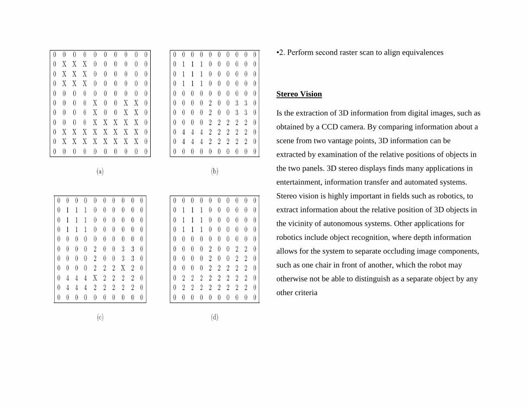
•2. Perform second raster scan to align equivalences
Stereo Vision
Is the extraction of 3D information from digital images, such as
obtained by a CCD camera. By comparing information about a
scene from two vantage points, 3D information can be
extracted by examination of the relative positions of objects in
the two panels. 3D stereo displays finds many applications in
entertainment, information transfer and automated systems.
Stereo vision is highly important in fields such as robotics, to
extract information about the relative position of 3D objects in
the vicinity of autonomous systems. Other applications for
robotics include object recognition, where depth information
allows for the system to separate occluding image components,
such as one chair in front of another, which the robot may
otherwise not be able to distinguish as a separate object by any
other criteria

Gaussian Masks
Are used to smooth images and for noise reduction .Used
before edge detection to avoid spurious edges.
1.1.3. KINEMATICS AND DYNAMICS
Kinematics is the process of determining the range of possible
movements for a robot, without consideration of the forces
acting on the robot, but taking into account the various
constraints on the motion. The kinematic equations for a robot
depend on the robot’s structure, i.e. the number of wheels, the
type of wheels used etc. Here, only the case of differentially
steered two wheeled robots will be considered. For balance, a

two-wheeled robot must also have one or several supporting
wheels (or some other form of ground contact, such as a ball in
a material with low friction). The influence of the supporting
wheels on the kinematics and dynamics will not be considered.
Dynamics
The kinematics considered in the previous section determines
the range of possible motions for a robot, given the constraints
which, in the case of the two wheeled differential robot,
enforce motion in the direction perpendicular to the wheel
axes. However, kinematics says nothing about the way in
which a particular motion is achieved. Dynamics, by contrast,
considers the motion of the robot in response to the forces (and
torques) acting on it. In the case of the two-wheeled,
differentially steered robot, the two motors generate torques (as
described above) that propel the wheels forward. The frictional
force at the contact point with the ground will try to move the
ground backwards. By Newton’s third law, a reaction force of
the same magnitude will attempt to move the wheel forward. In
addition to the torque _ from the motor (assumed to be known)
and the reaction force F from the ground, a reaction force _
from the main body of the robot will act on the wheel,
mediated by the wheel axis (the length of which is neglected in
this derivation).
1.1.4. Perception
A perception sensor for a mobile robot based on a
reconfigurable and flexible parallel architecture is developed.
Low-level image processing is implemented by using
reprogrammable FPGA technology, and high-level image
processing is performed by a dedicated reconfigurable parallel
architecture based on digital signal processor for example
TMS320C40. Hierarchical LINDA permits user-friendly
parallel programming and real-time application. To show that
our perception system can adapt to any application, we
undertake the parallelization of a 3D scene-reconstruction
algorithm using a geometric method, to meet the application
response time (10 Hz).
The basic configuration of a perception sensor hardware has
four main elements:
Image acquisition board;
Low-level image-processing board;
Medium- and high-level image-processing board;
Interconnection network board.

1.1.5. APPLICATIONS OF MOBILE ROBOTICS
Mobile robotics have various applications in the modern world
as compared to the past. In industries robots are replacing man
in various activities.
Application Example: Automated Inspection Robots
There are many applications of mobile robots, and their
importance in industrial processes continues to grow. Mobile
robots can be used for transportation tasks, surveillance, or
cleaning. Increasingly, they play an economic role also in the
entertainment industry (artificial pets being the best known
example).
One application of mobile robots of considerable economic
importance is that of automated inspection. Manual inspection
is a very costly process that is tedious to a human operator,
thereby increasing the risk that faults etc. are overlooked. It is
obvious that inspection would benefit from automation. A
major aspect of automated inspection is to detect abnormalities
automatically. Such novelty detection is hard to achieve with
classical machine learning methods, because those methods
typically require a balanced number of data points in all signal
classes to be classified. Yet by definition abnormalities are
rare, so that a classical machine learning algorithm cannot be
applied. A new approach to detect abnormality is to define
normality by some method, and then to compare all data points
with that measure of normality. Large deviations from \normal"
signals can then be aged as \novel". Kohen’s novelty Fillter
[7, 8] is an auto encoder neural network trained using back-
propagation of error, so that the network extracts the principal
components of the input. After training, any input presented to
the network produces one of the learned outputs, and the
bitwise difference between input and output highlights novel
components of the input. Other approaches include the manual
a priori definition of features to be detected to separate novel
perceptions from common ones [18].
It is possible to automate the acquisition of a model of
normality. In [10, 11] we present the implementation of an
automatic system for novelty detection, implemented on a
mobile robot and evaluated in unmodified \real world"
environments. Using the self-organising novelty Filter
presented there, Forty Two is able to construct a representation
of \normal" perceptions in its environment, and to detect novel
perceptions without prior knowledge installation.
Other areas of application include: Hazard Environments like
Inspection of hazard environments (catastrophic areas,
volcanoes, nuclear power plants, oil tanks) Inspection of gas or
oil pipes, and power transmission lines, Oil tank cleaning,
Construction and demolishing, Space exploration, Remote
inspection of space stations, Military, Surveillance vehicles,
Monitoring vehicles, Forests: Cleaning, fire preventing, tree
cutting, Material Handling: AGVs, SGVs, LGVs, Safety:
Surveillance of large areas, buildings, airports, car parking lots,
Civil Transportation: Inspection of airplanes, trains,
Entertainment: Robot Dog, Aibo – Robot dog from Sony,
Telepresence
Support to medical services – SERVICE ROBOTS,
Transportation of food, medication, medical exams,
Automation of pharmacy service. Automatic cleaning of (large)
areas:
• Supermarkets, airports, industrial sites
• Glass cleaning
• Domestic vacuum-cleaner
Client support:
• Museum tours, exhibitions guides
Agricultural:
• Fruit and vegetable picking, fertilization, planting
1.1.6. Challenges in Scientific Mobile Robotics
In the established sciences such as physics or chemistry, to
name but two examples, it is accepted practice that
experimental results are independently verified. To facilitate
this, precise (i.e. quantitative) descriptions of results are used.
Because research on quantitative descriptions of mobile robot
behavior is still in its infancy, mobile robotics to date is still an
empirical discipline that uses existence proofs extensively.
Robot systems to perform certain tasks are implemented, but,
for want of precise performance measures and behavioural
descriptions, are not independently verified. The first step
towards a science of mobile robotics, therefore, would be the
development of quantitative, rather than qualitative
descriptions of mobile robot behaviour. Some attempts have
been made to introduce quantitative evaluations to robotics.
Schoner et al. [16] use dynamical systems theory to investigate
robot environment interaction, and Smithers [17] discusses the
use of quantitative performance measures as a tool of scientific

mobile robotics research. In [13, 9, and 2] we present
quantitative evaluations of robot localisation systems (based on
contingency table analysis). Current work at Manchester
concentrates on the general, quantitative analysis of robot-
environment interaction, irrespective of the specific task
carried out or the control strategy used. This is done using
measures from chaos theory, [15] presents the approach and
results. In short, besides the technological challenges of mobile
robotics | fundamental sensor-motor competences, robot
navigation and application-oriented capabilities such as novelty
detection | the scientific challenge is to move mobile robotics
from a discipline of empirical practice towards a precise
science
CONCLUSION
Search and pursuit-evasion problems have recently become
central to many application domains in robotics, naturally
arising from the increased capabilities of autonomous agents.
Practical impact areas include: surveillance, emergency
response, and wilderness/ocean rescue. In keeping with its
interdisciplinary nature, robotics brings an applied context for
revisiting existing theoretical results, as well as inspiring new
ones. This paper has highlighted fundamental work in mobile
robotics as found in computer science, computer engineering,
and electronics and electrical and it has provided a deep
discussion on what a mobile robot is. In this technical research
paper various topics have been covered. Components that are
universal for building any mobile robot have been discussed
which includes sensors, vision, motion and communication.
Main topics under the research paper includes: Robot vision,
Robot sensors, Robot locomotion, navigation, mapping and
perception. Applications and the advantages of the mobile
robotics have led to the research and development of the
robots. Think of cargos without robots, space without robotic
satellites, and planets exploration without robots. Recent
discovery of the life in planet mass is as a result of the
investments done on robots. A series of experimental robots
named the Bearcats, have been constructed at the University of
Cincinnati over the past several years. This experience has
evolved into current, creative control design. Fortunately, our
intelligent robots have been able to use our increasingly
capable
computer controls in which multi-threaded, distributed
computing is now easily available.

The research has led to design intelligent robots that are
capable of adapting, learning
and predicting. This is a step toward understanding the
semiotic closure exhibited by biological
creatures and a further step toward appreciating the wonderful
capabilities of human intelligence
. So it will surely be interesting to consider the developments in
mobile robotics which are made in the next years.
REFERENCES
1. D. Fox, W. Burgard, S. Thrun, Active Markov localisation
for mobile robots, Robotics and
Autonomous Systems 25 (1998) 195207.
2. Ulrich Nehmzow and Carl Owen, Robot Navigation in the
Real World: Experiments with
Manchester's FortyTwo in Unmodi_ed, Large Environments, J.
Robotics and Autonomous
Systems, Vol. 33, Issue 4, 2000.
3. http:www.howstuffworks.com/mobile robotics.
4. Barshan, B. and Durrant-Whyte, H.F., 1995, “Inertial
Navigation Systems Mobile Robots.”
IEEE Transactions on Robotics and Automation, Vol. 11, No.
3, June, pp. 328-342.
5. Chenavier, F. and Crowley, J., 1992, “Position Estimation
for a Mobile Robot Using Vision and Odometry.” Proceedings
of IEEE International Conference on Robotics and Automation,
Nice, France, May 12-14, pp. 2588-2593.
6. Goldstein, A. S. and Reingold, E. M. (1995). The complexity
of pursuit on a graph. Theoretical Computer
Science, 143(1):93–112.
7. Cohen, C. and Koss, F., 1992, “A Comprehensive Study of
Three Object Triangulation.”
Proceedings of the 1993 SPIE Conference on Mobile Robots,
Boston, MA, Nov. 18-20, pp.
95-106.
8. http://www.ai.mit.edu/projects/leglab/robots/robots.html

9. S.Roland, “Introduction to autonomous mobile robots”, pp.
12-45, 2004
10. [19]
http://asl.epfl.ch/index.html?content=research/systems/Shrimp/
shrimp.php
Copyright © 2022 FDOKUMEN