2021 Infrastructure Design Manual (IDM) - Houston Permitting ...
Upload
khangminh22Category
view
2download
0
Design Manual
CO2humidity leveltemperature flow position
www.sensit.cz - 1 -
Motto: Temperature is the fourth most frequently measured physical quantity after time, weight and dimension.
Dear users of this Design and User Manual, You have received a document that originated from the need to preserve in writing the experience with the application and operation of resistance temperature sensors made by SENSIT s.r.o. (hereinafter Sensit) and to provide users with guidance and direction for their applications. The first edition of this Design Manual was later filled with not only more experience but also information most frequently requested by customers. We are delighted that the increasing number of users of the Design Manual also comes with feedback in the form of suggestions and requests for its expansion, especially of its theoretical aspect. Information contained in this Design Manual can be of great help especially for new designers or assembling companies when choosing the suitable type of temperature sensing element and subsequently the temperature sensor during project design and implementation. This information may also be useful to those who have heard about temperature measurement and want to learn the means by which this physical quantity is most frequently measured and what to pay attention to when measuring it. Consequently, the Design Manual is now not only a summary of experience, rules and principles of temperature sensor application, but also information that can be successfully used for teaching in third stage schools. The terminology of this manual strives to strictly observe EN 60751, valid from 1 June 2009. (The previous standard, IEC 751, expired on 1 August 2011). In cases where it is customary to use different terms or relationships, these are stated as well. The management of SENSIT s.r.o. will be grateful for any substantive comments on this Design Manual. All acceptable contributions will be included in the next edition or discussed further. Please contact us at [email protected] with the subject “Design Manual”. © RNDr. Jan Janíček
www.sensit.cz - 2 -
Content Content ................................................................................................................................. 2 A bit of theory will not kill anyone ......................................................................................... 4 Basic division of Sensit temperature sensors ...................................................................... 6 Temperature ranges ............................................................................................................. 7 Terminology ......................................................................................................................... 8 Division of resistance temperature sensors ....................................................................... 14 Wiring of resistance temperature sensors ......................................................................... 15 Design of temperature sensing elements .......................................................................... 16 Properties of temperature sensors ..................................................................................... 21 Temperature transducers for a defined output signal ........................................................ 26 Digital integrated temperature sensing elements ............................................................... 27 Calibration of temperature sensors .................................................................................... 29 Failures of resistance temperature sensors ....................................................................... 29 Installation, operation and maintenance of temperature sensors ...................................... 31 Ingress protection ratings (IP code) ................................................................................... 35 Temperature sensor specification ...................................................................................... 38 Application segments of Sensit resistance temperature sensors ...................................... 41 Temperature sensing elements Pt 100, α = 3.851·10-3 °C-1 .............................................. 45 Temperature sensing elements Pt 100, α = 3.91·10-3 °C-1 ................................................ 48 Temperature sensing elements Pt 500, α = 3.851·10-3 °C-1 .............................................. 50 Temperature sensing elements Pt 1000, α = 3.851·10-3 °C-1 ............................................ 53 Temperature sensing elements Ni 891 .............................................................................. 57 Temperature sensing element Ni 1000, α = 5.000·10-3 °C-1 .............................................. 59 Temperature sensing element Ni 1000, α = 6.18·10-3 °C-1 ................................................ 61 Temperature sensing elements Ni 2226 ............................................................................ 63 Temperature sensing elements KTY 81/xyz ...................................................................... 66 Temperature sensing element NTC 1k0; B25/85 = 3528 ...................................................... 68 Temperature sensing element NTC 2k0; B25/85 = 3552 ...................................................... 69 Temperature sensing element NTC 2k0; B25/85 = 3625 ...................................................... 70 Temperature sensing element NTC 2k7; B25/85 = 3977 ...................................................... 71 Temperature sensing element NTC 3k0; B25/85 = 3960 ...................................................... 72 Temperature sensing element NTC 3k0; B25/85 = 3974 ...................................................... 73 Temperature sensing element NTC 3k3; B25/85 = 2880 ...................................................... 74 Temperature sensing element NTC 4k7; B25/85 = 3977 ...................................................... 75 Temperature sensing element NTC 5k0; B25/85 = 3480 ...................................................... 76 Temperature sensing element NTC 5k0; B25/85 = 3988 ...................................................... 77 Temperature sensing element NTC 6k8; B25/85 = 3977 ...................................................... 78 Temperature sensing element NTC 10k; B25/85 = 3435 ...................................................... 79 Temperature sensing element NTC 10k; B25/85 = 3977 ...................................................... 80 Temperature sensing element NTC 12k; B25/85 = 3740 ...................................................... 81 Temperature sensing element NTC 20k; B25/85 = 4263 ...................................................... 82 Temperature sensing element NTC 22k; B25/85 = 3740 ...................................................... 83 Temperature sensing element NTC 68k; B25/85 = 4190 ...................................................... 84 Temperature sensing element NTC 100k; B25/85 = 4190 .................................................... 85 Type J thermocouple sensors ............................................................................................ 87 Type K thermocouple sensors ........................................................................................... 89 Unified signal 4–20 mA (temperature-current transducers) ............................................... 91 Unified signal 0–10 V (temperature-voltage transducers) .................................................. 94 Frequently asked questions ............................................................................................... 96

www.sensit.cz - 3 -
References ......................................................................................................................... 97 Space for notes .................................................................................................................. 98

www.sensit.cz - 4 -
A bit of theory will not kill anyone (this chapter can be skipped)
Temperature is one of the 7 base quantities of the International System of Units (SI). Temperature is also one of the state quantities that describe the state of a system. If a system is in the equilibrium state, it can be said that the temperature is the measure of the internal energy of the system (energy of the oscillating movement of atoms, energy of the movement of free electrons). In a non-equilibrium system, the temperature is the measure of the internal energy at the point of measurement. A temperature scale had to be established for the temperature quantity. The basis of the temperature scale is the thermodynamic temperature T measured in kelvin (K). Although temperature may seem infinite, it has certain limits (depending on the system to which it applies). The bottom limit is the so-called absolute zero, which was taken as the starting point – zero on the Kelvin thermodynamic scale. It is a state where any movement of elementary particles in the system ceases, the system has zero internal energy. The thermodynamic temperature is determined according to certain dependencies: State equations of ideal gas, the Carnot cycle efficiency and the Planck’s radiation law. One kelvin is then defined as the 273.16th part of the difference between the thermodynamic temperature zero (absolute zero) and the temperature of the triple point of water (in the phase diagram, the triple point of water indicates the temperature and pressure at which the three phases of water (solid – ice, liquid – water and gas – saturated water vapour) coexist in equilibrium). Apart from thermodynamic temperature T, there is also Celsius temperature t expressed in degrees Celsius (°C), which is much more frequently used in practice. The relationship between thermodynamic and Celsius temperature is expressed by the following equations:
T (K) = T0 + t = 273.16 + t (°C) t (°C) = T – T0 = T (K) – 273.16
If the difference of two temperatures is 1 K, it is also exactly 1 °C. Anglo-Saxon countries still commonly use the Fahrenheit temperature scale, whose unit is 1 degree Fahrenheit (°F). Its relationship to the Celsius scale is expressed by the following equations:
t (°F) = 1.8 · t (°C) + 32 t (°C) = (t (°F) – 32) / 1.8
Keep in mind the definition that if the heat flow between two objects in contact is equal to zero, both objects have the same temperature. Conversely, if two objects in contact have the same temperature, the heat flow between them is equal to zero – the objects are in thermal equilibrium. This must be taken into account especially when measuring the temperature of surfaces, both planar and concave. Heat, as a kind of energy, spreads (transfers) in three ways:
1. Conduction 2. Convection 3. Radiation.
The heat transfer through conduction and convection can only take place in a material environment and its principle is to transfer the oscillating kinetic energy of atoms between the matter atoms until the internal energies are balanced – the kinetic energy of the oscillating atoms is the same. Unlike conduction and convection, heat transfer by radiation can also occur in an immaterial environment (in vacuum), because energy is transmitted by electromagnetic

www.sensit.cz - 5 -
waves in the infrared range. The origin of electromagnetic waves is in the internal structure of atoms of a substance that radiates heat. Heat-excited electrons of individual atoms move from higher (high-energy) orbitals to lower (low-energy) orbitals, while radiating the difference in energy potential of individual orbitals in the form of electromagnetic (in this case infrared) radiation. By radiating infrared energy, the radiating object cools down, while the object receiving infrared radiation absorbs the energy and warms up. An object is in thermal equilibrium if the amount of radiated thermal energy is equal to the amount of absorbed thermal energy. Note: any object that has a higher temperature than absolute zero is a source of infrared radiation. Temperature is one of several quantities that cannot be measured directly, but only by means of other physical quantities. Temperature measurement is indirect measurement. The properties of various objects vary if their temperature varies: increasing the temperature increases the volume of liquids, increases the length of a metal rod, increases the resistance of a metal wire, decreases the resistance of some semi-conductive substances, increases the pressure of enclosed gas. All these properties are used to design instruments that show the level of temperature. These temperature meters are called thermometers, although they should be called temperature meters because they measure temperature and not heat. This historic inconsistency will probably never be corrected, so temperature meters are called thermometers and heat meters are called heat meters or calorimeters. Thermometers are usually compact instruments unlike thermometer devices that consist of a temperature sensor and auxiliary (evaluation) components. Thermometers or temperature sensors utilize the following physical principles for their function, including a clear temperature dependence:
- Volumetric expansion of liquids, gases and solids. For solids, only one dimension is used in a specific geometric arrangement – length. In this case, we are talking about
- linear expansion of solids - Change of electrical resistance of metals and semiconductors - Thermoelectric effect - Change of the resonant frequency of crystals - Change of the parameters of the fibre Bragg grating - Selective light scattering and refractive index in liquid crystals - Change of the pressure of saturated vapour - Heat radiation
The most accurate metrological method of temperature measurement, which is also a very technically demanding and time-consuming method, is gas thermometry, which is based on the state equation for constant volume. For this reason, the International Practical Temperature Scale was established in 1927, which is labelled ITS-90 after the last modification in 1990. ITS-90 is a temperature scale based on 17 fixed empirically determined and defined points that correspond to equilibrium state between the phases of selected chemical elements and water. The following chapters will address temperature measurement by elements using the physical principle of varying electrical resistance of metal and semiconductors depending on temperature and change of thermoelectric voltage on temperature.
www.sensit.cz - 6 -
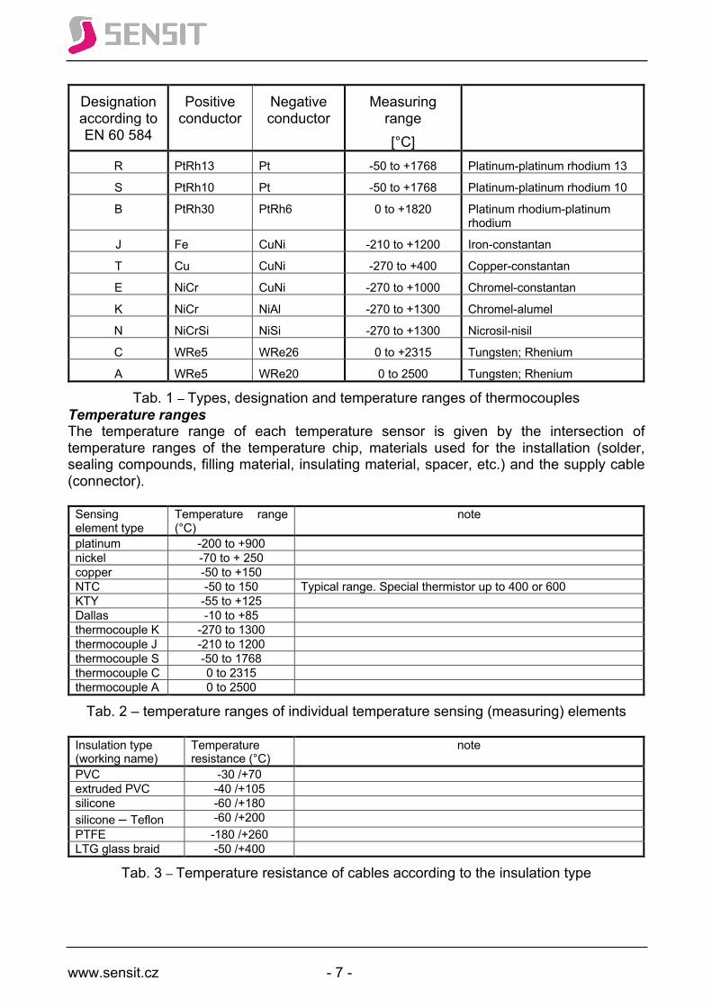
Basic division of Sensit temperature sensors Resistance temperature sensors utilize the dependence of the change of metal and semiconductor resistance on temperature and currently belong to the most widely used temperature measurement devices. They are widely used in all industries, e.g. engineering, automotive, chemical, heating, when using non-traditional forms of energy, in the food industry, etc. They are also used, for example, as standards for calibrating other types of sensors or thermometers. Their main advantages include stability, accuracy and signal shape. An indispensable advantage of resistance temperature sensors is the ability to electronically process and archive data. Resistance temperature sensors utilize the dependence of electrical resistance of materials on temperature. They are usually made of pure metal materials, such as platinum, nickel, copper or their alloys. In these materials, the change of resistance and temperature is directly proportional and approximately quadratic. Semiconductor and special resistance sensors are different. In the case of NTC thermistors, for example, the dependence is inversely proportional and approximately hyperbolic – the resistance decreases with increasing temperature unlike PTC thermistors, so-called posistors. The resistance of a posistor first slightly decreases, above the Curie temperature it sharply rises by about 3 orders of magnitude and then decreases again slightly. The narrow area of the sharp increase of electrical resistance, which is one of the characteristics of a posistor, can be influenced by the chemical composition of the input material, thus creating, for example, a set of elements with a graded point of sharp increase in resistance (typically per 10 °C). The dependence curve in the entire temperature range of the posistor can have one to three inflection points. Due to their steep temperature dependence, posistors are also used as resettable thermal fuses. Other applications include switching circuits with semiconductor elements or two-state sensors in control systems at the winding of electric motors, transformers or heating of power components. The thermoelectric phenomenon (the occurrence of electromotive voltage during the contact of two different metals and its dependence on temperature) is utilized by thermoelectric temperature sensors called thermocouples. Thermocouples are the second most widely used temperature sensors for temperature measurement after resistance temperature sensors and practically the only elements for contact measurement of temperatures above 800 °C. The contact (joint) of two different metal conductors creates a potential difference proportional to the joint temperature. When closing the circuit by connecting the other ends of the conductors and then disconnecting one of the conductors, the thermoelectric voltage between the ends of this disconnected conductor will be proportional to the temperature difference between the two joints. Its value depends on the materials of the individual conductors. A thermocouple thus represents a generator of voltage, whose value depends on the material from which it is made and on the temperature difference between the two joints, one of which is the measuring joint and one is the comparing joint. For the correct function of the thermocouple as a gauge, it is essential that the temperature of the comparing joint is constant or known (the parasitic effect of the thermoelectric voltage of this joint is compensated). Historical development of thermocouples has resulted in several metal pairs currently used in practice. The technical parameters and conditions of use are covered by ČSN EN 60 584 standards (May 2014). The types, designation and temperature ranges of thermocouples are listed in Table 1.
Conductor composition Note
www.sensit.cz - 7 -
Designation according to EN 60 584
Positive conductor
Negative conductor
Measuring range [°C]
R PtRh13 Pt -50 to +1768 Platinum-platinum rhodium 13
S PtRh10 Pt -50 to +1768 Platinum-platinum rhodium 10
B PtRh30 PtRh6 0 to +1820 Platinum rhodium-platinum rhodium
J Fe CuNi -210 to +1200 Iron-constantan
T Cu CuNi -270 to +400 Copper-constantan
E NiCr CuNi -270 to +1000 Chromel-constantan
K NiCr NiAl -270 to +1300 Chromel-alumel
N NiCrSi NiSi -270 to +1300 Nicrosil-nisil
C WRe5 WRe26 0 to +2315 Tungsten; Rhenium
A WRe5 WRe20 0 to 2500 Tungsten; Rhenium
Tab. 1 – Types, designation and temperature ranges of thermocouples Temperature ranges The temperature range of each temperature sensor is given by the intersection of temperature ranges of the temperature chip, materials used for the installation (solder, sealing compounds, filling material, insulating material, spacer, etc.) and the supply cable (connector).
Sensing element type
Temperature range (°C)
note
platinum -200 to +900 nickel -70 to + 250 copper -50 to +150 NTC -50 to 150 Typical range. Special thermistor up to 400 or 600 KTY -55 to +125 Dallas -10 to +85 thermocouple K -270 to 1300 thermocouple J -210 to 1200 thermocouple S -50 to 1768 thermocouple C 0 to 2315 thermocouple A 0 to 2500
Tab. 2 – temperature ranges of individual temperature sensing (measuring) elements
Insulation type (working name)
Temperature resistance (°C)
note
PVC -30 /+70 extruded PVC -40 /+105 silicone -60 /+180 silicone – Teflon -60 /+200 PTFE -180 /+260 LTG glass braid -50 /+400
Tab. 3 – Temperature resistance of cables according to the insulation type

www.sensit.cz - 8 -
Terminology (in alphabetical order)
The Curie point or Curie temperature (Tc) is a characteristic feature of ferromagnetic, ferroelectric and piezoelectric substances described by French physicist Pierre Curie. Above the Curie temperature, the substance loses its ferromagnetic, ferroelectric or piezoelectric properties. This feature is used by posistors – PTC thermistors. The response time t0.5 (t0.9) – the sensor time constant – indicates the time in which the input signal reaches 50 % (90 %) of the final value (steady state) in the case of a temperature jump. It depends on the dimensions, material and weight of the sensor and on the environment in which the temperature is measured (e.g. water, air) and its flow rate. The response time for temperature sensors of two different housing diameters is shown in Fig 1.
Fig. 1 – Graphical representation of the term “response time”
Electromagnetic compatibility (EMC) is a property of an electronic device (transducer, switch, temperature indicator) based on the fact that it does not influence other electronic devices, including itself, with its electromagnetic field and that it resists the effects of the electromagnetic fields of other devices. It is therefore divided into two subcategories: how such a device disturbs its surroundings and how the surroundings disturb the device. Standard – in general: the standard of a measuring unit or scale of a certain quantity is a gauge for the implementation and maintenance of the unit or scale and its transfer to less accurate gauges. Temperature sensor hysteresis – property of resistance temperature sensors, where values of electrical resistance measured at evenly increasing temperature from temperature t1 to temperature t2 are different from values of electrical resistance measured at evenly decreasing temperature from temperature t2 to temperature t1 (t1; t2 define the measuring range of the sensor). Absolute error – Δ – difference between the real value and the measured value, which depends on many factors, some of which cannot be minimized. Relative error – δ – ratio of the absolute error to the measured value. It represents the absolute error relative to the unit of the measured quantity. If multiplied by 100, it represents an error in %.
www.sensit.cz - 9 -
A systematic error distorts the measurement result in a certain way and on a regular basis, which primarily leads to values permanently higher or permanently lower than the correct value. Systematic errors may be caused by the measurement methods used, the measuring instruments used or the people carrying out the measurements (so-called personal error). Example: Temperature measurement by contact temperature sensors is affected by a considerable systematic error. The measured value is lower than the real value and there is an indirect proportion between the measurement error and the diameter of the pipe to which the temperature sensor is attached. An inflection point is a point on a curve at which the curvature changes its sign from positive to negative and vice versa (the curve changes from concave to convex and vice versa). ITS 90 – International Temperature Scale. It defines the unit of thermodynamic temperature (T) – kelvin [K] as 1/273.16 of the thermodynamic temperature of the triple point of water. At the same time, it defines temperature (t) in degrees Celsius [°C] as
t [°C] = T[K] - 273.15 It also defines other 16 empirically determined temperature points that correspond to equilibrium states between the phases (solid, liquid, gas) of selected elements (H2, He, Ne, O2, Ar, Hg, Ga, In, Sn, Zn, Al, Ag, Au, Cu). Insulation resistance is electrical resistance measured between any parts of an electrical circuit (temperature sensing element, supply cables) and the housing, at a defined temperature and with a specified measuring voltage (AC or DC). Joule heat – is generated by the passage of electric current and is proportional to the second power of this current. It causes self-heating of the temperature sensing element and positive systematic measurement error. Compensation line – interconnects the thermocouple and the measuring instrument and its branches are made of different materials (metal alloys) than the thermocouple branches. The branches of the compensation line do not create another (parasitic) thermocouple on the connections with the thermocouple branches. It is used in cases where the thermocouple branch material is expensive and the use of an extension line would increase the application costs. The temperature of the connections of the compensation line with the thermocouple must not exceed 200 °C and the electrical resistance of the compensation line must not exceed 100 ohms. Metal temperature sensing element – resistance temperature sensing element that measures temperature using the dependence of the electrical resistance of the metal on temperature . The metal can be platinum, nickel or copper and the sensing element can be wire-wound or thin-film. Wire-wound metal temperature sensing element – is made of a thin metal wire (Pt, Ni or Cu) of a given electrical resistance, which is evenly wound onto a ceramic cylinder and then fixed and passivated with a ceramic layer. A less common design is a thin wire wound into a spiral that is inserted into a ceramic capillary. Thin-film metal temperature sensing element – see Temperature (resistance) chip. Metal resistance temperature sensor – resistance sensor with a metal temperature sensing element. The critical temperature of a technological process is a temperature value, the observance of which has a significant impact on the process quality and therefore on the quality of the final product.
www.sensit.cz - 10 -
Cryogenic temperature – generally temperature below the freezing point. The division and terminology of the cryogenic temperature are ambiguous. In cryotechnology, the Kelvin scale is used more often than the Celsius scale. Normal cryogenic temperatures up to 120 K (-150 °C), low cryogenic temperatures from 120 K to 5 K (-268 °C), very low cryogenic temperatures from 5 K to 1 K (-272 °C). MGO – see Mineral insulated resistance temperature sensor Measurement uncertainty is the parameter related to the measurement result and characterizes the range of values that can be rationally assigned to the measured quantity. The causes (sources) of measurement uncertainties are influences that in some way affect the uncertainty of unambiguous determination of the measurement result and shift the measured value away from the actual value. Generally, the most common causes of uncertainties are: imperfect or incomplete definition of the measured quantity; wrong choice of the evaluation device; wrong choice of the measurement location/samples; wrong measurement procedure; rounding; linearisation; approximation; interpolation; extrapolation; unknown or uncompensated environmental influences; failure to maintain the same conditions in repeated measurements; subjective influences of the operator and, last but not least, the inaccuracy of the standards and reference materials. When measuring temperature, measurement uncertainties are mainly affected by the following factors: response time, self-heating of the temperature sensing element, mechanical stress (vibration, pressure, bending of the sensor), ambient temperature, heat radiation from the measured sample, insulation resistance of the sensor and its possible change, disturbing electric and magnetic fields (induced voltage), mechanical connection of unsuitable materials (parasitic thermoelectric voltages), thermal stress, deviations from the specified installation method (depth of immersion) and, last but not least, radioactive radiation with possible influence on the structure and properties of the mechanical layers of the temperature sensor. Nickel resistance temperature sensor – resistance temperature sensor with a nickel temperature sensing element. Resistance temperature sensing element – part of a temperature sensor used to sense temperature. It consists of a material with a defined dependence of electrical resistance on temperature and outlets. Sometimes it is also called a measuring element, measuring resistor (EN 60 751) or measuring sensor. For the purposes of this manual, we will stick to the term sensing element. Mineral insulated resistance temperature sensor – lead-in wires with a temperature chip are pressed with powder ceramic insulation (MgO) into a thin-walled metal tube made of austenitic steel. The diameter of a mineral insulated resistance temperature sensor is 1.5 mm to 6 mm, the temperature range is up to 600 °C. This type of temperature sensor is sometimes (illogically and incorrectly) called MGO (the design is similar to a mineral insulated thermocouple – see Fig. 2). Resistance temperature sensor – a unit consisting of a resistance temperature sensing element, internal wiring with insulation, a stem tube (stem) and a head or connecting line. It is also called a resistance thermometer. Optical temperature sensor – a so-called Bragg grating is created at the desired location of the structure of a glass (optical) fibre. The optical fibre extends due to temperature, which changes the parameters of the Bragg grating. The evaluation unit sends a light beam into the optical fibre with an optical temperature sensor. A narrow part of the light spectrum is reflected back from the Bragg grating to the device. Changing the parameters of the Bragg

www.sensit.cz - 11 -
grating also changes the value of the wavelength of the reflected light beam. The change of the wavelength of the light reflected from the Bragg grating is proportional to the temperature at its location. This type of temperature sensor allows the measurement of temperature at different points of the optical fibre simultaneously. The condition is that every fibre measuring point contains a Bragg grating with different parameters and that the evaluation device can process data in a cascade way. Due to the high cost of the optical temperature sensor and evaluator assembly compared to other sensor types, optical temperature sensors can be used where other types of sensors cannot be physically applied or where their use is economically disadvantageous. The primary circuits of nuclear power plants, plants and equipment with high electromagnetic disturbance, specific line structures (bridges, special roads), deep wells for heat pumps and, last but not least, some medical branches. Platinum resistance temperature sensor – resistance temperature sensor with a platinum temperature sensing element. Housing – metal (plastic) part of a temperature sensor protecting the temperature sensing element and the internal wiring from mechanical damage and external influences. A posistor (PTC thermistor) is a temperature-dependent resistor distinguished by a negative-positive temperature characteristic with a significant increase of resistance (by up to 5 orders of magnitude) in a specific narrow temperature interval, which is characteristic for all types of posistors. See page 15. Extension line – used to connect a thermocouple to a measuring instrument, made of the same materials as the thermocouple branches. If the material of the thermocouple branches is expensive, the extension line is usually replaced with a compensation line. An extension line should have an electrical resistance of up to 100 ohms. Real probe – commercial name for very fast resistance temperature sensors, where the temperature chip is soldered to the bottom of a stem with a diameter of 6 mm. There is therefore only a 0.2mm thick stainless steel layer between the temperature chip and the measured medium. Self-heating of a temperature sensing element – the passage of measuring current I through measuring resistance R creates electrical power P = I2 R, which completely changes to Joule heat. This increases the temperature of the temperature chip itself and affects the measurement with a positive systematic error. Specified gauge – gauge specified by the Ministry of Industry and Trade Decree No. 345/2002 Coll. for type approval and mandatory verification with respect to its significance. In the case of temperature sensors, these include paired temperature sensors for the billing measurement of heat consumption (charges, tariffs, taxes), temperature sensors having an irreplaceable influence on processes related to environmental protection, occupational safety or protection of other public interests protected by special legislation (HACCAP – temperature sensors measuring critical temperatures during food processing – baking temperature, pasteurisation temperature) and temperature sensors in sterilizers (sterilization temperature, health protection).
Stem – metal part of a head temperature sensor protecting the sensing element and the internal wiring from mechanical damage and external influences.
Mean time to failure (MTTF) – statistical value used to quantify the reliability of a product. It is expressed in hours in the format a.bc x 10y h. For a product set (set of temperature sensors), for which we know the time from deployment to failure, the MTTF is calculated as the average of these times.

www.sensit.cz - 12 -
Temperature resistance sensing element – see Resistance temperature sensing element.
Temperature (resistance) chip – electronic component – metal resistance path of 100, 200, 500, 1000 or 10000 ohms created on a miniature ceramic plate using vacuum deposition of a thin metal layer (Pt, Ni, Cu), photolithography, laser alignment of electrical resistance, splitting of a ceramic pad, point welding of lead-in wires, passivation of the overall structure against external influences and final dimensioning. Temperature coefficient α – determines the slope of the curve expressing the dependence of the resistance of a resistance temperature sensing element on temperature. The basic resistance at 0 °C R0 and temperature coefficient α are the main characteristics of every sensing element. Thermistor – temperature-dependent resistor made by press-forming a mixture of metals with semiconductor properties (Fe2O3, TiO2, CuO2, NiO, etc.) at high temperature into the shape of a bead or disc with two outlets. A thermistor referred to as NTC is characterized by a negative temperature dependence – the electrical resistance decreases with increasing temperature. The basic NTC parameters are electrical resistance at 25 °C and the β coefficient, which characterizes the slope of the curve of the dependence of electrical resistance on temperature. Thermocouple temperature sensor (thermocouple) – sensor consisting of two conductors of a specific composition isolated from each other and connected (welded) at the end into a ball. It uses the physical principle of creating an electrical potential at the point of contact of two different metals whose value is temperature-dependent. It measures the difference of the so-called thermoelectric voltage formed between the joints of the two metals on the “hot” and “cold” end. This thermoelectric voltage is proportional to the temperature difference between the “hot” and “cold” joint and is in the order of mV. Mineral insulated thermocouple – characterized by a configuration where both thermocouple branches are pressed with powder ceramic insulation into a thin-walled metal tube. The cross section of a mineral insulated thermocouple is shown in Fig. 2.
Fig. 2 – cross section of a mineral insulated thermocouple
The thin-wall jacket is made of austenitic steel or (for high temperatures) Inconel. The pressed powder insulation is usually MgO or Al2O3. Mineral insulated thermocouples are supplied with an insulated end, grounded end or with a bare measuring end. Type test – verification of the specified technical parameters of a given type of product, in this case a temperature sensor. The type test is performed by the manufacturer (testing – metrological – laboratory) and its output is a type test report. The type test is carried out
www.sensit.cz - 13 -
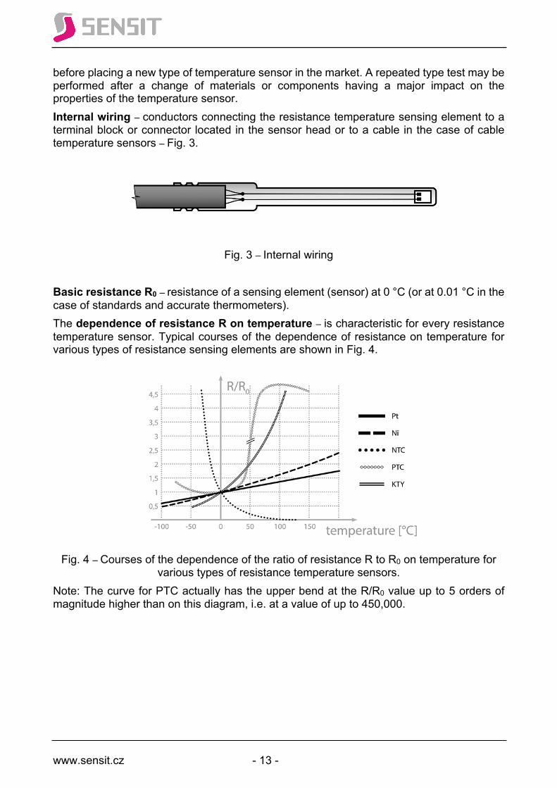
before placing a new type of temperature sensor in the market. A repeated type test may be performed after a change of materials or components having a major impact on the properties of the temperature sensor. Internal wiring – conductors connecting the resistance temperature sensing element to a terminal block or connector located in the sensor head or to a cable in the case of cable temperature sensors – Fig. 3.
Fig. 3 – Internal wiring
Basic resistance R0 – resistance of a sensing element (sensor) at 0 °C (or at 0.01 °C in the case of standards and accurate thermometers). The dependence of resistance R on temperature – is characteristic for every resistance temperature sensor. Typical courses of the dependence of resistance on temperature for various types of resistance sensing elements are shown in Fig. 4.
Fig. 4 – Courses of the dependence of the ratio of resistance R to R0 on temperature for
various types of resistance temperature sensors. Note: The curve for PTC actually has the upper bend at the R/R0 value up to 5 orders of magnitude higher than on this diagram, i.e. at a value of up to 450,000.
www.sensit.cz - 14 -
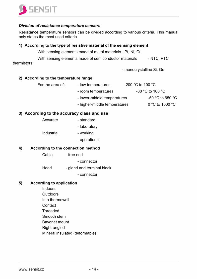
Division of resistance temperature sensors Resistance temperature sensors can be divided according to various criteria. This manual only states the most used criteria.
1) According to the type of resistive material of the sensing element With sensing elements made of metal materials - Pt, Ni, Cu With sensing elements made of semiconductor materials - NTC, PTC thermistors - monocrystalline Si, Ge
2) According to the temperature range For the area of: - low temperatures -200 °C to 100 °C - room temperatures -30 °C to 100 °C - lower-middle temperatures -50 °C to 650 °C - higher-middle temperatures 0 °C to 1000 °C
3) According to the accuracy class and use Accurate - standard - laboratory Industrial - working - operational
4) According to the connection method Cable - free end - connector Head - gland and terminal block - connector
5) According to application Indoors Outdoors
In a thermowell Contact Threaded Smooth stem Bayonet mount
Right-angled Mineral insulated (deformable)
www.sensit.cz - 15 -
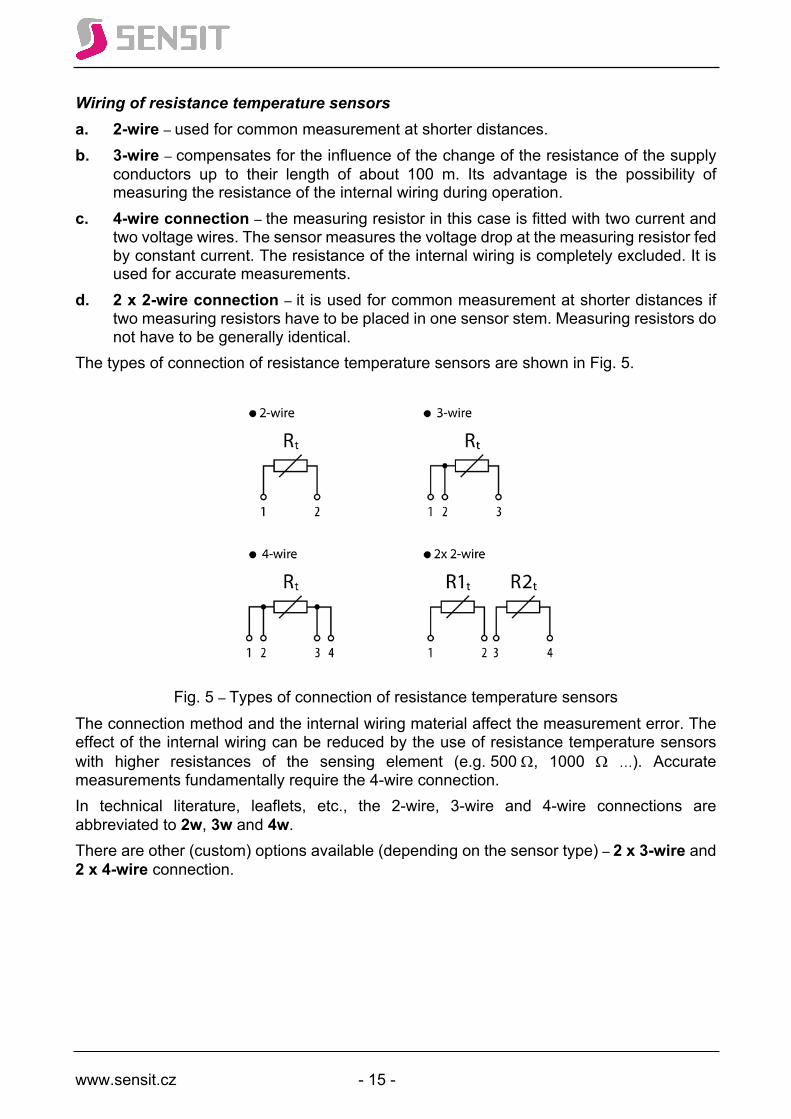
Wiring of resistance temperature sensors a. 2-wire – used for common measurement at shorter distances. b. 3-wire – compensates for the influence of the change of the resistance of the supply
conductors up to their length of about 100 m. Its advantage is the possibility of measuring the resistance of the internal wiring during operation.
c. 4-wire connection – the measuring resistor in this case is fitted with two current and two voltage wires. The sensor measures the voltage drop at the measuring resistor fed by constant current. The resistance of the internal wiring is completely excluded. It is used for accurate measurements.
d. 2 x 2-wire connection – it is used for common measurement at shorter distances if two measuring resistors have to be placed in one sensor stem. Measuring resistors do not have to be generally identical.
The types of connection of resistance temperature sensors are shown in Fig. 5.
Fig. 5 – Types of connection of resistance temperature sensors
The connection method and the internal wiring material affect the measurement error. The effect of the internal wiring can be reduced by the use of resistance temperature sensors with higher resistances of the sensing element (e.g. 500 W, 1000 W …). Accurate measurements fundamentally require the 4-wire connection. In technical literature, leaflets, etc., the 2-wire, 3-wire and 4-wire connections are abbreviated to 2w, 3w and 4w. There are other (custom) options available (depending on the sensor type) – 2 x 3-wire and 2 x 4-wire connection.

www.sensit.cz - 16 -
Design of temperature sensing elements
Wire-wound sensing elements
Wire-wound sensing elements are made of a platinum wire with a diameter of 0.007 to 0.05 mm
a) wound into a spiral, which is inserted in cylindrical openings of a ceramic body and appropriately fixed inside. These sensing elements have the hysteresis effect minimized at the expense of vibration resistance. Currently, they are mainly used as superior standards in metal stems filled with air or a mixture of helium and oxygen and hermetically sealed (direct contact with the atmosphere causes an increase of measurement uncertainty mainly due to hydrogen and carbon oxide).
b) bifilarily wound on a ceramic body and covered with ceramic enamel or wound on a glass body and covered with glass solder. These sensing elements are protected against vibration at the expense of hysteresis. The use of these wire-wound sensing elements rapidly drops at the expense of film sensing elements that have smaller dimensions and a shorter time constant, making them significantly more economical.
Wire-wound sensing elements are produced with R0 values equal to 100 Ω or 500 Ω. The outlets of these sensing elements are wired with a usual diameter of 0.3 or 0.35 mm and length of 10 to 30 mm. The electrical resistance of the outlets is included in the overall resistance of the sensing element, so the length of the outlets cannot be shortened. Note: For 2nd degree standards, the following values are used: Pt 100; α=1.3925.10-3 °C-1 (Pt 100/39252), Pt 100; α=1.3920.10-3 °C-1 (Pt 100/3950) or Pt 100; α=1.3850.10-3 °C-1 (Pt 100/3850). Standards must meet the requirements of ITS 90.
Film sensing elements
The base of film sensing elements is a ceramic pad made of corundum ceramics (Al2O3) with an active metal layer. One ceramic pad of 100 x 100 mm can be turned into 500 or more sensing elements at once. According to the active metal layer deposition technology, we distinguish:
a) the older, thick-film technology, which consists in applying an active layer in the form of a paste on a pad by screen printing. This is followed by burning of the screen printing (thermal stabilization) layer, laser setting of the base value of resistance R0 = 100, 500, or 1000 W, passivation of the active layer and cutting into individual sensing elements. Up to this point, the manufacturing operations are performed with whole ceramic pads and are called bulk operations. After cutting the ceramic pad into individual chips, individual operations take place – fixing of outlets and primary packaging.
b) the newer (approx. since 1988), thin-film technology. In this case, screen printing of the active metal layer is replaced by vacuum deposition (steaming, sputtering) of platinum, nickel or copper with subsequent formation of the final structure by photolithography. The basic (rough) setting of resistance R0 is given by the topology of the resistance meander and thickness of the deposited layer. The exact setting of resistance R0 (adjustment) is performed by burning the resistance path with a laser (trimming operation – the electrical resistance of the active metal layer after the photolithography operation is lower than R0. Using a laser beam, active material is cut off from the so-called adjustment zone, which increases resistance. This operation lasts until R0 is achieved. The final operations are multilayer passivation of the active layer, cutting of the ceramic pad into strips, contacting of outlets, their fixing with glass solder and cutting of strips into individual chips. This technology enables
www.sensit.cz - 17 -
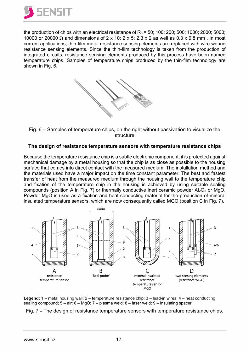
the production of chips with an electrical resistance of R0 = 50; 100; 200; 500; 1000; 2000; 5000; 10000 or 20000 W and dimensions of 2 x 10; 2 x 5; 2.3 x 2 as well as 0.3 x 0.8 mm . In most current applications, thin-film metal resistance sensing elements are replaced with wire-wound resistance sensing elements. Since the thin-film technology is taken from the production of integrated circuits, resistance sensing elements produced by this process have been named temperature chips. Samples of temperature chips produced by the thin-film technology are shown in Fig. 6.
Fig. 6 – Samples of temperature chips, on the right without passivation to visualize the
structure
The design of resistance temperature sensors with temperature resistance chips
Because the temperature resistance chip is a subtle electronic component, it is protected against mechanical damage by a metal housing so that the chip is as close as possible to the housing surface that comes into direct contact with the measured medium. The installation method and the materials used have a major impact on the time constant parameter. The best and fastest transfer of heat from the measured medium through the housing wall to the temperature chip and fixation of the temperature chip in the housing is achieved by using suitable sealing compounds (position A in Fig. 7) or thermally conductive inert ceramic powder Al2O3 or MgO. Powder MgO is used as a fixation and heat conducting material for the production of mineral insulated temperature sensors, which are now consequently called MGO (position C in Fig. 7).
Legend: 1 – metal housing wall; 2 – temperature resistance chip; 3 – lead-in wires; 4 – heat conducting sealing compound; 5 – air; 6 – MgO; 7 – plasma weld; 8 – laser weld; 9 – insulating spacer
Fig. 7 – The design of resistance temperature sensors with temperature resistance chips.

www.sensit.cz - 18 -
At this point, attention must be drawn to the unsuitability of the installation of MGO temperature sensors or temperature sensors filled with ceramic powder on equipment that vibrates or is subjected to mechanical shocks. Ceramic powder is an abrasive and it is only a matter of time when its abrasive effects first break the passivation and finally the thin active conductive layer of the temperature sensor. At present, the latest technology of installing temperature chips in a metal housing is shown in position B in Fig. 7 and has the working name “real probe”. The temperature chip is provided in the mass production process with a metal layer on the underside, which allows the temperature chip to be soldered to a metal disc with a thickness of 0.2 mm. The disc is then laser-welded to a metal tube to form its bottom. The space above the soldered chip is filled with air in order to minimize the heat capacity of the sensor. There is only an insulating spacer attached at a certain distance from the chip, securing the correct position of the lead-in wires. “Real probe” resistance temperature sensors have one order of magnitude lower time constant than sensors produced by the current procedures (position A in Fig. 7).
PTC thermistors
(posistors) are temperature-dependent resistors produced by press-forming polycrystalline ferroelectric ceramics (barium titanate BaTiO3) at high temperature and pressure into a bead or disc and fitted with two outlets. They are distinguished by a negative temperature characteristic with a significant increase in resistance (up to 5 orders of magnitude) in a specific narrow temperature interval, which is given for each type of posistor – see Fig. 8. For this reason, you may come across the term “limiting PTC thermistors”. The posistor characteristic can have 1 to 3 inflection points.
Fig. 8 – Diagram of the dependence of posistor electrical resistance on temperature
NTC thermistors
NTC thermistors are non-linear resistance semiconductor temperature sensing elements with a large negative temperature coefficient. Unlike metal sensing elements, a thermistor is defined by the value of electrical resistance at 25 °C – R25 and temperature coefficient β, which is

www.sensit.cz - 19 -
calculated from the values of two absolute temperatures T1 and T2 and two corresponding electrical resistances R1 a R2 according to the following formula
β t1/t2 = T1T2/( T2 - T1) * ln (R1/ R2) where t1 = T1 – 273 and is set to 25 °C and t2 = T2 – 273 and is usually 85 °C or 100 °C. Thermistor manufacturers indicate either β 25/85 or β 25/100. NTC thermistors are mainly used in applications with room temperatures that require a measurement accuracy of only 1 %, 3 % or 5 %, with high pressure on the price of the resulting product.
Semiconductor monocrystalline resistance sensing elements
Sensing elements with a monocrystalline structure include, for example, silicon and germanium sensors (very low temperature area). These sensing elements utilize the dependence of the mobility of the free electrical charge carriers in the crystal lattice on temperature. Changing the speed of their movement also changes the crystal resistivity. The base value of the monocrystal resistance is dependent on the amount of additives. Silicon resistance temperature sensing elements are made of doped monocrystalline silicon, which is connected through contact surfaces to the wire outlets. Temperature dependence of resistance with a positive temperature coefficienta:
RT = R25(1+a*DT+b*DT2). They are supplied in standard diode housings. Their advantage is a low price. A certain disadvantage is their temperature range of -50 to +125 °C.
Thermocouples
Thermocouple temperature sensors use the Seebeck effect, where thermoelectric voltage is generated in a simple electrical circuit formed by conductors of two different metals and is proportional to the temperature difference between the measuring and the reference (cold) end. According to the metals used, we divide thermocouples into base metal thermocouples and rare metal thermocouples. The designation, composition and properties of basic thermocouples are defined by EN 60584. In practice, we can rarely come across thermocouples according to other standards. Typical features:
• short response time; • very good temperature stability over a wide range of temperatures; • suitable for high and very high temperatures; • small size; • resistance to vibration and temperature shocks; • the resulting properties are determined by the observance of the exact composition of
the metals used; • generally lower accuracy compared to platinum resistance sensing elements; • more complex evaluation – we have to also evaluate the temperature of the reference
(cold) ends; • connection to the measuring device must be made through special cables (compensation
or extension line) or a special connector for the given type of thermocouple; • it ages quickly when used near the upper temperature limit, which results in a system
measurement error.
www.sensit.cz - 20 -
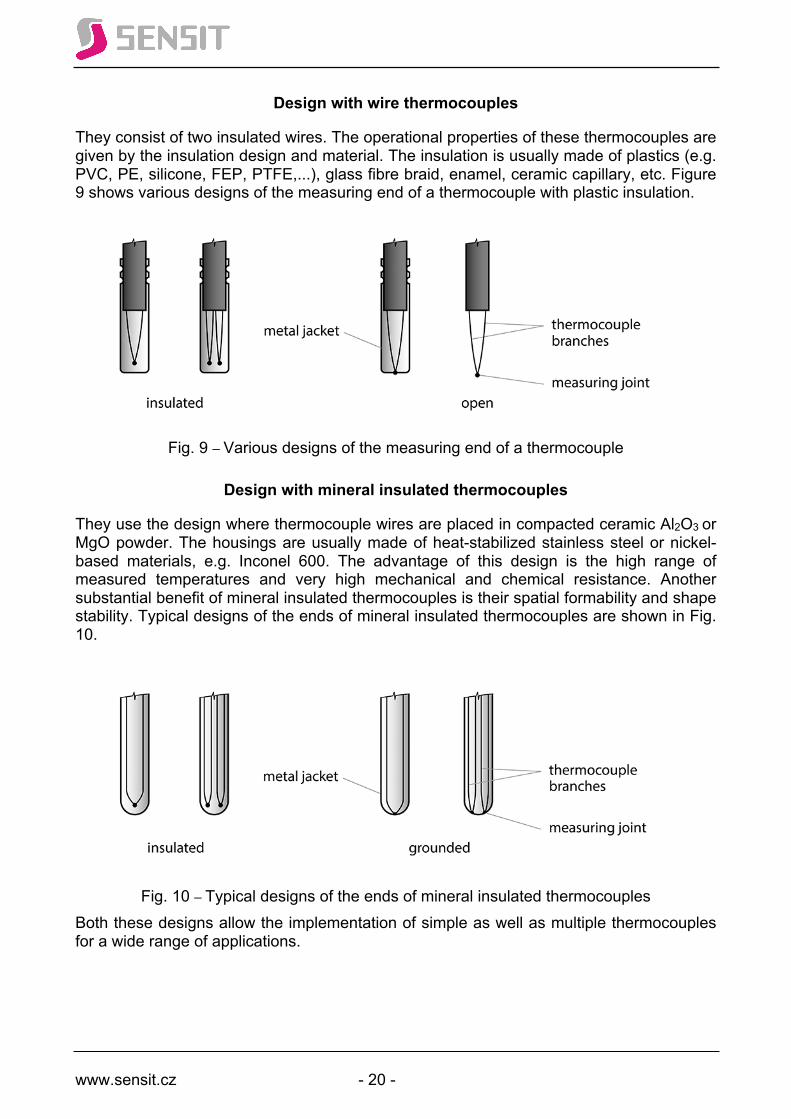
Design with wire thermocouples
They consist of two insulated wires. The operational properties of these thermocouples are given by the insulation design and material. The insulation is usually made of plastics (e.g. PVC, PE, silicone, FEP, PTFE,...), glass fibre braid, enamel, ceramic capillary, etc. Figure 9 shows various designs of the measuring end of a thermocouple with plastic insulation.
Fig. 9 – Various designs of the measuring end of a thermocouple
Design with mineral insulated thermocouples
They use the design where thermocouple wires are placed in compacted ceramic Al2O3 or MgO powder. The housings are usually made of heat-stabilized stainless steel or nickel-based materials, e.g. Inconel 600. The advantage of this design is the high range of measured temperatures and very high mechanical and chemical resistance. Another substantial benefit of mineral insulated thermocouples is their spatial formability and shape stability. Typical designs of the ends of mineral insulated thermocouples are shown in Fig. 10.
Fig. 10 – Typical designs of the ends of mineral insulated thermocouples
Both these designs allow the implementation of simple as well as multiple thermocouples for a wide range of applications.
www.sensit.cz - 21 -
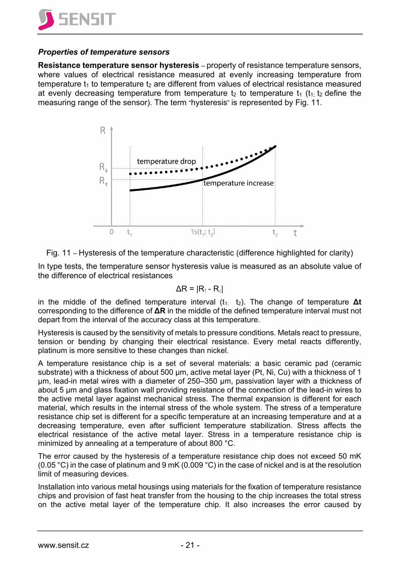
Properties of temperature sensors Resistance temperature sensor hysteresis – property of resistance temperature sensors, where values of electrical resistance measured at evenly increasing temperature from temperature t1 to temperature t2 are different from values of electrical resistance measured at evenly decreasing temperature from temperature t2 to temperature t1 (t1; t2 define the measuring range of the sensor). The term “hysteresis” is represented by Fig. 11.
Fig. 11 – Hysteresis of the temperature characteristic (difference highlighted for clarity)
In type tests, the temperature sensor hysteresis value is measured as an absolute value of the difference of electrical resistances
ΔR = |R↑ - R↓| in the middle of the defined temperature interval (t1; t2). The change of temperature Δt corresponding to the difference of ΔR in the middle of the defined temperature interval must not depart from the interval of the accuracy class at this temperature. Hysteresis is caused by the sensitivity of metals to pressure conditions. Metals react to pressure, tension or bending by changing their electrical resistance. Every metal reacts differently, platinum is more sensitive to these changes than nickel. A temperature resistance chip is a set of several materials: a basic ceramic pad (ceramic substrate) with a thickness of about 500 μm, active metal layer (Pt, Ni, Cu) with a thickness of 1 μm, lead-in metal wires with a diameter of 250–350 μm, passivation layer with a thickness of about 5 μm and glass fixation wall providing resistance of the connection of the lead-in wires to the active metal layer against mechanical stress. The thermal expansion is different for each material, which results in the internal stress of the whole system. The stress of a temperature resistance chip set is different for a specific temperature at an increasing temperature and at a decreasing temperature, even after sufficient temperature stabilization. Stress affects the electrical resistance of the active metal layer. Stress in a temperature resistance chip is minimized by annealing at a temperature of about 800 °C. The error caused by the hysteresis of a temperature resistance chip does not exceed 50 mK (0.05 °C) in the case of platinum and 9 mK (0.009 °C) in the case of nickel and is at the resolution limit of measuring devices. Installation into various metal housings using materials for the fixation of temperature resistance chips and provision of fast heat transfer from the housing to the chip increases the total stress on the active metal layer of the temperature chip. It also increases the error caused by
www.sensit.cz - 22 -
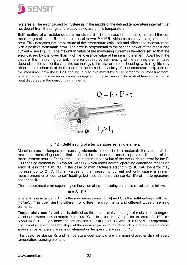
hysteresis. The error caused by hysteresis in the middle of the defined temperature interval must not depart from the range of the accuracy class at this temperature. Self-heating of a resistance sensing element – the passage of measuring current I through measuring resistance R creates electrical power P = I2 R, which completely changes to Joule heat. This increases the temperature of the temperature chip itself and affects the measurement with a positive systematic error. The error is proportional to the second power of the measuring current – see Fig. 12. The maximum value of the measuring current is therefore set so that the error caused by it is lower than ¼ of the tolerance value of the sensing element. Apart from the value of the measuring current, the error caused by self-heating of the sensing element also depends on the size of the chip, the technology of installation into the housing, which significantly affects the dissipation of Joule heat into the immediate vicinity of the temperature chip, and on the measured area itself. Self-heating is also minimized by pulse temperature measurement, where the nominal measuring current is applied to the sensor only for a short time so that Joule heat disperses in the surrounding material.
Fig. 12 – Self-heating of a temperature sensing element
Manufacturers of temperature sensing elements present in their materials the values of the maximum measuring current that must not be exceeded in order to prevent distortion of the measurement results. For example, the recommended value of the measuring current for the Pt 100 sensing element is 0.8 mA for Class B, which under normal operating conditions means an error of less than 0.05 °C. In the case of manufacturers stating 5 to 10 mA, the error may increase up to 2 °C. Higher values of the measuring current not only cause a system measurement error due to self-heating, but also decrease the service life of the temperature sensor itself. The measurement error depending on the value of the measuring current is calculated as follows:
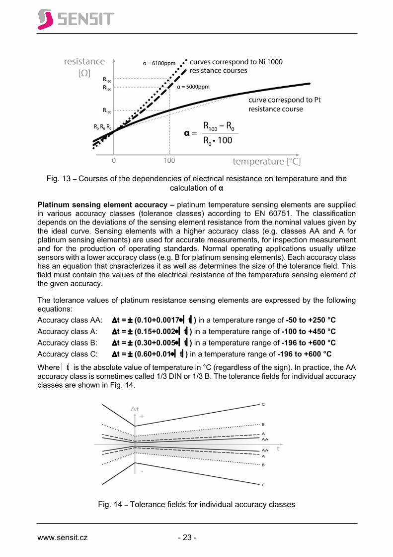
Dt = S · RI2 where R is resistance [kW], I is the measuring current [mA] and S is the self-heating coefficient [°C/mW]. This coefficient is different for different environments and different types of sensing elements. Temperature coefficient α – is defined as the mean relative change of resistance to degree Celsius between temperatures 0 to 100 °C. It is given in [°C-1] – for example Pt 100; α= 3.850·10-3 °C-1 – or under the designation TCR in [ ppm/°C] with Pt 100/3850. Temperature coefficient α determines the slope of the curve expressing the dependence of the resistance of a resistance temperature sensing element on temperature – see Fig. 13. The basic resistance R0 and temperature coefficient α are the main characteristics of every temperature sensing element.
www.sensit.cz - 23 -
Fig. 13 – Courses of the dependencies of electrical resistance on temperature and the
calculation of α
Platinum sensing element accuracy – platinum temperature sensing elements are supplied in various accuracy classes (tolerance classes) according to EN 60751. The classification depends on the deviations of the sensing element resistance from the nominal values given by the ideal curve. Sensing elements with a higher accuracy class (e.g. classes AA and A for platinum sensing elements) are used for accurate measurements, for inspection measurement and for the production of operating standards. Normal operating applications usually utilize sensors with a lower accuracy class (e.g. B for platinum sensing elements). Each accuracy class has an equation that characterizes it as well as determines the size of the tolerance field. This field must contain the values of the electrical resistance of the temperature sensing element of the given accuracy.
The tolerance values of platinum resistance sensing elements are expressed by the following equations: Accuracy class AA: Dt = ± (0.10+0.0017*ú tú) in a temperature range of -50 to +250 °C Accuracy class A: Dt = ± (0.15+0.002*ú tú) in a temperature range of -100 to +450 °C Accuracy class B: Dt = ± (0.30+0.005*ú tú) in a temperature range of -196 to +600 °C Accuracy class C: Dt = ± (0.60+0.01*ú tú) in a temperature range of -196 to +600 °C Where ú tú is the absolute value of temperature in °C (regardless of the sign). In practice, the AA accuracy class is sometimes called 1/3 DIN or 1/3 B. The tolerance fields for individual accuracy classes are shown in Fig. 14.
Fig. 14 – Tolerance fields for individual accuracy classes

www.sensit.cz - 24 -
Certain special applications (e.g. in medicine) require the accuracy of 1/10 B (1/10 DIN or also Premium Grade) with a tolerance band defined as follows Accuracy class 1/10B: Dt = ± (0.03+0.0005*ú tú) This relationship is not supported by EN 60751. Important note: Although EN 60751 and the above equations apply to “Industrial platinum resistance thermometers and platinum temperature sensors”, the same principles also apply to nickel temperature sensing elements.
Temperature sensor reliability The term Reliability, which went through complex historical development, not just content-wise, is defined in IEC 50 (191) as follows: Reliability is a generic term used to describe the availability and the factors that affect it: failure rate, maintainability and maintenance support (so far the term reliability has represented the failure rate). It is clear that such reliability cannot be measured or quantified and expressed by any numerical indicator. However, it is different for its sub-factors (failure rate, maintainability and maintenance support) that can be assessed using specific indicators. Reference (1) states that, in the broadest sense, reliability is also perceived as a science of correct or incorrect product function. Science that examines the conditions for the correct (required) function or conditions of malfunction, the possibilities of influencing them, prediction (estimation of the future course), verification and measurement. The reliability of each product is now also understood as an integral part of the characteristics, collectively called quality. Besides reliability, quality includes technical functionality, safety, economy, environmental friendliness, aesthetics. Considering the purpose and scope of this design and user manual, this paragraph is limited only to the description of the parameters and activities performed with temperature sensors with respect to the reliability in the strict sense of the word, i.e. the failure rate, by Sensit. Bathtub curve – expresses the dependence of the failure rate on time. The x axis represents logarithmic time, the y axis represents the failure rate in units. The curve consists of 3 parts that give it a characteristic shape of a bathtub – see Fig. 15.
Fig. 15 – Bathtub curve
The first part is a decreasing failure rate, called “infant mortality”. Failures are caused by cold joints, narrowed conductor paths on PCBs and chips (interruptions) or short circuits between wires. The second part represents a constant failure rate consisting of random phenomena. The third part is characterized by increasing failure rate resulting from wear and tear, ageing and end of life.

www.sensit.cz - 25 -
Sensit, as the only manufacturer of temperature sensors in the Czech Republic, uses the so-called “accelerated ageing” process to remove the first part of the bathtub curve. The process consists in exposing sensors to 9–11 temperature cycles in a temperature cycling chamber in the following temperature intervals: (-10 to +75 °C); (-10 to +120 °C) or (0 to 180 °C). Cycling, which takes place during the night, is part of the production process, followed by final calibration, output inspection and packaging. This ensures that early failures that would occur in the first days of deployment at the customer site are detected and contained by the manufacturer and will not reach the customer. The term “failure rate” can be quantified by several indicators used in the reliability field. These are: probability of fault-free operation (R (t1, t2)), failure intensity (ג(t)), mean time to failure (MTTF), meat time between failures (MTBF) and failure flow parameter (z(t)). Since most types of temperature sensors are irreparable or their repair is not cost-efficient, Sensit evaluates the failure rate parameter using the mean time to failure – MTTF. Minimum depth of immersion of a temperature sensor When immersing a temperature sensor in a liquid (no matter if in a pipe or a container), there is a heat flow between the measuring end and the part of the sensor with ambient temperature. This cools down the measuring end and causes an error of the temperature sensor. EN 60751, Chapter 6.5.8 Minimum immersion depth says: “A thermometer must be immersed in water at a temperature of at least 85 °C to the same depth as that used for determining the tolerance class and with the thermometer terminals close to ambient temperatures. The thermometer is then gradually pulled out of the medium if the resistance does not change by a value corresponding to a temperature change of 0.1 °C. This immersion depth must be declared as the minimum immersion depth.” Experience shows that the minimum immersion depth of a stem temperature sensor should be 10 times the stem diameter. I.e. 60 mm for a stem diameter of 6 mm. If a temperature sensor is inserted in a thermowell with a diameter of 10 mm, the minimum immersion length should be 100 mm. In order to implement this requirement also for small-diameter pipes (≤ 50 mm), either skew welded-on pieces are used, sensors for direct installation into pipes with a stem of Ø 4 or 3 mm (without thermowells) or installation in an elbow. See Fig. 20. Operating pressure Thermowells and stems of Sensit temperature sensors with diameters of 12, 10, 8 and 6 mm meet the requirements of Government Decree No. 26/2003 Coll., as amended, for the temperature range of -30 to +200 °C and were certified as part of pressure equipment for a maximum static pressure of PN 63 (6.3 MPa; 63 bar). Stems with a diameter of 4 mm were certified as part of pressure equipment for a maximum static pressure of PN 25 (2.5 MPa; 25 bar). The certification of stems with diameters of 3 and 2 mm is being prepared. Flow rate in piping The maximum flow rate of the measured medium (air and water vapour /water) for thermowells and stems of specified lengths and diameters is shown in Tab. 4.
thermowell length L2 (mm) up to 60 60 to 100 100 to 160 160 to 220 220 to 400 thermowell diameter (mm)
Ø6 and Ø8 20/2.0 15/1.5 8.0/1.0 2.5/0.6 0.6/0.3
Ø10 and Ø12 35/3.5 30/3.0 15/2.0 5.0/1.2 1.6/0.8
Table 4 – Maximum flow rates in m/s for air and water vapour/water

www.sensit.cz - 26 -
Temperature transducers for a defined output signal Transducers are electronic circuits that convert the change of resistance of a resistance temperature sensor or change of thermoelectric voltage of a thermocouple at the transducer input to a standardized value of current or voltage at the output. We are then talking about temperature-current transducers or temperature-voltage transducers. Transducers allow the transmission of temperature information to locations tens of meters away from the measurement point and convert the low level of the input signal to a level required for the input of evaluation equipment. They linearize the temperature sensor characteristic, suppress disturbing signals and, last but not least, loads the resistance sensing element with small current, reducing the systematic error caused by self-heating of the sensing element. Transducers with a thermocouple output provide temperature stabilization of the comparing (cold) joint. The standardized and most commonly used outputs of a temperature-current transducer are 4–20 mA and 0–20 mA. The standardized and most commonly used outputs of a temperature-voltage transducer are 0–10 V, 0–5 V, 0–3V. The transducer’s output interval requires a defined input temperature interval. From the time where electronic temperature-current and temperature-voltage transducers were manufactured using discrete components, the most commonly used temperature intervals were established, which corresponded with the output current or voltage intervals for a predefined temperature sensor. Temperature intervals with specified limit values of the outputs of temperature-current or temperature-voltage transducers are as follows: -30 °C to +60 °C; 0 °C to +35 °C; 0 °C to +100 °C; 0 °C to +150 °C; 0 °C to +250 °C and 0 °C to +400 °C. Sensit offers deliveries of transducers with custom intervals. The most often requested custom ranges are -50 °C to +50 °C and 0 °C to 200 °C. Nowadays, when temperature-current and temperature-voltage transducers are made of programmable integrated circuits (microprocessors), users set the required input (according to the temperature sensor type) and output themselves. Microprocessors contain equations of the characteristics of individual temperature sensing elements, so the output signal is ideally linearized. There are also transducers that convert temperature information from a temperature sending element to a digital RS485 or Ethernet signal. Such transducers differ in the types of data processing and transmission protocols, e.g. ASCII, Arion, ModBus, ProfiBus, HART, CAN, Modus TCP, etc. Transducers are supplied in two variants. Either as part of head temperature sensors (the transducer is located in the head of the temperature sensor) or separately with the corresponding terminals for connecting the temperature sensor, power supply and output. In most cases, the housing is standardized with possible DIN rail installation. Tables of the dependences of values of the input current or voltage on individual input temperature values for specific temperature intervals are presented in the table part of this manual.
www.sensit.cz - 27 -
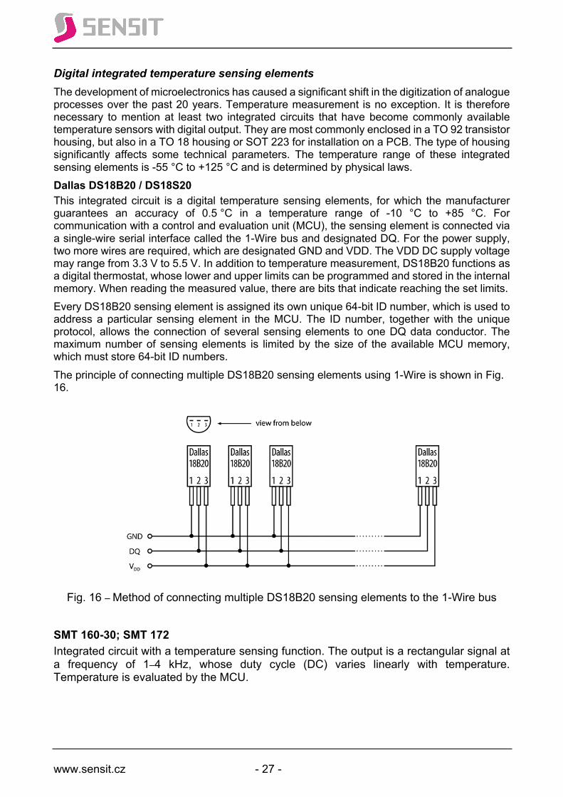
Digital integrated temperature sensing elements The development of microelectronics has caused a significant shift in the digitization of analogue processes over the past 20 years. Temperature measurement is no exception. It is therefore necessary to mention at least two integrated circuits that have become commonly available temperature sensors with digital output. They are most commonly enclosed in a TO 92 transistor housing, but also in a TO 18 housing or SOT 223 for installation on a PCB. The type of housing significantly affects some technical parameters. The temperature range of these integrated sensing elements is -55 °C to +125 °C and is determined by physical laws. Dallas DS18B20 / DS18S20 This integrated circuit is a digital temperature sensing elements, for which the manufacturer guarantees an accuracy of 0.5 °C in a temperature range of -10 °C to +85 °C. For communication with a control and evaluation unit (MCU), the sensing element is connected via a single-wire serial interface called the 1-Wire bus and designated DQ. For the power supply, two more wires are required, which are designated GND and VDD. The VDD DC supply voltage may range from 3.3 V to 5.5 V. In addition to temperature measurement, DS18B20 functions as a digital thermostat, whose lower and upper limits can be programmed and stored in the internal memory. When reading the measured value, there are bits that indicate reaching the set limits. Every DS18B20 sensing element is assigned its own unique 64-bit ID number, which is used to address a particular sensing element in the MCU. The ID number, together with the unique protocol, allows the connection of several sensing elements to one DQ data conductor. The maximum number of sensing elements is limited by the size of the available MCU memory, which must store 64-bit ID numbers. The principle of connecting multiple DS18B20 sensing elements using 1-Wire is shown in Fig. 16.
Fig. 16 – Method of connecting multiple DS18B20 sensing elements to the 1-Wire bus
SMT 160-30; SMT 172 Integrated circuit with a temperature sensing function. The output is a rectangular signal at a frequency of 1–4 kHz, whose duty cycle (DC) varies linearly with temperature. Temperature is evaluated by the MCU.

www.sensit.cz - 28 -
The duty cycle is explained in Fig. 17. The duty cycle is the ratio of the duration of pulse level 1 to the total pulse duration and is dimensionless. The dependence of the DC on temperature is expressed as follows:
DC = 0.32 + 0.0047 x T where T is temperature in °C. When the DC is known, temperature is calculated as follows:
T = 212.77 x DC – 68.085 The DC is calculated as the arithmetic mean of 8 consecutive duty cycles.
Fig. 17 – Calculation of the DC of a rectangular signal
www.sensit.cz - 29 -
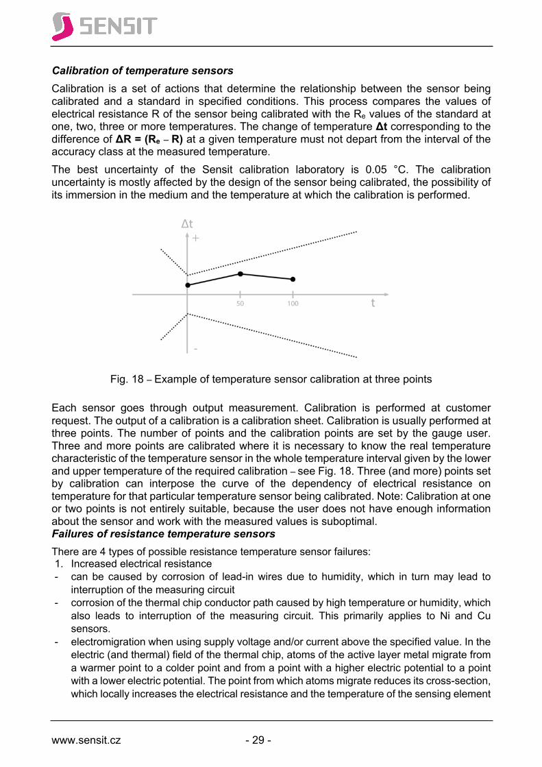
Calibration of temperature sensors Calibration is a set of actions that determine the relationship between the sensor being calibrated and a standard in specified conditions. This process compares the values of electrical resistance R of the sensor being calibrated with the Re values of the standard at one, two, three or more temperatures. The change of temperature Δt corresponding to the difference of ΔR = (Re – R) at a given temperature must not depart from the interval of the accuracy class at the measured temperature. The best uncertainty of the Sensit calibration laboratory is 0.05 °C. The calibration uncertainty is mostly affected by the design of the sensor being calibrated, the possibility of its immersion in the medium and the temperature at which the calibration is performed.
Fig. 18 – Example of temperature sensor calibration at three points
Each sensor goes through output measurement. Calibration is performed at customer request. The output of a calibration is a calibration sheet. Calibration is usually performed at three points. The number of points and the calibration points are set by the gauge user. Three and more points are calibrated where it is necessary to know the real temperature characteristic of the temperature sensor in the whole temperature interval given by the lower and upper temperature of the required calibration – see Fig. 18. Three (and more) points set by calibration can interpose the curve of the dependency of electrical resistance on temperature for that particular temperature sensor being calibrated. Note: Calibration at one or two points is not entirely suitable, because the user does not have enough information about the sensor and work with the measured values is suboptimal. Failures of resistance temperature sensors There are 4 types of possible resistance temperature sensor failures: 1. Increased electrical resistance - can be caused by corrosion of lead-in wires due to humidity, which in turn may lead to
interruption of the measuring circuit - corrosion of the thermal chip conductor path caused by high temperature or humidity, which
also leads to interruption of the measuring circuit. This primarily applies to Ni and Cu sensors.
- electromigration when using supply voltage and/or current above the specified value. In the electric (and thermal) field of the thermal chip, atoms of the active layer metal migrate from a warmer point to a colder point and from a point with a higher electric potential to a point with a lower electric potential. The point from which atoms migrate reduces its cross-section, which locally increases the electrical resistance and the temperature of the sensing element

www.sensit.cz - 30 -
(self-heating). Temperature measurement becomes entirely biased – it shows indefinably higher values. The metal atom migration exponentially increases until the sensor and the entire circuit are completely interrupted. This applies to all metal sensors.
- Connector corrosion – increase of the total resistance by the transient resistance at the connector. This usually does not cause circuit interruption. It is also manifested by a random fluctuation of the resistance value and therefore a fluctuation of the measured value.
2. Open sensor circuit – for the above reasons, where complete interruption of the circuit is preceded by gradually and indefinably increasing electrical resistance of the temperature sensor.
- Mechanically interrupted lead-in wire by twisting, cutting, tearing, etc. 3. Decreased electrical resistance is usually caused by moisture penetration and precipitation
in the area of the cable connection to the chip outlets, which creates parallel resistance. This phenomenon is a precursor to the subsequent increase of resistance and ultimately total destruction by corrosion.
4. Short circuit of the temperature sensor. Short circuits of temperature sensors are mainly caused by - breaking the primary and secondary insulation of both conductors by a metal object - twisting the supply cable
There are 3 types of possible thermocouple failures: 1. Decrease of the thermoelectric voltage by age or long-term exposure to the upper limit
temperature. This failure can be detected by inspection measurement. It is always detected during thermocouple recalibration.
2. Chaotically changing thermoelectric voltage. This failure is caused by mechanical interruption of the thermoelectric joint of the two thermocouple branches
3. Zero thermoelectric voltage. The thermoelectric circuit was either interrupted or short-circuited.
Failures of sensors with an active 4–20mA output: 1. The measuring current is lower than 3.5 mA – the temperature chip branch is short-circuited 2. The measuring current is higher than 23 mA – the temperature chip branch is interrupted 3. The measuring current chaotically changes its value in a range section – the temperature
sensing element exhibits instability for any of the above reasons 4. The measuring current is zero – electronics defect, the power supply is not connected or is
defective
Failures of sensors with an active 0–10V output: 1. The output voltage is permanently 0 V – the temperature sensing element input is short-
circuited 2. The output voltage is higher than 14 V – the temperature sensing element input is interrupted 3. The output voltage chaotically changes its value in a section of its range – the temperature
sensing element exhibits instability for any of the above reasons
www.sensit.cz - 31 -
Installation, operation and maintenance of temperature sensors
1. Work regulations
q Persons installing the sensor must observe laws, regulations and technical standards related to occupational safety.
q During the installation, observe the installation regulations and user manuals of the products.
q Wiring must be carried out by workers qualified at least according to Section 5 of Decree No. 50/1978 Coll., as amended.
2. General rules
q When designing and installing, take into account the properties of the sensor’s surroundings (ambient temperature and humidity range, possibility of splashing water, explosive environment, chemically aggressive environment, flow of the measured medium, vibration and shocks, sunlight, electromagnetic interference). Examples: A sensor for measuring the outdoor temperature should be placed on the northern wall. Beware of cellar windows and ventilation holes that let out warm air.
q When designing and installing, always ask and answer how accurately temperature shall be measured and what time constant is required. The sufficient accuracy for temperature measurement of flue gases is ±5 °C, for temperature measurement of an incubator heating pad ± 0.02 °C. Temperature measurement in the transmission of a wind turbine suffices with a temperature sensor time constant of t0.5 = 180 s; temperature measurement of blood in a patient’s artery requires t0.5 = 1 s.
q When designing and installing, choose the sensor location to minimize the possibility of their mechanical damage as well as personal injury. Place sensors so that they are readily accessible for potential inspection and servicing. If it is required for inspection and servicing reasons, use a disconnectable cable.
q To transmit the signal from the temperature sensor to a larger distance (for Pt 100 above 2 m, for Pt 1000 and Ni 1000 above 10 m), use a transducer according to the input of the control or displaying unit.
q When designing, take into account the properties of the sensor (measuring range, ingress protection, measurement error, accuracy class, maximum measuring current of the sensing element, time constant).
q Sensors generally cannot be used to measure the temperature of objects under voltage. If this is required, the application must be consulted with the sensor manufacturer.
q Sensors must be properly attached. The supply cables must not be mechanically stressed and must be protected against damage.
q Choose the operating position of sensors so that there is no accumulation of liquids around the entrance of the supply cable into the sensor (the bushing must not face upwards).
q The length of the supply cable at the sensor must be chosen so that handling of this cable is easy and safe.
q Observe the electrical and mechanical properties of the supply cable specified by the manufacturer (conductor cross-section, cable outer diameter, cable shielding) in the technical documentation (e.g. in the product’s user manual).
q The sensor’s supply cable should not be routed in the vicinity of conductors or equipment with a disturbing electromagnetic field (high voltage lines, inductive load, pulse and frequency converters, frequency-controlled motors, unshielded transformers).
q In areas with strong electromagnetic interference (industrial halls, etc.), it is advisable to use shielded cables with grounded shielding. When both cable ends are grounded,
www.sensit.cz - 32 -
they must have the same electric potential. Otherwise, large equalizing currents may flow through the shielding. In practice, only one end is grounded.
q Check if the wires of the supply cables are properly fastened in the terminal block by slightly pulling the wires.
q Do not install sensors in areas exposed to sunlight or near heat or cold sources (unless these sources are to be measured by the sensors).
q When measuring the temperature of a surface or object where the temperature sensor is located just under the surface, the measurement results are affected by a system error caused by heat dissipation from the measured point through the sensor housing and supply cables. The size of the error is directly dependent on the difference of the temperature of the measured surface or object and the ambient temperature and on the sensor design. In addition, when measuring the surface temperature of piping, the size of the measurement error is inversely proportional to the pipe diameter. Consequence: The requirement for the calibration of contact temperature sensors is unjustified.
q In order to reduce the error caused by the heat dissipation from the measured object outside the temperature sensor and/or to reduce the time constant of the measured object-temperature sensor system, so-called thermal compounds are applied between the measured object and the temperature sensor. Thermal compounds are usually made of silicone grease as a binder and fine metal dust (Fe, Cu, Al) or metal oxide dust as a filler, whose task is to improve heat transfer. Attention! Applying thermal compounds on vibrating systems may cause abrasion of the surface of the temperature sensor housing and subsequent destruction. Attention! When applying a thermal compound in gearbox thermowells, some gearbox designs may lead to the contamination of the gearbox oil with the thermal compound and subsequent seizure of bearings!!! The use of thermal compounds to measure the temperature of gearboxes is unjustified and can be elegantly avoided by the use of a bayonet mount and the shape of the sensor end.
q ATTENTION when measuring temperature in cold water tanks (air-conditioning unit rooms). These applications ALWAYS require temperature sensors with heads inserted in thermowells!!! Explanation: The sub-ambient temperature at the front of the thermowell results in precipitation of water, which flows down and, due to the physical phenomenon called capillary rise, enters the space between the inner wall of the thermowell and the stem of the sensor. The precipitated water completely fills this space. If there is only a cable temperature sensor inserted in the thermowell instead of a metal sensor stem with a head, it is completely submerged in water. It is only a matter of time when the water penetrates the steel housing of the sensor and at the first moment causes a leakage between the sensor leads (which results in erroneous measurement). After a certain, unpredictable time, it causes corrosive interruption of the conductors of the sensing element itself and thus the destruction of the whole cable temperature sensor.
q When installing a temperature sensor on a room wall using a mounting box, to which cabling is routed in a protective plastic hose (so-called “goose neck”), the end of the protective hose containing the cable should be sealed with expanding foam. There are known cases where air flow through this protective hose affected temperature measurement in the room by a sensor located on a mounting box so that the heating control was therefore non-functional.
q Attention! The connection of temperature sensor with an active (current, voltage, frequency, digital) output must always be carried out when the power is off!
www.sensit.cz - 33 -
q Pay attention when handling excess cable length. Keep in mind that an excess cable coiled into a circle acts like a coil, i.e. impedance entering the electrical circuit. During pulse measurement, this impedance first creates voltage at the terminals of the sensing element and when voltage in the pulse mode drops to zero, current starts flowing through the circuit. As a result, the evaluator does not measure and the temperature sensor appears to be interrupted. Solution: If the installed temperature sensor is not to be applied elsewhere, shorten the supply cable to the minimum required length. For two-wire connection, keep in mind the effect of the resistance of the lead-in wires on the measurement result. Decide when this change may be ignored and when it is necessary to perform a correction in the evaluation unit. Otherwise, route the excess length of the cable so that it does not create impedance (loops).
3. Sensors with a head
q Sensors must be hermetically sealed (tightened bushings, screwed-on lid). q Sensor stems must not be mechanically stressed. Sensors should be ideally attached
using plastic or metal holders supplied as accessories. q Temperature near the sensor head listed in the technical documentation must not be
exceeded, not even for a short time (unless specified otherwise). q Indoor sensors should not be placed in areas with minimum air flow or areas where
temperature is greatly influenced (niches, outer walls, wall shared with an unheated room, chimney wall, near the door, sunlit areas).
q Indoor sensors with a current output must only be installed in the position specified in the technical documentation.
4. Cable sensors
q The temperature range listed in the technical documentation must not be exceeded, not even for a short time (unless specified otherwise).
q Sensor housings must not be mechanically stressed. q The supply cable must be properly mechanically attached. q When choosing a cable temperature sensor, ask the manufacturer if the chosen type is
suitable for your application. q Cable sensors for the measurement of, for example, flue gases are not designed for
humid environments (a heat-resistant cable with glass insulation is hygroscopic, glass fibre insulation is able to hold in moisture that causes corrosion of the lead-in wires as well as the connection between the wires and the sensing element).
q Inappropriate miniaturization of a temperature sensor can affect the measurement accuracy (heat dissipation from the measured point through the supply cable).
q Do not use cable temperature sensors in thermowells on cold water tanks (see general rules above)!
5. Recommended methods of installing thermowells, weld-on pieces and temperature sensors in piping
q General principles for the installation of temperature sensors in piping are given in EN 1434-2 Heat meters – Part 2: Constructional requirements. This standard contains recommended installation procedures for weld-on pieces, thermowells and temperature sensors for various pipe diameters and flow rates. Even though the standard is intended for heat meters, the installation recommendations given here are generally applicable.
q Observance of these principles leads to the required accuracy and reproducibility of measurements.
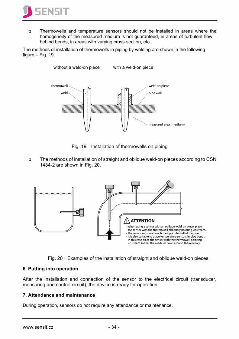
www.sensit.cz - 34 -
q Thermowells and temperature sensors should not be installed in areas where the homogeneity of the measured medium is not guaranteed, in areas of turbulent flow – behind bends, in areas with varying cross-section, etc.
The methods of installation of thermowells in piping by welding are shown in the following figure – Fig. 19.
without a weld-on piece with a weld-on piece
Fig. 19 – Installation of thermowells on piping
q The methods of installation of straight and oblique weld-on pieces according to CSN 1434-2 are shown in Fig. 20.
Fig. 20 – Examples of the installation of straight and oblique weld-on pieces
6. Putting into operation
After the installation and connection of the sensor to the electrical circuit (transducer, measuring and control circuit), the device is ready for operation.
7. Attendance and maintenance
During operation, sensors do not require any attendance or maintenance.

www.sensit.cz - 35 -
When connecting a sensor to an evaluation unit, it is possible that the system may not work or does not work as expected. There are simple procedures to examine the error: – the system does not work, it does not show any temperature. Is the evaluator connected to a power supply of the specified voltage? Is the temperature sensor correctly connected? This is important to check especially in the case of 3-wire or 4-wire connection. If the wiring is OK, disconnect the temperature sensor from the system and measure it with an ohmmeter. Again, pay extra attention in the case of 3-wire and 4-wire connection. If the measured value of resistance of the temperature sensor is zero or in megaohms, the sensor is defective and must be returned (if it is under warranty) or disposed of in an environmentally-friendly way and a new sensor should be ordered. If it shows a resistance value equal to the table value for temperature measured in another way, the sensor is OK and the fault is in the evaluation device. – the system shows temperature that does not correspond to reality. Is the temperature sensor correctly connected? This is important to check especially in the case of 3-wire or 4-wire connection. If the wiring is OK and it is not an indoor temperature sensor, remove the temperature sensor from the thermowell or release it and immerse its whole metal part for at least 10 minutes in crushed ice. Stir the crushed ice occasionally. The greater the weight of the sensor, the longer the immersion time should be. If the ohmmeter shows a sensor resistance value close to the table value of the given type of sensor for 0 °C, it is still too early to tell if the temperature sensor is OK. Now prepare a pot of boiling water and place the temperature sensor in it. Only if after about 5 minutes the ohmmeter shows a resistance value of the temperature sensor close to the table value for 95 °C to 100 °C (an error may result from the water boiling at a lower temperature than 100 °C – the boiling point depends on the air pressure), it is possible to state that the temperature sensor is OK and the fault has to be searched in the evaluation part of the system. Otherwise, the temperature sensor is defective and must be returned (if it is under warranty) or disposed of in an environmentally-friendly way and a new sensor should be ordered. Preparation of crushed ice: wrap pieces of ice (obtained e.g. from a refrigerator – approx ¼ kg) in cloth and crush into pea-sized or smaller pieces. Put the crushed ice into a container and add the coldest possible water to ½ of the height of the crushed ice. Allow the mixture to stabilize for 10 minutes while stirring occasionally. Then put the sensor into it.
8. Repairs
Warranty and post-warranty repairs are performed by the manufacturer. Send products for repairs in the original or equivalent packaging. In order for the warranty repair to be admitted, the product must be provided with the warranty card and undamaged identification plate. 9. Keep in mid the general experience
q The feeling of thermal comfort in a room does not depend only on the room temperature. It is also affected by the relative humidity and air flow.
q Women have the feeling of thermal comfort “set” differently from men. Women can perceive a temperature drop gradient of 0.1 °C/h.
q Two identical commercial thermometers in the same location never show the same temperature.
Ingress protection ratings (IP code) This chapter is included for quick orientation in the IP ratings and is based on
EN 60 529. IP code arrangement: IP XY AH where:
The first letters of the IP code mean International Protection. X = the first characteristic digit from 0 to 6 or the letter X indicates the degree of protection against contact with live parts and from the ingress of solid foreign objects.
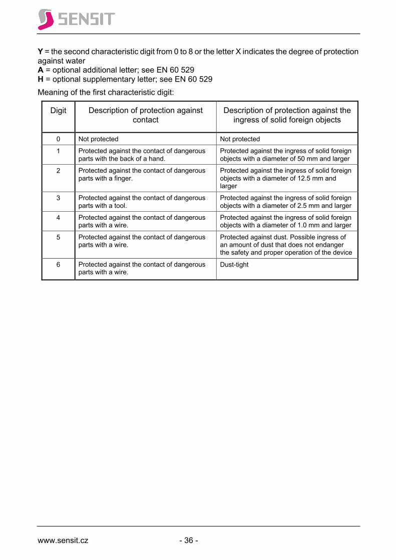
www.sensit.cz - 36 -
Y = the second characteristic digit from 0 to 8 or the letter X indicates the degree of protection against water A = optional additional letter; see EN 60 529 H = optional supplementary letter; see EN 60 529 Meaning of the first characteristic digit:
Digit Description of protection against contact
Description of protection against the ingress of solid foreign objects
0 Not protected Not protected
1 Protected against the contact of dangerous parts with the back of a hand.
Protected against the ingress of solid foreign objects with a diameter of 50 mm and larger
2 Protected against the contact of dangerous parts with a finger.
Protected against the ingress of solid foreign objects with a diameter of 12.5 mm and larger
3 Protected against the contact of dangerous parts with a tool.
Protected against the ingress of solid foreign objects with a diameter of 2.5 mm and larger
4 Protected against the contact of dangerous parts with a wire.
Protected against the ingress of solid foreign objects with a diameter of 1.0 mm and larger
5 Protected against the contact of dangerous parts with a wire.
Protected against dust. Possible ingress of an amount of dust that does not endanger the safety and proper operation of the device
6 Protected against the contact of dangerous parts with a wire.
Dust-tight

www.sensit.cz - 37 -
Meaning of the second characteristic digit (see Chapter 14 of EN 60529):
Digit Description of protection against water
Definition
0 Not protected -
1 Protected against vertically falling water drops
Vertically falling water drops must not have any harmful effects
2 Protected against vertically falling water drops when tilted at 15 °
Vertically falling water drops must not have any harmful effects if the enclosure is tilted at an angle of 15 ° to either side of the perpendicular.
3 Protected against spraying water (rain) Water sprayed at any angle up to 60 ° must not have any harmful effects
4 Protected against splashing water Water splashing from any direction must not have any harmful effects
5 Protected against water jets Water projected by nozzles from any direction against the enclosure must not have any harmful effects
6 Protected against powerful water jets Water projected in powerful jets from any direction against the enclosure must not have any harmful effects
7 Protected against the effects of temporary immersion in water
Under defined pressure and time conditions, the quantity of water that enters the enclosure when temporary immersed does not have harmful effects
8 Protected against the effects of continuous immersion in water
Under conditions agreed between the manufacturer and the customer, which must be stricter than the conditions specified for the characteristic digit 7, the quantity of water that enters the enclosure when continuously immersed must not have harmful effects. 1)
9 Protected against high-pressure, high-temperature water jets
High-pressure, high-temperature water projected by nozzles from any direction against the enclosure must not have any harmful effects
Note: this level can be also designated IP X9 K according to DIN40050-9, where K means high water temperature (above 80 °C).
1) Note: Unless otherwise agreed with the customer, the ingress protection of Sensit temperature sensors of up to IP67 is specified by the manufacturer. The guarantee of IP 68 and IP 69 protection must be supported by tests in an accredited laboratory and is part of type tests.
www.sensit.cz - 38 -
Temperature sensor specification If a potential buyer of a temperature sensor is not sure what type of temperature sensor from the Sensit catalogue they need, they should know if it is a head or cable temperature sensor, and it is always important to know and express the requirements for the sensor application. Sensors with a head
- According to the use: indoors, outdoors, in piping, air conditioning, contact - Plastic or metal head - Type of sensing element – Pt 100, Pt 1000, Ni 1000/5000, Ni 1000/6180 - Output signal – 4–20 mA, 0–10 V – here it is necessary to specify the
temperature range - Stem length – 70, 120, 180 mm… - Stem type – smooth, with a screw union… - Connection – 2-, 3- and 4-wire - Accuracy class - Special requirements – special standards, shock resistance, non-
flammability, etc. - Calibration requirement – at how many and what temperatures
Sensors with a cable:
- Cable type – according to the application temperature, shielded, non-shielded, 2w, 3w or 4w
- Housing type – material and design - Housing length and material, thread type - Type of sensing element – Pt 100, Pt 1000, Ni 1000/5000, Ni 1000/6180… - Accuracy class - Cable length and termination - Special requirements – special standards, shock resistance, non-
flammability, etc. - Calibration requirement – at how many and what temperatures
Standard temperature sensors may be modified – the customer can request a change of any parameter listed as standard. It is mostly the stem length, screw union dimension, installation of two identical or different types of sensing element in one stem or housing, cable length or its termination. If the customer requests a replacement for a temperature sensor of a different manufacturer (replacement) or temperature sensor according to their own specification (custom sensor), for the assessment of production possibilities and subsequent provision of the most accurate offer, they should provide the following information:
- Send a sample of the temperature sensor, preferably functional or non-functional with information about the type of the sensing element
- Send a sketch (even by hand) or drawing or reference to the required sensor in any literature
- Description of the sensor location, the temperature range, whose temperature it measures, the highest temperature it must endure.
www.sensit.cz - 39 -
- Requirement for the type of sensing element - Description of the surroundings of the sensor and the cabling itself (outdoors,
acidic environment, high temperature, rapid temperature changes, vibrations, shocks, etc.) required ingress protection (IP).
- How accurately should it measure, how far the temperature sensor will be from the evaluation unit.
- Special requirements (compliance with special standards, shock resistance, non-flammability, resistance of the environment against electromagnetic disturbance, temperature measurement of an object under voltage, salt water, explosive environment, cryogenic temperatures).
- Required time constant. If you have any questions or concerns, please contact our sales or technical department by calling +420 571 625 571 or via e-mail: [email protected] .

www.sensit.cz - 40 -
Labelling of Sensit temperature sensors Sensit temperature sensors are labelled by identification labels located on the heads and, in the case of cable temperature sensors, by identification sleeves. Unless otherwise agreed with the customer, the sleeve is located on the cable about 10 cm from its free end. The identification sleeve is placed on the cable and heat-shrunk so that it cannot move along the cable without force. The meaning of the data on the identification label and identification sleeve is explained in Fig. 21 and 22.
Fig. 21 – Meaning of data on the identification label
Fig. 22 – Meaning of data on the identification sleeve
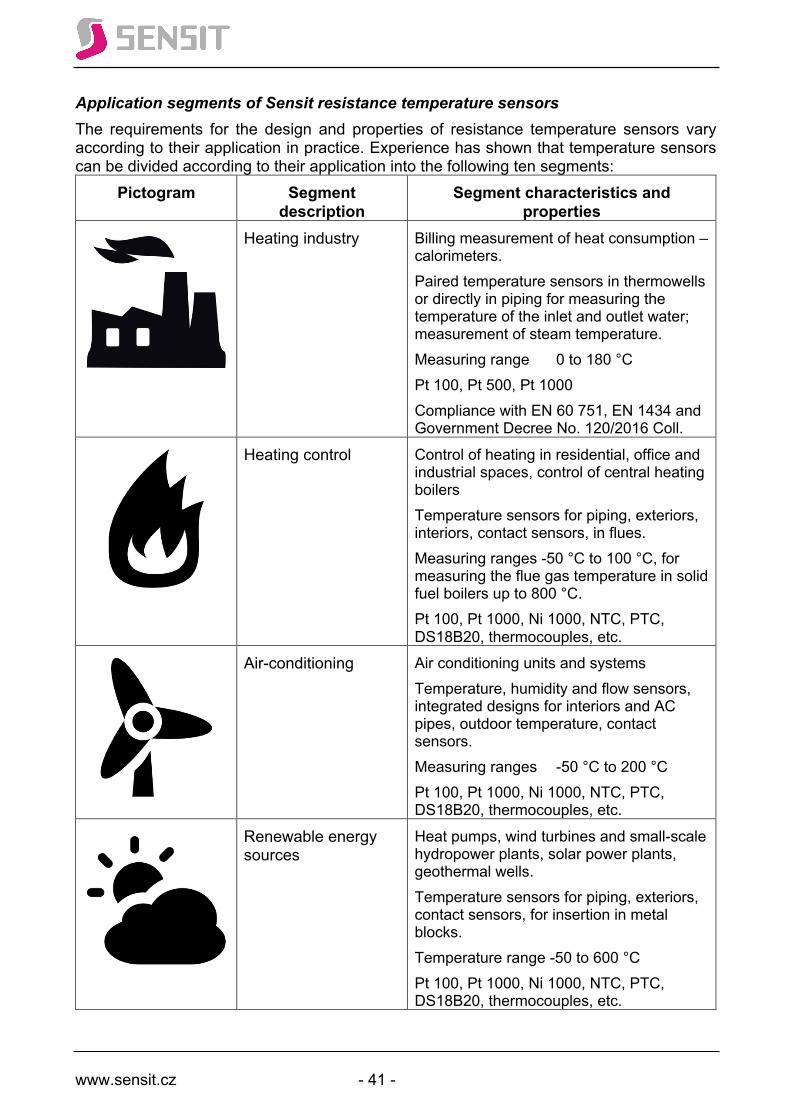
www.sensit.cz - 41 -
Application segments of Sensit resistance temperature sensors The requirements for the design and properties of resistance temperature sensors vary according to their application in practice. Experience has shown that temperature sensors can be divided according to their application into the following ten segments:
Pictogram Segment description
Segment characteristics and properties
Heating industry Billing measurement of heat consumption – calorimeters. Paired temperature sensors in thermowells or directly in piping for measuring the temperature of the inlet and outlet water; measurement of steam temperature. Measuring range 0 to 180 °C Pt 100, Pt 500, Pt 1000 Compliance with EN 60 751, EN 1434 and Government Decree No. 120/2016 Coll.
Heating control Control of heating in residential, office and industrial spaces, control of central heating boilers Temperature sensors for piping, exteriors, interiors, contact sensors, in flues. Measuring ranges -50 °C to 100 °C, for measuring the flue gas temperature in solid fuel boilers up to 800 °C. Pt 100, Pt 1000, Ni 1000, NTC, PTC, DS18B20, thermocouples, etc.
Air-conditioning Air conditioning units and systems Temperature, humidity and flow sensors, integrated designs for interiors and AC pipes, outdoor temperature, contact sensors. Measuring ranges -50 °C to 200 °C Pt 100, Pt 1000, Ni 1000, NTC, PTC, DS18B20, thermocouples, etc.
Renewable energy sources
Heat pumps, wind turbines and small-scale hydropower plants, solar power plants, geothermal wells. Temperature sensors for piping, exteriors, contact sensors, for insertion in metal blocks. Temperature range -50 to 600 °C Pt 100, Pt 1000, Ni 1000, NTC, PTC, DS18B20, thermocouples, etc.
www.sensit.cz - 42 -
Rail vehicles Locomotives, passenger cars, train sets, trams (trolleybuses). Temperature sensors for measuring the temperature of surfaces, metal blocks, air, coolants, oils. Temperature range -50 to 600 °C Pt 100, Pt 1000, Ni 1000, NTC, DS18B20, CAN converters, etc. Shock resistance, electrical safety, EMC, non-flammability, compliance with the requirements of EN 50155, EN 61373, EN 50121-3-2, EN 45545-2 and NFPA 130.
Rubber and plastics industry
Rubber machines and technologies. Temperature sensors for measuring the temperature of rubber and plastic mixtures, metal blocks, oils, coolants. Temperature range -50 to 1,100 °C Pt 100, Pt 1000, Ni 1000, NTC, PTC, DS18B20, thermocouples, etc. Temperature sensors meet the requirements for a short time constant and resistance to pressure, vibration and abrasion.
Healthcare and white goods
Neonatal incubators, medical equipment; washing machines, refrigerators, dryers, irons, microwaves, whirlpools, relaxation facilities, cryogenic chambers, autoclaves. Temperature range -200 to 1,100 °C Pt 100, Pt 1000, Ni 1000, NTC, PTC, DS18B20, thermocouples, etc. Miniature dimensions.
Food industry Smokehouses, bakery ovens, brewhouses, pasteurizers, convection ovens, dairy plants, meat industry, winemaking, food equipment overhauls, distilleries, sugar factories. Temperature sensors with a CLAMP or MILK flange, cable temperature sensors, stick-in temperature probes and multi-point probes. Temperature range -30 to 300 °C Pt 100, Pt 1000, Ni 1000, NTC, PTC, DS18B20, thermocouples, etc. Use of food steels and materials
www.sensit.cz - 43 -
Chemistry, chemical industry
Production of pharmaceuticals, inorganic and organic chemicals, landfill inspection, toiletries, cosmetics. Temperature range -200 to 1,100 °C Pt 100, Pt 1000, Ni 1000, NTC, PTC, DS18B20, thermocouples, etc. Requirements for Zone 2 explosive environment
Science and research Collaboration with universities, technical and research centres, Czech Academy of Sciences, laboratories, testing facilities. Temperature range -200 to 1,100 °C Pt 100, Pt 1000, Ni 1000, NTC, PTC, DS18B20, thermocouples, etc. High accuracy up to 1/10B, stability.
Machines and equipment
The broadest segment in terms of applications Gearboxes, bearings, windings of electric motors, stators, coolants, combustion engine blocks, critical points of technological processes, single-purpose machines and equipment. Cable temperature sensors according to specific requirements. Temperature range -200 to 1,100 °C Pt 100, Pt 1000, Ni 1000, NTC, PTC, DS18B20, thermocouples, etc.
Custom manufacturing
All applications with one-time production or production in small quantities (in units). E.g.: temperature measurement in a pheasant hatchery, measurement of the temperature profile of a bridge road, temperature profile of ground-water heat pump wells, etc. Cable temperature sensors according to specific requirements. Temperature range -200 to 1,100 °C Pt 100, Pt 1000, Ni 1000, NTC, PTC, DS18B20, thermocouples, etc.
The picture can't be displayed.
The picture can't be displayed.

www.sensit.cz - 44 -
Plat
inum
Res
ista
nce
Sens
ors

www.sensit.cz - 45 -
Temperature sensing elements Pt 100, α = 3.851·10-3 °C-1
Basic technical parameters Sensing element Thin-film platinum resistor Maximum range of working temperature -200 to 800 °C 1) Resistance at 0 °C 100 W Long-term resistance stability 0.03 % after 1000 h at t = 400 °C
Recommended / max. direct measuring current Class A: 0.5 mA / 1.2 mA 2)
Class B: 0.8 mA / 2 mA 2)
1) The real range of working temperature of the sensor is given by the design and production technology of the temperature sensor. 2) Applies to a temperature range of -50 to +400 °C
The temperature dependence of the sensing element resistance is expressed as follows: R = 100 (1 + At + Bt2 + C (t-100) t3) in a temperature range of -200 to 0 °C R = 100 (1 + At + Bt2) in a temperature range of 0 to 850 °C
where: A = 3.9083. 10-3 °C-1 B = -5.775. 10-7 °C-2 C = -4.183. 10-12 °C-4
Dependence of resistance on temperature in ohms [W]: °C 0 -1 -2 -3 -4 -5 -6 -7 -8 -9
-200 18.52 -190 22.83 22.40 21.97 21.54 21.11 20.68 20.25 19.82 19.38 18.95 -180 27.10 26.67 26.24 25.82 25.39 24.97 24.54 24.11 23.68 23.25 -170 31.34 30.91 30.49 30.07 29.64 29.22 28.80 28.37 27.95 27.52 -160 35.54 35.12 34.70 34.28 33.86 33.44 33.02 32.60 32.18 31.76 -150 39.72 39.31 38.89 38.47 38.05 37.64 37.22 36.80 36.38 35.96 -140 43.88 43.46 43.05 42.63 42.22 41.80 41.39 40.97 40.56 40.14 -130 48.00 47.59 47.18 46.77 46.36 45.94 45.53 45.12 44.70 44.29 -120 52.11 51.70 51.29 50.88 50.47 50.06 49.65 49.24 48.83 48.42 -110 56.19 55.79 55.38 54.97 54.56 54.15 53.75 53.34 52.93 52.52 -100 60.26 59.85 59.44 59.04 58.63 58.23 57.82 57.41 57.01 56.60 -90 64.30 63.90 63.49 63.09 62.68 62.28 61.88 61.47 61.07 60.66 -80 68.33 67.92 67.52 67.12 66.72 66.31 65.91 65.51 65.11 64.70 -70 72.33 71.93 71.53 71.13 70.73 70.33 69.93 69.53 69.13 68.73 -60 76.33 75.93 75.53 75.13 74.73 74.33 73.93 73.53 73.13 72.73 -50 80.31 79.91 79.51 79.11 78.72 78.32 77.92 77.52 77.12 76.73 -40 84.27 83.87 83.48 83.08 82.69 82.29 81.89 81.50 81.10 80.70 -30 88.22 87.83 87.43 87.04 86.64 86.25 85.85 85.46 85.06 84.67 -20 92.16 91.77 91.37 90.98 90.59 90.19 89.80 89.40 89.01 88.62 -10 96.09 95.69 95.30 94.91 94.52 94.12 93.73 93.34 92.95 92.55 0 100.00 99.61 99.22 98.83 98.44 98.04 97.65 97.26 96.87 96.48
°C 0 1 2 3 4 5 6 7 8 9 0 100.00 100.39 100.78 101.17 101.56 101.95 102.34 102.73 103.12 103.51 10 103.90 104.29 104.68 105.07 105.46 105.85 106.24 106.63 107.02 107.40 20 107.79 108.18 108.57 108.96 109.35 109.73 110.12 110.51 110.90 111.29 30 111.67 112.06 112.45 112.83 113.22 113.61 114.00 114.38 114.77 115.15 40 115.54 115.93 116.31 116.70 117.08 117.47 117.86 118.24 118.63 119.01 50 119.40 119.78 120.17 120.55 120.94 121.32 121.71 122.09 122.47 122.86 60 123.24 123.63 124.01 124.39 124.78 125.16 125.54 125.93 126.31 126.69 70 127.08 127.46 127.84 128.22 128.61 128.99 129.37 129.75 130.13 130.52 80 130.90 131.28 131.66 132.04 132.42 132.80 133.18 133.57 133.95 134.33 90 134.71 135.09 135.47 135.85 136.23 136.61 136.99 137.37 137.75 138.13
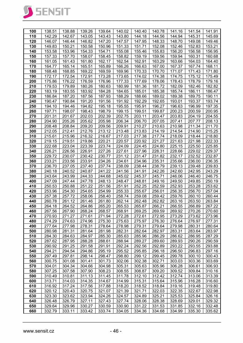
www.sensit.cz - 46 -
100 138.51 138.88 139.26 139.64 140.02 140.40 140.78 141.16 141.54 141.91 110 142.29 142.67 143.05 143.43 143.80 144.18 144.56 144.94 145.31 145.69 120 146.07 146.44 146.82 147.20 147.57 147.95 148.33 148.70 149.08 149.46 130 149.83 150.21 150.58 150.96 151.33 151.71 152.08 152.46 152.83 153.21 140 153.58 153.96 154.33 154.71 155.08 155.46 155.83 156.20 156.58 156.95 150 157.33 157.70 158.07 158.45 158.82 159.19 159.56 159.94 160.31 160.68 160 161.05 161.43 161.80 162.17 162.54 162.91 163.29 163.66 164.03 164.40 170 164.77 165.14 165.51 165.89 166.26 166.63 167.00 167.37 167.74 168.11 180 168.48 168.85 169.22 169.59 169.96 170.33 170.70 171.07 171.43 171.80 190 172.17 172.54 172.91 173.28 173.65 174.02 174.38 174.75 175.12 175.49 200 175.86 176.22 176.59 176.96 177.33 177.69 178.06 178.43 178.79 179.16 210 179.53 179.89 180.26 180.63 180.99 181.36 181.72 182.09 182.46 182.82 220 183.19 183.55 183.92 184.28 184.65 185.01 185.38 185.74 186.11 186.47 230 186.84 187.20 187.56 187.93 188.29 188.66 189.02 189.38 189.75 190.11 240 190.47 190.84 191.20 191.56 191.92 192.29 192.65 193.01 193.37 193.74 250 194.10 194.46 194.82 195.18 195.55 195.91 196.27 196.63 196.99 197.35 260 197.71 198.07 198.43 198.79 199.15 199.51 199.87 200.23 200.59 200.95 270 201.31 201.67 202.03 202.39 202.75 203.11 203.47 203.83 204.19 204.55 280 204.90 205.26 205.62 205.98 206.34 206.70 207.05 207.41 207.77 208.13 290 208.48 208.84 209.20 209.56 209.91 210.27 210.63 210.98 211.34 211.70 300 212.05 212.41 212.76 213.12 213.48 213.83 214.19 214.54 214.90 215.25 310 215.61 215.96 216.32 216.67 217.03 217.38 217.74 218.09 218.44 218.80 320 219.15 219.51 219.86 220.21 220.57 220.92 221.27 221.63 221.98 222.33 330 222.68 223.04 223.39 223.74 224.09 224.45 224.80 225.15 225.50 225.85 340 226.21 226.56 226.91 227.26 227.61 227.96 228.31 228.66 229.02 229.37 350 229.72 230.07 230.42 230.77 231.12 231.47 231.82 232.17 232.52 232.87 360 233.21 233.56 233.91 234.26 234.61 234.96 235.31 235.66 236.00 236.35 370 236.70 237.05 237.40 237.74 238.09 238.44 238.79 239.13 239.48 239.83 380 240.18 240.52 240.87 241.22 241.56 241.91 242.26 242.60 242.95 243.29 390 243.64 243.99 244.33 244.68 245.02 245.37 245.71 246.06 246.40 246.75 400 247.09 247.44 247.78 248.13 248.47 248.81 249.16 249.50 249.85 250.19 410 250.53 250.88 251.22 251.56 251.91 252.25 252.59 252.93 253.28 253.62 420 253.96 254.30 254.65 254.99 255.33 255.67 256.01 256.35 256.70 257.04 430 257.38 257.72 258.06 258.40 258.74 259.08 259.42 259.76 260.10 260.44 440 260.78 261.12 261.46 261.80 262.14 262.48 262.82 263.16 263.50 263.84 450 264.18 264.52 264.86 265.20 265.53 265.87 266.21 266.55 266.89 267.22 460 267.56 267.90 268.24 268.57 268.91 269.25 269.59 269.92 270.26 270.60 470 270.93 271.27 271.61 271.94 272.28 272.61 272.95 273.29 273.62 273.96 480 274.29 274.63 274.96 275.30 275.63 275.97 276.30 276.64 276.97 277.31 490 277.64 277.98 278.31 278.64 278.98 279.31 279.64 279.98 280.31 280.64 500 280.98 281.31 281.64 281.98 282.31 282.64 282.97 283.31 283.64 283.97 510 284.30 284.63 284.97 285.30 285.63 285.96 286.29 286.62 286.95 287.29 520 287.62 287.95 288.28 288.61 288.94 289.27 289.60 289.93 290.26 290.59 530 290.92 291.25 291.58 291.91 292.24 292.56 292.89 293.22 293.55 293.88 540 294.21 294.54 294.86 295.19 295.52 295.85 296.18 296.50 296.83 297.16 550 297.49 297.81 298.14 298.47 298.80 299.12 299.45 299.78 300.10 300.43 560 300.75 301.08 301.41 301.73 302.06 302.38 302.71 303.03 303.36 303.69 570 304.01 304.34 304.66 304.98 305.31 305.63 305.96 306.28 306.61 306.93 580 307.25 307.58 307.90 308.23 308.55 308.87 309.20 309.52 309.84 310.16 590 310.49 310.81 311.13 311.45 311.78 312.10 312.42 312.74 313.06 313.39 600 313.71 314.03 314.35 314.67 314.99 315.31 315.64 315.96 316.28 316.60 610 316.92 317.24 317.56 317.88 318.20 318.52 318.84 319.16 319.48 319.80 620 320.12 320.43 320.75 321.07 321.39 321.71 322.03 322.35 322.67 322.98 630 323.30 323.62 323.94 324.26 324.57 324.89 325.21 325.53 325.84 326.16 640 326.48 326.79 327.11 327.43 327.74 328.06 328.38 328.69 329.01 329.32 650 329.64 329.96 330.27 330.59 330.90 331.22 331.53 331.85 332.16 332.48 660 332.79 333.11 333.42 333.74 334.05 334.36 334.68 334.99 335.30 335.62
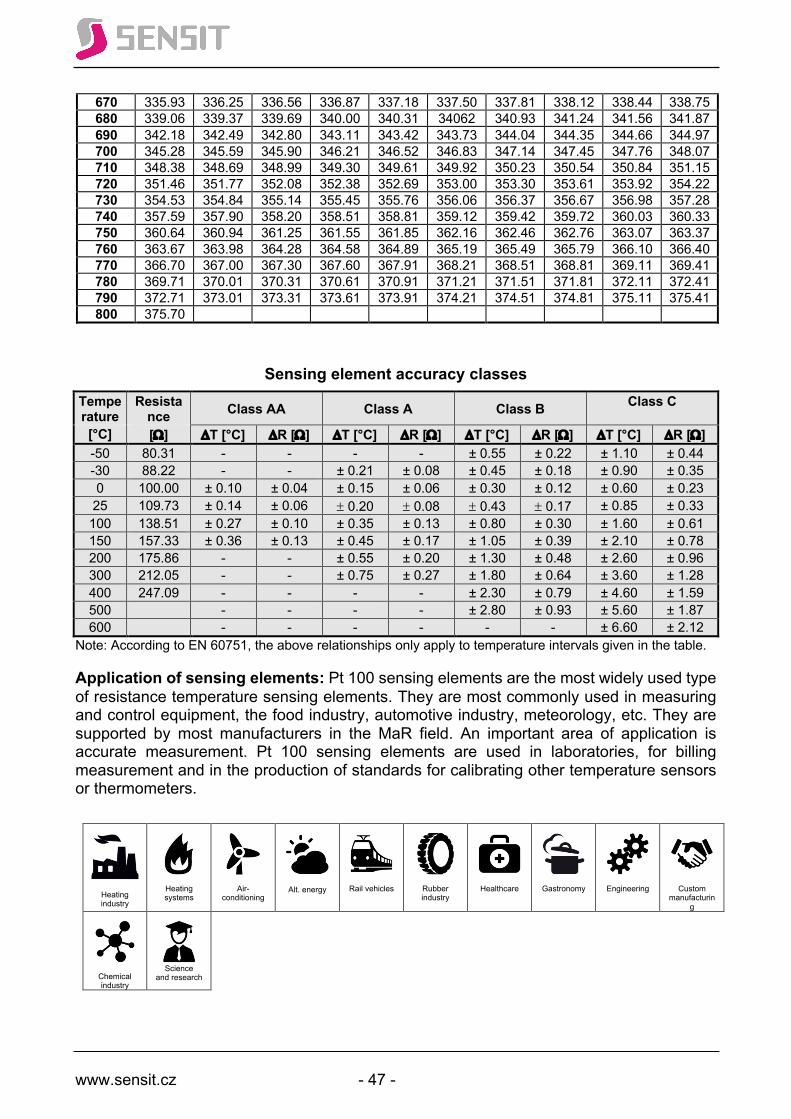
www.sensit.cz - 47 -
670 335.93 336.25 336.56 336.87 337.18 337.50 337.81 338.12 338.44 338.75 680 339.06 339.37 339.69 340.00 340.31 34062 340.93 341.24 341.56 341.87 690 342.18 342.49 342.80 343.11 343.42 343.73 344.04 344.35 344.66 344.97 700 345.28 345.59 345.90 346.21 346.52 346.83 347.14 347.45 347.76 348.07 710 348.38 348.69 348.99 349.30 349.61 349.92 350.23 350.54 350.84 351.15 720 351.46 351.77 352.08 352.38 352.69 353.00 353.30 353.61 353.92 354.22 730 354.53 354.84 355.14 355.45 355.76 356.06 356.37 356.67 356.98 357.28 740 357.59 357.90 358.20 358.51 358.81 359.12 359.42 359.72 360.03 360.33 750 360.64 360.94 361.25 361.55 361.85 362.16 362.46 362.76 363.07 363.37 760 363.67 363.98 364.28 364.58 364.89 365.19 365.49 365.79 366.10 366.40 770 366.70 367.00 367.30 367.60 367.91 368.21 368.51 368.81 369.11 369.41 780 369.71 370.01 370.31 370.61 370.91 371.21 371.51 371.81 372.11 372.41 790 372.71 373.01 373.31 373.61 373.91 374.21 374.51 374.81 375.11 375.41 800 375.70
Sensing element accuracy classes Temperature
Resistance Class AA Class A Class B Class C
[°C] [W] DT [°C] DR [W] DT [°C] DR [W] DT [°C] DR [W] DT [°C] DR [W] -50 80.31 - - - - ± 0.55 ± 0.22 ± 1.10 ± 0.44 -30 88.22 - - ± 0.21 ± 0.08 ± 0.45 ± 0.18 ± 0.90 ± 0.35 0 100.00 ± 0.10 ± 0.04 ± 0.15 ± 0.06 ± 0.30 ± 0.12 ± 0.60 ± 0.23 25 109.73 ± 0.14 ± 0.06 ± 0.20 ± 0.08 ± 0.43 ± 0.17 ± 0.85 ± 0.33 100 138.51 ± 0.27 ± 0.10 ± 0.35 ± 0.13 ± 0.80 ± 0.30 ± 1.60 ± 0.61 150 157.33 ± 0.36 ± 0.13 ± 0.45 ± 0.17 ± 1.05 ± 0.39 ± 2.10 ± 0.78 200 175.86 - - ± 0.55 ± 0.20 ± 1.30 ± 0.48 ± 2.60 ± 0.96 300 212.05 - - ± 0.75 ± 0.27 ± 1.80 ± 0.64 ± 3.60 ± 1.28 400 247.09 - - - - ± 2.30 ± 0.79 ± 4.60 ± 1.59 500 - - - - ± 2.80 ± 0.93 ± 5.60 ± 1.87 600 - - - - - - ± 6.60 ± 2.12
Note: According to EN 60751, the above relationships only apply to temperature intervals given in the table.
Application of sensing elements: Pt 100 sensing elements are the most widely used type of resistance temperature sensing elements. They are most commonly used in measuring and control equipment, the food industry, automotive industry, meteorology, etc. They are supported by most manufacturers in the MaR field. An important area of application is accurate measurement. Pt 100 sensing elements are used in laboratories, for billing measurement and in the production of standards for calibrating other temperature sensors or thermometers.
Heating industry
Heating systems
Air-conditioning
Alt. energy
Rail vehicles
Rubber industry
Healthcare
Gastronomy
Engineering
Custom manufacturin
g
Chemical industry
Science
and research
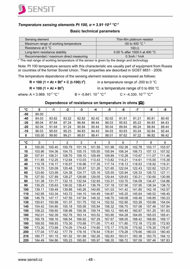
www.sensit.cz - 48 -
Temperature sensing elements Pt 100, α = 3.91·10-3 °C-1
Basic technical parameters
Sensing element Thin-film platinum resistor Maximum range of working temperature -50 to 400 °C * Resistance at 0 °C 100 W Long-term resistance stability 0.05 % after 1000 h at 400 °C Recommended / maximum direct measuring current
0.3mA / 1mA * The real range of working temperature of the sensor is given by the design and technology
Note: Pt 100 temperature sensors with this characteristic are usually part of equipment from Russia or countries of the former Soviet Union. Their properties are described in GOST 6651 - 2009. The temperature dependence of the sensing element resistance is expressed as follows: R = 100 (1 + At + Bt2 + C (t-100) t3) in a temperature range of -200 to 0 °C R = 100 (1 + At + Bt2) in a temperature range of 0 to 850 °C where: A = 3.969. 10-3 °C-1 B = -5.841. 10-7 °C-2 C = -4.330. 10-12 °C-4
Dependence of resistance on temperature in ohms [W]: °C 0 -1 -2 -3 -4 -5 -6 -7 -8 -9 -50 80.00 -40 84.03 83.62 83.22 82.82 82.42 82.02 81.61 81.21 80.81 80.40 -30 88.04 87.64 87.24 86.84 86.44 86.03 85.63 85.23 84.83 84.43 -20 92.04 91.64 91.24 90.84 90.44 90.04 89.64 89.24 88.84 88.44 -10 96.03 95.63 95.23 94.83 94.43 94.03 93.63 93.24 92.84 92.44 0 100.00 99.60 99.21 98.81 98.41 98.01 97.62 97.22 96.82 96.42
°C 0 1 2 3 4 5 6 7 8 9 0 100.00 100.40 100.79 101.19 101.59 101.98 102.38 102.78 103.17 103.57 10 103.96 104.36 104.75 105.15 105.55 105.94 106.34 106.73 107.13 107.52 20 107.91 108.31 108.70 109.10 109.49 109.89 110.28 110.67 111.07 111.46 30 111.85 112.25 112.64 113.03 113.43 113.82 114.21 114.61 115.00 115.39 40 115.78 116.17 116.57 116.96 117.35 117.74 118.13 118.53 118.92 119.31 50 119.70 120.09 120.48 120.87 121.26 121.65 122.04 122.43 122.82 123.21 60 123.60 123.99 124.38 124.77 125.16 125.55 125.94 126.33 126.72 127.11 70 127.50 127.89 128.27 128.66 129.05 129.44 129.83 130.21 130.60 130.99 80 131.38 131.77 132.15 132.54 132.93 133.31 133.70 134.09 134.47 134.86 90 135.25 135.63 136.02 136.41 136.79 137.18 137.56 137.95 138.34 138.72 100 139.11 139.49 139.88 140.26 140.65 141.03 141.42 141.80 142.18 142.57 110 142.95 143.34 143.72 144.10 144.49 144.87 145.25 145.64 146.02 146.40 120 146.79 147.17 147.55 147.94 148.32 148.70 149.08 149.46 149.85 150.23 130 150.61 150.99 151.37 151.75 152.14 152.52 152.90 153.28 153.66 154.04 140 154.42 154.80 155.18 155.56 155.94 156.32 156.70 157.08 157.46 157.84 150 158.22 158.60 158.98 159.36 159.74 160.12 160.49 160.87 161.25 161.63 160 162.01 162.39 162.76 163.14 163.52 163.90 164.28 164.65 165.03 165.41 170 165.78 166.16 166.54 166.92 167.29 167.67 168.05 168.42 168.80 169.17 180 169.55 169.93 170.30 170.68 171.05 171.43 171.80 172.18 172.55 172.93 190 173.30 173.68 174.05 174.43 174.80 175.17 175.55 175.92 176.30 176.67 200 177.04 177.42 177.79 178.16 178.54 178.91 179.28 179.66 180.03 180.40 210 180.77 181.15 181.52 181.89 182.26 182.63 183.01 183.38 183.75 184.12 220 184.49 184.86 185.23 185.60 185.97 186.35 186.72 187.09 187.46 187.83

www.sensit.cz - 49 -
Sensing element accuracy classes
Because EN 60 571 does not apply to Pt 100/3911, it is possible to conclude that even these sensing elements can be classified into two basic accuracy classes expressed as follows:
for -50°C ≤ t ≤ 400°C Class A DT = ± ( 0.15 + 0.002 * | t | ) in °C Class B DT = ± ( 0.30 + 0.005 * | t | ) in °C
* | t | is the absolute value of temperature.
Temperature Resistance Class A Class B [°C] [W] DT [°C] DR [W] DT [°C] DR [W] -50 80.00 ± 0.25 ± 0.10 ± 0.55 ± 0.22 0 100.00 ± 0.15 ± 0.06 ± 0.30 ± 0.12
100 139.11 ± 0.35 ± 0.13 ± 0.80 ± 0.30 200 177.04 ± 0.55 ± 0.20 ± 1.30 ± 0.47 400 249.44 ± 0.95 ± 0.33 ± 2.30 ± 0.79
Application of sensing elements:
Heating industry
Heating systems
Air-conditioning
Alt. energy
Rail vehicles
Rubber industry
Healthcare
Gastronomy
Engineering
Custom manufacturin
g
Chemical industry
Science
and research
230 188.20 188.57 188.94 189.31 189.68 190.05 190.4 190.78 191.15 191.52 240 191.89 192.26 192.63 193.00 193.37 193.73 194.10 194.47 194.84 195.21 250 195.57 195.94 196.31 196.68 197.04 197.41 197.78 198.15 198.51 198.88 260 199.25 199.61 199.98 200.34 200.71 201.08 201.44 201.81 202.17 202.54 270 202.90 203.27 203.64 204.00 204.37 204.73 205.09 205.46 205.82 206.19 280 206.55 206.92 207.28 207.64 208.01 208.37 208.74 209.10 209.46 209.83 290 210.19 210.55 210.91 211.28 211.64 212.00 212.36 212.73 213.09 213.45 300 213.81 214.17 214.54 214.90 215.26 215.62 215.98 216.34 216.70 217.07 310 217.43 217.79 218.15 218.51 218.87 219.23 219.59 219.95 220.31 220.67 320 221.03 221.39 221.75 222.10 222.46 222.82 223.18 223.54 223.90 224.26 330 224.62 224.97 225.33 225.69 226.05 226.41 226.76 227.12 227.48 227.84 340 228.19 228.55 228.91 229.26 229.62 229.98 230.33 230.69 231.05 231.40 350 231.76 232.12 232.47 232.83 233.18 233.54 233.89 234.25 234.60 234.96 360 235.31 235.67 236.02 236.38 236.73 237.09 237.44 237.80 238.15 238.50 370 238.86 239.21 239.56 239.92 240.27 240.62 240.98 241.33 241.68 242.04 380 242.39 242.74 243.09 243.44 243.80 244.15 244.50 244.85 245.20 245.56 390 245.91 246.26 246.61 246.96 247.31 247.66 248.01 248.36 248.71 249.06 400 249.41
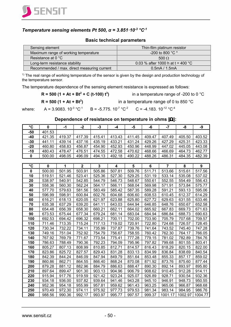
www.sensit.cz - 50 -
Temperature sensing elements Pt 500, α = 3.851·10-3 °C-1
Basic technical parameters Sensing element Thin-film platinum resistor Maximum range of working temperature -200 to 800 °C * Resistance at 0 °C 500 W Long-term resistance stability 0.03 % after 1000 h at t = 400 °C Recommended / max. direct measuring current 0.5mA / 1.5mA
1) The real range of working temperature of the sensor is given by the design and production technology of the temperature sensor.
The temperature dependence of the sensing element resistance is expressed as follows: R = 500 (1 + At + Bt2 + C (t-100) t3) in a temperature range of -200 to 0 °C R = 500 (1 + At + Bt2) in a temperature range of 0 to 850 °C
where: A = 3.9083. 10-3 °C-1 B = -5.775. 10-7 °C-2 C = -4.183. 10-12 °C-4
Dependence of resistance on temperature in ohms [W]: °C 0 -1 -2 -3 -4 -5 -6 -7 -8 -9 -50 401.53 -40 421.35 419.37 417.39 415.41 413.43 411.45 409.47 407.49 405.50 403.52 -30 441.11 439.14 437.16 435.19 433.21 431.24 429.26 427.29 425.31 423.33 -20 460.80 458.83 456.87 454.90 452.93 450.96 448.99 447.02 445.05 443.08 -10 480.43 478.47 476.51 474.55 472.58 470.62 468.66 466.69 464.73 462.77 0 500.00 498.05 496.09 494.13 492.18 490.22 488.26 486.31 484.35 482.39
°C 0 1 2 3 4 5 6 7 8 9 0 500.00 501.95 503.91 505.86 507.81 509.76 511.71 513.66 515.61 517.56 10 519.51 521.46 523.41 525.36 527.30 529.25 531.19 533.14 535.08 537.02 20 538.97 540.91 542.85 544.79 546.73 548.67 550.61 552.55 554.49 556.43 30 558.36 560.30 562.24 564.17 566.11 568.04 569.98 571.91 573.84 575.77 40 577.70 579.63 581.56 583.49 585.42 587.35 589.28 591.21 593.13 595.06 50 596.99 598.91 600.84 602.76 604.68 606.60 608.53 610.45 612.37 614.29 60 616.21 618.13 620.05 621.97 623.88 625.80 627.72 629.63 631.55 633.46 70 635.38 637.29 639.20 641.11 643.03 644.94 646.85 648.76 650.67 652.58 80 654.48 656.39 658.30 660.21 662.11 664.02 665.92 667.83 669.73 671.63 90 673.53 675.44 677.34 679.24 681.14 683.04 684.94 686.84 688.73 690.63 100 692.53 694.42 696.32 698.21 700.11 702.00 703.90 705.79 707.68 709.57 110 711.46 713.35 715.24 717.13 719.02 720.91 722.80 724.68 726.57 728.45 120 730.34 732.22 734.11 735.99 737.87 739.76 741.64 743.52 745.40 747.28 130 749.16 751.04 752.92 754.79 756.67 758.55 760.42 762.30 764.17 766.05 140 767.92 769.79 771.67 773.54 775.41 777.28 779.15 781.02 782.89 784.76 150 786.63 788.49 790.36 792.23 794.09 795.96 797.82 799.68 801.55 803.41 160 805.27 807.13 808.99 810.85 812.71 814.57 816.43 818.29 820.15 822.00 170 823.86 825.72 827.57 829.43 831.28 833.13 834.99 836.84 838.69 840.54 180 842.39 844.24 846.09 847.94 849.79 851.64 853.48 855.33 857.17 859.02 190 860.86 862.71 864.55 866.40 868.24 870.08 871.92 873.76 875.60 877.44 200 879.28 881.12 882.96 884.79 886.63 888.47 890.30 892.14 893.97 895.80 210 897.64 899.47 901.30 903.13 904.96 906.79 908.62 910.45 912.28 914.11 220 915.94 917.76 919.59 921.42 923.24 925.07 926.89 928.71 930.54 932.36 230 934.18 936.00 937.82 939.64 941.46 943.28 945.10 946.91 948.73 950.55 240 952.36 954.18 955.99 957.81 959.62 961.43 963.25 965.06 966.87 968.68 250 970.49 972.30 974.11 975.92 977.73 979.53 981.34 983.14 984.95 986.76 260 988.56 990.36 992.17 993.97 995.77 997.57 999.37 1001.17 1002.97 1004.77
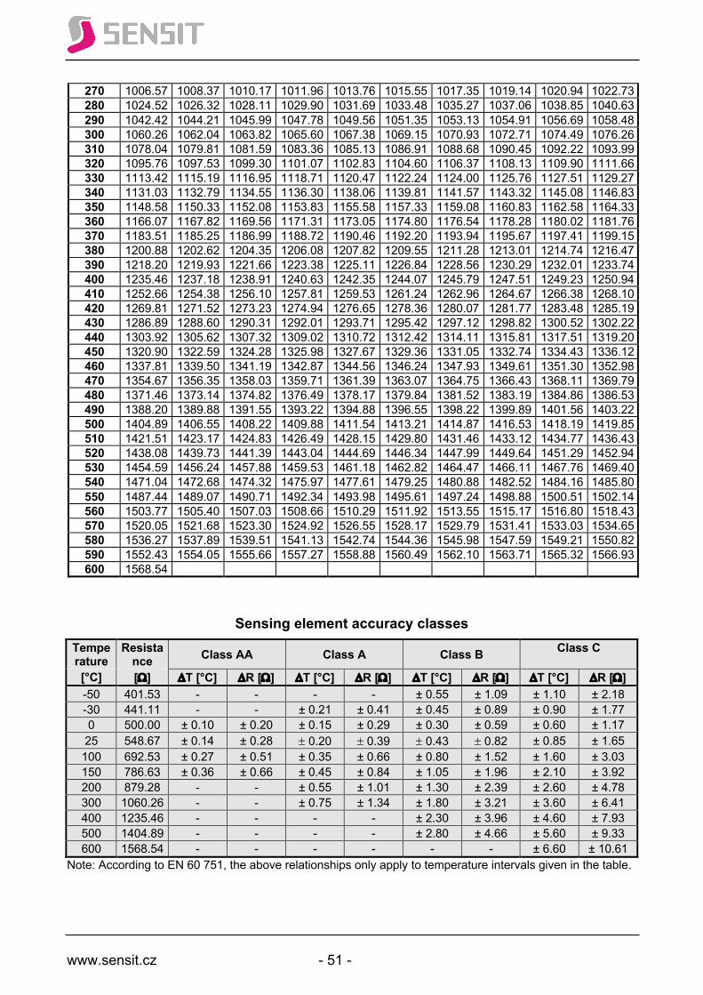
www.sensit.cz - 51 -
270 1006.57 1008.37 1010.17 1011.96 1013.76 1015.55 1017.35 1019.14 1020.94 1022.73 280 1024.52 1026.32 1028.11 1029.90 1031.69 1033.48 1035.27 1037.06 1038.85 1040.63 290 1042.42 1044.21 1045.99 1047.78 1049.56 1051.35 1053.13 1054.91 1056.69 1058.48 300 1060.26 1062.04 1063.82 1065.60 1067.38 1069.15 1070.93 1072.71 1074.49 1076.26 310 1078.04 1079.81 1081.59 1083.36 1085.13 1086.91 1088.68 1090.45 1092.22 1093.99 320 1095.76 1097.53 1099.30 1101.07 1102.83 1104.60 1106.37 1108.13 1109.90 1111.66 330 1113.42 1115.19 1116.95 1118.71 1120.47 1122.24 1124.00 1125.76 1127.51 1129.27 340 1131.03 1132.79 1134.55 1136.30 1138.06 1139.81 1141.57 1143.32 1145.08 1146.83 350 1148.58 1150.33 1152.08 1153.83 1155.58 1157.33 1159.08 1160.83 1162.58 1164.33 360 1166.07 1167.82 1169.56 1171.31 1173.05 1174.80 1176.54 1178.28 1180.02 1181.76 370 1183.51 1185.25 1186.99 1188.72 1190.46 1192.20 1193.94 1195.67 1197.41 1199.15 380 1200.88 1202.62 1204.35 1206.08 1207.82 1209.55 1211.28 1213.01 1214.74 1216.47 390 1218.20 1219.93 1221.66 1223.38 1225.11 1226.84 1228.56 1230.29 1232.01 1233.74 400 1235.46 1237.18 1238.91 1240.63 1242.35 1244.07 1245.79 1247.51 1249.23 1250.94 410 1252.66 1254.38 1256.10 1257.81 1259.53 1261.24 1262.96 1264.67 1266.38 1268.10 420 1269.81 1271.52 1273.23 1274.94 1276.65 1278.36 1280.07 1281.77 1283.48 1285.19 430 1286.89 1288.60 1290.31 1292.01 1293.71 1295.42 1297.12 1298.82 1300.52 1302.22 440 1303.92 1305.62 1307.32 1309.02 1310.72 1312.42 1314.11 1315.81 1317.51 1319.20 450 1320.90 1322.59 1324.28 1325.98 1327.67 1329.36 1331.05 1332.74 1334.43 1336.12 460 1337.81 1339.50 1341.19 1342.87 1344.56 1346.24 1347.93 1349.61 1351.30 1352.98 470 1354.67 1356.35 1358.03 1359.71 1361.39 1363.07 1364.75 1366.43 1368.11 1369.79 480 1371.46 1373.14 1374.82 1376.49 1378.17 1379.84 1381.52 1383.19 1384.86 1386.53 490 1388.20 1389.88 1391.55 1393.22 1394.88 1396.55 1398.22 1399.89 1401.56 1403.22 500 1404.89 1406.55 1408.22 1409.88 1411.54 1413.21 1414.87 1416.53 1418.19 1419.85 510 1421.51 1423.17 1424.83 1426.49 1428.15 1429.80 1431.46 1433.12 1434.77 1436.43 520 1438.08 1439.73 1441.39 1443.04 1444.69 1446.34 1447.99 1449.64 1451.29 1452.94 530 1454.59 1456.24 1457.88 1459.53 1461.18 1462.82 1464.47 1466.11 1467.76 1469.40 540 1471.04 1472.68 1474.32 1475.97 1477.61 1479.25 1480.88 1482.52 1484.16 1485.80 550 1487.44 1489.07 1490.71 1492.34 1493.98 1495.61 1497.24 1498.88 1500.51 1502.14 560 1503.77 1505.40 1507.03 1508.66 1510.29 1511.92 1513.55 1515.17 1516.80 1518.43 570 1520.05 1521.68 1523.30 1524.92 1526.55 1528.17 1529.79 1531.41 1533.03 1534.65 580 1536.27 1537.89 1539.51 1541.13 1542.74 1544.36 1545.98 1547.59 1549.21 1550.82 590 1552.43 1554.05 1555.66 1557.27 1558.88 1560.49 1562.10 1563.71 1565.32 1566.93 600 1568.54
Sensing element accuracy classes Temperature
Resistance Class AA Class A Class B Class C
[°C] [W] DT [°C] DR [W] DT [°C] DR [W] DT [°C] DR [W] DT [°C] DR [W] -50 401.53 - - - - ± 0.55 ± 1.09 ± 1.10 ± 2.18 -30 441.11 - - ± 0.21 ± 0.41 ± 0.45 ± 0.89 ± 0.90 ± 1.77 0 500.00 ± 0.10 ± 0.20 ± 0.15 ± 0.29 ± 0.30 ± 0.59 ± 0.60 ± 1.17 25 548.67 ± 0.14 ± 0.28 ± 0.20 ± 0.39 ± 0.43 ± 0.82 ± 0.85 ± 1.65 100 692.53 ± 0.27 ± 0.51 ± 0.35 ± 0.66 ± 0.80 ± 1.52 ± 1.60 ± 3.03 150 786.63 ± 0.36 ± 0.66 ± 0.45 ± 0.84 ± 1.05 ± 1.96 ± 2.10 ± 3.92 200 879.28 - - ± 0.55 ± 1.01 ± 1.30 ± 2.39 ± 2.60 ± 4.78 300 1060.26 - - ± 0.75 ± 1.34 ± 1.80 ± 3.21 ± 3.60 ± 6.41 400 1235.46 - - - - ± 2.30 ± 3.96 ± 4.60 ± 7.93 500 1404.89 - - - - ± 2.80 ± 4.66 ± 5.60 ± 9.33 600 1568.54 - - - - - - ± 6.60 ± 10.61
Note: According to EN 60 751, the above relationships only apply to temperature intervals given in the table.
www.sensit.cz - 52 -
Application of sensing elements:
Heating industry
Heating systems
Custom manufacturin
g
Notes:
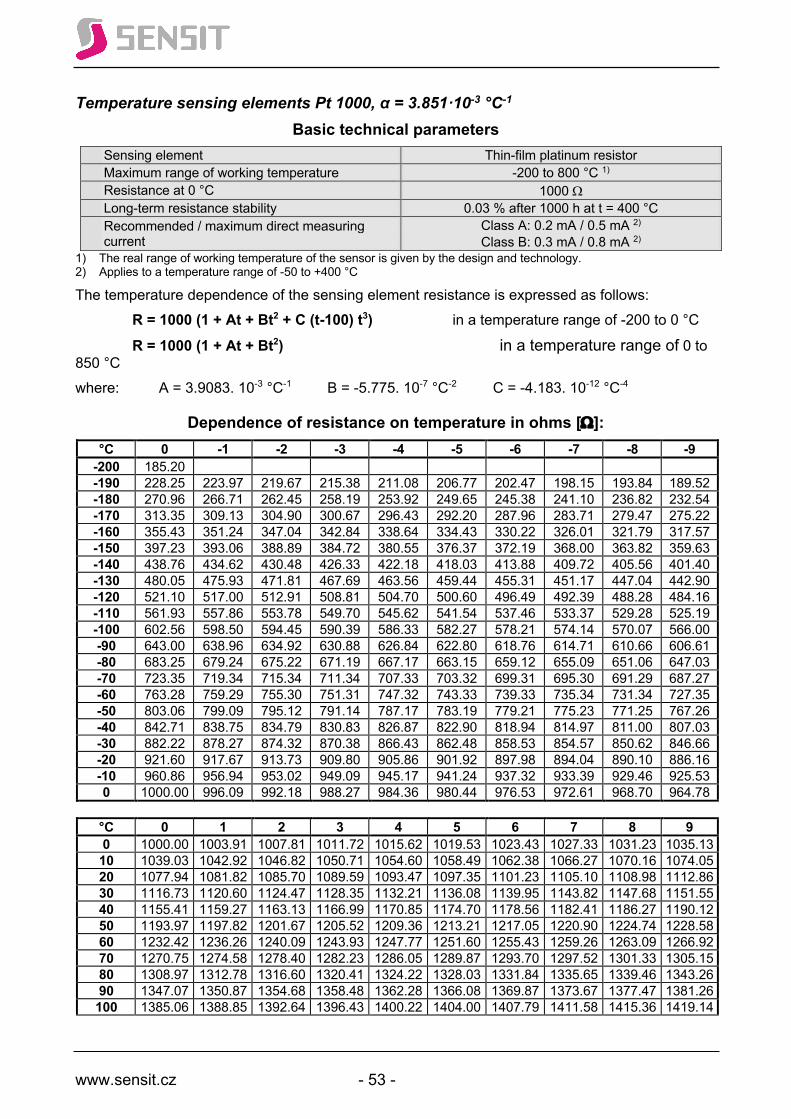
www.sensit.cz - 53 -
Temperature sensing elements Pt 1000, α = 3.851·10-3 °C-1
Basic technical parameters Sensing element Thin-film platinum resistor Maximum range of working temperature -200 to 800 °C 1) Resistance at 0 °C 1000 W Long-term resistance stability 0.03 % after 1000 h at t = 400 °C Recommended / maximum direct measuring current
Class A: 0.2 mA / 0.5 mA 2)
Class B: 0.3 mA / 0.8 mA 2) 1) The real range of working temperature of the sensor is given by the design and technology. 2) Applies to a temperature range of -50 to +400 °C
The temperature dependence of the sensing element resistance is expressed as follows: R = 1000 (1 + At + Bt2 + C (t-100) t3) in a temperature range of -200 to 0 °C R = 1000 (1 + At + Bt2) in a temperature range of 0 to 850 °C where: A = 3.9083. 10-3 °C-1 B = -5.775. 10-7 °C-2 C = -4.183. 10-12 °C-4
Dependence of resistance on temperature in ohms [W]: °C 0 -1 -2 -3 -4 -5 -6 -7 -8 -9
-200 185.20 -190 228.25 223.97 219.67 215.38 211.08 206.77 202.47 198.15 193.84 189.52 -180 270.96 266.71 262.45 258.19 253.92 249.65 245.38 241.10 236.82 232.54 -170 313.35 309.13 304.90 300.67 296.43 292.20 287.96 283.71 279.47 275.22 -160 355.43 351.24 347.04 342.84 338.64 334.43 330.22 326.01 321.79 317.57 -150 397.23 393.06 388.89 384.72 380.55 376.37 372.19 368.00 363.82 359.63 -140 438.76 434.62 430.48 426.33 422.18 418.03 413.88 409.72 405.56 401.40 -130 480.05 475.93 471.81 467.69 463.56 459.44 455.31 451.17 447.04 442.90 -120 521.10 517.00 512.91 508.81 504.70 500.60 496.49 492.39 488.28 484.16 -110 561.93 557.86 553.78 549.70 545.62 541.54 537.46 533.37 529.28 525.19 -100 602.56 598.50 594.45 590.39 586.33 582.27 578.21 574.14 570.07 566.00 -90 643.00 638.96 634.92 630.88 626.84 622.80 618.76 614.71 610.66 606.61 -80 683.25 679.24 675.22 671.19 667.17 663.15 659.12 655.09 651.06 647.03 -70 723.35 719.34 715.34 711.34 707.33 703.32 699.31 695.30 691.29 687.27 -60 763.28 759.29 755.30 751.31 747.32 743.33 739.33 735.34 731.34 727.35 -50 803.06 799.09 795.12 791.14 787.17 783.19 779.21 775.23 771.25 767.26 -40 842.71 838.75 834.79 830.83 826.87 822.90 818.94 814.97 811.00 807.03 -30 882.22 878.27 874.32 870.38 866.43 862.48 858.53 854.57 850.62 846.66 -20 921.60 917.67 913.73 909.80 905.86 901.92 897.98 894.04 890.10 886.16 -10 960.86 956.94 953.02 949.09 945.17 941.24 937.32 933.39 929.46 925.53 0 1000.00 996.09 992.18 988.27 984.36 980.44 976.53 972.61 968.70 964.78
°C 0 1 2 3 4 5 6 7 8 9 0 1000.00 1003.91 1007.81 1011.72 1015.62 1019.53 1023.43 1027.33 1031.23 1035.13 10 1039.03 1042.92 1046.82 1050.71 1054.60 1058.49 1062.38 1066.27 1070.16 1074.05 20 1077.94 1081.82 1085.70 1089.59 1093.47 1097.35 1101.23 1105.10 1108.98 1112.86 30 1116.73 1120.60 1124.47 1128.35 1132.21 1136.08 1139.95 1143.82 1147.68 1151.55 40 1155.41 1159.27 1163.13 1166.99 1170.85 1174.70 1178.56 1182.41 1186.27 1190.12 50 1193.97 1197.82 1201.67 1205.52 1209.36 1213.21 1217.05 1220.90 1224.74 1228.58 60 1232.42 1236.26 1240.09 1243.93 1247.77 1251.60 1255.43 1259.26 1263.09 1266.92 70 1270.75 1274.58 1278.40 1282.23 1286.05 1289.87 1293.70 1297.52 1301.33 1305.15 80 1308.97 1312.78 1316.60 1320.41 1324.22 1328.03 1331.84 1335.65 1339.46 1343.26 90 1347.07 1350.87 1354.68 1358.48 1362.28 1366.08 1369.87 1373.67 1377.47 1381.26 100 1385.06 1388.85 1392.64 1396.43 1400.22 1404.00 1407.79 1411.58 1415.36 1419.14
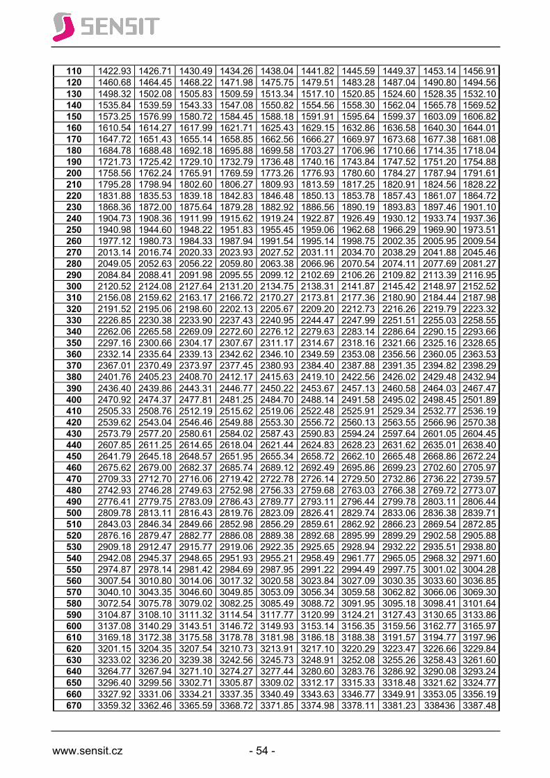
www.sensit.cz - 54 -
110 1422.93 1426.71 1430.49 1434.26 1438.04 1441.82 1445.59 1449.37 1453.14 1456.91 120 1460.68 1464.45 1468.22 1471.98 1475.75 1479.51 1483.28 1487.04 1490.80 1494.56 130 1498.32 1502.08 1505.83 1509.59 1513.34 1517.10 1520.85 1524.60 1528.35 1532.10 140 1535.84 1539.59 1543.33 1547.08 1550.82 1554.56 1558.30 1562.04 1565.78 1569.52 150 1573.25 1576.99 1580.72 1584.45 1588.18 1591.91 1595.64 1599.37 1603.09 1606.82 160 1610.54 1614.27 1617.99 1621.71 1625.43 1629.15 1632.86 1636.58 1640.30 1644.01 170 1647.72 1651.43 1655.14 1658.85 1662.56 1666.27 1669.97 1673.68 1677.38 1681.08 180 1684.78 1688.48 1692.18 1695.88 1699.58 1703.27 1706.96 1710.66 1714.35 1718.04 190 1721.73 1725.42 1729.10 1732.79 1736.48 1740.16 1743.84 1747.52 1751.20 1754.88 200 1758.56 1762.24 1765.91 1769.59 1773.26 1776.93 1780.60 1784.27 1787.94 1791.61 210 1795.28 1798.94 1802.60 1806.27 1809.93 1813.59 1817.25 1820.91 1824.56 1828.22 220 1831.88 1835.53 1839.18 1842.83 1846.48 1850.13 1853.78 1857.43 1861.07 1864.72 230 1868.36 1872.00 1875.64 1879.28 1882.92 1886.56 1890.19 1893.83 1897.46 1901.10 240 1904.73 1908.36 1911.99 1915.62 1919.24 1922.87 1926.49 1930.12 1933.74 1937.36 250 1940.98 1944.60 1948.22 1951.83 1955.45 1959.06 1962.68 1966.29 1969.90 1973.51 260 1977.12 1980.73 1984.33 1987.94 1991.54 1995.14 1998.75 2002.35 2005.95 2009.54 270 2013.14 2016.74 2020.33 2023.93 2027.52 2031.11 2034.70 2038.29 2041.88 2045.46 280 2049.05 2052.63 2056.22 2059.80 2063.38 2066.96 2070.54 2074.11 2077.69 2081.27 290 2084.84 2088.41 2091.98 2095.55 2099.12 2102.69 2106.26 2109.82 2113.39 2116.95 300 2120.52 2124.08 2127.64 2131.20 2134.75 2138.31 2141.87 2145.42 2148.97 2152.52 310 2156.08 2159.62 2163.17 2166.72 2170.27 2173.81 2177.36 2180.90 2184.44 2187.98 320 2191.52 2195.06 2198.60 2202.13 2205.67 2209.20 2212.73 2216.26 2219.79 2223.32 330 2226.85 2230.38 2233.90 2237.43 2240.95 2244.47 2247.99 2251.51 2255.03 2258.55 340 2262.06 2265.58 2269.09 2272.60 2276.12 2279.63 2283.14 2286.64 2290.15 2293.66 350 2297.16 2300.66 2304.17 2307.67 2311.17 2314.67 2318.16 2321.66 2325.16 2328.65 360 2332.14 2335.64 2339.13 2342.62 2346.10 2349.59 2353.08 2356.56 2360.05 2363.53 370 2367.01 2370.49 2373.97 2377.45 2380.93 2384.40 2387.88 2391.35 2394.82 2398.29 380 2401.76 2405.23 2408.70 2412.17 2415.63 2419.10 2422.56 2426.02 2429.48 2432.94 390 2436.40 2439.86 2443.31 2446.77 2450.22 2453.67 2457.13 2460.58 2464.03 2467.47 400 2470.92 2474.37 2477.81 2481.25 2484.70 2488.14 2491.58 2495.02 2498.45 2501.89 410 2505.33 2508.76 2512.19 2515.62 2519.06 2522.48 2525.91 2529.34 2532.77 2536.19 420 2539.62 2543.04 2546.46 2549.88 2553.30 2556.72 2560.13 2563.55 2566.96 2570.38 430 2573.79 2577.20 2580.61 2584.02 2587.43 2590.83 2594.24 2597.64 2601.05 2604.45 440 2607.85 2611.25 2614.65 2618.04 2621.44 2624.83 2628.23 2631.62 2635.01 2638.40 450 2641.79 2645.18 2648.57 2651.95 2655.34 2658.72 2662.10 2665.48 2668.86 2672.24 460 2675.62 2679.00 2682.37 2685.74 2689.12 2692.49 2695.86 2699.23 2702.60 2705.97 470 2709.33 2712.70 2716.06 2719.42 2722.78 2726.14 2729.50 2732.86 2736.22 2739.57 480 2742.93 2746.28 2749.63 2752.98 2756.33 2759.68 2763.03 2766.38 2769.72 2773.07 490 2776.41 2779.75 2783.09 2786.43 2789.77 2793.11 2796.44 2799.78 2803.11 2806.44 500 2809.78 2813.11 2816.43 2819.76 2823.09 2826.41 2829.74 2833.06 2836.38 2839.71 510 2843.03 2846.34 2849.66 2852.98 2856.29 2859.61 2862.92 2866.23 2869.54 2872.85 520 2876.16 2879.47 2882.77 2886.08 2889.38 2892.68 2895.99 2899.29 2902.58 2905.88 530 2909.18 2912.47 2915.77 2919.06 2922.35 2925.65 2928.94 2932.22 2935.51 2938.80 540 2942.08 2945.37 2948.65 2951.93 2955.21 2958.49 2961.77 2965.05 2968.32 2971.60 550 2974.87 2978.14 2981.42 2984.69 2987.95 2991.22 2994.49 2997.75 3001.02 3004.28 560 3007.54 3010.80 3014.06 3017.32 3020.58 3023.84 3027.09 3030.35 3033.60 3036.85 570 3040.10 3043.35 3046.60 3049.85 3053.09 3056.34 3059.58 3062.82 3066.06 3069.30 580 3072.54 3075.78 3079.02 3082.25 3085.49 3088.72 3091.95 3095.18 3098.41 3101.64 590 3104.87 3108.10 3111.32 3114.54 3117.77 3120.99 3124.21 3127.43 3130.65 3133.86 600 3137.08 3140.29 3143.51 3146.72 3149.93 3153.14 3156.35 3159.56 3162.77 3165.97 610 3169.18 3172.38 3175.58 3178.78 3181.98 3186.18 3188.38 3191.57 3194.77 3197.96 620 3201.15 3204.35 3207.54 3210.73 3213.91 3217.10 3220.29 3223.47 3226.66 3229.84 630 3233.02 3236.20 3239.38 3242.56 3245.73 3248.91 3252.08 3255.26 3258.43 3261.60 640 3264.77 3267.94 3271.10 3274.27 3277.44 3280.60 3283.76 3286.92 3290.08 3293.24 650 3296.40 3299.56 3302.71 3305.87 3309.02 3312.17 3315.33 3318.48 3321.62 3324.77 660 3327.92 3331.06 3334.21 3337.35 3340.49 3343.63 3346.77 3349.91 3353.05 3356.19 670 3359.32 3362.46 3365.59 3368.72 3371.85 3374.98 3378.11 3381.23 338436 3387.48
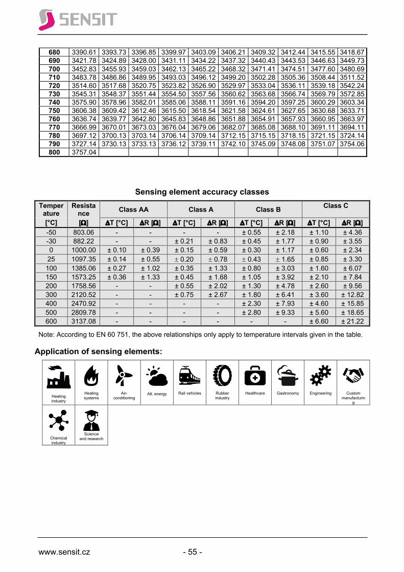
www.sensit.cz - 55 -
680 3390.61 3393.73 3396.85 3399.97 3403.09 3406.21 3409.32 3412.44 3415.55 3418.67 690 3421.78 3424.89 3428.00 3431.11 3434.22 3437.32 3440.43 3443.53 3446.63 3449.73 700 3452.83 3455.93 3459.03 3462.13 3465.22 3468.32 3471.41 3474.51 3477.60 3480.69 710 3483.78 3486.86 3489.95 3493.03 3496.12 3499.20 3502.28 3505.36 3508.44 3511.52 720 3514.60 3517.68 3520.75 3523.82 3526.90 3529.97 3533.04 3536.11 3539.18 3542.24 730 3545.31 3548.37 3551.44 3554.50 3557.56 3560.62 3563.68 3566.74 3569.79 3572.85 740 3575.90 3578.96 3582.01 3585.06 3588.11 3591.16 3594.20 3597.25 3600.29 3603.34 750 3606.38 3609.42 3612.46 3615.50 3618.54 3621.58 3624.61 3627.65 3630.68 3633.71 760 3636.74 3639.77 3642.80 3645.83 3648.86 3651.88 3654.91 3657.93 3660.95 3663.97 770 3666.99 3670.01 3673.03 3676.04 3679.06 3682.07 3685.08 3688.10 3691.11 3694.11 780 3697.12 3700.13 3703.14 3706.14 3709.14 3712.15 3715.15 3718.15 3721.15 3724.14 790 3727.14 3730.13 3733.13 3736.12 3739.11 3742.10 3745.09 3748.08 3751.07 3754.06 800 3757.04
Sensing element accuracy classes Temper
ature Resista
nce Class AA Class A Class B Class C
[°C] [W] DT [°C] DR [W] DT [°C] DR [W] DT [°C] DR [W] DT [°C] DR [W] -50 803.06 - - - - ± 0.55 ± 2.18 ± 1.10 ± 4.36 -30 882.22 - - ± 0.21 ± 0.83 ± 0.45 ± 1.77 ± 0.90 ± 3.55 0 1000.00 ± 0.10 ± 0.39 ± 0.15 ± 0.59 ± 0.30 ± 1.17 ± 0.60 ± 2.34 25 1097.35 ± 0.14 ± 0.55 ± 0.20 ± 0.78 ± 0.43 ± 1.65 ± 0.85 ± 3.30 100 1385.06 ± 0.27 ± 1.02 ± 0.35 ± 1.33 ± 0.80 ± 3.03 ± 1.60 ± 6.07 150 1573.25 ± 0.36 ± 1.33 ± 0.45 ± 1.68 ± 1.05 ± 3.92 ± 2.10 ± 7.84 200 1758.56 - - ± 0.55 ± 2.02 ± 1.30 ± 4.78 ± 2.60 ± 9.56 300 2120.52 - - ± 0.75 ± 2.67 ± 1.80 ± 6.41 ± 3.60 ± 12.82 400 2470.92 - - - - ± 2.30 ± 7.93 ± 4.60 ± 15.85 500 2809.78 - - - - ± 2.80 ± 9.33 ± 5.60 ± 18.65 600 3137.08 - - - - - - ± 6.60 ± 21.22
Note: According to EN 60 751, the above relationships only apply to temperature intervals given in the table.
Application of sensing elements:
Heating industry
Heating systems
Air-conditioning
Alt. energy
Rail vehicles
Rubber industry
Healthcare
Gastronomy
Engineering
Custom manufacturin
g
Chemical industry
Science
and research

www.sensit.cz - 56 -
Nic
kel R
esis
tanc
e Se
nsor
s
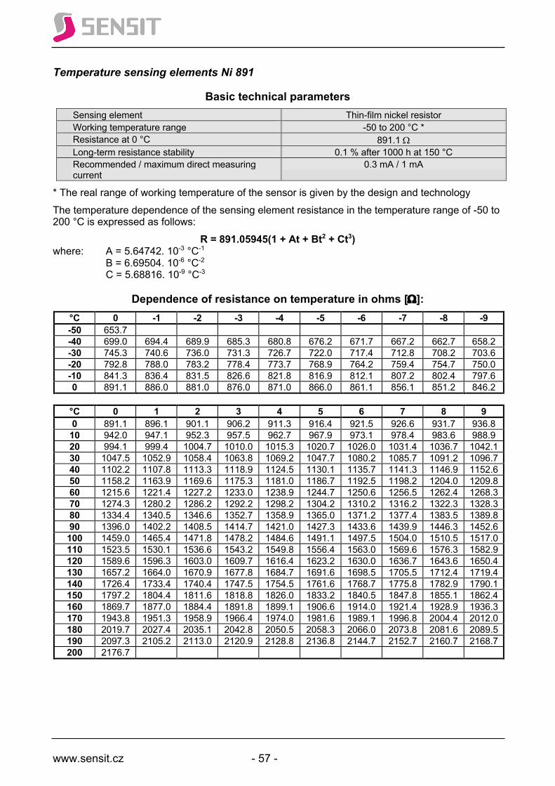
www.sensit.cz - 57 -
Temperature sensing elements Ni 891
Basic technical parameters Sensing element Thin-film nickel resistor Working temperature range -50 to 200 °C * Resistance at 0 °C 891.1 W Long-term resistance stability 0.1 % after 1000 h at 150 °C Recommended / maximum direct measuring current
0.3 mA / 1 mA
* The real range of working temperature of the sensor is given by the design and technology The temperature dependence of the sensing element resistance in the temperature range of -50 to 200 °C is expressed as follows:
R = 891.05945(1 + At + Bt2 + Ct3) where: A = 5.64742. 10-3 °C-1 B = 6.69504. 10-6 °C-2 C = 5.68816. 10-9 °C-3
Dependence of resistance on temperature in ohms [W]: °C 0 -1 -2 -3 -4 -5 -6 -7 -8 -9 -50 653.7 -40 699.0 694.4 689.9 685.3 680.8 676.2 671.7 667.2 662.7 658.2 -30 745.3 740.6 736.0 731.3 726.7 722.0 717.4 712.8 708.2 703.6 -20 792.8 788.0 783.2 778.4 773.7 768.9 764.2 759.4 754.7 750.0 -10 841.3 836.4 831.5 826.6 821.8 816.9 812.1 807.2 802.4 797.6 0 891.1 886.0 881.0 876.0 871.0 866.0 861.1 856.1 851.2 846.2
°C 0 1 2 3 4 5 6 7 8 9 0 891.1 896.1 901.1 906.2 911.3 916.4 921.5 926.6 931.7 936.8 10 942.0 947.1 952.3 957.5 962.7 967.9 973.1 978.4 983.6 988.9 20 994.1 999.4 1004.7 1010.0 1015.3 1020.7 1026.0 1031.4 1036.7 1042.1 30 1047.5 1052.9 1058.4 1063.8 1069.2 1047.7 1080.2 1085.7 1091.2 1096.7 40 1102.2 1107.8 1113.3 1118.9 1124.5 1130.1 1135.7 1141.3 1146.9 1152.6 50 1158.2 1163.9 1169.6 1175.3 1181.0 1186.7 1192.5 1198.2 1204.0 1209.8 60 1215.6 1221.4 1227.2 1233.0 1238.9 1244.7 1250.6 1256.5 1262.4 1268.3 70 1274.3 1280.2 1286.2 1292.2 1298.2 1304.2 1310.2 1316.2 1322.3 1328.3 80 1334.4 1340.5 1346.6 1352.7 1358.9 1365.0 1371.2 1377.4 1383.5 1389.8 90 1396.0 1402.2 1408.5 1414.7 1421.0 1427.3 1433.6 1439.9 1446.3 1452.6 100 1459.0 1465.4 1471.8 1478.2 1484.6 1491.1 1497.5 1504.0 1510.5 1517.0 110 1523.5 1530.1 1536.6 1543.2 1549.8 1556.4 1563.0 1569.6 1576.3 1582.9 120 1589.6 1596.3 1603.0 1609.7 1616.4 1623.2 1630.0 1636.7 1643.6 1650.4 130 1657.2 1664.0 1670.9 1677.8 1684.7 1691.6 1698.5 1705.5 1712.4 1719.4 140 1726.4 1733.4 1740.4 1747.5 1754.5 1761.6 1768.7 1775.8 1782.9 1790.1 150 1797.2 1804.4 1811.6 1818.8 1826.0 1833.2 1840.5 1847.8 1855.1 1862.4 160 1869.7 1877.0 1884.4 1891.8 1899.1 1906.6 1914.0 1921.4 1928.9 1936.3 170 1943.8 1951.3 1958.9 1966.4 1974.0 1981.6 1989.1 1996.8 2004.4 2012.0 180 2019.7 2027.4 2035.1 2042.8 2050.5 2058.3 2066.0 2073.8 2081.6 2089.5 190 2097.3 2105.2 2113.0 2120.9 2128.8 2136.8 2144.7 2152.7 2160.7 2168.7 200 2176.7
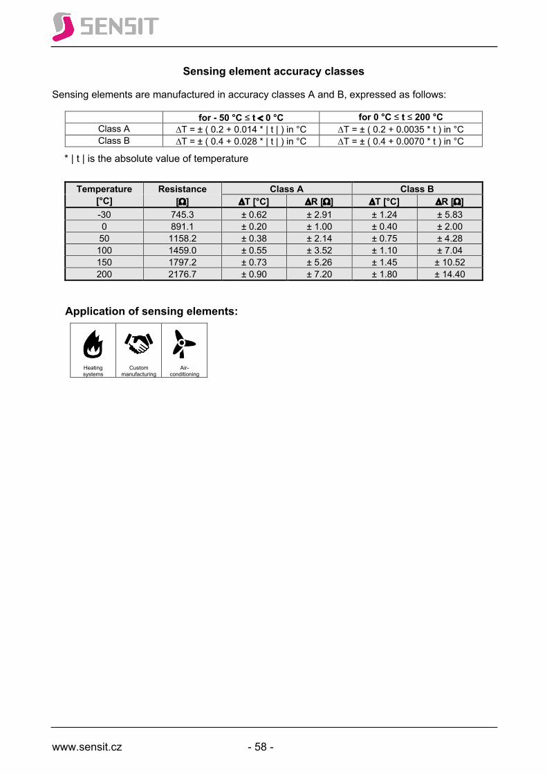
www.sensit.cz - 58 -
Sensing element accuracy classes
Sensing elements are manufactured in accuracy classes A and B, expressed as follows:
for - 50 °C ≤ t < 0 °C for 0 °C ≤ t ≤ 200 °C Class A DT = ± ( 0.2 + 0.014 * | t | ) in °C DT = ± ( 0.2 + 0.0035 * t ) in °C Class B DT = ± ( 0.4 + 0.028 * | t | ) in °C DT = ± ( 0.4 + 0.0070 * t ) in °C
* | t | is the absolute value of temperature
Temperature Resistance Class A Class B [°C] [W] DT [°C] DR [W] DT [°C] DR [W] -30 745.3 ± 0.62 ± 2.91 ± 1.24 ± 5.83 0 891.1 ± 0.20 ± 1.00 ± 0.40 ± 2.00 50 1158.2 ± 0.38 ± 2.14 ± 0.75 ± 4.28 100 1459.0 ± 0.55 ± 3.52 ± 1.10 ± 7.04 150 1797.2 ± 0.73 ± 5.26 ± 1.45 ± 10.52 200 2176.7 ± 0.90 ± 7.20 ± 1.80 ± 14.40
Application of sensing elements:
Heating systems
Custom manufacturing
Air-conditioning
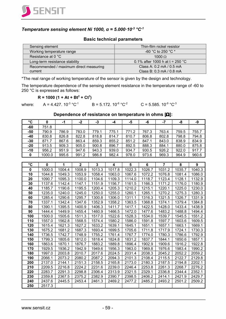
www.sensit.cz - 59 -
Temperature sensing element Ni 1000, α = 5.000·10-3 °C-1
Basic technical parameters Sensing element Thin-film nickel resistor Working temperature range -60 °C to 250 °C * Resistance at 0 °C 1000 W Long-term resistance stability 0.1% after 1000 h at t = 250 °C Recommended / maximum direct measuring current
Class A: 0.2 mA / 0.5 mA Class B: 0.3 mA / 0.8 mA
*The real range of working temperature of the sensor is given by the design and technology. The temperature dependence of the sensing element resistance in the temperature range of -60 to 250 °C is expressed as follows: R = 1000 (1 + At + Bt2 + Ct3) where: A = 4.427. 10-3 °C-1 B = 5.172. 10-6 °C-2 C = 5.585. 10-9 °C-3
Dependence of resistance on temperature in ohms [W]: °C 0 -1 -2 -3 -4 -5 -6 -7 -8 -9 -60 751.8 -50 790.9 786.9 783.0 779.1 775.1 771.2 767.3 763.4 759.5 755.7 -40 830.8 826.8 822.8 818.8 814.7 810.7 806.8 802.8 798.8 794.8 -30 871.7 867.6 863.4 859.3 855.2 851.2 847.1 843.0 838.9 834.9 -20 913.5 909.3 905.0 900.8 896.7 892.5 888.3 884.1 880.0 875.8 -10 956.2 951.9 947.6 943.3 939.0 934.7 930.5 926.2 922.0 917.7 0 1000.0 995.6 991.2 986.8 982.4 978.0 973.6 969.3 964.9 960.6
°C 0 1 2 3 4 5 6 7 8 9 0 1000.0 1004.4 1008.9 1013.3 1017.8 1022.3 1026.7 1031.2 1035.7 1040.3 10 1044.8 1049.3 1053.9 1058.4 1063.0 1067.6 1072.2 1076.8 1081.4 1086.0 20 1090.7 1095.3 1100.0 1104.6 1109.3 1114.0 1118.7 1123.4 1128.1 1132.9 30 1137.6 1142.4 1147.1 1151.9 1156.7 1161.5 1166.3 1171.2 1176.0 1180.9 40 1185.7 1190.6 1195.5 1200.4 1205.3 1210.2 1215.1 1220.1 1225.0 1230.0 50 1235.0 1240.0 1245.0 1250.0 1255.0 1260.1 1265.1 1270.2 1275.3 1280.3 60 1285.4 1290.6 1295.7 1300.8 1306.0 1311.1 1316.3 1321.5 1326.7 1331.9 70 1337.1 1342.4 1347.6 1352.9 1358.2 1363.5 1368.8 1374.1 1379.4 1384.8 80 1390.1 1395.5 1400.9 1406.3 1411.7 1417.1 1422.5 1428.0 1433.4 1438.9 90 1444.4 1449.9 1455.4 1460.9 1466.5 1472.0 1477.6 1483.2 1488.8 1494.4 100 1500.0 1505.6 1511.3 1517.0 1522.6 1528.3 1534.0 1539.7 1545.5 1551.2 110 1557.0 1562.8 1568.5 1574.4 1580.2 1586.0 1591.8 1597.7 1603.6 1609.5 120 1615.4 1621.3 1627.2 1633.2 1639.1 1645.1 1651.1 1657.1 1663.1 1669.1 130 1675.2 1681.2 1687.3 1693.4 1699.5 1705.6 1711.8 1717.9 1724.1 1730.3 140 1736.5 1742.7 1748.9 1755.2 1761.4 1767.7 1774.0 1780.3 1786.6 1792.9 150 1799.3 1805.6 1812.0 1818.4 1824.8 1831.2 1837.7 1844.1 1850.6 1857.1 160 1863.6 1870.1 1876.7 1883.2 1889.8 1896.4 1902.9 1909.6 1916.2 1922.8 170 1929.5 1936.2 1942.9 1949.6 1956.3 1963.0 1969.8 1976.6 1983.4 1990.2 180 1997.0 2003.8 2010.7 2017.6 2024.5 2031.4 2038.3 2045.2 2052.2 2059.2 190 2066.1 2073.2 2080.2 2087.2 2094.3 2101.3 2108.4 2115.5 2122.7 2129.8 200 2137.0 2144.1 2151.3 2158.5 2165.8 2173.0 2180.3 2187.5 2194.8 2202.1 210 2209.5 2216.8 2224.2 2231.6 2239.0 2246.4 2253.8 2261.3 2268.7 2276.2 220 2283.7 2291.3 2298.8 2306.4 2313.9 2321.5 2329.1 2336.8 2344.4 2352.1 230 2359.8 2367.5 2375.2 2382.9 2390.7 2398.5 2406.2 2414.1 2421.9 2429.7 240 2437.6 2445.5 2453.4 2461.3 2469.2 2477.2 2485.2 2493.2 2501.2 2509.2 250 2517.3
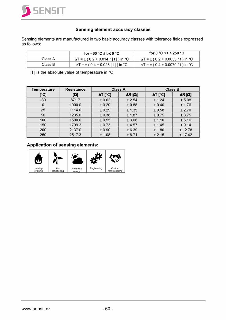
www.sensit.cz - 60 -
Sensing element accuracy classes
Sensing elements are manufactured in two basic accuracy classes with tolerance fields expressed as follows:
for - 60 °C ≤ t < 0 °C for 0 °C ≤ t ≤ 250 °C Class A DT = ± ( 0.2 + 0.014 * | t | ) in °C DT = ± ( 0.2 + 0.0035 * t ) in °C Class B DT = ± ( 0.4 + 0.028 | t | ) in °C DT = ± ( 0.4 + 0.0070 * t ) in °C
| t | is the absolute value of temperature in °C
Temperature Resistance Class A Class B [°C] [W] DT [°C] DR [W] DT [°C] DR [W] -30 871.7 ± 0.62 ± 2.54 ± 1.24 ± 5.08 0 1000.0 ± 0.20 ± 0.88 ± 0.40 ± 1.76 25 1114.0 ± 0.29 ± 1.35 ± 0.58 ± 2.70 50 1235.0 ± 0.38 ± 1.87 ± 0.75 ± 3.75 100 1500.0 ± 0.55 ± 3.08 ± 1.10 ± 6.16 150 1799.3 ± 0.73 ± 4.57 ± 1.45 ± 9.14 200 2137.0 ± 0.90 ± 6.39 ± 1.80 ± 12.78 250 2517.3 ± 1.08 ± 8.71 ± 2.15 ± 17.42
Application of sensing elements:
Heating systems
Air-conditioning
Alternative energy
Engineering
Custom manufacturing
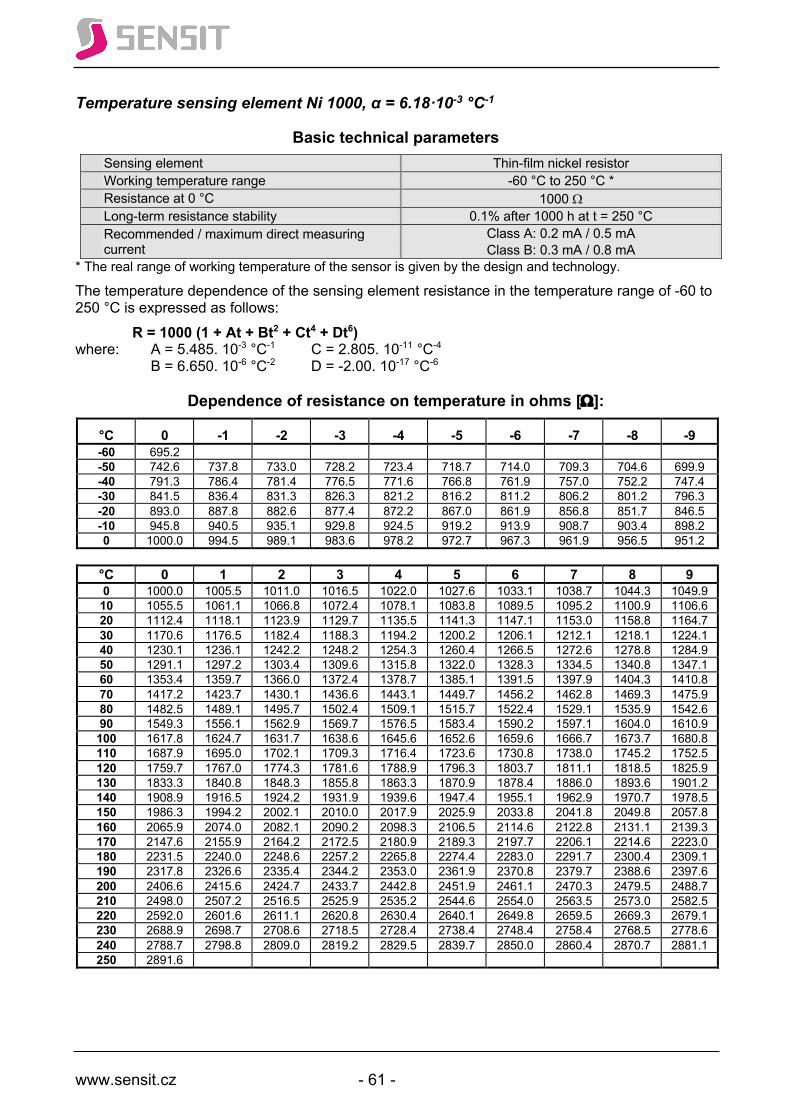
www.sensit.cz - 61 -
Temperature sensing element Ni 1000, α = 6.18·10-3 °C-1
Basic technical parameters Sensing element Thin-film nickel resistor Working temperature range -60 °C to 250 °C * Resistance at 0 °C 1000 W Long-term resistance stability 0.1% after 1000 h at t = 250 °C Recommended / maximum direct measuring current
Class A: 0.2 mA / 0.5 mA Class B: 0.3 mA / 0.8 mA
* The real range of working temperature of the sensor is given by the design and technology.
The temperature dependence of the sensing element resistance in the temperature range of -60 to 250 °C is expressed as follows: R = 1000 (1 + At + Bt2 + Ct4 + Dt6) where: A = 5.485. 10-3 °C-1 C = 2.805. 10-11 °C-4 B = 6.650. 10-6 °C-2 D = -2.00. 10-17 °C-6
Dependence of resistance on temperature in ohms [W]:
°C 0 -1 -2 -3 -4 -5 -6 -7 -8 -9 -60 695.2 -50 742.6 737.8 733.0 728.2 723.4 718.7 714.0 709.3 704.6 699.9 -40 791.3 786.4 781.4 776.5 771.6 766.8 761.9 757.0 752.2 747.4 -30 841.5 836.4 831.3 826.3 821.2 816.2 811.2 806.2 801.2 796.3 -20 893.0 887.8 882.6 877.4 872.2 867.0 861.9 856.8 851.7 846.5 -10 945.8 940.5 935.1 929.8 924.5 919.2 913.9 908.7 903.4 898.2 0 1000.0 994.5 989.1 983.6 978.2 972.7 967.3 961.9 956.5 951.2
°C 0 1 2 3 4 5 6 7 8 9 0 1000.0 1005.5 1011.0 1016.5 1022.0 1027.6 1033.1 1038.7 1044.3 1049.9 10 1055.5 1061.1 1066.8 1072.4 1078.1 1083.8 1089.5 1095.2 1100.9 1106.6 20 1112.4 1118.1 1123.9 1129.7 1135.5 1141.3 1147.1 1153.0 1158.8 1164.7 30 1170.6 1176.5 1182.4 1188.3 1194.2 1200.2 1206.1 1212.1 1218.1 1224.1 40 1230.1 1236.1 1242.2 1248.2 1254.3 1260.4 1266.5 1272.6 1278.8 1284.9 50 1291.1 1297.2 1303.4 1309.6 1315.8 1322.0 1328.3 1334.5 1340.8 1347.1 60 1353.4 1359.7 1366.0 1372.4 1378.7 1385.1 1391.5 1397.9 1404.3 1410.8 70 1417.2 1423.7 1430.1 1436.6 1443.1 1449.7 1456.2 1462.8 1469.3 1475.9 80 1482.5 1489.1 1495.7 1502.4 1509.1 1515.7 1522.4 1529.1 1535.9 1542.6 90 1549.3 1556.1 1562.9 1569.7 1576.5 1583.4 1590.2 1597.1 1604.0 1610.9 100 1617.8 1624.7 1631.7 1638.6 1645.6 1652.6 1659.6 1666.7 1673.7 1680.8 110 1687.9 1695.0 1702.1 1709.3 1716.4 1723.6 1730.8 1738.0 1745.2 1752.5 120 1759.7 1767.0 1774.3 1781.6 1788.9 1796.3 1803.7 1811.1 1818.5 1825.9 130 1833.3 1840.8 1848.3 1855.8 1863.3 1870.9 1878.4 1886.0 1893.6 1901.2 140 1908.9 1916.5 1924.2 1931.9 1939.6 1947.4 1955.1 1962.9 1970.7 1978.5 150 1986.3 1994.2 2002.1 2010.0 2017.9 2025.9 2033.8 2041.8 2049.8 2057.8 160 2065.9 2074.0 2082.1 2090.2 2098.3 2106.5 2114.6 2122.8 2131.1 2139.3 170 2147.6 2155.9 2164.2 2172.5 2180.9 2189.3 2197.7 2206.1 2214.6 2223.0 180 2231.5 2240.0 2248.6 2257.2 2265.8 2274.4 2283.0 2291.7 2300.4 2309.1 190 2317.8 2326.6 2335.4 2344.2 2353.0 2361.9 2370.8 2379.7 2388.6 2397.6 200 2406.6 2415.6 2424.7 2433.7 2442.8 2451.9 2461.1 2470.3 2479.5 2488.7 210 2498.0 2507.2 2516.5 2525.9 2535.2 2544.6 2554.0 2563.5 2573.0 2582.5 220 2592.0 2601.6 2611.1 2620.8 2630.4 2640.1 2649.8 2659.5 2669.3 2679.1 230 2688.9 2698.7 2708.6 2718.5 2728.4 2738.4 2748.4 2758.4 2768.5 2778.6 240 2788.7 2798.8 2809.0 2819.2 2829.5 2839.7 2850.0 2860.4 2870.7 2881.1 250 2891.6

www.sensit.cz - 62 -
Sensing element accuracy classes
Sensing elements are manufactured in two basic accuracy classes with tolerance fields expressed as follows:
for t = -60 °C to 0 °C for t = 0 °C to 250 °C Class A DT = ± ( 0.2 + 0.014 * | t | ) in °C DT = ± ( 0.2 + 0.0035 * t ) in °C Class B DT = ± ( 0.4 + 0.028 | t | ) in °C DT = ± ( 0.4 + 0.0070 * t ) in °C
| t | is the absolute value of temperature
Temperature Resistance Class A Class B [°C] [W] DT [°C] DR [W] DT [°C] DR [W] -30 841.5 ± 0.62 ± 3.16 ± 1.24 ± 6.32 0 1000.0 ± 0.20 ± 1.10 ± 0.40 ± 2.20 25 1141.3 ± 0.29 ± 1.67 ± 0.58 ± 3.34 50 1291.1 ± 0.38 ± 2.29 ± 0.75 ± 4.58 100 1617.8 ± 0.55 ± 3.79 ± 1.10 ± 7.59 150 1986.3 ± 0.73 ± 5.73 ± 1.45 ± 11.46 200 2406.6 ± 0.90 ± 8.10 ± 1.80 ± 16.20 250 2891.6 ± 1.08 ± 11.29 ± 2.15 ± 22.58
Application of sensing elements:
Heating industry
Heating systems
Air-conditioning
Alt. energy
Rail vehicles
Rubber industry
Healthcare
Gastronomy
Engineering
Custom manufacturin
g
Chemical industry
Science
and research

www.sensit.cz - 63 -
Temperature sensing elements Ni 2226
Basic technical parameters Sensing element Thin-film nickel resistor Working temperature range -30 °C to 150 °C * Resistance at 0 °C 2226 W Long-term resistance stability 0.1 % after 1000 h at t = 150 °C Recommended / maximum direct measuring current 0.2mA / 0.7mA
Note: This is a characteristic of sensors designated T1 (Staefa Control, later Siemens. They are no longer produced or offered by these companies.)
* The real range of working temperature of the temperature sensor is given by the design and technology. The temperature dependence of the sensing element resistance in the temperature range of -30 to 150 °C is expressed as follows: R = 2226 (1 + At + Bt2 + Ct3 + Dt4) where: A = 4.476. 10-3 °C-1 C = 2.906. 10-9 °C-3 B = 3.6496. 10-6 °C-2 D = 3.140. 10-12 °C-4
Dependence of resistance on temperature in ohms [W]: °C 0 -1 -2 -3 -4 -5 -6 -7 -8 -9 -30 1934.2 -20 2029.9 2020.3 2010.7 2001.1 1991.5 1981.9 1972.3 1962.8 1953.3 1943.7 -10 2127.2 2117.4 2107.6 2097.8 2088.1 2078.4 2068.6 2058.9 2049.3 2039.6 0 2226.0 2216.0 2206.1 2196.2 2186.3 2176.4 2166.5 2156.7 2146.8 2137.0
°C 0 1 2 3 4 5 6 7 8 9 0 2226.0 2236.0 2246.0 2256.0 2266.0 2276.0 2286.1 2296.1 2306.2 2316.3 10 2326.5 2336.6 2346.7 2356.9 2367.1 2377.3 2387.5 2397.8 2408.0 2418.3 20 2428.6 2438.9 2449.2 2459.5 2469.9 2480.3 2490.7 2501.1 2511.5 2521.9 30 2532.4 2542.9 2553.4 2563.9 2574.4 2585.0 2595.5 2606.1 2616.7 2627.3 40 2638.0 2648.6 2659.3 2670.0 2680.7 2691.4 2702.2 2712.9 2723.7 2734.5 50 2745.3 2756.2 2767.0 2777.9 2788.8 2799.7 2810.6 2821.6 2832.6 2843.5 60 2854.5 2865.6 2876.6 2887.7 2898.8 2909.9 2921.0 2932.1 2943.3 2954.4 70 2965.6 2976.9 2988.1 2999.3 3010.6 3021.9 3033.2 3044.6 3055.9 3067.3 80 3078.7 3090.1 3101.5 3113.0 3124.4 3135.9 3147.4 3159.0 3170.5 3182.1 90 3193.7 3205.3 3216.9 3228.6 3240.3 3252.0 3263.7 3275.4 3287.2 3299.0 100 3310.8 3322.6 3334.4 3346.3 3358.2 3370.1 3382.0 3394.0 3405.9 3417.9 110 3429.9 3442.0 3454.0 3466.1 3478.2 3490.3 3502.5 3514.6 3526.8 3539.0 120 3551.2 3563.5 3575.8 3588.1 3600.4 3612.7 3625.1 3637.5 3649.9 3662.3 130 3674.8 3687.2 3699.7 3712.3 3724.8 3737.4 3750.0 3762.6 3775.2 3787.9 140 3800.6 3813.3 3826.0 3838.8 3851.5 3864.3 3877.2 3890.0 3902.9 3915.8 150 3928.7

www.sensit.cz - 64 -
Sensing element accuracy classes
Sensing elements are manufactured in accuracy class B, expressed as follows:
for - 30°C ≤ t < 0°C for 0 °C ≤ t ≤ 50 °C for 50 °C< t ≤ 100 °C DT = ± ( 0.7 + 0.063 * | t | ) in °C DT = ± 0.7 °C DT = ± ( 0.7 + 0.038 * ( t- 50) ) in °C
| t | is the absolute value of temperature
Temperature
Resistance Class B
[°C] [W] DT [°C] DR [W] -20 2029.9 ± 1.96 ± 19.01 0 2226.0 ± 0.70 ± 7.00 25 2480.3 ± 0.70 ± 7.28 50 2745.3 ± 0.70 ± 7.63 70 2965.6 ± 1.46 ± 16.50 100 3310.8 ± 2.60 ± 30.68
Application of sensing elements: Previously, temperature sensors with this characteristic were used by Staefa Control, which was purchased in 1997 by the SIEMENS Group and in fact ceased to exist. Nowadays, they can be found under the designation T1. They are used as sensing elements for sensors for exteriors, interiors, piping, thermostats, etc. They are currently not used in new constructions and Sensit s.r.o. offers them as spare parts. Notes:
www.sensit.cz - 65 -
Se
mic
ondu
ctor
s R
esis
tanc
e Se
nsor
s
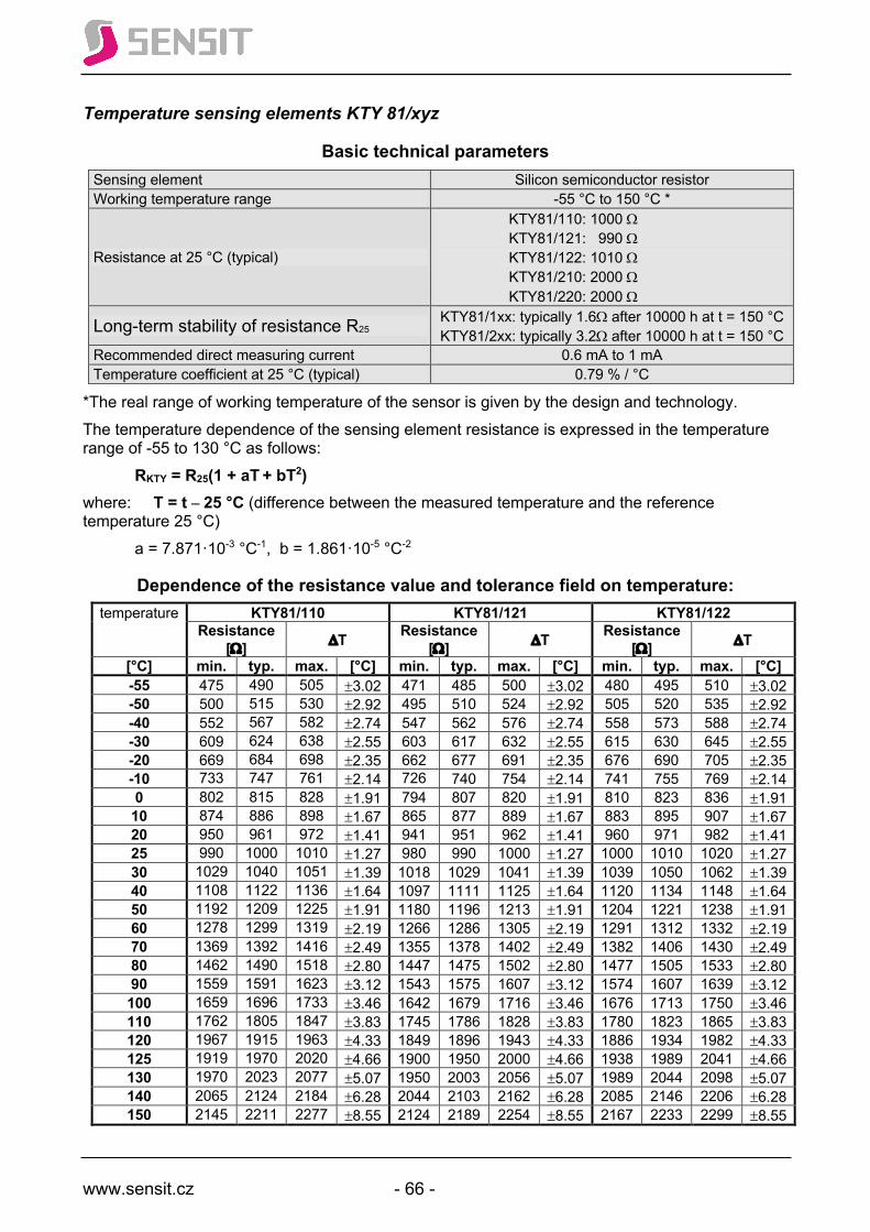
www.sensit.cz - 66 -
Temperature sensing elements KTY 81/xyz
Basic technical parameters Sensing element Silicon semiconductor resistor Working temperature range -55 °C to 150 °C *
Resistance at 25 °C (typical)
KTY81/110: 1000 W KTY81/121: 990 W KTY81/122: 1010 W KTY81/210: 2000 W KTY81/220: 2000 W
Long-term stability of resistance R25 KTY81/1xx: typically 1.6W after 10000 h at t = 150 °C KTY81/2xx: typically 3.2W after 10000 h at t = 150 °C
Recommended direct measuring current 0.6 mA to 1 mA Temperature coefficient at 25 °C (typical) 0.79 % / °C
*The real range of working temperature of the sensor is given by the design and technology. The temperature dependence of the sensing element resistance is expressed in the temperature range of -55 to 130 °C as follows: RKTY = R25(1 + aT + bT2) where: T = t – 25 °C (difference between the measured temperature and the reference temperature 25 °C) a = 7.871·10-3 °C-1, b = 1.861·10-5 °C-2
Dependence of the resistance value and tolerance field on temperature: temperature KTY81/110 KTY81/121 KTY81/122
Resistance [W] DT Resistance
[W] DT Resistance [W] DT
[°C] min. typ. max. [°C] min. typ. max. [°C] min. typ. max. [°C] -55 475 490 505 ±3.02 471 485 500 ±3.02 480 495 510 ±3.02 -50 500 515 530 ±2.92 495 510 524 ±2.92 505 520 535 ±2.92 -40 552 567 582 ±2.74 547 562 576 ±2.74 558 573 588 ±2.74 -30 609 624 638 ±2.55 603 617 632 ±2.55 615 630 645 ±2.55 -20 669 684 698 ±2.35 662 677 691 ±2.35 676 690 705 ±2.35 -10 733 747 761 ±2.14 726 740 754 ±2.14 741 755 769 ±2.14 0 802 815 828 ±1.91 794 807 820 ±1.91 810 823 836 ±1.91 10 874 886 898 ±1.67 865 877 889 ±1.67 883 895 907 ±1.67 20 950 961 972 ±1.41 941 951 962 ±1.41 960 971 982 ±1.41 25 990 1000 1010 ±1.27 980 990 1000 ±1.27 1000 1010 1020 ±1.27 30 1029 1040 1051 ±1.39 1018 1029 1041 ±1.39 1039 1050 1062 ±1.39 40 1108 1122 1136 ±1.64 1097 1111 1125 ±1.64 1120 1134 1148 ±1.64 50 1192 1209 1225 ±1.91 1180 1196 1213 ±1.91 1204 1221 1238 ±1.91 60 1278 1299 1319 ±2.19 1266 1286 1305 ±2.19 1291 1312 1332 ±2.19 70 1369 1392 1416 ±2.49 1355 1378 1402 ±2.49 1382 1406 1430 ±2.49 80 1462 1490 1518 ±2.80 1447 1475 1502 ±2.80 1477 1505 1533 ±2.80 90 1559 1591 1623 ±3.12 1543 1575 1607 ±3.12 1574 1607 1639 ±3.12 100 1659 1696 1733 ±3.46 1642 1679 1716 ±3.46 1676 1713 1750 ±3.46 110 1762 1805 1847 ±3.83 1745 1786 1828 ±3.83 1780 1823 1865 ±3.83 120 1967 1915 1963 ±4.33 1849 1896 1943 ±4.33 1886 1934 1982 ±4.33 125 1919 1970 2020 ±4.66 1900 1950 2000 ±4.66 1938 1989 2041 ±4.66 130 1970 2023 2077 ±5.07 1950 2003 2056 ±5.07 1989 2044 2098 ±5.07 140 2065 2124 2184 ±6.28 2044 2103 2162 ±6.28 2085 2146 2206 ±6.28 150 2145 2211 2277 ±8.55 2124 2189 2254 ±8.55 2167 2233 2299 ±8.55

www.sensit.cz - 67 -
temperature KTY81/210 KTY81/220 Resistance [W] DT Resistance [W] DT
[°C] min. typ. max. [°C] min. typ. max. [°C] -55 951 980 1009 ±3.02 941 980 1019 ±4.02 -50 1000 1030 1059 ±2.92 990 1030 1070 ±3.94 -40 1105 1135 1165 ±2.74 1094 1135 1176 ±3.78 -30 1218 1247 1277 ±2.55 1205 1247 1289 ±3.62 -20 1338 1367 1396 ±2.35 1325 1367 1410 ±3.45 -10 1467 1495 1523 ±2.14 1452 1495 1538 ±3.27 0 1603 1630 1656 ±1.91 1587 1630 1673 ±3.08 10 1748 1772 1797 ±1.67 1730 1772 1814 ±2.88 20 1901 1922 1944 ±1.41 1881 1922 1963 ±2.66 25 1980 2000 2020 ±1.27 1960 2000 2040 ±2.54 30 2057 2080 2102 ±1.39 2036 2080 2123 ±2.68 40 2217 2245 2272 ±1.64 2194 2245 2295 ±2.97 50 2383 2417 2451 ±1.91 2359 2417 2475 ±3.28 60 2557 2597 2637 ±2.19 2531 2597 2663 ±3.61 70 2737 2785 2832 ±2.49 2709 2785 2860 ±3.94 80 2924 2980 3035 ±2.80 2894 2980 3065 ±4.30 90 3118 3182 3246 ±3.12 3086 3182 3278 ±4.66 100 3318 3392 3466 ±3.46 3284 3392 3500 ±5.05 110 3523 3607 3691 ±3.93 3487 3607 3728 ±5.61 120 3722 3817 3912 ±4.70 3683 3817 3950 ±6.59 125 3815 3915 4016 ±5.26 3775 3915 4055 ±7.31 130 3901 4008 4114 ±6.00 3861 4008 4154 ±8.27 140 4049 4166 4283 ±8.45 4008 4166 4325 ±11.46 150 4153 4280 4407 ±14.63 4110 4280 4450 ±19.56
Application of sensing elements:
Heating systems
Air-conditioning
Alternative energy
Engineering
Custom manufacturin
g

www.sensit.cz - 68 -
Temperature sensing element NTC 1k0; B25/85 = 3528
Basic technical parameters Sensing element Bead NTC thermistor Working temperature range -40 to 125 °C * Resistance at 25 °C 1 kW Coefficient β25/85 3528 ± 0.5% Coefficient β25/100 3564 ± 0.5% Long-term resistance stability ≤ 3 % after 1000 h at 85 °C ** Recommended / maximum DC input 0.5 mW / 2 mW Sensor tolerance ±5 % ***
* The real range of working temperature of the sensor is given by the design of the sensing element and the production technology. ** These parameters depend on the specific type and design of the thermistor. *** The thermistor electrical resistance tolerance at a temperature of 25 °C is rated by the manufacturer into groups ±2 %, ±3 % or ±5%.
Dependence of resistance in W on temperature °C 0 -1 -2 -3 -4 -5 -6 -7 -8 -9 -40 23342 -30 13018 13882 14745 15609 16472 17336 18537 19738 20940 22141 -20 7569 8031 8492 8954 9415 9877 10505 11133 11762 12390 -10 4569 4826 5083 5341 5598 5855 6198 6541 6883 7226 0 2854 3002 3151 3299 3448 3596 3791 3985 4180 4374
°C 0 1 2 3 4 5 6 7 8 9 0 2854 2740 2625 2511 2396 2282 2193 2104 2016 1927 10 1838 1769 1699 1630 1560 1491 1436 1381 1327 1272 20 1217 1174 1130 1087 1043 1000 965 931 896 861 30 826.6 798.7 770.9 743.0 715.2 687.3 664.8 642.2 619.7 597.1 40 574.6 556.2 537.8 519.5 501.1 482.7 467.6 452.6 437.5 422.5 50 407.4 395.0 382.5 370.1 357.6 345.2 334.9 324.6 314.3 304.0 60 293.7 285.1 276.5 268.0 259.4 250.8 243.6 236.4 229.3 222.1 70 214.9 208.9 202.8 196.8 190.7 184.7 179.6 147.5 169.5 164.4 80 159.3 155.0 150.7 146.3 142.0 137.7 134.0 130.4 126.7 123.1 90 119.4 116.3 113.2 110.1 107.0 103.8 101.1 98.5 95.8 93.1 100 90.45 88.16 85.87 83.58 81.29 79.00 77.03 75.06 73.09 71.12 110 69.15 67.45 65.75 64.06 62.36 60.66 59.19 57.72 56.26 54.79 120 53.32 52.05 50.78 49.50 48.23 46.96 45.85 44.85 43.64 42.54 130 41.43 40.47 39.51 38.55 37.59 36.63 35.79 34.95 34.11 33.27 140 32.43 31.70 30.97 30.23 29.50 28.77 28.13 27.49 26.84 26.20 150 25.56
Note: The resistance values in bold are taken from the table of the manufacturer of the bead thermistor, the other values are calculated by linear interpolation, with the error caused by calculation being one order of magnitude lower than the tolerance specified by the manufacturer.
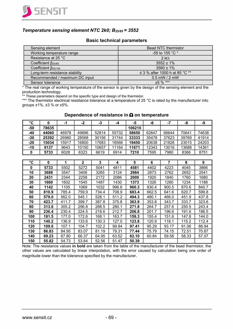
www.sensit.cz - 69 -
Temperature sensing element NTC 2k0; B25/85 = 3552
Basic technical parameters Sensing element Bead NTC thermistor Working temperature range -55 to 155 °C * Resistance at 25 °C 2 kW Coefficient β25/85 3552 ± 1% Coefficient β25/100 3560 ± 1% Long-term resistance stability ≤ 3 % after 1000 h at 85 °C ** Recommended / maximum DC input 0.5 mW / 2 mW Sensor tolerance ±5 % ***
* The real range of working temperature of the sensor is given by the design of the sensing element and the production technology. ** These parameters depend on the specific type and design of the thermistor. *** The thermistor electrical resistance tolerance at a temperature of 25 °C is rated by the manufacturer into groups ±1%, ±3 % or ±5%.
Dependence of resistance in W on temperature °C 0 -1 -2 -3 -4 -5 -6 -7 -8 -9 -50 78635 106210 -40 44060 46978 49896 52814 55732 58650 62647 66644 70641 74638 -30 25392 26980 28568 30156 31744 33333 35478 37623 39769 41914 -20 15034 15917 16800 17683 18566 19450 20638 21826 23015 24203 -10 9137 9643 10150 10657 11164 11671 12343 13016 13688 14361 0 5733 6028 6323 6619 6914 7210 7595 7980 8366 8751
°C 0 1 2 3 4 5 6 7 8 9 0 5733 5502 5272 5041 4811 4581 4402 4223 4045 3866 10 3688 3547 3406 3265 3124 2984 2873 2762 2652 2541 20 2431 2344 2258 2172 2086 2000 1920 1840 1760 1680 30 1660 1602 1545 1487 1430 1373 1326 1280 1234 1188 40 1142 1105 1069 1032 996.6 960.3 930.4 900.5 870.6 840.7 50 810.9 785.4 759.9 734.4 708.9 683.4 662.5 641.6 620.7 599.8 60 579.0 562.0 545.1 528.1 511.2 494.3 480.1 466.0 451.9 437.8 70 423.7 411.7 399.7 387.8 375.8 363.9 353.8 343.7 333.7 323.6 80 313.6 305.2 296.8 288.5 280.1 271.8 264.7 257.6 250.5 243.4 90 236.4 230.4 224.5 218.6 212.7 206.8 201.7 196.6 191.6 186.5 100 181.5 177.0 172.6 168.1 163.7 159.3 155.4 151.6 147.8 144.0 110 140.2 136.9 133.6 130.3 127.0 123.8 120.9 118.1 115.2 112.4 120 109.6 107.1 104.7 102.2 99.84 97.41 95.29 93.17 91.06 88.94 130 86.83 84.95 83.07 81.19 79.31 77.44 75.79 74.15 72.51 70.87 140 69.23 67.80 66.37 64.95 63.52 62.10 60.84 59.58 58.33 57.07 150 55.82 54.73 53.64 52.56 51.47 50.39
Note: The resistance values in bold are taken from the table of the manufacturer of the bead thermistor, the other values are calculated by linear interpolation, with the error caused by calculation being one order of magnitude lower than the tolerance specified by the manufacturer.

www.sensit.cz - 70 -
Temperature sensing element NTC 2k0; B25/85 = 3625
Basic technical parameters Sensing element Bead NTC thermistor Working temperature range -50 to 150 °C * Resistance at 25 °C 2 kW Coefficient β25/85 3625 ± 1% Coefficient β25/100 3636 ± 1% Long-term resistance stability ≤ 3 % after 1000 h at 85 °C ** Recommended / maximum DC input 0.5 mW / 2 mW Sensor tolerance ±5 % ***
* The real range of working temperature of the sensor is given by the design of the sensing element and the production technology. ** These parameters depend on the specific type and design of the thermistor. *** The thermistor electrical resistance tolerance at a temperature of 25 °C is rated by the manufacturer into groups ±1%, ±3 % or ±5%.
Dependence of resistance in W on temperature °C 0 -1 -2 -3 -4 -5 -6 -7 -8 -9 -50 88480 -40 47760 51140 54520 57900 61280 64660 69424 74188 78952 83716 -30 26820 28580 30340 32100 33860 35620 38048 40476 42904 45332 -20 15628 16578 17528 18479 19429 20380 21668 22956 24244 25532 -10 9414 9947 10480 11013 11546 12080 12789 13499 14208 14918 0 5846 6155 6464 6773 7082 7392 7796 8200 8605 9009
°C 0 1 2 3 4 5 6 7 8 9 0 5846 5608 5370 5133 4895 4658 4473 4288 4103 3918 10 3734 3590 3446 3302 3158 3014 2900 2787 2647 2561 20 2448 2358 2268 2179 2089 2000 1928 1857 1786 1714 30 1643 1586 1529 1471 1414 1357 1311 1265 1219 1173 40 1127 1090 1053 1015 978.6 941.4 911.0 880.6 850.3 819.9 50 789.6 764.8 740.0 715.2 690.4 665.6 645 624.8 604.4 584.0 60 563.6 546.7 529.8 512.9 496.0 479.2 465.2 451.2 437.2 423.2 70 409.2 397.5 385.8 374.1 362.4 350.8 341.0 331.2 321.5 311.7 80 302.0 293.8 285.6 277.4 269.2 261.0 254.0 247.0 240.1 233.1 90 226.2 220.3 214.4 208.6 202.7 196.9 191.9 186.9 181.9 176.9 100 171.9 167.6 163.4 159.1 154.8 150.6 146.9 143.3 139.6 136.0 110 132.3 129.2 126.0 122.9 119.8 116.6 117.9 119.2 120.5 121.8 120 123.1 116.8 110.4 104.1 97.80 91.46 89.43 87.40 85.37 83.34 130 81.32 79.55 77.79 74.02 74.26 75.50 70.96 69.42 67.88 66.34 140 64.80 63.45 62.10 60.75 59.40 58.06 56.88 55.70 54.52 53.34 150 52.16
Note: The resistance values in bold are taken from the table of the manufacturer of the bead thermistor, the other values are calculated by linear interpolation, with the error caused by calculation being one order of magnitude lower than the tolerance specified by the manufacturer.
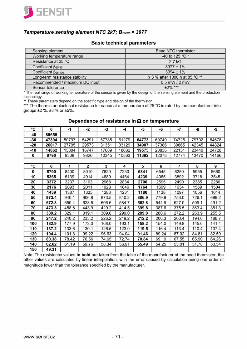
www.sensit.cz - 71 -
Temperature sensing element NTC 2k7; B25/85 = 3977
Basic technical parameters Sensing element Bead NTC thermistor Working temperature range -40 to 125 °C * Resistance at 25 °C 2.7 kW Coefficient β25/85 3977 ± 1% Coefficient β25/100 3994 ± 1% Long-term resistance stability ≤ 3 % after 1000 h at 85 °C ** Recommended / maximum DC input 0.5 mW / 2 mW Sensor tolerance ±2% ***
* The real range of working temperature of the sensor is given by the design of the sensing element and the production technology. ** These parameters depend on the specific type and design of the thermistor. *** The thermistor electrical resistance tolerance at a temperature of 25 °C is rated by the manufacturer into groups ±2 %, ±3 % or ±5%.
Dependence of resistance in W on temperature °C 0 -1 -2 -3 -4 -5 -6 -7 -8 -9 -40 89655 -30 47304 50797 54291 57785 61279 64773 69749 74725 79702 84678 -20 26017 27795 29573 31351 33129 34907 37386 39865 42345 44824 -10 14862 15804 16747 17689 18632 19575 20836 22151 23440 24728 0 8790 9308 9826 10345 10863 11382 12078 12774 13470 14166
°C 0 1 2 3 4 5 6 7 8 9 0 8790 8400 8010 7620 7230 6841 6545 6250 5955 5660 10 5365 5139 4914 4689 4464 4239 4065 3892 3718 3545 20 3372 3237 3103 2968 2834 2700 2595 2490 2385 2280 30 2176 2093 2011 1928 1846 1764 1699 1634 1569 1504 40 1439 1387 1335 1283 1231 1180 1138 1097 1056 1014 50 973.4 940.1 906.8 873.5 840.2 806.9 779.9 753.0 726.1 699.2 60 672.3 650.4 628.5 606.6 584.7 562.8 544.9 527.0 509.1 491.2 70 473.3 458.6 443.9 429.2 414.5 399.8 387.6 375.5 363.4 351.3 80 339.2 329.1 319.1 309.0 299.0 289.0 280.6 272.2 263.9 255.5 90 247.2 240.2 233.2 226.2 219.2 212.2 206.3 200.4 194.6 188.7 100 182.9 177.9 173.0 168.0 163.1 158.2 154.0 149.8 145.6 141.4 110 137.2 133.6 130.1 126.5 123.0 119.5 116.4 113.4 110.4 107.4 120 104.4 101.8 99.22 96.63 94.04 91.46 89.24 87.02 84.81 82.59 130 80.38 78.42 76.56 74.65 72.74 70.84 69.19 67.55 65.90 64.26 140 62.62 61.19 59.76 58.34 56.91 55.49 54.25 53.01 51.78 50.54 150 49.31
Note: The resistance values in bold are taken from the table of the manufacturer of the bead thermistor, the other values are calculated by linear interpolation, with the error caused by calculation being one order of magnitude lower than the tolerance specified by the manufacturer.

www.sensit.cz - 72 -
Temperature sensing element NTC 3k0; B25/85 = 3960
Basic technical parameters Sensing element Bead NTC thermistor Working temperature range -40 to 125 °C * Resistance at 25 °C 3 kW Coefficient β25/85 3956 ± 1% Coefficient β25/100 3966 ± 1% Long-term resistance stability ≤ 3 % after 1000 h at 85 °C ** Recommended / maximum DC input 0.5 mW / 2 mW Sensor tolerance ±1% ***
* The real range of working temperature of the sensor is given by the design of the sensing element and the production technology. ** These parameters depend on the specific type and design of the thermistor. *** The thermistor electrical resistance tolerance at a temperature of 25 °C is rated by the manufacturer into groups ±2 %, ±3 % or ±5%.
Dependence of resistance in W on temperature °C 0 -1 -2 -3 -4 -5 -6 -7 -8 -9 -40 105840 -30 54840 59022 63204 67386 71568 75750 81768 87786 93804 99822 -20 29751 31834 33918 36002 38086 40170 43104 46038 48972 51906 -10 16815 17903 18991 20080 21168 22257 23755 25254 26753 28252 0 9867 10458 11050 11641 12233 12825 13623 14421 15219 16017
°C 0 1 2 3 4 5 6 7 8 9 0 9867 9424 8982 8540 8098 7656 7323 6990 6657 6324 10 5991 5737 5483 5229 4975 4722 4527 4333 4138 3944 20 3750 3600 3450 3300 3150 3000 2883 2766 2649 2532 30 2415 2324 2232 2141 2049 1958 1885 1813 1741 1669 40 1596 1539 1482 1424 1367 1310 1264 1218 1172 1126 50 1081 1044 1007 970.6 933.8 897.0 867.1 837.3 807.5 777.7 60 747.9 723.7 699.5 675.3 651.1 627.0 607.2 587.4 567.6 547.8 70 528.0 511.7 495.4 479.2 462.9 446.7 433.3 419.9 406.5 393.1 80 379.8 368.7 357.6 346.5 335.4 324.3 315.0 305.7 296.4 287.1 90 277.8 270.1 262.3 254.6 246.8 239.1 232.5 226.0 219.5 213.0 100 206.5 201.0 195.5 190.0 184.5 179.0 174.4 169.7 165.1 160.4 110 155.8 151.8 147.9 143.9 140.0 136.0 132.6 129.3 125.9 122.5 120 119.1 116.2 113.4 110.5 107.6 104.7 102.2 99.76 97.27 94.79 130 92.31 90.17 88.03 85.90 83.76 81.63 79.77 77.92 76.06 74.21 140 72.36 70.75 69.15 67.55 65.95 64.35 62.95 61.55 60.15 58.75 150 57.36
Note: The resistance values in bold are taken from the table of the manufacturer of the bead thermistor, the other values are calculated by linear interpolation, with the error caused by calculation being one order of magnitude lower than the tolerance specified by the manufacturer.
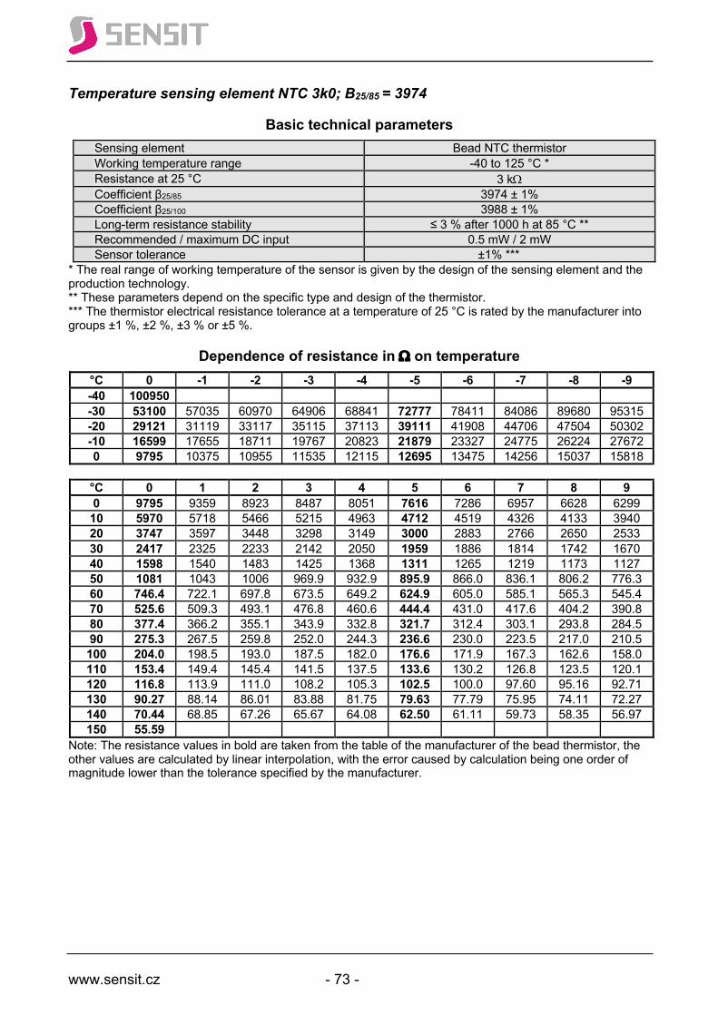
www.sensit.cz - 73 -
Temperature sensing element NTC 3k0; B25/85 = 3974
Basic technical parameters Sensing element Bead NTC thermistor Working temperature range -40 to 125 °C * Resistance at 25 °C 3 kW Coefficient β25/85 3974 ± 1% Coefficient β25/100 3988 ± 1% Long-term resistance stability ≤ 3 % after 1000 h at 85 °C ** Recommended / maximum DC input 0.5 mW / 2 mW Sensor tolerance ±1% ***
* The real range of working temperature of the sensor is given by the design of the sensing element and the production technology. ** These parameters depend on the specific type and design of the thermistor. *** The thermistor electrical resistance tolerance at a temperature of 25 °C is rated by the manufacturer into groups ±1 %, ±2 %, ±3 % or ±5 %.
Dependence of resistance in W on temperature °C 0 -1 -2 -3 -4 -5 -6 -7 -8 -9 -40 100950 -30 53100 57035 60970 64906 68841 72777 78411 84086 89680 95315 -20 29121 31119 33117 35115 37113 39111 41908 44706 47504 50302 -10 16599 17655 18711 19767 20823 21879 23327 24775 26224 27672 0 9795 10375 10955 11535 12115 12695 13475 14256 15037 15818
°C 0 1 2 3 4 5 6 7 8 9 0 9795 9359 8923 8487 8051 7616 7286 6957 6628 6299 10 5970 5718 5466 5215 4963 4712 4519 4326 4133 3940 20 3747 3597 3448 3298 3149 3000 2883 2766 2650 2533 30 2417 2325 2233 2142 2050 1959 1886 1814 1742 1670 40 1598 1540 1483 1425 1368 1311 1265 1219 1173 1127 50 1081 1043 1006 969.9 932.9 895.9 866.0 836.1 806.2 776.3 60 746.4 722.1 697.8 673.5 649.2 624.9 605.0 585.1 565.3 545.4 70 525.6 509.3 493.1 476.8 460.6 444.4 431.0 417.6 404.2 390.8 80 377.4 366.2 355.1 343.9 332.8 321.7 312.4 303.1 293.8 284.5 90 275.3 267.5 259.8 252.0 244.3 236.6 230.0 223.5 217.0 210.5 100 204.0 198.5 193.0 187.5 182.0 176.6 171.9 167.3 162.6 158.0 110 153.4 149.4 145.4 141.5 137.5 133.6 130.2 126.8 123.5 120.1 120 116.8 113.9 111.0 108.2 105.3 102.5 100.0 97.60 95.16 92.71 130 90.27 88.14 86.01 83.88 81.75 79.63 77.79 75.95 74.11 72.27 140 70.44 68.85 67.26 65.67 64.08 62.50 61.11 59.73 58.35 56.97 150 55.59
Note: The resistance values in bold are taken from the table of the manufacturer of the bead thermistor, the other values are calculated by linear interpolation, with the error caused by calculation being one order of magnitude lower than the tolerance specified by the manufacturer.
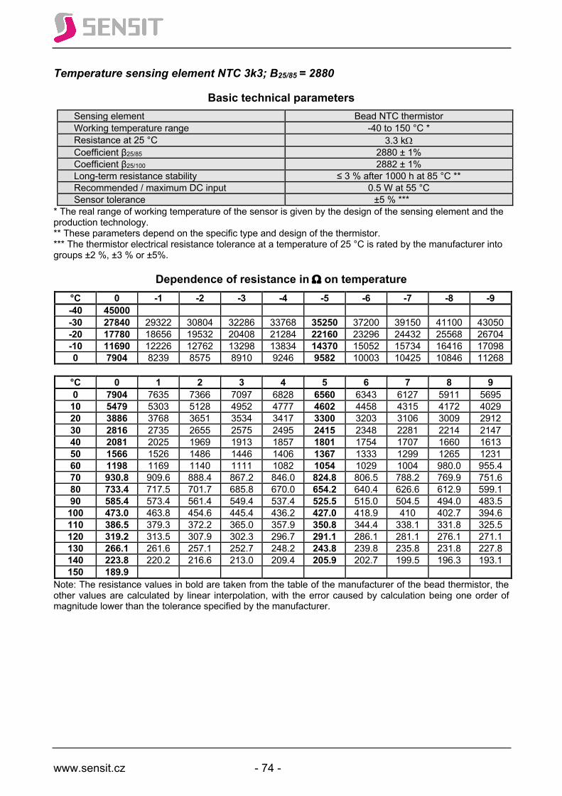
www.sensit.cz - 74 -
Temperature sensing element NTC 3k3; B25/85 = 2880
Basic technical parameters Sensing element Bead NTC thermistor Working temperature range -40 to 150 °C * Resistance at 25 °C 3.3 kW Coefficient β25/85 2880 ± 1% Coefficient β25/100 2882 ± 1% Long-term resistance stability ≤ 3 % after 1000 h at 85 °C ** Recommended / maximum DC input 0.5 W at 55 °C Sensor tolerance ±5 % ***
* The real range of working temperature of the sensor is given by the design of the sensing element and the production technology. ** These parameters depend on the specific type and design of the thermistor. *** The thermistor electrical resistance tolerance at a temperature of 25 °C is rated by the manufacturer into groups ±2 %, ±3 % or ±5%.
Dependence of resistance in W on temperature °C 0 -1 -2 -3 -4 -5 -6 -7 -8 -9 -40 45000 -30 27840 29322 30804 32286 33768 35250 37200 39150 41100 43050 -20 17780 18656 19532 20408 21284 22160 23296 24432 25568 26704 -10 11690 12226 12762 13298 13834 14370 15052 15734 16416 17098 0 7904 8239 8575 8910 9246 9582 10003 10425 10846 11268
°C 0 1 2 3 4 5 6 7 8 9 0 7904 7635 7366 7097 6828 6560 6343 6127 5911 5695 10 5479 5303 5128 4952 4777 4602 4458 4315 4172 4029 20 3886 3768 3651 3534 3417 3300 3203 3106 3009 2912 30 2816 2735 2655 2575 2495 2415 2348 2281 2214 2147 40 2081 2025 1969 1913 1857 1801 1754 1707 1660 1613 50 1566 1526 1486 1446 1406 1367 1333 1299 1265 1231 60 1198 1169 1140 1111 1082 1054 1029 1004 980.0 955.4 70 930.8 909.6 888.4 867.2 846.0 824.8 806.5 788.2 769.9 751.6 80 733.4 717.5 701.7 685.8 670.0 654.2 640.4 626.6 612.9 599.1 90 585.4 573.4 561.4 549.4 537.4 525.5 515.0 504.5 494.0 483.5 100 473.0 463.8 454.6 445.4 436.2 427.0 418.9 410 402.7 394.6 110 386.5 379.3 372.2 365.0 357.9 350.8 344.4 338.1 331.8 325.5 120 319.2 313.5 307.9 302.3 296.7 291.1 286.1 281.1 276.1 271.1 130 266.1 261.6 257.1 252.7 248.2 243.8 239.8 235.8 231.8 227.8 140 223.8 220.2 216.6 213.0 209.4 205.9 202.7 199.5 196.3 193.1 150 189.9
Note: The resistance values in bold are taken from the table of the manufacturer of the bead thermistor, the other values are calculated by linear interpolation, with the error caused by calculation being one order of magnitude lower than the tolerance specified by the manufacturer.

www.sensit.cz - 75 -
Temperature sensing element NTC 4k7; B25/85 = 3977
Basic technical parameters Sensing element Bead NTC thermistor Working temperature range -40 to 150 °C * Resistance at 25 °C 4.7 kW Coefficient β25/85 3977 ± 1% Coefficient β25/100 3994 ± 1% Long-term resistance stability ≤ 3 % after 1000 h at 85 °C ** Recommended / maximum DC input 0.5 mW / 2 mW Sensor tolerance ±5 % ***
* The real range of working temperature of the sensor is given by the design of the sensing element and the production technology. ** These parameters depend on the specific type and design of the thermistor. *** The thermistor electrical resistance tolerance at a temperature of 25 °C is rated by the manufacturer into groups ±2 %, ±3 % or ±5%.
Dependence of resistance in W on temperature °C 0 -1 -2 -3 -4 -5 -6 -7 -8 -9 -40 156084 -30 82344 88425 94507 100589 106671 112753 121419 130085 138751 147417 -20 45288 48383 51478 54574 57669 60765 65080 69396 73712 78028 -10 25872 27512 29153 30793 32434 34075 36317 38560 40802 43045 0 15300 16202 17105 18008 18911 19814 21025 22237 23448 24660
°C 0 1 2 3 4 5 6 7 8 9 0 15300 14621.8 13943.6 13265.4 12587.2 11909 11395.2 10881.4 10367.6 9853.8 10 9340 8947.6 8555.2 8162.8 7770.4 7378 7076.2 6774.4 6472.6 6170.8 20 5869 5635.2 5401.4 5167.6 4933.8 4700 4517.6 4335.2 4152.8 3970.4 30 3788 3644.6 3501.2 3357.8 3214.4 3071 2957.8 2844.6 2731.4 2618.2 40 2505 2415 2325 2235 2145 2055 1982.8 1910.6 1838.4 1766.2 50 1694 1636.2 1578.4 1520.6 1462.8 1405 1358 1311 1264 1217 60 1170 1131.94 1093.88 1055.82 1017.76 979.7 948.54 917.38 886.22 855.06 70 823.9 798.32 772.74 747.16 721.58 696 674.9 653.8 632.7 611.6 80 590.5 573 555.5 538 520.5 503 488.44 473.88 459.32 444.76 90 430.2 418.04 405.88 393.72 381.56 369.4 359.18 348.96 338.74 328.52 100 318.3 309.7 301.1 292.5 283.9 275.3 268.02 260.74 253.46 246.18 110 238.9 232.72 226.54 220.36 214.18 208 202.74 197.48 192.22 186.96 120 181.7 177.2 172.7 168.2 163.7 159.2 155.34 151.48 147.62 143.76 130 139.9 136.58 133.26 129.94 126.62 123.3 120.44 117.58 114.72 111.86 140 109 106.52 104.04 101.56 99.08 96.6 94.448 92.296 90.144 87.992 150 85.84
Note: The resistance values in bold are taken from the table of the manufacturer of the bead thermistor, the other values are calculated by linear interpolation, with the error caused by calculation being one order of magnitude lower than the tolerance specified by the manufacturer.

www.sensit.cz - 76 -
Temperature sensing element NTC 5k0; B25/85 = 3480
Basic technical parameters Sensing element Bead NTC thermistor Working temperature range -55 to 155 °C * Resistance at 25 °C 5.0 kW Coefficient β25/85 3480 ± 1% Coefficient β25/100 3497 ± 1% Long-term resistance stability ≤ 3 % after 1000 h at 85 °C ** Recommended / maximum DC input 0.5 mW / 2 mW Sensor tolerance ±5 % ***
* The real range of working temperature of the sensor is given by the design of the sensing element and the production technology. ** These parameters depend on the specific type and design of the thermistor. *** The thermistor electrical resistance tolerance at a temperature of 25 °C is rated by the manufacturer into groups ±2 %, ±3 % or ±5%.
Dependence of resistance in W on temperature °C 0 -1 -2 -3 -4 -5 -6 -7 -8 -9 -50 189950 203952 217954 231956 245958 259960 -40 104800 111910 119020 126130 133240 140350 150270 160190 170110 180030 -30 60186 63958 67729 71501 75272 79044 84195 89346 94498 99649 -20 35834 37916 39997 42079 44160 46242 49031 51820 54608 57397 -10 22043 23234 24424 25615 26805 27996 29564 31131 32699 34266 0 13968 14671 15375 16078 16782 17485 18397 19308 20220 21131
°C 0 1 2 3 4 5 6 7 8 9 0 13968 13421 12874 12328 11781 11234 10806 10378 9950 9522 10 9094 8757 8419 8082 7744 7407 7139 6871 6604 6336 20 6068 5854 5641 5427 5214 5000 4828 4657 4485 4314 30 4142 4004 3865 3727 3588 3450 3337 3225 3112 3000 40 2887 2795 2703 2612 2520 2428 2353 2277 2202 2126 50 2051 1989 1927 1865 1803 1741 1689.6 1638.2 1586.8 1535.4 60 1484 1441 1398 1356 1313 1270 1234 1198 1163 1127 70 1091 1061 1031 1001 970.8 940.8 915.5 890.2 865.0 839.7 80 814.4 793.0 771.6 750.3 728.9 707.5 689.4 671.2 653.1 634.9 90 616.8 601.3 585.8 570.4 554.9 539.4 526.2 513.0 499.7 486.5 100 473.3 462.0 450.6 439.3 427.9 416.6 406.8 397.0 387.3 377.5 110 367.7 359.3 350.9 342.4 334.0 325.6 318.3 311.0 303.6 296.3 120 289.0 282.7 276.3 270.0 263.6 257.3 251.8 246.3 240.7 235.2 130 229.7 224.9 220.0 215.2 210.3 205.5 201.3 197.1 192.8 188.6 140 184.4 180.7 177.0 173.2 169.5 165.8 162.5 159.2 156.0 152.7 150 149.4 146.5 143.6 140.8 137.9 135.0
Note: The resistance values in bold are taken from the table of the manufacturer of the bead thermistor, the other values are calculated by linear interpolation, with the error caused by calculation being one order of magnitude lower than the tolerance specified by the manufacturer.
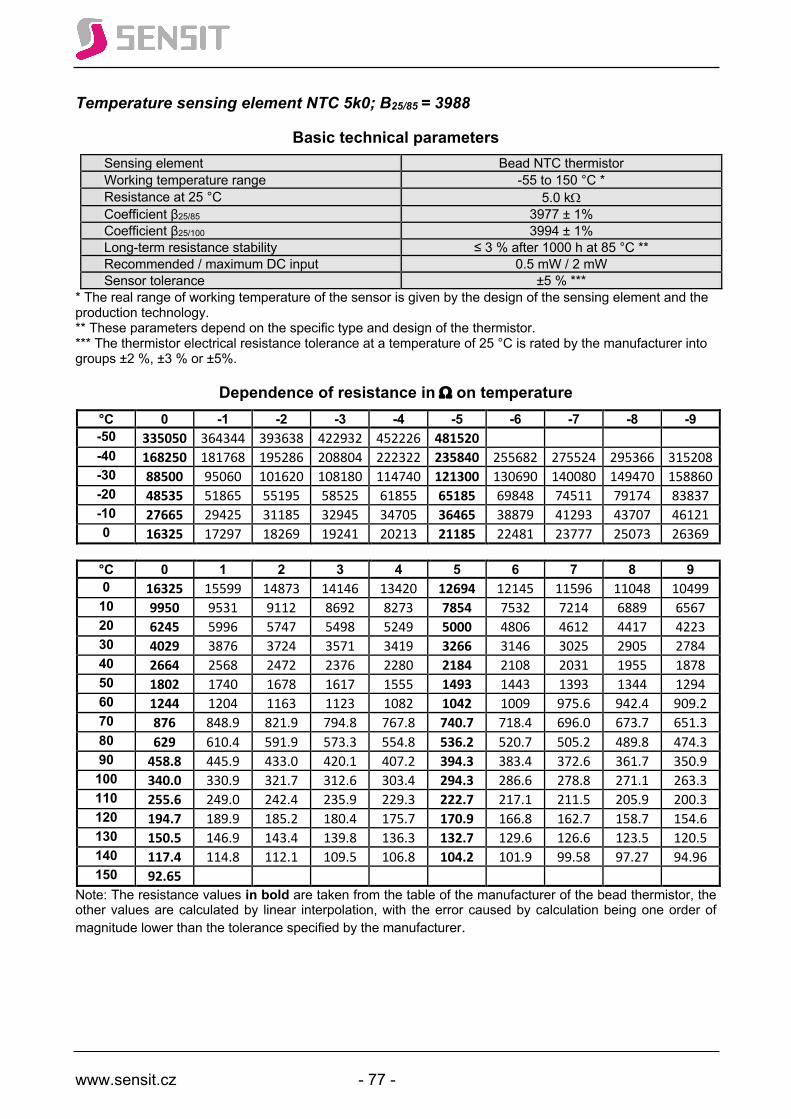
www.sensit.cz - 77 -
Temperature sensing element NTC 5k0; B25/85 = 3988
Basic technical parameters Sensing element Bead NTC thermistor Working temperature range -55 to 150 °C * Resistance at 25 °C 5.0 kW Coefficient β25/85 3977 ± 1% Coefficient β25/100 3994 ± 1% Long-term resistance stability ≤ 3 % after 1000 h at 85 °C ** Recommended / maximum DC input 0.5 mW / 2 mW Sensor tolerance ±5 % ***
* The real range of working temperature of the sensor is given by the design of the sensing element and the production technology. ** These parameters depend on the specific type and design of the thermistor. *** The thermistor electrical resistance tolerance at a temperature of 25 °C is rated by the manufacturer into groups ±2 %, ±3 % or ±5%.
Dependence of resistance in W on temperature °C 0 -1 -2 -3 -4 -5 -6 -7 -8 -9 -50 335050 364344 393638 422932 452226 481520 -40 168250 181768 195286 208804 222322 235840 255682 275524 295366 315208 -30 88500 95060 101620 108180 114740 121300 130690 140080 149470 158860 -20 48535 51865 55195 58525 61855 65185 69848 74511 79174 83837 -10 27665 29425 31185 32945 34705 36465 38879 41293 43707 46121 0 16325 17297 18269 19241 20213 21185 22481 23777 25073 26369
°C 0 1 2 3 4 5 6 7 8 9 0 16325 15599 14873 14146 13420 12694 12145 11596 11048 10499 10 9950 9531 9112 8692 8273 7854 7532 7214 6889 6567 20 6245 5996 5747 5498 5249 5000 4806 4612 4417 4223 30 4029 3876 3724 3571 3419 3266 3146 3025 2905 2784 40 2664 2568 2472 2376 2280 2184 2108 2031 1955 1878 50 1802 1740 1678 1617 1555 1493 1443 1393 1344 1294 60 1244 1204 1163 1123 1082 1042 1009 975.6 942.4 909.2 70 876 848.9 821.9 794.8 767.8 740.7 718.4 696.0 673.7 651.3 80 629 610.4 591.9 573.3 554.8 536.2 520.7 505.2 489.8 474.3 90 458.8 445.9 433.0 420.1 407.2 394.3 383.4 372.6 361.7 350.9 100 340.0 330.9 321.7 312.6 303.4 294.3 286.6 278.8 271.1 263.3 110 255.6 249.0 242.4 235.9 229.3 222.7 217.1 211.5 205.9 200.3 120 194.7 189.9 185.2 180.4 175.7 170.9 166.8 162.7 158.7 154.6 130 150.5 146.9 143.4 139.8 136.3 132.7 129.6 126.6 123.5 120.5 140 117.4 114.8 112.1 109.5 106.8 104.2 101.9 99.58 97.27 94.96 150 92.65
Note: The resistance values in bold are taken from the table of the manufacturer of the bead thermistor, the other values are calculated by linear interpolation, with the error caused by calculation being one order of magnitude lower than the tolerance specified by the manufacturer.
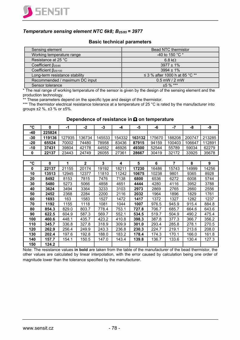
www.sensit.cz - 78 -
Temperature sensing element NTC 6k8; B25/85 = 3977
Basic technical parameters Sensing element Bead NTC thermistor Working temperature range -40 to 150 °C * Resistance at 25 °C 6.8 kW Coefficient β25/85 3977 ± 1% Coefficient β25/100 3994 ± 1% Long-term resistance stability ≤ 3 % after 1000 h at 85 °C ** Recommended / maximum DC input 0.5 mW / 2 mW Sensor tolerance ±5 % ***
* The real range of working temperature of the sensor is given by the design of the sensing element and the production technology. ** These parameters depend on the specific type and design of the thermistor. *** The thermistor electrical resistance tolerance at a temperature of 25 °C is rated by the manufacturer into groups ±2 %, ±3 % or ±5%.
Dependence of resistance in W on temperature °C 0 -1 -2 -3 -4 -5 -6 -7 -8 -9 -40 225824 -30 119136 127935 136734 145533 154332 163132 175670 188208 200747 213285 -20 65524 70002 74480 78958 83436 87915 94159 100403 106647 112891 -10 37431 39804 42178 44552 46926 49300 52544 55789 59034 62279 0 22137 23443 24749 26055 27361 28667 30419 32172 33925 35678
°C 0 1 2 3 4 5 6 7 8 9 0 22137 21155 20174 19192 18211 17230 16486 15743 14999 14256 10 13513 12945 12377 11810 11242 10675 10238 9801 9365 8928 20 8492 8153 7815 7476 7138 6800 6536 6272 6008 5744 30 5480 5273 5066 4858 4651 4444 4280 4116 3952 3788 40 3624 3494 3364 3233 3103 2973 2869 2765 2660 2556 50 2452 2368 2284 2200 2116 2032 1964 1896 1829 1761 60 1693 163 1583 1527 1472 1417 1372 1327 1282 1237 70 1192 1155 1118 1081 1044 1007 976.5 945.9 915.4 884.8 80 854.3 829.0 803.7 778.4 753.1 727.8 706.7 685.7 664.6 643.6 90 622.5 604.9 587.3 569.7 552.1 534.5 519.7 504.9 490.2 475.4 100 460.6 448.1 435.7 423.2 410.8 398.3 387.8 377.3 366.7 356.2 110 345.7 336.8 327.8 318.9 309.9 301.0 293.4 285.8 278.1 270.5 120 262.9 256.4 249.9 243.3 236.8 230.3 224.7 219.1 213.6 208.0 130 202.4 197.6 192.8 188.0 183.2 178.4 174.3 170.1 166.0 161.8 140 157.7 154.1 150.5 147.0 143.4 139.8 136.7 133.6 130.4 127.3 150 124.2
Note: The resistance values in bold are taken from the table of the manufacturer of the bead thermistor, the other values are calculated by linear interpolation, with the error caused by calculation being one order of magnitude lower than the tolerance specified by the manufacturer.

www.sensit.cz - 79 -
Temperature sensing element NTC 10k; B25/85 = 3435
Basic technical parameters Sensing element Bead NTC thermistor Working temperature range -40 to 125 °C * Resistance at 25 °C 10 kW Coefficient β25/85 3435 ± 1% Coefficient β25/100 3478 ± 1% Long-term resistance stability ≤ 3 % after 1000 h at 85 °C ** Recommended / maximum DC input 0.5 mW / 2 mW
Sensor tolerance ± 0.5 °C for t = 25 °C ** ± 1.0 °C for t = 0 to 70 °C **
* The real range of working temperature of the sensor is given by the design and technology. ** These parameters depend on the specific type and design of the thermistor.
Dependence of resistance in kW on temperature °C 0 -1 -2 -3 -4 -5 -6 -7 -8 -9 -40 210.514 -30 121.737 128.421 135.513 143.038 151.025 159.505 168.510 178.075 188.237 199.036 -20 72.503 76.257 80.230 84.435 88.886 93.600 98.593 103.884 109.491 115.434 -10 44.476 46.642 48.928 51.340 53.888 56.578 59.420 62.423 65.598 68.954 0 28.081 29.366 30.717 32.140 33.638 35.216 36.878 38.630 40.476 42.423
°C 0 1 2 3 4 5 6 7 8 9 0 28.081 26.861 25.700 24.596 23.547 22.548 21.597 20.691 19.829 19.008 10 18.226 17.480 16.770 16.092 15.445 14.829 14.240 13.678 13.142 12.630 20 12.141 11.673 11.226 10.799 10.391 10.000 9.626 9.269 8.926 8.599 30 8.285 7.984 7.696 7.420 7.156 6.902 6.659 6.426 6.202 5.987 40 5.781 5.583 5.393 5.211 5.035 4.867 4.705 4.549 4.399 4.255 50 4.117 3.984 3.855 3.732 3.613 3.499 3.388 3.282 3.180 3.081 60 2.986 2.895 2.806 2.721 2.639 2.560 2.483 2.409 2.338 2.269 70 2.203 2.138 2.076 2.016 1.958 1.902 1.848 1.796 1.745 1.696 80 1.649 1.603 1.558 1.515 1.474 1.434 1.395 1.357 1.320 1.285 90 1.250 1.217 1.185 1.154 1.123 1.094 1.065 1.038 1.011 0.985 100 0.959 0.935 0.911 0.888 0.866 0.844 0.823 0.802 0.782 0.763 110 0.744 0.725 0.707 0.690 0.673 0.657 0.641 0.625 0.610 0.596 120 0.581 0.567 0.554 0.541 0.528 0.516
Note 1: The resistance values in bold are taken from the table of the manufacturer of the bead thermistor, the other values are calculated by linear interpolation, with the error caused by calculation being one order of magnitude lower than the tolerance specified by the manufacturer. Note 2: this type of sensing element is interchangeable with sensor NTC 10k; β25/85 = 3455 with a tolerance of ± 1%

www.sensit.cz - 80 -
Temperature sensing element NTC 10k; B25/85 = 3977
Basic technical parameters Sensing element Bead NTC thermistor Working temperature range -40 to 125 °C * Resistance at 25 °C 10 kW Coefficient β25/85 3977 ± 1% Coefficient β25/100 3994 ± 1% Long-term resistance stability ≤ 3 % after 1000 h at 85 °C ** Recommended / maximum DC input 0.5 mW / 2 mW
Sensor tolerance ± 0.5 °C for t = 25 °C ** ± 1.0 °C for t = 0 to 70 °C **
* The real range of working temperature of the sensor is given by the design and technology. ** These parameters depend on the specific type and design of the thermistor.
Dependence of resistance in kW on temperature °C 0 -1 -2 -3 -4 -5 -6 -7 -8 -9 -40 334.202 -30 177.797 189.085 201.158 214.077 227.905 242.710 258.566 275.554 293.759 313.275 -20 97.923 103.781 110.026 116.687 123.795 131.380 139.479 148.128 157.368 167.242 -10 55.805 58.944 62.280 65.827 69.599 73.612 77.883 82.430 87.271 92.428 0 32.869 34.605 36.445 38.396 40.463 42.655 44.981 47.449 50.069 52.850
°C 0 1 2 3 4 5 6 7 8 9 0 32.869 31.229 29.680 28.217 26.834 25.527 24.291 23.122 22.015 20.968 10 19.977 19.038 18.149 17.306 16.507 15.750 15.032 14.350 13.703 13.090 20 12.507 11.953 11.427 10.927 10.452 10.000 9.570 9.161 8.772 8.402 30 8.049 7.713 7.393 7.088 6.798 6.521 6.256 6.004 5.764 5.534 40 5.315 5.106 4.906 4.715 4.533 4.358 4.191 4.032 3.879 3.733 50 3.594 3.460 3.332 3.210 3.092 2.980 2.872 2.768 2.669 2.574 60 2.483 2.396 2.312 2.231 2.154 2.080 2.009 1.940 1.874 1.811 70 1.750 1.692 1.636 1.582 1.530 1.480 1.431 1.385 1.340 1.298 80 1.256 1.216 1.178 1.141 1.105 1.071 1.038 1.006 0.975 0.945 90 0.916 0.889 0.862 0.836 0.811 0.787 0.764 0.741 0.720 0.699 100 0.678 0.659 0.640 0.622 0.604 0.587 0.570 0.554 0.539 0.524 110 0.509 0.495 0.481 0.468 0.455 0.443 0.431 0.419 0.408 0.397 120 0.386 0.376 0.366 0.357 0.347 0.338
Note: The resistance values in bold are taken from the table of the manufacturer of the bead thermistor, the other values are calculated by linear interpolation, with the error caused by calculation being one order of magnitude lower than the tolerance specified by the manufacturer.

www.sensit.cz - 81 -
Temperature sensing element NTC 12k; B25/85 = 3740
Basic technical parameters Sensing element Bead NTC thermistor Working temperature range -40 to 125 °C * Resistance at 25 °C 12 kW Coefficient β25/85 3740 ± 1% Coefficient β25/100 3760 ± 1% Long-term resistance stability ≤ 3 % after 1000 h at 85 °C ** Recommended / maximum DC input 0.5 mW / 5mW Sensor tolerance ±5 % ***
* The real range of working temperature of the sensor is given by the design of the sensing element and the production technology. ** These parameters depend on the specific type and design of the thermistor. *** The thermistor electrical resistance tolerance at a temperature of 25 °C is rated by the manufacturer into groups ±1%, ±3 % or ±5%.
Dependence of resistance in W on temperature °C 0 -1 -2 -3 -4 -5 -6 -7 -8 -9 -40 309400 -30 171800 183340 194880 206420 217960 229500 245480 261460 277440 293420 -20 98980 105144 111308 117472 123636 129800 245480 261460 277440 293420 -10 58880 62308 65736 69164 72592 76020 138200 146600 155000 163400 0 36130 38094 40058 42022 43986 45950 80612 85204 89796 94388
°C 0 1 2 3 4 5 6 7 8 9 0 36130 34624 33118 31612 30106 28600 27440 26280 25120 23960 10 22800 21900 21000 20100 19200 18300 17594 16888 16182 15476 20 14770 14216 13662 13108 12554 12000 11560.8 11121.6 10682.4 10243.2 30 9804 9454 9104 8754 8404 8054 7773.6 7493.2 7212.8 6932.4 40 6652 6426 6200 5974 5748 5522 5339 5156 4973 4790 50 4607 4458 4309 4160 4011 3862 3740 3618 3496 3374 60 3252 3152 3052 2951 2851 2751 2668 2585 2503 2420 70 2337 2268 2199 2131 2062 1993 1936 1879 1821 1764 80 1707 1659 1611 1563 1515 1467 1427 1387 1346 1306 90 1266 1232 1198 1164 1130 1096 1067 1038 1010 980.8 100 952.0 927.6 903.2 878.8 854.4 830.0 809.2 788.4 767.6 746.8 110 726.0 708.2 690.4 672.6 654.8 637.0 621.6 606.2 590.8 575.4 120 560.0 547.0 534.0 521.0 508.0 495.0
Note: The resistance values in bold are taken from the table of the manufacturer of the bead thermistor, the other values are calculated by linear interpolation, with the error caused by calculation being one order of magnitude lower than the tolerance specified by the manufacturer.
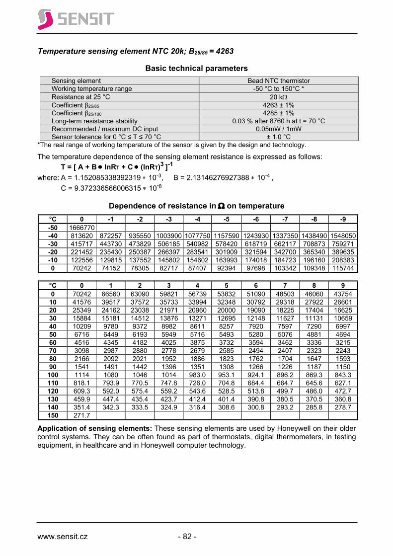
www.sensit.cz - 82 -
Temperature sensing element NTC 20k; B25/85 = 4263
Basic technical parameters Sensing element Bead NTC thermistor Working temperature range -50 °C to 150°C * Resistance at 25 °C 20 kW Coefficient β25/85 4263 ± 1% Coefficient β25/100 4285 ± 1% Long-term resistance stability 0.03 % after 8760 h at t = 70 °C Recommended / maximum DC input 0.05mW / 1mW Sensor tolerance for 0 °C ≤ T ≤ 70 °C ± 1.0 °C
*The real range of working temperature of the sensor is given by the design and technology.
The temperature dependence of the sensing element resistance is expressed as follows: T = [ A + B * lnRT + C * (lnRT)3 ]-1 where: A = 1.152085338392319 * 10-3, B = 2.13146276927388 * 10-4 , C = 9.372336566006315 * 10-8
Dependence of resistance in W on temperature °C 0 -1 -2 -3 -4 -5 -6 -7 -8 -9 -50 1666770 -40 813620 872257 935550 1003900 1077750 1157590 1243930 1337350 1438490 1548050 -30 415717 443730 473829 506185 540982 578420 618719 662117 708873 759271 -20 221452 235430 250387 266397 283541 301909 321594 342700 365340 389635 -10 122556 129815 137552 145802 154602 163993 174018 184723 196160 208383 0 70242 74152 78305 82717 87407 92394 97698 103342 109348 115744
°C 0 1 2 3 4 5 6 7 8 9 0 70242 66560 63090 59821 56739 53832 51090 48503 46060 43754 10 41576 39517 37572 35733 33994 32348 30792 29318 27922 26601 20 25349 24162 23038 21971 20960 20000 19090 18225 17404 16625 30 15884 15181 14512 13876 13271 12695 12148 11627 11131 10659 40 10209 9780 9372 8982 8611 8257 7920 7597 7290 6997 50 6716 6449 6193 5949 5716 5493 5280 5076 4881 4694 60 4516 4345 4182 4025 3875 3732 3594 3462 3336 3215 70 3098 2987 2880 2778 2679 2585 2494 2407 2323 2243 80 2166 2092 2021 1952 1886 1823 1762 1704 1647 1593 90 1541 1491 1442 1396 1351 1308 1266 1226 1187 1150 100 1114 1080 1046 1014 983.0 953.1 924.1 896.2 869.3 843.3 110 818.1 793.9 770.5 747.8 726.0 704.8 684.4 664.7 645.6 627.1 120 609.3 592.0 575.4 559.2 543.6 528.5 513.8 499.7 486.0 472.7 130 459.9 447.4 435.4 423.7 412.4 401.4 390.8 380.5 370.5 360.8 140 351.4 342.3 333.5 324.9 316.4 308.6 300.8 293.2 285.8 278.7 150 271.7
Application of sensing elements: These sensing elements are used by Honeywell on their older control systems. They can be often found as part of thermostats, digital thermometers, in testing equipment, in healthcare and in Honeywell computer technology.

www.sensit.cz - 83 -
Temperature sensing element NTC 22k; B25/85 = 3740
Basic technical parameters Sensing element Bead NTC thermistor Working temperature range -40 to 150 °C * Resistance at 25 °C 22 kW Coefficient β25/85 3740 ± 1% Coefficient β25/100 3760 ± 1% Long-term resistance stability ≤ 3 % after 1000 h at 85 °C ** Recommended / maximum DC input 0.5 mW / 2 mW Sensor tolerance ±5 % ***
* The real range of working temperature of the sensor is given by the design of the sensing element and the production technology. ** These parameters depend on the specific type and design of the thermistor. *** The thermistor electrical resistance tolerance at a temperature of 25 °C is rated by the manufacturer into groups ±2 %, ±3 % or ±5%.
Dependence of resistance in kΩ on temperature °C 0 -1 -2 -3 -4 -5 -6 -7 -8 -9 -40 567.2 -30 315.0 336.2 357.3 378.5 399.6 420.8 450.1 479.4 508.6 537.9 -20 181.4 192.7 204.0 215.4 226.7 238.0 253.4 268.8 284.2 299.6 -10 107.9 114.2 120.5 126.8 133.1 139.4 147.8 156.2 164.6 173.0 0 66.24 69.84 73.44 77.05 80.65 84.25 88.98 93.71 98.44 103.2
°C 0 1 2 3 4 5 6 7 8 9 0 66.24 63.48 60.72 57.97 55.21 52.45 50.32 48.19 46.07 43.94 10 41.81 40.16 38.51 36.85 35.20 33.55 32.26 30.96 29.67 28.37 20 27.08 26.06 25.05 24.03 23.02 22.00 21.19 20.39 19.58 18.78 30 17.97 17.33 16.69 16.05 15.41 14.77 14.26 13.74 13.23 12.71 40 12.20 11.78 11.37 10.95 10.54 10.12 9.785 9.451 9.116 8.782 50 8.447 8.174 7.901 7.627 7.354 7.081 6.857 6.634 6.410 6.187 60 5.963 5.779 5.595 5.412 5.228 5.044 4.892 4.740 4.588 4.436 70 4.284 4.158 4.032 3.906 3.780 3.654 3.549 3.444 3.339 3.234 80 3.129 3.041 2.953 2.866 2.778 2.690 2.616 2.542 2.469 2.395 90 2.321 2.259 2.197 2.134 2.072 2.010 1.957 1.904 1.852 1.799 100 1.746 1.701 1.656 1.612 1.567 1.522 1.484 1.446 1.407 1.369 110 1.331 1.298 1.266 1.233 1.201 1.168 1.140 1.112 1.083 1.055 120 1.027 1.003 0.9788 0.9547 0.9306 0.9065 0.8856 0.8648 0.8439 0.8231 130 0.8022 0.7841 0.7660 0.7479 0.7298 0.7117 0.6960 0.6803 0.6646 0.6489 140 0.6332 0.6195 0.6058 0.5921 0.5784 0.5647 0.5527 0.5408 0.5288 0.5169 150 0.5049
Note: The resistance values in bold are taken from the table of the manufacturer of the bead thermistor, the other values are calculated by linear interpolation, with the error caused by calculation being one order of magnitude lower than the tolerance specified by the manufacturer.
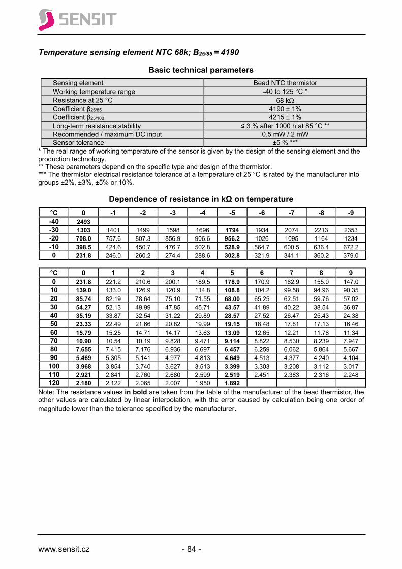
www.sensit.cz - 84 -
Temperature sensing element NTC 68k; B25/85 = 4190
Basic technical parameters Sensing element Bead NTC thermistor Working temperature range -40 to 125 °C * Resistance at 25 °C 68 kW Coefficient β25/85 4190 ± 1% Coefficient β25/100 4215 ± 1% Long-term resistance stability ≤ 3 % after 1000 h at 85 °C ** Recommended / maximum DC input 0.5 mW / 2 mW Sensor tolerance ±5 % ***
* The real range of working temperature of the sensor is given by the design of the sensing element and the production technology. ** These parameters depend on the specific type and design of the thermistor. *** The thermistor electrical resistance tolerance at a temperature of 25 °C is rated by the manufacturer into groups ±2%, ±3%, ±5% or 10%.
Dependence of resistance in kΩ on temperature °C 0 -1 -2 -3 -4 -5 -6 -7 -8 -9 -40 2493 -30 1303 1401 1499 1598 1696 1794 1934 2074 2213 2353 -20 708.0 757.6 807.3 856.9 906.6 956.2 1026 1095 1164 1234 -10 398.5 424.6 450.7 476.7 502.8 528.9 564.7 600.5 636.4 672.2 0 231.8 246.0 260.2 274.4 288.6 302.8 321.9 341.1 360.2 379.0
°C 0 1 2 3 4 5 6 7 8 9 0 231.8 221.2 210.6 200.1 189.5 178.9 170.9 162.9 155.0 147.0 10 139.0 133.0 126.9 120.9 114.8 108.8 104.2 99.58 94.96 90.35 20 85.74 82.19 78.64 75.10 71.55 68.00 65.25 62.51 59.76 57.02 30 54.27 52.13 49.99 47.85 45.71 43.57 41.89 40.22 38.54 36.87 40 35.19 33.87 32.54 31.22 29.89 28.57 27.52 26.47 25.43 24.38 50 23.33 22.49 21.66 20.82 19.99 19.15 18.48 17.81 17.13 16.46 60 15.79 15.25 14.71 14.17 13.63 13.09 12.65 12.21 11.78 11.34 70 10.90 10.54 10.19 9.828 9.471 9.114 8.822 8.530 8.239 7.947 80 7.655 7.415 7.176 6.936 6.697 6.457 6.259 6.062 5.864 5.667 90 5.469 5.305 5.141 4.977 4.813 4.649 4.513 4.377 4.240 4.104 100 3.968 3.854 3.740 3.627 3.513 3.399 3.303 3.208 3.112 3.017 110 2.921 2.841 2.760 2.680 2.599 2.519 2.451 2.383 2.316 2.248 120 2.180 2.122 2.065 2.007 1.950 1.892
Note: The resistance values in bold are taken from the table of the manufacturer of the bead thermistor, the other values are calculated by linear interpolation, with the error caused by calculation being one order of magnitude lower than the tolerance specified by the manufacturer.
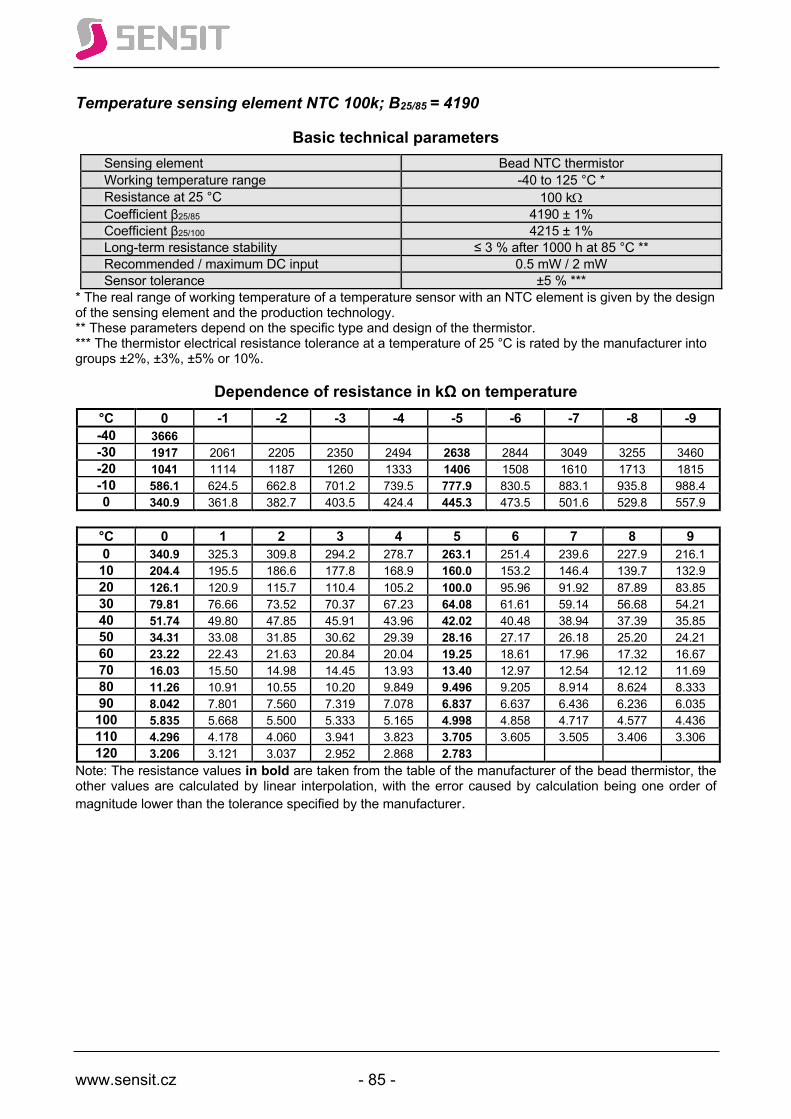
www.sensit.cz - 85 -
Temperature sensing element NTC 100k; B25/85 = 4190
Basic technical parameters Sensing element Bead NTC thermistor Working temperature range -40 to 125 °C * Resistance at 25 °C 100 kW Coefficient β25/85 4190 ± 1% Coefficient β25/100 4215 ± 1% Long-term resistance stability ≤ 3 % after 1000 h at 85 °C ** Recommended / maximum DC input 0.5 mW / 2 mW Sensor tolerance ±5 % ***
* The real range of working temperature of a temperature sensor with an NTC element is given by the design of the sensing element and the production technology. ** These parameters depend on the specific type and design of the thermistor. *** The thermistor electrical resistance tolerance at a temperature of 25 °C is rated by the manufacturer into groups ±2%, ±3%, ±5% or 10%.
Dependence of resistance in kΩ on temperature °C 0 -1 -2 -3 -4 -5 -6 -7 -8 -9 -40 3666 -30 1917 2061 2205 2350 2494 2638 2844 3049 3255 3460 -20 1041 1114 1187 1260 1333 1406 1508 1610 1713 1815 -10 586.1 624.5 662.8 701.2 739.5 777.9 830.5 883.1 935.8 988.4 0 340.9 361.8 382.7 403.5 424.4 445.3 473.5 501.6 529.8 557.9
°C 0 1 2 3 4 5 6 7 8 9 0 340.9 325.3 309.8 294.2 278.7 263.1 251.4 239.6 227.9 216.1 10 204.4 195.5 186.6 177.8 168.9 160.0 153.2 146.4 139.7 132.9 20 126.1 120.9 115.7 110.4 105.2 100.0 95.96 91.92 87.89 83.85 30 79.81 76.66 73.52 70.37 67.23 64.08 61.61 59.14 56.68 54.21 40 51.74 49.80 47.85 45.91 43.96 42.02 40.48 38.94 37.39 35.85 50 34.31 33.08 31.85 30.62 29.39 28.16 27.17 26.18 25.20 24.21 60 23.22 22.43 21.63 20.84 20.04 19.25 18.61 17.96 17.32 16.67 70 16.03 15.50 14.98 14.45 13.93 13.40 12.97 12.54 12.12 11.69 80 11.26 10.91 10.55 10.20 9.849 9.496 9.205 8.914 8.624 8.333 90 8.042 7.801 7.560 7.319 7.078 6.837 6.637 6.436 6.236 6.035 100 5.835 5.668 5.500 5.333 5.165 4.998 4.858 4.717 4.577 4.436 110 4.296 4.178 4.060 3.941 3.823 3.705 3.605 3.505 3.406 3.306 120 3.206 3.121 3.037 2.952 2.868 2.783
Note: The resistance values in bold are taken from the table of the manufacturer of the bead thermistor, the other values are calculated by linear interpolation, with the error caused by calculation being one order of magnitude lower than the tolerance specified by the manufacturer.
www.sensit.cz - 86 -
Th
erm
ocou
ple
Tem
pera
ture
Sen
sor s

www.sensit.cz - 87 -
Type J thermocouple sensors
Basic technical parameters Sensing element Type J thermocouple Maximum range of working temperature -40 to +750 °C * Reference voltage at 0 °C 0.00 µV
* The real range of working temperature of the sensor is given by the design and technology
Principle:
A change of the temperature of the measured environment results in a defined change of the measuring thermocouple voltage. The change of voltage is defined by the following equation according to EN 60584-1: n U = ∑ ai (t90)i µV in a temperature range of -210 to +760 °C i=1
where a1 = 5.038 118 7815 x 101 a5 = -1.705 295 8337 x 10-10 a2 = 3.047 583 6930 x 10-2 a6 = 2.094 809 0697 x 10-13 a3 = -8.568 106 5720 x 10-5 a7 = -1.253 839 5336 x 10-16 a4 = 1.322 819 5295 x 10-7 a8 = 1.563 172 5697 x 10-20 n U = ∑ ai (t90)i µV in a temperature range of +760 to 1200 °C i=1
where a0 = 2.964 562 5681 x 105 a3 = -3.184 768 6701 x 10-3 a1 = -1.497 612 7786 x 103 a4 = 1.572 081 9004 x 10-6 a2 = 3.178 710 3924 a5 = -3.069 136 9056 x 10-10
Dependence of voltage in mV on temperature: °C 0 -10 -20 -30 -40 -50 -60 -70 -80 -90
-200 -7.890 -8.095 -100 -4.633 -5.037 -5.426 -5.801 -6.159 -6.500 -6.821 -7.123 -7.403 -7.659
0 0.000 -0.501 -0.995 -1.482 -1.961 -2.431 -2.893 -3.344 -3.786 -4.215
°C 0 10 20 30 40 50 60 70 80 90 0 0.000 0.507 1.019 1.537 2.059 2.585 3.116 3.650 4.187 4.726
100 5.269 5.814 6.360 6.909 7.459 8.010 8.562 9.115 9.669 10.224 200 10.779 11.334 11.889 12.445 13.000 13.555 14.110 14.665 15.219 15.773 300 16.327 16.881 17.434 17.986 18.538 19.090 19.642 20.194 20.745 21.297 400 21.848 22.400 22.952 23.504 24.057 24.610 25.164 25.720 26.276 26.834 500 27.393 27.953 28.516 29.080 29.647 30.216 30.788 31.362 31.939 32.519 600 33.102 33.689 34.279 34.873 35.470 36.071 36.675 37.284 37.896 38.512 700 39.132 39.755 40.382 41.012 41.645 42.281 42.919 43.559 44.203 44.848 800 45.494 46.141 46.786 47.431 48.074 48.715 49.353 49.989 50.622 51.251 900 51.877 52.500 53.119 53.735 54.347 54.956 55.561 56.164 56.763 57.360 1000 57.953 58.545 59.134 59.721 60.307 60.890 61.473 62.054 62.634 63.214 1100 63.792 64.370 64.948 65.525 66.102 66.679 67.255 67.831 68.406 68.980 1200 69.553
The temperature dependence of voltage on temperature with 1 degree Celsius increments is shown in EN 60584-1.
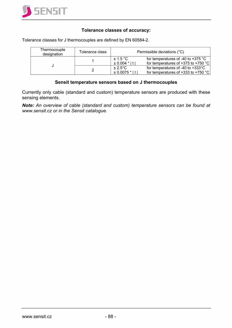
www.sensit.cz - 88 -
Tolerance classes of accuracy:
Tolerance classes for J thermocouples are defined by EN 60584-2.
Thermocouple designation Tolerance class Permissible deviations (°C)
J 1 ± 1.5 °C for temperatures of -40 to +375 °C
± 0.004 * | t | for temperatures of +375 to +750 °C
2 ± 2.5°C for temperatures of -40 to +333°C ± 0.0075 * | t | for temperatures of +333 to +750 °C
Sensit temperature sensors based on J thermocouples
Currently only cable (standard and custom) temperature sensors are produced with these sensing elements. Note: An overview of cable (standard and custom) temperature sensors can be found at www.sensit.cz or in the Sensit catalogue.

www.sensit.cz - 89 -
Type K thermocouple sensors
Basic technical parameters Sensing element Type K thermocouple Maximum range of working temperature -200 to 1200 °C * Reference voltage at 0 °C 0.00 µV
* The real range of working temperature of the sensor is given by the design and technology
Principle:
A change of the temperature of the measured environment results in a defined change of the measuring thermocouple voltage. The change of voltage is defined by the following equation according to EN 60584-1: n
U = ∑ ai (t90)i µV in a temperature range of -270 to 0 °C i=1
where a1 = 3.945 012 8025 x 101 a6 = -5.741 032 7428 x 10-10 a2 = 2.362 237 3598 x 10-2 a7 = -3.108 887 2894 x 10-12 a3 = -3.285 890 6784 x 10-4 a8 = -1.045 160 9365 x 10-14 a4 = -4.990 482 8777 x 10-6 a9 = -1.988 926 6878 x 10-17 a5 = -6.750 905 9173 x 10-8 a10 = -1.632 269 7486 x 10-20
n U = b0 + ∑bi (t90)i + c0exp[c1(t90 – 126,9686)2] µV in a temperature range of 0 to 1372 °C i=1
where b0 = -1.760 041 3686 x 101 b6 = -3.108 887 2894 x 10-12 b1 = 3.892 120 4975 x 101 b7 = -1.045 160 9365 x 10-14 b2 = 1.855 877 0032 x 10-2 b8 = -1.988 926 6878 x 10-17 b3 = -9.945 759 2874 x 10-5 b9 = -1.632 269 7486 x 10-20 b4 = 3.184 094 5719 x 10-7 c0 = 1.185 976 x 102
b5 = -5.607 284 4889 x 10-10 c1 = -1.183 432 x 10-4
Dependence of voltage in mV on temperature: °C 0 -10 -20 -30 -40 -50 -60 -70 -80 -90
-200 -5.891 -6.035 -6.158 -6.262 -6.344 -6.404 -6.441 -6.458 -100 -3.554 -3.852 -4.138 -4.411 -4.669 -4.913 -5.141 -5.354 -5.550 -5.730
0 0.000 -0.392 -0.778 -1.156 -1.527 -1.889 -2.243 -2.587 -2.920 -3.243
°C 0 10 20 30 40 50 60 70 80 90 0 0.000 0.397 0.798 1.203 1.612 2.023 2.436 2.851 3.267 3.682
100 4.096 4.509 4.920 5.328 5.735 6.138 6.540 6.941 7.340 7.739 200 8.138 8.539 8.940 9.343 9.747 10.153 10.561 10.971 11.382 11.795 300 12.209 12.624 13.040 13.457 13.874 14.293 14.713 15.133 15.554 15.975 400 16.397 16.820 17.243 17.667 18.091 18.516 18.941 19.366 19.792 20.218 500 20.644 21.071 21.497 21.924 22.350 22.776 23.203 23.629 24.055 24.480 600 24.905 25.330 25.755 26.179 26.602 27.025 27.447 27.869 28.289 28.710 700 29.129 29.548 29.965 30.382 30.798 31.213 31.628 32.041 32.453 32.865 800 33.275 33.685 34.093 34.501 34.908 35.313 35.718 36.121 36.524 36.925 900 37.326 37.725 38.124 38.522 38.918 39.314 39.708 40.101 40.494 40.885 1000 41.276 41.665 42.053 42.440 42.826 43.211 43.595 43.978 44.359 44.740 1100 45.119 45.497 45.873 46.249 46.623 46.995 47.367 47.737 48.105 48.473 1200 48.838 49.202 49.565 49.926 50.286 50.644 51.000 51.355 51.708 52.060 1300 52.410 52.759 53.106 53.451 53.795 54.138 54.479 54.819
The temperature dependence of voltage on temperature with 1 degree Celsius increments is shown in EN 60584-1.
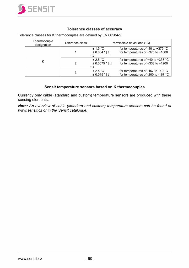
www.sensit.cz - 90 -
Tolerance classes of accuracy
Tolerance classes for K thermocouples are defined by EN 60584-2. Thermocouple
designation Tolerance class Permissible deviations (°C)
K
1 ± 1.5 °C for temperatures of -40 to +375 °C ± 0.004 * | t | for temperatures of +375 to +1000 °C
2 ± 2.5 °C for temperatures of +40 to +333 °C ± 0.0075 * | t | for temperatures of +333 to +1200 °C
3 ± 2.5 °C for temperatures of -167 to +40 °C ± 0.015 * | t | for temperatures of -200 to -167 °C
Sensit temperature sensors based on K thermocouples
Currently only cable (standard and custom) temperature sensors are produced with these sensing elements. Note: An overview of cable (standard and custom) temperature sensors can be found at www.sensit.cz or in the Sensit catalogue.

www.sensit.cz - 91 -
Unified signal 4–20 mA (temperature-current transducers) Temperature range -30 to 60 °C
°C 0 1 2 3 4 5 6 7 8 9 -30 4.000 4.178 4.356 4.533 4.711 4.889 5.067 5.244 5.422 5.600 -20 5.778 5.956 6.133 6.311 6.489 6.667 6.844 7.022 7.200 7.378 -10 7.556 7.733 7.911 8.089 8.267 8.444 8.622 8.800 8.978 9.156 0 9.333 9.511 9.689 9.867 10.044 10.222 10.400 10.578 10.756 10.933 10 11.111 11.289 11.467 11.644 11.822 12.000 12.178 12.356 12.533 12.711 20 12.889 13.067 13.244 13.422 13.600 13.778 13.956 14.133 14.311 14.489 30 14.667 14.844 15.022 15.200 15.378 15.556 15.733 15.911 16.089 16.267 40 16.444 16.622 16.800 16.978 17.156 17.333 17.511 17.689 17.867 18.044 50 18.222 18.400 18.578 18.756 18.933 19.111 19.289 19.467 19.644 19.822 60 20.000
Temperature range: 0 to 35 °C °C 0 1 2 3 4 5 6 7 8 9 0 4.000 4.457 4.914 5.371 5.829 6.286 6.743 7.200 7.657 8.114 10 8.571 9.029 9.486 9.943 10.400 10.857 11.314 11.771 12.229 12.686 20 13.143 13.600 14.057 14.514 14.971 15.429 15.886 16.343 16.800 17.257 30 17.714 18.171 18.629 19.086 19.543 20.000
Temperature range: 0 to 100 °C °C 0 1 2 3 4 5 6 7 8 9 0 4.000 4.160 4.320 4.480 4.640 4.800 4.960 5.120 5.280 5.440 10 5.600 5.760 5.920 6.080 6.240 6.400 6.560 6.720 6.880 7.040 20 7.200 7.360 7.520 7.680 7.840 8.000 8.160 8.320 8.480 8.640 30 8.800 8.960 9.120 9.280 9.440 9.600 9.760 9.920 10.080 10.240 40 10.400 10.560 10.720 10.880 11.040 11.200 11.360 11.520 11.680 11.840 50 12.000 12.160 12.320 12.480 12.640 12.800 12.960 13.120 13.280 13.440 60 13.600 13.760 13.920 14.080 14.240 14.400 14.560 14.720 14.880 15.040 70 15.200 15.360 15.520 15.680 15.840 16.000 16.160 16.320 16.480 16.640 80 16.800 16.960 17.120 17.280 17.440 17.600 17.760 17.920 18.080 18.240 90 18.400 18.560 18.720 18.880 19.040 19.200 19.360 19.520 19.680 19.840 100 20.000
Temperature range: 0 to 150 °C °C 0 1 2 3 4 5 6 7 8 9 0 4.000 4.107 4.213 4.320 4.427 4.533 4.640 4.747 4.853 4.960 10 5.067 5.173 5.280 5.387 5.493 5.600 5.707 5.813 5.920 6.027 20 6.133 6.240 6.347 6.453 6.560 6.667 6.773 6.880 6.987 7.093 30 7.200 7.307 7.413 7.520 7.627 7.733 7.840 7.947 8.053 8.160 40 8.267 8.373 8.480 8.587 8.693 8.800 8.907 9.013 9.120 9.227 50 9.333 9.440 9.547 9.653 9.760 9.867 9.973 10.080 10.187 10.293 60 10.400 10.507 10.613 10.720 10.827 10.933 11.040 11.147 11.253 11.360 70 11.467 11.573 11.680 11.787 11.893 12.000 12.107 12.213 12.320 12.427 80 12.533 12.640 12.747 12.853 12.960 13.067 13.173 13.280 13.387 13.493 90 13.600 13.707 13.813 13.920 14.027 14.133 14.240 14.347 14.453 14.560 100 14.667 14.773 14.880 14.987 15.093 15.200 15.307 15.413 15.520 15.627 110 15.733 15.840 15.947 16.053 16.160 16.267 16.373 16.480 16.587 16.693 120 16.800 16.907 17.013 17.120 17.227 17.333 17.440 17.547 17.653 17.760 130 17.867 17.973 18.080 18.187 18.293 18.400 18.507 18.613 18.720 18.827 140 18.933 19.040 9.467 19.253 19.360 19.467 19.573 19.680 19.787 19.893 150 20.000
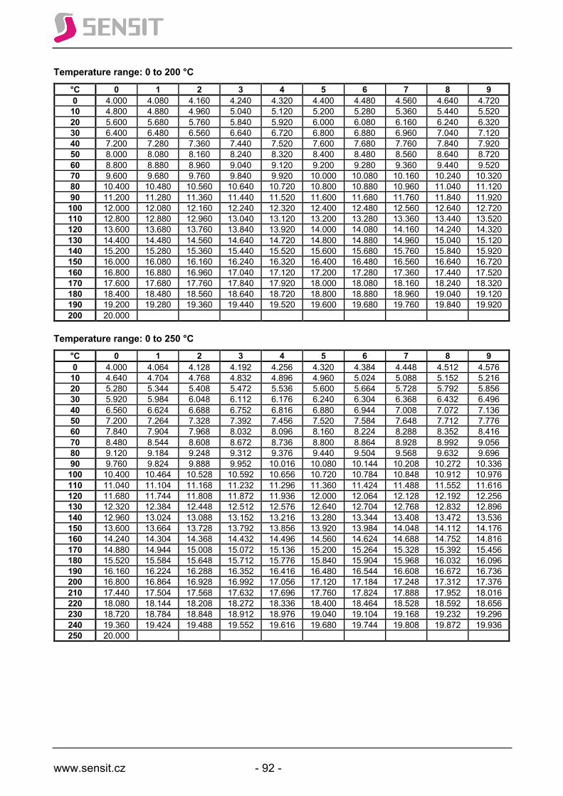
www.sensit.cz - 92 -
Temperature range: 0 to 200 °C
°C 0 1 2 3 4 5 6 7 8 9 0 4.000 4.080 4.160 4.240 4.320 4.400 4.480 4.560 4.640 4.720 10 4.800 4.880 4.960 5.040 5.120 5.200 5.280 5.360 5.440 5.520 20 5.600 5.680 5.760 5.840 5.920 6.000 6.080 6.160 6.240 6.320 30 6.400 6.480 6.560 6.640 6.720 6.800 6.880 6.960 7.040 7.120 40 7.200 7.280 7.360 7.440 7.520 7.600 7.680 7.760 7.840 7.920 50 8.000 8.080 8.160 8.240 8.320 8.400 8.480 8.560 8.640 8.720 60 8.800 8.880 8.960 9.040 9.120 9.200 9.280 9.360 9.440 9.520 70 9.600 9.680 9.760 9.840 9.920 10.000 10.080 10.160 10.240 10.320 80 10.400 10.480 10.560 10.640 10.720 10.800 10.880 10.960 11.040 11.120 90 11.200 11.280 11.360 11.440 11.520 11.600 11.680 11.760 11.840 11.920 100 12.000 12.080 12.160 12.240 12.320 12.400 12.480 12.560 12.640 12.720 110 12.800 12.880 12.960 13.040 13.120 13.200 13.280 13.360 13.440 13.520 120 13.600 13.680 13.760 13.840 13.920 14.000 14.080 14.160 14.240 14.320 130 14.400 14.480 14.560 14.640 14.720 14.800 14.880 14.960 15.040 15.120 140 15.200 15.280 15.360 15.440 15.520 15.600 15.680 15.760 15.840 15.920 150 16.000 16.080 16.160 16.240 16.320 16.400 16.480 16.560 16.640 16.720 160 16.800 16.880 16.960 17.040 17.120 17.200 17.280 17.360 17.440 17.520 170 17.600 17.680 17.760 17.840 17.920 18.000 18.080 18.160 18.240 18.320 180 18.400 18.480 18.560 18.640 18.720 18.800 18.880 18.960 19.040 19.120 190 19.200 19.280 19.360 19.440 19.520 19.600 19.680 19.760 19.840 19.920 200 20.000
Temperature range: 0 to 250 °C
°C 0 1 2 3 4 5 6 7 8 9 0 4.000 4.064 4.128 4.192 4.256 4.320 4.384 4.448 4.512 4.576 10 4.640 4.704 4.768 4.832 4.896 4.960 5.024 5.088 5.152 5.216 20 5.280 5.344 5.408 5.472 5.536 5.600 5.664 5.728 5.792 5.856 30 5.920 5.984 6.048 6.112 6.176 6.240 6.304 6.368 6.432 6.496 40 6.560 6.624 6.688 6.752 6.816 6.880 6.944 7.008 7.072 7.136 50 7.200 7.264 7.328 7.392 7.456 7.520 7.584 7.648 7.712 7.776 60 7.840 7.904 7.968 8.032 8.096 8.160 8.224 8.288 8.352 8.416 70 8.480 8.544 8.608 8.672 8.736 8.800 8.864 8.928 8.992 9.056 80 9.120 9.184 9.248 9.312 9.376 9.440 9.504 9.568 9.632 9.696 90 9.760 9.824 9.888 9.952 10.016 10.080 10.144 10.208 10.272 10.336 100 10.400 10.464 10.528 10.592 10.656 10.720 10.784 10.848 10.912 10.976 110 11.040 11.104 11.168 11.232 11.296 11.360 11.424 11.488 11.552 11.616 120 11.680 11.744 11.808 11.872 11.936 12.000 12.064 12.128 12.192 12.256 130 12.320 12.384 12.448 12.512 12.576 12.640 12.704 12.768 12.832 12.896 140 12.960 13.024 13.088 13.152 13.216 13.280 13.344 13.408 13.472 13.536 150 13.600 13.664 13.728 13.792 13.856 13.920 13.984 14.048 14.112 14.176 160 14.240 14.304 14.368 14.432 14.496 14.560 14.624 14.688 14.752 14.816 170 14.880 14.944 15.008 15.072 15.136 15.200 15.264 15.328 15.392 15.456 180 15.520 15.584 15.648 15.712 15.776 15.840 15.904 15.968 16.032 16.096 190 16.160 16.224 16.288 16.352 16.416 16.480 16.544 16.608 16.672 16.736 200 16.800 16.864 16.928 16.992 17.056 17.120 17.184 17.248 17.312 17.376 210 17.440 17.504 17.568 17.632 17.696 17.760 17.824 17.888 17.952 18.016 220 18.080 18.144 18.208 18.272 18.336 18.400 18.464 18.528 18.592 18.656 230 18.720 18.784 18.848 18.912 18.976 19.040 19.104 19.168 19.232 19.296 240 19.360 19.424 19.488 19.552 19.616 19.680 19.744 19.808 19.872 19.936 250 20.000
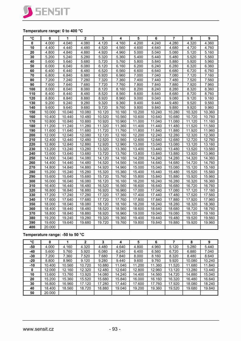
www.sensit.cz - 93 -
Temperature range: 0 to 400 °C
°C 0 1 2 3 4 5 6 7 8 9 0 4.000 4.040 4.080 4.120 4.160 4.200 4.240 4.280 4.320 4.360 10 4.400 4.440 4.480 4.520 4.560 4.600 4.640 4.680 4.720 4.760 20 4.800 4.840 4.880 4.920 4.960 5.000 5.040 5.080 5.120 5.160 30 5.200 5.240 5.280 5.320 5.360 5.400 5.440 5.480 5.520 5.560 40 5.600 5.640 5.680 5.720 5.760 5.800 5.840 5.880 5.920 5.960 50 6.000 6.040 6.080 6.120 6.160 6.200 6.240 6.280 6.320 6.360 60 6.400 6.440 6.480 6.520 6.560 6.600 6.640 6.680 6.720 6.760 70 6.800 6.840 6.880 6.920 6.960 7.000 7.040 7.080 7.120 7.160 80 7.200 7.240 7.280 7.320 7.360 7.400 7.440 7.480 7.520 7.560 90 7.600 7.640 7.680 7.720 7.760 7.800 7.840 7.880 7.920 7.960 100 8.000 8.040 8.080 8.120 8.160 8.200 8.240 8.280 8.320 8.360 110 8.400 8.440 8.480 8.520 8.560 8.600 8.640 8.680 8.720 8.760 120 8.800 8.840 8.880 8.920 8.960 9.000 9.040 9.080 9.120 9.160 130 9.200 9.240 9.280 9.320 9.360 9.400 9.440 9.480 9.520 9.560 140 9.600 9.640 9.680 9.720 9.760 9.800 9.840 9.880 9.920 9.960 150 10.000 10.040 10.080 10.120 10.160 10.200 10.240 10.280 10.320 10.360 160 10.400 10.440 10.480 10.520 10.560 10.600 10.640 10.680 10.720 10.760 170 10.800 10.840 10.880 10.920 10.960 11.000 11.040 11.080 11.120 11.160 180 11.200 11.240 11.280 11.320 11.360 11.400 11.440 11.480 11.520 11.560 190 11.600 11.640 11.680 11.720 11.760 11.800 11.840 11.880 11.920 11.960 200 12.000 12.040 12.080 12.120 12.160 12.200 12.240 12.280 12.320 12.360 210 12.400 12.440 12.480 12.520 12.560 12.600 12.640 12.680 12.720 12.760 220 12.800 12.840 12.880 12.920 12.960 13.000 13.040 13.080 13.120 13.160 230 13.200 13.240 13.280 13.320 13.360 13.400 13.440 13.480 13.520 13.560 240 13.600 13.640 13.680 13.720 13.760 13.800 13.840 13.880 13.920 13.960 250 14.000 14.040 14.080 14.120 14.160 14.200 14.240 14.280 14.320 14.360 260 14.400 14.440 14.480 14.520 14.560 14.600 14.640 14.680 14.720 14.760 270 14.800 14.840 14.880 14.920 14.960 15.000 15.040 15.080 15.120 15.160 280 15.200 15.240 15.280 15.320 15.360 15.400 15.440 15.480 15.520 15.560 290 15.600 15.640 15.680 15.720 15.760 15.800 15.840 15.880 15.920 15.960 300 16.000 16.040 16.080 16.120 16.160 16.200 16.240 16.280 16.320 16.360 310 16.400 16.440 16.480 16.520 16.560 16.600 16.640 16.680 16.720 16.760 320 16.800 16.840 16.880 16.920 16.960 17.000 17.040 17.080 17.120 17.160 330 17.200 17.240 17.280 17.320 17.360 17.400 17.440 17.480 17.520 17.560 340 17.600 17.640 17.680 17.720 17.760 17.800 17.840 17.880 17.920 17.960 350 18.000 18.040 18.080 18.120 18.160 18.200 18.240 18.280 18.320 18.360 360 18.400 18.440 18.480 18.520 18.560 18.600 18.640 18.680 18.720 18.760 370 18.800 18.840 18.880 18.920 18.960 19.000 19.040 19.080 19.120 19.160 380 19.200 19.240 19.280 19.320 19.360 19.400 19.440 19.480 19.520 19.560 390 19.600 19.640 19.680 19.720 19.760 19.800 19.840 19.880 19.920 19.960 400 20.000
Temperature range: -50 to 50 °C
°C 0 1 2 3 4 5 6 7 8 9 -50 4.000 4.160 4.320 4.480 4.640 4.800 4.960 5.120 5.280 5.440 -40 5.600 5.760 5.920 6.080 6.240 6.400 6.560 6.720 6.880 7.040 -30 7.200 7.360 7.520 7.680 7.840 8.000 8.160 8.320 8.480 8.640 -20 8.800 8.960 9.120 9.280 9.440 9.600 9.760 9.920 10.080 10.240 -10 10.400 10.560 10.720 10.880 11.040 11.200 11.360 11.520 11.680 11.840 0 12.000 12.160 12.320 12.480 12.640 12.800 12.960 13.120 13.280 13.440 10 13.600 13.760 13.920 14.080 14.240 14.400 14.560 14.720 14.880 15.040 20 15.200 15.360 15.520 15.680 15.840 16.000 16.160 16.320 16.480 16.640 30 16.800 16.960 17.120 17.280 17.440 17.600 17.760 17.920 18.080 18.240 40 18.400 18.560 18.720 18.880 19.040 19.200 19.360 19.520 19.680 19.840 50 20.000
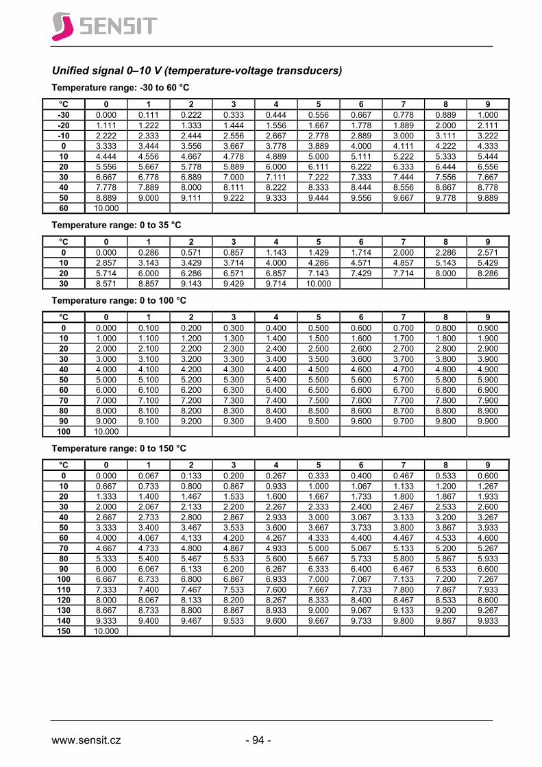
www.sensit.cz - 94 -
Unified signal 0–10 V (temperature-voltage transducers) Temperature range: -30 to 60 °C
°C 0 1 2 3 4 5 6 7 8 9 -30 0.000 0.111 0.222 0.333 0.444 0.556 0.667 0.778 0.889 1.000 -20 1.111 1.222 1.333 1.444 1.556 1.667 1.778 1.889 2.000 2.111 -10 2.222 2.333 2.444 2.556 2.667 2.778 2.889 3.000 3.111 3.222 0 3.333 3.444 3.556 3.667 3.778 3.889 4.000 4.111 4.222 4.333 10 4.444 4.556 4.667 4.778 4.889 5.000 5.111 5.222 5.333 5.444 20 5.556 5.667 5.778 5.889 6.000 6.111 6.222 6.333 6.444 6.556 30 6.667 6.778 6.889 7.000 7.111 7.222 7.333 7.444 7.556 7.667 40 7.778 7.889 8.000 8.111 8.222 8.333 8.444 8.556 8.667 8.778 50 8.889 9.000 9.111 9.222 9.333 9.444 9.556 9.667 9.778 9.889 60 10.000
Temperature range: 0 to 35 °C
°C 0 1 2 3 4 5 6 7 8 9 0 0.000 0.286 0.571 0.857 1.143 1.429 1.714 2.000 2.286 2.571 10 2.857 3.143 3.429 3.714 4.000 4.286 4.571 4.857 5.143 5.429 20 5.714 6.000 6.286 6.571 6.857 7.143 7.429 7.714 8.000 8.286 30 8.571 8.857 9.143 9.429 9.714 10.000
Temperature range: 0 to 100 °C
°C 0 1 2 3 4 5 6 7 8 9 0 0.000 0.100 0.200 0.300 0.400 0.500 0.600 0.700 0.800 0.900 10 1.000 1.100 1.200 1.300 1.400 1.500 1.600 1.700 1.800 1.900 20 2.000 2.100 2.200 2.300 2.400 2.500 2.600 2.700 2.800 2.900 30 3.000 3.100 3.200 3.300 3.400 3.500 3.600 3.700 3.800 3.900 40 4.000 4.100 4.200 4.300 4.400 4.500 4.600 4.700 4.800 4.900 50 5.000 5.100 5.200 5.300 5.400 5.500 5.600 5.700 5.800 5.900 60 6.000 6.100 6.200 6.300 6.400 6.500 6.600 6.700 6.800 6.900 70 7.000 7.100 7.200 7.300 7.400 7.500 7.600 7.700 7.800 7.900 80 8.000 8.100 8.200 8.300 8.400 8.500 8.600 8.700 8.800 8.900 90 9.000 9.100 9.200 9.300 9.400 9.500 9.600 9.700 9.800 9.900 100 10.000
Temperature range: 0 to 150 °C
°C 0 1 2 3 4 5 6 7 8 9 0 0.000 0.067 0.133 0.200 0.267 0.333 0.400 0.467 0.533 0.600 10 0.667 0.733 0.800 0.867 0.933 1.000 1.067 1.133 1.200 1.267 20 1.333 1.400 1.467 1.533 1.600 1.667 1.733 1.800 1.867 1.933 30 2.000 2.067 2.133 2.200 2.267 2.333 2.400 2.467 2.533 2.600 40 2.667 2.733 2.800 2.867 2.933 3.000 3.067 3.133 3.200 3.267 50 3.333 3.400 3.467 3.533 3.600 3.667 3.733 3.800 3.867 3.933 60 4.000 4.067 4.133 4.200 4.267 4.333 4.400 4.467 4.533 4.600 70 4.667 4.733 4.800 4.867 4.933 5.000 5.067 5.133 5.200 5.267 80 5.333 5.400 5.467 5.533 5.600 5.667 5.733 5.800 5.867 5.933 90 6.000 6.067 6.133 6.200 6.267 6.333 6.400 6.467 6.533 6.600 100 6.667 6.733 6.800 6.867 6.933 7.000 7.067 7.133 7.200 7.267 110 7.333 7.400 7.467 7.533 7.600 7.667 7.733 7.800 7.867 7.933 120 8.000 8.067 8.133 8.200 8.267 8.333 8.400 8.467 8.533 8.600 130 8.667 8.733 8.800 8.867 8.933 9.000 9.067 9.133 9.200 9.267 140 9.333 9.400 9.467 9.533 9.600 9.667 9.733 9.800 9.867 9.933 150 10.000
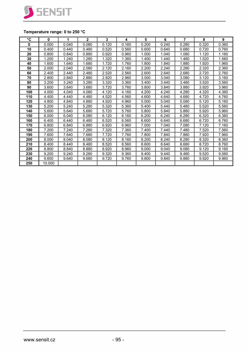
www.sensit.cz - 95 -
Temperature range: 0 to 250 °C
°C 0 1 2 3 4 5 6 7 8 9 0 0.000 0.040 0.080 0.120 0.160 0.200 0.240 0.280 0.320 0.360 10 0.400 0.440 0.480 0.520 0.560 0.600 0.640 0.680 0.720 0.760 20 0.800 0.840 0.880 0.920 0.960 1.000 1.040 1.080 1.120 1.160 30 1.200 1.240 1.280 1.320 1.360 1.400 1.440 1.480 1.520 1.560 40 1.600 1.640 1.680 1.720 1.760 1.800 1.840 1.880 1.920 1.960 50 2.000 2.040 2.080 2.120 2.160 2.200 2.240 2.280 2.320 2.360 60 2.400 2.440 2.480 2.520 2.560 2.600 2.640 2.680 2.720 2.760 70 2.800 2.840 2.880 2.920 2.960 3.000 3.040 3.080 3.120 3.160 80 3.200 3.240 3.280 3.320 3.360 3.400 3.440 3.480 3.520 3.560 90 3.600 3.640 3.680 3.720 3.760 3.800 3.840 3.880 3.920 3.960 100 4.000 4.040 4.080 4.120 4.160 4.200 4.240 4.280 4.320 4.360 110 4.400 4.440 4.480 4.520 4.560 4.600 4.640 4.680 4.720 4.760 120 4.800 4.840 4.880 4.920 4.960 5.000 5.040 5.080 5.120 5.160 130 5.200 5.240 5.280 5.320 5.360 5.400 5.440 5.480 5.520 5.560 140 5.600 5.640 5.680 5.720 5.760 5.800 5.840 5.880 5.920 5.960 150 6.000 6.040 6.080 6.120 6.160 6.200 6.240 6.280 6.320 6.360 160 6.400 6.440 6.480 6.520 6.560 6.600 6.640 6.680 6.720 6.760 170 6.800 6.840 6.880 6.920 6.960 7.000 7.040 7.080 7.120 7.160 180 7.200 7.240 7.280 7.320 7.360 7.400 7.440 7.480 7.520 7.560 190 7.600 7.640 7.680 7.720 7.760 7.800 7.840 7.880 7.920 7.960 200 8.000 8.040 8.080 8.120 8.160 8.200 8.240 8.280 8.320 8.360 210 8.400 8.440 8.480 8.520 8.560 8.600 8.640 8.680 8.720 8.760 220 8.800 8.840 8.880 8.920 8.960 9.000 9.040 9.080 9.120 9.160 230 9.200 9.240 9.280 9.320 9.360 9.400 9.440 9.480 9.520 9.560 240 9.600 9.640 9.680 9.720 9.760 9.800 9.840 9.880 9.920 9.960 250 10.000

www.sensit.cz - 96 -
Frequently asked questions
• Why is measurement by a nickel temperature sensor limited to 250 °C despite being a metal?
Compared to platinum, nickel is a highly corrosive element. That means that contact with oxygen creates nickel(II) oxide (NiO), which has substantially different physical properties than pure nickel. For this reason, the thin nickel layer on nickel temperature chips is relatively complexly protected by so-called passivation layers against direct contact with air oxygen. The passivation properties of these layers, however, are temperature-dependent. With increasing temperature, their passivation abilities decrease so that, at temperatures above 250 °C, they become partially permeable to air oxygen, the measuring nickel layer relatively rapidly oxidizes and the temperature sensor deteriorates.
• Why do nickel temperature sensors age and how does ageing affect the measurement result?
The answer follows on the previous question. Passivation layers on nickel temperature sensing elements are never absolutely impermeable to air oxygen, which results in slow gradual oxidation of the nickel layer. We say that the Ni sensing element ages, the value of its resistance gradually increases and, after a certain time (sufficiently long due to the service life of the evaluation equipment), the nickel temperature sensor shows a positive absolute error. It indicates a higher temperature value than the real value. The ageing rate of a nickel temperature sensor is higher the higher is the maximum measured temperature or the longer the sensor is permanently exposed to temperatures near the upper limit of the temperature range. For measured temperatures up to 150 °C, the absolute measurement error due to ageing of the nickel layer can be disregarded. The ageing rate (speed), given what has been said above, depends mainly on the quality of the passivation of the nickel layer, which varies not only between manufacturers, but also within a single manufacturer, depending on the specific type of nickel chip or even the batch of a single specific type.
www.sensit.cz - 97 -
References Ptáček, J. et al.; Měření teploty v průmyslu (Temperature measurement in industry); Dům techniky ČSVTS, Praha 1991 Halliday, D. et al.; Fyzika, část 2 Mechanika – Termodynamika (Physics, Part 2 Mechanics – Thermodynamics), VUT Brno and VITIUM; 2000; ISBN 80-214-1868-0 Holub,R.; Vintr.Z.: Spolehlivost letadlové techniky (Reliability of aircraft equipment) (electronic textbook); VUT Brno, FSI, Brno 2001 Vintr,Z. et al.: Metodika zrychlené zkoušky životnosti teplotních snímačů (Accelerated temperature test methodology for temperature sensors); Brno 2015 Vintr,Z. et al.: Závěrečná zpráva z průběhu zrychlené zkoušky životnosti teplotních snímačů (Final report of the accelerated temperature test of temperature sensors); Brno 2016; internal document of Sensit. EN 60751; UNMZ Prague 2014 EN 60584; UNMZ Prague 2014 EN 60529; UNMZ Prague EN 1434-2 Heat meters – Part 2: Constructional requirements; UNMZ Prague 2016 Bejček, L.; Přehled trhu snímačů teploty do průmyslového prostředí (Market overview of temperature sensors for industrial environments); AUTOMA 6/2009 Janíček, J.:Polovodičové spínače teploty – termistory (Semiconductor temperature sensors – thermistors); AUTOMA 1/2015 Kreidl, M.:Měření teploty (Temperature measurement); BEN, Praha, 2005; ISBN 80-7300-145-4 Catalogue TDK EPCOS 2013-2014 Katalog KROHNE Měření teploty (KROHNE Temperature Measurement Catalogue); © Krohne 02/2014 4003885901 CA Temperature-R02-cz Data sheet B+B Thermo Technik GmbH Act No. 505/1990 Coll. on Metrology, as amended Teplota (Temperature); document of JSP, s.r.o. Jičín, Vitouš, O. : Jak na převodník SMT160-30-92 (How to use the SMT160-30-92 transducer); www.vyvoj.HW.cz; 2001-12-01 Slaný, K.: Sběrnice 1-wire a čidlo DS18B20 (1-Wire bus and DS18B20 sensing element); http://merlin.fit.vutbr.cz/FITkit/docs/aplikace/apps_communication_1-wire_mcu.html
websites of IST, a.g.; VISHAY, AVX, EPCOS, BC components, Microtech GOST 6651-2009
Issued by SENSIT s.r.o. Školní 2610, 756 61 Rožnov pod Radhoštěm, Czech Republic
e-mail: [email protected], web: www.sensit.cz Phone: +420 571 625 571, Fax: +420 571 625 572
1st English edition – February 2019 (circulation 1000 units)
SENSIT s.r.o.Skolni 2610756 61 Roznov pod RadhostemCzech Republic
T +420 571 625 571F +420 571 625 572E [email protected]
www.sensit.czwww.railwayvehicles.com www.sensit-rubberplastic.cz
ID 64087484VAT CZ64087484
Version EN_01 (2019)
Prague
Slovakia
PolandGermany
Austria
Brno
Copyright © 2022 FDOKUMEN