Chapter 630 Geosynthetics - M22-01.20 Design Manual
28
WSDOT Design Manual M 22-01.20 Page 630-1 September 2021 Chapter 630 Geosynthetics 630.01 General 630.02 References 630.03 Geosynthetic Types and Characteristics 630.04 Geosynthetic Function Definitions and Applications 630.05 Design Approach for Geosynthetics 630.06 Design Responsibility 630.07 Documentation Exhibit 630-1 Selection Criteria for Geotextile Class Exhibit 630-2 Maximum Sheet Flow Lengths for Silt Fences Exhibit 630-3 Maximum Contributing Area for Ditch and Swale Applications Exhibit 630-4 Design Process for Drainage and Erosion Control: Geotextiles and Nonstandard Applications Exhibit 630-5 Design Process for Separation, Soil Stabilization, and Silt Fence Exhibit 630-6 Examples of Various Geosynthetics Exhibit 630-7 Geotextile Application Examples Exhibit 630-8 Definition of Slope Length Exhibit 630-9 Definition of Ditch or Swale Storage Length and Width Exhibit 630-10 Silt Fences for Large Contributing Area Exhibit 630-11 Silt Fence End Treatment Exhibit 630-12 Gravel Check Dams for Silt Fences 630.01 General Geosynthetics include a variety of manufactured products that are used by the Washington State Department of Transportation (WSDOT) in drainage, earthwork, erosion control, and soil reinforcement applications. The following geosynthetic applications are addressed in the Standard Specifications for Road, Bridge, and Municipal Construction (Standard Specifications): • Low survivability underground drainage • Moderate survivability underground drainage • Separation • Soil stabilization • Moderate survivability permanent erosion control • High survivability permanent erosion control • Ditch lining • Temporary silt fence The Standard Specifications addresses geosynthetic properties as well as installation requirements and are not site-specific. The geosynthetic properties provided are based on the range of soil conditions likely to be encountered in Washington for the applications defined. Other applications, such as prefabricated edge drains, pond liners, and geotextile retaining walls, are currently handled by special provision. Design responsibilities are discussed in Section 630.05 and illustrated in Exhibit 630-4 and Exhibit 630-5. This chapter does not address applications where geosynthetics are used to help establish vegetation through temporary prevention of erosion (vegetation mats).
-
Upload
khangminh22 -
Category
Documents
-
view
5 -
download
0
Transcript of Chapter 630 Geosynthetics - M22-01.20 Design Manual

WSDOT Design Manual M 22-01.20 Page 630-1
September 2021
Chapter 630 Geosynthetics
630.01 General
630.02 References
630.03 Geosynthetic Types and Characteristics
630.04 Geosynthetic Function Definitions and Applications
630.05 Design Approach for Geosynthetics
630.06 Design Responsibility
630.07 Documentation
Exhibit 630-1 Selection Criteria for Geotextile Class
Exhibit 630-2 Maximum Sheet Flow Lengths for Silt Fences
Exhibit 630-3 Maximum Contributing Area for Ditch and Swale Applications
Exhibit 630-4 Design Process for Drainage and Erosion Control: Geotextiles and Nonstandard Applications
Exhibit 630-5 Design Process for Separation, Soil Stabilization, and Silt Fence
Exhibit 630-6 Examples of Various Geosynthetics
Exhibit 630-7 Geotextile Application Examples
Exhibit 630-8 Definition of Slope Length
Exhibit 630-9 Definition of Ditch or Swale Storage Length and Width
Exhibit 630-10 Silt Fences for Large Contributing Area
Exhibit 630-11 Silt Fence End Treatment
Exhibit 630-12 Gravel Check Dams for Silt Fences
630.01 General
Geosynthetics include a variety of manufactured products that are used by the Washington State Department of
Transportation (WSDOT) in drainage, earthwork, erosion control, and soil reinforcement applications.
The following geosynthetic applications are addressed in the Standard Specifications for Road, Bridge, and
Municipal Construction (Standard Specifications):
• Low survivability underground drainage
• Moderate survivability underground drainage
• Separation
• Soil stabilization
• Moderate survivability permanent erosion control
• High survivability permanent erosion control
• Ditch lining
• Temporary silt fence
The Standard Specifications addresses geosynthetic properties as well as installation requirements and are not
site-specific. The geosynthetic properties provided are based on the range of soil conditions likely to be
encountered in Washington for the applications defined. Other applications, such as prefabricated edge drains,
pond liners, and geotextile retaining walls, are currently handled by special provision.
Design responsibilities are discussed in Section 630.05 and illustrated in Exhibit 630-4 and Exhibit 630-5.
This chapter does not address applications where geosynthetics are used to help establish vegetation through
temporary prevention of erosion (vegetation mats).

Chapter 630 Geosynthetics
WSDOT Design Manual M 22-01.20 Page 630-2
September 2021
630.02 References
630.02(1) Design Guidance
Highway Runoff Manual, M 31-15, WSDOT
Hydraulics Manual, M 23-03, WSDOT
Plans Preparation Manual, M 22-31, WSDOT
Standard Specifications for Road, Bridge, and Municipal Construction (Standard Specifications), M 41-10, WSDOT
WSDOT Pavement Policy, available at the Pavements website:
https://wsdot.wa.gov/engineering-standards/construction-materials/pavement-design-management
630.03 Geosynthetic Types and Characteristics
Geosynthetics include woven and nonwoven geotextiles, geogrids, geonets, geomembranes, and
geocomposites. (Examples of the various types of geosynthetics are provided in Exhibit 630-5.) Terms used in
the past for these construction materials include fabrics, filter fabric, or filter cloth, which are for the most part
synonymous with the newer term geotextile.
630.03(1) Definitions
Definitions of the geosynthetic types are as follows:
630.03(1)(a) Woven Geotextiles
Slit polymer tapes, monofilament fibers, fibrillated yarns, or multifilament yarns simply woven into a mat.
Woven geotextiles generally have relatively high strength and stiffness and, except for the monofilament
wovens, relatively poor drainage characteristics.
630.03(1)(b) Nonwoven Geotextiles
A sheet of continuous or staple fibers entangled randomly into a felt for needle-punched nonwovens and
pressed and melted together at the fiber contact points for heat-bonded nonwovens. Nonwoven geotextiles
tend to have low-to-medium strength and stiffness with high elongation at failure and relatively good drainage
characteristics. The high elongation characteristic gives them superior ability to deform around stones and
sticks.
630.03(1)(c) Geogrids
A polymer grid mat constructed either of coated yarns or a punched and stretched polymer sheet. Geogrids
usually have high strength and stiffness and are used primarily for soil reinforcement.
630.03(1)(d) Geonets
Similar to geogrids, but typically lighter weight and weaker, with smaller mesh openings. Geonets are used in
light reinforcement applications or are combined with drainage geotextiles to form a drainage structure.
630.03(1)(e) Geomembranes
Impervious polymer sheets that are typically used to line ponds or landfills. In some cases, geomembranes are
placed over moisture-sensitive swelling clays to control moisture.
Chapter 630 Geosynthetics
WSDOT Design Manual M 22-01.20 Page 630-3
September 2021
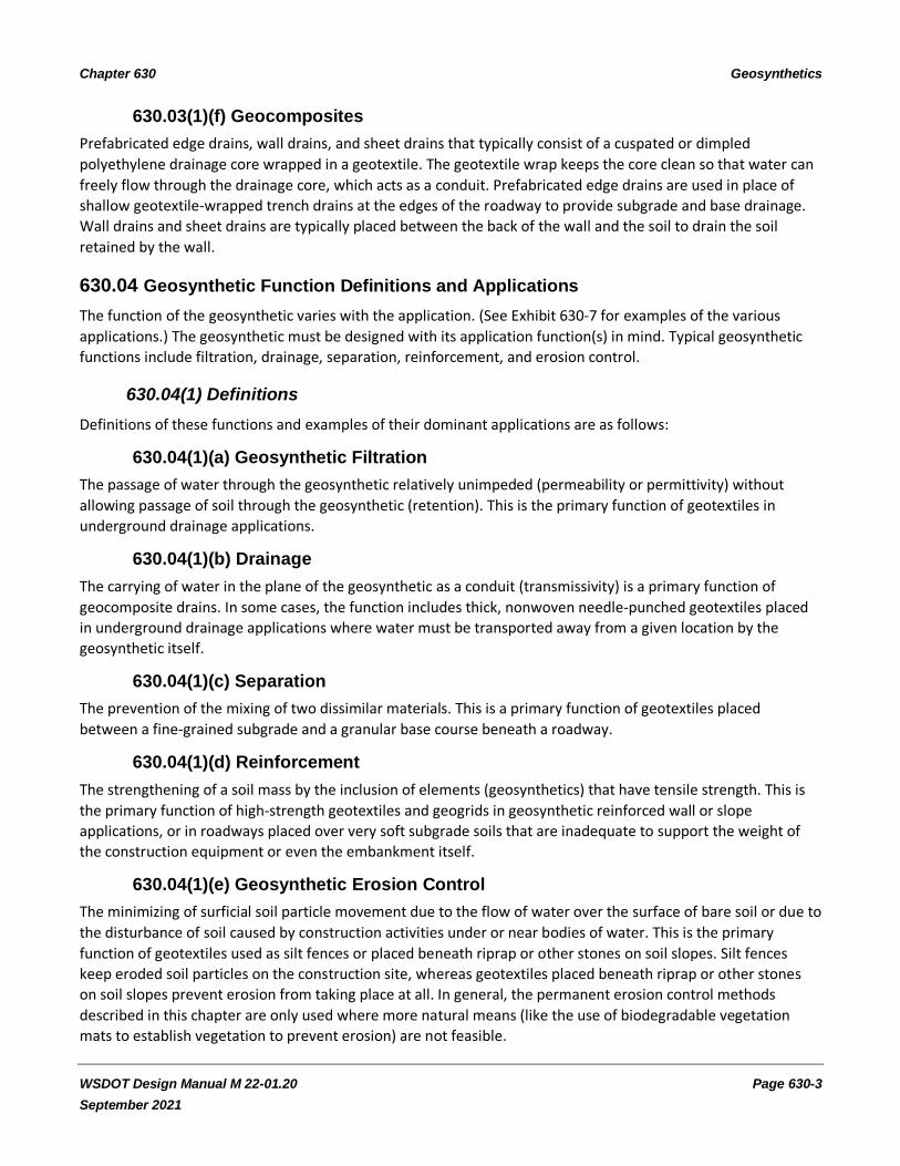
630.03(1)(f) Geocomposites
Prefabricated edge drains, wall drains, and sheet drains that typically consist of a cuspated or dimpled
polyethylene drainage core wrapped in a geotextile. The geotextile wrap keeps the core clean so that water can
freely flow through the drainage core, which acts as a conduit. Prefabricated edge drains are used in place of
shallow geotextile-wrapped trench drains at the edges of the roadway to provide subgrade and base drainage.
Wall drains and sheet drains are typically placed between the back of the wall and the soil to drain the soil
retained by the wall.
630.04 Geosynthetic Function Definitions and Applications
The function of the geosynthetic varies with the application. (See Exhibit 630-7 for examples of the various
applications.) The geosynthetic must be designed with its application function(s) in mind. Typical geosynthetic
functions include filtration, drainage, separation, reinforcement, and erosion control.
630.04(1) Definitions
Definitions of these functions and examples of their dominant applications are as follows:
630.04(1)(a) Geosynthetic Filtration
The passage of water through the geosynthetic relatively unimpeded (permeability or permittivity) without
allowing passage of soil through the geosynthetic (retention). This is the primary function of geotextiles in
underground drainage applications.
630.04(1)(b) Drainage
The carrying of water in the plane of the geosynthetic as a conduit (transmissivity) is a primary function of
geocomposite drains. In some cases, the function includes thick, nonwoven needle-punched geotextiles placed
in underground drainage applications where water must be transported away from a given location by the
geosynthetic itself.
630.04(1)(c) Separation
The prevention of the mixing of two dissimilar materials. This is a primary function of geotextiles placed
between a fine-grained subgrade and a granular base course beneath a roadway.
630.04(1)(d) Reinforcement
The strengthening of a soil mass by the inclusion of elements (geosynthetics) that have tensile strength. This is
the primary function of high-strength geotextiles and geogrids in geosynthetic reinforced wall or slope
applications, or in roadways placed over very soft subgrade soils that are inadequate to support the weight of
the construction equipment or even the embankment itself.
630.04(1)(e) Geosynthetic Erosion Control
The minimizing of surficial soil particle movement due to the flow of water over the surface of bare soil or due to
the disturbance of soil caused by construction activities under or near bodies of water. This is the primary
function of geotextiles used as silt fences or placed beneath riprap or other stones on soil slopes. Silt fences
keep eroded soil particles on the construction site, whereas geotextiles placed beneath riprap or other stones
on soil slopes prevent erosion from taking place at all. In general, the permanent erosion control methods
described in this chapter are only used where more natural means (like the use of biodegradable vegetation
mats to establish vegetation to prevent erosion) are not feasible.

Chapter 630 Geosynthetics
WSDOT Design Manual M 22-01.20 Page 630-4
September 2021
These functions control some of the geosynthetic properties, such as apparent opening size (AOS) and
permittivity, and in some cases load-strain characteristics.
The application will also affect the geosynthetic installation conditions. These installation conditions influence
the remaining geosynthetic properties needed, based on the survivability level required.
630.04(1)(f) Geosynthetic Survivability
The ability of the geosynthetic to resist installation conditions without significant damage, such that the
geosynthetic can function as intended. Survivability affects the strength properties of the geosynthetic required.
630.05 Design Approach for Geosynthetics
The following questions must be answered to complete a geosynthetic design:
• Is a geosynthetic really needed?
• What geosynthetic properties will ensure the geosynthetic functions as intended?
• Where should the geosynthetic be located?
• Will maintenance of the geosynthetic, or the structure of which it is a part, be needed? If so, how will it
be maintained?
The site conditions and purpose for the geotextile are reviewed to determine whether or not a geotextile is
needed.
• For most drainage, separation, soil stabilization, permanent erosion control, and silt fence applications,
if a geotextile is needed, the geotextile properties in the Standard Specifications can be used.
• In some situations where soil conditions are especially troublesome or in critical or high-risk
applications, a project-specific design may be needed.
• The location of the geosynthetic will depend on how it is intended to function. (See Exhibit 630-7 for
examples.)
• Consider the flow path of any groundwater or surface water when locating and selecting the geotextile
to be used. For example, in permanent erosion control applications, water may flow to the geotextile
from the existing ground as well as from the surface through wave action, stream flow, or overland
sheet flow. For saturated fine sandy or silty subgrades, water must be able to flow from the subgrade
through the geotextile soil stabilization layer during the pumping action caused by traffic loads.
Background information and the answers to each of these questions, or at least guidance to obtaining the
answers to these questions, are provided for each of the following Standard Specifications applications:
630.05(1) Underground Drainage: Low and Moderate Survivability
Geotextiles used for underground drainage must provide filtration to allow water to reach the drain aggregate
without allowing the aggregate to be contaminated by finer soil particles.
Geotextile filtration properties are a function of the soil type. For underground drainage applications, if the
subgrade soil is relatively clean gravel or coarse sand, a geotextile is probably not required. At issue is whether
or not there are enough fines in the surrounding soil to eventually clog the drain rock or drain pipe if
unrestricted flow toward the drain is allowed.
To approximately match the geotextile filtration properties to various soil types, specifications for three classes
of Construction Geotextile for Underground Drainage are available in the Standard Specifications.

Chapter 630 Geosynthetics
WSDOT Design Manual M 22-01.20 Page 630-5
September 2021
For underground drainage applications, use the gradation of the soil, specifically the percent by weight passing
the #200 sieve, to select the drainage geotextile class required. Base your selection of the appropriate class of
geotextile on Exhibit 630-1.
Exhibit 630-1 Selection Criteria for Geotextile Class
Percent Passing the #200 Sieve Geotextile Class
Less than 15% A
15% to 50% B
Greater than 50% C
Obtain soil samples for geotextile underdrain design every 300 feet along the roadway alignment, using hand
holes, and at major soil type transitions. This may be spread to every 1000 feet if the soil conditions appear to
be uniform. Use existing soil data where feasible instead of taking new soil samples.
If soil conditions vary widely along the alignment where underground drainage geotextile is anticipated,
different classes of drainage geotextile may be required for specific sections of a continuous system.
Strength properties for the underground drainage geotextile depend on the survivability level required to resist
installation stresses.
Low survivability designates that the installation stresses placed on the geotextile will be relatively low, requiring
only moderate geotextile strength to resist potentially damaging installation conditions. Examples of low
survivability level underground drainage applications include:
• Trench drains.
• Drains placed behind walls or other structures to drain the backfill.
• A geotextile filter sheet placed behind a gabion wall to prevent fines from being washed through the
gabion wall face. Trench depths, or the height of the geotextile filter sheet behind gabion walls, must be
less than or equal to 6 feet for the low survivability level.
In moderate survivability applications, significant installation stresses may occur, requiring higher geotextile
strength. Examples of the moderate survivability application include:
• Trench drains with a depth of greater than 6 feet.
• A geotextile filter sheet behind a gabion wall with a height greater than 6 feet.
• Any area drain.
An area drain is defined as a geotextile placed over or under a horizontal-to-moderately sloping (1.5H:1V or
flatter slope) layer of drainage aggregate. Examples of area drains include:
• Drainage layers over cut-and-cover tunnels.
• Rock buttress drainage.
• Permeable base beneath highway pavement (see the WSDOT Pavement Policy for additional
information on permeable bases).
• A parking lot drainage layer.
Note that pipe wrapping (the geotextile is wrapped around the surface of the pipe) is not included as an
underground drainage application.

Chapter 630 Geosynthetics
WSDOT Design Manual M 22-01.20 Page 630-6
September 2021
Locate the geotextile such that it will function as intended. For example, if the objective is to keep the drainage
aggregate surrounding a drain pipe clean, locate the geotextile so that it completely separates the drainage
aggregate from more silty surrounding soils, which may include native soils as well as relatively silty roadway
base or fill materials.
Consider the flow path of any groundwater or surface water when locating the geotextile.
The flow path from the geotextile, as part of the groundwater drainage, is typically directed to a surface water
conveyance system. Design of surface water conveyance is guided by the Hydraulics Manual. The surface water
conveyance must be low enough to prevent backflow and charging of the groundwater drainage—typically, by
matching inverts of groundwater drainage to crowns of surface water conveyance pipes. A 1-foot allowance is
usually applied when connecting to open water or ditches.
630.05(2) Separation
Geotextile used for separation must prevent penetration of relatively fine grained subgrade soil into the ballast
or other roadway or parking lot surfacing material to prevent contamination of the surfacing material (the
separation function). This application may also apply to situations other than beneath roadway or parking lot
surfacing where it is not necessary for water to drain through the geotextile unimpeded (filtration), but where
separation of two dissimilar materials is required.
Separation geotextile should only be used in roadway applications where the subgrade is can be prepared and
compacted as required in the Standard Specifications, but without removal and replacement of the subgrade
soil with granular material. Such removal and replacement defeats the purpose of the geotextile separator.
Separation geotextile placed beneath roadway surfacing is feasible if the subgrade resilient modulus is greater
than 5,800 psi and if a saturated fine sandy, silty, or clayey subgrade is not likely to be present. Note that the
feasibility of separation geotextile may be dependent on the time of year and weather conditions expected
when the geotextile is to be installed.
For separation applications, a geotextile is not needed if the subgrade is dense and granular (silty sands and
gravels), but is not saturated fine sands. In general, a separation geotextile is not needed if the subgrade
resilient modulus is greater than 15,000 psi.
630.05(3) Soil Stabilization
Geotextile used for soil stabilization must function as a separator, a filtration layer, and (to a minor extent) a
reinforcement layer. This application is similar to the separation application, except the subgrade is anticipated
to be softer and wetter than in the separation application.
Soil stabilization geotextile is used in roadway applications if the subgrade is too soft and wet to be prepared
and compacted as required in the Standard Specifications. Soil stabilization geotextile is placed directly on the
soft subgrade material, even if some overexcavation of the subgrade is performed. Backfill to replace the
overexcavated subgrade is not placed below the geotextile soil stabilization layer, as this would defeat the
purpose of the geotextile.
Anticipate the need for soil stabilization geotextile if the subgrade resilient modulus is less than or equal to
5,800 psi, or if a saturated fine sandy, silty, or clayey subgrade is likely to be present.
Consider the flow path of any groundwater or surface water when locating the soil stabilization geotextile and
when selecting the geotextile to be used. For saturated fine sandy or silty subgrades, water must be able to flow
from the subgrade through the geotextile soil stabilization layer during the pumping action caused by traffic
loads.

Chapter 630 Geosynthetics
WSDOT Design Manual M 22-01.20 Page 630-7
September 2021
Even if the subgrade is not anticipated to be saturated based on available data, if the subgrade is silty or clayey
and it is anticipated that the geotextile will be installed during prolonged wet weather, a soil stabilization
geotextile may still be needed.
Soil stabilization geotextile should not be used for roadway fills greater than 5 feet high or when extremely soft
and wet silt, clay, or peat is anticipated at the subgrade level (for example, the deposits encountered in
wetlands). In such cases, the reinforcement function becomes more dominant, requiring a site-specific design.
630.05(4) Permanent Erosion Control: Moderate and High Survivability
The primary function of geotextile used for permanent erosion control is to protect the soil beneath it from
erosion due to water flowing over the protected soil.
The need for a permanent erosion control geotextile depends on the type and magnitude of water flow over the
soil being considered for protection, the soil type in terms of its erodability, and the type and amount of
vegetative cover present (see the Highway Runoff Manual).
The source of flowing water could be streams, constructed channels, wave action, or runoff. Water may also
flow from the soil behind the geotextile depending on the groundwater level.
If groundwater cannot escape through the geotextile, an erosion control system failure termed ballooning
(resulting from water pressure buildup behind the geotextile) or soil piping could occur. Therefore, the
geotextile must have good filtration characteristics.
Three classes of permanent erosion control geotextile are available to approximately match geotextile filtration
characteristics to the soil. In order to select the drainage geotextile class, determine the gradation of the soil,
specifically the percent by weight passing the #200 sieve. Base selection of the appropriate class of geotextile on
Exhibit 630-1.
A minimal amount of soil sampling and testing is needed to determine the geotextile class required. Permanent
erosion control geotextile generally does not extend along the roadway alignment for significant distances as
does underground drainage geotextile. One soil sample per permanent erosion control location is sufficient. If
multiple erosion control locations are anticipated along a roadway alignment, soil sampling requirements for
underground drainage can be applied.
If soil conditions vary widely along the alignment where permanent erosion control geotextile is anticipated,
different classes of erosion control geotextile may be required for specific sections of a continuous system.
Examples of the permanent erosion control application are the placement of geotextile beneath riprap or
gabions along drainage channels, shorelines, and waterways; around bridge piers; and under slope protection
for highway cut or fill slopes.
If a moderate survivability geotextile is to be used, the geotextile must be protected by a 12-inch aggregate
cushion and be placed on slopes of 2H:1V or flatter to keep installation stresses to a relatively low level. Large
stones can cause significant damage to a moderate survivability geotextile if the geotextile is not protected in
this manner. If these conditions are not met, then a high survivability erosion control geotextile must be used.
630.05(5) Ditch Lining
The primary function of the geotextile in a ditch lining application is to protect the soil beneath it from erosion.
This ditch lining application is limited to constructed ditches less than 16 feet wide at the top with side slopes of
2H:1V or flatter.

Chapter 630 Geosynthetics
WSDOT Design Manual M 22-01.20 Page 630-8
September 2021
If the ditch does not meet these requirements, then permanent erosion control, with moderate or high
survivability geotextile, must be used. It is assumed that only quarry spall-sized stones or smaller will be placed
on the geotextile, so only a moderate survivability geotextile will be required.
Filtration is not a significant function in this application. Since the ditch is relatively shallow, it is expected that
the main water source will be the water carried by the ditch, and little water will pass through the geotextile.
Another application with a similar geotextile function is the placement of geotextile below culvert outlets to
prevent erosion at the outlet.
630.05(6) Temporary Silt Fence
The primary function of geotextile used in a temporary silt fence is to prevent eroded material from being
transported away from the construction site by runoff water. The silt fence acts primarily as a temporary dam
and secondarily as a filter. In some cases, depending on the topography, the silt fence may also function as a
barrier to direct flow to low areas at the bottom of swales where the water can be collected and temporarily
ponded. It is desirable to avoid the barrier function as much as possible, as silt fences are best suited to
intercepting sheet flow rather than the concentrated flows that would occur in swales or intermittent drainage
channels. To function as intended, the silt fence should have a low enough permeability to allow the water to be
temporarily retained behind the fence, allowing suspended soil particles in the water to settle to the ground. If
the retention time is too long, or if the flow rate of water is too high, the silt fence could be overtopped, thus
allowing silt-laden water to escape. Therefore, a minimal amount of water must be able to flow through the
fence at all times.
Temporary water ponding is considered the primary method of silt removal and the filtration capabilities of the
fence are the second line of defense. However, removal of silt-sized particles from the water directly by the
geotextile creates severe filtration conditions for the geotextile, forcing the geotextile to either blind or allow
the fines to pipe through the geotextile. (Blinding is the coating of the geotextile surface with soil particles such
that the openings are effectively plugged.) If the geotextile openings (AOS) are designed to be small enough to
capture most of the suspended soil particles, the geotextile will likely blind, reducing the permeability enough to
allow water to overtop the fence. Therefore, it is best to allow some geotextile openings that are large enough
to allow the silt-sized particles to easily pass through. Even if some silt particles pass through the fence, the
water flow rate below the fence will be decreased and the volume of silt-laden water passing through the
geotextile is likely to be relatively small and the water is partially filtered.
The geotextile apparent opening size (AOS) and permittivity are typically used to specify the filtration
performance of geotextiles. The geotextile function in silt fence applications is more complex than this and AOS
and permittivity do not relate directly to how well a silt fence will perform. However, nominal values of AOS and
permittivity can be specified such that the types of geotextile products known to perform satisfactorily in this
application are selected. These values are provided in the Standard Specifications.
The source of load on the geotextile is from silt buildup at the fence and water ponding. The amount of strength
required to resist this load depends on whether or not the geotextile is supported with a wire or polymer grid
mesh between the fence posts. Obviously, unsupported geotextile must have greater strength than supported
geotextile. If the strength of the geotextile or its support system is inadequate, the silt fence could fail.
Furthermore, unsupported geotextile must have enough stiffness that it does not deform excessively and allow
silt-laden water to go over the top of the fence.

Chapter 630 Geosynthetics
WSDOT Design Manual M 22-01.20 Page 630-9
September 2021
630.05(6)(a) Need for Silt Fence
The need for a silt fence can be anticipated where construction activities disturb and expose soil that could
erode. The ground surface is considered disturbed if vegetative cover is at least partially removed over a
significant area by construction activities. Consider whether or not silt-laden runoff water from the disturbed
area can reach an environmentally sensitive area or a constructed stormwater system. If the exposed soil is a
clean sand or gravel or if a significant zone of heavy vegetative cover separates the exposed soil from the
environmentally sensitive area, a silt fence may not even be needed. Contact the Headquarters (HQ) Hydraulics
Section for help in determining whether or not a silt fence is needed in such situations.
630.05(6)(b) Feasibility of Silt Fence
The feasibility of a geotextile silt fence depends on the magnitude of water flow to the fence, the steepness of
the slope behind the fence, and whether or not flow is concentrated at the fence. If the silt fence is not feasible,
alternative erosion control methods may be needed (see the Highway Runoff Manual).
Consider all feasible erosion control options in terms of potential effectiveness and economy before making the
final decision to use a silt fence. Select the best option for the site conditions, including site geometry and
contours, soil type, and rainfall potential. Consider silt fences for temporary erosion control in disturbed areas in
the following circumstances:
• Fully covering disturbed areas temporarily with polyethylene sheeting or other temporary covering is
not feasible or practical.
• Permanent ground cover for disturbed areas is not yet established.
• Runoff water reaches the silt fence primarily as sheet flow rather than as concentrated flows, with the
exception of some ditch and swale applications.
• Slopes above the silt fence are not steeper than 1.5H:1V.
• The sheet flow length (length of slope contributing runoff water to the silt fence) is not too long.
630.05(6)(c) Sheet Flow Length
Maximum sheet flow lengths allowed for silt fences are provided in Exhibit 630-2, which is based on the typical
2-year, 24-hour design storm for Washington, resulting in a 24-hour rainfall of 3 inches.
Exhibit 630-2 Maximum Sheet Flow Lengths for Silt Fences
Slope Sheet Flow Length
1.5H:1V 100 ft
2H:1V 115 ft
4H:1V 150 ft
6H:1V 200 ft
The sheet flow length represents the area contributing runoff water from precipitation. The sheet flow length is
defined in Exhibit 630-8. The sheet flow lengths provided in Exhibit 630-2 were determined assuming a bare soil
condition, with the soil classified as a silt. These are worst-case assumptions because less runoff would be
expected for sand or gravel soils or when some vegetation is present.
The sheet flow length is usually equal to or greater than the disturbed soil slope length. However, undisturbed
sloping ground above the disturbed slope area may also contribute runoff to the silt fence area. The length of
undisturbed sloping ground above the disturbed slope to be included in the total contributing slope length

Chapter 630 Geosynthetics
WSDOT Design Manual M 22-01.20 Page 630-10
September 2021
depends on the amount and type of vegetation present, the slope steepness, and the degree of development
above the slope.
If unsure whether the proposed silt fence meets the requirements in Exhibit 630-2, contact the HQ Hydraulics
Section for assistance.
Exhibit 630-3 Maximum Contributing Area for Ditch and Swale Applications
Average or Ditch Swale Grade Ditch or Swale
Storage Length
Allowable Contributing Area per
Foot of Ditch or Swale Storage
Width
16% 13 ft 200 ft2
10% 20 ft 250 ft2
5% 40 ft 300 ft2
4% 50 ft 400 ft2
3% 65 ft 500 ft2
2% 100 ft 600 ft2
1% 200 ft 1000 ft2
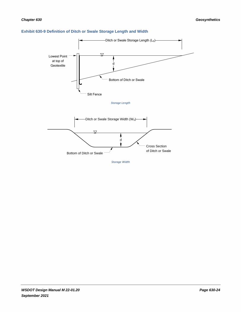
630.05(6)(d) Temporary Silt Fence
Temporary silt fences may also be used in ditch or swale applications. If the area contributing runoff to the fence
exceeds the value determined from Exhibit 630-3, hydraulic overload will occur. The ditch or swale storage
length and width are defined in Exhibit 630-9. The assumptions used in the development of Exhibit 630-3 are the
same as those used for Exhibit 630-2 in terms of the design storm and ground conditions.
As an example, if a site has a 13-foot-wide ditch with an average slope of 2%, the fence can be located such that
7800 ft2 of area drain to it. If it appears that the area draining to the fence will be larger than the allowable, it
may be possible to divide the contributing area into smaller areas and add a silt fence for each smaller area as
shown in Exhibit 630-10.
The minimum storage length for the ditch behind each silt fence must be maintained. If this is not possible, it
may be necessary to use an alternate erosion control structure, as described in the Highway Runoff Manual, or
develop a special silt fence design.
Exhibit 630-3 was developed with the assumption that water will be able to pond to a depth of at least 2 feet
behind the fence. If this is not the case (the ditch or swale depth is less than 2 feet), the table cannot be used.
Furthermore, the ditch depth must be greater than the height of the silt fence at its lowest point within the
ditch. Otherwise, there will not be enough storage available behind the fence and water will circumvent the
fence by flowing around it.
630.05(6)(e) Locating a Silt Fence
Locate silt fences on contour as much as possible. At the ends of the fence, turn it up hill such that it captures
the runoff water and prevents water from flowing around the end of the fence. This is illustrated in Exhibit
630-11.
Silt fences are designed to capture up to a 2-foot depth of water behind the fence. Therefore, the ground line at
the ends of the fence must be at least 2 feet above the ground line at the lowest part of the fence. This 2-foot
requirement applies to ditches as well as to general slope erosion control.

Chapter 630 Geosynthetics
WSDOT Design Manual M 22-01.20 Page 630-11
September 2021
If the fence must cross contours (except for the ends of the fence), use gravel check dams placed perpendicular
to the back of the fence to minimize concentrated flow and erosion along the back of the fence (see Exhibit
630-12).
• The gravel check dams are approximately 1 foot high at the back of the fence and are continued
perpendicular to the fence at the same elevation until the top of the dam intercepts the ground surface
behind the fence.
• Locate the gravel check dams every 10 feet along the fence.
• In general, the slope of the fence line is not to be steeper than 3H:1V.
• For the gravel check dams, use Crushed Surfacing Base Course, Gravel Backfill for Walls, or Permeable
Ballast (see the Standard Specifications).
If the silt fence application is considered critical (such as when the fence is placed immediately adjacent to
environmentally sensitive areas like streams, lakes, or wetlands), place a second silt fence below the first silt
fence to capture any silt that passes through the first fence and/or place straw bales behind the silt fence.
Locate silt fences at least 7 feet from an environmentally sensitive area. Where this is impossible, and a silt
fence must be used, a special design may be necessary.
Temporary silt fences are sometimes used to completely encircle underground drainage inlets or other similar
features to prevent silt from entering the drainage system. This is acceptable, but the silt fence functions
primarily as a barrier, and not as a ponding or filtering mechanism, unless the drainage inlet is in a depression
that is large enough to allow water to pond behind the silt fence.
• If the drainage inlet and silt fence are not in a large enough depression, silt-laden water will simply be
directed around the fence and must be captured by another fence or sedimentation pond downslope.
• If the depression is deep, locate the silt fence no more than 2 feet below the top of the depression to
prevent overtopping. A site-specific design may be needed if the silt fence is located deeper than 2 feet
within the depression.
It may be necessary to relocate silt fences during the course of a construction project as cuts and fills are built or
as disturbed areas change. An erosion control/silt fence plan that accounts for the anticipated construction
stages (and eventual removal) should be developed. Do not assume that one silt fence location can routinely be
used for the entire life of the contract. Periodically check the locations in the field during the construction
project, and field-adjust the silt fence locations as necessary to ensure the silt fences function as intended.
630.05(7) Standard Specification Geotextile Application Identification in the Contract Plans
Identify the geotextile in the contract plan detail in a way that ties it to the appropriate application in the
Standard Specifications. For example:
• If a geotextile is to be used to line an underground trench drain 3 feet deep and the native soil has less
than 15% passing the #200 sieve, identify the geotextile on the plan sheet as “Construction Geotextile
for Underground Drainage, Low Survivability, Class A.”
• If the geotextile is to be placed beneath riprap on a slope without a cushion layer between the
geotextile and the riprap, and the native soil contains 35% passing the #200 sieve, identify the geotextile
on the plan sheet as “Construction Geotextile for Permanent Erosion Control, High Survivability, Class
B.”

Chapter 630 Geosynthetics
WSDOT Design Manual M 22-01.20 Page 630-12
September 2021
• If the geotextile is to be placed between the roadway base course and a moist silt subgrade with a
resilient modulus of 6,500 psi, and the roadway is planned to be constructed during the dry summer and
early fall months, identify the geotextile on the plan sheet as “Construction Geotextile for Separation.”
630.05(8) Site-Specific Designs (All Applications)
A site-specific design is required:
• For all reinforcement applications.
• For applications not covered by the Standard Specifications.
Consider a site-specific design for:
• High-risk applications.
• Exceptionally large geotextile projects: if the geotextile quantity in a single application is over 35,000 yd2
or over 85,000 yd2 for the separation application.
• Severe or unusual soil or groundwater conditions.
• Soil in the vicinity of the proposed geotextile location that consists of alternate thin layers of silt or clay
with potentially water-bearing sand layers on the order of 1 to 3 inches thick or less.
• Soil known through past experience to be problematic for geosynthetic drains.
• Drains in native soil behind structures except drains contained within granular backfill.
• Drains designed to stabilize unstable slopes.
• Drains designed to mitigate frost heave.
In such cases, obtain assistance from the HQ Materials Laboratory, Geotechnical Office. To initiate the special
design, provide a plan and cross section showing:
• The geosynthetic structure to be designed.
• The structure’s relative location to other adjacent structures that it could potentially affect.
• The structure’s intended purpose.
• Any soil data in the vicinity.
Consider a site-specific design for temporary silt fences:
• If silt fence must be used in intermittent streams or where a significant portion of the silt fence
functions as a barrier that directs flow to the lower portions of the silt fence.
• If the fence must be located on steep slopes.
• In situations not meeting the requirements in Exhibit 630-2 and Exhibit 630-3.
• If the 2-year, 24-hour design storm for the site is greater than the 3 inches assumed for the
development of Exhibit 630-2 and Exhibit 630-3.
• Where concentrated flow is anticipated.
• If closer than 7 feet from an environmentally sensitive area.
• If more than 2 feet of storage depth is needed.

Chapter 630 Geosynthetics
WSDOT Design Manual M 22-01.20 Page 630-13
September 2021
For a site-specific temporary silt fence design, obtain assistance from the HQ Hydraulics Section. To initiate the
design, send the following information to the HQ Hydraulics Section and a copy to the HQ Materials Laboratory,
Geotechnical Office:
• Plan sheets showing proposed silt fence locations and grading contours.
• Estimate of the area contributing runoff to each silt fence, including percentage and general type of
vegetative cover within the contributing area.
• Any available site soil information.
For all site-specific designs of applications not covered by the Standard Specifications, complete plans and
special provisions are needed. In general, for site-specific designs of Standard Specifications applications, only a
minor modification of the appropriate geotextile property table will be needed.
630.06 Design Responsibility
The design responsibility and process for geotextile design are illustrated in Exhibit 630-4 and Exhibit 630-5. The
region Project Development Office, in particular the region Project Manager, is responsible to initiate and
develop all geotextile designs for the Standard Specifications, except for roadway separation and soil
stabilization applications, which are initiated and developed by the region Materials Laboratory.
The region Materials Laboratory assists the region Project Manager with Standard Specifications underground
drainage and permanent erosion control designs.
The region Environmental Design Office assists with Standard Specifications, permanent erosion control, and
temporary silt fence designs.
Once the region Project Manager or Materials Laboratory has determined that a geotextile is appropriate,
development of a geotextile design for the Standard Specifications includes the development of plan details
showing the plan location and cross section of the geotextile installation. Standard details for geotextiles as
provided in the Plans Preparation Manual may be used or modified to adapt to the specific project situation.
Note that only minimum dimensions for drains are provided in these standard details.
Site-specific geosynthetic designs and applications not addressed by the Standard Specifications are designed by
the region with the assistance of the HQ Materials Laboratory, Geotechnical Office, or the HQ Hydraulics Section
as described in Section 630.05.
Design assistance by the HQ Geotechnical Office or HQ Hydraulics Section for site-specific design of Standard
Specifications applications includes determination of geosynthetic properties and other advice as needed to
complete the geosynthetic plans and any special provisions required.
The HQ Geotechnical Office is fully responsible to develop and complete the following:
• Geosynthetic design, plan details that can be used to develop the contract plan sheets, and special
provisions for geosynthetic reinforced walls, slopes, and embankments.
• Deep trench drains for landslide stabilization.
• Other applications that are an integral part of a Headquarters geotechnical design.
The region Project Manager incorporates the plan details and special provisions into the PS&E.
630.07 Documentation
Refer to Chapter 300 for design documentation requirements.

Chapter 630 Geosynthetics
WSDOT Design Manual M 22-01.20 Page 630-14
September 2021
Exhibit 630-4 Design Process for Drainage and Erosion Control: Geotextiles and Nonstandard
Applications

Chapter 630 Geosynthetics
WSDOT Design Manual M 22-01.20 Page 630-15
September 2021
Exhibit 630-5 Design Process for Separation, Soil Stabilization, and Silt Fence
Region Project Manager (RPM) defines application
Separation/soil
stabilization
Temporary silt fence
(sediment control)
RML assesses site conditions,
obtains soil samples as needed,
assesses need for geotextile, and
determines whether the Standard Specifications applies
RPM assesses need for geotextile
silt fence (see the Highway Runoff
Manual for additional information) – This is generally addressed as part
of the permitting process
Geotextile needed Not needed
Is site-specific
design required?End
Yes No, use Standard Specs.
HQGSD
assists with
geotextile
property
selection
RML arranges for any
testing needed and uses
resilient modulus,
considering site
conditions, to select
geotextile properties
Silt fence needed Not needed
RPM assesses
whether Standard Specification designs
apply
Apply other
erosion control
measures as
required
EndNo, do site-
specific
design
Yes, use
StandardSpecs.
RPM submits site data to
HQ Hydraulics Section – HQ Hydraulics Section
completes silt fence
design and submits
design to RPM
RPM
completes
standard silt
fence design
RPM selects/modifies
appropriate details from the
Standard Plans and
completes silt fence plans
RML includes
geotextile design
requirements in
geotechnical or
resurfacing report
RPM = Region Project Manager
RML = Region Materials Laboratory
HQGSD = HQ Geotechnical Services Division

Chapter 630 Geosynthetics
WSDOT Design Manual M 22-01.20 Page 630-16
September 2021
Exhibit 630-6 Examples of Various Geosynthetics
Slit Film Woven Geotextile
Monofilament Woven Geotextile
Multifilament Woven Geotextile

Chapter 630 Geosynthetics
WSDOT Design Manual M 22-01.20 Page 630-17
September 2021
Needle-Punched Nonwoven Geotextile Heat-Bonded Nonwoven Geotextile
Geocomposite Drains (Geotextile With Core)
Extruded and Woven Geogrids

Chapter 630 Geosynthetics
WSDOT Design Manual M 22-01.20 Page 630-18
September 2021
Exhibit 630-7 Geotextile Application Examples
Base Course
Surfacing
Subgrade< 6 ft
Geotextile
A. Underground Drainage: Low Survivability (Roadway Trench Drain)
Gravel Buttress
Geotextile
B. Underground Drainage: Moderate Survivability (Area Drain Beneath Buttress)
> 6 ft
Gabion Wall
Geotextile
C. Underground Drainage: Moderate Survivability (Geotextile Sheet Drain)
Geotextile
Surfacing
Drainable Base Course
D. Underground Drainage: Moderate Survivability (Area Drain Under Parking Lot or Roadway)

Chapter 630 Geosynthetics
WSDOT Design Manual M 22-01.20 Page 630-19
September 2021
Geotextile
Wall Backfill
E. Underground Drainage: Low Survivability (Wrapped Drain Behind Foundation)
> 6 ft
Geotextile
F. Underground Drainage: Moderate Survivability (Deep Trench Drain for Slope Stabilization)
Base Course
SubgradeGeotextile
Surfacing
G. Separation or Soil Stabilization for New Roadway (Depends on Subgrade Condition)
Base Course
Subgrade GeotextileExisting Pavement
New Pavement
Surfacing
H. Separation or Soil Stabilization for Widened Roadway (Depends on Subgrade Condition)

Chapter 630 Geosynthetics
WSDOT Design Manual M 22-01.20 Page 630-20
September 2021
Riprap
Geotextile
Aggregate Cushion
I. Permanent Erosion Control: Moderate Survivability
Riprap
Geotextile
J. Permanent Erosion Control: High Survivability
< 16 ft
Geotextile
1
2 min.
Quarry Spalls
K. Ditch Lining

Chapter 630 Geosynthetics
WSDOT Design Manual M 22-01.20 Page 630-21
September 2021
GeotextileFence
Runoff
L. Silt Fence Not Immediately Adjacent to Environmentally Sensitive Area
GeotextileRunoff
GeotextileFence
Fence
M. Silt Fence Immediately Adjacent to Environmentally Sensitive Area
Base Course
Subgrade
Surfacing
Sand Backfill
Prefabricated Geotextile
Wrapped Drain
N. Prefabricated Edge Drain for Roadway

Chapter 630 Geosynthetics
WSDOT Design Manual M 22-01.20 Page 630-22
September 2021
Wall Top
Wall Base
Soil Nail
Prefabricated Geotextile
Wrapped Drain Strip
O. Prefabricated Drain Strip Behind Wall Face
Geosynthetic
Layers
P. Geosynthetic Wall
Geosynthetic
Layers
Q. Geosynthetic Reinforced Slope
Geosynthetic Layers
Fill
Very Soft Subsoil
R. Geosynthetic Reinforced Embankment

Chapter 630 Geosynthetics
WSDOT Design Manual M 22-01.20 Page 630-23
September 2021
GeosyntheticVery Soft
Subgrade
Base Course
S. Geosynthetic Subgrade Reinforcement for Temporary Roads
Exhibit 630-8 Definition of Slope Length
Portion of Slope
Not DisturbedSlo
pe Length
(L)
Disturb
ed Soil D
ue to
Constru
ctio
n Act
ivitie
s
Additional Slope Length*
* May need to be included as part of slope length
depending on vegetative cover, slope steepness,
and degree of development above slope
Chapter 630 Geosynthetics
WSDOT Design Manual M 22-01.20 Page 630-24
September 2021
Exhibit 630-9 Definition of Ditch or Swale Storage Length and Width
Silt Fence
d
Bottom of Ditch or Swale
Lowest Point
at top of
Geotextile
Ditch or Swale Storage Length (LS)
Storage Length
Bottom of Ditch or Swale
d
Ditch or Swale Storage Width (WS)
Cross Section
of Ditch or Swale
Storage Width

Chapter 630 Geosynthetics
WSDOT Design Manual M 22-01.20 Page 630-25
September 2021
Exhibit 630-10 Silt Fences for Large Contributing Area
LS1 (Min)
Area 1 Area 3Area 2
Area 2 Area 3Area 1
Ditch or Swale
Silt Fence 1 Silt Fence 3Silt Fence 2
Bottom of
Slope
Downhill
Top of Slope
Top of Slope
LS3 (Min)LS2 (Min)
Method to keep contributing area to ditch or swale within allowable limits if contributing area is too large based on Exhibit 630-3.

Chapter 630 Geosynthetics
WSDOT Design Manual M 22-01.20 Page 630-26
September 2021
Exhibit 630-11 Silt Fence End Treatment
Silt fence plan and profile illustrating how
silt fence will capture runoff water and
not allow water to run around ends of fence.
Silt Fence
Bottom of Slope
Sheet Flow
Top of Slope
Silt Fence Plan
Silt Fence Profile
2 ft. min
Silt fence plan and profile illustrating how silt fence will capture runoff water and not allow water to run around ends of fence.

Chapter 630 Geosynthetics
WSDOT Design Manual M 22-01.20 Page 630-27
September 2021
Exhibit 630-12 Gravel Check Dams for Silt Fences
Silt Fence
Ground Line
Profile
Gravel
Check Dam
Cross Section A-A
3 min1
10 ft max.
A
A
Ground Line
1 ft
1 ft
Gravel Check Dam
Geotextile

Chapter 630 Geosynthetics
WSDOT Design Manual M 22-01.20 Page 630-28
September 2021