
160 IT 55.0% - Certificate 49.4% - Certificate 46.7% - Certificate 71.1 ...
Upload
khangminh22Category
view
1download
0
Page 1 of 18
BOSTD Geosynthetics Qingdao Ltd
Qingda Industrial Zone, Chengyang Qingdao Shandong 266111 China Tel: +86-532-87806919 Fax: +86-532-87806789 HAPAS Certificate e-mail: [email protected] 17/H272 website: www.bostd.com Product Sheet 1
E’GRID GEOGRID-REINFORCED SOIL STRUCTURES E’GRID R GEOGRID WALL SYSTEM FOR REINFORCED SOIL RETAINING WALLS AND
BRIDGE ABUTMENTS
This HAPAS Certificate Product Sheet(1) is issued by the British Board of Agrément (BBA), supported by Highways England (HE) (acting on behalf of the Overseeing Organisations of the Department for Transport; Transport Scotland; the Welsh Assembly Government; and the Department for Infrastructure, Northern Ireland), the Association of Directors of Environment, Economy, Planning and Transport (ADEPT), the Local Government Technical Advisers Group and industry bodies. HAPAS Certificates are normally each subject to a review every three years. (1) Hereinafter referred to as ‘Certificate’.
This Certificate relates to the E’GRID(1) R Geogrid Wall System for reinforced soil retaining walls and bridge abutments. The system comprises precast modular concrete wall blocks, wall block connectors, high-density polyethylene (HDPE) uniaxial geogrids, HDPE bodkins for joining of geogrids, and compacted backfill material.
(1) E’GRID is a registered trademark.
CERTIFICATION INCLUDES: • factors relating to compliance with HAPAS requirements • factors relating to compliance with Regulations where applicable • independently verified technical specification • assessment criteria and technical investigations • design considerations • installation guidance • regular surveillance of production • formal three-yearly review.
KEY FACTORS ASSESSED Performance of geogrids — the short- and long-term tensile strength of the geogrids and geogrid connectors; resistance to installation damage, fire, weathering and environmental effects; and soil/geogrid interaction, have been assessed (see sections 6 to 10). Mechanical properties — the method of connection between the geogrids and concrete wall blocks has been assessed and long-term connection strength values determined for various concrete wall block/geogrid connections. The interface shear capacity between adjacent concrete wall blocks in between layers of geogrid reinforcement has been assessed and is satisfactory (see section 7). Durability — when designed and installed in accordance with the provisions of this Certificate, the system will have adequate durability for its intended use as a retaining wall or bridge abutment (see section 12).
The BBA has awarded this Certificate to the company named above for the system described herein. This system has been assessed by the BBA as being fit for its intended use provided it is installed, used and maintained as set out in this Certificate. On behalf of the British Board of Agrément
Date of Second issue: 4 June 2019
Originally certificated on: 10 October 2017
Paul Valentine Technical Excellence Director
Claire Curtis-Thomas Chief Executive
The BBA is a UKAS accredited certification body – Number 113. The schedule of the current scope of accreditation for product certification is available in pdf format via the UKAS link on the BBA website at www.bbacerts.co.uk Readers are advised to check the validity and latest issue number of this Agrément Certificate by either referring to the BBA website or contacting the BBA direct.
Any photographs are for illustrative purposes only, do not constitute advice and should not be relied upon.
British Board of Agrément Bucknalls Lane Watford Herts WD25 9BA
©2019
tel: 01923 665300
[email protected] www.bbacerts.co.uk

Page 2 of 18
Requirements In the opinion of the BBA, the E’GRID R Geogrid Wall System for reinforced soil retaining walls and bridge abutments, when designed and installed in accordance with the provisions of this Certificate, will satisfy or contribute to satisfying the requirements of Highways England and local Highway Authorities for the design and construction of reinforced soil retaining walls and bridge abutments.
Regulations
Construction (Design and Management) Regulations 2015 Construction (Design and Management) Regulations (Northern Ireland) 2016 Information in this Certificate may assist the client, designer (including Principal Designer) and contractor (including Principal Contractor) to address their obligations under these Regulations. See sections: 1 Description (1.2 to 1.4) and 3 Delivery and site handling (3.1 and 3.5) of this Certificate.
Additional Information
CE marking
The Certificate holder has taken the responsibility of CE marking the geogrids in accordance with harmonised European Standard BS EN 13251 : 2016.
Technical Specification
1 Description 1.1 The E’GRID R Wall System for reinforced soil retaining walls and bridge abutments comprises:
• E’GRID High-Density Polyethylene Uniaxial Geogrids
• E’GRID Wall Block Connectors
• E’GRID Bodkins — for joining geogrids
• specifications for E’Grid Concrete Wall Blocks — precast concrete wall blocks for use as facing units.
E’GRID Concrete Wall Blocks
1.2 The concrete wall blocks can be specified with either a smooth or split front face (see Figure 1) and with flat or tongued bottom faces. The concrete wall blocks must conform to BS 8006-1 : 2010 (including Annex B requirements) and BS EN 771-3 : 2011, with the characteristics given in Table 1 and dimensions as stated in Table 2.
Table 1 Specifications for E’GRID Concrete Wall Blocks
Characteristic (unit) Standard Value
Dimensions (mm)
BS EN 771-3 : 2011
As per Table 2 Dimensional tolerances Category D2 Configuration Group 1 to EN 1996-1-1 : 2005 Compressive strength (N mm-2) 40 N·mm-2 at 28 days Reaction to fire Euroclass A1
Net density (kg·m-3) 2100
Exposure class
BS 8500-1 : 2015
XF2
Pigment (if required) BS EN 12878 : 2014

Page 3 of 18
Table 2 Dimensions and tolerances for the concrete wall blocks Smooth face Split face
Length (mm) 400 +1/-3 400 +1/-3 Width (mm) 220 +1/-3 225 +1/-3 Height (mm) 220 ± 2 220 ± 2 Nominal weight (kg) 35 35
Figure 1 Concrete wall blocks with (a) smooth finish and (b) split finish
E’GRID High-Density Polyethylene Uniaxial Geogrids
1.3 The range and specification of the geogrids covered by this Certificate are shown in Figure 2, and Tables 3 and 4.
Figure 2 Geogrid detail

Page 4 of 18
Table 3 Typical dimensional data of geogrids Product Atd
(mm) Bw
(mm) Sw
(mm) Tb
(mm) Tr
(mm) Pnom (mm)
Standard roll sizes(1)
E'GRID 50R 16 18 5.5 2.1 0.6 235
50 m2 (1.0 x 50 m)
E'GRID 60R 16 18 5.5 2.8 0.7 245
50 m2 (1.0 x 50 m)
E'GRID 70R 16 18 5.5 2.9 0.8 245
50 m2 (1.0 x 50 m)
E'GRID 80R 16 18 5.5 3.4 0.9 255
50 m2 (1.0 x 50 m)
E'GRID 95R 16 18 5.5 4.1 1.1 255
50 m2 (1.0 x 50 m)
E'GRID 105R 16 18 5.5 4.5 1.2 260
50 m2 (1.0 x 50 m)
E'GRID 120R 16 18 5.5 5.2 1.3 260
50 m2 (1.0 x 50 m)
E'GRID 125R 16 18 5.5 5.3 1.4 260
50 m2 (1.0 x 50 m)
E'GRID 145R 16 18 5.5 5.7 1.6 260
50 m2 (1.0 x 50 m)
E'GRID 160R 16 18 5.5 6.7 1.8 260
50 m2 (1.0 x 50 m)
E'GRID 170R 16 18 5.5 7.8 2.0 260
50 m2 (1.0 x 50 m)
E'GRID 180R 16 18 5.5 8.0 2.3 260
50 m2 (1.0 x 50 m)
(1) Roll widths up to 1.3 m are available.
Table 4 Geogrid performance characteristics
Product Short-term tensile strength
(kN·m-1)(1)
Strain at peak load
(%)(1)
E'GRID 50R 50.0 11 ± 3
E'GRID 60R 60.0 11 ± 3
E'GRID 70R 70.0 11 ± 3
E'GRID 80R 80.0 11 ± 3
E'GRID 95R 95.7 11 ± 3
E'GRID 105R 105.0 11 ± 3
E'GRID 120R 120.0 11 ± 3
E'GRID 125R 127.2 11 ± 3
E'GRID 145R 147.0 11 ± 3
E'GRID 160R 160.0 11 ± 3
E'GRID 170R 170.0 11 ± 3
E'GRID 180R 180.0 11 ± 3 (1) Tensile tests in accordance with BS EN ISO 10319 : 2015 at 21±1°C and calculated as the 95% lower
confidence limit in accordance with BS 2846-2 : 1981 and ISO 2602 : 1980. E’GRID Bodkins 1.4 The bodkins are used for joining lengths of geogrid together end-to-end, as illustrated in Figure 3 and have the specifications given in Table 5.

Page 5 of 18
Table 5 E’GRID EGB 5046(1) Bodkin specifications
Cross-section dimensions
Width: 50 ± 3
Edge thickness: 4.0 ± 0.5
Middle thickness: 6.0 ± 0.5
Length 1045 ± 5 mm or 1345 ± 5 mm
Polymer HDPE to one specification
Yield strength(2) 22 MN·m-2 minimum
Elongation at break(2) 250% minimum
Minimum carbon black content(3) 2.0%
(1) The E’GRID EGB 5046 Bodkin can be used with any grade of E’GRID Geogrid. (2) Measured in accordance with BS 3412 : 1992, Type 2, Speed D. (3) Measured in accordance with BS 2782-4 : Method 452B : 1993.
Figure 3 Bodkin connection
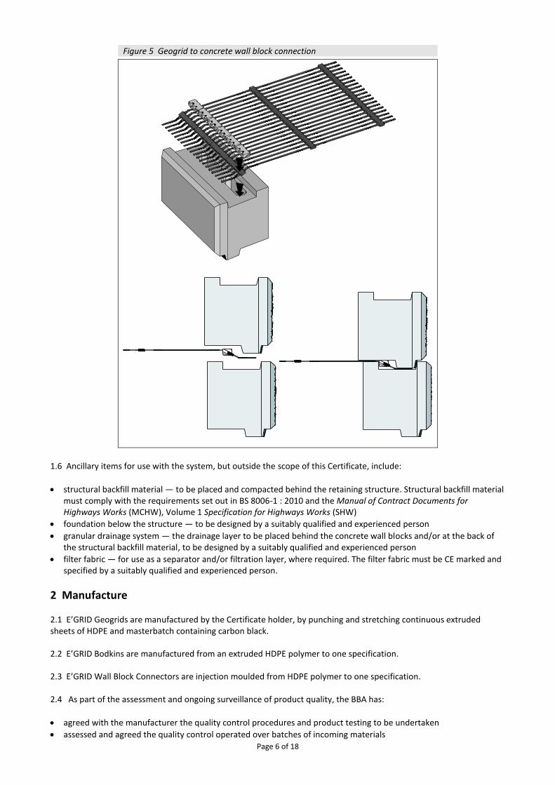
E’GRID Wall Block Connectors 1.5 The wall block connectors (see Figure 4) are manufactured from high-density polyethylene (HDPE) and are used to connect the geogrids to the concrete wall blocks, as illustrated in Figure 5.
Figure 4 Wall block connectors
Page 6 of 18
Figure 5 Geogrid to concrete wall block connection
1.6 Ancillary items for use with the system, but outside the scope of this Certificate, include:
• structural backfill material — to be placed and compacted behind the retaining structure. Structural backfill material must comply with the requirements set out in BS 8006-1 : 2010 and the Manual of Contract Documents for Highways Works (MCHW), Volume 1 Specification for Highways Works (SHW)
• foundation below the structure — to be designed by a suitably qualified and experienced person
• granular drainage system — the drainage layer to be placed behind the concrete wall blocks and/or at the back of the structural backfill material, to be designed by a suitably qualified and experienced person
• filter fabric — for use as a separator and/or filtration layer, where required. The filter fabric must be CE marked and specified by a suitably qualified and experienced person.
2 Manufacture 2.1 E’GRID Geogrids are manufactured by the Certificate holder, by punching and stretching continuous extruded sheets of HDPE and masterbatch containing carbon black. 2.2 E’GRID Bodkins are manufactured from an extruded HDPE polymer to one specification. 2.3 E’GRID Wall Block Connectors are injection moulded from HDPE polymer to one specification. 2.4 As part of the assessment and ongoing surveillance of product quality, the BBA has:
• agreed with the manufacturer the quality control procedures and product testing to be undertaken
• assessed and agreed the quality control operated over batches of incoming materials

Page 7 of 18
• monitored the production process and verified that it is in accordance with the documented process
• evaluated the process for management of nonconformities
• checked that equipment has been properly tested and calibrated
• undertaken to carry out the above measures on a regular basis through a surveillance process, to verify that the specifications and quality control being operated by the manufacturer are being maintained.
2.5 E’GRID Concrete Wall Blocks must be manufactured to an agreed specification by a supplier nominated by the Certificate holder. They must be moulded on block machines and compacted using mechanical vibratory compaction. Blocks with split face finishes must be moulded in pairs and split after drying. Smooth finish blocks are moulded in individual moulds. 2.6 The management system of BOSTD Geosynthetics Qingdao Ltd has been assessed and registered as meeting the requirements of BS EN ISO 9001 : 2015 and BS EN ISO 14001 : 2015 by the Quality Assurance Centre of China Association for Quality (Certificates 00617Q31529R5M and 00617E30388R0M respectively).
3 Delivery and site handling Concrete wall blocks 3.1 The concrete wall blocks should be handled and stored in accordance with the Certificate holder’s instructions, the requirements of BS 8006-1 : 2010, BS EN 14475 : 2006 and the MCHW, Volume 1. Geogrids and bodkins 3.2 The geogrids are delivered to site in rolls bearing the product grade and batch identification references. 3.3 CE marking in accordance with BS EN 13251 : 2016 is incorporated onto the product label. 3.4 The geogrids and bodkins should be stored under cover in clean, dry conditions and protected from mechanical and chemical damage, exposure to direct sunlight and extreme temperatures. Wall block connectors 3.5 The wall block connectors are supplied in packages of 300 units. They should be kept in their original packaging, under cover in clean, dry conditions and protected from mechanical or chemical damage, exposure to direct sunlight or extreme temperatures. Any damage or dirt accumulation will affect the structural integrity of the connection.
Assessment and Technical Investigations The following is a summary of the assessment and technical investigations carried out on the E’GRID R Geogrid Wall System for reinforced soil retaining walls and bridge abutments.
Design Considerations
4 Use 4.1 When designed and installed in accordance with this Certificate, the system is satisfactory for the construction of reinforced soil retaining walls and bridge abutments.
4.2 Structural stability of the system is achieved through:
• interface shear capacity between adjacent rows of concrete wall blocks
• the connection strength between the blocks and the geogrids at each layer of geogrid
• the tensile strength of the geogrids
• the embedment and resistance of the geogrids to sliding and pull-out from the compacted backfill material. 4.3 The connection between the concrete wall blocks and the geogrids is formed using the wall block connectors (see Figure 5).

Page 8 of 18
4.4 Prior to the commencement of work, the designer must satisfy the design approval and certification procedures of the relevant Highway Authority. 4.5 The BBA has not assessed the structures for supporting parapet loading caused by vehicle collision at the top of the concrete wall blocks. When applicable, this aspect of a design would require separate consideration and approval by Highways England. 4.6 Reinforced soil structures constructed using the system should be protected with suitable barriers, to protect the structure against potential damage from vehicle impacts. The barriers must be specified by a suitably competent person. 4.7 In addition to the factors covered in section 6, attention must also be paid in design to:
• site preparation
• compacted fill material properties
• specification for placing and compacting the fill material
• drainage issues
• protection of the geogrids during construction.
4.8 It is considered that with correct design and workmanship, a retaining wall constructed in accordance with this Certificate can satisfy the tolerances for line and level detailed in BS 8006-1 : 2010, Table 18. The design and specification of the concrete wall blocks is suitable for construction of a retaining wall with an 86o batter to the front face. 4.9 Particular attention should be paid to changes in alignment of the walls, where overlapping of the geogrids may occur. BS 8006-1 : 2010 also gives guidance on typical layout plans for the geogrids (reinforcing elements) in bridge abutments.
5 Practicability of installation
The system is designed to be installed by suitably trained contractors in accordance with the specifications and construction drawings (see the Installation part of this Certificate).
6 Design
Design methodology 6.1 Reinforced soil retaining walls and bridge abutments constructed using the system must be designed in accordance with BS 8006-1 : 2010 and the MCHW, Volume 1. 6.2 In accordance with BS 8006-1 : 2010, Annex B, the required design life for permanent walls and bridge abutments is 120 years. Design strength of geogrids 6.3 The design strength of the geogrids (TD) is calculated as:
• for ultimate limit state (ULS): TD(ULS) = TCR/(fn · fm)
• for serviceability limit state (SLS): TD(SLS) = TCS/fm
Where: TCR is the long-term tensile creep rupture strength of the reinforcement at the specified design life and design
temperature TCS is the maximum allowable tensile load to ensure that the prescribed post-construction, limiting strain specified
for the SLS is not exceeded fn is the partial factor for ramification of failure in accordance with BS 8006-1 : 2010, Table 9 fm is the material safety factor to allow for the strength-reducing effects of installation damage, weathering
(including exposure to sunlight) and chemical and other environmental effects, and to allow for the extrapolation of data used to establish the above reduction factors.
Page 9 of 18
6.4 The long-term creep rupture strength (TCR) for each grade of geogrid is calculated using the formula: TCR = Tchar/RFCR
where: Tchar is the characteristic short-term strength taken from Table 6 RFCR is the reduction factor for creep (see section 7). 6.5 The maximum allowable tensile load (TCS) to ensure that prescribed post-construction strain limits are not exceeded is set out in sections 7.4 and 7.5. 6.6 The material safety factor (fm) used in determining (TD(ULS)) and (TD(SLS)) is calculated as: fm = RFID x RFW x RFCH x fs where: RFID is the reduction factor for installation damage RFW is the reduction factor for weathering, including exposure to ultraviolet light RFCH is the reduction factor for chemical/environmental effects
fs is the factor of safety for the extrapolation of data. 6.7 Recommended values for RFCR; RFID; RFW; RFCH; and fs, are given in sections 7, 8, 9 and 10. Conditions of use outside the scope for which the reduction factors are defined are not covered by this Certificate and advice should be sought from the Certificate holder. Soil/geogrid interaction 6.8 There are two limiting modes of interaction between the soil and the reinforcement that need to be considered and for which the length of reinforcement necessary to maintain equilibrium needs to be determined:
• direct sliding — where the soil slides over the layer of reinforcement
• pull-out — where the layer of reinforcement pulls out of the layer of soil after it has mobilised the maximum available bond stress.
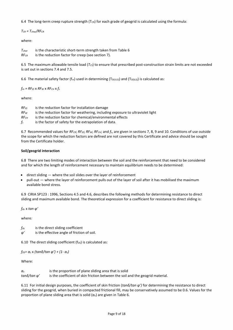
6.9 CIRIA SP123 : 1996, Sections 4.5 and 4.6, describes the following methods for determining resistance to direct sliding and maximum available bond. The theoretical expression for a coefficient for resistance to direct sliding is: fds x tan φ’ where: fds is the direct sliding coefficient φ’ is the effective angle of friction of soil. 6.10 The direct sliding coefficient (fDS) is calculated as: fDS= αs x (tanδ/tan φ’) + (1- αs) Where: αs is the proportion of plane sliding area that is solid tanδ/tan φ’ is the coefficient of skin friction between the soil and the geogrid material. 6.11 For initial design purposes, the coefficient of skin friction (tanδ/tan φ’) for determining the resistance to direct sliding for the geogrid, when buried in compacted frictional fill, may be conservatively assumed to be 0.6. Values for the proportion of plane sliding area that is solid (αs) are given in Table 6.

Page 10 of 18
Table 6 Soil geogrid interaction parameters
Product αs(1) Ratio of bearing(2) surface
area to plan area αb x B/2S
E'GRID 50R 0.41 0.003
E'GRID 60R 0.40 0.004
E'GRID 70R 0.40 0.004
E'GRID 80R 0.39 0.005
E'GRID 95R 0.39 0.006
E'GRID 105R 0.38 0.006
E'GRID 120R 0.38 0.007
E'GRID 125R 0.38 0.007
E'GRID 145R 0.38 0.008
E'GRID 160R 0.38 0.010
E'GRID 170R 0.37 0.010
E'GRID 180R 0.37 0.011
(1) αs is the proportion of plane sliding area that is solid and is required for the calculation of the bond coefficient (fb) and the direct sliding coefficient (fds). (2) The ratio is required to calculate the bond coefficient in accordance with CIRIA SP123 : 1996:
• αb is the thickness of a transverse member of a grid taking bearing
• B is the thickness of a longitudinal member of a grid taking bearing
• S is the spacing between transverse members taking bearing.
6.12 For detailed design, the resistance to direct sliding should be determined from soil and geogrid specific shear box testing. 6.13 The theoretical expression for a coefficient for the maximum allowable bond stress generated by soil-geogrid interaction is: fb x tan φ’ where: fb is the bond coefficient φ’ is the effective friction angle of the soil. 6.14 The bond coefficient may be calculated as: fb = αs x (tanδ/tan φ’) + (σ’b/σ’n) x (αb x B/2S) x (1/tan φ’) where: αs is the proportion of plane sliding area that is solid φ’ is the effective friction angle of the soil tanδ/tan φ’ is the coefficient of skin friction between the soil and the geogrid material σ’b/ σ’n is the bearing stress ratio αb x B/2S is the ratio of bearing surface to plan area (see Table 6). 6.15 The BBA recommends that site-specific pull-out tests are carried out to confirm the value of bond coefficient (fb) used in the final design. 6.16 The minimum length of reinforcement should be determined in accordance with Table 14 of BS 8006-1 : 2010, and BS EN 13738 : 2004. Concrete wall blocks 6.17 The concrete wall must be designed in accordance with the relevant provisions of BS 8006-1 : 2010, BS EN 14475 : 2006, and BS EN 1992-2 : 2005 and its UK National Annex.
Page 11 of 18
Connection strength between the geogrids and concrete wall blocks 6.18 The design connection strength between the geogrids and concrete wall blocks (TDconn) should be determined for the ULS and checks should be made to ensure that it is not exceeded by the design load Tl at each level. 6.19 The design connection strength (TDconn) is determined using the following formula: TDconn = Tconn /(fm · fn) Where: Tconn is the long-term connection strength derived from testing fm is the material partial safety factor fn is the partial factor for ramification of failure in accordance with BS 8006-1 : 2010, Table 9. 6.20 The minimum value of load factors to be used in determining the design load should be in accordance with Tables 12 and 13 of BS 8006-1 : 2010.
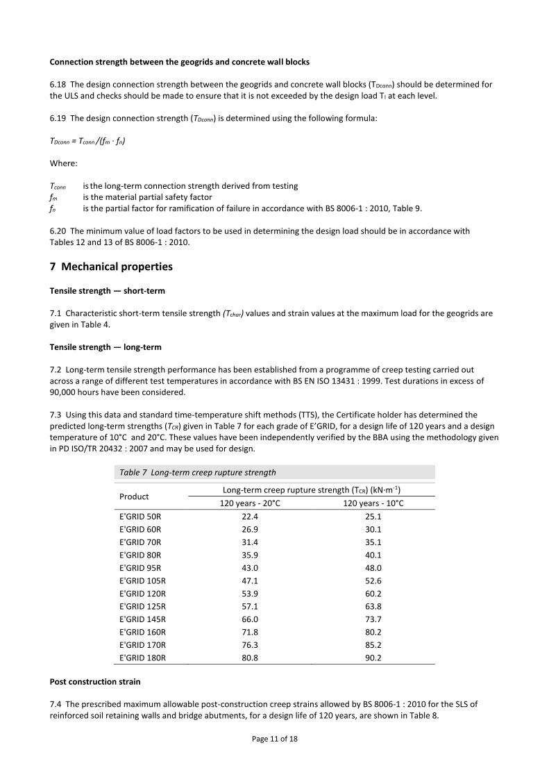
7 Mechanical properties Tensile strength — short-term 7.1 Characteristic short-term tensile strength (Tchar) values and strain values at the maximum load for the geogrids are given in Table 4. Tensile strength — long-term 7.2 Long-term tensile strength performance has been established from a programme of creep testing carried out across a range of different test temperatures in accordance with BS EN ISO 13431 : 1999. Test durations in excess of 90,000 hours have been considered. 7.3 Using this data and standard time-temperature shift methods (TTS), the Certificate holder has determined the predicted long-term strengths (TCR) given in Table 7 for each grade of E’GRID, for a design life of 120 years and a design temperature of 10°C and 20°C. These values have been independently verified by the BBA using the methodology given in PD ISO/TR 20432 : 2007 and may be used for design.
Table 7 Long-term creep rupture strength
Product Long-term creep rupture strength (TCR) (kN·m-1)
120 years - 20°C 120 years - 10°C
E'GRID 50R 22.4 25.1
E'GRID 60R 26.9 30.1
E'GRID 70R 31.4 35.1
E'GRID 80R 35.9 40.1
E'GRID 95R 43.0 48.0
E'GRID 105R 47.1 52.6
E'GRID 120R 53.9 60.2
E'GRID 125R 57.1 63.8
E'GRID 145R 66.0 73.7
E'GRID 160R 71.8 80.2
E'GRID 170R 76.3 85.2
E'GRID 180R 80.8 90.2
Post construction strain 7.4 The prescribed maximum allowable post-construction creep strains allowed by BS 8006-1 : 2010 for the SLS of reinforced soil retaining walls and bridge abutments, for a design life of 120 years, are shown in Table 8.

Page 12 of 18
Table 8 Serviceability limits on post-construction internal strains for bridge abutments and retaining walls Structure Strain (%) Design period for the purposes of
determining limiting strain
Bridge abutments and retaining walls with permanent structural loading
0.5 2 months – 120 years
Retaining walls, with no applied structural loading (ie transient live loadings only)
1.0 1 month – 120 years
7.5 Values for TCS may be established from the appropriate isochronous curves as illustrated in Figure 6. Values of TCS for the E’GRID Geogrids have been assessed by the BBA and are given in Table 9. These values may be used for design. Detailed guidance on the calculation of design loads at the SLS and the application of TCS should be obtained from BS 8006-1 : 2010, Clause 5.3.3.
Figure 6 Definition of TCS
Table 9 Tensile load (TCS) including prescribed post construction strain limits
Product Tensile load (TCS) (kN·m-1) prescribed post-construction strain limits
Design life of 120 years and design temperature of 20°C.
Design life of 120 years and design temperature of 10°C.
0.5 % 1.0 % 0.5 % 1.0 %
E'GRID 50R 5.95 9.60 6.64 10.72
E'GRID 60R 7.14 11.52 7.97 12.86
E'GRID 70R 8.33 13.44 9.30 15.01
E'GRID 80R 9.52 15.36 10.63 17.15
E'GRID 95R 11.39 18.37 12.72 20.52
E'GRID 105R 12.50 20.16 13.95 22.51
E'GRID 120R 14.28 23.04 15.95 25.73
E'GRID 125R 15.14 24.42 16.90 27.27
E'GRID 145R 17.49 28.22 19.53 31.52
E'GRID 160R 19.04 30.72 21.26 34.30
E'GRID 170R 20.23 32.64 22.59 36.45
E'GRID 180R 21.42 34.56 23.92 38.59
Reduction factor for installation damage (RFID) 7.6 To allow for the loss of strength due to mechanical damage that may be sustained during installation, the appropriate value for RFID should be selected from Table 10. These reduction factors have been established from full-scale tests using a range of materials whose gradings can be seen in Figure 7. The reduction factors assume a well-graded material (coefficient of uniformity >5) and minimum compacted depth above the geogrid of 150 mm. For fills not covered by Table 10, the appropriate RFID values may be determined from site-specific trials.

Page 13 of 18
Table 10 Partial safety factor — installation damage RFID
Crushed aggregate
Reduction factor for installation damage (RFID)
dmax particle size (mm)
d85 particle
size (mm)
E'GRID 50R
E'GRID 60R
E'GRID 70R
E'GRID 80R
E'GRID 95R
E'GRID 105R
E'GRID 120R
E'GRID 125R
E'GRID 145R
E'GRID 160R
E'GRID 170R
E’GRID 180R
4.75 2.25 1.01 1.03 1.03 1.03 1.03 1.03 1.03 1.01 1.01 1.01 1.01 1.01
50.8 40 1.06 1.08 1.09 1.09 1.06 1.06 1.06 1.05 1.06 1.06 1.06 1.06
127 75 1.10 1.15 1.19 1.19 1.16 1.16 1.16 1.12 1.11 1.11 1.09 1.09
Figure 7 Particle size distributions of fills used in installation damage testing
Connection strength 7.7 Long-term connection strength values for the connection between the concrete wall blocks and geogrids have been derived from short-term test results in accordance with ASTM D6638-07. Connection efficiencies determined from these tests have been assessed against the long-term creep rupture strength (TCR) values for the geogrids to determine the relevant long-term connection strengths (Tconn). The results are shown in Table 11 and can be used to determine the design connection strength (TDconn).
Table 11 Long-term connection strength
Product Wall height above geogrid
(m)(1)
120 years - 20˚C
120 years - 10˚C
TCR
(kN·m-1)
Tconn
(kN·m-1)
TCR
(kN·m-1)
Tconn
(kN·m-1)
E'GRID 50R 1.3-2.4 22.4 22.4 25.1 25.1
E'GRID 60R 2.1-6.1 26.9 26.9 30.1 30.1
E'GRID 70R 2.1-6.1 31.4 31.4 35.1 35.1
E'GRID 80R 2.1-6.1 35.9 35.9 40.1 40.1
E'GRID 95R 2.1-6.1 43.0 43.0 48.0 48.0
E'GRID 105R 6.2-12.5 47.1 47.1 52.6 52.6
E'GRID 120R 6.2-12.5 53.9 53.9 60.2 60.2
E'GRID 125R 6.2-12.5 57.1 57.1 63.8 63.8
E'GRID 145R 6.2-12.5 66.0 66.0 73.7 70.5
E'GRID 160R 6.2-12.5 71.8 70.5 80.2 70.5
E'GRID 170R 6.2-12.5 76.3 70.5 85.2 70.5
E'GRID 180R 6.2-12.5 80.8 70.5 90.2 70.5
Page 14 of 18
(1) For wall heights outside the range quoted, advice must be obtained from the Certificate holder.
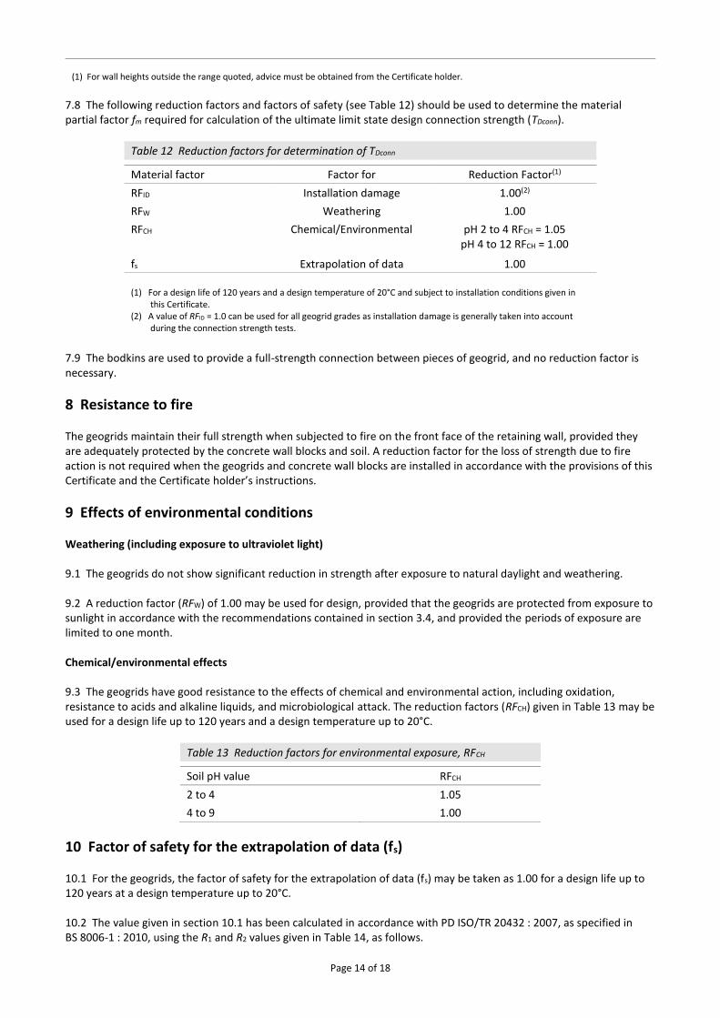
7.8 The following reduction factors and factors of safety (see Table 12) should be used to determine the material partial factor fm required for calculation of the ultimate limit state design connection strength (TDconn).
Table 12 Reduction factors for determination of TDconn
Material factor Factor for Reduction Factor(1)
RFID Installation damage 1.00(2)
RFW Weathering 1.00
RFCH Chemical/Environmental pH 2 to 4 RFCH = 1.05 pH 4 to 12 RFCH = 1.00
fs Extrapolation of data 1.00
(1) For a design life of 120 years and a design temperature of 20°C and subject to installation conditions given in
this Certificate. (2) A value of RFID = 1.0 can be used for all geogrid grades as installation damage is generally taken into account
during the connection strength tests.
7.9 The bodkins are used to provide a full-strength connection between pieces of geogrid, and no reduction factor is necessary.
8 Resistance to fire The geogrids maintain their full strength when subjected to fire on the front face of the retaining wall, provided they are adequately protected by the concrete wall blocks and soil. A reduction factor for the loss of strength due to fire action is not required when the geogrids and concrete wall blocks are installed in accordance with the provisions of this Certificate and the Certificate holder’s instructions.
9 Effects of environmental conditions Weathering (including exposure to ultraviolet light) 9.1 The geogrids do not show significant reduction in strength after exposure to natural daylight and weathering. 9.2 A reduction factor (RFW) of 1.00 may be used for design, provided that the geogrids are protected from exposure to sunlight in accordance with the recommendations contained in section 3.4, and provided the periods of exposure are limited to one month. Chemical/environmental effects 9.3 The geogrids have good resistance to the effects of chemical and environmental action, including oxidation, resistance to acids and alkaline liquids, and microbiological attack. The reduction factors (RFCH) given in Table 13 may be used for a design life up to 120 years and a design temperature up to 20°C.
Table 13 Reduction factors for environmental exposure, RFCH
Soil pH value RFCH
2 to 4 1.05
4 to 9 1.00
10 Factor of safety for the extrapolation of data (fs) 10.1 For the geogrids, the factor of safety for the extrapolation of data (fs) may be taken as 1.00 for a design life up to 120 years at a design temperature up to 20°C. 10.2 The value given in section 10.1 has been calculated in accordance with PD ISO/TR 20432 : 2007, as specified in BS 8006-1 : 2010, using the R1 and R2 values given in Table 14, as follows.

Page 15 of 18
Table 14 R1 and R2 values for determination of fs for a 120 year design life
Factor Taking account of Value
R1 Extrapolation of creep rupture data 1.0
R2 Extrapolation of chemical data 1.0
11 Maintenance The exposed surface of the concrete wall blocks may require periodic maintenance, to remove dirt build-up, mould and moss growth. All other components are contained within the retaining structure and should not require maintenance.
12 Durability 12.1 The geogrids, when designed and installed in accordance with this Certificate, will have adequate durability for a design life of 120 years. 12.2 The concrete wall blocks made to the specification given in section 1 will have adequate durability for the proposed life of the structure under exposure conditions normally encountered in reinforced earth retaining walls and bridge abutments in the UK, when designed and installed in accordance with the provisions of BS 8006-1 : 2010 and BS EN 14475 : 2006 and the requirements of this Certificate (see sections 6.17 to 6.20). 12.3 Where concrete wall blocks are to be embedded in soils which could be potentially aggressive, the guidance in BRE Special Digest 1 : 2005, Part C should be followed.
13 Reuse and recyclability The system contains concrete and HDPE, which can be recycled.
Installation
14 General 14.1 The construction of reinforced soil structures must be carried out in accordance with BS 8006-1 : 2010 and BS EN 14475 : 2006. 14.2 Installation of the system, within the context of this Certificate, is carried out by installers recommended or recognised by the Certificate holder. Such an installer is a company which:
• employs operatives who have been trained and approved by the Certificate holder to install the system
• has undertaken to comply with the Certificate holder’s application procedure
• is subject to supervision by the Certificate holder, including site inspections.
15 Preparation 15.1 The foundation for the retaining wall must be prepared in accordance with the designer’s instructions. 15.2 The surface onto which the geogrids are to be laid must be free from debris, tree roots, frozen matter and other sharp objects that could damage the geogrid.
16 Procedure 16.1 Formation levels are prepared and a concrete strip foundation is laid to the correct level for the first course of wall blocks. 16.2 The first course of wall blocks are placed, paying particular care to the accuracy of line and level. The blocks may be temporarily propped during the placing and compaction of fill material behind the blocks, up to the level of the first

Page 16 of 18
layer of geogrid. After the completion of each course of blocks, the upper surface must be thoroughly cleaned, as must the lower surfaces of the next course of blocks. If a drainage system is to be provided behind the wall, the appropriate pipes, outfalls and granular fill material are installed in accordance with the manufacturer’s specification. 16.3 To install a layer of geogrid, the wall block connectors are first clipped through the geogrid and then placed in the recess on the top of the wall block to form a positive connection. The placing of the next course of wall blocks secures the geogrid, which is then rolled out on top of the compacted fill, working away from the wall. The geogrid is pulled and held taut at the rear of the reinforced soil area using a tension beam. 16.4 The next courses of wall blocks are laid, and then the layer of fill material is laid and compacted, to the height specified by the designer. 16.5 The process in sections 16.3 and 16.4 is repeated up to the finished height of the wall. 16.6 Fill is placed to a depth not less than 150 mm before each pass of the compaction plant. To avoid excessive movement of the concrete wall blocks during compaction, heavy compaction plant should not be used within two metres of the face. Here, the depth of fill before each pass may be less than 150 mm, to suit the compaction method used. 16.7 To minimise wastage of the geogrids, the bodkins may be used to join shorter lengths of geogrid to form a layer. Care should be taken to remove all slack from the connection during installation.
Technical Investigations
17 Tests An assessment was made of test data relating to:
• short-term tensile strength and elongation of the geogrids
• long-term tensile strength and creep rupture performance
• creep elongation of the geogrids
• resistance of the geogrids to installation damage
• resistance of the geogrids to oxidation (chemical and weathering)
• soil/geogrid interaction with pull-out
• efficiency of the geogrids, connector and concrete wall block connection
• performance of the retaining wall system under fire test conditions
• efficiency of the geogrid and bodkins connection.
18 Investigations 18.1 The manufacturing process was evaluated, including the methods adopted for quality control, and details were obtained of the quality and composition of the materials used. 18.2 An assessment was made of data to establish:
• the short- and long-term tensile properties
• the effects of temperature
• the effects of ultra violet light, environmental degradation and fire action
• the friction coefficient between the system and the soil fill
• the effects of chemical degradation. 18.3 An assessment was made of the system’s practicability of installation, ease of construction and resistance to installation damage. The construction of a retaining wall was witnessed.

Page 17 of 18
Bibliography ASTM D6638-07 Standard Test Method for Determining Connection Strength Between Geosynthetic Reinforcement and Segmental Concrete Units (Modular Concrete Blocks) BRE Special Digest 1 : 2005 Concrete in aggressive ground : Part C Assessing the aggressive chemical environment BS 2782-4 : Method 452B : 1993 Methods of testing plastics — Chemical properties — Determination of carbon black content of polyolefin compound BS 2846-2 : 1981, ISO 2602 – 1980 Guide to statistical interpretation of data — Estimation of the mean: confidence interval BS 3412 : 1992 Methods of specifying general purpose polyethylene materials for moulding and extrusion BS 8006-1 : 2010 + A1 : 2016 Code of practice for strengthened/reinforced soils and other fills BS 8500-1 : 2015 Concrete — Complementary British Standard to BS EN 206-1 — Method of specifying and guidance for the specifier BS EN 206-1 : 2000 Concrete — Specification, performance, production and conformity BS EN 771-3 : 2011 + A1 : 2015 Specification for masonry units — Aggregate concrete masonry units (Dense and lightweight aggregates) BS EN 1992-2 : 2005 Eurocode 2 — Design of concrete structures — Concrete bridges — Design and detailing rules NA to BS EN 1992-2 : 2005 UK National Annex to Eurocode 2 — Design of concrete structures — Concrete bridges — Design and detailing rules BS EN 12878 : 2014 Pigments for the colouring of building materials based on cement and/or lime — Specifications and methods of test BS EN 13251 : 2016 Geotextiles and geotextile-related products — Characteristics required for use in earthworks, foundations and retaining structures BS EN 13738 : 2004 Geotextiles and geotextile-related products. Determination of pull-out resistance in soil BS EN 14475 : 2006 Execution of special geotechnical works — Reinforced fill BS EN ISO 9001 : 2015 Quality Management systems — Requirements BS EN ISO 10319 : 2015 Geosynthetics — Wide-width tensile test BS EN ISO 13431 : 1999 Geotextiles and geotextile-related products — Determination of tensile creep and creep rupture behaviour BS EN ISO 14001 : 2015 Environmental management systems – Requirements with guidance for use CIRIA SP123 : 1996 Soil Reinforcement with Geotextiles : Jewel R A EN 1996-1-1 : 2005 + A1 : 2012 Eurocode 6 — Design of masonry structures — General rules for reinforced and unreinforced masonry structures ISO 2602 : 1980 Statistical interpretation of test results – Estimation of the mean – Confidence interval Manual of Contract Documents for Highway Works, Volume 1 Specification for Highway Works PD ISO/TR 20432 : 2007 Guidelines for the determination of the long-term strength of geosynthetics for soil reinforcement

Page 18 of 18
Conditions of Certification
19 Conditions 19.1 This Certificate:
• relates only to the product/system that is named and described on the front page
• is issued only to the company, firm, organisation or person named on the front page – no other company, firm, organisation or person may hold or claim that this Certificate has been issued to them
• is valid only within the UK
• has to be read, considered and used as a whole document – it may be misleading and will be incomplete to be selective
• is copyright of the BBA
• is subject to English Law. 19.2 Publications, documents, specifications, legislation, regulations, standards and the like referenced in this Certificate are those that were current and/or deemed relevant by the BBA at the date of issue or reissue of this Certificate. 19.3 This Certificate will remain valid for an unlimited period provided that the product/system and its manufacture and/or fabrication, including all related and relevant parts and processes thereof:
• are maintained at or above the levels which have been assessed and found to be satisfactory by the BBA
• continue to be checked as and when deemed appropriate by the BBA under arrangements that it will determine
• are reviewed by the BBA as and when it considers appropriate. 19.4 The BBA has used due skill, care and diligence in preparing this Certificate, but no warranty is provided. 19.5 In issuing this Certificate the BBA is not responsible and is excluded from any liability to any company, firm, organisation or person, for any matters arising directly or indirectly from:
• the presence or absence of any patent, intellectual property or similar rights subsisting in the product/system or any other product/system
• the right of the Certificate holder to manufacture, supply, install, maintain or market the product/system
• actual installations of the product/system, including their nature, design, methods, performance, workmanship and maintenance
• any works and constructions in which the product/system is installed, including their nature, design, methods, performance, workmanship and maintenance
• any loss or damage, including personal injury, howsoever caused by the product/system, including its manufacture, supply, installation, use, maintenance and removal
• any claims by the manufacturer relating to CE marking. 19.6 Any information relating to the manufacture, supply, installation, use, maintenance and removal of this product/system which is contained or referred to in this Certificate is the minimum required to be met when the product/system is manufactured, supplied, installed, used, maintained and removed. It does not purport in any way to restate the requirements of the Health and Safety at Work etc. Act 1974, or of any other statutory, common law or other duty which may exist at the date of issue or reissue of this Certificate; nor is conformity with such information to be taken as satisfying the requirements of the 1974 Act or of any statutory, common law or other duty of care.
British Board of Agrément Bucknalls Lane Watford Herts WD25 9BA
©2019
tel: 01923 665300
[email protected] www.bbacerts.co.uk
Copyright © 2022 FDOKUMEN