Design and analysis of an innovative multifunctional cylinder
16
1 Design and analysis of an innovative multifunctional cylinder Ji Bin a,b , Gu Chengzhang b , Wu Chunlei b , Xu Anyi b , Li Hao b , Wang Meng b a Shanghai Key Laboratory of Spacecraft Mechanism, Shanghai 201109, China; b Aerospace System Engineering Shanghai, Shanghai 201109, China Abstract: Cylinders are the most common form of spacecraft primary structure, such as satellite central cylinder. These cylinders is usually subjected to complex environments, such as axial load caused by satellite overload, impact from micro meteor and orbital debris (MMOD) and thermal load by working electronical equipment and space temperature. Therefore, an innovative kind of sandwich cylinder is proposed, where bamboo-like cross-section is introduced and four layered skins are involved. Based on finite element methods, mechanical properties of the cylinder, including bearing capacity, structural response, lateral impact and heat dissipation are carefully investigated and have been compared with those of initial cylinder. Notice that this innovative cylinder can easily fabricated by additive manufacturing processing such as Selective Laser Melting (SLM). Numerical results show that except the load capacity, the multi-functional structure can have great advantages in axial vibration isolation, impact protection and heat dissipation. By neglecting thermal protection system and MMOD impact protection system, the mass of the spacecraft can be greatly reduced. 1 Introduction Lightweight design is always necessary in aerospace engineering due to the urgent lifting capability of launch vehicle. There are several lightweight methods. Firstly, the advanced lightweight material can be adopted. For example, CFRP has been more and more popularly applied in spacecraft. A famous example is that NASA and Boeing have been manufacturing the pressurized, large cryogenic propellant tank made of composite materials. Secondly, optimized design is another common method by combination of topo optimization, shape optimization and size optimization. Thirdly, spacecraft structure is usually made up of many different parts, especially for spaceship or satellite, including primary structure, thermal protection system, and space debris protection system. Each part has each function. If many functions can be integrated into a single structure, the number of parts can be largely reduced, and the super-lightweight design can be implemented. It is especially feasible for micro-satellite because of the popularity of additive manufacturing method. a NALT [3] b Sandwich antenna[4] DOI: 10.13009/EUCASS2019-32
-
Upload
khangminh22 -
Category
Documents
-
view
1 -
download
0
Transcript of Design and analysis of an innovative multifunctional cylinder

1
Design and analysis of an innovative multifunctional cylinder
Ji Bina,b, Gu Chengzhangb, Wu Chunleib, Xu Anyib, Li Haob, Wang Mengb
a Shanghai Key Laboratory of Spacecraft Mechanism, Shanghai 201109, China; b Aerospace System Engineering Shanghai, Shanghai
201109, China
Abstract: Cylinders are the most common form of spacecraft primary structure, such as satellite central cylinder. These cylinders is
usually subjected to complex environments, such as axial load caused by satellite overload, impact from micro meteor and orbital debris
(MMOD) and thermal load by working electronical equipment and space temperature. Therefore, an innovative kind of sandwich
cylinder is proposed, where bamboo-like cross-section is introduced and four layered skins are involved. Based on finite element
methods, mechanical properties of the cylinder, including bearing capacity, structural response, lateral impact and heat dissipation are
carefully investigated and have been compared with those of initial cylinder. Notice that this innovative cylinder can easily fabricated by
additive manufacturing processing such as Selective Laser Melting (SLM). Numerical results show that except the load capacity, the
multi-functional structure can have great advantages in axial vibration isolation, impact protection and heat dissipation. By neglecting
thermal protection system and MMOD impact protection system, the mass of the spacecraft can be greatly reduced.
1 Introduction
Lightweight design is always necessary in aerospace engineering due to the urgent lifting capability
of launch vehicle. There are several lightweight methods. Firstly, the advanced lightweight material
can be adopted. For example, CFRP has been more and more popularly applied in spacecraft. A
famous example is that NASA and Boeing have been manufacturing the pressurized, large cryogenic
propellant tank made of composite materials. Secondly, optimized design is another common method
by combination of topo optimization, shape optimization and size optimization. Thirdly, spacecraft
structure is usually made up of many different parts, especially for spaceship or satellite, including
primary structure, thermal protection system, and space debris protection system. Each part has each
function. If many functions can be integrated into a single structure, the number of parts can be largely
reduced, and the super-lightweight design can be implemented. It is especially feasible for
micro-satellite because of the popularity of additive manufacturing method.
a NALT [3] b Sandwich antenna[4]
DOI: 10.13009/EUCASS2019-32

2
c 3D printed structure with load bearing and heat dissipation
Figure 1 Multi-functional structures
Multi-functional design has been widely used in space engineering. A nonablative lightweight
thermal protection system (NALT) considered in Japan for Mars exploration is shown in Fig 1a[3]. The
system consists of a carbon/carbon composite skin, insulator tiles, and a honeycomb sandwich panel,
and has the function of load bearing, heat resistance and thermal insulation, respectively. You and
Hwang[4] designed a effective antenna composed of glass epoxy composite face sheets, micro strip
antenna and Nomex honeycomb core as shown in Fig 1b. The antenna has both structure and electric
functions. The experiment showed that antenna gain is increased in this sandwich construction and the
radiation patterns are comparable. With rapid development of additive manufacturing, multi-functional
structure can be easily fabricated as shown in Fig 1c and widely used in space engineering.
In this paper, a satellite central cylinder is re-designed with multi-functional method, where load
bearing, axial vibration isolation, lateral MMOD impact and heat dissipation are simultaneously
considered.
2 Design of the primary cylinder in spacecraft
In this part, an assumed satellite central cylinder is considered. According to complex
environments, several kinds of loads should be taken into account. Firstly, it carries most of the mass
in or around itself. Secondly, during flying period, its equipment is susceptible to severe vibration
passed from launch vehicle. Thirdly, the working electronic equipments can heat up the cylinder,
which needs to be mitigated. Fourthly, during orbit period, it should be protected from MMOD.
2.1 Initial cylinder
Assumed that the primary cylinder is a unstiffened shell with the radius 200mm, the height
350mm and the thickness of face sheet 3.5mm, as shown in Fig 1. The material is AlSi10Mg, with the
DOI: 10.13009/EUCASS2019-32
3
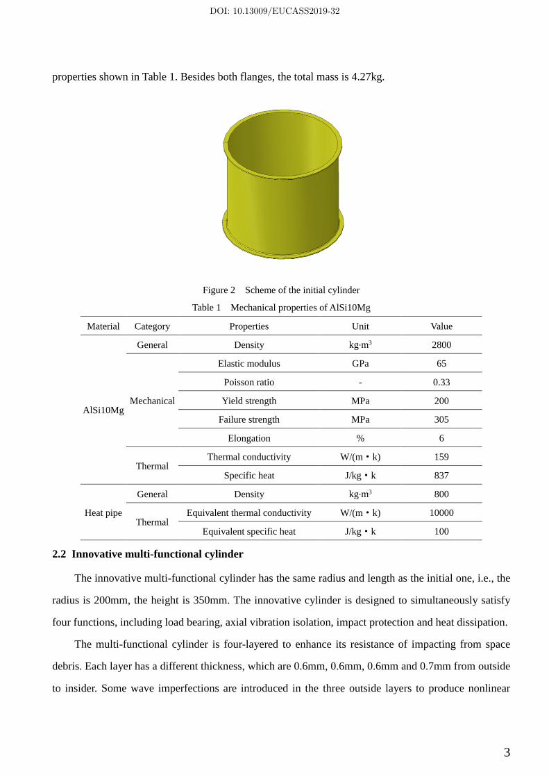
properties shown in Table 1. Besides both flanges, the total mass is 4.27kg.
Figure 2 Scheme of the initial cylinder
Table 1 Mechanical properties of AlSi10Mg
Material Category Properties Unit Value
AlSi10Mg
General Density kg∙m3 2800
Mechanical
Elastic modulus GPa 65
Poisson ratio - 0.33
Yield strength MPa 200
Failure strength MPa 305
Elongation % 6
Thermal Thermal conductivity W/(m·k) 159
Specific heat J/kg·k 837
Heat pipe
General Density kg∙m3 800
Thermal Equivalent thermal conductivity W/(m·k) 10000
Equivalent specific heat J/kg·k 100
2.2 Innovative multi-functional cylinder
The innovative multi-functional cylinder has the same radius and length as the initial one, i.e., the
radius is 200mm, the height is 350mm. The innovative cylinder is designed to simultaneously satisfy
four functions, including load bearing, axial vibration isolation, impact protection and heat dissipation.
The multi-functional cylinder is four-layered to enhance its resistance of impacting from space
debris. Each layer has a different thickness, which are 0.6mm, 0.6mm, 0.6mm and 0.7mm from outside
to insider. Some wave imperfections are introduced in the three outside layers to produce nonlinear
DOI: 10.13009/EUCASS2019-32

4
stiffness and then reduce the dynamic response. The specific imperfections can be referred in section
3.1.2. Inspired with cross-section of bamboo[5, 6], two kinds of pipes are inserted. The outsiders are
18 larger ones, linking three outer cylinders and preventing buckling mode to expand. The insiders are
smalls, some used as heat pipes. The CAD model of the multi-functional cylinder is shown in Figure 4.
Its total mass is 4.08kg, which is even a little lower than that of the initial cylinder.
a Cross-section b View 1
Figure 3 Scheme of the multi-functional cylinder
3 Analysis and comparison
3.1 Mechanical behavior
3.1.1 Initial cylinder
If the initial cylinder has no imperfection at all, its load capability is 3040kN based on eigenvalue
analysis. However, after introducing the imperfections in Table 2, the load capacity is reduced
seriously. It can be estimated as 820kN, i.e., the knock-down factor is about 0.27.
DOI: 10.13009/EUCASS2019-32

5
Figure 4 Buckling mode of the initial cylinder (Eigenvalue method)
Table 2 Load capacity and buckling mode for the initial cylinder with various imperfections
(Nonlinear static method)
Imperfection size 0.2mm 0.4mm 0.6mm
Load capacity 83.8T 83.7T 83.2 T
Buckling mode
Imperfection size 0.8mm 1mm
Load capacity 82.6 T 79.9 T
Buckling mode
3.1.2 Multi-functional cylinder
As abovementioned, in order to produce nonlinear stiffness, some wave imperfections are formed
through buckling mode analysis and then introduced into the three outside layers of the
multi-functional cylinder on purpose, as shown in Fig 6.
DOI: 10.13009/EUCASS2019-32

6
a The first layer b The second layer c The third layer
Figure 5 Imperfection introduction for the multi-functional cylinder
3.1.2.1 Mesh convergence analysis
a Coarse mesh b Fine mesh
Figure 6 Finite element model of multi-functional cylinder
Mesh convergence is firstly analyzed before further simulation. Two kinds of meshes are adopted
to investigate its mechanical behaviors. The coarse mesh has 50400 S4R elements, and the fine mesh
197640 ones. Numerical analysis shows that both results have good consistency, especially in the
elastic stage. When the displacement at the top end is 0.5mm, a sudden fluctuation appears for the
coarse mesh. However, the force vs displacement curve corresponding to the fine mesh is much
DOI: 10.13009/EUCASS2019-32

7
smoother, and therefore is more feasible. In conclusion, if there is no abnormal phenomenon, coarse
mesh is enough to get an accurate solution.
Figure 7 Force vs displacement curve for the multi-functional cylinder
3.1.2.2 Numerical results
Fine mesh in section 3.1.2.1 is adopted to analyze the mechanical behavior of the multifunctional
cylinder. Both static implicit and dynamic explicit arithmetic are used. Considering that the first
natural frequency of the cylinder is 555Hz, the total time periods are set as 0.006s, 0.01s and 0.02s.
However, there is little difference between static result and dynamic results, as shown in Fig 8a.
a Comparison of force vs displacement curves
between two kinds of cylinders b Force vs axial stiffness for multi-functional cylinder
Figure 8 Mechanical behaviors of satellite central cylinders
By comparison of mechanical behaviors between the initial cylinder and the multi-function
DOI: 10.13009/EUCASS2019-32
8
cylinder, their axial stiffness is almost the same at first. The stiffness of the initial cylinder remains
until the broken time. However, the stiffness of the multi-functional cylinder gradually decreases with
the increasing of force, even down to 71.2% of the initial stiffness when the force is up to 80% of
critical load. Nonlinear stiffness can improve its vibration isolation capacity, which will be discussed
in the next section in detail. This also makes the multi-functional cylinder has a little low load capacity
646kN, 21.8% lower than the initial cylinder.
3.2 Axial vibration isolation
In recent years, many researches focus on high static stiffness and low dynamic stiffness to solve
vibration isolation problem. Many quasi-zero-stiffness isolators have been proposed, such as SD
oscillator with viscous damping[7]:
2 2
12 1 cosx x x f
x
+ + − =
+
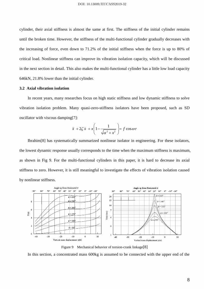
Ibrahim[8] has systematically summarized nonlinear isolator in engineering. For these isolators,
the lowest dynamic response usually corresponds to the time when the maximum stiffness is maximum,
as shown in Fig 9. For the multi-functional cylinders in this paper, it is hard to decrease its axial
stiffness to zero. However, it is still meaningful to investigate the effects of vibration isolation caused
by nonlinear stiffness.
Figure 9 Mechanical behavior of torsion-crank linkage[8]
In this section, a concentrated mass 600kg is assumed to be connected with the upper end of the
DOI: 10.13009/EUCASS2019-32
9
central cylinder. The axial dynamic behaviors are discussed for two kinds of cylinders.
3.2.1 Initial cylinder
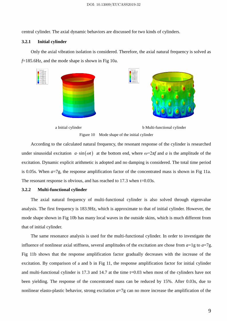
Only the axial vibration isolation is considered. Therefore, the axial natural frequency is solved as
f=185.6Hz, and the mode shape is shown in Fig 10a.
a Initial cylinder b Multi-functional cylinder
Figure 10 Mode shape of the initial cylinder
According to the calculated natural frequency, the resonant response of the cylinder is researched
under sinusoidal excitation ( )sina t at the bottom end, where ω=2πf and a is the amplitude of the
excitation. Dynamic explicit arithmetic is adopted and no damping is considered. The total time period
is 0.05s. When a=7g, the response amplification factor of the concentrated mass is shown in Fig 11a.
The resonant response is obvious, and has reached to 17.3 when t=0.03s.
3.2.2 Multi-functional cylinder
The axial natural frequency of multi-functional cylinder is also solved through eigenvalue
analysis. The first frequency is 183.9Hz, which is approximate to that of initial cylinder. However, the
mode shape shown in Fig 10b has many local waves in the outside skins, which is much different from
that of initial cylinder.
The same resonance analysis is used for the multi-functional cylinder. In order to investigate the
influence of nonlinear axial stiffness, several amplitudes of the excitation are chose from a=1g to a=7g.
Fig 11b shows that the response amplification factor gradually decreases with the increase of the
excitation. By comparison of a and b in Fig 11, the response amplification factor for initial cylinder
and multi-functional cylinder is 17.3 and 14.7 at the time t=0.03 when most of the cylinders have not
been yielding. The response of the concentrated mass can be reduced by 15%. After 0.03s, due to
nonlinear elasto-plastic behavior, strong excitation a=7g can no more increase the amplification of the
DOI: 10.13009/EUCASS2019-32

10
response. However, if the excitation a=1g, the amplification still works even when the time reaches to
0.045s. At the time around 0.045s, the amplification factors of initial cylinder and multi-functional
cylinder are 19.5 and 15.7. Here, the response of the concentrated mass can be reduced by 19.5%.
a Comparison between two kinds of cylinders b Multi-functional cylinder
Figure 11 Response amplification factor of the concentrated mass in the cylinder
Figure 12 Stress of the multi-functional cylinder (t=0.03s)
3.3 Lateral impact
At the orbit stage, satellite central cylinder needs to be protect from MMOD impacting. In general,
for such a small cylinder in space, the protect structure is not considered due to the high cost. In this
section, a MMOD is assumed to be an aluminum ball with diameter 2mm and about 12mg. The impact
velocities are chosen as 5km/s, 10km/s, respectively. Another assumption is also adopted that if the
plastic strain is reached to 6%, the material of the ball will vanish.
3.3.1 Initial cylinder
Finite element analysis is adopted to analyze the impact behavior by the MMOD. The mesh in the
DOI: 10.13009/EUCASS2019-32

11
impact area is fined to ensure the results accurate, as shown in Fig 13. When the cylinder is subjected
to impact, it can be damaged with a hole and the electronic equipment may be destroyed. So it is not
feasible to resist the MMOD impact. The impact behavior is also influenced by the impact velocities.
When the velocity is higher, the strain in the plastic area is lower due to the high stress wave speed.
Figure 13 Mesh of initial cylinder for impact analysis
a 5km/s b 10km/s
Figure 14 Equivalent plastic strain of the initial cylinder subjected to MMOD impact
3.3.2 Multi-functional cylinder
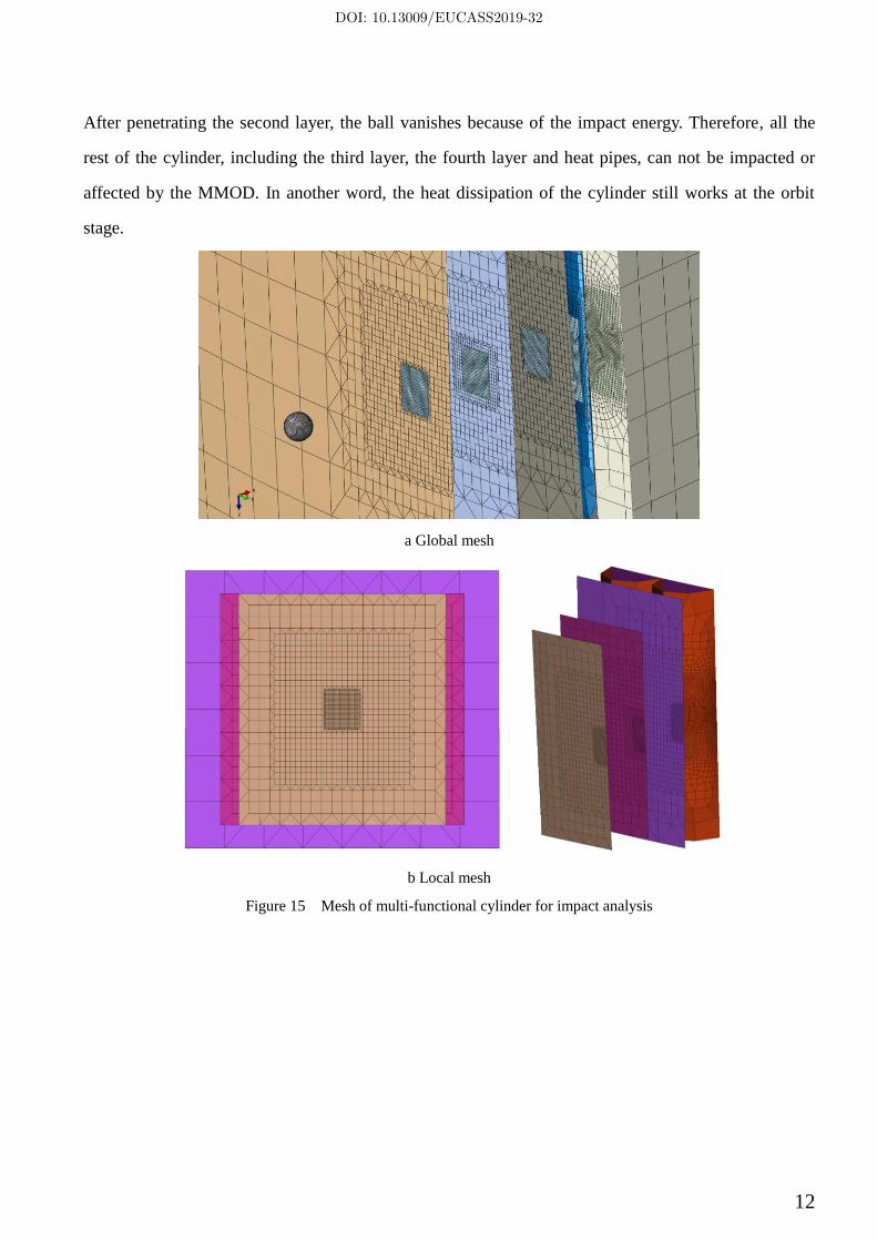
In the finite element model of the multi-functional cylinder, the mesh near the impact area is also
fined, as shown in Fig 15. Fig 16 gives the velocity of the ball all the time. When the initial velocity is
5km/s, the velocity of the ball can reduce to 2.84km/s after penetrating the first layer and the energy
absorbed by the cylinder is 973W. While the initial velocity is 10km/s, the velocity can reduce to
7.06km/s and the energy absorbed by the cylinder is 2873W. Besides the difference in plastic area and
energy absorbing, both impact velocities have the same results. As shown in Fig 17, when the ball
penetrates the first layer of the multi-functional cylinder, both the ball and the cylinder is damaged.
DOI: 10.13009/EUCASS2019-32
12
After penetrating the second layer, the ball vanishes because of the impact energy. Therefore, all the
rest of the cylinder, including the third layer, the fourth layer and heat pipes, can not be impacted or
affected by the MMOD. In another word, the heat dissipation of the cylinder still works at the orbit
stage.
a Global mesh
b Local mesh
Figure 15 Mesh of multi-functional cylinder for impact analysis
DOI: 10.13009/EUCASS2019-32

13
Figure 16 Velocity vs time curve for the multi-functional cylinder
5km/s 10km/s
a After penetrating the first layer
5km/s 10km/s
b After penetrating the second layer
Figure 17 Equivalent plastic strain of the multi-functional cylinder subjected to MMOD impact
3.4 Heat dissipation
In the multi-functional cylinder, the pipe connected with the inner layer can be used as heat pipe.
In this section, an electronic equipment with heating load 5W is fixed inside the cylinder, as shown in
DOI: 10.13009/EUCASS2019-32
14
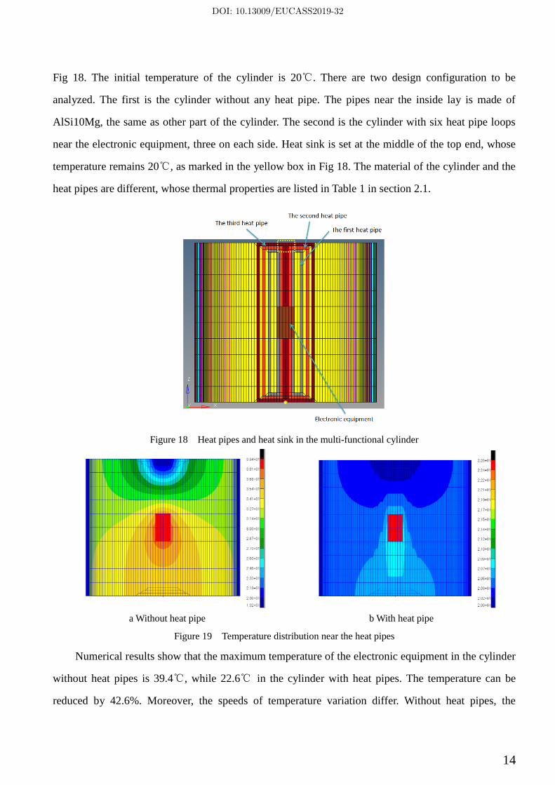
Fig 18. The initial temperature of the cylinder is 20℃. There are two design configuration to be
analyzed. The first is the cylinder without any heat pipe. The pipes near the inside lay is made of
AlSi10Mg, the same as other part of the cylinder. The second is the cylinder with six heat pipe loops
near the electronic equipment, three on each side. Heat sink is set at the middle of the top end, whose
temperature remains 20℃, as marked in the yellow box in Fig 18. The material of the cylinder and the
heat pipes are different, whose thermal properties are listed in Table 1 in section 2.1.
Figure 18 Heat pipes and heat sink in the multi-functional cylinder
a Without heat pipe b With heat pipe
Figure 19 Temperature distribution near the heat pipes
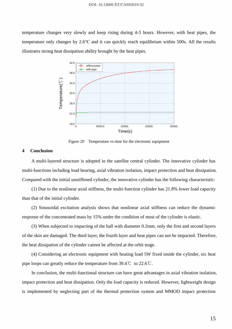
Numerical results show that the maximum temperature of the electronic equipment in the cylinder
without heat pipes is 39.4℃, while 22.6℃ in the cylinder with heat pipes. The temperature can be
reduced by 42.6%. Moreover, the speeds of temperature variation differ. Without heat pipes, the
DOI: 10.13009/EUCASS2019-32
15
temperature changes very slowly and keep rising during 4-5 hours. However, with heat pipes, the
temperature only changes by 2.6℃ and it can quickly reach equilibrium within 500s. All the results
illustrates strong heat dissipation ability brought by the heat pipes.
0 5000.0 10000. 15000. 20000.18.0
22.0
26.0
30.0
34.0
38.0
42.0without pipe
with pipe
Time(s)
Te
mp
era
ture
(℃)
Figure 20 Temperature vs time for the electronic equipment
4 Conclusion
A multi-layered structure is adopted in the satellite central cylinder. The innovative cylinder has
multi-functions including load bearing, axial vibration isolation, impact protection and heat dissipation.
Compared with the initial unstiffened cylinder, the innovative cylinder has the following characteristic:
(1) Due to the nonlinear axial stiffness, the multi-function cylinder has 21.8% lower load capacity
than that of the initial cylinder.
(2) Sinusoidal excitation analysis shows that nonlinear axial stiffness can reduce the dynamic
response of the concentrated mass by 15% under the condition of most of the cylinder is elastic.
(3) When subjected to impacting of the ball with diameter 0.2mm, only the first and second layers
of the skin are damaged. The third layer, the fourth layer and heat pipes can not be impacted. Therefore,
the heat dissipation of the cylinder cannot be affected at the orbit stage.
(4) Considering an electronic equipment with heating load 5W fixed inside the cylinder, six heat
pipe loops can greatly reduce the temperature from 39.4℃ to 22.6℃.
In conclusion, the multi-functional structure can have great advantages in axial vibration isolation,
impact protection and heat dissipation. Only the load capacity is reduced. However, lightweight design
is implemented by neglecting part of the thermal protection system and MMOD impact protection
DOI: 10.13009/EUCASS2019-32

16
system.
Reference
[1] Mccarville DA. Manufacture and test of cryotank components. Comprehensive Composite Materials II2018. p. 153-79.
[2] McCarville DA, Guzman JC, K. DA, Jackson JR, Birkland JO. Design, Manufacture and Test of Cryotank Components. 2017. p.
1-27.
[3] Suzuki T, Aoki T, Ogasawara T, Fujita K. Nonablative lightweight thermal protection system for Mars Aeroflyby Sample collection
mission. Acta Astronautica. 2017;136:407-20.
[4] You CS, Hwang W. Design of load-bearing antenna structures by embedding technology of microstrip antenna in composite sandwich
structure. Composite Structures. 2005;71:378-82.
[5] Fu J, Liu Q, Liufu K, Deng Y, Fang J, Li Q. Design of bionic-bamboo thin-walled structures for energy absorption. Thin-Walled
Structures. 2019;135:400-13.
[6] Zhang T, Wang A, Wang Q, Guan F. Bending characteristics analysis and lightweight design of a bionic beam inspired by bamboo
structures. Thin-Walled Structures. 2019;142:476-98.
[7] Cao Q, Wiercigroch M, Pavlovskaia E. An archetypal oscillator for smooth and discontinuous dynamics. Phys Rev E.
2006;74:046218.
[8] Ibrahim RA. Recent advances in nonlinear passive vibration isolators. Joumal of Sound and Vibration. 2008;314:371-452.
DOI: 10.13009/EUCASS2019-32