Projects on Ceramic and Ceramic Products - Entrepreneur India
Upload
khangminh22Category
view
1download
0
FULL PAPER
Damage and fracture of fiber-reinforced ceramic-matrix compositesunder thermal fatigue loading in oxidizing atmosphere
Li LONGBIAO1,³
1College of Civil Aviation, Nanjing University of Aeronautics and Astronautics, No.29 Yudao St., Nanjing 210016, PR China
In this paper, the damage and fracture of fiber-reinforced ceramic-matrix composites (CMCs) subjected to ther-mal cyclic fatigue loading at elevated temperatures in oxidizing atmosphere are investigated. The temperature/cyclic dependent fiber/matrix interface shear stress is determined as a function of testing temperature, appliedcycle number and material properties, which affects multiple thermal fatigue damage mechanisms. Themicrostress field of the thermal fatigue damaged composite is analyzed using the Budiansky-Hutchinson-Evansshear-lag model, considering matrix stochastic cracking, fiber/matrix interface debonding/sliding and fibersfracture. The matrix stochastic cracking, fiber/matrix interface debonding and sliding, fibers fracture in theinterface damage zones are determined using the micromechanical approach. The relationships between thethermal fatigue cycling, multiple thermal fatigue damage mechanisms, fatigue hysteresis-based damage param-eters and thermal fatigue lifetime are established. The effects of fiber/matrix interface properties, fiber radius,fiber volume fraction, matrix crack spacing and fatigue peak stress on thermal fatigue damage evolution in fiber-reinforced CMCs are analyzed. The thermal fatigue damage evolution and lifetime prediction of two differentfiber-reinforced CMCs, i.e., cross-ply SiC/MAS and 2D SiC/SiC composites, subjected to thermal cyclingfatigue in oxidizing atmosphere are predicted.©2019 The Ceramic Society of Japan. All rights reserved.
Key-words : Ceramic-matrix composites (CMCs), Thermal fatigue, Damage evolution, Hysteresis loops
[Received May 29, 2018; Accepted October 2, 2018]
1. Introduction
The aeroengine is the largest weight expense in theaircraft. The exceptional high-temperature mechanical sta-bility and excellent physical properties of ceramics makethem a reasonable candidate for implementation in de-manding environments such as a jet engine hot section.1)
Due to the brittle failure mode that occurs in these mate-rials, measures must be taken to make the ceramics moredurable, especially in applications where safety is of thehighest concern based on the airworthiness requirementsof the aircraft or aeroengine. The fiber-reinforced ceramic-matrix composites (CMCs) have been investigated andsuccessfully implemented in many applications includingexhaust nozzles and combustion chamber lining.2) GeneralElectric has committed to using the long-fiber-reinforcedCMCs for the next generation GE9x engine, and manyother applications including land-based turbine and nuclearheat exchangers are being investigated.3)
As new materials, it is necessary to develop the models,methods and tools to predict the degradation, damage andfailure mechanisms subjected to the cyclic loading at dif-ferent temperatures and environments.4) For the real life
applications, i.e., the turbine blades in a turbofan engine,dictate the need to determine the mechanical behavior ofthis material in an environment involving the thermalfatigue cycling under the constant load.5),6) Boccacciniaet al.7) investigated the damage evolution of Nicalon·-SiC/Borosilicate (DURAN) glass-matrix composite sub-jected to thermal fatigue cycling between high-temperature(T = 700°C) and room-temperature in air condition. Theflexural strength and Young’s modulus decreased and theinternal friction increased with increasing of the appliedcycle numbers, attributed to the viscous flow of the glassmatrix, the oxidation of the fiber/matrix interface andfibers. Udayakumar et al.8) investigated the effect of ther-mal cycling on the mechanical properties of Nicalon·-SiC/SiC composite at the elevated temperature between413 and 1273K. The matrix microcrackings are generatedunder thermal fatigue cycling, leading to the oxidation ofthe BN interface and the strengthen of the fiber/matrixbonding. Mei and Cheng9),10) investigated the strainresponse of a C/SiC composite simultaneously subjectedto the thermal fatigue cycling and mechanical cycling in anoxidizing atmosphere. The thermal and mechanical loadcycling in an oxidizing atmosphere could cause the coat-ing/matrix cracks, the degradation of the fiber/matrixinterface and fibers oxidation. Under cyclic thermal loadingat constant stress level, the fatigue stress-strain hysteresis
This is an Open Access article distributed under the terms of the Creative Commons Attribution License (https://creativecommons.org/licenses/by-nd/4.0/),which permits unrestricted use, distribution, and reproduction in any medium, provided the original work is properly cited.
³ Corresponding author: L. Longbiao; E-mail: [email protected]
Journal of the Ceramic Society of Japan 127 [2] 67-80 2019
DOI http://doi.org/10.2109/jcersj2.18107 JCS-Japan
©2019 The Ceramic Society of Japan 67

loops appear when the fiber repeatedly sliding relative tothe matrix in different debonded zones. Reynaud et al.11)
investigated the effects of temperature and oxidation on themechanical hysteresis behavior in the long-fiber-reinforcedCMCs. Li12) investigated the tensiontension cyclic fatiguebehavior of C/SiC composite at room and elevated temper-ature of 800°C in air condition. The degradation rate of thefiber/matrix interface shear stress at 800°C is much higherthan that at room temperature, leading to the greatly de-creasing of the fatigue limit stress. Under thermal cyclicfatigue loading, oxidation will affect the fiber/matrix inter-face damage condition, and then the damage evolution andfinal fracture in fiber-reinforced CMCs. However, in theresearches mentioned above, the temperature-dependentdamage development of fiber-reinforced CMCs subjectedto thermal fatigue cycling loading at elevated temperaturesin oxidizing atmosphere has not been analyzed using thefatigue hysteresis-based damage parameters.
The objective of this paper is to investigate the damageand fracture of fiber-reinforced CMCs subjected to ther-mal cycling fatigue loading in oxidizing atmosphere. TheBudiansky-Hutchinson-Evans shear-lag model is used todetermine the microstress field of the thermal damagedcomposites, considering the damage mechanisms of matrixmulticracking, fiber/matrix interface debonding and slid-ing, and fibers fracture. The matrix crack spacing, fiber/matrix interface debonding and sliding lengths, and brokenfibers fraction subjected to thermal fatigue cycling aredetermined. The relationships between the thermal fatiguecycling, thermal fatigue damage mechanisms, fatiguehysteresis-based damage parameters and thermal fatiguelifetime are established. The effects of fiber/matrix inter-face properties, fiber radius, fiber volume fraction, matrixcrack spacing and fatigue peak stress on thermal fatiguedamage development of SiC/SiC composite at elevatedtemperature in oxidizing atmosphere are analyzed. Thethermal fatigue damage evolution and thermal fatigue life-time of two different fiber-reinforced CMCs, i.e., cross-plySiC/MAS and 2D SiC/SiC composites subjected to ther-mal cycling are predicted.
2. Thermal fatigue damage models
The testing temperature affect the thermomechanicalfatigue (TMF) damage behavior of long-fiber-reinforcedCMCs, i.e., matrix microcracking, fiber/matrix interfacedebonding and thermal residual stress. If the radial ther-mal expansion coefficient of the matrix is higher than thecoefficient of the fibers, at a testing temperature T lowerthan the processing temperature T0, i.e., T < T0, the radialthermal residual stresses are compressive stresses. Thetemperature/cyclic-dependent fiber/matrix interface shearstress [¸i(T, N)] can be determined using the followingequation.11)
¸iðT; NÞ ¼ ¸0ðNÞ þ®j¡rf � ¡rmjðT0 � T Þ
Að1Þ
where ¸0 denotes the cyclic-dependent fiber/matrix inter-face shear stress, and degrades with applied cycles due to
the fiber/matrix interface wear or interface oxidation;6)
® denotes the fiber/matrix interface frictional coefficient;¡rf and ¡rm denote the fiber and matrix radial thermalexpansion coefficient, respectively; and A is a constantdepending on the elastic properties of the matrix andfibers.11) The fiber/matrix interface shear stress ¸0(N)decays after cycling from the initial value ¸initial to asteady-state value ¸steady.6)
ð¸initial � ¸steadyÞ=½¸0ðNÞ � ¸steady�¼ ð1þ b0Þð1þ b0N
jÞ�1 ð2Þwhere b0 is a coefficient; and j is an exponent whichdetermines the rate at which interface shear stress dropswith the number of cycle N.
2.1 Stress analysisTo analyze the micro stress distributions in the fiber
and the matrix after thermal fatigue damage, a unit cell isextracted from the long-fiber-reinforced CMCs, as shownin Fig. 1. The unit cell contains a single fiber surroundedby a hollow cylinder of matrix. The fiber radius is rf, andthe matrix radius is R(R = rf/Vf
1=2). The length of the unitcell is lc/2, which is just the half of the matrix crack space.The fiber/matrix interface debonded length is ld. At thematrix cracking plane, the fiber carries the applied stress(·/Vf), where · denotes the far-field applied stress and Vf
denotes the fiber volume fraction. The shear-lag modeladopted by the Budiansky, Hutchinson and Evans13) isadopted to perform the stress and strain calculations in thefiber/matrix interface debonded region (x 2 0, ld]) andfiber/matrix interface bonded region (x 2 [ld, lc/2]).
·fðxÞ ¼
·
Vf
� 2¸iðT Þrf
x; x 2 ð0; ldÞ
·fo þVm
Vf
·mo � 2ldrf¸iðT Þ
� �exp �μ
x� ldrf
� �;
x 2 ðld; lc=2Þ
8>>>><>>>>:
ð3Þ
·mðxÞ ¼2¸iðT Þ
Vf
Vm
x
rf; x 2 ð0; ldÞ
·mo � ·mo � 2¸iðT ÞVf
Vm
ldrf
� �exp � μðx� ldÞ
rf
� �;
x 2 ðld; lc=2Þ
8>>>><>>>>:
ð4Þwhere Vm denotes matrix volume fraction; and μ denotesthe BHE shear-lag parameter.13)
Fig. 1. The unit cell of the Budiansky-Hutchinson-Evans shearlag model.
Longbiao: Damage and fracture of fiber-reinforced ceramic-matrix composites under thermal fatigue loading in oxidizing atmosphereJCS-Japan
68
μ2 ¼ 4EcGm
VmEmEf¤ð5Þ
where Gm denotes matrix shear modulus, and
¤ ¼ � 2 lnVf þ Vmð3� VfÞ2V2
m
ð6Þ
·fo and ·mo denote the fiber and matrix axial stress in thefiber/matrix interface bonded region, respectively.
·fo ¼Ef
Ec
· þ Efð¡lc � ¡lfÞ�T ð7Þ
·mo ¼Em
Ec
· þ Emð¡lc � ¡lmÞ�T ð8Þ
where Ef, Em and Ec denote the fiber, matrix and compos-ite elastic modulus, respectively; ¡lf, ¡lm and ¡lc denotethe fiber, matrix and composite axial thermal expansioncoefficient, respectively; and ¦T denotes the temperaturedifference between the fabricated temperature T0 andtesting temperature T1 (¦T = T1 ¹ T0).
2.2 Multiple matrix crackingThe cracking of the matrix depends upon the internal
flaw inside of the matrix. The matrix cracking densityincreases with increasing of the applied stress above theinitial matrix cracking stress of ·mc,14),15) and may even-tually approach to the saturation at the applied stress of·sat. There are four dominant damage models for predict-ing the matrix multiple cracking development inside ofthe long-fiber-reinforced CMCs, i.e., the maximum stresscriterion,16) the energy balance approach,17)20) the criticalmatrix strain energy criterion21) and the statistical failureapproach.22) The statistical failure approach assumes thatthe matrix cracking is governed by the statistical relation,which relates the size and spatial distribution of the matrixflaws to their relative propagation stress.22) The brittlenature of the matrix material and the possible formation ofinitial cracks distribution in the microstructure suggest thata statistical approach for matrix multicracking evolutionis warranted in the long-fiber-reinforced CMCs. Usingthe statistical matrix cracking approach, the matrix crackspacing of lc can be determined using the followingequation.22)
lc ¼ rfVmEm
VfEc
� ·R
2¸iðT Þ� 1� exp � ·�ð·mc�·thÞ
ð·R�·thÞ�ð·mc�·thÞ
� �m� �� ��1
ð9Þwhere ·R denotes the matrix cracking characteristicstrength; ·mc denotes the matrix cracking stress; ·th
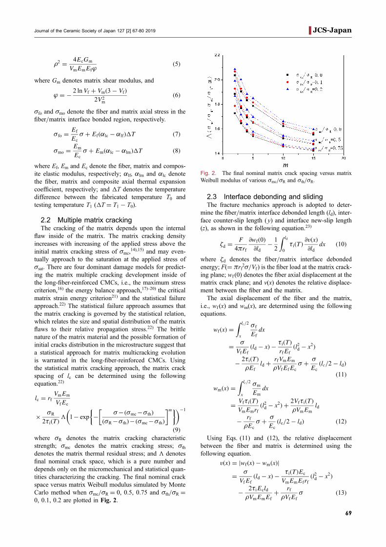
denotes the matrix thermal residual stress; and ª denotesfinal nominal crack space, which is a pure number anddepends only on the micromechanical and statistical quan-tities characterizing the cracking. The final nominal crackspace versus matrix Weibull modulus simulated by MonteCarlo method when ·mc/·R = 0, 0.5, 0.75 and ·th/·R =0, 0.1, 0.2 are plotted in Fig. 2.
2.3 Interface debonding and slidingThe fracture mechanics approach is adopted to deter-
mine the fiber/matrix interface debonded length (ld), inter-face counter-slip length ( y) and interface new-slip length(z), as shown in the following equation.23)
¦d ¼F
4³rf
@wfð0Þ@ld
� 1
2
Z ld
0
¸iðT Þ@vðxÞ@ld
dx ð10Þ
where ¦d denotes the fiber/matrix interface debondedenergy; F(= ³rf2·/Vf) is the fiber load at the matrix crack-ing plane; wf (0) denotes the fiber axial displacement at thematrix crack plane; and v(x) denotes the relative displace-ment between the fiber and the matrix.The axial displacement of the fiber and the matrix,
i.e., wf (x) and wm(x), are determined using the followingequations.
wfðxÞ ¼Z lc=2
x
·f
Ef
dx
¼ ·
VfEf
ðld � xÞ � ¸iðT ÞrfEf
ðl2d � x2Þ
� 2¸iðT ÞμEf
ld þrfVmEm
μVfEfEc
· þ ·
Ec
ðlc=2� ldÞð11Þ
wmðxÞ ¼Z lc=2
x
·m
Em
dx
¼ Vf¸iðT ÞVmEmrf
ðl2d � x2Þ þ 2Vf¸iðT ÞμVmEm
ld
� rfμEc
· þ ·
Ec
ðlc=2� ldÞ ð12Þ
Using Eqs. (11) and (12), the relative displacementbetween the fiber and matrix is determined using thefollowing equation.
vðxÞ ¼ jwfðxÞ � wmðxÞj
¼ ·
VfEf
ðld � xÞ � ¸iðT ÞEc
VmEmEfrfðl2d � x2Þ
� 2¸iEcldμVmEmEf
þ rfμVfEf
· ð13Þ
Fig. 2. The final nominal matrix crack spacing versus matrixWeibull modulus of various ·mc/·R and ·th/·R.
Journal of the Ceramic Society of Japan 127 [2] 67-80 2019 JCS-Japan
69

Substituting wf (x = 0) and v(x) into Eq. (10), it leads tothe following equation.
Ec ¸iðT Þ½ �2VmEmEfrf
l2d þEc ¸iðT Þ½ �2μVmEmEf
� ¸iðT Þ·VfEf
� �ld
þ rfVmEm·2
4V2f EfEc
� rf¸i2μVfEf
· � ¦d ¼ 0 ð14Þ
Solve Eq. (14), the fiber/matrix interface debondedlength (ld) is determined using the following equation.
ldðT Þ ¼rf2
VmEm·
VfEc¸iðT Þ� 1
μ
� �
�ffiffiffiffiffiffiffiffiffiffiffiffiffiffiffiffiffiffiffiffiffiffiffiffiffiffiffiffiffiffiffiffiffiffiffiffiffiffiffiffiffiffiffiffiffiffirf2μ
� �2
þ rfVmEmEf
Ec ¸iðT Þ½ �2 ¦d
sð15Þ
The temperature-dependent fiber/matrix interfacecounter-slip length ( y) and interface new-slip length (z)can also be determined using the fracture mechanicsapproach, as shown by the following equations.
yðT Þ ¼ 1
2
ldð·maxÞ �
(rf2
VmEm·
VfEc¸iðT Þ� 1
μ
� �
�ffiffiffiffiffiffiffiffiffiffiffiffiffiffiffiffiffiffiffiffiffiffiffiffiffiffiffiffiffiffiffiffiffiffiffiffiffiffiffiffiffiffiffiffiffiffirf2μ
� �2
þ rfVmEmEf
Ec ¸iðT Þ½ �2 ¦d
s )!ð16Þ
zðT Þ ¼ yð·minÞ �1
2
ld �
(rf2
VmEm·
VfEc¸iðT Þ� 1
μ
� �
�ffiffiffiffiffiffiffiffiffiffiffiffiffiffiffiffiffiffiffiffiffiffiffiffiffiffiffiffiffiffiffiffiffiffiffiffiffiffiffiffiffiffiffiffiffiffirf2μ
� �2
þ rfVmEmEf
Ec ¸iðT Þ½ �2 ¦d
s )!ð17Þ
2.4 Hysteresis-based damage parametersIf matrix multicracking and fiber/matrix interface de-
bonding are present upon first loading, the fatigue hyster-
esis loops develop as a result of energy dissipation throughthe frictional slip between fibers and the matrix uponunloading and subsequent reloading. Upon unloading, thecounter slip occurs in the fiber/matrix interface debondedregion. The fiber/matrix interface debonded region canbe divided into two regions, i.e., the interface counter-slipregion and the interface slip region, as shown in Fig. 3(a).The fiber/matrix interface counter-slip length is definedas y. Upon reloading, new slip occurs in the fiber/matrixinterface debonded region. The fiber/matrix interfacedebonded region can be divided into three regions, i.e.,the interface new-slip region, the interface counter-slipregion and the interface slip region, as shown in Fig. 3(b).The interface new-slip region is defined as z. Based onthe debonding and sliding condition between the fiber andthe matrix in the debonded regions, the fatigue hysteresisloops of the long-fiber-reinforced CMCs can be dividedinto four different cases, including:(1) Case 1, partially fiber/matrix interface debonding
and the fiber sliding completely relative to thematrix in the interface debonded region;
(2) Case 2, partially fiber/matrix interface debondingand the fiber sliding partially relative to the matrixin the interface debonded region;
(3) Case 3, completely fiber/matrix interface debond-ing and the fiber sliding partially relative to thematrix in the interface debonded region;
(4) Case 4, completely fiber/matrix interface debond-ing and the fiber sliding completely relative to thematrix in the interface debonded region.
When the damage forms within the composite, the com-posite strain is determined using the following equation,which assumes that the composite strain ¾c is equivalent tothe average strain in an undamaged fiber.
¾c ¼2
Ef lc
Zlc=2
·fðxÞdx� ð¡lc � ¡lfÞ�T ð18Þ
Fig. 3. The schematic figure for fiber slipping relative to matrix upon (a) unloading; and (b) reloading.
Longbiao: Damage and fracture of fiber-reinforced ceramic-matrix composites under thermal fatigue loading in oxidizing atmosphereJCS-Japan
70

When the fiber/matrix interface partially debonds, theunloading strain ¾unloading and reloading strain ¾reloading aredetermined using the following equations.
¾unloading ¼·
VfEf
þ 4¸iðT ÞEf
y2
rf lc
� 2¸iðT ÞEf
ð2y� ldÞð2yþ ld � lcÞrf lc
� ð¡lc � ¡lfÞ�T ð19Þ
¾reloading ¼·
VfEf
� 4¸iðT ÞEf
z2
rf lcþ 4
¸iðT ÞEf
ðy� 2zÞ2rf lc
þ 2¸iðT ÞEf
ðld � 2yþ 2zÞðld þ 2y� 2z� lcÞrf lc
� ð¡lc � ¡lfÞ�T ð20ÞWhen the fiber/matrix interface completely debonds,
the unloading strain ¾unloading and reloading strain ¾reloadingare determined using the following equations.
¾unloading ¼·
VfEf
þ 4¸iðT ÞEf
y2
rf lc� 2
¸iðT ÞEf
ð2y� lc=2Þ2rf lc
� ð¡lc � ¡lfÞ�T ð21Þ
¾reloading ¼·
VfEf
� 4¸iðT ÞEf
z2
rf lcþ 4
¸iðT ÞEf
ðy� 2zÞ2rf lc
� 2¸iðT ÞEf
ðlc=2� 2yþ 2zÞ2rf lc
� ð¡lc � ¡lfÞ�T ð22ÞThe area associated with the fatigue hysteresis loops
is the dissipated energy (Ue) during corresponding cycle,which is defined by the following equation.
Ue ¼Z ·max
·min
¾unloadingð·Þ � ¾reloadingð·Þ
d· ð23Þ
where ¾unloading and ¾reloading denote the unloading andreloading strain, respectively. Substituting the unloadingand reloading strains of Eqs. (19)(22) corresponding tothe fiber/matrix interface partially and completely debond-ing into Eq. (23), the fatigue hysteresis dissipated energyUe can be obtained.
The fatigue hysteresis width ¦¾ is defined by thefollowing equation.
�¾ ¼ ¾c unload
·min þ ·max
2
� �� ¾c reload
·min þ ·max
2
� �ð24Þ
The fatigue hysteresis modulus E is defined by thefollowing equation.
E ¼ ·max � ·min
¾cð·maxÞ � ¾cð·minÞð25Þ
3. Thermal fatigue lifetime prediction model
Under thermal cyclic fatigue loading at elevated temper-atures, fibers fracture occurred due to the gradual fiber/matrix interface wear and interface oxidation.24),25) TheGlobal Load Sharing assumption is used to determine thestress carried by the intact and fracture fibers.26)
·
Vf
¼ 1� Pf 1þ 2lflc
� �� �T þ Pr
2lflc
hTbi ð26Þ
where lf denotes the slip length over which the fiber stresswould decay to zero if not interrupted by the far-fieldequilibrium stresses; ©Tbª denotes the average stress carriedby the broken fibers; Pf denotes the total fiber failureprobability; and Pr denotes the fiber failure probabilityin the interface debonded region and interface bondedregion.
Pf ¼ » ¦Pfa þ ð1� ©ÞPfb
þ Pfc þ Pfd ð27ÞPr ¼ Pfc þ Pfd ð28Þ
where Pfa, Pfb, Pfc and Pfd denote the fiber failure proba-bility of oxidized fibers in the oxidation region, unoxidizedfibers in the oxidation region, fibers in the interfacedebonded region and interface bonded region, respective-ly; ¦ denotes the oxidation fibers fraction in the oxidizedregion; and » denotes the fraction of oxidation in themultiple matrix cracks.
Pfa ¼ 1� exp �2ltl0
T
·0ðtÞ
� �mf� �
ð29Þ
Pfb ¼ 1� exp �2ltl0
T
·0
� �mf� �
ð30Þ
Pfc ¼ 1� exp
� rfT
mfþ1
l0½·0ðNÞ�mf¸iðNÞðmf þ 1Þ
� 1� 1� ldðNÞlfðNÞ
� �mfþ1( )!
ð31Þ
Pfd ¼ 1� exp � 2rfTmf
μl0 ·0ðNÞ½ �mf ðmf þ 1Þ 1� ·fo
T� ldðNÞ
lsðNÞ
� �264
�
1� ldðNÞlfðNÞ � 1� ·fo
T� ldðNÞ
lfðNÞ
� �μldðNÞ
rf
� �mfþ1
� 1� ldðNÞlfðNÞ � 1� ·fo
T� ldðNÞ
lfðNÞ
� �μlc2rf
� �mfþ1!#
ð32Þwhere
·0ðtÞ ¼·0; t � 1
k
KIC
Y·0
� �4
KIC
Yffiffiffiffikt4
p ; t >1
k
KIC
Y·0
� �4
8>>><>>>:
ð33Þ
·oðNÞ ¼ ·o 1� p1ðlogNÞp2 ð34Þwhere mf denotes the fiber Weibull modulus; KIC denotesthe critical stress intensity factor; Y is a geometric param-eter; k is the parabolic rate constant; and p1 and p2 are fiberstrength degradation parameter.With increasing applied cycle number, the fibers failure
probability in the interface oxidation region, interfacedebonded region and interface bonded region can beobtained by combing the interface wear model, interface
Journal of the Ceramic Society of Japan 127 [2] 67-80 2019 JCS-Japan
71

oxidation model and fiber strength degradation modelwith Eqs. (33) and (34). When the fibers broken fractionapproaches to the critical value, the composite fatiguefractures.
4. Results and discussions
The ceramic composite systems of SiC/SiC compositeis used for the case study. For the SiC/SiC composite, thematerial properties are given by:27) Vf = 30%, Ef = 230GPa, Em = 300GPa, rf = 7.5¯m, ¦d = 0.1 J/m2, ¡rf =2.9 © 10¹6/K, ¡lf = 3.9 © 10¹6/K, ¡rm = 4.6 © 10¹6/K,¡lm = 2.0 © 10¹6/K and ·0 = 2.6GPa. In the presentanalysis, the thermal fatigue damage evolution of fatiguehysteresis dissipated energy, fatigue hysteresis modulus,fatigue hysteresis width and fiber/matrix interface debond-ing ratio are considered. These damage paramters relatewith the damage and fracture of the fiber-reinforced CMCssubjected to the thermal cyclic fatigue loading at elevatedtemperature. When the fibers broken fraction approachesto the critical value, the composite fatigue fracture, and thecritical values for the damage parameters can also be deter-mined. Li28) developed an appraoch to predict the finalfracture of carbon fiber-reinforced CMCs under cyclicfatigue loading using the fatigue hysteresis dissipatedenergy-based parameters. The critical fatigue hysteresisdissipated energy-based damage parameters for compositefracture have been determined. The effects of the fiber/matrix interface properties, fiber radius, fiber volume frac-tion, matrix crack spacing and fatigue peak stress levels onthe temperature-dependent thermal fatigue damage evolu-tion of SiC/SiC composite subjected to thermal cyclic andconstant loading are discussed.
4.1 Effect of fiber/matrix interface propertiesThe effect of fiber/matrix interface shear stress (¸0 = 5
and 10MPa) on the temperature-dependent thermal fatiguedamage evolution of the fatigue hysteresis dissipatedenergy (Ue), fatigue hysteresis modulus (E), fatigue hys-teresis width (¦¾) and interface debonding ratio (2ld/lc)versus the cyclic temperature curves under ·max = 200MPa at the temperature range from Tem = 100°C toTem = 800°C are shown in Fig. 4. When the cyclicdependent fiber/matrix interface shear stress decreasesfrom ¸0 = 10 to 5MPa, the fatigue hysteresis dissipat-ed energy and fatigue hysteresis width increase, and thefatigue hysteresis modulus decreases, due to the increasingfiber/matrix interface debonding and sliding length.
The effect of fiber/matrix interface frictional coefficient(® = 0.1 and 0.5) on the temperature-dependent thermalfatigue damage evolution of the fatigue hysteresis dissi-pated energy (Ue), fatigue hysteresis modulus (E), fatiguehysteresis width (¦¾) and fiber/matrix interface debond-ing ratio (2ld/lc) versus cyclic temperature curves under·max = 200MPa at the temperature range from Tem =100°C to Tem = 800°C are shown in Fig. 5. When thefiber/matrix interface frictional coefficient increases from® = 0.1 to 0.5, the fatigue hysteresis dissipated energyand fatigue hysteresis width decrease, and the fatigue
hysteresis modulus increases, due to the decreasing fiber/matrix interface debonding and sliding length.
4.2 Effect of fiber radiusThe effect of the fiber radius (rf = 6 and 9¯m) on the
temperature-dependent thermal fatigue damage evolutionof the fatigue hysteresis dissipated energy (Ue), fatiguehysteresis modulus (E), fatigue hysteresis width (¦¾) andfiber/matrix interface debonding ratio (2ld/lc) versuscyclic temperature curves under ·max = 300MPa and thetemperature range from Tem = 100°C to Tem = 800°Care shown in Fig. 6. When the fiber radius increases fromrf = 6 to 9¯m, the fatigue hysteresis dissipated energy andfatigue hysteresis width increase, and the fatigue hysteresismodulus decreases, due to the increasing fiber/matrixinterface debonding and sliding length.
4.3 Effect of fiber volume fractionThe effect of fiber volume fraction (Vf = 30 and 35%)
on the temperature-dependent thermal fatigue damageevolution of the fatigue hysteresis dissipated energy (Ue),fatigue hysteresis modulus (E), fatigue hysteresis width(¦¾) and fiber/matrix interface debonding ratio (2ld/lc)versus the cyclic temperature curves under ·max = 300MPa and the temperature range from Tem = 100°C toTem = 800°C are shown in Fig. 7. When the fiber vol-ume fraction increases from Vf = 30 to 35%, the fatiguehysteresis dissipated energy and fatigue hysteresis widthdecrease, and the fatigue hysteresis modulus increases, dueto the decreasing fiber/matrix interface debonding andsliding length.
4.4 Effect of matrix crack spacingThe effect of the matrix crack spacing (lc = 200 and
300¯m) on the temperature-dependent thermal fatiguedamage evolution of the fatigue hysteresis dissipated ener-gy (Ue), fatigue hysteresis modulus (E), fatigue hysteresiswidth (¦¾) and fiber/matrix interface debonding ratio(2ld/lc) versus the cyclic temperature curves under ·max =300MPa and the temperature range from Tem = 100°C toTem = 800°C are shown in Fig. 8. When the matrix crackspacing increases from lc = 200 to 300¯m, the fatiguehysteresis dissipated energy and fatigue hysteresis widthdecrease, and the fatigue hysteresis modulus increases, dueto the decreasing fiber/matrix interface debonding andsliding range.
4.5 Effect of fatigue peak stressThe effect of fatigue peak stress (·max = 200 and 250
MPa) on the temperature-dependent thermal fatigue dam-age evolution of the fatigue hysteresis dissipated energy(Ue), fatigue hysteresis modulus (E), fatigue hysteresiswidth (¦¾) and interface debonding ratio (2ld/lc) versuscyclic temperature curves at the temperature range fromTem = 100°C to Tem = 800°C are shown in Fig. 9. Whenthe fatigue peak stress increases from ·max = 200 to 250MPa, the fatigue hysteresis dissipated energy and fatiguehysteresis width increase, and the fatigue hysteresis modu-
Longbiao: Damage and fracture of fiber-reinforced ceramic-matrix composites under thermal fatigue loading in oxidizing atmosphereJCS-Japan
72

lus decreases, due to the increasing fiber/matrix interfacedebonding and sliding length.
5. Experimental comparisons
The temperature-dependent thermal fatigue damage,fracture and lifetime prediction of two different fiber-reinforced CMCs, i.e., cross-ply SiC/MAS and 2D SiC/SiC composites, subjected to thermal cycling fatigue
at elevated temperature in oxidizing atmosphere arepredicted.
5.1 Cross-ply SiC/MAS compositeReynaud et al.11) investigated the cyclic fatigue behav-
ior of cross-ply SiC/MAS at elevated temperatures in inertatmosphere. The temperature-dependent damage evolu-tion of cross-ply SiC/MAS is predicted. The experimental
Fig. 4. (a) The interface shear stress versus temperature curves; (b) the hysteresis energy versus temperaturecurves; (c) the hysteresis modulus versus temperature curve; (d) the hysteresis width versus temperature curves;and (e) the interface debonded length versus temperature curves of SiC/SiC composite subjected to thermal cycleunder constant loading for different interface shear stress of ¸0 = 5 and 10MPa.
Journal of the Ceramic Society of Japan 127 [2] 67-80 2019 JCS-Japan
73

fatigue hysteresis dissipated energy versus applied cyclenumber curves of cross-ply SiC/MAS under ·max = 110MPa at 600, 800 and 1000°C in inert atmosphere areshown in Fig. 10. The fatigue hysteresis dissipated energydecreases with test temperature. The material propertiesare given by:27) Vf = 32%, Ef = 230GPa, Em = 75GPa,rf = 7.5¯m, ¦d = 0.1 J/m2, ¡rf = 2.9 © 10¹6/K, ¡lf =
3.9 © 10¹6/K, ¡rm = ¡lm = 1.2 © 10¹6/K, and ·0 = 2.6GPa. The fatigue hysteresis dissipated energy correspond-ing to different applied cycle numbers and test temper-atures are predicted, as shown in Fig. 11. When N = 1, theexperimental hysteresis dissipated energy decreases from34.9 kJ/m3 at 1000°C, 18.8 kJ/m3 at 800°C, to 3.9 kJ/m3
at 600°C, corresponding to the interface shear stress of
Fig. 5. (a) The interface shear stress versus temperature curves; (b) the hysteresis energy versus temperaturecurves; (c) the hysteresis modulus versus temperature curve; (d) the hysteresis width versus temperature curves;and (e) the interface debonded length versus temperature curves of SiC/SiC composite subjected to thermal cycleunder constant loading for different interface frictional coefficient of ® = 0.1 and 0.5.
Longbiao: Damage and fracture of fiber-reinforced ceramic-matrix composites under thermal fatigue loading in oxidizing atmosphereJCS-Japan
74

Fig. 6. (a) The hysteresis energy versus temperature curves; (b) the hysteresis modulus versus temperaturecurve; (c) the hysteresis width versus temperature curves; and (d) the interface debonded length versus temper-ature curves of SiC/SiC composite subjected to thermal cycle under constant loading for different fiber volumefraction of rf = 6 and 9¯m.
Fig. 7. (a) The hysteresis energy versus temperature curves; (b) the hysteresis modulus versus temperaturecurve; (c) the hysteresis width versus temperature curves; and (d) the interface debonded length versus temper-ature curves of SiC/SiC composite subjected to thermal cycle under constant loading for different fiber volumefraction of Vf = 30 and 35%.
Journal of the Ceramic Society of Japan 127 [2] 67-80 2019 JCS-Japan
75

Fig. 8. (a) The hysteresis energy versus temperature curves; (b) the hysteresis modulus versus temperaturecurve; (c) the hysteresis width versus temperature curves; and (d) the interface debonded length versus temper-ature curves of SiC/SiC composite subjected to thermal cycle under constant loading for different fiber volumefraction of lc = 200 and 300¯m.
Fig. 9. (a) The hysteresis energy versus temperature curves; (b) the hysteresis modulus versus temperaturecurve; (c) the hysteresis width versus temperature curves; and (d) the interface debonded length versus temper-ature curves of SiC/SiC composite subjected to thermal cycle under constant loading for different fiber volumefraction of ·max = 200 and 250MPa.
Longbiao: Damage and fracture of fiber-reinforced ceramic-matrix composites under thermal fatigue loading in oxidizing atmosphereJCS-Japan
76

17.8MPa at 1000°C, 13.6MPa at 800°C, and 9.4MPa at600°C. When N = 10, the experimental fatigue hysteresisdissipated energy decreases from 11.1 kJ/m3 at 1000°C,
3.5 kJ/m3 at 800°C, to 1.1 kJ/m3 at 600°C, correspondingto the fiber/matrix interface shear stress of 15.4MPa at1000°C, 10.4MPa at 800°C, and 5.3MPa at 600°C. WhenN = 100, the experimental fatigue hysteresis dissipatedenergy decreases from 8.8 kJ/m3 at 1000°C, 2.0 kJ/m3 at800°C, to 0.62 kJ/m3 at 600°C, corresponding to the fiber/matrix interface shear stress of 13.2MPa at 1000°C, 7.8MPa at 800°C, and 2.3MPa at 600°C. When N = 1000,the experimental fatigue hysteresis dissipated energydecreases from 7.6 kJ/m3 at 1000°C, 0.6 kJ/m3 at 800°C,to 0.37 kJ/m3 at 600°C, corresponding to the fiber/matrixinterface shear stress of 12.1MPa at 1000°C, 6.1MPa at800°C, and 0.22MPa at 600°C.Worthem29) investigated the TMF behavior of cross-ply
SiC/MAS composite under in-phase (IP) and out-of-phase(OP) cyclic loadings with respect to thermal cyclingbetween 600 and 1100°C. The experimental and theoret-ical predicted fatigue life SN curves of cross-ply SiC/MAS composite subjected to the IP TMF loading areshown in Fig. 12(a). The broken fibers fraction versusapplied cycle number curves at ·max = 90 and 100MPaare shown in Fig. 12(b). When ·max = 90MPa, the brokenfibers fraction increases from 0.16% at the first appliedcycle to 25% at the 1066th applied cycle; and when
Fig. 10. The experimental fatigue hysteresis dissipated energyversus cycle number curves of SiC/MAS composite under·max = 110MPa at 600, 800, and 1000°C in inert atmosphere.
Fig. 11. (a) The experimental and theoretical fatigue hysteresisdissipated energy versus temperature curves; and (b) the fiber/matrix interface shear stress versus temperature curve of SiC/MAS composite at the applied cycle number of N = 1, 10, 100and 1000 under ·max = 110MPa at 600, 800, and 1000°C in inertatmosphere.
Fig. 12. (a) The experimental and theoretical fatigue lifecurves; and (b) the broken fibers fraction versus cycle numbercurves at ·max = 90 and 100MPa for SiC/MAS compositesubjected to IP TMF with respect to thermal cycling between 600and 1100°C.
Journal of the Ceramic Society of Japan 127 [2] 67-80 2019 JCS-Japan
77

·max = 100MPa, the broken fibers fraction increases from0.3% at the first applied cycle to 25% at the 301th appliedcycle. When the broken fibers fraction approaches to thecritical value, the composite fatigue fractures.
The experimental and theoretical predicted fatigue lifeSN curves of cross-ply SiC/MAS composite subjected tothe OP TMF loading are shown in Fig. 13(a). The brokenfibers fraction versus applied cycle number curves at·max = 90 and 100MPa are shown in Fig. 13(b). When·max = 90MPa, the broken fibers fraction increases from0.16% at the first applied cycle to 25% at the 63th appliedcycle; and when ·max = 100MPa, the broken fibers frac-tion increases from 0.33% at the first applied cycle to 25%at the 35th applied cycle. When the broken fibers frac-tion approaches to the critical value, the composite fatiguefractures.
5.2 2D SiC/SiC compositeReynaud et al.11) investigated the cyclic fatigue behav-
ior of 2D SiC/SiC composites at elevated temperatures ininert atmosphere. The temperature-dependent damage evo-lution of 2D SiC/SiC composites at elevated temperaturesare predicted. The experimental fatigue hysteresis dissi-
pated energy versus the applied cycle number curves of2D SiC/SiC composite under ·max = 130MPa at 600, 800and 1000°C in inert atmosphere are shown in Fig. 14. Thefatigue hysteresis dissipated energy decreases with testingtemperature. The material properties are given by:27) Vf =40%, Ef = 230GPa, Em = 350GPa, rf = 7.5¯m, ¦d = 1.0J/m2, ¡rf = 2.9 © 10¹6/K, ¡lf = 3.9 © 10¹6/K, ¡rm =4.6 © 10¹6/K, ¡lm = 2 © 10¹6/K, and ·0 = 2.6GPa. Thefatigue hysteresis dissipated energy corresponding to dif-ferent applied cycle numbers and test temperatures arepredicted, as shown in Fig. 15. When N = 10, the experi-mental fatigue hysteresis dissipated energy decreases from10 kJ/m3 at 1000°C, 9.2 kJ/m3 at 800°C, to 5.4 kJ/m3 at600°C, corresponding to the fiber/matrix interface shearstress of 24.9MPa at 1000°C, 34.7MPa at 800°C, and 44.6MPa at 600°C. When N = 100, the experimental fatiguehysteresis dissipated energy decreases from 10.2 kJ/m3 at1000°C, 9.4 kJ/m3 at 800°C, to 5.5 kJ/m3 at 600°C, corre-sponding to the fiber/matrix interface shear stress of 22.4MPa at 1000°C, 31.2MPa at 800°C, and 40.1MPa at600°C. When N = 1000, the experimental fatigue hystere-sis dissipated energy decreases from 11.5 kJ/m3 at 1000°C,10.6 kJ/m3 at 800°C, to 5.8 kJ/m3 at 600°C, correspondingto the fiber/matrix interface shear stress of 18.9MPa at1000°C, 26.8MPa at 800°C, and 34.7MPa at 600°C. WhenN = 100000, the experimental fatigue hysteresis dissipatedenergy decreases from 21.5 kJ/m3 at 1000°C, 15.4 kJ/m3
at 800°C, to 7.4 kJ/m3 at 600°C, corresponding to thefiber/matrix interface shear stress of 11.9MPa at 1000°C,19.8MPa at 800°C, and 27.6MPa at 600°C.Worthem29) investigated the TMF behavior of 2D SiC/
SiC composite under IP and OP cyclic loadings withrespect to thermal cycling between 600 and 1100°C. Theexperimental and theoretical predicted fatigue life SNcurves of 2D SiC/SiC composite subjected to the IP TMFloading are shown in Fig. 16(a). The broken fibers fractionversus cycle number curves at ·max = 50 and 60MPa areshown in Fig. 16(b). When ·max = 50MPa, the brokenfibers fraction increases from 0.002% at the first applied
Fig. 13. (a) The experimental and theoretical fatigue lifecurves; and (b) the broken fibers fraction versus cycle numbercurves at ·max = 90 and 100MPa for SiC/MAS compositesubjected to OP TMF with respect to thermal cycling between600 and 1100°C.
Fig. 14. The experimental fatigue hysteresis dissipated energyversus cycle number curves of SiC/SiC composite under ·max =130MPa at 600, 800, and 1000°C in inert atmosphere.
Longbiao: Damage and fracture of fiber-reinforced ceramic-matrix composites under thermal fatigue loading in oxidizing atmosphereJCS-Japan
78

cycle to 25% at the 505th applied cycle; and when ·max =60MPa, the broken fibers fraction increases from 0.01% atthe first applied cycle to 25% at the 225th applied cycle.When the broken fibers fraction approaches to the criticalvalue, the composite fatigue fractures.
The experimental and theoretical predicted fatigue lifeSN curves of 2D SiC/SiC composite subjected to the OPTMF loading are shown in Fig. 17(a). The broken fibersfraction versus cycle number curves at ·max = 50 and 60MPa are shown in Fig. 17(b). When ·max = 50MPa, thebroken fibers fraction increases from 0.002% at the firstapplied cycle to 25% at the 192th applied cycle; and when·max = 60MPa, the broken fibers fraction increases from0.01% at the first applied cycle to 25% at the 103th appliedcycle. When the broken fibers fraction approaches to thecritical value, the composite fatigue fractures.
6. Conclusions
In this paper, the damage and fracture of fiber-reinforcedCMCs subjected to thermal cycling at elevated temper-atures in oxidizing atmosphere has been investigated. Therelationships between thermal fatigue cycling, damage
mechanisms, fatigue hysteresis-based damage parametersand thermal fatigue lifetime have been established. Theeffects of fiber/matrix interface properties, fiber radius,fiber volume fraction, matrix crack spacing and fatiguepeak stress on the temperature-dependent thermal fatiguedamage evolution of SiC/SiC composite subjected tothermal cycling fatigue loading have been analyzed. Thetemperature-dependent damage, fracture and lifetime pre-diction of cross-ply SiC/MAS and 2D SiC/SiC compos-ites subjected to thermal fatigue cycling loading at elevat-ed temperatures have been predicted.(1) With increasing fiber/matrix interface frictional
coefficient, fiber volume fraction and matrix crackspacing, the fatigue hysteresis dissipated energy andfatigue hysteresis width decrease, and the fatiguehysteresis modulus increases, due to the decreasingfiber/matrix interface debonding and sliding range.
(2) With increasing fiber radius and fatigue peak stress,the fatigue hysteresis dissipated energy and fatiguehysteresis width increase, and the fatigue hysteresismodulus decreases, due to the increasing fiber/matrix interface debonding and sliding length.
Fig. 16. (a) The experimental and theoretical fatigue lifecurves; and (b) the broken fibers fraction versus cycle numbercurves at ·max = 60 and 50MPa for SiC/SiC composite subject-ed to IP TMF with respect to thermal cycling between 600 and1100°C.
Fig. 15. (a) The experimental and theoretical hysteresis dissi-pated energy versus temperature curves; and (b) the fiber/matrixinterface shear stress versus temperature curve of SiC/SiC com-posite at N = 10, 100, 1000, 100000 under ·max = 130MPa at600, 800, and 1000°C in inert atmosphere.
Journal of the Ceramic Society of Japan 127 [2] 67-80 2019 JCS-Japan
79

Acknowledgements The work reported here is sup-ported by the Fundamental Research Funds for the CentralUniversities (Grant no. NS2016070).
References1) L. Li, Int. J. Mech. Sci., 131–132, 938956 (2017).2) J. A. Dever, M. V. Nathal and J. A. Dicarlo,
J. Aerospace Eng., 26, 500514 (2013).3) T. Kellner, Ceramic matrix composites allow GE jet
engines to fly longer. GE Global Research (2015). http://www.ge.com/reports/post/110549411475/ceramic-
matrix-composites-allow-ge-jet-engines-to/.4) L. Li, Ceram. Int., 43, 26142624 (2017).5) L. Li, Mat. Sci. Eng. A-Struct., 695, 221229 (2017).6) A. G. Evans, Acta. Mater., 45, 2340 (1997).7) A. R. Boccaccinia, A. J. Struttb, K. S. Vecchiob, D.
Mendozac, K. K. Chawlac, C. B. Pontond and D. H.Pearced, Compos. Part A-Appl. S., 29, 13431352(1998).
8) A. Udayakumar, M. Stalin, M. B. Abhayalakshmi, R.Hariharan and M. Balasubramanian, J. Nucl. Mater.,442, S384S389 (2013).
9) H. Mei and L. Cheng, Adv. Appl. Ceram., 107, 8388(2008).
10) H. Mei and L. Cheng, Mat. Sci. Eng. A-Struct., 486,235240 (2008).
11) P. Reynaud, D. Rouby and G. Fantozzi, Acta. Mater.,46, 24612469 (1998).
12) L. Li, Materials, 8, 33163333 (2015).13) B. Budiansky, J. W. Hutchinson and A. G. Evans,
J. Mech. Phys. Solids, 34, 167189 (1986).14) L. Li, Mat. Sci. Eng. A-Struct., 682, 482490 (2017).15) L. Li, Theor. Appl. Fract. Mec., 87, 110119 (2017).16) I. M. Daniel, G. Anastassopoulos and J. W. Lee,
Compos. Sci. Technol., 46, 105113 (1993).17) J. Aveston, G. A. Cooper and A. Kelly, Single and
Multiple Fracture. Properties of Fiber Composites:conference on proceedings. England: National PhysicalLaboratory, IPC, 1526 (1971).
18) F. W. Zok and S. M. Spearing, Acta. Mater., 40, 20332043 (1992).
19) H. Zhu and Y. Weitsman, J. Mech. Phys. Solids, 42,16011632 (1994).
20) L. Li, Theor. Appl. Fract. Mec., 87, 110119 (2017).21) J. P. Solti, S. Mall and D. D. Robertson, J. Compos.
Tech. Res., 19, 2940 (1997).22) W. A. Curtin, Acta. Mater., 41, 13691377 (1993).23) Y. Gao, Y. Mai and B. Cotterell, Z. Angew. Math. Phys.,
39, 550572 (1988).24) F. Lamouroux, G. Camus and J. Thebault, J. Am.
Ceram. Soc., 77, 20492057 (1994).25) E. Lara-Curzio, Compos. Part A-Appl. S., 30, 549554
(1999).26) W. A. Curtin, B. K. Ahn and N. Takeda, Acta. Mater.,
46, 34093420 (1998).27) G. Fantozzi, P. Reynaud and D. Rouby, Sil. Ind., 66,
109119 (2000).28) L. Li, Compos. Part B-Eng., 82, 108128 (2015).29) D. W. Worthem, Thermomechanical fatigue behavior of
three CFCC’s. NASA Contractor Report 195441.
Fig. 17. (a) The experimental and theoretical fatigue lifecurves; and (b) the broken fibers fraction versus cycle numbercurves at ·max = 60 and 50MPa for SiC/SiC composite subject-ed to OP TMF with respect to thermal cycling between 600 and1100°C.
Longbiao: Damage and fracture of fiber-reinforced ceramic-matrix composites under thermal fatigue loading in oxidizing atmosphereJCS-Japan
80
Copyright © 2022 FDOKUMEN