Spark plasma sintering of graphene reinforced zirconium diboride ultra-high temperature ceramic...
10
CERAMICS INTERNATIONAL Available online at www.sciencedirect.com Ceramics International 39 (2013) 6637–6646 Spark plasma sintering of graphene reinforced zirconium diboride ultra-high temperature ceramic composites Govindaraajan B. Yadhukulakrishnan, Sriharsha Karumuri, Arif Rahman, Raman P. Singh, A. Kaan Kalkan, Sandip P. Harimkar n School of Mechanical and Aerospace Engineering Oklahoma State University, Stillwater, OK 74078, USA Received 8 January 2013; received in revised form 14 January 2013; accepted 15 January 2013 Available online 6 February 2013 Abstract Spark plasma sintering (SPS) of monolithic ZrB 2 ultra-high temperature ceramic and 2–6 vol% graphene nanoplates (GNPs) reinforced ZrB 2 matrix composites is reported. The SPS at 1900 1C with a uni-axial pressure of 70 MPa and soaking time of 15 min resulted in near-full densification in ZrB 2 –GNP composites. Systematic investigations on the effect of GNP reinforcement on densification behavior, microstructure, and mechanical properties (microhardness, biaxial flexural strength, and indentation fracture toughness) of the composites are presented. Densification mechanisms, initiated by interfacial reactions, are also proposed based on detailed thermodynamic analysis of possible reactions at the sintering temperature and the analysis of in-process punch displacement profiles. The results show that GNPs can be retained in the ZrB 2 matrix composites even with high SPS temperature of 1900 1C and cause toughening of the composites through a range of toughening mechanisms, including GNP pull-out, crack deflection, and crack bridging. & 2013 Elsevier Ltd and Techna Group S.r.l. All rights reserved. Keywords: A. Sintering; B. Composites; B. Microstructure-final; C. Toughness and toughening; D. Borides 1. Introduction Ceramics with melting point greater than 3200 1C are generally classified as ultra-high temperature ceramics (UHTC). The most important application of UHTC is in the leading edges and nose caps of space vehicles re-entering the earth’s atmosphere. These materials also find applications in high temperature crucibles and parts of electrical heaters and igniters [1–4]. Among the several UHTC systems (TaC, HfC, NbC, ZrC, HfB 2 , ZrB 2 , and TiB 2 ), ZrB 2 based ceramics are the most promising for thermal protection systems due to their good combination of elevated temperature mechanical properties and oxida- tion resistance. However, there is a critical need to further improve their oxidation resistance, thermal conductivity, and fracture toughness to realize the full potential of ZrB 2 - based ceramics as next generation materials for sharp leading edge re-entry space vehicles [5–8]. In general, reinforcements are added to ZrB 2 ceramic matrix to improve sinterability and mechanical, thermal, and oxida- tion properties of the composites. Several investigations have reported improved oxidation resistance and/or frac- ture toughness of SiC reinforced ZrB 2 ceramic composites [9–14]. Recently, carbon nanotubes (CNTs) have also been used as nano-scale filler in the ZrB 2 ceramics [14–15]. The CNT reinforcement resulted in improved densification particularly in the early (particle rearrangement) and final stages (diffusion) of densification. The CNT reinforcement also resulted in improvement in room temperature fracture toughness [14]. While the effectiveness of CNT reinforce- ment in improving densification and fracture toughness was demonstrated, exact mechanisms of densification and toughening are still not fully understood. Furthermore, uniform dispersion of the CNTs in the UHTC composites is often difficult [16]. Recently, graphene nanoplates (GNPs) are attracting significant attention as potential nano-scale reinforcement www.elsevier.com/locate/ceramint 0272-8842/$ - see front matter & 2013 Elsevier Ltd and Techna Group S.r.l. All rights reserved. http://dx.doi.org/10.1016/j.ceramint.2013.01.101 n Corresponding author. Tel.: þ 1 405 744 5830. E-mail address: [email protected] (S.P. Harimkar).
Transcript of Spark plasma sintering of graphene reinforced zirconium diboride ultra-high temperature ceramic...
CERAMICSINTERNATIONAL
Available online at www.sciencedirect.com
0272-8842/$ - se
http://dx.doi.or
nCorrespond
E-mail addr
Ceramics International 39 (2013) 6637–6646
www.elsevier.com/locate/ceramint
Spark plasma sintering of graphene reinforced zirconium diborideultra-high temperature ceramic composites
Govindaraajan B. Yadhukulakrishnan, Sriharsha Karumuri, Arif Rahman, Raman P. Singh,A. Kaan Kalkan, Sandip P. Harimkarn
School of Mechanical and Aerospace Engineering Oklahoma State University, Stillwater, OK 74078, USA
Received 8 January 2013; received in revised form 14 January 2013; accepted 15 January 2013
Available online 6 February 2013
Abstract
Spark plasma sintering (SPS) of monolithic ZrB2 ultra-high temperature ceramic and 2–6 vol% graphene nanoplates (GNPs)
reinforced ZrB2 matrix composites is reported. The SPS at 1900 1C with a uni-axial pressure of 70 MPa and soaking time of 15 min
resulted in near-full densification in ZrB2–GNP composites. Systematic investigations on the effect of GNP reinforcement on
densification behavior, microstructure, and mechanical properties (microhardness, biaxial flexural strength, and indentation fracture
toughness) of the composites are presented. Densification mechanisms, initiated by interfacial reactions, are also proposed based on
detailed thermodynamic analysis of possible reactions at the sintering temperature and the analysis of in-process punch displacement
profiles. The results show that GNPs can be retained in the ZrB2 matrix composites even with high SPS temperature of 1900 1C and
cause toughening of the composites through a range of toughening mechanisms, including GNP pull-out, crack deflection, and crack
bridging.
& 2013 Elsevier Ltd and Techna Group S.r.l. All rights reserved.
Keywords: A. Sintering; B. Composites; B. Microstructure-final; C. Toughness and toughening; D. Borides
1. Introduction
Ceramics with melting point greater than 3200 1C aregenerally classified as ultra-high temperature ceramics(UHTC). The most important application of UHTC isin the leading edges and nose caps of space vehiclesre-entering the earth’s atmosphere. These materials alsofind applications in high temperature crucibles and parts ofelectrical heaters and igniters [1–4]. Among the severalUHTC systems (TaC, HfC, NbC, ZrC, HfB2, ZrB2, andTiB2), ZrB2 based ceramics are the most promising forthermal protection systems due to their good combinationof elevated temperature mechanical properties and oxida-tion resistance. However, there is a critical need to furtherimprove their oxidation resistance, thermal conductivity,and fracture toughness to realize the full potential of ZrB2-based ceramics as next generation materials for sharp
e front matter & 2013 Elsevier Ltd and Techna Group S.r.l. A
g/10.1016/j.ceramint.2013.01.101
ing author. Tel.: þ1 405 744 5830.
ess: [email protected] (S.P. Harimkar).
leading edge re-entry space vehicles [5–8]. In general,reinforcements are added to ZrB2 ceramic matrix toimprove sinterability and mechanical, thermal, and oxida-tion properties of the composites. Several investigationshave reported improved oxidation resistance and/or frac-ture toughness of SiC reinforced ZrB2 ceramic composites[9–14]. Recently, carbon nanotubes (CNTs) have also beenused as nano-scale filler in the ZrB2 ceramics [14–15]. TheCNT reinforcement resulted in improved densificationparticularly in the early (particle rearrangement) and finalstages (diffusion) of densification. The CNT reinforcementalso resulted in improvement in room temperature fracturetoughness [14]. While the effectiveness of CNT reinforce-ment in improving densification and fracture toughnesswas demonstrated, exact mechanisms of densification andtoughening are still not fully understood. Furthermore,uniform dispersion of the CNTs in the UHTC compositesis often difficult [16].Recently, graphene nanoplates (GNPs) are attracting
significant attention as potential nano-scale reinforcement
ll rights reserved.

G.B. Yadhukulakrishnan et al. / Ceramics International 39 (2013) 6637–66466638
in advanced composites. Graphene is a single atom thicksheet of sp2 hybridized carbon atoms arranged in ahoneycomb structure. It is the building block for othersp2 hybridized carbon forms such as single and multi-walled CNTs. It also exhibits unique mechanical, electrical,and thermal properties [17–22]. These properties have alsobeen extended in bi- and few-layer graphene [23–25].Unlike CNTs, a fairly uniform distribution of GNPs ispossible in the ceramic matrices using traditional proces-sing approaches [26]. A number of studies have reportedon reinforcement of GNPs to improve the mechanicalproperties of polymer, metals/alloys, and ceramic matrixcomposites [27–33]. Most recently, Walker et al. [31] usedGNPs as nano-reinforcement in silicon nitride ceramicmatrix composites. The GNP reinforcement significantlyimproved the fracture toughness of Si3N4 through a rangeof toughening mechanisms including wrapping of GNPs toresist sheet pull-out, crack bridging, and crack deflection.A three-dimensional crack deflection mechanism, inducedby GNPs, for observed improved toughness of the ceramicmatrix was also proposed [31]. As with CNT reinforce-ment, the mechanisms of densification in presence ofGNPs are not well investigated. This is particularlyimportant in case of high temperature sintering of high-melting point ceramics because of potential structuraldamage to the GNPs and consequent degradation ofproperties.
In this paper, spark plasma sintering (SPS) of GNPreinforced ZrB2-based UHTCs is reported. Detailed inves-tigations on the effect of GNP reinforcement on densifica-tion behavior, microstructure, and mechanical properties(micro-hardness, bi-axial flexural strength, and indentationfracture toughness) of the composites are presented. TheSPS is a relatively novel process where powders aresintered under simultaneous influence of pulsed directcurrent and uni-axial pressure. While there is no generalagreement on the nature of active sintering mechanismsduring SPS, it is widely accepted that Joule heating at theparticle contacts causes localized heating and solid statediffusion. Due to unique mechanisms of sintering, SPSoften allows sintering at relatively lower temperature andin shorter sintering time compared to conventional hotpressing. In this investigation, in-process punch displace-ment profiles and thermodynamic analysis were used toseek better understanding of the densification mechanismsin presence of GNPs at sintering temperature of 1900 1C.Detailed results of Raman spectroscopy and SEM micro-scopy are also presented with critical analysis of structuralchanges in GNPs during SPS and potential tougheningmechanisms in the ZrB2–GNP composites.
2. Experimental procedure
Commercially available ZrB2 powder (1–2 mm diameter;Alfa Aesar, USA) and graphene nanoplates (6–8 nmthick, 5 mm diameter; XG Sciences, USA) were used asstarting materials for the processing of monolithic ZrB2
and ZrB2–GNP composites. ZrB2–GNP composite powdermixtures, with 2, 4, and 6 vol% GNPs were prepared usingcolloidal processing [34]. Pre-measured quantity of GNPswas stirred in 100 ml acetone for 1.5 h using a high speedmagnetic stirrer. ZrB2 powder was then added into themixture and stirred for additional 1.5 h. The slurry wasthen heated at 70 1C for 3 h using a hot plate followed by24 h drying in a fume hood. Fully dried composite powdermixture was then milled in a high energy ball mill (Fritsch,USA) with a speed of 500 revolutions per minute and ball-to-powder weight ratio of 5:2 for 5 min. For preparingmonolithic ZrB2, as-received powder was ball milled withthe milling parameters same as those for composite powdermixtures. Tungsten carbide (WC) balls and jar were usedfor ball milling. It has been reported that ball millingresults in exfoliation of graphene into fewer or even singlelayer GNPs in the composite powder mixture [35]. The ballmilled ZrB2, ZrB2–GNP composite powders were sinteredat 1900 1C with a uniaxial pressure of 70 MPa and soakingtime of 15 min under argon atmosphere using a commer-cial SPS system (Thermal Technology LLC, USA). Initialheating rate of 100 1C/min was used to attain sinteringtemperature of 1900 1C. Disc-shaped samples of 20 mmdiameter and 2 mm thickness were sintered using graphitedies and punches. To investigate densification behavior ofmonolithic ZrB2 and ZrB2–GNP composites, punch dis-placement was continuously monitored during the SPScycle. Archimedes0 principle was used to measure bulkdensities of the sintered samples. The theoretical densitiesof the composites were calculated using the rule ofmixtures. For phase analysis of the samples, a X-raydiffractometer (Philips Norelco, USA) operating with CuKa (l¼1.54178 A) radiation was used. Raman spectro-scopy was carried out to characterize GNPs on the fracturesurfaces of sintered composites using 532 nm laser excita-tion, 0.8 mW laser power, and 20 mm spot size (WITecInstruments Corp., Germany). A Vickers hardness tester(Clark Instrument, USA), operated with a normal force of9.8 N and holding time of 15 s, was used to determineindentation hardness of the samples. The indentationfracture toughness of the samples was calculated bymeasuring lengths of diagonal cracks emanated at theindentation corners. The fracture toughness values arebased on three samples with five indents per sample. Theindentation fracture toughness, KIC, is given by
K IC ¼ 0:016E
H
� �1=2P
c3=2;ð1Þ
where E is the Young’s modulus of the composites(Young’s moduli of ZrB2 and GNP are 500 and1000 GPa, respectively), H is the Vickers hardness (GPa),P is the applied load (N), and c is the diagonal crack length(m) [36]. The flexure strength for the samples, 20 mm indiameter and 2 mm in thickness, was determined usingASTM C1499-05 ring-on-ring test method (Instron, USA).The support and loading ring diameters were 15 mm and

Table 1
Relative density and mechanical properties.
Sample Relative density (%) Hardness (GPa) Fracture toughness (MPa m1/2) Flexural strength (MPa)
ZrB2 84.8 16.6470.90 1.5170.02 162731
ZrB2þ2% GNPs 84.5 13.5370.25 2.1070.43 204734
ZrB2þ4% GNPs 96.5 15.9070.84 2.1570.24 219723
ZrB2þ6% GNPs 96.9 14.0070.60 2.7770.06 316785
50
60
70
80
90
100
Rel
ativ
e D
ensi
ty (%
)
Vol.% GNP0 2 4 6
Fig. 1. Variation of relative density of ZrB2–GNP composites with
reinforcement content.
G.B. Yadhukulakrishnan et al. / Ceramics International 39 (2013) 6637–6646 6639
5 mm, respectively, with a displacement controlled loadingrate of 0.5 mm/min. The flexure strength, sRoR, is given by
sRoR ¼3P
2pt2ð1�uÞða2�r2Þ
2R2þð1þuÞln
a
r
� �; ð2Þ
where P is the applied load (N), n is the Poisson’s ratio ofthe composites (v of ZrB2 and GNP are 0.15 and 0.165,respectively), a is the radius of the support ring, r is theradius of the load ring (m), and R and t are the sampleradius and thickness (m), respectively [37]. Three flexuretests were conducted for each sample condition and averagevalues along with positive and negative error bars arereported. The fracture surfaces of the samples were ana-lyzed using SEM to investigate microstructure developmentand fracture behavior. The relative density and mechanicalproperties of sintered monolithic ZrB2 and ZrB2–GNPcomposites are listed in Table 1.
3. Results and discussion
3.1. Densification behavior and microstructure development
Fig. 1 presents the variation of relative density of ZrB2–GNP composite samples with GNP reinforcement content(0–6 vol%). The average relative density of monolithicZrB2 (0 vol% GNPs) and ZrB2–GNP (2 vol% GNPs)composites was about 85%. For the similar SPS processingparameters (sintering temperature of 1900 1C, uniaxialpressure of 70 MPa, and soaking time of 15 min), therelative density of ZrB2–GNP composites increased withGNP reinforcement content. The ZrB2–GNP compositeswith 6 vol% GNPs exhibited highest relative density ofabout 97%. The SEM micrographs from the fracturesurface of the ZrB2 and ZrB2–GNP composites are shownin Fig. 2. As seen in the figure, the monolithic ZrB2
samples exhibited uniformly distributed porosity (relativedensity of about 85%) with average grain size of about2.1 mm, which is slightly greater than starting ZrB2 particlesize (1–2 mm). The ZrB2–GNP composite reinforced with2 vol% GNPs had comparable density of about 85% andaverage grain size of about 2.3 mm. The ZrB2–GNPcomposites reinforced with 4 and 6 vol% GNPs exhibiteddense microstructure with relatively flatter features. Somedistributed closed porosity and grain pull-out depressionscan be seen on the fracture surfaces of these compositesamples. The average grain size for these dense ZrB2–GNPcomposites (4–6 vol% GNPs) was about 4.1–4.7 mm.
Furthermore, the SEM micrographs clearly show distrib-uted GNPs pulled out at the grain boundaries. Clearly, thereinforcement of GNPs above 2 vol% in ZrB2 UHTCresulted in significant improvement in densification withminimal grain growth. Similar improvements in the densi-fication of ZrB2 UHTC were also observed with reinforce-ment of carbon nanotubes (CNTs) and carbon [14].To get better insight into densification behavior of the
monolithic ZrB2 and ZrB2–GNP composites, the data onpunch displacement was recorded during SPS. The punchdisplacement profiles during initial heating and soakingstages of the SPS cycle for ZrB2 and ZrB2–GNP compositesare shown in Fig. 3. The temperature and pressure profilesduring sintering cycle are also plotted in the figure. Note thattemperature and pressure were simultaneously increasedduring sintering. The desired pressure of 70 MPa was reachedin first 8 min of the sintering cycle. The sintering temperatureof 1900 1C was reached in first 17 min of the cycle. With thesoaking time of 15 min, the total sintering time (heating andsoaking stages) was about 32 min. The punch displacementprofiles clearly indicate three distinct trends: initial increasingtrend (compaction) corresponding to increasing pressure(stage I), intermediate decreasing trend corresponding tothermal expansion (stage II), and final increasing trendcorresponding to final densification stages (stage III). It canbe seen from the figure that initial compression in monolithicZrB2 was about 0.25 mm. This compression was significantlyhigher for ZrB2–GNP composites reaching about 0.95 mm
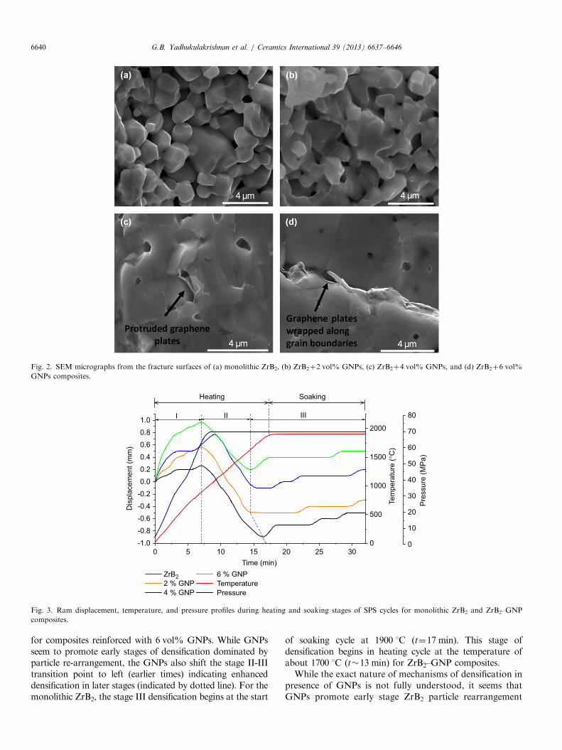
Fig. 2. SEM micrographs from the fracture surfaces of (a) monolithic ZrB2, (b) ZrB2þ2 vol% GNPs, (c) ZrB2þ4 vol% GNPs, and (d) ZrB2þ6 vol%
GNPs composites.
0-1.0
-0.8
-0.6
-0.4
-0.2
0.0
0.2
0.4
0.6
0.8
1.0
ZrB22 % GNP4 % GNP
6 % GNPTemperature Pressure
Dis
plac
emen
t (m
m)
0
500
1000
1500
2000
IIIIII
Tem
pera
ture
(°C
)
0
10
20
30
40
50
60
70
80P
ress
ure
(MP
a)
Time (min)5 10 15 20 25 30
Heating Soaking
Fig. 3. Ram displacement, temperature, and pressure profiles during heating and soaking stages of SPS cycles for monolithic ZrB2 and ZrB2–GNP
composites.
G.B. Yadhukulakrishnan et al. / Ceramics International 39 (2013) 6637–66466640
for composites reinforced with 6 vol% GNPs. While GNPsseem to promote early stages of densification dominated byparticle re-arrangement, the GNPs also shift the stage II-IIItransition point to left (earlier times) indicating enhanceddensification in later stages (indicated by dotted line). For themonolithic ZrB2, the stage III densification begins at the start
of soaking cycle at 1900 1C (t¼17 min). This stage ofdensification begins in heating cycle at the temperature ofabout 1700 1C (t�13 min) for ZrB2–GNP composites.While the exact nature of mechanisms of densification in
presence of GNPs is not fully understood, it seems thatGNPs promote early stage ZrB2 particle rearrangement

G.B. Yadhukulakrishnan et al. / Ceramics International 39 (2013) 6637–6646 6641
due to its self lubricating effects. In the later stages ofsintering of ZrB2–GNP composites, GNPs act more assintering aid. Carbon has long been used as a sintering aidfor the densification of ceramics, and it is often proposedthat carbon removes the native oxides on the surfaces ofthe non-oxide ceramics by some interfacial reactions andpromote the densification. Zhu et al. reported nearfulldensification of carbon-coated ZrB2 ceramic using pres-sureless sintering and proposed possible interfacial reac-tions based on thermodynamic analysis. For ZrB2 UHTC,the native oxides on the surfaces are ZrO2 and B2O3.During high temperature sintering, GNPs can react withthese native oxides according to carbothermal reductionreactions [38]:
ZrO2þB2O3þ5C-ZrB2þ5CO (3)
ZrO2þ3C-ZrCþ2CO (4)
The free energies of these reactions are plotted over arange of temperatures from 0 to 3000 1C in the standardstate (pressure �1 atm) in Fig. 4. From these thermo-dynamic calculations, it can be seen that the reactions (3)and (4) are feasible at temperatures above 1500 and1656 1C, respectively, in the standard state as long as theactivation barrier is surmounted by the available thermalenergy in the medium. With the reduced pressure duringSPS, these reactions are expected to be feasible even atlower temperatures. According to these reactions, thesurface oxides get converted back to ZrB2 or forminterfacial product (ZrC). The removal of oxide impuritiesin presence of graphene nanoplates possibly promotesdensification in ZrB2–GNP composites in later stages ofsintering as indicated by punch displacement profiles. Asthe fracture surfaces showed intact GNPs at the grainboundaries, the surface reactions leading to enhanceddensification seem to occur at ZrB2/GNP interface.
0-1500
-1000
-500
0
500
1000
1500
ZrO2 + B2O3 + 5C = ZrB2 + 5COZrO2 + 3C = ZrC + 2CO
1500
(°C
)16
56 (°
C)
ΔG (k
J)
500 1000 1500 2000 2500 3000Temperature (°C)
Fig. 4. Gibbs free energies of interfacial carbothermal reduction reactions
as a function of temperature.
3.2. X-ray diffraction and Raman spectroscopy analysis
X-ray diffraction (XRD) patterns from sintered mono-lithic ZrB2 and ZrB2–GNP composites are presented inFig. 5. While all the samples showed characteristic peaks ofZrB2 in the XRD patterns, the characteristic (002) peak ofgraphene at 2y¼26.61 was not observed in the patternsfrom composites. Furthermore, no additional peaks corre-sponding to possible interfacial reaction product ZrC wereobserved. This is not surprising as the XRD analysis oftendoes not show additional peaks when the reinforcementcontent is very low and the interfacial reactions are limitedto near-interface regions. Furthermore, some of the inter-facial products, possibly ZrC here, exhibit very highsolubility in the matrix ZrB2 phase and may not show upin XRD patterns.Raman spectroscopy was also used to characterize
ZrB2–GNP composites. Raman acquisitions reveal thestate of GNPs during the SPS of the composites. A typicalgraphitic carbon exhibit characteristic Raman peaks atD (1350 cm�1) and G (1580 cm�1) representing in-planestretching and breathing modes, respectively, while thepeaks at D0 (1620 cm�1) and G0 (2700 cm�1) are attributedto their respective higher order modes [39–41]. The modescorresponding to D and D0 peaks are forbidden in theperfect sp2 hybridized carbon due to symmetry. However,the presence of defects creates structural disorder thatallows the breathing mode [39–41]. Hence, the D and D0
peaks are observed only in graphitic carbon with disorderin its crystal structure. In the present study, we analyzedthe characteristic Raman peaks of GNPs at the fracturedsurfaces of the composites. Fig. 6(a) shows the Ramanspectra of ZrB2–GNP composites (2, 4 and 6 vol% GNPs)along with sintered GNPs and ZrB2. It is obvious from theRaman spectrum of ZrB2 that it has no detectable Raman-active vibrational modes in the frequency range of 1000–3000 cm�1. Hence, the Raman spectra acquired from thecomposites exhibit the characteristic peaks of GNPs. Further,it is apparent that the D and G peaks in ZrB2–GNP
20
ZrB2
ZrB2- 6% GNP
ZrB2- 4% GNP
ZrB2- 2% GNP
ZrB2
Inte
nsity
(a.u
.)
2θ (Degree)30 40 50 60 70 80 90
Fig. 5. XRD patterns from sintered ZrB2 and ZrB2–GNP composites.

1000
Inte
nsity
(a.u
.)
GGI
0.097
0.705
0.578
0.336
0.262
ZrB2
Sintered GNP
Pristine GNP
ZrB2-6% GNP
ZrB2-4% GNP
1352
1581
2700
13492700
1581
1352 26951584
13521585
2695
13591588
2698
1619
1623
1623
1623
ZrB2-2% GNP
ID/IG
D
1000
0.211
0.247ZrB2-6% GNP (ball milled)
Ball milled GNPInte
nsity
(a.u
.)
1359
1353
1352
1353
1588
1582
1582
1582
2711
2709
2707
2702
1619
1619
1619
1623
0.153
0.366
Pristine GNP
ZrB2-6% GNP(SPS sintered)
ID/IG DG
GI
1200 1400 1600 1800 2700 3000Raman Shift (cm-1)
Raman shift (cm-1)1200 1400 1600 1800 2700 3000
a
b
Fig. 6. Raman spectra of (a) ZrB2, ZrB2–GNP composites, pristine
GNPs, and sintered GNPs; and (b) pristine GNPs, ball milled GNPs,
ball milled ZrB2–6% GNPs powder, and sintered ZrB2–6% GNPs
composite.
G.B. Yadhukulakrishnan et al. / Ceramics International 39 (2013) 6637–66466642
composites have shifted to higher energy, while the G0 bandhas shifted to lower energy. The position of G and G0 peaksare influenced by the following factors: (i) density of defectsin the GNPs incurred during SPS processing [41], (ii) thethermal residual stress [42–44] that evolves during the coolingstep (i.e., thermal contraction of ZrB2 matrix surroundingGNPs), and (iii) reduction in number of graphene layers(nGLs) [45–46].
A routinely used measure of density of defects ingraphitic carbon materials is the ratio of intensities of D
to G peaks (ID/IG) [39,41]. ID/IG values for GNPs in ZrB2–GNP composites (2, 4 and 6 vol% GNPs), sintered GNPs,and pristine GNPs are displayed in Fig. 6(a) (in fact, thesevalues are close to average values of ID/IG). It is evidentfrom the values of ID/IG that the average density of defectshas increased by more than 2 times in ZrB2–GNP compo-sites reinforced with 2 and 4 vol% GNPs. The density ofdefects is comparatively higher in 2 vol% than 4 and6 vol% GNP reinforced composites and it scales inversely
with the concentration of GNPs. In general, high tem-perature (41600 1C) sintering of nanocrystalline graphiteincreases the average crystallite size [47]. This situation isdirectly observed in sintering of pure GNPs. The ID/IG
value of sintered GNPs is close to zero (Fig. 6a) which isreminiscent of crystalline graphite. This point is furthercorroborated by G peak position being at 1581 cm�1
(Fig. 6a), which is in close agreement with literature [41].Hence, it is inferred that ID/IG has increased for ZrB2
composites because of interfacial reactions between GNPsand ZrB2 matrix at high SPS processing temperature(1900 1C). ID/IG is higher at low concentrations of GNPspossibly due to two reasons: (i) less GNP aggregation andtherefore, more carbon surface interaction with ZrB2 perGNP; and (ii) higher multiplication of GNPs due toexfoliation at lower GNP concentration. The exfoliationof GNPs provides more GLs in contact with ZrB2 matrixin 2 and 4 vol% GNP reinforced composites and it willresult in a higher ID/IG [48]. This point is supported by thepositions of G and G0 peak.In addition, the G peak frequency in ZrB2–GNP (2, 4
and 6 vol%) for corresponding ID/IG values is expected todecrease simultaneously with increasing concentration ofGNPs [43]. According to Ferrari et al., when the ID/IG
value increases from 0 to 2 due to increasing concentrationof defects in nanocrystalline graphite, a high energy shift ofthe G peak from 1580 to 1600 cm�1 is observed concomi-tantly [41]. On the contrary, we observe the G peakfrequencies at 1584 and 1585 cm�1 for 2 and 4 vol%GNPs reinforced composites, respectively (Fig. 6a). Thisshift is lower than the expected G peak shift by 6 and5 cm�1, respectively (estimated from Ref. 43 using corre-sponding ID/IG values of 2 and 4 vol% GNPs). Thisdiscrepancy is attributed to reduction in nGLs in GNPsof 2 and 4 vol% reinforced composites that occurred dueto exfoliation [48,49]. On the other hand, the G peak of6 vol% GNP reinforced composite (at 1588 cm�1) hasshifted to higher energy than expected G peak (1583 cm�1)that is suggestive of the residual compressive stresses actingon GNPs incurred during thermal contraction of ZrB2
matrix [43–45]. The thermal stresses are more prominent in6 vol% than 2 vol% GNP reinforced composite due tohigher densification of the ceramic matrix. Concurrently,we observe a higher frequency shift in the D peak in6 vol% GNP reinforced composite due to residual com-pressive stresses.In order to investigate the process of exfoliation we
focused on the G0 band. It is evident from Fig. 6(a), thatthe G0 band of the composites has shifted to lower energy.This lower shift in G0 band implies that the nGLs hasdecreased [48,49]. Alternatively, the shift in the G0 peak isalso possible due to interfacial reactions incurred during thehigh temperature processing of composites. As discussedfrom the thermodynamic analysis, the possible interfacialreaction could be formation of ZrC or solid solution of ZrCin ZrB2. Another possibility is the doping of GNPs with Batoms. Both possible interfacial interactions are expected to

G.B. Yadhukulakrishnan et al. / Ceramics International 39 (2013) 6637–6646 6643
result in high energy shift in G0 band [50]. On the other hand,we observe a low energy shift in the G0 band that suggestsreduction in nGLs has the dominant influence on the G0 bandfrequency. To further investigate the origin behind exfolia-tion of graphene, we acquired Raman spectra in ball-milledGNPs with and without ZrB2 powder as shown in Fig. 6(b).The lower energy shift in the G0 band indicates a decrease innGLs during ball-milling. In addition, the trend in ID/IG aswell as G peak frequency suggests that the ball-milling hasinduced minimal damage. Additional shift in the G0 band ofsintered composite suggests further decrease in nGLs duringSPS processing of the ball-milled mixture of ZrB2 and GNPs.
3.3. Mechanical properties
The variation of indentation hardness with GNP rein-forcement content in the ZrB2–GNP composites is pre-sented in Fig. 7. Among all the compositions investigatedin this study, the monolithic ZrB2, with �85% relativedensity, exhibited highest average hardness of about16.6 GPa. Even though ZrB2–GNP composites exhibitedhigher relative density, no improvement in the hardnesswas observed with GNP reinforcement in the composites.In fact, the hardness of composites was relatively lowercompared to that of monolithic ZrB2. The average hard-ness of the composites (2–6 vol% GNPs) was in the rangeof 15.5–15.9 GPa without any specific trend with increas-ing GNP reinforcement content. The lower hardness of thecomposites could be due to competing effects of densifica-tion, GNP induced strengthening, grain growth, andinterfacial reactions on the hardening of ceramics. On theother hand, all the composites showed improved biaxialflexural strength compared to the monolithic ZrB2 (Fig. 8).The monolithic ZrB2 had the average flexural strength ofabout 162 MPa. The ZrB2–GNP composites reinforcedwith 2 and 4 vol% GNPs had the flexural strength ofabout 204 and 219 MPa, respectively. The compositesreinforced with 6 vol% GNPs exhibited highest flexuralstrength (316 MPa), which is about two times that of
10
12
14
16
18
0
Har
dnes
s (G
Pa)
Vol.% GNP2 4 6
Fig. 7. Hardness of ZrB2–GNP composites as a function of GNP
reinforcement content.
monolithic ZrB2. Clearly, the biaxial flexural strength,which better represents the strength-related property ofthe bulk samples than the surface microhardness, showsmuch better correlation with the GNP reinforcementcontent or the relative density of the ZrB2–GNP compo-sites. Fig. 9 shows the variation of indentation fracturetoughness of the ZrB2–GNP composites with GNP rein-forcement content. The fracture toughness of monolithicZrB2 samples (1.5 MPa m1/2) is also indicated in the figure.The fracture toughness values reported here for monolithicZrB2 samples are relatively lower than those reported fornearly fully dense ZrB2 samples (3–4 MPa m1/2). In gen-eral, the fracture toughness of the composites was higherthan that of monolithic ZrB2 and increased with increasingGNP content. Among all the composite compositionsinvestigated, the ZrB2–GNP composites reinforced with6 vol% GNPs exhibited highest average fracture toughnessof 2.8 MPa m1/2, an increase of about 83% over themonolithic ZrB2. While toughening effect of GNPs isclearly observed, the measurement of crack lengths usingSEM seems to have resulted in underestimation of fracturetoughness. Note that there are controversies surroundingthe use of indentation methods for characterizing fracturetoughness of ceramics reinforced with nano-scale fillers[51–53]. The indentation fracture toughness valuesobtained by indentation methods may not be representa-tive of the bulk samples due to complexity of stressconditions associated with indentation process. For bettercharacterization of the fracture toughness of the GNPreinforced ceramic samples, single edge V-notch bending(SEVNB) and rising R-curve methods will be used [53].SEM micrographs showing morphologies of cracks ema-nated from the indentation corners for ZrB2 and ZrB2–GNP composites are presented in Fig. 10. The crack frontwas relatively straight for monolithic ZrB2 samples with-out significant toughening mechanisms such as crackdeflection or bending (Fig. 10(a)). In these samples, thecracks propagate along the grain boundaries and meet
0
150
300
450
0
Flex
ural
Stre
ngth
(MP
a)
Vol.% GNP2 4 6
Fig. 8. Flexural strength of ZrB2–GNP composites as a function of GNP
reinforcement content.

G.B. Yadhukulakrishnan et al. / Ceramics International 39 (2013) 6637–66466644
open porosity of the samples. The SEM micrographfrom the fracture surface indicated clear intergranularfracture in these porous (relative density of about 85%)ZrB2 samples (Fig. 2(a)). For the ZrB2–GNP composites(2 vol% GNPs), the morphology of the indentationcracks is similar to that for ZrB2 samples except thatthe cracks encounter agglomerates of GNPs. The GNPagglomerates at the grain boundaries seem to deflect thecracks along the grain boundaries leading to intergranular
0
1
2
3
0
Frac
ture
Tou
ghne
ss (M
Pa.
m1/
2 )
Vol.% GNP2 4 6
Fig. 9. Fracture toughness of ZrB2–GNP composites as a function of
GNP reinforcement content.
Fig. 10. Morphologies of indentation cracks for (a) monolithic ZrB2, (b) ZrB
fracture (Figs. 10(b) and 2(b)). In ZrB2–GNP compositeswith higher amount of GNP reinforcement (4 and 6 vol%),the indentation cracks propagated both along the grainboundaries and through the grains with crack deflection atthe graphene agglomerates at the grain boundaries(Fig. 10(c,d)). The fracture surface also shows flatter surfacefeatures with predominantly transgranular fracture throughrelatively coarse grains (Fig. 2(c,d)). The figure clearly showsthe pulled out graphene plates at the grain boundary(Fig. 2(c)). The graphene plates wrapped along the grainboundaries over multiple grains can also be seen in thecomposite sample reinforced with 6 vol% GNPs (Fig. 2(d)).The difference in focus between lower left and upper rightregions of this micrograph (Fig. 2(d)) indicate crack deflec-tion at the graphene plates at the grain boundaries. Thegraphene plates also seem to bridge the indentation crackpropagating perpendicular to the plates as seen in Fig. 11.While the ZrB2–GNP composite samples exhibited relativelyhigher relative density and grain size than monolithic ZrB2
samples, the fracture surfaces clearly indicate tougheningmechanisms such as crack deflection and crack bridging withthe reinforcement of GNPs in the composites. The effect ofgrain size on toughening in ceramics is often very weak. Asthe ZrB2–GNP composites reinforced with 4 and 6 vol%GNPs exhibited fairly similar relative density (about 97%),higher indentation fracture toughness of composite rein-forced with 6 vol% GNPs is indicative of increased contribu-tion of GNPs in toughening the ceramic.
2–2% GNPs, (c) ZrB2–4% GNPs, and (d) ZrB2–6% GNPs composites.
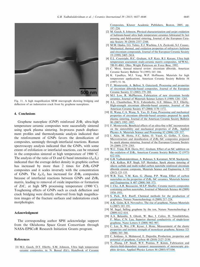
Fig. 11. A high magnification SEM micrograph showing bridging and
deflection of an indentation crack front by graphene nanoplates.
G.B. Yadhukulakrishnan et al. / Ceramics International 39 (2013) 6637–6646 6645
4. Conclusions
Graphene nanoplate (GNP) reinforced ZrB2 ultra-hightemperature ceramic composites were successfully sinteredusing spark plasma sintering. In-process punch displace-ment profiles and thermodynamic analysis indicated thatthe reinforcement of GNPs favors the densification ofcomposites, seemingly through interfacial reactions. Ramanspectroscopy analysis indicated that the GNPs, with someextent of exfoliation or interfacial reactions, can be retainedin the composites sintered at high temperature of 1900 1C.The analysis of the ratio of D and G band intensities (ID/IG)indicated that the average defect density in graphitic carbonhas increased by more than 2 times for ZrB2–GNPcomposites and it scales inversely with the concentrationof GNPs. The ID/IG has increased for ZrB2 compositesbecause of interfacial reactions between GNPs and ZrB2
matrix, leading to removal of oxide impurities or formationof ZrC, at high SPS processing temperature (1900 1C).Toughening effects of GNPs such as crack deflection andcrack bridging were directly observed from high magnifica-tion images of the fracture surfaces and indentations crackmorphologies.
Acknowledgment
The corresponding author SPH acknowledge supportfrom the Oklahoma Space Grant Consortium throughNASA-EPSCoR Research Initiation Grants program.
References
[1] M.J. Gasch, D.T. Ellerby, S.M. Johnson, Ultra high temperature
ceramic composites, in: N. Bansal (Ed.), Handbook of Ceramic
Composites, Kluwer Academic Publishers, Boston, 2005, pp.
197–224.
[2] M. Gasch, S. Johnson, Physical characterization and arcjet oxidation
of hafnium-based ultra high temperature ceramics fabricated by hot
pressing and field-assisted sintering, Journal of the European Cera-
mic Society 30 (2010) 2337–2344.
[3] M.M. Opeka, I.G. Talmy, E.J. Wuchina, J.A. Zaykoski, S.J. Causey,
Mechanical, thermal, and oxidation properties of refractory hafnium
and zirconium compounds, Journal of the European Ceramic Society
19 (1999) 2405–2414.
[4] E.L. Courtright, H.C. Graham, A.P. Katz, R.J. Kerans, Ultra high
temperature assessment study-ceramic matrix composites, AFWAL-
TR-91-4061, Ohio, Wright Patterson air Force Base, 1992.
[5] C. Mroz, Annual mineral review: zirconium diboride, American
Ceramic Society Bulletin 74 (1995) 165–166.
[6] K. Upadhya, M.J. Yang, W.P. Hoffmann, Materials for high
temperature applications, American Ceramic Society Bulletin 58
(1997) 51–56.
[7] F. Monteverde, A. Bellosi, S. Guicciardi, Processing and properties
of zirconium diboride-based composites, Journal of the European
Ceramic Society 22 (2002) 279–288.
[8] M.I. Low, R. McPherson, Fabrication of new zirconium boride
ceramics, Journal of Materials Science Letters 8 (1989) 1281–1283.
[9] A.L. Chamberlian, W.G. Fahrenholtz, G.E. Hilmas, D.T. Ellerby,
High-strength zirconium diboride-based ceramics, Journal of the
American Ceramic Society 87 (2004) 1170–1172.
[10] H. Wang, C.A. Wang, X. Yao, D. Fang, Processing and mechanical
properties of zirconium diboride-based ceramics prepared by spark
plasma sintering, Journal of the American Ceramic Society Bulletin
90 (2007) 1992–1997.
[11] F. Monteverde, Beneficial effects of an ultra-fine a-SiC incorporation
on the sinterability and mechanical properties of ZrB2, Applied
Physics A: Materials Science and Processing 82 (2006) 329–337.
[12] I. Akin, M. Hotta, F.C. Sahin, O. Yucel, G. Goller, T. Goto,
Microstructure and densification of ZrB2–SiC composites prepared
by spark plasma sintering, Journal of the European Ceramic Society
29 (2009) 2379–2385.
[13] W.C. Tripp, H.H. Davis, H.C. Graham, Effect of an SiC addition on
the oxidation of ZrB2, American Ceramic Society Bulletin 52 (1973)
612–616.
[14] G.B. Yadhukulakrishnan, A. Rahman, S. Karumuri, M.M. Stackpoole,
A.K. Kalkan, R.P. Singh, S.P. Harimkar, Spark plasma sintering of
silicon carbide and multi-walled carbon nanotube reinforced zirconium
diboride ceramic composite, Materials Science and Engineering A 552
(2012) 125–133.
[15] W.B. Tian, Y.M. Kan, G. Zhang, P.P. Wang, Effect of carbon
nanotubes on the properties of ZrB2–SiC ceramics, Materials Science
and Engineering A 487 (2008) 568–573.
[16] J. Cho, A.R. Boccaccini, M.S.P. Shaffer, Ceramic matrix composites
containing carbon nanotubes, Jouirnal of Materials Science 44 (2009)
1934–1951.
[17] S. Park, R.S. Ruoff, Chemical methods for the production of
graphenes, Nature Nanotechnology 4 (2009) 217–224.
[18] A.K. Geim, K.S. Novoselvo, The rise of graphene, Nature Materials
6 (2007) 183–191.
[19] M. Segal, Selling graphene by the ton, Nature Nanotechnology 4
(2009) 612–614.
[20] A.A. Balandin, S. Ghosh, W. Bao, I. Calizo, D. Teweldebrhan,
F. Miao, C.N. Lau, Superior thermal conductivity of single-layer
graphene, Nano Letters 8 (2008) 902–907.
[21] C. Lee, X. Wei, J.W. Kysar, J. Hone, Measurement of the elastic
properties and intrinsic strength of monolayer graphene, Science 321
(2008) 385–388.
[22] C. Soldano, A. Mahmood, E. Dujardin, Production, properties and
potential of graphene, Carbon 48 (2010) 2127–2150.
[23] Y. Zhang, J.P. Small, W.V. Pontius, P. Kimm, Fabrication and
electric-field-dependent transport measurements of mesoscopic gra-
phite devices, Applied Physics Letters 86 (2005) 073104.

G.B. Yadhukulakrishnan et al. / Ceramics International 39 (2013) 6637–66466646
[24] K.S. Novoselvo, A.K. Geim, J.D. Katsnelson, I.V. Grigorieva,
A.A. Firsov, Electric field effect in atomically thin carbon films,
Science 306 (2004) 666–669.
[25] K.S. Novoselov, E. McCann, S.V. Morozov, V.I. Fal0ko,
M.I. Katsnelson, U. Zeitler, Unconventional quantum Hall effect and
Berry’s phase of 2p in bilayer graphene, Nature Physics 2 (2006)
177–180.
[26] O. Tapaszto, L. Tapaszto, M. Marko, F. Kern, R. Gadow,
C. Balazsi, Dispersion patterns of graphene and carbon nanotubes
in ceramic matrix composites, Chemical Physics Letters 511 (2011)
340–343.
[27] S. Stankovich, D.A. Dikin, G.H.B. Dommet, K.M. Kohlhass,
E.J. Zimney, E.A. Stach, Graphene-based composite materials,
Nature 442 (2006) 282–286.
[28] U. Khan, P. May, A. O0Neill, N.J. Coleman, Development of stiff,
strong, yet tough composites by the addition of solvent exfoliated
graphene to polyurethane, Carbon 48 (2010) 4035–4041.
[29] T. Ramanathan, A.A. Abdala, S. Stankovich, D.A. Dikin,
M. Herrera-Alonso, R.D. Piner, Functionalized graphene sheets for
polymer nanocomposites, Nature Nanotechnology 3 (2008) 327–331.
[30] M.A. Rafiee, J. Rafiee, Z. Wang, H. Song, Z.Z. Yu, N. Koratkar,
Enhanced mechanical properties of nanocomposites at low graphene
content, ACS Nano 3 (2009) 3884–3890.
[31] L.S. Walker, V.R. Marotto, M.A. Rafiee, N. Koratkar, E.L. Corral,
Toughening in graphene ceramic composites, ACS Nano 5 (2011)
3182–3190.
[32] P. Kun, O. Tapaszto, F. Weber, C. Balazsi, Determination of
structural and mechanical properties of multilayer graphene added
silicon nitride-based composites, Ceramics International 38 (2012)
211–216.
[33] J. Wang, Z. Li, G. Fan, H. Pan, Z. Chen, G. Zhang, Reinforcement
with graphene nanosheets in aluminum matrix composites, Scripta
Materialia 66 (2012) 594–597.
[34] W. Zhang, I. Srivastava, Y.F. Zhu, C.R. Picu, N. Koratkar,
Heterogeneity in epoxy nanocomposites initiates crazing: significant
improvements in fatigue resistance and toughening, Small 5 (2009)
1403–1407.
[35] M.V. Antisari, A. Montone, N. Jovic, E. Piscopiello, C. Alvani,
L. Pilloni, Low energy pure shear milling: a method for the
preparation of graphite nano-sheets, Scripta Materialia 55 (2006)
1047–1050.
[36] K.A. Khalil, S.W. Kim, Effect of processing parameters on the
mechanical and microstructural behavior of ultra-fine Al2O3-
(ZrO2þ8% mol Y2O3) bioceramic, densified by high-frequency
induction heat sintering, International Journal of Applied Ceramic
Technology 3 (2006) 322–330.
[37] J.E.O. Ovri, A parametric study of the biaxial strength test for brittle
materials, Materials Chemistry and Physics 66 (2000) 1–5.
[38] S. Zhu, W.G. Fahrenholtz, G.E. Hilmas, S.C. Zhang, Pressureless
sintering of carbon-coated zirconium diboride powders, Materials
Science and Engineering A 459 (2007) 167–171.
[39] J. Ado, M.S. Dresselhaus, S. Ricchiro, G.F. Dresselhaus, Raman
Spectroscopy in Graphene Related Systems, Wiley-VCH Verlag,
Germany, 2011.
[40] M.S. Dresselhaus, A. Jorio, M. Hofmann, G. Dresselhaus, R. Saito,
Perspectives on carbon nanotubes and graphene raman spectroscopy,
Nano Letters 10 (2010) 751–758.
[41] A.C. Ferrari, J. Robertson, Interpretation of Raman spectra of
disordered and amorphous carbon, Physical Review B 61 (2000)
14095–14107.
[42] X. Wang, N.P. Padture, H. Tanaka, Contact-damage-resistant
ceramic/single-wall carbon nanotubes and ceramic/graphite compo-
sites, Nature Materials 3 (2004) 539–544.
[43] P.M. Ajayan, L.S. Schadler, C. Giannaris, A. Rubio, Single-walled
carbon nanotube–polymer composites: strength and weakness,
Advanced Materials 12 (2000) 750–753.
[44] G. Tsoukleri, J. Parthenios, K. Papagelis, R. Jalil, A.C. Ferrari,
A.K. Geim, Subjecting a graphene monolayer to tension and
compression, Small 5 (2009) 2397–2402.
[45] A. Gupta, G. Chen, P. Joshi, S. Tadigadapa, P.C. Eklund, Raman
scattering from high-frequency phonons in supported n-graphene
layer films, Nano Letters 6 (2006) 2667–2673.
[46] A.C. Ferrari, J.C. Meyer, V. Scardaci, C. Casiraghi, M. Lazzeri,
F. Mauri, Raman spectrum of graphene and graphene layers,
Physical Review Letters 97 (2006) 187401.
[47] K. Takai, M. Oga, H. Sato, T. Enoki, Y. Ohki, A. Taomoto,
Structure and electronic properties of a nongraphitic disordered
carbon system and its heat-treatment effects, Physical Review B 67
(2003) 214202.
[48] J. Ado, M.L. Marcia, S. Fernando, H.M.F. Erlon, V.O.M. Marcus,
B.C. Rodrigo, A.A. Carlos, Raman study of ion-induced defects in
N-layer graphene, Journal of Physics: Condensed Matter 22 (2010)
334204.
[49] E.H. Martins Ferreira, M.V.O. Moutinho, F. Staval, M.M. Lucchese,
R.B. Capaz, C.A. Achete, A. Jorio, Evolution of the Raman spectra
from single-, few-, and many-layer graphene with increasing disorder,
Physical Review B 82 (2010) 125429.
[50] A. Das, S. Pisana, B. Chakraborty, S. Piscanec, S.K. Saha,
U.V. Waghmare, Monitoring dopants by Raman scattering in an
electrochemically top-gated graphene transistor, Nature0 Nanotech-
nology 3 (2008) 210–215.
[51] D.T. Jiang, K. Thomson, J.D. Kuntz, J.W. Ager, A.K. Mukherjee,
Effect of sintering temperature on a single-wall carbon nanotube-
toughened alumina-based nanocomposite, Scripta Materialia 56
(2007) 959–962.
[52] N.P. Padture, W.A. Curtin, Comment on Effect of sintering
temperature on single-wall carbon nanotube toughened alumina-
based composite, Scripta Materialia 58 (2008) 989–990.
[53] D. Jiang, A.K. Mukherjee, Response to comment on Effect of
sintering temperature on single-wall carbon nanotube toughened
alumina-based nanocomposite, Scripta Materialia 58 (2008) 991–993.