
Self-Propagating High-Temperature Synthesis (SHS) and Spark Plasma Sintering (SPS) of Zr-, Hf-, and...
191
AD- A276 324 IEAThERII L T--
Transcript of Self-Propagating High-Temperature Synthesis (SHS) and Spark Plasma Sintering (SPS) of Zr-, Hf-, and...

AD- A276 324
IEAThERII L T--

BestAvailable
Copy

T
MATERIALS AND MANUFACTURING PROCESSES
January 1994
Aims and Scope. Materials and Manufacturing Processes is a journal in the English languageproviding an international forum for current developments and future direction in the area ofmaterials and manufacturing processes. Manuscripts may fall into several categories includingfull articles, solicited reviews, or commentary, unsolicited reviews or commentary, and patentand book reviews.
Identirication Statement. Materials and Manufacturing Processes (ISSN: 1042-6914) ispublished six times a year in the months of January, March, May, July, September, andNovember for the institutional rate of $545.00 and the individual rate of $35.00 by MarcelDekker, Inc., P.O. Box 5005, Monticello, NY 12701-5185.
Individual Foreign PostageProfessionals
Institutional and Student Airmail AirmailVolume Issues Rate Rate Surface To Europe To Asia
9 6 $545.00 $35.00 $22.50 $33.00 $39.00
Your order must be prepaid by personal check or may be charged to MasterCard, VISA, orAmerican Express. Please mail payment with your order to: Marcel Dekker Journals, P.O.Box 5017, Monticello, New York 12701-5176.
CODEN: MMAPET 9(1) i-ii, 1-178 (1994)ISSN: 1042-6914
Printed in the U.S.A.
IAccso For,,
NTIS C'RA&! 0]
11AB 11U ,-ounced []
j . ........ - ----- -- ---
...... ;ty, Codes
:c r

MATERIALSAND
MANUFACTURING PROCESSES
Editors
T.S. SUDARSHAN T.S. SRIVATSANMaterials Modification, Inc. Department of Mechanical
2929-PI Eskridge Center EngineeringFairfax, Virginia 22031 The University of Akron ~ Iphone # (703) 560-1371 Akron, Ohio 44325 I
fax # (703) 560-1372 phone # (216) 972-6196 F L1-( '
fax # (216) 972-6027 0 i3
Review Board
0. AUCIELLO, MCNC, P.O. Box 12889, Research Triangle Park, NC 27709-2889D.G. RHAT, Valenite, 1711 Thunderbird Drive, Troy, MI 48084R.L. BROWN, The Gillette Company, Gillette Park, Boston, MA 02106S.T. BULJAN, Norton Company, I New Bond Street, Worcester, MA 01615R. DOWDING, U.S. Army Materials Technology Laboratories, Watertown, MA 02172K. ISHIZAKI, Nagaoka University of Technology, Nagaoka, Niigata 940-21, JapanM. JEANDIN, Ecole Nationale Superieure des Mines de Paris, B.P. 87, 91003,
Evry, Cedex, FranceH. KATZMAN, The Aerospace Corporation, MS M2-248, P.O. Box 92957,
Los Angeles, CA 90009R.J. LEDERICH, McDonnell Douglas Aerospace, P.O. Box 516, St. Louis, MO
63166-0516K.L. LIN, Materials Engineering, National Cheng Kung University, Tainan,
Taiwan 70101, ROCJ.J. MOORE, Metallurigical Engineering, Colorado School of Mines, Golden, CO 80401S. NOURBAKHSH, Polytechnic Institute, 333 Jay Street, Brooklyn, NY 11201S. RAGHAVAN, Materials Science, University of Arizona, Tucson, AZ 85721W.O. SOBOYEJO, Materials Engineering, Ohio State University, Columbus, OH 43210G. SMOLIK, P.O. Box 1625, Idaho National Engineering Laboratory, Idaho Falls,
ID 83415J.B. TERRELL, Reynolds Metals Company, P.O. Box 27003, Richmond, VA 23261W. WALLACE, National Aeronautical Establishment, Ottawa, KIAOR6, CanadaJ.D. WHITTENBERGER, NASA Lewis Research Center, MS 49-1, Cleveland, OH 44135
D¶TCm mmA r .

MATERIALS AND MANUFACTURING PROCESSES
Indexing and Abstracting Services. Articles published in Materials and Manufacturing Processesare selectively indexed or abstracted in:
U Abstracts Journal of the Institute of Scientific Information of the USSR Academy of theSciences U Academy of Sciences of the USSR 6 Advanced Ceramics Bulletin I AdvancedComposites Bulletin U Applied Mechanics Reviews U ASM International-MaterialsInformation a Cambridge Scientific Abstracts I Ceramics Bulletin 0 Chemical Abstracts wCorrosion Abstracts 0 Engineering Index U INSPEC 1 ISI-Materials Science Citation Index8 Japan Abstracts I Japan Institute of Metals U Rapra Abstracts I UNIDO-Tech Monitor
Manuscript Preparation and Submission. See end of issue.
Copyright 01994 by Marcel Dekker, Inc. All rights reserved. Neither this work nor any partmay be reproduced or transmitted in any form or by any means, electronic or mechanical,microfilming and recording, or by any information storage and retrieval systems withoutpermission in writing from the publisher.
The Journals of Marcel Dekker, Inc. are available in microform from: RESEARCHPUBLICATIONS, 12 Lunar Drive, Drawer AB, Woodbridge, Connecticut, 06525, (203) 397-2600 or Toll Free 1-800-REACH-RP (732-2477). Outside North and South America: P.O.Box 45, Reading, RGI 8HF, England, 0734-583247.
Authorization to photocopy items for internal or personal use, or the internal or personal useof specific clients, is granted by Marcel Dekker, Inc., for users registered with the CopyrightClearance Center (CCC) Transactional Reporting Service, provided that the base fee is paiddirectly to CCC, 222 Rosewood Drive, Danvers, MA 01923. For those organizations thathave been granted to photocopy license by CCC, a separate system of payment has beenarranged.
Contributions to this journal are published free of charge.
This journal is printed on acid-free paper.

Materials and Manufacturing Processes VooL 9, No. 1, 1-36, 1994
Diamond Materials for Electromagnetic Railguns
Narendra B. Dahotre, Mary Helen McCay, andT. Dwayne McCay
Center for Laser ApplicationsThe University of Tennessee Space Institute
Tullahoma, Tennessee 37388
Abstract
The use of diamond film insulator in electromagnetic railguns is currently beingseriously considered since the state of the art in synthetic diamond exceeds therequirements of electromagnetic railguns. The reasons for not using diamond,however, include the major difficulty in producing diamond insulators in therequired shape and size that can survive the harsh railgun environment. Thispaper reviews railgun operation dynamics and potential materials includingdiamond for high performance of railguns. It further reviews the present statusof scientific, technological and commercial developments of diamond coatings.Alternate coatings and the properties that make them amenable for railgunapplications arc also discussed.
1.0 Introduction projectile-bore interactions. To date
however, considerable research efforts in
Electromagnetic railguns have been the this direction have so far failed to achievesubject of active research and development the high velocities predicted in thefor the past decade and a half (1-8). beginning. In fact, only a few experimentsDuring this period substantial enthusiasm (2,3) have been successful in reaching theexisted for the development of plasma apparent barrier of 6 to 7 km/sec. As aarmature accelerators operating at result, a consensus is building among thevelocities of 20 to 50 km/sec. The basis research community that the plasmafor this optimism was a common notion armature itself has strong interactions withthat plasma armatures could couple the railgun structure and these interactionsmagnetic force to projectiles at almost any are the dominant factor limiting thevelocity up to the speed of light and that performance of plasma armature railguns.the principal velocity limitation was
Copyright © 1994 by Marcel Dekker, Inc.
I

Dahotre, McCay, and McCay
The kinetic processes which act upon the of material from the walls. (Metal railsplasma armature in a conventional electro- may not be vaporized if the rate ofmagnetic railgun (in sequential order conduction cooling into the rail exceedsfollowing the armature as shown in Figure the rate of heat input from the gas.) The1) are: main plasma, plasma tail, neutral gas velocity in the heated region willregion and restrike plasma. These events continue to decrease due to viscous dragoccur in a quasi-equilibrium state of the against the wall and due to the admixturearmature which is generally achieved after of material vaporized from the insulator.having moved a typical distance of 20 to40 diameters. The main plasma is highly This region is called the neutral regionionized at temperatures from 20,000 to because the gas is neutral in the sense that30,000 K and dissipates power at a level the high gas density and weak ionizationof several MW/cm 2. Most of the primary result in a very low electrical conductivity.plasma is strongly magnetized and the No current flow is observed byboundary layers are thin due to magneto- conventional diagnostics. However, if ahydrodynamic effects. This results in a sufficiently high electric field is applied tohigh drag coefficient (Cf = 0.003 - 0.005). this gas, the resultant small current flowThe intense heat and radiation flux at the will lead to run-away ionization andwalls ablate material which in turn is reestablishment of a hot, low density,ionized and added to the armature plasma. highly ionized plasma, called the restrikeThe electromagnetic force accelerates the arc. The electric field required to causeablated material almost to the velocity of such a breakdown depends primarily uponthe main plasma. Viscous boundary forces neutral gas density and level of residualslowly drag most of this ablated material ionization and also secondary factors suchbackward into the plasma tail region. The as gas temperature, gas composition andablated material continues to radiate and electrode surface conditions. As theconduct energy to the walls. In the tail plasma armature velocity increases, theregion the power flux is lower and less of electric field increases until the breakdownthe wall material is ionized. The neutral field is reached. Since the gas velocity isgas from the walls begins to mix into the lowest near the breech and rail damage isplasma, quenching the conductivity. A often greatest near the breech, it is quitecool boundary layer develops which grows common for breakdown to occur in theinto the plasma until finally the breech region.conductivity becomes too low for currentto flow. This makes the end of the plasma When these events occur, the parametertail. which has a strong experimental
correlation with railgun velocity isThe gas entering the neutral region is still breakdown field for restrike (s.), which isvery hot. Although it is moving at a predicted by equation (1), where I is the
Svelocity substantially below that of the armature current, VA is the armatureplasma, it is in turbulent flow and both voltage, cta is the rail mass additionheat and momentum are rapidly coupled to coefficient for ablation. a, is the insulatorthe wall. This causes further vaporization mass addition coefficient for vaporization,
2

Diamond Materials for Electromagnetic Railguns
0,
a:a
COC
Cu 0E-
CL
C ca
C1
0~0
@
E 0CL
0~
0,0
CLC.D d)C
*zT ~ .
CN
ill I0
< C-
3

Dahotre, McCay, and McCay
+ 0.7 (eIN VA (aR+) _ VA ()A 7 RV VL LI
Equation (2) shows the expression for R is reducing the armature power dissipationthe bore radius, V, is the plasma velocity, by lowering the armature voltage or theL is the inductance gradient, Vg is the gas armature current, and f) using improvedvelocity, Va is the armature velocity, A is rail and armature materials.the average atomic weight of the gas (9).
1.1 Materials for High Performance
breakdown field (9). F_ is an electric field, RailgunsN is the particle density, 5N is the neutralgas density and the term (s/N) is the All of the above techniques have beenthreshold value for electrical breakdown. attempted for increasing railgun
performance and have achieved only
81N) (2) limited success, largely due to limitationsAe (2) in the design. In view of these limitations,
new techniques for the synthesis ofadvanced materials have opened the
This equation predicts an armature possibility of tailoring suitable materialsvelocity for restrike which is a weak for specific rail and insulator applicationsfunction of current but scales linearly with in electromagnetic railgun barrels. Thethe armature voltage Va proper selection of such maiLerials for the
successful performance of boreBased on the earlier explanation, it is components will depend on severalevident that the arc restrike is the principle practical as well as technological factors.armature velocity limiting process. Both In particular, the materials must surviveexperiment and theory (2-4, 10,11) predict multiple shots under rapid-fire burststhat velocities in excess of 6 to 8 kmpsec without suffering significant deteriorationwill not be achieved unless restrike is in performance.controlled. Such techniques for restrikecontrol include a) increasing the In order to meet these requirements, thebreakdown voltage of the gas in the bore, materials used to form the bore mustb) introducing external circuit changes by operate without significant degradation inadapting a multi-stage, segmented railgun, a dynamic environment which combinesc) lowering the electric field acting in the extreme thermal, mechanical and electricalrestrike region by increasing the velocity loading conditions. This behavior can be
Srof the neutral gas using a high velocity understood from the restrike velocityinjector, d) eliminating vaporized material relationship given by equation 1. Iffrom the bore by applying the magnetic restrike limits velocity, then the bestforce against the viscous drag force, e) results will be obtained when (ox, + QtR)/A
4

Diamond Materials for Electromagnetic Railguns
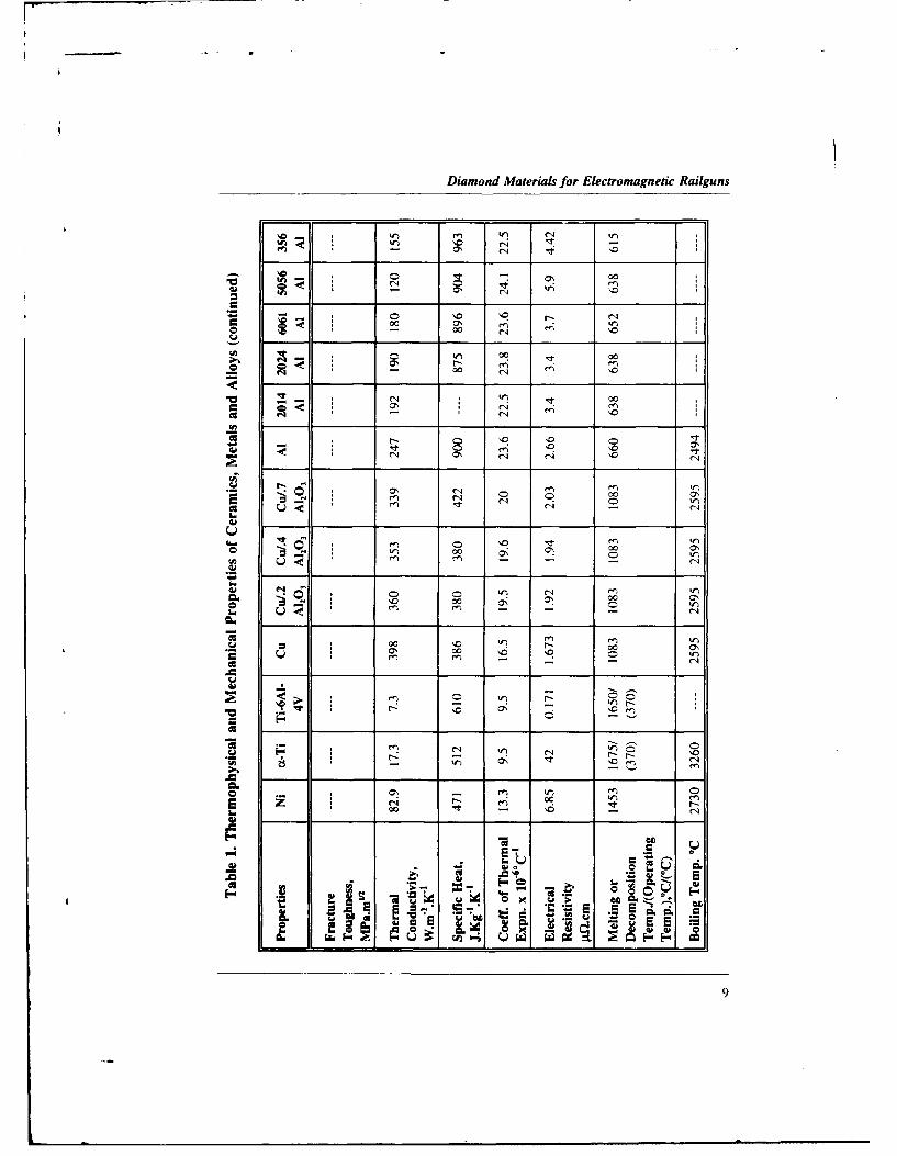
is large and the bore has a high particle properties to quantify the ability ofdensity to insulate against breakdown, insulator materials to resist brief, intenseThis quantity is maximized by using heat pulses in railgun environments.materials with low atomic weight (small Such quantification of the performanceA) and low heat of vaporization (large tx,). of insulator materials was done byMaterials which potentially might satisfy calculating figure-of-merit for arcthese requirements are organic insulators, melting/erosion resistance (AMR), tran-organic composites, conventional sient thermal shock resistance (TSR) andceramics, advanced ceramics and rein- relative fracture resistance (FR) whichforced ceramic composites. A partial list are expressed approximately as shown inof candidate materials for the rail, equations (3), (4) and (5). p is theinsulator and armature applications, density, C, is the specific heat attogether with their thermophysical constant volume, K is the thermalprconstantsvolumeiKtis theTthermalproperties, are listed in Table 1. conductivity, T, is the wall melting or
A review of the open technical literature dissociation temperature, T, is the initial
uncovers very little about the evaluation of wall surface temperature, MOR is the
alternate materials for railgun insulators, modulus of rupture or flexural bending
The study by Bedford (12) was not strength, v is the Poisson's ratio, E is the
comprehensive and did not provide Young's modulus, (x is the thermal
specific recommendations on the possible expansion coefficient, a, is the fractureusefulness of materials for railgun strength and H is the hardness.applications. Recent unpublished (13)studies confirmed the effectiveness ofdiamond film insulators in an ablation free AMR 0.5 (7 p CK )112 (T7' - T, )(3)environment to achieve 4 km/s velocitywith 1.4 g Lexan projectiles. In anotherunpublished study (14) host of materials MOR (1 - v) (p CK )i/2including pure metals, alloys, coated TSR E-
surfaces, insulators and graphite have been E asubjected to an incident flux of 33 GW/m 2
over 100 ps to develop a heat flux FR = of (H/E)-"6 (5)erosion data base. In contrast, a studyconducted by Rosenwasser andStevenson (15) adopted a systematic Based on these equations, the results ofapproach to first identify railgun bore their evaluations along with adesign environments followed by comparison of hardness for someselection and evaluation of various candidate materials are shown in Tableadvanced insulator materials with the 2. The authors did not include diamondpotential to meet these requirements. in this study, as synthetic diamondThey established a figure-of-merit based technology was in its infancy at the timeon thermophysical and mechanical of the study.
5

Dahotre, McCay, and McCay
0 00
C4 000 -
u 0 n
CA C
M~
c 0n,0. 0
e.J10 r i 4__ 0
2e
~ S S
C4 -
00 C- r r, cl
u 0 00 Cl 00 " s
_ _ Cl C_
U- 9 5)Wm 00c "I '
0' - 0' m J5 Ltd,
6~C ~ 0~ ,~

Diamond Materials for Electromagnetic Railguns
00
- I 00
00a, r- .4 ~
CC)
00 r-0
W 0 0
CV)
0 1ý d L
A T
~ Or7

Daholre, McCay, and McCay
000 '
00 r,- N 0 r
If~fn
C UC0
-~ ol 000 ~ 4
m 00 0'r 0
C * N
N0 0 0 0
U * 0
cco
U)W)0 0
u 00 *
* 70
00
0 E
u NA 0E uw LT0.
8~
Diamond Materials for Electromagnetic Railguns
C)0 e '0
00 '00 0% r
W kr 00
-~rl '0 '00000
2 c 00
cq -- ci
O 0 ~00 ON
0e0 00 ON
00 00 0~
00
00 00
'0 -) ci
r~i O W) e
K. U
402
9

Dahog'e, McCay, and McCay
Table 2. Calculated Insulator Figure-of-Merit
Material AMR* TSR** FR*** HardnessMW/mr2 x 102 MW/m2 MPal 33.m066 Kg.mm"2
Lexan 0.227 0.202 < 15
A1203 12.113 0.953 3.39 2100
Mullite 4.094 0.468 2.86 620
SiC 27.629 3.03 7.66 2500
Si3 N4 12.873 5.03 8.55 2000
PSZ 5.231 5.92 21.50 1300
AIN 13.967 1.91 6.35 1400
AI2OI/SiCw 12.701 1.47 16.00 2100
* Arc Melting/Erosion Resistance** Transient Thermal Shock Resistance
*** Relative Fracture Resistance Kc,"
Parker (9) later extended the concept of have reasonable values of figure-of-meritfigure-of-merit to evaluate the suitability for railgun operation. However, Lexanof various materials for use with plasma polycarbonate, although a high strengtharmatures. This figure-of-merit insulator, suffered considerable ablationestablishes an upper limit on the quantity and severe thermal cracks. ConventionalFt" for ablation free operation with a ceramics (A1201 , Mullite, SiC) on thegiven material (F is the heat flux and t is other hand, underwent surface meltingthe exposure time). This quantity in turn followed by surface fracture from thedefines a new figure-of-merit for a pressure stresses. The weight losses innumber of insulator and rail materials. the advanced ceramics (e.g. Si3N4, PSZTable 3 presents the calculated (partially stabilized zirconia), AIN) werefigure-of-merit for a number of insulator insignificant, but they showed a phaseand rail materials. Both of these studies instability at high temperature with theindicated that the materials investigated formation of a new surface layer infested
10

Diamond Materials for Electromagnetic Railguns
Table 3. Figure-of-Merit for Candidate Railgun Materials
Material ( Figure-of-Merit, MWS1M2
SiO, (vitreous) 2.4
Sialon 8.5
Si3N4 15.5
Ail0 3 20.6
SiC 35.8
BN (pyrolitic) 42.0
C (diamond) 210.0
Cu 35.0
Mo 46.0
W 58.0
C (graphite) 73.0
with microcracks. In view of these techniques for creating crystallineexperimental observations and theoretical diamond films and coatings has openedconsiderations, diamond film presently a new era in diamond technology. Theseappears to be the best candidate insulator developments offer the potential forfor railgun applications. Accordingly, the exploiting the unique properties offollowing discussion describes the status diamond in applications such as coatingsof diamond film technology and its for bearings and cutting tools, freepossible application for both insulator standing windows, lens coatings forand rail coatings. visible and infrared (IR) transmission,
and thin films for high temperature, high1.2 Properties of Diamond power semiconductor devices.
The unique properties of diamond are Carbon occurs widely in its elementalbeing utilized for a large number of form as crystalline and amorphousadvanced materials applications. The solids. Diamond, graphite, lonsdaleitedevelopment of new low pressure (sometimes called hexagonal diamond
Ii

Dahotre, McCay, and McCay
Table 4. Crystal Structure Data for Diamond
Symmetry CubicSpace group Fd3mAtoms per unit cell 8Lattice parameter (298 K), A 3.56683Theoretical density (298 K), g/cm3 3.51525Carbon-carbon bond distance, A 1.54450Positions of atoms (000), (1/21/20), (0'/2'/2), ('/201/2),
(1/41/41•4), (34341/4), (1/4343•4), (3/41/43/4)
because its structure and properties are used for various advanced applicationssimilar to those of diamond) and some of which are listed in Table 5 (17).carbynes (cross-linked linear carbonpolytypes) are the crystalline allotropes Diamonds are resistant to all acids, evenof carbon. Each of these phases of at high temperatures. They can, however,carbon is formed from carbon hybridized be etched by fluxes of caustic alkalis,in an sp3, sp 2 and/or sp state. The various oxysalts and metals. Etch figuresdiamond crystalline structure is the were formed with NaCIO4 and KOCI4,modified face centered cubic with both very strong oxidants, on I 1 I 1 )interatomic distances of 0.154 nm. Each faces at 380'C. 02, CO, CO 2, H2, H20carbon atom is covalently bonded to its and Cl2 at high temperature have alsofour carbon neighbors using been used to etch diamonds. In oxygen,(tetrahedrally directed) sp 3 atomic appreciable oxidation begins at aboutorbitals. The crystallographic data for 600'C with burning occurring in andiamond is shown in Table 4 (16). The oxygen jet at 7200C and in air at 850'C.1001 } planes of graphite form parallel to If diamond is heated in a clean, inertthe 111 ) planes of diamond (15). environment, the onset of graphitization
begins at about 1500°C. The rateThe tetrahedral, sp 3, carbon-carbon increases rapidly until about 2100°Cbonds in diamond account for such where a 0.1 carat octahedral is totallyproperties as extreme hardness, chemical converted to graphite in less than 3inertness, high electrical resistivity, high minutes (16) with (001 } planes ofdielectric strength, high thermal graphite parallel to the 111 planes ofconductivity, high density and optical diamond (18).transparency to visible and IR radiation.Based on these properties, diamond is
12

Diamond Materials for Electromagnetic Radguns
Table 5. Properties and Applications of Diamond Coatings
Properties Applications
Hardest known material Coatings for cutting toolsLow coefficient of friction Abrasive coatingsHigh thermal conductivity(highest known at room temperature) Coatings for bearingsLow thermal expansionHeat resistive Heat sinks for electronic devicesAcid resistiveRadiation resistive High-power microwave devices(to X-ray, ultraviolet, y-ray) Radio-frequency electronic devicesElectrical insulator High-speed electronic devicesHigh band gap semiconductor(either p or n-doped) Sensors for severe environmentsLow dielectric constantHigh hole mobility Window and lens materialsVisible and infrared transparentLarge refractive index Electro-optic devices
Table 6 lists a number of the thermal natural type Ila diamond contains veryproperties of diamond including little nitrogen impurity, whereas type Iathermodynamic properties of diamond contains up to about 0.1 at.% nitrogen.and the graphite to diamond transition This is reflected in the thermal(16). The maximum thermal conductivity conductivity of type Ila being aboutoccurs at about 80 K. At room three times that of type Ia (18).temperature, the conductivity of diamondis about four times greater than that of Near room temperature, diamond is thebeta-silicon carbide, fifteen times greater hardest known material and has a lowthan that of silicon, and five times coefficient of friction. Diamond isgreater than that of copper. Small perfect for many abrasives andamounts of boron impurity, as used for wear-resistant applications, except for itssemiconductor doping, have little effect chemical interactions at high temperatureon the thermal conductivity of diamond. with ferrous alloys (16). CleavageNitrogen impurities, however, markedly fracture occurs primarily along theaffect its conductivity (19). (The (1111 planes although the energytendency of nitrogen to cluster in differences for several planes are quitediamond may cause this effect). The small (16). At room temperature
13

Dahotre, McCay, and McCay
Table 6. Thermal Properties of Diamond
Properties Values
Thermal conductivity, W/cm.K at 293 KType Ia 6-10Type Ila 20-21
Thermal diffusivity, cm 2/s for Type Ilaat 77 K 4800at 298 K 10
Coefficient of thermal expansion, 106/Kat 193 K 0.4at 293 K 0.8at 400-1200 K 1.5-4.8
Debye temperature 0, K at T > 600 K 1880Heat of sublimation, ki/mol 669Thermal shock resistance parameter, W/m 3.8 x 10⁸Specific heat, J/mol.K
at 293 K 4.2 x 10⁴Tat 1800 K 24.7at 3000 K 26.3
Oxidation rate, g/cm2 .son (111) plane 2.38on (100) plane 0.167
Activation energy of oxidation, Kj/mol.K at 823-1023 K 172-184
Transition reaction: Graphite - DiamondAH298, J/mol 1872 _ 75AS2& , J/mol.K -3.22Equilibrium pressure at 2000 K, Pa 64 x 108Volume change at 2000 K transition, cm 3/mol 1.4
diamond behaves as an elastic brittle vacuum. If the surfaces are cleanedsolid. However, above 1800'C under vacuum by heating ordislocations become relatively mobile, bombardment, the high value of unity isand it is possible to produce appreciable approached. The actual friction dependsplastic deformation. The coefficient of on the crystallographic surface of thefriction (p) of diamond on diamond is diamond. The {111} surface shows anabout 0.1 in air and about 1.0 under isotropic pi of 0.005 in air, whereas the
14

Diamond Materials for Electromagnetic Railguns
Table 7. Mechanical Properties of Diamond
Properties Values
Density, g/cm 3 3.52
Elastic constants, GPa C1, = 950-1079C12 = 120-330C, = 430-578
Young's modulus, GPa 700-1200
Bulk modulus, GPa 440-590
Poisson's ratio 0.10-0.29
Tensile strength, GPa 16.4-32.4
Flexure strength, MPa 1050
Compressive strength, GPa 8.68-16.53
Fracture toughness, MPa.m"2 3.4
Cleavage energy, J/m 2 10-20
Hardness, GPaon (001) face 56-102on (110) and (11) faces 58-88
Sliding Coefficient of frictionin air 0.05-0.10in vacuum 0.9
Sound velocity, m/s(100) face 17500(110) face 18200
1100) cube face gives values of 0.05 Table 8 lists electronic and opticalalong the <011> direction and 0.1 to properties of diamond (20, 21). For0.15 along the <010> direction (20). The virtually every electronic property,mechanical properties of diamond are diamond is unmatched. It possesses thesummarized in Table 7 (21). highest electrical resistivity of all
15

Dahotre, McCay, and McCay
Table 8. Electrical and Optical Properties of Diamond
Properties Values
Electrical resistivity (at 298 K), Q.cmType la 101_1016
Type lb 10131016
Type Ila 101_3016
Type lib 10-10I
Dielectric constant (at 298 K, I Mhz) 5.5-5.7
Breakdown strength, V/cm >107
Activation energy, eVType lib (90-290 K) 0.29-0.37B-doped (270-710 K) 0.0029-0.087Al-doped (270-710 K) 0.32Be-doped (270-710 K) 0.20-0.35
Band gap energy (at 298 K), Ev 5.2-5.6
Effective massHoles (m/mo) Type lib <1.0Electrons (m/mo) Type lib 0.2
Carrier mobility, cm 2/V.sHole 1200-1600Electrons 1800-2200
Dissipation factor 0.0002Carrier lifetime, s
Saturated electron velocity, cm/s 2.7 x 10'Absorption edge, pm 0.2Refractive index 2.42
materials; the resistivity decreases with polycrystalline diamond, additions ofincreasing temperature. The electrical transition metal solvents may renderproperties of diamond are primarily them as electrically conductive as somedependent upon impurity type and alkali, Group IlIa, and even some of theconcentration. In the case of transition metals (22). As semi-
16

Diamond Materials for Electromagnetic Railguns
conductors, diamonds exhibit the highest during typical railgun operation promotesaturated electron velocity, the lowest surface wear and erosion for most of thedielectric constant, the highest dielectric known insulating and rail materials. Thestrength and the largest band gap of any life time of these components are signifi-semi-conducting material (23). cantly reduced by the ablation, melting
and erosion of both the bore insulatorThe most prevalent acceptor impurity in and conducting rails. This material lossboth natural and synthetic Type Ilb is primarily the result of thermal energydiamonds is boron. Both boron transfer during arcing between theconcentration and the temperature range armature and the rail and, to a lesserselected determine the activation energy. extent, the mechanical interaction of theGenerally, crystals with lower concentra- projectile with the bore.tions of uncompensated boron havehigher activation energies, while those Ideally, the entire current pulse in awith higher concentration tend to have railgun would be carried from rail to raillower activation energies due to the by a solid armature with no arcing oronset of impurity band conduction (24). transition to a hybrid armature. If such
performance is possible to a velocity ofExhibiting high transparency throughout 3 km/s, then the rail environment is lessthe visible, near infrared, and thermal extreme, and the rail heating will ariseinfrared, pure diamond has the widest from frictional heating and ohmicspectral transmission range of all known dissipation. If arcing does occur, thensolids (0.225 to 25 pm) (25-27). the thermal loading will increaseTheoretically, ideal diamond crystals significantly. Transition from solid toshould be absolutely transparent to arcing contact is a complex phenomenonvisible light, but impurities and other influenced by a concentration of currentdefects in the crystal structure affect near the rear of the armature whichabsorption in the visible region. The results from the velocity skin effect anddispersion of diamond is high (0.062) frictional heating of the microstructureand as a result, its refractive index, n, is of the sliding interface. Diamondhighly wavelength dependent (18). coatings have the potential to reduceFurthermore, the refractive index both these effects. Diamond has a verydecreases when subjected to hydrostatic low coefficient of friction under certainpressure and increases upon heating (16, conditions and can be doped to conduct18). current. However, it is not known how
the railgun environment will affect the1.3 Rail Environments and Projected surface of the diamond. Electrodynamic
Diamond Performance simulations have shown that a thin layerof material with a low electrical
The extreme thermal, mechanical and conductivity placed on the inner surfaceelectrical dynamic loading conditions of a highly conducting rail can signifi-
17

Dahotre, McCay, and McCay
Table 9. Calculated Resistance Values for Diamond
Material Arc Thermal Shock FractureMelting/Erosion Resistance (TSR), Resistance (FR),
Resistance (AMR), Mws"2 .m2 MPa'13.m°.6Mws`J.m2
Diamond 210 49.6 5.09
cantly reduce the current concentration high temperatures. Also depicted in thecaused by the velocity skin effect. figure are the regions where diamonds
have been synthesized b) man. In theIn view of these observations, resistance central portion of the diagram twovalues of diamond were calculated using regions are shown where diamonds arcearlier equations 3, 4, and 5 along with produced commercially by theits thermal and mechanical properties in simultaneous application of static highTables 6 and 7. These values are listed pressure and temperature to graphitein Table 9. The resistance values for with or without catalysts, such as Ni, Fe,diamond listed in Table 9 are much Mn, Cr, or Co. The catalysis methodhigher than those listed in Tables 2 and produces most of the synthesized3 for various other insulator and rail commercial industrial diamond usedmaterials. The high values for melt- throughout the world in micron toing/erosion, thermal shock and fracture millimeter size range. A variation of thisresistance project extended life perfor- method utilizing the above catalysts asmance for diamond under the extreme solvent is used to synthesizeconditions of railgun operation. polycrystalline diamond, usually in the
form of disks 5 to 10 mm in diameter.
2.0 Status of Diamond Coatings The top region in the diagram is wheredynamic explosive shock provides direct
Natural diamonds are produced deep conversion of graphite to diamond,within the earth's crust at extremely high yielding diamonds in the nanometer totemperatures and pressures. The carbon micron size range. The lattice planes ofphase diagram is shown in Figure 2 (28- the diamonds do not all have sufficient30). The three stable phase fields are time to stack in normal cubic sequencegraphite at lower pressures, diamond at and, therefore, consist of both cubic andhigh pressures and liquid at extremely non-cubic diamond polytypes. At the
18

Diamond Materials for Electromagnetic Railguns
120 Sok~
wavesynthesis • ___
t(3C+polytypes) .,,,..,Liquid Carbon:
30
25 - Diamond
20 High-pressure20 -high-temperature .
U) synthesis
15 Catalytic"15 high-pressure
high-temperaturesynthesis
10Metastable ! • -':
:•,•,• Grapiediamond . iOk
5 CVD .
~~0 .. W*
0_0 1000 2000 3000 4000 5000
Temperature, K
Figure 2: The carbon phase diagram sputtering (37), microwave plasma assistance(37, 39), laser beam (40), and electron beam (41).
bottom of the diagram, at pressures of beam (33, 34), ff sputtering (35, 36),one atmosphere or less, lies the region dcVarious hydrocarbon CVD precursorswhere diamond films can be synthesized have been used successfully includingmetastably by chemical vapor deposition methane, ethanol, ethylene, benzene and(CVD). This thin film CVD process has monosubstituted benzenes. The typicalbeen greatly advanced over the past process consists of a reactant gas at lessdecade via hot filament (31, 32), ion than atmospheric pressure and containing
19

Ti-
Dahotre, McCay, and McCay
> 95% hydrogen which is activated by the lower temperature deposition region.passing it through a plasma or past an = The precursor gas is saturated with2000TC filament before contacting an atomic hydrogen to superequilibrium800TC to 1000TC substrate on which the concentration (> 90 at.%) at the growthdiamond is deposited. surface which reduces graphite
codeposition by behaving like aMany scientific and technological "solvent" for graphite. The rate ofdifficulties must be overcome before this removal of graphite by activateddeceivingly simple-looking "metastable" hydrogen is generally orders ofcoating technology can be utilized to magnitude faster than that for diamondproduce practical diamond coatings on (20).railgun components. The understandingof process factors such as the role of 2.2 Role of Hydrocarbon Precursoratomic hydrogen (which controls theextent of graphite, i.e. sp2 bond The nature of the precursor hydrocarbonformation and growth rate), the role of gas has little effect on the depositionthe hydrocarbon precursor, (controls C/H behavior. Both saturated and unsaturatedratio in the input gas), the effect of hydrocarbons as input gas, although theyoxygen (controls fon-i of diamond and have different C/H ratios, producerate of deposition), the method of diamond film with similar growthdeposition (which controls rate of features. The density of nucleation anddeposition and deposit morphology), the the growth rates are essentially the sametype and size of the substrate (controls (43). This relative independence ofbonding between diamond film and sub- diamond growth on the nature of ',estrate) and the doping elements. The input hydrocarbon species is due to thefollowing description touches briefly fact that most hydrocarbon sources tendupon these factors in terms of their to chemically transform to commoninfluence on diamond coating science product species such as acetylene.and technology.
2.3 Effect of Oxygen2.1 Role of Atomic Hydrogen
The addition of oxygen (- 0.4 mol.%) toHydrogen enhances the rate of diamond the input precursor gas reduces thegrowth and reduces or eliminates concentration of acetylene (CH,)codeposition of graphite (42). Activating relative to methane (CH4) in the exhaustthe hydrocarbon precursor gas prior to gas (44). The reduction in C2H2 isdeposition increases the diamond growth produced by the pyrolysis of methane orrates from A/hr to pm/hr. The precursor hydrogenation of non-diamond carbon,gas can be activated by flowing in an Furthermore, the deposition of graphiteelectric discharge or flowing over a hot or amorphous carbon is suppressed by atungsten filament before encountering reduction of the acetylene concentration
20

V.-'
Diamond Materials for Electromagnetic Railguns
or the oxidation of non-diamond carbon, mechanical and thermal propertiesso that the quality of the deposited (Tables 6-8). However, before suchdiamond is improved. With the addition applications can be realized, moreof oxygen, the growth rate of diamond research is necessary to developincreases, and the total pressure for reasonably large non-native substratesdiamond synthesis can be extended, for the growth of diamond filmsOxygen can be added to precursor gaseither as a molecular gas or in the form Diamond has been vapor deposited on aof water vapor, wide variety of substrate materials, but
the dominant substrate has been single--2.4 Method of Deposition crystal silicon. Examples of substrate
materials u-ed are Si, Ta, Mo, W, SiC,The morphology of vapor-deposited WC, diamond, Si3N4, AI2O,, BN, Ni, Cu,diamond crystallites is dominated by Au, graphite and SiO2 (1I, 46-50). Thecubic ( 100) and octahedral I II I ) durability and eventual successful use ofsurfaces and ( 111) twin planes. diamond film grown on any substrate isCubo-octahedral exhibiting both (100) largely dependent on the adhesionand {1Il) surfaces are also common. strength between the film and theThe creation of a particular surface desired substrate. Adhesion is related tomorphology appears to depend on the the nature and the strength of themethod of deposition. Matsumoto and binding forces at the interface of theMatsui (31) found the domination of film and the substrate where they are in1 100) and I I I I ) surface crystallites in physical contact with each other. This, indiamond grown in a hot-filament turn, strongly depends on several factorsassisted CVD system. On the contrary, such as the chemical nature andin the diamond grown using microwave cleanliness of the substrate, the filmplasma-assisted CVD (45) at growth temperature (500-1 000C), latticetemperatures of 900°C and lower I I I Il constant, thermal expansion coefficient,faces dominate the crystallite surface energy of the film and themorphology, and at 1000°C and higher, substrate, nucleation density of the film1100) faces are predominant. At low on the substrate, substrate morphology,CH4 (precursor gas) concentrations, etc. In some cases, the diamond{1111 faces are predominant and, at nucleation rates and adhesion also varyhigh concentrations, 1100) faces are with the tendency to form intermediatepredominant, reaction layers (e.g. carbides).
2.5 Substrates for Deposition In earlier attempts by Lee et al. (48) thegrowth of diamond on W and Ni
Diamond films are attractive for both substrate resulted in the reproducibleelectronic and mechanical applications deposition of larger diamond crystalsbecause of their excellent electrical, than with the other substrates. This is
21

Dahotre, McCay, and McCay
believed to be related to the higher such as lattice mismatch between the
surface-free energy (3111 and 2072 substrate and/or interfacial reaction layerergs/cm 2 respectively) and closer lattice and diamond. However, for substrates(3.165 and 3.524 A respectively) match such as nickel which have a lower yieldof tungsten and nickel to diamond (3387 point, the thermal expansion mismatchergs/cm 2 and 3.567 A). It may also be may be accommodated in the substratedue to the lower nucleation density of by plastic deformation. An additionaldiamond films on these substrates. The problem is created during diamondsurface energy differences also appear to growth by CVD since the substrate mustaffect the particle profile as one expects, be maintained at relatively highthat is. higher surface energy substrates temperatures (500-900'C). This requires(i.e. closer to diamond) yield particles that these substrates should not incur anyhaving surfaces with lower indices (48). phase transition in bulk.High quality diamond films (high valueof sp3/sp2 bonded ratio) can be grown on It is also important to physically preparesilicon and tungsten due to their the substrate surface prior to diamondstructural match with diamond and the deposition in order to obtain successfulhigh surface free energy. However, nucleation rates and high qualitynickel, due to its catalytic nature, diamond films. Such preparation of theconverts various hydrocarbons into substrate surface is essential to createcrystalline graphite, thereby degrading nucleation sites for diamond crystallitesthe quality of diamond film. The which may reduce or enhance nucleationmaterials molybdenum and tantalum rate. By increasing nucleation rate, theappear to be unsuitable candidates as high temperature exposure time before asubstrates for growing diamond film. contiguous film of particles appear, canThey produce the poorest quality films be decreased (51). In addition, surfaceby forming a substantial amount of sp 2 preparation is required in certain specificbond graphite component. This is situations where a selective deposition ofbelieved to be caused by the larger diamond film is required. Surfacemismatch in surface energy and atomic preparation techniques include,spacing between these substrates and scratching with diamond paste, sanddiamond. Such mismatches are also blasting, etc.believed to contribute to small highlydefective diamond grains. For successful performance of diamond
for varie'y of applications, it is veryDiamond films grown on hard substrates important to evaluate the coating for itssuch as A120 3, SiC, Si 3N4, WC develop adherence to the substrate. However,thermal strain during cooling after only limited reports (46, 52-55) havegrowth. This occurs primarily due to been published on the adhesion of thedifferences in thermal expansion diamond films to the substrate. Most ofcoefficient and secondarily due to factors these reports have evaluated the
22
I

Diamond Materials for Electromagnetic Railguns
adherence performance qualitatively and Furthermore, Peebles and Pobe usedthey lack in quantitative data. This lack acoustic emission scratch adhesionof quantitative information may be due testing to measure the critical load forto absence of the standard testing failure of the diamond thin films grownmethod. Although, few researchers (49, on silicon substrate (55). For these tests,54, 55) have reported the adhesion a Rockwell C diamond tip with 1200performance of diamond films cone angle and 200 pm tip radius wasquantitatively, they have adopted used with a loading rate of 100 N.min-'different methods of testing in doing so. and a table speed of 10 mm.min'. ACheng et al. (54) used the indentation number of samples from various zonesadhesion tests to evaluate adhesion were tested, including the outer zone, thestrength of diamond films. A Rockwell intermediate zone, the center zone and ahardness tester with a Brale diamond number of edge pieces. On each sample,cone indenter was employed to apply at least four separate parallel scratchesdiscrete loads. Only the minimum load were made in order to assure aat which the film cracks and the next statistically representative critical loadlower available loads were recorded as determination for each sample failure.the range of crack initiation load, Pc,.The slope, dP/dX of the indentation load Table 12 shows the critical load valuesversus the lateral crack diameter curve is for local and total film adhesion failureused as a measure to differentiate the for each sample tested as determinedquality of adherence between the coating from the acoustic emission curves. Asand the substrate. The result of such these tests are conducted under variousadhesion tests are tabulated in Table 10. loading conditions for different film
thicknesses, they will necessarily notIn another attempt (45), the z-axis predict the bonding performance under(perpendicular to the substrate) pull test required conditions. It will bewas employed to determine the adhesion appropriate to test films in given set ofstrength of the as-grown diamond thin thermal and mechanical loadingfilm on various substrates. The non- conditions. There is no published datadiamond side of the substrates was available about the evaluation ofbonded to a backing plate of alumina diamond films for railgun application.using epoxy to obtain a rigid test set-up.
2.6 DopingA test stud was bonded to the diamondsurface which was inserted into the Arcing with solid armatures occurs nearplaten support of the test equipment until the back of the armature where thethe diamond material fails. Table I I lists velocity skin effect causes a high currentadhesion strength results of these tests. concentration. Electromagnetic
simulations have shown that the currentconcentration can be reduced substan-
23

Dahotre, McCay, and McCay
Table 10. Indentation Adhesion Test Results
Substrate Deposition Deposition Dp/Dx, P",Temp. *C Time, Kgf/mm Kgf
amin.
Pure W 880 120 FlakingPure W 980 180 133 < 10
94.3% WC, 5.7% Co 880 120 100 10-2094.3%WC,5.7% Co 980 120 162 10-20
SiAION 880 120 60 20-30SiAION 980 120 60 20-30
Table 11. Z-axis Pull Adhesion Strength Test Results
Substrate Film Thickness, Adhesion Strength,pm X 102 Kg.m-2
Cu/Al as a standard 62639
(no diamond coating)
Si 19.0 26067
Si 10.5 21564
A1203 9.0 31583
Si3N4/Si 10.0 33108
SiOj/Si 9.0 27020
Mo 10.5 poor adhesion
tially through the use of a lower achieve a uniform current density at aconductivity coating on a highly velocity of 3 km/s. Diamond film withconducting (copper) rail. This layer its exceptional thermal and frictionalshould have a conductivity approxi- characteristics would make a highlymately one hundredth that of copper to effective rail coating if its conductivity
24

Diamond Materials for Electromagnetic Railguns
Table 12. Critical Loads for Diamond Films Adhesion Failure Obtained UsingAcoustic Emission Scratch Adhesion Test
Zone Local Failure Load Total Failure LoadsNewtons Newtons
Edge 2.6 ± 0.3 9.3 ± 0.6
Edge 2.9 ± 0.1 8.5 ± 2.1
Outer 2.9 ± 0.1 11.5 ± 2.0
Outer 2.6 ± 0.3 13.3 ± 2.7
Intermediate 2.4 10.4 ± 1.6
Intermediate 2.5 ± 0.2 10.0 ± 1.6
Center 2.8 + 0.2 9.9 ± 0.2
can be controlled by doping to provide lithium, which is believed to occupy anthe desired characteristics. Due to the interstitial positior and to diffuse rapidlysmall lattice spacing and high energy of at elevated temperatures. Dopingthe crystal lattice, the number of diamond either p- or n-type lowers theimpurities capable of entering into activation energy for self-diffusion bydiamond in the atomic dispersed form is about 3 eV (52), thereby increasinglimited. There are only a few elements atomic transport and improving the(boron, phosphorus, lithium) which may annealing of lattice defects. Thisgive a large concentration of carriers and suggests that the doping during growthprovide substantial conductivity at 300 K leads to better quality films.upon their introduction into the diamondlattice. Boron is known to be the In general, an impurity can beimpurity which converts diamond into a incorporated into a diamond film inp-type semiconductor. It is to be noted three ways: (i) during growth, which isthat boron may be introduced artificially determined by solubility and kineticinto all of the main types of diamond. effects, (ii) by in-diffusion, which isBut although diamond can be easily solely determined by solubility and, (iii)doped p-type with boron, n-type doping by ion-implantation, which isis very difficult. Nitrogen is a solubility-independent. The solubility ofwell-known deep donor. The only the donor impurities such as Li, P andconfirmed shallow n-type dopant is Na in diamond is very low. Therefore,
25

Dahotre, McCay, and McCay
Table 13. Classification of Synthetic Semiconducting Diamond
Crystal Type Symbol Impurity Content Resistivityx loll atoms/cm 3 U.cm
Doping I Compensation Boron Nitrogen
low middle p-n+ 0.1-1 1-100 ]0s-_06
low low pn 0.1-I < 0. 1 01-_104
high middle p n+ 1-100 1-100 10-_104
high low p n 1-100 < 0.1 l0I-102
they cannot be introduced into diamond with boron. In a recent attempt on boronby an equilibrium process such as doping of diamond synthesized underin-diffusion. The kinetic trapping low (< I bar) and ultra-high (45 kbar)methods such as during-growth or pressures, Spitsyn et al. (59) haveion-implantation are the alternative studied some electrical properties. Themethods. Such implantation of diamond electrical resistance depended on thecan reduce the resistivity of diamond method of introducing boron into thesubstantially (I to 10' a-cm for boron crystallization medium and also on theconcentration on the order of l02' concentration of boron and the degree ofatoms/cm3) (39). its compensation in diamond by the
donor nitrogen impurity. The resistanceSeveral workers (57-59) have used ions of diamond decreases regularly withof lithium, boron, carbon, nitrogen, increasing content of boron in thealuminum, phosphorus, arsenic, crystallization medium up to 0.5 at.%.antimony and bismuth with energies Further increase in the content of boronusually 40 keV for doping diamond. The has little effect on conductivity. This isdose has generally been kept below 1024 due to the increased intensity of theatoms/cm3 to inhibit graphitization. In all formation of electrically neutral B-N
cases, a semiconducting layer with complexes in such crystals. Thus takingdifferent resistivity levels were formed the arbitrary boundary between theon the diamond surface which exhibited weekly and strongly doped crystals asp or n- type behavior. This conducting regards the concentration of boron to be
a layer, however, vanished on annealing in the range of 1017-10's atoms/cm3, thefor 2 hr at 1670 K. The only significant authors (59) have classified the boronresults appeared to have been achieved doped samples according to the degree
26

Diamond Materials for Electromagnetic Railguns
of compensation which is shown in iii) better adhesion to a variety ofTable 13. These low values of resistivity substrate materials (materials withsuggest that diamond could be used as large coefficient of expansion)an electrical conducting coating for acopper rail. The resistivity is similar to iv) eliminating graphite codepositionthat of plasma, and would provide for anearly uniform current distribution at the v) controlling defect densitiesrequired velocity of 3 km/s. However, inthe railgun application large coulomb vi) uniform thickness on irregulartransfers occur (= I0r C/mr2), and it is shapesnot clear how the diamond coatingswould respond to large pulsed current vii) depositing thick layers (> I Mm)transfers.
viii)increasing growth rates2.7 Cost and Availability of Diamond (> 10 pm/min)
Coatingsix) depositing over large surface areas
A major increase in activity around the (> 8 x 10' mm2)world on both the science and thetechnology of vapor deposited diamond These problems are also responsible foris quite apparent today. This activity is the extremely high cost of the diamonda result of a combination of demands films. Unless these problems are solvedfrom product designers for new super completely, the diamond film technologymaterials, decades of unheralded will not make the transition to fullresearch on low pressure diamond commercialization. At present, thegrowth and the breakthroughs of the production of diamond films is1970's which increased diamond growth conducted as part of research activitiesrates (jim/hr) while decreasing the primarily devoted to efforts tocodeposition of graphite. Unfortunately, understand the fundamental science.the major research and development These research activities are beingproblems which still restrict the full conducted at industrial and governmentcommercialization of products research laboratories and also atincorporating diamond films are not universities. Industries in the Unitedtrivial. States with activities in low-pressure
diamond growth include large companiesThese generic problem areas are: such as Air Products, Alcoa, Amp,
Armstrong, DuPont, Exxon, Ford,i) lowering substrate temperatures General Electric, General Motors, GTE,
(< 200'C) Hercules, IBM, AT&T, Kennametal,Martin Marietta, Phillips, PPG,
ii) controlling nucleation rates Raytheon, Sandvik, Texas Instruments
27

Dahotre, McCay, and McCay
and Westinghouse. Some of these conventional methods used to growcompanies do produce diamond diamond. At present, diamond films at acommercially for their own specific uses rate of 10-15 pm/hr can be made usingsuch as optical coating, cutting tool CVD with a plasma torch. The cost ofcoating and heat sinks in electronic diamond grown using this technique ispackaging. The partners in these efforts about $50/carat (one carat = 6.25 cm2 xfrom academia are located in places such 100 pm) (13). According to anotheras, Pennsylvania State University, estimate (62) a carbide insert coatedUniversity of North Carolina-Raleigh, with 5 pm thick diamond layer costsAuburn University, Ohio State $40/piece. This was achieved using fiveUniversity and University of Florida. 10 cm2 reactors depositing diamond filmOne cannot simply buy diamond from at a rate of 0.5 pm/hr. The same sourcethese academic sources. However, predicts that the identical insert with a 5diamond can be obtained by joining pm thick diamond coating will behands with them in research activities. In produced in the future at a cost ofcontrast, recently established companies $8.70/piece using two 30 cm 2 reactorssuch as Diamonex (a spinoff of Air depositing diamond film at a rate of 2Products), Crystallume Inc. and Norton pm/hr. This means that larger reactorsDiamond Film do routinely sell diamond and higher deposition rates can lowerfor applications including optical per piece cost as shown in Figure 3.coatings, cutting tool inserts andelectronic packaging. However, theircapabilities are limited to thin film (< 1 3.0 Alternate Coating Technologiesmm) over small areas (< 80 cm2) andrelatively simple surface profiles (flat). In view of the difficulties associatedThey often are willing to work on with growing large areas of good qualitycomplex applications requiring diamond diamond film on various substrates atfilm but the cost of such efforts is relatively low cost for railgunsubstantial and varies according to the applications, one could consider alternateapplication. In addition, the success of coating materials and coating methodssuch efforts will be uncertain, for films with comparable properties,
such as the well tested and provenThe cost of thin-film diamond depends technology of hard coatings of carbides,largely on deposition rate, bath size and nitrides, and oxides.yield. It also partly depends on themethod of deposition. The recent These hard coatings provide low wearattempts by some researchers (60, 61) and are generally capable of sustaininghave used ordinary oxygen-acetylene heavy loads, high speeds, and high
* flames at atmospheric pressure to grow temperatures for extended periodscrystalline diamond. These types of without deterioration. Thermophysicalefforts will definitely cost less than the and mechanical properties of selected
28

Diamond Materials for Electromagnetic Railguns
55 1 F
50 1 1st Generation 5pmr Diamond Coating45 4" Reactor 0.5x0.5" Substrate,40 ~ 50,000 Inserts/Yr. $4 Per Substrate
1=40
35
n 30-
- 25 -0
0 20 - 2nd Generation12" Reactor
15 500,000 Inserts/Yr.
10 - A' A - A -A ,A- A A .AS I I I I I
0 2 4 6 8 10Deposition Rate (pro/Hr.)
Figure 3: Manufacturing cost as a function of deposition rate for diamond.
materials used for hard coatings are 3.2 Carbide Coatingslisted in Table 1. Diamond-like-Carboncoatings or bonding free-standing polycr- SiC is another promising coatingystalline diamond with a substrate may because of some outstanding propertiesalso provide usable but less expensive such as high hardness, good oxidationmaterials. resistance at high temperatures, inertness
to corrosive media, and high electrical3.1 Oxide Coatings resistivity. SiC coatings up to 12-15 pm
in thickness are applied by rf reactiveSputtered and spin coated SiO 2 coatings ion plating in which Si is evaporated inare semiconducting. Sputtered SiO 2 a C2H2 gas atmosphere (65). Coatings upcoatings are deposited by magnetron to a thickness of 100 pm are applied bysputtering from an SiO2 target. CVD at 800 to 12000C (66).Spin-coated SiO2 coatings are producedby the sol-gel method. Plasma enhanced 3.3 Nitride CoatingsCVD (PECVD) coatings of SiO2 aredeposited by plasma enhanced reaction Si3N4 has high hardness and goodof SiH4 with N20 or CO2 gases (63, 64). chemical resistance. Due to its good
29

t
Dahotre, McCay, and McCay
dielectric properties it has applications as produces a larger optical band gap andan electrical insulator. It also has good consequently has a high electricaloxidation resistance principally due to resistivity. Hydrogenated DLC areformation of a protective silica layer. generally more resistant to galvanicSi3N4 coatings have been applied by corrosion due to their high electricalsputtering, CVD and PECVD (63, 67). resistivity (37). High-energy surfaceCoating by CVD and PECVD processes bombardment with argon ions results incan be produced by reaction with NH3 at DLC coatings with higher lightsubstrate temperatures as low as 300- transmittance, resistivity and hardness,400MC. suggesting an increase of sp3 bond and
decrease of sp2 bonds.3.4 Diamond-Like-Carbon (DLC)
Coatings The structure (sp 3/sp2 ratio) andproperties of the coatings depend
The term DLC is often used to indicate critically on the deposition technique anda variety of noncrystalline carbon the process parameters since, formaterials, ranging from amorphous to example, the hydrogen concentrationmicrocrystalline and typically containing changes by changing the processa few to about 50 at.% hydrogen. The parameters. The DLC coatings producedstructure of DLC coatings is predomi- by ion beam sputtering have highnantly amorphous. However, small areas hardness and high density compared towithin the coatings show polycrystalline those produced by PECVD. However,or even single-crystalline graphitic or ion beam deposition is a low-rate growthdiamond structure. Usually being a process compared to rf or dc PECVDmixture of amorphous and micro- methods. Thus, DLC coatings havecrystalline structure, the DLC coatings properties comparable to diamondare very smooth and featureless. coatings but may be produced with
better control at relatively low substrateDLC can be grown using dc, rf and temperatures (< 600°C).magnetron sputtering, ion beams, andplasmas. DLC may comprise 30 to 60 3.5 Bonding Free Standing Diamondat.% hydrogen with perhaps 50 to 70%of the carbon sites having an sp3 bond As mentioned earlier, growing diamondconfiguration. Sometimes hydrogen is on most of the substrates poses problemsdeliberately incorporated in the sputtered such as mismatch in thermal expansionor ion plated DLC coatings to increase coefficients and lattice parameters. Also,the optical band gap, i.e. to reduce the existing methods of growingoptical absorption. The band gap is diamond requires the substrates to becontrolled by the fraction of tetrahedral heated to about 900-1000°C which, in(sp3) versus trigonal or graphite (sp 2) turn, eliminates low melting temperaturebonding. Therefore this technique materials and materials which experience
30

Diamond Materials for Electromagnetic Railguns
phase transition at these temperatures. In transition metal powders to tin andthis context, an approach that involves heating them in a non-oxidizinggrowing a diamond film on a sacrificial atmosphere produces a direct strongsubstrate and then attaching this film to chemical bond to diamond. Thisthe required substrate using a bonding metallized diamond can then be brazedmaterial appears promising. to a variety of other materials. In order
to obtain a high temperature bondFor cutting tool applications, a between ceramic-ceramic or cerami-monolayer of diamond particles is c-metal such as diamond-diamond orroutinely galvanically bonded to a steel diamond-copper, Dahotre and McCaycore (67). Some times, instead of (72) have recently proposed a lasergalvanic bond, an Ag-Mn-Zr alloy with induced reaction joining (LIRJ)a high percentage of silver is also used technique to create a high temperatureto braze diamond grits to a metal joint by synthesizing compounds fromsupport (69). In a separate attempt (70), mixture of reactive elemental metalan abrasive tool was manufactured by powders.brazing a monolayer of diamond grits toa steel substrate using a Ni-Cr basedalloy. The concept was modified recently 4.0 Summaryby Chattopadhyay et al. (63) to bonddiamond particles to a steel substrate. A Diamond films have the potential tocommercially available Ni-Cr hardfacing significantly extend the useful life ofalloy was first flame sprayed on a steel both insulator and rail components of asubstrate with an oxyacetylene gun railgun barrel. Their hardness, strength,followed by induction brazing (at transparency and high thermal1080°C) of sprinkled diamond particles conductivity will resist surface erosion in(- 250 pm) in an argon atmosphere for the presence of arcing contacts. Perhaps30 seconds. Chromium was segregated the most exciting possibility for thepreferentially to the interface with application of diamond coatings indiamond to form a chromium-rich railguns is to use them as conductingreaction product which promoted the coatings on the rail surfaces. Thisweldability of the alloy, application has the potential to extend
the velocity at which arcing transitionFor the low strength and low from solid to hybrid armatures occurstemperature applications, diamond can and may significantly reduce the harshbe joined to metals, ceramics and environment expected on the borediamonds using a Direct Chemical surfaces.Bonding (DCB) technique (71). Theprocess is called Intragene Tm and it is a However, given the current state ofproprietary process from Advanced commercialization of CVD depositionTechnology Inc. Adding a few wt% of processes, it is not clear that diamond
31

Dahotre, McCay, and McCay
films can be grown in sufficient sizes on 2. Hawk, R.S., A.L. Brooks, F.J.substrates suitable for railgun Deadrck, J.K. Scudder, C.M. Fowler,components. Diamond cannot substitute R.S. Caird, and D.R. Peterson, Thedirectly for the monolithic insulator Institute of Electrical and Electronicscomponents found in conventional Engineers Transactions onrailguns, and new innovative barrel Magnetics, Vol.MAG-18, No.I,designs will be needed to take advantage p.82, (1982).of their unique properties. These designsmight employ lamination concepts where 3. Tower, M.M., and C t 1. Haight, Therelatively small individual components Institute of Electrical and Electronicswould be assembled into the larger Engineers Transactions oncomponent structures required for the Magnetics, Vol.MAG-20, No.2,barrel. Additional research must be p.298, (1984).conducted to determine the suitability ofdiamond coatings for railgun 4. Thio, Y.C., Final Report,applications. In particular, DOE/ER/13048-3, Westinghousesemiconducting diamond films must be Research and Developmentevaluated for pulsed high current Laboratory, Pittsburgh, PA, (June,applications, and the mechanical 1986).behavior of the coatings under theinfluence of large mechanical and 5. Sedghinasab, A., D. Keefer, and H.thermal dynamic loading must be Crowder, The Institute of Electricalevaluated for substrate materials which and Electronics Engineersare suitable for railgun components. Transactions on Plasma Science,
Vol.17, No.3, p.360, (1989).
5.0 Acknowledgments 6. Keefer, D., The Institute ofElectrical and Electronics Engineers
The authors gratefully acknowledge Transactions on Plasma Science,Professor Dennis Keefer and Professor Vol.17, No.3, p.455, (1989).Roger Crawford for introducing them tothis subject and for their comments on 7. Smith, L.M., and D. Keefer, Thethe manuscript. Institute of Electrical and Electronics
Transactions on Plasma Science,Vol.17, No.3, p.501, (1989).
6.0 References8. Keefer, D., The Institute of
1. Rashleigh, S.C., and R.A. Marshall, Electrical and Electronics Engineers4 Journal of Applied Physics, Vol.49, Transactions on Plasma Science,
p.2540, (1978). Vol.17, No.3, p.446, (1989).
32

Diamond Materials for Electromagnetic Railguns
9. Parker, J.V., the Institute of 17. Nishimura, K., K. Kobashi, Y.Electrical and Electronics Engineers Kawate, and T. Horiuchi,Transactions on Magnetics, KOBELCO Technology Review,Vol.MAG-25, No.1, p.418, (1989). No.2, p.49, (1987).
10. Hawk, R.S., W.J. Nellis, G.H. 18. Orlov, Y.L., The Mineralogy of theNewman, J. Rego, and A.R. Suseoff, Diamond, John Wiley & Sons, NewThe Institute of Electrical and York, (1977).Electronics Engineers Transactionson Magnetics, Voi.MAG-22, No.6, 19. Yoder, M.N., Novel Refractoryp. 1510, (1986). Semiconductors, eds. D. Emin, T.L.
Aselage, and C. Wood, Materials11. Schnurr, N.M., J.F. Kerrik, and J.V. Research Society, Pittsburgh, PA,
Parker, The Institute of Electrical p.315, (1987).and Electronics EngineersTransactions on Magnetics, 20. Spear, K.E., Journal of the AmericanVol.MAG-22, No.6, p.1733, (1986). Ceramic Society, Vol.72, No.12,
p.171, (1989).12. Bedford, A.J., The Institute of
Electrical and Electronics Engineers 21. Ownby, P.D., and R.W. Stewart,Transactions on Magnetics, Ceramics and Glasses: EngineeredVol.MAG-20, p.352, (1984). Materials Handbook, Vol.4,
American Society for Metals13. Stefani, F., and K.C. Radford, 10th International, p.823, (1990).
Electromagnetic LauncherAssociation Meeting, Dayton, OH, 22. Bowden, F.P., and D.Tabor Physical(Sept. 15-17, 1992). Properties of Diamond, ed. R.
Berman, Clarendon Press, Oxford,14. Bourham, M., J. Gilligan, and 0. p.184, (1965).
Hankins, 10th ElectromagneticLauncher Association Meeting, 23. Yoder, M.N., SPIE Proceedings, ed.Dayton, OH, (Sept. 15-17, 1992). A. Feldman and S. Holly, Vol.969,
The International Society for Optical15. Rosenwasser, S.N., and R.D. Engineering, San Diego, CA, p.106,
Stevenson, The Institute of Electrical (August 16-17, 1988).and Electronics EngineersTransactions on Magnetics, 24. Williams, A.W.S., E.C. Lightowlers,Vol.MAG-22, No.6, p. 1722, (1986). and A.T. Collins, Journal of Physics
C: Solid State Physics, Vol.2, No.8,16. Field, J.E., Properties of Diamond, p. 1727, (1970).
Academic Press, London, (1979).
33

Dahotre, McCay, and McCay
25. Clark, C.D., Physical Properties of 34. Weissmantel, C., K. Breuer, and B.Diamond, ed. R. Berman, Clarendon Winde, Thin Solid Films, Vol.100,Press, Oxford, p.2 9 5 , (1965). p. 3 8 3 , (1983).
26. Kemmey, P.J., and P.T. Wedepohl, 35. Bewilogua, K, B. Rau, B. Rother,Physical Properties of Diamond, ed. and C. Weissmantel, Proceedings ofR. Berman, Clarendon Press, International Conference on Dia-Oxford, p.3 2 5 , (1965). mond Crystallization Under Reduced
Pressure, Warsaw, Poland, (1985).27. Hench, L.L., and J.K. West,
Principles of Electronic Ceramics, 36. Cho, N.H., K.M. Krishnan, D.K.John Wiley & Sons, New York, Veirs, M.D. Rubin, C.B. Hopper, B.(1990). Bhushan, and D.B. Bogy, Materials
Research Society Symposium28. Buchmann, P.K., and R. Messier, Proceedings, Vol.164, p.3 0 9 , (1990).
Chemical Engineering News, Vol.67,No.20, p.2 4 , (1989). 37. Bhushan, B., Tribology and
Mechanics of Magnetic Storage29. Bundy, F.P., Journal of Geophysics Devices, Springer Verlag, New
Research, Vol.85, No.B12, p.6930, York, (1990).(1980).
38. Kamo, M., Y. Sato, S. Matsumoto,30. DeVries, R.C., Annual Review in and N. Setaka, Journal of Crystal
Materials Science, Vol.17, p. 16 1, Growth, Vol.62, p.6 4 2 , (1983).(1987).
39. Fujimori, M., T. Imai, and A. Doi,31. Matsumoto S., and Y. Matsui, Vacuum, Vol.36, p.9 9 , (1986).
Journal of Materials Science, Vol. 18,p. 17 85 , (1983). 40. Fink J., T. Muller-Heinzerling, J.
Pfluger, A. Bubenzer, P. Koidl, and32. Kobashi, K., K. Nishimura, Y. G. Crecelius, Solid State
Kawate, and T. Horiuchi, Physical Communications, Vol.47, p.6 8 7 ,Review B, Vol.38, No.6, p.4067, (1983).(1988).
41. Sawabe, A., T. Inuzuka, Thin Solid33. Weissmantel, C., K. Breuer, D. Films, Vol.137, p.8 9 , (1986).
Dietrich, V. Ebersbach, H. J. Erler,B. Rau, and G. Reisse, Thin Solid 42. Chauhan, S.P., J.C. Angus, and N.C.Films, Vol.96, p.3 1 , (1982). Gardner, Journal of Applied Physics,
Vol.47, No. 11, p.4 7 4 6 , (1976).
34

Diamond Materials for Electromagnetic Railguns
43. Sato, Y., M. Kamo, and N. Setaka, 51. Dennig, P.A., and D.A. Stevenson,Proceedings of 8th International New Diamond Science andSymposium Plasma Chemistry, ed. Technology, ed. R. Messier, J.T.K. Akashi, and A. Kinbara, Vol.1, Glass, J.E. Butler, and R. Roy,International Union of Pure and Materials Research Society,Applied Chemistry, Oxford, Pittsburgh, PA, p.4 0 3 , (1991).England, p.244 6, (1987).
52. Murakawa, M., S. Taeuchi, H.44. Kawato K., and K. Kondo, Japanese Miyazawa, and Y. Hirose, Surface
Journal of Applied Physics, Vol.26, and Coatings Technology, Vol.36,No.9, p.1429, (1987). p.303, (1988).
45. Badzian, A.R., Advances in X-ray 53. Suzuki, H., H. Matsubavo, and N.Analysis, Vol.31, eds. C.S. Barrett, Horie, Journal of the JapaneseJ.V. Gilfrich, R. Jenkins, J.C. Russ, Society for Powder Metallurgy,J.W. Richardson, and P.K. Predecki, Vol.33, p.262, (1986).Plenum, New York, p. 113, (1988).
54. Kuo, C.T., T.Y. Yen, and T.H.46. Badzian, A.R., T. Badzian, R. Roy, Huang, Journal of Materials
R. Messier, and K.E. Spear, Research, Vol.5, No.11, p.2515,Materials Research Bulletin, Vol.23, (1990).p.531, (1988).
55. Peebles, L.M., and L.E. Pope,47. Spitsyn, B.V., L.L. Bouilov, and Journal of Materials Research,
B.V. Deryagin, Journal of Crystal Vol.5, No.11, p.2589, (1990).Growth, Vol.52, p.219, (1981).
56. Berndolc, J., A. Antonelli, T.M.48. Lee, Y.H., K.J. Bachmann, J.T. DelSole, Y. Bar-Yam, and S.T.
Glass, Y.M. LeGrice, and R,J. Pantelides, Physical Review Letters,Nemanich, Applied Physics Letters, Vol.61, p.2689, (1988).Vol.57, No.18, p.1916, (1990).
57. Okano, K., H. Kiyota, T. Twasaki,49. Ramesham, R., T. Roppel, R.W. T. Kurosu, M. llda, and T.
Johnson, and J.M. Chang, Thin Nakamur, New Diamond ScienceSolid Films, Vol.212, p.96, (1992). and Technology, eds: R. Messier,
J.T. Glass, J.E. Butler, and R.Roy,50. Ramesham, R., and T. Roppel, Materials Research Society,
Journal of Materials Research, Pittsburgh, PA, p. 9 17 , (1991).Vol.7, No.5, p.1144, (1992).
58. Bernholc, J., S.A. Kajihara, and A.Antonelli, New Diamond Science
35
Dahotre, McCay, and McCay
and Technology, eds: R. Messier, 65. Fukutomi, M., M. Fujitsuka, H.J.T. Glass, L.E. Butler, and R. Roy, Shinno, M. Kitajima, T. Shikama,Materials Research Society, and M. Okada, in Proceedings of 7thPittsburgh, PA, p.917, (19ý 1). International Conference on Vacuum
Metallurgy, Vol.1, The Iron & Steel59. Spitsyn. B.V., A.E. Alexenko, G.A. Institute of Japan, Tokyo, p.99,
Sokolina, and V.A. Laptev, New (1982).Diamond Science and Technology,eds: R. Messier, J T. Glass, J.E. 66. Brutsch, R., Thin Solid Films,Butler, and R. Roy, Materials Vol.126, p.313, (1985).Research Society, Pittsburgh, PA,p.917, (1991). 67. Stiglich, J.J., and D.K. Bhat, Thin
Solid Films, Vol.72, p.503, (1980).60. Hirose, Y., and M. Mitsuizumi, New
Diamond, Vol.4, No.3, p.34, (1988). 68. Chattopadhyay, A.K., L. Chillet, andH.E. Hintermann, Journal of
61. Yazu, S., S. Sato, and N. Fujimory, Materials Science, Vol.26, p.5093,Proceedings of the Society of Photo- (1991).optical Instrumentation Engineers,Vol.969, Diamond Optics, eds. A. 69. Slack, G.A., and W.S. Knapp, USFeldman, and S. Holly, The Society Patent 4239502, (1980).of Photo-Optical InstrumentationEngineers, Bellingham, WA, (1988). 70. Lowder, J.T., and E.M. Tausch, US
Patent 4018576, (1977).62. Craig, P., Cutting Tool Engineering,
Vol.44, No.1, (1992). 71. Intrater, J., Machine Design, Nov.23, (1989).
63. Hess, D.W., Journal of VacuumScience and Technology, Vol.A2, 72. Dahotre, N.B., and M. H. McCay,p.244, (1984). unpublished work, (1993).
64. Reinberg, A.R., Journal ElectronicMaterials, Vol.8, p.345, (1979).
36

Materials and Manufacturing Processes VoL 9, No. 1, 37-43, 1994
Synthesis of Diamond Thin Films on TC4 by Usinga Scanning Linear Flame
G.F. Zhang and X. ZhengDepartment of Materials Science and Engineering
Northwestern Polytechnical UniversityXi'an, 710072, Shaanxi, P.R.China
Abstract
A scanning linear flame is used to deposit diamond films over a large area, andwith high quality and good continuity by employing appropriate cooling meansfor the substrate. It is found that the structure and morphology of the depositedfilms mainly depend on the substrate temperature, the ratio of 02 to C2H, flowrate and the relative position of the substrate with respect to the flame. Thesefactors affecting the structure and morphology of diamond films are interrelated.Moreover, the influences of surface pretreatments on nucleation and growth ofdiamond films are also studied. The experimental results show that the nucleationdensity of diamond films is enhanced by scratching the surface of the substratewith diamond grit and initially coating a mechanical pump oil layer. For thesubstrate surface etched with metallographic etching acid, the nucleation andgrowth of diamond films are very uniform. In addition, the adhesion between thefilm and substrate is enhanced. Nucleation is favored on the prominent featuresof the substrate, i.e. scratch and crystal boundary.
1.0 Introduction CVD, microwave plasma CVD andcombustion flame etc. (2,3), have been
Being the hardest crystal in nature and used to synthesize diamond films. Thewith many other superior properties, combustion flame deposition technologydiamond films have become one of the is one of the most attractive methods asmost significant functional materials in it has many advantages such as highermodem technological applications (1). film forming rate, larger film depositionUp to now, various CVD methods, such area, lower cost and ease of operation.as thermal CVD, RF or DC plasma
Copyright © 1994 by Marcel Dekker, Inc. 37

Zhang and Zheng
If a fixed flame is blowing TC4 plate is used as the substrate, ofperpendicularly against the substrate, the size 15 x 15 mm and 50 x 50 mm. Fourdeposited diamond film is non-uniform different pretreatments for the substrateacross the substrate surface and the surface are employed:variation of the quality of the film withposition radially outward from the center (1) Scratched with 1.5 pm diamondof the flame axis is noticeable. In order paste and then thoroughly cleanedto deposit a continuous diamond film, ultrasonically in acetone.the factors affecting the uniformity needto be eliminated. A practical method for (2) Coated with a thin film ofthe elimination is moving flame mechanical pump oil applied bydeposition. In addition, it is very dipping a cotton swab in the oil andimportant to study the effects of the smearing it on the substrate surface.substrate surface character and state onthe nucleation of diamond films and to (3) Etched with metallographic etchingstrengthen the deposition process of acid which is a mixture ofdiamond films by changing them hydrofluoric, nitric acid and distilledthrough adequate pretreatment measures water, andas well.
(4) Ground with 1000# waterproofabrasive paper.
2.0 Experimental DetailsThe diamond deposits are identified
The experimental equipment consists of using Raman spectroscopy. Thean oxyacetylene torch and a water- morphology of the diamond is observedcooled copper mount for the substrates. by a scanning electron microscope.The flow rates of 02 and C2H2 gases arecontrolled by float-type flow meters. Thesubstrate temperatures (Ts) are controlled 3.0 Results and Discussionby adjusting the flow rate of the coolantwater and are monitored with an optical 3.1 The Structure of Diamond Filmspyrometer.
The result of Raman spectroscopyThe experimental conditions are as analysis is shown in Figure 1, whichfollows: the flow rate ratio of 02 to C 2H2 indicates a strong diamond peak atis regulated to 0.7-1. 1; Ts is in the range 1333.0 cm- and a weak graphite peak atof 973 K-1373 K; the burner is 1552.0 cm'. The full width at halfperpendicular to the substrate surface maximum (FWHM) of the peak atduring growth; the speed of torch is in 1333.0 cm-, depicting the crystallinity ofthe range of 0-3 mm/min; the deposition the diamond particles, is 4.0 cm'.time for a fixed torch is 15 min.
38

I-- .
Synthesis of Diamond Thin Films on TC4 by Using a Scanning Linear Flame
2.000-
1.600
o 1.200
2 .800-0oS.400
0.000 I J,
1120. 1260. 1400. 1540.
Wavenumber (em')
Figure 1: Raman spectrum of the diamond films prepared in this study.
3.2 The Morphology of Diamond decompose into the species formingFilms diamond particles. Because the radial
and axial distributions of the flameTwo typical morphologies of the temperature and concentration of thedeposited films is observed, which is flame species are non-uniform, thesho'$n in Figure 2. The high quality and relative position of the substrate withwell faceted diamond film (as shown in respect to the flame has influence on theFigure 2(a)) is formed at Ts = 1073 K - quality of diamond films. In the present1273 K. When T, > 1373 K or < 873 K, study, high quality diamond film candiamond particles cannot be obtained, also be obtained at lower flow ratios byFor lower flow ratios (< 0.7), only ball- regulating other parameters properly.like particles, as seen in Figure 2(b), can This indicates that the three factors, asbe formed. In general, diamond film of mentioned above, are interrelated.high quality can be obtained at higherflow rate ratios of 02 to C 2H2. This is 3.3 Effects of Substrate Surfacedue to the increase in flame temperature. PretreatmentsWith increasing flow rate ratios and
Shigher flame temperature, more energy is In order to compare the effects of theavailable for C 2H2 molecule to substrate pretreatments, all diamond
39

Zhang and Zheng
(a) (b)
Figure 2: SEM photographs of synthetic diamond films:(a) well faceted diamond, and (b) ball like diamonds.
films are prepared with the same nucleation and growth are very uniformtechnical parameters. Figure 3 shows without secondary grain growth.results of SEM images revealing the Moreover, the adhesive strength betweennucleation density and surface the film and substrate is enhanced. Themorphologies of the films deposited on higher the nucleation density, the lowervarious pretreatment substrates. In the growth rate of the diamond particleaddition, Table I lists the number of (see Table I).diamond nuclei per square centimeterand maximum particle growth rate. As is The most common method of enhancingshown, the highest nucleation density of nucleation is to abrade the substrate withdiamond crystallites, 7.5 x 106 cm 2, is diamond powder. The reasons are asfound on the substrate polished with 1.5 follows (4): abrasion modifies theVam diamond grit. The nucleation density surface topography by introducingon the substrate coated with mechanical valleys, which are the preferred sites forpump oil is higher, but the nucleation of nucleation; mechanical damage inducesdiamond is very non-uniform with a dislocation cores, which are the preferredlarger number of secondary grains. The sites for nucleation; and residualnucleation density on the chemically diamond powder from the abrasionetched substrate is lower but the process can turn into nucleation sites.
40

Synthesis *of Diamond Thin Films on TC4 by Using a Scanning Linear Flame
(a) (b)
(c) (d)
Figure 3: SEM micrographs of diamonds on:(a) diamond scratched, (b) oil-coated, (c) chemically etched, and(d) water proof abrasive paper ground TC4 substrates.
Our experiments demonstrate that the on prominent features of the substrate,action of substrate topography on the such as edges or sharp valleys caused bynucleation of diamond films is polishing with diamond grit and onimportant. Nucleation is favored crystal boundary caused by chemical
41

Zhang and Zheng
Table 1. Nucleation Density and Maximum Growth Rate of Diamond Particles
Methods of Pretreatment Nucleation Density V .(cm"2) (pim/hr)
Abrading with diamond paste 7.5 x 10⁶ 22Coating with mechanical oil 3.8 x I05 53Chemically etching 4.7 x I0 132Grinding with waterproof 4.2 x l0 150abrasive paper
etching. The nucleation density on the moving torch method and the nucleationsubstrate burnished by water proof density is high, when the temperaturesabrasive paper is less than that with of the substrate are kept in the range ofdiamond paste. This shows that the 850-950'C. The uniformity, the morpho-effectiveness of the different logy and the nucleation density ofpretreatments also depends on density, diamond films strongly depend on thedepth of scratch, composition, and size substrate temperature. Therefore, it isofthe polishing compound. These results important to keep the substrate at aimply that silicon substrate photoetched constant temperature by employingto change substrate topography and appropriate cooling methods.metal or alloy substratemetallographically etched to alter the In order to achieve continuous diamondgrain size, can achieve controlled coating over a large area, a flame covernucleation. The quantitative relationship was used to prevent the substrate outsidebetween the character of substrate and the coated area from oxidation (3). Ournucleation of diamond film is being experiment indicates that a larger areastudied further. continuous diamond film can also be
deposited by improving the contact3.4 Scanning Flame Deposition of condition between the substrate and
Diamond Films water-cooling holder and by using anappropriate deposition method without a
The flame is blowing perpendicularly flame cover.against the substrate and the movingspeed of torch is about 2 mm/min.Figure 4 shows SEM micrographs of the 4.0 Conclusionsdiamond film obtained with a scanninglinear flame. From this figure, it can be The quality of diamond thin filmsseen that a uniform well-crystallized depends on the substrate temperature, thediamond film can be obtained by the flow rate ratio of 02 to C2H2 and the
42

Synthesis of Diamond Thin Films on TC4 by Using a Scanning Linear Flame
Figure 4: SEM photograph of diamond film synthesized by moving flame.
relative position of the substrate with 2. Lux, B. and Haubner, R., Lowrespect to the flame. These factors are Pressure Synthesis of Superhardinterrelated. Diamond nucleation is Coatings, Journal of Refractories &favored on scratch and crystal Hard Metals, Vol.8, No.3, pp. 158-boundaries. A large, continuous and high 174, (1989).quality diamond film can be obtainedbya scanning linear flame when 3. Murakawa, M. et al., An Experimentemploying appropriate cooling methods in Large Area Diamond Coatingfor the substrate and appropriate using A Combustion Flame Torch indeposition methods. its Traversing Mode, Surface
Coating Technology, Vol.43, No.44,pp.22-29, (1990).
5.0 References4. Paul A. Dennig and David A.
1. Hirose, Y. and Terasawa, Y., Stevenson, Influence of Substrate
Synthesis of Diamond Thin Films by Topography on the Nucleation of
Thermal CVD using Organic Diamond Thin Films, Applied
Compounds, Japan Journal of Physics Letters, Vol.59, No.13,Applied Physics, Vol.25, No.6, pp. 15 6 2- 15 6 4 , (1991).
pp.L519-L521, (1986).
43

j )Materials and Manufacturing Processes VoL 9, No. 1, 45.58, 1994
Comparison of Superplastic Formability PredictionsUsing 2-D Plane Strain and 3-D Modeling
S. Lee and J. LeeDepartment of Mechanical Engineering,
National Central University, Chung-li, Taiwan, R.O.C.
Abstract
Computational simulations of superplastic forming by 2-D plane strain includingsimple analytical and finite element and 3-1) finite element modeling werecompared with each other. The piece being formed was a rectangular pan witha female die. The effect of die entrance radii upon pressurization rate andthickness distribution was examined. Experimental work was conducted onsuperplastic aluminum-lithium 8090 material for comparison with predictionsfrom simulations.
1.0 Introduction strain rate between 10.3 and 10' s- byargon gas.
Superplastic forming (SPF) is amanufacturing process in which bulk or Mathematical models of the SPF processsheet metal components can be formed are used in predicting the pressurizationat relatively low stresses while rate for optimum superplasticdeveloping extremely large tensile formability, and also for predicting theelongation, at least of the order of distribution of thickness in the formedseveral hundred per cent. Superplastic part so that producibility and structurematerials unlike conventional ductile mechanics analysis can be assessed.metals, are significantly less susceptible Modeling also yields an estimate ofto strain localization. In particular, forming time, which is required forsuperplastic forming of thin sheet can estimating the cost of a SPF operation.produce quite complex, light and strong Finite element method (FEM) as well ascomponents. The material is typically a simple analytical method has beenheated to above half the absolute melting proposed. Superplastic forming of atemperature and pressure-formed at a rectangular pan has been first
Copyright 0 1994 by Marcel Dekker, Inc. 45

Lee and Lee
mathematically studied by Ghosh and relationship has been previouslyHamilton (1) and their method is termed published by Chandra and Pilling (10,"simple analytical" in this paper. Many i1), which is employed in the modelingnumerical models, primarily FEM, have work of this paper.been since then published (2-9).Different models may possibly requirerather different computing powers e.g. 2.0 Experimental Procedures andsimple analytical can be executed on a Model Descriptionspersonal computer while 3-D FEM coderequires a work station or more powerful 2.1 Materials and Equipmentcomputer facility. 2-D plane strainmodeling using three computer programs Al-Li 8090 material was purchased fromand 3-D modeling using two FEM codes Superform Metals Ltd., a Britishare investigated in this study. In addition company; its composition was, by wt%:to the commonly predicted pressurization 2.33 Li, 1. 1 Cu, 0.11 Zr, 0.74 Mg andrate and thickness distribution, the effect some minute elements and balanceof die entrance radii is studied in this aluminum. Forming work was done on apaper. commercial hot press with 2 mm thick
Al-Li sheet, and 120 mm x 40 mm x 20The material studied here is superplastic mm rectangular die made of mild steel.Al-Li alloy 8090 which is attractive for The die was maintained at a uniformpossibly enhancing the structural temperature of 530TC. For computation,performance of advanced airframe an IBM compatible PC and a RS 6000structures. It is relatively new and still work station were employed.being fully evaluated, and intensiveresearch work concerning its behavior 2.2 Modeling A Long Rectangularare currently being undertaken. A Pan with Simple Analyticalnecessary component of any analytical Methodprocess model is the constitutiveequation for the material (relationship The length of the rectangular pan isbetween stress, strain, strain-rate, assumed in this analysis to betemperature and microstructure). The substantially greater than the width. Thisstrain-rate dependency of the flow stress condition is, however, in practical termsis characterized by the strain-rate thought to be satisfied when the lengthsensitivity, m, which is an important is three times the width as in our samplesuperplastic forming parameter. A pan of size 120 mm x 40 mm. A sketchnumber of test techniques have been of relevant geometrical, dimensionalused for determining m, including the symbols during forming process, andconstant true strain-rate uniaxial tensile picture of a completed work piece, aretest and the biaxial cone test (10). A shown in Figure 1. A condition of planesimilar stress versus strain-rate strain indicates that the longitudinal
46

Comparison of Superplastic Formability Predictions
p
4--2w -O 41 L=6w
Figure 1: Geometry of the long rectangular pan studied in this paper and thepicture of a completed product.
strain, F-2, and strain rate, S2dot, vanishes, where so is the original thickness, and aleaving Eldot = 5 3dot; then effective can be determined using the constitutivestrain rate Edo, = (2/43) E3do*. The comer equation mentioned above. P-tradius is further assumed in this relationship can be determined for any psimplified analysis to be zero and for the above two equations until contactfrictional effects are negligible. If the is made at the bottom or side. Thedesign strain rate is Edo, the following thickness at any time is assumed to beequations then apply before the sheet constant and is given by
metal comes into contact with thebottom or side, depending on whether s = (so/p) exp (-'1 3EdW/2t) (3)
the box is shallow or deep. For a givenradius, p the time of formation is given After contact is made, on the side or theby bottom depending on the ratio of w/h
where h is the depth of the pan, radius pt = {2/(4i3F,.)) Inf(p/w) sin'(w/p)) (1) is given by
where w is the semi-width, and the p = (y2+x2) / 2y (4)pressure p is given by where x and y are the unsupported
p = (2/3) (s1/p) exp (-'4 353d0 t/2) a (2) distances along the respective side andbottom die surface.
47

Lae and Lee
t•+l = t. + {2/(C3ed)1 In t[p1+lCI+l+(Ay/2+AxI2)] / [pi0i - (Ay/2+Ax2)1] (5)
The time of formation can be determined of the previous increment is found.as shown in equation 5, where Oi = 2tan Pressure is adjusted in accordance to the' (y/x), and the subscript is the time following scheme of:increment index and Ax and Ay are therespective incremental distances of pi+l = 1.3pi if Z < 0.5contact in x and y directions. The thick-ness formulation remains the same as in Pi+l = pA if 0.5 < Z <1.1the first stage. A complete developmentof the analysis is given in the work by p1+l = p/..l if 1.1 < Z <1.3Ghosh (1), which dealt with Ti-6AI-4Valloy. p1+l = p/1.2 if Z > 1.3
2.3 Modeling A Long Rectangular where pi represents the pressure at ithPan With FEM Code (MARC) increment, and Z is the ratio of
maximum strain rate (Edot. max) to targetMARC, a general purpose and strain rate (E-M, ,g,).commercially available FEM code, isused. It has an element library The target strain rate is selected basedcontaining many elements to choose on the philosophy that high strain ratefrom. For 2-D case, arbitrary plane-strain sensitivity m is required to beand quadrilateral element consisting of maintained for resisting necking during140 elements with 213 nodes are forming process. By a trial and errorselected. An arbitrary distorted cubic method, an initial pressure of 27.584element consisting of 344 elements with KPa has been determined, and time766 nodes is prescribed in 3-D case. The increment was chosen to be 5 seconds.radii of the entrance angle and that Owing to its symmetrical shape, onlybetween the respective bottom and side one half or a quarter of the rectangularwalls of the die are 3.5 mm and 2.5 mm. pan needs to be considered for 2-D or 3-In 3-D case, there are four comers which D cases.are laborious to create and are shown inFigure 2. There is a draft angle of 60 on The material's relationship betweenside walls and sticking friction is strain-rate and strain-rate sensitivity massumed. Forming pressure control has been referred to in previousalgorithm is based on the philosophy publications. The strain-rate of 0.001 s-that the maximum strain rate of some and constitutive equation, o = 169.64element in the work piece stays around Ed 0 478 MPa are selected on the basis of
Sa target value. At the beginning of each Chandra's work for Al-Li 8090 alloytime increment, all elements are (10).examined and the maximum strain rate
48

Comparison of Superplastic Formability Predictions
Figure 2: One quarter of the forming die as modeled in computer.
2.4 Modeling with FEM code 3.0 Results and Discussion(SUPFORM)
3.1 Pressurization Rate Predictions bySUPFORM which is an elastic Different Modelsviscoplastic or rigid viscoplastic finiteelement code, used solely for On the basis of 0.001 s' target strainsuperplastic forming, was developed at rate, the pressurization rate needed toCEMEF in France. SUPFORM2 is for 2- form a 120 mm x 40 mm x 20 mmD computation and can be run on a PC, rectangular pan as predicted by simplewhile SUPFORM3 is for 3-D work and analytical, MARC and SUPFORM areis based on plane stress membrane shown in Figure 3. The curve derived onmechanics for an isotropic Mises the basis of simple analytical method ismaterial (12). User does not have an observed in this figure to sweep up to aelement option, time increment is higher pressure level earlier than theautomatically considered and others. The simple analytical curvepressurization rate control algorithm is furthermore exhibits a sharp turningpreset internally in contrast to MARC. point that indicates the moment that
forming sheet touches die bottom. Thetwo curves by 2-D and 3-D MARC, areobserved to be quite close to each other
49

Lee and Lee
4.0
3.5- ANALYTICAL :SUPFORM2
3.0 / MARC-2D
a- ,• 2.5 - I SUPFORM3
W 20;MARC-30"aw 2.0 - ._
En 1.5 /wcc
0 400 800 1200 1600 20010 2400 2800 3200TIME (SEC)
Figure 3: Pressurization rate input to form a 120 mm x 40 mm x 20 mmrectangular pan as predicted by different models.
from the beginning until -1750 seconds that of the 3-D corner which isindicating that plane strain assumption is approximately a part of the sphericalacceptable for approximation regarding surface. As indicated by the pressure-pressure profile input when modeling a radius relationship in Equation (2),long rectangular pan. pressure required increases earlier in 2-D
case than in 3-D. FEM modeling hasThree dimensional full scale modeling calculated the strain rate of everypredicts longer formation time (-330 element. MARC has showed that strainseconds) required since four corners are rate in the vicinity of die entrance,formed at the end. This can be shown in Figure 6, is maintained aroundaccounted for with the assistance of the the target strain rate for a long time.computer simulated configurationsdepicted in Figures 4 and 5. The profile The computation results of SUPFORMof the forming part at t=1,810 seconds, and MARC are compared next.is shown in Figure 4. SUPFORM3's prediction has not
significantly deviated from MARC 3D3's,The radius of the 2-D corner, which is and is also more realistic. However,actually a part of cylindrical surface is SUPFORM3 required much lessobserved in this figure to be smaller than computer time than MARC-3D3, hours
50

Comparison of Superplastic Formability Predictions
Figure 4: MARC's simulation showing the configuration and strain ratedistribution at t=l,810 seconds of the formed pan in 2-D and 3-D.
51

Lee and Lee
Figure 5: MARC-3D's simulation illustrating the configuration and strain ratedistribution at t=2,160 seconds of the formed pan (top), and contourshowing the highest and lowest strain rate regions.
52

Comparison of Superplastic Formability Predictions
Figure 6: MARC-3D's simulation exhibiting the configuration and strain ratedistribution at t=300 seconds of the formed pan (top), and contourshowing the region of highest strain rate.
53

Lee and Lee
2.4
2.0 //
0 1.6 /
"' ~/C- 1.2
S/IhiII 0.8
/
0.4 -
0.0 i0 400 800 1200 M600 2000 2400 2800 3200
TIME (sec)
Figure 7: Following the sweeping-up pressurization rate at final stage asprescribed by SUPFORM2 in forming a 120 mm x 40 mm x 20 mmrectangular pan would have led to failure before completion; plateau isdetermined by trial and error to avoid failure.
versus days on IBM RS 6000/320 work are identical except in the region of leaststation. thickness. Measured thickness
distribution is, however, more uniform3.2 Measured and Predicted Thickness than those predicted. This is because
Distribution sticking friction was assumed, whereasin a real situation, sliding exists even
Forming experiments were performed at when no lubricant was applied. Anotheran applied pressurization rate following comparison of the thickness distributionsSUPFORM2's prescription in Figure 3. by all FEM codes with the measuredThe rate was flattened during the final shows that SUPFORM3 provides thestage of this experiments instead of closest prediction (Figure 9).rising all the way (Figure 7), asotherwise rupture would have occurred 3.3 Effect of Die Entrance Radiibefore completion of the formation ofthe pan. Thickness distribution SUPFORM3 was used for simulating thecomputation based on realistic effect of die entrance radii (R = 0, 3.5experimental pressurization rate curve and 7 mm) upon pressurization rate andand non-modified one are shown in thickness distribution. A larger radius isFigures 7 and 8 for comparison, observed to lead to a shorter formingComputed thickness distributions by time and a more uniform thicknessSUPFORM2 in the above two conditions
54

Comparison of Superplastic Formabiliy Predictions
2.0
.A Il
Un "-\ -MODIFIED , UNMODIFIEDZ .2- -- " .. \
""- I0 -
O~e-i . . . .(B) -! MODIFIEDME E -- >MEASURED
2 .6 j -I
D 4 6 12 16 20 24 28 32
HORIZONTAL DISTANCE FROM CENTER (MM)
Figure 8: Thickness distribution in mid-span section containing half the width, asmeasured from the formed piece and computed by SUPFORM2 withand without modification in pressurization rate.
E-L)(;T X 10-.4,'i/
ifj1.4 - i !
ý- :3W FtRM2MARC-2D" •! " ' SUPFORMt31
'••' " " "'""• -'," .... MARC-3D
SMEASURED
1"4 21 e 4 28 3 •H( UTHC ZONTA!_ DISTANrWE FRHU ::NTER (MM)
Figure 9: Thickness distribution in mid-span section containing half the width, asmeasured from the formed piece and computed by all FEM models.
55

ir~i
Lee and Lee
STICKING FRICTION R=O
IR= 3.5
) 2
LU*ccu
0.
400 o00 1200 1600 2000 2400 2800
TIME (SEC)
2.0R3.5
S-, R=O
1.6 I
1. 1.4._ `I,.
CC)
Mi-- 1.0- ~ N
0.. -. " -" "
0.9
0.6 - I I I I
0 1 2 16 20 24 26 3,
DISTANCE FROM CENTER (MM)
Figure 10: Top - Influence of die entrance radii upon pressurization rate computedby SUPFORM3 with sticking friction assumption.Bottom - Influence on thickness distribution in mid-span sectioncontaining half the width.
distribution (Figure 10) in mid-span following conclusions can be made:section containing half the width.
1. Five different modelings yieldednon-identical pressurization rate
4.0 Summary curves and 3-D modeling requiressubstantially less computer time.
From the above discussions, the
56

Comparison of Superplastic Formability Predictions
2. Thickness distributions predicted by Engineering, Vol.26, pp. 1925-1944,the modeling exhibited a similar (1988).trend as those measured fromexperiment, which confirms the 5. Zang, W. C., R. D. Wood and 0. C.value of simulation. Zienkieicz, Superplastic Forming
Analysis using a Finite Element3. Preliminary study of die entrance Viscous Flow Formulation,
radius effect indicated that it is not Proceedings of Aluminumnegligible. Technology '86, London, pp. 111. 1-
111.6, (1986).
5.0 References 6. Bellet, M. and J. L. Chenot,Numerical Simulation of
1. Ghosh, A. K. and C. H. Hamilton, Superplastic Forming, ProceedingsSuperplastic Forming of a Long of Sixth World Conference onRectangular Box Section - Analysis Titanium, France (1988).and Experiment, Proceedings ofAmerican Society for Metals on 7. Bonet, J., R. D. Wood and 0. C.Process Modeling - Fundamentals Zienkieicz, Finite Element Analysisand Applications to Metals, pp.303- of Thin Sheet Superplastic Forming,331, (1979). Mathematical Models for Metals and
Materials Applications, Institute of2. Rebelo, N. and T. B. Wertheimer, Metals, London, 2.1-2.7, (1988).
Finite Element Simulation ofSuperplastic Forming, 16th North 8. Bellet, M. and J. L. Chenot,American Manufacturing Research Numerical Modeling of Thin SheetConference, University of Illinois, Superplastic Forming, ProceedingsUrbana, Illinois, pp. 10 7 - 1 13, (May of NUMIFORM '89 Conference,25-27, 1988). Colorado, pp.401-406, (1989).
3. Argyris, J. H. and J. St. Doltsinis, A 9. Zienkieicz, O.C., The Finite ElementPrimer on Superplasticity in Natural Method, Third Edition, McGraw HillFormulation, Computer Methods in (1977).Applied Mechanics and Engineering,Vol.46, pp.8 3 -13 1 (1984). 10. Goforth, R. E., and N. A. Chandra,
Analysis of the Cone Test to4. Chandra, N., Analysis of evaluate Superplastic Forming
Superplastic Metal Forming by a Characteristics of Sheet Metal,Finite Element method, International Superplasticity in Aerospace, TheJournal of Numerical Methods in Metallurgical Society, pp.149-166,
(1988).
57

Lee and Lee
11. Pilling, J. and N. Ridley, Role of 12. Massoni, E., M. Bellet and J.L.Hydrostatic Pressure on Cavitation Chenot, Thin Sheet FormingDuring Superplastic Flow of Al-Li Numerical Analysis with aAlloy, Aluminum-Lithium Alloys Membrane Approach, Model ofIII, The Institute of Metals, London, Metal Forming Process, Kluwerpp. 184-190, (1986). Academic Publishing, Boston,
pp.187-196, (1988).
58

~!
Materials and Manufacturing Processes VoL 9, No. 1, 59-74, 1994
Stretch Formability in HSLA and IF Steels
Paolo Matteazzi and Giovanni FarniDipartimento di Scienze e Tecnologie Chimiche
UniversitA di Udine, 1-33100 Udine, Italy
Giuseppe Randi and Marcello LeoniConsiglio Nazionale delle Ricerche
Istituto di Chimica Fisica Applicata dei MaterialiLungobisagno Istria 34, 1-16141 Genova, Italy
Abstract
Stretch formability of steel sheets can be evaluated by the strain hardeningexponent. Cold rolled High Strength Low Alloy (HSLA) and Interstitial Free (IF)steels having different compositions and processing histories have been studied.Steels were subjected to controlled strains and the values of strain hardeningexponents, microstrains and residual stresses were measured. It was found thata linear correlation exists between residual stresses and the strain hardeningexponents. A possible mechanism for work hardening in the presence ofmisoriented grains is proposed taking in account the storage of elastic strainenergy and the dislocation movements. A strain interval (10-15%) is proposedfor stretch forming operations to minimize residual stresses.
1.0 Introduction uniaxial tension test (2). The value of E,can be approximated (1) by the strain
Stretch-forming (a cold forming hardening exponent or index which inoperation) is employed most extensively turn can be used as a measure of thein the aircraft industry to produce parts stretch-formability of the material. The(usually sheets) of large radius of strain hardening exponent "n" iscurvature (1). The stress system is evaluated using equation:biaxial and the stretch-formability is
evaluated by the value of E,, (true strain = k en• (1)at necking) which can be obtained by a
Copyright © 1994 by Marcel Dekker, Inc. 59

Mateazzi et aL
Table 1. Chemical composition of HSLA and IF Steels (wt %).
Steel C Si Mn Ni V Nb Al Ti
HSLA 1 0.069 0.011 0.024 0.008 - 0.034 0.061 -
HSLA 2 0.071 0.011 0.024 0.009 - 0.033 0.050 -
HSLA 3 0.043 - 0.190 0.008 - 0.012 0.057 -
HSLA 4* 0.066 - 0.180 0.007 - 0.011 0.006 -
IF 5 0.002 0.006 0.180 0.011 0.014 0.005 0.028 0.180IF6 0.002 0.006 0.170 0.011 0.015 0.004 0.030 0.180IF 7* 0.011 0.006 0.180 0.011 0.015 0.005 0.008 0.120
For all steels, P < 0.009% and Cr < 0.008%.* Rimming Steels
where k is the strength constant from the The purpose of the work is to correlateslope of a log-log plot of true stress (u) the microscopic (residual stresses andand true strain (9) (1). microstrains) with the macroscopic
(strain hardening index "n") data,
Plastic deformation of steels generates measured using the progress of plasticresidual stresses and microstrains. deformation, of steel sheets employed inResidual stresses arise from elastic stretch-forming operations. The steelsresponse to an inhomogeneous investigated were High Strength Lowdistribution of strains, such as plastic Alloy (HSLA) and Interstitial Free (IF),strains (3) whereas microstrains (4) can which gave rise to different behaviorsbe correlated with lattice strains during stretch-forming, poor and verygenerated during the progress of good respectively.deformation in the plastic interval. X-raydiffraction line positions and shapes areinfluenced by the presence of residual 2.0 Experimental Methodsstresses and microstrains respectively.X-ray diffraction is therefore employed 2.1 HSLA and IF Steelsto investigate such effects of plasticdeformation (3,4). When the plastic Experiments were performed on colddeformation is obtained by the rolled (70% reduction), batch annealedapplication of a uniaxial stress, then the and skin passed HSLA and IF steelsmacroscopic quantity such as the strain (chemical compositions reported inhardening index "n" can also be Table I), produced in experimentalmeasured. batches by Nuova Italsider s.p.a.
(Genova, Italy).
60

Stretch Formability in HSLA and IF Steels
Table 2. Experimental Production Data of HSLA and IF Steels
Steel Hot Coiling Sheet Annealing ASTMRolling Temp. Thickness Temp/Time Grain
Finishing SizeTemp.
(°C) (OC) (mm) (0C/hr)
HSLA 1 840 630 1.5 630/10 10.5HSLA 2 840 630 1.0 650/10 11.9HSLA 3 840 660 1.5 640/10 9.0HSLA 4 840 660 1.0 640/10 10.0IF 5 890 600 1.5 690/6 8.0IF 6 890 570 1.5 690/6 8.0IF 7 890 550 1.5 690/6 8.0
Table 2 gives the relevant hot rolling The higher coiling temperature for steelsproduction data, the batch annealing 3 and 4 produced increased grain sizesparameters and the ASTM grain sizes (Table 2). IF steels had (Figure I c) aafter annealing. With the purpose of ferrite matrix with a larger grain sizedifferentiating the yield stress ay, the than the HSLA steels in addition tostrain hardening index (5) (Table 3) and visible prior austenite grain boundariesthe microstructural features of these and few coarse carbide particles (Figuresteels, various experimental conditions ld).(Table 2) were adopted to obtaindifferent degrees of coalescence of the 2.2 Determination of the Strainsecondary phase particles. Hardening Index
The IF 7 steel, for which a low coiling The strain hardening index wastemperature (6) was employed, turned measured on flat specimens preparedout to have a higher yield strength according to ISO standard N. 2776 by(Table 3) than the other IF steels and, using a universal testing machine atconsequently, a lower strain hardening 25°C with a deformation rate of 10- sl.index "n" (Table 3), which was to Measurements were performed in threethose of the HSLA steels. directions (longitudinal "I", transverse
"t", and diagonal "d", at angles with theThe microstructure of HSLA steels rolling direction 00, 900, 450 respectively)consisted of a matrix of fine ferrite for two deformation intervals (i.e. 9-13%grains (Figure Ia) with a homogeneous and 12-18%) commonly used fordispersion of small carbides (Figure I b). stretching operations.
61

Maueazzi et aL
Table 3. Yield Strengths and Strain Hardening Indexes
Steel Cy n,[ nI n nj nt n(MPa) (Deformation 9-13%) (Deformation 12-18%)
HSLA 1 294 0.156 0.149 0.150 0.161 0.158 0.160HSLA 2 286 0.160 0.122 0.134 0.173 0.170 0.173HSLA 3 225 0.203 0.206 0.205 0.211 0.217 0.207HSLA 4 216 0.193 0.203 0.201 0.211 0.217 0.207IF 5 169 0.250 0.194 0.219 0.240 0.229 0.237IF 6 169 0.272 0.264 0.257 0.265 0.247 0.242IF 7 230 0.190 0.216 0.208 0.191 0.206 0.184
n, = longitudinal, nt = transverse, n = averaged (equation 2), evaluated with respect to therolling direction)
(a) - -100- M ) 100#m
20 pml
(bM (d) 20pm
Figure 1: Optical micrographs of HSLA (a, b) steel 2 and IF (c, d) steel 5.Etching: (a, c) Nital 4%; (b, d) Picral 4%.Sheet surface at top of (a, c); sheet cross section (b, d).
62

Stretch Formability in HSLA and IF Steels
The average strain hardening index "n" The mean standard deviation on residual
(equation 1), was then calculated by: stresses was about 12 MPa for HSLAsteels and about 8 MPa for IF steels.
n = (n,+ 2 nd+n,) / 4 (2)
Microstrains were evaluated on samplesaccording to the method described in taken along the rolling direction(7). Each "n" value in Table 3 represents (4,15-19) after controlled plasticthe average of triplicate testing. deformation in the testing machine. The
examined surfaces were obtained by2.3 Microstrains and Residual Stresses cutting the deformed samples in the
center and by an electrolytic polishingThe X-ray diffraction patterns were 10 pm away. Microstrains were obtainedobtained with a computer controlled (4) by:diffractometer using Co Ka (k = 0.1789
nm) radiation. Data for residual stress <EL> 2 = G 2 (220/(L) (3)analysis were collected using 0.05' stepsin 20 angle. The behavior of lattice where <EL> 2 is the mean square strain; L
spacing "d" versus sine2 W (8-11) was is the columnar length and is equal toevaluated for the (310) a-Fe line at four "m d(22,)", where m is an integer andW angles (x' = 15), 300, 450, 60). Peak d(220) is the interplanar spacing; G2 (220) ispositions were calculated by parabolic an index defining the distribution ofapproximation of the top 15% of a peak microstrains in the direction (L) normal(12). The (310) a-Fe line was chosen to to the (220) planes.minimize the effects of recrystallizationtexture on d versus sin 2 behaviors (13). The function <EL>2 is obtained by
Fourier analysis of (220) line profile andThe following values for the constants the G2(22 0) value is obtained (equation 3)were employed in the calculation: using L=50 (20). Stokes correction (4,
do(310) = 0.09064 nm, 10, 15, 19) for instrumental broadeningE = 1.902 x l10 MPa, and was used by taking as a reference theN = 0.328, (220) line profile of an undeformed
where do(310) is the lattice spacing for sample.
the unstressed material, E and N are theYoung's modulus and Poisson's ratio Measurements of microstrains andrespectively. Residual stresses were residual stresses were then performed ondetermined in the longitudinal and samples deformed with 2% strain stepstransverse directions which are also starting from 5% up to necking. Each
assumed here as correspondent to the measurement was the average ofdirection of the main stresses (14). Each triplicate samples with the same strain.residual stress value given in the
following was averaged over 10 samples.
63

Mafteazi et aL
3.0 Results crystallites, as determined by X-raydiffraction line broadening analysis, were
Since the behavior of d versus sin v was in the range 150-200 nm. We did notessentially linear (3) we assumed a investigate the correspondingbiaxial stress state in the analysis. microstructural evolution although it isFigures 2 and 3 show the behavior of probable (22, 23) that the steel sheetsresidual stresses as a function of evolved from a cold worked cellulardeformation for HSLA and IF steels substructure characterized by cell wallsrespectively. In all cases, a compressive with high dislocation densities (causedstate was found. by cold strain) to the formation of
subgrains during annealing.The influence of deformation on G2(220)values is reported in Figure 4, where a The data reported in Figure 4 reveal thatmaximum is observed at intermediate at low strains a limited number of singlestrains (9-13%). Since the value of G'(220) dislocations are involved as addressed bycan be correlated (21) to the dislocation the low G2(220), so that the walls of thedensity in the coherent diffraction substructure seem to behave likedomain, then Figure 4 can also be dislocation forest cut by movingassumed to qualitatively show the dislocations. At higher strains, subgrainbehavior of the dislocation density boundaries act like grain boundaries,versus the plastic deformation. giving rise to a continuous generation of
new gliding dislocations (24).We should however observe that thepossible domain fragmentations over the An unusually rapid increase indistance taken to average the strain dislocation density was previouslydistribution may lead to a reduction in observed during cold plastic deformationthe G2(220) values. This is due to the fact of materials containing a fine dispersionthat the resultant misorientation across of second phase particles (25), where thethe new domain boundaries may be such density becomes particularly high forthat adjacent domains diffract strains greatcr than about 5% (26). Evenincoherently and therefore no coherent though this refers to face-centered cubicdiffracted intensity cart be received (22). materials, such data are in good
agreement with the G2(220) behaviorobserved in the IF and in some HSLA
4.0 Discussion steels. The IF steels 5 and 6,characterized by the presence of finely
4.1 Dislocation Densities and divided second phase particles, exhibit inDeformation fact quite large dislocation density
values (Figure 4b); also HSLA steels IAfter the thermomechanical treatments and 2, having a homogeneousreported in Table 2 the size of distributions of fine carbides resulting
64

Stretch Formability in HSLA and IF Steels
• • 270a.S240 (a)]
210
S180: 150
S120
S9060• 60
E 300
0 5 10 15 20 25 30
True Strain %
"" 270CLS240 2t
210 /T• 18 t, ) _4t
S18so-
:9150 X120
( 90
• 60
0E 30 3t00) 04
0 5 10 15 20 25 30True Strain %
Figure 2: Residual stresses versus true strain for HSLA steels measured in(a) longitudinal 'I" and (b) transverse "t" directions with respect to therolling direction.
180
150 t0t
05 120
Z 90
6061
® 306E 6t."o 00 5 10 15 20 25 30
True Strain %
Figure 3: Residual stresses versus true strain for IF steels measured in longitudinal"I" and "t" transverse directions with respect to the rolling direction.
65

Matteazzi et aL
60
50 (a, 40
a" 30
C'J 20<2 10
103
0 5 10 15 20 25 30True Strain %
60
50 [(b)40
S40
a 30
~20 /
10 7
0 5 10 15 20 25 30True Strain %
Figure 4 Dislocation density expressed as G22,, versus true strain for:(a) HSLA and (b) IF steels.
from the low coiling temperature, show cellular substructures, with fragmentationlarge dislocation density levels (Figure of the original subgrains. The4a) in the same strain range. The IF steel misorientation of the new substructures7, which has a lower coiling temperature tends in fact to give incoherent X-raythan steels 5 and 6, show mechanical diffraction, leading to reduced G2(2 ())and microstructural properties (Tables 2, values. This hypothesis is in agreement3) close to the HSLA steels as are the with data previously reported (27-30)G2(220)) values, and has been confirmed by TEM
observations (24) of decreasing cell sizeThe decrease of G'(220) values at higher with strain in Fe-C (0.07 wt%) wires andstrains (12-15%) can be explained by by the observation (31) of cell formationassuming that dislocation tangles form in ot-Fe subjected to a 6% strain. Aswithin the subgrains as strain increases; alloying delays cell formation at highsuch tangles gradually evolve into new strains (32), this supports the assumption
66

Stretch Formability in HSLA and IF Steels
made for the interpretation of X-ray data HSLA steels 3 and 4, which exhibit low(i.e., cell formation may occur in the G2(220) values with negligible peaks, at 9strain range 9 to 13%). It is in fact in and 12% strains respectively. The lowthis range that the profile analysis of G2(220) values seem to be due to the(220) reflection suggests a progressive higher coiling temperatures used fordecrease in the size of the initial these steels (Table 2) and to the lowersubstructures for all the steels under Nb content (giving fewer and coarserinvestigation \exception made for steels precipitates). Previously reported results4 and 5, for which the variations were (26) show that a lower content of finesmall). Experimental data reported in second phase particles leads to a strong(33) for a steel containing 0.09% C and decrease of dislocation density (26); the0.33% Mn, also support the hypothesis G2(220) value is therefore also decreasedof possible cell formation at 12% strain, in comparison with the other steels. It
should also be noticed that these steelsSince it is well known (34-36) that in (3 and 4) are less affected by theiron and steel fluctuations of "n" values "double n" behavior (typical of the other(the so-called "double n" behavior) occur steels, Table 3). This may be ascribed toin the interval 10-13% strain, this seems a greater continuity in the microscopicto suggest a correlation between the phenomenon of strain.grain substructure and the "n" value. Asthe latter can be attributed to arise from 4.2 Residual Stresses and Deformationinteractions among dislocations, itsfluctuations in the 10-13% strain range The graphs of Figures 2 and 3 show thatindicate a correlated variation of the the residual stresses first increase quitework hardening mechanism as a result of rapidly with strain up to strain levels ofa change in the slip mode (34, 37, 38). 9-13%. With further deformation beyondThe slip mode would change from the about 13%, the rate of increase ofmovement of single dislocations, within residual stress diminishes, or eventhe grains, to the one resulting from the reverses, and then finally with furthercooperative movement of dislocations in deformation of 15-16%, the residualthe cell walls. This hypothesis is in stresses begin to increase rapidly again.agreement with the assumption The behavior observed at intermediateconcerning cell misorientation at strains, may be interpreted by assumingincreasing strains. In fact, on the basis of that the activation of the slip planes ina theoretical calculation (24), such the grains on which the residual stressesmisorientation makes the transition of a are measured may occur later than in thesingle dislocation from one cell to matrix grains (at strains of aboutanother unlikely (24). 9-13%), as a result of misorientation
with respect to the applied load. In thisThe discussion above also allows a case, an upward trend at the intermediatecoherent interpretation of the behavior of strains should be ascribed to a
67

Mateazzi et aL
preferential slipping on the slip planes in demonstrated in (41), in a steel sheet,
the matrix grains as compared to the one the worK hardening index "n" dependsin grains utilized for the measurements. on the direction in which theThe effect of such a slipping could be a measurement is performed, as acompression of the (310) planes which is consequence of texture resulting fromminimized as compared with the one rolling. On the other hand, variations ofobserved at lower strains. A downward "n" values also imply correspondingtrend would imply an opposite behavior variations in the behavior anddue to the easier deformation of the distribution of the dislocations;grains utilized for the measurements; by consequently we may expect differentconforming to the matrix grains, they values of the residual stresses, for theallow a partial pressure relief onto the same strain, in the longitudinal and(310) planes. transverse directions (Figures 2 and 3).
This assumption, however, does not 4.3 Correlation between Microscopicallow any connection to be inferred (G2uW), Residual Stresses) andbetween the dislocation density behavior Macroscopic Parameters(i.e. G2(220)) discussed in the previoussection and the residual stresses behavior Since the behavior of G2(22.) values andin Figures 2 and 3, although previously the meaning of its maxima have beenreported results showed a possible correlated to the dislocation behavior, itcorrelation (39, 40). It has been shown appears reasonable to correlate G2( 220)
that dislocation tangles occurring after with "n" values which are (1, 36)plastic tensile strains, at room strongly dependent on the dislocationtemperature, imply small residual behavior. The "n" values reported instresses in low carbon steel or a-Fe, Figure 5 are those measured in thewhile a more uniform dislocation longitudinal direction as are the G2(220)
distribution gives rise to higher residual maximum values. A linear behavior withstresses (40). This observation has also negative slope is observed for HSLAbeen confirmed in other work (12), and steels (correlation coefficient 0.99) for n1the findings are in good agreement with (12-18%). Since the G2
(2 ,o) values dependthe fact that the maxima in G2(22o) are on dislocation density p, in the coherentobserved to occur in the same strain diffraction domains, the linear inverserange for which discontinuities are correlation between "n" and p deducedobserved in the residual stress behavior, in other work (7, 38) is therefore
experimentally verified.The differences observed for residualstresses in the longitudinal and A similar behavior can be observed fortransverse directions, in the same sample the IF steels if we classify steel 7(Figure 2 and Figure 3), can be (Tables 1, 2, 3) as very close to HSLAinterpreted by recalling that, as steels. The above considerations apply
68
m mmmmmmmm m • mmm A' m mm m m mm m in --. VONmm

Stretch Formability in HSLA and IF Steels
60
0 HSLA (nd 9-13%) 5 5
50 0 HSLA (nhi 12-18%)
0 IF (ni 9-13%)
S40 A IF (nI 12-18%) 06 6
6 30C 14
N 20 20 2 77
10
0. 3 40.15 0.2 0.25 0.3
Strain hardening index ni
Figure 5: G 2(220) maximum values versus strain hardening index ni (taken in thelongitudinal direction respect to the rolling one) for the HSLA and IFsteels, in two deformation intervals (9-13% and 12-18%).
also for n, (9-13%). This is not work hardening in the presence ofsurprising as the fluctuations of "n" (the misoriented grains. Since work
"double n" behavior) occur, in both steel hardening may be interpreted as thetypes, close to the G2(220) maxima values difficulty for plastic flow to occur, it can(section "Dislocation Densities and be regarded as arising from two mainDeformation"), which turn out to be in contributions:an intermediate position between the twostrain ranges taken for "n". (a) non-plastic behavior of
misoriented grains resulting in aFigures 6a and Figure 6b reveal that, storage of elastic strain energy,although with different slopes, a linear which can be considered ascorrelation also exists for the behavior of "tension strain hardening", andresidual stresses versus the strain
hardening index; this confirms the (b) dislocation movements withinvalidity of the assumption concerning a the grains, which can becorrelation between residual stresses and considered as "atomic straindislocations, hardening".
4.3 Processing Issues Data plotted in Figures 2 and 3 can then
be interpreted by assuming that theThe correlation found between residual above two terms can have a differentstress and strain hardening index allows weight depending on the extent ofto assume a possible mechanism for plastic strain. In the materials under
69

Matteazzi et aL
" 1900-21 2 (a)]
T 150 5
• 110() 3a:a) 4 6.>U 70C). 7E0
0.1 0.15 0.2 0.25 0.3Strain hardening index n1
" 1902 M]U)) 150 5
* 110-
ir 7
U) 7005 3
Q- 6E00 301
0.1 0.15 0.2 0.25 0.3Strain hardening index nt
Figure 6: Residual stresses (average) vs. (a) n, and (b) n, for strain interval 9-13%.Linear best fits for HSLA steels are shown (continuous lines).Symbols are as in Figure 5.
examination, for strain range 10-15%, The existence of residual stresses instretch tc-ming may lead to a structure stretch formed steel sheets may lead towith a lower "tension strain hardening" several consequences:contribution. It is therefore advisable todraw the most critical profiles in these (a) crack sensitivity due to thestrain ranges, due to the greater stability residual stress which may add toof the resulting structure. any applied stress (for example
during loading or joining); and
70

Stretch Formability in HSLA and IF Steels
(b) shape instability for the with the longitudinal strain hardeningrelaxation of elastic residual index, in good agreement with thestrains due to aging (for physical significance of "n" (37).example as a consequence oflow temperature annealing The behavior of residual stresses onduring coating/ processing). increasing strains seem to be the
consequence of a progressive dislocationThe opportunity to balance the level of redistribution. In particular, the reductiondeformation for the forming operation (or even the inversion) in slope shownwith the resulting residual stress is by residual stresses in the 9-13% straintherefore established. In the present work range has been correlated with the(HSLA and IF steels) a range of formation of dislocation tangles prior todeformation (10-15%) is found to give the reorganization of dislocations intominimized residual stresses (Figures 2 cellular substructures.and 3) which, can be evaluatednon-destructively. On the other hand, the The above conclusions lead to theactual residual stress in the stretch assumption that the residual stressesformed sheet should be taken into values correspond to the reduction oraccount in designing the maximum inversion in slope (Figures 2 and 3) andallowable stress due to in-service that the maximum G2(220) values (Figureloading. 4) are related to the same phenomenon
of dislocations redistribution. Suchvalues are, therefore, associated with a
5.0 Conclusions particular microscopic behavior of thematerial which brings about a reduction
The dislocation densities represented by in both G2(220) values and residualG2(220), calculated from the cc-Fe (220) stresses slope.line profile, show a discontinuousbehavior, with maximum values at A significant evidence of theintermediate strain ranges. microscopic similarity of the two
quantities was supplied by their parallelThe G2(220) maximum values seem to behavior when plotted as a function ofhave a macroscopic correspondence in "n" which is a particularly indicativethe so-called "double n" behavior parameter of the dislocation behaviorrevealed in steels for the same strain (35).range and correlated with the dislocationdistribution (31, 33, 37, 38). Under a technological point of view, the
correlation between the residual stressesThe significance of G2(220) maximum and the strain hardening index valuesvalues for the macroscopic behavior in allows an evaluation of the behavior ofsteels is also confirmed by its correlation cold rolled steel sheets, regarding stretch
71

Matteazzi et aL
formability, in terms of "tension strain 8. Taylor, A., X-Ray Metallography,hardening" and "atomic strain John Wiley & Sons, N.Y., chap.15,hardening". A deformation interval (1961).10-15% is found to minimize theresidual stresses in HSLA and IF steel 9. Cullity, B.D., Elements of X-Raysheets. Diffraction, Addison-Wesley
Publishing Company Inc., Reading,MA, 2nd edition, chap.16, p.454,
6.0 References (1978).
1. Dieter, G.E., Mechanical Metallurgy, 10. Zantopolus, H., and C.F. Jatczak,McGraw-Hill, N.Y., (1986). Advances in X-Ray Analysis,
Vol.14, p.360, (1971).
2. Keeler, S.P., and W.A. Backofen,ASM Transactions Quarterly, 11. Cohen, J.B., H. D61le, and M.R.Vol.56, p.25, (1963). James, Accuracy in Powder
Diffraction, NBS Special3. Noyan, I.C., and J.B. Cohen, Publication, No.567, Washington,
Residual Stress, Springer Verlag, p.453, (1980).N.Y., p.122, (1987).
12. D61le, H., and J.B. Cohen,4. Cohen, J.B., and R.L. Rothman, Metallurgical Transactions, Vol. llA,
Advances in X-Ray Analysis, p.159, (1980).Vol.12, p.208, (1969).
13. D61le, H., Journal of Applied5. Morrison, W.B., and R.L. Miller, Crystallography, Vol.12, p.489,
Ultrafine-Grain Metals, Syracuse (1979).University Press, Syracuse, N.Y.,p.348, (1970). 14. Macherauch, E., and K.H. Kloos,
Residual Stresses in Science and6. Goodman, S.R., P.R. Mould, and Technology, eds. E. Macherauch and
J.C. Siple, Technology of V. Hauk, DGS Informations-Continuously Annealed Cold Rolled gesellschaft Verlag, Germany, p.22,Sheet Steel, ed. R. Pradhan, TMS, (1987).Warrendale, PA, p.167, (1985).
15. Pines, B.Y., and A.F. Sirenko,7. Bergstrom, Y., and B. Aronsson, Soviet Physics Crystallography,
Metallurgical Transactions, Vol.3, Vol.7, p. 15, (1962).p.1951, (1972).
72
_ . . .. . . . . ... . .. . .. 4

Stretch Formability in HSLA and IF Steels
16. Savitzky, A., and M.J.F. Golay, 25. Klein, M.J., and R.A. Huggins, ActaAnalytical Chemistry, Vol. 13, p. 162, Metallurgica, Vol. 10, p.55, (1962).(1964).
26. Brimhall, J.L., and R.A. Huggins,17. Klug, H.P., and L.E. Alexander, Transactions TMS AIME, No.233,
X-Ray Diffraction Procedure, John p.1076, (1965).Wiley & Sons, N.Y., 2nd edition,chap.9, (1974). 27. Thompson, A.W., Metallurgical
Transactions, Vol.8A, p.833, (1977).18. Delhez, D.R., T.H. De Keijser, and
E.J. Mittemeijer, Accuracy in 28. Embury, J.D., A.S. Keh and R.M.Powder Diffraction, NBS Special Fisher, Transactions TMS AIME,Publication No.567, Washington, No. 236, p.1252, (1966).p.213, (1980).
29. Boyd, J.D., and J.D. Embury,19. Gazzara, C.P., J.J. Stiglich, F.P. Electron Microscopy and Structure
Meyer, and A.M. Hansen, Advances of Materials, ed. G. Thomas,in X-Ray Analysis, Vol.12, p.257, University of California Press,(1969). Berkeley (USA), p.48, (1972).
20. Morosin, B., High Pressure 30. Holt, D.L., Journal of AppliedExplosive Processing of Ceramics, Physics, Vol.41, p.319, (1970).eds. R.A. Graham and A.B.Sawaoka, Trans Tech Publications, 31. Keh, A.S., and S. Weissman,Switzerland, p.283, (1987). Electron Microscopy and Structure
of Materials, ed. G. Thomas,21. Williamson, G.K., and R. Smallman, University of California Press,
Philosophical Magazine, Vol. 1, p.34, Berkeley, p.231, (1972).(1956).
32. Langford, G., P.K. Nagata, R.J.22. Kalish, D., and G.B. Le Fevre, Sober, and W.C. Leslie,
Metallurgical Transactions, Vol.6A, Metallurgical Transactions, Vol.3,p.1319, (1975). p.1843, (1972).
23. McQueen, H.J., Metallurgical 33. Morrison, W.B., MetallurgicalTransactions, Vol.8A, p.807, (1977). Transactions, Vol.2, p.331, (1971).
24. Langford, G., and M. Cohen, 34. Morrison, W.B., Transactions ASM,Metallurgical Transactions, Vol.6A, Vol.59, p.824, (1966).p.901, (1975).
73

Matteazzi et aL
35. Bergstr6m, Y., and B. Aronsson, Newkirk and J.H. Wernick,Metallurgical Transactions, Vol.1, Interscience-Wiley, N.Y., p.23,p. 1029, (1970). (1962).
36. Bergstr6m, Y., Proceedings of 8th 39. Kolb, K., and E. Macherauch,Biennial Congress IDDRG on Sheet Archive Eisenhuettenwesen, Vol.36,Metal Forming and Formability, p.9, (1965).Gothenburg, Sweden, IDDRGGothenburg, p.43, (September, 40. Bollenrath, F., V. Hauk, and A.1974). Weidman, Archive Eisenhuetten-
wesen, Vol.38, p.793, (1967).37. Christ, B.W., and G.V. Smith, Acta
Metallurgica, Vol.15, p.8 09, (1967). 41. Hu, H., Metallurgical Transactions,Vol.6A, p.94, (1975).
38. Li, J.C.M., Direct Observation ofImperfections in Crystals, eds. J.B.
74

Materials and Manufaturing Processes VoL 9, No. 1, 75-87, 1994
Self-Propagating High Temperature Synthesis (SHS) ofIntermetallic Compounds Titanium and Nickel Aluminides
H. Y. Sohn and X. WangDepartment of Metallurgical Engineering
University of Utah, Salt Lake City, Utah 84112
Abstract
The self-propagating high temperature synthesis (SHS) of titanium and nickelaluminides was investigated. Effect of experimental variables on SHS tempera-ture, burning rate, product composition, and microhardness are discussed. Thedensities of the products are 70-80% of theoretical values and the microhardnessof Ni3AI produced is similar to that of low carbon steel. It is also shown that theSHS process is affected by the reactant ratios. Small reactant particle size andmoderate preheating result in high SHS rates. A small addition of boron and asmall change in the green density do not significantly affect the process.
1.0 Introduction such as the simplicity of process, lowenergy consumption, short reaction time
Self-propagating high temperature and low processing cost (4). Thus, SHSsynthesis (SHS) utilizes the exothermic has recently received considerableheat of a solid-solid or fluid-solid attention as an alternative to conven-reaction to propagate rapid reaction tional ceramic or powder metallurgythrough the entire body of reactants techniques (7-9). Intermetallic(1-3) and has been applied to the compounds nickel and titaniumpreparation of a large number of aluminides have been recognized asmaterials such as intermetallic potentially useful structural materialscompounds and ceramics (4-6). During (10-20). In this work, the SHS methodSHS processing, very high temperatures was used to produce intermetalliccan be reached without applying much compounds nickel and titaniumexternal energy, once the reactant is aluminides, with an emphasis on Ni 3AIignited. The SHS process has several and TiAI 3. The effects of variousadvantages over conventional processes
Copyright © 1994 by Marcel Dekker, Inc. 75

Sohn and Wang
experimental variables on SHS results the sample reached the ignitionwere determined, temperature. Electrical power was
disconnected as soon as the reactionstarted. As the sample was ignited and
2.0 Experimental Method SHS was in progress, time andtemperatures of the sample at different
Aluminum, titanium and nickel powders positions were recorded. The burningwere purchased from Alfa Morton process was recorded by a camcorder.Thiokol, Micron Metals and EM The self-propagating reaction displayedScience, respectively. The nominal size a bright front advancing through theof Al powder was 45 pm. Different sample from top to bottom.particle sizes of Ti and Ni were obtainedby screening the powders under argonatmosphere. The initial mixture ratio was 3.0 Results and Discussionselected stoichiometrically according tothe intermetallic phases in the Ti-Al and 3.1 Thermal Behavior of Ti-Al andNi-Al systems (21, 22). They are TiAI3, Ni-Al SHS ReactionsTiAI2, TiAI and Ti3AI for the Ti-Alsystem and NiAI3, Ni2AI3 , NiAI and The temperature-time responses for theNi,AI for the Ni-Al system. Metal formation of Ni 3AI and TiAl3 are shownpowders of predetermined particle sizes in Figures la and lb. Curve I in Figureand mass ratios were thoroughly mixed I a was taken from a position near thein a roller and pelletized using a double ignition heat source and shows a typicalaction press. The size of a green pellet ignition curve. The sample temperaturewas usually 6 cm in length and 1.5 cm increased slowly until there was a sharpsquare in cross section. These pellets increase. The temperature at the point ofusually had an apparent density of 60% the sharp increase was taken as theof the full density. ignition temperature. Curves 2 and 3 in
Figure la and the curves in Figure lbSeveral small holes were drilled into were taken from the middle and lowerabout one fourth of the width on one parts of the pellet. There was littleside of the sample to accommodate heating until the reaction front reachedthermocouples which were connected to these points. It can be seen that in thea PC. A silicon carbide heating element middle portion of the pellet, thewas used as the ignition heat source. temperature-time curves remainSamples were placed I to 2 mm below unchanged with position. These curvesthe heating element inside a glove box were converted to temperature-distanceunder an argon atmosphere. curves with the aid of the burning rate.
* Most combination of the reactantsWhen power was turned on, the top showed steady planar combustion aslayer of the sample started reacting as characterized by these temperature
76

Self-Propagating High Temperature Synthesis (SHS) of Intermetallic Compounds
Spatial Coordinate (cm)
0 1 2 3 4 5 6 7 8 9 10
1200- 3
200C
130 131 132 133 134 135' 136 137 138 139 140
Time (s)
Figure la: SHS temperature profile for NiAI.
Spatial Coordinate (cm)
0 2 4 6 8 10 121800 ,
16001
140 13 1 2 3
S12o00
200- 3
0 0o 2 .0 4 ' .0 6 0 8 0 1 00 1 2 0 1 ý 0 1 6 0Time (s)
Figure lb: SHS temperature profile for TiAI.
77
Spta oriae(m

Sohn and Wang
o TiAM,
0 0
00
.. . . . . . . . . .a
69 65 62 47 42 39
20Figure 2a: X-ray diffraction patterns of SHS product TiAI3.
0 Ni3AI0
................................................... ...........90 76 52 44
20Figure 2b: X-ray diffraction patterns of SHS product NiAI.
curves. Exceptions were the mixtures determine the phases. The XRD data for3Ti+AI and Ti+AI, which underwent the products from Ti + 3 Al and 3 Ni +spiral combustion. Al mixtures are shown in Figures 2a and
2b. The diffraction patterns show that3.2 XRD Analysis the products are basically TiAi3 and
* Ni1 AI, respectively.Products of the SHS were analyzed bythe X-ray diffraction method (XRD) to
78

Self-Propagating High Temperature Synthesis (SHS) of Intermetallic Compounds
Table 1. The Effect of Initial Mixing Ratio on Composition of SHS Products
Initial Mixing Major Phase in XRD Other Compounds in XRDRatios Pattern Patter',
3Ni+AI Ni 3Al2Ni+3A1 Ni,Ai3 Ni, Al
Ni+AI N dl Ni, AlNi+3A1 NiAl3 Ni, Al3Ti+AI Ti3AI TiAl, TiAI2, AlTi+AI TiAI Ti3Al, TiAlI, Ti, Al
Ti+2AI TiAI, Ti, Al, TiAt3Ti+3A1 TiAI3
The phases observed in other products Figure 3 shows effect of particle size onare listed in Table 1. Major phases the ignition temperature and n,-ximumcorrespond to the initial mixing ratios, reaction temperature. Larger particlesbut samples other than Ni3AI and TiAI 3 required higher ignition temperatures andshow various amounts of other phases. resulted in lower maximum reactionThese two compositions were selected to temperatures, because of somewhatfurther investigate the effects of the increased heat loss due to a lowerinitial variables on SHS. burning rate and in some cases due to
incomplete reaction.3.3 Effect of Particle Size on SHS
Figure 4 shows that burning rateEffect of aluminum particle size is not decreased significantly with increasingas significant as those of titanium and particle size. This is because largernickel particle sizes because the ignition particles react more slowly which in turntemperature exceeds the melting point of increases heat loss and lowers thealuminum, thus melting it. This liquid reaction temperature.aluminum makes good contact withother reactant particles (23). Effect of Particle size also affected the volumeparticle size on the SHS reaction was change between the reactant pellet andstudied for the formation of TiAI3. the product. Figure 5 shows thatSeveral sizes of the titanium particles titanium particle size between 76 to 106were selected by sieving, while the pm mixed with aluminum particles ofaluminum size was kept at the nominal -45 paim size gave the maximum volumesize of 45 pm. shrinkage. This is likely caused by a
better infiltration of liquid aluminum in
79

Sohn and Wang
1400 1400
1200 1200
1000 1000 0S~E
800 • -. " -, 800
600 , I , I , I * I . I 60020 40 60 80 100 120 140 160
Ti Particle Size (u/mm)Figure 3: Effect of particle size on T,, and Tm_, for SHS of TiAl.
this size range. In this figure, % aluminum, titanium and nickel of 45 pm,densification is defined as 45 pm and 10 pm, respectively.
% densification = P9 -Pp x 100, Preheating contributed to an increase inPg the shrinkage of the pellet during the
where Pg is green porosity and P. is reaction as shown in Figure 6. Higherproduct porosity. the preheating temperature, greater was
the shrinkage. Preheating increases the
3.4 Effect of Preheating on SHS temperature that the sample experiencesthroughout the reaction, which promotes
Effect of preheating was investigated by uniform melting and spreading of moltenpreheating the sample uniformly to a aluminum, thus reducing the voidage.predetermined temperature and holding Such a product with a lower voidage hasit for five minutes before ignition. The a greater hardness as shown in Figure 7.systems of Ti + 3AI and 3 Ni + Al wereselected with nominal particle sizes of
80

Self-Propagating High Temperature Synthesis (SHS) of Intermetallic Compounds
0.07
"• 0.06
0.05
eo 0.04
Et1 0.03
0.02 -. , I I. .20 40 60 80 100 120 140 160
Ti Particle Size (Itm)Figure 4: Effect of particle size on burning rate for SHS of TiAV,.
50
40
0 30
10S 20
I0 I * I
0 50 100 150 200
Ti Particle Size (ytm)Figure 5: Effect of particle size on densification in SHS of TiAil.
81

Sohn and Wang
6
50
4
-~ 30A 3NMI.A1+200ppmB
2
I * I * I
0 100 200 300 400
Preheating Temperature (0 C)Figure 6: Effect of preheating on linear shrinkage in SHS of Ni3AL.
190 0
170
150
130
S110
90
700 100 200 300 400
Preheating Temperature (0C)Figure 7: Effect of preheating on microhardness of SHS product Ni 3AI.
82

Self-Propagating High Temperature Synthesis (SHS) of Intermetallic Compounds
52
0
Z 50
48 -4
00
S46
44 1 1 .I
46 47 48 49
Green Porosity (%)Figure 8: Effect of porosity on densification in SHS of TiAI.
In Figure 7, each value represents an particles. Variation in the densityaverage of thirty points with a load of between 50 and 55% did not signifi-25 gins. cantly affect the burning rate and the
maximum temperature.3.5 Effect of Green Density on the
SHS 3.6 Effects of Atomic Ratio on theSHS
Pellet porosity was calculated based onapparent pellet density and true densities Each of the Ti-Al and the Ni-Al systemsof the reactant metals (24). Densification has four basic intermetallic phases. Asof the pellet increased with increasing discussed earlier, the composition of thegreen porosity, as shown in Figure 8 for products was determined by the initialthe case of TiAI3. A loose compact of mixture ratio of the reactant metals.powders of 3 Ni + Al, obtained bysimple pouring, did not sustain reaction The maximum temperature was alsoand in the case of a similarly obtained affected by the initial mixture ratio, asmixture of Ti + 3AI, the burning rate shown in Figure 9. Effect of aluminumwas half the value for a sample with content is consistent with the variation50% theoretical density. This was caused of the enthalpy of intermetallicsby poor contact between reactant formation with aluminum content.
83

Sohn and Wang
1500 1400
1400
,- 13001300U0
01200 U
1100
1000 I I , I I I , 10000.2 0.3 0.4 0.5 0.6 0.7 0.8 0.9
Al Atomic FractionFigure 9: Effect of initial mixing ratio on reaction temperatures.
For the Ni-Al system, the heat of 4.0 Conclusionsreaction has a maximum at Al atomicfraction of 0.5 (22). For the Ti-Al SHS process can be used tc producesystem, enthalpy data are available only titanium and nickel aluminides.in the Al atomic fraction range of 0.2 to Intermetallic phases with 70 to 80% of0.6 in which the heat of reaction theoretical density were obtained withoutincreases monotonically with Al content. external pressure. Initial mixture ratios,A mixture with a large exothermic heat particles sizes, and preheatingof reaction was easily ignited and more temperatures are the major factorscompletely reacted. affecting the synthesis process. Mixtures
of 3 Ni + Al and Ti + 3 Al yieldedMicrohardness of the nickel aluminides single intermetallic phases of Ni3AI andproduced from pellets of 60% theoretical TiA!3, respectively. Other mixtures, 2 Nidensity was between that of cutting tool + 3 Al, Ni + Al, Ni + 3 Al, 3 Ti + Al,steel and low carbon steel, as shown in Ti + Al, Ti + 2 Al, Ti + 3 A], formedFigure 10. Boron dopant, which major phases corresponding to the initialimproves ductility did not affect mixing ratios, but they also containedmicrohardness (25, 26). small amounts of other phases. There
exists an optimum particle size range ofthe higher melting reactant, which gives
84

Self-Propagating High Temperature Synthesis (SHS) of Intermetallic Compounds
400
+ 3Ni+AI cutting tool steelS300 X Ni+AI
2Ni+3A1"Ni+3AI
S200 0 3Ni+AI+200ppmB
C.) X
100
l-ow carbon steel
0 . 1 I I - .I , I I I
0.3 0.4 0.5 0.6 0.7 0.8 0.9 1.0
Al Atomic Fraction
Figure 10: Effect of initial mixing ratio on microhardness of product nickel aluminides.
a maximum product density when 6.0 Referencesreacted with fine aluminum powder (45pm). For titanium, this range was 1. Munir, Z., Synthesis of Highdetermined to be 76 to 106 pm. Temperature Materials by Self-Preheating of the green pellet prior to Propagating Combustion Methods,ignition also improved the product Ceramic Bulletin, Vol.67, No.2,density. pp. 3 4 2 - 3 4 9 (1988).
2. Merzhanov, A.G. and I. P.5.0 Acknowledgments Borovinskaya, A New Class of
Combustion Process, CombustionThis work was supported in part by the Science and Technology, Vol.10,state of Utah Mineral Leasing Fund, the No.5/6, pp. 195-201 (1975).University of Utah Research CommitteeGrant and the Department of the 3. Hlavacek, V., Combustion Synthesis:Interior's Mineral Institutes program A Historical Perspective, Ceramicunder allotment grant numbers Bulletin, Vol.70, No.2, pp.240-243G 1184149, G 1194149, and G 1104149. (1991).
4. Frankhouser, W. I., K. W. Brendley,M. C. Kieszek, and S. T. Sullivan,
85

Sohn and Wang
Gasless Combustion Synthesis of 10. Alman, D. E. and N. S. Stoloff,Refractory Compounds, Noyes Processing and Properties ofPublications, Park Ridge, New Intermetallic Matrix Composites,Jersey, pp.5-60, 106-117 (1985). Symposium Proceedings of High
Temperature Ordered Intermetallic5. Merzhanov, A. G., and I. P. Alloys IV, held Nov. 27-30, 1990,
Borovinskaya, Self-Propagating High Boston, Massachusetts, ed. L. A.Temperature Synthesis of Refractory Johnson, D. P. Pope, and J. 0.Inorganic Compounds, Doklady of Stiegler, Materials Research Society,the Academy of Sciences of the Vol.213, pp.989-1000 (1991).U.S.S.R., Earth Sciences Sections,Vol.204, No.2, pp.3 6 6 - 3 3 8 (1972). 11. German, R. M., A. Bose, and N. S.
Stoloff, Powder Processing of High6. Fleischer, R. L. and A. I. Taub, Temperature Aluminides,
Selecting High Temperature Symposium Proceedings of HighStructural Intermetallic Compound: Temperature Ordered IntermetallicThe Materials Science Approach, Alloys III, held Nov.29 - Dec. 1,Journal of Metals, Vol.41, No.9, 1988, ed. C. T. Liu, A. I. Taub, N.pp.8 - 1 1 (1989). S. Stoloff, and C. C. Koch,
Materials Research Society, Vol. 133,7. Philpot, K. A., Z. A. Munir, and J. pp.4 03-41 4 (1989).
B. Holt, An Investigation of theSynthesis of Nickel Aluminides 12. Destefani, J. D., Advances inthrough Gasless Combustion, Journal Intermetallics, Advanced Materialsof Materials Science, Vol.22, and Processes, Vol.135, No.2,pp. 15 9 - 16 9 (1987). pp.37-40 (1989).
8. Wang, L. L., Z. A. Munir, and J. B. 13. Bose, A., B. Moore, R. M. German,Holt, The Combustion Synthesis of and N. S. Stoloff, Elemental PowderCopper Aluminides, Metallurgical Approach to NiAI MatrixTransaction B, Vol.21B, pp.567-577 Composites, Journal of Metals,(1990). Vol.40, No.9, pp.14-17 (1988).
9. Merzhanov, A. G., Self-propagating 14. Flesicher, R. H., Review, High-High Temperature Synthesis: Strength, High temperatureTwenty Years of Search and Intermetallic Compounds, Journal ofFindings, Paper presented at 41st Materials Science, Vol.22, No.7,Pacific Coast Regional Meeting of pp. 2281-2288 (1987).American Ceramic Society, SanFrancisco, California (October 23- 15. Taub, A. I. and R. L. Fleischer,26, 1988). Intermetallic Compounds for High
86

Self-Propagating High Temperature Synthesis (SHS) of Intermetallic Compounds
Temperature Structural Use, Science, 20. Schulson, E. M., Structure,Vol.243, No.489 1, pp.616-621 Properties and Potential Applications(1989). of Intermetallic Compounds
Produced from Powders, The16. Froes, F. H., Structural International Journal of Powder
Intermetallics, Journal of Metals, Metallurgy, Vol.23, No.], pp.2 5 - 3 2
Vol.41, No.9, pp.6 - 7 (1989). (1987).
17. Upadhya, K., Ceramic and 21. Murray, J. L., Phase Diagrams ofComposites for Rocket Engines and Binary Titanium Alloys, ASMSpace Structure Materials, Journal of International, Metals Park, Ohio,Metals, Vol.44, No.5, pp. 15- 17 pp.10-14 (1987).(1992).
22. Hultgren, R., Selected Values of18. Sikka, V. K., Commercialization of Thermodynamics Properties of
Nickel Aluminides, Symposium Binary Alloys, American Society forProceedings, High Temperature Metals, p.19 3 (1973).Aluminides and Intermetallics, heldOctober 1-5, 1989, Indianapolis, 23. German, R. M., Supersolidus LiquidIndiana, ed. S. H. Whang, C. T. Liu, Phase Sintering, Part I: ProcessD. P. Pope, and J. D. Stiegler, The Review, The International Journal ofMinerals, Metals and Materials Powder Metallurgy, Vol.26, No.1,Society, Warrendale, Pennsylvania, pp.2 3 - 2 6 (1990).pp.5 0 5 - 5 1 9 (1990).
24. German, R. M., Liquid Phase19. Larsen, J. M., K. A. William, S. J. Sintering, pp.10-22, Plenum, New
Balsone, and M. A. Stuck, Titanium York (1985).Aluminides for AerospaceApplications, Symposium 25. Liu, C. T. and J. A. Stiegler, DuctileProceedings of High Temperature Ordered Intermetallic Alloy, Science,Aluminides and Intermetallics, held Vol.226, No.4675, pp.636-642October 1-5, 1989, Indianapolis, (1984).Indiana, ed. S. H. Whang, C. T. Liu,D. P. Pope, and J. D. Stiegler, The 26. Nieh, T. G., C. M. McNally, and J.Minerals, Metals and Materials Wadsworth, Superplasticity inSociety, Warrendale, Pennsylvania, Intermetallic Alloys and Ceramics,pp.5 2 1- 5 3 0 (1990). Journal of Metals, Vol.41, No.9,
pp.3 1- 3 5 (1989).
87

Materials and Manufacturing Processes VoL 9, No. 1, 89-109, 1994
Processing, Microstructures, and Properties ofCr-Cr 3Si, Nb-Nb 3Si, and V-V 3Si Eutectics
B.P. Bewlay, J.A. Sutliff, M.R. Jackson, and K.M. ChangGeneral Electric Company
Corporate Research and Development CenterP.O. Box 8, Schenectady, New York 12301
Abstract
The present paper examines the potential of refractory metal-A15 silicidecomposites as structural materials for high temperature applications. Threeeutectic systems are considered, Cr-Cr3Si, Nb-Nb 3Si, and V-V 3Si, since they allhave melting points above 1700°C and densities lower than Ni-based superalloys.Eutectic compositions were selected because directional solidification of eutecticscan be used to generate aligned composite microstructures. The present paperdescribes processing, microstructures and properties of directionally solidified Cr-Cr3Si, Nb-Nb 3Si, and V-V3Si. Based on microstructural and chemical analyses,some phase diagram modifications are suggested. The orientation relationshipsbetween the refractory metal and Al5-silicide phases were characterized usingtransmission electron microscopy. In the Cr-Cr3Si eutectic a strong orientationrelationship was observed; there was excellent lattice matching of the (110) inCr and (210) in Cr3Si. Room temperature and elevated temperature microhard-ness and fracture toughness are also reported; these indicate good strengthretention in Nb-Nb3Si at elevated temperatures.
1.0 Introduction temperature strengths (1-12).Unfortunately, limited low temperature
Intermetallics such as Cr3Si, Nb 3Si, toughness has hindered the developmentNbSi3 and V3Si, have recently been of these intermetallics. A commoninvestigated as potential structural approach which has been proposed tomaterials for high temperature increase the toughness of intermetallicsapplications, because of their high is to generate a two phase microstructuremelting points (> 17000C) and high of the intermetallic phase toughened
Copyright 0 1994 by Marcel Dekker, Inc. 89

Bewlay et aL
with a ductile phase. In pursuit of this the phase diagrams with regard to thesegoal, it was recognized that eutectics can compositions. In the Cr-Si system, theplay an important role (13). The present eutectic between b.c.c. Cr and Al 5 Cr3Sipaper discusses the potential of is at 15% Si (15, 16). All compositionsdirectionally solidified two phase alloys in the present paper are in atomic %.in the Cr-Si, Nb-Si and V-Si systems, as The recommended phase diagramhigh temperature structural materials, compositions of Cr and Cr3Si at theThree eutectics, Cr-Cr3Si, Nb-Nb3Si, and eutectic temperature are 9.5% Si andV-VSi were selected because of their 22.5% respectively. However, there is ahigh melting points (> 1700°C) and low lack of agreement in previous literaturedensities (< 7.5 Mg/m 3). regarding these compositions (17-20). Si
concentrations in Cr at the eutecticIn the present study, a strong emphasis temperature as low as 2.3% (13), and aswas placed on the preparation of aligned high as 10.7% (18) have been reported.composite structures based on high In addition, Cr3Si compositions betweentemperature eutectics. For this purpose a 15 and 24% Si have been published. TheCzochralski crystal growth technique volume fraction of Cr3Si in the eutectic,with cold crucible melting was as predicted using the phase diagramdeveloped for directional solidification compositions at the eutectic temperatureof intermetallic composites (7). Crystal is 0.42 (15).growth of intermetallics, such as Cr3Si,has also been performed previously by The Nb-Si system possesses a eutecticzone melting (14). However, cold between Nb and Nb3Si at 18.7% Si andcrucible Czochralski crystal growth 1882°C. The preferred phase diagramoffers certain advantages over zone solid solubility of Si in the terminal Nbmelting, such as alloy preparation, and at the eutectic temperature is -4.8% Si,compositional control. Other processes but recent data suggest it is less thanwhich have been used for preparation of this, since a Si solubility limit of 1.3%two phase refractory metal-silicon alloys at 17000C was measured (2). Nb3Si is ainclude arc melting, mechanical alloying line compound and decomposes into Nband hot pressing of elemental powders, and NbSi3 at 1720'C (16). Thebut alignment of the individual phases in calculated volume fraction of Nb.Si atthe composite is not possible using these the eutectic temperature is 0.68.techniques.
Smith (21) has reviewed the V-Si phasePhase equilibria are very important in diagram data reported previously (22-the context of eutectic solidification, 24). In the preferred phase diagram, thebecause they control the volume eutectic between V and V3Si is at 13%
* fractions of the respective phases and Si and 1870°C (21). The Sitherefore the mechanical properties. concentrations of V and V, Si at theUnfortunately, there are inaccuracies in eutectic temperature are 7% and 19%
90

Processing, Microstructures, and Properties of Cr-Cr3 Si, Nb-Nb3 Si, and V- VSi Eutectics
respectively. The volume fraction of The present paper describes directionalV3Si predicted by the recommended solidification of Cr-Cr3Si, Nb-NbSi andphase diagram is 0.50 at the eutectic V-V 3Si eutectic alloys using coldtemperature (16). crucible Czochralski crystal growth.
Phase morphologies, chemistries andAlthough, there is some mechanical volume fractions of the directionallyproperty data available on Cr-Si alloys solidified eutectics are described together(3, 9, 11), there is almost no data with fracture toughness andavailable on aligned Cr-Cr 3Si eutectics, microhardness measurements forprincipally due to difficulties associated temperatures up to 12500C. Thewith preparing the same. Newkirk and orientation relationships between theSago reported tensile and yield strengths refractory metal and AI5-silicide phases,of a range of arc-melted binary Cr-Si as determined using transmissionalloys, including a maximum yield electron microscopy, are also discussed.strength of 360 MPa at 1200°C in an18.6% Si alloy (9). The temperaturedependence of the microhardness of Cr- 2.0 ExperimentalSi alloys close to the CrSi compositionhas been reported by Fleischer for Eutectic alloys were directionallytemperatures up to 1200°C (1I). solidified using Czochralski cold
crucible crystal growth, as shownSingle phase and two phase Nb-Si alloys schematically in Figure I, in order tohave been studied recently by Mendiratta generate aligned two-phaseet al. for high temperature applications, microstructures (7). Samples werebecause they have good strength prepared from 99.99% pure Cr, Nb, or Vretention at temperatures above 10000 C together with 99.999% pure Si using(1, 2). In addition, the use of hot induction melting in a segmented, water-extrusion in increasing the room cooled copper crucible, of the formtemperature fracture toughness of Nb-Si shown in Figure 2 (27). A 50 kW, 345alloys has been a major advance (i). kHz induction generator was used toHowever, the poor oxidation resistance melt the alloy and levitate it from theremains a challenging problem in these hearth of the water-cooled copperalloys. In the case of Cr-Si alloys, crucible during directional solidification.Aitken (25) and Mazdiyasni and Miracle The alloys were triple melted in order to(13) have reported promising oxidation improve their homogeneity. Coldresistance of Cr-Cr 3Si eutectic at 800'C crucible induction melting had twoand 1200'C. Anton and Shah (1) and major benefits for the high temperatureMcKee and Fleischer (26) also reported alloys used in the present study. First,that stoichiometric Cr3Si has similar the levitation reduced physical contactoxidation resistance to MoSi2 below between the melt and the crucible, and1200 0C. thereby minimized contamination of the
91

Bewlay et aL
Rod
S-L ~ wtrme D.S,
..... cog
0 00 00 0
whir 2 chi emiatcdiga withinga sgethed water-cooled copper crucible.ad t
Figure 2: Schematic diagram showing the water-cooled copper crucible and its
internal cooling channels (27).
92

Processing, Microstructures, and Properties of Cr-Cr3S4 Nb-Nb3S4 and V-VSi Futectics
melt by the crucible. Second, the stirring individual phases. Samples wereinduced by the electromagnetic field prepared for transmission electronhomogenized the melt. microscopy (TEM) by mechanically
grinding both transverse and longitudinalDirectional solidification of eutectic slices to foils of a thickness of -100 gtm.alloys was initiated by lowering into the The foils were then thinned to electronmelt a previously prepared seed crystal transparency and examined using aof the same alloy, and then withdrawing Philips EM430 transmission electronthe seed at a controlled rate. The seed microscope (TEM) operated at 300 kV.was rotated at 20 rpm to improve thethermal symmetry during directional Microhardness testing was performed insolidification. Alloy melting and order to determine the variation ofdirectional solidification were performed strength with temperature, and tounder an atmosphere of ultra high purity estimate the brittle to ductile transitionargon. A constant growth rate was temperature by the presence or absenceemployed during each experiment, and of cracks at the indentation.the furnace power was adjusted to Measurements were performed undermaintain as stable a melt temperature vacuum as a function of temperature atdistribution as possible. Particular 200'C increments for temperatures fromattention was given to control of the 25°C up to 1250°C. Microhardnesswithdrawal rate, temperature gradient in indentations were generated using athe crystal and the temperature Vickers diamond indenter with a 500distribution in the melt. In order to gms load, on a longitudinal section in aimprove control of these last two direction perpendicular to the growthparameters, an infra-red imaging camera direction. Typically an indentationwas used to generate a thermal map of covered at least, and usually more than,both the melt pool and the sample 8 rods/lamellae.during directional solidification. Thethermal mapping system was based on a Since the directionally solidified samplesGeneral Electric charge-injection device did not have a large enough diameter toTN 2500 series television camera. provide full size bend bars, asSamples up to -10 mm diameter and recommended by ASTM E399, fracture-100 mm long were grown. toughness measurements were performed
on sub-size bend bars with a rectangularLongitudinal and transverse sections of cross section of 3.8 x 5.1 mm. Bendthe directionally solidified eutectics were bars were machined so that the growthprepared for optical microscopy and direction of the samples was parallel toscanning electron microscopy (SEM) the longitudinal axis of the bend bar.using standard techniques. Electron The bars were tested by four pointmicroprobe analysis was also employed bending using a strain rate of 8.5 x 10⁻³
to determine the composition of mmsl.
93

Bewlay et aL
25 pmG. D. - o.II
Figure 3a: Scanning electron micrographs (positive BSE) of longitudinal sectionsof Cr-15% Si directionally solidified at rates of 8.3 x 10.2 mms-
3.0 Results and Discussion sample grown at a faster rate of 1.6 x-I -I10r mmsi . The microstructure was less
3.1 Cr-Cr3Si regular than that in Figure 3a, and thereis a tendency towards the formation of
Figure 3a shows a scanning electron cells. Some of the lamellae were bentmicrograph taken using a back scattered away from the longitudinal axis of theelectron detector (BSE), of the sample at the cell boundaries. This is alongitudinal section of a lamellar Cr- relatively common feature of eutectics15% Si eutectic sample directionally which have grown with a cellular solid-solidified at 8.3 x 10² mms1 . The liquid interface.eutectic had an interlamellar spacing of2.2 ± 0.3 mm. The structure contained A bright field transmission electronseveral eutectic grains with their micrograph of the longitudinal section oflongitudinal grain boundaries parallel to a directionally solidified Cr-CrSi isthe growth direction. There was shown in Figure 4. A high density ofoccasional alteration of the lamellar dislocations was observed in the Cr-richspacing along the length of sample, as phase and ver ilw dislocations wereindicated by the occurrence of lamellar observed in i CrSi. Two crystallo-terminations. A volume fraction of CrSi graphic orientaon relationships wereof 0.62 ± 0.1 was measured using image measured between the Cr-rich and CrSianalysis, as shown in Table 1. No phases by electron diffraction. The habitprimary Cr-rich or Cr3Si dendrites were plane was always (110),. and the growthobserved, direction of the eutectic was always
parallel to (001) CrSi. These twoFigure 3b shows a micrograph of the orientation relationships are describedlongitudinal section of a Cr-15% Si by:
94

Processing, Microstructures, and Properties of Cr-CrSi, Nb-Nb3Si, and V-V3Si Eutectics
Table 1. Measured Eutectic Compositions, Phase Volume Fractions, andMorphologies
Refrac Silicide Eutectic Point Eutectic Second A15 Volumetory Density Phase Fraction
Metal Temp. Composition (Mg/m 3) morpho-(°C) (at.%Si) logy
V V3Si 1870 12.6 ± 0.2 5.9 Rod 0.48 ± 0.02Nb Nb 3Si 1883 18.2 ± 0.2 7.4 Rod/Plate 0.64 ± 0.02Cr Cr3Si 1705 15.0 ± 0.2 6.7 Lamellar 0.62 ± 0.02
Growth Dlremtlon 20urm
Figure 3b: Scanning electron micrographs (positive BSE) of longitudinal sectionsof Cr-15% Si directionally solidified at rates of 1.6 x 10⁻¹ mmsl.
(II l)Cr 11 (OOI)Cr3Si and relationships was observed more(I 10 )Cr II (2 10 )Cr3Si frequently than the first.
(0 0 1 )Cr II (OOI)Cr3Si and(I 1O)Cr II (2 10 )Cr3Si The measured volume fraction of Cr 3Si
in the eutectic was 0.62 + 0.1, and wasBoth of these orientation relationships larger than the predicted volume fractionwere observed in many eutectic grains of 0.42. The volume fraction of Cr 3Si inexamined in several TEM foils. The the 15% Si eutectic was calculated fromsecond of the above orientation the phase diagram by taking the
compositions of the Cr-rich and Cr3Si
95

Bewlay et aL
Figure 4: Bright field transmission electron micrograph of the transverse sectionof a Cr-Cr3Si eutectic directionally solidified at 8.3 x 10 mms-together with an electron diffraction pattern showing the first of theorientation relationships that were observed.
phases at the eutectic temperature as 9.5 reasons for the difference in theand 22.5% Si respectively, and assuming measured and predicted volumethere was no further modification of the fractions. First, there may becomposition of the phases during post- inaccuracies in the preferred phasesolidification cooling. Densities of 6.91 diagram (15) of the eutecticMg/m3 and 6.47 Mg/m3 for the Cr-rich composition, the composition of the Cr-and Cr3Si phases were calculated using rich phase, the composition of Cr3Si, or
, lattice parameters of 0.2880 nm for the any combination of the above. Second,Cr-rich phase (19, 28), and 0.4560 nm the actual densities of the two phases atfor Cr3Si (19). There are three possible the eutectic temperature may be different
96

Processing, Microstructures, and Properties of Cr-Cr3 Si, Nb-NbSi, and V-V.Si Eutectics
from the calculated densities. Third, the low index planes. These were calculatedCr-rich and Cr3Si phase compositions using lattice parameters of 0.2880 nmmay change from the compositions at for the Cr-rich phase (19, 28) andthe eutectic temperature during post 0.4560 nm for Cr 3Si (19). These datasolidification cooling. No dendrites were show that the (110) plane in Cr hasobserved in the Cr-15% Si composition, almost exactly the same interplanarwhich supports the previous data that spacing as the (210) plane in Cr3Si; therethis composition is on, or close to, the is -0.1% difference between the two.eutectic composition, and eliminates this The interplanar spacings and diffractionas a possible cause for the volume data suggest that the orientationfraction difference. Non-equilibrium relationship between Cr and Cr3Si iseffects associated with directional controlled by lattice matching in the twosolidification are unlikely to account for eutectic phases. Since the total interfacialthe size of the volume fraction area of the lamellar eutectic is verydifference that was observed, large, lowering of the interfacial area byIn order to examine the phase selection of a preferred orientationcomposition issues in more detail, Cr- relationship makes a significant15%Si samples were heat treated at contribution to the thermodynamic1200, 1400, and 1600°C. Microprobe stability of the lamellar eutectic. Table 2data indicated that both the Cr-rich and also shows a close match between theCr3Si phases contained less Si than inter-planar spacings of the (200) planesuggested by the phase diagram (29). in Cr and the (310) plane in Cr3Si.This is the most likely explanation for However, these planes were notthere being a larger volume fraction of observed as the lamellar interface plane.Cr3Si than Cr. For example, in thesample heat treated at 16000C the 3.2 Nb-Nb 3Simeasured composition of the Cr-richphase was 7.8% Si and that of Cr3Si was A scanning electron micrograph (BSE)20.8% Si. The phase diagram of the transverse section of a Nb-18.7%compositions of Cr and Cr3Si at the Si sample directionally solidified at 8.3same temperature are 8.8% Si and x 10"2 mms-I is shown in Figure 5.22.5% Si respectively. A volume Faceted dendrites were observed withinfraction of Cr3Si of 0.56 was calculated eutectic cells. EDAX indicated that thefor the measured compositions at dendrites were Nb3Si. These primary1600°C. This value is nearer the Nb3Si dendrites had a width of 20 ± 4measured value of 0.62. The volume gim, and the eutectic cell size was 75 ±fraction of Cr3Si at 1600WC, based on the 10 gim. This microstructure has beenpreferred phase diagram (15), is 0.45. discussed in detail elsewhere (7).
Although the preferred phase diagramInterplanar distances in the Cr-rich and composition of the Nb-Nb 3Si eutectic isCr3Si phases are shown in Table 2 for 18.7% Si (16), the microstructure
97

Bewlay et aL
Table 2. Interplanar Distances(G) in Cr, Cr 3Si, V and V 3 Si
hkl Cr Cr3Si V V3Si
100 - 4.56 - 4.7251I0 2.036 3.224 2.141 3.34111I - 2.633 - 2.728
200 1.440 2.280 1.514 2.363210 - 2.039 - 2.113211 1.176 1.862 1.236 1.929220 1.018 1.612 1.071 1.671221 0.960 1.520 1.009 1.575300 0.960 1.520 1.009 1.575310 0.911 1.442 0.958 1.494311 0.868 1.375 0.913 1.425321 0.770 1.219 0.809 1.263322 0.699 1.106 0.735 1.146
Figure 5: Scanning electron micrograph (positive BSE) of the transverse sectionof Nb-18.7% Si directionally solidified at 8.3 x 10.2 mmsl, showingfaceted Nb 3Si dendrites.
98

Processing, Microstructures, and Properties of Cr-Cr Si, Nb-Nb Si, and V-VJSi Eutectics
I ~10tLrn
Figure 6: Scanning electron micrograph (positive BSE) of the transversesection of Nb-18.2% Si directionally solidified at 8.3x10.2 mms .
observed in these samples indicated that eutectic point was 18.2% Si, assumingthe 18.7% Si composition was limited compositional range for twohyper-eutectic. Therefore samples with phase solidification. The total volumereduced Si concentrations were prepared fraction of Nb rods and plates wasto determine the eutectic composition. measured using image analysis as 0.36 ±
0.02, as shown in Table 1. The rods andThe microstructure of a transverse plates had a width of 1.2 ± 0.2 pm.section of an Nb-18.2% Si sample There was no evidence of eutectoiddirectionally solidified at 8.3 x 10⁻² decomposition of the NbSi phase in themmsI is shown in Figure 6. The as-solidified samples. Cockeram et al.microstructure contained Nb rods and observed two orientation relationshipsplates in a Nb 3Si matrix. These rods and between the Nb and Nb3Si in theseplates were aligned with the growth directionally solidified samples (5). Thedirection to within 10'. There were no first was described byNb-rich or Nb 3Si dendrites in this (01 l)Nb 11 (11 )Nb3Si andcomposition, which indicated that the (01 O)Nb 11 (1 O)Nb 3Si.
99

Bewlay et aL
The second was described by analysis indicated that the Si(1 l )Nb 11 (1 lO)Nb3Si and concentration of the Nb in the( 10 )Nb 11 (IO1)Nb 3Si. directionally solidified Nb-NbSi eutectic
was 2%.The microstructure of Nb-Nb3Si wasvery sensitive to eutectic growth 3.3 V-V 3Siconditions and alloy composition. Thecorrect eutectic composition and growth Figure 8 shows a scanning electronrate were required for formation of an micrograph of the transverse section ofaligned Nb - Nb 3 S i eutectic a V-VSi sample, with a composition ofmicrostructure. If a fast growth rate, V-12.6%Si, directionally solidified at 8.3
2l 2such as 0.25 mms" was used, eutectic x 10. mms- . Negative polarity BSEcells were formed and there was also a showed the V 3Si as the light phase,tendency towards banding along the consisting of rods and plates, in a V-richlength of the sample. If a slow growth matrix. The rod diameter/plate width wasrate, such as 8 x 10⁻³ mmsl was used, 1.8 ± 0.2 gtm. There was a suggestion insome break up of the Nb rods occurred, some areas of the microstructure that theas shown in Figure 7. V 3Si rods had a hexagonal cross-section,
but this was not a dominant feature.The volume fraction of Nb in the Nb- Micrographs of longitudinal sectionsNb 3Si eutectic for the 18.2% Si showed that the aspect ratio of the rodscomposition was calculated as 0.32 and was generally greater than 20 andthe measured volume fraction of Nb was sometimes as high as several hundred.0.36 ± 0.02. The volume fraction was The volume fraction of the V-rich phasecalculated from the recommended phase was measured using image analysis asdiagram assuming that the composition 0.52 ± 0.02, as shown in Table 1.of the Nb-rich and Nb3Si phases were4.8 and 25.1% Si respectively. Densities Samples of V-13% Si which werewere calculated from lattice parameter directionally solidified over a range ofmeasurements assuming that Nb 3Si has growth rates between 3.3 x 10.2 and 8.3an AI5 structure (16); there is some x 102 mmsI all contained a smalluncertainty regarding the crystal volume fraction of V3Si dendrites, asstructure of Nb3Si at the eutectic identified using EDAX. Unlike thetemperature. There is only a small faceted Nb3Si dendrites, V3Si dendritesdifference between the predicted and had a regular dendrite morphology. Inobserved volume fractions of Nb; this order to determine the eutecticmay be due to a smaller Si concentration composition, several V-Si samples within Nb at the eutectic temperature than compositions between 11.0 and 13.3 Siindicated by the phase diagram. were prepared. The eutectic point of V-Preliminary analysis of the phase VSi was measured as 12.6 ± 0.1% Si,compositions by electron microprobe using metallography, EDAX and wet
100

Processing, Microstructures, and Properties of Cr-Cr3Si, Nb-NbSi, and V- V3Si Eutectics
Figure 7: Scanning electron micrograph (positive BSE) of a longitudinal sectionof Nb-l8.2% Si directionally solidified at a slower growth rate of 8.3
3 1
x 10- mms- showing break up of the Nb rods.
chemical analysis (inductively coupled orientation relationship observed byplasma emission spectroscopy). electron diffraction using TEM was that
the (I.I )v was parallel to the ( I01)v3siA transmission electron micrograph of which was parallel to the growththe transverse section of the VNV3 Si direction of the sample. The ( 2 0 )v 3si
eutectic is shown in Figure 9. This was close to (Ih e ), but there was -4'micrograph was from a region where difference between the two. Table 2there was a slightly higher density of shows interplanar distances in the V-rich
plates rather than rods. The plate-shaped and V3Si phases for low index planes,phases were V3Si and the matrix was V. calculated using lattice parameters ofThere was a high density of dislocations, 0.3028 nm and 0.4725 nm respectivelyor possibly twins, in the V-rich matrix. (21). Unlike the case of the Cr-Cr3SiAn interesting feature of this eutectic, there is not so good matchingmicrostructure was that cracks which of the interplanar spacings between Voriginated in V3Si were blunted in the and V 3Si. The planes with closestV-rich phase. The crystallographic matching are the (I 10)v and (2 10 )v 3Si
101

Bewlay et aL
S 25[tm [
Figure 8: Scanning electron micrograph (negative BSE) of the transverse ofV-V 3Si directionally solidified at 8.3 x 10⁻² mms-.
planes, which have interplanar spacings equal interfacial free energies per unitof 0.2141 and 0.2113 nm respectively, area in the lamellar and rod structures.
There are two possible reasons for theIn the directionally solidified sample, the V-V 3Si eutectic having a rod/plateV-rich phase was the matrix with a structure rather than a lamellar structure.volume fraction of 0.48 of V 3Si rods. First, the growth rates investigated (3.3This was very close to the volume to 8.3 x 10⁻² mms ) may not have beenfraction of 0.5 calculated from the phase favorable for growth of lamellae.diagram. The small difference could be Second, the average interfacial freedue to the fact that the eutectic energy per unit area may be unfavorableconcentration was slightly lower in Si for a lamellar structure. Poor latticethan indicated by the recommended matching at the interface, as discussedphase diagram. Microprobe data above, would be a cause of the same.indicated that the Si concentrations ofthe V-rich and V3Si phases in the 3.3 Microhardness and Fractureeutectic were 4.5 ± 0.2 and 20.1 ± 0.2 Toughness Measurementsrespectively. It is interesting that theV3Si existed as rods rather than lamellae, Figure 10 shows the variation ofparticularly as the volume fraction of microhardness with temperature for therods of 0.48 was substantially greater three eutectics. The room temperaturethan the theoretical limit of 0.32 (30) for hardnesses of Cr-Cr3Si and Nb-NbSi
102

Processing, Microstructures, and Properties of Cr-CrSi, Nb-Nb~Si, and V VJSi Eutectics
Figure 9: Bright field transmission electron micrograph of the transverse2section of V-VSi directionally solidified at 8.3 x 10- mms-
800-
700 Nb-Si
600
I 4 0- -
E 400-
300
0 200 IN
0 200 400 6ý00 ýOO 1ý0!00 1200 1400
Temperature (*C)
Figure 10: The variation of niicrohardness, of Cr-CrSi, NbSi, V-V3Si, withtemperature.
103

Bewlay et aL
Table 3. Fracture Toughness and Microhardness Crack Measurements forCr-Cr3Si, Nb-Nb 3Si, and V-V 3Si Eutectics
Eutectic Temperature (0C) K. (MPa•Im) Temperature at whichno cracks weredetected (°C)
Nb-Nb3Si 20 6.0V-V3Si 20 6.8
Cr-Cr3Si 20 7.3 550Nb-Nb3Si 400 5.8 750
V-V3Si 400 16.5 550
were nearly twice that of V-V 3Si. There measurements of the three silicidewas a continuous reduction in eutectics at 20°C, and of Nb-Nb3Si andmicrohardness of Cr-Cr3Si with V-V 3Si alone at 400'C. At 400"C theincreasing temperature, until the fracture toughness of V-VSi wasmicrohardness approached that of V- significantly higher than that of Nb-V3Si at 1250'C. Fleischer (II) also Nb3Si. The greater fracture toughnessreported a substantial reduction in may be due to the fact that in the V-microhardness of arc-melted Cr-Cr3Si V3Si eutectic there is a larger volumetwo phase alloys of compositions close fraction of the V-rich phase which has ato Cr3Si above 750°C. Nb-Nb3Si has the lower ductile-brittle transitionbest strength retention at elevated temperature (DBTT) than the Nb rods intemperatures of the three eutectics the Nb-Nb3Si eutectics. In addition, theinvestigated, probably because it has a continuous phase in the V-V3Si is the V,greater volume fraction of the whereas the continuous phase in Nb-stoichioinetric AI5 phase than either Cr- Nb3Si is the intermetallic. At 20'C theCr3Si or V-V 3Si. The lower melting fracture toughness of all the directionallytemperatures and off-stoichiometric solidified eutectics was less than 10compositions of CrSi and V3Si may also MPa'/m. Newkirk and Sago (9)be factors. measurcd the fracture toughness of arc-
melted Cr-15.5% Si as 7 MPalm, whichAfter the microhardness measurements is similar to the fracture toughness ofhad been performed, the indentations in Cr-15% Si measured in the presentthe samples were examined for cracks. study.Table 3 shows the temperatures at whichcracks were no longer detected. Table 3 Dislocations were observed in the Cr-also shows fracture toughness rich phase but not the Cr3Si. The cause
104

Prf,, ,ang, Microstructures, and Properties of Cr-Cr.Si. Nb-Nb.,Si, and V. V1Si Eutectics
of these dislocations is differential remains almost independent ofthermal contraction between the Cr-rich temperature. Between room temperatureand CrSi phases during post- and 10300C there is only -4% differencesolidification cooling to room between the total expansions of Cr andtemperature. The coefficient of thermal Cr3Si; CrSi in fact expands slightlyexpansion of Cr is larger than that of more than Cr. However, above 1030'C,CrSi (31, 32), and as a result the Cr the total thermal expansion of Crphase contracts more than the CrSi on increases faster than that of CrSi andpost-solidification cooling. This this generates dislocations in Cr on post-introduces compressive stress in the solidification cooling.CrSi and a tensile stress in Cr. The highdislocation density in Cr suggests thatthe induced tensile stress was sufficient 4.0 Conclusionsto cause significant plastic deformationin the same. The same was also Directionally solidified Cr-CrSi had aobserved in the case of V-V3Si. but to a regular lamellar structure with volumelarger degree because there is a greater fraction of CrSi of 0.62 ± 0.02. Thedifference in the coefficients of thermal lamellar structure generated at a growthexpansion of the individual phases (31, rate of 8.3 x 10 2 mms had an inter-32). In the case of the V-V 3Si eutectic. lamellar spacing of 2.2 ± 0.3 pm. Atthe total expansion of V is I I% greater faster growth rates lamellae were stillthan that of V3Si between room observed but some band formationtemperature and I 100°C. Hence, in the occurred and the microstructures weredirectionally solidified sample, generally less regular. Dendrites of Cr ordislocations were observed in V. but not Cr3Si were not observed in any of thein VSi. The presence of these mobile Cr-CrSi samples. The measured volumedislocations in Cr and V, and the fraction of CrSi was much greater thancompressive stress in the brittle AI5's, that predicted from the previouslymay be exploited to improve the room recommended phase diagram.temperature toughness of thesecomposites. Microprobe analysis of heat treated
samples suggested that this was becauseThe thermal expansion argument does both the Cr and CrSi contained less Sirequire some further explanation in the than indicated by the phase diagram.case of the Cr-CrSi eutectic, because the The growth direction of the eutectic wascoefficients of thermal expansion of Cr parallel to the (001) in CrSi. Theand CrSi are similar up to -1030°C and preferred lamellar interface plane wasare almost independent of temperature. observed to be (IiO)cr and (210O)CrjSi.However, above 1030'C the coefficient Two crystallographic orientationof thermal expansion of Cr increases relationships between the Cr and CrSiwith temperature, but that of CrSi were observed, the predominant one
105

Bewlay et aL
being that where the (001) in Cr was was close to (110), but there was -4"parallel to (001) CrSi. The preferred difference between the two; there wasorientation relationship is stable because not as good matching of the interplanarof close matching of two different sets spacings between V and V3Si as thereof lattice planes. was between Cr and Cr , Si.
The Nb-NbSi eutectic consisted of rods Of the three systems investigated, Nb-and plates of Nb in a NbSi matrix. Nb 3Si has the best strength retention atFaceted NbSi dendrites were observed elevated temperatures, but it has veryin the Nb- 18.7% Si sample. low room temperature toughness. V-VSiMicrostructural and chemical analyses is the toughest eutectic but it hasindicated that the Nb-NbSi eutectic inadequate strength at elevatedcomposition was Nb-18.2% Si. In temperature for it to be considereddirectionally solidified samples of Nb- seriously as a high temperature structural18.2% Si which were grown at 8.3 x 10 material." mmsl, rods and plates of Nb alignedwith the growth direction were observed,with a total Nb volume fraction of 0.36 5.0 Acknowledgments± 0.02. Microprobe data indicated thatthe Nb contained -2% Si. The Nb-NbSi The authors would like to thank D.J.eutectic microstructure is very sensitive Dalpe for the directional solidificationto growth conditions. At slow growth experiments, R. Casey for the SEM, andrates break up of the Nb rods was Lou Pelouso for the microprobe. We areobserved. also very grateful to Prof. H. A. Lipsitt,
Wright State University, for hisDirectionally solidified V-VSi eutectic suggestions and comments. The authorsconsisted of V•Si rods and plates in a V are also grateful to Dr. T. B. Cox andmatrix. The rod diameter/plate width was Dr. A. I. Taub for their support during1.8 ± 0.2 gam when directionally this study.
2 Isolidified at 8.3 x 10² mms . Themeasured volume fraction of VSi was0.48 ± 0,02, which was close to that 6.0 Referencespredicted by the phase diagram. Fastergrowth rates than 8 x 10⁻² mms-1 I. Mendiratta, M. G., J. J.generated bands in the microstructure, Lewandowski and D. M. Dimiduk,and at very slow growth rates, such as Metallurgical Transactions, Vol.22A,8x 10 mms-, almost complete pp.1573-1581, (1991).spheroidization of the VSi occurred.The (I l), was parallel to the (0 01)v 3 S 2. Mendiratta, M. G., and D. M.which was parallel to the growth Dimiduk, Scripta Metallurgica anddirection of the sample. The (2 10 )v3si
106

Processing, Microstructures, and Properties of Cr-Cr3Si, Nb-Nb3Si, and V- V3Si Eutectics
Materiala, Vol.25, pp. 237-242, McMeeking, Materials Research(1991). Society, Pittsburgh, PA, pp. 183-189,
(1990).3. Anton, D. L., and D. M. Shah,
Development of Potential 10. Nekkanti, R.M., and D.M. Dimiduk,Intermetallic Compounds, US Air Intermetallic Matrix Composites,Force Report WRDC TR-90-4122, Vol.194, ed. D. L. Anton, P. L.(1990). Martin, D.B. Miracle and R.
McMeeking, Materials Research4. Cockeram, B., M. Saqib, R. Omlor, Society, Pittsburgh, PA, pp. 175-
R. Srinivasan, L. E. Matson, and I. 182, (1990).Weiss, Scripta Metallurgica andMateriala, Vol.25, pp.393-398, 11. Fleischer, R. L., Intermetallic Matrix(1991). Composites, Vol.194, ed. D. L.
Anton, P. L. Martin, D. B. Miracle5. Cockeram, B., H. A. Lipsitt, R. and R. McMeeking, Materials
Srinivasan and I. Weiss, Scripta Research Society, Pittsburgh, PA,Metallurgica and Materiala, Vol.25, pp. 249-256, (1990).pp. 2109-2114, (1991).
12. Shah, D. M., D. L. Anton and C. W.6. Rigney, J. D., P. M. Singh and J. J. Musson, in Intermetallic Matrix
Lewandowski, Journal of Metals, Composites, Vol.194, ed. D. L.Vol.44, No.8, pp.36-41, (1992). Anton, P. L. Martin, D. B. Miracle
and R. McMeeking, Materials7. Chang, K. M., B. P. Bewlay, J. A. Research Society, Pittsburgh, PA,
Sutliff and M. R. Jackson, Journal of pp. 333-340, (1990).Metals, Vol. 44 (6), p. 59-63,(1992). 13. Mazdiyasni, S., and D. B. Miracle,
in Intermetallic Matrix Composites,8. Bewlay, B. P., J. A. Sutliff, K. M. Vol.194, ed. D. L. Anton, P. L.
Chang and M. R. Jackson, in Martin, D. B. Miracle and R.Processing and Fabrication of McMeeking, Materials ResearchAdvanced Materials for High Society, Pittsburgh, PA, pp. 155-Tei. rature Applications, ed. V. A. 162, (1990).Ravi and T. S. Srivatsan, TMS,Warrendale, PA, pp.213-224, (1992). 14. Chang, C.S., and D. P. Pope, High
Temperature Ordered Intermetallic9. Newkirk, J. W., and J. A. Sago, Alloys IV, Vol.213, ed. D. L.
Intermetallic Matrix Composites, Anton, P. L. Martin, D. B. Miracle,Vol.194, ed. D. L. Anton, P. L. and R. McMeeking, MaterialsMartin, D. B. Miracle, and R.
107

Bewlay et aL
Research Society, Pittsburgh, PA, pp. 3058-3059, (1964).pp.745-750, (1990).
25. Aitken, E. A., Intermetallic15. Gokhale, A. B., and G. J. Compounds, ed. by J. H. Westbrook,
Abbaschian, Bulletin of Alloy Phase Krieger Publishing Co., Huntington,Diagrams, Vol.8, pp.474-484, N.Y., 1977, p. 513.(1987).
26. McKee, D. W., and R. L. Fleischer,16. Massalski, T.B., Binary Alloy Phase in High Temperature Ordered Inter-
Diagrams, ASM Metals Park, Ohio metallic Alloys IV, Vol.213, ed. L.(1991). A. Johnson, D. P. Pope and J. 0.
Stiegler, Materials Research Society,17. Kieffer, R., F. Benesovsky, and H. Pittsburgh, 1991, 969-974.
Schroth, Zeitschrift fur Metallkunde,Vol.44, pp. 437-442, (1953). 27. Hukin, D. A., US Patent 3702368
(1972).18. Nowotny, H., H. Schroth, R. Kieffer,
and F. Benesovsky, Monatsh. 28. Pyatovka, T. M., V. I. Suikov, A. K.Chem., Vol.84, pp.579-584, (1953). Shtolts, V. L. Zagrayazhsky, and P.
V. Geld, Izv. Akad. Nauk SSSR19. Chang, Y.A., Transactions of AIME, Neorg. Materials, Vol.7, No.10,
Vol.242, pp.1509-1515, (1968). pp.1755-1758, (1971).
20. Kocherzhinsky, Yu.A., Thermal 29. Sutliff, J. A., B. P. Bewlay and H.A.Analysis, Proceedings of 3rd ICTA, Lipsitt, submitted for publication inDavos, 1, pp.549-559, (1971). Scripta Metallurgica and Materiala,
Feb. 1993.21. Smith, J. F., Bulletin of Alloy Phase
Diagrams, Vol.6, pp.266-271, 30. Hunt, J. D., and J. P. Chilton,(1985). Journal of Institute of Metals,
Vol.91, pp.338-342, (1962).22. Jorda, J. L., and J. Muller, Journal
of Less Common Metals, Vol.84, 31. Touloukian, Y. S., R. K. Kirby, R.pp.39-48, (1982). E. Taylor and P. D. Desai, Thermal
and Physical Properties of Matter,23. Kieffer, R., R. Benesovsky, and H. Vol.12: Thermal Expansion-Metallic
Schmid, Zeitschrift fur Metallkunde, Elements and Alloys, Plenum Press,Vol.47, pp.247-253, (1956). New York, 1969.
24. Greiner, E. S., and H. Mason, 32. Touloukian, Y. S., R. K. Kirby, R.Journal of Applied Physics, Vol.35, E. Taylor, and T. Y. R. Lee,
108
-A

Processing, Microstructures, and Properties of Cr-Cr3 Si, Nb-Nb3 Si, and V-VjSi Eutectics
Thermal and Physical Properties ofMatter, Vol. 13: Thermal Expansion -Nonmetallic Solids, Plenum Press,New York, 1969.
109

Materials and Manufacturing Processes Vol. 9, No. 1, 111-138, 1994
Magnesium Filtration with Ceramic Foam Filters andSubsequent Quantitative Microscopy of the Filters
P. BakkeSintef Metallurgy, N-7034 Trondheim, Norway
T.A. EnghThe Norwegian Institute of Technology
Division of Metallurgy, N-7034 Trondheim, NorwayE. Bathen
Microscan, Tonstadgrenda 23, N-7075 Tiller, NorwayD. 0ymo and
Norsk Hydro A.S., Research Center, N-3901 Porsgrunn, NorwayA. Nordmark
Sintef Production Technology, N-7034 Trondheim, Norway
Abstract
Magnesium alloy AZ91 melts have been filtered through ceramic foam filters inlaboratory scale experiments. Inclusion contents in the melts were adjusted byadding fractions of return die cast metal. During the experiments metal flow andmetal temperatures were logged. The results show that the transition from depthto cake filtration is quite pronounced. This indicates that depth filtration and cakefiltration act in sequence. Some of the filters have been sliced in the flowdirection and analyzed for oxide inclusions employing automatic image analysis.The results from the metallographic examinations indicated that the filtrationefficiency of the ceramic foam filters was very good. However, the filter lifemight be considered unacceptable.
1.0 Introduction Over the years, however, magnesiumbased alloys have proven to be highly
Most of the world's magnesium competitive materials for constructionproduction is consumed in non-structural purposes and automotive applications,applications such as alloying in especially when weight is the criticalaluminum and desulphurizing of steels. parameter. In order to achieve high
Copyright © 1994 by Marcel Dekker, Inc. III

Bakke et aL
corrosion resistance and improved and lubricants may generate extra
mechanical properties, impurities which contamination.enter the metal during manufacturingand metal handling must be controlled. Besides settling in holding furnaces, theRecycling of magnesium scrap has refining of inclusions in magnesium canhitherto been troublesome due to the broadly be classified into flux andhigh levels of inclusions and other fluxless methods. Flux is used as acontaminants, protection against surface oxidation and
burning as well as for refining. FluxAccording to investigations by Simensen refining, developed in pre-war Germany,and Oberlander the inclusions that we has been a common method for removalcan expect to find in magnesium and of inclusions from magnesium alloymagnesium alloys are (1): melts (3,4).
"* Iron-rich intermetallic particles, Fluxes normally consist of chlorides of"* Magnesium oxides/nitrides as films, the alkaline and alkaline-earth metals. As
lumps and loosely connected the flux melts, chlorine and hydrochloricagglomerates, acid fumes are liberated. Also, the flux
"* Carbides, (AI4C1, CaC3) and containing sludges causes a disposal"• Chlorides. problem (5). All this has motivated the
search for flux-free alternatives forIn certain cases sulfide inclusions have protection as well as for refining. Today,also been discovered. In the molten SF6-blends are used extensively asmetal, chlorides are present as liquid protective atmospheres for magnesiuminclusions; the others as solids. No melts in cast houses (6).detailed specification on inclusion levelsin magnesium exists. This is probably Fluxless refining incorporating filtrationdue to difficulties in measuring the has sporadically been tested ininclusion content both with respect to magnesium (5,7,8.9). A flux-freesampling and metallographic analysis. two-furnace refining system forThere is no doubt, however, that magnesium has also been tried outinclusions may adversely affect the final successfully (10). Our conviction is thatmetal products (2). melt refining methods used extensively
in other metals, such as aluminum, mayInclusions and dissolved elements enter be applicable to magnesium as well. Thethe magnesium melt in a number of reason is that the physical properties ofways and at various steps in the the melts and the inclusions are veryproduction route. This includes the much the same. The principles forsmelting process, holding, alloying, inclusion removal are also very oftenmetal transfer and casting. In scrap independent of the metal to be refinedremelting surface oxides, lacquers, paints (2). As a result, transfer of a well
112

Magnesium Filtration with Ceramic Foam Filters
established process from one metal to inclusions are captured inside the filter,another may only involve material while in cake filtration the inclusions getproblems. In the case of filtration this stuck on other inclusions in front of themeans that we have to find a filter filter. We expect this classification ofmaterial that does not react with or filtration modes to be valid regardless ofdissolve in the molten magnesium, filter media, provided that the filter
material does not dissolve in the melt,Molten metal filtration very often puts react with the melt or react with thetwo incompatible requirements on the inclusions.industrial filter:i. Large volumes of metal should be The filtration theory is thoroughly
filtered before the pressure drop over described elsewhere, for instance bythe filter becomes too large, and Frisvold (17) and Engh (18) (depth
ii. The filter should remove virtually all filtration) and by Apelian and coworkersinclusions. Therefore, filtration is (19) (cake filtration). Here, only theoften a matter of compromise main results are reviewed.between filter life and metalcleanliness. 2.1 Depth Filtration
In order to lower the content of The most important parameter in adetrimental particles prior to casting, filtration process is the filtrationfiltration with ceramic foam filters is efficiency E, which for a filter of lengthcommon in casting of aluminum (11, 12, L can be expressed as shown in equation13). It is also being applied to steels (14, 1, where c, is the concentration of15, 16). The aim of this work has been inclusions in the unfiltered metal and coutto study the performance of ceramic the concentration of inclusions in thefoam filters in magnesium with respect filtered metal. Ti is the collisionto capacity and flow rates. Some of the efficiency, which for the differentresults have been presented in a previous collision mechanisms is thoroughlypaper (9). An equally important part of examined in the literature (17, 18, 20).the investigations has been to study a, is the surface area per unit volumeparticle deposition inside the ceramic length (18) and P3 is the ratio of thefoam filters using quantitative collector surface projected in the flowmicroscopy. direction to the total collector surface
area.
2.0 Filtration Theory
E -= CO I - exp(-iaPILSGenerally, we distinguish between two CO
modes of filtration, depth filtration and (i)cake filtration. In depth filtration the
113

I
Bakke et aL
An important example is a filter increasing function of inclusion sizeconsisting of spherical collectors of (17,20). Then, according to equation (3),diameter 2R. The void fraction in the the particle deposition function decreasesfilter is denoted F. Then 03=1/4 and more rapidly for larger inclusions than
for smaller ones. As a result, the sizedistributions of inclusions at different
E = 1 - exp(- 3TL(1 -e)) (2) depths inside the filter should generally4Re be different.
For the direct interception mechanism it 2.2 Cake Filtrationis found that the collision efficiencyri=3d/2R, where d is the inclusion The inverse average mass flow (t/m) asdiameter (17). The filtration efficiency a function of accumulated filtered mass(equation 1) is generally an increasing m during cake filtration can befunction of inclusion size. For ceramic expressed as (18,19)foam filters, experiments referred to byNetter and Conti have confirmed that t _ (rL + rcc m)(4)filtration efficiency increases as m pAA p fL 2cc pAinclusion size increases and filter poresize decreases (21).
where Ij is melt viscosity, p is meltLet c&p denote the concentration of density, A is the filter cross section andparticles deposited per unit filter length. Ap is the available pressure. rf and r, areThe inclusion deposition function inside resistances in the filter and cake,a deep bed filter can then be written as respectively, in units of m2 . c and c,shown in equation (3) (22), where z is a denote volume fractions of inclusions inposition inside the filter, 0 < z < L. the melt and filter cake. Generally c <<
c. Plotting t/m as a function of filteredmass m should then result in a straight
c &,(Z) = Co a "exp(-rqasl3z) line.
(3)
t - a + bm (5)m
Equation (3) predicts that wheninclusions are assumed to be completelymixed in the transverse direction of the where:flow, the particle deposition decreases a pLrexponentially as a function of distance pAghinto the filter z. Remember that thecollision efficiency generally is an
114

Magnesium Filtration with Ceramic Foam Filters
and To describe the performance of a filterthroughout the filtration process, we
b- pcrc have to look closely at the various2c, p3A2gh operation periods and the transition
between them. The theory, brieflypresented here, is developed to describe
Here we have introduced Ap = pgh experiments concerning filtration ofwhere h is the metallostatic head and g magnesium using ceramic foam filtersis the acceleration due to gravity, a and (see also a previous paper (9)). Theb may also be regarded as resistances for theory should also be applicable tofilter and cake, respectively, since they filtration of other metals employingare proportional to the resistances rf and various inert depth filter media.r..
We assume that ceramic foam filtersInitially, in the depth filtration mode, we have a certain depth filtration capacityshould expect a constant t/m ratio, since which is exceeded after a time. Then,re=O. After a time td, which corresponds cake filtration becomes predominant.to a filtered mass md, the cake filtrationstarts and r, attains a non-zero value. td During operation, a ceramic foam filterand md depend on the inclusion content is expected to undergo three differentin the incoming metal, stages:
0 The priming period.2.3 Depth and Cake Filtration in • The depth filtration period.
Sequence * The cake filtration period.
In aluminum melts, experiments by During the priming period, which is ex-Eckert and coworkers (23) clearly show pected to be short in comparison withthe straight line predicted by equation the others, the metal enters some or all(5) (see Figure 1). At the start of of the filter pores and heats the filter iffiltration in Figure 1, an almost constant it is not already preheated. The fractionflow rate is perceptible. Another of the filter pores infiltrated depends onexample from aluminum is illustrated in filter pore size, surface tension of theFigure 2 (24). In this diagram a constant melt and pressure head. During theflow rate filtration is followed by a priming period, the metal flow throughdecrease in metal flow. The decreasing the filter increases from zero up to aflow rate near the end represents the stationary value. In Figure 2 the primingcake filtration mode. The constant flow period is represented by the initialrate corresponds to depth filtration which increasing flow rate (24). In themeans that the cake resistance r, is experiments shown in Figure 3, thenegligible, sampling time of one second was too
long to describe the priming period.
115

Bakke et aL
08
ALLOY 1100
07 - .A EXPERIMENTAL DATA
-FIT TO MODEL EQUATION
ES0.6
0.5 -
_z CONTAMINATED0
-40.4 -
I-
ýjQ3 £
Uj A
Ir 02 A
9 CLEAN
01
I I I0 100 200 300 400 500 600 700
CUMULATIVE FILTRATE VOLUME, Vo (cm.3
)
Figure I: Time per volume vs. filtered volume for aluminum alloy melts. Nearthe beginning, flow rate is almost constant (t/V=constant) before t/Vstarts to increase linearly as a function of filtered volume. In this case,transition from depth to cake filtration occurs very early (23).
INITIAL SURGE
BLOCKAGE
TIME
FILlER PRIMING
Figure 2: Flow rate as a function of time for filtration by ceramic foam filters.We see that after an initial period (priming period) the flow is almostconstant (depth filtration mode) before it starts to decrease (cakefiltration mode) (from Kendrick and Hack (24)).
116

Magnesium Filtration with Ceramic Foam Filters
"•15 AZ91 + 50% scrap t
"-10
-J--r -------
0
0 2 4 6 8 10Filtered mass, m (kg)
Run 17'a 15 AZ91 + 10% scrap • -
E
S10
5".r/
00
0 2 4 6 8 10Filtered mass, m (kg)
6
",a 5 AZ91
24
2
E - --- - --- --
0 0 5 10 15 20 25 30Filtered mass, m (kg)
Figure 3: Inverse average flow (t/m) as a function of filtered mass for experimentsa) 27, b) 17 and c) 33 containing different fractions of return die castmetal.
117

k
Bakke et AL
During the depth filtration stage, the concerning filter capacity and inclusionmetal flow through the filter is found to size distribution are put forward:be approximately constant. Build-up ofinclusions does not seem to affect the i. No cake filtration during the depthoverall resistance in the filter, and an filtration period can be detected.almost constant flow rate is maintained. There is no depth filtration duringThis situation corresponds to negligible the cake filtration period; that is,cake resistance, r, = 0 in equation (4), when cake filtration has started onlywhich in turn leads to t/m = a. the cake acts as a filter. Its filtration
efficiency isDuring the cake filtration period, inclu- E = 1.sions deposit in front of the filter. Themetal flow decreases and finally ii. A certain number of inclusions of aterminates due to the resistance from the given size distribution must pass theincreasing build-up of inclusions at the filter inlet before cake filtrationfilter inlet. becomes dominant. Thus, during the
depth filtration period, the filter mayIn Figure 3, the two latter periods are capture a certain number of particlesillustrated quite well in (in, t/m) of the given size distribution. Thisdiagrams recorded from filtration mass of inclusions, ma, isexperiments using magnesium alloy proportional to the mass of meltAZ91 (9% Al, less than 1% Zn and filtered before cake filtration starts,approximately 0.2% Mn). We see that in md.
Figure 3a, which shows an experimentusing an AZ91 melt with 50% scrap These assumptions are in accordancemetal added, the flow was nearly with the results from Eckert andconstant until about 4.5 kg metal was coworkers (23) and Kendrick and Hackfiltered. This corresponds to (24) shown in Figures I and 2,approximately 6 seconds. Then, cake respectively.filtration took over and the metal flowdecreased rapidly. Figure 3b shows an The introduction of a depth filtrationAZ91 melt with 10% scrap metal added. period td and a depth filtered mass mdIn this case 6-7 kg was filtered in the modifies equation (5) todepth filtration mode. In an experimentusing pure AZ91, Figure 3c, 11-12 kg - = a (6a)was filtered at an almost constant flow mrate.
"where t < td and m < rnl. With t > td andIn order to describe the experimental m _ mid, equation (6a) becomesresults, the following hypotheses t= a + b(m - m) (6b)
m
118

Magnesium Filtration with Ceramic Foam Filters
The mass filtered during the depth The ceramic foam filters used in thesefiltration period mn can be determined experiments consisted of 68.2% AI.,0 3
by studying the changes of tim as a 14.6% SiO2, 15.2% ZrO2, 1.3% TiO 2 andfunction of accumulated filtered mass m. 0.7% others (K(20, CaO, HFO,, Fe2O,In Figure 3 the depth filtered masses are and MgO). The filter material was testeddefined as the point where the dashed with respect to reactivity with thelines intercept, magnesium melt. The elements in the
filter did not dissolve noticeably in themelt.
3.0 Experimental Methods andResults Filter manufacturers commonly
characterize the pore size of the filtersThe experimental set-up is described in by the number of pores per linear inch,
detail in another paper (9). The main ppi. Filters with pore sizes 10 and 20
features of the experimental arrangement ppi were used. Approximate pore sizes
are also shown in Figure 4. were thus 2.5 and 1.25 mm, respectively.
Inclusion levels in the melts were Before the experiments, samples were
adjusted by adding fractions of return taken from the melt with a filter
die cast scrap metal. The additional sampler. The samples were analyzed
inclusion content was proportional to the quantitatively with respect to inclusions
fraction of scrap metal added (9). The (9).AZ91 ingots were melted prior toaddition of the scrap. During melting 3.1 Filter Resistance
and pouring the melt was protected witha SF 6 - CO2 - air blend. No fluxes were According to Dawson and Shortall (25),added. Thermocouples were positioned ceramic foam filters generally consist of
inside the filter as well as in the crucible rounded polyhedra with diameter df. The
(see Figure 4). These were connected to polyhedra are connected to each other
a computer in order to record the through openings or windows with
temperatures every second. The filtered diameter 0. Generally 4 <d d. Gauckler
metal was collected in a ladle placed on and coworkers state that the mean
a balance. The filtered metal was window and pore sizes determine theweighed automatically at one second filter resistance and volume flow (26).
intervals throughout the experiments.Neither the sand mould nor the filter The filter parameter a which as seenwere heated prior to the filtration runs. from equation (5) is proportional to theThe temperature of 740'C in the ladle filter resistance r,, has been determinedwas sufficient to allow the metal to flow for all 18 filtration experiments. "a" isthrough the inlet (gating) system and the average of t/m during the depth
filter. filtration period. Thus, I/a is an
119

Bakke et aL
LTemperatureregistrations
C=
Snd ouldwith filter
Figure 4: Experimental arrangement. The temperatures in the ladle and inside thefilter as well as the accumulated mass of filtered metal were logged atone second intervals throughout the experiments.
averaged mass flow of metal through the considered as constant, p=1.2510- 3
filter in the depth filtration mode. In all kgm sl (27).runs the priming period is negligible,thus the calculated "a" values are based Figure 5 shows the filter parameter a ason mass data from t--O. Based on "a", a function of scrap content fraction (Xthe filter resistance rf can be determined (9). We see, as could be expected fromfrom equation (5). In the calculation of the theory, that the filter parameter "a"the filter resistance the viscosity is does not depend significantly on
inclusion content. However, it is also
120

Magnesium Filtration with Ceramic Foam Filters
I I I II I
A
2
S~I
1.5
20 ppi Filters0.5 A10 ppi Filters
aAverage
0S0 I I I I I
0 0.1 0.5
Scrap Content Fraction
Figure 5: The filter parameter a as a function of scrap content fraction ot.The average value of a and the standard deviation at each scrap content(oa = 0, 0. 1 and 0.5) is indicated. At a given scrap content the averageof "a" is calculated over all experiments, regardless of filter pore size(from Bakke and coworkers (9)).
seen that the scatter in the results is were, however, 10 to 20 times lowergreat, especially for the melts with 10% than those calculated from thescrap addition. magnesium filtration experiments by
equation (5). This is at least in part dueIn advance of the metal filtration to the fact that the interfacial tension ofexperiments a filter resistance for every liquid magnesium vs. the ceramicfilter was determined by pressure drop material a is much greater than that formeasurements at a constant water flow. water vs. filter material. We have noThe filter resistances measured for water data for how magnesium or water "wets"
121

Bakke el aL
this specific ceramic material. However, As already pointed out, when measuringthe surface tension of magnesium vs. filter resistances for water we shouldargon is approximately eight times that bear in mind the large difference inof water vs. air (28). An estimate of the surface tensions of water and metal.pressure needed to penetrate a pore Smaller filter pore sizes will probablyopening with diameter 0 is shown in lead to even larger discrepancies. Toequation (7) (29). some extent, however, the difference in
4a the measured filter resistances for theP water and metal can be compensated by
applying larger pressures during metalThe pressure required for magnesium to filtration. In other words, we should bepenetrate a pore opening should be about sure that the available metal head iseight times that for water. As a result, sufficient to force the metal into all partsthe smaller pores were not penetrated of the filter.when filtering magnesium, and onlyparts of the filters were filled. 3.2 Resistance in Filter Cake
When measuring pressure loss over the Measurement of the cake parameter "b"filter in water, the filter was the only can give an indication of meltresistance between the two measuring cleanliness. From equation (5) we seepoints. In the melt experiments, that the cake parameter "b" ishowever, the filter was mounted in an proportional to the inclusion content ininlet (gating) system inside a sand the melt "c". If only small amount ofmould. Therefore, an additional metal is filtered in cake filtration mode,resistance was due to the wall roughness, this indicates that the metal has a highbends, contractions and expansions in content of inclusions. This is seen fromthe gating system. Measurements to Figure 3, where the steepest slopedetermine the pressure drop only over (Figure 3a) indicates the most impurethe filter proved to be difficult and were melt.not undertaken. However, calculations ofmetal head loss caused by wall Figure 6 shows the cake parameter "b"roughness and changes in geometry as a function of scrap content fraction x(bends, contractions etc.), based on loss (9). It is seen that the numerical value offactors from Olson and Wright (30), "b" increases strongly with increasingindicate that the metal head loss hL was scrap content (increasing inclusionat most 5% of the original metal head. content). For the metal with 10% scrapAs a result, the filter was clearly the added, the values are five times highermain source of pressure loss in the than that for the ingot metal. Please notesystem. Nevertheless, when solving that the plots of "b" in Figure 6 areequation (5) with respect to r,, we use exponential.h-hr instead of h.
122

T i-
Magnesium Filtration with Ceramic Foam Filters
100
30
10
E
U 0.300 20 ppi Fiul
10 ppi Film.r
0.1 0
0 03 --- L - I I I05
0 0.1 0.5Scrap Content Fraction
Figure 6: The cake parameter "b" as a function of scrap content fraction a. Notethat the ordinate axis is exponential. The average of "b" and the standarddeviation at each scrap content (a = 0, 0.1 and 0.5) is indicated.At a given scrap content, the average of "b" is calculated over allexperiments, regardless of filter pore size (9).
3.3 Filtered Mass of Metal in Depth function of a (scrap content fraction).Filtration Mode vs Inclusion The regression line is also drawn.Content
3.4 Quantitative MicroscopyThe masses md were determined for thefiltration runs based on the changes in Metallographic examination of ceramict/m as a function of "in". From Figure 3, foam filters based on light microscopyit is seen that this change from depth to and image analysis has previously beencake filtration is fairly pronounced so applied successfully on aluminumthat in most cases it is easy to determine sampling filters (22, 31, 32, 33) and on(td, md). Previously (9), it has been magnesium sampling filters (9, 34).shown that there exists a linear relation Here, the same equipment andbetween the inverse mass of metal procedures have been adapted tofiltered in depth filtration mode, the investigate oxide inclusions in ceramicinclusion content in the ingot metal and foam filters in order to determine thethe extra inclusion content in the scrap number and size distributions and depthmetal. In Figure 7, Irma is plotted as a distributions of oxides.
123

Bakke et aL
0.6
20 ppi Filter a
0.5 G
10 Ppi Filter-B-
Ave. Masses Inv.0.4
0.3:E L
-. - B0.2 -
0
0 0.1 0.5Scrap Content Fractions
Figure 7: The inverse depth filtered masses i/md as a function of scrap contentfraction a. The solid triangles indicate the inverse of the averagedmasses. At a given scrap content the average of md is calculated overall experiments, regardless of filter pore size. The regression line is alsoindicated.
In the image analysis algorithm, In each measuring field, a primary imagemeasuring fields of size approximately of melt and filter material (collector) is360 x 320 pim are examined. These are initially generated. Based onplaced in a rectangular array so that predetermined intensity ranges, therows of fields are positioned at various program distinguishes between melt,depths in the filter. In these coarse collector and inclusions. Succeedingceramic foam filters the measuring fields images of inclusions are acquired, andmay occasionally contain only melt or these interact with the primary imageonly filter material. However, the ensuring that no detail outside the meltdistance between the fields at each depth areas contribute to the inclusion imagesis predetermined as constant and thereby (31).independent of the local geometry of thefilter. As a result, 10 fields or more at Distribution by area and number pereach depth should represent the filter square mm are measured. The latter arequite well. The number of depths to be based on registration of convexities ininvestigated and the distance between agglomerates or clusters of particlesthem can be chosen by the user. rather than separate details (31). Also,
the number of separate particles is
124

Magnesium Filtration with Ceramic Foam Filters
recorded. The counted inclusions are 3.5 Preparation of Filters forgrouped in 13 particle classes according Metallographic Analysisto the size of the individual particle. Theparticle class "i" is defined by the size of At the end of each filtration experimentthe largest hexagon that can be inscribed the metal inside the mould and gatingin the image of the sectioned particle, system was allowed to solidify.The width of each particle class is Thereafter, the sand mould was brokenapproximately 2.75 pm. The largest and the filter removed. In order toparticle class is thus 33 pm and above, preserve the filter cake, the gatingThe particle diameter in particle class system was cut off more than one cm"i", di, is defined as the midpoint of above the filter inlet. Three ceramicparticle class "i". For example, the foam filters, from experiments 27, 30diameter of particles in class 1, d, is 1.4 and 31 from melts containing 50%, 10%pm and d2 equals 4.1 pm. The output of and 0% return metal respectively, havethe program gives the discrete size been cut in two in the flow direction anddistribution at each depth, thus the depth subsequently polished. Later, they havedistribution of particles inside the filter been examined metallographicallyis assessed. employing the automatic image
processing algorithm briefly discussedVery often the agglomerate oxides above.appear to consist of numerous smallparticles. The image analysis algorithm 3.6 Depth Distributionsmay count these as small individualparticles and not as one particle. This Depth distributions of capturedmay lead to a large contribution to the inclusions obtained from the threesmallest particle classes in the size ceramic foam filters investigated aredistribution, while the total volume shown in Figure 8. Note that thefraction of inclusions becomes smaller. ordinate axis in Figure 8 is exponential.
The depth distribution is given as areaThe image analysis algorithm determines fraction of inclusions (%) relative to theoxide lumps very well, but the program melt. We observe that the depthprobably does not treat oxide films in distribution of inclusions rapidlythe best manner. If oxide films contain approaches zero for the highlyconvexities, they will be counted as contaminated melt (run 27). In otherseveral smaller particles according to the words, inclusions deposit near the filternumber of convexities. However, films inlet, and we scarcely have depthcan be taken into account by user filtration at all. For the ingot melt (runinteraction during program execution. 31) we obviously have depth filtration
since inclusions are found nearly all theway through the filter.
125

Bakke et aL
30
t. o ......... Go -o.. ............................ .So o. '\ R=30 Ia OA III
3 .......... ......... .......................... 27
.o I \I .\ o • ...
' ..V "•..... •............. ... . . . ..3 ".. ,
.:, o \ .. ", .0O , .................... , ........ .... .. a. ....... :.... ...... .' -. .... :.. ..
0.03"
-1o -5 0 5 10 15 20 25
Filter Depth (nmm)
Figure 8: Area fractions of inclusions deposited at various levels in front of andinside the three ceramic foam filters investigated (depth distributions).The regression lines assuming exponential depth distribution areindicated. For runs 27 and 30 only the cakes closer than 5 mm wereinvestigated. Please note that the plots are exponential.
Furthermore, we notice from Figure 8 are very small compared to the filterthat the amount of inclusions deposited geometry. Therefore, it is difficult toat the filter inlet in the three filters decide the exact position of the inlet.investigated is fairly similar. The Also, variations among the filters as welldeposited area fraction varies from 12% as local variations at the filter inlets mayin the ingot melt case (run 31) to 20% in have influenced the results. However,the 10% scrap case (run 30). The 50% based on the data in Figure 8, we mayscrap case (run 27) falls in between deduce that the area fraction of(13%). These variations do not seem to inclusions deposited at the filter inletbe systematic from any point of view. determines the transition from depth toThe discrepancies, viich are within a cake filtration. A certain number offactor of two, may be d-ie to different inclusions of a given size distributionsize distributions in 'lie three melts. passes the filter inlet in the depthFigure 9 illustrates clearly that the size filtration mode. Some of these particlesdistributions in the three cases are are necessarily retained at the filter inlet,different. The inconsistencies may also thus building up a "critical" fraction ofbe due to problems associated with an inclusions there. When this criticalexact determination of the filter inlet. As fraction of inclusions is exceeded, cakementioned earlier, the measuring fields filtration takes over. The detailedwhich are approximately 320 x 360 pm, mechanisms for the transition is not very
126

Magnesium Filtration with Ceramic Foam Fibers
1000
Ingot Melt,"Z 0 Run 31
100 0E 10% Scrap Added,
0 Run 30o 100 50% Scrap Added,
Run 27Sl oC: 1 0
A 0
0.0 0 0
0 a a£0E 0.01 0
"• 0.001 a
0.00010 10 20 30 40
Inclusion Size (microns)
Figure 9: Size distributions of deposited oxide inclusions averaged over all depthsfrom melts with three different scrap content fractions (0%, 10% and50%) obtained from image analysis on ceramic foam filters. Symbolsin parentheses indicate values accumulated for sizes greater than 34 Pm.
well understood. It has been suggested indicated. A relative estimate of the(35) that the transition is governed by volumes of deposit are obtained byparticle deposition taking place on integrating the exponential depositionalready deposited particles protruding curves. The results show that theinto the melt. It seems plausible that the deposited volumes of inclusions variescomplicated mechanisms that determine within only a factor two; the 50% scrapthe transition from depth to cake case (run 27) has the smallest deposit,filtration depend on area fraction of while the ingot melt case has the largestinclusions at filter inlet, size distribution (run 31). The 10% scrap case falls inof the inclusions, void fraction of the between.filter, pore openings, flow conditions andprobably also the wetting properties of The fact that apparently no particles arethe metal, inclusions and filter material. found near the filter outlet indicates that
all inclusions are captured inside and inIn Figure 8, regression lines for front of the ceramic foam filter, and asexponential depth distributions are also a result, the filtration efficiency is very
127

Bakke et aL
close to one for the inclusion size inclusion counts in the filter and in theclasses investigated, that is particles cake can be integrated to give the totalabove - 2.7 mim. inclusion content in the melt on, for
instance, a ppm basis (33, 34). In the3.7 Number and Size Distributions integration we assume a uniform
distribution of inclusions over the entireSize distributions per filter area at filter cross section "A" at each depth.various depths inside the ceramic foam Since several of the pores were notfilters are shown in Figures 10, 11 and infiltrated, this assumption is only an12. Figure 10 is from an AZ91 ingot approximation. As pointed outmelt (run 31), Figure 11 is from an previously, the effective filter crossAZ91 melt with 10% scrap metal added section is less than the apparent, Af < A.(run 30) and Figure 12 is from an AZ91 The average % of melt at each depthmelt with 50% scrap added (run 27). We which is an output from the automaticsee clearly that the larger inclusions are image analysis, is generally smaller thancaptured at an earlier stage than the the measured void fraction of the filters.small ones. This is in agreement with the This indicates that a substantial amountpredictions in equation (3). of pores were empty, and thereby
regarded as collectors (filter material) byAlthough we know that inclusions may the computer program. This confirmshave any shape, in the following we that the effective filter cross section isassume that they are spherical. The less than expected, Af < A. Therefore thenumber and size distribution per unit calculation of total inclusion contentsvolume melt can then be obtained (34, from analysis of the ceramic foam filters36, 37). The number and size clearly overestimates the total inclusiondistribution per unit volume, averaged levels. Visual observations of the filtersover all depths, from the three filters also indicate that parts of the filters wereinvestigated, are shown in Figure 9. We not filled with metal.see that the size distribution for run 31(AZ91 ingot melt) is similar to run 30 The size distribution inside the ceramic(10% scrap added) up to particle size 20 foam filter has been determined, after
mim. Above 20 pim, the number of excluding information pertaining to cake.inclusions in run 30 is greater. From this, the volume of inclusionsGenerally, the size distribution for run deposited inside the filter Vf can be27 (50% scrap added) is much higher calculated (34). We have found that forthan in the other two melts. ingot metal (run 31) Vf is largest (Vf =
0.66 cm 3) while in the 50% scrap case3.8 Calculation of Inclusion Levels (run 27) Vf = 0.30 cm 3. The 10% scrap
melt (run 30) falls in between (Vf = 0.47Still assuming spherical inclusions, the cm 3). These results compare quite wellnumber and size distribution from the with the integrals over the exponential
128

*1~~
Magnesium Filtration with Ceramic Foam Filters
S10,000Distancea Ahead
N. of FilterS1,000 Ceai FomFkr.N,3* -6 nm
too'-4 mm
C 10 "o £ A a1o
0.1
d 3,000 ,
• . 1 0 0 a r m
e D
30U A
"o 10 0 0
E 3 00
1 0,Z I
3,000 ,SDepth insideSUhe F'ilte
< 1,000 Ceramic Foam Filter. No.31 3rn9 aInside the Filte 0S300 -5 M
9 o• 10 0 A • 9m
S30 a 17 mm
10 A 0 0 010 - &
t • 3 A A (,A)
Z A a A aA (o
0 to 20 30 40Inclusion Diameter (microns)
Figure 10: Size distributions at various depths in a ceramic foam filter throughwhich AZ91 ingot melt was filtered (run 31). The top figure showssize distributions at four levels in front of the filter. The two otherfigures are from levels inside the filter. Symbols in parentheses indicatevalues accumulated for sizes greater than 34 pim. The filter depth isapproximately 22 mm.
129

-!i
Bakke et aL
10,000 Distances Ahead
neof r.o3 of FN.e3
1,000 - 1.F, e -3 mmU
to -12min
Z 0.1
,1000
al Deoths inside
1,000 -te ide _Ceramic Foam Flter, No.30 0OWU
S I Inside the Filter I*, 300 - I Iw m
~,100 -W3 30 *
o 30 a (0)! 3 "a
0 AZ 1 0 (, )
S3,000 Sinside
S1,000 O Ceramic Foam Filter. No.30 3 un
0 Inside the Filter-. 300 a SWiM
S 30' a030 A 0S10
E 3 a a (0)1 & A .0 a A
0 10 20 30 40Inclusion Diameter (microns)
Figure 11: Size distributions at various depths in a ceramic foam filter throughwhich AZ91 ingot melt with 10% scrap added was filtered (run 30).The top figure shows size distributions at three levels in front of thefilter. The two other figures are from inside the filter. Symbols inparentheses indicate values accumulated for sizes greater than 34 Pm.The filter depth is approximately 22 mm.
130

Magnesium Filtration with Ceramic Foam Filters
10,000Distances Ahead
I CeanuePoe Fakr. N 27of FilterS1,000Fra of the Filte 5
-3 rmI A
100 -1imm
10 A
0 1
A 01 8 A
Z
0.1
10,0003 0T aDistances insidet• 3,000 - ~ ~ r Fiter N• 107 i the Filter
F - i -,, he Filter) 0 nunS1,000 * 0 uS1mm
.. 300 - 2 mn -
" 100 A 3rna
"A - 5mm• 30 0 o
10 lO a aZ 3 0
0(0)1 * p.0 10 20 30 40
Inclusion Diameter (microns)
Figure 12: Size distributions at various depths in a ceramic foam filter throughwhich AZ91 ingot melt with 50% return die cast metal added wasfiltered (run 27). The top figure shows size distributions at three levelsin front of the filter. The bottom figure are from inside the filter.Symbols in parentheses indicate values accumulated for sizes greaterthan 34 pm. The filter depth is approximately 22 mm.
deposition curves in Figure 8. The the size distributions in Figure 9 indicatediscrepancies in Vf which are within a that the number of large particles in thefactor of two, can partly be due to the most impure melt is about same as indifferent size distribution of inclusions in the ingot melt, this may not be the case.the various melts. Furthermore, the startof cake filtration may also depend upon The occurrence of small particles (thethe occurrence of particles or films first three or four classes) are about 10larger than the pore openings. Although times more than that in the 50% scrap
131

Bakke et aL
melt. As discussed previously, several of drop is, however, large for the mostthese particles may in fact be connected contaminated melts. For experiment "a",and thus constitute a larger particle or (run 27) the temperature has decreasedfilm where the size is large enough to to about 600'C at the end of theblock pore openings, experiment. In Figure 13 b (run 17) the
temperature has fallen to approximately620°C while for the ingot melt in "c",
4.0 Discussion (run 33) the temperature was still above
700°C after 100 seconds of filtration.4,1 Temperature Effects
4.2 Pore SizesIt is recommended (12) that the filtershould be preheated prior to filtration in Figures 5 and 7 show that there is littleorder to ease priming, eliminate moisture difference in the performance of 20 andand minimize thermal shock damage to 10 ppi filters. This is probably due tothe filter. It may therefore be argued that the fact that the two filter types containsmore pores could have been filled and a wide range of pore and window sizes.the total throughput of the filters could However, since the flow during depthhave been greater if the filters and the filtration in both 20 and 10 ppi filters ismolds were preheated. However, it is essentially the same (the parameter "a"doubtful that the increase would have in Figure 5), we may deduce that bothbeen significant. If the melt temperature filter types contain approximately theis high enough, the metal contains same number of small windows thatenough heat to bring the filter have not been penetrated by melt duringtemperature up to a level high above the operation. The void fraction wasmelting point of the metal. In most of determined to be 0.82 for both filterthe experiments, a metal temperature of types. This underlines the similarity of740'C provided a temperature of about the 10 and 20 ppi filters.720'C inside the filter as soon as thefirst metal is registered on the balance. 4.3 Comparing the Size DistributionsThe superheat thus compensated for the Measured on Sampling Filters andlack of preheat as far as priming was Ceramic Foam Filtersconcerned.
As mentioned earlier, samples wereFrom Figure 13, we see that a small taken from the melt prior to filtrationmetal flow amplifies the temperature (9). It was expected that these samplesdrop inside the filter. The large metal should give a true representation of the
f flow in Figure 13c (run 33) provides melt to be filtered. However, theenough heat to keep the filter inclusion content in the melt istemperature at a high level throughout apparently higher when determined fromthe filtration process. The temperature the ceramic foam filters than that
132

Magnesium Filtration with Ceramic Foam Filters
30
so* gm '. oo
420
600
200
IQ
30
I t un _33l _ - _ -_--- 4o
30
25 20W •
~20 -7 ~ 600
2I3 -O.,PU •**
i20 I, •-.€...
400
.~200
2g 5 Run.33
S• /'•• O
20• 0
0 20 40 60 go 100Time (s)
Figure 13: Accumulated filtered mass vs. time for experiments a) 27, b) 17 andc) 33. The temperatures inside the filters are also given.
133

Bakke et aL
obtained from the sampling filters. An 4.4 The Importance of Clean Input
explanation is that additional inclusions Metalhave been introduced during transport ofmelt from the crucible to the ceramic The filter life can be defined as the
foam filter. This transport involved amount of metal that can be filtered
pouring of liquid metal followed by a before the filter is blocked. Theseturbulent metal flow upstream of the experiments have demonstrated that thefilter in the gating system inside the mass of metal filtered in the depthsand mould. Besides this potential filtration mode gives an indication ofgeneration of oxide inclusions, sand melt cleanliness; the more metal filtered
grains from the walls of the mould may the cleaner was the metal that entered.also have been entrapped in the melt. The filter life increases with increasing
cleanliness of this metal. We must also
A second explanation of the discrepancy remember that according to equation (1),
among the measured size distributions is a mechanical filter only removes a partthat the ceramic foam filters were of the inclusions in the melt. Thisstudied at a magnification half of that summarizes to a conclusion that mayemployed when investigating the seem obvious, but nevertheless has to be
magnesium sampling filters (9). At a emphasized repeatedly: the cleaner thelow magnification it is not possible to metal that goes in, the longer is the filterseparate details as clearly as at the high life and the cleaner is the output metal.magnification. As a result, clusters or As a result, if we want to use ceramicagglomerates of particles may appear as foam filters industrially, the metal to be
one large inclusion and not as a filtered should be as clean as possible.collection of smaller inclusions. Clearly, Scrap metal, in particular, should bethe size distribution acquired from image refined to the extent possible beforeanalysis of samples is sensitive with filtration, for instance by settling andrespect to the magnification. flotation. Settling and flotation remove
mainly the large inclusions. These tendThe discrepancy between the size to give an early transition to cake
distributions may also be due to different filtration.filtration efficiencies in the two filtertypes (ceramic foam filter and sampling
filter). As explained previously the 5.0 Conclusionsfiltration efficiency in the ceramic foamfilters seem to be very close to one Depth distributions of inclusions insidewhile in the sampling filter it is probably the ceramic foam filters show that nolower, especially for the smaller particles are deposited near the filter
inclusions (9). outlet. This indicates that the filtrationefficiency equals unity, at least for theparticle classes investigated. As a result,
134

Magnesium Filtration with Ceramic Foam Filters
the ceramic foam filters seem to be 6.0 Acknowledgmentseffective from a melt refining point ofview. However, metal throughputs are The authors gratefully acknowledge theprobably on the lower side of what is financial support of this work by Norskrequired industrially. Hydro and the Royal Norwegian Council
for Scientific and Industrial ResearchImage analysis of inclusions in a filter (NTNF) under the Expomat program.usea for sampling gives a very goodmeasure of melt cleanliness and filtrationefficiency. Roughly speaking, depth and 7.0 Referencescake filtration act in sequence. Duringdepth filtration a certain number of I. Simensen, C. J. and B. Oberljinder,inclusions of a given size distribution A Survey of Inclusions inpasses the filter inlet. Some of these Magnesium, Prakt i sc heparticles are necessarily retained at the Metallographie, Vol.17, p. 12 5 ,filter inlet, thus building up a "critical" (1980).fraction of inclusions there. When thiscritical fraction is exceeded, cake 2. Engh, T. A., Principles of Metalfiltration finally takes over. Refining, Oxford University Press,
Oxford, Ch. I, (1992).In the cake filtration mode the cakeparameter "b" which is proportional to 3. Emley, E. F., Principles ofthe inclusion content in the melt, can Magnesium Technology, Pergamongive a measure of the melt cleanliness. Press, Oxford, p.7 1, (1966).
The surface tension of the melt controls 4. Hoy-Petersen, N., T. Aune, T.the infiltration of the filter (priming Vrfilstad, K. Andreassen, D. 0ymo,period). Since surface tension of liquid T. Haugerod, and 0. SkAne,magnesium is much greater than that of Magnesium, U I I m a n n ' swater, it is difficult to translate the Encyclopedia of Industrialresistance measurements of ceramic Chemistry, 5th Ed., Vol.A15, VCHfoam filters from water to molten Verlagsgesellschaft, Weinheim,magnesium. Germany, p.559, (1990).
The melt to be filtered through a 5. Petrovich, V. W. and J. S. Waltrip,ceramic foam filter, or a mechanical Flux-free Refining of Magnesiumfilter in general, should be as clean as Die Cast Scrap, Light Metals 1989,possible in order to delay the onset of ed. P.G. Campbell, TMS-AIME,cake filtration. When cake filtration p.749, (1989).starts, for all practical purposes the filterlife must be considered as expired.
135

Bakke et aL
6. Fruehling, J. W. and J. D. Hanawalt, 12. Dore, J. E., A Practical Guide onProtective Atmospheres for Molten How to Optimize Ceramic FoamMagnesium, Transactions of Filter Performance, Light MetalsAmerican Foundry Society, p.159, 1990, ed. C. M. Bickert,(1969). TMS-AIME, p.791, (1990).
7. Unsworth, W., Control of 13. Neff. D. V., Scrap Melting andIntermetallic Particles in Magnesium Metallurgical Processes Employed inAlloys by Filtration, Metallurgia, Aluminum Recycling, Extraction,p.15, (July, 1960). Refining and Fabrication of Light
Metals, Proceedings of the8. Okumura, A., H. Suwa, R. Kanzawa, International Symposium, Ottawa,
K. Fukizawa and T. Suzuki, Ontario, p.393, (August 18-21,Manufacture of Magnesium Alloy 1991).Wheels, International MagnesiumAssociation, 46th Annual World 14. Apelian, D., S. Luk, T. Piccone andMagnesium Conference, (May R. Mutharasan, Removal of Liquid16-19, 1989). and Solid Inclusions from Steel
Melts, Proceedings of Steel Making9. Bakke, P., A. Nordmark, E. Bathen, Conference, 69, Book I, p.957,
T. A. Engh and D. Oymo, Filtration (1986).of Magnesium by Ceramic FoamFilters, Light Metals 1992, ed. E R. 15. Wieser, P. F., FundamentalCutshall, TMS-AIME, p.923,(1992). Considerations in Filtration of
Liquid Steel, Steel Making10. Oymo, D., 0. Holta, 0. M. Hustoft, Proceedings, Vol.69, Washington
and J. Henriksson, Magnesium D.C., p.969, (April 6-9, 1986).Recycling in the Die Casting Shop,Proceedings of the 1992 Conference 16. Bates, P. and R. A. P. Kent, Theon the Recycling of Metals, Use of Ceramic Foam Filters in theDuisseldorf/Neuss, Germany, p. 143, Production of High Integrity Steels(13-15 May, 1992). and Ni-base Alloys, ISIJ (Iron and
Steel Institute of Japan)II. Mollard, F. R. and N. Davidson, International, Vol.32, No.5, p.682,
Experience with Ceramic Foam (1992).Filtration of Aluminum Castings,American Foundry Society, 84th 17. Frisvold, F., Filtration of Aluminum.Annual Meeting; St.Louis, Missouri, Theory, Mechanisms andp.595, (April 21-25, 1980). Experiments, Dr.Ing. Thesis,
Norwegian Institute of Technology,Trondheim, Ch.2, (1990).
136

Magnesium Filtration with Ceramic Foam Filters
18. Engh, T.A., Principles of Metal 24. Kendrick, R. and J. A. Hack, TheRefining, Oxford University Press, Practical Application of CeramicOxford, Ch.5, (1992). Foam Filters to Nonferrous Metals,
The Foundryman, p.228, (May,19. Apelian, D., C. E. Eckert, R. 1988).
Mutharasan and R. E. Miller,Refining of Molten Aluminum by 25. Dawson, J.R. and J. B. Shortall, TheFiltration Technology, International Microstructure of RigidSeminar on Refining and Alloying Polyurethane Foams, Journal ofof Liquid Aluminum and Materials Science, Vol.17, p.220,Ferro-Alloys, Trondheim, p.121, (1982).(August 26-28, 1985).
26. Gauckler, L. J., M. M. Waeber, C.20. Rasch, B., Removal of Inclusions Conti and M. Jacob-Duliere,
from Molten Aluminum using Gas Ceramic Foam for Molten MetalPurging and Filtration, Dr.Ing. Filtration, Journal of Metals, p.47,Thesis, Norwegian Institute of (September, 1985).Technology, Trondheim (inNorwegian), Ch.5, (1987). 27. Brandes, E. A., ed. Smithells Metals
Reference Book, 6th edition,21. Netter, P. and C. Conti, Efficiency Butterworth & Co., London, p.14-7,
of Industrial Filters for Molten (1983).Metal Treatment: Evaluation of aFiltration Process Model, Light 28. Weast, R. C., ed. CRC Handbook ofMetals 1986, ed. R. E. Miller, Chemistry and Physics, 58th edition,TMS-AIME, p.847, (1986). CRC Press, Palm Beach, FL, p.F32
and F45, (1978).22. Frisvold, F., T. A. Engh, and E.
Bathen, Measurement of Filtration 29. Defaye, R., and I. Prigogine, SurfaceEfficiency of an ALCOA 528 Filter, Tension and Adsorption, Longmans,Light Metals 1990, ed. C. M. Green & Co. Ltd, London, p.7,Bickert, TMS-AIME, p.805, (1990). (1966).
23. Eckert, C. E., R. Mutharasan, D. 30. Olson, R. M. and S. J. Wright,Apelian and R. E. Miller, An Essentials of Engineering FluidExperimental Technique for Mechanics, 5th edition, Harper &Determining Specific Cake Row Publishers, New York, Ch.9,Resistance Values in the Cake Mode (1990).Filtration of Aluminum Alloys,Light Metals 1985, TMS-AIME, 31. Bathen, E., Investigations ofp.1225, (1985). Inclusions in Aluminum Melts by
137

Bakke et aL
Image Analysis, International Thesis, Norwegian Institute ofSeminar on Refining and Alloying Technology, Trondheim, p. 119,of Liquid Aluminum and (1992).Ferro-Alloys, Trondheim, p.174,(August 26-28, 1985). 35. Johansen, S. T. and N. M.
Anderson, A Mathematical Model
32. Engh, T. A, B. Rasch and E. for Large Scale Filtration ofBathen, Deep Bed Filtration Theory Aluminum, EPD Congress 90, ed.Compared with Experiments, Light D. R. Gaskell, TMS-AIME, p.441,Metals 1986, ed. R. E. Miller, (1990).TMS-AIME, p.829, (1986).
36. DeHoff, R. T. and F. N. Rhines,33. Frisvold, F., Filtration of Aluminum. Quantitative Microscopy, McGraw
Theory, Mechanisms and Hill, New York, p.151, (1968).Experiments, Dr.Ing. Thesis,Norwegian Institute of Technology, 37. Simensen, C. J. and U. Hartvedt,Trondheim, p.91, (1990). Analysis of Oxides in Aluminum by
Melt Filtration, Zeitschrift fUr34. Bakke, P., Measurement and Metallkunde, Band 76, Heft 6,
Removal of Inclusions and p.409, (1985).Hydrogen in Magnesium, Dr.Ing.
138

Materials and Manufacturing Processes VoL 9, No. 1, 139-150, 1994
Transformation and Sintering of y-AIOOH and TiNComposites
A. Kuzjuk~vi~sNagaoka University of Technology, Nagaoka, 940-21 Japan
M. DehlerFachhochschule Rheinland-Pfalz, 5410 H6hr-Grenzhausen, Germany
K. IshizakiNagaoka University of Technology, Nagaoka, 940-21 Japan
J. Grabis, andInstitute of Inorganic Chemistry, Latvian Academy of Sciences, Salaspils
Latvia, LV-2169J. Kriegesmann
Fachhochschule Rheinland-Pfalz, 5410 H6hr-Grenzhausen, Germany
Abstract
The transformation and sintering of y-AIOOH (pseudoboehmite) and TiNcomposites obtained by the hydrolysis of ultra fine AIN-TiN powders wasstudied at temperatures between 450 and 1600'C. The formation of a-AI20 3occurs at temperatures as low as 950'C and transformation is completed at1000'C in composites with TiN concentration greater than 8.4 wt%. Pure 'y-AIOOH obtained by the hydrolysis of ultra fine AIN transforms to a-form at11 50'C. The composites of y-AIOOH and TiN can be pressureless sintered to adensity as high as 0.95 of the theoretical density. Segregation of TiN particleson grain boundaries decreases their mobility and, as a result, grains become finerwith increasing concentration of TiN.
1.0 Introduction operations of superalloys, hard chill castirons, and high strength steels (1). TiN,
The high hardness, high temperature compared to TiC, has higher E-modulusstrength and chemical resistance of (2) and therefore a higher E-modulus isceramic tools, especially those based on expected for the A120 3-TiN compositesA120 3-TiC, make them particularly compared with AI20 3-TiC.useful for high speed finishing
Copyright © 1994 by Marcel Dekker, Inc. 139

Kuzjuki•vis et al.
Table 1. Characteristics of Ti-AI-O-N Composites
Ti fraction, Concentration, wt% Relative
Composite density of(Ti)/((AI)+(Ti)) TiN A!20 3 green bodies*
C-1 0.070 8.4 91.6 0.314
C-2 0.110 13.0 87.0 0.310
C-3 0.135 15.9 84.1 0.310
C-4 0.208 24.1 75.9 0.322
C-5 0.327 37.1 62.9 0.356
* Calculated as a fraction of the ca-AI20 3 and TiN composite theoretical density.
Manufacturing of the Ti-AI-O-N 2.0 Experimentalcomposites has been a subject ofextensive investigations (3-11). The An ultra fine AIN-TiN composite madecomposites were prepared by an in-situ by RF plasma chemical synthesis (13)reaction between TiO2 and AIN with or was a precursor for the preparation of y-without addition of A12 0 3 during AIOOH and TiN composites. (Thesintering or hot pressing (3-6, 9, 12), by composite was supplied by the Institutethe sol-gel method (7), or by sintering or of Inorganic Chemistry of the Latvianhot pressing of A120 3 and TiN mixtures Academy of Sciences). Characteristic(8). Additionally the preparation of features of the AIN-TiN powderA120 3-TiN composites by floating-type composites are particles, in which thefluidized-bed chemical vapor deposition TiN nucleus is surrounded by an AINhas been discussed (11). Among the shell with resultant average particle sizeabove mentioned preparation methods, of 0.04-0.08 pm, and homogeneousan application of a component with distribution of TiN and AIN (14). Thenanosize particles is reported in the case titanium fraction, i.e., (Ti)/((Ti)+(AI))of A120 3 mixture with ultra fine TiN ratio and calculated correspondingpowder (8,1 l)and composite fabrication concentrations of TiN and a-AI203 inby a sol-gel method (7). In the present the Ti-AI-O-N composites are shown instudy, the sintering and transformation Table 1.of y-AIOOH (pseudoboehmite) and TiNcomposites are investigated, when both To obtain y-AIOOH and TiN compositecomponent particles are nanosize. the AIN-TiN powder was hydrolyzed in
140

Transformation and Sintering of f-AIOOH and TiN Composites
boiling water. The water/AIN weight transitional phase aluminas are producedratio was > 50. According to the X-ray before final conversion to a-A120 3 (16):pattern (Figure la) the hydrolysis ofultra fine AIN leads to formation of the y-AIOOH -- -y 6 -- 0 -- ca-A120 3pseudoboehmite. In contrast withboehmite the pseudoboehmite is poorly Transformation temperatures are somecrystallized with broadened diffraction what variable, apparently dependent onpeaks and has enlarged lattice parameter the crystallinity and previous history of"b" (15). After drying, the slurries were the boehmite and on the conditions ofpreheated in vacuum at 4500C for 3 heat treatment. The dehydration ofhours to complete the y-AIOOH -+ y- boehmite is topotactic (i.e., the crystalA1203 transformation. y-A120 3 and TiN structure transforms without destructionwere the only phases observed after of the original crystal morphology) andpreheating (Figures lb and Ic). occurs at -450'C to form y-Al203 . With
further heating, transformations to thePellets with diameter of -18 mm and 3 other transitional-phase aluminas such asmm height were made by uniaxial 8 and O-A 20 3 also occur topotactically.pressing (20 MPa), followed by cold In the final transformation step e-phaseisostatic pressing (200 MPa) after transforms to a-alumina by a nucleationcrushing of the preheated (450°C) and growth process at -1200'C (17).powder and screening through 250 mesh.The relative density of green bodies is Similar transformation sequence isshown in Table 1. Samples were sintered observed in the case of pseudoboehmitein alumina crucibles under nitrogen (0.1 derived by hydrolysis of the ultra fineMPa) at temperatures from 900°C to AIN (Figure 2). According to the X-ray1600'C for 1 hr. A heating rate of 400 diffraction pattern y-Al203 transforms toK/h was used for all experiments. To &-A120 3 which is stable up to -950°Cevaluate the influence of the TiN on the (Figure 2a). It transforms to the O-phasey-AIOOH -- a-Al20 3 transformation, at 1000"C (Figure 2b) which is stable toheat treatments of pure boehmite made about 1 100'C (Figure 2c). The formationby hydrolysis of ultra fine AIN were of a-A120 3 occurs at 11 50°C (Figure 2d).also carried out under the same Lattice parameters of the a-phase wereconditions. a = 0.47629 and c = 1.2996 nm. They
decreased after heating at 12000 C to a =0.47585 and c = 1.2989 nm, approaching
3.0 Results and Discussion the tabular values of corundum, a =0.4758 and c = 1.2991 nm (18), which
3.1 Transformation to a-AI20 3 indicates the completion of thetransformation.
Previous studies of the dehydration ofboehmite have shown that a series of
141

Kuduuivi&s et aL
Ti * I 'L I
TiN
b)-I
y-AIl203 i I ~
I-
y-A1OOH
20 40 60DIFFRACTION ANGLE, 28 / degrees
Figure 1: X-ray diffraction patterns of (a) as-hydrolyzed ultra fine AIN and(b) after preheating of the as-hydrolyzed sample for 3 hours at 450'C,(c) hydrolyzed and preheated powder composite C-2. y-AI203 and TiNare the only phases observed after preheating at 450'C.
The presence of ultra fine TiN in y- As mentioned above, E to a-aluminaAIOOH notably changes the temperature transformation occurs by a nucleationstability range of transitional-phase and growth process. Introduction of a-aluminas (Figure 3). The formation of a- A120 3 seed particles increased the rate ofA120 3 was observed at temperatures as heterogeneous nucleation by providinglow as 950PC (Figure 3a). It is also low energy nucleation sites (19). Thisremarkable that the a-A120 3 coexists results in an increase in transformationwith B-A120 3 and no presence of 0- kinetics and lowering of the E to a-phase is seen on the X-ray pattern alumina transformation temperature by(Figure 3a). a-AI20 3 is the only oxide as much as 150TC (from 1220 tophase observed after heating of 1070QC) with an optimum seedingcomposite C-2 at 1000TC (Figure 3b). concentration of -5"101 seeds/mm3 ofHowever, traces of non-transformed 0.1 pim sized a-alumina particles (20).alumina are still detectable at this However, further increasing the amounttemperature with a smaller amount of of seeded grains does not influenceTiN (Figure 3c). significantly the final step of
transformation and can result in adecrease of density due to less control of
142

Transformation and Sintering of )uALOOH and TiN Composites
Cn
z
W" C
I--zj,
6-A'203
20 40 60DIFFRACTION ANGLE, 29 1 degrees
Figure 2: X-ray diffraction patterns of y-AIOOH heated at (a) 950°C, (b) 1000°C,(c) 11000C, and (d) I 150'C. The formation of a-AI203 occurs at-11500C.
seed dispersion and the formation of across the interphase boundary (19). Anagglomerates. Compared to this optimum increase of the diffusion distance fromvalue, the concentration of TiN ultra fine the parent phase to the a-A120 3 nucleiparticles in composite C-2 is -10 times leads to uncompleted transformation inlarger, while particles are smaller and composite C-I with -1.5 times lowerare homogeneously distributed. These TiN particle concentration and,seem to be the main conditions needed consequently, much larger aluminato promote efficient transformation to ca- volume compared with the C-2alumina. composite. The untransformed alumina
observed in C-I composite at 1000'CAlthough nucleation is essential to (Figure 3c) is believed to be the e-phaseinitiate transformation, the majority of since it coincides with the appearance oftransformation occurs during the growth the E-A1203 in pure boehmite (Figurestep. This means, once nucleated, the 2b).transformation is limited only by theenergy barrier for material transport
143

Ku~ukivias et aL
a-A1203
CI,•. ~TiN
zWI.-
6-AI20. , 1 I . .
20 40 60DIFFRACTION ANGLE, 2e / degrees
Figure 3: X-ray diffraction patterns of composites C-1 and C-2 heated at(a) 950PC, (b) 1000°C and (c) 1000TC; (a) and (b) refer to C-2;(c) refers to C-1. ot-A1203 coexists with 8-A1203 at 950TC.
3.2 Phase Composition Changes of the lattice parameters of TiNand a-A1203 (composite C-5) with
X-ray diffraction patterns of the sintered sintering temperature are shown inC-5 composite and starting TiN-AIN Figure 5. Compared to the starting value,composite powder are shown in Figure the lattice parameter of TiN decreased4. Besides TiN and a-Al20 3 as the major after preheating due to the oxidation ofphases additional diffraction maxima TiN. An increase of the parameter atappear on the X-ray pattern of the temperatures > 1000°C is caused by thesample sintered at 1200*C. Two of them grain growth of TiN and transition fromat 20-46.5 and 48.50 could be attributed the ultra fine to coarse grain state (14).to the pseudobrookite (Figure 4b). Similar to pure alumina derived fromThe maximum at 2E=39.8* (Figure 4b) pseudoboehmite its lattice parametersmost likely belongs to Ti2AIN which decreased in the temperature range offorms during nitridation of TiAI (21). 1000-1200'C indicating the completionTraces of Ti3AI are seen in the starting of the O to a-alumina transformation.TiN-AIN powder (Figure 4a). Traces of An increase of the lattice parameters atthe TiMAIN and pseudobrookite remain higher temperatures is due to interactionafter sintering at 1600°C (Figure 4c).
144

Transformation and Sintering of y-AIOOH and TiN Composites
a aTa To a T a a
C
A- A A A A
A A
20 40 60DIFFRACTION ANGLE, 20 / degrees
Figure 4: X-ray diffraction patterns of (a) starting TiN-AIN ultra fine powder C-5,(b) composites C-5 sintered at 1200"C for 1 hr and (c) composites C-5sintered at 1600"C for 3 hrs. Line identification: (T) TiN, (A) AIN, (a)A120 3, (PSB) pseudobrookite, (N) Ti2AIN, (1) Ti3AI.
between TiN and matrix and dissolution was calculated as a fraction of the a-of Ti3" in the at-A120 3 lattice (8). A120 3 and TiN composite theoretical
density without taking into account the3.3 Sintering Behavior presence of other phases. The
appearance of the pseudobrookite andIt has been reported that the sinterability Ti2AIN (Figure 4), both with smallerof Ti-AI-O-N composites is low and a density compared with TiN, results invalue of an apparent porosity of 49% lower density of the sintered composites.was obtained at 180M0 C for pressureless However, partial decomposition of TiNsintered Ti 6AI3.20 3.oN2 0 (12). Using the causing the formation of additionalultra fine precursor material provides a porosity might be also considered as asignificant improvement in the relative reason for a decrease in relative density.density (Figure 6). The highest relative A decrease of the (N)/(Ti) ratio anddensity of 0.95 is achieved with weight loss of ultra fine TiN is observedcomposition C-I sintered at 1600TC. A in vacuum at temperatures higher thandecrease in relative density is observed 1000TC (14). The other reason might be
a with an increase in the amount of TiN at a decrease in mobility of grain1300TC and higher temperatures. As boundaries.mentioned before, the relative density
145

Kudjukivift et aL
0.4242 . . .. . . . . . . '
E 0.424•
"- 0.4238 =!J"0.4236
S', ', ', ', I, I 1 , : , 1.3o04
E 0.4764 - - E•.=i.. "C 0 -Akena 1-.3000
C-0.4760 -1.2996
0.4756 '' 1 1.2992"0 500 1000 1500
TEMPERATURE / 0 C
Figure 5: Changes of the lattice parameters of TiN and (x-AI203 withsintering temperature.
- *1600*C 3 h"I- a 0 16000C 1 h•0.8 ,a a -
z a 1500*C I h.z
W 0.6 o
0 0 1300*C I h-JI
W. 4 * , 1000C I h'
X Green body-x x x X- , 1 -1 - -L ' ' i -
5 10- 2 5
[Ti] / ([All + [Ti])
Figure 6: Relationships between relative density of sintered composites andtitanium ratio.
146

Transformation and Sintering of y-AIOOH and TiN Composites
4w'
Figure 7: Fracture surfaces of composites sintered for I hr at 1600'C.
147
ml_

Kuoukivi6s et aL
The average A120 3 grain size also powders obtained by RF plasmachanges with an increase in the amount chemical synthesis.of TiN as revealed by SEM fractographyof composites fractured by bending at The formation of a-AI20 3 occurs atroom temperature (Figure 7). Small temperatures as low as 950'C and isgrains seen in C-i, C-2, and C-3 are completed at 1000'C in composites withTiN. For C-4 and C-5 the difference in TiN concentration greater than 8.4 wt%.the grain size of TiN and A12 0 3 becomes Pure y-AIOOH obtained by thesmaller, but the TiN grains are still hydrolysis of ultra fine AIN transformsrecognizable. to a-form at 11500C.
For composites sintered at 1600°C grain y-AIOOH and TiN composites can besize decreases from 3-5 pm (composite pressureless sintered to a density as highC-i) to less than 1 pm (composite C-5). as 0.95 of the theoretical density.A reason for the correlation between the Segregation of TiN particles on the grainA120 3 grain size and TiN concentration boundaries decreases their mobility and,is, at first, the amount of the a-alumina as a result, grains become finer withnuclei formed during the 0 to a increasing concentration of TiN.transformation which increases with theTiN concentration. The presence of theTiN particles on grain boundaries must 5.0 Acknowledgmentsalso inhibit the grain growth due to arequirement for additional energy to The authors gratefully acknowledgemove the boundary from the TiN Prof. T. Millers (Institute of Inorganicinclusions (22). This effect is Chemistry, Latvian Academy ofproportional to the size of the inclusion Sciences) and Dr. D. Perera (Australianand inversely proportional to the volume Nuclear Science and Technologyfraction of inclusions. This, together Organization) for their valuablewith the influence of the amount of suggestions.nuclei, leads to a smaller grain size.
6.0 References4.0 Conclusions
1. Tool Materials, Encyclopedia ofThe transformation and sintering of y- Chemical Technology, 3rd edition,AIOOH (pseudoboehmite) and TiN Vol.23, pp.273-309, (1978).composites has been studied attemperatures between 450 and 16000C. 2. Wemisch, J., W. Wruss, Ch. Nissel,
* Composites were prepared by the and B. Lux, Diffusions untersuchunghydrolysis of ultra fine AIN-TiN an Phasengrenzen von AI203/TiC,
148

Transformation and Sintering of y-AIOOH and TiN Composites
Sprechsaal, Vol.118, No.10, p.921, AIO,-TiN system during sintering,(1985). Powder Metallurgy, USSR, No.11,
p.32, (1985).3. Mukerji, J. and S. K. Biswas,
Synthesis, properties and oxidation 9. Perera, D. S., Phase relationships inof a!umina-titanium nitride the Ti-AI-O-N system, Britishcomposites, Journal of the American Ceramic Transactions Journal,Ceramic Society, Vol.73, No.1, Vol.89, No.1, p.57, (1990).p.142, (1990)
10. Kanamaru, M. and H. Okada, Alpha-4. Sperisen, T. and A. Mocellin, alumina ceramics with high strength,
Investigation of the displacement Japan Kokai Tokyo Koho JP Vol.02,reaction in mixed AIN-TiO2 No. 14 1, p.4 6 7 (1990).powders, Part I. Microstructuralchanges at I atmosphere of nitrogen, 11. Isao, K., H. Noriyasu, I. Kenji, andJournal of Materials Science, Vol.27, S. Natsukaze, Synthesis of titaniumNo.5, p.1121, (1992). nitride-alumina composite powder
by floating-type fluidized-bed5. Sperisen, T. and A. Mocellin, chemical vapor deposition (CVD),
Investigation of the displacement Nippon Seramikkusu Kyokaireaction in mixed AIN-TiO 2 Gakujutsu Ronbushi, Vol.97, No.12,powders. Part II. Atmosphere p.1525, (1989).effects, Journal of Materials Science,Vol.27, No.5, p. 1129, (1992). 12. Perera, D. S., S. Moricca, and S.
Leing, Study of different sintering6. Mocellin, A. and G. Bayer, techniques for a Ti-AI-O-N
Chemical and microstructural composite, Hot Isostatic Pressing -investigations of high-temperature Theory and Application, ed. M.interactions between AIN and TiO2, Kozumi, Elsevier ScienceJournal of Materials Science, Vol.20, Publishing, p.439, (1992).No.10, p.3697, (1985).
13. Grabis, J., I. Ubele, and A.7. Han, K., Composites of titanium Kuzjukevics, Physical and chemical
nitride/alumina/titanium aluminum properties of the titanium andoxynitride, U.S. Patent Application aluminum highly dispersed powders,US 502,709 (1990). Latvian Journal of Chemistry, No.3,
p.279, (1982).8. Mnatsakanyan, J. D., Yu. N. Vil'k,
Yu. N. Paputskii, L. V. Kozlovskii, 14. Millers, T. and A. Kuzjukevics,and S. S. Ordan'yan, Phase Micromonocrystals of refractoryinteraction and mass transfer in the compounds: composition, structure
149

Kuzjukivies et aL
and properties, Progress in Crystal transformation of seeded y-alumina,Growth and Characterizations, Journal of the American CeramicVol.16, p.367, (1988). Society, Vol.71, No.5, p. 3 17, (1988).
15. Baker, B. R., and R. M. Pearson, 20. Kumagi M., and G. L. Messing,Water content of pseudoboehmite: A Contro!led transformation andnew model for its structure, Journal sintering of a boehmite sol-gel by a-of Catalysis, Vol.33, No.1, p.265, alumina seeding, Journal of the(1974). American Ceramic Society, Vol.68,
No.9, p.500, (1985).16. Wefers, K. and C. Misra, Oxides
and hydroxides of aluminum, Alcoa 21. Yoshimura, M., M. Nishioka, and N.Technical Paper No. 19, Revised. Ishizawa, Synthesis of AIN and TiNAlcoa, (1987). from Al and Ti-Al alloy by arc
image heating, Journal of Materials
17. Dynys, F. W., and J. W. Halloran, Science Letters, Vol.9, No.1, p.322,Alpha alumina formation in alum (1990).derived gamma alumina, Journal ofthe American Ceramic Society, 22. Kingery, W. D., H. K. Bowen, andVol.65, No.9, p.442, (1982). D. R. Uhimann, Introduction to
Ceramics, 2nd edition, John Wiley
18. JCPDS card No 10-0173. & Sons, New York, (1976).
19. Shelleman, R. A. and G. L.Messing, Liquid-phase-assisted
150

Materials and Manufacturing Processes VoL 9, No. 1, 151-169, 1994
Book Reviews
Fundamentals of Shaped ChargesW.P. Walters and J.A. Zukas
This book is a very good introduction to reader's misconceptions about thesethe concept of the shaped charge and the devices and the way they operate. Theuse of metal liners in shaped charges. third chapter is devoted to a descriptionThe most common, and best known, use of shaped charge applications.of shaped charges is in ordnance devicesfor the defeat of armor. This application The two chapters that follow begin withis extensively discussed by the authors, mathematical depiction of the effect oflikely due to their background and explosive loading on metal liners andconnection to the U.S. Army Ballistic descriptions of shape charge jetResearch Laboratory (now the U.S. formation. These chapters are invaluableArmy Research Laboratory, Weapons to anyone desiring a detailedTechnology Directorate). They do not understanding and the extensiveignore other applications and discuss references allow the reader who seeksthem as well. These include demolition more a means to obtain furtherwork, eg. buildings and bridges; information. Chapter 7 of this bookconstruction (rock breaking), tunneling, gives a unique insight in that there existswell drilling, breaking log jams, ice a relationship between explosivedams and timber cutting. A unique welding, bonding and forming and theapplication is in tapping steel mill formation of the shaped charge jet. It isfurnaces. The shaped charge is used as a pointed out that the similarities betweenmeans to open-up plugged tap holes; this these processes mean that many of theis sometimes called salamander blasting. geometry related requirements are also
the same.The first three chapters of this book givea basic understanding of shaped charges Chapter 8 includes a discussion of thewithout resorting to equations, a break-up of the shaped charge jet andphenomenological description. Included the consequence of particulation of theis a history of their development and an jet. The typical jet has a very high tipattempt is made to dispel any of the velocity while the tail is at a somewhat
151

Book Reviews
relatively lower velocity. This causes the The last chapter, 14, is loaded withjet to stretch to extreme lengths and the figures, photographs and micrographslength is directly related to the that describe the shaped charge liners, jetpenetration performance. The jet length formation, target interaction,is limited by its eventual axial break-up, microstructural effects and results ofthis leads to great reductions in computer simulations. The visualeffectiveness. The chapter examines information in this chapter is almostvarious theories of jet particulation and worth all the previous discussion,break-up and offers solutions to early equations and descriptions.break-up times. Chapter 9 is related inthat it looks at models that predict This book is well written with numerouspenetration and as a result incorporate references and would provide thethe discussion of the previous chapter interested reader a sufficient backgroundquite extensively, to pursue greater depth in the field of
shaped charge liners and liner materials.Chapters 10 and 13 are somewhatrelated in that the former discussesaspects of fabricating the metallic liners To obtain contact:including the geometry and metallurgical John Wiley & Sons, New York, NYrequirements. The latter chapter 398 pages, hardcover, 1989, 2nd Printing
considers generalities related to design Reviewed by:and fabrication. It is more a compilation Robert J. Dowdingof "rules of thumb" and simple equations U.S. Army Research Laboratorythat can lead to successful design of Materials Directorate, Watertown, MA 02172shaped charge liner devices.
152

Book Reviews
Handbook of Structural CeramicsM. Schwartz
Although there has been and continues Chapter 2 is on the mechanicalto be a considerable interest in using properties of ceramics and begins with aceramic materials in structural comparison with metals, showing theapplications, there is no concise brittle nature and low strain tolerance ofhandbook available for the designer to ceramic materials. Strength testingget the data needed for accomplishing methods are dealt with in detail withdesign tasks. In addition, most of the mention about the Weibull Modulus anddesign engineers are unaware of the its importance. The section of fracturerecent developments in the materials deals with the nature of fracture inarena especially in relation to the ceramic materials and the methods ofceramic materials that this book is fracture toughness determination. Thetimely and fills a very important need. design section deals with the problemsThe book is well organized and is easy faced with designing with ceramics andto read and understand. how probabilistic design is better suited
than deterministic design. The problemsThe book starts with a general with surface effects are detailed in theintroduction to the exciting field of next section which shows the need toceramics in the first chapter. It details all pay special attention to the surfaces andthe current uses and describes the surface effects in these materials both ingeneral technology behind traditional design and manufacture. Specialand advanced ceramics. It also gives the considerations on designing withnovice an overview of the important composites are outlined in the nextcharacteristics about ceramics in general section. The section on non destructiveand thus lays the ground work for the evaluation, although short, describes theneed to learn about ceramic materials methods used and also mentions theand their processing. The section on need for proof testing.market potential brings a real worldperspective for the practicing Chapter 3 on commercial structuralengineer/businessman who has to always ceramics deals with the problems ofwonder where the market is and if it is standardization and the currentpossible to penetrate the market and approaches to achieve some type ofunder what conditions. The section on standardization of these materials. It iseducation has clearly brought out the well known that this is a major problemdifficulties with the current educational and hinders progress in terms ofsystem resulting in the problems with designing with ceramic materials. The
4 the use of advanced ceramic materials. excellent descriptions and the table ofproperties that follow touch on all theimportant commercial ceramic materials
153

I
Book Reviews
and the modified ceramic materials that injection molding, casting methods,are available in the market place. dynamic compaction, cryogenicAlumina, silicon carbide, silicon nitride, processing and drying methods areSIALONs and zirconia ceramics are discussed in the next sections. Specialdiscussed in detail. The compilation of processes such as squeeze casting and athe property data is very useful. few other newer techniques are
discussed in the closing seition of theChapter 4 deals with ceramic powder chapter.production and densification processes.The difficulties with the starting Chapter 6 discusses high temperaturematerials (powders) are detailed after consolidation processes. After a briefingwhich the powder production methods on sintering mechanisms and sinteringare described. The description of aids, the author details hot pressing,processes for powder production enable pressureless sintering, reaction sintering,the reader understand the processes and overpressure sintering, hot isostaticthe tables/charts show the relative pressing and sinter/hip processing. Theadvantage and disadvantage of each of methods are in considerable detail.the processes. The polymer pyrolysis is Novel methods such as pressure-assisteddescribed at length which is very useful and plasma sintering, microwavefor the ceramist unfamiliar with the sintering etc. are described in the laterprocess. An introduction to special section of the chapter. Microwaveprocesses such as chemical vapor processing which is becoming a verydeposition, functionally gradient important method has been dealt with inprocessing etc. introduces th n•ader to fair detail.such novel processing methods. lhe nextsection describes the method of Chapter 7 on fabrication andproduction of the commonly used manufacturing methods discuses theceramic powders such as silicon carbide, various methods that are generally in usesilicon nitride, aluminum nitride, boron for the fabrication of products fromnitride, titanium diboride, alumina and ceramic materials. Mechanical, chemical,zirconia. The reason for reinforcements electrical and radiation techniques arefor ceramics and the method of detailed. The descriptions present anproduction of reinforcing materials is excellent overview of the productiondealt with in the next section. methods. Advantages and disadvantages
of each of the manufacturing methodsChapter 5 on greenware fabrication, are also mentioned. Examples given forinitiates with a short description of each of the cutting methods and thecomposite production methods which is tables and charts showing the differencesfollowed by a concise but informative in the methods and the applicability ofsection on additives. Forming processes the methods are very useful inoich as pressing methods, extrusion, understanding the manufacturing
154

Book Reviews
methods. The section on cutting tool Some of latest processing developmentsmaterials is informative, although it does in the areas of sol-gel processing, gelnot seem to fit into the overall scheme casting, microwave processing, injectionof the chapter. This could have been a molding, chemical vapor infiltration andseparate chapter by itself. Ceramic chemical vapor deposition is at thejoining methods are dealt with in the beginning of Chapter 9. The need fornext section of the chapter, in good improvement in the traditional anddetail. The joining methods such as nontraditional fabrication processes andbonding with adhesives, brazing, a brief description on superplasticity ofwelding, diffusion bonding and some ceramics follow. Improvements and newspecial methods are discussed. A approaches in the areas of nondestructivediscussion on coating methods such as and destructive testing are outlined inchemical vapor deposition, physical the next section. The developments invapor deposition and a short section on the application areas are mentioned intesting coatings conclude the chapter. the next section. Some of the newer
techniques such as the Lanxide process,Chapter 8 entitled applications for Ion implantation, self propagating highceramic materials and processes, begins temperature synthesis, composites usingwith electronic, electromechanical, whiskers and continuous fibers and somemagnetic and optical functional property combination methods are mentioned asstatement and table and a section on the fabrication methods under furthermechanical and tribological properties. development. A short section onThe markets for structural ceramics is reliability and design with and a sectiondealt with in fair detail in the next on future trends conclude the chapter.section touching on all the importantareas for tribological applications, The book is well researched and written.cutting tools, bearings, biological The author has considerable knowledgeapplications and heat exchangers. There and expertise in ceramics materialis a separate section dealing with development and applications whichmilitary and space applications such as comes across nicely throughout theturbines, armor, radomes and laser book. Extensive application overviews,mirrors. A fairly detailed section on heat examples, comparison tables andengine applications is followed by the property data make this a very usefulelectronic ceramics area. In each of these reference book. I am sure that the booksections, the author has gone into will be very useful to applicationconsiderable details and it is easy engineers to learn about the new ceramicenough even for the novice to materials and enable them to use theunderstand the application areas. The new materials that are available. Thechapter closes with a short section on book will also serve as an excellentnon-destructive evaluation, resource for those in the materials
development/research arena to explore at
155

Book Reviews
alternate processes for the development To obtain contact:
of new materials and the problems McGraw-Hill Inc.
associated with the processes and what 11 West I9th Street, New York, NY 10011
they need to be watchful. It is obvious 550 pages, hard cover, 1992.
that the author has put in substantial Reviewed by:effort to review and research each of the P.N. Vaidyanathanareas covered. The references and the Assistant Director, MicroFabritech
bibliography are extensive, which bear Department of Materials Science &
evidence to this fact. In conclusion, the Engineering, University of Florida
Handbook of Structural Ceramics is an
excellent reference book and should bepart of every ceramics reference library.
156

Book Reviews
Ferroelectric Films, Volume 25: Ceramic Transactionsedited by A.S. Bhalla and K.M. Nair
This book is a collection of papers process is given in details depending onpresented at the Symposium on the material prepared (nature of theFerroelectricity Thin Films for the 93rd substrate, elaboration of the target,Annual Meeting of the American sputtering conditions,...).Ceramic Society in Cincinnati, Ohio,April 28 - May 3, 1991. The 35 articles Many characterizations of the films areare devoted to preparation, undertaken:characterization and applications offerroelectric films. It attempts to provide * thickness, chemical composition,an in depth overview of ferroelectric morphology, domain structure,films. defects,....
0 crystallinity, symmetry,The first two articles give generalities orientation,...which are of great interest for those who • dielectric, ferroelectric, piezoelectric,envisage to work in the field of electrooptic and photocurrentferroelectric films. A background on response properties,...ferroelectricity is followed by an history 0 reliability,...of ferroelectric films. The various filmdeposition techniques are described. The various properties are correlated toDetails are given in particular about the the elaboration parameters. Somesol-gel process. Tables present the film examples are given here for PZTmaterials, the phenomenon involved and (PbZrTi,.XO,). The largest values of thethe corresponding applications. remanent polarization and the lowest
values of the coercive field are obtained
Most of the studied materials are lead for a composition corresponding to aboutperovskites: PZT (75%), PLZT and x = 0.90. A brief annealing at 650°C forPMN (5%). The other materials (20%) only 20 seconds imparts the perovskiteare other perovskites (BaTiO3, KNbOj), phase. The stoichiometry can beBi4Ti30, 2, LiNbO 3, LiTaO3, ZnSnO 3 and controlled using an automated ion beamtetragonal tungsten bronzes. sputter-deposition system. The films
prepared by ion-assisted deposition showThe film deposition techniques described better morphology and unique grainare for about half, vapor phase (R.F. distribution. The use of alkoxide basedmagnetron sputtering, C.V.D., polymeric precursor solutions allows toM.O.C.V.D., ion beam assisted reduce the number of deposition steps,sputtering,...) and for half, liquid phase process highly desirable for commercial(sol-gel, M.O.D..). The experimental scale integration.
157

Book Reviews
Interface layers between the film and the To obtain contact:electrodes can be largely removed by The American Ceramic Society, Westervilleannealing... Such kinds of relations have Ohio, 469 pages, hard cover, 1992been also determined for the other Reviewed by:materials. Jean Ravez
Laboratoire de Chimie du Solide du CNRSThis book contains a great number of 351 cours de la Liberationdata and references. Tables and figures 33405 TALENCE cedex
are of good quality. This book is notonly a must for the shelf of any seriousstudent of ferroelectric films but also avery useful service for the scientificcommunity.
158

Book Reviews
Forming Science and Technology for CeramicsVolume 26: Ceramic Transactions
edited by Michael J. Cima
This book is one of a series in which the process steps in a step wise fashion. Thismost recent project findings in ceramic makes it difficult to go directly to theforming science are detailed by several specific area of forming and processinginvestigators. This book is devoted to and learn what current technology mayissues in ceramic 'green' forming before offer a practical solution. Such lack offiring - such as formulations for coherence makes the book difficult toachieving optimum dispersions of raw read and to form an overall view of howmaterials that are required for the the book is supposed to convey theprocess, forming to shape such as slip status of current technology in thecasting, (pressure) slip casting, gel- ceramic industry. Also, the articlescasting, tape casting, (low-pressure) describe the findings and offer explana-injection molding, and 'dry' pressing, tions for observations of very limitedand some relevant binder removal experiments related to specific systemsconsiderations. A limited number of and as such do not contribute to thearticles are also included regarding the technology that one might practice on anmachining of ceramics in the green state industrial scale in order to improve theand hole drilling in the fired state for process yield.alumina sheet. The articles are brief andassume that the reader is already aware Although the editor states in the prefaceof the scientific principles and that the information contained in thefundamentals which are involved in the book is a step towards increasing thedifferent forming steps in making and reliability of ceramics as well asshaping ceramic green ware. reducing their cost, information has not
been presented in explicit fashion thatBefore we write in detail about the addresses, either directly or indirectly,contents of the book, here is an overall the stated objective. The reviewer foundimpression of this book. Contrary to the a serious flaw to be the lack oftitle and what is covered in the preface, addressing the scale up issues involvedthis book is not meant for knowing what in laboratory practice to either pilot scaleis the current state-of-the-art t-,-hnology or production scale. This issue is by farrelated to the forming of ce -. bodies. the most important in the formingAlthough the science involved is covered technology for ceramics for speedierin isolated fashion, it is not coherent by commercialization. We already haveany means. The articles have not been enough science - but we have not evensegmented in a sequence of how a attempted to define, describe, andceramic green ware is formed by various propose methods to investigate or find
159

Book Reviews
solutions to these issues in the The first four papers are devoted to themanufacturing plant. If one is looking fine powder synthesis, the science oftowards finding the answers to real which is adequately addressed. Theproblems in industry, as the reviewer colloidal stability of the precipitatingwas - especially after reading the first material has been deemed to be moresentence of the preface - one will be important than the nucleation processesdisappointed. The reviewer wishes that by studying the titanium alkoxide in thethe editors considered the seriousness of first paper. The second paper,the lack of reliability in making ceramics conversely, addresses the nucleationas well as the inability to form ceramics issue with the objective to obtain mono-with very high yield; the people dispersed, sub micron particles ofinvolved in industrial manufacture have barium titanates and yttrium bariumsaid time and again that they need more cuprates. Because of the nature of thehelp in scale up issues. This has been limited experimentation and explanationlargely ignored in this book. This is a of observed results, no information can
serious flaw especially if the book is de discerned that can be said to containpurported to contain information technological value.regarding the technology for formingfine ceramics. The discussion on characterization
techniques is quite informative andThe reviewer has artificially segmented perhaps useful in directly applying thethe contents of the book into these findings to current industry practice. Thetopics: characterization of alumina coating bya. Fine powder synthesis using sol-gel using surface-sensitive x-ray
techniques, photoelectron spectroscopy technique, asb. Characterization of surface demonstrated by Malghan et. al. has
characteristics of the powders, good potential as a quality control toolc. Characterization of powder in the important mixing step. The
agglomerates, mapping of acoustophoretic mobilityd. Drying of powders, through the measurement of
e. Characterization of ceramic slips, electrokinetic sonic amplitude has beenf. Drying of cast objects, demonstrated to be a viable tool by theseg. Binder removal technologies, authors in a later paper. Theh. Ceramic green-shaping processes, characterization of slurries by
and determining the zeta potential has beeni. Machining. used by several authors - but there is
nothing novel here and this is aWe will review the general contents of technique that is already practiced ineach of these topics. manufacturing.
160

Book Reviews
The subject of agglomerates and their The technology of green forming andcharacterization is considered in two shaping of ceramics needs advances thatpapers by using both light scattering will introduce the least stresses duringtechnique and rheological property forming, be amenable to large anddeterminations. Both are good papers complex shape fabrication, and finallyconfirming the usefulness of the advances in instrumented processing thatapplication of these techniques in can offer monitoring and feed backdetecting agglomeration for the very fine control during such shaping procedures.powders. The subject of agglomeration Unfortunately no papers deal with theseis visited again in a later paper that deals subjects in a meaningful and helpfulwith the making of solid fuel cell fashion to be of use to the industrialceramics through colloidal processing. manufacturer. One article is devoted toThere is one paper that describes a foamed ceramics which concerns withlaboratory spray drier behavior on the the explanation of observed foam-bodyformation of non-spherical spray dried characteristics to the processing variablespowder. The results are fundamental in including processing additives. Thenature and provide no clues to scale up article regarding the Quickset injectionissues in spray drying. The drying of molding, as a review, offers the readergreen-formed shapes without cracking is the advantages of low pressure molding.a subject that has a large interest since it Although no details have been given, thedirectly affects the process yield and article claims that instrumentedtherefore the cost. There is a single processing can be handled well by thispaper advocating a theory that considers process. The requirement of well-the sol-gel drying process and several dispersed powders, as contrasted to thepapers that illustrate the effect of powders with agglomerates that give riseatmospheric moisture content as well as to ring-porosity structure around thethe effect of inclusions that dry along grains, in obtaining a fine-grainedwith the matrix. A paper (by Tang and homogeneous microstructure has beenCima) deals with the deformation of confirmed by Salomoni et. al. withmulti-layer ceramic green ware during respect to alumina and zirconia. Thethe binder removal which is attributed to importance of sheet forming technologydelamination. The possible causes are via tape casting in the forming ofconvincingly explained; however, no electronic ceramics is well recognized inresults are reported with further the book with the inclusion of fiveexperiments that would overcome this articles devoted to this subject. All ofproblem. The subject of the binder is re- them have good scientific concepts andvisited after several papers that deal with proof-of-concept type experimentalnovel ceramic processing techniques. investigations and data. Once again, theSome alcohol-based binders were feature that is missing in the articles isexplored but with limited success. how to translate the findings into useful
industry practice where one needs to
161

Book Reviews
demonstrate the repeatability of these We have a long way to go from thesefindings. However good may be the limited number of scientific concepts tointentions of near net-shape green real applications of these results in anforming that may be practiced, green industrial environment. The reviewermachining to net shape before firing is a wishes that, as a start, at least somerequirement for many components. papers were devoted to scale-up issuesAdditionally, the technology involved in and repeatability issues that plague thethe machining after firing without ceramic industry for rapid successfulintroducing damage and at low cost is of commercialization. Unless these issuesinterest in the manufacturing of are addressed by the engineers andceramics. The reviewer was glad to see scientists involved in ceramic processing,at least four articles devoted to this the goals identified in the first paragraphsubject. The via hole drilling using an of the preface of the book will beelectron-beam perforation system at high difficult to reach.speeds for sintered A120 3 plates has beendemonstrated by Sakurai et. al. although The articles in the book could have beennot enough detail can be discerned, organized better to have a smoother flow
in terms of the steps involved in ceramicOverall, this book contains a good processing. The articles are very shortcompilation of the various recent and not detailed enough to be of help inscientific approaches to establish a better particular situations where low yields areunderstanding of the processing encountered in ceramic processing.variables. The results presented here may Several articles can be used in ceramicbe useful in the future to manufacture processing courses in colleges for theflaw-free and reliable ceramics. The purpose of stimulating the students todocumentation of the proceedings of the help offer solutions using the science ofSymposium on "Forming Science and ceramic processing addressed. This bookTechnology for Ceramics" as published should be considered to be of thein this book format will undoubtedly general interest-type.stimulate more basic research, as writtenby the Editor in the preface. However,the reviewer takes exception to the To obtain contact:misleading statements in the first The American Ceramic Society
paragraph of the preface. The book Westerville, Ohio
contains no explicitly useful information 250 pages, 1991
that is technology-oriented that will Reviewed by:a. reduce the cost of the existing Dr. M. Srinivasan
processes, and Vice President, Materials Solutionsb. reduce the time involved in various P.O. Box 663, Grand Island, NY 14072
processing steps, as was alluded toin the preface.
162
A 7 .-'

Book Reviews
Surface Modification Technologies Vedited by T. S. Sudarshan and J. F. Braza
This book is a compilation of eighty of the implant. The causes and effects offour papers and posters that were wear debris are studied in connectionpresented at the Fifth International with the stresses on implant components,Conference on Surface Modification clinical rates of wear, amount of wearTechnologies. The conference was held debris, biological responses to particulatein Birmingham, UK, from 2-4 debris etc.September 1991. Technical reports byscientists from about twenty-three Several interesting approaches taken tocountries are included in this book. It examine the usefulness of a particularcovers an impressive range of topics: fabrication method include:
1. Orthopedic implants, 1. Use of human bo o cell cultures in2. Diamond and related coatings, 3. an in-vitro study to investigateVapor deposition, biocompatibility of weai particles.4. Ceramic coatings, Temperature and particle5. Optical coatings, concentrations were the variables for6. Laser processing and this case.
characterization, 2. Studying wear behavior of alumina7. Characterization of surfaces, and 8. ceramic and UHMWPE implantTribological evaluations, bearing surfaces by experimentally
characterizing several implantFirst paper in this book is a review of surfaces up to nine years aftermaterials used for orthopedic implants. surgery.Ultrahigh molecular weight polyethylene 3. Usefulness of Titanium and its(UHMWPE) applications with various alloys as biomaterials is investigated.surface modifications was discussed Various deposition techniquesalong with limitations of existing total including plasma nitriding arejoint systems. Hard coatings on described.UHMWPE include TiN, amorphous 4. Titanium based materials are used todiamond like coatings and in-situ attach, retain and release antibiotics,oxidation of zirconium. Next twelve by forming a porous surface coatingpapers presented clinical studies for by anodizing.performance of orthopedic bearing 5. An alumina head with an UHMWPEsurfaces. Wear of the articulating socket irradiated with gammasurfaces of total joint implants is radiation was found to be a good hipconsidered to be a major problem that prosthesis by a Japanese team.puts severe limitations on performance
163

Book Reviews
6. Wear resistance of alumina and mass spectroscopy, Raman spectradiamond like coatings was etc.),investigated by Auger, X-Ray and 6. Tribological behavior,SIM spectro-scopy and wear 7. Mechanical strength and wearresistance data. resistance,
7. Ion implantation of metallic 8. Corrosion resistance, andcomponents has also been discussed 9. Adhesion strength.in some papers for altering wearproperties. Plenty of characterization and physical
property data are available in theseOther papers in this book deal with papers through the above analyticalmodifications of materials properties by techniques. Influence of depositiongrowth of various films: barium titanate, techniques on adhesion and weartitanium nitriding, metallic hard layer resistance of diamond and DLC filmsco•tings (CrN, TiN, Ti-Al-V-N) and was summarized by the editors of thisceramic coatings (AIO 3 , SiN, SiC), book. It is their observation that thisdiamond and diamond like carbon, area is full of diverse opinions andmetallic (At, Cu, Ag), TiC. Diamond conclusions. I agree that there is a needand diamond like carbon (DLC) are for systematic data compilation in thistopics of interest for over ten papers. field.
Various aspects about thin films were Other techniques for coatings included inconsidered: this book are:
I. Hydrogen content of CVD diamond, I. Laser cladding,2. Laser alloying of predeposited
2. Practical application of powders,semiconducting diamond films for 3. Laser melting with shot peening,electronic devices, 4. Chemical deposition for solar energy
3. Review of n and p type doping of applications,diamond, 5. Caustic flame machining etc.
4. Deposition of diamond and DLCfilm by ion beam, RF plasma ion The possible applications for thesesource, laser ablation and flame modified surfaces or materials arecombustion, diverse in nature. Some of them are:
5. Characterization of thin films byanalytical techniques (HRTEM, 1. Bio materials for surgical implants,SEM, electron diffraction, electron 2. Micro-electronic devices,energy loss spectrometry, Auger 3. Solar applications,electron spectroscopy, X-Ray 4. Auto industry, andphotoelectron and secondary ion 5. Aircraft and space industry.
164

Book Reviews
A book like this is a good start to Simulations are used to understand andappreciate the diversity and complexity predict the effects of processes on thinof the topic. The papers are well written film growth, defect formations andand are easy to read. The book itself is microscopic properties. This importantcrisply typeset and printed with good aspect is completely missing from thisreproductions of figures. book. Entire emphasis is on
experimental characterizations andThis book contains a vast amount of follow up studies. The reader can makeinformation which may make it his or her reading complete by referringcumbersome for many readers. Certain to some simulation studies. Apart frompapers that are of interest to a particular these draw backs, this bookgroup of people, may be totally appropriately covers current status ofunsuitable for other group. The surface modification technologies.connection between scientific data andproduction specifics is also not clearlydefined in any of the papers. The book To obtain contact:provides a good overview of surface The Institute of Materialsmodification techniques but its' possible 1 Carlton House Terrace, London SW1 Y 5DB
integration into manufacturing in various Hardcover, 902 pages
types of industries is not very clear.Reviewed by:
Thin film and other surface modification A. S. Nandedkartechnologies have been utilizing a very President, CASA Services, 15 Dartantra Drive
gtechnique of computer Hopewell Junction, NY 12533fasciatingTel. and Fax (914) 226-1925simulations to aid the process.
165

Book Reviews
Pressure Effects on Materials, Processing and DesignMaterials Research Society Symposium Proceedings, Volume 251,
edited by K. Ishizaki, E. Hodge, and M. Concannon
This volume represents the collected bent for applied research sets the tonepapers from a symposium Pressure for the book.Effects on Materials Processing andDesign held in Boston, Massachusetts, The first section is led off by one ofon December 3-5, 1991, as part of the Ishizakis' papers, a good one describingannual Materials Research Society the effects of total pressure on reactions(MRS) meeting. which may occur between gases and
solids. He points out that one cannotAs such, it is not a coherent textbook, ignore the effect of total system pressurecovering all of the items one would on thermodynamics of such reactionsnormally expect in a text such as theory, when working at elevated pressures.equipment, techniques, etc. Rather, it is Ishizaki devises so-called "HIP phasea collection of papers mainly diagrams" to display free energies as arepresenting applications of gas pressure function of temperature, partial pressure,in materials processing, although a few and total pressure.papers do contain some theoreticalbackground. Most deal with some aspect The next three papers bear noof hot-isostatic-pressing (HIP). Many, in relationship to the first, covering a newfact more than half, of the papers are family of high temperature alloys basedwritten by foreign authors (mostly on zirconium silicide, HIPing of powderJapanese) and several of these papers mixtures, and pore elimination fromshould have been more strongly edited alumina under HIP conditions. The lastfor grammar. The sentence construction two papers in this section (Generaland word use often leaves the reader Papers) deal with hot isostatic forgingunclear as to what is actually meant. The and the development of a volumetric43 papers are probably organized in dilatometer for use at elevatedparallel with the symposium, into temperatures and pressures. While thesesections entitled General Papers, New papers represent good ideas and someApplications, Porous Materials, nice work, they do not relate to eachDensification, Electronic Materials and other at all and are symptomatic of theGlass, and Superconductors. This general lack of organization in the book.organization is somewhat unfortunate, as The reader has to scan the entire table ofit occasionally lumps together papers contents, studying the titles individually,with no common thread. The first named in an attempt to locate papers relevant toeditor, Ishizaki, is listed as an author of his interests.14 of the papers, and his apparent strong
166

Book Reviews
The second paper, on zirconium - silicon The second section, New Applications,alloys, in fact does not strictly relate to contains some elegant scientific studieshigh pressure technology at all. The mixed in with some general overviewauthors describe the properties of these papers. Again, this reviewer wouldnew powder metal materials, which are quibble with the organization of thedifficult to sinter and had to be densified book. A paper on materials processingby HIP. The third paper, on HIPing of through levitation in high gas pressurepowder mixtures, provides a good study describes formation of a perfectof the effects on densification of mixing polyethylene sphere from a rectangulartwo sizes of monosized powders at chunk without contamination from avarious volume fractions. The fourth crucible or furnace. The high pressure
paper describes the elimination of pores HIP gas is of such a density that theduring HIP of alumina, using direct polyethylene remains levitated. This ismicroscopic evidence. They show that an interesting idea, but of little practical
the overpressure of the HIP cycle will in use since gas density decreases withfact remove even the large, temperature increase, and even theinteragglomerate pores which grow into densest HIP gases, such as krypton or
stable configurations during normal xenon, do not exceed densities of aboutsintering. Unfortunately, it appears that three grams per cubic centimeter. Thus,some of the figures and captions have few materials could be levitationbeen reversed. Again, better proofing processed, and the expense would beshould have been performed by the very high. On the other hand, thiseditors. section contains a well written overview
of surface engineering by HIP. TheThe paper on hot isostatic forging (HIF) author defines surface engineering as theshows some rather remarkable results use of HIP processes to improve thewith powder metal alloy steels, Ti properties of conventional coatings, oralloys, and nickel aluminide composites produce new types of coatings thatbeing shaped and forged at high would be difficult or impossible to attainpressures in minutes, as compared to by other techniques. Papers on oxidation
several hours for normal sintering. of silicon - germanium alloys, andOften, very much lower temperatures are attaining high nitrogen concentration in
utilized during HIF and, in combination Fe-Ni-Cr alloys, represent excellentwith the shorter times, novel scientific work, but are very specificallymicrostructures and properties can be applied to the materials underattained. The high temperature discussion. A paper on bimetallicdilatometer description includes a coatings for twin-screw extruder barrels,detailed sketch, should the reader desire and one on gas-pressure sintered silicon
4 to fabricate one. No real examples of its nitride, are short on descriptions of theuse are provided, however. HIP cycle and its effects. Rather, these
papers deal with description of the
167

Book Reviews
properties of materials made by pressure carbon-carbon papers deal with effectsdensification. A final paper frum this of high gas pressures on phase andsection is a good overview article on microstructure development of C/Cequipment for atmosphere-controlled composites, while the lone metallurgicalHIPing and its applications, paper describes the application of HIP to
Co-based alloys and nickel aluminides.The third section deals exclusively withporous materials and has papers The fifth section, Electronic Materialsdescribing preparation of porous metals, and Glass, contains seven papers; threestructural ceramics, and electronic on glass and four on electronic ceramics.ceramics. The metal, subject of two The ceramics include BaTiO 3, Mn-Znpapers, is copper, while the ceramics ferrites, MgAl20 4 spinel, and lead-include alumina, silicon nitride, lead lanthanum-zirconate-titanate. Thesezirconate titanate, and composites of mostly relate to control of thealumina-BN and alumina-alumina. All of atmosphere during HIP, since thethese materials are generally made stoichiometry of these materials playsthrough cyclic application of pressure in such an important role in defining theira HIP, such that the pores which are properties. One of the glass papers moreformed are long and rather more strictly relates to ceramics as they arestraight, like tubes, than one could affected by the diffusion of the glassobtain through normal techniques for HIP capsule material into the ceramic.fabricating porous materials. Another paper is an excellent review ofApplications for such materials include pressure effects during densification onuse as gas or liquid metal filters, the properties of glasses. The last paperbearings, catalyst supports, electrodes, deals with optical absorption of silicaand piezoelectric devices, glasses produced by HIPing.
The fourth section deals with The final section of the book containsdensification, a topic which has been seven papers on high temperaturerepeatedly dealt with in other papers ceramic superconductors. Thesealready, as mentioned. Six papers deal materials are in a rapid state ofwith ceramics, two with carbon-carbon, development, and these papers revealand one with metals. The papers discuss new data on phase assemblages,specific ceramics such as alumina, microstructures, and thermodynamics intitanium diboride, Si/TiC composite these systems. Oxygen pressure HIPingmixtures, and silicon nitride, while there is the dominant technique described.is also an excellent invited paper ondensification of ceramics by gas pressure In summary, this book contains severalsintering, and one describing the perhaps very useful papers, depending(proposed) combination of on the reader's viewpoint, but it is notrate-controlled sintering plus HIP. The the type of book the individual
168

I.Book Reviews
researcher would buy to put on his shelf. To obtain contact:It is better to let the local library Materials Research Society, Pittsburgh, PApurchase it and then borrow it to refer to 344 pages, 1992
the one or two or three papers of Reviewed by:relevance to your work. The book is not Arvid Pasto, Ph. D.a textbook, lacking much of the Leader, Ceramic Processing Group, Oakfundamental information one would Ridge National Laboratory, Metals andexpect from a text. Further, its Ceramics Division, Oak Ridge, TN 37831organization leaves much to be desired.However, many of the papers containedwithin are worthy of note.
169

Materials and Manufacturing Processes VoL 9, No. 1, 171.173, 1994
Conference Review
The First International Conference on Tungsten and Tungsten Alloys
This conference was held in late 1992. L S. Magness of the Army ResearchThe attendance was approximately 150 Laboratory's (ARL) Weaponsscientists and engineers from Technology Directorate (WTD),government, industry and academia Aberdeen, MD, discussed the "Propertiesrepresenting 14 countries. The and Performance of KE Penetratorconference discussed processing, Materials". Critical factors that limit theapplications, quasistatic and dynamic use of tungsten alloys in an importantmechanical behavior, micro-structure, potential defense application wereand ballistic properties of tungsten-based discussed in this paper. Magness alsomaterials. Additionally, a poster display illustrated the differences in theof several papers on these topics was deformation behavior of variousheld. The focus of the meeting was very penetrator materials. Specifically, thestrongly towards defense applications of deformation behavior of tungsten heavytungsten heavy alloys, specifically for alloy versus the current KE penetratorkinetic energy (KE) penetrators. material, depleted uranium (DU), is
meaningful to the overall ballisticFrom the general session, held the first performance of each of these materials.day, the attendees gained a common The tungsten alloys tend to deformknowledge base for interpreting plastically which results in a stablesubsequent presentations. The paper mushroom cap at the nose of thedescribing "Critical Developments in penetrator whereas the DU alloy sloughsTungsten Heavy Alloys" was presented off this build-up through a shearby R.M. German (Pennsylvania State localization mechanism that keeps theUniversity, University Park, PA) and nose sharp.highlighted the importance of using thepowder metallurgy approach to G.L. Krasko of ARL's Materialsproducing state of the art tungsten heavy Directorate (MD), Watertown, MA,alloys. Proper process control was shown examined the cohesion of the grainto result in alloys of superior quality. boundaries of commercially pure
tungsten and described their
171

i
Conference Review
embrittlement by impurities through could be attained in a tungsten-basedelectronic calculations. The principles of material. To put significant resourcesmodeling of the energetics and the behind this type of concept one mustelectronic structure of various impurities have a reasonable belief that it has anon an idealized 13 (111) grain boundary excellent possibility for success.were also discussed. The calculations
confirmed that excess quantities of B.D. Baker and P.S Dunn of Losnitrogen, oxygen, phosphorus, sulfur and Alamos National Laboratory, Lossilicon could lead to intergranular Alamos, NM provided the proof ofdecohesion. On the other hand, the principle for this alloy developmentcalculations also revealed that boron and approach. In two companion papers,carbon are cohesion enhancers. "Matrix Substitution: Fabrication andMicroalloying with boron was Properties" and "Target Penetratortheoretically shown to be the most likely Interaction: 70 Vol.% Tungsten/30method of developing ductility in "pure" Vol.% Uranium", they showed that apolycrystalline tungsten due to a site tungsten composite with a DU matrixcompetition effect where boron has the behaved in a manner similar to thelowest energy at the grain boundary. monolithic DU alloy that is now used in
Army anti-armor projectiles. The volume
As mentioned previously, much of the relationship between tungsten andwork presented had application in uranium was chosen to mirror the
defense, namely kinetic energy (KE) percentages between tungsten and matrixpenetrators. It was demonstrated in phases in the heavy alloy. This workMagness's paper that a shear localization paves the way for future matrixfailure during penetration was beneficial substitution work with identification ofto the overall performance of the KE the alternate matrix as the first hurdle topenetrator in that a minimum nose be addressed in the near term.diameter was maintained. This effectmaximizes the depth of penetration for a There were several papers presented thatgiven energy. The alloy work that has examined high strain rate mechanical
been ongoing for the last few years has behavior and ballistic performance oftried to induce that type of failure in a tungsten heavy alloys. Two companiontungsten-based material (alloy or papers, "Influence of Microstructure oncomposite) and much of that work was Shear Localization in Tungsten Heavysummarized at this meeting. The general Alloys" and "The Role of Swaging onthrust of the alloy development work has Dynamic Deformation of Tungsten
been to find a substitute for the Alloys" revealed the compressive hightraditional nickel-iron heavy alloy strain rate behavior of commerciallymatrix. It is believed that by replacing available tungsten heavy alloys. Theythe matrix with a material more prone to observed a strong dependence of shearshear failure, a DU-like performance localization on the amount of prior cold
172

Conference Review
work, grain size and tungsten volume increase in the Charpy toughness byfraction. It was shown that greater repetitively annealing at 1150°C andamounts of swaging result in more water quenching. This improvement wasintense shear bands and that this effect shown to be the result of the nearwas enhanced by finer grain sizes and elimination of tungsten grain contiguity.lower volume fractions of tungsten. Over the course of 20 thermal cycles,
contiguity was reduced from 0.34 to lessThe ballistic properties of tungsten than 0.05. Interestingly, no change washeavy alloys are of great interest to noticed in the tensile properties.those applying them to kinetic energypenetrators. Previously, Magness showed Based on the breadth of subjects coveredthat these alloys are inferior to depleted at this meeting and the enormous interesturanium alloys and stated that the generated by interaction and cooperationmechanical properties of the tungsten it is intended that a Second Internationalalloys should have no effect on the Conference on Tungsten and Tungsten
depth of penetration (DOP) ballistic Alloys be held in November, 1994.performance. This was verified by otherauthors who examined a wide range oftungsten alloys of varying strengths and To obtain Proceedings contact:
densities and found that strength and The Metal Powder Industries Federation
tensile elongation, over a wide range, 105 College Road East, Princeton,NJ 08540-6692, Tel. (609) 452-7700.had no influence on the performance.
The only apparent driver of DOP Reviewed by:
performance was density where high Robert J. Dowdingdensity gave a small increment of U.S. Army Research Laboratoryimprovement. Arsenal Street, AMSRL-MA-MB, Watertown
MA 02172-0001, Tel: (617) 923-5340, and
A unique cyclic heat treatment was Animesh Bosepresented that was shown to improve the Paramtech Corporationtoughness of the heavy alloy. The 2221 Pineview Way, Petaluma, CA 94952
authors demonstrated a three-fold Tel: (707) 778-2262
173

Mftfir "lyad Manufactun ragPooesses VoL 9, No. 1, 175-178, 1994
Forthcoming Meetings
February,1994 Surface Treatments in
27-3 6th nteratinal ympoiumManufacturing: Adelaide,27-3 6th nteratinal ympoiumAustralia. Send Abstracts to:onl Experimental Methods for Prof. Ken Strafford, ChairmanMicrogravity Materials of the Organizing Committee,Science, 123rd TMS Annual Surface Engineering Conference,Meeting: San Francisco, CA, C/Techsearch Inc., G.P.O. BoxDr. Robert Schiffman, R.S. yy2471, Adelaide, SouthResearcher Inc., 1960 Saunders Australia 5001, Tel: +(61) 8-Rd., Riverwoods, IL 60015, 267-5466, Fax +(61) 8-267-Tel/Fax: (708) 940-7417 4031.
27-3 International Symposium on 17-19 JFCC International WorkshopActinides: Processing and on Fine Ceramics '94: MikawaMaterials: San Francisco, CA, Heights, Koda-Cho, Nukata-Obtain abstract forms from: Gun, Aichi Pref., Japan.Marlene Karl, Technical Secretariat: Noriyuki Kosuge,Program Coordinator, TMS- Japan Fine Ceramics Center, 2-Meetings Dept., 420 4-1 Mutsuno, Atsuta, Nagoya,CoRemnwealth Dr., Warrendale, 456 Japan, Tel: +(81) 52-871-PA 15086, Phone: (412) 776- 3500, Fax: +(81) 52-871-3599.9050, Fax: (412) 776-3770.Send abstracts to: Brajendra 21-25 APS March Meeting:Mishra, Metallurgical & Pittsburgh, PA, AmericanMaterials Engineering, Colorado Physical Society, 335 E. 45 St.,Scholl of Mines, Golden, CO New York, NY 10017-3483,80401, Fax (303) 273-3795. Tel: (212) 682-7341.
March, 1994 27-31 6th International Conference
on Indium Phosphide and7-10 Second Australian Intrnational Related Materials: SantaConference on Surface Barbara, CA, IEEE/LEOS, 445Engineering: Coatings and Hoes Lane, P.O. Box 1331,
175

Forthcoming Meetings
Piscataway, N.J. 08855, Tel: 25-29 ICMCTF: San Diego, CA, USA(908) 562-3893, Fax: (908) 563- Greg Exarhos, Pacific NW Lab,1571. PO Box 999, MS K2-44,
Richland, WA 99352, Tel: (509)29-31 Fiber Reinforced Composites: 375-2440, Fax: (509) 375-2186.
Newcastle, U.K., The Institute
of Materials, 1 Carlton House May, 1994Terrace, London SW1Y 5DB,Tel: +(44) 71-839-4071, Fax: 8-11 International Conference on+(44) 71-839-2078. Powder Metallurgy and
Particulate Materials: Toronto,April, 1994 Ontario, Canada, MPIF, 105
College Road East, Princeton,4-8 MRS Spring Meeting: San N.J. 08540-6692, Fax 609-987-
Francisco, CA, M. Geil, 8523.Materials Research Society,9800 McKnight Blvd., 24-26 International Conference onPittsburgh, PA 15237, Tel: (412) Superplasticity in Advanced367-3003, Fax: (412) 367-4373. Materials (ICSAM 94):
Moscow, A. Alaykin, Moscow18-20 First International Symposium Steel and Alloy Institute,
on Semiconductor Processing Moscow, Russia, Tel: +(7) 95-and Characterization with 236-1210, Fax: +(7) 95-237-Lasers, Applications in 8756.Photovoltaics: Stuttgart,Germany, Dr. M. Breiger, 29-1 5th International SymposiumInstitut fur Technische Physik, on Ceramic Materials &DLR Stuttgart, Pfaffenwaldring Components for Engines:38-40, D-7000 Stuttgart 80, Shanghai, China, Prof. Xiren Fu,Germany, Tel: +(49) 711-6862- Shanghai Institute of Ceramics,770, Fax: +(49) 711-6862-788. Chinese Academy of Sciences,
1295 Dingxi Road, Shanghai19-21 The Best in Melting and Metal 200050, China.
Treatments: University ofWarwick, U.K. Hywel Morgan, 30-1 Euromat 94: Balatonszeplak,Conference Coordinator, BCIRA Hungary, Hungarian Mining andMembership Services, Metallurgical Society, Tel: +(36)Alvechurch, Birmingham B48 1-201-7337, Fax: +(36) 1-156-
S7QB, U.K. 1215.
176

Forthcoming Meetings
June, 1994 July, 1994
1-4 Forum on New Materials: 17-22 International Conference OnAdvances in Inorganic Films New Diamond Science and& Coatings: Florence, Italy, 8th Technology: Japan NewCIMTEC, Forum on New Diamond Forum, SumitomoMaterials, Topical Symposium I, Seimei Midousuji Bldg., 13F,P.O. Box 174, 48018 Faenza, 14-3, Nishitenma 4 -chome,Italy, Tel: +(546) 22-461, Fax: Kita-Ku, Osaka 530, Japan, Fax:+(546) 664-138 +(81) 6-311-2130.
6-10 PM 94: Paris, France, Societ6 September, 1994Francaise de Metallurgie et deMateriaux, Tel: + 1-47-67-88- 21-23 TMS Extraction and Process71, Fax: +1-47-67-85-77. Metallurgy Meeting, Second
International Symposium on6-10 International Symposium on Metallurgical Processes for
Optical Interference Coatings: The Year 2000 and Beyond:Grenoble, France, SPIE, P.O. San Diego, CA at the RanchoBox 10. Bellingham, WA Bernardo Inn; General Meeting98227-0010, Tel: (206) 676- Chairman: H.Y. Sohn; Dept. of3290, Fax: (206) 647-1445. Metallurgical Engineering, 412
WBB, University of Utah, Salt17-22 International Conference on Lake City, UT 84112-1183, Tel:
PTM, Solid to Solid Phase (801) 581-6386, Fax: (801) 581-Transformations In Inorganic 5560.Materials '94: NemacolinWoodlands, Pittsburgh, PA, October, 1994TMS, Meeting Services, 420Commonwealth Drive, 3-7 ICNM-2: Second InternationalWarrendale, PA 15086-9987. Conference on Nanostructured
Materials, Greece, Contact: H.27-29 International Symposium on Gleiter, Universitat des
Superalloys and Derivatives: Saarlandes, Fax:+(49) 681-302-Pittsburgh Airport Marriott, 5222.Pittsburgh, PA, TMS, MeetingServices, 420 Commonwealth 24-28 AVS 41st NationalDrive, Warrendale, PA 15086- Symposium: Denver, CO, USA.9987, Tel: (412) 776-9050, Fax: AVS, 335 E. 45th St., New
S(412) 776-3770. York, NY 10017, Tel: (212)661-9404.
177

Forthcoming Meetings
November, 1994 October, 1995
15-17 3rd International Conference 16-20 AVS 42nd Nationalon Behavior of Materials Symposium: Minneapolis, MN,during Machining: Warwick, USA. AVS, 335 E. 45th St.,U.K., The Institute of Materials, New York NY 10017, Tel:1 Carlton House Terrace, (212) 661-9404.London SW1Y 5DB, Tel: +(44)71-839-4071, Fax: +(44) 71- October, 1996839-2078.
14-18 AVS 43rd National
28-2 MRS Fall Meeting: Boston, Symposium: Philadelphia, PA.MA, M. Geil, Materials AVS, 335 E. 45th St., NewResearch Society, 9800 York NY 10017, Tel: (212) 661-McKnight Rd., Pittsburgh, PA 9404.15237, Tel: (412) 367-3003,Fax: (412) 367-4373. Please send announcement of
meetings to:May, 1995
Dr. T.S. Sudarshan22-24 Zinc & Lead '95: Sendai, Editor
Japan. M. Hino, Department ofMetalurg, Fcult of Materials Modification, Inc.Engineerugy, F l .o 2929-P1, Eskridge CenterEngineering, Tohoku University, Fairfax, VA 22031Aoba, Aramaki, Sendai, Japan980, Fax: +(81) 22-268-2949, orJ.E. Dutrizac, CANMET, 555Booth Street, Ottawa, Ontario,Canada KIA OGI, Tel: (613)995-4823, Fax: (613) 995-9041.
178

The Complete Phtetnies LibraryThese eleven leadling publications serve every major segment of the photonics technology.
- URAT
LLITERATUR
source tax photonics (optics. lasers. fiber optics, electto-optics, imapgiTng aOc..w~swm xksvt devotedato tgh-aiualityand optical computing) Iit ~the magazne ref erred to worldwide by the Promotion of biochures, Catalogs and other literature. and teatu esy full-largest Purchasing audience ot engineers, scientists. designers and color photographs, concis~e copy and reader service nurmbers torspecifiers. a BPA-qlualitted circulation of 81,492 ais of May 1992. and a IMmedlate response The 78.00) circulation isoa combination ot the UStotalditribuition ofover 90,000i Each month. Phalanics~pectrapravidles circulations ot Phollonics Spectra and ThO Photofilcs Directory.global news reports. technorogy and applications updates. in-depthstaff reports, articles by industry experts, and 27 departments V M 0 fi 0 X I C a F 0 0 DU C Ti
PI4OTONICS The PolioI5Cs Product Poriolo is theindustr s onry product publicationC-ORPO0RATE GUIDE" teaturing tull-color photos aescriptions and redder service numbers It
5tis tilbuted to 78,000 decision-makers three times a yearThe tout-volume houturc Directory, published far 39 yeats. is consid-ered to be the mast trusited reference in the photonics industry If is alsoa v7M=the only directory with a paid circulation The PhotonicN CooralC~e UR E N D R C iY"Guide. Book I tthe se.providles complete pratiles on 350)nea E R PA IR C IR "tional mianufaicturers - addresses. phone and FAXt numbers, sizes, The Ptioollrill European Directory contains addresses telecommuni-personnel and products - plus a special catalog section cations numbers and praductstar phatonics manufacturers. distributors
and suppliers in Europe and Israel This important Publication is disifrib-uted to the European and Israweli circulations of Pholcutlc, Spectra and
PHOT NICSto attendees at major European trade showsBUYERS' GUIDE®Book 2. The Phollonlcs @Wyrin Guide. It, s mate than 1680O product PACIFIC RIM/ASIAN DIPECTO.RY"'categories that list products bymanufacturers or distributors and idn The Photorsics Aslcpr/Poclc IRim Directory reaches more than 10,00)rifes them ais custom at stocki itemsl important buyers in Asia and th Pacific Rim countries, a combination
at P1h*kosSpectra readers and members of societies in th-ese countries
PHOTONICSHAND OOSpecil segments ofphoftinics technology ore highkightet1 monthlyt
Book 3. iThe Hndbook. has mare than 40) pages ot practical intarma- These include detectors fiber optics. optics. losers. imaging spectros-Tion with new developments and technology know-how tar today s copy and positioning These special sections ate overprinted anddlesigni and applications engineers. It is completely revised and up- distributed at trade show$ tor maximum impactdated eachs year to ensure that the latest technology is covered,
IWI4PHOTIONICS
M 7CINARY-P photoric Spectra Postcards are published three times a year andUpdated and expanded each year. Book 4 is the onlfy Dictionary in the reach 70,030 domestic subscribers. A unklue adivertising package withindustry It has more than 5500 technical teirns and definitions, with established timpact. the Postcard, go to engineers, designers. manag-ilketraftiorss abbrevlotian and symnbols. els, specifiers and researchers.

Stay ahtead of tie latest developments in fiber-rfeiiforredcomnposite materials,, including thermoplastic, mnetal, and Maintaininig the broad. interdisciplitiarv lerspecilie that iradc theceramic mat ni composcies o~th the new edition of.. first edition so popular. thisSecnd Md~on of atn insaluable refer-
enceteid prvdscmprehensive discussions of all aspects of fiber-
d rinfrce . ...postes includintg materials. mechanics, properties,
IIIPWrittenIfrom aIconceptual point-of-view and emphasizing fundameicFlU Re *BeiUUnRUURU U tals AbrRed;Vreedo Compositm, Secod Edition offers fu lly u p-F ~ to-date, thoroughly expanded sections onfiesadmatrix, including thermiaplastii matrices
dico tinosfbers and laminated structures
stoeanicemechanical properties, fatigue properties. and damage
Mar~, M~ubriri, ii Oiga moldingand much more'
Secon EdiionEnhancing those diilactir features that sent the hirst edition int,________________________________________________ multiple printings and led to its adoption at a host of colleges unitRev se an E pan eduniversities, including the t nitted S~ale.sAir Force Acadfrny.
tet-eun lnwittlte of Technology, and Pennaujlranio Stale I nit en-i(Mecanial Eginerig Sines83)ty, theSecodmAdidtton offers niany more application examplesI Mecanicl Enineeing erie/831and worked-out problemts in e-ach chapter atid trosides entirely
nem coverage of current topics such as
P. K. MALLICK * thermoplastio conmposite manufacturing77u I nueii/ eet.dt, hltIaun- P'itSo?7i * delanonatioti itilitiioti
metteal and ceramic miatrix conipositesMay. 1993 *woven fabrics576 pages, illustrated *residual stresses$1 00 *alternatise nocromechanical eqdatlJOtt$6500 and more'
With sec 1000 literatur -, itations. figures, tables. and droplaY eiua-
Prasefr te pevousediion..tions. Rbe'Reu~orced mpoita Secad dion is an incoinpa-Pruie fo theprewawei~on.. able reference for mechanical, manufacturing, materials, aerospace."P K.Malickhasdonean xitellnt ob i WTtin d ery automotiv e design, and struc tural engineers, and the text of choice for
read. ablei hasd dom hnse an exletibo in whitin ahul vrert- upper-level undergraduate and graduate studetits in these disciplines.
ly ' SiSot both those studying composites and those lectur- Ce e sing on the subject. The presentation is good. the diagrants C n e tare clear, and the book ts well worth having as a reference lntrds, iontext b%~ anyone wo, king in the fieldl.' iiei
-oldvancd Co~mpouitev Bulktia %1, ll.,.,1--frtirance
provides valuable background informiation (iit Mateutar'roogComposites - an ult lh.,[Ar
*the author has covered a \sast vxianse if ktnowledge inotd f~~odb# a,.-er wos Fanrm Ti~rmn,vo*
-,"Ipow 4feranjI evis eRi"lal St r.'-.e in Fitter, ind Mtatris is, ilarvuna due to CooingAllvrfidwt- Equation, for the, Elasn. wit Tvhcai roat Prtl,.rt of , imnnan
I \o4 ecaia Iroptrerfti'i no,firri-tinoai * *otuniou, Fiho-r
* * * o~ortrite to f %ariou,, SMi toniliein~iuuui 1 1151K *flj~ijo-i Me, hanoai iriperti c-f WUetai trix C~ontn-rmtn
I ~i isetiii Refer.--
I"2 alm 6 Nw ot.N 1006 So-letredi Cimpui-r Priigramr1Hatilp 4. Postli 812. CH-4001 ll. klwitaadm BOIN "14U7-"31 ---711 (161 261 .410

jpl two leading publications fromThe Institute of Materials...
. As the monthly members' journal of The Institute of Mate-rials, Materials World embraces the whole spectrum ofmaterials - metals, ceramics, plastics, rubber, glasses andcomposite materials, with particular emphasis on advancedtechnologies, latest developments and new applications.The journal gives regular coverage to topics of fundamen-tal importance to those in industry, including: analyticaltechniques, joining technology, materials development,materials processing, microscopy, powder technology,quality assurance, testing (destructive and NDT) and ther-mal processing.The journal contains regularsections on international news,conferences, courses and exhibitions, new books and pub-lications, Institute news, products and equipment.Materials World is a leading advertising medium for prod-ucts and services for the materials industries.1994 Subscription Rates
EC Non-EC
£136.00 US$283.00
Materials Science and Technology carries refereed paperson a variety of topics relevant to those concerned with theproduction, processing, structure and properties, andapplication of structural and engineering materials andMthir future development.
Types of contribution include...*refereed papers on research and practice*critical assessments*overviews on topics of current importance* book reviews*diary of forthcoming events
1994 Subscription RatesEC Non-EC
£438.00 US$837.00
Free sample copies on For further information about books or journals pub-request! lished by The Institute of Materials or to place your order,
please contact:
The Institute of MaterialsSales & Marketing Department1 Carlton House TerraceLondon SW1Y 5DB, UKTel. (071) 976 1338 Fax. (071) 839 2078S(Registered with Charity No. 269275)

SILICATES INDUSTRIELSCeramic Science and Technology
Journal of the Belgian Ceramic Society
WILL ORGANIZE IN 1994
Advisory Board of th Journal The CCCIII conference.F BAUMARD (F)
RJ. BROOK (GB)F CAMBIER (B)S DEAZA (B) CERAMIC-CERAMIC COMPOSITES IIIG. FANTOzzI (F)S. HAMPSHIRE (IR.L)J.M. HAUSSONNE (F) Ceramic-Cerarmc Composite materials comprised of a ceramicH.W. HENNICKE (D)W. HOLAND (D) matrix reinforced with particles, allotropic phases, short and longC. PALMONARI (1) fibres, whiskers or platelets, have been developed by the academicN1. PATEL (IND).P. SKALXY (USA) and industrial sectors over recent years.
S. SOMIUYA () Two very successful international conferences on this topic haveN. TENOUTASSE (B)F. THEVENOT (F) already been organised by the Belgian Ceramic Society and itsH. YANAGIDA 0) journal "Silicates industriels (Ceramic Science and Technology)" in
April 1987 and October 1989.
Editorial Board Since then, many developments in the processing, thecharacterization and the applications of this family of materials have
J. TMOC (CRIBC, B)P.H. DUVIGNEAUD (ULB, B) occurred and the Organizing Committee of CCC I and CCC I
considered it timely to plan the third event in this series. It will take
place in October 18-20, 1994 in MONS (Belgium).
Editor The conference will include both scientific and industrial
communications, with selected invited papers to review the state of
4. Avenue Gouverneur CORNEZ the art. Proceedings will be published in special issues of the journal.B-7000 MONS (BelgiUM) If you are interested in attending this meeting, please contact:
Dr F. CambierBelgian Ceramic Society
Av. Gouverneur Cornez, 4 - B-7000 MonsTel +32/65/348000 - Fax +32/65/348005
Annual subscription rate for foreign countries: 5.200 Belgian francsAddress i StucATEs INDU5sm - Avenue Gouvemeur Corner, 4. B-7000 MONS (Belgium)
phoae : 32/65/348000 - fax : 32/65/348005Bask : Crtdit Communal de Belgioque -account 06-052S690-67

Project and Cost Sponsi red by AACE lnrerinatmunaiTheA lo'ta T ost M .. i-me...
Engineers' HandbookIf� I i'tie, o-ng 'ler- it,
"filred tsy Nii-hem~r.I 9
KUMt L~nna it'NtWNR iltut~
Praise for the second edition! (ietgsat-~-h-artra~~tisaa nlsr
.Tirts is nor only a hatoL retri-ite bosok lsnr has ben-i iratn taterloriht(I by rettigoed 1leadrs in the hield
plaiuisril As a gtitde ii, int-le 1ýttlil iiititit Itir ietiignoilii Proects/ and Cost En ginevers* ttanaodrob. ihird Edition
A' a (eniheilce ( tist Engiiieer It itsawirtrhy Addtito~ni ii the preents so t h ew Ieacurr at
tsrt etnginteering series anti evers menmber oft the tiist ingi- * ip-in-ihe-minkite appri at ie' ist.i ht-ilttlng Andl the its,
netting iniitessLOii shtoltlbate their own e-niial op if st hedtlolin aoftware
-thbe Cost Engineer as examiniatiion ttf ihe bturgeoninig -otelti alo iiir-siiitl
'pttmiiersetteni Anti prttgraiitel- ttl.,a~io tin ith iitnerni tan law plns examples
Maintaintng antI enhant ing rise aLtrhiiriiAtiseittteeAge ttAtt ot Me. iotei Ati eleraiet Cin Retttre System raaspns iso cos tts engineerting that matle this ihe siandarti ret- ealt taio,iii
erente in the heltd. Project and oton Engineers' Handbnoort an t-np.1lo lto, i.n tan exalotiaton methoiisittis1,lIbe I' S
thbird Edition t inr...i.ie, ii, proitde dieailei tis Assin ittueapet, f-g dgsoth itipit sa priltiet resalilar ito. tint protet iont anti t.in- *a natiteaii-tlno tgett alnso i
intl. prints t management. planning AntI s hrs~lotng. opir-ca
ionin restart h, Anti ttnt ,reporinng 'rhisione-it-a-kint vlu 1tinei tnilisln-itsntile ltr ot,,s - lrtilet,
Dr-signed ats a tday-tii-tday tnsiiiree tin prat titiiities. and As A atiti tdisign iigtneers. pir,,1ei maitagers, t-Si estin~tair AntI
self-smit guidte hor the AA(IE finiematitinal tint engineers (oititrollers. tlanners anti shetoltlrs. anti oliper-lese tundler-
ten itttatiiit enaminartion. Peoject and tort Engineerr' gradutate Anitt graduiate stitieitis in engineering etittitme'
Handboosk. T/ideaEditionf etnsiruti uni eshtotatiin. -p1 laniniig AntI sthetlitig Atog iit net-
*aitds tiinteprnat estimating with worktetd examplis. lir- wosrk analysis ttttr-s
mulAt, tigores. tharts, and detinitions
* l~rptais key methodti anil Iastt pett ilesi
a so ppl ies sam ple woirkting doin oment ( Andi t hei kIs Ivfrs -it tinttngeneetg ttasns
estimates tioding att utonts, and mo~nitioring Anti inter- . At, ntn
preering prio),, ata 1(1A t'iiaino and math more' ttýostnot FijitiAenti- And Ptiilisahi i
tot~ roilanilRet-ini
...iti . ...g.r-n 1-4d, Sttlte -ni-d
tiisrn,like-' i.alai inlta" t
M arcel D ekke, Inc. tmputiiir Ai,,11Atiolt-aie ti ette, i
270) Madmi. Anieno. New York. NY tiX)tS Apinilin A ( ..ttia.i.i I tan-iarttt Soittiit
a2121 oiosittiiOO A'pte oli ft Nianlari (iii Iig -,ng ten1 oi- g
Heaps.. 4. Piwifaek 812. 01-44)(11 8-1,e Swri.tahnd IW, n crs-t
8E1,1 Iitd2(lI-0 Itt

Learen to desgignpaourvepohrnter compon~enis andelstr/erni thatfully inegate aegoha and eledrorus ,s-tb...
POLYMERIS7 FOR LI¶TWEAND INMGRAf MhDVTechnology and Applicationstuptoita Eripweenog esi
edite b i Passive Optical Polymers and Large-Scale Iniregration of Klecirn-optic PIioiner
lAWRENCE A. HORNAK Applications ~avetuidesR, L.Vel. 6. F Iipscomh. j T hnzi. ndtr
Iln't ireouou I m'Annl.M.'te~siN lwi. "'di 'oli nrenc Optical Fibers E. S. BinklersfCIe'.41 11, Adiir, Nf~i.k jm e Tmdkoishiu AM11o Pokimer Eraloits and Free Space liirerconninet
Jol,. 1992 l'olimier Optical Fiber, in Data (ommunications arid apenTAulidtreo Fh'igNS pages. illustrated Seinsor Appldications ThpivnT AbutdaIreend o~rk~ Ilt~o rigii
si;uto I 715ls.. Brockrni'ew. WCroin. andi f)cn Tirondorlio h-ore opi aii pro pesssinLinear Cal inspFeN i
G .raded Index Nlarenals and Componenrt, tenCorrelationTenis ad xeiena ~prRt)iiiibiin Hokr j R. Heflin andid F Gwarb
This unique, single-source reference offers nit-tn- Patterninig Piii (iiietho I iietlacrilatel 'Ilurd-iorder Noinlinear Opltical '~rict-ane d I lrratltoithe-rrnunte coverage of the entire field of pol% - Hi-lmlar Friiiike D'lanuocs. In poliniers
tie itegrated optica,. includintg passie pol~viner l'lioiopolviiiers for Hllligraplivanno% Waregodit liikiinchi tKohloia'l~ma1'eterlials atnd their appitcationes, and wecond- and Applicatonis 'lori rdioer iaterialy rcsooai lircriii
third-order noinlinear nmaterials. Bruce .tt. lnitro.' andt lldutzi K' Smrothers F kltzar.J.Ael'.ose.Ii .\oo1 Nuzl ! and' l~n~itoidMitirvoptical Grauitg Elementels Thirnd-Order Noolinear Opticl 'oerte t ostie
Prodiicng detailed reviews of traditional topics ntd Nobmuire Akioemcuki anid~tlraoa t eisilij Materialsexplicating the latws research. Polymters for osrnihesrs and ipplicationoof Pokssilvne Thin Filmn Opti- Tofiokunt iikinooind hiikoshi AoidsrihirLighiwave anzd Integrated Optics cal It aveguide Media All-Optical Phase Ntloulaiiiii in Poltililo-itih-oe
"* delineates fundamnental areas such an theoreti- Pioh .1 t~nrw.Eizb~ EKck Waieguidescal modlelinig. design, and th sytet mi WaricilA .. Bianconi. aiolLawi-eriCeA. Hormiak 1 .tl. ihakur
characterizaltion cofoptical polvimer rmaerial l1k~id ne- Ljighrguidas Bilograplic ieiuiines t[sing Organic Storage" Ia asvepliesfr pi.clfies ue ilmaor Franke Mateirials
* ~ ~ ~ ~ ~ ~ ~ ~~ ~~~l(I tgaspuiepliesfo pia ies ie 'uliride Mataerials for 'A ioeguide Applicatiiirs WC Onoeite alidl .1) 1) faidrigrated seasegurdes. htilogramns. and ticricriree- Ri F B& h tAmerialStructuresiif Organisc tnlciile arid \latncis
Me'tI, rfleinc iptics ii tire Infororiation Age for tpersistenti Spectral Hotle Booting"* doIkiNtpsses iaow pnilsziier integrated optics, lowiw // Hatioinall tichi fobauitit fiohiro 'bunt
1nilloer optical Inttercornnectintrs. ardid ll -(optical and electro-nlrtic sticithing Nonlinear Optical Polymers and ISN "24-8a'l697-1-
*exaititntes,%serin ipplicationi issoie `ouch ;I Applications ihn'.4. ý. 1 o?~,si"'~I
pate~ihilirs. andipticalendlectroiri c orintrie iOptical Pidyrirersawid\itultifuirctiiiiial MIaterials -Optkat EMSCrwreee in , u-e ofmiduoi~ , ieiiiepatibilm Bi pia etoncItrae .4 Aomruoel. T Frinokmk/ Hf .4 Gohlt/g. C unider the geoeral editmo s-do B". issue "ol'
*errphasires the interdepenidencies of systerirs Alkintiruiau. B sbanarqol anitoo ff NX tteui i Pichs-tetsrb Probork Iii' seu iCce
iaid niaterials, Ntolecular Polinnieoc Materials fomhoNolnear Optics __________
0 furnishes perspecites oni future direcions; AIiiirlb 1.) Not5ret
0 and rituch miorel Intieoitnt Plosiner interSNns: for secoiid-lOrler Optical . I aII'CWlith user 1800 literature citatiutsisnd hgures. \jitii lehýadiiatie R Hill P ek e
\filatrar ititcal.Sile-Claiar Poluiiers arid Elcr-Polymers for Lighiwairw and Integrated tioc lest Devoices I iOptics is an insaluabte resoiurce mrid practical 1', 1, if lal& lion. It GI 6 loeullrut. tutu 270 Madison Asenutguide for optical isknis,. electrial arid electron. '.li~iiiii New York. NY 10016
rca. arid laser eingi Ineers and designers, rtaterial, 6hiaii ar i t1, ririein otir 1i 'o1tr1 tiht 6 -HPoI0 ek81research scientistse optical physiists, arid giradit Fartoe n hrcezin i truce'cLglt Hugiis 4n . Poso 812 Slwin
* irle-level studenrts Ini iles disciplines, t111111i1m 5? HIlubiiii TO 061 261 t

Get easy access to techniques that offer controlled, reproducible, andwell-defined properties when working vith the...
Prepo raoionhis book provides, in a single source, an up-to-date andfcomprehensive account of various deposition techniques forthe preparation of thin filnis of'elements, compounds, alloys,
Oceramics, and semiconductors-emphasizing inorganic corn-Tpound thin films.
Discusses high vacuum and chemical deposition methods usedfor preparing high temperature superconducting oxide thinfilms-an area of unprecedented research activity!
Preparation of Thin Films
U describes thin film preparation by- vacuum evaporati .on-offeringclassification according to the mode of heating
M details thin film preparation by the sputtering technique and itsvariants--including triode, getter, radio frequency, inagnctron,and ion beam sputtering
N examines ion beam and ion-assisted techniques-discussing theion-plating and hot hollow cathode approaches
JOY GEORGE N explores reactive deposition techniques-presenting the reactiveCochin University oJ'Science and Tecnalogy, evaporation, reactive sputtering, reactive ion beam sputtering,
Cocin,. Kerala, India (rtrQed) and reactive ion plating methods
February, 1992 U covers epitaxial methods such as metal organic chemical vapor
384 pages, illustrated depositon and molecular beam epitaxy---considering techniques
S125.00 Us ,C.a,,h, for producing high quality semiconductor thin films for device
S143.75 (A?/ ,,sro n-rni applications
U and much more!
Illustrated with over 200 drawings and tables and containing morethan 1000 bibliographic references, Preparation of Thin Films isimportant reading for plastics, materials, and process engineers;industrial physicists; physical, surface, colloid, and polymer chemists;
,va c rceeI and graduate and postgraduate students in these disciplines.
Dekker, ContentsVacuum Evaporation
Inc. Sputtering
Ion Beam and Ion-Assisted Deposition270 Modlson Avenue
Now York, NY 10016 Reactive Deposition Techniques
(212) 696-9000 Ionized Cluster Beam Methods
Chemical Methods of Film DepositionHutgass. 4, Posifoch 812
CH-4001 Basel, Switzerlond Epitaxial Film Deposition Techniques
Tel. 061-261-8482 Other Methods of Film Deposition
Summary
ISBN: 0-8247-8196-1ST~~5555h8ik pnntsd on a.,ad-s•¢t pcpr

Increase your understanding of ceramic technology and itspractical applications with the new edition of..
MODERN CERAMICENGINEERING
Properties, Processing, and Use in Design
DAVID W. RICHERSONConsultant, and University of Utah, Salt Lake City
January, 1992 872 pages, illustrated$125.00 (U.S. and Cada)$143.75 (Alt other tnis )
$ 55.00 4 7oPo, u al
International praisefor the Maintaining the non-mathematical approach thatmade the first edition so popular, this reference/first edition. text describes thc source of physical, thermal,mechanical, electrical, magnetic, and optical
-.. a welcome book, since it fills the gap between properties in ceramics; reviews the fabricationintroductory materials science and engineering processes used for manufacturing ceramic corn-courses and the classic ceramic text of Kingery ponents; and discusses the selection and design[Bowen and Uhlmann].... of ceramic components for advanced engineering"...recommended for classroom use." applications.
-American CUpdated and revised throughout, here are some¶...though written as a textbook-complete with of the changes in the Second Edition of Modernchapter problems-the book is quite a usefid Ceramic Engineeringreference. N a new chapter on toughening and ceramic'...recommended for anyone who by choice or matrix compositesnecessity will be dealing with the manufacture, N a new chapter on phase equilibriumfinishing or assembly ofceramic posts." N expanded material on crystal structure and
-T]e Carbdie and Tool Journa crystal chemistry
"*...contains much information that would be U expanded discussions on eectcrical, dielectric,hard to find elsewhere in a single source.... optical, and mechanical properties'he book is well produced with a high standard U expanded chapters on all aspects of processing
of illustration and lay-out" of ceramics-The Brit" Ceramic Society J E and more! continued on the back W
-... Students of ceranies vill be immenselybenefited in gathering a comprehensive under- Marcel Dekker, Inc.standing and the practitioners of ceramics willfind this publication a practical guide." 270 SMtI-d As...u., Ne- 1-k. NY 10016(ide."(212:) 6 ,mi-il(M x)
-Mhe Indianl Ceruanic Society iJourunal 4. l1-tikOh 812. ('i.O1401 l,1. .*-hMOdIII I ..N.l.. . . . . .

MODERN CERAMIC ENGINEERING
Additionally, this practical volume offers several Contentsself-study and teaching features, including
0 introductions for each section of the book Structures and Properties
summarizing the objectives of the section and Atomic Bonding and Crystal Structureits content chapter by chapter Crystal Chemistry and Specific Crystal Structures
0 end-of-chapter problems that clarify and rein- Phase Equilibria and Phase Equilibrium Diagramsforce important concepts Physical and Thermal Behavior
E a new glossary with easy-to-understand Mechanical Behavior and Measurement
definitions Electrical BehaviorDielectric, Magnetic, and Optical Behavior
Sover 500 drawings, photographs ad o- Time, Temperature, and Environmental Effects ongraphs, and tables to help readers grasp Propertesinformation easily and quickly
E a Solutions Manual (for instructors onlv)** Processing of CeramicsPower ProcessingShape-Forming Process
Presents unique coverage on the design of Densificationbrittle materials and the use of composite Final MachiningfLbrication to decrease brittle behavior! Quafity Assurance
Modern Ceramic Engineering. Second Edition Design with Ceramics
serves as an invaluable desk-top reference for Design Considerations
mechanical, ceramic, materials, chemical, Design Approaches
design, and manufacturing engineers and as an Failure Anah-sis
excellent text for upper-level undergraduate and Toughening of Ceramicsgraduate students in these disciplinesi. Applications: Material SelectionGlossary
Reqaa.i f-r the-Saiin Mea1aia,,nu be .tde ,4offW-h-4 intoa -* ISN: 0--847--86-4-3
Thig boek Is printed m a&id-fre paper.
* Engineered .lateriats is a series of individual roltumestunder the general editorial direction of Dr. Peter Hilton.Arthur D. Little, Ite., Cianbridge, 1las-husetts
Mail to: Promotion Dept., MLARCEL DEKKER, INC.270 Madison Avenue, New York, N. Y. 10016
Q Please send me _ copv~ies) of Modern Ceramic Engineering. Second Edition 'by David W. Richerson at 8125.00 plus 81.50 for postage and handling per volume. g.On prepaid orders, please add $.50 per vohune. x .. 1-
Iencloscpaymentinthe amountofg _by: ?*check 7: money order 0
J Visa J MasterCard (4-digit interbank no. _ ) _ 1 nAm.Exp- o .,5 r=
Card No. ___Lp. Date An • N______
Please bill my company: P.O. No. _._ _ _ __ _ __ _
C..1Signature !.4 ,
Name 12 ,_ __
R..Address _____________________________________CO,~
City/State/Zip
i~a~-t c .•• .t t•,1tt -. , t(ia•,lot I•-jan p tn p,,in-. Parmnn, = ; 2a. -t S
Pn ta., I l15l1 I'•e - I 5•A it._5

Analyze all major metal manufacturng processes-
more eflciently and effectvely-with
Estimating andCosing for theMetal Manufacturing
I ~August 1992In d u 288 pages, illustrated(Cost Engineering Senes/18) $99 75
$49,75 * on orr of Vi or mc,. roe....
R O B E R T C . C R E E S E ,wo , I, ,,,, n0.oo 'y
West Virginia Unversty Morgantoivn
M. ADITHAN and B. S. PABLATechn,cal Teachers Training institute. Chandigarh. India
This practical referenceitext provides a thorough overview of cost lntroouctionestimating as applied to various manufacturing industries-with Cost Estimationstoecal emphasis on metal manufacturing concerns Costing
Presents examples and study problems illustrating Analysis of Overhead Expensespotential applications and the techniques involved in Break-Even Analysisestimating costs!
Depreciation, Taxes, Cash Flow, and TimeContaining both U S and metric units for easy conversion of world- Value of Money Considerationswide manufacturing data. Estimating and Costing for the MetalManufacturing Industries Costidneior Matenals with Design
ConierationsI outlines professional societies and publications dealing with cost
estimating and cost analysis Conceptual Cost Estimating Techniques
I details the four basic metalworking processes: machining, Basic Costing for Machining Processescasting, forming, and joining Basic Costing for Welding Processes
a reveals five techniques for capital cost estimating, including the Basic Costing for Casting Processesnew AACE International's Recommended Practice 16R-90 and Basic Costing for Forging Processesthe new knowledge and experience method Cost Indexes, Cost Capacity Factors, and
a discusses the effect of scrap rates and operation costs upon Improvement Curvesunit costs Facility Capital Cost Estimation and the
I offers four formula methods for conceptual cost estimating and Estimation of Operating Costsexamines material-design-cost relationships Appendix: A Generalized Metal Cutting
a describes cost indexes, cost capacity factors, multiple-improve- Economics Model for Single-Pass Cutting inment curves, and facility cost estimation techniques Turning, Drilling, Shaping, and Milling
i offers a generalized metal cutting economics model for compari- Operationsson with traditional economic models ISBN: 0-.247-8712-9
a and morei This bSok •rtf•ieil - aco-tin pacs'
Estimating and Costing for the Metal Manufacturing Industriesserves as an on-the-job, single-source reference for cost, manufactur- A Solutions Manual to the end-of-chaptering, and industrial engineers and as an important text for upper-level problems Is available FREE OF CHARGE toundergraduate, graduate, and postgraduate students in cost estimating. Instructors only. Requests for the manualengineering economics, and production operations courses, must be made on official school stationery.
270 Madison wvenue, New York, NY 10016(122)69-00
Nutgasr 4, Postfach 612. CN-4001 Basel. SwilterlandTel 061-261-8482

Preparation of Manuscripts
A paper submitted for publication must be 3.0 Guidelines for Style:an original work that is not being consideredfor publication elsewhere. • No underlining any where; use only
bold or italics. Also no All-Caps.
1.0 Directions for Submission: . Single line spacing only throughout.. No tabs or indents anywhere in the
One original manuscript carefully paper, except for the indents ininserted in a folder, and three (3) copies References.of the manuscript must be submitted to • Use Times Roman I I pointone of the Editors: throughout and do not change the
font anywhere in the text.T.S. Sudarshan . The superscript and subscript codesMaterials Modification Inc. must not cover any blanks or tab2029-P1 Eskridge Center character.Fairfax VA 22031 * There should not be any hard
returns inside a paragraph. The textT.S. Srivatsan should wrap automatically.Dept. of Mechanical Engineering * Use only superscripted "o" forThe University of Akron degree symbol.Akron, OH44325 . Number each page of the
manuscript (not the word processing2.0 Format of Manuscript: file) lightly at the bottom of the
sheet with a light blue pencil.Page size is 17.8 x 25.4 cms (7" x 10"). . Use only SI units throughout. UseGeneral format of the manuscript should negative indices rather than anbe as follows: Title of article, names oblique, thus: g m2 not g/m 2.and full addresses of authors, abstract Do not use Imperial units.(maximum 150 words) and textdiscussion. All headings including title, 4.0 References:should be Initial caps only.
References should be listed at the end ofThe text discussion should be divided the paper in the order in which theyinto such major sections as: occur in the text. They should be1.0 Introduction indicated within the text by sequential2.0 Methods numerals in parentheses, at the end of3.0 Results the sentence. The references4.0 Discussions consecutively numbered in numerical5.0 Conclusion order, should be separated from one6.0 Acknowledgments, and another by an extra line of space.7.0 References. References to journal articles should
include (1) surname, first and middleCenter title and abstract headings. All initials, (2) journal, (3) volume number,other headings should be flush with the (4) first page, and (5) year, in thatleft margin. Secondary headings, order. References to books shouldthroughout the paper, should be include (1) author, surname, first andnumbered such as 2.1, 2.2 etc.. No foot middle initials, (2) title of book, (3)notes should be included. editor of book (if applicable), (4) edition

of book (if any), (5) publisher, (6) city in light blue pencil on the back or typedof publication, (7) page reference, and on a gummed label, which should be(8) year of publication, attached to the back of the illustration.
For graphs, legend for symbols usedUse Indent key in word processor after (eg. @, E, &x) must be placed withinentering reference number. Expand all each graph, and not in the caption.abbreviations such as "Proc.", "Inst.", Captions for the figures should be typed"J.", etc. For the first author, enter last single spaced on a separate sheet, alongname first. For journal articles, the issue the full width of the page, and precededmust be specified in the format: by the word Figure and a number in"Vol.37, No.2, p.8 1, (1990)." Arabic numerals.
5.0 Tables: 7.0 Printing of Manuscript:
Tables should be typed as part of the The manuscript must be printed on goodtext. and must be separated from the quality white bond paper measuringtext by a two-line space above and approximately 21.6 x 27.9 cms (8.5" xbelow the table. If using WordPerfect I I"), with 4 cms (1.63") margin on leftsoftware, please use Table option to and right and 3.81 cms (I.5") on topcreate tables. Use Arabic numerals for and bottom.the table number. Tables should beinserted in the text close to the point of 8.0 Word Processing File:reference, and authors must make surethat a table does not run over to the We require 3.5", 1.44 MB M.S.DOSnext page. Titles should be typed format (IBM compatible) diskettes forsingle-spaced preceded by the word all papers. Use only Word Perfect,Table. Please remember that the Word, or Wordstar. Use only brandavailable width in the printed page is name diskettes. Please label the disketteonly 17.8 cms (5.25"). with the first author's full name, title of
paper, and Word Processor used. Make6.0 Illustrations: sure that the hard copy matches exactly
with the computer file.Graphs, and other numbered figuresshould be drawn using graphics software 9.0 Key Words:and printed on laser printer. They mustbe placed on separate sheets of white All papers must have a list of 15 keypaper and placed at the end of the text. words listed on a separate sheet ofTwo graphs or figures should be placed paper, one per line and first letterper page. Allowing for figure captions, capitalized. The list must also be
each figure must fit within the size 12.7 included in the diskette submitted.wide x 7.6 cms high (5" x 3"). Figuresshould not be placed in the body of the 10.0 Computer Virus:text. Photographs must be glossy blackand white prints and must have pm All authors must ensure virus-freemarkers. Illustrations larger than 12.7 x diskettes. A contaminated diskette will7.6 cms will be rejected. Figure entail a substantial clean up charge, asnumbers, name of first author, and we would then have to disinfect ourarrow indicating "top" should be written entire computer system.

MATERIALS AND MANUFACTURING PROCESSES
Volume 9, Number 1, 1994
CONTENTS
Diamond Materials for Electromagnetic Railg is ..................N. B. Dahotre, M. H. McCay, and T. D. McCay
Synthesis of Diamond Thin Films on TC4 by Using aScanning Linear Flame ................................... 37G. F. Zihang and X. Zhzeng
Comparison of Superplastic Formability PredictionsUsing 2-D Plane Strain and 3-D Modeling ....................... 45S. Lee and J. Lee
Stretch Fonnability in HSLA and IF Steels ...................... 59P. Matteazzi, G. Farnm, G. Randi, and M. Leoni
Self-Propagating High Temperature Synthesis (SHS)of Intermetallic Compounds Titanium and Nickel Aluminides .......... 75H. Y. Sohn and X. Wang
Processing, Microstructures, and Properties of Cr-Cr 3Si,Nb-Nb3Si, and V-V 3Si Eutectics;............................... 89B. P. Bewlay, J. A. Sutliff, M. R. Jackson, and K. M. Chang
Magnesium Filtration with Ceramic Foam Filterr and SubsequentQuantitative Microscopy of the Filters ......................... 111P. Bakke, T. A. Engh, E. Bathen, D. Oymo, and A. Nordmark
Tranformation and Sintering of -y-AIOOH and TiN Composites ......... 139A. Kuzjukevies, M. Dehler, K. Ishizaki, J. Grabis, andJ. Kriegesmann
Book Reviews ......................................... 151
Conference Review ...................................... 171
Forthcoming Meetings ................................... 175
MARCEL DEKKER, INC. New York, Basel, Hong KongContributions to this journal are published free of charge