Crystallization of Ca^{+} ions in a linear rf octupole ion trap
10
Crystallization of Ca + ions in a linear rf octupole ion trap Kunihiro Okada, * Kazuhiro Yasuda, and Toshinobu Takayanagi Department of Physics, Sophia University, 7-1 Kioicho, Chiyoda, Tokyo 102-8554, Japan Michiharu Wada Atomic Physics Laboratory, RIKEN, 2-1 Hirosawa, Wako, Saitama 351-0198, Japan Hans A. Schuessler Department of Physics, Texas A&M University, College Station, Texas 77843, USA Shunsuke Ohtani Institute for Laser Science (ILS), University of Electro-Communications, 1-5-1 Chofugaoka, Chofu, Tokyo, 182-8585, Japan Received 15 November 2006; published 22 March 2007 A laser-cooling experiment with Ca + ions trapped in a linear rf octupole ion trap is presented. The phase transition of the laser-cooled Ca + ions from the cloud to the crystal state is observed by an abrupt dip of the laser-induced fluorescence spectrum and indicates that mK temperatures are obtained. We have also performed molecular dynamics simulations under various conditions to confirm this property by deducing axially sym- metric structures of Coulomb crystals and by evaluating the translational temperatures of the laser-cooled ions. The simulation results show that for small numbers of ions novel ring-shaped crystals are produced. As the number of ions is increased, cylindrical layers in the ring crystal are sequentially formed. For more than 100 ions, also hexagonal and spiral structures emerge in parts of the large-size ion crystal, which has a length on the order of millimeters for the present geometrical arrangement and voltages. An advantage of the linear rf octupole trap is its large almost-field-free region in the middle of the trap, where the micromotion amplitude is small for trapped ions. These results demonstrate that such a multipole trap has attractive features for quantum computing and ultracold ion-atom collision studies. DOI: 10.1103/PhysRevA.75.033409 PACS numbers: 32.80.Pj, 39.90.d, 42.50.Vk, 52.27.Jt I. INTRODUCTION Coulomb crystals of laser-cooled alkaline-earth-metal and other ions are an interesting research object because there are many applications—e.g., a microwave standard based on ion crystals, quantum computing 1–3, tools for studying non- neutral plasma physics 4 –6, the formation of cold molecu- lar ions by sympathetic cooling 7–9, and tests of a possible variation of the fundamental physical constants and physical principles 10–12. To our knowledge, laser-cooling experi- ments in a linear rf multipole ion trap and in particularly an octupole trap have so far not been performed, although Cou- lomb crystals in other ion traps were studied in detail at many institutes 8,13–20. In the case of the linear quadrupole Paul trap, a small number of ions initially align themselves along the central trap axis like a string. As the number of ions increases, the shape of the Coulomb crystal gradually changes to cylindri- cal layers of prolate oblate shape 5. In contrast to these well-studied structures, new features of Coulomb crystals not present in a linear quadrupole trap arise in a multipole trap due to the large almost-field-free region in the middle of this trap 21. In principle, a large numbers of cold ions can be trapped, since the trapping volume of the multipole trap is larger than that of the linear Paul trap of comparable size. This feature is of particular advantage for highly stable ion clocks to support space-borne applications 22. It is well known that the adiabatic radial pseudopotential 21 for a single trapped ion in a linear rf octupole ion trap is given by psd r = 4q 2 V ac 2 mr 0 8 2 r 6 , r = x 2 + y 2 , 1 where q is the charge of the trapped ion, V ac is the amplitude of the radio frequency rf voltage applied to adjacent rod electrodes, m is the mass of the ion, and /2 is the oper- ating frequency of the ion trap. For axial confinement of ions, the electrodes are normally segmented into three or more parts and the static voltage V z0 is applied to the outside sets of segmented electrodes. The static potential is given by s x, y, z = V z0 z 0 2 z 2 - x 2 + y 2 2 , 2 where 2z 0 is the length of the center part of the segmented trap. The geometrical factor is determined by the particular geometry of the octupole trap. The flatness of the radial pseudopotential of Eq. 1 provides novel features for crys- tallized ions, since the static potential s gives a small dis- tortion to psd see Fig. 3. As a consequence, it is expected that laser-cooled ions are distributed like a ring and the struc- tures of these ring Coulomb crystals are changed by varia- tions of V z0 . For very large ion numbers also the inner re- gions of the octupole trap are expected to be filled up as cylindrical rings of smaller diameters develop, similar to *Electronic address: [email protected] PHYSICAL REVIEW A 75, 033409 2007 1050-2947/2007/753/03340910 ©2007 The American Physical Society 033409-1
-
Upload
independent -
Category
Documents
-
view
1 -
download
0
Transcript of Crystallization of Ca^{+} ions in a linear rf octupole ion trap
Crystallization of Ca+ ions in a linear rf octupole ion trap
Kunihiro Okada,* Kazuhiro Yasuda, and Toshinobu TakayanagiDepartment of Physics, Sophia University, 7-1 Kioicho, Chiyoda, Tokyo 102-8554, Japan
Michiharu WadaAtomic Physics Laboratory, RIKEN, 2-1 Hirosawa, Wako, Saitama 351-0198, Japan
Hans A. SchuesslerDepartment of Physics, Texas A&M University, College Station, Texas 77843, USA
Shunsuke OhtaniInstitute for Laser Science (ILS), University of Electro-Communications, 1-5-1 Chofugaoka, Chofu, Tokyo, 182-8585, Japan
�Received 15 November 2006; published 22 March 2007�
A laser-cooling experiment with Ca+ ions trapped in a linear rf octupole ion trap is presented. The phasetransition of the laser-cooled Ca+ ions from the cloud to the crystal state is observed by an abrupt dip of thelaser-induced fluorescence spectrum and indicates that mK temperatures are obtained. We have also performedmolecular dynamics simulations under various conditions to confirm this property by deducing axially sym-metric structures of Coulomb crystals and by evaluating the translational temperatures of the laser-cooled ions.The simulation results show that for small numbers of ions novel ring-shaped crystals are produced. As thenumber of ions is increased, cylindrical layers in the ring crystal are sequentially formed. For more than 100ions, also hexagonal and spiral structures emerge in parts of the large-size ion crystal, which has a length on theorder of millimeters for the present geometrical arrangement and voltages. An advantage of the linear rfoctupole trap is its large almost-field-free region in the middle of the trap, where the micromotion amplitude issmall for trapped ions. These results demonstrate that such a multipole trap has attractive features for quantumcomputing and ultracold ion-atom collision studies.
DOI: 10.1103/PhysRevA.75.033409 PACS number�s�: 32.80.Pj, 39.90.�d, 42.50.Vk, 52.27.Jt
I. INTRODUCTION
Coulomb crystals of laser-cooled alkaline-earth-metal andother ions are an interesting research object because there aremany applications—e.g., a microwave standard based on ioncrystals, quantum computing �1–3�, tools for studying non-neutral plasma physics �4–6�, the formation of cold molecu-lar ions by sympathetic cooling �7–9�, and tests of a possiblevariation of the fundamental physical constants and physicalprinciples �10–12�. To our knowledge, laser-cooling experi-ments in a linear rf multipole ion trap and in particularly anoctupole trap have so far not been performed, although Cou-lomb crystals in other ion traps were studied in detail atmany institutes �8,13–20�.
In the case of the linear quadrupole Paul trap, a smallnumber of ions initially align themselves along the centraltrap axis like a string. As the number of ions increases, theshape of the Coulomb crystal gradually changes to cylindri-cal layers of prolate �oblate� shape �5�. In contrast to thesewell-studied structures, new features of Coulomb crystals notpresent in a linear quadrupole trap arise in a multipole trapdue to the large almost-field-free region in the middle of thistrap �21�. In principle, a large numbers of cold ions can betrapped, since the trapping volume of the multipole trap islarger than that of the linear Paul trap of comparable size.This feature is of particular advantage for highly stable ion
clocks to support space-borne applications �22�.It is well known that the adiabatic radial pseudopotential
�21� for a single trapped ion in a linear rf octupole ion trap isgiven by
�psd�r� =4q2Vac
2
mr08�2r6, r = �x2 + y2, �1�
where q is the charge of the trapped ion, Vac is the amplitudeof the radio frequency �rf� voltage applied to adjacent rodelectrodes, m is the mass of the ion, and � /2� is the oper-ating frequency of the ion trap. For axial confinement ofions, the electrodes are normally segmented into three ormore parts and the static voltage Vz0 is applied to the outsidesets of segmented electrodes. The static potential is given by
�s�x,y,z� =�Vz0
z02 �z2 −
x2 + y2
2� , �2�
where 2z0 is the length of the center part of the segmentedtrap. The geometrical factor � is determined by the particulargeometry of the octupole trap. The flatness of the radialpseudopotential of Eq. �1� provides novel features for crys-tallized ions, since the static potential �s gives a small dis-tortion to �psd �see Fig. 3�. As a consequence, it is expectedthat laser-cooled ions are distributed like a ring and the struc-tures of these ring Coulomb crystals are changed by varia-tions of Vz0. For very large ion numbers also the inner re-gions of the octupole trap are expected to be filled up ascylindrical rings of smaller diameters develop, similar to*Electronic address: [email protected]
PHYSICAL REVIEW A 75, 033409 �2007�
1050-2947/2007/75�3�/033409�10� ©2007 The American Physical Society033409-1
what was observed with increasing ring diameters in a linearquadrupole ion trap �5�.
One of our experimental plans is to produce planar Cou-lomb crystals using a suitably chosen multipole trap. As afirst step towards that goal, we chose a linear rf octupole iontrap for testing the performance of rf multipole traps in laser-cooling experiments. As described in the following sections,we numerically simulate the case where ring-shaped Cou-lomb crystals are produced by laser-cooled ions in a linear rfoctupole trap. Such a two-dimensional structure of a Cou-lomb crystal is novel and could be useful for quantum com-puting using laser-cooled ions.
The other experimental plan is to measure the reactionrates of astrophysically important chemical reactions, such asNH3
++H2�D2� �23–25�, at an ultracold temperature using thesympathetic cooling method �7,8,26–29�. The experimentalrealization of sympathetic crystallization of molecular ions inthe octupole trap is challenging. As an initial step, we havestudied sympathetic cooling of molecular ions by moleculardynamics �MD� simulations to explore the possibility to pro-duce cold molecular ions in the linear rf octupole trap. In thissimulation study, we found that the sympathetically crystal-lized light molecular ions by laser-cooled heavy ions migrateto the inner part of the linear octupole trap, where the micro-motion amplitude is smaller and the sympathetic cooling iseffective for the molecular ions. These studies are reportedelsewhere �30�.
In this paper, we describe laser-cooling experiments per-formed with a linear rf octupole trap. Both experimentalmeasurements and MD simulations were carried out. Thepaper is arranged as follows. First, we present the results of alaser-cooling experiment with trapped Ca+ ions in Sec. II. Init the phase transition of the laser-cooled Ca+ ions was con-firmed by the observation of an abrupt dip of the laser-induced fluorescence �LIF� spectrum. These fluorescencespectra show all the features �line shape, laser intensity, laserfrequency, and ion number dependence� known from laser-cooling studies with linear quadrupole traps. In Secs. III andIV, MD simulations were carried out to deduce the particularshapes of the Coulomb crystals and to determine the transla-tional temperatures of the Ca+ ions. The results of a system-atic study of the expected forms of Coulomb crystals asfunctions of the number of ions and the trapping parametersare also presented. A LIF spectrum with an abrupt dip issimulated to explain also the influence of rf heating on theoctupole trap. In this section a particular, not planar form ofa large size Coulomb crystal is selected and its interwovencylindrical structure is described. Finally, a summary is givenin Sec. V.
II. EXPERIMENT
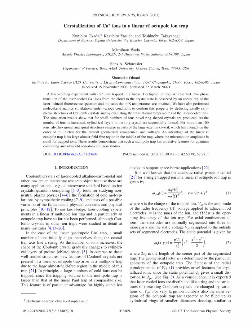
A schematic diagram of the central part of the linear rfoctupole ion trap is shown in Fig. 1. The octupole trap con-sists of eight cylindrical electrodes, which are sectioned intothree sets. For confinement in the radial direction, rf voltageswith inverted phases are alternately applied to adjacent rodelectrodes. The inner radius of the trap is r0=7.5 mm, andthe diameter of the cylindrical electrodes is 5 mm. The
length of the center electrode of the segmented trap is 2z0=10 mm. The driving rf frequency and the amplitude aretypically f rf=10 MHz and Vac=370 V, respectively. Staticvoltages �Vz1, Vz2� of up to about 300 mV are normally ap-plied to the set of side electrodes to confine ions in themiddle section along the axial direction. The linear rf octu-pole trap is mounted on a cryogenic vessel, which can befilled with liquid nitrogen or liquid helium �31,32�. In thepresent laser-cooling experiment, the trap electrodes arecooled to approximately 100 K by liquid nitrogen to avoidloss of trapped ions as much as possible. The ion trap isenclosed in a vacuum chamber evacuated to below 1�10−7 Pa. The laser ablation method is applied to produceCa+ ions from a Ca metal piece located outside the ion trap.Before the ion production process, we admit helium gas atabout 10−4 Pa for efficient trapping and buffer gas cooling ofCa+ ions. This process promotes also the accumulation of theions to the middle of the trap so that the laser cooling cansubsequently become effective. Then, we close the leakvalve and quickly pump to ultrahigh vacuum when we applythe laser cooling.
For the laser cooling of trapped Ca+ ions, we used twograting-stabilized diode lasers with oscillation wavelengthsat 397 nm and 866 nm �33�. The wavelengths correspond tothe two optical dipole transitions of the 4s 2S1/2→4p 2P1/2and the 3d 2D3/2→4p 2P1/2, respectively. The cooling transi-tion is at 397 nm. The laser light at 866 nm is necessary toprevent optical pumping into the metastable 2D3/2 state. Thelifetime of the P1/2 state is 7.14 ns which corresponds to anatural linewidth of 22 MHz �34�. The available powers ofthe cooling laser and the repumper are 0.2 mW and 2 mW,respectively. Two commercial wavemeters �Burleigh, WA-1000 and Advantest, TQ8325� are used to monitor the abso-lute wavelengths of the lasers. The relative frequency of the397 nm laser is monitored by a confocal Fabry-Perot �CFP�cavity with a length of 150 mm. The LIF at 397 nm is fo-cused on a photomultiplier tube �Hamamatsu Photonics,R464� located at right angles to the trap axis. The photon-counting signal is recorded by a computer. An interferencefilter for 397 nm is used for the reduction of backgroundphotons. The geometrical detection efficiency of the optics isestimated by a Monte Carlo simulation to be 1.4%, and the
FIG. 1. Schematic diagram of the central part of the linear rfoctupole trap. The lower part shows the arrangement of the staticvoltages of Vz1 and Vz2 applied to the set of side electrodes.
OKADA et al. PHYSICAL REVIEW A 75, 033409 �2007�
033409-2
total detection efficiency including the losses of the optics isabout 3�10−4.
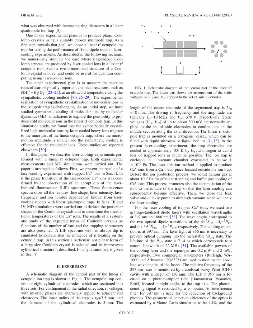
Figure 2 shows the LIF spectra of both buffer-gas-cooledand laser-cooled Ca+ ions in the linear rf octupole ion traptogether with the CFP cavity fringes of the light from the397-nm laser. The cooling occurs on the red-detuned side ofthe spectrum. Ion heating and loss from the trap take placeon the blue side. Therefore only half of the linewidth is de-tected and we call this width the half width at half maximum�HWHM�. The HWHM of the laser-cooled ions is ��=108�2� MHz, which corresponds to an ion temperature of12.7�5� K. In this measurement, an ion cloud of about 103
ions was present in the octupole trap and the crystal state wasnot yet realized.
For the present experimental setup, a higher power of thecooling laser is needed to produce the crystal state due to thelarge trap volume. Alternatively, it is possible to obtain thephase transition LIF spectrum with the present laser power ifthe number of trapped ions is smaller. To reduce the numberof ions, we applied higher static voltages �Vz1 ,Vz27 V� fora few tens of a second. When the static voltages are in-creased, the trapped ions are heated by the rf fields and a partof the ions escapes from the trap, since the static potential �sproduces potential minima far from the central trap axis inthe radial pseudopotential �psd as shown in Figs. 3 and 4. Inthis way, the number of trapped ions can be reduced if thisnecessary.
After reducing the number of trapped ions, we obtain anarrow LIF spectrum with the abrupt dip as depicted in Fig.5. The dip in the spectrum indicates the phase transition ofthe trapped Ca+ ions from the cloud state to the crystal state�35�. The number of Ca+ ions in the crystal state is estimatedto be about 200 ions by using the detection efficiency and theestimated LIF rate of 1.5 Mcps/ion at 0.2 mW of the 397-nmcooling laser intensity.
(a)
0 1 2 3 4 5 6
laser sweep frequency (GHz)
LIF
inte
nsit
y(a
rb.u
nits
)
(b)
FIG. 2. �a� Laser-induced fluorescence spectrum of heliumbuffer-gas-cooled ions without liquid nitrogen cooling. The numberof Ca+ ions in the cloud is estimated to be about 1.5�103. Heliumbuffer gas is present, at room temperature and a pressure of 1.4�10−4 Pa. �b� Laser-induced fluorescence spectrum of a laser-cooled ion cloud obtained by scanning the laser frequency at11 MHz/s over the resonance position under the ultrahigh-vacuumcondition. The number of Ca+ ions in the cloud is about 1�103.The HWHM of the spectrum is ��=108�2� MHz, which corre-sponds to an ion temperature of 12.7�5� K. The upper trace showsthe reference signal from the CFP cavity with a length of 150 mm.Experimental parameters of the ion trap are f rf=� /2�=9.978 MHz, Vac=370 V, and Vz1=Vz2=83 mV.
-0.1
-0.05
0
0.05
0.1
0.15
0.2
-1.5 -1 -0.5 0 0.5 1 1.5
M=17
M=40
pote
ntia
l[m
V]
x, y [mm]
φpsd
+ φs
(b)
-0.1
-0.05
0
0.05
0.1
0.15
0.2
M=17
M=40
pote
ntia
l[m
V]
φpsd
φs
φs
(a)
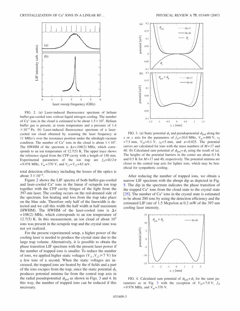
FIG. 3. �a� Static potential �s and pseudopotential �psd along thex or y axis for the parameters of f rf=10.0 MHz, Vac=400 V, r0
=7.5 mm, Vz0=0.1 V, z0=5 mm, and �=0.025. The potentialcurves are calculated for ions with the mass numbers of M =17 and40. �b� Calculated sum potential of �psd+�s using the result of �a�.The heights of the potential barriers in the center are about 0.3 Kand 0.5 K for M =17 and 40, respectively. The potential minima arecloser to the central trap axis for lighter ions, which may be ben-eficial for sympathetic cooling.
-15
-10
-5
0
5
10
15
-3 -2 -1 0 1 2 3
M=40
pote
ntia
l[m
V]
x, y [mm]
φpsd
+ φs
FIG. 4. Calculated sum potential of �psd+�s for the same pa-rameters as in Fig. 3 with the exception of Vz0=7.0 V, f rf
=9.978 MHz, and Vac=370 V.
CRYSTALLIZATION OF Ca+ IONS IN A LINEAR RF… PHYSICAL REVIEW A 75, 033409 �2007�
033409-3
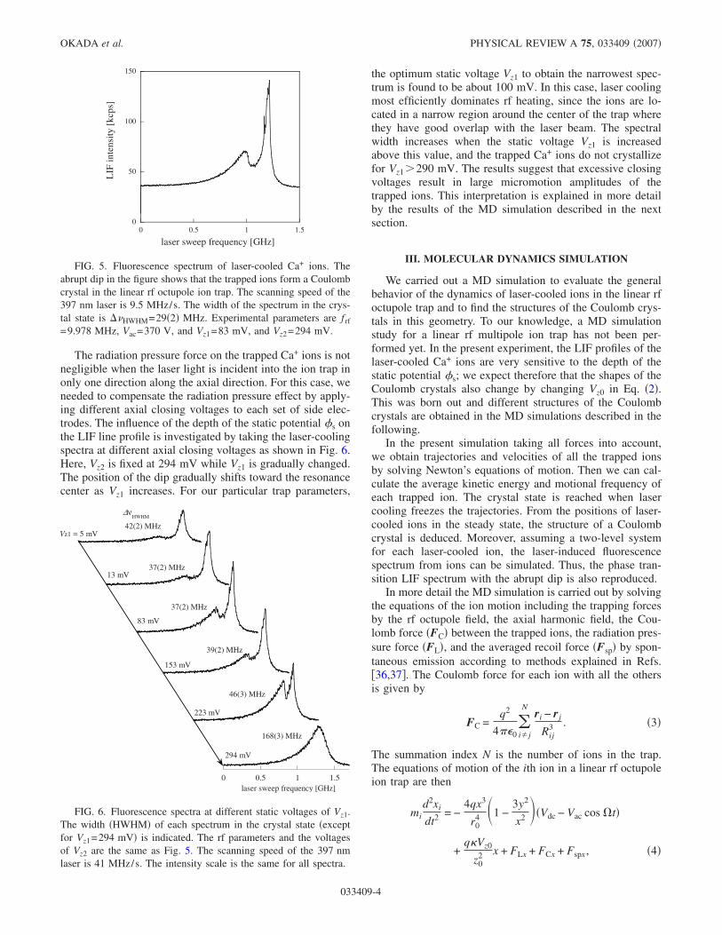
The radiation pressure force on the trapped Ca+ ions is notnegligible when the laser light is incident into the ion trap inonly one direction along the axial direction. For this case, weneeded to compensate the radiation pressure effect by apply-ing different axial closing voltages to each set of side elec-trodes. The influence of the depth of the static potential �s onthe LIF line profile is investigated by taking the laser-coolingspectra at different axial closing voltages as shown in Fig. 6.Here, Vz2 is fixed at 294 mV while Vz1 is gradually changed.The position of the dip gradually shifts toward the resonancecenter as Vz1 increases. For our particular trap parameters,
the optimum static voltage Vz1 to obtain the narrowest spec-trum is found to be about 100 mV. In this case, laser coolingmost efficiently dominates rf heating, since the ions are lo-cated in a narrow region around the center of the trap wherethey have good overlap with the laser beam. The spectralwidth increases when the static voltage Vz1 is increasedabove this value, and the trapped Ca+ ions do not crystallizefor Vz1290 mV. The results suggest that excessive closingvoltages result in large micromotion amplitudes of thetrapped ions. This interpretation is explained in more detailby the results of the MD simulation described in the nextsection.
III. MOLECULAR DYNAMICS SIMULATION
We carried out a MD simulation to evaluate the generalbehavior of the dynamics of laser-cooled ions in the linear rfoctupole trap and to find the structures of the Coulomb crys-tals in this geometry. To our knowledge, a MD simulationstudy for a linear rf multipole ion trap has not been per-formed yet. In the present experiment, the LIF profiles of thelaser-cooled Ca+ ions are very sensitive to the depth of thestatic potential �s; we expect therefore that the shapes of theCoulomb crystals also change by changing Vz0 in Eq. �2�.This was born out and different structures of the Coulombcrystals are obtained in the MD simulations described in thefollowing.
In the present simulation taking all forces into account,we obtain trajectories and velocities of all the trapped ionsby solving Newton’s equations of motion. Then we can cal-culate the average kinetic energy and motional frequency ofeach trapped ion. The crystal state is reached when lasercooling freezes the trajectories. From the positions of laser-cooled ions in the steady state, the structure of a Coulombcrystal is deduced. Moreover, assuming a two-level systemfor each laser-cooled ion, the laser-induced fluorescencespectrum from ions can be simulated. Thus, the phase tran-sition LIF spectrum with the abrupt dip is also reproduced.
In more detail the MD simulation is carried out by solvingthe equations of the ion motion including the trapping forcesby the rf octupole field, the axial harmonic field, the Cou-lomb force �FC� between the trapped ions, the radiation pres-sure force �FL�, and the averaged recoil force �Fsp� by spon-taneous emission according to methods explained in Refs.�36,37�. The Coulomb force for each ion with all the othersis given by
FC =q2
4��0�i�j
Nri − r j
Rij3 . �3�
The summation index N is the number of ions in the trap.The equations of motion of the ith ion in a linear rf octupoleion trap are then
mid2xi
dt2 = −4qx3
r04 �1 −
3y2
x2 ��Vdc − Vac cos �t�
+q�Vz0
z02 x + FLx + FCx + Fspx, �4�
0
50
100
150
0 0.5 1 1.5
laser sweep frequency [GHz]
LIF
inte
nsit
y[k
cps]
FIG. 5. Fluorescence spectrum of laser-cooled Ca+ ions. Theabrupt dip in the figure shows that the trapped ions form a Coulombcrystal in the linear rf octupole ion trap. The scanning speed of the397 nm laser is 9.5 MHz/s. The width of the spectrum in the crys-tal state is ��HWHM=29�2� MHz. Experimental parameters are f rf
=9.978 MHz, Vac=370 V, and Vz1=83 mV, and Vz2=294 mV.
13 mV37(2) MHz
Vz1 = 5 mV
∆νHWHM
42(2) MHz
83 mV
37(2) MHz
0 0.5 1 1.5
294 mV
168(3) MHz
laser sweep frequency [GHz]
153 mV
39(2) MHz
223 mV
46(3) MHz
FIG. 6. Fluorescence spectra at different static voltages of Vz1.The width �HWHM� of each spectrum in the crystal state �exceptfor Vz1=294 mV� is indicated. The rf parameters and the voltagesof Vz2 are the same as Fig. 5. The scanning speed of the 397 nmlaser is 41 MHz/s. The intensity scale is the same for all spectra.
OKADA et al. PHYSICAL REVIEW A 75, 033409 �2007�
033409-4
mid2yi
dt2 = −4qy3
r04 �1 −
3x2
y2 ��Vdc − Vac cos �t�
+q�Vz0
z02 y + FLy + FCy + Fspy , �5�
mid2zi
dt2 = −2q�Vz0
z02 z + FLz + FCz + Fspz, �6�
where FLj and Fspj �j=x ,y ,z� represent the projection of theradiation pressure and the recoil force onto the j axis. Equa-tions �4�–�6� are numerically solved by the fourth-orderRunge-Kutta method �36�.
In addition, the effect of elastic collisions by the buffergas atoms is included, since initially we employ buffer gascooling before laser cooling. The elastic collision effect isimplemented as follows. After each integration step of theRunge-Kutta algorithm, we calculate the mean free path bythe equation �L=1/ng L, where L is the Langevin crosssection depending on the collision velocity v. ng is the num-ber density of the buffer gas. If the flight length of an ion,which is added at each time step, exceeds �L, we apply thestandard equation for the determination of an ion’s velocityafter a classical elastic collision �38�, where the unit vectorof the ion velocity after the collision is given by randomnumbers.
A short time step of 10 ns was usually used to solve theNewton equations. The value was chosen to be small againstthe micromotion period and to be able to preserve the initialkinetic energy of a trapped ion for each simulation interval,when the gas collision and the radiation effects are not inten-tionally included. The number of ions is limited to a fewhundred ions due to the available computer power. The totalintegration time of each cycle is also limited to be less than1 s and strongly depends on the number of ions.
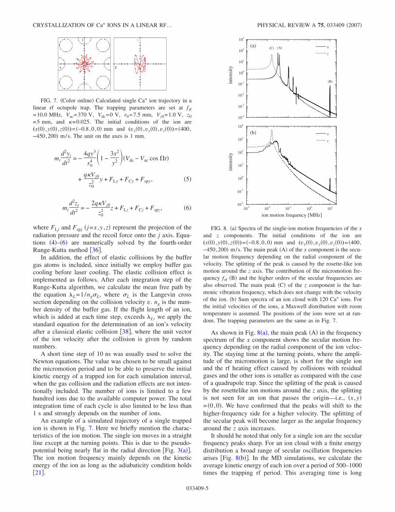
An example of a simulated trajectory of a single trappedion is shown in Fig. 7. Here we briefly mention the charac-teristics of the ion motion. The single ion moves in a straightline except at the turning points. This is due to the pseudo-potential being nearly flat in the radial direction �Fig. 3�a��.The ion motion frequency mainly depends on the kineticenergy of the ion as long as the adiabaticity condition holds�21�.
As shown in Fig. 8�a�, the main peak �A� in the frequencyspectrum of the x component shows the secular motion fre-quency depending on the radial component of the ion veloc-ity. The staying time at the turning points, where the ampli-tude of the micromotion is large, is short for the single ionand the rf heating effect caused by collisions with residualgases and the other ions is smaller as compared with the caseof a quadrupole trap. Since the splitting of the peak is causedby the rosettelike ion motions around the z axis, the splittingis not seen for an ion that passes the origin—i.e., �x ,y�= �0,0�. We have confirmed that the peaks will shift to thehigher-frequency side for a higher velocity. The splitting ofthe secular peak will become larger as the angular frequencyaround the z axis increases.
It should be noted that only for a single ion are the secularfrequency peaks sharp. For an ion cloud with a finite energydistribution a broad range of secular oscillation frequenciesarises �Fig. 8�b��. In the MD simulations, we calculate theaverage kinetic energy of each ion over a period of 500–1000times the trapping rf period. This averaging time is long
FIG. 7. �Color online� Calculated single Ca+ ion trajectory in alinear rf octupole trap. The trapping parameters are set at f rf
=10.0 MHz, Vac=370 V, Vdc=0 V, r0=7.5 mm, Vz0=1.0 V, z0
=5 mm, and �=0.025. The initial conditions of the ion are(x�0� ,y�0� ,z�0�)= �−0.8,0 ,0� mm and (vx�0� ,vy�0� ,vz�0�)= �400,−450,200� m/s. The unit on the axes is 1 mm.
10-4
10-3
10-2
10-1
100
101
102
103
x
z
inte
nsit
y
(a) (A)(C)
(B)
10-2
10-1
100
101
102
103
104
x
z
10-3 10-2 10-1 100 101
inte
nsit
y
(b)
ion motion frequency [MHz]
FIG. 8. �a� Spectra of the single-ion motion frequencies of the xand z components. The initial conditions of the ion are(x�0� ,y�0� ,z�0�)= �−0.8,0 ,0� mm and (vx�0� ,vy�0� ,vz�0�)= �400,−450,200� m/s. The main peak �A� of the x component is the secu-lar motion frequency depending on the radial component of thevelocity. The splitting of the peak is caused by the rosette-like ionmotion around the z axis. The contribution of the micromotion fre-quency f rf �B� and the higher orders of the secular frequencies arealso observed. The main peak �C� of the z component is the har-monic vibration frequency, which does not change with the velocityof the ion. �b� Sum spectra of an ion cloud with 120 Ca+ ions. Forthe initial velocities of the ions, a Maxwell distribution with roomtemperature is assumed. The positions of the ions were set at ran-dom. The trapping parameters are the same as in Fig. 7.
CRYSTALLIZATION OF Ca+ IONS IN A LINEAR RF… PHYSICAL REVIEW A 75, 033409 �2007�
033409-5
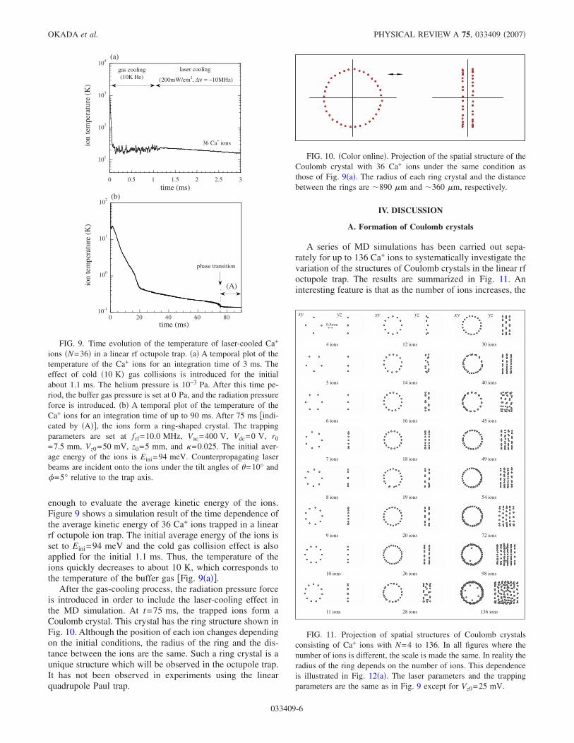
enough to evaluate the average kinetic energy of the ions.Figure 9 shows a simulation result of the time dependence ofthe average kinetic energy of 36 Ca+ ions trapped in a linearrf octupole ion trap. The initial average energy of the ions isset to Eini=94 meV and the cold gas collision effect is alsoapplied for the initial 1.1 ms. Thus, the temperature of theions quickly decreases to about 10 K, which corresponds tothe temperature of the buffer gas �Fig. 9�a��.
After the gas-cooling process, the radiation pressure forceis introduced in order to include the laser-cooling effect inthe MD simulation. At t=75 ms, the trapped ions form aCoulomb crystal. This crystal has the ring structure shown inFig. 10. Although the position of each ion changes dependingon the initial conditions, the radius of the ring and the dis-tance between the ions are the same. Such a ring crystal is aunique structure which will be observed in the octupole trap.It has not been observed in experiments using the linearquadrupole Paul trap.
IV. DISCUSSION
A. Formation of Coulomb crystals
A series of MD simulations has been carried out sepa-rately for up to 136 Ca+ ions to systematically investigate thevariation of the structures of Coulomb crystals in the linear rfoctupole trap. The results are summarized in Fig. 11. Aninteresting feature is that as the number of ions increases, the
10-1
100
101
102
0 20 40 60 80
ion
tem
pera
ture
(K)
time (ms)
(A)
(b)
phase transition
101
102
103
104
0 0.5 1 1.5 2 2.5 3
ion
tem
pera
ture
(K)
time (ms)
36 Ca+ ions
gas cooling(10K He)
laser cooling
(200mW/cm2, ∆ν = −10MHz)
(a)
FIG. 9. Time evolution of the temperature of laser-cooled Ca+
ions �N=36� in a linear rf octupole trap. �a� A temporal plot of thetemperature of the Ca+ ions for an integration time of 3 ms. Theeffect of cold �10 K� gas collisions is introduced for the initialabout 1.1 ms. The helium pressure is 10−3 Pa. After this time pe-riod, the buffer gas pressure is set at 0 Pa, and the radiation pressureforce is introduced. �b� A temporal plot of the temperature of theCa+ ions for an integration time of up to 90 ms. After 75 ms �indi-cated by �A��, the ions form a ring-shaped crystal. The trappingparameters are set at f rf=10.0 MHz, Vac=400 V, Vdc=0 V, r0
=7.5 mm, Vz0=50 mV, z0=5 mm, and �=0.025. The initial aver-age energy of the ions is Eini=94 meV. Counterpropagating laserbeams are incident onto the ions under the tilt angles of �=10° and�=5° relative to the trap axis.
FIG. 10. �Color online�. Projection of the spatial structure of theCoulomb crystal with 36 Ca+ ions under the same condition asthose of Fig. 9�a�. The radius of each ring crystal and the distancebetween the rings are 890 �m and 360 �m, respectively.
0.5mm
4 ions
5 ions
6 ions
7 ions
8 ions
9 ions
10 ions
11 ions
12 ions
14 ions
16 ions
18 ions
19 ions
20 ions
26 ions
28 ions
30 ions
40 ions
45 ions
49 ions
54 ions
72 ions
98 ions
136 ions
xy yz xy xyyz yz
FIG. 11. Projection of spatial structures of Coulomb crystalsconsisting of Ca+ ions with N=4 to 136. In all figures where thenumber of ions is different, the scale is made the same. In reality theradius of the ring depends on the number of ions. This dependenceis illustrated in Fig. 12�a�. The laser parameters and the trappingparameters are the same as in Fig. 9 except for Vz0=25 mV.
OKADA et al. PHYSICAL REVIEW A 75, 033409 �2007�
033409-6
trapped ions form a cylindrical crystal with ring-shaped lay-ers. The maximum number of ions in the first ring crystal is12 ions in the present simulation. Then, the structure of theCoulomb crystal changes to the two-ring structure �n=2� forN=16 ions. For the ion crystal containing N=13–15 ions,there are different stable structures, which change by varia-tions of the initial conditions of the MD simulations. Simi-larly, the next transition from n=2 to 3 rings occurs for N=27–29 ions. This behavior can be understood by the loca-tion of the ion motions in the ring-shaped pseudopotentialvalley �Fig. 3�b��. The actual position of this valley is deter-mined by the balance between the depth of the sum potentialof �psd+�s and the Coulomb potentials between the trappedions.
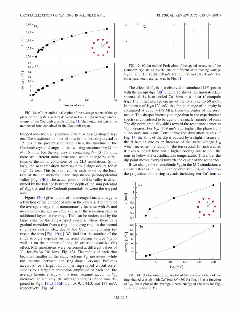
Figure 12�b� gives a plot of the average kinetic energy asa function of the number of ions in the crystals. The trend ofthe average energy is to monotonously increase with N, andno obvious changes are observed near the transition state toadditional layers of the rings. This can be understood by thelarge radii of the ring-shaped crystals, where there is agradual transition from a ring to a zigzag ring, to the secondring layer crystal, etc., due to the Coulomb repulsion be-tween the ions �Fig. 12�a��. We find that the number of therings strongly depends on the axial closing voltage Vz0 aswell as on the number of ions. In order to visualize thiseffect, MD simulations were performed at different values ofVz0 for N=36 Ca+ ions �Fig. 13�. The radius of each ringbecomes smaller as the static voltage Vz0 decreases, whilethe distance between the ring-shaped crystals becomeslarger. Since a larger radius of a ring-shaped crystal corre-sponds to a larger micromotion amplitude of each ion, theaverage kinetic energy of the ions becomes larger as Vz0increases. In actuality, the average energies of the ions de-picted in Figs. 13�a�–13�d� are 4.9, 9.1, 44.3, and 137 �eV,respectively �Fig. 14�.
The effect of Vz0 is also observed in simulated LIF spectrawith the abrupt dips �39�. Figure 15 shows the simulated LIFspectra of six laser-cooled Ca+ ions in a linear rf octupoletrap. The initial average energy of the ions is set to 50 meV.In the case of Vz0=120 mV, the abrupt change of intensity isconfirmed at about −138 MHz from the center of the reso-nance. The sharper intensity change than in the experimentalspectra is considered to be due to the smaller number of ions.The dip point gradually shifts toward the resonance center asVz0 increases. For Vz0=149 meV and higher, the phase tran-sition does not occur. Considering the simulation results ofFig. 14, the shift of the dip is caused by a slight increase ofthe rf heating due to an increase of the static voltage Vz0which increases the radius of the ion crystal. In such a case,it takes a longer time and a higher cooling rate to cool theions to below the crystallization temperature. Therefore, thedip point moves forward towards the center of the resonance.
If we change the rf amplitude Vac in the MD simulation, asimilar effect as in Fig. 13 can be observed. Figure 16 showsthe projection of the ring crystals including ten Ca+ ions at
FIG. 12. �Color online� �a� A plot of the average radius of the xyplane of the crystals �N7� depicted in Fig. 11. �b� Average kineticenergy of the Coulomb crystals of Fig. 11. The horizontal axis is thenumber of ions contained in the Coulomb crystal.
FIG. 13. �Color online� Projection of the spatial structures of theCoulomb crystals of N=36 ions at different axial closing voltageVz0 of �a� 11.1 mV, �b� 25.0 mV, �c� 110 mV, and �d� 250 mV. Theother parameters are same as in Fig. 11.
FIG. 14. �Color online� �a� A plot of the average radius of thering-shaped crystals with Ca+ ions �N=36� for Fig. 13 as a functionof Vz0. �b� A plot of the average kinetic energy of the ions for Fig.13 as a function of Vz0.
CRYSTALLIZATION OF Ca+ IONS IN A LINEAR RF… PHYSICAL REVIEW A 75, 033409 �2007�
033409-7
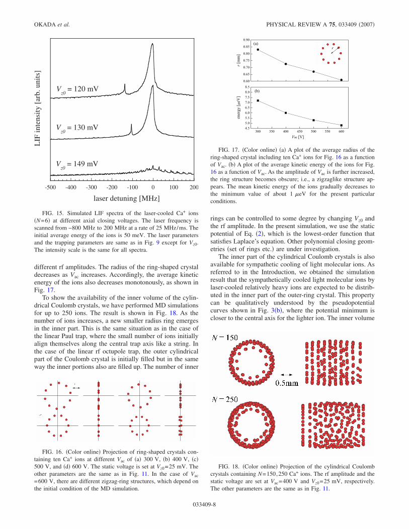
different rf amplitudes. The radius of the ring-shaped crystaldecreases as Vac increases. Accordingly, the average kineticenergy of the ions also decreases monotonously, as shown inFig. 17.
To show the availability of the inner volume of the cylin-drical Coulomb crystals, we have performed MD simulationsfor up to 250 ions. The result is shown in Fig. 18. As thenumber of ions increases, a new smaller radius ring emergesin the inner part. This is the same situation as in the case ofthe linear Paul trap, where the small number of ions initiallyalign themselves along the central trap axis like a string. Inthe case of the linear rf octupole trap, the outer cylindricalpart of the Coulomb crystal is initially filled but in the sameway the inner portions also are filled up. The number of inner
rings can be controlled to some degree by changing Vz0 andthe rf amplitude. In the present simulation, we use the staticpotential of Eq. �2�, which is the lowest-order function thatsatisfies Laplace’s equation. Other polynomial closing geom-etries �set of rings etc.� are under investigation.
The inner part of the cylindrical Coulomb crystals is alsoavailable for sympathetic cooling of light molecular ions. Asreferred to in the Introduction, we obtained the simulationresult that the sympathetically cooled light molecular ions bylaser-cooled relatively heavy ions are expected to be distrib-uted in the inner part of the outer-ring crystal. This propertycan be qualitatively understood by the pseudopotentialcurves shown in Fig. 3�b�, where the potential minimum iscloser to the central axis for the lighter ion. The inner volume
-500 -400 -300 -200 -100 0 100 200
LIF
inte
nsit
y[a
rb.u
nits
]
laser detuning [MHz]
Vz0
= 120 mV
Vz0
= 130 mV
Vz0
= 149 mV
FIG. 15. Simulated LIF spectra of the laser-cooled Ca+ ions�N=6� at different axial closing voltages. The laser frequency isscanned from −800 MHz to 200 MHz at a rate of 25 MHz/ms. Theinitial average energy of the ions is 50 meV. The laser parametersand the trapping parameters are same as in Fig. 9 except for Vz0.The intensity scale is the same for all spectra.
FIG. 16. �Color online� Projection of ring-shaped crystals con-taining ten Ca+ ions at different Vac of �a� 300 V, �b� 400 V, �c�500 V, and �d� 600 V. The static voltage is set at Vz0=25 mV. Theother parameters are the same as in Fig. 11. In the case of Vac
=600 V, there are different zigzag-ring structures, which depend onthe initial condition of the MD simulation.
FIG. 17. �Color online� �a� A plot of the average radius of thering-shaped crystal including ten Ca+ ions for Fig. 16 as a functionof Vac. �b� A plot of the average kinetic energy of the ions for Fig.16 as a function of Vac. As the amplitude of Vac is further increased,the ring structure becomes obscure; i.e., a zigzaglike structure ap-pears. The mean kinetic energy of the ions gradually decreases tothe minimum value of about 1 �eV for the present particularconditions.
FIG. 18. �Color online� Projection of the cylindrical Coulombcrystals containing N=150,250 Ca+ ions. The rf amplitude and thestatic voltage are set at Vac=400 V and Vz0=25 mV, respectively.The other parameters are the same as in Fig. 11.
OKADA et al. PHYSICAL REVIEW A 75, 033409 �2007�
033409-8
of the cylindrical Coulomb crystal is available for filling up alarger number of ions and also for sympathetically cooled �orcrystallized� light molecular ions.
B. Large-size Coulomb crystal
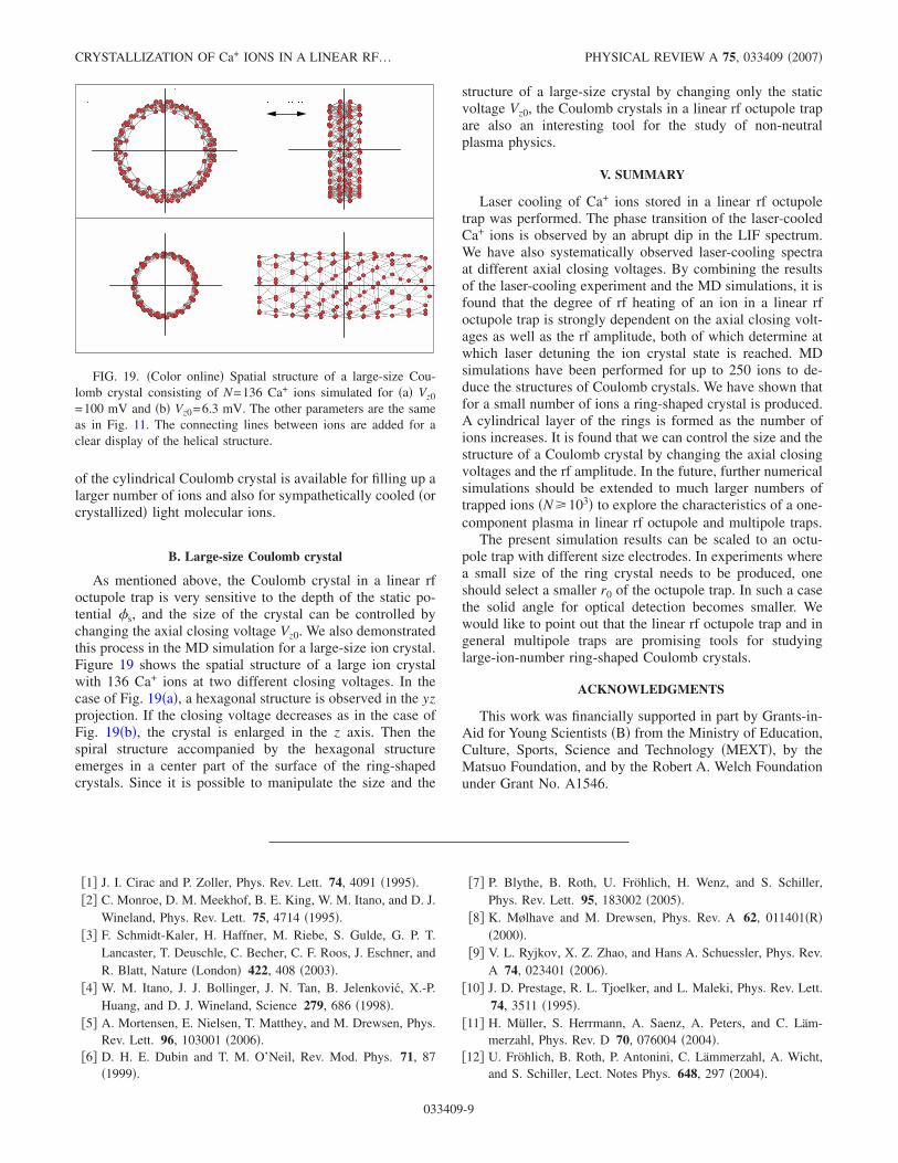
As mentioned above, the Coulomb crystal in a linear rfoctupole trap is very sensitive to the depth of the static po-tential �s, and the size of the crystal can be controlled bychanging the axial closing voltage Vz0. We also demonstratedthis process in the MD simulation for a large-size ion crystal.Figure 19 shows the spatial structure of a large ion crystalwith 136 Ca+ ions at two different closing voltages. In thecase of Fig. 19�a�, a hexagonal structure is observed in the yzprojection. If the closing voltage decreases as in the case ofFig. 19�b�, the crystal is enlarged in the z axis. Then thespiral structure accompanied by the hexagonal structureemerges in a center part of the surface of the ring-shapedcrystals. Since it is possible to manipulate the size and the
structure of a large-size crystal by changing only the staticvoltage Vz0, the Coulomb crystals in a linear rf octupole trapare also an interesting tool for the study of non-neutralplasma physics.
V. SUMMARY
Laser cooling of Ca+ ions stored in a linear rf octupoletrap was performed. The phase transition of the laser-cooledCa+ ions is observed by an abrupt dip in the LIF spectrum.We have also systematically observed laser-cooling spectraat different axial closing voltages. By combining the resultsof the laser-cooling experiment and the MD simulations, it isfound that the degree of rf heating of an ion in a linear rfoctupole trap is strongly dependent on the axial closing volt-ages as well as the rf amplitude, both of which determine atwhich laser detuning the ion crystal state is reached. MDsimulations have been performed for up to 250 ions to de-duce the structures of Coulomb crystals. We have shown thatfor a small number of ions a ring-shaped crystal is produced.A cylindrical layer of the rings is formed as the number ofions increases. It is found that we can control the size and thestructure of a Coulomb crystal by changing the axial closingvoltages and the rf amplitude. In the future, further numericalsimulations should be extended to much larger numbers oftrapped ions �N103� to explore the characteristics of a one-component plasma in linear rf octupole and multipole traps.
The present simulation results can be scaled to an octu-pole trap with different size electrodes. In experiments wherea small size of the ring crystal needs to be produced, oneshould select a smaller r0 of the octupole trap. In such a casethe solid angle for optical detection becomes smaller. Wewould like to point out that the linear rf octupole trap and ingeneral multipole traps are promising tools for studyinglarge-ion-number ring-shaped Coulomb crystals.
ACKNOWLEDGMENTS
This work was financially supported in part by Grants-in-Aid for Young Scientists �B� from the Ministry of Education,Culture, Sports, Science and Technology �MEXT�, by theMatsuo Foundation, and by the Robert A. Welch Foundationunder Grant No. A1546.
�1� J. I. Cirac and P. Zoller, Phys. Rev. Lett. 74, 4091 �1995�.�2� C. Monroe, D. M. Meekhof, B. E. King, W. M. Itano, and D. J.
Wineland, Phys. Rev. Lett. 75, 4714 �1995�.�3� F. Schmidt-Kaler, H. Haffner, M. Riebe, S. Gulde, G. P. T.
Lancaster, T. Deuschle, C. Becher, C. F. Roos, J. Eschner, andR. Blatt, Nature �London� 422, 408 �2003�.
�4� W. M. Itano, J. J. Bollinger, J. N. Tan, B. Jelenković, X.-P.Huang, and D. J. Wineland, Science 279, 686 �1998�.
�5� A. Mortensen, E. Nielsen, T. Matthey, and M. Drewsen, Phys.Rev. Lett. 96, 103001 �2006�.
�6� D. H. E. Dubin and T. M. O’Neil, Rev. Mod. Phys. 71, 87�1999�.
�7� P. Blythe, B. Roth, U. Fröhlich, H. Wenz, and S. Schiller,Phys. Rev. Lett. 95, 183002 �2005�.
�8� K. Mølhave and M. Drewsen, Phys. Rev. A 62, 011401�R��2000�.
�9� V. L. Ryjkov, X. Z. Zhao, and Hans A. Schuessler, Phys. Rev.A 74, 023401 �2006�.
�10� J. D. Prestage, R. L. Tjoelker, and L. Maleki, Phys. Rev. Lett.74, 3511 �1995�.
�11� H. Müller, S. Herrmann, A. Saenz, A. Peters, and C. Läm-merzahl, Phys. Rev. D 70, 076004 �2004�.
�12� U. Fröhlich, B. Roth, P. Antonini, C. Lämmerzahl, A. Wicht,and S. Schiller, Lect. Notes Phys. 648, 297 �2004�.
FIG. 19. �Color online� Spatial structure of a large-size Cou-lomb crystal consisting of N=136 Ca+ ions simulated for �a� Vz0
=100 mV and �b� Vz0=6.3 mV. The other parameters are the sameas in Fig. 11. The connecting lines between ions are added for aclear display of the helical structure.
CRYSTALLIZATION OF Ca+ IONS IN A LINEAR RF… PHYSICAL REVIEW A 75, 033409 �2007�
033409-9
�13� R. Blümel, C. Kappler, W. Quint, and H. Walther, Phys. Rev. A40, 808 �1989�.
�14� J. D. Prestage, A. Williams, L. Maleki, M. J. Djomehri, and E.Harabetian, Phys. Rev. Lett. 66, 2964 �1991�.
�15� T. B. Mitchell, J. J. Bollinger, D. H. E. Dubin, X. P. Huang, W.M. Itano, and R. H. Baughman, Science 282, 1290 �1998�.
�16� D. H. E. Dubin and T. M. O’Neil, Rev. Mod. Phys. 71, 87�1999�.
�17� M. Block, A. Drakoudis, H. Leuthner, P. Seibert, and G. Werth,J. Phys. B 33, 1290 �2000�.
�18� T. Schätz, U. Schramm, and D. Habs, Nature �London� 412,717 �2001�.
�19� M. Drewsen, I. Jensen, J. Lindballe, N. Nissen, R. Martinus-sen, A. Morttensen, P. Staanum, and D. Voigt, Int. J. Mass.Spectrom. 229, 83 �2003�.
�20� J. P. Schiffer, Phys. Rev. Lett. 88, 205003 �2005�.�21� D. Gerlich, Adv. Chem. Phys. 82, 1 �1992�.�22� L. Maleki and J. D. Prestage, Lect. Notes Phys. 648, 331
�2004�.�23� D. Gerlich and M. Smith, Phys. Scr. 73, C25 �2006�.�24� E. Herbst, D. J. DeFrees, D. Talbi, F. Pauzat, W. Koch, and D.
McLean, J. Chem. Phys. 94, 7842 �1991�.�25� B. J. McCall, A. J. Huneycutt, R. J. Saykally, T. R. Geballe, N.
Djuric, G. H. Dunn, J. Semaniak, O. Novotny, A. Al-Khalili,A. Ehlerding, F. Hellberg, S. Kalhori, A. Neau, R. Thomas, F.Österdahl, and M. Larsson, Nature �London� 422, 500 �2003�.
�26� B. Roth, P. Blythe, H. Wenz, H. Daerr, and S. Schiller, Phys.Rev. A 73, 042712 �2006�.
�27� T. J. Harmon, N. Moazzan-Ahmadi, and R. I. Thompson, Phys.Rev. A 67, 013415 �2003�.
�28� S. Schiller and C. Lämmerzahl, Phys. Rev. A 68, 053406�2003�.
�29� T. Baba and I. Waki, Appl. Phys. B: Lasers Opt. 74, 375�2002�.
�30� K. Okada et al. Book of abstracts for the 20th InternationalConference on Atomic Physics �ICAP 2006�, p. 495
�31� K. Okada, M. Wada, T. Nakamura, I. Katayama, L. Boesten,and S. Ohtani, Jpn. J. Appl. Phys., Part 1 40, 4221 �2001�.
�32� K. Okada, M. Wada, T. Nakamura, T. Takayanagi, I.Katayama, and S. Ohtani, Jpn. J. Appl. Phys., Part 1 45, 956�2006�.
�33� K. Okada, M. Wada, L. Boesten, T. Nakamura, I. Katayamaand S. Ohtani, J. Phys. B 36, 33 �2003�.
�34� NIST atomic spectra database version 3.1.0, http://physics.nist.gov/PhysRefData/ASD/index.html
�35� F. Diedrich, E. Peik, J. M. Chen, W. Quint, and H. Walther,Phys. Rev. Lett. 59, 2931 �1987�.
�36� R. Blümel, J. M. Chen, F. Diedrich, E. Peik, W. Quint, W.Schleich, Y. R. Shen, and H. Walther, Proceeding of the 11thInternational Conference on Atomic Physics (ELICAP), Paris,1988 �World Scientific, Singapore, 1989�; H. Walther, Ad-vances in Atomic, Molecular, and Optical Physics �AcademicPress, New York, 1993�, Vol. 31, pp 137–182.
�37� Vladimir L. Ryjkov, XianZhen Zhao, and Hans A. Schuessler,Phys. Rev. A 71, 033414 �2005�.
�38� L. D. Landau and E. M. Lifshitz, Mechanics (Course of The-oretical Physics) �Elsevier, New York, 1969�.
�39� X. Z. Zhao, V. L. Ryjkov, and H. A. Schuessler, Phys. Rev. A73, 033412 �2006�.
OKADA et al. PHYSICAL REVIEW A 75, 033409 �2007�
033409-10