Investigation of electron-beam welding in wrought Inconel 706—experimental and numerical analysis
Upload
independentCategory
view
0download
0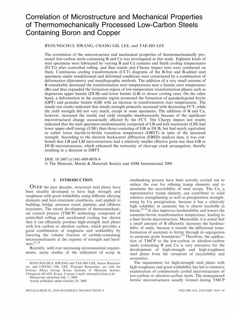
Correlation of Microstructure and Mechanical Propertiesof Thermomechanically Processed Low-Carbon SteelsContaining Boron and Copper
BYOUNGCHUL HWANG, CHANG GIL LEE, and TAE-HO LEE
The correlation of the microstructure and mechanical properties of thermomechanically pro-cessed low-carbon steels containing B and Cu was investigated in this study. Eighteen kinds ofsteel specimens were fabricated by varying B and Cu contents and finish cooling temperatures(FCTs) after controlled rolling, and then tensile and Charpy impact tests were conducted onthem. Continuous cooling transformation (CCT) diagrams of the B-free and B-added steelspecimens under nondeformed and deformed conditions were constructed by a combination ofdeformation dilatometry and metallographic methods. The addition of a very small amount ofB remarkably decreased the transformation start temperatures near a bainite start temperature(Bs) and thus expanded the formation region of low-temperature transformation phases such asdegenerate upper bainite (DUB) and lower bainite (LB) to slower cooling rates. On the otherhand, a deformation in the austenite region promoted the formation of quasipolygonal ferrite(QPF) and granular bainite (GB) with an increase in transformation start temperatures. Thetensile test results indicated that tensile strength primarily increased with decreasing FCT, whilethe yield strength did not vary much, except in some specimens. The addition of B and Cu,however, increased the tensile and yield strengths simultaneously because of the significantmicrostructural change occasionally affected by the FCT. The Charpy impact test resultsindicated that the steel specimens predominantly composed of LB and lath martensite (LM) hadlower upper-shelf energy (USE) than those consisting of GB or DUB, but had nearly equivalentor rather lower ductile-to-brittle transition temperature (DBTT) in spite of the increasedstrength. According to the electron backscatter diffraction (EBSD) analysis data, it was con-firmed that LB and LM microstructures had a relatively smaller effective grain size than GB orDUB microstructures, which enhanced the tortuosity of cleavage crack propagation, therebyresulting in a decrease in DBTT.
DOI: 10.1007/s11661-009-0070-4� The Minerals, Metals & Materials Society and ASM International 2009
I. INTRODUCTION
OVER the past decades, structural steel plates havebeen steadily developed to have high strength andtoughness with good weldability using different alloyingelements and heat-treatment conditions, and applied tobuilding, bridge, pressure vessel, pipeline, and offshorestructures. The recent development of thermomechani-cal control process (TMCP) technology composed ofcontrolled rolling and accelerated cooling has shownthat it can efficiently produce high-strength steel plateswith low carbon or ultralow carbon, which provides agood combination of toughness and weldability bylowering the volume fraction of carbide-containingmicroconstituents at the expense of strength and hard-ness.[1–3]
Recently, with ever increasing environmental require-ments, many studies of the utilization of scrap in
steelmaking process have been actively carried out toreduce the cost for refining tramp elements and tomaximize the recyclability of steel scraps. The Cu, arepresentative tramp element, can contribute to solidsolution strengthening as well as precipitation strength-ening by Cu precipitation, because it has a relativelyhigh solubility in austenite but is almost insoluble inferrite.[4–6] It also improves hardenability and lowers theaustenite-ferrite transformation temperature, leading toa finer ferrite microstructure. Meanwhile, it is noted thata small amount of B efficiently increases the hardena-bility of steels, because it retards the diffusional trans-formation of austenite to ferrite through its segregationto austenite grain boundaries.[7] Therefore, the applica-tion of TMCP to the low-carbon or ultralow-carbonsteels containing B and Cu is very attractive for thedevelopment of high-strength and high-toughnesssteel plates from the viewpoint of recyclability andeconomics.The requirement for high-strength steel plates with
high toughness and good weldability has led to intensiveexamination of continuously cooled microstructures oflow-carbon or ultralow-carbon steels. The nonequiaxedferritic microstructures usually formed during TMCP
BYOUNGCHUL HWANG and TAE-HO LEE, Senior Research-ers, and CHANG GIL LEE, Principal Researcher, are with theFerrous Alloys Group, Korea Institute of Materials Science,Changwon 641-010, Korea. Contact e-mail: [email protected]
Manuscript submitted July 3, 2009.Article published online October 29, 2009
METALLURGICAL AND MATERIALS TRANSACTIONS A VOLUME 41A, JANUARY 2010—85
have been regarded as very complicated compared to theequiaxed or polygonal ferritic microstructures of con-ventional hot-rolled steels. There are many difficulties inidentifying the phases and sometimes serious confusionin the terminology of the microstructures.[8–11] Thetemperature range for the formation of the nonequiaxedferritic microstructures with different morphologies andproperties is intermediate, between those at whichaustenite transforms to equiaxed ferrite and to martens-ite, and thus is similar to that in which bainite forms inmedium-carbon steels. These nonequiaxed ferriticmicrostructures are to be expected over a wide rangeof cooling rates during continuous cooling, and gener-ally have a variety of mixed phases transformed betweenpurely diffusional and displacive transformations inassociation with minor islands of carbon-enriched aus-tenite and martensite-austenite (MA) constituents thatdepend on the level of carbon partitioning in theremaining austenite and the thermal cycle. Therefore,systematic studies of mechanical properties in correla-tion with their complicated microstructures are neededin thermomechanically processed low-carbon steels.
In the present study, based on the continuous coolingtransformation (CCT) diagrams of steels containing Band Cu, steel specimens having various low-temperaturetransformation phases were fabricated by varying thefinish cooling temperature (FCT), and their microstruc-tures were analyzed. Tensile and Charpy impact testswere conducted on them in order to investigate thecorrelation between the microstructure and mechanicalproperties of thermomechanically processed low-carbonsteels containing Cu and B. In particular, the effectivegrain size of various low-temperature transformationphases was characterized by determining their crystal-lographic units using electron backscatter diffraction(EBSD) analysis.
II. EXPERIMENTAL
Six kinds of steels with different B and Cu contents, asshown in Table I, were prepared by melting in a vacuum-induction furnace. For convenience, the B-free steelscontaining 0, 0.5, and 1.5 wt pct Cu are referred to as‘‘0Cu,’’ ‘‘0.5Cu,’’ and ‘‘1.5Cu,’’ respectively; in addition,the B-added steels are referred to as ‘‘0Cu-B,’’ ‘‘0.5Cu-B,’’ and ‘‘1.5Cu-B,’’ respectively. Nondeformation anddeformation dilatometric tests were performed using a
deformation dilatometer (model: Gleeble 3500, DynamicSystems Inc., Los Angeles, CA). Dilatometric specimenswere machined into cylindrical rods with a diameter of8 mm and a length of 12 mm. Figure 1 shows theschedule for the nondeformed and deformed CCTdiagrams. The microstructures after deformation andthe thermal cycles were characterized using an opticalmicroscope (model: EPIPHOT 200, Nikon, Tokyo,Japan) and a microhardness tester (model: FM-700,Future-tech, Kawasaki, Japan). For a given cooling rate,transformation start and finish temperatures were deter-mined for each specimen by locating the temperature atwhich the dilatation-temperature curve showed a devi-ation from linearity. Nondeformed and deformed CCTdiagrams were constructed with the microstructureobservation, dilatometric, and hardness test results tosimulate the controlled hot rolling and cooling of low-carbon steels containing B and Cu.Based on the deformed CCT diagrams, three TMCP
conditions were designed to obtain different microstruc-tures by varying the FCT. After austenitization at1150 �C for 2 hours, a rolling was started at 980 �C andfinished at 820 �C, which was the temperature of theaustenite single-phase region above Ar3. A first hotrolling to a reduction of approximately 50 pct wasconducted to form plate in 7 passes within a firsttemperature range in which austenite recrystallizes,while an overall grain refinement effect was expectedby a second rolling to a reduction of above 60 pct in 7passes within a second temperature range, somewhatlower than the first temperature range, at which
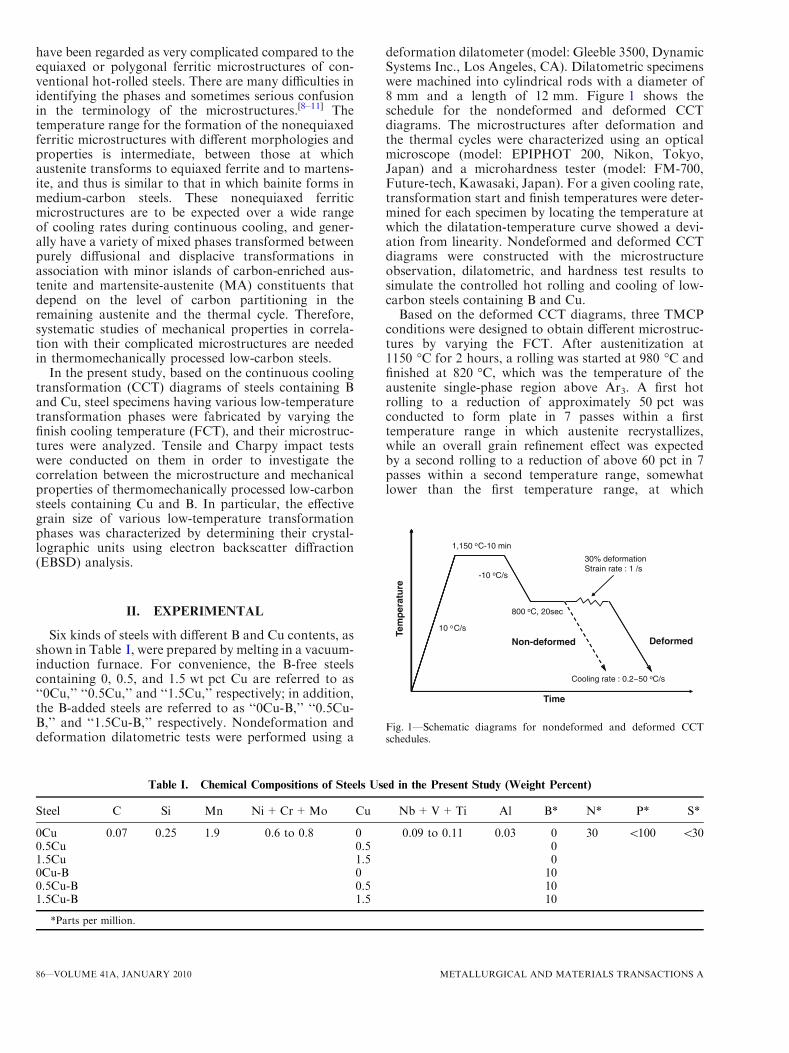
Table I. Chemical Compositions of Steels Used in the Present Study (Weight Percent)
Steel C Si Mn Ni+Cr+Mo Cu Nb+V+Ti Al B* N* P* S*
0Cu 0.07 0.25 1.9 0.6 to 0.8 0 0.09 to 0.11 0.03 0 30 <100 <300.5Cu 0.5 01.5Cu 1.5 00Cu-B 0 100.5Cu-B 0.5 101.5Cu-B 1.5 10
*Parts per million.
1,150 oC-10 min
-10 oC/s
30% deformationStrain rate : 1 /s
ture
800 oC, 20sec
10 oC/s
Tem
per
at
DeformedNon deformed
Cooling rate : 0.2~50 oC/s
DeformedNon-deformed
Time
Fig. 1—Schematic diagrams for nondeformed and deformed CCTschedules.
86—VOLUME 41A, JANUARY 2010 METALLURGICAL AND MATERIALS TRANSACTIONS A
austenite does not recrystallize and above the Ar3transformation temperature. After the finish rolling, thespecimens were acceleratedly cooled down to the differ-ent FCTs of 250 �C, 350 �C, and 450 �C with thecooling rate of approximately 20 �C/s, followed bycooling in air. The initial and final thicknesses of thesteel plates were 100 and 15 mm, respectively. Thus, thetotal rolling reduction ratio was 85 pct.
After the longitudinal-transverse plane of the regionat a quarter thickness of the rolled specimens waspolished and etched by a 2 pct nital solution, micro-structures were observed using an optical microscopeand a scanning electron microscope (SEM), and theirhardness was measured under a load of 300 g. A moredetailed metallographic examination was performed onselected specimens using a transmission electron micro-scope (model: JEM 2100F, JEOL*). Thin foils for
transmission electron microscopy (TEM) were preparedin a twin-jet electrolytic polishing apparatus using asolution containing 5 vol pct perchloric acid and95 vol pct methanol, and were examined at 200 kV.The analysis of the selected area diffraction pattern(SADP) was performed using Desktop Microsoft V2.2software (Lucuna Laboratory, Beaverton, OR). TheEBSD analysis was also conducted on the 0Cu, 0.5Cu,and 0Cu-B specimens by a field emission SEM (model:S-4300SE, Hitachi, Tokyo, Japan) in order to determinetheir effective grain size. The data were then interpretedby orientation imaging microscopy analysis softwareprovided by TexSEM Laboratories, Inc., Draper, UT.
Round tensile specimens with a gage diameter of6.35 mm and a gage length of 25.4 mm were prepared inthe transverse direction and tested at room temperatureat a crosshead speed of 5 mm/min using a 10-tonuniversal testing machine (model: Instron 5882, InstronCo., Norwood, MA). The data reported in this studyrepresent an average of at least three tests. Charpy V-notch (CVN) impact tests were performed on standardspecimens with a 10 9 10 9 55-mm size that weremachined in the transverse-longitudinal orientation inthe temperature range –196 �C to 20 �C using an impacttester with a 500-J capacity. In order to reduce errors indata interpretation, a regression analysis for absorbedenergy as a function of test temperature was done by ahyperbolic tangent curve-fitting method. Based on thedata obtained from the regression analysis, the ductile-to-brittle transition temperature (DBTT), which corre-sponds to the average value of the upper-shelf energy(USE) and lower-shelf energy, was determined.
III. RESULTS
A. CCT Characteristics
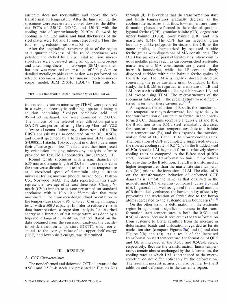
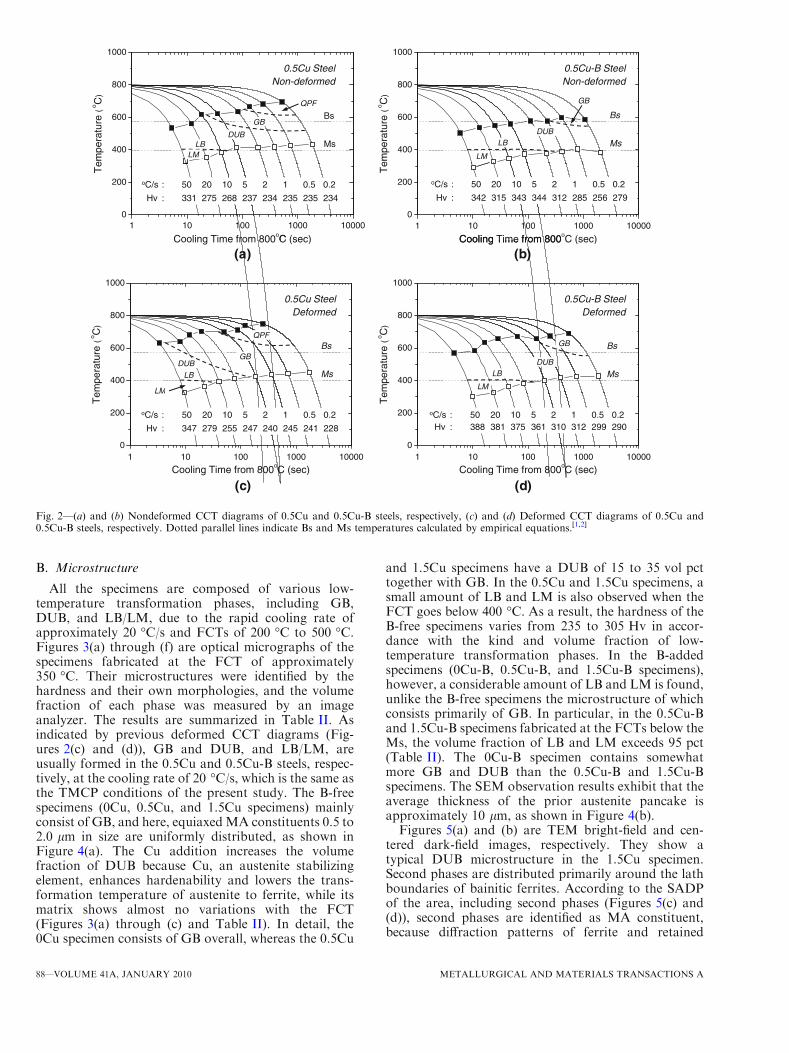
The nondeformed and deformed CCT diagrams of the0.5Cu and 0.5Cu-B steels are presented in Figures 2(a)
through (d). It is evident that the transformation startand finish temperatures gradually decrease as thecooling rate increases and, thus, low-temperature trans-formation phases are formed in the order of quasipo-lygonal ferrite (QPF), granular bainite (GB), degenerateupper bainite (DUB), lower bainite (LB), and lathmartensite (LM). The QPF has an irregular grainboundary unlike polygonal ferrite, and the GB, as thename implies, is characterized by equiaxed bainiticferrite grains with dispersions of MA constituents. TheDUB has packets of parallel ferrite laths, where contin-uous metallic phases such as carbon-enriched austenite,martensite, and MA constituents are present in theinterlath boundaries, while the LB contains finelydispersed carbides within the bainitic ferrite grains ofthe lath type. The LM is a highly dislocated structureconserving the prior austenite grain boundary. In thisstudy, the LB/LM is regarded as a mixture of LB andLM, because it is difficult to distinguish between LB andLM except using TEM. The microstructures of thespecimens fabricated in the present study were differen-tiated in terms of these categories.[3,8–11]
As expected, the addition of B shifts the transforma-tion temperature ranges downward, leading to delay inthe transformation of austenite to ferrite. In the nonde-formed CCT diagrams (compare Figures 2(a) and (b)),the B addition to the 0.5Cu steel remarkably decreasesthe transformation start temperatures close to a bainitestart temperature (Bs) and thus expands the transfor-mation field of DUB and LB to slower cooling rates.The formation of QPF is completely suppressed, even atthe slowest cooling rate of 0.2 �C/s. In the B-added steel(0.5Cu-B steel), LM begins to form at relatively slowercooling rates as compared to the B-free steel (0.5Custeel), because the transformation finish temperaturesdecrease due to the B addition. The LB is transformed athigher temperatures than the martensite start tempera-ture (Ms) prior to the formation of LM. The effect of Bon the transformation behavior of deformed CCTdiagrams is almost the same as that observed in thenondeformed CCT diagrams (compare Figures 2(c) and(d)). In general, it is well recognized that a small amountof B dramatically enhances the hardenability of steels bypreventing the nucleation of ferrite due to the boronatoms segregated to the austenite grain boundaries.[7,11]
On the other hand, a deformation in the austeniteregion brings about a significant increase in the trans-formation start temperatures in both the 0.5Cu and0.5Cu-B steels, because it accelerates the transformationfrom austenite to ferrite resulting from the increase indeformation bands and dislocations regarded as ferritenucleation sites (compare Figures 2(a) and (c) and alsoFigures 2(b) and (d)). As a result of the increasedtransformation start temperature, the formation of QPFand GB is increased in the 0.5Cu and 0.5Cu-B steels,respectively. Because the transformation finish temper-atures remain almost unchanged by the deformation, thecooling rates at which LM is introduced to the micro-structure do not differ noticeably by the deformation.The resultant microstructures can also be finer by the Baddition and deformation in the austenite region.
*JEOL is a trademark of Japan Electron Optics Ltd., Tokyo.
METALLURGICAL AND MATERIALS TRANSACTIONS A VOLUME 41A, JANUARY 2010—87
B. Microstructure
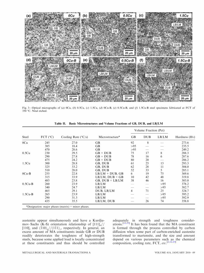
All the specimens are composed of various low-temperature transformation phases, including GB,DUB, and LB/LM, due to the rapid cooling rate ofapproximately 20 �C/s and FCTs of 200 �C to 500 �C.Figures 3(a) through (f) are optical micrographs of thespecimens fabricated at the FCT of approximately350 �C. Their microstructures were identified by thehardness and their own morphologies, and the volumefraction of each phase was measured by an imageanalyzer. The results are summarized in Table II. Asindicated by previous deformed CCT diagrams (Fig-ures 2(c) and (d)), GB and DUB, and LB/LM, areusually formed in the 0.5Cu and 0.5Cu-B steels, respec-tively, at the cooling rate of 20 �C/s, which is the same asthe TMCP conditions of the present study. The B-freespecimens (0Cu, 0.5Cu, and 1.5Cu specimens) mainlyconsist of GB, and here, equiaxedMA constituents 0.5 to2.0 lm in size are uniformly distributed, as shown inFigure 4(a). The Cu addition increases the volumefraction of DUB because Cu, an austenite stabilizingelement, enhances hardenability and lowers the trans-formation temperature of austenite to ferrite, while itsmatrix shows almost no variations with the FCT(Figures 3(a) through (c) and Table II). In detail, the0Cu specimen consists of GB overall, whereas the 0.5Cu
and 1.5Cu specimens have a DUB of 15 to 35 vol pcttogether with GB. In the 0.5Cu and 1.5Cu specimens, asmall amount of LB and LM is also observed when theFCT goes below 400 �C. As a result, the hardness of theB-free specimens varies from 235 to 305 Hv in accor-dance with the kind and volume fraction of low-temperature transformation phases. In the B-addedspecimens (0Cu-B, 0.5Cu-B, and 1.5Cu-B specimens),however, a considerable amount of LB and LM is found,unlike the B-free specimens the microstructure of whichconsists primarily of GB. In particular, in the 0.5Cu-Band 1.5Cu-B specimens fabricated at the FCTs below theMs, the volume fraction of LB and LM exceeds 95 pct(Table II). The 0Cu-B specimen contains somewhatmore GB and DUB than the 0.5Cu-B and 1.5Cu-Bspecimens. The SEM observation results exhibit that theaverage thickness of the prior austenite pancake isapproximately 10 lm, as shown in Figure 4(b).Figures 5(a) and (b) are TEM bright-field and cen-
tered dark-field images, respectively. They show atypical DUB microstructure in the 1.5Cu specimen.Second phases are distributed primarily around the lathboundaries of bainitic ferrites. According to the SADPof the area, including second phases (Figures 5(c) and(d)), second phases are identified as MA constituent,because diffraction patterns of ferrite and retained
800
1000
800
1000
0.5Cu SteelNon-deformed
0.5Cu-B SteelNon-deformed
)b()a(
400
600
800
empe
ratu
re (
o C)
400
600
800
empe
ratu
re (
o C)
Ms
Bs
Ms
BsQPF
GB
DUB
LMLB
GB
DUB
LM
LB
1 10 100 1000 100000
200
Te
oC (sec)1 10 100 1000 10000
0
200
Te
Cooling Time from 800oC (sec)
oC/s : 50 20 10 5 2 1 0.5 0.2
Hv : 331 275 268 237 234 235 235 234
oC/s : 50 20 10 5 2 1 0.5 0.2
Hv : 342 315 343 344 312 285 256 279
Cooling Time from 800 C (sec) Cooling Time from 800 C (sec)
800
1000
800
1000
0.5Cu-B SteelDeformed
0.5Cu SteelDeformed
)d()c(
400
600
800
empe
ratu
re (
o C)
400
600
800
empe
ratu
re (
o C)
Ms
Bs
Ms
BsGB
DUB
LM
LB
QPF
GBDUB
LM
LB
1 10 100 1000 100000
200
Te
Cooling Time from 800oC (sec)1 10 100 1000 10000
0
200
Te
Cooling Time from 800oC (sec)
oC/s : 50 20 10 5 2 1 0.5 0.2
Hv : 347 279 255 247 240 245 241 228
oC/s : 50 20 10 5 2 1 0.5 0.2Hv : 388 381 375 361 310 312 299 290
LM
C (sec) Cooling Time from 800 C (sec)
Fig. 2—(a) and (b) Nondeformed CCT diagrams of 0.5Cu and 0.5Cu-B steels, respectively, (c) and (d) Deformed CCT diagrams of 0.5Cu and0.5Cu-B steels, respectively. Dotted parallel lines indicate Bs and Ms temperatures calculated by empirical equations.[1,2]
88—VOLUME 41A, JANUARY 2010 METALLURGICAL AND MATERIALS TRANSACTIONS A
austenite appear simultaneously and have a Kurdju-mov–Sachs (K-S) orientation relationship of [111]a==[110]c and ð�110Þa==ð1�11Þc, respectively. In general, anexcess amount of MA constituents inside GB or DUBreadily deteriorates the toughness of high-strengthsteels, because some applied load is locally concentratedat these constituents and thus should be controlled
adequately in strength and toughness consider-ations.[12,13] It has been found that the MA constituentis formed through the process controlled by carbondiffusion when some part of carbon-enriched austenitetransformed to martensite, and the size and amountdepend on various parameters such as the chemicalcomposition, cooling rate, FCT, etc.[2,12,13]
Fig. 3—Optical micrographs of (a) 0Cu, (b) 0.5Cu, (c) 1.5Cu, (d) 0Cu-B, (e) 0.5Cu-B, and (f) 1.5Cu-B steel specimens fabricated at FCT of350 �C. Nital etched.
Table II. Basic Microstructures and Volume Fractions of GB, DUB, and LB/LM
Steel FCT (�C) Cooling Rate (�C/s) Microstructure*
Volume Fraction (Pct)
Hardness (Hv)GB DUB LB/LM
0Cu 245 27.0 GB 92 8 — 273.6385 18.4 GB >95 — — 235.5470 28.6 GB >95 — — 249.2
0.5Cu 230 29.5 GB+DUB 75 17 8 288.3290 27.8 GB+DUB 78 16 6 287.6475 24.2 GB+DUB 80 20 — 286.2
1.5Cu 300 28.8 GB, DUB 61 25 13 293.3325 33.2 GB, DUB 62 28 11 304.0510 28.0 GB, DUB 52 33 5 285.1
0Cu-B 255 22.8 LB/LM+DUB, GB 6 19 75 369.6315 33.9 LB/LM, DUB+GB 10 42 48 319.8485 23.8 GB, DUB+LB/LM 38 46 16 303.0
0.5Cu-B 260 23.9 LB/LM — — >95 378.2340 24.7 LB/LM — — >95 382.7465 29.1 DUB, LB/LM 4 71 25 324.7
1.5Cu-B 265 23.9 LB/LM — — >95 395.2290 31.3 LB/LM — — >95 392.9435 35.5 LB/LM, DUB — 26 74 358.8
*Designation: major phases (matrix)+minor phases.
METALLURGICAL AND MATERIALS TRANSACTIONS A VOLUME 41A, JANUARY 2010—89

C. Tensile Properties
Figures 6(a) through (d) show the variations in yieldand tensile strengths, yield ratio (YR), and elongation asa function of FCT. The stress-strain curves of all thespecimens showed continuous yielding behaviors. TheB-added specimens have higher tensile strength by over300 MPa and lower elongation by 5 to 10 pct than theB-free specimens. In general, the tensile strength varieswith the volume fraction of hard phases and with thedegree of strain hardening.[1–3,14] The 1.5Cu-B specimen
predominantly composed of LB and LM shows thehighest tensile strength, having above 1100 MPa at allFCTs. As the FCT decreases, the tensile strengthgradually increases, irrespective of B and Cu additions,because the volume fraction of harder phases trans-formed at a lower temperature in the order of DUB, LB,and LM is increased with decreasing FCT.The yield strength of most specimens does not vary
much with FCT except for the 0Cu-B specimen, whichhas relatively much higher yield strengths at the FCTs
Fig. 4—(a) Optical micrograph of 0.5Cu steel specimen, showing typical GB containing MA constituents and (b) SEM micrograph of 1.5Cu-Bsteel specimen showing austenite pancake structures. White arrows indicate MA constituents identified using a Le Pera etching method.
Fig. 5—TEM micrographs of the 1.5Cu steel specimen fabricated at FCT of approximately 350 �C, showing DUB microstructure: (a) bright-fieldimage, (b) centered dark-field image of MA constituent using (222) reflection, (c) SADP (Z = [111]a//[110]c), and (d) computer-simulated SADPof (c).
90—VOLUME 41A, JANUARY 2010 METALLURGICAL AND MATERIALS TRANSACTIONS A
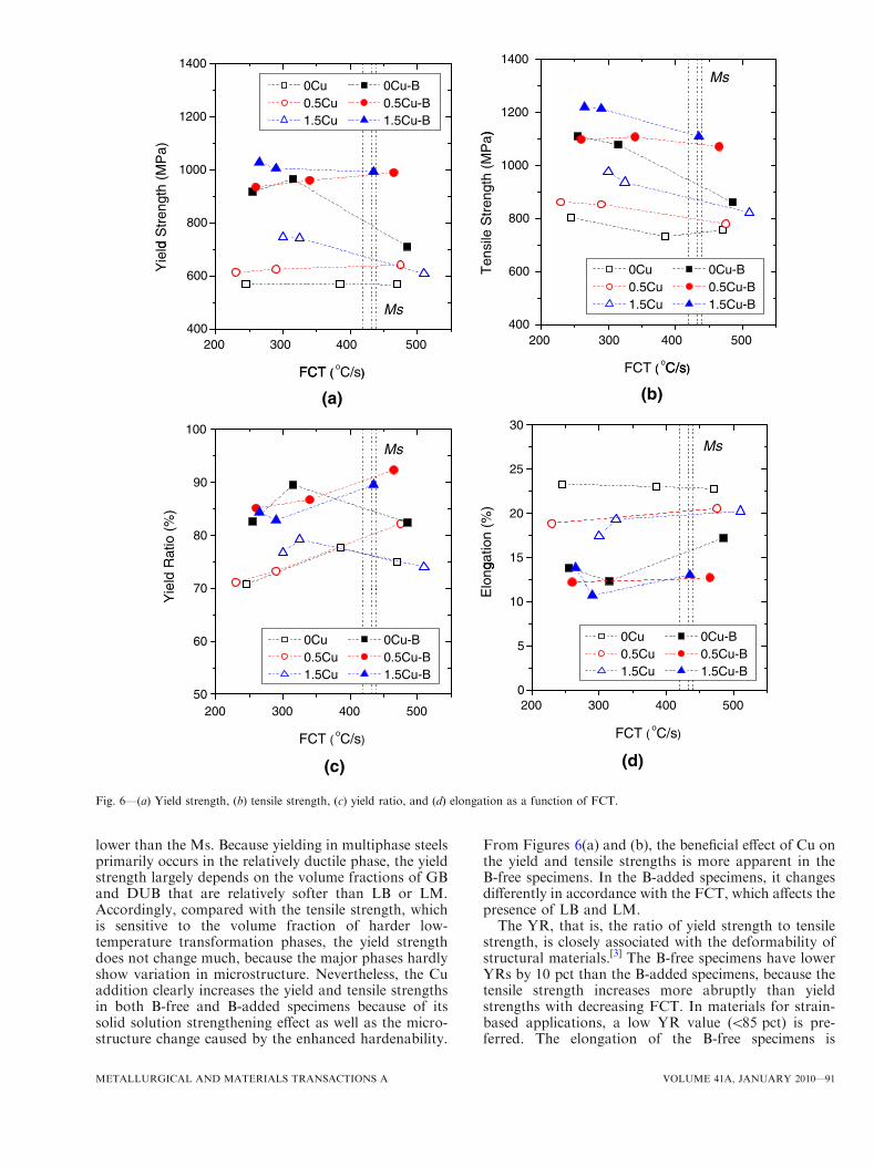
lower than the Ms. Because yielding in multiphase steelsprimarily occurs in the relatively ductile phase, the yieldstrength largely depends on the volume fractions of GBand DUB that are relatively softer than LB or LM.Accordingly, compared with the tensile strength, whichis sensitive to the volume fraction of harder low-temperature transformation phases, the yield strengthdoes not change much, because the major phases hardlyshow variation in microstructure. Nevertheless, the Cuaddition clearly increases the yield and tensile strengthsin both B-free and B-added specimens because of itssolid solution strengthening effect as well as the micro-structure change caused by the enhanced hardenability.
From Figures 6(a) and (b), the beneficial effect of Cu onthe yield and tensile strengths is more apparent in theB-free specimens. In the B-added specimens, it changesdifferently in accordance with the FCT, which affects thepresence of LB and LM.The YR, that is, the ratio of yield strength to tensile
strength, is closely associated with the deformability ofstructural materials.[3] The B-free specimens have lowerYRs by 10 pct than the B-added specimens, because thetensile strength increases more abruptly than yieldstrengths with decreasing FCT. In materials for strain-based applications, a low YR value (<85 pct) is pre-ferred. The elongation of the B-free specimens is
(b)(a)
Ms
1200
1400
)
1200
1400
0Cu 0Cu-B 0.5Cu 0.5Cu-B 1.5Cu 1.5Cu-B
800
1000
le S
tren
gth
(MP
a)
800
1000d
Str
engt
h (M
Pa)
Ms
200 300 400 500400
600Ten
si
FCT (oC/s)
0Cu 0Cu-B 0.5Cu 0.5Cu-B 1.5Cu 1.5Cu-B
200 300 400 500400
600
Yie
ld
FCT (oC/s)
30100
(d)(c)
MsMs
( C/s)FCT ( )
15
20
25ga
tion
(%)
70
80
90
Rat
io (
%)
200 5000
5
10
Elo
ng
0Cu 0Cu-B 0.5Cu 0.5Cu-B 1.5Cu 1.5Cu-B
200 400 50050
60
Yie
ld
0Cu 0Cu-B 0.5Cu 0.5Cu-B 1.5Cu 1.5Cu-B
300 400
FCT ( oC/s)
300
FCT ( oC/s)
Fig. 6—(a) Yield strength, (b) tensile strength, (c) yield ratio, and (d) elongation as a function of FCT.
METALLURGICAL AND MATERIALS TRANSACTIONS A VOLUME 41A, JANUARY 2010—91

approximately 16 to 24 pct, which is higher by 5 to10 pct than that of the B-added specimens and hardlychanges with the variation of FCT. The Cu addition,however, reduces the elongation of the B-free specimens,while it largely does not affect the YR and elongation ofthe B-added specimens.
D. Charpy Impact Properties
Figures 7(a) and (b) show the variations in CVN USEand DBTT as a function of FCT. In the specimenscontaining the same content of Cu, the B-addedspecimens usually show a lower USE than the B-freespecimens. Specimens primarily consisting of GB have arelatively excellent USE of 100 to 160 J, while thosecontaining LB and LM have a lower USE of 40 to 80 J.With an increase in the Cu content, the USE tends toreduce clearly in both the B-free and B-added specimens.However, it does not vary much according to FCT,except for the 0Cu-B, which has the lowest USE at theFCT of approximately 250 �C because of the rapidlyincreased volume fraction of LB and LM (Table II).
According to Figure 7(b), the DBTT of all thespecimens is below –50 �C, showing good low-temper-ature toughness, and roughly lowers with the decrease inthe FCT. The specimens fabricated at lower FCTs havesimilar or somewhat lower DBTT than those fabricatedat higher FCTs, although those fabricated at lowerFCTs have relatively higher strength than those fabri-cated at higher FCTs. It seems to be because low-temperature transformation phases have a difference intheir overall effective grain size from the viewpoint ofstrength and DBTT. In Section IV, we will discuss theinfluence of the effective grain size on DBTT bydetermining the crystallographic units based on theEBSD analysis.
IV. DISCUSSION
The Cu addition to ferritic steels generally improvestheir hardness and strength by increasing the stability ofaustenite and by causing solid solution and precipitationhardening.[4–6] In the present study, it is confirmed thattransformation start and finish temperatures decreaseand the volume fraction of low-temperature transfor-mation phases increases by the Cu addition, therebyleading to the increase in yield and tensile strengths. Inorder to scrutinize the effect of Cu on the phasetransformation behavior and mechanical properties,detailed TEM observations were performed on the0Cu and 1.5Cu specimens. In the 1.5Cu specimen, Cuprecipitates such as 9R, 3R, and e-Cu are hardlyobserved, but GB primarily constitutes the microstruc-ture. Energy-filtered TEM observation results show thatthe substructure of the 1.5Cu specimen is changedslightly compared to the 0Cu specimen, as shown inFigure 8. The discrete striation is found perpendicularto the [001]a direction of the matrix. It is a case similar tothe modulated structure reported in the alloy systemswith spinodal decomposition.[15]
Although extensive studies have been carried out onthe precipitation of Cu in ferritic steels, the initial stageof the microstructure prior to Cu precipitation was notfully understood. It was first reported by Hornbogenand Glenn[16] that bcc Cu clusters were initially formedand were coherent with the ferritic matrix in Fe-1.23 pctCu alloy. Later, Youle, Ralph and Goodman[17,18]
confirmed, using field-ion microscopy, that the hardnessof the Fe-Cu alloy reached its peak value when thedensity of coherent bcc Cu clusters in the a matrixattained their maximum. Recent investigations of the Cuprecipitation, using extended X-ray absorption finestructure, small-angle neutron scattering, TEM, and
200
250
300
(J)
0Cu 0Cu-B 0.5Cu 0.5Cu-B 1.5Cu 1.5Cu-B
-40
-20
0
o C)
0Cu 0Cu-B 0.5Cu 0.5Cu-B 1.5Cu 1.5Cu-B
(b)(a)
50
100
150
CV
N U
SE
(
-100
-80
-60
CV
N D
BT
T (
200 300 400 5000
FCT ( oC/s)
200 300 400 500-120
FCT ( oC/s)
MsMs
Fig. 7—CVN (a) USE and (b) DBTT as a function of FCT.
92—VOLUME 41A, JANUARY 2010 METALLURGICAL AND MATERIALS TRANSACTIONS A
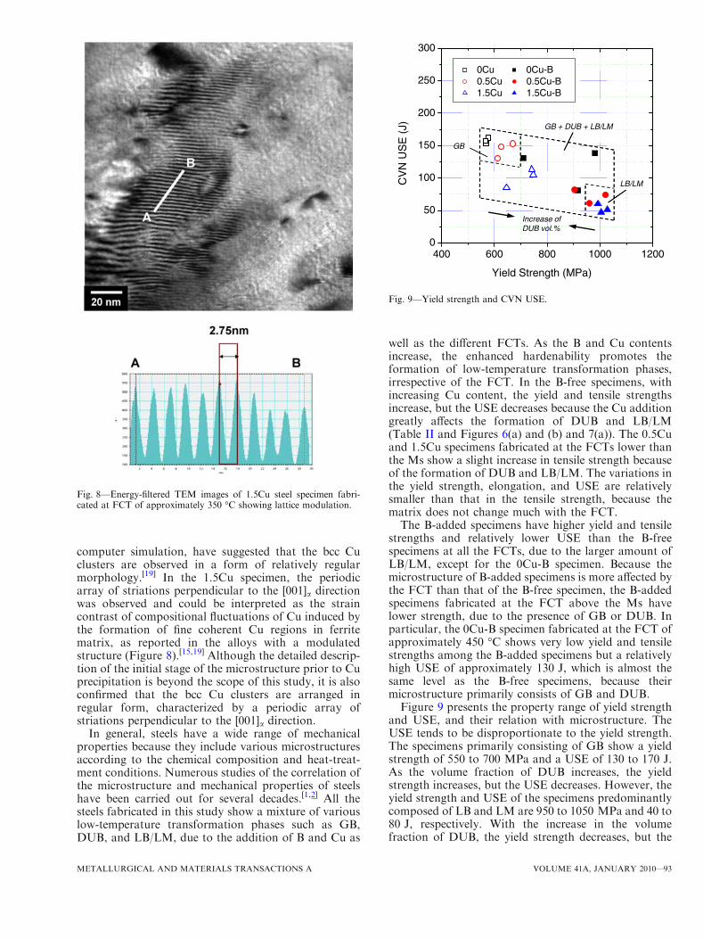
computer simulation, have suggested that the bcc Cuclusters are observed in a form of relatively regularmorphology.[19] In the 1.5Cu specimen, the periodicarray of striations perpendicular to the [001]a directionwas observed and could be interpreted as the straincontrast of compositional fluctuations of Cu induced bythe formation of fine coherent Cu regions in ferritematrix, as reported in the alloys with a modulatedstructure (Figure 8).[15,19] Although the detailed descrip-tion of the initial stage of the microstructure prior to Cuprecipitation is beyond the scope of this study, it is alsoconfirmed that the bcc Cu clusters are arranged inregular form, characterized by a periodic array ofstriations perpendicular to the [001]a direction.
In general, steels have a wide range of mechanicalproperties because they include various microstructuresaccording to the chemical composition and heat-treat-ment conditions. Numerous studies of the correlation ofthe microstructure and mechanical properties of steelshave been carried out for several decades.[1,2] All thesteels fabricated in this study show a mixture of variouslow-temperature transformation phases such as GB,DUB, and LB/LM, due to the addition of B and Cu as
well as the different FCTs. As the B and Cu contentsincrease, the enhanced hardenability promotes theformation of low-temperature transformation phases,irrespective of the FCT. In the B-free specimens, withincreasing Cu content, the yield and tensile strengthsincrease, but the USE decreases because the Cu additiongreatly affects the formation of DUB and LB/LM(Table II and Figures 6(a) and (b) and 7(a)). The 0.5Cuand 1.5Cu specimens fabricated at the FCTs lower thanthe Ms show a slight increase in tensile strength becauseof the formation of DUB and LB/LM. The variations inthe yield strength, elongation, and USE are relativelysmaller than that in the tensile strength, because thematrix does not change much with the FCT.The B-added specimens have higher yield and tensile
strengths and relatively lower USE than the B-freespecimens at all the FCTs, due to the larger amount ofLB/LM, except for the 0Cu-B specimen. Because themicrostructure of B-added specimens is more affected bythe FCT than that of the B-free specimen, the B-addedspecimens fabricated at the FCT above the Ms havelower strength, due to the presence of GB or DUB. Inparticular, the 0Cu-B specimen fabricated at the FCT ofapproximately 450 �C shows very low yield and tensilestrengths among the B-added specimens but a relativelyhigh USE of approximately 130 J, which is almost thesame level as the B-free specimens, because theirmicrostructure primarily consists of GB and DUB.Figure 9 presents the property range of yield strength
and USE, and their relation with microstructure. TheUSE tends to be disproportionate to the yield strength.The specimens primarily consisting of GB show a yieldstrength of 550 to 700 MPa and a USE of 130 to 170 J.As the volume fraction of DUB increases, the yieldstrength increases, but the USE decreases. However, theyield strength and USE of the specimens predominantlycomposed of LB and LM are 950 to 1050 MPa and 40 to80 J, respectively. With the increase in the volumefraction of DUB, the yield strength decreases, but the
Fig. 8—Energy-filtered TEM images of 1.5Cu steel specimen fabri-cated at FCT of approximately 350 �C showing lattice modulation.
250
300
0Cu 0Cu-B
200
250
E (
J)
0.5Cu 0.5Cu-B 1.5Cu 1.5Cu-B
GB + DUB + LB/LM
100
150
CV
N U
SE
GB
LB/LM
400 600 800 1000 12000
50Increase of DUB vol.%
Yield Strength (MPa)
Fig. 9—Yield strength and CVN USE.
METALLURGICAL AND MATERIALS TRANSACTIONS A VOLUME 41A, JANUARY 2010—93
USE increases, in contrast with the specimens consistingof GB. Accordingly, it is likely that the specimenscomposed of GB, DUB, and LB/LM will have proper-ties between the combinations of the yield strength andUSE. Indeed, the 0Cu-B specimen fabricated at the FCTof approximately 350 �C provides an excellent combi-nation of a high yield strength of approximately970 MPa and a high USE of approximately 140 J,among the specimens fabricated in the present study,because the microstructure is optimally mixed withLB/LM and DUB together with a GB of 10 vol pct.
Unexpectedly, the DBTT of the specimens does notseriously increase with decreasing FCT, although thestrength increases due to the harder low-temperaturetransformation phases usually transformed at the lowerFCTs. The USE obtained from the CVN impact data iscommonly affected by the matrix phase and the type,volume fraction, and size of the secondary phases, whilethe DBTT mainly depends on the type and size of thephases and especially the effective grain size.[14,20,21]
When many high-angled grains with large misorienta-tions are finely formed, the effective grain size decreases,and thus the DBTT lowers. As is well known in theliterature, nearly all strengthening mechanisms areaccompanied by a reduction in toughness, except forgrain size refinement.[1–3] The following modified Hall–Petch and Cottrell–Petch relationships indicate the yieldstrength (ry) and CVN DBTT (VTrs), as a function ofcommon strengthening approaches in structural steels:[3]
ry ¼ r0 þ rS þ rD þ rP þ k�D�1=2 ½1�
VTrs ¼ F r0 þ rS þ rD þ rPð Þ � k0�D�1=2 ½2�
where r0 refers to the friction strengthening, rS to thesolid solution strengthening, rD to the dislocationstrengthening, rP to the precipitation strengthening,and D to the effective grain size or facet size forcleavage. In simple ferritic steels, D corresponds to themean grain size of polygonal ferrite. However, in steelswith more complex microstructures, it has been foundthat the mean effective grain size, usually characterizedby crystal misorientations of at least 10 deg, moreproperly describes the microstructural parameter forD.[3,21]
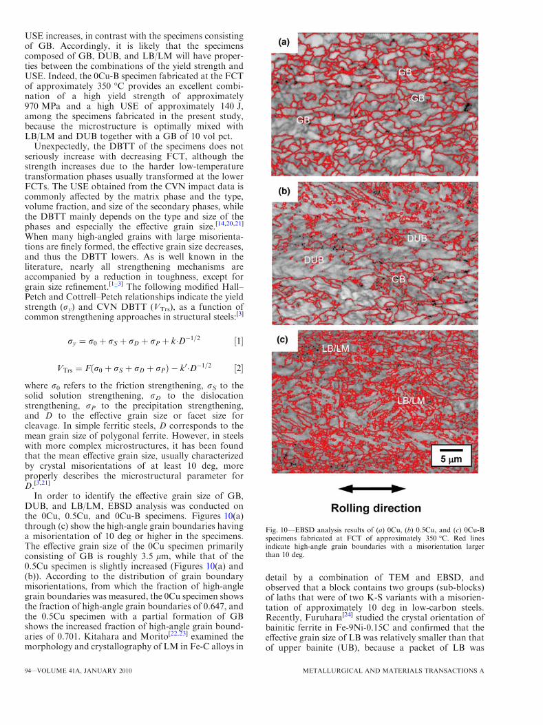
In order to identify the effective grain size of GB,DUB, and LB/LM, EBSD analysis was conducted onthe 0Cu, 0.5Cu, and 0Cu-B specimens. Figures 10(a)through (c) show the high-angle grain boundaries havinga misorientation of 10 deg or higher in the specimens.The effective grain size of the 0Cu specimen primarilyconsisting of GB is roughly 3.5 lm, while that of the0.5Cu specimen is slightly increased (Figures 10(a) and(b)). According to the distribution of grain boundarymisorientations, from which the fraction of high-anglegrain boundaries was measured, the 0Cu specimen showsthe fraction of high-angle grain boundaries of 0.647, andthe 0.5Cu specimen with a partial formation of GBshows the increased fraction of high-angle grain bound-aries of 0.701. Kitahara and Morito[22,23] examined themorphology and crystallography of LM in Fe-C alloys in
detail by a combination of TEM and EBSD, andobserved that a block contains two groups (sub-blocks)of laths that were of two K-S variants with a misorien-tation of approximately 10 deg in low-carbon steels.Recently, Furuhara[24] studied the crystal orientation ofbainitic ferrite in Fe-9Ni-0.15C and confirmed that theeffective grain size of LB was relatively smaller than thatof upper bainite (UB), because a packet of LB was
Fig. 10—EBSD analysis results of (a) 0Cu, (b) 0.5Cu, and (c) 0Cu-Bspecimens fabricated at FCT of approximately 350 �C. Red linesindicate high-angle grain boundaries with a misorientation largerthan 10 deg.
94—VOLUME 41A, JANUARY 2010 METALLURGICAL AND MATERIALS TRANSACTIONS A
divided by blocks containing a single variant of laths,whereas that of UB had laths of two K-S variants with asmall misorientation (sub-blocks). As with these results,the 0Cu-B specimen predominantly composed of LB andLM has a very fine effective grain size, below 1.5 lm, andshows the highest fraction of high-angle grain bound-aries of 0.738, compared to the 0Cu and 0.5Cu specimens(Figures 10(a) through (c)).[3] As mentioned earlier,because the increase in strength can be accompanied bydeteriorating toughness, hard LB and LM phases canusually result in a decrease in USE or an increase inDBTT. Nevertheless, the specimens containing LB andLM have a DBTT similar to or rather lower than theother specimens, although they have a higher strengthand lower USE. This could be explained in terms of theeffective grain size.[20,21]
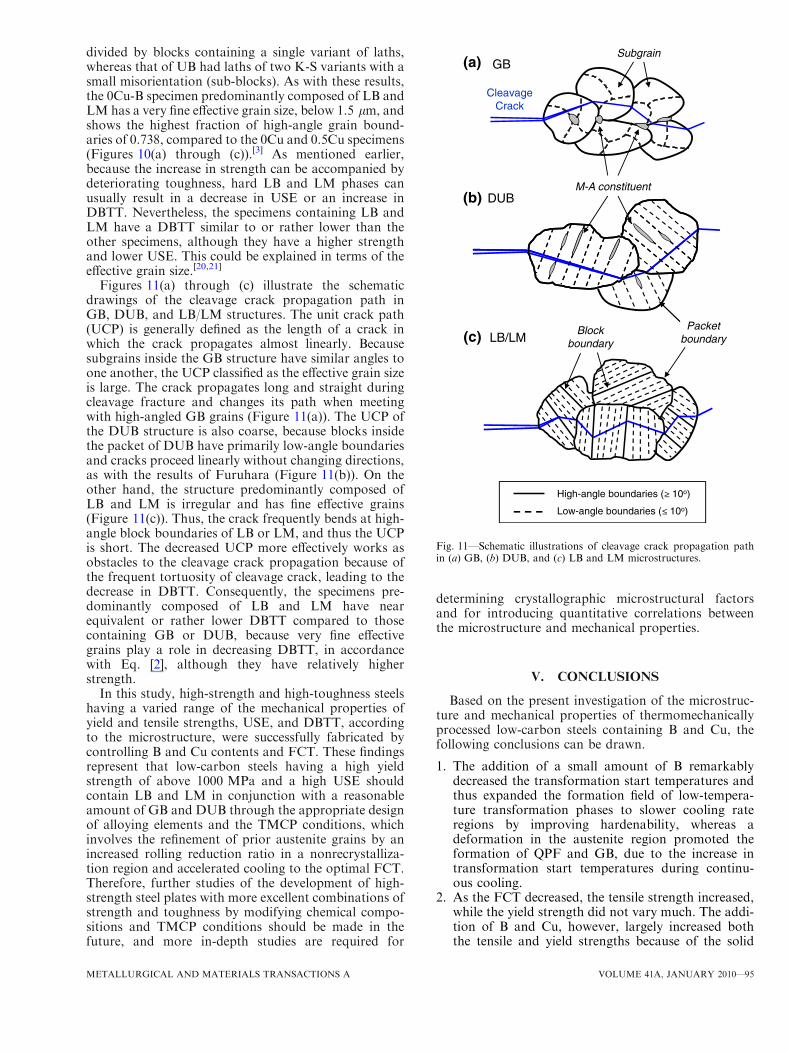
Figures 11(a) through (c) illustrate the schematicdrawings of the cleavage crack propagation path inGB, DUB, and LB/LM structures. The unit crack path(UCP) is generally defined as the length of a crack inwhich the crack propagates almost linearly. Becausesubgrains inside the GB structure have similar angles toone another, the UCP classified as the effective grain sizeis large. The crack propagates long and straight duringcleavage fracture and changes its path when meetingwith high-angled GB grains (Figure 11(a)). The UCP ofthe DUB structure is also coarse, because blocks insidethe packet of DUB have primarily low-angle boundariesand cracks proceed linearly without changing directions,as with the results of Furuhara (Figure 11(b)). On theother hand, the structure predominantly composed ofLB and LM is irregular and has fine effective grains(Figure 11(c)). Thus, the crack frequently bends at high-angle block boundaries of LB or LM, and thus the UCPis short. The decreased UCP more effectively works asobstacles to the cleavage crack propagation because ofthe frequent tortuosity of cleavage crack, leading to thedecrease in DBTT. Consequently, the specimens pre-dominantly composed of LB and LM have nearequivalent or rather lower DBTT compared to thosecontaining GB or DUB, because very fine effectivegrains play a role in decreasing DBTT, in accordancewith Eq. [2], although they have relatively higherstrength.
In this study, high-strength and high-toughness steelshaving a varied range of the mechanical properties ofyield and tensile strengths, USE, and DBTT, accordingto the microstructure, were successfully fabricated bycontrolling B and Cu contents and FCT. These findingsrepresent that low-carbon steels having a high yieldstrength of above 1000 MPa and a high USE shouldcontain LB and LM in conjunction with a reasonableamount of GB and DUB through the appropriate designof alloying elements and the TMCP conditions, whichinvolves the refinement of prior austenite grains by anincreased rolling reduction ratio in a nonrecrystalliza-tion region and accelerated cooling to the optimal FCT.Therefore, further studies of the development of high-strength steel plates with more excellent combinations ofstrength and toughness by modifying chemical compo-sitions and TMCP conditions should be made in thefuture, and more in-depth studies are required for
determining crystallographic microstructural factorsand for introducing quantitative correlations betweenthe microstructure and mechanical properties.
V. CONCLUSIONS
Based on the present investigation of the microstruc-ture and mechanical properties of thermomechanicallyprocessed low-carbon steels containing B and Cu, thefollowing conclusions can be drawn.
1. The addition of a small amount of B remarkablydecreased the transformation start temperatures andthus expanded the formation field of low-tempera-ture transformation phases to slower cooling rateregions by improving hardenability, whereas adeformation in the austenite region promoted theformation of QPF and GB, due to the increase intransformation start temperatures during continu-ous cooling.
2. As the FCT decreased, the tensile strength increased,while the yield strength did not vary much. The addi-tion of B and Cu, however, largely increased boththe tensile and yield strengths because of the solid
(a)
CleavageCrack
GBSubgrain
(b)M-A constituent
DUB
(c) LB/LMBlock
boundary
Packetboundary
High-angle boundaries ( 10o)
Low-angle boundaries ( 10o)
Fig. 11—Schematic illustrations of cleavage crack propagation pathin (a) GB, (b) DUB, and (c) LB and LM microstructures.
METALLURGICAL AND MATERIALS TRANSACTIONS A VOLUME 41A, JANUARY 2010—95

solution strengthening effect and the microstructuralchange by the enhanced hardenability irrespective ofthe FCT.
3. The yield strength and USE of the specimens pri-marily consisting of GB were 550 to 700 MPa and130 to 170 J, respectively. As the volume fraction ofDUB increased, the yield strength increased, butthe USE decreased. On the other hand, the speci-mens predominantly composed of LB and LMshowed a yield strength of 950 to 1050 MPa and aUSE of 40 to 80 J. With increases in the volumefraction of DUB, the yield strength decreased, butthe USE increased, in contrast with those primarilyconsisting of GB.
4. The 0Cu-B specimen fabricated at the FCT ofapproximately 350 �C was optimally mixed withDUB and LB/LM together with a GB of 10 vol pct,and thus provided an excellent combination of ahigh yield strength of approximately 970 MPa anda high USE of approximately 140 J.
5. The specimens predominantly composed of LB andLM had relatively lower USE than those mainlyconsisting of GB and DUB. However, the formerspecimens exhibited nearly a DBTT equivalent toor lower than the latter specimens, in spite of theincreased strength. This was because the LB or LMmicrostructure had a relatively smaller effectivegrain size than the GB or DUB microstructure,according to the EBSD analysis data.
ACKNOWLEDGMENTS
This study was financially supported by a grant(Grant No. M2007010007) from the Fundamental R&DProgram for Core Technology of Materials fundedby the Ministry of Knowledge Economy, Gwacheon,Korea. The authors thank Professor Sunghak Lee, Dr.Sang Yong Shin, and Mr. Hyo Kyung Sung of PohangUniversity of Science and Technology (POSTECH,Pohang, Korea) for their help with the Charpy impacttest analysis.
REFERENCES1. I. Tamura, H. Sekine, T. Tanaka, and C. Ouchi: Thermomechan-
ical Processing of High-Strength Low-Alloy Steels, Butterworth &Co. Ltd., London, UK, 1988.
2. T. Gladman: The Physical Metallurgy of Microalloyed Steels, TheInstitute of Materials, London, UK, 1997.
3. J.Y. Koo, M.J. Luton, N.V. Bangaru, R.A. Petkovic, D.P.Fairchild, C.W. Petersen, H. Asahi, T. Hara, Y. Terada, M.Sugiyama, H. Tamehiro, Y. Komizo, S. Okaguchi, M. Hamada,A. Yamamoto, and I. Takeuchi: Int. J. Offshore Polar Eng.,2004, vol. 14, pp. 2–10.
4. Y.N. Malinochka, G.Z. Koval’chuk, and V.N. Yarmosh:Met. Sci.Heat Treat., 1982, vol. 24, pp. 760–65.
5. S.S. Ghasemi Banadkouki and D.P. Dunne: ISIJ Int., 2006,vol. 46, pp. 759–68.
6. A. Fatehi, A.M. Elwazri, J. Calvo, and S. Yue: Proc. MaterialsScience and Technology 2008, TMS, Warrendale, PA, 2008,pp. 1562–70.
7. S.K. Banerji and J.E. Morral: Proc. Int. Symp. Boron in Steels,TMS-AIME, Warrendale, PA, 1979.
8. B.L. Bramfitt and J.G. Speer: Metall. Trans. A, 1990, vol. 21A,pp. 817–29.
9. G.Krauss and S.W. Thompson: ISIJ Int., 1995, vol. 35, pp. 937–45.10. T. Hayashi, F. Kawabata, and K. Amano: Proc. Materials Solu-
tion ’97 on Accelerated Cooling/Direct Quenching Steels, ASMINTERNATIONAL, Materials Park, OH, 1997, pp. 93–99.
11. P. Cizek, B.P. Wynne, C.H.J. Davies, B.C. Muddle, and P.D.Hodgson: Metall. Mater. Trans. A, 2002, vol. 33A, pp. 1331–49.
12. B.C. Kim, S. Lee, N.J. Kim, and D.Y. Lee:Metall. Trans. A, 1991,vol. 22A, pp. 139–49.
13. J.H. Chen, Y. Kikuta, T. Araki, M. Yoneda, and Y. Matsuda:Acta Metall., 1984, vol. 32, pp. 1779–88.
14. Y.M. Kim, S.Y. Shin, H. Lee, B. Hwang, S. Lee, and N.J. Kim:Metall. Mater. Trans. A, 2007, vol. 38A, pp. 1731–42.
15. J.C. Zhao andM.R.Notis:ActaMetall., 1998, vol. 46, pp. 4203–18.16. E. Hornbogen and R.C. Glenn: Trans. TMS-AIME, 1960,
vol. 218, pp. 1064–70.17. A. Youle and B. Ralph: Met. Sci., 1972, vol. 6, pp. 149–52.18. S.R. Goodman, S.S. Brenner, and J.R. Low, Jr.: Metall. Trans.,
1973, vol. 4, pp. 2363–69.19. T.-H. Lee, Y.-O. Kim, and S.-J. Kim: Philos. Mag., 2007, vol. 87,
pp. 209–24.20. B. Hwang, Y.M. Kim, S. Lee, N.J. Kim, and S.S. Ahn: Metall.
Mater. Trans. A, 2005, vol. 36A, pp. 725–39.21. B. Hwang, Y.G. Kim, S. Lee, Y.M. Kim, N.J. Kim, and J.Y. Yoo:
Metall. Mater. Trans. A, 2005, vol. 36A, pp. 2107–14.22. H. Kitahara, R. Ueji, N. Tsuji, and Y. Minamino: Acta Mater.,
2006, vol. 54, pp. 1279–88.23. S. Morito, X. Huang, T. Furuhara, T. Maki, and N. Hansen: Acta
Mater., 2006, vol. 54, pp. 5323–31.24. T. Furuhara, S. Morito, and T. Maki: Proc. 1st Int. Symp. on Steel
Science, ISIJ, Kyoto, Japan, 2007, pp. 51–56.
96—VOLUME 41A, JANUARY 2010 METALLURGICAL AND MATERIALS TRANSACTIONS A
Copyright © 2022 FDOKUMEN