ControlLogix Digital Isolated Input Module - Spectrum Controls
44
Owner’s Guide 0300275-01B ControlLogix Digital Isolated Input Module Catalog Number: 1756sc-IC32
-
Upload
khangminh22 -
Category
Documents
-
view
3 -
download
0
Transcript of ControlLogix Digital Isolated Input Module - Spectrum Controls
Owner’s Guide 0300275-01B
ControlLogix Digital Isolated Input Module Catalog Number: 1756sc-IC32

ii ControlLogix Digital Isolated Input Module Owner’s Guide
Owner’s Guide 0300275-01B
ControlLogix Digital Isolated Input Module Owner’s Guide iii
Owner’s Guide 0300275-01B
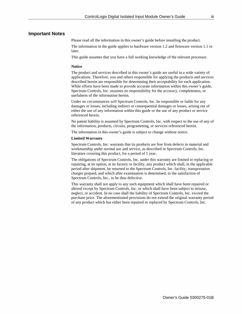
Important Notes Please read all the information in this owner’s guide before installing the product. The information in the guide applies to hardware version 1.2 and firmware version 1.1 or later. This guide assumes that you have a full working knowledge of the relevant processor.
Notice The product and services described in this owner’s guide are useful in a wide variety of applications. Therefore, you and others responsible for applying the products and services described herein are responsible for determining their acceptability for each application. While efforts have been made to provide accurate information within this owner’s guide, Spectrum Controls, Inc. assumes no responsibility for the accuracy, completeness, or usefulness of the information herein. Under no circumstances will Spectrum Controls, Inc. be responsible or liable for any damages or losses, including indirect or consequential damages or losses, arising out of either the use of any information within this guide or the use of any product or service referenced herein. No patent liability is assumed by Spectrum Controls, Inc. with respect to the use of any of the information, products, circuits, programming, or services referenced herein. The information in this owner’s guide is subject to change without notice. Limited Warranty Spectrum Controls, Inc. warrants that its products are free from defects in material and workmanship under normal use and service, as described in Spectrum Controls, Inc. literature covering this product, for a period of 1 year. The obligations of Spectrum Controls, Inc. under this warranty are limited to replacing or repairing, at its option, at its factory or facility, any product which shall, in the applicable period after shipment, be returned to the Spectrum Controls, Inc. facility, transportation charges prepaid, and which after examination is determined, to the satisfaction of Spectrum Controls, Inc., to be thus defective. This warranty shall not apply to any such equipment which shall have been repaired or altered except by Spectrum Controls, Inc. or which shall have been subject to misuse, neglect, or accident. In no case shall the liability of Spectrum Controls, Inc. exceed the purchase price. The aforementioned provisions do not extend the original warranty period of any product which has either been repaired or replaced by Spectrum Controls, Inc.
iv ControlLogix Digital Isolated Input Module Owner’s Guide
Owner’s Guide 0300275-01B
Microsoft and Microsoft Windows are registered trademarks of Microsoft Corporation. The Encompass logo, ControlLogix, RSLinx, and EtherNet/IP are trademarks of Rockwell Automation. Other brands and their products are trademarks or registered trademarks of their respective holders and should be noted as such.
ControlLogix Digital Isolated Input Module Owner’s Guide v
Owner’s Guide 0300275-01B
Table of Contents
IMPORTANT NOTES .............................................................................................................................................. III
PREFACE ............................................................................................................................................................... VI
CHAPTER 1 INSTALLING A CONTROLLOGIX 1756SC-IC32 – DIGITAL ISOLATED INPUT MODULE .............................. 1
SECTION 1.1 BEFORE YOU BEGIN .................................................................................................................................. 1-1 SECTION 1.2 UNDERSTAND COMPLIANCE TO EUROPEAN DIRECTIVE ..................................................................................... 1-2
1.2.1 EMC Directive ............................................................................................................................................ 1-2 1.2.2 Low Voltage Directive ............................................................................................................................... 1-2 1.2.3 Important Power Requirements Information ........................................................................................... 1-3 1.2.4 Identifying the Module Components ........................................................................................................ 1-3 1.2.5 Removable Terminal Block and Housing ................................................................................................... 1-3
SECTION 1.3 INSTALLING THE MODULE ........................................................................................................................... 1-4 SECTION 1.4 KEYING THE REMOVABLE TERMINAL BLOCK/INTERFACE MODULE ...................................................................... 1-5 SECTION 1.5 WIRING THE REMOVABLE TERMINAL BLOCK .................................................................................................. 1-5
1.5.1 Wiring the Spring Clamp RTB .................................................................................................................... 1-6 1.5.2 Wiring the Cage Clamp RTB ...................................................................................................................... 1-6 1.5.3 1756sc-IC32 Wiring Example .................................................................................................................... 1-7
SECTION 1.6 ASSEMBLING THE REMOVABLE TERMINAL BLOCK AND THE HOUSING .................................................................. 1-8 SECTION 1.7 INSTALLING THE REMOVABLE TERMINAL BLOCK ONTO THE MODULE................................................................... 1-8
1.7.1 Checking the Indicators ............................................................................................................................. 1-9 SECTION 1.8 REMOVING THE REMOVABLE TERMINAL BLOCK AND THE HOUSING .................................................................. 1-10 SECTION 1.9 CONFIGURING THE MODULE ..................................................................................................................... 1-11
1.9.1 Module Identity Information .................................................................................................................. 1-11 1.9.2 PLC Interface Information ....................................................................................................................... 1-12 1.9.3 Configuration Table Information ............................................................................................................ 1-13 1.9.4 Configuration Table Information ............................................................................................................ 1-14 1.9.1 AOP Input Data Tags Information........................................................................................................... 1-15
CHAPTER 2 CONFIGURING THE MODULE WITH RSLOGIX 5000 ............................................................................ 2-1
SECTION 2.1 CONFIGURING THE MODULE WITH RSLOGIX 5000 ......................................................................................... 2-1 2.1.1 Specifying General Options ....................................................................................................................... 2-5 2.1.2 Specifying Connection Options ................................................................................................................. 2-7 2.1.3 Viewing Module Information .................................................................................................................... 2-9 2.1.4 Specifying Configuration Information ..................................................................................................... 2-10 2.1.5 Viewing Vendor Information ................................................................................................................... 2-11
vi ControlLogix Digital Isolated Input Module Owner’s Guide
Owner’s Guide 0300275-01B
Preface
Read this introduction to familiarize you with the rest of the owner’s guide. This preface covers the following topics:
• Who should use this guide • How to use this guide • Related publications • Conventions used in this guide • Rockwell Automation support
Who Should Use This Manual
You must be able to program and operate an Allen-Bradley ControlLogix™ 1756 Controller to efficiently use your input modules. We assume that you know how to do that in this manual. If you do not, refer to the appropriate Allen Bradley manual for the associated AB controller.
How to Use This Manual
Use this guide to install, configure, and troubleshoot your ControlLogix input module. The AC or DC (30-60 V) Input Module mounts to an Allen-Bradley ControlLogix 1756 Controller chassis. The module uses a Removable Terminal Block (RTB) or an Interface Module (IFM) to connect all field-side wiring. When using an IFM to wire your module, consult the installation instructions that came with it to connect all wiring. Before you install your module you should have already:
• Installed and grounded a 1756 chassis and power supply. • Ordered and received an RTB or IFM and its components for your application.
Technical Support
For technical support, please contact your local Rockwell Automation TechConnect Office for all Spectrum I/O (1746, 1756, 1771, 1769, 1794, and 1762). Contact numbers are as follows:
• United States: 1-440-646-6900 • United Kingdom: 01908-635230 • Australia: 1800-809929 • Brazil: 011 (55) 1136198800 • Mexico: 001-888-365-8677 • Europe: (49) 2104 960 630
or send an email to [email protected]
ControlLogix Digital Isolated Input Module Owner’s Guide vii
Owner’s Guide 0300275-01B
Conventions Used in This Manual
The following conventions are used throughout this manual: • Bulleted lists (like this one) provide information not procedural steps. • Numbered lists provide sequential steps or hierarchical information. • Italic type is used for emphasis. • Bold type identifies headings and sub-headings:
WARNING DANGER
• Are used to identify critical information for you.

viii ControlLogix Digital Isolated Input Module Owner’s Guide
Owner’s Guide 0300275-01B
Owner’s Guide 0300275-01B
Chapter 1 Installing a ControlLogix 1756sc-IC32 – Digital Isolated Input Module
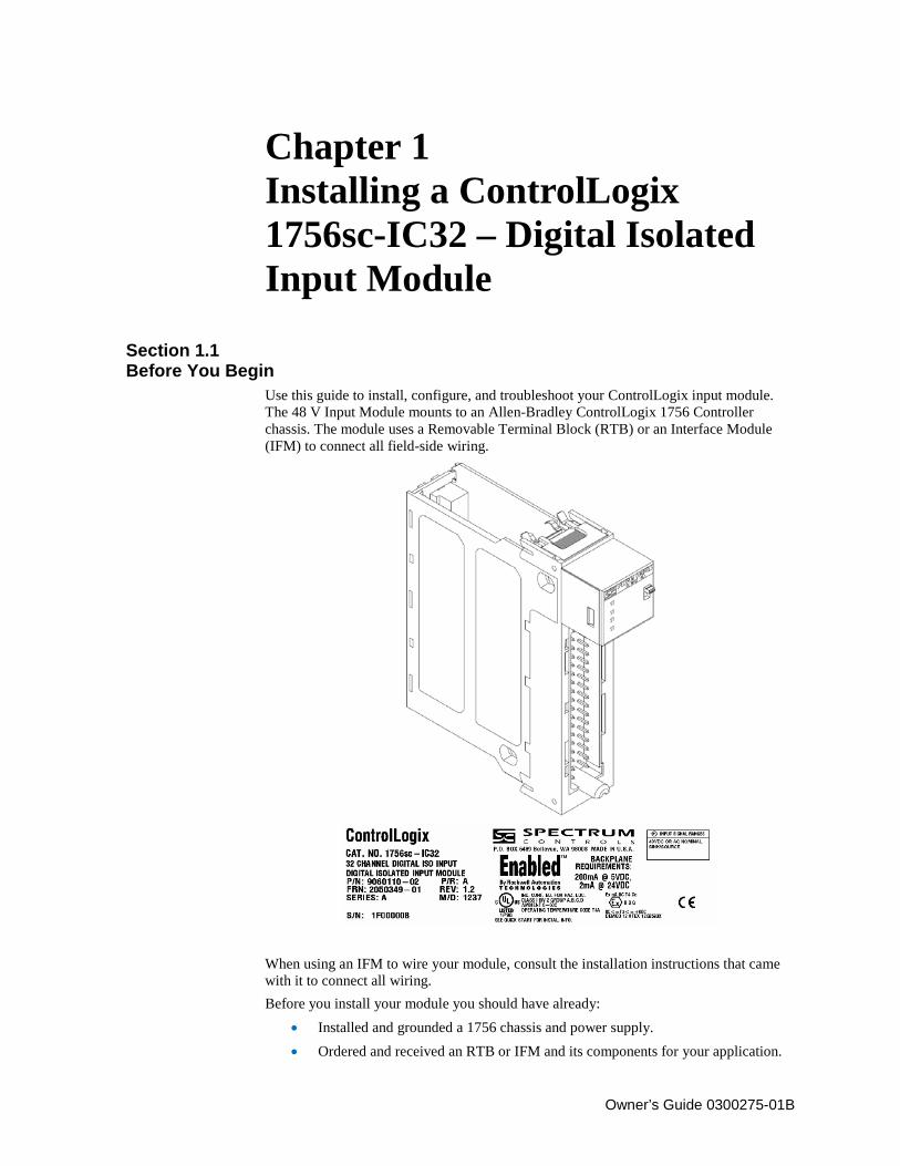
Section 1.1 Before You Begin
Use this guide to install, configure, and troubleshoot your ControlLogix input module. The 48 V Input Module mounts to an Allen-Bradley ControlLogix 1756 Controller chassis. The module uses a Removable Terminal Block (RTB) or an Interface Module (IFM) to connect all field-side wiring.
When using an IFM to wire your module, consult the installation instructions that came with it to connect all wiring. Before you install your module you should have already:
• Installed and grounded a 1756 chassis and power supply. • Ordered and received an RTB or IFM and its components for your application.
1-2 Installing a ControlLogix 1756sc-IC32 – Digital Isolated Input Module
Owner’s Guide 0300275-01B
WARNING
Electrostatic discharge can damage integrated circuits or semiconductors if you touch backplane connector pins. To prevent damage, follow these guidelines when you handle the module:
• Touch a grounded object to discharge static potential. • Wear an approved wrist-strap grounding device. • Do not touch the backplane connector or connector pins. • Do not touch circuit components inside the module. • If available, use a static-safe work station. • When not in use, keep the module in its static-shield box.
WARNING
Hazard of electrical arcing when removing or inserting the module while power is applied to the rack. This module is designed so you can remove and insert it under backplane power and field-side power. When you remove or insert a module while field-side power is applied, you may cause an electrical arc. An electrical arc can cause personal injury or property damage because it may:
• Send an erroneous signal to your system’s field devices, causing unintended machine motion or loss of process control.
• Cause an explosion in a hazardous environment. Repeated electrical arcing also causes excessive wear to contacts on both the module and its mating connector. Worn contacts may create electrical resistance.
Section 1.2 Understand Compliance to European Directive
If this product bears the CE marking, it is approved for installation within the European Union and EEA regions. It has been designed and tested to meet the following directives:
1.2.1 EMC Directive This product is tested to meet Council Directive 89/336/EEC Electromagnetic Compatibility (EMC) and the following standards, in whole or in part, documented in a technical construction file:
• EN 50081-2 EMC - Generic Emission Standard, Part 2–Industrial Environment • EN 50082-2 EMC - Generic Immunity Standard, Part 2–Industrial Environment
This product is intended for use in an industrial environment.
1.2.2 Low Voltage Directive This product is tested to meet Council Directive 73/23/EEC Low Voltage, by applying the safety requirements of EN 61131-2 Programmable Controllers, Part 2–Equipment Requirements and Tests.
Installing a ControlLogix 1756sc-IC32 – Digital Isolated Input Module 1-3
Owner’s Guide 0300275-01B
For specific information required by EN 61131-2, see the appropriate sections in this publication, as well as the following Allen-Bradley publications:
• Industrial Automation Wiring and Grounding Guidelines For Noise Immunity, publication 1770-4.1
• Automation Systems Catalog, publication B111. This equipment is classified as open equipment and must be installed (mounted) in an enclosure during operation as a means of providing safety protection.
1.2.3 Important Power Requirements Information This module receives power from the 1756 chassis power supply and requires 2 sources of power: 200 mA at 5 V and 2 mA at 24 V from the backplane. Add this current to the requirements of all other modules in this chassis to prevent overloading the chassis backplane. You receive the following components with your RTB:
• 1756-TBH standard-depth RTB housing. • Wedge-shaped keying tabs and U-shaped keying bands. • A generic RTB door label.
Use these components in all module applications. Use an optional extended-depth cover (1756-TBE) or applications requiring heavy gauge wiring.
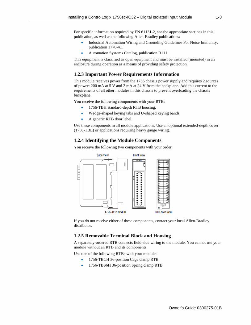
1.2.4 Identifying the Module Components You receive the following two components with your order:
If you do not receive either of these components, contact your local Allen-Bradley distributor.
1.2.5 Removable Terminal Block and Housing A separately-ordered RTB connects field-side wiring to the module. You cannot use your module without an RTB and its components. Use one of the following RTBs with your module:
• 1756-TBCH 36-position Cage clamp RTB • 1756-TBS6H 36-position Spring clamp RTB
1-4 Installing a ControlLogix 1756sc-IC32 – Digital Isolated Input Module
Owner’s Guide 0300275-01B
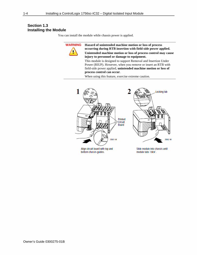
Section 1.3 Installing the Module
You can install the module while chassis power is applied.
WARNING
Hazard of unintended machine motion or loss of process occurring during RTB insertion with field-side power applied. Unintended machine motion or loss of process control may cause injury to personnel or damage to equipment. This module is designed to support Removal and Insertion Under Power (RIUP). However, when you remove or insert an RTB with field-side power applied, unintended machine motion or loss of process control can occur. When using this feature, exercise extreme caution.
Installing a ControlLogix 1756sc-IC32 – Digital Isolated Input Module 1-5
Owner’s Guide 0300275-01B
Section 1.4 Keying the Removable Terminal Block/Interface Module
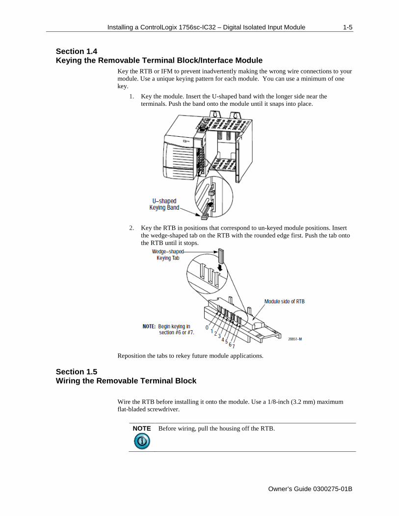
Key the RTB or IFM to prevent inadvertently making the wrong wire connections to your module. Use a unique keying pattern for each module. You can use a minimum of one key.
1. Key the module. Insert the U-shaped band with the longer side near the terminals. Push the band onto the module until it snaps into place.
2. Key the RTB in positions that correspond to un-keyed module positions. Insert
the wedge-shaped tab on the RTB with the rounded edge first. Push the tab onto the RTB until it stops.
Reposition the tabs to rekey future module applications.
Section 1.5 Wiring the Removable Terminal Block
Wire the RTB before installing it onto the module. Use a 1/8-inch (3.2 mm) maximum flat-bladed screwdriver.
NOTE
Before wiring, pull the housing off the RTB.
1-6 Installing a ControlLogix 1756sc-IC32 – Digital Isolated Input Module
Owner’s Guide 0300275-01B
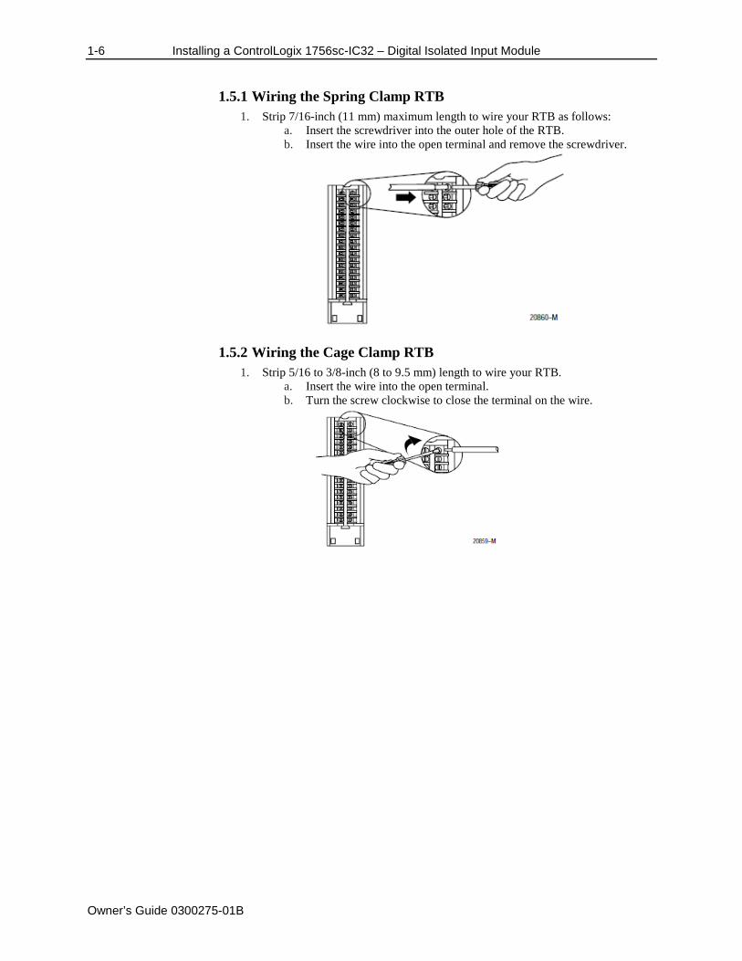
1.5.1 Wiring the Spring Clamp RTB 1. Strip 7/16-inch (11 mm) maximum length to wire your RTB as follows:
a. Insert the screwdriver into the outer hole of the RTB. b. Insert the wire into the open terminal and remove the screwdriver.
1.5.2 Wiring the Cage Clamp RTB 1. Strip 5/16 to 3/8-inch (8 to 9.5 mm) length to wire your RTB.
a. Insert the wire into the open terminal. b. Turn the screw clockwise to close the terminal on the wire.
Installing a ControlLogix 1756sc-IC32 – Digital Isolated Input Module 1-7
Owner’s Guide 0300275-01B
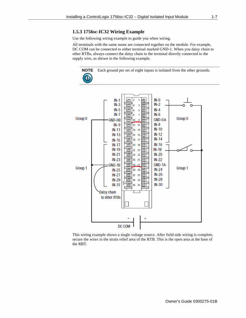
1.5.3 1756sc-IC32 Wiring Example Use the following wiring example to guide you when wiring. All terminals with the same name are connected together on the module. For example, DC COM can be connected to either terminal marked GND-1. When you daisy chain to other RTBs, always connect the daisy chain to the terminal directly connected to the supply wire, as shown in the following example.
NOTE
Each ground per set of eight inputs is isolated from the other grounds.
This wiring example shows a single voltage source. After field-side wiring is complete, secure the wires in the strain relief area of the RTB. This is the open area at the base of the RBT.
1-8 Installing a ControlLogix 1756sc-IC32 – Digital Isolated Input Module
Owner’s Guide 0300275-01B
Section 1.6 Assembling the Removable Terminal Block and the Housing
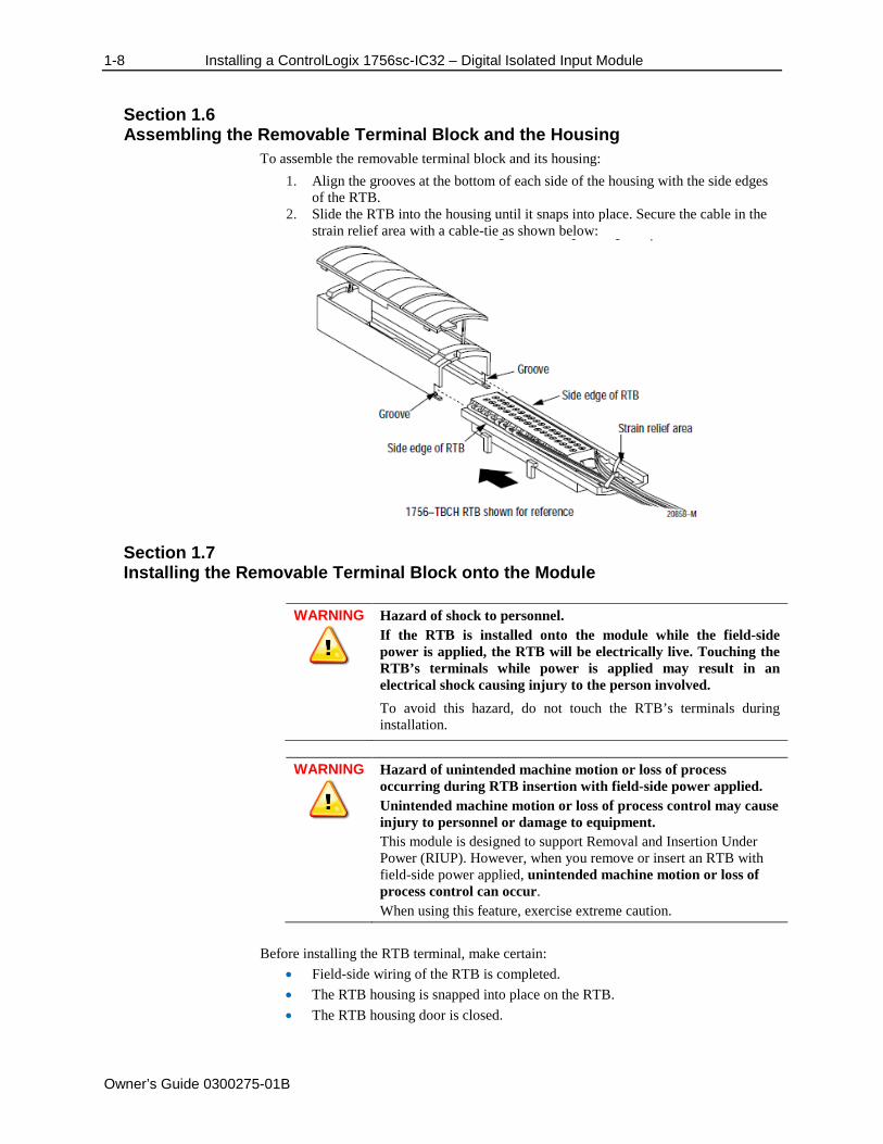
To assemble the removable terminal block and its housing: 1. Align the grooves at the bottom of each side of the housing with the side edges
of the RTB. 2. Slide the RTB into the housing until it snaps into place. Secure the cable in the
strain relief area with a cable-tie as shown below:
Section 1.7 Installing the Removable Terminal Block onto the Module
WARNING
Hazard of shock to personnel. If the RTB is installed onto the module while the field-side power is applied, the RTB will be electrically live. Touching the RTB’s terminals while power is applied may result in an electrical shock causing injury to the person involved. To avoid this hazard, do not touch the RTB’s terminals during installation.
WARNING
Hazard of unintended machine motion or loss of process occurring during RTB insertion with field-side power applied. Unintended machine motion or loss of process control may cause injury to personnel or damage to equipment. This module is designed to support Removal and Insertion Under Power (RIUP). However, when you remove or insert an RTB with field-side power applied, unintended machine motion or loss of process control can occur. When using this feature, exercise extreme caution.
Before installing the RTB terminal, make certain:
• Field-side wiring of the RTB is completed. • The RTB housing is snapped into place on the RTB. • The RTB housing door is closed.
Installing a ControlLogix 1756sc-IC32 – Digital Isolated Input Module 1-9
Owner’s Guide 0300275-01B
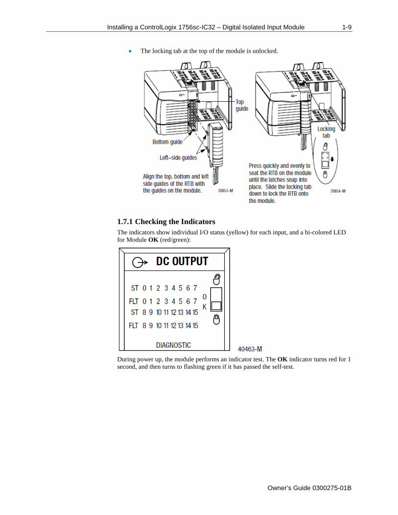
• The locking tab at the top of the module is unlocked.
1.7.1 Checking the Indicators The indicators show individual I/O status (yellow) for each input, and a bi-colored LED for Module OK (red/green):
During power up, the module performs an indicator test. The OK indicator turns red for 1 second, and then turns to flashing green if it has passed the self-test.
1-10 Installing a ControlLogix 1756sc-IC32 – Digital Isolated Input Module
Owner’s Guide 0300275-01B
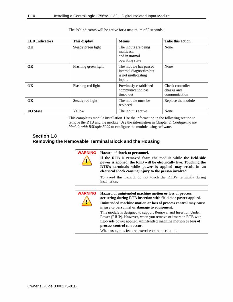
The I/O indicators will be active for a maximum of 2 seconds:
LED Indicators This display Means Take this action OK Steady green light The inputs are being
multicast, and in normal operating state
None
OK Flashing green light The module has passed internal diagnostics but is not multicasting inputs
None
OK Flashing red light Previously established communication has timed out
Check controller chassis and communication
OK Steady red light The module must be replaced
Replace the module
I/O State Yellow The input is active None
This completes module installation. Use the information in the following section to remove the RTB and the module. Use the information in Chapter 2, Configuring the Module with RSLogix 5000 to configure the module using software.
Section 1.8 Removing the Removable Terminal Block and the Housing
WARNING
Hazard of shock to personnel. If the RTB is removed from the module while the field-side power is applied, the RTB will be electrically live. Touching the RTB’s terminals while power is applied may result in an electrical shock causing injury to the person involved. To avoid this hazard, do not touch the RTB’s terminals during installation.
WARNING
Hazard of unintended machine motion or loss of process occurring during RTB insertion with field-side power applied. Unintended machine motion or loss of process control may cause injury to personnel or damage to equipment. This module is designed to support Removal and Insertion Under Power (RIUP). However, when you remove or insert an RTB with field-side power applied, unintended machine motion or loss of process control can occur. When using this feature, exercise extreme caution.
Installing a ControlLogix 1756sc-IC32 – Digital Isolated Input Module 1-11
Owner’s Guide 0300275-01B
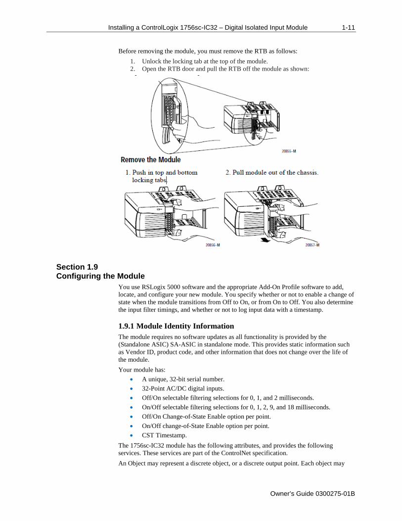
Before removing the module, you must remove the RTB as follows: 1. Unlock the locking tab at the top of the module. 2. Open the RTB door and pull the RTB off the module as shown:
Section 1.9 Configuring the Module
You use RSLogix 5000 software and the appropriate Add-On Profile software to add, locate, and configure your new module. You specify whether or not to enable a change of state when the module transitions from Off to On, or from On to Off. You also determine the input filter timings, and whether or not to log input data with a timestamp.
1.9.1 Module Identity Information The module requires no software updates as all functionality is provided by the (Standalone ASIC) SA-ASIC in standalone mode. This provides static information such as Vendor ID, product code, and other information that does not change over the life of the module. Your module has:
• A unique, 32-bit serial number. • 32-Point AC/DC digital inputs. • Off/On selectable filtering selections for 0, 1, and 2 milliseconds. • On/Off selectable filtering selections for 0, 1, 2, 9, and 18 milliseconds. • Off/On Change-of-State Enable option per point. • On/Off change-of-State Enable option per point. • CST Timestamp.
The 1756sc-IC32 module has the following attributes, and provides the following services. These services are part of the ControlNet specification. An Object may represent a discrete object, or a discrete output point. Each object may
1-12 Installing a ControlLogix 1756sc-IC32 – Digital Isolated Input Module
Owner’s Guide 0300275-01B
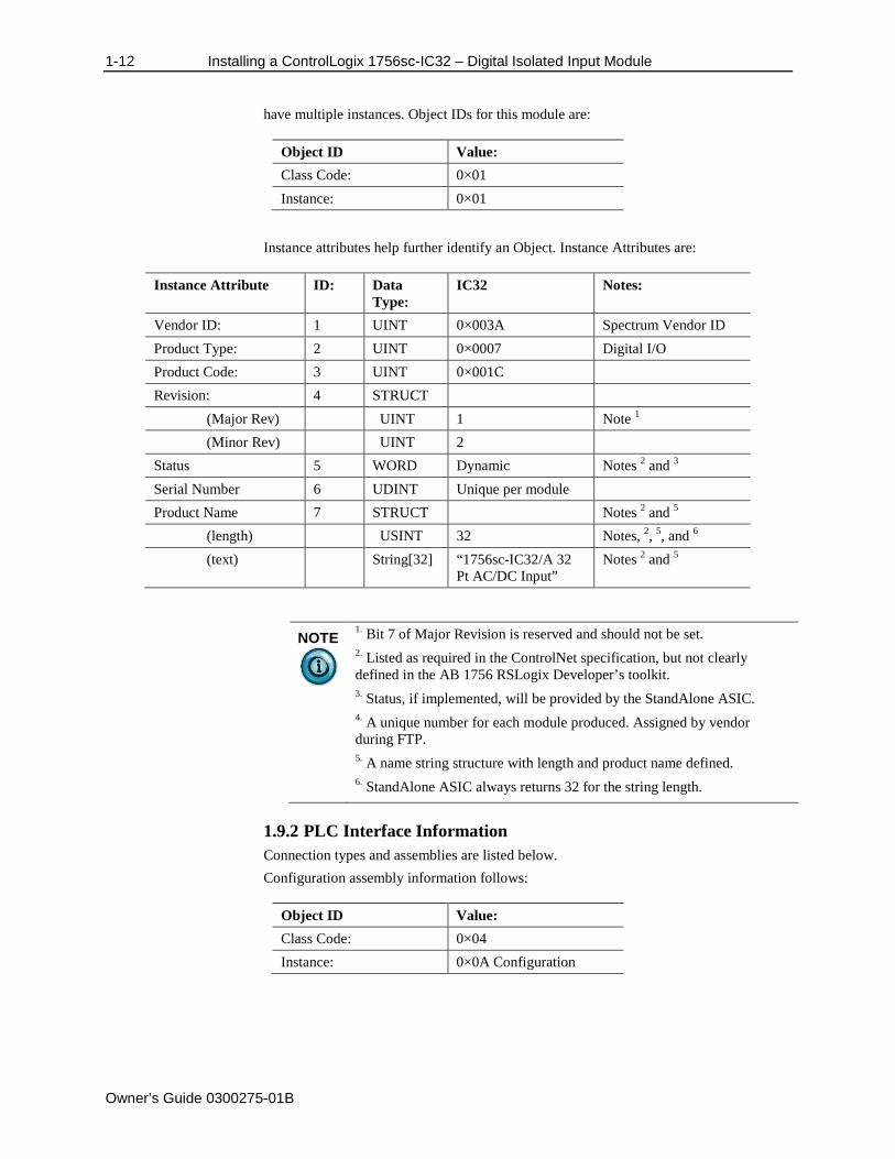
have multiple instances. Object IDs for this module are:
Object ID Value: Class Code: 0×01 Instance: 0×01
Instance attributes help further identify an Object. Instance Attributes are:
Instance Attribute ID: Data
Type: IC32 Notes:
Vendor ID: 1 UINT 0×003A Spectrum Vendor ID Product Type: 2 UINT 0×0007 Digital I/O Product Code: 3 UINT 0×001C Revision: 4 STRUCT (Major Rev) UINT 1 Note 1 (Minor Rev) UINT 2 Status 5 WORD Dynamic Notes 2 and 3 Serial Number 6 UDINT Unique per module Product Name 7 STRUCT Notes 2 and 5 (length) USINT 32 Notes, 2, 5, and 6 (text) String[32] “1756sc-IC32/A 32
Pt AC/DC Input” Notes 2 and 5
NOTE
1. Bit 7 of Major Revision is reserved and should not be set. 2. Listed as required in the ControlNet specification, but not clearly defined in the AB 1756 RSLogix Developer’s toolkit. 3. Status, if implemented, will be provided by the StandAlone ASIC. 4. A unique number for each module produced. Assigned by vendor during FTP. 5. A name string structure with length and product name defined. 6. StandAlone ASIC always returns 32 for the string length.
1.9.2 PLC Interface Information Connection types and assemblies are listed below. Configuration assembly information follows:
Object ID Value: Class Code: 0×04 Instance: 0×0A Configuration
Installing a ControlLogix 1756sc-IC32 – Digital Isolated Input Module 1-13
Owner’s Guide 0300275-01B
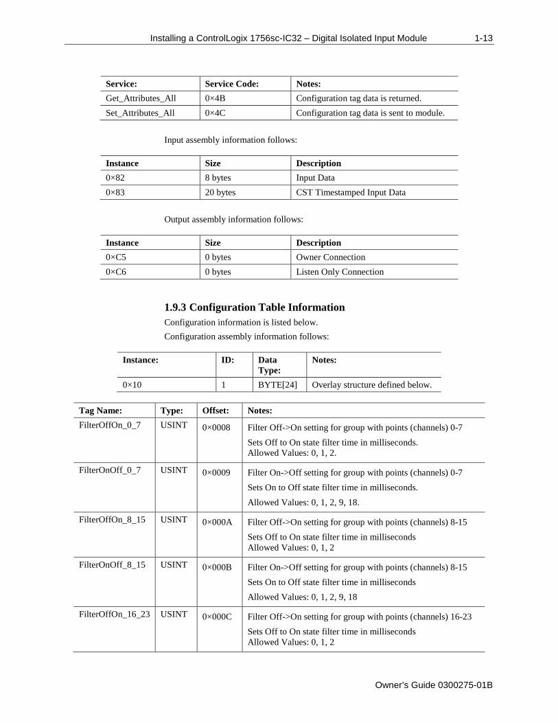
Service: Service Code: Notes: Get_Attributes_All 0×4B Configuration tag data is returned. Set_Attributes_All 0×4C Configuration tag data is sent to module.
Input assembly information follows:
Instance Size Description 0×82 8 bytes Input Data 0×83 20 bytes CST Timestamped Input Data
Output assembly information follows:
Instance Size Description 0×C5 0 bytes Owner Connection 0×C6 0 bytes Listen Only Connection
1.9.3 Configuration Table Information Configuration information is listed below. Configuration assembly information follows:
Instance: ID: Data
Type: Notes:
0×10 1 BYTE[24] Overlay structure defined below.
Tag Name: Type: Offset: Notes: FilterOffOn_0_7 USINT 0×0008 Filter Off->On setting for group with points (channels) 0-7
Sets Off to On state filter time in milliseconds. Allowed Values: 0, 1, 2.
FilterOnOff_0_7 USINT 0×0009 Filter On->Off setting for group with points (channels) 0-7 Sets On to Off state filter time in milliseconds. Allowed Values: 0, 1, 2, 9, 18.
FilterOffOn_8_15 USINT 0×000A Filter Off->On setting for group with points (channels) 8-15 Sets Off to On state filter time in milliseconds Allowed Values: 0, 1, 2
FilterOnOff_8_15 USINT 0×000B Filter On->Off setting for group with points (channels) 8-15 Sets On to Off state filter time in milliseconds Allowed Values: 0, 1, 2, 9, 18
FilterOffOn_16_23 USINT 0×000C Filter Off->On setting for group with points (channels) 16-23 Sets Off to On state filter time in milliseconds Allowed Values: 0, 1, 2
1-14 Installing a ControlLogix 1756sc-IC32 – Digital Isolated Input Module
Owner’s Guide 0300275-01B
Tag Name: Type: Offset: Notes: FilterOnOff_16_23 USINT 0×000D Filter On->Off setting for group with points (channels) 16-23
Sets On to Off state filter time in milliseconds Allowed Values: 0, 1, 2, 9, 18
FilterOffOn_24_31 USINT 0×000E Filter Off->On setting for group with points (channels) 24-31 Sets Off to On state filter time in milliseconds Allowed Values: 0, 1, 2
FilterOnOff_24_31 USINT 0×000F Filter On->Off setting for group with points (channels) 24-31 Sets On to Off state filter time in milliseconds Allowed Values: 0, 1, 2, 9, 18
COSOnOffEnable DINT 0×0010 Enable change of state (COS) trigger for On->Off transition 32 bit Mask, bit per point, bit 0 = point 0
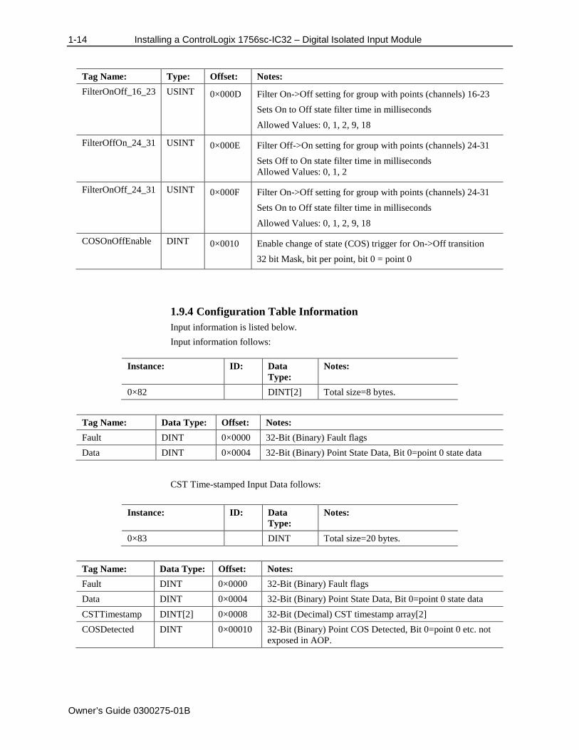
1.9.4 Configuration Table Information Input information is listed below. Input information follows:
Instance: ID: Data
Type: Notes:
0×82 DINT[2] Total size=8 bytes.
Tag Name: Data Type: Offset: Notes: Fault DINT 0×0000 32-Bit (Binary) Fault flags Data DINT 0×0004 32-Bit (Binary) Point State Data, Bit 0=point 0 state data
CST Time-stamped Input Data follows:
Instance: ID: Data Type:
Notes:
0×83 DINT Total size=20 bytes.
Tag Name: Data Type: Offset: Notes: Fault DINT 0×0000 32-Bit (Binary) Fault flags Data DINT 0×0004 32-Bit (Binary) Point State Data, Bit 0=point 0 state data CSTTimestamp DINT[2] 0×0008 32-Bit (Decimal) CST timestamp array[2] COSDetected DINT 0×00010 32-Bit (Binary) Point COS Detected, Bit 0=point 0 etc. not
exposed in AOP.
Installing a ControlLogix 1756sc-IC32 – Digital Isolated Input Module 1-15
Owner’s Guide 0300275-01B
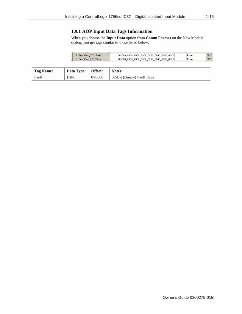
1.9.1 AOP Input Data Tags Information When you choose the Input Data option from Comm Format on the New Module dialog, you get tags similar to those listed below:
Tag Name: Data Type: Offset: Notes: Fault DINT 0×0000 32-Bit (Binary) Fault flags
1-16 Installing a ControlLogix 1756sc-IC32 – Digital Isolated Input Module
Owner’s Guide 0300275-01B
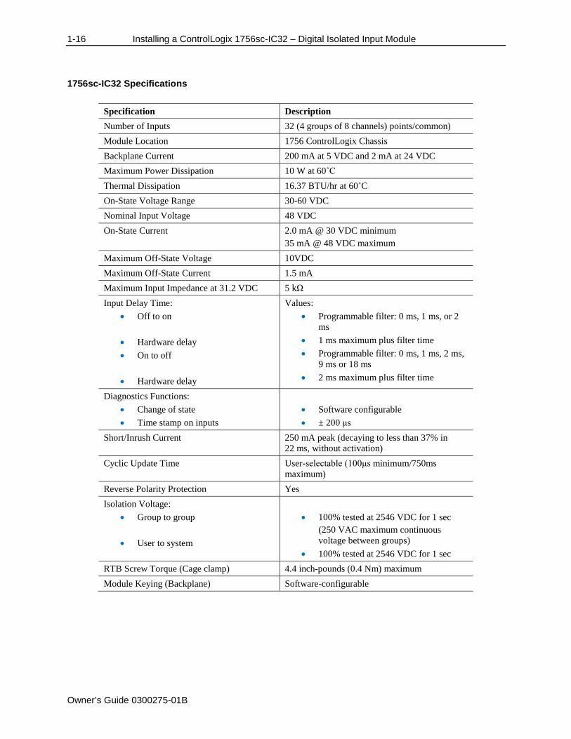
1756sc-IC32 Specifications
Specification Description Number of Inputs 32 (4 groups of 8 channels) points/common) Module Location 1756 ControlLogix Chassis Backplane Current 200 mA at 5 VDC and 2 mA at 24 VDC Maximum Power Dissipation 10 W at 60˚C Thermal Dissipation 16.37 BTU/hr at 60˚C On-State Voltage Range 30-60 VDC Nominal Input Voltage 48 VDC On-State Current 2.0 mA @ 30 VDC minimum
35 mA @ 48 VDC maximum Maximum Off-State Voltage 10VDC Maximum Off-State Current 1.5 mA Maximum Input Impedance at 31.2 VDC 5 kΩ Input Delay Time:
• Off to on
• Hardware delay • On to off
• Hardware delay
Values: • Programmable filter: 0 ms, 1 ms, or 2
ms • 1 ms maximum plus filter time • Programmable filter: 0 ms, 1 ms, 2 ms,
9 ms or 18 ms • 2 ms maximum plus filter time
Diagnostics Functions: • Change of state • Time stamp on inputs
• Software configurable • ± 200 μs
Short/Inrush Current 250 mA peak (decaying to less than 37% in 22 ms, without activation)
Cyclic Update Time User-selectable (100μs minimum/750ms maximum)
Reverse Polarity Protection Yes Isolation Voltage:
• Group to group
• User to system
• 100% tested at 2546 VDC for 1 sec
(250 VAC maximum continuous voltage between groups)
• 100% tested at 2546 VDC for 1 sec RTB Screw Torque (Cage clamp) 4.4 inch-pounds (0.4 Nm) maximum Module Keying (Backplane) Software-configurable
Installing a ControlLogix 1756sc-IC32 – Digital Isolated Input Module 1-17
Owner’s Guide 0300275-01B
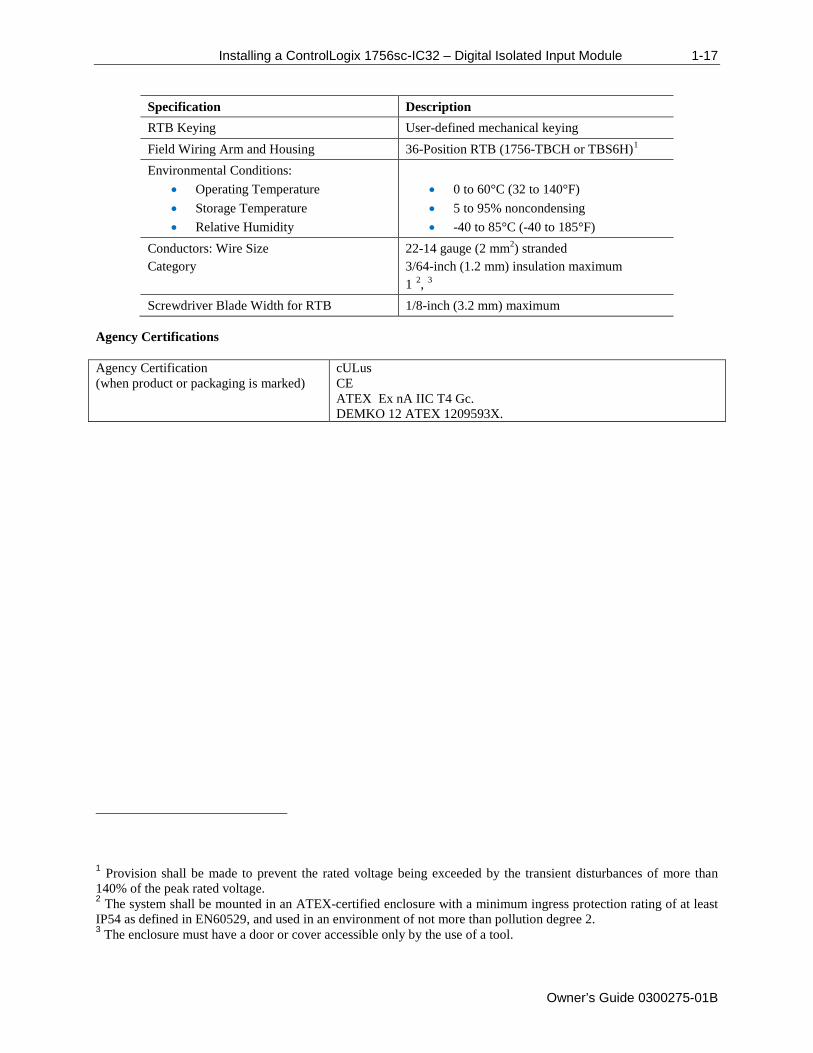
Specification Description RTB Keying User-defined mechanical keying Field Wiring Arm and Housing 36-Position RTB (1756-TBCH or TBS6H)1 Environmental Conditions:
• Operating Temperature • Storage Temperature • Relative Humidity
• 0 to 60°C (32 to 140°F) • 5 to 95% noncondensing • -40 to 85°C (-40 to 185°F)
Conductors: Wire Size Category
22-14 gauge (2 mm2) stranded 3/64-inch (1.2 mm) insulation maximum 1 2, 3
Screwdriver Blade Width for RTB 1/8-inch (3.2 mm) maximum Agency Certifications
Agency Certification (when product or packaging is marked)
cULus CE ATEX Ex nA IIC T4 Gc. DEMKO 12 ATEX 1209593X.
1 Provision shall be made to prevent the rated voltage being exceeded by the transient disturbances of more than 140% of the peak rated voltage. 2 The system shall be mounted in an ATEX-certified enclosure with a minimum ingress protection rating of at least IP54 as defined in EN60529, and used in an environment of not more than pollution degree 2. 3 The enclosure must have a door or cover accessible only by the use of a tool.

1-18 Installing a ControlLogix 1756sc-IC32 – Digital Isolated Input Module
Owner’s Guide 0300275-01B
Owner’s Guide 0300275-01B
Chapter 2 Configuring the Module with RSLogix 5000
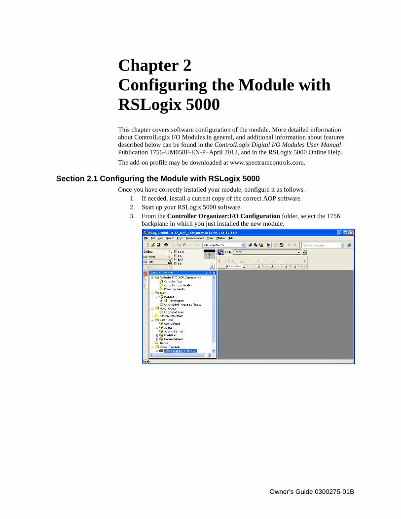
This chapter covers software configuration of the module. More detailed information about ControlLogix I/O Modules in general, and additional information about features described below can be found in the ControlLogix Digital I/O Modules User Manual Publication 1756-UM058F-EN-P–April 2012, and in the RSLogix 5000 Online Help. The add-on profile may be downloaded at www.spectrumcontrols.com.
Section 2.1 Configuring the Module with RSLogix 5000 Once you have correctly installed your module, configure it as follows.
1. If needed, install a current copy of the correct AOP software. 2. Start up your RSLogix 5000 software. 3. From the Controller Organizer:I/O Configuration folder, select the 1756
backplane in which you just installed the new module:
2-2 Chapter 2: Configuring the Module with RSLogix 5000
Owner’s Guide 0300275-01B
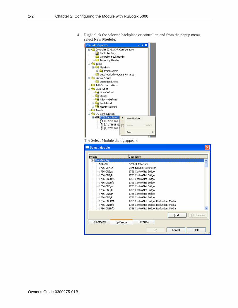
4. Right click the selected backplane or controller, and from the popup menu, select New Module:
The Select Module dialog appears:
Chapter 2: Configuring the Module with RSLogix 5000 2-3
Owner’s Guide 0300275-01B
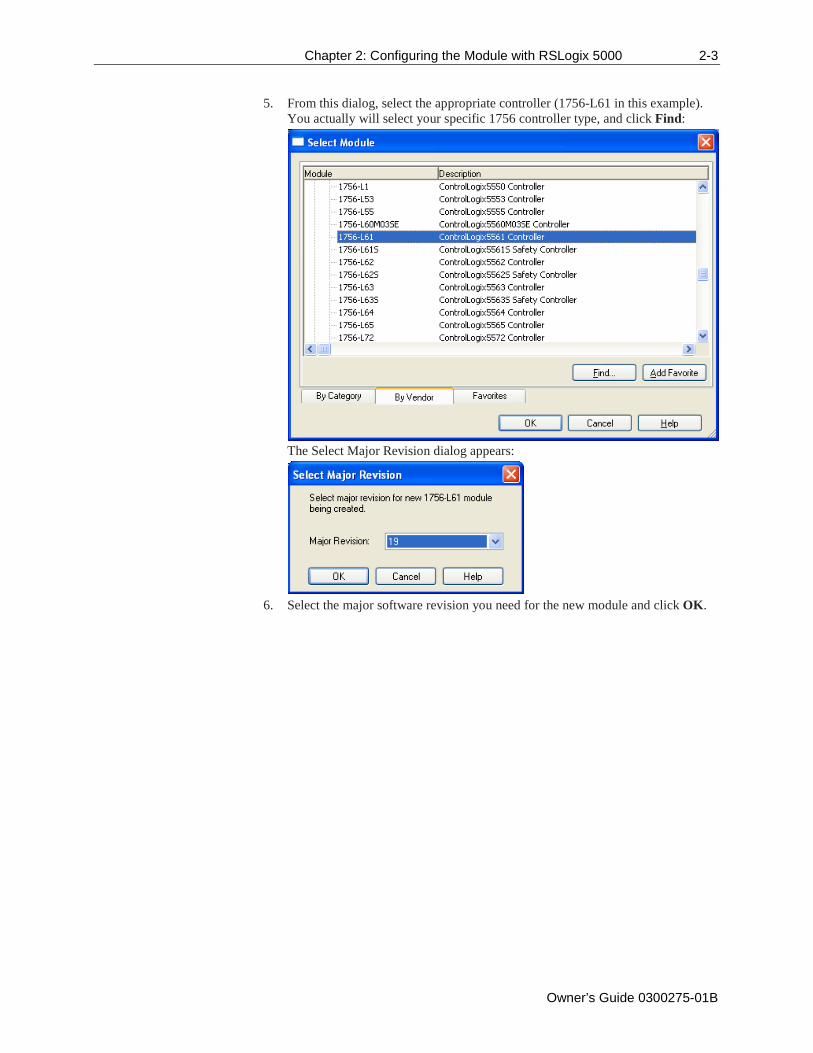
5. From this dialog, select the appropriate controller (1756-L61 in this example). You actually will select your specific 1756 controller type, and click Find:
The Select Major Revision dialog appears:
6. Select the major software revision you need for the new module and click OK.
2-4 Chapter 2: Configuring the Module with RSLogix 5000
Owner’s Guide 0300275-01B
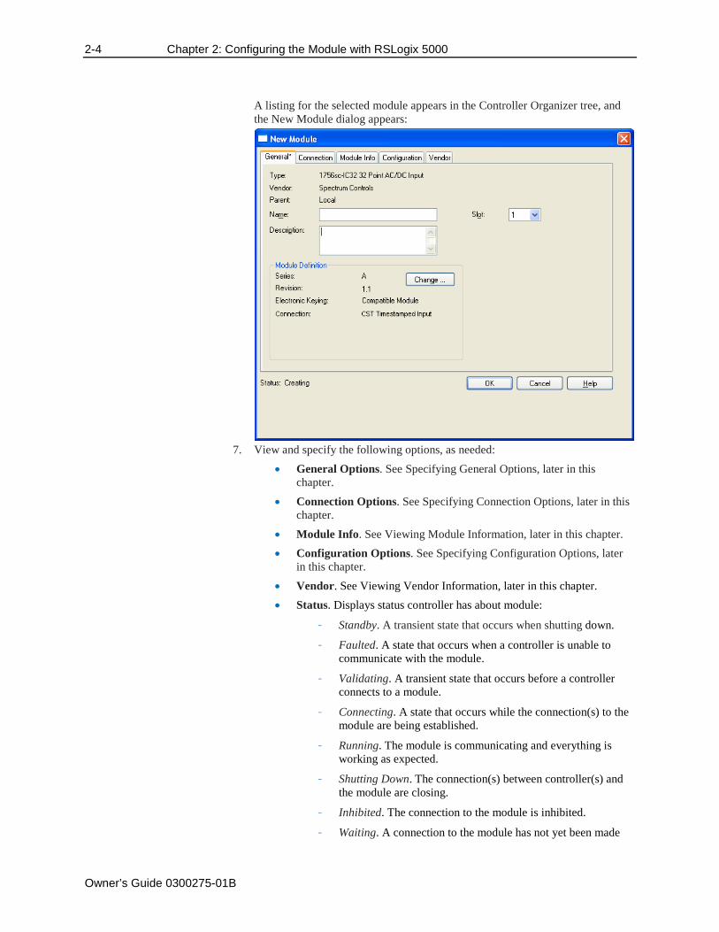
A listing for the selected module appears in the Controller Organizer tree, and the New Module dialog appears:
7. View and specify the following options, as needed:
• General Options. See Specifying General Options, later in this chapter.
• Connection Options. See Specifying Connection Options, later in this chapter.
• Module Info. See Viewing Module Information, later in this chapter. • Configuration Options. See Specifying Configuration Options, later
in this chapter. • Vendor. See Viewing Vendor Information, later in this chapter. • Status. Displays status controller has about module:
- Standby. A transient state that occurs when shutting down.
- Faulted. A state that occurs when a controller is unable to communicate with the module.
- Validating. A transient state that occurs before a controller connects to a module.
- Connecting. A state that occurs while the connection(s) to the module are being established.
- Running. The module is communicating and everything is working as expected.
- Shutting Down. The connection(s) between controller(s) and the module are closing.
- Inhibited. The connection to the module is inhibited.
- Waiting. A connection to the module has not yet been made
Chapter 2: Configuring the Module with RSLogix 5000 2-5
Owner’s Guide 0300275-01B
due to one of the following: Its parent has not yet made a connection to it. Its parent is inhibited. Its parent is faulted.
- Offline. You are not online.
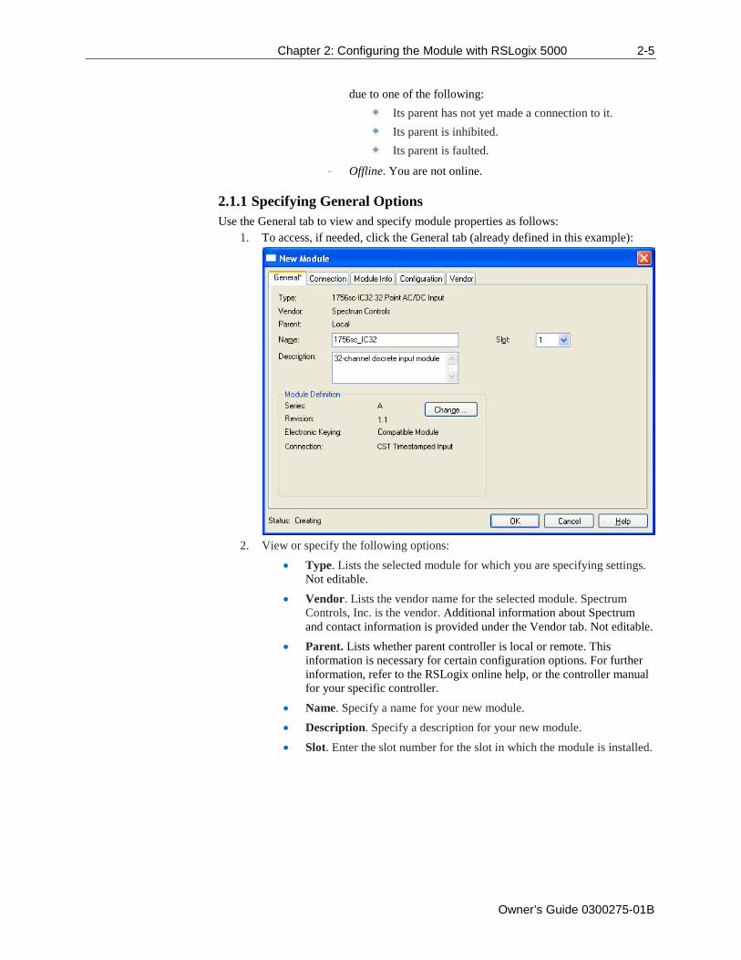
2.1.1 Specifying General Options Use the General tab to view and specify module properties as follows:
1. To access, if needed, click the General tab (already defined in this example):
2. View or specify the following options:
• Type. Lists the selected module for which you are specifying settings. Not editable.
• Vendor. Lists the vendor name for the selected module. Spectrum Controls, Inc. is the vendor. Additional information about Spectrum and contact information is provided under the Vendor tab. Not editable.
• Parent. Lists whether parent controller is local or remote. This information is necessary for certain configuration options. For further information, refer to the RSLogix online help, or the controller manual for your specific controller.
• Name. Specify a name for your new module. • Description. Specify a description for your new module. • Slot. Enter the slot number for the slot in which the module is installed.
2-6 Chapter 2: Configuring the Module with RSLogix 5000
Owner’s Guide 0300275-01B
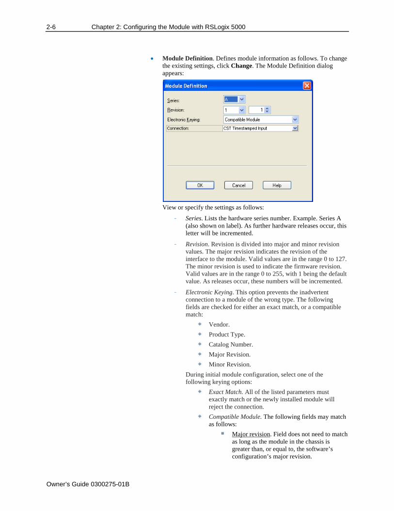
• Module Definition. Defines module information as follows. To change the existing settings, click Change. The Module Definition dialog appears:
View or specify the settings as follows:
- Series. Lists the hardware series number. Example. Series A (also shown on label). As further hardware releases occur, this letter will be incremented.
- Revision. Revision is divided into major and minor revision values. The major revision indicates the revision of the interface to the module. Valid values are in the range 0 to 127. The minor revision is used to indicate the firmware revision. Valid values are in the range 0 to 255, with 1 being the default value. As releases occur, these numbers will be incremented.
- Electronic Keying. This option prevents the inadvertent connection to a module of the wrong type. The following fields are checked for either an exact match, or a compatible match:
Vendor. Product Type. Catalog Number. Major Revision. Minor Revision.
During initial module configuration, select one of the following keying options:
Exact Match. All of the listed parameters must exactly match or the newly installed module will reject the connection.
Compatible Module. The following fields may match as follows:
Major revision. Field does not need to match as long as the module in the chassis is greater than, or equal to, the software’s configuration’s major revision.
Chapter 2: Configuring the Module with RSLogix 5000 2-7
Owner’s Guide 0300275-01B
Minor revision. Field of the physical module must be equal to, or greater than, the one specified in the software.
DANGER
Hazard of personnel death or injury, damage to property, or economic loss if keying is disabled. Disabling keying could lead to a module being incorrectly connected to a programmable logic controller, resulting in loss of connection and/or improper controller function. When using this feature, exercise extreme caution.
- Disable Keying. When selected, the controller employs no keying to check whether it is connected to a compatible module.
• Connection. Defines the connection between the controller and the module. From the pull down menu, select one of the following options:
- Input. Selecting this mode means that the module returns only general fault and input data to the controller.
- CST Timestamped Input. Selecting this mode allows the controller to access the Coordinated System Time (CST) and to timestamp general fault and input data with the value of the CST when that input data changes state.
- Listen Only–Input. Selecting this mode allows the controller and module to establish communications without the controller sending any configuration data. In this case, the controller only listens to the module and data coming from the module has no timestamp.
- Listen Only–CST Timestamped Input. Selecting this mode means that the controller only listens to the module but data coming from the module has a timestamp.
• When done making changes, to save your changes and exit, click OK. • To cancel any changes made, and exit, click Cancel. • To apply any changes made, and continue making changes, click
Apply.
2.1.2 Specifying Connection Options Use the Connection tab to define controller-to-module operation. Data that shows on this tab comes directly from the controller. You may:
• Select a requested packet interval. • Choose to inhibit the module. • Configure the controller so that a loss of connection to this module causes a
major fault.
2-8 Chapter 2: Configuring the Module with RSLogix 5000
Owner’s Guide 0300275-01B
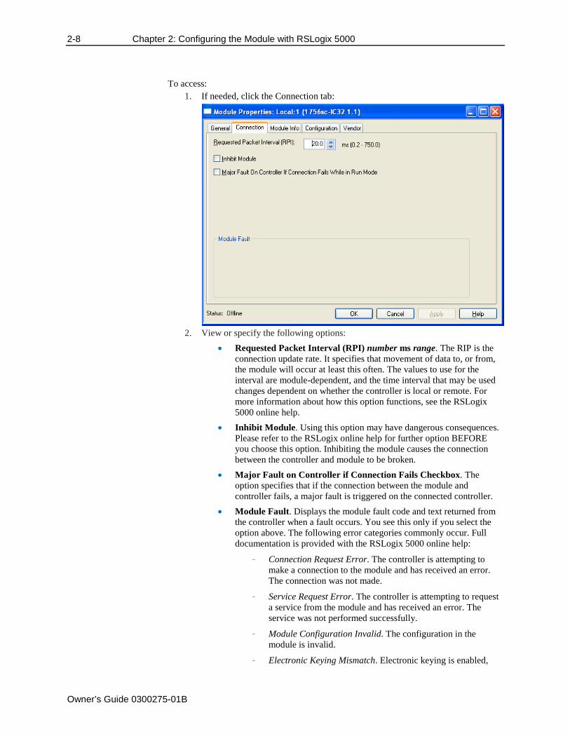
To access: 1. If needed, click the Connection tab:
2. View or specify the following options:
• Requested Packet Interval (RPI) number ms range. The RIP is the connection update rate. It specifies that movement of data to, or from, the module will occur at least this often. The values to use for the interval are module-dependent, and the time interval that may be used changes dependent on whether the controller is local or remote. For more information about how this option functions, see the RSLogix 5000 online help.
• Inhibit Module. Using this option may have dangerous consequences. Please refer to the RSLogix online help for further option BEFORE you choose this option. Inhibiting the module causes the connection between the controller and module to be broken.
• Major Fault on Controller if Connection Fails Checkbox. The option specifies that if the connection between the module and controller fails, a major fault is triggered on the connected controller.
• Module Fault. Displays the module fault code and text returned from the controller when a fault occurs. You see this only if you select the option above. The following error categories commonly occur. Full documentation is provided with the RSLogix 5000 online help:
- Connection Request Error. The controller is attempting to make a connection to the module and has received an error. The connection was not made.
- Service Request Error. The controller is attempting to request a service from the module and has received an error. The service was not performed successfully.
- Module Configuration Invalid. The configuration in the module is invalid.
- Electronic Keying Mismatch. Electronic keying is enabled,
Chapter 2: Configuring the Module with RSLogix 5000 2-9
Owner’s Guide 0300275-01B
and some part of the keying information differs between the software and the module.
• When done making changes, to save your changes and exit, click OK. • To cancel any changes made, and exit, click Cancel. • To apply any changes made, and continue making changes, click
Apply.
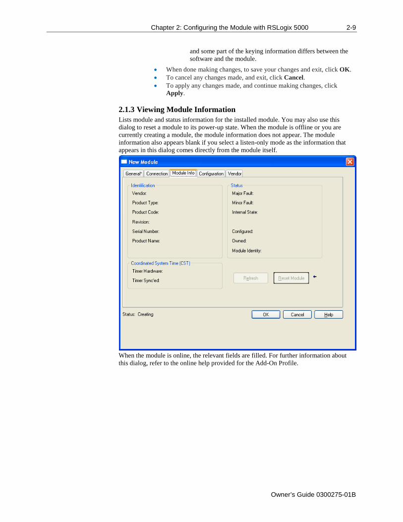
2.1.3 Viewing Module Information Lists module and status information for the installed module. You may also use this dialog to reset a module to its power-up state. When the module is offline or you are currently creating a module, the module information does not appear. The module information also appears blank if you select a listen-only mode as the information that appears in this dialog comes directly from the module itself.
When the module is online, the relevant fields are filled. For further information about this dialog, refer to the online help provided for the Add-On Profile.
2-10 Chapter 2: Configuring the Module with RSLogix 5000
Owner’s Guide 0300275-01B
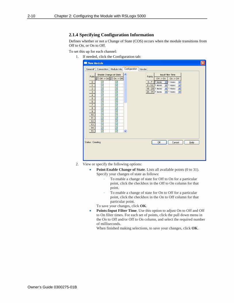
2.1.4 Specifying Configuration Information Defines whether or not a Change of State (COS) occurs when the module transitions from Off to On, or On to Off. To set this up for each channel:
1. If needed, click the Configuration tab:
2. View or specify the following options:
• Point:Enable Change of State. Lists all available points (0 to 31). Specify your changes of state as follows:
- To enable a change of state for Off to On for a particular point, click the checkbox in the Off to On column for that point.
- To enable a change of state for On to Off for a particular point, click the checkbox in the On to Off column for that particular point.
To save your changes, click OK. • Points:Input Filter Time. Use this option to adjust On to Off and Off
to On filter times. For each set of points, click the pull down menu in the On to Off and/or Off to On column, and select the required number of milliseconds. When finished making selections, to save your changes, click OK.
Chapter 2: Configuring the Module with RSLogix 5000 2-11
Owner’s Guide 0300275-01B
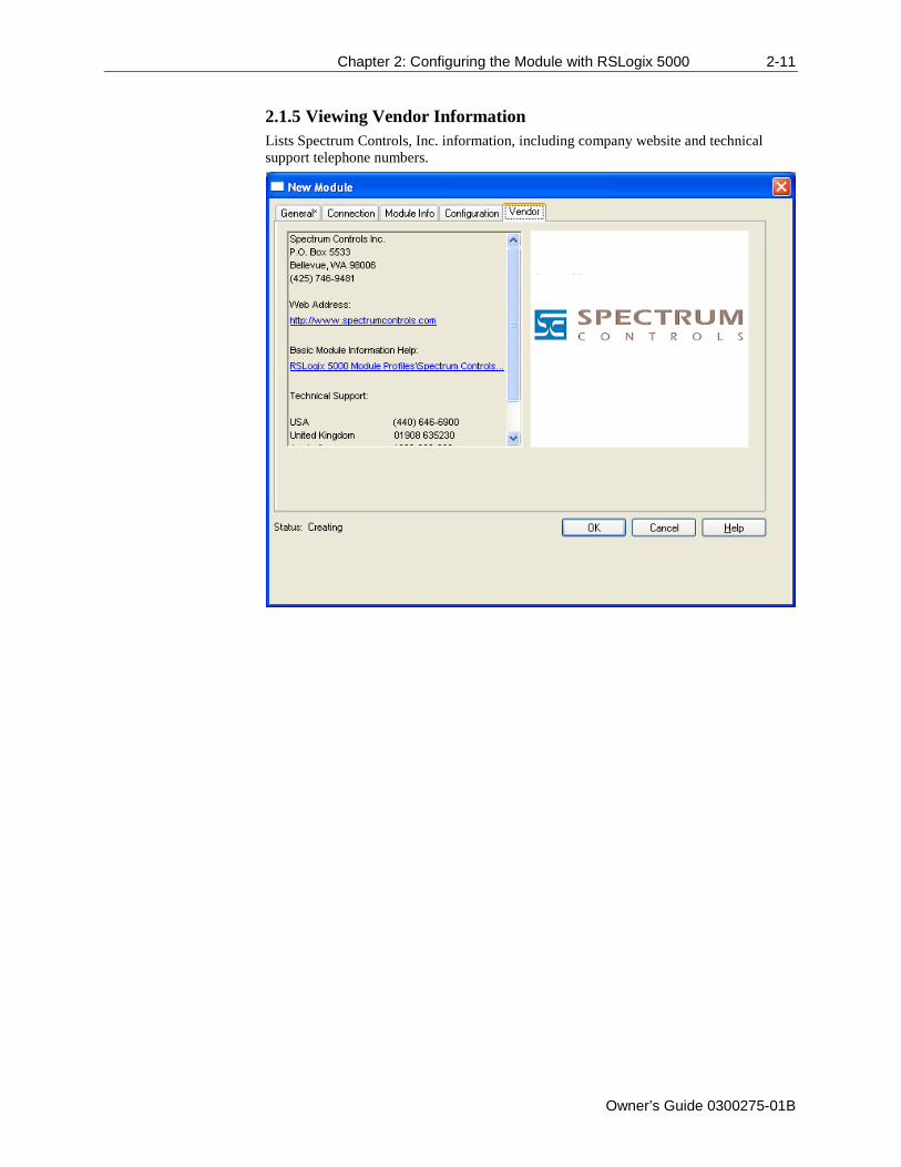
2.1.5 Viewing Vendor Information Lists Spectrum Controls, Inc. information, including company website and technical support telephone numbers.
2-12 Chapter 2: Configuring the Module with RSLogix 5000
Owner’s Guide 0300275-01B
Owner’s Guide 0300275-01B
Appendix A Index
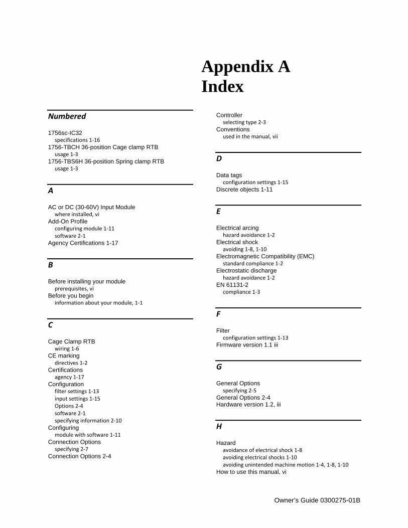
Numbered
1756sc-IC32 specifications 1-16
1756-TBCH 36-position Cage clamp RTB usage 1-3
1756-TBS6H 36-position Spring clamp RTB usage 1-3
A
AC or DC (30-60V) Input Module where installed, vi
Add-On Profile configuring module 1-11 software 2-1
Agency Certifications 1-17
B
Before installing your module prerequisites, vi
Before you begin information about your module, 1-1
C
Cage Clamp RTB wiring 1-6
CE marking directives 1-2
Certifications agency 1-17
Configuration filter settings 1-13 input settings 1-15 Options 2-4 software 2-1 specifying information 2-10
Configuring module with software 1-11
Connection Options specifying 2-7
Connection Options 2-4
Controller
selecting type 2-3 Conventions
used in the manual, vii
D
Data tags configuration settings 1-15
Discrete objects 1-11
E
Electrical arcing hazard avoidance 1-2
Electrical shock avoiding 1-8, 1-10
Electromagnetic Compatibility (EMC) standard compliance 1-2
Electrostatic discharge hazard avoidance 1-2
EN 61131-2 compliance 1-3
F
Filter configuration settings 1-13
Firmware version 1.1 iii
G
General Options specifying 2-5
General Options 2-4 Hardware version 1.2, iii
H
Hazard avoidance of electrical shock 1-8 avoiding electrical shocks 1-10 avoiding unintended machine motion 1-4, 1-8, 1-10
How to use this manual, vi
I-2
Owner’s Guide 0300275-01B
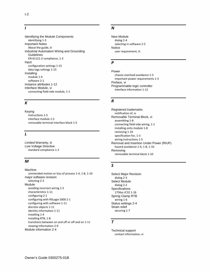
I
Identifying the Module Components identifying 1-3
Important Notes About the guide, iii
Industrial Automation Wiring and Grounding Guidelines EN 61121-2 compliance, 1-3
Input configuration settings 1-15 data tags settings 1-15
Installing module 1-4 software 2-1
Instance attributes 1-12 Interface Module, vi
connecting field-side module, 1-1
K
Keying instructions 1-5 interface module 1-5 removable terminal interface block 1-5
L
Limited Warranty, iii Low Voltage Directive
standard compliance 1-2
M
Machine unintended motion or loss of process 1-4, 1-8, 1-10
major software revision selecting 2-3
Module avoiding incorrect wiring 1-5 characteristics 1-11 configuring 2-1 configuring with RSLogix 5000 2-1 configuring with software 1-11 discrete objects 1-11 identity information 1-11 installing 1-4 installing RTB, 1-8 transitions between on and off or off and on 1-11 viewing Information 2-9
Module information 2-4
N
New Module dialog 2-4 selecting in software 2-2
Notice user requirement, iii
P
Power chassis overload avoidance 1-3 important power requirements 1-3
Preface, vi Programmable logic controller
interface information 1-12
R
Registered trademarks notification of, iv
Removable Terminal Block, vi assembling 1-8 connecting field-side wiring, 1-1 installing onto module 1-8 removing 1-10 specification for, 1-3 wiring instructions 1-5
Removal and Insertion Under Power (RIUP) hazard avoidance 1-4, 1-8, 1-10
Removing removable terminal block 1-10
S
Select Major Revision dialog 2-3
Select Module dialog 2-2
Specifications 1756sc-IC32 1-16
Spring Clamp RTB wiring 1-6
Status settings 2-4 Strain relief
securing 1-7
T
Technical support contact information, vi

Index I-3
Owner’s Guide 0300275-01B
V
Vendor Information 2- viewing 2-11
W
Who should use this manual, vi
Wiring 1756sc-IC32 example 1-7 cage clamp RTB 1-6 removable terminal block 1-5 spring clamp RTB 1-6
Wiring connections avoidance of wrong wire connections 1-5
Technical Assistance Note that your module contains electrostatic components that are susceptible to damage from electrostatic discharge (ESD). An electrostatic charge can accumulate on the surface of ordinary wrapping or cushioning material. In the unlikely event that the module should need to be returned to Spectrum Controls, Inc., please ensure that the unit is enclosed in approved ESD packaging (such as static-shielding/metallized bag or black conductive container). Spectrum Controls, Inc. reserves the right to void the warranty on any unit that is improperly packaged for shipment. For further information or assistance, please contact your local distributor, or call the technical support number provided under the Technical Support section in the Preface.
Declaration of Conformity Declaration available upon request.

Owner’s Guide 0300275-01B
©2009-2012 Spectrum Controls, Inc. All rights reserved. Specifications subject to change without notice. The Encompass logo and ControlLogix are trademarks of Rockwell Automation. Corporate Headquarters Spectrum Controls Inc. P.O. Box 6489 Bellevue, WA 98006 USA Fax: 425-641-9473 Tel: 425-746-9481
Web Site: www.spectrumcontrols.com E-mail: [email protected]