INPUT/OUTPUT System - WordPress.com
54
INPUT/OUTPUT System
-
Upload
khangminh22 -
Category
Documents
-
view
3 -
download
0
Transcript of INPUT/OUTPUT System - WordPress.com
INPUT/OUTPUT System
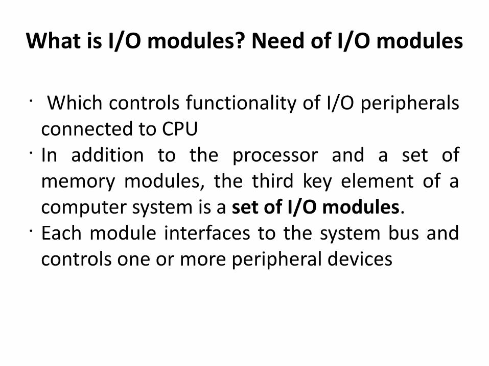
What is I/O modules? Need of I/O modules
• Which controls functionality of I/O peripherals connected to CPU
• In addition to the processor and a set of memory modules, the third key element of a computer system is a set of I/O modules.
• Each module interfaces to the system bus and controls one or more peripheral devices
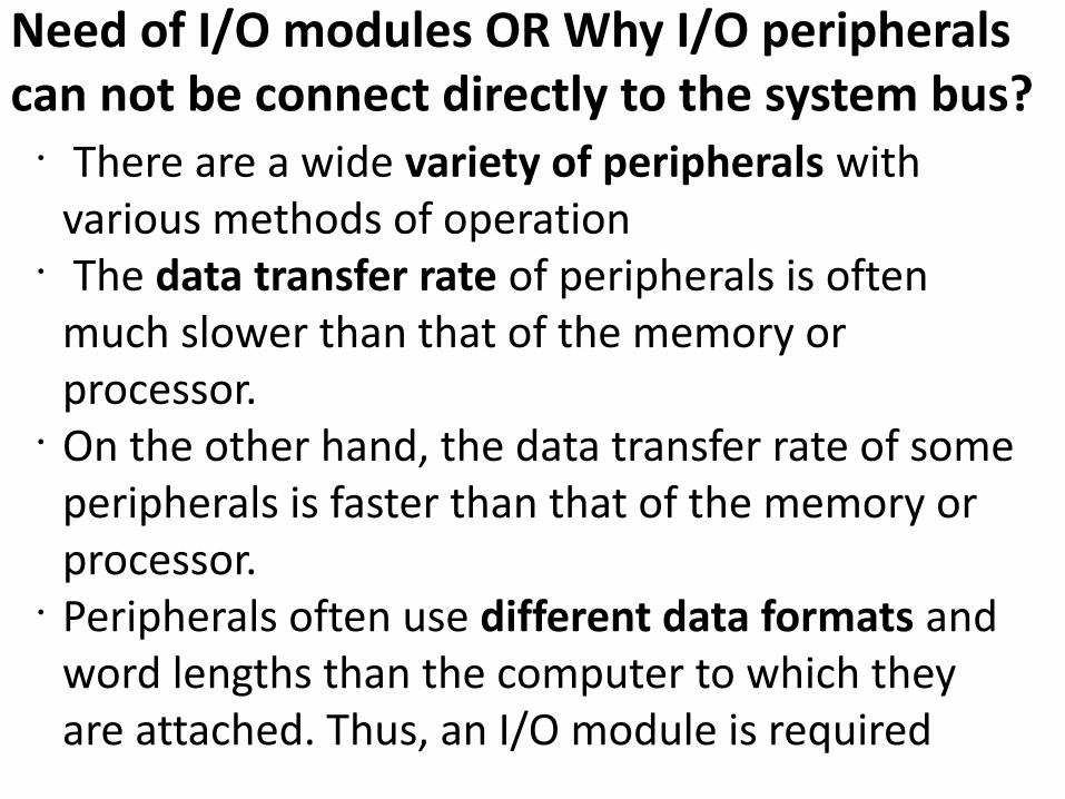
Need of I/O modules OR Why I/O peripherals can not be connect directly to the system bus? • There are a wide variety of peripherals with
various methods of operation• The data transfer rate of peripherals is often
much slower than that of the memory or processor.
• On the other hand, the data transfer rate of some peripherals is faster than that of the memory or processor.
• Peripherals often use different data formats and word lengths than the computer to which they are attached. Thus, an I/O module is required
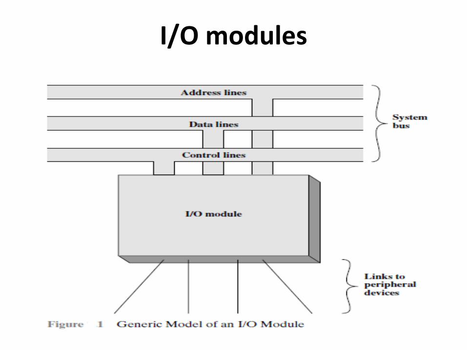
I/O modules
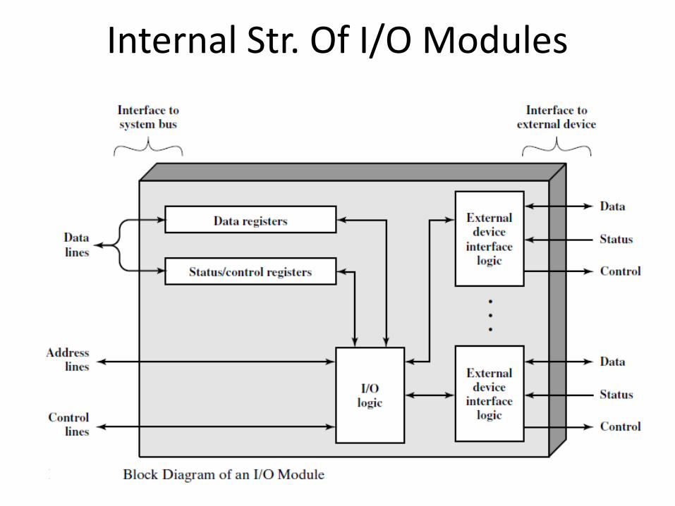
Internal Str. Of I/O Modules
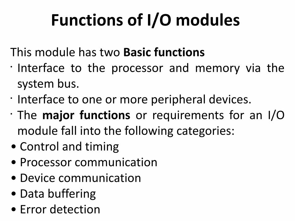
Functions of I/O modules
This module has two Basic functions• Interface to the processor and memory via the
system bus.• Interface to one or more peripheral devices.• The major functions or requirements for an I/O
module fall into the following categories:• Control and timing• Processor communication• Device communication• Data buffering• Error detection
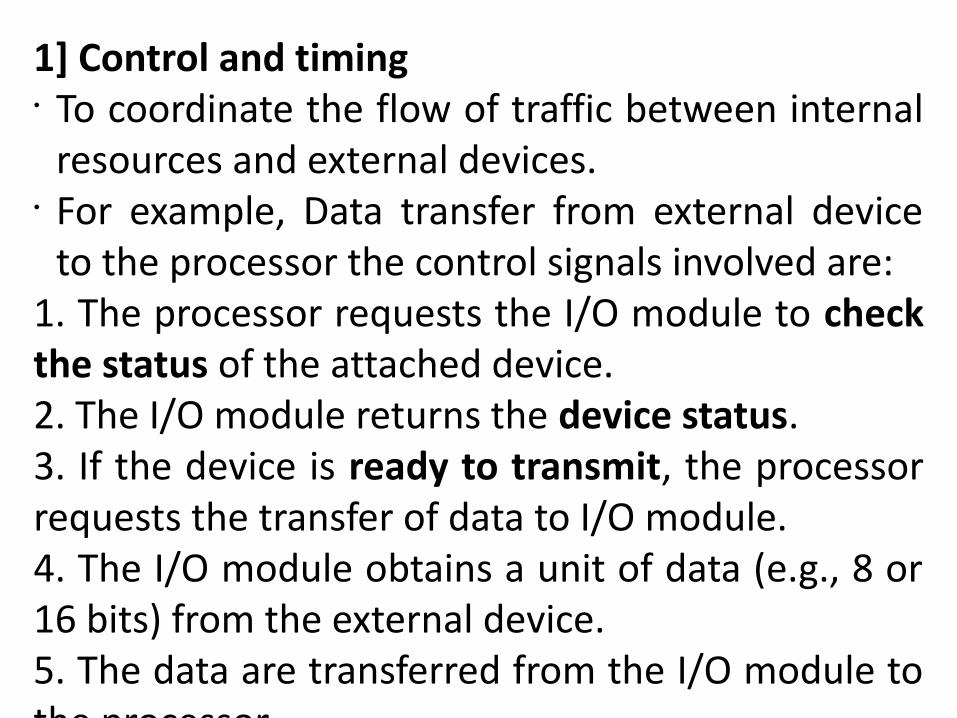
1] Control and timing• To coordinate the flow of traffic between internal
resources and external devices. • For example, Data transfer from external device
to the processor the control signals involved are: 1. The processor requests the I/O module to check the status of the attached device.2. The I/O module returns the device status.3. If the device is ready to transmit, the processor requests the transfer of data to I/O module.4. The I/O module obtains a unit of data (e.g., 8 or 16 bits) from the external device.5. The data are transferred from the I/O module to the processor.
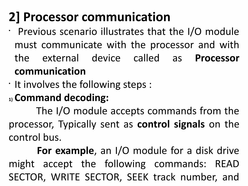
2] Processor communication• Previous scenario illustrates that the I/O module
must communicate with the processor and with the external device called as Processor communication
• It involves the following steps :1) Command decoding: The I/O module accepts commands from the processor, Typically sent as control signals on the control bus. For example, an I/O module for a disk drive might accept the following commands: READ SECTOR, WRITE SECTOR, SEEK track number, and SCAN record ID. 2) Data: Data are exchanged between the processor and the I/O module over the data bus.3) Status reporting: Because peripherals are so slow, it is important to know the status of the I/O module. For example, if an I/O module is asked to send data to the processor (read), it may not be ready to do so because it is still working on the previous I/O command. This fact can be reported with a status signal
3] Device communication• Communication of external devices(peripherals)
by means of commands, status information, and data, is called as device communication
4] Data buffering• The transfer rate into and out of main memory or
the processor is quite high, and the data rate should be lower for many peripheral devices.
• So, the data are buffered in the I/O module and then sent to the peripheral device at its data rate.
5] Error detection • Finally, an I/O module is often responsible for
error detection and for subsequently reporting errors to the processor.
• Some form of error-detecting code is often used to detect transmission errors.
• A simple example is the use of a parity bit on each character of data.
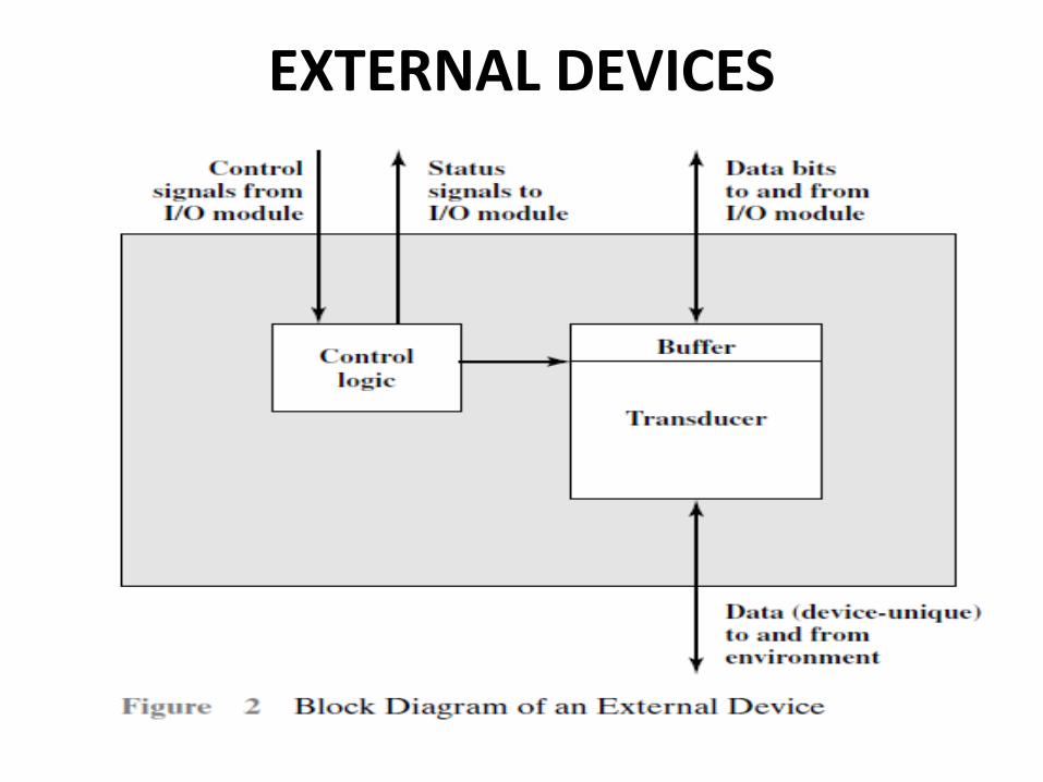
EXTERNAL DEVICES• An external device connected to an I/O module is
often referred to as a peripheral device or, simply, a peripheral.
• Used for exchanging data between the external environment and the computer.
• An external device attaches to the computer by a link to an I/O module.
• We can broadly classify external devices into three categories:
• 1]Human readable: Suitable for communicating with the computer user
e.g. video display terminals (VDTs) and printers.• 2]Machine readable: Suitable for communicating
with equipment e.g. magnetic disk and tape systems, and sensors and actuators• 3]Communication: Suitable for communicating
with remote devices e.g. may be a human-readable device, such as a terminal, a machine-readable device, or even another computer.
EXTERNAL DEVICES
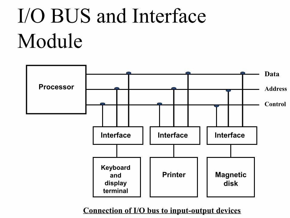
Processor
Interface Interface Interface
Keyboard and
display terminal
Printer Magnetic disk
Data
Address
Control
Connection of I/O bus to input-output devices
I/O BUS and Interface Module
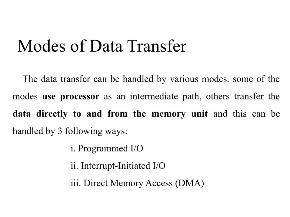
The data transfer can be handled by various modes. some of the
modes use processor as an intermediate path, others transfer the
data directly to and from the memory unit and this can be
handled by 3 following ways:
i. Programmed I/O
ii. Interrupt-Initiated I/O
iii. Direct Memory Access (DMA)
Modes of Data Transfer
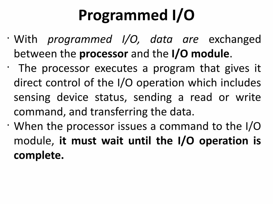
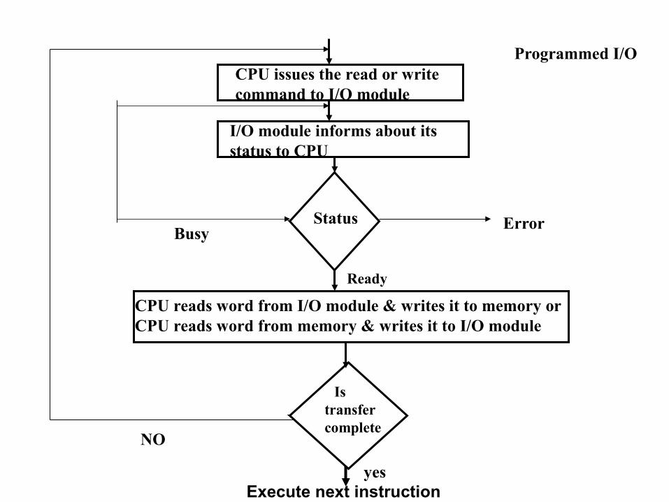
Programmed I/O• With programmed I/O, data are exchanged
between the processor and the I/O module.• The processor executes a program that gives it
direct control of the I/O operation which includes sensing device status, sending a read or write command, and transferring the data.
• When the processor issues a command to the I/O module, it must wait until the I/O operation is complete.
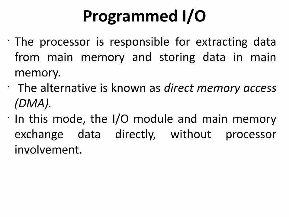
Programmed I/O• The processor is responsible for extracting data
from main memory and storing data in main memory.
• The alternative is known as direct memory access (DMA).
• In this mode, the I/O module and main memory exchange data directly, without processor involvement.
yes
CPU issues the read or write command to I/O module
I/O module informs about its status to CPU
Status
Ready
CPU reads word from I/O module & writes it to memory or CPU reads word from memory & writes it to I/O module
Is transfercomplete
Execute next instruction
NO
Error
Programmed I/O
Busy
The main drawback of the Programmed I/O was that the CPU
has to monitor the units(memory and I/O) all the times when the
program is executing.
This is a time consuming process and the CPU time is wasted
a lot in keeping an eye to the executing of program.
Drawback of the Programmed I/O
I/O Commands• There are four types of I/O commands that an I/O
module may receive when it is addressed by a processor:
1] Control: Used to activate a peripheral and tell it what to do. For example, a magnetic-tape unit may be instructed to rewind or to move forward one record.2] Test: Used to test various status conditions associated with an I/O module and its peripherals. It will also want to know about the most recent I/O operation is completed and if any errors occurred.
I/O Commands
3] Read: Causes the I/O module to obtain an data item from the peripheral and place it in an internal buffer The processor can then obtain the data item by requesting that the I/O module place it on the data bus.4] Write: Causes the I/O module to take an data item (byte or word) from the data bus and transmit that data item to the peripheral.
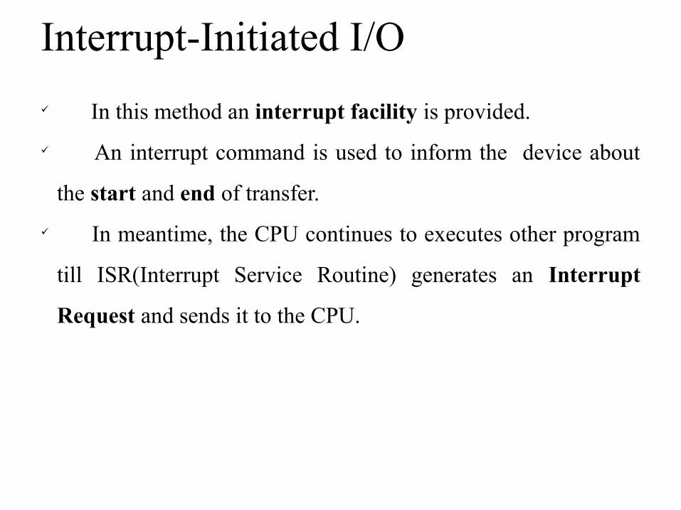
In this method an interrupt facility is provided.
An interrupt command is used to inform the device about
the start and end of transfer.
In meantime, the CPU continues to executes other program
till ISR(Interrupt Service Routine) generates an Interrupt
Request and sends it to the CPU.
Interrupt-Initiated I/O
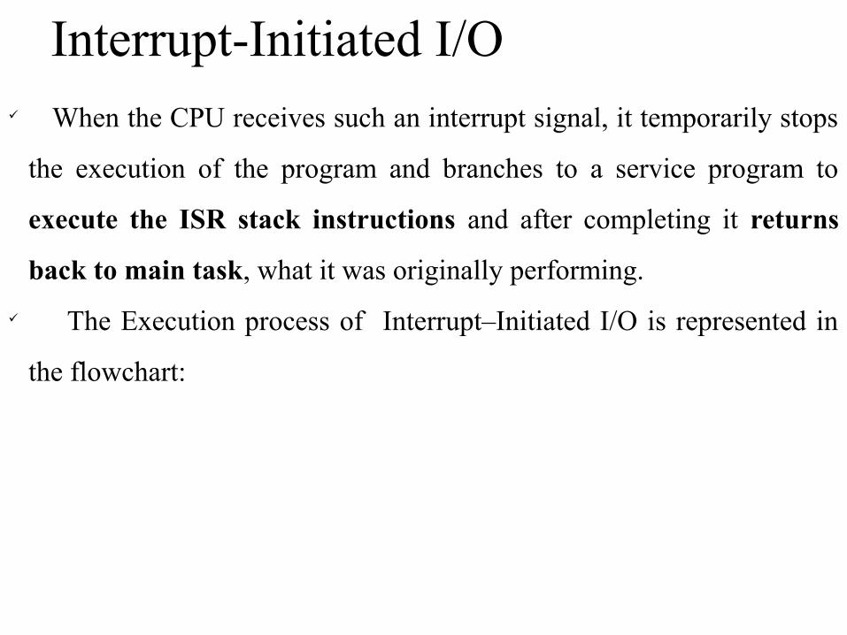
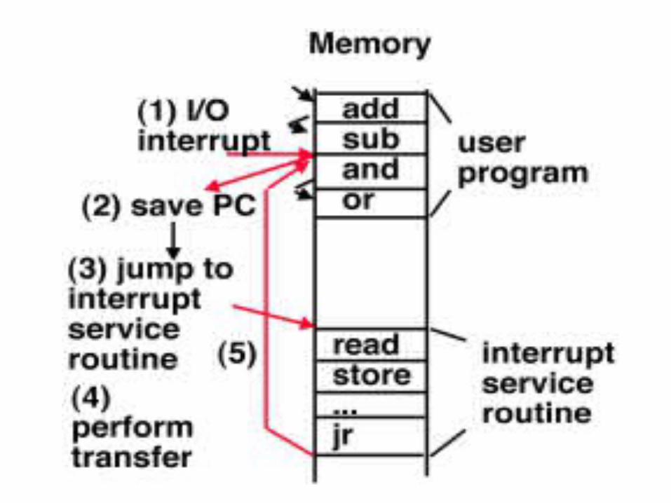
When the CPU receives such an interrupt signal, it temporarily stops
the execution of the program and branches to a service program to
execute the ISR stack instructions and after completing it returns
back to main task, what it was originally performing.
The Execution process of Interrupt–Initiated I/O is represented in
the flowchart:
Interrupt-Initiated I/O
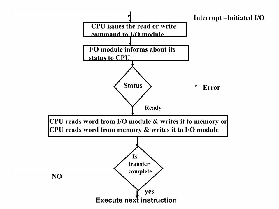
Ready
CPU issues the read or write command to I/O module
I/O module informs about its status to CPU
Status
CPU reads word from I/O module & writes it to memory or CPU reads word from memory & writes it to I/O module
Is transfercomplete
yesExecute next instruction
NO
Error
Interrupt –Initiated I/O
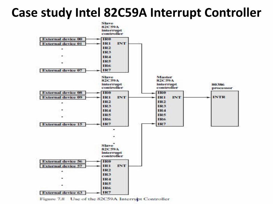
Case study Intel 82C59A Interrupt Controller
Case study Intel 82C59A Interrupt Controller
• The Intel 80386 provides a single Interrupt Request (INTR) and a single Interrupt Acknowledge (INTA) line.
• To allow the 80386 to handle a variety of devices and priority structures, it is usually configured with an interrupt controller 82C59A.
• Thus, external devices are connected to the 82C59A, which in turn connects to the 80386.
• A single 82C59A can handle up to eight I/O modules.
• If control for more than eight modules is required, a cascade arrangement can be used
Case study Intel 82C59A Interrupt Controller
• 82C59A accepts interrupt requests from attached modules, determines which interrupt has the highest priority, and then signals the processor by raising the INTR line.
• The processor acknowledges via the INTA line.
• 1] The major problem with existing system is that when the
transfer of data between a fast storage device (such as magnetic
disk and memory) is often limited by the speed of the CPU.
• 2] So, removing the CPU from the operations, memory buses can
directly manage the peripheral devices.
• 3] It would improve the speed of transfer, This transfer
technique is called Direct Memory Access (DMA).
• 4] In the Direct Memory Access (DMA) the interface transfer the
data into and out of the memory unit through the memory
bus.
Direct Memory Access (DMA)
5] During the DMA transfer, the CPU is idle and has
no control of the memory buses.
6] A DMA Controller takes control over the memory
buses to manage the transfer directly between the I/O
device and memory.
Direct Memory Access (DMA)
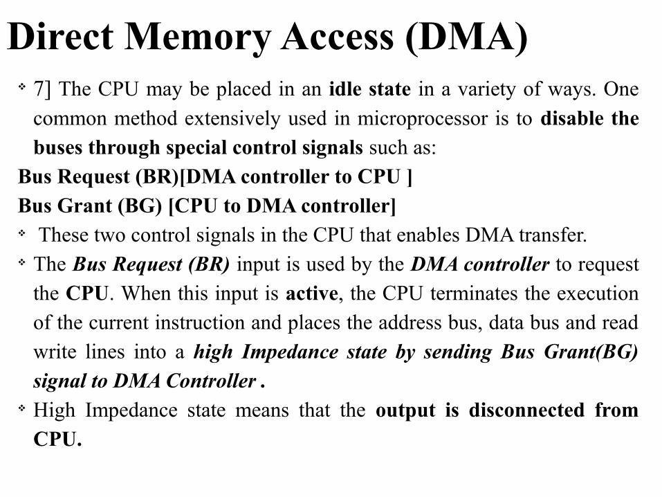
Direct Memory Access (DMA) 7] The CPU may be placed in an idle state in a variety of ways. One
common method extensively used in microprocessor is to disable the buses through special control signals such as:
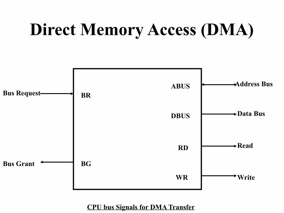
Bus Request (BR)[DMA controller to CPU ]Bus Grant (BG) [CPU to DMA controller] These two control signals in the CPU that enables DMA transfer. The Bus Request (BR) input is used by the DMA controller to request
the CPU. When this input is active, the CPU terminates the execution of the current instruction and places the address bus, data bus and read write lines into a high Impedance state by sending Bus Grant(BG) signal to DMA Controller .
High Impedance state means that the output is disconnected from CPU.
Bus Request
Bus Grant BG
BR
WR
RD
DBUS
ABUS Address Bus
Data Bus
Read
Write
CPU bus Signals for DMA Transfer
Direct Memory Access (DMA)
When the DMA terminates the transfer, it disables
the Bus Request (BR) line. The CPU disables the Bus Grant (BG), takes
control of the buses and return to its normal operation.
Direct Memory Access (DMA)
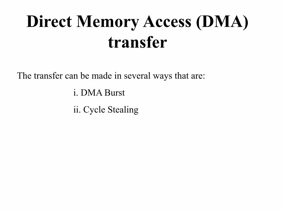
The transfer can be made in several ways that are:
i. DMA Burst
ii. Cycle Stealing
Direct Memory Access (DMA) transfer
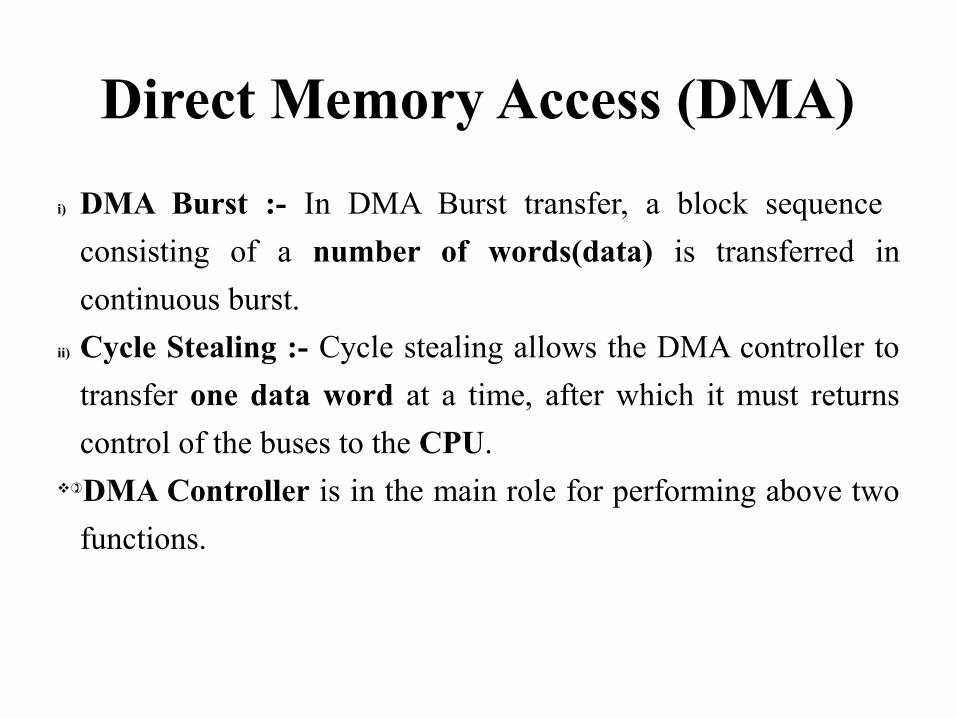
i) DMA Burst :- In DMA Burst transfer, a block sequence
consisting of a number of words(data) is transferred in
continuous burst.
ii) Cycle Stealing :- Cycle stealing allows the DMA controller to
transfer one data word at a time, after which it must returns
control of the buses to the CPU.)DMA Controller is in the main role for performing above two
functions.
Direct Memory Access (DMA)
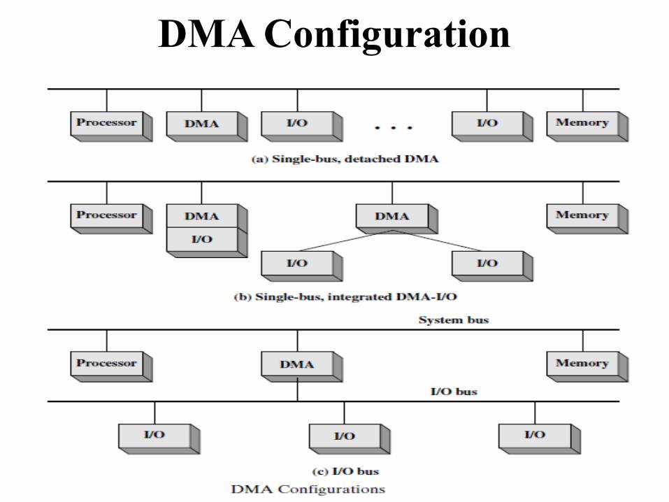
DMA Configuration
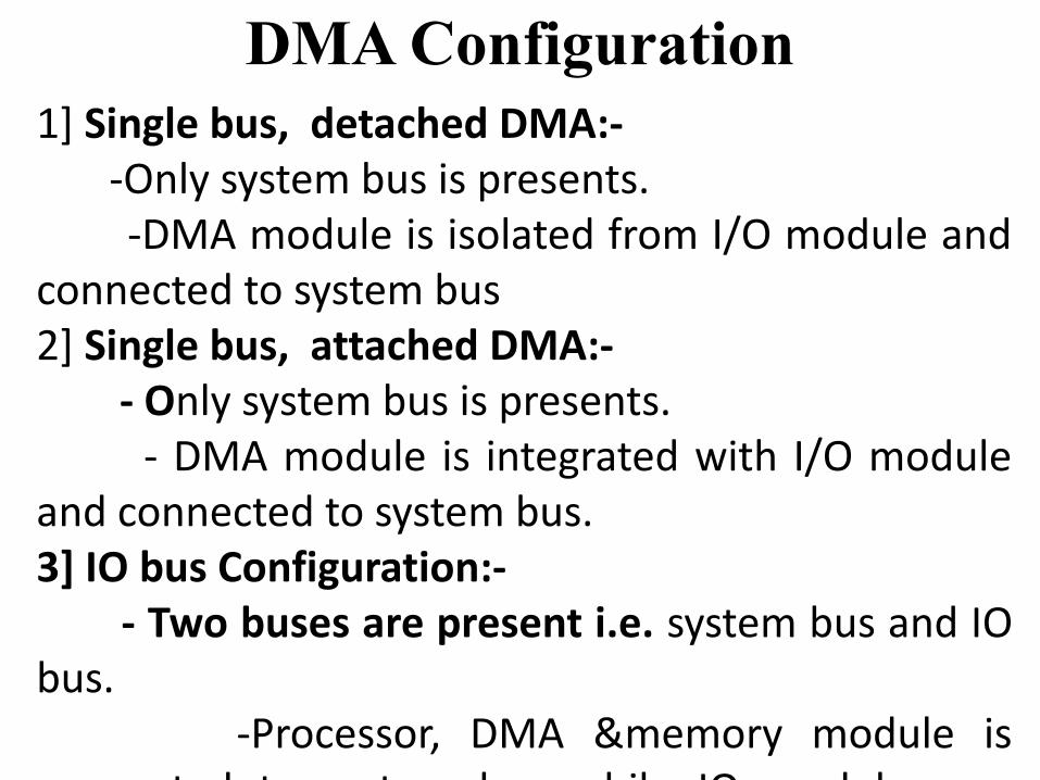
DMA Configuration1] Single bus, detached DMA:- -Only system bus is presents. -DMA module is isolated from I/O module and connected to system bus2] Single bus, attached DMA:- - Only system bus is presents. - DMA module is integrated with I/O module and connected to system bus.3] IO bus Configuration:- - Two buses are present i.e. system bus and IO bus. -Processor, DMA &memory module is connected to system bus while IO modules are connected to IO bus.
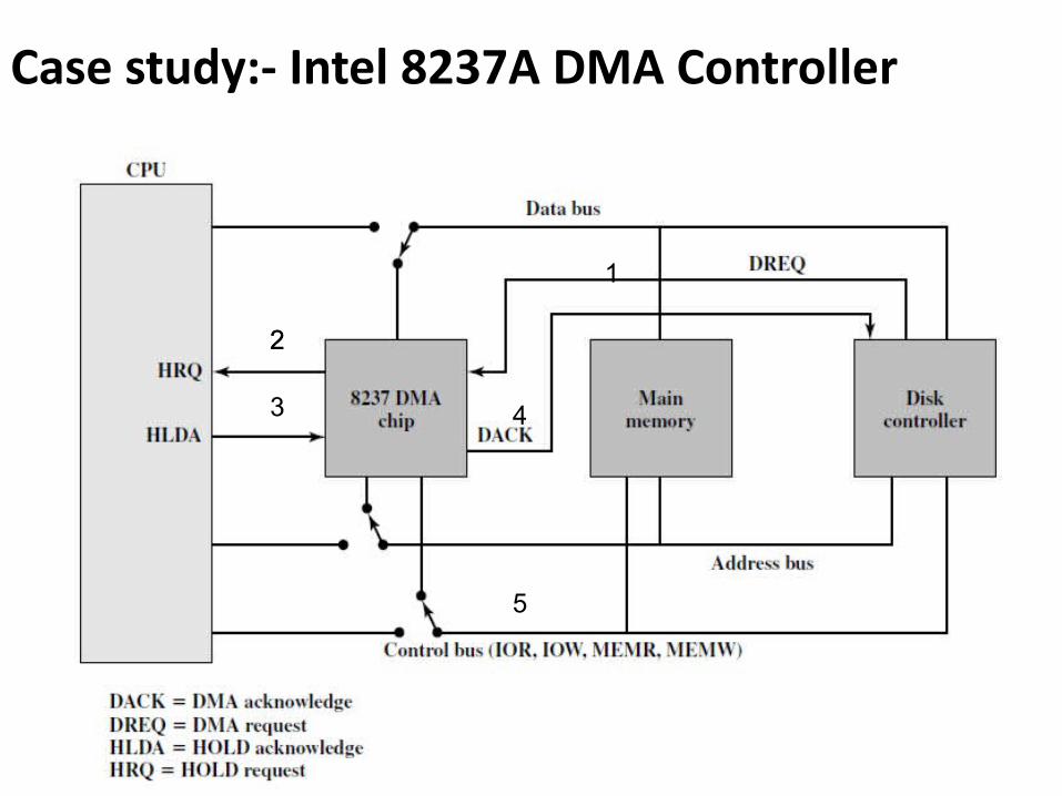
Case study:- Intel 8237A DMA Controller
1
2
3
2
4
5
• Consider, the DMA module is to transfer a block of data from memory to disk, it will do the following:
1. The disk controller will request the service of DMA by pulling DREQ (DMA request) high.2. The DMA will put a high on its HRQ (hold request), signaling the CPU through its HOLD pin that it needs to use the buses.3. The CPU will finish the present bus cycle and respond to the DMA request by putting high on its HDLA (hold acknowledge), thus telling the 8237 DMA that it can go ahead and use the buses to perform its task. HOLD must remain active high as long as DMA is performing its task.
4. DMA will activate DACK (DMA acknowledge), which tells the peripheral device(disk) that it will start to transfer the data to memory.5. DMA starts to transfer the data from memory to peripheral(disk) by putting the address of the first byte of the block on the address bus and activating MEMR, thereby reading the byte from memory into the data bus; 6. After the DMA has finished its job it will deactivate HRQ, signaling the CPU that it can regain control over its buses.
I/O CHANNELS AND PROCESSORSThe Evolution of the I/O Channel
1. The CPU directly controls a peripheral device. This is seen in simple microprocessor-2. Later on, A controller or I/O module is added. The CPU uses programmed I/O without interrupts.3. The same configuration as in step 2 is used, but now interrupts are employed.4. The I/O module is given direct access to memory via DMA. It can now move a block of data to or from memory without involving the CPU
The Evolution of the I/O Channel5. The I/O module is enhanced to become a processor, The CPU directs the I/O processor to execute an I/O program in memory. The I/O processor itself fetches and executes these instructions without CPU intervention. 6. The I/O module has a local memory of its own and is, in fact, all processing power to execute instruction, with minimal CPU involvement.
The Evolution of the I/O Channel
• So , one can easily observed that with the last two steps (5–6), a major change occurs with the introduction of the concept of an I/O module is capable of executing a program.
• That why in step 5-6, the I/O module is often referred to as an I/O channel and I/O processor.
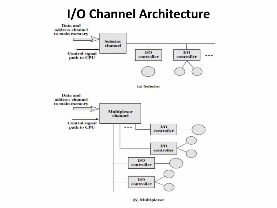
I/O Channel Architecture• An I/O channel has the ability to execute I/O
instructions, which gives it complete control over I/O operations.
• So, here CPU does not execute I/O instructions. Such instructions are stored in main memory to be executed by a special-purpose processor in the I/O channel itself.
• Thus, the CPU initiates an I/O transfer by instructing the I/O channel to execute a program in memory.
I/O Channel Architecture• There are Two types of I/O channels: 1] Selector2] Multiplexor
1] Selector• selector channel controls multiple high-speed
devices but at any one time only one of those devices can transfer data.
• Thus, the I/O channel selects one device and perform the data transfer.
• Each device, or a small set of devices, is handled by an I/O module(I/O Controller).
• Thus, the I/O channel serves in place of the CPU in controlling.
I/O Channel Architecture
I/O Channel Architecture
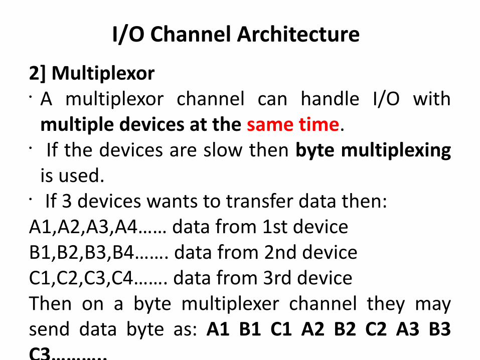
2] Multiplexor• A multiplexor channel can handle I/O with
multiple devices at the same time. • If the devices are slow then byte multiplexing
is used.• If 3 devices wants to transfer data then:A1,A2,A3,A4…… data from 1st deviceB1,B2,B3,B4……. data from 2nd deviceC1,C2,C3,C4……. data from 3rd deviceThen on a byte multiplexer channel they may send data byte as: A1 B1 C1 A2 B2 C2 A3 B3 C3………..
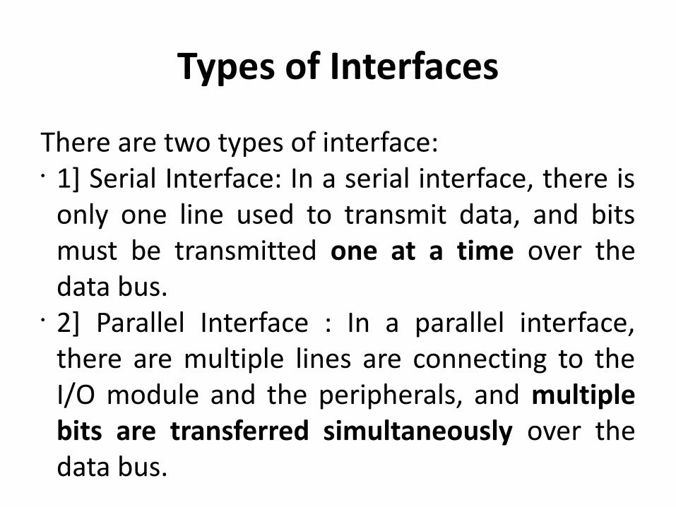
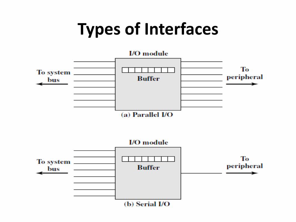
Types of Interfaces
There are two types of interface:• 1] Serial Interface: In a serial interface, there is
only one line used to transmit data, and bits must be transmitted one at a time over the data bus.
• 2] Parallel Interface : In a parallel interface, there are multiple lines are connecting to the I/O module and the peripherals, and multiple bits are transferred simultaneously over the data bus.
Types of Interfaces
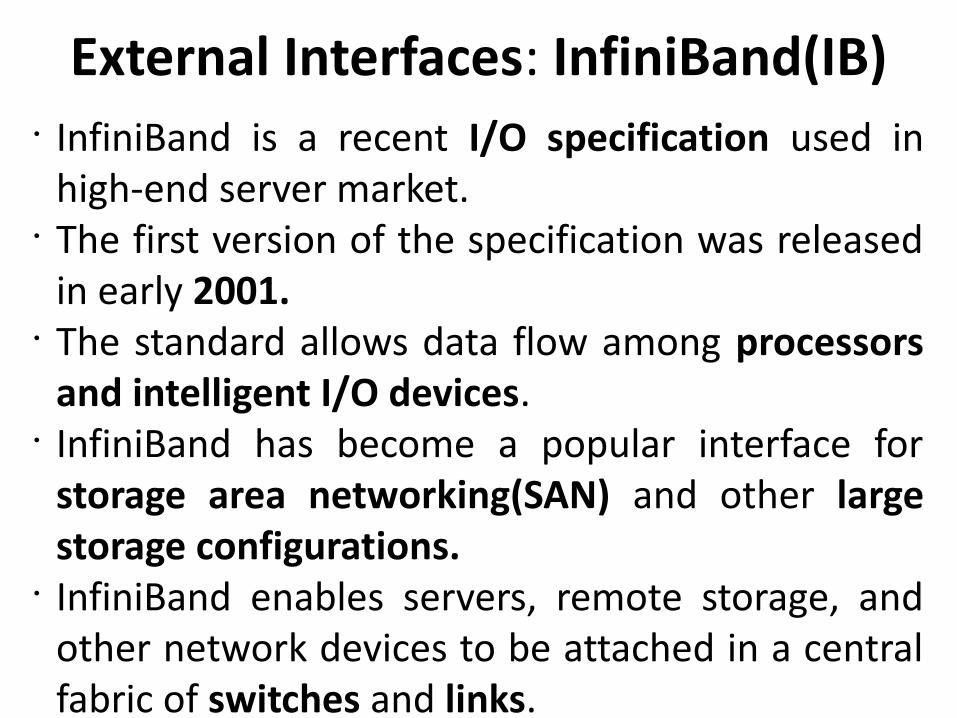
External Interfaces: InfiniBand(IB)• InfiniBand is a recent I/O specification used in
high-end server market.• The first version of the specification was released
in early 2001.• The standard allows data flow among processors
and intelligent I/O devices. • InfiniBand has become a popular interface for
storage area networking(SAN) and other large storage configurations.
• InfiniBand enables servers, remote storage, and other network devices to be attached in a central fabric of switches and links.
• The switch-based architecture can connect up to 64,000 servers, storage systems, and networking devices.
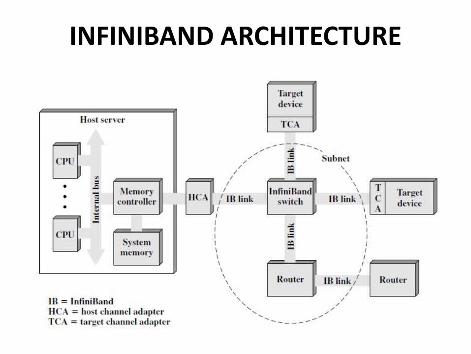
INFINIBAND ARCHITECTURE
INFINIBAND ARCHITECTURE• InfiniBand’s channel design enables I/O devices to
be placed: up to 17 meters away from the server using copper, up to 300 m using multimode optical fiber, and up to 10 km with single-mode optical fiber. • Transmission rates can be achieved upto 30 Gbps
INFINIBAND ARCHITECTURE1] Host channel adapter (HCA): • Adapter is used to links the server to an
InfiniBand switch. • The HCA attaches to the server at a memory
controller, which has access to the system bus and controls traffic between the processor and memory and between the HCA and memory.
• The HCA uses direct-memory access (DMA) to read and write memory.
2] Target channel adapter (TCA): A TCA is used to connect storage systems, routers, and other peripheral devices to an InfiniBand switch.
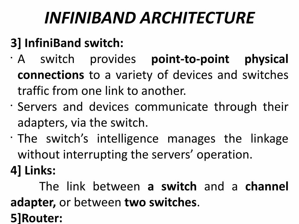
INFINIBAND ARCHITECTURE3] InfiniBand switch: • A switch provides point-to-point physical
connections to a variety of devices and switches traffic from one link to another.
• Servers and devices communicate through their adapters, via the switch.
• The switch’s intelligence manages the linkage without interrupting the servers’ operation.
4] Links: The link between a switch and a channel adapter, or between two switches.5]Router: • Connects an Infiniband switch to a network,
such as a local area network, wide area network, or storage area network.