Control developments for wheelchairs in slope environments
6
Control Developments for Wheelchairs in Slope Environments Sehoon Oh, Naoki Hata, Yoichi Hori Department of Electrical Engineering University of Tokyo 4-6-1 Komaba, Meguro, Tokyo, 153-8505 Japan {sehoon,hata}@horilab.iis.u-tokyo.ac.jp, [email protected] Abstract—We have developed an observer and controllers for wheelchairs in slope environments in this paper. We select two problems that frequently happen in power- assisted wheelchair caused by gravity. The first problem lies in overturning of wheelchairs and the second problem occurs when the difficulty happens in propulsion of wheelchairs on a hill. The former is related to the observation problem, and the latter is related to the control problem. We would like to propose solutions to the both problems. The observer, which we would like to propose here can estimate three main physical values; (1)the speed of the wheelchair,(2) the leaning angle of the wheelchair body from the ground, and (3) external disturbances. The observer can sensorfuse the informations from three sensors, which it uses the kalman filter theory. In order to prevent the problem of the wheelchair’s overturn- ing, assistive power by the motor attached to the wheelchair should be decreased according to the state of the wheelchair concerning the leaning angle and its anglular velocity. By this, it can realized by using the proposed observer and varying assistance-ratio controller. Key Words : kalman filter, multisensor, two-degree-of-freedom control, power-assisted wheelchair, gravity compensation, compli- ance control I. I NTRODUCTION Nowadays advanced power assistance tools are drawing people’s attention as emerging control application. These tools are usually located near a man or attached to one’s body amplify human power. This operational environment is unique to these tools and makes the control of these difficult. Though a variety of power assistance tools are being developed, there is little discussion on control methods for these tools. A power-assisted wheelchair is a good example of that kind of assistance tools. Development of controllers for a power- assisted wheelchair has just started[1]. In conventional power- assisted wheelchairs, motors just multiply original human force by up to several times. But, when a wheelchair goes on a hill, assisting motors can worsen the maneuverability. The wheelchair needs different type of assisting power when it is on a slope, but conventional controllers do not consider the slope of ground. This can make dangerous situation such as overturning of the wheelchair or increasing the speed when the wheelchair goes down a hill. To prevent these problems, assistance system should dis- tinguish the road condition and identify the states of the wheelchair. But how can the controller sense all these infor- mation? We will pick up this problem in Section II and IV. Fig. 1. Power-assisted Wheelchair as an Example of Power Assistance Tools (YAMAHA JW II) Based on these obtained information, assisting power will be modified in order to prevent overturning. These controller design problems are explored in Section III and IV. In Section IV, a gravity compensation controller is suggeted. We adpot the two degree of freedom controller for this problem. II. DEVELOPMENT OF OBSERVER FOR I DENTIFYING OF THE STATES OF WHEELCHAIR There are some important physical values when one drives a wheelchair, such as driving speed(v f in figure 2 (a)) and inclination angle(θ p in figure 2 (a)). The driving speed v f means the speed of the whole wheelchair and it is in a paralle direction with the ground, which is illustrated in figure 2 (a). Inclination angle is the leaning angle of the wheelchair frame from the horizon. If the wheelchair is on a level ground this angle becomes zero, but if the wheelchair is on a slope or the frame of the wheelchair is inclined against the ground, this angle has non-zero value. This inclination angle can be located in a phase plane, and the location of this angle denotes the stability of the wheelchair. If a controller can use the value, it will make the rider feel comfortable even when the wheelchair is on a hill. Encoders usually measure the driving speed. It should be noted that the wheelchair repeats low speed drivings and stops. Speed measurements at low or zero speed are liable to be noisy and incorrect when we use encoders for measurements. But correct and good estimation of this driving speed is necessary for a feedback control. 2005 American Control Conference June 8-10, 2005. Portland, OR, USA WeB06.4 0-7803-9098-9/05/$25.00 ©2005 AACC 739
-
Upload
independent -
Category
Documents
-
view
1 -
download
0
Transcript of Control developments for wheelchairs in slope environments

Control Developments for Wheelchairs in Slope Environments
Sehoon Oh, Naoki Hata, Yoichi HoriDepartment of Electrical Engineering
University of Tokyo4-6-1 Komaba, Meguro, Tokyo, 153-8505 Japan{sehoon,hata}@horilab.iis.u-tokyo.ac.jp,
Abstract— We have developed an observer and controllers forwheelchairs in slope environments in this paper.
We select two problems that frequently happen in power-assisted wheelchair caused by gravity. The first problem lies inoverturning of wheelchairs and the second problem occurs whenthe difficulty happens in propulsion of wheelchairs on a hill. Theformer is related to the observation problem, and the latter isrelated to the control problem. We would like to propose solutionsto the both problems.
The observer, which we would like to propose here can estimatethree main physical values; (1)the speed of the wheelchair,(2)the leaning angle of the wheelchair body from the ground,and (3) external disturbances. The observer can sensorfuse theinformations from three sensors, which it uses the kalman filtertheory.
In order to prevent the problem of the wheelchair’s overturn-ing, assistive power by the motor attached to the wheelchairshould be decreased according to the state of the wheelchairconcerning the leaning angle and its anglular velocity. By this,it can realized by using the proposed observer and varyingassistance-ratio controller.
Key Words : kalman filter, multisensor, two-degree-of-freedomcontrol, power-assisted wheelchair, gravity compensation, compli-ance control
I. INTRODUCTION
Nowadays advanced power assistance tools are drawingpeople’s attention as emerging control application. These toolsare usually located near a man or attached to one’s bodyamplify human power. This operational environment is uniqueto these tools and makes the control of these difficult. Thougha variety of power assistance tools are being developed, thereis little discussion on control methods for these tools.
A power-assisted wheelchair is a good example of that kindof assistance tools. Development of controllers for a power-assisted wheelchair has just started[1]. In conventional power-assisted wheelchairs, motors just multiply original humanforce by up to several times. But, when a wheelchair goeson a hill, assisting motors can worsen the maneuverability.
The wheelchair needs different type of assisting power whenit is on a slope, but conventional controllers do not considerthe slope of ground. This can make dangerous situation suchas overturning of the wheelchair or increasing the speed whenthe wheelchair goes down a hill.
To prevent these problems, assistance system should dis-tinguish the road condition and identify the states of thewheelchair. But how can the controller sense all these infor-mation? We will pick up this problem in Section II and IV.
Fig. 1. Power-assisted Wheelchair as an Example of Power Assistance Tools(YAMAHA JW II)
Based on these obtained information, assisting power willbe modified in order to prevent overturning. These controllerdesign problems are explored in Section III and IV.
In Section IV, a gravity compensation controller is suggeted.We adpot the two degree of freedom controller for thisproblem.
II. DEVELOPMENT OF OBSERVER FOR IDENTIFYING OF
THE STATES OF WHEELCHAIR
There are some important physical values when one drivesa wheelchair, such as driving speed(vf in figure 2 (a)) andinclination angle(θp in figure 2 (a)). The driving speed vf
means the speed of the whole wheelchair and it is in a paralledirection with the ground, which is illustrated in figure 2 (a).Inclination angle is the leaning angle of the wheelchair framefrom the horizon. If the wheelchair is on a level ground thisangle becomes zero, but if the wheelchair is on a slope or theframe of the wheelchair is inclined against the ground, thisangle has non-zero value.
This inclination angle can be located in a phase plane,and the location of this angle denotes the stability of thewheelchair. If a controller can use the value, it will makethe rider feel comfortable even when the wheelchair is on ahill. Encoders usually measure the driving speed. It should benoted that the wheelchair repeats low speed drivings and stops.Speed measurements at low or zero speed are liable to be noisyand incorrect when we use encoders for measurements. Butcorrect and good estimation of this driving speed is necessaryfor a feedback control.
2005 American Control ConferenceJune 8-10, 2005. Portland, OR, USA
WeB06.4
0-7803-9098-9/05/$25.00 ©2005 AACC 739
θpθf
g
vf M
m
l
R
(a) states of wheelchair (b) inverted pedulum model
Fig. 2. Physical Values Needed for Control
An observer that observes these two values is developedhere.
A. Observer Design Using Kalman Filter Theory
In order to design the required observer, states in equation(1) are adopted. ωp, ωf are the velocites of θp, θf . θp is theinclination angle explained previously. θf is the rotated angleof a wheel. Driving speed vf can be calculated by vf = Rωf
ignoring slips on wheels (R is the radius of the wheel). Lastlydp, df are the disturbances exerted on θp, θf respectively.
x =(
ωp ωf θp θf dp df
)T(1)
Motion equations of these states are shown in equation (2).
Jf θ̈f = −Bf θ̇f +τf +df , Jpθ̈p = −Bpθ̇p+dp, vf = Rθf (2)
Jf , Jp, Bf , Bp are inertias and dampings in each state. τf isthe torque to propel the wheel, and it is exerted by humanor motor. This equation uses disturbance terms to simplifythe equation. The input torque to θp is set as 0, and θp isexcited only by disturbance dp. This enables us to ignore therestriction by the connection between θp and θf .
Equation (3) and (4) show detailed form of these equations.These equations are derived based on the inverted pendulummodel
τf +df = {(M + m) r + JM} θ̈f −mlrθ̈p cos θp
+mlrθ̇2p sin θp + BM θ̇f (3)
dp =(Jm + ml2
)θ̈p −mlrθ̈f cos θp −mgl sin θp
+Bmθ̇p (4)
M is the weights of wheels of wheelchair and m is theweight of the body including a rider. l is the distance ofthe center of gravity of the body from the axis of wheels.g is the gravity acceleration (See figure 2 (b)). We can noticethat the former motion equations are in extremely simplifiedforms using the disturbances df , dp compared with the latterequations.
[4] shows that these two types of equations does not makeany difference in estimation. In this paper, simplified equation(2) is employed.
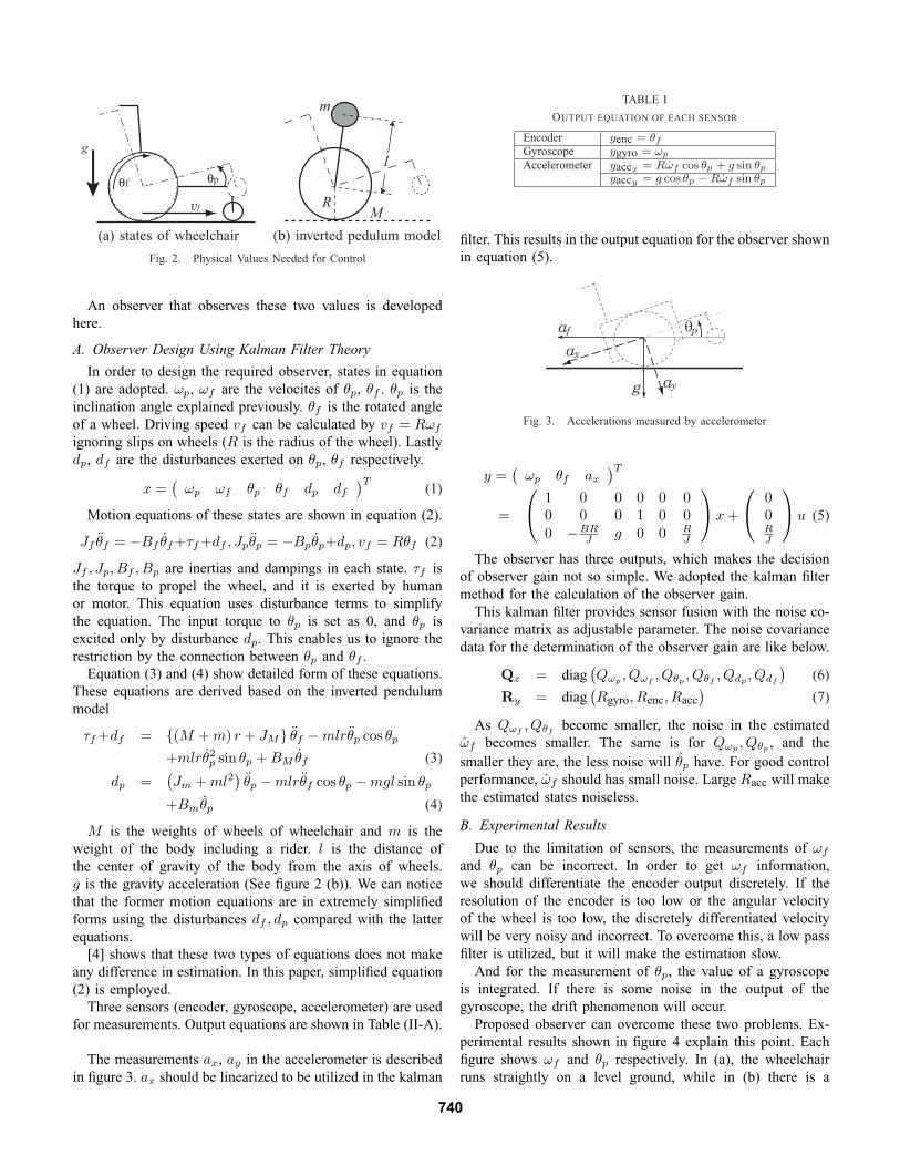
Three sensors (encoder, gyroscope, accelerometer) are usedfor measurements. Output equations are shown in Table (II-A).
The measurements ax, ay in the accelerometer is describedin figure 3. ax should be linearized to be utilized in the kalman
TABLE I
OUTPUT EQUATION OF EACH SENSOR
Encoder yenc = θf
Gyroscope ygyro = ωp
Accelerometer yaccx = Rω̇f cos θp + g sin θp
yaccy = g cos θp −Rω̇f sin θp
filter. This results in the output equation for the observer shownin equation (5).
ax
g ay
θpaf
Fig. 3. Accelerations measured by accelerometer
y =(
ωp θf ax
)T
=
1 0 0 0 0 00 0 0 1 0 00 −BR
J g 0 0 RJ
x +
00RJ
u (5)
The observer has three outputs, which makes the decisionof observer gain not so simple. We adopted the kalman filtermethod for the calculation of the observer gain.
This kalman filter provides sensor fusion with the noise co-variance matrix as adjustable parameter. The noise covariancedata for the determination of the observer gain are like below.
Qx = diag(Qωp
, Qωf, Qθp
, Qθf, Qdp
, Qdf
)(6)
Ry = diag(Rgyro, Renc, Racc
)(7)
As Qωf, Qθf
become smaller, the noise in the estimatedω̂f becomes smaller. The same is for Qωp
, Qθp, and the
smaller they are, the less noise will θ̂p have. For good controlperformance, ω̂f should has small noise. Large Racc will makethe estimated states noiseless.
B. Experimental Results
Due to the limitation of sensors, the measurements of ωf
and θp can be incorrect. In order to get ωf information,we should differentiate the encoder output discretely. If theresolution of the encoder is too low or the angular velocityof the wheel is too low, the discretely differentiated velocitywill be very noisy and incorrect. To overcome this, a low passfilter is utilized, but it will make the estimation slow.
And for the measurement of θp, the value of a gyroscopeis integrated. If there is some noise in the output of thegyroscope, the drift phenomenon will occur.
Proposed observer can overcome these two problems. Ex-perimental results shown in figure 4 explain this point. Eachfigure shows ωf and θp respectively. In (a), the wheelchairruns straightly on a level ground, while in (b) there is a
740

0 5 10 15 202
0
2
4
0 5 10 15 200.1
0
0.1
Time(sec)
Time(sec)
θpωf
(a) Without Wheelie
Time(sec)
θpωf
0 5 10 15 20-1
0
1
2
0 5 10 15 200.2
0
0.2
Time(sec)
(b) With Wheelie
0 5 10 15 202
0
2
0 5 10 15 200.5
0
0.5
Time(sec)
Time(sec)
θpωf
(b) With Wheelie
Fig. 4. Estimated States: ω̂f and θ̂p
wheelie around 4 sec. (c) shows the result of experiment ona slope. The red line in the upper figure of each experimentwhich shows ωf , is the low pass filtered differential of theencoder output. This value is very noisy and delayed, while theestimation of the proposed observer (blue line) is fast and notnoisy. To investigate the robustness of proposed observer, weadded a noise to the gyroscope output at 10 sec. Let’s see thebelow figure of each experiment. This shows the estimated θp.Compared to the integration of the gyroscope output (red linein the below figure of each experiment), the proposed observerestimation (blue line) shows robust observation results. Fromthis experimental result, we can conclude that using theproposed observer, the drift phenomenon can be avoided andbetter velocity information will be obtained.
We can identify the states of the wheelchair using thisestimated θp, and apply this information to the control. But
the inclination angle is not sufficient to tell whether it is on aslope or during a wheelie. df will tell this information. Figure5 is the estimated df s. The left figure is d̂f on a slope, andthe right is d̂f during a wheelie.
0 5 10 15 20−30
−20
−10
0
10
20
30
time (sec)
Dis
turb
ance
Disturbance on θ (dθ)
0 5 10 15 20−30
−20
−10
0
10
20
30
Disturbance on θ (dθ)
time (sec)
Dis
turb
ance
(b) With Wheelie (b) With Wheelie
Fig. 5. Estimated States: ω̂f and θ̂p
If the wheelchair is on a slope, the gravity act as a distur-bance to driving, but if the wheelchair is during a wheelie,it is not. Using this d̂f , more classified identification of thewheelchair states is available.
III. POWER-ASSISTANCE-RATIO CONTROL METHOD
BASED ON PHASE PLANE ANALYSIS
A. Fundamental method for power-assistance control
The power-assistance units amplify the manual inputs fromthe push rims with first order delay. The equation of power-assistance controller is
Tassist = α1
1 + τsThuman, (8)
, where α is power-assistance-ratio, Tassist is the amplifiedtorque from the push rim, Thuman is the input torque fromthe push rim and τ is the time constant of first order delay.τ should be a suitable value realizing inertia for wheelchair.Therefore, τ at the beginning of propelling should be smallvalue and that at the ending should be large.
And the behavior of this controller is shown in Fig.6.Fig.7 shows the block diagram of power-assistance con-
troller.
0 1 2 3 4 5 6 7 8 9 100
2
4
6
8
10
12
14
16
18
assist
input
τ =1.0
τ =0.08
time[sec]
torq
ue[N
m]
Fig. 6. Input Torque and AssistanceTorque versus Time.
1+ατs
Wheel Chair
T
T
human
assist
Tdist
z
θ
Fig. 7. Power-assisted Controller.
741

-0.5 -0.4 -0.3 -0.2 -0.1 0 0.1 0.2 0.3 0.4 0.5-2
-1.5
-1
-0.5
0
0.5
1
1.5
2
B
C
A
θ[rad]
ω[rad/s]
P
Fig. 8. Man-wheelchair Phase Plane.
B. Analysis of Overturning Using Phase Plane
Overturning of a wheelchair can be discussed with a phaseplane of θ̂p and ωp. θp moves according to the equation (4),so its movements can be calcuated on the phase plane usingthe equation.
Figure 8 shows this phase plane, which divides the planeinto three regions depending on the level of danger; A) propersafety zone (ωp < 0 and below the negative slope asymptote),B) semi-safety zone (θp < 0, ωp > 0 and below the negativeslope asymptote), and C) dangerous zone (above the negativeslope asymptote).
Point P in figure 8 which denotes the state of thewheelchair, is staying generally at the point (θp, ωp) = (θ0, 0).But it will shift to C region through B region when thewheelchair overturns. Figure 9 show the results of manualcontrol without power-assistance. Figure 9 shows that humanoperated the wheelchair successfully to return from C region.
-2
-1.5
-1
-0.5
0
0.5
1
1.5
2
-0.5 -0.4 -0.3 -0.2 -0.1 0 0.1 0.2 0.3
θ [rad]
ω [
rad/
s]
B C
A
Fig. 9. θp in the Phase Plane during manual control
C. Design of power-assistance-ratio
Power-assistance-ratio control strategy to prevent overturn-ing is proposed in this section. Power-assisted wheelchairtends to overturn easily on a slope because the assisting powerworks as overturning power on the slope. The assisting powershould be decrease according to the state of θp. This canbe achieved by modification of power-assistance-ratio. Theproposed power-assistance-ratio adjustment is shown as
α = αmax exp(βωp
θ̂p
), (9)
gyro
A/D D/A PulseCounter
PCI Bus
torque sensor encoder
motor
Real-time OS
PIO
accelerometer
Fig. 10. Experimental Setup.
0-0.5
0
0.5
1
1.5
2
2.5
3
3.5
4
time[sec]
[rad], A
ssis
tance r
atio
θ̂
assistanceratio
θ̂
1 2 3 4 5 6 7 8 9 10
time[sec]
[rad], A
ssis
tance-r
atio
θ̂
assistance-ratio
θ^
-0.5
0
0.5
1
1.5
2
2.5
3
3.5
4
0 1 2 3 4 5 6 7 8 9 10
-2
-1.5
-1
-0.5
0
0.5
1
1.5
2
-0.5 -0.4 -0.3 -0.2 -0.1 0 0.1 0.2 0.3θ [rad]
ω [
rad/
s]B C
A
(a) β = 0.5
-2
-1.5
-1
-0.5
0
0.5
1
1.5
2
-0.5 -0.4 -0.3 -0.2 -0.1 0 0.1 0.2 0.3
θ [rad]
ω [
rad/
s]
B C
A
(b) β = 3Fig. 11. Experimental Results.
where β is the decreasing constant which decides a speedof decreasing power-assistance-ratio. ωp/θ̂p implies the slopefrom origin on the phase plane, namely the level of danger.αmax is the maximum power-assistance-ratio.
D. Experiments
Figure 10 shows the setup of the experimental apparatus.Experiments with β = [0.5, 3.0] are performed. The subjectpropels rims with a certain power so that it may overturn thewheelchair. The results are shown in figure 11. Figure 11(a)is done with β = 0.5, and it shows that the decrease in theassisting power is not enough and endangers the wheelchair.However, figure 11(b) which is done under β = 3.0, showsa safe front-wheel raising to get over the step on the unevengrand. β can adjust the extent of the proposed overturningprevention control and should be chosen considering theoperators’ preferences and driving characteristics.
IV. GRAVITY COMPENSATION CONTROLLER DESIGN
A. Flexible Disturbance Attenuation Control - Generalizationof Compliance Control
Design of the disturbance response plays very important rolein these power-assisting tools. These tools compensate humanpower against external force. Human power, however, itselfcan be a disturbance when it is seen from the controller. This
742

problem is similar to the cooperation problem between robotand human, but more general.
The disturbance observer in figure 12 is a typical method ofthe disturbance rejection in industrial motor controls. It aimsat perfect disturbance rejection up to high frequency ranges.This perfect disturbance rejection is not suitable for the powerassist control. Disturbance in power assistance tools can berelated to human activities in many cases. Stiff rejection ofdisturbance can worsen the operational performance and evenmake dangerous situation.
P
Pn
Q
-1
r y
u
d
-
+
+-
Fig. 12. The Structure of the Disturbance Observer
The disturbance attenuation should be flexible when it isapplied to the power assistance tools. But the feedback in thisdisturbance observer is not suitable for flexible disturbanceattenuation. The adjustable parameter in the disturbance ob-server is only suitable for the stiff rejection, and does notprovide enough degree of freedom for the flexible disturbanceattenuation.
B. Flexible Disturbance Attenuation Control
How can we make the disturbance attenuation flexible? As asolution we propose a feedback controller in figure 13. We candesign the disturbance response arbitrarily using this feedback.
Pr yu
d
-
Pn
C-
+
+ ++
Fig. 13. Proposed Flexible Disturbance Attenuation Control
By this feedback controller, the response of the wheelchairwill be :
y = P
(1 + CPn
1 + CPr +
11 + CP
d
). (10)
r is a reference input and d is a disturbance. r and d areassisted torque and gravity respectively. Note that if Pn =P , the response by r will be Pr, which means the feedbackcontroller does not affect this response. However the responseby d is adjusted to P
1+CP d from Pd.
The passive adaptive control in [6] has the same structurewith figure 13. While [6] adopted P−1
n for C to realize theperfect disturbance rejection, our proposed method decides Cconsidering physical characteristics.
Flexible disturbance attenuation does not reject disturbanceperfectly. It just modifies the physical characteristics of theplant against disturbance. This point is similar with the compli-ance control[7] used in robot controls. Utilizing various filtersas C, we can realize various flexible disturbance attenuations,and it will provide enough degree of freedom.
We will design a gravity compensation controller as oneexample of this flexible disturbance attenuation in next section.
C. Necessity of Gravity Compensation in the Power-assistedWheelchair
Propulsion of a wheelchair on a slope is heavier burdenthan on level ground. Figure 14 compares necessary torquesfor propulsions in these two cases. It shows that necessarypropulsion torque on hills is much larger than the torque forlevel ground propulsion. This means the power assist controlis more necessary on hills. However, many of commercialpower-assisted wheelchairs do not assist the propulsion on hillsbecause of difficulties of control. Furthermore, as discussedthe previous section, inadequate power assistance can makethe wheelchair unstable.
-10
-5
0
5
10
15
20
0 2 4 6 8 10 12 14 16
torqueangle
-10
-5
0
5
10
15
20
0 2 4 6 8 10 12 14 16
torqueangle
Fig. 14. Necessary torques to drive a wheelchair (Upper: drive on levelground, Lower: drive on hill)
D. Flexible Gravity Attenuation Control
Figure 15 shows the structure of proposed gravity attenua-tion controller. The TDOF controller using proposed flexibledisturbance attenuation is applied.
+
FF Cont.(Assist)
HumanTorque
Disturbance(d)
Output++
+-
-
Feedback Controller
rPSfrag repla ements Jds�s+ 1 BdJs+BJns+Bn1
1
Fig. 15. Structure of flexible gravity attenuation controller applied to apower-assisted wheelchair
743

1Js+B is the dynamics of the wheelchair, and ”FF
Cont.(Assist)” means a feedforward controller for a powerassistance which was introduced in section III-A. Controller inthe dotted rectangular is the gravity compensation controller.
Increasing the friction and inertia of the wheelchair makesthe wheelchair seem heavy to gravity. Here, zero stiffness(Kd = 0) is employed for it will produce just a certain amountof power to attenuate the effect of gravity on the wheelchair.The amount can be modified arbitrarily based on the inertiaand friction of the wheelchair changed by the filter C. To thisend, we adopt Jds+Bd as C, and it will change like follows:
1Js + B
→ 1(J + Jd)s + (B + Bd)
. (11)
E. Experimental verification of proposed method
The effectiveness of this gravity compensation controller areverified by experiments using the same experimental setup infigure 10.
Two kinds experiment were done. One is done on levelground and the other is done on a hill. The result is shownin figure 16. In contrast to the drive on level ground, on ahill the controller produces a certain amount of motor torquewhile there is no human torque input. Almost same torque isproduced even when the wheelchair descend the hill.
The amount of produced torque can be adjusted by the Bd
parameter, and the parameter Jd will adjust the response timeagainst gravity.
-8
-6
-4
-2
0
2
4
6
8
0 2 4 6 8 10 12 14 16 18 20
human torqueangle
motor torque
-2
-1
0
1
2
3
4
5
6
7
0 2 4 6 8 10 12 14 16 18 20
human torqueangle
motor torque
Fig. 16. Experimental Results (Left: drive on level ground, Right: drive onhill))
We should notice that this controller does not remove theeffect of gravity perfectly, which means that this feedbackcontroller will not stop the wheelchair on a hill. This is thepoint of proposed flexible disturbance rejection.
F. Extention to the Compensation in the Lateral Direction
A slope in the lateral direction is troublesome for awheelchair. The proposed controller can be extended to thisproblem. Figure 17 is the structure of the compensator for thegravity in the lateral direction.
Comparing the disturbances in the left and the right direc-tion, we can assess the gravity in the lateral direction. By feed-back of this gravity information, the gravity is compensated.This compensator is to be validated by experiments.
+
FF Cont.(Assist)
HumanTorque
Disturbance(d)
Output
++
+-
-r
+
FF Cont.(Assist)
HumanTorque
Disturbance(d)
Output
+ +
+-
-r
LateralCompensator
Fig. 17. Structure of Lateral Direction Gravity Compensator
V. CONCLUSION
In this paper, we have suggested an observer and controllerfor wheelchairs in slope environments.
The first suggestion was the development of observer forimportant physical values. The observer should be designedto make user of power assistance tools feel comfort and toadapt to various environments. The observer we proposed wasan example that provides a rider safe and natural assistivecontrol. Also we have shown that sensor fusion by the observerdesign method can improve the ability of sensors and makethe estimation more robust to sensor noise.
The other suggestion was the flexible disturbance attenu-ation. It provides the TDOF control which can design thedisturbance response by changing physical values of a plant,and it can make the response flexible. In the gravity com-pensation control, the parameters was inertia, damping. Thisflexible disturbance attenuation is a key when we design acontroller for power assistance tools, because the stiffness tothe disturbance should be modified arbitrarily.
What we have suggested in this paper showed that advancedmotion control theory can improve existing power assistancesystems when it is properly designed. There are many things tobe discussed to establish this human-friendly motion control.This technology is notable not only from the viewpoint ofengineering but also from that of society.
REFERENCES
[1] http://www.independencenow.com/[2] Yoshihiko Takahashi, Tsuyoshi Takagaki, Jun Kishi, and Yohei Ishii:
“Back and forward moving scheme of front wheel raising for inversependulum control wheelchair robot”, Proc. of the 2001 IEEE Int. Conf.on Robotics and Automation,pp. 3189-3194, Korea, May 21-26, 2001.
[3] B. Gopinath: “On the control of linear multiple input-output systems”,the Bell Technical Journal, Vol. 50, No. 3, pp. 1063-1081, March, 1971.
[4] Sehoon Oh, Hata Naoki, Yoichi Hori: ”Developments of Noise RobustState Observer for Power-assisted Wheelchair”, IPEC-Niigata 2005,2005.4 (to be submitted).
[5] Takaji Umeno, Yoichi Hori: ”Robust Speed Control of DC Servomo-tors using Modern Two-Degrees-of-Freedom Controller Design”, IEEETrans. on IE, Vol.38, No.5, pp.363-368, 1991
[6] Kenji Tamaki, Kiyoshi Ohishi, Kouhei Ohnishi and Hunio Miyachi:”Two-Degrees-of-Freedom Control of DC Servo Motor by Means ofPassive Adaptive Control”, Transactions of the Society of Instrument andControl Engineers (in japanese)AVol.22, No.11, pp.1175 1182, 1986.
[7] H.Kazerooni, T.B.Sherindan, P.K. Houpt: ”Robust Compliant Motion forManipulators, PART I,II”, IEEE Journal of Robotics and Automation,Vol.2, No.2, pp.83-105, 1986.
744