Slope Failures in Hong Kong
20
1 Slope Failures in Hong Kong P. Lumb Department of Civil Engineering, The University of Hong Kong Summary: The recurrence of slope failures in residual soils of Hong Kong is analysed for the period 1950 to 1973, and various factors contributing to the instability are described. It is postulated that the prime cause of the failures is direct infiltration of rain water into the surficial zones of the slopes, producing a loss of effective cohesion following the saturation of the soil. Prevention of slips implies protection against excessive infiltration. INTRODUCTION Slope failures are very common in Hong Kong, and the consequences of these failures are often disastrous. The majority of the failures take place during periods of heavy rain and are small debris avalanches of decomposed rock mantle, occurring very quickly with little or no prior warning. Rock-slides and slow- moving slips are rare. The survey to be presented here deals with the frequency and distribution of slope failures during the period from 1950 to 1973 and is restricted essentially to the urban areas of Hong Kong Island and Kowloon Peninsula shown in Figure 1. The prevalence of failures is due to a combination of factors (topography, climate, geology and land use) which perhaps makes Hong Kong unique. Other countries have similar soils but different rainfall patterns, or similar rainfall but different land use and so on, and while urban development of potentially unstable areas elsewhere may never reach the intensity of Hong Kong (see Figure 2) nevertheless a description of the situation might have value as a warning against over- development of steep slopes. The topography of Hong Kong is rugged, with steep natural slopes in residual soil mantles. Rainfall is high but seasonal, averaging about 2000 mm in the wet season from May to October, and occurs in very heavy downpours lasting several days, allowing part of the soil mantle possibly to become fully saturated several times during the wet season of any year. The mantle is either decomposed volcanic rock (a silt) or decomposed granite (a silty sand) and both soils have a high strength when unsaturated during the dry season but a low strength when fully saturated. Use of these steep natural slopes for roads or housing has involved numerous side-hill cuttings up-slope together with side-hill embankments of fill down-slope. Failure of these cuts and embankments causes road blocks and overwhelming of down- slope areas by debris avalanches, slumps and falling boulders. The speed of the avalanches, up to 30 m/s, combined with a lack of any warning can produce tragic results; 138 people were killed by two of the 185 slips which occurred in the disaster of June 1972. Figure 1. Sketch map of Hong Kong Island and Kowloon Peninsula Figure 2. Mid-levels District, Hong Kong Island The essential design difficulty lies in identifying potentially dangerous situations. Many apparently dangerous cuttings have remained perfectly stable for more than twenty years; other apparently safe cuts fail soon after construction. While the immediate
-
Upload
khangminh22 -
Category
Documents
-
view
0 -
download
0
Transcript of Slope Failures in Hong Kong

1
Slope Failures in Hong Kong
P. LumbDepartment of Civil Engineering, The University of Hong Kong
Summary: The recurrence of slope failures in residual soils of Hong Kong is analysed for the period 1950 to 1973, and various factors contributing to the instability are described. It is postulated that the prime cause of the failures is direct infiltration of rain water into the surficial zones of the slopes, producing a loss of effective cohesion following the saturation of the soil. Prevention of slips implies protection against excessive infiltration.
INTRODUCTION
Slope failures are very common in Hong Kong, and the consequences of these failures are often disastrous. The majority of the failures take place during periods of heavy rain and are small debris avalanches of decomposed rock mantle, occurring very quickly with little or no prior warning. Rock-slides and slow-moving slips are rare.
The survey to be presented here deals with the frequency and distribution of slope failures during the period from 1950 to 1973 and is restricted essentially to the urban areas of Hong Kong Island and Kowloon Peninsula shown in Figure 1. The prevalence of failures is due to a combination of factors (topography, climate, geology and land use) which perhaps makes Hong Kong unique. Other countries have similar soils but different rainfall patterns, or similar rainfall but different land use and so on, and while urban development of potentially unstable areas elsewhere may never reach the intensity of Hong Kong (see Figure 2) nevertheless a description of the situation might have value as a warning against over-development of steep slopes.
The topography of Hong Kong is rugged, with steep natural slopes in residual soil mantles. Rainfall is high but seasonal, averaging about 2000 mm in the wet season from May to October, and occurs in very heavy downpours lasting several days, allowing part of the soil mantle possibly to become fully saturated several times during the wet season of any year. The mantle is either decomposed volcanic rock (a silt) or decomposed granite (a silty sand) and both soils have a high strength when unsaturated during the dry season but a low strength when fully saturated.
Use of these steep natural slopes for roads or housing has involved numerous side-hill cuttings up-slope together with side-hill embankments of fill down-slope. Failure of these cuts and embankments causes road blocks and overwhelming of down-slope areas by debris avalanches, slumps and falling boulders. The speed of the avalanches, up to 30 m/s,
combined with a lack of any warning can produce tragic results; 138 people were killed by two of the 185 slips which occurred in the disaster of June 1972.
Figure 1. Sketch map of Hong Kong Island and Kowloon Peninsula
Figure 2. Mid-levels District, Hong Kong Island
The essential design difficulty lies in identifying potentially dangerous situations. Many apparently dangerous cuttings have remained perfectly stable for more than twenty years; other apparently safe cuts fail soon after construction. While the immediate
Finish.indb306 2007/8/1711:06:37AM

2
cause of a particular slip can usually be determined after the event, these causes are quite commonly due to factors beyond control at the design stage or even the construction stage. Faulty drainage systems, deterioration of protective works and changes in up-slope surface cover, are more frequently the prime cause of a failure rather than over-ambitious cutting heights or steep slope angles.
The relative importance of the various factors influencing stability can be assessed and some precautions taken to reduce the effect of the dominating factors. But the end result can never be an absolute unconditional guarantee of safety and the probability of failure at any site will always be non-zero.
TOPOGRAPHY AND GEOLOGY
The densely populated urban portions of Hong Kong Island and Kowloon Peninsula occupy about one tenth of the total 1000 km2 area of the whole Colony of Hong Kong.
On the Island the terrain is hilly, apart from the northern coast strip of reclaimed land, rising to heights of more than 450 m with steep slopes exceeding 30 degrees. All roads have substantial portions constructed in cuttings with slopes up to 75 degrees or on part-cut part-fill with fill slopes up to 30 degrees. The northern face of the Island is heavily developed up to about the 150 m contour (the Mid-Levels District, Figure 1 & 2) and above the 270 m contour (the Peak District, Figure 1) with a multitude of small sites formed on cut platforms with 45 to 75 degrees back slopes.
The greater part of the Kowloon Peninsula has been levelled and only a few isolated hills now remain with heights up to 100 m, but along the north and north-east boundaries of the urban development the Kowloon Hills rise to over 450 m. Major roads along the boundaries and extensive developments at Kwun Tong, Sau Mau Ping, Tsz Wan Shan (see Figure 1) and other districts have involved deep cuttings, large-scale platforming and substantial embankments.
The geology has been described by Ruxton (1960) and more recently by Allen and Stephens (1971). The two main rock types in the area are the older acid volcanics, principally rhyolitic ignimbrites, overlying the younger granitic batholith. Considerable erosion over the central portion of the area has removed the volcanic cover, exposing the underlying granite. On the Island the urban area is mainly volcanic, only the north and north-east being granitic, while on the Peninsula the urban area is granitic, except at the north-east boundary (Figure 1). Both the granite and the volcanic rocks have decomposed extensively but steep scarps of fresh rock remain at the upper slopes of the surrounding hills, close to the watershed.
The decomposition process has been described by
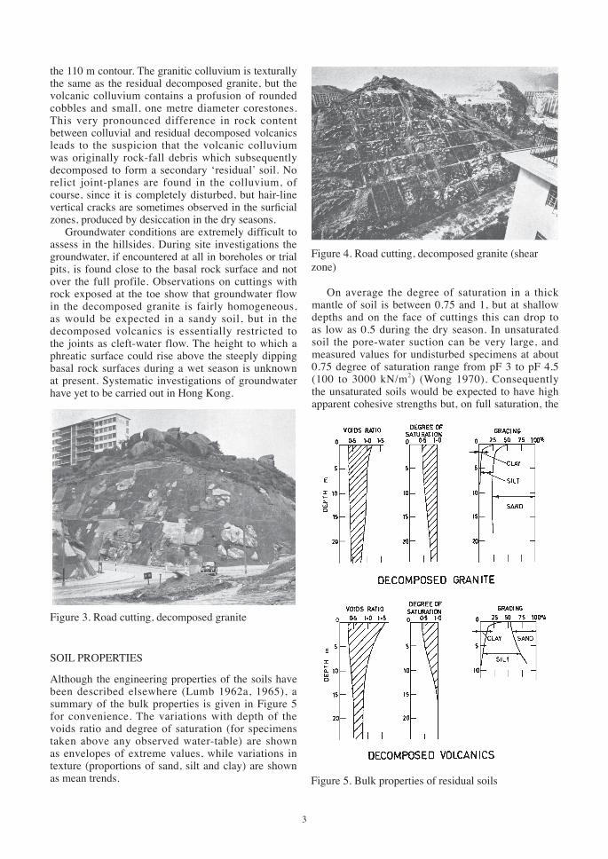
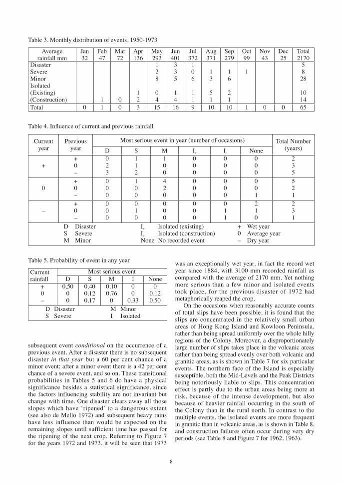
Ruxton and Berry (1957), Berry and Ruxton (1960) and Lumb (1962a, 1965). The granite decomposes to depths greater than 30 m, forming a residual silty sand mantle (or clayey sand near ground surface) which has low resistance to surface erosion. The vegetation cover is sparse, and bald patches of exposed residual soil are very common. Hillside slopes have been dissected into steep-sided rounded spurs, but there is little correlation between surface topography and depth to basal rock surface, and the valley floors between spurs are not always eroded to bedrock level. Very large corestones more than 3 m diameter are commonly found in the silty sand matrix or exposed on the hillsides, perched precariously on the surface (Figure 3). Large variations in thickness of mantle and abundance of corestones are the rule rather than the exception, both within small areas and between neighbouring areas. Figure 4, showing a location only 750 m from that of Figure 3, is a somewhat extreme example of this variability (in a shear zone), but illustrates what difficulties would arise when estimating depth to bedrock from the results of a few boreholes in a preliminary investigation.
The volcanic rocks do not decompose to the same depth as the granite, mantle thicknesses being of the order of 10 m and rarely in excess of 20 m. The residual soils are silts (or clayey silt near ground surface) which are not as susceptible to erosion as the decomposed granite. There is less dissection and little rounding of spurs and ridges, and the soil can sustain a very dense cover of scrub and trees (see Figure 2). Corestones are not found in the mantle, although pinnacles of fresh or soft rock often extend upwards from the basal rock surface into the mantle.
From an engineering point of view the essential differences between granitic and volcanic areas are the differences in texture, sandy or silty, of the two residual soils, and a very marked contrast in jointing patterns. The original joints of the parent rock are preserved in the mantle; in the granite these joints are typically wide, at 2 to 10 m spacing, whereas in the volcanics they are close, at 0.2 to 1 m spacing, giving a blocky structure to the decomposed volcanics. In the decomposed granite the large joint-planes can cause localized failures in cuttings, usually during construction, if oriented at a critical dip and strike. On the other hand, in the decomposed volcanics the joint-planes, although profuse, do not extend continuously over any appreciable area and have little influence on slope stability, other than promoting a limited amount of unravelling on occasion.
The natural slopes show no signs of creep, nor do the cut slopes, but there has been considerable mass-movement in the form of colluvial debris from old slips. The lower slopes of the hills are commonly blanketed by colluvial fans (see Figure 1) and this is particularly noticeable in the Mid-Levels District, where a layer 2 to 5 m thick of colluvium completely masks the contact between volcanics and granite at
Finish.indb307 2007/8/1711:06:37AM
3
the 110 m contour. The granitic colluvium is texturally the same as the residual decomposed granite, but the volcanic colluvium contains a profusion of rounded cobbles and small, one metre diameter corestones. This very pronounced difference in rock content between colluvial and residual decomposed volcanics leads to the suspicion that the volcanic colluvium was originally rock-fall debris which subsequently decomposed to form a secondary ‘residual’ soil. No relict joint-planes are found in the colluvium, of course, since it is completely disturbed, but hair-line vertical cracks are sometimes observed in the surficial zones, produced by desiccation in the dry seasons.
Groundwater conditions are extremely difficult to assess in the hillsides. During site investigations the groundwater, if encountered at all in boreholes or trial pits, is found close to the basal rock surface and not over the full profile. Observations on cuttings with rock exposed at the toe show that groundwater flow in the decomposed granite is fairly homogeneous, as would be expected in a sandy soil, but in the decomposed volcanics is essentially restricted to the joints as cleft-water flow. The height to which a phreatic surface could rise above the steeply dipping basal rock surfaces during a wet season is unknown at present. Systematic investigations of groundwater have yet to be carried out in Hong Kong.
Figure 3. Road cutting, decomposed granite
SOIL PROPERTIES
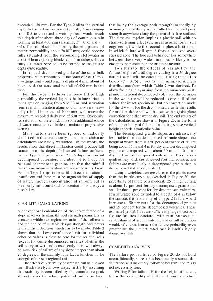
Although the engineering properties of the soils have been described elsewhere (Lumb 1962a, 1965), a summary of the bulk properties is given in Figure 5 for convenience. The variations with depth of the voids ratio and degree of saturation (for specimens taken above any observed water-table) are shown as envelopes of extreme values, while variations in texture (proportions of sand, silt and clay) are shown as mean trends.
On average the degree of saturation in a thick mantle of soil is between 0.75 and 1, but at shallow depths and on the face of cuttings this can drop to as low as 0.5 during the dry season. In unsaturated soil the pore-water suction can be very large, and measured values for undisturbed specimens at about 0.75 degree of saturation range from pF 3 to pF 4.5 (100 to 3000 kN/m2) (Wong 1970). Consequently the unsaturated soils would be expected to have high apparent cohesive strengths but, on full saturation, the
Figure 4. Road cutting, decomposed granite (shear zone)
Figure 5. Bulk properties of residual soils
Finish.indb308 2007/8/1711:06:38AM

4
apparent cohesion would drop to low values on release of the suction.
The clay fraction (smaller than 2 μm) is generally less than 10 per cent of the total and the major clay mineral is halloysite (Lee 1970). The engineering behaviour is not controlled to any marked degree by the clay fraction but is controlled by the dominant size-fraction (coarse sand for the decomposed granite, silt for the decomposed volcanics), to a slight extent by the voids ratio, and to a great extent by the degree of saturation.
The main characteristic of the residual soils is their variability, both laterally and vertically, and the variance of test results within any site is of the same order as the variance between different sites. Apart from the rapid decrease in clay content at shallow depths, the bulk properties show no strong dependence on depth. Texturally and structurally the soils are grossly uniform below the surficial clayey layers.
The strength of both unsaturated and fully saturated soil is best characterized by triaxial compression tests carried out under drained conditions, allowing water to enter or leave the specimen at atmospheric pressure (tests with zero excess pore-air pressure), the ‘drained cohesion’ cd and ‘drained angle of shearing resistance’ φd, being calculated in terms of the total applied stresses. Undrained tests are not representative of field behaviour, since excess air or water pressures dissipate very rapidly, even in fully saturated decomposed volcanics.
Table 1. Correlation coefficients(A) Decomposed granite (58 specimens)
z e S φd cd
zeSφdcd
−0L00
+0.07−00
VH
+0.24–0.14
−0L
+0.20+0.13–0.20
−0
+0.11–0.59–0.27–0.08
−(B) Decomposed volcanics (56 specimens)
z e S φd cd
zeSφdcd
−0LLH
–0.18−H00
+0.28+0.37
−0
VH
+0.29–0.22–0.03
–0
–0.31–0.16–0.58–0.19
–z Depth below surface 0 Zero significance e Voids ratio L Low significance S Degree of saturation H High significance φd Angle of shearing resistancecd Cohesion VH Very high significance
The relative influence of depth z, voids ratio e, and degree of saturation S, on cd and φd for undisturbed specimens is shown by the correlation matrix of Table 1. The upper half of the matrix gives the
measured correlation coefficients and the lower half their statistical significance as compared with a zero value. Allowing for the inter-correlations between z, e and S by using partial correlation coefficients, the factors influencing the strength parameters to any practical extent are:
cd φdDecomposed granite S, e NoneDecomposed volcanics S None
The estimated strength parameters for dry (S = 0.75) and wet (S = 1) soil in a loose (e = 1), medium (e = 0.75) or dense (e = 0.5) state are given in Table 2 as 90 per cent confidence intervals for individual specimens and also for overall averages on a typical site. For example, the cohesion of dry decomposed volcanics would range from 2 to 110 kN/m2 with a mean value between 48 and 65 kN/m2, with 90 per cent confidence in each case. Occasional specimens will have cohesions well outside these average confidence limits, of course, since the scatter in cohesion is always large. One specimen of decomposed volcanics at a degree of saturation of 0.6 had a cohesion of 620 kN/m2 with φd of 30º; other specimens at 0.5 degree of saturation showed zero cohesion.
The strength parameters are empirical, since they are extrapolated from strengths measured at fairly high confining stresses (140 to 420 kN/m2), and it is quite possible that the failure envelope is curved at low confining stresses. Also, the confidence limits for the wet soil may overestimate the cohesion, since they are derived by assuming a linear variation of strength with degree of saturation. The parameters refer to peak strength, but this is relevant to field performance
Table 2. 90% Confidence limits for strength
(A) Drained angle of shearing resistance, degreesLower Limit
Site average
Upper Limit
Decomposed volcanicsDecomposed granite
25.6
30.5
31.7±0.6
35.6±0.3
37.8
40.6
(B) Drained cohesion, kN/m2
Lower Limit
Site average
Upper Limit
Decomposed volcanics
Dry WetDecomposed granite
Dry LooseMedium
DenseWet Loose
MediumDense
20
00320 05
56.5±8.123.2±10.0
030.6±6.474.1±8.6
0 3.8±12.6 47.4±12.6
110 78
307211664790
Finish.indb309 2007/8/1711:06:39AM

5
since failures occur at small strains and do not involve reactivation of old slips. Being based on laboratory tests on small (40 mm dia.) intact specimens of soil matrix, the parameters make no allowance for the influence of the joints in the soil, and thus are again somewhat biased to the high side for the residual decomposed volcanics. Some preliminary work on joint-strength shows that φd is relatively unbiased, but the joint-plane cohesion may be less than half the matrix cohesion. However, the inherent variability of the matrix cohesion will generally outweigh the influence of the joints.
Seasonal changes in saturation from dry to wet states are controlled by the amount of water that can actually infiltrate into the soil and, for present purposes, this can be characterized by the fully saturated permeability. Figure 6 gives a summary of this property for undisturbed soil. Laboratory determinations for decomposed granite were carried out on small intact specimens carved from large undisturbed blocks, and the results are shown for four blocks to illustrate the variations which can occur with voids ratio changes and slight changes in texture. Field permeabilities, also shown, were measured by tests in boreholes and trial pits, representing the equivalent permeability over lengths of about 1.5 m. The field values are of the same order as the laboratory results, with a mean of about 8×10⁻⁶ m/s. The field values are probably biased to the high side, since field tests are only performed on sites where ground water problems are expected, but the broad agreement between field and laboratory results shows that the decomposed granite can be regarded as a free-draining porous mass and that the influence of joint-planes is weak.
In contrast with the decomposed granite, the field results for decomposed volcanics are two orders of magnitude greater than the laboratory results (for small intact sample-tube specimens), with a mean field value of 1.5×10⁻⁶ m/s and a mean laboratory value of 2×10⁻⁸ m/s, showing that the influence of joint-planes on permeability is strong for these soils. Assuming uniform joints at 0.2 to 1 m spacings, this difference between field and laboratory results can be attributed to joint separations of the order of 0.05 to 0.1 mm, which are plausible values.
In embankments the soil properties will depend on the state of compaction of the fill. For well-compacted fill the strength is at least equal to the undisturbed strength, while the permeability is generally much less than for the undisturbed soil. For uncompacted fill in embankments formed by end-tipping, as is common in Hong Kong, the dry strength is about the same as for the corresponding loose undisturbed soil and the infiltrative capacity is greater. For loose fill the most important aspect is the possibility of liquefaction after saturation, the very open structure of the loose fill being extremely liable to sudden collapse once saturation has eliminated the pore-water suctions which temporarily stabilized the structure. Loose fill is
a ‘collapsing’ soil but even moderately compacted fill has a stable, dilatant structure. Undisturbed soils show no evidence of a collapsing structure, even at high natural voids ratios.
SLOPE DESIGN
Before dealing with the main survey of failures, a brief description of the actual treatment of slopes in Hong Kong is necessary to give perspective to the problem. Until the disaster of 1972 already referred to, very little attention was ever paid to the nature of the soils either in cuttings or fill, and design as such was simply a matter of constructing a standard slope which, in the most part, was a perfectly satisfactory procedure. The standard has changed slightly over the years but only in detail, and allowable slopes have always been very steep.
Until about 1950, while Hong Kong was still essentially undeveloped, extensive or deep cuttings were rarely necessary, and cut slopes as steep as 75 degrees were usual. The following quotation from Eves (1913) sums up the general attitude:
“When roads, etc., necessitated cuttings in the Colony, the slopes were inevitably steep. This had the advantage ... of offering a very small surface to the falling rain; but, on the other hand, falls are very frequent. However, as there was no wheeled traffic in Hong Kong, no damage or delay ensued, as the foot-passengers climbed over the obstruction, which was often left for weeks without any outcry being made.”In post-war years the standard slope was a batter
of 10:6 (60º) for cuts of any height, and many of these deep cuts are still perfectly stable at this angle. By the mid-1960s the standard was still 10:6 but with 1 to 2 m wide berms at about 7.5 m intervals reducing the average slope to 50 degrees. If construction failures
Figure 6. Permeability of residual soils
Finish.indb310 2007/8/1711:06:39AM

6
occurred or seepage was observed at the toe, the batter was reduced to 1:1 giving average slopes of 40 degrees.
As is implied in the quotation from Eves, failures were attributed to infiltration into the cut face itself, and consequently protection against infiltration was limited to surface protection of the actual face, with surface channels along the berms and a surface channel at most 1 m beyond the top of the cut (see Figure 3 & 4). With slopes steeper than 45 degrees grass-transplantation can rarely establish itself on the face, and the common method of face protection is still a soil-lime-cement chunam plaster, such as can be seen in patches in Figure 3. The amount of infiltration of rain into a 60 degree slope will be extremely small even for bare soil, and the true value of the chunam plaster lies in the prevention of erosion rather than prevention of infiltration.
In decomposed volcanics the chunam performs quite well, provided that the cement content is low enough to preclude shrinkage cracking, and an adequate bond develops between soil and chunam. In decomposed granite the bond is often poor, and large patches of chunam either spall off or cavities develop. If seepage close to the basal rock surface is persistent, the chunam cannot be sustained and stone pitching is often resorted to over short sections, as can be seen in the lower left-hand corner of Figure 4.
Recently, after a disaster in 1966 which blocked all major roads on the Island, it has become fashionable to puncture the chunam plaster by rows of ‘weep-holes’, small lengths of 50 mm dia. pipe driven 100 mm into the soil, intended to relieve any seepage water pressure behind the chunam. The value of these weep-holes is very doubtful, for no discharge is ever observed from them unless very close to rock level, when patches of chunam still burst off despite the weep-holes.
From 1950 onwards, the increasing use of steep slopes for building sites produced a change in the consequences of a failure. It was now no longer a matter of foot-passengers clambering over obstructions, making no outcry, but a very real danger of loss of life for dwellers at the foot of the slopes. Design was still confined to the cut face itself, attention rarely being directed beyond the actual site boundaries. If slips did occur these were repaired by compacting soil to the old pre-slip profile.
The outcry after the large number of deaths in the 1972 disaster resulted in an official Commission of Inquiry (Hong Kong Government 1972a, 1972b) which brought the problem of slope safety forcibly to the attention of site developers. One consequence of the report of this Commission is that a soil investigation is now a prerequisite before earthwork designs can be approved. Nevertheless, in spite of its faults, the standard slope approach still has considerable merit in the Hong Kong context, provided that the designer does have a grasp of the factors involved and can make a reasonable assessment of risk.
FREQUENCY AND DISTRIBUTION OF FAILURES
The number of individual failures occurring at one time can range from one single slip to several hundreds, localized or spaced over a large area. After a multitude of slips it is rarely possible to inspect or even count them all and many slips in remote parts of the Colony remain unrecorded, unless they caused loss of life or serious damage to property. Small slips involving a few hundred cubic metres of soil, either during construction or in existing slopes, also pass unrecorded in the urban areas, and consequently no claims for high precision of the number of slips can be made. Since it is really the consequences of failures rather than an absolute count of slips which are of practical concern, a simple classification with the events grouped into the following four types will be used:
Disastrous Event Colony-wide damage; more than 50 individual slips recorded in one day
Severe Event Wide-spread damage; between 10 and 50 slips in one day
Minor Event Localized damage; less than 10 slips in one day
Isolated Event A single individual slip.
On occasion, the isolated events will be sub-divided into:
Existing A slip in an old existing slope.Construction A slip occurring during the
actual course of excavation or filling.
The association of events with rainfall is clearly shown in Figure 7, giving the cumulative rainfall from 1 January up to the date of failure, plotted against cumulative average rainfall (seventy year average) up to the same date. Events are more common in May to July than in the rest of the year, as can be seen from Table 3.
The most serious event in any year depends mainly on the current rainfall and slightly on the rainfall in the previous year, as can be seen from Table 4, where current and previous years are classed as wetter than (+), equal to (0), or dryer than (−) the average. Disastrous and severe events are both more likely to happen in wet years subsequent to dry or average years than in average years subsequent to wet years, as would be expected; minor events are more likely in average years; isolated events are the most likely in dry years. Table 5 summarizes the likelihood of the most serious event in a year as a probability of occurrence; for example, in a wet year there is a 50 per cent chance of a disaster, while in a dry year there is a 50 per cent chance of no failures at all.
The chances of repetitions of events within a single year depend on the severity of the earlier event, as shown in Table 6 which gives the probability of a
Finish.indb311 2007/8/1711:06:39AM

7
Figure 4 Variation of Failure Probability with Factor of Safety (after Li and White 1987b)
Figure 7. Cumulative rainfall and occurrence of events
Finish.indb312 2007/8/1711:06:40AM
8
Figure 4 Variation of Failure Probability with Factor of Safety (after Li and White 1987b)
Table 3. Monthly distribution of events, 1950-1973
Averagerainfall mm
Jan32
Feb47
Mar72
Apr136
May293
Jun401
Jul372
Aug371
Sep279
Oct99
Nov43
Dec25
Total2170
DisasterSevereMinorIsolated (Existing)(Construction) 1 0
12
128
04
335
14
106
11
13
51
16
21
15828
1014
Total 0 1 0 3 15 16 9 10 10 1 0 0 65
Table 4. Influence of current and previous rainfall
Current year
Previous year
Most serious event in year (number of occasions) Total Number (years)D S M Ie Ic None
++0–
023
112
100
000
000
000
235
0+0–
000
100
420
000
000
001
521
–+0–
000
010
000
000
011
210
231
D Disaster Ie Isolated (existing) + Wet yearS Severe Ic Isolated (construction) 0 Average yearM Minor None No recorded event – Dry year
Table 5. Probability of event in any year
Current rainfall
Most serious eventD S M I None
+0–
0.5000
0.400.120.17
0.100.76
0
00
0.33
00.120.50
D Disaster M MinorS Severe I Isolated
subsequent event conditional on the occurrence of a previous event. After a disaster there is no subsequent disaster in that year but a 60 per cent chance of a minor event; after a minor event there is a 42 per cent chance of a severe event, and so on. These transitional probabilities in Tables 5 and 6 do have a physical significance besides a statistical significance, since the factors influencing stability are not invariant but change with time. One disaster clears away all those slopes which have ‘ripened’ to a dangerous extent (see also de Mello 1972) and subsequent heavy rains have less influence than would be expected on the remaining slopes until sufficient time has passed for the ripening of the next crop. Referring to Figure 7 for the years 1972 and 1973, it will be seen that 1973
was an exceptionally wet year, in fact the record wet year since 1884, with 3100 mm recorded rainfall as compared with the average of 2170 mm. Yet nothing more serious than a few minor and isolated events took place, for the previous disaster of 1972 had metaphorically reaped the crop.
On the occasions when reasonably accurate counts of total slips have been possible, it is found that the slips are concentrated in the relatively small urban areas of Hong Kong Island and Kowloon Peninsula, rather than being spread uniformly over the whole hilly regions of the Colony. Moreover, a disproportionately large number of slips takes place in the volcanic areas rather than being spread evenly over both volcanic and granitic areas, as is shown in Table 7 for six particular events. The northern face of the Island is especially susceptible, both the Mid-Levels and the Peak Districts being notoriously liable to slips. This concentration effect is partly due to the urban areas being more at risk, because of the intense development, but also because of heavier rainfall occurring in the south of the Colony than in the rural north. In contrast to the multiple events, the isolated events are more frequent in granitic than in volcanic areas, as is shown in Table 8, and construction failures often occur during very dry periods (see Table 8 and Figure 7 for 1962, 1963).
Finish.indb313 2007/8/1711:06:40AM

9
RAINFALL
Heavy rains are produced by two different processes, either by slow-moving low-pressure troughs or by tropical cyclonic storms. The troughs bring continuous rain over several days, one trough often succeeding another after a few days of dry weather. The storms, always associated with strong winds up to typhoon strength, can produce very intense rainfall over several hours but rarely cause more than two or three days continuous rain. Figure 8 shows the different patterns of rainfall produced by troughs and storms, for particularly heavy falls.
Table 6. Probability or repetition within one year
Subsequent most serious eventD S M I None
Previousmost seriousevent
DSM
00.25
0
00
0.42
0.600.120.33
00.25
0
0.400.380.25
D Disaster M MinorS Severe I Isolated
Table 7. Number of individual slips in events
Event Date H K R Total
Minor23:9:65 V
G41
00
20
61
7
5:6:69 VG
40
00
10
50
5
Severe13:10:64 V
G173
00
252
425
47
11:5:72 VG
56
011
718
1235
47
Disaster12-13:6:66 V
G15658
036
8729
243123
366
16-18:6:72 VG
459
060
2249
67118
185
V Volcanic area H Hong Kong Island G Granitic area K Kowloon Peninsula
R Remainder of Colony
Table 8. Isolated failures
Existing Slopes During constructionG V Total G V Total
RainDry
52
30
82
57
11
68
Total 7 3 10 12 2 14V Volcanic area G Granitic area
The troughs have more significance than the storms, with regard to slope failures, as is shown in Figure 7 and Table 9, and for multiple events there must have been heavy rain for some period prior to the event together with heavy rain at the actual time of the event. To quantify the influence of rain, records
taken at the Royal Observatory (see Figure 1) were studied and, after trying many combinations, the most satisfactory association was found to be between event intensity and total 24 h rainfall on the day of the event together with cumulative rainfall over the previous 15 days (excluding the rainfall on the failure day). The end results are shown in Figure 9, together with discriminatory or predictive zones for the different types of event. For example, disasters occur when daily rainfall exceeds 100 mm and the previous 15-day rainfall exceeds 350 mm.
Figure 9. 1-day and 15-day rainfall, and predictive zones
These predictive zones are inevitably crude, since the rainfall at the Observatory is not necessarily the same as that at the location of the event, and also because there have been occasions when heavy rains
Figure 8. Daily rainfall patterns
Finish.indb314 2007/8/1711:06:41AM

10
produced no failures. These latter ‘null events’ are also plotted on Figure 9 for cases where daily rainfall exceeded 50 mm. Some of the isolated and minor events occurred soon after a more serious event, resulting in their being plotted in a higher order predictive zone since the 15-day rainfall was inevitably large. On some occasions when heavy rains occurred shortly after a severe or disastrous event there was no consequent event, for the ripe crop had been reaped. Ignoring these subsequent null, isolated and minor events the number of results falling in each predictive zone is summarized in Table 10, grouping construction and existing isolated events together.
There are only three occasions when an event occurred of greater intensity than would have been predicted; the severe event of Oct. 1964 (1-day rain 246 mm; 15-day rain 178 mm) and the two minor events of May 1960 (42 mm; 41 mm) and Sept. 1961 (45 mm; 315 mm). The 1964 severe event occurred after a series of four wet typhoons, a most unfortunate and rare occurrence, and also was a borderline case as was the 1961 minor event. The 1960 minor event was in a remote part of the Colony far from the Observatory and the rainfall records are not truly representative for this location.
There are 24 occasions when a less serious event occurred than would have been predicted, including 17 null events. Of these, the most extreme are the null event of Aug. 1967 (126 mm; 380 mm) during a typhoon, and the isolated event of Aug. 1973 (252 mm; 310 mm), and both these occasions were in years subsequent to disasters. Two of the three minor events occurring when severe events would have been predicted, Sept. 1964 (120 mm; 283 mm) and Sept. 1965 (169 mm; 231 mm), were in dry years.
Table 9. Rainfall pattern and event intensity
EventD S M Ie Ic Total
TroughStormDry
500
440
18100
550
329
35219
Total 5 8 28 10 14 65D Disaster M Minor Ie Isolated (existing)S Severe Ic Isolated (construction)
Table 10. Number of events in predictive zones
Observed eventD S M I Null
Predicted event
DSMI
5000
0710
03162
01318
1016–
D Disaster M Minor S Severe I Isolated
Bearing in mind the arbitrary nature of the intensity classification and the areal variability of rainfall, the prediction zones perform quite well for disastrous and severe events but poorly, although on the safe side, for minor events. The zone for isolated events is useless, of course, since most days of the year plot in this zone, but these events will always remain unpredictable.
TYPE OF FAILURE
The failures are all ‘first-time slips’ in the sense that there has been no record of previous instability at the actual location where failure occurred. For cuttings further slips may occur at neighbouring locations during subsequent rains but not at the location of the first slip. Repeated slips are known in fill, but after repairing an embankment the new slope is a replacement of the old, and can be regarded as an addition to the population.
There are only two documented cases where soil movements occurred at slow intermittent rates over long periods (weeks or months), and in these two cases failure was not complete. Ignoring these two atypical cases for the moment, the main characteristics of the slips are the rapidity of fall of debris and the shallow depth of the failure surface.
There is rarely any prior warning that a slip is imminent; sometimes water-seepage increases noticeably but more often does not; sometimes the chunam cracks but failure does not necessarily follow; sometimes tension cracks appear beyond the top of the slope but again failure may not follow; nor are there signs of creep. Once movement starts the whole mass separates from the main slope within minutes.
Figure 10 shows three idealized shapes of the resulting scars; Type 1 is very characteristic of slips in fill on hillside roads; Type 2 is very common in decomposed volcanic cuttings; Type 3 is characteristic of construction failures in decomposed granite. Figures 11, 12 & 13 show the actual shapes of some selected scars, and Table 11 gives a summary of the dimensions of large and small slips. The thickness of the failed zone is generally less than 3 m, and the ratio of thickness to length of scar is generally less than 0.15. After failure there is no retrogression and tension cracks above the scarp rarely develop. The scar is normally spoon-shaped, the shallow bowl being formed by the main slip and the narrow handle being formed by gouging down-slope by the debris (see Figure 11c).
TYPE 1 FAILURES
All Type 1 failures take place in fill during heavy rains. As mentioned previously it is common practice for this fill to be tipped loosely over the natural ground, with no attempt being made to compact the soil. The fill
Finish.indb315 2007/8/1711:06:42AM

11
comes to rest at an angle of about 30 degrees which is a flat enough angle for grass to establish itself, forming a reasonably impermeable covering to the embankment proper. At the top of the embankment the level ground is paved or grassed, but some arrangements must be made to cater for run-off and large surface channels or storm-water drains are always present just above the crest of the slope. The channels and drains, together with sewers and water mains, suffer distortion since the loose fill inevitably settles a certain amount, and if maintenance is neglected the region at the top of the embankment becomes a potential source of water injected under pressure into the body of the fill. In all cases where failures have in fact occurred there has been ample opportunity of over-loading the drainage system by concentration of run-off from catchments well beyond the crest of the fill. This leads to ponding, cracking of drains, saturation of the fill, liquefaction, and to a slip such as that of Figure 14. The scarp of the slip always stops short at an impermeable upper boundary, such as the shallow building foundations of Figure 15 and 16, and the soil exposed by the slip is still relatively dry and not fully saturated. This has significance, for it implies a local source of infiltration rather than a general groundwater flow.
The largest slip of this type occurred at Sau Mau Ping (Figure 11a) on 8 Aug. 1964, when a
large platform of uncompacted decomposed granite fill collapsed suddenly after heavy rains. The top of the platform had not been surfaced at the time, and construction work was still in progress beyond the platform. During the rains the run-off from a catchment of 20 hectares discharged onto the platform, through a temporary drainage system, saturating the fill and causing collapse. The mud avalanche debris travelled 200 m in a few minutes, eventually coming
Figure 11. Type 1 slips
Figure 10. Types of slip
Finish.indb316 2007/8/1711:06:43AM

12
to rest at the foot of the valley, where it drained and consolidated into a thick layer of colluvium (Figure 17).
The consequences of these Type 1 slips are often extremely grave. The debris causes havoc down-slope, particularly with decomposed granite fill which can be extremely mobile when saturated. The mud avalanche
of the slip shown in Figure 18 (June 1966) split into two streams at the foot of the slope and one stream, sweeping behind the seven storey building to the left, carried away several ground-floor columns and buried and killed a resident who had just stepped out to the car-park. A second slip at Sau Mau Ping (June 1972), similar to that of Figure 11a, completely buried a
Figure 13. Type 3 slips
Figure 12. Type 2 slips
Finish.indb317 2007/8/1711:06:43AM

13
Table 11. Dimensions of slips
(A) Type 1 slipsVolume (103 m3) d(m) d/L B/L βº Soil Figure no.
5418 4.0 4.0 3.4 2.8 2.1 2.0 1.7 0.65 0.48 0.37
153.5 4.6 6.7 3.0 3.4 2.7 4.6 3.6 2.7 1.2 1.5
0.140.02 0.12 0.26 0.11 0.08 0.08 0.19 0.24 0.14 0.05 0.08
0.560.27 0.48 1.12 2.38 0.51 0.68 0.75 2.00 0.62 0.73 0.62
3032 25 35 32 36 36 43 40 30 30 30
GV G G V V V V V V G V
11(a), 1711(b)
1511(c)
––––––––
(B) Type 2 slipsVolume (103 m3) d(m) d/L B/L βº β0º Soil Figure no.
5740 5.1 1.5 0.9 0.1
3.06.1 2.7 1.8 2.4 0.6
0.050.08 0.09 0.07 0.10 0.04
0.50 0.36 1.67 1.11 0.62 0.70
55 60 65 67 65 70
35 35 35 45 39 45
GVc*VVcV*Vc
12(a)2
12(c)12(d)12(b)
–
(C) Type 3 slipsVolume (103 m3) d(m) d/L B/L L/L0 βº β0º Soil Figure no.
7.6 0.25 0.25 0.12 0.12 0.07 0.03
4.0 3.6 2.4 1.2 1.5 1.5 0.9
0.12 0.40 0.22 0.09 0.20 0.42 0.19
0.58 1.80 0.81 0.57 1.40 3.33 1.25
1.0 1.0 0.7 0.6 1.0 0.5 1.0
55 80 65 67 60 60 60
25 30 0 30 30 30 30
G* Vc* G*G* V V V
–13(b)
–13(a)
–––
G Decomposed granite c ColluviumV Decomposed volcanics * Excavation in progress
Figure 14. Type 1 slip on road Figure 15. Type 1 slip, platform
Finish.indb318 2007/8/1711:06:44AM

14
number of huts at the foot of the embankment, killing 71 people (Hong Kong Government 1972a).
There is never more than half an hour warning of these slips, and all movements are over within minutes.
TYPE 2 FAILURES
These occur in undisturbed soil (or colluvium) with the major portion of the slip extending beyond the crest of the cut, and are again always associated with heavy rain. Most of the failures are in decomposed volcanics, and the falling debris is less mobile than that from loose fill, commonly forming a slump cone at the foot of the cutting (Figure 19). Corestones are dislodged and fall with or soon after the main slip, and these cause considerable damage down-slope. Although excavation at the toe of the cutting is often in progress at the time of the slip, this work is not necessarily the prime cause of the failure, and the slip itself may not extend over the full depth of the cutting.
An unusually severe slip of this type can be seen in the centre of Figure 2 (Mid-Levels District, June 1972). The debris from the main slip (colluvium, corestones and decomposed volcanics) fell onto saturated debris from an earlier cutting failure on a down-slope construction site, swept across two
lower roads and completely demolished an occupied twelve-storey building, causing 67 deaths (Hong Kong Government 1972b). The time from commencement of the main slip to destruction of the building was less than five minutes.
The slip shown in Figure 12a occurred in residual decomposed granite on 29 June 1972, eleven days after the heavy rains had ceased. The cutting, constructed some time between 1963 and 1965, failed suddenly, after some preliminary cracking and bulging on the third batter face, and all movement was completed within twenty minutes. No water seepage from the cut was noticed either before or after the failure, and the debris came to rest as a slump cone since the soil was dry. The 11-day time-lag between rains and failure is difficult to account for, other than by postulating that the slip was triggered off by local failure along a joint-plane, subsequently spreading in a progressive
Figure 16. Type 1 slip, platform
Figure 17. Debris from Type 1 slip, decomposed granite fill
Figure 18. Scar from Type 1 slip, decomposed granite fill
Finish.indb319 2007/8/1711:06:45AM

15
manner. Slips along joint-planes are certainly known in decomposed granite, but during or immediately after excavation and not seven years after construction. This slip remains an enigma even though a full post-failure investigation was made.
A small but interesting slip is shown in Figure 12b in loose decomposed volcanic fill on a very steep slope (Peak District 1961) which was being excavated at the toe. Failure was quite definitely within the fill layer and did not extend through to the underlying residual soil. In contrast, the slip of Figure 12c (Peak District 1960) in residual decomposed volcanics extended throughout the full mantle and was bounded by the underlying rock surface. Some excavation at the toe was in progress, but the prime cause here was cracked surface-water channels.
TYPE 3 FAILURES
These failures, illustrated in Figure 13, occur within the cut face and do not extend beyond the crest of the cut, and occur more frequently during construction in dry periods than in existing cuts during the rains. The failure scar is quite small and usually does not extend over the full depth of cut, as shown in Figure 13a for a slip in a temporary excavation in decomposed granite during a dry period (May 1960). After the slip the exposed scarp remained stable, although much steeper than the original 65 degree cut and a line of trees just at the crest was unaffected, and there was no damage to the parapet wall behind the trees. The roots of the trees and the tensile strength of the clayey surficial layer at the cutting crest probably prevented extension of this slip. It is possible that failure was due to the presence of a joint-plane, although there was no direct evidence.
Other Type 3 slips have been attributed to saturation of residual decomposed granite consequent upon bursting of water mains located close to the crest, or to ponding of water close to the top. But more often they are due to encountering zones of soil locally
weaker or looser than average and to somewhat rash excavation during temporary work. Failures are quite independent of cutting height.
Possible causes often combine, of course, as happened with the low cutting in colluvial decomposed volcanics shown in Figure 13b, where failure occurred during excavation in heavy rains (June 1960). Both ponding of water behind the parapet wall and the excavation itself were necessary to produce failure in this case. This slip, exposing the foundations of the light single-storey structure shown, caused the building to collapse, but such damage to an up-slope structure is rare (compare Figures 15 & 16).
SLOW-MOVING FAILURES
In contrast to the shallow Types 1 to 3 slips, the two slow-moving incomplete failures were at depth and can be attributed to transient seepage forces.
The first case (Figure 13c) was in a deep cutting in residual decomposed volcanics, being excavated during the dry year of 1962. After a wet typhoon (Sept. 1962) the chunam plaster cracked badly and on 10 Nov. 1962 deep tension cracks appeared beyond the top of the cut. No slip occurred but the slope was trimmed back to 45 degrees as a precautionary measure. Cracking of the chunam and some unravelling at the toe again occurred in April 1963 (the start of the wet season) and movements continued until July 1963. Water seepage at the toe had always been noticed throughout the whole period, but no seepage came from the upper part of the slope. The excavation had been made to allow construction of a service reservoir; this reservoir was redesigned as a buried structure and the total depth of cutting reduced by back-filling to above the seepage line. The final reduced cutting has since proved quite stable.
The second case, an existing cutting in residual decomposed granite, is shown in Figure 4. The cut, constructed in 1962 had successfully withstood the disastrous rains of 1966 but started to move in Sept. 1970, about nine days after heavy rain. Failure was at depth along a plane surface dipping at the surprisingly low angle of 20 degrees to the horizontal. The traces of this failure plane were clearly visible along two of the cutting faces, bounded up-slope by deep vertical tension cracks. Movements continued at irregular rates until the end of the wet season, with delays of two or three days between maximum rainfall and maximum rate of movement. The slip was attributed to increases in water pressure, the water seeping to the soil mass from a bare unprotected level area (in the right-hand middle distance of Figure 4) about 100 m from the actual failure zone (O’Rorke 1972). This level area had not been stripped until 1967, and consequently had not been a potential catchment area during the rains of 1966. The slip was stabilized by removing
Figure 19. Debris from Type 2 slip, decomposed granite
Finish.indb320 2007/8/1711:06:45AM

16
most of the sliding block of soil and corestones, by providing adequate surface drains and by paving the large catchment area.
SUMMARY
The most abundant failures during multiple events are the Type 1 and 2 slips, or combinations such as in Figure 11b, and these have the most disastrous consequences. Isolated events and Type 3 slips are generally no more than an annoyance during construction, unless workers are killed or injured, while the slow-moving failures, although impressively large, have little general significance.
The dominant types of failure, debris avalanches and debris falls in the classification of Varnes (1972), are consistent with the assumption that saturation occurs by direct infiltration of rain falling beyond the crest of the cut. This is augmented in Type 1 failures of embankments by infiltration under pressure after concentration of run-off from up-slope catchments.
The more customary assumption, however, is that the soil becomes saturated from below, through a rise in the water table, producing artesian uplift pressures if the surface soil has low permeability (Deere and Patton 1971), or down-slope seepage forces if the flow is unconfined. If this were so, then large quantities of water would inevitably discharge from the exposed scarps after slip, and piping or unravelling would promote some retrogression of the scarps. However, no significant seepage is ever noticed from the scarp after slip, nor does retrogression occur. Furthermore, the exposed soil is always unsaturated, and although there may have been a few days’ delay between slip and examination this would be an insufficient time to allow drying out of previously saturated soil.
A particularly significant item of negative information is the lack of severe or disastrous events in the record wet year of 1973. In that year the rains were spread fairly evenly throughout the wet season (Figure 7), producing conditions more conducive to a general rise in water table than occur during the commoner short-duration intense rains. While seepage from some cuttings was certainly more noticeable in 1973 than in any other year of the period studied, it was still insufficiently great to cause major instability.
Although it would be unwise to be too dogmatic, the weight of evidence at present favours infiltration from above rather than seepage from below as the principal cause of failure.
ANALYSIS
Any rational analysis of stability must pay regard to the fact that for these residual soils the strength reserve is controlled by the pore-water suction and that this is far from invariant both in space and time.
The association of failures with heavy rains is clear, but this qualitative association must be quantified on a physical basis, if at all possible, before reliable design methods can be established. Some advance can be made in this direction if infiltration is postulated as the dominating factor.
INFILTRATION
The effects of the rains depend on the infiltrative capacity of the soil and, for an unsaturated soil mass, this is a very complicated matter. However, a limiting rate of infiltration can be obtained fairly easily (Lumb 1962b).
For an unprotected flat surface on a just-saturated mass of soil the rate of infiltration of rain, with no surface ponding (vertical seepage under gravity), is numerically equal to the saturated permeability of the soil. If the soil is initially unsaturated the rate of infiltration will be greater than the permeability but will soon decrease to the steady limiting rate after a few hours. The percolating water produces a zone of saturation, provided that the rain continues to fall at a rate equal to the infiltration rate, and the saturated zone penetrates further into the soil mass with time. Simplifying the junction between overlying saturated soil and underlying unsaturated soil into a sharp ‘wetting-front’, the limiting rate of advance of this wetting-front, v, is easily found to be v = k/(1−S)n, where k is the permeability, S the initial degree of saturation and n the soil porosity.
If the permeability increases suddenly, on reaching a layer of coarser or looser soil, the infiltration rate will continue to be controlled by the permeability of the upper layer, and the amount of water entering the lower layer may be insufficient to produce a sharp wetting-front. Saturation of the lower layer would eventually occur, but at a slower rate and in a diffuse manner, controlled by the pore-water suctions in the lower soil. For a soil protected by vegetation or other less permeable surface coating, a wetting-front may consequently not develop, since infiltration will be controlled by the permeability of the surface layer, but bare patches or surface cracks would allow local uninhibited infiltration, producing wetting-front zones which, spreading laterally, would eventually combine to form a general wetting-front.
With sloping ground surfaces, not all the rain falling will infiltrate and a portion of the supply will become run-off, but after a few hours of heavy rain a steady state of overland flow will be established which could still allow vertical infiltration at the limiting rate, just as for the level ground surface.
In residual decomposed volcanics, the infiltration rate is governed by the effective permeability of the relict joint system which, as quoted earlier, is of the order of 1.5×10⁻⁶ m/s. With unhindered infiltration, a wetting-front would develop if the daily rainfall
Finish.indb321 2007/8/1711:06:46AM
17
exceeded 130 mm. For the Type 2 slips the vertical depth to the failure surface is typically 4 m (ranging from 0.5 to 9 m) and a wetting-front would reach this depth after about three days of continuous rain totalling at least 400 mm (assuming S = 0.75 and n = 0.4). The soil blocks bounded by the joint-planes (of matrix permeability about 2×10⁻⁸ m/s) could become fully saturated from the surrounding cleft-water in about 3 hours (taking blocks as 0.5 m cubes), thus a fully saturated zone could be formed to the failure depth quite readily.
In residual decomposed granite of the same bulk properties but permeability of the order of 8×10⁻⁶ m/s, a wetting-front would reach a depth of 4 m in about 14 hours, with the same total rainfall of 400 mm in this time.
For the Type 1 failures in loose fill of high permeability, the vertical depth to the failure surface is much greater, ranging from 5 to 23 m, and saturation from rainfall infiltration alone would imply very heavy daily rainfall in excess of 1000 mm, well above the maximum recorded daily rate of 530 mm. Obviously, for saturation of these thick fills some additional source of water must be available to maintain progressive wetting.
Many factors have been ignored or radically simplified in this crude analysis but more elaborate calculations are hardly warranted. On the whole, the results show that direct infiltration could produce full saturation to the depth of observed failure surfaces, for the Type 2 slips, in about 2 to 5 days for residual decomposed volcanics, and about ½ to 1 day for residual decomposed granite, and that the rainfall rates to maintain saturation are not impossibly large. For the Type 1 slips in loose fill, direct infiltration is insufficient and there must be augmentation of supply of water, through concentration of run-off, but as previously mentioned such concentration is always a possibility.
STABILITY CALCULATIONS
A conventional calculation of the safety factor of a slope involves treating the soil strength parameters as constants within sub-regions or ‘units’ of the soil mass, and the choice of suitable design strength parameters is the critical decision which has to be made. Table 2 shows that the lower confidence limit for individual cohesion values is close to zero for the residual soils (except for dense decomposed granite) whether the soil is dry or wet, and consequently there will always be some risk of failure of any slope steeper than about 25 degrees, if the stability is in fact a function of the strength of the sub-regional units.
The effects of variability of strength can be allowed for, illustratively, in two ways; firstly by assuming that stability is controlled by the cumulative peak strength over the whole potential failure surface,
that is, by the average peak strength; secondly by assuming that stability is controlled by the least peak strength anywhere along the potential failure surface. The first assumption implies a plastic soil with no strain-softening effect (the usual assumption in soil engineering) while the second implies a brittle soil in which failure will spread from a localized over-stressed zone. The true soil behaviour lies somewhere between these very wide limits but is likely to be closer to the plastic than the brittle behaviour.
To il lustrate the effects of variabili ty, the failure height of a 60 degree cutting in a 30 degree natural slope will be calculated, taking the soil to be dry (S = 0.75) or wet (S = 1), using the strength distributions from which Table 2 was derived. To allow for bias in cd arising from the numerous joint-planes in residual decomposed volcanics, the cohesion in the wet state will be reduced to one half of the values for intact specimens, but no correction made for the dry soil. For the decomposed granite the results for medium-dense soil will be used with no joint-plane correction for either wet or dry soil. The end results of the calculations are shown in Figure 20, in the form of the probability of failure of a cutting whose vertical height exceeds a particular value.
The decomposed granite slopes are intrinsically less stable than the decomposed volcanic slopes; the height at which there is a 50 per cent chance of failure being about 35 m and 4 m for dry and wet decomposed granite as compared with about 50 m and 10 m for dry and wet decomposed volcanics. This agrees qualitatively with the observed fact that construction failures are more likely in decomposed granite than in decomposed volcanics (Table 8).
Using a weighted average closer to the plastic curve than the brittle curve, as sketched in Figure 20, the probability of failure of a moderate 25 m high cutting is about 12 per cent for dry decomposed granite but smaller than 1 per cent for dry decomposed volcanics. If a saturated zone extended to a depth of 4 m below the surface, the probability of a Type 2 failure would increase to 50 per cent for the decomposed granite and 25 per cent for the decomposed volcanics. These estimated probabilities are sufficiently large to account for the failures associated with rain. Subsequent establishment of groundwater flow after full saturation would, of course, increase the failure probability even greater but the just-saturated case is itself a highly dangerous state.
COMBINED ANALYSIS
The failure probabilities of Figure 20 do not hold unconditionally, since it has been tacitly assumed that saturation will inevitably follow heavy rains and this is not necessarily true.
Writing F for failure, H for the height of the cut, R for the availability of sufficient rain to produce
Finish.indb322 2007/8/1711:06:46AM

18
saturation, I for a sufficiently high infiltrative capacity of the soil, and X for a lumped effect of other possible factors such as location, the combined probability of failure P(FHRIX) can usefully be expanded as a product of various conditional probabilities P(A|B) (the probability of A occurring given that B also occurs).
It is this first conditional probability P(F|HRIX) which is given in Figure 20. Since the rainfall is only weakly dependent on location in the urban areas and the height of cut is under the control of the designer to a certain extent, the equation can be simplified a little to read:
From analysis of rainfall in Hong Kong (Bell and Chin 1968) the probability P(R) of sufficient rainfall in any year to saturate the mantle to a depth of 4 m is approximately 2.5 per cent for decomposed granite (400 mm in 14 hours) but 20 per cent for decomposed volcanics (400 mm in 3 days), which implies comparative failure probabilities of the 60 degree slope of:
and
Thus, other things being equal, the chances of a failure during heavy rains are four times greater for a cutting in decomposed volcanics than in decomposed granite. This ratio is in broad agreement with the observed frequencies of failures during multiple events on Hong Kong Island, as shown in Table 7.
The failure probability can be reduced a certain amount by decreasing P(F|HRIX) through flattening the slope, but the greatest reduction will come from decreasing P(I|RX) through providing surface drains and low-permeability coatings beyond the crest of the cut. Perfect protection against infiltration can never be ensured, so P(I|RX) will inevitably be non-zero, but P(I|RX) can be reduced from 1 (certainty) to a value as low as 10−3 or less without exorbitant expense.
The analysis could be extended to include the effects of a rising water table. Writing P(Fz) as the failure probability due to groundwater rising above a depth z and P(Fh) as the previous failure probability P(FHRIX) due to infiltration to a depth h, the combined failure probability is given by
P(Fz) can be reduced by sub-surface drainage, through installation of deep wells and horizontal toe-drains, but at great expense, and since it is contended that in the general case P(Fz) will always be very much smaller than P(Fh) the net gain in safety accruing from this reduction will be negligible.
DISCuSSIon
Although this survey is primarily a study of past events it would be incomplete without some comment on the implications. The old method of ignoring soil type entirely and relying on protective works at the cut face alone, although perhaps adequate in the past, would find no advocates today, particularly after the disasters of 1966 and 1972. Since 1972 much emphasis has been placed locally on site investigation, laboratory testing and stability analysis, but the end result of such investigations is more often than not a conventional safety factor, equivalent to a single point lying somewhere between the wide limits of a diagram such as that of Figure 20. Field studies of infiltration, pore-water suction and groundwater flow could lead to improvement in the design calculations to a certain extent, but the inherent variability of residual soils and their weakness under stress-relief conditions impose strict limitations on the reliability of the calculations, and there will always be an unknown but finite risk of failure of any steep slope. This may be difficult to
Figure 20. Probability of failure versus cutting height, 60 degree cut
CEED1.indd 323 2007/8/17 11:33:15 AM
19
accept, for it goes against the grain to regard a design problem as indeterminate, but it must be accepted and the implications faced before any real advance can be made.
By quantifying both the failure probability and also the consequences of a failure the problem can be re-cast into the form of a benefit-risk analysis of the whole project in which the slopes are involved, and the most useful service that the soil engineer can give is to assess these probabilities and consequences realistically and impartially. It is never perfect safety which is really being sought but an answer to the question ‘How safe is safe enough?’ and the answer must always be that this depends on the consequences. During construction, provided that the contractor is fully aware of the risks involved, a failure probability as high as 25 per cent or more may be perfectly acceptable; for long term stability, when the consequences fall on the general public who are totally unaware of the risks, a failure probability of 0.025 per cent may still be too high.
This is not the place to go into details of benefit-risk analysis, but it should be obvious that the two conditional probabilities P(F|HRIX) and P(I|RX) will play an important role in the calculations, and that long-term stability will be dominated by the infiltration probability P(I|RX). A strong case can be made for accepting a fairly high value of P(F|HRIX) provided that P(I|RX) is very small. In other words, a standard slope for the cut face will commonly be perfectly satisfactory if adequate up-slope protection works are carried out.
If the estimated combined failure probability remains high then most attention should be given to ameliorating the consequences of failure, for example by constructing wide berms on the cut faces capable of containing up-slope debris falls or by re-locating down-slope housing estates. If, however, expected consequences are irreducibly grave then the project should be abandoned. It is very likely that even a crude benefit-risk analysis would have led unequivocally to the abandonment of many of the developments in the Mid-Levels District based on unsupported cuttings.
The most serious consequences arise from the Type 1 failures in loose fill, and for new embankments there is no difficulty in preventing repetitions of the Sau Mau Ping type of disaster. Adequate compaction would eliminate the possibility of liquefaction, and greater care in locating and maintaining storm-water drains would reduce infiltration probability to an acceptably low value. For existing potentially dangerous fills there is little that can be done to prevent liquefaction, other than demolition and reconstruction of the embankments, and reliance must be placed entirely on up-slope protective works.
The cutting failures cannot be dismissed so cursorily, since the potentially dangerous locations in existing cuts can rarely be picked out in advance,
and while the predictive zones of Figure 9 might serve as an early warning system that a disastrous or severe event were imminent such a warning is quite useless for a particular site, unless its ‘ripeness’ can be assessed. This ripening is not due to changes in the soil properties but to changes in the protective cover and the drainage system. In almost every case of a cutting failure there is evidence of some deterioration of the protective works; cracking of chunam plaster, broken surface channels, blocked outlets to drains, overtopping of sand-traps in the channels, stripping of up-slope natural cover, and so on. These changes are commonly in no-man’s land, well beyond the site boundaries, unobserved or ignored during routine inspection.
After a disaster there is a closed period when no further disasters occur, as in 1973, and this is partly due to an increased awareness of the need for maintenance and drains are cleared, chunam repaired, etc., conscientiously for a time after a disaster. But the return period of rainfall sufficiently heavy to provoke a disaster is about five years, and this is long enough for memories of past disasters to be lost and for the necessity of maintenance work to be forgotten. Constant vigilance is the key to safety, and without this vigilance disasters will continue to take Hong Kong by surprise.
ACKNOWLEDGEMENTS
Acknowledgements are gratefully made to the Director of Public Works, Government of Hong Kong, for permission to use unpublished data on the slips of Figure 11a and 13c and for many details of the disasters of 1966 and 1972 which have been incorporated into the Tables; to Mr. J. Downer of Maunsell Consultants (Asia) for details of the slip of Figure 12a; and to Mr. A. L. Little of Binnie & Partners for the field permeabilityresults for decomposed volcanics.
The photographs shown in Figure 2, 14, 16 & 18 are reproduced with the permission of the Editor of the South China Morning Post, and that shown in Figure 4 with the permission of the Director of Public Works, Government of Hong Kong.
REFERENCES
Allen, P. M., and Stephens, E. A. (1971). Report on the Geological Survey of Hong Kong. Hong Kong Government Press, 107 pp.
Bell, G. J., and Chin, P. C. (1968). The Probable Maximum Rainfa l l in Hong Kong. Royal Observatory Technical Memoir No. 10, Hong Kong Government Press, 145 pp.
Berry, L., and Ruxton, B. P. (1960). The evolution of Hong Kong Harbour Basin. Zeitschrift fűr
Finish.indb324 2007/8/1711:06:47AM

20
Geomorphologie, 4:97-115.Deere, D. U., and Patton, F. D. (1971). Slope stability
in residual soils. Proc., 4th Pan-American Conf. Soil Mech. & Found. Eng., San Juan, 1:87-170.
de Mello, V. F. B. (1972). Thoughts on soil engineering applicable to residual soils. Proc., 3rd Southeast Asian Conf. Soil Eng., Hong Kong, 5-34.
Eves, G. W. (1913). The Canton-Kowloon railway: British section (with discussion). M. Proc. Inst. C.E., 192:190-246.
Hong Kong Government (1972a). Interim Report on the Commission of Inquiry into the Rainstorm Disasters of 1972. Hong Kong Government Press, 20 pp.
Hong Kong Government (1972b). Final Report of the Commission of Inquiry into the Rainstorm Disasters of 1972. Hong Kong Government Press, 91 pp.
Lee, C. F. (1970). A study of the clay minerals in Hong Kong soils. Unpublished MSc(Eng) Thesis, University of Hong Kong, 138 pp.
Lumb, P. (1962a). The properties of decomposed granite. Géotechnique, 12:226-243.
Lumb, P. (1962b). Effects of rainstorms on slope stability. Proc., Symposium on Hong Kong Soils, Hong Kong, 78-87.
Lumb, P. (1965). The residual soils of Hong Kong. Géotechnique, 15:180-194.
O’Rorke, G. B. (1972). A cutting failure in Hong Kong granite. Proc., 3rd Southeast Asian Conf. Soil Eng., Hong Kong, 161-69.
Ruxton, B. P. (1960). The geology of Hong Kong. Quart. J. Geol. Soc., 115:233-260.
Ruxton, B. P., and Berry, L. (1957). Weathering of granite and associated erosional features in Hong Kong. Bull. Geol. Soc. America, 68:1263-1292.
Varnes, D. J. (1972). A classification of landslides. Proc., Symp. on Landslide Control, Kyoto, Japan Soc. Landslides, 65-79.
Wong, K. K. (1970). Pore-water suction in Hong Kong soils by psychrometric technique. Unpublished MSc(Eng) Thesis, University of Hong Kong, 122 pp.
Finish.indb325 2007/8/1711:06:48AM