Thimphu – Phuntsholing Road Selected slope site inspection
61
Thimphu – Phuntsholing Road page 1 of 61 Selected slope site inspection 26 October 2005 Thimphu – Phuntsholing Road Selected slope site inspection 26 October 2005 version 1 Date: November 2005 Hack, H.R.G.K., 2005. Thimphu – Phuntsholing Road; Selected slope site inspection. ITC, Delft, The Netherlands. p. 61
Transcript of Thimphu – Phuntsholing Road Selected slope site inspection

Thimphu – Phuntsholing Road page 1 of 61 Selected slope site inspection 26 October 2005
Thimphu – Phuntsholing Road
Selected slope site inspection 26 October 2005 version 1 Date: November 2005
Hack, H.R.G.K., 2005. Thimphu – Phuntsholing Road; Selected slope site inspection. ITC, Delft, The Netherlands. p. 61

Thimphu – Phuntsholing Road page 2 of 61 Selected slope site inspection 26 October 2005
Hack, H.R.G.K., 2005. Thimphu – Phuntsholing Road; Selected slope site inspection. ITC, Delft, The Netherlands. p. 61

Thimphu – Phuntsholing Road page 3 of 61 Selected slope site inspection 26 October 2005
Table of contents TExecutive summary UT 31H5 1HTUWaiverUT 32H5 2HTU1.UT TUIntroductionUT 33H6 3HTU2.UT TUUnitsUT 34H6 4HTU3.UT TUAvailable informationUT 35H7 5HTU4.UT TUMethodologyUT 36H7 6HTU5.UT TUSlope Stability Probability Calculation (SSPC)UT 37H7 7HTU6.UT TUWeather and climateUT 38H8 8HTU7.UT TULimitationsUT 39H8 9HTU8.UT TUGeologyUT 40H8 10HTU9.UT TUMethod of excavationUT 41H9 11HTU10.UT TUReconnaissance surveyUT 42H10
12HTU10.1.UT TUStretch A: Between Damtak road sign “highest point” and Damtak road sign “60 RCC Damtak” UT 43H10
13HTU10.1.1.UT TUStepped slopesUT 44H11 14HTU10.2.UT TUStretch B: Southern side tributary river, opposite Damtak village and camp “60 RCC Damtak” UT 45H11 15HTU10.3.UT TUStretch C: Southern side Jantulam ChhuUT 46H11
16HTU11.UT TUConclusionsUT 47H11 17HTUReferencesUT 48H12 18HTUAppendix IUT 49H13 19HTUStretch A: Between Damtak road sign “highest point” and Damtak road sign “60 RCC Damtak” UT 50H13 20HTUExposure 1UT 51H17 21HTUExposure 2UT 52H19 22HTUExposure 3UT 53H28 23HTUExposure 4UT 54H30 24HTUExposure 5UT 55H33 25HTUExposures between exposure 5 and road sign “60 RCCDAMTAK” UT 56H35 26HTUStretch B: South side river, opposite Damtak village and camp “60 RCC Damtak” UT 57H36 27HTUStretch C: South side Jantulam Chhu riverUT 58H37 28HTUExposure 6UT 59H38 29HTUAppendix II – SSPC slope stability calculationsUT 60H42 30HTUAppendix III – Activity logUT 61H61
Hack, H.R.G.K., 2005. Thimphu – Phuntsholing Road; Selected slope site inspection. ITC, Delft, The Netherlands. p. 61

Thimphu – Phuntsholing Road page 4 of 61 Selected slope site inspection 26 October 2005
Hack, H.R.G.K., 2005. Thimphu – Phuntsholing Road; Selected slope site inspection. ITC, Delft, The Netherlands. p. 61

Thimphu – Phuntsholing Road page 5 of 61 Selected slope site inspection 26 October 2005
Executive summary
On request of the Department of Geology and Mines of the Kingdom of Bhutan a one-day reconnaissance survey was done of selected stretches along the Thimphu - Phuntsholing Road to assess the slope stability along the road and to assess the opportunities for widening of the existing road. Although the survey was limited in time all stretches have been visited and briefly investigated. The conclusions are that 1) the present slopes and road cuts are instable and dangerous in many places along the road in the investigated stretches, 2) widening the existing road will inevitably require that new very large road cuts have to be made, 3) new large road cuts have to be made by highly skilled engineers and labour and following the most modern techniques in blasting and road cut engineering to ensure that no unnecessary damage (backbreak) is inflicted on the rock mass and future slope faces resulting in unnecessary artificial support requirements, and 4) many new large cuts may require artificial reinforcement by bolts, anchors, etc, to result in stable and safe road cuts. Hence, widening the existing road will be at many locations a major and costly operation. Alternative routings for parts of the road where a wider road can be constructed with less effort and less costs should therefore be considered. It is strongly advised that a detailed engineering geological and geotechnical survey is done in a corridor along the whole road. This to investigate possible alternative routing options for parts of the road, and to obtain rock and soil mass properties in detail. Then a proper evaluation can be made of the efforts and costs of new routed parts of the road compared to widening the existing road.
Waiver
The study of which the results are presented in this report including the maps, drawings, and figures belonging to this report, is based on the best use of the data at hand and has been prepared with the highest standards of professional integrity. Survey and Report made by Dr. Robert Hack
Hack, H.R.G.K., 2005. Thimphu – Phuntsholing Road; Selected slope site inspection. ITC, Delft, The Netherlands. p. 61
Thimphu – Phuntsholing Road page 6 of 61 Selected slope site inspection 26 October 2005
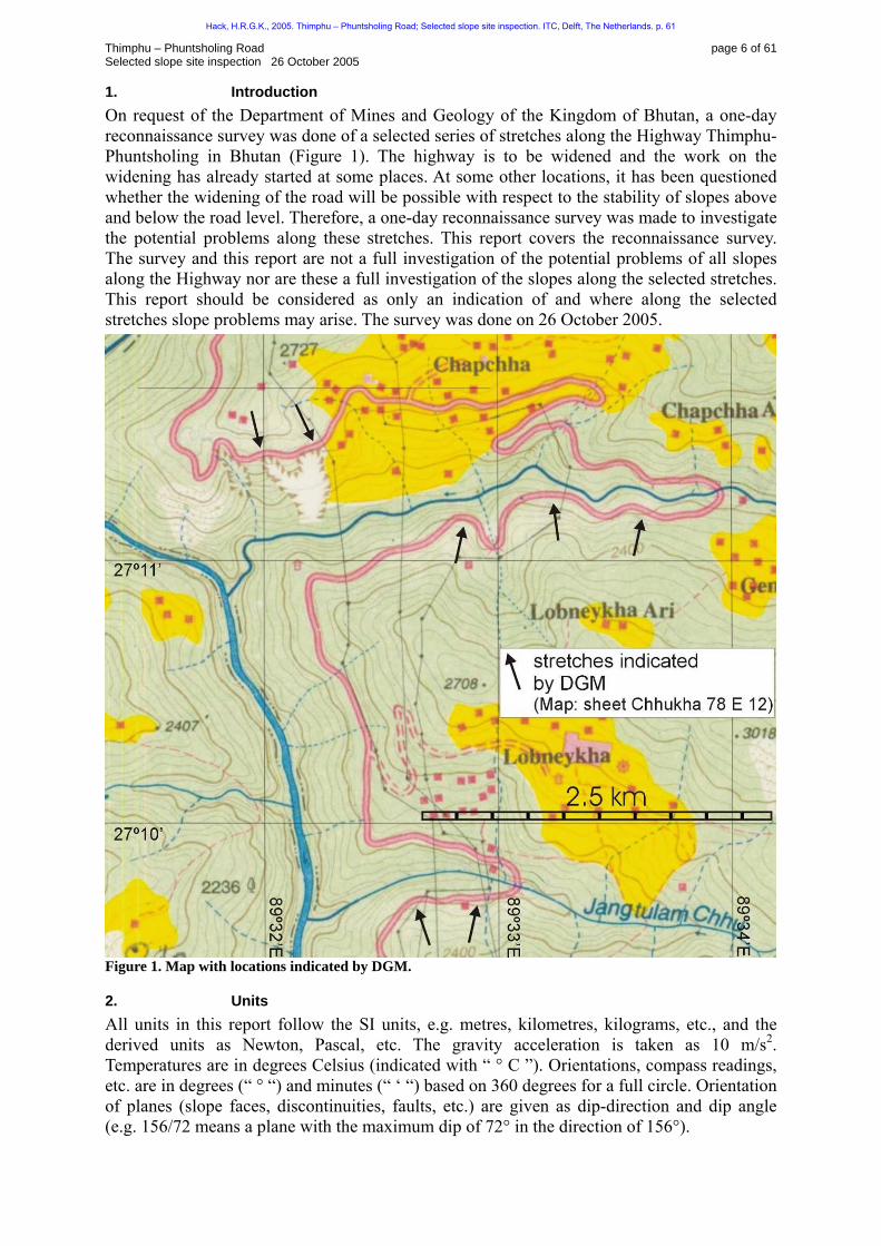
1. Introduction On request of the Department of Mines and Geology of the Kingdom of Bhutan, a one-day reconnaissance survey was done of a selected series of stretches along the Highway Thimphu- Phuntsholing in Bhutan ( 62HFigure 1). The highway is to be widened and the work on the widening has already started at some places. At some other locations, it has been questioned whether the widening of the road will be possible with respect to the stability of slopes above and below the road level. Therefore, a one-day reconnaissance survey was made to investigate the potential problems along these stretches. This report covers the reconnaissance survey. The survey and this report are not a full investigation of the potential problems of all slopes along the Highway nor are these a full investigation of the slopes along the selected stretches. This report should be considered as only an indication of and where along the selected stretches slope problems may arise. The survey was done on 26 October 2005.
Figure 1. Map with locations indicated by DGM.
2. Units All units in this report follow the SI units, e.g. metres, kilometres, kilograms, etc., and the derived units as Newton, Pascal, etc. The gravity acceleration is taken as 10 m/s P
2P.
Temperatures are in degrees Celsius (indicated with “ ° C ”). Orientations, compass readings, etc. are in degrees (“ ° “) and minutes (“ ‘ “) based on 360 degrees for a full circle. Orientation of planes (slope faces, discontinuities, faults, etc.) are given as dip-direction and dip angle (e.g. 156/72 means a plane with the maximum dip of 72° in the direction of 156°).
Hack, H.R.G.K., 2005. Thimphu – Phuntsholing Road; Selected slope site inspection. ITC, Delft, The Netherlands. p. 61

Thimphu – Phuntsholing Road page 7 of 61 Selected slope site inspection 26 October 2005
3. Available information Prior to departure the following information was given:
• Chhukha sheet 78E/12, (2000) topographic map 1 : 50,000, publ. Department of Survey and Land Reports, Royal Government of Bhutan, 1P
stP edition. Note: the contour
lines on this map are only approximate (see note on published map centre, bottom). • On the above map, the stretches to be investigated were indicated by the Department
of Geology and Mines (DGM) of the Kingdom of Bhutan (63HFigure 1). • “Geological Map of the Himalaya 1 : 2,000,000", Gansser, 1983.
4. Methodology The reconnaissance survey consisted of a series of geotechnical observations and measurements at the requested locations. Photos and sketches were made of the locations, and where appropriate and time permitted, a detailed rock mass characterization was done with aslope stability calculation following the SSPC system (chapter 64H5). The descriptions of rock and soil masses follow BS 5930; 1999. See for location of observations and exposures descriptions 65HFigure 2. See for activity log appendix III.
Figure 2. Stops and exposure locations.
5. Slope Stability Probability Calculation (SSPC) On two exposures (exposures 2 and 6) the probability to be stable was calculated following the Slope Stability Probability Classification (SSPC) system (Hack et al., 2003). The results
Hack, H.R.G.K., 2005. Thimphu – Phuntsholing Road; Selected slope site inspection. ITC, Delft, The Netherlands. p. 61
Thimphu – Phuntsholing Road page 8 of 61 Selected slope site inspection 26 October 2005
are included in “66HAppendix II – SSPC slope stability calculations”. All calculations were done for a rock slope with a steepness angle of 75°.
6. Weather and climate The investigated slopes are located in a mountainous area on a for Bhutan moderate height (around 2200 – 2400 m). General daytime temperatures are around 15 - 25°C. Night temperatures may be down to below zero between November and March. Extensive rain may fall between April and September. Between November and February, it may occasionally snow. On the day of the survey, the weather was bright and sunny with a temperature around 20°C.
7. Limitations The reconnaissance survey was limited by the following: Time constraints have been limiting the activities. An aerial photo interpretation has not been done, neither were aerial photos available during the survey. The compass available was not very suited for measurements of discontinuities in rock masses. Neither GPS nor other position tools were available. Hence, the locations of stops and exposures have been marked as best as possible on the topographic map based on visual reconnaissance of the surroundings of the location, and assuming that the position of roads and rivers on the topographic map (Chhukha, 2000) are accurate.
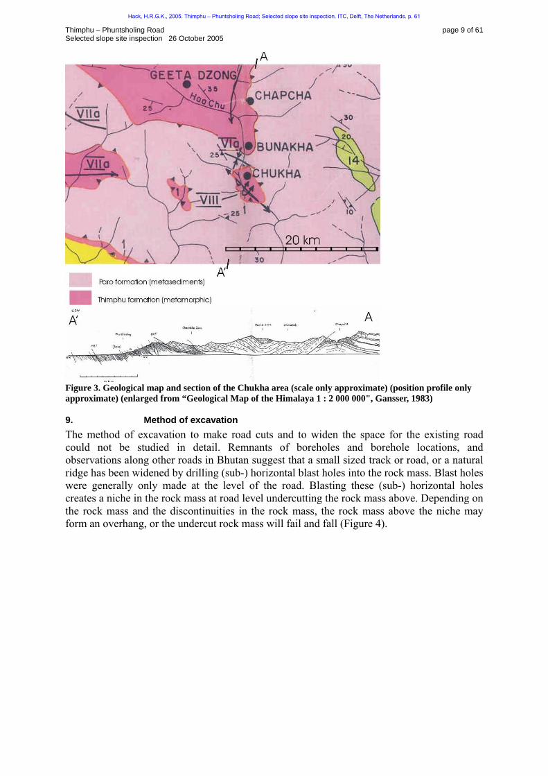
8. Geology The geology of the area is shown in 67HFigure 3. The scale of the original map is such that boundaries between geological units are highly uncertain on the scale of the site investigation. However, tentative is likely that the slopes and exposures in stretches A, B, and C are in the Thimphu formation.
Hack, H.R.G.K., 2005. Thimphu – Phuntsholing Road; Selected slope site inspection. ITC, Delft, The Netherlands. p. 61
Thimphu – Phuntsholing Road page 9 of 61 Selected slope site inspection 26 October 2005
Figure 3. Geological map and section of the Chukha area (scale only approximate) (position profile only approximate) (enlarged from “Geological Map of the Himalaya 1 : 2 000 000", Gansser, 1983)
9. Method of excavation The method of excavation to make road cuts and to widen the space for the existing road could not be studied in detail. Remnants of boreholes and borehole locations, and observations along other roads in Bhutan suggest that a small sized track or road, or a natural ridge has been widened by drilling (sub-) horizontal blast holes into the rock mass. Blast holes were generally only made at the level of the road. Blasting these (sub-) horizontal holes creates a niche in the rock mass at road level undercutting the rock mass above. Depending on the rock mass and the discontinuities in the rock mass, the rock mass above the niche may form an overhang, or the undercut rock mass will fail and fall (68HFigure 4).
Hack, H.R.G.K., 2005. Thimphu – Phuntsholing Road; Selected slope site inspection. ITC, Delft, The Netherlands. p. 61

Thimphu – Phuntsholing Road page 10 of 61 Selected slope site inspection 26 October 2005
Figure 4. Method of excavation by widening existing track or bench A), existing road or path, B) drilling blast holes, C) niche is formed, and D) rock mass above may form overhang, or fail depending on discontinuities and rock mass.
10. Reconnaissance survey The investigated stretches are divided based on their type of expected problem and the rock mass character (69HFigure 2) as follows:
1. Stretch A: Between Damtak road sign “highest point” and Damtak road sign “60 RCC Damtak” (which is the start of Damtak village).
2. Stretch B: South side river, opposite Damtak village and camp “60 RCC Damtak” 3. Stretch C: South side Jantulam Chhu river
All descriptions of observations, photos, sketches and detailed descriptions of rock masses and slopes are included in appendix I.
10.1. Stretch A: Between Damtak road sign “highest point” and Damtak road sign “60 RCC Damtak”
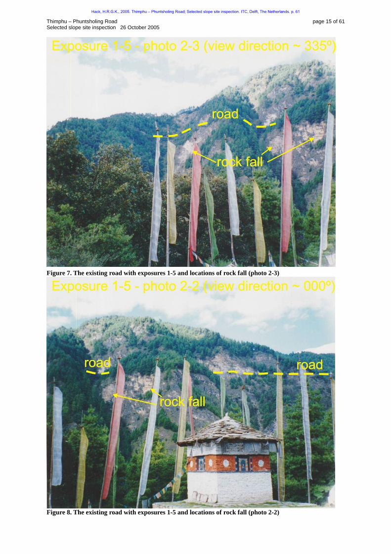
The road passes here on a bench in very high and steep slopes. The slopes are controlled by distinctive vertical or sub-vertical and persistent joints. The natural slopes are also formed by these joints and are also very high and steep. From the topographic map (Chhucka, 2000) has been deducted that some near vertical natural slopes have heights of over 200 m. The stability of the natural slopes is likely to be near equity as is shown by the regular and recent rock falls from the slopes (photos 70HFigure 7 and 71HFigure 8). These rock falls may endanger the road at its present location by undercutting. Widening of the road in such slopes possesses obviously a problem. Any space for an embankment without reinforcement is not present. Hence, the widening of the road should be fully acquired by cutting into the natural rock mass above the road level. As these are very steep up to 90º, it means that the rock mass over the full slope height above the road will have to be removed. Overhanging slopes (as seen often along the highway) are not possible on the long term. The persistence (in particular, in this area) of the vertical and sub-vertical joints is such that overhanging rock masses cannot be maintained without artificial reinforcement of the masses. Overhanging rock masses without reinforcement, may be possible at some locations for a sort time span, but are likely to collapse (without warning) in due time and are definitely not considered as being a safe design. The widening of the road has however, likely a positive effect on the stability of the natural slopes below the road level. The widening will reduce the stress levels in those slopes, and, hence, will reduce the amount of rock fall of the slopes below the road level.
Hack, H.R.G.K., 2005. Thimphu – Phuntsholing Road; Selected slope site inspection. ITC, Delft, The Netherlands. p. 61
Thimphu – Phuntsholing Road page 11 of 61 Selected slope site inspection 26 October 2005
10.1.1. Stepped slopes Before the site inspection, it was speculated that the slices of rock mass controlled by the joints could have been undercut and consequently slit downward along the joints, resulting in a stepped slope (photos 72HFigure 24 and 73HFigure 25). This could not be fully confirmed. In some locations, it is clear that sliding along the joints occurred for small distances up to a couple of metres. However, sliding over longer distances is not well understandable. The rock mass contains at least three well-developed and persistent discontinuity sets in three more-or-less perpendicular directions (see exposure characterization appendix I, exposure 2). Sliding over more than a couple of meters would likely have resulted in a disintegration of the rock mass, not in a piece of the rock mass still maintaining a structural integrity after sliding downward. A more likely explanation of the stepped slopes is that these are formed by collapses of the rock mass above the now present step (photos 74HFigure 24 and 75HFigure 25). The maximum possible height for these slopes is following the SSPC system between 12 and 27 m for a slope with a dip of 75°.
10.2. Stretch B: Southern side tributary river, opposite Damtak village and camp “60 RCC Damtak”
The discontinuities in this area are considerably less persistent than in the stretch described above. The reason for this could not be established. The less persistent vertical and sub-vertical discontinuities allow the overhang of the rock mass at many locations. Whether the overhanging rock masses are safe is questionable. An overhanging rock mass is based on the tensile strength of the rock blocks and the integrity of the rock mass. Tensile failure is, however, an instant feature without any warning. Design based on overhanging rock masses is therefore normally not considered good engineering practice. The natural slopes in this area are considerably less steep compared to those in stretch A, and therefore widening of the road by making an (wider) embankment or by making a decent not overhanging rock cut will be easier and less hazardous.
10.3. Stretch C: Southern side Jantulam Chhu The discontinuities in this area are considerably less persistent than at the stretch A. The reason for this could not be established. The less persistent vertical and sub-vertical discontinuities allow the overhang of the rock mass at many locations. Whether the overhanging rock masses are safe is questionable. An overhanging rock mass is based on the tensile strength of the rock blocks or mass. Tensile failure is, however, an instant feature without any warning. Design based on overhanging rock masses is therefore normally not considered good practice. The natural slopes in this area are considerably less steep compared to above, and therefore is widening of the road by making an (wider) embankment or by making a decent not overhanging rock cut easier.
11. Conclusions Although the survey was limited in time, it can be concluded that: 1) The present slopes and road cuts are instable and dangerous in many places along the road in the investigated stretches. 2) Widening the existing road will inevitably require that new very large road cuts have to be made. 3) New large road cuts have to be made by highly skilled engineers and labours and following the most modern techniques in blasting and road cut engineering to ensure that no unnecessary damage (backbreak) is inflicted on the rock mass and future slope faces resulting in unnecessary artificial support requirements.
Hack, H.R.G.K., 2005. Thimphu – Phuntsholing Road; Selected slope site inspection. ITC, Delft, The Netherlands. p. 61
Thimphu – Phuntsholing Road page 12 of 61 Selected slope site inspection 26 October 2005
4) Many new large cuts may require artificial reinforcement by bolts, anchors, etc, to result in stable and safe road cuts. Hence, widening the existing road will be at many locations a major and costly operation. Alternative routings for parts of the road where a wider road can be constructed with less effort and less costs should therefore be considered. It is therefore strongly advised that a detailed engineering geological and geotechnical survey is done in a corridor along the whole road. This to investigate possible alternative routing options for parts of the road, and to obtain rock and soil mass properties in detail. Then a proper evaluation can be made of the efforts and costs of new routed parts of the road compared to widening the existing road.
References
BS 5930 (1981, 1999). Code of Practice for Site Investigations. British Standards Institution (BSI). London. Chhukha sheet 78E/12, (2000) topographic map 1 : 50,000, publ. Department of Survey and Land Reports, Royal Government of Bhutan, 1st edition. Gansser, A. (1983): Geology of the Bhutan Himalaya.- Denkschriften der Schweizerischen Naturforschenden Gesellschaft Basel, 96, 181 S. Birkhäuser Verlag (ISBN 3-7643-1371-4). Hack R., Price, D. & Rengers N. (2003). A new approach to rock slope stability - a probability classification (SSPC). Bulletin of Engineering Geology and the Environment. Springer Verlag. Vol. 62: article: DOI 10.1007/s10064-002-0155-4. pp. 167-184 & erratum: DOI 10.1007/s10064-002-0171-4. pp 185-185.
Hack, H.R.G.K., 2005. Thimphu – Phuntsholing Road; Selected slope site inspection. ITC, Delft, The Netherlands. p. 61
Thimphu – Phuntsholing Road page 13 of 61 Selected slope site inspection 26 October 2005
Appendix I
Stretch A: Between Damtak road sign “highest point” and Damtak road sign “60 RCC Damtak”
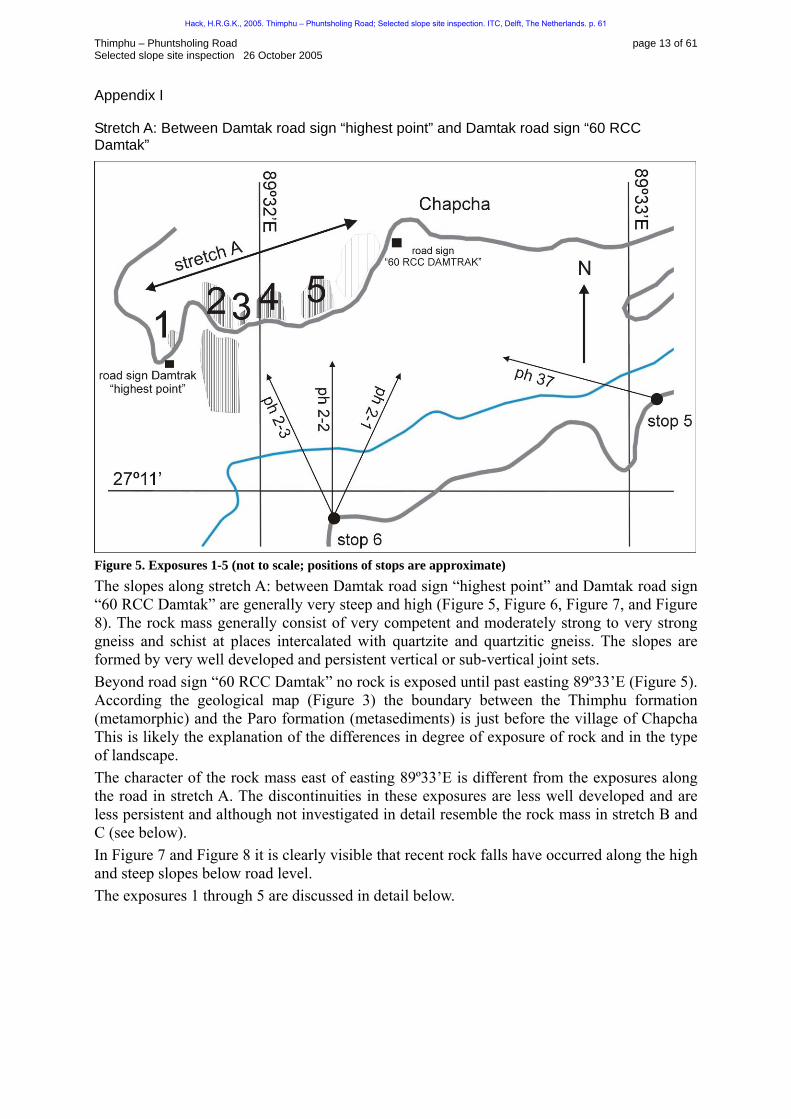
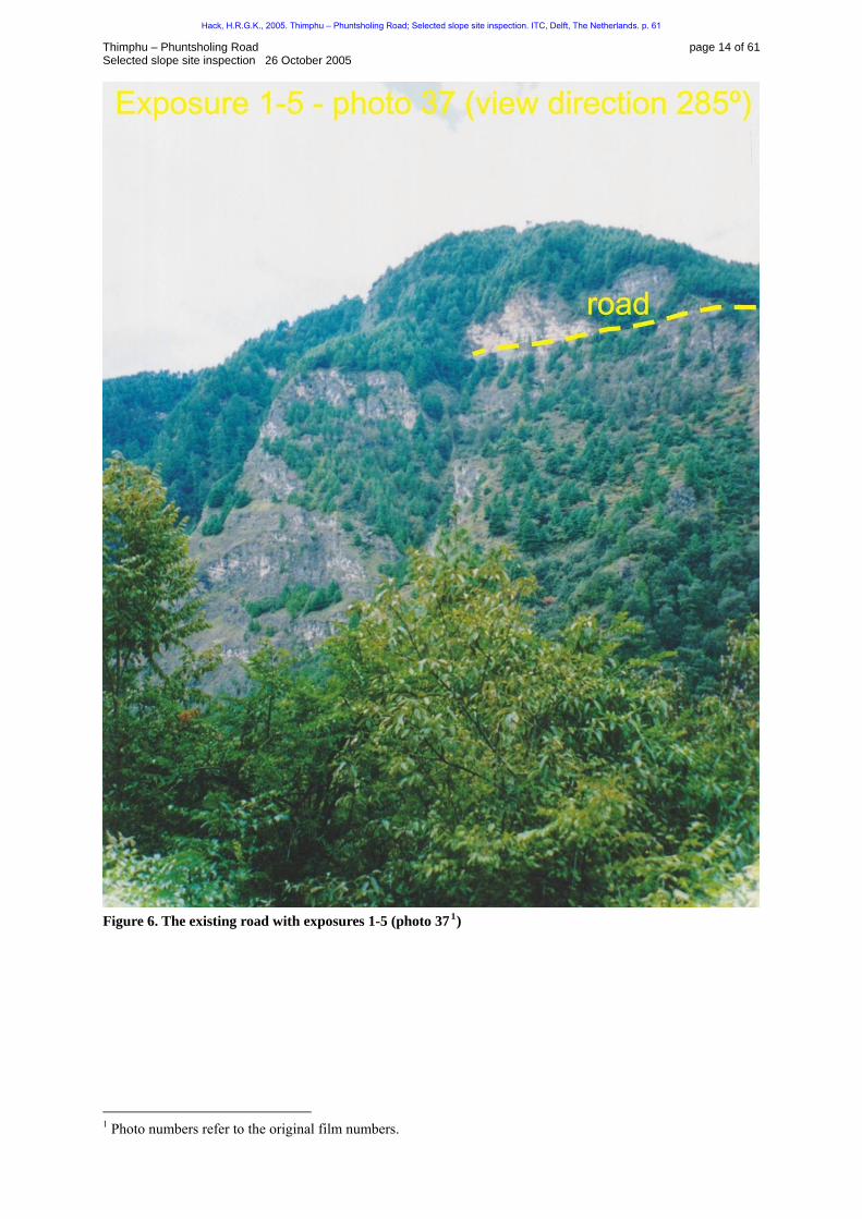
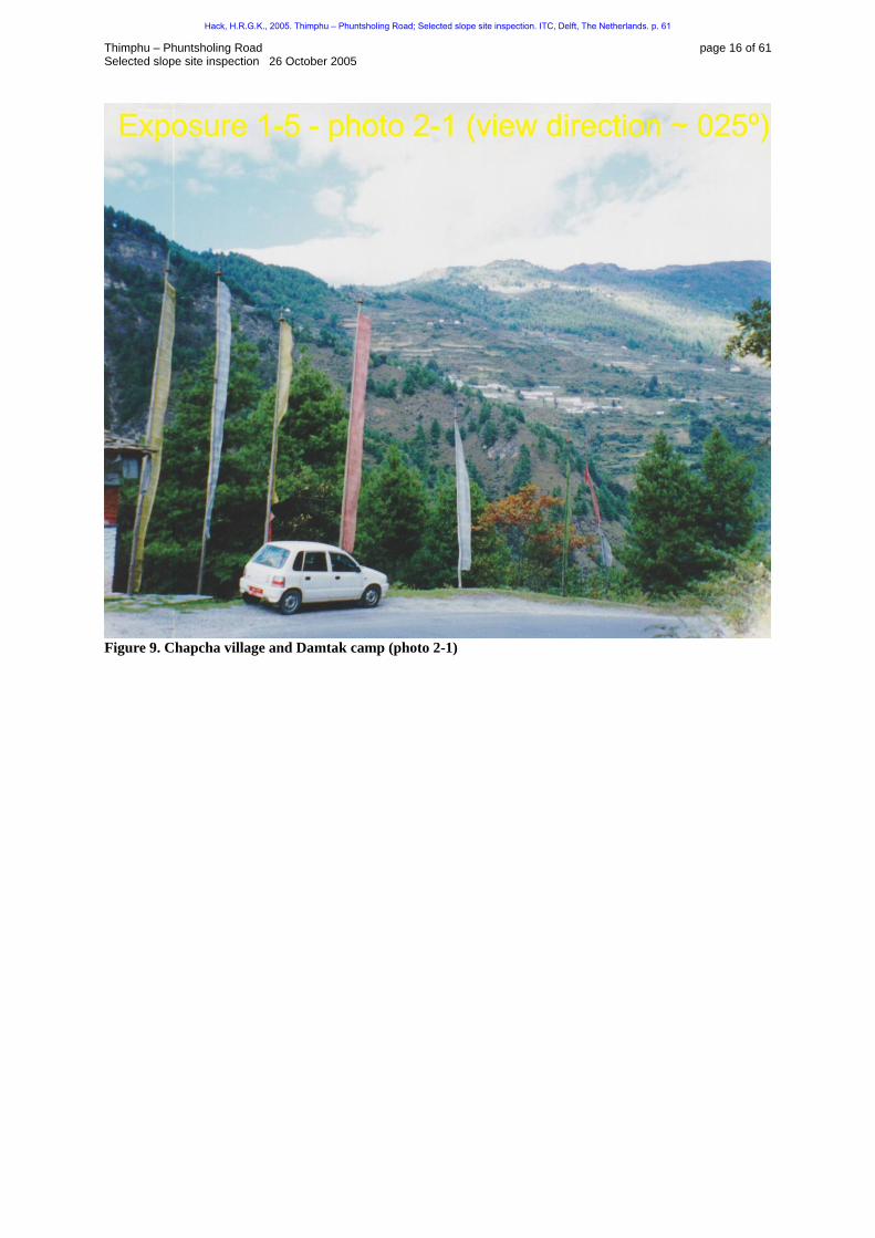
Figure 5. Exposures 1-5 (not to scale; positions of stops are approximate) The slopes along stretch A: between Damtak road sign “highest point” and Damtak road sign “60 RCC Damtak” are generally very steep and high ( 76HFigure 5, 77HFigure 6, 78HFigure 7, and 79HFigure 8). The rock mass generally consist of very competent and moderately strong to very strong gneiss and schist at places intercalated with quartzite and quartzitic gneiss. The slopes are formed by very well developed and persistent vertical or sub-vertical joint sets. Beyond road sign “60 RCC Damtak” no rock is exposed until past easting 89º33’E (80HFigure 5). According the geological map (81HFigure 3) the boundary between the Thimphu formation (metamorphic) and the Paro formation (metasediments) is just before the village of Chapcha This is likely the explanation of the differences in degree of exposure of rock and in the type of landscape. The character of the rock mass east of easting 89º33’E is different from the exposures along the road in stretch A. The discontinuities in these exposures are less well developed and are less persistent and although not investigated in detail resemble the rock mass in stretch B and C (see below). In 82HFigure 7 and 83HFigure 8 it is clearly visible that recent rock falls have occurred along the high and steep slopes below road level. The exposures 1 through 5 are discussed in detail below.
Hack, H.R.G.K., 2005. Thimphu – Phuntsholing Road; Selected slope site inspection. ITC, Delft, The Netherlands. p. 61
Thimphu – Phuntsholing Road page 14 of 61 Selected slope site inspection 26 October 2005
Figure 6. The existing road with exposures 1-5 (photo 37 TPF0F
1FPT)
TP
1PT Photo numbers refer to the original film numbers.
Hack, H.R.G.K., 2005. Thimphu – Phuntsholing Road; Selected slope site inspection. ITC, Delft, The Netherlands. p. 61
Thimphu – Phuntsholing Road page 15 of 61 Selected slope site inspection 26 October 2005
Figure 7. The existing road with exposures 1-5 and locations of rock fall (photo 2-3)
Figure 8. The existing road with exposures 1-5 and locations of rock fall (photo 2-2)
Hack, H.R.G.K., 2005. Thimphu – Phuntsholing Road; Selected slope site inspection. ITC, Delft, The Netherlands. p. 61
Thimphu – Phuntsholing Road page 16 of 61 Selected slope site inspection 26 October 2005
Figure 9. Chapcha village and Damtak camp (photo 2-1)
Hack, H.R.G.K., 2005. Thimphu – Phuntsholing Road; Selected slope site inspection. ITC, Delft, The Netherlands. p. 61

Thimphu – Phuntsholing Road page 17 of 61 Selected slope site inspection 26 October 2005
Exposure 1
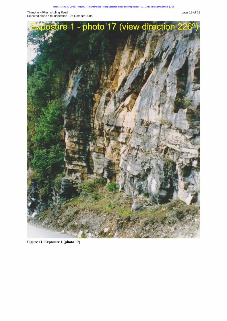
Figure 10. Location sketch exposure 1 (not to scale). Exposure description Exposure 1 is a fairly small (approximate dimensions: length 10 m, height 10 m, depth 5 m) exposure along the road, above road level (84HFigure 10 and 85HFigure 11). The exposure is excavated by single-hole blasting and excavated by hand. The exposure face is regular. The rock mass contains very well developed and persistent vertical or sub-vertical jointing. The joint set with approximate direction 188° and with a dip of 70º controls for a large part the slope face. The rock mass consists of interbedded schist and gneiss. The orientation of the beds is approximately horizontal.
Hack, H.R.G.K., 2005. Thimphu – Phuntsholing Road; Selected slope site inspection. ITC, Delft, The Netherlands. p. 61
Thimphu – Phuntsholing Road page 18 of 61 Selected slope site inspection 26 October 2005
Figure 11. Exposure 1 (photo 17)
Hack, H.R.G.K., 2005. Thimphu – Phuntsholing Road; Selected slope site inspection. ITC, Delft, The Netherlands. p. 61
Thimphu – Phuntsholing Road page 19 of 61 Selected slope site inspection 26 October 2005
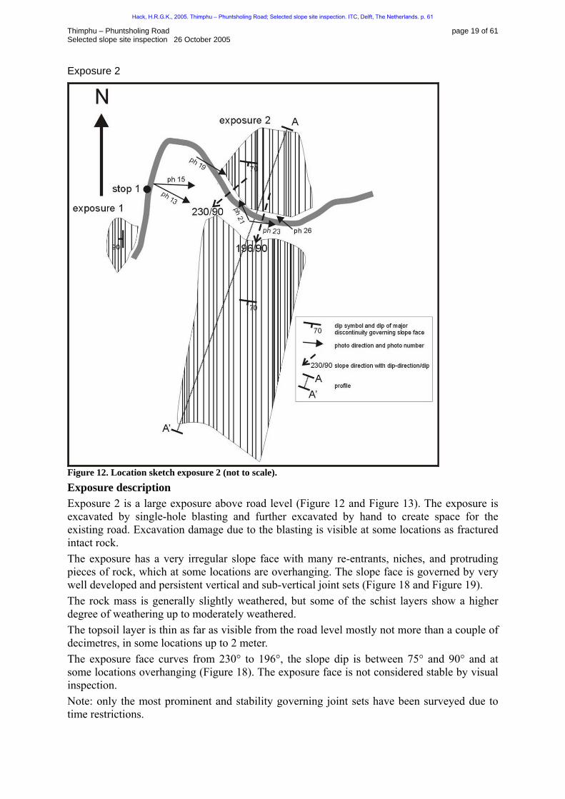
Exposure 2
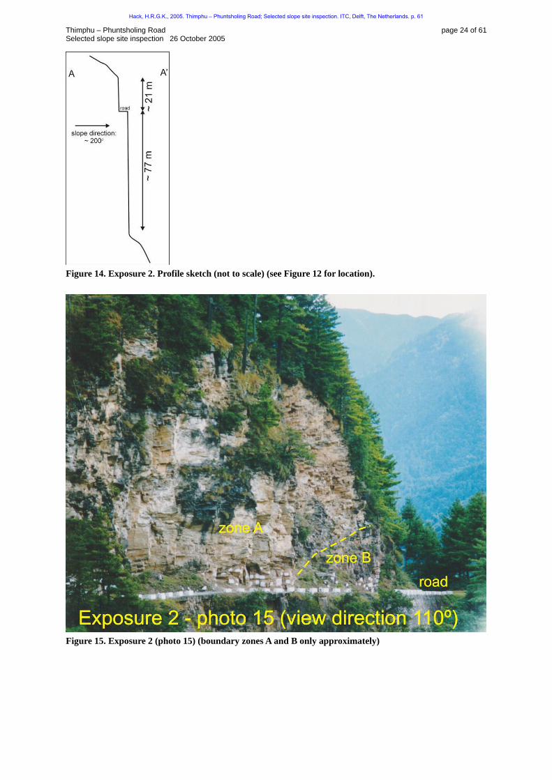
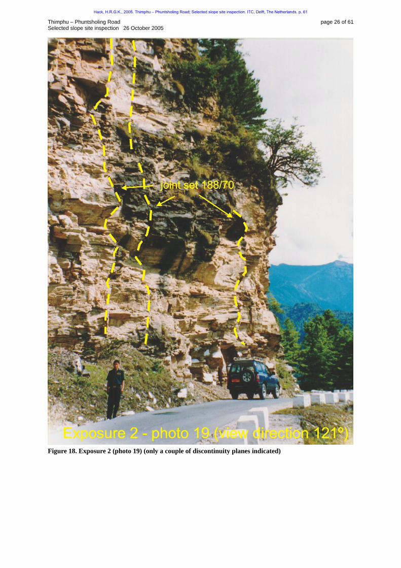
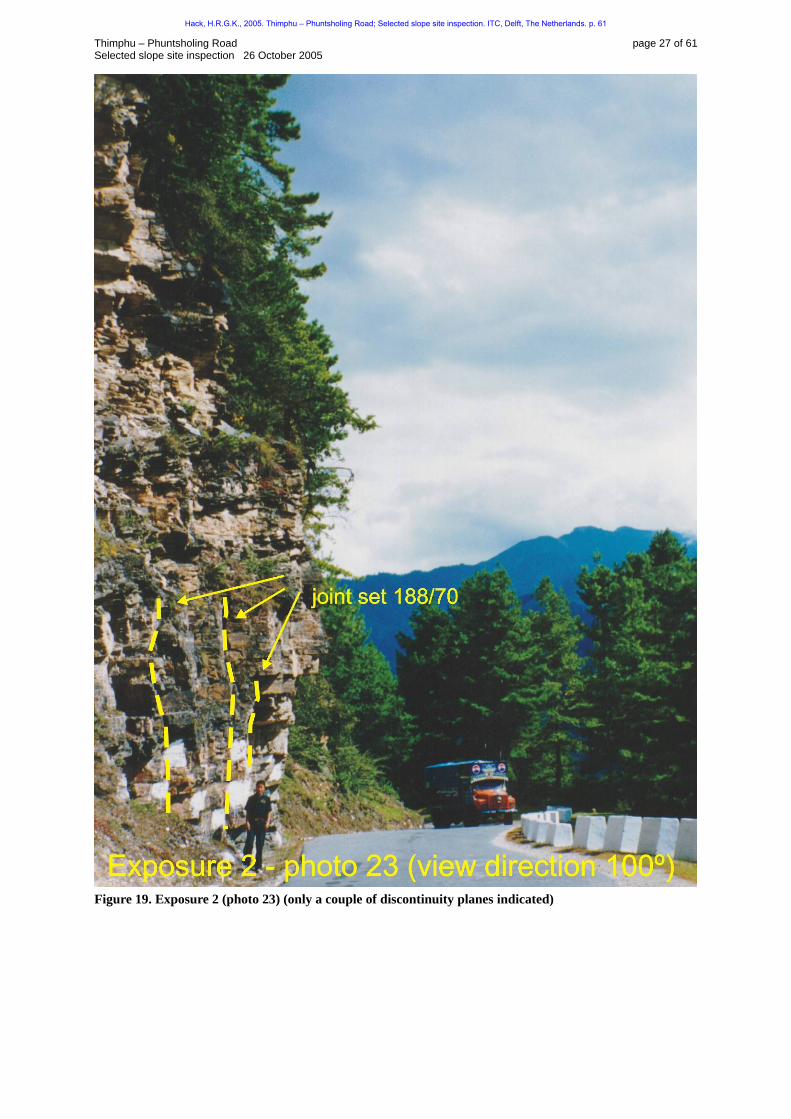
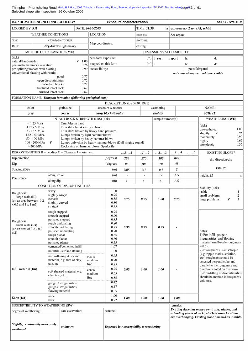
Figure 12. Location sketch exposure 2 (not to scale). Exposure description Exposure 2 is a large exposure above road level (86HFigure 12 and 87HFigure 13). The exposure is excavated by single-hole blasting and further excavated by hand to create space for the existing road. Excavation damage due to the blasting is visible at some locations as fractured intact rock. The exposure has a very irregular slope face with many re-entrants, niches, and protruding pieces of rock, which at some locations are overhanging. The slope face is governed by very well developed and persistent vertical and sub-vertical joint sets (88HFigure 18 and 89HFigure 19). The rock mass is generally slightly weathered, but some of the schist layers show a higher degree of weathering up to moderately weathered. The topsoil layer is thin as far as visible from the road level mostly not more than a couple of decimetres, in some locations up to 2 meter. The exposure face curves from 230° to 196°, the slope dip is between 75° and 90° and at some locations overhanging (90HFigure 18). The exposure face is not considered stable by visual inspection. Note: only the most prominent and stability governing joint sets have been surveyed due to time restrictions.
Hack, H.R.G.K., 2005. Thimphu – Phuntsholing Road; Selected slope site inspection. ITC, Delft, The Netherlands. p. 61

Thimphu – Phuntsholing Road page 20 of 61 Selected slope site inspection 26 October 2005
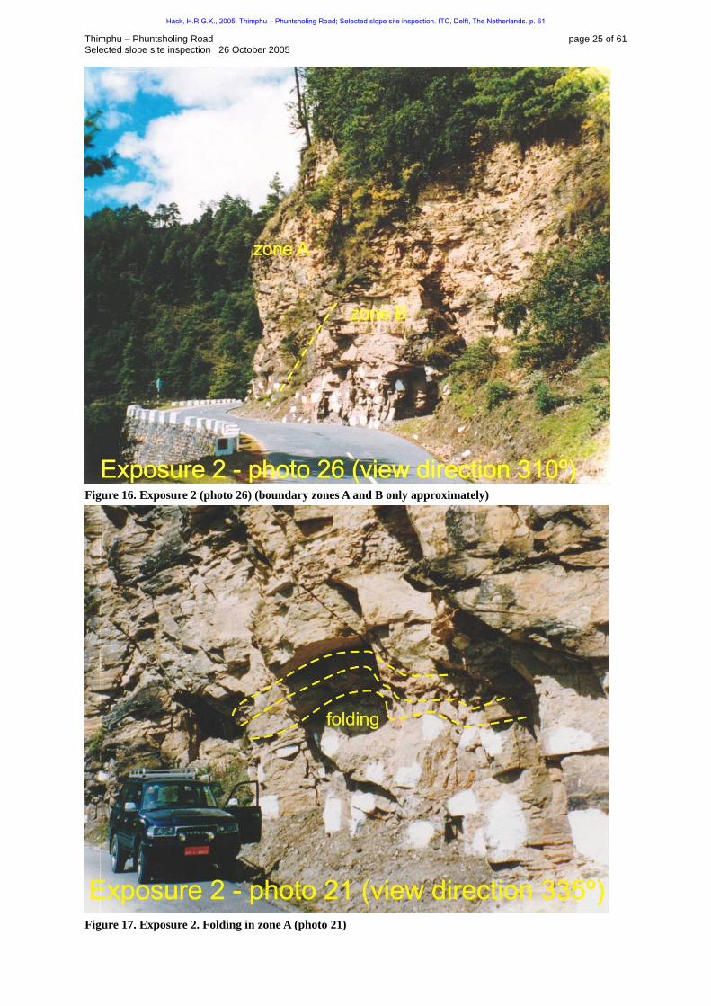
Geology Exposure 2 contains two zones: A and B. The materials of the rock masses in zones A and B are markedly different. Zone A is only present in the lower parts of the exposure just above the road level (91HFigure 15 and 92HFigure 16). Whether both zones are also present below the road level could not be established because of inaccessibility. The boundary between zones A and B is fairly sharp. Neither the bedding nor the foliation seems to be discontinuous at the boundary between zones A and B, nor are the discontinuity sets interrupted at the boundary. At the northern side of exposure 2 folding is present within zone A (93HFigure 17). Rock mass characterization Zone A Zone A consists of units of interbedded schist and quartzitic gneiss. The quantities are estimated to be 80 % schist in beds up to 0.2 m, and 20 % quartzitic gneiss up to 0.2 m. The quantities are difficult to estimate as the weathering colour of both schist and quartzitic gneiss are about the same. Unit AI: schist Moderately strong, very thinly foliated, very thin tabular, slightly weathered, grey, SCHIST UMaterial:U metamorphic minerals and quartz and feldspar, likely to contain a large quantity of biotite. UDiscontinuities Bedding (discontinuity set 1): orientation 280/08 (see note *1), spacing: 0.01 m, persistent along strike and dip, large scale roughness: straight (see note *1), small scale roughness: rough stepped, infill: non-softening fine material; where the schist is moderately weathered some clay is present and the infill is characterized as fine softening material, sliding criterion friction angle: 54°. Joint (discontinuity set 2): orientation 270/90 (see note *1), spacing: 0.1 m, persistent along strike and dip, large scale roughness: straight (see note *1), small scale roughness: rough stepped, infill: none (many open joints with openness up to 0.02 – 0.03 m), sliding criterion friction angle: 63°. Joint (discontinuity set 3): orientation 188/70 (see note *1), spacing: 0.1 m, persistent along strike and dip, large scale roughness: wavy (see note *1), small scale roughness: rough stepped, infill: none (many open joints with openness up to 0.02 – 0.03 m), sliding criterion friction angle: 84°. Joint (discontinuity set 4 established from photos, only present at some locations): orientation approximately 075/45 (see note *1), spacing: 2 m, abutting 5 m along strike and abutting 5 m along dip, large scale roughness: straight (see note *1), small scale roughness: could not be established, infill: could not be established. Note *1: Orientation and large-scale roughness of all discontinuities at locations of folding vary widely ( 94HFigure 17). Unit AII: quartzitic gneiss Strong, thin to medium foliated, medium blocky, slightly weathered, grey, QUARTZITIC GNEISS UMaterial:U metamorphic minerals and quartz and feldspar and subordinate dark minerals, containing large quantities of quartz. UDiscontinuities Bedding (discontinuity set 1): orientation 280/08 (see note *1), spacing: 0.2 m, persistent along strike and dip, large scale roughness: straight (see note *1), small scale roughness: rough stepped, infill: non-softening fine material; where the schist is moderately weathered
Hack, H.R.G.K., 2005. Thimphu – Phuntsholing Road; Selected slope site inspection. ITC, Delft, The Netherlands. p. 61
Thimphu – Phuntsholing Road page 21 of 61 Selected slope site inspection 26 October 2005
some clay is present and the infill is characterized as fine softening material, sliding criterion friction angle: 54°. Joint (discontinuity set 2): orientation 270/90 (see note *1), spacing: 0.5 m, persistent along strike and dip, large scale roughness: straight (see note *1), small scale roughness: rough stepped, infill: none (many open joints with openness up to 0.02 – 0.03 m), sliding criterion friction angle: 63°. Joint (discontinuity set 3): orientation 188/70 (see note *1), spacing: 0.5 m, persistent along strike and dip, large scale roughness: wavy (see note *1), small scale roughness: rough stepped, infill: none (many open joints with openness up to 0.02 – 0.03 m), sliding criterion friction angle: 84°. Joint (discontinuity set 4 established from photos, only present at some locations): orientation approximately 075/45 (see note *1), spacing: 2 m, abutting 5 m along strike and abutting 5 m along dip, large scale roughness: straight (see note *1), small scale roughness: could not be established, infill: could not be established. Note *1: Orientation and large-scale roughness of all discontinuities at locations of folding vary widely ( 95HFigure 17). Zone B Zone B consists of intercalated schist and quartz beds (and some minor beds of quartzitic gneiss). The quantities of both are estimated to be 10 % schist in bands up to 0.05 m, and 90% quartz beds and quartzitic gneiss in bands of up to 1 m. Unit BI: quartzitic beds Very strong, thin foliated, small blocky, slightly weathered, white, QUARTZITE BEDS UMaterialU: mainly crystalline quartz UDiscontinuities Bedding (discontinuity set 1): orientation 280/08 (see note *1), spacing: 0.05 m, persistent along strike and dip, large scale roughness: straight to slightly curved (see note *1), small scale roughness: rough undulating, infill: often schist intercalated which is characterized as non-softening fine material; where the schist is moderately weathered some clay is present and the infill is characterized as fine softening material, sliding criterion friction angle: 48°. Joint (discontinuity set 2): orientation 270/90 (see note *1), spacing: 0.2 m, persistent along strike and dip, large scale roughness: straight (see note *1), small scale roughness: rough stepped, infill: none (many open joints with openness up to 0.02 – 0.03 m), sliding criterion friction angle: 63°. Joint (discontinuity set 3): orientation 160/80 (see note *1), spacing: 0.1 m, persistent along strike and dip, large scale roughness: wavy (see note *1), small scale roughness: rough stepped, infill: none (many open joints with openness up to 0.02 – 0.03 m), sliding criterion friction angle: 84°. Note *1: Orientations and large scale roughness of all discontinuities at locations of folding vary widely ( 96HFigure 17). Unit BII: schist Weak to moderately strong, very thinly foliated, very small tabular (flaky in part), slightly to moderately weathered, grey, SCHIST UMaterial:U metamorphic minerals, likely to contain a large quantity of biotite UDiscontinuities Bedding (discontinuity set 1): orientation 280/08 (see note *1), spacing: 0.005 m, persistent along strike and dip, large scale roughness: straight to slightly curved (see note *1), small scale roughness: rough undulating, infill: non-softening fine material; where the schist is
Hack, H.R.G.K., 2005. Thimphu – Phuntsholing Road; Selected slope site inspection. ITC, Delft, The Netherlands. p. 61
Thimphu – Phuntsholing Road page 22 of 61 Selected slope site inspection 26 October 2005
moderately weathered some clay is present and the infill is characterized as fine softening material, sliding criterion friction angle: 48°. Joint (discontinuity set 2): orientation 270/90 (see note *1), spacing: 0.01 m, persistent along strike and dip, large scale roughness: straight (see note *1), small scale roughness: rough stepped, infill: none (many open joints with openness up to 0.02 – 0.03 m), sliding criterion friction angle: 63°. Joint (discontinuity set 3): orientation 160/80 (see note *1), spacing: 0.05 m, persistent along strike and dip, large scale roughness: wavy (see note *1), small scale roughness: rough stepped, infill: none (many open joints with openness up to 0.02 – 0.03 m), sliding criterion friction angle: 84°. Note *1: Orientations and large-scale roughness of all discontinuities at locations of folding vary widely ( 97HFigure 17). Slope Stability Probability Classification (SSPC) Four SSPC classifications have been done on the rock masses in exposure 2 (Appendix II). The schist in zone B is generally weaker and consequently has lower rock mass strength properties than the other units. This unit is, however, not a large constituent of the mass in the slopes and is not governing the stability of the slopes in the present situation. The other three units govern the slope stability for which the maximum admissible slope height following the SSPC system is between 12 and 27 m, depending on the unit, for a slope with a dip of 75°. It has not been possible to identify the location and quantities of units in the exposure in any detail in this reconnaissance survey; hence it is not possible to compare the SSPC admissible heights in detail with the real slope heights. However, the admissible heights following the SSPC system seem to be reasonable in agreement with the slopes above road level. The real slopes are steeper up to 90 or overhanging but those are visually considered as highly unstable.
Hack, H.R.G.K., 2005. Thimphu – Phuntsholing Road; Selected slope site inspection. ITC, Delft, The Netherlands. p. 61
Thimphu – Phuntsholing Road page 23 of 61 Selected slope site inspection 26 October 2005
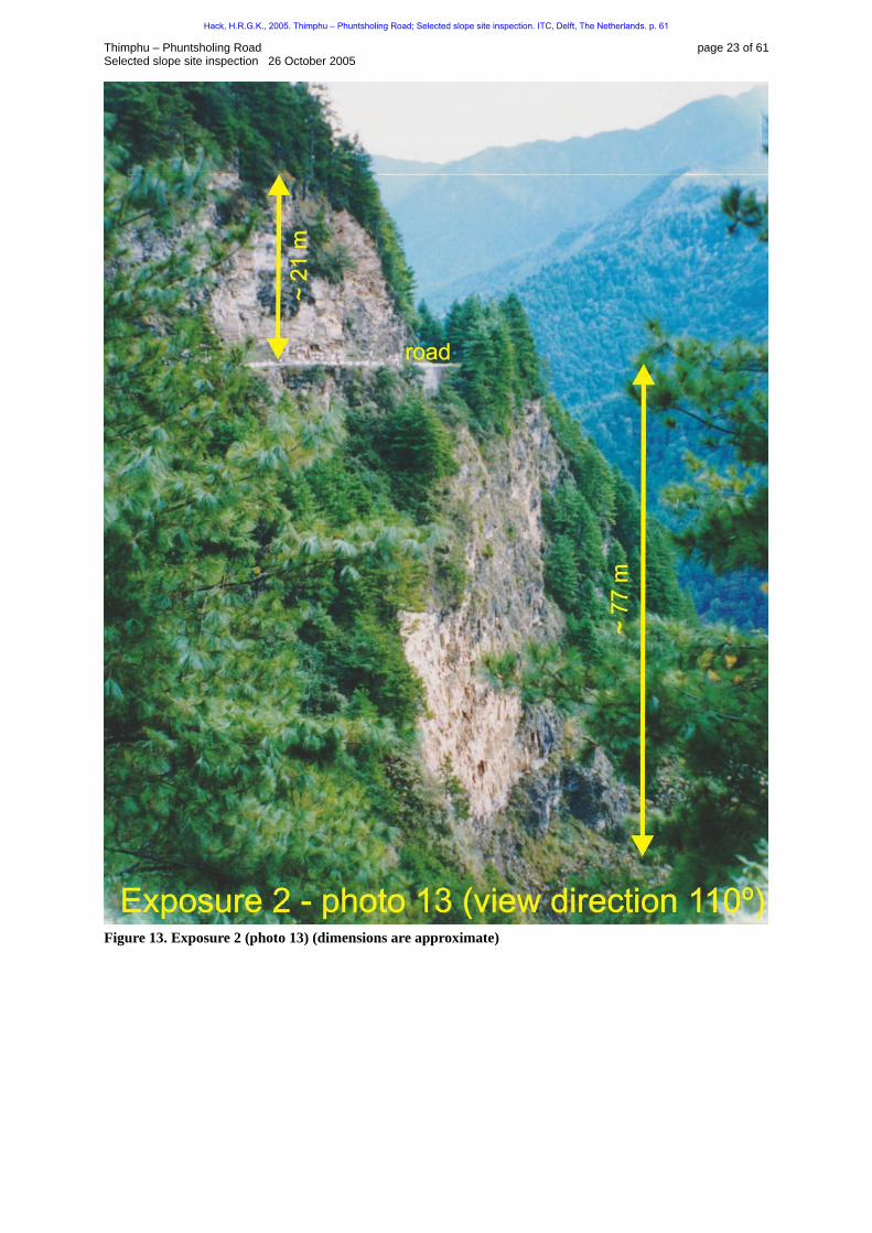
Figure 13. Exposure 2 (photo 13) (dimensions are approximate)
Hack, H.R.G.K., 2005. Thimphu – Phuntsholing Road; Selected slope site inspection. ITC, Delft, The Netherlands. p. 61
Thimphu – Phuntsholing Road page 24 of 61 Selected slope site inspection 26 October 2005
Figure 14. Exposure 2. Profile sketch (not to scale) (see 98HFigure 12 for location).
Figure 15. Exposure 2 (photo 15) (boundary zones A and B only approximately)
Hack, H.R.G.K., 2005. Thimphu – Phuntsholing Road; Selected slope site inspection. ITC, Delft, The Netherlands. p. 61
Thimphu – Phuntsholing Road page 25 of 61 Selected slope site inspection 26 October 2005
Figure 16. Exposure 2 (photo 26) (boundary zones A and B only approximately)
Figure 17. Exposure 2. Folding in zone A (photo 21)
Hack, H.R.G.K., 2005. Thimphu – Phuntsholing Road; Selected slope site inspection. ITC, Delft, The Netherlands. p. 61
Thimphu – Phuntsholing Road page 26 of 61 Selected slope site inspection 26 October 2005
Figure 18. Exposure 2 (photo 19) (only a couple of discontinuity planes indicated)
Hack, H.R.G.K., 2005. Thimphu – Phuntsholing Road; Selected slope site inspection. ITC, Delft, The Netherlands. p. 61
Thimphu – Phuntsholing Road page 27 of 61 Selected slope site inspection 26 October 2005
Figure 19. Exposure 2 (photo 23) (only a couple of discontinuity planes indicated)
Hack, H.R.G.K., 2005. Thimphu – Phuntsholing Road; Selected slope site inspection. ITC, Delft, The Netherlands. p. 61

Thimphu – Phuntsholing Road page 28 of 61 Selected slope site inspection 26 October 2005
Exposure 3
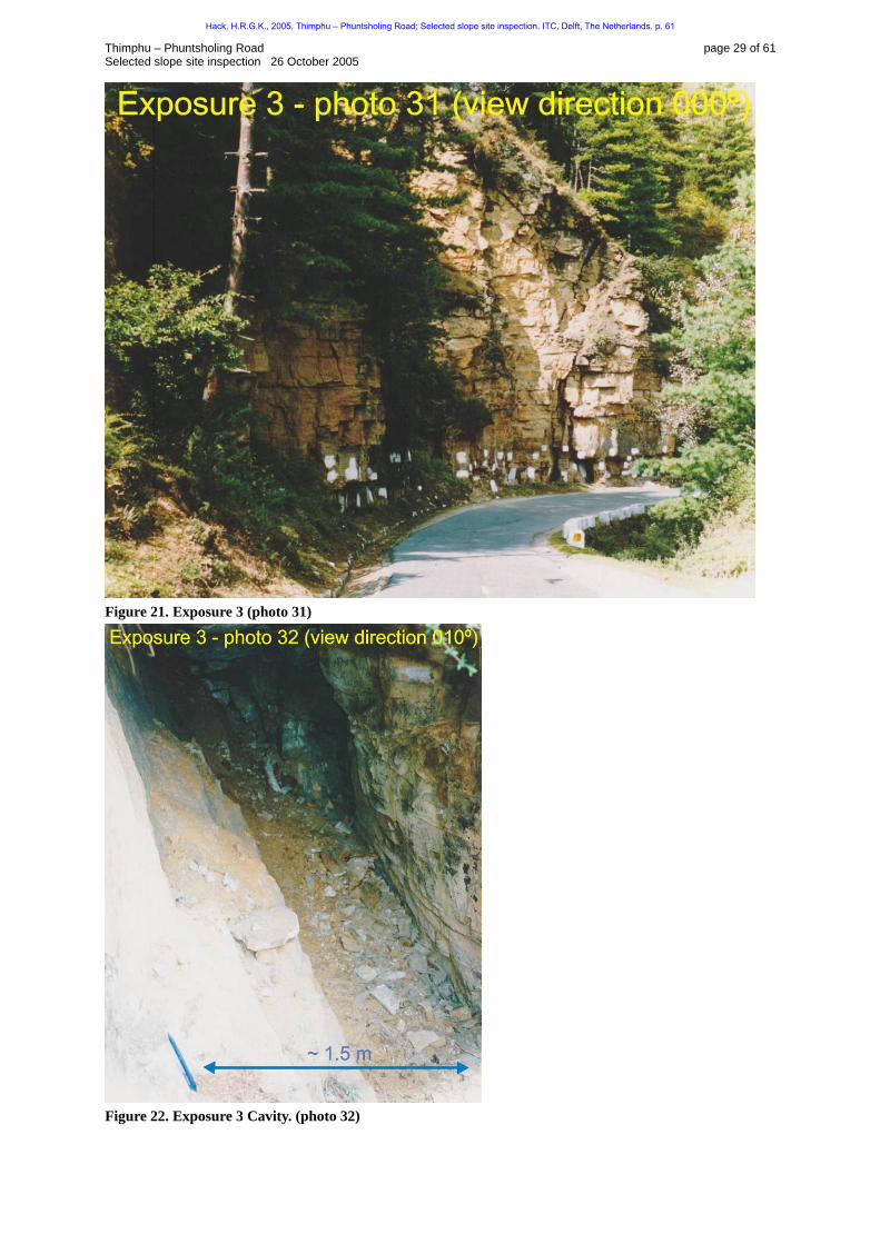
Figure 20. Location sketch exposure 3 (not to scale). Exposure description Exposure 3 is a relatively small exposure above road level (99HFigure 20 and 100HFigure 21). The exposure is excavated by single-hole blasting and further excavated by hand to create space for the existing road. Excavation damage due to the blasting is visible at some locations as fractured intact rock. The exposure has a very irregular slope face with many re-entrants, niches, and protruding pieces of rock, which at some locations are overhanging. The slope face is controlled by very well developed and persistent vertical and sub-vertical joint sets. The rock mass is generally slightly weathered. The topsoil layer is thin as far as visible from the road level and is not more than a couple of decimetres thick. The character of the rock mass is consistent with the zone B rock mass of exposure 2. Large open joints are present (openness up to 0.2 m). One of these has formed a cavity with a width of 2 m ( 101HFigure 22). Whether the openness is natural can be doubted as rock apparently has been excavated from the cavity. It is tentative possible that his has been done for mineral exploration. The origin of the cavity may correspond to a major joint plane developed into a fault along which mineralisation has taken place.
Hack, H.R.G.K., 2005. Thimphu – Phuntsholing Road; Selected slope site inspection. ITC, Delft, The Netherlands. p. 61
Thimphu – Phuntsholing Road page 29 of 61 Selected slope site inspection 26 October 2005
Figure 21. Exposure 3 (photo 31)
Figure 22. Exposure 3 Cavity. (photo 32)
Hack, H.R.G.K., 2005. Thimphu – Phuntsholing Road; Selected slope site inspection. ITC, Delft, The Netherlands. p. 61
Thimphu – Phuntsholing Road page 30 of 61 Selected slope site inspection 26 October 2005
Exposure 4
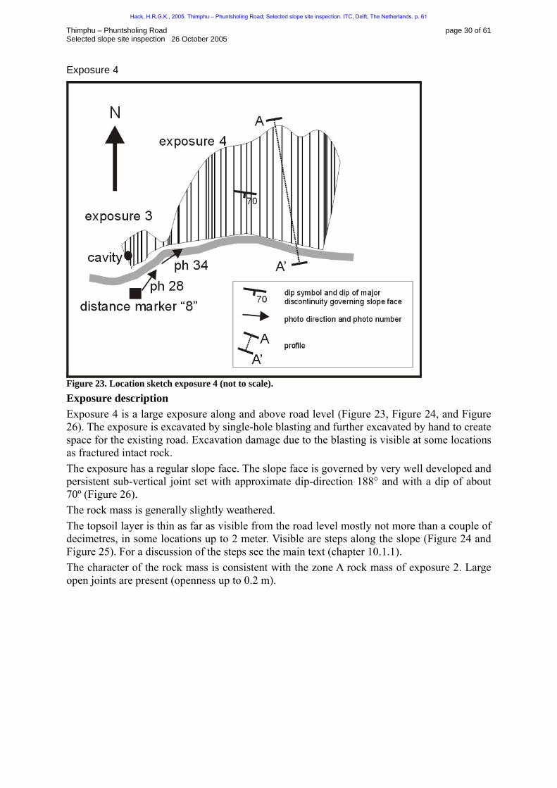
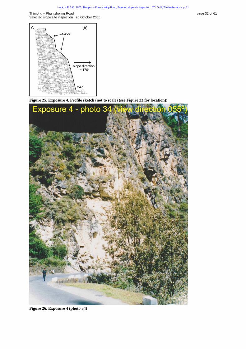
Figure 23. Location sketch exposure 4 (not to scale). Exposure description Exposure 4 is a large exposure along and above road level (102HFigure 23, 103HFigure 24, and 104HFigure 26). The exposure is excavated by single-hole blasting and further excavated by hand to create space for the existing road. Excavation damage due to the blasting is visible at some locations as fractured intact rock. The exposure has a regular slope face. The slope face is governed by very well developed and persistent sub-vertical joint set with approximate dip-direction 188° and with a dip of about 70º (105HFigure 26). The rock mass is generally slightly weathered. The topsoil layer is thin as far as visible from the road level mostly not more than a couple of decimetres, in some locations up to 2 meter. Visible are steps along the slope (106HFigure 24 and 107HFigure 25). For a discussion of the steps see the main text (chapter 108H10.1.1). The character of the rock mass is consistent with the zone A rock mass of exposure 2. Large open joints are present (openness up to 0.2 m).
Hack, H.R.G.K., 2005. Thimphu – Phuntsholing Road; Selected slope site inspection. ITC, Delft, The Netherlands. p. 61

Thimphu – Phuntsholing Road page 31 of 61 Selected slope site inspection 26 October 2005
Figure 24. Exposure 4 (photo 28)
Hack, H.R.G.K., 2005. Thimphu – Phuntsholing Road; Selected slope site inspection. ITC, Delft, The Netherlands. p. 61
Thimphu – Phuntsholing Road page 32 of 61 Selected slope site inspection 26 October 2005
Figure 25. Exposure 4. Profile sketch (not to scale) (see 109HFigure 23 for location))
Figure 26. Exposure 4 (photo 34)
Hack, H.R.G.K., 2005. Thimphu – Phuntsholing Road; Selected slope site inspection. ITC, Delft, The Netherlands. p. 61
Thimphu – Phuntsholing Road page 33 of 61 Selected slope site inspection 26 October 2005
Exposure 5
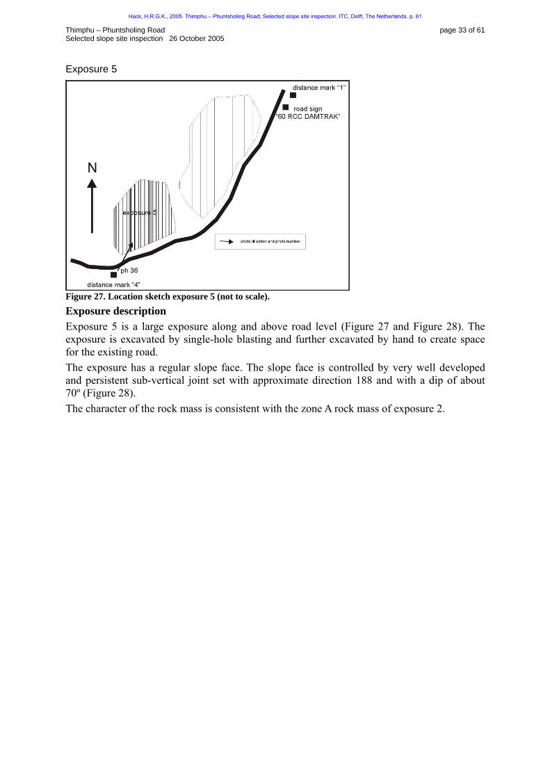
Figure 27. Location sketch exposure 5 (not to scale). Exposure description Exposure 5 is a large exposure along and above road level (110HFigure 27 and 111HFigure 28). The exposure is excavated by single-hole blasting and further excavated by hand to create space for the existing road. The exposure has a regular slope face. The slope face is controlled by very well developed and persistent sub-vertical joint set with approximate direction 188 and with a dip of about 70º (112HFigure 28). The character of the rock mass is consistent with the zone A rock mass of exposure 2.
Hack, H.R.G.K., 2005. Thimphu – Phuntsholing Road; Selected slope site inspection. ITC, Delft, The Netherlands. p. 61

Thimphu – Phuntsholing Road page 34 of 61 Selected slope site inspection 26 October 2005
Figure 28. Exposure 5 (photo 36)
Hack, H.R.G.K., 2005. Thimphu – Phuntsholing Road; Selected slope site inspection. ITC, Delft, The Netherlands. p. 61

Thimphu – Phuntsholing Road page 35 of 61 Selected slope site inspection 26 October 2005
Exposures between exposure 5 and road sign “60 RCCDAMTAK”
Exposure description The exposures between exposure 5 and the road sign”60 RCC DAMTAK” are similar to exposure 5 (113HFigure 28).
Hack, H.R.G.K., 2005. Thimphu – Phuntsholing Road; Selected slope site inspection. ITC, Delft, The Netherlands. p. 61
Thimphu – Phuntsholing Road page 36 of 61 Selected slope site inspection 26 October 2005
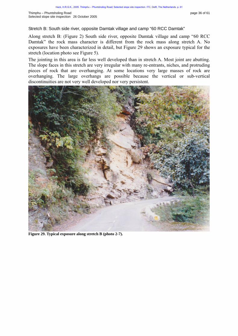
Stretch B: South side river, opposite Damtak village and camp “60 RCC Damtak”
Along stretch B: ( 114HFigure 2) South side river, opposite Damtak village and camp “60 RCC Damtak” the rock mass character is different from the rock mass along stretch A. No exposures have been characterized in detail, but 115HFigure 29 shows an exposure typical for the stretch (location photo see 116HFigure 5). The jointing in this area is far less well developed than in stretch A. Most joint are abutting. The slope faces in this stretch are very irregular with many re-entrants, niches, and protruding pieces of rock that are overhanging. At some locations very large masses of rock are overhanging. The large overhangs are possible because the vertical or sub-vertical discontinuities are not very well developed nor very persistent.
Figure 29. Typical exposure along stretch B (photo 2-7).
Hack, H.R.G.K., 2005. Thimphu – Phuntsholing Road; Selected slope site inspection. ITC, Delft, The Netherlands. p. 61

Thimphu – Phuntsholing Road page 37 of 61 Selected slope site inspection 26 October 2005
Stretch C: South side Jantulam Chhu river
The slopes along stretch C (117HFigure 2 and 118HFigure 30): South side Jantulam Chhu river is different from the rock mass along stretch A. Exposure 6 was considered typical for the exposures along stretch C and has been characterized in detail (see below). The jointing in the rock mass along stretch C is far less well developed than in stretch A. Most joints are abutting. The slope faces in this stretch are very irregular with many re-entrants, niches, and protruding pieces of rock that are overhanging. At some locations, very large masses of rock are overhanging. The large overhangs are possible because the vertical or sub-vertical discontinuities are not very well developed nor very persistent.
Hack, H.R.G.K., 2005. Thimphu – Phuntsholing Road; Selected slope site inspection. ITC, Delft, The Netherlands. p. 61
Thimphu – Phuntsholing Road page 38 of 61 Selected slope site inspection 26 October 2005
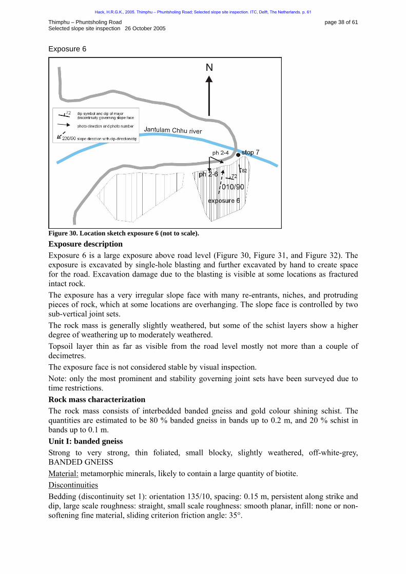
Exposure 6
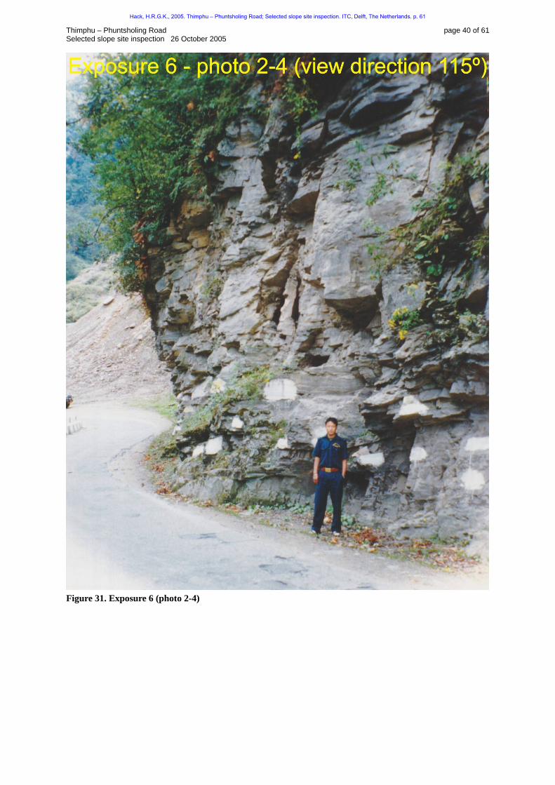
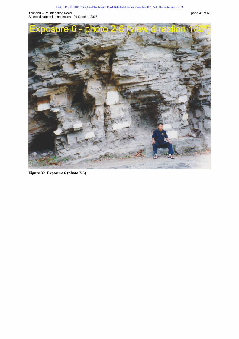
Figure 30. Location sketch exposure 6 (not to scale). Exposure description Exposure 6 is a large exposure above road level (119HFigure 30, 120HFigure 31, and 121HFigure 32). The exposure is excavated by single-hole blasting and further excavated by hand to create space for the road. Excavation damage due to the blasting is visible at some locations as fractured intact rock. The exposure has a very irregular slope face with many re-entrants, niches, and protruding pieces of rock, which at some locations are overhanging. The slope face is controlled by two sub-vertical joint sets. The rock mass is generally slightly weathered, but some of the schist layers show a higher degree of weathering up to moderately weathered. Topsoil layer thin as far as visible from the road level mostly not more than a couple of decimetres. The exposure face is not considered stable by visual inspection. Note: only the most prominent and stability governing joint sets have been surveyed due to time restrictions. Rock mass characterization The rock mass consists of interbedded banded gneiss and gold colour shining schist. The quantities are estimated to be 80 % banded gneiss in bands up to 0.2 m, and 20 % schist in bands up to 0.1 m. Unit I: banded gneiss Strong to very strong, thin foliated, small blocky, slightly weathered, off-white-grey, BANDED GNEISS UMaterial:U metamorphic minerals, likely to contain a large quantity of biotite. UDiscontinuities Bedding (discontinuity set 1): orientation 135/10, spacing: 0.15 m, persistent along strike and dip, large scale roughness: straight, small scale roughness: smooth planar, infill: none or non-softening fine material, sliding criterion friction angle: 35°.
Hack, H.R.G.K., 2005. Thimphu – Phuntsholing Road; Selected slope site inspection. ITC, Delft, The Netherlands. p. 61

Thimphu – Phuntsholing Road page 39 of 61 Selected slope site inspection 26 October 2005
Joint (discontinuity set 2): orientation 010/72, spacing: 0.3 m, abutting 0.2 m along strike and abutting 0.15 m along dip, large-scale roughness: not applicable, small-scale roughness: rough stepped, infill: none (many open joints with openness up to 0.02 – 0.03 m), sliding criterion friction angle: 85°. Joint (discontinuity set 3): orientation 080/82, spacing: 0.2 m, abutting 0.3 m along strike and abutting 0.15 m along dip, large scale roughness: not applicable, small scale roughness: rough planar, infill: none (many open joints with openness up to 0.02 – 0.03 m), sliding criterion friction angle: 85°. Joint (discontinuity set 4 established from photos, very irregular): orientation approximately 100/50-90, spacing: 4 m, persistent along strike and dip, large-scale roughness: wavy, small-scale roughness: could not be established, infill: could not be established. Unit II: schist Very weak, very thinly foliated, very thin tabular, slightly weathered, gold shining, SCHIST UMaterial:U metamorphic minerals, contains large quantities of mica’s. UDiscontinuities Schistosity (discontinuity set 1): orientation 135/10, spacing: 0.005 m, persistent along strike and dip, large scale roughness: straight, small scale roughness: smooth planar, infill: non-softening fine material, sliding criterion friction angle: 34°. Joint (discontinuity set 2): orientation 010/72 (see note *1), spacing: 0.03 m (see note *1), abutting 0.03 m along strike and abutting 0.005 m along dip, large-scale roughness: not applicable, small-scale roughness: rough stepped, infill: none, sliding criterion friction angle: 84°. Joint (discontinuity set 3): orientation 080/82 (see note *1), spacing: 0.03 m (see note *1), abutting 0.03 m along strike and abutting 0.005 m along dip, large scale roughness: not applicable, small scale roughness: rough planar, infill: none, sliding criterion friction angle: 84°. Joint (discontinuity set 4 established from photos, very irregular): orientation approximately 100/50-90, spacing: 4 m, persistent along strike and dip, large-scale roughness: wavy, small-scale roughness: could not be established, infill: could not be established. Note *1: orientations from unit I, spacing based on block size. Slope Stability Probability Classification (SSPC) Two SSPC classifications have been done on the rock masses in exposure 6 (Appendix II). The schist of unit II is generally weak and consequently has lower rock mass strength properties than the banded gneiss. The banded gneiss unit allows for a maximum admissible slope height following the SSPC system of around 19 m for a slope with a dip of 75°. The schist allows considerably lower slope heights. It has not been possible to identify the location and quantities of units in the exposure in any detail in this reconnaissance survey hence, it is not possible to compare the SSPC admissible heights in detail with the real slope heights. However, the admissible heights following the SSPC system seem to be reasonable in agreement with the slopes above road level. The real slopes are steeper up to 90 or overhanging but those are visually considered as highly unstable.
Hack, H.R.G.K., 2005. Thimphu – Phuntsholing Road; Selected slope site inspection. ITC, Delft, The Netherlands. p. 61
Thimphu – Phuntsholing Road page 40 of 61 Selected slope site inspection 26 October 2005
Figure 31. Exposure 6 (photo 2-4)
Hack, H.R.G.K., 2005. Thimphu – Phuntsholing Road; Selected slope site inspection. ITC, Delft, The Netherlands. p. 61
Thimphu – Phuntsholing Road page 41 of 61 Selected slope site inspection 26 October 2005
Figure 32. Exposure 6 (photo 2-6)
Hack, H.R.G.K., 2005. Thimphu – Phuntsholing Road; Selected slope site inspection. ITC, Delft, The Netherlands. p. 61

Thimphu – Phuntsholing Road page 42 of 61 Selected slope site inspection 26 October 2005
Appendix II – SSPC slope stability calculations
Hack, H.R.G.K., 2005. Thimphu – Phuntsholing Road; Selected slope site inspection. ITC, Delft, The Netherlands. p. 61
Thimphu – Phuntsholing Road page 43 of 61 Selected slope site inspection 26 October 2005 BAP DGM/ITC ENGINEERING GEOLOGY exposure characterization SSPC - SYSTEM
LOGGED BY: RH DATE: 26/10/2005 TIME: 11:30 hr exposure no: 2 zone AI; schist
WEATHER CONDITIONS LOCATION map no: See report Sun: cloudy/fair/bright northing:
Rain: dry/drizzle/slight/heavy Map coordinates:
easting:
METHOD OF EXCAVATION (ME) DIMENSIONS/ACCESSIBILITY
Size total exposure: (m) l: see report h: d: mapped on this form (m) l: h: d:
(tick) natural/hand-made pneumatic hammer excavation pre-splitting/smooth wall blasting conventional blasting with result:
good open discontinuities
dislodged blocks fractured intact rock crushed intact rock
V 1.00
0.76 0.99
0.77 0.75 0.72 0.67 0.62
Accessibility: poor/fair/good only part along the road is accessible
FORMATION NAME: Thimphu formation (following geological map)
DESCRIPTION (BS 5930: 1981) color grain size structure & texture weathering NAME
grey coarse large blocky/tabular slightly SCHIST
INTACT ROCK STRENGTH (IRS) (tick) sample number(s): WEATHERING (WE) < 1.25 MPa 1.25 - 5 MPa 5 - 12.5 MPa 12.5 - 50 MPa 50 - 100 MPa
100 - 200 MPa V > 200 MPa
Crumbles in hand Thin slabs break easily in hand Thin slabs broken by heavy hand pressure Lumps broken by light hammer blows Lumps broken by heavy hammer blows Lumps only chip by heavy hammer blows (Dull ringing sound) Rocks ring on hammer blows. Sparks fly
(tick) unweathered slightly V moderately highly completely
1.000.950.900.620.35
DISCONTINUITIES B = bedding C = Cleavage J = joint; etc. …B….1 …J….2 …J…..3 …J….4 …....5 EXISTING SLOPE? Dip direction (degrees) 280 270 188 075
Dip (degrees 08 90 70 45
Spacing (DS) (m) 0.05 0.1 0.1 2
dip-direction/dip
196./ 75
along strike (m) > > > A 5 height: 21 mPersistence
along dip (m) > > > A 5 CONDITION OF DISCONTINUITIES
Roughness large scale (Rl) (on an area between 0.2 x 0.2 and 1 x 1 m2)
wavy: slightly wavy: curved: slightly curved straight
1.000.950.850.800.75
0.75 0.75 1.00 0.75
Stability (tick) stable small problems large problems V
1 2 3
Roughness small scale (Rs) (on an area of 0.2 x 0.2 m2)
rough stepped smooth stepped polished stepped rough undulating smooth undulating polished undulating rough planar smooth planar polished planar
0.950.900.850.800.750.700.650.600.55
0.95 0.95 0.95 -
cemented/cemented infill no infill - surface staining
1.071.00
non softening & sheared material, e.g. free of clay, talc, etc.
coarse medium fine
0.950.900.85
soft sheared material, e.g. clay, talc, etc.
coarse medium fine
0.750.650.55
Infill material (Im)
gouge < irregularities gouge > irregularities flowing material
0.420.170.05
0.85 1.00 1.00 -
Karst (Ka) none karst
1.000.92 1.00 1.00 1.00 1.00
notes: 1) For infill 'gouge > irregularities' and 'flowing material' small-scale roughness = 0.55. 2) If roughness is anisotropic (e.g. ripple marks, striation, etc.) roughness should be assessed perpendicular and parallel to the roughness and directions noted on this form. 3) Non-fitting of discontinuities should be marked in roughness columns.
SUSCEPTIBILITY TO WEATHERING (SW)
degree of weathering: date excavation: remarks:
Slightly, occasionally moderately weathered
unknown Expected low susceptibility to weathering
remarks: Existing slope has many re-entrants, niches, and extending pieces of rock, which at some locations are overhanging. Existing slope assessed as instable.
Hack, H.R.G.K., 2005. Thimphu – Phuntsholing Road; Selected slope site inspection. ITC, Delft, The Netherlands. p. 61
Thimphu – Phuntsholing Road page 44 of 61 Selected slope site inspection 26 October 2005 BAP DGM/ITC ENGINEERING GEOLOGY reference rock mass calculation SSPC - SYSTEM
CALCULATED BY: RH DATE: 26/10/2005 exposure no: 2 zone AI; schist
REFERENCE UNIT NAME: Thimphu formation (following geological map)
INTACT ROCK STRENGTH (RIRS)
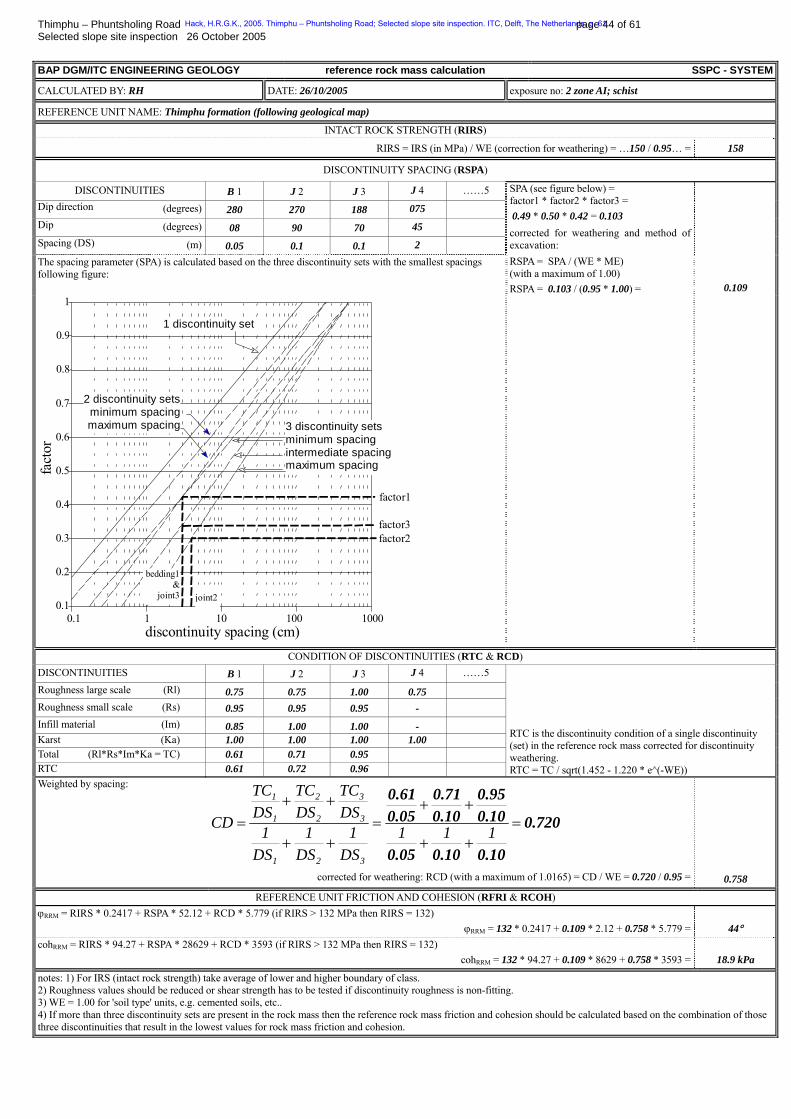
RIRS = IRS (in MPa) / WE (correction for weathering) = …150 / 0.95… = 158
DISCONTINUITY SPACING (RSPA)
DISCONTINUITIES B 1 J 2 J 3 J 4 ……5 Dip direction (degrees) 280 270 188 075
Dip (degrees) 08 90 70 45
Spacing (DS) (m) 0.05 0.1 0.1 2
The spacing parameter (SPA) is calculated based on the three discontinuity sets with the smallest spacings following figure:
SPA (see figure below) = factor1 * factor2 * factor3 = 0.49 * 0.50 * 0.42 = 0.103 corrected for weathering and method of excavation: RSPA = SPA / (WE * ME) (with a maximum of 1.00) RSPA = 0.103 / (0.95 * 1.00) = 0.109
0.1 1 10 100 10000.1
0.2
0.3
0.4
0.5
0.6
0.7
0.8
0.9
1
discontinuity spacing (cm)
fact
or
1 discontinuity set
2 discontinuity setsminimum spacingmaximum spacing
factor1
factor3
joint2
factor2
3 discontinuity sets minimum spacing intermediate spacingmaximum spacing
bedding1&
joint3
CONDITION OF DISCONTINUITIES (RTC & RCD) DISCONTINUITIES B 1 J 2 J 3 J 4 ……5 Roughness large scale (Rl) 0.75 0.75 1.00 0.75 Roughness small scale (Rs) 0.95 0.95 0.95 - Infill material (Im) 0.85 1.00 1.00 - Karst (Ka) 1.00 1.00 1.00 1.00 Total (Rl*Rs*Im*Ka = TC) 0.61 0.71 0.95 RTC 0.61 0.72 0.96
RTC is the discontinuity condition of a single discontinuity (set) in the reference rock mass corrected for discontinuity weathering. RTC = TC / sqrt(1.452 - 1.220 * e^(-WE))
Weighted by spacing:
0.720
0.100.100.05
0.100.95
0.100.71
0.050.61
=++
++=
++
++= 111
DS1
DS1
DS1
DSTC
DSTC
DSTC
CD
321
3
3
2
2
1
1
corrected for weathering: RCD (with a maximum of 1.0165) = CD / WE = 0.720 / 0.95 = 0.758
REFERENCE UNIT FRICTION AND COHESION (RFRI & RCOH) ϕBRRMB = RIRS * 0.2417 + RSPA * 52.12 + RCD * 5.779 (if RIRS > 132 MPa then RIRS = 132)
ϕBRRMB = 132 * 0.2417 + 0.109 * 2.12 + 0.758 * 5.779 = 44° cohBRRMB = RIRS * 94.27 + RSPA * 28629 + RCD * 3593 (if RIRS > 132 MPa then RIRS = 132)
cohBRRMB = 132 * 94.27 + 0.109 * 8629 + 0.758 * 3593 = 18.9 kPa
notes: 1) For IRS (intact rock strength) take average of lower and higher boundary of class. 2) Roughness values should be reduced or shear strength has to be tested if discontinuity roughness is non-fitting. 3) WE = 1.00 for 'soil type' units, e.g. cemented soils, etc.. 4) If more than three discontinuity sets are present in the rock mass then the reference rock mass friction and cohesion should be calculated based on the combination of those three discontinuities that result in the lowest values for rock mass friction and cohesion.
Hack, H.R.G.K., 2005. Thimphu – Phuntsholing Road; Selected slope site inspection. ITC, Delft, The Netherlands. p. 61
Thimphu – Phuntsholing Road page 45 of 61 Selected slope site inspection 26 October 2005 BAP DGM/ITC ENGINEERING GEOLOGY slope stability probability SSPC - SYSTEM
LOGGED BY: RH DATE: 26/10/2005 slope no: 2 zone AI; schist
LOCATION map no: Existing slope (see report) northing:
Map coordinates: easting:
DETAILS OF (NEW) SLOPE METHOD OF EXCAVATION (SME) (EXPECTED DEGREE OF) WEATHERING (SWE)
Slope dip direction (degrees): 196
Slope dip (degrees): 75
(tick) unweathered slightly moderately highly completely
1.00V 0.95
0.900.620.35 Height (Hslope) (m) 21
:
(tick) natural/hand-made pneumatic hammer excavation pre-splitting/smooth wall blasting conventional blasting with result:
good open discontinuities
dislodged blocks fractured intact rock crushed intact rock
V 1.00
0.76 0.99
0.77 0.75 0.72 0.67 0.62
note: SWE = 1.00 for 'soil type' units, e.g. cemented soil, etc.
SLOPE UNIT NAME: Thimphu formation (following geological map)
ORIENTATION INDEPENDENT STABILITY INTACT ROCK STRENGTH (SIRS)
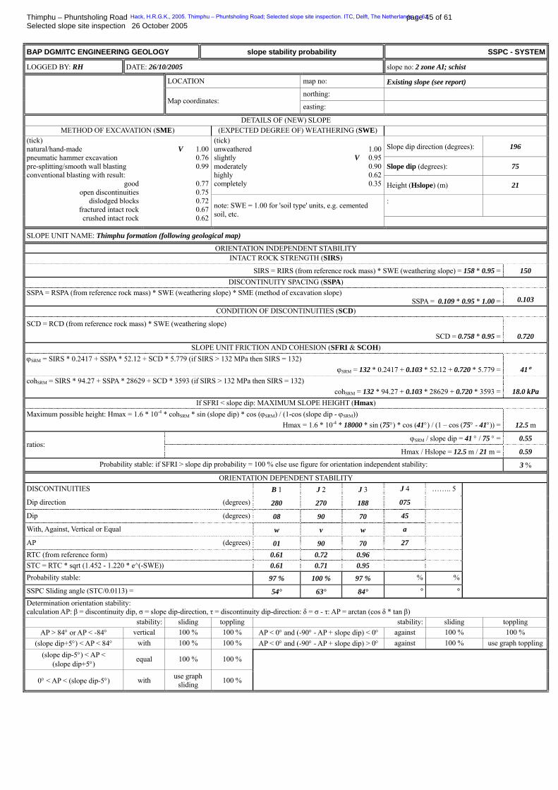
SIRS = RIRS (from reference rock mass) * SWE (weathering slope) = 158 * 0.95 = 150 DISCONTINUITY SPACING (SSPA)
SSPA = RSPA (from reference rock mass) * SWE (weathering slope) * SME (method of excavation slope) SSPA = 0.109 * 0.95 * 1.00 = 0.103
CONDITION OF DISCONTINUITIES (SCD)
SCD = RCD (from reference rock mass) * SWE (weathering slope)
SCD = 0.758 * 0.95 = 0.720 SLOPE UNIT FRICTION AND COHESION (SFRI & SCOH)
ϕBSRMB = SIRS * 0.2417 + SSPA * 52.12 + SCD * 5.779 (if SIRS > 132 MPa then SIRS = 132) ϕBSRMB = 132 * 0.2417 + 0.103 * 52.12 + 0.720 * 5.779 = 41°
cohBSRMB = SIRS * 94.27 + SSPA * 28629 + SCD * 3593 (if SIRS > 132 MPa then SIRS = 132) cohBSRMB = 132 * 94.27 + 0.103 * 28629 + 0.720 * 3593 = 18.0 kPa
If SFRI < slope dip: MAXIMUM SLOPE HEIGHT (Hmax) Maximum possible height: Hmax = 1.6 * 10P
-4P * cohBSRMB * sin (slope dip) * cos (ϕBSRMB) / (1-cos (slope dip - ϕBSRMB))
Hmax = 1.6 * 10P
-4P * 18000 * sin (75°) * cos (41°) / (1 – cos (75° - 41°)) = 12.5 m
ϕBSRMB / slope dip = 41 ° / 75 ° = 0.55 ratios:
Hmax / Hslope = 12.5 m / 21 m = 0.59
Probability stable: if SFRI > slope dip probability = 100 % else use figure for orientation independent stability: 3 %
ORIENTATION DEPENDENT STABILITY DISCONTINUITIES B 1 J 2 J 3 J 4 …….. 5
Dip direction (degrees) 280 270 188 075
Dip (degrees) 08 90 70 45
With, Against, Vertical or Equal w v w a
AP (degrees) 01 90 70 27 RTC (from reference form) 0.61 0.72 0.96 STC = RTC * sqrt (1.452 - 1.220 * e^(-SWE)) 0.61 0.71 0.95 Probability stable: 97 % 100 % 97 % % %
SSPC Sliding angle (STC/0.0113) = 54° 63° 84° ° °
Determination orientation stability: calculation AP: β = discontinuity dip, σ = slope dip-direction, τ = discontinuity dip-direction: δ = σ - τ: AP = arctan (cos δ * tan β)
stability: sliding toppling stability: sliding toppling AP > 84° or AP < -84° vertical 100 % 100 % AP < 0° and (-90° - AP + slope dip) < 0° against 100 % 100 %
(slope dip+5°) < AP < 84° with 100 % 100 % AP < 0° and (-90° - AP + slope dip) > 0° against 100 % use graph toppling (slope dip-5°) < AP <
(slope dip+5°) equal 100 % 100 %
0° < AP < (slope dip-5°) with use graph sliding 100 %
Hack, H.R.G.K., 2005. Thimphu – Phuntsholing Road; Selected slope site inspection. ITC, Delft, The Netherlands. p. 61
Thimphu – Phuntsholing Road page 46 of 61 Selected slope site inspection 26 October 2005 BAP DGM/ITC ENGINEERING GEOLOGY exposure characterization SSPC - SYSTEM
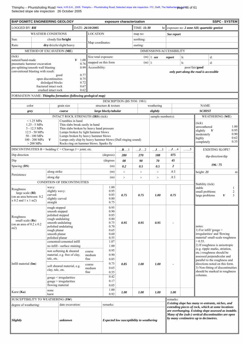
LOGGED BY: RH DATE: 26/10/2005 TIME: 11:30 hr exposure no: 2 zone AII; quartzitic gneisst
WEATHER CONDITIONS LOCATION map no: See report Sun: cloudy/fair/bright northing:
Rain: dry/drizzle/slight/heavy Map coordinates:
easting:
METHOD OF EXCAVATION (ME) DIMENSIONS/ACCESSIBILITY
Size total exposure: (m) l: see report h: d: mapped on this form (m) l: h: d:
(tick) natural/hand-made pneumatic hammer excavation pre-splitting/smooth wall blasting conventional blasting with result:
good open discontinuities
dislodged blocks fractured intact rock crushed intact rock
V 1.00
0.76 0.99
0.77 0.75 0.72 0.67 0.62
Accessibility: poor/fair/good only part along the road is accessible
FORMATION NAME: Thimphu formation (following geological map)
DESCRIPTION (BS 5930: 1981) color grain size structure & texture weathering NAME
grey coarse large blocky/tabular slightly SCHIST
INTACT ROCK STRENGTH (IRS) (tick) sample number(s): WEATHERING (WE) < 1.25 MPa 1.25 - 5 MPa 5 - 12.5 MPa 12.5 - 50 MPa 50 - 100 MPa
100 - 200 MPa V > 200 MPa
Crumbles in hand Thin slabs break easily in hand Thin slabs broken by heavy hand pressure Lumps broken by light hammer blows Lumps broken by heavy hammer blows Lumps only chip by heavy hammer blows (Dull ringing sound) Rocks ring on hammer blows. Sparks fly
(tick) unweathered slightly V moderately highly completely
1.000.950.900.620.35
DISCONTINUITIES B = bedding C = Cleavage J = joint; etc. …B….1 …J….2 …J…..3 …J….4 …....5 EXISTING SLOPE? Dip direction (degrees) 280 270 188 075
Dip (degrees 08 90 70 45
Spacing (DS) (m) 0.2 0.5 0.5 2
dip-direction/dip
196./ 75
along strike (m) > > > A 5 height: 21 mPersistence
along dip (m) > > > A 5 CONDITION OF DISCONTINUITIES
Roughness large scale (Rl) (on an area between 0.2 x 0.2 and 1 x 1 m2)
wavy: slightly wavy: curved: slightly curved straight
1.000.950.850.800.75
0.75 0.75 1.00 0.75
Stability (tick) stable small problems large problems V
1 2 3
Roughness small scale (Rs) (on an area of 0.2 x 0.2 m2)
rough stepped smooth stepped polished stepped rough undulating smooth undulating polished undulating rough planar smooth planar polished planar
0.950.900.850.800.750.700.650.600.55
0.95 0.95 0.95 -
cemented/cemented infill no infill - surface staining
1.071.00
non softening & sheared material, e.g. free of clay, talc, etc.
coarse medium fine
0.950.900.85
soft sheared material, e.g. clay, talc, etc.
coarse medium fine
0.750.650.55
Infill material (Im)
gouge < irregularities gouge > irregularities flowing material
0.420.170.05
0.85 1.00 1.00 -
Karst (Ka) none karst
1.000.92 1.00 1.00 1.00 1.00
notes: 1) For infill 'gouge > irregularities' and 'flowing material' small-scale roughness = 0.55. 2) If roughness is anisotropic (e.g. ripple marks, striation, etc.) roughness should be assessed perpendicular and parallel to the roughness and directions noted on this form. 3) Non-fitting of discontinuities should be marked in roughness columns.
SUSCEPTIBILITY TO WEATHERING (SW)
degree of weathering: date excavation: remarks:
Slightly unknown Expected low susceptibility to weathering
remarks: Existing slope has many re-entrants, niches, and extending pieces of rock, which at some locations are overhanging. Existing slope assessed as instable.Many of the (sub-) vertical discontinuities are open by many centimetres up to decimetres.
Hack, H.R.G.K., 2005. Thimphu – Phuntsholing Road; Selected slope site inspection. ITC, Delft, The Netherlands. p. 61
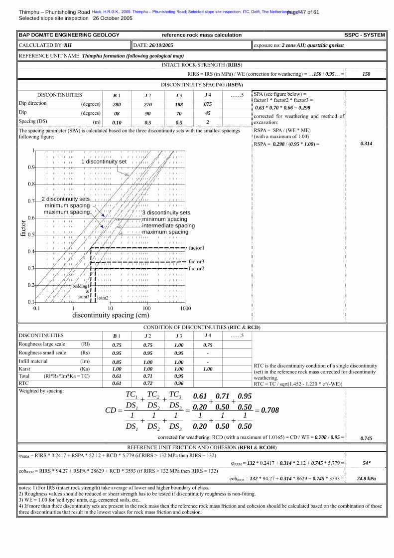
Thimphu – Phuntsholing Road page 47 of 61 Selected slope site inspection 26 October 2005 BAP DGM/ITC ENGINEERING GEOLOGY reference rock mass calculation SSPC - SYSTEM
CALCULATED BY: RH DATE: 26/10/2005 exposure no: 2 zone AII; quartzitic gneisst
REFERENCE UNIT NAME: Thimphu formation (following geological map)
INTACT ROCK STRENGTH (RIRS)
RIRS = IRS (in MPa) / WE (correction for weathering) = …150 / 0.95… = 158
DISCONTINUITY SPACING (RSPA)
DISCONTINUITIES B 1 J 2 J 3 J 4 ……5 Dip direction (degrees) 280 270 188 075
Dip (degrees) 08 90 70 45
Spacing (DS) (m) 0.10 0.5 0.5 2
The spacing parameter (SPA) is calculated based on the three discontinuity sets with the smallest spacings following figure:
SPA (see figure below) = factor1 * factor2 * factor3 = 0.63 * 0.70 * 0.66 = 0.298 corrected for weathering and method of excavation: RSPA = SPA / (WE * ME) (with a maximum of 1.00) RSPA = 0.298 / (0.95 * 1.00) = 0.314
0.1 1 10 100 10000.1
0.2
0.3
0.4
0.5
0.6
0.7
0.8
0.9
1
discontinuity spacing (cm)
fact
or
1 discontinuity set
2 discontinuity setsminimum spacingmaximum spacing
factor1
factor3
joint2
factor2
3 discontinuity sets minimum spacing intermediate spacingmaximum spacing
bedding1&
joint3
CONDITION OF DISCONTINUITIES (RTC & RCD) DISCONTINUITIES B 1 J 2 J 3 J 4 ……5 Roughness large scale (Rl) 0.75 0.75 1.00 0.75 Roughness small scale (Rs) 0.95 0.95 0.95 - Infill material (Im) 0.85 1.00 1.00 - Karst (Ka) 1.00 1.00 1.00 1.00 Total (Rl*Rs*Im*Ka = TC) 0.61 0.71 0.95 RTC 0.61 0.72 0.96
RTC is the discontinuity condition of a single discontinuity (set) in the reference rock mass corrected for discontinuity weathering. RTC = TC / sqrt(1.452 - 1.220 * e^(-WE))
Weighted by spacing:
0.708
0.500.500.20
0.500.95
0.500.71
0.200.61
=++
++=
++
++= 111
DS1
DS1
DS1
DSTC
DSTC
DSTC
CD
321
3
3
2
2
1
1
corrected for weathering: RCD (with a maximum of 1.0165) = CD / WE = 0.708 / 0.95 = 0.745
REFERENCE UNIT FRICTION AND COHESION (RFRI & RCOH) ϕBRRMB = RIRS * 0.2417 + RSPA * 52.12 + RCD * 5.779 (if RIRS > 132 MPa then RIRS = 132)
ϕBRRMB = 132 * 0.2417 + 0.314 * 2.12 + 0.745 * 5.779 = 54° cohBRRMB = RIRS * 94.27 + RSPA * 28629 + RCD * 3593 (if RIRS > 132 MPa then RIRS = 132)
cohBRRMB = 132 * 94.27 + 0.314 * 8629 + 0.745 * 3593 = 24.8 kPa
notes: 1) For IRS (intact rock strength) take average of lower and higher boundary of class. 2) Roughness values should be reduced or shear strength has to be tested if discontinuity roughness is non-fitting. 3) WE = 1.00 for 'soil type' units, e.g. cemented soils, etc.. 4) If more than three discontinuity sets are present in the rock mass then the reference rock mass friction and cohesion should be calculated based on the combination of those three discontinuities that result in the lowest values for rock mass friction and cohesion.
Hack, H.R.G.K., 2005. Thimphu – Phuntsholing Road; Selected slope site inspection. ITC, Delft, The Netherlands. p. 61
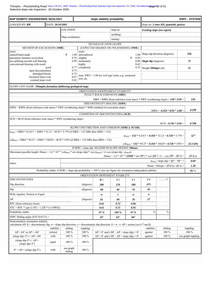
Thimphu – Phuntsholing Road page 48 of 61 Selected slope site inspection 26 October 2005 BAP DGM/ITC ENGINEERING GEOLOGY slope stability probability SSPC - SYSTEM
LOGGED BY: RH DATE: 26/10/2005 slope no: 2 zone AII; quartzitic gneisst
LOCATION map no: Existing slope (see report) northing:
Map coordinates: easting:
DETAILS OF (NEW) SLOPE METHOD OF EXCAVATION (SME) (EXPECTED DEGREE OF) WEATHERING (SWE)
Slope dip direction (degrees): 196
Slope dip (degrees): 75
(tick) unweathered slightly moderately highly completely
1.00V 0.95
0.900.620.35 Height (Hslope) (m) 21
:
(tick) natural/hand-made pneumatic hammer excavation pre-splitting/smooth wall blasting conventional blasting with result:
good open discontinuities
dislodged blocks fractured intact rock crushed intact rock
V 1.00
0.76 0.99
0.77 0.75 0.72 0.67 0.62
note: SWE = 1.00 for 'soil type' units, e.g. cemented soil, etc.
SLOPE UNIT NAME: Thimphu formation (following geological map)
ORIENTATION INDEPENDENT STABILITY INTACT ROCK STRENGTH (SIRS)
SIRS = RIRS (from reference rock mass) * SWE (weathering slope) = 158 * 0.95 = 150 DISCONTINUITY SPACING (SSPA)
SSPA = RSPA (from reference rock mass) * SWE (weathering slope) * SME (method of excavation slope) SSPA = 0.314 * 0.95 * 1.00 = 0.298
CONDITION OF DISCONTINUITIES (SCD)
SCD = RCD (from reference rock mass) * SWE (weathering slope)
SCD = 0.745 * 0.95 = 0.708 SLOPE UNIT FRICTION AND COHESION (SFRI & SCOH)
ϕBSRMB = SIRS * 0.2417 + SSPA * 52.12 + SCD * 5.779 (if SIRS > 132 MPa then SIRS = 132) ϕBSRMB = 132 * 0.2417 + 0.103 * 52.12 + 0.720 * 5.779 = 52°
cohBSRMB = SIRS * 94.27 + SSPA * 28629 + SCD * 3593 (if SIRS > 132 MPa then SIRS = 132) cohBSRMB = 132 * 94.27 + 0.103 * 28629 + 0.720 * 3593 = 23.5 kPa
If SFRI < slope dip: MAXIMUM SLOPE HEIGHT (Hmax) Maximum possible height: Hmax = 1.6 * 10P
-4P * cohBSRMB * sin (slope dip) * cos (ϕBSRMB) / (1-cos (slope dip - ϕBSRMB))
Hmax = 1.6 * 10P
-4P * 23500 * sin (75°) * cos (52°) / (1 – cos (75° - 52°)) = 27.3 m
ϕBSRMB / slope dip = 52 ° / 75 ° = 0.69 ratios:
Hmax / Hslope = 27.3 m / 21 m = 1.30
Probability stable: if SFRI > slope dip probability = 100 % else use figure for orientation independent stability: 85 %
ORIENTATION DEPENDENT STABILITY DISCONTINUITIES B 1 J 2 J 3 J 4 …….. 5
Dip direction (degrees) 280 270 188 075
Dip (degrees) 08 90 70 45
With, Against, Vertical or Equal w v w a
AP (degrees) 01 90 70 27 RTC (from reference form) 0.61 0.72 0.96 STC = RTC * sqrt (1.452 - 1.220 * e^(-SWE)) 0.61 0.71 0.95 Probability stable: 97 % 100 % 97 % % %
SSPC Sliding angle (STC/0.0113) = 54° 63° 84°
Determination orientation stability: calculation AP: β = discontinuity dip, σ = slope dip-direction, τ = discontinuity dip-direction: δ = σ - τ: AP = arctan (cos δ * tan β)
stability: sliding toppling stability: sliding toppling AP > 84° or AP < -84° vertical 100 % 100 % AP < 0° and (-90° - AP + slope dip) < 0° against 100 % 100 %
(slope dip+5°) < AP < 84° with 100 % 100 % AP < 0° and (-90° - AP + slope dip) > 0° against 100 % use graph toppling (slope dip-5°) < AP <
(slope dip+5°) equal 100 % 100 %
0° < AP < (slope dip-5°) with use graph sliding 100 %
Hack, H.R.G.K., 2005. Thimphu – Phuntsholing Road; Selected slope site inspection. ITC, Delft, The Netherlands. p. 61
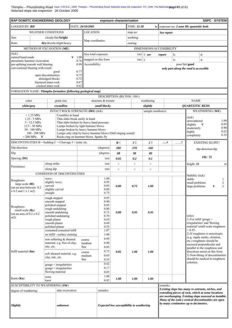
Thimphu – Phuntsholing Road page 49 of 61 Selected slope site inspection 26 October 2005 BAP DGM/ITC ENGINEERING GEOLOGY exposure characterization SSPC - SYSTEM
LOGGED BY: RH DATE: 26/10/2005 TIME: 11:30 hr exposure no: 2 zone BI; quartzitic beds
WEATHER CONDITIONS LOCATION map no: See report Sun: cloudy/fair/bright northing:
Rain: dry/drizzle/slight/heavy Map coordinates:
easting:
METHOD OF EXCAVATION (ME) DIMENSIONS/ACCESSIBILITY
Size total exposure: (m) l: see report h: d: mapped on this form (m) l: h: d:
(tick) natural/hand-made pneumatic hammer excavation pre-splitting/smooth wall blasting conventional blasting with result:
good open discontinuities
dislodged blocks fractured intact rock crushed intact rock
V 1.00
0.76 0.99
0.77 0.75 0.72 0.67 0.62
Accessibility: poor/fair/good only part along the road is accessible
FORMATION NAME: Thimphu formation (following geological map)
DESCRIPTION (BS 5930: 1981) color grain size structure & texture weathering NAME
white/grey crystalline small blocky slightly QUARTZITIC BEDS
INTACT ROCK STRENGTH (IRS) (tick) sample number(s): WEATHERING (WE) < 1.25 MPa 1.25 - 5 MPa 5 - 12.5 MPa 12.5 - 50 MPa 50 - 100 MPa
100 - 200 MPa > 200 MPa V
Crumbles in hand Thin slabs break easily in hand Thin slabs broken by heavy hand pressure Lumps broken by light hammer blows Lumps broken by heavy hammer blows Lumps only chip by heavy hammer blows (Dull ringing sound) Rocks ring on hammer blows. Sparks fly
(tick) unweathered slightly V moderately highly completely
1.000.950.900.620.35
DISCONTINUITIES B = bedding C = Cleavage J = joint; etc. B 1 J 2 J 3 ….4 …....5 EXISTING SLOPE? Dip direction (degrees) 280 270 160
Dip (degrees 08 90 80
Spacing (DS) (m) 0.05 0.2 0.1
dip-direction/dip
196./ 75
along strike (m) > > > height: 21 mPersistence
along dip (m) > > > CONDITION OF DISCONTINUITIES
Roughness large scale (Rl) (on an area between 0.2 x 0.2 and 1 x 1 m2)
wavy: slightly wavy: curved: slightly curved straight
1.000.950.850.800.75
0.80 0.75 1.00
Stability (tick) stable small problems large problems V
1 2 3
Roughness small scale (Rs) (on an area of 0.2 x 0.2 m2)
rough stepped smooth stepped polished stepped rough undulating smooth undulating polished undulating rough planar smooth planar polished planar
0.950.900.850.800.750.700.650.600.55
0.80 0.95 0.95
cemented/cemented infill no infill - surface staining
1.071.00
non softening & sheared material, e.g. free of clay, talc, etc.
coarse medium fine
0.950.900.85
soft sheared material, e.g. clay, talc, etc.
coarse medium fine
0.750.650.55
Infill material (Im)
gouge < irregularities gouge > irregularities flowing material
0.420.170.05
0.85 1.00 1.00
Karst (Ka) none karst
1.000.92 1.00 1.00 1.00
notes: 1) For infill 'gouge > irregularities' and 'flowing material' small-scale roughness = 0.55. 2) If roughness is anisotropic (e.g. ripple marks, striation, etc.) roughness should be assessed perpendicular and parallel to the roughness and directions noted on this form. 3) Non-fitting of discontinuities should be marked in roughness columns.
SUSCEPTIBILITY TO WEATHERING (SW)
degree of weathering: date excavation: remarks:
Slightly unknown Expected low susceptibility to weathering
remarks: Existing slope has many re-entrants, niches, and extending pieces of rock, which at some locations are overhanging. Existing slope assessed as instable.Many of the (sub-) vertical discontinuities are open by many centimetres up to decimetres.
Hack, H.R.G.K., 2005. Thimphu – Phuntsholing Road; Selected slope site inspection. ITC, Delft, The Netherlands. p. 61
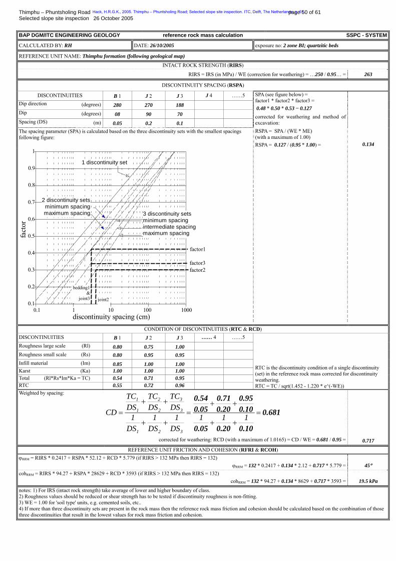
Thimphu – Phuntsholing Road page 50 of 61 Selected slope site inspection 26 October 2005 BAP DGM/ITC ENGINEERING GEOLOGY reference rock mass calculation SSPC - SYSTEM
CALCULATED BY: RH DATE: 26/10/2005 exposure no: 2 zone BI; quartzitic beds
REFERENCE UNIT NAME: Thimphu formation (following geological map)
INTACT ROCK STRENGTH (RIRS)
RIRS = IRS (in MPa) / WE (correction for weathering) = …250 / 0.95… = 263
DISCONTINUITY SPACING (RSPA)
DISCONTINUITIES B 1 J 2 J 3 J 4 ……5 Dip direction (degrees) 280 270 188
Dip (degrees) 08 90 70
Spacing (DS) (m) 0.05 0.2 0.1
The spacing parameter (SPA) is calculated based on the three discontinuity sets with the smallest spacings following figure:
SPA (see figure below) = factor1 * factor2 * factor3 = 0.48 * 0.50 * 0.53 = 0.127 corrected for weathering and method of excavation: RSPA = SPA / (WE * ME) (with a maximum of 1.00) RSPA = 0.127 / (0.95 * 1.00) = 0.134
0.1 1 10 100 10000.1
0.2
0.3
0.4
0.5
0.6
0.7
0.8
0.9
1
discontinuity spacing (cm)
fact
or
1 discontinuity set
2 discontinuity setsminimum spacingmaximum spacing
factor1
factor3
joint2
factor2
3 discontinuity sets minimum spacing intermediate spacingmaximum spacing
bedding1&
joint3
CONDITION OF DISCONTINUITIES (RTC & RCD) DISCONTINUITIES B 1 J 2 J 3 …… 4 ……5 Roughness large scale (Rl) 0.80 0.75 1.00 Roughness small scale (Rs) 0.80 0.95 0.95 Infill material (Im) 0.85 1.00 1.00 Karst (Ka) 1.00 1.00 1.00 Total (Rl*Rs*Im*Ka = TC) 0.54 0.71 0.95 RTC 0.55 0.72 0.96
RTC is the discontinuity condition of a single discontinuity (set) in the reference rock mass corrected for discontinuity weathering. RTC = TC / sqrt(1.452 - 1.220 * e^(-WE))
Weighted by spacing:
0.681
0.100.200.05
0.100.95
0.200.71
0.050.54
=++
++=
++
++= 111
DS1
DS1
DS1
DSTC
DSTC
DSTC
CD
321
3
3
2
2
1
1
corrected for weathering: RCD (with a maximum of 1.0165) = CD / WE = 0.681 / 0.95 = 0.717
REFERENCE UNIT FRICTION AND COHESION (RFRI & RCOH) ϕBRRMB = RIRS * 0.2417 + RSPA * 52.12 + RCD * 5.779 (if RIRS > 132 MPa then RIRS = 132)
ϕBRRMB = 132 * 0.2417 + 0.134 * 2.12 + 0.717 * 5.779 = 45° cohBRRMB = RIRS * 94.27 + RSPA * 28629 + RCD * 3593 (if RIRS > 132 MPa then RIRS = 132)
cohBRRMB = 132 * 94.27 + 0.134 * 8629 + 0.717 * 3593 = 19.5 kPa
notes: 1) For IRS (intact rock strength) take average of lower and higher boundary of class. 2) Roughness values should be reduced or shear strength has to be tested if discontinuity roughness is non-fitting. 3) WE = 1.00 for 'soil type' units, e.g. cemented soils, etc.. 4) If more than three discontinuity sets are present in the rock mass then the reference rock mass friction and cohesion should be calculated based on the combination of those three discontinuities that result in the lowest values for rock mass friction and cohesion.
Hack, H.R.G.K., 2005. Thimphu – Phuntsholing Road; Selected slope site inspection. ITC, Delft, The Netherlands. p. 61
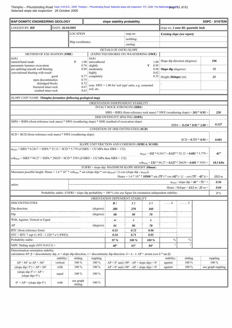
Thimphu – Phuntsholing Road page 51 of 61 Selected slope site inspection 26 October 2005 BAP DGM/ITC ENGINEERING GEOLOGY slope stability probability SSPC - SYSTEM
LOGGED BY: RH DATE: 26/10/2005 slope no: 2 zone BI; quartzitic beds
LOCATION map no: Existing slope (see report) northing:
Map coordinates: easting:
DETAILS OF (NEW) SLOPE METHOD OF EXCAVATION (SME) (EXPECTED DEGREE OF) WEATHERING (SWE)
Slope dip direction (degrees): 196
Slope dip (degrees): 75
(tick) unweathered slightly moderately highly completely
1.00V 0.95
0.900.620.35 Height (Hslope) (m) 21
:
(tick) natural/hand-made pneumatic hammer excavation pre-splitting/smooth wall blasting conventional blasting with result:
good open discontinuities
dislodged blocks fractured intact rock crushed intact rock
V 1.00
0.76 0.99
0.77 0.75 0.72 0.67 0.62
note: SWE = 1.00 for 'soil type' units, e.g. cemented soil, etc.
SLOPE UNIT NAME: Thimphu formation (following geological map)
ORIENTATION INDEPENDENT STABILITY INTACT ROCK STRENGTH (SIRS)
SIRS = RIRS (from reference rock mass) * SWE (weathering slope) = 263 * 0.95 = 250 DISCONTINUITY SPACING (SSPA)
SSPA = RSPA (from reference rock mass) * SWE (weathering slope) * SME (method of excavation slope) SSPA = 0.134 * 0.95 * 1.00 = 0.127
CONDITION OF DISCONTINUITIES (SCD)
SCD = RCD (from reference rock mass) * SWE (weathering slope)
SCD = 0.717 * 0.95 = 0.681 SLOPE UNIT FRICTION AND COHESION (SFRI & SCOH)
ϕBSRMB = SIRS * 0.2417 + SSPA * 52.12 + SCD * 5.779 (if SIRS > 132 MPa then SIRS = 132) ϕBSRMB = 132 * 0.2417 + 0.127 * 52.12 + 0.681 * 5.779 = 42°
cohBSRMB = SIRS * 94.27 + SSPA * 28629 + SCD * 3593 (if SIRS > 132 MPa then SIRS = 132) cohBSRMB = 132 * 94.27 + 0.127 * 28629 + 0.681 * 3593 = 18.5 kPa
If SFRI < slope dip: MAXIMUM SLOPE HEIGHT (Hmax) Maximum possible height: Hmax = 1.6 * 10P
-4P * cohBSRMB * sin (slope dip) * cos (ϕBSRMB) / (1-cos (slope dip - ϕBSRMB))
Hmax = 1.6 * 10P
-4P * 18500 * sin (75°) * cos (42°) / (1 – cos (75° - 42°)) = 13.5 m
ϕBSRMB / slope dip = 42 ° / 75 ° = 0.56 ratios:
Hmax / Hslope = 13.5 m / 21 m = 0.64
Probability stable: if SFRI > slope dip probability = 100 % else use figure for orientation independent stability: 3 %
ORIENTATION DEPENDENT STABILITY DISCONTINUITIES B 1 J 2 J 3 …… 4 …….. 5
Dip direction (degrees) 280 270 160
Dip (degrees) 08 90 70
With, Against, Vertical or Equal w v e
AP (degrees) 01 90 78 RTC (from reference form) 0.55 0.72 0.96 STC = RTC * sqrt (1.452 - 1.220 * e^(-SWE)) 0.54 0.71 0.95 Probability stable: 97 % 100 % 100 % % %
SSPC Sliding angle (STC/0.0113) = 48° 63° 84° ° °
Determination orientation stability: calculation AP: β = discontinuity dip, σ = slope dip-direction, τ = discontinuity dip-direction: δ = σ - τ: AP = arctan (cos δ * tan β)
stability: sliding toppling stability: sliding toppling AP > 84° or AP < -84° vertical 100 % 100 % AP < 0° and (-90° - AP + slope dip) < 0° against 100 % 100 %
(slope dip+5°) < AP < 84° with 100 % 100 % AP < 0° and (-90° - AP + slope dip) > 0° against 100 % use graph toppling (slope dip-5°) < AP <
(slope dip+5°) equal 100 % 100 %
0° < AP < (slope dip-5°) with use graph sliding 100 %
Hack, H.R.G.K., 2005. Thimphu – Phuntsholing Road; Selected slope site inspection. ITC, Delft, The Netherlands. p. 61
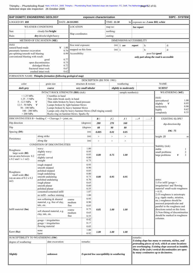
Thimphu – Phuntsholing Road page 52 of 61 Selected slope site inspection 26 October 2005 BAP DGM/ITC ENGINEERING GEOLOGY exposure characterization SSPC - SYSTEM
LOGGED BY: RH DATE: 26/10/2005 TIME: 11:30 hr exposure no: 2 zone BII; schist
WEATHER CONDITIONS LOCATION map no: See report Sun: cloudy/fair/bright northing:
Rain: dry/drizzle/slight/heavy Map coordinates:
easting:
METHOD OF EXCAVATION (ME) DIMENSIONS/ACCESSIBILITY
Size total exposure: (m) l: see report h: d: mapped on this form (m) l: h: d:
(tick) natural/hand-made pneumatic hammer excavation pre-splitting/smooth wall blasting conventional blasting with result:
good open discontinuities
dislodged blocks fractured intact rock crushed intact rock
V 1.00
0.76 0.99
0.77 0.75 0.72 0.67 0.62
Accessibility: poor/fair/good only part along the road is accessible
FORMATION NAME: Thimphu formation (following geological map)
DESCRIPTION (BS 5930: 1981) color grain size structure & texture weathering NAME
dark grey coarse very small tabular slightly to moderately SCHIST
INTACT ROCK STRENGTH (IRS) (tick) sample number(s): WEATHERING (WE) < 1.25 MPa 1.25 - 5 MPa
5 - 12.5 MPa V 12.5 - 50 MPa V
50 - 100 MPa 100 - 200 MPa
> 200 MPa
Crumbles in hand Thin slabs break easily in hand Thin slabs broken by heavy hand pressure Lumps broken by light hammer blows Lumps broken by heavy hammer blows Lumps only chip by heavy hammer blows (Dull ringing sound) Rocks ring on hammer blows. Sparks fly
(tick) unweathered slightly V moderately highly completely
1.000.950.900.620.35
DISCONTINUITIES B = bedding C = Cleavage J = joint; etc. B 1 J 2 J 3 ….4 …....5 EXISTING SLOPE? Dip direction (degrees) 280 270 160
Dip (degrees 08 90 80
Spacing (DS) (m) 0.005 0.01 0.05
dip-direction/dip
196./ 75
along strike (m) > > > height: 21 mPersistence
along dip (m) > > > CONDITION OF DISCONTINUITIES
Roughness large scale (Rl) (on an area between 0.2 x 0.2 and 1 x 1 m2)
wavy: slightly wavy: curved: slightly curved straight
1.000.950.850.800.75
0.80 0.75 1.00
Stability (tick) stable small problems large problems V
1 2 3
Roughness small scale (Rs) (on an area of 0.2 x 0.2 m2)
rough stepped smooth stepped polished stepped rough undulating smooth undulating polished undulating rough planar smooth planar polished planar
0.950.900.850.800.750.700.650.600.55
0.80 0.95 0.95
cemented/cemented infill no infill - surface staining
1.071.00
non softening & sheared material, e.g. free of clay, talc, etc.
coarse medium fine
0.950.900.85
soft sheared material, e.g. clay, talc, etc.
coarse medium fine
0.750.650.55
Infill material (Im)
gouge < irregularities gouge > irregularities flowing material
0.420.170.05
0.85 1.00 1.00
Karst (Ka) none karst
1.000.92 1.00 1.00 1.00
notes: 1) For infill 'gouge > irregularities' and 'flowing material' small-scale roughness = 0.55. 2) If roughness is anisotropic (e.g. ripple marks, striation, etc.) roughness should be assessed perpendicular and parallel to the roughness and directions noted on this form. 3) Non-fitting of discontinuities should be marked in roughness columns.
SUSCEPTIBILITY TO WEATHERING (SW)
degree of weathering: date excavation: remarks:
Slightly unknown Expected low susceptibility to weathering
remarks: Existing slope has many re-entrants, niches, and protruding pieces of rock, which at some locations are overhanging. Existing slope assessed as instable.Many of the (sub-) vertical discontinuities are open by many centimetres up to decimetres.
Hack, H.R.G.K., 2005. Thimphu – Phuntsholing Road; Selected slope site inspection. ITC, Delft, The Netherlands. p. 61
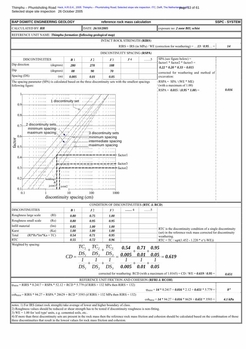
Thimphu – Phuntsholing Road page 53 of 61 Selected slope site inspection 26 October 2005 BAP DGM/ITC ENGINEERING GEOLOGY reference rock mass calculation SSPC - SYSTEM
CALCULATED BY: RH DATE: 26/10/2005 exposure no: 2 zone BII; schist
REFERENCE UNIT NAME: Thimphu formation (following geological map)
INTACT ROCK STRENGTH (RIRS)
RIRS = IRS (in MPa) / WE (correction for weathering) = …13 / 0.95… = 14
DISCONTINUITY SPACING (RSPA)
DISCONTINUITIES B 1 J 2 J 3 J 4 ……5 Dip direction (degrees) 280 270 188
Dip (degrees) 08 90 70
Spacing (DS) (m) 0.005 0.01 0.05
The spacing parameter (SPA) is calculated based on the three discontinuity sets with the smallest spacings following figure:
SPA (see figure below) = factor1 * factor2 * factor3 = 0.22 * 0.20 * 0.33 = 0.015 corrected for weathering and method of excavation: RSPA = SPA / (WE * ME) (with a maximum of 1.00) RSPA = 0.015 / (0.95 * 1.00) = 0.016
0.1 1 10 100 10000.1
0.2
0.3
0.4
0.5
0.6
0.7
0.8
0.9
1
discontinuity spacing (cm)
fact
or
1 discontinuity set
2 discontinuity setsminimum spacingmaximum spacing
factor1
factor3
joint2
factor2
3 discontinuity sets minimum spacing intermediate spacingmaximum spacing
bedding1&
joint3
CONDITION OF DISCONTINUITIES (RTC & RCD) DISCONTINUITIES B 1 J 2 J 3 …… 4 ……5 Roughness large scale (Rl) 0.80 0.75 1.00 Roughness small scale (Rs) 0.80 0.95 0.95 Infill material (Im) 0.85 1.00 1.00 Karst (Ka) 1.00 1.00 1.00 Total (Rl*Rs*Im*Ka = TC) 0.54 0.71 0.95 RTC 0.55 0.72 0.96
RTC is the discontinuity condition of a single discontinuity (set) in the reference rock mass corrected for discontinuity weathering. RTC = TC / sqrt(1.452 - 1.220 * e^(-WE))
Weighted by spacing:
0.619
0.050.010.005
0.050.95
0.010.71
0.0050.54
=++
++=
++
++= 111
DS1
DS1
DS1
DSTC
DSTC
DSTC
CD
321
3
3
2
2
1
1
corrected for weathering: RCD (with a maximum of 1.0165) = CD / WE = 0.619 / 0.95 = 0.651
REFERENCE UNIT FRICTION AND COHESION (RFRI & RCOH) ϕBRRMB = RIRS * 0.2417 + RSPA * 52.12 + RCD * 5.779 (if RIRS > 132 MPa then RIRS = 132)
ϕBRRMB = 14 * 0.2417 + 0.016 * 2.12 + 0.651 * 5.779 = 8° cohBRRMB = RIRS * 94.27 + RSPA * 28629 + RCD * 3593 (if RIRS > 132 MPa then RIRS = 132)
cohBRRMB = 14 * 94.27 + 0.016 * 8629 + 0.651 * 3593 = 4.1 kPa
notes: 1) For IRS (intact rock strength) take average of lower and higher boundary of class. 2) Roughness values should be reduced or shear strength has to be tested if discontinuity roughness is non-fitting. 3) WE = 1.00 for 'soil type' units, e.g. cemented soils, etc.. 4) If more than three discontinuity sets are present in the rock mass then the reference rock mass friction and cohesion should be calculated based on the combination of those three discontinuities that result in the lowest values for rock mass friction and cohesion.
Hack, H.R.G.K., 2005. Thimphu – Phuntsholing Road; Selected slope site inspection. ITC, Delft, The Netherlands. p. 61

Thimphu – Phuntsholing Road page 54 of 61 Selected slope site inspection 26 October 2005 BAP DGM/ITC ENGINEERING GEOLOGY slope stability probability SSPC - SYSTEM
LOGGED BY: RH DATE: 26/10/2005 slope no: 2 zone BII; schist
LOCATION map no: Existing slope (see report) northing:
Map coordinates: easting:
DETAILS OF (NEW) SLOPE METHOD OF EXCAVATION (SME) (EXPECTED DEGREE OF) WEATHERING (SWE)
Slope dip direction (degrees): 196
Slope dip (degrees): 75
(tick) unweathered slightly moderately highly completely
1.00V 0.95
0.900.620.35 Height (Hslope) (m) 21
:
(tick) natural/hand-made pneumatic hammer excavation pre-splitting/smooth wall blasting conventional blasting with result:
good open discontinuities
dislodged blocks fractured intact rock crushed intact rock
V 1.00
0.76 0.99
0.77 0.75 0.72 0.67 0.62
note: SWE = 1.00 for 'soil type' units, e.g. cemented soil, etc.
SLOPE UNIT NAME: Thimphu formation (following geological map)
ORIENTATION INDEPENDENT STABILITY INTACT ROCK STRENGTH (SIRS)
SIRS = RIRS (from reference rock mass) * SWE (weathering slope) = 14 * 0.95 = 13 DISCONTINUITY SPACING (SSPA)
SSPA = RSPA (from reference rock mass) * SWE (weathering slope) * SME (method of excavation slope) SSPA = 0.016 * 0.95 * 1.00 = 0.015
CONDITION OF DISCONTINUITIES (SCD)
SCD = RCD (from reference rock mass) * SWE (weathering slope)
SCD = 0.651 * 0.95 = 0.619 SLOPE UNIT FRICTION AND COHESION (SFRI & SCOH)
ϕBSRMB = SIRS * 0.2417 + SSPA * 52.12 + SCD * 5.779 (if SIRS > 132 MPa then SIRS = 132) ϕBSRMB = 13 * 0.2417 + 0.015 * 52.12 + 0.619 * 5.779 = 7°
cohBSRMB = SIRS * 94.27 + SSPA * 28629 + SCD * 3593 (if SIRS > 132 MPa then SIRS = 132) cohBSRMB = 13 * 94.27 + 0.015 * 28629 + 0.619 * 3593 = 3.9 kPa
If SFRI < slope dip: MAXIMUM SLOPE HEIGHT (Hmax) Maximum possible height: Hmax = 1.6 * 10P
-4P * cohBSRMB * sin (slope dip) * cos (ϕBSRMB) / (1-cos (slope dip - ϕBSRMB))
Hmax = 1.6 * 10P
-4P * 3900 * sin (75°) * cos (7°) / (1 – cos (75° - 7°)) = 1 m
ϕBSRMB / slope dip = 7 ° / 75 ° = 0.093 ratios:
Hmax / Hslope = 1 m / 21 m = 0.05
Probability stable: if SFRI > slope dip probability = 100 % else use figure for orientation independent stability: 3 %
ORIENTATION DEPENDENT STABILITY DISCONTINUITIES B 1 J 2 J 3 …… 4 …….. 5
Dip direction (degrees) 280 270 160
Dip (degrees) 08 90 70
With, Against, Vertical or Equal w v e
AP (degrees) 01 90 78 RTC (from reference form) 0.55 0.72 0.96 STC = RTC * sqrt (1.452 - 1.220 * e^(-SWE)) 0.54 0.71 0.95 Probability stable: 97 % 100 % 100 % % %
SSPC Sliding angle (STC/0.0113) = 48° 63° 84° ° °
Determination orientation stability: calculation AP: β = discontinuity dip, σ = slope dip-direction, τ = discontinuity dip-direction: δ = σ - τ: AP = arctan (cos δ * tan β)
stability: sliding toppling stability: sliding toppling AP > 84° or AP < -84° vertical 100 % 100 % AP < 0° and (-90° - AP + slope dip) < 0° against 100 % 100 %
(slope dip+5°) < AP < 84° with 100 % 100 % AP < 0° and (-90° - AP + slope dip) > 0° against 100 % use graph toppling (slope dip-5°) < AP <
(slope dip+5°) equal 100 % 100 %
0° < AP < (slope dip-5°) with use graph sliding 100 %
Hack, H.R.G.K., 2005. Thimphu – Phuntsholing Road; Selected slope site inspection. ITC, Delft, The Netherlands. p. 61
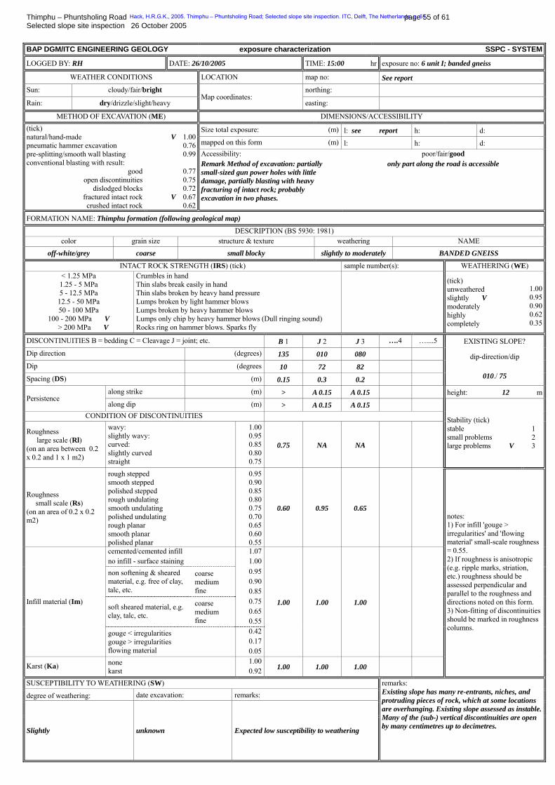
Thimphu – Phuntsholing Road page 55 of 61 Selected slope site inspection 26 October 2005 BAP DGM/ITC ENGINEERING GEOLOGY exposure characterization SSPC - SYSTEM
LOGGED BY: RH DATE: 26/10/2005 TIME: 15:00 hr exposure no: 6 unit I; banded gneiss
WEATHER CONDITIONS LOCATION map no: See report Sun: cloudy/fair/bright northing:
Rain: dry/drizzle/slight/heavy Map coordinates:
easting:
METHOD OF EXCAVATION (ME) DIMENSIONS/ACCESSIBILITY
Size total exposure: (m) l: see report h: d: mapped on this form (m) l: h: d:
(tick) natural/hand-made pneumatic hammer excavation pre-splitting/smooth wall blasting conventional blasting with result:
good open discontinuities
dislodged blocks fractured intact rock crushed intact rock
V 1.00
0.76 0.99
0.77 0.75 0.72
V 0.67 0.62
Accessibility: Remark Method of excavation: partially small-sized gun power holes with little damage, partially blasting with heavy fracturing of intact rock; probably excavation in two phases.
poor/fair/good only part along the road is accessible
FORMATION NAME: Thimphu formation (following geological map)
DESCRIPTION (BS 5930: 1981) color grain size structure & texture weathering NAME
off-white/grey coarse small blocky slightly to moderately BANDED GNEISS
INTACT ROCK STRENGTH (IRS) (tick) sample number(s): WEATHERING (WE) < 1.25 MPa 1.25 - 5 MPa 5 - 12.5 MPa 12.5 - 50 MPa 50 - 100 MPa
100 - 200 MPa V > 200 MPa V
Crumbles in hand Thin slabs break easily in hand Thin slabs broken by heavy hand pressure Lumps broken by light hammer blows Lumps broken by heavy hammer blows Lumps only chip by heavy hammer blows (Dull ringing sound) Rocks ring on hammer blows. Sparks fly
(tick) unweathered slightly V moderately highly completely
1.000.950.900.620.35
DISCONTINUITIES B = bedding C = Cleavage J = joint; etc. B 1 J 2 J 3 ….4 …....5 EXISTING SLOPE? Dip direction (degrees) 135 010 080
Dip (degrees 10 72 82
Spacing (DS) (m) 0.15 0.3 0.2
dip-direction/dip
010./ 75
along strike (m) > A 0.15 A 0.15 height: 12 mPersistence
along dip (m) > A 0.15 A 0.15 CONDITION OF DISCONTINUITIES
Roughness large scale (Rl) (on an area between 0.2 x 0.2 and 1 x 1 m2)
wavy: slightly wavy: curved: slightly curved straight
1.000.950.850.800.75
0.75 NA NA
Stability (tick) stable small problems large problems V
1 2 3
Roughness small scale (Rs) (on an area of 0.2 x 0.2 m2)
rough stepped smooth stepped polished stepped rough undulating smooth undulating polished undulating rough planar smooth planar polished planar
0.950.900.850.800.750.700.650.600.55
0.60 0.95 0.65
cemented/cemented infill no infill - surface staining
1.071.00
non softening & sheared material, e.g. free of clay, talc, etc.
coarse medium fine
0.950.900.85
soft sheared material, e.g. clay, talc, etc.
coarse medium fine
0.750.650.55
Infill material (Im)
gouge < irregularities gouge > irregularities flowing material
0.420.170.05
1.00 1.00 1.00
Karst (Ka) none karst
1.000.92 1.00 1.00 1.00
notes: 1) For infill 'gouge > irregularities' and 'flowing material' small-scale roughness = 0.55. 2) If roughness is anisotropic (e.g. ripple marks, striation, etc.) roughness should be assessed perpendicular and parallel to the roughness and directions noted on this form. 3) Non-fitting of discontinuities should be marked in roughness columns.
SUSCEPTIBILITY TO WEATHERING (SW)
degree of weathering: date excavation: remarks:
Slightly unknown Expected low susceptibility to weathering
remarks: Existing slope has many re-entrants, niches, and protruding pieces of rock, which at some locations are overhanging. Existing slope assessed as instable.Many of the (sub-) vertical discontinuities are open by many centimetres up to decimetres.
Hack, H.R.G.K., 2005. Thimphu – Phuntsholing Road; Selected slope site inspection. ITC, Delft, The Netherlands. p. 61

Thimphu – Phuntsholing Road page 56 of 61 Selected slope site inspection 26 October 2005 BAP DGM/ITC ENGINEERING GEOLOGY reference rock mass calculation SSPC - SYSTEM
CALCULATED BY: RH DATE: 26/10/2005 exposure no: 6 unit I; banded gneiss
REFERENCE UNIT NAME: Thimphu formation (following geological map)
INTACT ROCK STRENGTH (RIRS)
RIRS = IRS (in MPa) / WE (correction for weathering) = …200 / 0.95… = 211
DISCONTINUITY SPACING (RSPA)
DISCONTINUITIES B 1 J 2 J 3 J 4 ……5 Dip direction (degrees) 135 010 080
Dip (degrees) 10 72 82
Spacing (DS) (m) 0.15 0.3 0.2
The spacing parameter (SPA) is calculated based on the three discontinuity sets with the smallest spacings following figure:
SPA (see figure below) = factor1 * factor2 * factor3 = 0.61 * 0.60 * 0.59 = 0.21 corrected for weathering and method of excavation: RSPA = SPA / (WE * ME) (with a maximum of 1.00) RSPA = 0.21 / (0.95 * 1.00) = 0.22
0.1 1 10 100 10000.1
0.2
0.3
0.4
0.5
0.6
0.7
0.8
0.9
1
discontinuity spacing (cm)
fact
or
1 discontinuity set
2 discontinuity setsminimum spacingmaximum spacing
factor1
factor3
joint2
factor2
3 discontinuity sets minimum spacing intermediate spacingmaximum spacing
bedding1&
joint3
CONDITION OF DISCONTINUITIES (RTC & RCD) DISCONTINUITIES B 1 J 2 J 3 …… 4 ……5 Roughness large scale (Rl) 0.75 1.00 1.00 Roughness small scale (Rs) 0.60 0.95 0.95 Infill material (Im) 1.00 1.00 1.00 Karst (Ka) 1.00 1.00 1.00 Total (Rl*Rs*Im*Ka = TC) 0.38 0.95 0.95 RTC 0.39 0.96 0.96
Remark: Disc. 2 & 3 are abutting therefore discontinuities changed to maximum roughness profiles. RTC is the discontinuity condition of a single discontinuity (set) in the reference rock mass corrected for discontinuity weathering. RTC = TC / sqrt(1.452 - 1.220 * e^(-WE))
Weighted by spacing:
0.697
0.20.30.15
0.20.95
0.30.95
0.150.38
=++
++=
++
++= 111
DS1
DS1
DS1
DSTC
DSTC
DSTC
CD
321
3
3
2
2
1
1
corrected for weathering: RCD (with a maximum of 1.0165) = CD / WE = 0.697 / 0.95 = 0.733
1
REFERENCE UNIT FRICTION AND COHESION (RFRI & RCOH) ϕBRRMB = RIRS * 0.2417 + RSPA * 52.12 + RCD * 5.779 (if RIRS > 132 MPa then RIRS = 132)
ϕBRRMB = 132 * 0.2417 + 0.22 * 2.12 + 0.733 * 5.779 = 49° cohBRRMB = RIRS * 94.27 + RSPA * 28629 + RCD * 3593 (if RIRS > 132 MPa then RIRS = 132)
cohBRRMB = 132 * 94.27 + 0.22 * 8629 + 0.733 * 3593 = 22.01 kPa
notes: 1) For IRS (intact rock strength) take average of lower and higher boundary of class. 2) Roughness values should be reduced or shear strength has to be tested if discontinuity roughness is non-fitting. 3) WE = 1.00 for 'soil type' units, e.g. cemented soils, etc.. 4) If more than three discontinuity sets are present in the rock mass then the reference rock mass friction and cohesion should be calculated based on the combination of those three discontinuities that result in the lowest values for rock mass friction and cohesion.
Hack, H.R.G.K., 2005. Thimphu – Phuntsholing Road; Selected slope site inspection. ITC, Delft, The Netherlands. p. 61
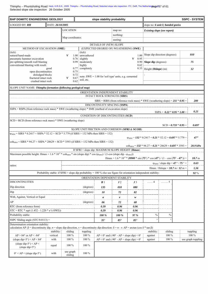
Thimphu – Phuntsholing Road page 57 of 61 Selected slope site inspection 26 October 2005 BAP DGM/ITC ENGINEERING GEOLOGY slope stability probability SSPC - SYSTEM
LOGGED BY: RH DATE: 26/10/2005 slope no: 6 unit I; banded gneiss
LOCATION map no: Existing slope (see report) northing:
Map coordinates: easting:
DETAILS OF (NEW) SLOPE METHOD OF EXCAVATION (SME) (EXPECTED DEGREE OF) WEATHERING (SWE)
Slope dip direction (degrees): 010
Slope dip (degrees): 75
(tick) unweathered slightly moderately highly completely
1.00V 0.95
0.900.620.35 Height (Hslope) (m) 12
:
(tick) natural/hand-made pneumatic hammer excavation pre-splitting/smooth wall blasting conventional blasting with result:
good open discontinuities
dislodged blocks fractured intact rock crushed intact rock
V 1.00
0.76 0.99
0.77 0.75 0.72
V 0.67 0.62
note: SWE = 1.00 for 'soil type' units, e.g. cemented soil, etc.
SLOPE UNIT NAME: Thimphu formation (following geological map)
ORIENTATION INDEPENDENT STABILITY INTACT ROCK STRENGTH (SIRS)
SIRS = RIRS (from reference rock mass) * SWE (weathering slope) = 211 * 0.95 = 200 DISCONTINUITY SPACING (SSPA)
SSPA = RSPA (from reference rock mass) * SWE (weathering slope) * SME (method of excavation slope) SSPA = 0.22 * 0.95 * 1.00 = 0.21
CONDITION OF DISCONTINUITIES (SCD)
SCD = RCD (from reference rock mass) * SWE (weathering slope)
SCD = 0.733 * 0.95 = 0.697 SLOPE UNIT FRICTION AND COHESION (SFRI & SCOH)
ϕBSRMB = SIRS * 0.2417 + SSPA * 52.12 + SCD * 5.779 (if SIRS > 132 MPa then SIRS = 132) ϕBSRMB = 132 * 0.2417 + 0.21 * 52.12 + 0.697 * 5.779 = 47°
cohBSRMB = SIRS * 94.27 + SSPA * 28629 + SCD * 3593 (if SIRS > 132 MPa then SIRS = 132) cohBSRMB = 132 * 94.27 + 0.21 * 28629 + 0.697 * 3593 = 20.9 kPa
If SFRI < slope dip: MAXIMUM SLOPE HEIGHT (Hmax) Maximum possible height: Hmax = 1.6 * 10P
-4P * cohBSRMB * sin (slope dip) * cos (ϕBSRMB) / (1-cos (slope dip - ϕBSRMB))
Hmax = 1.6 * 10P
-4P * 20900 * sin (75°) * cos (47°) / (1 – cos (75° - 47°)) = 18.7 m
ϕBSRMB / slope dip = 47 ° / 75 ° = 0.63 ratios:
Hmax / Hslope = 18.7 m / 12 m = 1,56
Probability stable: if SFRI > slope dip probability = 100 % else use figure for orientation independent stability: 92 %
ORIENTATION DEPENDENT STABILITY DISCONTINUITIES B 1 J 2 J 3 …… 4 …….. 5
Dip direction (degrees) 135 010 080
Dip (degrees) 10 72 82
With, Against, Vertical or Equal a e w
AP (degrees) 06 72 68 RTC (from reference form) 0.39 0.96 0.96 STC = RTC * sqrt (1.452 - 1.220 * e^(-SWE)) 0.39 0.96 0.96 Probability stable: 100 % 100 % 97 % % %
SSPC Sliding angle (STC/0.0113) = 35° 85° 85° ° °
Determination orientation stability: calculation AP: β = discontinuity dip, σ = slope dip-direction, τ = discontinuity dip-direction: δ = σ - τ: AP = arctan (cos δ * tan β)
stability: sliding toppling stability: sliding toppling AP > 84° or AP < -84° vertical 100 % 100 % AP < 0° and (-90° - AP + slope dip) < 0° against 100 % 100 %
(slope dip+5°) < AP < 84° with 100 % 100 % AP < 0° and (-90° - AP + slope dip) > 0° against 100 % use graph toppling (slope dip-5°) < AP <
(slope dip+5°) equal 100 % 100 %
0° < AP < (slope dip-5°) with use graph sliding 100 %
Hack, H.R.G.K., 2005. Thimphu – Phuntsholing Road; Selected slope site inspection. ITC, Delft, The Netherlands. p. 61
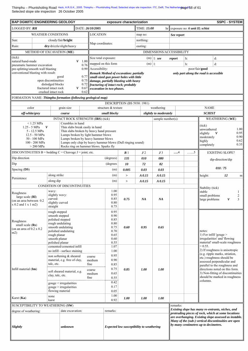
Thimphu – Phuntsholing Road page 58 of 61 Selected slope site inspection 26 October 2005 BAP DGM/ITC ENGINEERING GEOLOGY exposure characterization SSPC - SYSTEM
LOGGED BY: RH DATE: 26/10/2005 TIME: 15:00 hr exposure no: 6 unit II; schist
WEATHER CONDITIONS LOCATION map no: See report Sun: cloudy/fair/bright northing:
Rain: dry/drizzle/slight/heavy Map coordinates:
easting:
METHOD OF EXCAVATION (ME) DIMENSIONS/ACCESSIBILITY
Size total exposure: (m) l: see report h: d: mapped on this form (m) l: h: d:
(tick) natural/hand-made pneumatic hammer excavation pre-splitting/smooth wall blasting conventional blasting with result:
good open discontinuities
dislodged blocks fractured intact rock crushed intact rock
V 1.00
0.76 0.99
0.77 0.75 0.72
V 0.67 0.62
Accessibility: Remark Method of excavation: partially small-sized gun power holes with little damage, partially blasting with heavy fracturing of intact rock; probably excavation in two phases.
poor/fair/good only part along the road is accessible
FORMATION NAME: Thimphu formation (following geological map)
DESCRIPTION (BS 5930: 1981) color grain size structure & texture weathering NAME
off-white/grey coarse small blocky slightly to moderately SCHIST
INTACT ROCK STRENGTH (IRS) (tick) sample number(s): WEATHERING (WE) < 1.25 MPa
1.25 - 5 MPa V 5 - 12.5 MPa 12.5 - 50 MPa 50 - 100 MPa 100 - 200 MPa > 200 MPa
Crumbles in hand Thin slabs break easily in hand Thin slabs broken by heavy hand pressure Lumps broken by light hammer blows Lumps broken by heavy hammer blows Lumps only chip by heavy hammer blows (Dull ringing sound) Rocks ring on hammer blows. Sparks fly
(tick) unweathered slightly V moderately highly completely
1.000.950.900.620.35
DISCONTINUITIES B = bedding C = Cleavage J = joint; etc. B 1 J 2 J 3 ….4 …....5 EXISTING SLOPE? Dip direction (degrees) 135 010 080
Dip (degrees 10 72 82
Spacing (DS) (m) 0.005 0.03 0.03
dip-direction/dip
010./ 75
along strike (m) > A 0.15 A 0.15 height: 12 mPersistence
along dip (m) > A 0.15 A 0.15 CONDITION OF DISCONTINUITIES
Roughness large scale (Rl) (on an area between 0.2 x 0.2 and 1 x 1 m2)
wavy: slightly wavy: curved: slightly curved straight
1.000.950.850.800.75
0.75 NA NA
Stability (tick) stable small problems large problems V
1 2 3
Roughness small scale (Rs) (on an area of 0.2 x 0.2 m2)
rough stepped smooth stepped polished stepped rough undulating smooth undulating polished undulating rough planar smooth planar polished planar
0.950.900.850.800.750.700.650.600.55
0.60 0.95 0.65
cemented/cemented infill no infill - surface staining
1.071.00
non softening & sheared material, e.g. free of clay, talc, etc.
coarse medium fine
0.950.900.85
soft sheared material, e.g. clay, talc, etc.
coarse medium fine
0.750.650.55
Infill material (Im)
gouge < irregularities gouge > irregularities flowing material
0.420.170.05
0.85 1.00 1.00
Karst (Ka) none karst
1.000.92 1.00 1.00 1.00
notes: 1) For infill 'gouge > irregularities' and 'flowing material' small-scale roughness = 0.55. 2) If roughness is anisotropic (e.g. ripple marks, striation, etc.) roughness should be assessed perpendicular and parallel to the roughness and directions noted on this form. 3) Non-fitting of discontinuities should be marked in roughness columns.
SUSCEPTIBILITY TO WEATHERING (SW)
degree of weathering: date excavation: remarks:
Slightly unknown Expected low susceptibility to weathering
remarks: Existing slope has many re-entrants, niches, and protruding pieces of rock, which at some locations are overhanging. Existing slope assessed as instable.Many of the (sub-) vertical discontinuities are open by many centimetres up to decimetres.
Hack, H.R.G.K., 2005. Thimphu – Phuntsholing Road; Selected slope site inspection. ITC, Delft, The Netherlands. p. 61
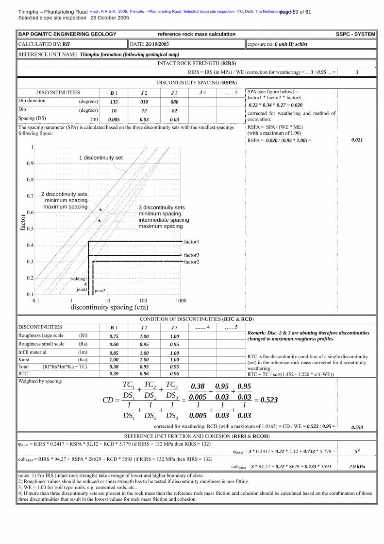
Thimphu – Phuntsholing Road page 59 of 61 Selected slope site inspection 26 October 2005 BAP DGM/ITC ENGINEERING GEOLOGY reference rock mass calculation SSPC - SYSTEM
CALCULATED BY: RH DATE: 26/10/2005 exposure no: 6 unit II; schist
REFERENCE UNIT NAME: Thimphu formation (following geological map)
INTACT ROCK STRENGTH (RIRS)
RIRS = IRS (in MPa) / WE (correction for weathering) = …3 / 0.95… = 3
DISCONTINUITY SPACING (RSPA)
DISCONTINUITIES B 1 J 2 J 3 J 4 ……5 Dip direction (degrees) 135 010 080
Dip (degrees) 10 72 82
Spacing (DS) (m) 0.005 0.03 0.03
The spacing parameter (SPA) is calculated based on the three discontinuity sets with the smallest spacings following figure:
SPA (see figure below) = factor1 * factor2 * factor3 = 0.22 * 0.34 * 0.27 = 0.020 corrected for weathering and method of excavation: RSPA = SPA / (WE * ME) (with a maximum of 1.00) RSPA = 0.020 / (0.95 * 1.00) = 0.021
0.1 1 10 100 10000.1
0.2
0.3
0.4
0.5
0.6
0.7
0.8
0.9
1
discontinuity spacing (cm)
fact
or
1 discontinuity set
2 discontinuity sets minimum spacing maximum spacing
factor1
factor3
joint2
factor2
3 discontinuity sets minimum spacing intermediate spacing maximum spacing
bedding1&
joint3
CONDITION OF DISCONTINUITIES (RTC & RCD) DISCONTINUITIES B 1 J 2 J 3 …… 4 ……5 Roughness large scale (Rl) 0.75 1.00 1.00 Roughness small scale (Rs) 0.60 0.95 0.95 Infill material (Im) 0.85 1.00 1.00 Karst (Ka) 1.00 1.00 1.00 Total (Rl*Rs*Im*Ka = TC) 0.38 0.95 0.95 RTC 0.39 0.96 0.96
Remark: Disc. 2 & 3 are abutting therefore discontinuities changed to maximum roughness profiles. RTC is the discontinuity condition of a single discontinuity (set) in the reference rock mass corrected for discontinuity weathering. RTC = TC / sqrt(1.452 - 1.220 * e^(-WE))
Weighted by spacing:
0.523
0.030.030.005
0.030.95
0.030.95
0.0050.38
=++
++=
++
++= 111
DS1
DS1
DS1
DSTC
DSTC
DSTC
CD
321
3
3
2
2
1
1
corrected for weathering: RCD (with a maximum of 1.0165) = CD / WE = 0.523 / 0.95 = 0.550
1
REFERENCE UNIT FRICTION AND COHESION (RFRI & RCOH) ϕBRRMB = RIRS * 0.2417 + RSPA * 52.12 + RCD * 5.779 (if RIRS > 132 MPa then RIRS = 132)
ϕBRRMB = 3 * 0.2417 + 0.22 * 2.12 + 0.733 * 5.779 = 5° cohBRRMB = RIRS * 94.27 + RSPA * 28629 + RCD * 3593 (if RIRS > 132 MPa then RIRS = 132)
cohBRRMB = 3 * 94.27 + 0.22 * 8629 + 0.733 * 3593 = 2.9 kPa
notes: 1) For IRS (intact rock strength) take average of lower and higher boundary of class. 2) Roughness values should be reduced or shear strength has to be tested if discontinuity roughness is non-fitting. 3) WE = 1.00 for 'soil type' units, e.g. cemented soils, etc.. 4) If more than three discontinuity sets are present in the rock mass then the reference rock mass friction and cohesion should be calculated based on the combination of those three discontinuities that result in the lowest values for rock mass friction and cohesion.
Hack, H.R.G.K., 2005. Thimphu – Phuntsholing Road; Selected slope site inspection. ITC, Delft, The Netherlands. p. 61

Thimphu – Phuntsholing Road page 60 of 61 Selected slope site inspection 26 October 2005 BAP DGM/ITC ENGINEERING GEOLOGY slope stability probability SSPC - SYSTEM
LOGGED BY: RH DATE: 26/10/2005 slope no: 6 unit II; schist
LOCATION map no: Existing slope (see report) northing:
Map coordinates: easting:
DETAILS OF (NEW) SLOPE METHOD OF EXCAVATION (SME) (EXPECTED DEGREE OF) WEATHERING (SWE)
Slope dip direction (degrees): 010
Slope dip (degrees): 75
(tick) unweathered slightly moderately highly completely
1.00V 0.95
0.900.620.35 Height (Hslope) (m) 12
:
(tick) natural/hand-made pneumatic hammer excavation pre-splitting/smooth wall blasting conventional blasting with result:
good open discontinuities
dislodged blocks fractured intact rock crushed intact rock
V 1.00
0.76 0.99
0.77 0.75 0.72
V 0.67 0.62
note: SWE = 1.00 for 'soil type' units, e.g. cemented soil, etc.
SLOPE UNIT NAME: Thimphu formation (following geological map)
ORIENTATION INDEPENDENT STABILITY INTACT ROCK STRENGTH (SIRS)
SIRS = RIRS (from reference rock mass) * SWE (weathering slope) = 3 * 0.95 = 3 DISCONTINUITY SPACING (SSPA)
SSPA = RSPA (from reference rock mass) * SWE (weathering slope) * SME (method of excavation slope) SSPA = 0.21 * 0.95 * 1.00 = 0.20
CONDITION OF DISCONTINUITIES (SCD)
SCD = RCD (from reference rock mass) * SWE (weathering slope)
SCD = 0.523 * 0.95 = 0.550 SLOPE UNIT FRICTION AND COHESION (SFRI & SCOH)
ϕBSRMB = SIRS * 0.2417 + SSPA * 52.12 + SCD * 5.779 (if SIRS > 132 MPa then SIRS = 132) ϕBSRMB = 132 * 0.2417 + 0.21 * 52.12 + 0.697 * 5.779 = 5°
cohBSRMB = SIRS * 94.27 + SSPA * 28629 + SCD * 3593 (if SIRS > 132 MPa then SIRS = 132) cohBSRMB = 132 * 94.27 + 0.21 * 28629 + 0.697 * 3593 = 2.7 kPa
If SFRI < slope dip: MAXIMUM SLOPE HEIGHT (Hmax) Maximum possible height: Hmax = 1.6 * 10P
-4P * cohBSRMB * sin (slope dip) * cos (ϕBSRMB) / (1-cos (slope dip - ϕBSRMB))
Hmax = 1.6 * 10P
-4P * 20900 * sin (75°) * cos (47°) / (1 – cos (75° - 47°)) = 0.6 m
ϕBSRMB / slope dip = 5 ° / 75 ° = 0.067 ratios:
Hmax / Hslope = 0.6 m / 12 m = 0.050
Probability stable: if SFRI > slope dip probability = 100 % else use figure for orientation independent stability: 3 %
ORIENTATION DEPENDENT STABILITY DISCONTINUITIES B 1 J 2 J 3 …… 4 …….. 5
Dip direction (degrees) 135 010 080
Dip (degrees) 10 72 82
With, Against, Vertical or Equal a e w
AP (degrees) 06 72 68 RTC (from reference form) 0.39 0.96 0.96 STC = RTC * sqrt (1.452 - 1.220 * e^(-SWE)) 0.38 0.95 0.95 Probability stable: 100 % 100 % 97 % % %
SSPC Sliding angle (STC/0.0113) = 34° 84° 84° ° °
Determination orientation stability: calculation AP: β = discontinuity dip, σ = slope dip-direction, τ = discontinuity dip-direction: δ = σ - τ: AP = arctan (cos δ * tan β)
stability: sliding toppling stability: sliding toppling AP > 84° or AP < -84° vertical 100 % 100 % AP < 0° and (-90° - AP + slope dip) < 0° against 100 % 100 %
(slope dip+5°) < AP < 84° with 100 % 100 % AP < 0° and (-90° - AP + slope dip) > 0° against 100 % use graph toppling (slope dip-5°) < AP <
(slope dip+5°) equal 100 % 100 %
0° < AP < (slope dip-5°) with use graph sliding 100 %
Hack, H.R.G.K., 2005. Thimphu – Phuntsholing Road; Selected slope site inspection. ITC, Delft, The Netherlands. p. 61
Thimphu – Phuntsholing Road page 61 of 61 Selected slope site inspection 26 October 2005
Appendix III – Activity log
25 October 2005 (for location of stops and exposures see fig. 2 and fig. 3, main report) 08:45 hrs Departure Thimphu 10:45 hrs, stop 1(approximately 50 m in South direction past the Damtak road sign of the highest point along the road) Photos and sketches of exposure 1 and 2 11:30 hrs stop 2 Full exposure characterization with photos and sketches of exposure 2 13:15 hrs stop 3 Photos and sketches of exposure 3 and 4 14:10 hrs stop 4 Photos and sketches of the exposure 5. 14:30 hrs Photos and sketches of the exposures between exposure 5 and the road sign “60RCC Damtak” and road marker “1” (just before the village and camp of Damtak) 14:45 – 15:15 hrs, stop 5 and 6, and various stops for photos along the south side of the river (opposite village and camp of Damtak) 15:30 hrs stop 7 Full exposure characterization of exposure 6 with photos and sketches (South side along Jangtulam Chhu river) 15:45 – 16:15, hrs, various stops for photos along the south side of the Jangtulam Chhu river. 16:30 hrs various stops for photos along the south side of the river (opposite village and camp of Damtak) 19:30 hrs, Arrival Thimphu
Hack, H.R.G.K., 2005. Thimphu – Phuntsholing Road; Selected slope site inspection. ITC, Delft, The Netherlands. p. 61