Natural Resources and the Demands of Equality - ePrints Soton
Upload
khangminh22Category
view
0download
0
The influence of sleeper material characteristics on railway track behaviour: concrete vs composite
sleeper
E. Ferroa*1, J. Harknessa and L. Le Pena
a Infrastructure Research Group, Faculty of Engineering and Physical Sciences, School of Engineering, University of Southampton, United Kingdom
* Corresponding author: [email protected] This article was accepted for publication in the journal of Transportation Geotechnics on 27 February 2020. This is the authors accepted version of the manuscript. Abstract Composite sleepers and bearers formed of polymers and sometimes steel or fibre reinforcement are an alternative to traditionally used timber or prestressed concrete counterparts. Composite materials offer the combined benefits of the compliant sleeper/ballast contact of timber with the longer service life of concrete. However, composite and timber sleepers have lower bending stiffness compared with concrete, and this affects their track performance. To better understand the influence of sleeper material on performance, a concrete and a composite sleeper were tested in the Southampton Railway Testing Facility. Test results were interpreted with the aid of finite difference and discrete element method numerical modelling. It was found that composite sleepers can provide a more compliant sleeper/ballast interface with increased numbers of ballast grain contacts of larger area that attenuate the peak contact forces. However, owing to their lower bending stiffness, they have more exaggerated deflection profiles and a tendency to become centre-bound compared with stiffer prestressed concrete counterparts. Keywords: composite sleeper; concrete sleeper; bending stiffness; DEM; elastic foundation. 1 Introduction
Rail transport faces growing demand for both passenger and freight journeys, owing at least in part to population growth and lifestyle changes, although there are a number of complex contributing factors to this. Rail is the safest, most energy efficient and, for freight, most environmentally friendly mode of transport [1]. As
1 Present address: Department of Civil Environmental and Mechanical Engineering, University of Trento, Italy

increasing demands are being placed on many existing railways, there is a need to improve performance, reliability and durability of the infrastructure so that existing capacity and performance can be improved with sustainable maintenance costs, minimal disruptions and adequate safety. This can be achieved partly through improvements in the specification and performance of the components forming the track superstructure.
Railway sleepers and bearers are key structural components of the railway track. They must be adequately strong, stiff and durable to maintain correct rail gauge, distribute the railseat forces over the ballast bed at an acceptable stress level and resist lateral movements via their interface with the ballast. It has been estimated that approximately 2 billion sleepers are present on world’s railway lines, with a demand of tens of millions of new sleepers per year [2].
Today, the most widely used sleeper materials are timber and steel prestressed concrete. Timber sleepers have been used extensively for over 150 years [3] but have been widely replaced with concrete sleepers in many parts of the world, especially in Europe and Asia, although they are still predominant in areas with abundant wood resources, e.g. the USA [4]. Concrete sleepers are generally used on higher specification new build lines and renewals; however, even in regions and routes where concrete sleepers are the main type, timber sleepers remain in widespread use [2,5]; for example on branch lines or sidings or locally at sensitive locations such as over older bridges or at switches and crossings (S&C) where impact loading could cause structural/trackbed damage.
Timber sleepers degrade with time due to biological and mechanical processes, especially fungal decay and end splitting. Hardwood timber sleepers have remained in track for prolonged periods in some locations while elsewhere they require quicker replacement. The service life for a timber sleeper is strongly dependent on local environmental conditions so that determining a universal design life is difficult. Using creosote preservative, the traditional design life for hardwood timber sleepers may be estimated at 30 years, while softwood timber sleepers have much shorter design life; prestressed concrete sleepers can be designed for a life cycle of 60 years [6]. In recent years creosoted sleepers have come to be classified as a hazardous waste, owing to the preservatives toxicity; for this reason the use of creosote has more recently been discouraged by regional and national authorities and might be banned in some places from 2020 [5,7]. To date, alternatives to creosote have not been identified/engineered to provide the same level of longevity for timber, leading to dramatic reductions in the estimated design life for timber sleepers. Anecdotally track engineers in the UK have advised that the design life of timber sleepers preserved with environmentally friendly products is less than 10 years. As a result, there is a strengthening economic case for using alternative materials that retain the performance characteristics of timber but have a greater design life.
Composite sleepers can be designed to mimic the geometrical and mechanical properties of timber sleepers but have a design life similar to that of steel prestressed concrete sleepers [6]. Therefore, although the initial cost for the highest specification versions of composite products can be higher, they may be conveniently used in place of timber sleepers in certain scenarios such as for the replacement of isolated

timber sleepers (spot replacement) [8] or for use at sensitive locations, e.g. old infrastructure and S&C [9–13]. Moreover, composite sleepers are potentially more environmentally sustainable than concrete, if formed of recycled (or recyclable) polymeric materials [11,14].
Composite sleepers can be classified by their properties and designated as type-1, type-2 and type-3 [11]. Type-1 sleepers are typically made of recycled plastic with no or short fibre reinforcement and have poor mechanical properties governed by their polymeric matrix, e.g. [15,16]. Type-2 sleepers are reinforced in the longitudinal direction only with long continuous reinforcement, e.g. glass fibres [17] or steel [18]; as a result, they offer significantly higher flexural strength and stiffness, while their shear and vertical compression behaviour remain governed by their polymeric matrix. Type-3 sleepers are also reinforced in the transversal direction, which provides them with greater resistance to shear and vertical compression, e.g. [19]. Type-1 composite sleepers have Young’s modulus of 1.5-1.8 GPa, type-2 and type-3 of 5-12 GPa [11]. Therefore, only composite sleepers with at least longitudinal reinforcement can mimic the mechanical behaviour of hardwood timber sleepers, which have Young’s modulus of typically 12 MPa but can range (depending on source wood) from 7 GPa to 27 GPa [20,21]. Prior studies have investigated the site performance of composite, timber and concrete sleepers [12,22,23]. These studies generally show that when installed along significant lengths of track, the tracks with timber and composite sleepers have very similar vertical stiffness, while those with concrete sleepers are stiffer. These different performances are related to the differing material properties.
Steel prestressed concrete sleepers are significantly stiffer than currently available composite sleepers. The differences in Young’s modulus and cross-sectional geometry lead to significantly differing flexural rigidities between timber, composite and prestressed concrete sleepers. The differing Young’s moduli and potential for plastic indentation also present different interfaces with ballast grains. To better understand the effects of differing material properties and geometries on performance between steel prestressed concrete and composite sleepers, cyclic laboratory tests were carried out. Numerical models based on the beam on elastic foundation (BOEF) theory and the discrete element method (DEM) aided the interpretation of the laboratory tests. A type-2 composite sleeper formed of rigid polyurethane foam reinforced with glass fibres and a steel prestressed concrete sleeper were used for testing. The composite sleeper was more flexible and provided a more compliant sleeper/ballast interface susceptible to plastic indentation compared with the prestressed concrete sleeper. Therefore, this study provides an insight into the effect of sleeper material properties on track short-term and long-term mechanical behaviour, and contributes to an improved understanding for the selection and development of innovative railway sleepers. 2 Laboratory tests 2.1 Materials and methods

The composite and prestressed concrete sleepers were tested in the Southampton Railway Testing Facility (SRTF). This is a laboratory representation of a single sleeper on a single-line track (Figure 1). Each test was prepared with a 12 mm rubber base layer placed onto a strong floor overlain by 300 mm of ballast and a sleeper within two stiff steel walls at a fixed distance of 0.65 m apart. The rubber mat provided resilient deflections typical of well performing subgrade [24–27].
In each test the ballast was placed manually in the rig, then carefully compacted and levelled using an electric compactor to achieve an initially uniform sleeper support. This is an idealised initial condition that may be representative of a sleeper at an early or midway stage through a maintenance cycle (i.e. between tamps). The sleeper was then placed and crib and shoulder ballast added. In each test, a sinusoidal vertical load was applied ranging between 5 kN and 98 kN using a hydraulic actuator at 3 Hz for 3 million cycles, approximately 2 years of service on a busy UK line [27]. The loading is representative of a 20-tonne train axle, assuming a 50% longitudinal load transfer to the adjacent sleepers. Further details of the testing apparatus and preparation methods can be found in [28,29].
Figure 1. Photo of the testing rig
The ballast used in these tests was a crushed, uniformly graded, angular granite sourced from Mountsorrel Quarry [30] and is representative of the material currently placed on UK tracks. Its key properties are: specific gravity 𝐺𝐺𝑠𝑠 of 2.66, average grain size 𝐷𝐷50 of 41 mm, coefficient of uniformity 𝐶𝐶𝑢𝑢 = 𝐷𝐷60/𝐷𝐷10 of 1.4.
Two sleepers were tested: a composite sleeper formed of longitudinal continuous glass fibres soaked in a polyurethane matrix [31] and a type G44 prestressed concrete sleeper [32] (Figure 2).
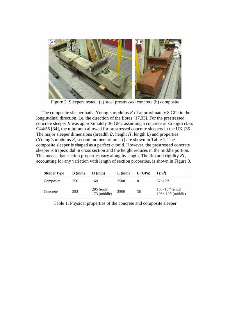
Figure 2. Sleepers tested: (a) steel prestressed concrete (b) composite
The composite sleeper had a Young’s modulus 𝐸𝐸 of approximately 8 GPa in the
longitudinal direction, i.e. the direction of the fibres [17,33]. For the prestressed concrete sleeper 𝐸𝐸 was approximately 36 GPa, assuming a concrete of strength class C44/55 [34], the minimum allowed for prestressed concrete sleepers in the UK [35]. The major sleeper dimensions (breadth 𝐵𝐵, height 𝐻𝐻, length 𝐿𝐿) and properties (Young’s modulus 𝐸𝐸, second moment of area 𝐼𝐼) are shown in Table 1. The composite sleeper is shaped as a perfect cuboid. However, the prestressed concrete sleeper is trapezoidal in cross section and the height reduces in the middle portion. This means that section properties vary along its length. The flexural rigidity 𝐸𝐸𝐼𝐼, accounting for any variation with length of section properties, is shown in Figure 3.
Sleeper type B (mm) H (mm) L (mm) E (GPa) I (m4)
Composite 256 160 2500 8 87×10-6
Concrete 282 205 (ends) 173 (middle) 2500 36 168×10-6 (ends)
105× 10-6 (middle)
Table 1. Physical properties of the concrete and composite sleeper

Figure 3. Flexural rigidity of the composite and concrete sleeper
Mechanical performance in the tests was assessed in terms of resilient deflection,
permanent settlement, sleeper/ballast contact, and ballast grain wear and breakage. The measurements, their type and ballast sample locations are schematically shown in Figure 4.
Figure 4. Schematic representation of measurements, their type and ballast sample
locations
Sleeper movements were measured using linear variable displacement transducers (LVDTs) installed at the sleeper ends, near the rail seats and in the middle. The resilient deflections were calculated as the difference between the maximum and minimum deflections in a load cycle. The sleeper permanent settlement was taken as the minimum deflection in a load cycle and was calculated using a weighted area method considering all LVDTs.
Pressure sensitive paper of dimensions 200 mm × 270 mm was attached to the sleeper base under both rails and under the middle of the sleeper to evaluate the number and area of sleeper/ballast contacts. The paper used in this study was sensitive to pressures greater than 10 MPa [36].
Ballast damage was assessed in terms of mass loss and number of broken grains. The former is representative of abrasive wear, the latter of corner breakage and grain splitting. To assess ballast damage, ~48 kg of ballast grains were marked and placed

in the top part of the ballast bed under the middle of the sleeper and under both rails not in direct contact with the sleeper soffit (Figure 5). The marked grains are representative of the top-half part of the ballast bed, they were placed beneath about 40% of the sleeper base area and reached a depth of almost 150 mm. Only the grains not passing the 31.5 mm sieve were considered to assess ballast damage. These were gently cleaned to remove dust before and after each test using a brush so that their weight could be measured accurately. The marked grains were divided into subgroups. The subgroups not containing broken grains were considered to calculate the mass loss due to wear and chipping. The number of broken grains (i.e. split or with broken corners) was counted.
Figure 5. Marked grains placed in the ballast bed before being covered
2.2 Test results 2.2.1 Sleeper resilient deflection
The distribution of the resilient deflections along the length of the sleepers at different key cycles (10, 100,000 and 3 million) is shown in Figure 6.
Initially (at 10 cycles) the sleepers showed similar resilient deflections at the middle and at the sleeper ends. However, the deflections near the rails were significantly greater for the composite sleeper, leading to a pronounced “w-shaped” distribution of deflection, which is not recognisable for the concrete sleeper.
In the longer term, both sleepers saw a slight reduction of the middle deflection, which might be explained by the ballast becoming stiffer as it densifies. In contrast, the movements of the sleeper ends increased with the load cycles and the sleepers became increasingly centre-bound. This was significantly more evident for the composite sleeper, which saw particularly large long-term deflections at the sleeper ends, indicative of the development of gapping (voiding) at the sleeper ends between the sleeper base and the ballast surface.

Figure 6. Lab tests, distribution of the resilient deflections along the sleepers at key
numbers of load cycles
The evolution of resilient deflections at different locations with the logarithm of the number of cycles is presented in Figure 7. The movements at the middle changed only slightly throughout the tests and their magnitude was not obviously strongly influenced by sleeper type. Those near the rails were significantly larger for the composite sleeper but remained stable in the first ~50,000 cycles, beyond this they increased moderately but steadily for the composite sleeper. At the sleeper ends, the sleepers showed similar resilient deflections in the first ~20,000 cycles, beyond which the movements of the ends of the composite sleeper increased dramatically.
A visual assessment of the support condition offered by the ballast to the sleeper with the aid of a level was carried out at the end of each test. To examine the ballast surface the crib and shoulder ballast were carefully manually removed and the sleeper hoisted out. The central 0.9 m of the ballast surface was flat and therefore had been in contact with the sleeper base throughout the load cycle at the test end. Further away from the sleeper centre the ballast surface was uneven and would not have been in direct contact with the sleeper base at the minimum load. This is explained by a combination of the greater pressure exerted on the ballast under the rails and the very light confinement offered by the shoulders, which led to greater ballast permanent strains under the rails and the formation of a gap under parts of the sleeper. The evolution of the height and extent of this gap with the loading cycles is responsible for the increasingly hogged (∩-shaped) loaded sleeper shape shown by the resilient LVDT measurements (Figure 6).

Figure 7. Lab tests, sleeper resilient deflections vs number of load cycles
2.2.2 Sleeper permanent settlement
Figure 8 shows the area weighted average sleeper settlement plotted against the
logarithm of the number of loading cycles. The settlement was re-zeroed after the first load cycle to eliminate bedding [29]. This is also believed to have removed most of the small additional permanent vertical movement of the composite sleeper caused by the penetration of the ballast grains into its relatively soft base.
Figure 8. Lab tests, sleeper settlement vs number of load cycles
In the first ~30 cycles the sleepers showed similar settlement rates. However, in
the longer term, especially beyond 200,000 cycles, the composite sleeper settled at a faster rate. At 3 million cycles its settlement was about 25% greater than that shown by the concrete sleeper.

2.2.3 Sleeper/ballast interface
At the end of the test the base of the composite sleeper was marked by small indentations caused by the contact with the ballast grains (Figure 9).
Figure 9. Base of composite sleeper after testing; (a) left rail (b) middle, (c) right rail
The pressure sensitive paper was recovered at the end of each test and is shown in Figure 10. The red patches identify locations where the pressure exceeded 10 MPa at any point during the test to create a record of the cumulative area of contact. Comparing the paper from each test the contacts were significantly larger for the composite sleeper, especially under the rails, owing to the indentation of its softer base.
Figure 10. Pressure sensitive paper after testing
The area percentage and number of contacts by location are reported in Table 2.
The composite sleeper average contact area was about 5 times greater, and the number of contacts increased by ~25% compared with the prestressed concrete sleeper. In all tests the contact area and number of contacts were relatively small and

greater under the rails than at the middle, in common with previous studies [36–38]. The greater cumulative contact area under the rails is attributed to a more extensive rearrangement of the ballast grains during the test. This effect was particularly pronounced for the composite sleeper: the ratio of the area of contact under the rails to the area of contact in the middle was almost 4 for the composite sleeper and only ~2 for the concrete sleeper. This can be explained by the significantly larger resilient movements exhibited by the composite sleeper near the rails. In contrast, the effect of the sleeper material on the distribution of the contact points over the sleeper base is less evident. For the concrete sleeper the contact points under the rails were about 1.7 times greater than those in the middle, for the composite about 1.4 times.
Concrete Composite
Area of contact (%)
Middle 0.34 0.95
Rail seats 0.75 3.68
Average 0.63 2.86
Number of contacts normalized per m2
Middle 241 333
Rail seats 407 481
Average 352 444
Table 2. Contact at the interface between the sleeper and the ballast 2.2.4 Ballast wear and breakage
In both tests, the percentage of grain mass loss was about 0.12% and only a few
grains (3 and 2 respectively for the prestressed concrete and composite sleepers) showed signs of breakage, i.e. corner breakage or splitting. These results are consistent with previous similar laboratory tests, which showed that UK granite ballast suffers only marginal breakage, at least under controlled loading conditions where the load is essentially pseudo static (i.e. the loading frequency and amplitude are not sufficient to cause significant accelerations) [27,29]. Although the use of a composite sleeper did not reduce ballast damage in the laboratory, it might be more effective on real tracks particularly at locations where impact loading is severe and ballast is subject to higher dynamic peak stresses, e.g. in proximity of trackbed faults, at S&C and transition zones.
3 Numerical modelling 3.1 Sleeper resilient response (BOEF)
3.1.1 Methods
To obtain a better understanding of the resilient behaviour of the sleepers, a
numerical tool based on the beam on elastic foundation (BOEF) was implemented in a finite difference scheme using Matlab [39,40]. Equation (1) shows the governing

differential equation solved by this finite difference tool, which may be determined from first principles by considering an elastic beam element of flexural stiffness 𝐸𝐸 ∙𝐼𝐼(𝑥𝑥) on a continuous support of modulus 𝑘𝑘(𝑥𝑥) and subjected to a load 𝑞𝑞(𝑥𝑥) at point 𝑥𝑥 along the length that causes the deflection y:
𝑑𝑑2
𝑑𝑑𝑥𝑥2�𝐸𝐸 ∙ 𝐼𝐼(𝑥𝑥)
𝑑𝑑2𝑦𝑦𝑑𝑑𝑥𝑥2
� + 𝑘𝑘(𝑥𝑥) ∙ 𝑦𝑦 = 𝑞𝑞(𝑥𝑥) (1)
This equation reduces to a form more commonly described as a beam on elastic foundation (BOEF) for a beam of constant flexural stiffness 𝐸𝐸𝐼𝐼 on a uniform support of modulus 𝑘𝑘, widely adopted in railway engineering (e.g. [41–43]):
𝐸𝐸𝐼𝐼 ∙
𝑑𝑑4𝑦𝑦𝑑𝑑𝑥𝑥4
+ 𝑘𝑘 ∙ 𝑦𝑦 = 𝑞𝑞(𝑥𝑥) (2)
In the more conventional form [equation (2)] a closed form solution can be found for the deflection 𝑦𝑦, bending moment and shear force. For example, a closed form solution for a uniformly supported sleeper of constant properties along its length and loaded at the rail positions by two concentrated forces is presented in [44]. However, a finite difference implementation can also be used to solve the more general form [Equation (1)], allowing the support modulus 𝑘𝑘 and the beam properties 𝐸𝐸 ∙ 𝐼𝐼(𝑥𝑥) to change over the finite difference steps (small steps of the coordinate 𝑥𝑥, the distance along the beam). Central, forwards and backwards derivatives may be applied to create a conventional stiffness matrix using appropriate boundary conditions, the known properties of the beam (𝐸𝐸, 𝐼𝐼) and loading (𝑞𝑞). The deflection (𝑦𝑦) values may then be found using a suitable solver to implement the Gaussian elimination such as the in-built solver offered by Matlab.
Figure 11. Sleeper on elastic foundation with voided ends subject to concentrated
forces at the railseats In this research the finite difference implementation was set up so that it would be
able to solve the problem shown in Figure 11, which requires a gap to be closed before the sleeper engages with the support at certain locations beneath the sleeper. As well as problems where the support is consistent. To adapt the implementation to cope with possible gapping, the load is applied in steps and the output of each step is interrogated to identify when the local beam deflection is sufficient for the support to be engaged; on the next step the support is then included and the load step outputs are summed to provide the final deflection and support pressure; finally, other variables, e.g. the bending moment and shear force, are calculated via Euler-Bernoulli’s beam theory.

In principle the finite difference implementation will give very similar results to a finite element model provided that the mesh size and finite difference steps are of a similar scale. However, the finite difference implementation offers greater ease for varying the parameters of the problem compared with commercial finite difference codes and for this reason it was preferred.
Using the numerical tool two cases were set up. The first was to investigate the response of the concrete and composite sleepers in the short term, when the support is expected to be relatively uniform. The second to investigate the long-term behaviour with gapping present under the sleeper ends. In both cases, the support modulus was selected to match the sleeper middle deflections: in the short term, a uniform support was assumed; in the long term the support was considered uniform beneath a central portion of 0.9 m, based on the visual assessment of the ballast after the tests. A triangular gapping profile was then implemented so that the gap increased linearly from the end of the central supported length to the sleeper ends on either side. The depth of the end gap was adjusted to obtain a sleeper deflection profile similar to that measured in the laboratory tests. Variation of these test parameters for a given sleeper identified that the length of the central area of support has only a small effect on the deflections, at least if between 0.5 m and 1.3 m; the magnitude of the support modulus mainly affects the central deflections; and the magnitude of the gap assigned at the sleeper ends mainly affects the sleeper curvature.
3.1.2 Short-term results and discussion
The beam support modulus of Equation (1), 𝑘𝑘(𝑥𝑥), used with the finite difference implementation of the BOEF is a one-dimensional property varying only with length coordinate and assigned units of force per unit length along the beam per unit deflection (e.g. MN/m/m). However, beams, sleepers in this case, have a breadth 𝐵𝐵 in contact with the soil (Table 1). Therefore a more appropriate way to assign the beam support modulus was considered to be as a foundation modulus 𝑘𝑘𝑠𝑠 having units of force per unit area per unit deflection (e.g. MN/m2/m). To use this approach the foundation modulus must be multiplied by the beam breadth 𝐵𝐵 to give the support modulus per unit length of sleeper (i.e. 𝑘𝑘 = 𝑘𝑘𝑠𝑠 ∙ 𝐵𝐵). This use of a foundation modulus allows for an increase in sleeper breadth to increase the contact area and hence the effective support stiffness.
Table 3 shows the foundation and beam modulus values found to most closely match the laboratory tests. It also shows the equivalent spring stiffness per railseat 𝐾𝐾𝑒𝑒𝑒𝑒, given in kN per mm (a common industry convention) i.e. the kN load per railseat required to deflect a rigid uniformly supported sleeper by 1 mm.
The numerical results for the short-term (10 loading cycles) are shown in Figure 12 and Figure 13 in terms of displacements and ballast pressure respectively.
To match the laboratory data a foundation modulus of 250 MN/m2/m was used for the prestressed concrete sleeper. When the same value was used for the composite sleeper, the distribution of the resilient deflections showed an exaggerated “w-shaped” deflection, similar to that observed in the laboratory but shifted upward by about 0.2 mm. This shift is not surprising, as in an elastic BOEF
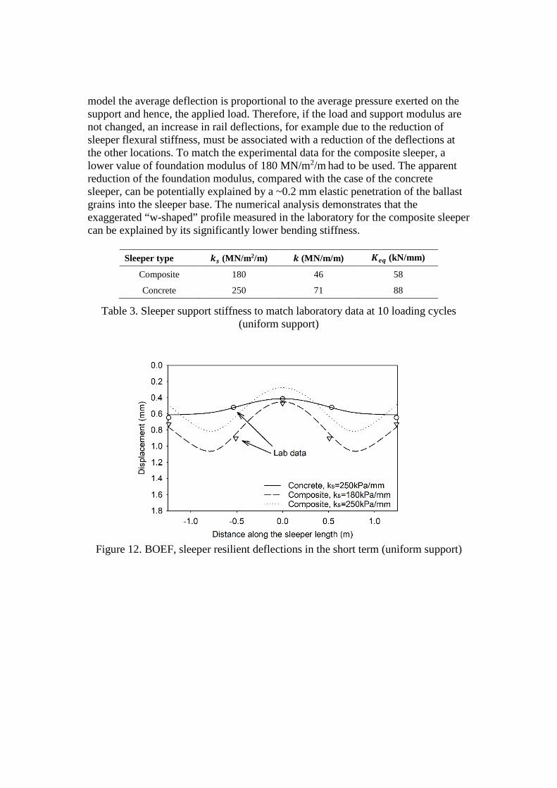
model the average deflection is proportional to the average pressure exerted on the support and hence, the applied load. Therefore, if the load and support modulus are not changed, an increase in rail deflections, for example due to the reduction of sleeper flexural stiffness, must be associated with a reduction of the deflections at the other locations. To match the experimental data for the composite sleeper, a lower value of foundation modulus of 180 MN/m2/m had to be used. The apparent reduction of the foundation modulus, compared with the case of the concrete sleeper, can be potentially explained by a ~0.2 mm elastic penetration of the ballast grains into the sleeper base. The numerical analysis demonstrates that the exaggerated “w-shaped” profile measured in the laboratory for the composite sleeper can be explained by its significantly lower bending stiffness.
Sleeper type 𝒌𝒌𝒔𝒔 (MN/m2/m) 𝒌𝒌 (MN/m/m) 𝑲𝑲𝒆𝒆𝒆𝒆 (kN/mm)
Composite 180 46 58
Concrete 250 71 88
Table 3. Sleeper support stiffness to match laboratory data at 10 loading cycles (uniform support)
Figure 12. BOEF, sleeper resilient deflections in the short term (uniform support)

Figure 13. BOEF, ballast pressures in the short-term (uniform support)
When the support is uniform, a relatively flexible composite sleeper exerts a less uniform distribution of pressure onto the ballast, with higher peaks under the rails (Figure 13). This might be responsible for the voiding of the sleeper ends and the development of significant sleeper centre-binding, as observed in the laboratory tests.
3.1.3 Long-term results and discussion
The numerical results for the long-term (3 million cycles) are shown in Figure 14.
To match the experimental data the values for the support parameters shown in Table 4 have been used.
Figure 14. Sleeper long-term flexural behaviour (voided sleeper ends)

Sleeper type 𝒌𝒌𝒔𝒔 (MN/m2/m) 𝒌𝒌 (MN/m/m) 𝑲𝑲𝒆𝒆𝒆𝒆 (kN/mm) End gap (mm)
Composite 205 52 66 1.3
Concrete 310 87 109 0.4
Table 4. Sleeper support stiffness to match laboratory data at 3 million loading cycles (voided sleeper ends)
Compared with the case of uniform support, the foundation modulus 𝑘𝑘𝑠𝑠 had to be
increased to match the experimental data beneath the central portion of the sleepers. This can be explained by the ballast densifying with the loading cycles. As with the short-term, a lower value of foundation modulus had to be used for the composite sleeper to translate the deformed shape downward by about 0.2 mm and match the experimental data. While in the short term the different distribution of the resilient deflections for the composite and concrete sleeper could be solely explained by their different flexural rigidity, in the long term the more pronounced hogging shape shown by the composite sleeper can only be explained by more substantial voiding beneath the sleeper ends. The magnitudes of the gaps assigned at the sleeper ends (0.4 mm and 1.3 mm) are similar to the difference between the deflection of the middle and the sleeper ends (Figure 6).
3.2 Sleeper settlement and sleeper/ballast contact (DEM)
3.2.1 Base model
The discrete element method (DEM) was used to give insights into the effect of
the differing propensities for grain indentation on sleeper/ballast behaviour of the two different sleeper materials. The primary variables inherent to the modelling approach are described here with fuller details of the underlying numerical tool used described in the references provided.
The code used for the numerical analyses was previously developed to investigate ballast mechanical behaviour [45–47] and further modified to include the effect of the indentation of the ballast grains into the base of a sleeper. For computational efficiency, the numerical model was designed to be a simplified representation of the central 0.65 m of the SRTF, consisting of a rigid sleeper section on a ballast bed in a box (Figure 17c). This simplified arrangement is not intended to (and would not) give the same outcomes as the laboratory testing in terms of measured settlement and does not consider the influence of the bending stiffness of the sleeper. However, the DEM simulations offer insights for the mechanical interaction between ballast grains and the sleeper base, and the load transfer down through the ballast medium. The settlement and resilient response results of the DEM simulations may also be compared between themselves, knowing that only grain indentation has been varied.
The ballast grains were modelled as polyhedral forms with slightly rounded corners, edges and faces. A total of 13 different shapes were created in a range of sizes to match the aspect ratio and size distribution of real ballast [46]. For inter-ballast and ballast to wall contacts, the simulations conducted in this work used a

Hertzian contact model for the normal stiffness [48], defined by a shear modulus 𝐺𝐺 and Poisson’s ratio 𝜈𝜈, and an elastic-perfectly plastic model for relative tangential movement, with an inter-particle friction angle 𝜙𝜙𝑢𝑢. The inter-particle contact properties were selected based on previous studies where the behaviour of ballast observed in monotonic and cyclic triaxial tests was simulated using the DEM [46,47]. A Hertzian contact law with a shear stiffness of 𝐺𝐺 = 10 GPa was used throughout with a friction angle of 𝜙𝜙𝑢𝑢 = 30° for the ballast, floor and side walls. Poisson’s ratio 𝜈𝜈 was set to 0.2. The grain density was 2650 kg/m3, representative of granite aggregate. The end walls were frictionless, approximating a plane-strain condition. 3.2.2 Indenter model
To simulate the effect of a more deformable sleeper/ballast interface, similar to a
composite or timber sleeper, an indenter model was implemented into the DEM toolset. This governs the contact behaviour between the ballast grains and the sleeper base normal to the contact plane.
The normal behaviour at the sleeper/ballast interface was based on a model presented in [49] for a conical indenter and is schematically represented in Figure 15, where: 𝐹𝐹 is the normal force, 𝑎𝑎 is the radius of the projected contact area 𝐴𝐴𝑐𝑐, 𝛼𝛼 is the angle between the contact plane and the indenter surface, ℎ𝑠𝑠 is the elastic deflection of the bowed surface, ℎ𝑐𝑐 is the indentation depth of the tip, ℎ𝑚𝑚𝑚𝑚𝑚𝑚 is the maximum indentation depth, ℎ0 is the indentation depth after load removal.
During first-time loading, the relationship between the normal force 𝐹𝐹 and the indentation depth ℎ is given by the following equation:
𝐹𝐹 =4𝜋𝜋𝐸𝐸𝑟𝑟2𝐻𝐻
(2𝐸𝐸𝑟𝑟𝑡𝑡𝑎𝑎𝑡𝑡𝛼𝛼 + 𝜋𝜋𝜋𝜋𝐻𝐻)2 ℎ2 (3)
where the hardness 𝐻𝐻 and the reduced Young’s modulus 𝐸𝐸𝑟𝑟 are calculated as
follows:
𝐻𝐻 =𝐹𝐹𝑚𝑚𝑚𝑚𝑚𝑚𝜋𝜋𝑎𝑎2
(4)
1
𝐸𝐸𝑟𝑟=
1 − 𝜈𝜈𝑖𝑖2
𝐸𝐸𝑖𝑖+
1 − 𝜈𝜈𝑠𝑠2
𝐸𝐸𝑠𝑠 (5)
The constant 𝜋𝜋 ≅ 0.725 for a conical indenter, 𝐸𝐸𝑖𝑖 and 𝜈𝜈𝑖𝑖 are the indenter Young’s
modulus and Poisson’s ratio, 𝐸𝐸𝑠𝑠 and 𝜈𝜈𝑠𝑠 are the surface Young’s modulus and Poisson’s ratio and 𝐹𝐹𝑚𝑚𝑚𝑚𝑚𝑚 is the historical maximum normal force applied. The normal force vs overlap relationship for unloading/reloading is the following:
𝐹𝐹 =
𝐹𝐹𝑚𝑚𝑚𝑚𝑚𝑚�ℎ𝑒𝑒,𝑚𝑚𝑚𝑚𝑚𝑚�
𝑚𝑚 (ℎ − ℎ0)𝑚𝑚 (6) where m = 2 for a conical indenter and the maximum elastic overlap ℎ𝑒𝑒,𝑚𝑚𝑚𝑚𝑚𝑚 is
given by:

ℎ𝑒𝑒,𝑚𝑚𝑚𝑚𝑚𝑚 =
𝑚𝑚�𝜋𝜋𝐻𝐻𝐹𝐹𝑚𝑚𝑚𝑚𝑚𝑚2𝐸𝐸𝑟𝑟
(7) The indentation depth after unloading ℎ0 is related to the maximum elastic
displacement ℎ𝑒𝑒,𝑚𝑚𝑚𝑚𝑚𝑚 and the maximum indentation depth ℎ𝑚𝑚𝑚𝑚𝑚𝑚 through the following equation: ℎ𝑒𝑒,𝑚𝑚𝑚𝑚𝑚𝑚 = ℎ𝑠𝑠 + (ℎ𝑐𝑐 − ℎ0) = ℎ𝑚𝑚𝑚𝑚𝑚𝑚 − ℎ0 (8)
An example of the model behaviour in loading/unloading is shown in Figure 16
for the parameters shown in Table 5 and used in the simulations.
Figure 15. Schematic representation of the indenter model adopted to reproduce the
contact between a ballast grain and the base of a deformable sleeper [49]
The tangential force between a ballast grain and the sleeper base, which arises from the resistance to lateral movement provided by friction and grain embedding, is determined on an incremental basis. At each simulation step, a potential shear force increment is calculated using the product of the shear stiffness and the relative lateral displacement. The magnitude of the total shear force is limited to the lower of the frictional limit (𝐹𝐹 ∙ 𝑡𝑡𝑎𝑎𝑡𝑡𝜙𝜙𝑢𝑢) where 𝜙𝜙𝑢𝑢 is the surface friction angle and 𝐹𝐹 the force normal to the sleeper base) and a lateral failure load, 𝐹𝐹𝑓𝑓𝑚𝑚𝑖𝑖𝑓𝑓, applicable if embedding has occurred and relative lateral movement would involve plastic failure. A simplistic approximation of this failure load was modelled as the product of the material hardness and the vertical cross-sectional area of the current indentation, as:
𝐹𝐹𝑓𝑓𝑚𝑚𝑖𝑖𝑓𝑓 = 𝐻𝐻ℎ2
𝑡𝑡𝑎𝑎𝑡𝑡𝛼𝛼 (9)

Parameter Value Source
𝐸𝐸𝑖𝑖 (GPa) 50 Granite (ballast)
𝐸𝐸𝑠𝑠 (GPa) 12 Relatively soft sleeper material
𝐻𝐻 (MPa) 50 Estimated from [50]
𝜈𝜈𝑖𝑖 and 𝜈𝜈𝑠𝑠 (-) 0.2 Typical value for granite, concrete, plastic
𝛼𝛼 (°) 30 Based on typical grain shape and angularity
Table 5. Mechanical properties for the indenter model
Figure 16. Indenter model, load vs indentation depth relationship for loading and
unloading/reloading 3.2.3 Model preparation
The specimen was prepared using a two-part procedure. Firstly, the ballast grains
to be placed under the sleeper base were generated, randomly distributed and then compacted. Secondly, the bearer and crib ballast were placed and compacted, and the cyclic loading defined. The main steps of specimen preparation are shown in Figure 17.
Figure 17. Discrete element model: (a) bearer and crib ballast added; (b)
assembly during compaction; (c) final setup

3.2.4 Results and discussion
Two simulations were carried out, with and without plastic indentation. The
model without indentation is here referred to as “elastic” and represents a sleeper whose base is not indented by the ballast grains, e.g. a concrete sleeper. In this case, the interaction between the sleeper and ballast grains was the same as the Hertzian inter-ballast contact law. The model accounting for the plastic indentation of the sleeper base is representative of a deformable sleeper material, e.g. composite or timber, is referred to as “plastic” and used the indenter model.
A vertical sinusoidal load was applied to the sleeper centroid. Its magnitude was adjusted to exert an average pressure on the ballast equivalent to that applied in the laboratory tests. Owing to the computational cost, only 850 load cycles were simulated.
The simulated displacements in the first load cycles for the “elastic” and “plastic” models are shown in Figure 18. In the first load cycle, which was not considered in the laboratory tests, the “plastic” model shows a greater settlement owing to the indentation of the sleeper base.
After the first cycle, both simulations showed very similar settlement rates, as shown in Figure 19. The DEM results showed no settlement improvement with the introduction of a softer sleeper/ballast interface. In contrast with the numerical simulations, the laboratory tests showed a greater propensity to settle for a sleeper made of a softer material. However, the simulations did not account for the effect of the lower bending stiffness, which, as already observed, can alter the distribution of the ballast pressures and exacerbate the voiding of the sleeper ends.
Figure 18. DEM simulations, sleeper displacement in the first load cycles

Figure 19. DEM simulations, sleeper settlement vs number of load cycles
At 850 load cycles, under maximum compressive load, 29% more contacts were
present with the plastic indentation model (587 contacts/m2) than with the elastic sleeper (455 contacts/m2). This compares closely with the results from the laboratory tests, which showed that the use of a composite sleeper increased the number of sleeper/ballast contacts, above the 10 MPa threshold of the paper used, by about 25% compared with a concrete sleeper (from 352 contacts/m2 to 444 contacts/m2).
A similar distribution of the sleeper/ballast contact forces was found for the “elastic” and “plastic” models, with almost 50% of the load being taken by a large number of small forces (Figure 20). However, while in the “elastic” model some contact forces exceeded 2.5 kN, the indentations limited the peak forces to 1.7 kN.
Images of the force chains beneath the sleeper (Figure 21) show a slightly less uniform distribution of the set of force chains for the “elastic” model, with a particularly high force chain on the right side of the sleeper base.
The DEM simulations show that the indentation of the sleeper base reduces peak sleeper/ballast contact force and produces a more uniform distribution of contact forces, which could potentially reduce ballast damage.

Figure 20. DEM simulations, percentage of total vertical load taken by the particles
grouped by vertical force at maximum load at 300 load cycles
Figure 21. DEM simulations, force chains at maximum load after 300 loading
cycles, (a) “elastic” model, (b) “plastic” model 4 Conclusions
This study compared the performance of a steel prestressed concrete sleeper and a softer glass fibre reinforced composite sleeper using laboratory tests and numerical modelling to provide insights into their relative performance.
Based on the analysis of the tests and numerical modelling the following observations can be made:
- In the initial cycles, when the sleepers are still well supported, the more flexible composite sleeper showed significantly greater deflections at the rail seats, leading to a pronounced “w-shape” that was barely noticeable for the concrete sleeper.

- The ballast beneath the sleeper centres became denser and stiffer with loading cycles, which is reflected in the reduction of the resilient movement at the middle of the sleepers.
- Beneath the sleeper ends (beyond the rails) gapping developed between the sleeper base and the ballast with loading cycles, leading to increasing resilient deflections of the sleeper ends; the sleepers showed similar end resilient deflections until 20,000 cycles, beyond which they increased dramatically for the composite sleeper, owing to the development of a greater sleeper end gap.
- The composite sleeper provided a softer sleeper/ballast interface slightly indented by the ballast grains; the indentation of the sleeper base increased the area and number of the sleeper/ballast contacts with the potential to reduce the peak sleeper/ballast contact forces; nevertheless, the actual grain damage was marginal and not measurably affected by the sleeper type.
- The composite sleeper exhibited greater settlement; this can be attributed to its significantly lower flexural stiffness, which produced an initially less uniform distribution of the ballast stress, leading to greater voiding under the sleeper ends.
5 Final remarks and recommendations This work provides supporting evidence for the use of composite sleepers as a means to reduce peak trackbed stresses. Reducing peak trackbed stresses has the potential to extend ballast/track lifecycle and increase the interval between maintenance interventions. Composite sleepers may perform similarly to hardwood timber sleepers but with the significant advantage of a much greater design life. The use of composite sleepers by preference could be appropriate at locations where there are high dynamic loads such as at S&C or transitions zones and over sensitive older structures. However, consideration should also be given to limiting centre binding. Installation and maintenance procedures may mitigate the development of centre binding, but these have not been considered in the present study. Further research could use the data from this paper to assist the development/calibration of advanced numerical models for sleeper-ballast interaction and hence, assist the design of innovative sleeper designs with optimised short-term and long-term performance. Researchers could take advantage of the freedoms offered by composite materials to engineer optimised material properties and sleeper shape. Acknowledgements
This study was jointly supported by Horizon 2020 European Union Funding for Research and Innovation (In2Rail H2020-MG-2014, 635900) and the Engineering and Physical Sciences Research Council (EPSRC) through the programme grant Track to the Future (EP/M025276/1). The authors would also like to thank Network Rail, SEKISUI and Dr Günther Koller for their support, and Dr Antonis Zervos for initially developing and kindly sharing the beam on elastic foundation finite

difference numerical tool used. The data presented in this paper will be freely available on the University of Southampton online repository. References [1] International Union of Railways (UIC). A global vision for railway
development. 2015. [2] Ferdous W, Manalo A. Failures of mainline railway sleepers and suggested
remedies – Review of current practice. Eng Fail Anal 2014;44:17–35. https://doi.org/10.1016/j.engfailanal.2014.04.020.
[3] Webster PD. The Wood Crosstie - A 150 Year Success History. First Edit. The Railway Tie Association; 1992.
[4] Sadeghi J, Barati P. Comparisons of the mechanical properties of timber, steel and concrete sleepers. Struct Infrastruct Eng 2012;8:1–9. https://doi.org/10.1080/15732479.2010.507706.
[5] International Union of Railways (UIC). Sustainable Wooden railway Sleepers. 2013.
[6] Manalo A, Aravinthan T, Karunasena W, Ticoalu A. A review of alternative materials for replacing existing timber sleepers. Compos Struct 2010;92:603–11. https://doi.org/10.1016/j.compstruct.2009.08.046.
[7] EU L 333/64. Commision implementing decision (EU) 2017/2334 of 14 December 2017, postponing the expiry date of approval of creosote for use in biocidal products of product-type 8. Official Journal of the European Union 2017:64–5.
[8] Manalo A, Aravinthan T, Karunasena W, Stevens N. Analysis of a typical railway turnout sleeper system using grillage beam analogy. Finite Elements in Analysis and Design 2012;48:1376–91. https://doi.org/10.1016/j.finel.2011.08.007.
[9] Lampo RG, Sullivan HW, Nosker TJ. Development, testing, and applications of recycled-plastic composite cross ties. WCRR, Edimburgh (UK): 2003, p. 940–7.
[10] Li D, Otter D, Carr G. Railway Bridge Approaches under Heavy Axle Load Traffic: Problems, Causes, and Remedies. Proc Inst Mech Eng Part F J Rail Rapid Transit 2010;224:383–90. https://doi.org/10.1243/09544097JRRT345.
[11] Ferdous W, Manalo A, Van Erp G, Aravinthan T, Kaewunruen S, Remennikov A. Composite railway sleepers – Recent developments, challenges and future prospects. Compos Struct 2015;134:158–68. https://doi.org/10.1016/j.compstruct.2015.08.058.
[12] Li D, Hyslip J, Sussmann T, Chrismer S. Railway Geotechnics. CRC Press; 2016.
[13] Railway Gazette. Synthetic wood sleepers installed. 2019. https://www.railwaygazette.com/news/infrastructure/single-view/view/synthetic-wood-sleepers-installed.html (accessed March 1, 2019).
[14] Van Erp G, McKay M. Recent Australian developments in fibre composite railway sleepers. Electron J Struct Eng 2013;13:62–6.
[15] Nosker TJ, Tewatia A. Development, testing and application of recycled

plastic composite sleepers. PWI Journal 2017;135 part 2:20–4. [16] TieTek. Increase Productive Track Time and Reduce Costs with TieTekTM
composite ties. 2019. http://www.tietek.net/product.asp (accessed March 1, 2019).
[17] Kaewunruen S, You R, Ishida M. Composites for Timber-Replacement Bearers in Railway Switches and Crossings. Infrastractures 2017;2(4), 13. https://doi.org/10.3390/infrastructures2040013.
[18] LankhorstRail. Recycled plastic railway sleepers. 2019. https://www.lankhorstrail.com/en/railway-sleeper (accessed March 1, 2019).
[19] Manalo A, Aravinthan T. Behavior of Full-Scale Railway Turnout Sleepers from Glue-Laminated Fiber Composite Sandwich Structures. J Compos Constr 2012;16:724–36. https://doi.org/10.1061/(ASCE)CC.1943-5614.
[20] Ticoalu A, Aravinthan T, Karunasena W. An investigation on the stiffness of timber sleepers for the design of fibre composite sleepers. 20th ACMSM 2008.
[21] BS EN 338:2016. Structural timber - Strength classes. British Standards 2016. [22] Jimenez R. Vertical Track Modulus in Plastic Composite Tie Test Zones at
FAST. Pueblo, CO (USA): 2003. [23] Li MXD, Berggren EG. A study of the effect of global track stiffness and its
variations on track performance: Simulation and measurement. 9th International Heavy Haul Conference: “Heavy Haul and Innovation Development” 2009:246–53.
[24] Bowness D, Lock AC, Powrie W, Priest JA, Richards DJ. Monitoring the dynamic displacements of railway track. Proc Inst Mech Eng Part F J Rail Rapid Transit 2007;221:13–22. https://doi.org/10.1243/0954409JRRT51.
[25] Le Pen L, Watson G, Powrie W, Yeo G, Weston P, Roberts C. The behaviour of railway level crossings: insights through field monitoring. Transportation Geotechnics 2014;1:201–13. https://doi.org/10.1016/j.trgeo.2014.05.002.
[26] Cross industry track stiffness working group (TSWG). A Guide to Track Stiffness. Edited by W. Powrie & L. Le Pen on Behalf of the TSWG. University of Southampton, UK: 2016.
[27] Abadi T, Le Pen L, Zervos A, Powrie W. Improving the performance of railway tracks through ballast interventions. Proc Inst Mech Eng Part F J Rail Rapid Transit 2016;0:1–19. https://doi.org/10.1177/0954409716671545.
[28] Abadi T. Effect of Sleeper and Ballast Interventions on Rail Track Performance. PhD thesis. University of Southampton, 2014.
[29] Ferro E. The Mechanical Behaviour of Fibre Reinforced Railway Ballast. PhD thesis. University of Southampton, UK, 2019.
[30] Tarmac Ltd. About Mount Sorrel Quarry. 2019. http://www.tarmac.com/mountsorrel-quarry/about (accessed March 1, 2019).
[31] SEKISUI Chemical GmbH. FFU synthetic wood railway sleepers. 2019. https://www.sekisui-rail.com/en/ffu_en.html (accessed March 1, 2019).
[32] NR/L2/TRK/030:4. Specifications: concrete sleepers and bearers. Network Rail 2016.
[33] Freudenstein S. Report no. 3017, 08.07.2013 - Investigations on FFU synthetic wood sleepers of 100 mm and 120 mm height. Technical University

of Munich, Department and Test Authority for Road, Railway and Airfield Construction: 2013.
[34] BS EN 1992-1-1:2004. Eurocode 2: Design of concrete structures - Part 1-1: General rules and rules for buildings. British Standards 2004.
[35] BS EN 206:2013. Concrete - Specification , performance , production and conformity. British Standards 2013.
[36] Abadi T, Le Pen L, Zervos A, Powrie W. Measuring the Area and Number of Ballast Particle Contacts at Sleeper-Ballast and Ballast-Subgrade Interfaces. IJRT 2015;4:45–72. https://doi.org/10.4203/ijrt.4.2.3.
[37] Gräbe PJ, Mtshotana BF, Sebati MM, Thünemann EQ. The effects of under-sleeper pads on sleeper-ballast interaction. J S Afr Inst Civ Eng 2016;58:35–41.
[38] Jayasuriya C, Indraratna B, Ngo TN. Experimental study to examine the role of under sleeper pads for improved performance of ballast under cyclic loading. Transportation Geotechnics 2019;19:61–73. https://doi.org/10.1016/j.trgeo.2019.01.005.
[39] Hetenyi M. Beams on Elastic Foundation: theory with applications in the fields of civil and mechanical engineering. University of Michigan Press: 1946.
[40] Le Pen L, Zervos A. Finite Difference Implementation of BOEF in Matlab applied to a railway sleeper. Internal Report 01/11/2018, University of Southampton, Department of Civil Engineering, UK: 2018.
[41] Timoshenko S. Methods of Analysis of Statistical and Dynamical Stresses in Rail. 2nd Int. Congr. Appl. Mech., Zurich, Switzerland: 1927, p. 407–20.
[42] Raymond GP. Analysis of Track Support and Determination of Track Modulus. Transportation Research Record 1985;1022:80–90.
[43] Esveld C. Modern Railway Track. MRT Productions; 2001. [44] Shokrieh M, Rahmat M. Effects of Young’s modulus on response of railway
sleeper. Appl Math Model 2007;31:700–11. https://doi.org/10.1016/j.apm.2005.12.004.
[45] Harkness J. Potential particles for the modelling of interlocking media in three dimensions. Int J Numer Meth Engng 2009;80:1573–94. https://doi.org/10.1002/nme.
[46] Ahmed S, Harkness J, Le Pen L, Powrie W, Zervos A. Numerical modelling of railway ballast at the particle scale. Int J Numer Anal Meth Geomech 2016;40:713–37. https://doi.org/10.1002/nag.2424.
[47] Harkness J, Zervos A, Le Pen L, Aingaran S, Powrie W. Discrete element simulation of railway ballast: modelling cell pressure effects in triaxial tests. Granul Matter 2016;18:65. https://doi.org/10.1007/s10035-016-0660-y.
[48] Hertz HR. On the Contact of Rigid Elastic Bodies and on Hardness. In Lenard, P. (Ed.) Miscellaneous Papers. London, MacMillan and Co. Ltd, New York, Macmillan and Co. (Uber die Berührung fester elastische Körper und uber die Härte, Verhandlungen des Vercins sur Beforderung des Gewerbefleisses, November 1882); 1896.
[49] Chudoba T, Jennett NM. Higher accuracy analysis of instrumented indentation data obtained with pointed indenters. J Phys D: Appl Phys

2008;41 215407. https://doi.org/10.1088/0022-3727/41/21/215407. [50] Freudenstein S. Report no. 2466, 19.09.2008 - Investigation on FFU synthetic
wood sleeper. Technical University of Munich, Department and Test Authority for Road, Railway and Airfield Construction: 2008.
Copyright © 2022 FDOKUMEN