Concept development of a household robot platform - Lund ...
194
DIVISION OF PRODUCT DEVELOPMENT | DEPARTMENT OF DESIGN SCIENCES FACULTY OF ENGINEERING LTH | LUND UNIVERSITY 2019 MASTER THESIS Robin Emanuelsson and Petter Samuelsson Concept development of a household robot platform
-
Upload
khangminh22 -
Category
Documents
-
view
0 -
download
0
Transcript of Concept development of a household robot platform - Lund ...
DIVISION OF PRODUCT DEVELOPMENT | DEPARTMENT OF DESIGN SCIENCES FACULTY OF ENGINEERING LTH | LUND UNIVERSITY 2019
MASTER THESIS
Robin Emanuelsson and Petter Samuelsson
Concept development of a household robot platform

Concept development of a household robot platform
Robin Emanuelsson and Petter Samuelsson
Concept development of a household robot platform Copyright © 2019 Robin Emanuelsson and Petter Samuelsson
Published by
Department of Design Sciences Faculty of Engineering LTH, Lund University P.O. Box 118, SE-221 00 Lund, Sweden Subject: Product Development (MMKM05) Division: Product Development Supervisor: Per-Erik Andersson Co-supervisor: Anders Carlius (Additude Innovation AB) Examiner: Giorgos Nikoleris
Abstract
Recently, the consumer interest and revenue from domestic aide robots have been rapidly increasing. A report from 2018 estimates that the global revenue from this sector will rise from $6.4 billion to nearly $23 billion by 2022, an increase by 250%.
This thesis covers a concept development process defining a multi-purpose, autonomous household robot. The focus user group is consumers, and it is aimed towards domestic purposes. However, the final concept is also evaluated with regards to other application areas that were identified during the thesis.
The work is structured according to the Double Diamond model, and its four phases. Discover, the first phase, includes e.g. product/patent benchmarking and user research in order to gain information and inspiration. Based on this, more than 100 possible functions were identified. In the next phase, these were screened based on a user survey and target group. Following this, a survey of available sensor technology and positioning systems was performed.
The final concept consists of an intelligence platform which is handling positioning, computing and connectivity. This is implemented on top of a movement module, which is specific for one, or several, application areas such as lawn mowing, vacuuming, etc. The movement module handles the basic functionality and movement, while also providing interfaces for several accessory modules.
Only the intelligence platform and lawn moving movement module are defined in the thesis. Some possible accessory modules are illustrated in the renders.
Keywords: Concept development, platform development, domestic robot, lawnmower, positioning methods
Sammanfattning
På senare tid har både köpintresse och omsättning från hushållsrobotsektorn ökat kraftigt. Enligt en rapport från 2018 förutspås att den globala omsättningen från denna sektor kommer öka från 6,4 miljarder dollar till närmare 23 miljarder dollar 2022, en ökning på 250%.
Denna uppsats behandlar en konceptutvecklingsprocess för att definiera en autonom hushållsrobot, kapabel att utföra ett flertal uppgifter. Målgruppen är i huvudsak konsumenter, och produkten är riktad mot hushållsuppgifter. Det slutgiltiga konceptet lämplighet gentemot andra användningsområden som identifierades under arbetets gång är dock också utvärderat.
Arbetet är strukturerat enligt Double Diamond modellen, och de fyra faser den består av. Discover, den först fasen, inkluderar t.ex. produkt/patent-sökning och användarforskning för att hämta information och inspiration. Baserat på detta identifierades mer än 100 möjliga funktioner. Efter detta sållades det i dessa funktioner, baserat på en användarundersökning och valda målgrupp. I den efterföljande fasen genomfördes en undersökning av tillgänglig sensorteknologi och positioneringssystem.
Det slutgiltiga konceptet består av en intelligensplattform som hanterar positionering, beräkning och anslutbarhet. Denna plattform implementeras på en rörelsemodul, som är specifik för en, eller flera, användningsområden såsom gräsklippning, dammsugning, etc. Rörelsemodulen hanterar grundfunktionalitet och rörelse, samtidigt som den tillhandahåller anslutningsmöjligheter för ett flertal tillbehör.
Endast intelligensplattform och rörelsemodul för gräsklippning definieras i arbetet. Några möjliga tillbehör är illustrerade i renderingarna.
Nyckelord: Konceptutveckling, plattformsutveckling, hushållsrobot, gräsklippare, positioneringsmetoder

Acknowledgments
We would like to thank our supervisor at Additude, Anders Carlius, for his energetic and valuable guidance and input. We would also like to thank all the different employees at Additude, who helped us with design and sensor technology input. Lastly, we would like to express our appreciation to Additude for providing us with proper workstations, fika and an unlimited supply of coffee at the office in Malmö.
We would also like to thank Per-Erik Andersson, our supervisor at LTH, for his input throughout the thesis.
Lund, December 2018
Robin Emanuelsson and Petter Samuelsson
Table of contents
List of acronyms and abbreviations 12
Introduction 14
1.1 Background 14
Additude Innovation AB 15
2 Methodology 16
2.1 Double Diamond 16
2.2 Approach 17
3 Discover 18
3.1 Methods 18
Product benchmarking 18
Patent study 18
Marketing platform research 19
User research 19
Exploratory expert interview 19
Brainstorming 19
3.2 Product benchmarking 19
Robotic Lawn mowers 20
Indoor Cleaning robots 21
Gardening tools 22
Household robots 23
3.3 Patent study 24
System comprising of autonomous lawn mower and module 24
Autonomous robotic vehicle with lawn care function 25
Agricultural autonomous vehicle platform 26
3.4 Marketing platform research 26
3.5 User research 27
User survey 27
User reviews 27
3.6 Expert interview 28
3.7 Brainstorming 28
4 Define 29
4.1 Methods 29
User definition (Persona) 29
User scenarios 29
Mood board 30
Market potential/complexity quadrant and initial function screening 30
User survey 30
Platform architecture definition method 30
4.2 User definition (Persona) 32
4.3 User scenarios 33
Glenn - 1. “Driveway Piste” 34
Glenn - 2. “Mother” 34
Jesper - 3. “The Cooperative” 35
Jesper - 4. “Beer-getting-device” 35
Jesper - 5. “The Babysitter” 36
4.4 Mood board 37
4.5 Market potential/complexity quadrant and initial function screening 38
4.6 User survey 39
Survey design 39
Respondent data 39
Results 40
Survey Analysis 46
4.7 Market potential/complexity revised function screening 47
Platform architecture development 50
Revised product description 51
5 Develop 52
5.1 Positioning and mapping systems 52
Satellite-based radio positioning systems (GPS, Galileo and more) 52
Sonic positioning systems 54
Dead Reckoning 55
Vision based positioning 56
LIDAR 60
RADAR 60
5.2 Selection of sensor array and positioning/mapping method 62
5.3 Processing and connectivity 65
5.4 Lawn mower movement module 66
Movement and mowing concepts 66
Technical specifications, power budget and packaging 66
Aesthetic concepts 67
5.5 Base station 68
5.6 Accessory modules & interfaces 69
5.7 Revised product architecture 71
6 Deliver 72
6.1 Surface modelling 72
6.2 Rendering 72
6.3 Final Concept 73
7 Discussion 75
7.1 The process 75
7.2 The result 76
7.3 The future 76
7.4 Application areas revisited 77
Lawn mowing 77
Indoor floor cleaning 77
Sport field/track care 77
Traffic warden 77
Guard dog 78
Mine clearing 78
Construction, quality assurance 78
Snow clearing 78
Surveying 78
Summary 78
References 79
Appendix A Time plan and work distribution 87
A.1 Work distribution & time plan 87
Appendix B Positioning matrix and function lists 89
B.1 Positioning matrix 89
B.2 Full function list from brainstorming 90
B.3 Reclustered function list 94
Appendix C MIM drivers and adapted definitions 95
C.1 Component efficiency 95
C.2 Technology evolution 95
C.3 Carry over/Planned evolution 95
C.4 Styling 95
C.5 Common units 95
C.6 Hackability 96
C.7 Upgrading 96
C.8 Technology complexity 96
C.9 Application efficiency 96
Appendix D Full survey 97
Appendix E Concepts, scoring matrices and renders 104
E.1 Outdoor function module concepts 104
E.2 Indoor function module concepts 110
E.3 Platform concepts 117
E.4 Platform scoring matrices 120
E.5 Movement/mowing concepts & scoring matrix – Lawn mower module 121
E.6 Rover aesthetic concepts - session 1 124
E.7 Rover aesthetic concepts – session 2 133
E.8 Rover aesthetic concepts – session 3 159
E.9 Rover aesthetic concepts – session 4 166
E.10 Base station aesthetic concepts session 1 169
E.11 Base station aesthetic concepts session 2 173
E.12 Renders of final concept 180
Appendix F Revised product description and sensor tables 186
F.1 Description 186
F.2 Graphic of product architecture 188
F.3 Chosen sensor combination 189
F.4 Considered sensor combinations 190
F.5 Sensors functional mapping 191
F.6 Graphical sensor layout, top view 192
Appendix G Technical specifications 193
12
List of acronyms and abbreviations
AF 360 Autodesk Fusion 360
AOTK Art of the Kickstart
CAN controller area network
dGPS differential GPS
DSM design structure matrix
FSH function structure heuristics
FT feature tracking
FvSLAM filtering vSLAM
GNSS global navigation satellite systems
GPS global positioning system
HSV hue, saturation, and value
IMU inertial measurement unit
I/O input/output
KvSLAM keyframe based vSLAM
LEDDAR light-emitting diode detection and ranging
LIDAR light detection and ranging
LPS local positioning system
MFD modular function deployment
MIM module indication matrix
OF optical flow
QFD quality function deployment
RADAR radio detection and ranging
RF radio frequency
RTK real-time kinematic
13
SBAS satellite-based augmentation systems
SLAM simultaneous localization and mapping
ToF time-of-flight
UWB ultrawide-band
VO visual odometry
vSLAM visual SLAM
14
Introduction
1.1 Background
The first robotic lawn mower appeared on the market in 1995, Husqvarna’s Solar Mower. Since then the company has sold more than one million robotic lawn mowers [1].
In 2001 another Swedish company became the first to market a robotic vacuum cleaner, the Trilobite, from Electrolux [2]. A prototype of the product appeared on a BBC science programme as early as 1997 [3].
Since then, the household robotic device market has grown considerably, and many other companies have launched products competing with Electrolux and Husqvarna. A recent study from Juniper Research, an analyst firm specializing in identifying new high growth market sectors within the digital ecosystem, investigated the global consumer robotics sector. According to the report, “domestic aide robotics will drive consumer robotics hardware revenues from an estimated $6.4 billion in 2018 to nearly $23 billion by 2022; an increase of 250%”. [4]
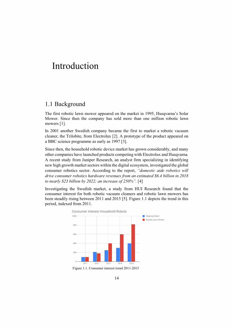
Investigating the Swedish market, a study from HUI Research found that the consumer interest for both robotic vacuum cleaners and robotic lawn mowers has been steadily rising between 2011 and 2015 [5]. Figure 1.1 depicts the trend in this period, indexed from 2011.
Figure 1.1. Consumer interest trend 2011-2015
15
Additude Innovation AB
Additude Innovation AB is a branch of Additude AB which specializes in business development and innovation projects for external companies. Within the innovation branch, an interesting business opportunity has been identified. One of their customers are manufacturing high precision short range radars at a low cost. If these radars were to be integrated in a robotic lawn mower, the possible intelligence and autonomy level of the device would allow for a wider range of tasks and usability. Furthermore, considering a modular architecture, the platform functionality could be extended to cover indoor applications such as cleaning etc.
The goal of this project is to develop a concept of a self-driving autonomous multi-purpose garden platform. The platform should be able to perform several different tasks, primarily in a garden setting. Furthermore, indoor applications such as cleaning should be considered, and if possible incorporated into the concept. It should be noted that the intention is to deliver conceptual solutions of various maturity, no detail design is included in the scope. The mandatory functions of the platform are that it should be able to mow a lawn, be aware of its surroundings and be connected to the internet.
The possibility of incorporating further functionalities should be explored. The intention is to reach a product maturity level that allows for a potential launch on Indiegogo, a well-known crowdfunding site. This does not necessarily mean that the concept should be adapted specifically for Indiegogo, but it will be used as a guidance for what type of visualisation and maturity that is desired.
More specifically, the deliverables of the project are a report, technical specifications of the platform, conceptual design of some modules/functions and an “emotional presentation” suitable for e.g. Indiegogo, including conceptual renders.
16
Methodology
This section describes the overall method, and the adoptions made specifically for this thesis.
2.1 Double Diamond The overall structure of the thesis follows the Double Diamond model, which was created by the British Design Council in 2005. It was developed based on case studies gathered from 11 different design departments, each belonging to a global brand or firm. Based on these studies, four generic phases were defined: Discover, Define, Develop and Deliver.
The Discover phase focuses on understanding the problem in a new way and should provide fresh insight into the problem. Following this, the Define phase should entail stages to define the possibilities discovered in the previous phase, and in that way frame the fundamental project challenge. The third stage, named Develop, marks the period where several solutions and concepts are created. Lastly, the Deliver phase is where the concept is finalized and presented. [6]
One other possible approach would have been to use the Ulrich and Eppinger product development cycle. However, the project team favoured the Double Diamond model due to the flexible structure, and initial focus on framing the project correctly. It was deemed very suitable for a conceptual and loosely defined project such as this.
17
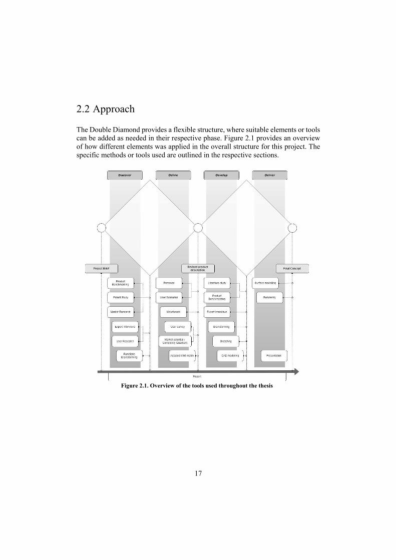
2.2 Approach
The Double Diamond provides a flexible structure, where suitable elements or tools can be added as needed in their respective phase. Figure 2.1 provides an overview of how different elements was applied in the overall structure for this project. The specific methods or tools used are outlined in the respective sections.
Figure 2.1. Overview of the tools used throughout the thesis
18
Discover
The focus of the Discover phase was to explore in which areas and for what tasks a small, intelligent, robotic platform could be useful. Furthermore, an overview of current products within possible market areas were gained. The work also revealed some pain points that customers were experiencing with current products within the robotic lawn mower segment.
3.1 Methods The divergent nature of the Discover phase calls for a high level of creativity and inspiration in order to encompass a broad solution space. Therefore, the tools commonly used in this phase allows for subjective reasoning and creative thoughts. The approach used for this project was to initially focus on knowledge gathering in order to broaden the team’s perspective, whilst at the last stage of the phase conduct a brainstorming session in order to define possible applications.
Product benchmarking
Benchmarking of similar products is a method that is useful throughout the product development process [7, p. 49]. In this case the focus of the benchmarking was to gain inspiration of possible applications, while simultaneously gaining an overview of the current status of robotic applications. A positioning matrix was created in order to visualize market situation and communicate intended product positioning, it can be found in Appendix B. Product information was gathered from supplier datasheets and marketing material.
Patent study
Patents are detailed and can provide an accessible source of information, both for technical information and explanations for how products are composed and function [7, p. 176]. A brief patent study was performed to further facilitate the creative process and provide more information of how household robots generally are composed.

19
Marketing platform research
As one of the project goals was to deliver a conceptual solution and presentation suitable for Indiegogo, some focus was put on investigating crowdfunding platforms and projects in general, and Indiegogo in particular.
User research
In this phase only secondary user research was conducted. Data was gathered from user surveys and online reviews, focusing on the robotic lawn mower segment.
Exploratory expert interview
Expert consultations early in a product development process can provide both increased knowledge about a certain problem, but also direct focus and provide information about more rewarding areas [7, p. 176]. An expert interview was conducted, as an introduction and broad overview of common positioning, mapping and sensing methods.
Brainstorming
An intuitive and commonly used tool for ideation, brainstorming is used naturally throughout the product development process. For this phase, possible applications for a small, intelligent robot were generated.
3.2 Product benchmarking Due to the unconstrained initial scope, the following four different product segments were targeted for the benchmarking.
Robotic lawn mowers Indoor Cleaning robots Gardening tools Pool cleaning robots
The segments were chosen due to their compatibility with the functional requirement “autonomously mow lawn”, that was stated in the initial brief. It is important to note that this benchmarking first and foremost was used as an inspirational tool in order to widen the team’s knowledge regarding these products. By no means does this choice exclude other product segments for the continuation of the process. Below are some interesting products and functions that were identified.
20
Robotic Lawn mowers During the benchmarking some trends were noticed. Several manufacturers are introducing possibilities to interact with the mowers using mobile applications [8] [9] [10]. Another trend was that more and more refined positioning systems seems to be implemented, especially in the high-end segment. Husqvarna utilises ultrasound and GPS-positioning in their Automower 450X [11] to better cope with narrow segments and Bosch has implemented a path planning system in their Indego 400 Connect [12]. 3.2.1.1 Indego 400 Connect The Indego 400 Connect from Bosch is one of the few robotic lawn mowers that plans its route and remembers which areas that has been mowed recently. This information and current position are presented to the user through a mobile application. Information is sent from the mower to the user through GPRS. Like most other mowers a perimeter wire is needed to define the working area. [8] 3.2.1.2 Gardena Smart Sileno With this Gardena-branded product Husqvarna caters towards the smart home trend. The mower can be monitored through a mobile application, if a special internet gateway is installed. The same gateway can be used to control Gardena’s smart watering system, consisting of soil moisture sensors that are able to control sprinkler heads and water valves, resulting in a fully automated garden watering system. [13] 3.2.1.3 LawnBott LB1200 Spyder The LB1200 uses a novel approach to limit the working area. Six downward facing sensors check for “living grass”, when at least two of them cannot sense any grass the mower turns around. This means that instead of installing a perimeter wire the user must ensure that the working area is enclosed by a 15-20 cm wide strip of dead material. [14]

21
Indoor Cleaning robots
Regarding indoor cleaning robots, several trends within the high-end segment could be identified. One of the more notable is the increased incorporation of voice activation [15] [16] [17]. Other trends include added interaction through mobile solutions, and ease of usage regarding working area limitations and scheduling [18] [19] [20] [21]. Below are some interesting products and functions that were identified.
3.2.2.1 iRobot Braava 380t
The Braava is a mopping robot, wiping the floors with an attached microfibre cloth as it moves. As the cloth is interchangeable, the Braava can both wipe and mop floors, though limited to moving on hard surfaces and the use of water without cleaning agents. For navigation the Braava uses a local positioning system (LPS) or commonly known as a beacon system. The beacon system is expandable, and more beacons can be added as needed, to cover additional rooms. [18]
3.2.2.2 iRobot Roomba 980
The Roomba 980 is a vacuum robot that vacuums both hard flooring and textile surfaces, such as mats or wall-to-wall carpets. The manufacturer claims that it can detect dirt and adjust suction to facilitate different thicknesses of carpets. The robot implements visual simultaneous localization and mapping (vSLAM) technology by utilizing a 45° inclined camera, which means it builds a virtual map over time to reuse when cleaning its dedicated environment. The robot can be combined with “Virtual walls”, which is physical beacons placed out in regions where the robot shouldn’t enter. The beacons create a “no-entry-zone" and is intended to be utilized when it is not feasible to put large physical objects as a blockade. [19]
3.2.2.3 Neato Botvac D7
The Botvac D7 is a vacuum robot utilizing VSLAM through a spinning laser. A technology usually called LIDAR (light detection and ranging). The laser allows Botvac to work in a low light or dark environment, compared to the camera equivalent. The Botvac also have a “virtual walls” functionality, but rather than using physical bacons, it can adjust cleaning routines or areas through adding limitations in the supporting mobile application. [20]
3.2.2.4 Ecovacs Deebot R98
The Deebot R98 is a two-part system, sold as both a vacuum robot that uses VSLAM trough LIDAR technology, and a traditional handheld small vacuum cleaner. The robot and the handheld unit share the same charging platform, which enables the robot unit to empty its dustbin into the handheld unit when full. [21]
22
3.2.2.5 Ecovacs Winbot 950
The Winbot is a window-cleaning robot, designed to wipe vertical glass or mirror surfaces automatically. It has a suction unit that keeps it attached to the surface, while the wiping is achieved with an interchangeable microfibre cloth as the unit moves, driven by small tracks. Sensors can detect edges and frames. To change between different windows, the unit must be moved manually. [22]
Gardening tools
Within the product segment gardening tools, many different interesting products were identified, such as:
Spreaders (fertilizer, sand, salt) Handheld grass shears for lawn edges Grass trimmers Lawn rakes (for removing moss) Lawn aerators Lawn edge cutters Hedge trimmers Shrub shears (for contouring hedges, etc.) Pruning tools Snow shovels Snow blowers Leaf blowers Stump grinders Earth tillers Rakes Fruit collector Weeding tools based on cutting Weeding tools based on uprooting Watering tools
Below are some examples of interesting products within this segment.
3.2.3.1 Telescopic weed puller, Fiskars
This product simplifies the weeding process while also allowing an upright working position. The actual function is very straightforward, four jagged metal blades are attached to a telescopic shaft with a footplate. The blades are forced into the soil, through the plant, by the user. The user then pulls the tool out of the ground, uprooting the weed in the process. A slider on the shafts operates a moveable plate
23
that pushes the weed of the blades, allowing the user to remove the weed at a suitable location before repeating the process. [23]
3.2.3.2 Fruit collector, Gardena
The fruit collector from Gardena consists of two rigid circular plates connected to a plastic U-frame, that in turn can be attached to a telescopic handle. Semi-flexible wires are attached between the plates, causing an enclosed spherical space. When the product is rolled over a fallen fruit, the wires flex, allowing the fruit to enter the space. Although the wires are flexible enough to let the fruit in, they are still rigid enough to close behind the fruit and keep it enclosed in the tool. The fruit is removed through a pipe on the side of the tool, by tilting the tool 90 degrees. [24]
Household robots
During the benchmarking process some very interesting multipurpose robots were encountered. These robots are presented in this section.
3.2.4.1 Trimbot 2020
TrimBot2020 is an EU funded project aiming to prototype the first outdoor garden trimming robot. From the project's official webpage, it can be found that “The project is focused on the development of intelligent outdoor hedge, rose and bush trimming capabilities, allowing the robot to navigate over varying garden terrain, approaching hedges to restore them to their ideal tidy state, and approaching topiary-styled bushes to restore them to their ideal shape”. The robot will be based on a modified Bosch Indego lawnmower which is intended to use cameras for object recognition. [25]
3.2.4.2 KOBI
This product implements three different modules allowing it to act as a leaf mulcher, snow blower and lawn mower. According to the manufacturer it will feature wireless communication, a mobile application for control, an obstacle avoidance system and fully autonomous navigation – with no need for perimeter wires. It is unclear whether KOBI can switch between the modules automatically or if that is left to the user. [26]
According to CNN the robot positions itself with the help of two separate beacons that must be placed in the yard [27]. It should be noted that in 2016 the company claimed that KOBI would go on sale to the public in early 2017 [28], but according to the company's official website only pre-orders can be made [26].
24
3.3 Patent study A brief patent study proved to provide a broader understanding of some trends in autonomous platforms and interesting use cases. Below some of the most relevant patents are summarized.
System comprising of autonomous lawn mower and module
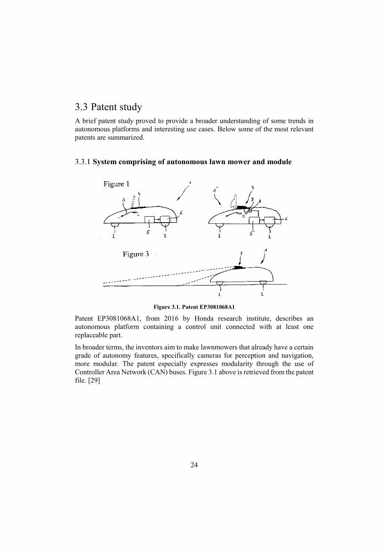
Figure 3.1. Patent EP3081068A1
Patent EP3081068A1, from 2016 by Honda research institute, describes an autonomous platform containing a control unit connected with at least one replaceable part.
In broader terms, the inventors aim to make lawnmowers that already have a certain grade of autonomy features, specifically cameras for perception and navigation, more modular. The patent especially expresses modularity through the use of Controller Area Network (CAN) buses. Figure 3.1 above is retrieved from the patent file. [29]
25
Autonomous robotic vehicle with lawn care function
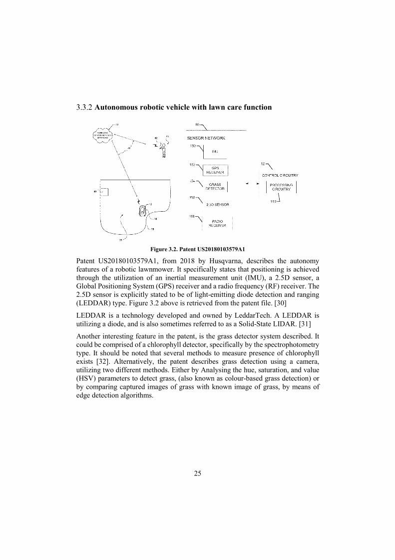
Figure 3.2. Patent US20180103579A1
Patent US20180103579A1, from 2018 by Husqvarna, describes the autonomy features of a robotic lawnmower. It specifically states that positioning is achieved through the utilization of an inertial measurement unit (IMU), a 2.5D sensor, a Global Positioning System (GPS) receiver and a radio frequency (RF) receiver. The 2.5D sensor is explicitly stated to be of light-emitting diode detection and ranging (LEDDAR) type. Figure 3.2 above is retrieved from the patent file. [30]
LEDDAR is a technology developed and owned by LeddarTech. A LEDDAR is utilizing a diode, and is also sometimes referred to as a Solid-State LIDAR. [31]
Another interesting feature in the patent, is the grass detector system described. It could be comprised of a chlorophyll detector, specifically by the spectrophotometry type. It should be noted that several methods to measure presence of chlorophyll exists [32]. Alternatively, the patent describes grass detection using a camera, utilizing two different methods. Either by Analysing the hue, saturation, and value (HSV) parameters to detect grass, (also known as colour-based grass detection) or by comparing captured images of grass with known image of grass, by means of edge detection algorithms.
26
Agricultural autonomous vehicle platform
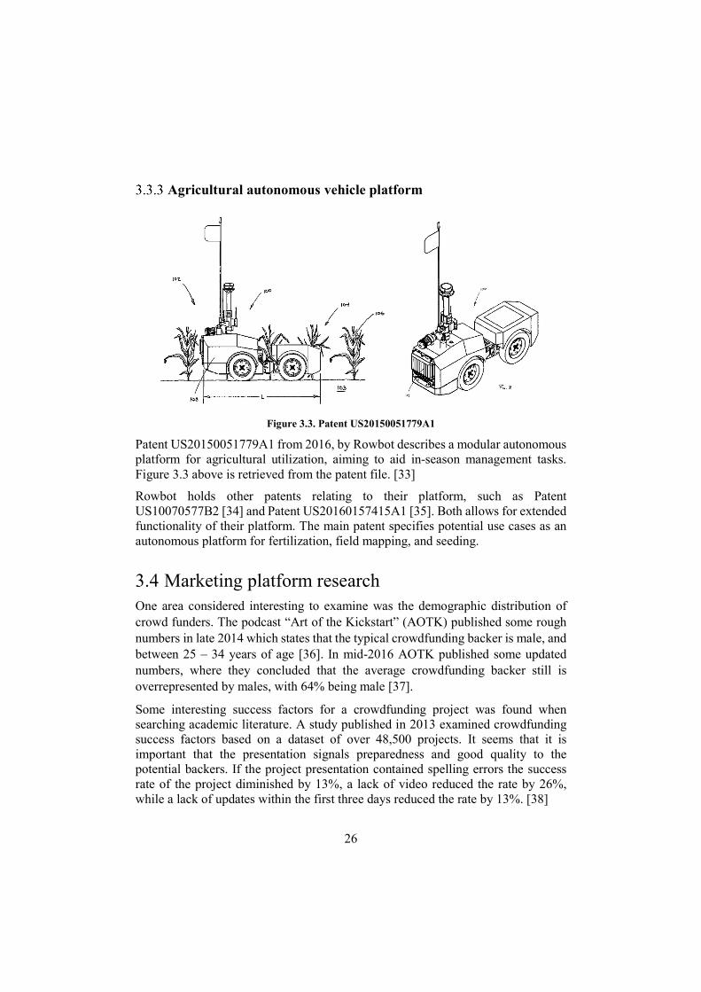
Figure 3.3. Patent US20150051779A1
Patent US20150051779A1 from 2016, by Rowbot describes a modular autonomous platform for agricultural utilization, aiming to aid in-season management tasks. Figure 3.3 above is retrieved from the patent file. [33]
Rowbot holds other patents relating to their platform, such as Patent US10070577B2 [34] and Patent US20160157415A1 [35]. Both allows for extended functionality of their platform. The main patent specifies potential use cases as an autonomous platform for fertilization, field mapping, and seeding.
3.4 Marketing platform research One area considered interesting to examine was the demographic distribution of crowd funders. The podcast “Art of the Kickstart” (AOTK) published some rough numbers in late 2014 which states that the typical crowdfunding backer is male, and between 25 – 34 years of age [36]. In mid-2016 AOTK published some updated numbers, where they concluded that the average crowdfunding backer still is overrepresented by males, with 64% being male [37].
Some interesting success factors for a crowdfunding project was found when searching academic literature. A study published in 2013 examined crowdfunding success factors based on a dataset of over 48,500 projects. It seems that it is important that the presentation signals preparedness and good quality to the potential backers. If the project presentation contained spelling errors the success rate of the project diminished by 13%, a lack of video reduced the rate by 26%, while a lack of updates within the first three days reduced the rate by 13%. [38]
27
3.5 User research No primary user research was conducted in this phase, instead the research relied on secondary sources such as consolidated surveys and existing user reviews.
User survey
In 2018 Andreas Stihl Nordic initiated a study named “Trädgårdsbarometern 2018” (sv, “The garden barometer 2018”). The study was based on a survey examining 1944 Swedish houseowners opinions regarding robotic lawn mowers. Some interesting results were found, the most notable are presented below [39]:
53% of the participants has named their robot. The most common reasons for not installing a robotic lawn mower were:
o 37% Unsuitable yard. o 11% Too expensive. o 7% Appreciates the exercise coupled with manual lawn mowing. o 4% Too cumbersome installation.
When asked about their expectations on future generations of robotic lawn mowers the participants answered:
o 49% The robot handles dandelions and other weeds. o 45% The robot eliminates Spanish Slugs and other vermin. o Seeding and watering was another expectation, although the report
did not state any percentage regarding the frequency of participants expecting this.
User reviews
A convenient way to investigate user experience is through the many user reviews available online. The apparent drawback with this approach is that it only provides answers to questions that the consumer posting the review consider relevant, it is not possible to ask any specific or follow-up questions. However, the approach is very resource effective and can quickly reveal important pain points of existing products. Some opinions from the reviews are stated below:
The lawn must be kept tidy from interfering objects such as toys [40]. Unplanned stops due to interfering objects or uneven lawns [41]. Some robots have a problem with grass build-up around the blades [42]
28
3.6 Expert interview The interview was conducted via phone with a lead engineer of software and electronics at a Swedish company. The company specializes in concept and system development coupled with validation and homologation within the electric transportation segment.
Key points gained from the interview was a general overview of different methods for:
Positioning Perceiving surroundings Connectivity Object recognition Mapping
This was further discussed in general terms of how computational requirements varies with different solutions.
3.7 Brainstorming To conclude the Discover phase and suggest possible applications and tasks for an autonomous platform, a brainstorming session was conducted. The aim was to utilize what was learned in the previous stages and try to generate as many applications as possible for a product similar to that of a robotic lawnmower. The overall goal was to find at least 100 different possible applications. At this stage, level of complexity and other limitations was not considered. The complete result is presented in Appendix B and encompasses 103 possible applications.
29
Define
The Define phase builds on the knowledge and information gained in the Discover phase. It is a convergent phase, in our case the main goal was to determine which functions and limitations should be the criteria of the robotic platform. Furthermore, a revised product description was created, stating product architecture and functionality.
4.1 Methods
User definition (Persona)
Personas are commonly used in the field of user experience design, or wherever a user centered design approach is desired (also called human centered design or customer centered design). According to one source a persona is intended to "create reliable and realistic representations of your key audience segments for reference”. [43]
Pruitt and Adlin describe personas as “fictitious, specific, concrete representations of target users”. In its most powerful form, a persona is a detailed description of an imaginary person, that is based on highly specific data about real people within a products target audience. The description should involve both narrative and specific data in order to build empathy with and communicate key insights or elements of a specific target group. [44]
User scenarios
The intention of user scenarios is to provide a context and setting in which your personas can benefit from using the intended product. This approach leverages the power of storytelling and sets the personas in motion, hopefully exposing flaws or discrepancies in intended product functionality. User scenarios also help designers visualise different interaction and product functionality possibilities. [44]
30
Mood board
Mood boards are a common tool within the design industry and the term is often used generically to include a wide range of different types [45]. In this thesis the mood board was used as an inspiration design for the aesthetical design.
Market potential/complexity quadrant and initial function screening
A quadrant of suggested features can be constructed based on the market potential (or value) and complexity of each feature. This can then be used as an aid for prioritising between the different features. [46] [47]
User survey
It is not recommended to utilize surveys for collecting and identifying customer needs, but it can be a relatively good resource later in the project [7]. In the Define phase for example, it can be suitable to implement online surveys to verify the existence of identified costumer needs. Especially since an online survey provides a high number in interviewees at a minimal time cost in relation to traditional survey methods. However, an online survey requires a specific topic, with few to no open-end questions. It should also be noted that through using online surveys, a certain group without easy access to internet is always neglected. [48]
In this case, an online survey was deemed suitable for identifying a hierarchic structure of already discovered functions. The goal was to verify the market potential of these functions, and hence the importance of implementation of them in the actual concept.
Analysis of the results was done using traditional statistical methods. A binomial distribution was assumed, which is valid since the number of respondents (~400) was small in comparison to the total population. [49, p. 178]
Platform architecture definition method
Defining the platform architecture and modularity is a complex task, that can have a profound impact on profitability and time to market. One author state that "The key to a successful product family lies in properly balancing the inherent trade-off between commonality and distinctiveness” [50, p. 5]. This summarizes many of the arguments found in literature, where it is commonly argued that extensive modularisation removes the unique features and functions of products, resulting in
31
sub-optimal and less attractive products, while total lack of modularisation results in increased production and logistics cost. It is furthermore argued that after a platform has been developed, development time for derivate products is shorter, and hence development time is shifted up-front, which possibly can result in a quicker response towards shifting market demands and technology advancements. [50, pp. 1-15]
Three main methodologies for modular product design was identified, namely:
Function structure heuristics (FSH) Modular function deployment (MFD) Design structure matrix (DSM)
A brief explanation of the different approaches is given below, for more in-depth information see e.g. Börjesson (2010) [51].
Modularisation through FSH is initiated by mapping the different flows (energy, matter, signals etc.) in a function structure diagram. Based on different heuristics, modules are formed.
MFD utilises different scoring matrices to connect customer, engineering and business aspects of the modularisation.
DSM focuses on physical couplings and interactions between components in order to define module groups.
4.1.6.1 Chosen approach
After investigating the different methods, the project team reached the conclusion that none of the above methods was suitable for the product architecture concept evaluation. The main reason was that the methods seemed more suited for modularisation of technical solutions within a set product architecture. The team was under the impression that each architecture concept would have to be refined individually using the above methods before actually evaluating the different architectural concepts against each other.
Hence it was chosen to only implement parts of the module indication matrix (MIM), the core part of MFD. The MIM is very similar to a quality function deployment (QFD) matrix, with the difference that the customer requirements axis is replaced by 12 predefined module drivers. In MFD the MIM is used in order to group functions into module groups, based on component similarity with regards to the module drivers. In this work the drivers were instead extracted and used as basis for a conventional concept screening matrix of the architecture concepts. The drivers and adapted definitions can be found in Appendix C. [52]
32
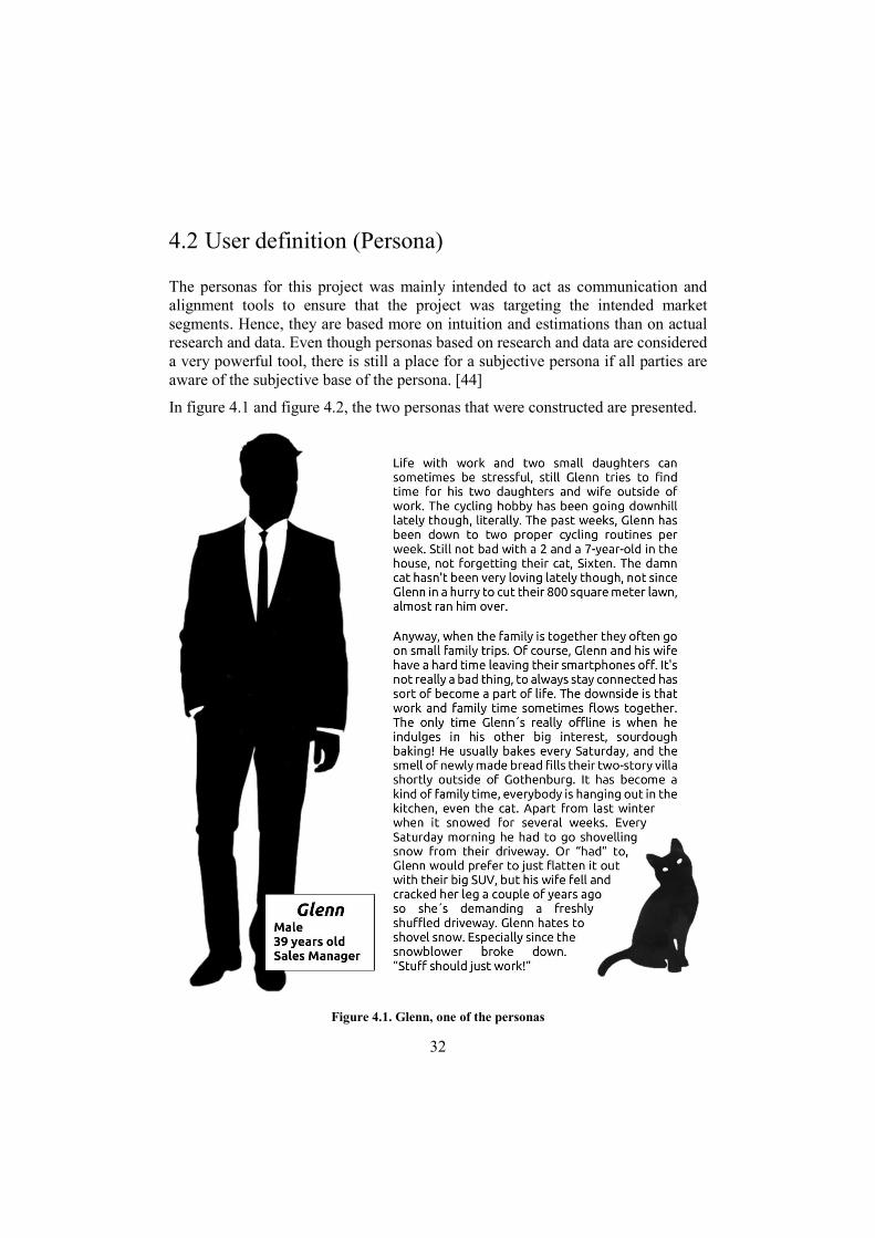
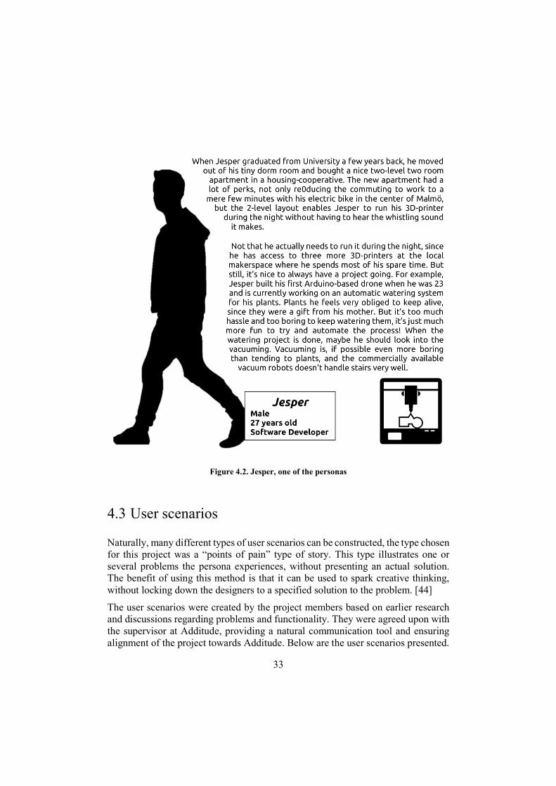
4.2 User definition (Persona)
The personas for this project was mainly intended to act as communication and alignment tools to ensure that the project was targeting the intended market segments. Hence, they are based more on intuition and estimations than on actual research and data. Even though personas based on research and data are considered a very powerful tool, there is still a place for a subjective persona if all parties are aware of the subjective base of the persona. [44]
In figure 4.1 and figure 4.2, the two personas that were constructed are presented.
Figure 4.1. Glenn, one of the personas
33
Figure 4.2. Jesper, one of the personas
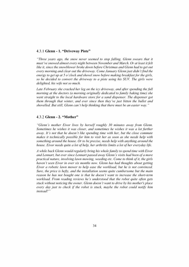
4.3 User scenarios
Naturally, many different types of user scenarios can be constructed, the type chosen for this project was a “points of pain” type of story. This type illustrates one or several problems the persona experiences, without presenting an actual solution. The benefit of using this method is that it can be used to spark creative thinking, without locking down the designers to a specified solution to the problem. [44]
The user scenarios were created by the project members based on earlier research and discussions regarding problems and functionality. They were agreed upon with the supervisor at Additude, providing a natural communication tool and ensuring alignment of the project towards Additude. Below are the user scenarios presented.
34
Glenn - 1. “Driveway Piste”
“Three years ago, the snow never seemed to stop falling. Glenn swears that it must’ve snowed almost every night between November and March. Or at least it felt like it, since the snowblower broke down before Christmas and Glenn had to get out every morning and clear out the driveway. Come January Glenn just didn’t find the energy to get up at 5 o’clock and shovel snow before making breakfast for the girls, so he decided to convert the driveway to a piste using his SUV. The girls were delighted, his wife not so much.
Late February she cracked her leg on the icy driveway, and after spending the full morning at the doctors (a morning originally dedicated to family baking time) she went straight to the local hardware store for a sand dispenser. The dispenser got them through that winter, and ever since then they’ve just bitten the bullet and shovelled. But still, Glenn can’t help thinking that there must be an easier way.”
Glenn - 2. “Mother”
“Glenn’s mother Eivor lives by herself roughly 30 minutes away from Glenn. Sometimes he wishes it was closer, and sometimes he wishes it was a lot further away. It’s not that he doesn’t like spending time with her, but the close commute makes it technically possible for him to visit her as soon as she needs help with something around the house. Or to be precise, needs help with anything around the house. Eivor needs quite a lot of help, her arthritis limits a lot of her everyday life.
A while back Glenn would regularly bring his whole family to spend time with Eivor and Lennart, but ever since Lennart passed away Glenn’s visits had been of a more practical nature, involving lawn mowing, weeding etc. Come to think of it, the girls haven’t seen Eivor in over six months now. Glenn has had thoughts about getting Eivor a robotic lawn mower to help ease the workload, but he is not convinced. Sure, the price is hefty, and the installation seems quite cumbersome but the main reason he has not bought one is that he doesn’t want to increase the short-term workload. From reading reviews he’s understood that the robot quite often gets stuck without noticing the owner. Glenn doesn’t want to drive by his mother's place every day just to check if the robot is stuck, maybe the robot could notify him instead?”
35
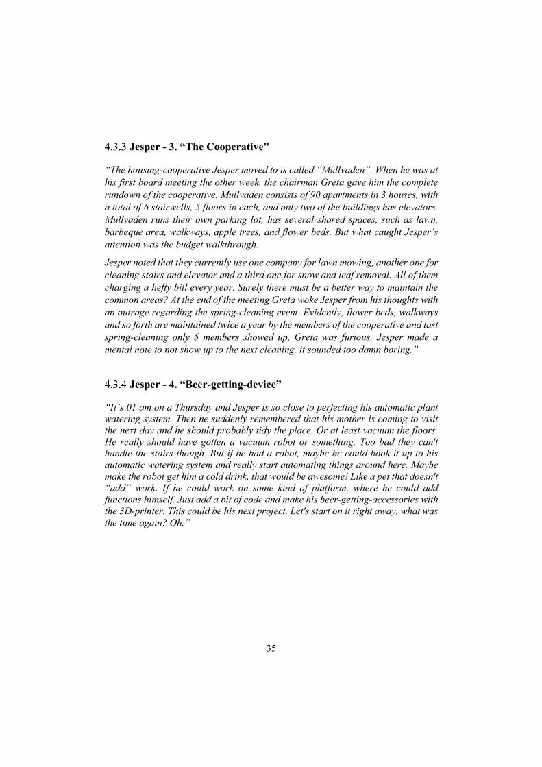
Jesper - 3. “The Cooperative”
“The housing-cooperative Jesper moved to is called “Mullvaden”. When he was at his first board meeting the other week, the chairman Greta gave him the complete rundown of the cooperative. Mullvaden consists of 90 apartments in 3 houses, with a total of 6 stairwells, 5 floors in each, and only two of the buildings has elevators. Mullvaden runs their own parking lot, has several shared spaces, such as lawn, barbeque area, walkways, apple trees, and flower beds. But what caught Jesper’s attention was the budget walkthrough.
Jesper noted that they currently use one company for lawn mowing, another one for cleaning stairs and elevator and a third one for snow and leaf removal. All of them charging a hefty bill every year. Surely there must be a better way to maintain the common areas? At the end of the meeting Greta woke Jesper from his thoughts with an outrage regarding the spring-cleaning event. Evidently, flower beds, walkways and so forth are maintained twice a year by the members of the cooperative and last spring-cleaning only 5 members showed up, Greta was furious. Jesper made a mental note to not show up to the next cleaning, it sounded too damn boring.”
Jesper - 4. “Beer-getting-device”
“It’s 01 am on a Thursday and Jesper is so close to perfecting his automatic plant watering system. Then he suddenly remembered that his mother is coming to visit the next day and he should probably tidy the place. Or at least vacuum the floors. He really should have gotten a vacuum robot or something. Too bad they can't handle the stairs though. But if he had a robot, maybe he could hook it up to his automatic watering system and really start automating things around here. Maybe make the robot get him a cold drink, that would be awesome! Like a pet that doesn't “add” work. If he could work on some kind of platform, where he could add functions himself. Just add a bit of code and make his beer-getting-accessories with the 3D-printer. This could be his next project. Let's start on it right away, what was the time again? Oh.”
36
Jesper - 5. “The Babysitter”
“Jesper is browsing through AliExpress looking to stock up on some moisture sensors when he hears the doorbell. Oh shit, he totally forgot that he is supposed to babysit his 10-year old nephew Alexander tonight. It’s not really a problem though, Alexander loves all the gadgets Jesper’s building and it’s usually easy to keep him occupied for a couple of hours with the drone/RC-car hybrid. Jesper has more than once let Alexander build and program his own stuff with Jesper’s gear. However, Alexander usually gets bored of making the lights flash in sequence and moves on to play with the RC-car. Too bad it’s too hard for Alexander to build something mechanically robust, otherwise he could build his own miniature robot.
Jesper wanders away in thought, maybe he should build a generic platform that Alexander can connect stuff to and develop his programming skills. Yeah, that’s a good idea! I’ll get to it straight away! Or, after the watering system, eh, and the coffee automation of course. The doorbell rings again.”
37
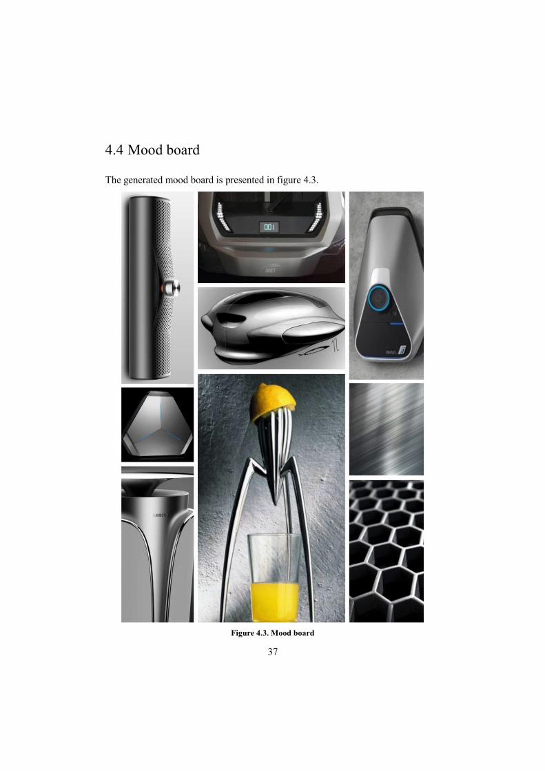
4.4 Mood board
The generated mood board is presented in figure 4.3.
Figure 4.3. Mood board
38
4.5 Market potential/complexity quadrant and initial function screening
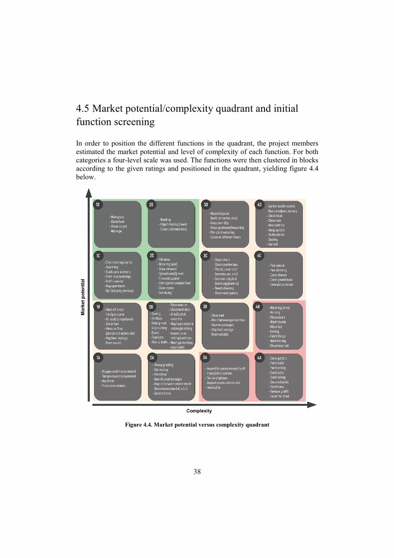
In order to position the different functions in the quadrant, the project members estimated the market potential and level of complexity of each function. For both categories a four-level scale was used. The functions were then clustered in blocks according to the given ratings and positioned in the quadrant, yielding figure 4.4 below.
Figure 4.4. Market potential versus complexity quadrant
39
The functions positioned in the lower right corner was removed from the function list. The functions in the top left corner were used to specify different application areas. The functions were then regrouped and clustered according to these application areas in order to illustrate which functions that enhanced each other. The full regrouped function chart can be found in Appendix B.
A decision was taken to focus on consumer-related application areas for the continued platform development process.
4.6 User survey
In order to objectively assess the market potential for the different functions it was decided to conduct a market survey. A short internet survey was put together using google forms and distributed on Facebook groups. The full survey (in Swedish) can be found in Appendix D.
Survey design
The primary goal of the survey was to assess market potential of already identified functions. This would be used as basis when selecting which functions to prioritise in the development process. Hence a list of the previously selected functions was composed, and the respondents were asked to select the functions that they would be interested in. A concern from the project team was that the respondents, if allowed, would select all the suggested functions. To cope with this a maximum limit of seven functions were set in the survey. Seven was chosen since it was considered to be a high enough number to allow for a considerable variation in respondent answers while still limiting the respondent.
Although not serving the primary goal, it was decided to incorporate some open-ended questions regarding functionality and experience. The reason was simply that the estimated benefit compared to the extra workload was deemed favourable.
Furthermore, some questions regarding respondent data, such as age, gender, garden interest, robotic lawn mower ownership etc., was incorporated in the survey.
Respondent data
The survey was marketed and made available through three different Facebook groups reaching in total ~51.000 profiles. One group consisted of people owning a Husqvarna Automower (21.000 members), another group was for people interested

40
in smart homes and home automation (29.000 members) and the third group was for people that were especially interested in lawn care (1.500 members). In total 393 questionnaires were submitted. The gender and age distribution of the respondents were according to figure 4.5 below, it can be noted that the survey base is highly biased towards a male population.
Due to some time difference between group postings the authors believe that a large portion (>75%) of these answers were from the robotic lawn mower group.
Results
The survey was very well received and considering the number of responses gathered it was deemed very successful. This section presents a summary of the findings.
4.6.3.1 Function scoring
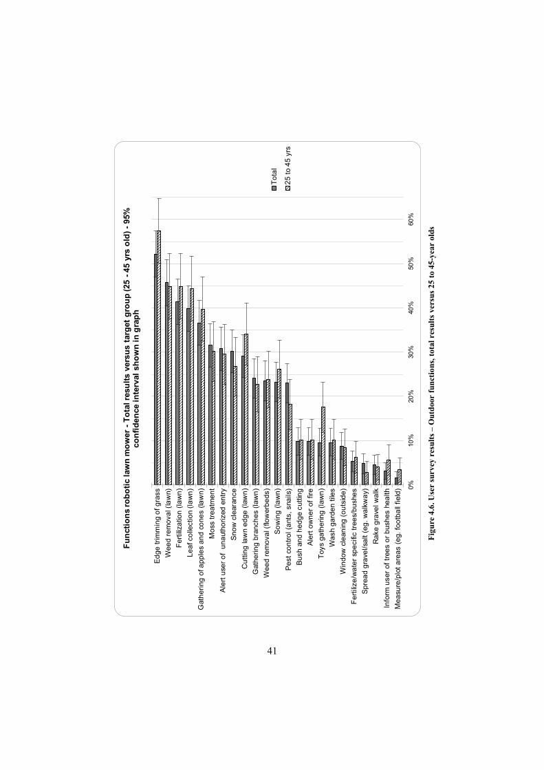
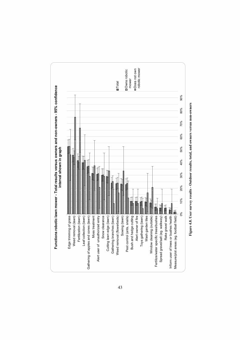
Table 4.1 shows the average number of function votes per person for the total respondent category versus 25 to 45-year olds. The function scoring results from the survey was compiled into different bar charts. Figures 4.6 and 4.7 below depict the total results versus the chosen target group of 25 to 45-year olds. Figures 4.8 and 4.9 show the results for owners versus non-owners.
Overlaid in the charts are the confidence intervals for a confidence level of 95% shown. As stated in chapter 4.1.5, these were calculated assuming a binomial distribution. [49, p. 307]
Table 4.1. Average amount of function votes per respondent
Total 25 – 45 years old
Robotic lawn mower 5.0 5.2 Robotic vacuum 4.0 4.3
Figure 4.5. Respondent gender and age distribution
41
0%10
%20
%30
%40
%50
%60
%
Ed
ge
tri
mm
ing
of
gra
ss
We
ed
re
mo
val (
law
n)
Fe
rtili
zatio
n (
law
n)
Le
af c
olle
ctio
n (l
aw
n)
Gat
he
rin
g o
f ap
ple
s a
nd
co
ne
s (la
wn
)
Mo
ss t
rea
tme
nt
Ale
rt u
ser
of
un
aut
ho
rize
d e
ntr
y
Sn
ow
cle
aran
ce
Cu
ttin
g la
wn
ed
ge
(la
wn
)
Gat
he
rin
g b
ran
che
s (l
aw
n)
We
ed
re
mo
val (
flow
erb
ed
s)
So
win
g (
law
n)
Pe
st c
on
tro
l (a
nts,
sna
ils)
Bu
sh a
nd
he
dg
e cu
ttin
g
Ale
rt o
wn
er
of
fire
To
ys g
ath
erin
g (
law
n)
Wa
sh g
ard
en
tile
s
Win
dow
cle
an
ing
(o
uts
ide
)
Fe
rtili
ze/w
ate
r sp
eci
fic t
ree
s/b
ush
es
Sp
rea
d g
rave
l/sa
lt (e
g.
wa
lkw
ay)
Ra
ke g
rave
l wa
lk
Info
rm u
ser
of
tree
s o
r b
ush
es
hea
lth
Me
asu
re/p
lot
are
as
(eg.
fo
otb
all
field
)
Fu
nct
ion
s ro
bo
tic
law
n m
ow
er -
To
tal r
esu
lts
vers
us
targ
et g
rou
p (2
5 -
45 y
rs o
ld)
-95
%
con
fid
ence
inte
rval
sh
ow
n in
gra
ph
To
tal
25
to
45
yrs
Fig
ure
4.6.
Use
r su
rvey
res
ults
– O
utd
oor
fun
ctio
ns, t
otal
res
ults
ver
sus
25 t
o 45
-yea
r ol
ds

42
0%10
%20
%30
%40
%50
%60
%70
%
We
t w
ipin
g (
floo
r)
Cle
an
bas
eb
oa
rds
Ale
rt o
wn
er
of
fire
Ale
rt u
ser
of
un
aut
ho
rize
d e
ntr
y
Cle
an
flo
or
tiles
Cle
an
sta
irca
se
De
tect
he
at
lea
kag
e
To
ys g
ath
erin
g (
floo
r)
Clo
the
s g
ath
eri
ng (
floo
r)
Win
dow
cle
an
ing
(in
sid
e)
De
tect
an
d e
xtin
gu
ish
fir
es
Me
asu
re a
nd
ad
just
hu
mid
ity
Wip
e c
ou
nte
rto
ps
Ch
art
flo
or
pla
n
Fe
rtili
ze a
nd
wat
er
po
t p
lan
ts
Fin
d ke
ys
Fe
ed
do
g o
r ca
t
Info
rm u
ser
of
pot
pla
nts
he
alth
Fu
nct
ion
s ro
bo
tic
vacu
um
-T
ota
l res
ult
s ve
rsu
s ta
rget
gro
up
(25
-45
yrs
old
) -95
% c
on
fid
ence
in
terv
al s
ho
wn
in g
rap
h
To
tal
25
to
45
yrs
Fig
ure
4.7.
Use
r su
rvey
res
ults
– I
ndoo
r fu
nct
ions
, tot
al r
esul
ts v
ersu
s 25
to
45-y
ear
olds
43
0%10
%20
%30
%40
%50
%60
%70
%80
%90
%
Ed
ge
tri
mm
ing
of
gra
ss
We
ed
re
mo
val (
law
n)
Fe
rtili
zatio
n (
law
n)
Le
af c
olle
ctio
n (l
aw
n)
Gat
he
rin
g o
f ap
ple
s a
nd
co
ne
s (la
wn
)
Mo
ss t
rea
tme
nt
Ale
rt u
ser
of
un
aut
ho
rize
d e
ntr
y
Sn
ow
cle
aran
ce
Cu
ttin
g la
wn
ed
ge
(la
wn
)
Gat
he
rin
g b
ran
che
s (l
aw
n)
We
ed
re
mo
val (
flow
erb
ed
s)
So
win
g (
law
n)
Pe
st c
on
tro
l (a
nts,
sna
ils)
Bu
sh a
nd
he
dg
e cu
ttin
g
Ale
rt o
wn
er
of
fire
To
ys g
ath
erin
g (
law
n)
Wa
sh g
ard
en
tile
s
Win
dow
cle
an
ing
(o
uts
ide
)
Fe
rtili
ze/w
ate
r sp
eci
fic t
ree
s/b
ush
es
Sp
rea
d g
rave
l/sa
lt (e
g.
wa
lkw
ay)
Ra
ke g
rave
l wa
lk
Info
rm u
ser
of
tree
s o
r b
ush
es
hea
lth
Me
asu
re/p
lot
are
as
(eg.
fo
otb
all
field
)
Fu
nct
ion
s ro
bo
tic
law
n m
ow
er -
To
tal r
esu
lts
vers
us
ow
ner
s an
d n
on
-ow
ner
s -
95%
co
nfi
den
ce
inte
rval
sh
ow
n in
gra
ph
To
tal
Ow
ns
rob
otic
mo
we
r
Do
es
not
ow
nro
bo
tic m
ow
er
Fig
ure
4.8.
Use
r su
rvey
res
ults
- O
utdo
or r
esul
ts, t
otal
, an
d ow
ners
ver
sus
non
-ow
ners

44
0%10
%20
%30
%40
%50
%60
%70
%80
%
We
t w
ipin
g (
floo
r)
Cle
an
bas
eb
oa
rds
Ale
rt o
wn
er
of
fire
Ale
rt u
ser
of
un
aut
ho
rize
d e
ntr
y
Cle
an
flo
or
tiles
Cle
an
sta
irca
se
De
tect
he
at
lea
kag
e
To
ys g
ath
erin
g (
floo
r)
Clo
the
s g
ath
eri
ng (
floo
r)
Win
dow
cle
an
ing
(in
sid
e)
De
tect
an
d e
xtin
gu
ish
fir
es
Me
asu
re a
nd
ad
just
hu
mid
ity
Wip
e c
ou
nte
rto
ps
Ch
art
flo
or
pla
n
Fe
rtili
ze a
nd
wat
er
po
t p
lan
ts
Fin
d ke
ys
Fe
ed
do
g o
r ca
t
Info
rm u
ser
of
pot
pla
nts
he
alth
Fu
nct
ion
s ro
bo
tic
vacu
um
-T
ota
l res
ult
s ve
rsu
s o
wn
ers
and
no
n-o
wn
ers
-95
% c
on
fid
ence
in
terv
al s
ho
wn
in g
rap
h
To
tal
Ow
ns
rob
otic
mo
we
r
Do
es
not
ow
nro
bo
tic m
ow
er
Fig
ure
4.9.
Use
r su
rvey
res
ults
- I
ndoo
r re
sult
s, t
otal
, an
d ow
ners
ver
sus
non-
owne
rs
45
4.6.3.2 Open answers
At certain points in the survey, the respondents were asked to fill in additional thoughts or comments. Some were reoccurring, and some only appeared occasionally. Below is a summary of some reoccurring ones within the two categories, followed by some sporadic, yet interesting, comments.
4.6.3.2.1 Robotic Lawnmower
The mower gets stuck a lot, mainly due to: o Uneven lawn. o Fallen fruit, such as apples.
Slopes can be difficult, doesn’t necessarily mean the robot gets stuck, but it can entail that the wheels dig unwanted holes in the lawn
Underdeveloped communication is a source of irritation, examples expressed in the survey were:
o Difficult to control or steer the robot to specific areas. o It´s usually not possible to restart an interrupted lawnmowing
session via the app. o Respondents asks for possibilities to connect and combine different
platforms. Example could be communication between lawnmower and a watering system.
o The lawnmower should be able to detect rain, plan accordingly and communicate it to the owner.
The demarcation cable is problematic at times: o When dug down around the lawn, the cable acts as a giant coil
which can attract lightning strikes during thunderstorms. o Moles are known to occasionally gnaw through the cable below
earth, which results in a line breakage that is hard to locate for the user.
The lawnmowers are known to have a hard time finding its way through long and narrow passages. (It should be noted that this is something the manufacturers usually specifies, for example Husqvarna recommends not to use passages narrower than 0.6 meters [53].
4.6.3.2.2 Robotic Vacuum cleaner
The vacuum unit gets stuck a lot, usually due to: o Thresholds o Carpets o Cables
Respondents also expressed irritation that their units: o Tangles the carpet fringe o Doesn't reach in to corners o Tangles cables and cords
46
o Doesn’t find its way back to the charging pad o Requires frequent emptying of dust container
4.6.3.2.3 General thoughts and interesting comments
Respondents requests that several lawnmower units should be able to share the same work area and charging station.
Surveillance cameras and home security is sometimes known to be triggered by both robotic lawnmowers and robotic vacuum cleaners.
Respondents want to be able to make temporary limitations and closed entry zones in an easy and flexible way with both their robotic lawnmowers and robotic vacuum cleaners.
Robotic vacuum cleaners as is today generally doesn’t work very well with small kids, due to the erratic scattering of toys, clothes and so forth.
One respondent requested the ability to connect a traditional vacuum cleaner handle to the robot, in order to easily use it as a traditional vacuum cleaner if necessary.
“Robonect” is a third-party software used for robotic lawnmowers that several respondents expressed their appreciation for.
Some respondents wanted their robotic lawnmowers to detect activity on their lawn, such as kids playing and abort the ongoing grass cutting session.
A reoccurring comment was that since the mower gets stuck a lot due to unevenness in the lawn, it should be able to detect these areas and even them out.
Survey Analysis
According to the project team the results from the survey can be used as an indicator regarding which functions that the market in general requests. It could, validly, be argued that the respondent base is heavily biased towards a population that already owns a robotic lawn mower. As can be seen in the graphs where the population results are subdivided into owners versus non-owners some function ratings differ substantially between the two groups, but the overall trend is somewhat consistent. The small number of respondents in the non-owner group presents another difficulty since it means that the level of confidence for these ratings is low, and as such the confidence intervals are wide. This is particularly troubling for the low-ranking functions since the results mainly will be used to “weed out” the lowest scoring functions. When prioritising between the functions this reasoning should be kept in mind.
47
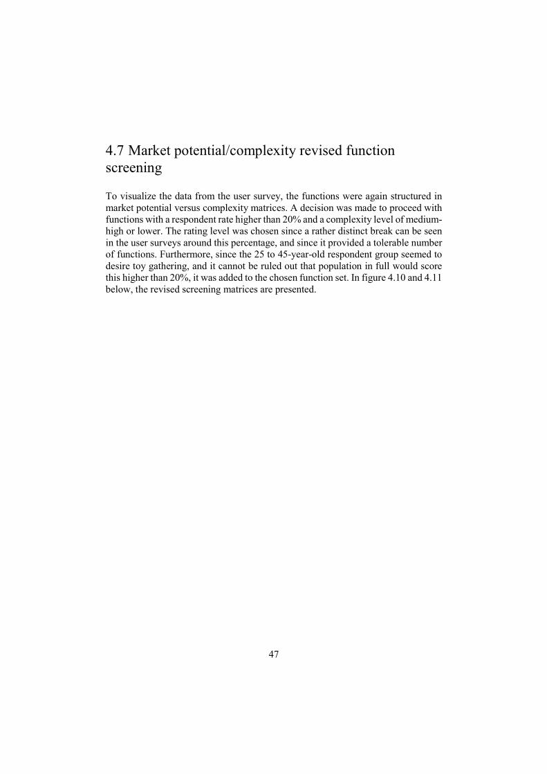
4.7 Market potential/complexity revised function screening
To visualize the data from the user survey, the functions were again structured in market potential versus complexity matrices. A decision was made to proceed with functions with a respondent rate higher than 20% and a complexity level of medium-high or lower. The rating level was chosen since a rather distinct break can be seen in the user surveys around this percentage, and since it provided a tolerable number of functions. Furthermore, since the 25 to 45-year-old respondent group seemed to desire toy gathering, and it cannot be ruled out that population in full would score this higher than 20%, it was added to the chosen function set. In figure 4.10 and 4.11 below, the revised screening matrices are presented.
48
Figure 4.10. Function screening - Outdoor functions

49
Figure 4.11. Function screening - Indoor functions
50
Platform architecture development
Following the function screening, two possible options of moving forward were considered. Option A was to form different modules based on the chosen functions and based on these groupings generate concept solutions for the different modules and platform. Option B was to generate concept solutions for all the different functions separately, and then group these solutions based on similarity.
It was decided to go with Option B. The main reason was that Option A would probably result in a personal and informal concept generation process for each team member, which could cause misunderstanding and different perceptions of the task. The concept generation for the different functions was done very informally using brainstorming and discussions.
With the different concept solutions fresh in mind, a platform architecture concept generation process was conducted, using brainstorming and concept combining. The resulting concepts were then evaluated using the approach explained in chapter 4.1.6.1. Two scorings were done, since the first one yielded several concepts at the same score. For the second one the different factors were weighted, and a wider scoring scale was used. The different concepts and scoring matrices can be found in Appendix E.
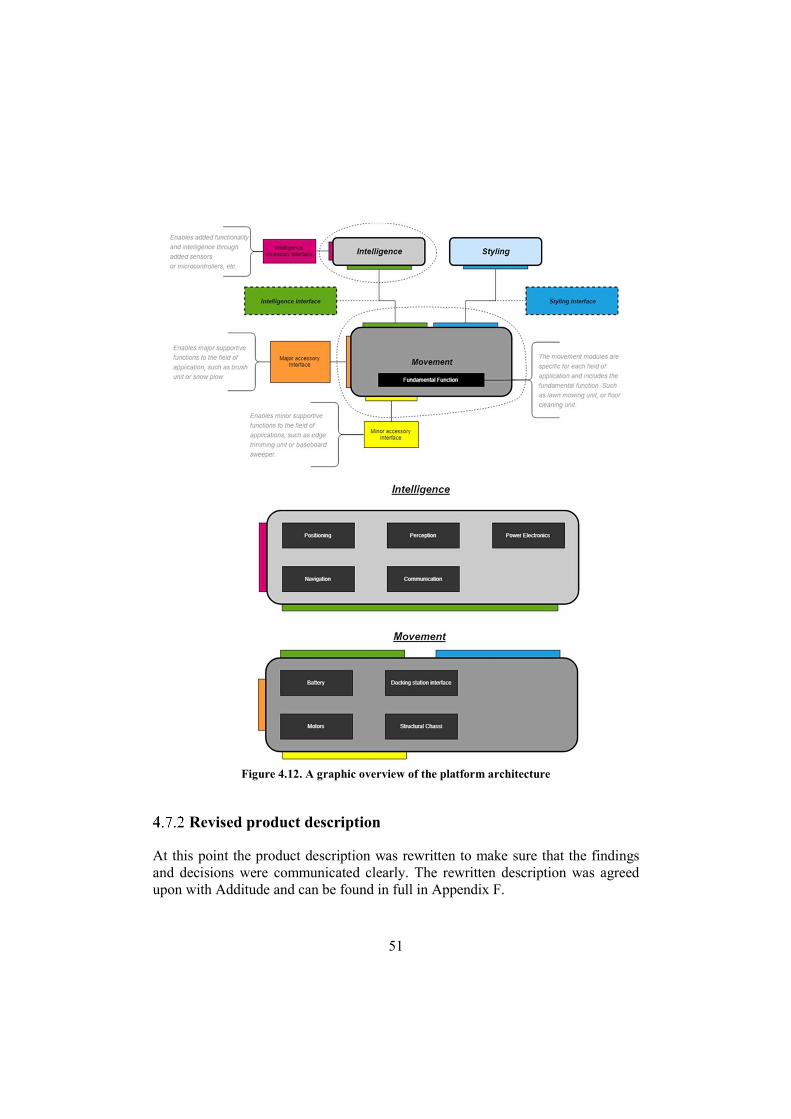
The chosen architecture concept consists of a stationary base station and a rover. The rover is in turn composed of an intelligence module that is shared across different application areas, plus a movement module that is application specific. The movement module satisfies the main functional requirement of one application area, e.g. mows grass or removes dust. Added functionality is achieved through accessory modules that are attached to the movement and/or intelligence module using standardized interfaces. On the next page, in figure 4.12, a graphic explaining the intended architecture is shown.
51
Revised product description
At this point the product description was rewritten to make sure that the findings and decisions were communicated clearly. The rewritten description was agreed upon with Additude and can be found in full in Appendix F.
Figure 4.12. A graphic overview of the platform architecture
52
Develop
The Develop phase is, like the Define phase, a divergent phase. Our goal for this period was to produce possible concepts and aesthetic designs for the revised product description. Intelligence platform, lawn mower (movement) module, base station and accessory interfaces were covered. The chapter starts with an overview of different positioning and mapping systems, necessary in order to choose intelligence concept.
5.1 Positioning and mapping systems
A key feature of the base platform is that it should be able to determine its position and workspace limits. Preferably this should be done with no need for extra hardware or installation work, the perimeter wire solution commonly employed in robotic lawn mowers is explicitly unwanted by Additude. Furthermore, no separate mapping of obstacles within the work area should be needed. The topic of simultaneous localization and mapping (SLAM) is a popular research subject, and several approaches to solve this has been implemented [54]. In order to understand the relevance of the different approaches a brief technology survey of positioning and ranging technologies, and their limitations was done. This is presented below.
Satellite-based radio positioning systems (GPS, Galileo and more)
In short, satellite-based radio positioning systems determine a user's position through triangulation of radio signals transmitted from the satellites. Due to the wide coverage achieved by one satellite, a global coverage of the system can be achieved. A common name for these systems is global navigation satellite systems (GNSS). The most common GNSS is the GPS system, made available by the U.S government. Simple GPS-enabled smartphones can typically determine the position accurately within a 4.9m radius, under open sky. However, using high-end technology and different augmentation techniques much more precise positioning can be achieved. [55]
53
Due to the strategic importance of a global positioning system several countries are either developing or already running alternatives to GPS, such as Galileo (European Union) [56], GLONASS (Russia) [57], BeiDou (China) [58] and IRNSS (India) [59].
5.1.1.1 Area augmentation systems
There are several different approaches and techniques in order to enhance the accuracy of a GNSS. One approach is the use of regional satellite-based augmentation systems (SBABs). Such a system is based on several accurately located ground reference stations that collect GNSS measurements which then are compared to the known reference positions. [60]
Based on this, corrections for ionospheric disturbances affecting positioning in the covered area can be made. This correction information is then broadcasted over the coverage area using geostationary satellites. [61]
Several different systems are employed such as WAAS (USA), MSAS (Japan), GAGAN (India), SNAS (China), WADGPS (South Korea) and SDCM (Russia) [60]. According to the European Space Agency (ESA) the Egnos system improves GNSS positioning to 1-3 m horizontally [62].
A variant of SBAS is differential GPS (DGPS). The basic principle is the same as for SBAS, but the correction information is not broadcasted using satellites but broadcasted locally, usually using RF signals. [63]
5.1.1.2 Dual frequency receivers
Another approach is using dual frequency receivers. Simple GNSS receivers operate only on one frequency band, typically L1/E1, corresponding to 1559 – 1610 MHz [64]. More advanced receivers operate on two, or more, frequency bands. Since the ionospheric error varies with frequency, a comparison of the time delay for the two signals allows for a correction of the error [65]. One example implementing this is the newly released BCM47755 by Broadcom. According to the company the receiver is capable of centimetre-level accuracy [66]. The receiver is being deployed in the MI 8 smartphone by Xiaomi where it according to the producer enables a positioning accuracy of up to a few decimetres for the device [67].
5.1.1.3 Real-time Kinematic correction
Another interesting approach is the use of Real-Time Kinematic (RTK) correction techniques in order to correct the GNSS fix. A local RTK system incorporates a stationary base station and a mobile rover. The position of the base station must be well established, since this will be used as a reference for the rover. Simply put, the range to the satellite is calculated by determining the number of cycles plus phase position of the radio signal and the signal frequency. This information in
54
combination with correction data from the base station allows the rover to accurately determine the position with a precision of up to 1 cm. [68]
It is important to note that buildings, tunnels and other objects may interfere with the signals, making GNSS unsuitable for indoor positioning [69].
Sonic positioning systems
Sonic sensors can be used for distance measurements by sending and receiving a sound pulse. When measuring the time difference between the sent and received pulse, the distance can be determined. This is referred to as a time-of-flight (ToF) measurement. If an array of sensors, or a rotating sensor, is used, the technology can be used to construct a map of the environment. Submarines commonly employ sonic sensors active in the frequency range of 1kHz to 10kHz. Ultrasonic sensors, on the other hand, operate above audible frequencies, making them inaudible for the human ear. [70]
They are a cheap option for distance measurements and obstacle detection, such as the HC-SR04 which is currently priced below 4 USD, with a range up to 4m and a precision up to 3mm [71]. Some Benefits of sonic sensors are [70, pp. 753-762], [72]:
They are unaffected by surface colour, making them suitable for dark environments
Work well in dusty, dirty and moist conditions Can accurately detect mirrors and glass surfaces.
Some limitations of the technology include [72], [70, pp. 753-762]:
Poor directional resolution, wide beams occlude small openings, limiting robot navigation.
Soft materials tend to absorb some of the waves instead of reflecting them. Variations in sound speed cause fluctuations in the measured travel time,
resulting in precision loss. Environmental factors such as temperature change affects sound speed.
Relatively slow sensing rate, especially problematic in reverberant environments where false readings may be encountered or when several sensors are used in parallel.
In unfavourable conditions, smooth surfaces can redirect the sound waves, rendering them invisible for the sensor.
In some environments multiple reflections can produce false readings, indicating physical objects where there is none.
55
Much like GNSS and satellite systems, active sonic beacons with known, fixed positions can be used for positioning. This does not provide any information regarding the environment but can be used to accurately position the receiver. One drawback of sonic beacon systems is that the relatively short-range sonic signals are sensitive to obstacles and walls, meaning that in order to cover a large area, or several rooms, several active beacons would be needed. This adds installation costs and complexity. [73]
Dead Reckoning
Dead reckoning is the process of determining the current position based on a previously established one, as a function of time. The most common way to accomplish this within autonomous vehicles is through odometry, which utilises motion sensor data from mechanisms such as wheels, legs or other types of movement solutions to estimate distance and direction travelled. However, since the latest position is determined through the collection of movement data, the method inherently implies that any errors in the data collection will accumulate over time and distance travelled. In other words, the farther the unit travels, the less likely it is that it knows where it is. To determine the absolute position error other methods can be used intermittently. [70] [74]
An example of dead reckoning could be applied to a train. Suppose a train has odometrical sensors in the form of rotary encoders connected to its wheels. As the train leaves a station, the encoders can provide information about the distance travelled and speed if considering time passed. The data can be used to estimate a relative position of the train and hence how well it is keeping its timetable. However, errors such as wheel slip on the tracks will accumulate over time. At the next station, a sensor will record the absolute position of the train and the error and timetable will be corrected.
Suppose the train is a robotic unit, the railway the planned path, and the stations another method of positioning, such as GPS or LPS. Between GPS measurement points or blind spots, the odometrical measurements provide a good estimation of where the unit is. Especially if combined with a heading sensor, such as a gyroscope, and a motion sensor, such as an accelerometer, to help reduce errors accumulated by e.g. slipping actions of the wheel.
56
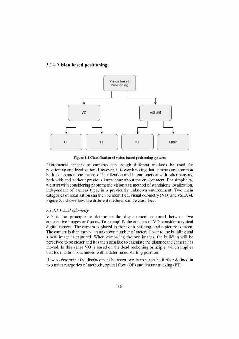
Vision based positioning
Figure 5.1 Classification of vision-based positioning systems
Photometric sensors or cameras can trough different methods be used for positioning and localization. However, it is worth noting that cameras are common both as a standalone means of localization and in conjunction with other sensors, both with and without previous knowledge about the environment. For simplicity, we start with considering photometric vision as a method of standalone localization, independent of camera type, in a previously unknown environment. Two main categories of localisation can then be identified, visual odometry (VO) and vSLAM. Figure 5.1 shows how the different methods can be classified.
5.1.4.1 Visual odometry
VO is the principle to determine the displacement occurred between two consecutive images or frames. To exemplify the concept of VO, consider a typical digital camera. The camera is placed in front of a building, and a picture is taken. The camera is then moved an unknown number of meters closer to the building and a new image is captured. When comparing the two images, the building will be perceived to be closer and it is then possible to calculate the distance the camera has moved. In this sense VO is based on the dead reckoning principle, which implies that localization is achieved with a determined starting position.
How to determine the displacement between two frames can be further defined in two main categories of methods, optical flow (OF) and feature tracking (FT).
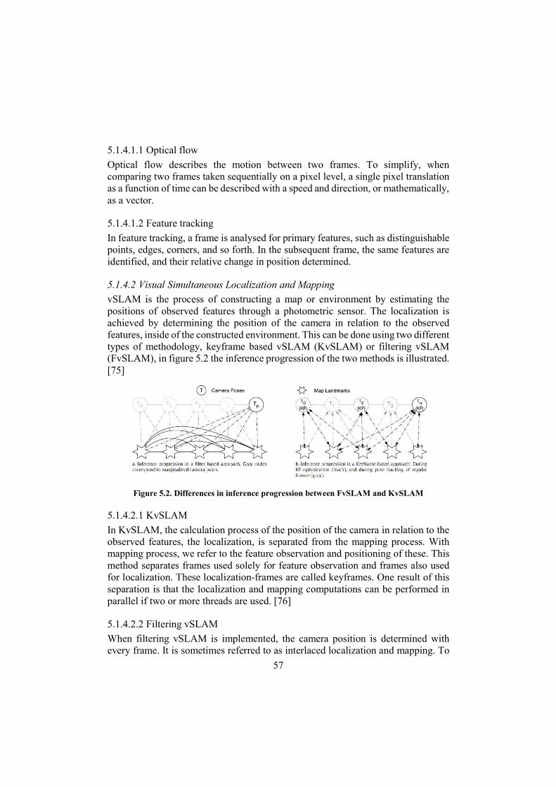
57
5.1.4.1.1 Optical flow
Optical flow describes the motion between two frames. To simplify, when comparing two frames taken sequentially on a pixel level, a single pixel translation as a function of time can be described with a speed and direction, or mathematically, as a vector.
5.1.4.1.2 Feature tracking
In feature tracking, a frame is analysed for primary features, such as distinguishable points, edges, corners, and so forth. In the subsequent frame, the same features are identified, and their relative change in position determined.
5.1.4.2 Visual Simultaneous Localization and Mapping
vSLAM is the process of constructing a map or environment by estimating the positions of observed features through a photometric sensor. The localization is achieved by determining the position of the camera in relation to the observed features, inside of the constructed environment. This can be done using two different types of methodology, keyframe based vSLAM (KvSLAM) or filtering vSLAM (FvSLAM), in figure 5.2 the inference progression of the two methods is illustrated. [75]
Figure 5.2. Differences in inference progression between FvSLAM and KvSLAM
5.1.4.2.1 KvSLAM
In KvSLAM, the calculation process of the position of the camera in relation to the observed features, the localization, is separated from the mapping process. With mapping process, we refer to the feature observation and positioning of these. This method separates frames used solely for feature observation and frames also used for localization. These localization-frames are called keyframes. One result of this separation is that the localization and mapping computations can be performed in parallel if two or more threads are used. [76]
5.1.4.2.2 Filtering vSLAM
When filtering vSLAM is implemented, the camera position is determined with every frame. It is sometimes referred to as interlaced localization and mapping. To
58
achieve this, several filters are usually utilized, such as extended Kalman filter or particle filter. A study performed by the Imperial College in London proved in 2011 that a keyframe based method is considerably more efficient than a filtering method in respect to both precision and computational expense. [77]
5.1.4.3 Photometric vison sensors
With the different methods for utilizing photometric sensors or cameras for positioning defined above, this section aims to describe the main types of photometric vison sensors available. [72]
Monocular camera RGB-D Sensor Stereo Cameras Event camera Omni-directional camera
5.1.4.3.1 Monocular camera
Monocular cameras are as the name implies, single camera lenses standard RGB cameras. In other words, a typical digital camera or recorder.
5.1.4.3.2 RGB-D Sensor
RGB-D sensors are a combination of IR-transmitter and receiver and a monocular camera. The IR unit means it can provide information about pixel-distance, similarly to a LIDAR or sonic system, utilizing ToF. The most commonly known version of this camera-type is the Microsoft Kinect Sensor.
5.1.4.3.3 Stereo Cameras
Stereo cameras are inspired by the human eyes and work much in the same way. The principle is simple, two lenses with a known distance apart, perceives the same object at a certain distance. If the object is very far away, then the two images captures by the different lenses, will be perceived to be at almost identical. However, if an object is very close, the right lens will perceive the object far to the right, and the left lens will perceive the object far to the left. When comparing the frames on a pixel level, it is possible to calculate the pixel-offset and hence determine the distance of the object from the camera. [78]
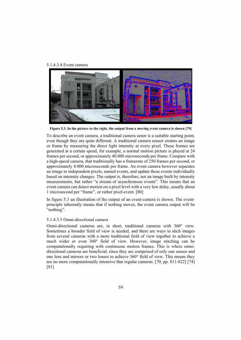
59
5.1.4.3.4 Event camera
Figure 5.3. In the picture to the right, the output from a moving event camera is shown [79]
To describe an event camera, a traditional camera senor is a suitable starting point, even though they are quite different. A traditional camera sensor creates an image or frame by measuring the direct light intensity at every pixel. These frames are generated at a certain speed, for example, a normal motion picture is played at 24 frames per second, or approximately 40.000 microseconds per frame. Compare with a high-speed camera, that traditionally has a framerate of 250 frames per second, or approximately 4.000 microseconds per frame. An event camera however separates an image to independent pixels, named events, and update these events individually based on intensity changes. The output is, therefore, not an image built by intensity measurements, but rather “a stream of asynchronous events”. This means that an event camera can detect motion on a pixel level with a very low delay, usually about 1 microsecond per “frame”, or rather pixel-event. [80]
In figure 5.3 an illustration of the output of an event-camera is shown. The event-principle inherently means that if nothing moves, the event camera output will be “nothing”.
5.1.4.3.5 Omni-directional camera
Omni-directional cameras are, in short, traditional cameras with 360° view. Sometimes a broader field of view is needed, and there are ways to stich images from several cameras with a more traditional field of view together to achieve a much wider or even 360° field of view. However, image stitching can be computationally requiring with continuous motion frames. This is where omni-directional cameras are beneficial, since they are comprised of only one sensor and one lens and mirrors or two lenses to achieve 360° field of view. This means they are no more computationally intensive that regular cameras. [70, pp. 811-822] [74] [81]
60
LIDAR
The word LIDAR originates from a blend of light and radar [82]. It is a light-based technology that can be used to measure distances based on time-of-flight measurements, the same principle as used in sonic sensors. In its simplest form, a single laser beam is transmitted, providing distance information to one single point. In order to obtain more information, the beam can be swept across a surface, generating a vector of distance measurements. To obtain even more information several laser beams arranged vertically can be simultaneously swept, or one beam can be swept both horizontally and vertically, providing several distance vectors at different heights. This data can be used to create a map of the environment and determine the robot's current position. [70]
Available LIDAR units are expensive, although there is a wide price range. The Xiaomi MiJia Roborock 2 is a robotic vacuum cleaner that features a 360-degree rotational LIDAR unit [83]. This LIDAR unit can be bought as a spare part for roughly 100 USD.
Some LIDAR characteristics are [72] [70, pp. 783-794]:
High range, up to several hundred meters At least centimetre level accuracy Some materials, such as glass, will not reflect the laser and remain
undetected. Heavy rain and fog can be problematic since it can scatter the light. Works in both sunlight and darkness
RADAR
Radio detection and ranging (RADAR) is another distance measuring technology that is based on ToF measurements. Like LIDAR, RADAR employs electromagnetic waves, but in the micro and radio wave frequency spectrum. Depending on chosen frequency the atmospheric signal attenuation characteristics change, but for the applications considered in this work RADAR systems can operate regardless of environmental conditions. RADAR systems are suitable for long-range detection of objects and can be used in applications such as airplane detection or automotive collision avoidance systems. [84]
The angular resolution of RADAR technology depends on antenna characteristics but is in general good. This means that if the antenna pointing angle is redirected in between measurements the azimuth and elevation angles for detected objects can be
61
determined. Beam redirection can be done either mechanically using for example a rotating antenna, or electrically using phased antenna arrays. Furthermore, due to the Doppler effect moving objects cause frequency variations which can be detected and used to calculate object speed. [84]
5.1.6.1 Short range radar
One interesting short-range radar is the Acconeer A1 radar sensor. It is a one chip solution with integrated antenna, a power consumption well below 1W and a stated measuring range of 60-2000 mm, with millimetre level precision. Furthermore, it can distinguish between materials with different dielectric constants. [85]
The current unit cost for orders above 1.000 units is roughly 6 USD [86].
5.1.6.2 Radio frequency beacons
Several different approaches employing radio frequency signals and active beacons has been tested, including Wi-Fi™ (wireless local area network IEEE 802.11) [87] and Bluetooth based systems [88]. The benefit of using these technologies is that they are readily available and already deployed in many environments, however they suffer from relatively low accuracy and range and are sensitive to objects and walls [89] [90].
5.1.6.3 Ultra-wideband Beacons
Ultrawide-band (UWB) is low-energy signals, broadcasted over a wide spectrum, typically over 500 MHz [91]. It is generally regarded as a method with good object penetration, low power consumption and relatively good accuracy in positioning. However, it is considered a short-range method compared to other radar systems [92].
An interesting application of the UWB technology is an indoor positioning system by a company called Pozyx. They utilize four beacons and a locator on the rover to achieve cm accuracy localization. According to their specification, the Pozyx system should be able to penetrate 1-2 walls, and outside in a clear line of sight, able to reach up to 100 meters. [93] [94]
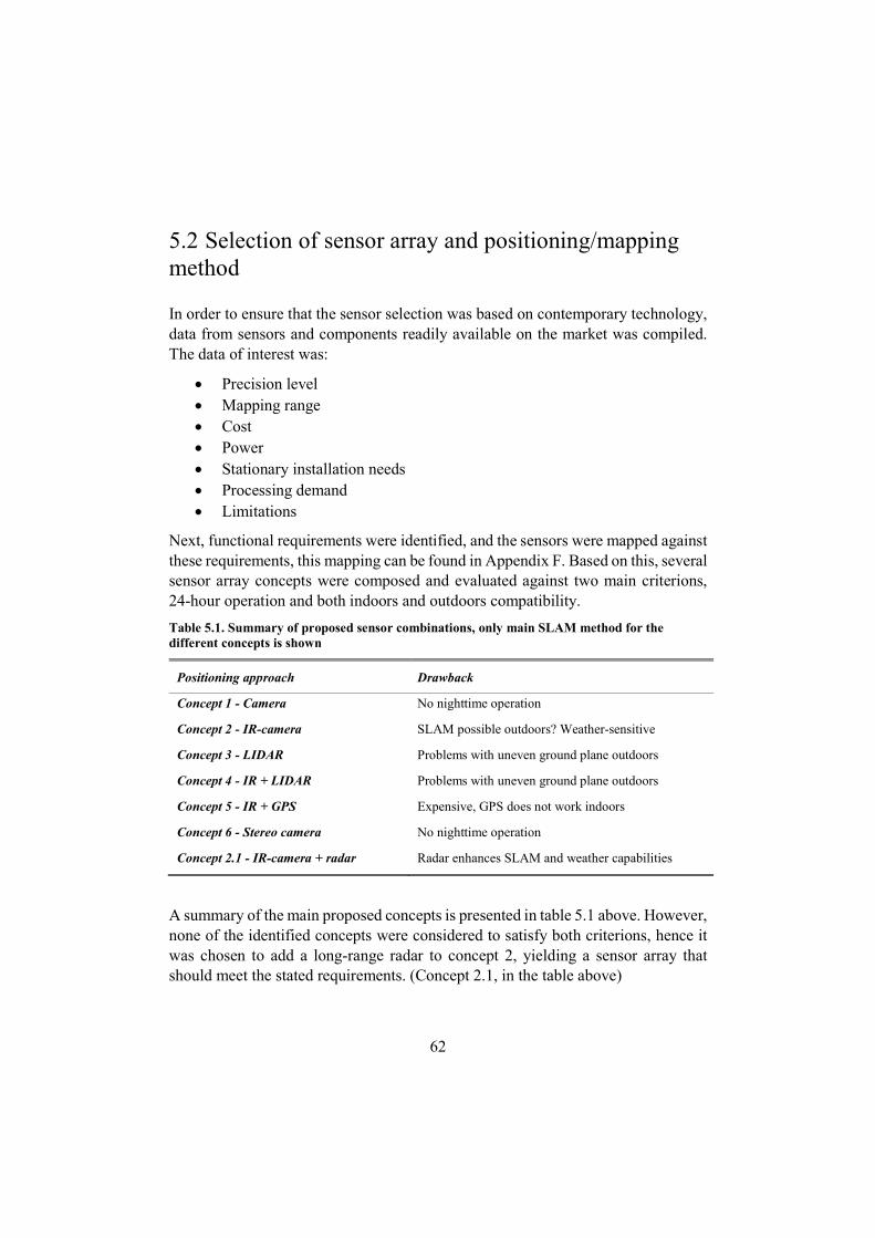
62
5.2 Selection of sensor array and positioning/mapping method
In order to ensure that the sensor selection was based on contemporary technology, data from sensors and components readily available on the market was compiled. The data of interest was:
Precision level Mapping range Cost Power Stationary installation needs Processing demand Limitations
Next, functional requirements were identified, and the sensors were mapped against these requirements, this mapping can be found in Appendix F. Based on this, several sensor array concepts were composed and evaluated against two main criterions, 24-hour operation and both indoors and outdoors compatibility.
Table 5.1. Summary of proposed sensor combinations, only main SLAM method for the different concepts is shown
Positioning approach Drawback
Concept 1 - Camera No nighttime operation
Concept 2 - IR-camera SLAM possible outdoors? Weather-sensitive
Concept 3 - LIDAR Problems with uneven ground plane outdoors
Concept 4 - IR + LIDAR Problems with uneven ground plane outdoors
Concept 5 - IR + GPS Expensive, GPS does not work indoors
Concept 6 - Stereo camera No nighttime operation
Concept 2.1 - IR-camera + radar Radar enhances SLAM and weather capabilities
A summary of the main proposed concepts is presented in table 5.1 above. However, none of the identified concepts were considered to satisfy both criterions, hence it was chosen to add a long-range radar to concept 2, yielding a sensor array that should meet the stated requirements. (Concept 2.1, in the table above)
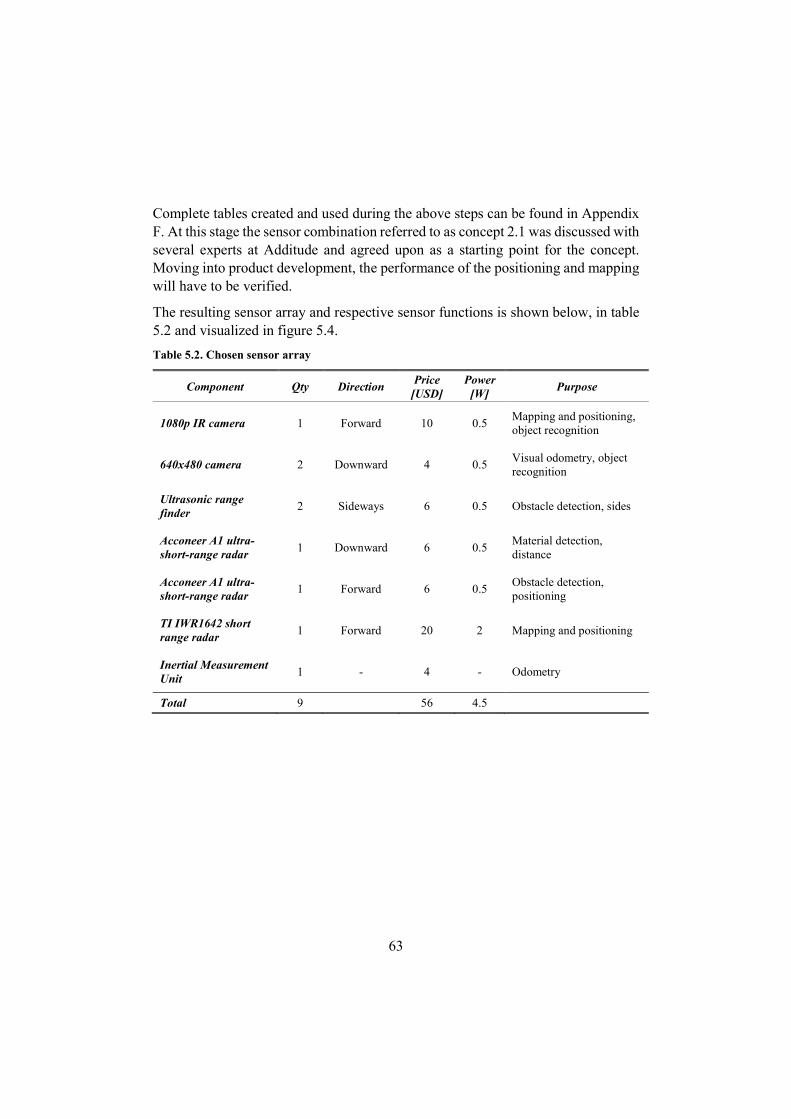
63
Complete tables created and used during the above steps can be found in Appendix F. At this stage the sensor combination referred to as concept 2.1 was discussed with several experts at Additude and agreed upon as a starting point for the concept. Moving into product development, the performance of the positioning and mapping will have to be verified.
The resulting sensor array and respective sensor functions is shown below, in table 5.2 and visualized in figure 5.4.
Table 5.2. Chosen sensor array
Component Qty Direction Price
[USD] Power
[W] Purpose
1080p IR camera 1 Forward 10 0.5 Mapping and positioning, object recognition
640x480 camera 2 Downward 4 0.5 Visual odometry, object recognition
Ultrasonic range finder
2 Sideways 6 0.5 Obstacle detection, sides
Acconeer A1 ultra-short-range radar
1 Downward 6 0.5 Material detection, distance
Acconeer A1 ultra-short-range radar
1 Forward 6 0.5 Obstacle detection, positioning
TI IWR1642 short range radar
1 Forward 20 2 Mapping and positioning
Inertial Measurement Unit
1 - 4 - Odometry
Total 9 56 4.5
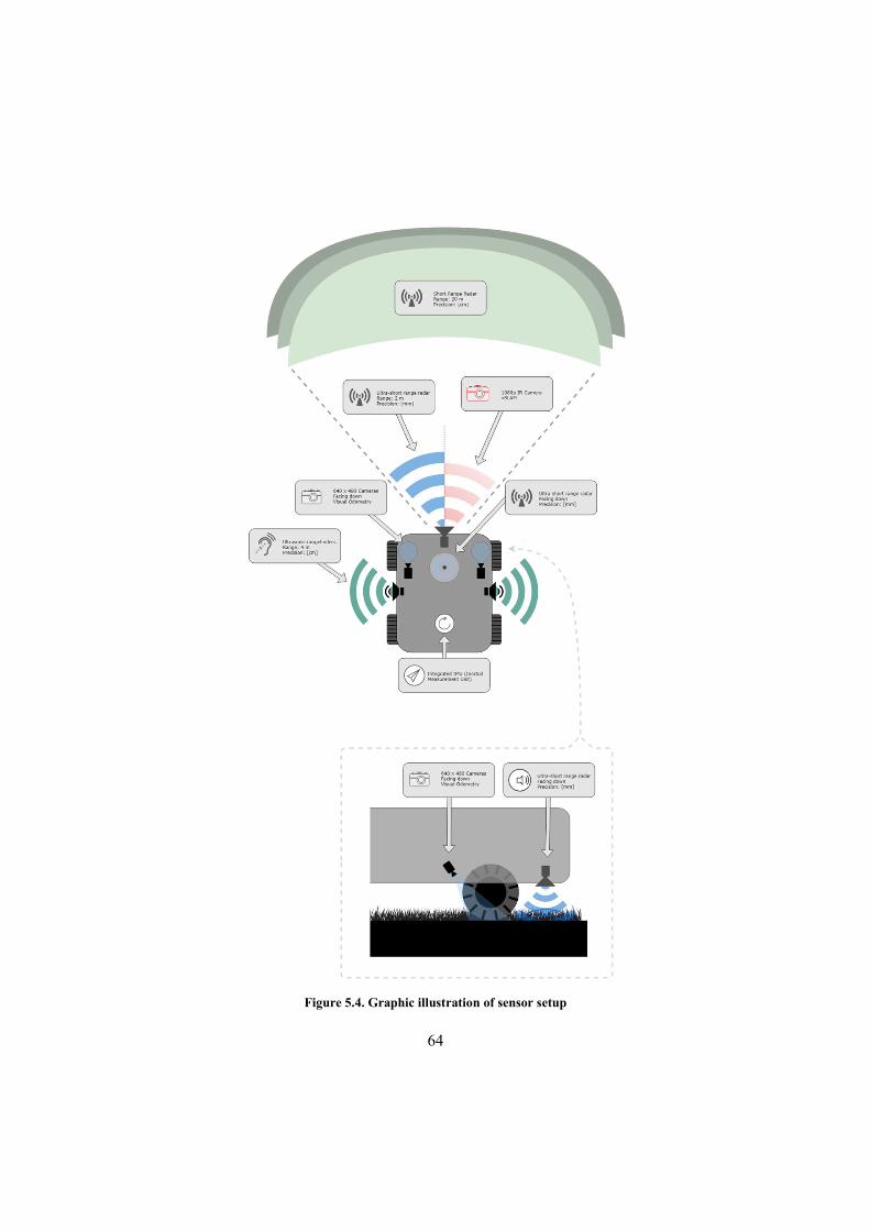
64
Figure 5.4. Graphic illustration of sensor setup

65
5.3 Processing and connectivity
The chosen sensor concept implies that image processing will be needed for the positioning and obstacle recognition. Depending on chosen algorithm and functionality the required processing capability will vary significantly. Determining the processor needs was outside of the scope of this thesis, but it was realised that high processing demands impacts both cost and power budget.
Real-time positioning is not a criterion due to the low velocities and the possibility for the rover to take short pauses in order to establish its position. Furthermore, in a case where dead reckoning is used in between known positions, the real-time criteria can be eliminated without the need for frequent stops. Utilising a cloud solution and off-loading the data for external computing would alleviate the processing requirements of the physical platform while simultaneously providing a centralized software system, implying scale benefits regarding feature recognition and software changes.
However, this would also imply that all products would need at least an intermittent internet connection of some sort, if during short periods offline the positioning could be handled locally. A cloud solution would of course also have a cost, but the decrease of hardware cost and software benefits were considered to outweigh the drawbacks.
A possible way to allow offline positioning could be to separate mapping and imaging while offline. In short, if the rover sense that it has lost internet connection and that it according to odometry readings should be well inside the working area, it could take a series of images before backing out to the last known position with internet connection. When the connection is re-established, the images would be off-loaded for calculations allowing the system to map the covered area. Several other approaches could be viable as well, such as simply performing the calculations onboard at a significantly lower speed.
The combination of cloud-computing and a lower end processor was chosen in consultation with Additude and will not be further elaborated upon. Regarding connectivity, it was chosen that the base station should be connected to the internet, while the rover establishes internet connection through a local connection with the base station. This connection should be some sort of RF connection capable of handling both long range connection and obstacles, e.g. walls. It could possibly be a Wi-Fi™ network or a bespoke system. This decision was also done in consultation with Additude.
It should be noted that the rover system should have a set of 3.3 V input/output channels in order to allow the user to connect external devices such as microcontrollers, allowing customization and “hacking”. These channels should be

66
accessible for programming, e.g. “if rover enters base station, set output X to high” and similar.
A brief feasibility study of cloud based vSLAM systems was performed, and several successful approaches achieving real-time performance was found [95] [96] [97].
It was assumed that a Raspberry PI 3B+ would be capable enough to use, hence specifications for this device was used for power budget and packaging.
5.4 Lawn mower movement module
Following the definition of the intelligence module, the movement module for the lawn mowing functionality was defined.
Movement and mowing concepts
Once again, brainstorming and scoring matrices was used in order to choose movement and mowing concepts. A very traditional combination of four wheels and a spinning disc with attached razorblades was chosen.
A three wheeled solution was considered to be an option as well, if the exterior design would benefit from it. The scoring matrices can be found in Appendix E.
Technical specifications, power budget and packaging
Target dimensions and driving/cutting motor power rating was set using specifications from an Automower 450X as benchmark. For the accessory modules a power rating of 20W was assumed (same as for the cutting motor). In order to estimate the power consumption, it was assumed that a maximum of two modules would be running at the same time as the cutting motor. Based on these numbers and the specifications of the intelligence module, a total maximum power consumption of ca 130W was computed.
If the battery pack voltage would be 18V, which is a common voltage for e.g. power tools, it could consist of 4 parallel lines of 5 18650 cells at a nominal voltage of 3.7V each. LG Chemicals can provide 18650 cells rated at 3500 mAh [98]. If these were used a total capacity of roughly 260 Wh would be possible. According to our estimations, found in full in Appendix G, this would result in an area coverage of roughly 3.700 m2/day.

67
Based on the dimensions gained above a rough packaging model was created in Autodesk Fusion 360 (AF 360). The technical specifications and power budget can be found in full in Appendix G.
Aesthetic concepts
After discussions with Additude, it was decided to temporarily step back from the created packaging model in order to not constrain the creative process. Hence several models of different aesthetic designs were created in AF 360. An iterative process of sketching, modelling and evaluating was performed until a refined aesthetic design was reached. In figure 5.5 the refined aesthetic design is shown, all the different designs are shown in Appendix E.
Figure 5.5. The refined rover aesthetic design
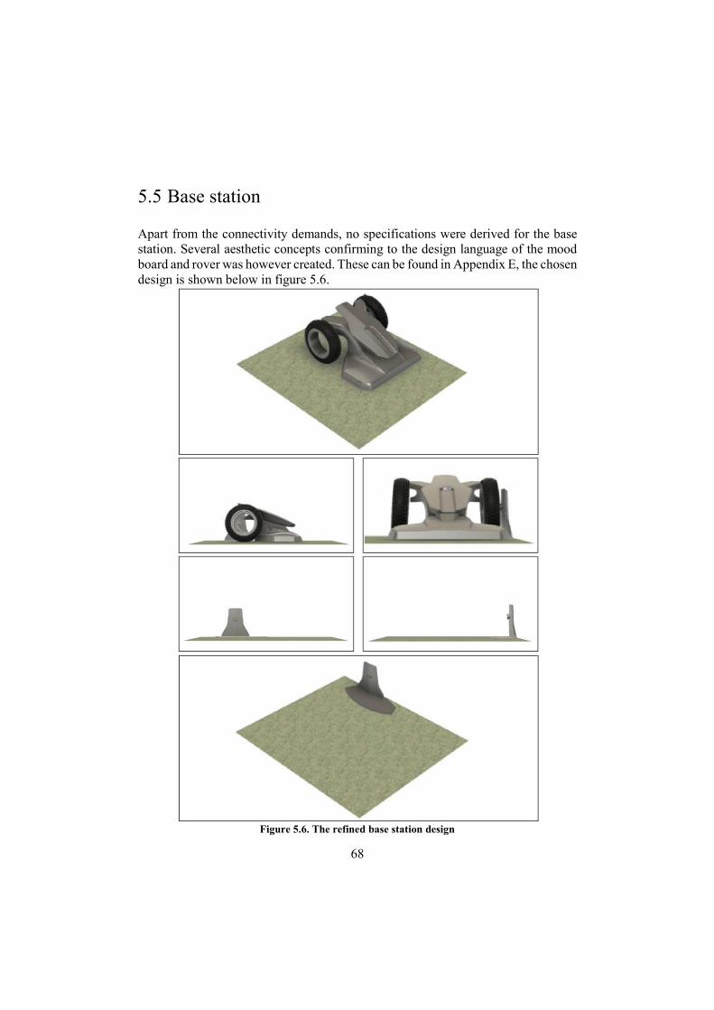
68
5.5 Base station
Apart from the connectivity demands, no specifications were derived for the base station. Several aesthetic concepts confirming to the design language of the mood board and rover was however created. These can be found in Appendix E, the chosen design is shown below in figure 5.6.
Figure 5.6. The refined base station design
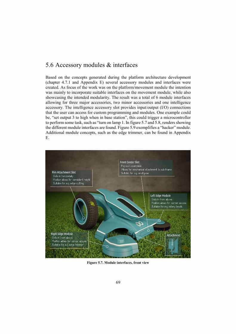
69
5.6 Accessory modules & interfaces
Based on the concepts generated during the platform architecture development (chapter 4.7.1 and Appendix E) several accessory modules and interfaces were created. As focus of the work was on the platform/movement module the intention was mainly to incorporate suitable interfaces on the movement module, while also showcasing the intended modularity. The result was a total of 6 module interfaces allowing for three major accessories, two minor accessories and one intelligence accessory. The intelligence accessory slot provides input/output (I/O) connections that the user can access for custom programming and modules. One example could be, “set output 3 to high when in base station”, this could trigger a microcontroller to perform some task, such as “turn on lamp 1. In figure 5.7 and 5.8, renders showing the different module interfaces are found. Figure 5.9 exemplifies a “hacker” module. Additional module concepts, such as the edge trimmer, can be found in Appendix E.
Figure 5.7. Module interfaces, front view
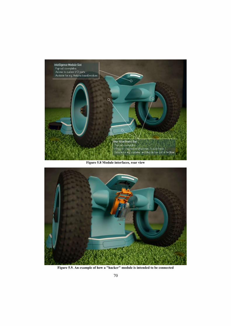
70
Figure 5.9. An example of how a "hacker" module is intended to be connected
Figure 5.8 Module interfaces, rear view
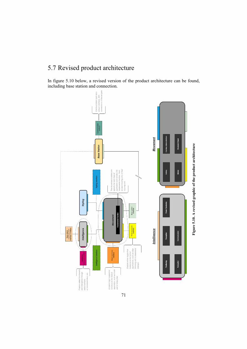
71
5.7 Revised product architecture
In figure 5.10 below, a revised version of the product architecture can be found, including base station and connection.
Fig
ure
5.10
. A r
evis
ed g
raph
ic o
f th
e pr
odu
ct a
rchi
tect
ure
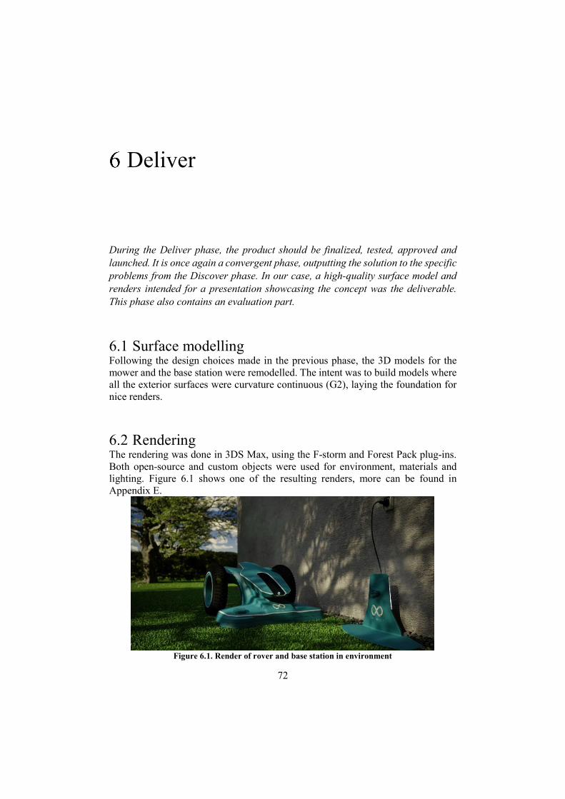
72
Deliver
During the Deliver phase, the product should be finalized, tested, approved and launched. It is once again a convergent phase, outputting the solution to the specific problems from the Discover phase. In our case, a high-quality surface model and renders intended for a presentation showcasing the concept was the deliverable. This phase also contains an evaluation part.
6.1 Surface modelling Following the design choices made in the previous phase, the 3D models for the mower and the base station were remodelled. The intent was to build models where all the exterior surfaces were curvature continuous (G2), laying the foundation for nice renders.
6.2 Rendering The rendering was done in 3DS Max, using the F-storm and Forest Pack plug-ins. Both open-source and custom objects were used for environment, materials and lighting. Figure 6.1 shows one of the resulting renders, more can be found in Appendix E.
Figure 6.1. Render of rover and base station in environment
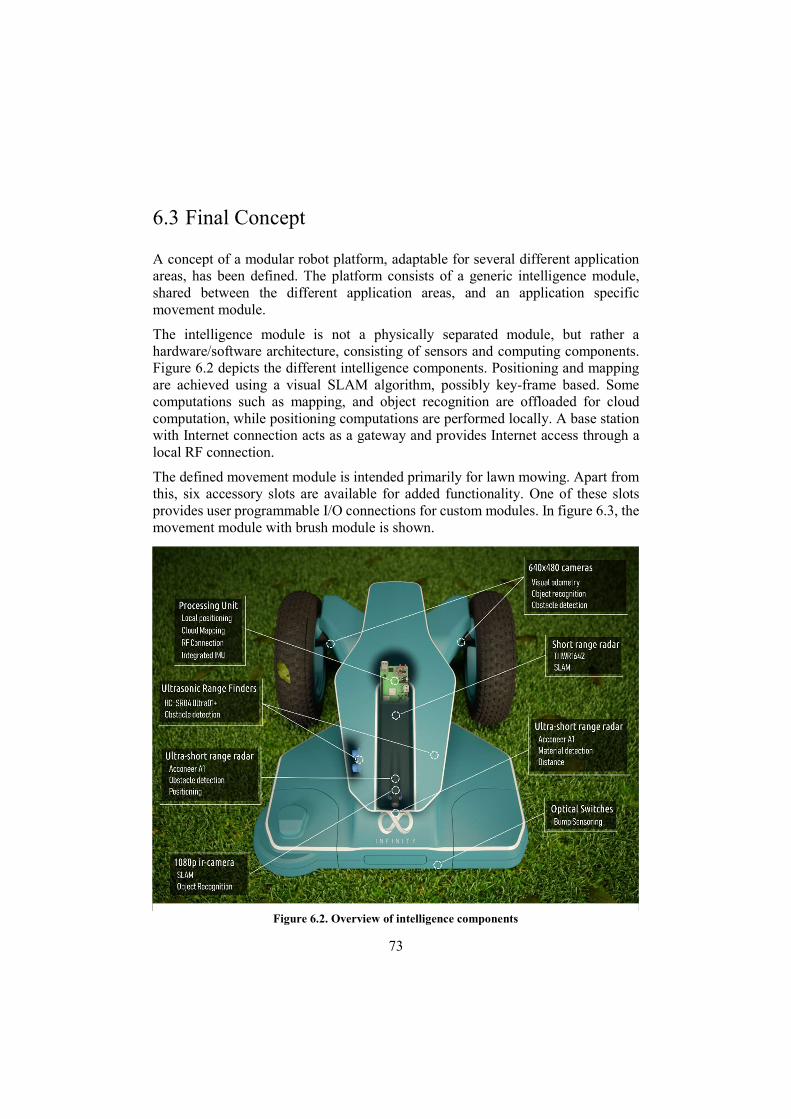
73
6.3 Final Concept
A concept of a modular robot platform, adaptable for several different application areas, has been defined. The platform consists of a generic intelligence module, shared between the different application areas, and an application specific movement module.
The intelligence module is not a physically separated module, but rather a hardware/software architecture, consisting of sensors and computing components. Figure 6.2 depicts the different intelligence components. Positioning and mapping are achieved using a visual SLAM algorithm, possibly key-frame based. Some computations such as mapping, and object recognition are offloaded for cloud computation, while positioning computations are performed locally. A base station with Internet connection acts as a gateway and provides Internet access through a local RF connection.
The defined movement module is intended primarily for lawn mowing. Apart from this, six accessory slots are available for added functionality. One of these slots provides user programmable I/O connections for custom modules. In figure 6.3, the movement module with brush module is shown.
Figure 6.2. Overview of intelligence components
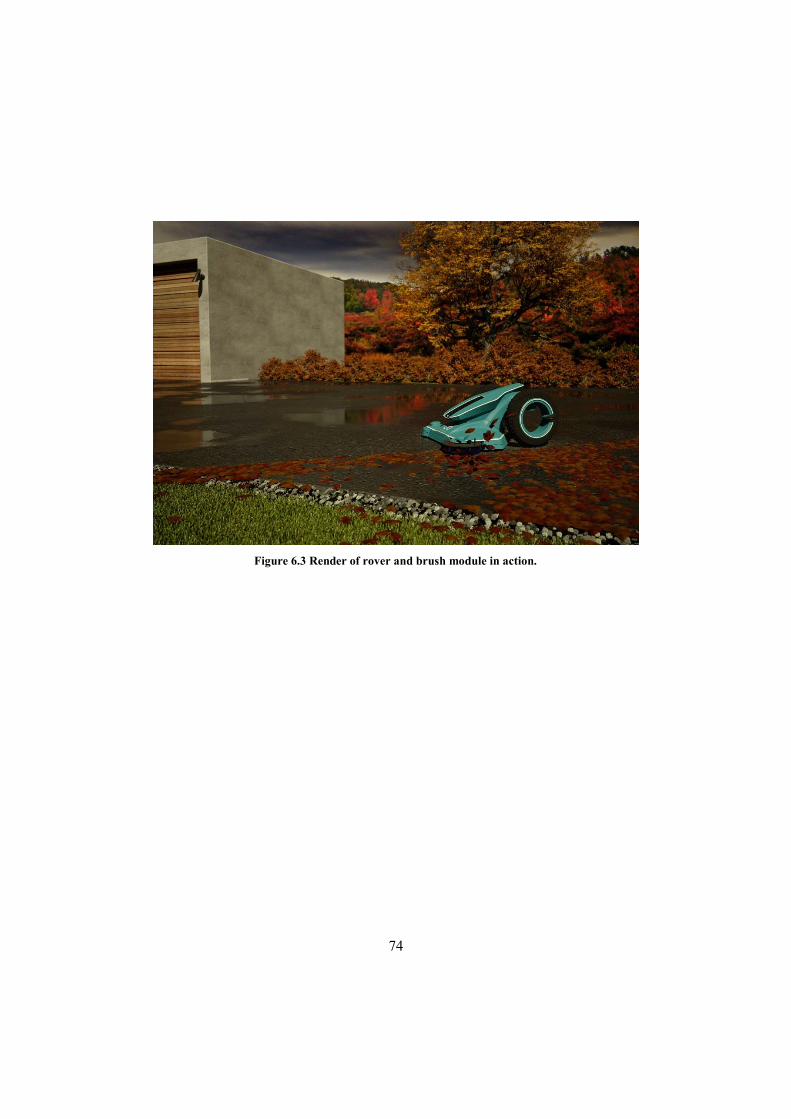
74
Figure 6.3 Render of rover and brush module in action.
75
Discussion
This chapter contains a discussion part where the team evaluates their work and presents future possibilities. The last section evaluates the suitability of the final concepts for the different application areas that were identified.
7.1 The process
The Double Diamond structured worked very well for the team. It is a very flexible and generic structure, rendering it possible to adjust and adapt it for both specific task and team preference. The core idea of two sequential diverging/converging phases ensured that plenty of resources were spent on specifying product description and user group. Also, since it is a widely known structure, plenty of information and suggestions regarding suitable tools for the different phases were available.
Regarding time plan, the initial time allocation between the different phases was slightly changed, one week was shifted from Deliver to Develop. Also, some activities were scrapped, and several were added due to re-evaluation and gained knowledge during the thesis. Most notably, both the exploratory and validating user interviews were scrapped in favour of an applications study and a user survey. Overall, the team is satisfied with the outcome and resource allocation. Initially, the team thought it would have been interesting to include an economic analysis of part costs for the main body/chassis. This was however a low priority task and the only economic aspects that has been considered was regarding the sensors. The planned and actual time plans can be found in Appendix A.
Regarding the user survey, the team would have preferred a more generic respondent base. The one attained is very biased towards current Automower owners, which influences the result, and limits the possibility to draw general conclusions.
76
7.2 The result
As expected, the resulting concept is quite loosely defined. The team was expecting this due to the large scope of the initial brief, which sometimes was a challenge.
One aspect not fully covered and communicated in the report is the user interaction. Several ideas were identified during the thesis that would have been interesting to explore and define more. The connectivity and processing power of the product would allow for a sophisticated user interface and high-level interaction. The team believes that if done properly this interaction could be used to establish a bond between user and product, possibly moving the product identity towards a pet or family member in the user's eyes.
Furthermore, the team is a bit concerned regarding how well the platform can handle rough terrain. Due to aesthetic and packaging reasons the front wheels were kept rather small, which possibly could pose a problem.
7.3 The future
As stated in the previous section, both user interaction and capability to handle rough terrain are aspects that deserve more attention. User interaction is interesting since the team believes that it could be a key differentiator between this product and existing ones on the market. Wheel dimensions and setup should be tested since changing them would have a profound impact on packaging and design.
Furthermore, the team believes that the sensor setup and vSLAM approach should be validated. This would include data handling, fusion of sensor data and connectivity. Preferably a crude prototype with correct dimensions, weight and components should be developed and used as proof of concept.
77
7.4 Application areas revisited
The defined concept’s suitability for the different application areas specified in chapter 4.5, also found in Appendix B, was evaluated. This was done based on the team’s experience and opinions, and is presented below.
Lawn mowing
When evaluating the lawn mowing movement module with the brainstormed functions, it seems compatible with most of them, if bespoke accessory modules are designed. Problematic functions could be roof/solar panel cleaning, pool cleaning, greenhouse cleaning and window cleaning.
Indoor floor cleaning
Functions such as floor cleaning under chairs/sofas, stair climbing, pool cleaning, bathroom cleaning, and opening doors would be problematic for the lawn mowing module. As especially floor cleaning is considered a core function, this application area would benefit from a different movement module.
Sport field/track care
For this application area the lawn mowing movement module would be suitable. Some of the identified functions, such as pool cleaning, would be problematic but the functions that the team considers to be core functions should be possible.
Traffic warden
This application area could maybe work with the lawn mowing movement module, but would benefit from a bespoke one, possible the same as used for “Guard dog”. Problematic functions would be the manoeuvrability over curbs and similar, and the placing of the parking ticket on the car in question. However, this could possibly be solved by retrieving owner contact information from the authorities, which is used to send the ticket electronically. Or, by using the rover as a surveillance system that notifies a human warden where there are illegally parked cars.
78
Guard dog
Similar to “Traffic warden”, problems associated with the lawn mower movement module would be curbs and general accessibility such as opening doors, climbing stairs.
Mine clearing
This application area would need a movement module that handles rough terrain Furthermore, it needs to somehow detect and disarm mines. Detection could possibly be done using ground radar, chemical detectors or similar.
Construction, quality assurance
This application area has similar requirements as the “Guard dog” and could probably use the same movement module.
Snow clearing
This application area could possibly be covered using the lawn mowing movement module, depending on intended end user and snow clearing capacity. It would probably be beneficial to use a movement module with more capable traction system, possibly the mine clearing one.
Surveying
This application area poses similar requirements as the mine clearing and could probably use the same movement module.
Summary
According to this reasoning, in order to cover the application areas above four movement modules (including lawn mowing module), and several accessory modules would need to be designed.
79
References
[1] Husqvarna Group, ”Celebrating 1 million robotic lawn mowers on a growing market,” 21 April 2017. [Online]. Available: http://news.cision.com/husqvarna-ab/r/celebrating-1-million-robotic-lawn-mowers-on-a-growing-market,c2244294. [Retrieved 26 09 2018].
[2] Electrolux Group, ”History 2000-2009,” 2009. [Online]. Available: https://www.electroluxgroup.com/en/history-2000-2009-770/. [Retrieved 5 December 2018].
[3] BBC News, ”Robot Cleaner Hits The Shops,” 16 May 2003. [Online]. Available: http://news.bbc.co.uk/2/hi/technology/3031219.stm. [Retrieved 26 09 2018].
[4] Juniper Research, ”Consumer robotics hardware to reach $23BN per annum by 2022,” 3 April 2018. [Online]. Available: https://www.juniperresearch.com/press/press-releases/consumer-robotics-hardware-revenues-to-reach-$23bn. [Retrieved 27 September 2018].
[5] HUI Research AB; Prisjakt, ”Teknikbarometern Oktober,” 2015.
[6] Design Council, ”The Design Process:: What is the Double Diamond?,” [Online]. Available: https://www.designcouncil.org.uk/news-opinion/design-process-what-double-diamond. [Retrieved 27 09 2018].
[7] K. T. Ulrich och S. D. Eppinger, Produktutveckling, Lund: Studentlitteratur AB, 2014.
[8] Robert Bosch GmbH, ”Appen Bosch Indego Connect,” [Online]. Available: https://www.bosch-garden.com/se/sv/traedg%C3%A5rdsredskap/indego-connectivity.jsp. [Retrieved 14 September 2018].
[9] Robomow Friendly House, ”Robomow App 2.0,” [Online]. Available: https://www.robomow.com/en-GB/app. [Retrieved 14 September 2018].
[10] STIHL Tirol GmbH, ”All the trumps in your hand when mowing. The iMow app.,” [Online]. Available: https://www.viking-garden.com/all-the-trumps-in-your-hand-when-mowing-the-imow-app.aspx#r=stage-teaser. [Retrieved 14 September 2018].
[11] Husqvarna AB, ”Husqvarna Robotic Lawn Mowers AUTOMOWER® 450X,” [Online]. Available: https://www.husqvarna.com/uk/products/robotic-lawn-mowers/automower-450x/967673403/. [Retrieved 14 September 2018].
80
[12] Robert Bosch Power Tools GmbH, ”Beautiful lawns made easy,” [Online]. Available: https://www.bosch-garden.com/media/en-gb/microsites/indego_s_1/indego_s_doc/leaflet_indego_s.pdf. [Retrieved 14 September 2018].
[13] Gardena, ”Gardena smart system produkter smart SILENO,” 2018. [Online]. Available: https://www.gardena.com/se/produkter/smart/smart-system/smart-sileno/967350505/. [Retrieved 14 September 2018].
[14] Cyberceptions Inc., ”Lawnbott Spyder LB1200 Robotic Lawn Mower Review and Overwiev - New,” 2004. [Online]. Available: http://www.probotics.com/lb1200-spyder-lawnbott.htm. [Retrieved 14 September 2018].
[15] M. Estrada, ”This robot vacuum can be controlled with Alexa for hundreds less than a comparable Roomba,” BGR Media, LLC, 5 August 2018. [Online]. Available: https://bgr.com/2018/08/05/best-robot-vacuum-with-alexa-voice-controls/. [Retrieved 14 September 2018].
[16] E. O'Brien, ”Roundup: Robot Vacuums add Connectivity, App, and Voice Control,” Robotics Business Review, EH Publishing Inc, 27 April 2018. [Online]. Available: https://www.roboticsbusinessreview.com/consumer/roundup-robot-vacuums-add-connectivity-app-and-voice-control/. [Retrieved 14 September 2018].
[17] A. Kooser, ”LG voice-activated vacuum robot does your cleaning bidding,” CBS Interactive Inc., 16 April 2013. [Online]. Available: https://www.cnet.com/news/lg-voice-activated-vacuum-robot-does-your-cleaning-bidding/. [Retrieved 14 September 2018].
[18] iRobot Corporation, ”Braava® Mopping Robot,” 2018. [Online]. Available: https://store.irobot.com/default/braava-floor-mopping-irobot-braava-floor-mopping/B380020.html. [Retrieved 14 September 2018].
[19] iRobot Corporation, ”Roomba® 980 Dammsugarrobot,” 2018. [Online]. Available: https://butik.irobot.se/roomba-dammsugarrobot-robot-stofzuigrobot-roomba-980/R980040.html. [Retrieved 14 September 2018].
[20] Neato Robotics, Inc, ”LaserSmart: Kartläggning & navigering,” 2018. [Online]. Available: https://www.neatorobotics.com/se/lasersmart-kartlaggning-navigering/. [Retrieved 14 September 2018].
[21] ECOVACS, ”Deebot R98 | Vacuum Cleaning Robot,” 2017. [Online]. Available: https://www.ecovacs.com/global/deebot-robotic-vacuum-cleaner/DEEBOT-R98/. [Retrieved 14 September 2018].
[22] ECOVACS, ”WINBOT 950 | Window Cleaning Robot,” 2017. [Online]. Available: https://www.ecovacs.com/global/winbot-window-cleaning-robot/WINBOT-950. [Retrieved 14 September 2018].

81
[23] Fiskars Group, ”Weed Puller Telescopic W82 | Lawn Care Tools,” 2018. [Online]. Available: https://www.fiskars.eu/products/gardening/Lawn-Care-Tools/weed-puller-telescopic-w82-1000737. [Retrieved 14 September 2018].
[24] Gardena, ”Gardena Combisystem Fruit Collector,” 2018. [Online]. Available: https://www.gardena.com/int/products/soil-ground/combisystem/fruit-collector/967635101/. [Retrieved 12 September 2018].
[25] TrimBot2020 Project, ”Details,” 2018. [Online]. Available: http://trimbot2020.webhosting.rug.nl/project/details/. [Retrieved 13 September 2018].
[26] The Kobi Company, ”lawn maintenance is no longer your concern,” 2018. [Online]. Available: https://thekobi.com/meet-kobi/. [Retrieved 13 September 2018].
[27] M. McFarland, ”This Robot will rake your leaves and shovel snow,” Cable News Network (CNN), Turner Broadcasting System, Inc, 2018. [Online]. Available: https://money.cnn.com/2016/10/13/technology/robot-yardwork-kobi/. [Retrieved 13 September 2018].
[28] L. Plummer, ”Little robot gardener can cut the grass, rake up leaves and even plough snow for you,” Associated Newspapers Ltd, Metro Media Group, 14 October 2016. [Online]. Available: https://www.dailymail.co.uk/sciencetech/article-3838129/Say-hello-Kobi-Little-robot-cut-grass-rake-leaves-plough-snow-you.html. [Retrieved 13 September 2018].
[29] M. Franzius, N. Einecke, R. Dimberger och R. Borsdorf, ”Autonomous lawn mower, module for an autonomous lawn mower and system comprising such autonomous lawn mower and module”. Europe Patent EP 3 081 068 A1, 19 October 2016.
[30] G. e. al., ”Multi-sensor, autonomous robotic vehicle with lawn care function”. United States Patent US 2018/0103579 A1, 19 April 2018.
[31] ”Leddar Solid-State LiDAR Technology Fundamentals,” LeddarTech, 2018. [Online]. Available: https://leddartech.com/technology-fundamentals/. [Retrieved 10 September 2018].
[32] YSI Environmental, Xylem, ”The Basics of Chlorophyll Measurement,” [Online]. Available: https://www.ysi.com/File%20Library/Documents/Technical%20Notes/T606-The-Basics-of-Chlorophyll-Measurement.pdf. [Retrieved 11 September 2018].
[33] C.-C. e. al., ”Agricultural Autonomous Vehicle Platform with Articulated Base”. United States Patent US2015/0051779 A1, 19 February 2015.
[34] K. Cavender-Bares, ”Real-time field mapping for autonomous agricultural platform”. United States Patent US10070577B2, 14 September 2018.
82
[35] K. Cavender-Bares och C. C. Bares, ”Robotic platform and method for performing multiple functions in agricultural systems”. United States Patent US20160157415A1, 9 June 2016.
[36] Art Of The Kickstart, ”Crowdfunding Demographics: Understand Kickstarter and Indiegogo Backers,” 28 November 2014. [Online]. Available: https://artofthekickstart.com/crowdfunding-demographics-understand-kickstarter-and-indiegogo-backers/. [Retrieved 7 September 2018].
[37] Art Of The Kickstart, ”Crowdfunding Demographics and Kickstarter Project Statistics,” 4 May 2016. [Online]. Available: https://artofthekickstart.com/crowdfunding-demographics-kickstarter-project-statistics/. [Retrieved 7 September 2018].
[38] E. Mollick, ”The dynamics of crowdfunding: An exploratory study,” Journal of Business Venturing, vol. 29, nr 1, pp. 1-16, 2014.
[39] Andreas Stihl, ”Svenskarna älskar sina robotgräsklippare,” 2017. [Online]. Available: https://villatradgard.se/svenskarna-alskar-sina-robotgrasklippare. [Retrieved 10 September 2018].
[40] Prisjakt, ”Recension av Husqvarna Automower 420 (2018) Robotgräsklippare,” [Online]. Available: https://www.prisjakt.nu/produkt.php?o=3462654. [Retrieved 25 September 2018].
[41] Prisjakt, ”Recension av Worx Landroid M WG790E Robotgräsklippare,” [Online]. Available: https://www.prisjakt.nu/produkt.php?o=3039368. [Retrieved 25 September 2018].
[42] Prisjakt, ”Recension av Viking Garden iMow MI 632 Robotgräsklippare,” [Online]. Available: https://www.prisjakt.nu/produkt.php?o=2544019. [Retrieved 25 September 2018].
[43] Usability.gov, U.S Department of Health & Human Services, ”Personas,” [Online]. Available: https://www.usability.gov/how-to-and-tools/methods/personas.html. [Retrieved 26 September 2018].
[44] J. Pruitt och T. Adlin, The persona lifecycle: keeping people in mind throughout product design, San Francisco: Elsevier Inc, 2006.
[45] T. Cassidy, ”The Mood Board Process Modeled and Understood as a Qualitative Design Research Tool,” Journal of Fashion Practice, vol. 3, nr 2, pp. 225-252, 2011.
[46] A. Wicks, ”Enter The Matrix - Lean Prioritisation,” Mind the Product Ltd, 17 July 2017. [Online]. Available: https://www.mindtheproduct.com/2017/07/enter-matrix-lean-prioritisation/. [Retrieved 28 September 2018].
83
[47] J. Semick, ”7 Strategies to Choose the Best Features for Your Product,” ProductPlan, [Online]. Available: https://www.productplan.com/strategies-prioritize-product-features/. [Retrieved 28 September 2018].
[48] S. M. Sincero, ”Online Surveys - Pros and cons of web-based questionnaires,” 16 October 2012. [Online]. Available: https://explorable.com/online-surveys. [Retrieved 26 September 2018].
[49] G. Blom, J. Enger, G. Englund, J. Grandell och L. Holst, Sannolikhetsteori och statistikteori med tillämpningar, Lund: Studentlitteratur AB, 2014, p. 178.
[50] T. W. e. a. Simpson, Product Platform and Product Family Design, New York: Springer Science + Business Media, Inc, 2006.
[51] F. Börjesson, ”Approaches to Modularity in Product Architecture,” (Licentiate thesis, Department of Machine Design, Royal Institute of Technology, Stockholm), 2012.
[52] M. Eiden, ”Modular Product Development Literature Review and Case Study,” (Bachelor thesis, Environmental Engineeringm Environmental Technology, Tampere University of Applied Sciences, Tampere), 2013.
[53] Husqvarna Group, ”Vanliga frågor om robotgräsklippare,” [Online]. Available: https://www.husqvarna.com/se/grasmatta-tradgard/nar-du-arbetar/underhall/robotgrasklippare-vanliga-fragor/. [Retrieved 3 October 2018].
[54] H. Durrant-Whyte och T. Bailey, ”Simultaneous Localization and Mapping: Part I,” IEEE Robotics & Automation Magazine, vol. 13, nr 2, pp. 99-110, 2006.
[55] U.S government, ”GPS.gov: GPS Accuracy,” 5 December 2017. [Online]. Available: https://www.gps.gov/systems/gps/performance/accuracy/#sa. [Retrieved 18 September 2018].
[56] Galileo GNSS, ”About | GALILEO,” [Online]. Available: http://galileognss.eu/about/. [Retrieved 20 September 2018].
[57] Information and Analysis Center for Positioning, Navigation and Timing, ”Glonass history,” [Online]. Available: https://www.glonass-iac.ru/en/guide/index.php. [Retrieved 20 September 2018].
[58] ”BEIDOU GLOBAL NAVIGATION SATELLITE SYSTEM,” Information and Analysis Center for Positioning, Navigation and Timing, [Online]. Available: https://www.glonass-iac.ru/en/guide/beidou.php. [Retrieved 20 September 2018].
[59] Indian Space Research Organisation, ”IRNSS Programme - ISRO,” 2017. [Online]. Available: https://www.isro.gov.in/irnss-programme. [Retrieved 20 September 2018].

84
[60] European Global Navigation Satellite Systems Agency, ”What is SBAS?,” 12 July 2016. [Online]. Available: https://www.gsa.europa.eu/european-gnss/what-gnss/what-sbas. [Retrieved 20 September 2018].
[61] European Global Navigation Satellite Systems Agency, ”FAQ,” 14 July 2016. [Online]. Available: https://www.gsa.europa.eu/european-gnss/egnos/faq#egnoswork. [Retrieved 20 September 2018].
[62] European Space Agency, ”EGNOS: European Geostationary Navigation Overlay Service,” 2009. [Online]. Available: http://www.egnos-pro.esa.int/Publications/ESA_EGNOS_br284_2009.pdf. [Retrieved 20 September 2018].
[63] Hexagon, Novatel Inc, ”Differential GPS (DGPS),” [Online]. Available: https://www.novatel.com/products/novatel-correct-with-sbas-and-dgps/sbas-and-dgps/differential-gps-dgps/. [Retrieved 20 September 2018].
[64] S. e. a. Subirana, ”GNSS signal,” 30 May 2014. [Online]. Available: https://gssc.esa.int/navipedia/index.php/GNSS_signal. [Retrieved 20 September 2018].
[65] Hexagon, Novatel Inc, ”Multi-Constellation and Multi-Frequency,” [Online]. Available: https://www.novatel.com/an-introduction-to-gnss/chapter-5-resolving-errors/multi-constellation-and-multi-frequency/. [Retrieved 20 September 2018].
[66] North Coast Media, LLC, ”Broadcom Brings Dual-Frequency to Consumer,” GPS World, p. 37, October 2017.
[67] Galileo GNSS, ”World’s first dual-frequency GNSS smartphone hits the market,” 17 June 2018. [Online]. Available: http://galileognss.eu/worlds-first-dual-frequency-gnss-smartphone-hits-the-market/#more-3293. [Retrieved 21 September 2018].
[68] Hexagon, Novatel Inc, ”Real-Time Kinematic (RTK),” [Online]. Available: https://www.novatel.com/an-introduction-to-gnss/chapter-5-resolving-errors/real-time-kinematic-rtk/. [Retrieved 21 September 2018].
[69] GPS World, ”Continuous Indoor Positioning: GNSS, Wi-Fi, and MEMS Dead Reckoning,” 1 November 2012. [Online]. Available: http://gpsworld.com/continuous-indoor-positioning-gnss-wi-fi-and-mems-dead-reckoning/. [Retrieved 21 September 2018].
[70] B. Siciliano och O. Khatib, Springer Handbook of Robotics, 2nd edition, Berlin: Springer-Verlag GmbH Berlin Heidelberg, 2016.
[71] SparkFun Electronics, ”Ultrasonic Sensor - HC-SR04 - SEN-13959,” [Online]. Available: https://www.sparkfun.com/products/13959. [Retrieved 21 September 2018].
[72] M. e. a. Zaffar, ”Sensors, SLAM and Long-term Autonomy: A Review,” 2018. [Online]. Available:
85
http://ludwig.lub.lu.se/login?url=http://search.ebscohost.com/login.aspx?direct=true&db=edsarx&AN=edsarx.1807.01605&site=eds-live&scope=site. [Retrieved 17 September 2018].
[73] J. e. a. Urena, ”Acoustic Local Positioning With Encoded Emission Beacons,” Proceedings of thee IEEE Proc., vol. 106, nr 6, pp. 1042-1062, 2018.
[74] J. e. a. Borenstein, ”Where am i? Sensors and Methods for Mobile Robot Positioning,” The University of Michigan, 1996.
[75] G. Younes, D. Asmar, E. Shammas och J. Zelek, ”Keyframe-based monocular SLAM: design, survey, and future directions,” Robotics and Autonomous Systems, vol. 98, pp. 67-88, 2017.
[76] G. Younes, D. Asmar, E. Shammas och J. Zelek, ”Keyframe-based monocular SLAM: design, survey, and future directions,” Robotics and Autonomous Systems, vol. 98, pp. 67-88, 2017.
[77] H. Strasdat och J. D. A. J. Montiel, ”Visual SLAM: Why filter?,” Image and Vision Computing, vol. 30, pp. 65-77, 2012.
[78] A. Olofsson, ”Modern Stereo Correspondencce Algorithms: Investigation and evaluation,” (Master thesis, Department of Electrical Engineering, Linköping University, Linköping), 2010.
[79] E. Mueggler, H. Rebecq, G. Gallego, T. Delbruck och D. Scaramuzza, ”The Event-Camera Dataset and Simulatior: Event-based Data for Pose Estimation, Visual Odometry, and SLAM,” International Journal of Robotics Research, vol. 36, nr 2, pp. 142-149, 2017.
[80] D. Gehrig, H. Rebecq, G. Gallego och D. Scaramuzza, ”Asynchronous, Photometric Feature Tracking,” i European Conference on Computer Vision (ECCV), Munich, 2018.
[81] L. Payá, A. Gil och O. Reinoso, ”A State-of-the-Art Review on Mapping and Localization of Mobile Robots Using Omnidirectional Vision Sensors,” Journal of Sensors, vol. 2017, p. 20, 2017.
[82] Oxford University Press, ”Definition of lidar in English by Oxford Dictionaries,” 2018. [Online]. Available: https://en.oxforddictionaries.com/definition/lidar. [Retrieved 18 September 2018].
[83] Xiaomi Global Community, ”MiJia Roborock Robot Vacuum Cleaner 2 White: full specifications, photo,” [Online]. Available: https://xiaomi-mi.com/appliances/xiaomi-mijia-roborock-robot-vacuum-cleaner-2-white/. [Retrieved 9 October 2018].
[84] M. A. Richards, J. A. Scheer och W. A. Holm, Principles of modern radar. Vol 1, Basic principles, London: Eurospan, 2008.
86
[85] Acconeer, ”A111 - Pulsed Coherent Radar (PCR), Datasheet v1.3,” 1 October 2018. [Online]. Available: https://download.acconeer.com/doc/A111%20Datasheet. [Retrieved 10 October 2018].
[86] Digi-Key Electronics, ”A111 Acconeer AB,” 12 June 2018. [Online]. Available: https://www.digikey.com/product-detail/en/acconeer-ab/A111/1891-1000-ND/8040771. [Retrieved 11 October 2018].
[87] P. Rempel och A. Borisov, ”Local System of Positioning Using a WIFI Network,” i MATEC Web of Conferences, 2018.
[88] V. Cantón, A. Calveras, J. Paradells och M. A. Pérez, ”A Bluetooth Low Energy Indoor Positioning System,” Sensors, vol. 17, nr 12, p. 2927, 2017.
[89] A. Makki, A. Siddig, M. Saad och C. Bleakley, ”Survey of WiFi positioning using time-based techniques,” Computer Networks, vol. 88, pp. 218-233, 2015.
[90] B. Al-Qudsi, N. Joram, M. El-Shennawy och F. Ellinger, ”Scalable indoor positioning system with,” IET Radar, Sonar & Navigation, vol. 12, nr 1, pp. 46-55, 2018.
[91] University of Southern California, ”USC Electrical Engineering: Innovation and Excellence,” [Online]. Available: https://viterbi.usc.edu/news/news/2006/usc-electrical-engineering.htm. [Retrieved 8 October 2018].
[92] W. Sakpere, M. Adeyeye-Oshin och N. B. Mlitwa, ”A state-of-the-art survey of indoor,” South African Computer Journal, vol. 29, nr 3, pp. 145-197, 2017.
[93] Pozyx BVBA, ”Pozyx - centimeter positioning for arduino,” [Online]. Available: https://www.pozyx.io/. [Retrieved 8 October 2018].
[94] Pozyx BVBA, ”Pozyx - centimeter positioning for arduino - FAQ,” [Online]. Available: https://www.pozyx.io/Documentation/faq. [Retrieved 8 October 2018].
[95] L. Riazuelo, J. Civera och M. J. Montiel, ”C²TAM: A Cloud framework for Cooperative Tracking And Mapping,” Robotics and Autonomous Systems, vol. 62, nr 4, pp. 401-413, 2014.
[96] P. Benavidez, M. Muppidi, P. Rad, J. J. Prevost, M. Jamshidi och L. Brown, ”Cloud-based realtime robotic Visual SLAM,” i 2015 Annual IEEE Systems Conference (SysCon) Proceedings, Vancouver, 2015.
[97] R. Doriya, P. Sao, V. Payal, V. Anand och P. Chakraborty, ”A Review on Cloud Robotics Based Frameworks to Solve Simultaneous Localization and Mapping (Slam) Problem,” i Proceedings of ISER International Conference, Bangkok, 2015.
[98] E Group Inc, ”LG Chem 18650MJ1 power battery cells with 3.5Ah,” [Online]. Available: http://www.lg18650.com/home/42-lg-18650-mj1-3500-mah-10a-36v.html. [Retrieved 9 November 2018].
87
Appendix A Time plan and work distribution
A.1 Work distribution & time plan
Most of the work has been distributed evenly between the two students and all major decisions has been made in collaboration. During the final phase work efforts were a bit divided. All the final renders have been done by Robin Emanuelsson, while the surface modelling of the final model was done by Petter Samuelsson.
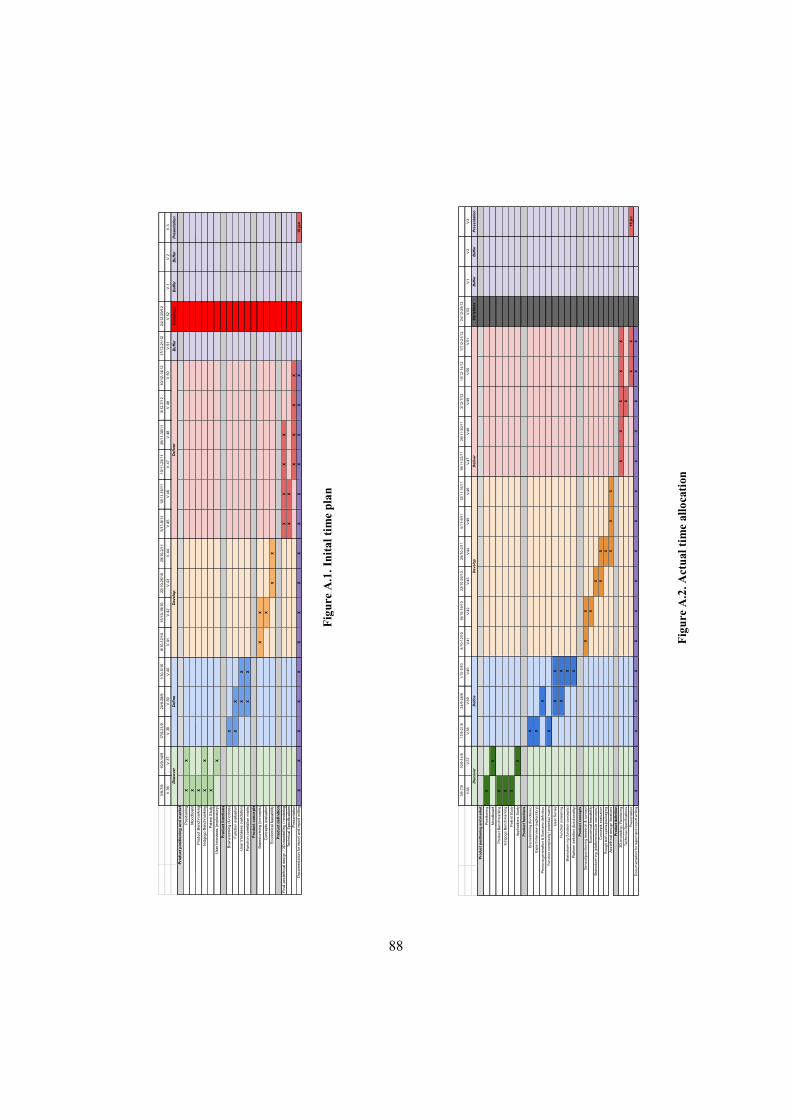
88
3/9
-7/9
10
/9-1
4/9
17
/9-2
1/9
24
/9-2
8/9
1/1
0-5
/10
8/1
0-1
2/1
01
5/1
0-1
9/1
02
2/1
0-2
6/1
02
9/1
0-2
/11
5/1
1-9
/11
12
/11
-16
/11
19
/11
-23
/11
26
/11
-30
/11
3/1
2-7
/12
10
/12
-14
/12
17
/12
-21
/12
24
/12
-29
/12
V.3
6V
.37
V.3
8V
.39
V.4
0V
.41
V.4
2V
.43
V.4
4V
.45
V.4
6V
.47
V.4
8V
.49
V.5
0V
.51
V.5
2V
.1V
.2V
.3
Deliver
Christm
as
Buffer
Buffer
Presentation
X
X
X X X
X
X X
X
X
XX
XX X X
XX X
X XX X X
XX
XX
XX
X
X
XX
16
jan
XX
XX
XX
XX
XX
XX
XX
XX
Ae
ste
thic
al d
es
ign
ite
ratio
ns
Ro
ug
h te
ch s
pe
cs/p
ack
ag
ing
Pre
se
nta
tion
Do
cum
en
tatio
n fo
r re
po
rt a
nd
re
po
rt w
ritin
g
Bra
ins
torm
ing
(fu
nct
ion
co
nce
pts
)
Pro
du
ct B
en
chm
ark
ing
Discover
Define
Develop
Ind
igo
go
Be
nch
ma
rkin
g
Pa
ten
t Stu
dy
Bra
ins
torm
ing
(fu
nct
ion
s)
Pro
du
ct
fun
cti
on
s
Ap
plic
atio
ns
Stu
dy
Exp
ert
Inte
rvie
w (
exp
lora
tory
)
Pe
rso
na
ge
ne
ratio
n &
Sce
na
rio
de
finiti
on
Fu
nct
ion
scr
ee
nin
g
Fu
nct
ion
co
mp
lexi
ty /
po
ten
tial m
atr
ix
Us
er
Su
rve
y
Mo
od
bo
ard
Po
siti
on
ing
Pro
du
ct
po
sit
ion
ing
an
d m
ark
et
Pro
du
ct
co
nc
ep
ts
Pla
tform
de
finiti
on
(fu
nct
ion
alit
y)
Se
ns
or/
po
siti
on
ing
re
se
arc
h &
co
nce
pt
Eco
no
mic
al f
ea
sa
bili
ty
Te
chn
ica
l Sp
eci
fica
tion
s
Pro
du
ct
de
fin
itio
n3
D-m
od
elin
g /
Re
nd
eri
ng
Bra
ins
torm
ing
(p
latfo
rm/m
od
ule
co
nce
pts
)C
on
cep
ts e
valu
atio
n
3/9-
7/9
10/9
-14/
917
/9-2
1/9
24/9
-28/
91/
10-5
/10
8/10
-12/
1015
/10-
19/1
022
/10-
26/1
029
/10-
2/11
5/11
-9/1
112
/11-
16/1
119
/11-
23/1
126
/11-
30/1
13/
12-7
/12
10/1
2-14
/12
17/1
2-21
/12
24/1
2-29
/12
V.3
6V
.37
V.3
8V
.39
V.4
0V
.41
V.4
2V
.43
V.4
4V
.45
V.4
6V
.47
V.4
8V
.49
V.5
0V
.51
V.5
2V
.1V
.2V
.3
Buffer
Christmas
Buffer
Buffer
Presentation
XX
X X XX
X
X
X XX X
X
XX
XX X
XX
XX
XX
XX
XX
XX
XX
XX
XX
XX
XX
XX
XX
X16
ja
nP
rese
ntat
ion
Doc
umen
tatio
n fo
r re
port
and
rep
ort
writ
ing
Tech
nica
l Spe
cific
atio
ns
Bra
inst
orm
ing
(con
cept
s)
Con
cept
s ev
alua
tion
Eco
nom
ical
feas
abili
ty
Pro
du
ct d
efi
nit
ion
Fin
al a
este
thic
al d
esig
n /
3D-m
odde
lling
/ r
ende
ring
Deliver
Pro
du
ct c
on
cep
ts
Pro
du
ct f
un
ctio
ns
Bra
inst
orm
ing
(func
tions
)
Fun
ctio
n ev
alua
tion
Use
r In
terv
iew
s (v
alid
atio
n)
Fun
ctio
n co
rrel
atio
n m
atrix
Pat
ent
Stu
dy
Use
r In
terv
iew
s (e
xplo
rato
ry)
Disco
ver
Define
Develop
Pro
du
ct p
osi
tio
nin
g a
nd
ma
rke
t
Pos
ition
ing
Moo
dboa
rd
Pro
duct
Ben
chm
arki
ng
Indi
gogo
Ben
chm
arki
ng
Fig
ure
A.1
. Ini
tal t
ime
plan
Fig
ure
A.2
. Act
ual t
ime
allo
cati
on

89
Appendix B Positioning matrix and function lists
B.1 Positioning matrix
Figure B.1. Positiong matrix
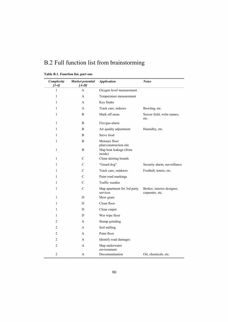
90
B.2 Full function list from brainstorming
Table B.1. Function list, part one
Complexity [1-4]
Market potential [A-D]
Application Notes
1 A Oxygen level measurement
1 A Temperature measurement
1 A Key finder
1 A Track care, indoors Bowling, etc.
1 B Mark off areas Soccer field, write names, etc.
1 B Fire/gas-alarm
1 B Air quality adjustment Humidity, etc.
1 B Serve food
1 B Measure floor plan/construction site
1 B Map heat leakage (from inside)
1 C Clean skirting boards
1 C "Guard dog" Security alarm, surveillance
1 C Track care, outdoors Football, tennis, etc.
1 C Paint road markings
1 C Traffic warden
1 C Map apartment for 3rd party services
Broker, interior designer, carpenter, etc.
1 D Mow grass
1 D Clean floor
1 D Clean carpet
1 D Wet wipe floor
2 A Stump grinding
2 A Soil milling
2 A Paint floor
2 A Identify road damages
2 A Map underwater environment
2 A Decontamination Oil, chemicals, etc.
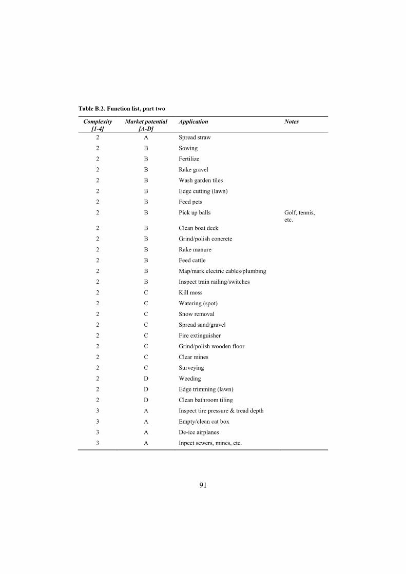
91
Table B.2. Function list, part two
Complexity [1-4]
Market potential [A-D]
Application Notes
2 A Spread straw
2 B Sowing
2 B Fertilize
2 B Rake gravel
2 B Wash garden tiles
2 B Edge cutting (lawn)
2 B Feed pets
2 B Pick up balls Golf, tennis, etc.
2 B Clean boat deck
2 B Grind/polish concrete
2 B Rake manure
2 B Feed cattle
2 B Map/mark electric cables/plumbing
2 B Inspect train railing/switches
2 C Kill moss
2 C Watering (spot)
2 C Snow removal
2 C Spread sand/gravel
2 C Fire extinguisher
2 C Grind/polish wooden floor
2 C Clear mines
2 C Surveying
2 D Weeding
2 D Edge trimming (lawn)
2 D Clean bathroom tiling
3 A Inspect tire pressure & tread depth
3 A Empty/clean cat box
3 A De-ice airplanes
3 A Inpect sewers, mines, etc.

92
Table B.3. Function list, part three
Complexity [1-4]
Market potential [A-D]
Application Notes
3 A Herd cattle
3 B Clear weeds/grass between garden tiles
3 B Clean roof
3 B Receive packages
3 B Map heat leakage (from outside)
3 C Clean stairs
3 C Clean countertops
3 C Pick & place robot Warehouse, stores, etc.
3 C Commercial plant handling/planting
3 C Beach cleaning
3 C Clean solar panels
3 D Waste disposal Leafs, branches, apples, etc.
3 D Keep lawn tidy Toys, etc.
3 D Keep apartment/house tidy Toys, clothes, etc.
3 D Pot-plant watering
3 D Clean on different floors
4 A Clear gutters
4 A Paint walls
4 A Paint ceiling
4 A Sand walls
4 A Sand ceiling
4 A Desarm bombs
4 A Plant trees
4 A Remove graffiti
4 A Escort for blind
4 B Watering (area)
4 B Pruning
4 B Clean doors
4 B Wash facade
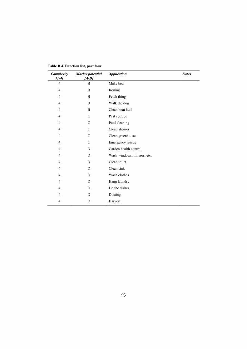
93
Table B.4. Function list, part four
Complexity [1-4]
Market potential [A-D]
Application Notes
4 B Make bed
4 B Ironing
4 B Fetch things
4 B Walk the dog
4 B Clean boat hull
4 C Pest control
4 C Pool cleaning
4 C Clean shower
4 C Clean greenhouse
4 C Emergency rescue
4 D Garden health control
4 D Wash windows, mirrors, etc.
4 D Clean toilet
4 D Clean sink
4 D Wash clothes
4 D Hang laundry
4 D Do the dishes
4 D Dusting
4 D Harvest
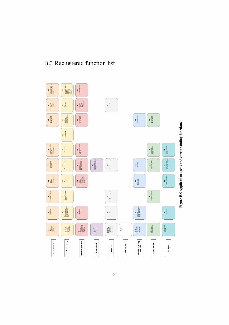
94
B.3 Reclustered function list
Fig
ure
B.5
App
lica
tion
are
as a
nd
corr
esp
ondi
ng f
unct
ions

95
Appendix C MIM drivers and adapted definitions
C.1 Component efficiency
The potential to design in such a way that no unused components are incorporated in the product.
C.2 Technology evolution
The potential to design in such a way that technological advancements of components can easily be incorporated in the platform/modules.
C.3 Carry over/Planned evolution
The potential to design in such a way that platforms/modules can be used for added functionality that evolves over time.
C.4 Styling
The potential to design in such a way that styling easily can be customized.
C.5 Common units
The potential to design in such a way that several products within different applications utilise the same components/units.

96
C.6 Hackability
The potential to design in such a way that a user can modify and add custom functionality to the product
C.7 Upgrading
The potential to design in such a way that the functional modules/components can be upgraded at a minimal cost and effort.
C.8 Technology complexity
The estimated general technological complexity of the concept
C.9 Application efficiency
The potential to design in such a way that the product can perform each of the different specific applications in an efficient way
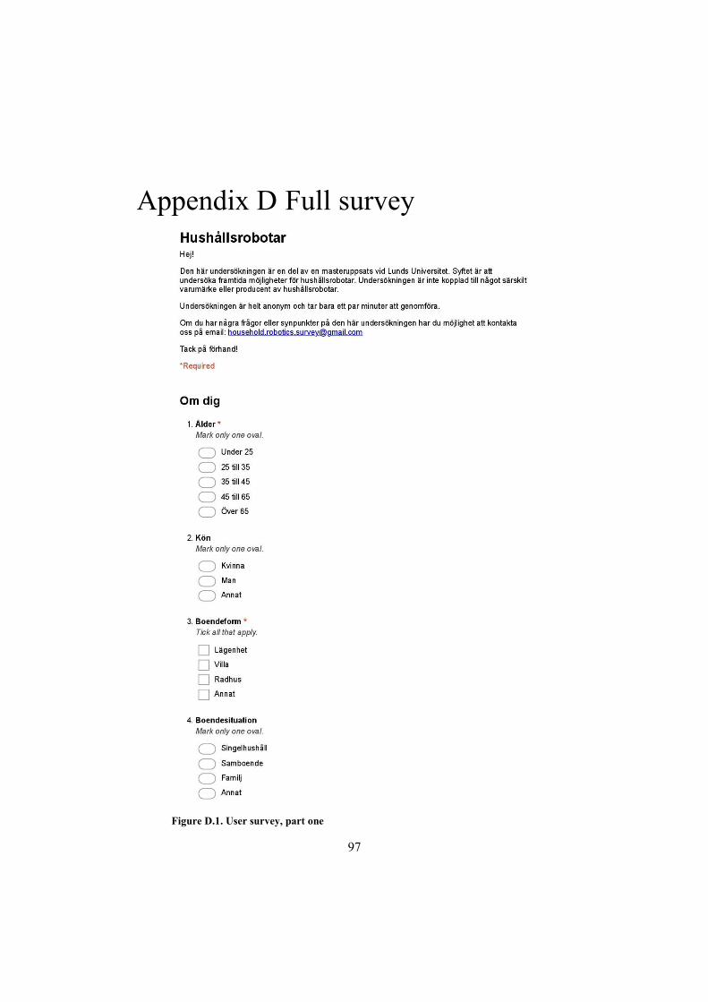
97
Appendix D Full survey
Figure D.1. User survey, part one

98
Figure D.2. User survey, part two
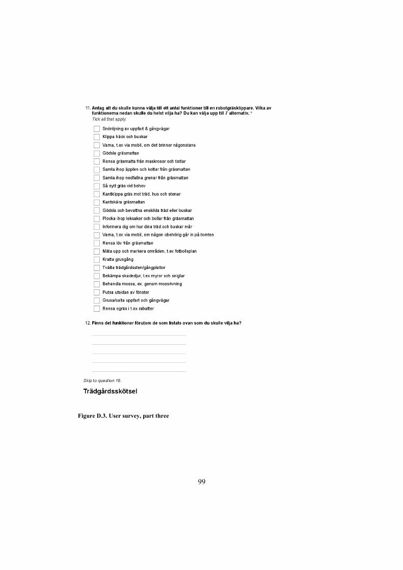
99
Figure D.3. User survey, part three
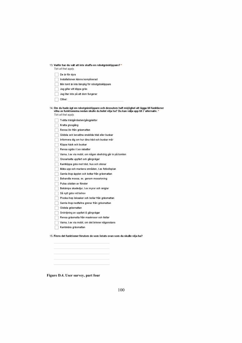
100
Figure D.4. User survey, part four
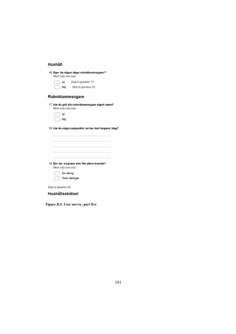
101
Figure D.5. User survey, part five
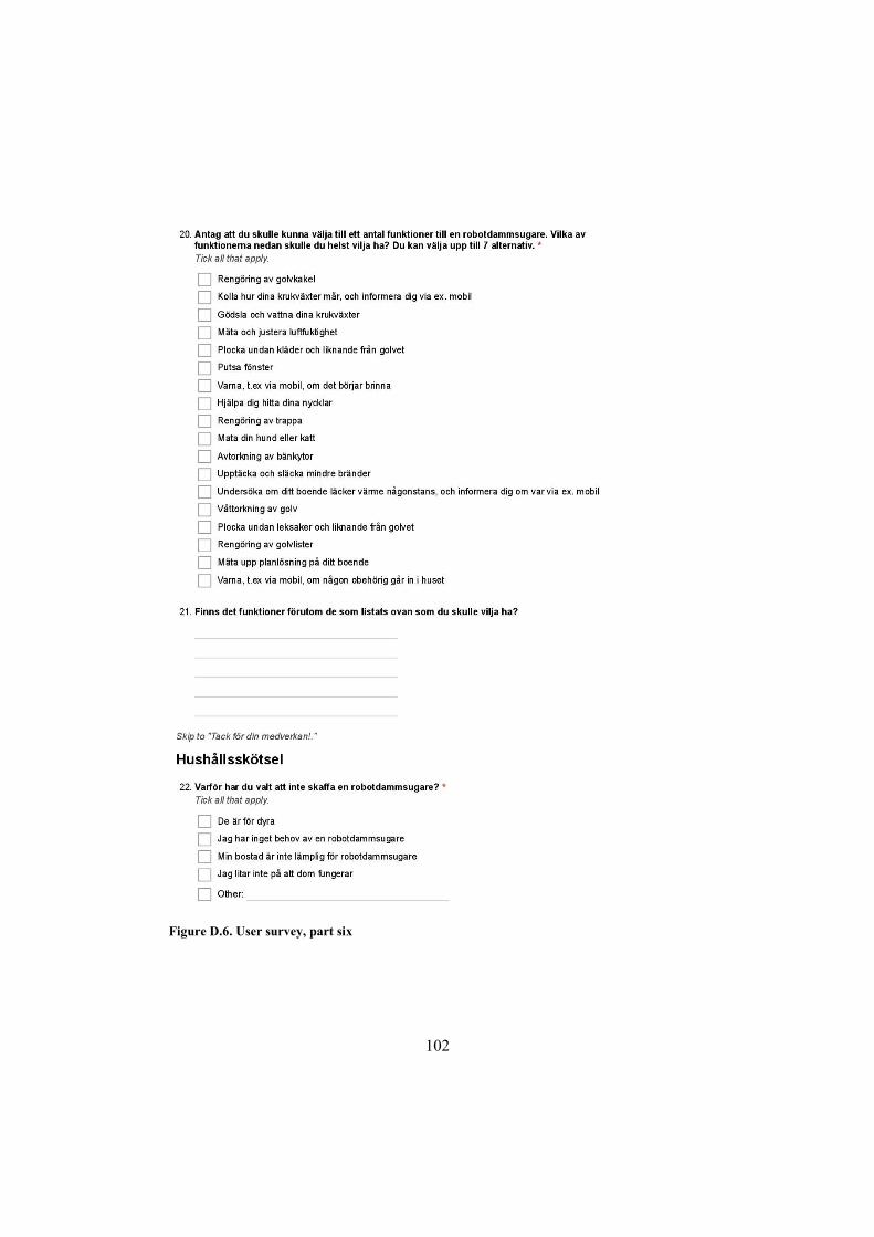
102
Figure D.6. User survey, part six
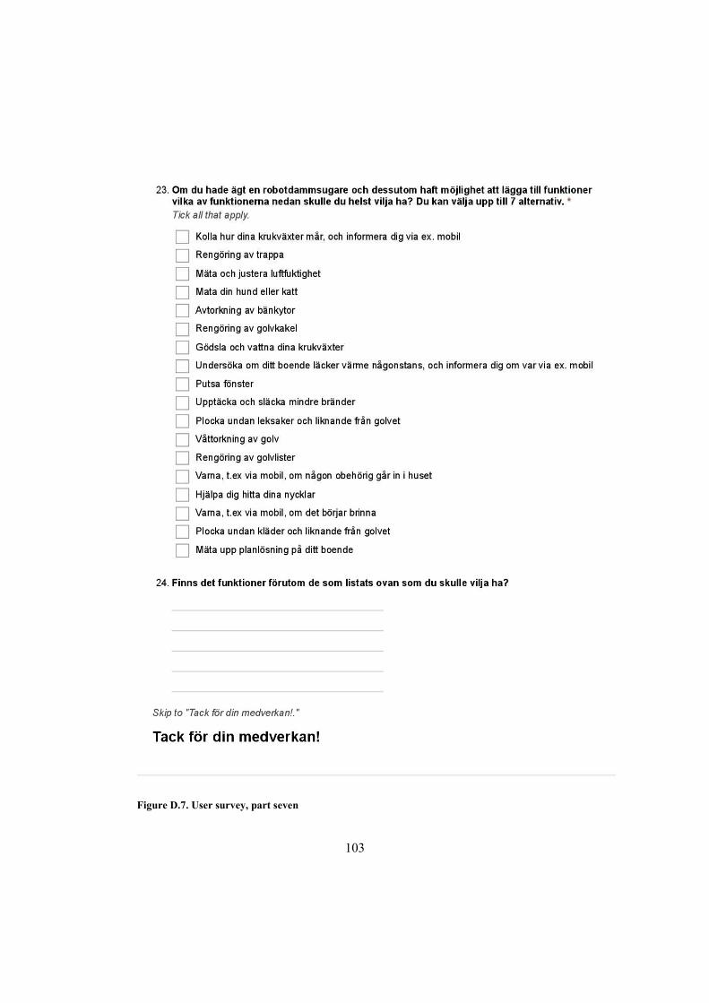
103
Figure D.7. User survey, part seven
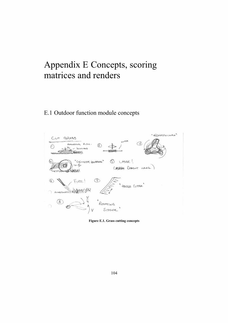
104
Appendix E Concepts, scoring matrices and renders
E.1 Outdoor function module concepts
Figure E.1. Grass cutting concepts
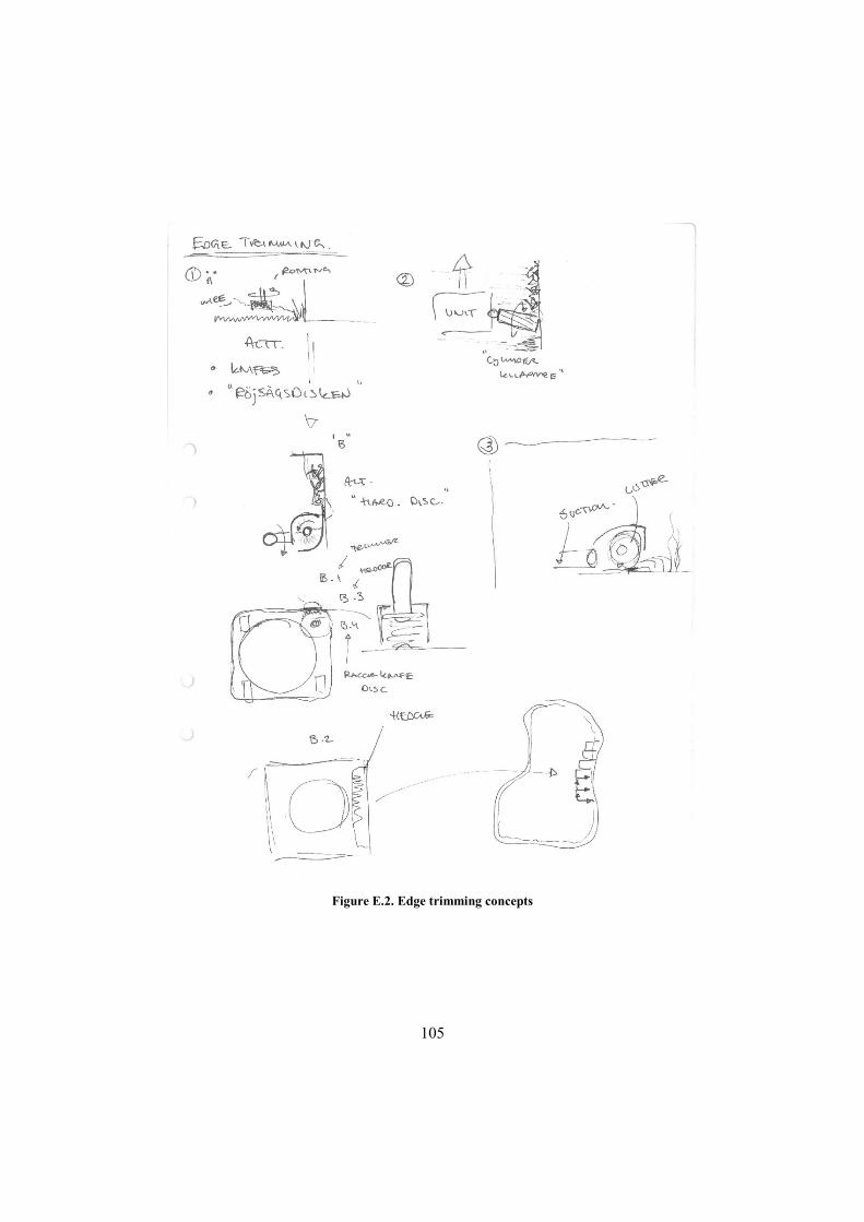
105
Figure E.2. Edge trimming concepts

106
Figure E.3. Edge cutting concepts
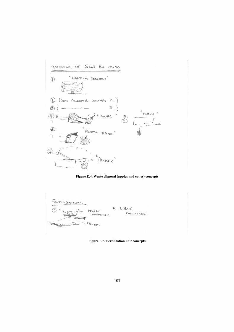
107
Figure E.4. Waste disposal (apples and cones) concepts
Figure E.5. Fertilization unit concepts
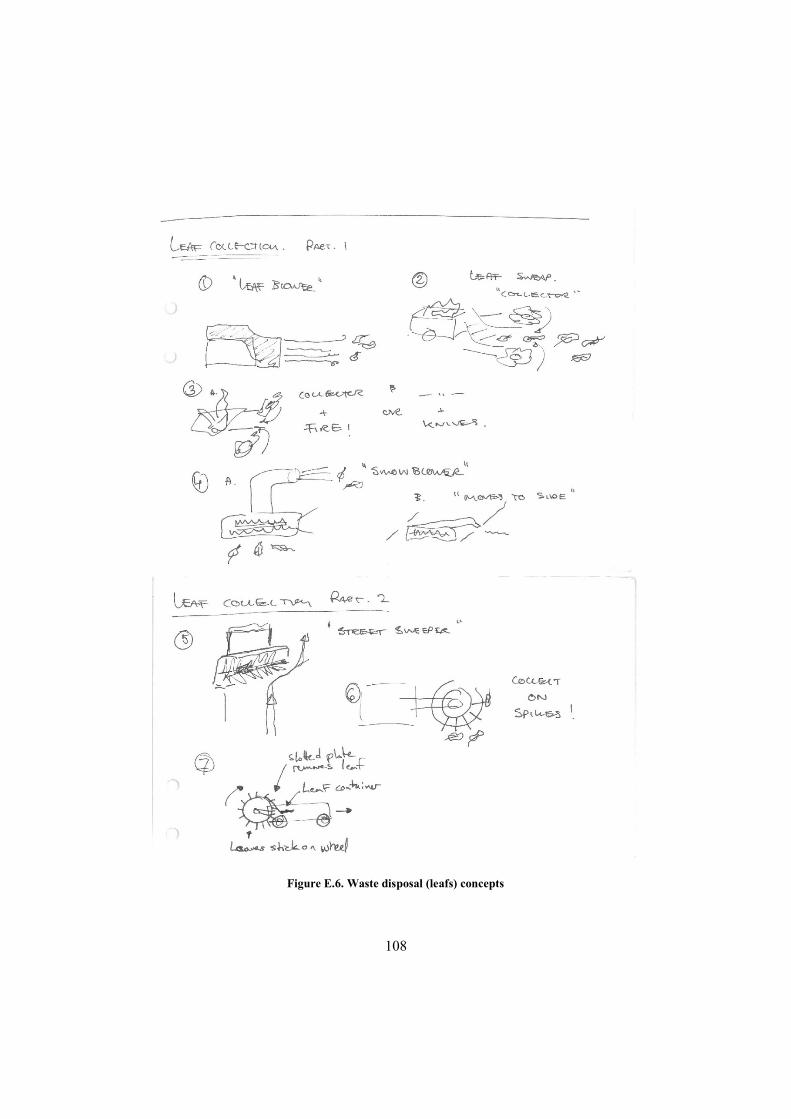
108
Figure E.6. Waste disposal (leafs) concepts
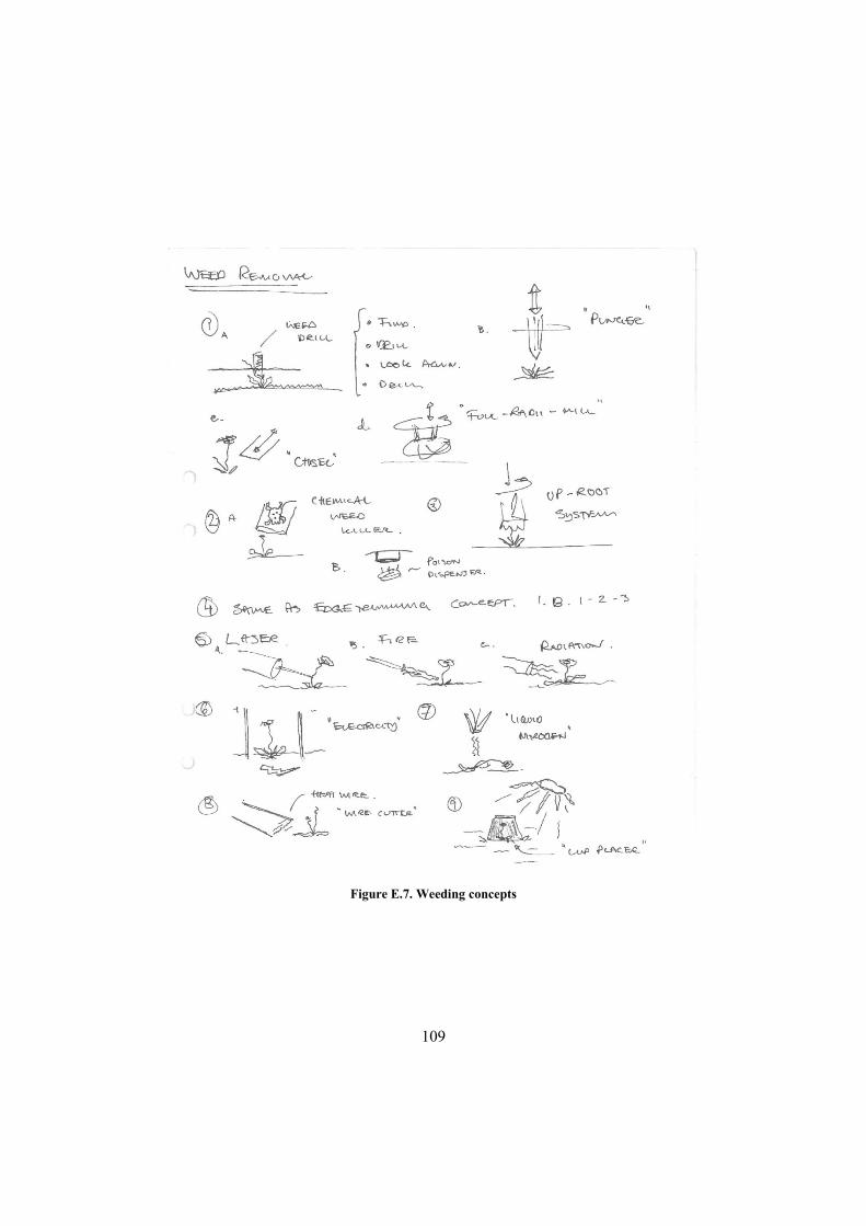
109
Figure E.7. Weeding concepts
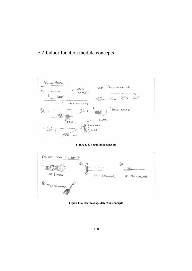
110
E.2 Indoor function module concepts
Figure E.8. Vacuuming concepts
Figure E.9. Heat leakage detection concepts
111
Figure E.10. Toy gathering concepts
112
Figure E.11. Staircase cleaning concepts
113
Figure E.12. Unauthorized entry detection concepts
Figure E.13. Floor tile cleaning concepts

114
Figure E.14. Base/skirting board cleaning concepts
115
Figure E.15. Wet wiping concepts, part one
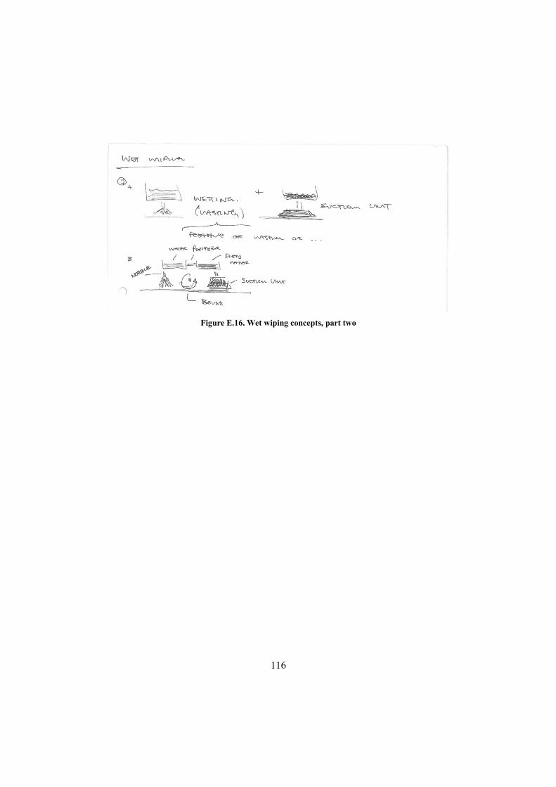
116
Figure E.16. Wet wiping concepts, part two
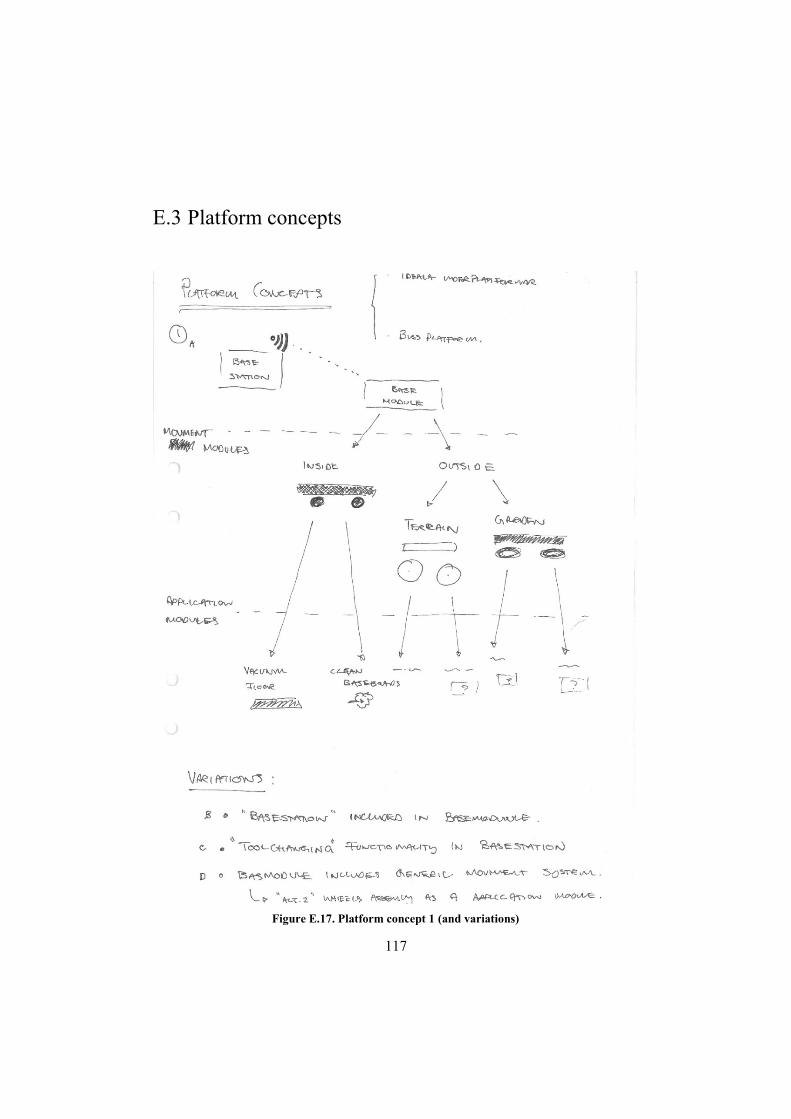
117
E.3 Platform concepts
Figure E.17. Platform concept 1 (and variations)
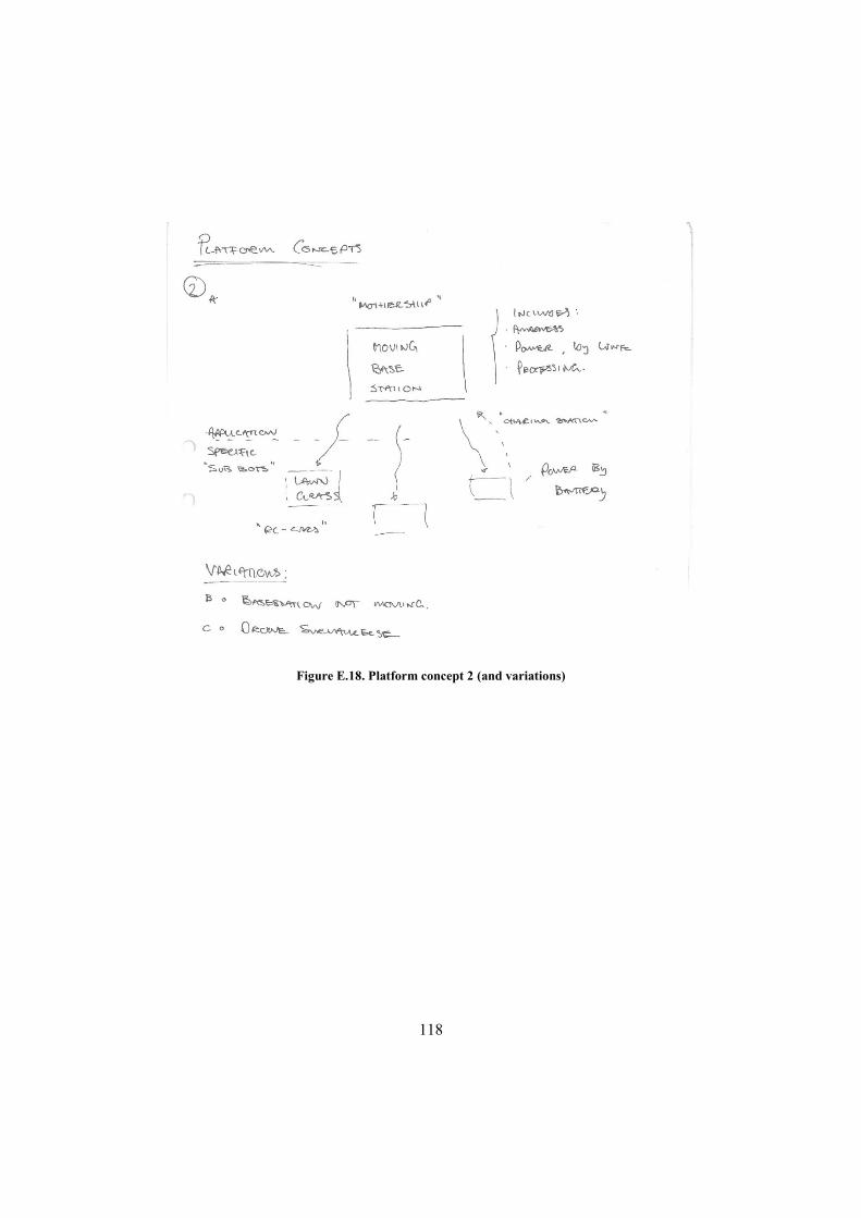
118
Figure E.18. Platform concept 2 (and variations)
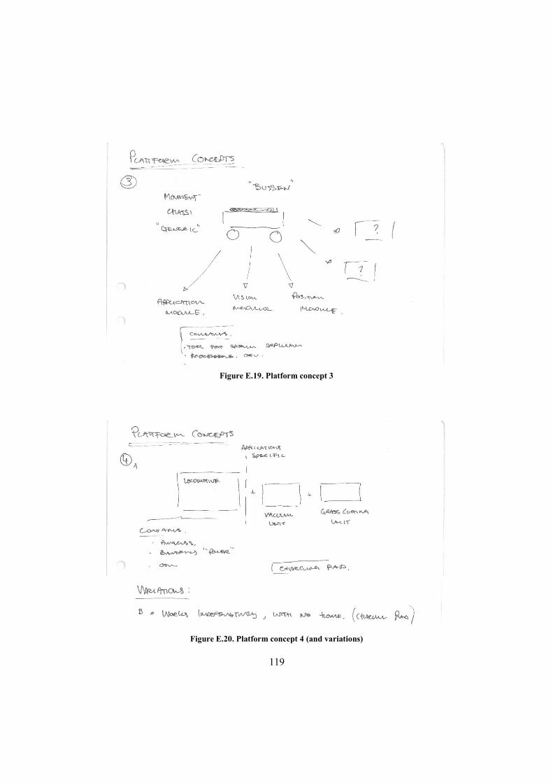
119
Figure E.19. Platform concept 3
Figure E.20. Platform concept 4 (and variations)
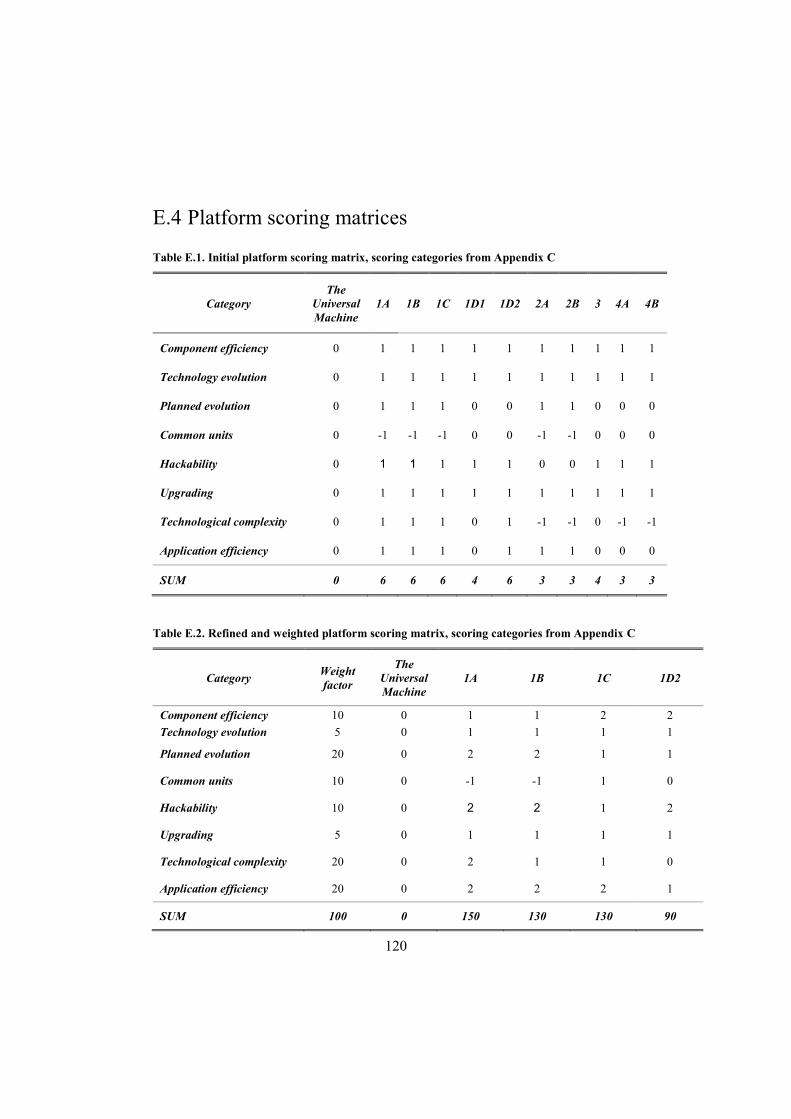
120
E.4 Platform scoring matrices
Table E.1. Initial platform scoring matrix, scoring categories from Appendix C
Category The
Universal Machine
1A 1B 1C 1D1 1D2 2A 2B 3 4A 4B
Component efficiency 0 1 1 1 1 1 1 1 1 1 1
Technology evolution 0 1 1 1 1 1 1 1 1 1 1
Planned evolution 0 1 1 1 0 0 1 1 0 0 0
Common units 0 -1 -1 -1 0 0 -1 -1 0 0 0
Hackability 0 1 1 1 1 1 0 0 1 1 1
Upgrading 0 1 1 1 1 1 1 1 1 1 1
Technological complexity 0 1 1 1 0 1 -1 -1 0 -1 -1
Application efficiency 0 1 1 1 0 1 1 1 0 0 0
SUM 0 6 6 6 4 6 3 3 4 3 3
Table E.2. Refined and weighted platform scoring matrix, scoring categories from Appendix C
Category Weight factor
The Universal Machine
1A 1B 1C 1D2
Component efficiency 10 0 1 1 2 2
Technology evolution 5 0 1 1 1 1
Planned evolution 20 0 2 2 1 1
Common units 10 0 -1 -1 1 0
Hackability 10 0 2 2 1 2
Upgrading 5 0 1 1 1 1
Technological complexity 20 0 2 1 1 0
Application efficiency 20 0 2 2 2 1
SUM 100 0 150 130 130 90
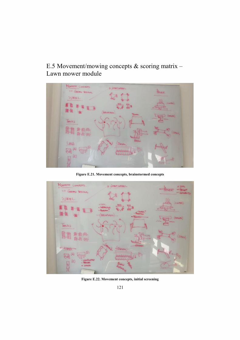
121
E.5 Movement/mowing concepts & scoring matrix – Lawn mower module
Figure E.21. Movement concepts, brainstormed concepts
Figure E.22. Movement concepts, initial screening
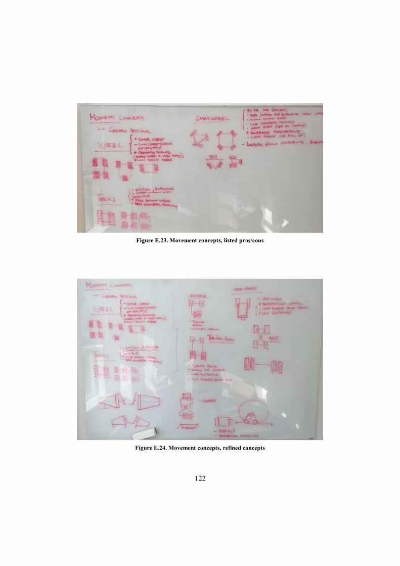
122
Figure E.23. Movement concepts, listed pros/cons
Figure E.24. Movement concepts, refined concepts

123
Table E.3. Movement concepts scoring matrix
Category "The tank"
"Dual Dyson"
4 wheels
3 wheels
4 wheels
AWDa
4 cone wheels
3 cone wheels
Stability 0 0 0 -1 0 0 -1
Turning radius 0 0 0 0 -1 0 0
Space efficiency 0 0 1 1 0 -1 -1
Low complexity 0 -1 1 1 0 -1 -1
Low cost 0 -1 1 1 0 0 0
Hill climbing 0 -1 -1 -1 0 0 0
Low ground damage 0 0 1 1 1 1 1
Total 0 -3 3 2 0 -1 -2
a Hinged body
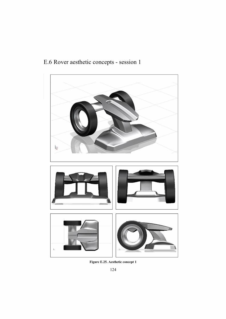
124
E.6 Rover aesthetic concepts - session 1
Figure E.25. Aesthetic concept 1
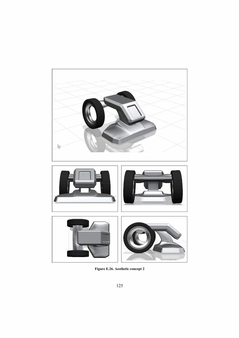
125
Figure E.26. Aesthetic concept 2
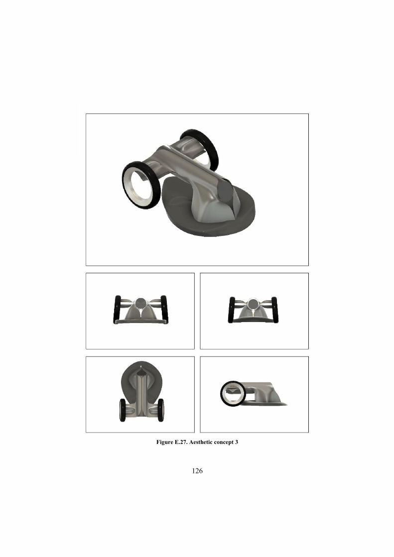
126
Figure E.27. Aesthetic concept 3

127
Figure E.28. Aesthetic concept 4
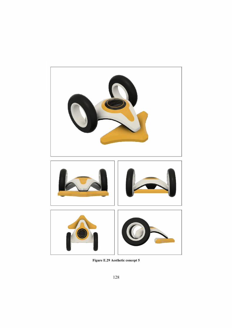
128
Figure E.29 Aesthetic concept 5

129
Figure E.30. Aesthetic concept 6
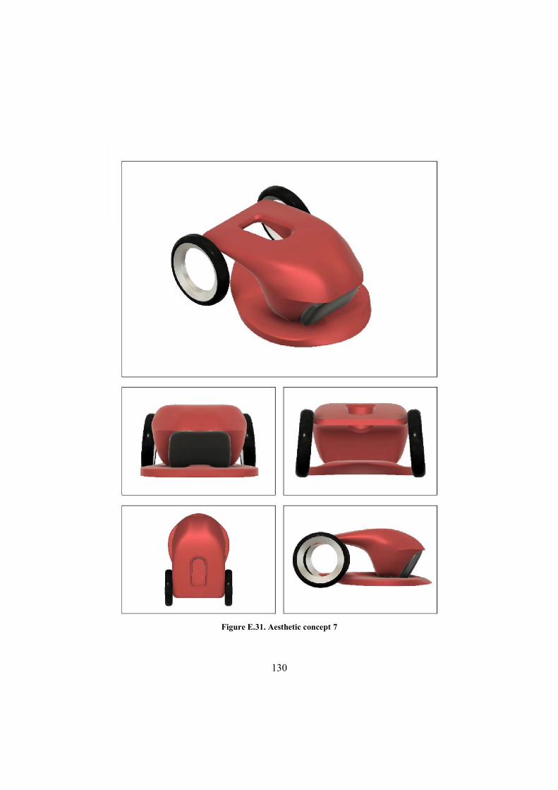
130
Figure E.31. Aesthetic concept 7
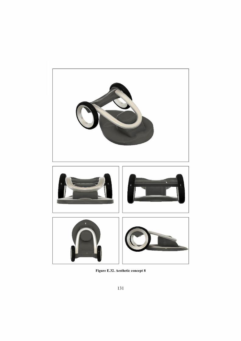
131
Figure E.32. Aesthetic concept 8
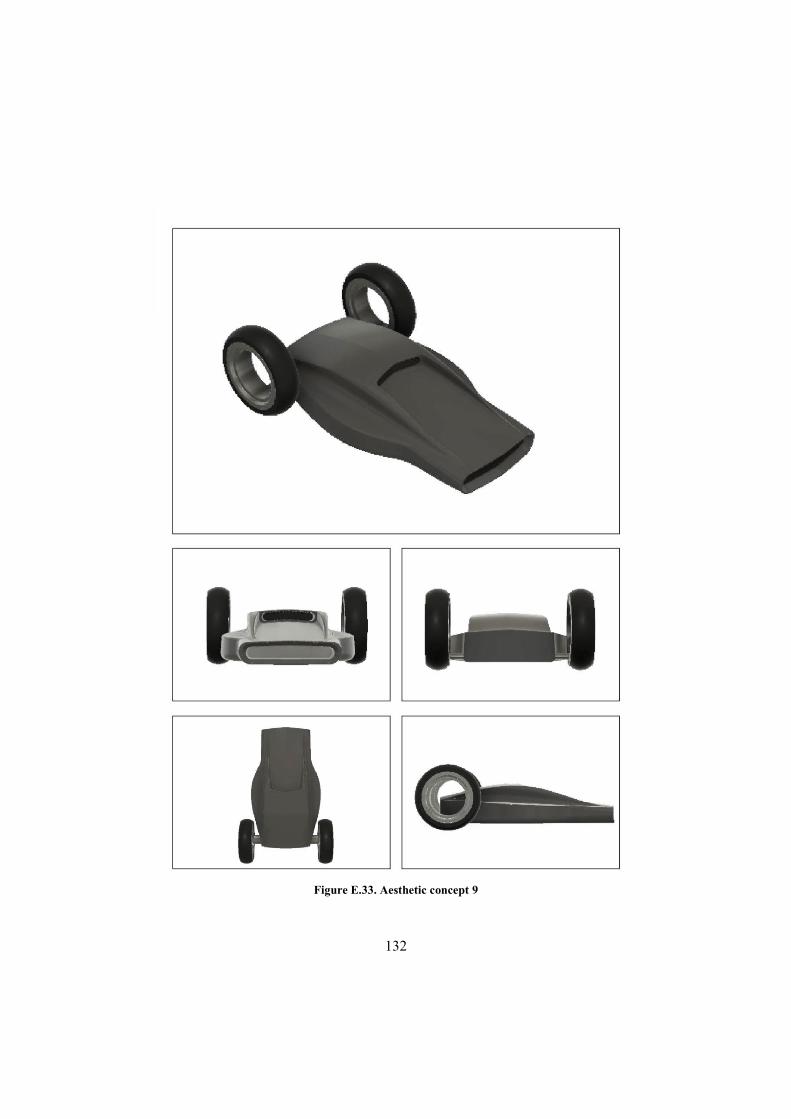
132
Figure E.33. Aesthetic concept 9

133
E.7 Rover aesthetic concepts – session 2
Figure E.34 Aesthetic concept 10
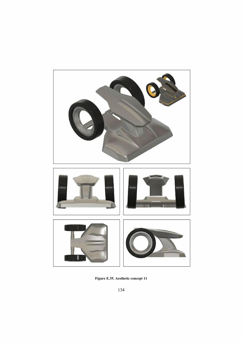
134
Figure E.35. Aesthetic concept 11

135
Figure E.36. Aesthetic concept 12

136
Figure E.37. Aesthetic concept 13
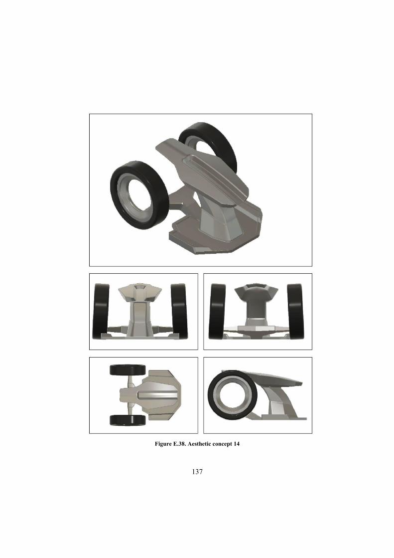
137
Figure E.38. Aesthetic concept 14
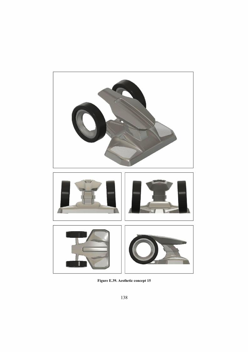
138
Figure E.39. Aesthetic concept 15

139
Figure E.40. Aesthetic concept 16
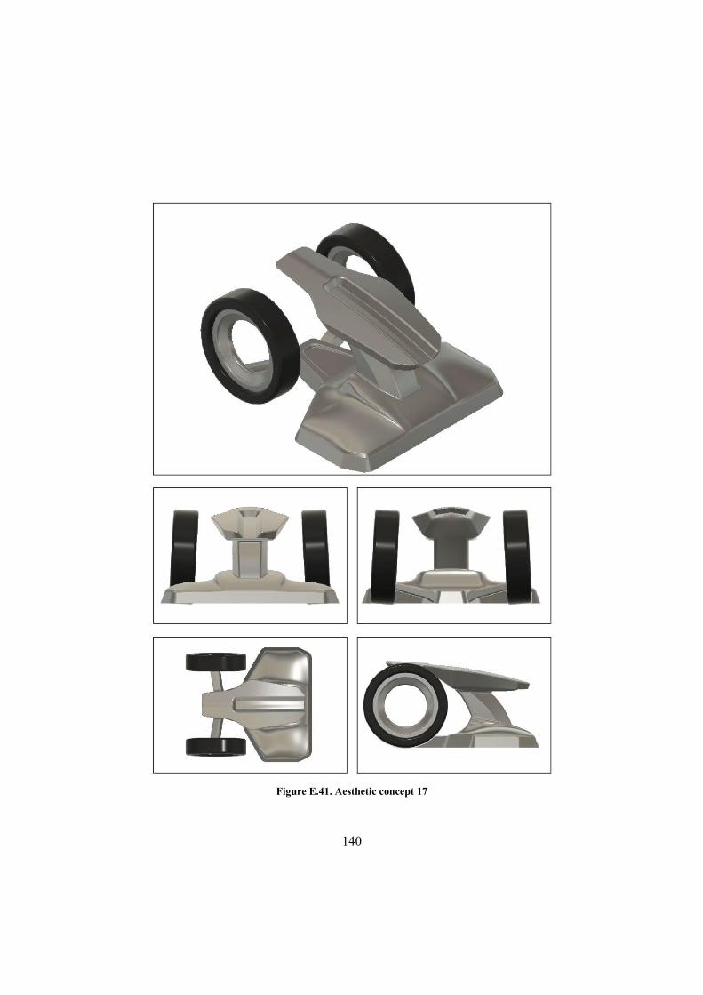
140
Figure E.41. Aesthetic concept 17

141
Figure E.42. Aesthetic concept 18
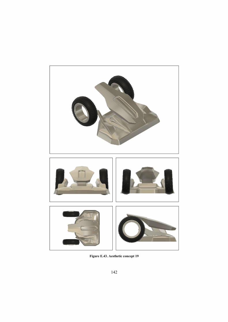
142
Figure E.43. Aesthetic concept 19
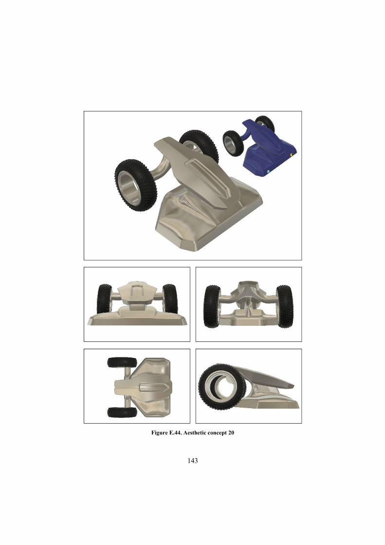
143
Figure E.44. Aesthetic concept 20
144
Figure E.45. Aesthetic concept 21
145
Figure E.46. Aesthetic concept 22
146
Figure E.47. Aesthetic concept 23
147
Figure E.48. Aesthetic concept 24

148
Figure E.49. Aesthetic concept 25

149
Figure E.50. Aesthetic concept 26

150
Figure E.51. Aesthetic concept 27
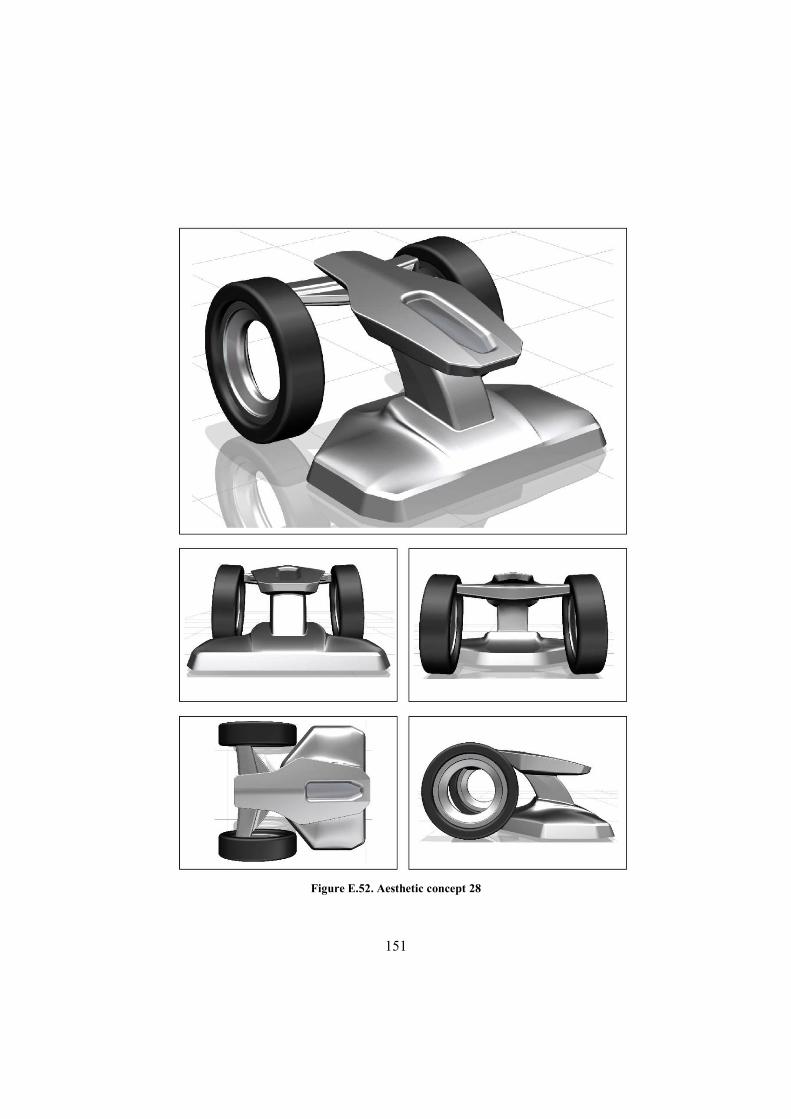
151
Figure E.52. Aesthetic concept 28
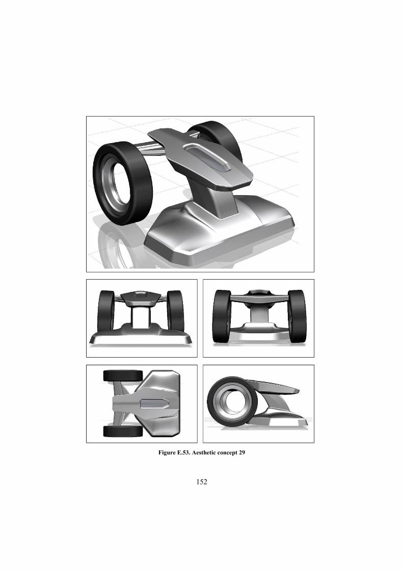
152
Figure E.53. Aesthetic concept 29
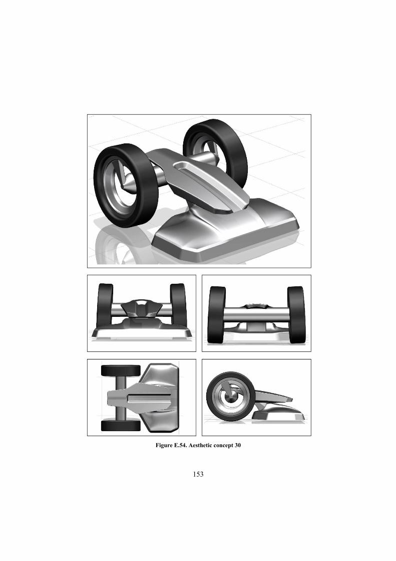
153
Figure E.54. Aesthetic concept 30

154
Figure E.55. Aesthetic concept 31

155
Figure E.56. Aesthetic concept 32

156
Figure E.57. Aesthetic concept 33

157
Figure E.58. Aesthetic concept 34

158
Figure E.59. Aesthetic concept 35
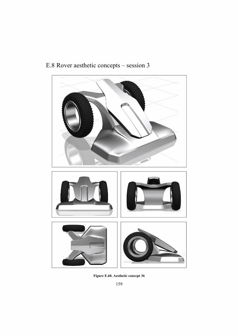
159
E.8 Rover aesthetic concepts – session 3
Figure E.60. Aesthetic concept 36
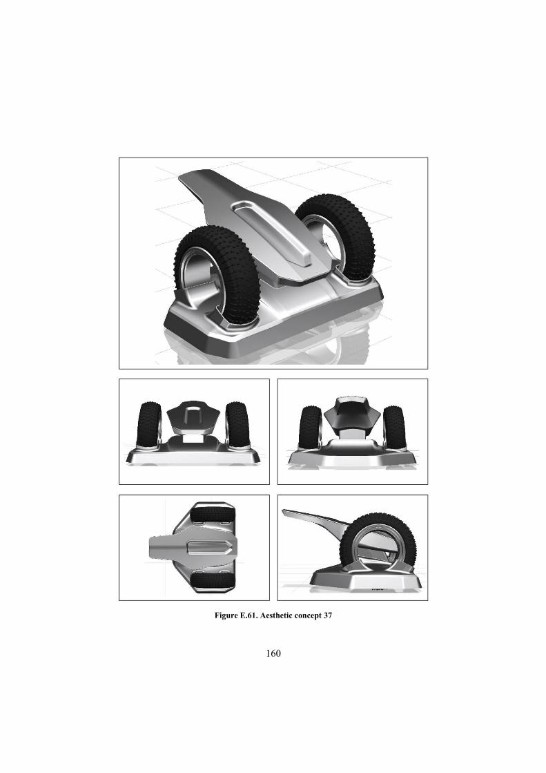
160
Figure E.61. Aesthetic concept 37

161
Figure E.62. Aesthetic concept 38
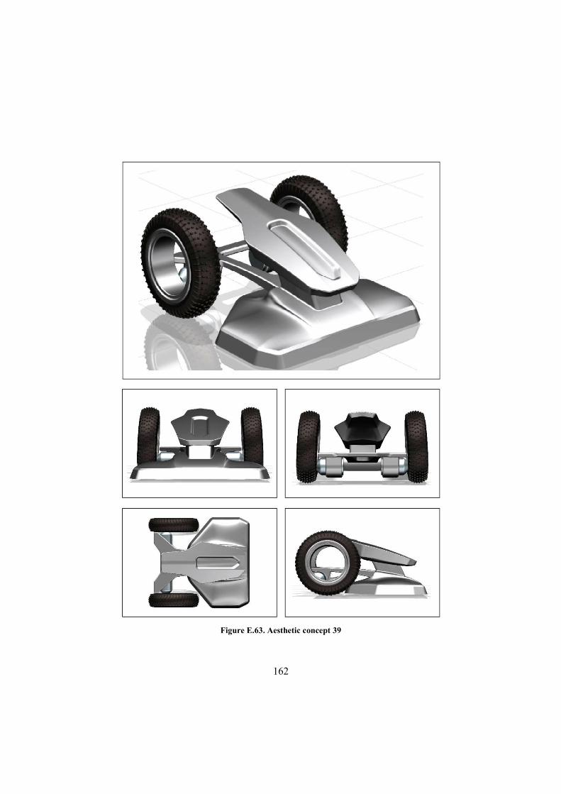
162
Figure E.63. Aesthetic concept 39
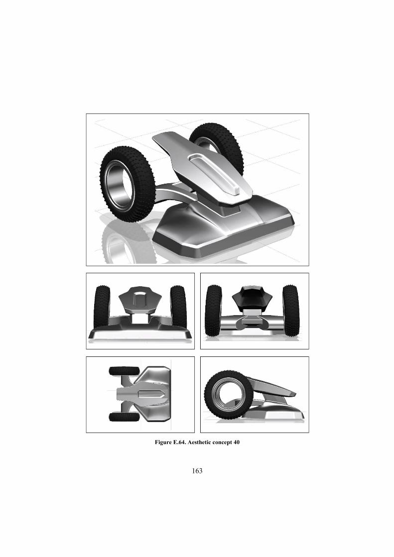
163
Figure E.64. Aesthetic concept 40
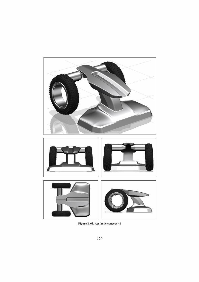
164
Figure E.65. Aesthetic concept 41
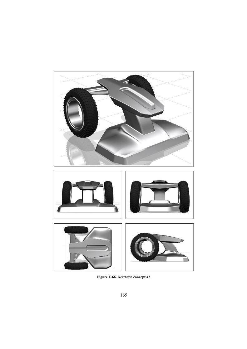
165
Figure E.66. Aesthetic concept 42

166
E.9 Rover aesthetic concepts – session 4
Figure E.67. Aesthetic concept 43

167
Figure E.68. Aesthetic concept 44
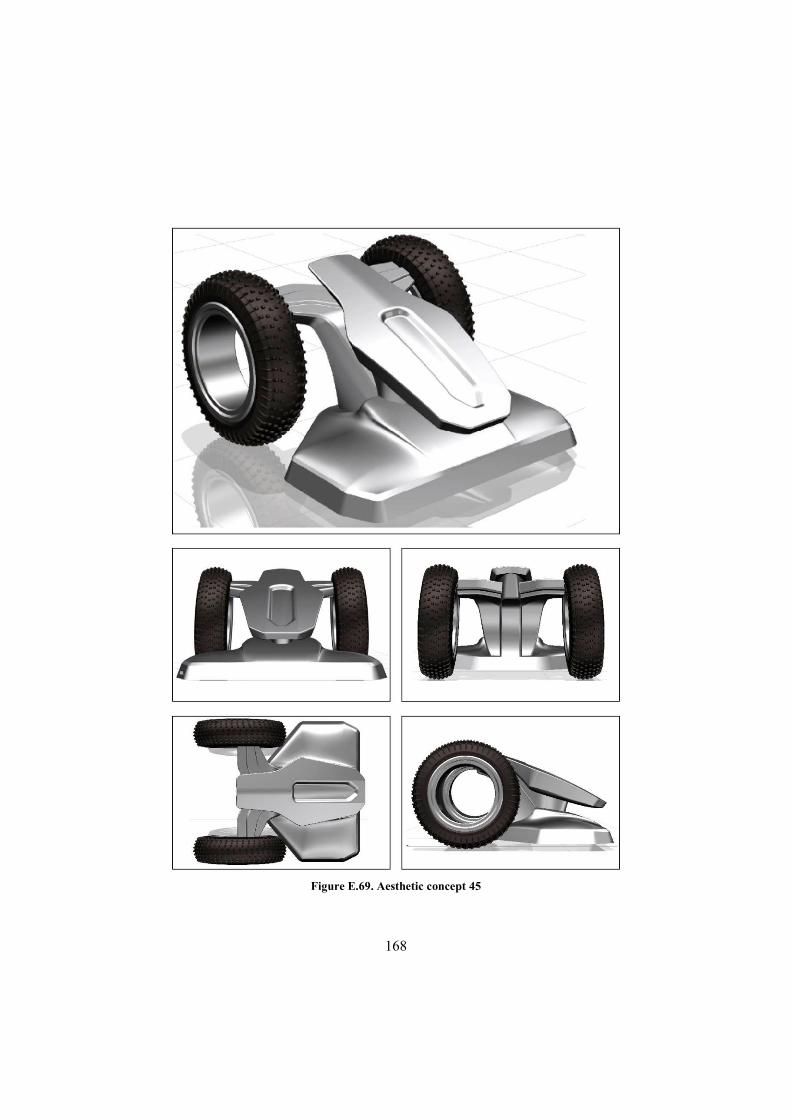
168
Figure E.69. Aesthetic concept 45

169
E.10 Base station aesthetic concepts session 1
Figure E.70. Aesthetic concept 1

170
Figure E.71. Aesthetic concept 2
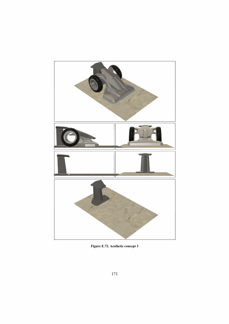
171
Figure E.72. Aesthetic concept 3
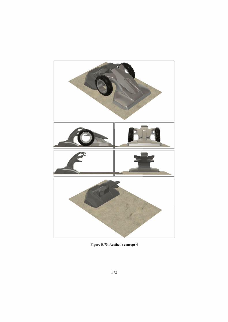
172
Figure E.73. Aesthetic concept 4

173
E.11 Base station aesthetic concepts session 2
Figure E.74. Aesthetic concept 5
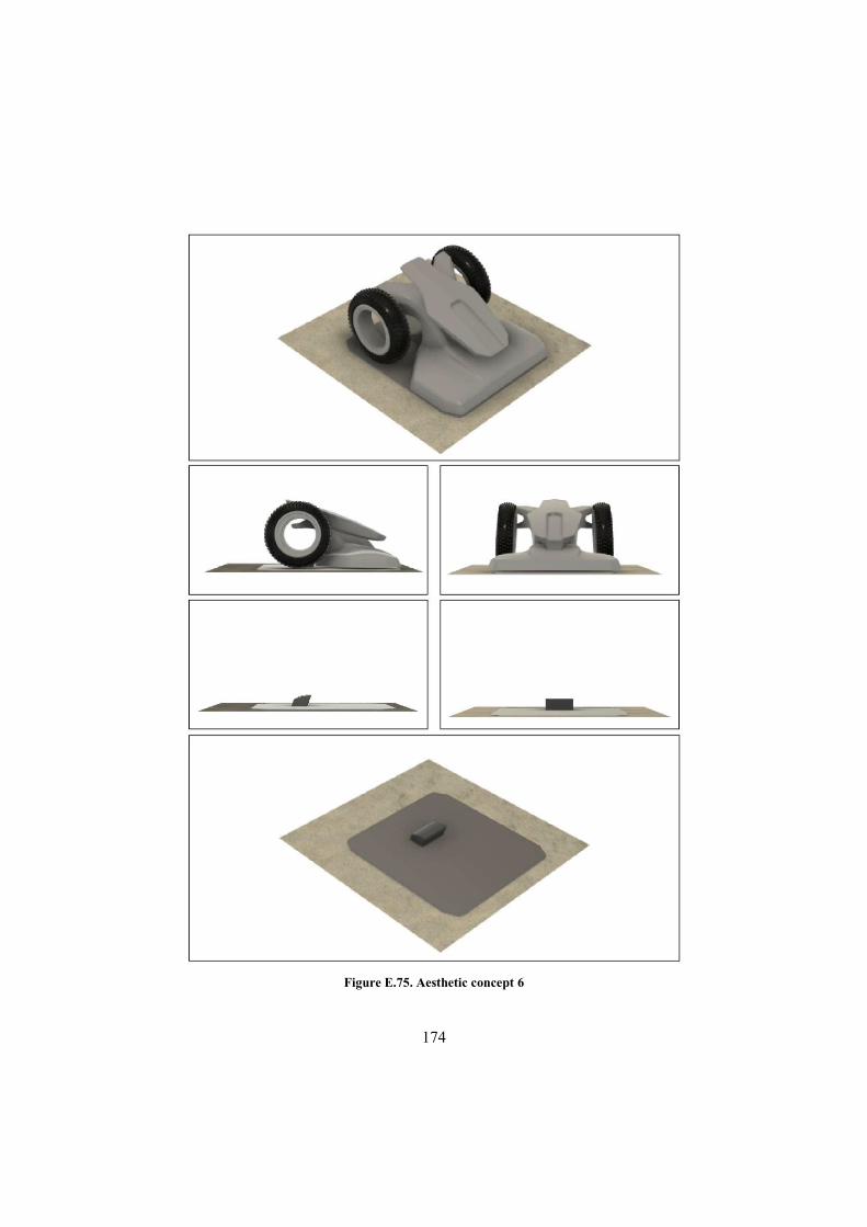
174
Figure E.75. Aesthetic concept 6
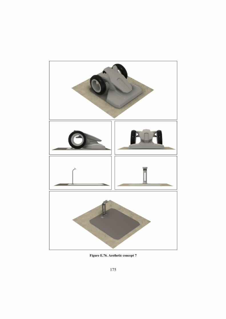
175
Figure E.76. Aesthetic concept 7

176
Figure E.77. Aesthetic concept 8

177
Figure E.78. Aesthetic concept 9
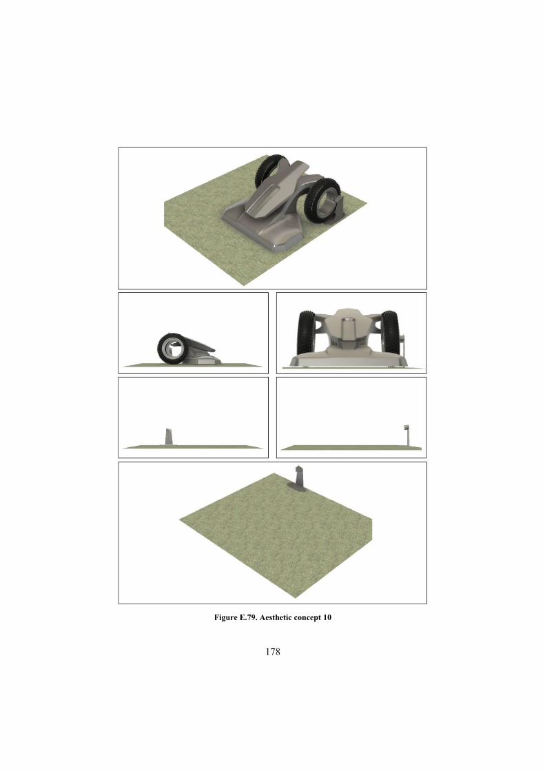
178
Figure E.79. Aesthetic concept 10
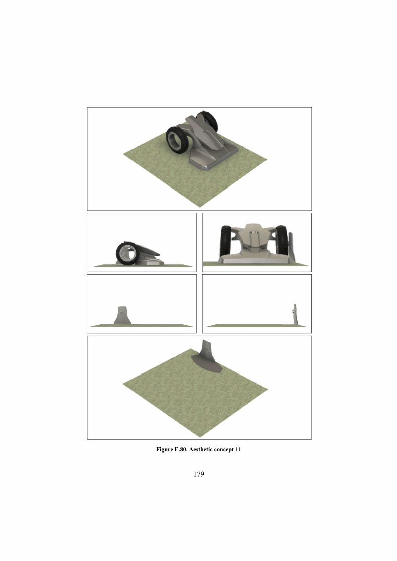
179
Figure E.80. Aesthetic concept 11
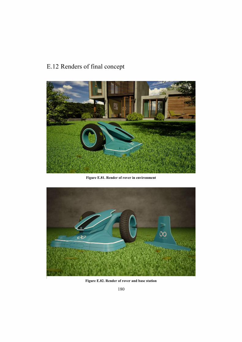
180
E.12 Renders of final concept
Figure E.81. Render of rover in environment
Figure E.82. Render of rover and base station
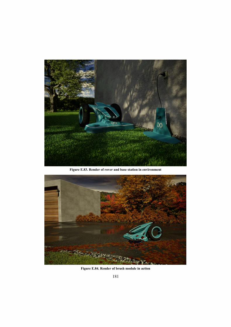
181
Figure E.84. Render of brush module in action
Figure E.83. Render of rover and base station in environment
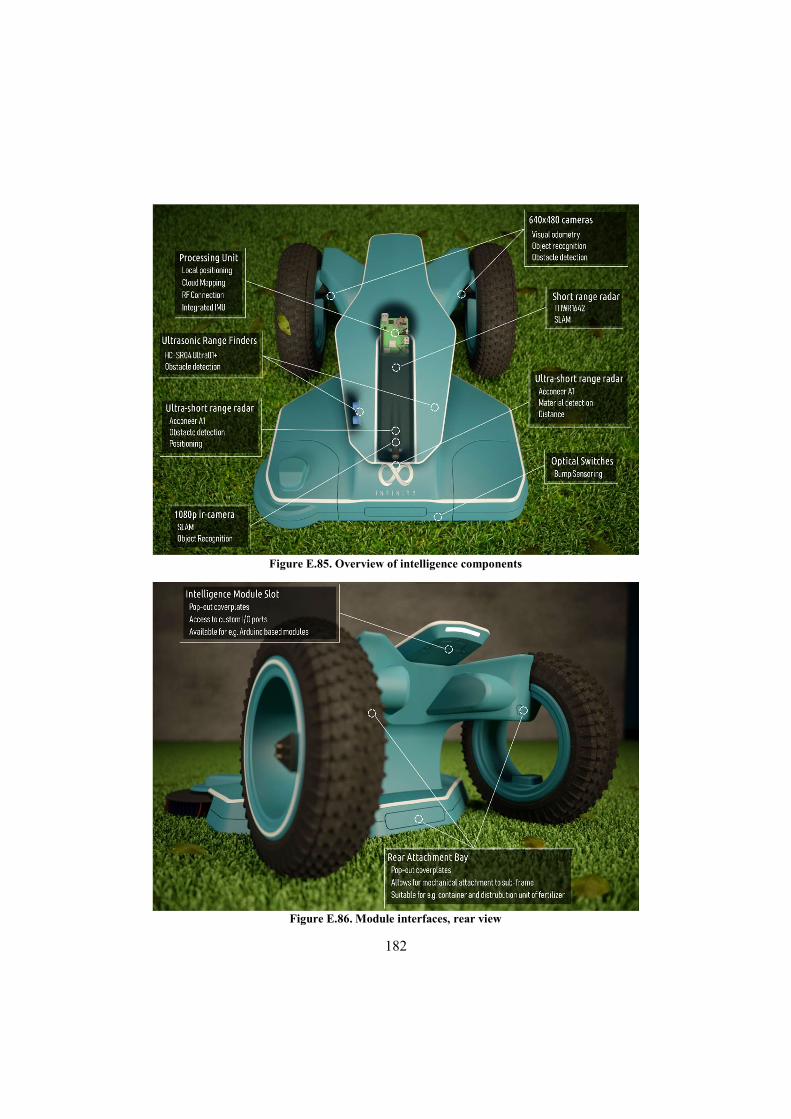
182
Figure E.86. Module interfaces, rear view
Figure E.85. Overview of intelligence components

183
Figure E.88. "Hacker" module, mounted
Figure E.87. "Hacker” module, exploded
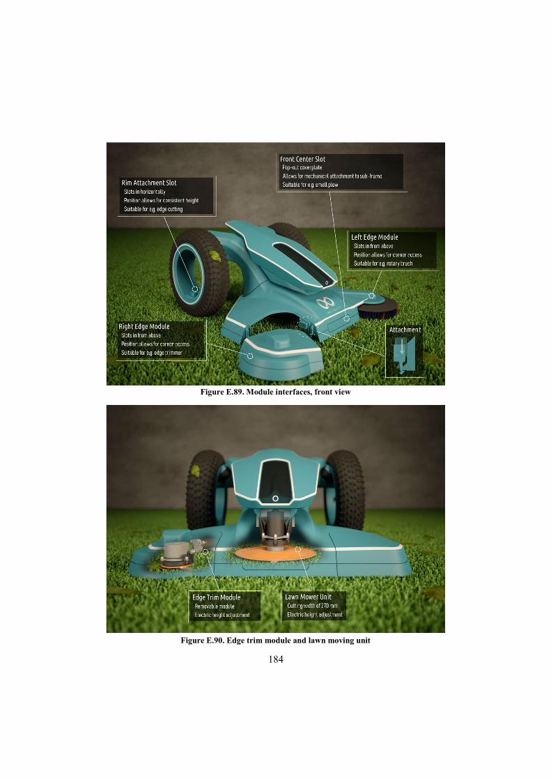
184
Figure E.90. Edge trim module and lawn moving unit
Figure E.89. Module interfaces, front view
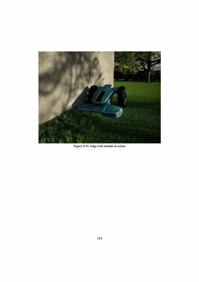
185
Figure E.91. Edge trim module in action

186
Appendix F Revised product description and sensor tables
F.1 Description
The revised goal after the Define phase is to develop a product family that can perform several different functions within several different fields of applications. The two primary application fields are garden mowing and floor cleaning. Within these fields the products should either implement, or be prepared to implement, as many as possible of the functions listed below in table F.1.
The architecture should be according to the graphic below, where the intelligence module is generic for all product variations. The intelligence module should, to the maximum extent possible, include components and systems used for positioning, connectivity and logic/processing. Furthermore, it should implement a mechanical and signal interface that allows incorporation of added sensors, environment manipulators, microcontrollers, etc. Cloud computing possibilities and associated benefits should be explored.
The Movement modules are specific for the different application fields and include the basic functionality of that field, such as mowing lawn. The accessory interfaces allow function specific modules to be mechanically and electrically attached to the movement module, according to the user’s current needs. This architecture simplifies development and introduction of added functional modules, as long as they adhere to the set accessory interface. After the two primary application fields has been covered, development focus can move one level up and concentrate on developing movement modules for new application fields, tapping into new markets and customer segments.
The styling module can either be tailored according to customer needs, application fields or be generic throughout the product family.
The primary market is represented using the two personas “Jesper” and “Glenn”, and typical situations depicting problems the products should solve are presented in the associated user scenarios.
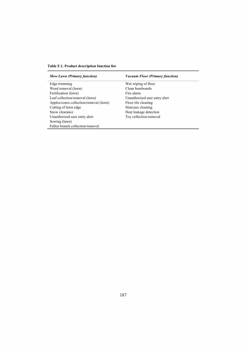
187
Table F.1. Product description function list
Mow Lawn (Primary function) Vacuum Floor (Primary function)
Edge trimming Weed removal (lawn) Fertilization (lawn) Leaf collection/removal (lawn) Apples/cones collection/removal (lawn) Cutting of lawn edge Snow clearance Unauthorized user entry alert Sowing (lawn) Fallen branch collection/removal
Wet wiping of floor Clean baseboards Fire alarm Unauthorized user entry alert Floor tile cleaning Staircase cleaning Heat leakage detection Toy collection/removal
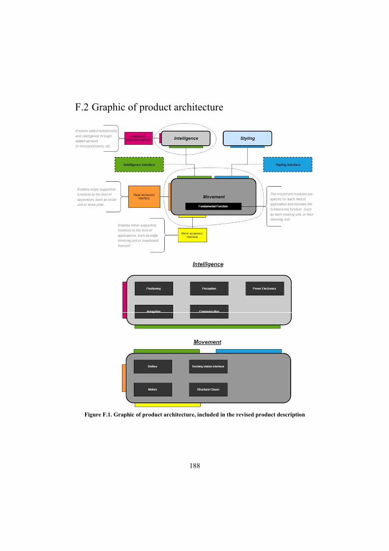
188
F.2 Graphic of product architecture
Figure F.1. Graphic of product architecture, included in the revised product description
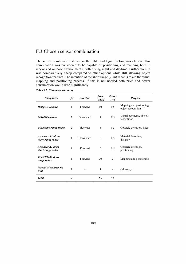
189
F.3 Chosen sensor combination
The sensor combination shown in the table and figure below was chosen. This combination was considered to be capable of positioning and mapping both in indoor and outdoor environments, both during night and daytime. Furthermore, it was comparatively cheap compared to other options while still allowing object recognition features. The intention of the short range (20m) radar is to aid the visual mapping and positioning process. If this is not needed both price and power consumption would drop significantly.
Table F.2. Chosen sensor array
Component Qty Direction Price
[USD] Power
[W] Purpose
1080p IR camera 1 Forward 10 0.5 Mapping and positioning, object recognition
640x480 camera 2 Downward 4 0.5 Visual odometry, object recognition
Ultrasonic range finder 2 Sideways 6 0.5 Obstacle detection, sides
Acconeer A1 ultra-short-range radar
1 Downward 6 0.5 Material detection, distance
Acconeer A1 ultra-short-range radar
1 Forward 6 0.5 Obstacle detection, positioning
TI IWR1642 short range radar
1 Forward 20 2 Mapping and positioning
Inertial Measurement Unit
1 - 4 - Odometry
Total 9 56 4.5
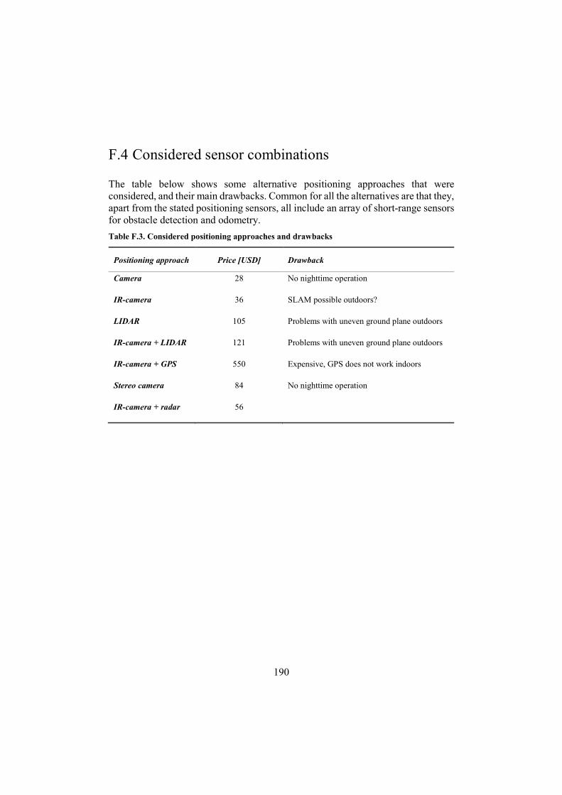
190
F.4 Considered sensor combinations
The table below shows some alternative positioning approaches that were considered, and their main drawbacks. Common for all the alternatives are that they, apart from the stated positioning sensors, all include an array of short-range sensors for obstacle detection and odometry.
Table F.3. Considered positioning approaches and drawbacks
Positioning approach Price [USD] Drawback
Camera 28 No nighttime operation
IR-camera 36 SLAM possible outdoors?
LIDAR 105 Problems with uneven ground plane outdoors
IR-camera + LIDAR 121 Problems with uneven ground plane outdoors
IR-camera + GPS 550 Expensive, GPS does not work indoors
Stereo camera 84 No nighttime operation
IR-camera + radar 56

191
F.5 Sensors functional mapping
Fu
nct
ion
HC
-SR
04
Ult
ra01
+
Ult
raso
nic
R
ange
Fin
der
Hex
amit
e H
X19
640x
480
cam
era
mod
ule
1080
p ir
ca
mer
a m
odu
le
Ste
reo
cam
era
mod
ule
, EL
P
720P
Cm
os
OV
9712
Spa
rkfu
n
GP
S R
TK
bo
ard
+
ante
nn
a
NE
O-8
M
GP
S
Mod
ule
YD
LID
AR
X
4 36
0°
Ben
ewak
e T
FM
INI
Mic
ro L
IDA
R
Mod
ule
TI
IWR
164
2 77
GH
z, r
adar
-on
-ch
ip, i
nte
g.
MC
U
MR
2001
–77
GH
z R
adar
T
ran
scei
ver
Ch
ipse
t
Acc
onee
r A
1 R
adar
PR
OX
IO
T
beac
on
9 D
OF
, L
3GD
20
LS
M30
3D
IMU
Mod
ule
Poz
yxB
um
p-sy
stem
Sh
arp
GP
2Y0A
21Y
K0
F -
IR
dis
tan
ce
sen
sor
Bou
nda
ry w
/ou
t w
ire
Cu
stom
bou
nda
ries
Pat
h p
lan
nin
g
Det
ect
use
r bo
rder
in
put
-X
/X
XX
-/
-X
XX
X-
X-
-
Det
ect
law
ned
ge f
or c
utt
ing
/-
//
XX
--
-/
/X
--
--
/
Det
ect
wee
d-
-X
XX
--
--
--
--
--
--
Obs
tacl
e de
tect
ion
X-
XX
X-
-X
XX
XX
--
-X
/
Obs
tacl
e re
cogn
itio
n-
-X
XX
--
--
--
/-
--
--
Bas
eboa
rd d
etec
tion
--
XX
X-
--
--
-/
--
--
-
Car
pet
dete
ctio
n/
-X
XX
--
--
--
X-
--
--
Fir
e de
tect
ion
--
XX
X-
--
--
--
--
--
-
Flo
orti
le d
etec
tion
--
XX
X-
--
--
-X
--
--
-
Sta
irca
se d
etec
tion
X-
//
X-
--
--
-X
--
--
X
Nig
htt
ime
oper
atio
nX
X-
X-
XX
XX
XX
XX
XX
XX
An
gula
r co
vera
ge30
°-
67°
160°
100°
--
360°
2.3°
??
80°
--
--
40°
Cos
t3
USD
?2
USD
10 U
SD60
USD
520
USD
10 U
SD85
USD
35 U
SD20
USD
? (1
5 U
SD)
6 U
SDm
in. 5
0 U
SD4
USD
min
675
USD
-4
USD
Con
cept
1 -
cam
1+1
(lef
t+ri
ght)
3 (d
own
+ f
orw
ard)
2 (f
orw
ard+
dow
n)X
X
Con
cept
2 -
IR
-cam
1+1
(lef
t+ri
ght)
2 (d
own)
1 (f
orw
ard)
2 (f
orw
ard+
dow
n)X
X
Con
cept
3 -
LID
AR
1+1
(lef
t+ri
ght)
2 (d
own)
11
(dow
n)X
X
Con
cept
4 -
IR
+L
IDA
R1+
1 (l
eft+
righ
t)2
(dow
n)1
(for
war
d)1
2 (f
orw
ard+
dow
n)X
X
Con
cept
5 -
IR
+G
PS
1+1
(lef
t+ri
ght)
2 (d
own)
1 (f
orw
ard)
11
(dow
n)X
X
Con
cept
6 -
Ste
reo
1+1
(lef
t+ri
ght)
1 (d
own)
1 (f
orw
ard)
2 (f
orw
ard+
dow
n)X
X
Con
cept
2.1
- I
R-c
am w
ith
rad
ar1+
1 (l
eft+
righ
t)2
(dow
n)1
(for
war
d)1
2 (f
orw
ard+
dow
n)X
X
Not
es
Pri
ce [
US
D]
SLA
M -
not
sen
sor
spec
ific
SLA
M -
not
sen
sor
spec
ific
SLA
M -
not
sen
sor
spec
ific
28 36 105
121
550
84 56
Fig
ure
F.2
. Fun
ctio
nal
map
ping
of
sens
ors
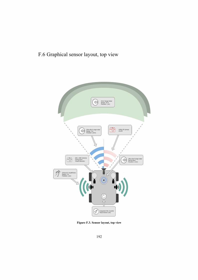
192
F.6 Graphical sensor layout, top view
Figure F.3. Sensor layout, top view
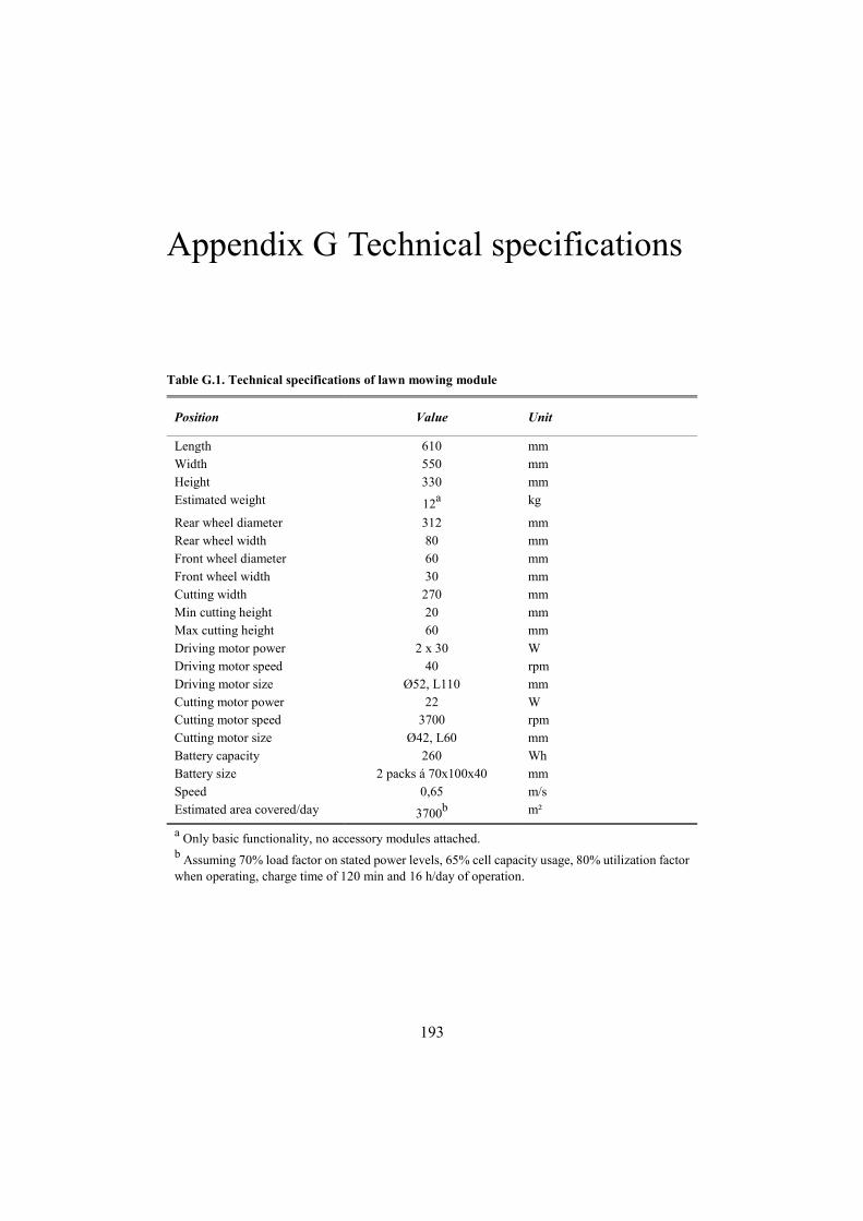
193
Appendix G Technical specifications
Table G.1. Technical specifications of lawn mowing module
Position Value Unit
Length 610 mm Width 550 mm Height 330 mm Estimated weight 12a kg
Rear wheel diameter 312 mm Rear wheel width 80 mm Front wheel diameter 60 mm Front wheel width 30 mm Cutting width 270 mm Min cutting height 20 mm Max cutting height 60 mm Driving motor power 2 x 30 W Driving motor speed 40 rpm Driving motor size Ø52, L110 mm Cutting motor power 22 W Cutting motor speed 3700 rpm Cutting motor size Ø42, L60 mm Battery capacity 260 Wh Battery size 2 packs á 70x100x40 mm Speed 0,65 m/s Estimated area covered/day 3700b m²
a Only basic functionality, no accessory modules attached. b Assuming 70% load factor on stated power levels, 65% cell capacity usage, 80% utilization factor when operating, charge time of 120 min and 16 h/day of operation.
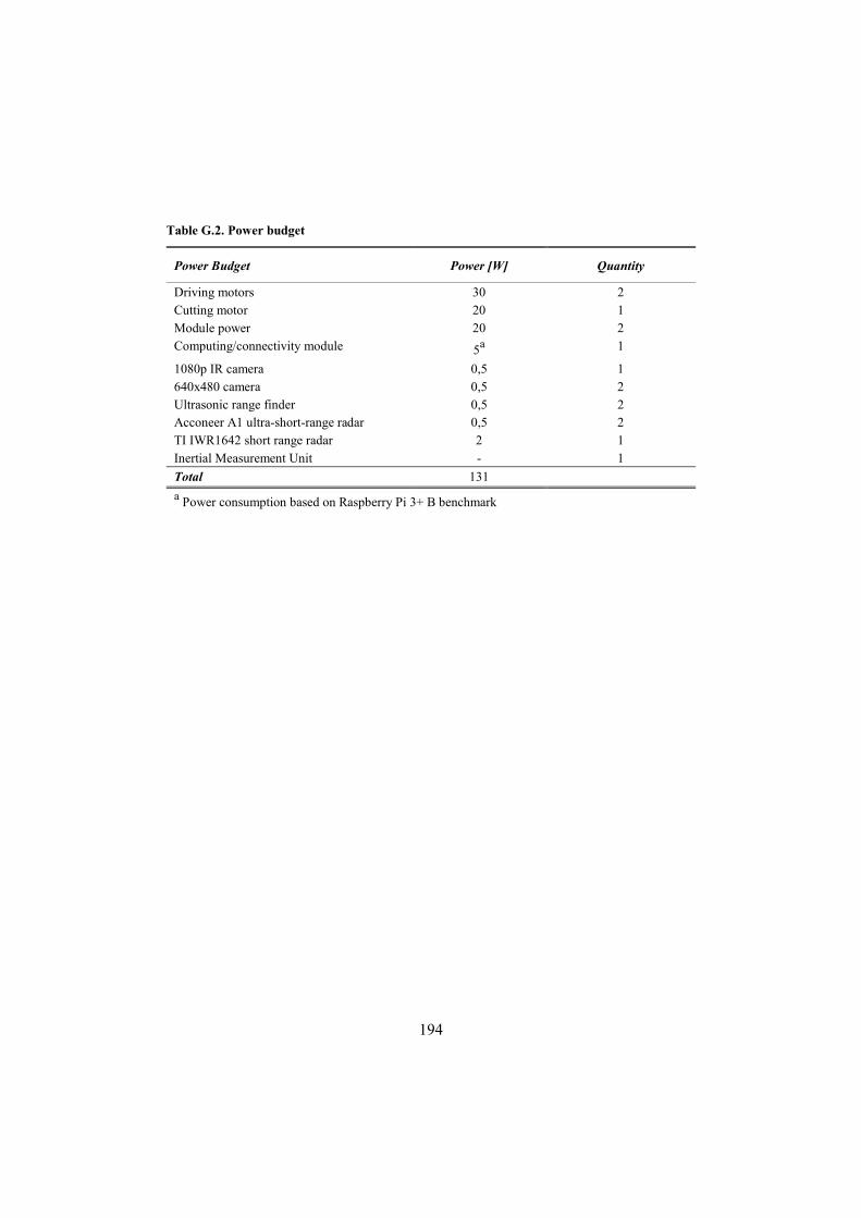
194
Table G.2. Power budget
Power Budget Power [W] Quantity
Driving motors 30 2 Cutting motor 20 1 Module power 20 2 Computing/connectivity module 5a 1
1080p IR camera 0,5 1 640x480 camera 0,5 2 Ultrasonic range finder 0,5 2 Acconeer A1 ultra-short-range radar 0,5 2 TI IWR1642 short range radar 2 1 Inertial Measurement Unit - 1
Total 131
a Power consumption based on Raspberry Pi 3+ B benchmark