espik.pdf - Lund University Research Portal
233
Intuitive Instruction of Industrial Robots A Knowledge-Based Approach Stenmark, Maj 2017 Link to publication Citation for published version (APA): Stenmark, M. (2017). Intuitive Instruction of Industrial Robots: A Knowledge-Based Approach. Department of Computer Science, Lund University. Total number of authors: 1 General rights Unless other specific re-use rights are stated the following general rights apply: Copyright and moral rights for the publications made accessible in the public portal are retained by the authors and/or other copyright owners and it is a condition of accessing publications that users recognise and abide by the legal requirements associated with these rights. • Users may download and print one copy of any publication from the public portal for the purpose of private study or research. • You may not further distribute the material or use it for any profit-making activity or commercial gain • You may freely distribute the URL identifying the publication in the public portal Read more about Creative commons licenses: https://creativecommons.org/licenses/ Take down policy If you believe that this document breaches copyright please contact us providing details, and we will remove access to the work immediately and investigate your claim.
-
Upload
khangminh22 -
Category
Documents
-
view
1 -
download
0
Transcript of espik.pdf - Lund University Research Portal

LUND UNIVERSITY
PO Box 117221 00 Lund+46 46-222 00 00
Intuitive Instruction of Industrial Robots
A Knowledge-Based ApproachStenmark, Maj
2017
Link to publication
Citation for published version (APA):Stenmark, M. (2017). Intuitive Instruction of Industrial Robots: A Knowledge-Based Approach. Department ofComputer Science, Lund University.
Total number of authors:1
General rightsUnless other specific re-use rights are stated the following general rights apply:Copyright and moral rights for the publications made accessible in the public portal are retained by the authorsand/or other copyright owners and it is a condition of accessing publications that users recognise and abide by thelegal requirements associated with these rights. • Users may download and print one copy of any publication from the public portal for the purpose of private studyor research. • You may not further distribute the material or use it for any profit-making activity or commercial gain • You may freely distribute the URL identifying the publication in the public portal
Read more about Creative commons licenses: https://creativecommons.org/licenses/Take down policyIf you believe that this document breaches copyright please contact us providing details, and we will removeaccess to the work immediately and investigate your claim.

Intuitive Instruction of Industrial Robots

Intuitive Instruction ofIndustrial Robots
A Knowledge-Based Approach
by Maj Stenmark
Thesis for the degree of PhDThesis advisors: Prof. Jacek Malec
Faculty opponent: Dr. Maya Cakmak
To be presented, with the permission of the Faculty of Engineering of Lund University, for public criticism inthe lecture hall E:1406 at the Department of Computer Science on Monday, the 29th of May 2017 at 10:15.

DOKUMEN
TDATA
BLADen
lSIS61
4121
Organization
LUND UNIVERSITY
Department of Computer ScienceBox 118SE–221 00 LUNDSweden
Author(s)
Maj Stenmark
Document name
DOCTORAL DISSERTATIONDate of disputation
2017-05-29Sponsoring organization
EU FP7 and EU H2020
Title and subtitle
Intuitive Instruction of Industrial Robots: A Knowledge-Based Approach
Abstract
With more advanced manufacturing technologies, small and medium sized enterprises can compete with low-wagelabor by providing customized and high quality products. For small production series, robotic systems can providea cost-effective solution. However, for robots to be able to perform on par with human workers in manufacturingindustries, they must become flexible and autonomous in their task execution and swift and easy to instruct. Thiswill enable small businesses with short production series or highly customized products to use robot coworkerswithout consulting expert robot programmers. The objective of this thesis is to explore programming solutionsthat can reduce the programming effort of sensor-controlled robot tasks. The robot motions are expressed usingconstraints, and multiple of simple constrained motions can be combined into a robot skill. The skill can be storedin a knowledge base together with a semantic description, which enables reuse and reasoning. The main contribu-tions of the thesis are 1) development of ontologies for knowledge about robot devices and skills, 2) a user interfacethat provides simple programming of dual-arm skills for non-experts and experts, 3) a programming interface fortask descriptions in unstructured natural language in a user-specified vocabulary and 4) an implementation wherelow-level code is generated from the high-level descriptions. The resulting system greatly reduces the number ofparameters exposed to the user, is simple to use for non-experts and reduces the programming time for experts by80. The representation is described on a semantic level, which means that the same skill can be used on differentrobot platforms. The research is presented in seven papers, the first describing the knowledge representation andthe second the knowledge-based architecture that enables skill sharing between robots. The third paper presentsthe translation from high-level instructions to low-level code for force-controlled motions. The two followingpapers evaluate the simplified programming prototype for non-expert and expert users. The last two present howprogram statements are extracted from unstructured natural language descriptions.
Key words
robot skills, high-level programming, industrial robot, human-robot interaction, natural language, knowledgerepresentation
Classification system and/or index terms (if any)
Supplementary bibliographical information Language
English
ISSN and key title
1404-1219ISBN
978-91-7753-297-2 (print)978-91-7753-298-9 (pdf )
Recipient’s notes Number of pages
232Price
Security classification
I, the undersigned, being the copyright owner of the abstract of the above-mentioned dissertation, hereby grant toall reference sources the permission to publish and disseminate the abstract of the above-mentioned dissertation.
Signature Date 2017-04-26

Intuitive Instruction ofIndustrial Robots
A Knowledge-Based Approach
by Maj Stenmark
Thesis for the degree of PhDThesis advisors: Prof. Jacek Malec
Faculty opponent: Dr. Maya Cakmak
To be presented, with the permission of the Faculty of Engineering of Lund University, for public criticism inthe lecture hall E:1406 at the Department of Computer Science on Monday, the 29th of May 2017 at 10:15.

Cover illustration front: The Fall of Man. Composition and photography by Maj Stenmark.
Cover illustration back: Piece of mind. Composition and photography by Maj Stenmark.
Funding information: The work presented in this thesis was financially supported by the Eu-ropean Union’s seventh framework program (FP7/2007-2013) under grant agreements N◦230902(ROSETTA) and N◦285380 (PRACE), and the European Community’s Framework ProgrammeHorizon 2020 under grant agreement N◦644938 (SARAFun).
© Maj Stenmark 2017
Faculty of Engineering, Department of Computer Science
isbn: 978-91-7753-297-2 (print)isbn: 978-91-7753-298-9 (pdf )issn: 1404-1219
LU-CS-DISS 2017-02Dissertation 56, 2017
Printed in Sweden by Tryckeriet i E-huset, Lund, 2017

Dedicated to my mother


Abstract
With more advanced manufacturing technologies, small and medium sized enterprises cancompete with low-wage labor by providing customized and high quality products. Forsmall production series, robotic systems can provide a cost-effective solution. However, forrobots to be able to perform on par with human workers in manufacturing industries, theymust become flexible and autonomous in their task execution and swift and easy to in-struct. This will enable small businesses with short production series or highly customizedproducts to use robot coworkers without consulting expert robot programmers. The ob-jective of this thesis is to explore programming solutions that can reduce the programmingeffort of sensor-controlled robot tasks. The robot motions are expressed using constraints,and multiple of simple constrained motions can be combined into a robot skill. The skillcan be stored in a knowledge base together with a semantic description, which enablesreuse and reasoning. The main contributions of the thesis are 1) development of ontolo-gies for knowledge about robot devices and skills, 2) a user interface that provides simpleprogramming of dual-arm skills for non-experts and experts, 3) a programming interfacefor task descriptions in unstructured natural language in a user-specified vocabulary and4) an implementation where low-level code is generated from the high-level descriptions.The resulting system greatly reduces the number of parameters exposed to the user, is sim-ple to use for non-experts and reduces the programming time for experts by 80. Therepresentation is described on a semantic level, which means that the same skill can beused on different robot platforms. The research is presented in seven papers, the first de-scribing the knowledge representation and the second the knowledge-based architecturethat enables skill sharing between robots. The third paper presents the translation fromhigh-level instructions to low-level code for force-controlled motions. The two followingpapers evaluate the simplified programming prototype for non-expert and expert users. Thelast two present how program statements are extracted from unstructured natural languagedescriptions.
i


Acknowledgements
The last five years have been a journey of self-discovery. I started out all optimistic andenthusiastic, ready to solve World Problems, just to be brutally rejected from conferencesand broken-in as a robot programmer. It has been a humbling experience. That makesthe taste of achievement so much sweeter, when we got our papers accepted or when ademo started working. So, between the Impostor syndrome and Messiah complex, resilienceprevailed, and here we are, more or less on time. More so because of the patience andsupport from my awesome supervisor Jacek Malec and my co-supervisors Elin Anna Toppand Mathias Haage. They have a fantastic ability to squeeze in many hours of paper writingbetween dinner and midnight anywhere on earth. Thank you, Jacek, for your hard worktrying to keep me on course. Thank you, Elin, for teaching me how to run user studies andfor the wine we shared on our conference trips. And thank you, Mathias, for sharing yourknowledge about robot controllers and networking. Less on time, because of our groupleader Klas Nilsson, who knows that I cannot say no to a challenging side project, and, ifit seems difficult, the answer will be “we need Andreas”. So thank you, Andreas Stolt, forthe great work as a co-author and co-programmer, especially during the gift-wrapping tour( “who agreed to this insane project?”).
To all my co-authors: it has been a pleasure cooperating with you, thank you for the stim-ulating discussions and hard efforts.
When I was running experiments on bleeding edge robotics software, the odds were evenbetween system failure and success. Successful experiments, regarded with surprise andsuspicion, were mainly due to the hard work of my colleagues in the RobotLab. Especially,thank you Anders Robertsson and Anders Blomdell for keeping everything afloat.
The Depts. of Computer Science and Automatic Control are populated with intelligent,industrious, humorous and creative colleagues: you make this a motivating workplace.Talking to you over coffee has been educational, entertaining and awe inspiring, sometimesall three at once.
I want to thank Daniel, for his encouragement and understanding, and Jonas, for his TEX-support, and the rest of my family and friends. This thesis is dedicated to my mother,who has supported my pursuit of knowledge and education all my life: from the day inschool when they taught us about Genesis and she was called to a parent-teacher conferencebecause her first-grader argued too much about the meaning of the story, until this veryday, when I will argue once more, about the meaning of things.
iii


Popular summary in English
The work presented in this thesis focuses on methods for simplified programming of indus-trial robots. It is expensive to automate manufacturing processes and consumer products areoften manufactured in low-cost countries with poor working conditions. One bottleneckis that it requires an expert roboticist to work with robots. To mitigate this, we developedtechnologies that make it possible for non-experts to interact with robots using an iconicgraphical interface combined with kinesthetic teaching and natural (human) language. Thegraphical interface has a set of common instructions which makes the programming sim-ple for non-experts while also increasing the efficiency for experienced robot programmers.The robot programs, the so-called skills, can be made more general by specifying that themotions should be relative to objects in the work space. For example, if the robot shouldpick nuts placed in a box, it can locate nuts with its camera system and then always centerits gripping position above the piece. The user can add additional abstractions by creatingmultiple objects of different types, for example, in an emergency stop button box assembly,there are red buttons and grey switches.
The user can name their programs and objects in natural language, in this case English, andcreate their own small vocabulary that the robot understands. Using statistical languageanalysis, the meaning of the sentences is interpreted as existing robot programs appliedto objects. When instructing the robot to assemble the emergency stop button box, forexample, the user can demonstrate for the robot where the objects are while telling ”hereis a red button” and, if the program for picking objects is saved as a ”pick” skill, say to therobot to ”pick red buttons”.
The programs are general and reusable and can be shared with other robots through adatabase, for example the dual-arm robot ABB YuMi in our lab can transfer a programfrom the right arm to the left. The two arms of the YuMi robot can work independently,but our methods allow the user to rapidly instruct synchronized dual-arm tasks. When aprogram is transferred from one robot, e.g., the YuMi robot, to another, e.g., a classicalABB robot, the positions must be recalculated to work with the different embodiment ofthe robot but also adapted to the specific sensors, e.g., a different type of force sensor.
The methods and experimental setups were evaluated using non-experts and experts anddifferent robots in the RobotLab at the Departments of Computer Science and AutomaticControl at Lund University.
v

Populärvetenskaplig sammanfattning på svenska
I avhandlingen presenteras metoder som förenklar programmeringen av industrirobotar.Att automatisera är ofta kostsamt och mycket av produktionen av konsumentprodukterutförs i låglöneländer under dåliga arbetsförhållanden. Ett av problemen är att det oftakrävs expertis inom robotik för att arbeta med robotar. Vi har därför utvecklat teknik somgör det möjligt för oerfarna användare att interagera med maskinerna.
Genom att visualisera varje instruktion som ikoner och låta användaren fysiskt leda robo-tarmen till rätt positioner går det snabbare för både robotexperter och ovana testpersoneratt skapa välfungerande program. Programmen kan göras mer generella genom att specifi-cera att rörelserna ska vara relativt objekt i världen. Till exempel, om roboten ska plockaupp muttrar som ligger lite utspritt i en låda kan den med hjälp av sitt kamerasystem hittapositionen av en bit, men sen måste plockrörelsen alltid centrera robotens gripdon i mittenpå biten. Användaren kan abstrahera sitt program ännu mer genom att skapa fler typer avobjekt som ska plockas, till exempel har en nödstoppsknapp i plast röda knappar, brytareoch en gul låda. Programmen är generiska och kan föras över till andra robotar, t ex kanvår tvåarmade robot YuMi återanvända program både på vänster och höger sida. Armarnakan arbeta helt separat men vi har också utvecklat tillvägagångssätt för att enkelt instruerasynkroniserade tvåarmade rörelser.
Genom att ge programmet namn och beskrivningar i mänskligt språk, t ex ”plocka”, kananvändaren skapa ett eget ordförråd med objekt i robotens värld och handlingar eller opera-tioner som roboten kan utföra. Med hjälp av språkanalys baserad på statistisk databehand-ling kan meningar tolkas som just handlingar (verb) på objekt i världen. Vi har kopplatihop språkanalys och robotprogrammering så att användaren kan prata med sin robot föratt skapa nya begrepp, t ex ”här finns en röd knapp” och ”plocka upp den röda knappen”(fast på engelska). Robotprogrammen sparas i en databas tillsammans med den språkligabeskrivningen som kan förstås av människor och data som kan förstås av maskinen. För attåteranvända ett program som är skapat för en viss typ av robot, t ex vår YuMi, på en annan,t ex en klassisk ABB robot, måste inte bara rörelserna översättas till en robotarm med annatutseende, utan också mätvärden från olika givare, t ex för kraft, behöver anpassas till denandra robotens sensorer.
Teknikerna vi utvecklat har evaluerats med oerfarna användare och experter på olika robotari LTH:s robotlabb.
vi

Contents
I Background 1
Introduction 31 Research Questions . . . . . . . . . . . . . . . . . . . . . . . . . . . . 72 Contribution Statement . . . . . . . . . . . . . . . . . . . . . . . . . . 8
Terminology 9
Robot Software and Systems 171 Standard Industrial Workflow and Tools . . . . . . . . . . . . . . . . . . 172 Research Software Architectures . . . . . . . . . . . . . . . . . . . . . . 183 Overview of the Lund Software Architecture . . . . . . . . . . . . . . . . 21
Related Work 231 End-to-end Robot Programming . . . . . . . . . . . . . . . . . . . . . 232 Data-driven Approaches . . . . . . . . . . . . . . . . . . . . . . . . . . 243 Dual-arm Manipulation . . . . . . . . . . . . . . . . . . . . . . . . . . 274 Multiple Modalities . . . . . . . . . . . . . . . . . . . . . . . . . . . . 285 Manipulation Primitives and Skills . . . . . . . . . . . . . . . . . . . . . 296 The Grounding Problem . . . . . . . . . . . . . . . . . . . . . . . . . . 307 Ontologies . . . . . . . . . . . . . . . . . . . . . . . . . . . . . . . . . 318 Connecting Natural Language and Robot Actions . . . . . . . . . . . . . 32
Approach 37
Implementation and Evaluation 391 Knowledge Integration and Services . . . . . . . . . . . . . . . . . . . . 392 Code Generation . . . . . . . . . . . . . . . . . . . . . . . . . . . . . 423 Human-robot Interaction . . . . . . . . . . . . . . . . . . . . . . . . . 464 Natural Language Programming . . . . . . . . . . . . . . . . . . . . . . 48
Summary of the Included Papers 51
Discussion 551 Knowledge Representation . . . . . . . . . . . . . . . . . . . . . . . . . 562 Code Generation . . . . . . . . . . . . . . . . . . . . . . . . . . . . . 57

3 Human-robot Interaction . . . . . . . . . . . . . . . . . . . . . . . . . 574 Skill Creation . . . . . . . . . . . . . . . . . . . . . . . . . . . . . . . 585 Dual-arm Manipulation . . . . . . . . . . . . . . . . . . . . . . . . . . 586 Natural Language Interfaces . . . . . . . . . . . . . . . . . . . . . . . . 597 Future Work . . . . . . . . . . . . . . . . . . . . . . . . . . . . . . . . 60
Scientific publications 61Included papers . . . . . . . . . . . . . . . . . . . . . . . . . . . . . . . . . 61Other contributions . . . . . . . . . . . . . . . . . . . . . . . . . . . . . . . 63
II Included Papers 67
Paper I: Knowledge-Based Instruction of Manipulation Tasks for Industrial Robotics 711 Introduction . . . . . . . . . . . . . . . . . . . . . . . . . . . . . . . . 732 Robot Skills . . . . . . . . . . . . . . . . . . . . . . . . . . . . . . . . 733 Architecture . . . . . . . . . . . . . . . . . . . . . . . . . . . . . . . . 744 Knowledge Integration Framework . . . . . . . . . . . . . . . . . . . . 775 Knowledge-Based Services . . . . . . . . . . . . . . . . . . . . . . . . . 816 Engineering System . . . . . . . . . . . . . . . . . . . . . . . . . . . . 867 Execution . . . . . . . . . . . . . . . . . . . . . . . . . . . . . . . . . 868 Related Work . . . . . . . . . . . . . . . . . . . . . . . . . . . . . . . 869 Conclusions . . . . . . . . . . . . . . . . . . . . . . . . . . . . . . . . 89
Paper II: On Distributed Knowledge Bases for Small-Batch Assembly 931 Introduction . . . . . . . . . . . . . . . . . . . . . . . . . . . . . . . . 952 A first local utility-based approach . . . . . . . . . . . . . . . . . . . . . 963 Knowledge integration . . . . . . . . . . . . . . . . . . . . . . . . . . . 984 Knowledge representation . . . . . . . . . . . . . . . . . . . . . . . . . 995 Human-robot interaction . . . . . . . . . . . . . . . . . . . . . . . . . 1016 SME-suitable cognition . . . . . . . . . . . . . . . . . . . . . . . . . . 1027 Related work . . . . . . . . . . . . . . . . . . . . . . . . . . . . . . . . 1038 Implementations . . . . . . . . . . . . . . . . . . . . . . . . . . . . . . 1059 Discussion . . . . . . . . . . . . . . . . . . . . . . . . . . . . . . . . . 10510 Conclusions . . . . . . . . . . . . . . . . . . . . . . . . . . . . . . . . 108
Paper III: From High-Level Task Descriptions to Executable Robot Code 1131 Introduction . . . . . . . . . . . . . . . . . . . . . . . . . . . . . . . . 1152 System Overview . . . . . . . . . . . . . . . . . . . . . . . . . . . . . . 1153 Code Generation . . . . . . . . . . . . . . . . . . . . . . . . . . . . . 1174 Experiments . . . . . . . . . . . . . . . . . . . . . . . . . . . . . . . . 1235 Related Work . . . . . . . . . . . . . . . . . . . . . . . . . . . . . . . 1236 Conclusions and Future Work . . . . . . . . . . . . . . . . . . . . . . . 1247 Acknowledgments . . . . . . . . . . . . . . . . . . . . . . . . . . . . . 125
viii
Paper IV: Simplified Programming of Re-usable Skills on a Safe Industrial Robot– Prototype and Evaluation 1291 Introduction . . . . . . . . . . . . . . . . . . . . . . . . . . . . . . . . 1312 Related Work . . . . . . . . . . . . . . . . . . . . . . . . . . . . . . . 1323 Case Studies . . . . . . . . . . . . . . . . . . . . . . . . . . . . . . . . 1334 Implementation . . . . . . . . . . . . . . . . . . . . . . . . . . . . . . 1355 Evaluation and User Study . . . . . . . . . . . . . . . . . . . . . . . . . 1386 Conclusion . . . . . . . . . . . . . . . . . . . . . . . . . . . . . . . . 1457 Acknowledgments . . . . . . . . . . . . . . . . . . . . . . . . . . . . . 146
Paper V: The Art of Synchronized Dual-Arm Robot Programming 1491 Introduction . . . . . . . . . . . . . . . . . . . . . . . . . . . . . . . . 1502 Related Work . . . . . . . . . . . . . . . . . . . . . . . . . . . . . . . 1523 Objects, Primitives and Skills . . . . . . . . . . . . . . . . . . . . . . . 1524 Implementation . . . . . . . . . . . . . . . . . . . . . . . . . . . . . . 1545 Experiments . . . . . . . . . . . . . . . . . . . . . . . . . . . . . . . . 1566 Conclusions . . . . . . . . . . . . . . . . . . . . . . . . . . . . . . . . 159
Paper VI: Natural Language Programming of Industrial Robots 1631 Introduction . . . . . . . . . . . . . . . . . . . . . . . . . . . . . . . . 1652 Related Work . . . . . . . . . . . . . . . . . . . . . . . . . . . . . . . 1653 System Overview . . . . . . . . . . . . . . . . . . . . . . . . . . . . . . 1664 High-level Programming Prototype . . . . . . . . . . . . . . . . . . . . 1685 Conclusions . . . . . . . . . . . . . . . . . . . . . . . . . . . . . . . . 1716 Future Work . . . . . . . . . . . . . . . . . . . . . . . . . . . . . . . . 1727 Acknowledgments . . . . . . . . . . . . . . . . . . . . . . . . . . . . . 172
Paper VII: Describing Constraint-Based Assembly Tasks in Unstructured NaturalLanguage 1751 Introduction . . . . . . . . . . . . . . . . . . . . . . . . . . . . . . . . 1772 Related Work . . . . . . . . . . . . . . . . . . . . . . . . . . . . . . . 1773 Background . . . . . . . . . . . . . . . . . . . . . . . . . . . . . . . . 1784 Pattern-Matching Algorithm . . . . . . . . . . . . . . . . . . . . . . . . 1825 Discussion . . . . . . . . . . . . . . . . . . . . . . . . . . . . . . . . . 188
Bibliography 189
Appendix: Conference posters 211
ix


Part I
Background
1

Introduction
It’s just a matter of semantics.
The robot revolution is yet to come. Robot programming requires expertise in machineryand sensor technologies and application development is time consuming even for profes-sionals. Therefore, manufacturing is outsourced to low-cost countries, with poor workingconditions. Also, small enterprises cannot afford to employ an expert to program variousrepetitive tasks. To reduce the cost of automation and for example make it feasible for smallcompanies to robotize parts of their production, it is necessary to reduce the workload forexperts to program robots and to make it possible for non-experts to instruct robots aboutnon-trivial tasks.
Instead of aiming for fully automatic assembly lines, human-machine cooperation can re-sult in flexible manufacturing, where the robots can carry out simple repetitive tasks whilethe human operators can complement with their superior dexterity and perception capabil-ities. The cooperation reduces the cost of automation because the programming of a fullyautomated assembly can be very costly and tedious. This is a sharp contrast to traditionalindustrial robot systems that execute the same tasks for years without any user interactionduring regular operation; in fact, they are locked in cages for safety reasons. In the lattercase, the programming phase is short compared to the operational phase and the programis seldom updated. In a traditional factory setting, the robot is continuously in production,so the larger part of the program is implemented and optimized offline in a simulation en-vironment to reduce the downtime of the robot during deployment and real-world testing.
Recently, a new generation of collaborative robot systems have entered the market. Theseso-called cobots are designed to work safely side-by-side with human co-workers. Theintended applications are small-parts assembly in close cooperation with humans. Therobots are often equipped with internal force estimation and sensors, and are small enoughto be guided manually using lead-through, that is, the robot arms can be moved physically bythe operator. This method is used in online programming and is considered more intuitivethan a joystick which otherwise is used to guide large robots.
3
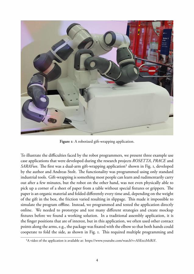
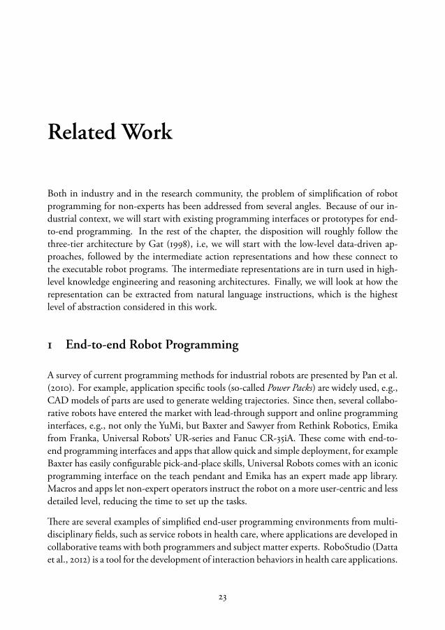
Figure 1: A robotized gift-wrapping application.
To illustrate the difficulties faced by the robot programmers, we present three example usecase applications that were developed during the research projects ROSETTA, PRACE andSARAFun. The first was a dual-arm gift-wrapping application¹ shown in Fig. 1, developedby the author and Andreas Stolt. The functionality was programmed using only standardindustrial tools. Gift-wrapping is something most people can learn and rudimentarily carryout after a few minutes, but the robot on the other hand, was not even physically able topick up a corner of a sheet of paper from a table without special fixtures or grippers. Thepaper is an organic material and folded differently every time and, depending on the weightof the gift in the box, the friction varied resulting in slippage. This made it impossible tosimulate the program offline. Instead, we programmed and tested the application directlyonline. We needed to prototype and test many different strategies and create mockupfixtures before we found a working solution. In a traditional assembly application, it isthe finger positions that are of interest, but in this application, we often used other contactpoints along the arms, e.g., the package was fixated with the elbow so that both hands couldcooperate to fold the side, as shown in Fig. 1. This required multiple programming and
¹A video of the application is available at: https://www.youtube.com/watch?v=ASEtz2M1RiY.
4

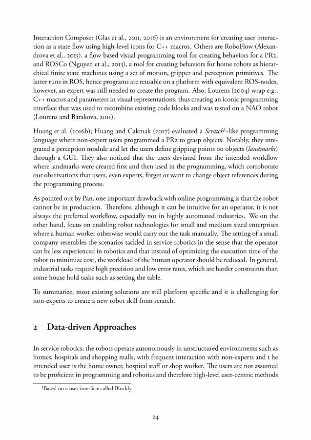
Figure 2: A robotized emergency stop button box assembly task.
debugging sessions, and the standard programming methods were very time-consuming.For example, the arms were programmed as two separate robots and the synchronizationneeded for dual-arm operations added significant overhead.
The second example that illustrates the challenges faced by the roboticist, is the force-controlled dual-arm assembly task of the emergency stop button box² shown in Fig. 2. Theapplication was developed by Andreas Stolt and Magnus Linderoth during the EuropeanFP7 project ROSETTA. The task consisted of several fine-tuned subassemblies that neededprecise force-controlled motions. This required an extension of the standard robotics soft-ware to enable real-time control. The resulting implementation included switching con-trollers and setting the parameters to the sensor-controlled motions. Creating the sensor-based control algorithms and programming the application required an expert in automaticcontrol. In make it possible for non-experts to program similar tasks, it was necessary todevelop an abstraction that significantly reduced the level of technical details exposed tothe user. Also, after developing the various advanced skills used in the assembly, we wantedto be able to reuse them on other robots to reduce the reimplementation effort.
²A video is available at https://www.youtube.com/watch?v=7JgdbFW5mEg
5
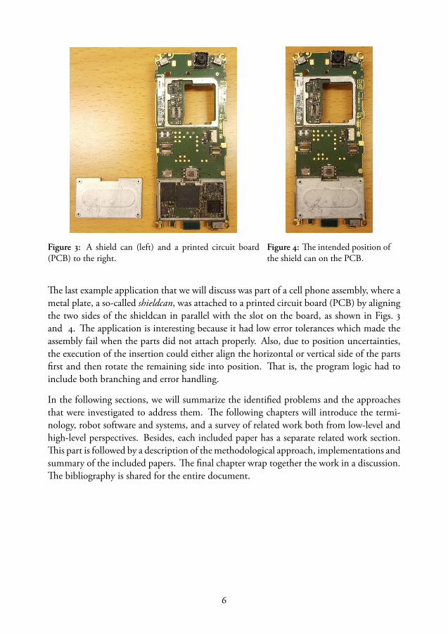
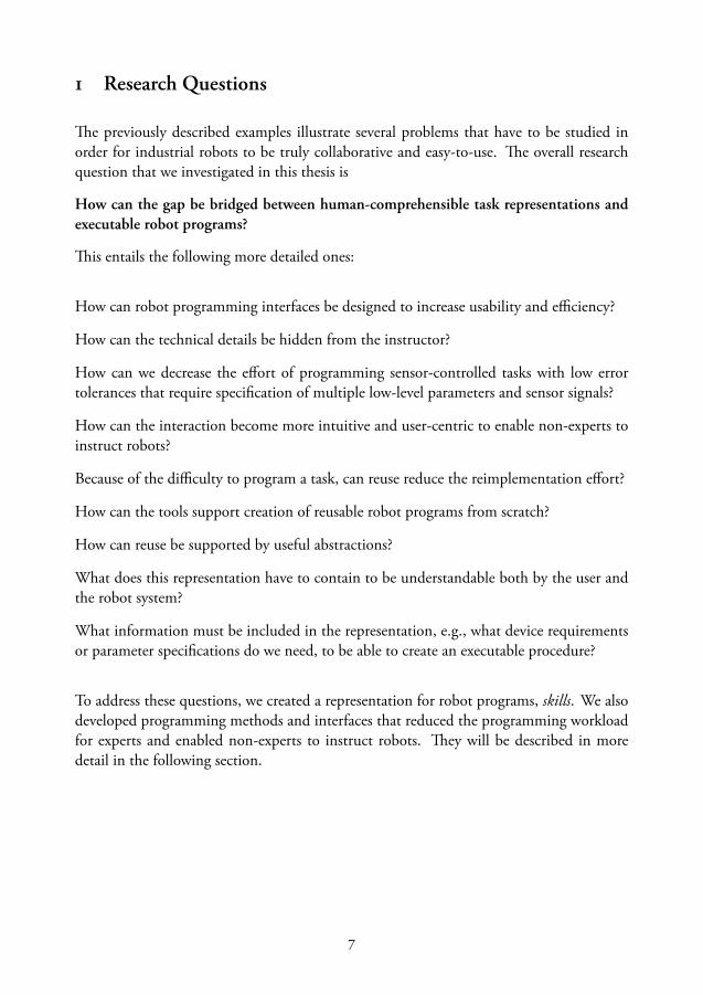
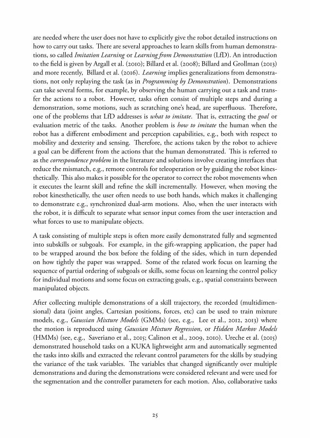
Figure 3: A shield can (left) and a printed circuit board(PCB) to the right.
Figure 4: The intended position ofthe shield can on the PCB.
The last example application that we will discuss was part of a cell phone assembly, where ametal plate, a so-called shieldcan, was attached to a printed circuit board (PCB) by aligningthe two sides of the shieldcan in parallel with the slot on the board, as shown in Figs. 3and 4. The application is interesting because it had low error tolerances which made theassembly fail when the parts did not attach properly. Also, due to position uncertainties,the execution of the insertion could either align the horizontal or vertical side of the partsfirst and then rotate the remaining side into position. That is, the program logic had toinclude both branching and error handling.
In the following sections, we will summarize the identified problems and the approachesthat were investigated to address them. The following chapters will introduce the termi-nology, robot software and systems, and a survey of related work both from low-level andhigh-level perspectives. Besides, each included paper has a separate related work section.This part is followed by a description of the methodological approach, implementations andsummary of the included papers. The final chapter wrap together the work in a discussion.The bibliography is shared for the entire document.
6
1 Research Questions
The previously described examples illustrate several problems that have to be studied inorder for industrial robots to be truly collaborative and easy-to-use. The overall researchquestion that we investigated in this thesis is
How can the gap be bridged between human-comprehensible task representations andexecutable robot programs?
This entails the following more detailed ones:
How can robot programming interfaces be designed to increase usability and efficiency?
How can the technical details be hidden from the instructor?
How can we decrease the effort of programming sensor-controlled tasks with low errortolerances that require specification of multiple low-level parameters and sensor signals?
How can the interaction become more intuitive and user-centric to enable non-experts toinstruct robots?
Because of the difficulty to program a task, can reuse reduce the reimplementation effort?
How can the tools support creation of reusable robot programs from scratch?
How can reuse be supported by useful abstractions?
What does this representation have to contain to be understandable both by the user andthe robot system?
What information must be included in the representation, e.g., what device requirementsor parameter specifications do we need, to be able to create an executable procedure?
To address these questions, we created a representation for robot programs, skills. We alsodeveloped programming methods and interfaces that reduced the programming workloadfor experts and enabled non-experts to instruct robots. They will be described in moredetail in the following section.
7
2 Contribution Statement
The four main contributions of the work presented in this thesis are the following:
1. Knowledge representation for robot devices and skills. The symbolic knowledgeof the system is expressed as modular ontologies. The core ontology includes robotdevices, such as robots, sensors, tool changers and fixtures. Tasks and skills are rep-resented by graphs, hence we developed a graph ontology which includes differentstate machine descriptions. Each step in the state machine has parameters, theseparameters are semantically described in separate ontologies for relative coordinateframes and quantities. Skills are represented by a small sub-ontology that describesthe device requirements, parameters for each action and pre-and post-conditions (Pa-per i). The knowledge is shared between robots and tools in a cloud-based softwarearchitecture (Paper ii).
2. Generation of executable code for sensor-controlled skills. It is necessary to be ableto execute the complete task on a physical system. The contribution of Paper iiiis an implementation of a code generation service that takes high-level semanticallyannotated tasks and creates executable task-level state machines by combining force-controlled and position-controlled motions and reusable skills by automatically han-dling the handover between controllers and setting up the kinematic chains.
3. Simplified programming methods. We developed and evaluated a prototype forend-to-end robot programming that simplified task instruction and debugging fornon-experts, and for experts it decreased the workload significantly for both singleand synchronized dual-arm tasks (Papers iv and v). The methods allow the usersto incrementally add abstractions, create reusable parameterized skills and reducethe overhead for bi-manual task programming by handling synchronized motions inpairs.
4. A service for natural language programming of robots. The users can build theirown vocabulary of objects and skills and instruct the robots using unstructured natu-ral language. The language analysis is carried out by using the semantic output froma statistical parser combined with the knowledge in the system about the object re-lations and skills to generate executable code. This was evaluated for e.g., loops,sensor-based motions and multiple conditions (Papers vi and vii).
8

Terminology
Robotics is an interdisciplinary field connecting computer science areas such as artificialintelligence (AI), machine learning and distributed computing with hardware and sensortechnologies from automatic control, electronics and computer vision, and cognitive sci-ence, linguistics, design, psychology and philosophy. Within this broad community, thereis not even a consensus what a robot is, therefore let us begin by establishing a commonvocabulary.
The following definitions are made by the International Organization for Standardization,edited for readability:
ISO 8373:2012: Robots and robotic devices – Vocabulary
Robot: actuated mechanism programmable in two or more axes with a degree of autonomy,moving within its environment, to perform intended tasks.Note 1 to entry: A robot includes the control system and interface of the control system.Note 2 to entry: The classification of robot into industrial robot or service robot is done according to its intendedapplication.
Manipulator: machine in which the mechanism usually consists of a series of segments, jointedor sliding relative to one another, for the purpose of grasping and/or moving objects (pieces ortools) usually in several degrees of freedom.
Autonomy: ability to perform intended tasks based on current state and sensing, without hu-man intervention.
Physical alteration: alteration of the mechanical system.
Reprogrammable: designed so that the programmed motions or auxiliary functions can bechanged without physical alteration.
Multipurpose: capable of being adapted to a different application with physical alteration.
9
Control system: set of logic control and power functions which allows monitoring and controlof the mechanical structure of the robot and communication with the environment (equipmentand users).
Industrial robot: automatically controlled, reprogrammable, multipurpose, manipula-tor, programmable in three or more axes, which can be either fixed in place or mobile for use inindustrial automation applications.Note 1 to entry: The industrial robot includes:— the manipulator, including actuators.— the controller, including teach pendant and any communication interface (hardware and software).
Industrial robot system: system comprising industrial robot, end effectors and any machin-ery, equipment, devices, external auxiliary axes or sensors supporting the robot performing itstask.
Service Robotics: robot that performs useful tasks for humans or equipment excluding indus-trial automation applications. Personal service robot: used for a non-commercial task, usuallyby lay persons, for example: domestic servant robot, automated wheelchair, personal mobilityassist robot, and pet exercising robot.
Intelligent robot: robot capable of performing tasks by sensing its environment and/or inter-acting with external sources and adapting its behaviour.
Note that a robot has a physical representation, and manipulates objects in the real world.The program execution of the robot can be simulated in a virtual environment with moreor less advanced simulations of perception and physics, but in general, virtual agents arebots and not robots. The embodiment of industrial robots can vary significantly, the linksand the joints can be connected e.g., serially as the classic orange single arm manipulatorwith six links joined by revolute (rotating) joints (see Fig. 1), or in parallel with sphericaland prismatic (translational) joints (see Fig. 2). The links and joints of the robot create aa kinematic chain. The degrees of freedom (DOFs) of a robot is the number of parametersrequired to specify the configuration of the mechanical system, e.g., the classic industrialarm has 6 DOFs. To specify a target position in the workspace, that is, the physical spacethat the robot can reach, either the respective position (in degrees or radians) of each jointshould be specified as a joint target, or the position of the end-effector can be specified inCartesian coordinates. Throughout this work, position will refer to the pose, that is, bothtranslation (x, y, z) and orientation (values given in quaternions or Euler angles). When thejoint values are specified, the forward kinematics of the robot is used to calculate the position(and velocity and acceleration) of the end-effector. It is often desired to specify the positionin Cartesian coordinates of the end-effector, in so-called task space, and then the inversekinematics is used to compute the actuator torques for each joint so that the position isreached. The Cartesian coordinates can either be specified in absolute coordinates, usually
10
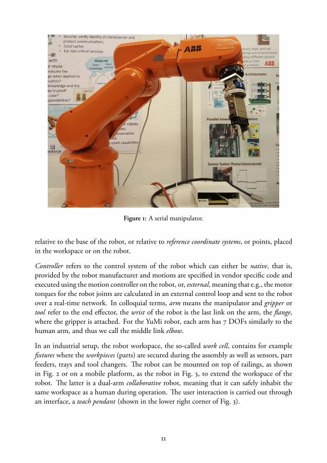
Figure 1: A serial manipulator.
relative to the base of the robot, or relative to reference coordinate systems, or points, placedin the workspace or on the robot.
Controller refers to the control system of the robot which can either be native, that is,provided by the robot manufacturer and motions are specified in vendor specific code andexecuted using the motion controller on the robot, or, external, meaning that e.g., the motortorques for the robot joints are calculated in an external control loop and sent to the robotover a real-time network. In colloquial terms, arm means the manipulator and gripper ortool refer to the end effector, the wrist of the robot is the last link on the arm, the flange,where the gripper is attached. For the YuMi robot, each arm has 7 DOFs similarly to thehuman arm, and thus we call the middle link elbow.
In an industrial setup, the robot workspace, the so-called work cell, contains for examplefixtures where the workpieces (parts) are secured during the assembly as well as sensors, partfeeders, trays and tool changers. The robot can be mounted on top of railings, as shownin Fig. 2 or on a mobile platform, as the robot in Fig. 3, to extend the workspace of therobot. The latter is a dual-arm collaborative robot, meaning that it can safely inhabit thesame workspace as a human during operation. The user interaction is carried out throughan interface, a teach pendant (shown in the lower right corner of Fig. 3).
11

Figure 2: A parallel manipulator.
Each time the robot is commanded to move to a specific joint position, it should moveto the same configuration with low error, that is, with a high repeatability. The YuMi forexample has 0.02 mm repeatability. Each robot is unique due to small manufacturingdifferences and tear and wear, so when two robots of the same model are given positionswith the same joint values they will move to slightly different Cartesian positions. Themeasurement of how close a robot reaches a specific Cartesian position in the workspacewith low error is accuracy, this typically requires calibration of the robot.
Even with external sensors for part localization, e.g., a camera system, and even if the partsin the assembly are placed in fixtures and the robot has high repeatability, the measure-ments will have small inaccuracies and the parts have small deviations in the shape, slipand slide in the grippers or jam together, hence there is an uncertainty when manipulat-ing objects in the physical world. Therefore, tasks with low error tolerances need reactiveexecution with sensor feedback and control. Sensors and devices and communication sig-nals can be integrated into the system by a system integrator. This often puts hard real-timerequirements on the system, that is, the computation and communication tasks must bescheduled in a timely manner and must guarantee a response within their deadlines (Shinand Ramanathan, 1994), which often are measured in milliseconds. These deadlines mustalways be met, no matter, e.g., the load on the communication link. A system without thisguarantee can still have fast average, actual or expected response times.
12

Figure 3: A dual-arm robot mounted on a mobile platform.
In the ISO definition, the bar is set very low for a robot to be considered intelligent. In thescientific community, this is not always the case, rather, some high-level reasoning or un-derstanding is frequently required. The following terms are often used to describe researchproblems in the AI and robotics literature:
Manipulation primitive: A semantically described atomic action that functions as an in-terface to the low-level robot control, see e.g., Kröger et al. (2010).
Embodiment: in robotics, it refers to the physical form of an agent, e.g., the robot or thehuman body. The embodiment of the robot can be anything from a standard industrialmanipulator mounted on a table and equipped with a two-finger gripper and a force sen-sor, to a full-sized humanoid with vision system and five finger end-effectors. In artificialintelligence and especially cognitive science or philosophy, embodiment can refer to virtualbodies or interaction with the world.
Correspondence Problem: the difficulty to transfer a task description between entitieswith different embodiment and perception capabilities (Nehaniv, 2007).
13

Non-expert: A person who would not be hired to program robots but might need to in-teract with it in work or home environments.
End-to-end robot programming interfaces: User interfaces that let the intended operators(end-users) create the complete robot program.
Wizard-of-Oz experiment: An experimental setup in user studies where the subjects be-lieve that they interact with a machine but it is controlled by a human experimenter. Thisenables evaluation of user interfaces without implementation e.g., when evaluating modal-ity preferences.
Semantics: the meaning of a word, sign or symbol.
Knowledge base: in the field of artificial intelligence, knowledge representation refers tothe symbolic modeling of information about the world and logical rules (using e.g., De-scription Logic) that describe relations between symbols. That is, there are assertions, orfacts, about entities, and logical rules so that the a system can automatically infer moreinformation about the entities (see the example below).
Ontology: a way to describe a taxonomy, that is, the symbolic model describing types,properties and relationships between the entities. A knowledge base can contain multipleontologies. In our work, we use the Web Ontology Language (OWL) to model the assemblydomain. There are object types, or classes, modeled in a class hierarchy (comparable toobject-oriented programming but allowing, among other things, multiple inheritance), forexample, the class DualArmRobot is a subclass of Robot, and instances of classes, e.g.,theLundYuMiRobot, which is an instance of the class DualArmRobot (and by inference,Robot). Additional rules specify that a dual-arm robot has exactly two manipulators.
The Open World Assumption: given the knowledge in a system, if a statement cannot beproven true, we cannot draw the conclusion that it is false, rather, it is unknown.
The Symbol Grounding Problem: a symbol in an ontology must be connected to somereal-world entity, otherwise the knowledge is simply a meaningless abstract exercise (Har-nad, 1990). Using the (biologically dubious) example given by Harnad (1990), if an ontol-ogy has the concept of Horse and Stripes, their combination can represent Zebra. Ifthe symbols for Horse and Stripes are grounded in real world data, in, e.g., a descriptionof the physical characteristics of a horse and a pattern describing stripes, the system shouldbe able to recognize a zebra as well. Creating and maintaining this connection betweensymbols and real world sensor data that refer to the same object, so-called anchoring, is aspecial case of the symbol grounding problem only referring to physical objects.
Affordance: A possible action offered by objects or environments (Gibson, 1986).
14
Cognitive Robotics: is the field of robotics that tries to enable robots to learn, reason andreact in complex real-world situations, that is connect perception and action to a symbolicrepresentation that allows them to reason and replan its behavior.
Natural Language: human languages and biologically evolved languages, such as whalesong. In contrast to formal languages such as programming languages or description logic,natural language sentences can be ambiguous and mean different things depending on con-text and the receiver, using implicit assumptions about the receiver’s belief and knowledge.Also, there are many ways to express semantically equivalent statements grammatically andby using synonyms and sarcasm, making implicit assumptions about common sense rea-soning and culture, etc. There are lexical ambiguities, e.g., when a homonym has multiplemeanings (e.g., study, execute) and practical ambiguities when information must be in-ferred, e.g., put the food on the table does not specify exactly what edible items to bring,how to carry the food, e.g., in a pot and without turning it upside down during the trans-port.
15


Robot Software and Systems
This chapter provides an an introductory overview to standard industrial robot systemsand programming, research robot software and finally, the software architecture used inour experiments. Robot systems consist of a heterogeneous mix of hardware and softwarecomponents. The hardware can consist of robot manipulators, sensors, fixtures, grippers,tools and tool changers, and input devices such as teach pendants or tablets. The softwarecan for example be image processing algorithms, control software, databases, and graphicalprogramming user interfaces. The architecture is distributed and setting up the communi-cation and data management of the full system while ensuring real-time requirements canbe quite a challenge.
1 Standard Industrial Workflow and Tools
A standard industrial manipulator is programmed using a teach pendant or in a program-ming and virtual simulation environment. The YuMi comes with a programming app fora tablet as well as with lead-through. Each robot arm has a gripper that is controlled usingsignals, the YuMi grippers are also equipped with a camera and a suction tool. Programsare created by recording a sequence of points and replaying them interluded gripper andsensor commands. Typically, an industrial robot is programmed point-to-point, the pathcan be a series of close points specifying, e.g., a welding trajectory. Program logic and userinterfaces for the operator can also be programmed into the system using, for example, thenative robot language.
Many industrial robot vendors have created their own programming languages. These lan-guages are designed with motion specification in mind, allowing debugging by steppingthrough instructions one by one, either forward or backwards. An example program writ-ten in ABB native code, RAPID (ABB Robotics, 2010), is displayed in Fig. 1. It is a smallprogram where the robot arm moves to target positions (target_3, target_5), opensand closes the gripper (by setting the digital signal DOutput). Each instruction specifiesmotion types (MoveL is a linear move) and parameters (e.g., v100 is speed 100 mm/s).
17

Figure 1: An example program written in RAPID. Figure 2: An example of an SFC.
Native robot languages are widespread but non-standard. There are five standard languagesfor industrial automation applications, defined in the IEC-61131-3 standard (IEC, 2003).Three of them are graphical: Sequential Function Charts (SFC), Ladder Diagram (LD)and Function Block Diagram (FBD) while Instruction List (IL) and Structured Text (ST)are textual. SFCs are used to program programmable logic controllers (PLCs). Each state(step) has an action that is executed periodically until a transition condition is true andthe next states are activated. An example of a SFC with four states is shown in Fig. 2. Inthe example, the uppermost state is the initial state (with double-lined border), followedby parallel execution of two states (the running states are marked with a dot). The lower-most step is a nested state machine which can be expanded into a hierarchical structure ofadditional state machines.
A robot program can be debugged and optimized using graphical simulation environments.Typically, such simulation environments have a graphical representation of the robot andthe workspace, and a virtual robot controller that can execute the instructions in a realisticmanner, e.g., ABB robots can be simulated in RobotStudio (ABB RobotStudio, 2017), seeFig. 3. In a typical workflow, the program is created and tested in the simulation andprogramming environment. During deployment on the physical system only a few pointsare updated using the teach pendant.
2 Research Software Architectures
To abstract away the details of the low-level system components, and make the softwaredevelopment easier, the communication and data management can be handled by middle-
18

Figure 3: A screen capture of ABB RobotStudio.
ware. Middleware is an abstraction layer between software applications and the operatingsystem and provides an interface for execution and communication between components.Hence, middleware can decrease development time and simplify code reuse. Surveys of cur-rent robotic middleware are presented by Elkady and Sobh (2012); Mohamed et al. (2008),a few are mentioned below.
The Robot Operating System, (ROS, 2014), is a robotic middleware that is tremendouslypopular in the research community. Code modules called nodes can be written in Pythonor C++. The nodes communicate using an asynchronous publisher-subscriber model or bycalling blocking services on other nodes. In the publisher-subscriber model there are a setof topics that publisher nodes can write to and other nodes can subscribe to. A publishernode can be a sensor that publishes data messages, for example, a camera node with animage message. A Master node helps the nodes to set up the communication. The pub-lisher node will advertise its topics to the Master, and a subscriber node, for example animage processing algorithm, connects with a subscribe call to the Master which sets up di-rect communication between the nodes. The topics are one-directional and asynchronous,but there are also synchronous services where one node sends a request and a response is re-turned. Because of the popularity of ROS, there is a large collection of open source packagesfor sensors, robots, navigation with varying levels of quality.
However, in the industry, the enthusiasm has been mild, since the flat architecture givesscaling issues and the system lacks real-time guarantees. One attempt to cater to the needs
19
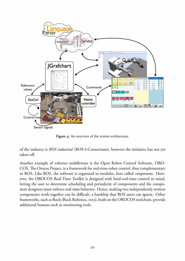
Figure 4: An overview of the system architecture.
of the industry is ROS industrial (ROS-I-Consortium), however the initiative has not yettaken off.
Another example of robotics middleware is the Open Robot Control Software, ORO-COS. The Orocos Project, is a framework for real-time robot control, thus complementaryto ROS. Like ROS, the software is organized in modules, here called components. How-ever, the OROCOS Real-Time Toolkit is designed with hard real-time control in mind,letting the user to determine scheduling and periodicity of components and the compo-nent designers must enforce real-time behavior. Hence, making two independently writtencomponents work together can be difficult, a hardship that ROS users can ignore. Otherframeworks, such as Rock (Rock Robotics, 2015), built on the OROCOS toolchain, provideadditional features such as monitoring tools.
20
3 Overview of the Lund Software Architecture
An overview of the robot software architecture used in our experiments is shown in Fig. 4.The ontologies are stored in a Knowledge Integration Framework (KIF), represented bythe cloud in the figure. On KIF, the services for code generation and the natural languageprogram extractors are deployed. The user interacts with the robot either through the En-gineering System implemented as a plugin in ABB RobotStudio, or via a Windows app thatwe developed for simplified user interaction. Sensor-based tasks are executed as SFCs inJGrafchart (Theorin, 2014), which sends reference values to the controllers using a dataprotocol called LabComm. The user interfaces communicate with the robot controller di-rectly through ABB libraries, e.g., generated RAPID code is deployed directly to the nativecontroller (even when the procedures are called from JGrafchart). The sensors and controlalgorithms are deployed on the external controller, ExtCtrl (Blomdell et al., 2010).
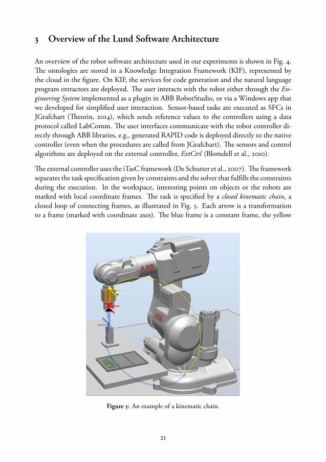
The external controller uses the iTasC framework (De Schutter et al., 2007). The frameworkseparates the task specification given by constraints and the solver that fulfills the constraintsduring the execution. In the workspace, interesting points on objects or the robots aremarked with local coordinate frames. The task is specified by a closed kinematic chain, aclosed loop of connecting frames, as illustrated in Fig. 5. Each arrow is a transformationto a frame (marked with coordinate axes). The blue frame is a constant frame, the yellow
Figure 5: An example of a kinematic chain.
21

is the robot frame which will be determined by the kinematics of the robot, the red arrowis a tool frame and the black is a feature frame. When setting up a kinematic chain, thedirection of the frames must be consistent, hence some frames will be inverted, e.g., thetool frame and the robot frame. The frames can either go through the robot (yellow arrowin the figure), the tool (red) or be constant (blue). The last frame in the loop (black in thefigure) is called feature frame, and is used to constrain the execution. For example, it can beset to be constant relative to a moving frame, or the robot motion can be expressed in thatframe. Each frame in the kinematic chain can be accompanied with an uncertainty frame,expressing the certainty of the coordinate values. The kinematic chain can go through morethan one robot, thus expressing synchronized motions between arms. During execution,the solver implementation carries out the low-level control of the robot, hence the taskspecification can be expressed with high-level platform-independent constraints.
The robot architecture in Fig. 4 resembled other architectures by having abstraction lay-ers separating the low-level hard real-time sensor-based control and the task execution thatparameterize the skills and switches between the states, and high-level task sequencing pro-vided by the knowledge-based services. This is related to the classic three-tier (3T) architec-ture presented by Gat (1998), where the robot software architecture is divided into a skilllayer, where the low-level real-time control is executed, a sequencer layer that keeps a systemstate and selects which skill to execute at a particular time and sets the parameters to thatskill, and on top are a deliberation layer where predictions and computationally heavy planscomputed. However, in our system, the robot does not automatically replan its task duringoperation.
Different users interact with a robot system on different levels. For example, the experts inautomatic control develop control algorithms, that are general enough to be reused task-independently. An application developer creates the state machine of the assembly, whichcan then be reused by robot operators that update the task parameters to new scenarios.
22
Related Work
Both in industry and in the research community, the problem of simplification of robotprogramming for non-experts has been addressed from several angles. Because of our in-dustrial context, we will start with existing programming interfaces or prototypes for end-to-end programming. In the rest of the chapter, the disposition will roughly follow thethree-tier architecture by Gat (1998), i.e, we will start with the low-level data-driven ap-proaches, followed by the intermediate action representations and how these connect tothe executable robot programs. The intermediate representations are in turn used in high-level knowledge engineering and reasoning architectures. Finally, we will look at how therepresentation can be extracted from natural language instructions, which is the highestlevel of abstraction considered in this work.
1 End-to-end Robot Programming
A survey of current programming methods for industrial robots are presented by Pan et al.(2010). For example, application specific tools (so-called Power Packs) are widely used, e.g.,CAD models of parts are used to generate welding trajectories. Since then, several collabo-rative robots have entered the market with lead-through support and online programminginterfaces, e.g., not only the YuMi, but Baxter and Sawyer from Rethink Robotics, Emikafrom Franka, Universal Robots’ UR-series and Fanuc CR-35iA. These come with end-to-end programming interfaces and apps that allow quick and simple deployment, for exampleBaxter has easily configurable pick-and-place skills, Universal Robots comes with an iconicprogramming interface on the teach pendant and Emika has an expert made app library.Macros and apps let non-expert operators instruct the robot on a more user-centric and lessdetailed level, reducing the time to set up the tasks.
There are several examples of simplified end-user programming environments from multi-disciplinary fields, such as service robots in health care, where applications are developed incollaborative teams with both programmers and subject matter experts. RoboStudio (Dattaet al., 2012) is a tool for the development of interaction behaviors in health care applications.
23
Interaction Composer (Glas et al., 2011, 2016) is an environment for creating user interac-tion as a state flow using high-level icons for C++ macros. Others are RoboFlow (Alexan-drova et al., 2015), a flow-based visual programming tool for creating behaviors for a PR2,and ROSCo (Nguyen et al., 2013), a tool for creating behaviors for home robots as hierar-chical finite state machines using a set of motion, gripper and perception primitives. Thelatter runs in ROS, hence programs are reusable on a platform with equivalent ROS-nodes,however, an expert was still needed to create the program. Also, Lourens (2004) wrap e.g.,C++ macros and parameters in visual representations, thus creating an iconic programminginterface that was used to recombine existing code blocks and was tested on a NAO robot(Lourens and Barakova, 2011).
Huang et al. (2016b); Huang and Cakmak (2017) evaluated a Scratch¹-like programminglanguage where non-expert users programmed a PR2 to grasp objects. Notably, they inte-grated a perception module and let the users define gripping points on objects (landmarks)through a GUI. They also noticed that the users deviated from the intended workflowwhere landmarks were created first and then used in the programming, which corroborateour observations that users, even experts, forget or want to change object references duringthe programming process.
As pointed out by Pan, one important drawback with online programming is that the robotcannot be in production. Therefore, although it can be intuitive for an operator, it is notalways the preferred workflow, especially not in highly automated industries. We on theother hand, focus on enabling robot technologies for small and medium sized enterpriseswhere a human worker otherwise would carry out the task manually. The setting of a smallcompany resembles the scenarios tackled in service robotics in the sense that the operatorcan be less experienced in robotics and that instead of optimizing the execution time of therobot to minimize cost, the workload of the human operator should be reduced. In general,industrial tasks require high precision and low error rates, which are harder constraints thansome house hold tasks such as setting the table.
To summarize, most existing solutions are still platform specific and it is challenging fornon-experts to create a new robot skill from scratch.
2 Data-driven Approaches
In service robotics, the robots operate autonomously in unstructured environments such ashomes, hospitals and shopping malls, with frequent interaction with non-experts and t heintended user is the home owner, hospital staff or shop worker. The users are not assumedto be proficient in programming and robotics and therefore high-level user-centric methods
¹Based on a user interface called Blockly.
24
are needed where the user does not have to explicitly give the robot detailed instructions onhow to carry out tasks. There are several approaches to learn skills from human demonstra-tions, so called Imitation Learning or Learning from Demonstration (LfD). An introductionto the field is given by Argall et al. (2010); Billard et al. (2008); Billard and Grollman (2013)and more recently, Billard et al. (2016). Learning implies generalizations from demonstra-tions, not only replaying the task (as in Programming by Demonstration). Demonstrationscan take several forms, for example, by observing the human carrying out a task and trans-fer the actions to a robot. However, tasks often consist of multiple steps and during ademonstration, some motions, such as scratching one’s head, are superfluous. Therefore,one of the problems that LfD addresses is what to imitate. That is, extracting the goal orevaluation metric of the tasks. Another problem is how to imitate the human when therobot has a different embodiment and perception capabilities, e.g., both with respect tomobility and dexterity and sensing. Therefore, the actions taken by the robot to achievea goal can be different from the actions that the human demonstrated. This is referred toas the correspondence problem in the literature and solutions involve creating interfaces thatreduce the mismatch, e.g., remote controls for teleoperation or by guiding the robot kines-thetically. This also makes it possible for the operator to correct the robot movements whenit executes the learnt skill and refine the skill incrementally. However, when moving therobot kinesthetically, the user often needs to use both hands, which makes it challengingto demonstrate e.g., synchronized dual-arm motions. Also, when the user interacts withthe robot, it is difficult to separate what sensor input comes from the user interaction andwhat forces to use to manipulate objects.
A task consisting of multiple steps is often more easily demonstrated fully and segmentedinto subskills or subgoals. For example, in the gift-wrapping application, the paper hadto be wrapped around the box before the folding of the sides, which in turn dependedon how tightly the paper was wrapped. Some of the related work focus on learning thesequence of partial ordering of subgoals or skills, some focus on learning the control policyfor individual motions and some focus on extracting goals, e.g., spatial constraints betweenmanipulated objects.
After collecting multiple demonstrations of a skill trajectory, the recorded (multidimen-sional) data (joint angles, Cartesian positions, forces, etc) can be used to train mixturemodels, e.g., Gaussian Mixture Models (GMMs) (see, e.g., Lee et al., 2012, 2013) wherethe motion is reproduced using Gaussian Mixture Regression, or Hidden Markov Models(HMMs) (see, e.g., Saveriano et al., 2015; Calinon et al., 2009, 2010). Ureche et al. (2015)demonstrated household tasks on a KUKA lightweight arm and automatically segmentedthe tasks into skills and extracted the relevant control parameters for the skills by studyingthe variance of the task variables. The variables that changed significantly over multipledemonstrations and during the demonstrations were considered relevant and were used forthe segmentation and the controller parameters for each motion. Also, collaborative tasks
25

between a robot and a human can be encoded with GMMs and HMMs: see, e.g., Calinonet al. (2009); Rozo et al. (2014, 2016) where not only the position, but also the complianceand force interaction with the user were learned. Niekum et al. (2015) and Ekvall and Kragic(2008) used multiple demonstrations to learn partial ordering between subtasks. Ekvall andKragic (2008) used the skill dependencies and combined high-level action planning withpath planning to avoid object collisions.
Another widely used trajectory representation are Dynamic Movement Primitives (DMPs),developed by Ijspeert et al. (2002) (see ,e.g., Ude et al., 2010; Pastor et al., 2011; Kormushevet al., 2011). DMPs are stable nonlinear point attractor systems, where forcing terms² canbe added to modify the trajectory. The forcing term consists of a set of weighted Gaus-sian basis functions that are activated over time. The weights can be learnt from a singledemonstration, the target position is just a parameter to the function so the learnt trajec-tory can be used for different goals. Additional terms can be added to not only encodeposition-based trajectories but also forces, e.g., Kormushev et al. (2011) added a force termto the DMP through a haptic interface and Pastor et al. (2009) adapted the formulationto generalize robustly to new object positions and attached semantics to the trajectory tofacilitate reuse. Later, Pastor et al. (2011) improved the policy using reinforcement learningwhere the success of the task was predicted from the sensor data.
In data-driven approaches, the user must provide multiple high-quality demonstrations thatvary in the relevant parameters e.g., move objects in the scene between demonstrations todetect relative reference systems. In our context, even providing one demonstration is timeconsuming and challenging, hence one-shot programming methods with subsequent re-finement are preferred or an unsupervised approach can be used. For example, Levine et al.(2016b) presented an approach where 14 robots were trained in two months to grasp objectsproducing 800 000 grasps that were used to train a Convolutional Neural Network (CNN)mapping vision input to motor commands. The perception and action can be coupled ona low-level, see, e.g., Lee et al. (2015) and several other methods from the research groupfrom Berkeley: Levine et al. (2015) learned manipulation tasks with guided policy searchwhere the cost function is specified as the desired goal position of the task. Levine et al.(2016a) used reinforcement learning and CNNs to map vision input to torque commands.In reinforcement learning, the challenge is to express a good cost function for the goal ofthe task that can be used for evaluation, this can either be hand-coded or learned, e.g., Yinet al. (2014) learned a cost function for letter trajectories and exploited it to encode therobot motions in a writing task.
These approaches learn the parameters to the low-level control and, depending on the vari-ability in the training data, the skills can be generalized and reused in a slightly differentsetting. One major challenge is to annotate and semantically describe these learnt skills
²Forcing the trajectory to follow the demonstrated path, not meaning using force measurements.
26
with, e.g., partial ordering (which can be extracted from demonstrations, see, e.g., Niekumet al., 2015) and resource constraints so that an automatic planner or scheduler can reordertasks, and with human understandable descriptions that help the operator to adapt andupdate the task when it fails. And the task will fail, both during deployment and regularexecution. During deployment, the operator must be able to further adapt the task, e.g.,by letting the user correct the robot trajectory (Ewerton et al., 2016), by incrementally up-dating the model with new demonstrations as described by Saveriano et al. (2015), where aforgetting factor is added to the previous learnt model.
3 Dual-arm Manipulation
In the gift-wrapping use case, dual-arm motions were needed to position the large packagethat was too heavy and bulky for a single arm. One arm was also used to fixate the packagewhile the other folded the sides. In the emergency stop button box use case, some taskswere carried out using independent single arm skills and the arms were synchronized viarendezvous points because, e.g., the force sensor was a shared resource. In the dual-armscrewing skill, instead of using a fixture, one arm was used to hold the button while theother arm screwed the nut into place.
In a traditional industrial setup, the programming of dual-arm or multi-robot operations ismore than twice as difficult as the programming of a single manipulation task because thereis an overhead from synchronization and coordination. However, in a pure master-slaveconfiguration, where one arm follows the other with a fixed offset, the programming timeis only dependent on the master arm’s program and the initialization of the synchroniza-tion. If the robots move synchronized but independently, the programming process can bedecoupled and the synchronization added later, but this approach requires programmingexperience.
Smith et al. (2012) present a survey of dual-arm systems, applications and technical chal-lenges from a control and planning perspective. Many approaches use remote control,either via joysticks or via human motion tracking. For example Kruse et al. (2015) presentan application where the robot autonomously located and grasped a heavy object and thenhuman operator took over and tele-operated the robot through skeleton tracking using Mi-crosoft Kinect. Ramirez-Amaro et al. (2015) used video recordings of humans carrying outhousehold tasks and transferred them to the iCub and the REEM-C humanoids. Ge (2013)used optical tracking to program a YuMi robot and although the YuMi arms have 7 DOFsso that the human arm movements could be mimicked and Tunstel et al. (2013) remotecontrolled terrain driving mobile dual-arm robots using a two-hand multi-DOF joystick.
27

An example of application specific user support is given by Makris et al. (2014), who letthe user guide bi-manual pick-and-place tasks through a gesture interface. Zöllner et al.(2004) presented work in 2004 where human demonstrations were recorded with stereocameras and sensor gloves and segmented and classified as manipulation primitives. Theprimitives were either symmetric or asymmetric coordinated actions depending on whetheror not the arms manipulated the same or different objects. Similarly, Krüger et al. (2011)simplified the dual-arm programming by providing macros for bi-manual actions on anobject, e.g., bi-approach or bi-hinge. Also, Reinhart and Zaidan (2009) used the motionof workpieces as the references for cooperating robots, so the user only had to specify thedesired trajectory of the object using a 3D model. However, their work focused mostly onimplementing a compliance control algorithm for the joint control of the robots. Muhliget al. (2009) tracked the workpiece trajectories using a stereo vision system and learned themotions (using GMMs) for a bi-manual pouring task on an ASIMO robot. However, mostrelated work is concerned with multi-robot planning (see, e.g., Vahrenkamp et al., 2011) orcontrol (e.g., Sariyildiz and Temeltas, 2011; Sieber et al., 2013; Lee et al., 2014), for example,Park and Lee (2015, 2016) presents a control framework for a humanoid for different typesof coordinated motions expressed in task space variables.
In a framework using LfD, kinesthetic teaching of bi-manual operations is challenging be-cause the human operator must demonstrate two tasks simultaneously, but possible if therobot is for example small. Gribovskaya and Billard (2008) used kinesthetic demonstra-tions on a small humanoid to record trajectories and learn spatial constraints and synchro-nization points. For a larger robot, this approach is impractical. Instead, the trajectoriescan be extracted from observations of human dual-arm manipulations, e.g., Zhou et al.(2016) extract trajectories and create coordinated DMPs using tracking data from the KITdatabase (Mandery et al., 2015). They experiment with a wiping task, where movement ofthe arm and the hand are controlled by two different DMPs coupled in a leader-follower(or serial) manner so that the local movement of the hand is encoded in the coordinatesystem of the leader. The leader on the other hand can move relative to a plane, so that theentire wiping task can be translated.
4 Multiple Modalities
Kinesthetic teaching combined with graphical user interfaces are now standard interfacesfor small collaborative robots. Additional modalities such as speech, pointing gestures andhaptics are common in laboratory settings. Profanter et al. (2015) evaluated the user pref-erences for four different modalities in a Wizard-of-Oz user study where the experimentersinterpreted the users’ pointing gestures, speech input, 3D pen input as well as touch inputon a screen. They found that gestures were preferred for selecting objects and specifyingpoints on the object, while touch was the preferred for specifying a location. Speech was
28

considered the most difficult, e.g., because the users struggled to name the objects. Theseresults correspond well to our assumptions that speech is suitable only when the user canname or display the object names and only for high-level tasks, e.g., not for specifyingparameters. In subsequent work, Perzylo et al. (2015b) describe a natural language inter-face for high-level instructions, which parallel our work by connecting the utterances toan ontology of objects and tasks. Multiple modalities can be used to reduce the numberof necessary demonstrations and can be used to communicate the knowledge and states ofthe robot system. Alexandrova et al. (2015) use action visualizations of a single demonstra-tion to let users change reference frames (landmarks) of motions and e.g., reorder actions.This can allow more intuitive and natural means of communication, and, e.g., Mead (2017)provides a cloud-based software platform for robot and application developers called Semio,with drivers for multimodal interaction, e.g., speech recognition (including pitch, rate andvolume) and body language (e.g., gaze).
5 Manipulation Primitives and Skills
To bridge the gap from low-level control to more abstract reasoning, the motor skills needa semantic representation. A review of research approaches up to 2007 were presentedby Krüger et al. (2007). The problem can be approached either bottom-up from a machineperspective as the data-driven methods discussed in the previous section, or top-down,starting with human concepts of symbolic actions. The symbolic representation of robotskills, e.g., as action primitives, can be used in automated reasoning process or to generateaction plans using standard AI planning and scheduling tools (see, e.g., Mosemann andWahl, 2001).
Action primitives are predefined parameterized templates for executable robot instructionsthat can be combined into more complex skills (Kröger et al., 2010; Felip et al., 2013). Theseprimitives can either be procedural or declarative, but correspond to an executable low-levelinstruction. In a declarative approach, Bruyninckx and Schutter (1996) and De Schutteret al. (2007) expressed the desired motion and sensor-values as constraints on a kinematicchain using coordinate reference frames of objects in the world or on the robot. This TaskFrame Formalism (iTasC) was extended by Kröger et al. (2010) and implemented by, e.g.,Finkemeyer et al. (2005) and Pedersen et al. (2014), to describe a hybrid motion expressedin a frame, a synchronously executed tool command and a terminating stop command. Themotion primitives abstract low-level sensor-based constraints and motions and must becombined into more complex state machines to produce a robot skill. The implementationpresented in Paper iii is based on the same formalism and a comparable control architecture,however, the technical implementation details differ.
29

A procedural approach with parameterized action templates (so-called Robotic AssemblySkills) were presented by Wahrburg et al. (2015) where the actions were encoded as tra-jectories and the complete skill was represented as a finite state machine. Their applicationwas similar to ours, with an expert-made parameterized snapfit that was implemented on aYuMi robot. An approach related to ours, where the task description had a platform inde-pendent reusable description, was presented by Perzylo et al. (2016). In their work, assemblytasks were described by defining spatial constraints between parts in a graphical view. Usingan ontology, their system could then generate executable programs fulfilling the semanticspatial constraints (Somani et al., 2016), and demonstrated that a robot system with do-main knowledge and domain specific user-centric tools reduced the programming timeswith around 70 - 80. The bottleneck in such system is to model the knowledge aboutobjects and robot skills which, in our experience, does not scale well to new domains.
Skills can also be based on code-reuse, e.g., the robot manipulation skills presented by Ped-ersen et al. (2014) encapsulate blocks of parameterized executable code with pre-condition,post-condition and continuous checks. The skills were initialized with a set of parametersand terminated with an evaluation of the post-conditions. Andersen et al. (2014) createdan abstraction layer between an execution environment (called the Robot Virtual Machine)and parameterized skills for, e.g., pick-and-place and palletizing with a user interface withwizards for helping the operator specify the skill parameters. They, as well as Krüger et al.(2010), explored the concept that primitives should be encoded as actions on objects, anal-ogous to human language.
6 The Grounding Problem
The concept of affordances stemming from cognitive science (Gibson, 1986), is used by As-four et al. (2008); Wörgötter et al. (2009); Wächter et al. (2013), who introduced the Action-Object-Complexes. The objects in the Action-Object-Complexes have attributes, e.g., a cupcan be empty or full and the actions that are offered by the object transform the attributes.Each action has pre-and postconditions to describe the transition and the implementationshould evaluate whether or not it succeeded. The representation was grounded to actionslearned from human demonstrations, e.g., Asfour et al. (2008) learned trajectories (encodedas HMMs) from observing humans, Kalkan et al. (2014) labeled actions on an iCub witheffects and trained support vector machine classifiers to predict the outcome of a behav-ior, and Wächter et al. (2013) used a library of predefined complexes to classify segmenteddemonstrations of human tasks (see also Aksoy et al., 2016; Kaiser et al., 2016). The workdeveloped further into semantic event chains presented by Aksoy et al. (2011). In their work,a sequence of (human) actions on objects were observed and used to compare manipulationscenarios. Aksoy et al. (2011) and (Asfour et al., 2008) made the analogy between primitiveactions (such as objects touching and not touching) to an alphabet, hence, sequence com-
30
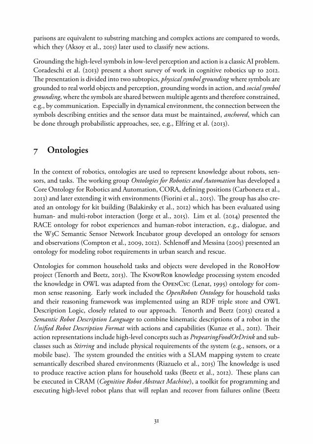
parisons are equivalent to substring matching and complex actions are compared to words,which they (Aksoy et al., 2015) later used to classify new actions.
Grounding the high-level symbols in low-level perception and action is a classic AI problem.Coradeschi et al. (2013) present a short survey of work in cognitive robotics up to 2012.The presentation is divided into two subtopics, physical symbol grounding where symbols aregrounded to real world objects and perception, grounding words in action, and social symbolgrounding, where the symbols are shared between multiple agents and therefore constrained,e.g., by communication. Especially in dynamical environment, the connection between thesymbols describing entities and the sensor data must be maintained, anchored, which canbe done through probabilistic approaches, see, e.g., Elfring et al. (2013).
7 Ontologies
In the context of robotics, ontologies are used to represent knowledge about robots, sen-sors, and tasks. The working group Ontologies for Robotics and Automation has developed aCore Ontology for Robotics and Automation, CORA, defining positions (Carbonera et al.,2013) and later extending it with environments (Fiorini et al., 2015). The group has also cre-ated an ontology for kit building (Balakirsky et al., 2012) which has been evaluated usinghuman- and multi-robot interaction (Jorge et al., 2015). Lim et al. (2014) presented theRACE ontology for robot experiences and human-robot interaction, e.g., dialogue, andthe W3C Semantic Sensor Network Incubator group developed an ontology for sensorsand observations (Compton et al., 2009, 2012). Schlenoff and Messina (2005) presented anontology for modeling robot requirements in urban search and rescue.
Ontologies for common household tasks and objects were developed in the RoboHowproject (Tenorth and Beetz, 2013). The KnowRob knowledge processing system encodedthe knowledge in OWL was adapted from the OpenCyc (Lenat, 1995) ontology for com-mon sense reasoning. Early work included the OpenRobots Ontology for household tasksand their reasoning framework was implemented using an RDF triple store and OWLDescription Logic, closely related to our approach. Tenorth and Beetz (2013) created aSemantic Robot Description Language to combine kinematic descriptions of a robot in theUnified Robot Description Format with actions and capabilities (Kunze et al., 2011). Theiraction representations include high-level concepts such as PrepearingFoodOrDrink and sub-classes such as Stirring and include physical requirements of the system (e.g., sensors, or amobile base). The system grounded the entities with a SLAM mapping system to createsemantically described shared environments (Riazuelo et al., 2015) The knowledge is usedto produce reactive action plans for household tasks (Beetz et al., 2012). These plans canbe executed in CRAM (Cognitive Robot Abstract Machine), a toolkit for programming andexecuting high-level robot plans that will replan and recover from failures online (Beetz
31
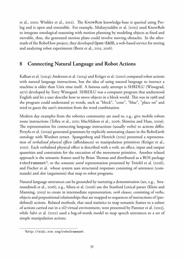
et al., 2010; Winkler et al., 2012). The KnowRob knowledge-base is queried using Pro-log and is open and extensible. For example, Muhayyuddin et al. (2015) used KnowRobto integrate ontological reasoning with motion planning by modeling objects as fixed andmovable, thus, the generated motion plans could involve moving obstacles. In the after-math of the RoboHow project, they developed Open-EASE, a web-based service for storingand analyzing robot experiments (Beetz et al., 2015, 2016).
8 Connecting Natural Language and Robot Actions
Kalkan et al. (2014); Andersen et al. (2014) and Krüger et al. (2010) compared robot actionswith natural language instructions, but the idea of using natural language to instruct amachine is older than Unix time itself. A famous early attempt is SHRDLU (Winograd,1971) developed by Terry Winogard. SHRDLU was a computer program that understoodEnglish and let a user describe how to move objects in a block world. This was in 1968 andthe program could understand 50 words, such as ”block”, ”cone”, ”blue”, ”place on” andtried to guess the user’s intention from the word combination.
Modern day examples from the robotics community are used to, e.g., give mobile robotsroute instructions (Tellex et al., 2011; MacMahon et al., 2006; Shimizu and Haas, 2009).The representation for connecting language instructions (usually verbs) to actions differ.Perzylo et al. (2015a) generated grammars by explicitly annotating classes in the RoboEarthontology with Wordnet synset. Spangenberg and Henrich (2015) presented a representa-tion of verbalized physical effects (affordances) to manipulation primitives (Kröger et al.,2010). Each verbalized physical effect is described with a verb, an effect, input and outputquantities and constraints for the execution of the movement primitive. Another relatedapproach is the semantic frames used by Brian Thomas and distributed as a ROS packageroboframenet³, or the semantic word representation presented by Twiefel et al. (2016),and Fischer et al. whose system uses structured responses consisting of utterances (com-mands) and slots (arguments) that map to robot programs.
Natural language utterances can be grounded by narrating a demonstration (see, e.g., Stra-mandinoli et al., 2016), e.g., Misra et al. (2016) use the Stanford Lexical parser (Klein andManning, 2003) to create in intermediate representation, verb clauses, consisting of verbs,objects and prepositional relationships that are mapped to sequences of instructions of (pre-defined) actions. Related methods, that used statistics to map semantic frames to a subsetof actions carried out in a 2D virtual environment, were presented by Panzner et al. (2015),while Salvi et al. (2012) used a bag-of-words model to map speech utterances to a set ofsimple manipulation actions.
³http://wiki.ros.org/roboframenet
32

One of the drawbacks of approaches where the classification of language instructions torobot actions are trained from labeled examples is that the user cannot easily extend thevocabulary on their own. In our applications, we use the general purpose statistical parserand semantic role labeler described below.
Background note on the Lund statistical parser
An introduction to natural language processing (NLP) applications is given by Nugues(2016a). The first approaches were ruled-based, where hand-made grammatical rules whereused to process text (Nugues, 2016b). However, for unrestricted natural language manyrules are needed, especially for handling homophones, ambiguous interpretations and spo-ken language, and since 2000, when the performance and availability of processing powerincreased, most computational linguistics use statistical methods.
The general purpose statistical model running on a virtual machine at Lund University canprocess (parse) unstructured English sentences in about 10 − 50 ms and is accessed fromfor example mobile devices.
When the meaning of a sentence is extracted the following questions are at least partiallyanswered:
• What is going on? (Predicate)
• Who/what is doing it? (Actor)
• What objects are involved? (Arguments to the predicate)
• Where is this going on? (Location argument)
• When and how long is this going on? (Temporal argument)
• How is the action carried out? (Manner)
• Who is the beneficiary of the event? (Beneficiary)
Language is ambiguous, homophones, such as press in news press and press down belongto different part-of-speech and have different meaning. In a sentence, the words that an-swer the above questions are labeled with the semantic role listed in parentheses after thequestion. This is done using special purpose dictionaries such as WordNet (Princeton Uni-versity, 2010), FrameNet (Ruppenhofer et al., 2010), or PropBank (Palmer et al., 2005), thatlist predicates and roles that can belong to the predicate. In the robotics context, the sen-tence execute the program, where execute means enact (the predicate execute.02), is perfectly
33

acceptable, but the command execute the human, where the homophone refers to killing(execute.01), certainly is not.
The model for the parser is trained using a corpus, which is a large text mass where thesentences are annotated with syntactic and semantic information. There are several corpora,for example the Penn Treebank (Marcus et al., 1994) which is created from Wall StreetJournal articles, and the PropBank (Palmer et al., 2005) that added predicate-argumentstructures to the Penn TreeBank. The latter is used by the Lund parser. The parser uses threemain steps to classify the sentence, further details are described in Björkelund et al. (2010).First the sentence is split into words (tokenized), and each word is assigned a part-of-speechtag and the canonical form (lemmatization). Next, it produces a dependency graph, which isa graph structure with the grammatical relations between the words. The dependency graphis finally used in a semantic role labeler to produce the predicate argument structures. Thesemantic role labeler uses binary or multiple logistic regression in a cascade of classifyingsteps.
• Predicate Identification: Each word is either classified as a predicate or not usingbinary logistic regression.
• Predicate Disambiguation: Determines the sense of the predicate if there are mul-tiple senses. Lemmas that can be both verb and nouns have one classifier per part-of-speech.
• Argument Identification: First each word is either classified as an argument or not.Then a multi-class identifier determines the role of the word.
If the sentence is somewhat grammatically correct, the parser will produce a well-formedmachine-readable table structure.
For example, the input sentence Take all the pins and put them in the pallet produces theoutput tables shown in Fig. 1. Two predicates were identified, take.01 and put.01, these arevisually presented in the first table. Because the sentence is formulated as a direct com-mand, there is no actor (A0) and the first argument (A1) are the things being taken orput respectively. For the second predicate, put.01, a second argument, in the pallet, wasidentified answering the question where the A1 should be put. In the middle figure, thedependency graph is visually displayed, it is a tree rooted in take. The same informationis also presented in the CoNNL-format in the last table. In the part-of-speech (POS) col-umn, e.g., the token pins was identified as a plural noun (NNS), the as a determiner (DT ),and and as a conjunction⁴.
⁴The word or is also a grammatical conjunction, not to be confused with the logical conjunction AND anddisjunction OR.
34

Figure 1: The semantic parser outputs predicate-argument structures in the CoNNL-format.
From this table, the output can be matched to robot instructions from the skill databaseand arguments can be mapped to objects in the world, as described in Papers vi and vii.
35

Approach
Robotics is an engineering research, where we build and evaluate artifacts. The method-ological approach resembles design science, where an artifact is designed in an iterativeprocess of problem identification, ideas, implementation and evaluation. The robotic sys-tem is thus designed in small incremental steps, where isolated features are implementedand tested separately. Fig. 1 presents an overview of the research work presented in thisthesis. The work started with vague ideas about what abstractions we needed to reduce theprogramming workload for human operators but still be able to generate executable robotcode. Because humans express their tasks using actions on objects, we wanted to apply thesehigh-level concepts to instruct robots as well. Humans also use multiple modalities duringcommunication, e.g., language to convey high-level goals of a task, and physical interactionto show positions or contact forces. The hypothesis was that a platform-independent repre-sentation of reusable robot programs would simplify task programming by bootstrappingthe programming process and abstract away from the low-level details of the system. Areusable robot program is called skill which is the capability of performing an action resultingin a meaningful outcome. The work presented in this thesis describes and evaluates a skillrepresentation where a robot program consists of a semantically annotated state machine,where each step is an action primitive that has a direct mapping to executable commands.
The work was thus carried out incrementally, first we created a skill representation and thenwe evaluated it from machine and user perspective and refined it further. The knowledgeabout objects, devices and tasks were modeled in OWL ontologies (Paper i). The ontologieswere stored together with instances of work cell descriptions and skills in an online databaserepository that could be accessed by multiple robots. The ontology was a development fromprevious research projects (Paper ii) into knowledge-based robot architectures.
The evaluations were prioritized from a pragmatical point of view, a representation thatcannot be executed on a physical robot system has very little value in practice, hence themachine perspective was evaluated first (Paper iii).
The skill acquisition bottleneck can also be addressed by simplified programming toolsfor non-experts and experts (Paper iv and Paper v). Based on experiences from the gift-
37

Idea:Representation
Artifact
Evaluation
Problemidentification
OntologyCodegenerationLanguageprogrammingProgrammingtools
IDEASProgramabstractionsHigh-levelenoughforhumansLow-levelenoughforrobotsHumannotions(actionsonobjects)AdaptableMultiplemodalitiesCombineimperativeanddeclarativeinformation
Proof-of-conceptsystemarchitectureExperimentswithdifferentrobotsandsensorsUserstudywithnon-expertsExperttesting
Figure 1: An overview of the methodological approach.
wrapping and emergency stop button case studies we developed a prototype for skill-basedprogramming from scratch. To test the usability of our representation, we developed asimple user interface that allowed non-experts to program reusable robot skills, and verifiedin a user study that, not only could non-experts program new skills, they could also reuseand edit expert-made skills (Paper iv). When comparing programming methods we usedtime as a metric, because it corresponds to cost, but also because other metrics, such asfor example number of steps, are not equivalent between different modalities (e.g., writingcode and selecting buttons in an interface). There are two phases worth measuring, first,the time it takes for the operator to find a robust solution (task prototyping), and the timeit takes to program a robot when a strategy is known (programming time). In the expertevaluations, we first let the users test different strategies using their preferred programmingenvironment and debug their program on the robot, and then program it from scratchusing both the prototype and traditional tools (Paper v).
One challenge when programming dual-arm robots using kinesthetic teaching in contactsituations, is that the user is limited to a few modalities at once, that is, the user cannotsimultaneously insert instructions on a touch screen and demonstrate the task on the robot.To overcome this issue, we have support for speech commands in unstructured naturallanguage. Each object and skill has a parameter with a set of natural language names that areused to match programs and objects to predicates and arguments (Paper vi and Paper vii).
38
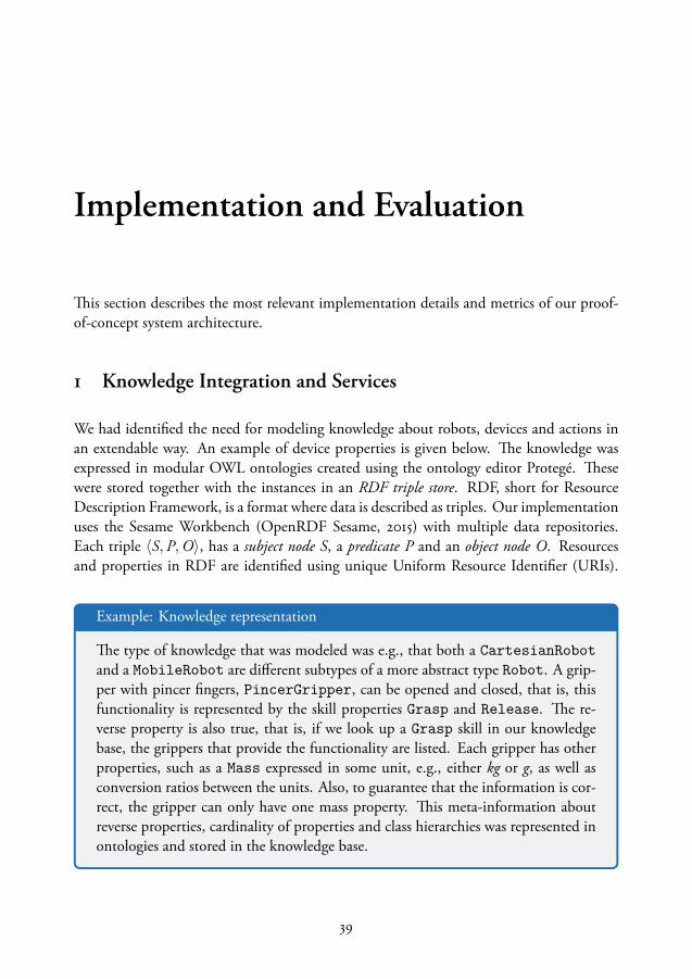
Implementation and Evaluation
This section describes the most relevant implementation details and metrics of our proof-of-concept system architecture.
1 Knowledge Integration and Services
We had identified the need for modeling knowledge about robots, devices and actions inan extendable way. An example of device properties is given below. The knowledge wasexpressed in modular OWL ontologies created using the ontology editor Protegé. Thesewere stored together with the instances in an RDF triple store. RDF, short for ResourceDescription Framework, is a format where data is described as triples. Our implementationuses the Sesame Workbench (OpenRDF Sesame, 2015) with multiple data repositories.Each triple ⟨S, P,O⟩, has a subject node S, a predicate P and an object node O. Resourcesand properties in RDF are identified using unique Uniform Resource Identifier (URIs).
Example: Knowledge representation
The type of knowledge that was modeled was e.g., that both a CartesianRobotand a MobileRobot are different subtypes of a more abstract type Robot. A grip-per with pincer fingers, PincerGripper, can be opened and closed, that is, thisfunctionality is represented by the skill properties Grasp and Release. The re-verse property is also true, that is, if we look up a Grasp skill in our knowledgebase, the grippers that provide the functionality are listed. Each gripper has otherproperties, such as a Mass expressed in some unit, e.g., either kg or g, as well asconversion ratios between the units. Also, to guarantee that the information is cor-rect, the gripper can only have one mass property. This meta-information aboutreverse properties, cardinality of properties and class hierarchies was represented inontologies and stored in the knowledge base.
39
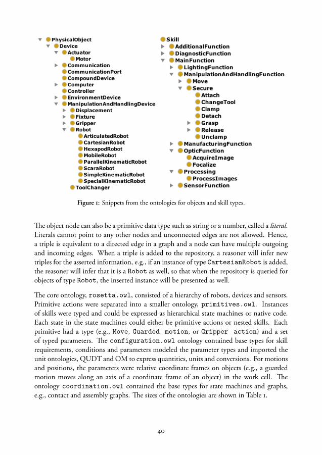
Figure 1: Snippets from the ontologies for objects and skill types.
The object node can also be a primitive data type such as string or a number, called a literal.Literals cannot point to any other nodes and unconnected edges are not allowed. Hence,a triple is equivalent to a directed edge in a graph and a node can have multiple outgoingand incoming edges. When a triple is added to the repository, a reasoner will infer newtriples for the asserted information, e.g., if an instance of type CartesianRobot is added,the reasoner will infer that it is a Robot as well, so that when the repository is queried forobjects of type Robot, the inserted instance will be presented as well.
The core ontology, rosetta.owl, consisted of a hierarchy of robots, devices and sensors.Primitive actions were separated into a smaller ontology, primitives.owl. Instancesof skills were typed and could be expressed as hierarchical state machines or native code.Each state in the state machines could either be primitive actions or nested skills. Eachprimitive had a type (e.g., Move, Guarded motion, or Gripper action) and a setof typed parameters. The configuration.owl ontology contained base types for skillrequirements, conditions and parameters modeled the parameter types and imported theunit ontologies, QUDT and OM to express quantities, units and conversions. For motionsand positions, the parameters were relative coordinate frames on objects (e.g., a guardedmotion moves along an axis of a coordinate frame of an object) in the work cell. Theontology coordination.owl contained the base types for state machines and graphs,e.g., contact and assembly graphs. The sizes of the ontologies are shown in Table 1.
40
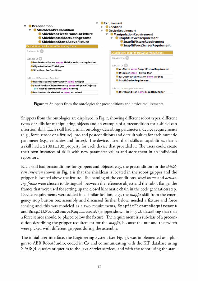
Figure 2: Snippets from the ontologies for preconditions and device requirements.
Snippets from the ontologies are displayed in Fig. 1, showing different robot types, differenttypes of skills for manipulating objects and an example of a precondition for a shield caninsertion skill. Each skill had a small ontology describing parameters, device requirements(e.g., force sensor or a fixture), pre-and postconditions and default values for each numericparameter (e.g., velocities and forces). The devices listed their skills as capabilities, that isa skill had a isSkillOf property for each device that provided it. The users could createtheir own instances of skills with new parameter values and store them in an individualrepository.
Each skill had preconditions for grippers and objects, e.g., the precondition for the shield-can insertion shown in Fig. 2 is that the shieldcan is located in the robot gripper and thegripper is located above the fixture. The naming of the conditions, fixed frame and actuat-ing frame were chosen to distinguish between the reference object and the robot flange, theframes that were used for setting up the closed kinematic chain in the code generation step.Device requirements were added in a similar fashion, e.g., the snapfit skill from the emer-gency stop button box assembly and discussed further below, needed a fixture and forcesensing and this was modeled as a two requirements, SnapfitFictureRequirementand SnapfitForceSensorRequirement (snippet shown in Fig. 2), describing that thata force sensor should be placed below the fixture. The requirement is a subclass of a precon-dition describing the gripper requirement for the snapfit, because the nut and the switchwere picked with different grippers during the assembly.
The initial user interface, the Engineering System (see Fig. 3), was implemented as a plu-gin to ABB RobotStudio, coded in C and communicating with the KIF database usingSPARQL queries or queries to the Java Servlet services, and with the robot using the stan-
41
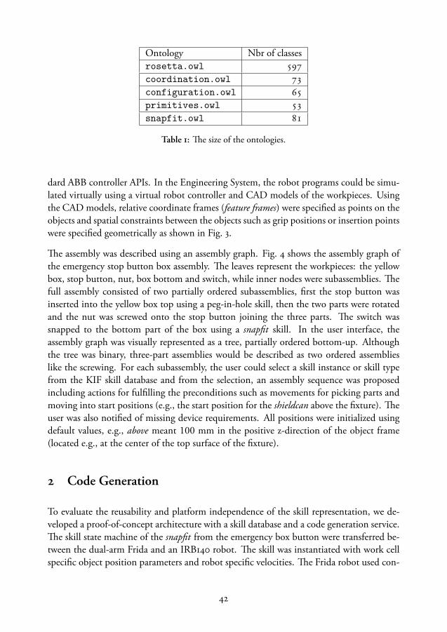
Ontology Nbr of classesrosetta.owl coordination.owl configuration.owl primitives.owl snapfit.owl
Table 1: The size of the ontologies.
dard ABB controller APIs. In the Engineering System, the robot programs could be simu-lated virtually using a virtual robot controller and CAD models of the workpieces. Usingthe CAD models, relative coordinate frames (feature frames) were specified as points on theobjects and spatial constraints between the objects such as grip positions or insertion pointswere specified geometrically as shown in Fig. 3.
The assembly was described using an assembly graph. Fig. 4 shows the assembly graph ofthe emergency stop button box assembly. The leaves represent the workpieces: the yellowbox, stop button, nut, box bottom and switch, while inner nodes were subassemblies. Thefull assembly consisted of two partially ordered subassemblies, first the stop button wasinserted into the yellow box top using a peg-in-hole skill, then the two parts were rotatedand the nut was screwed onto the stop button joining the three parts. The switch wassnapped to the bottom part of the box using a snapfit skill. In the user interface, theassembly graph was visually represented as a tree, partially ordered bottom-up. Althoughthe tree was binary, three-part assemblies would be described as two ordered assemblieslike the screwing. For each subassembly, the user could select a skill instance or skill typefrom the KIF skill database and from the selection, an assembly sequence was proposedincluding actions for fulfilling the preconditions such as movements for picking parts andmoving into start positions (e.g., the start position for the shieldcan above the fixture). Theuser was also notified of missing device requirements. All positions were initialized usingdefault values, e.g., above meant 100 mm in the positive z-direction of the object frame(located e.g., at the center of the top surface of the fixture).
2 Code Generation
To evaluate the reusability and platform independence of the skill representation, we de-veloped a proof-of-concept architecture with a skill database and a code generation service.The skill state machine of the snapfit from the emergency box button were transferred be-tween the dual-arm Frida and an IRB140 robot. The skill was instantiated with work cellspecific object position parameters and robot specific velocities. The Frida robot used con-
42

Relationbetweentwoobjects
Featureframe=Localcoordinateframe
Figure 3: The graphical user interface in RobotStudio were used to specify spatial relations betweenCAD models of objects, e.g., the shieldcan and the PCB shown to the right.
tact force estimation while the IRB140 had an external force controller mounted on thewrist. From a high-level perspective, the setups were equivalent, but the sensing and thekinematics of the robots differed. The parameters for each instance of the skill were editedusing the Engineering System, see Fig 5. The reusable description reduced the number ofparameters that had to be specified by the operator significantly, and the parameters that
43
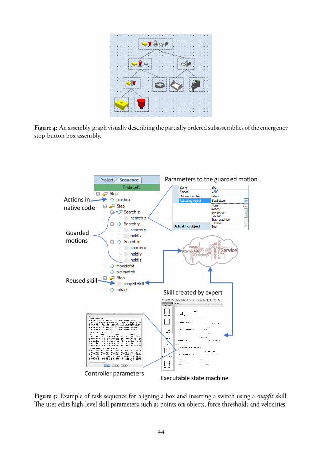
Figure 4: An assembly graph visually describing the partially ordered subassemblies of the emergencystop button box assembly.
Skillcreatedbyexpert
Actionsinnativecode
Guardedmotions
Reusedskill
Parameterstotheguardedmotion
ControllerparametersExecutablestatemachine
Figure 5: Example of task sequence for aligning a box and inserting a switch using a snapfit skill.The user edits high-level skill parameters such as points on objects, force thresholds and velocities.
44
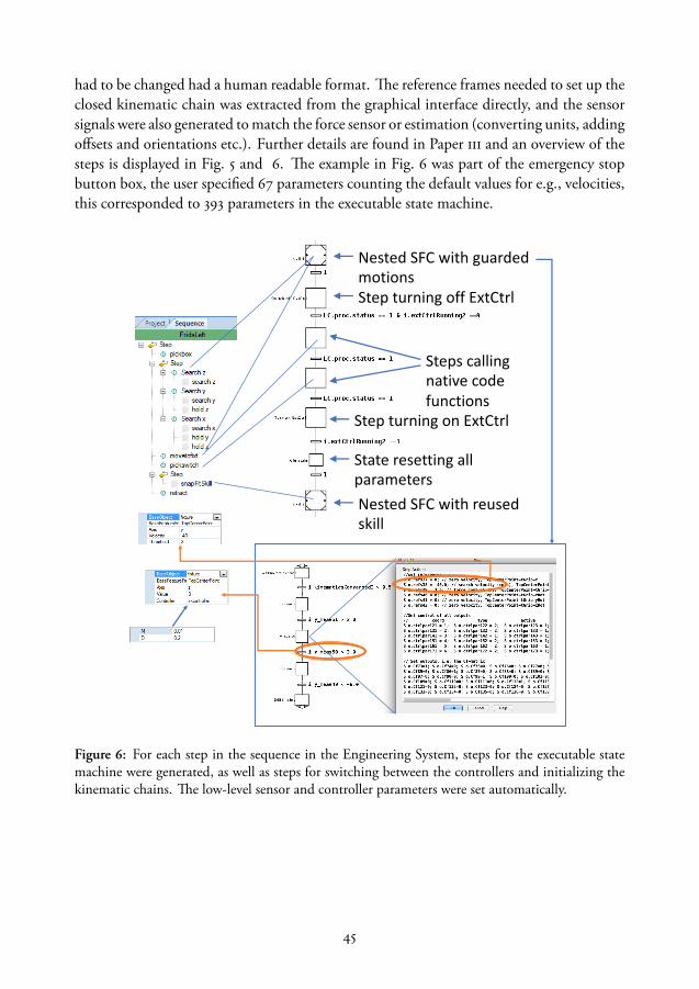
had to be changed had a human readable format. The reference frames needed to set up theclosed kinematic chain was extracted from the graphical interface directly, and the sensorsignals were also generated to match the force sensor or estimation (converting units, addingoffsets and orientations etc.). Further details are found in Paper iii and an overview of thesteps is displayed in Fig. 5 and 6. The example in Fig. 6 was part of the emergency stopbutton box, the user specified 67 parameters counting the default values for e.g., velocities,this corresponded to 393 parameters in the executable state machine.
NestedSFCwithguardedmotions
NestedSFCwithreusedskill
Stepscallingnativecodefunctions
Stateresettingallparameters
StepturningoffExtCtrl
StepturningonExtCtrl
Figure 6: For each step in the sequence in the Engineering System, steps for the executable statemachine were generated, as well as steps for switching between the controllers and initializing thekinematic chains. The low-level sensor and controller parameters were set automatically.
45

3 Human-robot Interaction
Although the user interface in the Engineering System reduced the programming effort forexperts, it used the traditional offline programming workflow. After analyzing the use cases,we implemented a prototype for online programming that reduced the number of featuresand only generated native code. The prototype was implemented as a Windows app thatran on a Surface Pro tablet. The prototype was used to evaluate the skill representationfrom a usability and user perspective. The resulting iconic programming interface is shownin Fig. 7.
The implementation has shortcut buttons (to the top left) that generate macros for themost common instructions. Each instruction was represented as an icon in the programsequences to the right. For example, the Contact Move was a macro for contact forcedetection with reasonable default parameter values for velocity and torque. Synchronizedmotions and rendezvous points were added in pairs. The example sequence shown in Fig. 7contains multiple synchronized motions, master-slave motions, where the right arm followsthe left to move a lid bi-manually and insert it on a box (see Paper v). Testing and debug-ging was facilitated by for example automatic execution of synchronized actions duringdebugging, and through individual play buttons on each instruction for testing skills oractions and updating positions with a single click. The user could also select a subset ofinstructions to execute (Run Selected) or start the execution from an arbitrary point in
Figure 7: The graphical user interface for skill-based end-to-end programming.
46
the program (Run from here). The task was represented as a sequence and generatednative code, which the operator could modify further. Any native code procedure could becalled from the graphical interface directly using the native code instruction. The pro-grams could be saved as skills and were then added in the same panel as the macros. Wheninitializing an empty workspace, there were only reference systems for absolute coordinates(called World in the graphical user interface) and the respective flanges, and the user hadto create new reference systems by pointing out objects using the robot arms.
The main difference compared to other tools was the support for iterative refinement andabstraction. This was facilitated by storing both the joint values, the absolute and, if areference object was used, relative Cartesian position for each motion. The user couldtherefore switch back and forth between the reference systems, which allowed a workflowthat started with testing in absolute coordinates, followed by the addition of suitable objectcoordinate systems (such as the desired grip positions).
As presented in Paper iv, we evaluated the prototype in a user study with 21 non-expertsubjects for task prototyping and debugging of an application that they were familiar with(Duplo building). After a three-minute introduction to the tool, the subjects had 30 min-utes to program the robot to pick LEGO pieces and insert them robustly on a tower. Insubsequent steps, the users had to reuse either their own or an expert-made skill, and, as acontrol group, some had to reprogram everything. Out of the 21, 19 succeeded in develop-ing a robust solution for the initial task and 14 managed to complete at least one additionalstep. We could also see that reuse simplified the programming significantly.
For expert programmers instructing single and dual-arm tasks, the programming time wasreduced with 70-80. Because synchronized skills were coupled and each action storedmultiple target representations, the flange position of both arms were known when thesynchronized motions started, and the reference frame of one arm could be changed to theother to reconfigure the coordination to master-slave mode. That is, the user could switchthe master and the follower arms by changing reference frame of the master to the flangeof the other arm. The graphical interface corrected automatically dubious combinationssuch as both arms moving relative to each other or one arm relative to itself. When dual-arm skills were swapped between the arms, the position of the slave arm was inverted. Thesynchronized motions could also be relative to objects, either the same or separate, andby changing the reference system the dual-arm motions could be rotated or mirrored asdescribed in Paper v.
The design of the code behind the prototype is modular so that both the graphical view(e.g., with two robot arms) and the code generation and robot communication can beeasily exchanged. The last version of the prototype also supported the natural languageprogramming features for English.
47

NaturalLanguageParser
ProgramExtractor
TextProgramstatements(XML)
Text
CoNLL format+dependencygraph
Picktheshieldcan…
Speech-to-textdictation
Figure 8: The user writes or dictates the instructions to the robot, the text is sent to the programextractor that in turn calls the semantic parser. The parse result is matched to program statementsand the resulting sequence is returned to the user interface.
4 Natural Language Programming
The natural language programming interface that we developed consisted of a chain ofspeech-to-text dictation, semantic analysis of the text using the general-purpose Lund parserfor semantic role labeling, a program statement extractor algorithm that matched the sen-tences to robot programs, and finally, an instantiation to robot programs using the knowl-edge in the system, as shown in Fig. 8. The user gave the instructions either by typingor using off-the-shelf dictation tools (Android speech-to-text API, Windows dictation orGoogle cloud services). The text was sent to the program extractor together with a de-scription of the robot workspace including predefined commands, user created object andskills with names and types. The program extractor was implemented as a Java servlet andwas deployed on the KIF server. The servlet separated the instructions into sentences andforwarded them one-by-one to the Lund parser. The output from the parser was then thenmatched to the existing robot programs by using the (nested) predicate-argument structuresstarting with the root predicate (Paper vi and vii).
Because of the general-purpose parser, the user could extend their own vocabulary on thefly (Paper ix), by naming objects and skills with arbitrary names without retraining thesystem. For the speech-to-text interface, we tested both the Android speech recognizer ona tablet and the Microsoft .Net API, with best results for the Android API, however, thefree form dictation is the weakest point in the chain because it often failed in the noisy labenvironment.
48

PredicatesMappedtoaction
ArgumentsMappedtoparametersinactionsMappedtoobjectsinworld
Figure 9: The semantic output is matched to skills and objects in the robot workspace.
An example is shown in Fig. 9, where the instruction Pick the PCB from the input trayand place it on the fixture was parsed into two predicates (pick.01 and place.01) and eachpredicate had two arguments. If no other actor (A0) was mentioned, the robot was usedas default. The predicates could either be mapped to robot skills or commands from theworkspace description, or if the predicate was a wildcard (do, use, assemble and some typesof move), the arguments determined the action type, that is, if the arguments includeda skill name or a nested predicate argument structure (e.g., a condition) this would beused. The arguments could either refer to objects in the world, measurements or skills.The program statement extractor returned a sequence of program statements, Statement,with actions IDs from the robot workspace and object arguments (ignoring determinersetc.) with type and cardinality. Conditions were subtypes to Statement, either parallel(AndStatement), branching (IfStatement) or guard conditions (UntilStatement),which linked to the nested condition Statements, created from the nested predicate-argument structures in the sentence as described further in Paper vii.
49

In this example, the PCB is a named object in the workspace. When the argument isin plural form, e.g., pick all PCBs or pick three PCBs, the resulting match will identifythe objects by type (PCB) and select all or three depending on cardinality. Coreferences(it) would naively be solved by using the last object(s). When the program sequence wasreturned to the user interface, it still had to be instantiated with correct parameters. E.g.,by using the positions of the objects and spatial relations between the objects. Ambiguitieswere solved to match the object types as close as possible to the parameter types in theskills (e.g., assemble the PCB and the shieldcan using shieldcan insertion can be interpretedas inserting the PCB on the shieldcan or vice versa, but because the shieldcan insertion skillwas created using an object of type shieldcan as a manipulated object (and PCB as a fixedframe), the best match would use the same types. Similarly, when instantiating loops overmultiple objects, for example in the palletizing example in Fig. 1, where several pins weremoved to a pallet, the pallet or tray properties were used to generate a grid of insertionpositions.
50
Summary of the Included PapersPaper i
A Knowledge-based robotic system architecture
The paper presents our knowledge-based software architecture with anonline knowledge integration framework (KIF) containing ontologies forrobots, devices, sensors and tasks. The knowledge is modeled in mod-ular ontologies. The base ontology is the rosetta.owl which containsrobots and devices. frames.owl describes relative coordinate frames thatcan be attached to objects and are used to specify a kinematic chain. Robotprograms are described as sequential function charts in sfc.owl, and theaction parameters are described in params.owl. KIF contains a databasewith semantically annotated expert-made skills that can be downloadedby the user interface (the Engineering System) and deployed on differenttypes of robot systems. It also presents the reasoning services on KIF whichprovides program sequence verification, a natural language interface, andcode generation that the user invokes from Engineering System.
Paper ii
Cloud-based robot architectures
The paper presents experiences from four European projects (SIARAS,ROSETTA, PRACE and SMErobotics) and their software architecture.The SIARAS software system supported reconfiguration of the robotcell provided utility functions and interfaces to simulation tools in thecloud. The siaras.owl ontology was the embryo to what later wouldbe ROSETTA ontology. The ROSETTA architecture was focused onknowledge-sharing for automatic robot program generation by skill reuse.In the PRACE project, the focus was to simplify the human-robot inter-action by extracting task parameters from demonstrations. SMEroboticsevaluated an architecture suitable for small and medium sized enterprises(SMEs) and formulated the requirements of a useful skill representation.
51

Paper iii
Code generation for force-controlled skills
The paper presents the code generation process where high-level sequencesof parameterized actions created in the Engineering System are trans-formed into executable force-controlled robot code for the external forcecontroller. The steps in the sequence can either be position-based robotmotions relative to object positions, reusable skill implementations down-loaded from KIF, or created as guarded search motions using the coordi-nate frames specified on objects using CAD models in the virtual simula-tion environment. The guarded motions have a search direction along oneof the axes on a coordinate frame, a stop condition (a force value) and pos-sible force-constraints in other directions than the search. The executablecode is a state machine in the Grafchart language where additional stepsfor switches between the position and the force controller are added, thekinematic chain is setup automatically using the robot type and the frameparameters. Each guarded search sets new reference values for force andvelocities in different directions, as well as the transition conditions. Thecode generation works for four ABB robots.
Paper iv
Prototype evaluation for simplified programming of reusable robot skills
After two case studies, a programming prototype was developed to sim-plify the robot programming and debugging using a graphical user inter-face together with lead-through programming. The prototype was evalu-ated in a user study with 21 non-experts as well as an expert programmingtest. The users had to program a Duplo building task using a single-armand macros for motions, gripper actions and primitives for vision andcontact force estimation. The result showed that 19 out of 21 non-expertscould program the task after a 3-minute introduction. The average timeto finish the task was 20 minutes. Additional tasks were carried out to testskill reusability by dividing the test subjects into 3 groups: the first groupreused their own skill, the second group received an expert-made skill andthe third group had to program everything from scratch. The sample setwas small, however, we could conclude that the expert-made skill was theeasiest to reuse. Another interesting observation was that the correlationbetween success rate was very weakly correlated to the users’ self-reportedexperience with programming and machinery. The programming time forthe expert was reduced by 80.
52

Paper v
Reusing and transforming synchronized dual-arm skills
The prototype from paper iv was further developed to support dual-armsynchronized motions, either in master-slave configuration or relative toobject coordinate frames. Traditional dual-arm robot programming treatsthe robot arms as two separate tasks and synchronization adds a large over-head. In our prototype, the synchronized motions are treated as linked en-tities and automatically executed, deleted or moved in pairs. The linkinglets the user swap the programs for each arm in master-slave configurationsand the master arm will be switched and all relative positions updated tothe inverse transformation for the (new) slave arm. The prototype was alsoevaluated for task transformations in a gift-wrapping application. Whenswitching the arms the relative positions for the arms can either be rotatedif a single point of reference is used. Using two reference pairs of oppositepoints, the task was mirrored after the switch.
Paper vi
Natural language programming of industrial robot tasks
A method for natural language programming was presented where the out-put from a general purpose statistical parser with semantic labeling wasmatched to high-level robot skills and objects in the robot’s workspace.The semantic output from the parser, created by Björkelund et al. (2010)consists of a table of predicate-argument structures, where the predicatescorresponds to the action or verb in the sentence and the arguments arethe objects acted upon. The architecture had a small library of robot skills,each with natural language labels and position parameters relative to ob-jects. Mapping the predicates to robot skills and the arguments to theobject parameters, a skeleton of a task could rapidly be generated fromwritten unstructured natural language descriptions. The functionality wasdemonstrated with pick-and-place tasks. The objects were matched to thearguments by name or type and coreferences (it) were solved naively byusing the previously identified object. The knowledge from the system wasused to set parameters for the generated action sequence, e.g., the skills foropening and closing the gripper were extracted from the device descrip-tion and spatial constraints between objects were used as parameters forrelative positions.
53
Paper vii
Extracting constraints from natural language instructions
The natural language programming interface from Paper vi was furtherdeveloped to support the generation of force-controlled search motions,control structures such as loops, parallel constraints and skills as argu-ments. The output from the semantic parser can be ordered as a tree wherethe main activity is the root (or higher up in the tree). The tree and thesemantic labels are matched to program structures using an algorithm thatextracts conditionals for each predicate. That is, predicate-argument struc-tures that are nested by while, until, if and when. The nested predicate-argument structures were labeled by the parser as temporal or locationalarguments. The until-conditions were mapped to transition conditionsin the guarded motions and the while-conditions were mapped to parallelconstraints, for example a constant force during a search. The conditionscould be nested using and or or and express sensor readings or by usingkeywords for default parameters (contact and timeout). When multipleobjects are mentioned, e.g., take three needles and put them in the pallet,the cardinality is used to generate a loop over three objects with the typeneedle and, one-by-one, pick them and place them in a pallet. The ambi-guity from the example sentence (whether to pick all three needles at onceand then placing them one-by-one) was solved by using the knowledgeabout the gripper (if it could hold more than one object) and the pallet,which has a grid of potential positions. The conclusion of the paper wasthat the low number of robot skills available in the library was a limitingfactor in the application.
54
Discussion
Before we reach the robotized society of tomorrow, with mechanical co-workers and deliv-ery drones, where human labor is precious and pleasant, we have to find solutions to severalchallenges. To reiterate a few: present day robots are difficult to instruct and interact with,and the hard work results in tailored applications that are neither general, reusable nor ro-bust. The robots have poor perception and situational awareness, and unforeseen situationsend in failures. Even if failure is detected, they can hardly reason about why, or what toadjust or redo to complete the task. For the human operator, it can be cumbersome toresolve the issues and correct the program accordingly.
Researchers have addressed these issues for years. There are high-level planning approaches,low-level sensor control, and user experiments evaluating how people prefer to instructrobots. We have reviewed several intermediate action representations that support contrast-ing efforts, focusing on various aspects, from verbalizing actions, to solving collaborativedual-arm motions. However, we cannot find a useful representation by just looking at thequestion from one perspective, because the problem is the gap between how humans andmachines describe actions and perceive objects, and the robot systems have both symbolicAI reasoning processes and robotic devices acting and sensing in the real world. Humansdescribe tasks in high-level unstructured language, while the reasoners work with high-levelformal languages and the physical systems interpret and execute tasks in low-level platform-specific (structured) code. We needed to use a holistic approach, because the problem ofsimplification of robot programming is not about optimizing one single algorithm, it isabout creating a system that functions efficiently as a whole.
In the skill representation that we developed, we attempted to take all these perspectives intoaccount. We used a high-level ontological approach where we modeled symbolic knowl-edge, as well as code generation for the low-level platform-specific code. We evaluatedit from a user perspective, to verify that the representation was useful and simplified therobot programming. We also presented a method for extracting program statements fromunstructured natural language instructions. To be able to carry out our experiments, wedeveloped a robotics software architecture with a knowledge base, reasoning services, pro-gramming interfaces and task execution.
55

The work was carried out iteratively. First a knowledge framework was developed where wemodeled complex skills and evaluated the code generation and skill transfer. However, thisrequired expert-made skills as well as detailed annotation, which was time consuming tocreate. To bootstrap the skill acquisition, we developed a (simplified) user interface whereboth non-experts and experts could program skills from scratch. The semantic annotationswere extracted using natural language, which the user could then use to interact with therobot. In the following sections, we will discuss the implementation in more detail andcompare with related work.
1 Knowledge Representation
First, we developed a knowledge-based architecture and the core ontological concepts. Pre-vious work in the robotics domain used ontologies to model mostly positions and simplekitting applications. Only recently Perzylo et al. (2016) provided a model of geometricalknowledge and spatial constraints in a suitable ontology. Our work extended the state-of-the-art to include assembly skills, parameters, specification of kinematic chains and thedescription of devices and robots. The focus was industrial assembly operations. The on-tologies are modular to avoid conflicts and let the user select only the dependencies theywant.
We chose to implement the database as an RDF triple store to provide reasoning servicesbecause it was more flexible than a relational database with fixed tables and there existedmultiple inference engines. One drawback with the approach is that queries to the reposi-tory can become very slow if not expressed in an effective manner, for example, by explicitlybinding subgraphs to variables. Another option that we briefly investigated was to use agraph database, Neo4J, where the literal properties can be directly attached to the nodes sothat the information is stored in a compact format, however, there was no inference enginethat we could use.
The skills are shared in a cloud-based architecture where multiple robots can access thesame skill database and knowledge-based AI services. Other architectures have exploredfunctionality in other directions, e.g., were used to generate PDDL from action descriptionsto automatically plan and replan tasks on a high level. While, e.g., RoboEarth (Waibel et al.,2011) populated their skill database from natural language text of, e.g., cooking instructions,such approach assumes that there exist executable skills for each instruction, an assumptionwe could not make because our domain focuses on assemblies of novel products.
Our approach is philosophically different from the Action-Object-Complexes, in that it isnot the object that affords skills, the objects are mere parameters to the skills, rather, it isthe devices that have skills as capabilities. In this way, we do not have to model the human
56

as an object during user interaction, and, e.g., dancing and waving are simply non-objectrelative actions. Otherwise, the concept of pre- and postconditions are similar, however,they ground the actions using trajectories extracted from human demonstrations encodedas HMMs, while we focused on providing programming tools that let the user manipulatethe representation directly.
2 Code Generation
During the initial evaluation presented in Paper iii, we focused on the low-level code gener-ation functionality, therefore ignoring the complexity of the system setup from a usabilityperspective. It had required experts from automatic control to create the force-controlledskill and experts in knowledge representation to create the ontology descriptions. The as-sumption that a robot system would have access to a library of robust expert-made skills didnot scale, because the acquisition of expert-made general-purpose skills was a bottleneckin the system. Worse yet, just because the generated programs were syntactically correctand executable, did not mean that the program worked well on the new robot, e.g., thevelocity and force parameters had to be adapted depending on the robot and sensor type.The latter is a focus of the related field of parameter learning, where automatic adaption andexploration of parameters can be used to optimize assemblies. Learning can also be used todetect errors, e.g., by learning a nominal force profile and then detecting deviations fromit. The work to automatically adapt parameters during deployment was out of scope of thisthesis. However, the reason the skills and the parameters were typed was to simplify theuse and integration of existing algorithms for low-level parameters optimization.
3 Human-robot Interaction
High-level approaches are limited by the small number of executable robot skills in thelibrary, where the knowledge must be modeled and added into the system by an expertin knowledge engineering or in robotics. Hence, we had to bootstrap the knowledge ac-quisition by developing a simple programming prototype that non-expert operators coulduse, which was evaluated in Paper iv and v. It limited the usage to object specification andsequential skill programming of dual-arm robot programs. For practical reasons, specifi-cally the high implementation effort to integrate functionality in an experimental lab setup,we limited what type of features we evaluated in the user study, e.g., we left out speech,trajectories and the teaching of force-controlled policies and vision calibration. Also, thefunctionality described in the chronologically earlier papers was not evaluated, that is, theusers did not try more complex guarded motions or reuse skills between different typesof robots, which were discussed in for example Paper iii. This is a very relevant direction
57

of future work and the user interaction for instructing and refining trajectories and force-controlled tasks is an active research area in the robotics community.
In the gift-wrapping application, the collaborative aspects of the task had to be reducedto preparation work (putting the paper and the box in front of the robot), starting theprocess through a graphical user interface and manually resume the program after the usergave a ribbon to the robot. This interaction had to be programmed in native code andthe current user interface does not aid the non-expert user in creating collaborative tasks.In related work, multi-disciplinary teams with both robot programmers and interactionexperts developed interfaces for programming of interactive tasks using high-level modules.Non-expert programming of collaborative human-robot tasks from scratch is an excitingarea of future work.
4 Skill Creation
For a skill library to be useful, the intended users must be able to understand, adapt andmodify the downloaded skills. Also, it must be easy to create and add new skills to thelibrary for both experts and non-experts. While other approaches use multiple demon-strations to train skill models, in our context this approach is intractable for two mainreasons: even a single demonstration is time consuming to carry out sufficiently well, anda black-box model with implicit (hyper-)parameters that the operator cannot interpret isundesirable. When using demonstrations, it must be clear what and how the user shoulddemonstrate, e.g., the operator can use a haptic device to input a specific parameter valuefor a force-controlled task. We developed a prototype interface for one-shot instructionswhere non-experts could program reusable skills from scratch.
5 Dual-arm Manipulation
The programming of dual-arm motions poses a challenge from both a programming anda control point of view. The position- and force-based control of coupled arms can behandled by, e.g., coordinated DMPs (Zhou et al., 2016) or by setting up a closed kinematicchain using the iTasC formulation (Stolt et al., 2011). Instructing multiple robot arms tocarry out coordinated tasks adds a potentially large overhead for the operator, hence relatedwork has investigated specifying the movements of multi-robot systems as trajectories onthe workpiece or by extracting trajectories from human demonstrations. Synchronizedtasks are difficult to extract from for example kinesthetic demonstrations using the robot,because the user has to physically move both arms simultaneously which is only feasibleon small robots. Other approaches track human demonstrations using vision, which thenmust be mapped to the robot.
58
However, in our gift-wrapping use case, we used the full arms to move and hold the pack-age and these full arm motions are not easily extracted from observations of humans orexpressed as end-effector trajectories relative to the object. Instead, we focused on reducingthe workload during the programming process for expert users. By simple means such asdebugging actions in pairs and setting up the master-slave configuration with default val-ues, we could significantly decrease the programming time for the dual-arm tasks in ourexperiment. While programming dual-arm motions, especially in contact, the need forrobust speech commands became evident.
6 Natural Language Interfaces
The system used general purpose components to analyze the language commands, andespecially the speech-to-text dictation was a weak link in the chain because of noisy lab-oratory environments, non-native English speakers and application-specific user specifiedvocabulary (e.g., PCB, snapfitskill). In further experiments, components of the system werereplaced, e.g., the different dictation APIs were evaluated, the semantic parser was switchedto Swedish and mapped to English program descriptions using dictionaries and synonyms.The arguments to the actions can be sensor values, however, the examples using force pa-rameters were somewhat artificial, because it is more suitable to input the forces usingother means, e.g., haptic devices or external force measurements. Other applications thatuse natural language programming in robotics extract, e.g., spatial information from thesentences for direction following for mobile robots. They learn their models from examplesand the resulting application can effectively run locally on a battery-driven mobile system,instead of using a cloud-based solution. One drawback with such an approach is that ifthe user wants to extend the vocabulary, it requires multiple examples and retraining. Thiscan be mitigated with generated grammars as presented by Perzylo et al. (2015a) resulting ina structured language interface. The related work that used intermediate representations,such as the verbalized effects, was verb-centric, mapping the verbs to robot actions. Whilethe predicate-argument structures that we use are verb-centric as well, the skills can be theargument if the predicate is a wildcard in sentences such as Do a snapfit and Assemble theshieldcan and the PCB using the shieldcan insertion skill. The use of conditions and parallelaction extractions is to our knowledge not well investigated in the robotics community.
The modular architecture allowed the components to be switched, e.g., both the Engineer-ing System and the Windows app called the same program extractor that was deployed asa Java servlet on the KIF server. We created an English version as well as Swedish versionof the servlet, the first was presented in Paper vi and vii, the bilingual program extractorwas presented in Paper xiii. The Swedish statement extractor implemented the same algo-rithm as presented in Paper vii, but a few language adaptions had to be made because theSwedish semantic parser was less robust and it used automatic translation to find skills withoriginally English natural language names.
59
7 Future Work
Future work can be extended in several directions, here I will only mention the ones that Ipersonally am interested in investigating. One of the programming features that has beendiscussed in the literature but that was out of scope of this work, was the programming offully collaborative tasks, where non-experts create a task involving dialogues and physicalinteraction with humans. Also, psychological aspects in human-robot interaction, such astrust (see, e.g., Sadrfaridpour et al., 2016) are out of scope.
While the presented user interface supports some simple debugging and automatic trans-formations of the program and high-level features such as natural language support, manyinteresting areas of research have been left out. For example, the dialog system for userinteraction is very rudimentary, so potential future work includes a robot system that asksquestions to resolve ambiguities and collect user data to provide helpful suggestions, e.g.,by presenting suitable skills from the database depending on what types of objects the useradds. Also, the semantic extraction is limited to skill and object types (and parameter types),and pre- and postconditions still need more advanced users.
Last words
There are people who look towards a robotized future with dread, regarding automationas a threat to jobs and society. Others look forward to a life in leisure in a post-scarcityeconomy. Some think robots will take over the world, either out of malice or ignorance.If the present is a book, it is open-ended. I am aware that I cannot make any assumptionsabout the unknown, but I believe, that to make robots helpful, they need to be able tocomprehend what we want and not just obediently follow their programming. They needto be able to understand the meaning of their actions and goals, and the reason behindthem. They need to know when to follow a human command and when to refuse. Theyneed knowledge.
60
Scientific publications
Included papers
Co-authors are abbreviated as follows:Jacek Malec (JM), Elin A. Topp (ET), Mathias Haage (MH), Klas Nilsson (KN), AndersRobertsson (AR), Andreas Stolt (AS), and Pierre Nugues (PN).
Paper i: Knowledge-Based Instruction ofManipulationTasks for Industrial Robotics
I did the implementation of the knowledge-based services for sequence generation fromlanguage, assembly graphs, scheduling and task checking as well as the corresponding im-plementation in the Engineering System. JM did the implementation of the knowledgeintegration framework and the original ontologies from SIARAS and RoSta and SFCs.I added ontologies for frames and parameters and added pre- and postconditions to theROSETTA ontology.
Paper ii: On Distributed Knowledge Bases for Small-Batch Assembly
The paper presents the experiences of cloud-based robotics architectures from several re-search projects. I did the implementation of the Engineering System and reasoning servicespresented in the sections regarding ROSETTA and PRACE. JM did most of the work re-lated to knowledge integration. KN contributed with the SME perspective and AR con-tributed collecting and discussing the experiences from the different types of cloud-basedarchitectures.
Paper iii: From High-Level Task Descriptions to Executable Robot Code
I did the high-level implementation of the graphical user interface where, e.g., parametersand coordinate frames were specified by the user. I implemented the code generation ser-vice that generated the task level state machine, that, e.g., switched between position andforce-controlled skills. JM was responsible for the knowledge integration framework. ASimplemented the code generation for the guarded motions where the kinematic chain was
61
setup and reference values specified to the controller. AS also implemented the low-levelcontrol algorithms.
Paper iv: Simplified Programming of Re-usable Skills on a Safe Industrial Robot– Prototype and Evaluation
I did and ET did the analysis of the case studies, I did the implementation of the prototypeand MH did code review and minor feature additions. The study design to evaluate reusewas done in cooperation between me and ET, I was responsible for the task design and pilottesting, she was responsible the setup with video and consent. During the study we sharethe task of monitoring the subject. I carried out the expert evaluations. The data presentedin the paper was measured by ET from the collected video material.
Paper v: The Art of Synchronized Dual-Arm Robot Programming
I did the implementation of the dual-arm programming interface and I and MH carriedout the expert evaluations. I and ET developed the ideas behind the user interaction fromPaper iv further to include dual-arm motions. The representation of the synchronizationand task transformations relative to objects is based upon long standing discussions betweenall co–authors.
Paper vi: Natural Language Programming of Industrial Robots
I developed and implemented the method of mapping predicates to robot programs andarguments to objects, PN did the parser interface and semantic parsing that he and othershad developed in previous work.
Paper vii: Describing Constraint-Based Assembly Tasks in Unstructured NaturalLanguage
I did the development of the additional natural language features and the implementationin the Engineering System. The resulting task is generated using knowledge about the worldand object relations using ideas developed by JM.
62
Other contributions
viii Making Robotic Sense of Incomplete Human Instructions in High-level Pro-gramming for Industrial Robotic Assembly
M. Stenmark, M. Haage, EA. Topp, J. MalecAAAI-17 Workshop on Human-Machine Collaborative Learning, 2017, AAAIPress.
ix Supporting Semantic Capture during Kinesthetic Teaching of Collaborative In-dustrial Robots
M. Stenmark, M. Haage, EA. Topp, J. MalecProc. of the 2017 IEEE 11th International Conference on Semantic Computing,366-371, 2017. DOI: 10.1109/ICSC.2017.40
x From Demonstrations to Skills for High-level Programming of IndustrialRobots
M. Stenmark, EA. ToppAAAI Fall Symposium 2016. Technical Report FS-16, 2016, 75–78, AAAI Press.
xi Robotic Gift Wrapping or a Glance at the Present State in Santa’s Workshop
A. Stolt, M. Stenmark, A. Robertsson, K. NilssonPaper presented at Reglermöte 2016, Gothenburg, Sweden.
xii The GiftWrapper: Programming a Dual-Arm Robot With Lead-through
M. Stenmark, A. Stolt, EA. Topp, M. Haage, A. Robertsson, K. Nilsson, R.JohanssonICRA Workshop on Human-Robot Interfaces for Enhanced Physical Interac-tions, 2016, available at http://robotics.ozyegin.edu.tr/icra16workshop/papers/
xiii Bilingual robots: Extracting robot program statements from Swedish naturallanguage instructions
M. StenmarkFrontiers in Artificial Intelligence and Applications. Vol. 278: 13th Scandi-navian Conference on Artificial Intelligence, 2015, 137–146, IOS Press, DOI:10.3233/978-1-61499-589-0-137
63

xiv Connecting natural language to task demonstrations and low-level control ofindustrial robots
M. Stenmark, J. MalecProc. of the Workshop on Multimodal and Semantics for Robotics Systems,IEEE/RSJ International Conference on Intelligent Robots and Systems, CEURWorkshop Proc. 1540, 25 – 29, 2015, available at http://ceur-ws.org/Vol-1540/
xv High-level task descriptions for industrial robots
M. StenmarkFrontiers in Artificial Intelligence and Applications. Vol. 278: 13th ScandinavianConference on Artificial Intelligence, 2015, 191–192, IOS Press, DOI: 10.3233/978-1-61499-589-0-191
xvi A Helping Hand: Industrial Robotics, Knowledge and User-Oriented Services
M. Stenmark, J. MalecProc. AI-based Robotics Workshop, IEEE/RSJ International Con-ference on Intelligent Robots and Systems, 2013, available at??http://robohow.eu/workshops/ai-based-robotics-iros-2013/program
xvii A System for High-Level Task Specification Using Complex Sensor-Based Skills
M. Stenmark, A. StoltAbstract, Robotics: Science and Systems, Workshop on Programming withConstraints, 2013, available at https://robohow.eu/meetings/rss-2013-constraints-workshop
xvii Industrial Robot Skills
M. StenmarkFrontiers in Artificial Intelligence and Applications. Vol. 257: 12th Scandi-navian Conference on Artificial Intelligence, 2013, 295–298, IOS Press, DOI:10.3233/978-1-61499-330-8-295
xix Knowledge-Based Industrial Robotics
M. Stenmark, J. MalecFrontiers in Artificial Intelligence and Applications. Vol. 257: 12th Scandi-navian Conference on Artificial Intelligence, 2013, 265–274, IOS Press, DOI:10.3233/978-1-61499-330-8-265
64

xx On Distributed Knowledge Bases for Small-Batch Assembly
M. Stenmark, J. Malec, K. Nilsson, A. RobertssonCloud Robotics Workshop, IEEE/RSJ International Conference on IntelligentRobots and Systems, 2013, available at http://roboearth.ethz.ch/iros2013/
xxi Semantic modelling of hybrid controllers for robotic cells
M. Haage, J. Malec, A. Nilsson, M. Stenmark, EA ToppAccepted to the 27th International Conference on Flexible Automation and In-telligent Manufacturing, 2017
65


Part II
Included Papers
67


Paper i

Paper I
Knowledge-Based Instruction of Manipulation Tasks forIndustrial Robotics
Maj Stenmark Jacek Malec
Department of Computer ScienceLund University
[email protected]@cs.lth.se
ABSTRACT
When robots are working in dynamic environments, close to humans lacking extensive knowledgeof robotics, there is a strong need to simplify the user interaction and make the system execute asautonomously as possible, as long as it is feasible. For industrial robots working side-by-side withhumans in manufacturing industry, AI systems are necessary to lower the demand on programmingtime and system integration expertise. Only by building a system with appropriate knowledge andreasoning services can one simplify the robot programming sufficiently to meet those demands whilestill getting a robust and efficient task execution.
In this paper, we present a system we have realized that aims at fulfilling the above demands. Thepaper focuses on the knowledge put into ontologies created for robotic devices and manufacturingtasks, and presents examples of AI-related services that use the semantic descriptions of skills to helpusers instruct the robot adequately.
Robotics and Computer-Integrated Manufacturing, 33 (2015), pages 56–67,DOI: 10.1016/j.rcim.2014.07.004.

1 Introduction
The availability of efficient and cheap computing and storage hardware, together with intensiveresearch on big data and appropriate processing algorithms on one hand, and on semantic web andreasoning algorithms on the other hand, makes the existing results of artificial intelligence studiesattractive in many application areas.
The pace of adoption of the knowledge-based paradigm depends not only on the complexity of thedomain, but also on the economic models used and the perspective taken by the leading actors.It may be quite well illustrated by opposing the service robotics area (mostly research-oriented,mostly publicly funded, using open source solutions, acting in non-standardized and not-yet-legallycodified domain) with industrial robotics (application-oriented, privately funded, using normallyclosed software, enforcing repeatability and reliability of the solutions in legally hard-controlledsetting).
When robots are working in dynamic environments, close to humans lacking extensive knowledgeof robot programming, there is a strong need to simplify the user interaction and make the systemexecute as autonomously as possible (but only as long as it is reasonable). This also motivates theintegration of AI techniques into robotics systems. For industrial robots working side-by-side withhumans in manufacturing industry, AI-based systems are necessary to lower the programming costwith respect to the required time and expertise. We believe that only by building a system withappropriate knowledge and reasoning services, we can simplify the robot programming sufficientlyto meet those demands and still get a robust and efficient task execution.
In this paper, we present a knowledge-based system aimed at fulfilling the above demands. Thepaper is focusing on the knowledge and ontologies we have created for the robotized manufacturingdomain and is presenting examples of AI-related services that are using the semantic descriptions ofskills to help the user instruct the robot adequately. In particular, the adopted semantic approachallows us to treat skills as compositional pieces of declarative, portable and directly applicable knowl-edge on robotized manufacturing.
The paper is organized as follows: first we introduce the robot skill, then we describe the systemarchitecture. Next section introduces our robot skill ontology and other relevant ontologies availablein the knowledge base, as well as some services provided by the system. Next we introduce theinterface towards the user, i.e. the Engineering System, and briefly describe the program executionenvironment exploiting the knowledge in a non-trivial way, then we describe the related research.We conclude by suggesting future work.
2 Robot Skills
Our approach is anchored on the concept of a robot skill. As it may be understood in many differentways, both by humans and machines, it needs to be properly defined and made usable in the contextof our domain of applications. The presentation in this section adopts a historical perspective,showing how our understanding of skills pushed forward the capacities of systems we have created.
73
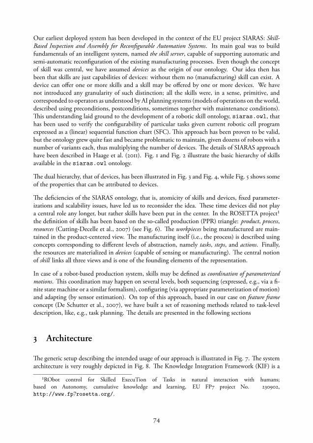
Our earliest deployed system has been developed in the context of the EU project SIARAS: Skill-Based Inspection and Assembly for Reconfigurable Automation Systems. Its main goal was to buildfundamentals of an intelligent system, named the skill server, capable of supporting automatic andsemi-automatic reconfiguration of the existing manufacturing processes. Even though the conceptof skill was central, we have assumed devices as the origin of our ontology. Our idea then hasbeen that skills are just capabilities of devices: without them no (manufacturing) skill can exist. Adevice can offer one or more skills and a skill may be offered by one or more devices. We havenot introduced any granularity of such distinction; all the skills were, in a sense, primitive, andcorresponded to operators as understood by AI planning systems (models of operations on the world,described using preconditions, postconditions, sometimes together with maintenance conditions).This understanding laid ground to the development of a robotic skill ontology, siaras.owl, thathas been used to verify the configurability of particular tasks given current robotic cell programexpressed as a (linear) sequential function chart (SFC). This approach has been proven to be valid,but the ontology grew quite fast and became problematic to maintain, given dozens of robots with anumber of variants each, thus multiplying the number of devices. The details of SIARAS approachhave been described in Haage et al. (2011). Fig. 1 and Fig. 2 illustrate the basic hierarchy of skillsavailable in the siaras.owl ontology.
The dual hierarchy, that of devices, has been illustrated in Fig. 3 and Fig. 4, while Fig. 5 shows someof the properties that can be attributed to devices.
The deficiencies of the SIARAS ontology, that is, atomicity of skills and devices, fixed parameter-izations and scalability issues, have led us to reconsider the idea. These time devices did not playa central role any longer, but rather skills have been put in the center. In the ROSETTA project¹the definition of skills has been based on the so-called production (PPR) triangle: product, process,resources (Cutting-Decelle et al., 2007) (see Fig. 6). The workpieces being manufactured are main-tained in the product-centered view. The manufacturing itself (i.e., the process) is described usingconcepts corresponding to different levels of abstraction, namely tasks, steps, and actions. Finally,the resources are materialized in devices (capable of sensing or manufacturing). The central notionof skill links all three views and is one of the founding elements of the representation.
In case of a robot-based production system, skills may be defined as coordination of parameterizedmotions. This coordination may happen on several levels, both sequencing (expressed, e.g., via a fi-nite state machine or a similar formalism), configuring (via appropriate parameterization of motion)and adapting (by sensor estimation). On top of this approach, based in our case on feature frameconcept (De Schutter et al., 2007), we have built a set of reasoning methods related to task-leveldescription, like, e.g., task planning. The details are presented in the following sections
3 Architecture
The generic setup describing the intended usage of our approach is illustrated in Fig. 7. The systemarchitecture is very roughly depicted in Fig. 8. The Knowledge Integration Framework (KIF) is a
¹RObot control for Skilled ExecuTion of Tasks in natural interaction with humans;based on Autonomy, cumulative knowledge and learning, EU FP7 project No. 230902,http://www.fp7rosetta.org/.
74
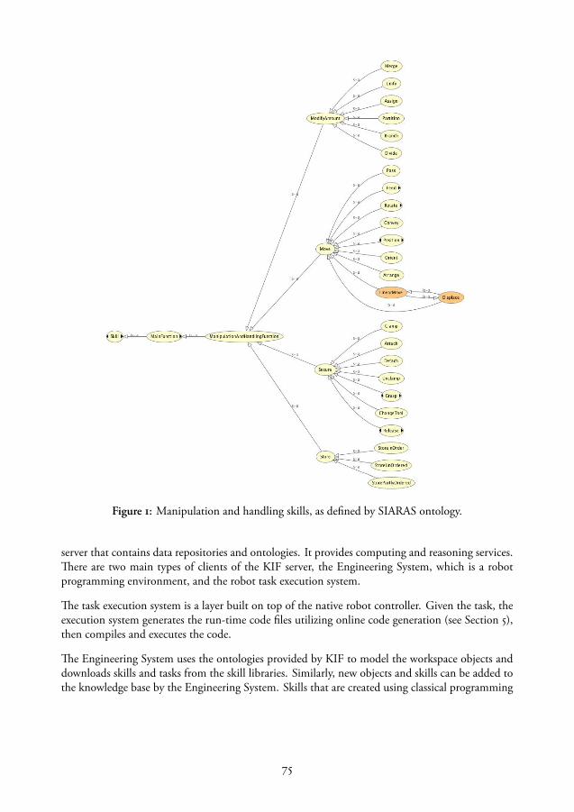
Figure 1: Manipulation and handling skills, as defined by SIARAS ontology.
server that contains data repositories and ontologies. It provides computing and reasoning services.There are two main types of clients of the KIF server, the Engineering System, which is a robotprogramming environment, and the robot task execution system.
The task execution system is a layer built on top of the native robot controller. Given the task, theexecution system generates the run-time code files utilizing online code generation (see Section 5),then compiles and executes the code.
The Engineering System uses the ontologies provided by KIF to model the workspace objects anddownloads skills and tasks from the skill libraries. Similarly, new objects and skills can be added tothe knowledge base by the Engineering System. Skills that are created using classical programming
75

Figure 2: Top skill classification, as defined by SIARAS ontology.
tools such as various state machine editors (like, e.g., JGrafchart²), can be parsed, automaticallyannotated with semantic data and stored in the skill libraries.
The services, described later in the paper, are mainly used by the Engineering System to program,plan and schedule the tasks.
²http://www.control.lth.se/grafchart/
76
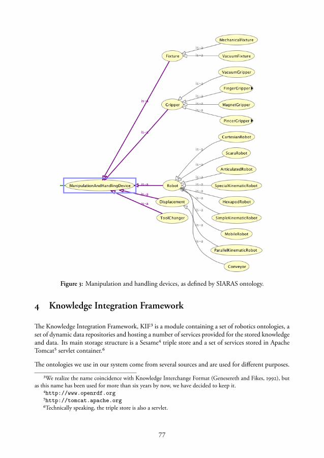
Figure 3: Manipulation and handling devices, as defined by SIARAS ontology.
4 Knowledge Integration Framework
The Knowledge Integration Framework, KIF³ is a module containing a set of robotics ontologies, aset of dynamic data repositories and hosting a number of services provided for the stored knowledgeand data. Its main storage structure is a Sesame⁴ triple store and a set of services stored in ApacheTomcat⁵ servlet container.⁶
The ontologies we use in our system come from several sources and are used for different purposes.
³We realize the name coincidence with Knowledge Interchange Format (Genesereth and Fikes, 1992), butas this name has been used for more than six years by now, we have decided to keep it.
⁴http://www.openrdf.org⁵http://tomcat.apache.org⁶Technically speaking, the triple store is also a servlet.
77

Figure 4: Sensor devices, as defined by SIARAS ontology.
The main, core ontology, rosetta.owl, is a continuous development aimed at creating a genericontology for industrial robotics. Its origins is the FP6 EU project SIARAS described earlier inSection 2. It has been further modified within the FP6 EU project RoSta, (Robot Standards andreference architectures, http://www.robot-standards.eu/, see Nilsson et al., 2009). Within the FP7EU Rosetta project this ontology has been extended, refactored and made available online on thepublic KIF ontology server http://kif.cs.lth.se/ontologies/rosetta.owl. However,this is just the first of a set of ontologies available on KIF and useful for reasoning about robotictasks.
The ontology hierarchy is depicted in Fig. 9, where arrows denote the ontology import operations.We used extensively the QUDT ontologies and vocabularies (Quantities, Units, Dimensions andTypes, initiated by NASA and available at http://www.qudt.org) in order to express physicalunits and dimensions. This ontology has been slightly modified to suit the needs of our reasoner.However, as QUDT ontologies led to inconsistencies, we have introduced the possibility to basethe quantities, units and dimensions on the alternative OM ontology⁷ (Rijgersberg et al., 2013).
The core Rosetta ontology (as its predecessors) is focusing mostly on robotic devices and skills.According to it, every device can offer one or more skills, and every skill is offered by one or moredevices. Production processes are divided into tasks (which may be considered specifications), each
⁷http://www.wurvoc.org/vocabularies/om-1.6/
78

Figure 5: Device properties, as defined by SIARAS ontology.
realized by some skill (implementation). Skills are compositional items: there are primitive skills(non-divisible) and compound ones. Skills may be executed in parallel, if the hardware resourcesand constraints allow it.
On top of the core ontology we have created a number of ”pluggable” ontologies, serving severalpurposes:
Frames The frames.owl ontology deals with feature frames and object frames of physical ob-jects, normally workpieces involved in a task. In particular, the feature frames are related to ge-ometrical locations and therefore the representation of location is of major importance here. Theconstraints among feature frames are expressed using kinematic chains (De Schutter et al., 2007),also introduced by this ontology.
Injury The injury.owl ontology deals with the levels of injury risks when humans and robotscooperate, or at least share common space. The ontology specifies the possible injury kinds, whilethe associated data, either extracted from earlier work (Deutsche Gezetzliche Unfallversicherung,2011), or gathered during the Rosetta project (Matthias et al., 2012), are provided as the upper limitvalues that may be used in computations of injury risks or of evasive trajectories for a robot.
79

Product
Resources Process
Skills
Figure 6: The PPR model, with skills as common coordinating points for the three views.
Params Each skill may be parameterized in a number of ways, depending on the granularity levelof control, available information or the demands posed on the skill. In order to provide knowl-edge about skill parameterization for knowledge services (like, e.g., task consistency checking), theparams.owl ontology describes skills and their mandatory and optional parameters, their unitsand constraints.
SFC The sfc.owl ontology characterizes various behavior representations using variants of exe-cutable state machines (Sequential Function Charts are one of them; the others included are Open-PLC, Statecharts, rFSMs and IML). It also contains the semantic description of several graph-basedrepresentations of assembly, like assembly graphs, constraint graphs or task graphs (Malec et al.,2013), that may also be considered to be behavior specification, although at a rather high level ofabstraction.
This solution illustrates two important principles of compositionality and incrementality: everynon-trivial knowledge base needs to be composable out of simpler elements, possible to be createdby a single designer or team without the need to align it with all the other elements. The alignment,or conflict resolution (e.g., inconsistency), should be performed (semi-)automatically, after pluggingthe element into the system. So, every ”top” ontology should only be forced to adhere to QUDT(or OM) and ROSETTA ontologies, possibly neglecting other elements existing in parallel.
The incrementality principle ensures that every ”top” ontology should be amenable to incrementalchange without the risk of breaking the whole system. Thus, changes to, e.g., Params ontologyshould not affect the consistency and utility of, e.g., SFC ontology. On the other hand, one canimagine situations where changes in one module (e.g., introduction of a new constraint type betweenfeature frames, described in frames.owl) might facilitate improvements in another (e.g., easierspecification of parameters for a given skill, described in params.owl).
Besides storing the ontologies, the triple store of KIF provides also a dynamic semantic storage usedby Engineering System to update, modify and reload scene graphs and task definitions. Dependingon the kind of repository used, some reasoning support may be provided for the storage function-ality. More advanced reasoning, and a generic storage of arbitrary kind of data, is provided by KIFservices, described below.
80

Figure 7: The Knowledge Integration Framework provides services to the Engineering System andthe Task Execution. The latter two communicate during deployment and execution of tasks. TheTask Execution uses sensor input to control the robot and tools.
5 Knowledge-Based Services
The knowledge base provides storage and reasoning services to its clients. The most basic service itoffers is access to libraries with objects and skills, where the user can upload and download objectdescriptions and task specifications. Some of them are stored with semantic annotations, as triples,e.g., workpieces, scene graphs or skill definitions. Others are stored as uniform chunks of datawithout semantically visible structure (e.g., RAPID programs or COLLADA files), although othertools may access and meaningfully manipulate them for various purposes.
The services are mostly user-oriented, providing programming aid, and can be used step-by-step tocreate a workspace and then to refine a task sequence from a high-level specification to low levelcode. The workspace is created by adding a robot, tools, sensors and workpieces to the scene, givingthe object properties relevant values and defining relations between objects (see Section ??).
The user specifies a task using the workpieces and their relations. On the highest level, the task isrepresented by an assembly graph (Malec et al., 2013). An example assembly graph of a cell phone isshown in Fig. 10. The assembly graph is normally a tree (not necessarily binary). The leaves are theoriginal workpieces which are joined into subassemblies represented by parent nodes and the fullassembly is represented by the root. Each subassembly can be annotated by more information, suchas geometrical relations between the objects, or what type of joining mechanism to use (e.g., glueing,snapping, screwing). The tree imposes a partial order on the operations, where child assemblies haveto be carried out first. When going from the task specification given by the assembly graph to anexecutable program, the task has to be sequentialized. Depending on the robot, or on the numberof collaborating robots, the sequence can be realized in several ways, hence, an assembly graphspecification can be shared by several robot systems, even though the sequences realizing it willdiffer.
81
Figure 8: The Knowledge Integration Framework provides services to the Engineering System andthe Task Execution. The latter two communicate during deployment and execution of tasks. TheTask Execution uses sensor input to control the robot and tools.
KIF provides a planning service that transforms an assembly graph to a sequence of operations usingpreconditions and postconditions of the skills. Initially the service verifies the device requirementsof a skill. Fig. 11 displays the device requirements of an implementation of the skill that insertsa shieldcan onto a printed circuit board (PCB). This skill has only three device requirements: amounted tool (which is a manipulation requirement), a fixture and a force sensor, which (though itis not displayed in the figure) must be aligned vertically. When planning the sequence, the planneradds actions that fulfill the preconditions (see the example in Fig. 12), such as moving objects intoplace.
However, the sequence can also be created directly by the user, either manually or by using a naturallanguage instruction interface. Later, the same planner can be used to verify that the sequence fulfillsthe preconditions of each action (Fig. 13).
The natural language interface is described in more detail elsewhere (Stenmark and Nugues, 2013;Stenmark and Malec, 2014b). The user either dictates or types English instructions in a text field (seean example in Fig. 14). The input text is sent to a natural language service on KIF where the sentencesare parsed into predicates (verbs) and their corresponding arguments. Each verb has several differentsenses depending on the context and meaning, e.g., the predicate take in take off the shoes has sensetake.01, but in the sentence Take on the competition it has sense take.09. The shoes and (on) thecompetition are arguments to the predicates. Each sense has a number of predefined arguments for,e.g., the actor doing the deed, the object being manipulated, the source or the destination. Thesearguments are labelled as A0, A1, etc. Both the sense of the verbs and the arguments are determinedusing statistical methods described in Björkelund et al. (2010).
The natural language service outputs a preliminary form of program statements derived from thesentences. However, the matching to actions and objects existing in the world is done in the En-gineering System. In the simplest form a program statement contains an action (the predicate)and a few arguments (objects). The action is then mapped to a robot program template while thearguments are mapped to the physical objects in the workspace, using their names and types. Ac-tions described this way can be picking, placing, moving and locating objects. More complicated
82
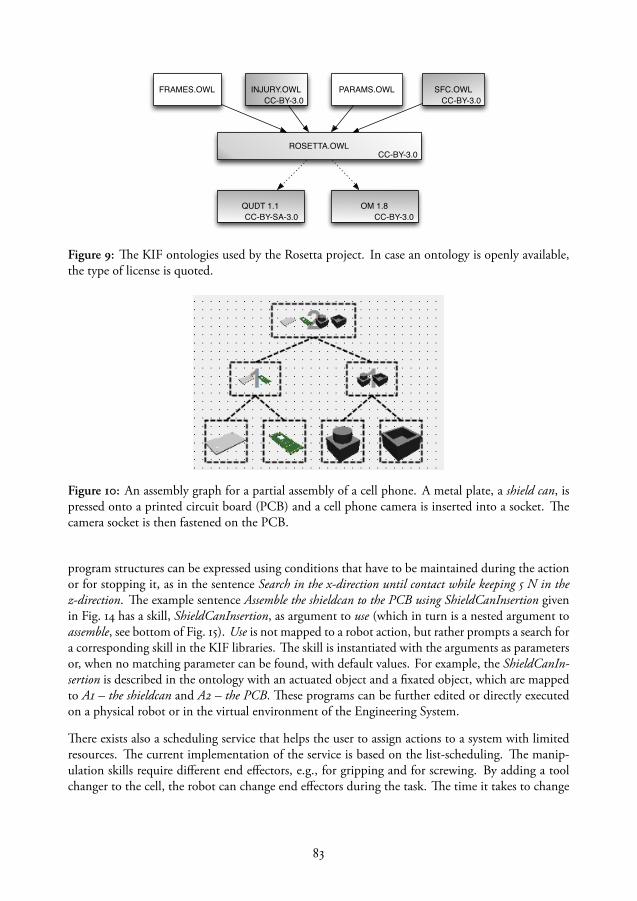
ROSETTA.OWL
QUDT 1.1
INJURY.OWL SFC.OWLPARAMS.OWLFRAMES.OWL
OM 1.8
CC-BY-3.0
CC-BY-SA-3.0
CC-BY-3.0CC-BY-3.0
CC-BY-3.0
Figure 9: The KIF ontologies used by the Rosetta project. In case an ontology is openly available,the type of license is quoted.
Figure 10: An assembly graph for a partial assembly of a cell phone. A metal plate, a shield can, ispressed onto a printed circuit board (PCB) and a cell phone camera is inserted into a socket. Thecamera socket is then fastened on the PCB.
program structures can be expressed using conditions that have to be maintained during the actionor for stopping it, as in the sentence Search in the x-direction until contact while keeping 5 N in thez-direction. The example sentence Assemble the shieldcan to the PCB using ShieldCanInsertion givenin Fig. 14 has a skill, ShieldCanInsertion, as argument to use (which in turn is a nested argument toassemble, see bottom of Fig. 15). Use is not mapped to a robot action, but rather prompts a search fora corresponding skill in the KIF libraries. The skill is instantiated with the arguments as parametersor, when no matching parameter can be found, with default values. For example, the ShieldCanIn-sertion is described in the ontology with an actuated object and a fixated object, which are mappedto A1 – the shieldcan and A2 – the PCB. These programs can be further edited or directly executedon a physical robot or in the virtual environment of the Engineering System.
There exists also a scheduling service that helps the user to assign actions to a system with limitedresources. The current implementation of the service is based on the list-scheduling. The manip-ulation skills require different end effectors, e.g., for gripping and for screwing. By adding a toolchanger to the cell, the robot can change end effectors during the task. The time it takes to change
83
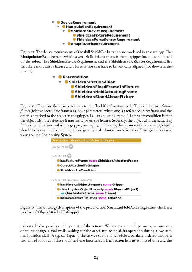
Figure 11: The device requirements of the skill ShieldCanInsertion are modelled in an ontology. TheManipulationRequirement which several skills inherit from, is that a gripper has to be mountedon the robot. The ShieldcanFixtureRequirement and the ShieldcanForceSensorRequirement listthat there must exist a fixture and a force sensor that have to be vertically aligned (not shown in thepicture).
Figure 12: There are three preconditions to the ShieldCanInsertion skill. The skill has two featureframes (relative coordinate frames) as input parameters, where one is a reference object frame and theother is attached to the object in the gripper, i.e., an actuating frame. The first precondition is thatthe object with the reference frame has to be on the fixture. Secondly, the object with the actuatingframe should be attached to the gripper, see Fig. 13, and finally, the position of the actuating objectshould be above the fixture. Imprecise geometrical relations such as “Above” are given concretevalues by the Engineering System.
Figure 13: The ontology description of the precondition ShieldcanHoldActuatingFrame which is asubclass of ObjectAttachedToGripper.
tools is added as penalty on the priority of the actions. When there are multiple arms, one arm canof course change a tool while waiting for the other arm to finish its operation during a two-armmanipulation skill. A typical input to the service can be to schedule a partially ordered task on atwo-armed robot with three tools and one force sensor. Each action lists its estimated time and the
84
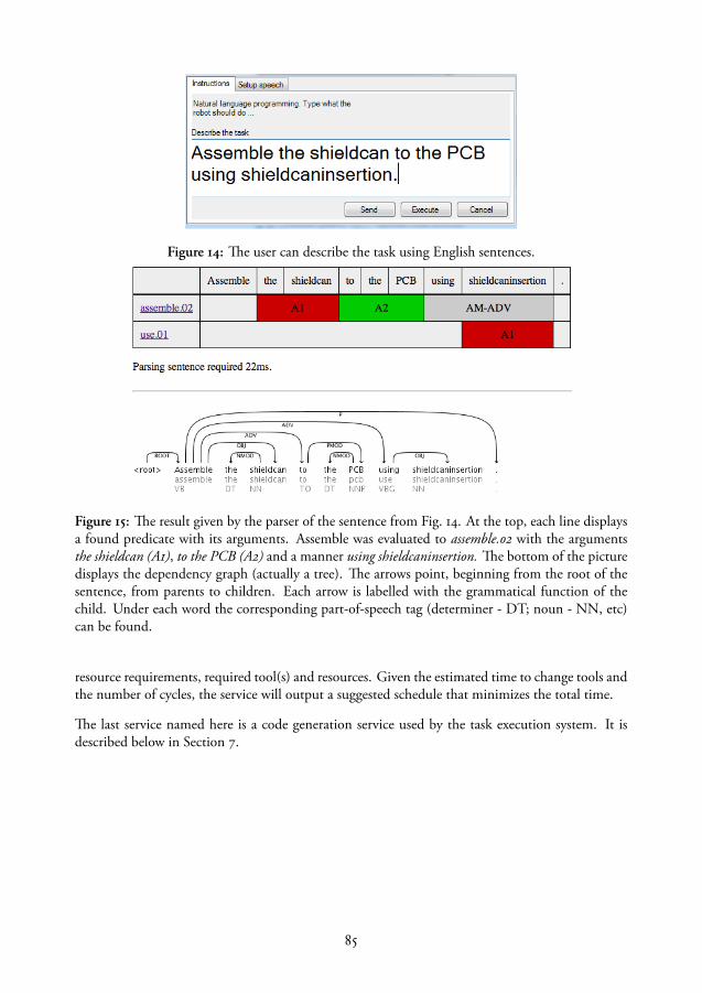
Figure 14: The user can describe the task using English sentences.
Figure 15: The result given by the parser of the sentence from Fig. 14. At the top, each line displaysa found predicate with its arguments. Assemble was evaluated to assemble.02 with the argumentsthe shieldcan (A1), to the PCB (A2) and a manner using shieldcaninsertion. The bottom of the picturedisplays the dependency graph (actually a tree). The arrows point, beginning from the root of thesentence, from parents to children. Each arrow is labelled with the grammatical function of thechild. Under each word the corresponding part-of-speech tag (determiner - DT; noun - NN, etc)can be found.
resource requirements, required tool(s) and resources. Given the estimated time to change tools andthe number of cycles, the service will output a suggested schedule that minimizes the total time.
The last service named here is a code generation service used by the task execution system. It isdescribed below in Section 7.
85
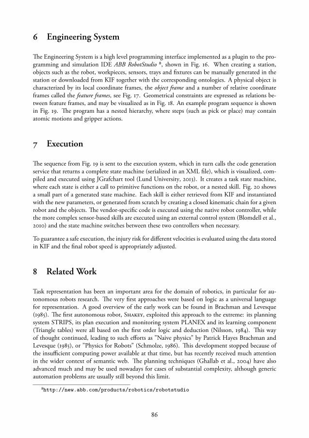
6 Engineering System
The Engineering System is a high level programming interface implemented as a plugin to the pro-gramming and simulation IDE ABB RobotStudio ⁸, shown in Fig. 16. When creating a station,objects such as the robot, workpieces, sensors, trays and fixtures can be manually generated in thestation or downloaded from KIF together with the corresponding ontologies. A physical object ischaracterized by its local coordinate frames, the object frame and a number of relative coordinateframes called the feature frames, see Fig. 17. Geometrical constraints are expressed as relations be-tween feature frames, and may be visualized as in Fig. 18. An example program sequence is shownin Fig. 19. The program has a nested hierarchy, where steps (such as pick or place) may containatomic motions and gripper actions.
7 Execution
The sequence from Fig. 19 is sent to the execution system, which in turn calls the code generationservice that returns a complete state machine (serialized in an XML file), which is visualized, com-piled and executed using JGrafchart tool (Lund University, 2013). It creates a task state machine,where each state is either a call to primitive functions on the robot, or a nested skill. Fig. 20 showsa small part of a generated state machine. Each skill is either retrieved from KIF and instantiatedwith the new parameters, or generated from scratch by creating a closed kinematic chain for a givenrobot and the objects. The vendor-specific code is executed using the native robot controller, whilethe more complex sensor-based skills are executed using an external control system (Blomdell et al.,2010) and the state machine switches between these two controllers when necessary.
To guarantee a safe execution, the injury risk for different velocities is evaluated using the data storedin KIF and the final robot speed is appropriately adjusted.
8 Related Work
Task representation has been an important area for the domain of robotics, in particular for au-tonomous robots research. The very first approaches were based on logic as a universal languagefor representation. A good overview of the early work can be found in Brachman and Levesque(1985). The first autonomous robot, Shakey, exploited this approach to the extreme: its planningsystem STRIPS, its plan execution and monitoring system PLANEX and its learning component(Triangle tables) were all based on the first order logic and deduction (Nilsson, 1984). This wayof thought continued, leading to such efforts as ”Naive physics” by Patrick Hayes Brachman andLevesque (1985), or ”Physics for Robots” (Schmolze, 1986). This development stopped because ofthe insufficient computing power available at that time, but has recently received much attentionin the wider context of semantic web. The planning techniques (Ghallab et al., 2004) have alsoadvanced much and may be used nowadays for cases of substantial complexity, although genericautomation problems are usually still beyond this limit.
⁸http://new.abb.com/products/robotics/robotstudio
86
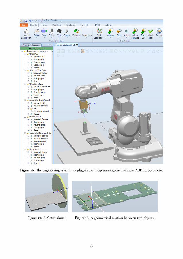
Figure 16: The engineering system is a plug-in the programming environment ABB RobotStudio.
Figure 17: A feature frame. Figure 18: A geometrical relation between two objects.
87

Figure 19: An example sequence of thecell phone assembly. First, the PCB ismoved to the fixture. Then, the shield-can is picked and inserted on the PCBusing a sensor-based skill called shield-caninsertion. The cell phone camera isassembled with the socket, and then thesocket is inserted on the PCB.
Figure 20: Each box is a state in the task state ma-chine. The state called Skill 1 with marked cornersis a nested state machine containing a (dynami-cally generated) sensor-based skill. Before and af-ter the sensor-based skill the external controller isstarted and turned off, respectively.
Later, mixed architectures begun to emerge, with a reasoning layer on the top, reactive layer in thebottom, and some synchronization mechanism, realized in various disguises, in the middle. Thisapproach to building autonomous robots is prevalent nowadays (Bekey, 2005), where researcherstry to find an appropriate interface between abstract, declarative description needed for any kind ofreasoning, and procedural one needed for control. The problem remains open until today, only itscomplexity (or the complexity of solutions) grows with time and available computing power.
Task description in industrial robotics setting comes also in the form of hierarchical representationand control, but the languages used are much more limited (and thus more amenable to effectiveimplementation). There exist a number of standardized approaches, based, e.g., on the IEC 61131standards (IEC, 2003) devised for programmable logic controllers, or proprietary solutions providedby robot manufacturers, however, to a large extent the solutions are incompatible with each other.EU projects like RoSta⁹ are attempts to change this situation.
At the theory level all the approaches combining continuous and discrete formalisms may be consid-ered as variants or extensions of hybrid systems (Goebel et al., 2012), possibly hierarchical. Hybridcontrol architectures allow us to some extent separation of concerns, where the continuous and
⁹www.robot-standards.org
88

real-time phenomena are handled in their part of the system, while the discrete aspects are treatedby appropriate discrete tools. Our earlier work attempted at declaratively specifying such hybridsystems, but was limited to knowledge-based configuration (Haage et al., 2011).
Robotics systems are usually build from a number of distributed heterogenous hardware and soft-ware components that have to seamlessly interact during execution phase. In order to simplify con-figuration, communication and hide the complexity of the system, as well as to promote portabilityand modularity, there exist several frameworks for robotics middleware (see comprehensive surveysElkady and Sobh, 2012; Mohamed et al., 2008). Module functionality can be provided as nodes inthe ROS 10 environment, or as standardized components in RT-components (Noriaki et al., 2005),where the modules can provide blackbox-type computations with well-specified interfaces.
Task descriptions come in different disguises, depending on the context, application domain, levelof abstraction considered, tools available, etc. Usually tasks are composed out of skills, under-stood as capabilities of available devices (Björkelund et al., 2011), but the way of finding appropriatecomposition varies heavily, from manual sequencing in many workflows, via AI-influenced taskplanning (Ghallab et al., 2004), hybrid automata development tools (Goebel et al., 2012), State-charts (Harel, 1987) and Sequential Function Charts (SFCs) (IEC, 2003), iTaSC specifications (DeSchutter et al., 2007), to development of monolithic programs in concrete robot programminglanguages, like, e.g., ABB RAPID.
There have been several attempts to codify and standardize the vocabulary of robotics. There existsan old ISO standard 8373 requiring however a major revision to suit the demands of contemporaryrobotics. IEEE Robotics and Automation Society is leading some work towards standardization ofrobotic ontologies. In particular, there are first drafts of robotic core ontology (Carbonera et al.,2013), although not as developed as the ROSETTA ontology described in this paper. Regardingindustrial robotics, the work on kitting ontologies, originated at NIST (Balakirsky et al., 2012),may be considered as an early attempt to address the problem.
In the area of service robotics there are several systems exploiting the knowledge-based approach,and relying on an underlying ontology, like KnowRob (Tenorth and Beetz, 2013) (based on thegeneric OpenCyC ontology by Matuszek et al., 2006), used in RoboHow project¹⁰ or severalparticipants in the RoboEarth project¹¹ (Waibel et al., 2011). However, they do not attempt tostandardize the domain, as the variance of tasks and skills in the service robotics is very large. Onthe other hand, the KnowRob ontology became a de-facto standard used in several experimentalrobot systems.
9 Conclusions
We have shown a generic knowledge-based system architecture and its possible use in industrialrobotic systems. In particular, we have employed the approach for representing and realizing force-controlled tasks realized by one- and two-armed ABB robots in an industrial setting. The presentedgeneric ontologies are either novel, or a derivative of our earlier research. The use of semantic tools
¹⁰http://robohow.eu¹¹http://roboearth.org/
89

and explicit knowledge in industrial robotics is in its early stage, with only a few other publishedexamples (Balakirsky et al., 2012). The ideas have been experimentally verified and work well in thecurrently ongoing EU-projects PRACE¹² and SMErobotics¹³. The implemented system is just aproof of concept, and systems that are derived from this work must undergo usability, security andperformance testing, before they might be considered to be ready for industrial practice. But alreadynow it can be stressed that the knowledge-based approach allowed us to create composable represen-tations of non-trivial assembly skills, shown to be reusable among different models of ABB robots,but also portable to other vendors and control architectures (like the one reported in Klotzbücherand Bruyninckx, 2012) and running on a Kuka LWR4 robot.
The already ongoing continuation of the work presented above involves integration of a heteroge-neous system consisting of a mobile robot platform (Rob@Work) running a ROS-based controlsystem, and a real-time-enabled ABB-manipulator running the ABB-specific control software, sothat the two parts can operate seamlessly together as an integrated, knowledge-based, productiverobotic system. This work includes deploying knowledge-based services in the context of chosenrobotic middleware.
Future work involves contribution to the IEEE standardization efforts, and aligning and sharingrobotic ontologies with other research groups. An online documentation of the core ROSETTAontology is also expected. The number of knowledge-based services should be extended with, e.g.,online reasoning during execution, geometrical reasoning and integrated path planning and op-timization. We are also verifying this approach in other domains of manufacturing, like wood-working and machining, expecting to extend the ontologies appropriately.
We have found out during the work described in this paper that skills are much more than just apotential to execute coordinated motions. This line of thought has been already present in Nilssonet al. (2013), where business aspects of skills have been pointed to. We plan to explore this topic inthe nearest future.
Acknowledgments
The research leading to these results has received partial funding from the European Union’s seventhframework program (FP7/2007-2013) under Grant agreement nos. 230902 (project ROSETTA),285380 (project PRACE) and 287787 (project SMErobotics).
The work described in this paper has been done in tight collaboration with many people from theproject consortia. The authors are indebted for many fruitful discussions.
An early version of this paper has been presented during the 12th Scandinavian Conference onArtificial Intelligence, Aalborg, Denmark, October 2013.
¹²http://prace-fp7.eu/¹³http://www.smerobotics.org/
90

Paper ii


Paper II
On Distributed Knowledge Bases for Small-Batch Assembly
Maj Stenmark∗ Jacek Malec∗ Klas Nilsson∗ Anders Robertsson†
∗Department of Computer ScienceLund University
†Department of Automatic ControlLund University
[email protected]@[email protected]
ABSTRACT
This paper presents ongoing research involving design and evaluation of different architectures forproviding knowledge-based solutions in industrial robotized automation systems. The conclusionsare that distributed, cloud-based approaches offer many possibilities, in particular for knowledgeexchange and reuse, and facilitate new business models for industrial solutions. However, there aremany unresolved questions yet, e.g., those related to reliability, consistency, or legal responsibility.There is a definite need for further research and better infrastructure before this approach wouldbecome attractive for industrial actors.
Note to Practitioners:
It is possible to extend the capabilities of a robot system by providing online services. An exam-ple of such service is an online library of robot applications, an app store, where robot programscan be downloaded and installed on the system with little effort from the user. Another is textanalysis, that requires heavy computations but can provide a more natural user interaction. In thispaper we discuss technical solutions and challenges that we have experiences during several Euro-pean projects, that aimed at simplifying the robot programming by providing such libraries withknowledge and computational services. Since robot programming is time consuming and requiresexpertise, and thus is expensive, there is need for good services that simplifies this process. However,at the moment, there is no working market place for the distribution of existing solutions.
IEEE Transactions on Automation and Engineering, 2015, Vol. 12, 519 - 528,DOI: 10.1109/TASE.2015.2408264.

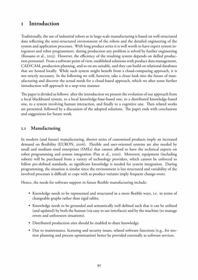
1 Introduction
Traditionally, the use of industrial robots as in large-scale manufacturing is based on well-structureddata reflecting the semi-structured environment of the robots and the detailed engineering of thesystem and application processes. With long product series it is well worth to have expert system in-tegrators and robot programmers: during production any problem is solved by further engineering(Rossano et al., 2013). However, the efficiency of the resulting system depends on skilled produc-tion personnel. From a software point of view, established solutions with product data management,CAD/CAM, production planning, and so on are suitable, and they can build on relational databasesthat are hosted locally. While such system might benefit from a cloud-computing approach, it isnot strictly necessary. In the following we will, however, take a closer look into the future of man-ufacturing and discover the actual needs for a cloud-based approach, which we after some furtherintroduction will approach in a step-wise manner.
The paper is divided as follows: after the introduction we present the evolution of our approach froma local blackboard system, to a local knowledge-base-based one, to a distributed knowledge-basedone, to a system involving human interaction, and finally to a cognitive one. Then related worksare presented, followed by a discussion of the adopted solutions. The paper ends with conclusionsand suggestions for future work.
1.1 Manufacturing
In modern (and future) manufacturing, shorter series of customized products imply an increaseddemand on flexibility (EURON, 2006). Flexible and user-oriented systems are also needed bysmall and medium sized enterprises (SMEs) that cannot afford to have the technical experts onrobot programming and system integration (Pan et al., 2010). Moreover, equipment (includingrobots) will be purchased from a variety of technology providers, which cannot be enforced tofollow pre-defined standards, so significant knowledge is needed for system integration. Duringprogramming, the situation is similar since the environment is less structured and variability of theinvolved processes is difficult to cope with as product variants imply frequent change-overs.
Hence, the needs for software support in future flexible manufacturing include:
• Knowledge needs to be represented and structured in a more flexible ways, i.e. in terms ofchangeable graphs rather than rigid tables.
• Knowledge needs to be grounded and semantically well defined such that it can be utilized(and updated) by both the human (via easy to use interfaces) and by the machine (to manageerrors and unforeseen situations).
• Distributed production sites should be enabled to share knowledge.
• Due to maintenance, licensing and security issues, related software functions (e.g., for mo-tion planning and process optimization) better be provided externally as software services.
95
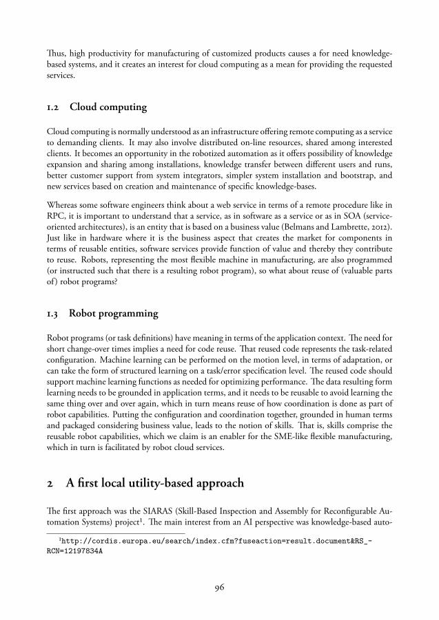
Thus, high productivity for manufacturing of customized products causes a for need knowledge-based systems, and it creates an interest for cloud computing as a mean for providing the requestedservices.
1.2 Cloud computing
Cloud computing is normally understood as an infrastructure offering remote computing as a serviceto demanding clients. It may also involve distributed on-line resources, shared among interestedclients. It becomes an opportunity in the robotized automation as it offers possibility of knowledgeexpansion and sharing among installations, knowledge transfer between different users and runs,better customer support from system integrators, simpler system installation and bootstrap, andnew services based on creation and maintenance of specific knowledge-bases.
Whereas some software engineers think about a web service in terms of a remote procedure like inRPC, it is important to understand that a service, as in software as a service or as in SOA (service-oriented architectures), is an entity that is based on a business value (Belmans and Lambrette, 2012).Just like in hardware where it is the business aspect that creates the market for components interms of reusable entities, software services provide function of value and thereby they contributeto reuse. Robots, representing the most flexible machine in manufacturing, are also programmed(or instructed such that there is a resulting robot program), so what about reuse of (valuable partsof ) robot programs?
1.3 Robot programming
Robot programs (or task definitions) have meaning in terms of the application context. The need forshort change-over times implies a need for code reuse. That reused code represents the task-relatedconfiguration. Machine learning can be performed on the motion level, in terms of adaptation, orcan take the form of structured learning on a task/error specification level. The reused code shouldsupport machine learning functions as needed for optimizing performance. The data resulting formlearning needs to be grounded in application terms, and it needs to be reusable to avoid learning thesame thing over and over again, which in turn means reuse of how coordination is done as part ofrobot capabilities. Putting the configuration and coordination together, grounded in human termsand packaged considering business value, leads to the notion of skills. That is, skills comprise thereusable robot capabilities, which we claim is an enabler for the SME-like flexible manufacturing,which in turn is facilitated by robot cloud services.
2 A first local utility-based approach
The first approach was the SIARAS (Skill-Based Inspection and Assembly for Reconfigurable Au-tomation Systems) project¹. The main interest from an AI perspective was knowledge-based auto-
¹http://cordis.europa.eu/search/index.cfm?fuseaction=result.document&RS_-RCN=12197834A
96

analysis
Vendor specific
Ontology
Database
Main loop
Commercialreasoner
Customreasoner
Systemintegrator
Open sourcesoftware
Commercialsoftware
End userprovider
Pathplanning
Energyoptimisation
Timeoptimisation
Grippability
SIARASreasoner
Device
Reasoner interfacesSi
mul
atio
n/vi
sual
isatio
n in
terfa
ces
Utility function interfaces
(G)UI interfaces
Figure 1: The SIARAS blackboard architecture
matic reconfiguration of automation systems. The results of this work have been presented in Sten-mark and Malec (2014a). The outcome was an intelligent support system for reconfiguration andadaptation of robot-based manufacturing cells. Declarative knowledge was represented first of allin an ontology expressed in OWL, for a generic taxonomical reasoning, and in a number of special-purpose reasoning modules, specific for the application domain. The domain-dependent moduleswere organized in a blackboard-like architecture.
An overview of the adopted architectural solution is shown in Fig. 1. The main focus has beenput on generic interfaces, allowing independent service, data or knowledge providers to adapt tothe system expectations. In particular, some experiments have been made using several simula-tion/vizualisation tools, providing independent user interfaces suited for different needs and, lastbut not least, exploiting external “utility functions” (knowledge sources in blackboard architectureterms) provided by robot manufacturers, sensor manufacturers and system integrators.
The SIARAS system demonstrator used several machines communication using Ethernet (simula-tion software required different operating systems), but only locally within the engineered system.
97

Some further experiments were done with distributing device database (shown in the central mod-ule in the Figure), allowing several device manufacturers to provide their data independently ofeach other, using their own computer systems connected to Internet (Lidén, 2009). However, theontology used was single and centralized, available locally on the SIARAS system.
3 Knowledge integration
The ROSETTA project² (RObot control for Skilled ExecuTion of Tasks in natural interaction withhumans; based on Autonomy, cumulative knowledge and learning) focused on simplifying interac-tion between the user and the robotized automation system, and on ensuring human safety in allcircumstances. The former goal in particular demanded knowledge-based solutions, although thelatter one also exploited some explicit knowledge encoded in a specific injury ontology.
The concrete system built around this idea has been designed with assembly tasks as the main do-main of application. This has limited the set of skills necessary to specify, kinds of sensors usedas well as the end effectors that robots need for fulfilling their objectives and made creation of thetest system possible. The architecture, depicted in Fig. 2, is an instantiation of the previous one,assuming a concrete simulation and visualization environment, here called Engineering Station,and concrete brands and models of robots for which the Task Execution system generates code,executable by the Native Controller. The architecture assumes a number, possibly geographicallyseparated, engineering stations, and a number of independent robot system installations, connectedto a common knowledge server.
During the ROSETTA project we have built KIF server and made it available for testing by allproject partners. The server provides access to semantic storage with skill descriptions, task speci-fications and station (robot installation) definitions. It also contains a set of ontologies expressedin the OWL language. Besides, it provides a set of knowledge-based services like task consistencychecks, rudimentary planning and scheduling, natural-language-based task definition, or processparameter learning. The engineering system has been realized as a plug-in to the ABB RobotStudiosoftware, as we used ABB robots in our experiments.
The KIF concept can also be used in a hierarchical way with local servers. By setting up a local serverin a factory or a lab, it is possible to address some of the problems of a distributed system. The server
²http://www.fp7rosetta.org
IntegrationFramework
Knowledge
Station
Engineering
TaskExecution
NativeController
Figure 2: The ROSETTA architecture
98
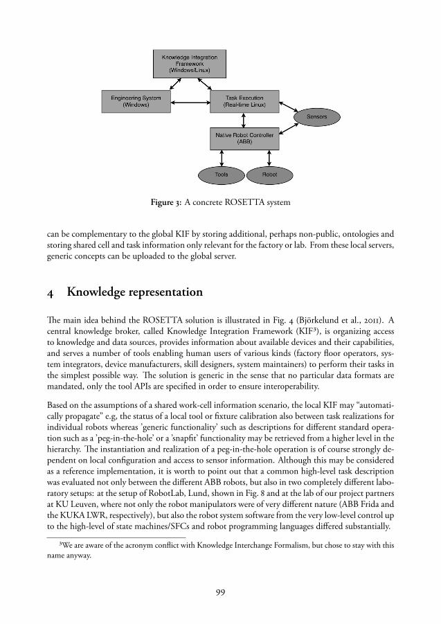
Figure 3: A concrete ROSETTA system
can be complementary to the global KIF by storing additional, perhaps non-public, ontologies andstoring shared cell and task information only relevant for the factory or lab. From these local servers,generic concepts can be uploaded to the global server.
4 Knowledge representation
The main idea behind the ROSETTA solution is illustrated in Fig. 4 (Björkelund et al., 2011). Acentral knowledge broker, called Knowledge Integration Framework (KIF³), is organizing accessto knowledge and data sources, provides information about available devices and their capabilities,and serves a number of tools enabling human users of various kinds (factory floor operators, sys-tem integrators, device manufacturers, skill designers, system maintainers) to perform their tasks inthe simplest possible way. The solution is generic in the sense that no particular data formats aremandated, only the tool APIs are specified in order to ensure interoperability.
Based on the assumptions of a shared work-cell information scenario, the local KIF may “automati-cally propagate” e.g, the status of a local tool or fixture calibration also between task realizations forindividual robots whereas ’generic functionality’ such as descriptions for different standard opera-tion such as a ’peg-in-the-hole’ or a ’snapfit’ functionality may be retrieved from a higher level in thehierarchy. The instantiation and realization of a peg-in-the-hole operation is of course strongly de-pendent on local configuration and access to sensor information. Although this may be consideredas a reference implementation, it is worth to point out that a common high-level task descriptionwas evaluated not only between the different ABB robots, but also in two completely different labo-ratory setups: at the setup of RobotLab, Lund, shown in Fig. 8 and at the lab of our project partnersat KU Leuven, where not only the robot manipulators were of very different nature (ABB Frida andthe KUKA LWR, respectively), but also the robot system software from the very low-level control upto the high-level of state machines/SFCs and robot programming languages differed substantially.
³We are aware of the acronym conflict with Knowledge Interchange Formalism, but chose to stay with thisname anyway.
99
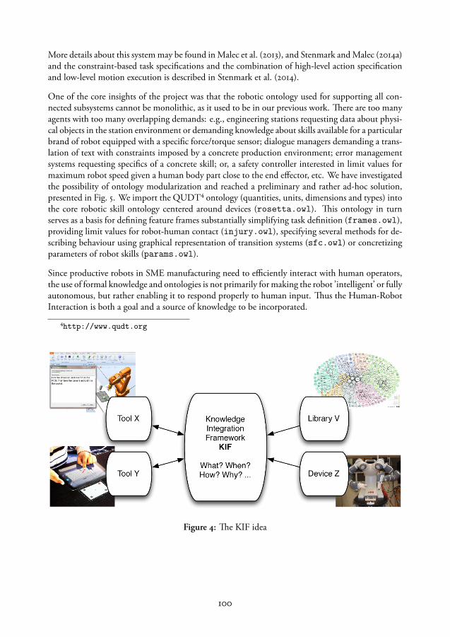
More details about this system may be found in Malec et al. (2013), and Stenmark and Malec (2014a)and the constraint-based task specifications and the combination of high-level action specificationand low-level motion execution is described in Stenmark et al. (2014).
One of the core insights of the project was that the robotic ontology used for supporting all con-nected subsystems cannot be monolithic, as it used to be in our previous work. There are too manyagents with too many overlapping demands: e.g., engineering stations requesting data about physi-cal objects in the station environment or demanding knowledge about skills available for a particularbrand of robot equipped with a specific force/torque sensor; dialogue managers demanding a trans-lation of text with constraints imposed by a concrete production environment; error managementsystems requesting specifics of a concrete skill; or, a safety controller interested in limit values formaximum robot speed given a human body part close to the end effector, etc. We have investigatedthe possibility of ontology modularization and reached a preliminary and rather ad-hoc solution,presented in Fig. 5. We import the QUDT⁴ ontology (quantities, units, dimensions and types) intothe core robotic skill ontology centered around devices (rosetta.owl). This ontology in turnserves as a basis for defining feature frames substantially simplifying task definition (frames.owl),providing limit values for robot-human contact (injury.owl), specifying several methods for de-scribing behaviour using graphical representation of transition systems (sfc.owl) or concretizingparameters of robot skills (params.owl).
Since productive robots in SME manufacturing need to efficiently interact with human operators,the use of formal knowledge and ontologies is not primarily for making the robot ’intelligent’ or fullyautonomous, but rather enabling it to respond properly to human input. Thus the Human-RobotInteraction is both a goal and a source of knowledge to be incorporated.
⁴http://www.qudt.org
Figure 4: The KIF idea
100
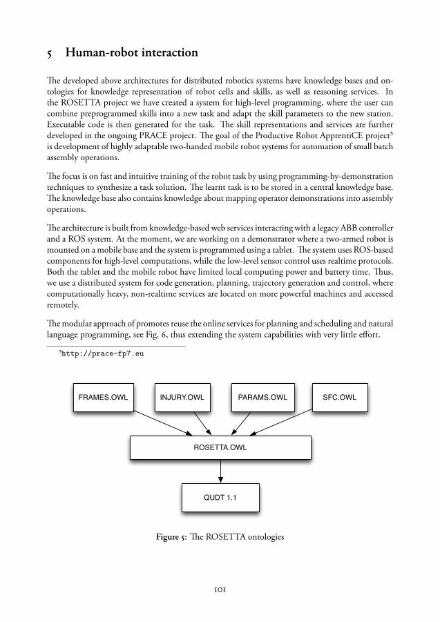
5 Human-robot interaction
The developed above architectures for distributed robotics systems have knowledge bases and on-tologies for knowledge representation of robot cells and skills, as well as reasoning services. Inthe ROSETTA project we have created a system for high-level programming, where the user cancombine preprogrammed skills into a new task and adapt the skill parameters to the new station.Executable code is then generated for the task. The skill representations and services are furtherdeveloped in the ongoing PRACE project. The goal of the Productive Robot ApprentiCE project⁵is development of highly adaptable two-handed mobile robot systems for automation of small batchassembly operations.
The focus is on fast and intuitive training of the robot task by using programming-by-demonstrationtechniques to synthesize a task solution. The learnt task is to be stored in a central knowledge base.The knowledge base also contains knowledge about mapping operator demonstrations into assemblyoperations.
The architecture is built from knowledge-based web services interacting with a legacy ABB controllerand a ROS system. At the moment, we are working on a demonstrator where a two-armed robot ismounted on a mobile base and the system is programmed using a tablet. The system uses ROS-basedcomponents for high-level computations, while the low-level sensor control uses realtime protocols.Both the tablet and the mobile robot have limited local computing power and battery time. Thus,we use a distributed system for code generation, planning, trajectory generation and control, wherecomputationally heavy, non-realtime services are located on more powerful machines and accessedremotely.
The modular approach of promotes reuse the online services for planning and scheduling and naturallanguage programming, see Fig. 6, thus extending the system capabilities with very little effort.
⁵http://prace-fp7.eu
ROSETTA.OWL
QUDT 1.1
INJURY.OWL SFC.OWLPARAMS.OWLFRAMES.OWL
Figure 5: The ROSETTA ontologies
101

KIF
KIF NL service
NL parser
Engineering System Android tablet
Speech-to-text
Figure 6: The service architecture for the natural language programming interface. The NL serviceon KIF receives text, sends it to a general natural language parser (NL parser) and outputs a sequenceof robot actions. These actions are generated into executable code using the architecture displayedin Fig. 3. The Android tablet can use its own speech-to-text cloud service and send the text to theEngineering System, thus extending the user interface to a portable platform.
6 SME-suitable cognition
In the SMErobotics⁶ initiative one of the main foci is on applicable robot solutions for small andmedium sized enterprises (SMEs). In a typical SME-scenario, short production series call for less useof expensive fixture-based production for economical reasons, but then require easily reconfigurablesetups which need to cope with and compensate for large structural uncertainties. The higher levelof uncertainty can be handled by advanced sensor-based systems, but today even the conventionalindustrial robot programming, without the above mentioned extensions, is still a bottleneck withrespect to both time and expertise. Based on high-level task descriptions and intuitive interactionwhere the worker’s process knowledge (not the knowledge of robotics) can be fully utilized, the goalis not to reach a fully automated system, but a system with high productivity due to the interac-tion of an operator with the robot system, giving flexibility in production changes, and short errorrecoveries.
Cognition is needed both on the robot side and on the human side, symbiotically, and must beintegrated with learning. Although newly learnt functionality on the robot side may be immediatelydistributed, locally or globally, this does of course not count for the human operators where eachindividual will have a different level of experience and expertise and thereby different abilities andpreferences on how to interact and instruct. A personalized interface and dialogue system thatthe individual operator can access remotely, may be beneficial in this human-robot-collaboration.Concepts and symbols used in dialogues need to have a grounding that is shared by the human andthe machine, e.g., to support the user in error situations.
⁶http://www.smerobotics.org
102
In this scenario the possibility to extend the available services with online reasoning and policygeneration of error handling procedures opens also for efficient individual operator dialogues. In theSMErobotics project this topic is investigated in the context of modular knowledge and distributedreasoning systems.
The modularity of knowledge is also crucial for reuse of robot tasks or subtasks, representing partialsolutions to production problems. Without being able to reuse solutions, the SME user will find therobot overly dumb and not productive in the common case of frequent changeovers. To accomplishsuch reuse it was found that stored knowledge must be in a compositional form, and the definitionof skills need to be enhanced such that it maps to the notions and practices of the SME end user.More specifically, a useful skill representation should fulfill the following requirements:
• It has a business value, meaning that it carries out a non-trivial computation or motionsequence.
• It encapsulates the configuration and coordination information of the system.
• It describes parameters that can be adapted and automatically optimized by the robot system.
• The motions and actions are semantically described so that the system can reason about theskill.
• The semantics and taxonomy of the machine readable representation should relate to thehuman notions i natural language.
There is to our knowledge no such skill definition developed yet, but this is the current core topicin our ongoing research, with the aim of supporting reuse/portability of motions (see Nilsson et al.,2013) for a motivation of the the business and natural language aspects).
In order to semantically anchor the term skill we use an appropriate ontology including all theabove mentioned aspects. Figure 7 shows a fragment of this ontology that extends our earlier workpresented in Nilsson et al. (2013) and Stenmark and Malec (2014a). The full insight regarding theimplication of 6D motions and uncertainties (in both processes, equipment and specifications), andwhy that results in a fundamentally different problem than reuse of computer code, is outside thescope of this paper.
7 Related work
The rapid growth of network services and the latest development of cloud solutions in a very generalform has definitely had its impact also in automation and robotics (in industrial as well as in servicerobotics).
Although the concept of network distributed control and functionality in not new, see e.g., Inabaet al. (2000), the term “cloud robotics” has spread tremendously since James Kuffner has introducedit in 2010; it has attained a large interest in the robotics community reflected in a number of publi-cations, it is appearing in research calls and has led to important development in open-source and
103

Figure 7: Central part of ongoing skill definition.
open-access projects⁷ during the last couple of years. An important European project addressingthe topic of knowledge sharing online, is RoboEarth⁸ (Waibel et al., 2011), that aims at creating aWorld Wide Web for robots. Their knowledge base contains ontologies, tasks and environmentaldata (Beetz and Tenorth, 2012), which are shared by robots. The RoboEarth infrastructure, namedRapyuta, has recently become available publicly (Hunziker et al., 2013; Mohanarajah et al., 2014a)in its alpha version. Rapyuta is a system for distributed robot control of multiple agents. Each agenthas an endpoint (or a clone) in the system and a Master task that handles the configuration of thecommunication. A use case is presented in (Mohanarajah et al., 2014b), where mobile robots col-lectively build a 3D map. The robots carry out very little processing, instead each device has a robotclone deployed in Rapyuta. The clone is a ROS environment that controls the robot remotely andpropagates the image messages to another process that builds the map. The RoboEarth knowledge-base, which is equivalent to KIF with ontologies and services, can be accessed from Rapyuta. Thecommunication within Rapyuta is handled similarly to ROS, with the addition of process-IDs tothe (ROS) messages, hence, it is a system that integrates multiple ROS environments. It is a systemsuitable for, e.g., service robotics, where the latency of the system does not impact the performance.This architecture is not suitable for industrial applications where: 1) the system has real-time require-ments, 2) the software is proprietary, that is, it might not be an option to deploy software withinthe system, but instead services and software might run remotely on company servers, hence, theconfiguration cannot be done by a Master task.
⁷See e.g., http://code.google.com/p/rosjava/⁸http://www.roboearth.org
104
Departing from network research, and in particular, networked robotics systems, Hu and coworkersanalyze the opportunities offered by cloud robotics infrastructure (Hu et al., 2012). Their applica-tions focus though on the typical mobile robotics domains, like SLAM, navigation and grasping,leaving manufacturing outside the scope of interest.
Another popular cloud service, also in and for robotics, is natural language interpretation, such asspeech-to-text techniques which we also see commonly appearing in e.g., smartphones. Thomasand Jenkins (2012) describe a system for commanding a robot using natural language. Stenmarkand Nugues (2013) describe a more advanced solution to this problem.
An recent survey of work related to cloud robotics and automation was made by Goldberg andKehoe (2013). Kehoe et al. (2013) have also presented a concrete application of cloud computingfor robot grasping using Google’s object recognition infrastructure. However, it is not availablepublicly, making it less attractive for the cloud robotics community.
8 Implementations
The architecture in Fig 2 is implemented in an experimental setup at Lund University. The mainresearch platform in the ROSETTA and PRACE projects was the two-armed concept robot (withChristian name Frida) from ABB Robotics, seen to the left in Fig 8. To the right we have a conven-tional industrial robot (ABB IRB120) extended with an open robot control interface Blomdell et al.(2010). Thus, the workcell contains two different manipulators and different hardware configura-tions with respect to sensor information (e.g., force/torque measurements) are used.
The Engineering System is implemented as an extension to ABB RobotStudio⁹, and displayedin Fig 9. In the Engineering System the task is realized as a sequence of actions, which in turncan be generated from a partially ordered assembly graph or by using online services provided byKIF. The ontologies, architecture and services provided in the system are described in more detailin Stenmark and Malec (2014a).
9 Discussion
The research done so far allows us to make the following observations. However, we would liketo stress that their scope is limited by the context in which our research has been done: industrialrobotized manufacturing systems, mostly relevant for assembly.
Online knowledge bases Their simplest possible advantage is to make deployment of a knowl-edge base and its associated services to every single system installation unnecessary. Instead, onecentral copy (or several mirrored ones) of the knowledge server needs to be created and maintained.In particular, the knowledge update and system upgrade can be made instantaneous, making freshservices immediately available to all users worldwide.
⁹http://new.abb.com/products/robotics/robotstudio/downloads
105

Figure 8: A setup of two different robots, the two-armed concept robot Frida and the ABB IRB120,for individual or coordinated assembly of emergency buttons within the ROSETTA project.
Depending on the model adopted for the knowledge base (monolithic or distributed, federated orgoverned by a single body) the chances of getting more knowledge provided to the system increasedramatically. However, this introduces also a whole set of issues that need careful attention, likee.g., reliability of knowledge coming from different, possibly unknown sources, guarantees of accessto the (or a) knowledge base in all circumstances, depending on the business model adopted, con-sistency of knowledge provided by different actors, completeness of available resources with respectto a given set of tasks, knowledge overlap and possibility of choosing particular services based onexperience, trust, or other criteria, just to name a few.
In particular, such federated model would allow many stakeholders like robot producers, systemintegrators, sensor providers, software deployers, to cooperate and contribute to a rich market ofknowledge-based solutions, in a manner similar to what happens now in the ROS communityregarding lower-level solutions for robotics.
One of the greatest challenges during the implementation of the knowledge-base was to handleseveral different formats of knowledge. The ontology is created in OWL, however, knowledge isprovided in several standards, such as Automation ML, Collada, PLCOpen and it has to be possibleto read to and from and convert between different formats.
106

Figure 9: The user can program the robot using a visual programming tool developed in ROSETTA,where the task is represented by a sequence of actions that are refined into executable code using theonline services for e.g., code generation.
Reuse of knowledge As it has been shown in our investigations, such approach allows reuseof knowledge introduced by one stakeholder by others. This applies to skill definitions as well asconcrete parameter modifications or adaptations, or fault detection routines inserted after a skill hasbeen deployed in a concrete task. The experience gathered during deployment of a system may bemade available to others without unnecessary delay or update burden.
On the other hand, the question of relevance of such experience is unclear and needs to be raisedhere. How can one judge whether parameters adapted at site A are useful for site B? How can onerealize whether a user of a particular robot C possibly wants to deceive other users by uploadingincorrect values? Being able to generalize, evaluate the relevance and reason about the collected datafrom several setups is a challenge that service providers have to overcome in order to improve theirsolutions for e.g., parameter adaption and error handling.
Web services for robots Web services are an attractive computational model, making it possi-ble to request specific (possibly knowledge-based) services, without knowing any particular detailsabout their implementation, residence, ownership, etc. With a thoroughly defined API it makes itpossible to separate concerns between the installed system: specific, task-related, hardware-specificcomputations, and the service provider: generic, task-independent, hardware-independent, portablecomputations.
As in the cases above, the questions of reliability, responsibility of service providers, portabilityand generality need to be raised here. However, the responsibility question is clearer, as it seems
107

rather straightforward how to make service providers accountable. In this manner, given sufficientlylarge market, robot system capabilities may increase substantially in a very short time. This is anopportunity for the robot manufacturers that seems to be very attractive.
It has to be made clear here that industrial players are rather conservative with that respect and thata lot of effort needs to be put into issues of security, reliability and dependability. Both on the sideof manufacturers, be it robot, sensory equipment, or end effectors, as well as system integrators andend users, everyone is interested in keeping their know-how well protected as this is the main sourceof their profit. Sharing it freely, or just making it vulnerable to cyberattacks, is a risk that needs to beseriously considered and resolved. Without addressing those questions there is a risk that researchactivities will have only very modest influence on industrial practices.
On the other hand, there are solutions available, known from computer networking area and used inbusiness-to-business communication, that address those issues. They are currently being extendedto the context of cloud-based services (see e.g., Yoshinori et al., 2013). What needs to be done isporting them or adapting to a domain involving both software and heterogenous hardware subsys-tems, tightly interacting with each other. It is definitely a challenging task, but e.g., the automotiveindustry shows¹⁰ that these questions may be answered in a manner satisfying to all market partici-pants.
10 Conclusions
Cloud robotics is a key enabling factor for automation in SMEs. First, it can provide an ecosystemfor distribution of solutions, similar to an app store. The applications can collect data and store itonline in order to improve the skills and learn parameters, thus improving the capabilities of therobot over time. Also, user-interaction (such as natural language or image processing) and learningalgorithms can use data and/or computationally heavy procedures during the setup and adaption.The applications cannot guarantee safety, this certification has to be done independently. Marketforces will affect the quality of the services, solutions with better performance/features can have ahigher price or license fee and, more importantly, solutions that are too difficult to understand orconfigure will be outcompeted.
This vision of a robot app store and shared knowledge-bases is ambitious and the efforts described inthis paper are just the very first steps towards the goal. The main challenge for cloud robotics to takeoff in industrial robotics is not the lack of possible technical solutions, but it it trapped in its startupphase: in order to provide services with business value, the knowledge bases, services and solutiondistribution system(s) (the market place) have to be in place, but these in turn need knowledge andsolutions to distribute to get started.
¹⁰www.autosar.org
108
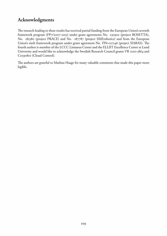
Acknowledgments
The research leading to these results has received partial funding from the European Union’s seventhframework program (FP7/2007-2013) under grant agreements No. 230902 (project ROSETTA),No. 285380 (project PRACE) and No. 287787 (project SMErobotics) and from the EuropeanUnion’s sixth framework program under grant agreement No. FP6-017146 (project SIARAS). Thefourth author is member of the LCCC Linnaeus Center and the ELLIIT Excellence Center at LundUniversity and would like to acknowledge the Swedish Research Council grants VR 2010-5864 andC0590801 (Cloud Control).
The authors are grateful to Mathias Haage for many valuable comments that made this paper morelegible.
109


Paper iii

Paper III
From High-Level Task Descriptions to Executable Robot Code
Maj Stenmark1 Jacek Malec1 Andreas Stolt2
1. Department of Computer ScienceLund University
2. Department of Automatic ControlLund University
[email protected]@cs.lth.se
ABSTRACT
For robots to be productive co-workers in the manufacturing industry, it is necessary that theirhuman colleagues can interact with them and instruct them in a simple manner. The goal of ourresearch is to lower the threshold for humans to instruct manipulation tasks, especially sensor-controlled assembly. In our previous work we have presented tools for high-level task instruction,while in this paper we present how these symbolic descriptions of object manipulation are translatedinto executable code for our hybrid industrial robot controllers.
IEEE Intelligent Systems’ 2014, Advances in Intelligent Systems and Computing, 323 (2015), 189–202,DOI: 10.1007/978-3-319-11310-4_17.


1 Introduction
Deployment of a robot-based manufacturing system involves a substantial amount of programmingwork, requiring background knowledge and experience about the application domain as well asadvanced programming skills. To set up even a straightforward assembly system often demandsmany days of work of skilled system integrators.
Introducing sensor-based skills, like positioning based on visual information or force-feedback-based movements, adds yet another level of complexity to this problem. Lack of appropriate mod-els and necessity to adapt to complexity of the real world multiplies the time needed to program arobotic task involving continuous sensor feedback. The standard robot programming environmentsavailable on the market do not normally provide sufficient sensing simulation facility together withthe code development for specific industrial applications. There are some generic robot simulatorsused in research context that allow simulating various complex sensors like lidars, sonars or cameras,but the leap from such simulation to an executable robot code is still very long and not appropriatelysupported by robot programming tools.
The goal of our research is to provide an environment for robot task programming which would beeasy and natural to use, even for plain users. If possible, that would allow simulation and visualiza-tion of the programmed task before the deployment phase, and that would offer code generationfor a number of predefined robot control system architectures. We aim in particular at ROS-basedsystems and ABB industrial manipulators, but also other systems are considered.
In our work we have developed a system for translation from a high-level, task-oriented languageinto either the robot native code, or calls at the level of a common API like, e.g., ROS, or both, andcapable to handle complex, sensor-based actions, likewise the usual movement primitives.
This paper focuses on the code generation aspect of this solution, while our earlier publicationsdescribed the task-level programming process in much more detail (Björkelund et al., 2011; Malecet al., 2013; Stenmark and Malec, 2013, 2014b).
Below we begin by describing the system architecture and the involved, already existing components.Then we proceed to the presentation of the actual contribution, namely the code generation process.In the next section we describe the experiments that have been performed in order to validate thisapproach. Finally we present a number of related works. The paper ends with conclusions andsuggestions for future work.
2 System Overview
The principles of knowledge-based task synthesis developed earlier by our group (Björkelund et al.,2011; Björkelund et al., 2012) may be considered in light of the Model-Driven Engineering principles(Kent, 2002). In particular, the system described in the rest of this paper realizes the principlesof separation of concerns, and separation of user roles, as spelled out recently in robotic contextin Vanthienen et al. (2014). It consists of the following components:
115
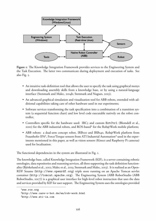
Figure 1: The Knowledge Integration Framework provides services to the Engineering System andthe Task Execution. The latter two communicate during deployment and execution of tasks. Seealso Fig. 5.
• An intuitive task-definition tool that allows the user to specify the task using graphical menysand downloading assembly skills from a knowledge base, or by using a natural-languageinterface (Stenmark and Malec, 2014b; Stenmark and Nugues, 2013);
• An advanced graphical simulation and visualization tool for ABB robots, extended with ad-ditional capabilities taking care of other hardware used in our experiments;
• Software services transforming the task specification into a combination of a transition sys-tem (a sequential function chart) and low level code executable natively on the robot con-troller;
• Controllers specific for the hardware used: IRC5 and custom ExtCtrl (Blomdell et al.,2010) for the ABB industrial robots, and ROS-based¹ for the Rob@Work mobile platform;
• ABB robots: a dual-arm concept robot, IRB120 and IRB140, Rob@Work platform fromFraunhofer IPA², Force/Torque sensors from ATI Industrial Automation³ used in the exper-iments mentioned in this paper, as well as vision sensors (Kinect and Raspberry Pi cameras)used for localization.
The functional dependencies in the system are illustrated in Fig. 1.
The knowledge base, called Knowledge Integration Framework (KIF), is a server containing roboticontologies, data repositories and reasoning services, all three supporting the task definition function-ality (Björkelund et al., 2012; Malec et al., 2013; Stenmark and Malec, 2013). It is realized as an Open-RDF Sesame (http://www.openrdf.org) triple store running on an Apache Tomcat servletcontainer (http://tomcat.apache.org). The Engineering System (ABB RobotStudio (ABBRobotStudio, 2017)) is a graphical user interface for high-level robot instruction that uses the dataand services provided by KIF for user support. The Engineering System uses the ontologies provided
¹www.ros.org²http://www.care-o-bot.de/en/rob-work.html³http://www.ati-ia.com
116
by KIF to model the workspace objects and downloads known skills and tasks from the skill libraries.Similarly, new objects and skills can be added to the knowledge base via the Engineering System.Skills that are created using classical programming tools, such as various state machine editors (like,e.g., JGrafchart (Theorin, 2014), used both as a sequential function chart (IEC, 2003)—a variant ofStatecharts (Harel, 1987)—editor, and its execution environment), can be parsed, automatically ormanually annotated with semantic data, and stored in the skill libraries.
The Task Execution module is built on top of the native robot controller and sensor hardware. Itcompiles, with the help of KIF, a symbolic task specification (like the one shown in Fig. 2) intogeneric executable files and, when needed, hardware-specific code, before executing it. It is imple-mented on a real-time-enabled Linux machine, linking the external control coming from JGrafchart(a simple example is shown in Fig. 2b) or possibly other software, with the native controller of therobot. Depending on the system state (execution or teaching mode) or the action being carried out,the control is switched between the ExtCtrl system for sensor control and the native controller,allowing smooth integration of the low-level robot code with the high-level instructions expressedusing the SFC formalism. It also runs adaption and error detection algorithms. The native robotcontroller is in our case an ABB IRC5 system running code written in the language Rapid, butany (accessible) robot controller might be used here. The Engineering System uses among othertools a sensor-based-motion compiler (Stenmark and Stolt, 2013) translating a symbolic, constraint-based (De Schutter et al., 2007) motion specification into an appropriately parametrized corre-sponding SFC and the native controller code.
In addition to the benefit of providing modular exchangeable components, the rationale behindKIF as a separate entity is that the knowledge-providing services can be treated as black boxes.Robot and system-integration vendors can offer their customers computationally expensive or data-heavy cloud-based services (Stenmark et al., 2013) instead of deploying them on every site and eachinstallation.
3 Code Generation
In order to illustrate the process of code generation, we will use an example task where a switch isassembled into the bottom of an emergency stop box. Both parts are displayed in Fig. 3a. The task isdescribed in the Engineering System as a sequence, shown earlier in Fig. 2a. First the box is pickedand aligned to a fixture with a force sensor. Then the switch is picked and assembled with the boxusing a snap-fit skill. The sequence is mixing actions (pickbox, movetofixt, pickswitch andretract) that are written in native robot controller code (ordinary blind moves), guarded searchmotions which are actions that are force-controlled (alignment to the fixture), and it also reuses asensor-based skill (snapFitSkill. In this section we present how we generate and execute codefor tasks containing these three types of actions. As an example we will use the sequence shown inFig. 2a that, when executed, requires switching between the native robot controller and the external,sensor-based control (ExtCtrl).
117

(a) The task is shown as a se-quence in Engineering System.
(b) A small part of the state chartgenerated from the sequence inFig. 2a.
(c) A sample XML description corresponding to the guardedmotion skill from Fig. 2a that is sent to the code generationservice by Engineering System. The parameter values are eitherset automatically or by the user in the Engineering System. If aguarded motion is generated, e.g., from text and one of the pa-rameters is an impedance controller, the controller is selectedamong the controller objects in the station. All mandatory pa-rameters must be specified before the code generation step.
Figure 2: A task can be created using the graphical interface of the Engineering System or by servicesfor automatic sequence generation. The sequence shown is part of an assembly of an emergency stopbutton (see next section), consisting of a synthesized guarded motion, a complex snapFitSkill andthree position-based primitives, see Fig. 2a. In Fig. 2b the step named skill1 is a macro step containingthe synthesized guarded motion skill. Before and after the actual skill the steps for starting andturning off ExtCtrl are inserted. The idle state resets all reference values of the controller. Finally,Fig. 2c presents the corresponding input to the code generation service.
118
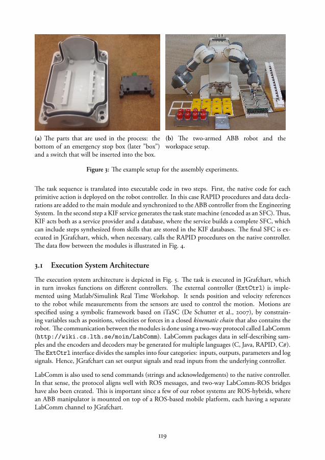
(a) The parts that are used in the process: thebottom of an emergency stop box (later ”box”)and a switch that will be inserted into the box.
(b) The two-armed ABB robot and theworkspace setup.
Figure 3: The example setup for the assembly experiments.
The task sequence is translated into executable code in two steps. First, the native code for eachprimitive action is deployed on the robot controller. In this case RAPID procedures and data decla-rations are added to the main module and synchronized to the ABB controller from the EngineeringSystem. In the second step a KIF service generates the task state machine (encoded as an SFC). Thus,KIF acts both as a service provider and a database, where the service builds a complete SFC, whichcan include steps synthesized from skills that are stored in the KIF databases. The final SFC is ex-ecuted in JGrafchart, which, when necessary, calls the RAPID procedures on the native controller.The data flow between the modules is illustrated in Fig. 4.
3.1 Execution System Architecture
The execution system architecture is depicted in Fig. 5. The task is executed in JGrafchart, whichin turn invokes functions on different controllers. The external controller (ExtCtrl) is imple-mented using Matlab/Simulink Real Time Workshop. It sends position and velocity referencesto the robot while measurements from the sensors are used to control the motion. Motions arespecified using a symbolic framework based on iTaSC (De Schutter et al., 2007), by constrain-ing variables such as positions, velocities or forces in a closed kinematic chain that also contains therobot. The communication between the modules is done using a two-way protocol called LabComm(http://wiki.cs.lth.se/moin/LabComm). LabComm packages data in self-describing sam-ples and the encoders and decoders may be generated for multiple languages (C, Java, RAPID, C).The ExtCtrl interface divides the samples into four categories: inputs, outputs, parameters and logsignals. Hence, JGrafchart can set output signals and read inputs from the underlying controller.
LabComm is also used to send commands (strings and acknowledgements) to the native controller.In that sense, the protocol aligns well with ROS messages, and two-way LabComm-ROS bridgeshave also been created. This is important since a few of our robot systems are ROS-hybrids, wherean ABB manipulator is mounted on top of a ROS-based mobile platform, each having a separateLabComm channel to JGrafchart.
119
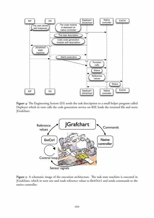
KIF ES
Native controllerKIF ES Deployer/
JGrafchart
Native controller
The user stores skill instances
The code module is deployed on
native controller
Deployer/JGrafchart
The task description
Calls code generation module with description
JGrafchart state
machine
ExtCtrl
ExtCtrl
Starts execution
Function calls
Status
Reference values
Status
Figure 4: The Engineering System (ES) sends the task description to a small helper program calledDeployer which in turn calls the code generation service on KIF, loads the returned file and startsJGrafchart.
JGrafchart
ExtCtrl Native controller
CommandsReference values
Sensor signals
Control loop
Wednesday, February 5, 14
Figure 5: A schematic image of the execution architecture. The task state machine is executed inJGrafchart, which in turn sets and reads reference values to ExtCtrl and sends commands to thenative controller.
120
3.2 Sequential function charts in JGrafchart
JGrafchart is a tool for graphical editing and execution of state charts (Theorin, 2014). JGrafchartis used for programming sensor-based skills and has a hierarchical structure where state machinescan be nested. For each robot, the generated state machine will be a sequence. Each primitive orsensor-based skill is represented by a state (step), and transitions are triggered when the primitiveaction or skill has finished. Each state can either contain a few simple commands or be a nested statemachine, put into a so called macro step (in Fig. 2b shown by a square with marked corners). Thegenerated and reused skills are put into these macro steps while primitive actions becomes simplesteps with function calls.
When alternating between sensor-based external control and the native controller, the controllersare turned on and off during the execution, so these steps need to be added as well during thegeneration phase. The switching between controllers is handled by the state machine in JGrafchart.When ExtCtrl is turned on or off, the robot has to stand still to avoid inconsistent position andvelocity values. When a controller is turned on it starts by updating its position, velocity andacceleration values to the current values on the robot.
The state machine can have parallel activities and multiple communication channels at the sametime. Hence, code can be generated for multiple tasks and executed in parallel. Although the statemachine allows synchronization between the tasks, we do not have a high-level representation ofsynchronized motions yet.
Finally, the sequence IDs and graphical elements, such as positions of the blocks, have to be addedin order to provide an editable view. We generate very simple layout, however, much more couldbe done with respect to the legibility of the generated SFCs.
3.3 Code generation service
The code generation is implemented as an online service which is called by the Engineering System.It takes an XML description with the sequence as input and outputs the XML-encoding of thesequential function chart understood by JGrafchart. An example of the input is shown in Fig. 2c.Each robot has its own task, which needs to specify what LabComm port it will connect to. Aprimitive is specified by its procedure name and parameters to the procedure. Reusable skills arereferenced by their URI, which is the unique identifier that is stored in the KIF repositories.
3.4 Reusing skills
A skill that is created in JGrafchart as a macro step, can be uploaded to KIF and reused. During theupload, it is translated into RDF triples. The skills are annotated with types, e.g., SnapFit, and skillparameters that are exposed to the users are also annotated with types and descriptions. The RDFrepresentation is a simple transformation, where each state in the state machine is an RDF nodeannotated as a State, together with parameters belonging to the state, the commands, a descriptionof the state (e.g. Search x) and is linked to transitions (which similarly are annotated with type andvalues). In this way, the parameters can be retrieved and updated externally using the graphical view
121

in the engineering system. When a skill is updated in the engineering system, the new instance isalso stored in KIF with the new parameter values. The URI in the input XML file refers to theupdated skill, that is retrieved during the code generation process and translated back from triplesto XML describing a macro step. The macro step is then parameterized and added as a step in thetask sequence XML.
3.5 Guarded motions
One drawback of using the reusable skills is that there are implicit assumptions of the robot kinemat-ics built into them, and thus the skill can only be used for the same (type of ) robot. This limitationcan be avoided by using a symbolic skill description and regenerating the code for each specificrobot. This is what we do for the guarded motions. In this case, the skill specification is larger, asshown in Fig. 2c, where three actions are described. First, a search in the negative z-direction ofthe force sensor frame (f1) is performed. When the surface is hit, the motion continues in negativey-direction of the same frame while holding 3 N in the z-direction, pushing the piece to the side ofthe sensor. The last motion is in the x-direction while both pressing down and to the side, until thepiece is lodged into the corner. In order to setup the kinematic chain, the coordinate frames thatare used to express the motions have to be set, as well as the tool transform, that is, the transfor-mation from the point where the tool is attached on the robot flange to the tip of the tool. Eachconstraint is specified along an axis of a chosen frame. There can be one motion constraint (usingthe <Direction> tag) which specifies the motion direction, speed and the threshold value for stop-ping. The other rotational and translational axes can also be constrained. The constraint shouldalso specify what set of impedance controller parameters to use. Knowing what robot the code isgenerated for, the control parameters for the kinematic chain are set to the values of the frames andeach motion sets reference values on corresponding parameters. Simply put, it is a mapping, whereseveral hundred output signals have to get a value, where most are just dependent on the robot type,while some represent the coordinates of the frames in the kinematic chain and other reference valuesduring execution. During the code generation the right value has to be set to the correspondingreference output signal and this is calculated depending on what frame is used.
3.6 RAPID code generation
The actions that have native controller code are called primitives. There are several different prim-itives and, in fact, they do not have to be simple. The most used are simple linear motions, moveprimitives for translation and rotation, and actions for opening and closing the gripper. The gripperprimitives are downloaded together with the tool. The simplest form of a primitive is pure nativecode, a RAPID primitive, which does not have any semantically described parameters but wherethe user can add arbitrary lines of code which will be called as a function in the program. This isan exception though, since most primitives are specified by their parameters. E.g., the properties ofa linear move are shown in Fig. 6. The target positions will be calculated from the objects’ CAD-models and the objects’ relative frames and positions in the virtual environment. The code for eachprimitive type and target values are synchronized to the controller as RAPID procedures and datadeclarations.
122
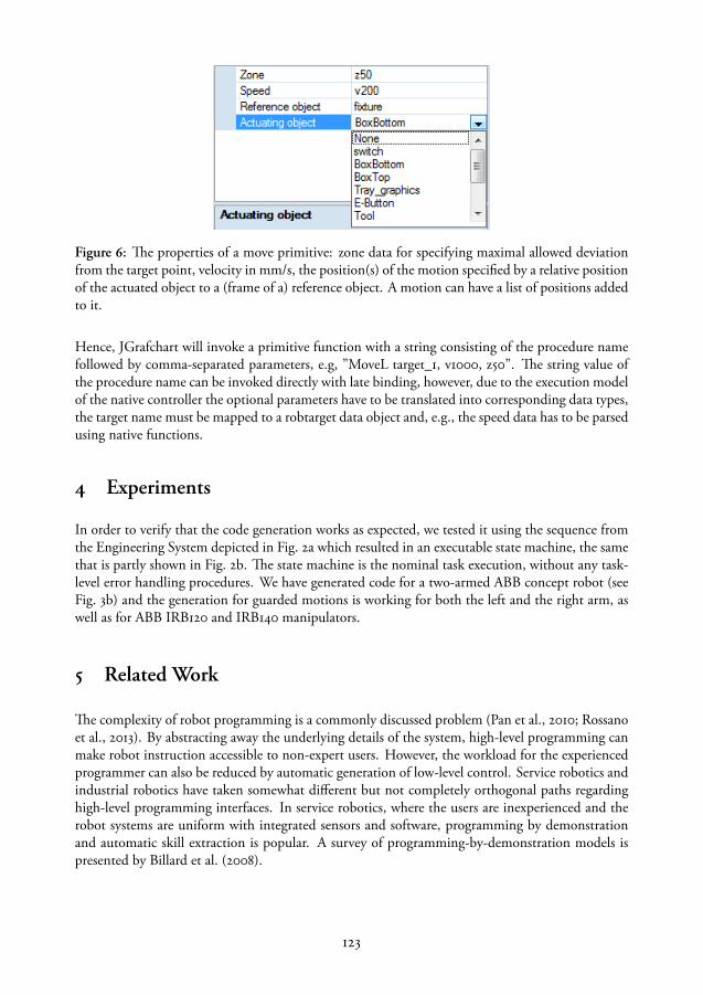
Figure 6: The properties of a move primitive: zone data for specifying maximal allowed deviationfrom the target point, velocity in mm/s, the position(s) of the motion specified by a relative positionof the actuated object to a (frame of a) reference object. A motion can have a list of positions addedto it.
Hence, JGrafchart will invoke a primitive function with a string consisting of the procedure namefollowed by comma-separated parameters, e.g, ”MoveL target_1, v1000, z50”. The string value ofthe procedure name can be invoked directly with late binding, however, due to the execution modelof the native controller the optional parameters have to be translated into corresponding data types,the target name must be mapped to a robtarget data object and, e.g., the speed data has to be parsedusing native functions.
4 Experiments
In order to verify that the code generation works as expected, we tested it using the sequence fromthe Engineering System depicted in Fig. 2a which resulted in an executable state machine, the samethat is partly shown in Fig. 2b. The state machine is the nominal task execution, without any task-level error handling procedures. We have generated code for a two-armed ABB concept robot (seeFig. 3b) and the generation for guarded motions is working for both the left and the right arm, aswell as for ABB IRB120 and IRB140 manipulators.
5 Related Work
The complexity of robot programming is a commonly discussed problem (Pan et al., 2010; Rossanoet al., 2013). By abstracting away the underlying details of the system, high-level programming canmake robot instruction accessible to non-expert users. However, the workload for the experiencedprogrammer can also be reduced by automatic generation of low-level control. Service robotics andindustrial robotics have taken somewhat different but not completely orthogonal paths regardinghigh-level programming interfaces. In service robotics, where the users are inexperienced and therobot systems are uniform with integrated sensors and software, programming by demonstrationand automatic skill extraction is popular. A survey of programming-by-demonstration models ispresented by Billard et al. (2008).
123
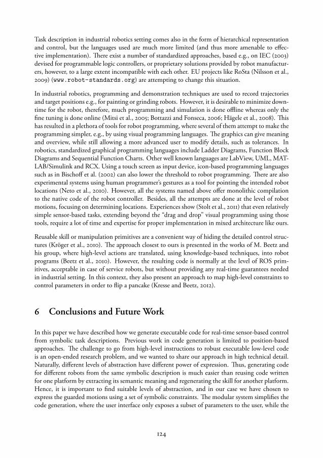
Task description in industrial robotics setting comes also in the form of hierarchical representationand control, but the languages used are much more limited (and thus more amenable to effec-tive implementation). There exist a number of standardized approaches, based e.g., on IEC (2003)devised for programmable logic controllers, or proprietary solutions provided by robot manufactur-ers, however, to a large extent incompatible with each other. EU projects like RoSta (Nilsson et al.,2009) (www.robot-standards.org) are attempting to change this situation.
In industrial robotics, programming and demonstration techniques are used to record trajectoriesand target positions e.g., for painting or grinding robots. However, it is desirable to minimize down-time for the robot, therefore, much programming and simulation is done offline whereas only thefine tuning is done online (Mitsi et al., 2005; Bottazzi and Fonseca, 2006; Hägele et al., 2008). Thishas resulted in a plethora of tools for robot programming, where several of them attempt to make theprogramming simpler, e.g., by using visual programming languages. The graphics can give meaningand overview, while still allowing a more advanced user to modify details, such as tolerances. Inrobotics, standardized graphical programming languages include Ladder Diagrams, Function BlockDiagrams and Sequential Function Charts. Other well known languages are LabView, UML, MAT-LAB/Simulink and RCX. Using a touch screen as input device, icon-based programming languagessuch as in Bischoff et al. (2002) can also lower the threshold to robot programming. There are alsoexperimental systems using human programmer’s gestures as a tool for pointing the intended robotlocations (Neto et al., 2010). However, all the systems named above offer monolithic compilationto the native code of the robot controller. Besides, all the attempts are done at the level of robotmotions, focusing on determining locations. Experiences show (Stolt et al., 2011) that even relativelysimple sensor-based tasks, extending beyond the “drag and drop” visual programming using thosetools, require a lot of time and expertise for proper implementation in mixed architecture like ours.
Reusable skill or manipulation primitives are a convenient way of hiding the detailed control struc-tures (Kröger et al., 2010). The approach closest to ours is presented in the works of M. Beetz andhis group, where high-level actions are translated, using knowledge-based techniques, into robotprograms (Beetz et al., 2010). However, the resulting code is normally at the level of ROS prim-itives, acceptable in case of service robots, but without providing any real-time guarantees neededin industrial setting. In this context, they also present an approach to map high-level constraints tocontrol parameters in order to flip a pancake (Kresse and Beetz, 2012).
6 Conclusions and Future Work
In this paper we have described how we generate executable code for real-time sensor-based controlfrom symbolic task descriptions. Previous work in code generation is limited to position-basedapproaches. The challenge to go from high-level instructions to robust executable low-level codeis an open-ended research problem, and we wanted to share our approach in high technical detail.Naturally, different levels of abstraction have different power of expression. Thus, generating codefor different robots from the same symbolic description is much easier than reusing code writtenfor one platform by extracting its semantic meaning and regenerating the skill for another platform.Hence, it is important to find suitable levels of abstraction, and in our case we have chosen toexpress the guarded motions using a set of symbolic constraints. The modular system simplifies thecode generation, where the user interface only exposes a subset of parameters to the user, while the
124
JGrafchart state machine contains the calculated reference values to the controllers and coordinatesthe high-level execution. The external controller is responsible for the real-time sensor control whichis necessary for achieving the necessary performance for assembly operations.
In future work we plan to experiment using a mobile platform running ROS together with our dual-arm robot and thus evaluate how easy it is to extend the code generation to simultaneously supportother platforms. The sequence can express control structures, such as loops and if-statements, on-going work involves adding these control structures to the task state machine as well as describingand generating the synchronization between robots.
The robustness of the generated skills depends on the user input. One direction of future work isto couple the graphical user interface with haptic demonstrations and learning algorithms in orderto extract e.g., force thresholds and impedance controller parameters. Another direction is to addknowledge and reasoning to the system to automatically generate error handling states to the taskstate machine.
7 Acknowledgments
The research leading to these results has received partial funding from the European Union’s seventhframework program (FP7/2007-2013) under grant agreements No. 285380 (project PRACE) and No.287787 (project SMErobotics). The third author is a member of the LCCC Linnaeus Center andthe eLLIIT Excellence Center at Lund University.
The work described in this paper has been done in tight collaboration with other researchers fromthe project consortia. The authors are indebted for many fruitful discussions.
The authors are grateful to Anders Robertsson for careful proofreading.
125


Paper iv


Paper IV
Simplified Programming of Re-usable Skills on a Safe IndustrialRobot – Prototype and Evaluation
Maj Stenmark Mathias Haage Elin Anna Topp
Department of Computer ScienceLund University
[email protected]@[email protected]
ABSTRACT
This paper presents a study on iconic programming support for mainly position-based lead-throughprogramming of an ABB YuMi collaborative robot. A prototype tool supporting a hybrid program-ming and execution mode was developed and evaluated with 21 non-expert users with varying pro-gramming and robotics experience. We also present a comparison of the programming times for anexpert robot programmer using traditional tools versus the new tool. The expert programmed thesame tasks in 1/5 of the time compared to traditional tools and the non-experts were able to programand debug a LEGO building task using the robot within 30 minutes.
Proc. of the IEEE/ACM Conference on Human-Robot Interaction, 463 – 472, 2017.DOI: http://dx.doi.org/10.1145/2909824.3020227.

1 Introduction
In recent years, we have had a renaissance in industrial robotics: a new segment of robot models(e.g., UR5, ABB YuMi, Rethink Robotics’ Baxter and KUKA’s LBR iiwa) intended for safe human–robot collaboration and simpler robot programming have emerged. The application areas for theserobot models are typically assembly of consumer electronics or repackaging of (small) products.One difference between these robots and previous models is the lead–through programming, orkinesthetic teaching, mode. In this mode, the user can guide the robot arm into the desired positionsand thus record and replay a robot program.
Kinesthetic teaching using force-guided motions (Massa et al., 2015), gravity compensation andvariable stiffness (Wrede et al., 2013; Tykal et al., 2016) support also non-expert operators to programand configure tasks (Rodamilans et al., 2016), however, dynamic environments, uncertainty and theuse of noisy sensor feedback are still challenges for the operator (Stenmark et al., 2016), and so far,experts are still needed to program the robots on the necessary levels of robustness and precision.
Programming by demonstration, PbD, or learning from demonstration, LfD (Billard et al., 2016),is a well-established concept in service robotics, however, these methods often require multipledemonstrations which we consider less suitable in an industrial setting where rapid instruction andevaluation is needed. The desired approach in an industrial context is rather a one–shot demonstra-tion, from which enough parameters for an executable representation can be extracted.
Orthogonal to the PbD approach is the use of high–level instructions to simplify robot program-ming for industrial tasks, e.g., using natural language (Stenmark and Nugues, 2013) and semanticallydefined parameterized motion primitives (Felip et al., 2013), often called skills (Pedersen et al., 2014,2016). Such semantic descriptions are desirable because they enable the automatic generation of,e.g., standard PDDL¹–descriptions for planning and scheduling of tasks or path planning and gen-eration from virtual models (Perzylo et al., 2016).
We propose to aim for a middle ground by combining programming by demonstration and parametrizedskill representations to simplify robot programming, i.e., it must be possible for non-expert users tocreate their own skills from scratch and specify object references that can later be used as basic buildingblocks in high–level approaches.
In this paper we present a prototype of a programming tool for industrial robots, which enablesnon–expert users to program and edit simple industrial tasks using one–shot demonstrations, i.e.,kinesthetic teaching, and also reduces the programming and debugging time for an expert program-mer. We extracted initial requirements regarding functionality and behavior for the design of thistool from two case studies and evaluated it in two experiments with an expert user and in a studywith 21 non–experts.
The remainder of the paper is organized as follows. In Section 2 we present the background andrelated work for our efforts. We present the case studies for extraction of requirements in Section 3and our resulting prototype implementation in Section 4. In Section 5 we report on the evaluationof the tool through a user study with 21 subjects and by two expert experiments. We conclude thepaper in Section 6 with a discussion of our findings and suggestions for future work.
¹Planning Domain Definition Language
131

2 Related Work
The research into intuitive human-robot interaction and programming is so far more active in thefield of service robotics, since service robots act in dynamic non-structured environments and areintended to interact with non-expert operators. Some of the following approaches are nonethelessrelevant also for work in intuitive programming of industrial robots.
For instance, robots can learn from humans by observing the human carrying out a task and extractaction parameters and objects involved in this process. Billard et al. (2016) use objects and locationsas task parameters and can extract these in a new workspace from human demonstrations. Fenielloet al. (2014) synthesize the program specification for repositioning tasks from examples, e.g., theirsystem can learn a program sequence that sorts objects by color. Visuospatial skill learning is alsoused by Ahmadzadeh et al. (2015) to extract the geometric constraints of the objects in a task and tolearn the sequence of push and pull skills in a task. Using Gaussian mixture regression, trajectories canbe generated from the learning results (Huang et al., 2016a). From multiple demonstrations, high-level semantics such as intentions (Fonooni et al., 2016), transition conditions (Kober et al., 2015)and precedence constraints for sequencing of manipulation primitives (Kramberger et al., 2016;Manschitz et al., 2014) can be extracted. Niekum et al. (2015) segment demonstrations automaticallyusing (beta process autoregressive) Hidden Markov Models, learn the reference coordinates for eachtrajectory from clustering the demonstrations in different coordinate frames and iteratively refinethe resulting finite state machine based on new demonstrations.
Low-level skills can be encoded as dynamic movement primitives (DMPs) (Ijspeert et al., 2002)demonstrated using, e.g., Imitation Learning and further optimized using Reinforcement Learning.Examples of research in imitation learning methods for robot skill learning are given by Kormushevet al. (2011), who combine kinesthetic learning of positional trajectories with force profiles demon-strated using a haptic input device to demonstrate ironing skills. Steinmetz et al. (2015) use anexternal force/torque sensor mounted on the robot arm to record force and position simultaneouslyand learn the force profiles for a PID-controller. Abu-Dakka et al. (2014) redeploy peg-in-hole skillsin new settings by adding exception strategies that randomly search for the hole to improve robust-ness. Nemec et al. (2013) use a priori knowledge and reinforcement learning to reduce the numberof demonstrations needed to teach a flip task to a robot and Pastor et al. (2011) use reinforcementlearning to optimize a pool strike. All these methods, however, focus on one specific type of move-ment or task, each of which requiring a specific setup. Additionally, data driven approaches requiremultiple demonstrations with enough feature variation to extract task parameters and specifically forreinforcement learning based approaches it is a challenging problem to design a good cost function(which needs to be either taught or manually tuned).
Multiple demonstrations are time consuming, hence a one-shot approach is desired. Also, industrialtasks often require high precision, which can be difficult to achieve from generalizations betweenmultiple demonstrations and the underlying representation of instructions must support adaptionand debugging. Ko et al. (2015) list and motivate the main qualitative aspects of a programming (bydemonstration) system that have to be evaluated, namely: accuracy and repeatability, adaptabilityand generality, learning fatigue, system complexity and production speed .
Tsarouchi et al. (2016) identify various challenges in the human-robot interaction for industrialrobots, and while e.g., multimodal communication and learning by demonstration have received
132
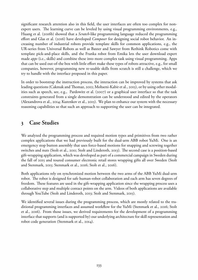
significant research attention also in this field, the user interfaces are often too complex for non-expert users. The learning curve can be leveled by using visual programming environments, e.g.,Huang et al. (2016b) showed that a Scratch-like programming language reduced the programmingeffort and Glas et al. (2016) have developed Composer for designing social robot behavior. An in-creasing number of industrial robots provide template skills for common applications, e.g., theUR-series from Universal Robots as well as Baxter and Sawyer from Rethink Robotics come withtemplate pick-and-place skills, and the Franka robot from Emika lets the user download expertmade apps (i.e., skills) and combine these into more complex task using visual programming. Appsthat can be used out-of-the box with little effort make these types of robots attractive, e.g., for smallcompanies, however, programming new re-usable skills from scratch is still a challenge, which wetry to handle with the interface proposed in this paper.
In order to bootstrap the instruction process, the interaction can be improved by systems that askleading questions (Cakmak and Thomaz, 2012; Mohseni-Kabir et al., 2015), or by using other modal-ities such as speech, see, e.g., Pardowitz et al. (2007) or a graphical user interface so that the taskconstraints generated from a single demonstration can be understood and edited by the operators(Alexandrova et al., 2014; Kurenkov et al., 2015). We plan to enhance our system with the necessaryreasoning capabilities so that such an approach to supporting the user can be integrated.
3 Case Studies
We analyzed the programming process and required motion types and primitives from two rathercomplex applications that we had previously built for the dual-arm ABB robot YuMi. One is anemergency stop button assembly that uses force-based motions for snapping and screwing togetherswitches and nuts (Stolt et al., 2011; Stolt and Linderoth, 2013). The second case is a position-basedgift-wrapping application, which was developed as part of a commercial campaign in Sweden duringthe fall of 2015 and toured consumer electronic retail stores wrapping gifts all over Sweden (Stoltand Stenmark, 2015; Stenmark et al., 2016; Stolt et al., 2016).
Both applications rely on synchronized motion between the two arms of the ABB YuMi dual-armrobot. The robot is designed for safe human-robot collaboration and each arm has seven degrees offreedom. These features are used in the gift-wrapping application since the wrapping process uses acollaborative step and multiple contact points on the arm. Videos of both applications are availablethrough YouTube (Stolt and Linderoth, 2013; Stolt and Stenmark, 2015).
We identified several issues during the programming process, which are mostly related to the tra-ditional programming interfaces and assumed workflow for the YuMi (Stenmark et al., 2016; Stoltet al., 2016). From those issues, we derived requirements for the development of a programminginterface that supports (and is supported by) our underlying architecture for skill representation androbot code generation (Stenmark et al., 2014).
133

3.1 Traditional interfaces and interaction
The ABB robot can be programmed in the ABB programming language RAPID either using anengineering tool called RobotStudio, a Windows Universal App (YuMi Online) or by using the teachpendant (an integrated joystick and touch display interface for direct robot control, a standard pieceof equipment usually accompanying industrial robots, see Figure 1), directly. RobotStudio and theapp can run on the same Windows device and are connected to the robot through a local network.Each of the tools has different features. RobotStudio is intended for editing RAPID programs andfor simulation. The app has an online programming interface supporting a few commands (motionsand gripper actions) and has a limited debugging support. It has however a kinesthetic programmingmode, lead-through, which makes it easy to teach positions in free space. Contact situations aremore suitable to teach with the joystick on the teach pendant since contact forces will move thearms out of position if lead-through is enabled. The teach pendant can also be used for debugging,for example by moving the program pointer and executing instructions one-by-one.
The traditional workflow starts with offline programming and simulation before deploying a pro-gram on the physical robot. First, the program can be written and executed in the virtual environ-ment in RobotStudio. When the user is satisfied, the program is deployed on the physical systemand testing in the real environment can begin. User interaction can be added into the RAPID pro-gram by inserting dialogue prompts into the program. Then the resulting program can be deployedin the factory and the robot operator will only interact with the robot using the dialogues. All errorhandling procedures need to be added beforehand by the programmer.
It is not trivial to include (contact) forces and deformable material into simulations, hence, ourapplications required online programming, i.e., testing and updating using the physical robot systemincluding the lead-through functionality for kinesthetic teaching of poses, which was non-trivialwith the given interfaces due to their different features. Specifically, in the gift-wrapping applicationthe programmers were required to sometimes circumvent the safety mechanisms originally designedfor unsafe robots, but still deployed on the inherently safe YuMi.
Figure 1: ABB’s (YuMi’s) teach pendant (left) and YuMi in the LEGO building task (right).
134
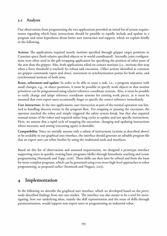
3.2 Analysis
Our observations from programming the two applications provided an initial list of system require-ments regarding which basic instructions should be possible to rapidly include and update in aprogram and some hypotheses about better user interaction and support, which we explain brieflyin the following.
Actions: The applications required mostly motions specified through gripper target positions inCartesian space (both relative specified objects or in world coordinated). Secondly, joint configura-tions were often used in the gift-wrapping application for specifying the position of other parts ofthe arm than the gripper. Also, both applications relied on contact motions (i.e., motions that stopwhen a force threshold is reached) for robust task execution. Other actions identified as commonare gripper commands (open and close), movement to synchronization points for both arms, andsynchronized motions of both arms.
Reuse, refinement and update: In order to be able to reuse a task, i.e., a program sequence withsmall changes, e.g., in object positions, it must be possible to specify work objects so that motionprimitives can be programmed using relative reference coordinate systems. Also, it must be possibleto easily change and adapt reference coordinate systems for existing work pieces, as it must beassumed that even expert users occasionally forget to specify the correct reference immediately.
User interaction: In the two applications, user interaction as part of the normal operation was lim-ited to handling discrete events in the program flow. For stopping or pausing the execution, theoperator touched the robot and simply triggered the safety system break, but that also requiredmanual restart of the robot and required rather long cycles to update and test specific instructions.Here, we assume that a rapid cycle of stopping the execution, changing and updating instructionswhere necessary and testing (executing again) is desirable.
Compatibility: Since we initially assume only a subset of instructions (actions as described above)to be available in our graphical user interface, the interface should generate an editable program filethat an expert user can refine further by using the traditional tools and interfaces.
Based on this list of observations and assumed requirements, we designed a prototype interfacesupporting users in quickly creating basic programs (skills) through kinesthetic teaching and iconicprogramming (Stenmark and Topp, 2016). These skills can then later be refined and form the basisfor more complex programs, which can be generated using even more high-level approaches to robotprogramming, as proposed earlier (Stenmark and Nugues, 2013).
4 Implementation
In the following we describe the graphical user interface, which we developed based on the previ-ously described findings from our case studies. The interface was also meant to be a tool for inves-tigating, how our underlying ideas, mainly the skill representation and the reuse of skills throughparameterization, would support non-expert users in programming an industrial robot.
135

A screen capture of the implemented programming tool is shown in Fig. 2. It is implemented as atouch-enabled Windows app running on a Surface Pro with 8 GB RAM and a wireless connectionto the robot controller. The implementation is programmed in C and uses ABB robot controllerlibraries for network communication and math calculations.
4.1 Features
The graphical interface divides the screen into an instruction panel to the left and a program panelto the right. In the upper left corner, the built-in basic actions are displayed in yellow, while theuser-created skills (sequences and combinations of such primitives or other skills) are added to thelist in purple. The default actions are the following:
Move: a fine-point slow move. When this instruction is added to the robot program sequence, ittakes the current position of the active arm and saves it as precise goal position (trajectories betweenspecified points are generated by the robot controller so far). The target is saved with three positions:the exact joint position for the robot arm, the Cartesian position relative to the world (or robot base)system and, if an object is selected, the position relative to the object. Thus, the user can switchcoordinate systems between objects or to absolute positions, or between Cartesian and joint spacemotions without updating the position.Via: a fast motion with zone parameter 5 mm as default, i.e., getting close to the specified posewithin this zone is considered sufficient. Analogously to the fine-point move, the position is savedin absolute and relative coordinates as well as in joint space.Open and Close for fully opening and closing the gripper. The gripper action will execute whenadded to the program.Contact Move: a movement towards a contact point which will stop when detecting an estimatedcontact force. The current position of the robot will be used to set a contact position, but the motionwill continue beyond that point.Sync: adds synchronization points, i.e., points in the program sequence where both arms shouldreach the specified pose at the same time.Fingers: an action for setting the finger positions exactly and changing the gripping force of thefingers.Locate objects: will call a local procedure on the robot controller for detecting objects using thebuilt-in cameras on the robot’s hands. For the time being, the camera calibration, image settings anddetection algorithms must be provided by an expert and reloaded into the controller. The detectedobject’s reference system will, however, be updated each time the procedure is executed hence theuser can use the object references to program the robot without considering the underlying code.
Under the actions, the user can add coordinate frames related to objects by pointing with the robot.These can be updated when the object is moved.
The current robot programs for respective arms are displayed to the right. Each action has a linewith an individual play arrow, an editable name, a color label for the relative coordinate system, abutton for updating the position, editing and a picture. The order of the sequence can be edited bydragging and dropping.
136
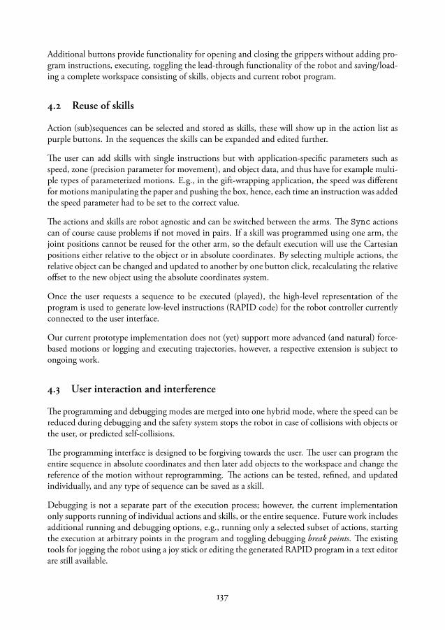
Additional buttons provide functionality for opening and closing the grippers without adding pro-gram instructions, executing, toggling the lead-through functionality of the robot and saving/load-ing a complete workspace consisting of skills, objects and current robot program.
4.2 Reuse of skills
Action (sub)sequences can be selected and stored as skills, these will show up in the action list aspurple buttons. In the sequences the skills can be expanded and edited further.
The user can add skills with single instructions but with application-specific parameters such asspeed, zone (precision parameter for movement), and object data, and thus have for example multi-ple types of parameterized motions. E.g., in the gift-wrapping application, the speed was differentfor motions manipulating the paper and pushing the box, hence, each time an instruction was addedthe speed parameter had to be set to the correct value.
The actions and skills are robot agnostic and can be switched between the arms. The Sync actionscan of course cause problems if not moved in pairs. If a skill was programmed using one arm, thejoint positions cannot be reused for the other arm, so the default execution will use the Cartesianpositions either relative to the object or in absolute coordinates. By selecting multiple actions, therelative object can be changed and updated to another by one button click, recalculating the relativeoffset to the new object using the absolute coordinates system.
Once the user requests a sequence to be executed (played), the high-level representation of theprogram is used to generate low-level instructions (RAPID code) for the robot controller currentlyconnected to the user interface.
Our current prototype implementation does not (yet) support more advanced (and natural) force-based motions or logging and executing trajectories, however, a respective extension is subject toongoing work.
4.3 User interaction and interference
The programming and debugging modes are merged into one hybrid mode, where the speed can bereduced during debugging and the safety system stops the robot in case of collisions with objects orthe user, or predicted self-collisions.
The programming interface is designed to be forgiving towards the user. The user can program theentire sequence in absolute coordinates and then later add objects to the workspace and change thereference of the motion without reprogramming. The actions can be tested, refined, and updatedindividually, and any type of sequence can be saved as a skill.
Debugging is not a separate part of the execution process; however, the current implementationonly supports running of individual actions and skills, or the entire sequence. Future work includesadditional running and debugging options, e.g., running only a selected subset of actions, startingthe execution at arbitrary points in the program and toggling debugging break points. The existingtools for jogging the robot using a joy stick or editing the generated RAPID program in a text editorare still available.
137

Figure 2: The graphical user interface.
5 Evaluation and User Study
The programming interface was evaluated by comparing programming times for one expert whoprogrammed two robot tasks using both the new interface and traditional programming methodsand through a user study with 21 non-expert, although technically or mathematically interested andexperienced, users in a LEGO building task.
We see this study as an opportunity to observe potential users interacting with an industrial robotin a realistic setting, as the LEGO building task, although seemingly a child’s play, has quite somechallenges similar to those of assembling smaller products like, e.g., mobile phones. In the followingparagraphs, we describe the study setup which had the original background of testing the effects ofskill re-use and parameterization for non-expert programming of assembly tasks for industrial robots(Stenmark and Topp, 2016). We will thus in the following explain the different conditions for testingour hypotheses on the re-use of skills and break down our results by these conditions, but we had torealize that the study turned out to be as much an evaluation of the interface’s general applicabilityas it was a tool for testing our original hypotheses. Thus, we focus on the rather general results aboutthe overall benefits of our approach for non-expert programming of industrial robots and on theresults we could achieve in the experiments carried out by the expert.
138

5.1 Study setup
We recruited our subjects mainly from an undergraduate (introductory) course on robotics andthrough advertising at the departments of Computer Science and Automatic Control at our uni-versity to ensure a somewhat technical or software oriented background. Here, we assume that thiswould be the case also for prospective users (instructors) of this type of robots in industrial contexts.However, we had the subjects fill in a questionnaire to also collect data about how they ranked theirown experience with programming and technical equipment, to get a more accurate understandingregarding their background.
Our subjects were asked to program one arm on a dual-arm ABB YuMi with standard grippersto assemble different types of LEGO Duplo bricks using the robot’s lead-through mechanism forkinesthetic teaching of poses in combination with our graphical interface for iconic programming.Figure 1 shows the setup for the study with the robot just finishing one step of the overall task.Routines for locating two specific types of LEGO bricks with the help of the built-in camera of therobot gripper were already provided by the experiment leaders as functionalities to be invoked byinserting a respective instruction in the program sequence. This was done for convenience as thecamera calibration procedure is quite tedious and time consuming and should not be part of thestudy. The LEGO piece localization procedures had the arm move to a predefined position, fromwhere the pieces could be localized robustly, given that they were placed within a coarsely sketchedarea. This allowed to specify pick-up poses relative to the work piece. We are aware that this is quitesophisticated knowledge about robotic systems to be handled for non-experts, however, it gave us theopportunity to observe how our subjects could be supported by our interface in switching betweenreference coordinate frames for the different objects involved in the task.
Conditions and specific tasks
The overall task was carried out in two phases: The first phase was the same for all participants whilethe second phase divided the users evenly into three groups corresponding to the three different testconditions. During the first phase, the instructions were to program the robot arm to pick up aLEGO Duplo “2x2” piece (referred to as “small LEGO”) and insert it on top of another small piece,which was already the top of a little “tower” (task step 1). This program should then be used tocreate a skill, i.e., a re-usable representation of a sequence of motion primitives. For the secondphase, the participants were asked to program the robot arm to carry out the same task anotherthree times, but with a “2x4” piece (“large LEGO”), which should be placed first “centered” (step2), then “hanging over on the left” (step 3), and finally “hanging over on the right” (step 4) withrespect to the “tower top”. For these three steps, the different conditions defined the programmingparadigm, i.e., the first group, Group A, was to re-use and refine their own previously created skills,Group B was to re-use an expert-made skill and Group C was a control group in which participantsshould program each step from scratch without re-use of previously created and saved skills.
The instructions were given in written form, for each phase separately. After reading the instructionsfor step 1 the participants were introduced to the robot and the programming interface by one of theexperiment leaders for a couple of minutes and then started to work on their tasks. The experimentleader observed the process, both to be able to resolve technical problems (the robot stops and needs
139

Figure 3: Participants’ background and gender (left), experience and comfort level ratings (middle),and experience in programming a robot (right).
to be reset when it collides with any obstacle) and to assist the subjects with the handling of theprogramming tool in case they needed help (the tool has no built-in “help” functionality so far).Upon completion of step 1 and if the time frame allowed, the participants received the instructionsfor steps 2–4.
From pilot testing with involved researchers we had estimated that roughly 30 minutes for the actualprogramming was a suitable time limitation for each participant, however, this had the effect thatin quite some cases the participants would not reach far enough into the second phase to completeall four programming steps. In this paper, we will thus focus on rather general evaluation criterialike success rate and time needed for completion in the first phase, and how many further steps thesubjects managed to complete before running out of time. A more thorough analysis regarding theeffect of the different methods and the subjects’ individual ways of handling the task steps of thesecond phase is planned as future work.
After either completing all four steps or running out of time, we asked our subjects to fill in aquestionnaire with both demographic questions (gender, occupation) and several five–level scalequestions ranging from “not at all” to ”absolutely” about their previous experiences with robots orprogramming, and the level of comfort they felt when handling the robot. Additionally, there wasone yes/no question on whether they had ever programmed a physical robot before. We also gavethem the opportunity to explain in free text what they found most difficult and what they wouldsuggest to be changed in the programming interface.
Analysis
We had 21 participants (five female, 16 male), seven in each of the condition groups A, B, andC respectively. Figure 3 shows the distribution of professional background and gender as well aswhether they had any previous experience of robot programming. The two participants with a non-technical professional background registered as communicator and nurse / kindergarten teacherrespectively.
140
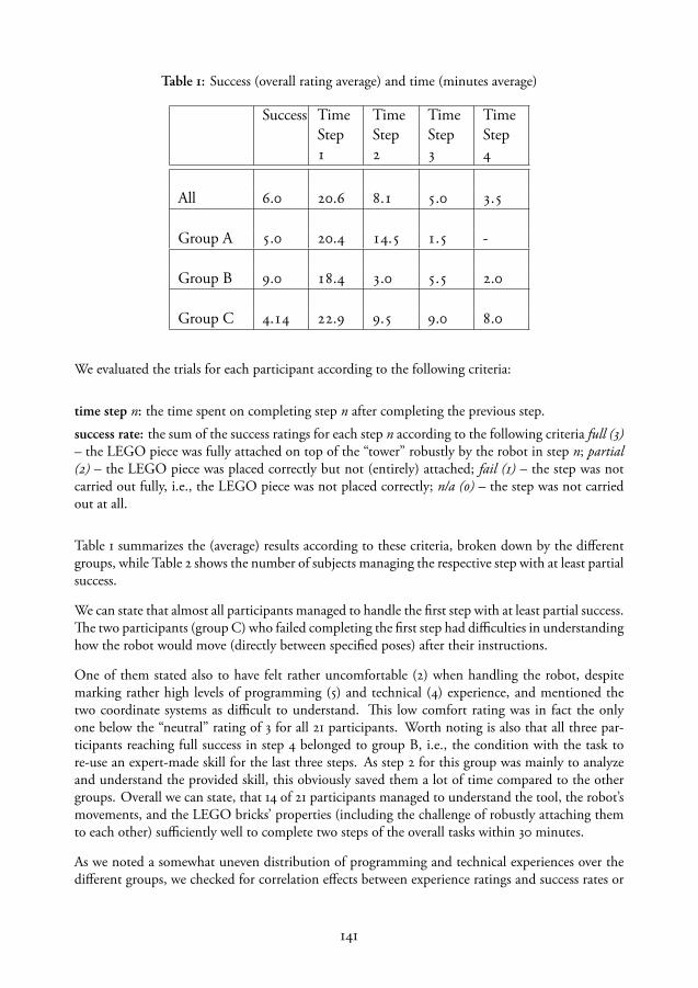
Table 1: Success (overall rating average) and time (minutes average)
Success TimeStep
TimeStep
TimeStep
TimeStep
All . . . . .
Group A . . . . -
Group B . . . . .
Group C . . . . .
We evaluated the trials for each participant according to the following criteria:
time step n: the time spent on completing step n after completing the previous step.success rate: the sum of the success ratings for each step n according to the following criteria full (3)– the LEGO piece was fully attached on top of the “tower” robustly by the robot in step n; partial(2) – the LEGO piece was placed correctly but not (entirely) attached; fail (1) – the step was notcarried out fully, i.e., the LEGO piece was not placed correctly; n/a (0) – the step was not carriedout at all.
Table 1 summarizes the (average) results according to these criteria, broken down by the differentgroups, while Table 2 shows the number of subjects managing the respective step with at least partialsuccess.
We can state that almost all participants managed to handle the first step with at least partial success.The two participants (group C) who failed completing the first step had difficulties in understandinghow the robot would move (directly between specified poses) after their instructions.
One of them stated also to have felt rather uncomfortable (2) when handling the robot, despitemarking rather high levels of programming (5) and technical (4) experience, and mentioned thetwo coordinate systems as difficult to understand. This low comfort rating was in fact the onlyone below the “neutral” rating of 3 for all 21 participants. Worth noting is also that all three par-ticipants reaching full success in step 4 belonged to group B, i.e., the condition with the task tore-use an expert-made skill for the last three steps. As step 2 for this group was mainly to analyzeand understand the provided skill, this obviously saved them a lot of time compared to the othergroups. Overall we can state, that 14 of 21 participants managed to understand the tool, the robot’smovements, and the LEGO bricks’ properties (including the challenge of robustly attaching themto each other) sufficiently well to complete two steps of the overall tasks within 30 minutes.
As we noted a somewhat uneven distribution of programming and technical experiences over thedifferent groups, we checked for correlation effects between experience ratings and success rates or
141

Table 2: The number of subjects reaching success rating 3-2-1 respectively in the different steps.
Step Step Step Step -- -- -- --
All --
--
-- --
Group A -- -- -- --
Group B -- -- -- --
Group C -- -- -- --
time needed for the different steps respectively, but we could not find any obvious connections;programming experience, technical experience and robot programming experience had all a verylow negative correlation (-0.18, -0.18, and -0.23) with time for completion of step 1 and a slightlystronger, but still very low, positive correlation (0.24, 0.22, and 0.33) with the overall success rate.Thus, we consider the different outcomes for the groups as an indication for an effect of the differentconditions, i.e., being able to reuse previously programmed or even provided skill representationssimplifies the programming process significantly, as the subjects in the control group (C) neededroughly the same amount of time for each step in the second phase, when programming fromscratch.
In group A, who should re-use their own previously created step1 skill for the following steps, thesubjects needed some time to handle the updating and parametrization of the skill in step 2, butonce they had understood how to do this, the following steps were handled within rather short timeframes, which were even shorter than those for group B, who otherwise had very high success rates,but had to understand and update a program that they were not familiar with from the beginning.However, sample sizes are small and became even smaller over the different steps, hence, these resultsshould be seen with some caution and treated as trend indications rather than definite findings.
Specific challenges and observations
As indicated above, all participants but one felt at least neutral, if not comfortable, when han-dling and programming the robot. We consider this a confirmation for the overall idea of combin-ing kinesthetic teaching with iconic programming in an interactive way, i.e., allowing for frequentswitches between execution, testing / debugging and further instruction, is a good starting point forfurther development of the tool. However, we also have to see the comments (and observations)regarding the challenges the subjects experienced, which we summarize in the following, accordingto how often they were mentioned (high frequency first).
142

Precise positioning and fixating of the LEGO piece Many subjects mentioned the placement of thepiece as a challenge. In fact, attaching two LEGO bricks to each other robustly with slippery robotgrippers is tricky, and the success seems to depend a lot on whether the respective subject coulddetermine a good strategy from the LEGO properties (the piece clicks best into place when being“folded” and then pressed, rather than through hovering over the target and moving straight down atonce). The expert–made skill provided for group B followed this strategy, and worked very robustly(it merely took the expert—one of the researchers involved in the study setup—roughly two minutesto create this skill). Here, we plan to equip a future high–level interface for programming with thecapability of providing suggestions based on previously known skills for similar work pieces to findthe optimal strategy for a given work piece.
Different reference coordinate frames and switching between them As mentioned before, we are awarethat selecting relevant coordinate frames is quite a challenge for any non–expert user, however, wecan now, based on our observations of how the subjects managed to solve the problem and howexactly they could be supported, design further support based on reasoning and mixed–initiative in-teraction into future tools. We also observed, that many subjects simply forgot to assign the correctcoordinate system, even though they understood how relative motions work. This was anticipatedin the design of the tool, allowing the user to switch reference frames for an already existing move-ment, which made it very easy to correct the program after an issue with the reference frames wasdiscovered.
Understanding all functionalities of the tool in the limited time frame, handling the interface This sug-gests that we might even have had better results, had the subjects been given more time to “play”with the tool. Some stated also informally after finishing, that “now, it would be great to start over,now I have understood this!”.
Pose recording vs trajectory recording, understanding robot movement Some of the subjects, as alsomentioned above, struggled to understand the concept of specifying positions to move to ratherthan trajectories to move along. In particular, the “contact move” posed a challenge as it resultsin a movement towards a virtual projection of a desired pose beyond the contact point. Furtherdevelopment of respective tools to include trajectory and contact force profile teaching is ongoingwork.
Robustness, compensating for the LEGO piece sometimes slipping from the gripper As we did not makeuse of specifically designed grippers for LEGO-bricks, this was obviously a problem in some cases.It could be compensated for only through a good picking and placing strategy that would be robustto the slipping. Using more appropriate tools on the robot for grasping specific work pieces isobviously a good strategy, and is subject to investigations within the project work for the ongoingSARAFun project (SARAFun).
We see quite some of the challenges pointed out by our subjects as concrete confirmation of as-sumptions we had regarding obvious points to work with in the future.
In addition to not finding a strong correlation between experience and success rates, we observedthat the one person with the least technical background not only felt very comfortable (4) when pro-gramming the robot, but also managed to complete all four steps of both phases within 21 minuteswith full success. On the other hand, we observed highly experienced PhD students in AutomaticControl struggling with the task for significantly longer periods of time and had one participantwith high experience ratings failing in the first step already.
143

Figure 4: Paper folding (left). When rotating the box, only two positions must be updated (right).
In a sideline of the study, we had one nine-year old child test the interface in the study setup. Thechild, while certainly an expert in LEGO building, was not a proper study participant due to a lackof English reading capabilities, but managed with only a little help regarding the switch of refer-ence coordinate frames and the use of the contact move to program the first step (picking up andinserting the 2x2-piece on top of the “tower”) within 20 minutes.
Boldly speaking, these observations seem to suggest that understanding of the task and assuming therobot to follow kinesthetic instructions as precisely as a (fellow, smaller) child, rather than assumingit being capable of understanding complex instructions, made it easier for the subjects to solve thetask. In the following we will present the evaluation of the programming tool carried out by anexpert user, before drawing conclusions from our findings.
5.2 Expert evaluation
One of the case studies we presented in section 3, the gift-wrapping task, formed the basis for theevaluation of the programming tool by an expert who is quite familiar both with programmingYuMi in the traditional way using a teach pendant and coding directly in RAPID as well as with thespecifics of the gift-wrapping process. For the evaluation, a folding task was chosen, where the rightarm fixated a gift box with the elbow while the left straightened the corners using nine positions(fine and via), as illustrated in Figure 4. The operator used the programming tool presented in thispaper to add a packet object to the world and programmed the actions for the left arm relative tothis packet object. Then the box was moved to a different position and the packet and right armpositions were updated accordingly. After that the left-hand program executed without change.The entire programming, involving one test execution for each position took slightly below twominutes. The same process was then programmed using traditional tools which took slightly morethan 11 minutes.
We also evaluated the interface in another context. Here, the overall task was to create two skills,one for picking a tool from a fixture and one for placing it back into the fixture. Creating a tool objectand storing the positions for the picking and placing and saving these as skills took 70 seconds withour interface and more than 5 minutes with traditional programming methods, hence, the initialprogramming time was reduced by 80 using our interface compared to the traditionally providedmethods. A more realistic scenario would then certainly involve multiple adjustments and parameter
144

tuning, if required using the advanced settings in the traditional tools, however, executing andupdating single instructions requires two button presses in our tool, while the traditional approachrequires at least five steps, twice that if more than one coordinate system is used in the task.
We can thus state, that for an initial online programming process of applications that are difficultto test in a simulator (e.g., paper folding), our interface speeds up the programming process signif-icantly. As it allows for debugging, executing, as well as updating and even reordering single stepsin the robot program, we would expect our programming interface to be quite suitable (and fasterthan the traditional methods) also for more complex procedures.
6 Conclusion
In this paper we discussed our approach to high–level, intuitive programming of industrial robotsfor assembly tasks. We presented findings from an analysis of two case studies regarding the de-sired capabilities and functionalities of a programming interface for online programming in settingswhere the traditional work flow is not suitable, due to, e.g., simulation for testing not being anoption. Based on these findings we developed a programming interface that supports a hybrid in-struction and evaluation (execution) process and thus quick implementation and test cycles througha graphical interface for iconic programming. The interface supports also the specification of objectsand their positions in the work cell of the robot, as well as updating these at any time. It is alsopossible to reorder instructions graphically and sequences of instructions can be saved as a skill forlater re-use and refinement. We evaluated both with experts and 21 non–expert users in a user studyand can state the following regarding the improvements and simplifications we assumed our tool toyield.
Already the basic support of a rapid instruction, test, and execution cycle with the possibility toreorder and update single instructions for refinement reduced the programming time for an expertby 80 compared to using the traditional programming tools and interfaces. This was specificallysupported by the possibility to easily specify and refine object positions and reference frames andassigning them to certain instructions, so that re-use of program parts (skills) was enabled or even(as evaluated) a full program for one robot arm could be run without modifications, when the poseof the object the respective instructions referred to was updated. The possibility to change the frameof reference for already existing instructions is an additional convenience, as it is easy to forget toalways set the correct one from the beginning, even for experts.
Our evaluation with 21 non–experts showed that the programming tool provides an interface suffi-ciently easy to handle, so that 19 of 21 participants could construct a satisfying solution to a LEGO–building task within 30 minutes, and 14 of them even managed to complete one or several follow–upsteps. We can also state, that the reuse of previously created (own) skills and even more so of pro-vided, expert–made skills, simplifies the programming process significantly. Our subjects struggledmainly with the precise positioning of the LEGO–bricks so that they would click into place firmlyand (as we previously assumed) with the different object reference frames needed to handle pickingup the pieces from arbitrary poses. For the first issue, we assume that process knowledge (how tobest approach one work piece with the other to attach them correctly) was here of more signifi-cance than knowledge about the robot system, as we could not find an obvious correlation between
145
success rate and experience. For the reference coordinate system issue we can state that althoughthe users—even if they had understood the problem with the frames—would frequently forget toassign the correct one to their instructions, they managed to correct their mistakes quickly with thefunctionality for changing reference frames.
Other tools for high-level programming often assume an existing library of robot skills, e.g., toolssupporting natural language instructions as for example presented by Stenmark et al. (2014) needbasic knowledge of objects (and their coordinate frames) and that it is possible to update and refinesolutions suggested by a learning and reasoning system to industrially adequate robustness and pre-cision. Hence, we see our interface as appropriate to support even non–expert users in handling theconstruction of such basic knowledge items as well as in updating and refining existing solutions.
Overall, we see our implementation as a successful prototype, which we can now use as a basis forfurther development and studies and software distribution within the research community. Theintegration of high-level (natural language) instruction capabilities with the interface as well asfunctionalities for teaching force profiles and trajectories as basic movement primitives, or skillsare subject to ongoing work. This would presumably support the user even more in teaching con-tact moves and specific operations like snap–fit assembly. As the reference coordinate problem isdifficult for users to both understand and then also to remember in the programming process, weplan to integrate mixed–initiative support based on reasoning about possible options regarding theassignment of reference frames to instructions.
7 Acknowledgments
The research leading to these results has received funding from the European Community’s Frame-work Programme Horizon 2020 under grant agreement No 644938 SARAFun.
146

Paper v


Paper V
The Art of Synchronized Dual-Arm Robot Programming
Maj Stenmark Mathias Haage Elin Anna Topp Jacek Malec
Department of Computer ScienceLund University
[email protected]@[email protected]
Abstract
In this paper, we present our successful efforts to improve intuitive programming of synchronizeddual-arm operations in industrial robotic assembly tasks. To this end we extend an earlier proposedprogramming interface to integrate options for the specification, adaptation and refinement of syn-chronization points, synchronized motions and master-slave relations during program parts. Ourapproach supports the user by handling motion constraints and geometrical transformations nec-essary for refinement and transfer of program sequences between arms implicitly, hence, the usercan express desired modifications by updating (high-level) instructions in a graphical interface. Wereport on two experiments confirming the applicability and efficiency of our approach.
Submitted to IROS 2017.
149

1 Introduction
Over the recent years a new type of inherently safe industrial manipulators intended for direct col-laboration with human shop floor workers has entered the market, examples of which are UniversalRobots’ UR5, ABB’s YuMi, Rethink Robotics’ Baxter and KUKA’s LBR iiwa. These, as well as sometraditional manipulators can be set up in a dual-arm configuration (in the case of ABB’s YuMi orRethink Robotics’ Baxter this is the default solution) to handle bi-manual tasks, e.g., in productassembly.
A common property of these robot models is the lead–through programming, or kinesthetic teach-ing, mode which enables the user to physically guide the robot manipulator into desired positionsinstead of using e.g., a joystick. Still, the robot program has to be created as a sequence of motionsand control logic, e.g., by adding instructions one by one using a teach pendant (shown in fig. 1),a textual program editor installed on a PC or simplified programming interfaces such as the YuMiOnline Windows app.
Such kinesthetic teaching using force-guided motions (Massa et al., 2015), gravity compensationand variable stiffness (Wrede et al., 2013; Tykal et al., 2016) supports also non-expert operators toprogram and configure tasks (Rodamilans et al., 2016), however, dynamic environments, uncertaintyand the use of noisy sensor feedback are still challenges for the operator (Stolt et al., 2016), and sofar, experts are still needed to program the robots on the necessary levels of robustness and precision.Specifically, dual-arm operations like synchronized motions or master-slave configurations, whereone arm’s movements are specified in relation to the other one’s, are quite complex to program, asoften (even in originally dual-arm configurations like the ABB YuMi) the two arms are controlled astwo independent robots for which the synchronization for bi-manual manipulation must be handledexplicitly, and the programming of dual-arm programs needs user support, e.g., both by letting theuser fine tune the positions of a single arm separately, and debugging synchronized motions in pairs(Stenmark et al., 2016). Re-use and adaptation of parts of the robot program that require essentiallythe same operations, but from a different arm’s or even switched master-slave perspective, are rathercomplex.
Another approach to making the programming of complex robot instructions more available tonon-expert users is the use of high–level instructions to simplify robot programming for indus-trial tasks, e.g., using natural language (Stenmark and Nugues, 2013) and semantically defined pa-rameterized motion primitives (Felip et al., 2013), often called skills (Pedersen et al., 2014, 2016).
Figure 1: A teach pendant.
150
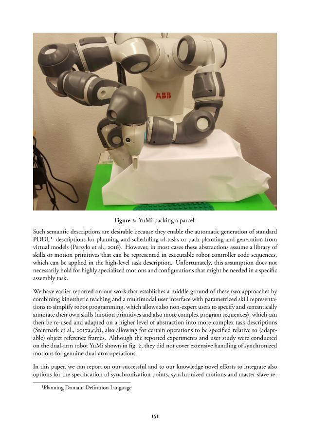
Figure 2: YuMi packing a parcel.
Such semantic descriptions are desirable because they enable the automatic generation of standardPDDL¹–descriptions for planning and scheduling of tasks or path planning and generation fromvirtual models (Perzylo et al., 2016). However, in most cases these abstractions assume a library ofskills or motion primitives that can be represented in executable robot controller code sequences,which can be applied in the high-level task description. Unfortunately, this assumption does notnecessarily hold for highly specialized motions and configurations that might be needed in a specificassembly task.
We have earlier reported on our work that establishes a middle ground of these two approaches bycombining kinesthetic teaching and a multimodal user interface with parametrized skill representa-tions to simplify robot programming, which allows also non-expert users to specify and semanticallyannotate their own skills (motion primitives and also more complex program sequences), which canthen be re-used and adapted on a higher level of abstraction into more complex task descriptions(Stenmark et al., 2017a,c,b), also allowing for certain operations to be specified relative to (adapt-able) object reference frames. Although the reported experiments and user study were conductedon the dual-arm robot YuMi shown in fig. 2, they did not cover extensive handling of synchronizedmotions for genuine dual-arm operations.
In this paper, we can report on our successful and to our knowledge novel efforts to integrate alsooptions for the specification of synchronization points, synchronized motions and master-slave re-
¹Planning Domain Definition Language
151

lations during program parts, which can then, based on our parameterizable skill representation, bere-used and adapted into high-level instructions. This adaptation includes also the transfer of a skill(motion primitive) from one arm to the other, adaptation of synchronized motions to new objectreference frames, and the switch of the master-slave relationship. Our approach supports the user byhandling the necessary geometrical transformations implicitly based on the high-level instructiontransfers expressed by the programmer through the graphical interface.
The remainder of the paper is organized as follows. We will refer to related work in the area ofdual-arm robot programming in section 2. In section 3 we describe our skill representation andthe conceptual framework for handling the re-use and parameterization of synchronized motions.We explain our implementation and experiments in sections 4 and 5, respectively, and discuss ourresults and conclusions in section 6.
2 Related Work
Dual-arm or bi-manual task handling has been investigated under different paradigms or pointsof views. An overview of dual-arm manipulation approaches considering among others the con-trol and planning perspective is given by Smith et al. (2012). An early approach to programmingby demonstration of bi-manual, tasks was reported by Zöllner et al. (2004), however, they con-sider mainly household related tasks, while we assume that a pure programming by demonstrationapproach is not sufficient for an industrial assembly context. This assumption is shared by Krügeret al. (2011), who report on an approach quite similar to ours for intuitive programming of industrialmanipulators based on a combination of task representations and human demonstration (Makriset al., 2014). Their focus, however, is more on the observation of human movement demonstrationsand transfer of these movements into robot control sequences for direct imitation, while we focusrather on the programming of re-usable synchronized motion sequences based on a representationthat supports the robot operator by abstracting the low-level control primitives for synchronizationof the two arms into intuitively understandable skill descriptions.
3 Objects, Primitives and Skills
The knowledge in the system is centered around objects (workpieces), devices such as manipulators,grippers and sensors and assembly processes describing the robot program. In this experimentalsetup, objects are created as abstract entities with a unique name, a type, and positions describingpoints on the object as relative reference coordinate systems. For example, the gift box used in theexperiments described in Section 5 has multiple points defined, one for each side and two corners.Robot motions can then be specified using the reference coordinate frames and the positions can beupdated e.g., using cameras. The robot manipulators have a reference frame attached to the wrist,the flange. The gripper is attached to the flange and has in turn one or more reference points, e.g.,the tips of the fingers. For our experiments, we use a dual-arm robot where motions of one armare specified in the other arm’s flange reference system. The low-level implementation in this setupdoes not allow arbitrary reference points along the robot arms, thus, contact situations where theso-called elbow or lower arm are used are specified using joint angles.
152

3.1 Primitives
Each primitive has a set of semantically annotated parameter types with (system dependent) defaultvalues. The following primitives are implemented in the interface described in Section 4:
• Motion types: Motion has subtypes Free Motion and Contact Motion. Free Motion hassubtype AbsJointMove (where the target is expressed in joint angles), Linear Move, CircularMove and Joint Move where the target is expressed in Cartesian space relative to a point onan object and the path will be linear, circular or by moving all joints simultaneously. TheContact Motion is a simple Guarded Search, which moves towards a specified point untilthe desired (estimated) contact force is reached, or, if no contact occurs, an error is thrown.
• Gripper Actions of the subtypes Open, Close and Finger Position. The first two actionsopen and close the fingers fully or until the current value of the gripping force is reached. TheFinger action is used to set the gripping force and finger positions to the specified parametervalues. It also has a Wait/NoWait flag indicating whether or not the gripper action isexecuted while the robot is moving.
• Synchronization: there are two types of synchronization in the system, either a synchroniza-tion point or synchronized motions. By default, the two arms execute independently as twoseparate robots, but a synchronization point is a rendez-vous between the robot programsthat will force one arm to wait until the other reaches the corresponding point in its program.Similarly, the synchronized motions have references to each other.
• Synchronized motions: the two arms will start and finish motions at the same time, that is,the longest motion determines the execution time of all the motions. The motions can bespecified in absolute joint (or Cartesian) coordinates or relative to objects in the workspace.They can also be specified relative to the position of the other arm, in a so-called Master-Slave configuration. The master-slave motions are used to lock a specific offset between thearms, e.g., when moving an object bimanually.
• Native Code: the (advanced) user can add any native robot code in plain text as a snippetthat will be included inline at a given point of a program. Only object references are analyzedsemantically. This action is used by the system integrator or an expert to create skill macrosfor sensor communication, e.g., by creating a function that uses cameras to locate an object.For example, if the user added an object named screw and the expert created a procedurethat locates a screw called screwLocatingFunction, the position of the screw is updated withthe native code line screw := screwLocatingFunction. Since the variable names areunique and typed both in native code and in the user interface, object references can bechanged using the interface, hence, non-expert users do not have to edit the native code toupdate the object positions of other (similar) screws.
3.2 Re-use and transformation of skills
Motions relative to object reference coordinate systems can be transformed by either by changingthe coordinate system or updating it. Using only one reference point (translation and rotation),whether it is the flange of the robot or a point placed on an object, is enough to rotate the skill. To
153

mirror the task in a plane, two pairs of points are needed, one point for each arm that is used duringthe programming phase, and then one new point for each arm respectively to allow the skills foreach arm to be rotated and translated arbitrarily in the space.
3.3 Programming synchronized motions
While related work, e.g., the app provided with the YuMi robot, lets the user create a pair of motionsfor both arms with one click, the motions are not semantically or syntactically connected. Withour representation, where synchronized points and motions have a reference to the other memberin the pair, they can be created, deleted, executed, moved in the program sequence and copied inpairs. Hence, when moving a synchronized motion from one arm to the other, the other motion inthe pair has to swap places with it in order to preserve a correct program.
Synchronized skills can also be re-used bi-manually and moved between the arms. When re-usingdual-arm skills containing master-slave motions, when the skills for each arm are swapped, i.e., theoriginal skill had the left arm as a master and the master moved in the reference coordinate systemof object objX and the right arm, the slave, had an offset to the left offsY, then (when the skillsare swapped) the right arm will become the master, moving to the same positions in the referencecoordinate system of object objX and the position of the left arm, now the slave, will be updated tothe inverse of offsY.
A special case is the refactoring of reference frames for synchronized motions. Since the synchro-nization is an alignment in time, the reference frame of one arm can be changed to the flange of theother if the original positions are known, thus synchronized motions can be refactored into master-slave configurations. All these programming concepts are implemented in the prototype describedin the following section.
4 Implementation
The prototype design was developed after several case studies where the authors developed assem-bly applications on the ABB dual-arm robot YuMi. The user interaction is intended to simplifyagile online robot programming. Mistakes should be easily corrected, with programming and debugmodes merged into a single screen to facilitate a quick program modification and execution loop.All available information about the program is retained even though it may not be used immedi-ately. As an example, a target position is saved with data for the current joint values, the Cartesiantool position and, if a reference object is selected, the relative position, which makes it easy to switchbetween representations. This allows the operator to quickly create a program and later work oncreating and applying abstractions such as object references to make the program easier to re-useand adapt. The current graphical user interface is shown in fig. 3.
154

4.1 Code generation
Writing and debugging native controller code for synchronized motions is time consuming, evenfor experts. To simplify the user interaction during programming, the creation, reordering, deletionand execution of synchronized motions is done in pairs.
Below is an example of the generated RAPID code (edited for clarity) for the right arm in theexample shown in the user interface screen capture in fig. 3. The example is a dual-arm pick andplace of the lid on the toy box described in sec. 5. First, the arms move unsynchronized, open thegrippers and move into gripping positions, after closing the fingers, four master-slave motions areused to move the lid and place it on top of the toy box. Finally, the lid is released (also synchronized).First, all variable names are declared and given values, these declarations are generated from the userspecified objects and added automatically for synchronization points.
The main procedure corresponds to the actions of the right arm. After an initial via move in abso-lute joint space, the two following motions are relative to the grippoint and after closing the gripperthe following four motions are relative to the flange of the left arm. Each slave move has an IDthat must match a corresponding master move on the left arm. The synchronized motions are sur-rounded by commands for turning on and off the synchronization (SyncMoveOn/SyncMoveOff).The parameters such as speed (v200), precision (fine), tool offset (GripperR) and reference coordi-nate system (e.g., grippoint) are generated from the (default) parameter values or reference positionsof the actions.
Figure 3: A screen capture of the GUI.
155

PERS tasks taskList {2} := [["T_ROB_L"], ["T_ROB_R"]];VAR syncident syncMoveStart;VAR syncident syncMoveStop;
VAR jointtarget ViaMove5 := ...VAR robtarget Move1 :=...VAR robtarget Slave1 :=...[...]PERS wobjdata grippoint :=...[...]TASK PERS wobjdata flangeRobL := ...TASK PERS wobjdata flangeRobR := ...
PROC main()
Hand_SetHoldForce 15;Hand_MoveTo 18\NoWait;MoveAbsJ ViaMove5,v500,z5, GripperR;MoveL Move1,v200,fine, GripperR\WObj:=grippoint;MoveL Move2,v200,fine, GripperR\WObj:=grippoint;WaitSyncTask Sync1, taskList;CloseHand;SyncMoveOn syncMoveStart, tasklist;MoveL Slave1\ID:=1,v200,fine, GripperR\WObj:=flangeRobL;MoveL Slave2\ID:=2,v200,fine, GripperR\WObj:=flangeRobL;MoveL Slave3\ID:=3,v200,fine, GripperR\WObj:=flangeRobL;MoveL Slave4\ID:=4,v200,fine, GripperR\WObj:=flangeRobL;SyncMoveOff syncMoveStop;Hand_SetHoldForce 15;Hand_MoveTo 18\NoWait;SyncMoveOn syncMoveStart, tasklist;MoveL Slave41\ID:=41,v200,fine, GripperR\WObj:=flangeRobL;SyncMoveOff syncMoveStop;
5 Experiments
Two programming experiments were conducted on the YuMi robot. The first was a bi-manual pick and place of a lid of a toy box, the second was a sub-procedure of a gift-wrapping application.
5.1 Bi-manual object manipulation
The first setup is depicted in fig. 4 and the robot was programmed to carry out a bimanualpick and place where a lid of the toy box was picked up and inserted on the box. To solvethe task the grippers had to be placed in the holes of the lid using half-opened fingers,then a sequence of four master-slave motions were used to lift the lid and place it on topof the box. The program is shown in fig. 3. A robot programmer who had never used thetool prototype for synchronized motions and was presented with the task for the first time,needed 32 minutes to solve and debug the task fully. This involved finding a robust grippingstrategy with half-opened grippers that did not subject the lid for high forces.
When a strategy was known, two experts (two of the authors of this paper) needed 5 and10 minutes, respectively, to program the task but 21 and 32 minutes, respectively, usingtraditional tools (text editor and teach pendant). Prototyping from scratch using traditionaltools was not tested.
156
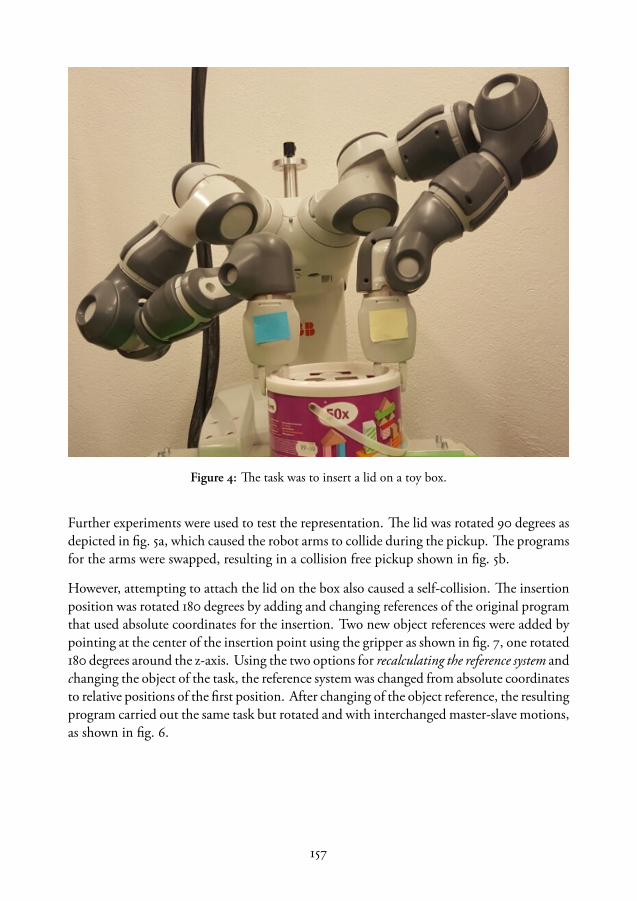
Figure 4: The task was to insert a lid on a toy box.
Further experiments were used to test the representation. The lid was rotated 90 degrees asdepicted in fig. 5a, which caused the robot arms to collide during the pickup. The programsfor the arms were swapped, resulting in a collision free pickup shown in fig. 5b.
However, attempting to attach the lid on the box also caused a self-collision. The insertionposition was rotated 180 degrees by adding and changing references of the original programthat used absolute coordinates for the insertion. Two new object references were added bypointing at the center of the insertion point using the gripper as shown in fig. 7, one rotated180 degrees around the z-axis. Using the two options for recalculating the reference system andchanging the object of the task, the reference system was changed from absolute coordinatesto relative positions of the first position. After changing of the object reference, the resultingprogram carried out the same task but rotated and with interchanged master-slave motions,as shown in fig. 6.
157
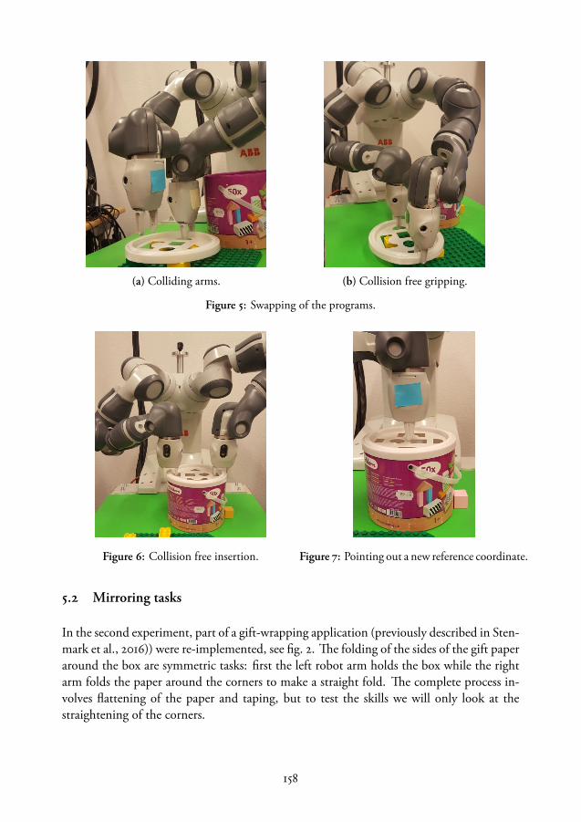
(a) Colliding arms. (b) Collision free gripping.
Figure 5: Swapping of the programs.
Figure 6: Collision free insertion. Figure 7: Pointing out a new reference coordinate.
5.2 Mirroring tasks
In the second experiment, part of a gift-wrapping application (previously described in Sten-mark et al., 2016)) were re-implemented, see fig. 2. The folding of the sides of the gift paperaround the box are symmetric tasks: first the left robot arm holds the box while the rightarm folds the paper around the corners to make a straight fold. The complete process in-volves flattening of the paper and taping, but to test the skills we will only look at thestraightening of the corners.
158

Figure 8: The rotated position. Figure 9: The mirrored position.
First, one reference point was added on the right (for the robot) side of the robot. Thetask was first programmed using the side point as reference point. A second reference pointwas added, this time on the left side pointing outward. The robot programs for the armswere swapped and a new reference object for the right arm changed to the new side point,resulting in a rotation of the task as shown in fig. 8.
The original task was mirrored from one side to the other by adding a point on the cornerwhere the right arm is pointing in fig. 2 as well as a point in the mirrored corner (fig. 9)using the left arm. The programs for the arms were swapped but this time the folding handused the (robot) left corner point as reference while the holding hand used the side point,which resulted in a mirrored task execution.
6 Conclusions
In this paper, we discussed our efforts to improve intuitive dual-arm programming of col-laborative industrial robots. Our programming model allows for primitive dual-arm mo-tion constructs with associated motion constraints to capture specification of synchroniza-tion points, synchronized motions and master-slave relations during program parts. Wealso present a taxonomy of our programming constructs as a starting point for a dual-armontology of programming constructs. This is combined with a programming interface thatsupports a hybrid instruction and evaluation (execution) process and thus quick implemen-tation and test cycles through a graphical interface for iconic programming. The interface
159
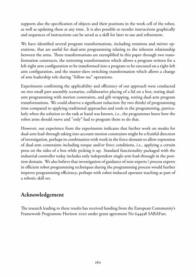
supports also the specification of objects and their positions in the work cell of the robot,as well as updating these at any time. It is also possible to reorder instructions graphicallyand sequences of instructions can be saved as a skill for later re-use and refinement.
We have identified several program transformations, including rotations and mirror op-erations, that are useful for dual-arm programming relating to the inherent relationshipbetween the arms. These transformations are exemplified in this paper through two trans-formation constructs, the mirroring transformation which allows a program written for aleft-right arm configuration to be transformed into a program to be executed on a right-leftarm configuration, and the master-slave switching transformation which allows a changeof arm leadership role during ”follow me” operations.
Experiments confirming the applicability and efficiency of our approach were conductedon two small part assembly scenarios, collaborative placing of a lid on a box, testing dual-arm programming with motion constraints, and gift wrapping, testing dual-arm programtransformations. We could observe a significant reduction (by two thirds) of programmingtime compared to applying traditional approaches and tools to the programming, particu-larly when the solution to the task at hand was known, i.e., the programmer knew how therobot arms should move and ”only” had to program them to do that.
However, our experience from the experiments indicates that further work on modes fordual-arm lead-through taking into account motion constraints might be a fruitful directionof investigation, perhaps in combination with work in the force-domain to allow expressionof dual-arm constraints including torque and/or force conditions, i.e., applying a certainpress on the sides of a box while picking it up. Standard functionality packaged with theindustrial controller today includes only independent single-arm lead-through in the posi-tion domain. We also believe that investigation of guidance of non-experts / process expertsin efficient robot programming techniques during the programming process would furtherimprove programming efficiency, perhaps with robot-induced operator teaching as part ofa robotic skill set.
Acknowledgement
The research leading to these results has received funding from the European Community’sFramework Programme Horizon 2020 under grant agreement No 644938 SARAFun.
160

Paper vi

Paper VI
Natural Language Programming of Industrial Robots
Maj Stenmark Pierre Nugues
Department of Computer ScienceLund University
[email protected]@cs.lth.se
ABSTRACT
In this paper, we introduce a method to use written natural language instructions to program assem-bly tasks for industrial robots. In our application, we used a state-of-the-art semantic and syntacticparser together with semantically rich world and skill descriptions to create high-level symbolic tasksequences. From these sequences, we generated executable code for both virtual and physical robotsystems. Our focus lays on the applicability of these methods in an industrial setting with real-timeconstraints.
Proc. of the 44th International Symposium on Robotics, Seoul, South Korea, Oct 24-26, 2013. DOI:10.1109/ISR.2013.6695630.


1 Introduction
Robot programming is time consuming, complex, error-prone, and requires expertise both of thetask and the platform. Within industrial robotics, there are numerous vendor-specific programminglanguages and tools, which require certain proficiency. However, to increase the level of automationin industry, as well as to extend the use of robots in other domains, such as service robotics anddisaster management, it has to be possible for non-experts to instruct the robots.
Since humans communicate with natural language (NL), it is appealing to use speech or text asinstruction means for robots as well. This is complicated for two main reasons: First, NL can beambiguous and its expressivity is richer than that of a typical programming language. Secondly, taskscan be expressed as goals as well as imperative statements, hence, even if the instructions are correctlyparsed, the description itself is often not enough to create a successful execution. There has to be asubstantial amount of knowledge in the system to translate the high-level language instructions toexecutable robot programs.
In this paper, we introduce a method for using natural language to program robotized assembly tasksand we describe a prototype of it. The core idea of the method is to use a generic semantic parser toproduce a set of predicate-argument structures from the input sentences. Such predicate-argumentstructures reflect common semantic situations described through language and at the same timeuse a logical representation. Using the predicate-argument structures, we can extract the ordersembedded in a user’s sentences and map them more easily onto robot instructions.
2 Related Work
Natural language programming for robots has been investigated for both service and navigationalrobots from the early 1970’s. SHRLDU (Winograd, 1971) is an oft-cited example of the first at-tempts to give robots conversational competences. To interpret and convert a user’s sentences intoinstructions, robotic system often make use of an intermediate representation. Examples includeTellex et al. (2011); MacMahon et al. (2006); Shimizu and Haas (2009), where the authors havedeveloped their own domain specific semantic representation for navigational robots.
Tenorth et al. (2010) parse pancake recipes in English from the World Wide Web and generateprograms for their household robots. They use the WordNet lexical graph (Princeton University,2010) with a constituent parser and they map WordNet’s synsets to concepts in the Cyc (Matuszeket al., 2006) ontology. Finally, they add mappings to common household objects.
In order to bridge the sentence to the robot actions, all the examples mentioned above seem touse ad-hoc intermediate formalisms that are difficult to adapt to other domains, languages, or en-vironments. Frame semantics (Fillmore, 1976) is an attempt to provide generic models of logicalrepresentations of sentences. Frame semantics starts from prototypical situations shared by a lan-guage community, English for instance, and abstracts them into frames. While frame semanticsis only a theory, FrameNet (FrameNet, 2013; Ruppenhofer et al., 2010) is a comprehensive dictio-nary that provides a list of lexical models of the conceptual structures. Commercial situations likeselling are represented with the Commerce_sell predicate-argument structure, where the arguments
165
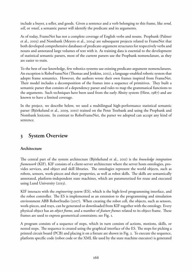
include a buyer, a seller, and goods. Given a sentence and a verb belonging to this frame, like vend,sell, or retail, a semantic parser will identify the predicate and its arguments.
As of today, FrameNet has not a complete coverage of English verbs and nouns. Propbank (Palmeret al., 2005) and Nombank (Meyers et al., 2004) are subsequent projects related to FrameNet thatboth developed comprehensive databases of predicate-argument structures for respectively verbs andnouns and annotated large volumes of text with it. As training data is essential to the developmentof statistical semantic parsers, most of the current parsers use the Propbank nomenclature, as theyare easier to train.
To the best of our knowledge, few robotics systems use existing predicate-argument nomenclatures.An exception is RoboFrameNet (Thomas and Jenkins, 2012), a language-enabled robotic system thatadopts frame semantics. However, the authors wrote their own frames inspired from FrameNet.Their model includes a decomposition of the frames into a sequence of primitives. They built asemantic parser that consists of a dependency parser and rules to map the grammatical functions tothe arguments. Such techniques have been used from the early Absity system (Hirst, 1987) and areknown to have a limited coverage.
In the project, we describe below, we used a multilingual high-performance statistical semanticparser (Björkelund et al., 2009, 2010) trained on the Penn Treebank and using the Propbank andNombank lexicons. In contrast to RoboFrameNet, the parser we adopted can accept any kind ofsentence.
3 System Overview
Architecture
The central part of the system architecture (Björkelund et al., 2011) is the knowledge integrationframework (KIF). KIF consists of a client-server architecture where the server hosts ontologies, pro-vides services, and object and skill libraries. The ontologies represent the world objects, such asrobots, sensors, work-pieces and their properties, as well as robot skills. The skills are semanticallyannotated, platform-independent state machines, which are parameterized for reuse and executedusing Lund University (2013).
KIF interacts with the engineering system (ES), which is the high-level programming interface, andthe robot controller. The ES is implemented as an extension to the programming and simulationenvironment ABB RobotStudio (2017). When creating the robot cell, the objects, such as sensors,work-pieces, and trays, can be generated or downloaded from KIF together with the ontology. Everyphysical object has an object frame, and a number of feature frames related to its object frame. Theseframes are used to express geometrical constraints; see Fig. 1.
A program consists of a sequence of steps, which in turn consists of actions, motions, skills, ornested steps. The sequence is created using the graphical interface of the ES. The steps for picking aprinted circuit board (PCB) and placing it on a fixture are shown in Fig. 2. To execute the sequence,platform specific code (robot code or the XML file used by the state machine executor) is generated
166

Figure 1: In the object browser, the robotsare listed under robots; all physical objectsare listed under world and each object listsits own frames and relations.
Figure 2: The visual rendering of a programfor picking and placing a PCB.
for the motions, actions and skills, and deployed on the target platform. To help the user quicklysetup a skeleton sequence of a task, we provide a natural-language parsing service on KIF; see Fig. 3.The service reads the text input, parses the text in search of predicate-arguments structures, andreturns those containing predicates that match the task vocabulary.
On the client side, the predicates are mapped to programs; the arguments representing stationobjects and the other parameters are filled with default values or geometrical relations taken fromthe station. The programmer can then check the sequence, possibly alter it, and finally execute it.
ES KIF NL parser
ES KIF NL parser
User writes the NL text in a text box. The text is sent
as a requestForwards the text The parser
finds the predicates and arguments in the sentences
Returns the parsed result
The KIF service filters the result and returns only those predicates that are relevant for the assembly task
Returns the filtered predicates and their arguments
Matches the arguments to the objects in the station and generates the sequence
Figure 3: The data flow between the user, the KIF service and the semantic parser.
167

Figure 4: Parsing result from the first sentence. The parser identified two predicates, pick and place,and two arguments for each predicate.
Predicate-Argument Structures
An assembly task can be defined as e.g.: Pick the PCB from the input tray and place it on the fixture.Then take a shield can and insert it on the PCB. These sentences are parsed to extract the predicates-argument structures pick(PCB, input tray) and place(it, fixture), while the agent parameter, robot, isimplicit.
The parser is trained on the Penn Treebank that uses the Propbank lexicon (Johansson and Nugues,2008). Propbank labels each English verb with a sense and defines a set of arguments that is specificto each verb. In the sentence: Pick the PCB from the input tray and place it on the fixture, both pickand place have sense 1 (pick.01 and place.01):
• Pick.01 has three possible arguments; arg0: agent, entity acquiring something, arg1: thingacquired and arg2: seller.
• Place.01 has arg0: putter, arg1: thing put, and arg2: where put.
The parsing output is shown in Fig. 4. As shown in this figure, the arg1 and arg2 arguments topick.01 are matched to the PCB and the input tray respectively, while the robot (arg0) is implicit.Before mapping the identified arguments to the station objects, the arguments corresponding to thesame entity have to be gathered into coreference chains; see Fig. 5. The last step links the coreferencechains to the entities in the station using the object name or type.
Task Vocabulary
The vocabulary is currently rather limited. We only considered predicates matching programs thatthe robot could generate. Each program has arbitrary language tags such as take, insert, put, cali-brate, either predefined or edited by the user. Possible arguments to the programs are the objects inthe station, which is a well-defined, finite world.
4 High-level Programming Prototype
On the highest level, the task is represented by an assembly graph (Malec et al., 2013), which is apartially ordered tree of assembly operations; see Fig. 6. The graph describes the assembly of anemergency stop button box.
168
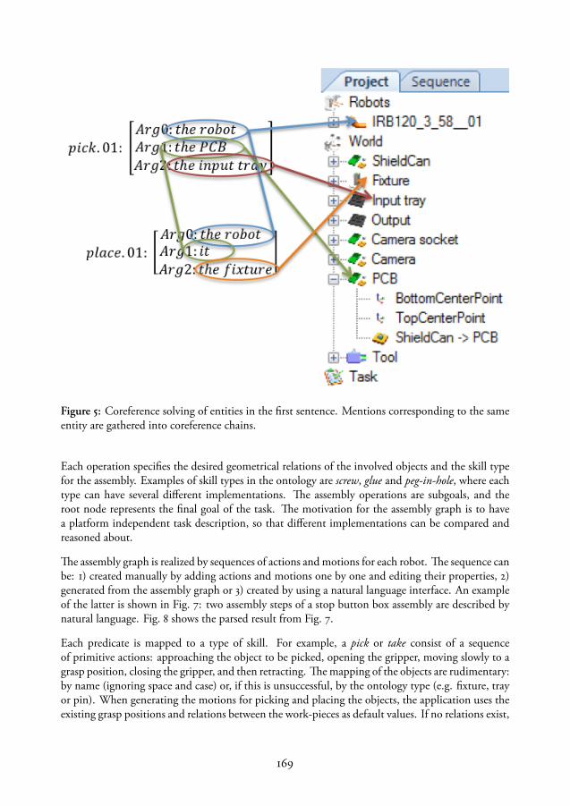
Figure 5: Coreference solving of entities in the first sentence. Mentions corresponding to the sameentity are gathered into coreference chains.
Each operation specifies the desired geometrical relations of the involved objects and the skill typefor the assembly. Examples of skill types in the ontology are screw, glue and peg-in-hole, where eachtype can have several different implementations. The assembly operations are subgoals, and theroot node represents the final goal of the task. The motivation for the assembly graph is to havea platform independent task description, so that different implementations can be compared andreasoned about.
The assembly graph is realized by sequences of actions and motions for each robot. The sequence canbe: 1) created manually by adding actions and motions one by one and editing their properties, 2)generated from the assembly graph or 3) created by using a natural language interface. An exampleof the latter is shown in Fig. 7: two assembly steps of a stop button box assembly are described bynatural language. Fig. 8 shows the parsed result from Fig. 7.
Each predicate is mapped to a type of skill. For example, a pick or take consist of a sequenceof primitive actions: approaching the object to be picked, opening the gripper, moving slowly to agrasp position, closing the gripper, and then retracting. The mapping of the objects are rudimentary:by name (ignoring space and case) or, if this is unsuccessful, by the ontology type (e.g. fixture, trayor pin). When generating the motions for picking and placing the objects, the application uses theexisting grasp positions and relations between the work-pieces as default values. If no relations exist,
169

Figure 6: The assembly graph is created by dragging and dropping icons of the objects. Here, thefirst assembly operation involves the base of the emergency button (left) and the switch (right). Inthe second operation the lid is added to the subassembly.
Figure 7: The commands are written into a sim-ple text field, the narrative is then sent to the KIFservice that facilitates semantic parsing.
Figure 8: The result the parsed predicatesalong with their arguments.
a new one is created with zero offset. The actions for opening and closing the gripper are taken fromthe selected tool, since each tool describes its own procedures. The resulting sequence is shown inFig. 9. Using reasoning services available from KIF, the generated sequence can then be checked forinconsistencies and additional skills are suggested to solve missing constraints (e.g. an object hasto be placed in a fixture before an assembly or a tool needs to be exchanged between drilling andpicking). The code generated from the sequence is executable on both virtual and physical robots;see Fig. 10. To expand the vocabulary, the user can add natural language tags to existing steps andupload them to KIF.
170
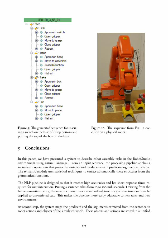
Figure 9: The generated sequence for insert-ing a switch on the base of a stop bottom andputting the top of the box on the base.
Figure 10: The sequence from Fig. 8 exe-cuted on a physical robot.
5 Conclusions
In this paper, we have presented a system to describe robot assembly tasks in the RobotStudioenvironment using natural language. From an input sentence, the processing pipeline applies asequence of operations that parses the sentence and produces a set of predicate-argument structures.The semantic module uses statistical techniques to extract automatically these structures from thegrammatical functions.
The NLP pipeline is designed so that it reaches high accuracies and has short response times re-quired for user interaction. Parsing a sentence takes from 10 to 100 milliseconds. Drawing from theframe semantics theory, the semantic parser uses a standardized inventory of structures and can beapplied to unrestricted text. This makes the pipeline more easily adaptable to new tasks and newenvironments.
As second step, the system maps the predicate and the arguments extracted from the sentence torobot actions and objects of the simulated world. These objects and actions are stored in a unified
171

architecture, the knowledge integration framework that represents and manages the entities, services,and skill libraries accessible to the robot.
Making the application part of a tool already used by industry is a conscious choice: high-level nat-ural language programming is convenient to get an application up and running quickly. However,when tuning the parameters of a task, the programmer can still use the traditional tools, e.g. to editthe generated code directly. Also, because of the industrial focus, we have real-time performanceon the underlying sensor and control systems, which is necessary for many manipulation tasks inassembly operations.
Unlike previously reported results, our approach supports both a command-like interface and pars-ing of longer texts, yielding multistep programs.
6 Future Work
The obvious drawback of this implementation is the lack of speech as an input modality. How-ever, since many smartphones have sufficient speech recognition for our purposes, this was not ourmain scientific concern. Rather, we wanted to extend the skill library with relevant and genericassembly skills. We plan to extend our application with tools that make it simple to extract the nat-ural language predicate-argument structures given a skill, its parameters (objects, velocities, forces),and a textual description of the skill. Another extension is to automatically search after suitableimplementations that are tagged with synonyms to the used words.
7 Acknowledgments
The research leading to these results has received funding from the European Union’s seventh frame-work program (FP7/2007-2013) under grant agreements N◦ 230902 (ROSETTA) and N◦ 285380(PRACE) and from the Swedish Research Council grant N◦ 2010-4800 (SEMANTICA).
172
Paper vii

Paper VII
Describing Constraint-Based Assembly Tasks in UnstructuredNatural Language
Maj Stenmark Jacek Malec
Department of Computer ScienceLund University
[email protected]@cs.lth.se
ABSTRACT
Task-level industrial robot programming is a mundane, error-prone activity requiring expertise andskill. Since humans easily communicate with natural language (NL), it may be attractive to usespeech or text as instruction means for robots. However, there has to be a substantial amountof knowledge in the system to translate the high-level language instructions to executable robotprograms.
In this paper, the method of (Stenmark and Nugues, 2013) for natural language programming ofrobotized assembly tasks is extended. The core idea of the method is to use a generic semantic parserto produce a set of predicate-argument structures from the input sentences. The algorithm presentedhere facilitates extraction of more complicated, advanced task instructions involving cardinalities,conditionals, parallelism and constraint-bounded programs, besides plain sequences of commands.
The bottleneck of this approach is the availability of easily parametrizable robotic skills and func-tionalities in the system, rather than the natural language understanding by itself.
Proc. of the 19th IFAC World Congress, Cape Town, South Africa, 3056 - 3061, 2014, DOI: 10.3182/20140824-6-ZA-1003.02062.


1 Introduction
Programming of a traditional robot cell requires considerable expertise and effort. The new genera-tion of robots, that work in an unstructured environment, that might have more degrees of freedomand two arms, introduces an increased level of complexity in user interaction and instruction. There-fore, methods of robot instruction that are accessible to non-experts would lead to greater usabilityof industrial robotics. Yet another aspect of the problem lies in vendor-specific solutions, avail-able for each brand of robots. Different tools of varying complexity, different robot programminglanguages and different abstraction levels of task descriptions make them inaccessible for a plainuser.
Since humans communicate with natural language (NL), it may be attractive to use speech or text asinstruction means for robots. This is non-trivial for two main reasons: First, NL is often ambiguousand its expressivity is richer than that of a typical programming language. Secondly, tasks can beexpressed as goals as well as imperative statements, hence, even if the instructions are correctlyinterpreted, the description itself is often not enough to create a successful execution. There has tobe a substantial amount of knowledge in the system to translate the high-level language instructionsto executable robot programs.
In this paper, the simple method from (Stenmark and Nugues, 2013) for natural language pro-gramming of assembly tasks is extended. The core idea of the method is to use a generic semanticparser to produce a set of predicate-argument structures from the input sentences. The originalalgorithm allows extraction of only plain sequences of commands. Here we show that using thepredicate-argument structures together with the dependency graphs facilitates also extraction ofmore complicated task instructions, which involve cardinalities (e.g., pick two bolts and two nuts),conditionals (e.g., if...then...else) and constraint-characterized programs (e.g., do...until...)
2 Related Work
By abstracting away the underlying details of the system, e.g., by demonstration, high-level pro-gramming can make robot instruction accessible to non-expert users and reduce the workload foran experienced programmer. A survey of programming-by-demonstration models in robotics ispresented by Billard et al. (2008).
In industrial robotics, programming and demonstration techniques are normally used to record tra-jectories and positions. As it is desirable to minimize downtime for the robot, much programmingand simulation is done offline whereas only the fine tuning is done online (Hägele et al., 2008).There is a plethora of tools, often visual, for robot programming. In robotics, standardized graph-ical programming languages include Ladder Diagrams, Function Block Diagrams and SequentialFunction Charts (IEC, 2003). Using a touch screen as an input device, icon-based programminglanguages such as in Bischoff et al. (2002) can also lower the threshold to robot programming.
Natural language programming for robots has been investigated since the early 1970’s. SHRLDU(Winograd, 1971) is an example of the first attempts to give robots conversational competences.To interpret and convert a user’s sentences into instructions, robotic system often make use of an
177
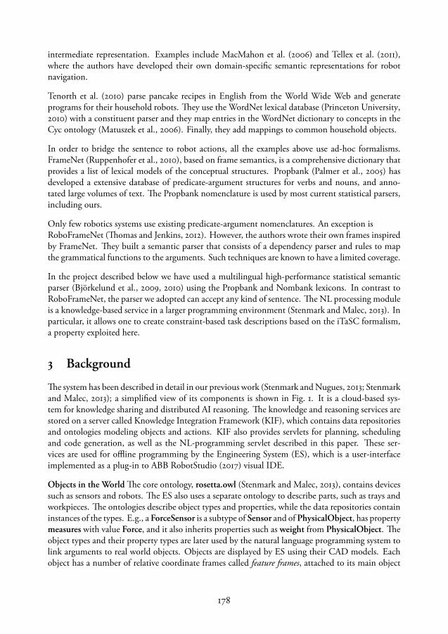
intermediate representation. Examples include MacMahon et al. (2006) and Tellex et al. (2011),where the authors have developed their own domain-specific semantic representations for robotnavigation.
Tenorth et al. (2010) parse pancake recipes in English from the World Wide Web and generateprograms for their household robots. They use the WordNet lexical database (Princeton University,2010) with a constituent parser and they map entries in the WordNet dictionary to concepts in theCyc ontology (Matuszek et al., 2006). Finally, they add mappings to common household objects.
In order to bridge the sentence to robot actions, all the examples above use ad-hoc formalisms.FrameNet (Ruppenhofer et al., 2010), based on frame semantics, is a comprehensive dictionary thatprovides a list of lexical models of the conceptual structures. Propbank (Palmer et al., 2005) hasdeveloped a extensive database of predicate-argument structures for verbs and nouns, and anno-tated large volumes of text. The Propbank nomenclature is used by most current statistical parsers,including ours.
Only few robotics systems use existing predicate-argument nomenclatures. An exception isRoboFrameNet (Thomas and Jenkins, 2012). However, the authors wrote their own frames inspiredby FrameNet. They built a semantic parser that consists of a dependency parser and rules to mapthe grammatical functions to the arguments. Such techniques are known to have a limited coverage.
In the project described below we have used a multilingual high-performance statistical semanticparser (Björkelund et al., 2009, 2010) using the Propbank and Nombank lexicons. In contrast toRoboFrameNet, the parser we adopted can accept any kind of sentence. The NL processing moduleis a knowledge-based service in a larger programming environment (Stenmark and Malec, 2013). Inparticular, it allows one to create constraint-based task descriptions based on the iTaSC formalism,a property exploited here.
3 Background
The system has been described in detail in our previous work (Stenmark and Nugues, 2013; Stenmarkand Malec, 2013); a simplified view of its components is shown in Fig. 1. It is a cloud-based sys-tem for knowledge sharing and distributed AI reasoning. The knowledge and reasoning services arestored on a server called Knowledge Integration Framework (KIF), which contains data repositoriesand ontologies modeling objects and actions. KIF also provides servlets for planning, schedulingand code generation, as well as the NL-programming servlet described in this paper. These ser-vices are used for offline programming by the Engineering System (ES), which is a user-interfaceimplemented as a plug-in to ABB RobotStudio (2017) visual IDE.
Objects in the World The core ontology, rosetta.owl (Stenmark and Malec, 2013), contains devicessuch as sensors and robots. The ES also uses a separate ontology to describe parts, such as trays andworkpieces. The ontologies describe object types and properties, while the data repositories containinstances of the types. E.g., a ForceSensor is a subtype of Sensor and of PhysicalObject, has propertymeasures with value Force, and it also inherits properties such as weight from PhysicalObject. Theobject types and their property types are later used by the natural language programming system tolink arguments to real world objects. Objects are displayed by ES using their CAD models. Eachobject has a number of relative coordinate frames called feature frames, attached to its main object
178
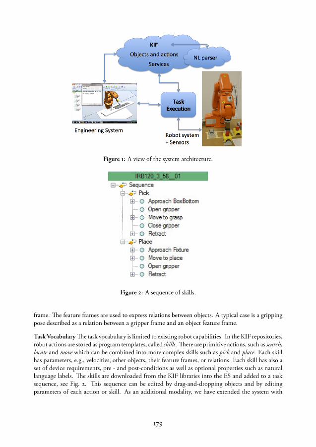
Figure 1: A view of the system architecture.
Figure 2: A sequence of skills.
frame. The feature frames are used to express relations between objects. A typical case is a grippingpose described as a relation between a gripper frame and an object feature frame.
TaskVocabulary The task vocabulary is limited to existing robot capabilities. In the KIF repositories,robot actions are stored as program templates, called skills. There are primitive actions, such as search,locate and move which can be combined into more complex skills such as pick and place. Each skillhas parameters, e.g., velocities, other objects, their feature frames, or relations. Each skill has also aset of device requirements, pre - and post-conditions as well as optional properties such as naturallanguage labels. The skills are downloaded from the KIF libraries into the ES and added to a tasksequence, see Fig. 2. This sequence can be edited by drag-and-dropping objects and by editingparameters of each action or skill. As an additional modality, we have extended the system with
179
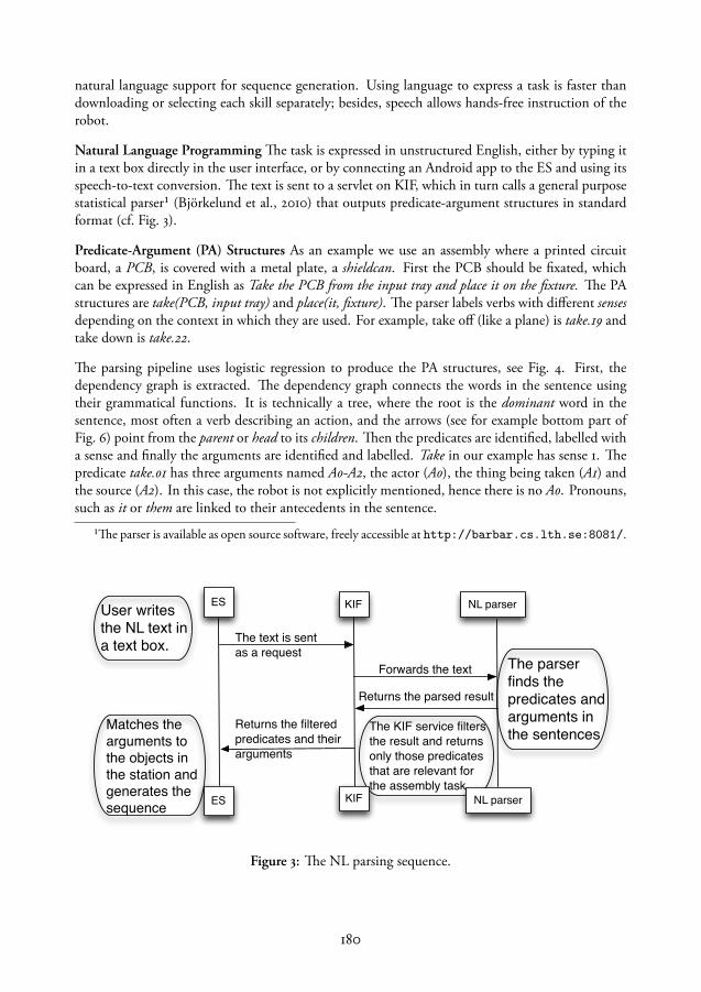
natural language support for sequence generation. Using language to express a task is faster thandownloading or selecting each skill separately; besides, speech allows hands-free instruction of therobot.
Natural Language Programming The task is expressed in unstructured English, either by typing itin a text box directly in the user interface, or by connecting an Android app to the ES and using itsspeech-to-text conversion. The text is sent to a servlet on KIF, which in turn calls a general purposestatistical parser¹ (Björkelund et al., 2010) that outputs predicate-argument structures in standardformat (cf. Fig. 3).
Predicate-Argument (PA) Structures As an example we use an assembly where a printed circuitboard, a PCB, is covered with a metal plate, a shieldcan. First the PCB should be fixated, whichcan be expressed in English as Take the PCB from the input tray and place it on the fixture. The PAstructures are take(PCB, input tray) and place(it, fixture). The parser labels verbs with different sensesdepending on the context in which they are used. For example, take off (like a plane) is take.19 andtake down is take.22.
The parsing pipeline uses logistic regression to produce the PA structures, see Fig. 4. First, thedependency graph is extracted. The dependency graph connects the words in the sentence usingtheir grammatical functions. It is technically a tree, where the root is the dominant word in thesentence, most often a verb describing an action, and the arrows (see for example bottom part ofFig. 6) point from the parent or head to its children. Then the predicates are identified, labelled witha sense and finally the arguments are identified and labelled. Take in our example has sense 1. Thepredicate take.01 has three arguments named A0-A2, the actor (A0), the thing being taken (A1) andthe source (A2). In this case, the robot is not explicitly mentioned, hence there is no A0. Pronouns,such as it or them are linked to their antecedents in the sentence.
¹The parser is available as open source software, freely accessible at http://barbar.cs.lth.se:8081/.
ES KIF NL parser
ES KIF NL parser
User writes the NL text in a text box. The text is sent
as a requestForwards the text The parser
finds the predicates and arguments in the sentences
Returns the parsed result
The KIF service filters the result and returns only those predicates that are relevant for the assembly task
Returns the filtered predicates and their arguments
Matches the arguments to the objects in the station and generates the sequence
Figure 3: The NL parsing sequence.
180

� ��� ������������ ����������������� ��������� ������� �
Predicate sense
Predicate identification
Argument identification+ Argument labeling
� ��� ������������ ����������������� ��������� ������� �
�� ��� ��� ���
� ��� ������������ ����������������� ��������� ������� �
�� ��� ��� ���
måndag 21 oktober 13
Figure 4: The parsing pipeline.
Previous work (Stenmark and Nugues, 2013) defined an algorithm describing how predicates canbe mapped to robot skills, and arguments linked to specific world objects in order to create an exe-cutable sequence of the task, as displayed in Fig. 2. However, the supported programming featureswere limited, excluding e.g., such control structures as conditionals, temporal constraints, controlparameters, parallel execution and references to program features. The contributions of this workare that predicate-argument pairs can be mapped to complex skills and the novel methods we areusing to extract constraints and control structures from NL instructions.
Code Generation and Execution The executable code for primitive actions is generated in nativecontroller language (RAPID). E.g., each gripper can have a predefined native code to open and closeit. On the other hand, the sensor-controlled skills use a framework based on iTaSC (De Schutteret al., 2007), together with external force/torque sensors. These skills are specified by state machinesusing Lund University (2013) language, where states are simple motions and transition conditionsare, e.g., timeouts or force and torque thresholds. A motion is specified by constraining outputs(e.g., positions or force values) from a kinematic chain. The kinematic chain is a specification of therelation between task variables and the robot, which are represented by a list of transformations.The state machine is generated by ES for all skills and all constrained motions (Stenmark and Stolt,2013).
181
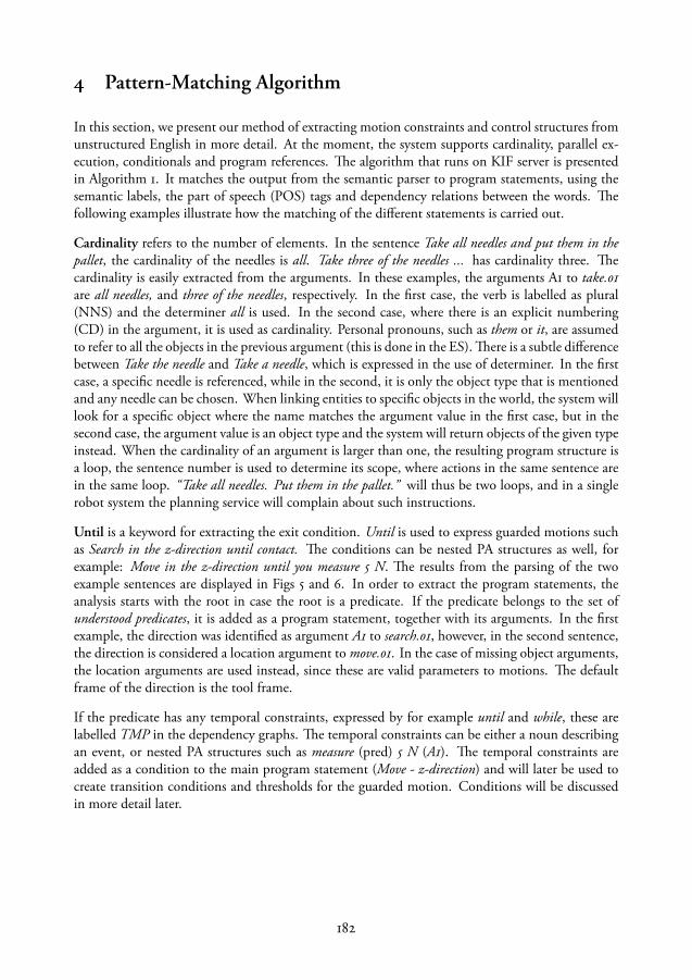
4 Pattern-Matching Algorithm
In this section, we present our method of extracting motion constraints and control structures fromunstructured English in more detail. At the moment, the system supports cardinality, parallel ex-ecution, conditionals and program references. The algorithm that runs on KIF server is presentedin Algorithm 1. It matches the output from the semantic parser to program statements, using thesemantic labels, the part of speech (POS) tags and dependency relations between the words. Thefollowing examples illustrate how the matching of the different statements is carried out.
Cardinality refers to the number of elements. In the sentence Take all needles and put them in thepallet, the cardinality of the needles is all. Take three of the needles ... has cardinality three. Thecardinality is easily extracted from the arguments. In these examples, the arguments A1 to take.01are all needles, and three of the needles, respectively. In the first case, the verb is labelled as plural(NNS) and the determiner all is used. In the second case, where there is an explicit numbering(CD) in the argument, it is used as cardinality. Personal pronouns, such as them or it, are assumedto refer to all the objects in the previous argument (this is done in the ES). There is a subtle differencebetween Take the needle and Take a needle, which is expressed in the use of determiner. In the firstcase, a specific needle is referenced, while in the second, it is only the object type that is mentionedand any needle can be chosen. When linking entities to specific objects in the world, the system willlook for a specific object where the name matches the argument value in the first case, but in thesecond case, the argument value is an object type and the system will return objects of the given typeinstead. When the cardinality of an argument is larger than one, the resulting program structure isa loop, the sentence number is used to determine its scope, where actions in the same sentence arein the same loop. “Take all needles. Put them in the pallet.” will thus be two loops, and in a singlerobot system the planning service will complain about such instructions.
Until is a keyword for extracting the exit condition. Until is used to express guarded motions suchas Search in the z-direction until contact. The conditions can be nested PA structures as well, forexample: Move in the z-direction until you measure 5 N. The results from the parsing of the twoexample sentences are displayed in Figs 5 and 6. In order to extract the program statements, theanalysis starts with the root in case the root is a predicate. If the predicate belongs to the set ofunderstood predicates, it is added as a program statement, together with its arguments. In the firstexample, the direction was identified as argument A1 to search.01, however, in the second sentence,the direction is considered a location argument to move.01. In the case of missing object arguments,the location arguments are used instead, since these are valid parameters to motions. The defaultframe of the direction is the tool frame.
If the predicate has any temporal constraints, expressed by for example until and while, these arelabelled TMP in the dependency graphs. The temporal constraints can be either a noun describingan event, or nested PA structures such as measure (pred) 5 N (A1). The temporal constraints areadded as a condition to the main program statement (Move - z-direction) and will later be used tocreate transition conditions and thresholds for the guarded motion. Conditions will be discussedin more detail later.
182
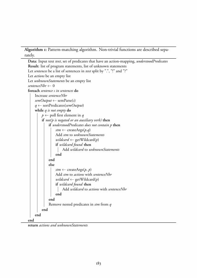
Algorithm 1: Pattern-matching algorithm. Non-trivial functions are described sepa-rately.
Data: Input text text, set of predicates that have an action-mapping, understoodPredicatesResult: list of program statements, list of unknown statementsLet sentences be a list of sentences in text split by ”.”, ”!” and ”?”Let actions be an empty listLet unknownStatements be an empty listsentenceNbr← 0foreach sentence s in sentences do
Increase sentenceNbrsemOutput← semParse(s)q← sortPredicates(semOutput)while q is not empty do
p← poll first element in qif not(p is negated or an auxiliary verb) then
if understoodPredicates does not contain p thenstm← createArgs(p,q)Add stm to unknownStatementswildcard← getWildcard(p)if wildcard found then
Add wildcard to unknownStatementsend
endelse
stm← createArgs(p, p)Add stm to actions with sentenceNbrwildcard← getWildcard(p)if wildcard found then
Add wildcard to actions with sentenceNbrend
endRemove nested predicates in stm from q
endend
endreturn actions and unknownStatements
183

Function sortPredicates(semOutput)if semOutput has a root element then
Let q be an empty queueroot← get root predicate from semOutputif root is a predicate then
Add root to qParse the tree breath first adding all predicates to q
endendelse
predicates← all predicates from semOutput in input orderAdd all predicates to q
endreturn q
Function createArgs(p)args← findArgs(p)stm← (p, args)if hasIfCondition(p) then
word← the child of p of form ”if” or ”when”condition← recursiveSearch(word)stm← if-statement with condtion and stm
endif hasBreakCondition(p) then
word← the child of p of form ”until”condition← recursiveSearch(word)stm← break-statement with condtion and stm
endif hasParallellActivity(p) then
word← the child of p of form ”while”condition← recursiveSearch(word)stm← while-statement with a and stm
endreturn stm
184
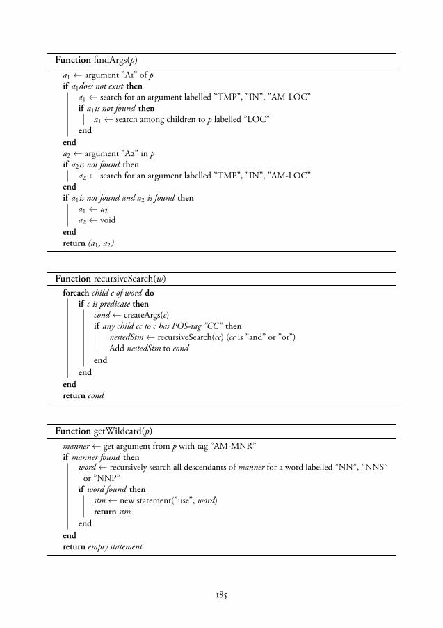
Function findArgs(p)a1 ← argument ”A1” of pif a1does not exist then
a1 ← search for an argument labelled ”TMP”, ”IN”, ”AM-LOC”if a1is not found then
a1 ← search among children to p labelled ”LOC”end
enda2 ← argument ”A2” in pif a2is not found then
a2 ← search for an argument labelled ”TMP”, ”IN”, ”AM-LOC”endif a1is not found and a2 is found then
a1 ← a2a2 ← void
endreturn (a1, a2)
Function recursiveSearch(w)foreach child c of word do
if c is predicate thencond← createArgs(c)if any child cc to c has POS-tag ”CC” then
nestedStm← recursiveSearch(cc) (cc is ”and” or ”or”)Add nestedStm to cond
endend
endreturn cond
Function getWildcard(p)manner← get argument from p with tag ”AM-MNR”if manner found then
word← recursively search all descendants of manner for a word labelled ”NN”, ”NNS”or ”NNP”
if word found thenstm← new statement(”use”, word)return stm
endendreturn empty statement
185

Figure 5: The parse result of “Search in the z-direction until contact”, together with the dependencygraph.
Figure 6: The parse result of “Move in the z-direction until you measure 5 N”.
Figure 7: Result for an if-sentence.
Figure 8: Result for a when-sentence.
186

While. In most programming languages while statements are equivalent to until, however, in nat-ural language they also express parallelism. For example “While holding 5 N in z-direction, search inx-direction until contact” is a guarded motion along one axis, while adding a constraint in anotherdirection. The result is translated into program statements similarly to until-statements. This sen-tence results in a while-statement describing the parallell actions of searching and holding, whilethe search is a nested until-statement with the transition condition.
Conditions. Conditions can be events or PA structures. In our system, the events that can beused are contact, collision and timeout. The predicates that are allowed are limited to measure, reach,sense, thus limiting the expressions to sensor values. The system also supports nested conditionsusing AND and OR, such as contact or timeout, because and and or are tagged as coordinationconjunctions (CC) by the dependency parser.
If and when. In our system, these are considered equivalent, however, in the if-sentence the con-dition is considered an adverbial while in the when-sentence it is a temporal, see Fig. 7 and Fig. 8.This difference is ignored and the PA structure is used as a condition in both cases.
Keywords. All robot skills are not suited to be mapped to predicates, e.g., in a Snapfit skill twoplastic pieces are snapped into position. Hence, the predicate use is dedicated as a keyword, wherethe argument is either another program or a device that is not part of the assembled parts, such assensors or tools. That allows sentences such as “Assemble the shieldcan and the PCB using myskill”, seeFig. ??. Here myskill can be snapfit or peg-in-hole, or be replaced with tool such as gripper2. Whena use-predicate is evaluated by the system, it first searches among the sensors and tools for devicesthat the skill can use, and then online for a skill which can be used to replace the generic assembleaction.
Another way to express similar commands is by using the word with. This will naturally not beparsed into a predicate, but rather be an argument to assemble.2 called manner which is labelledAM-MNR in the result shown in Fig. ??. Adverbs typically describe the manner of a predicate, suchas Carefully assemble.... In case the manner contains with and a noun it is simply interpreted as a usewith the noun as its argument.
Program references. A small set of predicates and PA structures are used to describe the programitself. For example Repeat the task. The predicates are pause, stop, start, repeat, and restart, while thearguments can be skills or general references such as the task and the program.
Negation. Predicates with negation are ignored. Although it is possible to imagine commands suchas Don’t go close to the human, we have chosen to require usage of an active command such as Avoidthe human. For a negation to be meaningful, both an action and its negation have to be mapped todifferent skills, since the complement of an action is not a well defined concept.
When the program statements have been extracted from English sentences, the predicates are mappedinto programs and functions, and the arguments are linked to objects in the world or to skills thatare downloaded to the station. Thresholds for sensor values and parallell constraints are added tothe guarded motions. Executable robot code for the task is generated from the guarded motions andskills. The resulting code has been verified by virtual robot execution in the Engineering System.
187

5 Discussion
Using the standard predicate argument-structures together with the dependency graphs, it is possi-ble to extract the semantic meaning of complicated assembly task descriptions from unstructuredEnglish. The bottleneck is rather the availability of robotic skills and functionalities in the system,not the natural language understanding by itself.
In a virtual world, control parameters and sensor thresholds can be set to default values. In order tocarry out robust task execution on a physical platform though, the damping and stiffness factors ofthe impedance controller and force signatures should be learnt for the task. The parameters to theimpedance control can be learnt by experimentation, as shown by Stolt et al. (2012).
The approach and algorithms presented in this paper are not limited to just assembly tasks, or justto industrial robot task descriptions. After having completed experiments involving skill parameterlearning, we plan to extend this approach to other manufacturing domains.
188

Bibliography

Bibliography
ABB Robotics. Technical reference manual RAPID Instructions, Functions and Data types. ABB ABRobotics Products, 2010.
ABB RobotStudio. RobotStudio, 2017. Available from:http://new.abb.com/products/robotics/robotstudio. Online; last accessed 8 April 2017.
F. J. Abu-Dakka, B. Nemec, A. Kramberger, A. G. Buch, N. Krüger, and A. Ude. Solving peg-in-hole tasks by human demonstration and exception strategies. Industrial Robot: An InternationalJournal, 41(6):575–584, 2014. doi:10.1108/IR-07-2014-0363.
S. Ahmadzadeh, A. Paikan, F. Mastrogiovanni, L. Natale, P. Kormushev, and D. Caldwell. Learningsymbolic representations of actions from human demonstrations. pages 3801–3808. IEEE, 2015.doi:10.1109/ICRA.2015.7139728.
E. E. Aksoy, M. J. Aein, M. Tamosiunaite, and F. Wörgötter. Semantic parsing of human ma-nipulation activities using on-line learned models for robot imitation. In 2015 IEEE/RSJ In-ternational Conference on Intelligent Robots and Systems (IROS), pages 2875–2882, Sept 2015.doi:10.1109/IROS.2015.7353773.
E. E. Aksoy, Y. Zhou, M. Wächter, and T. Asfour. Enriched manipulation action semantics for robotexecution of time constrained tasks. In 2016 IEEE-RAS 16th International Conference on HumanoidRobots (Humanoids), pages 109–116, Nov 2016. doi:10.1109/HUMANOIDS.2016.7803262.
E. E. Aksoy, A. Abramov, J. Dörr, K. Ning, B. Dellen, and F. Wörgötter. Learning the semantics ofobject-action relations by observation. Int. J. Rob. Res., 30(10):1229–1249, September 2011. ISSN0278-3649. doi:10.1177/0278364911410459.
S. Alexandrova, Z. Tatlock, and M. Cakmak. Roboflow: A flow-based visual programming languagefor mobile manipulation tasks. In 2015 IEEE International Conference on Robotics and Automation(ICRA), pages 5537–5544, May 2015. doi:10.1109/ICRA.2015.7139973.
S. Alexandrova, M. Cakmak, K. Hsiao, and L. Takayama. Robot programming by demonstrationwith interactive action visualizations. In Proceedings of Robotics: Science and Systems, Berkeley,USA, July 2014.
R. H. Andersen, T. Sølund, and J. Hallam. Definition and initial case-based evaluation of hardware-independent robot skills for industrial robotic co-workers. In ISR/Robotik 2014; 41st InternationalSymposium on Robotics, pages 1–7, June 2014.
191
B. D. Argall, S. Chernova, M. Veloso, and B. Browning. A survey of robot learning from demon-stration. Robotics and Autonomous Systems, 57(5):469–483, 2010.
T. Asfour, K. Welke, A. Ude, P. Azad, and R. Dillmann. Perceiving Objects and Movements toGenerate Actions on a Humanoid Robot, pages 41–55. Springer US, Boston, MA, 2008. ISBN978-0-387-75523-6. doi:10.1007/978-0-387-75523-6_4.
S. Balakirsky, Z. Kootbally, C. Schlenoff, T. Kramer, and S. Gupta. An industrial robotic knowledgerepresentation for kit building applications. In Proc. of IEEE/RSJ International Conference onIntelligent Robots and Systems, Vilamoura, Algarve, Portugal, 2012.
M. Beetz, D. Jain, L. Mösenlechner, M. Tenorth, L. Kunze, N. Blodow, and D. Panger-cic. Cognition-enabled autonomous robot control for the realization of home chore taskintelligence. Proceedings of the IEEE, 100(8):2454–2471, Aug 2012. ISSN 0018-9219.doi:10.1109/JPROC.2012.2200552.
M. Beetz, M. Tenorth, and J. Winkler. Open-EASE. In 2015 IEEE International Conference onRobotics and Automation (ICRA), pages 1983–1990, May 2015. doi:10.1109/ICRA.2015.7139458.
M. Beetz, D. Beßler, J. Winkler, J. H. Worch, F. Bálint-Benczédi, G. Bartels, A. Billard, A. K.Bozcuoğlu, Z. Fang, N. Figueroa, A. Haidu, H. Langer, A. Maldonado, A. L. P. Ureche,M. Tenorth, and T. Wiedemeyer. Open robotics research using web-based knowledge services.In 2016 IEEE International Conference on Robotics and Automation (ICRA), pages 5380–5387, May2016. doi:10.1109/ICRA.2016.7487749.
M. Beetz and M. Tenorth. Exchanging action-related information among autonomous robots. In12th International Conference on Intelligent Autonomous Systems, 2012.
M. Beetz, L. Mösenlechner, and M. Tenorth. CRAM: A Cognitive Robot Abstract Machine foreveryday manipulation in human environments. In Proc. of IEEE/RSJ International Conferenceon Intelligent Robots and Systems, Taipei, Taiwan, 2010.
G. A. Bekey. Autonomous Robots. MIT Press, 2005.
W. Belmans and U. Lambrette. The Cloud Value Chain Exposed - Key Takeaways for NetworkService Providers. Technical report, Cisco Internet Business Solutions Group (IBSG), 03 2012.
A. Billard and D. Grollman. Robot learning by demonstration. Scholarpedia, 8(12):3824, 2013.revision no. 138061.
A. Billard, S. Calinon, R. Dillmann, and S. Schaal. Springer handbook of robotics, robot program-ming by demonstration. pages 1371–1394. Springer Verlag, 2008.
A. Billard, S. Calinon, and R. Dillmann. Learning from humans. In Springer Handbook of Robotics,Chapter 74, pages 1995–2014. Springer, 2016.
R. Bischoff, A. Kazi, and M. Seyfarth. The morpha style guide for icon-based programming. InProc. of the IEEE Int. Workshop on Robot and Human Interactive Communication, 2002.
192

A. Björkelund, L. Hafdell, and P. Nugues. Multilingual semantic role labeling. In Proc. of theThirteenth Conference on Computational Natural Language Learning (CoNLL):Shared Task, pages43–48, Boulder, Colorado, USA, 2009.
A. Björkelund, B. Bohnet, L. Hafdell, and P. Nugues. A high-performance syntactic and semanticdependency parser. In Coling 2010: Demonstration Volume, pages 33–36, Beijing, China, August23-27 2010.
A. Björkelund, L. Edström, M. Haage, J. Malec, K. Nilsson, P. Nugues, S. G. Robertz, D. Störkle,A. Blomdell, R. Johansson, M. Linderoth, A. Nilsson, A. Robertsson, A. Stolt, and H. Bruyn-inckx. On the integration of skilled robot motions for productivity in manufacturing. In Proc.IEEE International Symposium on Assembly and Manufacturing, Tampere, Finland, 2011.
A. Björkelund, J. Malec, K. Nilsson, P. Nugues, and H. Bruyninckx. Knowledge for intelligentindustrial robots. In Proc. AAAI 2012 Spring Symp. On Designing Intelligent Robots, StanfordUniv., 2012.
A. Blomdell, I. Dressler, K. Nilsson, and A. Robertsson. Flexible application development and high-performance motion control based on external sensing and reconfiguration of ABB industrialrobot controllers. In Proc. of ICRA 2010, pages 62–66, Anchorage, AK, USA, 2010.
V. Bottazzi and J. Fonseca. Off-line programming industrial robots based in the information ex-tracted from neutral files generated by the commercial CAD tools. Industrial Robotics: Program-ming and Simulation and Application, 2006.
R. J. Brachman and H. J. Levesque. Readings in Knowledge Representation. Morgan Kaufmann,1985.
H. Bruyninckx and J. D. Schutter. Specification of Force-Controlled Actions in the “Task FrameFormalism”-A Synthesis. In IEEE Transactions on Robotics and Automation, volume 12, 1996.
M. Cakmak and A. L. Thomaz. Designing robot learners that ask good questions. In Human-RobotInteraction (HRI), 2012 7th ACM/IEEE International Conference on, pages 17–24, March 2012.doi:10.1145/2157689.2157693.
S. Calinon, P. Evrard, E. Gribovskaya, A. Billard, and A. Kheddar. Learning collaborative ma-nipulation tasks by demonstration using a haptic interface. In 2009 International Conference onAdvanced Robotics, pages 1–6, June 2009.
S. Calinon, F. D’halluin, E. Sauser, D. Caldwell, and A. Billard. Learning and reproductionof gestures by imitation: An approach based on Hidden Markov Model and Gaussian Mix-ture Regression. IEEE Robotics and Automation Magazine, 17(2):44–54, 2010. ISSN 1070-9932.doi:10.1109/MRA.2010.936947.
J. L. Carbonera, S. R. Fiorini, E. Prestes, V. A. M. Jorge, M. Abel, R. Madhavan, A. Locoro,P. Goncalves, T. H. M. E. Barreto, and C. Schlenoff. Defining position in a core ontology forrobotics. In Proc. 2013 IEEE/RSJ IROS, Tokyo, Japan, 2013.
193

M. Compton, H. Neuhaus, K. Taylor, and K.-N. Tran. Reasoning about sensors and compositions.In Proceedings of the 2Nd International Conference on Semantic Sensor Networks - Volume 522,SSN’09, pages 33–48, Aachen, Germany, Germany, 2009. CEUR-WS.org. URL http://dl.acm.org/citation.cfm?id=2889933.2889936.
M. Compton, P. Barnaghi, L. Bermudez, R. Garcıa-Castro, O. Corcho, S. Cox, J. Graybeal,M. Hauswirth, C. Henson, A. Herzog, V. Huang, K. Janowicz, W. D. Kelsey, D. L. Phuoc,L. Lefort, M. Leggieri, H. Neuhaus, A. Nikolov, K. Page, A. Passant, A. Sheth, and K. Tay-lor. The ssn ontology of the w3c semantic sensor network incubator group. Web Seman-tics: Science, Services and Agents on the World Wide Web, 17(0), 2012. ISSN 1570-8268. URLhttp://www.websemanticsjournal.org/index.php/ps/article/view/312.
S. Coradeschi, A. Loutfi, and B. Wrede. A short review of symbol grounding in robotic and intel-ligent systems. KI-Künstliche Intelligenz, 27(2):129—-136, 2013.
A. Cutting-Decelle, R. Young, J. Michel, R. Grangeland, J. L. Cardinal, and J. Bourey. ISO 15531MANDATE: A Product-process-resource based Approach for Managing Modularity in Produc-tion Management. Concurrent Engineering, 15, 2007.
C. Datta, C. Jayawardena, I. H. Kuo, and B. A. MacDonald. Robostudio: A visual programmingenvironment for rapid authoring and customization of complex services on a personal servicerobot. In 2012 IEEE/RSJ International Conference on Intelligent Robots and Systems, pages 2352–2357, Oct 2012. doi:10.1109/IROS.2012.6386105.
J. De Schutter, T. De Laet, J. Rutgeerts, W. Decré, R. Smits, E. Aertbeliën, K. Claes, and H. Bruyn-inckx. Constraint-based task specification and estimation for sensor-based robot systems in thepresence of geometric uncertainty. 26(5):433–455, 2007.
Deutsche Gezetzliche Unfallversicherung. BG/BGIA risk assessment recommendations accordingto machinery directive, design of workplaces with collaborative robots. Technical report, Reportno. U001/2009e, 2011.
S. Ekvall and D. Kragic. Robot learning from demonstration: A task-level planning approach.International Journal of Advanced Robotic Systems, 5(3):33, 2008. doi:10.5772/5611.
J. Elfring, S. Van Den Dries, M. J. G. Van De Molengraft, and M. Steinbuch. Semantic worldmodeling using probabilistic multiple hypothesis anchoring. Robot. Auton. Syst., 61(2):95–105,February 2013. ISSN 0921-8890. doi:10.1016/j.robot.2012.11.005.
A. Elkady and T. Sobh. Robotics middleware: A comprehensive literature survey and attribute-based bibliography. Journal of Robotics, 2012, 2012.
EURON. Research roadmap. Version 1, April 2006.
M. Ewerton, G. Maeda, G. Kollegger, J. Wiemeyer, and J. Peters. Incremental imitation learning ofcontext-dependent motor skills. In 2016 IEEE-RAS 16th International Conference on HumanoidRobots (Humanoids), pages 351–358, Nov 2016. doi:10.1109/HUMANOIDS.2016.7803300.
194
J. Felip, J. Laaksonen, A. Morales, and V. Kyrki. Manipulation primitives: A paradigm for abstrac-tion and execution of grasping and manipulation tasks. Robot. Auton. Syst., 61(3):283–296, March2013. ISSN 0921-8890. doi:10.1016/j.robot.2012.11.010.
A. Feniello, H. Dang, and S. Birchfield. Program synthesis by examples for object repositioningtasks. In 2014 IEEE/RSJ International Conference on Intelligent Robots and Systems, pages 4428–4435, Sept 2014. doi:10.1109/IROS.2014.6943189.
C. J. Fillmore. Frame semantics and the nature of language. Annals of the New York Academy ofSciences: Conference on the Origin and Development of Language and Speech, 280:20–32, 1976.
B. Finkemeyer, T. Kröger, and F. M. Wahl. Executing assembly tasks specified by manipulationprimitive nets. Advanced Robotics, 19(5):591–611, 2005.
S. R. Fiorini, J. L. Carbonera, P. Gonçalves, V. A. Jorge, V. F. Rey, T. Haidegger, M. Abel, S. A.Redfield, S. Balakirsky, V. Ragavan, H. Li, C. Schlenoff, and E. Prestes. Extensions to the coreontology for robotics and automation. Robotics and Computer-Integrated Manufacturing, 33:3–11,2015.
M. Fischer, S. Menon, and O. Khatib. From bot to bot: Using a chat bot to synthesize robotmotion.
B. Fonooni, T. Hellström, and L.-E. Janlert. Priming as a means to reduce ambiguity in learningfrom demonstration. International Journal of Social Robotics, 8(1):5–19, 2016. ISSN 1875-4805.doi:10.1007/s12369-015-0292-0.
FrameNet. https://framenet.icsi.berkeley.edu/fndrupal/, 2013. Available from:https://framenet.icsi.berkeley.edu/fndrupal/. Online; accessed 14 January 2015.
E. Gat. Artificial intelligence and mobile robots. chapter Three-layer Architectures, pages 195–210.MIT Press, Cambridge, MA, USA, 1998. ISBN 0-262-61137-6. URL http://dl.acm.org/citation.cfm?id=292092.292130.
J.-G. Ge. Programming by demonstration by optical tracking system for dual arm robot. In IEEEISR 2013, pages 1–7, Oct 2013. doi:10.1109/ISR.2013.6695708.
M. R. Genesereth and R. E. Fikes. Knowledge interchange format, version 3.0. Technical report,Stanford University Logic Group, Technical Report Logic-92-1, 1992.
M. Ghallab, D. Nau, and P. Traverso. Automated Planning, Theory and Practice. Morgan-Kaufman,2004.
J. J. Gibson. The theory of affordances, chapter 8, pages 127–143. Psychology Press, new ed edi-tion, September 1986. ISBN 0898599598. URL http://www.amazon.com/exec/obidos/redirect?tag=citeulike07-20&path=ASIN/0898599598.
D. F. Glas, T. Kanda, and H. Ishiguro. Human-robot interaction design using interaction composereight years of lessons learned. In 2016 11th ACM/IEEE International Conference on Human-RobotInteraction (HRI), pages 303–310, March 2016. doi:10.1109/HRI.2016.7451766.
195
D. Glas, S. Satake, T. Kanda, and N. Hagita. An interaction design framework for socialrobots. In Proceedings of Robotics: Science and Systems, Los Angeles, CA, USA, June 2011.doi:10.15607/RSS.2011.VII.014.
R. Goebel, R. G. Sanfelice, and A. R. Teel. Hybrid Dynamical Systems: Modeling and Stability andand Robustness. Princeton University Press, 2012.
K. Goldberg and B. Kehoe. Cloud robotics and automation: A survey of related work. Techni-cal Report UCB/EECS-2013-5, EECS Department, University of California, Berkeley, Jan 2013.URL http://www.eecs.berkeley.edu/Pubs/TechRpts/2013/EECS-2013-5.html.
E. Gribovskaya and A. Billard. Combining dynamical systems control and programmingby demon-stration for teaching discrete bimanual coordination tasks to a humanoid robot. In Proceedings ofthe 3rd ACM/IEEE International Conference on Human Robot Interaction, HRI ’08, pages 33–40,New York, NY, USA, 2008. ACM. ISBN 978-1-60558-017-3. doi:10.1145/1349822.1349828.
M. Haage, J. Malec, A. Nilsson, K. Nilsson, and S. Nowaczyk. Declarative-knowledge-based re-configuration of automation systems using a blackboard architecture. In A. Kofod-Petersen,F. Heintz, and H. Langseth, editors, Proc. 11th Scandinavian Conference on Artificial Intelligence,pages 163–172. IOS Press, 2011.
M. Hägele, K. Nilsson, and J. N. Pires. Springer Handbook of Robotics, chapter: Industrial Robotics,pages 963–986. Springer Verlag, 2008.
D. Harel. Statecharts: A visual formalism for complex systems. Science of Computer Programming,8(3):231–274, 1987.
S. Harnad. The symbol grounding problem. Phys. D, 42(1-3):335–346, June 1990. ISSN 0167-2789.doi:10.1016/0167-2789(90)90087-6.
G. Hirst. Semantic interpretation and the resolution of ambiguity. Cambridge University Press, 1987.
G. Hu, W. P. Tay, and Y. Wen. Cloud robotics: architecture, challenges and applications. Network,IEEE, 36(3):21–28, May 2012. doi: 10.1109/MNET.2012.6201212.
B. Huang, M. Li, R. L. Souza, J. J. Bryson, and A. Billard. A modular approach to learning manip-ulation strategies from human demonstration. Auton. Robots, 40(5):903–927, June 2016a. ISSN0929-5593. doi:10.1007/s10514-015-9501-9.
J. Huang, T. Lau, and M. Cakmak. Design and evaluation of a rapid programming system forservice robots. In 2016 11th ACM/IEEE International Conference on Human-Robot Interaction(HRI), pages 295–302, March 2016b. doi:10.1109/HRI.2016.7451765.
J. Huang and M. Cakmak. Code3: A system for end-to-end programming of mobile manipulatorrobots for novices and experts. In Proceedings of the Twelfth Annual ACM/IEEE InternationalConference on Human-Robot Interaction, 2017.
D. Hunziker, M. Gajamohan, M. Waibel, and R. D’Andrea. Rapyuta: The RoboEarth cloud engine.In Proc. IEEE Int. Conf. on Robotics and Automation (ICRA), Karlsruhe, Germany, pages 438–444,2013. URL http://roboearth.org/uploads/RCE2013.pdf.
196
IEC. IEC 61131-3: Programmable controllers – part 3: Programming languages. Technical report,International Electrotechnical Commission, 2003.
A. J. Ijspeert, J. Nakanishi, and S. Schaal. Learning attractor landscapes for learning motor primi-tives. Technical report, 2002.
M. Inaba, S. Kagami, F. Kanehiro, Y. Hoshino, and H. Inoue. A platform for robotics researchbased on the remote-brained robot approach. Int. J. of Robotics Research, 19:933–954, 2000.
R. Johansson and P. Nugues. Dependency-based syntactic-semantic analysis with probbank andnombank. In Proceedings of CoNLL-2008, pages 183–187, Manchester, United Kingdom, 2008.
V. A. Jorge, V. F. Rey, R. Maffei, S. R. Fiorini, J. L. Carbonera, F. Branchi, J. P. Meireles, G. S. Franco,F. Farina, T. S. da Silva, M. Kolberg, M. Abel, and E. Prestes. Exploring the IEEE ontologyfor robotics and automation for heterogeneous agent interaction. In Robotics and Computer-Integrated Manufacturing, volume 33, pages 12–20, 2015.
P. Kaiser, D. Kanoulas, M. Grotz, L. Muratore, A. Rocchi, E. M. Hoffman, N. G. Tsagarakis,and T. Asfour. An affordance-based pilot interface for high-level control of humanoid robotsin supervised autonomy. In 2016 IEEE-RAS 16th International Conference on Humanoid Robots(Humanoids), pages 621–628, Nov 2016. doi:10.1109/HUMANOIDS.2016.7803339.
S. Kalkan, N. Dag, O. Yürüten, A. M. Borghi, and E. Şahin. Verb concepts from affordances.Interaction Studies, 15(1):1–37, 2014. doi:http://dx.doi.org/10.1075/is.15.1.01kal.
B. Kehoe, A. Matsukawa, S. Candido, J. Kuffner, and K. Goldberg. Cloud-based robot graspingwith the google object recognition engine. In Proc. IROS 2013, Karlsruhe, Germany, May 2013.
S. Kent. Model driven engineering. In M. Butler, L. Petre, and K. Sere, editors, Integrated For-mal Methods, volume 2335 of Lecture Notes in Computer Science, pages 286–298. Springer BerlinHeidelberg, 2002. ISBN 978-3-540-43703-1. doi:10.1007/3-540-47884-1_16.
D. Klein and C. D. Manning. Accurate unlexicalized parsing. In Proceedings of the 41st Annual Meet-ing on Association for Computational Linguistics - Volume 1, ACL ’03, pages 423–430, Stroudsburg,PA, USA, 2003. Association for Computational Linguistics. doi:10.3115/1075096.1075150.
M. Klotzbücher and H. Bruyninckx. Coordinating robotic tasks and systems with rFSM statecharts.Journal of Software Engineering for Robotics, 1(3):28–56, 2012.
W. K. H. Ko, Y. Wu, K. P. Tee, and J. Buchli. Towards industrial robot learning from demonstration.In Proceedings of the 3rd International Conference on Human-Agent Interaction, pages 235–238.ACM, 2015.
J. Kober, M. Gienger, and J. J. Steil. Learning movement primitives for force interaction tasks. InRobotics and Automation (ICRA), 2015 IEEE International Conference on, pages 3192–3199. IEEE,2015.
P. Kormushev, S. Calinon, and D. G. Caldwell. Imitation learning of positional and force skillsdemonstrated via kinesthetic teaching and haptic input. Advanced Robotics, 25(5):581–603, 2011.URL http://kormushev.com/papers/Kormushev_AdvancedRobotics_2011.pdf.
197
A. Kramberger, R. Piltaver, B. Nemec, M. Gams, and A. Ude. Learning of assembly constraints bydemonstration and active exploration. Industrial Robot: An International Journal, 43(5):524–534,2016. doi:10.1108/IR-02-2016-0058.
I. Kresse and M. Beetz. Movement-aware action control — integrating symbolic and control-theoretic action execution. In Proc. ICRA 2012, pages 3245–3251, Saint Paul, MN, USA, 2012.
T. Kröger, B. Finkemeyer, and F. M. Wahl. Manipulation primitives — a universal interface be-tween sensor-based motion control and robot programming. In Robotic Systems for Handling andAssembly, pages 293–313. Springer, 2010.
J. Krüger, G. Schreck, and D. Surdilovic. Dual arm robot for flexible and cooperative assembly.CIRP Annals-Manufacturing Technology, 60(1):5–8, 2011.
V. Krüger, D. L. Herzog, S. Baby, A. Ude, and D. Kragic. Learning actions from obser-vations. IEEE Robotics Automation Magazine, 17(2):30–43, June 2010. ISSN 1070-9932.doi:10.1109/MRA.2010.936961.
V. Krüger, D. Kragic, A. Ude, and C. Geib. The meaning of action: a review on action recognitionand mapping. Advanced Robotics, 21(13):1473–1501, 2007. doi:10.1163/156855307782148578.
D. Kruse, J. T. Wen, and R. J. Radke. A sensor-based dual-arm tele-robotic system. IEEETransactions on Automation Science and Engineering, 12(1):4–18, Jan 2015. ISSN 1545-5955.doi:10.1109/TASE.2014.2333754.
L. Kunze, T. Roehm, and M. Beetz. Towards semantic robot description languages. In2011 IEEE International Conference on Robotics and Automation, pages 5589–5595, May 2011.doi:10.1109/ICRA.2011.5980170.
A. Kurenkov, B. Akgun, and A. L. Thomaz. An evaluation of gui and kinesthetic teaching methodsfor constrained-keyframe skills. In 2015 IEEE/RSJ International Conference on Intelligent Robotsand Systems (IROS), pages 3608–3613, Sept 2015.
A. X. Lee, H. Lu, A. Gupta, S. Levine, and P. Abbeel. Learning force-based manipulation of de-formable objects from multiple demonstrations. In 2015 IEEE International Conference on Roboticsand Automation (ICRA), pages 177–184, May 2015. doi:10.1109/ICRA.2015.7138997.
J. Lee, P. H. Chang, and R. S. Jamisola. Relative impedance control for dual-arm robots performingasymmetric bimanual tasks. IEEE Transactions on Industrial Electronics, 61(7):3786–3796, July2014. ISSN 0278-0046. doi:10.1109/TIE.2013.2266079.
S. H. Lee, I. H. Suh, S. Calinon, and R. Johansson. Learning basis skills by au-tonomous segmentation of humanoid motion trajectories. In 2012 12th IEEE-RAS In-ternational Conference on Humanoid Robots (Humanoids 2012), pages 112–119, Nov 2012.doi:10.1109/HUMANOIDS.2012.6651507.
S. H. Lee, G. N. Han, I. H. Suh, and B. J. You. Skill learning using temporal and spatial entropiesfor accurate skill acquisition. In 2013 IEEE International Conference on Robotics and Automation,pages 1323–1330, May 2013. doi:10.1109/ICRA.2013.6630742.
198

D. B. Lenat. Cyc: A large-scale investment in knowledge infrastructure. Communications of theACM, 38(11):33–38, 1995.
S. Levine, N. Wagener, and P. Abbeel. Learning contact-rich manipulation skills with guided policysearch. In 2015 IEEE International Conference on Robotics and Automation (ICRA), pages 156–163,May 2015. doi:10.1109/ICRA.2015.7138994.
S. Levine, C. Finn, T. Darrell, and P. Abbeel. End-to-end training of deep visuomotor policies.J. Mach. Learn. Res., 17(1):1334–1373, January 2016a. ISSN 1532-4435. URL http://dl.acm.org/citation.cfm?id=2946645.2946684.
S. Levine, P. Pastor, A. Krizhevsky, and D. Quillen. Learning hand-eye coordination for roboticgrasping with deep learning and large-scale data collection. CoRR, abs/1603.02199, 2016b. URLhttp://arxiv.org/abs/1603.02199.
P. Lidén. Distributed knowledge sources in SIARAS. Master’s thesis, Department of ComputerScience, Lund University, 2009.
G. H. Lim, M. Oliveira, V. Mokhtari, S. H. Kasaei, A. Chauhan, L. S. Lopes, and A. M. Tomé.Interactive teaching and experience extraction for learning about objects and robot activities. InThe 23rd IEEE International Symposium on Robot and Human Interactive Communication, pages153–160, Aug 2014. doi:10.1109/ROMAN.2014.6926246.
T. Lourens. Tivipe - tino’s visual programming environment. In Proceedings of the 28th AnnualInternational Computer Software and Applications Conference, 2004. COMPSAC 2004., pages 10–15 vol.1, Sept 2004. doi:10.1109/CMPSAC.2004.1342799.
T. Lourens and E. Barakova. User-friendly robot environment for creation of social scenarios. InFoundations on natural and artificial computation : 4th international work-conference on the inter-play between natural and artificial computation, IWINAC, pages 212–221, 2011.
Lund University. JGrafchart, 2013. Available from: http://www.control.lth.se/grafchart. Online;last accessed 17 April 2017.
M. MacMahon, B. Stankiewicz, and B. Kuipers. Walk the talk: Connecting language, knowledge,and action in route instructions. In Proceedings of the 21st National Conference on Artificial Intel-ligence - Volume 2, AAAI’06, pages 1475–1482. AAAI Press, 2006. ISBN 978-1-57735-281-5. URLhttp://dl.acm.org/citation.cfm?id=1597348.1597423.
S. Makris, P. Tsarouchi, D. Surdilovic, and J. Krüger. Intuitive dual arm robot programming forassembly operations. CIRP Annals - Manufacturing Technology, 63(1):13–16, 2014.
J. Malec, K. Nilsson, and H. Bruyninckx. Describing assembly tasks in a declarative way. InICRA 2013 WS Semantics and Identification and Control of Robot-Human-Environment Interaction,Karlsruhe, Germany, 2013.
C. Mandery, Ö. Terlemez, M. Do, N. Vahrenkamp, and T. Asfour. The kit whole-body humanmotion database. In 2015 International Conference on Advanced Robotics (ICAR), pages 329–336,July 2015. doi:10.1109/ICAR.2015.7251476.
199

S. Manschitz, J. Kober, M. Gienger, and J. Peters. Learning to sequence movement primitives fromdemonstrations. In 2014 IEEE/RSJ International Conference on Intelligent Robots and Systems,pages 4414–4421, Sept 2014. doi:10.1109/IROS.2014.6943187.
M. Marcus, G. Kim, M. A. Marcinkiewicz, R. MacIntyre, A. Bies, M. Ferguson, K. Katz, andB. Schasberger. The Penn Treebank: Annotating predicate argument structure. ARPA HumanLanguage Technology Workshop, 1994.
D. Massa, M. Callegari, and C. Cristalli. Manual guidance for industrial robot programming.Industrial Robot: An International Journal, 42(5):457–465, 2015. doi:10.1108/IR-11-2014-0413.
B. Matthias, S. Oberer-Treitz, and H. Ding. Collision testing for human-robot collaboration. InSafety in Human-Robot Coexistence and Interaction: How Can Standardization and Research benefitfrom each other?. IEEE Int. Conf. Intelligent Robots and Systems (IROS), Vilamoura, Portugal, 2012.
C. Matuszek, J. Cabral, M. Witbrock, and J. DeOliveira. An introduction to the syntax and contentof Cyc. In AAAI Spring Symposium on Formalizing and Compiling Background Knowledge and ItsApplications to Knowledge Representation and Question Answering, 2006.
R. Mead. Semio: Developing a cloud-based platform for multimodal conversational ai in socialrobotics. In 2017 IEEE International Conference on Consumer Electronics (ICCE), pages 291–292,Jan 2017. doi:10.1109/ICCE.2017.7889324.
A. Meyers, R. Reeves, C. Macleod, R. Szekely, V. Zielinska, B. Young, and R. Grishman. The Nom-Bank project: An interim report. In A. Meyers, editor, HLT-NAACL 2004 Workshop: Frontiersin Corpus Annotation, pages 24–31, Boston, May 2004.
D. K. Misra, J. Sung, K. Lee, and A. Saxena. Tell me dave: Context-sensitive grounding of naturallanguage to manipulation instructions. The International Journal of Robotics Research, 35(1-3):281–300, 2016. doi:10.1177/0278364915602060.
S. Mitsi, K.-D.Bouzakis, G. Mansour, D. Sagris, and G. Maliaris. Off-line programming of anindustrial robot for manufacturing. In Int. J. Adv. Manuf. Technol., volume 26, pages 262–267,2005.
N. Mohamed, J. Al-Jaroodi, and I. Jawhar. Middleware for robotics: A survey. In Proc. of The IEEEIntl. Conf. on Robotics and Automation and and Mechatronics (RAM 2008), pages 736–742, 2008.
G. Mohanarajah, D. Hunziker, R. D’Andrea, and M. Waibel. Rapyuta: A cloud robotics platform.IEEE Transactions on Automation Science and Engineering, PP(99):1–13, July 2014a.
G. Mohanarajah, V. Usenko, M. Singh, M. Waibel, and R. D’Andrea. Cloud-based collaborative3d mapping in real-time with low-cost robots. IEEE Transactions on Automation Science andEngineering, 2014b.
A. Mohseni-Kabir, C. Rich, S. Chernova, C. L. Sidner, and D. Miller. Interactive hierarchical tasklearning from a single demonstration. In Proceedings of the Tenth Annual ACM/IEEE InternationalConference on Human-Robot Interaction, HRI ’15, pages 205–212, New York, NY, USA, 2015.ACM. ISBN 978-1-4503-2883-8. doi:10.1145/2696454.2696474.
200

H. Mosemann and F. M. Wahl. Automatic decomposition of planned assembly sequences intoskill primitives. IEEE Transactions on Robotics and Automation, 17(5):709–718, Oct 2001. ISSN1042-296X. doi:10.1109/70.964670.
Muhayyuddin, A. Akbari, and J. Rosell. Ontological physics-based motion planning for manipu-lation. In 2015 IEEE 20th Conference on Emerging Technologies Factory Automation (ETFA), pages1–7, Sept 2015. doi:10.1109/ETFA.2015.7301404.
M. Muhlig, M. Gienger, S. Hellbach, J. J. Steil, and C. Goerick. Task-level imitation learning usingvariance-based movement optimization. In 2009 IEEE International Conference on Robotics andAutomation, pages 1177–1184, May 2009. doi:10.1109/ROBOT.2009.5152439.
C. L. Nehaniv. Nine billion correspondence problems. In C. L. Nehaniv and K. Dauten-hahn, editors, Imitation and Social Learning in Robots, Humans and Animals: Behavioural, So-cial and Communicative Dimensions, chapter 2, pages 35–46. Cambridge University Press, 2007.doi:10.1017/CBO9780511489808.004.
B. Nemec, R. Vuga, and A. Ude. Efficient sensorimotor learning from multiple demonstrations.Advanced Robotics, 27(13):1023–1031, 2013. doi:10.1080/01691864.2013.814211.
P. Neto, J. N. Pires, and A. P. Moreira. High-level programming and control for industrial robotics:using a hand-held accelerometer-based input device for gesture and posture recognition. Indus-trial Robot, 37(2):137–147, 2010.
H. Nguyen, M. Ciocarlie, K. Hsiao, and C. C. Kemp. Ros commander (rosco): Behavior creationfor home robots. In 2013 IEEE International Conference on Robotics and Automation, pages 467–474, May 2013. doi:10.1109/ICRA.2013.6630616.
S. Niekum, S. Osentoski, G. Konidaris, S. Chitta, B. Marthi, and A. G. Barto. Learning groundedfinite-state representations from unstructured demonstrations. The International Journal ofRobotics Research, 34(2):131–157, 2015. doi:10.1177/0278364914554471.
A. Nilsson, R. Muradore, K. Nilsson, and P. Fiorini. Ontology for robotics: a roadmap. In Proc. ofThe Int. Conf. Advanced Robotics (ICAR09), Munich, Germany, 2009.
K. Nilsson, E. A. Topp, J. Malec, and I.-H. Suh. Enabling reuse of robot tasks and capabilitiesby business-related skills grounded in natural language. In ICAS 2013, 9th Int. Conference onAutonomic and Autonomous Systems, Lisbon, Portugal, 2013.
N. J. Nilsson. Shakey the robot. Technical Report 323, SRI International, Menlo Park, CA, USA,1984.
A. Noriaki, S. Takashi, K. Kosei, K. Tetsuo, and Y. Woo-Keun. RT-component object model inRT-middleware — distributed component middleware for RT (robot rechnology). In Proc. ofIEEE international symposium on computational intelligence in robotics and automation (CIRA),pages 457–62, Espoo, Finland, 2005.
P. M. Nugues. An Introduction to Language Processing with Perl and Prolog, chapter 1, pages 1–21.Springer, 2016a.
201

P. M. Nugues. An Introduction to Language Processing with Perl and Prolog, chapter 6, pages 148–162.Springer, 2016b.
OpenRDF Sesame, 2015. Available from: http://rdf4j.org/. Online; last accessed 17 April 2017.
M. Palmer, P. Kingsbury, and D. Gildea. The proposition bank: An annotated corpus of semanticroles. Computational Linguistics, 31(1):71–106, 2005.
Z. Pan, J. Polden, N. Larkin, S. van Duin, and J. Norrish. Recent progress on programming methodsfor industrial robots. In 41st International Symposium on Robotics (ISR) and 6th German Conferenceon Robotics (ROBOTIK), pages 619–626, Berlin, Germany, 2010. VDE VERLAG GMBH.
M. Panzner, J. Gaspers, and P. Cimiano. Learning linguistic constructions grounded in qualita-tive action models. In 2015 24th IEEE International Symposium on Robot and Human InteractiveCommunication (RO-MAN), pages 121–127, Aug 2015. doi:10.1109/ROMAN.2015.7333632.
M. Pardowitz, S. Knoop, R. Dillmann, and R. D. Zöllner. Incremental learning of tasksfrom user demonstrations, past experiences, and vocal comments. IEEE Transactions on Sys-tems, Man, and Cybernetics, Part B (Cybernetics), 37(2):322–332, April 2007. ISSN 1083-4419.doi:10.1109/TSMCB.2006.886951.
H. A. Park and C. S. G. Lee. Extended cooperative task space for manipulation tasks of humanoidrobots. In 2015 IEEE International Conference on Robotics and Automation (ICRA), pages 6088–6093, May 2015. doi:10.1109/ICRA.2015.7140053.
H. A. Park and C. S. G. Lee. Dual-arm coordinated-motion task specification and performanceevaluation. In 2016 IEEE/RSJ International Conference on Intelligent Robots and Systems (IROS),pages 929–936, Oct 2016. doi:10.1109/IROS.2016.7759161.
P. Pastor, H. Hoffmann, T. Asfour, and S. Schaal. Learning and generalization of motor skills bylearning from demonstration. In Robotics and Automation, 2009. ICRA ’09. IEEE InternationalConference on, pages 763–768, May 2009. doi:10.1109/ROBOT.2009.5152385.
P. Pastor, M. Kalakrishnan, S. Chitta, E. Theodorou, and S. Schaal. Skill learning and task outcomeprediction for manipulation. In 2011 IEEE International Conference on Robotics and Automation,pages 3828–3834, May 2011. doi:10.1109/ICRA.2011.5980200.
M. R. Pedersen, D. Herzog, and V. Krüger. Intuitive skill-level programming of industrial handlingtasks on a mobile manipulator. In IEEE/RSJ International Conference on Intelligent Robots andSystems (IROS), pages 4523–4530, Chicago, IL, USA, 2014.
M. R. Pedersen, L. Nalpantidis, R. S. Andersen, C. Schou, S. Bøgh, V. Krüger, andO. Madsen. Robot skills for manufacturing: From concept to industrial deployment.Robotics and Computer-Integrated Manufacturing, 37:282 – 291, 2016. ISSN 0736-5845.doi:http://dx.doi.org/10.1016/j.rcim.2015.04.002.
A. Perzylo, S. Griffiths, R. Lafrenz, and A. Knoll. Generating grammars for natural lan-guage understanding from knowledge about actions and objects. In 2015 IEEE Inter-national Conference on Robotics and Biomimetics (ROBIO), pages 2008–2013, Dec 2015a.doi:10.1109/ROBIO.2015.7419068.
202

A. Perzylo, N. Somani, S. Profanter, A. Gaschler, S. Griffiths, M. Rickert, and A. Knoll. Ubiquitoussemantics: Representing and exploiting knowledge, geometry, and language for cognitive robotsystems. In IEEE/RAS International Conference on Humanoid Robots (HUMANOIDS), Work-shop Towards Intelligent Social Robots - Current Advances in Cognitive Robotics, Seoul, Republic ofKorea, November 2015b.
A. Perzylo, N. Somani, S. Profanter, I. Kessler, M. Rickert, and A. Knoll. Intuitive instruction ofindustrial robots: Semantic process descriptions for small lot production. In IEEE/RSJ Interna-tional Conference on Intelligent Robots and Systems (IROS), Daejeon, Republic of Korea, October2016. https://youtu.be/bbInEMEF5zU.
Princeton University. About WordNet, 2010. Available from: http://wordnet.princeton.edu/. On-line; last accessed 17 April 2017.
S. Profanter, A. Perzylo, N. Somani, M. Rickert, and A. Knoll. Analysis and semantic modelingof modality preferences in industrial human-robot interaction. In Proceedings of the IEEE/RSJInternational Conference on Intelligent Robots and Systems (IROS), Hamburg, Germany, September2015. doi:10.1109/IROS.2015.7353613.
K. Ramirez-Amaro, E. Dean-Leon, and G. Cheng. Robust semantic representations for infer-ring human co-manipulation activities even with different demonstration styles. In 2015 IEEE-RAS 15th International Conference on Humanoid Robots (Humanoids), pages 1141–1146, Nov 2015.doi:10.1109/HUMANOIDS.2015.7363496.
G. Reinhart and S. Zaidan. A generic framework for workpiece-based programming of cooperatingindustrial robots. In 2009 International Conference on Mechatronics and Automation, pages 37–42,Aug 2009. doi:10.1109/ICMA.2009.5245122.
L. Riazuelo, M. Tenorth, D. D. Marco, M. Salas, D. Gálvez-López, L. Mösenlechner, L. Kunze,M. Beetz, J. D. Tardós, L. Montano, and J. M. M. Montiel. Roboearth semantic mapping: Acloud enabled knowledge-based approach. IEEE Transactions on Automation Science and Engi-neering, 12(2):432–443, April 2015. ISSN 1545-5955. doi:10.1109/TASE.2014.2377791.
H. Rijgersberg, M. van Assem, and J. Top. Ontology of units of measure and related concepts.Semantic Web Journal, 4(1):3–13, 2013.
Rock Robotics, 2015. Available from: http://rock-robotics.org/. Online; last accessed 17 April 2017.
G. B. Rodamilans, E. Villani, L. G. Trabasso, W. R. d. Oliveira, and R. Suterio. A comparison ofindustrial robots interface: force guidance system and teach pendant operation. Industrial Robot:An International Journal, 43(5):552–562, 2016. doi:10.1108/IR-02-2016-0074.
ROS, 2014. Available from: http://wiki.ros.org/. Online; last accessed 14 April 2017.
ROS-I-Consortium. ROS Industrial. Available from: http://rosindustrial.org/. Online; last accessed14 April 2017.
G. F. Rossano, C. Martinez, M. Hedelind, S. Murphy, and T. A. Fuhlbrigge. Easy robot program-ming concepts: An industrial perspective. In Automation Science and Engineering (CASE), 2013IEEE International Conference on, pages 1119–1126. IEEE, 2013.
203
L. Rozo, S. Calinon, and D. G. Caldwell. Learning force and position constraints in human-robotcooperative transportation. In The 23rd IEEE International Symposium on Robot and HumanInteractive Communication, pages 619–624, Aug 2014. doi:10.1109/ROMAN.2014.6926321.
L. Rozo, S. Calinon, D. G. Caldwell, P. Jiménez, and C. Torras. Learning physical collaborativerobot behaviors from human demonstrations. IEEE Transactions on Robotics, 32(3):513–527, June2016. ISSN 1552-3098. doi:10.1109/TRO.2016.2540623.
J. Ruppenhofer, M. Ellsworth, M. R. L. Petruck, R. Johnson, and J. Scheffczyk. FrameNet II:Extended theory and practice. Tech. report, UCB, 2010.
B. Sadrfaridpour, H. Saeidi, and Y. Wang. An integrated framework for human-robot collaborativeassembly in hybrid manufacturing cells. In 2016 IEEE International Conference on AutomationScience and Engineering (CASE), pages 462–467, Aug 2016. doi:10.1109/COASE.2016.7743441.
G. Salvi, L. Montesano, A. Bernardino, and J. Santos-Victor. Language bootstrapping: Learn-ing word meanings from perception–action association. IEEE Transactions on Systems,Man, and Cybernetics, Part B (Cybernetics), 42(3):660–671, June 2012. ISSN 1083-4419.doi:10.1109/TSMCB.2011.2172420.
SARAFun. H2020 sarafun - smart assembly robots with advanced functionalities - grant agreementno 644938. http://h2020sarafun.eu/. Accessed: 2016-10-03.
E. Sariyildiz and H. Temeltas. A singularity free trajectory tracking method for the cooperativeworking of multi-arm robots using screw theory. In 2011 IEEE International Conference on Mecha-tronics, pages 451–456, April 2011. doi:10.1109/ICMECH.2011.5971328.
M. Saveriano, S. I. An, and D. Lee. Incremental kinesthetic teaching of end-effector and null-spacemotion primitives. In 2015 IEEE International Conference on Robotics and Automation (ICRA),pages 3570–3575, May 2015. doi:10.1109/ICRA.2015.7139694.
C. Schlenoff and E. Messina. A robot ontology for urban search and rescue. In Proceedings of the 2005ACM Workshop on Research in Knowledge Representation for Autonomous Systems, KRAS ’05, pages27–34, New York, NY, USA, 2005. ACM. ISBN 1-59593-202-X. doi:10.1145/1096961.1096965.
J. G. Schmolze. Physics for robots. In Proc. AAAI-86, pages 44–50, 1986.
N. Shimizu and A. R. Haas. Learning to follow navigational route instructions. In IJCAI, volume 9,pages 1488–1493, 2009.
K. G. Shin and P. Ramanathan. Real-time computing: a new discipline of computer science andengineering. Proceedings of the IEEE, 82(1):6–24, Jan 1994. ISSN 0018-9219. doi:10.1109/5.259423.
D. Sieber, F. Deroo, and S. Hirche. Iterative optimal feedback control design under relaxed rigidityconstraints for multi-robot cooperative manipulation. In 52nd IEEE Conference on Decision andControl, pages 971–976, Dec 2013. doi:10.1109/CDC.2013.6760008.
C. Smith, Y. Karayiannidis, L. Nalpantidis, X. Gratal, P. Qi, D. V. Dimarogonas, and D. Kragic.Dual arm manipulation—a survey. Robotics and Autonomous Systems, 60(10):1340–1353, 2012.
204
N. Somani, M. Rickert, A. Gaschler, C. Cai, A. Perzylo, and A. Knoll. Task level robot programmingusing prioritized non-linear inequality constraints. In 2016 IEEE/RSJ International Conference onIntelligent Robots and Systems (IROS), pages 430–437, Oct 2016. doi:10.1109/IROS.2016.7759090.
M. Spangenberg and D. Henrich. Grounding of actions based on verbalized physical effects andmanipulation primitives. In 2015 IEEE/RSJ International Conference on Intelligent Robots andSystems (IROS), pages 844–851, Sept 2015. doi:10.1109/IROS.2015.7353470.
F. Steinmetz, A. Montebelli, and V. Kyrki. Simultaneous kinesthetic teaching of posi-tional and force requirements for sequential in-contact tasks. In 2015 IEEE-RAS 15thInternational Conference on Humanoid Robots (Humanoids), pages 202–209, Nov 2015.doi:10.1109/HUMANOIDS.2015.7363552.
M. Stenmark and J. Malec. Knowledge-based instruction of manipulation tasks for industrialrobotics. Robotics and Computer-Integrated Manufacturing, 2014a.
M. Stenmark, J. Malec, and A. Stolt. From high-level task descriptions to executable robot code.In Intelligent Systems ’14, Special Session on Intelligent Robotics, Warsaw, Poland, September 24-262014.
M. Stenmark and J. Malec. Knowledge-based industrial robotics. In Proc. of The 12th ScandinavianAI Conference, Aalborg, Denmark, 2013.
M. Stenmark and J. Malec. Describing constraint-based assembly tasks in unstructured naturallanguage. In Proc. IFAC 2014 World Congress, Cape Town, South Africa, 2014b.
M. Stenmark and P. Nugues. Natural language programming of industrial robots. In Proc. Inter-national Symposium of Robotics 2013, Seoul, South Korea, 2013.
M. Stenmark and A. Stolt. A system for high-level task specification using complex sensor-basedskill. In RSS 2013 workshop and Programming with constraints: Combining high-level action speci-fication and low-level motion execution, Berlin, Germany, 2013.
M. Stenmark and E. A. Topp. From demonstrations to skills for high-level programming of indus-trial robots. In AAAI Fall Symposium Series 2016, Symposium on AI for HRI, 2016.
M. Stenmark, J. Malec, K. Nilsson, and A. Robertsson. On distributed knowledge bases for indus-trial robotics needs. In Proc. Cloud Robotics Workshop at IROS 2013, Tokyo, Japan, 2013.
M. Stenmark, A. Stolt, E. A. Topp, M. Haage, A. Robertsson, K. Nilsson, and R. Johansson. TheGiftWrapper: Programming a Dual-Arm Robot With Lead-through. In ICRA Workshop onHuman-Robot Interfaces for Enhanced Physical Interactions, 2016.
M. Stenmark, M. Haage, and E. A. Topp. Simplified Programming of Re-usable Skills on a SafeIndustrial Robot – Prototype and Evaluation. In Proceedings of the IEEE/ACM Conference onHuman-Robot Interaction (HRI), 2017a.
M. Stenmark, M. Haage, E. A. Topp, and J. Malec. Making robotic sense of incomplete humaninstructions in high-level programming for industrial robotic assembly. In In Proceedings of theAAAI-17 Workshop on Human Machine Collaborative Learning, 2017b.
205
M. Stenmark, M. Haage, E. A. Topp, and J. Malec. Supporting Semantic Capture during Kines-thetic Teaching of Collaborative Industrial Robots. In Proceedings of IEEE International Confer-ence on Semantic Computing, 2017c.
A. Stolt, M. Linderoth, A. Robertsson, and R. Johansson. Adaptation of force control parameters inrobotic assembly. In 10th International IFAC Symposium on Robot Control, Dubrovnik, Croatia,2012.
A. Stolt and M. Linderoth. Robotic assembly of emergency stop buttons - youtube video.https://youtu.be/7JgdbFW5mEg, 2013. Accessed: 2016-10-03.
A. Stolt and M. Stenmark. YuMi wraps Christmas gifts - youtube video.https://youtu.be/ASEtz2M1RiY, 2015. Accessed: 2016-10-03.
A. Stolt, M. Linderoth, A. Robertsson, and R. Johansson. Force controlled assembly of emergencystop button. In Robotics and Automation (ICRA), 2011 IEEE International Conference on, pages3751–3756. IEEE, 2011.
A. Stolt, M. Stenmark, A. Robertsson, and K. Nilsson. Robotic gift wrapping or a glance at thepresent state in santa’s workshop. In Reglermote 2016 (Swedish meeting on automatic control 2016),2016.
F. Stramandinoli, V. Tikhanoff, U. Pattacini, and F. Nori. Grounding speech utterances in roboticsaffordances: An embodied statistical language model. In 2016 Joint IEEE International Conferenceon Development and Learning and Epigenetic Robotics (ICDL-EpiRob), pages 79–86, Sept 2016.doi:10.1109/DEVLRN.2016.7846794.
S. Tellex, T. Kollar, S. Dickerson, M. R. Walter, A. G. Banerjee, S. Teller, and N. Roy. Understandingnatural language commands for robotics navigation and mobile manipulation. In Proceedings ofAAAI 2011, 2011.
M. Tenorth, D. Nyga, and M. Beetz. Understanding and executing instructions for everyday ma-nipulation tasks from the world wide web. In Proc. IEEE ICRA, Anchorage, AK, USA, 2010.
M. Tenorth and M. Beetz. KnowRob – a knowledge processing infrastructure for cognition-enabledrobots. In International Journal of Robotics Research, volume 32, 2013.
The Orocos Project. Orocos. Available from: http://www.orocos.org/. Online; last accessed 20 April2017.
A. Theorin. A Sequential Control Language for Industrial Automation. PhD thesis, Lund University,2014.
B. J. Thomas and O. C. Jenkins. RoboFrameNet: Verb-centric semantics for actions in robotmiddleware. In IEEE International Conference on Robotics and Automation, pages 4750–4755,2012. doi:10.1109/ICRA.2012.6225172.
P. Tsarouchi, S. Makris, and G. Chryssolouris. Human–robot interaction review and challengeson task planning and programming. Int. J. Comput. Integr. Manuf., 29(8):916–931, August 2016.ISSN 0951-192X. doi:10.1080/0951192X.2015.1130251.
206

E. W. Tunstel, K. C. Wolfe, M. D. M. Kutzer, M. S. Johannes, C. Y. Brown, K. D. Katyal, M. P. Para,M. J. Zeher, and J. Hopkins. Recent enhancements to mobile bimanual robotic teleoperationwith insight toward improving operator control. 2013.
J. Twiefel, X. Hinaut, M. Borghetti, E. Strahl, and S. Wermter. Using natural language feedbackin a neuro-inspired integrated multimodal robotic architecture. In 2016 25th IEEE InternationalSymposium on Robot and Human Interactive Communication (RO-MAN), pages 52–57, Aug 2016.doi:10.1109/ROMAN.2016.7745090.
M. Tykal, A. Montebelli, and V. Kyrki. Incrementally assisted kinesthetic teaching for programmingby demonstration. In 2016 11th ACM/IEEE International Conference on Human-Robot Interaction(HRI), pages 205–212, March 2016. doi:10.1109/HRI.2016.7451753.
A. Ude, A. Gams, T. Asfour, and J. Morimoto. Task-specific generalization of discrete and periodicdynamic movement primitives. IEEE Transactions on Robotics, 26(5):800–815, Oct 2010. ISSN1552-3098. doi:10.1109/TRO.2010.2065430.
A. L. P. Ureche, K. Umezawa, Y. Nakamura, and A. Billard. Task parameterization using continuousconstraints extracted from human demonstrations. IEEE Transactions on Robotics, 31(6):1458–1471, Dec 2015. ISSN 1552-3098. doi:10.1109/TRO.2015.2495003.
N. Vahrenkamp, M. Przybylski, T. Asfour, and R. Dillmann. Bimanual grasp planning. In2011 11th IEEE-RAS International Conference on Humanoid Robots, pages 493–499, Oct 2011.doi:10.1109/Humanoids.2011.6100824.
D. Vanthienen, M. Klotzbuecher, and H. Bruyninckx. The 5C-based architectural compositionpattern. Journal of Software Engineering for Robotics, 5(1):17–35, 2014.
M. Wächter, S. Schulz, T. Asfour, E. Aksoy, F. Wörgötter, and R. Dillmann. Action sequencereproduction based on automatic segmentation and object-action complexes. In 2013 13thIEEE-RAS International Conference on Humanoid Robots (Humanoids), pages 189–195, Oct 2013.doi:10.1109/HUMANOIDS.2013.7029975.
A. Wahrburg, S. Zeiss, B. Matthias, J. Peters, and H. Ding. Combined pose-wrench andstate machine representation for modeling robotic assembly skills. In 2015 IEEE/RSJ In-ternational Conference on Intelligent Robots and Systems (IROS), pages 852–857, Sept 2015.doi:10.1109/IROS.2015.7353471.
M. Waibel, M. Beetz, J. Civera, R. d’Andrea, J. Elfring, D. Galvez-Lopez, K. Häussermann,R. Janssen, J. Montiel, A. Perzylo, B. Schiessle, M. Tenorth, O. Zweigle, and M. R. V. de Molen-graft. RoboEarth-A World Wide Web for Robots. Robotics and Automation Magazine, IEEE, 18(2):69–82, 2011.
J. Winkler, G. Bartels, L. Mösenlechner, and M. Beetz. Knowledge Enabled High-Level Task Ab-straction and Execution. First Annual Conference on Advances in Cognitive Systems, 2(1):131–148,December 2012.
T. Winograd. Procedures as a representation for data in a computer program for understandingnatural language. Technical report, MIT, 1971.
207
F. Wörgötter, A. Agostini, N. Krüger, N. Shylo, and B. Porr. Cognitive agents - a proceduralperspective relying on the predictability of object-action-complexes (oacs). Robot. Auton. Syst.,57(4):420–432, April 2009. ISSN 0921-8890. doi:10.1016/j.robot.2008.06.011.
S. Wrede, C. Emmerich, R. Grünberg, A. Nordmann, A. Swadzba, and J. Steil. A user study onkinesthetic teaching of redundant robots in task and configuration space. Journal of Human-RobotInteraction, 2(1):56 – 81, 2013.
H. Yin, A. Paiva, and A. Billard. Learning cost function and trajectory for robotic writing mo-tion. In 2014 IEEE-RAS International Conference on Humanoid Robots, pages 608–615, Nov 2014.doi:10.1109/HUMANOIDS.2014.7041425.
S. Yoshinori, I. Takahiro, M. Gen, W. Yoshikazu, and K. Shuichi. Implementing secure commu-nications for business-use smart devices by applying openflow. NEC Technical Journal: SpecialIssue on Smart Device Solutions, 7(3), 2013.
Y. Zhou, M. Do, and T. Asfour. Learning and force adaptation for interactive actions. In 2016IEEE-RAS 16th International Conference on Humanoid Robots (Humanoids), pages 1129–1134, Nov2016. doi:10.1109/HUMANOIDS.2016.7803412.
R. Zöllner, T. Asfour, and R. Dillmann. Programming by demonstration: dual-arm manipulationtasks for humanoid robots. In 2004 IEEE/RSJ International Conference on Intelligent Robots andSystems (IROS), pages 479–484, 2004. doi:10.1109/IROS.2004.1389398.
208

Appendix


Appendix: Conference posters
Poster 1: On Distributed Knowledge Bases for Small-Batch Assem-bly
Poster 2: From Demonstrations to Skills for High-level Program-ming of Industrial Robots
Poster 3: The GiftWrapper: Programming a Dual-Arm Robot WithLead-through
211

Problems with knowledge reuse • How to evaluate the
knowledge when applied to a new situa7on?
• Can the knowledge and the sources be trusted?
• Business case? • Legal responsibili7es?
Local KIF Local KIF
Closed Black box service
Global KIF Open
services Open
knowledge
Experience
PRACE loop:
On Distributed Knowledge Bases for Small-‐Batch Assembly
Maj Stenmark, Jacek Malec, Klas Nilsson, Anders Robertsson
We propose federated architectures • Easier knowledge sharing and reuse; • Security: verify iden7ty of client/server and
protect communica7on; • Local cache; • For non-‐cri7cal services.
Web services for robots • Black box model; • Industry: conserva7ve
and closed; • Extend robot capabili7es.
[maj.stenmark,jacek.malec,klas.nilsson]@cs.lth.se, [email protected]
FP7-285380 PRACE 16 May 2011
9
Figure 4: Adapted learning cycle. The Reflective Observation and Active Experimentation are performed by the robot while the Concrete Demonstration is done by the human. The Abstract Conceptualisation is supported and finalised by the human.
With this concept of learning, intuitive and fast programming will be possible for a non-expert user (a master) within half a day. Therefore, the master’s motions during assembly are tracked with the help of optical sensors like video capturing and a sensor glove. Object recognition algorithms in the combination with 3D scene interpretation are applied to the captured data streams. As the complete assignment of the tracked motions to skills is hardly possible without the human’s cognitive support, appropriate human machine interfaces are provided in order to enable the master to fill missing gaps. Learning algorithms are invoked to benefit from manual assignments. The captured motions are abstracted and synthesised into executable code which is parameterised with the help of specific dynamic simulation. After the master having confirmed the correct capturing, the real devices are invoked.
Consequently, this approach is flexible towards changing applications as the previously gathered knowledge can be employed in order to generate or derive new knowledge applicable to the new situation.
The process of motion capturing is depicted in figure 5. The human motions are tracked via gloves or other appropriate sensor devices. This information is merged with the recorded video stream which leads to much more precise tracking results.
ConcreteDemonstration
ReflectiveObservation
Abstract Conceptualisation
ActiveExperimentation
Master/HumanModel of Task
Capturing
Semanticmotions
Synthesizedtask/motions
Master‘s DecisionMaking Process
Desired change
Knowledgebase
Master‘s way of working
Robot
Human
Legend
Transfer
Data
ROSETTA FP7 – Project no. 230902
Doc. title Dissemination Level Revision Page
Application Study- Small-parts assembly at Cewe-Control Project Internal 01 117/118
We reserve all rights in this document and in the information contained therein. Reproduction, use or disclosure to third parties without express authority is strictly forbidden. ! ICT – 230902 - ROSETTA.
7.1.4 Enclosure
$VVHPEO\�*UDSK
AO: 2
AO: 3
AO: 5
AO: 4
AO: 6
AO: 1
AO: 7 The screws are fixed in the top of the enclosure, even when loosened.
AO = Assembly Operation
The enclosure is delivered screwed together top and bottom. It has to be unscrewed and disassembled before assembly.

From Demonstrations to Skills for High-level Programming of Industrial Robots
Maj Stenmark and Elin Anna ToppDepartment of Computer Science, Lund University, Sweden
Maj Stenmark, [email protected] Anna Topp, [email protected] Department of Computer Science, Faculty of Engineering Lund University, Lund, Sweden
Skill reuse
The user can create program abstrac-tions from scratch, so-called skills e.g.
Pick and PlaceParameterization, e.g., positions relative to
objects can be modified easily
Yes, robot programming is for (almost) everyone!Yes, parameterization bootstraps the programming process!
Preliminary results• 19 out of 21 could program the first step.• 14 out of 21 managed to steps.• Reusing expert-made skill had best results, but the group was
more experienced with machines.• Difficult: finding a good insertion strategy for robust attachment.• Understanding and using different reference systems.• Very limited time to learn the tool and how the robot moved.• Pose vs. trajectory recording. • Robot should suggest actions based on previous skills!
In a user study with 21 subjects divided into 3 groups we tested different weather a parameterized skill representation was 1) understandable by a non-expert and 2) helpful when programming a similar task. One group reused their own
skill, one group used an expert-made skill and one group reprogrammed every step from scratch.
Can we link behavioural patterns to communicative intentions?Would they help us to resolve ambiguities and improve mutual understanding?Can non-experts create reusable robot programs from scratch?
Can parameterized skills simplify and speed up robot programming?
Prototype programming tool
The initial design specification was made from analysis of two case studies
The tool has object and skill abstractions and simple debugging and execution
The tool is intended to work together with lead-through to provide rapid online
programming and testing
Action representation
Motion
Free Motion
AbsJoint, LinearCircular, Joint
Points
Trajectories
Contact Motion Guarded searchForce-controlled motion
Gripper Action
OpenClose
Finger commandsSuction ON/OFF
Locating Action Vision
DMP
Study21 Participants
30 minutes each with the robot
ABB YuMi — an inherently safe robot
Program a LEGO building task using lead-through and GUI
Step 1: insert small LEGO on tower
Step 2: reuse skill to insert large piece
Video for later analysis
Programming task: pick LEGO pieces and insert them on a tower
Understand robot motion, use gripper cam-eras to locate LEGO (predefined robot ac-tion) and contact force estimation to insert
the pieces
Switch from the LEGO’s reference coordi-nate system and tower coordinates
Reuse own or expert made skill to repeat the task with a large LEGO in three positions

The GiftWrapper: Programming a Dual-Arm Robot with Lead-Through1
Maj Stenmark, Andreas Stolt, Elin A. Topp, Mathias Haage, Anders Robertsson, Klas Nilsson, and Rolf Johansson
Example
1. Finalist for the 2016 euRobotics TechTransfer Award http://www.erf2016.eu
Robustness to uncertainty. No sensors were available and using only position-based execution is error-prone. Hence, the robot had to adjust the position of the box repeatedly during the wrapping to address uncertainty.
Multiple contact points and synchronized motions require the programmer to teach positions while using other means to interact with the application.
While lead-through can be useful for teaching positions, even simple robot programs need a graphical interface to add logic and control grippers, e.g., by setting the gripping force to avoid tearing.
Conclusions: It works!
We handled complex contact situations for soft objects with significant uncertainties by using clever combinations of position-based motions. These were achieved and tested using lead-through programming. See the full process online
Inherently safe user interaction both during programming and during the gift wrapping.
The application: customers at electronic retail stores in Sweden got their Christmas presents wrapped by a robot.